EP4055642B1 - Materials for organic electroluminescent devices - Google Patents
Materials for organic electroluminescent devices Download PDFInfo
- Publication number
- EP4055642B1 EP4055642B1 EP20797490.8A EP20797490A EP4055642B1 EP 4055642 B1 EP4055642 B1 EP 4055642B1 EP 20797490 A EP20797490 A EP 20797490A EP 4055642 B1 EP4055642 B1 EP 4055642B1
- Authority
- EP
- European Patent Office
- Prior art keywords
- radicals
- substituted
- atoms
- group
- occurrence
- Prior art date
- Legal status (The legal status is an assumption and is not a legal conclusion. Google has not performed a legal analysis and makes no representation as to the accuracy of the status listed.)
- Active
Links
- 239000000463 material Substances 0.000 title claims description 47
- 150000001875 compounds Chemical class 0.000 claims description 183
- 125000003118 aryl group Chemical group 0.000 claims description 126
- 125000004432 carbon atom Chemical group C* 0.000 claims description 66
- 239000011159 matrix material Substances 0.000 claims description 41
- 125000006165 cyclic alkyl group Chemical group 0.000 claims description 39
- 229910052760 oxygen Inorganic materials 0.000 claims description 36
- 229910052799 carbon Inorganic materials 0.000 claims description 32
- 125000000217 alkyl group Chemical group 0.000 claims description 29
- 239000000203 mixture Substances 0.000 claims description 29
- 229910052717 sulfur Inorganic materials 0.000 claims description 28
- 125000003545 alkoxy group Chemical group 0.000 claims description 25
- 229910052731 fluorine Inorganic materials 0.000 claims description 23
- 229910052794 bromium Inorganic materials 0.000 claims description 21
- 229910052801 chlorine Inorganic materials 0.000 claims description 21
- 229910052740 iodine Inorganic materials 0.000 claims description 21
- 125000004001 thioalkyl group Chemical group 0.000 claims description 19
- RAHZWNYVWXNFOC-UHFFFAOYSA-N sulfur dioxide Inorganic materials O=S=O RAHZWNYVWXNFOC-UHFFFAOYSA-N 0.000 claims description 17
- 229910052739 hydrogen Inorganic materials 0.000 claims description 16
- 125000004435 hydrogen atom Chemical group [H]* 0.000 claims description 16
- 229910052805 deuterium Inorganic materials 0.000 claims description 15
- 239000002904 solvent Substances 0.000 claims description 15
- 229910052757 nitrogen Inorganic materials 0.000 claims description 12
- 125000001931 aliphatic group Chemical group 0.000 claims description 11
- 229920000642 polymer Polymers 0.000 claims description 10
- 125000001424 substituent group Chemical group 0.000 claims description 9
- 230000003111 delayed effect Effects 0.000 claims description 7
- 238000009472 formulation Methods 0.000 claims description 7
- 229910052710 silicon Inorganic materials 0.000 claims description 7
- 125000003710 aryl alkyl group Chemical group 0.000 claims description 5
- 125000004122 cyclic group Chemical group 0.000 claims description 5
- XSXHWVKGUXMUQE-UHFFFAOYSA-N osmium dioxide Inorganic materials O=[Os]=O XSXHWVKGUXMUQE-UHFFFAOYSA-N 0.000 claims description 4
- 125000004104 aryloxy group Chemical group 0.000 claims description 3
- 230000005669 field effect Effects 0.000 claims description 3
- 125000004475 heteroaralkyl group Chemical group 0.000 claims description 3
- 230000003287 optical effect Effects 0.000 claims description 3
- 108091008695 photoreceptors Proteins 0.000 claims description 3
- 238000010791 quenching Methods 0.000 claims description 3
- 239000010409 thin film Substances 0.000 claims description 3
- 239000000412 dendrimer Substances 0.000 claims 9
- 229920000736 dendritic polymer Polymers 0.000 claims 9
- YXFVVABEGXRONW-UHFFFAOYSA-N Toluene Chemical compound CC1=CC=CC=C1 YXFVVABEGXRONW-UHFFFAOYSA-N 0.000 description 84
- 239000010410 layer Substances 0.000 description 84
- 150000003254 radicals Chemical class 0.000 description 77
- -1 polycyclic aromatic compounds Chemical class 0.000 description 29
- 239000000243 solution Substances 0.000 description 28
- IMNFDUFMRHMDMM-UHFFFAOYSA-N N-Heptane Chemical compound CCCCCCC IMNFDUFMRHMDMM-UHFFFAOYSA-N 0.000 description 14
- 238000004770 highest occupied molecular orbital Methods 0.000 description 13
- 238000004768 lowest unoccupied molecular orbital Methods 0.000 description 13
- 229910052751 metal Inorganic materials 0.000 description 13
- 239000002184 metal Substances 0.000 description 13
- UHOVQNZJYSORNB-UHFFFAOYSA-N Benzene Chemical compound C1=CC=CC=C1 UHOVQNZJYSORNB-UHFFFAOYSA-N 0.000 description 12
- PMZURENOXWZQFD-UHFFFAOYSA-L Sodium Sulfate Chemical compound [Na+].[Na+].[O-]S([O-])(=O)=O PMZURENOXWZQFD-UHFFFAOYSA-L 0.000 description 12
- 125000001072 heteroaryl group Chemical group 0.000 description 12
- GVEPBJHOBDJJJI-UHFFFAOYSA-N fluoranthrene Natural products C1=CC(C2=CC=CC=C22)=C3C2=CC=CC3=C1 GVEPBJHOBDJJJI-UHFFFAOYSA-N 0.000 description 11
- 230000005525 hole transport Effects 0.000 description 11
- UFWIBTONFRDIAS-UHFFFAOYSA-N Naphthalene Chemical compound C1=CC=CC2=CC=CC=C21 UFWIBTONFRDIAS-UHFFFAOYSA-N 0.000 description 10
- MWPLVEDNUUSJAV-UHFFFAOYSA-N anthracene Chemical compound C1=CC=CC2=CC3=CC=CC=C3C=C21 MWPLVEDNUUSJAV-UHFFFAOYSA-N 0.000 description 10
- 238000000034 method Methods 0.000 description 10
- MFRIHAYPQRLWNB-UHFFFAOYSA-N sodium tert-butoxide Chemical compound [Na+].CC(C)(C)[O-] MFRIHAYPQRLWNB-UHFFFAOYSA-N 0.000 description 10
- 238000005160 1H NMR spectroscopy Methods 0.000 description 9
- 239000002019 doping agent Substances 0.000 description 9
- 150000002739 metals Chemical class 0.000 description 9
- 239000012074 organic phase Substances 0.000 description 9
- BBEAQIROQSPTKN-UHFFFAOYSA-N pyrene Chemical compound C1=CC=C2C=CC3=CC=CC4=CC=C1C2=C43 BBEAQIROQSPTKN-UHFFFAOYSA-N 0.000 description 9
- UJOBWOGCFQCDNV-UHFFFAOYSA-N 9H-carbazole Chemical compound C1=CC=C2C3=CC=CC=C3NC2=C1 UJOBWOGCFQCDNV-UHFFFAOYSA-N 0.000 description 8
- JUJWROOIHBZHMG-UHFFFAOYSA-N Pyridine Chemical compound C1=CC=NC=C1 JUJWROOIHBZHMG-UHFFFAOYSA-N 0.000 description 8
- SMWDFEZZVXVKRB-UHFFFAOYSA-N Quinoline Chemical compound N1=CC=CC2=CC=CC=C21 SMWDFEZZVXVKRB-UHFFFAOYSA-N 0.000 description 8
- VYPSYNLAJGMNEJ-UHFFFAOYSA-N Silicium dioxide Chemical compound O=[Si]=O VYPSYNLAJGMNEJ-UHFFFAOYSA-N 0.000 description 8
- ILAHWRKJUDSMFH-UHFFFAOYSA-N boron tribromide Chemical compound BrB(Br)Br ILAHWRKJUDSMFH-UHFFFAOYSA-N 0.000 description 8
- 230000005284 excitation Effects 0.000 description 8
- 238000004519 manufacturing process Methods 0.000 description 8
- VLKZOEOYAKHREP-UHFFFAOYSA-N n-Hexane Chemical compound CCCCCC VLKZOEOYAKHREP-UHFFFAOYSA-N 0.000 description 8
- YNPNZTXNASCQKK-UHFFFAOYSA-N phenanthrene Chemical compound C1=CC=C2C3=CC=CC=C3C=CC2=C1 YNPNZTXNASCQKK-UHFFFAOYSA-N 0.000 description 8
- 239000000741 silica gel Substances 0.000 description 8
- 229910002027 silica gel Inorganic materials 0.000 description 8
- 229910052709 silver Inorganic materials 0.000 description 8
- XLYOFNOQVPJJNP-UHFFFAOYSA-N water Substances O XLYOFNOQVPJJNP-UHFFFAOYSA-N 0.000 description 8
- 150000001716 carbazoles Chemical class 0.000 description 7
- TXCDCPKCNAJMEE-UHFFFAOYSA-N dibenzofuran Chemical group C1=CC=C2C3=CC=CC=C3OC2=C1 TXCDCPKCNAJMEE-UHFFFAOYSA-N 0.000 description 7
- 238000002347 injection Methods 0.000 description 7
- 239000007924 injection Substances 0.000 description 7
- BASFCYQUMIYNBI-UHFFFAOYSA-N platinum Chemical compound [Pt] BASFCYQUMIYNBI-UHFFFAOYSA-N 0.000 description 7
- 239000000047 product Substances 0.000 description 7
- 239000011541 reaction mixture Substances 0.000 description 7
- 229910052938 sodium sulfate Inorganic materials 0.000 description 7
- DXBHBZVCASKNBY-UHFFFAOYSA-N 1,2-Benz(a)anthracene Chemical compound C1=CC=C2C3=CC4=CC=CC=C4C=C3C=CC2=C1 DXBHBZVCASKNBY-UHFFFAOYSA-N 0.000 description 6
- FCEHBMOGCRZNNI-UHFFFAOYSA-N 1-benzothiophene Chemical compound C1=CC=C2SC=CC2=C1 FCEHBMOGCRZNNI-UHFFFAOYSA-N 0.000 description 6
- YMWUJEATGCHHMB-UHFFFAOYSA-N Dichloromethane Chemical compound ClCCl YMWUJEATGCHHMB-UHFFFAOYSA-N 0.000 description 6
- XEKOWRVHYACXOJ-UHFFFAOYSA-N Ethyl acetate Chemical compound CCOC(C)=O XEKOWRVHYACXOJ-UHFFFAOYSA-N 0.000 description 6
- SIKJAQJRHWYJAI-UHFFFAOYSA-N Indole Chemical compound C1=CC=C2NC=CC2=C1 SIKJAQJRHWYJAI-UHFFFAOYSA-N 0.000 description 6
- KYQCOXFCLRTKLS-UHFFFAOYSA-N Pyrazine Chemical compound C1=CN=CC=N1 KYQCOXFCLRTKLS-UHFFFAOYSA-N 0.000 description 6
- YTPLMLYBLZKORZ-UHFFFAOYSA-N Thiophene Chemical compound C=1C=CSC=1 YTPLMLYBLZKORZ-UHFFFAOYSA-N 0.000 description 6
- 239000008346 aqueous phase Substances 0.000 description 6
- IOJUPLGTWVMSFF-UHFFFAOYSA-N benzothiazole Chemical compound C1=CC=C2SC=NC2=C1 IOJUPLGTWVMSFF-UHFFFAOYSA-N 0.000 description 6
- IYYZUPMFVPLQIF-UHFFFAOYSA-N dibenzothiophene Chemical compound C1=CC=C2C3=CC=CC=C3SC2=C1 IYYZUPMFVPLQIF-UHFFFAOYSA-N 0.000 description 6
- ZUOUZKKEUPVFJK-UHFFFAOYSA-N diphenyl Chemical compound C1=CC=CC=C1C1=CC=CC=C1 ZUOUZKKEUPVFJK-UHFFFAOYSA-N 0.000 description 6
- 208000027386 essential tremor 1 Diseases 0.000 description 6
- RAXXELZNTBOGNW-UHFFFAOYSA-N imidazole Natural products C1=CNC=N1 RAXXELZNTBOGNW-UHFFFAOYSA-N 0.000 description 6
- 150000002894 organic compounds Chemical class 0.000 description 6
- PCNDJXKNXGMECE-UHFFFAOYSA-N Phenazine Natural products C1=CC=CC2=NC3=CC=CC=C3N=C21 PCNDJXKNXGMECE-UHFFFAOYSA-N 0.000 description 5
- WYURNTSHIVDZCO-UHFFFAOYSA-N Tetrahydrofuran Chemical compound C1CCOC1 WYURNTSHIVDZCO-UHFFFAOYSA-N 0.000 description 5
- 125000004429 atom Chemical group 0.000 description 5
- 238000006243 chemical reaction Methods 0.000 description 5
- 238000000151 deposition Methods 0.000 description 5
- 230000008021 deposition Effects 0.000 description 5
- 125000005842 heteroatom Chemical group 0.000 description 5
- 229910052741 iridium Inorganic materials 0.000 description 5
- GKOZUEZYRPOHIO-UHFFFAOYSA-N iridium atom Chemical compound [Ir] GKOZUEZYRPOHIO-UHFFFAOYSA-N 0.000 description 5
- 125000002524 organometallic group Chemical group 0.000 description 5
- 238000007639 printing Methods 0.000 description 5
- 235000011152 sodium sulphate Nutrition 0.000 description 5
- 238000000859 sublimation Methods 0.000 description 5
- 230000008022 sublimation Effects 0.000 description 5
- 238000006467 substitution reaction Methods 0.000 description 5
- JYEUMXHLPRZUAT-UHFFFAOYSA-N 1,2,3-triazine Chemical compound C1=CN=NN=C1 JYEUMXHLPRZUAT-UHFFFAOYSA-N 0.000 description 4
- KDCGOANMDULRCW-UHFFFAOYSA-N 7H-purine Chemical compound N1=CNC2=NC=NC2=C1 KDCGOANMDULRCW-UHFFFAOYSA-N 0.000 description 4
- PAYRUJLWNCNPSJ-UHFFFAOYSA-N Aniline Chemical compound NC1=CC=CC=C1 PAYRUJLWNCNPSJ-UHFFFAOYSA-N 0.000 description 4
- HEDRZPFGACZZDS-UHFFFAOYSA-N Chloroform Chemical compound ClC(Cl)Cl HEDRZPFGACZZDS-UHFFFAOYSA-N 0.000 description 4
- YLQBMQCUIZJEEH-UHFFFAOYSA-N Furan Chemical compound C=1C=COC=1 YLQBMQCUIZJEEH-UHFFFAOYSA-N 0.000 description 4
- OFBQJSOFQDEBGM-UHFFFAOYSA-N Pentane Chemical compound CCCCC OFBQJSOFQDEBGM-UHFFFAOYSA-N 0.000 description 4
- CZPWVGJYEJSRLH-UHFFFAOYSA-N Pyrimidine Chemical compound C1=CN=CN=C1 CZPWVGJYEJSRLH-UHFFFAOYSA-N 0.000 description 4
- KAESVJOAVNADME-UHFFFAOYSA-N Pyrrole Chemical compound C=1C=CNC=1 KAESVJOAVNADME-UHFFFAOYSA-N 0.000 description 4
- DZBUGLKDJFMEHC-UHFFFAOYSA-N acridine Chemical compound C1=CC=CC2=CC3=CC=CC=C3N=C21 DZBUGLKDJFMEHC-UHFFFAOYSA-N 0.000 description 4
- 150000004982 aromatic amines Chemical class 0.000 description 4
- 238000004364 calculation method Methods 0.000 description 4
- WDECIBYCCFPHNR-UHFFFAOYSA-N chrysene Chemical compound C1=CC=CC2=CC=C3C4=CC=CC=C4C=CC3=C21 WDECIBYCCFPHNR-UHFFFAOYSA-N 0.000 description 4
- WUNJCKOTXFSWBK-UHFFFAOYSA-N indeno[2,1-a]carbazole Chemical compound C1=CC=C2C=C3C4=NC5=CC=CC=C5C4=CC=C3C2=C1 WUNJCKOTXFSWBK-UHFFFAOYSA-N 0.000 description 4
- VVVPGLRKXQSQSZ-UHFFFAOYSA-N indolo[3,2-c]carbazole Chemical compound C1=CC=CC2=NC3=C4C5=CC=CC=C5N=C4C=CC3=C21 VVVPGLRKXQSQSZ-UHFFFAOYSA-N 0.000 description 4
- AWJUIBRHMBBTKR-UHFFFAOYSA-N isoquinoline Chemical compound C1=NC=CC2=CC=CC=C21 AWJUIBRHMBBTKR-UHFFFAOYSA-N 0.000 description 4
- QPJVMBTYPHYUOC-UHFFFAOYSA-N methyl benzoate Chemical compound COC(=O)C1=CC=CC=C1 QPJVMBTYPHYUOC-UHFFFAOYSA-N 0.000 description 4
- 239000011368 organic material Substances 0.000 description 4
- MPQXHAGKBWFSNV-UHFFFAOYSA-N oxidophosphanium Chemical class [PH3]=O MPQXHAGKBWFSNV-UHFFFAOYSA-N 0.000 description 4
- RDOWQLZANAYVLL-UHFFFAOYSA-N phenanthridine Chemical compound C1=CC=C2C3=CC=CC=C3C=NC2=C1 RDOWQLZANAYVLL-UHFFFAOYSA-N 0.000 description 4
- 229910052697 platinum Inorganic materials 0.000 description 4
- 238000000746 purification Methods 0.000 description 4
- UMJSCPRVCHMLSP-UHFFFAOYSA-N pyridine Natural products COC1=CC=CN=C1 UMJSCPRVCHMLSP-UHFFFAOYSA-N 0.000 description 4
- JWVCLYRUEFBMGU-UHFFFAOYSA-N quinazoline Chemical compound N1=CN=CC2=CC=CC=C21 JWVCLYRUEFBMGU-UHFFFAOYSA-N 0.000 description 4
- XSCHRSMBECNVNS-UHFFFAOYSA-N quinoxaline Chemical compound N1=CC=NC2=CC=CC=C21 XSCHRSMBECNVNS-UHFFFAOYSA-N 0.000 description 4
- 238000001953 recrystallisation Methods 0.000 description 4
- 238000003756 stirring Methods 0.000 description 4
- 239000000126 substance Substances 0.000 description 4
- 238000003786 synthesis reaction Methods 0.000 description 4
- 150000003918 triazines Chemical class 0.000 description 4
- SLGBZMMZGDRARJ-UHFFFAOYSA-N triphenylene Chemical compound C1=CC=C2C3=CC=CC=C3C3=CC=CC=C3C2=C1 SLGBZMMZGDRARJ-UHFFFAOYSA-N 0.000 description 4
- YJTKZCDBKVTVBY-UHFFFAOYSA-N 1,3-Diphenylbenzene Chemical group C1=CC=CC=C1C1=CC=CC(C=2C=CC=CC=2)=C1 YJTKZCDBKVTVBY-UHFFFAOYSA-N 0.000 description 3
- WJFKNYWRSNBZNX-UHFFFAOYSA-N 10H-phenothiazine Chemical compound C1=CC=C2NC3=CC=CC=C3SC2=C1 WJFKNYWRSNBZNX-UHFFFAOYSA-N 0.000 description 3
- TZMSYXZUNZXBOL-UHFFFAOYSA-N 10H-phenoxazine Chemical compound C1=CC=C2NC3=CC=CC=C3OC2=C1 TZMSYXZUNZXBOL-UHFFFAOYSA-N 0.000 description 3
- HYZJCKYKOHLVJF-UHFFFAOYSA-N 1H-benzimidazole Chemical compound C1=CC=C2NC=NC2=C1 HYZJCKYKOHLVJF-UHFFFAOYSA-N 0.000 description 3
- LPHIYKWSEYTCLW-UHFFFAOYSA-N 1h-azaborole Chemical class N1B=CC=C1 LPHIYKWSEYTCLW-UHFFFAOYSA-N 0.000 description 3
- BPMFPOGUJAAYHL-UHFFFAOYSA-N 9H-Pyrido[2,3-b]indole Chemical compound C1=CC=C2C3=CC=CC=C3NC2=N1 BPMFPOGUJAAYHL-UHFFFAOYSA-N 0.000 description 3
- 229910015845 BBr3 Inorganic materials 0.000 description 3
- OKKJLVBELUTLKV-UHFFFAOYSA-N Methanol Chemical compound OC OKKJLVBELUTLKV-UHFFFAOYSA-N 0.000 description 3
- KDLHZDBZIXYQEI-UHFFFAOYSA-N Palladium Chemical compound [Pd] KDLHZDBZIXYQEI-UHFFFAOYSA-N 0.000 description 3
- BQCADISMDOOEFD-UHFFFAOYSA-N Silver Chemical compound [Ag] BQCADISMDOOEFD-UHFFFAOYSA-N 0.000 description 3
- DGEZNRSVGBDHLK-UHFFFAOYSA-N [1,10]phenanthroline Chemical compound C1=CN=C2C3=NC=CC=C3C=CC2=C1 DGEZNRSVGBDHLK-UHFFFAOYSA-N 0.000 description 3
- 229910052782 aluminium Inorganic materials 0.000 description 3
- 150000001412 amines Chemical class 0.000 description 3
- 150000008365 aromatic ketones Chemical class 0.000 description 3
- RFRXIWQYSOIBDI-UHFFFAOYSA-N benzarone Chemical compound CCC=1OC2=CC=CC=C2C=1C(=O)C1=CC=C(O)C=C1 RFRXIWQYSOIBDI-UHFFFAOYSA-N 0.000 description 3
- 230000015572 biosynthetic process Effects 0.000 description 3
- 239000004305 biphenyl Substances 0.000 description 3
- 235000010290 biphenyl Nutrition 0.000 description 3
- WCZVZNOTHYJIEI-UHFFFAOYSA-N cinnoline Chemical compound N1=NC=CC2=CC=CC=C21 WCZVZNOTHYJIEI-UHFFFAOYSA-N 0.000 description 3
- 150000001879 copper Chemical class 0.000 description 3
- 125000004986 diarylamino group Chemical group 0.000 description 3
- 150000007858 diazaphosphole derivatives Chemical class 0.000 description 3
- 208000027385 essential tremor 2 Diseases 0.000 description 3
- 208000026462 essential tremor 3 Diseases 0.000 description 3
- 150000002148 esters Chemical class 0.000 description 3
- 230000005281 excited state Effects 0.000 description 3
- 208000031534 hereditary essential 2 tremor Diseases 0.000 description 3
- 208000031683 hereditary essential 3 tremor Diseases 0.000 description 3
- PZOUSPYUWWUPPK-UHFFFAOYSA-N indole Natural products CC1=CC=CC2=C1C=CN2 PZOUSPYUWWUPPK-UHFFFAOYSA-N 0.000 description 3
- RKJUIXBNRJVNHR-UHFFFAOYSA-N indolenine Natural products C1=CC=C2CC=NC2=C1 RKJUIXBNRJVNHR-UHFFFAOYSA-N 0.000 description 3
- 229910010272 inorganic material Inorganic materials 0.000 description 3
- 150000002576 ketones Chemical class 0.000 description 3
- 150000003951 lactams Chemical class 0.000 description 3
- 229910052749 magnesium Inorganic materials 0.000 description 3
- 239000011777 magnesium Substances 0.000 description 3
- 125000004433 nitrogen atom Chemical group N* 0.000 description 3
- YJVFFLUZDVXJQI-UHFFFAOYSA-L palladium(ii) acetate Chemical compound [Pd+2].CC([O-])=O.CC([O-])=O YJVFFLUZDVXJQI-UHFFFAOYSA-L 0.000 description 3
- 229950000688 phenothiazine Drugs 0.000 description 3
- 238000012545 processing Methods 0.000 description 3
- PBMFSQRYOILNGV-UHFFFAOYSA-N pyridazine Chemical compound C1=CC=NN=C1 PBMFSQRYOILNGV-UHFFFAOYSA-N 0.000 description 3
- 150000003230 pyrimidines Chemical class 0.000 description 3
- 238000003077 quantum chemistry computational method Methods 0.000 description 3
- 150000003252 quinoxalines Chemical class 0.000 description 3
- 238000010992 reflux Methods 0.000 description 3
- 239000004332 silver Substances 0.000 description 3
- 150000003462 sulfoxides Chemical class 0.000 description 3
- CXWXQJXEFPUFDZ-UHFFFAOYSA-N tetralin Chemical compound C1=CC=C2CCCCC2=C1 CXWXQJXEFPUFDZ-UHFFFAOYSA-N 0.000 description 3
- 229930192474 thiophene Natural products 0.000 description 3
- 125000005259 triarylamine group Chemical group 0.000 description 3
- BWHDROKFUHTORW-UHFFFAOYSA-N tritert-butylphosphane Chemical compound CC(C)(C)P(C(C)(C)C)C(C)(C)C BWHDROKFUHTORW-UHFFFAOYSA-N 0.000 description 3
- KZPYGQFFRCFCPP-UHFFFAOYSA-N 1,1'-bis(diphenylphosphino)ferrocene Chemical compound [Fe+2].C1=CC=C[C-]1P(C=1C=CC=CC=1)C1=CC=CC=C1.C1=CC=C[C-]1P(C=1C=CC=CC=1)C1=CC=CC=C1 KZPYGQFFRCFCPP-UHFFFAOYSA-N 0.000 description 2
- ICPSWZFVWAPUKF-UHFFFAOYSA-N 1,1'-spirobi[fluorene] Chemical compound C1=CC=C2C=C3C4(C=5C(C6=CC=CC=C6C=5)=CC=C4)C=CC=C3C2=C1 ICPSWZFVWAPUKF-UHFFFAOYSA-N 0.000 description 2
- BFIMMTCNYPIMRN-UHFFFAOYSA-N 1,2,3,5-tetramethylbenzene Chemical compound CC1=CC(C)=C(C)C(C)=C1 BFIMMTCNYPIMRN-UHFFFAOYSA-N 0.000 description 2
- ZFXBERJDEUDDMX-UHFFFAOYSA-N 1,2,3,5-tetrazine Chemical compound C1=NC=NN=N1 ZFXBERJDEUDDMX-UHFFFAOYSA-N 0.000 description 2
- FNQJDLTXOVEEFB-UHFFFAOYSA-N 1,2,3-benzothiadiazole Chemical compound C1=CC=C2SN=NC2=C1 FNQJDLTXOVEEFB-UHFFFAOYSA-N 0.000 description 2
- UGUHFDPGDQDVGX-UHFFFAOYSA-N 1,2,3-thiadiazole Chemical compound C1=CSN=N1 UGUHFDPGDQDVGX-UHFFFAOYSA-N 0.000 description 2
- HTJMXYRLEDBSLT-UHFFFAOYSA-N 1,2,4,5-tetrazine Chemical compound C1=NN=CN=N1 HTJMXYRLEDBSLT-UHFFFAOYSA-N 0.000 description 2
- BBVIDBNAYOIXOE-UHFFFAOYSA-N 1,2,4-oxadiazole Chemical compound C=1N=CON=1 BBVIDBNAYOIXOE-UHFFFAOYSA-N 0.000 description 2
- YGTAZGSLCXNBQL-UHFFFAOYSA-N 1,2,4-thiadiazole Chemical compound C=1N=CSN=1 YGTAZGSLCXNBQL-UHFFFAOYSA-N 0.000 description 2
- FYADHXFMURLYQI-UHFFFAOYSA-N 1,2,4-triazine Chemical compound C1=CN=NC=N1 FYADHXFMURLYQI-UHFFFAOYSA-N 0.000 description 2
- UDGKZGLPXCRRAM-UHFFFAOYSA-N 1,2,5-thiadiazole Chemical compound C=1C=NSN=1 UDGKZGLPXCRRAM-UHFFFAOYSA-N 0.000 description 2
- UUSUFQUCLACDTA-UHFFFAOYSA-N 1,2-dihydropyrene Chemical compound C1=CC=C2C=CC3=CCCC4=CC=C1C2=C43 UUSUFQUCLACDTA-UHFFFAOYSA-N 0.000 description 2
- FKASFBLJDCHBNZ-UHFFFAOYSA-N 1,3,4-oxadiazole Chemical compound C1=NN=CO1 FKASFBLJDCHBNZ-UHFFFAOYSA-N 0.000 description 2
- MBIZXFATKUQOOA-UHFFFAOYSA-N 1,3,4-thiadiazole Chemical compound C1=NN=CS1 MBIZXFATKUQOOA-UHFFFAOYSA-N 0.000 description 2
- JIHQDMXYYFUGFV-UHFFFAOYSA-N 1,3,5-triazine Chemical compound C1=NC=NC=N1 JIHQDMXYYFUGFV-UHFFFAOYSA-N 0.000 description 2
- IVSZLXZYQVIEFR-UHFFFAOYSA-N 1,3-Dimethylbenzene Natural products CC1=CC=CC(C)=C1 IVSZLXZYQVIEFR-UHFFFAOYSA-N 0.000 description 2
- BCMCBBGGLRIHSE-UHFFFAOYSA-N 1,3-benzoxazole Chemical compound C1=CC=C2OC=NC2=C1 BCMCBBGGLRIHSE-UHFFFAOYSA-N 0.000 description 2
- RYHBNJHYFVUHQT-UHFFFAOYSA-N 1,4-Dioxane Chemical compound C1COCCO1 RYHBNJHYFVUHQT-UHFFFAOYSA-N 0.000 description 2
- FLBAYUMRQUHISI-UHFFFAOYSA-N 1,8-naphthyridine Chemical compound N1=CC=CC2=CC=CN=C21 FLBAYUMRQUHISI-UHFFFAOYSA-N 0.000 description 2
- CHLICZRVGGXEOD-UHFFFAOYSA-N 1-Methoxy-4-methylbenzene Chemical compound COC1=CC=C(C)C=C1 CHLICZRVGGXEOD-UHFFFAOYSA-N 0.000 description 2
- METYZJUHMKZGBM-UHFFFAOYSA-N 1-N,4-N-bis(3-bromo-2-chlorophenyl)-1-N,4-N-diphenylbenzene-1,4-diamine Chemical compound BrC=1C(=C(C=CC=1)N(C1=CC=C(C=C1)N(C1=CC=CC=C1)C1=C(C(=CC=C1)Br)Cl)C1=CC=CC=C1)Cl METYZJUHMKZGBM-UHFFFAOYSA-N 0.000 description 2
- QPUYECUOLPXSFR-UHFFFAOYSA-N 1-methylnaphthalene Chemical compound C1=CC=C2C(C)=CC=CC2=C1 QPUYECUOLPXSFR-UHFFFAOYSA-N 0.000 description 2
- QWENRTYMTSOGBR-UHFFFAOYSA-N 1H-1,2,3-Triazole Chemical compound C=1C=NNN=1 QWENRTYMTSOGBR-UHFFFAOYSA-N 0.000 description 2
- AGSGBXQHMGBCBO-UHFFFAOYSA-N 1H-diazasilole Chemical class N1C=C[SiH]=N1 AGSGBXQHMGBCBO-UHFFFAOYSA-N 0.000 description 2
- BAXOFTOLAUCFNW-UHFFFAOYSA-N 1H-indazole Chemical compound C1=CC=C2C=NNC2=C1 BAXOFTOLAUCFNW-UHFFFAOYSA-N 0.000 description 2
- USYCQABRSUEURP-UHFFFAOYSA-N 1h-benzo[f]benzimidazole Chemical compound C1=CC=C2C=C(NC=N3)C3=CC2=C1 USYCQABRSUEURP-UHFFFAOYSA-N 0.000 description 2
- KOVNIOVOIIEHDK-UHFFFAOYSA-N 2,3-dibromo-1-N,1-N,4-N,4-N-tetraphenylbenzene-1,4-diamine Chemical compound BrC1=C(C=CC(=C1Br)N(C1=CC=CC=C1)C1=CC=CC=C1)N(C1=CC=CC=C1)C1=CC=CC=C1 KOVNIOVOIIEHDK-UHFFFAOYSA-N 0.000 description 2
- VEPOHXYIFQMVHW-XOZOLZJESA-N 2,3-dihydroxybutanedioic acid (2S,3S)-3,4-dimethyl-2-phenylmorpholine Chemical compound OC(C(O)C(O)=O)C(O)=O.C[C@H]1[C@@H](OCCN1C)c1ccccc1 VEPOHXYIFQMVHW-XOZOLZJESA-N 0.000 description 2
- UXGVMFHEKMGWMA-UHFFFAOYSA-N 2-benzofuran Chemical compound C1=CC=CC2=COC=C21 UXGVMFHEKMGWMA-UHFFFAOYSA-N 0.000 description 2
- LYTMVABTDYMBQK-UHFFFAOYSA-N 2-benzothiophene Chemical compound C1=CC=CC2=CSC=C21 LYTMVABTDYMBQK-UHFFFAOYSA-N 0.000 description 2
- DXYYSGDWQCSKKO-UHFFFAOYSA-N 2-methylbenzothiazole Chemical compound C1=CC=C2SC(C)=NC2=C1 DXYYSGDWQCSKKO-UHFFFAOYSA-N 0.000 description 2
- VHMICKWLTGFITH-UHFFFAOYSA-N 2H-isoindole Chemical compound C1=CC=CC2=CNC=C21 VHMICKWLTGFITH-UHFFFAOYSA-N 0.000 description 2
- BRTFXHKSINRORM-UHFFFAOYSA-N 3-N-[4-(N-(3-anilino-2-chlorophenyl)anilino)phenyl]-2-chloro-1-N,3-N-diphenylbenzene-1,3-diamine Chemical compound N(C1=CC=CC=C1)C=1C(=C(C=CC=1)N(C1=CC=CC=C1)C1=CC=C(C=C1)N(C=1C(=C(C=CC=1)NC1=CC=CC=C1)Cl)C1=CC=CC=C1)Cl BRTFXHKSINRORM-UHFFFAOYSA-N 0.000 description 2
- NSPMIYGKQJPBQR-UHFFFAOYSA-N 4H-1,2,4-triazole Chemical compound C=1N=CNN=1 NSPMIYGKQJPBQR-UHFFFAOYSA-N 0.000 description 2
- KWOLFJPFCHCOCG-UHFFFAOYSA-N Acetophenone Chemical compound CC(=O)C1=CC=CC=C1 KWOLFJPFCHCOCG-UHFFFAOYSA-N 0.000 description 2
- 239000005964 Acibenzolar-S-methyl Substances 0.000 description 2
- IJGRMHOSHXDMSA-UHFFFAOYSA-N Atomic nitrogen Chemical compound N#N IJGRMHOSHXDMSA-UHFFFAOYSA-N 0.000 description 2
- FMMWHPNWAFZXNH-UHFFFAOYSA-N Benz[a]pyrene Chemical compound C1=C2C3=CC=CC=C3C=C(C=C3)C2=C2C3=CC=CC2=C1 FMMWHPNWAFZXNH-UHFFFAOYSA-N 0.000 description 2
- NJIMUBSNULKOQH-UHFFFAOYSA-N C[SiH](C1=C(C=CC(=C1[SiH](C)C)N(C1=CC=CC=C1)C1=CC=CC=C1)N(C1=CC=CC=C1)C1=CC=CC=C1)C Chemical compound C[SiH](C1=C(C=CC(=C1[SiH](C)C)N(C1=CC=CC=C1)C1=CC=CC=C1)N(C1=CC=CC=C1)C1=CC=CC=C1)C NJIMUBSNULKOQH-UHFFFAOYSA-N 0.000 description 2
- RYGMFSIKBFXOCR-UHFFFAOYSA-N Copper Chemical compound [Cu] RYGMFSIKBFXOCR-UHFFFAOYSA-N 0.000 description 2
- 238000001327 Förster resonance energy transfer Methods 0.000 description 2
- LTEQMZWBSYACLV-UHFFFAOYSA-N Hexylbenzene Chemical compound CCCCCCC1=CC=CC=C1 LTEQMZWBSYACLV-UHFFFAOYSA-N 0.000 description 2
- CPLXHLVBOLITMK-UHFFFAOYSA-N Magnesium oxide Chemical compound [Mg]=O CPLXHLVBOLITMK-UHFFFAOYSA-N 0.000 description 2
- CSNNHWWHGAXBCP-UHFFFAOYSA-L Magnesium sulfate Chemical compound [Mg+2].[O-][S+2]([O-])([O-])[O-] CSNNHWWHGAXBCP-UHFFFAOYSA-L 0.000 description 2
- SECXISVLQFMRJM-UHFFFAOYSA-N N-Methylpyrrolidone Chemical compound CN1CCCC1=O SECXISVLQFMRJM-UHFFFAOYSA-N 0.000 description 2
- 239000007832 Na2SO4 Substances 0.000 description 2
- ZCQWOFVYLHDMMC-UHFFFAOYSA-N Oxazole Chemical compound C1=COC=N1 ZCQWOFVYLHDMMC-UHFFFAOYSA-N 0.000 description 2
- URLKBWYHVLBVBO-UHFFFAOYSA-N Para-Xylene Chemical group CC1=CC=C(C)C=C1 URLKBWYHVLBVBO-UHFFFAOYSA-N 0.000 description 2
- PWATWSYOIIXYMA-UHFFFAOYSA-N Pentylbenzene Chemical compound CCCCCC1=CC=CC=C1 PWATWSYOIIXYMA-UHFFFAOYSA-N 0.000 description 2
- WTKZEGDFNFYCGP-UHFFFAOYSA-N Pyrazole Chemical compound C=1C=NNC=1 WTKZEGDFNFYCGP-UHFFFAOYSA-N 0.000 description 2
- DPOPAJRDYZGTIR-UHFFFAOYSA-N Tetrazine Chemical compound C1=CN=NN=N1 DPOPAJRDYZGTIR-UHFFFAOYSA-N 0.000 description 2
- FZWLAAWBMGSTSO-UHFFFAOYSA-N Thiazole Chemical compound C1=CSC=N1 FZWLAAWBMGSTSO-UHFFFAOYSA-N 0.000 description 2
- 229910052783 alkali metal Inorganic materials 0.000 description 2
- 150000001340 alkali metals Chemical class 0.000 description 2
- 229910052784 alkaline earth metal Inorganic materials 0.000 description 2
- 150000001342 alkaline earth metals Chemical class 0.000 description 2
- 125000003342 alkenyl group Chemical group 0.000 description 2
- 125000000304 alkynyl group Chemical group 0.000 description 2
- 229910045601 alloy Inorganic materials 0.000 description 2
- 239000000956 alloy Substances 0.000 description 2
- RDOXTESZEPMUJZ-UHFFFAOYSA-N anisole Chemical compound COC1=CC=CC=C1 RDOXTESZEPMUJZ-UHFFFAOYSA-N 0.000 description 2
- 125000005577 anthracene group Chemical group 0.000 description 2
- 150000001491 aromatic compounds Chemical class 0.000 description 2
- WMUIZUWOEIQJEH-UHFFFAOYSA-N benzo[e][1,3]benzoxazole Chemical compound C1=CC=C2C(N=CO3)=C3C=CC2=C1 WMUIZUWOEIQJEH-UHFFFAOYSA-N 0.000 description 2
- QRUDEWIWKLJBPS-UHFFFAOYSA-N benzotriazole Chemical compound C1=CC=C2N[N][N]C2=C1 QRUDEWIWKLJBPS-UHFFFAOYSA-N 0.000 description 2
- 239000012964 benzotriazole Substances 0.000 description 2
- 230000000903 blocking effect Effects 0.000 description 2
- 229910052796 boron Inorganic materials 0.000 description 2
- XSIFPSYPOVKYCO-UHFFFAOYSA-N butyl benzoate Chemical compound CCCCOC(=O)C1=CC=CC=C1 XSIFPSYPOVKYCO-UHFFFAOYSA-N 0.000 description 2
- FJDQFPXHSGXQBY-UHFFFAOYSA-L caesium carbonate Chemical compound [Cs+].[Cs+].[O-]C([O-])=O FJDQFPXHSGXQBY-UHFFFAOYSA-L 0.000 description 2
- MVPPADPHJFYWMZ-UHFFFAOYSA-N chlorobenzene Chemical compound ClC1=CC=CC=C1 MVPPADPHJFYWMZ-UHFFFAOYSA-N 0.000 description 2
- 238000004440 column chromatography Methods 0.000 description 2
- 229910052802 copper Inorganic materials 0.000 description 2
- 239000010949 copper Substances 0.000 description 2
- RWGFKTVRMDUZSP-UHFFFAOYSA-N cumene Chemical compound CC(C)C1=CC=CC=C1 RWGFKTVRMDUZSP-UHFFFAOYSA-N 0.000 description 2
- JHIVVAPYMSGYDF-UHFFFAOYSA-N cyclohexanone Chemical compound O=C1CCCCC1 JHIVVAPYMSGYDF-UHFFFAOYSA-N 0.000 description 2
- NNBZCPXTIHJBJL-UHFFFAOYSA-N decalin Chemical compound C1CCCC2CCCCC21 NNBZCPXTIHJBJL-UHFFFAOYSA-N 0.000 description 2
- 238000011161 development Methods 0.000 description 2
- MHDVGSVTJDSBDK-UHFFFAOYSA-N dibenzyl ether Chemical compound C=1C=CC=CC=1COCC1=CC=CC=C1 MHDVGSVTJDSBDK-UHFFFAOYSA-N 0.000 description 2
- SQNZJJAZBFDUTD-UHFFFAOYSA-N durene Chemical compound CC1=CC(C)=C(C)C=C1C SQNZJJAZBFDUTD-UHFFFAOYSA-N 0.000 description 2
- 238000001194 electroluminescence spectrum Methods 0.000 description 2
- MTZQAGJQAFMTAQ-UHFFFAOYSA-N ethyl benzoate Chemical compound CCOC(=O)C1=CC=CC=C1 MTZQAGJQAFMTAQ-UHFFFAOYSA-N 0.000 description 2
- 125000001495 ethyl group Chemical group [H]C([H])([H])C([H])([H])* 0.000 description 2
- RMBPEFMHABBEKP-UHFFFAOYSA-N fluorene Chemical compound C1=CC=C2C3=C[CH]C=CC3=CC2=C1 RMBPEFMHABBEKP-UHFFFAOYSA-N 0.000 description 2
- 239000007850 fluorescent dye Substances 0.000 description 2
- JKFAIQOWCVVSKC-UHFFFAOYSA-N furazan Chemical compound C=1C=NON=1 JKFAIQOWCVVSKC-UHFFFAOYSA-N 0.000 description 2
- 239000007789 gas Substances 0.000 description 2
- 239000011521 glass Substances 0.000 description 2
- 229910052737 gold Inorganic materials 0.000 description 2
- 239000010931 gold Substances 0.000 description 2
- 230000005283 ground state Effects 0.000 description 2
- 229910052736 halogen Inorganic materials 0.000 description 2
- 150000002367 halogens Chemical class 0.000 description 2
- 125000005553 heteroaryloxy group Chemical group 0.000 description 2
- PQNFLJBBNBOBRQ-UHFFFAOYSA-N indane Chemical compound C1=CC=C2CCCC2=C1 PQNFLJBBNBOBRQ-UHFFFAOYSA-N 0.000 description 2
- PJULCNAVAGQLAT-UHFFFAOYSA-N indeno[2,1-a]fluorene Chemical class C1=CC=C2C=C3C4=CC5=CC=CC=C5C4=CC=C3C2=C1 PJULCNAVAGQLAT-UHFFFAOYSA-N 0.000 description 2
- AMGQUBHHOARCQH-UHFFFAOYSA-N indium;oxotin Chemical compound [In].[Sn]=O AMGQUBHHOARCQH-UHFFFAOYSA-N 0.000 description 2
- HOBCFUWDNJPFHB-UHFFFAOYSA-N indolizine Chemical compound C1=CC=CN2C=CC=C21 HOBCFUWDNJPFHB-UHFFFAOYSA-N 0.000 description 2
- 229960005544 indolocarbazole Drugs 0.000 description 2
- 239000011147 inorganic material Substances 0.000 description 2
- 239000011229 interlayer Substances 0.000 description 2
- ZLTPDFXIESTBQG-UHFFFAOYSA-N isothiazole Chemical compound C=1C=NSC=1 ZLTPDFXIESTBQG-UHFFFAOYSA-N 0.000 description 2
- CTAPFRYPJLPFDF-UHFFFAOYSA-N isoxazole Chemical compound C=1C=NOC=1 CTAPFRYPJLPFDF-UHFFFAOYSA-N 0.000 description 2
- 239000003446 ligand Substances 0.000 description 2
- 239000007791 liquid phase Substances 0.000 description 2
- UBJFKNSINUCEAL-UHFFFAOYSA-N lithium;2-methylpropane Chemical compound [Li+].C[C-](C)C UBJFKNSINUCEAL-UHFFFAOYSA-N 0.000 description 2
- 229940095102 methyl benzoate Drugs 0.000 description 2
- 125000002950 monocyclic group Chemical group 0.000 description 2
- 230000007935 neutral effect Effects 0.000 description 2
- NIHNNTQXNPWCJQ-UHFFFAOYSA-N o-biphenylenemethane Natural products C1=CC=C2CC3=CC=CC=C3C2=C1 NIHNNTQXNPWCJQ-UHFFFAOYSA-N 0.000 description 2
- CTQNGGLPUBDAKN-UHFFFAOYSA-N o-dimethylbenzene Natural products CC1=CC=CC=C1C CTQNGGLPUBDAKN-UHFFFAOYSA-N 0.000 description 2
- WCPAKWJPBJAGKN-UHFFFAOYSA-N oxadiazole Chemical compound C1=CON=N1 WCPAKWJPBJAGKN-UHFFFAOYSA-N 0.000 description 2
- 125000004430 oxygen atom Chemical group O* 0.000 description 2
- HFPZCAJZSCWRBC-UHFFFAOYSA-N p-cymene Chemical compound CC(C)C1=CC=C(C)C=C1 HFPZCAJZSCWRBC-UHFFFAOYSA-N 0.000 description 2
- LXNAVEXFUKBNMK-UHFFFAOYSA-N palladium(II) acetate Substances [Pd].CC(O)=O.CC(O)=O LXNAVEXFUKBNMK-UHFFFAOYSA-N 0.000 description 2
- SLIUAWYAILUBJU-UHFFFAOYSA-N pentacene Chemical compound C1=CC=CC2=CC3=CC4=CC5=CC=CC=C5C=C4C=C3C=C21 SLIUAWYAILUBJU-UHFFFAOYSA-N 0.000 description 2
- 125000002080 perylenyl group Chemical group C1(=CC=C2C=CC=C3C4=CC=CC5=CC=CC(C1=C23)=C45)* 0.000 description 2
- CSHWQDPOILHKBI-UHFFFAOYSA-N peryrene Natural products C1=CC(C2=CC=CC=3C2=C2C=CC=3)=C3C2=CC=CC3=C1 CSHWQDPOILHKBI-UHFFFAOYSA-N 0.000 description 2
- 238000000103 photoluminescence spectrum Methods 0.000 description 2
- 150000003057 platinum Chemical class 0.000 description 2
- 125000003367 polycyclic group Chemical group 0.000 description 2
- CPNGPNLZQNNVQM-UHFFFAOYSA-N pteridine Chemical compound N1=CN=CC2=NC=CN=C21 CPNGPNLZQNNVQM-UHFFFAOYSA-N 0.000 description 2
- 229940083082 pyrimidine derivative acting on arteriolar smooth muscle Drugs 0.000 description 2
- 229920006395 saturated elastomer Polymers 0.000 description 2
- 150000004756 silanes Chemical class 0.000 description 2
- 239000007787 solid Substances 0.000 description 2
- 238000004528 spin coating Methods 0.000 description 2
- 239000000758 substrate Substances 0.000 description 2
- 150000003457 sulfones Chemical class 0.000 description 2
- 125000000999 tert-butyl group Chemical group [H]C([H])([H])C(*)(C([H])([H])[H])C([H])([H])[H] 0.000 description 2
- YTZKOQUCBOVLHL-UHFFFAOYSA-N tert-butylbenzene Chemical compound CC(C)(C)C1=CC=CC=C1 YTZKOQUCBOVLHL-UHFFFAOYSA-N 0.000 description 2
- IFLREYGFSNHWGE-UHFFFAOYSA-N tetracene Chemical compound C1=CC=CC2=CC3=CC4=CC=CC=C4C=C3C=C21 IFLREYGFSNHWGE-UHFFFAOYSA-N 0.000 description 2
- ZUHZGEOKBKGPSW-UHFFFAOYSA-N tetraglyme Chemical compound COCCOCCOCCOCCOC ZUHZGEOKBKGPSW-UHFFFAOYSA-N 0.000 description 2
- 150000003536 tetrazoles Chemical class 0.000 description 2
- 125000005309 thioalkoxy group Chemical group 0.000 description 2
- 125000005580 triphenylene group Chemical group 0.000 description 2
- RIOQSEWOXXDEQQ-UHFFFAOYSA-N triphenylphosphine Chemical compound C1=CC=CC=C1P(C=1C=CC=CC=1)C1=CC=CC=C1 RIOQSEWOXXDEQQ-UHFFFAOYSA-N 0.000 description 2
- 238000007740 vapor deposition Methods 0.000 description 2
- CXNIUSPIQKWYAI-UHFFFAOYSA-N xantphos Chemical compound C=12OC3=C(P(C=4C=CC=CC=4)C=4C=CC=CC=4)C=CC=C3C(C)(C)C2=CC=CC=1P(C=1C=CC=CC=1)C1=CC=CC=C1 CXNIUSPIQKWYAI-UHFFFAOYSA-N 0.000 description 2
- 239000011701 zinc Chemical class 0.000 description 2
- LHXDLQBQYFFVNW-OIBJUYFYSA-N (-)-Fenchone Chemical compound C1C[C@@]2(C)C(=O)C(C)(C)[C@@H]1C2 LHXDLQBQYFFVNW-OIBJUYFYSA-N 0.000 description 1
- 229930006729 (1R,4S)-fenchone Natural products 0.000 description 1
- WUOACPNHFRMFPN-SECBINFHSA-N (S)-(-)-alpha-terpineol Chemical compound CC1=CC[C@@H](C(C)(C)O)CC1 WUOACPNHFRMFPN-SECBINFHSA-N 0.000 description 1
- HKRVHTFXSUGWIV-UHFFFAOYSA-N 1,1'-spirobi[fluorene]-2'-amine Chemical class C12=CC3=CC=CC=C3C1=CC=CC12C2=CC3=CC=CC=C3C2=CC=C1N HKRVHTFXSUGWIV-UHFFFAOYSA-N 0.000 description 1
- HQDYNFWTFJFEPR-UHFFFAOYSA-N 1,2,3,3a-tetrahydropyrene Chemical compound C1=C2CCCC(C=C3)C2=C2C3=CC=CC2=C1 HQDYNFWTFJFEPR-UHFFFAOYSA-N 0.000 description 1
- WQONPSCCEXUXTQ-UHFFFAOYSA-N 1,2-dibromobenzene Chemical compound BrC1=CC=CC=C1Br WQONPSCCEXUXTQ-UHFFFAOYSA-N 0.000 description 1
- UXJHQQLYKUVLIE-UHFFFAOYSA-N 1,2-dihydroacridine Chemical class C1=CC=C2N=C(C=CCC3)C3=CC2=C1 UXJHQQLYKUVLIE-UHFFFAOYSA-N 0.000 description 1
- BBOLNFYSRZVALD-UHFFFAOYSA-N 1,2-diiodobenzene Chemical compound IC1=CC=CC=C1I BBOLNFYSRZVALD-UHFFFAOYSA-N 0.000 description 1
- 125000002030 1,2-phenylene group Chemical group [H]C1=C([H])C([*:1])=C([*:2])C([H])=C1[H] 0.000 description 1
- IRPWVEBIMPXCAZ-UHFFFAOYSA-N 1,3-dibromo-2-chlorobenzene Chemical compound ClC1=C(Br)C=CC=C1Br IRPWVEBIMPXCAZ-UHFFFAOYSA-N 0.000 description 1
- SPPWGCYEYAMHDT-UHFFFAOYSA-N 1,4-di(propan-2-yl)benzene Chemical compound CC(C)C1=CC=C(C(C)C)C=C1 SPPWGCYEYAMHDT-UHFFFAOYSA-N 0.000 description 1
- WMKGGPCROCCUDY-UHFFFAOYSA-N 1,5-diphenylpenta-1,4-dien-3-one Chemical compound C=1C=CC=CC=1C=CC(=O)C=CC1=CC=CC=C1 WMKGGPCROCCUDY-UHFFFAOYSA-N 0.000 description 1
- UHXOHPVVEHBKKT-UHFFFAOYSA-N 1-(2,2-diphenylethenyl)-4-[4-(2,2-diphenylethenyl)phenyl]benzene Chemical compound C=1C=C(C=2C=CC(C=C(C=3C=CC=CC=3)C=3C=CC=CC=3)=CC=2)C=CC=1C=C(C=1C=CC=CC=1)C1=CC=CC=C1 UHXOHPVVEHBKKT-UHFFFAOYSA-N 0.000 description 1
- OSIGJGFTADMDOB-UHFFFAOYSA-N 1-Methoxy-3-methylbenzene Chemical compound COC1=CC=CC(C)=C1 OSIGJGFTADMDOB-UHFFFAOYSA-N 0.000 description 1
- LBNXAWYDQUGHGX-UHFFFAOYSA-N 1-Phenylheptane Chemical compound CCCCCCCC1=CC=CC=C1 LBNXAWYDQUGHGX-UHFFFAOYSA-N 0.000 description 1
- HYLLZXPMJRMUHH-UHFFFAOYSA-N 1-[2-(2-methoxyethoxy)ethoxy]butane Chemical compound CCCCOCCOCCOC HYLLZXPMJRMUHH-UHFFFAOYSA-N 0.000 description 1
- SNAQINZKMQFYFV-UHFFFAOYSA-N 1-[2-[2-(2-methoxyethoxy)ethoxy]ethoxy]butane Chemical compound CCCCOCCOCCOCCOC SNAQINZKMQFYFV-UHFFFAOYSA-N 0.000 description 1
- RERATEUBWLKDFE-UHFFFAOYSA-N 1-methoxy-2-[2-(2-methoxypropoxy)propoxy]propane Chemical compound COCC(C)OCC(C)OCC(C)OC RERATEUBWLKDFE-UHFFFAOYSA-N 0.000 description 1
- JCHJBEZBHANKGA-UHFFFAOYSA-N 1-methoxy-3,5-dimethylbenzene Chemical compound COC1=CC(C)=CC(C)=C1 JCHJBEZBHANKGA-UHFFFAOYSA-N 0.000 description 1
- WCOYPFBMFKXWBM-UHFFFAOYSA-N 1-methyl-2-phenoxybenzene Chemical compound CC1=CC=CC=C1OC1=CC=CC=C1 WCOYPFBMFKXWBM-UHFFFAOYSA-N 0.000 description 1
- UDONPJKEOAWFGI-UHFFFAOYSA-N 1-methyl-3-phenoxybenzene Chemical compound CC1=CC=CC(OC=2C=CC=CC=2)=C1 UDONPJKEOAWFGI-UHFFFAOYSA-N 0.000 description 1
- CKJOUKWDAKSVKW-UHFFFAOYSA-N 11h-benzo[a]fluoren-1-amine Chemical class C1=CC=C2CC3=C4C(N)=CC=CC4=CC=C3C2=C1 CKJOUKWDAKSVKW-UHFFFAOYSA-N 0.000 description 1
- PLJDGKPRGUMSAA-UHFFFAOYSA-N 2,2',7,7'-tetraphenyl-1,1'-spirobi[fluorene] Chemical compound C12=CC=C(C=3C=CC=CC=3)C=C2C=C(C23C(=CC=C4C5=CC=C(C=C5C=C43)C=3C=CC=CC=3)C=3C=CC=CC=3)C1=CC=C2C1=CC=CC=C1 PLJDGKPRGUMSAA-UHFFFAOYSA-N 0.000 description 1
- 125000004206 2,2,2-trifluoroethyl group Chemical group [H]C([H])(*)C(F)(F)F 0.000 description 1
- PFRPMHBYYJIARU-UHFFFAOYSA-N 2,3-diazatetracyclo[6.6.2.04,16.011,15]hexadeca-1(14),2,4,6,8(16),9,11(15),12-octaene Chemical compound C1=CC=C2N=NC3=CC=CC4=CC=C1C2=C43 PFRPMHBYYJIARU-UHFFFAOYSA-N 0.000 description 1
- PRSIEYLGCNAOAK-UHFFFAOYSA-N 2,3-dibromo-1,4-diiodobenzene Chemical compound BrC1=C(Br)C(I)=CC=C1I PRSIEYLGCNAOAK-UHFFFAOYSA-N 0.000 description 1
- ZNOVTXRBGFNYRX-UHFFFAOYSA-N 2-[[4-[(2-amino-5-methyl-4-oxo-1,6,7,8-tetrahydropteridin-6-yl)methylamino]benzoyl]amino]pentanedioic acid Chemical compound C1NC=2NC(N)=NC(=O)C=2N(C)C1CNC1=CC=C(C(=O)NC(CCC(O)=O)C(O)=O)C=C1 ZNOVTXRBGFNYRX-UHFFFAOYSA-N 0.000 description 1
- CRWNQZTZTZWPOF-UHFFFAOYSA-N 2-methyl-4-phenylpyridine Chemical compound C1=NC(C)=CC(C=2C=CC=CC=2)=C1 CRWNQZTZTZWPOF-UHFFFAOYSA-N 0.000 description 1
- 125000004493 2-methylbut-1-yl group Chemical group CC(C*)CC 0.000 description 1
- QCDWFXQBSFUVSP-UHFFFAOYSA-N 2-phenoxyethanol Chemical compound OCCOC1=CC=CC=C1 QCDWFXQBSFUVSP-UHFFFAOYSA-N 0.000 description 1
- VQGHOUODWALEFC-UHFFFAOYSA-N 2-phenylpyridine Chemical compound C1=CC=CC=C1C1=CC=CC=N1 VQGHOUODWALEFC-UHFFFAOYSA-N 0.000 description 1
- TVYVQNHYIHAJTD-UHFFFAOYSA-N 2-propan-2-ylnaphthalene Chemical compound C1=CC=CC2=CC(C(C)C)=CC=C21 TVYVQNHYIHAJTD-UHFFFAOYSA-N 0.000 description 1
- PKXHXOTZMFCXSH-UHFFFAOYSA-N 3,3-dimethylbut-1-ene Chemical compound CC(C)(C)C=C PKXHXOTZMFCXSH-UHFFFAOYSA-N 0.000 description 1
- DMEVMYSQZPJFOK-UHFFFAOYSA-N 3,4,5,6,9,10-hexazatetracyclo[12.4.0.02,7.08,13]octadeca-1(18),2(7),3,5,8(13),9,11,14,16-nonaene Chemical group N1=NN=C2C3=CC=CC=C3C3=CC=NN=C3C2=N1 DMEVMYSQZPJFOK-UHFFFAOYSA-N 0.000 description 1
- CPDDXQJCPYHULE-UHFFFAOYSA-N 4,5,14,16-tetrazapentacyclo[9.7.1.12,6.015,19.010,20]icosa-1(18),2,4,6,8,10(20),11(19),12,14,16-decaene Chemical group C1=CC(C2=CC=CC=3C2=C2C=NN=3)=C3C2=CC=NC3=N1 CPDDXQJCPYHULE-UHFFFAOYSA-N 0.000 description 1
- HHVGZHHLRBNWAD-UHFFFAOYSA-N 4,6-diphenyltriazine Chemical compound C1=CC=CC=C1C1=CC(C=2C=CC=CC=2)=NN=N1 HHVGZHHLRBNWAD-UHFFFAOYSA-N 0.000 description 1
- NCSVCMFDHINRJE-UHFFFAOYSA-N 4-[1-(3,4-dimethylphenyl)ethyl]-1,2-dimethylbenzene Chemical compound C=1C=C(C)C(C)=CC=1C(C)C1=CC=C(C)C(C)=C1 NCSVCMFDHINRJE-UHFFFAOYSA-N 0.000 description 1
- LVUBSVWMOWKPDJ-UHFFFAOYSA-N 4-methoxy-1,2-dimethylbenzene Chemical compound COC1=CC=C(C)C(C)=C1 LVUBSVWMOWKPDJ-UHFFFAOYSA-N 0.000 description 1
- 229940077398 4-methyl anisole Drugs 0.000 description 1
- IUKNPBPXZUWMNO-UHFFFAOYSA-N 5,12-diazatetracyclo[6.6.2.04,16.011,15]hexadeca-1(15),2,4,6,8(16),9,11,13-octaene Chemical compound N1=CC=C2C=CC3=NC=CC4=CC=C1C2=C43 IUKNPBPXZUWMNO-UHFFFAOYSA-N 0.000 description 1
- NHWJSCHQRMCCAD-UHFFFAOYSA-N 5,14-diazatetracyclo[6.6.2.04,16.011,15]hexadeca-1(14),2,4,6,8(16),9,11(15),12-octaene Chemical compound C1=CN=C2C=CC3=NC=CC4=CC=C1C2=C43 NHWJSCHQRMCCAD-UHFFFAOYSA-N 0.000 description 1
- PODJSIAAYWCBDV-UHFFFAOYSA-N 5,6-diazatetracyclo[6.6.2.04,16.011,15]hexadeca-1(14),2,4(16),5,7,9,11(15),12-octaene Chemical compound C1=NN=C2C=CC3=CC=CC4=CC=C1C2=C43 PODJSIAAYWCBDV-UHFFFAOYSA-N 0.000 description 1
- KJCRNHQXMXUTEB-UHFFFAOYSA-N 69637-93-0 Chemical compound C1=CC=C2N=C(N=C3NC=4C(=CC=CC=4)NC3=N3)C3=NC2=C1 KJCRNHQXMXUTEB-UHFFFAOYSA-N 0.000 description 1
- SNFCXVRWFNAHQX-UHFFFAOYSA-N 9,9'-spirobi[fluorene] Chemical compound C12=CC=CC=C2C2=CC=CC=C2C21C1=CC=CC=C1C1=CC=CC=C21 SNFCXVRWFNAHQX-UHFFFAOYSA-N 0.000 description 1
- NLXLAEXVIDQMFP-UHFFFAOYSA-N Ammonia chloride Chemical compound [NH4+].[Cl-] NLXLAEXVIDQMFP-UHFFFAOYSA-N 0.000 description 1
- ZOXJGFHDIHLPTG-UHFFFAOYSA-N Boron Chemical compound [B] ZOXJGFHDIHLPTG-UHFFFAOYSA-N 0.000 description 1
- 238000006443 Buchwald-Hartwig cross coupling reaction Methods 0.000 description 1
- ZPIPUFJBRZFYKJ-UHFFFAOYSA-N C1=NC=C2C=CC3=CN=CC4=CC=C1C2=C34 Chemical compound C1=NC=C2C=CC3=CN=CC4=CC=C1C2=C34 ZPIPUFJBRZFYKJ-UHFFFAOYSA-N 0.000 description 1
- 229910052693 Europium Inorganic materials 0.000 description 1
- 101000801643 Homo sapiens Retinal-specific phospholipid-transporting ATPase ABCA4 Proteins 0.000 description 1
- FUJCRWPEOMXPAD-UHFFFAOYSA-N Li2O Inorganic materials [Li+].[Li+].[O-2] FUJCRWPEOMXPAD-UHFFFAOYSA-N 0.000 description 1
- FYYHWMGAXLPEAU-UHFFFAOYSA-N Magnesium Chemical compound [Mg] FYYHWMGAXLPEAU-UHFFFAOYSA-N 0.000 description 1
- ZOKXTWBITQBERF-UHFFFAOYSA-N Molybdenum Chemical compound [Mo] ZOKXTWBITQBERF-UHFFFAOYSA-N 0.000 description 1
- UTGQNNCQYDRXCH-UHFFFAOYSA-N N,N'-diphenyl-1,4-phenylenediamine Chemical compound C=1C=C(NC=2C=CC=CC=2)C=CC=1NC1=CC=CC=C1 UTGQNNCQYDRXCH-UHFFFAOYSA-N 0.000 description 1
- JGFZNNIVVJXRND-UHFFFAOYSA-N N,N-diisopropylethylamine Substances CCN(C(C)C)C(C)C JGFZNNIVVJXRND-UHFFFAOYSA-N 0.000 description 1
- AHVYPIQETPWLSZ-UHFFFAOYSA-N N-methyl-pyrrolidine Natural products CN1CC=CC1 AHVYPIQETPWLSZ-UHFFFAOYSA-N 0.000 description 1
- 229910005855 NiOx Inorganic materials 0.000 description 1
- 229910002842 PtOx Inorganic materials 0.000 description 1
- 102100033617 Retinal-specific phospholipid-transporting ATPase ABCA4 Human genes 0.000 description 1
- KJTLSVCANCCWHF-UHFFFAOYSA-N Ruthenium Chemical compound [Ru] KJTLSVCANCCWHF-UHFFFAOYSA-N 0.000 description 1
- 101100457453 Saccharomyces cerevisiae (strain ATCC 204508 / S288c) MNL1 gene Proteins 0.000 description 1
- 229910052772 Samarium Inorganic materials 0.000 description 1
- VMHLLURERBWHNL-UHFFFAOYSA-M Sodium acetate Chemical compound [Na+].CC([O-])=O VMHLLURERBWHNL-UHFFFAOYSA-M 0.000 description 1
- PJANXHGTPQOBST-VAWYXSNFSA-N Stilbene Natural products C=1C=CC=CC=1/C=C/C1=CC=CC=C1 PJANXHGTPQOBST-VAWYXSNFSA-N 0.000 description 1
- 238000006069 Suzuki reaction reaction Methods 0.000 description 1
- XBDYBAVJXHJMNQ-UHFFFAOYSA-N Tetrahydroanthracene Natural products C1=CC=C2C=C(CCCC3)C3=CC2=C1 XBDYBAVJXHJMNQ-UHFFFAOYSA-N 0.000 description 1
- DHXVGJBLRPWPCS-UHFFFAOYSA-N Tetrahydropyran Chemical compound C1CCOCC1 DHXVGJBLRPWPCS-UHFFFAOYSA-N 0.000 description 1
- 239000007983 Tris buffer Substances 0.000 description 1
- 238000006887 Ullmann reaction Methods 0.000 description 1
- AWDPXXIAFZOEGB-UHFFFAOYSA-N [Mg]C1=CC=CC=C1Cl Chemical compound [Mg]C1=CC=CC=C1Cl AWDPXXIAFZOEGB-UHFFFAOYSA-N 0.000 description 1
- VGRJHHLDEYYRNF-UHFFFAOYSA-N ac1lasce Chemical compound C1C2=CC=CC=C2C(C=2C3=CC=CC=C3CC=22)=C1C1=C2CC2=CC=CC=C21 VGRJHHLDEYYRNF-UHFFFAOYSA-N 0.000 description 1
- 229910001515 alkali metal fluoride Inorganic materials 0.000 description 1
- 229910001618 alkaline earth metal fluoride Inorganic materials 0.000 description 1
- OVKDFILSBMEKLT-UHFFFAOYSA-N alpha-Terpineol Natural products CC(=C)C1(O)CCC(C)=CC1 OVKDFILSBMEKLT-UHFFFAOYSA-N 0.000 description 1
- HSFWRNGVRCDJHI-UHFFFAOYSA-N alpha-acetylene Natural products C#C HSFWRNGVRCDJHI-UHFFFAOYSA-N 0.000 description 1
- LHXDLQBQYFFVNW-UHFFFAOYSA-N alpha-fenchone Natural products C1CC2(C)C(=O)C(C)(C)C1C2 LHXDLQBQYFFVNW-UHFFFAOYSA-N 0.000 description 1
- 229940088601 alpha-terpineol Drugs 0.000 description 1
- 150000001398 aluminium Chemical class 0.000 description 1
- 235000019270 ammonium chloride Nutrition 0.000 description 1
- 239000010405 anode material Substances 0.000 description 1
- YUENFNPLGJCNRB-UHFFFAOYSA-N anthracen-1-amine Chemical compound C1=CC=C2C=C3C(N)=CC=CC3=CC2=C1 YUENFNPLGJCNRB-UHFFFAOYSA-N 0.000 description 1
- VVLCNWYWKSWJTG-UHFFFAOYSA-N anthracene-1,2-diamine Chemical compound C1=CC=CC2=CC3=C(N)C(N)=CC=C3C=C21 VVLCNWYWKSWJTG-UHFFFAOYSA-N 0.000 description 1
- 150000001454 anthracenes Chemical class 0.000 description 1
- 229940058303 antinematodal benzimidazole derivative Drugs 0.000 description 1
- 229940027991 antiseptic and disinfectant quinoline derivative Drugs 0.000 description 1
- 239000007864 aqueous solution Substances 0.000 description 1
- 125000000732 arylene group Chemical group 0.000 description 1
- 239000012298 atmosphere Substances 0.000 description 1
- 150000007859 azaphosphole derivatives Chemical class 0.000 description 1
- 229910052788 barium Inorganic materials 0.000 description 1
- 229910001632 barium fluoride Inorganic materials 0.000 description 1
- 239000002585 base Substances 0.000 description 1
- 150000001556 benzimidazoles Chemical class 0.000 description 1
- 229910052790 beryllium Inorganic materials 0.000 description 1
- 125000002529 biphenylenyl group Chemical group C1(=CC=CC=2C3=CC=CC=C3C12)* 0.000 description 1
- UORVGPXVDQYIDP-UHFFFAOYSA-N borane Chemical class B UORVGPXVDQYIDP-UHFFFAOYSA-N 0.000 description 1
- 229910000085 borane Inorganic materials 0.000 description 1
- HSDKSALMHWEMGR-UHFFFAOYSA-N boranthrene Chemical compound C1=CC=C2B=C(C=CC=C3)C3=BC2=C1 HSDKSALMHWEMGR-UHFFFAOYSA-N 0.000 description 1
- 150000001642 boronic acid derivatives Chemical class 0.000 description 1
- 230000031709 bromination Effects 0.000 description 1
- 238000005893 bromination reaction Methods 0.000 description 1
- 125000001246 bromo group Chemical group Br* 0.000 description 1
- 125000004369 butenyl group Chemical group C(=CCC)* 0.000 description 1
- 125000000484 butyl group Chemical group [H]C([*])([H])C([H])([H])C([H])([H])C([H])([H])[H] 0.000 description 1
- 125000000480 butynyl group Chemical group [*]C#CC([H])([H])C([H])([H])[H] 0.000 description 1
- 229910000024 caesium carbonate Inorganic materials 0.000 description 1
- XJHCXCQVJFPJIK-UHFFFAOYSA-M caesium fluoride Inorganic materials [F-].[Cs+] XJHCXCQVJFPJIK-UHFFFAOYSA-M 0.000 description 1
- 229910052791 calcium Inorganic materials 0.000 description 1
- 125000000609 carbazolyl group Chemical group C1(=CC=CC=2C3=CC=CC=C3NC12)* 0.000 description 1
- 150000004649 carbonic acid derivatives Chemical class 0.000 description 1
- 239000012159 carrier gas Substances 0.000 description 1
- 125000003636 chemical group Chemical group 0.000 description 1
- 239000003153 chemical reaction reagent Substances 0.000 description 1
- YGHUUVGIRWMJGE-UHFFFAOYSA-N chlorodimethylsilane Chemical compound C[SiH](C)Cl YGHUUVGIRWMJGE-UHFFFAOYSA-N 0.000 description 1
- 238000010549 co-Evaporation Methods 0.000 description 1
- 239000003086 colorant Substances 0.000 description 1
- 238000010668 complexation reaction Methods 0.000 description 1
- 238000010276 construction Methods 0.000 description 1
- 239000002537 cosmetic Substances 0.000 description 1
- 230000008878 coupling Effects 0.000 description 1
- 238000010168 coupling process Methods 0.000 description 1
- 238000005859 coupling reaction Methods 0.000 description 1
- 125000004093 cyano group Chemical group *C#N 0.000 description 1
- 238000002484 cyclic voltammetry Methods 0.000 description 1
- 125000001162 cycloheptenyl group Chemical group C1(=CCCCCC1)* 0.000 description 1
- 125000000582 cycloheptyl group Chemical group [H]C1([H])C([H])([H])C([H])([H])C([H])([H])C([H])(*)C([H])([H])C1([H])[H] 0.000 description 1
- HPXRVTGHNJAIIH-UHFFFAOYSA-N cyclohexanol Chemical compound OC1CCCCC1 HPXRVTGHNJAIIH-UHFFFAOYSA-N 0.000 description 1
- 125000000596 cyclohexenyl group Chemical group C1(=CCCCC1)* 0.000 description 1
- 125000000113 cyclohexyl group Chemical group [H]C1([H])C([H])([H])C([H])([H])C([H])(*)C([H])([H])C1([H])[H] 0.000 description 1
- HHNHBFLGXIUXCM-GFCCVEGCSA-N cyclohexylbenzene Chemical compound [CH]1CCCC[C@@H]1C1=CC=CC=C1 HHNHBFLGXIUXCM-GFCCVEGCSA-N 0.000 description 1
- 125000000522 cyclooctenyl group Chemical group C1(=CCCCCCC1)* 0.000 description 1
- 125000000640 cyclooctyl group Chemical group [H]C1([H])C([H])([H])C([H])([H])C([H])([H])C([H])(*)C([H])([H])C([H])([H])C1([H])[H] 0.000 description 1
- 125000002433 cyclopentenyl group Chemical group C1(=CCCC1)* 0.000 description 1
- 125000001511 cyclopentyl group Chemical group [H]C1([H])C([H])([H])C([H])([H])C([H])(*)C1([H])[H] 0.000 description 1
- 230000002950 deficient Effects 0.000 description 1
- 238000013461 design Methods 0.000 description 1
- 150000001987 diarylethers Chemical class 0.000 description 1
- 150000004826 dibenzofurans Chemical class 0.000 description 1
- 229940028356 diethylene glycol monobutyl ether Drugs 0.000 description 1
- XXPBFNVKTVJZKF-UHFFFAOYSA-N dihydrophenanthrene Natural products C1=CC=C2CCC3=CC=CC=C3C2=C1 XXPBFNVKTVJZKF-UHFFFAOYSA-N 0.000 description 1
- XUCJHNOBJLKZNU-UHFFFAOYSA-M dilithium;hydroxide Chemical compound [Li+].[Li+].[OH-] XUCJHNOBJLKZNU-UHFFFAOYSA-M 0.000 description 1
- 239000006185 dispersion Substances 0.000 description 1
- KWKXNDCHNDYVRT-UHFFFAOYSA-N dodecylbenzene Chemical compound CCCCCCCCCCCCC1=CC=CC=C1 KWKXNDCHNDYVRT-UHFFFAOYSA-N 0.000 description 1
- 239000003480 eluent Substances 0.000 description 1
- 239000000839 emulsion Substances 0.000 description 1
- 125000002534 ethynyl group Chemical group [H]C#C* 0.000 description 1
- OGPBJKLSAFTDLK-UHFFFAOYSA-N europium atom Chemical compound [Eu] OGPBJKLSAFTDLK-UHFFFAOYSA-N 0.000 description 1
- 230000001747 exhibiting effect Effects 0.000 description 1
- 239000000284 extract Substances 0.000 description 1
- 230000001815 facial effect Effects 0.000 description 1
- 239000010408 film Substances 0.000 description 1
- 238000003818 flash chromatography Methods 0.000 description 1
- 125000003983 fluorenyl group Chemical class C1(=CC=CC=2C3=CC=CC=C3CC12)* 0.000 description 1
- 230000009477 glass transition Effects 0.000 description 1
- PCHJSUWPFVWCPO-UHFFFAOYSA-N gold Chemical compound [Au] PCHJSUWPFVWCPO-UHFFFAOYSA-N 0.000 description 1
- 125000006038 hexenyl group Chemical group 0.000 description 1
- 125000005980 hexynyl group Chemical group 0.000 description 1
- 239000001257 hydrogen Substances 0.000 description 1
- SWGQKRKXZZPKJA-UHFFFAOYSA-N indeno[2,1-a]fluorene-1,2-diamine Chemical class C1=CC=C2C=C3C4=CC5=C(N)C(N)=CC=C5C4=CC=C3C2=C1 SWGQKRKXZZPKJA-UHFFFAOYSA-N 0.000 description 1
- 229910052738 indium Inorganic materials 0.000 description 1
- 238000007641 inkjet printing Methods 0.000 description 1
- 150000002484 inorganic compounds Chemical class 0.000 description 1
- 238000011835 investigation Methods 0.000 description 1
- 125000000959 isobutyl group Chemical group [H]C([H])([H])C([H])(C([H])([H])[H])C([H])([H])* 0.000 description 1
- 125000001449 isopropyl group Chemical group [H]C([H])([H])C([H])(*)C([H])([H])[H] 0.000 description 1
- 229910052747 lanthanoid Inorganic materials 0.000 description 1
- 150000002602 lanthanoids Chemical class 0.000 description 1
- 150000002641 lithium Chemical class 0.000 description 1
- DLEDOFVPSDKWEF-UHFFFAOYSA-N lithium butane Chemical compound [Li+].CCC[CH2-] DLEDOFVPSDKWEF-UHFFFAOYSA-N 0.000 description 1
- PQXKHYXIUOZZFA-UHFFFAOYSA-M lithium fluoride Inorganic materials [Li+].[F-] PQXKHYXIUOZZFA-UHFFFAOYSA-M 0.000 description 1
- IMKMFBIYHXBKRX-UHFFFAOYSA-M lithium;quinoline-2-carboxylate Chemical compound [Li+].C1=CC=CC2=NC(C(=O)[O-])=CC=C21 IMKMFBIYHXBKRX-UHFFFAOYSA-M 0.000 description 1
- 229910052943 magnesium sulfate Inorganic materials 0.000 description 1
- 239000008204 material by function Substances 0.000 description 1
- 238000005259 measurement Methods 0.000 description 1
- AUHZEENZYGFFBQ-UHFFFAOYSA-N mesitylene Substances CC1=CC(C)=CC(C)=C1 AUHZEENZYGFFBQ-UHFFFAOYSA-N 0.000 description 1
- 125000001827 mesitylenyl group Chemical group [H]C1=C(C(*)=C(C([H])=C1C([H])([H])[H])C([H])([H])[H])C([H])([H])[H] 0.000 description 1
- 229910001092 metal group alloy Inorganic materials 0.000 description 1
- 229910044991 metal oxide Inorganic materials 0.000 description 1
- 150000004706 metal oxides Chemical class 0.000 description 1
- HZVOZRGWRWCICA-UHFFFAOYSA-N methanediyl Chemical compound [CH2] HZVOZRGWRWCICA-UHFFFAOYSA-N 0.000 description 1
- UZKWTJUDCOPSNM-UHFFFAOYSA-N methoxybenzene Substances CCCCOC=C UZKWTJUDCOPSNM-UHFFFAOYSA-N 0.000 description 1
- 125000002496 methyl group Chemical group [H]C([H])([H])* 0.000 description 1
- 229910003455 mixed metal oxide Inorganic materials 0.000 description 1
- 238000002156 mixing Methods 0.000 description 1
- 238000000302 molecular modelling Methods 0.000 description 1
- 229910052750 molybdenum Inorganic materials 0.000 description 1
- 239000011733 molybdenum Substances 0.000 description 1
- MZRVEZGGRBJDDB-UHFFFAOYSA-N n-Butyllithium Substances [Li]CCCC MZRVEZGGRBJDDB-UHFFFAOYSA-N 0.000 description 1
- 125000004108 n-butyl group Chemical group [H]C([H])([H])C([H])([H])C([H])([H])C([H])([H])* 0.000 description 1
- 125000003136 n-heptyl group Chemical group [H]C([H])([H])C([H])([H])C([H])([H])C([H])([H])C([H])([H])C([H])([H])C([H])([H])* 0.000 description 1
- 125000001280 n-hexyl group Chemical group C(CCCCC)* 0.000 description 1
- 125000000740 n-pentyl group Chemical group [H]C([H])([H])C([H])([H])C([H])([H])C([H])([H])C([H])([H])* 0.000 description 1
- 125000004123 n-propyl group Chemical group [H]C([H])([H])C([H])([H])C([H])([H])* 0.000 description 1
- 125000005244 neohexyl group Chemical group [H]C([H])([H])C(C([H])([H])[H])(C([H])([H])[H])C([H])([H])C([H])([H])* 0.000 description 1
- 125000001971 neopentyl group Chemical group [H]C([*])([H])C(C([H])([H])[H])(C([H])([H])[H])C([H])([H])[H] 0.000 description 1
- 239000012299 nitrogen atmosphere Substances 0.000 description 1
- 125000004365 octenyl group Chemical group C(=CCCCCCC)* 0.000 description 1
- VXNSQGRKHCZUSU-UHFFFAOYSA-N octylbenzene Chemical compound [CH2]CCCCCCCC1=CC=CC=C1 VXNSQGRKHCZUSU-UHFFFAOYSA-N 0.000 description 1
- 125000005069 octynyl group Chemical group [H]C([H])([H])C([H])([H])C([H])([H])C([H])([H])C([H])([H])C([H])([H])C#C* 0.000 description 1
- 238000007645 offset printing Methods 0.000 description 1
- 239000012044 organic layer Substances 0.000 description 1
- 150000002902 organometallic compounds Chemical class 0.000 description 1
- 229910052762 osmium Inorganic materials 0.000 description 1
- SYQBFIAQOQZEGI-UHFFFAOYSA-N osmium atom Chemical compound [Os] SYQBFIAQOQZEGI-UHFFFAOYSA-N 0.000 description 1
- 150000004866 oxadiazoles Chemical class 0.000 description 1
- JCGNDDUYTRNOFT-UHFFFAOYSA-N oxolane-2,4-dione Chemical compound O=C1COC(=O)C1 JCGNDDUYTRNOFT-UHFFFAOYSA-N 0.000 description 1
- 229910052763 palladium Inorganic materials 0.000 description 1
- 125000006340 pentafluoro ethyl group Chemical group FC(F)(F)C(F)(F)* 0.000 description 1
- 125000002255 pentenyl group Chemical group C(=CCCC)* 0.000 description 1
- 125000005981 pentynyl group Chemical group 0.000 description 1
- 239000012071 phase Substances 0.000 description 1
- DLRJIFUOBPOJNS-UHFFFAOYSA-N phenetole Chemical compound CCOC1=CC=CC=C1 DLRJIFUOBPOJNS-UHFFFAOYSA-N 0.000 description 1
- 150000002991 phenoxazines Chemical class 0.000 description 1
- 229960005323 phenoxyethanol Drugs 0.000 description 1
- 125000001997 phenyl group Chemical group [H]C1=C([H])C([H])=C(*)C([H])=C1[H] 0.000 description 1
- 229910052698 phosphorus Inorganic materials 0.000 description 1
- 238000001126 phototherapy Methods 0.000 description 1
- 239000004810 polytetrafluoroethylene Substances 0.000 description 1
- 229920001343 polytetrafluoroethylene Polymers 0.000 description 1
- 125000004368 propenyl group Chemical group C(=CC)* 0.000 description 1
- 125000001436 propyl group Chemical group [H]C([*])([H])C([H])([H])C([H])([H])[H] 0.000 description 1
- 125000002568 propynyl group Chemical group [*]C#CC([H])([H])[H] 0.000 description 1
- 230000001681 protective effect Effects 0.000 description 1
- 150000003216 pyrazines Chemical class 0.000 description 1
- 125000005581 pyrene group Chemical group 0.000 description 1
- BUAWIRPPAOOHKD-UHFFFAOYSA-N pyrene-1,2-diamine Chemical class C1=CC=C2C=CC3=C(N)C(N)=CC4=CC=C1C2=C43 BUAWIRPPAOOHKD-UHFFFAOYSA-N 0.000 description 1
- 150000003222 pyridines Chemical class 0.000 description 1
- GDISDVBCNPLSDU-UHFFFAOYSA-N pyrido[2,3-g]quinoline Chemical compound C1=CC=NC2=CC3=CC=CN=C3C=C21 GDISDVBCNPLSDU-UHFFFAOYSA-N 0.000 description 1
- HNJBEVLQSNELDL-UHFFFAOYSA-N pyrrolidin-2-one Chemical compound O=C1CCCN1 HNJBEVLQSNELDL-UHFFFAOYSA-N 0.000 description 1
- 239000002096 quantum dot Substances 0.000 description 1
- LISFMEBWQUVKPJ-UHFFFAOYSA-N quinolin-2-ol Chemical compound C1=CC=C2NC(=O)C=CC2=C1 LISFMEBWQUVKPJ-UHFFFAOYSA-N 0.000 description 1
- 150000003248 quinolines Chemical class 0.000 description 1
- 230000005855 radiation Effects 0.000 description 1
- 238000011160 research Methods 0.000 description 1
- 229910052702 rhenium Inorganic materials 0.000 description 1
- WUAPFZMCVAUBPE-UHFFFAOYSA-N rhenium atom Chemical compound [Re] WUAPFZMCVAUBPE-UHFFFAOYSA-N 0.000 description 1
- 229910052703 rhodium Inorganic materials 0.000 description 1
- 239000010948 rhodium Substances 0.000 description 1
- MHOVAHRLVXNVSD-UHFFFAOYSA-N rhodium atom Chemical compound [Rh] MHOVAHRLVXNVSD-UHFFFAOYSA-N 0.000 description 1
- 238000007363 ring formation reaction Methods 0.000 description 1
- YYMBJDOZVAITBP-UHFFFAOYSA-N rubrene Chemical compound C1=CC=CC=C1C(C1=C(C=2C=CC=CC=2)C2=CC=CC=C2C(C=2C=CC=CC=2)=C11)=C(C=CC=C2)C2=C1C1=CC=CC=C1 YYMBJDOZVAITBP-UHFFFAOYSA-N 0.000 description 1
- 229910052707 ruthenium Inorganic materials 0.000 description 1
- 238000007650 screen-printing Methods 0.000 description 1
- 125000002914 sec-butyl group Chemical group [H]C([H])([H])C([H])([H])C([H])(*)C([H])([H])[H] 0.000 description 1
- 239000004065 semiconductor Substances 0.000 description 1
- 239000010944 silver (metal) Substances 0.000 description 1
- 125000003808 silyl group Chemical group [H][Si]([H])([H])[*] 0.000 description 1
- 239000001632 sodium acetate Substances 0.000 description 1
- 235000017281 sodium acetate Nutrition 0.000 description 1
- PUZPDOWCWNUUKD-UHFFFAOYSA-M sodium fluoride Inorganic materials [F-].[Na+] PUZPDOWCWNUUKD-UHFFFAOYSA-M 0.000 description 1
- 238000010129 solution processing Methods 0.000 description 1
- 238000010561 standard procedure Methods 0.000 description 1
- PJANXHGTPQOBST-UHFFFAOYSA-N stilbene Chemical compound C=1C=CC=CC=1C=CC1=CC=CC=C1 PJANXHGTPQOBST-UHFFFAOYSA-N 0.000 description 1
- 235000021286 stilbenes Nutrition 0.000 description 1
- 238000005092 sublimation method Methods 0.000 description 1
- 239000006228 supernatant Substances 0.000 description 1
- 239000000725 suspension Substances 0.000 description 1
- 238000001308 synthesis method Methods 0.000 description 1
- 125000006836 terphenylene group Chemical group 0.000 description 1
- 238000001931 thermography Methods 0.000 description 1
- 238000010023 transfer printing Methods 0.000 description 1
- TVIVIEFSHFOWTE-UHFFFAOYSA-K tri(quinolin-8-yloxy)alumane Chemical compound [Al+3].C1=CN=C2C([O-])=CC=CC2=C1.C1=CN=C2C([O-])=CC=CC2=C1.C1=CN=C2C([O-])=CC=CC2=C1 TVIVIEFSHFOWTE-UHFFFAOYSA-K 0.000 description 1
- 125000002023 trifluoromethyl group Chemical group FC(F)(F)* 0.000 description 1
- YFNKIDBQEZZDLK-UHFFFAOYSA-N triglyme Chemical compound COCCOCCOCCOC YFNKIDBQEZZDLK-UHFFFAOYSA-N 0.000 description 1
- YGPLLMPPZRUGTJ-UHFFFAOYSA-N truxene Chemical compound C1C2=CC=CC=C2C(C2=C3C4=CC=CC=C4C2)=C1C1=C3CC2=CC=CC=C21 YGPLLMPPZRUGTJ-UHFFFAOYSA-N 0.000 description 1
- WFKWXMTUELFFGS-UHFFFAOYSA-N tungsten Chemical compound [W] WFKWXMTUELFFGS-UHFFFAOYSA-N 0.000 description 1
- 229910052721 tungsten Inorganic materials 0.000 description 1
- 239000010937 tungsten Substances 0.000 description 1
- 238000002061 vacuum sublimation Methods 0.000 description 1
- 238000001947 vapour-phase growth Methods 0.000 description 1
- ABDKAPXRBAPSQN-UHFFFAOYSA-N veratrole Chemical compound COC1=CC=CC=C1OC ABDKAPXRBAPSQN-UHFFFAOYSA-N 0.000 description 1
- PXXNTAGJWPJAGM-UHFFFAOYSA-N vertaline Natural products C1C2C=3C=C(OC)C(OC)=CC=3OC(C=C3)=CC=C3CCC(=O)OC1CC1N2CCCC1 PXXNTAGJWPJAGM-UHFFFAOYSA-N 0.000 description 1
- 235000021419 vinegar Nutrition 0.000 description 1
- 239000000052 vinegar Substances 0.000 description 1
- 125000000391 vinyl group Chemical group [H]C([*])=C([H])[H] 0.000 description 1
- 229910052725 zinc Inorganic materials 0.000 description 1
- 150000003751 zinc Chemical class 0.000 description 1
- YVTHLONGBIQYBO-UHFFFAOYSA-N zinc indium(3+) oxygen(2-) Chemical compound [O--].[Zn++].[In+3] YVTHLONGBIQYBO-UHFFFAOYSA-N 0.000 description 1
- 150000003754 zirconium Chemical class 0.000 description 1
Classifications
-
- H—ELECTRICITY
- H10—SEMICONDUCTOR DEVICES; ELECTRIC SOLID-STATE DEVICES NOT OTHERWISE PROVIDED FOR
- H10K—ORGANIC ELECTRIC SOLID-STATE DEVICES
- H10K85/00—Organic materials used in the body or electrodes of devices covered by this subclass
- H10K85/60—Organic compounds having low molecular weight
- H10K85/649—Aromatic compounds comprising a hetero atom
- H10K85/657—Polycyclic condensed heteroaromatic hydrocarbons
-
- C—CHEMISTRY; METALLURGY
- C07—ORGANIC CHEMISTRY
- C07F—ACYCLIC, CARBOCYCLIC OR HETEROCYCLIC COMPOUNDS CONTAINING ELEMENTS OTHER THAN CARBON, HYDROGEN, HALOGEN, OXYGEN, NITROGEN, SULFUR, SELENIUM OR TELLURIUM
- C07F5/00—Compounds containing elements of Groups 3 or 13 of the Periodic Table
- C07F5/02—Boron compounds
- C07F5/027—Organoboranes and organoborohydrides
-
- C—CHEMISTRY; METALLURGY
- C07—ORGANIC CHEMISTRY
- C07F—ACYCLIC, CARBOCYCLIC OR HETEROCYCLIC COMPOUNDS CONTAINING ELEMENTS OTHER THAN CARBON, HYDROGEN, HALOGEN, OXYGEN, NITROGEN, SULFUR, SELENIUM OR TELLURIUM
- C07F5/00—Compounds containing elements of Groups 3 or 13 of the Periodic Table
- C07F5/02—Boron compounds
-
- C—CHEMISTRY; METALLURGY
- C09—DYES; PAINTS; POLISHES; NATURAL RESINS; ADHESIVES; COMPOSITIONS NOT OTHERWISE PROVIDED FOR; APPLICATIONS OF MATERIALS NOT OTHERWISE PROVIDED FOR
- C09K—MATERIALS FOR MISCELLANEOUS APPLICATIONS, NOT PROVIDED FOR ELSEWHERE
- C09K11/00—Luminescent, e.g. electroluminescent, chemiluminescent materials
- C09K11/06—Luminescent, e.g. electroluminescent, chemiluminescent materials containing organic luminescent materials
-
- H—ELECTRICITY
- H10—SEMICONDUCTOR DEVICES; ELECTRIC SOLID-STATE DEVICES NOT OTHERWISE PROVIDED FOR
- H10K—ORGANIC ELECTRIC SOLID-STATE DEVICES
- H10K50/00—Organic light-emitting devices
- H10K50/10—OLEDs or polymer light-emitting diodes [PLED]
- H10K50/11—OLEDs or polymer light-emitting diodes [PLED] characterised by the electroluminescent [EL] layers
- H10K50/12—OLEDs or polymer light-emitting diodes [PLED] characterised by the electroluminescent [EL] layers comprising dopants
-
- H—ELECTRICITY
- H10—SEMICONDUCTOR DEVICES; ELECTRIC SOLID-STATE DEVICES NOT OTHERWISE PROVIDED FOR
- H10K—ORGANIC ELECTRIC SOLID-STATE DEVICES
- H10K85/00—Organic materials used in the body or electrodes of devices covered by this subclass
- H10K85/30—Coordination compounds
- H10K85/321—Metal complexes comprising a group IIIA element, e.g. Tris (8-hydroxyquinoline) gallium [Gaq3]
- H10K85/322—Metal complexes comprising a group IIIA element, e.g. Tris (8-hydroxyquinoline) gallium [Gaq3] comprising boron
-
- H—ELECTRICITY
- H10—SEMICONDUCTOR DEVICES; ELECTRIC SOLID-STATE DEVICES NOT OTHERWISE PROVIDED FOR
- H10K—ORGANIC ELECTRIC SOLID-STATE DEVICES
- H10K85/00—Organic materials used in the body or electrodes of devices covered by this subclass
- H10K85/60—Organic compounds having low molecular weight
- H10K85/615—Polycyclic condensed aromatic hydrocarbons, e.g. anthracene
-
- H—ELECTRICITY
- H10—SEMICONDUCTOR DEVICES; ELECTRIC SOLID-STATE DEVICES NOT OTHERWISE PROVIDED FOR
- H10K—ORGANIC ELECTRIC SOLID-STATE DEVICES
- H10K85/00—Organic materials used in the body or electrodes of devices covered by this subclass
- H10K85/60—Organic compounds having low molecular weight
- H10K85/649—Aromatic compounds comprising a hetero atom
- H10K85/657—Polycyclic condensed heteroaromatic hydrocarbons
- H10K85/6574—Polycyclic condensed heteroaromatic hydrocarbons comprising only oxygen in the heteroaromatic polycondensed ring system, e.g. cumarine dyes
-
- H—ELECTRICITY
- H10—SEMICONDUCTOR DEVICES; ELECTRIC SOLID-STATE DEVICES NOT OTHERWISE PROVIDED FOR
- H10K—ORGANIC ELECTRIC SOLID-STATE DEVICES
- H10K85/00—Organic materials used in the body or electrodes of devices covered by this subclass
- H10K85/60—Organic compounds having low molecular weight
- H10K85/658—Organoboranes
-
- C—CHEMISTRY; METALLURGY
- C09—DYES; PAINTS; POLISHES; NATURAL RESINS; ADHESIVES; COMPOSITIONS NOT OTHERWISE PROVIDED FOR; APPLICATIONS OF MATERIALS NOT OTHERWISE PROVIDED FOR
- C09K—MATERIALS FOR MISCELLANEOUS APPLICATIONS, NOT PROVIDED FOR ELSEWHERE
- C09K2211/00—Chemical nature of organic luminescent or tenebrescent compounds
- C09K2211/10—Non-macromolecular compounds
- C09K2211/1018—Heterocyclic compounds
- C09K2211/1025—Heterocyclic compounds characterised by ligands
- C09K2211/1029—Heterocyclic compounds characterised by ligands containing one nitrogen atom as the heteroatom
- C09K2211/104—Heterocyclic compounds characterised by ligands containing one nitrogen atom as the heteroatom with other heteroatoms
-
- C—CHEMISTRY; METALLURGY
- C09—DYES; PAINTS; POLISHES; NATURAL RESINS; ADHESIVES; COMPOSITIONS NOT OTHERWISE PROVIDED FOR; APPLICATIONS OF MATERIALS NOT OTHERWISE PROVIDED FOR
- C09K—MATERIALS FOR MISCELLANEOUS APPLICATIONS, NOT PROVIDED FOR ELSEWHERE
- C09K2211/00—Chemical nature of organic luminescent or tenebrescent compounds
- C09K2211/10—Non-macromolecular compounds
- C09K2211/1018—Heterocyclic compounds
- C09K2211/1025—Heterocyclic compounds characterised by ligands
- C09K2211/1059—Heterocyclic compounds characterised by ligands containing three nitrogen atoms as heteroatoms
- C09K2211/107—Heterocyclic compounds characterised by ligands containing three nitrogen atoms as heteroatoms with other heteroatoms
-
- C—CHEMISTRY; METALLURGY
- C09—DYES; PAINTS; POLISHES; NATURAL RESINS; ADHESIVES; COMPOSITIONS NOT OTHERWISE PROVIDED FOR; APPLICATIONS OF MATERIALS NOT OTHERWISE PROVIDED FOR
- C09K—MATERIALS FOR MISCELLANEOUS APPLICATIONS, NOT PROVIDED FOR ELSEWHERE
- C09K2211/00—Chemical nature of organic luminescent or tenebrescent compounds
- C09K2211/10—Non-macromolecular compounds
- C09K2211/1018—Heterocyclic compounds
- C09K2211/1025—Heterocyclic compounds characterised by ligands
- C09K2211/1074—Heterocyclic compounds characterised by ligands containing more than three nitrogen atoms as heteroatoms
- C09K2211/1085—Heterocyclic compounds characterised by ligands containing more than three nitrogen atoms as heteroatoms with other heteroatoms
-
- C—CHEMISTRY; METALLURGY
- C09—DYES; PAINTS; POLISHES; NATURAL RESINS; ADHESIVES; COMPOSITIONS NOT OTHERWISE PROVIDED FOR; APPLICATIONS OF MATERIALS NOT OTHERWISE PROVIDED FOR
- C09K—MATERIALS FOR MISCELLANEOUS APPLICATIONS, NOT PROVIDED FOR ELSEWHERE
- C09K2211/00—Chemical nature of organic luminescent or tenebrescent compounds
- C09K2211/10—Non-macromolecular compounds
- C09K2211/1018—Heterocyclic compounds
- C09K2211/1025—Heterocyclic compounds characterised by ligands
- C09K2211/1096—Heterocyclic compounds characterised by ligands containing other heteroatoms
-
- H—ELECTRICITY
- H10—SEMICONDUCTOR DEVICES; ELECTRIC SOLID-STATE DEVICES NOT OTHERWISE PROVIDED FOR
- H10K—ORGANIC ELECTRIC SOLID-STATE DEVICES
- H10K2101/00—Properties of the organic materials covered by group H10K85/00
- H10K2101/10—Triplet emission
-
- H—ELECTRICITY
- H10—SEMICONDUCTOR DEVICES; ELECTRIC SOLID-STATE DEVICES NOT OTHERWISE PROVIDED FOR
- H10K—ORGANIC ELECTRIC SOLID-STATE DEVICES
- H10K2101/00—Properties of the organic materials covered by group H10K85/00
- H10K2101/20—Delayed fluorescence emission
-
- H—ELECTRICITY
- H10—SEMICONDUCTOR DEVICES; ELECTRIC SOLID-STATE DEVICES NOT OTHERWISE PROVIDED FOR
- H10K—ORGANIC ELECTRIC SOLID-STATE DEVICES
- H10K2101/00—Properties of the organic materials covered by group H10K85/00
- H10K2101/27—Combination of fluorescent and phosphorescent emission
-
- H—ELECTRICITY
- H10—SEMICONDUCTOR DEVICES; ELECTRIC SOLID-STATE DEVICES NOT OTHERWISE PROVIDED FOR
- H10K—ORGANIC ELECTRIC SOLID-STATE DEVICES
- H10K50/00—Organic light-emitting devices
- H10K50/10—OLEDs or polymer light-emitting diodes [PLED]
- H10K50/11—OLEDs or polymer light-emitting diodes [PLED] characterised by the electroluminescent [EL] layers
- H10K50/12—OLEDs or polymer light-emitting diodes [PLED] characterised by the electroluminescent [EL] layers comprising dopants
- H10K50/121—OLEDs or polymer light-emitting diodes [PLED] characterised by the electroluminescent [EL] layers comprising dopants for assisting energy transfer, e.g. sensitization
-
- Y—GENERAL TAGGING OF NEW TECHNOLOGICAL DEVELOPMENTS; GENERAL TAGGING OF CROSS-SECTIONAL TECHNOLOGIES SPANNING OVER SEVERAL SECTIONS OF THE IPC; TECHNICAL SUBJECTS COVERED BY FORMER USPC CROSS-REFERENCE ART COLLECTIONS [XRACs] AND DIGESTS
- Y02—TECHNOLOGIES OR APPLICATIONS FOR MITIGATION OR ADAPTATION AGAINST CLIMATE CHANGE
- Y02E—REDUCTION OF GREENHOUSE GAS [GHG] EMISSIONS, RELATED TO ENERGY GENERATION, TRANSMISSION OR DISTRIBUTION
- Y02E10/00—Energy generation through renewable energy sources
- Y02E10/50—Photovoltaic [PV] energy
- Y02E10/549—Organic PV cells
-
- Y—GENERAL TAGGING OF NEW TECHNOLOGICAL DEVELOPMENTS; GENERAL TAGGING OF CROSS-SECTIONAL TECHNOLOGIES SPANNING OVER SEVERAL SECTIONS OF THE IPC; TECHNICAL SUBJECTS COVERED BY FORMER USPC CROSS-REFERENCE ART COLLECTIONS [XRACs] AND DIGESTS
- Y02—TECHNOLOGIES OR APPLICATIONS FOR MITIGATION OR ADAPTATION AGAINST CLIMATE CHANGE
- Y02P—CLIMATE CHANGE MITIGATION TECHNOLOGIES IN THE PRODUCTION OR PROCESSING OF GOODS
- Y02P70/00—Climate change mitigation technologies in the production process for final industrial or consumer products
- Y02P70/50—Manufacturing or production processes characterised by the final manufactured product
Definitions
- the present invention relates to a compound of the formula (1), to the use of the compound in an electronic device, and to an electronic device comprising a compound of the formula (1).
- the present invention furthermore relates to a formulation comprising one or more compounds of the formula (1).
- the development of functional compounds for use in electronic devices is currently the subject of intensive research.
- the aim is, in particular, the development of compounds with which improved properties of electronic devices in one or more relevant points can be achieved, such as, for example, power efficiency and lifetime of the device as well as colour coordinates of the emitted light.
- the term electronic device is taken to mean, inter alia, organic integrated circuits (OICs), organic field-effect transistors (OFETs), organic thin-film transistors (OTFTs), organic light-emitting transistors (OLETs), organic solar cells (OSCs), organic optical detectors, organic photoreceptors, organic field-quench devices (OFQDs), organic light-emitting electrochemical cells (OLECs), organic laser diodes (O-lasers) and organic electroluminescent devices (OLEDs).
- OICs organic integrated circuits
- OFETs organic field-effect transistors
- OFTs organic thin-film transistors
- OLETs organic light-emitting transistors
- OSCs organic solar cells
- OFQDs organic field-quench devices
- OLEDs organic light-emitting electrochemical cells
- O-lasers organic laser diodes
- OEDs organic electroluminescent devices
- OLEDs Of particular interest is the provision of compounds for use in the lastmentioned electronic devices called OLEDs.
- the general structure and the functional principle of OLEDs are known to the person skilled in the art and are described, for example, in US 4539507 .
- Blue-fluorescent emitters known from the prior art are a multiplicity of compounds.
- Arylamines containing one or more condensed aryl are known from the prior art.
- Arylamines containing dibenzofuran groups (as disclosed in US 2017/0012214 ) or indenodibenzofuran groups (as disclosed in CN 10753308 ) are also known from the prior art.
- TADF thermally activated delayed fluorescence
- the energy gap between the lowest triplet state and the lowest excited singlet state is sufficiently small, the first excited singlet state of the molecule is accessible from the triplet state by thermal excitation and can be populated thermally. Since this singlet state is an emissive state from which fluorescence is possible, this state can be used to generate light. Thus, in principle, the conversion of up to 100% of the electrical energy to light is possible when purely organic materials are used as emitter.
- organic electroluminescent devices having, in the emitting layer, a TADF compound as a sensitizer and a fluorescent compound having high steric shielding with respect to its environment as an emitter have been described (for example in WO2015/135624 ).
- This device construction makes it possible to provide organic electroluminescent devices which emit in all emission colours, so that it is possible to use the base structures of known fluorescent emitters which nevertheless exhibit the high efficiency of electroluminescent devices with TADF. This is also known as hyperfluorescence.
- organic electroluminescent devices comprising, in the emitting layer, a phosphorescent organometallic complex as a sensitizer, which shows mixing of S1 and T1 states due to the large spinorbit coupling, and a fluorescent compound as an emitter, so that the emission decay time can significantly be shortened. This is also known as hyperphosphorescence.
- Hyperfluorescence and hyperphosphorescence are also promising techniques to improve OLEDs properties, especially in terms of deep blue emission.
- the fluorescent emitter compound which might advantageously be a sterically hindered fluorescent emitter compound.
- the fluorescent emitter compound which might advantageously be a sterically hindered fluorescent emitter compound.
- sterically hindered fluorescent emitters based on rubrene are described in WO 2015/135624 .
- an OLED may comprise different layers, which may be applied either by vapour deposition in a vacuum chamber or by processing from a solution.
- the materials are used for the fabrication a layer applied from a solution, the materials should have good solubility properties in the solution that comprises them.
- the present invention is based on the technical object of providing emitters exhibiting prompt fluorescence and/or delayed fluorescence.
- the present invention is also based on the technical object of providing sterically hindered fluorescent emitters, which can be used in combination with a sensitizer compound in a hyperfluorescent or hyperphosphorescent system.
- the present invention is also based on the technical object of providing compounds which are suitable for use in electronic devices, such as OLEDs, more particularly as emitters and, which are suitable for vacuum processing or for solution processing.
- the invention thus relates to compounds of the formula (1), where the following applies to the symbols and indices used:
- Adjacent substituents in the sense of the present invention are substituents which are bonded to atoms which are linked directly to one another or which are bonded to the same atom.
- An aryl group in the sense of this invention contains 6 to 60 aromatic ring atoms, preferably 6 to 40 aromatic ring atoms, more preferably 6 to 20 aromatic ring atoms; a heteroaryl group in the sense of this invention contains 5 to 60 aromatic ring atoms, preferably 5 to 40 aromatic ring atoms, more preferably 5 to 20 aromatic ring atoms, at least one of which is a heteroatom.
- the heteroatoms are preferably selected from N, O and S. This represents the basic definition. If other preferences are indicated in the description of the present invention, for example with respect to the number of aromatic ring atoms or the heteroatoms present, these apply.
- An aryl group or heteroaryl group here is taken to mean either a simple aromatic ring, i.e. benzene, or a simple heteroaromatic ring, for example pyridine, pyrimidine or thiophene, or a condensed (annellated) aromatic or heteroaromatic polycycle, for example naphthalene, phenanthrene, quinoline or carbazole.
- a condensed (annellated) aromatic or heteroaromatic polycycle in the sense of the present application consists of two or more simple aromatic or heteroaromatic rings condensed with one another.
- An aryl or heteroaryl group which may in each case be substituted by the above-mentioned radicals and which may be linked to the aromatic or heteroaromatic ring system via any desired positions, is taken to mean, in particular, groups derived from benzene, naphthalene, anthracene, phenanthrene, pyrene, dihydropyrene, chrysene, perylene, fluoranthene, benzanthracene, benzophenanthrene, tetracene, pentacene, benzopyrene, furan, benzofuran, isobenzofuran, dibenzofuran, thiophene, benzothiophene, isobenzothiophene, dibenzothiophene, pyrrole, indole, isoindole, carbazole, pyridine, quinoline, isoquinoline, acridine, phenanthridine, benzo-5,6-quinoline,
- aryloxy group in accordance with the definition of the present invention is taken to mean an aryl group, as defined above, which is bonded via an oxygen atom.
- An analogous definition applies to heteroaryloxy groups.
- An aralkyl group in accordance with the definition of the present invention is taken to mean an alkyl group, where at least one hydrogen atom is replaced by an aryl group.
- An analogous definition applies to heteroaralkyl groups.
- An aromatic ring system in the sense of this invention contains 6 to 60 C atoms in the ring system, preferably 6 to 40 C atoms, more preferably 6 to 20 C atoms.
- a heteroaromatic ring system in the sense of this invention contains 5 to 60 aromatic ring atoms, preferably 5 to 40 aromatic ring atoms, more preferably 5 to 20 aromatic ring atoms, at least one of which is a heteroatom.
- the heteroatoms are preferably selected from N, O and/or S.
- An aromatic or heteroaromatic ring system in the sense of this invention is intended to be taken to mean a system which does not necessarily contain only aryl or heteroaryl groups, but instead in which, in addition, a plurality of aryl or heteroaryl groups may be connected by a non-aromatic unit (preferably less than 10% of the atoms other than H), such as, for example, an sp 3 -hybridised C, Si, N or O atom, an sp 2 -hybridised C or N atom or an sp-hybridised C atom.
- systems such as 9,9'-spirobifluorene, 9,9'-diarylfluorene, triarylamine, diaryl ether, stilbene, etc., are also intended to be taken to be aromatic ring systems in the sense of this invention, as are systems in which two or more aryl groups are connected, for example, by a linear or cyclic alkyl, alkenyl or alkynyl group or by a silyl group.
- systems in which two or more aryl or heteroaryl groups are linked to one another via single bonds are also taken to be aromatic or heteroaromatic ring systems in the sense of this invention, such as, for example, systems such as biphenyl, terphenyl or diphenyltriazine.
- An aromatic or heteroaromatic ring system having 5-60 aromatic ring atoms, which may in each case also be substituted by radicals as defined above and which may be linked to the aromatic or heteroaromatic group via any desired positions, is taken to mean, in particular, groups derived from benzene, naphthalene, anthracene, benzanthracene, phenanthrene, benzophenanthrene, pyrene, chrysene, perylene, fluoranthene, naphthacene, pentacene, benzopyrene, biphenyl, biphenylene, terphenyl, terphenylene, quaterphenyl, fluorene, spirobifluorene, dihydrophenanthrene, dihydropyrene, tetrahydropyrene, cis- or trans-indenofluorene, truxene, isotruxene, spirotruxene, spirois
- a straight-chain alkyl group having 1 to 40 C atoms or a branched or cyclic alkyl group having 3 to 40 C atoms or an alkenyl or alkynyl group having 2 to 40 C atoms in which, in addition, individual H atoms or CH 2 groups may be substituted by the groups mentioned above under the definition of the radicals, is preferably taken to mean the radicals methyl, ethyl, n-propyl, i-propyl, n-butyl, i-butyl, s-butyl, t-butyl, 2-methylbutyl, n-pentyl, s-pentyl, cyclopentyl, neopentyl, n-hexyl, cyclohexyl, neohexyl, n-heptyl, cycloheptyl, n-octyl, cyclooctyl, cyclooct
- An alkoxy or thioalkyl group having 1 to 40 C atoms is preferably taken to mean methoxy, trifluoromethoxy, ethoxy, n-propoxy, i-propoxy, n-butoxy, i-butoxy, s-butoxy, t-butoxy, n-pentoxy, s-pentoxy, 2-methylbutoxy, n-hexoxy, cyclohexyloxy, n-heptoxy, cycloheptyloxy, n-octyloxy, cyclooctyloxy, 2-ethylhexyloxy, pentafluoroethoxy, 2,2,2-trifluoroethoxy, methylthio, ethylthio, n-propylthio, i-propylthio, n-butylthio, i-butylthio, s-butylthio, t-butylthio, n-penty
- the above-mentioned formulation is also intended to be taken to mean that, in the case where one of the two radicals represents hydrogen, the second radical is bonded at the position to which the hydrogen atom was bonded, with formation of a ring.
- This is illustrated by the following scheme: In the present invention at least one of the index n, m or p is equal to 1.
- m + p is equal to 1 or 2.
- the group Y 1 stands for B(R°), O, S or N(R N ), more preferably for O, S or N(R N ), very more preferably for N(R N ).
- the compounds of formula (1) are selected from the compounds of formulae (2) to (6), where the symbols have the same meaning as above.
- the compounds of formula (1) are selected from the compounds of formulae (2-1) to (6-1), where the symbols have the same meaning as above.
- the compounds of formula (1) are selected from the compounds of formulae (2-1-1) to (6-1-2), where the symbols have the same meaning as above.
- the compounds of formula (1) are selected from the compounds of formulae (2-1-1a) to (6-1-2a), where the symbols have the same meaning as above.
- the compounds of formula (1) comprise at least one group R X , R N or R 0 , which is selected from
- Examples of suitable groups of formulae (RS-a) to (RS-d) are the groups (RS-1) to (RS-78): where the dashed bond indicates the bonding of these groups to the structure of formula (1) and where the groups of formulae (RS-1) to (RS-47) may further be substituted by a least one group R 25 as defined above and groups (RS-48) to (RS-78) may further be substituted by a least one group R 32 as defined above.
- the compounds of formula (1) comprise at least one group R X , R N or R 0 , which is selected from a group of formula (ArL-1), where the dashed bond in formula (ArL-1) indicates the bonding of the corresponding group R X , R N or R 0 to the rest of the structure, where Ar 2 , Ar 3 stand on each occurrence, identically or differently, for an aromatic or heteroaromatic ring system having 5 to 60 aromatic ring atoms, which may in each case be substituted by one or more radicals R; and where m is an integer selected from 1 to 10.
- the index m in the group of formula (ArL-1) is an integer selected from 1 to 6, very preferably from 1 to 4, very more preferably from 1 and 2.
- the group Ar 2 is selected from the groups of formulae (Ar2-1) to (Ar2-25), where the dashed bonds indicate the bonding to the structure of formula (1) and to a group Ar 2 or Ar 3 and the groups of formulae (Ar2-1) to (Ar2-25) may be substituted at each free position by a group R, which has the same meaning as above and where:
- At least one group Ar 2 in formula (ArL-1) stands for a group of formula (Ar2-2) and/or at least one group Ar 3 stands for a group of formula (Ar3-2), where the dashed bonds in formula (Ar2-2) indicate the bonding to the structure of formula (1) and to a group Ar 2 or Ar 3 ; and the dashed bond in formula (Ar3-2) indicates the bonding to Ar 2 ; and E 4 has the same meaning as in above; and the groups of formulae (Ar2-2) and (Ar3-2) may be substituted at each free position by a group R, which has the same meaning as above.
- At least one group Ar 2 stands for a group of formula (Ar2-2-1) and/or at least one group Ar 3 stands for a group of formula (Ar3-2-1), where
- At least one group Ar 2 stands for a group of formula (Ar2-2-1b) and/or at least one group Ar 3 stands for a group of formula (Ar3-2-1b), where
- the group R° stands on each occurrence, identically or differently,
- the group R° stands on each occurrence, identically or differently,
- R X stands on each occurrence, identically or differently,
- R X stands on each occurrence, identically or differently,
- R X examples include H, D, F, CN, substituted and unsubstituted straight-chain alkyl groups having 1 to 10 C atoms, more particularly, methyl, ethyl, propyl, butyl, substituted and unsubstituted branched or cyclic alkyl groups having 3 to 10 C atoms, more particularly t-butyl, and groups of formulae (Ar1-1) to (Ar1-24), where in formulae (Ar1-1) to (Ar1-24):
- R N stands on each occurrence, identically or differently,
- R N stands on each occurrence, identically or differently,
- radicals R N are the groups of formulae (Ar1-1) to (Ar1-24) as depicted above.
- R is selected from aromatic and heteroaromatic ring systems, it is preferably selected from aromatic and heteroaromatic ring systems having 5 to 40, preferably 5 to 30, more preferably 5 to 18 aromatic ring atoms or from aromatic or heteroaromatic ring system having 5 to 60 aromatic ring atoms corresponding to groups of formula (ArL-1) as defined above.
- the group Ar is on each occurrence, identically or differently, an aromatic or heteroaromatic ring system having 5 to 18, preferably 6 to 18 aromatic ring atoms, which may in each case also be substituted by one or more radicals R'.
- R' stands on each occurrence, identically or differently, for H, D, F, Cl, Br, I, CN, a straight-chain alkyl, alkoxy or thioalkyl group having 1 to 10 C atoms or a branched or cyclic alkyl, alkoxy or thioalkyl group having 3 to 10 C atoms, where one or more H atoms may be replaced by D or F, or an aromatic or heteroaromatic ring system having 5 to 18, preferably 6 to 18 C atoms.
- the compounds according to the invention can be prepared by synthesis steps known to the person skilled in the art, such as, for example, bromination, Suzuki coupling, Ullmann coupling, Hartwig-Buchwald coupling, etc.
- An example of a suitable synthesis process is depicted in general terms in schemes 1 and 5 below.
- R is a radical and X 1 to X 4 are leaving groups, preferably selected from -OH and halogens (I, Br, Cl, F). More preferably, X 1 is -OH, X 2 is Br, X 3 is Cl and X 4 is I.
- R, X 2 and X 3 have the same meaning as above.
- R, X 2 and X 3 have the same meaning as above.
- R is a radical, X 2 and X 5 are leaving groups, preferably selected from halogens (I, Br, Cl, F). More preferably, X 2 is Br and X 5 is F.
- formulations of the compounds according to the invention are necessary. These formulations can be, for example, solutions, dispersions or emulsions. It may be preferred to use mixtures of two or more solvents for this purpose.
- Suitable and preferred solvents are, for example, toluene, anisole, o-, m- or p-xylene, methyl benzoate, mesitylene, tetralin, veratrol, THF, methyl-THF, THP, chlorobenzene, dioxane, phenoxytoluene, in particular 3-phenoxytoluene, (-)-fenchone, 1,2,3,5-tetramethylbenzene, 1,2,4,5-tetramethylbenzene, 1-methylnaphthalene, 2-methylbenzothiazole, 2-phenoxyethanol, 2-pyrrolidinone, 3-methylanisole, 4-methylanisole, 3,4-dimethylanisole, 3,5-dimethylanisole, acetophenone, ⁇ -terpineol, benzothiazole, butyl benzoate, cumene, cyclohexanol, cyclohexanone, cyclohexylbenzene, decalin, do
- the present invention therefore furthermore relates to a formulation comprising a compound according to the invention and at least one further compound.
- the further compound may be, for example, a solvent, in particular one of the above-mentioned solvents or a mixture of these solvents.
- the further compound may also be at least one further organic or inorganic compound which is likewise employed in the electronic device, for example an emitting compound, in particular a phosphorescent dopant, and/or a further matrix material. Suitable emitting compounds and further matrix materials are indicated below in connection with the organic electroluminescent device.
- This further compound may also be polymeric.
- An electronic device here is taken to mean a device which comprises at least one layer which comprises at least one organic compound.
- the component here may also comprise inorganic materials or also layers built up entirely from inorganic materials.
- the present invention therefore furthermore relates to the use of the compounds or mixtures according to the invention in an electronic device, in particular in an organic electroluminescent device.
- the present invention again furthermore relates to an electronic device comprising at least one of the compounds or mixtures according to the invention mentioned above.
- the preferences stated above for the compound also apply to the electronic devices.
- the electronic device is preferably selected from the group consisting of organic electroluminescent devices (OLEDs, PLEDs), organic integrated circuits (O-ICs), organic field-effect transistors (O-FETs), organic thin-film transistors (O-TFTs), organic light-emitting transistors (O-LETs), organic solar cells (O-SCs), organic dye-sensitised solar cells, organic optical detectors, organic photoreceptors, organic field-quench devices (O-FQDs), light-emitting electrochemical cells (LECs), organic laser diodes (O-lasers) and "organic plasmon emitting devices” (D. M. Koller et al., Nature Photonics 2008, 1-4), preferably organic electroluminescent devices (OLEDs, PLEDs), in particular phosphorescent OLEDs.
- OLEDs organic electroluminescent devices
- O-ICs organic integrated circuits
- O-FETs organic field-effect transistors
- OF-TFTs organic thin-film
- the organic electroluminescent device comprises a cathode, an anode and at least one emitting layer. Apart from these layers, it may also comprise further layers, for example in each case one or more hole-injection layers, hole-transport layers, hole-blocking layers, electron-transport layers, electroninjection layers, exciton-blocking layers, electron-blocking layers and/or charge-generation layers. It is likewise possible for interlayers, which have, for example, an exciton-blocking function, to be introduced between two emitting layers. However, it should be pointed out that each of these layers does not necessarily have to be present.
- the organic electroluminescent device here may comprise one emitting layer or a plurality of emitting layers.
- a plurality of emission layers are present, these preferably have in total a plurality of emission maxima between 380 nm and 750 nm, resulting overall in white emission, i.e. various emitting compounds which are able to fluoresce or phosphoresce are used in the emitting layers.
- various emitting compounds which are able to fluoresce or phosphoresce are used in the emitting layers.
- Particular preference is given to systems having three emitting layers, where the three layers exhibit blue, green and orange or red emission (for the basic structure see, for example, WO 2005/011013 ).
- These can be fluorescent or phosphorescent emission layers or hybrid systems, in which fluorescent and phosphorescent emission layers are combined with one another.
- an organic electroluminescent device comprising a compound of the formula (1) or in accordance with the preferred embodiments as fluorescent emitters or TADF (Thermally Activated Delayed Fluorescence) emitters. More particularly, the compound of the formula (1) or in accordance with the preferred embodiments is preferably employed as a blue-fluorescent emitter showing prompt fluorescence or as a blue TADF emitter.
- the compound of formula (1) or in accordance with the preferred embodiments is employed in a hyperfluorescent system, as described for example in WO2015/135624 , comprising the compound of formula (1) as a fluorescent emitter and a sensitizer compound selected from thermally activated delayed fluorescence compounds (TADF compounds), wherein the energy of the sensitizer is transferred to the fluorescent emitter via Förster resonance energy transfer.
- TADF compounds thermally activated delayed fluorescence compounds
- the compound of formula (1) or in accordance with the preferred embodiments is employed in a hyperphosphorescent system, as described for example in WO2001/08230A1 , comprising the compound of formula (1) as a fluorescent emitter, and a sensitizer compound selected from phosphorescent compounds, wherein the energy of the sensitizer is transferred to the fluorescent emitter via Förster resonance energy transfer.
- the compounds of formula (1) can also be employed in an electron-transport layer and/or in an electron-blocking or exciton-blocking layer and/or in a hole-transport layer, depending on the precise substitution.
- the preferred embodiments indicated above also apply to the use of the materials in organic electronic devices.
- the compound of formula (1) is particularly suitable for use as a blue emitter compound.
- the electronic device concerned may comprise a single emitting layer comprising the compound according to the invention or it may comprise two or more emitting layers.
- the further emitting layers here may comprise one or more compounds according to the invention or alternatively other compounds.
- the compound according to the invention is employed as a fluorescent emitter or TADF emitter in an emitting layer, it is preferably employed in combination with one or more matrix materials.
- a matrix material here is taken to mean a material which is present in the emitting layer, preferably as the principal component, and which does not emit light on operation of the device.
- the matrix compound has a glass transition temperature T G of greater than 70°C, more preferably greater than 90°C, most preferably greater than 110°C.
- the proportion of the emitting compound in the mixture of the emitting layer is between 0.1 and 50.0%, preferably between 0.5 and 20.0%, particularly preferably between 1.0 and 10.0%.
- the proportion of the matrix material or matrix materials is between 50.0 and 99.9%, preferably between 80.0 and 99.5%, particularly preferably between 90.0 and 99.0%.
- the specifications of the proportions in % are, for the purposes of the present application, taken to mean % by vol. if the compounds are applied from the gas phase and % by weight if the compounds are applied from solution.
- the preferred matrix materials for use in combination with the fluorescent emitter are selected from the classes of the oligoarylenes (for example 2,2',7,7'-tetraphenylspirobifluorene in accordance with EP 676461 or dinaphthylanthracene), in particular the oligoarylenes containing condensed aromatic groups, the oligoarylenevinylenes (for example DPVBi or spiro-DPVBi in accordance with EP 676461 ), the polypodal metal complexes (for example in accordance with WO 2004/081017 ), the hole-conducting compounds (for example in accordance with WO 2004/058911 ), the electron-conducting compounds, in particular ketones, phosphine oxides, sulfoxides, etc.
- the oligoarylenes for example 2,2',7,7'-tetraphenylspirobifluorene in accordance with EP 676461 or dinaphthylanth
- Particularly preferred matrix materials are selected from the classes of the oligoarylenes, comprising naphthalene, anthracene, benzanthracene and/or pyrene or atropisomers of these compounds, the oligoarylenevinylenes, the ketones, the phosphine oxides and the sulfoxides.
- Very particularly preferred matrix materials are selected from the classes of the oligoarylenes, comprising anthracene, benzanthracene, benzophenanthrene and/or pyrene or atropisomers of these compounds.
- An oligoarylene in the sense of this invention is intended to be taken to mean a compound in which at least three aryl or arylene groups are bonded to one another.
- the compound according to the invention is employed as a fluorescent emitting compound in an emitting layer, it may be employed in combination with one or more other fluorescent emitting compounds.
- Preferred fluorescent emitters are selected from the class of the arylamines.
- An arylamine in the sense of this invention is taken to mean a compound which contains three substituted or unsubstituted aromatic or heteroaromatic ring systems bonded directly to the nitrogen. At least one of these aromatic or heteroaromatic ring systems is preferably a condensed ring system, particularly preferably having at least 14 aromatic ring atoms.
- Preferred examples thereof are aromatic anthracenamines, aromatic anthracenediamines, aromatic pyrenamines, aromatic pyrenediamines, aromatic chrysenamines or aromatic chrysenediamines.
- An aromatic anthracenamine is taken to mean a compound in which one diarylamino group is bonded directly to an anthracene group, preferably in the 9-position.
- An aromatic anthracenediamine is taken to mean a compound in which two diarylamino groups are bonded directly to an anthracene group, preferably in the 9,10-position.
- Aromatic pyrenamines, pyrenediamines, chrysenamines and chrysenediamines are defined analogously thereto, where the diarylamino groups are preferably bonded to the pyrene in the 1-position or in the 1,6-position.
- emitters are indenofluorenamines or indenofluorenediamines, for example in accordance with WO 2006/108497 or WO 2006/122630 , benzoindenofluorenamines or benzoindenofluorenediamines, for example in accordance with WO 2008/ 006449 , and dibenzoindenofluorenamines or dibenzoindenofluorenediamines, for example in accordance with WO 2007/140847 , and the indenofluorene derivatives containing condensed aryl groups which are disclosed in WO 2010/012328 .
- Still further preferred emitters are benzanthracene derivatives as disclosed in WO 2015/158409 , anthracene derivatives as disclosed in WO 2017/036573 , fluorene dimers like in WO 2016/150544 or phenoxazine derivatives as disclosed in WO 2017/028940 and WO 2017/028941 .
- Preference is likewise given to the pyrenarylamines disclosed in WO 2012/048780 and WO 2013/185871 .
- the preferred matrix materials for use in combination with the TADF emitter are selected from the classes of the ketones, phosphine oxides, sulfoxides and sulfones, for example according to WO 2004/013080 , WO 2004/093207 , WO 2006/005627 or WO 2010/006680 , triarylamines, carbazole derivatives, e.g.
- CBP N,N-biscarbazolylbiphenyl
- m-CBP carbazole derivatives disclosed in WO 2005/039246 , US 2005/0069729 , JP 2004/288381 , EP 1205527 , WO 2008/086851 or US 2009/0134784 , dibenzofuran derivatives, indolocarbazole derivatives, for example according to WO 2007/063754 or WO 2008/056746 , indenocarbazole derivatives, for example according to WO 2010/136109 or WO 2011/000455 , azacarbazoles, for example according to EP 1617710 , EP 1617711 , EP 1731584 , JP 2005/347160 , bipolar matrix materials, for example according to WO 2007/137725 , silanes, for example according to WO 2005/111172 , azaboroles or boronic esters, for example according to WO 2006/117052 , diazasilole derivatives,
- the matrix compounds for TADF emitters are preferably chargetransporting, i.e. electron-transporting or hole-transporting, or bipolar compounds. Matrix compounds used may additionally also be compounds which are neither hole- nor electron-transporting in the context of the present application.
- An electron-transporting compound in the context of the present invention is a compound having a LUMO ⁇ -2.50 eV.
- the LUMO is ⁇ -2.60 eV, more preferably ⁇ -2.65 eV, most preferably ⁇ -2.70 eV.
- the LUMO is the lowest unoccupied molecular orbital. The value of the LUMO of the compound is determined by quantum-chemical calculation, as described in general terms in the examples section at the back.
- a hole-transporting compound in the context of the present invention is a compound having a HOMO ⁇ -5.5 eV.
- the HOMO is preferably ⁇ -5.4 eV, more preferably ⁇ -5.3 eV.
- the HOMO is the highest occupied molecular orbital.
- the value of the HOMO of the compound is determined by quantum-chemical calculation, as described in general terms in the examples section at the back.
- a bipolar compound in the context of the present invention is a compound which is both hole- and electron-transporting.
- Suitable electron-conducting matrix compounds for TADF emitters are selected from the substance classes of the triazines, the pyrimidines, the lactams, the metal complexes, especially the Be, Zn and Al complexes, the aromatic ketones, the aromatic phosphine oxides, the azaphospholes, the azaboroles substituted by at least one electron-conducting substituent, and the quinoxalines.
- the electron-conducting compound is a purely organic compound, i.e. a compound containing no metals.
- the hyperfluorescent and hyperphosphorescent systems as mentioned above preferably comprise, additionally to the sensitizer and the fluorescent emitter, at least one matrix material.
- the lowest triplet energy of the matrix compound is not more than 0.1 eV lower than the triplet energy of the sensitizer compound.
- T 1 matrix ⁇ T 1 sensitizer Especially preferably, T 1 matrix ⁇ T 1 sensitizer .
- T 1 matrix ⁇ T 1 sensitizer ⁇ 0.1 eV More preferably: T 1 matrix ⁇ T 1 sensitizer ⁇ 0.2 eV .
- T 1 (matrix) here is the lowest triplet energy of the matrix compound and T 1 (sensitizer) is the lowest triplet energy of the sensitizer compound.
- the triplet energy of the matrix compound T 1 (matrix) is determined here from the edge of the photoluminescence spectrum measured at 4 K of the neat film.
- T 1 (sensitizer) is determined from the edge of the photoluminescence spectrum measured at room temperature in toluene solution.
- Suitable matrix materials for hyperfluorescent or hyperphosphorescent systems are the same matrix materials as mentioned above, more preferred are the matrix materials that are also preferred for TADF materials.
- Suitable phosphorescent emitters are, in particular, compounds which emit light, preferably in the visible region, on suitable excitation and in addition contain at least one atom having an atomic number greater than 20, preferably greater than 38 and less than 84, particularly preferably greater than 56 and less than 80.
- the phosphorescent emitters used are preferably compounds which contain copper, molybdenum, tungsten, rhenium, ruthenium, osmium, rhodium, iridium, palladium, platinum, silver, gold or europium, in particular compounds which contain iridium, platinum or copper.
- luminescent iridium, platinum or copper complexes are regarded as phosphorescent compounds.
- Examples of the phosphorescent emitters described above are revealed by the applications WO 2000/70655 , WO 2001/41512 , WO 2002/02714 , WO 2002/15645 , EP 1191613 , EP 1191612 , EP 1191614 , WO 2005/033244 , WO 2005/019373 and US 2005/0258742 .
- all phosphorescent complexes as used in accordance with the prior art for phosphorescent OLEDs and as are known to the person skilled in the art in the area of organic electroluminescent devices are suitable for use in the devices according to the invention.
- the person skilled in the art will also be able to employ further phosphorescent complexes without inventive step in combination with the compounds according to the invention in OLEDs.
- Preferred matrix materials for phosphorescent emitters are aromatic ketones, aromatic phosphine oxides or aromatic sulfoxides or sulfones, for example in accordance with WO 2004/013080 , WO 2004/093207 , WO 2006/005627 or WO 2010/006680 , triarylamines, carbazole derivatives, for example CBP (N,N-biscarbazolylbiphenyl) or the carbazole derivatives disclosed in WO 2005/039246 , US 2005/0069729 , JP 2004/288381 , EP 1205527 or WO 2008/086851 , indolocarbazole derivatives, for example in accordance with WO 2007/063754 or WO 2008/056746 , indenocarbazole derivatives, for example in accordance with WO 2010/136109 , WO 2011/000455 or WO 2013/041176 , azacarbazole derivatives, for example in accordance with EP 1617710
- the phosphorescent compound when employed in a hyperphosphorescent system as described above, is preferably selected from the phosphorescent organometallic complexes, which are described, for example, in WO2015/091716 .
- phosphorescent organometallic complexes which are described in WO2000/70655 , WO2001/41512 , WO2002/02714 , WO2002/15645 , EP1191612 , WO2005/033244 , WO2005/019373 , US2005/0258742 , WO2006/056418 , WO2007/115970 , WO2007/115981 , WO2008/000727 , WO2009/050281 , WO2009/050290 , WO2011/051404 , WO2011/073149 , WO2012/121936 , US2012/0305894 , WO2012/170571 , WO2012/170461 , WO2012/170463 , WO2006/121811 , WO2007/095118 , WO2008/156879 , WO2008/156879 , WO2010/068876 , WO2011/106344 , WO2012/
- phosphorescent organometallic complexes having polypodal ligands as described, for example, in WO2004/081017 , WO2005/042550 , US2005/0170206 , WO2009/146770 , WO2010/102709 , WO2011/066898 , WO2016124304 , WO2017/032439 , WO2018/019688 , EP3184534 and WO2018/011186 .
- phosphorescent binuclear organometallic complexes as described, for example, in WO2011/045337 , US20150171350 , WO2016/079169 , WO2018/019687 , WO2018/041769 , WO2018/054798 , WO2018/069196 , WO2018/069197 , WO2018/069273 .
- phosphorescent sensitizers are Ir(ppy) 3 and its derivatives as well as the structures listed below:
- phosphorescent sensitizers are iridium and platinum complexes containing carbene ligands and the structures listed below, wherein homoleptic and heteroleptic complexes and meridonal and facial isomers may be suitable:
- phosphorescent sensitizers are also copper complexes and the structures listed below:
- suitable TADF compounds are compounds in which the energy gap between the lowest triplet state T 1 and the first excited singlet state S 1 is sufficiently small that the S 1 state is thermally accessible from the T 1 state.
- TADF compounds have a gap between the lowest triplet state T 1 and the first excited singlet state S 1 of ⁇ 0.30 eV. More preferably, the gap between S 1 and T 1 is ⁇ 0.20 eV, even more preferably ⁇ 0.15 eV, especially more preferably ⁇ 0.10 eV and even more especially preferably ⁇ 0.08 eV.
- the energy of the lowest excited singlet state (S 1 ) and the lowest triplet state (T 1 ) as well as the HOMO and LUMO values are determined by quantum-chemical calculations.
- the Gaussian09 program package (revision D or later) is used. Neutral ground state geometries of all purely organic molecules are optimized at the AM1 level of theory.
- B3PW91/6-31G(d) single point calculations including a calculation of the lowest singlet and triplet excited states with TD-B3PW91/6-31G(d).
- HOMO and LUMO values as well as S1 and T1 excitation energies are taken from this single-point calculation at the B3PW91/6-31G(d) level of theory.
- B3PW91/6-31G(d)+LANL2DZ (LANL2DZ for all metal atoms, 6-31G(d) for all low-weight elements) is subsequently employed to calculate HOMO and LUMO values as well as TD-DFT excitation energies.
- HOMO (HEh) and LUMO (LEh) values from the calculation are given in Hartree units.
- the lowest triplet state T 1 is defined as the energy of the lowest TD-DFT triplet excitation energy.
- the lowest excited singlet state S 1 is defined as the energy of the lowest TD-DFT singlet excitation energy.
- the TADF compound is an organic compound.
- Organic compounds in the context of the present invention are carbonaceous compounds that do not contain any metals. More particularly, organic compounds are formed from the elements C, H, D, B, Si, N, P, O, S, F, Cl, Br and I.
- the TADF compound is more preferably an aromatic compound having both donor and acceptor substituents, with only slight spatial overlap between the LUMO and the HOMO of the compound.
- donor and acceptor substituents are known in principle to those skilled in the art.
- Suitable donor substituents are especially diaryl- or -heteroarylamino groups and carbazole groups or carbazole derivatives, each preferably bonded to the aromatic compound via N. These groups may also have further substitution.
- Suitable acceptor substituents are especially cyano groups, but also, for example, electron-deficient heteroaryl groups which may also have further substitution, for example substituted or unsubstituted triazine groups.
- the preferred dopant concentrations of the TADF compound in the emitting layer are described hereinafter. Because of the difference in production of the organic electroluminescent device, the dopant concentration in the case of production of the emitting layer by vapor deposition is reported in % by volume, and in the case of production of the emitting layer from solution in % by weight. The dopant concentrations in % by volume and % by weight is generally very similar.
- the TADF compound in the case of production of the emitting layer by vapor deposition, is present in a dopant concentration of 1% to 70% by volume in the emitting layer, more preferably of 5% to 50% by volume, even more preferably of 5% to 30% by volume.
- the TADF compound in the case of production of the emitting layer from solution, is present in a dopant concentration of 1% to 70% by weight in the emitting layer, more preferably of 5% to 50% by weight, even more preferably of 5% to 30% by weight.
- the compounds of formula (1) or in accordance with the preferred embodiments may be used as fluorescent emitters in combination with a sensitizer in a hyperfluorescent or hyperphosphorescent system.
- the compounds of formula (1) are sterically shielded.
- compounds of formula (1) corresponding to compounds of formulae (5) and (6), more particularly (5-1) to (5-3) are very suitable as sterically shielded fluorescent emitters in combination with a sensitizer selected from TADF compounds and phosphorescent compounds in an emitting layer.
- the emitting layer further comprises at least one organic functional material selected from matrix materials.
- the compounds of formula (1) or in accordance with preferred embodiments can also be employed in combination with further compounds selected from the group consisting of HTM (Hole Transport Material), HIM (Hole Injection Material), HBM (Hole Blocking Material), p-dopant, ETM (Electron Transport Material), EIM (Electron Injection Material), EBM (Electron Blocking Material), n-dopant, fluorescent emitter, phosphorescent emitter, delayed fluorescent emitter, matrix material, host material, wide band gap material and quantum material, like quantum dot and quantum rod.
- the compounds of formula (1) or in accordance with preferred embodiments can also be employed in other layers, for example as hole-transport materials in a hole-injection or hole-transport layer or electron-blocking layer or as matrix materials in an emitting layer.
- Suitable charge-transport materials are, for example, the compounds disclosed in Y. Shirota et al., Chem. Rev. 2007, 107(4), 953-1010 , or other materials as are employed in these layers in accordance with the prior art.
- Materials which can be used for the electron-transport layer are all materials as are used in accordance with the prior art as electron-transport materials in the electron-transport layer. Particularly suitable are aluminium complexes, for example Alq 3 , zirconium complexes, for example Zrq 4 , lithium complexes, for example LiQ, benzimidazole derivatives, triazine derivatives, pyrimidine derivatives, pyridine derivatives, pyrazine derivatives, quinoxaline derivatives, quinoline derivatives, oxadiazole derivatives, aromatic ketones, lactams, boranes, diazaphosphole derivatives and phosphine oxide derivatives.
- aluminium complexes for example Alq 3
- zirconium complexes for example Zrq 4
- lithium complexes for example LiQ
- benzimidazole derivatives triazine derivatives
- pyrimidine derivatives pyridine derivatives
- pyrazine derivatives quinoxaline derivatives
- suitable materials are derivatives of the above-mentioned compounds, as disclosed in JP 2000/053957 , WO 2003/060956 , WO 2004/028217 , WO 2004/080975 and WO 2010/072300 .
- Preferred hole-transport materials which can be used in a hole-transport, hole-injection or electron-blocking layer in the electroluminescent device according to the invention are indenofluorenamine derivatives (for example in accordance with WO 06/122630 or WO 06/100896 ), the amine derivatives disclosed in EP 1661888 , hexaazatriphenylene derivatives (for example in accordance with WO 01/049806 ), amine derivatives containing condensed aromatic rings (for example in accordance with US 5,061,569 ), the amine derivatives disclosed in WO 95/09147 , monobenzoindenofluorenamines (for example in accordance with WO 08/006449 ), dibenzoindenofluorenamines (for example in accordance with WO 07/140847 ), spirobifluorenamines (for example in accordance with WO 2012/034627 or WO 2013/120577 ), fluorenamines (for example in accordance with the as applications EP 28750
- the cathode of the organic electroluminescent device preferably comprises metals having a low work function, metal alloys or multilayered structures comprising various metals, such as, for example, alkaline-earth metals, alkali metals, main-group metals or lanthanoids (for example Ca, Ba, Mg, Al, In, Mg, Yb, Sm, etc.). Also suitable are alloys comprising an alkali metal or alkaline-earth metal and silver, for example an alloy comprising magnesium and silver.
- further metals which have a relatively high work function such as, for example, Ag or Al
- lithium quinolinate (LiQ) can be used for this purpose.
- the layer thickness of this layer is preferably between 0.5 and 5 nm.
- the anode preferably comprises materials having a high work function.
- the anode preferably has a work function of greater than 4.5 eV vs. vacuum. Suitable for this purpose are on the one hand metals having a high redox potential, such as, for example, Ag, Pt or Au.
- metal/metal oxide electrodes for example Al/Ni/NiO x , Al/PtO x ) may also be preferred.
- at least one of the electrodes must be transparent or partially transparent in order to facilitate either irradiation of the organic material (organic solar cells) or the coupling-out of light (OLEDs, O-lasers).
- Preferred anode materials here are conductive mixed metal oxides. Particular preference is given to indium tin oxide (ITO) or indium zinc oxide (IZO). Preference is furthermore given to conductive, doped organic materials, in particular conductive doped polymers.
- the device is appropriately (depending on the application) structured, provided with contacts and finally sealed, since the lifetime of the devices according to the invention is shortened in the presence of water and/or air.
- the organic electroluminescent device according to the invention is characterised in that one or more layers are coated by means of a sublimation process, in which the materials are applied by vapour deposition in vacuum sublimation units at an initial pressure of less than 10 -5 mbar, preferably less than 10 -6 mbar.
- the initial pressure it is also possible here for the initial pressure to be even lower, for example less than 10 -7 mbar.
- an organic electroluminescent device characterised in that one or more layers are coated by means of the OVPD (organic vapour phase deposition) process or with the aid of carrier-gas sublimation, in which the materials are applied at a pressure of between 10 -5 mbar and 1 bar.
- OVPD organic vapour phase deposition
- carrier-gas sublimation in which the materials are applied at a pressure of between 10 -5 mbar and 1 bar.
- OVJP organic vapour jet printing
- an organic electroluminescent device characterised in that one or more layers are produced from solution, such as, for example, by spin coating, or by means of any desired printing process, such as, for example, screen printing, flexographic printing, nozzle printing or offset printing, but particularly preferably LITI (light induced thermal imaging, thermal transfer printing) or ink-jet printing.
- Soluble compounds of the formula (I) are necessary for this purpose. High solubility can be achieved through suitable substitution of the compounds.
- hybrid processes in which, for example, one or more layers are applied from solution and one or more further layers are applied by vapour deposition.
- the electronic devices comprising one or more compounds according to the invention can be employed in displays, as light sources in lighting applications and as light sources in medical and/or cosmetic applications (for example light therapy).
- a suspension of 21.0 g (57,4 mmol) of 1,6-dibromo-5,10-dihydro-5,10-dihydroxy-boranthrene is added to 2000 ml of benzene in a glass tube with a PTFE tap. Then, 29.0 g (11 ml, 120 mmol) of BBr3 is added to this solution at room temperature. The resulting clear solution is heated to 80 ° C, the tube is closed, and the temperature is maintained for 6 hours. The mixture is stirred overnight at RT, after which a small amount of the formed solid settles. The supernatant is then transferred via a tube to a Schlenk tube, which is put under vacuum to remove all volatile vapors.
- the solid residue is mixed with 50 ml heptane and kept in an ultrasonic bath and then connected again to vacuum to remove the rest of BBr3.
- the residue is recrystallized into hot hexane.
- the residue is dissolved in toluene and cooled down to -78 °C.
- the yield is 19 g (34 mmol), i.e. 60% of the theory.
- the aqueous phase is then extracted with vinegar ester, then the combined organic phases are dried over sodium sulphate and are concentrated under reduced pressure. The residue is recrystallized from toluene and from heptane/methanol and finally purified by sublimation.
- the batch is cooled down to room temperature and extracted with 500 ml of water.
- the aqueous phase is then washed three times with toluene, the combined organic phases are dried over sodium sulphate and the solvent is removed using the rotary evaporator.
- the brown residue is mixed with approx. 200ml toluene and filtered over silica gel.
- a further purification is carried out via recrystallization from toluene/heptane.
- the residue is recrystallized from toluene/heptane and finally purified by sublimation.
- the mixture is cooled down to room temperature and extracted with 500 ml of water.
- the aqueous phase is then washed three times with toluene, the combined organic phases are dried over sodium sulphate and the solvent is removed at the rotary evaporator.
- the brown residue is mixed with approx. 200ml toluene and filtered over silica gel. For further purification a recrystallization from toluene/heptane is carried out.
- the reaction mixture is heated at room temperature overnight and stirred at room temperature. Then, the mixture is quenched with water (15 ml) and extracted with CH 2 Cl 2 (3 ⁇ 50 ml). The organic phases are dried with anhydrous Na 2 SO 4 and concentrated in a vacuum. The raw product is purified by flash column chromatography on silica gel.
- the resulting mixture is dissolved in 70 ml of anhydrous toluene. 20 ml (1M solution, 20mmol) of a freshly prepared solution of 1,2-phenylene dilithim, synthesized from diiodobenzene and t-BuLi in THF, is added to this solution at 0°C solution. After 20 hours stirring at 50°, the mixture is mixed with a saturated aqueous NH4Cl solution. The organic layer is separated and the aqueous layer is extracted three times with CH 2 Cl 2 . The combined organic phase is dried with Na 2 SO 4 , filtered and concentrated under reduced pressure.
- OLEDs are based on a process, which is described for example in WO 04/058911 , and which is adapted to the individual conditions (e.g. layer thickness variation to achieve optimum efficiency or color).
- the OLEDs have the following layer structure: substrate / hole injection layer (HIL) / hole transport layer (HTL1) 60 nm/ hole transport layer (HTL2) 20 nm/ emission layer (EML) 30 nm/ electron transport layer (ETL) 20 nm and finally a cathode. All materials are applied by thermal vapour deposition in a vacuum chamber.
- the emission layer here always consists of at least one matrix material (host material) and an emitting dopant (emitter), which is admixed with the matrix material or matrix materials in a certain proportion by volume by co-evaporation.
- the cathode is formed by a 1 nm thin LiF layer and a 100 nm Al layer deposited on it. Table 1shows the chemical structures of the materials used to build the OLEDs.
- the OLEDs are characterized by standard methods.
- the electroluminescence spectra, efficiency (measured in cd/A), power efficiency (measured in lm/W) and operating voltage (V) are determined as a function of luminance, calculated from current-voltage-luminance characteristics assuming a Lambertian radiation characteristic.
- the electroluminescence spectra are determined at a brightness of 1000 cd/m 2 and the CIE 1931 x and y colour coordinates are determined.
- the lifetime is defined as the time after which the initial brightness of 6000 cd/m 2 (for blue emitting OLEDs) or 25000 cd/m 2 (for green emitting OLEDs) has been divided by two.
- Tables 2 and 3 summarize the results of some OLEDs (examples E1 to E10).
- the compounds of the examples E1 and E2 are used as inventive host materials or emitter materials for green emission.
- the compounds of the examples E4, E5, E6, E7, E9 and E10 are used as inventive host materials or emitter materials for blue.
Landscapes
- Chemical & Material Sciences (AREA)
- Physics & Mathematics (AREA)
- Engineering & Computer Science (AREA)
- Materials Engineering (AREA)
- Spectroscopy & Molecular Physics (AREA)
- Organic Chemistry (AREA)
- Optics & Photonics (AREA)
- Inorganic Chemistry (AREA)
- Electroluminescent Light Sources (AREA)
- Plural Heterocyclic Compounds (AREA)
Description
- The present invention relates to a compound of the formula (1), to the use of the compound in an electronic device, and to an electronic device comprising a compound of the formula (1). The present invention furthermore relates to a formulation comprising one or more compounds of the formula (1).
- The development of functional compounds for use in electronic devices is currently the subject of intensive research. The aim is, in particular, the development of compounds with which improved properties of electronic devices in one or more relevant points can be achieved, such as, for example, power efficiency and lifetime of the device as well as colour coordinates of the emitted light.
- In accordance with the present invention, the term electronic device is taken to mean, inter alia, organic integrated circuits (OICs), organic field-effect transistors (OFETs), organic thin-film transistors (OTFTs), organic light-emitting transistors (OLETs), organic solar cells (OSCs), organic optical detectors, organic photoreceptors, organic field-quench devices (OFQDs), organic light-emitting electrochemical cells (OLECs), organic laser diodes (O-lasers) and organic electroluminescent devices (OLEDs).
- Of particular interest is the provision of compounds for use in the lastmentioned electronic devices called OLEDs. The general structure and the functional principle of OLEDs are known to the person skilled in the art and are described, for example, in
US 4539507 . - Further improvements are still necessary with respect to the performance data of OLEDs, in particular with a view to broad commercial use, for example in display devices or as light sources. Of particular importance in this connection are the lifetime, the efficiency and the operating voltage of the OLEDs and also the colour values achieved. In particular, in case of blue-emitting OLEDs, there is potential for improvement with respect to the lifetime, the efficiency of the devices and the colour purity of the emitters.
- An important starting point for achieving the said improvements is the choice of the emitter compound and of the host compound employed in the electronic device.
- Blue-fluorescent emitters known from the prior art are a multiplicity of compounds. Arylamines containing one or more condensed aryl are known from the prior art. Arylamines containing dibenzofuran groups (as disclosed in
US 2017/0012214 ) or indenodibenzofuran groups (as disclosed inCN 10753308 ) are also known from the prior art. - In the last decade, compounds which exhibit thermally activated delayed fluorescence (TADF) (e.g. H. Uoyama et al., Nature 2012, vol. 492, 234) have also been intensively researched. TADF materials are, in general, organic materials in which the energy gap between the lowest triplet state T1 and the first excited singlet state S1 is sufficiently small so that the S1 state is thermally accessible from the T1 state. For quantum-statistical reasons, on electronic excitation in the OLED, 75% of the excited states are in the triplet state and 25% in the singlet state. Since purely organic molecules cannot usually emit efficiently from the triplet state, 75% of the excited states cannot be utilized for emission, which means that it is possible in principle to convert only 25% of the excitation energy to light. If, however, the energy gap between the lowest triplet state and the lowest excited singlet state is sufficiently small, the first excited singlet state of the molecule is accessible from the triplet state by thermal excitation and can be populated thermally. Since this singlet state is an emissive state from which fluorescence is possible, this state can be used to generate light. Thus, in principle, the conversion of up to 100% of the electrical energy to light is possible when purely organic materials are used as emitter.
- Recently, polycyclic aromatic compounds comprising Boron and Nitrogen atoms have been described (for example in
US2015/0236274A1 ,CN107501311A ,WO2018/047639A1 ,CN107417715A ,JP2013056859A - However, there is still a need for further fluorescent emitters, especially blue-fluorescent emitters, which may be employed in OLEDs and lead to OLEDs having very good properties in terms of lifetime, colour emission and efficiency. More particularly, there is a need for blue-fluorescent emitters combining very high efficiencies, very good life time and suitable colour coordinates as well as high colour purity.
- Recently, organic electroluminescent devices having, in the emitting layer, a TADF compound as a sensitizer and a fluorescent compound having high steric shielding with respect to its environment as an emitter have been described (for example in
WO2015/135624 ). This device construction makes it possible to provide organic electroluminescent devices which emit in all emission colours, so that it is possible to use the base structures of known fluorescent emitters which nevertheless exhibit the high efficiency of electroluminescent devices with TADF. This is also known as hyperfluorescence. - As an alternative, the prior art describes organic electroluminescent devices comprising, in the emitting layer, a phosphorescent organometallic complex as a sensitizer, which shows mixing of S1 and T1 states due to the large spinorbit coupling, and a fluorescent compound as an emitter, so that the emission decay time can significantly be shortened. This is also known as hyperphosphorescence.
- Hyperfluorescence and hyperphosphorescence are also promising techniques to improve OLEDs properties, especially in terms of deep blue emission.
- However, here too, further improvements are still necessary with respect to the performance data of OLEDs, in particular with a view to broad commercial use, for example in display devices or as light sources. Of particular importance in this connection are the lifetime, the efficiency, the operating voltage of the OLEDs and the colour values achieved, in particular colour purity.
- An important starting point for achieving the said improvements in hyperfluorescent and hyperphosphorescent systems is the choice of the fluorescent emitter compound, which might advantageously be a sterically hindered fluorescent emitter compound. For example, sterically hindered fluorescent emitters based on rubrene are described in
WO 2015/135624 . - Furthermore, it is known that an OLED may comprise different layers, which may be applied either by vapour deposition in a vacuum chamber or by processing from a solution. In case the materials are used for the fabrication a layer applied from a solution, the materials should have good solubility properties in the solution that comprises them.
- The present invention is based on the technical object of providing emitters exhibiting prompt fluorescence and/or delayed fluorescence. The present invention is also based on the technical object of providing sterically hindered fluorescent emitters, which can be used in combination with a sensitizer compound in a hyperfluorescent or hyperphosphorescent system. The present invention is also based on the technical object of providing compounds which are suitable for use in electronic devices, such as OLEDs, more particularly as emitters and, which are suitable for vacuum processing or for solution processing.
- In investigations on novel compounds for use in electronic devices, it has now been found, that compounds of formula (1) as defined below are eminently suitable for use in electronic devices. In particular, they achieve one or more, preferably all, of the above-mentioned technical objects.
- The invention thus relates to compounds of the formula (1),

- X stands on each occurrence, identically or differently, for CRX or N;
- Y1 stands for B(R0), Si(R0)2, C=O, C=NRN, C=C(R0)2, O, S, S=O, SO2, N(RN), P(R°) or P(=O)R°;
- Y2, Y3 and Y4 stand on each occurrence, identically or differently for B(R°), C(R0)2, Si(R0)2, C=O, C=NRN, C=C(R0)2, O, S, S=O, SO2, N(RN), P(R°) or P(=O)R0;
- RX, R0, RN stand on each occurrence, identically or differently, for H, D, F, Cl, Br, I, CHO, CN, C(=O)Ar, P(=O)(Ar)2, S(=O)Ar, S(=O)2Ar, N(R)2, N(Ar)2, NO2, Si(R)3, B(OR)2, OSO2R, a straight-chain alkyl, alkoxy or thioalkyl group having 1 to 40 C atoms or branched or a cyclic alkyl, alkoxy or thioalkyl group having 3 to 40 C atoms, each of which may be substituted by one or more radicals R, where in each case one or more non-adjacent CH2 groups may be replaced by RC=CR, C=C, Si(R)2, Ge(R)2, Sn(R)2, C=O, C=S, C=Se, P(=O)(R), SO, SO2, O, S or CONR and where one or more H atoms may be replaced by D, F, Cl, Br, I, CN or NO2, an aromatic or heteroaromatic ring system having 5 to 60 aromatic ring atoms, which may in each case be substituted by one or more radicals R, an aralkyl or heteroaralkyl group having 5 to 60 aromatic ring atoms, which may be substituted by one or more R radicals, or an aryloxy or heteroaryloxy group having 5 to 60 aromatic ring atoms, which may be substituted by one or more radicals R; where two adjacent radicals RX may form an aliphatic, aromatic or heteroaromatic ring system together, which may be substituted by one or more radicals R; and where two adjacent radicals R° may form an aliphatic, aromatic or heteroaromatic ring system together, which may be substituted by one or more radicals R;
- R stands on each occurrence, identically or differently, for H, D, F, Cl, Br, I, CHO, CN, C(=O)Ar, P(=O)(Ar)2, S(=O)Ar, S(=O)2Ar, N(R')2, N(Ar)2, NO2, Si(R')3, B(OR')2, OSO2R', a straight-chain alkyl, alkoxy or thioalkyl group having 1 to 40 C atoms or branched or a cyclic alkyl, alkoxy or thioalkyl group having 3 to 40 C atoms, each of which may be substituted by one or more radicals R', where in each case one or more non-adjacent CH2 groups may be replaced by R'C=CR', C=C, Si(R')2, Ge(R')2, Sn(R')2, C=O, C=S, C=Se, P(=O)(R'), SO, SO2, O, S or CONR' and where one or more H atoms may be replaced by D, F, Cl, Br, I, CN or NO2, an aromatic or heteroaromatic ring system having 5 to 60 aromatic ring atoms, which may in each case be substituted by one or more radicals R'; where two adjacent substituents R may form an aliphatic or aromatic ring system together, which may be substituted by one or more radicals R';
- Ar is, on each occurrence, identically or differently, an aromatic or heteroaromatic ring system having 5 to 60 aromatic ring atoms, which may in each case also be substituted by one or more radicals R';
- R' stands on each occurrence, identically or differently, for H, D, F, Cl, Br, I, CN, a straight-chain alkyl, alkoxy or thioalkyl group having 1 to 20 C atoms or branched or cyclic alkyl, alkoxy or thioalkyl group having 3 to 20 C atoms, where in each case one or more non-adjacent CH2 groups may be replaced by SO, SO2, O, S and where one or more H atoms may be replaced by D, F, Cl, Br or I, or an aromatic or heteroaromatic ring system having 5 to 24 aromatic ring atoms.;
- n, m, p are on each occurrence, identically or differently, 0 or 1, whereas when n, m or p is 0, then the corresponding group Y2, Y3 or Y4 is absent and the bonds to Y2, Y3 and Y4 are replaced by groups X, and where at least one of the index n, m or p is equal to 1.
- Adjacent substituents in the sense of the present invention are substituents which are bonded to atoms which are linked directly to one another or which are bonded to the same atom.
- Furthermore, the following definitions of chemical groups apply for the purposes of the present application:
An aryl group in the sense of this invention contains 6 to 60 aromatic ring atoms, preferably 6 to 40 aromatic ring atoms, more preferably 6 to 20 aromatic ring atoms; a heteroaryl group in the sense of this invention contains 5 to 60 aromatic ring atoms, preferably 5 to 40 aromatic ring atoms, more preferably 5 to 20 aromatic ring atoms, at least one of which is a heteroatom. The heteroatoms are preferably selected from N, O and S. This represents the basic definition. If other preferences are indicated in the description of the present invention, for example with respect to the number of aromatic ring atoms or the heteroatoms present, these apply. - An aryl group or heteroaryl group here is taken to mean either a simple aromatic ring, i.e. benzene, or a simple heteroaromatic ring, for example pyridine, pyrimidine or thiophene, or a condensed (annellated) aromatic or heteroaromatic polycycle, for example naphthalene, phenanthrene, quinoline or carbazole. A condensed (annellated) aromatic or heteroaromatic polycycle in the sense of the present application consists of two or more simple aromatic or heteroaromatic rings condensed with one another.
- An aryl or heteroaryl group, which may in each case be substituted by the above-mentioned radicals and which may be linked to the aromatic or heteroaromatic ring system via any desired positions, is taken to mean, in particular, groups derived from benzene, naphthalene, anthracene, phenanthrene, pyrene, dihydropyrene, chrysene, perylene, fluoranthene, benzanthracene, benzophenanthrene, tetracene, pentacene, benzopyrene, furan, benzofuran, isobenzofuran, dibenzofuran, thiophene, benzothiophene, isobenzothiophene, dibenzothiophene, pyrrole, indole, isoindole, carbazole, pyridine, quinoline, isoquinoline, acridine, phenanthridine, benzo-5,6-quinoline, benzo-6,7-quinoline, benzo-7,8-quinoline, phenothiazine, phenoxazine, pyrazole, indazole, imidazole, benzimidazole, naphthimidazole, phenanthrimidazole, pyridimidazole, pyrazinimidazole, quinoxalinimidazole, oxazole, benzoxazole, naphthoxazole, anthroxazole, phenanthroxazole, isoxazole, 1,2-thiazole, 1,3-thiazole, benzothiazole, pyridazine, benzopyridazine, pyrimidine, benzopyrimidine, quinoxaline, pyrazine, phenazine, naphthyridine, azacarbazole, benzocarboline, phenanthroline, 1,2,3-triazole, 1,2,4-triazole, benzotriazole, 1,2,3-oxadiazole, 1,2,4-oxadiazole, 1,2,5-oxadiazole, 1,3,4-oxadiazole, 1,2,3-thiadiazole, 1,2,4-thiadiazole, 1,2,5-thiadiazole, 1,3,4-thiadiazole, 1,3,5-triazine, 1,2,4-triazine, 1,2,3-triazine, tetrazole, 1,2,4,5-tetrazine, 1,2,3,4-tetrazine, 1,2,3,5-tetrazine, purine, pteridine, indolizine and benzothiadiazole.
- An aryloxy group in accordance with the definition of the present invention is taken to mean an aryl group, as defined above, which is bonded via an oxygen atom. An analogous definition applies to heteroaryloxy groups.
- An aralkyl group in accordance with the definition of the present invention is taken to mean an alkyl group, where at least one hydrogen atom is replaced by an aryl group. An analogous definition applies to heteroaralkyl groups.
- An aromatic ring system in the sense of this invention contains 6 to 60 C atoms in the ring system, preferably 6 to 40 C atoms, more preferably 6 to 20 C atoms. A heteroaromatic ring system in the sense of this invention contains 5 to 60 aromatic ring atoms, preferably 5 to 40 aromatic ring atoms, more preferably 5 to 20 aromatic ring atoms, at least one of which is a heteroatom. The heteroatoms are preferably selected from N, O and/or S. An aromatic or heteroaromatic ring system in the sense of this invention is intended to be taken to mean a system which does not necessarily contain only aryl or heteroaryl groups, but instead in which, in addition, a plurality of aryl or heteroaryl groups may be connected by a non-aromatic unit (preferably less than 10% of the atoms other than H), such as, for example, an sp3-hybridised C, Si, N or O atom, an sp2-hybridised C or N atom or an sp-hybridised C atom. Thus, for example, systems such as 9,9'-spirobifluorene, 9,9'-diarylfluorene, triarylamine, diaryl ether, stilbene, etc., are also intended to be taken to be aromatic ring systems in the sense of this invention, as are systems in which two or more aryl groups are connected, for example, by a linear or cyclic alkyl, alkenyl or alkynyl group or by a silyl group. Furthermore, systems in which two or more aryl or heteroaryl groups are linked to one another via single bonds are also taken to be aromatic or heteroaromatic ring systems in the sense of this invention, such as, for example, systems such as biphenyl, terphenyl or diphenyltriazine.
- An aromatic or heteroaromatic ring system having 5-60 aromatic ring atoms, which may in each case also be substituted by radicals as defined above and which may be linked to the aromatic or heteroaromatic group via any desired positions, is taken to mean, in particular, groups derived from benzene, naphthalene, anthracene, benzanthracene, phenanthrene, benzophenanthrene, pyrene, chrysene, perylene, fluoranthene, naphthacene, pentacene, benzopyrene, biphenyl, biphenylene, terphenyl, terphenylene, quaterphenyl, fluorene, spirobifluorene, dihydrophenanthrene, dihydropyrene, tetrahydropyrene, cis- or trans-indenofluorene, truxene, isotruxene, spirotruxene, spiroisotruxene, furan, benzofuran, isobenzofuran, dibenzofuran, thiophene, benzothiophene, isobenzothiophene, dibenzothiophene, pyrrole, indole, isoindole, carbazole, indolocarbazole, indenocarbazole, pyridine, quinoline, isoquinoline, acridine, phenanthridine, benzo-5,6-quinoline, benzo-6,7-quinoline, benzo-7,8-quinoline, phenothiazine, phenoxazine, pyrazole, indazole, imidazole, benzimidazole, naphthimidazole, phenanthrimidazole, pyridimidazole, pyrazinimidazole, quinoxalinimidazole, oxazole, benzoxazole, naphthoxazole, anthroxazole, phenanthroxazole, isoxazole, 1,2-thiazole, 1,3-thiazole, benzothiazole, pyridazine, benzopyridazine, pyrimidine, benzopyrimidine, quinoxaline, 1,5-diazaanthracene, 2,7-diazapyrene, 2,3-diazapyrene, 1,6-diazapyrene, 1,8-diazapyrene, 4,5-diazapyrene, 4,5,9,10-tetraazaperylene, pyrazine, phenazine, phenoxazine, phenothiazine, fluorubin, naphthyridine, azacarbazole, benzocarboline, phenanthroline, 1,2,3-triazole, 1,2,4-triazole, benzotriazole, 1,2,3-oxadiazole, 1,2,4-oxadiazole, 1,2,5-oxadiazole, 1,3,4-oxadiazole, 1,2,3-thiadiazole, 1,2,4-thiadiazole, 1,2,5-thiadiazole, 1,3,4-thiadiazole, 1,3,5-triazine, 1,2,4-triazine, 1,2,3-triazine, tetrazole, 1,2,4,5-tetrazine, 1,2,3,4-tetrazine, 1,2,3,5-tetrazine, purine, pteridine, indolizine and benzothiadiazole, or combinations of these groups.
- For the purposes of the present invention, a straight-chain alkyl group having 1 to 40 C atoms or a branched or cyclic alkyl group having 3 to 40 C atoms or an alkenyl or alkynyl group having 2 to 40 C atoms, in which, in addition, individual H atoms or CH2 groups may be substituted by the groups mentioned above under the definition of the radicals, is preferably taken to mean the radicals methyl, ethyl, n-propyl, i-propyl, n-butyl, i-butyl, s-butyl, t-butyl, 2-methylbutyl, n-pentyl, s-pentyl, cyclopentyl, neopentyl, n-hexyl, cyclohexyl, neohexyl, n-heptyl, cycloheptyl, n-octyl, cyclooctyl, 2-ethylhexyl, trifluoromethyl, pentafluoroethyl, 2,2,2-trifluoroethyl, ethenyl, propenyl, butenyl, pentenyl, cyclopentenyl, hexenyl, cyclohexenyl, heptenyl, cycloheptenyl, octenyl, cyclooctenyl, ethynyl, propynyl, butynyl, pentynyl, hexynyl or octynyl. An alkoxy or thioalkyl group having 1 to 40 C atoms is preferably taken to mean methoxy, trifluoromethoxy, ethoxy, n-propoxy, i-propoxy, n-butoxy, i-butoxy, s-butoxy, t-butoxy, n-pentoxy, s-pentoxy, 2-methylbutoxy, n-hexoxy, cyclohexyloxy, n-heptoxy, cycloheptyloxy, n-octyloxy, cyclooctyloxy, 2-ethylhexyloxy, pentafluoroethoxy, 2,2,2-trifluoroethoxy, methylthio, ethylthio, n-propylthio, i-propylthio, n-butylthio, i-butylthio, s-butylthio, t-butylthio, n-pentylthio, s-pentylthio, n-hexylthio, cyclohexylthio, n-heptylthio, cycloheptylthio, n-octylthio, cyclooctylthio, 2-ethylhexylthio, trifluoromethylthio, pentafluoroethylthio, 2,2,2-trifluoroethylthio, ethenylthio, propenylthio, butenylthio, pentenylthio, cyclopentenylthio, hexenylthio, cyclohexenylthio, heptenylthio, cycloheptenylthio, octenylthio, cyclooctenylthio, ethynylthio, propynylthio, butynylthio, pentynylthio, hexynylthio, heptynylthio or octynylthio.
- The formulation that two or more radicals may form a ring with one another is, for the purposes of the present application, intended to be taken to mean, inter alia, that the two radicals are linked to one another by a chemical bond. This is illustrated by the following schemes:

- Furthermore, however, the above-mentioned formulation is also intended to be taken to mean that, in the case where one of the two radicals represents hydrogen, the second radical is bonded at the position to which the hydrogen atom was bonded, with formation of a ring. This is illustrated by the following scheme:

- Following combinations are preferred:
- n is 0, m is 0 and p is 1;
- n is 0, m is 1 and p is 0;
- n is 1, m is 0 and p is 1;
- n is 1, m is 1 and p is 0;
- n is 1, m is 0 and p is 0;
- n is 0, m is 1, p is 1;
- n is 1, m is 1, p is 1.
- It is more preferred that m + p is equal to 1 or 2.
- Preferably, the group Y1 stands for B(R°), O, S or N(RN), more preferably for O, S or N(RN), very more preferably for N(RN).
- Preferably, the groups Y2, Y3 and Y4 stand on each occurrence, identically or differently, for B(R°), C(R0)2, Si(R0)2, C=O, O, S or N(RN), more preferably for C(R0)2, C=O, O, S or N(RN), very more preferably for C(R0)2 or N(RN). It is particularly preferred that at least one group Y2, Y3 or Y4 is present in the compounds of formula (1), which stands for N(RN).
- Preferably, the compounds of formula (1) are selected from the compounds of formulae (2) to (6),


- More preferably, the compounds of formula (1) are selected from the compounds of formulae (2-1) to (6-1),


- Particularly preferably, the compounds of formula (1) are selected from the compounds of formulae (2-1-1) to (6-1-2),


- Very particularly preferably, the compounds of formula (1) are selected from the compounds of formulae (2-1-1a) to (6-1-2a),


- Preferably, in formulae (2-1-1a) to (6-1-2a), the symbols Y2 and Y3 are selected on each occurrence, identically or differently, from C(R0)2, C=O, O, S and N(RN), more preferably C(R0)2 and N(RN), very more preferably N(RN).
- In accordance with a preferred embodiment, the compounds of formula (1) comprise at least one group RX, RN or R0, which is selected from
- branched or cyclic alkyl groups represented by the general following formula (RS-a)

- R22, R23, R24 are at each occurrence, identically or differently, selected from H, a straight-chain alkyl group having 1 to 10 carbon atoms, or a branched or cyclic alkyl group having 3 to 10 carbon atoms, where the above-mentioned groups may each be substituted by one or more radicals R25, and where two of radicals R22, R23, R24 or all radicals R22, R23, R24 may be joined to form a (poly)cyclic alkyl group, which may be substituted by one or more radicals R25;
- R25 is at each occurrence, identically or differently, selected from a straight-chain alkyl group having 1 to 10 carbon atoms, or a branched or cyclic alkyl group having 3 to 10 carbon atoms;
- with the proviso that at each occurrence at least one of radicals R22, R23 and R24 is other than H, with the proviso that at each occurrence all of radicals R22, R23 and R24 together have at least 4 carbon atoms and with the proviso that at each occurrence, if two of radicals R22, R23, R24 are H, the remaining radical is not a straight-chain;
- from branched or cyclic alkoxy groups represented by the general following formula (RS-b)

- R26, R27, R28 are at each occurrence, identically or differently, selected from H, a straight-chain alkyl group having 1 to 10 carbon atoms, or a branched or cyclic alkyl group having 3 to 10 carbon atoms, where the above-mentioned groups may each be substituted by one or more radicals R25 as defined above, and where two of radicals R26, R27, R28 or all radicals R26, R27, R28 may be joined to form a (poly)cyclic alkyl group, which may be substituted by one or more radicals R25 as defined above;
- with the proviso that at each occurrence only one of radicals R26, R27 and R28 may be H;
- from aralkyl groups represented by the general following formula

- R29, R30, R31 are at each occurrence, identically or differently, selected from H, a straight-chain alkyl group having 1 to 10 carbon atoms, or a branched or cyclic alkyl group having 3 to 10 carbon atoms, where the above-mentioned groups may each be substituted by one or more radicals R32, or an aromatic ring system having 6 to 30 aromatic ring atoms, which may in each case be substituted by one or more radicals R32, and where two or all of radicals R29, R30, R31 may be joined to form a (poly)cyclic alkyl group or an aromatic ring system, each of which may be substituted by one or more radicals R32;
- R32 is at each occurrence, identically or differently, selected from a straight-chain alkyl group having 1 to 10 carbon atoms, or a branched or cyclic alkyl group having 3 to 10 carbon atoms, or an aromatic ring system having 6 to 24 aromatic ring atoms;
- with the proviso that at each occurrence at least one of radicals R29, R30 and R31 is other than H and that at each occurrence at least one of radicals R29, R30 and R31 is or contains an aromatic ring system having at least 6 aromatic ring atoms; or
- from aromatic ring systems represented by the general following formula (RS-d)

- R40 to R44 is at each occurrence, identically or differently, selected from H, a straight-chain alkyl group having 1 to 10 carbon atoms, or a branched or cyclic alkyl group having 3 to 10 carbon atoms, where the above-mentioned groups may each be substituted by one or more radicals R32, or an aromatic ring system having 6 to 30 aromatic ring atoms, which may in each case be substituted by one or more radicals R32, and where two or more of radicals R40 to R44 may be joined to form a (poly)cyclic alkyl group or an aromatic ring system, each of which may be substituted by one or more radicals R32 as defined above;
- Examples of suitable groups of formulae (RS-a) to (RS-d) are the groups (RS-1) to (RS-78):


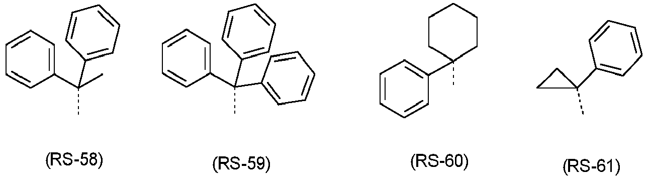


- In accordance with a preferred embodiment, the compounds of formula (1) comprise at least one group RX, RN or R0, which is selected from a group of formula (ArL-1),

- Preferably, the index m in the group of formula (ArL-1) is an integer selected from 1 to 6, very preferably from 1 to 4, very more preferably from 1 and 2.
- In formula (ArL-1), it is preferred that the group Ar2 is selected from the groups of formulae (Ar2-1) to (Ar2-25),


- E4 is selected from -B(R0-), -C(R0)2-, -C(R0)2-C(R0)2-, -Si(R0)2-, -C(=O)-, - C(=NR0)-, -C=(C(R0))2-, -O-, -S-, -S(=O)-, -SO2-, -N(R°)-, -P(R°)- and - P((=O)R°)-, preferably from -C(R0)2-, -Si(R0)2-, -O-, -S- or -N(R°)-; and
- R° has the same definition as above.
- In accordance with a preferred embodiment at least one group Ar2 in formula (ArL-1) stands for a group of formula (Ar2-2) and/or at least one group Ar3 stands for a group of formula (Ar3-2),

the dashed bonds in formula (Ar2-2) indicate the bonding to the structure of formula (1) and to a group Ar2 or Ar3; and the dashed bond in formula (Ar3-2) indicates the bonding to Ar2; and E4 has the same meaning as in above; and the groups of formulae (Ar2-2) and (Ar3-2) may be substituted at each free position by a group R, which has the same meaning as above. - In accordance with a very preferred embodiment, at least one group Ar2 stands for a group of formula (Ar2-2-1) and/or at least one group Ar3 stands for a group of formula (Ar3-2-1),

- the dashed bonds in formula (Ar2-2-1) indicate the bonding to the structure of formula (1) and to a group Ar2 or Ar3;
- the dashed bond in formula (Ar3-2-1) indicates the bonding to Ar2; E4 has the same meaning as above; and
- the groups of formulae (Ar2-2-1) and (Ar3-2-1) may be substituted at each free position by a group R, which has the same meaning as above.
- In accordance with a particularly preferred embodiment, at least one group Ar2 stands for a group of formula (Ar2-2-1b) and/or at least one group Ar3 stands for a group of formula (Ar3-2-1b),

- the dashed bonds in formula (Ar2-2-1b) indicate the bonding to the structure of formula (1) and to a group Ar2 or Ar3;
- the dashed bond in formula (Ar3-2-1b) indicates the bonding to Ar2;
- R° has the same meaning as above; and
- the groups of formulae (Ar2-2-1b) and (Ar3-2-1b) may be substituted at each free position by a group R, which has the same meaning as above.
- Preferably, the group R° stands on each occurrence, identically or differently,
- for H, D;
- for a straight-chain alkyl group having 1 to 20, preferably 1 to 10 carbon atoms, a branched or cyclic alkyl group having 3 to 20, preferably 3 to 10 carbon atoms, each of which may be substituted by one or more radicals R;
- for an aromatic or heteroaromatic ring system having 5 to 60, preferably 5 to 40, more preferably 5 to 30, very preferably 5 to 18 aromatic ring atoms, which may in each case be substituted by one or more radicals R;
- for a group of formula (RS-a), (RS-b), (RS-c) or (RS-d) as defined above; or
- for a group of formula (ArL-1) as defined above;
- Very preferably, the group R° stands on each occurrence, identically or differently,
- for H;
- for a straight-chain alkyl group having 1 to 10, preferably 1 to 5 carbon atoms, a branched or cyclic alkyl group having 3 to 10, preferably 3 to 5 carbon atoms, each of which may be substituted by one or more radicals R;
- for an aromatic or heteroaromatic ring system having 5 to 18 aromatic ring atoms, which may in each case be substituted by one or more radicals R;
- When two adjacent radicals R° form a ring system together, they preferably form a ring of formula (R0-1),

- Preferably, RX stands on each occurrence, identically or differently,
- for H, D, F, Cl, Br, I, CN or N(Ar)2;
- for a straight-chain alkyl, alkoxy or thioalkyl group having 1 to 40, preferably 1 to 20, more preferably 1 to 10 C atoms or for a branched or cyclic alkyl, alkoxy or thioalkyl group having 3 to 40, preferably 3 to 20, more preferably 3 to 10 C atoms, each of which may be substituted by one or more radicals R, where in each case one or more non-adjacent CH2 groups may be replaced by RC=CR, C=C, Si(R)2, Ge(R)2, Sn(R)2, C=O, C=S, C=Se, P(=O)(R), SO, SO2, O, S or CONR and where one or more H atoms may be replaced by D, F, Cl, Br, I, CN or NO2;
- for an aromatic or heteroaromatic ring system having 5 to 60, preferably 5 to 40, more preferably 5 to 30, very preferably 5 to 18 aromatic ring atoms, which may in each case be substituted by one or more radicals R;
- for a group of formula (RS-a), (RS-b), (RS-c) or (RS-d) as defined above; or
- for a group of formula (ArL-1) as defined above;
- More preferably, RX stands on each occurrence, identically or differently,
- for H, D, For CN;
- for a straight-chain alkyl or alkoxy group having 1 to 40, preferably 1 to 20, more preferably 1 to 10 C atoms or for a branched or cyclic alkyl or alkoxy group having 3 to 40, preferably 3 to 20, more preferably 3 to 10 C atoms, each of which may be substituted by one or more radicals R, and where one or more H atoms may be replaced by D or F;
- for an aromatic or heteroaromatic ring system having 5 to 60, preferably 5 to 40, more preferably 5 to 30, very preferably 5 to 18 aromatic ring atoms, which may in each case be substituted by one or more radicals R;
- for a group of formula (RS-a), (RS-b), (RS-c) or (RS-d) as defined above; or
- for a group of formula (ArL-1) as defined above;
- Examples of very suitable radicals RX are H, D, F, CN, substituted and unsubstituted straight-chain alkyl groups having 1 to 10 C atoms, more particularly, methyl, ethyl, propyl, butyl, substituted and unsubstituted branched or cyclic alkyl groups having 3 to 10 C atoms, more particularly t-butyl, and groups of formulae (Ar1-1) to (Ar1-24),


- the dashed bond indicates the bonding of the radical to the rest of the structure;
- RN0, RC0 are on each occurrence, identically or differently, H, D, F, Cl, Br, I, CN, a straight-chain alkyl, alkoxy or thioalkoxy group having 1 to 40, preferably 1 to 20, more preferably 1 to 10 C atoms or cyclic alkyl, alkoxy or thioalkoxy group having 3 to 40, preferably 3 to 20, more preferably 3 to 10 C atoms, each of which may be substituted by one or more radicals R, where one or more non-adjacent CH2 groups may be replaced by (R)C=C(R), C=C, O or S and where one or more H atoms may be replaced by D, F, Cl, Br, I, CN or NO2, or an aromatic or heteroaromatic ring system having 5 to 60, preferably 5 to 40, more preferably 5 to 30, very more preferably 5 to 18 aromatic ring atoms, which may in each case be substituted by one or more radicals R, where optionally two adjacent radicals RC0 can form a mono- or polycyclic, aliphatic, aromatic or heteroaromatic ring system with one another;
- the groups of formulae (Ar1-1) to (Ar1-24) may be substituted at each free position by a group R, which has the same meaning as above.
- Preferably, RN stands on each occurrence, identically or differently,
- for H, D;
- for a straight-chain alkyl group having 1 to 40, preferably 1 to 20, more preferably 1 to 10 C atoms or a branched or cyclic alkyl group having 3 to 40, preferably 3 to 20, more preferably 3 to 10 C atoms, each of which may be substituted by one or more radicals R, where in each case one or more non-adjacent CH2 groups may be replaced by RC=CR, C=C, O or S and where one or more H atoms may be replaced by D or F;
- for an aromatic or heteroaromatic ring system having 5 to 60, preferably 5 to 40, more preferably 5 to 30, very preferably 5 to 18 aromatic ring atoms, which may in each case be substituted by one or more radicals R;
- for a group of formula (RS-a), (RS-b), (RS-c) or (RS-d) as defined above; or
- for a group of formula (ArL-1) as defined above.
- More preferably, RN stands on each occurrence, identically or differently,
- for an aromatic or heteroaromatic ring system having 5 to 30, preferably 5 to 18 aromatic ring atoms, preferably selected from the group consisting of phenyl, biphenyl, terphenyl, quaterphenyl, fluorene, spirobifluorene, naphthalene, anthracene, phenanthrene, triphenylene, fluoranthene, indole, benzofuran, benzothiophene, dibenzofuran, dibenzothiophene, carbazole, indenocarbazole, indolocarbazole, phenanthroline, pyridine, pyrimidine, pyrazine, pyridazine, triazine, quinolone, benzopyridine, benzopyridazine, benzopyrimidine, quinazoline, benzimidazole, or a combination of two or three of these groups, each of which may be substituted by one or more radicals R;
- for a group of formula (RS-a), (RS-b), (RS-c) or (RS-d) as defined above; or
- for a group of formula (ArL-1) as defined above.
- Examples of very suitable radicals RN are the groups of formulae (Ar1-1) to (Ar1-24) as depicted above.
- Preferably, the group R stands on each occurrence, identically or differently, for H, D, F, Cl, Br, I, CHO, CN, N(Ar)2, si(R')3, a straight-chain alkyl, alkoxy or thioalkyl group having 1 to 40, preferably 1 to 20, more preferably 1 to 10 C atoms or a branched or cyclic alkyl, alkoxy or thioalkyl group having 3 to 40, preferably 3 to 20, more preferably 3 to 10 C atoms, each of which may be substituted by one or more radicals R', where in each case one or more non-adjacent CH2 groups may be replaced by R'C=CR', O or S and where one or more H atoms may be replaced by D, F or CN, an aromatic or heteroaromatic ring system having 5 to 60 aromatic ring atoms, which may in each case be substituted by one or more radicals R', where two adjacent radicals R may form a mono- or polycyclic, aliphatic ring system or aromatic ring system, which may be substituted by one or more radicals R'. When R is selected from aromatic and heteroaromatic ring systems, it is preferably selected from aromatic and heteroaromatic ring systems having 5 to 40, preferably 5 to 30, more preferably 5 to 18 aromatic ring atoms or from aromatic or heteroaromatic ring system having 5 to 60 aromatic ring atoms corresponding to groups of formula (ArL-1) as defined above.
- Preferably, the group Ar is on each occurrence, identically or differently, an aromatic or heteroaromatic ring system having 5 to 18, preferably 6 to 18 aromatic ring atoms, which may in each case also be substituted by one or more radicals R'.
- Preferably, R' stands on each occurrence, identically or differently, for H, D, F, Cl, Br, I, CN, a straight-chain alkyl, alkoxy or thioalkyl group having 1 to 10 C atoms or a branched or cyclic alkyl, alkoxy or thioalkyl group having 3 to 10 C atoms, where one or more H atoms may be replaced by D or F, or an aromatic or heteroaromatic ring system having 5 to 18, preferably 6 to 18 C atoms.
- Examples of suitable compounds of formula (1) are the structures shown in the table below:


- The compounds according to the invention can be prepared by synthesis steps known to the person skilled in the art, such as, for example, bromination, Suzuki coupling, Ullmann coupling, Hartwig-Buchwald coupling, etc. An example of a suitable synthesis process is depicted in general terms in schemes 1 and 5 below.


- For the processing of the compounds according to the invention from the liquid phase, for example by spin coating or by printing processes, formulations of the compounds according to the invention are necessary. These formulations can be, for example, solutions, dispersions or emulsions. It may be preferred to use mixtures of two or more solvents for this purpose. Suitable and preferred solvents are, for example, toluene, anisole, o-, m- or p-xylene, methyl benzoate, mesitylene, tetralin, veratrol, THF, methyl-THF, THP, chlorobenzene, dioxane, phenoxytoluene, in particular 3-phenoxytoluene, (-)-fenchone, 1,2,3,5-tetramethylbenzene, 1,2,4,5-tetramethylbenzene, 1-methylnaphthalene, 2-methylbenzothiazole, 2-phenoxyethanol, 2-pyrrolidinone, 3-methylanisole, 4-methylanisole, 3,4-dimethylanisole, 3,5-dimethylanisole, acetophenone, α-terpineol, benzothiazole, butyl benzoate, cumene, cyclohexanol, cyclohexanone, cyclohexylbenzene, decalin, dodecylbenzene, ethyl benzoate, indane, methyl benzoate, NMP, p-cymene, phenetole, 1,4-diisopropylbenzene, dibenzyl ether, diethylene glycol butyl methyl ether, triethylene glycol butyl methyl ether, diethylene glycol dibutyl ether, triethylene glycol dimethyl ether, diethylene glycol monobutyl ether, tripropylene glycol dimethyl ether, tetraethylene glycol dimethyl ether, 2-isopropylnaphthalene, pentylbenzene, hexylbenzene, heptylbenzene, octylbenzene, 1,1-bis(3,4-dimethylphenyl)ethane or mixtures of these solvents.
- The present invention therefore furthermore relates to a formulation comprising a compound according to the invention and at least one further compound. The further compound may be, for example, a solvent, in particular one of the above-mentioned solvents or a mixture of these solvents. However, the further compound may also be at least one further organic or inorganic compound which is likewise employed in the electronic device, for example an emitting compound, in particular a phosphorescent dopant, and/or a further matrix material. Suitable emitting compounds and further matrix materials are indicated below in connection with the organic electroluminescent device. This further compound may also be polymeric.
- The compounds and mixtures according to the invention are suitable for use in an electronic device. An electronic device here is taken to mean a device which comprises at least one layer which comprises at least one organic compound. However, the component here may also comprise inorganic materials or also layers built up entirely from inorganic materials.
- The present invention therefore furthermore relates to the use of the compounds or mixtures according to the invention in an electronic device, in particular in an organic electroluminescent device.
- The present invention again furthermore relates to an electronic device comprising at least one of the compounds or mixtures according to the invention mentioned above. The preferences stated above for the compound also apply to the electronic devices.
- The electronic device is preferably selected from the group consisting of organic electroluminescent devices (OLEDs, PLEDs), organic integrated circuits (O-ICs), organic field-effect transistors (O-FETs), organic thin-film transistors (O-TFTs), organic light-emitting transistors (O-LETs), organic solar cells (O-SCs), organic dye-sensitised solar cells, organic optical detectors, organic photoreceptors, organic field-quench devices (O-FQDs), light-emitting electrochemical cells (LECs), organic laser diodes (O-lasers) and "organic plasmon emitting devices" (D. M. Koller et al., Nature Photonics 2008, 1-4), preferably organic electroluminescent devices (OLEDs, PLEDs), in particular phosphorescent OLEDs.
- The organic electroluminescent device comprises a cathode, an anode and at least one emitting layer. Apart from these layers, it may also comprise further layers, for example in each case one or more hole-injection layers, hole-transport layers, hole-blocking layers, electron-transport layers, electroninjection layers, exciton-blocking layers, electron-blocking layers and/or charge-generation layers. It is likewise possible for interlayers, which have, for example, an exciton-blocking function, to be introduced between two emitting layers. However, it should be pointed out that each of these layers does not necessarily have to be present. The organic electroluminescent device here may comprise one emitting layer or a plurality of emitting layers. If a plurality of emission layers are present, these preferably have in total a plurality of emission maxima between 380 nm and 750 nm, resulting overall in white emission, i.e. various emitting compounds which are able to fluoresce or phosphoresce are used in the emitting layers. Particular preference is given to systems having three emitting layers, where the three layers exhibit blue, green and orange or red emission (for the basic structure see, for example,
WO 2005/011013 ). These can be fluorescent or phosphorescent emission layers or hybrid systems, in which fluorescent and phosphorescent emission layers are combined with one another. - The compound according to the invention in accordance with the embodiments indicated above can be employed in various layers, depending on the precise structure and on the substitution.
- Preference is given to an organic electroluminescent device comprising a compound of the formula (1) or in accordance with the preferred embodiments as fluorescent emitters or TADF (Thermally Activated Delayed Fluorescence) emitters. More particularly, the compound of the formula (1) or in accordance with the preferred embodiments is preferably employed as a blue-fluorescent emitter showing prompt fluorescence or as a blue TADF emitter.
- In accordance with another preferred embodiment of the invention, the compound of formula (1) or in accordance with the preferred embodiments is employed in a hyperfluorescent system, as described for example in
WO2015/135624 , comprising the compound of formula (1) as a fluorescent emitter and a sensitizer compound selected from thermally activated delayed fluorescence compounds (TADF compounds), wherein the energy of the sensitizer is transferred to the fluorescent emitter via Förster resonance energy transfer. - In accordance with still another preferred embodiment of the invention, the compound of formula (1) or in accordance with the preferred embodiments is employed in a hyperphosphorescent system, as described for example in
WO2001/08230A1 - The compounds of formula (1) can also be employed in an electron-transport layer and/or in an electron-blocking or exciton-blocking layer and/or in a hole-transport layer, depending on the precise substitution. The preferred embodiments indicated above also apply to the use of the materials in organic electronic devices.
- The compound of formula (1) is particularly suitable for use as a blue emitter compound. The electronic device concerned may comprise a single emitting layer comprising the compound according to the invention or it may comprise two or more emitting layers. The further emitting layers here may comprise one or more compounds according to the invention or alternatively other compounds.
- If the compound according to the invention is employed as a fluorescent emitter or TADF emitter in an emitting layer, it is preferably employed in combination with one or more matrix materials. A matrix material here is taken to mean a material which is present in the emitting layer, preferably as the principal component, and which does not emit light on operation of the device.
- Preferably, the matrix compound has a glass transition temperature TG of greater than 70°C, more preferably greater than 90°C, most preferably greater than 110°C.
- The proportion of the emitting compound in the mixture of the emitting layer is between 0.1 and 50.0%, preferably between 0.5 and 20.0%, particularly preferably between 1.0 and 10.0%. Correspondingly, the proportion of the matrix material or matrix materials is between 50.0 and 99.9%, preferably between 80.0 and 99.5%, particularly preferably between 90.0 and 99.0%.
- The specifications of the proportions in % are, for the purposes of the present application, taken to mean % by vol. if the compounds are applied from the gas phase and % by weight if the compounds are applied from solution.
- If the compound of formula (1) or in accordance with the preferred embodiments is employed in an emitting layer as a fluorescent emitter (prompt fluorescence), then the preferred matrix materials for use in combination with the fluorescent emitter are selected from the classes of the oligoarylenes (for example 2,2',7,7'-tetraphenylspirobifluorene in accordance with
EP 676461 EP 676461 WO 2004/081017 ), the hole-conducting compounds (for example in accordance withWO 2004/058911 ), the electron-conducting compounds, in particular ketones, phosphine oxides, sulfoxides, etc. (for example in accordance withWO 2005/084081 andWO 2005/084082 ), the atropisomers (for example in accordance withWO 2006/048268 ), the boronic acid derivatives (for example in accordance withWO 2006/117052 ) or the benzanthracenes (for example in accordance withWO 2008/145239 ). Particularly preferred matrix materials are selected from the classes of the oligoarylenes, comprising naphthalene, anthracene, benzanthracene and/or pyrene or atropisomers of these compounds, the oligoarylenevinylenes, the ketones, the phosphine oxides and the sulfoxides. Very particularly preferred matrix materials are selected from the classes of the oligoarylenes, comprising anthracene, benzanthracene, benzophenanthrene and/or pyrene or atropisomers of these compounds. An oligoarylene in the sense of this invention is intended to be taken to mean a compound in which at least three aryl or arylene groups are bonded to one another. - Particularly preferred matrix materials for use in combination with the compounds of the formula (1) employed as fluorescent emitters in the emitting layer are depicted in the following table:


- If the compound according to the invention is employed as a fluorescent emitting compound in an emitting layer, it may be employed in combination with one or more other fluorescent emitting compounds.
- Preferred fluorescent emitters, besides the compounds according to the invention, are selected from the class of the arylamines. An arylamine in the sense of this invention is taken to mean a compound which contains three substituted or unsubstituted aromatic or heteroaromatic ring systems bonded directly to the nitrogen. At least one of these aromatic or heteroaromatic ring systems is preferably a condensed ring system, particularly preferably having at least 14 aromatic ring atoms. Preferred examples thereof are aromatic anthracenamines, aromatic anthracenediamines, aromatic pyrenamines, aromatic pyrenediamines, aromatic chrysenamines or aromatic chrysenediamines. An aromatic anthracenamine is taken to mean a compound in which one diarylamino group is bonded directly to an anthracene group, preferably in the 9-position. An aromatic anthracenediamine is taken to mean a compound in which two diarylamino groups are bonded directly to an anthracene group, preferably in the 9,10-position. Aromatic pyrenamines, pyrenediamines, chrysenamines and chrysenediamines are defined analogously thereto, where the diarylamino groups are preferably bonded to the pyrene in the 1-position or in the 1,6-position. Further preferred emitters are indenofluorenamines or indenofluorenediamines, for example in accordance with
WO 2006/108497 orWO 2006/122630 , benzoindenofluorenamines or benzoindenofluorenediamines, for example in accordance withWO 2008/ 006449 , and dibenzoindenofluorenamines or dibenzoindenofluorenediamines, for example in accordance withWO 2007/140847 , and the indenofluorene derivatives containing condensed aryl groups which are disclosed inWO 2010/012328 . Still further preferred emitters are benzanthracene derivatives as disclosed inWO 2015/158409 , anthracene derivatives as disclosed inWO 2017/036573 , fluorene dimers like inWO 2016/150544 or phenoxazine derivatives as disclosed inWO 2017/028940 andWO 2017/028941 . Preference is likewise given to the pyrenarylamines disclosed inWO 2012/048780 andWO 2013/185871 . Preference is likewise given to the benzoindenofluorenamines disclosed inWO 2014/037077 , the benzofluorenamines disclosed inWO 2014/106522 and the indenofluorenes disclosed inWO 2014/111269 orWO 2017/036574 . - Examples of preferred fluorescent emitting compounds, besides the compounds according to the invention, which can be used in combination with the compounds of the invention in an emitting layer or which can be used in another emitting layer of the same device are depicted in the following table:


- If the compound of formula (1) or in accordance with the preferred embodiments is employed in an emitting layer as a TADF emitter, then the preferred matrix materials for use in combination with the TADF emitter are selected from the classes of the ketones, phosphine oxides, sulfoxides and sulfones, for example according to
WO 2004/013080 ,WO 2004/093207 ,WO 2006/005627 orWO 2010/006680 , triarylamines, carbazole derivatives, e.g. CBP (N,N-biscarbazolylbiphenyl), m-CBP or the carbazole derivatives disclosed inWO 2005/039246 ,US 2005/0069729 ,JP 2004/288381 EP 1205527 ,WO 2008/086851 orUS 2009/0134784 , dibenzofuran derivatives, indolocarbazole derivatives, for example according toWO 2007/063754 orWO 2008/056746 , indenocarbazole derivatives, for example according toWO 2010/136109 orWO 2011/000455 , azacarbazoles, for example according toEP 1617710 ,EP 1617711 ,EP 1731584 ,JP 2005/347160 WO 2007/137725 , silanes, for example according toWO 2005/111172 , azaboroles or boronic esters, for example according toWO 2006/117052 , diazasilole derivatives, for example according toWO 2010/054729 , diazaphosphole derivatives, for example according toWO 2010/054730 , triazine derivatives, for example according toWO 2010/015306 ,WO 2007/063754 orWO 2008/056746 , pyrimidine derivatives, quinoxaline derivatives, Zn complexes, Al complexes or Be complexes, for example according toEP 652273 WO 2009/062578 , or bridged carbazole derivatives, for example according toUS 2009/0136779 ,WO 2010/050778 ,WO 2011/042107 orWO 2011/088877 . Suitable matrix materials are also those described inWO 2015/135624 . It is also possible to use mixtures of two or more of these matrix materials. - The matrix compounds for TADF emitters are preferably chargetransporting, i.e. electron-transporting or hole-transporting, or bipolar compounds. Matrix compounds used may additionally also be compounds which are neither hole- nor electron-transporting in the context of the present application. An electron-transporting compound in the context of the present invention is a compound having a LUMO ≤ -2.50 eV. Preferably, the LUMO is ≤ -2.60 eV, more preferably ≤ -2.65 eV, most preferably ≤ -2.70 eV. The LUMO is the lowest unoccupied molecular orbital. The value of the LUMO of the compound is determined by quantum-chemical calculation, as described in general terms in the examples section at the back. A hole-transporting compound in the context of the present invention is a compound having a HOMO ≥ -5.5 eV. The HOMO is preferably ≥ -5.4 eV, more preferably ≥ -5.3 eV. The HOMO is the highest occupied molecular orbital. The value of the HOMO of the compound is determined by quantum-chemical calculation, as described in general terms in the examples section at the back. A bipolar compound in the context of the present invention is a compound which is both hole- and electron-transporting.
- Suitable electron-conducting matrix compounds for TADF emitters are selected from the substance classes of the triazines, the pyrimidines, the lactams, the metal complexes, especially the Be, Zn and Al complexes, the aromatic ketones, the aromatic phosphine oxides, the azaphospholes, the azaboroles substituted by at least one electron-conducting substituent, and the quinoxalines. In a preferred embodiment of the invention, the electron-conducting compound is a purely organic compound, i.e. a compound containing no metals.
- Furthermore, the hyperfluorescent and hyperphosphorescent systems as mentioned above preferably comprise, additionally to the sensitizer and the fluorescent emitter, at least one matrix material. In this case, it is preferable that the lowest triplet energy of the matrix compound is not more than 0.1 eV lower than the triplet energy of the sensitizer compound.
- Especially preferably,

- More preferably:


- T1(matrix) here is the lowest triplet energy of the matrix compound and T1(sensitizer) is the lowest triplet energy of the sensitizer compound. The triplet energy of the matrix compound T1(matrix) is determined here from the edge of the photoluminescence spectrum measured at 4 K of the neat film. T1(sensitizer) is determined from the edge of the photoluminescence spectrum measured at room temperature in toluene solution.
- Suitable matrix materials for hyperfluorescent or hyperphosphorescent systems are the same matrix materials as mentioned above, more preferred are the matrix materials that are also preferred for TADF materials.
- Suitable phosphorescent emitters are, in particular, compounds which emit light, preferably in the visible region, on suitable excitation and in addition contain at least one atom having an atomic number greater than 20, preferably greater than 38 and less than 84, particularly preferably greater than 56 and less than 80. The phosphorescent emitters used are preferably compounds which contain copper, molybdenum, tungsten, rhenium, ruthenium, osmium, rhodium, iridium, palladium, platinum, silver, gold or europium, in particular compounds which contain iridium, platinum or copper.
- For the purposes of the present invention, all luminescent iridium, platinum or copper complexes are regarded as phosphorescent compounds.
- Examples of the phosphorescent emitters described above are revealed by the applications
WO 2000/70655 WO 2001/41512 WO 2002/02714 WO 2002/15645 EP 1191613 ,EP 1191612 ,EP 1191614 ,WO 2005/033244 ,WO 2005/019373 andUS 2005/0258742 . In general, all phosphorescent complexes as used in accordance with the prior art for phosphorescent OLEDs and as are known to the person skilled in the art in the area of organic electroluminescent devices are suitable for use in the devices according to the invention. The person skilled in the art will also be able to employ further phosphorescent complexes without inventive step in combination with the compounds according to the invention in OLEDs. - Preferred matrix materials for phosphorescent emitters are aromatic ketones, aromatic phosphine oxides or aromatic sulfoxides or sulfones, for example in accordance with
WO 2004/013080 ,WO 2004/093207 ,WO 2006/005627 orWO 2010/006680 , triarylamines, carbazole derivatives, for example CBP (N,N-biscarbazolylbiphenyl) or the carbazole derivatives disclosed inWO 2005/039246 ,US 2005/0069729 ,JP 2004/288381 EP 1205527 orWO 2008/086851 , indolocarbazole derivatives, for example in accordance withWO 2007/063754 orWO 2008/056746 , indenocarbazole derivatives, for example in accordance withWO 2010/136109 ,WO 2011/000455 orWO 2013/041176 , azacarbazole derivatives, for example in accordance withEP 1617710 ,EP 1617711 ,EP 1731584 ,JP 2005/347160 WO 2007/137725 , silanes, for example in accordance withWO 2005/111172 , azaboroles or boronic esters, for example in accordance withWO 2006/117052 , triazine derivatives, for example in accordance withWO 2010/015306 ,WO 2007/063754 orWO 2008/056746 , zinc complexes, for example in accordance withEP 652273 WO 2009/062578 , diazasilole or tetraazasilole derivatives, for example in accordance withWO 2010/054729 , diazaphosphole derivatives, for example in accordance withWO 2010/054730 , bridged carbazole derivatives, for example in accordance withUS 2009/0136779 ,WO 2010/050778 ,WO 2011/042107 ,WO 2011/088877 orWO 2012/143080 , triphenylene derivatives, for example in accordance withWO 2012/048781 , or lactams, for example in accordance withWO 2011/116865 orWO 2011/137951 . - More particularly, when the phosphorescent compound is employed in a hyperphosphorescent system as described above, the phosphorescent compound is preferably selected from the phosphorescent organometallic complexes, which are described, for example, in
WO2015/091716 . Also particularly preferred are the phosphorescent organometallic complexes, which are described inWO2000/70655 WO2001/41512 WO2002/02714 WO2002/15645 EP1191612 ,WO2005/033244 ,WO2005/019373 ,US2005/0258742 ,WO2006/056418 ,WO2007/115970 ,WO2007/115981 ,WO2008/000727 ,WO2009/050281 ,WO2009/050290 ,WO2011/051404 ,WO2011/073149 ,WO2012/121936 ,US2012/0305894 ,WO2012/170571 ,WO2012/170461 ,WO2012/170463 ,WO2006/121811 ,WO2007/095118 ,WO2008/156879 ,WO2008/156879 ,WO2010/068876 ,WO2011/106344 ,WO2012/172482 ,EP3126371 ,WO2015/014835 ,WO2015/014944 ,WO2016/020516 ,US20160072081 ,WO2010/086089 ,WO2011/044988 ,WO2014/008982 ,WO2014/023377 ,WO2014/094961 ,WO2010/069442 ,WO2012/163471 ,WO2013/020631 ,US20150243912 ,WO2008/000726 ,WO2010/015307 ,WO2010/054731 ,WO2010/054728 ,WO2010/099852 ,WO2011/032626 ,WO2011/157339 ,WO2012/007086 ,WO2015/036074 ,WO2015/104045 ,WO2015/117718 ,WO2016/015815 , which are preferably iridium and platinum complexes. - Particularly preferred are also the phosphorescent organometallic complexes having polypodal ligands as described, for example, in
WO2004/081017 ,WO2005/042550 ,US2005/0170206 ,WO2009/146770 ,WO2010/102709 ,WO2011/066898 ,WO2016124304 ,WO2017/032439 ,WO2018/019688 ,EP3184534 andWO2018/011186 . - Particularly preferred are also the phosphorescent binuclear organometallic complexes as described, for example, in
WO2011/045337 ,US20150171350 ,WO2016/079169 ,WO2018/019687 ,WO2018/041769 ,WO2018/054798 ,WO2018/069196 ,WO2018/069197 ,WO2018/069273 . - Particularly preferred are also the copper complexes as described, for example, in
WO2010/031485 ,US2013150581 ,WO2013/017675 ,WO2013/007707 ,WO2013/001086 ,WO2012/156378 ,WO2013/072508 ,EP2543672 . - Explicit examples of phosphorescent sensitizers are Ir(ppy)3 and its derivatives as well as the structures listed below:


- Further explicit examples of phosphorescent sensitizers are iridium and platinum complexes containing carbene ligands and the structures listed below, wherein homoleptic and heteroleptic complexes and meridonal and facial isomers may be suitable:


- Further explicit examples of phosphorescent sensitizers are also copper complexes and the structures listed below:

- Besides the compounds according to the invention, suitable TADF compounds are compounds in which the energy gap between the lowest triplet state T1 and the first excited singlet state S1 is sufficiently small that the S1 state is thermally accessible from the T1 state. Preferably, TADF compounds have a gap between the lowest triplet state T1 and the first excited singlet state S1 of ≤ 0.30 eV. More preferably, the gap between S1 and T1 is ≤ 0.20 eV, even more preferably ≤ 0.15 eV, especially more preferably ≤ 0.10 eV and even more especially preferably ≤ 0.08 eV.
- The energy of the lowest excited singlet state (S1) and the lowest triplet state (T1) as well as the HOMO and LUMO values are determined by quantum-chemical calculations. The Gaussian09 program package (revision D or later) is used. Neutral ground state geometries of all purely organic molecules are optimized at the AM1 level of theory. Subsequently, B3PW91/6-31G(d) single point calculations including a calculation of the lowest singlet and triplet excited states with TD-B3PW91/6-31G(d). HOMO and LUMO values as well as S1 and T1 excitation energies are taken from this single-point calculation at the B3PW91/6-31G(d) level of theory.
- Similarly, for metalorganic compounds, neutral ground state geometries are optimized at the HF/LANL2MB level of theory. B3PW91/6-31G(d)+LANL2DZ (LANL2DZ for all metal atoms, 6-31G(d) for all low-weight elements) is subsequently employed to calculate HOMO and LUMO values as well as TD-DFT excitation energies.
- HOMO (HEh) and LUMO (LEh) values from the calculation are given in Hartree units. The HOMO and LUMO energy levels calibrated with reference to cyclic voltammetry measurements are determined therefrom in electron volts as follows:


- These values are to be regarded in the sense of the present invention as HOMO and LUMO energy levels of the materials.
- The lowest triplet state T1 is defined as the energy of the lowest TD-DFT triplet excitation energy.
- The lowest excited singlet state S1 is defined as the energy of the lowest TD-DFT singlet excitation energy.
- Preferably, the TADF compound is an organic compound. Organic compounds in the context of the present invention are carbonaceous compounds that do not contain any metals. More particularly, organic compounds are formed from the elements C, H, D, B, Si, N, P, O, S, F, Cl, Br and I.
- The TADF compound is more preferably an aromatic compound having both donor and acceptor substituents, with only slight spatial overlap between the LUMO and the HOMO of the compound. What is understood by donor and acceptor substituents is known in principle to those skilled in the art. Suitable donor substituents are especially diaryl- or -heteroarylamino groups and carbazole groups or carbazole derivatives, each preferably bonded to the aromatic compound via N. These groups may also have further substitution. Suitable acceptor substituents are especially cyano groups, but also, for example, electron-deficient heteroaryl groups which may also have further substitution, for example substituted or unsubstituted triazine groups.
- The preferred dopant concentrations of the TADF compound in the emitting layer are described hereinafter. Because of the difference in production of the organic electroluminescent device, the dopant concentration in the case of production of the emitting layer by vapor deposition is reported in % by volume, and in the case of production of the emitting layer from solution in % by weight. The dopant concentrations in % by volume and % by weight is generally very similar.
- In a preferred embodiment of the invention, in the case of production of the emitting layer by vapor deposition, the TADF compound is present in a dopant concentration of 1% to 70% by volume in the emitting layer, more preferably of 5% to 50% by volume, even more preferably of 5% to 30% by volume.
- In a preferred embodiment of the invention, in the case of production of the emitting layer from solution, the TADF compound is present in a dopant concentration of 1% to 70% by weight in the emitting layer, more preferably of 5% to 50% by weight, even more preferably of 5% to 30% by weight.
- The general art knowledge of the person skilled in the art includes knowledge of which materials are generally suitable as TADF compounds. The following references disclose, by way of example, materials that are potentially suitable as TADF compounds:
- Tanaka et al., Chemistry of Materials 25(18), 3766 (2013).
- Lee et al., Journal of Materials Chemistry C 1(30), 4599 (2013).
- Zhang et al., Nature Photonics advance online publication, 1 (2014), doi: 10.1038/nphoton.2014.12.
- Serevicius et al., Physical Chemistry Chemical Physics 15(38), 15850 (2013).
- Li et al., Advanced Materials 25(24), 3319 (2013).
- Youn Lee et al., Applied Physics Letters 101(9), 093306 (2012).
- Nishimoto et al., Materials Horizons 1, 264 (2014), doi: 10.1039/C3MH00079F.
- Valchanov et al., Organic Electronics, 14(11), 2727 (2013).
- Nasu et al., ChemComm, 49, 10385 (2013).
- In addition, the following patent applications disclose potential TADF compounds:
US2019058130 ,WO18155642 WO18117179A1 US2017047522 ,US2016372682A ,US2015041784 ,US2014336379 ,US2014138669 ,WO 2013/154064 ,WO 2013/133359 ,WO 2013/161437 ,WO 2013/081088 ,WO 2013/081088 ,WO 2013/011954 ,JP 2013/116975 US 2012/0241732 . - In addition, the person skilled in the art is able to infer design principles for TADF compounds from these publications. For example, Valchanov et al. show how the colour of TADF compounds can be adjusted.
- Examples of suitable molecules which exhibit TADF are the structures shown in the following table:


- As mentioned above, the compounds of formula (1) or in accordance with the preferred embodiments may be used as fluorescent emitters in combination with a sensitizer in a hyperfluorescent or hyperphosphorescent system. In this case, it is preferred that the compounds of formula (1) are sterically shielded. For examples compounds of formula (1) corresponding to compounds of formulae (5) and (6), more particularly (5-1) to (5-3), are very suitable as sterically shielded fluorescent emitters in combination with a sensitizer selected from TADF compounds and phosphorescent compounds in an emitting layer. Preferably, the emitting layer further comprises at least one organic functional material selected from matrix materials.
- The compounds of formula (1) or in accordance with preferred embodiments can also be employed in combination with further compounds selected from the group consisting of HTM (Hole Transport Material), HIM (Hole Injection Material), HBM (Hole Blocking Material), p-dopant, ETM (Electron Transport Material), EIM (Electron Injection Material), EBM (Electron Blocking Material), n-dopant, fluorescent emitter, phosphorescent emitter, delayed fluorescent emitter, matrix material, host material, wide band gap material and quantum material, like quantum dot and quantum rod.
- The compounds of formula (1) or in accordance with preferred embodiments can also be employed in other layers, for example as hole-transport materials in a hole-injection or hole-transport layer or electron-blocking layer or as matrix materials in an emitting layer.
- Generally preferred classes of material for use as corresponding functional materials in the organic electroluminescent devices according to the invention are indicated below.
- Suitable charge-transport materials, as can be used in the hole-injection or hole-transport layer or electron-blocking layer or in the electron-transport layer of the electronic device according to the invention, are, for example, the compounds disclosed in Y. Shirota et al., Chem. Rev. 2007, 107(4), 953-1010, or other materials as are employed in these layers in accordance with the prior art.
- Materials which can be used for the electron-transport layer are all materials as are used in accordance with the prior art as electron-transport materials in the electron-transport layer. Particularly suitable are aluminium complexes, for example Alq3, zirconium complexes, for example Zrq4, lithium complexes, for example LiQ, benzimidazole derivatives, triazine derivatives, pyrimidine derivatives, pyridine derivatives, pyrazine derivatives, quinoxaline derivatives, quinoline derivatives, oxadiazole derivatives, aromatic ketones, lactams, boranes, diazaphosphole derivatives and phosphine oxide derivatives. Furthermore, suitable materials are derivatives of the above-mentioned compounds, as disclosed in
JP 2000/053957 WO 2003/060956 ,WO 2004/028217 ,WO 2004/080975 andWO 2010/072300 . - Preferred hole-transport materials which can be used in a hole-transport, hole-injection or electron-blocking layer in the electroluminescent device according to the invention are indenofluorenamine derivatives (for example in accordance with
WO 06/122630 WO 06/100896 EP 1661888 , hexaazatriphenylene derivatives (for example in accordance withWO 01/049806 US 5,061,569 ), the amine derivatives disclosed inWO 95/09147 WO 08/006449 WO 07/140847 WO 2012/034627 orWO 2013/120577 ), fluorenamines (for example in accordance with the as applicationsEP 2875092 ,EP 2875699 andEP 2875004 ), spirodibenzopyranamines (for example in accordance withWO 2013/083216 ) and dihydroacridine derivatives (for example in accordance withWO 2012/150001 ). The compounds according to the invention can also be used as hole-transport materials. - The cathode of the organic electroluminescent device preferably comprises metals having a low work function, metal alloys or multilayered structures comprising various metals, such as, for example, alkaline-earth metals, alkali metals, main-group metals or lanthanoids (for example Ca, Ba, Mg, Al, In, Mg, Yb, Sm, etc.). Also suitable are alloys comprising an alkali metal or alkaline-earth metal and silver, for example an alloy comprising magnesium and silver. In the case of multilayered structures, further metals which have a relatively high work function, such as, for example, Ag or Al, can also be used in addition to the said metals, in which case combinations of the metals, such as, for example, Ca/Ag, Mg/Ag or Ag/Ag, are generally used. It may also be preferred to introduce a thin interlayer of a material having a high dielectric constant between a metallic cathode and the organic semiconductor. Suitable for this purpose are, for example, alkali metal fluorides or alkaline-earth metal fluorides, but also the corresponding oxides or carbonates (for example LiF, Li2O, BaF2, MgO, NaF, CsF, Cs2CO3, etc.). Furthermore, lithium quinolinate (LiQ) can be used for this purpose. The layer thickness of this layer is preferably between 0.5 and 5 nm.
- The anode preferably comprises materials having a high work function. The anode preferably has a work function of greater than 4.5 eV vs. vacuum. Suitable for this purpose are on the one hand metals having a high redox potential, such as, for example, Ag, Pt or Au. On the other hand, metal/metal oxide electrodes (for example Al/Ni/NiOx, Al/PtOx) may also be preferred. For some applications, at least one of the electrodes must be transparent or partially transparent in order to facilitate either irradiation of the organic material (organic solar cells) or the coupling-out of light (OLEDs, O-lasers). Preferred anode materials here are conductive mixed metal oxides. Particular preference is given to indium tin oxide (ITO) or indium zinc oxide (IZO). Preference is furthermore given to conductive, doped organic materials, in particular conductive doped polymers.
- The device is appropriately (depending on the application) structured, provided with contacts and finally sealed, since the lifetime of the devices according to the invention is shortened in the presence of water and/or air.
- In a preferred embodiment, the organic electroluminescent device according to the invention is characterised in that one or more layers are coated by means of a sublimation process, in which the materials are applied by vapour deposition in vacuum sublimation units at an initial pressure of less than 10-5 mbar, preferably less than 10-6 mbar. However, it is also possible here for the initial pressure to be even lower, for example less than 10-7 mbar.
- Preference is likewise given to an organic electroluminescent device, characterised in that one or more layers are coated by means of the OVPD (organic vapour phase deposition) process or with the aid of carrier-gas sublimation, in which the materials are applied at a pressure of between 10-5 mbar and 1 bar. A special case of this process is the OVJP (organic vapour jet printing) process, in which the materials are applied directly through a nozzle and are thus structured (for example M. S. Arnold et al., Appl. Phys. Lett. 2008, 92, 053301).
- Preference is furthermore given to an organic electroluminescent device, characterised in that one or more layers are produced from solution, such as, for example, by spin coating, or by means of any desired printing process, such as, for example, screen printing, flexographic printing, nozzle printing or offset printing, but particularly preferably LITI (light induced thermal imaging, thermal transfer printing) or ink-jet printing. Soluble compounds of the formula (I) are necessary for this purpose. High solubility can be achieved through suitable substitution of the compounds.
- Also possible are hybrid processes, in which, for example, one or more layers are applied from solution and one or more further layers are applied by vapour deposition. Thus, it is possible, for example, to apply the emitting layer from solution and to apply the electron-transport layer by vapour deposition.
- These processes are generally known to the person skilled in the art and can be applied by him without inventive step to organic electroluminescent devices comprising the compounds according to the invention.
- In accordance with the invention, the electronic devices comprising one or more compounds according to the invention can be employed in displays, as light sources in lighting applications and as light sources in medical and/or cosmetic applications (for example light therapy).
- The invention will now be explained in greater detail by the following examples, without wishing to restrict it thereby.
- Unless otherwise stated, the following syntheses are carried out in a protective gas atmosphere in dried solvents. The solvents and reagents can be obtained from Sigma-ALDRICH or ABCR. The CAS numbers of the compounds known from the literature are also indicated below. The compounds according to the invention can be synthesised by means of synthesis methods known to the skilled person.

- A suspension of 21.0 g (57,4 mmol) of 1,6-dibromo-5,10-dihydro-5,10-dihydroxy-boranthrene is added to 2000 ml of benzene in a glass tube with a PTFE tap. Then, 29.0 g (11 ml, 120 mmol) of BBr3 is added to this solution at room temperature. The resulting clear solution is heated to 80 ° C, the tube is closed, and the temperature is maintained for 6 hours. The mixture is stirred overnight at RT, after which a small amount of the formed solid settles. The supernatant is then transferred via a tube to a Schlenk tube, which is put under vacuum to remove all volatile vapors.
- The solid residue is mixed with 50 ml heptane and kept in an ultrasonic bath and then connected again to vacuum to remove the rest of BBr3.
- The residue is recrystallized into hot hexane. The residue is dissolved in toluene and cooled down to -78 °C.
- 236 ml (118 mmol) of bromo(2-chlorophenyl-magnesium (0.5 M solution in THF) is added to the solution. The reaction mixture is heated to room temperature over the night and then quenched with a saturated aqueous NH4Cl-solution. The two liquid phases are separated, the aqueous phase is extracted with CHCl3 (3 × 150 ml), the combined organic phases are dried over MgSO4, concentrated in vacuum and purified via a column chromatography (silica gel, CHCl3: n-hexane = 1:9) and finally purified by sublimation.
- The yield is 19 g (34 mmol), i.e. 60% of the theory.
- The following compounds can be obtained analogously:
Educt 1 Educt 2 Product Yield 1a 


62% -

- 11 g (20 mmol) of 1,6-dibromo-5,10-bis(2-chlorophenyl)boranthrene, 0.95 g (1 mmol) of tris(dibenzylidenacetone)dipalladium, 4 mL (1M) of t-Bu3P solution in toluene and 4.6 g (48 mmol) of sodium tert-butoxide are added to 200 ml toluene. Then, 1.8 g (16 mmol) of aniline are added to the mixture. The mixture is then heated to 110 °C for 20 h, then cooled down to room temperature and 100 ml of water are added. The aqueous phase is then extracted with vinegar ester, then the combined organic phases are dried over sodium sulphate and are concentrated under reduced pressure. The residue is recrystallized from toluene and from heptane/methanol and finally purified by sublimation.
- The yield is 3.3 g (8.64 mmol), corresponding to 43 % of the theory. Purity after 1H-NMR is approx. 87 %.
- The following compounds can be obtained analogously:
Educt 1 Educt 2 Product Yield 1b 


45% -

- 10 g (34.7 mmol, 1eq) of N,N '-diphenyl-1,4-benzenediamine are mixed with 91 g (340 mmol, 10 eq) of 1,3-dibromo-2-chlorobenzene and 10 g (111 mmol, 3 eq) of sodium t-butoxide in 150 ml toluene absolute in a 2L four-necked flask and degas for 30 minutes. Then, 310 mg (1.3 mmol, 0.04eq) of palladium(II)acetate and 1.5 g (2.7 mmol, 0.08 eq) of DPPF are added and the mixture is heated overnight with reflux. When the reaction is complete, the batch is cooled down to room temperature and extracted with 500 ml of water. The aqueous phase is then washed three times with toluene, the combined organic phases are dried over sodium sulphate and the solvent is removed using the rotary evaporator. The brown residue is mixed with approx. 200ml toluene and filtered over silica gel. A further purification is carried out via recrystallization from toluene/heptane.
- The yield is 19.9 g (31 mmol), corresponding to 81 % of the theory. Purity after 1H-NMR approx. 89 %.
- The following compounds can be obtained analogously:
Educt 1 Educt 2 Product Yield 1c 


89% 2c 


75% 3c 


77% 4c 


80% -

- 19.1 g (30 mmol, 1eq) N1,N4-bis(3-bromo-2-chloro-phenyl)-N1,N4-diphenyl-benzene-1,4-diamine together with 8,3 g (90 mmol, 3 eq) aniline and 8 g (90 mmol, 3 eq) sodium t-butoxide in 150 ml toluene absolute in a 2L four-necked flask and degas for 30 minutes. Then add 286 mg (1.2 mmol, 0.04 eq) of palladium(II)acetate and 1.3 g (2.4 mmol, 0.08eq) of DPPF and heat the mixture overnight with reflux. When the reaction is complete, cool the batch to room temperature and extract with 500 ml of water. The aqueous phase is then washed three times with toluene, the combined organic phases are dried over sodium sulphate and the solvent is removed at the rotary evaporator. The brown residue is absorbed in approx. 200ml toluene and filtered over silica gel. For further purification a recrystallization from toluene/heptane is carried out.
- The yield is 17.8 g (26 mmol), corresponding to 90 % of the theory. Purity after 1H-NMR approx. 88 %.
- The following compounds can be obtained analogously:
Edukt 1 Edukt 2 Produkt Ausbeute 1d 


87% -

- In a 2L four-neck flask, 13.26 g (20 mmol, 1eq) of N3-[4-(N-(3-anilino-2-chloro-phenyl)anilino)phenyl]-2-chloro-N1,N3-diphenyl-benzene-1,3-diamine is mixed with 4.7 g (20 mmol, 3 eq) of 1-4 dibromobenzene and 5.3 g (60 mmol, 3 eq) of sodium t-butoxide in 150 ml of toluene absolute and degassed for 30 minutes. Then, 0.73 g (0.8 mmol, 0.04eq) of Pd(dba)2 and 2.9 ml (1-M solution in toluene, 0.6 mmol, 0.08 eq) of tri-t-butylphosphine are added to the mixture, which is heated overnight under reflux. When the reaction is complete, the mixture is cooled down to room temperature and extracted with 500 ml of water. The aqueous phase is then washed three times with toluene, the combined organic phases are dried over sodium sulphate and the solvent is removed with the rotary evaporator. The brown residue is mixed with appprox. 200ml of toluene and filtered over silica gel. For further purification a recrystallization from toluene/heptane is carried out.
- The yield is 6 g (8.2 mmol), corresponding to 41 % of the theory. Purity after 1H-NMR approx. 88%.
-

- A solution of 31.6 ml (1.70 M, 53.7 mmol) of tert-butyl lithium in pentane is slowly added to a solution of 33 g (44.7 mmol) of compound (e) in 150 ml of tert-butyl benzene at -30 °C under a nitrogen atmosphere. After 2 hours stirring at 60°C, the pentane was removed under vacuum. After the addition of 5.1 ml (53.9 mmol) of boron tribromide at -30 °C, the reaction mixture is stirred for 0,5 hour at room temperature. Then, 15.6 ml (91.1 mmol) of N-diisopropylethylamine is added at 0 °C, the reaction mixture is then heated to room temperature. After 3 h stirring at 120 °C, the reaction mixture is cooled down to room temperature. An aqueous solution of 13.0 g of sodium acetate in 100 ml water and 50 ml of ethyl acetate is added to the reaction mixture. The aqueous layer is separated and extracted with 100 ml of ethyl acetate. The combined organic phases are condensed under vacuum. The residue is dissolved in toluene and filtered with a silica gel pad (eluent: toluene). The solvent is removed under vacuum.
- The residue is recrystallized from toluene/heptane and finally purified by sublimation.
- The yield is 9.2 g (13.4 mmol), corresponding to 30 % of the theory. Purity after 1H-NMR is approx. 99.9%.
- The following compounds can be obtained analogously:
Educt 1 Product Yield 1f 

31% 2f 

28% 3f 

27% -

- 33 g (200 mmol, 2 eq) of diphenyldiamine are placed in a 2L four-neck flask and mixed with 48 g (100 mmol, 3 eq) of 2,3-dibromo-1,4-diiodobenzene and 28 g (300 mmol, 1 eq) of sodium t-butoxide in 150 ml of toluene absolute and degassed for 30 minutes. Then, 1.34 g (6 mmol, 0.03 eq) of Pd(OAc)2 and 5.78 g (10 mmol, 0.05 eq) of Xantphos are added and the mixture is heated overnight to 110°C. When the reaction is complete, the mixture is cooled down to room temperature and extracted with 500 ml of water. The aqueous phase is then washed three times with toluene, the combined organic phases are dried over sodium sulphate and the solvent is removed at the rotary evaporator. The brown residue is mixed with approx. 200ml toluene and filtered over silica gel. For further purification a recrystallization from toluene/heptane is carried out.
- The yield is 39g (69 mmol), corresponding to 71 % of the theory. Purity after 1H NMR is approx. 87%.
-

- A hexane solution of n-BuLi (13.2 ml, 1.6 M, 21 mmol) is added drop by drop at -78 ° C to a solution of 5.7 g (10 mmol) of 2,3-dibromo-N1,N1,N4,N4-tetraphenyl-benzene-1,4-diamine in freshly distilled THF (50 ml). The reaction mixture is then stirred for 1.5 hour and 2.6 ml (24 mmol) of chlorodimethylsilane is added.
- The reaction mixture is heated at room temperature overnight and stirred at room temperature. Then, the mixture is quenched with water (15 ml) and extracted with CH2Cl2 (3 × 50 ml). The organic phases are dried with anhydrous Na2SO4 and concentrated in a vacuum. The raw product is purified by flash column chromatography on silica gel.
- The yield is 4.8 g (9.1 mmol), corresponding to 91 % of the theory. Purity after 1H-NMR is approx. 87%.
-

- A mixture of 26g (50 mmol) of 2,3-bis(dimethylsilyl)-N1,N1,N4,N4-tetraphenyl-benzene-1,4-diamine, 32 ml (250 mmol) of 3,3-dimethyl-1-butene, 230 mg (0,25 mmol) of RhCl(PPh3)3 and 500 ml of 1,4-dioxane is stirred at 135 °C for 24 h. The solvent is then removed under vacuum and the product is isolated by column chromatography on silica gel.
- The yield is 23.9 g (45 mmol), corresponding to 93 % of the theory. Purity after 1H-NMR is approx. 91%.
-

- 10 ml (26.4 g, 105 mmol) of BBr3 are added to a solution of 10.4 g (20 mmol) of compound (i) in 200 ml of anhydrous CH2Cl2 at room temperature. After 4,5 h stirring at the same temperature, the mixture is concentrated at 50 °C under vacuum.
- The resulting mixture is dissolved in 70 ml of anhydrous toluene. 20 ml (1M solution, 20mmol) of a freshly prepared solution of 1,2-phenylene dilithim, synthesized from diiodobenzene and t-BuLi in THF, is added to this solution at 0°C solution. After 20 hours stirring at 50°, the mixture is mixed with a saturated aqueous NH4Cl solution. The organic layer is separated and the aqueous layer is extracted three times with CH2Cl2. The combined organic phase is dried with Na2SO4, filtered and concentrated under reduced pressure.
- The product is recrystallized in toluene and finally purified by sublimation. The yield is 8 g (15.9 mmol), corresponding to 80% of the theory. Purity after 1H-NMR is approx. 99.9%.
- The fabrication of OLEDs is based on a process, which is described for example in
WO 04/058911 - Glass plates coated with structured ITO (indium tin oxide) form the substrates of the OLEDs. In principle, the OLEDs have the following layer structure: substrate / hole injection layer (HIL) / hole transport layer (HTL1) 60 nm/ hole transport layer (HTL2) 20 nm/ emission layer (EML) 30 nm/ electron transport layer (ETL) 20 nm and finally a cathode. All materials are applied by thermal vapour deposition in a vacuum chamber. The emission layer here always consists of at least one matrix material (host material) and an emitting dopant (emitter), which is admixed with the matrix material or matrix materials in a certain proportion by volume by co-evaporation. The cathode is formed by a 1 nm thin LiF layer and a 100 nm Al layer deposited on it. Table 1shows the chemical structures of the materials used to build the OLEDs.
- The OLEDs are characterized by standard methods. For this purpose, the electroluminescence spectra, efficiency (measured in cd/A), power efficiency (measured in lm/W) and operating voltage (V) are determined as a function of luminance, calculated from current-voltage-luminance characteristics assuming a Lambertian radiation characteristic. The electroluminescence spectra are determined at a brightness of 1000 cd/m2 and the CIE 1931 x and y colour coordinates are determined. The lifetime is defined as the time after which the initial brightness of 6000 cd/m2 (for blue emitting OLEDs) or 25000 cd/m2 (for green emitting OLEDs) has been divided by two.
- Tables 2 and 3 summarize the results of some OLEDs (examples E1 to E10). The compounds of the examples E1 and E2 are used as inventive host materials or emitter materials for green emission. The compounds of the examples E4, E5, E6, E7, E9 and E10 are used as inventive host materials or emitter materials for blue.
- As can be seen from the results summarized in Table 2 and 3 inventive OLEDs lead to a significantly improved lifetime compared to state-of-the-art OLEDs. Furthermore, with deeper blue color coordinates, a comparable or even higher efficiency is obtained compared to the state-of-the-art OLEDs.
Table 1 


HTM1 HTM 2 HIM 


ETM1 ETM 2 ETM3 


H2 H1 D1 (f) 


D2 (1f) D3 (b) D 4 (3f) 


D5 (2f) D6 (j) D7( JP2013056859 
D8( CN10741771 )Table 2 Ex. EML ETL Color Efficiency (cd/A) at 1000 cd/m2 Voltage (V) at 1000 cd/m2 CIE Lifetime at 25000 cd/m2 (h) E1 H1 + 9% D1 ETM2 green 17.1 4.2 x=0.29 / y=0.61 300 E2 H1 + 9% D2 ETM2 green 18.3 4.3 x=0.29 / y=0.60 320 E3 (comp.) H1 + 9% D7 ETM2 green 15.2 4.9 x=0.29 / y=0.60 188 Table 3 Ex. EML ETM Colo r Efficiency (cd/A) at 1000 cd/m2 Voltage (V) at 1000 cd/m2 CIE Lifetime at 6000 cd/m2 (h) E4 H1 + 5% D3 ETM1 blau 4.8 5.2 x=0.14 / y=0.15 190 E5 H2 + 5% D4 ETM1 blau 4.3 5.0 x=0.15 / y=0.16 185 E6 H2 + 5% D5 ETM1 blau 4.7 5.1 x=0.16 / y=0.10 200 E7 H2 + 5% D6 ETM1 blau 4.4 5.0 x=0.16 / y=0.10 200 E8 (comp.) H2 + 5% D8 ETM1 blau 4.0 5.6 x=0.16 / y=0.10 120 E9 H1 + 5% D6 H2 (50%) + ETM3 (50%) blau 5.1 4.3 x=0.14 / y=0.16 270 E10 H2 + 5% D3 H2 (50%) + ETM3 (50%) blau 5.3 4.4 x=0.15 / y=0.15 250
Claims (19)
- Compound of the formula (1),
 X stands on each occurrence, identically or differently, for CRX or N;Y1 stands for B(R0), Si(R0)2, C=O, C=NRN, C=C(R0)2, O, S, S=O, SO2, N(RN), P(R°) or P(=O)R°;Y2, Y3 and Y4 stand on each occurrence, identically or differently for B(R0), C(R0)2, Si(R0)2, C=O, C=NRN, C=C(R0)2, O, S, S=O, SO2, N(RN), P(R0) or P(=O)R0;RX, R0, RN stand on each occurrence, identically or differently, for H, D, F, Cl, Br, I, CHO, CN, C(=O)Ar, P(=O)(Ar)2, S(=O)Ar, S(=O)2Ar, N(R)2, N(Ar)2, NO2, Si(R)3, B(OR)2, OSO2R, a straight-chain alkyl, alkoxy or thioalkyl group having 1 to 40 C atoms or a branched or a cyclic alkyl, alkoxy or thioalkyl group having 3 to 40 C atoms, each of which may be substituted by one or more radicals R, where in each case one or more non-adjacent CH2 groups may be replaced by RC=CR, C=C, Si(R)2, Ge(R)2, Sn(R)2, C=O, C=S, C=Se, P(=O)(R), SO, SO2, O, S or CONR and where one or more H atoms may be replaced by D, F, Cl, Br, I, CN or NO2, an aromatic or heteroaromatic ring system having 5 to 60 aromatic ring atoms, which may in each case be substituted by one or more radicals R, an aralkyl or heteroaralkyl group which has 5 to 60 aromatic ring atoms, which may be substituted by one or more radicals R, or an aryloxy group having 5 to 60 aromatic ring atoms, which may be substituted by one or more radicals R; where two adjacent radicals RX may form an aliphatic, aromatic or heteroaromatic ring system together, which may be substituted by one or more radicals R; and where two adjacent radicals R° may form an aliphatic, aromatic or heteroaromatic ring system together, which may be substituted by one or more radicals R;R stands on each occurrence, identically or differently, for H, D, F, Cl, Br, I, CHO, CN, C(=O)Ar, P(=O)(Ar)2, S(=O)Ar, S(=O)2Ar, N(R')2, N(Ar)2, NO2, Si(R')3, B(OR')2, OSO2R', a straight-chain alkyl, alkoxy or thioalkyl group having 1 to 40 C atoms or a branched or a cyclic alkyl, alkoxy or thioalkyl group having 3 to 40 C atoms, each of which may be substituted by one or more radicals R , where in each case one or more non-adjacent CH2 groups may be replaced by R'C=CR', C=C, Si(R')2, Ge(R')2, Sn(R')2, C=O, C=S, C=Se, P(=O)(R'), SO, SO2, O, S or CONR' and where one or more H atoms may be replaced by D, F, Cl, Br, I, CN or NO2, an aromatic or heteroaromatic ring system having 5 to 60 aromatic ring atoms, which may in each case be substituted by one or more radicals R'; where two adjacent substituents R may form an aliphatic or aromatic ring system together, which may be substituted by one or more radicals R';Ar is, on each occurrence, identically or differently, an aromatic or heteroaromatic ring system having 5 to 60 aromatic ring atoms, which may in each case also be substituted by one or more radicals R';R' stands on each occurrence, identically or differently, for H, D, F, Cl, Br, I, CN, a straight-chain alkyl, alkoxy or thioalkyl group having 1 to 20 C atoms or a branched or cyclic alkyl, alkoxy or thioalkyl group having 3 to 20 C atoms, where in each case one or more non-adjacent CH2 groups may be replaced by SO, SO2, O, S and where one or more H atoms may be replaced by D, F, Cl, Br or I, or an aromatic or heteroaromatic ring system having 5 to 24 aromatic ring atoms.;n, m, p are on each occurrence, identically or differently, 0 or 1, whereas when n, m or p is 0, then the corresponding group Y2, Y3 or Y4 is absent and the bonds to Y2, Y3 and Y4 are replaced by groups X, and where at least one of the index n, m or p is equal to 1.
 - Compound according to claim 1, characterized in that m + p is equal to 1 or 2.
- Compound according to claim 1 or 2, characterized in that Y1 stands for B(R0), O, S or N(RN).
- Compound according to one or more of the preceding claims, characterized in that Y1 stands for N(RN).
- Compound according to one or more of the preceding claims, characterized Y2, Y3 and Y4 stand on each occurrence, identically or differently for B(R0), C(R0)2, Si(R0)2, C=O, O, S or N(RN).
- Compound according to one or more of the preceding claims, characterized at least one group Y2, Y3 or Y4 is present, which stands for N(RN).
- Compound according to one or more of the preceding claims, characterized in that it is selected from compounds of formulae (2) to (6),


- Compound according to one or more of the preceding claims, characterized in that it is selected from compound (2-1) to (6-1),


- Compound according to one or more of the preceding claims, characterized in that it is selected from compounds (2-1-1) to (6-1-2),


- Compound according to one or more of the preceding claims, characterized in that it comprises at least one group RX, RN or R0, which is selected:- from branched or cyclic alkyl groups represented by the general following formula (RS-a)
 R22, R23, R24 are at each occurrence, identically or differently, selected from H, a straight-chain alkyl group having 1 to 10 carbon atoms, or a branched or cyclic alkyl group having 3 to 10 carbon atoms, where the above-mentioned groups may each be substituted by one or more radicals R25, and where two of radicals R22, R23, R24 or all radicals R22, R23, R24 may be joined to form a (poly)cyclic alkyl group, which may be substituted by one or more radicals R25;R25 is at each occurrence, identically or differently, selected from a straight-chain alkyl group having 1 to 10 carbon atoms, or a branched or cyclic alkyl group having 3 to 10 carbon atoms;with the proviso that at each occurrence at least one of radicals R22, R23 and R24 is other than H, with the proviso that at each occurrence all of radicals R22, R23 and R24 together have at least 4 carbon atoms and with the proviso that at each occurrence, if two of radicals R22, R23, R24 are H, the remaining radical is not a straight-chain;- from branched or cyclic alkoxy groups represented by the general following formula (RS-b)
 R26, R27, R28 are at each occurrence, identically or differently, selected from H, a straight-chain alkyl group having 1 to 10 carbon atoms, or a branched or cyclic alkyl group having 3 to 10 carbon atoms, where the above-mentioned groups may each be substituted by one or more radicals R25 as defined above, and where two of radicals R26, R27, R28 or all radicals R26, R27, R28 may be joined to form a (poly)cyclic alkyl group, which may be substituted by one or more radicals R25 as defined above;with the proviso that at each occurrence only one of radicals R26, R27 and R28 may be H;- from aralkyl groups represented by the general following formula (RS-c)
 R29, R30, R31 are at each occurrence, identically or differently, selected from H, a straight-chain alkyl group having 1 to 10 carbon atoms, or a branched or cyclic alkyl group having 3 to 10 carbon atoms, where the above-mentioned groups may each be substituted by one or more radicals R32, or an aromatic ring system having 6 to 30 aromatic ring atoms, which may in each case be substituted by one or more radicals R32, and where two or all of radicals R29, R30, R31 may be joined to form a (poly)cyclic alkyl group or an aromatic ring system, each of which may be substituted by one or more radicals R32;R32 is at each occurrence, identically or differently, selected from a straight-chain alkyl group having 1 to 10 carbon atoms, or a branched or cyclic alkyl group having 3 to 10 carbon atoms, or an aromatic ring system having 6 to 24 aromatic ring atoms;with the proviso that at each occurrence at least one of radicals R29, R30 and R31 is other than H and that at each occurrence at least one of radicals R29, R30 and R31 is or contains an aromatic ring system having at least 6 aromatic ring atoms; or- from aromatic ring systems represented by the general following formula (RS-d)
 R40 to R44 is at each occurrence, identically or differently, selected from H, a straight-chain alkyl group having 1 to 10 carbon atoms, or a branched or cyclic alkyl group having 3 to 10 carbon atoms, where the above-mentioned groups may each be substituted by one or more radicals R32, or an aromatic ring system having 6 to 30 aromatic ring atoms, which may in each case be substituted by one or more radicals R32, and where two or more of radicals R40 to R44 may be joined to form a (poly)cyclic alkyl group or an aromatic ring system, each of which may be substituted by one or more radicals R32 as defined above;where the dashed bonds indicate the bonding of the corresponding group RX, RN or R0 to the rest of the structure.
 - Compound according to one or more of the preceding claims, characterized in that it comprises at least one group RX, RN or R0, which is selected from a group of formula (ArL-1),

- Polymer, oligomer or dendrimer containing one or more compounds according to claim 1, where the bond(s) to the polymer, oligomer or dendrimer may be localised at any positions in formula (1) which is substituted by RX, R0, RN or R.
- Formulation comprising at least one compound according to one or more of the claims 1 to 11 or at least one polymer, oligomer or dendrimer according to claim 12 and at least one solvent.
- Electronic device comprising at least one compound according to one or more of claims 1 to 11 or at least one polymer, oligomer or dendrimer according to claim 12, selected from the group consisting of organic electroluminescent devices, organic integrated circuits, organic field-effect transistors, organic thin-film transistors, organic light-emitting transistors, organic solar cells, dye-sensitised organic solar cells, organic optical detectors, organic photoreceptors, organic field-quench devices, light-emitting electrochemical cells, organic laser diodes and organic plasmon emitting devices.
- Organic electroluminescent device comprising at least one compound according to one or more of claims 1 to 11 or at least one polymer, oligomer or dendrimer according to claim 12, characterised in that the compound according to one or more of claims 1 to 11 or the polymer, oligomer or dendrimer according to claim 12 is employed as an emitter in an emitting layer.
- Organic electroluminescent device according to claim 15, characterized in that the compound according to one or more of claims 1 to 11 or the polymer, oligomer or dendrimer according to claim 12 is employed as a fluorescent emitter in an emitting layer, wherein the emitting layer comprises at least one further component selected from matrix materials.
- Organic electroluminescent device according to claim 15, characterized in that the compound according to one or more of claims 1 to 11 or the polymer, oligomer or dendrimer according to claim 12 is employed as an emitter showing Thermally Activated Delayed Fluorescence in an emitting layer, wherein the emitting layer comprises at least one further component selected from matrix materials.
- Organic electroluminescent device according to claim 15, characterized in that the compound according to one or more of claims 1 to 11 or the polymer, oligomer or dendrimer according to claim 12 is employed as a fluorescent emitter in an emitting layer, wherein the emitting layer comprises at least one sensitizer selected from phosphorescent compounds and thermally activated delayed fluorescence compounds.
- Organic electroluminescent device according to claim 18, characterized in that the emitting layer further comprises at least one organic functional material selected from matrix materials.
Applications Claiming Priority (2)
| Application Number | Priority Date | Filing Date | Title |
|---|---|---|---|
| EP19206969 | 2019-11-04 | ||
| PCT/EP2020/080620 WO2021089450A1 (en) | 2019-11-04 | 2020-11-02 | Materials for organic electroluminescent devices |
Publications (2)
| Publication Number | Publication Date |
|---|---|
| EP4055642A1 EP4055642A1 (en) | 2022-09-14 |
| EP4055642B1 true EP4055642B1 (en) | 2024-09-04 |
Family
ID=68426340
Family Applications (1)
| Application Number | Title | Priority Date | Filing Date |
|---|---|---|---|
| EP20797490.8A Active EP4055642B1 (en) | 2019-11-04 | 2020-11-02 | Materials for organic electroluminescent devices |
Country Status (5)
| Country | Link |
|---|---|
| US (1) | US20230002416A1 (en) |
| EP (1) | EP4055642B1 (en) |
| KR (1) | KR20220092590A (en) |
| CN (1) | CN114641482A (en) |
| WO (1) | WO2021089450A1 (en) |
Families Citing this family (14)
| Publication number | Priority date | Publication date | Assignee | Title |
|---|---|---|---|---|
| CN113072568B (en) * | 2020-01-04 | 2023-07-14 | 江苏三月科技股份有限公司 | Organic electroluminescent material containing diboron and application thereof |
| US20220348596A1 (en) * | 2020-02-28 | 2022-11-03 | Universal Display Corporation | Organic electroluminescent materials and devices |
| EP4410074A1 (en) | 2021-09-28 | 2024-08-07 | Merck Patent GmbH | Materials for electronic devices |
| KR20240075872A (en) | 2021-09-28 | 2024-05-29 | 메르크 파텐트 게엠베하 | Materials for Electronic Devices |
| WO2023052275A1 (en) | 2021-09-28 | 2023-04-06 | Merck Patent Gmbh | Materials for electronic devices |
| WO2023052314A1 (en) | 2021-09-28 | 2023-04-06 | Merck Patent Gmbh | Materials for electronic devices |
| CN119452060A (en) | 2022-07-11 | 2025-02-14 | 默克专利有限公司 | Materials for electronic devices |
| WO2024132993A1 (en) | 2022-12-19 | 2024-06-27 | Merck Patent Gmbh | Materials for electronic devices |
| WO2024218109A1 (en) | 2023-04-20 | 2024-10-24 | Merck Patent Gmbh | Materials for electronic devices |
| WO2024240725A1 (en) | 2023-05-25 | 2024-11-28 | Merck Patent Gmbh | Tris[1,2,4]triazolo[1,5-a:1',5'-c:1'',5''-e][1,3,5]triazine derivatives for use in organic electroluminescent devices |
| WO2025021855A1 (en) | 2023-07-27 | 2025-01-30 | Merck Patent Gmbh | Materials for organic light-emitting devices and organic sensors |
| WO2025045851A1 (en) | 2023-08-30 | 2025-03-06 | Merck Patent Gmbh | Materials for organic light-emitting devices |
| WO2025045843A1 (en) | 2023-08-30 | 2025-03-06 | Merck Patent Gmbh | Materials for organic light-emitting devices |
| WO2025045842A1 (en) | 2023-08-30 | 2025-03-06 | Merck Patent Gmbh | Materials for organic light-emitting devices |
Family Cites Families (187)
| Publication number | Priority date | Publication date | Assignee | Title |
|---|---|---|---|---|
| US4539507A (en) | 1983-03-25 | 1985-09-03 | Eastman Kodak Company | Organic electroluminescent devices having improved power conversion efficiencies |
| US5061569A (en) | 1990-07-26 | 1991-10-29 | Eastman Kodak Company | Electroluminescent device with organic electroluminescent medium |
| EP0721935B1 (en) | 1993-09-29 | 2003-01-22 | Idemitsu Kosan Company Limited | Organic electroluminescent element and arylenediamine derivative |
| JPH07133483A (en) | 1993-11-09 | 1995-05-23 | Shinko Electric Ind Co Ltd | Organic luminescent material for el element and el element |
| EP0676461B1 (en) | 1994-04-07 | 2002-08-14 | Covion Organic Semiconductors GmbH | Spiro compounds and their application as electroluminescence materials |
| JP3302945B2 (en) | 1998-06-23 | 2002-07-15 | ネースディスプレイ・カンパニー・リミテッド | Novel organometallic luminescent material and organic electroluminescent device containing the same |
| CN101312235B (en) | 1999-05-13 | 2010-06-09 | 普林斯顿大学理事会 | Ultra-efficient organic light-emitting devices based on electrophosphorescence |
| US6310360B1 (en) | 1999-07-21 | 2001-10-30 | The Trustees Of Princeton University | Intersystem crossing agents for efficient utilization of excitons in organic light emitting devices |
| EP2278637B2 (en) | 1999-12-01 | 2021-06-09 | The Trustees of Princeton University | Complexes of form L2MX |
| KR100377321B1 (en) | 1999-12-31 | 2003-03-26 | 주식회사 엘지화학 | Electronic device comprising organic compound having p-type semiconducting characteristics |
| US6660410B2 (en) | 2000-03-27 | 2003-12-09 | Idemitsu Kosan Co., Ltd. | Organic electroluminescence element |
| US20020121638A1 (en) | 2000-06-30 | 2002-09-05 | Vladimir Grushin | Electroluminescent iridium compounds with fluorinated phenylpyridines, phenylpyrimidines, and phenylquinolines and devices made with such compounds |
| AU2001283274A1 (en) | 2000-08-11 | 2002-02-25 | The Trustees Of Princeton University | Organometallic compounds and emission-shifting organic electrophosphorescence |
| JP4154140B2 (en) | 2000-09-26 | 2008-09-24 | キヤノン株式会社 | Metal coordination compounds |
| JP4154138B2 (en) | 2000-09-26 | 2008-09-24 | キヤノン株式会社 | Light emitting element, display device and metal coordination compound |
| JP4154139B2 (en) | 2000-09-26 | 2008-09-24 | キヤノン株式会社 | Light emitting element |
| KR100691543B1 (en) | 2002-01-18 | 2007-03-09 | 주식회사 엘지화학 | New material for electron transport and organic light emitting device using the same |
| ITRM20020411A1 (en) | 2002-08-01 | 2004-02-02 | Univ Roma La Sapienza | SPIROBIFLUORENE DERIVATIVES, THEIR PREPARATION AND USE. |
| TWI276369B (en) | 2002-09-20 | 2007-03-11 | Idemitsu Kosan Co | Organic electroluminescent device |
| CN100489056C (en) | 2002-12-23 | 2009-05-20 | 默克专利有限公司 | Organic electroluminescent element |
| DE10310887A1 (en) | 2003-03-11 | 2004-09-30 | Covion Organic Semiconductors Gmbh | Matallkomplexe |
| CN101812021B (en) | 2003-03-13 | 2012-12-26 | 出光兴产株式会社 | Nitrogen-containing heterocyclic derivative and organic electroluminescent device using the same |
| JP4411851B2 (en) | 2003-03-19 | 2010-02-10 | コニカミノルタホールディングス株式会社 | Organic electroluminescence device |
| JP5318347B2 (en) | 2003-04-15 | 2013-10-16 | メルク パテント ゲーエムベーハー | Mixture of matrix material and organic semiconductor capable of emitting light, use thereof, and electronic component comprising said mixture |
| WO2004095889A1 (en) | 2003-04-23 | 2004-11-04 | Konica Minolta Holdings, Inc. | Organic electroluminescent device and display |
| DE10333232A1 (en) | 2003-07-21 | 2007-10-11 | Merck Patent Gmbh | Organic electroluminescent element |
| DE10338550A1 (en) | 2003-08-19 | 2005-03-31 | Basf Ag | Transition metal complexes with carbene ligands as emitters for organic light-emitting diodes (OLEDs) |
| DE10345572A1 (en) | 2003-09-29 | 2005-05-19 | Covion Organic Semiconductors Gmbh | metal complexes |
| US7795801B2 (en) | 2003-09-30 | 2010-09-14 | Konica Minolta Holdings, Inc. | Organic electroluminescent element, illuminator, display and compound |
| DE10350722A1 (en) | 2003-10-30 | 2005-05-25 | Covion Organic Semiconductors Gmbh | metal complexes |
| US20050170206A1 (en) | 2004-02-03 | 2005-08-04 | Bin Ma | OLEDs utilizing multidentate ligand systems |
| DE102004008304A1 (en) | 2004-02-20 | 2005-09-08 | Covion Organic Semiconductors Gmbh | Organic electronic devices |
| US7790890B2 (en) | 2004-03-31 | 2010-09-07 | Konica Minolta Holdings, Inc. | Organic electroluminescence element material, organic electroluminescence element, display device and illumination device |
| KR100787425B1 (en) | 2004-11-29 | 2007-12-26 | 삼성에스디아이 주식회사 | Phenylcarbazole compound and organic electroluminescent device using same |
| DE102004023277A1 (en) | 2004-05-11 | 2005-12-01 | Covion Organic Semiconductors Gmbh | New material mixtures for electroluminescence |
| US7598388B2 (en) | 2004-05-18 | 2009-10-06 | The University Of Southern California | Carbene containing metal complexes as OLEDs |
| JP4862248B2 (en) | 2004-06-04 | 2012-01-25 | コニカミノルタホールディングス株式会社 | Organic electroluminescence element, lighting device and display device |
| ITRM20040352A1 (en) | 2004-07-15 | 2004-10-15 | Univ Roma La Sapienza | OLIGOMERIC DERIVATIVES OF SPIROBIFLUORENE, THEIR PREPARATION AND THEIR USE. |
| EP1655359A1 (en) | 2004-11-06 | 2006-05-10 | Covion Organic Semiconductors GmbH | Organic electroluminescent device |
| DE102004057072A1 (en) | 2004-11-25 | 2006-06-01 | Basf Ag | Use of Transition Metal Carbene Complexes in Organic Light Emitting Diodes (OLEDs) |
| CN101142170B (en) | 2005-03-18 | 2011-04-13 | 出光兴产株式会社 | Aromatic amine derivative and organic electroluminescent device using the derivative |
| EP1869141B1 (en) | 2005-04-14 | 2020-03-11 | Merck Patent GmbH | Compounds for organic electronic devices |
| KR101289923B1 (en) | 2005-05-03 | 2013-07-25 | 메르크 파텐트 게엠베하 | Organic electroluminescent device and boric acid and borinic acid derivatives used therein |
| US9051344B2 (en) | 2005-05-06 | 2015-06-09 | Universal Display Corporation | Stability OLED materials and devices |
| DE102005023437A1 (en) | 2005-05-20 | 2006-11-30 | Merck Patent Gmbh | Connections for organic electronic devices |
| KR101082258B1 (en) | 2005-12-01 | 2011-11-09 | 신닛테츠가가쿠 가부시키가이샤 | Compound for organic electroluminescent element and organic electroluminescent element |
| KR102173629B1 (en) | 2006-02-10 | 2020-11-04 | 유니버셜 디스플레이 코포레이션 | METAL COMPLEXES OF CYCLOMETALLATED IMIDAZO[1,2-f]PHENANTHRIDINE AND DIIMIDAZO[1,2-A:1',2'-C]QUINAZOLINE LIGANDS AND ISOELECTRONIC AND BENZANNULATED ANALOGS THEREOF |
| US8383828B2 (en) | 2006-04-04 | 2013-02-26 | Basf Aktiengesellschaft | Transition metal complexes comprising one noncarbene ligand and one or two carbene ligands and their use in OLEDs |
| WO2007115970A1 (en) | 2006-04-05 | 2007-10-18 | Basf Se | Heteroleptic transition metal-carbene complexes and their use in organic light-emitting diodes (oleds) |
| DE102006025777A1 (en) | 2006-05-31 | 2007-12-06 | Merck Patent Gmbh | New materials for organic electroluminescent devices |
| DE102006025846A1 (en) | 2006-06-02 | 2007-12-06 | Merck Patent Gmbh | New materials for organic electroluminescent devices |
| KR20090024300A (en) | 2006-06-26 | 2009-03-06 | 바스프 에스이 | Use in OLD of a transition metal-carbene complex that does not include any metal cyclization with bicarbenes |
| WO2008000726A1 (en) | 2006-06-26 | 2008-01-03 | Basf Se | Use of pt- and pd-bis- and tetra-carbon complexes with bridged carbon ligands in oleds |
| DE102006031990A1 (en) | 2006-07-11 | 2008-01-17 | Merck Patent Gmbh | New materials for organic electroluminescent devices |
| US8062769B2 (en) | 2006-11-09 | 2011-11-22 | Nippon Steel Chemical Co., Ltd. | Indolocarbazole compound for use in organic electroluminescent device and organic electroluminescent device |
| DE102007002714A1 (en) | 2007-01-18 | 2008-07-31 | Merck Patent Gmbh | New materials for organic electroluminescent devices |
| DE102007024850A1 (en) | 2007-05-29 | 2008-12-04 | Merck Patent Gmbh | New materials for organic electroluminescent devices |
| WO2008156879A1 (en) | 2007-06-20 | 2008-12-24 | Universal Display Corporation | Blue phosphorescent imidazophenanthridine materials |
| WO2009050290A1 (en) | 2007-10-17 | 2009-04-23 | Basf Se | Transition metal complexes having bridged carbene ligands and the use thereof in oleds |
| WO2009050281A1 (en) | 2007-10-17 | 2009-04-23 | Basf Se | Transition metal complexes with bridged carbene ligands and use thereof in oleds |
| DE102007053771A1 (en) | 2007-11-12 | 2009-05-14 | Merck Patent Gmbh | Organic electroluminescent devices |
| US7862908B2 (en) | 2007-11-26 | 2011-01-04 | National Tsing Hua University | Conjugated compounds containing hydroindoloacridine structural elements, and their use |
| US8221905B2 (en) | 2007-12-28 | 2012-07-17 | Universal Display Corporation | Carbazole-containing materials in phosphorescent light emitting diodes |
| DE102008027005A1 (en) | 2008-06-05 | 2009-12-10 | Merck Patent Gmbh | Organic electronic device containing metal complexes |
| DE102008033943A1 (en) | 2008-07-18 | 2010-01-21 | Merck Patent Gmbh | New materials for organic electroluminescent devices |
| DE102008035413A1 (en) | 2008-07-29 | 2010-02-04 | Merck Patent Gmbh | Connections for organic electronic devices |
| DE102008036247A1 (en) | 2008-08-04 | 2010-02-11 | Merck Patent Gmbh | Electronic devices containing metal complexes |
| DE102008036982A1 (en) | 2008-08-08 | 2010-02-11 | Merck Patent Gmbh | Organic electroluminescent device |
| DE102008048336A1 (en) | 2008-09-22 | 2010-03-25 | Merck Patent Gmbh | Mononuclear neutral copper (I) complexes and their use for the production of optoelectronic devices |
| KR101506919B1 (en) | 2008-10-31 | 2015-03-30 | 롬엔드하스전자재료코리아유한회사 | Novel compounds for organic electronic material and organic electronic device using the same |
| DE102008056688A1 (en) | 2008-11-11 | 2010-05-12 | Merck Patent Gmbh | Materials for organic electroluminescent devices |
| US8865321B2 (en) | 2008-11-11 | 2014-10-21 | Merck Patent Gmbh | Organic electroluminescent devices |
| DE102008057051B4 (en) | 2008-11-13 | 2021-06-17 | Merck Patent Gmbh | Materials for organic electroluminescent devices |
| DE102008057050B4 (en) | 2008-11-13 | 2021-06-02 | Merck Patent Gmbh | Materials for organic electroluminescent devices |
| US8815415B2 (en) | 2008-12-12 | 2014-08-26 | Universal Display Corporation | Blue emitter with high efficiency based on imidazo[1,2-f] phenanthridine iridium complexes |
| DE102008063470A1 (en) | 2008-12-17 | 2010-07-01 | Merck Patent Gmbh | Organic electroluminescent device |
| DE102008064200A1 (en) | 2008-12-22 | 2010-07-01 | Merck Patent Gmbh | Organic electroluminescent device |
| DE102009007038A1 (en) | 2009-02-02 | 2010-08-05 | Merck Patent Gmbh | metal complexes |
| DE102009011223A1 (en) | 2009-03-02 | 2010-09-23 | Merck Patent Gmbh | metal complexes |
| DE102009013041A1 (en) | 2009-03-13 | 2010-09-16 | Merck Patent Gmbh | Materials for organic electroluminescent devices |
| DE102009023155A1 (en) | 2009-05-29 | 2010-12-02 | Merck Patent Gmbh | Materials for organic electroluminescent devices |
| DE102009031021A1 (en) | 2009-06-30 | 2011-01-05 | Merck Patent Gmbh | Materials for organic electroluminescent devices |
| DE102009041414A1 (en) | 2009-09-16 | 2011-03-17 | Merck Patent Gmbh | metal complexes |
| DE102009048791A1 (en) | 2009-10-08 | 2011-04-14 | Merck Patent Gmbh | Materials for organic electroluminescent devices |
| WO2011045337A1 (en) | 2009-10-14 | 2011-04-21 | Basf Se | Dinuclear platinum-carbene complexes and the use thereof in oleds |
| DE102009049587A1 (en) | 2009-10-16 | 2011-04-21 | Merck Patent Gmbh | metal complexes |
| JP5939984B2 (en) | 2009-10-28 | 2016-06-29 | ビーエーエスエフ ソシエタス・ヨーロピアBasf Se | Heteroleptic carbene complexes and uses thereof in organic electronics |
| DE102009057167A1 (en) | 2009-12-05 | 2011-06-09 | Merck Patent Gmbh | Electronic device containing metal complexes |
| WO2011070963A1 (en) | 2009-12-07 | 2011-06-16 | 新日鐵化学株式会社 | Organic light-emitting material and organic light-emitting element |
| ES2525757T3 (en) | 2009-12-14 | 2014-12-30 | Basf Se | Metal complexes containing diazabenzimidazolecarbon ligands and their use in OLED |
| DE102010005697A1 (en) | 2010-01-25 | 2011-07-28 | Merck Patent GmbH, 64293 | Connections for electronic devices |
| US9156870B2 (en) | 2010-02-25 | 2015-10-13 | Universal Display Corporation | Phosphorescent emitters |
| DE102010012738A1 (en) | 2010-03-25 | 2011-09-29 | Merck Patent Gmbh | Materials for organic electroluminescent devices |
| DE102010019306B4 (en) | 2010-05-04 | 2021-05-20 | Merck Patent Gmbh | Organic electroluminescent devices |
| WO2011157339A1 (en) | 2010-06-15 | 2011-12-22 | Merck Patent Gmbh | Metal complexes |
| DE102010027317A1 (en) | 2010-07-16 | 2012-01-19 | Merck Patent Gmbh | metal complexes |
| DE102010031831A1 (en) | 2010-07-20 | 2012-01-26 | Cynora Gmbh | Singlet Harvesting with Soluble Copper (I) Complexes for Optoelectronic Devices |
| DE102010045405A1 (en) | 2010-09-15 | 2012-03-15 | Merck Patent Gmbh | Materials for organic electroluminescent devices |
| DE102010048607A1 (en) | 2010-10-15 | 2012-04-19 | Merck Patent Gmbh | Connections for electronic devices |
| DE102010048608A1 (en) | 2010-10-15 | 2012-04-19 | Merck Patent Gmbh | Materials for organic electroluminescent devices |
| US8883322B2 (en) | 2011-03-08 | 2014-11-11 | Universal Display Corporation | Pyridyl carbene phosphorescent emitters |
| WO2012143080A2 (en) | 2011-04-18 | 2012-10-26 | Merck Patent Gmbh | Materials for organic electroluminescent devices |
| EP2705552B1 (en) | 2011-05-05 | 2015-03-04 | Merck Patent GmbH | Compounds for electronic devices |
| EP2707374B1 (en) | 2011-05-13 | 2016-03-02 | cynora GmbH | Copper(i)complexes, in particular for optoelectronic devices |
| EP2543672A1 (en) | 2011-07-08 | 2013-01-09 | cynora GmbH | Copper(I) complexes, in particular for optoelectronic components |
| KR20120135363A (en) | 2011-06-01 | 2012-12-13 | 엘지디스플레이 주식회사 | Blue phosphorescent compound and organic electroluminescence device using the same |
| JP6125492B2 (en) | 2011-06-03 | 2017-05-10 | メルク パテント ゲーエムベーハー | Metal complex |
| EP2718302B1 (en) | 2011-06-08 | 2017-02-01 | Universal Display Corporation | Heteroleptic iridium carbene complexes and light emitting device using them |
| WO2012172482A1 (en) | 2011-06-14 | 2012-12-20 | Basf Se | Metal complexes comprising azabenzimidazole carbene ligands and the use thereof in oleds |
| EP2540730A1 (en) | 2011-06-29 | 2013-01-02 | cynora GmbH | Copper(I) complexes, in particular for optoelectronic components |
| EP2543673A1 (en) | 2011-07-08 | 2013-01-09 | cynora GmbH | Copper(I) complexes for optoelectronic devices |
| KR102006506B1 (en) | 2011-07-15 | 2019-08-01 | 가부시키가이샤 큐럭스 | Organic electroluminescence element and compound used therein |
| EP2733761A4 (en) | 2011-07-15 | 2015-06-17 | Univ Kyushu Nat Univ Corp | DELAYED FLUORESCENCE MATERIAL AND ORGANIC ELECTROLUMINESCENCE ELEMENT USING THE MATERIAL |
| DE102011080240A1 (en) | 2011-08-02 | 2013-02-07 | Cynora Gmbh | Singlet Harvesting with binuclear copper (I) complexes for opto-electronic devices |
| CN103732602B (en) | 2011-08-10 | 2017-02-08 | 默克专利有限公司 | Metal complexes |
| JP5959171B2 (en) * | 2011-09-08 | 2016-08-02 | 国立大学法人名古屋大学 | PI-conjugated organoboron compound and method for producing the same |
| EP2758372B1 (en) | 2011-09-21 | 2017-05-17 | Merck Patent GmbH | Carbazole derivatives for organic electroluminescent devices |
| EP2594571A1 (en) | 2011-11-16 | 2013-05-22 | Cynora GmbH | Copper complexes for optoelectronic applications |
| WO2013083216A1 (en) | 2011-11-17 | 2013-06-13 | Merck Patent Gmbh | Spiro dihydroacridine derivatives and the use thereof as materials for organic electroluminescence devices |
| JP2013116975A (en) | 2011-12-02 | 2013-06-13 | Kyushu Univ | Delayed fluorescent material, organic light emitting device, and compound |
| US9153788B2 (en) | 2011-12-02 | 2015-10-06 | Kyushu University National University Corporation | Organic light-emitting device, and delayed fluorescent material and compound used therefor |
| CN104114672B (en) | 2012-02-14 | 2017-03-15 | 默克专利有限公司 | Two fluorene compound of spiral shell for organic electroluminescence device |
| CN104159994B (en) | 2012-03-09 | 2016-11-16 | 九州有机光材股份有限公司 | Luminescent material and organic illuminating element |
| JP2014135466A (en) | 2012-04-09 | 2014-07-24 | Kyushu Univ | Organic light emitting element, and light emitting material and compound used in the same |
| JPWO2013161437A1 (en) | 2012-04-25 | 2015-12-24 | 国立大学法人九州大学 | Luminescent material and organic light emitting device |
| JP5594750B2 (en) | 2012-05-17 | 2014-09-24 | 国立大学法人九州大学 | COMPOUND, LIGHT EMITTING MATERIAL AND ORGANIC LIGHT EMITTING DEVICE |
| WO2013185871A1 (en) | 2012-06-12 | 2013-12-19 | Merck Patent Gmbh | Compounds for electronic devices |
| CN104428392B (en) | 2012-07-13 | 2017-05-31 | 默克专利有限公司 | Metal complex |
| CN108003196B (en) | 2012-07-19 | 2021-07-23 | Udc 爱尔兰有限责任公司 | Dinuclear metal complexes containing carbene ligands and use thereof in OLEDs |
| KR20210076207A (en) | 2012-07-23 | 2021-06-23 | 메르크 파텐트 게엠베하 | Fluorenes and electronic devices containing them |
| KR102104855B1 (en) | 2012-07-23 | 2020-04-27 | 메르크 파텐트 게엠베하 | Derivatives of 2-diarylaminofluorene and organic electronic compounds containing them |
| KR102006621B1 (en) | 2012-07-23 | 2019-08-02 | 메르크 파텐트 게엠베하 | Compounds and organic electroluminescent devices |
| CN104520308B (en) | 2012-08-07 | 2018-09-28 | 默克专利有限公司 | Metal complex |
| CN110003280A (en) | 2012-08-09 | 2019-07-12 | Udc 爱尔兰有限责任公司 | Transient metal complex with carbene ligands and its purposes in OLED |
| CN104684886B (en) | 2012-09-04 | 2017-07-18 | 默克专利有限公司 | Compound for electronic device |
| JP6556629B2 (en) | 2012-12-21 | 2019-08-07 | メルク パテント ゲーエムベーハー | Metal complex |
| JP6367229B2 (en) | 2013-01-03 | 2018-08-01 | メルク パテント ゲーエムベーハー | Compounds for electronic devices |
| KR102098340B1 (en) | 2013-04-29 | 2020-04-13 | 유디씨 아일랜드 리미티드 | Transition metal complexes with carbene ligands and the use thereof in oleds |
| US9673408B2 (en) | 2013-07-31 | 2017-06-06 | Udc Ireland Limited | Luminescent diazabenzimidazole carbene metal complexes |
| KR102218122B1 (en) | 2013-09-11 | 2021-02-19 | 메르크 파텐트 게엠베하 | Metal complexes |
| CN105636944B (en) | 2013-10-14 | 2019-03-01 | 默克专利有限公司 | Material for electronic device |
| KR20230015524A (en) | 2013-12-20 | 2023-01-31 | 유디씨 아일랜드 리미티드 | Highly efficient oled devices with very short decay times |
| EP3094638B1 (en) | 2014-01-13 | 2017-11-08 | Merck Patent GmbH | Metal complexes |
| EP3102650B1 (en) | 2014-02-05 | 2018-08-29 | Merck Patent GmbH | Metal complexes |
| US10374166B2 (en) | 2014-02-18 | 2019-08-06 | Kwansei Gakuin Educational Foundation | Polycyclic aromatic compound |
| CN106062126B (en) | 2014-02-28 | 2019-01-11 | 九州有机光材股份有限公司 | Luminescent material, organic illuminating element and compound |
| JP6526625B2 (en) | 2014-03-07 | 2019-06-05 | 株式会社Kyulux | Luminescent material, organic light emitting device and compound |
| JP6612270B2 (en) | 2014-03-13 | 2019-11-27 | メルク パテント ゲーエムベーハー | Organic electroluminescent device |
| EP3126371B1 (en) | 2014-03-31 | 2021-11-10 | UDC Ireland Limited | Metal complexes, comprising carbene ligands having an o-substituted non-cyclometalated aryl group and their use in organic light emitting diodes |
| EP3132476B1 (en) | 2014-04-16 | 2023-08-23 | Merck Patent GmbH | Materials for electronic devices |
| JP6707517B2 (en) | 2014-07-28 | 2020-06-10 | メルク、パテント、ゲゼルシャフト、ミット、ベシュレンクテル、ハフツングMerck Patent GmbH | Metal complex |
| EP3466957A1 (en) | 2014-08-08 | 2019-04-10 | UDC Ireland Limited | Oled comprising an electroluminescent imidazo-quinoxaline carbene metal complexes |
| KR102512938B1 (en) | 2014-11-18 | 2023-03-23 | 유디씨 아일랜드 리미티드 | Pt- or pd-carbene complexes for use in organic light emitting diodes |
| CN107207550B (en) | 2015-02-03 | 2020-06-05 | 默克专利有限公司 | Metal complexes |
| US10487262B2 (en) | 2015-03-25 | 2019-11-26 | Merck Patent Gmbh | Materials for organic electroluminescent devices |
| CA2980876C (en) | 2015-04-20 | 2020-04-28 | Ventana Medical Systems, Inc. | Inkjet deposition of reagents for histological samples |
| KR102002034B1 (en) | 2015-07-09 | 2019-07-22 | 에스에프씨주식회사 | organic light-emitting diode with High efficiency and long lifetime |
| CN107949561B (en) | 2015-08-14 | 2021-11-02 | 默克专利有限公司 | Phenoxazine Derivatives for Organic Electroluminescent Devices |
| US11189801B2 (en) | 2015-08-14 | 2021-11-30 | Merck Patent Gmbh | Phenoxazine derivatives for organic electroluminescent devices |
| CN107922451B (en) | 2015-08-25 | 2023-01-31 | 默克专利有限公司 | Metal complexes |
| US11158816B2 (en) | 2015-08-28 | 2021-10-26 | Merck Patent Gmbh | 6,9,15,18-tetrahydro-s-indaceno[1,2-b:5,6-b′]difluorene derivatives and use thereof in electronic devices |
| JP6833821B2 (en) | 2015-08-28 | 2021-02-24 | メルク、パテント、ゲゼルシャフト、ミット、ベシュレンクテル、ハフツングMerck Patent GmbH | Materials for electronic devices |
| KR102684614B1 (en) | 2015-12-21 | 2024-07-15 | 유디씨 아일랜드 리미티드 | Transition metal complexes with tripodal ligands and the use thereof in oleds |
| WO2018011186A1 (en) | 2016-07-14 | 2018-01-18 | Merck Patent Gmbh | Metal complexes |
| WO2018019688A1 (en) | 2016-07-25 | 2018-02-01 | Merck Patent Gmbh | Metal complexes for use as emitters in organic electroluminescence devices |
| TW201817738A (en) | 2016-07-25 | 2018-05-16 | 德商麥克專利有限公司 | Metal complexes |
| WO2018041769A1 (en) | 2016-08-30 | 2018-03-08 | Merck Patent Gmbh | Binuclear and trinuclear metal complexes composed of two inter-linked tripodal hexadentate ligands for use in electroluminescent devices |
| US11407774B2 (en) | 2016-09-07 | 2022-08-09 | Kwansei Gakuin Educational Foundation | Polycyclic aromatic compound |
| KR102464513B1 (en) | 2016-09-21 | 2022-11-07 | 메르크 파텐트 게엠베하 | Binuclear metal complexes for use as emitters in organic electroluminescent devices |
| KR102522745B1 (en) | 2016-10-12 | 2023-04-17 | 메르크 파텐트 게엠베하 | Binuclear metal complexes and electronic devices containing the metal complexes, in particular organic electroluminescent devices |
| CN109937207A (en) | 2016-10-12 | 2019-06-25 | 默克专利有限公司 | metal complex |
| CN109790192A (en) | 2016-10-13 | 2019-05-21 | 默克专利有限公司 | Metal complex |
| US11322693B2 (en) | 2016-12-20 | 2022-05-03 | Kyushu University National University Corporation | Organic light-emitting element, and light-emitting material and fluorescent body used in same |
| KR102507944B1 (en) | 2017-02-24 | 2023-03-08 | 가부시키가이샤 큐럭스 | Compounds, light-emitting materials and light-emitting devices |
| CN107417715A (en) * | 2017-07-14 | 2017-12-01 | 瑞声科技(南京)有限公司 | A kind of electroluminescent organic material and its luminescent device |
| CN107266484A (en) * | 2017-07-14 | 2017-10-20 | 瑞声科技(南京)有限公司 | Electroluminescent organic material and its luminescent device |
| CN107501311A (en) | 2017-07-14 | 2017-12-22 | 瑞声科技(南京)有限公司 | Electroluminescent organic material and its luminescent device |
| US11069860B2 (en) | 2017-08-21 | 2021-07-20 | Kyulux, Inc. | Composition of matter for use in organic light-emitting diodes |
| CN110838549B (en) * | 2018-08-15 | 2020-09-18 | 江苏三月科技股份有限公司 | Organic electroluminescent device based on exciplex and exciplex system |
| CN111377955A (en) * | 2018-12-29 | 2020-07-07 | 江苏三月光电科技有限公司 | A kind of boron-containing compound, its preparation method and its application |
| CN111377954A (en) * | 2018-12-29 | 2020-07-07 | 江苏三月光电科技有限公司 | Organic compound containing boron and application thereof in organic electroluminescent device |
| CN111377957A (en) * | 2018-12-29 | 2020-07-07 | 江苏三月光电科技有限公司 | Boron-containing compound and application thereof in organic electroluminescent device |
| CN111440203A (en) * | 2018-12-29 | 2020-07-24 | 江苏三月科技股份有限公司 | Organic compound with diboron as core and application thereof |
| CN111377953A (en) * | 2018-12-29 | 2020-07-07 | 江苏三月光电科技有限公司 | Organic compound containing boron and application thereof in organic electroluminescent device |
| CN111377956A (en) * | 2018-12-29 | 2020-07-07 | 江苏三月光电科技有限公司 | Organic compound with double boron as core, preparation method thereof and application thereof in organic electroluminescent device |
| CN111440202A (en) * | 2018-12-29 | 2020-07-24 | 江苏三月科技股份有限公司 | Organic compound with diboron as core and application thereof in O L ED |
| CN111574543A (en) * | 2019-02-18 | 2020-08-25 | 江苏三月科技股份有限公司 | Organic compound containing boron and application thereof in organic electroluminescent device |
-
2020
- 2020-11-02 EP EP20797490.8A patent/EP4055642B1/en active Active
- 2020-11-02 CN CN202080076040.8A patent/CN114641482A/en active Pending
- 2020-11-02 WO PCT/EP2020/080620 patent/WO2021089450A1/en unknown
- 2020-11-02 KR KR1020227018600A patent/KR20220092590A/en active Pending
- 2020-11-02 US US17/773,964 patent/US20230002416A1/en active Pending
Also Published As
| Publication number | Publication date |
|---|---|
| US20230002416A1 (en) | 2023-01-05 |
| KR20220092590A (en) | 2022-07-01 |
| CN114641482A (en) | 2022-06-17 |
| EP4055642A1 (en) | 2022-09-14 |
| WO2021089450A1 (en) | 2021-05-14 |
Similar Documents
| Publication | Publication Date | Title |
|---|---|---|
| EP4055642B1 (en) | Materials for organic electroluminescent devices | |
| KR102769410B1 (en) | Materials for organic electroluminescent devices | |
| EP3334731B1 (en) | Phenoxazine derivatives for organic electroluminescent devices | |
| KR102284234B1 (en) | Derivatives of 2-diarylaminofluorene and organic electronic compounds containing them | |
| KR102380808B1 (en) | Substituted oxepines | |
| KR102769406B1 (en) | Materials for organic electroluminescent devices | |
| EP3762382A1 (en) | Materials for organic electroluminescent devices | |
| KR102760292B1 (en) | Materials for organic electroluminescent devices | |
| US20230048904A1 (en) | Materials for organic electroluminescent devices | |
| EP3844244B1 (en) | Materials for organic electroluminescent devices | |
| EP3464244B1 (en) | Materials for organic electroluminescent devices | |
| EP3844243B1 (en) | Materials for organic electroluminescent devices | |
| EP4058462A1 (en) | Materials for organic electroluminescent devices | |
| EP3844242A1 (en) | Materials for organic electroluminescent devices | |
| EP3538535A1 (en) | Compounds for electronic devices | |
| EP3713945A1 (en) | Materials for organic electroluminescent devices | |
| EP4069663B1 (en) | Materials for organic electroluminescent devices | |
| EP4126884A1 (en) | Materials for organic electroluminescent devices | |
| WO2019101833A1 (en) | Materials for organic electroluminescent devices | |
| WO2024105066A1 (en) | Materials for organic electroluminescent devices |
Legal Events
| Date | Code | Title | Description |
|---|---|---|---|
| STAA | Information on the status of an ep patent application or granted ep patent |
Free format text: STATUS: UNKNOWN |
|
| STAA | Information on the status of an ep patent application or granted ep patent |
Free format text: STATUS: THE INTERNATIONAL PUBLICATION HAS BEEN MADE |
|
| PUAI | Public reference made under article 153(3) epc to a published international application that has entered the european phase |
Free format text: ORIGINAL CODE: 0009012 |
|
| STAA | Information on the status of an ep patent application or granted ep patent |
Free format text: STATUS: REQUEST FOR EXAMINATION WAS MADE |
|
| 17P | Request for examination filed |
Effective date: 20220502 |
|
| AK | Designated contracting states |
Kind code of ref document: A1 Designated state(s): AL AT BE BG CH CY CZ DE DK EE ES FI FR GB GR HR HU IE IS IT LI LT LU LV MC MK MT NL NO PL PT RO RS SE SI SK SM TR |
|
| DAV | Request for validation of the european patent (deleted) | ||
| DAX | Request for extension of the european patent (deleted) | ||
| P01 | Opt-out of the competence of the unified patent court (upc) registered |
Effective date: 20230519 |
|
| REG | Reference to a national code |
Ref country code: DE Ref legal event code: R079 Ref document number: 602020037187 Country of ref document: DE Free format text: PREVIOUS MAIN CLASS: H01L0051540000 Ipc: H10K0085600000 Ref country code: DE Free format text: PREVIOUS MAIN CLASS: H01L0051540000 Ipc: H10K0085600000 |
|
| RIC1 | Information provided on ipc code assigned before grant |
Ipc: H10K 101/20 20230101ALN20240411BHEP Ipc: H10K 50/11 20230101ALN20240411BHEP Ipc: H10K 85/60 20230101AFI20240411BHEP |
|
| RIC1 | Information provided on ipc code assigned before grant |
Ipc: H10K 101/20 20230101ALN20240412BHEP Ipc: H10K 50/11 20230101ALN20240412BHEP Ipc: H10K 85/60 20230101AFI20240412BHEP |
|
| GRAP | Despatch of communication of intention to grant a patent |
Free format text: ORIGINAL CODE: EPIDOSNIGR1 |
|
| STAA | Information on the status of an ep patent application or granted ep patent |
Free format text: STATUS: GRANT OF PATENT IS INTENDED |
|
| INTG | Intention to grant announced |
Effective date: 20240527 |
|
| RIC1 | Information provided on ipc code assigned before grant |
Ipc: H10K 101/20 20230101ALN20240516BHEP Ipc: H10K 50/11 20230101ALN20240516BHEP Ipc: H10K 85/60 20230101AFI20240516BHEP |
|
| RIN1 | Information on inventor provided before grant (corrected) |
Inventor name: STOESSEL, PHILIPP Inventor name: PARHAM, AMIR HOSSAIN |
|
| GRAS | Grant fee paid |
Free format text: ORIGINAL CODE: EPIDOSNIGR3 |
|
| GRAA | (expected) grant |
Free format text: ORIGINAL CODE: 0009210 |
|
| STAA | Information on the status of an ep patent application or granted ep patent |
Free format text: STATUS: THE PATENT HAS BEEN GRANTED |
|
| AK | Designated contracting states |
Kind code of ref document: B1 Designated state(s): AL AT BE BG CH CY CZ DE DK EE ES FI FR GB GR HR HU IE IS IT LI LT LU LV MC MK MT NL NO PL PT RO RS SE SI SK SM TR |
|
| REG | Reference to a national code |
Ref country code: GB Ref legal event code: FG4D |
|
| REG | Reference to a national code |
Ref country code: CH Ref legal event code: EP |
|
| REG | Reference to a national code |
Ref country code: IE Ref legal event code: FG4D |
|
| REG | Reference to a national code |
Ref country code: DE Ref legal event code: R096 Ref document number: 602020037187 Country of ref document: DE |
|
| REG | Reference to a national code |
Ref country code: LT Ref legal event code: MG9D |
|
| REG | Reference to a national code |
Ref country code: NL Ref legal event code: MP Effective date: 20240904 |
|
| PGFP | Annual fee paid to national office [announced via postgrant information from national office to epo] |
Ref country code: DE Payment date: 20240910 Year of fee payment: 5 |
|
| PG25 | Lapsed in a contracting state [announced via postgrant information from national office to epo] |
Ref country code: NO Free format text: LAPSE BECAUSE OF FAILURE TO SUBMIT A TRANSLATION OF THE DESCRIPTION OR TO PAY THE FEE WITHIN THE PRESCRIBED TIME-LIMIT Effective date: 20241204 |
|
| PG25 | Lapsed in a contracting state [announced via postgrant information from national office to epo] |
Ref country code: PL Free format text: LAPSE BECAUSE OF FAILURE TO SUBMIT A TRANSLATION OF THE DESCRIPTION OR TO PAY THE FEE WITHIN THE PRESCRIBED TIME-LIMIT Effective date: 20240904 Ref country code: GR Free format text: LAPSE BECAUSE OF FAILURE TO SUBMIT A TRANSLATION OF THE DESCRIPTION OR TO PAY THE FEE WITHIN THE PRESCRIBED TIME-LIMIT Effective date: 20241205 Ref country code: FI Free format text: LAPSE BECAUSE OF FAILURE TO SUBMIT A TRANSLATION OF THE DESCRIPTION OR TO PAY THE FEE WITHIN THE PRESCRIBED TIME-LIMIT Effective date: 20240904 |
|
| PG25 | Lapsed in a contracting state [announced via postgrant information from national office to epo] |
Ref country code: BG Free format text: LAPSE BECAUSE OF FAILURE TO SUBMIT A TRANSLATION OF THE DESCRIPTION OR TO PAY THE FEE WITHIN THE PRESCRIBED TIME-LIMIT Effective date: 20240904 |
|
| PG25 | Lapsed in a contracting state [announced via postgrant information from national office to epo] |
Ref country code: LV Free format text: LAPSE BECAUSE OF FAILURE TO SUBMIT A TRANSLATION OF THE DESCRIPTION OR TO PAY THE FEE WITHIN THE PRESCRIBED TIME-LIMIT Effective date: 20240904 |
|
| PG25 | Lapsed in a contracting state [announced via postgrant information from national office to epo] |
Ref country code: HR Free format text: LAPSE BECAUSE OF FAILURE TO SUBMIT A TRANSLATION OF THE DESCRIPTION OR TO PAY THE FEE WITHIN THE PRESCRIBED TIME-LIMIT Effective date: 20240904 |
|
| PG25 | Lapsed in a contracting state [announced via postgrant information from national office to epo] |
Ref country code: ES Free format text: LAPSE BECAUSE OF FAILURE TO SUBMIT A TRANSLATION OF THE DESCRIPTION OR TO PAY THE FEE WITHIN THE PRESCRIBED TIME-LIMIT Effective date: 20240904 Ref country code: RS Free format text: LAPSE BECAUSE OF FAILURE TO SUBMIT A TRANSLATION OF THE DESCRIPTION OR TO PAY THE FEE WITHIN THE PRESCRIBED TIME-LIMIT Effective date: 20241204 |
|
| PG25 | Lapsed in a contracting state [announced via postgrant information from national office to epo] |
Ref country code: RS Free format text: LAPSE BECAUSE OF FAILURE TO SUBMIT A TRANSLATION OF THE DESCRIPTION OR TO PAY THE FEE WITHIN THE PRESCRIBED TIME-LIMIT Effective date: 20241204 Ref country code: PL Free format text: LAPSE BECAUSE OF FAILURE TO SUBMIT A TRANSLATION OF THE DESCRIPTION OR TO PAY THE FEE WITHIN THE PRESCRIBED TIME-LIMIT Effective date: 20240904 Ref country code: NO Free format text: LAPSE BECAUSE OF FAILURE TO SUBMIT A TRANSLATION OF THE DESCRIPTION OR TO PAY THE FEE WITHIN THE PRESCRIBED TIME-LIMIT Effective date: 20241204 Ref country code: LV Free format text: LAPSE BECAUSE OF FAILURE TO SUBMIT A TRANSLATION OF THE DESCRIPTION OR TO PAY THE FEE WITHIN THE PRESCRIBED TIME-LIMIT Effective date: 20240904 Ref country code: HR Free format text: LAPSE BECAUSE OF FAILURE TO SUBMIT A TRANSLATION OF THE DESCRIPTION OR TO PAY THE FEE WITHIN THE PRESCRIBED TIME-LIMIT Effective date: 20240904 Ref country code: GR Free format text: LAPSE BECAUSE OF FAILURE TO SUBMIT A TRANSLATION OF THE DESCRIPTION OR TO PAY THE FEE WITHIN THE PRESCRIBED TIME-LIMIT Effective date: 20241205 Ref country code: FI Free format text: LAPSE BECAUSE OF FAILURE TO SUBMIT A TRANSLATION OF THE DESCRIPTION OR TO PAY THE FEE WITHIN THE PRESCRIBED TIME-LIMIT Effective date: 20240904 Ref country code: ES Free format text: LAPSE BECAUSE OF FAILURE TO SUBMIT A TRANSLATION OF THE DESCRIPTION OR TO PAY THE FEE WITHIN THE PRESCRIBED TIME-LIMIT Effective date: 20240904 Ref country code: BG Free format text: LAPSE BECAUSE OF FAILURE TO SUBMIT A TRANSLATION OF THE DESCRIPTION OR TO PAY THE FEE WITHIN THE PRESCRIBED TIME-LIMIT Effective date: 20240904 |
|
| REG | Reference to a national code |
Ref country code: AT Ref legal event code: MK05 Ref document number: 1721791 Country of ref document: AT Kind code of ref document: T Effective date: 20240904 |
|
| PG25 | Lapsed in a contracting state [announced via postgrant information from national office to epo] |
Ref country code: NL Free format text: LAPSE BECAUSE OF FAILURE TO SUBMIT A TRANSLATION OF THE DESCRIPTION OR TO PAY THE FEE WITHIN THE PRESCRIBED TIME-LIMIT Effective date: 20240904 |