JP3929456B2 - Dishwasher - Google Patents
Dishwasher Download PDFInfo
- Publication number
- JP3929456B2 JP3929456B2 JP2004241209A JP2004241209A JP3929456B2 JP 3929456 B2 JP3929456 B2 JP 3929456B2 JP 2004241209 A JP2004241209 A JP 2004241209A JP 2004241209 A JP2004241209 A JP 2004241209A JP 3929456 B2 JP3929456 B2 JP 3929456B2
- Authority
- JP
- Japan
- Prior art keywords
- cleaning
- cabinet
- cleaning chamber
- chamber
- rim
- Prior art date
- Legal status (The legal status is an assumption and is not a legal conclusion. Google has not performed a legal analysis and makes no representation as to the accuracy of the status listed.)
- Expired - Fee Related
Links
- 239000007788 liquid Substances 0.000 claims abstract description 62
- 238000005406 washing Methods 0.000 claims abstract description 36
- 230000002093 peripheral effect Effects 0.000 claims abstract description 28
- 238000004140 cleaning Methods 0.000 claims description 386
- XLYOFNOQVPJJNP-UHFFFAOYSA-N water Substances O XLYOFNOQVPJJNP-UHFFFAOYSA-N 0.000 claims description 67
- 238000007599 discharging Methods 0.000 claims description 14
- 238000004851 dishwashing Methods 0.000 claims description 11
- 238000003860 storage Methods 0.000 claims description 5
- 239000008400 supply water Substances 0.000 claims description 4
- 230000000295 complement effect Effects 0.000 claims description 3
- 238000003825 pressing Methods 0.000 claims description 2
- 230000000717 retained effect Effects 0.000 abstract 1
- 239000003599 detergent Substances 0.000 description 44
- 238000007789 sealing Methods 0.000 description 27
- 238000000034 method Methods 0.000 description 20
- 238000010586 diagram Methods 0.000 description 14
- 238000010438 heat treatment Methods 0.000 description 8
- 230000007246 mechanism Effects 0.000 description 7
- 230000009471 action Effects 0.000 description 6
- 238000004804 winding Methods 0.000 description 6
- 229910000831 Steel Inorganic materials 0.000 description 5
- 239000000203 mixture Substances 0.000 description 5
- 239000010959 steel Substances 0.000 description 5
- 238000009826 distribution Methods 0.000 description 3
- 239000000463 material Substances 0.000 description 3
- 230000004913 activation Effects 0.000 description 2
- 239000011248 coating agent Substances 0.000 description 2
- 238000000576 coating method Methods 0.000 description 2
- 230000006835 compression Effects 0.000 description 2
- 238000007906 compression Methods 0.000 description 2
- 238000009434 installation Methods 0.000 description 2
- 230000007935 neutral effect Effects 0.000 description 2
- 230000003014 reinforcing effect Effects 0.000 description 2
- 238000005096 rolling process Methods 0.000 description 2
- 239000000758 substrate Substances 0.000 description 2
- 239000000956 alloy Substances 0.000 description 1
- 229910045601 alloy Inorganic materials 0.000 description 1
- 238000004891 communication Methods 0.000 description 1
- 238000001035 drying Methods 0.000 description 1
- 230000000694 effects Effects 0.000 description 1
- 230000006872 improvement Effects 0.000 description 1
- 238000005304 joining Methods 0.000 description 1
- 238000004519 manufacturing process Methods 0.000 description 1
- 229910052751 metal Inorganic materials 0.000 description 1
- 239000002184 metal Substances 0.000 description 1
- 238000012544 monitoring process Methods 0.000 description 1
- SWELZOZIOHGSPA-UHFFFAOYSA-N palladium silver Chemical compound [Pd].[Ag] SWELZOZIOHGSPA-UHFFFAOYSA-N 0.000 description 1
- 239000002245 particle Substances 0.000 description 1
- 239000002861 polymer material Substances 0.000 description 1
- 230000037452 priming Effects 0.000 description 1
- 239000004071 soot Substances 0.000 description 1
- 239000007921 spray Substances 0.000 description 1
Images


Classifications
-
- A—HUMAN NECESSITIES
- A47—FURNITURE; DOMESTIC ARTICLES OR APPLIANCES; COFFEE MILLS; SPICE MILLS; SUCTION CLEANERS IN GENERAL
- A47L—DOMESTIC WASHING OR CLEANING; SUCTION CLEANERS IN GENERAL
- A47L15/00—Washing or rinsing machines for crockery or tableware
-
- H—ELECTRICITY
- H02—GENERATION; CONVERSION OR DISTRIBUTION OF ELECTRIC POWER
- H02H—EMERGENCY PROTECTIVE CIRCUIT ARRANGEMENTS
- H02H3/00—Emergency protective circuit arrangements for automatic disconnection directly responsive to an undesired change from normal electric working condition with or without subsequent reconnection ; integrated protection
- H02H3/26—Emergency protective circuit arrangements for automatic disconnection directly responsive to an undesired change from normal electric working condition with or without subsequent reconnection ; integrated protection responsive to difference between voltages or between currents; responsive to phase angle between voltages or between currents
- H02H3/32—Emergency protective circuit arrangements for automatic disconnection directly responsive to an undesired change from normal electric working condition with or without subsequent reconnection ; integrated protection responsive to difference between voltages or between currents; responsive to phase angle between voltages or between currents involving comparison of the voltage or current values at corresponding points in different conductors of a single system, e.g. of currents in go and return conductors
- H02H3/33—Emergency protective circuit arrangements for automatic disconnection directly responsive to an undesired change from normal electric working condition with or without subsequent reconnection ; integrated protection responsive to difference between voltages or between currents; responsive to phase angle between voltages or between currents involving comparison of the voltage or current values at corresponding points in different conductors of a single system, e.g. of currents in go and return conductors using summation current transformers
- H02H3/334—Emergency protective circuit arrangements for automatic disconnection directly responsive to an undesired change from normal electric working condition with or without subsequent reconnection ; integrated protection responsive to difference between voltages or between currents; responsive to phase angle between voltages or between currents involving comparison of the voltage or current values at corresponding points in different conductors of a single system, e.g. of currents in go and return conductors using summation current transformers with means to produce an artificial imbalance for other protection or monitoring reasons or remote control
-
- A—HUMAN NECESSITIES
- A47—FURNITURE; DOMESTIC ARTICLES OR APPLIANCES; COFFEE MILLS; SPICE MILLS; SUCTION CLEANERS IN GENERAL
- A47L—DOMESTIC WASHING OR CLEANING; SUCTION CLEANERS IN GENERAL
- A47L15/00—Washing or rinsing machines for crockery or tableware
- A47L15/0018—Controlling processes, i.e. processes to control the operation of the machine characterised by the purpose or target of the control
- A47L15/0021—Regulation of operational steps within the washing processes, e.g. optimisation or improvement of operational steps depending from the detergent nature or from the condition of the crockery
- A47L15/0026—Rinsing phases
-
- A—HUMAN NECESSITIES
- A47—FURNITURE; DOMESTIC ARTICLES OR APPLIANCES; COFFEE MILLS; SPICE MILLS; SUCTION CLEANERS IN GENERAL
- A47L—DOMESTIC WASHING OR CLEANING; SUCTION CLEANERS IN GENERAL
- A47L15/00—Washing or rinsing machines for crockery or tableware
- A47L15/0018—Controlling processes, i.e. processes to control the operation of the machine characterised by the purpose or target of the control
- A47L15/0055—Metering or indication of used products, e.g. type or quantity of detergent, rinse aid or salt; for measuring or controlling the product concentration
-
- A—HUMAN NECESSITIES
- A47—FURNITURE; DOMESTIC ARTICLES OR APPLIANCES; COFFEE MILLS; SPICE MILLS; SUCTION CLEANERS IN GENERAL
- A47L—DOMESTIC WASHING OR CLEANING; SUCTION CLEANERS IN GENERAL
- A47L15/00—Washing or rinsing machines for crockery or tableware
- A47L15/0084—Washing or rinsing machines for crockery or tableware of drawer-type
-
- A—HUMAN NECESSITIES
- A47—FURNITURE; DOMESTIC ARTICLES OR APPLIANCES; COFFEE MILLS; SPICE MILLS; SUCTION CLEANERS IN GENERAL
- A47L—DOMESTIC WASHING OR CLEANING; SUCTION CLEANERS IN GENERAL
- A47L15/00—Washing or rinsing machines for crockery or tableware
- A47L15/42—Details
-
- A—HUMAN NECESSITIES
- A47—FURNITURE; DOMESTIC ARTICLES OR APPLIANCES; COFFEE MILLS; SPICE MILLS; SUCTION CLEANERS IN GENERAL
- A47L—DOMESTIC WASHING OR CLEANING; SUCTION CLEANERS IN GENERAL
- A47L15/00—Washing or rinsing machines for crockery or tableware
- A47L15/42—Details
- A47L15/4214—Water supply, recirculation or discharge arrangements; Devices therefor
- A47L15/4217—Fittings for water supply, e.g. valves or plumbing means to connect to cold or warm water lines, aquastops
-
- A—HUMAN NECESSITIES
- A47—FURNITURE; DOMESTIC ARTICLES OR APPLIANCES; COFFEE MILLS; SPICE MILLS; SUCTION CLEANERS IN GENERAL
- A47L—DOMESTIC WASHING OR CLEANING; SUCTION CLEANERS IN GENERAL
- A47L15/00—Washing or rinsing machines for crockery or tableware
- A47L15/42—Details
- A47L15/4214—Water supply, recirculation or discharge arrangements; Devices therefor
- A47L15/4219—Water recirculation
- A47L15/4221—Arrangements for redirection of washing water, e.g. water diverters to selectively supply the spray arms
-
- A—HUMAN NECESSITIES
- A47—FURNITURE; DOMESTIC ARTICLES OR APPLIANCES; COFFEE MILLS; SPICE MILLS; SUCTION CLEANERS IN GENERAL
- A47L—DOMESTIC WASHING OR CLEANING; SUCTION CLEANERS IN GENERAL
- A47L15/00—Washing or rinsing machines for crockery or tableware
- A47L15/42—Details
- A47L15/4214—Water supply, recirculation or discharge arrangements; Devices therefor
- A47L15/4223—Devices for water discharge, e.g. devices to prevent siphoning, non-return valves
-
- A—HUMAN NECESSITIES
- A47—FURNITURE; DOMESTIC ARTICLES OR APPLIANCES; COFFEE MILLS; SPICE MILLS; SUCTION CLEANERS IN GENERAL
- A47L—DOMESTIC WASHING OR CLEANING; SUCTION CLEANERS IN GENERAL
- A47L15/00—Washing or rinsing machines for crockery or tableware
- A47L15/42—Details
- A47L15/4214—Water supply, recirculation or discharge arrangements; Devices therefor
- A47L15/4225—Arrangements or adaption of recirculation or discharge pumps
-
- A—HUMAN NECESSITIES
- A47—FURNITURE; DOMESTIC ARTICLES OR APPLIANCES; COFFEE MILLS; SPICE MILLS; SUCTION CLEANERS IN GENERAL
- A47L—DOMESTIC WASHING OR CLEANING; SUCTION CLEANERS IN GENERAL
- A47L15/00—Washing or rinsing machines for crockery or tableware
- A47L15/42—Details
- A47L15/4251—Details of the casing
- A47L15/4257—Details of the loading door
- A47L15/4263—Door sealing arrangements
-
- A—HUMAN NECESSITIES
- A47—FURNITURE; DOMESTIC ARTICLES OR APPLIANCES; COFFEE MILLS; SPICE MILLS; SUCTION CLEANERS IN GENERAL
- A47L—DOMESTIC WASHING OR CLEANING; SUCTION CLEANERS IN GENERAL
- A47L15/00—Washing or rinsing machines for crockery or tableware
- A47L15/42—Details
- A47L15/4285—Water-heater arrangements
-
- A—HUMAN NECESSITIES
- A47—FURNITURE; DOMESTIC ARTICLES OR APPLIANCES; COFFEE MILLS; SPICE MILLS; SUCTION CLEANERS IN GENERAL
- A47L—DOMESTIC WASHING OR CLEANING; SUCTION CLEANERS IN GENERAL
- A47L15/00—Washing or rinsing machines for crockery or tableware
- A47L15/42—Details
- A47L15/44—Devices for adding cleaning agents; Devices for dispensing cleaning agents, rinsing aids or deodorants
- A47L15/4436—Devices for adding cleaning agents; Devices for dispensing cleaning agents, rinsing aids or deodorants in the form of a detergent solution made by gradually dissolving a powder detergent cake or a solid detergent block
-
- A—HUMAN NECESSITIES
- A47—FURNITURE; DOMESTIC ARTICLES OR APPLIANCES; COFFEE MILLS; SPICE MILLS; SUCTION CLEANERS IN GENERAL
- A47L—DOMESTIC WASHING OR CLEANING; SUCTION CLEANERS IN GENERAL
- A47L15/00—Washing or rinsing machines for crockery or tableware
- A47L15/42—Details
- A47L15/46—Devices for the automatic control of the different phases of cleaning ; Controlling devices
-
- D—TEXTILES; PAPER
- D06—TREATMENT OF TEXTILES OR THE LIKE; LAUNDERING; FLEXIBLE MATERIALS NOT OTHERWISE PROVIDED FOR
- D06F—LAUNDERING, DRYING, IRONING, PRESSING OR FOLDING TEXTILE ARTICLES
- D06F39/00—Details of washing machines not specific to a single type of machines covered by groups D06F9/00 - D06F27/00
- D06F39/08—Liquid supply or discharge arrangements
- D06F39/083—Liquid discharge or recirculation arrangements
- D06F39/085—Arrangements or adaptations of pumps
-
- A—HUMAN NECESSITIES
- A47—FURNITURE; DOMESTIC ARTICLES OR APPLIANCES; COFFEE MILLS; SPICE MILLS; SUCTION CLEANERS IN GENERAL
- A47L—DOMESTIC WASHING OR CLEANING; SUCTION CLEANERS IN GENERAL
- A47L2401/00—Automatic detection in controlling methods of washing or rinsing machines for crockery or tableware, e.g. information provided by sensors entered into controlling devices
- A47L2401/20—Time, e.g. elapsed operating time
-
- A—HUMAN NECESSITIES
- A47—FURNITURE; DOMESTIC ARTICLES OR APPLIANCES; COFFEE MILLS; SPICE MILLS; SUCTION CLEANERS IN GENERAL
- A47L—DOMESTIC WASHING OR CLEANING; SUCTION CLEANERS IN GENERAL
- A47L2501/00—Output in controlling method of washing or rinsing machines for crockery or tableware, i.e. quantities or components controlled, or actions performed by the controlling device executing the controlling method
- A47L2501/03—Water recirculation, e.g. control of distributing valves for redirection of water flow
-
- A—HUMAN NECESSITIES
- A47—FURNITURE; DOMESTIC ARTICLES OR APPLIANCES; COFFEE MILLS; SPICE MILLS; SUCTION CLEANERS IN GENERAL
- A47L—DOMESTIC WASHING OR CLEANING; SUCTION CLEANERS IN GENERAL
- A47L2501/00—Output in controlling method of washing or rinsing machines for crockery or tableware, i.e. quantities or components controlled, or actions performed by the controlling device executing the controlling method
- A47L2501/28—Machine starting, e.g. normal start, restart after electricity cut-off or start scheduling
-
- A—HUMAN NECESSITIES
- A47—FURNITURE; DOMESTIC ARTICLES OR APPLIANCES; COFFEE MILLS; SPICE MILLS; SUCTION CLEANERS IN GENERAL
- A47L—DOMESTIC WASHING OR CLEANING; SUCTION CLEANERS IN GENERAL
- A47L2501/00—Output in controlling method of washing or rinsing machines for crockery or tableware, i.e. quantities or components controlled, or actions performed by the controlling device executing the controlling method
- A47L2501/30—Regulation of machine operational steps within the washing process, e.g. performing an additional rinsing phase, shortening or stopping of the drying phase, washing at decreased noise operation conditions
-
- D—TEXTILES; PAPER
- D06—TREATMENT OF TEXTILES OR THE LIKE; LAUNDERING; FLEXIBLE MATERIALS NOT OTHERWISE PROVIDED FOR
- D06F—LAUNDERING, DRYING, IRONING, PRESSING OR FOLDING TEXTILE ARTICLES
- D06F2103/00—Parameters monitored or detected for the control of domestic laundry washing machines, washer-dryers or laundry dryers
- D06F2103/44—Current or voltage
- D06F2103/48—Current or voltage of the motor driving the pump
-
- Y—GENERAL TAGGING OF NEW TECHNOLOGICAL DEVELOPMENTS; GENERAL TAGGING OF CROSS-SECTIONAL TECHNOLOGIES SPANNING OVER SEVERAL SECTIONS OF THE IPC; TECHNICAL SUBJECTS COVERED BY FORMER USPC CROSS-REFERENCE ART COLLECTIONS [XRACs] AND DIGESTS
- Y10—TECHNICAL SUBJECTS COVERED BY FORMER USPC
- Y10S—TECHNICAL SUBJECTS COVERED BY FORMER USPC CROSS-REFERENCE ART COLLECTIONS [XRACs] AND DIGESTS
- Y10S415/00—Rotary kinetic fluid motors or pumps
- Y10S415/911—Pump having reversible runner rotation and separate outlets for opposing directions of rotation
Landscapes
- Engineering & Computer Science (AREA)
- Water Supply & Treatment (AREA)
- Power Engineering (AREA)
- Textile Engineering (AREA)
- Washing And Drying Of Tableware (AREA)
- Detergent Compositions (AREA)
- Cleaning By Liquid Or Steam (AREA)
- Combinations Of Kitchen Furniture (AREA)
- Control Of Resistance Heating (AREA)
- Centrifugal Separators (AREA)
Abstract
Description
本発明は食器洗浄装置に関連し、特に出願人による国際公開公報WO第93/12706号に開示された種類の食器洗浄装置のみではないがこのような食器洗浄装置に関連する。 The present invention relates to a dishwashing apparatus, and more particularly to such a dishwashing apparatus, not just the dishwashing apparatus of the type disclosed in the Applicant's International Publication No. WO 93/12706.
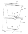
国際公開公報WO第93/12706号明細書の食器洗浄装置は、図1及び2に概略的に示された形態であり、図4〜6において示されているような取り付けの選択をすることができる。国際公開公報WO第93/12706号の食器洗浄装置は、洗浄室及び関連する洗浄システムは、キャビネット内の引き出しという形態で摺動可能に取り付けられ、洗浄室は水平方向に引き出されて洗浄室の開放した上部を通して装填することを可能とするという点で従来の食器洗浄装置と異なる。洗浄室が引っ込められた、関連する蓋が、操作中に洗浄液を閉じこめるように洗浄室の上部をシールして遮断する。 The dishwashing apparatus of WO 93/12706 is in the form schematically shown in FIGS. 1 and 2 and can be selected for attachment as shown in FIGS. it can. In the tableware washing apparatus of International Publication No. WO 93/12706, the washing room and the related washing system are slidably mounted in the form of a drawer in the cabinet, and the washing room is drawn out in the horizontal direction to It differs from a conventional dishwashing apparatus in that it can be loaded through an open top. The associated lid, with which the cleaning chamber is retracted, seals and shuts off the top of the cleaning chamber so as to confine the cleaning liquid during operation.
国際公開公報WO第93/12706号において、洗浄室の蓋は、キャビネットの上部に移動可能に保持されている一体の構造であり、引っ込められたとき洗浄室によって係合され、平行四辺形のリンク機構及びカム機構を使用して洗浄室の上部へ降りる。実際において、他の種類の洗浄室のカバーが満足できるものでありかつよりよい生産経済性があるということが見いだされた。 In International Publication No. WO 93/12706, the lid of the cleaning chamber is an integral structure that is movably held at the top of the cabinet and is engaged by the cleaning chamber when retracted, and is a parallelogram link Use the mechanism and cam mechanism to descend to the top of the cleaning chamber. In practice, it has been found that other types of cleaning room covers are satisfactory and have better production economics.
洗剤分配装置は、全ての食器洗浄装置の中で必要な構成要素である。従来の分配装置は、洗浄サイクルの適当な時点まで洗剤を保持し、その時点で洗剤受けが開き洗浄室内へ洗剤を解放する。適切に洗剤が流し込まれ、そこで受口は洗剤を放出するために移動ドアを使用する。ドアの開放が洗浄液の荷重によって防がれるということを保証するために、従来の分配器は、かなりの量の高圧液体が洗剤受口内へ入る必要があるという不利な点をもつ。 The detergent dispensing device is a necessary component in all dishwashers. Conventional dispensing devices hold the detergent until the appropriate point in the wash cycle, at which point the detergent receiver opens and releases the detergent into the wash chamber. Properly detergent is poured, where the receptacle uses a moving door to release the detergent. In order to ensure that the door opening is prevented by the load of the cleaning liquid, the conventional distributor has the disadvantage that a considerable amount of high pressure liquid needs to enter the detergent receptacle.
以前に記載された国際公開公報WO第93/12706号において、食器洗浄装置の排水ポンプが開示されている。ここで記載された排水ポンプは満足に動作する一方で、汚染された洗浄水内の粒子が、モータのロータと溜め部106との間の隙間に堆積する可能性がある。
In the previously described International Publication No. WO 93/12706, a drainage pump for a dishwasher is disclosed. While the drainage pump described herein operates satisfactorily, contaminated wash water particles can accumulate in the gap between the motor rotor and the
国際公開公報WO第93/12706号において、一つの洗浄室を有するキャビネットと、関連する洗浄システムとを有する食器洗浄装置が開示されている。摺動引き出しタイプの形状は、正面の装填機械よりも多くの力をキャビネットに及ぼすので、キャビネットの引っ掛け(racking)抵抗を増加させる門状フレーム部材が開示されている。国際公開公報WO第93/12706号において、食器洗浄能力の向上は別個の食器洗浄モジュールの数を単に増やすことによって実現できると考えられる。台所作業台の下に二つのモジュールを重ねて取り付けていることに関して特別に説明されている。各モジュールの高さは、二つのモジュールが台所の建具内で重ねて取り付けられる時にこれらモジュールは典型的な家庭の作業台の高さの台所内に適合することを保証するように選択される。いくつかの状況において、一体の二つの洗浄槽の食器洗浄装置、すなわち、一つの引き出しの代わりの二つの引き出しを有するキャビネットが好適である。しかしながら、「開放」した正面のキャビネットが一つの引き出しキャビネットの高さのほぼ二倍であることが必要とされているので、これは、洗浄槽によって及ぼされる引っ掛け力に対する十分な耐性を付与するという問題を大きくする。 International Publication No. WO 93/12706 discloses a dishwashing apparatus having a cabinet having one washing chamber and an associated washing system. Since the sliding drawer type shape exerts more force on the cabinet than the front loading machine, a portal frame member is disclosed that increases the racking resistance of the cabinet. In WO 93/12706, it is believed that an improvement in dishwashing capacity can be achieved by simply increasing the number of separate dishwashing modules. Special mention is made of mounting two modules on top of each other under a kitchen workbench. The height of each module is selected to ensure that when the two modules are mounted in stacks in a kitchen fixture, these modules fit within a typical home platform height kitchen. In some situations, a dishwasher with two integrated washing tubs, i.e. a cabinet with two drawers instead of one drawer, is preferred. However, since it is required that the “open” front cabinet is approximately twice the height of a single drawer cabinet, this provides sufficient resistance to the hooking force exerted by the washing tub. Make the problem bigger.
本発明の目的は、効果的な洗浄室の密閉シールシステムを有する上述した種類の食器洗浄装置を提供することである。 It is an object of the present invention to provide a dishwasher of the type described above having an effective cleaning chamber hermetic seal system.
本発明のさらなる目的は、前述された不利な点を克服するために、少なくともいくつかの方法を行う食器洗浄装置の洗剤分配装置を提供することである。 It is a further object of the present invention to provide a detergent dispensing device for a dishwasher that performs at least some methods to overcome the disadvantages described above.
本発明のさらなる目的は、改良された排水ポンプを有する食器洗浄装置と、二つの洗浄室を収納する食器洗浄装置のキャビネットと、食器洗浄装置の水管理システムと、加熱要素の故障保護回路とを提供することである。 A further object of the present invention is to provide a dishwasher with an improved drainage pump, a cabinet for a dishwasher that houses two washrooms, a water management system for the dishwasher, and a fault protection circuit for the heating element. Is to provide.
本発明によれば、
(a)キャビネットと、
(b)使用するために水平方向に前記キャビネットから引き出されるように前記キャビネット内に摺動可能に取り付けられた洗浄システムであって、
(i)洗浄される物品を収容し、内部で洗浄液が循環し、かつ頂部周縁リムを有する頂部開口洗浄室と、
(ii)前記洗浄室内に洗浄液を導入しかつ循環させる手段と、
(iii)前記洗浄室から洗浄液を排出する手段とを有する、洗浄システムと、
(c)前記洗浄室を前記キャビネット内へ引っ込めたとき前記洗浄室の前記頂部開口を覆う、前記キャビネットの頂部に取り付けられた実質的に剛性の蓋と、を備え、
(d)前記蓋が、前記キャビネットの頂部でほぼ不変の上下方向位置に保持され、前記蓋は、前記洗浄室が前記キャビネット内に完全に引っ込められたとき、前記リムの近傍で前記洗浄室の頂部と協働して、前記洗浄室が前記キャビネット内に引っ込められたとき、前記洗浄室から洗浄液が出るのを防ぐ周囲手段を有し、
(e)前記洗浄室のリムは、正面が後部より高くなるように一様に傾斜しており、
前記蓋は、前記正面においてより背面において深さが高くなるように対応して傾斜した周縁フランジ部を有し、
弾性シール部材が前記蓋の下側の周縁部周りに配置されており、
前記蓋の垂直方向位置は、前記洗浄室が完全に引っ込められたとき、前記シール部材が前記洗浄室のリムに係合されかつ圧縮される位置である、
ことを特徴とする洗浄装置、が提供される。
According to the present invention,
(A) a cabinet;
(B) a cleaning system slidably mounted within the cabinet to be pulled out of the cabinet horizontally for use;
(I) a top-opening cleaning chamber containing articles to be cleaned, in which cleaning liquid circulates, and having a top peripheral rim;
(Ii) means for introducing and circulating a cleaning liquid into the cleaning chamber;
(Iii) a cleaning system having means for discharging the cleaning liquid from the cleaning chamber;
(C) a substantially rigid lid attached to the top of the cabinet that covers the top opening of the cleaning chamber when the cleaning chamber is retracted into the cabinet;
(D) the lid is held in a generally unchanged vertical position at the top of the cabinet, and the lid is located near the rim when the washing chamber is fully retracted into the cabinet; In cooperation with the top, having peripheral means for preventing cleaning liquid from exiting the cleaning chamber when the cleaning chamber is retracted into the cabinet;
(E) The rim of the cleaning chamber is uniformly inclined so that the front is higher than the rear,
The lid has a peripheral flange portion that is correspondingly inclined so as to have a higher depth at the back than at the front,
An elastic seal member is disposed around the lower peripheral edge of the lid;
The vertical position of the lid is the position where the seal member is engaged and compressed with the rim of the cleaning chamber when the cleaning chamber is fully retracted,
A cleaning device is provided.
本発明の他の態様によれば、
(a)キャビネットと、
(b)使用するために前記洗浄システムが水平方向に前記キャビネットから引き出されるように前記キャビネット内に摺動可能に取り付けられた洗浄システムであって、
(i)洗浄される物品を収容し、洗浄液が内部で循環し、かつ頂部周縁リムを有する頂部開口洗浄室と、
(ii)前記洗浄室内に洗浄液を導入しかつ循環させる手段と、
(iii)前記洗浄室から洗浄液を排出する手段とを有する洗浄システムと、
(c)前記洗浄室が前記キャビネット内へ引っ込められたとき、前記洗浄室の前記頂部開口を覆う、前記キャビネットの頂部に取り付けられた洗浄室閉鎖部材と、を備え、
(d)前記閉鎖部材は、前記キャビネットの上面においてほぼ不変の上下方向位置に保持され、前記閉鎖部材は、前記洗浄室が前記キャビネット内に完全に引っ込められたときに、前記リムの近傍で前記洗浄室の頂部と協働し、前記洗浄室が前記キャビネットに引っ込められたとき洗浄液が前記洗浄室から出るのを防ぐ周縁手段を有し、
(e)前記閉鎖部材は、前記洗浄室が引っ込められたときは前記キャビネットの上面に取り付けられている貯蔵手段から延びて前記洗浄室の頂部開口を覆い、かつ前記洗浄室が引き出されたときは前記貯蔵手段内に引っ込められて前記洗浄室の頂部開口を覆わない可撓性部材である、
ことを特徴とする洗浄装置、が提供される。
According to another aspect of the invention,
(A) a cabinet;
(B) a cleaning system slidably mounted within the cabinet such that the cleaning system is pulled out of the cabinet in a horizontal direction for use;
(I) a top opening cleaning chamber containing articles to be cleaned, in which cleaning liquid circulates, and having a top peripheral rim;
(Ii) means for introducing and circulating a cleaning liquid into the cleaning chamber;
(Iii) a cleaning system having means for discharging the cleaning liquid from the cleaning chamber;
(C) a cleaning chamber closing member attached to the top of the cabinet that covers the top opening of the cleaning chamber when the cleaning chamber is retracted into the cabinet;
(D) the closure member is held in a substantially unchanged vertical position on the upper surface of the cabinet, the closure member being near the rim when the cleaning chamber is fully retracted into the cabinet; Cooperating with the top of the cleaning chamber, having peripheral means for preventing cleaning liquid from exiting the cleaning chamber when the cleaning chamber is retracted into the cabinet;
(E) When the cleaning chamber is retracted, the closing member extends from a storage means attached to the upper surface of the cabinet to cover the top opening of the cleaning chamber, and when the cleaning chamber is pulled out A flexible member that is retracted into the storage means and does not cover the top opening of the cleaning chamber;
A cleaning device is provided.
本発明の他の好ましい態様によれば、前記可撓性部材は、一端部が前記リムの遠位部に留められ他端部がばね付勢ローラに固定された可撓性シートであり、前記ローラは、前記キャビネット内の正面開口近傍の該キャビネットの頂部であって前記リムの近位部の上方に取付けられ、前記ローラは、前記洗浄室が引き出されたとき、前記可撓性シートのほぼ全領域を巻き取る。 According to another preferred aspect of the present invention, the flexible member is a flexible sheet having one end fastened to a distal portion of the rim and the other end fixed to a spring biasing roller. A roller is mounted at the top of the cabinet near the front opening in the cabinet and above the proximal portion of the rim, and the roller is substantially free of the flexible sheet when the cleaning chamber is pulled out. Wind up the entire area.
本発明の他の好ましい態様によれば、前記可撓性部材は、蛇腹形状であり、一端部が前記リムの遠位部へ固定され、他端部が前記キャビネットの正面開口の頂部に固定されている。 According to another preferred aspect of the present invention, the flexible member has a bellows shape, one end is fixed to the distal portion of the rim, and the other end is fixed to the top of the front opening of the cabinet. ing.
本発明の他の態様によれば、
(a)キャビネットと、
(b)使用するために前記洗浄システムが水平方向に前記キャビネットから引き出されるように前記キャビネット内に摺動可能に取り付けられた洗浄システムであって、
(i)洗浄される物品を収容し、内部で洗浄液が循環し、かつ頂部周縁リムを有する頂部開口洗浄室と、
(ii)前記洗浄室内に洗浄液を導入しかつ循環させる手段と、
(iii)前記洗浄室から洗浄液を排出する手段とを有する洗浄システムと、
(c)前記キャビネットの上面に取り付けられ、前記洗浄室が前記キャビネット内へ引っ込められたとき、前記洗浄室の頂部開口を覆う洗浄室閉鎖部材と、を備え、
(d)前記閉鎖部材は、前記閉鎖部材が垂直方向のみに移動することを可能とする機械的な手段によって前記キャビネットの頂部に取り付けられ、
前記閉鎖部材が高い位置から下げられたとき、前記閉鎖部材がリムと協働して前記洗浄室から洗浄液が出ることを防ぐ周縁手段を有し、
(e)膨張可能な部材が前記蓋の上面と前記キャビネットの上面との間に配置され、
前記洗浄室が前記キャビネット内に引っ込められたとき、前記膨張可能な部材は膨張させられ、前記蓋及びシール部材を前記洗浄室のリムに押し付け、前記洗浄システムを前記キャビネットから引き出す前に前記閉鎖部材を上昇させ、前記洗浄システムを前記キャビネット内に完全に引っ込めた後に前記閉鎖部材を下降させる、
ことを特徴とする洗浄装置、が提供される。
According to another aspect of the invention,
(A) a cabinet;
(B) a cleaning system slidably mounted within the cabinet such that the cleaning system is pulled out of the cabinet in a horizontal direction for use;
(I) a top-opening cleaning chamber containing articles to be cleaned, in which cleaning liquid circulates, and having a top peripheral rim;
(Ii) means for introducing and circulating a cleaning liquid into the cleaning chamber;
(Iii) a cleaning system having means for discharging the cleaning liquid from the cleaning chamber;
(C) a cleaning chamber closing member attached to the upper surface of the cabinet and covering a top opening of the cleaning chamber when the cleaning chamber is retracted into the cabinet;
(D) the closure member is attached to the top of the cabinet by mechanical means that allow the closure member to move only vertically;
Peripheral means for preventing the cleaning liquid from coming out of the cleaning chamber in cooperation with the rim when the closing member is lowered from a high position;
(E) an inflatable member is disposed between the top surface of the lid and the top surface of the cabinet;
When the cleaning chamber is retracted into the cabinet, the inflatable member is inflated, pressing the lid and seal member against the rim of the cleaning chamber and before closing the cleaning system out of the cabinet, the closure member And lowering the closure member after the cleaning system is fully retracted into the cabinet,
A cleaning device is provided.
本発明の他の好ましい態様によれば、前記洗浄室が引っ込められたときに降下し、かつ、前記洗浄室が引き出されたときに上昇するように、前記蓋は前記キャビネットの頂部に取り付けられ、前記蓋の縁部には、下方に面するフランジが設けられ、前記洗浄室のリムには相補的な上方に面するフランジが設けられ、前記蓋が下げられて前記蓋と前記リムフランジとの間で入り組んだシールを形成するとき、前記蓋及びリムのフランジは緩く相互係合する。 According to another preferred aspect of the present invention, the lid is attached to the top of the cabinet so that it drops when the cleaning chamber is retracted and rises when the cleaning chamber is pulled out, A flange facing downward is provided at the edge of the lid, a complementary upward facing flange is provided on the rim of the cleaning chamber, and the lid is lowered so that the lid and the rim flange The lid and rim flanges loosely interengage when forming an intricate seal.
本発明の他の態様によれば、
(a)キャビネットと、
(b)洗浄システムであって、使用するために前記洗浄システムが水平方向に前記キャビネットから引き出されるように前記キャビネット内に摺動可能に取り付けられた洗浄システムであって、
(i)洗浄される物品を収容し、洗浄液が循環し、かつ頂部周縁リムを有する頂部開口洗浄室と、
(ii)前記洗浄室内に洗浄液を導入しかつ循環させる手段と、
(iii)前記洗浄室から洗浄液を排出する手段とを有する、洗浄システムと、
(c)前記キャビネットの上面に取り付けられ、前記洗浄室が前記キャビネット内へ引っ込められたとき前記洗浄室の前記頂部開口を覆う洗浄室閉鎖部材と、を備え、
(d)前記閉鎖部材は、前記閉鎖部材が予め定めた移動の自由度を持って垂直方向のみに移動することを可能とする機械的な手段によって前記キャビネットの頂部で水平面内に取り付けられ、
前記閉鎖部材が高い位置から降下したとき、前記閉鎖部材がリムと協働して前記洗浄室から洗浄液が出ることを防ぐ周縁手段を有し、
(e)線形作動手段が設けられ、該線形作動手段が、前記キャビネットからの前記洗浄システム引き出しに先だって、前記閉鎖部材を、前記閉鎖部材が前記洗浄室リムと係合し前記キャビネットへの洗浄システムの完全な引き込みの後に閉鎖部材を降下させている第一位置と、前記閉鎖部材が前記洗浄室リムの頂部から上下方向に離れている第二位置へ、上下動させる、
ことを特徴とする食器洗浄装置、が提供される。
According to another aspect of the invention,
(A) a cabinet;
(B) a cleaning system, wherein the cleaning system is slidably mounted in the cabinet such that the cleaning system is pulled out of the cabinet in a horizontal direction for use;
(I) a top opening cleaning chamber containing articles to be cleaned, in which cleaning liquid circulates and having a top peripheral rim;
(Ii) means for introducing and circulating a cleaning liquid into the cleaning chamber;
(Iii) a cleaning system having means for discharging the cleaning liquid from the cleaning chamber;
(C) a cleaning chamber closing member attached to the upper surface of the cabinet and covering the top opening of the cleaning chamber when the cleaning chamber is retracted into the cabinet;
(D) the closure member is mounted in a horizontal plane at the top of the cabinet by mechanical means that allows the closure member to move only in the vertical direction with a predetermined degree of movement;
Peripheral means for preventing the cleaning liquid from coming out of the cleaning chamber in cooperation with the rim when the closing member is lowered from a high position;
(E) linear actuating means is provided, the linear actuating means engaging the closure member prior to withdrawal of the washing system from the cabinet, the closure member engaging the washing chamber rim and the washing system to the cabinet; Moving up and down to a first position where the closure member is lowered after full retraction, and a second position where the closure member is vertically away from the top of the cleaning chamber rim,
A dishwashing apparatus is provided.
本発明の他の好ましい態様によれば、前記線形作動手段は、前記閉鎖部材を前記第二位置に付勢するばねと、前記洗浄室の各側に配置されかつ前記上端部が前記閉鎖部材に固定されかつ前記下端部がカム従動手段に固定されたほぼ垂直方向の引張り棒部材と、前記カム従動手段の各々と整列した前記洗浄室の両側に設けられたカム面を有し、前記カム従動手段は、前記キャビネット内へ引っ込める時の前記洗浄室の水平方向移動の前記最終段階において前記カム面と係合し、前記引張り棒部材が前記閉鎖部材を前記ばね付勢に抗して前記第一位置へ引張って下げさせる。 According to another preferred aspect of the present invention, the linear actuating means includes a spring that biases the closing member to the second position, and is disposed on each side of the cleaning chamber, and the upper end portion is located on the closing member. A substantially vertical tension bar member fixed and having a lower end fixed to the cam follower; and cam surfaces provided on both sides of the cleaning chamber aligned with each of the cam follower; The means engages the cam surface in the final stage of horizontal movement of the cleaning chamber when retracted into the cabinet, and the pull bar member resists the spring bias to the first Pull it down to the position.
本発明の他の態様によれば
(a)キャビネットと、
(b)使用するために前記キャビネットから水平方向に引き出されるように、前記キャビネット内で摺動可能に取り付けられている第一洗浄システムと、
(c)使用するために前記キャビネットから水平方向に引き出されるように、前記第一洗浄システムの上方で且つ前記第一洗浄システムと垂直方向に整列されて前記キャビネット内に摺動可能に取付けられた第二洗浄システムと、を備え、
前記第一洗浄システム及び前記第二洗浄システムの各々は、
(i)前記洗浄液がその中で循環させられる、食器を収納する頂部開口洗浄室と、
(ii)前記室内に洗浄液を導入しかつ循環させる手段と、
(iii)前記室から洗浄液を排出する手段とを有し、
(d)前記キャビネット内で第一洗浄室及び第二洗浄室の各々の直上に第一洗浄室及び第二洗浄室の各々と整列して各々が取り付けられている第一洗浄室及び第二洗浄室の閉鎖部材であって、各洗浄室が前記キャビネット内へ引っ込められたときに前記洗浄室の前記頂部開口を覆う、第一洗浄室及び第二洗浄室の閉鎖部材とを備え、
(e)前記第一閉鎖部材及び前記第二閉鎖部材が、前記キャビネット内でほぼ不変の垂直方向位置に保持され、前記閉鎖部材の各々は、前記洗浄室から洗浄液が出ることを防ぐように、対応の洗浄室が前記キャビネット内に完全に引っ込められたときに前記洗浄室の頂部と協働する周縁手段を有し、さらに、
(f)前記第一洗浄システムの前記洗浄室内へ放出させることができる第一放水手段と、
(g)前記第二洗浄システムの前記洗浄室内へ放出させることができる第二放水手段と、
(h)使用時に給水接続部に接続され、かつホースによって前記第一水手段と前記第二放水手段の各々へ接続され、電気的に操作される弁手段とを備え、
該弁手段は、前記各洗浄システムが完全に前記キャビネット手段内に引っ込められたとき前記第一放水手段と前記第二放水手段の一方又は両方に選択的に給水する操作をするように作動可能である、
ことを特徴とする食器洗浄機、が提供される。
According to another aspect of the present invention, (a) a cabinet;
(B) a first cleaning system that is slidably mounted within the cabinet so as to be pulled horizontally from the cabinet for use;
(C) slidably mounted in the cabinet above the first cleaning system and vertically aligned with the first cleaning system so that it can be pulled horizontally from the cabinet for use. A second cleaning system,
Each of the first cleaning system and the second cleaning system includes:
(I) a top opening cleaning chamber for storing tableware in which the cleaning liquid is circulated;
(Ii) means for introducing and circulating a cleaning liquid into the chamber;
(Iii) means for discharging the cleaning liquid from the chamber;
(D) A first cleaning chamber and a second cleaning chamber in which the first cleaning chamber and the second cleaning chamber are respectively aligned with and attached to the first cleaning chamber and the second cleaning chamber in the cabinet. A chamber closure member comprising: a first wash chamber and a second wash chamber closure member that covers the top opening of the wash chamber when each wash chamber is retracted into the cabinet;
(E) the first closure member and the second closure member are held in a substantially unchanged vertical position within the cabinet, each of the closure members preventing the cleaning liquid from exiting the cleaning chamber; Peripheral means for cooperating with the top of the cleaning chamber when the corresponding cleaning chamber is fully retracted into the cabinet;
(F) first water discharge means that can be discharged into the cleaning chamber of the first cleaning system;
(G) a second water discharge means that can be discharged into the cleaning chamber of the second cleaning system;
(H) a valve means which is connected to the water supply connection portion in use and connected to each of the first water means and the second water discharge means by a hose and electrically operated;
The valve means is operable to selectively supply water to one or both of the first water discharge means and the second water discharge means when each cleaning system is fully retracted into the cabinet means. is there,
A dishwasher is provided.
本発明の他の態様によれば、
(a)キャビネットと、
(b)使用するために前記キャビネットから水平方向に引き出されるように、前記キャビネット内で摺動可能に取り付けられている第一洗浄システムと、
(c)使用するために前記キャビネットから水平方向に引き出されるように、前記第一洗浄システムの上方で且つ前記第一洗浄システムと垂直方向に整列されて前記キャビネット内に摺動可能に取付けられた第二洗浄システムと、を備え、
前記第一洗浄システム及び前記第二洗浄システムの各々は、
(i)前記洗浄液がその中で循環させられる、食器を収容する頂部開口洗浄室と、
(ii)前記室内に洗浄液を導入しかつ循環させる手段と、
(iii)前記室から洗浄液を排出する手段とを有し、
(d)前記キャビネット内で第一洗浄室及び第二洗浄室の各々の直上に第一洗浄室及び第二洗浄室の各々と整列して各々が取り付けられている第一洗浄室及び第二洗浄室の閉鎖部材であって、各洗浄室が前記キャビネット内へ引っ込められたときに、前記洗浄室の前記頂部開口を覆う第一洗浄室及び第二洗浄室の閉鎖部材とを備え、
(e)前記第一閉鎖部材及び前記第二閉鎖部材の各々は、各機械的手段によって取り付けられており、前記機械手段は、対応の洗浄室が完全に前記キャビネット内に引っ込められた時に前記洗浄室から洗浄液が出るのを防ぐように、垂直方向のみの前記閉鎖部材の移動を許容することにより、付随した閉鎖部材を高い位置から下降させて前記洗浄室の頂部と協働し、さらに、
(f)前記第一洗浄システムの前記洗浄室内へ放出させることができる第一放水手段と、
(g)前記第二洗浄システムの前記洗浄室内へ放出させることができる第二放水手段と、(h)使用時に給水接続部に接続され、かつホースによって前記第一放水手段と前記第二放水手段の各々へ接続された、電気的に操作されている弁手段とを備え、
該弁手段が、前記各洗浄システムが完全に前記キャビネット手段内に引っ込められたとき前記第一放水手段と前記第二放水手段の一方又は両方に選択的に水を供給するように作動可能である、
ことを特徴とする食器洗浄機、が提供される。
According to another aspect of the invention,
(A) a cabinet;
(B) a first cleaning system that is slidably mounted within the cabinet so as to be pulled horizontally from the cabinet for use;
(C) slidably mounted in the cabinet above the first cleaning system and vertically aligned with the first cleaning system so that it can be pulled horizontally from the cabinet for use. A second cleaning system,
Each of the first cleaning system and the second cleaning system includes:
(I) a top-opening cleaning chamber containing tableware in which the cleaning liquid is circulated;
(Ii) means for introducing and circulating a cleaning liquid into the chamber;
(Iii) means for discharging the cleaning liquid from the chamber;
(D) A first cleaning chamber and a second cleaning chamber in which the first cleaning chamber and the second cleaning chamber are respectively aligned with and attached to the first cleaning chamber and the second cleaning chamber in the cabinet. A chamber closing member comprising: a first cleaning chamber and a second cleaning chamber closing member that cover the top opening of the cleaning chamber when each cleaning chamber is retracted into the cabinet;
(E) Each of the first closure member and the second closure member is attached by a respective mechanical means, the mechanical means being adapted to perform the cleaning when the corresponding cleaning chamber is fully retracted into the cabinet. Cooperating with the top of the cleaning chamber by lowering the associated closing member from a high position by allowing movement of the closing member in the vertical direction only to prevent cleaning liquid from exiting the chamber;
(F) first water discharge means that can be discharged into the cleaning chamber of the first cleaning system;
(G) a second water discharge means that can be discharged into the cleaning chamber of the second cleaning system; Electrically operated valve means connected to each of the
The valve means is operable to selectively supply water to one or both of the first water discharge means and the second water discharge means when each of the cleaning systems is fully retracted into the cabinet means. ,
A dishwasher is provided.
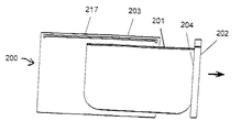
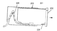
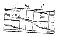
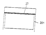
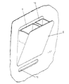
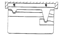
本発明の食器洗浄機200は図1に示したタイプである。前方パネル202を備えた(全ての洗浄システム構成要素を有する)洗浄室201はキャビネット203に”引出し”のように摺動可能に取り付けられる。洗浄室201は頂部が開いており、矢印の方向へキャビネット203から引き出されて食器の出し入れができ、洗浄中は、キャビネット203に引っ込められている。洗浄室201には洗浄・排出システムが取り付けられ、洗浄室201はモータおよびポンプを有する。図2および図3に示したように可撓性のある接続配線・配管228が洗浄室201をキャビネット203内の関連する端子に接続している。また、食器洗浄機の制御装置がキャビネット203または摺動洗浄システムに取付けられている。
The
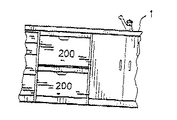
食器洗浄機は前方から装填するタイプの従来の国産食器洗浄機の高さの半分の高さで作られる。この形態では食器洗浄機を、単体で用いられても多数の中の一つ、特に一対の食器洗浄機の一つとして用いてもよい。図4から図6は、モジュラーとしてのコンセプトを用いた一つまたは二つの食器洗浄機を用いた設置案を示している。図4にはシンク台1の下方で上下に重ねられた二つの食器洗浄機200が示されており、シンク台の高さは典型的には床面から850から900mmである。図5にはシンク台1のシンクを形成する部分の両側に横に並んで配置された二つの食器洗浄機200が示されている。図6では唯一の食器洗浄機がシンク台1の下側に提供されている。本発明によれば高さを低くしたので食器洗浄機をシンク台に取り付けることができる。
The dishwasher is made at half the height of a traditional domestic dishwasher that is loaded from the front. In this embodiment, the dishwasher may be used alone or as one of many, particularly as one of a pair of dishwashers. FIGS. 4 to 6 show installation plans using one or two dishwashers using the modular concept. FIG. 4 shows two
図4を参照すると、モジュールタイプの二つの食器洗浄ユニット200が上下に重ねたとき、その構成は従来の食器洗浄機の外寸と同じであることが分かる。図5のようにシンク台の頂部の直ぐ下に横に並んで設置された二つのモジュラーユニット200の容量は従来の食器洗浄機と同じであるが使用者が下半分の食器洗浄機に到達するのに腰を曲げなければならないという不便を解消する。
Referring to FIG. 4, when two module-
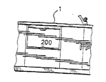
設置において二つの個別のモジュールを組にする以外にも幾つかの対の構成を製造可能である。例えば図4に示した二つの食器洗浄機を上下に配置する構成を一つの外側の覆い内またはキャビネット内に製造し、単一の装置として設置してもよい。図7は二つの引出しを有する装置を示しており、この装置は二つの引出しタイプの洗浄室202a、202bを収容する単一のキャビネット203を備えている。各引出しの前部は美観的に好ましい面を有する。
Besides the pairing of two individual modules in the installation, several pairs of configurations can be manufactured. For example, the configuration in which the two dishwashers shown in FIG. 4 are arranged one above the other may be manufactured in one outer cover or cabinet and installed as a single device. FIG. 7 shows an apparatus with two drawers, which comprises a
二つの引出しを有するこのタイプの装置は相当に柔軟性のある操作モードを可能とする。これらモードには以下が含まれる。 This type of device with two drawers allows a considerably flexible operating mode. These modes include:
1.混在した食器を装填した状態での一つのモジュールの作動、または二つのモジュールの同時作動。この場合、各モジュールが搭載された皿の中で最も大きなものを収容できるようにし、このようなコンセプトは大きな食器類のための容量を増大する。 1. Operation of one module with mixed tableware loaded or simultaneous operation of two modules. In this case, it is possible to accommodate the largest of the dishes on which each module is mounted, and such a concept increases the capacity for large dishes.
2.一つのモジュールの作動または必ずしも同時ではない両モジュールの作動。この場合、各モジュールには汚れが少ない食器または非常に汚れた食器が搭載されると共に各モジュールは個々のモジュールを適合させるように設定された適切な洗浄プログラムを有する。 2. Activation of one module or activation of both modules not necessarily simultaneously. In this case, each module is loaded with low or very dirty dishes and each module has a suitable cleaning program set to adapt the individual modules.
3.一方のモジュールは汚れた食器が徐々に装填され、第二のモジュールは搭載された綺麗な食器を再使用している時にのみ空になっている。これは衛生上の理由から単一の食器洗浄機では実行できない。 3. One module is gradually loaded with dirty dishes, and the second module is empty only when reusing the clean dishes. This cannot be done with a single dishwasher for hygienic reasons.
4.搭載される食器の汚れが少ない場合用に一方のモジュールをプログラミングし、搭載される食器の汚れがひどい場合用に他方のモジュールをプログラミングする。 4). One module is programmed for when the mounted dishes are lightly soiled, and the other module is programmed for when the mounted dishes are very dirty.
.汚れた食器で満たされると直ぐに一方のモジュールを始動する。すなわち搭載される食器が少ないと効率的に洗浄できる。 . Start one module as soon as it is filled with dirty dishes. In other words, if there is little tableware installed, it can be cleaned efficiently.
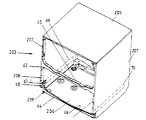
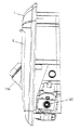
キャビネット
図8は図7のキャビネット203の幾つかの構造上の特徴を示している。キャビネット203は通常、金属シートで作製され、側面が開いた箱の形をしており、上部パネル205と、下部パネル206と、二つの側壁207と、後部壁(図示せず)とを有する。キャビネット203の前部はこのキャビネットの前部の主要面から凹んだ浅いキックプレート62を除いて開いている。キャビネット203の開いた前部はWO93/12706号明細書に記載されているような門状フレーム部材63および64を備えることにより横揺れモーメントに抵抗できるように補強される。二つの洗浄室202aおよび202bの各底部は各門状フレーム部材63および64の上部フランジ65および66上を通るように形成される。しかしながら上側の開口のための門状フレーム(およびWO93/1206号明細書に示したキャビネット)とは異なり、門状フレーム64はキャビネット61の前部の主要面から後方へずれており、キャビネット61の下半分の横揺れモーメントに抵抗する効果が減少する。本発明ではこのことは補強プレート67および68をキックプレート62の頂部に提供し、そして構造上これら補強プレートを下方の洗浄室のスライド部材(図示せず)を介して互いに接合することにより克服され、上記スライド部材は破線で示した位置69および70に配置される。また補強プレート67および68はその堅さおよび底部フレーム64および側部フレーム208に対する堅固な接続の理由で側部フレームに加えられる横揺れモーメントを底部フレーム64の各端部におけるガセット領域209に伝達する。
Cabinet FIG. 8 illustrates some structural features of the
摺動引出し洗浄システム用閉鎖部材
洗浄室が摺動引出しとして取り付けられている本願の洗浄機では、洗浄サイクルの開始に先立って洗浄室を閉鎖が、従来の前方から出し入れするタイプの洗浄機やシンク台上に載せられる洗浄機に比べて複雑である。飛び出している引出しをキャビネット内に押す前に使用者が手動でドアを閉じ、頂部が開いている洗浄室を密閉することは望ましくない。洗浄室をキャビネット内に引き入れる動作により作動する閉鎖部材を有することが好ましい。
Closing member for sliding drawer cleaning system In the cleaning machine of the present invention in which the cleaning chamber is attached as a sliding drawer, the cleaning chamber is closed prior to the start of the cleaning cycle. It is more complex than a washing machine that can be placed on a table. It is not desirable for the user to manually close the door and seal the wash chamber open at the top before pushing the protruding drawer into the cabinet. It is preferable to have a closure member that is activated by the action of pulling the cleaning chamber into the cabinet.
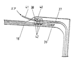
図1には剛性のある閉鎖部材または蓋217が線図で示されており、この閉鎖部材は、洗浄室201の開いている頂部を閉じるためにキャビネット203の頂部に取り付けられている。なお洗浄室がキャビネット203内に引き込まれた時に洗浄室のリム上へと下方に機械的に移動させられるように蓋を取り付けることにより閉鎖を実行することもできる。このタイプの密閉作用を達成するための一つの手段はWO93/12706号明細書に開示されている。洗浄室の移動の最終段階で平行四辺形の形態の機械的なリンクにより水平・鉛直方向に剛性のある蓋を密閉位置まで移動することとは対照的に本発明は別の選択可能な解決手段を提供する。
In FIG. 1, a rigid closure member or
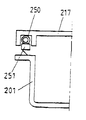
これら解決手段のうちの一番目の解決手段を図9および図10に線図で示した。ここでの剛性のある蓋217は、上述したように用いられるが、キャビネット203の頂部の所定位置に固定され、洗浄室201のリム19と鉛直方向において整列して配置された膨張可能な周方向ガスケット18を備える。本実施例では洗浄室が完全に引き込まれた時に部材18は図10に示したように膨張させられ、リム19とシール状態で係合する。この場合、部材18はシール部材であるが、等しく適した選択可能な手段は、図38に示したように蓋とシール部材251との間に配置されたシール部材キャリア250を膨張させることである。
The first of these solutions is shown diagrammatically in FIGS. Here, the
本実施例の実際の実施を図11および図13に詳細に示した。洗浄室201にはフランジの形をしたリム19が形成され、このリム19は使用時に膨張可能なガスケット18のための座部を提供する。図11は、ガスケット18が膨張させられてリム19にシール状態で係合し、洗浄タブ201がキャビネット3内に完全に引き込まれている状態を示している。
The actual implementation of this example is shown in detail in FIGS. The
剛性のある蓋217がキャビネット203の頂部内に嵌め込まれ、蓋217の周縁当接部30がキャビネット3の頂部の下側に当接する。蓋217はキャビネット203に実質的に固定される。またその下周面にはガスケット18を保持するための通路31を備える。
A
ガスケット18は、弾性のあるプラスチック材料から成形され、不定の長さで形成される。ガスケットの頂面には、蓋217の通路31内に係合するようにリブ状の延在部32が一体的に成形され、これによりガスケットを蓋に係合する。
The
一つの実施例(図示せず)では蓋17の周縁をたどるのに十分な長さのガスケット材料18が所定位置に配置され、ガスケットの各端部は、T字コネクタの両側の接続部に連結される。T字コネクタは必要な時にガスケット18の両端に空気を供給し、ガスケット18を膨張させる。図12に線図で示した好適な実施例では、端部37と端部38とが部分的に重なり合うのに十分な長さのガスケット材料が採用される。蓋内の通路31はガスケットの端部を非常に近い平行の関係でもって支持するために部分的に重なり合った平行な端部を有する。ガスケット18の端部37は気密性のある(またはシールされた)支持部39を有し、他方の端部38はガスケットを膨張するために空気を供給する空気ホース41のためのコネクタ40を有する。
In one embodiment (not shown), a
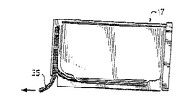
ガスケットが膨張させられた時でも食器洗浄機の洗浄サイクル中に少量の洗浄液がガスケットの部分的に重なり合った端部の間から漏れてしまう。この間隙を通った水の放出を制御しなければならず、この目的でガスケットの外側の端部38の領域の洗浄室のリム19に排出スロット42が設けられる(図13参照)。ガスケットの端部の間から逃げた水は排出スロットを介してダクト36にそらされる。ダクト36は別体のプラスチック成形品であり、室17の背面に取り付けられる。ダクト36内の水は、ダクト36の水溜め部分33に整列して配置された室の壁の開口(図示せず)を介して室17の底部に戻るように指し向けられる。
Even when the gasket is inflated, a small amount of cleaning liquid leaks from between the partially overlapping ends of the gasket during the dishwasher cleaning cycle. The discharge of water through this gap must be controlled, and for this purpose a
ガスケット18を膨張させるために空気ポンプが設けられ、この空気ポンプは好ましくはソレノイドにより駆動されるダイアフラムポンプである。このポンプは室3の後壁の内側に取り付けられる。ダイアフラムポンプは食器洗浄機の制御装置により供給されるさい断直流電源を用いて作動される。
An air pump is provided for inflating the
使用時には室201に食器が搭載され、室201がキャビネット203内に完全に引き込まれ、そして食器洗浄機が始動させられた時に空気ポンプが作動せしめられ、ガスケット18を膨張し、これにより蓋217が室201の頂部をシールする。膨張サイクルの終わりはガスケット18内の圧力が所望圧力に達したことにより表示される。次いで、食器洗浄機の制御装置が洗浄サイクルを開始する。室は乾燥サイクルが終了するまで又は使用者がキャビネット203から室201を引き出すまでシールされたままである。この期間中、ガスケット18内に適切なシール圧が確実に維持されるように空気ポンプは時々、作動される。
In use, tableware is loaded into
別の実施例が図14に示されており、ここでは蓋217と洗浄室201のリム19とはその側部に沿って相補形状に傾斜したエッジを備える。蓋217の周縁周りには弾性のあるシール部材が配置される。洗浄室201がキャビネット203内に完全に引き込まれた時には蓋と室のリムとの前後への傾斜の結果として生じる楔作用により洗浄室が蓋217にシールされる。
Another embodiment is shown in FIG. 14, where the
さらに別の構造(図示せず)の平坦で剛性のある蓋は周縁の可撓性のあるガスケットを備え、このガスケットは洗浄室のリム上の手段と協動し、この手段は室がキャビネット内に引き込まれた時の純粋な摺動作用により蓋と洗浄室との間を積極的にシールする。 The flat, rigid lid of yet another structure (not shown) includes a peripheral flexible gasket that cooperates with means on the rim of the cleaning chamber, which means that the chamber is within the cabinet. It is positively sealed between the lid and the cleaning chamber by a pure sliding action when pulled into the chamber.
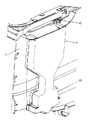
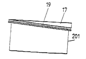
図15〜図17は選択可能な実施例を示しており、ここでは剛性のある蓋を用いる代わりに可撓性のある閉鎖部材が用いられる。図15ではカーテンタイプの閉鎖部材24がエッジ25に沿って洗浄室のリム19の後方部分26に固定される。カーテン24は食器洗浄機のキャビネット203の上方前方部に取り付けられたバネ付勢ローラ25上に後退可能に保管される。洗浄室201が引き出された時には、カーテン24はローラ25に巻き取られ、一方、洗浄室が引き込まれた時には、カーテン24はローラ25から出され、洗浄室201の開いた頂部を完全に覆う。
FIGS. 15-17 show alternative embodiments where a flexible closure member is used instead of a rigid lid. In FIG. 15, a curtain-
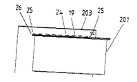
図16はコンチェルティナタイプの構造を備えた可撓性のある閉鎖部材27を示しており、この閉鎖部材27は食器洗浄機のキャビネットの上方側部に設けられたスライド内に取り付けられる。洗浄キャビネット201が図17で示したようにキャビネット203から引き出された時、閉鎖部材27はコンチェルティナ作用により折り畳まれ、一方、洗浄室が図16に示したように引き込まれた時には洗浄室の頂部に沿って平らになるように閉鎖部材27が開かれる。
FIG. 16 shows a
図18および図19に別の実施例を示した。本実施例の蓋217はその外側エッジ周りに膨張可能な環状部材を備え、この環状部材は図19に示したように膨張させられて洗浄室201の内壁の側面にシール状態で係合する。この場合、洗浄室の後部壁の高さが低く、これにより蓋が室の壁の上部エッジよりも鉛直方向において低い位置に固定されているにも係わらず洗浄室をキャビネット内に摺動することができる。
18 and 19 show another embodiment. The
洗浄室がキャビネット内に引き込まれた時に洗浄室の頂部にシール部材を移動する又は拡張することを利用するのに加えて、蓋の周面とシール部材との間に別体のシール支持キャリアを配置し、閉鎖はこの支持キャリアを下げることにより達成される。これは図39に示しており、ここではシール支持キャリア252が拡張可能なスカート253により蓋217に取り付けられている。シールキャリアを移動するためには往復動を与える様々なアクチュエータ手段を用いることができる。
In addition to utilizing moving or expanding the sealing member to the top of the cleaning chamber when the cleaning chamber is retracted into the cabinet, a separate seal support carrier is provided between the peripheral surface of the lid and the sealing member. Positioning and closing is accomplished by lowering this support carrier. This is illustrated in FIG. 39, where a
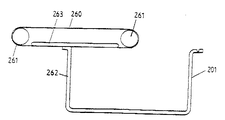
図42に他の柔軟な閉鎖部材を示す。洗浄室と同じ幅を有し、ローラー間の間隔が洗浄室の長さとほぼ等しいローラー261に取付けられたエンドレスベルト260が、洗浄室が完全に引っ込められた時に、洗浄室の上面を覆う。
FIG. 42 shows another flexible closure member. An
ローラー261は、洗浄機キャビネットの上部に一定の高さで取付けられる。
The
室の後方壁262の上端は、ベルト260へ固定され、ベルトが回転し、ベルトが滑って室を密閉するのと同様な直線的な動作をするようにする。圧力パッド263が、ベルトで確実に洗浄室を密閉するために用いられても良く、ベルトは又、一連の間隔をおいた横方向の帯板で補強されても良い。
The upper end of the
これまで述べてきた実施形態においては、閉鎖部材217はキャビネット203内において、剛的に又は柔軟性をもって、鉛直方向にほぼ固定されている。以下の実施形態においては、閉鎖部材は、洗浄室201の開口している上面を密閉する種々の手段により下方に移動する。
In the embodiments described so far, the
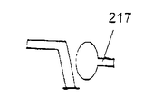
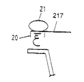
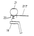
第1の実施形態を図20、21に示す。ここでは、周囲の弾性シール部材20が、蓋217の下面に配置され、図19に示すように、可膨張環状部材21が、蓋217を鉛直方向下向きに押し、洗浄室のリム19に当ててシールするために使用される。
A first embodiment is shown in FIGS. Here, the surrounding
他の実施形態を図22、23に示す。ここでは、蓋217がキャビネット203の上部に取付けられ、図22に示す位置から図23に示す位置へ、鉛直方向に移動可能であるようにする。蓋の縁部の廻り及び洗浄室壁の上面にフランジ構成を設けることによりシールがなされ、図23に示すように、閉鎖した場合には、通過不可能な入り組んだ流体経路22が形成され、洗浄室を効果的にシールする。蓋及び洗浄室のフランジ構成は、均圧室を構成し、洗浄液が漏れないことを確実にする。この蓋の構成は、洗浄室の後方壁の高さが減じられ、蓋フランジが閉鎖位置に摺動して入るように、蓋フランジのための隙間が設けられている場合には、固定された蓋の形式においても使用可能である。
Another embodiment is shown in FIGS. Here, the
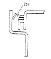
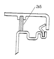
入り組んだ経路の構成に加え、図43に示す柔軟で変形可能な摺動部材264、及び/又は図44に示す直線状のブラシ部材によって補助的にシールしても良い。
In addition to the complicated path configuration, the flexible and deformable sliding
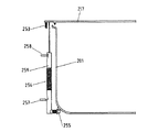
剛体の蓋を昇降する他の手段を図40に示す。圧縮ばね253が蓋217へ押上げ力を作用させ、通常、蓋を開いた位置に維持する。引張ばね254が、洗浄室が完全にキャビネット201に引っ込められた時、蓋を閉鎖する力を作用させるために用いられる。洗浄室が完全に引っ込められる前に、カム又はランプ256を越えて移動するばねの一端に取付けられたローラー255によって張力が作用する。ラッチ257が、ローラーがカム256を通過した後、ばねの張力を維持する。この張力は、後で蓋を上昇させたい場合に解除される。第2のラッチ258は、洗浄室が完全に格納され、部材259が開放されて閉鎖する(下げる力)が蓋217に作用することが可能となるまで、伸張されたばねのために下向きの力を受ける。
Another means for raising and lowering the rigid lid is shown in FIG. The
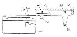
剛体の蓋を昇降する他の機構を図45、47に示す。カム及びカム従動装置が以下のように使用される。水平方向の動作は制限されるが、蓋217が、キャビネット203の上部で圧縮ばね270に取付けられる。洗浄室201には、両側面の壁の外側にカム表面266、267が設けられ、これらのカム表面は、室が水平方向に引っ込められた位置まで移動した時、対応するローラー268、269と係合する。表面266が、まずローラー268に接触し、図46に示すように蓋217の前方部を持ち上げる。同様に、蓋267が、ローラー269に接触し、洗浄室が更に引っ込められるように、蓋217の後方端を持ち上げる。水平方向の移動の最後には(図47)、蓋217を洗浄室の上面に降下して、閉鎖するばね270の作用により、ローラーは、カム表面266、267の半円部分へ入る。
45 and 47 show other mechanisms for raising and lowering the rigid lid. A cam and cam follower are used as follows. A horizontal movement is limited, but a
このカム及びカム従動節の技術は、図14に示した楔形の蓋と洗浄室壁の構成で使用することが可能である。これは、洗浄室をキャビネットへ押し入れることによって生じる水平方向の力の成分に加え、鉛直方向の力の成分を提供することによって、密閉力の増加を補助することが可能である。カム及びカム従動装置は、蓋の前方部が、キャビネットの前方の上部で、一定の高さの横断方向の水平軸線を中心として枢動するようにされている構造において、蓋の後方端を昇降するために使用することも可能である。 This cam and cam follower technique can be used with the wedge-shaped lid and wash chamber wall configuration shown in FIG. This can help increase the sealing force by providing a vertical force component in addition to the horizontal force component caused by pushing the wash chamber into the cabinet. The cam and the cam follower move up and down the rear end of the lid in a structure in which the front portion of the lid is pivoted around a horizontal horizontal axis having a constant height at the upper front portion of the cabinet. It can also be used to
水管理システム 図7に示す洗浄槽が2つある構成の食器洗浄機においては、洗浄サイクルで消費される水の総容積を最小化するために、水は、上槽202aと下槽202bとの間を移送されても良い。
Water Management System In a dishwasher having two washing tubs as shown in FIG. 7, water is divided between the
図24を参照すると、キャビネット203は、上部洗浄槽202aと下部洗浄槽202bとを包含している。各槽は、排水溜め136からの排水管57によって供給される排水ポンプ135を有している。洗浄槽202aの排水管は、弁138へ接続される分岐管137を有しており、弁138は、これを開くと、上槽202aからの水が、分岐管137を通って下部洗浄槽202bへ流れることが可能である構成を有している。
各洗浄槽についての一般的な洗浄プログラムは、事前すすぎ、洗浄、後すすぎ1、後すすぎ2である。
Referring to FIG. 24, the
A typical cleaning program for each wash tank is pre-rinse, wash, post-rinse 1 and post-rinse 2.
本発明のこの態様によれば、上槽の後すすぎサイクル1で使用された水は、下部洗浄槽へ、その事前すすぎサイクルのために供給され、上槽の後すすぎサイクル2で使用された水は、下部洗浄槽へ、その洗浄サイクルのために供給される。
According to this aspect of the invention, the water used in the upper rinse
従って、食器洗浄機制御装置は、行程のこの手順を、洗浄槽202aと洗浄槽202bに対する洗浄サイクルに時間差を持たせることによって実行するようにプログラムされ、槽202bの洗浄プログラムが、上層202aの後すすぎサイクル1が終了するまで開始されないようにする。この時に、弁138は、すすぎ水が槽202aから槽202bへ流れることを可能とするために開かれる。次いで、槽202bの洗浄プログラムが、槽202aからの水を使用する事前すすぎサイクルを開始する。後すすぎサイクル2の時間が、事前すすぎサイクルの時間と同じならば、槽202aの後すすぎサイクルの終了時に、すすぎ水は、その洗浄サイクル開始時である槽202bへ吐出される。
Accordingly, the dishwasher controller is programmed to perform this procedure of the stroke by providing a time difference in the cleaning cycle for the
他の洗浄プログラムが、同様に、ある程度洗浄水を節約するという上述の考えを利用して構成されても良い。 Other cleaning programs may be similarly configured utilizing the above-described idea of saving some cleaning water.
排水ポンプ
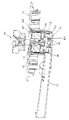
図25を参照すると、本発明の洗浄機では(国際公開公報第93/12706号の場合と同様に)、1つのモーターが洗浄ポンプと排水ポンプの両方の羽根車を駆動するのに用いられ、これらの羽根車は、モーターのローター軸の両端に取付けられている。国際公開公報第93/12706号の場合のように、ローターは、洗浄機の底板の溜め部内で回転するが、モーターのステーターは、摺動洗浄室の下方で溜め部の外部に取付けられている。モーターがある方向に回転した場合に、洗浄ポンプが作動し、モーターがその反対の方向に回転した場合に、排水ポンプが作動する。
Drain Pump With reference to FIG. 25, in the washer of the present invention (as in WO 93/12706), one motor is used to drive the impeller of both the wash pump and the drain pump. These impellers are attached to both ends of the rotor shaft of the motor. As in the case of WO 93/12706, the rotor rotates within the reservoir of the bottom plate of the washer, but the motor stator is attached to the exterior of the reservoir below the sliding cleaning chamber. . When the motor rotates in one direction, the washing pump is activated, and when the motor rotates in the opposite direction, the drainage pump is activated.
図25では、モーターローター105は、洗浄室の取外し可能な中央底板部分51に設けられた溜め部106内に同軸で取付けられる。ローター105は、ローターの両端面から外方へ延設される駆動軸52にキーで取付けられる。駆動軸52の上方部分は、洗浄ポンプの羽根車95(ポンプケーシングとスプレーシステムは図示無し)を備えており、駆動軸の下方部分は、排水ポンプの羽根車54を備えている。溜め部106の下方部分58は、内部で羽根車54が、排水管57へ接続される排水溜め58に排水される洗浄水をポンピングする(汲む)ために機能するケーシングとなる。
In FIG. 25, the
ローターの摩耗を減らすと共に、物が詰まってローターが作動しなくなる可能性を取り除くために、汚れた洗浄水が溜め部106とローター105の間隙に入ることを防止する必要がある。本発明では、プラスチック製のシールリング59が、ローター105の下方面と羽根車54の上方面の間の軸52上に取付けられている。しかしながら、更に他の方法も講じない場合には、シール59により、排水ポンプに導入された空気が、ポンプの呼び水となる液体を妨げる、又は止めるほどに蓄積される。
In order to reduce the wear of the rotor and to remove the possibility that the rotor may not work due to clogging, it is necessary to prevent dirty cleaning water from entering the gap between the
本発明では、この問題は、排水管57が排水ポンプの排水溜めを水平から約6°傾斜した状態にしておくこと、及びポンプの羽根車の羽根を適切な形状にすることによって克服する。排水管57が上方に傾斜している時、シール59に対して蓄積された空気は、抜くことが可能であり、ポイント60のレベルより下がらないようにされる。
In the present invention, this problem is overcome by allowing the
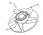
又、図26を参照すると、羽根車54の羽根55には、その付け根に鉛直方向のスロット61が設けられており、羽根車が回転を開始した時に、捕捉された空気が蓄積され得る環状の隙間を提供する。この事により、適切な呼び水が可能となり、排水ポンプの適切な運転が達せられる。
Referring also to FIG. 26, the
加熱要素の保護
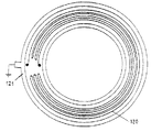
本発明の食器洗浄機の加熱要素は、環状プレートの形状をしており、国際公開公報第93/12706号に記載されているように、食器洗浄機の底板の一部を構成している。図27、28に示された加熱要素は、琺瑯コーティング122された鋼(又は合金鋼(alloy of steel))板121を含む基板にプリントされた厚膜回路120で構成される。琺瑯は、誘電体を形成し、下塗りと上塗りから成り、それぞれが別々に焼き付けられる。厚膜抵抗回路120は、パラジウム銀合成物(palladium silver composition)から成り、順次、琺瑯コーティング上に焼き付けられる。あるいは、高分子材料で鋼板をコーティングし、誘電体を形成しても良い。これらは、保蔵処理されることが可能で、琺瑯の場合のように高温の炉で焼き付ける必要がない。
Protection of the heating element The heating element of the dishwasher according to the invention is in the form of an annular plate and constitutes part of the bottom plate of the dishwasher as described in WO 93/12706. is doing. The heating element shown in FIGS. 27 and 28 is comprised of a
加熱要素が乾燥の状態で作動されると、温度が上昇し、厚膜導回路(thick film track)が焼け、断線により加熱要素でのエネルギーの散逸を停止させる。これにより、プラスチック製の支持部品を損傷する可能性のある過度の温度上昇を最小限に抑える。しかしながら、この内在する保護方法は、幾つかの電気的基準を満たさないので、要素の電源を切るセンサー回路が設けられる。鋼板121は、接地されて用いられるので、本発明において、要素システムの過度の温度上昇は、接地への漏洩電流を監視することによって検知される。琺瑯の誘電体は局所的な温度上昇を受けるので、厚膜120と鋼製の基板との間を電流が流れる場合があることが理解されよう。
When the heating element is activated in a dry state, the temperature rises and the thick film track burns, stopping the dissipation of energy in the heating element by disconnection. This minimizes excessive temperature rise that can damage the plastic support components. However, this inherent protection method does not meet some electrical criteria, so a sensor circuit is provided to turn off the element. Since the
要素システムを保護するのに適した接地漏洩保護回路を図29に示す。要素120は、トライアック123及びリレー124を有する一連のスイッチ装置を通して、交流幹線主電源(mains supply)(フェーズP、ニュートラルN)から電圧を加えられる。差動変流器(differential current transformer)125が要素120への交流電源に接続され、供給フェーズ及び中性線において均衡のとれない電流が存在する場合に巻線126において電圧を生じる。これは、接地された要素板121へのヒーターへの供給電流の漏洩がある場合に起こる。
A ground leakage protection circuit suitable for protecting the element system is shown in FIG.
オペレーショナルアンプ127が、変流器の巻線126を横切る電圧を監視し、接地漏洩電流が所定の最大値、例えば20mAを超えた場合、オペレーショナルアンプ127の出力は、npnトランジスター128を飽和モード(saturation mode)に切り替える。この事により、過度の電流が、直流12Vのレール電源(rail supply)129から、200mAヒューズ130、pnpトランジスター133、リレーコイル131を通って、接地へ流れることが可能になる。ヒューズが飛び、リレーコイル131へ電流が供給されなくなると、リレースイッチ124が開き、要素120の電源を切る。
If the
本発明では又、上述した接地漏洩トリガリング回路のためのフェイルセイフ回路も提供する。この事により、上述の回路が故障を起こしている場合、要素120は、確実に起動不可能になる。つまり、抵抗体132が、変流器125を通って、直流の小さな「バイアス」電流(約5mAであっても良い)を供給する。この事は、巻線126を横切る小さな均衡のとれない電圧を生じ、オペレーショナルアンプ127の出力において、正の電圧差を生じて、トランジスター128を通ってトランジスター133のバイアスへ十分な電流を流すようにし、これによって、リレー巻線131を通って十分な電流を流し、リレースイッチを閉じた状態に保つことを可能にする。変流器の巻線126の電流は、ヒューズを飛ばすための十分な電流をヒューズ130及びトランジスター128を通して流すためには不十分である。この構成では、保護回路の何れかの部分が破損した場合には、抵抗体132を通る電流の流れは止まり、巻線の「バイアス」のずれが検出されなくなり、この状態である間、トランジスター133がオフの状態になり、スイッチ124を開き、又開いた状態に維持するリレーの電源が断たれる。
The present invention also provides a fail-safe circuit for the ground leakage triggering circuit described above. This ensures that the
洗剤分配装置
本発明の食器洗浄機で使用する洗剤分配装置を図30から図37に示す。洗剤分配装置は洗浄室の内部前面壁4の後ろに取付けられ、フロントパネル202の厚さ内に収容される(図1参照)。
Detergent Dispensing Device A detergent dispensing device used in the dishwasher of the present invention is shown in FIGS. The detergent dispensing device is mounted behind the interior front wall 4 of the cleaning chamber and is housed within the thickness of the front panel 202 (see FIG. 1).
図30から図32を参照すると、洗剤分配装置は、洗浄室壁4のほぼ方形の開口に、成形された受口5を設けることにより構成される。受口5を閉じるピボット状又はヒンジ状に取付けられたドア8が、洗剤容器9、10が取付けられるサブフレームを提供する。ベント11が、ドア8が閉じられている場合においても、受口5と洗浄室間を連通させる。ベント11により、以下で述べるように、洗剤を洗浄室に入れることが可能になる。2つの水出口ノズル12A及び12B(1つのノズルのみ図30、31に示す)を、受口5の上部に設置し、それぞれ洗剤容器9、10に水を吐出するように位置させる。
Referring to FIGS. 30 to 32, the detergent dispensing device is configured by providing a molded
洗剤分配装置の作用は以下の通りである。洗剤は、図30に示すように洗剤容器9、10に充填される。この目的のためにドア8が開けられる。次いで、ドアが閉じられ、食器が装填された洗浄室1が、キャビネット3に格納される。洗浄サイクルの適切な時に、食器洗浄機制御装置が弁を開き、ノズル12Bから水を吐出させる。このノズルは、主要な洗浄サイクルに先行するすすぎサイクルで小さい方の洗剤容器10の中へ吐出する。しかしながら、洗剤分配装置の動作は、大きい方の容器9の中に吐出するノズル12Aに関して説明する。水が吐出することにより、容器9内で水と洗剤が混合され、水/洗剤混合物が容器9の上部から流れ出て、受口5に溢れる。洗剤容器には、排水のために、小さな底部開口部13(図33に示す)が設けられている。この開口部は、乾燥した洗剤が漏れ出ない程度に十分小さい。次いで、水/洗剤混合物は、ベント11を通って洗浄室に入る。
The operation of the detergent dispensing device is as follows. The detergent is filled in the
受口5は、洗浄室壁4に、ねじによって固定されるクランプを使用して取付けられても良い。このねじは、公知の方法で洗浄室の壁4へ分配装置のフランジをシールするために、Oリングを圧縮するように機能する。移動する洗浄システムの水出口の設備では、水供給ホース229は、キャビネットと洗浄室間で、前方パネル202の中へ向かって柔軟に延設されなければならない。これは、排水ホース及び電気ワイヤーと共に纏められ、図3に示すようなホースとワイヤーの束228を形成する。
The receiving
本発明の食器洗浄機の分配装置は、洗浄室の容積に影響を与えず、洗剤を入れるために洗浄水に依存せず、分配サイクルの間に汚れる可能性のある可動部品を有していない。ここでは摺動ドロワー型の食器洗浄機への使用について説明したが、前面に洗浄室への開口するドアを有する従来の構成の食器洗浄機に使用されても良い。 The dispensing device of the dishwasher of the present invention does not affect the volume of the washing chamber, does not rely on washing water to contain the detergent, and has no moving parts that can become dirty during the dispensing cycle . Here, the use for the sliding drawer type dishwasher has been described. However, the present invention may be used for a dishwasher having a conventional structure having a door that opens to the washing chamber on the front surface.
好ましい構成では、洗剤分配装置は、2つの部品、即ち、図35、36に示すような受口5とドア8とであり、プラスチックで成形される。構成部品を減らすために、水管路と弁ケーシングは、受口5と一体で成形される。この事は図36から理解される。前述したように、水はノズル12A又は12Bの一方を通り、洗剤分配装置の中へ、制御して放出されなければならない。二方向シャトル弁151が、分配装置の水の入口152に入る水の流れをそれぞれの出口153又は154へ変えるために使用される。出口154は、事前すすぎ洗剤容器へ吐出し、出口153は、主となる洗浄洗剤容器に送水する。水の経路及び弁ケーシングは全て、洗剤分配装置成形品内に設けられる。
In a preferred configuration, the detergent dispensing device is two parts, a
図37に更に詳細に示されている二方向弁151は、ソレノイドコイル(図示無し)内のソレノイドアーマチャー156によって、2つの位置の間を往復するシール155を有している。
The two-
食器洗浄機制御装置は、洗浄サイクルの適切な時に弁を開き、水を洗剤分配装置の入口152へ供給する。この水は、経路157を通り、二方弁151の接続口158へ流れる。弁シール155が、示してある位置にあるならば、接続口158を入った水は、接続口159を通って出ることが可能であり、この接続口159から経路160を進み、出口153を通って吐出される。次いで、吐出された水は洗剤容器に入り、前述したように機能する。
The dishwasher controller opens the valve at the appropriate time in the wash cycle and supplies water to the
ソレノイドアーマチャー156が引っ込められると、弁シール155が弁シート161に当接し、入口158を入った水が出口159を通って出ることを妨げる。しかしながら、弁本体に入った水は、出口162を通って放出され得る。それから、この水は水の経路163に入り、次いで出口154から吐出される。これが、事前すすぎ洗剤容器10への水の放出の吐出ポイントである。
When the
洗剤分配装置成形品には又、すすぎ補助リザーバー164が組込まれ、すすぎ補助液体が、ポンプ165によって計量された容量で、洗浄室に入れられる。このポンプは、好ましくは、パルス状の直流が供給される、ソレノイドで作動するダイアフラムポンプであり、注入されるすすぎ補助液体の容量は、ポンプ165の作動時間に直接的に比例する。
The detergent dispenser mold also incorporates a rinse
すすぎ補助液体の投入は、以下のように、主な洗浄サイクルの間に、洗浄室の中へ可能である。再補充可能なすすぎ補助リザーバーへ吸込み側が接続されたソレノイド駆動のダイアフラムポンプに、所定時間の間、チョッパーされた直流電流(chopped direct current)が通電される。この時間は、食器洗浄機制御装置に事前に記憶させられ、通常の洗浄に最適なすすぎ補助液体の容量を送出するように設定される。 The rinse aid liquid can be charged into the cleaning chamber during the main cleaning cycle as follows. A chopped direct current is applied to a solenoid-driven diaphragm pump whose suction side is connected to a refillable rinsing auxiliary reservoir for a predetermined time. This time is stored in advance in the dishwasher controller and is set to deliver a volume of rinse aid liquid that is optimal for normal washing.
Claims (10)
(b)使用するために水平方向に前記キャビネットから引き出されるように前記キャビネット内に摺動可能に取り付けられた洗浄システムであって、
(i)洗浄される物品を収容し、内部で洗浄液が循環し、かつ頂部周縁リムを有する頂部開口洗浄室と、
(ii)前記洗浄室内に洗浄液を導入しかつ循環させる手段と、
(iii)前記洗浄室から洗浄液を排出する手段とを有する、洗浄システムと、
(c)前記洗浄室を前記キャビネット内へ引っ込めたとき前記洗浄室の前記頂部開口を覆う、前記キャビネットの頂部に取り付けられた実質的に剛性の蓋と、を備え、
(d)前記蓋が、前記キャビネットの頂部でほぼ不変の上下方向位置に保持され、前記蓋は、前記洗浄室が前記キャビネット内に完全に引っ込められたとき、前記リムの近傍で前記洗浄室の頂部と協働して、前記洗浄室が前記キャビネット内に引っ込められたとき、前記洗浄室から洗浄液が出るのを防ぐ周囲手段を有し、
(e)前記洗浄室のリムは、正面が後部より高くなるように一様に傾斜しており、
前記蓋は、前記正面においてより背面において深さが高くなるように対応して傾斜した周縁フランジ部を有し、
弾性シール部材が前記蓋の下側の周縁部周りに配置されており、
前記蓋の垂直方向位置は、前記洗浄室が完全に引っ込められたとき、前記シール部材が前記洗浄室のリムに係合されかつ圧縮される位置である、
ことを特徴とする洗浄装置。 (A) a cabinet;
(B) a cleaning system slidably mounted within the cabinet to be pulled out of the cabinet horizontally for use;
(I) a top-opening cleaning chamber containing articles to be cleaned, in which cleaning liquid circulates, and having a top peripheral rim;
(Ii) means for introducing and circulating a cleaning liquid into the cleaning chamber;
(Iii) a cleaning system having means for discharging the cleaning liquid from the cleaning chamber;
(C) a substantially rigid lid attached to the top of the cabinet that covers the top opening of the cleaning chamber when the cleaning chamber is retracted into the cabinet;
(D) the lid is held in a substantially unchanged vertical position at the top of the cabinet, and the lid is located near the rim when the washing chamber is fully retracted into the cabinet; In cooperation with the top, having peripheral means for preventing cleaning liquid from exiting the cleaning chamber when the cleaning chamber is retracted into the cabinet;
(E) The rim of the cleaning chamber is uniformly inclined so that the front is higher than the rear,
The lid has a peripheral flange portion that is correspondingly inclined so as to have a higher depth on the back surface than on the front surface,
An elastic seal member is disposed around the lower peripheral edge of the lid;
The vertical position of the lid is the position where the seal member is engaged and compressed with the rim of the cleaning chamber when the cleaning chamber is fully retracted,
A cleaning apparatus characterized by that.
(b)使用するために前記洗浄システムが水平方向に前記キャビネットから引き出されるように前記キャビネット内に摺動可能に取り付けられた洗浄システムであって、
(i)洗浄される物品を収容し、洗浄液が内部で循環し、かつ頂部周縁リムを有する頂部開口洗浄室と、
(ii)前記洗浄室内に洗浄液を導入しかつ循環させる手段と、
(iii)前記洗浄室から洗浄液を排出する手段とを有する洗浄システムと、
(c)前記洗浄室が前記キャビネット内へ引っ込められたとき、前記洗浄室の前記頂部開口を覆う、前記キャビネットの頂部に取り付けられた洗浄室閉鎖部材と、を備え、
(d)前記閉鎖部材は、前記キャビネットの上面においてほぼ不変の上下方向位置に保持され、前記閉鎖部材は、前記洗浄室が前記キャビネット内に完全に引っ込められたときに、前記リムの近傍で前記洗浄室の頂部と協働し、前記洗浄室が前記キャビネットに引っ込められたとき洗浄液が前記洗浄室から出るのを防ぐ周縁手段を有し、
(e)前記閉鎖部材は、前記洗浄室が引っ込められたときは前記キャビネットの上面に取り付けられている貯蔵手段から延びて前記洗浄室の頂部開口を覆い、かつ前記洗浄室が引き出されたときは前記貯蔵手段内に引っ込められて前記洗浄室の頂部開口を覆わない可撓性部材である、
ことを特徴とする洗浄装置。 (A) a cabinet;
(B) a cleaning system slidably mounted within the cabinet such that the cleaning system is pulled out of the cabinet in a horizontal direction for use;
(I) a top opening cleaning chamber containing articles to be cleaned, in which cleaning liquid circulates, and having a top peripheral rim;
(Ii) means for introducing and circulating a cleaning liquid into the cleaning chamber;
(Iii) a cleaning system having means for discharging the cleaning liquid from the cleaning chamber;
(C) a cleaning chamber closing member attached to the top of the cabinet that covers the top opening of the cleaning chamber when the cleaning chamber is retracted into the cabinet;
(D) the closure member is held in a generally unchanged vertical position on the top surface of the cabinet, the closure member being near the rim when the cleaning chamber is fully retracted into the cabinet; Cooperating with the top of the cleaning chamber, having peripheral means for preventing cleaning liquid from exiting the cleaning chamber when the cleaning chamber is retracted into the cabinet;
(E) When the cleaning chamber is retracted, the closing member extends from a storage means attached to the upper surface of the cabinet to cover the top opening of the cleaning chamber, and when the cleaning chamber is pulled out A flexible member that is retracted into the storage means and does not cover the top opening of the cleaning chamber;
A cleaning apparatus characterized by that.
前記ローラは、前記キャビネット内の正面開口近傍の該キャビネットの頂部であって前記リムの近位部の上方に取付けられ、
前記ローラは、前記洗浄室が引き出されたとき、前記可撓性シートのほぼ全領域を巻き取る、
請求項2に記載の洗浄装置。 The flexible member is a flexible sheet having one end fastened to the distal portion of the rim and the other end fixed to a spring biasing roller,
The roller is mounted at the top of the cabinet near the front opening in the cabinet and above the proximal portion of the rim;
The roller winds up substantially the entire area of the flexible sheet when the cleaning chamber is pulled out;
The cleaning apparatus according to claim 2.
請求項2に記載の洗浄装置。 The flexible member has a bellows shape, one end is fixed to the distal portion of the rim, and the other end is fixed to the top of the front opening of the cabinet.
The cleaning apparatus according to claim 2.
(b)使用するために前記洗浄システムが水平方向に前記キャビネットから引き出されるように前記キャビネット内に摺動可能に取り付けられた洗浄システムであって、
(i)洗浄される物品を収容し、内部で洗浄液が循環し、かつ頂部周縁リムを有する頂部開口洗浄室と、
(ii)前記洗浄室内に洗浄液を導入しかつ循環させる手段と、
(iii)前記洗浄室から洗浄液を排出する手段とを有する洗浄システムと、
(c)前記キャビネットの上面に取り付けられ、前記洗浄室が前記キャビネット内へ引っ込められたとき、前記洗浄室の頂部開口を覆う洗浄室閉鎖部材と、を備え、
(d)前記閉鎖部材は、前記閉鎖部材が垂直方向のみに移動することを可能とする機械的な手段によって前記キャビネットの頂部に取り付けられ、
前記閉鎖部材が高い位置から下げられたとき、前記閉鎖部材がリムと協働して前記洗浄室から洗浄液が出ることを防ぐ周縁手段を有し、
(e)膨張可能な部材が前記蓋の上面と前記キャビネットの上面との間に配置され、
前記洗浄室が前記キャビネット内に引っ込められたとき、前記膨張可能な部材は膨張させられ、前記蓋及びシール部材を前記洗浄室のリムに押し付け、前記洗浄システムを前記キャビネットから引き出す前に前記閉鎖部材を上昇させ、前記洗浄システムを前記キャビネット内に完全に引っ込めた後に前記閉鎖部材を下降させる、
ことを特徴とする洗浄装置。 (A) a cabinet;
(B) a cleaning system slidably mounted within the cabinet such that the cleaning system is pulled out of the cabinet in a horizontal direction for use;
(I) a top-opening cleaning chamber containing articles to be cleaned, in which cleaning liquid circulates, and having a top peripheral rim;
(Ii) means for introducing and circulating a cleaning liquid into the cleaning chamber;
(Iii) a cleaning system having means for discharging the cleaning liquid from the cleaning chamber;
(C) a cleaning chamber closing member attached to the upper surface of the cabinet and covering a top opening of the cleaning chamber when the cleaning chamber is retracted into the cabinet;
(D) the closure member is attached to the top of the cabinet by mechanical means that allow the closure member to move only vertically;
Peripheral means for preventing the cleaning liquid from coming out of the cleaning chamber in cooperation with the rim when the closing member is lowered from a high position;
(E) an inflatable member is disposed between the top surface of the lid and the top surface of the cabinet;
When the cleaning chamber is retracted into the cabinet, the inflatable member is inflated, pressing the lid and seal member against the rim of the cleaning chamber and before closing the cleaning system out of the cabinet, the closure member And lowering the closure member after the cleaning system is fully retracted into the cabinet,
A cleaning apparatus characterized by that.
前記蓋の縁部には、下方に面するフランジが設けられ、前記洗浄室のリムには相補的な上方に面するフランジが設けられ、
前記蓋が下げられて前記蓋と前記リムフランジとの間で入り組んだシールを形成するとき、前記蓋及びリムのフランジは緩く相互係合する、
請求項5に記載の洗浄装置。 The lid is attached to the top of the cabinet so that it drops when the cleaning chamber is retracted and rises when the cleaning chamber is pulled out;
The lid edge is provided with a downward facing flange, the rim of the cleaning chamber is provided with a complementary upward facing flange,
When the lid is lowered to form an intricate seal between the lid and the rim flange, the lid and rim flanges loosely interengage;
The cleaning apparatus according to claim 5.
(b)洗浄システムであって、使用するために前記洗浄システムが水平方向に前記キャビネットから引き出されるように前記キャビネット内に摺動可能に取り付けられた洗浄システムであって、
(i)洗浄される物品を収容し、洗浄液が循環し、かつ頂部周縁リムを有する頂部開口洗浄室と、
(ii)前記洗浄室内に洗浄液を導入しかつ循環させる手段と、
(iii)前記洗浄室から洗浄液を排出する手段とを有する、洗浄システムと、
(c)前記キャビネットの上面に取り付けられ、前記洗浄室が前記キャビネット内へ引っ込められたとき前記洗浄室の前記頂部開口を覆う洗浄室閉鎖部材と、を備え、
(d)前記閉鎖部材は、前記閉鎖部材が予め定めた移動の自由度を持って垂直方向のみに移動することを可能とする機械的な手段によって前記キャビネットの頂部で水平面内に取り付けられ、
前記閉鎖部材が高い位置から降下したとき、前記閉鎖部材がリムと協働して前記洗浄室から洗浄液が出ることを防ぐ周縁手段を有し、
(e)線形作動手段が設けられ、該線形作動手段が、前記キャビネットからの前記洗浄システム引き出しに先だって、前記閉鎖部材を、前記閉鎖部材が前記洗浄室リムと係合し前記キャビネットへの洗浄システムの完全な引き込みの後に閉鎖部材を降下させている第一位置と、前記閉鎖部材が前記洗浄室リムの頂部から上下方向に離れている第二位置へ、上下動させる、
ことを特徴とする食器洗浄装置。 (A) a cabinet;
(B) a cleaning system, wherein the cleaning system is slidably mounted in the cabinet such that the cleaning system is pulled out of the cabinet in a horizontal direction for use;
(I) a top opening cleaning chamber containing articles to be cleaned, in which cleaning liquid circulates and having a top peripheral rim;
(Ii) means for introducing and circulating a cleaning liquid into the cleaning chamber;
(Iii) a cleaning system having means for discharging the cleaning liquid from the cleaning chamber;
(C) a cleaning chamber closing member attached to the upper surface of the cabinet and covering the top opening of the cleaning chamber when the cleaning chamber is retracted into the cabinet;
(D) the closure member is mounted in a horizontal plane at the top of the cabinet by mechanical means that allows the closure member to move only in the vertical direction with a predetermined degree of movement;
Peripheral means for preventing the cleaning liquid from coming out of the cleaning chamber in cooperation with the rim when the closing member is lowered from a high position;
(E) linear actuating means is provided, the linear actuating means engaging the closure member prior to withdrawal of the washing system from the cabinet, the closure member engaging the washing chamber rim and the washing system to the cabinet; Moving up and down to a first position where the closure member is lowered after full retraction, and a second position where the closure member is vertically away from the top of the cleaning chamber rim,
A dishwashing apparatus characterized by that.
請求項7に記載の食器洗浄装置。 The linear actuating means includes a spring that biases the closing member to the second position, and is disposed on each side of the cleaning chamber, the upper end is fixed to the closing member, and the lower end is a cam follower A fixed substantially vertical pull bar member and cam surfaces provided on opposite sides of the cleaning chamber aligned with each of the cam follower means, the cam follower means when the cam follower is retracted into the cabinet; Engaging the cam surface at the final stage of horizontal movement of the cleaning chamber, and the pull bar member pulls the closure member down to the first position against the spring bias;
The tableware washing apparatus according to claim 7.
(b)使用するために前記キャビネットから水平方向に引き出されるように、前記キャビネット内で摺動可能に取り付けられている第一洗浄システムと、
(c)使用するために前記キャビネットから水平方向に引き出されるように、前記第一洗浄システムの上方で且つ前記第一洗浄システムと垂直方向に整列されて前記キャビネット内に摺動可能に取付けられた第二洗浄システムと、を備え、
前記第一洗浄システム及び前記第二洗浄システムの各々は、
(i)前記洗浄液がその中で循環させられる、食器を収納する頂部開口洗浄室と、
(ii)前記室内に洗浄液を導入しかつ循環させる手段と、
(iii)前記室から洗浄液を排出する手段とを有し、
(d)前記キャビネット内で第一洗浄室及び第二洗浄室の各々の直上に第一洗浄室及び第二洗浄室の各々と整列して各々が取り付けられている第一洗浄室及び第二洗浄室の閉鎖部材であって、各洗浄室が前記キャビネット内へ引っ込められたときに前記洗浄室の前記頂部開口を覆う、第一洗浄室及び第二洗浄室の閉鎖部材とを備え、
(e)前記第一閉鎖部材及び前記第二閉鎖部材が、前記キャビネット内でほぼ不変の垂直方向位置に保持され、前記閉鎖部材の各々は、前記洗浄室から洗浄液が出ることを防ぐように、対応の洗浄室が前記キャビネット内に完全に引っ込められたときに前記洗浄室の頂部と協働する周縁手段を有し、さらに、
(f)前記第一洗浄システムの前記洗浄室内へ放出させることができる第一放水手段と、
(g)前記第二洗浄システムの前記洗浄室内へ放出させることができる第二放水手段と、
(h)使用時に給水接続部に接続され、かつホースによって前記第一水手段と前記第二放水手段の各々へ接続され、電気的に操作される弁手段とを備え、
該弁手段は、前記各洗浄システムが完全に前記キャビネット手段内に引っ込められたとき前記第一放水手段と前記第二放水手段の一方又は両方に選択的に給水する操作をするように作動可能である、
ことを特徴とする食器洗浄機。 (A) a cabinet;
(B) a first cleaning system that is slidably mounted within the cabinet so as to be pulled horizontally from the cabinet for use;
(C) slidably mounted in the cabinet above the first cleaning system and vertically aligned with the first cleaning system so that it can be pulled horizontally from the cabinet for use. A second cleaning system,
Each of the first cleaning system and the second cleaning system includes:
(I) a top opening cleaning chamber for storing tableware in which the cleaning liquid is circulated;
(Ii) means for introducing and circulating a cleaning liquid into the chamber;
(Iii) means for discharging the cleaning liquid from the chamber;
(D) A first cleaning chamber and a second cleaning chamber in which the first cleaning chamber and the second cleaning chamber are respectively aligned with and attached to the first cleaning chamber and the second cleaning chamber in the cabinet. A chamber closure member comprising: a first wash chamber and a second wash chamber closure member that covers the top opening of the wash chamber when each wash chamber is retracted into the cabinet;
(E) the first closure member and the second closure member are held in a substantially unchanged vertical position within the cabinet, each of the closure members preventing the cleaning liquid from exiting the cleaning chamber; Peripheral means for cooperating with the top of the cleaning chamber when the corresponding cleaning chamber is fully retracted into the cabinet;
(F) first water discharge means that can be discharged into the cleaning chamber of the first cleaning system;
(G) a second water discharge means that can be discharged into the cleaning chamber of the second cleaning system;
(H) a valve means that is connected to the water supply connection portion in use and connected to each of the first water means and the second water discharge means by a hose and electrically operated;
The valve means is operable to selectively supply water to one or both of the first water discharge means and the second water discharge means when each cleaning system is fully retracted into the cabinet means. is there,
A dishwasher characterized by that.
(b)使用するために前記キャビネットから水平方向に引き出されるように、前記キャビネット内で摺動可能に取り付けられている第一洗浄システムと、
(c)使用するために前記キャビネットから水平方向に引き出されるように、前記第一洗浄システムの上方で且つ前記第一洗浄システムと垂直方向に整列されて前記キャビネット内に摺動可能に取付けられた第二洗浄システムと、を備え、
前記第一洗浄システム及び前記第二洗浄システムの各々は、
(i)前記洗浄液がその中で循環させられる、食器を収容する頂部開口洗浄室と、
(ii)前記室内に洗浄液を導入しかつ循環させる手段と、
(iii)前記室から洗浄液を排出する手段とを有し、
(d)前記キャビネット内で第一洗浄室及び第二洗浄室の各々の直上に第一洗浄室及び第二洗浄室の各々と整列して各々が取り付けられている第一洗浄室及び第二洗浄室の閉鎖部材であって、各洗浄室が前記キャビネット内へ引っ込められたときに、前記洗浄室の前記頂部開口を覆う第一洗浄室及び第二洗浄室の閉鎖部材とを備え、
(e)前記第一閉鎖部材及び前記第二閉鎖部材の各々は、各機械的手段によって取り付けられており、前記機械手段は、対応の洗浄室が完全に前記キャビネット内に引っ込められた時に前記洗浄室から洗浄液が出るのを防ぐように、垂直方向のみの前記閉鎖部材の移動を許容することにより、付随した閉鎖部材を高い位置から下降させて前記洗浄室の頂部と協働し、さらに、
(f)前記第一洗浄システムの前記洗浄室内へ放出させることができる第一放水手段と、
(g)前記第二洗浄システムの前記洗浄室内へ放出させることができる第二放水手段と、
(h)使用時に給水接続部に接続され、かつホースによって前記第一放水手段と前記第二放水手段の各々へ接続された、電気的に操作されている弁手段とを備え、
該弁手段が、前記各洗浄システムが完全に前記キャビネット手段内に引っ込められたとき前記第一放水手段と前記第二放水手段の一方又は両方に選択的に水を供給するように作動可能である、
ことを特徴とする食器洗浄機。 (A) a cabinet;
(B) a first cleaning system that is slidably mounted within the cabinet so as to be pulled horizontally from the cabinet for use;
(C) slidably mounted in the cabinet above the first cleaning system and vertically aligned with the first cleaning system so that it can be pulled horizontally from the cabinet for use. A second cleaning system,
Each of the first cleaning system and the second cleaning system includes:
(I) a top-opening cleaning chamber containing tableware in which the cleaning liquid is circulated;
(Ii) means for introducing and circulating a cleaning liquid into the chamber;
(Iii) means for discharging the cleaning liquid from the chamber;
(D) A first cleaning chamber and a second cleaning chamber in which the first cleaning chamber and the second cleaning chamber are respectively aligned with and attached to the first cleaning chamber and the second cleaning chamber in the cabinet. A chamber closing member comprising: a first cleaning chamber and a second cleaning chamber closing member that cover the top opening of the cleaning chamber when each cleaning chamber is retracted into the cabinet;
(E) Each of the first closure member and the second closure member is attached by a respective mechanical means, the mechanical means being adapted to perform the cleaning when the corresponding cleaning chamber is fully retracted into the cabinet. Cooperating with the top of the cleaning chamber by lowering the associated closing member from a high position by allowing movement of the closing member in the vertical direction only to prevent cleaning liquid from exiting the chamber;
(F) first water discharge means that can be discharged into the cleaning chamber of the first cleaning system;
(G) a second water discharge means that can be discharged into the cleaning chamber of the second cleaning system;
(H) an electrically operated valve means connected to the water supply connection part in use and connected to each of the first water discharge means and the second water discharge means by a hose;
The valve means is operable to selectively supply water to one or both of the first water discharge means and the second water discharge means when each of the cleaning systems is fully retracted into the cabinet means. ,
A dishwasher characterized by that.
Applications Claiming Priority (1)
| Application Number | Priority Date | Filing Date | Title |
|---|---|---|---|
| NZ314155A NZ314155A (en) | 1997-01-30 | 1997-01-30 | Dishwasher detergent dispenser located in door recess, having open top and being flushed out by overhead nozzle |
Related Parent Applications (1)
| Application Number | Title | Priority Date | Filing Date |
|---|---|---|---|
| JP53276298A Division JP3782463B2 (en) | 1997-01-30 | 1998-01-30 | Dishwasher |
Related Child Applications (1)
| Application Number | Title | Priority Date | Filing Date |
|---|---|---|---|
| JP2006188991A Division JP4147257B2 (en) | 1997-01-30 | 2006-07-10 | Dishwasher |
Publications (2)
| Publication Number | Publication Date |
|---|---|
| JP2005013753A JP2005013753A (en) | 2005-01-20 |
| JP3929456B2 true JP3929456B2 (en) | 2007-06-13 |
Family
ID=19926125
Family Applications (7)
| Application Number | Title | Priority Date | Filing Date |
|---|---|---|---|
| JP53276298A Expired - Fee Related JP3782463B2 (en) | 1997-01-30 | 1998-01-30 | Dishwasher |
| JP2001308996A Expired - Fee Related JP3742321B2 (en) | 1997-01-30 | 2001-10-04 | Dishwasher |
| JP2001308999A Pending JP2002184556A (en) | 1997-01-30 | 2001-10-04 | Dishwasher |
| JP2001308995A Expired - Fee Related JP3993757B2 (en) | 1997-01-30 | 2001-10-04 | Dishwasher |
| JP2001308993A Pending JP2002119460A (en) | 1997-01-30 | 2001-10-04 | Dishwasher |
| JP2004241209A Expired - Fee Related JP3929456B2 (en) | 1997-01-30 | 2004-08-20 | Dishwasher |
| JP2006188991A Expired - Fee Related JP4147257B2 (en) | 1997-01-30 | 2006-07-10 | Dishwasher |
Family Applications Before (5)
| Application Number | Title | Priority Date | Filing Date |
|---|---|---|---|
| JP53276298A Expired - Fee Related JP3782463B2 (en) | 1997-01-30 | 1998-01-30 | Dishwasher |
| JP2001308996A Expired - Fee Related JP3742321B2 (en) | 1997-01-30 | 2001-10-04 | Dishwasher |
| JP2001308999A Pending JP2002184556A (en) | 1997-01-30 | 2001-10-04 | Dishwasher |
| JP2001308995A Expired - Fee Related JP3993757B2 (en) | 1997-01-30 | 2001-10-04 | Dishwasher |
| JP2001308993A Pending JP2002119460A (en) | 1997-01-30 | 2001-10-04 | Dishwasher |
Family Applications After (1)
| Application Number | Title | Priority Date | Filing Date |
|---|---|---|---|
| JP2006188991A Expired - Fee Related JP4147257B2 (en) | 1997-01-30 | 2006-07-10 | Dishwasher |
Country Status (15)
| Country | Link |
|---|---|
| US (5) | US6189551B1 (en) |
| EP (9) | EP1297779B1 (en) |
| JP (7) | JP3782463B2 (en) |
| KR (1) | KR100455512B1 (en) |
| AT (6) | ATE269026T1 (en) |
| AU (1) | AU735290B2 (en) |
| BR (1) | BR9807044A (en) |
| CA (9) | CA2380564C (en) |
| DE (6) | DE69824649T2 (en) |
| DK (4) | DK1393667T3 (en) |
| ES (1) | ES2212261T3 (en) |
| HK (4) | HK1046226A1 (en) |
| NO (1) | NO993668L (en) |
| NZ (2) | NZ335414A (en) |
| WO (1) | WO1998033426A1 (en) |
Families Citing this family (135)
| Publication number | Priority date | Publication date | Assignee | Title |
|---|---|---|---|---|
| US6291309B1 (en) * | 1997-11-28 | 2001-09-18 | Niigata Seimitsu Co., Ltd. | Semiconductor device and method for manufacturing the same |
| US6460555B1 (en) * | 1998-09-21 | 2002-10-08 | Maytag Corporation | Dual dishwasher construction |
| US6491049B1 (en) * | 1998-09-21 | 2002-12-10 | Maytag Corporation | Lid construction for drawer dishwasher |
| DE19924897B4 (en) * | 1999-06-01 | 2012-01-26 | Aweco Appliance Systems Gmbh & Co. Kg | Dosing device for a dishwasher |
| IT1311224B1 (en) * | 1999-06-01 | 2002-03-04 | Electrolux Zanussi Elettrodome | DISHWASHER MACHINE, PREFERABLY FOR DOMESTIC USE, WITH IMPROVED ARCHITECTURE |
| IT1311704B1 (en) * | 1999-08-05 | 2002-03-19 | Electrolux Zanussi Elettrodome | DISHWASHER MACHINE, IN PARTICULAR FOR DOMESTIC USE, WITH A FUNCTIONAL LOADING DOOR |
| NZ516951A (en) | 1999-10-08 | 2003-10-31 | Fisher & Paykel Appliances Ltd | Linkage arrangement for wash chamber closure of dishwasher |
| IT248152Y1 (en) * | 1999-11-15 | 2002-12-10 | Electrolux Zanussi Elettrodome | DISHWASHER WITH REMOVABLE DRAWER |
| ITPN20000011A1 (en) * | 2000-02-15 | 2001-08-15 | Electrolux Zanussi Elettrodome | DISHWASHER PERFECTED EQUIPPED WITH AN ELECTRO-HYDRAULIC FUNCTIONAL UNIT |
| NZ503866A (en) * | 2000-04-10 | 2003-01-31 | Fisher & Paykel Appliances Ltd | Dishwasher with sliding drawer type wash chamber(s) in cabinet with seal formed by motor driving linkages pulling top lid down onto open top(s) fo chamber(s) |
| ITPN20000037A1 (en) | 2000-06-07 | 2001-12-07 | Electrolux Zanussi Elettrodome | ERGONOMIC DISHWASHER |
| US6799085B1 (en) * | 2000-06-08 | 2004-09-28 | Beverage Works, Inc. | Appliance supply distribution, dispensing and use system method |
| US7754025B1 (en) | 2000-06-08 | 2010-07-13 | Beverage Works, Inc. | Dishwasher having a door supply housing which holds dish washing supply for multiple wash cycles |
| US7083071B1 (en) | 2000-06-08 | 2006-08-01 | Beverage Works, Inc. | Drink supply canister for beverage dispensing apparatus |
| US20020017117A1 (en) * | 2000-07-25 | 2002-02-14 | Sunshine Richard A. | Integrated laundry center |
| NZ512503A (en) * | 2000-11-13 | 2002-11-26 | Lg Electronics Inc | Drawer-type washing machine and locking method thereof |
| KR100377622B1 (en) * | 2000-12-11 | 2003-03-26 | 엘지전자 주식회사 | Structure for sealing of dish washer which is of drawer type |
| KR100399326B1 (en) * | 2000-12-11 | 2003-09-26 | 엘지전자 주식회사 | Structure for sealing of dish washer which is of drawer type |
| DE10065637A1 (en) * | 2000-12-29 | 2002-07-04 | Bsh Bosch Siemens Hausgeraete | dishwasher |
| US7763119B2 (en) * | 2005-04-22 | 2010-07-27 | Steelkor, L.L.C. | Kitchenware washers and methods of manufacturing the same |
| US7475698B2 (en) * | 2005-04-22 | 2009-01-13 | Steelkor, L.L.C. | Kitchenware washers and methods of manufacturing the same |
| US7527062B2 (en) * | 2001-02-15 | 2009-05-05 | Steelkor, L.L.C. | Kitchenware washers and methods of manufacturing the same |
| US6659114B2 (en) | 2001-02-15 | 2003-12-09 | X-Stream Technologies Ii, Llc | Automated kitchenware washer |
| JP4615777B2 (en) * | 2001-07-30 | 2011-01-19 | 株式会社ハーマンプロ | Storage device |
| ITPN20010056A1 (en) * | 2001-08-27 | 2003-02-27 | Electrolux Zanussi Elettrodome | DISHWASHER WITH REMOVABLE FUNCTIONAL UNIT |
| US6622896B2 (en) | 2001-10-25 | 2003-09-23 | General Electric Company | Dishwasher detergent dispenser |
| DE60102828T2 (en) * | 2001-12-06 | 2005-04-28 | Candy S.P.A., Monza | A domestic dishwasher with a door having a recess having a panel and a dishwashing detergent dispenser supported by the upper dish rack |
| US7069181B2 (en) * | 2001-12-21 | 2006-06-27 | BSH Bosch und Siemens Hausgeräte | Method of determining the energy and water consumption of dishwashers, and dishwashers |
| DE10163192A1 (en) * | 2001-12-21 | 2003-07-03 | Bsh Bosch Siemens Hausgeraete | Method for determining the energy and water consumption of dishwashers and dishwashers |
| US6826933B2 (en) * | 2002-02-06 | 2004-12-07 | Maytag Corporation | Dual use detergent dispenser |
| NZ518288A (en) * | 2002-04-10 | 2004-09-24 | Fisher & Paykel Appliances Ltd | Washing appliance water softner |
| JP3645884B2 (en) * | 2002-11-05 | 2005-05-11 | 松下電器産業株式会社 | Dishwasher |
| JP3974017B2 (en) * | 2002-11-05 | 2007-09-12 | 松下電器産業株式会社 | Dishwasher |
| US7021891B2 (en) * | 2002-12-18 | 2006-04-04 | Intel Corporation | Micro-impeller miniature centrifugal compressor |
| US20040244825A1 (en) * | 2003-06-06 | 2004-12-09 | Ashton Robert H. | Dishwasher with drawer lifting mechanism |
| EP1662964A2 (en) * | 2003-08-26 | 2006-06-07 | Martin A. Alpert | Dishwasher and method |
| GB2398355B (en) * | 2003-09-05 | 2004-12-29 | Applied Design & Eng Ltd | Improvements in or relating to seals |
| KR100601436B1 (en) * | 2004-07-09 | 2006-07-14 | 주식회사 대우일렉트로닉스 | Lead lifting device for dish washer |
| US20070151306A1 (en) | 2005-12-30 | 2007-07-05 | Gilboe Kevin J | Modular laundry system with work surface |
| US20070151303A1 (en) | 2005-12-30 | 2007-07-05 | Doyle Colleen M | Modular laundry system with work surface having a functional element |
| US11255040B2 (en) | 2004-10-22 | 2022-02-22 | Whirlpool Corporation | Modular laundry system |
| US20060117711A1 (en) * | 2004-11-02 | 2006-06-08 | Landen Higer | Direct bag insert vacuum packaging appliance |
| NZ536816A (en) * | 2004-11-24 | 2006-02-24 | Fisher & Paykel Appliances Ltd | Dishwasher with sliding chamber drawer sealing to cabinet via permanent magnetic material |
| DE102004062767B3 (en) | 2004-12-21 | 2006-05-11 | Miele & Cie. Kg | Dishwasher, has drawer guide running diagonally opposite to housing cover and/ or top edges of side walls of washing container, such that edges are lifted from lower level to dishwasher level, during drawing process |
| US8551255B2 (en) * | 2005-02-09 | 2013-10-08 | Whirlpool Corporation | Rapid heat system for a multi-tub dishwasher |
| US7870863B2 (en) * | 2005-02-09 | 2011-01-18 | Maytag Corporation | Multi-use sump for a drawer-type dishwaher |
| US7862665B2 (en) * | 2005-02-09 | 2011-01-04 | Maytag Corporation | Pump system for a drawer-type dishwasher |
| DE102005008248B4 (en) * | 2005-02-22 | 2006-11-16 | Miele & Cie. Kg | Dishwasher with a drawer-like pull out of the housing washing compartment |
| DE102005008247B4 (en) * | 2005-02-22 | 2006-11-16 | Miele & Cie. Kg | Dishwasher with a drawer-like pull out of the housing washing compartment |
| DE102005008249B4 (en) * | 2005-02-22 | 2006-11-16 | Miele & Cie. Kg | Dishwasher with a drawer-like pull out of the housing washing compartment |
| DE502006007834D1 (en) * | 2005-02-22 | 2010-10-21 | Miele & Cie | DISHWASHER WITH A DRAWER REMOVABLE FROM THE HOUSING DRAWER |
| JP2008536635A (en) * | 2005-04-22 | 2008-09-11 | スティールコー・リミテッド・ライアビリティ・カンパニー | Commercial dishwasher and related methods |
| US9265400B2 (en) | 2005-04-22 | 2016-02-23 | Duke Manufacturing Co. | Commercial kitchenware washers and related methods |
| US8680442B2 (en) * | 2005-07-11 | 2014-03-25 | Allied Precision Industries Inc. | Systems and methods for a temperature-controlled electrical outlet |
| US7699063B2 (en) * | 2005-08-18 | 2010-04-20 | Maytag Corporation | Dispenser for a drawer-type dishwasher |
| US7607444B2 (en) * | 2005-11-29 | 2009-10-27 | Maytag Corporation | Latching and sealing mechanism for a drawer-type dishwasher |
| US7363093B2 (en) * | 2005-11-29 | 2008-04-22 | Whirlpool Corporation | Control system for a multi-compartment dishwasher |
| US7850784B2 (en) * | 2005-11-29 | 2010-12-14 | Maytag Corporation | Lid seal for a drawer-type dishwasher |
| US7775223B2 (en) * | 2005-11-29 | 2010-08-17 | Maytag Corporation | Flexible utility link for a drawer-type dishwasher |
| DE102005058899A1 (en) * | 2005-12-09 | 2007-06-14 | BSH Bosch und Siemens Hausgeräte GmbH | Circuit arrangement for locking and / or unlocking a door lock, in particular in an electrical domestic appliance |
| CN2916195Y (en) | 2006-01-26 | 2007-06-27 | 江门市汉宇电器有限公司 | Centrifugal drainage pump |
| NZ553187A (en) * | 2006-02-10 | 2007-09-28 | Fisher & Paykel Appliances Ltd | Drawer style dishwasher of reduced height and increased width with two separate rotating head spray arms |
| US7568487B2 (en) * | 2006-04-20 | 2009-08-04 | Maytag Corporation | Lid mechanism for a drawer-type dishwasher |
| US7695571B2 (en) * | 2006-04-20 | 2010-04-13 | Maytag Corporation | Wash/rinse system for a drawer-type dishwasher |
| US7624745B2 (en) * | 2006-04-20 | 2009-12-01 | Maytag Corporation | Drawer-type dishwasher having modular support body |
| US7832417B2 (en) * | 2006-04-20 | 2010-11-16 | Maytag Corporation | Dispenser for a drawer-type dishwasher |
| US7749335B2 (en) * | 2006-04-20 | 2010-07-06 | Maytag Corporation | Dispenser rinse system for a drawer-type dishwasher |
| US7931032B1 (en) | 2006-05-19 | 2011-04-26 | Knight, Llc | Bulk dispensing of chemicals into a residential dishwasher |
| US7731804B2 (en) * | 2006-08-09 | 2010-06-08 | Maytag Corporation | Lid operating mechanism for a drawer-type dishwasher |
| CN101141060A (en) * | 2006-09-08 | 2008-03-12 | 鸿富锦精密工业(深圳)有限公司 | Auto-power-off control device |
| US7845361B1 (en) | 2006-11-08 | 2010-12-07 | Knight, Llc | Design and method for a dripless liquid wash aid pumping mechanism |
| EP1925250A1 (en) * | 2006-11-23 | 2008-05-28 | Electrolux Home Products N.V. | Dishwasher with an alarm device |
| DE602006016623D1 (en) * | 2006-12-06 | 2010-10-14 | Electrolux Home Prod Corp | dishwasher |
| ATE479380T1 (en) * | 2006-12-06 | 2010-09-15 | Electrolux Home Prod Corp | DISHWASHER |
| ES2624055T3 (en) * | 2007-01-10 | 2017-07-12 | Lg Electronics Inc. | Pedestal washing machine |
| US20090090400A1 (en) * | 2007-05-04 | 2009-04-09 | Electrolux Home Products, Inc. | Water Delivery System For Multi-Position Spray Arm Of A Dishwasher |
| WO2008150184A1 (en) * | 2007-06-08 | 2008-12-11 | Fisher & Paykel Appliances Limited | Dishwasher lid sealing assembly |
| DE102007030064A1 (en) * | 2007-06-29 | 2009-01-02 | BSH Bosch und Siemens Hausgeräte GmbH | Platform for a dishwasher |
| US7954913B2 (en) | 2007-07-11 | 2011-06-07 | Whirlpool Corporation | Molded plastic support frame for a drawer-type dishwasher |
| US7959742B2 (en) | 2007-07-11 | 2011-06-14 | Whirlpool Corporation | Outer support body for a drawer-type dishwasher |
| NZ569965A (en) * | 2007-07-23 | 2009-02-28 | Fisher & Paykel Appliances Ltd | Appliance pump |
| DE102007062953A1 (en) * | 2007-12-21 | 2009-06-25 | Premark Feg L.L.C., Wilmington | Dishwasher in the form of a programmer and method for their operation |
| EP2127587A1 (en) | 2008-05-31 | 2009-12-02 | Electrolux Home Products Corporation N.V. | Water outlet system for a dishwasher |
| DE102008042758A1 (en) * | 2008-06-23 | 2009-12-24 | BSH Bosch und Siemens Hausgeräte GmbH | Storage container for a detergent cartridge and dishwasher |
| KR100985384B1 (en) * | 2008-06-27 | 2010-10-05 | 주식회사 경동네트웍 | Method for controlling hot water temperature when using low flow hot water in hot water supply system |
| KR101742991B1 (en) * | 2009-05-11 | 2017-06-02 | 엘지전자 주식회사 | Washing machine |
| DE102009046084A1 (en) | 2009-10-28 | 2011-05-12 | BSH Bosch und Siemens Hausgeräte GmbH | Household appliance, in particular dishwasher |
| DE102009044540B3 (en) * | 2009-11-16 | 2010-12-16 | Miele & Cie. Kg | Drawer-type dishwasher, has covering lid for closing feed opening of washing drawer and pivotably arranged in housing around rotational axis that is formed in area of housing corner |
| DE102009044590A1 (en) | 2009-11-19 | 2010-12-02 | Miele & Cie. Kg | Push loading drawer dishwasher, has rinsing drawer comprising rear wall, front wall, two side walls and base plate and providing volume space that serves as rinsing space, where one of walls of rinsing drawer is cooled |
| AU2010246375B2 (en) * | 2009-11-25 | 2015-10-01 | Fisher & Paykel Appliances Limited | Appliance Lid And Assembly |
| US9592539B2 (en) * | 2010-01-05 | 2017-03-14 | Stratasys, Inc. | Support cleaning system |
| US8337631B2 (en) * | 2010-03-08 | 2012-12-25 | Whirlpool Corporation | Dishwasher with separate sump for concentrated fluid supply |
| US9265398B2 (en) * | 2010-03-08 | 2016-02-23 | Whirlpool Corporation | Dishwasher with separate sump for concentrated fluid supply |
| JP5267530B2 (en) * | 2010-10-01 | 2013-08-21 | トヨタ自動車株式会社 | Piping support structure |
| US8043437B1 (en) * | 2010-12-03 | 2011-10-25 | Whirlpool Corporation | Dishwasher with multiple treating chambers |
| DE102010061354A1 (en) * | 2010-12-20 | 2012-06-21 | Miele & Cie. Kg | Water diverter for distributing water within a water-bearing household appliance |
| US8619396B2 (en) * | 2011-06-24 | 2013-12-31 | Renewable Power Conversion, Inc. | Renewable one-time load break contactor |
| US9603501B2 (en) * | 2011-09-02 | 2017-03-28 | Ecolab Usa Inc. | Use of recycled wash and rinse water for the pre-rinse operation of dishes |
| US8459280B2 (en) | 2011-09-23 | 2013-06-11 | Stratasys, Inc. | Support structure removal system |
| US9307888B2 (en) | 2011-11-23 | 2016-04-12 | Whirlpool Corporation | System for charging a power supply in a closure element of a household appliance |
| US10004379B2 (en) | 2011-11-23 | 2018-06-26 | Whirlpool Corporation | Dishwasher with transforming door |
| ITUD20120018A1 (en) * | 2012-02-06 | 2013-08-07 | Steelco Spa | WASHING MACHINE |
| US9743821B2 (en) * | 2012-04-16 | 2017-08-29 | Whirlpool Corporation | Dispenser for multi-compartment dishwasher |
| US9155446B2 (en) | 2012-07-12 | 2015-10-13 | Whirlpool Corporation | Dishwasher door mounted dispenser assembly |
| US9260847B2 (en) * | 2013-02-13 | 2016-02-16 | General Wire Spring Company | Ball type clamp assembly |
| US9861258B2 (en) * | 2013-03-15 | 2018-01-09 | Whirlpool Corporation | Dishwasher |
| ITTO20130259A1 (en) * | 2013-03-28 | 2014-09-29 | Indesit Co Spa | APPLIANCES WITH SAFETY CIRCUIT |
| US9572475B2 (en) | 2013-04-29 | 2017-02-21 | Whirlpool Corporation | Appliance with closure element having an operative device |
| US9714318B2 (en) | 2013-07-26 | 2017-07-25 | Stratasys, Inc. | Polyglycolic acid support material for additive manufacturing systems |
| US9737192B2 (en) | 2014-01-28 | 2017-08-22 | Haier Us Appliance Solutions, Inc. | Door latch interruption upon detection of current leakage |
| US10059053B2 (en) | 2014-11-04 | 2018-08-28 | Stratasys, Inc. | Break-away support material for additive manufacturing |
| CN113576364B (en) | 2015-02-13 | 2024-10-18 | 菲舍尔和佩克尔应用有限公司 | Washing system of washing electric appliance |
| KR20170002883A (en) | 2015-06-30 | 2017-01-09 | 엘지전자 주식회사 | Laundry Treating Apparatus |
| CN107630820B (en) * | 2016-07-19 | 2020-01-21 | 青岛海尔洗衣机有限公司 | Draining pump and washing machine using same |
| KR101816583B1 (en) | 2016-09-13 | 2018-01-09 | 엘지전자 주식회사 | Drain pump |
| DE102017104303A1 (en) * | 2017-03-01 | 2018-09-06 | Cl Schutzrechtsverwaltungs Gmbh | Handling device for a device for the additive production of three-dimensional objects |
| CN107713415B (en) * | 2017-11-21 | 2023-08-15 | 广东佳居乐家居科技有限公司 | Multifunctional cabinet |
| CA3108040A1 (en) | 2018-07-31 | 2020-02-06 | O&M Halyard, Inc. | Seal integrity indicators for sterilization containers |
| WO2020095124A1 (en) | 2018-11-09 | 2020-05-14 | O&M Halyard International Unlimited Company | Closure mechanisms and seal integrity indicators for sterilization containers |
| WO2021004159A1 (en) * | 2019-07-05 | 2021-01-14 | 佛山市顺德区美的洗涤电器制造有限公司 | Dispenser and washing appliance |
| IT202000013468A1 (en) | 2020-06-05 | 2021-12-05 | Eltek Spa | WASHING AGENTS DISPENSER FOR DISHWASHERS |
| IT202000013435A1 (en) | 2020-06-05 | 2021-12-05 | Eltek Spa | WASHING AGENTS DISPENSER FOR DISHWASHERS |
| IT202000013441A1 (en) | 2020-06-05 | 2021-12-05 | Eltek Spa | WASHING AGENTS DISPENSER FOR DISHWASHERS |
| IT202000013432A1 (en) | 2020-06-05 | 2021-12-05 | Eltek Spa | WASHING AGENTS DISPENSER FOR DISHWASHERS |
| IT202000013459A1 (en) | 2020-06-05 | 2021-12-05 | Eltek Spa | WASHING AGENTS DISPENSER FOR DISHWASHERS |
| IT202000013444A1 (en) | 2020-06-05 | 2021-12-05 | Eltek Spa | WASHING AGENTS DISPENSER FOR DISHWASHERS |
| IT202000013453A1 (en) | 2020-06-05 | 2021-12-05 | Eltek Spa | WASHING AGENTS DISPENSER FOR DISHWASHERS |
| CN113796815B (en) * | 2020-06-15 | 2023-03-07 | 佛山市顺德区美的洗涤电器制造有限公司 | Dispensing device and dish washing machine |
| CN114108219A (en) * | 2020-08-28 | 2022-03-01 | 青岛海高设计制造有限公司 | Washing machine |
| US11324380B2 (en) | 2020-09-30 | 2022-05-10 | Midea Group Co., Ltd. | Drawer type single cavity dishwashing appliance with convertible drip shields |
| CN114592325A (en) * | 2020-12-03 | 2022-06-07 | 青岛海尔滚筒洗衣机有限公司 | Clothes treatment device |
| KR102245446B1 (en) * | 2021-02-25 | 2021-04-27 | 박상옥 | Manufacturing method of the gasket for the dish washer |
| CN118678912A (en) * | 2022-01-28 | 2024-09-20 | 斐雪派克家用电器有限公司 | Washing appliance |
| IT202200007283A1 (en) | 2022-04-12 | 2023-10-12 | Eltek Spa | Washing agent dispenser for dishwashers |
| US20240315443A1 (en) * | 2023-03-24 | 2024-09-26 | Ikea Supply Ag | Storage furniture with tip-over prevention mechanism |
Family Cites Families (55)
| Publication number | Priority date | Publication date | Assignee | Title |
|---|---|---|---|---|
| US1162966A (en) * | 1915-03-29 | 1915-12-07 | Nicholas Zaninovich | Dish-washing machine. |
| US1397846A (en) * | 1918-08-13 | 1921-11-22 | Walker Brothers Company | Dish-washing machine |
| US1426318A (en) * | 1921-03-24 | 1922-08-15 | Davis Sewing Machine Company | Frame and casing for washing machines |
| US1878254A (en) * | 1926-07-27 | 1932-09-20 | Robert E Warren | Washing machine |
| US1931996A (en) * | 1932-12-16 | 1933-10-24 | Albert J Schimpke | Dishwasher |
| US2106619A (en) * | 1935-05-01 | 1938-01-25 | Gen Electric | Washing apparatus |
| US2216388A (en) * | 1938-10-05 | 1940-10-01 | Edward J Shea | Washing and sterilizing machine |
| US2375242A (en) * | 1941-11-11 | 1945-05-08 | Westinghouse Electric & Mfg Co | Heating apparatus |
| US2428487A (en) * | 1945-06-09 | 1947-10-07 | Marine Products Company | Centrifugal pump and automatic primer |
| US2668091A (en) * | 1949-09-30 | 1954-02-02 | Westinghouse Electric Corp | Washing apparatus |
| US2661750A (en) * | 1951-05-26 | 1953-12-08 | Gen Electric | Under-counter dishwasher |
| US2667400A (en) * | 1952-05-09 | 1954-01-26 | Gen Electric | Appliance of the drawer type |
| US2814809A (en) * | 1954-04-23 | 1957-12-03 | William P Boyle | Sink assembly |
| US2836186A (en) * | 1955-12-14 | 1958-05-27 | Gen Electric | Washing apparatus with tub sealing system |
| GB900599A (en) * | 1959-02-09 | 1962-07-11 | Gen Motors Corp | Improvements in dishwashers |
| US3040663A (en) * | 1959-12-30 | 1962-06-26 | Gen Electric | Two-way valveless pump |
| US3169540A (en) * | 1963-12-26 | 1965-02-16 | Gen Electric | Washing machine having improved closure member sealing means |
| US3169541A (en) * | 1963-12-26 | 1965-02-16 | Gen Electric | Washing machine having improved closure member sealing means |
| US3288154A (en) * | 1964-11-02 | 1966-11-29 | Gen Motors Corp | Plural compartment dishwasher with unitary pump |
| US3425355A (en) * | 1967-07-14 | 1969-02-04 | Gen Motors Corp | Dishwasher pump assembly |
| US4047079A (en) * | 1968-10-29 | 1977-09-06 | Federal Pacific Electric Co. | Ground leakage current protection system |
| US3659781A (en) * | 1969-11-12 | 1972-05-02 | Robertshaw Controls Co | Monitoring apparatus having auxiliary switching means |
| DE2208622A1 (en) * | 1972-02-24 | 1973-09-06 | Bosch Hausgeraete Gmbh | DISHWASHER WITH A CIRCULAR PUMP |
| US4031431A (en) * | 1975-10-01 | 1977-06-21 | The Gillette Company | Ground fault circuit interrupter |
| DE2730489C2 (en) * | 1977-07-06 | 1984-08-02 | Bosch-Siemens Hausgeräte GmbH, 7000 Stuttgart | Method for recovering heat in a household dishwasher and household dishwasher for carrying out the method |
| DE2735626A1 (en) * | 1977-08-06 | 1979-02-15 | Bosch Gmbh Robert | WASHING SYSTEM FOR WINDOWS IN MOTOR VEHICLE |
| JPS6080034A (en) * | 1983-10-11 | 1985-05-07 | Matsushita Electric Ind Co Ltd | Heating cooker |
| US4628439A (en) * | 1983-12-12 | 1986-12-09 | Robertshaw Controls Company | Supervised start system for microprocessor based appliance controls |
| US4535610A (en) * | 1984-05-31 | 1985-08-20 | Speed Queen Company | Apparatus and control for tilt-out washer |
| US4534188A (en) * | 1984-05-31 | 1985-08-13 | Speed Queen Company | Tilt washer with automatic lid |
| US4526020A (en) * | 1984-05-31 | 1985-07-02 | Speed Queen Company | Tiltable washer |
| JPS6034408A (en) * | 1984-06-07 | 1985-02-22 | 松下電器産業株式会社 | Cabinet of cooker |
| US4608780A (en) * | 1984-06-22 | 1986-09-02 | Noy William J Van | Spray channeling door seal |
| IT1187638B (en) * | 1985-03-13 | 1987-12-23 | Top Srl | COMPACT DISHWASHER MACHINE FOR LOADING FROM ABOVE BY INSERTION IN FURNITURE |
| US4666373A (en) * | 1986-03-20 | 1987-05-19 | Eiichi Sugiura | Impeller for rotary fluid machine |
| GB2203907A (en) * | 1987-03-09 | 1988-10-26 | Qualcast Garden Prod | Testing residual current circuit breakers |
| JPH058427Y2 (en) * | 1987-03-16 | 1993-03-03 | ||
| JPH01107612A (en) * | 1987-10-20 | 1989-04-25 | Mitsubishi Electric Corp | Digital protective relay |
| US4900109A (en) * | 1989-04-04 | 1990-02-13 | General Electric Company | Versatile dishwasher front construction |
| US5159165A (en) * | 1989-12-30 | 1992-10-27 | Goldstar Co., Ltd. | Control circuit for a microwave oven having barbecue and fish-broiling options |
| US5107880A (en) * | 1990-03-07 | 1992-04-28 | Pathway Systems, Inc. | Disk cleaning apparatus |
| IT1247630B (en) * | 1990-11-08 | 1994-12-28 | Zanussi Elettrodomestici | DIFFERENTIAL TYPE ELECTRONIC SAFETY DEVICE FOR HOUSEHOLD APPLIANCES |
| GB9024419D0 (en) * | 1990-11-09 | 1991-01-02 | Ist Lab Ltd | Heating apparatus |
| CA2123600C (en) * | 1991-11-14 | 2003-06-17 | Thomas M. Mcdonald | Personnel protection system for electrical power connections |
| DE69233316T2 (en) * | 1991-12-20 | 2005-02-17 | Fisher + Paykel Appliances Ltd., East Tamaki | dishwasher |
| JPH05253161A (en) * | 1992-03-09 | 1993-10-05 | Kurebua Denki Kogyo Kk | Dish washer |
| DE9416710U1 (en) * | 1994-10-18 | 1994-12-01 | Röser, Karlo, 74074 Heilbronn | Device for cleaning dishes |
| JP3402534B2 (en) * | 1995-01-27 | 2003-05-06 | 積水ハウス株式会社 | Dishwasher with integrated sink |
| DE19619692A1 (en) * | 1995-05-23 | 1996-11-28 | Unisia Jecs Corp | Volute pump for IC engine of vehicle |
| GB9512559D0 (en) * | 1995-06-21 | 1995-08-23 | Strix Ltd | Printed heating elements |
| JP3193639B2 (en) * | 1996-07-18 | 2001-07-30 | 横河電子機器株式会社 | Dishwasher |
| DE19639123C1 (en) * | 1996-09-24 | 1997-11-20 | Daimler Benz Aerospace Airbus | Dishwasher for aircraft catering, especially for drinking vessels |
| US5787911A (en) * | 1996-11-25 | 1998-08-04 | General Electric Company | Wireless plastic upper dish rack |
| JP3731318B2 (en) * | 1997-10-13 | 2006-01-05 | 松下電器産業株式会社 | Kitchen equipment |
| JP3095002B2 (en) * | 1998-12-02 | 2000-10-03 | 松下電器産業株式会社 | Dishwasher |
-
1997
- 1997-01-30 NZ NZ335414A patent/NZ335414A/en not_active IP Right Cessation
- 1997-01-30 NZ NZ314155A patent/NZ314155A/en not_active IP Right Cessation
-
1998
- 1998-01-30 EP EP02018073A patent/EP1297779B1/en not_active Expired - Lifetime
- 1998-01-30 EP EP02018072A patent/EP1269906A1/en not_active Withdrawn
- 1998-01-30 AT AT02018074T patent/ATE269026T1/en not_active IP Right Cessation
- 1998-01-30 DE DE69824649T patent/DE69824649T2/en not_active Expired - Lifetime
- 1998-01-30 AU AU57835/98A patent/AU735290B2/en not_active Ceased
- 1998-01-30 DK DK03025401T patent/DK1393667T3/en active
- 1998-01-30 AT AT98901600T patent/ATE256417T1/en not_active IP Right Cessation
- 1998-01-30 CA CA002380564A patent/CA2380564C/en not_active Expired - Fee Related
- 1998-01-30 EP EP06026371.2A patent/EP1785083B1/en not_active Expired - Lifetime
- 1998-01-30 EP EP98901600A patent/EP1021123B1/en not_active Expired - Lifetime
- 1998-01-30 EP EP02018074A patent/EP1285622B1/en not_active Expired - Lifetime
- 1998-01-30 AT AT05026041T patent/ATE405208T1/en not_active IP Right Cessation
- 1998-01-30 EP EP05026041A patent/EP1661504B1/en not_active Expired - Lifetime
- 1998-01-30 CA CA002376631A patent/CA2376631C/en not_active Expired - Fee Related
- 1998-01-30 US US09/020,580 patent/US6189551B1/en not_active Expired - Lifetime
- 1998-01-30 AT AT02018075T patent/ATE272973T1/en not_active IP Right Cessation
- 1998-01-30 DE DE69839930T patent/DE69839930D1/en not_active Expired - Lifetime
- 1998-01-30 CA CA002380568A patent/CA2380568A1/en not_active Abandoned
- 1998-01-30 DE DE69820659T patent/DE69820659T2/en not_active Expired - Lifetime
- 1998-01-30 BR BRPI9807044-4A patent/BR9807044A/en not_active IP Right Cessation
- 1998-01-30 CA CA002550378A patent/CA2550378C/en not_active Expired - Fee Related
- 1998-01-30 EP EP02018075A patent/EP1290974B1/en not_active Expired - Lifetime
- 1998-01-30 AT AT02018073T patent/ATE408998T1/en not_active IP Right Cessation
- 1998-01-30 EP EP06001553A patent/EP1671573A3/en not_active Withdrawn
- 1998-01-30 DK DK02018075T patent/DK1290974T3/en active
- 1998-01-30 AT AT03025401T patent/ATE336939T1/en not_active IP Right Cessation
- 1998-01-30 WO PCT/NZ1998/000008 patent/WO1998033426A1/en active IP Right Grant
- 1998-01-30 DK DK98901600T patent/DK1021123T3/en active
- 1998-01-30 CA CA002526116A patent/CA2526116C/en not_active Expired - Fee Related
- 1998-01-30 DK DK02018074T patent/DK1285622T3/en active
- 1998-01-30 DE DE69825641T patent/DE69825641T2/en not_active Expired - Lifetime
- 1998-01-30 KR KR10-1999-7006887A patent/KR100455512B1/en not_active IP Right Cessation
- 1998-01-30 JP JP53276298A patent/JP3782463B2/en not_active Expired - Fee Related
- 1998-01-30 CA CA002380571A patent/CA2380571C/en not_active Expired - Fee Related
- 1998-01-30 EP EP03025401A patent/EP1393667B1/en not_active Expired - Lifetime
- 1998-01-30 DE DE69840055T patent/DE69840055D1/en not_active Expired - Fee Related
- 1998-01-30 ES ES98901600T patent/ES2212261T3/en not_active Expired - Lifetime
- 1998-01-30 DE DE69835707T patent/DE69835707T2/en not_active Expired - Lifetime
- 1998-01-30 CA CA002524616A patent/CA2524616C/en not_active Expired - Fee Related
- 1998-01-30 CA CA002279891A patent/CA2279891C/en not_active Expired - Fee Related
- 1998-01-30 CA CA002440382A patent/CA2440382C/en not_active Expired - Fee Related
-
1999
- 1999-07-28 NO NO993668A patent/NO993668L/en not_active Application Discontinuation
-
2000
- 2000-09-18 US US09/666,503 patent/US6447081B1/en not_active Expired - Lifetime
- 2000-09-19 US US09/664,028 patent/US6398495B1/en not_active Expired - Fee Related
- 2000-09-19 US US09/663,980 patent/US6244277B1/en not_active Expired - Fee Related
- 2000-09-20 US US09/666,513 patent/US6294767B1/en not_active Expired - Fee Related
-
2001
- 2001-10-04 JP JP2001308996A patent/JP3742321B2/en not_active Expired - Fee Related
- 2001-10-04 JP JP2001308999A patent/JP2002184556A/en active Pending
- 2001-10-04 JP JP2001308995A patent/JP3993757B2/en not_active Expired - Fee Related
- 2001-10-04 JP JP2001308993A patent/JP2002119460A/en active Pending
-
2003
- 2003-03-24 HK HK03102100A patent/HK1046226A1/en unknown
- 2003-03-24 HK HK03102099A patent/HK1049777A1/en not_active IP Right Cessation
-
2004
- 2004-05-28 HK HK04103815A patent/HK1062384A1/en not_active IP Right Cessation
- 2004-05-28 HK HK06107596A patent/HK1085106A1/en not_active IP Right Cessation
- 2004-08-20 JP JP2004241209A patent/JP3929456B2/en not_active Expired - Fee Related
-
2006
- 2006-07-10 JP JP2006188991A patent/JP4147257B2/en not_active Expired - Fee Related
Also Published As
Similar Documents
| Publication | Publication Date | Title |
|---|---|---|
| JP3929456B2 (en) | Dishwasher | |
| AU1363000A (en) | Dishwasher | |
| AU741915B2 (en) | Dishwasher | |
| AU756375B2 (en) | Dishwasher | |
| AU742014B2 (en) | Dishwasher | |
| AU738211B2 (en) | Dishwasher | |
| AU742511B2 (en) | Dishwasher | |
| NZ335410A (en) | Washer, typically dishwasher, with closure to seal top of retracted sliding chamber in cabinet, with sealing between sliding drawer type container and lid formed by overlapping air hose, with drainage provided between overlapping sections | |
| NZ335411A (en) | Washer, typically dishwasher, with chamber sliding in cabinet being top sealed after retraction by closure moving vertically | |
| NZ507754A (en) | Dishwasher with multiple independent claims |
Legal Events
| Date | Code | Title | Description |
|---|---|---|---|
| A977 | Report on retrieval |
Free format text: JAPANESE INTERMEDIATE CODE: A971007 Effective date: 20061228 |
|
| TRDD | Decision of grant or rejection written | ||
| A01 | Written decision to grant a patent or to grant a registration (utility model) |
Free format text: JAPANESE INTERMEDIATE CODE: A01 Effective date: 20070219 |
|
| A61 | First payment of annual fees (during grant procedure) |
Free format text: JAPANESE INTERMEDIATE CODE: A61 Effective date: 20070306 |
|
| R150 | Certificate of patent or registration of utility model |
Free format text: JAPANESE INTERMEDIATE CODE: R150 |
|
| FPAY | Renewal fee payment (event date is renewal date of database) |
Free format text: PAYMENT UNTIL: 20110316 Year of fee payment: 4 |
|
| FPAY | Renewal fee payment (event date is renewal date of database) |
Free format text: PAYMENT UNTIL: 20130316 Year of fee payment: 6 |
|
| FPAY | Renewal fee payment (event date is renewal date of database) |
Free format text: PAYMENT UNTIL: 20130316 Year of fee payment: 6 |
|
| FPAY | Renewal fee payment (event date is renewal date of database) |
Free format text: PAYMENT UNTIL: 20140316 Year of fee payment: 7 |
|
| R250 | Receipt of annual fees |
Free format text: JAPANESE INTERMEDIATE CODE: R250 |
|
| R250 | Receipt of annual fees |
Free format text: JAPANESE INTERMEDIATE CODE: R250 |
|
| R250 | Receipt of annual fees |
Free format text: JAPANESE INTERMEDIATE CODE: R250 |
|
| LAPS | Cancellation because of no payment of annual fees |