US3659781A - Monitoring apparatus having auxiliary switching means - Google Patents
Monitoring apparatus having auxiliary switching means Download PDFInfo
- Publication number
- US3659781A US3659781A US875977A US3659781DA US3659781A US 3659781 A US3659781 A US 3659781A US 875977 A US875977 A US 875977A US 3659781D A US3659781D A US 3659781DA US 3659781 A US3659781 A US 3659781A
- Authority
- US
- United States
- Prior art keywords
- relay
- temperature change
- change unit
- coil
- circuit
- Prior art date
- Legal status (The legal status is an assumption and is not a legal conclusion. Google has not performed a legal analysis and makes no representation as to the accuracy of the status listed.)
- Expired - Lifetime
Links
Images
Classifications
-
- G—PHYSICS
- G05—CONTROLLING; REGULATING
- G05D—SYSTEMS FOR CONTROLLING OR REGULATING NON-ELECTRIC VARIABLES
- G05D23/00—Control of temperature
- G05D23/19—Control of temperature characterised by the use of electric means
- G05D23/275—Control of temperature characterised by the use of electric means with sensing element expanding, contracting, or fusing in response to changes of temperature
-
- G—PHYSICS
- G05—CONTROLLING; REGULATING
- G05D—SYSTEMS FOR CONTROLLING OR REGULATING NON-ELECTRIC VARIABLES
- G05D23/00—Control of temperature
- G05D23/19—Control of temperature characterised by the use of electric means
- G05D23/1906—Control of temperature characterised by the use of electric means using an analogue comparing device
- G05D23/1912—Control of temperature characterised by the use of electric means using an analogue comparing device whose output amplitude can take more than two discrete values
Definitions
- Monitoring apparatus for controlling a circulating means which circulates a fluid in heat exchange relationship with a temperature change unit.
- Condition sensing means is provided for actuating the temperature change unit when a predetermined condition is sensed.
- Monitoring means includes a housing which mounts a current sensing means which is responsive to current flow in the temperature change unit to produce an electrical signal.
- An automatic actuator is mounted in the housing and is connected in circuit with the current sensing means and is responsive to such electrical signal to actuate the circulating means.
- An auxiliary actuator is connected in circuit with the automatic actuator and is actuable to produce an electric signal to actuate the circulating means independently of the temperature change unit whereby the circulating means can be actuated by the auxiliary actuator independently of the temperature change unit.
- the present invention relates to a control apparatus which includes a monitoring means for actuating a circulating means whenever a temperature change unit is actuated to circulate fluid in heat exchange relationship therein.
- the monitoring apparatus of present invention is characterized by a current sensing means which senses actuation of a temperature change unit to produce an electrical signal.
- An automatic actuator is connected in circuit with the current sensing means and is responsive to the electrical signal to operate a circulating means which circulates fluid in heat exchange relationship with the temperature change unit.
- An auxiliary actuator is connected in circuit with the automatic actuation means to produce an electrical signal to actuate the automatic actuator to energize the circulating means independently of the temperature change unit.
- Another object of the present invention is to provide a monitoring apparatus of the type described wherein the auxiliary actuator can be conveniently added to the automatic actuator after such means has been installed.
- FIG. 5 is a horizontal sectional view taken along the line 5- 5 of FIG. 3;
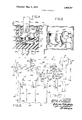
- FIG. 6 is a schematic of an electric circuit which may be utilized with the monitoring apparatus shown in FIG. 1.
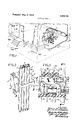
- the monitoring apparatus 11 of present invention is adapted for use with an electric furnace 15 for maintaining a predetermined temperature in a building 17.
- a thermostat 21 is disposed in the living space which is to be heated and senses a predetermined temperature to sequentially actuate electric resistance heating elements 23 in the furnace 15.
- a current sensing relay R which may be constructed in accordance with the current sensing relay R disclosed in co-pending U. S. application Ser. No. 6,529 filed Jan.
- a sensing transformer generally designated 27, that senses current to the heating elements 23 and is responsive thereto to produce an electrical signal which triggers a silicon controlled rectifier (SCR) 31 that energizes a relay coil 33 to close a relay switch, generally designated 35, in circuit with a motor 37 that drives a blower 39 for blowing air across the heating elements 23.
- SCR silicon controlled rectifier
- the current sensing transformer 27, SCR 31, relay coil 33, and switch 35 are all mounted in a relay housing, generally designated 41.
- a resistor 43 which leads from the gate of the SCR 3] to an auxiliary terminal plug prong 45 which is connected with an auxiliary manual switch 47 by means of a lead 49 whereby the fan motor 37 may be actuated independently of the furnace 15 by merely closing the switch 47.
- the furnace 15 includes a plurality of warm air distribution ducts 48 which lead to different distribution points throughout the house 17 and a cold air return duct 51 which returns cold air to the bottom of the furnace.
- one pair of heating elements 23 of the furnace 15 are connected in parallel between two poles 51 and 53 of a 240 volt source 55 by means of leads 57, 59, 61 and 63 and a second pair are connected in parallel between a second pair of poles 67 and 69 of the source 55 by means of leads 71, 73, and 79.
- Connected in series with each of the heating elements 23 are respective thermostatic blades forming element control switches 83 which are disposed in heat exchange relationship with respective drive motors 85.
- the drive motor 85 for the first control switch 83 disposed to the right in FIG. 6, is connected in series with the thermostat 21 and with the secondary coil 93 of a line transformer having its primary coil 95 connected between the poles Hand 53 of the electrical source 55.
- the remaining drive motors 85 are connected in series with their respective preceding heating elements 23 whereby sequential operation of all the elements starts with the energization of the first switch 83.
- the relay housing 41 includes a cover 101 which has a ferrous bale 103 mounted thereon to form a magnetic loop which receives the leads 57, 59, 71 and 73 to the heating elements 23. Any one ofthe leads 57, 59, 71 and 73 will serve as the primary coil for the sensing transformer 27 and the secondary coil 107 is connected between the gate and cathode of the SCR 31.
- the power circuit of the SCR 31 is connected in series with the relay coil 33 whereby such coil will be energized whenever the current induced in the sensing transformer 27 by any one or combination of the heating element leads 57, 59, 71 or 73 exceeds the triggering level of such SCR.
- the relay coil 33 is connected across the secondary transformer coil 93 and has a free-wheeling diode 109 connected thereacross to provide a path for reverse flow of current during negative going half cycles to thereby reduce hum.
- a capaciter 111 is connected across the secondary transformer coil 93 to control voltage spikes.
- Connected across the sensing coil 107 is a voltage limiting resistor l 13.
- the sensing relay housing 41 includes a base, generally designated 117, which is formed with a pair of opposed upstanding side walls 119 and 120 over which the cover 101 fits.
- the relay switch 35 is mounted on the base 117 and includes a resilient arcuate blade I25 connected on its fixed end with a plug prong terminal 126 and carrying a movable contact 127 on its free end.
- the movable contact 127 is disposed in engageable alignment with an underlying stationary contact 129 carried from a second plug prong terminal 131.
- a second stationary contact 132 is disposed above the movable contact 127 and is carried from a terminal 133 which may be connected with an auxiliary power source (not shown).
- movement of the resilient blade is controlled by an elongated ferrowmagnetic actuating arm 135 which is carried on its rear extremity from a vertical support post 137 and extends forwardly over the relay coil 33 and sandwiches a spacing post 141 between its free extremity and the intermediate portion of the resilient blade 125,
- ferro-magnetic support bar 151 spans the upper portion of the cover 101 and has the opposite ends of the bale 103 joined with its opposite ends.
- the support bar 151 extends through an axial passage in a plastic bobbin, generally designated 155, which forms a spool for receiving the windings of the sensing coil 107 and has horizontally extending flanges 157 and 159 which are formed with slots for receipt of the leads from the voltage limiting resistor 43.
- a plastic bobbin generally designated 155
- a pair of resilient jaws 163 and 165 which mount the SCR 31 therebetween.
- projecting oppositely the jaws 163 and 165 are a pair of flanges 181 and 183 which hold the voltage limiting resistor 113 therebetween.
- a lead 152 connects one side of the relay coil 33 with a plug prong terminal 153 and a lead 156 connects the other side of such coil with a plug prong terminal 158.
- a plug socket may be provided for connection with the sensing relay R and the individual socket passage receiving the plug prong 153 may be connected with the top end of the secondary coil 93 by means of a lead 187 and the individual socket passage receiving the plug prong 158 connected with the bottom end of the secondary coil 93 by means of a lead 189.
- the current sensing relay R may be mounted adjacent the furnace which, for instance, may be located in the basement of a building 17 to be heated.
- the leads 57, 59, 71 and 73 will then be threaded in the same direction through the bale 103 to produce like polarities and are connected with the respective heating elements 23.
- the thermostat 21 will then be installed in the space in which the temperature is to be controlled and leads run therefrom to the furnace and power source 55.
- the auxiliary manual switch 47 will then be installed in convenient location, which may be remote from the furnace l5 and adjacent the thermostate 21, and the lead 49 run to the relay R and connected with the terminal prong 45. In practice the switch 47 is often incorporated in the thermostat 21.
- Closure of the relay switch 35 will actuate the motor 37 to drive the fan 39 to blow air over the heating elements 23 to prevent overheating of the energized element and provide circulation through the furnace heating ducts.
- the drive motor 85 for the second stage control switch 83 is connected in series with the first stage heating element to thereby heat and close the control switch 83 connected in series with the second stage heating element 23 to thereby energize such element. This process will be continued until either the thermostat 21 discontinues its call for heat or all the heating elements 23 are energized.
- the thermostat 21 When the temperature in the room being heated reaches the predetermined level, the thermostat 21 will open the circuit to the first drive motor 85 to enable such motor to cool thereby enabling the associated control switch 83 to open to discontinue current to the first heating element 23. This process will continue for each drive motor 85 and switch 83 until the current in all the heating element leads 57, 59, 71 and 73 is discontinued and all the heating elements 23 de-energized.
- the switch 83 in the last lead 73 is opened, the current induced in the sensing coil 107 will be lowered below the triggering level of the SCR 31 to thereby discontinue current to the relay coil 33 and enable the relay switch 35 to open and de-energize the blower motor 37.
- the manual switch 47 When it is desirable to operate the blower 39 without operation of the furnace 15 to thereby circulate air in the room or rooms to which the air is ducted, the manual switch 47 is closed to thereby commence current flow through the lead 49 and a sufiicient voltage drop will be provided by the resistor 43 to impose a triggering signal on the gate of the SCR 31 to trigger such SCR. Triggering of the SCR 31 to render such SCR conductive completes a circuit from the top end of the secondary coil 93 through the lead 187 to the left hand end of the relay coil 33, through such relay coil, the SCR 31, leads 156 and 189, and to the bottom end of the secondary coil 93.
- Energization of the relay coil 33 closes the relay switch 35 to actuate the motor 37 and drive the blower 39.
- the circulated air will then be blown through the warm air ducts 48 to the various points of distribution.
- the auxiliary switch 47 may be opened to discontinue the triggering signal to the SCR 31.
- the monitoring apparatus of present invention provides a convenient means for automatically blowing air over a plurality of heating elements whenever any one of the heating elements is energized and which only requires the installation of a switch to operate the blower independently of the heating elements.
- Monitoring apparatus for use with an electrical temperature change unit comprising:
- condition sensing means responsive to a predetermined I condition to actuate said temperature change unit
- monitoring means in the form of a current sensing relay including a relay housing, relay switch means adapted for connection with said circulating means, relay coil means for controlling said relay switch means, control switch means in circuit with said current sensing means and including triggering means responsive to an electrical signal to actuate said relay coil means to close said relay switch means, and current sensing means connected with said triggering means and responsive to current flow in said temperature change unit to produce said electrical signal to actuate said relay coil means to close said relay switch means, said current sensing relay further including an electrical connector mounted on said housing and electrically connected with said triggering means; and
- a manual auxiliary actuator for connection with said electrical connector and actuable to produce an electrical signal to energize said control switch means to energize said relay coil to close said relay switch means and actuate said circulating means
- said current sensing relay may be installed to automatically actuate said circulating means when said temperature change unit is energized and said manual auxiliary actuator may be selectively installed remotely from said circulating means and a lead run from said actuator to said electrical connector so said actuator may be activated to produce said electrical signal to actuate said current sensing relay and energize said circulating means independent of said condition sensing means.
- said temperature change unit is in the form of an electrical furnace device including a plurality of electrical heaters
- said current sensing means is adapted to sense current to all heaters so said circulating means will be energized anytime any one of said heaters is energized.
- said relay switch means includes a silicon controlled rectifier having its gate in circuit with said current sensing means, and a relay having its coil in circuit with the power circuit of said silicon controlled rectifier and its contacts in circuit with said circulating means.
- said circulating means is in the form of blower means for blowing air in heat exchange relationship with said temperature change unit and said apparatus includes:
- thermostat switch means connected with said triggering means
- thermostat switch means and auxiliary actuator may be mounted remotely from said monitoring and only said first, second and third leads means run therebetween.
- Monitoring apparatus as set forth in claim 4 that includes:
- an electrical transformer having a high voltage coil and a low voltage coil
- an electrical transformer having a high voltage primary coil and a low voltage secondary coil
- first lead means connecting said temperature change unit across said primary coil
- said triggering means is responsive to a relatively low voltage electrical signal
- said auxiliary actuator includes an auxiliary switch
- said apparatus includes circuit means for connecting said auxiliary switch with a relatively high voltage source and including resistance means for limiting the voltage on said triggering means to said relatively low voltage.
- said electrical connector is in the form of a plug prong terminal in circuit with said triggering means for connection with a plug socket connected with said auxiliary actuator.
Landscapes
- Physics & Mathematics (AREA)
- General Physics & Mathematics (AREA)
- Engineering & Computer Science (AREA)
- Automation & Control Theory (AREA)
- Control Of Resistance Heating (AREA)
Abstract
Monitoring apparatus for controlling a circulating means which circulates a fluid in heat exchange relationship with a temperature change unit. Condition sensing means is provided for actuating the temperature change unit when a predetermined condition is sensed. Monitoring means includes a housing which mounts a current sensing means which is responsive to current flow in the temperature change unit to produce an electrical signal. An automatic actuator is mounted in the housing and is connected in circuit with the current sensing means and is responsive to such electrical signal to actuate the circulating means. An auxiliary actuator is connected in circuit with the automatic actuator and is actuable to produce an electric signal to actuate the circulating means independently of the temperature change unit whereby the circulating means can be actuated by the auxiliary actuator independently of the temperature change unit.
Description
United States Patent Graham et al.
[72] Inventors: Marvin M. Graham, Seal Beach; William W. Chambers, Anaheim, both of Calif.
[451 May 2, 1972 Primary Examiner-Edward J. Michael AltorneyFulwider, Patton, Rieber, Lee & Utecht ABSTRACT Monitoring apparatus for controlling a circulating means which circulates a fluid in heat exchange relationship with a temperature change unit. Condition sensing means is provided for actuating the temperature change unit when a predetermined condition is sensed. Monitoring means includes a housing which mounts a current sensing means which is responsive to current flow in the temperature change unit to produce an electrical signal. An automatic actuator is mounted in the housing and is connected in circuit with the current sensing means and is responsive to such electrical signal to actuate the circulating means. An auxiliary actuator is connected in circuit with the automatic actuator and is actuable to produce an electric signal to actuate the circulating means independently of the temperature change unit whereby the circulating means can be actuated by the auxiliary actuator independently of the temperature change unit.
8 Claims, 6 Drawing Figures MONITORING APPARATUS HAVING AUXILIARY SWITCHING MEANS BACKGROUND OF THE INVENTION 1 Field of the Invention The present invention relates to a control apparatus which includes a monitoring means for actuating a circulating means whenever a temperature change unit is actuated to circulate fluid in heat exchange relationship therein.
2. Description of the Prior Art There are no prior art control devices known to applicant which include current sensing means for automatically actuating circulating means whenever a temperature change unit is actuated and also an auxiliary actuator for actuating the circulating means independently of the temperature change unit.
SUMMARY OF THE INVENTION The monitoring apparatus of present invention is characterized by a current sensing means which senses actuation of a temperature change unit to produce an electrical signal. An automatic actuator is connected in circuit with the current sensing means and is responsive to the electrical signal to operate a circulating means which circulates fluid in heat exchange relationship with the temperature change unit. An auxiliary actuator is connected in circuit with the automatic actuation means to produce an electrical signal to actuate the automatic actuator to energize the circulating means independently of the temperature change unit.
It is an object of the present invention to provide a monitoring apparatus of the type described which includes a single relay which automatically monitors a temperature change unit and which can be actuated independently thereof by an auxiliary switch.
It is an object of the present invention to provide a monitoring apparatus of the type described wherein a majority of the components are mounted in a single housing which can be mounted adjacent the temperature change unit and only a minimum number of electrical leads need be run to the remotely disposed condition sensing means and auxiliary actuator.
Another object of the present invention is to provide a monitoring apparatus of the type described wherein the auxiliary actuator can be conveniently added to the automatic actuator after such means has been installed.
These and other objects and the advantages of the present invention will become apparent from a consideration of the following detailed description when taken in conjunction with the accompanying drawings.
DESCRIPTION OF THE DRAWINGS of FIG. 3;
FIG. 5 is a horizontal sectional view taken along the line 5- 5 of FIG. 3; and
FIG. 6 is a schematic of an electric circuit which may be utilized with the monitoring apparatus shown in FIG. 1.
DESCRIPTION OF THE PREFERRED EMBODIMENT Referring to FIGS. 1 and 6, generally, the monitoring apparatus 11 of present invention is adapted for use with an electric furnace 15 for maintaining a predetermined temperature in a building 17. Referring to FIGS. 1 and 6, a thermostat 21 is disposed in the living space which is to be heated and senses a predetermined temperature to sequentially actuate electric resistance heating elements 23 in the furnace 15. A current sensing relay R, which may be constructed in accordance with the current sensing relay R disclosed in co-pending U. S. application Ser. No. 6,529 filed Jan. 28, 1970, includes a sensing transformer, generally designated 27, that senses current to the heating elements 23 and is responsive thereto to produce an electrical signal which triggers a silicon controlled rectifier (SCR) 31 that energizes a relay coil 33 to close a relay switch, generally designated 35, in circuit with a motor 37 that drives a blower 39 for blowing air across the heating elements 23. Referring to FIGS. 4 and 6, the current sensing transformer 27, SCR 31, relay coil 33, and switch 35 are all mounted in a relay housing, generally designated 41. Also mounted in the relay housing 41 is a resistor 43 which leads from the gate of the SCR 3] to an auxiliary terminal plug prong 45 which is connected with an auxiliary manual switch 47 by means of a lead 49 whereby the fan motor 37 may be actuated independently of the furnace 15 by merely closing the switch 47.
Still referring to FIG. 1, the furnace 15 includes a plurality of warm air distribution ducts 48 which lead to different distribution points throughout the house 17 and a cold air return duct 51 which returns cold air to the bottom of the furnace.
Referring to FIG. 6, one pair of heating elements 23 of the furnace 15 are connected in parallel between two poles 51 and 53 of a 240 volt source 55 by means of leads 57, 59, 61 and 63 and a second pair are connected in parallel between a second pair of poles 67 and 69 of the source 55 by means of leads 71, 73, and 79. Connected in series with each of the heating elements 23 are respective thermostatic blades forming element control switches 83 which are disposed in heat exchange relationship with respective drive motors 85. The drive motor 85 for the first control switch 83, disposed to the right in FIG. 6, is connected in series with the thermostat 21 and with the secondary coil 93 of a line transformer having its primary coil 95 connected between the poles Hand 53 of the electrical source 55. The remaining drive motors 85 are connected in series with their respective preceding heating elements 23 whereby sequential operation of all the elements starts with the energization of the first switch 83.
The relay housing 41 includes a cover 101 which has a ferrous bale 103 mounted thereon to form a magnetic loop which receives the leads 57, 59, 71 and 73 to the heating elements 23. Any one ofthe leads 57, 59, 71 and 73 will serve as the primary coil for the sensing transformer 27 and the secondary coil 107 is connected between the gate and cathode of the SCR 31. The power circuit of the SCR 31 is connected in series with the relay coil 33 whereby such coil will be energized whenever the current induced in the sensing transformer 27 by any one or combination of the heating element leads 57, 59, 71 or 73 exceeds the triggering level of such SCR. The relay coil 33 is connected across the secondary transformer coil 93 and has a free-wheeling diode 109 connected thereacross to provide a path for reverse flow of current during negative going half cycles to thereby reduce hum. A capaciter 111 is connected across the secondary transformer coil 93 to control voltage spikes. Connected across the sensing coil 107 is a voltage limiting resistor l 13.
Referring to FIGS. 3 and 4, the sensing relay housing 41 includes a base, generally designated 117, which is formed with a pair of opposed upstanding side walls 119 and 120 over which the cover 101 fits. The relay switch 35 is mounted on the base 117 and includes a resilient arcuate blade I25 connected on its fixed end with a plug prong terminal 126 and carrying a movable contact 127 on its free end. The movable contact 127 is disposed in engageable alignment with an underlying stationary contact 129 carried from a second plug prong terminal 131. A second stationary contact 132 is disposed above the movable contact 127 and is carried from a terminal 133 which may be connected with an auxiliary power source (not shown).
Referring to FIG. 3, movement of the resilient blade is controlled by an elongated ferrowmagnetic actuating arm 135 which is carried on its rear extremity from a vertical support post 137 and extends forwardly over the relay coil 33 and sandwiches a spacing post 141 between its free extremity and the intermediate portion of the resilient blade 125,
Referring to FIG. 5, ferro-magnetic support bar 151 spans the upper portion of the cover 101 and has the opposite ends of the bale 103 joined with its opposite ends. The support bar 151 extends through an axial passage in a plastic bobbin, generally designated 155, which forms a spool for receiving the windings of the sensing coil 107 and has horizontally extending flanges 157 and 159 which are formed with slots for receipt of the leads from the voltage limiting resistor 43. Referring to FIG. 4, also, extending horizontally from the bobbin 155 are a pair of resilient jaws 163 and 165 which mount the SCR 31 therebetween. Still referring to FIG. 4, projecting oppositely the jaws 163 and 165 are a pair of flanges 181 and 183 which hold the voltage limiting resistor 113 therebetween.
A lead 152 connects one side of the relay coil 33 with a plug prong terminal 153 and a lead 156 connects the other side of such coil with a plug prong terminal 158. Thus, on installation a plug socket may be provided for connection with the sensing relay R and the individual socket passage receiving the plug prong 153 may be connected with the top end of the secondary coil 93 by means of a lead 187 and the individual socket passage receiving the plug prong 158 connected with the bottom end of the secondary coil 93 by means of a lead 189.
In operation, the current sensing relay R may be mounted adjacent the furnace which, for instance, may be located in the basement of a building 17 to be heated. The leads 57, 59, 71 and 73 will then be threaded in the same direction through the bale 103 to produce like polarities and are connected with the respective heating elements 23. The thermostat 21 will then be installed in the space in which the temperature is to be controlled and leads run therefrom to the furnace and power source 55. The auxiliary manual switch 47 will then be installed in convenient location, which may be remote from the furnace l5 and adjacent the thermostate 21, and the lead 49 run to the relay R and connected with the terminal prong 45. In practice the switch 47 is often incorporated in the thermostat 21.
When the temperature drops sufficiently low for the thermostat 21 to call for heat, its switch contacts will close thereby energizing the drive motor 85 disposed on the right hand side of FIG. 6 to heat and close the associated control switch 83 and commence current flow through the lead 57 to the first heating element 23. Current flow through the lead 57 will induce current in the secondary coil 107 of the sensing transformer to thereby provide a triggering signal to the SCR 31 which will be triggered to energize the relay coil 33. The energized coil 33 attracts the actuating arm 135 to flex the resilient blade 125 downwardly to close the contacts 127 and 129 of the relay switch 135. Closure of the relay switch 35 will actuate the motor 37 to drive the fan 39 to blow air over the heating elements 23 to prevent overheating of the energized element and provide circulation through the furnace heating ducts. The drive motor 85 for the second stage control switch 83 is connected in series with the first stage heating element to thereby heat and close the control switch 83 connected in series with the second stage heating element 23 to thereby energize such element. This process will be continued until either the thermostat 21 discontinues its call for heat or all the heating elements 23 are energized.
When the temperature in the room being heated reaches the predetermined level, the thermostat 21 will open the circuit to the first drive motor 85 to enable such motor to cool thereby enabling the associated control switch 83 to open to discontinue current to the first heating element 23. This process will continue for each drive motor 85 and switch 83 until the current in all the heating element leads 57, 59, 71 and 73 is discontinued and all the heating elements 23 de-energized. When the switch 83 in the last lead 73 is opened, the current induced in the sensing coil 107 will be lowered below the triggering level of the SCR 31 to thereby discontinue current to the relay coil 33 and enable the relay switch 35 to open and de-energize the blower motor 37.
When it is desirable to operate the blower 39 without operation of the furnace 15 to thereby circulate air in the room or rooms to which the air is ducted, the manual switch 47 is closed to thereby commence current flow through the lead 49 and a sufiicient voltage drop will be provided by the resistor 43 to impose a triggering signal on the gate of the SCR 31 to trigger such SCR. Triggering of the SCR 31 to render such SCR conductive completes a circuit from the top end of the secondary coil 93 through the lead 187 to the left hand end of the relay coil 33, through such relay coil, the SCR 31, leads 156 and 189, and to the bottom end of the secondary coil 93. Energization of the relay coil 33 closes the relay switch 35 to actuate the motor 37 and drive the blower 39. The circulated air will then be blown through the warm air ducts 48 to the various points of distribution. When air circulation is to be discontinued, the auxiliary switch 47 may be opened to discontinue the triggering signal to the SCR 31.
From the foregoing it will be apparent that the monitoring apparatus of present invention provides a convenient means for automatically blowing air over a plurality of heating elements whenever any one of the heating elements is energized and which only requires the installation of a switch to operate the blower independently of the heating elements.
Various modifications and changes may be made with regard to the foregoing without departing from the spirit of the invention.
What is claimed is:
1. Monitoring apparatus for use with an electrical temperature change unit, said apparatus comprising:
circulating means for circulating a fluid in heat exchange relationship with said temperature change unit;
condition sensing means responsive to a predetermined I condition to actuate said temperature change unit;
monitoring means in the form of a current sensing relay including a relay housing, relay switch means adapted for connection with said circulating means, relay coil means for controlling said relay switch means, control switch means in circuit with said current sensing means and including triggering means responsive to an electrical signal to actuate said relay coil means to close said relay switch means, and current sensing means connected with said triggering means and responsive to current flow in said temperature change unit to produce said electrical signal to actuate said relay coil means to close said relay switch means, said current sensing relay further including an electrical connector mounted on said housing and electrically connected with said triggering means; and
a manual auxiliary actuator for connection with said electrical connector and actuable to produce an electrical signal to energize said control switch means to energize said relay coil to close said relay switch means and actuate said circulating means whereby said current sensing relay may be installed to automatically actuate said circulating means when said temperature change unit is energized and said manual auxiliary actuator may be selectively installed remotely from said circulating means and a lead run from said actuator to said electrical connector so said actuator may be activated to produce said electrical signal to actuate said current sensing relay and energize said circulating means independent of said condition sensing means.
2. Monitoring apparatus as set forth in claim 1 wherein said temperature change unit is in the form of an electrical furnace device including a plurality of electrical heaters; and
said current sensing means is adapted to sense current to all heaters so said circulating means will be energized anytime any one of said heaters is energized.
3. Monitoring apparatus as set forth in claim 1 wherein:
said relay switch means includes a silicon controlled rectifier having its gate in circuit with said current sensing means, and a relay having its coil in circuit with the power circuit of said silicon controlled rectifier and its contacts in circuit with said circulating means.
4. Monitoring apparatus as set forth in claim 1 wherein:
said circulating means is in the form of blower means for blowing air in heat exchange relationship with said temperature change unit and said apparatus includes:
thermostat switch means connected with said triggering means;
first lead means connecting one side of said thermostat switch means and said auxiliary actuator with one side of said control switch means; and
second and third lead means connecting the respective sides of said thermostat switch and auxiliary actuator opposite said respective one sides with the side of said control switch means opposite said one side whereby said thermostat switch means and auxiliary actuator may be mounted remotely from said monitoring and only said first, second and third leads means run therebetween.
5. Monitoring apparatus as set forth in claim 4 that includes:
an electrical transformer having a high voltage coil and a low voltage coil;
fourth lead means connecting said temperature change unit across said primary coil; and
fifth lead means connecting said triggering means and said auxiliary actuator in circuit with said secondary coil whereby said auxiliary actuator will be subjected to said relatively low voltages.
6. Monitoring apparatus as set forth in claim 1 that includes:
an electrical transformer having a high voltage primary coil and a low voltage secondary coil;
first lead means connecting said temperature change unit across said primary coil; and
second lead means connecting said triggering means and said auxiliary actuator in circuit with said secondary coil whereby said auxiliary actuator will be subjected to said relatively low voltages.
7. Monitoring apparatus as set forth in claim 1 wherein:
said triggering means is responsive to a relatively low voltage electrical signal;
said auxiliary actuator includes an auxiliary switch; and
said apparatus includes circuit means for connecting said auxiliary switch with a relatively high voltage source and including resistance means for limiting the voltage on said triggering means to said relatively low voltage.
8. Monitoring apparatus as set forth in claim 1 wherein:
said electrical connector is in the form of a plug prong terminal in circuit with said triggering means for connection with a plug socket connected with said auxiliary actuator.
Claims (8)
1. Monitoring apparatus for use with an electrical temperature change unit, said apparatus comprising: circulating means for circulating a fluid in heat exchange relationship with said temperature change unit; condition sensing means responsive to a predetermined condition to actuate said temperature change unit; monitoring means in the form of a current sensing relay including a relay housing, relay switch means adapted for connection with said circulating means, relay coil means for controlling said relay switch means, control switch means in circuit with said current sensing means and including triggering means responsive to an electrical sigNal to actuate said relay coil means to close said relay switch means, and current sensing means connected with said triggering means and responsive to current flow in said temperature change unit to produce said electrical signal to actuate said relay coil means to close said relay switch means, said current sensing relay further including an electrical connector mounted on said housing and electrically connected with said triggering means; and a manual auxiliary actuator for connection with said electrical connector and actuable to produce an electrical signal to energize said control switch means to energize said relay coil to close said relay switch means and actuate said circulating means whereby said current sensing relay may be installed to automatically actuate said circulating means when said temperature change unit is energized and said manual auxiliary actuator may be selectively installed remotely from said circulating means and a lead run from said actuator to said electrical connector so said actuator may be activated to produce said electrical signal to actuate said current sensing relay and energize said circulating means independent of said condition sensing means.
2. Monitoring apparatus as set forth in claim 1 wherein said temperature change unit is in the form of an electrical furnace device including a plurality of electrical heaters; and said current sensing means is adapted to sense current to all heaters so said circulating means will be energized anytime any one of said heaters is energized.
3. Monitoring apparatus as set forth in claim 1 wherein: said relay switch means includes a silicon controlled rectifier having its gate in circuit with said current sensing means, and a relay having its coil in circuit with the power circuit of said silicon controlled rectifier and its contacts in circuit with said circulating means.
4. Monitoring apparatus as set forth in claim 1 wherein: said circulating means is in the form of blower means for blowing air in heat exchange relationship with said temperature change unit and said apparatus includes: thermostat switch means connected with said triggering means; first lead means connecting one side of said thermostat switch means and said auxiliary actuator with one side of said control switch means; and second and third lead means connecting the respective sides of said thermostat switch and auxiliary actuator opposite said respective one sides with the side of said control switch means opposite said one side whereby said thermostat switch means and auxiliary actuator may be mounted remotely from said monitoring and only said first, second and third leads means run therebetween.
5. Monitoring apparatus as set forth in claim 4 that includes: an electrical transformer having a high voltage coil and a low voltage coil; fourth lead means connecting said temperature change unit across said primary coil; and fifth lead means connecting said triggering means and said auxiliary actuator in circuit with said secondary coil whereby said auxiliary actuator will be subjected to said relatively low voltages.
6. Monitoring apparatus as set forth in claim 1 that includes: an electrical transformer having a high voltage primary coil and a low voltage secondary coil; first lead means connecting said temperature change unit across said primary coil; and second lead means connecting said triggering means and said auxiliary actuator in circuit with said secondary coil whereby said auxiliary actuator will be subjected to said relatively low voltages.
7. Monitoring apparatus as set forth in claim 1 wherein: said triggering means is responsive to a relatively low voltage electrical signal; said auxiliary actuator includes an auxiliary switch; and said apparatus includes circuit means for connecting said auxiliary switch with a relatively high voltage source and including resistance means for limiting the voltage on said triggering mEans to said relatively low voltage.
8. Monitoring apparatus as set forth in claim 1 wherein: said electrical connector is in the form of a plug prong terminal in circuit with said triggering means for connection with a plug socket connected with said auxiliary actuator.
Applications Claiming Priority (1)
| Application Number | Priority Date | Filing Date | Title |
|---|---|---|---|
| US87597769A | 1969-11-12 | 1969-11-12 |
Publications (1)
| Publication Number | Publication Date |
|---|---|
| US3659781A true US3659781A (en) | 1972-05-02 |
Family
ID=25366701
Family Applications (1)
| Application Number | Title | Priority Date | Filing Date |
|---|---|---|---|
| US875977A Expired - Lifetime US3659781A (en) | 1969-11-12 | 1969-11-12 | Monitoring apparatus having auxiliary switching means |
Country Status (1)
| Country | Link |
|---|---|
| US (1) | US3659781A (en) |
Cited By (2)
| Publication number | Priority date | Publication date | Assignee | Title |
|---|---|---|---|---|
| US6294767B1 (en) * | 1997-01-30 | 2001-09-25 | Fisher & Paykel Limited | Dishwasher |
| US20070006603A1 (en) * | 2005-07-11 | 2007-01-11 | Allied Precision Industries, Inc. | Systems and methods for a temperature-controlled electrical outlet |
Citations (4)
| Publication number | Priority date | Publication date | Assignee | Title |
|---|---|---|---|---|
| US2269036A (en) * | 1938-09-24 | 1942-01-06 | Honeywell Regulator Co | Summer-winter air conditioning control system |
| US2498054A (en) * | 1945-11-20 | 1950-02-21 | Riley H Taylor | Electric heating system with modulating control |
| US3158319A (en) * | 1963-03-25 | 1964-11-24 | Honeywell Inc | Control apparatus |
| US3489345A (en) * | 1967-02-27 | 1970-01-13 | White Consolidated Ind Inc | Heater control |
-
1969
- 1969-11-12 US US875977A patent/US3659781A/en not_active Expired - Lifetime
Patent Citations (4)
| Publication number | Priority date | Publication date | Assignee | Title |
|---|---|---|---|---|
| US2269036A (en) * | 1938-09-24 | 1942-01-06 | Honeywell Regulator Co | Summer-winter air conditioning control system |
| US2498054A (en) * | 1945-11-20 | 1950-02-21 | Riley H Taylor | Electric heating system with modulating control |
| US3158319A (en) * | 1963-03-25 | 1964-11-24 | Honeywell Inc | Control apparatus |
| US3489345A (en) * | 1967-02-27 | 1970-01-13 | White Consolidated Ind Inc | Heater control |
Cited By (3)
| Publication number | Priority date | Publication date | Assignee | Title |
|---|---|---|---|---|
| US6294767B1 (en) * | 1997-01-30 | 2001-09-25 | Fisher & Paykel Limited | Dishwasher |
| US20070006603A1 (en) * | 2005-07-11 | 2007-01-11 | Allied Precision Industries, Inc. | Systems and methods for a temperature-controlled electrical outlet |
| US8680442B2 (en) * | 2005-07-11 | 2014-03-25 | Allied Precision Industries Inc. | Systems and methods for a temperature-controlled electrical outlet |
Similar Documents
| Publication | Publication Date | Title |
|---|---|---|
| US4009825A (en) | Control for forced air heating or cooling system | |
| US3934797A (en) | Individual room temperature control system | |
| US3959979A (en) | Dual voltage forced air heat exchanger | |
| US3351739A (en) | Control system for electrically heated boiler | |
| US3659781A (en) | Monitoring apparatus having auxiliary switching means | |
| US3486081A (en) | Extension thermostat and adapter assembly | |
| US3209125A (en) | Humidifier | |
| US3852695A (en) | Electrical switching system | |
| US3958100A (en) | Means for preventing heat build-up in a wall-mounted room ventilator | |
| US4298165A (en) | Controls for heating system | |
| US2450478A (en) | Automatic electric fluid heating and cooling system | |
| US1708580A (en) | Heating system | |
| US2262341A (en) | System for controlling the flow of heating mediums | |
| US3312398A (en) | Humidity controller with thermal relay | |
| US4673028A (en) | Automatic thermostatic control system for heater and evaporative cooler | |
| US3267994A (en) | Household conditioning system | |
| US3599710A (en) | Relay-type control for air conditioner | |
| US2064389A (en) | Unit heater | |
| US4851747A (en) | Non-precise heat control operation periodic positive & reverse circulating fan | |
| US3659155A (en) | Current sensing apparatus | |
| US3587558A (en) | Furnace having multiple speed motor and accessory control system | |
| US3339628A (en) | Electrically controlled heating system | |
| US2053771A (en) | Air conditioning system | |
| US543929A (en) | Electric temperature-controlling device | |
| GB1190323A (en) | Control means for Electrical Storage Heaters |