DE102009046084A1 - Household appliance, in particular dishwasher - Google Patents
Household appliance, in particular dishwasher Download PDFInfo
- Publication number
- DE102009046084A1 DE102009046084A1 DE102009046084A DE102009046084A DE102009046084A1 DE 102009046084 A1 DE102009046084 A1 DE 102009046084A1 DE 102009046084 A DE102009046084 A DE 102009046084A DE 102009046084 A DE102009046084 A DE 102009046084A DE 102009046084 A1 DE102009046084 A1 DE 102009046084A1
- Authority
- DE
- Germany
- Prior art keywords
- current
- domestic appliance
- appliance according
- device component
- monitoring unit
- Prior art date
- Legal status (The legal status is an assumption and is not a legal conclusion. Google has not performed a legal analysis and makes no representation as to the accuracy of the status listed.)
- Withdrawn
Links
Images


Classifications
-
- A—HUMAN NECESSITIES
- A47—FURNITURE; DOMESTIC ARTICLES OR APPLIANCES; COFFEE MILLS; SPICE MILLS; SUCTION CLEANERS IN GENERAL
- A47L—DOMESTIC WASHING OR CLEANING; SUCTION CLEANERS IN GENERAL
- A47L15/00—Washing or rinsing machines for crockery or tableware
- A47L15/0018—Controlling processes, i.e. processes to control the operation of the machine characterised by the purpose or target of the control
- A47L15/0049—Detection or prevention of malfunction, including accident prevention
-
- A—HUMAN NECESSITIES
- A47—FURNITURE; DOMESTIC ARTICLES OR APPLIANCES; COFFEE MILLS; SPICE MILLS; SUCTION CLEANERS IN GENERAL
- A47L—DOMESTIC WASHING OR CLEANING; SUCTION CLEANERS IN GENERAL
- A47L15/00—Washing or rinsing machines for crockery or tableware
- A47L15/42—Details
- A47L15/46—Devices for the automatic control of the different phases of cleaning ; Controlling devices
-
- D—TEXTILES; PAPER
- D06—TREATMENT OF TEXTILES OR THE LIKE; LAUNDERING; FLEXIBLE MATERIALS NOT OTHERWISE PROVIDED FOR
- D06F—LAUNDERING, DRYING, IRONING, PRESSING OR FOLDING TEXTILE ARTICLES
- D06F33/00—Control of operations performed in washing machines or washer-dryers
- D06F33/30—Control of washing machines characterised by the purpose or target of the control
- D06F33/47—Responding to irregular working conditions, e.g. malfunctioning of pumps
-
- A—HUMAN NECESSITIES
- A47—FURNITURE; DOMESTIC ARTICLES OR APPLIANCES; COFFEE MILLS; SPICE MILLS; SUCTION CLEANERS IN GENERAL
- A47L—DOMESTIC WASHING OR CLEANING; SUCTION CLEANERS IN GENERAL
- A47L15/00—Washing or rinsing machines for crockery or tableware
- A47L15/42—Details
- A47L15/4214—Water supply, recirculation or discharge arrangements; Devices therefor
- A47L15/4217—Fittings for water supply, e.g. valves or plumbing means to connect to cold or warm water lines, aquastops
-
- A—HUMAN NECESSITIES
- A47—FURNITURE; DOMESTIC ARTICLES OR APPLIANCES; COFFEE MILLS; SPICE MILLS; SUCTION CLEANERS IN GENERAL
- A47L—DOMESTIC WASHING OR CLEANING; SUCTION CLEANERS IN GENERAL
- A47L15/00—Washing or rinsing machines for crockery or tableware
- A47L15/42—Details
- A47L15/4214—Water supply, recirculation or discharge arrangements; Devices therefor
- A47L15/4219—Water recirculation
- A47L15/4221—Arrangements for redirection of washing water, e.g. water diverters to selectively supply the spray arms
-
- A—HUMAN NECESSITIES
- A47—FURNITURE; DOMESTIC ARTICLES OR APPLIANCES; COFFEE MILLS; SPICE MILLS; SUCTION CLEANERS IN GENERAL
- A47L—DOMESTIC WASHING OR CLEANING; SUCTION CLEANERS IN GENERAL
- A47L15/00—Washing or rinsing machines for crockery or tableware
- A47L15/42—Details
- A47L15/4291—Recovery arrangements, e.g. for the recovery of energy or water
-
- A—HUMAN NECESSITIES
- A47—FURNITURE; DOMESTIC ARTICLES OR APPLIANCES; COFFEE MILLS; SPICE MILLS; SUCTION CLEANERS IN GENERAL
- A47L—DOMESTIC WASHING OR CLEANING; SUCTION CLEANERS IN GENERAL
- A47L2401/00—Automatic detection in controlling methods of washing or rinsing machines for crockery or tableware, e.g. information provided by sensors entered into controlling devices
- A47L2401/30—Variation of electrical, magnetical or optical quantities
-
- A—HUMAN NECESSITIES
- A47—FURNITURE; DOMESTIC ARTICLES OR APPLIANCES; COFFEE MILLS; SPICE MILLS; SUCTION CLEANERS IN GENERAL
- A47L—DOMESTIC WASHING OR CLEANING; SUCTION CLEANERS IN GENERAL
- A47L2501/00—Output in controlling method of washing or rinsing machines for crockery or tableware, i.e. quantities or components controlled, or actions performed by the controlling device executing the controlling method
- A47L2501/32—Stopping or disabling machine operation, including disconnecting the machine from a network, e.g. from an electrical power supply
-
- D—TEXTILES; PAPER
- D06—TREATMENT OF TEXTILES OR THE LIKE; LAUNDERING; FLEXIBLE MATERIALS NOT OTHERWISE PROVIDED FOR
- D06F—LAUNDERING, DRYING, IRONING, PRESSING OR FOLDING TEXTILE ARTICLES
- D06F2103/00—Parameters monitored or detected for the control of domestic laundry washing machines, washer-dryers or laundry dryers
- D06F2103/44—Current or voltage
-
- D—TEXTILES; PAPER
- D06—TREATMENT OF TEXTILES OR THE LIKE; LAUNDERING; FLEXIBLE MATERIALS NOT OTHERWISE PROVIDED FOR
- D06F—LAUNDERING, DRYING, IRONING, PRESSING OR FOLDING TEXTILE ARTICLES
- D06F2105/00—Systems or parameters controlled or affected by the control systems of washing machines, washer-dryers or laundry dryers
- D06F2105/58—Indications or alarms to the control system or to the user
-
- D—TEXTILES; PAPER
- D06—TREATMENT OF TEXTILES OR THE LIKE; LAUNDERING; FLEXIBLE MATERIALS NOT OTHERWISE PROVIDED FOR
- D06F—LAUNDERING, DRYING, IRONING, PRESSING OR FOLDING TEXTILE ARTICLES
- D06F2105/00—Systems or parameters controlled or affected by the control systems of washing machines, washer-dryers or laundry dryers
- D06F2105/62—Stopping or disabling machine operation
-
- D—TEXTILES; PAPER
- D06—TREATMENT OF TEXTILES OR THE LIKE; LAUNDERING; FLEXIBLE MATERIALS NOT OTHERWISE PROVIDED FOR
- D06F—LAUNDERING, DRYING, IRONING, PRESSING OR FOLDING TEXTILE ARTICLES
- D06F37/00—Details specific to washing machines covered by groups D06F21/00 - D06F25/00
- D06F37/42—Safety arrangements, e.g. for stopping rotation of the receptacle upon opening of the casing door
-
- G—PHYSICS
- G01—MEASURING; TESTING
- G01R—MEASURING ELECTRIC VARIABLES; MEASURING MAGNETIC VARIABLES
- G01R31/00—Arrangements for testing electric properties; Arrangements for locating electric faults; Arrangements for electrical testing characterised by what is being tested not provided for elsewhere
- G01R31/50—Testing of electric apparatus, lines, cables or components for short-circuits, continuity, leakage current or incorrect line connections
- G01R31/52—Testing for short-circuits, leakage current or ground faults
Landscapes
- Engineering & Computer Science (AREA)
- Textile Engineering (AREA)
- Washing And Drying Of Tableware (AREA)
Abstract
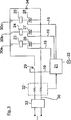
Die Erfindung betrifft ein Haushaltsgerät, insbesondere Geschirrspülmaschine, mit zumindest einer Gerätekomponente (23, 24, 25), die über eine Arbeitsleitung (30) mit elektrischem Strom versorgbar ist, und einer Überwachungseinheit (32), mit der ein durch die Arbeitsleitung (30) in wenigstens einem Fehlerfall fließender Fehlerstrom erfasst werden kann. Erfindungsgemäß ist mittels der Überwachungseinheit (32) zur Gerätekomponente (23, 24, 25) fließender Strom und ein davon abfließender Strom erfassbar.The invention relates to a household appliance, in particular a dishwasher, with at least one appliance component (23, 24, 25) which can be supplied with electrical current via a working line (30) and a monitoring unit (32) with which a through the working line (30) flowing fault current can be detected in at least one fault case. According to the invention, current flowing to the device component (23, 24, 25) and a current flowing away from it can be detected by means of the monitoring unit (32).
Description
Die Erfindung betrifft ein Haushaltsgerät, insbesondere eine Geschirrspülmaschine, mit zumindest einer Gerätekomponente, die über eine Arbeitsleitung mit elektrischem Strom versorgbar ist, und einer Überwachungseinheit, mit der ein durch die Arbeitsleitung in einem Fehlerfall fließender Fehlerstrom erfasst werden kann.The invention relates to a domestic appliance, in particular a dishwasher, with at least one device component which can be supplied with electrical power via a working line, and a monitoring unit with which a residual current flowing through the working line in the event of a fault can be detected.
Im Spülflüssigkeitskreislauf einer Geschirrspülmaschine sind bekanntermaßen Gerätekomponenten, etwa ein Zulaufventil, ein Regenerierventil und/oder eine Wasserweiche, geschaltet. Diese können elektromagnetisch betätigbare Stellglieder oder Aktoren aufweisen, die mittels einer Steuereinrichtung ansteuerbar sind und über eine Arbeitsleitung mit elektrischem Strom versorgbar ist. Hierzu ist jedem Aktor ein Ansteuerelement zugeordnet, das in der zum Aktor führenden Arbeitsleitung angeordnet ist und von der Steuereinrichtung ansteuerbar ist. In der Geschlossenstellung des Ansteuerelementes ist die Stromversorgung zum Aktor unterbrochen, während in der Offenstellung des Ansteuerelementes die Stromversorgung zum Aktor freigegeben ist. Das Ansteuerelement des Aktors kann ein Triac, ein Relais, ein Transistor oder ein Mosfet sein.As is known, device components, such as an inlet valve, a regeneration valve and / or a water diverter, are connected in the rinsing fluid circuit of a dishwasher. These may comprise electromagnetically operable actuators or actuators, which are controllable by means of a control device and can be supplied with electrical current via a working line. For this purpose, a control element is associated with each actuator, which is arranged in the leading to the actuator working line and can be controlled by the control device. In the closed position of the drive element, the power supply to the actuator is interrupted, while in the open position of the drive element, the power supply to the actuator is released. The drive element of the actuator can be a triac, a relay, a transistor or a mosfet.
Im Falle des Zulaufventils, des Regenerierventils oder der Wasserweiche sind deren Aktoren während eines Spülzyklus insgesamt lediglich über eine Zeitdauer von wenigen Minuten in Betrieb. Aus Gründen der Betriebssicherheit sind jedoch diese Aktoren für einen Dauerbetrieb auszulegen. Ein solcher Dauerbetrieb des Aktors würde sich bei einem Fehlerfall ergeben, in dem der Triac defekt ist und daher dauerhaft stromleitend ist. In diesem Fall würde der zugeordnete Aktor dauerhaft angesteuert sein. Die Aktoren sind daher für den Normalbetrieb, in dem diese lediglich kurzzeitig in Betrieb sind, weit überdimensioniert.In the case of the inlet valve, the regeneration valve or the water diverter their actuators during a rinse cycle in total only over a period of a few minutes in operation. For reasons of reliability, however, these actuators are designed for continuous operation. Such a continuous operation of the actuator would result in an error case in which the triac is defective and therefore permanently conductive. In this case, the associated actuator would be permanently activated. The actuators are therefore far oversized for normal operation in which they are only briefly in operation.
Bei Haushaltsgeräten, etwa der oben genannten Geschirrspülmaschine, können unterschiedliche Fehlerfälle auftreten. So kann eines der Ansteuerelemente durchbrennen, wodurch dieses dauerhaft stromleitend wird. In diesem Fall würde der dem defekten Ansteuerelement zugeordnete Aktor in unzulässiger Weise im Dauerbetrieb arbeiten.For household appliances, such as the above-mentioned dishwasher, different error cases can occur. Thus, one of the drive elements can burn out, as a result of which it becomes permanently conductive. In this case, the actuator associated with the defective control element would operate in an impermissible manner in continuous operation.
In einem weiteren Fehlerfall können unzulässige Kriechströme im Haushaltsgerät auftreten. Ein solcher Fehlerfall kann in einem, aus der
Aus der
Die Aufgabe der Erfindung besteht darin, ein Haushaltsgerät, insbesondere eine Geschirrspülmaschine, bereitzustellen, bei dem in einfacher sowie zuverlässiger Weise die Betriebssicherheit gewährleistet ist.The object of the invention is to provide a household appliance, in particular a dishwasher, in which the reliability is ensured in a simple and reliable manner.
Erfindungsgemäß ist mittels der Überwachungseinheit ein zu der Gerätekomponente fließender Strom und ein davon abfließender Strom erfassbar. Somit können mit der Überwachungseinheit verschiedene Fehlerfälle erfasst werden, und es sind erweiterte Diagnosemöglichkeiten gegeben, da durch Erfassung des zufließenden und des abfließenden Stroms sowie in Beziehung zueinander setzen eine Fehlerdiagnose ermöglicht wird, bspw. ob ein Kurzschluss eines Leistungselementes vorliegt und/oder ein Leckstrom in der Arbeitsleitung vorliegt.According to the invention, a current flowing to the device component and a current flowing therefrom can be detected by means of the monitoring unit. Thus, with the monitoring unit different error cases can be detected, and there are extended diagnostic possibilities, since by detecting the inflowing and outflowing current and in relation to each other a fault diagnosis is made possible, for example. Whether there is a short circuit of a power element and / or a leakage current in the management is present.
In einer bevorzugten Ausführungsform ist vorgesehen, dass die Differenz zwischen zu- und abfließenden Strom zur Erfassung des Fehlerfalls auswertbar ist. Somit ist auf einfache Weise zusätzlich möglich zu überprüfen, ob ein Fehlerfall durch einen Erdschluss gegeben ist, der eine Differenz zwischen zufließenden und abfließenden Strom zur Folge hat. Ferner ist es möglich, in einem Fehlerfall in die Arbeitsleitung eingekoppelte elektrische Ströme zu erfassen.In a preferred embodiment, it is provided that the difference between the inflowing and outflowing flow can be evaluated to detect the fault. Thus, it is also possible in a simple manner to check whether an error situation is caused by a ground fault, which results in a difference between incoming and outgoing current. Furthermore, it is possible to detect electrical currents coupled into the working line in the event of a fault.
In einer einfachen Ausführungsform kann die Überwachungseinheit eine erste und eine zweite Strommesseinrichtung aufweisen, die in einer Reihenschaltung in der Arbeitsleitung vor und nach der zumindest einen Gerätekomponente geschaltet ist. Mittels der beiden Strommesseinrichtungen kann eine Differenzstrommessung erfolgen, bei der die Differenz zwischen zu- und abfließendem Strom erfasst wird. Bei Erfassen einer solchen Differenz kann ein Fehlerstrom beziehungsweise Kriechstrom erkannt werden.In a simple embodiment, the monitoring unit may comprise a first and a second current measuring device, which is connected in a series circuit in the working line before and after the at least one device component. By means of the two current measuring devices, a differential current measurement can be carried out, in which the difference between incoming and outgoing current is detected. Upon detection of such a difference, a fault current or leakage current can be detected.
Die Strommesseinrichtungen können beispielhaft Messshunts sein, mit denen der Stromfluss durch die Arbeitsleitung beziehungsweise durch die Gerätekomponente erfasst wird. Der erfasste Differenzstrom kann für eine Funktions- und Plausibilitätskontrolle mit einem Schwellwert verglichen werden. Die Größe des Schwellwertes kann dabei in Abhängigkeit von den jeweiligen Betriebszuständen der zu überprüfenden Gerätekomponente variieren. Bei Verwendung eines Messshunts kann der Spannungsabfall an einem, in die Arbeitsleitung geschalteten Messwiderstand erfasst werden. Ein solcher Spannungsabfall wird erfasst, sofern Strom durch den Messwiderstand fließt.The current measuring devices can be exemplary measuring shunts with which the current flow is detected by the work line or by the device component. The detected differential current can be compared with a threshold value for a function and plausibility check. The size of the threshold value can vary depending on the respective operating states of the device component to be tested. When using a shunt, the voltage drop can be detected on a measuring resistor connected to the working line. Such a voltage drop is detected if current flows through the measuring resistor.
Alternativ zu dem oben angegebenen Fehlerfall kann mit der Überwachungseinheit auch eine Funktionsüberwachung des Ansteuerelements des jeweiligen Aktors erfolgen. Dabei wird geprüft, ob das Ansteuerelement fehlerfrei auf- und zusteuerbar ist oder unzulässigerweise dauerhaft stromleitend ist, wie es bei einem durchgebrannten Ansteuerelement der Fall ist.As an alternative to the error case specified above, the monitoring unit can also be used to monitor the function of the activation element of the respective actuator. In this case, it is checked whether the drive element is open and can be controlled without errors or is impermissibly permanently conducting current, as is the case with a blown drive element.
Zum Erfassen eines solchen Fehlerfalls kann die Überwachungseinheit bei nicht angesteuertem Ansteuerelement einen elektrischen Strom in einer Arbeitsleitung der Gerätekomponente erfassen und mit einem Schwellwert vergleichen. Auf der Grundlage dieses Vergleichs ist der Defektzustand des Ansteuerelementes erkennbar.In order to detect such an error, the monitoring unit can record an electrical current in a working line of the device component when the activation element is not activated and compare it with a threshold value. On the basis of this comparison, the defect state of the drive element can be seen.
Wird ein solcher Defektzustand des Ansteuerelementes erfasst, so können geeignete Maßnahmen eingeleitet werden, um eine Stromversorgung zur zumindest einen zugeordneten Gerätekomponente zu unterbrechen. Da erfindungsgemäß ein fehlerhafter Aktor erkannt werden kann, muss daher die zugeordnete Gerätekomponente nicht mehr auf den Dauerbetrieb ausgelegt sein, wie es ohne eine solche Überwachungseinheit der Fall ist. Bei einer solchen Funktionsüberwachung kann somit die Überwachungseinheit anhand einer Spannungs- oder Strommessung erkennen, ob das Ansteuerelement leitend oder nichtleitend ist.If such a defect state of the drive element is detected, appropriate measures can be taken to interrupt a power supply to the at least one associated device component. Since, according to the invention, a faulty actuator can be detected, therefore, the associated device component no longer has to be designed for continuous operation, as is the case without such a monitoring unit. With such a function monitoring, the monitoring unit can thus use a voltage or current measurement to detect whether the activation element is conductive or non-conductive.
Das Ansteuerelement der Gerätekomponente kann ein Steuerelement sein, beispielhaft ein Triac, ein Transistor oder ein Mosfet, das zwischen einer stromleitenden Geschlossenstellung und einer Offenstellung schaltbar ist.The drive element of the device component can be a control, for example a triac, a transistor or a mosfet, which can be switched between a current-conducting closed position and an open position.
In einer Ausführungsform kann der Steuereinrichtung – neben dem Ansteuerelement der Gerätekomponente – ein zusätzliches Abschaltelement zugeordnet sein, etwa ein Relais oder ein Halbleiter. Mit dem zusätzlichen Abschaltelement kann die Steuereinrichtung unabhängig von einer Schaltstellung des Ansteuerelementes eine Stromversorgung zur Gerätekomponente unterbrechen oder freigeben.In one embodiment, the control device - in addition to the drive element of the device component - be associated with an additional shutdown element, such as a relay or a semiconductor. With the additional shutdown element, the control device can interrupt or release a power supply to the device component independently of a switching position of the drive element.
Dies kann insbesondere bei dem oben erwähnten Fehlerfall von Vorteil sein, bei dem das Ansteuerelement der Gerätekomponente defekt ist und unsachgemäß dauerhaft in einer stromleitenden Geschlossenstellung ist, in der es von der Steuereinrichtung nicht mehr angesteuert werden kann. In diesem Fall würde sich die bereits erwähnte, nachteilige Daueransteuerung der Gerätekomponente ergeben. Eine solche Daueransteuerung kann dadurch vermieden werden, dass die Steuereinrichtung die Stromversorgung zur Gerätekomponente mit Hilfe des zusätzlichen Abschaltelementes unterbricht. Mit dem zusätzlichen Abschaltelement ist somit eine Daueransteuerung ausgeschlossen. Die Gerätekomponenten beziehungsweise deren Aktoren müssen deswegen nicht kostspielig auf diesen Fehlerfall ausgelegt werden.This may be particularly advantageous in the case of the above-mentioned error, in which the drive element of the device component is defective and is improperly permanently in a current-conducting closed position, in which it can no longer be actuated by the control device. In this case, the already mentioned, disadvantageous continuous activation of the device component would result. Such continuous activation can be avoided by interrupting the power supply to the device component with the aid of the additional shutdown element. With the additional shutdown a permanent control is thus excluded. The device components or their actuators therefore do not have to be costly designed for this fault.
Bevorzugt sind zwei oder mehrere Gerätekomponenten in der Arbeitsleitung vorgesehen. Deren Ansteuerelemente können in Signalverbindung mit der Steuereinrichtung sein. Die Gerätekomponenten können in Teilleitungen der Arbeitsleitung parallel zueinander geschaltet sein, wobei jeder Gerätekomponente ein Ansteuerelement zugeordnet sein kann. Bevorzugt kann dabei der Mehrzahl von Gerätekomponenten ein gemeinsames Abschaltelement zugeordnet sein. Das Abschaltelement kann insbesondere in Reihe zu den in Parallelschaltung verbundenen Gerätekomponenten geschaltet sein.Preferably, two or more device components are provided in the working line. Their control elements can be in signal connection with the control device. The device components may be connected in parallel to each other in sub-lines of the working line, each device component may be assigned a control element. In this case, the plurality of device components may preferably be assigned a common switch-off element. The turn-off element can in particular be connected in series with the device components connected in parallel.
Zusätzlich kann bei der Stromversorgung der Gerätekomponente eine Pulsweitenmodulation eingesetzt werden. Dadurch kann unabhängig von Netzschwankungen die zur Gerätekomponente geführte elektrische Energie konstant gehalten werden.In addition, a pulse width modulation can be used in the power supply of the device component. As a result, regardless of network fluctuations, the electrical energy conducted to the device component can be kept constant.
Für eine solche Pulsweitenmodulation kann im Stromkreis der Gerätekomponente ein Gleichrichter geschaltet werden, der die Netzspannung gleichrichtet. Gleichzeitig kann die Steuereinrichtung das oben erwähnte Abschaltelement oder das Ansteuerelement in einem einstellbaren Tastverhältnis getaktet ansteuern. Das Tastverhältnis kann insbesondere in einem Frequenzbereich größer als 1000 Hz, bevorzugt größer als hörbare Frequenzen, das heißt größer als 10 bis 12 kHz liegen. Bei einer Schwankung der Netzspannung kann das Tastverhältnis des Abschaltelementes oder des Ansteuerelements derart variiert werden, dass an der Gerätekomponente eine arithmetisch gemittelte Spannung anliegt, auf die in etwa der Spannung entspricht, auf die die Gerätekomponente ausgelegt ist.For such a pulse width modulation, a rectifier can be connected in the circuit of the device component, which rectifies the mains voltage. At the same time, the control device can control the abovementioned shutdown element or the control element clocked in an adjustable duty cycle. The duty cycle may be in particular in a frequency range greater than 1000 Hz, preferably greater than audible frequencies, that is greater than 10 to 12 kHz. In case of a fluctuation of the mains voltage, the duty cycle of the shutdown element or the control element can be varied such that an arithmetically averaged voltage is applied to the device component, which corresponds approximately to the voltage to which the device component is designed.
Mit der oben erwähnten Pulsweitenmodulation kann somit die Gerätekomponente unabhängig von der Größe der Netzspannung eingesetzt werden. Beispielsweise kann im Falle einer Netzspannung von 230 V (Wechselspannung) bei direkter Gleichrichtung der Netzspannung eine Gleichspannung von 320 V erzeugt werden. Die Gleichspannung kann vom Abschaltelement oder vom Ansteuerelement beispielsweise in einem Tastverhältnis von 50:50 sowie mit in einer vorgegebener Schaltfrequenz getaktet werden. Auf diese Weise liegt an der Gerätekomponente eine arithmetisch gemittelte Gleichspannung von 160 V an. Bei einer veränderten Netzspannung kann das Taktverhältnis derart verändert werden, dass sich wiederum eine arithmetisch gemittelte Gleichspannung von 160 V an der Gerätekomponente einstellen kann. Eine auf 160 V ausgelegte Gerätekomponente kann somit für variierende Netzspannungen eingesetzt werden.With the above-mentioned pulse width modulation thus the device component can be used regardless of the size of the mains voltage. For example, in the case of a mains voltage of 230 V (AC voltage) with direct rectification of the mains voltage DC voltage of 320 V are generated. The DC voltage can be clocked by the shutdown element or the control element, for example, in a duty cycle of 50:50 as well as in a predetermined switching frequency. In this way, an arithmetically averaged DC voltage of 160 V is applied to the device component. With a changed mains voltage, the clock ratio can be changed in such a way that in turn an arithmetically averaged DC voltage of 160 V can be set on the device component. A device component designed for 160 V can thus be used for varying mains voltages.
Nachfolgend sind zwei Ausführungsbeispiele der Erfindung anhand der beigefügten Figuren beschrieben. Es zeigen:In the following, two embodiments of the invention will be described with reference to the attached figures. Show it:
In der
Anhand des in der
Die Ansteuerelemente
Den parallel zueinander verlaufenden Teilleitungen
Mit der Überwachungseinheit
Während eines Spülzyklus der Geschirrspülmaschine sind die Aktoren
Im Gerätebetrieb kann zum Beispiel der Triac
Bei erfasstem Fehlerfall leitet die Überwachungseinheit
Mittels der Überwachungseinheit
In der
Das Abschaltelement
Beispielhaft kann bei einer ersten Netzspannung von 230 V (Wechselspannung) mittels des Gleichrichters
Wird nunmehr die Geschirrspülmaschine an ein Stromversorgungsnetz mit reduzierter oder erhöhter Netzspannung angelegt, so kann das Tastverhältnis ausgehend von 50:50 ebenfalls so angepasst werden, dass sich wieder eine arithmetisch gemittelte Gleichspannung von 160 V einstellt, die den Aktoren
BezugszeichenlisteLIST OF REFERENCE NUMBERS
- 11
- Spülbehälterrinse tank
- 33
- Pumpentopfsump
- 55
- Zulaufleitungsupply line
- 77
- Zulaufventilinlet valve
- 99
- Umwälzleitungcirculation line
- 1313
- Umwälzpumpecirculating pump
- 1414
- Wasserheizungwater Heating
- 1515
- Wasserweichewater points
- 1616
- Sprüharmespray arms
- 1717
- Flottenspeicherfleet memory
- 1919
- Signalleitungensignal lines
- 2121
- Steuereinrichtungcontrol device
- 23, 24, 2523, 24, 25
- Gerätekomponentendevice components
- 26, 27, 2826, 27, 28
- AnsteuerelementeActuation
- 2929
- Abschaltelementdisconnection element
- 3030
- Arbeitsleitungworking line
- 30a, b, c30a, b, c
- Teilleitungenpartial lines
- 3131
- StrommesseinrichtungenCurrent measuring devices
- 3232
- Überwachungseinheitmonitoring unit
- 3333
- Gleichrichterrectifier
- 3434
- FreilaufdiodeFreewheeling diode
ZITATE ENTHALTEN IN DER BESCHREIBUNG QUOTES INCLUDE IN THE DESCRIPTION
Diese Liste der vom Anmelder aufgeführten Dokumente wurde automatisiert erzeugt und ist ausschließlich zur besseren Information des Lesers aufgenommen. Die Liste ist nicht Bestandteil der deutschen Patent- bzw. Gebrauchsmusteranmeldung. Das DPMA übernimmt keinerlei Haftung für etwaige Fehler oder Auslassungen.This list of the documents listed by the applicant has been generated automatically and is included solely for the better information of the reader. The list is not part of the German patent or utility model application. The DPMA assumes no liability for any errors or omissions.
Zitierte PatentliteraturCited patent literature
- DE 10163197 A1 [0005] DE 10163197 A1 [0005]
- EP 1021123 B1 [0006] EP 1021123 B1 [0006]
- EP 1269906 A1 [0006] EP 1269906 A1 [0006]
Claims (15)
Priority Applications (3)
| Application Number | Priority Date | Filing Date | Title |
|---|---|---|---|
| DE102009046084A DE102009046084A1 (en) | 2009-10-28 | 2009-10-28 | Household appliance, in particular dishwasher |
| PCT/EP2010/065958 WO2011051181A1 (en) | 2009-10-28 | 2010-10-22 | Domestic appliance, in particular dishwasher |
| EP10770808A EP2493365A1 (en) | 2009-10-28 | 2010-10-22 | Domestic appliance, in particular dishwasher |
Applications Claiming Priority (1)
| Application Number | Priority Date | Filing Date | Title |
|---|---|---|---|
| DE102009046084A DE102009046084A1 (en) | 2009-10-28 | 2009-10-28 | Household appliance, in particular dishwasher |
Publications (1)
| Publication Number | Publication Date |
|---|---|
| DE102009046084A1 true DE102009046084A1 (en) | 2011-05-12 |
Family
ID=43743729
Family Applications (1)
| Application Number | Title | Priority Date | Filing Date |
|---|---|---|---|
| DE102009046084A Withdrawn DE102009046084A1 (en) | 2009-10-28 | 2009-10-28 | Household appliance, in particular dishwasher |
Country Status (3)
| Country | Link |
|---|---|
| EP (1) | EP2493365A1 (en) |
| DE (1) | DE102009046084A1 (en) |
| WO (1) | WO2011051181A1 (en) |
Cited By (2)
| Publication number | Priority date | Publication date | Assignee | Title |
|---|---|---|---|---|
| DE102013215405A1 (en) * | 2013-08-06 | 2015-02-12 | BSH Bosch und Siemens Hausgeräte GmbH | Control of an electrical consumer of a household appliance |
| WO2015173070A1 (en) * | 2014-05-14 | 2015-11-19 | BSH Hausgeräte GmbH | Valve device for a domestic appliance, domestic appliance, and corresponding method |
Citations (2)
| Publication number | Priority date | Publication date | Assignee | Title |
|---|---|---|---|---|
| EP1269906A1 (en) | 1997-01-30 | 2003-01-02 | Fisher & Paykel Appliances Limited | Current earth leakage protection circuit for resistive heater |
| DE10163197A1 (en) | 2001-12-21 | 2003-07-03 | Bsh Bosch Siemens Hausgeraete | Method for checking the electrical safety of a household appliance and corresponding household appliance |
Family Cites Families (4)
| Publication number | Priority date | Publication date | Assignee | Title |
|---|---|---|---|---|
| IT1247630B (en) * | 1990-11-08 | 1994-12-28 | Zanussi Elettrodomestici | DIFFERENTIAL TYPE ELECTRONIC SAFETY DEVICE FOR HOUSEHOLD APPLIANCES |
| JP3524376B2 (en) * | 1998-03-31 | 2004-05-10 | 株式会社東芝 | Dehydration combined washing machine |
| DE10130606A1 (en) | 2001-06-26 | 2003-01-09 | Bsh Bosch Siemens Hausgeraete | Method for checking the electrical safety of a household appliance and corresponding household appliance |
| JP4661739B2 (en) * | 2006-08-30 | 2011-03-30 | パナソニック株式会社 | Motor drive device |
-
2009
- 2009-10-28 DE DE102009046084A patent/DE102009046084A1/en not_active Withdrawn
-
2010
- 2010-10-22 EP EP10770808A patent/EP2493365A1/en not_active Withdrawn
- 2010-10-22 WO PCT/EP2010/065958 patent/WO2011051181A1/en active Application Filing
Patent Citations (3)
| Publication number | Priority date | Publication date | Assignee | Title |
|---|---|---|---|---|
| EP1269906A1 (en) | 1997-01-30 | 2003-01-02 | Fisher & Paykel Appliances Limited | Current earth leakage protection circuit for resistive heater |
| EP1021123B1 (en) | 1997-01-30 | 2003-12-17 | Fisher & Paykel Appliances Limited | Dishwasher |
| DE10163197A1 (en) | 2001-12-21 | 2003-07-03 | Bsh Bosch Siemens Hausgeraete | Method for checking the electrical safety of a household appliance and corresponding household appliance |
Cited By (2)
| Publication number | Priority date | Publication date | Assignee | Title |
|---|---|---|---|---|
| DE102013215405A1 (en) * | 2013-08-06 | 2015-02-12 | BSH Bosch und Siemens Hausgeräte GmbH | Control of an electrical consumer of a household appliance |
| WO2015173070A1 (en) * | 2014-05-14 | 2015-11-19 | BSH Hausgeräte GmbH | Valve device for a domestic appliance, domestic appliance, and corresponding method |
Also Published As
| Publication number | Publication date |
|---|---|
| WO2011051181A1 (en) | 2011-05-05 |
| EP2493365A1 (en) | 2012-09-05 |
Similar Documents
| Publication | Publication Date | Title |
|---|---|---|
| DE19930122C1 (en) | Method for preventing switching on to existing electrical short circuits in branches and associated arrangement | |
| DE102005055325B3 (en) | Safety switching device for use in automated operation system, has switching arrangement determining operating voltage at connecting terminals, where arrangement is arranged to control output switching signal depending on operating voltage | |
| EP3381043B1 (en) | Switching apparatus and method for actuating a switching device | |
| DE102016107598B3 (en) | DEVICE AND METHOD FOR MONITORING A HIGH-VOLTAGE PROTECTOR IN A VEHICLE | |
| EP2085836A1 (en) | Circuit arrangement and method for operating a home appliance | |
| DE19733533C2 (en) | Monitoring circuit for the control of an electric motor, in particular a laundry drum motor | |
| DE102011122359A1 (en) | Circuit arrangement with an inverter and method for functional testing of electromechanical switches | |
| EP2741407B1 (en) | Power electronics circuit, electric machine and method for monitoring the functionality of a power electronics circuit | |
| DE102009046084A1 (en) | Household appliance, in particular dishwasher | |
| DE102015107030A1 (en) | Energy bypass | |
| EP2355353A1 (en) | Control method for limiting excess voltage and short circuits of an output adjuster and corresponding device | |
| DE102009046083A1 (en) | Household appliance, in particular dishwasher | |
| DE19702904C2 (en) | Monitoring circuit for a water heater | |
| DE102015009662B3 (en) | Apparatus and method for operating an electronic device having at least one electrical load | |
| DE19814302A1 (en) | Household electrical appliance, in particular electrical instantaneous water heater | |
| BE1026605B1 (en) | Relay module | |
| EP1109177B1 (en) | Method for switching a load | |
| DE112005001480T5 (en) | Device fault monitor | |
| DE102018122269A1 (en) | Relay module | |
| EP0059774B1 (en) | Method of testing and supervising direct-voltage loads in electric household apparatuses | |
| DE10013928C2 (en) | Procedure for switching a load | |
| DE102019204528A1 (en) | Household appliance with an electrical functional unit and method for its operation | |
| DE19808595B4 (en) | Arrangement with an electrical load in series with two controllable semiconductor devices | |
| DE102009059884A1 (en) | Grid separation with semiconductor switches for power tools | |
| EP2146550B1 (en) | Safety device for a cooker with high power microwave function |
Legal Events
| Date | Code | Title | Description |
|---|---|---|---|
| R081 | Change of applicant/patentee |
Owner name: BSH HAUSGERAETE GMBH, DE Free format text: FORMER OWNER: BSH BOSCH UND SIEMENS HAUSGERAETE GMBH, 81739 MUENCHEN, DE Effective date: 20150409 |
|
| R120 | Application withdrawn or ip right abandoned |