EP0498598B1 - Abgasentgiftungsanlage für eine Brennkraftmaschine - Google Patents
Abgasentgiftungsanlage für eine Brennkraftmaschine Download PDFInfo
- Publication number
- EP0498598B1 EP0498598B1 EP92300896A EP92300896A EP0498598B1 EP 0498598 B1 EP0498598 B1 EP 0498598B1 EP 92300896 A EP92300896 A EP 92300896A EP 92300896 A EP92300896 A EP 92300896A EP 0498598 B1 EP0498598 B1 EP 0498598B1
- Authority
- EP
- European Patent Office
- Prior art keywords
- catalyst
- exhaust gas
- internal combustion
- combustion engine
- purification system
- Prior art date
- Legal status (The legal status is an assumption and is not a legal conclusion. Google has not performed a legal analysis and makes no representation as to the accuracy of the status listed.)
- Expired - Lifetime
Links
Images


Classifications
-
- F—MECHANICAL ENGINEERING; LIGHTING; HEATING; WEAPONS; BLASTING
- F01—MACHINES OR ENGINES IN GENERAL; ENGINE PLANTS IN GENERAL; STEAM ENGINES
- F01N—GAS-FLOW SILENCERS OR EXHAUST APPARATUS FOR MACHINES OR ENGINES IN GENERAL; GAS-FLOW SILENCERS OR EXHAUST APPARATUS FOR INTERNAL COMBUSTION ENGINES
- F01N3/00—Exhaust or silencing apparatus having means for purifying, rendering innocuous, or otherwise treating exhaust
- F01N3/08—Exhaust or silencing apparatus having means for purifying, rendering innocuous, or otherwise treating exhaust for rendering innocuous
- F01N3/10—Exhaust or silencing apparatus having means for purifying, rendering innocuous, or otherwise treating exhaust for rendering innocuous by thermal or catalytic conversion of noxious components of exhaust
- F01N3/18—Exhaust or silencing apparatus having means for purifying, rendering innocuous, or otherwise treating exhaust for rendering innocuous by thermal or catalytic conversion of noxious components of exhaust characterised by methods of operation; Control
- F01N3/20—Exhaust or silencing apparatus having means for purifying, rendering innocuous, or otherwise treating exhaust for rendering innocuous by thermal or catalytic conversion of noxious components of exhaust characterised by methods of operation; Control specially adapted for catalytic conversion ; Methods of operation or control of catalytic converters
- F01N3/2006—Periodically heating or cooling catalytic reactors, e.g. at cold starting or overheating
- F01N3/2046—Periodically cooling catalytic reactors
-
- F—MECHANICAL ENGINEERING; LIGHTING; HEATING; WEAPONS; BLASTING
- F01—MACHINES OR ENGINES IN GENERAL; ENGINE PLANTS IN GENERAL; STEAM ENGINES
- F01N—GAS-FLOW SILENCERS OR EXHAUST APPARATUS FOR MACHINES OR ENGINES IN GENERAL; GAS-FLOW SILENCERS OR EXHAUST APPARATUS FOR INTERNAL COMBUSTION ENGINES
- F01N11/00—Monitoring or diagnostic devices for exhaust-gas treatment apparatus, e.g. for catalytic activity
- F01N11/002—Monitoring or diagnostic devices for exhaust-gas treatment apparatus, e.g. for catalytic activity the diagnostic devices measuring or estimating temperature or pressure in, or downstream of the exhaust apparatus
-
- F—MECHANICAL ENGINEERING; LIGHTING; HEATING; WEAPONS; BLASTING
- F01—MACHINES OR ENGINES IN GENERAL; ENGINE PLANTS IN GENERAL; STEAM ENGINES
- F01N—GAS-FLOW SILENCERS OR EXHAUST APPARATUS FOR MACHINES OR ENGINES IN GENERAL; GAS-FLOW SILENCERS OR EXHAUST APPARATUS FOR INTERNAL COMBUSTION ENGINES
- F01N3/00—Exhaust or silencing apparatus having means for purifying, rendering innocuous, or otherwise treating exhaust
- F01N3/08—Exhaust or silencing apparatus having means for purifying, rendering innocuous, or otherwise treating exhaust for rendering innocuous
- F01N3/10—Exhaust or silencing apparatus having means for purifying, rendering innocuous, or otherwise treating exhaust for rendering innocuous by thermal or catalytic conversion of noxious components of exhaust
- F01N3/18—Exhaust or silencing apparatus having means for purifying, rendering innocuous, or otherwise treating exhaust for rendering innocuous by thermal or catalytic conversion of noxious components of exhaust characterised by methods of operation; Control
- F01N3/20—Exhaust or silencing apparatus having means for purifying, rendering innocuous, or otherwise treating exhaust for rendering innocuous by thermal or catalytic conversion of noxious components of exhaust characterised by methods of operation; Control specially adapted for catalytic conversion ; Methods of operation or control of catalytic converters
- F01N3/2006—Periodically heating or cooling catalytic reactors, e.g. at cold starting or overheating
- F01N3/2033—Periodically heating or cooling catalytic reactors, e.g. at cold starting or overheating using a fuel burner or introducing fuel into exhaust duct
-
- F—MECHANICAL ENGINEERING; LIGHTING; HEATING; WEAPONS; BLASTING
- F01—MACHINES OR ENGINES IN GENERAL; ENGINE PLANTS IN GENERAL; STEAM ENGINES
- F01N—GAS-FLOW SILENCERS OR EXHAUST APPARATUS FOR MACHINES OR ENGINES IN GENERAL; GAS-FLOW SILENCERS OR EXHAUST APPARATUS FOR INTERNAL COMBUSTION ENGINES
- F01N3/00—Exhaust or silencing apparatus having means for purifying, rendering innocuous, or otherwise treating exhaust
- F01N3/08—Exhaust or silencing apparatus having means for purifying, rendering innocuous, or otherwise treating exhaust for rendering innocuous
- F01N3/10—Exhaust or silencing apparatus having means for purifying, rendering innocuous, or otherwise treating exhaust for rendering innocuous by thermal or catalytic conversion of noxious components of exhaust
- F01N3/18—Exhaust or silencing apparatus having means for purifying, rendering innocuous, or otherwise treating exhaust for rendering innocuous by thermal or catalytic conversion of noxious components of exhaust characterised by methods of operation; Control
- F01N3/20—Exhaust or silencing apparatus having means for purifying, rendering innocuous, or otherwise treating exhaust for rendering innocuous by thermal or catalytic conversion of noxious components of exhaust characterised by methods of operation; Control specially adapted for catalytic conversion ; Methods of operation or control of catalytic converters
- F01N3/2066—Selective catalytic reduction [SCR]
- F01N3/208—Control of selective catalytic reduction [SCR], e.g. dosing of reducing agent
-
- F—MECHANICAL ENGINEERING; LIGHTING; HEATING; WEAPONS; BLASTING
- F01—MACHINES OR ENGINES IN GENERAL; ENGINE PLANTS IN GENERAL; STEAM ENGINES
- F01N—GAS-FLOW SILENCERS OR EXHAUST APPARATUS FOR MACHINES OR ENGINES IN GENERAL; GAS-FLOW SILENCERS OR EXHAUST APPARATUS FOR INTERNAL COMBUSTION ENGINES
- F01N9/00—Electrical control of exhaust gas treating apparatus
-
- F—MECHANICAL ENGINEERING; LIGHTING; HEATING; WEAPONS; BLASTING
- F01—MACHINES OR ENGINES IN GENERAL; ENGINE PLANTS IN GENERAL; STEAM ENGINES
- F01N—GAS-FLOW SILENCERS OR EXHAUST APPARATUS FOR MACHINES OR ENGINES IN GENERAL; GAS-FLOW SILENCERS OR EXHAUST APPARATUS FOR INTERNAL COMBUSTION ENGINES
- F01N2240/00—Combination or association of two or more different exhaust treating devices, or of at least one such device with an auxiliary device, not covered by indexing codes F01N2230/00 or F01N2250/00, one of the devices being
- F01N2240/02—Combination or association of two or more different exhaust treating devices, or of at least one such device with an auxiliary device, not covered by indexing codes F01N2230/00 or F01N2250/00, one of the devices being a heat exchanger
-
- F—MECHANICAL ENGINEERING; LIGHTING; HEATING; WEAPONS; BLASTING
- F01—MACHINES OR ENGINES IN GENERAL; ENGINE PLANTS IN GENERAL; STEAM ENGINES
- F01N—GAS-FLOW SILENCERS OR EXHAUST APPARATUS FOR MACHINES OR ENGINES IN GENERAL; GAS-FLOW SILENCERS OR EXHAUST APPARATUS FOR INTERNAL COMBUSTION ENGINES
- F01N2260/00—Exhaust treating devices having provisions not otherwise provided for
- F01N2260/02—Exhaust treating devices having provisions not otherwise provided for for cooling the device
- F01N2260/024—Exhaust treating devices having provisions not otherwise provided for for cooling the device using a liquid
-
- F—MECHANICAL ENGINEERING; LIGHTING; HEATING; WEAPONS; BLASTING
- F01—MACHINES OR ENGINES IN GENERAL; ENGINE PLANTS IN GENERAL; STEAM ENGINES
- F01N—GAS-FLOW SILENCERS OR EXHAUST APPARATUS FOR MACHINES OR ENGINES IN GENERAL; GAS-FLOW SILENCERS OR EXHAUST APPARATUS FOR INTERNAL COMBUSTION ENGINES
- F01N2510/00—Surface coverings
- F01N2510/06—Surface coverings for exhaust purification, e.g. catalytic reaction
- F01N2510/063—Surface coverings for exhaust purification, e.g. catalytic reaction zeolites
-
- F—MECHANICAL ENGINEERING; LIGHTING; HEATING; WEAPONS; BLASTING
- F01—MACHINES OR ENGINES IN GENERAL; ENGINE PLANTS IN GENERAL; STEAM ENGINES
- F01N—GAS-FLOW SILENCERS OR EXHAUST APPARATUS FOR MACHINES OR ENGINES IN GENERAL; GAS-FLOW SILENCERS OR EXHAUST APPARATUS FOR INTERNAL COMBUSTION ENGINES
- F01N2550/00—Monitoring or diagnosing the deterioration of exhaust systems
- F01N2550/02—Catalytic activity of catalytic converters
-
- F—MECHANICAL ENGINEERING; LIGHTING; HEATING; WEAPONS; BLASTING
- F01—MACHINES OR ENGINES IN GENERAL; ENGINE PLANTS IN GENERAL; STEAM ENGINES
- F01N—GAS-FLOW SILENCERS OR EXHAUST APPARATUS FOR MACHINES OR ENGINES IN GENERAL; GAS-FLOW SILENCERS OR EXHAUST APPARATUS FOR INTERNAL COMBUSTION ENGINES
- F01N2550/00—Monitoring or diagnosing the deterioration of exhaust systems
- F01N2550/05—Systems for adding substances into exhaust
-
- F—MECHANICAL ENGINEERING; LIGHTING; HEATING; WEAPONS; BLASTING
- F01—MACHINES OR ENGINES IN GENERAL; ENGINE PLANTS IN GENERAL; STEAM ENGINES
- F01N—GAS-FLOW SILENCERS OR EXHAUST APPARATUS FOR MACHINES OR ENGINES IN GENERAL; GAS-FLOW SILENCERS OR EXHAUST APPARATUS FOR INTERNAL COMBUSTION ENGINES
- F01N2560/00—Exhaust systems with means for detecting or measuring exhaust gas components or characteristics
- F01N2560/02—Exhaust systems with means for detecting or measuring exhaust gas components or characteristics the means being an exhaust gas sensor
- F01N2560/026—Exhaust systems with means for detecting or measuring exhaust gas components or characteristics the means being an exhaust gas sensor for measuring or detecting NOx
-
- F—MECHANICAL ENGINEERING; LIGHTING; HEATING; WEAPONS; BLASTING
- F01—MACHINES OR ENGINES IN GENERAL; ENGINE PLANTS IN GENERAL; STEAM ENGINES
- F01N—GAS-FLOW SILENCERS OR EXHAUST APPARATUS FOR MACHINES OR ENGINES IN GENERAL; GAS-FLOW SILENCERS OR EXHAUST APPARATUS FOR INTERNAL COMBUSTION ENGINES
- F01N2560/00—Exhaust systems with means for detecting or measuring exhaust gas components or characteristics
- F01N2560/06—Exhaust systems with means for detecting or measuring exhaust gas components or characteristics the means being a temperature sensor
-
- F—MECHANICAL ENGINEERING; LIGHTING; HEATING; WEAPONS; BLASTING
- F01—MACHINES OR ENGINES IN GENERAL; ENGINE PLANTS IN GENERAL; STEAM ENGINES
- F01N—GAS-FLOW SILENCERS OR EXHAUST APPARATUS FOR MACHINES OR ENGINES IN GENERAL; GAS-FLOW SILENCERS OR EXHAUST APPARATUS FOR INTERNAL COMBUSTION ENGINES
- F01N2610/00—Adding substances to exhaust gases
- F01N2610/03—Adding substances to exhaust gases the substance being hydrocarbons, e.g. engine fuel
-
- F—MECHANICAL ENGINEERING; LIGHTING; HEATING; WEAPONS; BLASTING
- F01—MACHINES OR ENGINES IN GENERAL; ENGINE PLANTS IN GENERAL; STEAM ENGINES
- F01N—GAS-FLOW SILENCERS OR EXHAUST APPARATUS FOR MACHINES OR ENGINES IN GENERAL; GAS-FLOW SILENCERS OR EXHAUST APPARATUS FOR INTERNAL COMBUSTION ENGINES
- F01N2610/00—Adding substances to exhaust gases
- F01N2610/14—Arrangements for the supply of substances, e.g. conduits
- F01N2610/1453—Sprayers or atomisers; Arrangement thereof in the exhaust apparatus
- F01N2610/146—Control thereof, e.g. control of injectors or injection valves
-
- F—MECHANICAL ENGINEERING; LIGHTING; HEATING; WEAPONS; BLASTING
- F01—MACHINES OR ENGINES IN GENERAL; ENGINE PLANTS IN GENERAL; STEAM ENGINES
- F01N—GAS-FLOW SILENCERS OR EXHAUST APPARATUS FOR MACHINES OR ENGINES IN GENERAL; GAS-FLOW SILENCERS OR EXHAUST APPARATUS FOR INTERNAL COMBUSTION ENGINES
- F01N2900/00—Details of electrical control or of the monitoring of the exhaust gas treating apparatus
- F01N2900/06—Parameters used for exhaust control or diagnosing
- F01N2900/10—Parameters used for exhaust control or diagnosing said parameters being related to the vehicle or its components
- F01N2900/102—Travelling distance
-
- Y—GENERAL TAGGING OF NEW TECHNOLOGICAL DEVELOPMENTS; GENERAL TAGGING OF CROSS-SECTIONAL TECHNOLOGIES SPANNING OVER SEVERAL SECTIONS OF THE IPC; TECHNICAL SUBJECTS COVERED BY FORMER USPC CROSS-REFERENCE ART COLLECTIONS [XRACs] AND DIGESTS
- Y02—TECHNOLOGIES OR APPLICATIONS FOR MITIGATION OR ADAPTATION AGAINST CLIMATE CHANGE
- Y02A—TECHNOLOGIES FOR ADAPTATION TO CLIMATE CHANGE
- Y02A50/00—TECHNOLOGIES FOR ADAPTATION TO CLIMATE CHANGE in human health protection, e.g. against extreme weather
- Y02A50/20—Air quality improvement or preservation, e.g. vehicle emission control or emission reduction by using catalytic converters
-
- Y—GENERAL TAGGING OF NEW TECHNOLOGICAL DEVELOPMENTS; GENERAL TAGGING OF CROSS-SECTIONAL TECHNOLOGIES SPANNING OVER SEVERAL SECTIONS OF THE IPC; TECHNICAL SUBJECTS COVERED BY FORMER USPC CROSS-REFERENCE ART COLLECTIONS [XRACs] AND DIGESTS
- Y02—TECHNOLOGIES OR APPLICATIONS FOR MITIGATION OR ADAPTATION AGAINST CLIMATE CHANGE
- Y02T—CLIMATE CHANGE MITIGATION TECHNOLOGIES RELATED TO TRANSPORTATION
- Y02T10/00—Road transport of goods or passengers
- Y02T10/10—Internal combustion engine [ICE] based vehicles
- Y02T10/12—Improving ICE efficiencies
-
- Y—GENERAL TAGGING OF NEW TECHNOLOGICAL DEVELOPMENTS; GENERAL TAGGING OF CROSS-SECTIONAL TECHNOLOGIES SPANNING OVER SEVERAL SECTIONS OF THE IPC; TECHNICAL SUBJECTS COVERED BY FORMER USPC CROSS-REFERENCE ART COLLECTIONS [XRACs] AND DIGESTS
- Y02—TECHNOLOGIES OR APPLICATIONS FOR MITIGATION OR ADAPTATION AGAINST CLIMATE CHANGE
- Y02T—CLIMATE CHANGE MITIGATION TECHNOLOGIES RELATED TO TRANSPORTATION
- Y02T10/00—Road transport of goods or passengers
- Y02T10/10—Internal combustion engine [ICE] based vehicles
- Y02T10/40—Engine management systems
Definitions
- the present invention relates to an exhaust gas purification system for an internal combustion engine provided with a zeolite-type NOx reduction catalyst in an exhaust conduit of the engine wherein a high NOx purification rate of the catalyst can be obtained even after the catalyst has been degraded.
- Carbon dioxide (CO2) exhausted from automobile engines is desired to be reduced for environmental protection, and fuel combustion of engines at lean air-fuel ratios (lean burn) is one solution therefor.
- a conventional three-way catalyst cannot reduce nitrogen oxides (NOx) included in the exhaust gas from the lean burn engine, it is a problem how to decrease the amount of NOx exhausted from the engine to the environment.
- NOx nitrogen oxides
- a catalyst capable of reducing NOx under oxidizing gas conditions exhaust gas conditions of the lean burn engine
- a catalyst constructed of zeolite carrying transition metals and reducing NOx in the presence of hydrocarbons (HC) is disclosed in, for example, Japanese Patent Publications HEI 1-130735 and HEI 1-135541.
- An object of the invention is to provide an exhaust gas purification system for an internal combustion engine with a zeolite catalyst installed in an exhaust conduit of the engine, wherein the zeolite catalyst can still operate with a considerably high NOx purification rate (NOx conversion) even after the catalyst has been thermally degraded.
- the above-described object is attained by an exhaust gas purification system for an internal combustion engine in accordance with the present invention.
- the exhaust gas purification system includes an internal combustion engine capable of fuel combustion at lean air-fuel ratios and having an exhaust conduit, and a catalyst installed in the exhaust conduit of the engine.
- the catalyst may be constructed of zeolite carrying at least one metal- selected from the group consisting of transition metals and noble metals to reduce nitrogen oxides included in exhaust gas from the engine under oxidizing gas conditions and in the presence of hydrocarbons (such catalyst may be called a lean NOx catalyst hereinafter).
- the exhaust gas purification system further includes means for determining degradation of the catalyst, and means for increasing the amount of hydrocarbons supplied to the catalyst when the means for determining degradation of the catalyst determines that the catalyst has been degraded. (This system will be explained as first through third embodiments of the invention hereinafter.)
- the means for increasing the amount of hydrocarbons can be substituted by or may be used together with means for changing a catalyst temperature to a higher temperature side when the means for determining degradation of the catalyst determines that the catalyst has been degraded. (This system will be explained as fourth through six embodiments of the invention hereinafter.)
- An NOx reduction mechanism of the lean NOx catalyst is presumed to be a reaction of radicals generated through partial oxidation of HC with NOx. Therefore, if the amount of HC included in the exhaust gas is increased, the amount of radicals will increase and the NOx purification rate of the lean NOx catalyst will be increased.
- the means for determining degradation of the catalyst determines the extent of degradation of the catalyst and increases the amount of HC supplied to the catalyst in accordance with the degradation extent of the catalyst.
- JP-62251415 describes an exhaust gas purifying device for an IC engine, in which fuel evaporated gas is supplied to a catalytic device but only when a lean air fuel ratio is detected.
- the first through third embodiments include means for increasing the amount of HC as an essential element thereof, and the fourth through sixth embodiments include means for changing the catalyst temperature as an essential element thereof.
- the first embodiment which includes means for determining degradation of a catalyst based on an accumulated running distance of an automobile
- the second embodiment which includes means for studying and determing degradation of a catalyst based on an accumulated running distance
- the third embodiment which includes means for determining degradation of a catalyst based on a temperature difference between the inlet gas and the outlet gas of the catalyst, is illustrated in FIGS. 6 and 14-18.
- the fourth embodiment which includes means for determining degradation of a catalyst based on an accumulated running distance of an automobile, is illustrated in FIGS. 1-7.
- the fifth embodiment which includes means for studying and determing degradation of a catalyst based on an accumulated running distance, is illustrated in FIGS. 6 and 8-13.
- the sixth embodiment includes means for changing a catalyst temperature by controlling the amount of cooling wind and is illustrated in FIGS. 19 and 20.
- an engine 2 capable of fuel combustion at lean air-fuel ratios has an exhaust conduit 4 where a lean NOx catalyst 6 is installed.
- An exhaust gas temperature control device 8 is installed in a portion of the exhaust conduit upstream of the lean NOx catalyst 6.
- a catalyst temperature of the lean NOx catalyst 6 changes according to the change in the exhaust gas temperature.
- a portion of engine cooling water is lead to the exhaust gas temperature control device 8 and the circulation amount of cooling water is controlled by a control valve so that the exhaust gas temperature control device 8 can control the exhaust gas temperature.
- the engine cooling water-type exhaust gas temperature control device 8 may be replaced by other-type exhaust gas temperature control devices.
- a device using introduction of secondary air if the secondary air is introduced into the exhaust gas, the exhaust gas temperature is lowered
- a device using an air-fuel ratio control if the air-fuel ratio is changed to a richer side in a lean air-fuel ratio range, the exhaust gas temperature rises
- a device using an ignition timing control if the ignition timing is advanced, the exhaust gas-temperature is lowered up to a certain ignition timing and then rises at further advanced ignition timings
- the exhaust gas temperature control device 8 may be replaced by a device using a charging pressure control (if the charging pressure is increased, the exhaust gas temperature lowers), and a device using an intake throttle valve control (if an opening degree of the intake throttle valve is made large, the exhaust gas temperature lowers).
- the operation of the exhaust gas temperature control device 8 is controlled by an electronic control unit (ECU) 10.
- ECU electronice control unit
- a hydrocarbon supply device In the portion of the exhaust conduit 4 upstream of the lean NOx catalyst 6, a hydrocarbon supply device (HC supply device) is provided.
- the HC supply device includes a hydrocarbon source (HC source) 12, a hydrocarbon supply port (HC supply port) 14 for introducing the HC from the HC source 12 into the portion of the exhaust conduit 4 upstream of the lean.
- the control valve 16 is driven by a valve drive device 18 which is controlled by the ECU 10.
- a first exhaust gas temperature sensor 24 is installed in the portion of the exhaust conduit upstream of the lean NOx catalyst 6, and a second exhaust gas temperature sensor 20 is installed in a portion of the exhaust conduit downstream of the lean NOx catalyst 6. Further, an NOx sensor 22 is installed in the portion of the exhaust conduit downstream of the lean NOx catalyst 6.
- the output signals of these sensors 20, 24, and 22 are fed to the ECU 10. Also, a signal of a running distance of the automobile to which the engine 2 is mounted, and signals of an engine load and an engine speed are fed to the ECU 10.
- the ECU 10 is constituted by a micro-computer which includes an input interface, an output interface, an analog/digital converter for converting analog signals to digital signals, a read-only memory (ROM), a random access memory (ROM), and a central processor unit (CPU) for conducting calculation.
- the ROM stores the flow charts and maps of FIGS 1-5, and the calculations are executed in the CPU.
- FIG. 1 illustrates a routine for determining a degradation extent of the lean NOx catalyst 6 and constitutes means for determing degradation of the catalyst 6. This routine is entered at intervals of predetermined periods of time, for example, at intervals of fifty milliseconds.
- step 102 it is determined whether or not the ignition switch is turned on. If the ignition switch is in an OFF state, the routine proceeds to a return step because it is necessary to determine degradation of the catalyst. If the ignition switch is in an ON state at step 102, the routine proceeds to step 104, where an accumulated running distance S of the automobile, to which the engine 2 is mounted, is calculated. Then, at step 106, a lower temperature limit T1 and an upper temperature limit T2 of a temperature range where the lean NOx catalyst 6 can operate with a high NOx purification rate are calculated so as to correspond to the calculated running distance S using the map of FIG. 2. As illustrated in FIG.
- the values of T1 and T2 increase in accordance with the degradation extent of the lean NOx catalyst, that is, an increase in the accumulated running distance S.
- the T1 and T2 shown in FIG. 7 correspond to those of the lean NOx catalyst at an initial state.
- the routine proceeds to step 108, where a lower limit TC of an object exhaust gas temperature range is replaced by T1 and an upper limit TH of the object exhaust gas temperature range is replaced by T2.
- the routine further proceeds to step 110, where an object hydrocarbon concentration H1 is calculated based on the calculated accumulated running distance S using FIG. 3.
- an object amount of HC supplied to the lean NOx catalyst 6 should be increased, as shown in FIG. 3, so that the radicals generated through partial oxidation of HC are increased to suppress a decrease in the NOx purification rate of the lean NOx catalyst 6.
- an HC concentration HT according to which the opening degree of HC control valve 16 is operated, is replaced by the increased H1, and then the routine returns.
- the catalyst temperature is controlled using the routine of FIG. 4 and the HC amount is increased using the routine of FIG. 5.
- the routine of FIG. 4 is not essential in the first embodiment, but the routine of FIG. 5 is essential in the first embodiment.
- a current exhaust gas temperature TE (an output of the exhaust gas temperature sensor 20) is entered at step 202. Then, at step 204, it is determined whether or not the exhaust gas temperature TE is lower than the lower limit TC of the object temperature range calculated in FIG. 1. When TE is lower than TC, it is necessary to increase the exhaust gas temperature and the routine proceeds to step 206 where circulation of the engine cooling water to the exhaust gas temperature control device 8 is stopped. When TE is equal to or higher than TC at step 204, the routine proceeds to step 208, where it is determined whether or not the current exhaust gas temperature TE is higher than the upper limit TH of the object temperature range.
- step 210 the engine cooling water is circulated to the exhaust gas temperature control device 8.
- step 212 the previous state is maintained and then the routine returns.
- the routine of FIG. 4, the steps 106 and 108 of FIG. 1, and the map of FIG. 3, constitute means for changing the catalyst temperature (which corresponds to the exhaust gas temperature) to a richer side when the lean NOx catalyst 6 has been degraded.
- FIG. 5 illustrates a routine for increasing the amount of HC.
- This routine is entered at intervals of predetermined periods of time, for example, at intervals of fifty milliseconds.
- an intake air amount or quantity Q is entered.
- an object opening degree VA of the HC control valve 16 is calculated based on the intake air amount Q and the calculated object HC concentration HT using a predetermined Q versus HT map so that the higher the HC concentration HT is the larger the opening degree VA of the HC control valve 16 is. Further, the larger the intake air amount Q is, the larger the opening degree VA of the HC control valve 16 is.
- the output VA is sent to the actuator of the HC control valve 16 so that the opening degree of the HC control valve 16 is adjusted to the opening degree VA.
- the HT value is made large at step 112 of FIG. 1, and the amount of HC supplied to the lean NOx catalyst 6 is increased by the routine of FIG. 5, so that decrease of the NOx purification rate of the lean NOx catalyst 6 is suppressed or the NOx purification rate is increased.
- the step 110 of FIG. 1, FIG. 3, and the routine of FIG. 5 constitutes the means for increasing the HC amount.
- the HC amount is increased by the means for increasing the HC amount in accordance with the degradation extent of the lean NOx catalyst 6.
- the catalyst temperature is changed to a higher side, using the routine of FIG. 4 together with the above-described HC amount increase, the NOx purification rate of the lean NOx catalyst 6 is further increased. More particularly, even if the lean NOx catalyst is degraded, accompanied by a shift of the NOx purification rate peak temperature, to a higher temperature side, the catalyst temperature also is changed to the higher side corresponding to the degradation extent of the catalyst 6, so that the lean NOx catalyst 6 is always used at or near its NOx purification rate peak temperature and the NOx purification ability of the lean NOx catalyst 6 can be extracted for a long period of time.
- the second embodiment differs from the first embodiment with regard to the means for determining degradation of the lean NOx catalyst 6. Further, in the second embodiment, the means for changing the catalyst temperature includes means for changing a catalyst temperature using an ignition timing control. Since structures of other portions, and the operation of the other portions, are the same as those of the first embodiment, only the portions different from the first embodiment will be explained below.
- FIG. 8 illustrates a routine for studying and determining degradation of the lean NOx catalyst 6.
- This routine is entered at intervals of predetermined periods of time, for example, at intervals of fifty milliseconds.
- a predetermined value S for example, 2,000 km.
- the catalyst 6 When the accumulated running distance exceeds the predetermined value S, the catalyst 6 is deemed to have been degraded, and the routine proceeds to step 414 and the subsequent steps where the degradation extent of the catalyst 6 is calculated by a difference of the current output of the NOx sensor and the stored value. Then, the HC amount is increased corresponding to the degradation extent of the catalyst 6.
- step 404 where it is determined whether or not a catalyst degradation studying condition is satisfied, for example, whether or not the current engine operating condition is in a warmed-up and usual running condition. If the current condition is not in the catalyst degradation studying condition, the routine returns, and if the current condition is in the catalyst degradation studying condition, the routine proceeds to step 406.
- the current operating conditions for example, the current engine load Q/N and the current engine speed NE are entered.
- the stored NOx sensor output Gi corresponding to the current engine operating conditions is found using the map of engine load versus engine speed of FIG. 9.
- the stored NOx sensor output Gi is gradually modified by the current output N of the NOx sensor 22 using the equation (N + 9*Gi) / 10 and this modified value is stored as Gi in the RAM of the ECU 10.
- a temperature modification factor K which will be used in a routine of FIG. 12 is set to 0 and an HC concentration HT used in the routine of FIG. 5 is set to a basic HC concentration H10 which will be obtained in FIG. 11.
- step 414 a determination is made as to whether or not a catalyst degradation determining condition is satisfied, for example, whether or not the current engine operating condition is in a warmed-up and usual running condition. If the current condition is not in the catalyst degradation determining condition, the routine returns, and if the current condition is in the catalyst degradation determining condition, the routine proceeds to step 416. At step 416, the current engine load Q/N and the current engine speed NE are entered. Then, at step 418, the Gi value corresponding to the engine operating condition is read from the studied and stored Gi values.
- steps 402-420 and FIG. 9 constitute the means for determining degradation of the lean NOx catalyst 6 in the second embodiment.
- a catalyst temperature modification factor K is calculated from the NOx purification rate decrease extent D using a map of K versus D of FIG. 10. As shown in FIG. 10, the larger the value D is, the larger the factor K is. Then, at step 424, an object HC concentration H1 is calculated using a map of H1 versus D of FIG. 11. In FIG. 11, the larger the value D is, the larger the object concentration H1 is. The initial value of H1 is H10. Then, the routine proceeds to step 426, where HT is replaced by the calculated value H1, and then the routine returns.
- the above-described steps 424 and 426 and FIGS. 11 and 5 constitute the means for increasing the amount of HC supplied to the lean NOx catalyst 6 in the second embodiment.
- FIG. 12 illustrates a routine for ignition timing control for changing the catalyst temperature in the second embodiment. Since there is a relationship between ignition timing and exhaust gas temperature as shown in FIG. 13, the catalyst temperature is controlled by the ignition timing in the second embodiment.
- the routine of FIG. 12 is entered at intervals of predetermined crank angles, for example at intervals of 30° crank angles.
- a basic ignitior timing ⁇ BASE is calculated from the current engine load Q/N and the current engine speed NE.
- the value ⁇ A is restricted to a value equal to or less than a predetermined value, alpha.
- step 512 the ignition timing ⁇ is executed, and then the routine returns.
- the value K is large
- the value ⁇ is also large, so that the exhaust gas temperature and the catalyst temperature are high.
- the above-described step 422 of FIG. 8, the map of FIG. 10, and the routine of FIG. 12 constitute the means for changing the catalyst temperature to a higher side when the lean NOx catalyst 6 has been degraded in the second embodiment.
- the third embodiment differs from the first embodiment only in the means for determining degradation of the lean NOx catalyst 6. Since the structure of the other portions and the operation of the other portions are the same as those of the first embodiment, only the portions different from those of the first embodiment will be explained below.
- FIG. 14 illustrates a routine for determining degradation of the lean NOx catalyst 6.
- This routine is entered at intervals of predetermined periods of time, for example, at intervals of fifty milliseconds.
- a determination is made as to whether or not the current engine operating condition is in a catalyst degradation determining condition, for example, in a warmed-up and usual running condition. If the current condition is not in the catalyst degradation determining condition, the routine returns. If the current condition is in the catalyst degradation determining condition, the routine proceeds to step 604, where the current engine load Q/N and the current engine speed NE are entered. Then, at step 606, a predetermined reference temperature difference (delta Ti) between the inlet gas and the outlet gas of the lean NOx catalyst 6, which corresponds to the engine load and engine speed conditions, is read from a map of FIG. 15.
- delta Ti a predetermined reference temperature difference
- step 612 a catalyst degradation extent DR is calculated using a map of DR versus D map of FIG. 16.
- the steps 604 through 612 and FIG. 16 constitute the means for determining degradation of the lean NOx catalyst 6 in the third embodiment.
- a lower limit T1 and an upper limit T2 of an object temperature range for the catalyst 6 are calculated based on the catalyst degradation extent DR using a map of object temperature range versus catalyst degradation extent of FIG. 17.
- FIG. 17 there is a relationship between the temperatures T1 and T2 and the degradation extent DR such that the larger the value DR is, the higher the temperatures T1 and T2 are.
- the lower limit of the object temperature range TC is replaced by the calculated T1 and the upper limit of the range TH is replaced by T2.
- the control of catalyst temperature is executed according to the routine of FIG. 4 which was discussed.
- step 618 an object HC concentration H1 is calculated using the map of H1 versus DR of FIG. 18.
- FIG. 18 there is a relationship between the object HC concentration H1 and the degradation extent DR such that the larger the DR is, the higher the HC concentration H1 is.
- step 620 the object HC concentration HT is replaced by the calculated H1.
- the control of the HC amount is executed using the routine of FIG. 5 which was discussed.
- the steps 618 and 620 and FIG. 18 constitute the means for increasing the amount of hydrocarbons supplied to the lean NOx catalyst 6 in the third embodiment.
- the steps 614 and 616 and FIG. 17 constitute the means for increasing the catalyst temperature when the catalyst 6 has been degraded in the third embodiment.
- FIGS. 1-7 An exhaust gas purification system for an internal combustion engine of a fourth embodiment is illustrated in FIGS. 1-7.
- the system according to the fourth embodiment has the same structure and operation as those of the exhaust gas purification system of the first embodiment except that the means for changing a catalyst temperature to a higher temperature side is essential in the fourth embodiment while such means was not absolutely essential in the first embodiment.
- the means for increasing the amount of hydrocarbons supplied to the catalyst 6 was essential in the first embodiment, while such means is not absolutely essential in the fourth embodiment.
- means for determining degradation of the lean NOx catalyst 6 determines degradation of the catalyst 6 based on an accumulated running distance of an automobile to which the engine 2 is mounted, as in the first embodiment.
- the catalyst temperature is shifted to a higher temperature side when the means for determining degradation of the lean NOx catalyst 6 determines that the catalyst 6 has been degraded.
- the maximum NOx purification rate of the catalyst 6 can be used even after the catalyst 6 has been degraded, so that decrease of the NOx purification rate of the lean NOx catalyst 6 is suppressed.
- FIGS. 6 and 8-13 An exhaust gas purification system for an internal combustion engine of a fifth embodiment is illustrated in FIGS. 6 and 8-13.
- the system according to the fifth embodiment has the same structure and operation as the exhaust gas purification system of the second embodiment except that the means for changing a catalyst temperature to a higher temperature side is essential in the fifth embodiment while such means was not absolutely essential in the second embodiment.
- the means for increasing the amount of hydrocarbons supplied to the catalyst 6 was essential in the second embodiment, while such means is not absolutely essential in the fifth embodiment.
- means for determining degradation of the lean NOx catalyst 6 studies and determines degradation of the catalyst 6 based on an accumulated running distance of an automobile to which the engine 2 is mounted, as in the second embodiment.
- the catalyst temperature is shifted to a higher temperature side when the means for determining degradation of the lean NOx catalyst 6 determines that the catalyst 6 has been degraded.
- the maximum NOx purification rate of the catalyst 6 can be used even after the catalyst 6 has been degraded, so that decrease of the NOx purification rate of the lean NOx catalyst 6 is suppressed.
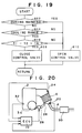
- FIGS. 19 and 20 An exhaust gas purification system for an internal combustion engine in accordance with a sixth embodiment is illustrated in FIGS. 19 and 20.
- the internal combustion engine 2, the exhaust conduit 4, the lean NOx catalyst 6, the inlet gas temperature sensor 24, and the outlet gas temperature sensor 20 illustrated in FIG. 6 are applicable to the sixth embodiment. Further, a cooling water temperature sensor 32 and a muffler 30 are provided.
- a catalyst temperature control device includes an air pump 34 driven by the engine 2, an air nozzle 26 for injecting air from the air pump 34 against a converter case housing the lean NOx catalyst 6, and a control valve 28 installed in an air conduit connecting the air pump 34 and the air nozzle 26.
- the amount of air injected from the air nozzle 26 is controlled by the air control valve 28 which is controlled by the ECU 10.
- a routine (FIG. 19) for controlling the amount of cooling air is stored in the ROM of the ECU 10 and the routine is executed in the CPU of the ECU 10.
- This routine of FIG. 19 is entered at intervals of predetermined periods of time, for example, at intervals of fifty milliseconds.
- the output of the cooling water temperature sensor 32 is entered and it is determined whether or not the engine is being warmed based on the cooling water temperature. For example, when the cooling water temperature is equal to or lower than 90°C, the engine condition is determined to be during a warming condition.
- the routine proceeds to step 710 to close the air control valve 28 to stop air injection because the lean NOx catalyst 6 should be warmed-up quickly in such a condition.
- step 704 a determination is made as to whether or not the current engine operating condition is in a condition in which engine cooling is allowed. For example, if the current engine operating condition is not in an idling condition, the engine operating condition may be deemed to be an engine cooling allowable condition, and the routine proceeds to step 710 where the air control valve 28 is closed. Contrarily, if the current engine operating condition is in an engine cooling allowable condition at step 704, the routine proceeds to step 706.
- a difference between the output TI of the inlet gas temperature sensor 24 and the output TE of the outlet gas temperature sensor 20 is calculated, and it is determined whether or not the temperature difference is larger than a predetermined value TA.
- TA a predetermined value
- the lean NOx catalyst 6 is deemed to have been degraded.
- the step 706 of FIG. 19 constitutes means for determining degradation of the lean NOx catalyst 6 of the sixth embodiment.
- step 710 the air control valve 28 is closed so that cooling of the catalyst 6 is stopped and the catalyst temperature is changed to a higher side.
- step 710 of FIG. 19 constitutes means for changing a catalyst temperature to a higher side in the sixth embodiment.
- step 708 the air control valve 28 is opened so that the catalyst 6 is cooled.
- Other structures and operation of the sixth embodiment are the same as those of the first embodiment of the invention.
- either the amount of HC supplied to the catalyst 6 is increased by the means for increasing the amount of HC or the catalyst temperature is changed to a higher side by the means for changing the catalyst temperature, so that, in either case, the NOx purification rate of the catalyst 6 is maintained to be high even after the catalyst 6 has been degraded.
Landscapes
- Engineering & Computer Science (AREA)
- Chemical & Material Sciences (AREA)
- Chemical Kinetics & Catalysis (AREA)
- Combustion & Propulsion (AREA)
- Mechanical Engineering (AREA)
- General Engineering & Computer Science (AREA)
- Health & Medical Sciences (AREA)
- Toxicology (AREA)
- Exhaust Gas After Treatment (AREA)
Claims (22)
- System zur Reinigung von Abgasen für eine Brennkraftmaschine mit innerer Verbrennung, umfassend:
eine Brennkraftmaschine mit innerer Verbrennung (2), die dazu geeignet ist, Kraftstoff bei mageren Kraftstoff-Luft-Verhältnissen zu verbrennen und die eine Abgasleitung (4) aufweist;
einen Katalysator (6), der in der Abgasleitung (4) des Motors (2) angeordnet ist und der aus Zeolit aufgebaut ist, wobei der Katalysator mindestens ein Metall trägt, das aus der Gruppe ausgewählt ist, die aus den Übergangsmetallen und den Edelmetallen besteht, um Stickoxide, die in dem Abgas des Motors (2) enthalten sind, unter Bedingungen von oxydierendem Gas und in der Gegenwart von Kohlenwasserstoffen zu reduzieren;
ein Mittel zur Bestimmung der Zersetzung des Katalysators (6); und
ein Mittel zur Steigerung der Menge der Kohlenwasserstoffe, die dem Katalysator (6) zugeführt werden, wenn das Mittel zur Bestimmung der Zersetzung des Katalysators bestimmt, daß sich der Katalysator (6) zersetzt hat. - System zur Reinigung von Abgasen für eine Brennkraftmaschine mit innerer Verbrennung nach Anspruch 1, weiters umfassend eine Steuer-Vorrichtung (8) für die Temperatur des Abgases, die in einem Abschnitt der Abgasleitung (4) stromaufwärts des Katalysators (6) angeordnet ist.
- System zur Reinigung von Abgasen für eine Brennkraftmaschine mit innerer Verbrennung nach Anspruch 1, weiters umfassend eine Vorrichtung zur Zufuhr von Kohlenwasserstoffen, die eine Kohlenwasserstoff-Quelle (12), einen Kohlenwasserstoff-Zufuhr-Anschluß (14) zum Einführen der Kohlenwasserstoffe von der Kohlenwasserstoff-Quelle (14) in einen Abschnitt der Abgasleitung (4) stromaufwärts des Katalysators (6) und ein Steuer-Ventil (16) umfaßt, das in einer Leitung vorgesehen ist, die die Kohlenwasserstoff-Quelle (12) und die Kohlenwasserstoff-Zufuhr-Öffnung (14) miteinander verbindet, um die Menge der Kohlenwasserstoffe zu steuern, die in die Abgasleitung (4) geführt werden.
- System zur Reinigung von Abgasen für eine Brennkraftmaschine mit innerer Verbrennung nach Anspruch 1, weiters umfassend:
einen ersten Temperatur-Sensor (24) für das Abgas, der in einem Abschnitt der Abgasleitung (4) stromaufwärts des Katalysators (6) angeordnet ist;
einen zweiten Temperatur-Sensor (20) für das Abgas, der in einem Abschnitt der Abgasleitung (4) stromabwärts des Katalysators (6) angeordnet ist; und
einen NOx-Sensor (22), der in einem Abschnitt der Abgasleitung (4) stromabwärts des Katalysators (6) angeordnet ist. - System zur Reinigung von Abgasen für eine Brennkraftmaschine mit innerer Verbrennung nach Anspruch 1, wobei das Mittel zur Bestimmung der Zersetzung des Katalysators ein Mittel zur Bestimmung der Zersetzung des Katalysators (6) auf Basis einer Gesamtfahrstrecke eines Kraftfahrzeuges umfaßt, in dem der Motor (2) eingebaut ist.
- System zur Reinigung von Abgasen für eine Brennkraftmaschine mit innerer Verbrennung nach Anspruch 5, wobei das Mittel zur Steigerung der Menge der Kohlenwasserstoffe ein Mittel zur Berechnung einer Ziel-Menge von Kohlenwasserstoffen, die dem Katalysator (6) zugeführt werden, umfaßt, so daß die Ziel-Menge der Kohlenwasserstoffe, die dem Katalysator (6) zuzuführen ist, umso größer ist, je größer die Gesamtfahrstrecke ist.
- System zur Reinigung von Abgasen für eine Brennkraftmaschine mit innerer Verbrennung nach Anspruch 5, weiters umfassend: ein Mittel zur Veränderung der Temperatur des Katalysators, um einen oberen und einen unteren Grenzwert eines Ziel-Katalysator-Temperatur-Bereiches so zu berechnen, daß der obere und der untere Grenzwert des Ziel-Katalysator-Temperatur-Bereiches umso größer wird, je mehr sich der Katalysator (6) zersetzt hat.
- System zur Reinigung von Abgasen für eine Brennkraftmaschine mit innerer Verbrennung nach Anspruch 1, wobei das Mittel zur Bestimmung der Zersetzung des Katalysators (6) Mittel zur Abänderung eines Referenz-NOx-Wertes durch eine laufend erfaßte NOx-Menge und zum Speichern des abgeänderten Referenz-NOx-Wertes umfaßt, bis die Gesamtfahrstrecke eines Kraftfahrzeugs, in das der Motor eingebaut ist, letztlich einen vorbestimmten Wert erreicht, sowie Mittel zur Berechnung einer NOx-Wert-Differenz zwischen einer laufend erfaßten NOx-Menge und dem gespeicherten Referenz-NOx-Wert, um ein Ausmaß der Zersetzung des Katalysators (6) auf Basis der NOx-Wert-Differenz zu bestimmen.
- System zur Reinigung von Abgasen für eine Brennkraftmaschine mit innerer Verbrennung nach Anspruch 8, wobei das Mittel zur Steigerung der Menge der Kohlenwasserstoffe, die dem Katalysator (6) zugeführt werden, ein Mittel zur Berechnung einer Ziel-Kohlenwasserstoff-Konzentration auf der Basis der berechneten NOx-Wert-Differenz aufweist, so daß die Ziel-Kohlenwasserstoff-Konzentration umso höher ist, je größer die berechnete NOx-Wert-Differenz ist.
- System zur Reinigung von Abgasen für eine Brennkraftmaschine mit innerer Verbrennung nach Anspruch 8, weiters umfassend: ein Mittel zur Berechnung eines Katalysator-Temperatur-Modifikations-Faktors auf der Basis der berechneten NOx-Wert-Differenz, so daß der Katalysator-Temperatur-Modifikations-Faktor umso größer ist, je größer die berechnete NOx-Wert-Differenz ist; sowie ein Mittel zur Steuerung einer Ziel-Abgas-Temperatur auf der Basis des berechneten Katalysator-Temperatur-Modifikations-Faktors, so daß die Ziel-Abgas-Temperatur umso höher ist, je größer der berechnete Katalysator-Temperatur-Modifikations-Faktor ist.
- System zur Reinigung von Abgasen für eine Brennkraftmaschine mit innerer Verbrennung nach Anspruch 1, wobei das Mittel zur Bestimmung der Zersetzung des Katalysators (6) ein Mittel zur Berechnung einer Referenz-Temperatur-Differenz zwischen dem einströmenden Gas und dem ausströmenden Gas des Katalysators (6) in einem nicht zersetzten Zustand aus einer Zuordnung einer Motor-Last über der Motordrehzahl, sowie zum Erfassen einer laufenden Temperatur-Differenz zwischen dem einströmenden Gas und dem ausströmenden Gas des Katalysators (6) und zum Berechnen des Ausmaßes der Zersetzung des Katalysators (6) auf der Basis einer Differenz zwischen der erfaßten laufenden Temperatur-Differenz und der Referenz-Temperatur-Differenz umfaßt.
- System zur Reinigung von Abgasen für eine Brennkraftmaschine mit innerer Verbrennung nach Anspruch 11, wobei das Mittel zum Steigern der Menge der Kohlenwasserstoffe, die dem Katalysator (6) zugeführt werden, ein Mittel zur Berechnung einer Ziel-Kohlenwasserstoff-Konzentration auf Basis des berechneten Ausmaßes der Zersetzung des Katalysators (6) umfaßt, so daß die Ziel-Kohlenwasserstoff-Konzentration umso größer ist, je größer das berechnete Ausmaß der Zersetzung des Katalysators (6) ist.
- System zur Reinigung von Abgasen für eine Brennkraftmaschine mit innerer Verbrennung nach Anspruch 11, weiters umfassend: ein Mittel zur Veränderung der Temperatur des Katalysators, um einen oberen und einen unteren Grenzwert eines Ziel-Katalysator-Temperatur-Bereiches auf der Basis des berechneten Ausmaßes der Zersetzung des Katalysators (6) zu berechnen, so daß der obere und der untere Grenzwert des Ziel-Katalysator-Temperatur-Bereiches umso größer sind, je größer das berechnete Ausmaß der Zersetzung des Katalysators (6) ist.
- System zur Reinigung von Abgasen für eine Brennkraftmaschine mit innerer Verbrennung, umfassend:
eine Brennkraftmaschine mit innerer Verbrennung (2), die dazu geeignet ist, Kraftstoff bei mageren Kraftstoff-Luft-Verhältnissen zu verbrennen und die eine Abgasleitung (4) aufweist;
einen Katalysator (6), der in der Abgasleitung (4) des Motors (2) angeordnet ist und der aus Zeolit aufgebaut ist, wobei der Katalysator mindestens ein Metall trägt, das aus der Gruppe ausgewählt ist, die aus den Übergangsmetallen und den Edelmetallen besteht, um Stickoxide, die in dem Abgas des Motors (2) enthalten sind, unter Bedingungen von oxydierendem Gas und in der Gegenwart von Kohlenwasserstoffen zu reduzieren;
ein Mittel zur Bestimmung der Zersetzung des Katalysators (6); und
ein Mittel zur Veränderung einer Temperatur des Katalysators zu einer höheren Seite hin, wenn das Mittel zur Bestimmung der Zersetzung des Katalysators bestimmt, daß sich der Katalysator (6) zersetzt hat. - System zur Reinigung von Abgasen für eine Brennkraftmaschine mit innerer Verbrennung nach Anspruch 14, weiters umfassend eine Steuer-Vorrichtung (8) für die Temperatur des Abgases, die in einem Abschnitt der Abgasleitung (4) stromaufwärts des Katalysators (6) angeordnet ist.
- System zur Reinigung von Abgasen für eine Brennkraftmaschine mit innerer Verbrennung nach Anspruch 14, weiters umfassend eine Vorrichtung zur Zufuhr von Kohlenwasserstoffen, die eine Kohlenwasserstoff-Quelle (12), einen Kohlenwasserstoff-Zufuhr-Anschluß (14) zum Einführen der Kohlenwasserstoffe von der Kohlenwasserstoff-Quelle (14) in einen Abschnitt der Abgasleitung (4) stromaufwärts des Katalysators (6) und ein Steuer-Ventil (16) umfaßt, das in einer Leitung vorgesehen ist, die die Kohlenwasserstoff-Quelle (12) und die Kohlenwasserstoff-Zufuhr-Öffnung (14) miteinander verbindet, um die Menge der Kohlenwasserstoffe zu steuern, die in die Abgasleitung (4) geführt werden.
- System zur Reinigung von Abgasen für eine Brennkraftmaschine mit innerer Verbrennung nach Anspruch 14, weiters umfassend:
einen ersten Temperatur-Sensor (24) für das Abgas, der in einem Abschnitt der Abgasleitung (4) stromaufwärts des Katalysators (6) angeordnet ist;
einen zweiten Temperatur-Sensor (20) für das Abgas, der in einem Abschnitt der Abgasleitung (4) stromabwärts des Katalysators (6) angeordnet ist; und
einen NOx-Sensor (22), der in einem Abschnitt der Abgasleitung (4) stromabwärts des Katalysators (6) angeordnet ist. - System zur Reinigung von Abgasen für eine Brennkraftmaschine mit innerer Verbrennung nach Anspruch 14, wobei das Mittel zur Bestimmung der Zersetzung des Katalysators ein Mittel zur Bestimmung der Zersetzung des Katalysators (6) auf Basis einer Gesamtfahrstrecke eines Kraftfahrzeuges umfaßt, in dem der Motor (2) eingebaut ist.
- System zur Reinigung von Abgasen für eine Brennkraftmaschine mit innerer Verbrennung nach Anspruch 14, wobei das Mittel zur Bestimmung der Zersetzung des Katalysators (6) Mittel zur Abänderung eines Referenz-NOx-Wertes durch eine laufend erfaßte NOx-Menge und zum Speichern des abgeänderten Referenz-NOx-Wertes umfaßt, bis die Gesamtfahrstrecke eines Kraftfahrzeugs, in das der Motor eingebaut ist, letztlich einen vorbestimmten Wert erreicht, sowie Mittel zur Berechnung einer NOx-Wert-Differenz zwischen einer laufend erfaßten NOx-Menge und dem gespeicherten Referenz-NOx-Wert, um ein Ausmaß der Zersetzung des Katalysators (6) auf Basis der NOx-Wert-Differenz zu bestimmen.
- System zur Reinigung von Abgasen für eine Brennkraftmaschine mit innerer Verbrennung nach Anspruch 14, wobei die Steuervorrichtung für die Abgas-Temperatur eine Luftpumpe (34), eine Luft-Düse (26) zum Ausblasen von Luft von der Luftpumpe (34) zu einem Behälter-Gehäuse, das den Katalysator (6) in seinem Inneren aufnimmt, sowie ein Steuer-Ventil (28) umfaßt, das in einer Luft-Leitung vorgesehen ist, die die Luftpumpe (34) und die Luft-Düse (26) miteinander verbindet.
- System zur Reinigung von Abgasen für eine Brennkraftmaschine mit innerer Verbrennung nach Anspruch 20, wobei das Mittel zur Bestimmung der Zersetzung des Katalysators (6) ein Mittel umfaßt, das bestimmt, daß sich der Katalysator (6) zersetzt hat, wenn eine Temperaturdifferenz zwischen dem einströmenden Gas und dem ausströmenden Gas des Katalysators (6) einen vorbestimmten Wert übersteigt.
- System zur Reinigung von Abgasen für eine Brennkraftmaschine mit innerer Verbrennung nach Anspruch 21, wobei das Mittel zur Bestimmung der Zersetzung des Katalysators (6) ein Mittel zum Schließen des Steuer-Ventils (28) umfaßt, wenn das Mittel zur Bestimmung der Zersetzung des Katalysators bestimmt, daß sich der Katalysator (6) zersetzt hat.
Applications Claiming Priority (4)
| Application Number | Priority Date | Filing Date | Title |
|---|---|---|---|
| JP33366/91 | 1991-02-04 | ||
| JP3336691A JP2884798B2 (ja) | 1991-02-04 | 1991-02-04 | 内燃機関の排気浄化装置 |
| JP3045662A JP2616262B2 (ja) | 1991-02-20 | 1991-02-20 | 内燃機関の排気浄化装置 |
| JP45662/91 | 1991-02-20 |
Publications (2)
| Publication Number | Publication Date |
|---|---|
| EP0498598A1 EP0498598A1 (de) | 1992-08-12 |
| EP0498598B1 true EP0498598B1 (de) | 1995-04-26 |
Family
ID=26372045
Family Applications (1)
| Application Number | Title | Priority Date | Filing Date |
|---|---|---|---|
| EP92300896A Expired - Lifetime EP0498598B1 (de) | 1991-02-04 | 1992-02-03 | Abgasentgiftungsanlage für eine Brennkraftmaschine |
Country Status (3)
| Country | Link |
|---|---|
| US (1) | US5201802A (de) |
| EP (1) | EP0498598B1 (de) |
| DE (1) | DE69202163T2 (de) |
Families Citing this family (143)
| Publication number | Priority date | Publication date | Assignee | Title |
|---|---|---|---|---|
| DE69202172T2 (de) * | 1991-02-20 | 1995-11-30 | Hitachi Automotive Eng | Katalysatorsteuergerät. |
| DE4217552C1 (de) * | 1992-05-27 | 1993-08-19 | Mercedes-Benz Aktiengesellschaft, 7000 Stuttgart, De | |
| JPH0631173A (ja) * | 1992-07-10 | 1994-02-08 | N E Chemcat Corp | 排気ガス浄化用触媒及び排気ガスの浄化方法 |
| US5433074A (en) * | 1992-07-30 | 1995-07-18 | Toyota Jidosha Kabushiki Kaisha | Exhaust gas purification device for an engine |
| DE4310926A1 (de) * | 1993-04-02 | 1994-10-06 | Siemens Ag | Vorrichtung und Verfahren zur Schadstoffminderung im Abgas |
| JP2605579B2 (ja) * | 1993-05-31 | 1997-04-30 | トヨタ自動車株式会社 | 内燃機関の排気浄化装置 |
| US5497617A (en) * | 1993-07-02 | 1996-03-12 | Corning Incorporated | Gas-enriched light-off |
| US5611198A (en) * | 1994-08-16 | 1997-03-18 | Caterpillar Inc. | Series combination catalytic converter |
| DE4436415A1 (de) * | 1994-10-12 | 1996-04-18 | Bosch Gmbh Robert | Einrichtung zum Nachbehandeln von Abgasen einer selbstzündenden Brennkraftmaschine |
| US5609022A (en) * | 1994-10-31 | 1997-03-11 | General Motors Corporation | Method of reducing NOx emissions from lean-burn combustion engines |
| DE19512298A1 (de) * | 1995-04-05 | 1996-10-24 | Haefele Cornelia | Emissionsgeregelte Anordnung zur Katalytischenschadstoffreduzierung von Katalysatoren |
| DE19536571C2 (de) * | 1995-09-29 | 1998-09-03 | Siemens Ag | Verfahren sowie Vorrichtung zur Dosierung der Eingabe eines Reduktionsmittels in den Abgas- oder Abluftstrom einer Verbrennungsanlage |
| KR19990063752A (ko) * | 1995-09-29 | 1999-07-26 | 피터 토마스 | 촉매 변환기에서 배기 가스중의 유해물질을 변환시키기 위한방법 및 장치 |
| JP3852788B2 (ja) * | 1995-10-02 | 2006-12-06 | 株式会社小松製作所 | ディーゼルエンジンのNOx 触媒の劣化検出装置およびその劣化検出方法 |
| DE19543219C1 (de) * | 1995-11-20 | 1996-12-05 | Daimler Benz Ag | Verfahren zum Betreiben eines Dieselmotors |
| JPH09177640A (ja) * | 1995-12-15 | 1997-07-11 | Caterpillar Inc | 高サック容積を有する燃料噴射器による燃焼排気ガス清浄化システムとその方法 |
| US5709080A (en) * | 1996-03-15 | 1998-01-20 | Caterpillar Inc. | Leak detection method and apparatus for an exhaust purification system |
| US6199372B1 (en) * | 1996-04-26 | 2001-03-13 | Komatsu Ltd. | Apparatus and method for regenerating NOx catalyst for diesel engine |
| DE19629163C1 (de) * | 1996-07-19 | 1997-10-09 | Daimler Benz Ag | Verfahren und Vorrichtung zum stickoxidemissionsarmen Betrieb eines Verbrennungsmotors |
| JPH1047048A (ja) * | 1996-08-02 | 1998-02-17 | Toyota Motor Corp | 内燃機関の排気浄化装置 |
| JP3787913B2 (ja) * | 1996-09-17 | 2006-06-21 | 株式会社デンソー | 内燃機関の排ガス浄化装置 |
| JP3426451B2 (ja) * | 1996-10-23 | 2003-07-14 | トヨタ自動車株式会社 | 内燃機関の排気ガス浄化装置 |
| US5897846A (en) * | 1997-01-27 | 1999-04-27 | Asec Manufacturing | Catalytic converter having a catalyst with noble metal on molecular sieve crystal surface and method of treating diesel engine exhaust gas with same |
| FR2764638B1 (fr) * | 1997-06-16 | 1999-08-13 | Inst Francais Du Petrole | Procede et ensemble d'elimination des oxydes d'azote presents dans des gaz d'echappement, utilisant un echangeur thermique |
| DE59807160D1 (de) * | 1997-07-19 | 2003-03-20 | Volkswagen Ag | Verfahren und Vorrichtung zur Überwachung der De-Sulfatierung bei NOx-Speicherkatalysatoren |
| JP3799758B2 (ja) * | 1997-08-05 | 2006-07-19 | トヨタ自動車株式会社 | 内燃機関の触媒再生装置 |
| DE69816939T2 (de) * | 1997-11-10 | 2004-06-03 | Mitsubishi Jidosha Kogyo K.K. | Vorrichtung zur Abgasreinigung für eine Brennkraftmaschine |
| JP3331935B2 (ja) * | 1997-12-04 | 2002-10-07 | トヨタ自動車株式会社 | 圧縮着火式内燃機関 |
| DE19801625A1 (de) * | 1998-01-17 | 1999-07-22 | Bosch Gmbh Robert | Diagnose eines NOx-Speicherkatalysators beim Betrieb von Verbrennungsmotoren |
| JP3456401B2 (ja) * | 1998-02-12 | 2003-10-14 | 日産自動車株式会社 | 内燃機関の排気浄化装置 |
| DE19808382A1 (de) * | 1998-02-27 | 1999-09-02 | Volkswagen Ag | Steuerung eines NOx-Absorber-Katalysator |
| DE19823923C2 (de) * | 1998-05-28 | 2003-04-17 | Siemens Ag | Verfahren zur Stickoxidreduzierung im Abgas einer Brennkraftmaschine |
| DE19843423A1 (de) * | 1998-09-22 | 2000-03-30 | Siemens Ag | Verfahren und Vorrichtung zur katalytischen Beseitigung eines Schadstoffes aus dem Abgas einer Verbrennungsanlage |
| US6357226B2 (en) * | 1998-10-22 | 2002-03-19 | Chrysler Corporation | Control system for lean air-fuel ratio NOx catalyst system |
| SE519240C2 (sv) * | 1998-11-20 | 2003-02-04 | Volvo Personvagnar Ab | Arrangemang vid förbränningsmotor innefattandes en värmeväxlare för anpassning av temperaturen hos avgaser vilka ska passera en NOx-adsorberande katalysator |
| FR2787037B1 (fr) * | 1998-12-09 | 2002-01-11 | Inst Francais Du Petrole | Procede et dispositif d'elimination des oxydes d'azote dans une ligne d'echappement de moteur a combustion interne |
| US6718756B1 (en) * | 1999-01-21 | 2004-04-13 | Mitsubishi Jidosha Kogyo Kabushiki Kaisha | Exhaust gas purifier for use in internal combustion engine |
| DE19903439A1 (de) * | 1999-01-29 | 2000-08-03 | Bosch Gmbh Robert | Verfahren und Vorrichtung zur Steuerung eines Abgasnachbehandlungssystem |
| DE19906344A1 (de) * | 1999-02-17 | 2000-08-24 | Man Nutzfahrzeuge Ag | Verfahren zur Dosierung eines Reduktionsmittels in stickoxidhaltiges Abgas einer Brennkraftmaschine |
| JP3607976B2 (ja) * | 1999-03-29 | 2005-01-05 | トヨタ自動車株式会社 | 内燃機関の排気浄化装置 |
| DE19931321A1 (de) | 1999-07-07 | 2001-01-18 | Siemens Ag | Verfahren zum Überprüfen eines Dreiwege-Abgaskatalysators einer Brennkraftmaschine |
| US6305160B1 (en) * | 1999-07-12 | 2001-10-23 | Ford Global Technologies, Inc. | Emission control system |
| CA2322915C (en) * | 1999-10-12 | 2004-12-14 | Honda Giken Kogyo Kabushiki Kaisha | Exhaust emission control system for internal combustion engine |
| DE19963901A1 (de) * | 1999-12-31 | 2001-07-12 | Bosch Gmbh Robert | Verfahren zum Betreiben eines Katalysators einer Brennkraftmaschine |
| US6269633B1 (en) * | 2000-03-08 | 2001-08-07 | Ford Global Technologies, Inc. | Emission control system |
| US6810659B1 (en) * | 2000-03-17 | 2004-11-02 | Ford Global Technologies, Llc | Method for determining emission control system operability |
| US6487850B1 (en) | 2000-03-17 | 2002-12-03 | Ford Global Technologies, Inc. | Method for improved engine control |
| US6499293B1 (en) | 2000-03-17 | 2002-12-31 | Ford Global Technologies, Inc. | Method and system for reducing NOx tailpipe emissions of a lean-burn internal combustion engine |
| US6629453B1 (en) | 2000-03-17 | 2003-10-07 | Ford Global Technologies, Llc | Method and apparatus for measuring the performance of an emissions control device |
| US6594989B1 (en) | 2000-03-17 | 2003-07-22 | Ford Global Technologies, Llc | Method and apparatus for enhancing fuel economy of a lean burn internal combustion engine |
| US6327847B1 (en) | 2000-03-17 | 2001-12-11 | Ford Global Technologies, Inc. | Method for improved performance of a vehicle |
| US6360530B1 (en) | 2000-03-17 | 2002-03-26 | Ford Global Technologies, Inc. | Method and apparatus for measuring lean-burn engine emissions |
| US6438944B1 (en) | 2000-03-17 | 2002-08-27 | Ford Global Technologies, Inc. | Method and apparatus for optimizing purge fuel for purging emissions control device |
| US6374597B1 (en) | 2000-03-17 | 2002-04-23 | Ford Global Technologies, Inc. | Method and apparatus for accessing ability of lean NOx trap to store exhaust gas constituent |
| US6308697B1 (en) | 2000-03-17 | 2001-10-30 | Ford Global Technologies, Inc. | Method for improved air-fuel ratio control in engines |
| US6539704B1 (en) | 2000-03-17 | 2003-04-01 | Ford Global Technologies, Inc. | Method for improved vehicle performance |
| US6477832B1 (en) * | 2000-03-17 | 2002-11-12 | Ford Global Technologies, Inc. | Method for improved performance of a vehicle having an internal combustion engine |
| US6434930B1 (en) | 2000-03-17 | 2002-08-20 | Ford Global Technologies, Inc. | Method and apparatus for controlling lean operation of an internal combustion engine |
| US6843051B1 (en) | 2000-03-17 | 2005-01-18 | Ford Global Technologies, Llc | Method and apparatus for controlling lean-burn engine to purge trap of stored NOx |
| US6708483B1 (en) | 2000-03-17 | 2004-03-23 | Ford Global Technologies, Llc | Method and apparatus for controlling lean-burn engine based upon predicted performance impact |
| US6481199B1 (en) | 2000-03-17 | 2002-11-19 | Ford Global Technologies, Inc. | Control for improved vehicle performance |
| US6487849B1 (en) | 2000-03-17 | 2002-12-03 | Ford Global Technologies, Inc. | Method and apparatus for controlling lean-burn engine based upon predicted performance impact and trap efficiency |
| US6860100B1 (en) | 2000-03-17 | 2005-03-01 | Ford Global Technologies, Llc | Degradation detection method for an engine having a NOx sensor |
| US6427437B1 (en) | 2000-03-17 | 2002-08-06 | Ford Global Technologies, Inc. | Method for improved performance of an engine emission control system |
| US6308515B1 (en) | 2000-03-17 | 2001-10-30 | Ford Global Technologies, Inc. | Method and apparatus for accessing ability of lean NOx trap to store exhaust gas constituent |
| US6370868B1 (en) | 2000-04-04 | 2002-04-16 | Ford Global Technologies, Inc. | Method and system for purge cycle management of a lean NOx trap |
| US6427439B1 (en) | 2000-07-13 | 2002-08-06 | Ford Global Technologies, Inc. | Method and system for NOx reduction |
| US6363713B1 (en) | 2000-07-20 | 2002-04-02 | Ford Global Technologies, Inc. | On-board diagnostics for detecting the operation of diesel emissions control system |
| US6408616B1 (en) | 2000-07-20 | 2002-06-25 | Ford Global Technologies, Inc. | Diesel OBD-II system for detection of degradation of catalyst activity |
| US6389803B1 (en) | 2000-08-02 | 2002-05-21 | Ford Global Technologies, Inc. | Emission control for improved vehicle performance |
| JP4491932B2 (ja) * | 2000-08-07 | 2010-06-30 | マツダ株式会社 | エンジンの排気浄化装置 |
| US6826906B2 (en) * | 2000-08-15 | 2004-12-07 | Engelhard Corporation | Exhaust system for enhanced reduction of nitrogen oxides and particulates from diesel engines |
| US6691507B1 (en) | 2000-10-16 | 2004-02-17 | Ford Global Technologies, Llc | Closed-loop temperature control for an emission control device |
| JP3685052B2 (ja) * | 2000-11-30 | 2005-08-17 | 日産自動車株式会社 | 内燃機関の排気浄化装置 |
| US6568179B2 (en) * | 2001-03-01 | 2003-05-27 | Engelhard Corporation | Apparatus and method for vehicle emissions control |
| DE10113010A1 (de) * | 2001-03-17 | 2002-09-19 | Bosch Gmbh Robert | Verfahren und Vorrichtung zur Überwachung eines Abgasnachbehandlungssystems |
| US6449945B1 (en) | 2001-04-18 | 2002-09-17 | Ford Global Technologies, Inc. | Emission control system |
| US6453666B1 (en) | 2001-06-19 | 2002-09-24 | Ford Global Technologies, Inc. | Method and system for reducing vehicle tailpipe emissions when operating lean |
| US6650991B2 (en) | 2001-06-19 | 2003-11-18 | Ford Global Technologies, Llc | Closed-loop method and system for purging a vehicle emission control |
| US6553754B2 (en) | 2001-06-19 | 2003-04-29 | Ford Global Technologies, Inc. | Method and system for controlling an emission control device based on depletion of device storage capacity |
| US6539706B2 (en) | 2001-06-19 | 2003-04-01 | Ford Global Technologies, Inc. | Method and system for preconditioning an emission control device for operation about stoichiometry |
| US6487853B1 (en) | 2001-06-19 | 2002-12-03 | Ford Global Technologies. Inc. | Method and system for reducing lean-burn vehicle emissions using a downstream reductant sensor |
| US6546718B2 (en) | 2001-06-19 | 2003-04-15 | Ford Global Technologies, Inc. | Method and system for reducing vehicle emissions using a sensor downstream of an emission control device |
| US6691020B2 (en) | 2001-06-19 | 2004-02-10 | Ford Global Technologies, Llc | Method and system for optimizing purge of exhaust gas constituent stored in an emission control device |
| US6463733B1 (en) | 2001-06-19 | 2002-10-15 | Ford Global Technologies, Inc. | Method and system for optimizing open-loop fill and purge times for an emission control device |
| US6615577B2 (en) | 2001-06-19 | 2003-09-09 | Ford Global Technologies, Llc | Method and system for controlling a regeneration cycle of an emission control device |
| US6490860B1 (en) | 2001-06-19 | 2002-12-10 | Ford Global Technologies, Inc. | Open-loop method and system for controlling the storage and release cycles of an emission control device |
| US6502387B1 (en) | 2001-06-19 | 2003-01-07 | Ford Global Technologies, Inc. | Method and system for controlling storage and release of exhaust gas constituents in an emission control device |
| US6694244B2 (en) | 2001-06-19 | 2004-02-17 | Ford Global Technologies, Llc | Method for quantifying oxygen stored in a vehicle emission control device |
| US6604504B2 (en) | 2001-06-19 | 2003-08-12 | Ford Global Technologies, Llc | Method and system for transitioning between lean and stoichiometric operation of a lean-burn engine |
| US6467259B1 (en) | 2001-06-19 | 2002-10-22 | Ford Global Technologies, Inc. | Method and system for operating dual-exhaust engine |
| DE10135646A1 (de) * | 2001-07-21 | 2003-02-06 | Ballard Power Systems | Vorrichtung und Verfahren zur Reduzierung von Stichoxiden im Abgas einer Brennkraftmaschine |
| US6928359B2 (en) | 2001-08-09 | 2005-08-09 | Ford Global Technologies, Llc | High efficiency conversion of nitrogen oxides in an exhaust aftertreatment device at low temperature |
| US6742326B2 (en) | 2001-08-09 | 2004-06-01 | Ford Global Technologies, Llc | High efficiency conversion of nitrogen oxides in an exhaust aftertreatment device at low temperature |
| US6421599B1 (en) * | 2001-08-09 | 2002-07-16 | Ford Global Technologies, Inc. | Control strategy for an internal combustion engine in a hybrid vehicle |
| US6698191B2 (en) | 2001-08-09 | 2004-03-02 | Ford Global Technologies, Llc | High efficiency conversion of nitrogen oxides in an exhaust aftertreatment device at low temperature |
| US6487852B1 (en) | 2001-09-04 | 2002-12-03 | Ford Global Technologies, Inc. | Method and apparatus for controlling reactant injection into an active lean NOx catalyst |
| US7121085B2 (en) * | 2001-09-04 | 2006-10-17 | Ford Global Technologies, Llc | Method and apparatus for controlling hydrocarbon injection into engine exhaust to reduce NOx |
| JP2003148198A (ja) * | 2001-11-13 | 2003-05-21 | Toyota Motor Corp | 内燃機関の排気浄化装置 |
| US6868827B2 (en) | 2002-06-04 | 2005-03-22 | Ford Global Technologies, Llc | Method for controlling transitions between operating modes of an engine for rapid heating of an emission control device |
| US7032572B2 (en) * | 2002-06-04 | 2006-04-25 | Ford Global Technologies, Llc | Method for controlling an engine to obtain rapid catalyst heating |
| US6736120B2 (en) | 2002-06-04 | 2004-05-18 | Ford Global Technologies, Llc | Method and system of adaptive learning for engine exhaust gas sensors |
| US6925982B2 (en) | 2002-06-04 | 2005-08-09 | Ford Global Technologies, Llc | Overall scheduling of a lean burn engine system |
| US6736121B2 (en) | 2002-06-04 | 2004-05-18 | Ford Global Technologies, Llc | Method for air-fuel ratio sensor diagnosis |
| US6769398B2 (en) | 2002-06-04 | 2004-08-03 | Ford Global Technologies, Llc | Idle speed control for lean burn engine with variable-displacement-like characteristic |
| US7111450B2 (en) * | 2002-06-04 | 2006-09-26 | Ford Global Technologies, Llc | Method for controlling the temperature of an emission control device |
| US6758185B2 (en) | 2002-06-04 | 2004-07-06 | Ford Global Technologies, Llc | Method to improve fuel economy in lean burn engines with variable-displacement-like characteristics |
| US6745747B2 (en) | 2002-06-04 | 2004-06-08 | Ford Global Technologies, Llc | Method for air-fuel ratio control of a lean burn engine |
| US6715462B2 (en) | 2002-06-04 | 2004-04-06 | Ford Global Technologies, Llc | Method to control fuel vapor purging |
| US6568177B1 (en) | 2002-06-04 | 2003-05-27 | Ford Global Technologies, Llc | Method for rapid catalyst heating |
| US6735938B2 (en) | 2002-06-04 | 2004-05-18 | Ford Global Technologies, Llc | Method to control transitions between modes of operation of an engine |
| US7168239B2 (en) * | 2002-06-04 | 2007-01-30 | Ford Global Technologies, Llc | Method and system for rapid heating of an emission control device |
| US6725830B2 (en) | 2002-06-04 | 2004-04-27 | Ford Global Technologies, Llc | Method for split ignition timing for idle speed control of an engine |
| US6928806B2 (en) * | 2002-11-21 | 2005-08-16 | Ford Global Technologies, Llc | Exhaust gas aftertreatment systems |
| US6834498B2 (en) * | 2002-11-21 | 2004-12-28 | Ford Global Technologies, Llc | Diesel aftertreatment systems |
| US6862879B2 (en) | 2002-11-21 | 2005-03-08 | Ford Global Technologies, Llc | Diesel aftertreatment system |
| US6895747B2 (en) | 2002-11-21 | 2005-05-24 | Ford Global Technologies, Llc | Diesel aftertreatment systems |
| US6761025B1 (en) * | 2002-12-19 | 2004-07-13 | Caterpillar Inc. | Enhanced ammonia feed control for selective catalytic reduction |
| DE10301602A1 (de) * | 2003-01-17 | 2004-07-29 | Robert Bosch Gmbh | Verfahren und Vorrichtung zum Betreiben einer Dosiereinheit eines Katalysators |
| US6871489B2 (en) * | 2003-04-16 | 2005-03-29 | Arvin Technologies, Inc. | Thermal management of exhaust systems |
| DE10323247A1 (de) | 2003-05-22 | 2004-12-09 | Umicore Ag & Co.Kg | Verfahren zum Betreiben eines Antriebssystems aus einem Dieselmotor mit einem Dieseloxidationskatalysator zur Abgasreinigung |
| SE526488C2 (sv) * | 2003-06-10 | 2005-09-27 | Scania Cv Abp | Förfarande och anordning för övervakning av en SCR-katalysator där uppmätta och beräknade temperaturvärden jämförs |
| US6925796B2 (en) * | 2003-11-19 | 2005-08-09 | Ford Global Technologies, Llc | Diagnosis of a urea SCR catalytic system |
| US20060254260A1 (en) * | 2005-05-16 | 2006-11-16 | Arvinmeritor Emissions Technologies Gmbh | Method and apparatus for piezoelectric injection of agent into exhaust gas for use with emission abatement device |
| US7332142B2 (en) * | 2005-06-17 | 2008-02-19 | Emcon Tehnologies Germany (Augsburg) Gmbh | Method and apparatus for bubble injection of agent into exhaust gas for use with emission abatement device |
| US7533519B2 (en) * | 2005-11-09 | 2009-05-19 | International Engine Intellectual Property Company, Llc | Three sensor comparison rationality test |
| JP4710564B2 (ja) * | 2005-11-22 | 2011-06-29 | いすゞ自動車株式会社 | 排気ガス浄化システムの制御方法及び排気ガス浄化システム |
| JP4215050B2 (ja) * | 2005-12-15 | 2009-01-28 | トヨタ自動車株式会社 | 内燃機関の排気浄化システム |
| US8156732B2 (en) * | 2006-03-24 | 2012-04-17 | Fleetguard, Inc. | Apparatus, system, and method for regenerating an exhaust gas treatment device |
| JP4428361B2 (ja) * | 2006-05-24 | 2010-03-10 | トヨタ自動車株式会社 | 内燃機関の排気浄化システム |
| US7587890B2 (en) * | 2006-08-21 | 2009-09-15 | Cummins Inc. | Reductant injection rate shaping method for regeneration of aftertreatment systems |
| JP4733003B2 (ja) * | 2006-11-24 | 2011-07-27 | 本田技研工業株式会社 | 内燃機関の排ガス浄化装置 |
| JP2008138522A (ja) * | 2006-11-30 | 2008-06-19 | Hitachi Ltd | エンジンの始動時の触媒の早期昇温方法、及びその方法を備えた燃料制御装置 |
| JP5121240B2 (ja) * | 2007-02-02 | 2013-01-16 | ボッシュ株式会社 | 排気浄化システムの故障診断装置及び排気浄化システムの故障診断方法 |
| JP4665924B2 (ja) * | 2007-03-16 | 2011-04-06 | トヨタ自動車株式会社 | 内燃機関の排気浄化システム |
| US20090139210A1 (en) * | 2007-11-30 | 2009-06-04 | Rodrigo Lain Sanchez | Gas concentration sensor drift and failure detection system |
| US9631538B2 (en) * | 2009-07-10 | 2017-04-25 | GM Global Technology Operations LLC | Identifying ammonia slip conditions in a selective catalytic reduction application |
| KR101251517B1 (ko) * | 2010-12-09 | 2013-04-05 | 현대자동차주식회사 | 배기가스 후처리 시스템 |
| US20120222399A1 (en) * | 2011-03-03 | 2012-09-06 | GM Global Technology Operations LLC | Oxidation catalyst burn threshold adjustment to avoid quenching |
| JP6025606B2 (ja) * | 2013-02-22 | 2016-11-16 | 三菱重工業株式会社 | 燃料セタン価推定方法及び装置 |
| KR101518941B1 (ko) * | 2013-12-23 | 2015-05-11 | 현대자동차 주식회사 | 선택적 환원 촉매의 제어 로직 보정 방법 및 이를 이용한 배기 장치 |
| US10920645B2 (en) * | 2018-08-02 | 2021-02-16 | Ford Global Technologies, Llc | Systems and methods for on-board monitoring of a passive NOx adsorption catalyst |
| US10865689B2 (en) * | 2018-09-21 | 2020-12-15 | Cummins Inc. | Systems and methods for diagnosis of NOx storage catalyst |
Family Cites Families (12)
| Publication number | Priority date | Publication date | Assignee | Title |
|---|---|---|---|---|
| JPS5129260B2 (de) * | 1972-09-14 | 1976-08-24 | ||
| GB1530343A (en) * | 1975-03-31 | 1978-10-25 | Nissan Motor | Air-fuel mixture supply device of internal combustion engine |
| JPS62223427A (ja) * | 1986-03-20 | 1987-10-01 | Nissan Motor Co Ltd | 空燃比制御装置 |
| JPS62251415A (ja) * | 1986-04-23 | 1987-11-02 | Toyota Motor Corp | 内燃機関の排ガス浄化装置 |
| DE3713169A1 (de) * | 1987-04-17 | 1988-11-03 | Bayer Ag | Verfahren und vorrichtung zur reduktion von stickoxiden |
| JP2659720B2 (ja) * | 1987-09-11 | 1997-09-30 | 三菱重工業株式会社 | 排ガス熱交換装置 |
| JP2660411B2 (ja) * | 1987-11-18 | 1997-10-08 | トヨタ自動車株式会社 | 排気ガス中の窒素酸化物を還元除去する方法 |
| JP2660412B2 (ja) * | 1987-11-19 | 1997-10-08 | トヨタ自動車株式会社 | 排気ガス浄化方法 |
| JP2593506B2 (ja) * | 1988-02-22 | 1997-03-26 | 三菱自動車工業株式会社 | 内燃機関の触媒劣化診断装置 |
| JP3150679B2 (ja) * | 1989-07-20 | 2001-03-26 | トヨタ自動車株式会社 | 内燃機関の空燃比制御装置 |
| CA2031560C (en) * | 1989-12-06 | 1995-07-18 | Shinichi Takeshima | Exhaust gas purification system for an internal combustion engine |
| JP2850547B2 (ja) * | 1990-02-09 | 1999-01-27 | トヨタ自動車株式会社 | 内燃機関の排気浄化装置 |
-
1992
- 1992-01-31 US US07/829,212 patent/US5201802A/en not_active Expired - Fee Related
- 1992-02-03 EP EP92300896A patent/EP0498598B1/de not_active Expired - Lifetime
- 1992-02-03 DE DE69202163T patent/DE69202163T2/de not_active Expired - Fee Related
Non-Patent Citations (2)
| Title |
|---|
| PATENT ABSTRACTS OF JAPAN, vol. 12, no. 126 (M-687), 19th April 1988; & JP-A-62 251 415 (TOYOTA MOTOR CORP.) 02-11-1987 * |
| PATENT ABSTRACTS OF JAPAN, vol. 13, no. 528 (M-898), 24th November 1989; & JP-A-1 216 009 (MITSUBISHI MOTORS CORP.) 30-08-1989 * |
Also Published As
| Publication number | Publication date |
|---|---|
| US5201802A (en) | 1993-04-13 |
| DE69202163T2 (de) | 1995-09-28 |
| EP0498598A1 (de) | 1992-08-12 |
| DE69202163D1 (de) | 1995-06-01 |
Similar Documents
| Publication | Publication Date | Title |
|---|---|---|
| EP0498598B1 (de) | Abgasentgiftungsanlage für eine Brennkraftmaschine | |
| EP0503882B1 (de) | Vorrichtung zur Reinigung von Abgasen eines Verbrennungsmotors | |
| EP0490550B1 (de) | Vorrichtung zur Steuerung von Verbrennungsmotoren | |
| US6148612A (en) | Engine exhaust gas control system having NOx catalyst | |
| US6701707B1 (en) | Exhaust emission diagnostics | |
| EP0822323B1 (de) | Abgasreinigungsvorrichtung und Verfahen für eine Brennkraftmaschine | |
| US6983589B2 (en) | Diesel aftertreatment systems | |
| US7134273B2 (en) | Exhaust emission control and diagnostics | |
| US5483795A (en) | Exhaust purification device of internal combustion engine | |
| US6438943B1 (en) | In-cylinder injection type internal combustion engine | |
| US8943804B2 (en) | Compression-ignition engine with exhaust system | |
| EP0560991A1 (de) | Gerät zum reinigen von verbrennungsmotor-abgasen | |
| JP3613676B2 (ja) | 内燃機関の排気浄化装置 | |
| US20050252197A1 (en) | Diesel aftertreatment systems | |
| US5737917A (en) | Device for judging deterioration of catalyst of engine | |
| US20050223698A1 (en) | Exhaust gas cleaning device | |
| JP3508744B2 (ja) | 内燃機関の排気浄化装置 | |
| US6449945B1 (en) | Emission control system | |
| US5501074A (en) | Exhaust gas purifying system | |
| JP3855444B2 (ja) | 内燃機関の還元剤供給装置 | |
| JP2962127B2 (ja) | 内燃機関の制御装置 | |
| US20220186643A1 (en) | Exhaust purification system of internal combustion engine | |
| JP2962089B2 (ja) | 内燃機関の触媒劣化診断装置 | |
| JP4888368B2 (ja) | 内燃機関の制御装置 | |
| JPH04255521A (ja) | 内燃機関の排気浄化装置 |
Legal Events
| Date | Code | Title | Description |
|---|---|---|---|
| PUAI | Public reference made under article 153(3) epc to a published international application that has entered the european phase |
Free format text: ORIGINAL CODE: 0009012 |
|
| 17P | Request for examination filed |
Effective date: 19920212 |
|
| AK | Designated contracting states |
Kind code of ref document: A1 Designated state(s): DE FR GB |
|
| 17Q | First examination report despatched |
Effective date: 19940302 |
|
| GRAA | (expected) grant |
Free format text: ORIGINAL CODE: 0009210 |
|
| AK | Designated contracting states |
Kind code of ref document: B1 Designated state(s): DE FR GB |
|
| REF | Corresponds to: |
Ref document number: 69202163 Country of ref document: DE Date of ref document: 19950601 |
|
| ET | Fr: translation filed | ||
| PLBE | No opposition filed within time limit |
Free format text: ORIGINAL CODE: 0009261 |
|
| STAA | Information on the status of an ep patent application or granted ep patent |
Free format text: STATUS: NO OPPOSITION FILED WITHIN TIME LIMIT |
|
| 26N | No opposition filed | ||
| PGFP | Annual fee paid to national office [announced via postgrant information from national office to epo] |
Ref country code: DE Payment date: 19991231 Year of fee payment: 9 |
|
| PGFP | Annual fee paid to national office [announced via postgrant information from national office to epo] |
Ref country code: GB Payment date: 20000202 Year of fee payment: 9 |
|
| PGFP | Annual fee paid to national office [announced via postgrant information from national office to epo] |
Ref country code: FR Payment date: 20000210 Year of fee payment: 9 |
|
| PG25 | Lapsed in a contracting state [announced via postgrant information from national office to epo] |
Ref country code: GB Free format text: LAPSE BECAUSE OF NON-PAYMENT OF DUE FEES Effective date: 20010203 |
|
| GBPC | Gb: european patent ceased through non-payment of renewal fee |
Effective date: 20010203 |
|
| PG25 | Lapsed in a contracting state [announced via postgrant information from national office to epo] |
Ref country code: FR Free format text: LAPSE BECAUSE OF NON-PAYMENT OF DUE FEES Effective date: 20011031 |
|
| REG | Reference to a national code |
Ref country code: FR Ref legal event code: ST |
|
| PG25 | Lapsed in a contracting state [announced via postgrant information from national office to epo] |
Ref country code: DE Free format text: LAPSE BECAUSE OF NON-PAYMENT OF DUE FEES Effective date: 20011201 |