CN102256507A - Composite members, multilayer panels and plate-shaped members used to form this composite member - Google Patents
Composite members, multilayer panels and plate-shaped members used to form this composite member Download PDFInfo
- Publication number
- CN102256507A CN102256507A CN2009801507059A CN200980150705A CN102256507A CN 102256507 A CN102256507 A CN 102256507A CN 2009801507059 A CN2009801507059 A CN 2009801507059A CN 200980150705 A CN200980150705 A CN 200980150705A CN 102256507 A CN102256507 A CN 102256507A
- Authority
- CN
- China
- Prior art keywords
- plate type
- plate
- material layer
- layer
- type member
- Prior art date
- Legal status (The legal status is an assumption and is not a legal conclusion. Google has not performed a legal analysis and makes no representation as to the accuracy of the status listed.)
- Granted
Links
Images


Classifications
-
- F—MECHANICAL ENGINEERING; LIGHTING; HEATING; WEAPONS; BLASTING
- F16—ENGINEERING ELEMENTS AND UNITS; GENERAL MEASURES FOR PRODUCING AND MAINTAINING EFFECTIVE FUNCTIONING OF MACHINES OR INSTALLATIONS; THERMAL INSULATION IN GENERAL
- F16B—DEVICES FOR FASTENING OR SECURING CONSTRUCTIONAL ELEMENTS OR MACHINE PARTS TOGETHER, e.g. NAILS, BOLTS, CIRCLIPS, CLAMPS, CLIPS OR WEDGES; JOINTS OR JOINTING
- F16B12/00—Jointing of furniture or the like, e.g. hidden from exterior
- F16B12/10—Jointing of furniture or the like, e.g. hidden from exterior using pegs, bolts, tenons, clamps, clips, or the like
- F16B12/12—Jointing of furniture or the like, e.g. hidden from exterior using pegs, bolts, tenons, clamps, clips, or the like for non-metal furniture parts, e.g. made of wood, of plastics
- F16B12/26—Jointing of furniture or the like, e.g. hidden from exterior using pegs, bolts, tenons, clamps, clips, or the like for non-metal furniture parts, e.g. made of wood, of plastics using snap-action elements
-
- A—HUMAN NECESSITIES
- A47—FURNITURE; DOMESTIC ARTICLES OR APPLIANCES; COFFEE MILLS; SPICE MILLS; SUCTION CLEANERS IN GENERAL
- A47B—TABLES; DESKS; OFFICE FURNITURE; CABINETS; DRAWERS; GENERAL DETAILS OF FURNITURE
- A47B47/00—Cabinets, racks or shelf units, characterised by features related to dismountability or building-up from elements
- A47B47/04—Cabinets, racks or shelf units, characterised by features related to dismountability or building-up from elements made mainly of wood or plastics
- A47B47/042—Panels connected without frames
-
- A—HUMAN NECESSITIES
- A47—FURNITURE; DOMESTIC ARTICLES OR APPLIANCES; COFFEE MILLS; SPICE MILLS; SUCTION CLEANERS IN GENERAL
- A47B—TABLES; DESKS; OFFICE FURNITURE; CABINETS; DRAWERS; GENERAL DETAILS OF FURNITURE
- A47B96/00—Details of cabinets, racks or shelf units not covered by a single one of groups A47B43/00 - A47B95/00; General details of furniture
- A47B96/20—Furniture panels or like furniture elements
- A47B96/201—Edge features
-
- A—HUMAN NECESSITIES
- A47—FURNITURE; DOMESTIC ARTICLES OR APPLIANCES; COFFEE MILLS; SPICE MILLS; SUCTION CLEANERS IN GENERAL
- A47B—TABLES; DESKS; OFFICE FURNITURE; CABINETS; DRAWERS; GENERAL DETAILS OF FURNITURE
- A47B96/00—Details of cabinets, racks or shelf units not covered by a single one of groups A47B43/00 - A47B95/00; General details of furniture
- A47B96/20—Furniture panels or like furniture elements
- A47B96/205—Composite panels, comprising several elements joined together
- A47B96/206—Composite panels, comprising several elements joined together with laminates comprising planar, continuous or separate layers
-
- B—PERFORMING OPERATIONS; TRANSPORTING
- B27—WORKING OR PRESERVING WOOD OR SIMILAR MATERIAL; NAILING OR STAPLING MACHINES IN GENERAL
- B27M—WORKING OF WOOD NOT PROVIDED FOR IN SUBCLASSES B27B - B27L; MANUFACTURE OF SPECIFIC WOODEN ARTICLES
- B27M3/00—Manufacture or reconditioning of specific semi-finished or finished articles
- B27M3/0013—Manufacture or reconditioning of specific semi-finished or finished articles of composite or compound articles
- B27M3/0026—Manufacture or reconditioning of specific semi-finished or finished articles of composite or compound articles characterised by oblong elements connected laterally
-
- B—PERFORMING OPERATIONS; TRANSPORTING
- B27—WORKING OR PRESERVING WOOD OR SIMILAR MATERIAL; NAILING OR STAPLING MACHINES IN GENERAL
- B27M—WORKING OF WOOD NOT PROVIDED FOR IN SUBCLASSES B27B - B27L; MANUFACTURE OF SPECIFIC WOODEN ARTICLES
- B27M3/00—Manufacture or reconditioning of specific semi-finished or finished articles
- B27M3/18—Manufacture or reconditioning of specific semi-finished or finished articles of furniture or of doors
-
- B—PERFORMING OPERATIONS; TRANSPORTING
- B32—LAYERED PRODUCTS
- B32B—LAYERED PRODUCTS, i.e. PRODUCTS BUILT-UP OF STRATA OF FLAT OR NON-FLAT, e.g. CELLULAR OR HONEYCOMB, FORM
- B32B21/00—Layered products comprising a layer of wood, e.g. wood board, veneer, wood particle board
- B32B21/02—Layered products comprising a layer of wood, e.g. wood board, veneer, wood particle board the layer being formed of fibres, chips, or particles, e.g. MDF, HDF, OSB, chipboard, particle board, hardboard
-
- B—PERFORMING OPERATIONS; TRANSPORTING
- B32—LAYERED PRODUCTS
- B32B—LAYERED PRODUCTS, i.e. PRODUCTS BUILT-UP OF STRATA OF FLAT OR NON-FLAT, e.g. CELLULAR OR HONEYCOMB, FORM
- B32B21/00—Layered products comprising a layer of wood, e.g. wood board, veneer, wood particle board
- B32B21/04—Layered products comprising a layer of wood, e.g. wood board, veneer, wood particle board comprising wood as the main or only constituent of a layer, which is next to another layer of the same or of a different material
-
- B—PERFORMING OPERATIONS; TRANSPORTING
- B32—LAYERED PRODUCTS
- B32B—LAYERED PRODUCTS, i.e. PRODUCTS BUILT-UP OF STRATA OF FLAT OR NON-FLAT, e.g. CELLULAR OR HONEYCOMB, FORM
- B32B3/00—Layered products comprising a layer with external or internal discontinuities or unevennesses, or a layer of non-planar shape; Layered products comprising a layer having particular features of form
- B32B3/02—Layered products comprising a layer with external or internal discontinuities or unevennesses, or a layer of non-planar shape; Layered products comprising a layer having particular features of form characterised by features of form at particular places, e.g. in edge regions
- B32B3/06—Layered products comprising a layer with external or internal discontinuities or unevennesses, or a layer of non-planar shape; Layered products comprising a layer having particular features of form characterised by features of form at particular places, e.g. in edge regions for securing layers together; for attaching the product to another member, e.g. to a support, or to another product, e.g. groove/tongue, interlocking
-
- E—FIXED CONSTRUCTIONS
- E04—BUILDING
- E04F—FINISHING WORK ON BUILDINGS, e.g. STAIRS, FLOORS
- E04F13/00—Coverings or linings, e.g. for walls or ceilings
- E04F13/07—Coverings or linings, e.g. for walls or ceilings composed of covering or lining elements; Sub-structures therefor; Fastening means therefor
- E04F13/08—Coverings or linings, e.g. for walls or ceilings composed of covering or lining elements; Sub-structures therefor; Fastening means therefor composed of a plurality of similar covering or lining elements
- E04F13/0889—Coverings or linings, e.g. for walls or ceilings composed of covering or lining elements; Sub-structures therefor; Fastening means therefor composed of a plurality of similar covering or lining elements characterised by the joints between neighbouring elements, e.g. with joint fillings or with tongue and groove connections
- E04F13/0894—Coverings or linings, e.g. for walls or ceilings composed of covering or lining elements; Sub-structures therefor; Fastening means therefor composed of a plurality of similar covering or lining elements characterised by the joints between neighbouring elements, e.g. with joint fillings or with tongue and groove connections with tongue and groove connections
-
- E—FIXED CONSTRUCTIONS
- E04—BUILDING
- E04F—FINISHING WORK ON BUILDINGS, e.g. STAIRS, FLOORS
- E04F13/00—Coverings or linings, e.g. for walls or ceilings
- E04F13/07—Coverings or linings, e.g. for walls or ceilings composed of covering or lining elements; Sub-structures therefor; Fastening means therefor
- E04F13/08—Coverings or linings, e.g. for walls or ceilings composed of covering or lining elements; Sub-structures therefor; Fastening means therefor composed of a plurality of similar covering or lining elements
- E04F13/10—Coverings or linings, e.g. for walls or ceilings composed of covering or lining elements; Sub-structures therefor; Fastening means therefor composed of a plurality of similar covering or lining elements of wood or with an outer layer of wood
-
- E—FIXED CONSTRUCTIONS
- E04—BUILDING
- E04F—FINISHING WORK ON BUILDINGS, e.g. STAIRS, FLOORS
- E04F15/00—Flooring
- E04F15/02—Flooring or floor layers composed of a number of similar elements
-
- E—FIXED CONSTRUCTIONS
- E04—BUILDING
- E04F—FINISHING WORK ON BUILDINGS, e.g. STAIRS, FLOORS
- E04F15/00—Flooring
- E04F15/02—Flooring or floor layers composed of a number of similar elements
- E04F15/02038—Flooring or floor layers composed of a number of similar elements characterised by tongue and groove connections between neighbouring flooring elements
-
- E—FIXED CONSTRUCTIONS
- E04—BUILDING
- E04F—FINISHING WORK ON BUILDINGS, e.g. STAIRS, FLOORS
- E04F15/00—Flooring
- E04F15/02—Flooring or floor layers composed of a number of similar elements
- E04F15/04—Flooring or floor layers composed of a number of similar elements only of wood or with a top layer of wood, e.g. with wooden or metal connecting members
- E04F15/045—Layered panels only of wood
-
- F—MECHANICAL ENGINEERING; LIGHTING; HEATING; WEAPONS; BLASTING
- F16—ENGINEERING ELEMENTS AND UNITS; GENERAL MEASURES FOR PRODUCING AND MAINTAINING EFFECTIVE FUNCTIONING OF MACHINES OR INSTALLATIONS; THERMAL INSULATION IN GENERAL
- F16B—DEVICES FOR FASTENING OR SECURING CONSTRUCTIONAL ELEMENTS OR MACHINE PARTS TOGETHER, e.g. NAILS, BOLTS, CIRCLIPS, CLAMPS, CLIPS OR WEDGES; JOINTS OR JOINTING
- F16B12/00—Jointing of furniture or the like, e.g. hidden from exterior
- F16B12/10—Jointing of furniture or the like, e.g. hidden from exterior using pegs, bolts, tenons, clamps, clips, or the like
- F16B12/12—Jointing of furniture or the like, e.g. hidden from exterior using pegs, bolts, tenons, clamps, clips, or the like for non-metal furniture parts, e.g. made of wood, of plastics
- F16B12/125—Jointing of furniture or the like, e.g. hidden from exterior using pegs, bolts, tenons, clamps, clips, or the like for non-metal furniture parts, e.g. made of wood, of plastics using mortise and tenon joints
-
- F—MECHANICAL ENGINEERING; LIGHTING; HEATING; WEAPONS; BLASTING
- F16—ENGINEERING ELEMENTS AND UNITS; GENERAL MEASURES FOR PRODUCING AND MAINTAINING EFFECTIVE FUNCTIONING OF MACHINES OR INSTALLATIONS; THERMAL INSULATION IN GENERAL
- F16B—DEVICES FOR FASTENING OR SECURING CONSTRUCTIONAL ELEMENTS OR MACHINE PARTS TOGETHER, e.g. NAILS, BOLTS, CIRCLIPS, CLAMPS, CLIPS OR WEDGES; JOINTS OR JOINTING
- F16B12/00—Jointing of furniture or the like, e.g. hidden from exterior
- F16B12/44—Leg joints; Corner joints
- F16B12/46—Non-metal corner connections
-
- F—MECHANICAL ENGINEERING; LIGHTING; HEATING; WEAPONS; BLASTING
- F16—ENGINEERING ELEMENTS AND UNITS; GENERAL MEASURES FOR PRODUCING AND MAINTAINING EFFECTIVE FUNCTIONING OF MACHINES OR INSTALLATIONS; THERMAL INSULATION IN GENERAL
- F16B—DEVICES FOR FASTENING OR SECURING CONSTRUCTIONAL ELEMENTS OR MACHINE PARTS TOGETHER, e.g. NAILS, BOLTS, CIRCLIPS, CLAMPS, CLIPS OR WEDGES; JOINTS OR JOINTING
- F16B5/00—Joining sheets or plates, e.g. panels, to one another or to strips or bars parallel to them
- F16B5/0004—Joining sheets, plates or panels in abutting relationship
- F16B5/0056—Joining sheets, plates or panels in abutting relationship by moving the sheets, plates or panels or the interlocking key perpendicular to the main plane
-
- F—MECHANICAL ENGINEERING; LIGHTING; HEATING; WEAPONS; BLASTING
- F16—ENGINEERING ELEMENTS AND UNITS; GENERAL MEASURES FOR PRODUCING AND MAINTAINING EFFECTIVE FUNCTIONING OF MACHINES OR INSTALLATIONS; THERMAL INSULATION IN GENERAL
- F16B—DEVICES FOR FASTENING OR SECURING CONSTRUCTIONAL ELEMENTS OR MACHINE PARTS TOGETHER, e.g. NAILS, BOLTS, CIRCLIPS, CLAMPS, CLIPS OR WEDGES; JOINTS OR JOINTING
- F16B5/00—Joining sheets or plates, e.g. panels, to one another or to strips or bars parallel to them
- F16B5/0004—Joining sheets, plates or panels in abutting relationship
- F16B5/008—Joining sheets, plates or panels in abutting relationship by a rotating or sliding and rotating movement
-
- F—MECHANICAL ENGINEERING; LIGHTING; HEATING; WEAPONS; BLASTING
- F16—ENGINEERING ELEMENTS AND UNITS; GENERAL MEASURES FOR PRODUCING AND MAINTAINING EFFECTIVE FUNCTIONING OF MACHINES OR INSTALLATIONS; THERMAL INSULATION IN GENERAL
- F16B—DEVICES FOR FASTENING OR SECURING CONSTRUCTIONAL ELEMENTS OR MACHINE PARTS TOGETHER, e.g. NAILS, BOLTS, CIRCLIPS, CLAMPS, CLIPS OR WEDGES; JOINTS OR JOINTING
- F16B5/00—Joining sheets or plates, e.g. panels, to one another or to strips or bars parallel to them
- F16B5/0004—Joining sheets, plates or panels in abutting relationship
- F16B5/0084—Joining sheets, plates or panels in abutting relationship characterised by particular locking means
- F16B5/0092—Joining sheets, plates or panels in abutting relationship characterised by particular locking means with locking means rotating about an axis parallel to the main plane and perpendicular to the abutting edge, e.g. screw, bayonet
-
- A—HUMAN NECESSITIES
- A47—FURNITURE; DOMESTIC ARTICLES OR APPLIANCES; COFFEE MILLS; SPICE MILLS; SUCTION CLEANERS IN GENERAL
- A47B—TABLES; DESKS; OFFICE FURNITURE; CABINETS; DRAWERS; GENERAL DETAILS OF FURNITURE
- A47B2230/00—Furniture jointing; Furniture with such jointing
- A47B2230/0074—Mortise and tenon joints or the like including some general male and female connections
- A47B2230/0081—Mortise and tenon type joints with some general male and female joints
-
- A—HUMAN NECESSITIES
- A47—FURNITURE; DOMESTIC ARTICLES OR APPLIANCES; COFFEE MILLS; SPICE MILLS; SUCTION CLEANERS IN GENERAL
- A47B—TABLES; DESKS; OFFICE FURNITURE; CABINETS; DRAWERS; GENERAL DETAILS OF FURNITURE
- A47B2230/00—Furniture jointing; Furniture with such jointing
- A47B2230/0074—Mortise and tenon joints or the like including some general male and female connections
- A47B2230/0096—Assembling sheet parts by male and female parts formed in the sheet thickness
-
- A—HUMAN NECESSITIES
- A47—FURNITURE; DOMESTIC ARTICLES OR APPLIANCES; COFFEE MILLS; SPICE MILLS; SUCTION CLEANERS IN GENERAL
- A47B—TABLES; DESKS; OFFICE FURNITURE; CABINETS; DRAWERS; GENERAL DETAILS OF FURNITURE
- A47B2230/00—Furniture jointing; Furniture with such jointing
- A47B2230/01—Assemblies of strip sections, able to hold panels and corner parts for furniture
-
- B—PERFORMING OPERATIONS; TRANSPORTING
- B32—LAYERED PRODUCTS
- B32B—LAYERED PRODUCTS, i.e. PRODUCTS BUILT-UP OF STRATA OF FLAT OR NON-FLAT, e.g. CELLULAR OR HONEYCOMB, FORM
- B32B2471/00—Floor coverings
-
- E—FIXED CONSTRUCTIONS
- E04—BUILDING
- E04F—FINISHING WORK ON BUILDINGS, e.g. STAIRS, FLOORS
- E04F2201/00—Joining sheets or plates or panels
- E04F2201/01—Joining sheets, plates or panels with edges in abutting relationship
- E04F2201/0107—Joining sheets, plates or panels with edges in abutting relationship by moving the sheets, plates or panels substantially in their own plane, perpendicular to the abutting edges
- E04F2201/0115—Joining sheets, plates or panels with edges in abutting relationship by moving the sheets, plates or panels substantially in their own plane, perpendicular to the abutting edges with snap action of the edge connectors
-
- E—FIXED CONSTRUCTIONS
- E04—BUILDING
- E04F—FINISHING WORK ON BUILDINGS, e.g. STAIRS, FLOORS
- E04F2201/00—Joining sheets or plates or panels
- E04F2201/01—Joining sheets, plates or panels with edges in abutting relationship
- E04F2201/0153—Joining sheets, plates or panels with edges in abutting relationship by rotating the sheets, plates or panels around an axis which is parallel to the abutting edges, possibly combined with a sliding movement
-
- E—FIXED CONSTRUCTIONS
- E04—BUILDING
- E04F—FINISHING WORK ON BUILDINGS, e.g. STAIRS, FLOORS
- E04F2201/00—Joining sheets or plates or panels
- E04F2201/04—Other details of tongues or grooves
- E04F2201/041—Tongues or grooves with slits or cuts for expansion or flexibility
-
- E—FIXED CONSTRUCTIONS
- E04—BUILDING
- E04F—FINISHING WORK ON BUILDINGS, e.g. STAIRS, FLOORS
- E04F2201/00—Joining sheets or plates or panels
- E04F2201/05—Separate connectors or inserts, e.g. pegs, pins, keys or strips
- E04F2201/0523—Separate tongues; Interlocking keys, e.g. joining mouldings of circular, square or rectangular shape
-
- F—MECHANICAL ENGINEERING; LIGHTING; HEATING; WEAPONS; BLASTING
- F16—ENGINEERING ELEMENTS AND UNITS; GENERAL MEASURES FOR PRODUCING AND MAINTAINING EFFECTIVE FUNCTIONING OF MACHINES OR INSTALLATIONS; THERMAL INSULATION IN GENERAL
- F16B—DEVICES FOR FASTENING OR SECURING CONSTRUCTIONAL ELEMENTS OR MACHINE PARTS TOGETHER, e.g. NAILS, BOLTS, CIRCLIPS, CLAMPS, CLIPS OR WEDGES; JOINTS OR JOINTING
- F16B12/00—Jointing of furniture or the like, e.g. hidden from exterior
- F16B12/44—Leg joints; Corner joints
- F16B12/46—Non-metal corner connections
- F16B2012/463—Non-metal corner connections for wooden members without additional elements
-
- F—MECHANICAL ENGINEERING; LIGHTING; HEATING; WEAPONS; BLASTING
- F16—ENGINEERING ELEMENTS AND UNITS; GENERAL MEASURES FOR PRODUCING AND MAINTAINING EFFECTIVE FUNCTIONING OF MACHINES OR INSTALLATIONS; THERMAL INSULATION IN GENERAL
- F16B—DEVICES FOR FASTENING OR SECURING CONSTRUCTIONAL ELEMENTS OR MACHINE PARTS TOGETHER, e.g. NAILS, BOLTS, CIRCLIPS, CLAMPS, CLIPS OR WEDGES; JOINTS OR JOINTING
- F16B12/00—Jointing of furniture or the like, e.g. hidden from exterior
- F16B12/44—Leg joints; Corner joints
- F16B12/46—Non-metal corner connections
- F16B2012/466—Non-metal corner connections using mortise and tenon joints
-
- Y—GENERAL TAGGING OF NEW TECHNOLOGICAL DEVELOPMENTS; GENERAL TAGGING OF CROSS-SECTIONAL TECHNOLOGIES SPANNING OVER SEVERAL SECTIONS OF THE IPC; TECHNICAL SUBJECTS COVERED BY FORMER USPC CROSS-REFERENCE ART COLLECTIONS [XRACs] AND DIGESTS
- Y10—TECHNICAL SUBJECTS COVERED BY FORMER USPC
- Y10T—TECHNICAL SUBJECTS COVERED BY FORMER US CLASSIFICATION
- Y10T403/00—Joints and connections
- Y10T403/70—Interfitted members
- Y10T403/7005—Lugged member, rotary engagement
-
- Y—GENERAL TAGGING OF NEW TECHNOLOGICAL DEVELOPMENTS; GENERAL TAGGING OF CROSS-SECTIONAL TECHNOLOGIES SPANNING OVER SEVERAL SECTIONS OF THE IPC; TECHNICAL SUBJECTS COVERED BY FORMER USPC CROSS-REFERENCE ART COLLECTIONS [XRACs] AND DIGESTS
- Y10—TECHNICAL SUBJECTS COVERED BY FORMER USPC
- Y10T—TECHNICAL SUBJECTS COVERED BY FORMER US CLASSIFICATION
- Y10T428/00—Stock material or miscellaneous articles
- Y10T428/13—Hollow or container type article [e.g., tube, vase, etc.]
-
- Y—GENERAL TAGGING OF NEW TECHNOLOGICAL DEVELOPMENTS; GENERAL TAGGING OF CROSS-SECTIONAL TECHNOLOGIES SPANNING OVER SEVERAL SECTIONS OF THE IPC; TECHNICAL SUBJECTS COVERED BY FORMER USPC CROSS-REFERENCE ART COLLECTIONS [XRACs] AND DIGESTS
- Y10—TECHNICAL SUBJECTS COVERED BY FORMER USPC
- Y10T—TECHNICAL SUBJECTS COVERED BY FORMER US CLASSIFICATION
- Y10T428/00—Stock material or miscellaneous articles
- Y10T428/19—Sheets or webs edge spliced or joined
-
- Y—GENERAL TAGGING OF NEW TECHNOLOGICAL DEVELOPMENTS; GENERAL TAGGING OF CROSS-SECTIONAL TECHNOLOGIES SPANNING OVER SEVERAL SECTIONS OF THE IPC; TECHNICAL SUBJECTS COVERED BY FORMER USPC CROSS-REFERENCE ART COLLECTIONS [XRACs] AND DIGESTS
- Y10—TECHNICAL SUBJECTS COVERED BY FORMER USPC
- Y10T—TECHNICAL SUBJECTS COVERED BY FORMER US CLASSIFICATION
- Y10T428/00—Stock material or miscellaneous articles
- Y10T428/24—Structurally defined web or sheet [e.g., overall dimension, etc.]
- Y10T428/24008—Structurally defined web or sheet [e.g., overall dimension, etc.] including fastener for attaching to external surface
-
- Y—GENERAL TAGGING OF NEW TECHNOLOGICAL DEVELOPMENTS; GENERAL TAGGING OF CROSS-SECTIONAL TECHNOLOGIES SPANNING OVER SEVERAL SECTIONS OF THE IPC; TECHNICAL SUBJECTS COVERED BY FORMER USPC CROSS-REFERENCE ART COLLECTIONS [XRACs] AND DIGESTS
- Y10—TECHNICAL SUBJECTS COVERED BY FORMER USPC
- Y10T—TECHNICAL SUBJECTS COVERED BY FORMER US CLASSIFICATION
- Y10T428/00—Stock material or miscellaneous articles
- Y10T428/24—Structurally defined web or sheet [e.g., overall dimension, etc.]
- Y10T428/24479—Structurally defined web or sheet [e.g., overall dimension, etc.] including variation in thickness
- Y10T428/24488—Differential nonuniformity at margin
-
- Y—GENERAL TAGGING OF NEW TECHNOLOGICAL DEVELOPMENTS; GENERAL TAGGING OF CROSS-SECTIONAL TECHNOLOGIES SPANNING OVER SEVERAL SECTIONS OF THE IPC; TECHNICAL SUBJECTS COVERED BY FORMER USPC CROSS-REFERENCE ART COLLECTIONS [XRACs] AND DIGESTS
- Y10—TECHNICAL SUBJECTS COVERED BY FORMER USPC
- Y10T—TECHNICAL SUBJECTS COVERED BY FORMER US CLASSIFICATION
- Y10T428/00—Stock material or miscellaneous articles
- Y10T428/24—Structurally defined web or sheet [e.g., overall dimension, etc.]
- Y10T428/24942—Structurally defined web or sheet [e.g., overall dimension, etc.] including components having same physical characteristic in differing degree
-
- Y—GENERAL TAGGING OF NEW TECHNOLOGICAL DEVELOPMENTS; GENERAL TAGGING OF CROSS-SECTIONAL TECHNOLOGIES SPANNING OVER SEVERAL SECTIONS OF THE IPC; TECHNICAL SUBJECTS COVERED BY FORMER USPC CROSS-REFERENCE ART COLLECTIONS [XRACs] AND DIGESTS
- Y10—TECHNICAL SUBJECTS COVERED BY FORMER USPC
- Y10T—TECHNICAL SUBJECTS COVERED BY FORMER US CLASSIFICATION
- Y10T428/00—Stock material or miscellaneous articles
- Y10T428/31504—Composite [nonstructural laminate]
- Y10T428/31551—Of polyamidoester [polyurethane, polyisocyanate, polycarbamate, etc.]
- Y10T428/31591—Next to cellulosic
-
- Y—GENERAL TAGGING OF NEW TECHNOLOGICAL DEVELOPMENTS; GENERAL TAGGING OF CROSS-SECTIONAL TECHNOLOGIES SPANNING OVER SEVERAL SECTIONS OF THE IPC; TECHNICAL SUBJECTS COVERED BY FORMER USPC CROSS-REFERENCE ART COLLECTIONS [XRACs] AND DIGESTS
- Y10—TECHNICAL SUBJECTS COVERED BY FORMER USPC
- Y10T—TECHNICAL SUBJECTS COVERED BY FORMER US CLASSIFICATION
- Y10T428/00—Stock material or miscellaneous articles
- Y10T428/31504—Composite [nonstructural laminate]
- Y10T428/31971—Of carbohydrate
- Y10T428/31975—Of cellulosic next to another carbohydrate
- Y10T428/31978—Cellulosic next to another cellulosic
- Y10T428/31982—Wood or paper
Landscapes
- Engineering & Computer Science (AREA)
- Architecture (AREA)
- General Engineering & Computer Science (AREA)
- Life Sciences & Earth Sciences (AREA)
- Wood Science & Technology (AREA)
- Mechanical Engineering (AREA)
- Civil Engineering (AREA)
- Structural Engineering (AREA)
- Manufacturing & Machinery (AREA)
- Forests & Forestry (AREA)
- Panels For Use In Building Construction (AREA)
- Finishing Walls (AREA)
- Laminated Bodies (AREA)
- Furniture Connections (AREA)
- Assembled Shelves (AREA)
- Floor Finish (AREA)
- Veneer Processing And Manufacture Of Plywood (AREA)
- Toys (AREA)
- Joining Of Building Structures In Genera (AREA)
- Burglar Alarm Systems (AREA)
- Battery Mounting, Suspending (AREA)
- Connection Of Plates (AREA)
Abstract
Description
本发明涉及一种组合构件(组成元件)、用于形成这种组合构件的多层板和板形构件。The present invention relates to a composite member (constituent element), a multilayer board and a plate-shaped member for forming the composite member.
更具体地,本发明的目的在于一种包括至少两个彼此接合的板形构件的组合构件,所述组合构件可分别彼此接合。这里,本发明涉及任何形式的包括至少两个或更多个板形构件的组合构件,不管应用领域如何,并且不管组合构件是否基本上只由板形构件组成或是否这些板形构件只形成板形构件的一部分的事实。More specifically, the object of the present invention is a combined member comprising at least two plate-shaped members joined to each other, the combined members being respectively joinable to each other. Here, the present invention relates to any form of composite member comprising at least two or more plate-shaped members, regardless of the field of application, and regardless of whether the composite member consists substantially only of plate-shaped members or whether these plate-shaped members only form a plate fact that is part of the shape component.
虽然本发明可应用于任何应用场合,但是,其旨在特别应用于家具、墙壁和墙壁覆盖物的领域。这里,本发明的目的特别在于板形构件以及多层板之间的连接,所述多层板特别适用于这种板形构件。Although the invention may be applied to any application, it is intended to have particular application in the field of furniture, walls and wall coverings. The object of the invention here is in particular the connection between plate-shaped components and multi-layer panels which are particularly suitable for such plate-shaped components.
更具体地,本发明的目的在于板形构件之间的连接,所述连接可以平滑的方式实现并适于由以拆卸状态销售并且必须由买主自己装配的家具所使用。这里,其特别涉及所谓的平装(flat-pack)家具。More specifically, the object of the invention is a connection between plate-shaped elements that can be achieved in a smooth manner and is suitable for use by furniture that is sold in a disassembled state and that must be assembled by the buyer himself. Here, it relates in particular to so-called flat-pack furniture.
众所周知,家具面板以各种方式彼此接合。一种传统的技术是,将其用驱动至开口中的榫钉(dowel)连接,并且还通过胶粘固定,然而,这是一种不是非常适于自行装配的技术。It is well known that furniture panels are joined to each other in various ways. A conventional technique is to connect them with dowels driven into openings and also fixed by gluing, however, this is a technique not very suitable for self-assembly.
还知道的是,对家具提供大量销钉、螺钉、夹销等形式的连接附件。一方面,此大量附件使得用户难以明白其必须如何装配一件家具,另一方面,制造商必须将所有这些附件与家具部件一起包装,这需要额外的成本和工作。特别是对于所谓的平装家具,其中,在扁平包装中运送所有部件,希望这样的包装尽可能简单地销售,在简单生产和平装组成方面,以及在对于必须自己装配家具的买主的用户友好性方面。It is also known to provide furniture with a large number of connection accessories in the form of pins, screws, clip pins or the like. On the one hand, this large number of accessories makes it difficult for the user to understand how he has to assemble a piece of furniture, and on the other hand, the manufacturer has to pack all these accessories together with the furniture parts, which requires additional cost and work. Especially for so-called flat-pack furniture, in which all components are shipped in flat packs, it is desirable that such packs be sold as simply as possible, both in terms of simple production and flat-pack composition, and in terms of user-friendliness for buyers who have to assemble the furniture themselves .
而且,已经提出,通过允许将两个或更多个家具面板在其边缘进入彼此中的接合装置来连接家具面板。然而,所提出的解决方案表现出某些缺点,这是由于到目前为止尚未提供以简单方式组合家具面板(以及更大的整体)的功能性解决方案。Furthermore, it has been proposed to connect furniture panels by means of joints which allow two or more furniture panels to be brought into each other at their edges. However, the proposed solutions exhibit certain disadvantages, since so far no functional solutions for combining furniture panels (and larger wholes) in a simple manner have been provided.
因此,本发明涉及一种组合构件,其组合部件可以功能性方式接合在一起,并且其中,此外,与其一起应用的接合装置优选地是这种类型的,即,其可简单地生产,并且该接合装置提供了这样的接合,该接合在技术上被开发成使得其仅最低程度地影响一件家具的美学上的外观,或者对其根本没有影响。Therefore, the present invention relates to a composite component, the composite parts of which can be joined together in a functional manner, and wherein, moreover, the joining means applied therewith are preferably of such a type that they are simple to produce and the The joint means provide a joint which has been technically developed such that it only minimally affects the aesthetic appearance of a piece of furniture, or has no effect on it at all.
为此目的,根据第一方面,本发明涉及一种包括至少两个板形构件的组合构件,每个板形构件具有这样的边缘区域,其中,存在成型部件形式的接合装置,其分别在所涉及的边缘区域的纵向方向上延伸,并且,每个板形构件包括相对于相应边缘区域横向地延伸的端面,其中,所述成型部件允许以互锁方式将板形构件接合在一起,其特性在于,至少一个板形构件包括这样的装置,该装置在端面的位置处隐藏形成于相关边缘区域处的成型部件的至少一部分。For this purpose, the invention relates, according to a first aspect, to a combined component comprising at least two plate-shaped components, each having an edge region in which there are joining means in the form of profiled parts, respectively at the The edge regions concerned extend in the longitudinal direction, and each plate-shaped member comprises an end face extending transversely with respect to the corresponding edge region, wherein the profiled parts allow the plate-shaped members to be joined together in an interlocking manner, the properties of which In that at least one plate-shaped component comprises means for concealing at the position of the end face at least a part of the profiled part formed at the relevant edge region.
由于这些装置的原因,成型部件的设计不再影响组合构件的外部,并且,可以最佳方式对外表面进行加工。因为,当实现成型部件时,不再必须考虑其对外部的影响,所以制造商还可能在良好连接特性方面以无限方式优化成型部件。Thanks to these means, the design of the profiled part no longer affects the exterior of the composite component and the exterior surface can be machined in an optimal manner. Since, when realizing a molded part, its external influences no longer have to be taken into account, the manufacturer also has the possibility to optimize the molded part in infinite ways with regard to good connection properties.
根据第一可能性,所述装置是这样的,在端面设置覆盖材料条,其在所述边缘区域的毗邻位置具有与所述成型部件的轮廓线不同的轮廓线。According to a first possibility, the device is such that a strip of covering material is provided on the end face, which has a contour that differs from the contour of the profiled part adjacent to the edge region.
在一个优选实施方式中,所述覆盖材料条在所述边缘区域的毗邻位置具有直线的轮廓线。显而易见的是,以此方式,可使用传统的平直覆盖条。In a preferred embodiment, the strip of covering material has a straight contour adjacent to the edge region. It is obvious that in this way conventional straight covering strips can be used.
此外,优选地,所述边缘区域的高度处的所述覆盖材料条具有这样的轮廓线,在边缘区域位于面板表面的情况中,该轮廓线位于此面板表面的平面中,并且,在边缘区域位于侧边缘的情况中,该轮廓线在此侧边缘的拐角边缘之间延伸。Furthermore, preferably, the strip of covering material at the height of the edge region has a contour which, in the case of an edge region lying on a panel surface, lies in the plane of this panel surface and, in the edge region In the case of a side edge, the contour line extends between the corner edges of the side edge.
所述覆盖材料条优选地由粘结的边缘条构成,更具体地,是层压条或ABS条(丙烯腈丁二烯苯乙烯的合成材料条)。此后者提供的优点是,其比层压条更坚固,从而具有更好的抗损性。Said strips of covering material preferably consist of bonded edge strips, more particularly laminated strips or ABS strips (strips of acrylonitrile butadiene styrene synthetic material). This latter offers the advantage that it is stronger than laminated strips and thus better resistant to damage.
根据第二可能性,所述成型部件在第一边缘区域中至少表现出凹入部分,并且,所述装置由至少填充所述端面边缘毗邻位置的凹入部分的一部分的填充材料组成。这里,填充材料可由填料以及插入件构成。According to a second possibility, the profiled part exhibits at least a recess in the first edge region, and the means consist of a filling material filling at least part of the recess adjacent the edge of the end face. Here, the filling material can consist of fillers as well as inserts.
根据第三可能性,使所述边缘区域处的成型部件距离所述狭窄边缘仅具有一定距离,使得在位于靠近狭窄边缘处的边缘区域的端部,留有同样未设置有轮廓的面板部分。According to a third possibility, the profiled part at the edge region is only at a distance from the narrow edge, so that at the end of the edge region located close to the narrow edge, there remains a panel section which is likewise not provided with a profile.
在第一方面的一个优选实施方式中,所述装置形成为使得,在板形构件的接合状态中,根据端面上的观察,隐藏了两个成型部件。还优选地,在板形构件接合在一起的地方,其表现出具有矩形端部轮廓的端面,更具体地,仿佛板的平直侧面将彼此抵靠装配一样。In a preferred embodiment of the first aspect, the device is formed such that, in the joined state of the plate-shaped members, the two profiled parts are hidden from view on the end faces. It is also preferred that where the plate-shaped members are joined together, they exhibit end faces with a rectangular end profile, more particularly as if the straight sides of the plates were to fit against each other.
上述接合装置可以是任何类型的,然而,它们可以形成为使得,可将板形构件侧向地接合在一起。此后者意味着,可使两个这种板形构件彼此相对,边缘区域设置有成型部件,并且,从这种位置开始,可通过适当的位移将其彼此接合。此运动可由转动运动和/或位移组成,其中,通过卡合操作形成接合。The above-mentioned joining means may be of any type, however, they may be formed such that the plate-shaped members can be joined together laterally. The latter means that two such plate-shaped components can be brought opposite each other, the edge regions being provided with profiled parts, and, from this position, joined to each other by a suitable displacement. This movement can consist of a rotational movement and/or a displacement, wherein the joint is formed by a snap-in operation.
接合装置优选地包括舌榫和槽,并且在板形构件的正常相互使用位置中的锁定元件阻止舌榫和槽的漂离。The engaging means preferably comprise a tongue and groove, and the locking element in the normal mutual use position of the plate-shaped members prevents the tongue and groove from drifting off.
根据第二方面,本发明涉及一种包括至少两个板形构件的组合构件,每个板形构件具有这样的边缘区域,其中具有成型部件形式的接合装置,接合装置分别在所涉及的边缘区域的纵向方向上延伸,并且每个板形构件包括相对于相应边缘区域横向延伸的端面,其中,所述成型部件允许以互锁方式将板形构件接合在一起,其特性在于,至少一个板形构件在端面设置有覆盖材料条形式的覆盖物,并且,延伸至相同面板元件的成型部件连续地贯穿所述覆盖材料条。根据此方面,在成型部件的前端仍保持一定加工(终饰)的同时获得了较便宜的解决方案。According to a second aspect, the invention relates to a composite component comprising at least two plate-shaped components, each having an edge region, wherein there are joining means in the form of profiled parts, respectively in the edge region concerned and each plate-shaped member comprises an end face extending transversely with respect to the corresponding edge region, wherein the profiled parts allow joining the plate-shaped members together in an interlocking manner, characterized in that at least one plate-shaped The component is provided at the end faces with a covering in the form of a strip of covering material, and the profiled part extending to the same panel element runs continuously through said strip of covering material. According to this aspect, a cheaper solution is obtained while still maintaining a certain machining (finishing) of the front end of the shaped part.
根据第三方面,本发明涉及一种包括至少两个板形构件的组合构件,每个板形构件具有这样的边缘区域,其中具有成型部件形式的接合装置,成型部件分别在所涉及的边缘区域的纵向方向上延伸,并且每个板形构件包括相对于相应边缘区域横向延伸的端面,其中,所述成型部件使得以互锁方式将板形构件接合在一起,其特性在于,至少一个板形构件的成型部件连续地延伸到达所述端面,使得在此侧面能看到成型部件的轮廓,并且,组合构件包括附加元件(更具体地,前面板),其至少在一个使用位置中时位于所述轮廓的前方,并基本上覆盖后者,由此将其隐藏。According to a third aspect, the invention relates to a combined component comprising at least two plate-shaped components, each having an edge region, wherein there are joining means in the form of profiled parts, respectively in the edge region concerned and each plate-shaped member comprises an end face extending transversely with respect to the corresponding edge region, wherein the profiled part makes it possible to join the plate-shaped members together in an interlocking manner, characterized in that at least one plate-shaped The profiled part of the component extends continuously up to said end face, so that the profile of the profiled part can be seen at this side, and the combined component comprises an additional element (more specifically, a front panel), which is located at least in one position of use. The front of the outline and substantially cover the latter, thereby hiding it.
在一个实际应用中,所述附加元件是门,例如,橱柜门,其在闭合状态中基本上覆盖该轮廓。In one practical application, the additional element is a door, for example a cabinet door, which substantially covers the profile in the closed state.
而且,同样,提供了至少在最常见的使用位置中隐藏了成型部件的简单且更便宜的解决方案。And, likewise, a simple and cheaper solution is provided that hides the molded parts, at least in the most common places of use.
根据第四方面,本发明涉及一种壁部或家具构件形式的组合构件,其特征在于,其包括至少两个板形构件;至少一个(优选地,两个)板形构件由这样的板形成,该板由至少两个结构材料层形成,分别是第一材料层和第二材料层;并且,板形构件设置有成型部件形式的接合装置,成型部件在装配状态中使得板形构件以互锁的方式接合在一起。According to a fourth aspect, the invention relates to a composite element in the form of a wall or furniture element, characterized in that it comprises at least two plate-shaped elements; at least one (preferably two) plate-shaped elements are formed by such plates , the plate is formed from at least two layers of structural material, respectively a first material layer and a second material layer; The locks are joined together.
此方面提供这样的优点:通过使用两个结构层,获得了优化板形构件的可能性。例如,可制作一个材料层,以在其中实现坚固的接合装置,但是也可制作另一材料层,以通过经济的方式使板形构件具有更大的厚度和强度。This aspect offers the advantage that by using two structural layers, the possibility of optimizing the plate-shaped component is obtained. For example, one layer of material can be produced in order to achieve a strong joining device therein, but also another layer of material can be produced in order to impart greater thickness and strength to the plate-shaped component in an economical manner.
优选地,在板材料本身中设置成型部件,更具体地,通过机加工切割处理,特别是铣削处理。Preferably, the profiled part is provided in the plate material itself, more particularly by a machining cutting process, in particular a milling process.
至少两个结构层的使用对以一定角度(优选地,以90度)彼此接合的板形构件特别有用。The use of at least two structural layers is particularly useful for plate-shaped members joined to each other at an angle, preferably at 90 degrees.
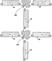
在一个具体实施方式中,根据第四方面的组合构件的特征在于,用接合装置将板形构件以一定角度连接,其中,接合装置包括集成在板材料中的舌榫和槽,以及存在于舌榫和槽处的锁定装置,锁定装置阻止舌榫和槽的偏移,其中,这些锁定装置由锁定元件组成,锁定元件均位于沿着最靠近相应拐角的内侧的舌榫的一侧。因此,锁定元件位于离外拐角一定距离处,由于此距离的原因,可将在重负载下撕裂某些零件的危险减到最小。In a specific embodiment, the combined element according to the fourth aspect is characterized in that the plate-shaped elements are connected at an angle by means of joints, wherein the joint means comprise a tongue and groove integrated in the plate material, as well as present in the tongue Locking means at the tongue and groove, locking means against deflection of the tongue and groove, wherein these locking means consist of locking elements each located along the side of the tongue closest to the inner side of the respective corner. Thus, the locking element is located at a distance from the outer corner, due to which distance the risk of tearing certain parts under heavy loads is minimized.
优选地,这里应这样制造这种组合构件,使得板形构件形成拐角连接,拐角连接在外侧形成平齐拐角,因此,没有伸出部。Preferably, the combined component is here produced such that the plate-shaped components form a corner connection, which forms a flush corner on the outside and therefore has no protrusions.
根据第四方面的组合构件优选地利用多层板,其进一步也表现出一个或多个以下特性:A composite member according to the fourth aspect preferably utilizes a multilayer board, which further also exhibits one or more of the following properties:
-第一材料层是MDF(中密度纤维板)或HDF(高密度纤维板);- the first material layer is MDF (Medium Density Fibreboard) or HDF (High Density Fibreboard);
-第二材料层是刨花板(碎木板);- the second material layer is chipboard (chipboard);
-第二材料层是重量轻的基于木材的板;- The second material layer is a light weight wood based board;
-第一材料层的厚度比第二材料层小;- the first material layer has a smaller thickness than the second material layer;
-第一材料层的厚度小于第二材料层的厚度的0.7倍;- the thickness of the first material layer is less than 0.7 times the thickness of the second material layer;
-多层板的总厚度的至少90%由所述第一材料层和所述第二材料层组成;- at least 90% of the total thickness of the multilayer board consists of said first material layer and said second material layer;
-第一材料层和第二材料层由彼此粘结的(更具体地,彼此胶粘的)不同的板组成;- the first material layer and the second material layer consist of different plates bonded to each other, more particularly glued to each other;
-第一材料层和第二材料层形成整体压制结构的一部分,其中,第一层优选地以木纤维为基础,第二层以碎木为基础;- a first layer of material and a second layer of material form part of an integral pressed structure, wherein the first layer is preferably based on wood fibers and the second layer is based on chipped wood;
-在拐角连接的情况中,第一材料层相对于第二层位于内侧。- In the case of a corner connection, the first layer of material is located on the inside with respect to the second layer.
如从详细描述中将变得显而易见的,明显地,优选地将接合装置和相关的锁定元件至少部分地实现在第一材料层中。As will become apparent from the detailed description, it is evident that the engagement means and associated locking elements are preferably at least partially realized in the first material layer.
第一、第二、第三和第四方面是这样的方面:其可应用于在相同平面中接合在一起的板形构件,以及以一定角度接合在一起的板形构件。The first, second, third, and fourth aspects are aspects that are applicable to plate-shaped members joined together in the same plane, and plate-shaped members joined together at an angle.
根据第五方面,本发明涉及一种包括至少两个板形构件的组合构件,所述板形构件由板材料组成并以一定角度连接在一起,其特征在于,通过接合装置将板形构件连接在一起,接合装置包括在板材料本身中基本上制成为成型部件的舌榫和槽,其中舌榫具有第一侧和相对的第二侧,并且其中,所述接合装置进一步还包括锁定元件,在接合状态中锁定元件防止舌榫和槽的漂离。According to a fifth aspect, the invention relates to a composite structure comprising at least two plate-shaped elements consisting of plate material and connected together at an angle, characterized in that the plate-shaped elements are connected by means of joints Together, the engaging means comprise a tongue and groove substantially made as profiled parts in the board material itself, wherein the tongue has a first side and an opposite second side, and wherein said engaging means further comprise a locking element, In the engaged state the locking element prevents the tongue and groove from drifting off.
在根据第五方面的组合构件的一个优选实施方式中,所述接合装置表现出一个或多个以下特性:In a preferred embodiment of the composite member according to the fifth aspect, said engagement means exhibit one or more of the following properties:
-所述锁定元件仅存在于舌榫的一侧,但是,由此另一侧没有锁定元件;- said locking elements are only present on one side of the tongue, however, the other side is thus free of locking elements;
-锁定装置或锁定元件由舌榫处的至少一个锁定部分和槽中的至少一个与所述锁定部分配合的锁定部分组成,其中,锁定部分设置于舌榫,在舌榫的可弹性弯曲的部分处,该部分也形成舌榫的一侧;- the locking device or locking element consists of at least one locking part at the tongue and at least one locking part cooperating with said locking part in the groove, wherein the locking part is arranged on the tongue, in the elastically bendable part of the tongue , which part also forms one side of the tongue;
-舌榫的所述弹性部分在远端方向上伸出得比舌榫的其余部分更远;- said elastic portion of the tongue protrudes farther in distal direction than the rest of the tongue;
-通过狭槽使所述弹性部分与舌榫的其余部分分离,优选地,所述狭槽延伸得比板形构件彼此邻接所在的平面更深;- said elastic portion is separated from the rest of the tongue by a slot, preferably said slot extending deeper than the plane in which the plate-shaped members adjoin each other;
-使舌榫裂开,以允许卡合运动,其中,舌榫中的狭槽优选地延伸得比板形构件彼此邻接所在的平面更深;- splitting the tongue to allow a snap-in movement, wherein the slot in the tongue preferably extends deeper than the plane in which the plate-shaped members abut each other;
-所述锁定装置仅位于舌榫的一侧,其中,这是位于舌榫的最靠近所述拐角的内侧的一侧;- said locking means are located on only one side of the tongue, wherein this is the side of the tongue located closest to the inner side of said corner;
-接合装置和锁定元件允许通过卡合运动来接合;- the engagement means and the locking element allow engagement by a snap movement;
-接合装置和锁定元件允许通过卡合运动以及通过转动运动来接合;- the engagement means and the locking element allow engagement by a snapping movement as well as by a rotational movement;
-舌榫位于板形构件的远端(换句话说,在其端侧上),而槽位于另一板形构件的侧壁;- the tongue is located at the distal end of the plate-shaped member (in other words, on its end side), and the groove is located at the side wall of the other plate-shaped member;
-用压制和加固的木材成分的板材料来实现板形构件,例如刨花板或木材纤维板,例如,MDF或HDF,其中,接合装置包括在相关的板形构件的平面中远端地延伸的舌榫,而槽垂直于设置板形构件所在的平面而延伸。- Realize the board-shaped member with a board material of pressed and reinforced wood composition, such as particle board or wood fibreboard, for example, MDF or HDF, wherein the joining means comprise a tongue extending distally in the plane of the relevant board-shaped member , while the groove extends perpendicular to the plane on which the plate-shaped member is disposed.
在第五方面的又一优选实施方式中,这种组合构件的特征进一步在于,板形构件由至少两个结构材料层组成,分别是第一材料层和第二材料层,其中,此组合构件进一步表现出任何以下特性:In yet another preferred embodiment of the fifth aspect, the composite member is further characterized in that the plate-shaped member is composed of at least two structural material layers, namely a first material layer and a second material layer, wherein the composite member Further exhibits any of the following characteristics:
-舌榫的一侧位于第一材料层中和相对侧位于第二材料层中;- one side of the tongue is in the first material layer and the opposite side is in the second material layer;
-第一材料层的材料表现出比第二材料层的材料更细的结构,而至少一个所述锁定元件位于第一材料层中,更具体地在其中制成一片,这允许精确地实现锁定元件;- the material of the first material layer exhibits a finer structure than the material of the second material layer, while at least one of said locking elements is located in the first material layer, more particularly made in one piece, which allows the locking to be precisely achieved element;
-第一材料层的材料表现出比第二材料层的材料更细的结构,其中,舌榫和槽处的锁定元件都包括均位于所涉及的板形构件的第一材料层中的锁定元件。- the material of the first material layer exhibits a finer structure than the material of the second material layer, wherein both the locking elements at the tongue and the groove comprise locking elements both located in the first material layer of the plate-shaped member concerned .
由于用更细的材料(例如,MDF或HDF)来实现锁定元件,所以掉落的颗粒将对锁定产生不利影响的危险较小。而且,可具有更小的公差。Since the locking element is realized with a finer material, eg MDF or HDF, there is less risk that falling particles will adversely affect the locking. Also, smaller tolerances are possible.
而且,通过根据第五方面的组合面板,优选地,位于由板形构件形成的拐角的外侧的板形构件以平齐方式彼此邻接,使得所涉及的拐角没有伸出的面板部分。Furthermore, with the composite panel according to the fifth aspect, preferably, the plate-shaped members located outside the corner formed by the plate-shaped members abut each other in a flush manner, so that the corner in question has no protruding panel portion.
根据第六方面,本发明涉及一种组合构件,其至少部分地由一组板形构件组成,完全包围一定空间,其特征在于,通过集成在面板的边缘中的成型部件形式的接合装置,将板形构件彼此接合在此空间整个周围,所述成型部件允许可将所有这些板形构件侧向地连接在彼此中。优选地,所述空间由四个板形构件包围,通过集成在这些元件的边缘中的成型部件的形式的接合装置,将这四个板形构件连续地侧向连接在彼此中,并由此形成具有四个拐角的元件。此外,这里优选地是,所述四个板形构件具有成型部件,其被组成为使得可以至少以下方式中的一种将四个板形构件连接在一起:According to a sixth aspect, the invention relates to a composite element consisting at least partially of a set of plate-shaped elements completely enclosing a certain space, characterized in that the The plate-shaped components engage with each other all around this space, the profiled part making it possible to connect all these plate-shaped components laterally in one another. Preferably, said space is surrounded by four plate-shaped members, which are connected laterally in succession to each other by joint means in the form of profiled parts integrated in the edges of these elements, and thus Form an element with four corners. Furthermore, it is preferred here that the four plate-shaped components have profiled parts, which are constituted such that the four plate-shaped components can be joined together in at least one of the following ways:
-至少通过转动运动,在所述四个拐角中的三个处,可将板形构件连接在彼此中,然而,至少通过卡合运动,在第四拐角处,可将彼此相邻的板形构件侧向地连接在彼此中;- at least by a turning movement, at three of said four corners, the plate-shaped members can be connected in each other, however, at least by a snap-in movement, at the fourth corner, the plate-shaped members adjacent to each other can be connected the members are laterally connected in each other;
-至少通过卡合运动,在所有四个拐角处,可将板形构件侧向地连接在彼此中;- at least by a snap-in movement, the plate-shaped members can be connected laterally in each other at all four corners;
-通过转动运动,至少在两个连续拐角处,可将四个板形构件中的三个连接在彼此中,然而,至少通过卡合运动,可将第四板形构件与其它板连接,更具体地,连接在其它板之间。- three of the four plate-shaped members can be connected in each other by a turning movement, at least at two consecutive corners, however, at least by a snap-in movement, the fourth plate-shaped member can be connected with the other plates, more Specifically, connections between other boards.
第六方面提供了装配简单的优点。The sixth aspect offers the advantage of simplicity of assembly.
根据第七方面,本发明涉及一种组合构件,其特征在于,其包括这样的基本结构:至少在三个连续侧面,其设置有由板形构件形成的覆盖物,其特征在于,这些板形构件通过接合装置彼此相互地连接。这种组合构件允许,由于所述接合装置的原因,可在基本结构周围轻松地设置覆盖物,同样也可将其保持在其适当的位置中。在一个实际的实施方式中,板形构件由板材料组成,并且,至少通过形成于板材料本身中的成型部件,形成接合装置。According to a seventh aspect, the invention relates to a composite element, characterized in that it comprises a basic structure provided, at least on three consecutive sides, with a covering formed by plate-shaped elements, characterized in that the plate-shaped The components are interconnected to each other by joint means. Such a combined component allows, thanks to said joint means, to easily arrange a covering around the basic structure and also to keep it in place. In a practical embodiment, the plate-shaped member consists of a plate material and the joining means are formed at least by profiled parts formed in the plate material itself.
基本结构可由任何元件组成。例如,其可涉及用于一件厨房家具的框架,电冰箱,例如,存酒橱柜,等等。The basic structure can consist of any elements. For example, it may relate to a frame for a piece of kitchen furniture, a refrigerator, eg a wine cabinet, etc.
根据第八方面,本发明涉及一种组合构件,其组成的基本结构由在许多侧面设置有覆盖物的电冰箱形成,其特征在于,覆盖物由板形构件组成,该板形构件由设置有层压覆盖物的基于木材的板组成。此第八方面允许以便宜的方式提供覆盖物。例如,基于木材的板是MDF或HDF板。According to an eighth aspect, the present invention relates to a composite member whose basic structure is formed by a refrigerator provided with a cover on many sides, characterized in that the cover consists of a plate-shaped member provided with Composition of wood-based boards for laminate coverings. This eighth aspect allows covering to be provided in an inexpensive manner. Wood-based boards are, for example, MDF or HDF boards.
根据第九方面,本发明涉及一种壁部或家具构件形式的组合构件,其包括至少两个板形构件,其特征在于,利用锁定元件,通过接合装置将板形构件连接,将锁定元件制造成为位于一个板形构件中的边缘中的插入件。这种插入件的使用提供了这样的优点:关于锁定、弯曲等,可获得除了在板形构件的板材料本身中实现接合装置以外的其它特征。因此,可明显地优化两个板形构件之间的连接,因为以此方式可实现更坚固的锁定,然而,对板材料本身不会施加过大的负载。According to a ninth aspect, the present invention relates to a composite element in the form of a wall or furniture element, comprising at least two plate-shaped elements, characterized in that the plate-shaped elements are connected by means of joint means, the locking elements being manufactured Be an insert in an edge in a plate-shaped member. The use of such inserts offers the advantage that, with respect to locking, bending etc., other features than the realization of the engagement means in the plate material itself of the plate-shaped member can be obtained. Thus, the connection between the two plate-shaped components can be significantly optimized, since in this way a stronger locking can be achieved without, however, exerting excessive loads on the plate material itself.
从说明书和权利要求书中,使用插入件的这种接合装置的优选特性将变得显而易见。Preferred characteristics of such engagement means using inserts will become apparent from the description and claims.
根据第十方面,本发明涉及一种多层板,其特征在于,其由至少两个结构材料层组成,分别是第一材料层和第二材料层,将结构材料层均制造成为木材复合物,并且其中,第一材料层的材料表现出比第二层的材料更细的结构。According to a tenth aspect, the invention relates to a multilayer panel, characterized in that it consists of at least two layers of structural material, respectively a first material layer and a second material layer, each of which is manufactured as a wood composite , and wherein the material of the first material layer exhibits a finer structure than the material of the second layer.
显而易见的是,就“木材复合物”来说,是这样的组成:至少由以木材为基础的成分和将这些成分彼此连接的粘合剂形成。例如,这些成分由木颗粒和/或木纤维和/或木粉(也叫做锯屑)组成。表示成复数形式的“成分”的事实意味着,这涉及一定量的组成颗粒,因此不意味着,必须在相同的层中存在不同类型(例如,一方面是纤维,另一方面是颗粒),虽然并不排除此情况。It is obvious that in the case of a "wood composite" a composition is formed of at least wood-based components and an adhesive connecting these components to each other. For example, these components consist of wood particles and/or wood fibers and/or wood flour (also called sawdust). The fact that "constituents" are expressed in plural means that this involves a certain amount of constituent particles and therefore does not mean that different types must be present in the same layer (e.g. fibers on the one hand and particles on the other), Although this is not ruled out.
就“更细的”结构来说,特别是这样的结构:在第一材料层的横截面中,该结构提供比通过第二材料层的横截面获得的表面更细的表面。In the case of a "finer" structure, in particular a structure which, in the cross-section of the first material layer, provides a finer surface than is obtained by the cross-section of the second material layer.
例如,这种“更细的”结构可这样组成:在第一材料层中应用更细的木材成分和/或在第一材料层中使用更好的填充材料,使得获得孔更少的结构,和/或在第一材料层中应用更高的密度。Such a "finer" structure can be composed, for example, by applying a finer wood component in the first material layer and/or using a better filling material in the first material layer, so that a structure with fewer pores is obtained, And/or apply a higher density in the first material layer.
显而易见的是,当板基本上在木材的基础上制造时,可以以相对便宜的方式实现这种板,然而,因为可根据应用来优化每个材料层,所以同时具有重要的使用可能性。It is obvious that such a board can be realized in a relatively cheap manner when it is manufactured essentially on a wood basis, but at the same time has important possibilities of use because each material layer can be optimized according to the application.
此多层板优选地具有满足一个或多个以下可能性的结构:This multilayer board preferably has a structure satisfying one or more of the following possibilities:
-在木纤维材料的基础上形成第一层,更具体地,由MDF或HDF组成;- Formation of the first layer on the basis of wood fiber material, more specifically, consisting of MDF or HDF;
-在木颗粒的基础上形成第二层,更具体地,由刨花板组成;- A second layer is formed on the basis of wood particles, more specifically, composed of chipboard;
-将第二层制造成为重量轻的基于木材的层,例如,重量轻的基于木材的板;这种重量轻的基于木材的层或板由其中具有一个或多个更轻的填充材料的木材成分组成;- manufacturing the second layer as a lightweight wood-based layer, e.g., a lightweight wood-based board; such a light-weight wood-based layer or board is made of wood with one or more lighter filler materials therein Composition;
-所述重量轻的基于木材的板至少包括作为填充材料的泡沫合成材料和/或亚麻碎片等;- said lightweight wood-based board comprises at least foamed synthetic material and/or flax chips etc. as filling material;
-第一层的厚度比第二层小;- the thickness of the first layer is smaller than that of the second layer;
-第一层的厚度小于第二层的厚度的0.7倍;- the thickness of the first layer is less than 0.7 times the thickness of the second layer;
-多层板的总厚度的至少90%由所述第一层和所述第二层组成;- at least 90% of the total thickness of the multilayer board consists of said first layer and said second layer;
-第一和第二材料层由颗粒(更具体地,木颗粒)组成,然而,第一材料层平均比第二材料层包括更细的木颗粒和/或更多的粘合剂;- the first and second material layers consist of particles, more particularly wood particles, however, the first material layer comprises on average finer wood particles and/or more binder than the second material layer;
-第一层和第二层由彼此粘结在一起的(更具体地,胶粘在一起的)独立的板组成;- the first layer and the second layer consist of separate panels bonded to each other (more in particular glued together);
-第一层和第二层形成整体压制结构的一部分,因此,在单次操作中实现两个层。- The first layer and the second layer form part of an overall pressed structure, thus realizing both layers in a single operation.
应注意,对于第一和第二材料层的所有可能的组合(这里以上总结的可能性)明确地落在本发明范围内,除了表现出相互矛盾的特性的组合以外。It should be noted that all possible combinations for the first and second material layers (possibilities summarized here above) expressly fall within the scope of the invention, except combinations exhibiting contradictory properties.
显而易见的是,就“结构的”层来说,必须这样理解所述层:在横截面中观察时,每个层形成组合板的厚度的基本组成部分。不可将这样的层认为是结构层,例如,专门作为外壳而实现的层,例如,为了获得更平滑的表面而具有的在板的表面处的更细颗粒的薄层。优选地,第一和第二材料层表现出这样的厚度,每个厚度至少是组合板的总厚度的25%,更优地,是其30%。It is obvious that, in terms of "structural" layers, the layers must be understood in such a way that each layer forms an essential part of the thickness of the composite panel when viewed in cross-section. Such a layer cannot be considered as a structural layer, eg a layer realized exclusively as a skin, eg a thin layer with finer grains at the surface of the plate in order to obtain a smoother surface. Preferably, the first and second material layers exhibit a thickness that is each at least 25%, more preferably 30%, of the total thickness of the composite panel.
显而易见的是,“更细的结构”所指的差异表示了由只为此目的而应用的生产方法所获得的差异,更具体地,通过应用相互不同的材料,相互不同的材料混合物,或不同比例的材料。然而,当密度分布仅是,例如,在压机中压制并加固材料块(material mass)的结果(其中,如所知道的,在表面出现比在中心更大的压缩),不将这样的密度分布认为是本发明所希望的“差异”。It is obvious that the differences referred to by "finer structure" represent differences obtained by production methods applied only for this purpose, more specifically by applying mutually different materials, mutually different mixtures of materials, or different proportional material. However, when the density distribution is only the result, for example, of pressing and consolidating a material mass in a press (where, as is known, greater compression occurs at the surface than at the centre), such density The distribution is considered the "variance" desired by the present invention.
应该注意,包括至少两个结构层的板同样也是有利的,不管第一材料是否具有比第二材料层更细的结构,其中每个结构层具有相对于总厚度相当大的厚度,并且其中,第一材料层由压制木材成分形成而第二材料层包括更轻重量的压制复合材料。为此目的,根据第十一方面,本发明由此还涉及一种板,其特征在于,其包括至少两个结构材料层,其中,其第一材料层由压制木材复合物形成,而第二材料层包括更轻重量的压制复合材料,更具体地是重量轻类型的。优选地,第一材料层基本上由木材复合物组成,更好地,仅由其组成,由此,由木材成分组成,例如,木颗粒和/或纤维,第一材料层被压制并通过粘合剂加固,通过粘合剂,例如,第一材料层可与刨花板或MDF/HDF板相当,或由其组成。第二材料层的复合材料优选地是复合物,因此,在一个或多个从以下系列中选择的材料的基础上,形成具有粘合剂的材料颗粒:It should be noted that panels comprising at least two structural layers are also advantageous, irrespective of whether the first material has a finer structure than the second material layer, wherein each structural layer has a considerable thickness relative to the total thickness, and wherein, The first material layer is formed from pressed wood components and the second material layer includes a lighter weight pressed composite material. For this purpose, the invention thus also relates to a panel according to an eleventh aspect, characterized in that it comprises at least two layers of structural material, wherein its first material layer is formed from a pressed wood composite and the second The layer of material comprises a lighter weight pressed composite material, more particularly of a lighter weight type. Preferably, the first material layer consists essentially of wood composites, better only, whereby, consisting of wood components, e.g. wood particles and/or fibers, the first material layer is pressed and glued together. Reinforced with a compound, by means of an adhesive, for example, the first layer of material may be comparable to or consist of particle board or MDF/HDF board. The composite material of the second material layer is preferably a composite, whereby material particles with a binder are formed on the basis of one or more materials selected from the following series:
-具有泡沫合成材料的木材,例如,具有泡沫合成材料的木颗粒和/或具有泡沫合成材料的木纤维;- wood with a foamed composition, for example wood particles with a foamed composition and/or wood fibers with a foamed composition;
-亚麻,更具体地,亚麻颗粒,来源于亚麻碎片;- flax, more specifically flax grains, derived from flax chips;
-稻草;-straw;
-草,例如干草、大麻纤维或象草;- Grasses, such as hay, hemp or elephant grass;
-在亚麻和/或稻草和/或草的基础上形成的复合物,与泡沫合成材料和/或木颗粒结合。-Compounds formed on the basis of flax and/or straw and/or grass in combination with foamed synthetics and/or wood pellets.
显而易见的是,可将另一些其它材料混入复合物中。Obviously, still other materials can be mixed into the compound.
在板的生产过程中,可使泡沫合成材料发泡,以及使其已经预先发泡,并可在将整体压成板之前使泡沫合成材料占据木材成分之间的空间,例如,以泡沫颗粒的形式(例如颗粒)。During the production of boards, the foamed composite can be foamed, as well as already pre-foamed, and the foamed composite can be made to occupy the spaces between the wood components before pressing the whole into boards, for example, in the form of foam particles form (e.g. granules).
根据本发明的第十一方面,第一材料层和第二材料层优选地形成整体压制结构的一部分,但是并不排除从独立制造的板来形成这两个材料层中的每个,其中,可将相应的板彼此连接。According to the eleventh aspect of the invention, the first and second material layers preferably form part of a unitary pressed structure, but it is not excluded that each of the two material layers is formed from a separately manufactured plate, wherein, The corresponding boards can be connected to each other.
显而易见的是,还根据第十一方面,就“结构层”来说,必须这样理解所述层:在横截面中观察时,每个层形成组合板的厚度的基本组成部分。例如,专门作为外壳而实现的层(例如,为了获得更平滑的表面而具有的板的表面处的更细颗粒的薄层),不可将这样的层认为是结构层。优选地,第一和第二材料层表现出这样的厚度,每个厚度至少是组合板的总厚度的25%,更优地,是其30%。It is obvious, also according to the eleventh aspect, that with regard to "structural layers", said layers must be understood in such a way that each layer forms an essential part of the thickness of the composite panel when viewed in cross-section. For example, a layer realized exclusively as a skin (for example, a finer-grained thin layer at the surface of a plate in order to obtain a smoother surface), such a layer cannot be considered a structural layer. Preferably, the first and second material layers exhibit a thickness that is each at least 25%, more preferably 30%, of the total thickness of the composite panel.
显而易见的是,与所述两个结构材料层不同,第十以及第十一方面的板可包括另一些其它结构材料层。根据一个特定实施方式,将所述板实现为夹心板,具有至少三个结构材料层,其中,优选地,上述三个材料层中的两个相邻材料层由所述第一和第二材料层形成。It is obvious that, instead of said two layers of structural material, the panels of the tenth and eleventh aspects may comprise still other layers of structural material. According to a particular embodiment, said panel is realized as a sandwich panel with at least three structural material layers, wherein, preferably, two adjacent material layers of said three material layers are made of said first and second material layers layer formation.
然而,仅具有两个结构材料层的板表现出其更易于实现的优点。而且,然后,每个材料层可具有相对于总厚度来说相对较大的厚度,当必须在一个材料层中实现接合部件时,这是有用的。However, panels with only two layers of structural material present the advantage of being easier to implement. Also, then, each material layer may have a relatively large thickness relative to the total thickness, which is useful when joining components have to be realized in one material layer.
当然,第十和第十一方面的板可在一个或两个平侧上具有精加工,例如,用三聚氰胺处理和/或印刷和/或涂漆。Of course, the panels of the tenth and eleventh aspects may have a finishing on one or both flat sides, eg melamine treatment and/or printing and/or painting.
应该指出,当将第十或第十一方面的板实现为整体压制结构时,第一材料层和第二材料层之间的过渡可以是逐步的。然后,应将过渡的中点认为是边界线。It should be noted that when the panel of the tenth or eleventh aspect is realized as a unitary pressed structure, the transition between the first material layer and the second material layer may be gradual. The midpoint of the transition should then be considered the boundary line.
此外,优选地,根据第十或第十一方面的所述多层板的特征在于,将其制造成为板形构件,其至少在两个边缘设置有用于以互锁方式将几个这种板形构件彼此接合的接合装置,其通过或不通过设置于成形连接件之间中间物,其中,这些接合装置表现出一个或多个以下特征:Furthermore, preferably, said multi-layer panel according to the tenth or eleventh aspect is characterized in that it is manufactured as a plate-shaped member provided at least on two edges with means for interlocking several such panels. Engagement means for joining shaped members to one another, with or without intermediaries disposed between shaped connectors, wherein these engaging means exhibit one or more of the following characteristics:
-接合装置允许将至少两个这种板形构件在相同的平面中彼此接合,优选地彼此直接接合;- engaging means allow at least two such plate-shaped members to be joined to each other in the same plane, preferably directly to each other;
-接合装置允许将至少两个这种板形构件以一定角度彼此接合,直接地接合或(如进一步描述的)通过中间件接合;- engaging means allow at least two such plate-shaped members to be joined to each other at an angle, either directly or (as further described) via an intermediate piece;
-接合装置由舌榫和槽以及锁定元件组成,锁定元件至少在板形构件的某一相互位置中防止一个元件的舌榫从另一元件的槽出来;- the engaging means consist of a tongue and a groove and a locking element which prevents the tongue of one element from coming out of the groove of the other element at least in a certain mutual position of the plate-shaped member;
-所述锁定元件仅存在于舌榫的一侧,由此另一侧没有锁定元件;- said locking element is only present on one side of the tongue, whereby the other side has no locking element;
-锁定装置由舌榫处的至少一个锁定部分和槽中的至少一个与其配合的锁定部分组成,其中,舌榫处的锁定部分设置于舌榫的可弹性弯曲的部分,其也形成舌榫的一侧;- The locking device consists of at least one locking part at the tongue and at least one locking part cooperating with it in the groove, wherein the locking part at the tongue is arranged on an elastically bendable part of the tongue, which also forms the part of the tongue side;
-舌榫的所述弹性部分在远端方向上比舌榫的其余部分伸出得更远;- said elastic portion of the tongue protrudes farther in distal direction than the rest of the tongue;
-通过狭槽使所述弹性部分与舌榫的其余部分分离;- separating said elastic part from the rest of the tongue by means of a slot;
-所述锁定装置仅位于舌榫的一侧,其中,这是舌榫的位于最靠近所述拐角的内侧的一侧;- said locking means are located on only one side of the tongue, wherein this is the side of the tongue which is located on the inside closest to said corner;
-舌榫的一侧位于第一材料层中和相对侧位于第二材料层中;- one side of the tongue is in the first material layer and the opposite side is in the second material layer;
-至少一个上述锁定元件位于第一材料层中,更具体地与其制成一体;- at least one of the above-mentioned locking elements is located in the first material layer, more particularly in one piece therewith;
-舌榫以及槽处的所述锁定元件均位于第一材料层中;- said locking elements at the tongue as well as at the groove are located in the first material layer;
-整个舌榫和槽(其中,所述槽的肋(flank)通过至少朝着彼此指向的槽来设计)以及锁定元件在第一材料层的材料中实现。- The entire tongue and groove (wherein the flanks of said grooves are designed by at least grooves pointing towards each other) and the locking element are realized in the material of the first material layer.
根据本发明,以上这里总结的所有特征可任意组合,只要这种组合是不矛盾的。According to the invention, all the features summarized here above can be combined arbitrarily as long as such combinations are not contradictory.
根据独立的第十二方面,本发明涉及一种组合构件,其包括至少两个相互成一定角度的板形构件,以及至少一个可与两个板形构件配合的连接件,其特征在于,至少一个板形构件包括这样的边缘区域,其中,存在成型部件形式的接合装置,所述接合装置在所涉及的边缘区域的纵向方向上延伸;连接件包括至少一个在其纵向方向上延伸的成型部件;并且,所述成型部件允许以互锁方式将板形构件与连接件侧向地连接在彼此中,并以此方式将其彼此接合。According to an independent twelfth aspect, the present invention relates to a composite member comprising at least two plate-shaped members at an angle to each other, and at least one connecting piece capable of cooperating with the two plate-shaped members, characterized in that at least A plate-shaped component comprises such an edge area, wherein, there is the joint device in the form of profiled part, and described joint device extends in the longitudinal direction of the edge area concerned; Connecting part comprises at least one profiled part extending in its longitudinal direction and, said profiled parts allow to laterally connect the plate-shaped member and the connector in each other in an interlocking manner and engage them in each other in this way.
这种组合构件具有这样的优点:其易于装配,并且,对于形成拐角连接,可排除小部件的使用,例如,螺钉、连接销、夹紧系统等。而且,易于制造。连接件可根据制造商的选择由不同的材料实现,由此,对于此目的,除了用于板形构件的材料,可选择另一材料。Such a combined component has the advantage that it is easy to assemble and, for forming the corner connection, the use of small parts such as screws, connecting pins, clamping systems etc. can be excluded. Moreover, it is easy to manufacture. The connection piece can be realized from different materials according to the choice of the manufacturer, whereby for this purpose, another material can be selected than the material used for the plate-shaped component.
例如,板形构件由层压木材复合板组成,例如,层压刨花板或木纤维板,或多层板,例如以上已经描述的。而且,可考虑用其它方式涂覆的木材复合板。For example, the panel-shaped component consists of laminated wood composite panels, for example laminated particleboard or wood fiberboard, or multilayer panels, such as already described above. Also, wood composite panels coated in other ways are contemplated.
优选地,将连接件制造成为成形板条(profiled lath)。例如,可通过挤出或通过用机加工处理(例如,铣削处理)提供笔直板条中必需的轮廓,来形成连接件。Preferably, the connector is manufactured as profiled lath. For example, the connectors may be formed by extrusion or by providing the necessary contours in straight slats with a machining process (eg, a milling process).
可用于实现连接件的材料的许多实际实例是MDF、HDF、实木、铝或合成材料,更具体地,尼龙、PET、PP、PVC等。当然,可对成型部件提供覆盖物,例如,通过印刷机和/或一个或多个硝基漆层和/或通过包覆。在包覆的情况中,可使用任何薄膜,例如,纸、PP、PVC、PET、单板(veneer)等。Many practical examples of materials that can be used to realize the joints are MDF, HDF, solid wood, aluminum or synthetic materials, more particularly nylon, PET, PP, PVC, etc. Of course, the profiled part can be provided with a covering, for example by means of a printing press and/or one or more layers of lacquer and/or by cladding. In the case of cladding, any film can be used, for example paper, PP, PVC, PET, veneer, etc.
连接件可具有不同的长度。其最终长度可相当于应用连接件的一件家具等的深度,或与其不同。例如,并不排除应用较短的连接件,由此,例如,将必须沿着一件家具的相应边缘以彼此具有一定距离的方式,应用其中的至少两个连接件。在这种情况中,这些连接件可具有几厘米的长度,或甚至具有小于或等于一厘米的长度。The connectors can be of different lengths. Its final length may correspond to, or differ from, the depth of a piece of furniture or the like to which the connector is applied. For example, the application of shorter connectors is not excluded, whereby, for example, at least two of them would have to be applied along respective edges of a piece of furniture at a distance from each other. In this case, these connectors may have a length of a few centimeters, or even a length less than or equal to one centimeter.
优选地,将板形构件处的成型部件与其制成一体。Preferably, the profiled part at the plate-shaped member is integrally formed therewith.
优选地,成型部件被构造成使得,可至少通过卡合运动使板形构件和连接件连接在彼此中。更好地,其被构造成使得,在一个连接或相同的连接的位置,可根据装配者的选择,通过转动以及通过卡合运动将它们连接在彼此中。Preferably, the profiled part is configured such that the plate-shaped component and the connecting piece can be connected in one another at least by a snap-in movement. Preferably, it is constructed such that, at the position of one connection or the same connection, they can be connected in each other by rotation and by a snap-in movement, according to the fitter's choice.
成型部件优选地应用舌榫和槽连接,其中,舌榫和槽设置有防止漂离的锁定部分或锁定元件。舌榫优选地位于板形构件的远端,而槽设置于连接件中。优选地,为了卡合操作的目的而使舌榫裂开。这里,有利的是:为此目的而存在于舌榫中的狭槽向上延伸至一定深度,在安装状态中,该深度比直到板形构件与连接件邻接所在的平面的距离更深。The profiled parts preferably apply a tongue and groove connection, wherein the tongue and groove are provided with locking portions or locking elements that prevent drifting away. The tongue is preferably located at the distal end of the plate-shaped member, while the groove is provided in the connector. Preferably, the tongue is split for the purpose of the snapping operation. Here, it is advantageous that the slot present in the tongue for this purpose extends upwards to a depth which, in the installed state, is deeper than the distance up to the plane where the plate-shaped component adjoins the connecting piece.
第十二方面的组合构件优选地是家具构件。这可涉及任何类型的家具构件。一个实际的应用领域是在模块化悬挂或直立橱柜中。另一种应用是在厨房橱柜中,例如,用于组成基本的厨房模块,其可由厨房安装者进一步完成,例如,通过在其上提供前壁、工作台面等。The composite member of the twelfth aspect is preferably a furniture member. This can involve any type of furniture component. A practical area of application is in modular hanging or upright cabinets. Another application is in kitchen cabinets, for example for composing basic kitchen modules, which can be further completed by the kitchen installer, for example by providing front walls, worktops etc. thereon.
在拐角结构中,优选地,通过成型部件以这种方式将两个彼此邻接的板形构件接合至连接件。应该指出,单次折叠的拐角连接中的舌榫和槽优选地总是位于离内拐角的距离比离外拐角的距离更小的地方。In corner constructions, preferably two mutually adjoining plate-shaped components are joined to the connection piece in this way by means of a profiled part. It should be pointed out that the tongue and groove in a single-fold corner connection is preferably always located at a smaller distance from the inner corner than from the outer corner.
而且,可应用允许T连接、交叉连接或在相同平面中连接的连接件,使得可将多个家具模块形成为彼此靠近并且一个在另一个之上。Furthermore, connections can be applied which allow T-connections, cross-connections or connections in the same plane, so that a plurality of furniture modules can be formed close to each other and one above the other.
优选地,沿着拐角边缘安装连接件,在拐角边缘,侧壁必须分别与模块的上壁、下壁接合。更具体地,优选地,由此,通过连接件,以这种方式将侧壁、上壁和下壁之间周围的所有这种模块的组成部分接合。Preferably, the connectors are installed along the corner edges where the side walls must engage with the upper and lower walls of the modules respectively. More specifically, it is preferred thereby to join in this way all the constituent parts of such modules around the perimeter between the side walls, the upper wall and the lower wall by means of connectors.
根据第十三方面,本发明涉及一种组合构件,其包括至少两个彼此靠近的模块,具有侧壁、上壁和下壁,由板形构件形成,其特征在于,用单个公共板形构件形成侧壁(在那里,模块彼此邻接);在此公共板形构件和模块的上壁之间具有第一连接结构;在此公共板形构件和模块的下壁之间具有第二连接结构;并且,在至少一个所述连接结构的位置,经由形成于此板形构件的成型部件,将一个板形构件与其它板形构件直接或间接地接合。According to a thirteenth aspect, the present invention relates to a composite element comprising at least two modules close to each other, having side walls, an upper wall and a lower wall, formed by plate-shaped elements, characterized in that, with a single common plate-shaped element forming side walls (where the modules abut one another); having a first connecting structure between the common plate-shaped member and the upper wall of the modules; having a second connecting structure between the common plate-shaped member and the lower wall of the modules; And, at the position of at least one of the connection structures, one plate-shaped member is directly or indirectly joined to the other plate-shaped member via a molding part formed on this plate-shaped member.
通过第十三方面的技术,可以快速的方式装配各个模块。独立侧壁之间的分开高度调节和连接不再是必需的。此外,考虑到这样的事实:在模块之间仅需要单个公共板形构件,所以节省了空间。With the technique of the thirteenth aspect, individual modules can be assembled in a rapid manner. Separate height adjustments and connections between separate side walls are no longer necessary. Furthermore, space is saved in view of the fact that only a single common plate-shaped member is required between the modules.
在一个优选实施方式中,通过设置于元件中的成型部件,将所有与所述连接结构在一起的板形构件彼此接合,其通过或不通过中间件。In a preferred embodiment, all plate-shaped components together with the connection structure are joined to each other by means of profiled parts arranged in the element, with or without intermediate pieces.
对于接合装置和/或与其一起使用的连接件,优选地,使用由如在之前的方面中描述的实施方式组成。For the coupling device and/or the connection used therewith, preferably, the use consists of an embodiment as described in the previous aspect.
当建造厨房橱柜时,第十一方面是特别有利的,特别是作为厨房建造者的基础而提供的模块,厨房建造者用这些模块建造完整的厨房橱柜,例如,通过对其提供前面板、工作台面、可能的附加横向覆盖物以及各种附件。The eleventh aspect is particularly advantageous when building kitchen cabinets, in particular modules provided as a basis for kitchen builders who use these modules to build complete kitchen cabinets, for example, by providing them with front panels, working Worktops, possible additional lateral coverings and various accessories.
根据第十四方面,本发明还涉及一种板,在其大部分厚度上,该板包括压制木材复合物,其至少由木材成分和粘合剂组成,其特征在于:在木材复合物中,通过其成分形成了局部厚度的加强层。就“局部厚度”来说,意味着,加强层表现出比板的总厚度更小的厚度,因此,在横截面中观察时,仅局部地存在。According to a fourteenth aspect, the present invention also relates to a panel comprising, over a majority of its thickness, a pressed wood composite consisting at least of wood components and a binder, characterized in that in the wood composite, Through its composition, a reinforcing layer of local thickness is formed. By "local thickness" it is meant that the reinforcing layer exhibits a smaller thickness than the overall thickness of the plate and is therefore only locally present when viewed in cross-section.
应该指出,加强层形成于木材复合物中,这意味着,加强层是集成在板中的一体件,并且这不涉及通过在提前形成的其它板形层之间的胶粘等而应用的分开的层。It should be noted that the reinforcement layer is formed in the wood composite, which means that the reinforcement layer is an integral piece integrated in the board, and this does not involve the separation applied by gluing etc. between other board-shaped layers formed in advance layer.
第十四方面的这种板具有这样的优点:一方面,其可以经济的方式实现,另一方面,其在许多应用中提供有利的特征。This plate of the fourteenth aspect has the advantage that, on the one hand, it can be realized in an economical manner and, on the other hand, it offers advantageous characteristics in many applications.
然而,由于是从压制木材复合物开始的并且由此最重要的基本材料是木材的事实,成本保持相对较低。由于加强层此外仅形成于一定厚度上,所以,为此目的而所需的材料的量和成本保持较低。However, due to the fact that starting from pressed wood composites and thus the most important basic material is wood, the costs are kept relatively low. Since the reinforcing layer is moreover formed only to a certain thickness, the amount and cost of material required for this purpose remains low.
显而易见的是,例如,当制造家具面板时,可有利地应用这种板。其中,由此制造的家具面板表现出增加的弯曲阻力,由于其影响,当例如作为架子时,其将较慢地下垂和/或可承载更重的负载。It is obvious that such a board can be advantageously applied, for example, when manufacturing furniture panels. Therein, the furniture panels thus produced exhibit an increased bending resistance, as a result of which they will sag more slowly and/or can carry heavier loads when, for example, acting as a shelf.
在一个特定实施方式中,在设置有由板材料形成的接合装置的面板的制造中应用所述板,接合装置包括锁定部分或锁定元件,并且,将这些接合装置至少部分地实现在加强层中。这提供这样的优点:与由相似板实现的面板(但是不存在这种加强层)相比,所获得的接合装置更坚固。其结果是,例如,可实现更坚固的接合,其中,可承载更重的接合零件,不会出现其破裂和/或撕裂。另一方面,根据本发明,还可实现便宜一些的板,例如,具有更低的密度,并由此相对地具有更少的木材复合物,其中,由于加强层的原因,仍可在其中实现接合装置,其具有正常或甚至更好的强度。例如,它的一个实际应用由在MDF中制造面板组成,其中,加强层集成在其至少一定厚度中,使得在该位置中,在板中产生增加的强度,并且可在许多应用中用这种MDF板作为更贵一些的HDF板的替代物。In a particular embodiment, said panels are applied in the manufacture of panels provided with engaging means formed of the panel material, comprising locking portions or locking elements, and these engaging means are realized at least partially in the reinforcing layer . This offers the advantage that the joint obtained is stronger than a panel realized from similar panels, but without such a reinforcement layer. As a result, for example, a stronger joint can be achieved, wherein heavier joint parts can be loaded without cracking and/or tearing thereof. On the other hand, according to the invention, less expensive boards can also be realized, for example, with a lower density and thus relatively less wood composite, wherein, due to the reinforcement layer, it is still possible to realize Engagement means, which have normal or even better strength. One practical application of it consists, for example, in the manufacture of panels in MDF, in which a reinforcement layer is integrated in at least a certain thickness thereof, so that in this position an increased strength is produced in the panel, and this can be used in many applications MDF boards are used as an alternative to more expensive HDF boards.
因此,本发明对于在其边缘设置有接合装置的地板块(地板镶板,floorpanel)、家具面板和顶棚镶板来说特别有用,接合装置允许以互锁方式将这种面板直接或间接地彼此接合。The invention is therefore particularly useful for floorboards (floor panels), furniture panels and ceiling panels provided at their edges with joint means which allow to connect such panels directly or indirectly to each other in an interlocking manner. join.
显而易见的是,通常,可根据使用板的应用场合,来选择加强层的位置。而且,显而易见的是,在板中也可以设置两个或更多个加强层。It will be apparent that, in general, the location of the reinforcement layer can be chosen according to the application in which the panel is used. Furthermore, it is obvious that two or more reinforcement layers can also be provided in the panel.
优选地,加强层基本上在整个板上延伸,优选地相对均匀地延伸。这提供这样的优点:不管面板由板形成所做的位置如何,例如,从那里被锯开,总是可在边缘形成加强的接合装置。Preferably, the reinforcement layer extends substantially across the entire panel, preferably relatively uniformly. This offers the advantage that a reinforced joint can always be formed at the edge, irrespective of the position in which the panels are formed from the panels, for example, from which they are sawn.
根据第十四方面的板优选地涉及通过压制一层垫子形状的木材复合物来获得的类型的板,无论是否与其它材料组合或不组合,如在刨花板和MDF/HDF板的传统制造中所常见的。The board according to the fourteenth aspect preferably relates to a board of the type obtained by pressing a layer of mat-shaped wood composite, whether in combination with other materials or not, as is done in the traditional manufacture of particle boards and MDF/HDF boards Common.
应用于根据本发明的第十四方面的板中的木材复合物优选地由具有粘合剂的木纤维组成。更具体地,优选地,将木材复合物实现为MDF或HDF板,加强层集成在其中。The wood composite used in the board according to the fourteenth aspect of the invention preferably consists of wood fibers with binder. More specifically, preferably, the wood composite is realized as an MDF or HDF board, in which the reinforcement layer is integrated.
然而,为此目的,并不排除应用其它木材复合物,例如木颗粒等,使得在这种情况中,根据第十四方面的板由具有集成于其中的加强层的刨花板组成。However, for this purpose, the application of other wood composites, such as wood particles etc., is not excluded, so that in this case the board according to the fourteenth aspect consists of a particle board with a reinforcement layer integrated therein.
可以不同的方式实现加强层。The reinforcement layer can be realized in different ways.
例如,可通过在局部应用木材成分来形成加强层,至少在某一个方向上,这提供了比其余的木材成分更高的强度。其一个实例是已在其中集成木纤维层的刨花板。然后,与例如MDF或HDF相当的木纤维层表现的板平面的抗张强度高于由颗粒组成的板的部分。在这种应用中,优选地,木纤维层仅位于板的一侧,而不是位于中间,由此,在离两侧一定距离处,这是由于在此加强层中形成接合装置的原因。For example, the reinforcing layer may be formed by locally applying a wood component, at least in one direction, which provides greater strength than the remaining wood component. An example of this is particleboard in which wood fiber layers have been integrated. A wood fiber layer comparable to eg MDF or HDF then exhibits a higher tensile strength in the plane of the board than in the part of the board consisting of particles. In this application, it is preferred that the wood fiber layer is only on one side of the board, and not in the middle, thus at a distance from both sides, due to the formation of joint means in this reinforcement layer.
根据本发明的第十四方面,加强层并非必须由木材复合物组成,也可能由利用其它材料的加强层形成。例如,其可由玻璃纤维形成,玻璃纤维同样在木材复合物之间形成一层,或者在某一厚度上与木材复合物混合;优选地作为通过压制来加固的更松的纤维颗粒而引入。According to the fourteenth aspect of the present invention, the reinforcing layer does not have to be composed of a wood composite, and it is also possible to form a reinforcing layer using other materials. For example, it may be formed from glass fibers which also form a layer between the wood composites, or are mixed with the wood composites at some thickness; preferably introduced as looser fiber particles consolidated by pressing.
本发明的另一有效技术在于:通过所施加的粘合剂来实现加强层。根据第一可能性,板形成为使得其在加强层的位置包括更多的粘合剂。这里,其可涉及相同粘合剂的额外量的粘合剂,其应用在板的其余部分中,和/或应用于具有粘合效果的额外量的另一材料。通过施加更多的粘合剂,获得了更好的粘结和更坚固的质量块,这也会增加板在加强层的位置的强度。Another effective technique of the invention consists in realizing the reinforcing layer by means of an applied adhesive. According to a first possibility, the panel is formed such that it comprises more adhesive at the place of the reinforcing layer. Here, it may involve an additional amount of adhesive of the same adhesive applied in the rest of the board, and/or an additional amount of another material applied with an adhesive effect. By applying more adhesive, a better bond and a stronger mass is obtained, which also increases the strength of the plate at the place of the stiffener.
可在待加强的层中使用的特定粘合剂是弹性体和/或热塑性塑料。更具体地,优选地,应用非泡沫形式的聚亚安酯,尤其是热塑性聚亚安酯。Particular adhesives that can be used in the layer to be reinforced are elastomers and/or thermoplastics. More specifically, preferably, polyurethanes, especially thermoplastic polyurethanes, are applied in non-foamed form.
可在板的表面(由此,原材料板的表面)附近以及在板内设置加强层,因此,在离板的两个平侧一定距离处设置。例如,当希望实现在表面处具有增加的冲击抗性的板时,显而易见的是,优选地,在该表面实现加强层。例如,当希望能够在板的边缘中形成更坚固的接合装置时,那么,加强层优选地存在于板的厚度的一部分上,其中,这有助于以最佳方式实现接合装置中的加强。Reinforcing layers may be provided near the surface of the panel (and thus the surface of the raw material panel) as well as within the panel, thus at a distance from the two flat sides of the panel. For example, when it is desired to realize a panel with increased impact resistance at a surface, it is evident that preferably a reinforcing layer is realized at this surface. For example, when it is desired to be able to form stronger joints in the edges of the panels, then the reinforcement layer is preferably present on a part of the thickness of the panels, wherein this helps to achieve the reinforcement in the joints in an optimal manner.
显而易见的是,本发明还涉及由根据本发明的第十四方面的板形成的面板,更具体地,是具有接合装置的面板,其至少部分地实现于加强层中。这里,这可涉及家具面板、墙壁或顶棚镶板、以及地板块。It is obvious that the present invention also relates to a panel formed from a panel according to the fourteenth aspect of the invention, more particularly a panel having joining means realized at least partly in a reinforcement layer. Here, this can relate to furniture panels, wall or ceiling panels, and floorboards.
应该注意,用弹性体和/或热塑性塑料作为粘合剂,在隔音方面也提供了良好的特性,特别是在碰撞噪声方面,例如,当在地板块上行走时的脚步声,然而,在穿透噪声方面也提供了良好的特性。相关地,根据第十五方面的本发明涉及一种其大部分厚度由压制木材复合物组成的板,其由通过粘合剂粘合的木材成分组成,其特征在于,其在局部厚度上设置有一层弹性体和/或热塑性塑料,更具体地,是聚亚安酯或以聚亚安酯为基础的产品,更具体地,是热塑性聚亚安酯。通过仅在微小的厚度上应用此材料,换句话说,不是整个厚度,成本保持较低。然而,因为产品是作为一层而存在于整个板中的,所以即使这仅在其厚度的一部分上,也可保持较好的效率。It should be noted that the use of elastomers and/or thermoplastics as adhesives also provides good properties in terms of sound insulation, especially in terms of impact noise, for example footsteps when walking on floorboards, however, in wearing It also provides good characteristics in terms of noise transmission. Relatedly, the invention according to the fifteenth aspect relates to a board whose majority thickness consists of a pressed wood composite consisting of wood components bonded by an adhesive, characterized in that it is provided in local thicknesses There is a layer of elastomer and/or thermoplastic, more specifically polyurethane or a product based on polyurethane, more specifically thermoplastic polyurethane. By applying this material only over a slight thickness, in other words not the entire thickness, costs are kept low. However, since the product is present as a layer throughout the board, good efficiency can be maintained even if this is only over a portion of its thickness.
显而易见的是,这是形成压制板本身的一部分的一层。弹性体和/或热塑性塑料,更具体地,聚亚安酯,位于木材成分之间,和/或与其一起注入木材成分。为此目的,可在必须形成所涉及的层的位置,以与木材复合物的常用粘合剂组合的方式或作为其替代物的方式,对木材成分增加弹性体和/或热塑性塑料(更具体地,聚亚安酯或以聚亚安酯为基础的产品)。Obviously, this is a layer that forms part of the pressed board itself. Elastomers and/or thermoplastics, more specifically polyurethanes, are located between and/or are impregnated with the wood components. For this purpose, elastomers and/or thermoplastics (more specifically ground, polyurethane or polyurethane-based products).
木材成分可由颗粒和/或木纤维组成,并且,例如,可以与木材刨花板或木纤维板(例如,MDF和HDF)相似的方式实现这种板,其中,其从两种木材复合物开始,一方面是,以与其它粘合剂组合或不组合的方式,至少用弹性体和/或热塑性塑料(更具体地,聚亚安酯或以聚亚安酯为基础的产品)胶粘的木材成分,另一方面是,用不包括所述弹性体和/或热塑性塑料(更具体地,聚亚安酯或以聚亚安酯为基础的产品)的或包括的程度明显更少的粘合剂所胶粘的木材成分。从这些木材复合物开始,可通过散布所处理的木材成分来形成由不同层组成的垫子,从而在压制此垫子之后,获得了根据本发明的板。The wood component may consist of particles and/or wood fibers and, for example, such a board may be realized in a similar manner to wood particle boards or wood fiber boards (e.g. MDF and HDF), wherein it starts from two wood composites, on the one hand is, in combination or not with other adhesives, at least wood components glued with elastomers and/or thermoplastics, more specifically polyurethane or polyurethane-based products, On the other hand, the use of adhesives that do not include said elastomers and/or thermoplastics (more specifically polyurethane or polyurethane-based products) or include significantly less Glued wood composition. Starting from these wood composites, a mat consisting of different layers can be formed by spreading the treated wood components, so that after pressing this mat, a board according to the invention is obtained.
替代地,也可从相同的用传统粘合剂胶粘的木材复合物开始,其中,在形成待压制垫子的过程中,例如,通过喷射等对其增加所涉及的弹性体和/或所涉及的热塑性塑料。Alternatively, it is also possible to start from the same wood composite glued with conventional adhesives, wherein, during the formation of the mat to be pressed, it is added, for example, by spraying etc. the elastomer involved and/or the involved of thermoplastics.
不排除在板本身中提供层形式的弹性体和/或热塑性塑料(更具体地,聚亚安酯或以聚亚安酯为基础的产品,更优选地,热塑性聚亚安酯)的其他可能性,以实现根据第十五方面的板。例如,一种可能性可在于:通过用相应材料注入已经形成的刨花板或木纤维板的上侧,来形成该层。Other possibilities of providing elastomers and/or thermoplastics (more specifically polyurethane or products based on polyurethane, more preferably thermoplastic polyurethane) in the form of layers in the board itself are not excluded properties to achieve a board according to the fifteenth aspect. For example, one possibility may consist in forming the layer by impregnating the upper side of an already formed particleboard or wood fiberboard with a corresponding material.
弹性体和/或热塑性塑料(更具体地,聚亚安酯或以聚亚安酯为基础的产品,特别是热塑性聚亚安酯)最佳地位于板的表面附近,更具体地,优选地靠近此表面。因此,将这种板认为是尤其适用于用作用于实现地板块的基本板(更具体地,该地板块的薄顶层位于由其组成的基本层的顶部上)。因为,在这种应用中,相应的层直接位于顶层的下方或在顶层下方非常小的距离处,所以,获得了可明显观察到的对脚步声的隔音效果,这大概是由于这样的事实的原因:所述层形成了对于最硬的顶层具有或多或少的弹性的衬垫。Elastomers and/or thermoplastics (more specifically, polyurethane or polyurethane-based products, especially thermoplastic polyurethane) are optimally located near the surface of the board, more specifically, preferably close to this surface. Therefore, such a board is considered to be especially suitable for use as a base board for realizing a floorboard (more specifically a thin top layer of the floorboard on top of the base layer it consists of). Since, in this application, the corresponding layer is located directly below the top layer or at a very small distance below the top layer, a clearly observable sound insulation effect on the sound of footsteps is obtained, presumably due to the fact that Reason: Said layers form a cushion that is more or less elastic to the hardest top layer.
对于由这种板形成的并设置有层压层(特别是DPL(直接层压))的地板块,上述效果特别有用。这里,顶层是硬且薄的。由于硬度的原因,通常,当在上面行走时,会产生不希望有的脚步声。然而,由于这样的事实:顶层是薄的且所述隔音层直接或几乎直接地位于下方,所以获得了良好的隔音效果。而且,在具有其它顶层的地板块中,具有一个改进,例如,在具有HPL(高压层压)的顶层或由一个或多个印刷品(print)和/或一个或多个漆层(例如,底漆、装饰性漆层、透明顶层等)组成的顶层的地板块中。This effect is particularly useful for floorboards formed from such boards and provided with laminated layers, in particular DPL (Direct Lamination). Here, the top layer is hard and thin. Due to the stiffness, there is generally an undesired footstep sound when walking on it. However, good sound insulation is obtained due to the fact that the top layer is thin and said sound insulation layer lies directly or almost directly below. Furthermore, in floorboards with other top layers, there is an improvement, for example, in a top layer with HPL (High Pressure Lamination) or by one or more prints and/or one or more lacquer layers (e.g. lacquer, decorative lacquer layer, clear top layer, etc.)
然而,特别是对于直接印刷板,不管是否通过底漆的中间物,并且,不管是否设置有透明保护层,除了由一个或多个浸泡在树脂中的纸张组成的传统层压层以外,本发明都将表现出其有效性,因为所产生的脚步声将较小,此外,隔音也比较好。However, especially for direct printing plates, whether through the intermediary of a primer or not, and whether or not provided with a transparent protective layer, in addition to conventional laminates consisting of one or more papers soaked in resin, the present invention Both will demonstrate their effectiveness, as the resulting footstep noise will be less and, moreover, the sound insulation will be better.
这层弹性体和/或热塑性塑料(更具体地,聚亚安酯或以聚亚安酯为基础的产品,特别是热塑性聚亚安酯)定位成使得,其上侧优选地不远过2mm,更好地,不低于地板块的将在其上步行的表面1mm。This layer of elastomer and/or thermoplastic (more specifically polyurethane or products based on polyurethane, especially thermoplastic polyurethane) is positioned such that its upper side is preferably no further than 2 mm , preferably not less than 1 mm below the surface on which the floorboards are to be walked.
因此,还显而易见的是,本发明涉及表现出上述特性的地板块。It is therefore also evident that the present invention relates to floorboards exhibiting the above-mentioned properties.
根据第十六方面,本发明涉及一种包括至少两个板形构件的组合构件,板形构件以一定角度并通过连接来相互接合,其中,这两个板形构件中的一个形成背部,而另一个形成相对于背部垂直延伸的部分,其特征在于,为了形成所述连接,至少一个板形构件包括一个区域,更具体地,是边缘区域,在相应区域的纵向方向上延伸的成型部件的形式的接合装置存在于该边缘区域,其中,此成型部件允许,可以互锁方式将所述板形构件直接或间接地连接在彼此中,并且可以此方式彼此接合。这里,优选地,这样构造成型部件以及其中必须进行接合的部分(其通常也将由成型部件组成),使得可以互锁方式将相应的板形构件直接或间接地侧向连接在彼此中。就“侧向地”来说,意味着,从相应成型部件彼此相对平行定位的位置,可将板形构件连接在彼此中,更具体地,通过转动和/或卡合运动,或者直接连接在彼此中,或者通过连接件的中间物。根据本发明的第十六方面的组合构件提供这样的优点:其非常易于装配,并且由于与背部的锁定连接,获得了特别稳定的结构。According to a sixteenth aspect, the present invention relates to a composite member comprising at least two plate-shaped members joined to each other at an angle and by connection, wherein one of the two plate-shaped members forms the back and The other forms a portion extending perpendicularly with respect to the back, characterized in that, in order to form said connection, at least one plate-shaped member comprises an area, more specifically an edge area, of the profiled part extending in the longitudinal direction of the corresponding area. Joint means of the form are present in this edge region, wherein this profiled part allows the plate-shaped components to be directly or indirectly connected to each other in an interlocking manner and can be joined to each other in this manner. Here, the profiled parts and the parts in which the engagement has to take place (which will generally also consist of profiled parts) are preferably configured in such a way that the respective plate-shaped components can be directly or indirectly connected laterally in one another in an interlocking manner. By "laterally" it is meant that, from a position in which the respective profiled parts are positioned parallel to each other, the plate-shaped members can be connected in each other, more particularly by a turning and/or snapping movement, or directly in the in each other, or through the intermediary of the connectors. The composite member according to the sixteenth aspect of the invention offers the advantage that it is very easy to assemble and, thanks to the locking connection to the back, a particularly stable structure is obtained.
就“互锁”连接来说,必须理解,一旦板形构件处于接合状态和正常相互位置,便可防止它们彼此分离。优选地,将这种连接实现为舌榫和槽接合,附加的锁定元件存在于此处,例如,如以上已经结合其它方面描述的。As far as an "interlocking" connection is concerned, it must be understood that once the plate-shaped members are in engagement and normal mutual position, they are prevented from being separated from each other. Preferably, this connection is realized as a tongue and groove joint, where additional locking elements are present, eg as already described above in connection with other aspects.
通过第十六方面的实施方式来获得特别实用的结构,其中,所述纵向方向在高度上延伸,由此,这种连接在背部和一个或多个直立侧壁和/或直立中间壁之间是活动的。优选地,根据第十六方面,实现背部和通常两个侧壁之间的至少两个连接。在应用一个或多个直立中间壁的情况中,还优选地,通过第十六方面的连接,也将其一个或多个(更好地,其所有)与背部接合。A particularly practical structure is obtained by an embodiment of the sixteenth aspect, wherein said longitudinal direction extends in height, whereby this connection is between the back and one or more upstanding side walls and/or upstanding intermediate walls is active. Preferably, according to the sixteenth aspect, at least two connections between the back and generally two side walls are achieved. Where one or more upstanding intermediate walls are applied, it is also preferred that one or more (better all of them) are also joined to the back by means of the connection of the sixteenth aspect.
组合构件(其中,所述连接在高度上延伸)的一个附加优点是,当这种元件比人高时,看不到端面处的接合装置,因此,不必应用特定装置来从其向上指向的端部隐藏成型部件。这里,优选地,通过传统的支撑装置,将可能的架子等放在侧壁和/或中间壁之间,使得可简单地将侧面板的端面和/或向前指向的隔离物制造成是直的。换句话说,在端面中没有必须用一种方式或另一种方式隐藏的连续的成型部件。An additional advantage of the composite member (wherein the connection extends in height) is that when such an element is taller than a person, the engaging means at the end faces are not visible, and therefore no special means have to be applied for the upwardly directed end from it. Fully concealed molded parts. Here, preferably, by means of conventional support means, possible shelves etc. are placed between the side walls and/or the intermediate walls, so that the end faces of the side panels and/or the forwardly directed partitions can simply be produced as straight of. In other words, there is no continuous profiled part in the end face that has to be hidden in one way or another.
虽然第十六方面在垂直引导的连接方面特别有利,但是,其也可应用于背部和板形构件之间的水平连接,例如,在(一方面)背部和(另一方面)架子、底板或顶板之间。Although the sixteenth aspect is particularly advantageous in connection with vertical guidance, it is also applicable to horizontal connections between the back and plate-shaped members, for example between (on the one hand) the back and (on the other hand) a shelf, floor or between the top plates.
根据第十六方面的一个优选实施方式,两个相应的板形构件设置有成型部件,其可直接接合在彼此中。这提供这样的优点:没有分开的连接件是必须的,并且,保持限制结构的成本。According to a preferred embodiment of the sixteenth aspect, two respective plate-shaped members are provided with profiled parts, which can be engaged directly in each other. This offers the advantage that no separate connections are necessary and the cost of the structure remains limited.
然而,这并不排除,根据一个变型而可使用一个或多个连接件作为位于板形构件(例如,根据第十二方面制造的成形板条)之间的中间件。However, this does not exclude that, according to a variant, one or more connecting elements may be used as intermediate pieces between plate-shaped members, for example shaped slats produced according to the twelfth aspect.
应该指出,上述制造成为背部的板形构件可由多个部分组成,每个部分同样也可通过成型部件直接或间接地彼此接合。在一个间接接合中,优选地,应用一个或多个板条形状的连接件,优选地,其分别也可也通过成型部件,分别在连接件处和在中间壁的边缘处,实现与中间壁的连接。It should be pointed out that the above-mentioned plate-shaped member manufactured as the back can be composed of several parts, each of which can likewise be joined to each other directly or indirectly by means of profiled parts. In an indirect joint, preferably one or more slat-shaped connecting elements are used, preferably also by means of profiled parts, respectively at the connecting piece and at the edge of the intermediate wall, to achieve a connection with the intermediate wall. Connection.
一件根据第十六方面实现的家具的一个特别实用的实施方式这样组成:在侧壁和背部之间,存在具有成型部件(其分别在相应的板形构件中直接实现)的拐角连接,而对于背部和中间壁之间的连接,则使用连接件。A particularly practical embodiment of a piece of furniture realized according to the sixteenth aspect consists in that between the side walls and the back there is a corner connection with profiled parts (which are each implemented directly in the corresponding plate-shaped component), while For the connection between the back and the middle wall, a connector is used.
显而易见的是,根据本发明的第十六方面的实施方式特别适于具有架子(shelve)的支架(rack)形式的家具构件。显而易见的是,在此应用中以及在其它应用中,必须宽泛地解释术语家具或家具构件,并且,以此方式,这可涉及直立橱柜、悬挂橱柜等形式的家具构件,以及大组件(例如,壁橱、装饰、大支架,例如,用于商店等的)形式的家具构件,还有其他的家具构件。It is evident that the embodiments according to the sixteenth aspect of the invention are particularly suitable for furniture elements in the form of racks with shelves. It is obvious that in this application, as in others, the term furniture or furniture element has to be interpreted broadly and, in this way, can relate to furniture elements in the form of standing cabinets, hanging cabinets, etc., as well as large assemblies (e.g. Furniture elements in the form of closets, trim, large brackets, eg for shops etc., and other furniture elements.
此外,本发明还涉及一种组合构件,例如以上定义的或例如在下面描述的,其中,至少一个板形构件,优选地两个,分别由多层板制成,例如以上描述的。Furthermore, the invention also relates to a composite component, such as defined above or described below, wherein at least one plate-shaped component, preferably two, are each made of a multi-layer sheet, such as described above.
而且,本发明涉及在一个连接以及相同的连接的位置处结合各种上述方面的一个或多个特性的板形构件,当然,只要这些特性不是矛盾的。这里,本发明的目的在于这种特性的所有可能的组合。Furthermore, the invention relates to a plate-shaped member combining one or more properties of the various above-mentioned aspects at one connection and at the same connection location, provided, of course, that these properties are not contradictory. Here, the invention aims at all possible combinations of such properties.
显而易见的是,本发明涉及任何形式的包括至少两个或更多个板形构件的组合构件,如上所述,与应用领域无关,并且,与组合构件是否基本上只由所述板形构件组成或者这些板形构件是否仅形成其一部分的事实无关。It is obvious that the present invention relates to any form of composite member comprising at least two or more plate-shaped members, as stated above, irrespective of the field of application and whether the composite member consists substantially only of said plate-shaped members Or the fact that these plate-shaped members only form part of it is irrelevant.
虽然本发明可应用于任何应用场合中,但是,对于各种上述方面,特别希望将其应用在家具、墙壁和墙壁覆盖物领域中。对于相同平面中的接合,这可涉及,例如,共同形成墙壁或墙壁覆盖物的板形构件,或共同形成一件家具的大面板,例如,由多个板形构件形成的桌面。在这种桌面中,端面形成此桌面的侧边缘。对于以一定角度接合,这可涉及,例如,形成橱柜的不同侧面的板形构件。Although the invention may be used in any application, for the various aspects described above it is particularly desirable to apply it in the field of furniture, walls and wall coverings. For joints in the same plane, this may involve, for example, plate-shaped elements which together form a wall or a wall covering, or large panels which together form a piece of furniture, eg a table top formed of several plate-shaped elements. In such table tops, the end faces form the side edges of the table top. For joining at an angle, this may involve, for example, plate-shaped members forming different sides of the cabinet.
以下是本发明在家具领域中的许多应用可能性:The following are the many application possibilities of the invention in the field of furniture:
-桌子,例如,宴会桌;运动桌,更具体地,乒乓球桌等,其中,桌面由多个所述可接合的或接合的板形构件组成;- tables, such as banquet tables; sports tables, more particularly table tennis tables, etc., wherein the table top consists of a plurality of said engageable or joined plate-shaped members;
-橱柜,其中,板形构件至少形成竖直壁和水平壁;- a cabinet, wherein the plate-shaped members form at least vertical and horizontal walls;
-一件浴室家具或厨房橱柜;- a piece of bathroom furniture or kitchen cabinet;
-具有在其周围设置覆盖物壳体的基本结构的橱柜,其中,组合构件形成覆盖壳体或其一部分;- a cabinet having a basic structure around which a covering shell is arranged, wherein the composite member forms a covering shell or a part thereof;
-存酒橱柜;- wine cabinets;
-平装家具。- Flat pack furniture.
在桌面的情况中,板形构件可由必须一个接一个地系统地接合的部件组成;然而,根据一个变型,这些元件也可形成彼此靠近以及一个接一个的定位的桌面的多个部分,例如,以四象限的形式。In the case of tabletops, the plate-shaped member may consist of parts that must be joined systematically one after the other; however, according to a variant, these elements may also form parts of the tabletop positioned close to each other and one after the other, for example, in the form of four quadrants.
显而易见的是,本发明还涉及这样的板形构件,其允许与其它元件一起实现根据本发明的组合构件。It is obvious that the invention also relates to such a plate-shaped component which allows, together with other elements, to realize a combined component according to the invention.
从以下详细描述和所附权利要求中,可理解本发明的其它特性。Other characteristics of the present invention will be apparent from the following detailed description and appended claims.
为了更好地表现出本发明的特性,在下文中,作为没有任何限制性特性的实例,参考附图,描述了几个优选实施方式,其中:In order to better demonstrate the characteristics of the invention, several preferred embodiments are described below, as examples without any limiting characteristics, with reference to the accompanying drawings, in which:
图1表示处于拆卸状态中的根据本发明的组合构件;Figure 1 shows a composite member according to the invention in a disassembled state;
图2和图3分别以更大比例表示按照图1中的箭头F2和F3的视图;Figures 2 and 3 represent views according to arrows F2 and F3 in Figure 1, respectively, on a larger scale;
图4和图5分别表示按照图2中的线IV-IV和V-V的截面;Fig. 4 and Fig. 5 represent respectively according to the section of line IV-IV and V-V in Fig. 2;
图6和图7分别表示按照图5中的线VI-VI和VII-VII的截面;Fig. 6 and Fig. 7 represent respectively the section according to line VI-VI and VII-VII in Fig. 5;
图8和图9表示按照图3中的线VIII-VIII和IX-IX的截面;Fig. 8 and Fig. 9 represent the section according to line VIII-VIII and IX-IX in Fig. 3;
图10和图11表示按照图9中的线X-X和XI-XI的截面;Fig. 10 and Fig. 11 represent the section according to line X-X and XI-XI in Fig. 9;
图12和图13分别表示按照图5中的线XII-XII和按照图8中的线XIII-XIII的截面;Fig. 12 and Fig. 13 represent respectively the section according to the line XII-XII among Fig. 5 and according to the line XIII-XIII among Fig. 8;
图14以横截面以及安装状态的形式,表示图1的组合构件;Figure 14 shows the composite member of Figure 1 in cross-section and in an installed state;
图15和图16表示可如何连接组合构件的板形构件;Figures 15 and 16 show how the plate-shaped members of the composite member can be connected;
图17表示所述组合构件上的视图,在其完成的端面上;Figure 17 represents a view on the composite member, on its completed end face;
图18表示根据本发明的组合构件,其制造成为桌子的形式;Figure 18 shows a composite member according to the invention manufactured in the form of a table;
图19和图20表示用于实现组合构件的板形元件的两个变型;Figures 19 and 20 represent two variants of plate-shaped elements for realizing composite components;
图21表示根据本发明的组合构件,具有两个以一定角度接合的板形构件;Figure 21 shows a composite member according to the invention with two plate-shaped members joined at an angle;
图22在横截面中示出了根据本发明的另一组合构件;Figure 22 shows in cross-section another composite member according to the invention;
图23以更大的比例表示由图22中的F23指示的部分;FIG. 23 represents the portion indicated by F23 in FIG. 22 on a larger scale;
图24在横截面中表示根据本发明的另一组合构件;Figure 24 represents in cross-section another composite member according to the invention;
图25以更大的比例表示由图24中的F25指示的部分;FIG. 25 represents the portion indicated by F25 in FIG. 24 on a larger scale;
图26表示图24的组合构件的正视图;Fig. 26 shows the front view of the composite member of Fig. 24;
图27在横截面中表示根据本发明的另一组合构件;Figure 27 shows in cross section another composite member according to the invention;
图28和图29表示图27的组合构件的两个板形构件;Figure 28 and Figure 29 represent two plate-shaped members of the combined member of Figure 27;
图30以更大的比例表示由图27中的F30指示的部分;FIG. 30 represents the portion indicated by F30 in FIG. 27 on a larger scale;
图31和图32表示根据本发明的多层板的两个实施方式;Figures 31 and 32 represent two embodiments of multilayer boards according to the invention;
图33和图34在横截面中表示两个位置中的根据本发明的另一组合构件的拐角结构;Figures 33 and 34 represent in cross section the corner configuration of another composite member according to the invention in two positions;
图35至图37在横截面中表示三个状态的根据本发明的又一组合构件的拐角结构;Fig. 35 to Fig. 37 represent the corner structure of yet another composite member according to the present invention in three states in cross-section;
图38,图39和图40表示应用来自图35至图37的拐角结构的组合构件;Fig. 38, Fig. 39 and Fig. 40 show the composite member applying the corner structure from Fig. 35 to Fig. 37;
图41表示根据本发明的组合构件,其中,在拐角处应用独立的连接件;Fig. 41 shows a composite member according to the invention, in which independent connectors are applied at the corners;
图42以更大的比例表示按照图41中的线XLII-XLII的横截面;Figure 42 shows a cross-section according to line XLII-XLII in Figure 41 on a larger scale;
图43表示同样来自图41的连接件;Figure 43 represents the connector also from Figure 41;
图44在分解图中表示与图41相似的组合构件的许多组成部件,但是,其中,也存在背面;Figure 44 shows in an exploded view many of the constituent parts of a composite member similar to that of Figure 41, however, where a back side is also present;
图45和图46在分解图中示出了组合构件,其具有连接件的各种实施方式;Figures 45 and 46 show composite components in exploded views with various embodiments of connectors;
图47表示图43的连接件的一个变型;Figure 47 represents a modification of the connector of Figure 43;
图48表示图42的实施方式的一个变型;Figure 48 represents a modification of the embodiment of Figure 42;
图49示意性地表示根据本发明的另一组合构件;Figure 49 schematically represents another composite member according to the present invention;
图50表示根据本发明的组合构件中的拐角连接形式的一部分,其中,板形构件设置有加强层;Figure 50 shows a part of the corner connection form in the composite member according to the present invention, wherein the plate-shaped member is provided with a reinforcing layer;
图51表示根据本发明设置有加强层的地板块;Figure 51 shows a floorboard provided with a reinforcing layer according to the invention;
图52和图53示意性地表示另两个板,其根据本发明的一个特定方面而实现;Figures 52 and 53 schematically represent two other panels, implemented according to a particular aspect of the invention;
图54表示根据本发明的另一组合构件,其为一件家具的形式;Figure 54 shows another composite element according to the invention, in the form of a piece of furniture;
图55表示按照图54中的线LV-LV的横截面;Figure 55 represents a cross-section according to the line LV-LV in Figure 54;
图56表示图54的实施方式的一个变型;Figure 56 represents a modification of the embodiment of Figure 54;
图57表示按照图54中的线LVII-LVII的横截面;Figure 57 represents a cross-section according to line LVII-LVII among Figure 54;
图58在分解图中示意性地表示根据本发明的组合构件的背面和两个侧壁;Figure 58 schematically represents in exploded view the rear side and two side walls of a composite member according to the invention;
图59在透视图中表示图58的实施方式的一个变型;Figure 59 represents a variant of the embodiment of Figure 58 in perspective view;
图60表示图59中的元件的顶视图;Figure 60 shows a top view of the elements in Figure 59;
图61至图65表示本发明的各种变型,分别在与图60的顶视图相似的顶视图中;Figures 61 to 65 show various variants of the invention, respectively in a top view similar to that of Figure 60;
图66表示根据本发明的又一拐角连接;Figure 66 shows yet another corner connection according to the present invention;
图67表示根据本发明的另一组合构件;Figure 67 shows another composite member according to the present invention;
图68表示按照图67中的线LXVIII-LXVIII的横截面;Figure 68 represents a cross-section according to line LXVIII-LXVIII in Figure 67;
图69表示按照图68中的线LXIX-LXIX的横截面;Figure 69 shows a cross-section according to line LXIX-LXIX in Figure 68;
图70以更大的比例表示由图68中的F70指示的部分;FIG. 70 represents the portion indicated by F70 in FIG. 68 on a larger scale;
图71和图72表示可根据本发明而应用的接合装置的两个变型。Figures 71 and 72 show two variants of engagement means that can be applied according to the invention.
图1至图17表示组合构件1以及其组成部分,将其至少根据上述第一方面来制造。Figures 1 to 17 show a
这里,组合构件1包括两个板形构件2、3,每个板形构件具有边缘区域4、5,在其中存在成型部件8、9形式的接合装置6、7,成型部件8、9分别在所涉及的边缘区域4、5的纵向方向上延伸,并且,每个板形构件包括至少一个相对于相应边缘区域4、5横向延伸的端面10、11,其中,所述接合装置6、7,更具体地,成型部件8、9,允许可以互锁方式将板形构件2、3接合在一起。根据本发明的第一方面,至少一个板形构件(在此实例中,两个板形构件2、3)包括这样的装置12,装置12分别隐藏成型部件8、9的在端面10、11的位置处的一部分。Here, the combined
接合装置6、7是这种类型的:如图1所示,可使板形构件2、3彼此相对,并可侧向地连接到彼此中,如将在下面说明的。The joint means 6, 7 are of such a type that, as shown in Fig. 1, the plate-shaped
如在该实例中表示的,接合装置6、7优选地包括舌榫13和槽14,以及锁定元件15、16,在板形构件2、3的正常相互使用位置中,其阻止舌榫和槽的漂离,如可在示出了接合状态的图14中看到的。As represented in this example, the engagement means 6, 7 preferably comprise a
图1至图17的实施方式的具体特性在于:唇缘17、18与槽14相连,其中一个唇缘17从所涉及的板形构件3的实际边缘19向外伸出。此外,在板形构件2处设置凹槽20,在接合状态中,该凹槽为唇缘17的伸出部分提供空间,并且,如从图15中显而易见的,允许此伸出部分的自由转动运动。A particular feature of the embodiment of FIGS. 1 to 17 is that
在这些图的实例中,上述装置12这样组成:在端面10、11处分别设置覆盖物材料条21、22,其在所述边缘区域毗邻位置分别表现出轮廓线23、24,其分别与所述成型部件的轮廓线25、26不同,在图17中表示了所有这些轮廓线。如这里所表示的,轮廓线23和24是直线的,其结果是,简单的精加工是可能的。In the example of these figures, the above-mentioned
此外,覆盖物材料条21、22在所述边缘区域的高度处具有在每个相应侧边缘的拐角边缘27、28之间延伸的轮廓线,从而覆盖物材料不在其拐角处伸出,这减小了例如由折断而导致损坏的危险。Furthermore, the strips of covering
在所表示的实例中,条形覆盖物材料21、22的末端具有矩形末端轮廓,更具体地,好像板形构件的直侧边彼此装配一样,所述侧边由所述笔直的轮廓线23和24形成,并由轮廓线29,30,31和32形成,其由板形构件的拐角边缘33,34,35和36确定,其大表面终止于那里。In the example shown, the ends of the strip-shaped
将相应边缘区域处的成型部件的伸出部分37、38实现为仅离所述端面距离A,或者,换句话说,向上移动至距离A。The
所述覆盖物材料条可由任何适当的材料组成。在一个实际的实施方式中,优选地,应由粘结的边缘条制成,更具体地,是层压条或ABS条(丙烯腈丁二烯苯乙烯),通常已知将其用作粘结的边缘条。层压条提供这样的优点:容易使得具有与层压物相同的颜色和/或具有相同的图案,可用所述层压物覆盖板形构件2、3的大表面。然而,ABS条提供这样的优点:其更坚固并且将不会轻易损坏。The strips of cover material may consist of any suitable material. In a practical embodiment, preferably, it should be made of bonded edge strips, more specifically laminated strips or ABS strips (acrylonitrile butadiene styrene), which are generally known to be used as bonding edge strips. Lamination strips offer the advantage that it is easy to have the same color and/or have the same pattern as the laminate with which a large surface of the plate-shaped
可以已知的方式应用这种可粘合的边缘条,其通常通过以下方式来实现:通过粘合剂的中间物,在待覆盖的端面上滚动这种条,并在最后自动地将其切断,例如,用切割刀具。应该指出,这种切割刀具39同时还可用来去除伸出部分37、38,如上所述,至离所涉及的端面距离A处,其结果是,不需要独立的处理来实现此目的。在图7和图11中,示意性地表示了此处理。Adhesive edge strips of this kind can be applied in a known manner, which is usually achieved by rolling such a strip over the end face to be covered through an intermediate of adhesive and automatically cutting it off at the end , for example, with a cutting knife. It should be noted that such a
应该指出,还可通过切割刀具39以非常小的角度(例如,2度)实现切断,从而此切割刀具在其穿透到面板中更深的地方的位置,指向稍微远离面板的方向。通过这样做,可避免切割刀具39由于可能的公差偏离的结果而将切入所涉及的板形构件的平直侧中。It should be noted that severing can also be achieved by the cutting
优选地,板形构件在一侧或两侧具有覆盖物。这种覆盖物可以是任何类型的,例如,可实现为层压物的形式,例如,HPL类型的或DPL类型的。而且,考虑其它覆盖物,例如,箔片、漆层,其同样可由或可不由多层组成。在图1至图17的实例中,表示了薄层压覆盖物40、41。Preferably, the plate-shaped member has a covering on one or both sides. This covering can be of any type, for example, can be realized in the form of a laminate, for example of the HPL type or of the DPL type. Furthermore, other coverings, eg foils, lacquer layers, which may or may not also consist of multiple layers, come into consideration. In the example of Figures 1 to 17, thin laminate covers 40, 41 are shown.
应该指出,在层压覆盖物的情况中,优选地,在板形构件的制造中,从一开始,从已经在一侧或两侧上被层压的更大的板开始,然后,从那里实现更小的板形构件2、3。It should be noted that in the case of laminated coverings, it is preferred, in the manufacture of the plate-shaped member, to start from a larger plate which has been laminated on one or both sides, and then, from there Smaller plate-shaped
根据接合装置6、7的设计,可以一种或多种明确确定的方式将板形构件2、3连接在一起,也可将其再次分离。在图1至图17的实施方式中,接合装置6、7允许根据需要通过转动运动以及通过平移和卡合运动,将板形构件2和3连接在一起。在图15中表示了转动运动W,而在图16中示出了平移运动T。在此后者中,唇缘17简单地弯出,以提供卡合效果。Depending on the design of the joining
通常,应该指出,可这样实现接合装置2、3,更具体地,在某些位置上具有重叠设计,从而板形构件2和3在安装状态中朝着彼此永久地牵拉,该术语也叫做“预拉”,同样,其可从地板块的领域中得知,并且,例如,在文献WO 97/47834中对其进行了描述。In general, it should be pointed out that the joint means 2, 3 can be realized in such a way that, more specifically, they have an overlapping design in certain positions, so that the plate-shaped
图1至图17表示一个实施方式,其中,板形构件2、3在连接状态中位于相同的平面中。然而,显而易见的是,本发明并不局限于这种实施方式,而是也可应用于如下的实施方式,其中,板形构件以一定角度连接,如从进一步描述的实例中将变得显而易见的。1 to 17 show an embodiment in which the plate-shaped
显而易见的是,接合装置6、7也可设置于板形构件的两侧或多侧。例如,当应用在两个相对边缘具有互补的接合装置的板形构件时,例如,上述接合装置6和7,显而易见的是,多个这些元件可彼此接合。在图18中表示了这种接合的板形构件42的一个实例,其中,这些与两个端部元件43一起形成了桌面44。端部元件43只在其与元件42邻接的纵向边缘处具有接合装置。在端面处,根据本发明的元件42、43设置有覆盖物材料条45。而且,向外引导的纵向边缘46设置有这种覆盖物材料。所表示的桌子提供这样的优点:桌面的各部分易于处理并运输。而且,通过应用或多或少的元件42,可使这种桌面轻松地放大或缩短。因此,本发明特别适于组合大尺寸的桌子,例如长餐桌或运动桌,例如,用于打乒乓球的运动桌。因此,这种桌子还提供这样的优点:当不使用时,其易于储存。显而易见的是,提供适当的支撑结构48和支腿部49。It is obvious that the engaging
图19表示本发明的一个变型,其中,所述装置12组成如下:具有伸出部分37、38,其中,这里仅示出了具有伸出部分38的板形构件3,伸出部分37、38在一定距离上缩短,而在端面的高度处利用(在此情况中)填充材料51填充与成型部件相关的凹入部分50,其结果是,相应的板形构件(在此情况中,是所表示的元件3)均获得直线的拐角轮廓。Figure 19 represents a variant of the invention, wherein said
填充材料51可能由填充复合物(加工使其与邻接的侧边平齐)组成,或由设置于相应凹入部分50中的插入件组成。当处于其外观的考虑使填充材料51与相应板形构件的基本材料相适合时,可省略端面11的其它覆盖物。然而,当这里使用条形覆盖物材料时,填充材料对此行程(stroke)形成支撑,然后,在此位置,还可提供胶粘。这种填充材料51的使用还提供这样的优点:此技术可应用于涂漆的家具,例如,具有涂漆的MDF/HDF橱柜。The filling
图20示意性地表示一个变型,其中,将剖面的凹入部分扩大为更大的凹槽52,例如,通过铣刀53,其通过板形构件3的材料在一定距离A上移动。此技术提供这样的优点:可将凹槽实现为具有矩形横截面,这使得能够以简单的方式将插入件51实现为可胶粘到凹槽52中的小矩形块。通过铣削处理,以及相应的伸出部分,在此情况中,也可将伸出部分38移除,直至距离A。FIG. 20 schematically represents a variant in which the concave part of the profile is enlarged into a
显而易见的是,对于其他板形构件2,可应用相同的技术。It is obvious that the same technique can be applied to other plate-shaped
图21表示组合构件1,或其至少一部分,其至少由以一定角度彼此接合的两个板形构件2和3组成,其中,整体形成了本发明的所述第二和所述第三方面的实例。这里,板形构件2和3这样组成:其彼此接合,在此情况中,通过舌榫13和槽14形式的成型部件8、9,转到彼此中。舌榫13位于边缘区域4,在板形构件2的侧端面处。槽14位于板形构件3的一个大表面处,然而,在其边缘区域5中,由此必须将区域理解为位于边缘的附近。在此实例中,这涉及沿高度延伸距离E的区域。根据本发明的第二方面,板形构件2、3表现出相对于相应边缘区域4、5垂直延伸的端面10、11;所述成型部件允许可以互锁的方式将板形构件彼此接合;板形构件2、3设置于分别具有覆盖物材料条21、22形式的覆盖物的端面上;并且,成型部件实现为是连续的,通过上述覆盖材料条21、22。Figure 21 shows a
根据第三方面,在图21的实施方式中,还提供附加元件53,更具体地,是前面板(在此情况中,是门,例如,橱柜门),其至少处于使用状态G中,在此情况中,其是门的闭合状态,位于接合装置的轮廓(这里,通常用参考标记54表示)的前方,基本上覆盖它们并由隐藏了它们。According to a third aspect, in the embodiment of Fig. 21 there is also provided an
应该指出,根据本发明的上述板形构件可以各种方式组合。根据第一可能性,对于这种板形构件,应用相同或基本相同的材料的简单的板,例如,简单的MDF板(中密度纤维板)或HDF板(高密度纤维板),或传统的刨花板,在外表面可具有更细的木颗粒。就简单的板来说,意味着,仅应用一种基本的结构材料层,这不排除其它薄层,例如,可存在覆盖物。作为一个替代方式,板形构件由多层板组成,优选地,将根据本发明的所述第四方面来实现。It should be noted that the above-mentioned plate-shaped members according to the present invention can be combined in various ways. According to a first possibility, simple boards of the same or substantially the same material are used for such board-shaped elements, for example simple MDF boards (medium density fibreboard) or HDF boards (high density fibreboard), or conventional chipboards, There may be finer wood particles on the outer surface. In the case of simple panels, this means that only one basic layer of structural material is applied, this does not exclude that other thin layers, eg coverings, may be present. As an alternative, the plate-shaped member consists of a multi-layer plate, which will preferably be realized according to said fourth aspect of the invention.
在图14中,通过虚线55示出了一个变型,其中,板形构件2、3由一个板组成,该板由至少两个结构材料层形成,分别是第一材料层56和第二材料层57。In Fig. 14, a variant is shown by dashed
如在前述中讨论的,组成板形构件的多层板可以各种方式组合,其中,包括以下重要的可能性:As discussed in the foregoing, the multilayer panels making up the panel-shaped element can be combined in various ways, among which the following important possibilities are included:
-第一材料层56是MDF(中密度纤维板)或HDF(高密度纤维板);- the
-第二材料层57是刨花板;- the
-第二材料层57是重量轻的基于木材的板,例如,在其中包含合成泡沫材料的刨花板;- the
-第一材料层56的厚度比第二材料层57小;- the
-第一材料层56的厚度小于第二材料层57的厚度的0.7倍;- the thickness of the
-多层板的总厚度的至少90%由所述第一材料层56和所述第二材料层57组成;- at least 90% of the total thickness of the multilayer board consists of said
-第一材料层56和第二材料层57由彼此粘结的(更具体地,彼此胶粘的)不同的板组成;- the
-第一材料层56和第二材料层57形成整体压制结构的一部分,其中,第一材料层56优选地以木纤维为基础,第二材料层57以木颗粒为基础。- A
如图14中表示的,接合装置6、7或至少锁定元件15、16位于第一材料层56中。As represented in FIG. 14 , the engagement means 6 , 7 or at least the locking
图22表示根据本发明的组合构件1,其由四个板形构件58、59、60和61组成,其中,这涉及例如橱柜,更具体地,悬挂式橱柜,其中,板形构件58、60形成侧壁,而板形构件59和61分别形成顶壁和底壁。板形构件58和60基本上由仅具有一个结构材料层的板材料组成,优选地,MDF或HDF。板形构件59和61由具有两个材料层56和57的组合板组成,在此情况中,两个板材料彼此胶粘在一起。在此情况中,材料层56由MDF或HDF板组成,而材料层57由刨花板组成,其中,两个材料层彼此胶粘在一起。如可在图23的放大图中看到的,优选地,只用MDF或HDF实现接合装置6、7,而刨花板材料只用来以更低的成本产生更大的厚度。FIG. 22 shows a
图24和图25表示一个变型,其中,板形构件59和61的第一材料层56定位成抵靠组合构件1的内侧,具有这样的优点:形成于其中的接合装置变得位于离末端62较大距离X处,从而当家具构件经受重负载时,明显降低在拐角中撕裂的危险。Figures 24 and 25 represent a variant in which the
图26示出了,根据本发明的第一方面,在图24中表示的组合构件1的端面也可设置有由条形覆盖物材料63、64、65、66形成的覆盖物,通过覆盖物能够隐藏接合装置6、7的实际成型部件。一个重要方面在于:可以利用简单的矩形条进行操作,而事实上每个条的所有四个拐角67均与下面的板材料连接并由此与其连接。显而易见的是,除了由条形覆盖物材料63、64、65、66形成的覆盖物以外,板形构件58、59、60、61也可在其它侧面上设置有覆盖物。Fig. 26 shows that, according to the first aspect of the invention, the end face of the
图27表示一个变型,其中,板形构件58、59、60和61均由两个结构材料层56和57组成,在此情况中,是MDF或HDF板的第一结构材料层和刨花板的第二结构材料层57。此外,该整体设置有必需的层压覆盖物68。在整体的端面上,可提供具有简单的矩形形状的覆盖物材料条,与图26类似,其中,显而易见的是,旨在在板形构件的制造过程中(由此,在连接板形构件之前),施加层压覆盖物68和覆盖物材料条。Figure 27 shows a variant in which the plate-shaped
应该指出,图27中表示的结构允许通过将相应的板形构件在组合构件1的三个转角位置转到彼此中而组合该元件1,然而,必须只通过卡合连接来实现第四拐角。结果,可如下所述地继续操作。首先,通过转动运动W1,将板形构件59与板形构件58连接。然后,通过转动运动W2,将板形构件60与板形构件59接合,其中,同时稍微进一步地迫使此元件60,直至进入以虚线表示的位置P中,由此产生足够的空间,用以通过转动运动W3使板形构件61与板形构件58接合。最后,通过用卡合运动S将板形构件60与板形构件61连接,可获得完全装配形式的元件1。显而易见的是,以此方式,可由用户轻松地将板形构件彼此接合,例如,用于以此方式组合橱柜等。It should be noted that the structure represented in FIG. 27 allows combining the
图28和图29表示,基本上,对于待应用的板形构件来说只需要使用两个设计。Figures 28 and 29 show that basically only two designs need to be used for the plate-shaped member to be applied.
对于接合装置,在此情况中,还分别使用舌榫13和槽14以及锁定元件15和16。For the coupling means, in this case also
如从图28和图29以及从图30中的放大图中看得更清楚的,在此情况中,使用表现出以下特征的接合装置:As can be seen more clearly from Figures 28 and 29 and from the enlarged view in Figure 30, in this case an engagement device is used which exhibits the following characteristics:
-所述锁定元件15、16仅存在于舌榫13的一侧69,而另一侧70没有锁定元件;- said
-锁定装置由舌榫13处的至少一个锁定部分15和槽14中的至少一个与其配合的锁定部分16组成,其中,锁定元件15设置于舌榫13上,在舌榫的可弹性弯曲的部分71处,其同时形成舌榫的一侧69;- The locking device consists of at least one locking
-在远端方向上,舌榫的所述可弹性弯曲的部分71比舌榫的其余部分伸出得更远;- said elastically
-通过狭槽72使所述弹性部分71与舌榫13的其余部分分离;- separation of said
-所述锁定装置仅位于舌榫的一侧,其中,这是舌榫的位于最靠近拐角73的内侧的一侧69。- The locking means are located on only one side of the tongue, wherein this is the
应该指出,具有一个或多个以上列出的特性的接合装置还可以和可在相同平面中彼此接合的板形构件一起应用,以及和与由两层组成的所示结构不同组成的板形构件一起应用。It should be noted that joining means having one or more of the properties listed above can also be applied with plate-shaped members that can be joined to each other in the same plane, and with plate-shaped members of different composition than the illustrated structure consisting of two layers apply together.
图27至图30的实施方式还示出了,当板形构件由至少两个结构材料层组成时(分别是第一材料层和第二材料层),此组合构件可进一步表现出任何以下特性:The embodiments of Figures 27 to 30 also show that when the plate-shaped member is composed of at least two layers of structural material (respectively a first material layer and a second material layer), the composite member may further exhibit any of the following properties :
-舌榫的一侧69位于第一材料层56中的,而相对侧70位于第二材料层57中;- one
-第一材料层56的材料具有比第二材料层57的材料更细的结构,而所述锁定元件15、16中的至少一个位于第一材料层中,更具体地在其中制成一体;- the material of the
-第一材料层56的材料层具有比第二材料层57的材料更细的结构,而锁定元件在舌榫和在槽两者处分别包括锁定元件15、16,其均位于相应的板形构件的第一材料层中。- the material layer of the
图21至图27以及图30示出了,根据本发明,板形构件在由此形成的拐角的外侧处以平齐的方式彼此邻接,从而相应的外拐角是直的,并且没有伸出的面板部分。Figures 21 to 27 and 30 show that, according to the invention, the plate-shaped members abut each other in a flush manner at the outsides of the corners thus formed, so that the respective outer corners are straight and there are no protruding panels part.
图30还再一次示出了,由于特定构造而设置于板形构件的大平直侧中的接合装置可实现为位于离边缘适当的距离处。换句话说,图30中的凹槽位于离板形构件57的上边缘相当大的距离处。与其相关,优选地,距离Z(其是从外侧直到舌榫的距离)大于板形构件的厚度TH的1/3。Figure 30 also shows once again that the engagement means provided in the large straight side of the plate-shaped member due to the specific configuration can be realized to be located at a suitable distance from the edge. In other words, the groove in FIG. 30 is located at a considerable distance from the upper edge of the plate-shaped
如在前述中讨论的,本发明还涉及一种多层板,其特征在于:其由至少两个材料层组成,分别是第一材料层和第二材料层,将它们均实现为木材复合物,并且其中,第一材料层的材料表现出比第二材料层的材料更细的结构。图31和图32通过两个实例示出,各种变型是可能的。As discussed in the foregoing, the invention also relates to a multilayer panel, characterized in that it consists of at least two layers of material, respectively a first material layer and a second material layer, both realized as a wood composite , and wherein the material of the first material layer exhibits a finer structure than the material of the second material layer. Figures 31 and 32 show by way of two examples that various modifications are possible.
例如,图31表示这样一个结构,其中,以木纤维材料为基础形成第一材料层56,例如,由MDF板或HDF板构成,而以木颗粒为基础形成第二层57,更具体地,由刨花板组成,其中,将两个板粘结在彼此之上。此外,多层板可在一侧或两侧上设置有层压覆盖物74。而且,可设置其它层。例如,可从两个板开始,每个板在两侧上设置有三聚氰胺,所述两个板分别是MDF或HDF板和刨花板,将其粘结在彼此之上。For example, FIG. 31 shows a structure in which a
图32示意性地表示一个变型,其中,第一材料层56和第二材料层57形成整体压制结构的一部分。可通过在刨花板的生产过程中形成待压制的颗粒垫(mat)来实现这种结构,然而,不仅是颗粒垫,在颗粒垫的组合中,还可将纤维层结合到颗粒垫中,优选地,在垫的一侧。然后在压机中将整体加固。整体可设置有或可不设置有层压覆盖物74。Figure 32 schematically shows a variant in which the
图33和图34表示示出了本发明的一个特定方面的又一组合构件1。这里,组合构件1(仅表示其一部分)形成墙壁或家具构件,并表现出应用接合装置6、7的特定特性,接合装置6、7利用锁定元件,在此情况中,将其实现为设置于一个板形构件中的边缘中的插入件,在此情况中,是板形构件3。更具体地,此插入件由条组成,其设置有可移动的锁定部分75,锁定部分75可与形成于另一板形构件2处的锁定元件15配合。Figures 33 and 34 show yet another
更具体地,此插入件由条形成,在横截面中观察时,该条由具有不同材料特性的材料制成,优选地,合成材料。这提供这样的优点:根据其功能,可使其组成部件具有不同的特性。更具体地,可将某些部件制造得比其它的更柔软。More specifically, this insert is formed by a strip made of materials having different material properties, preferably synthetic materials, when viewed in cross section. This offers the advantage that its constituent parts can have different properties depending on their function. More specifically, some components can be made more flexible than others.
在该实例中,除了已经提到的锁定部分75以外,该条还包括连接部分76和位于其之间的铰接部分77。用比铰接部分77更硬且更具刚性的合成材料制造锁定部分75和连接部分76,一方面,这是为了使锁定部分75在接合状态中提供良好的锁定,并以稳定方式使连接部分进入为此目的而提供的凹槽78,另一方面,这是为了通过铰接部分77使锁定部分以柔软方式移动。应该指出,此铰接部分77不仅具有铰链的功能,而且,还具有将处于静止位置中的锁定部分75(其自由末端朝着外部)推入图33的状态中的弹性物质的功能。In this example, in addition to the locking
在最优选的实施方式中,将用通过混合挤压而形成的条来制造插入件。In the most preferred embodiment, the insert will be made from strips formed by co-extrusion.
可通过以下方式将板形构件1和2简单地接合:从图33中的位置开始,利用板形构件1和2的舌榫13和槽14将板形构件1和2压入彼此中,其中,然后首先将锁定部分75转至侧面,以再次朝外移动并出现在锁定元件15后面,其中,获得了图34的锁定状态。The plate-shaped
应该指出,可以在所涉及的轮廓的纵向方向上设置凹槽79,该凹槽在板形构件2和3处于可能的分离的过程中,是有帮助的。这种凹槽允许,在接合状态中,将小销子推入其中,其具有足够的厚度,以将锁定部分75向内弹性地推动,这不会使锁定松开。如果对组合构件1的前侧进行精加工,例如,通过粘结的边缘条,那么,可能需要注意,仅可沿着组合构件1的背面而通向凹槽79,例如,橱柜的背面,使得在正常使用的过程中看不到凹槽。It should be noted that a
这种具有插入件的接合特别适于应用在用于家具的拐角连接中,一方面,因为可与其实现稳定的连接,另一方面,因为在连接过程中,不用施加扭转力等便可简单地将舌榫压入槽中。Such joints with inserts are particularly suitable for use in corner connections for furniture, on the one hand, because a stable connection can be achieved therewith, and on the other hand, because during the connection process, no torsion forces etc. are applied simply Press the tongue into the groove.
应该指出,这种组合构件1可具有除了相应的板形构件以外的其它部件。其中,还可有用于加固由板形构件形成的结构的部件,更具体地,使其进入刚性状态。例如,在四个拐角的结构的情况中,例如小橱柜等,例如,如在图22,图24,图27以及图33至图34中描述的,为此目的,可在板形构件之间设置矩形背面。例如,此背面可简单地由在其连接过程中设置于板形构件之间的组成,并且该板出现在完全沿着周缘延伸的凹槽中。It should be noted that such a
显而易见的是,至少在橱柜的情况中,例如,其它部件由架子、中间立柱、门等组成。It is evident that, at least in the case of cabinets, the other components consist, for example, of shelves, central uprights, doors, etc.
对于根据本发明的第十一方面的板,在图中未表示特定的实施方式,因为从在前述中描述的实施方式来看,其结构是足够显而易见的。然而,图32可以是其一个实例,如果材料层56和57分别由如相对于第十一方面描述的材料制成。For the panel according to the eleventh aspect of the invention, no particular embodiment is shown in the figures, since its structure is sufficiently obvious from the embodiments described in the foregoing. However, FIG. 32 may be an example thereof if the material layers 56 and 57 are respectively made of materials as described with respect to the eleventh aspect.
图35至图37在横截面中并在三个状态表示了根据本发明的又一组合构件的拐角结构,其中,其符合本发明的第五方面。通过铣削处理,将接合装置6、7,更具体地舌榫13和槽14,与锁定元件15和16在板形构件2、3中制成一体,例如,以形成于其上的成型部件8和9的形式。Figures 35 to 37 show, in cross-section and in three states, a corner structure of a further composite member according to the invention, wherein it complies with the fifth aspect of the invention. The joint means 6, 7, more specifically the
舌榫13位于板形构件2的外端,而槽14位于板形构件3的侧壁中。当板形构件由板材料组成,且板材料由压制成板的复合物形成时,这种布置和结构提供坚固的接合装置。The
此实施方式示出了,槽72可延伸得比直到板形构件2、3彼此邻接所在的平面更深的地方,这对舌榫的弹性是有利的。This embodiment shows that the
图35至图37的板形构件2、3优选地由MDF或HDF组成。The plate-shaped
图38,图39和图40表示许多组合构件,更具体地,是家具构件,其应用如图35至图37所示的拐角结构。Figures 38, 39 and 40 show a number of composite elements, more particularly furniture elements, which employ the corner configurations shown in Figures 35-37.
图38示出了一个设备,其中,在竖直板形构件3之间设置水平板形构件2,而图39表示一个变型,其中,分别在顶部上和在底部设置水平板形构件3,与竖直板形构件2抵靠。根据应用的不同,可选择一个或另一个解决方案。例如,图38的实施方式适于悬挂橱柜,其中,希望看不到侧边缘处的水平板形构件2。然后,图39的实施方式更适于直立橱柜,其中,可将具有来自顶部的重负载的接合仅向下地更紧地压入彼此中,并排除撕裂接合部件的危险。Figure 38 shows an apparatus in which horizontal plate-shaped
图40示出了,在板形构件3的相同的边缘区域,可存在多个槽14,这允许几个板形构件2、3具有T连接或交叉连接。Figure 40 shows that in the same edge region of a plate-shaped
图41至图43涉及组合构件1,在此情况中,是一件家具,其根据本发明的第十二方面来实现。此组合构件1包括相互成一定角度的板形构件80,以及分别与两个相邻的板形构件配合的连接件81。至少一个板形构件80(在此情况中,甚至是每个板形构件80)包括边缘区域4,在这里,存在在相应边缘区域的纵向方向上延伸的成型部件8形式的接合装置6,而连接件81以这种方式包括至少一个(在此情况中,分别是两个)在其纵向方向上延伸的成型部件9,其方式使得成型部件8和9允许可以互锁的方式将板形构件80和连接件81侧向地连接到彼此中,并且,以此方式,可通过连接件81的中间物将板形构件80彼此接合。Figures 41 to 43 relate to a
优选地,将成型部件8和9实现为舌榫13和槽14的形式。优选地,应用表现出一个或多个在前述中描述的或相对于其它实施方式描述的特性的舌榫13和槽14。特别地,使用裂开的舌榫13(如通过图35至图37描述的)是有用的。而且,优选地,应用这样的成型部件,其至少允许通过卡合动作可在连接件中设置板形构件80,更好地,可这样实现,使得可通过卡合运动和转动,将它们连接到彼此中。Preferably, the profiled
图43明显地示出了,可将连接件81制造成为板条。FIG. 43 clearly shows that the connecting
在前述中描述了利用一个或多个连接件81的这种组合构件1的其它可能的特性,这里不再重复。Other possible properties of such a combined
图44示出了这种组合构件可如何设置有背部82。为此目的,在板形构件80中,可在底座83中设置这种背部82,更具体地是槽。也可将底座84设置在连接件81中。在装配之后,背部82自动地保持在其自己的位置中。此外,以此方式,其使整体具有稳定性。显而易见的是,通过本发明的其它方面的所有组合构件,以此方式应用背部也是可能的。FIG. 44 shows how such a combination member may be provided with a back 82 . For this purpose, in the plate-shaped
而且,可应用这样的连接件,其允许相同平面中的进一步连接、T连接或交叉连接,从而可形成彼此临近并在彼此的顶部上的多个家具模块。在图45和图46中表示了这种连接件的实施方式,并分别用81A,81B和81C表示。Furthermore, connections can be applied which allow further connections in the same plane, T-connections or cross-connections, so that a plurality of furniture modules next to each other and on top of each other can be formed. Embodiments of such connectors are shown in Figures 45 and 46, and designated 81A, 81B and 81C, respectively.
显而易见的是,也可用装置(更具体地,覆盖物,从视图中看,其隐藏相应的成型部件)在端面提供第十二方面的组合构件的组成部分,这与本发明的第一方面相似。图47表示连接件81的外端处的这种覆盖物85的一个实例。It is obvious that the constituent parts of the composite member of the twelfth aspect can also be provided at the end faces by means (more specifically, a covering, which hides the corresponding profiled part from view), similar to the first aspect of the invention . FIG. 47 shows an example of such a
与本发明的第三方面相似,也可用前面板(例如,用处于闭合状态中的门)来覆盖板形构件80和连接件81的配合的成型部件。Similar to the third aspect of the invention, it is also possible to cover the cooperating profiled parts of the plate-shaped
图48表示一个变型,其中,使连接件81在外拐角处形成倒角。FIG. 48 shows a variant in which the connecting
图49示意性地表示本发明的第十三方面的实施方式。这涉及一种组合构件,其包括彼此临近的至少两个模块86,具有由板形构件形成的侧壁、上壁和底壁,在此情况80和80D中,其特征在于,用单个公共板形构件(这里是80D)形成侧壁(在那里,模块彼此邻接);在此公共板形构件80D和模块86的上壁之间具有第一连接结构87;在此公共板形构件80D和模块86的底壁之间具有第二连接结构;并且,在至少一个所述连接结构的位置,经由形成于此板形构件的成型部件将一个板形构件与其它板形构件直接或间接地接合。考虑到这样的事实:在图49的实例中,对连接结构87和88应用连接件81B,如从图46中已知的,所以,显而易见的是,所有邻接的板形构件80-80D具有与其形成为一体的成型部件8,如通过图42描述的。Fig. 49 schematically shows an embodiment of the thirteenth aspect of the present invention. This concerns a composite member comprising at least two
图49还示意性地表示了这如何在一件厨房家具中应用,其中,可在这种模块的下方提供必需的支腿部89,并可将工作台面90与其连接,以及,可将未示出的前部和其它附件与其连接。Figure 49 also shows schematically how this can be applied in a piece of kitchen furniture, where the
应该指出,图40的组合构件的组成也符合本发明的第十三方面。It should be noted that the composition of the composite member of Fig. 40 also complies with the thirteenth aspect of the present invention.
图50和图51表示由板91制成的板形构件,而图52和图53表示板91的部分,其均根据本发明的第十四方面而制造,并且,为此目的,设置有集成在板91中的加强层92。Figures 50 and 51 show a plate-shaped member made of a
在图50中,这涉及用于一件家具等的板形构件2、3,而在图51中,表示了地板块93形式的板形构件。在两种情况中,在板91的局部厚度(因此,不是总厚度)上设置加强层92,然而,在接合装置的位置(在此情况中,至少是这样),使得锁定元件或锁定部分15、16位于此层92中并由此被加强。当然,变型是可能的,取决于制造商认为哪里需要加强。在设置有顶层94的地板块中,由于连续的应变,偶尔地,可在边缘附件出现撕裂,直接位于此顶层94的下方,特别地具有层压。在这种情况中,可能希望利用局部加强层92A,其直接或几乎直接位于顶层94的下方。In FIG. 50 this relates to a plate-shaped
图52表示诸如图50中应用的板。可能地,例如,板50可涂有层压覆盖物74。图53表示一种板,其中,在中央设置加强层92。Figure 52 shows a board such as that used in Figure 50. Possibly, for example, the board 50 may be coated with a laminate covering 74 . Figure 53 shows a panel in which a reinforcing
在前述中描述了第十四方面的其它特性,例如,可组成板和加强层的材料,这里不再重复。Other characteristics of the fourteenth aspect, such as the materials that can make up the plate and the reinforcement layer, have been described in the foregoing, and will not be repeated here.
图50至图52还形成了本发明的第十五方面的实例,至少当板91的材料和层92的材料(后者并非必须加强)符合在前述中描述的此第十五方面的材料需求时。Figures 50 to 52 also form an example of a fifteenth aspect of the invention, at least if the material of the
显而易见的是,此第十五方面由此表现出其优点,特别是,通过地板块而表现优点,其中,层92A直接位于顶层94的下方,如也在前述中更详细地描述的。It is evident that this fifteenth aspect thus exhibits its advantages, in particular by means of floorboards, wherein the layer 92A is located directly below the
图54至图65表示本发明的许多实施方式,其中,至少应用上述第十六方面。Figures 54 to 65 show a number of embodiments of the present invention in which at least the sixteenth aspect described above is applied.
图54示出了支架形式的组合构件1,其由多个板形构件组成,在此情况中,是背部94、侧壁95、96、底部97、顶部98和架子99。FIG. 54 shows a
如在图55的横截面中表示的,在用作背部94的板形构件与用作侧壁95、96的板形构件之间实现连接100,由于其作用,组合构件1符合在前述中描述的本发明的上述第十六方面。侧壁95、96相对于背部94垂直地延伸,并且,两个都设置有区域,在此情况中,是具有允许连接的成型部件8、9的边缘区域4、5。As represented in the cross-section of FIG. 55 , a
对于在第十六方面中应用的成型部件8、9,也优选地使用舌榫和槽,锁定元件存在于该处。在第十六方面的所有所示出的实例中,表示了成型部件8、9,其与例如图35至图37的那些相似,其中,使用装配在槽中的裂开的舌榫。显而易见的是,舌榫和槽的这种实施方式或其某些特性,在与连接100结合方面也是有利的,根据第十六方面来实现此连接100。根据第十六方面的特定实施方式,这种连接100由此装配有这样的舌榫和槽,其表现出一个或多个特性,这在相对于之前的舌榫和槽的连接进行描述时已经描述了。之前已充分描述了这些特性,因此这里不再特别地重复。For the profiled
应该指出,然而,并不排除在根据第十六方面的实施方式中应用其它形式的舌榫和槽。也可能使用被制造成为插入件的锁定元件,例如,如在图33和图34中表示的。It should be noted, however, that the use of other forms of tongue and groove in embodiments according to the sixteenth aspect is not excluded. It is also possible to use locking elements manufactured as inserts, eg as represented in FIGS. 33 and 34 .
在图54和图55的实施方式中,在侧壁95和96之间设置背部94。In the embodiment of FIGS. 54 and 55 , a
图56和图57表示一个变型,其中,背部94延伸至侧壁95和96的后边缘的后方。FIGS. 56 and 57 show a variant in which the back 94 extends behind the rear edges of the
优选地,连接100被实现为使得,至少可通过转动运动将侧壁95、96与背部94接合,如在两个实施方式中由箭头101指示的。这里,优选地这样构造连接100,使得其不允许或至少阻止进一步转动至这个位置中,在该位置中,侧壁95、96垂直于或几乎垂直于背部94地竖立。然后,例如通过利用传统的支撑装置102(这里,仅示意性地表示此装置),在侧壁95、96之间设置底部97和/或顶部98和/或架子99,可自动防止侧壁95、96向内转回。Preferably, the
应该指出,然而,根据一个未示出的变型,也并不排除在侧壁95、96与一个或多个所述组成部分97、98、99(也是装配在彼此中的成型部件的形式)之间实现接合。It should be noted, however, that, according to a variant not shown, it is not excluded that between the
在顶视图中和在分解图中,图58表现了一个变型,其中,还存在中间壁103,可通过在高度上延伸的成型部件8和9将中间壁103与背部94接合。为了清楚的的原因,不描述架子。In top view and in exploded view, FIG. 58 represents a variant in which there is also an
图59和图60表现了另一变型,其中,用作背部94的板形构件由多个部分104组成,通过连接件81A将这些部分104彼此接合。图61表现了其一个变型。通过将背部94分成多个部分,可更轻松地将其包装和运输。此外,具有或多或少的部分的模块化结构是可能的。FIGS. 59 and 60 show another modification in which the plate-shaped member serving as the back 94 is composed of a plurality of
图62至图65示出了具有一个或多个连接件81B的其它变型,此外,连接件81B提供了与中间壁103的每次的接合。这种连接件81B的优点是,三个板形构件在其边缘靠在一起,因此,可以平滑的方式将两个部分104以及中间壁103彼此接合。FIGS. 62 to 65 show other variants having one or
应该指出,根据一个特定的部分方面,其可与部分104一起操作,对于一件家具以及相同家具来说,这些部分104均是相同的,这使得对装配者来说更简单。图62和图64的实施方式形成其实例。It should be noted that according to a particular part aspect it can be operated with
并不排除在背部94和侧壁95、96之间的拐角处还应用独立的连接件,例如,之前描述的连接件81,然而,为了简单的原因以及为了美观的目的,在拐角处没有连接件的实施方式是优选的。It is not excluded to also apply separate connectors at the corners between the back 94 and the
应该指出,所有在图54至图65中描述的实施方式基本上也可用这样的接合装置来实现,该接合装置可仅通过转动运动(且由此不可通过卡合运动)来将所述接合装置连接到彼此中。It should be pointed out that basically all the embodiments described in FIGS. 54 to 65 can also be realized with an engagement device which can be moved only by a rotational movement (and thus not by a snapping movement). connected to each other.
显而易见的是,本发明还涉及旨在实现根据第十六方面的组合构件的板形构件。It is obvious that the present invention also relates to a plate-shaped member intended to realize the combined member according to the sixteenth aspect.
虽然仅通过支架形式的实例来表现图中的第十六方面,但是显而易见的是,其也可应用于其它家具构件等。Although the sixteenth aspect in the drawings is represented only by an example in the form of a bracket, it is obvious that it is also applicable to other furniture components and the like.
图66表现了拐角连接的另一特定实施方式,其中,该拐角连接满足本发明的第十五方面。图66的实施方式的特性在于:板形构件2、3至少部分地用斜角连接(miter joint)来彼此邻接,而其仍通过成型部件8、9彼此连接。由此,这意味着,此连接表现出以下三个特性中的一个或多个,其在这里均是可适用的:Fig. 66 shows another specific embodiment of the corner connection, wherein the corner connection satisfies the fifteenth aspect of the present invention. The particularity of the embodiment of FIG. 66 is that the plate-shaped
-板形构件2、3的拐角边缘105和106以及拐角边缘107和108在斜接面的对角线109的高度处彼此邻接;- the corner edges 105 and 106 and the corner edges 107 and 108 of the plate-shaped
-板形构件2、3之间的接触表面的至少一部分110与所述对角线109重合;- at least a
-板形构件2、3的端面均用覆盖物材料条最后覆盖,其中,这些条按照线111在斜角连接中彼此邻接。- The end faces of the plate-shaped
所表现的实施方式的特性在于:舌榫和槽所在的平面112不垂直于对角线109,但是与一个板形构件的平面重合或大约重合,并且如所表现的,优选地是板形构件2的设置有舌榫的平面。这允许通过垂直于板形构件3的平侧施加力,其将自动地位于舌榫和槽的延长部分中,因此,可以最佳的方式将板形构件连接在一起。然而,根据变型,并不排除在另一方向上实现舌榫和槽。It is characteristic of the embodiment represented that the
在图67至图69中,表现了本发明的一个特别应用,其中,组合构件1是抽屉。这里,特性是将至少两个(在此情况中,甚至是更多个)组成部分(更具体地,直立壁)实现为板形构件2、3,根据本发明,通过舌榫13和槽14形式的接合装置6、7将板形构件以一定角度互相连接,其中,接合装置6、7也包括锁定元件15、16,其在接合状态中防止舌榫和槽从彼此中移出,即,至少防止简单地将其拆开。In Figures 67 to 69 a particular application of the invention is represented, in which the
更具体地,所表现的实例的抽屉由分别形成后壁113和前壁114的两个板形构件2以及分别形成抽屉的两个侧壁115和116的两个板形构件3组成。此外,抽屉包括底部117,如在图69中表现的,底部117优选地简单设置于相应板形构件2、3中的槽118中。More specifically, the drawer of the represented example is composed of two plate-shaped
在所表现的实例中,抽屉还设置有独立的前面板119,例如,用螺钉120将其与前壁114附接。In the example represented, the drawer is also provided with a separate
显而易见的是,在此情况中,接合装置6、7由在竖直方向上延伸的成型部件组成。优选地,一般结构是如在图68中描述的。更具体地,舌榫13位于后壁113和前壁114的远端处,而槽14位于侧壁115、116的向内引导的表面处。以此方式,可获得这样的优点:当使用抽屉时并且当将其拉出时,施加于其中的力具有的方向垂直于舌榫和槽的接合方向,并且,当拉出抽屉时所施加的力决不会产生迫使接合装置彼此离开的力。It is evident that in this case the engagement means 6 , 7 consist of profiled parts extending in the vertical direction. Preferably, the general structure is as described in FIG. 68 . More specifically, the
为了装配所示出的抽屉,优选地,如在下文中描述的,进行以下过程:To assemble the drawer shown, preferably, as described hereinafter, the following procedure is carried out:
首先,例如,取出侧壁116,并通过利用转动运动分别在侧壁116的相应槽14中设置相应的舌榫13,将后壁113和前壁114连接到侧壁116。然后,底部117可从仍必须设置侧壁115所在的一侧,滑入后壁113和前壁114的槽118中,这样直到底部的边缘也处于侧壁116的槽118中为止。然后,通过利用卡合作用使相应的舌榫和槽彼此连接,将侧壁155固定在后壁113和前壁114的仍自由的远端上。例如,这可通过以下方式来实现:将抽屉竖直地放置(侧壁116位于底部),并在此位置中向下轻叩侧壁115使其安装到后壁113和前壁114的向上指向的舌榫13上。First, for example, the
应该指出,底部117优选地具有这样的尺寸,使得当其一个边缘121完全位于侧壁116的槽118中时,其相对的边缘122到达并超过存在于那里的舌榫13的远端。在图68中,用距离F表示此额外的长度。这产生这样的效果:当侧壁115设置在后壁113和前壁114的末端上时,此侧壁115首先必须利用设置于其中的槽118而定位在底部117的伸出部分上,并且仅在这时才可实现卡合接合,具有这样的优点:在将整体连接在彼此中之前,底部117必然位于侧壁115的槽118中。没有此设置,可能出现的是,当之后分别按压、叩打侧壁115以将其固定在后壁113和前壁114的远端上时,底部并不适当地位于相应槽118的前方,这样损坏了底部。应该指出,在图68中,仅用虚线示出了底部117的周界,由此不表现槽118的周界。It should be noted that the bottom 117 preferably has dimensions such that when one
作为螺钉120的一个替代方式,还可使用接合装置123,用接合装置123,通过将其卡合连接,将前面板119固定在抽屉的其余部分上。将这些接合装置123示意性地表现为图68中的一个替代方式。对于这些接合装置123,还可使用匹配的成型部件,例如,在侧壁115和116的最远端处和在前面板119的后壁中使用。As an alternative to the
最后,图67还示出了,可用平直的覆盖物材料条(例如,层压条124等)敲打板形构件的边缘(特别是上边缘),从而根据本发明的第一方面,隐藏了接合装置6、7的成型部件。Finally, Fig. 67 also shows that the edges (particularly the upper edge) of the plate-shaped member may be struck with a flat strip of covering material (e.g.,
应该指出,如上所述,抽屉还形成本发明的第十六方面的一个应用,因为后壁113也形成第十六方面所需要的背部。然而,这并不排除,本发明还涉及在其中没有接合装置的抽屉,例如上面提到的,应用了后壁,但是,在抽屉的其它地方仍应用了根据本发明的接合装置。It should be noted that, as mentioned above, the drawer also forms an application of the sixteenth aspect of the invention, since the
图70以更大的比例表现了图68中的由F70指示的部分。根据本发明,在此图中示出的接合优选地满足许多特定特征。必须将这些特征(在下文中,参考图70进行总结,其大部分已经在上面提到或已经在图中表现出)均认为是本发明的不同方面,但却应用在拐角连接中。因此,本发明的这些方面并非必须相互组合。然而,两个或更多个特征的所有随机组合是可能的。而且,本发明的这些方面并不限制于抽屉的所示出的应用,而是可用在板形构件之间的拐角连接的任何应用中。因此,本发明同样还涉及包括至少两个板形构件2、3的组合构件1,将板形构件2、3以一定角度彼此连接,其特征在于,通过包括舌榫13和槽14的接合装置6、7,将板形构件2、3连接,将舌榫13和槽14基本上制造成为成型部件,优选地在板材料本身中,其中,所述接合装置6、7进一步还包括锁定元件15、16,其在接合状态中防止舌榫和槽的分离,其中,组合构件(更具体地,一个接合装置)表现出一个或多个以下特征:FIG. 70 represents the portion indicated by F70 in FIG. 68 on a larger scale. According to the invention, the engagement shown in this figure preferably fulfills a number of specific characteristics. These features (in the following, summarized with reference to Figure 70, most of which have been mentioned above or already shown in the Figures) must be considered as different aspects of the invention, but applied in corner connections. Therefore, these aspects of the invention are not necessarily combined with each other. However, all random combinations of two or more features are possible. Also, these aspects of the invention are not limited to the illustrated application of drawers, but may be used in any application where corner connections between panel members are used. Therefore, the invention likewise also relates to a combined
-舌榫13位于板形构件2的远端处,而槽14位于另一板形构件3的侧壁中,换句话说,位于其任何大表面中;- the
-通过卡合连接,将舌榫13装配在槽14中,例如,通过按压相应的板形构件2,其中舌榫13在其平面中朝着槽14,或者,反之亦然;- Fitting the
-通过转动运动将舌榫13装配在槽14中;- fitting of the
-舌榫13和槽14被构造成使得,其可通过转动运动以及通过经由平移的卡合运动彼此接触,并且这取决于装配者的选择;- the
-舌榫13处的锁定元件15位于舌榫13的指向内拐角的一侧;- the
-舌榫13是裂开的;- the
-舌榫13是裂开的,结果是表现出两个部分125和126,并且,这些部分中仅有一个(在此情况中,是还用作可弹性弯曲的部分71的部分125)设置有锁定元件15;- the
-舌榫13是裂开的,并由此包括两个部分125和126,这些部分中仅有一个设置有锁定元件15,其中,包括锁定元件15的部分125在远端方向上延伸得比另一部分126更远;- the
-舌榫13是裂开的,并且,狭槽72延伸至比板形构件2-3彼此邻接所在的基本平面更大的深度;- the
-舌榫13是裂开的,并且,仅在舌榫13的一部分(位于朝着内拐角指向的狭槽的一侧)处存在锁定元件15,具有这样的优点:包括槽的板形构件的末端在不牢固的位置不受到负载;- the
-可通过相互平移运动将舌榫13卡合插入槽14中,其中,舌榫是裂开的,并且,裂开的舌榫13的两个部分中的一个设置有锁定元件,其中,此部分125是可弹性弯曲的;- the
-可通过相互平移运动将舌榫13卡合插入槽14中,其中,舌榫13是裂开的,并且,裂开的舌榫的两个部分中的一个设置有锁定元件15,其中,此部分125是可朝着狭槽弹性弯曲的,并且其中,狭槽具有宽度B1,其大于或等于锁定元件15在卡合一起的过程中所执行的最大侧向位移B2;- the
-舌榫13(裂开的或未裂开的)整体位于相对于板形构件偏心的地方,并且,定位成离对着内拐角的一侧的距离比离相对侧的距离小;- the tongue 13 (split or unsplit) is located entirely eccentrically with respect to the plate-shaped member and is positioned at a smaller distance from the side facing the inner corner than from the opposite side;
-舌榫位置距离板形构件的位于内拐角的一侧的距离Z大于相应板形构件2的总厚度TH的1/3;- the distance Z of the tongue position from the side of the plate-shaped member located at the inner corner is greater than 1/3 of the total thickness TH of the corresponding plate-shaped
-槽14的深度DG的值位于设置槽所在的板形构件的厚度B3的1/3与2/3之间;- the value of the depth DG of the
-在相应板形构件的应该位于内拐角的一侧,舌榫13设置有锁定元件15,其中,锁定元件15的侧向伸出最远的部分位于距离面板的上述一侧距离B4的地方,该距离小于2mm,更好地,小于1mm;- on the side of the corresponding plate-shaped member that should be located at the inner corner, the
-设置舌榫13所在的板形构件2的厚度大于槽所在板形构件3的厚度;- the thickness of the plate-shaped
-板形构件3的包括槽14的最远端127位于板形构件2的包括舌榫13并位于外拐角的一侧的延长部分中或大约位于该延长部分中;根据一个变型,此最远端127伸出超过板形构件2;- the most
-舌榫13和/或槽14设置于板形构件中,该板形构件由通过以下方式形成的板材料实现:通过挤压来加固设置有粘合剂的颗粒和/或纤维垫,其中,舌榫和槽连接包括可弹性弯曲的部件,即,在该实例中,是包括锁定元件15的舌榫13的部分125,并且其中,此可弹性弯曲的部分在基本上平行于板的方向上延伸;这具有这样的优点:由于这种板在抵抗撕裂力的抗性方面在其平面中比(例如)在垂直于其平面的平面中表现出明显更高的稳定性,所以可弯曲的部分是相对可弯曲的并且将不会裂开;- the
-应用该接合装置,以在竖直延伸的板形构件之间实现拐角连接;- applying the joint means to realize corner connections between vertically extending plate-shaped members;
-在接合状态中,在舌榫的外围与槽的壁之间存在一个或多个空间,具有这样的优点:在这些空间中,可排除可能的干扰颗粒。- In the engaged state, there are one or more spaces between the periphery of the tongue and the wall of the groove, with the advantage that in these spaces possible interfering particles can be excluded.
应该指出,如在图中表现的,所述尺寸优选地由基本板(可以是或可能不是组合的)确定,因此,不考虑存在于基本板上的可能存在的覆盖物的厚度,例如上述层压覆盖物40、41,或在图70中通常用附图标记128表示的覆盖物。根据一个变型,实际上这些厚度会包括在所述尺寸中。当覆盖物的厚度大于2mm时,优选地将实现后一种情况,因为此覆盖物可以说将用作结构部件。It should be noted that, as represented in the Figures, said dimensions are preferably determined by the base plate (which may or may not be combined), therefore, regardless of the thickness of any covering present on the base plate, such as the above-mentioned
显而易见的是,以上列出的基本上涉及这种类型的接合装置6、7,所述类型允许将相应组合的板形构件2、3侧向地连接到彼此中。就“侧向地”来说,如已经讨论的,意味着,它们可放置成使得舌榫和槽沿着彼此,然后,可通过相互转动运动(或平移)和卡合运动,或在其中组合转动和移动的运动,而互相连接。这并不排除,除了那些以外,在某些应用中,其还允许以另外的非侧向的方式连接相应的板形构件。就非侧向的方式来说,可以这样理解,例如,将成型部件在纵向方向上滑入彼此中,与传统的楔形连接相似。It is evident that what has been listed above basically relates to
此外,显而易见的是,还可在实施方式中应用大多数这些特性,其中,至少一个接合装置是独立的连接件的一部分,例如,连接件81,如上面已经描述的,其通过转动与组合构件的另一部分连接,优选地,是另一板形构件。Moreover, it is obvious that most of these characteristics can also be applied in embodiments in which at least one engagement means is part of a separate connection, for
显而易见的是,优选地,所有上述接合装置实现为使得板形构件2、3以一定预张力匹配到彼此中,这提供了:将处于接合状态中的板形构件2、3朝着彼此牵拉。在图70的实施方式中,这可通过以下方式来实现,例如,提供彼此稍微重合的锁定元件15和16的轮廓,使得处于最终接合状态中的可弹性弯曲的部分71保持弹性地弯曲。在图70中,以虚线表现以此方式制造的弹性件71,作为一个变型。这里,弯曲的弹性件形成为使得,由弯曲导致的力经由锁定元件15、16而产生分力,其牵拉板形构件2,其中舌榫永久地进入板形构件3的槽中。It is obvious that preferably all above-mentioned engagement means are realized such that the plate-shaped
根据本发明的另一特定方面,至少部分地增强舌榫和/或槽。在图50中,这已经通过分层结构来表现。根据一个变型,还可提供局部加固。图71表现了其一个实例,其特征在于,对舌榫13的可弯曲的部分125注入增强剂129,以及槽14和端面之间的材料部分,或由此设置有槽的板形构件3的末端127,以及锁定元件16的区域及其周围也注入。显而易见的是,这种增强可仅出现于这些位置中的一个,以及位于可能的其它位置。所有这些增强具有这样的目的:当拐角连接受到过大的力时,避免相应部分将撕裂或裂开。这种增强还可有助于部分125中的弹性的增加。According to another particular aspect of the invention, the tongue and/or groove are at least partially reinforced. In Figure 50, this has been represented by a layered structure. According to a variant, local reinforcements can also be provided. Figure 71 shows an example thereof, characterized in that a reinforcing
例如,可通过在实际轮廓的铣削之前或之后注入增强剂(例如,聚亚安酯)来实现这种增强。Such reinforcement can be achieved, for example, by injecting a reinforcing agent (eg polyurethane) before or after milling of the actual profile.
显而易见的是,由于经济的原因,优选地,用板形构件2、3的板材料来制造一体形成的舌榫13和槽14,例如,通过必需的铣削处理。然而,这并不排除,用其它材料实现舌榫和/或槽的某些部分和/或它们所在的边缘区域。图72中表现了其一个可能性,其中,在相应的边缘区域中集成插入件130,插入件由与板形构件2不同的材料组成,并且构成舌榫13。例如,这种插入件130由合成材料组成,例如PVC等,然而,例如,实际的板材料是基于木材的,并且,例如,由刨花板或HDF或MDF组成。不排除其它可能性。例如,插入件可由MDF或HDF组成,而板材料由刨花板组成。It is evident that, for economical reasons, it is preferred to manufacture the integrally formed
可预先形成这种插入件130,并将其安装在板形构件的边缘,然而,如图72中示意性地表现的,其还可通过以下方式来实现:沿着相应边缘放置材料块131(例如,通过挤出),并且,在其已经固化后,例如,通过铣削处理从那里形成相应的接合装置(在此情况中,是舌榫13)。这里,可通过粘合作用,和/或由于其粘在槽132的边缘后方的事实,而将材料块131保持在板形构件处。Such an
根据本发明的又一重要实施方式,对板形构件应用质量上不同的板材料,板形构件一方面包括槽,另一方面包括舌榫。然后,可用较低质量的板材料来制造板形构件,板形构件包括最不重要的接合部分,其大多位于槽中,为此目的,可使用便宜一些的材料。在实际中,这意味着,例如,用刨花板制造具有槽的板形构件,而包括舌榫的板形构件由MDF或HDF制成。According to a further important embodiment of the invention, qualitatively different plate materials are used for the plate-shaped component, which comprises a groove on the one hand and a tongue on the other hand. Then, a lower quality plate material can be used to manufacture the plate-shaped member, which comprises the least important joint parts, which are mostly located in the grooves, for which purpose a less expensive material can be used. In practice this means, for example, that the plate-shaped component with the groove is made of particleboard, while the plate-shaped component comprising the tongue is made of MDF or HDF.
出乎意料地,发明人还发现,可将舌榫和槽制造在一块刨花板中,即使在传统的刨花板的情况中。这里,可期望,当二者均由刨花板制成时,可产生易碎的接合,其中,碎片可与舌榫脱离并干扰良好的接合。与此相反,发明人发现,在拐角连接中仍获得了良好的结果。这里,裂开的舌榫是额外的优点,因为当在舌榫和槽的表面之间出现脱落的部分时,两个部分则更多地可活动,和/或因为狭槽形成一个空间,脱落的颗粒可收集在该空间中,没有干扰的功能。Surprisingly, the inventors have also found that it is possible to manufacture the tongue and groove in one piece of particleboard, even in the case of conventional particleboard. Here, it can be expected that when both are made of particleboard, a brittle joint can result where chips can break away from the tongue and interfere with a good joint. In contrast to this, the inventors have found that good results are still obtained in corner connections. Here, the split tongue is an additional advantage, since both parts are more movable when there is a part that comes off between the surfaces of the tongue and the groove, and/or because the slot creates a space, the part that falls off Particles can be collected in this space without disturbing the function.
特别是对于刨花板中的实施方式,应用增强剂可以是有用的,例如,在图71中所表现的。Especially for embodiments in particleboard, it may be useful to apply reinforcement, for example, as represented in FIG. 71 .
根据另一特定的特性,根据本发明的组合构件包括一个或多个面板,其中,这种面板在两个相对的边缘区域同样包括接合装置,如上所述,是舌榫的形式,并优选地,不进一步地包括槽形式的接合装置。而且,优选地,其它面板仅包括槽形式的接合装置。通过不在同一板形构件应用舌榫和槽,可将板形构件更好地优化并更简单地实现。例如,如上所述,可用刨花板制造仅具有槽的板形构件,并且,由于在此元件不存在舌榫,所以并非必须转换至更贵的材料,例如MDF或HDF。According to another particular characteristic, the composite element according to the invention comprises one or more panels, wherein such panels likewise comprise joint means in two opposite edge regions, as mentioned above, in the form of tongues and preferably , not further comprising engaging means in the form of grooves. Also, preferably, the other panels only comprise engagement means in the form of grooves. By not using the tongue and groove on the same plate-shaped component, the plate-shaped component can be better optimized and realized more easily. For example, as mentioned above, chipboard can be used to manufacture plate-shaped members with only grooves, and since there is no tongue and groove in the element, it is not necessary to switch to more expensive materials, such as MDF or HDF.
显而易见的是,图中所表现的实施方式总是应用在前述中提到的一个或多个方面,在这些图的描述中,并不每次都明确地提到这些。It is obvious that the embodiments shown in the figures are always applied to one or more aspects mentioned above, and these are not explicitly mentioned every time in the description of these figures.
还显而易见的是,可通过任何适当的技术来实现所有上述成型部件。对于板形构件,这优选地通过铣削处理来进行,例如,用以不同角度布置的铣刀。这还可用连接件来实现,然而,这些也可以是被挤出的,并可另外通过机加工处理来进行精加工。It will also be apparent that all of the above profiled parts may be realized by any suitable technique. For plate-shaped components, this is preferably done by a milling process, eg with milling cutters arranged at different angles. This can also be achieved with connecting pieces, however, these can also be extruded and can additionally be finished by a machining treatment.
虽然,相对于上述接合技术,本发明的目的特别在于在制造家具面板时的应用,但是,显而易见的是,其也可应用于其它应用领域中,例如,墙板、盒形元件,例如包装和储存盒,等等。Although, with respect to the joining technique described above, the invention is aimed specifically at the application in the manufacture of furniture panels, it is obvious that it can also be applied in other areas of application, for example wall panels, box-shaped elements such as packaging and Storage boxes, etc.
应该指出,所述拐角连接特别适于实现90度的连接,然而,并不排除将其也应用于以与90度不同的角度的连接。It should be pointed out that the described corner connection is particularly suitable for realizing a connection at 90°, however, it is not excluded that it is also used for connections at angles other than 90°.
显而易见的是,本发明不限于具有板形构件的实施方式,所述板形构件设置有层压覆盖物,并且,也可以应用任何其它板形构件,例如,覆盖有单板的面板,多层板,用所谓的“工程木”制造的面板,设置有任何覆盖物的面板,等等。It is obvious that the invention is not limited to the embodiment with a plate-shaped member provided with a laminate covering, and that any other plate-shaped member can also be applied, for example panels covered with veneers, multi-layer panels, panels made of so-called "engineered wood", panels provided with any covering, etc.
另一共同的特性在于:当根据本发明的组合构件的四周包括四个板形构件时,所述板形构件分别通过根据本发明的接合装置彼此连接,其中,由此在拐角中实现四个连接,那么,至少一个连接允许通过卡合连接来连接。更具体地,优选地,至少两个其它连接允许通过转动来连接。在最优选的实施方式中,可至少通过转动来实现位于相同板形构件处的至少两个连接,然而,可至少通过平移和卡合运动来实现两个相对的连接。Another common feature is that, when the composite element according to the invention comprises four plate-shaped elements on its periphery, said plate-shaped elements are connected to each other by means of joint devices according to the invention, whereby four connection, then at least one connection allows connection by a snap connection. More specifically, preferably at least two other connections allow connection by rotation. In the most preferred embodiment, at least two connections at the same plate-shaped member can be realized at least by rotation, however, two opposite connections can be realized at least by translation and snap-in movement.
本发明决不限于那些作为实例被描述且在图中示出的实施方式,相反,在不背离本发明的范围的前提下,可将这种组合构件,这种多层板,以及这种板形构件实现为各种形状和尺寸。The invention is in no way limited to the embodiments described as examples and shown in the drawings, but such composite members, such multilayer panels, and such panels may be used without departing from the scope of the invention. Shaped members are realized in various shapes and sizes.
Claims (72)
Applications Claiming Priority (7)
| Application Number | Priority Date | Filing Date | Title |
|---|---|---|---|
| BE2008/0677A BE1018389A3 (en) | 2008-12-17 | 2008-12-17 | COMPOSITE ELEMENT, MULTI-LAYER PLATE AND PANEL-SHAPED ELEMENT FOR FORMING SUCH COMPOSITE ELEMENT. |
| BEBE2008/0677 | 2008-12-17 | ||
| US17559609P | 2009-05-05 | 2009-05-05 | |
| US61/175,596 | 2009-05-05 | ||
| DE202009008825.1 | 2009-06-26 | ||
| DE202009008825U DE202009008825U1 (en) | 2008-12-17 | 2009-06-26 | Composite element, multilayer panel and panel-shaped member for molding such composite element |
| PCT/IB2009/054812 WO2010070472A2 (en) | 2008-12-17 | 2009-10-29 | Composed element, multi -layered board and panel-shaped element for forming this composed element |
Related Child Applications (1)
| Application Number | Title | Priority Date | Filing Date |
|---|---|---|---|
| CN201410203597.XA Division CN103932510A (en) | 2008-12-17 | 2009-10-29 | Composed element |
Publications (2)
| Publication Number | Publication Date |
|---|---|
| CN102256507A true CN102256507A (en) | 2011-11-23 |
| CN102256507B CN102256507B (en) | 2015-08-12 |
Family
ID=41180779
Family Applications (6)
| Application Number | Title | Priority Date | Filing Date |
|---|---|---|---|
| CN200980150705.9A Active CN102256507B (en) | 2008-12-17 | 2009-10-29 | Composite members, multilayer panels and plate-shaped members used to form this composite member |
| CN201410203597.XA Pending CN103932510A (en) | 2008-12-17 | 2009-10-29 | Composed element |
| CN201711169363.8A Pending CN107836851A (en) | 2008-12-17 | 2009-12-17 | Combined member and plate type member |
| CN201711169376.5A Active CN107874474B (en) | 2008-12-17 | 2009-12-17 | Composite and plate elements |
| CN2009801507078A Pending CN102256508A (en) | 2008-12-17 | 2009-12-17 | Composite members, multilayer panels and plate-shaped members used to form this composite member |
| CN201710623400.1A Pending CN107268923A (en) | 2008-12-17 | 2009-12-17 | Combined member |
Family Applications After (5)
| Application Number | Title | Priority Date | Filing Date |
|---|---|---|---|
| CN201410203597.XA Pending CN103932510A (en) | 2008-12-17 | 2009-10-29 | Composed element |
| CN201711169363.8A Pending CN107836851A (en) | 2008-12-17 | 2009-12-17 | Combined member and plate type member |
| CN201711169376.5A Active CN107874474B (en) | 2008-12-17 | 2009-12-17 | Composite and plate elements |
| CN2009801507078A Pending CN102256508A (en) | 2008-12-17 | 2009-12-17 | Composite members, multilayer panels and plate-shaped members used to form this composite member |
| CN201710623400.1A Pending CN107268923A (en) | 2008-12-17 | 2009-12-17 | Combined member |
Country Status (35)
| Country | Link |
|---|---|
| US (13) | US9175703B2 (en) |
| EP (7) | EP2373194B1 (en) |
| JP (1) | JP5788328B2 (en) |
| KR (7) | KR20220082102A (en) |
| CN (6) | CN102256507B (en) |
| AU (1) | AU2009329212B2 (en) |
| BE (1) | BE1018389A3 (en) |
| BR (2) | BRPI0923024B1 (en) |
| CA (5) | CA2741588C (en) |
| CL (1) | CL2011001437A1 (en) |
| CO (1) | CO6331407A2 (en) |
| CR (1) | CR20110345A (en) |
| DE (2) | DE202009008825U1 (en) |
| DK (2) | DK2378921T4 (en) |
| EA (1) | EA031226B1 (en) |
| EC (1) | ECSP11011141A (en) |
| EG (1) | EG26336A (en) |
| ES (1) | ES2467674T5 (en) |
| GE (1) | GEP20156391B (en) |
| HR (1) | HRP20140438T1 (en) |
| IL (1) | IL213591A (en) |
| MA (1) | MA33168B1 (en) |
| MX (2) | MX366680B (en) |
| MY (3) | MY188337A (en) |
| NZ (1) | NZ592659A (en) |
| PE (1) | PE20120564A1 (en) |
| PL (3) | PL3729998T3 (en) |
| PT (1) | PT2378921E (en) |
| RU (1) | RU2541279C2 (en) |
| SG (1) | SG171089A1 (en) |
| SI (1) | SI2378921T1 (en) |
| TN (1) | TN2011000215A1 (en) |
| UA (1) | UA105643C2 (en) |
| WO (2) | WO2010070472A2 (en) |
| ZA (1) | ZA201103232B (en) |
Cited By (5)
| Publication number | Priority date | Publication date | Assignee | Title |
|---|---|---|---|---|
| CN105873475A (en) * | 2014-01-10 | 2016-08-17 | 瓦林格创新股份有限公司 | A furniture panel |
| CN109154319A (en) * | 2016-07-07 | 2019-01-04 | 莱昂纳多有限公司 | The fastener of the secure interconnection of first panel and second panel for furniture and other household items |
| CN110335574A (en) * | 2018-03-28 | 2019-10-15 | 株式会社河合乐器制作所 | Long part installation structure of piano |
| CN111720392A (en) * | 2019-03-20 | 2020-09-29 | 奥托福克斯两合公司 | Profile assembly |
| CN111919037A (en) * | 2018-03-23 | 2020-11-10 | 瓦林格创新股份有限公司 | Panel including mechanical locking device and assembled product including the panel |
Families Citing this family (168)
| Publication number | Priority date | Publication date | Assignee | Title |
|---|---|---|---|---|
| SE533410C2 (en) | 2006-07-11 | 2010-09-14 | Vaelinge Innovation Ab | Floor panels with mechanical locking systems with a flexible and slidable tongue as well as heavy therefore |
| CA2712099C (en) | 2008-01-31 | 2016-07-05 | Darko Pervan | Mechanical locking of floor panels, methods to install and uninstall panels, a method and an equipment to produce the locking system, a method to connect a displaceable tongue to a panel and a tongue blank |
| WO2009139687A1 (en) | 2008-05-15 | 2009-11-19 | Välinge Innovation AB | Floor panels with a mechanical locking system activated by a magnetic field and a method to install the panels |
| BE1018389A3 (en) | 2008-12-17 | 2010-10-05 | Unilin Bvba | COMPOSITE ELEMENT, MULTI-LAYER PLATE AND PANEL-SHAPED ELEMENT FOR FORMING SUCH COMPOSITE ELEMENT. |
| CN102301079B (en) | 2009-01-30 | 2014-01-08 | 瓦林格创新股份有限公司 | Mechanical locking system for floor panels and tongue blanks |
| US8956071B2 (en) * | 2009-02-12 | 2015-02-17 | Moss Holding Company | Quick release joint system for assembling frames |
| EP2524093B1 (en) | 2010-01-12 | 2020-02-05 | Välinge Innovation AB | Mechanical locking system for floor panels |
| CN102725464B (en) | 2010-02-04 | 2015-01-07 | 瓦林格创新股份有限公司 | Mechanical locking system for floor panels and a tongue therefore |
| JP4897902B2 (en) * | 2010-03-05 | 2012-03-14 | スガツネ工業株式会社 | Shelf receiving device and shelf holder |
| EP2377684A1 (en) * | 2010-04-08 | 2011-10-19 | Johns Manville Europe GmbH | New compound materials, method for their manufacture and application thereof for floors |
| EP2558658B1 (en) | 2010-04-15 | 2018-11-21 | Unilin, BVBA | Floor panel assembly |
| BE1019361A5 (en) * | 2010-06-03 | 2012-06-05 | Unilin Bvba | COMPOSED ELEMENT. |
| CA2796588C (en) | 2010-06-03 | 2019-03-19 | Unilin, Bvba | Composed element and corner connection applied herewith. |
| KR101899170B1 (en) * | 2010-06-03 | 2018-09-14 | 유니린 비브이비에이 | Composed element and corner connection applied herewith |
| EP2455648B1 (en) * | 2010-11-23 | 2019-01-09 | Ecotherm Austria GmbH | Linking element for container insulations |
| BE1019701A5 (en) * | 2010-12-13 | 2012-10-02 | Unilin Bvba | DOOR, AND FURNITURE THAT CONTAINS SUCH DOOR. |
| EP2481848B1 (en) * | 2011-02-01 | 2015-09-30 | Ivc Nv | Method for manufacturing a plate shaped product and plate shaped product manufactured thereby |
| US8806832B2 (en) * | 2011-03-18 | 2014-08-19 | Inotec Global Limited | Vertical joint system and associated surface covering system |
| BE1019891A5 (en) | 2011-03-28 | 2013-02-05 | Unilin Bvba | COMPOSITIONED ELEMENT AND BACK WALL CONSTRUCTION APPLIED HEREIN. |
| UA109938C2 (en) | 2011-05-06 | 2015-10-26 | MECHANICAL LOCKING SYSTEM FOR CONSTRUCTION PANELS | |
| BE1020044A5 (en) | 2011-06-29 | 2013-04-02 | Unilin Bvba | TRAY, TRAY CONSTRUCTION AND METHOD FOR MANUFACTURING A TRAY. |
| UA114715C2 (en) | 2011-07-05 | 2017-07-25 | Сералок Інновейшн Аб | Mechanical locking of floor panels with a glued tongue |
| US9725912B2 (en) | 2011-07-11 | 2017-08-08 | Ceraloc Innovation Ab | Mechanical locking system for floor panels |
| US8650826B2 (en) | 2011-07-19 | 2014-02-18 | Valinge Flooring Technology Ab | Mechanical locking system for floor panels |
| US8763340B2 (en) | 2011-08-15 | 2014-07-01 | Valinge Flooring Technology Ab | Mechanical locking system for floor panels |
| US8769905B2 (en) | 2011-08-15 | 2014-07-08 | Valinge Flooring Technology Ab | Mechanical locking system for floor panels |
| US8857126B2 (en) | 2011-08-15 | 2014-10-14 | Valinge Flooring Technology Ab | Mechanical locking system for floor panels |
| BE1020453A3 (en) * | 2011-12-01 | 2013-10-01 | Unilin Bvba | FURNITURE AND METHOD FOR MANUFACTURING FURNITURE. |
| BE1020305A5 (en) | 2011-12-05 | 2013-07-02 | Unilin Bvba | PACKED SET OF PANELS. |
| DE102011057023B4 (en) | 2011-12-23 | 2017-11-02 | Guido Schulte | Glueless body |
| DE102011057018B4 (en) | 2011-12-23 | 2017-11-02 | Guido Schulte | Glueless body |
| DE102012105219A1 (en) | 2011-12-23 | 2013-06-27 | Guido Schulte | Glueless body |
| BE1022209B1 (en) * | 2012-01-12 | 2016-03-01 | I.V.C. N.V. | FLOOR PANEL |
| BE1020495A4 (en) | 2012-02-08 | 2013-11-05 | Unilin Bvba | COMPOSED ELEMENT AND CORNER CONNECTION APPLIED HEREIN. |
| US20150320210A1 (en) * | 2012-02-13 | 2015-11-12 | Unilin, Bvba | Methods for Manufacturing a Drawer |
| US8596013B2 (en) | 2012-04-04 | 2013-12-03 | Valinge Innovation Ab | Building panel with a mechanical locking system |
| US9216541B2 (en) | 2012-04-04 | 2015-12-22 | Valinge Innovation Ab | Method for producing a mechanical locking system for building panels |
| DE102012103831A1 (en) | 2012-05-02 | 2013-11-07 | Guido Schulte | Corner connection of two components |
| US8985514B2 (en) * | 2012-06-20 | 2015-03-24 | The Boeing Company | Composite structural panels and aircraft fuselages |
| CN102715740A (en) * | 2012-07-13 | 2012-10-10 | 江苏永发医用设备有限公司 | Medical bedside table body of assembled structure |
| CA2831529C (en) * | 2012-10-29 | 2017-02-28 | Madison T. J. Sawatzky | Laminate concrete panels for use as countertops or the like |
| CA2892212C (en) | 2012-11-22 | 2020-06-30 | Valinge Flooring Technology Ab | Mechanical locking system for floor panels |
| DE102013100352A1 (en) | 2013-01-14 | 2014-07-17 | Guido Schulte | Glueless panel composite and method for glueless joining of two panel elements |
| DE102013100481B4 (en) * | 2013-01-17 | 2015-08-06 | Wolfgang Fünfgeld | Modular system, in particular for furniture, exhibition structures or the like and furniture or exhibition construction |
| US20140331584A1 (en) * | 2013-05-13 | 2014-11-13 | Victor Amend | Dividing wall panel and method of manufacturing same |
| CA3140669C (en) | 2013-06-27 | 2025-06-10 | Valinge Innovation Ab | Building panel with a mechanical locking system |
| DE202014100090U1 (en) | 2013-08-09 | 2014-11-13 | Paul Henke Gmbh & Co. Kg | Connection fitting for furniture parts |
| LT3470690T (en) * | 2013-09-16 | 2021-12-10 | Välinge Innovation AB | ASSEMBLED PRODUCT |
| US9726210B2 (en) | 2013-09-16 | 2017-08-08 | Valinge Innovation Ab | Assembled product and a method of assembling the product |
| US9151060B2 (en) * | 2013-10-22 | 2015-10-06 | Stramos Oy | Construction block |
| US20150110554A1 (en) * | 2013-10-22 | 2015-04-23 | Plastic Safety Systems, Inc. | Portable roadway warning device |
| DE202014100089U1 (en) | 2014-01-10 | 2015-04-13 | Paul Henke Gmbh & Co. Kg | Connection fitting for furniture parts |
| EA031386B1 (en) * | 2014-01-10 | 2018-12-28 | Велинге Инновейшн Аб | Panels comprising a mechanical locking device and an assembled product comprising the panels |
| US9714672B2 (en) | 2014-01-10 | 2017-07-25 | Valinge Innovation Ab | Panels comprising a mechanical locking device and an assembled product comprising the panels |
| UA119763C2 (en) * | 2014-01-10 | 2019-08-12 | Велінге Інновейшн Аб | ASSEMBLED PRODUCT AND METHOD OF ASSEMBLING THE PRODUCT |
| US9260870B2 (en) | 2014-03-24 | 2016-02-16 | Ivc N.V. | Set of mutually lockable panels |
| AU2015238409B2 (en) | 2014-03-24 | 2019-05-23 | Flooring Industries Limited, Sarl | A set of mutually lockable panels |
| JP2015188509A (en) * | 2014-03-27 | 2015-11-02 | 株式会社岡村製作所 | Panel unit and fixture system |
| ES2873499T3 (en) | 2014-05-09 | 2021-11-03 | Vaelinge Innovation Ab | Mechanical interlocking system for construction panels |
| US10246883B2 (en) | 2014-05-14 | 2019-04-02 | Valinge Innovation Ab | Building panel with a mechanical locking system |
| CN106460394B (en) | 2014-05-14 | 2019-09-17 | 瓦林格创新股份有限公司 | Building panel with mechanical locking system |
| CN107027318A (en) | 2014-07-11 | 2017-08-08 | 瓦林格创新股份有限公司 | Panel with sliding part |
| DE102014110124A1 (en) | 2014-07-18 | 2016-01-21 | Guido Schulte | Tongue and Federeckverbindung of two components under inclusion of an additional tongue and groove connector |
| DE102014110123B4 (en) | 2014-07-18 | 2025-04-24 | Guido Schulte | Corner connection of two components with a gap |
| WO2016046800A1 (en) | 2014-09-26 | 2016-03-31 | Flooring Industries Limited, Sarl | Floor panel for forming a floor covering and method for manufacturing a floor panel. |
| BE1022484B1 (en) | 2014-10-17 | 2016-05-03 | Unilin Bvba | COMPOSITIONED ELEMENT, DRAWER AND METHOD FOR MANUFACTURING SUCH DRAWER |
| BE1022567B1 (en) | 2014-10-31 | 2016-06-07 | Unilin Bvba | Furniture |
| EP3868978B1 (en) | 2014-11-27 | 2025-05-21 | Välinge Innovation AB | Set of essentially identical floor panels provided with a mechanical locking system |
| EP3594514B1 (en) | 2014-12-19 | 2023-01-25 | Välinge Innovation AB | Panels comprising a mechanical locking device |
| DE102015206713A1 (en) * | 2015-04-15 | 2016-10-20 | Airbus Operations Gmbh | Kit and method for housing construction of a vehicle cabin monument |
| WO2016171607A1 (en) | 2015-04-21 | 2016-10-27 | Välinge Innovation AB | Panel with a slider |
| UA123581C2 (en) * | 2015-04-30 | 2021-04-28 | Велінге Інновейшн Аб | Panel with a fastening device |
| WO2016180980A1 (en) * | 2015-05-13 | 2016-11-17 | Falquon Gmbh | Panel and method for laying panels |
| KR101587044B1 (en) * | 2015-07-08 | 2016-01-20 | 주식회사 티마운트 | Ping-pong table upper surface with increasing ping-pong ball rotation and method for manufacturing of the same |
| WO2017017139A1 (en) * | 2015-07-27 | 2017-02-02 | Hamberger Industriewerke Gmbh | Panel |
| US10448739B2 (en) | 2015-09-22 | 2019-10-22 | Valinge Innovation Ab | Panels comprising a mechanical locking device and an assembled product comprising the panels |
| CA3006420C (en) | 2015-12-03 | 2024-02-13 | Valinge Innovation Ab | Panels comprising a mechanical locking device and an assembled product comprising the panels |
| DE102015226598B4 (en) * | 2015-12-22 | 2017-08-31 | Tobias Petri | Method for building a furniture assembly and associated furniture assembly |
| UA126556C2 (en) * | 2016-01-26 | 2022-11-02 | Велінге Інновейшн Аб | Panels comprising a mechanical locking device and an assembled product comprising the panels |
| KR20180109957A (en) | 2016-02-04 | 2018-10-08 | 뵈린게 이노베이션 에이비이 | Set of panels for assembled products |
| BR112018014107A2 (en) | 2016-02-09 | 2018-12-11 | Vaelinge Innovation Ab | set of three panel-shaped elements |
| CN108603523B (en) | 2016-02-09 | 2020-05-26 | 瓦林格创新股份有限公司 | Element and method for providing a relief groove |
| HUE053138T2 (en) * | 2016-02-15 | 2021-06-28 | Vaelinge Innovation Ab | Method for forming sheets of furniture products |
| BE1024157B1 (en) | 2016-04-25 | 2017-11-24 | Flooring Industries Limited, Sarl | Set of floor panels and method for installing this set of floor panels. |
| KR101800119B1 (en) | 2016-05-18 | 2017-11-21 | 박형선 | Combination structure of timber frame |
| CN105901970B (en) * | 2016-05-20 | 2018-03-13 | 宁波欧琳厨具有限公司 | A kind of multi-functional welding integral cabinet |
| CN105852433B (en) * | 2016-05-20 | 2018-04-03 | 宁波欧琳厨具有限公司 | A kind of cabinet |
| CN105852432B (en) * | 2016-05-20 | 2018-03-13 | 宁波欧琳厨具有限公司 | A kind of Height Adjustable cabinet of backboard |
| CN105852436B (en) * | 2016-05-20 | 2018-04-03 | 宁波欧琳厨具有限公司 | A kind of smooth cabinet of fixing compact |
| WO2017219073A1 (en) * | 2016-06-19 | 2017-12-28 | Marcel Eric Morokutti | Construction apparatus and method |
| BR102016019163B1 (en) * | 2016-08-18 | 2021-10-13 | André Cavalcante De Albuquerque | FURNITURE MANUFACTURING PROCESS USING POLYMER EXTRUDED PROFILES |
| MY193824A (en) | 2016-10-27 | 2022-10-27 | Valinge Innovation Ab | Set of panels with a mechanical locking device |
| KR102611209B1 (en) * | 2016-10-31 | 2023-12-08 | 김종원 | Drawer of furniture |
| CN206414030U (en) * | 2016-11-11 | 2017-08-18 | 黄刚 | Storing keeps away calamity Multifunctional cabinet |
| WO2018098532A1 (en) * | 2016-11-30 | 2018-06-07 | Sourcecorp Victoria Pty Ltd | A system for joining interlocking panels |
| WO2018114438A1 (en) * | 2016-12-20 | 2018-06-28 | Terry Store-Age S.P.A. | Assemblable modular wardrobe made of plastic material |
| US12084869B2 (en) * | 2017-04-18 | 2024-09-10 | Louisiana-Pacific Corp. | Self-spacing lap siding product |
| CN110537030B (en) | 2017-04-20 | 2021-04-27 | 瓦林格创新股份有限公司 | Panel for a composite product |
| RU2690331C2 (en) * | 2017-05-10 | 2019-05-31 | Денис Андреевич Гранаткин | Connection of parts from sheet material of non-uniform thickness by tenon-groove connection method |
| CN110621889A (en) | 2017-05-15 | 2019-12-27 | 瓦林格创新股份有限公司 | Element and locking device for a composite product |
| CN114182911A (en) | 2017-06-27 | 2022-03-15 | 地板工业有限公司 | Wall or ceiling panel and wall or ceiling assembly |
| CN207620259U (en) * | 2017-07-19 | 2018-07-17 | 上海协承昌化工有限公司 | A kind of plank and its decoration panel |
| CN109386123A (en) * | 2017-08-10 | 2019-02-26 | 浙江菱格木业有限公司 | For re-packing for installation floor |
| USD850897S1 (en) | 2018-05-18 | 2019-06-11 | National Nail Corp. | Fastener positioning device |
| USD853829S1 (en) | 2018-06-01 | 2019-07-16 | National Nail Corp. | Fastener positioning device |
| US12234654B2 (en) | 2017-08-15 | 2025-02-25 | National Nail Corp. | Hidden fastener unit and related method of use |
| USD945870S1 (en) | 2020-11-17 | 2022-03-15 | National Nail Corp. | Fastener positioning device |
| US11261893B2 (en) | 2017-08-15 | 2022-03-01 | National Nail Corp. | Hidden fastener unit and related method of use |
| USD1019365S1 (en) | 2023-05-31 | 2024-03-26 | National Nail Corp. | Fastener positioning device |
| US11898357B2 (en) | 2017-08-15 | 2024-02-13 | National Nail Corp. | Hidden fastener unit and related method of use |
| US11111679B2 (en) | 2017-08-15 | 2021-09-07 | National Nail Corp. | Hidden fastener unit and related method of use |
| USD924044S1 (en) | 2019-11-20 | 2021-07-06 | National Nail Corp. | Fastener positioning device |
| US11149445B2 (en) | 2017-08-15 | 2021-10-19 | National Nail Corp. | Hidden fastener unit and related method of use |
| US10378218B2 (en) | 2017-08-15 | 2019-08-13 | National Nail Corp. | Hidden fastener unit and related method of use |
| PL3728870T3 (en) | 2017-12-22 | 2023-08-21 | Välinge Innovation AB | PANEL SET |
| WO2019125292A1 (en) | 2017-12-22 | 2019-06-27 | Välinge Innovation AB | A set of panels, a method for assembly of the same and a locking device for a furniture product. |
| WO2019138365A1 (en) * | 2018-01-11 | 2019-07-18 | Flooring Industries Limited, Sarl | Set of floor panels and method for installing this set of floor panels |
| EP3745922A4 (en) * | 2018-01-30 | 2021-11-03 | Pålskog Teknik AB | CONE ARRANGEMENT AND METHOD OF MANUFACTURING SUCH AN ARRANGEMENT |
| BR112020018226A2 (en) * | 2018-03-06 | 2020-12-29 | Clickstair Pty Ltd | FURNITURE SYSTEM |
| EP3543427A1 (en) * | 2018-03-23 | 2019-09-25 | Franz Eschlbeck | Panel, second panel, panel connection and method of manufacturing the panel connection |
| SE543558C2 (en) * | 2018-03-27 | 2021-03-30 | Ikea Supply Ag | A laminated building material for use in furniture elements and a method for its production |
| CN112292537B (en) * | 2018-04-18 | 2022-11-29 | 瓦林格创新股份有限公司 | Panel group with mechanical locking device |
| EP3781824B1 (en) | 2018-04-18 | 2024-04-10 | Välinge Innovation AB | Set of panels with a mechanical locking device |
| WO2019203721A1 (en) | 2018-04-18 | 2019-10-24 | Välinge Innovation AB | Set of panels with a mechanical locking device |
| KR20200141076A (en) | 2018-04-18 | 2020-12-17 | 뵈린게 이노베이션 에이비이 | Symmetrical tongue and tea-cross |
| US11614114B2 (en) | 2018-04-19 | 2023-03-28 | Valinge Innovation Ab | Panels for an assembled product |
| WO2019246458A1 (en) * | 2018-06-20 | 2019-12-26 | Adeptus IP, LLC | Ready-to-assemble (rta) furniture kit, construction and method of assembly |
| LT6702B (en) | 2018-06-26 | 2020-02-25 | UAB "Adolesa" | Structural furniture element |
| CA3107629A1 (en) * | 2018-08-01 | 2020-02-06 | Xylo Technologies Ag | Method for the production of panels from a board, press plate, method for the production of a board and board |
| US11530716B2 (en) * | 2018-08-24 | 2022-12-20 | Mcs Industries, Inc. | Wall hanging system |
| LT3844407T (en) | 2018-08-30 | 2024-05-27 | Välinge Innovation AB | Set of panels with a mechanical locking device |
| CA3109462A1 (en) | 2018-08-30 | 2020-03-05 | Valinge Innovation Ab | Set of panels with a mechanical locking device |
| DE102018122907A1 (en) * | 2018-09-18 | 2020-03-19 | Bulthaup Gmbh & Co. Kg | Plate and method of making a plate |
| AT522092B1 (en) | 2018-12-20 | 2020-08-15 | Blum Gmbh Julius | Furniture drive |
| CN109853356A (en) * | 2018-12-25 | 2019-06-07 | 浙江中隧桥波形钢腹板有限公司 | Quick assembled type waveform board member, corrugated sheet Rapid Combination case and its assembly method |
| USD850898S1 (en) | 2019-01-07 | 2019-06-11 | National Nail Corp. | Fastener positioning device |
| SI3908718T1 (en) | 2019-01-10 | 2025-11-28 | Välinge Innovation AB | Set of panels that can be vertically unlocked |
| KR102850011B1 (en) * | 2019-01-29 | 2025-08-26 | 빌록스 에이비 | Connecting system for furniture parts |
| JP3236228U (en) * | 2019-02-26 | 2022-02-07 | レヨ ホールディングス エスディーエヌ ビーエイチディー | Panel assembly |
| EP3718437A1 (en) * | 2019-04-05 | 2020-10-07 | Välinge Innovation AB | Method for assembling a piece of furniture |
| US11260619B2 (en) * | 2019-04-25 | 2022-03-01 | The Boeing Company | Composite panel systems and methods |
| EP3735861A1 (en) | 2019-05-09 | 2020-11-11 | Flooring Industries Limited, SARL | Set of at least two panels with coupling means |
| IT201900010050A1 (en) * | 2019-06-25 | 2020-12-25 | Poliedro Innovazione Srl | WOODEN SURFACE COVERING FOR PRE-EXISTING AND NON-EXISTING STRUCTURES |
| SE544408C2 (en) | 2019-12-18 | 2022-05-10 | Vilox Ab | Joining system for furniture, furniture portion comprising the joining system and method for manufacturing the joining element of the joining system |
| EP4328397A3 (en) | 2020-02-17 | 2024-04-24 | Flooring Industries Limited, SARL | Board, method for manufacturing a board and a panel comprising such board material |
| WO2021165769A1 (en) | 2020-02-17 | 2021-08-26 | Flooring Industries Limited, Sarl | Board, method for manufacturing a board and a panel comprising such board material |
| EP4181732B1 (en) * | 2020-07-17 | 2025-11-12 | Välinge Innovation AB | Mechanical locking system for panels |
| KR102233242B1 (en) | 2020-08-04 | 2021-03-29 | 주식회사 미다스엔지니어링 | Decoration panel |
| CN111972880B (en) * | 2020-09-23 | 2024-09-10 | 广西新高盛薄型建陶有限公司 | Middle island platform with composite board |
| EP4248796A4 (en) * | 2020-12-21 | 2024-05-08 | Kinki University | EASY TO ASSEMBLE BED, MULTI-PURPOSE TABLE AND LIGHTWEIGHT TRANSPORT PLATE |
| US11731252B2 (en) | 2021-01-29 | 2023-08-22 | National Nail Corp. | Screw guide and related method of use |
| US20220288810A1 (en) * | 2021-03-12 | 2022-09-15 | Ideal Cabinet Operations, Ltd. | Outdoor cabinet |
| BE1029288B1 (en) | 2021-04-09 | 2022-11-17 | Decruy Nv | IMPROVED FURNITURE COMPOSITION, ESPECIALLY A DRAWER |
| US20220338632A1 (en) * | 2021-04-27 | 2022-10-27 | Charles William Burgett | Construction panel with modular lattice/composite design |
| US11346111B1 (en) * | 2021-05-14 | 2022-05-31 | Superior Aluminum Products, Inc. | Decorative column assembly |
| NL1044047B1 (en) * | 2021-06-01 | 2022-12-14 | M Quint Holding Leersum B V | Furniture and method of building it |
| BE1029431B1 (en) * | 2021-06-14 | 2023-05-03 | Findes | A COMPOSITION CONTAINING A BAT ATTACHED TO A FLAT SUPPORT |
| US11773600B2 (en) | 2021-07-23 | 2023-10-03 | Bath Systems, LLC | Wall paneling system |
| EP4413272A4 (en) * | 2021-10-04 | 2025-05-14 | Välinge Innovation AB | MECHANICAL CONNECTION ARRANGEMENT FOR PANELS |
| RU2769563C1 (en) * | 2021-10-18 | 2022-04-04 | Вячеслав Игоревич Кададов | Table top manufacturing method |
| KR102400762B1 (en) * | 2022-01-24 | 2022-05-23 | (주)이즈라커 | Prefab Storage Box |
| IL291736A (en) | 2022-03-27 | 2023-10-01 | Flooring Ind Ltd Sarl | Composed element and corner connection applied herewith |
| KR102474820B1 (en) * | 2022-06-03 | 2022-12-06 | 영원우드엔스틸 주식회사 | Prefab storage closet |
| WO2024084324A1 (en) | 2022-10-20 | 2024-04-25 | Unilin, Bv | Composed element and corner connection applied herewith. |
| US12297649B2 (en) | 2022-10-27 | 2025-05-13 | Primesource Building Products, Inc. | Deck clip |
| GR20230100161A (en) * | 2023-02-23 | 2024-09-06 | Αχιλλεας Γεωργιου Βαρκας | Semi-furnished panel for cabinet construction |
| USD1022684S1 (en) | 2023-02-23 | 2024-04-16 | National Nail Corp. | Fastener positioning device |
| DE102024119468A1 (en) * | 2024-07-09 | 2026-01-15 | HYMER GmbH & Co. KG | Connecting element for mechanically coupling components |
Family Cites Families (360)
| Publication number | Priority date | Publication date | Assignee | Title |
|---|---|---|---|---|
| US325049A (en) | 1885-08-25 | Knockdown furniture | ||
| US37212A (en) | 1862-12-23 | Improvement in lamp-insulators | ||
| US242026A (en) | 1881-05-24 | Knock-down box | ||
| US1194636A (en) | 1916-08-15 | Silent door latch | ||
| BE465593A (en) | ||||
| US517348A (en) | 1894-03-27 | Method of preparing lumber-trimmings for boxes | ||
| GB598687A (en) | 1945-11-03 | 1948-02-24 | Ernest Goodall Malthouse | Improvements in or relating to joints for prefabricated structures |
| US443271A (en) | 1890-12-23 | Butter-box | ||
| US316176A (en) | 1885-04-21 | Fbank h | ||
| US372694A (en) | 1887-11-08 | Joint for boxes | ||
| US2732706A (en) | 1956-01-31 | Friedman | ||
| US634581A (en) | 1898-11-21 | 1899-10-10 | Robert H Miller | Carpenter's square. |
| US637212A (en) | 1899-03-18 | 1899-11-14 | Eugene F Harris | Timber lock-joint. |
| US653514A (en) | 1900-02-08 | 1900-07-10 | Jean H Kasschau | Box. |
| US671954A (en) | 1900-07-21 | 1901-04-16 | Matthias B Eaton | Lumber-joint. |
| US786940A (en) | 1904-12-10 | 1905-04-11 | Hero M Amsden | Knockdown sectional bookcase. |
| US861911A (en) | 1905-11-04 | 1907-07-30 | William Stewart | Joint for articles of furniture or woodwork. |
| US873496A (en) | 1905-11-22 | 1907-12-10 | John J Corell | System of shelf-supports. |
| US881673A (en) | 1907-03-11 | 1908-03-10 | Arthur L Ellison | Wardrobe or safe. |
| US1032674A (en) | 1911-11-06 | 1912-07-16 | Thomas S Holland | Interlocking joint. |
| US1070572A (en) | 1912-09-10 | 1913-08-19 | Spofford F Wyckoff | Joint for wooden columns, conduits, and the like. |
| US1159229A (en) | 1912-11-18 | 1915-11-02 | Fred Wilder Keith | Knockdown box. |
| CH83681A (en) | 1918-12-30 | 1920-01-02 | Eugen Ruschke | Containers for jams and similar thick or mushy masses |
| US1468786A (en) | 1922-02-04 | 1923-09-25 | Jacob S Knechtel | Cabinet joint |
| US1436858A (en) | 1922-03-22 | 1922-11-28 | Walter P Riester | Screen frame |
| US1534468A (en) | 1922-10-30 | 1925-04-21 | Jr John J Shea | Joint structure |
| US1533099A (en) | 1924-07-14 | 1925-04-14 | Robert E Carroll | Square-corner glue joint |
| US1743492A (en) | 1927-08-02 | 1930-01-14 | Harry E Sipe | Resilient plug, dowel, and coupling pin |
| US1954242A (en) * | 1932-07-28 | 1934-04-10 | Thomas E Heppenstall | Dovetail spring joint |
| US1922994A (en) | 1932-11-25 | 1933-08-15 | Charles G Voigt | Trimming joint |
| US2065133A (en) | 1933-07-05 | 1936-12-22 | Thomas E Heppenstall | Shelving |
| US2002228A (en) | 1933-08-31 | 1935-05-21 | Reconstruction Finance Corp | Corner construction for furniture or the like |
| US2116584A (en) | 1936-10-05 | 1938-05-10 | Shelby Leon | T-lock joint |
| US2362904A (en) | 1943-01-20 | 1944-11-14 | Allied Purchasing Corp | Joint for demountable furniture |
| US2453918A (en) | 1945-03-15 | 1948-11-16 | Joseph P Jansen | Joint for composite structural elements |
| GB620754A (en) | 1946-01-11 | 1949-03-30 | William Cookson | Improvements in or relating to structural or like members applicable for example to cabinets, cupboards, and similar box-like structures |
| US2496184A (en) | 1946-06-11 | 1950-01-31 | Canon Paul L Von | Furniture drawer construction and method |
| US2551775A (en) | 1946-11-22 | 1951-05-08 | Canon Paul L Von | Corner joint structure for knockdown boxes |
| US2607375A (en) | 1948-07-31 | 1952-08-19 | Gillespie | Dovetailing attachment |
| US2681483A (en) | 1948-10-14 | 1954-06-22 | Morawetz Hugo | Dowel connection |
| FR1016352A (en) | 1950-04-15 | 1952-11-10 | Improvement in the manufacture of rigid objects in thin plates | |
| US2863185A (en) | 1954-02-16 | 1958-12-09 | Arnold T Riedi | Joint construction including a fastener for securing two structural members together in edge-to-edge closely abutting relation |
| FR1103169A (en) | 1954-06-25 | 1955-10-31 | New manufacturing process for removable and transformable furniture using prefabricated elements | |
| US2801895A (en) | 1954-08-23 | 1957-08-06 | Walter A Duckworth | Interlocked-joint structures |
| GB794401A (en) | 1956-08-23 | 1958-05-07 | Weldalloy Bodies Ltd | Interlocking system for panel and other structures |
| US2872712A (en) | 1956-09-17 | 1959-02-10 | Potlatch Forests Inc | Wall board construction |
| US3090086A (en) | 1958-07-07 | 1963-05-21 | Fata Bernard | Tapered dove-tail joints |
| US2981669A (en) | 1958-10-22 | 1961-04-25 | Sylvania Corning Nuclear Corp | Reactor fuel plate assembly and method |
| US3021187A (en) | 1959-12-17 | 1962-02-13 | George M Mitchell | Dovetail method of cabinet construction |
| DE1812390U (en) | 1959-12-18 | 1960-06-02 | Ver Schulmoebelfabriken G M B | CONNECTING ARRANGEMENT OF A BOARD WITH AN INTERMEDIATE PIECE. |
| US3078888A (en) | 1960-11-03 | 1963-02-26 | Herman L Bruemmer | Dovetailing machine and method |
| FR1318585A (en) | 1962-03-30 | 1963-02-15 | August Moralt | wood powder form elements |
| DE1484108A1 (en) | 1962-07-05 | 1969-04-17 | Georg Blaschke | Components made of plastic |
| GB1004008A (en) | 1962-11-16 | 1965-09-08 | Design Furniture Ltd | Improvements in or relating to cabinet furniture |
| US3195968A (en) | 1962-12-06 | 1965-07-20 | Lok Trim Corp | Knock-down furniture |
| BE626753A (en) | 1962-12-28 | |||
| DE1240638B (en) | 1963-03-07 | 1967-05-18 | Kueche | Dismountable furniture |
| GB1046810A (en) | 1963-12-10 | 1966-10-26 | Hudson Patents Ltd | Knock-down furniture or cabinets |
| CH433633A (en) * | 1965-01-21 | 1967-04-15 | Pritelli Jun Giuseppe | Modular furniture |
| CH430565A (en) | 1965-07-30 | 1967-02-15 | Holzwerte Ag | Nailless box |
| IS831B6 (en) | 1965-10-28 | 1973-04-12 | Nordischer Maschinenbau Rud. BaaderNordischer Maschinenbau, Rud. Baader | Method of removing the liver from the fishToys to decapitate the highly cut fish so that the wet bone remains on the fish |
| US3325585A (en) | 1966-03-15 | 1967-06-13 | John H Brenneman | Combined panel fastener and electrical conduit |
| US3410441A (en) | 1966-06-29 | 1968-11-12 | Jeff S. Rhyne | Container |
| US3347610A (en) | 1966-07-28 | 1967-10-17 | Pilliod Cabinet Company | Cabinet construction |
| US3378958A (en) | 1966-09-21 | 1968-04-23 | Goodrich Co B F | Extrusions having integral portions of different stiffness |
| US3539425A (en) | 1966-11-09 | 1970-11-10 | Arthur Marburg | Method of assembling the walls of a box-like structure |
| DE1654545A1 (en) * | 1967-06-09 | 1971-05-19 | Wolfgang Sandrock | Plastic drawer made from side elements in the plug-in assembly system |
| US3491896A (en) * | 1967-10-19 | 1970-01-27 | Thomas H Crary | Sectional structure |
| FR1557100A (en) | 1967-12-12 | 1969-02-14 | ||
| NL6809848A (en) | 1968-04-19 | 1969-10-21 | ||
| DE6923049U (en) | 1969-06-10 | 1969-10-16 | Schock & Co Gmbh Fa | DRAWER OR BOX-SHAPED FURNITURE |
| US3483904A (en) | 1968-12-13 | 1969-12-16 | Jimmy R Jacumin | Woodworking machine and method |
| BE740678A (en) | 1969-02-11 | 1970-04-23 | Collapsible fruit boxes - of expanded polystyrene panels with hinge zones reinforced with polypropylene tape | |
| US3526071A (en) | 1969-02-17 | 1970-09-01 | Kogyo Gomu Co Ltd | Panel for curtain walls and method of jointing corners of the same |
| DE6909680U (en) | 1969-03-10 | 1969-09-25 | Rehau Plastiks Gmbh Fa | REAR BRACKET PROFILE FOR FURNITURE |
| DE1935283A1 (en) | 1969-07-11 | 1971-01-14 | Alfred Schmidt | Combination furniture |
| US3664011A (en) | 1969-08-08 | 1972-05-23 | Jacques Guillon Designers Inc | Method of making a joinery joint |
| US3760547A (en) | 1969-08-13 | 1973-09-25 | J Brenneman | Spline and seat connector assemblies |
| NL6912630A (en) * | 1969-08-19 | 1971-02-23 | ||
| DE1955922C3 (en) | 1969-11-06 | 1974-01-10 | Hefendehl, Hansfriedrich, 5893 Kierspe | Box furniture made of plastic |
| DE2008785B2 (en) | 1970-02-25 | 1972-02-10 | Xaver Frede, Möbelfabrik, 4401 Ha vixbeck | PROFILE STRIP FOR CONNECTING TWO WALLS OR PANELS |
| US3933401A (en) | 1971-03-23 | 1976-01-20 | Armstrong Cork Company | Foamed poly(vinyl chloride) drawer sides |
| CH539814A (en) | 1971-06-21 | 1973-07-31 | Hoffmann Leresche Charles Henr | Assembly comprising at least one horizontal panel and two vertical panels assembled perpendicularly |
| DE2153713A1 (en) * | 1971-10-28 | 1973-05-03 | Groth | PANEL CONSTRUCTION SYSTEM WITH CLAMPING-IN CONNECTING ELEMENTS |
| FR2186076A5 (en) | 1972-05-25 | 1974-01-04 | See Jacques | |
| IT988463B (en) | 1972-06-23 | 1975-04-10 | Celtic Ind Ltd & Co Kg | GROUP OF CONSTRUCTION ELEMENTS FOR DESIGN BOXES FOR CONSTRUCTION OF MODELS OF BUILDINGS AND MORE |
| US3874753A (en) * | 1972-07-21 | 1975-04-01 | Iwate Fuji Sangyo Kk | Unit furniture |
| DE2300675C2 (en) | 1973-01-08 | 1982-11-25 | Franz Josef 6233 Kelkheim Lang | Box element for shelf structures |
| DE2330532C3 (en) | 1973-06-15 | 1979-05-23 | Team Form Ag, Staefa (Schweiz) | Dismountable cabinet |
| US4019298A (en) | 1973-07-18 | 1977-04-26 | Johnson Iv John J | Beam suspension system |
| DE2426722A1 (en) | 1974-06-01 | 1975-12-18 | Duepree Hans Werner | Corner connection for furniture drawer parts - consists of two rims interconnected by a thin strip |
| US3885845A (en) | 1974-06-27 | 1975-05-27 | Hans Krieks | Knock-down furniture system |
| CA1012731A (en) | 1974-08-30 | 1977-06-28 | Beaconfield Consulting Services Limited | Attaching means for members at an angle to one another |
| US4195462A (en) | 1975-03-14 | 1980-04-01 | Wood I Systems, Inc. | Fabricated wood structural member |
| GB1491083A (en) | 1975-03-19 | 1977-11-09 | Newage Kitchens Ltd | Joint assemblies |
| US4012155A (en) | 1975-05-02 | 1977-03-15 | Morris Max O | Snap lock connector for components such as knock-down furniture components |
| FR2313629A1 (en) | 1975-06-05 | 1976-12-31 | Hamon Henri | Profiled construction elements for cabinet - having joints formed by tongues and grooves with mating beads and recesses |
| US4005738A (en) | 1975-07-31 | 1977-02-01 | Manufacturing Approaches & Total Concepts Inc. | Automatic dadoing machine |
| US4012090A (en) | 1975-11-05 | 1977-03-15 | Raymond Pfeifer | Knockdown put-together drawer |
| US4047777A (en) | 1975-11-10 | 1977-09-13 | Raymond Pfeifer | Knockdown put-together article of furniture |
| US4021089A (en) * | 1976-01-15 | 1977-05-03 | Bush Paul S | Knock down modular unit and assemblies thereof |
| US4037380A (en) | 1976-01-29 | 1977-07-26 | Pollock Gordon J | Interior partition structure with resiliently-biased panels |
| US4416097A (en) | 1976-02-20 | 1983-11-22 | Weir Richard L | Universal beam construction system |
| AT342872B (en) | 1976-05-03 | 1978-04-25 | Oesterr Hiag Werke Ag | WOODEN CHIPBOARD WITH A COATING LAYER OF MELAMINE RESIN ON AT LEAST ONE SIDE AND A METHOD FOR MANUFACTURING SUCH A PANEL |
| CA1062321A (en) | 1976-05-12 | 1979-09-11 | I. T. W. Ltd. | Grommets for furniture connectors |
| USRE30154E (en) | 1976-09-02 | 1979-11-20 | Bose Corporation | Joining |
| US4116513A (en) | 1977-01-17 | 1978-09-26 | Kessler Products Company | Drawer construction |
| CA1065944A (en) | 1977-03-15 | 1979-11-06 | Max O. Morris | Snap lock connector for components such as knock-down furniture components |
| US4099887A (en) | 1977-07-18 | 1978-07-11 | Einhard Mackenroth | Structural joints |
| US4110946A (en) | 1977-08-15 | 1978-09-05 | Afp Corporation | Split back furniture article and method of assembly |
| SE424258B (en) | 1977-10-12 | 1982-07-12 | Elfa Ing Firma Ab | CREA |
| USD259690S (en) * | 1977-12-22 | 1981-06-30 | Johannes Buchsteiner Gmbh & Co. Kg | Dish with hinged cover |
| GB2041146A (en) | 1979-01-15 | 1980-09-03 | Adam R A | Panel jointing system |
| GB2051916A (en) | 1979-05-02 | 1981-01-21 | Ludford D | Structural Panels, Connectors Therefor and a Structure Erected Therefrom |
| US4279455A (en) | 1980-01-24 | 1981-07-21 | Santo Philip J | Drawer assembly |
| US4391008A (en) | 1980-07-29 | 1983-07-05 | Yamaoka Don N | Elements for assembly of knocked-down waterbed pedestal |
| DE3041781A1 (en) | 1980-11-05 | 1982-06-24 | Terbrack Kunststoff GmbH & Co KG, 4426 Vreden | Skating or bowling rink tongue and groove panels - have tongue kink fitting trapezoid or half trapezium groove recess |
| US4422488A (en) | 1981-09-09 | 1983-12-27 | Centre De Recherche Industrielle Du Quebec | Machine for producing drawer-sides |
| JPS5841251U (en) | 1981-09-14 | 1983-03-18 | 株式会社 多田木工製作所 | Furniture corner material |
| NL8104564A (en) | 1981-10-07 | 1983-05-02 | Philips Nv | MOUNTING PROFILE FOR PLATE-SHAPED BODIES. |
| JPS58149709A (en) | 1982-02-27 | 1983-09-06 | 松下電工株式会社 | Counter connecting structure |
| US4514104A (en) | 1982-06-18 | 1985-04-30 | Monitronik Ltee | Self-supporting element for mosaic display panel |
| US4456497A (en) | 1982-09-29 | 1984-06-26 | Eberle George F | Wood I-beam and method of fabricating the same |
| US4466675A (en) | 1982-10-19 | 1984-08-21 | Hirsh Company | Knock-down drawer assembly |
| DE3244398C2 (en) | 1982-12-01 | 1985-05-15 | Team Form Ag, Hinwil | Arrangement for the detachable angular connection of two plate-shaped elements |
| US4471822A (en) | 1983-02-04 | 1984-09-18 | Goldenhill Wood Products, Inc. | Machine for manufacturing drawer sides |
| US4462647A (en) | 1983-03-14 | 1984-07-31 | Gerald Key | Knock-down cupboard |
| CA1240914A (en) | 1983-06-01 | 1988-08-23 | Roy M. Wieland | Knock-down furniture assembly |
| AT381551B (en) | 1983-07-14 | 1986-11-10 | Greiner Kg | INSULATION FOR STORAGE |
| US4750794A (en) | 1984-11-21 | 1988-06-14 | Bass Cabinet Manufacturing, Inc. | Slide-fitted article of furniture |
| EP0231168A1 (en) | 1985-07-24 | 1987-08-12 | André GARCIA | Method for fabricating furniture and method for assembling furniture, furniture prepacked in kits and final furniture obtained |
| NL8502524A (en) | 1985-09-16 | 1987-04-16 | Albertus Van Den Bosch | Box with walls and door - accommodates walls between top and bottom plates secured by dowels in holes |
| US4651651A (en) | 1985-11-12 | 1987-03-24 | Merchandising Innovations, Inc. | Shelving units |
| FR2597173B1 (en) | 1986-04-10 | 1988-10-07 | Forschle Andre | DEVICE FOR EASILY ASSEMBLING AND MODIFYING THE COMPOSITION OF A KITCHEN FURNITURE |
| AT391063B (en) | 1987-01-08 | 1990-08-10 | Blum Gmbh Julius | CONNECTING FITTING FOR FASTENING THE RAILING OF A DRAWER |
| US4758056A (en) * | 1987-02-12 | 1988-07-19 | Buck Ken D | Cabinet and method for making |
| US4800821A (en) | 1987-02-24 | 1989-01-31 | Harbor Industries | Dispensing rack |
| US4996817A (en) | 1987-03-31 | 1991-03-05 | Nelson Thomas J | Furniture edge construction |
| US5103614A (en) * | 1987-05-12 | 1992-04-14 | Eidai Industry Co., Ltd. | Soundproofing woody flooring |
| DE8708112U1 (en) | 1987-06-09 | 1987-09-17 | Prell, Heinrich, 4056 Schwalmtal | Piece of furniture, made up of several detachable components |
| CA1297934C (en) | 1987-07-24 | 1992-03-24 | Craig Mengel | Method of and structure for the joining of substantially rigidparts together |
| US4766821A (en) | 1987-12-07 | 1988-08-30 | Ashley Furniture Industries, Inc. | Table leg securement device |
| US4886326A (en) | 1988-01-29 | 1989-12-12 | Tetrad Marketing/Sales Ltd. | Interlock system for ready to assemble furniture, and furniture incorporating such system |
| DE3804660A1 (en) | 1988-02-15 | 1989-08-17 | Pan Brasilia Werk Gmbh | CABINET OR CABINET WALL |
| US4832421A (en) | 1988-04-27 | 1989-05-23 | Shoffner Donald I | Ready-to-assemble cabinet |
| US5247773A (en) | 1988-11-23 | 1993-09-28 | Weir Richard L | Building structures |
| US4909581A (en) | 1988-12-12 | 1990-03-20 | American Moulding & Millwork Company | Drawer construction |
| US4884854A (en) | 1989-03-16 | 1989-12-05 | Joffe Edward J | Interconnecting panels for knockdown structures |
| USD320327S (en) * | 1989-04-06 | 1991-10-01 | Hollins Edward J | Butter dish |
| US5148850A (en) | 1989-06-28 | 1992-09-22 | Paneltech Ltd. | Weatherproof continuous hinge connector for articulated vehicular overhead doors |
| US5323584A (en) | 1989-09-11 | 1994-06-28 | Jager Industries Inc. | Structural beam and joint therefor |
| DE59001304D1 (en) | 1989-10-17 | 1993-06-03 | Goldbach Gmbh Holz | FURNITURE IN THE FORM OF A CABINET OR SHELVING WITH STRING PROFILES HAVING BRACKET LEGS AS CONNECTING ELEMENTS OF SIDEWALLS AND REAR WALL. |
| DE3937231C2 (en) | 1989-11-09 | 2001-01-04 | Gefinex Jackon Gmbh | Corner profile |
| US4974389A (en) | 1989-12-05 | 1990-12-04 | Nordel | Wooden structural member |
| JPH0450633U (en) | 1990-09-07 | 1992-04-28 | ||
| AT394252B (en) | 1990-10-03 | 1992-02-25 | Katteneder Wolfgang | MITER CONNECTION |
| GB2269839B (en) * | 1991-04-01 | 1995-06-07 | Walter Lindal | Wooden frame building construction |
| US5348778A (en) | 1991-04-12 | 1994-09-20 | Bayer Aktiengesellschaft | Sandwich elements in the form of slabs, shells and the like |
| GB2256023A (en) * | 1991-05-18 | 1992-11-25 | Magnet Holdings Ltd | Joint |
| US5267425A (en) | 1991-06-11 | 1993-12-07 | Forintek Canada Corp. | I-beam joint |
| ZA927897B (en) | 1991-11-19 | 1993-04-21 | Johannes Jacobus Du Preez | Heating tile. |
| WO1994000700A1 (en) | 1992-06-30 | 1994-01-06 | Douglas Green | Furniture constructions |
| US5295341A (en) | 1992-07-10 | 1994-03-22 | Nikken Seattle, Inc. | Snap-together flooring system |
| DE4224250A1 (en) | 1992-07-22 | 1994-01-27 | Framec Spa San Giorgio Monferr | Coupling profile for connection of heat insulated components - has interlocking profile with locking element having rounded profile sections |
| CA2147988C (en) | 1992-10-27 | 2004-01-27 | Ralph Glockemann | Reciprocating engine |
| WO1994010462A1 (en) | 1992-11-05 | 1994-05-11 | Tandy Corporation | Foldable frame with self-locking mechanism |
| US5368380A (en) | 1993-01-08 | 1994-11-29 | Rubbermaid Incorporated | Cabinet assembly |
| RU2063158C1 (en) | 1993-05-28 | 1996-07-10 | Василий Сергеевич Бобылев | Panel |
| JPH0748879A (en) | 1993-08-05 | 1995-02-21 | Takeshige Shimonohara | Connecting method and connecting structure for member |
| GB2281950A (en) | 1993-09-16 | 1995-03-22 | Peter Herbert Edward Bennett | Slide assembly jointing system |
| US5527103A (en) | 1993-10-01 | 1996-06-18 | Pittman; Charles | Cabinet of improved design and construction |
| US5499886A (en) | 1994-03-02 | 1996-03-19 | Sauder Woodworking Co. | Coupling assembly for furniture components |
| US6086995A (en) * | 1994-05-13 | 2000-07-11 | Decora North America | Self-wound self-adhesive surface covering material |
| AT402596B (en) | 1994-08-26 | 1997-06-25 | Blum Gmbh Julius | FURNITURE FITTING, IN PARTICULAR FITTING FITTING FURNITURE FITTING, PARTICULAR FITTING FITTING |
| US5605389A (en) | 1994-09-16 | 1997-02-25 | Angeles Group, Inc. | Cabinet, bookcase, locker and cubby structures |
| US5555980A (en) | 1994-09-23 | 1996-09-17 | Johnson's Trading Post, Inc. | Collapsible palletized container |
| US5647181A (en) | 1994-10-11 | 1997-07-15 | Hunts; Larry David | Construction system and method for connecting rigid sheet-like panels together into doll houses, play houses, utility sheds and other structures |
| AUPN055995A0 (en) | 1995-01-16 | 1995-02-09 | Turner, Allan William | Improved wood machineable joint |
| DE19503948A1 (en) | 1995-02-07 | 1996-08-08 | Bub Frank Martin | Structural element for covering wall or floor tiles, e.g. in bathrooms, shower rooms etc. |
| SE9500810D0 (en) * | 1995-03-07 | 1995-03-07 | Perstorp Flooring Ab | Floor tile |
| US6421970B1 (en) * | 1995-03-07 | 2002-07-23 | Perstorp Flooring Ab | Flooring panel or wall panel and use thereof |
| FR2737264B1 (en) | 1995-07-24 | 1997-10-17 | Brioude Fabrication Sa | INVISIBLE HANGING DEVICE FOR PANELS OR SIDING PLATES AND INTERIOR ARRANGEMENT USING THE SAME |
| DK9500332U3 (en) | 1995-08-29 | 1996-12-27 | Ikea Of Sweden Ab | Corner assembly between the end portions of two board-like items |
| US5662399A (en) | 1995-09-01 | 1997-09-02 | Doxey Furniture Corporation | Ready-to-assemble cabinet |
| US5597221A (en) | 1995-11-01 | 1997-01-28 | Sauder Woodworking Co. | Drawer assembly having interlocking members |
| US5658086A (en) | 1995-11-24 | 1997-08-19 | Brokaw; Paul E. | Furniture connector |
| BE1010487A6 (en) | 1996-06-11 | 1998-10-06 | Unilin Beheer Bv | FLOOR COATING CONSISTING OF HARD FLOOR PANELS AND METHOD FOR MANUFACTURING SUCH FLOOR PANELS. |
| US5911180A (en) | 1996-08-21 | 1999-06-15 | Mullens; Gordon E. | Knock-down (unassembled) interlocking shelf unit |
| US5803561A (en) | 1997-01-23 | 1998-09-08 | Puehlhorn; Richard J. | Assembly made from dove tail panels and the method of assembling |
| DE19706651A1 (en) | 1997-02-20 | 1998-08-27 | Juergen John | Shuttering panels for building construction |
| US5857304A (en) | 1997-04-07 | 1999-01-12 | Abex Display Systems | Slidable locking system for disengageable panels |
| CA2204301C (en) | 1997-05-02 | 2000-04-18 | Shang-Ming Lee | A connecting assembly for horizontal boards and wall boards of a cabinet |
| NO974666L (en) | 1997-10-09 | 1999-04-12 | New Ideas | Joining device for plate-shaped structural parts, as well as measuring structure |
| US6324809B1 (en) * | 1997-11-25 | 2001-12-04 | Premark Rwp Holdings, Inc. | Article with interlocking edges and covering product prepared therefrom |
| US6345481B1 (en) * | 1997-11-25 | 2002-02-12 | Premark Rwp Holdings, Inc. | Article with interlocking edges and covering product prepared therefrom |
| US5970675A (en) | 1997-12-05 | 1999-10-26 | James D. Wright | Modular panel assembly |
| US6183585B1 (en) * | 1998-01-23 | 2001-02-06 | Basil T. Kelley | Method for making corners for laminate and veneer countertops |
| US6314701B1 (en) * | 1998-02-09 | 2001-11-13 | Steven C. Meyerson | Construction panel and method |
| US6502002B2 (en) | 1998-05-13 | 2002-12-31 | Thermwood Corporation | System and method of implementing new product designs on computer numerical control machines |
| DE19827597A1 (en) | 1998-06-20 | 1999-12-23 | Harald Windecker | Shelving unit of assembled panels |
| CH693683A5 (en) | 1999-03-08 | 2003-12-15 | Remo Reinhard | Edge connection. |
| US6357194B1 (en) | 1999-03-11 | 2002-03-19 | Archie Valejo Jones, Jr. | Tapered dovetail joint |
| SE517478C2 (en) * | 1999-04-30 | 2002-06-11 | Valinge Aluminium Ab | Locking system for mechanical hoisting of floorboards, floorboard provided with the locking system and method for producing mechanically foldable floorboards |
| EP1554951A1 (en) | 1999-05-26 | 2005-07-20 | Luis Antonio Lira Campino | Furniture production system |
| US6182413B1 (en) * | 1999-07-27 | 2001-02-06 | Award Hardwood Floors, L.L.P. | Engineered hardwood flooring system having acoustic attenuation characteristics |
| DE29920656U1 (en) | 1999-11-24 | 2000-02-17 | Vincent, Irvin G., Luxemburg, Wis. | Universal component |
| DE10008108C1 (en) | 2000-02-22 | 2001-05-23 | Kronotec Ag | Panel, especially a floorboard panel, comprises a tongue on one end and a groove on the other end provided with locking devices which prevent movement against the connection direction of two interlocked panels |
| CN2404402Y (en) * | 2000-02-22 | 2000-11-08 | 林正华 | An easy-to-assemble filing cabinet |
| US6309039B1 (en) | 2000-02-24 | 2001-10-30 | Gh Canada Inc. | Container with bottom panel and method of making same |
| SE518184C2 (en) | 2000-03-31 | 2002-09-03 | Perstorp Flooring Ab | Floor covering material comprising disc-shaped floor elements which are joined together by means of interconnecting means |
| US6363677B1 (en) * | 2000-04-10 | 2002-04-02 | Mannington Mills, Inc. | Surface covering system and methods of installing same |
| US6413007B1 (en) * | 2000-05-01 | 2002-07-02 | Sauder Woodworking Co. | Joint assembly |
| US6553724B1 (en) | 2000-05-05 | 2003-04-29 | Robert A. Bigler | Panel and trade show booth made therefrom |
| DE20009333U1 (en) | 2000-05-24 | 2000-09-07 | Oster Möbelwerkstätten GmbH, 56812 Dohr | Wooden wall part |
| RU2175848C1 (en) * | 2000-06-13 | 2001-11-20 | Общество с ограниченной ответственностью "Эльпино" | Furniture element |
| BE1013569A3 (en) * | 2000-06-20 | 2002-04-02 | Unilin Beheer Bv | Floor covering. |
| US6601357B2 (en) * | 2000-09-06 | 2003-08-05 | George Tunis | Un-reinforced thermoplastic coating |
| LV12815A (en) | 2000-10-16 | 2002-04-20 | Saga Sia | Mortise-and-tenon joint for wooden parts of furniture |
| SE520926C2 (en) | 2000-12-11 | 2003-09-16 | Pergo Ab | Process for making a decorative laminate with sound-absorbing elastomeric layer |
| DE10064280C1 (en) | 2000-12-22 | 2002-10-10 | Huelsta Werke Huels Kg | Panel for interior construction and method for creating new walls of a room or for cladding existing surfaces of a room |
| US6851241B2 (en) * | 2001-01-12 | 2005-02-08 | Valinge Aluminium Ab | Floorboards and methods for production and installation thereof |
| CN1212462C (en) | 2001-01-12 | 2005-07-27 | 凡林奇铝业有限公司 | Floor and Locking Systems |
| US6557955B2 (en) | 2001-01-13 | 2003-05-06 | Darren Saravis | Snap together modular storage |
| DE10103505B4 (en) * | 2001-01-26 | 2008-06-26 | Pergo (Europe) Ab | Floor or wall panel |
| US6675979B2 (en) | 2001-05-21 | 2004-01-13 | Gregory Albert Taylor | Furniture assembly system |
| DE20109840U1 (en) | 2001-06-17 | 2001-09-06 | Kronospan Technical Co. Ltd., Nikosia | Plates with push-in profile |
| FR2826391A1 (en) | 2001-06-20 | 2002-12-27 | Arnaud Becker | Assembly mechanism for panel edges comprises male and female parts fitting longitudinal edges, male part being elastically deformable |
| US20040211144A1 (en) * | 2001-06-27 | 2004-10-28 | Stanchfield Oliver O. | Flooring panel or wall panel and use thereof |
| US8028486B2 (en) * | 2001-07-27 | 2011-10-04 | Valinge Innovation Ab | Floor panel with sealing means |
| CN2492701Y (en) | 2001-08-06 | 2002-05-22 | 杨绍斌 | Dismount-free expanding plate connecting structure |
| DE20122778U1 (en) | 2001-08-10 | 2007-10-25 | Akzenta Paneele + Profile Gmbh | Panel and fastening system for panels |
| BE1014345A3 (en) * | 2001-08-14 | 2003-09-02 | Unilin Beheer Bv | Floor panel and method for manufacturing it. |
| KR100466260B1 (en) * | 2001-09-05 | 2005-01-13 | 김용진 | Multipurpose modular furniture for receiving an article |
| US20050225216A1 (en) | 2001-09-06 | 2005-10-13 | K-Binet, Inc. | Cabinet door |
| DE10206877B4 (en) * | 2002-02-18 | 2004-02-05 | E.F.P. Floor Products Fussböden GmbH | Panel, especially floor panel |
| US20030155847A1 (en) | 2002-02-19 | 2003-08-21 | Henkel Richard E. | Mostly pre-assembled kit for casegood furniture |
| NL1020152C2 (en) | 2002-03-11 | 2003-09-12 | Karma Design B V | Profile system for constructing cupboards, among other things. |
| BRPI0308966B8 (en) | 2002-04-03 | 2016-05-17 | Vaelinge Innovation Ab | floor board |
| SE525657C2 (en) * | 2002-04-08 | 2005-03-29 | Vaelinge Innovation Ab | Flooring boards for floating floors made of at least two different layers of material and semi-finished products for the manufacture of floorboards |
| DE10227205A1 (en) | 2002-06-18 | 2004-01-29 | Matthias Sauerwein | Furniture and shelving system and its use |
| DE10227607A1 (en) * | 2002-06-20 | 2004-01-08 | Boxler Gmbh & Co. Kg | Panel compound |
| EP1461535B1 (en) | 2002-08-23 | 2008-03-26 | Anton Hurtz GmbH & Co. KG | Assembling device |
| US6820950B1 (en) | 2002-08-26 | 2004-11-23 | Ching-Ching Trading Co. | Modular case for holding articles |
| US6792727B2 (en) | 2002-09-12 | 2004-09-21 | Commercial And Architectural Products, Inc. | Curved wall panel system |
| DE10243196B4 (en) | 2002-09-18 | 2007-03-22 | Kaindl Flooring Gmbh | Panels with connection bracket |
| US6817153B2 (en) * | 2002-10-02 | 2004-11-16 | Robert Steinberg | Cornerboard assembly |
| JP4013736B2 (en) * | 2002-11-08 | 2007-11-28 | ヤマハ株式会社 | Wood fiber integrated board and pachinko machine gauge board |
| US20040090156A1 (en) | 2002-11-11 | 2004-05-13 | Siam Steel International Public Company Limited | Knock-down 2 swing door storage cupboard |
| DE50309830D1 (en) | 2002-11-15 | 2008-06-26 | Flooring Technologies Ltd | Device consisting of two interconnected construction panels and an insert for locking these building panels |
| GR20020100533A (en) | 2002-12-10 | 2004-08-25 | Βασιλειουακωνσταντινοσαχαραλαμπους | System for the manufacture of cabinets with the use of plastic panels |
| US6827028B1 (en) | 2002-12-11 | 2004-12-07 | E. Pryor Callaway | Collapsible support |
| US7845140B2 (en) * | 2003-03-06 | 2010-12-07 | Valinge Innovation Ab | Flooring and method for installation and manufacturing thereof |
| US7306299B2 (en) | 2003-03-07 | 2007-12-11 | Masterbrand Cabinets, Inc. | Semi-frameless cabinet and method for making the same |
| DE20304761U1 (en) * | 2003-03-24 | 2004-04-08 | Kronotec Ag | Device for connecting building boards, in particular floor panels |
| US7152383B1 (en) | 2003-04-10 | 2006-12-26 | Eps Specialties Ltd., Inc. | Joining of foam core panels |
| ES1055226Y (en) | 2003-06-19 | 2004-02-16 | Grupo T Diffusion S A | FURNITURE STRUCTURE FOR TRAINING OF CABINETS, BOOKS AND SIMILAR. |
| US6922965B2 (en) * | 2003-07-25 | 2005-08-02 | Ilinois Tool Works Inc. | Bonded interlocking flooring |
| RU2366352C2 (en) | 2003-08-22 | 2009-09-10 | Эггер Бешихтунгсверк Мариенмюнстер Гмбх Унд Ко. Кг | Folding structural element, and namely furniture item |
| EP1516977A1 (en) * | 2003-09-17 | 2005-03-23 | Cosmo S.p.A. | Panel, in particular for wood floors |
| DE10344161B4 (en) | 2003-09-22 | 2005-09-01 | W. Lehbrink Gmbh & Co. Kg, Maschinenfabrik | Method of producing a fiberboard back panel for furniture |
| GB0326119D0 (en) | 2003-11-08 | 2003-12-17 | Ridehough Benjamin J | Improvements in or relating to items manufactured, using wood for the component parts |
| SE526784C2 (en) | 2003-11-13 | 2005-11-01 | Swedwood Internat Ab | Particleboard and process for the manufacture of particleboard |
| SE526688C2 (en) | 2003-11-20 | 2005-10-25 | Pergo Europ Ab | Method of joining panels where a locking rod is inserted into a locking groove or locking cavity |
| DE202004001382U1 (en) | 2004-01-30 | 2004-04-08 | Industrie Service Center Siebengebirge Ag | Box repeatedly usable in sea transport containers comprises side walls releasably attached to the bottom element, and front and rear walls releasably attached to the side walls |
| US7880751B2 (en) | 2004-02-27 | 2011-02-01 | Align Technology, Inc. | Method and system for providing dynamic orthodontic assessment and treatment profiles |
| DE202004003393U1 (en) | 2004-03-04 | 2004-08-19 | Konnerth, Alfred | Quick build prefabricated wall modules |
| AT500407B8 (en) | 2004-03-23 | 2007-02-15 | Kaindl Flooring Gmbh | CONNECTION PLATE |
| WO2005099396A2 (en) | 2004-04-08 | 2005-10-27 | Dombroski, James, M. | Snap fit pultrusion for housing elements |
| US7997044B2 (en) * | 2004-04-19 | 2011-08-16 | Marhaygue, Llc | Enclosure and method for making an enclosure |
| FR2871826A1 (en) | 2004-06-22 | 2005-12-23 | Valerie Roy | PANEL ASSEMBLY FOR WALL, CEILING OR FLOOR |
| EP1614525A1 (en) | 2004-07-07 | 2006-01-11 | Woodwelding AG | Method for joining two objects and corresponding joining element |
| JP2006020979A (en) * | 2004-07-09 | 2006-01-26 | Shin Mori | Multipurpose storage unit |
| DE202005010758U1 (en) * | 2004-07-13 | 2005-09-22 | Nolte-Möbel GmbH & Co. KG | System for connecting thin panels with thick panels comprises grooves in thick panels with undercut at their outer ends and parallel inner sections, into which thin panel is fitted with corresponding tongues and ribs at its outer ends |
| DE202004010897U1 (en) | 2004-07-13 | 2004-11-18 | Nolte-Möbel GmbH & Co. KG | Connection of thin wooden board to thick wooden element for furniture making has groove with undercut in front, passing into deep parallel groove |
| US7914091B1 (en) * | 2004-09-04 | 2011-03-29 | Joyce Jared L | Furniture systems |
| US7641414B1 (en) | 2004-09-04 | 2010-01-05 | Joyce Jared L | Furniture and joint systems |
| DE202004015275U1 (en) * | 2004-09-17 | 2005-05-04 | Hdm Gmbh | Panel, in particular, floor panel comprises a tongue section which carries or interacts with a locking element and has a greater elasticity than the locking element |
| BE1016216A5 (en) * | 2004-09-24 | 2006-05-02 | Flooring Ind Ltd | FLOOR PANEL AND FLOOR COVERING COMPOSED OF SUCH FLOOR PANELS. |
| US20060080927A1 (en) | 2004-10-15 | 2006-04-20 | Werzalit Ag & Co. Kg | Profiled element for establishing tongue and groove connections, and laminate thereof |
| DK1936068T3 (en) | 2004-10-22 | 2012-03-19 | Vaelinge Innovation Ab | Method of providing floor panels with a mechanical locking system |
| US7454875B2 (en) | 2004-10-22 | 2008-11-25 | Valinge Aluminium Ab | Mechanical locking system for floor panels |
| US7841144B2 (en) | 2005-03-30 | 2010-11-30 | Valinge Innovation Ab | Mechanical locking system for panels and method of installing same |
| FI118378B (en) | 2004-11-29 | 2007-10-31 | Patenttitoimisto T Poutanen Oy | Process for making one of woody parts with adhesive assembled joints |
| FR2878707B1 (en) | 2004-12-03 | 2008-01-04 | Saint Gobain | SHELF, ESPECIALLY FOR REFRIGERATED FACILITIES, SUITABLE FOR SUPPORTING AT LEAST ONE ACCESSORY AND CORRESPONDING ACCESSORIES |
| DE202004019882U1 (en) | 2004-12-20 | 2006-04-27 | Fritz Egger Gmbh & Co. | Furniture parts with connecting means |
| US7255236B1 (en) | 2005-01-31 | 2007-08-14 | Sauder Woodworking Co. | Shelf assembly |
| DE202005005498U1 (en) | 2005-04-07 | 2005-06-23 | Saxinger, Horst Oskar | Compound body, for furniture, is composed of separate shaped segments cut from medium density fiberboard to click together and be glued in place |
| US8061104B2 (en) | 2005-05-20 | 2011-11-22 | Valinge Innovation Ab | Mechanical locking system for floor panels |
| DK176569B1 (en) | 2005-05-27 | 2008-09-15 | Inter Ikea Sys Bv | Assembly between a wicker and a back panel in a piece of furniture |
| GB2428078B (en) | 2005-07-06 | 2008-08-27 | Esp | A fastener |
| SE529076C2 (en) | 2005-07-11 | 2007-04-24 | Pergo Europ Ab | A joint for panels |
| JP4854248B2 (en) | 2005-09-27 | 2012-01-18 | 倉敷紡績株式会社 | Ventilation decorative member and its construction method |
| CN2856538Y (en) * | 2005-12-24 | 2007-01-10 | 徐谦 | Combined member |
| US7854100B2 (en) | 2006-01-12 | 2010-12-21 | Valinge Innovation Ab | Laminate floor panels |
| US8464489B2 (en) | 2006-01-12 | 2013-06-18 | Valinge Innovation Ab | Laminate floor panels |
| DE102006011887A1 (en) | 2006-01-13 | 2007-07-19 | Akzenta Paneele + Profile Gmbh | Blocking element, panel with separate blocking element, method of installing a panel covering of panels with blocking elements, and method and device for pre-assembling a blocking element on a panel |
| DE102006006124A1 (en) | 2006-02-10 | 2007-08-23 | Flooring Technologies Ltd. | Device for locking two building panels |
| DE102006007522B4 (en) | 2006-02-16 | 2013-01-24 | Warendorfer Küchen GmbH | furniture body |
| CN2894422Y (en) * | 2006-04-12 | 2007-05-02 | 鲍俊武 | Three-dimensional space combined structural member |
| ES2574671T3 (en) | 2006-04-14 | 2016-06-21 | Yekalon Industry Inc. | A floor block, a flooring system and a corresponding placement procedure |
| DE102006018277B4 (en) * | 2006-04-20 | 2008-04-17 | Kronotec Ag | Building board and method for producing a building board |
| DE102006022313B4 (en) | 2006-05-11 | 2013-12-05 | Fritz Egger Gmbh & Co. | Furniture part and furniture |
| US8162559B2 (en) | 2006-05-18 | 2012-04-24 | Rk Intellectual Property (Pty) Ltd | Connector for panels or panel-like components |
| BE1017157A3 (en) * | 2006-06-02 | 2008-03-04 | Flooring Ind Ltd | FLOOR COVERING, FLOOR ELEMENT AND METHOD FOR MANUFACTURING FLOOR ELEMENTS. |
| SE0601329L (en) | 2006-06-16 | 2007-09-11 | Pergo Europ Ab | A decorative wood laminate comprising a sound attenuating balance layer of varied density |
| SE533410C2 (en) | 2006-07-11 | 2010-09-14 | Vaelinge Innovation Ab | Floor panels with mechanical locking systems with a flexible and slidable tongue as well as heavy therefore |
| US7861482B2 (en) | 2006-07-14 | 2011-01-04 | Valinge Innovation Ab | Locking system comprising a combination lock for panels |
| US7654055B2 (en) * | 2006-08-08 | 2010-02-02 | Ricker Michael B | Glueless panel locking system |
| US20080042532A1 (en) | 2006-08-16 | 2008-02-21 | Crabtree Phillip C | Cabinet system and method of assembling the same |
| BE1017350A6 (en) * | 2006-10-31 | 2008-06-03 | Flooring Ind Ltd | Panel for floor covering, has space that defines predetermined distance between upper edges of floor panels which are locked through coupler |
| US8689512B2 (en) | 2006-11-15 | 2014-04-08 | Valinge Innovation Ab | Mechanical locking of floor panels with vertical folding |
| US7748196B2 (en) | 2006-11-28 | 2010-07-06 | Palmer/Snyder Furniture Company | Portable panel construction and method for making the same |
| DE102006057491A1 (en) | 2006-12-06 | 2008-06-12 | Akzenta Paneele + Profile Gmbh | Panel and flooring |
| DE102007002590A1 (en) | 2007-01-12 | 2008-07-31 | Akzenta Paneele + Profile Gmbh | Panel and flooring |
| EP1953395A1 (en) | 2007-01-31 | 2008-08-06 | IKD Produktion A/S | A method of assembling sandwich panels in an angular relationship, and structures made by the method |
| DE102007007832A1 (en) * | 2007-02-16 | 2008-11-20 | Kaindl Flooring Gmbh | trim panel |
| CN100575640C (en) * | 2007-03-13 | 2009-12-30 | 滁州扬子木业有限公司 | Wooden floor and its manufacturing method and installation method |
| DE202007018662U1 (en) | 2007-03-26 | 2009-02-19 | Kronotec Ag | Panel, in particular floor panel |
| US8104850B2 (en) * | 2007-05-30 | 2012-01-31 | Steelcase Inc. | Furniture storage unit |
| US7818939B2 (en) * | 2007-06-05 | 2010-10-26 | Irvin Bearinger | Snap lock joint |
| SE533028C2 (en) | 2007-06-05 | 2010-06-15 | Rickard Olsson | Box construction and mounting method |
| US7726088B2 (en) | 2007-07-20 | 2010-06-01 | Moritz Andre Muehlebach | Flooring system |
| US8220217B2 (en) | 2007-07-20 | 2012-07-17 | Innovaris Ag | Flooring system |
| US8641155B2 (en) | 2007-07-26 | 2014-02-04 | David Lee | Modular furniture system |
| CN101099618A (en) | 2007-07-26 | 2008-01-09 | 刘瑞东 | Mortise and tenon type furniture |
| NL1034336C2 (en) | 2007-09-05 | 2009-03-09 | Martinus Bernard Grevers | Dovetail connection for building cabinet, has body with projection, where cross section of groove is equal to cross section of projection, so that projection can be placed in groove in direction parallel to flat head area |
| DE102007042250B4 (en) | 2007-09-06 | 2010-04-22 | Flooring Technologies Ltd. | Device for connecting and locking two building panels, in particular floor panels |
| US8206054B1 (en) | 2007-09-21 | 2012-06-26 | Sauder Woodworking Co. | Furniture coupling assembly |
| EP2237704A1 (en) | 2007-10-04 | 2010-10-13 | Steen Sauer | An assembly system for connecting furniture elements |
| BE1018600A5 (en) | 2007-11-23 | 2011-04-05 | Flooring Ind Ltd Sarl | FLOOR PANEL. |
| EP2065526A3 (en) | 2007-11-30 | 2010-04-21 | Reiner Zoller | Connection system and device |
| US8092112B2 (en) | 2007-12-18 | 2012-01-10 | Haworth, Inc. | Dowel assembly for a furniture system |
| DE102008005067A1 (en) | 2008-01-18 | 2009-07-23 | Hansen, Björn | Cylindrical wall panel for furniture- and rack system in private home, has four side surfaces, where two of side surfaces have recesses running parallel to edges and extending up to base surface |
| US8505257B2 (en) | 2008-01-31 | 2013-08-13 | Valinge Innovation Ab | Mechanical locking of floor panels |
| DE202008004146U1 (en) | 2008-03-26 | 2009-08-06 | Hettich-Heinze Gmbh & Co. Kg | furniture body |
| DE202008004145U1 (en) | 2008-03-26 | 2009-08-06 | Hettich-Heinze Gmbh & Co. Kg | furniture body |
| DE202008004148U1 (en) | 2008-03-26 | 2009-08-06 | Hettich-Heinze Gmbh & Co. Kg | furniture body |
| CA2665439A1 (en) | 2008-05-08 | 2009-11-08 | Sauder Woodworking Company | Coupling assembly for furniture components |
| CN201194657Y (en) | 2008-05-08 | 2009-02-18 | 萌立尔有限公司 | Hollow frame type bamboo collection lumber furniture |
| DE102008027631A1 (en) * | 2008-06-05 | 2009-12-10 | Flooring Technologies Ltd. | Wood fiber board, in particular for floor panels |
| GB2460856A (en) | 2008-06-12 | 2009-12-16 | Peter David Bailey | Inter-engaging panel construction system |
| BE1018389A3 (en) | 2008-12-17 | 2010-10-05 | Unilin Bvba | COMPOSITE ELEMENT, MULTI-LAYER PLATE AND PANEL-SHAPED ELEMENT FOR FORMING SUCH COMPOSITE ELEMENT. |
| AT507690B1 (en) | 2009-01-02 | 2012-07-15 | Blum Gmbh Julius | FURNITURE FITTING FOR SOLDER CONNECTING TWO FURNITURE PARTS |
| US8359985B2 (en) | 2009-01-05 | 2013-01-29 | Wangdak Lama Pema | Modular components for constructing larger system |
| US7998549B2 (en) | 2009-01-08 | 2011-08-16 | Thermwood Corporation | Structure and method of assembly thereof |
| BE1018627A5 (en) | 2009-01-16 | 2011-05-03 | Flooring Ind Ltd Sarl | FLOOR PANEL. |
| JP5574316B2 (en) | 2009-01-21 | 2014-08-20 | 国立大学法人岩手大学 | Assembled storage furniture and connector used therefor |
| US20100189492A1 (en) | 2009-01-27 | 2010-07-29 | Bush Industries, Inc. | Quick Assembly Desk System And Components Therefor |
| DE102009020724A1 (en) | 2009-05-11 | 2010-11-25 | Bünger, Jörg | Plate connection and its manufacture |
| CN201448322U (en) | 2009-05-12 | 2010-05-05 | 曹蕾 | Furniture connecting shifting buckle |
| DE202009008093U1 (en) | 2009-06-08 | 2009-08-27 | Gamper, Eugen | furniture system |
| DE202009004982U1 (en) | 2009-07-02 | 2010-11-25 | Paul Hettich Gmbh & Co. Kg | drawer |
| DE202009010381U1 (en) | 2009-07-31 | 2009-11-19 | Kan, Kuo-Ying | combination plate |
| FR2949046B1 (en) | 2009-08-12 | 2015-04-24 | Paperflow | STORAGE CABINET WITH SUPERMABLE MODULE (S) |
| FR2953702B1 (en) | 2009-12-10 | 2012-05-25 | Lacoste | FURNITURE ELEMENT, IN PARTICULAR COMMERCIAL FURNITURE |
| WO2011101033A1 (en) | 2010-02-19 | 2011-08-25 | Inter Ikea Systems B.V. [Nl] | Furniture element and method of manufacturing |
| CA2796588C (en) | 2010-06-03 | 2019-03-19 | Unilin, Bvba | Composed element and corner connection applied herewith. |
| BE1019361A5 (en) | 2010-06-03 | 2012-06-05 | Unilin Bvba | COMPOSED ELEMENT. |
| US8590976B2 (en) * | 2010-10-01 | 2013-11-26 | Clark Davis | Knock down furniture with locking joints |
| DE102012102637A1 (en) | 2012-03-27 | 2013-10-02 | Pergo (Europe) Ab | Method for producing a floor or wall element |
-
2008
- 2008-12-17 BE BE2008/0677A patent/BE1018389A3/en not_active IP Right Cessation
-
2009
- 2009-06-26 DE DE202009008825U patent/DE202009008825U1/en not_active Expired - Lifetime
- 2009-10-29 CA CA2741588A patent/CA2741588C/en active Active
- 2009-10-29 KR KR1020227018817A patent/KR20220082102A/en not_active Ceased
- 2009-10-29 EP EP09793577.9A patent/EP2373194B1/en active Active
- 2009-10-29 KR KR1020197006406A patent/KR102048667B1/en active Active
- 2009-10-29 DE DE202009019151.6U patent/DE202009019151U1/en not_active Expired - Lifetime
- 2009-10-29 GE GEAP200912297A patent/GEP20156391B/en unknown
- 2009-10-29 UA UAA201105524A patent/UA105643C2/en unknown
- 2009-10-29 MY MYPI2011002484A patent/MY188337A/en unknown
- 2009-10-29 BR BRPI0923024A patent/BRPI0923024B1/en not_active IP Right Cessation
- 2009-10-29 CN CN200980150705.9A patent/CN102256507B/en active Active
- 2009-10-29 MX MX2014000892A patent/MX366680B/en unknown
- 2009-10-29 EP EP17153220.3A patent/EP3181008B1/en active Active
- 2009-10-29 WO PCT/IB2009/054812 patent/WO2010070472A2/en not_active Ceased
- 2009-10-29 NZ NZ592659A patent/NZ592659A/en unknown
- 2009-10-29 KR KR1020117015735A patent/KR20110094328A/en not_active Ceased
- 2009-10-29 KR KR1020177016043A patent/KR20170071611A/en not_active Ceased
- 2009-10-29 SG SG2011031721A patent/SG171089A1/en unknown
- 2009-10-29 MY MYPI2016002207A patent/MY198341A/en unknown
- 2009-10-29 KR KR1020207037237A patent/KR20210000744A/en not_active Ceased
- 2009-10-29 JP JP2011541642A patent/JP5788328B2/en active Active
- 2009-10-29 EP EP20207163.5A patent/EP3800308B1/en active Active
- 2009-10-29 US US13/140,590 patent/US9175703B2/en active Active
- 2009-10-29 AU AU2009329212A patent/AU2009329212B2/en active Active
- 2009-10-29 KR KR1020197025161A patent/KR20190103479A/en not_active Ceased
- 2009-10-29 MX MX2011005708A patent/MX340007B/en active IP Right Grant
- 2009-10-29 MA MA33994A patent/MA33168B1/en unknown
- 2009-10-29 CA CA3251326A patent/CA3251326A1/en active Pending
- 2009-10-29 CN CN201410203597.XA patent/CN103932510A/en active Pending
- 2009-10-29 CA CA3112646A patent/CA3112646A1/en active Pending
- 2009-10-29 CA CA3028044A patent/CA3028044C/en active Active
- 2009-10-29 KR KR1020237031734A patent/KR102834617B1/en active Active
- 2009-10-29 EA EA201100961A patent/EA031226B1/en not_active IP Right Cessation
- 2009-10-29 PE PE2011001231A patent/PE20120564A1/en not_active Application Discontinuation
- 2009-12-17 PL PL20171332.8T patent/PL3729998T3/en unknown
- 2009-12-17 BR BRPI0922564A patent/BRPI0922564B1/en active IP Right Grant
- 2009-12-17 DK DK09807461.0T patent/DK2378921T4/en active
- 2009-12-17 EP EP09807461.0A patent/EP2378921B2/en active Active
- 2009-12-17 HR HRP20140438AT patent/HRP20140438T1/en unknown
- 2009-12-17 EP EP13197014.7A patent/EP2712518B1/en active Active
- 2009-12-17 PL PL13197014T patent/PL2712518T3/en unknown
- 2009-12-17 ES ES09807461T patent/ES2467674T5/en active Active
- 2009-12-17 CN CN201711169363.8A patent/CN107836851A/en active Pending
- 2009-12-17 PL PL09807461.0T patent/PL2378921T5/en unknown
- 2009-12-17 EP EP20171332.8A patent/EP3729998B1/en active Active
- 2009-12-17 CN CN201711169376.5A patent/CN107874474B/en active Active
- 2009-12-17 CN CN2009801507078A patent/CN102256508A/en active Pending
- 2009-12-17 RU RU2011129674/12A patent/RU2541279C2/en active
- 2009-12-17 CN CN201710623400.1A patent/CN107268923A/en active Pending
- 2009-12-17 CA CA2741593A patent/CA2741593C/en active Active
- 2009-12-17 SI SI200930921T patent/SI2378921T1/en unknown
- 2009-12-17 MY MYPI2011002483A patent/MY155060A/en unknown
- 2009-12-17 US US13/140,618 patent/US9695856B2/en active Active
- 2009-12-17 PT PT98074610T patent/PT2378921E/en unknown
- 2009-12-17 EP EP23197571.5A patent/EP4302648A1/en active Pending
- 2009-12-17 WO PCT/IB2009/055816 patent/WO2010070605A2/en not_active Ceased
-
2011
- 2011-03-08 DK DKBA201100046U patent/DK201100046U3/en not_active IP Right Cessation
- 2011-05-03 TN TN2011000215A patent/TN2011000215A1/en unknown
- 2011-05-04 ZA ZA2011/03232A patent/ZA201103232B/en unknown
- 2011-06-13 CO CO11073164A patent/CO6331407A2/en active IP Right Grant
- 2011-06-13 CL CL2011001437A patent/CL2011001437A1/en unknown
- 2011-06-16 IL IL213591A patent/IL213591A/en active IP Right Grant
- 2011-06-16 EG EG2011061008A patent/EG26336A/en active
- 2011-06-17 EC ECSP11011141 patent/ECSP11011141A/en unknown
- 2011-06-17 CR CR20110345A patent/CR20110345A/en unknown
-
2014
- 2014-07-07 US US14/324,504 patent/US9347470B2/en active Active
-
2016
- 2016-05-03 US US15/145,324 patent/US9797427B2/en active Active
-
2017
- 2017-06-30 US US15/638,698 patent/US11085475B2/en not_active Expired - Fee Related
- 2017-09-11 US US15/700,958 patent/US10323670B2/en active Active
-
2019
- 2019-05-02 US US16/401,421 patent/US10731689B2/en active Active
-
2020
- 2020-06-25 US US16/911,893 patent/US10935063B2/en active Active
-
2021
- 2021-01-22 US US17/156,190 patent/US11319977B2/en active Active
- 2021-05-25 US US17/329,789 patent/US11788568B2/en active Active
-
2022
- 2022-03-17 US US17/697,344 patent/US20220299058A1/en not_active Abandoned
-
2023
- 2023-08-15 US US18/450,114 patent/US12123441B2/en active Active
-
2024
- 2024-08-07 US US18/797,040 patent/US20240392821A1/en active Pending
Cited By (9)
| Publication number | Priority date | Publication date | Assignee | Title |
|---|---|---|---|---|
| CN105873475A (en) * | 2014-01-10 | 2016-08-17 | 瓦林格创新股份有限公司 | A furniture panel |
| CN109154319A (en) * | 2016-07-07 | 2019-01-04 | 莱昂纳多有限公司 | The fastener of the secure interconnection of first panel and second panel for furniture and other household items |
| CN109154319B (en) * | 2016-07-07 | 2021-08-13 | 莱昂纳多有限公司 | Securely interconnected joint for first and second panels of furniture and other household items |
| CN111919037A (en) * | 2018-03-23 | 2020-11-10 | 瓦林格创新股份有限公司 | Panel including mechanical locking device and assembled product including the panel |
| CN111919037B (en) * | 2018-03-23 | 2022-02-25 | 瓦林格创新股份有限公司 | Panel including mechanical locking device and assembled product including the panel |
| CN110335574A (en) * | 2018-03-28 | 2019-10-15 | 株式会社河合乐器制作所 | Long part installation structure of piano |
| CN110335574B (en) * | 2018-03-28 | 2024-08-13 | 株式会社河合乐器制作所 | Long part mounting structure for piano |
| CN111720392A (en) * | 2019-03-20 | 2020-09-29 | 奥托福克斯两合公司 | Profile assembly |
| CN111720392B (en) * | 2019-03-20 | 2023-11-07 | 奥托福克斯两合公司 | Profile assembly |
Also Published As
Similar Documents
| Publication | Publication Date | Title |
|---|---|---|
| CN102256507B (en) | Composite members, multilayer panels and plate-shaped members used to form this composite member | |
| HK1159969B (en) | Composed element, multi-layered board and panel-shaped element for forming this composed element | |
| HK1159444A (en) | Composed element, multi-layered board and panel-shaped element for forming this composed element |
Legal Events
| Date | Code | Title | Description |
|---|---|---|---|
| C06 | Publication | ||
| PB01 | Publication | ||
| C10 | Entry into substantive examination | ||
| SE01 | Entry into force of request for substantive examination | ||
| REG | Reference to a national code |
Ref country code: HK Ref legal event code: DE Ref document number: 1159969 Country of ref document: HK |
|
| C14 | Grant of patent or utility model | ||
| GR01 | Patent grant | ||
| REG | Reference to a national code |
Ref country code: HK Ref legal event code: GR Ref document number: 1159969 Country of ref document: HK |
|
| EE01 | Entry into force of recordation of patent licensing contract | ||
| EE01 | Entry into force of recordation of patent licensing contract |
Application publication date: 20111123 Assignee: BEIJING LONGFA ARCHITECTURAL ORNAMENT ENGINEERING CO.,LTD. Assignor: FLOORING INDUSTRIES LTD.,S.A.R.L.|UNILIN, BVBA Contract record no.: X2019990000162 Denomination of invention: Composed element, multi-layered board and panel-shaped element for forming this composed element Granted publication date: 20150812 License type: Common License Record date: 20191101 |
|
| TR01 | Transfer of patent right | ||
| TR01 | Transfer of patent right |
Effective date of registration: 20211012 Address after: Luxemburg Belt Lang ri Patentee after: FLOORING INDUSTRIES Ltd.,S.A.R.L. Address before: Wells Beck Belgium Patentee before: UNILIN, BVBA |
|
| TR01 | Transfer of patent right | ||
| TR01 | Transfer of patent right |
Effective date of registration: 20230802 Address after: Luxemburg Belt long day Patentee after: FLOORING INDUSTRIES LTD.,S.A.R.L. Patentee after: UNILIN, BVBA Address before: Luxemburg Belt long day Patentee before: FLOORING INDUSTRIES LTD.,S.A.R.L. |
|
| TR01 | Transfer of patent right | ||
| TR01 | Transfer of patent right |
Effective date of registration: 20251030 Address after: Wells Beck Belgium Patentee after: UNILIN, BVBA Country or region after: Belgium Address before: Luxemburg Belt Lang ri Patentee before: FLOORING INDUSTRIES LTD.,S.A.R.L. Country or region before: Ireland Patentee before: UNILIN, BVBA Country or region before: Belgium |