CN112292537B - Panel group with mechanical locking device - Google Patents
Panel group with mechanical locking device Download PDFInfo
- Publication number
- CN112292537B CN112292537B CN201980038399.3A CN201980038399A CN112292537B CN 112292537 B CN112292537 B CN 112292537B CN 201980038399 A CN201980038399 A CN 201980038399A CN 112292537 B CN112292537 B CN 112292537B
- Authority
- CN
- China
- Prior art keywords
- panel
- groove
- paneling
- assembly
- rod
- Prior art date
- Legal status (The legal status is an assumption and is not a legal conclusion. Google has not performed a legal analysis and makes no representation as to the accuracy of the status listed.)
- Active
Links
Images


Classifications
-
- A—HUMAN NECESSITIES
- A47—FURNITURE; DOMESTIC ARTICLES OR APPLIANCES; COFFEE MILLS; SPICE MILLS; SUCTION CLEANERS IN GENERAL
- A47B—TABLES; DESKS; OFFICE FURNITURE; CABINETS; DRAWERS; GENERAL DETAILS OF FURNITURE
- A47B47/00—Cabinets, racks or shelf units, characterised by features related to dismountability or building-up from elements
- A47B47/0066—Formed panels connected without frames
-
- A—HUMAN NECESSITIES
- A47—FURNITURE; DOMESTIC ARTICLES OR APPLIANCES; COFFEE MILLS; SPICE MILLS; SUCTION CLEANERS IN GENERAL
- A47B—TABLES; DESKS; OFFICE FURNITURE; CABINETS; DRAWERS; GENERAL DETAILS OF FURNITURE
- A47B47/00—Cabinets, racks or shelf units, characterised by features related to dismountability or building-up from elements
- A47B47/0075—Flat or flat-like panels connected without frames
-
- A—HUMAN NECESSITIES
- A47—FURNITURE; DOMESTIC ARTICLES OR APPLIANCES; COFFEE MILLS; SPICE MILLS; SUCTION CLEANERS IN GENERAL
- A47B—TABLES; DESKS; OFFICE FURNITURE; CABINETS; DRAWERS; GENERAL DETAILS OF FURNITURE
- A47B47/00—Cabinets, racks or shelf units, characterised by features related to dismountability or building-up from elements
- A47B47/04—Cabinets, racks or shelf units, characterised by features related to dismountability or building-up from elements made mainly of wood or plastics
- A47B47/042—Panels connected without frames
-
- A—HUMAN NECESSITIES
- A47—FURNITURE; DOMESTIC ARTICLES OR APPLIANCES; COFFEE MILLS; SPICE MILLS; SUCTION CLEANERS IN GENERAL
- A47B—TABLES; DESKS; OFFICE FURNITURE; CABINETS; DRAWERS; GENERAL DETAILS OF FURNITURE
- A47B88/00—Drawers for tables, cabinets or like furniture; Guides for drawers
- A47B88/90—Constructional details of drawers
-
- A—HUMAN NECESSITIES
- A47—FURNITURE; DOMESTIC ARTICLES OR APPLIANCES; COFFEE MILLS; SPICE MILLS; SUCTION CLEANERS IN GENERAL
- A47B—TABLES; DESKS; OFFICE FURNITURE; CABINETS; DRAWERS; GENERAL DETAILS OF FURNITURE
- A47B97/00—Furniture or accessories for furniture, not provided for in other groups of this subclass
-
- F—MECHANICAL ENGINEERING; LIGHTING; HEATING; WEAPONS; BLASTING
- F16—ENGINEERING ELEMENTS AND UNITS; GENERAL MEASURES FOR PRODUCING AND MAINTAINING EFFECTIVE FUNCTIONING OF MACHINES OR INSTALLATIONS; THERMAL INSULATION IN GENERAL
- F16B—DEVICES FOR FASTENING OR SECURING CONSTRUCTIONAL ELEMENTS OR MACHINE PARTS TOGETHER, e.g. NAILS, BOLTS, CIRCLIPS, CLAMPS, CLIPS OR WEDGES; JOINTS OR JOINTING
- F16B12/00—Jointing of furniture or the like, e.g. hidden from exterior
- F16B12/10—Jointing of furniture or the like, e.g. hidden from exterior using pegs, bolts, tenons, clamps, clips, or the like
- F16B12/12—Jointing of furniture or the like, e.g. hidden from exterior using pegs, bolts, tenons, clamps, clips, or the like for non-metal furniture parts, e.g. made of wood, of plastics
- F16B12/125—Jointing of furniture or the like, e.g. hidden from exterior using pegs, bolts, tenons, clamps, clips, or the like for non-metal furniture parts, e.g. made of wood, of plastics using mortise and tenon joints
-
- F—MECHANICAL ENGINEERING; LIGHTING; HEATING; WEAPONS; BLASTING
- F16—ENGINEERING ELEMENTS AND UNITS; GENERAL MEASURES FOR PRODUCING AND MAINTAINING EFFECTIVE FUNCTIONING OF MACHINES OR INSTALLATIONS; THERMAL INSULATION IN GENERAL
- F16B—DEVICES FOR FASTENING OR SECURING CONSTRUCTIONAL ELEMENTS OR MACHINE PARTS TOGETHER, e.g. NAILS, BOLTS, CIRCLIPS, CLAMPS, CLIPS OR WEDGES; JOINTS OR JOINTING
- F16B12/00—Jointing of furniture or the like, e.g. hidden from exterior
- F16B12/10—Jointing of furniture or the like, e.g. hidden from exterior using pegs, bolts, tenons, clamps, clips, or the like
- F16B12/12—Jointing of furniture or the like, e.g. hidden from exterior using pegs, bolts, tenons, clamps, clips, or the like for non-metal furniture parts, e.g. made of wood, of plastics
- F16B12/24—Jointing of furniture or the like, e.g. hidden from exterior using pegs, bolts, tenons, clamps, clips, or the like for non-metal furniture parts, e.g. made of wood, of plastics using separate pins, dowels, or the like
-
- F—MECHANICAL ENGINEERING; LIGHTING; HEATING; WEAPONS; BLASTING
- F16—ENGINEERING ELEMENTS AND UNITS; GENERAL MEASURES FOR PRODUCING AND MAINTAINING EFFECTIVE FUNCTIONING OF MACHINES OR INSTALLATIONS; THERMAL INSULATION IN GENERAL
- F16B—DEVICES FOR FASTENING OR SECURING CONSTRUCTIONAL ELEMENTS OR MACHINE PARTS TOGETHER, e.g. NAILS, BOLTS, CIRCLIPS, CLAMPS, CLIPS OR WEDGES; JOINTS OR JOINTING
- F16B12/00—Jointing of furniture or the like, e.g. hidden from exterior
- F16B12/10—Jointing of furniture or the like, e.g. hidden from exterior using pegs, bolts, tenons, clamps, clips, or the like
- F16B12/12—Jointing of furniture or the like, e.g. hidden from exterior using pegs, bolts, tenons, clamps, clips, or the like for non-metal furniture parts, e.g. made of wood, of plastics
- F16B12/26—Jointing of furniture or the like, e.g. hidden from exterior using pegs, bolts, tenons, clamps, clips, or the like for non-metal furniture parts, e.g. made of wood, of plastics using snap-action elements
-
- E—FIXED CONSTRUCTIONS
- E04—BUILDING
- E04F—FINISHING WORK ON BUILDINGS, e.g. STAIRS, FLOORS
- E04F2201/00—Joining sheets or plates or panels
- E04F2201/01—Joining sheets, plates or panels with edges in abutting relationship
- E04F2201/0138—Joining sheets, plates or panels with edges in abutting relationship by moving the sheets, plates or panels perpendicular to the main plane
Landscapes
- Engineering & Computer Science (AREA)
- General Engineering & Computer Science (AREA)
- Mechanical Engineering (AREA)
- Life Sciences & Earth Sciences (AREA)
- Wood Science & Technology (AREA)
- Connection Of Plates (AREA)
- Snaps, Bayonet Connections, Set Pins, And Snap Rings (AREA)
- Furniture Connections (AREA)
Abstract
一种用于拆卸组件的方法和组件,组件包括第一镶板、第二镶板和用于将第一镶板锁定到第二镶板的机械锁定装置,其中第一镶板包括第一边缘表面和第一镶板表面,第二镶板包括第二镶板表面,在第一镶板和第二镶板的锁定位置,第一边缘表面面对第二镶板表面,机械锁定装置包括在第二镶板表面处的镶板沟槽、位于镶板沟槽中的柔性榫舌、在第一边缘表面处的杆状元件和在第二镶板表面处并从第二镶板表面延伸至镶板沟槽的插入凹槽,杆状元件配置成插入至插入凹槽中,并且杆状元件包括凹部,柔性榫舌配置成与凹部协作以在垂直于第二镶板表面的第一方向上将第一镶板锁定到第二镶板,并且,镶板沟槽在第二镶板中相对于第二镶板表面以角度α延伸。
A method and assembly for disassembling an assembly comprising a first panel, a second panel and a mechanical locking device for locking the first panel to the second panel, wherein the first panel includes a first edge surface and the first paneling surface, the second paneling comprises the second paneling surface, in the locked position of the first panel and the second paneling, the first edge surface faces the second paneling surface, the mechanical locking means is included in A paneling groove at the second paneling surface, a flexible tongue in the paneling groove, a rod-like element at the first edge surface and at and extending from the second paneling surface to an insertion groove of the paneling groove, the rod-shaped element is configured to be inserted into the insertion groove, and the rod-shaped element comprises a recess, the flexible tongue is configured to cooperate with the recess to rotate in a first direction perpendicular to the second paneling surface The first panel is locked to the second panel, and the panel groove extends in the second panel at an angle a with respect to the second panel surface.
Description
技术领域technical field
本发明的实施例涉及可以彼此垂直布置并用机械锁定装置锁定在一起的镶板。镶板可以被组装并锁定在一起以获得家具产品,例如书架、橱柜、衣柜、箱子、抽屉或家具部件,并且之后可以被拆卸。机械锁定装置可以包括柔性榫舌。Embodiments of the invention relate to panels that can be arranged perpendicular to each other and locked together with mechanical locking means. Panels can be assembled and locked together to obtain furniture products such as bookshelves, cabinets, wardrobes, chests, drawers or furniture parts and can be disassembled afterwards. The mechanical locking means may comprise a flexible tongue.
背景技术Background technique
如WO2015/038059所示,本领域已知一种设有机械锁定装置的家具产品。该家具产品包括通过机械锁定装置垂直连接的第一镶板和第二镶板,该机械锁定装置包括插入凹槽中的柔性榫舌。As shown in WO2015/038059, a furniture product provided with a mechanical locking device is known in the art. The product of furniture comprises a first panel and a second panel vertically connected by a mechanical locking device comprising a flexible tongue inserted into a groove.
以上对各种已知方面的描述是申请人对这些方面的描述,并非承认任何前述说明是现有技术。The above description of various known aspects is the applicant's description of these aspects, and is not an admission that any of the foregoing descriptions are prior art.
本发明的实施例解决了提供可组装和拆卸的镶板的需求。Embodiments of the present invention address the need to provide panels that can be assembled and disassembled.
发明内容Contents of the invention
本发明的一些方面的目的是提供对上述技术和已知技术的改进;具体而言,实现了一种组件,该组件在组装后可以被拆卸/拆开而不会损坏机械锁定装置,使得该组件可以再次组装。Aspects of the present invention aim to provide improvements over the above mentioned and known techniques; in particular, to achieve an assembly which, after assembly, can be disassembled/disassembled without damaging the mechanical locking means such that the Components can be assembled again.
本发明的至少一些实施例和方面的目的是提供对上述技术和已知技术的改进。It is an object of at least some embodiments and aspects of the present invention to provide improvements over the above-described techniques and known techniques.
本发明的至少一些方面的另一个目的是便于组装镶板,该镶板配置成在不需要使用任何工具的情况下进行组装。It is another object of at least some aspects of the present invention to facilitate assembly of panels configured to be assembled without the use of any tools.
本发明的至少一些方面的另一个目的是便于拆卸配置成待组装的镶板。Another object of at least some aspects of the present invention is to facilitate disassembly of panels configured to be assembled.
本发明的至少一些方面的另一个目的是便于组装和拆卸镶板,所述镶板配置成利用易于制造和使用的锁定装置组装。It is another object of at least some aspects of the present invention to facilitate assembly and disassembly of panels configured to be assembled with locking devices that are easy to manufacture and use.
本发明至少一些方面的另一个目的是改善一种拆卸已组装的镶板的方法。It is another object of at least some aspects of the present invention to improve a method of disassembling assembled panels.
从说明书中明确可见的这些和其它目的和优点中的至少一部分已经通过一种组件实现,该组件包括第一镶板、第二镶板和用于将第一镶板锁定到第二镶板的机械锁定装置,其中第一镶板包括第一边缘表面和第一镶板表面,第二镶板包括第二镶板表面,在第一镶板和第二镶板的锁定位置,第一边缘表面面对第二镶板表面,机械锁定装置包括在第二镶板表面处的镶板沟槽、位于镶板沟槽中的柔性榫舌、在第一边缘表面处的杆状元件和在第二镶板表面处并从第二镶板表面延伸至镶板沟槽的插入凹槽,杆状元件配置成插入至插入凹槽中并且杆状元件包括凹部,柔性榫舌配置成与凹部协作以在垂直于第二镶板表面的第一方向上将第一镶板锁定到第二镶板,并且镶板沟槽在第二镶板中相对于第二镶板表面以一角度延伸。因此,该组件可以在组装后被拆卸。这提供了以下的可能性:组件或包括一个或多个组件的产品可以被拆卸以更容易移动或改变组件的组装方式。这也提供了以下可能性:镶板可以以不同的方式重复使用。At least some of these and other objects and advantages that are evident from the specification have been achieved by an assembly comprising a first panel, a second panel and a locking mechanism for locking the first panel to the second panel. A mechanical locking device, wherein the first panel comprises a first edge surface and a first panel surface, the second panel comprises a second panel surface, and in the locked position of the first panel and the second panel, the first edge surface Facing the second paneling surface, the mechanical locking means comprises a paneling groove at the second paneling surface, a flexible tongue in the paneling groove, a rod-shaped element at the first edge surface and a an insertion groove at the paneling surface and extending from the second paneling surface to the paneling groove, the rod-shaped element is configured to be inserted into the insertion groove and the rod-shaped element comprises a recess, the flexible tongue is configured to cooperate with the recess to The first panel is locked to the second panel in a first direction perpendicular to the second panel surface, and a panel groove extends in the second panel at an angle relative to the second panel surface. Therefore, the assembly can be disassembled after assembly. This provides the possibility that a component or a product comprising one or more components can be disassembled to more easily move or change the way the components are assembled. This also offers the possibility that the panels can be reused in different ways.
根据一个方面,该角度在10至80度之间。According to one aspect, the angle is between 10 and 80 degrees.
根据一个方面,该角度在30至70度之间。根据一个方面,该角度在10至70度之间。根据一个方面,该角度在15至50度之间。根据一个方面,该角度在25至35度之间。According to one aspect, the angle is between 30 and 70 degrees. According to one aspect, the angle is between 10 and 70 degrees. According to one aspect, the angle is between 15 and 50 degrees. According to one aspect, the angle is between 25 and 35 degrees.
根据一个方面,第二镶板包括与镶板沟槽相距一距离的第二边缘表面。According to one aspect, the second panel comprises a second edge surface at a distance from the panel groove.
根据一个方面,第二镶板表面中的镶板沟槽的宽度小于第一边缘表面的宽度。According to one aspect, the width of the panel groove in the second panel surface is smaller than the width of the first edge surface.
根据一个方面,第二镶板表面中的镶板沟槽的宽度大于杆状元件的直径。According to one aspect, the width of the paneling groove in the second paneling surface is greater than the diameter of the rod-shaped element.
根据一个方面,镶板沟槽是具有底端的沟槽,包括位于与插入凹槽相距一距离处的底面。According to one aspect, the paneling groove is a groove having a bottom end, comprising a bottom surface at a distance from the insertion groove.
根据一个方面,柔性榫舌布置在镶板沟槽的底面处。According to one aspect, the flexible tongue is arranged at the bottom face of the paneling groove.
根据一个方面,柔性榫舌配置成朝向底面向内挠曲以完全定位在镶板沟槽中。According to an aspect, the flexible tongue is configured to flex inwards towards the bottom surface to be fully positioned in the panel groove.
根据一个方面,处于非挠曲状态的柔性榫舌配置成部分位于镶板沟槽中且部分位于插入凹槽中。According to one aspect, the flexible tongue in the non-flexed state is configured to lie partly in the paneling groove and partly in the insertion groove.
根据一个方面,插入凹槽是沿着第二平坦表面的纵向方向延伸的纵向沟槽。According to one aspect, the insertion groove is a longitudinal groove extending along the longitudinal direction of the second flat surface.
根据一个方面,纵向沟槽的纵向方向基本平行于第二边缘表面。According to one aspect, the longitudinal direction of the longitudinal groove is substantially parallel to the second edge surface.
根据一个方面,第二镶板包括第三边缘表面,并且机械锁定装置的镶板沟槽还位于第三边缘表面处。According to an aspect, the second panel comprises a third edge surface, and the panel groove of the mechanical locking device is also located at the third edge surface.
根据一个方面,第二镶板包括第四边缘表面,并且机械锁定装置的镶板沟槽还位于第四边缘表面处。According to one aspect, the second panel comprises a fourth edge surface, and the panel groove of the mechanical locking device is also located at the fourth edge surface.
根据一个方面,镶板沟槽从第三边缘表面延伸至第四边缘表面。According to one aspect, the panel groove extends from the third edge surface to the fourth edge surface.
根据一个方面,插入凹槽是具有底端的凹槽,例如具有底端的钻孔,包括位于与镶板沟槽相距一距离处的底面。According to one aspect, the insertion groove is a groove with a bottom end, such as a bore with a bottom end, comprising a bottom surface at a distance from the paneling groove.
根据一个方面,第一边缘表面包括优选地成直线布置的两个或更多个所述杆状元件,第二镶板表面包括优选地成直线布置的两个或更多个所述插入凹槽,其中每个杆状元件配置成插入至插入凹槽之一中。According to one aspect, the first edge surface comprises two or more said rod-shaped elements, preferably arranged in a line, and the second paneling surface comprises two or more said insertion grooves, preferably arranged in a line , wherein each rod-shaped element is configured to be inserted into one of the insertion grooves.
根据一个方面,在锁定位置,镶板沟槽配置成接收拆卸杆。According to one aspect, in the locked position, the panel channel is configured to receive the removal rod.
根据一个方面,当拆卸杆被接收在镶板沟槽中时,杆状元件被配置成与拆卸杆协作以使柔性榫舌在镶板沟槽中向内挠曲。According to one aspect, the rod-shaped element is configured to cooperate with the knockout bar to deflect the flexible tongue inwardly in the panel groove when the knockout bar is received in the panel groove.
根据一个方面,当柔性榫舌在镶板沟槽中向内挠曲时,杆状元件和拆卸杆配置成可在插入凹槽中向外移动并移出插入凹槽以从第二镶板拆卸第一镶板。According to one aspect, when the flexible tongue is deflected inwardly in the panel groove, the rod-shaped element and the removal lever are configured to be movable outwardly in and out of the insertion groove to remove the second panel from the second panel. One paneling.
根据一个方面,机械锁定装置配置成当杆状元件插入至插入凹槽中并且第一边缘表面抵靠第二镶板表面布置时将第一镶板自动锁定到第二镶板。According to an aspect, the mechanical locking device is configured to automatically lock the first panel to the second panel when the rod-like element is inserted into the insertion groove and the first edge surface is arranged against the second panel surface.
根据一个方面,在锁定位置,柔性榫舌布置在凹部和镶板沟槽的底面之间。According to one aspect, in the locked position, the flexible tongue is arranged between the recess and the bottom surface of the paneling groove.
根据一个方面,杆状元件配置成附接在第一边缘表面中的附接槽中。According to one aspect, the rod-shaped element is configured to be attached in an attachment groove in the first edge surface.
根据一个方面,第二边缘表面基本上垂直于第二镶板表面。According to one aspect, the second edge surface is substantially perpendicular to the second panel surface.
此外,通过一种用于将根据上述任一方面的组件从锁定位置拆卸至拆卸位置的方法,已经实现了将从说明书中明确可见的这些和其他目的以及优点中的至少一部分,该方法包括:将拆卸杆插入边缘沟槽中,并通过使柔性榫舌在边缘沟槽中向内挠曲而将柔性榫舌移出杆状元件的凹部,使杆状元件和拆卸杆在插入凹槽中向外移动并移出插入凹槽,以从第二镶板拆卸第一镶板。Furthermore, at least some of these and other objects and advantages which will be apparent from the description have been achieved by a method for dismounting an assembly according to any of the above aspects from a locked position to a disassembled position, the method comprising: Insert the removal rod into the edge groove and move the flexible tongue out of the recess of the rod element by flexing the flexible tongue inwards in the edge groove, with the rod element and removal rod outwards in the insertion groove Move and remove the insertion groove to detach the first panel from the second panel.
根据一个方面,柔性榫舌是根据在WO2015/105449中描述并在图2A-2F中示出的柔性榫舌。WO2015/105449中的图2A-2F和从第6页第15行到第7页第2行的相关公开内容通过引用明确合并于此。According to one aspect, the flexible tongue is according to the flexible tongue described in WO2015/105449 and shown in Figures 2A-2F. Figures 2A-2F in WO2015/105449 and the related disclosure from
根据一个方面,第一镶板和/或第二镶板的芯部可以是木质芯部,优选由中密度纤维板、高密度纤维板、定向刨花板、木塑复合材料、胶合板或刨花板/粒片板制成。芯部也可以是塑料芯部,包括热固性塑料或热塑性塑料,例如乙烯树脂/聚乙烯、聚氯乙烯、聚氨酯或聚酯。塑料芯部可以包括填充物。According to one aspect, the core of the first and/or second panel may be a wooden core, preferably made of MDF, HDF, oriented strand board, wood-plastic composite, plywood or particle/particle board to make. The core may also be a plastic core, including a thermoset or thermoplastic such as vinyl/polyethylene, polyvinylchloride, polyurethane or polyester. The plastic core may include fillers.
第一镶板和/或第二镶板也可以是实木的。The first panel and/or the second panel may also be solid wood.
第一镶板和/或第二镶板可以在一个或多个表面上设置有装饰层,例如箔/薄片或饰面板。The first panel and/or the second panel may be provided on one or more surfaces with a decorative layer, eg foil/foil or veneer.
通过根据上述内容的一种用于家具产品的锁定装置,已经实现了从说明书中可以明确看出的上述和其他目的以及优点中的至少一部分。At least a part of the above and other objects and advantages clearly seen from the description have been achieved by a locking device for a furniture product according to the above content.
附图说明Description of drawings
参考附图,从本发明的实施例和方面的以下描述中,本发明的实施例能够具有的这些和其他方面、特征和优点将变得明确并得以阐明,其中:These and other aspects, features and advantages that embodiments of the invention can have will become apparent and elucidated from the following description of embodiments and aspects of the invention, with reference to the accompanying drawings, in which:
图1a示出了本发明一个方面的处于未组装/拆卸状态的组件的俯视三维视图。Figure 1a shows a top three-dimensional view of an assembly of an aspect of the invention in an unassembled/disassembled state.
图1b示出了本发明一个方面的处于未组装/拆卸状态的组件的侧视图。Figure 1b shows a side view of an assembly of an aspect of the invention in an unassembled/disassembled state.
图1c示出了本发明一个方面的处于未组装/拆卸状态的组件的仰视三维视图。Figure 1c shows a bottom three-dimensional view of an assembly of an aspect of the invention in an unassembled/disassembled state.
图2a示出了本发明一个方面的处于组装状态的组件的俯视三维视图。Figure 2a shows a top three-dimensional view of an assembly of an aspect of the invention in an assembled state.
图2b示出了本发明一个方面的处于组装状态的组件的侧视图。Figure 2b shows a side view of an assembled assembly of an aspect of the invention.
图3示出了根据本发明一个方面的柔性榫舌的实施例。Figure 3 shows an embodiment of a flexible tongue according to an aspect of the invention.
图4示出了第一镶板的一部分的放大侧视图。Figure 4 shows an enlarged side view of a portion of the first panel.
图5a-5b示出了根据本发明一个方面的组件和拆卸杆在拆卸该组件期间的俯视三维视图。Figures 5a-5b show top three-dimensional views of an assembly and a removal lever during removal of the assembly according to an aspect of the present invention.
图6a-6e示出了在从组装状态到拆卸状态的组件拆卸期间组件的一部分和拆卸杆的放大图。Figures 6a-6e show enlarged views of a part of the assembly and the disassembly lever during disassembly of the assembly from the assembled state to the disassembled state.
图7a-7b示出了根据本发明一个方面的第二镶板的实施例的俯视图和侧视图。Figures 7a-7b show top and side views of an embodiment of a second panel according to an aspect of the invention.
图8a-8b示出了根据本发明一个方面的第一镶板的实施例的俯视图和侧视图。Figures 8a-8b show top and side views of an embodiment of a first panel according to an aspect of the invention.
图9示出了根据本发明一个方面的图7a、7b中的第二镶板的一部分的剖视图。Figure 9 shows a cross-sectional view of a portion of the second panel of Figures 7a, 7b according to an aspect of the invention.
图10示出了根据本发明一个方面的图8a、8b中的第一镶板的一部分和杆状元件的侧视图。Figure 10 shows a side view of a portion of the first panel and rod-like elements of Figures 8a, 8b according to an aspect of the invention.
图11示出了根据本发明一个方面的图7a、7b中的第一镶板的一部分的俯视三维视图。Figure 11 shows a top three-dimensional view of a portion of the first panel in Figures 7a, 7b according to an aspect of the invention.
图12a-12b示出了根据本发明一个方面的杆状元件的侧视图和俯视三维视图。Figures 12a-12b show side and top three-dimensional views of a rod-shaped element according to an aspect of the invention.
图13a-13b示出了根据本发明一个方面的杆状元件的侧视图和俯视三维视图。Figures 13a-13b show side and top three-dimensional views of a rod-shaped element according to an aspect of the invention.
图14a-14b示出了根据本发明一个方面的杆状元件的侧视图和俯视三维视图。Figures 14a-14b show side and top three-dimensional views of a rod-shaped element according to an aspect of the invention.
图15示出了本发明一个方面的处于组装状态和未组装状态的组件的侧视图。Figure 15 shows a side view of an assembled and disassembled assembly of an aspect of the invention.
图16示出了图15中的组件的一部分的放大侧视图。FIG. 16 shows an enlarged side view of a portion of the assembly in FIG. 15 .
图17示出了图15中的两个第二镶板的俯视图。FIG. 17 shows a top view of the two second panels in FIG. 15 .
图18a-18b示出了附接槽的实施例的侧视图和俯视图。Figures 18a-18b show side and top views of an embodiment of an attachment slot.
图18c示出了第二镶板的实施例的一部分的侧视图。Figure 18c shows a side view of a portion of an embodiment of a second panel.
具体实施方式Detailed ways
下文将参照附图更全面地描述本公开的各个方面。附图中相同的数字始终指代相同的元件。Various aspects of the disclosure are described more fully hereinafter with reference to the accompanying drawings. Like numbers refer to like elements throughout the drawings.
这里使用的术语仅仅是为了描述本公开的特定方面,而不是为了限制本公开。如这里所使用的,单数形式“一”、“一个”和“该”意在也包括复数形式,除非上下文清楚地另外指出。The terms used herein are for describing certain aspects of the present disclosure only, and are not intended to limit the present disclosure. As used herein, the singular forms "a", "an" and "the" are intended to include the plural forms as well, unless the context clearly dictates otherwise.
在附图和说明书中,已经公开了本公开的示例性方面。然而,在基本上不脱离本公开的原理的情况下,可以对这些方面进行许多变型和修改。因此,本公开应被视为说明性的而非限制性的,并且不限于上述特定方面。因此,尽管使用了特定的术语,但是它们仅用于一般的和描述性的意义,而不是为了限制的目的,例如,诸如宽度或幅度或高度或长度或直径的尺寸的定义取决于示例性方面是如何叙述/描绘的,因此,如果叙述不同,则在一个叙述/描绘中所示的宽度或直径在另一个叙述/描绘中是长度或厚度。In the drawings and specification, there have been disclosed exemplary aspects of the present disclosure. However, many variations and modifications are possible in these aspects without departing substantially from the principles of this disclosure. Accordingly, the present disclosure is to be regarded as illustrative rather than restrictive, and not limited to the particular aspects described above. Thus, although specific terms are used, they are used in a generic and descriptive sense only and not for purposes of limitation, for example, the definitions of dimensions such as width or amplitude or height or length or diameter depend on exemplary aspects How it is described/depicted, so that what is shown as width or diameter in one description/depictment is length or thickness in another if the descriptions are different.
应当注意的是,词语“包括”不一定排除所列元件或步骤之外的其他元件或步骤的存在,并且元件前面的词语“一/一个”不排除多个这样的元件的存在。还应当注意,任何附图标记都不限制权利要求的范围,示例方面可以至少部分地通过硬件和软件来实现,并且几个“装置”、“单元”或“设备”可以由同一项硬件来表示。It should be noted that the word "comprising" does not necessarily exclude the presence of other elements or steps than those listed, and the word "a/an" preceding an element does not exclude the presence of a plurality of such elements. It should also be noted that any reference signs do not limit the scope of the claims, that example aspects may be implemented at least in part by hardware and software, and that several "means", "units" or "devices" may be represented by the same item of hardware .
本文公开的本发明的不同方面、替代方案和实施例可以与本文描述的一个或多个其他方面、替代方案和实施例相结合。两个或更多个方面可以结合。The various aspects, alternatives and embodiments of the invention disclosed herein may be combined with one or more of the other aspects, alternatives and embodiments described herein. Two or more aspects can be combined.
本发明的第一实施例在图1a-图4中示出,包括组件1,组件1包括第一镶板10、第二镶板20和用于将第一镶板10锁定到第二镶板20的机械锁定装置30。第一镶板10包括第一边缘表面11和第一镶板表面12。第二镶板20包括第二边缘表面21和第二镶板表面22。在第一镶板和第二镶板10、20的锁定位置,第一边缘表面11面向第二镶板表面22。机械锁定装置30包括在第一边缘表面11处的杆状元件31和在第二镶板表面22处的插入凹槽32。机械锁定装置30还包括在第二边缘表面21处的边缘沟槽33和位于边缘沟槽33中的柔性榫舌6。杆状元件31包括凹部34。杆状元件31配置成插入至插入凹槽32中。柔性榫舌6配置成与凹部34协作以在垂直于第二镶板表面22的第一方向上将第一镶板10锁定到第二镶板20。A first embodiment of the invention is shown in FIGS. 1 a - 4 and comprises an
第一镶板10和第二镶板20优选是用于家具产品的镶板,并且可以是家具产品框架的一部分。The
组件1优选配置成将第一镶板10锁定到第二镶板20,其中第一镶板表面12垂直于或基本垂直于第二镶板表面22。The
图1a-1c公开了根据一个方面的处于未组装或拆卸状态的组件。图2a-2b公开了根据一个方面的处于组装状态的组件。可以通过在垂直于第二镶板表面22的方向上相对于第二镶板20移动第一镶板10来组装组件1。机械锁定装置20可以配置成当杆状元件31插入至插入凹槽32中并且第一边缘表面11抵靠第二镶板表面22布置时将第一镶板10自动锁定到第二镶板20。Figures 1a-1c disclose an assembly in an unassembled or disassembled state according to one aspect. Figures 2a-2b disclose an assembly in an assembled state according to one aspect. The
插入凹槽32可以形成在第二镶板表面22中以及第二镶板20的芯部中。
第二镶板表面22可以包括装饰层,并且插入凹槽可以延伸穿过装饰层。The
插入凹槽可以通过机械切削、例如钻孔形成。The insertion groove can be formed by mechanical cutting, eg drilling.
图3示出了柔性榫舌6的一个方面。柔性榫舌6的第一部分配置成与边缘沟槽33协作,第二部分配置成与杆状元件31的凹部34协作。FIG. 3 shows one aspect of the
第二部分可包括第一斜面65和第二斜面64,第一斜面65配置成在组装期间与杆状元件31协作,第二斜面64配置成与凹部34协作以便锁定。The second part may comprise a first bevel 65 configured to cooperate with the rod-
柔性榫舌6可以包括柔性材料以使得柔性榫舌6能够在组装和拆卸期间在边缘沟槽33中移位和压缩。The
柔性榫舌6可以包括一个柔性足以使柔性榫舌6能够在组装和拆卸期间在边缘沟槽33中移位和压缩的元件和另一个柔性较小以便提高锁定强度的元件。The
柔性榫舌6的一个实施例的弯曲表面的一部分可以配置成抵靠边缘沟槽33的表面(例如圆柱形表面)移位。WO2018/080387中示出了一个实施例,其在此通过引用明确合并于此。A portion of the curved surface of an embodiment of the
柔性榫舌6可以包括第一、基本上直的边以及第二边,第二边包括可弯曲部分61,优选第一可弯曲部分和第二可弯曲部分。第一边缘优选配置成与杆状元件31的凹部34协作。柔性榫舌优选地在每个所述可弯曲部分包括凹进部分63。柔性榫舌的这个实施例的优点是可以获得更强的弹力,这可以提供更强的锁定。The
柔性榫舌6的锁定表面可以与凹部34的锁定表面62协作以将第一镶板10锁定到第二镶板20。The locking surface of the
第一边缘表面11可以包括优选成直线布置的两个或更多个所述杆状元件31,第二镶板表面22可以包括优选成直线布置的两个或更多个所述插入凹槽32,其中每个杆状元件31被配置为插入一个插入凹槽32中。The
图6a-6e示出了杆状元件31的一个方面,其包括凹部34的一个实施例。杆状元件31具有纵向形状,其具有平行于第一镶板表面的长度方向L。杆状元件31在平行于第二镶板表面22的平面中的第一横截面可以具有圆形、矩形、星形、椭圆形或六边形。横截面可以在凹部34和边缘11之间。Figures 6a-6e show an aspect of a rod-
第一镶板10在垂直于第一镶板表面12的第二方向上与第二镶板20的锁定可以通过插入凹槽32和杆状元件31之间的锁定表面协作来实现。The locking of the
第一镶板在垂直于第一方向和第二方向表面的第三方向上与第二镶板的锁定可以通过插入凹槽32和杆状元件31之间的锁定表面协作来实现。The locking of the first panel with the second panel in a third direction perpendicular to the first and second direction surfaces can be achieved by cooperation of the locking surfaces between the
在平行于第二镶板表面的平面中,插入凹槽32的第二横截面优选地具有与杆状元件31在平行于第二镶板表面的平面中的第一横截面相匹配的形状。这样做的一个优点是可以获得第一镶板10在第二方向上与第二镶板20的改进的锁定,和/或获得第一镶板10在第三方向上与第二镶板20的改进的锁定。In a plane parallel to the second paneling surface, the second cross section of the
边缘沟槽33和插入凹槽32在图4中更详细地公开,图4是沿着插入凹槽32的横截面。The
边缘沟槽33在第二镶板20中从第二镶板20的第二边缘表面21向内延伸。边缘沟槽33包括内部部分36和外部部分37。边缘沟槽的内部部分36具有第一高度H1。边缘沟槽的外部部分37具有第二高度H2。可以看到内部部分和外部部分的高度是沿着平行于第二端面21的方向。换句话说,内部部分和外部部分的高度H1、H2沿着第二镶板的厚度延伸。外部部分37的第二高度H2大于内部部分36的第一高度H1。外部部分37比内部部分更靠近第二边缘表面。The
边缘沟槽33的内部部分36可以包括第一表面、相对的第二表面和在第一表面和相对的第二表面之间延伸的底面35。根据一个方面,边缘沟槽33是包括底面35的有底沟槽/具有底端的沟槽。
底面35可以位于与插入凹槽32相距一距离处。The
边缘沟槽33的外部部分37可以包括第一表面、相对的第二表面和在第一表面和相对的第二表面之间延伸的底面38。第二部分37的底面38包括第一部分36的开口39。
根据一个方面,边缘沟槽33的内部部分36的高度H1等于或大于柔性榫舌6的厚度。According to one aspect, the height H1 of the
根据一个方面,杆状元件31在第一端41处连接到第一边缘表面11,并且包括位于凹部34和杆状元件31的第二端43之间的杆表面42。According to one aspect, the rod-shaped
根据一个方面,边缘沟槽33的外部部分37的第二高度H2和边缘沟槽33的内部部分36的第一高度H1之间的差等于或大于凹部34和杆状元件31的第二端43之间的杆表面42的长度。According to one aspect, the difference between the second height H2 of the
根据一个方面,边缘沟槽33的外部部分37的第二高度H2和边缘沟槽33的内部部分36的第一高度H1之间的差等于或大于从柔性榫舌6的外部梢端66到柔性榫舌6的表面67的距离,该柔性榫舌6的表面67与边缘沟槽33的内部部分36的表面协作。根据一个方面,边缘沟槽33的外部部分37的第二高度H2和边缘沟槽33的内部部分36的第一高度H1之间的差等于或大于从柔性榫舌的外部梢端到柔性榫舌6的锁定表面62的距离。According to one aspect, the difference between the second height H2 of the
根据一个方面,边缘沟槽33的外部部分37的第二高度H2是内部部分36的第一高度H1的1.1-2.5倍。根据一个方面,边缘沟槽33的外部部分37的第二高度H2是内部部分的第一高度的1.1-1.5倍。According to one aspect, the second height H2 of the
根据一个方面,柔性榫舌6布置在边缘沟槽33的底面35处。According to one aspect, the
根据一个方面,柔性榫舌6配置成朝着底面35向内挠曲以完全定位在边缘沟槽33的内部部分36中,如图6b、6c、6d所示。According to one aspect, the
根据一个方面,处于非挠曲状态的柔性榫舌6配置成部分地位于边缘沟槽的外部部分37中且部分位于边缘沟槽的内部部分37中,如图6a和图6e所示。According to one aspect, the
根据一个方面,边缘沟槽33是沿第二边缘表面22的纵向方向延伸的纵向沟槽33,如图1a、1c和2a中所公开的。According to one aspect, the
根据一个方面,第二镶板20包括第三边缘表面23。根据一个方面,机械锁定装置30的边缘沟槽33还位于第三边缘表面23处,如图2a所示。According to one aspect, the
根据一个方面,第二镶板20包括第四边缘表面24。根据一个方面,机械锁定装置30的边缘沟槽33还位于第四边缘表面24处,如图2a所示。根据一个方面,边缘沟槽33从第三边缘表面23延伸至第四边缘表面24。According to one aspect, the
柔性榫舌6的可弯曲部分61可以布置在边缘沟槽33的底面35处。The
柔性榫舌6可以布置在边缘沟槽33的底面35处。The
在锁定位置,柔性榫舌可以布置在凹部34和边缘沟槽的底面35之间。In the locked position, the flexible tongue can be arranged between the
柔性榫舌6的一部分可以配置成抵靠边缘沟槽35的表面——例如第一表面和/或第二表面——移位。A part of the
根据一个方面并且如图12a、12b;图13a、13b;图14a、14b中所公开的,杆状元件31具有纵向形状,其长度方向L平行于第一镶板表面12。杆状元件31包括位于第一端41的第一部分51和位于第二端43的第二部分52。根据一个方面,凹部34包括在第二部分52中。According to an aspect and as disclosed in FIGS. 12a, 12b; FIGS. 13a, 13b; The rod-shaped
如图1a、6e、8a、8b、10、18a和18b所示,杆状元件31的第一部分51配置成插入第一边缘表面11中的附接槽101中。图18a示出了第一镶板10的一个实施例的一部分的侧视图,图18b示出了俯视图。根据一个方面,杆状元件31的第二部分52配置成插入至插入凹槽32中。根据一个方面,杆状元件31包括第三部分53。第三部分位于第一部分和第二部分51、52之间。根据一个方面,第三部分53具有垂直于长度方向L的延伸范围,该延伸范围大于第一边缘表面11中的附接槽101在相应方向上的延伸范围。通过具有更大的延伸范围,第三部分配置成约束/限定/限制第一部分51能够插入附接槽101中的深度。通过限制杆状元件31的可以插入第一镶板10的附接槽中的长度,只要附接槽101的深度大于第一部分51,该深度就不能限定杆状元件31的位置。这使得附接槽101可以以大的公差制造,而不影响杆状元件在插入凹槽32中的位置。这将会降低组件的生产成本。As shown in FIGS. 1a , 6e , 8a , 8b , 10 , 18a and 18b , the
根据一个方面,如图13a、13b;图14a、14b所示,第三部分53集成在第二部分52中。根据一个方面,第三部分53的垂直于长度方向L的延伸范围等于第二部分52在相应方向上的延伸范围。According to one aspect, the
根据一个方面,如图12a、12b中所公开的,第三部分53的垂直于长度方向L的延伸范围大于插入凹槽32在相应方向上的延伸范围D1,使得第三部分53被配置为约束/限定/限制第二部分52能够插入至插入凹槽32中的深度。由此,可以插入至插入凹槽32中的杆状元件31的长度被限制和限定,并且降低了组件1的公差,以将杆状元件31相对于柔性榫舌6定位在预期锁定位置。According to one aspect, as disclosed in FIGS. 12a, 12b, the extension of the
根据一个方面,第三部分53包括垂直于长度方向L延伸的凸缘54。According to one aspect, the
根据一个方面,凸缘54是环形/环周凸缘54。According to one aspect, the
根据一个方面,凸缘54是矩形、正方形、三角形或星形。According to one aspect,
根据一个方面,第一边缘表面11包括对应于第三部分53的形状的台阶孔/沉孔102。According to one aspect, the
根据一个方面,第二镶板20的第二镶板表面22可以包括对应于第三部分53的形状的台阶孔102。图18c出示了第二镶板20的一部分的侧视图。According to one aspect, the
根据一个方面,第一边缘表面11和/或第二镶板表面22的台阶孔102的深度等于第三部分53在长度方向L上的厚度。According to one aspect, the depth of the stepped
根据一个方面,杆状元件31的第一部分、第二部分和第三部分51、52、53制成单件/一体。According to one aspect, the first, second and
根据一个方面,附接槽101是具有底端的槽/有底槽,例如具有底端的钻孔,包括定位在与第一边缘表面11相距一距离处的底面,该距离大于第一部分51在长度方向L上的长度。According to one aspect, the
根据一个方面,杆状元件31的第一部分51配置成通过摩擦附接到附接槽101。According to one aspect, the
根据一个方面,杆状元件31由一种或多种木质材料、聚合物材料制成,优选具有增强材料,例如玻璃纤维或金属。According to one aspect, the rod-shaped
根据一个方面,杆状元件31的第一部分、第二部分和第三部分51、52、53中的一个或多个具有大致圆形的形状。According to one aspect, one or more of the first, second and
根据一个方面,杆状元件31可以配置成胶合在第一边缘表面11中的附接槽101中。According to one aspect, the rod-shaped
根据一个方面,杆状元件31的第一部分51包括螺纹。根据一个方面,杆状元件31的第一部分51包括倒钩55,如图14a、14b所示。根据一个方面,杆状元件31配置成通过摩擦连接或通过机械连接——例如螺纹或通过锁定元件(如倒钩55)——锁定在附接槽101中。According to one aspect, the
根据一个方面,插入凹槽32是具有底端的凹槽,例如具有底端的钻孔,包括底面46,底面46定位在与边缘沟槽33相距一距离处。According to one aspect, the
插入凹槽32可以具有在边缘沟槽33的第一侧上的第一部分43和在边缘沟槽33的第二侧上的第二部分44,其中第二部分包括底面46和侧壁,其中,在锁定位置,杆状元件31通过插入凹槽32的第一部分43,穿过边缘沟槽33并进入插入凹槽32的第二部分44。The
图6a示出了处于锁定位置、即处于组装位置的第一镶板10和第二镶板20的横截面。根据一个方面,插入凹槽从第二镶板表面22延伸至边缘沟槽33。Figure 6a shows a cross-section of the
为了在第二方向上锁定,杆状元件31可以配置成与插入凹槽32的第二部分44的侧壁协作。For locking in the second direction, the rod-
杆状元件31可以配置成在锁定位置与底面46协作。The rod-
插入凹槽32的第一部分43可以包括侧壁,其中杆状元件31可以被配置成与第一部分43的侧壁协作以在第二方向上锁定。The
侧壁可以包括第二镶板20的芯部的材料。The side walls may comprise the material of the core of the
第二边缘表面21可以基本垂直于第二镶板表面22。The
根据一个方面,可以通过在垂直于第二镶板表面22的方向上相对于第二镶板20移动第一镶板10来组装第一镶板10。根据一个方面,机械锁定装置30配置成当杆状元件31插入至插入凹槽32中并且第一边缘表面11抵靠第二镶板表面22布置时将第一镶板10自动锁定到第二镶板20。According to one aspect, the
根据一个方面,组装的第一镶板和第二镶板10、20可以彼此拆卸。换句话说,在第一镶板和第二镶板10、20已经组装之后,它们可以被拆卸和分离。拆卸后,它们可以再次组装在一起,或者与另一个镶板组装在一起。According to one aspect, the assembled first and
此后,将参照图5a、5b和6a-6e描述从第二镶板20拆卸第一镶板10的方法。Thereafter, the method of detaching the
在组装位置,边缘沟槽33的外部部分37配置成接收拆卸杆40。拆卸杆40是可插入外槽33的外部部分37的杆状元件。拆卸杆具有包括第一端和第二端的纵向形状。拆卸杆40的第二端适于被使用者抓住,第一端适于插入边缘沟槽33中。根据一个方面,拆卸杆40在垂直于其纵向长度的方向上的横截面形状是多边形,例如图6b和6c中公开的梯形。根据一个方面,拆卸杆40在垂直于其纵向长度的方向上的横截面形状是圆形、正方形、矩形或三角形。In the assembled position, the
根据一个方面,拆卸杆40是柔性的,使得其可从第二边缘表面21插入边缘沟槽33中。当拆卸杆40从第二边缘表面插入时,它挠曲并弯折,从而定位在柔性榫舌6和凹部34处。根据一个方面,拆卸杆40可从第三边缘表面23插入边缘沟槽33中。根据一个方面,拆卸杆40可从第四边缘表面24插入边缘沟槽33中。According to one aspect, the
当使用者应该从第二镶板20拆卸第一镶板10并因此解锁机械锁定装置30时,使用者将拆卸杆40的第一端插入边缘沟槽33的外部部分37。当拆卸杆40被插入并容纳在边缘沟槽33中时,杆状元件31配置成与拆卸杆40协作以使柔性榫舌6在边缘沟槽33中向内挠曲。当拆卸杆40插入外部部分37时,它与杆状元件31的凹部34和柔性榫舌6接触。拆卸杆40的形状对应于凹部34的形状,并且当拆卸杆40进一步插入外部部分37时,它将定位在凹部34中并使柔性榫舌6从凹部34向边缘沟槽33的内部部分36挠曲,如图6b所示。When the user should detach the
当柔性榫舌6在边缘沟槽33中向内挠曲时,杆状元件31配置成可在插入凹槽32中移动,如图6b所示。根据该组件的一个方面和定向,杆状元件可向上或向下移动,即,它可在第一边缘表面11的方向上向外移动。当杆状元件31移动时,拆卸杆40在移动一段距离后将与边缘沟槽33的外部部分37的内壁接触,如图6c所示。根据一个方面,杆状元件可以移动的距离是内部部分36的第一高度H1和外部部分37的第二高度H2之间的差。在该位置,柔性榫舌6位于杆状元件31的杆表面42处。杆表面42限制柔性榫舌6向外挠曲。根据一个方面,柔性榫舌6向外挠曲,直到它与杆状元件31的杆表面42接触。When the
当使用者将杆状元件31在插入凹槽32中向上移动并且柔性榫舌6没有位于凹部34中时,拆卸杆40配置成被移出边缘沟槽33。由于在该位置杆表面42限制柔性榫舌6挠曲回到凹部34中,因此拆卸杆40可以从外部部分37中被抽出,而机械锁定装置30不会返回到其锁定位置。When the user moves the rod-shaped
在拆卸杆40已经移出边缘沟槽33之后,杆状元件31配置成进一步向外移动并移出插入凹槽32,以从第二镶板20拆卸第一镶板10。第一镶板10现在从第二镶板20上拆除。After the
根据一个方面,当杆状元件31在插入凹槽32中向外移动时,柔性榫舌6朝着杆状元件31的杆表面42向外挠曲。According to one aspect, when the rod-shaped
根据一个方面,一种用于将组件1从锁定位置拆卸至拆卸位置的方法,通过将拆卸杆40插入边缘沟槽33的外部部分37中并且通过使柔性榫舌6在边缘沟槽33中向内挠曲而将柔性榫舌6移出杆状元件31的凹部34,在插入凹槽32中向外移动杆状元件31和拆卸杆40,将拆卸杆40从边缘沟槽33中退出,并且将杆状元件31进一步向外退回并从插入凹槽32中退出,以将第一镶板10从第二镶板20中拆除。According to one aspect, a method for detaching an
根据一个方面,移动步骤包括将杆状元件31向外移动这样一段距离,使得柔性榫舌6不能挠曲回到凹部34中。According to one aspect, the moving step comprises moving the rod-shaped
在第一镶板10已经从第二镶板20拆除之后,第一镶板10可以再次组装到第二镶板20或包括相应特征的另一镶板。在第一镶板10已经从第二镶板20拆除之后,第二镶板20可以再次组装到第二镶板10或包括相应特征的另一镶板。After the
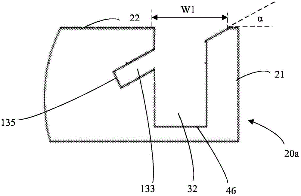
根据一个方面,如图9、10、11所示,组件1包括第二镶板20a,并且机械锁定装置30包括在第二镶板20a的第二镶板表面22处的镶板沟槽133。镶板沟槽133具有与上面公开的边缘沟槽33相同的功能,然而,根据该方面,沟槽位于第二镶板表面22处而不是第二边缘表面21处。镶板沟槽133在第二镶板20a中相对于第二镶板表面22以角度α延伸。换句话说,镶板沟槽133形成在第二镶板20a中,并且相对于第二镶板表面以角度α倾斜,如图9所示。According to one aspect, as shown in Figures 9, 10, 11, the
图9中未示出的柔性榫舌6根据一个方面位于镶板沟槽133中。如上所述,杆状元件31位于第一边缘表面11处。根据该方面,插入凹槽32位于第二镶板表面22处,并且从第二镶板表面22延伸至镶板沟槽133。The
根据一个方面,杆状元件31配置成插入至插入凹槽32中,并且杆状元件31包括凹部34。According to one aspect, the rod-shaped
根据一个方面,柔性榫舌6配置成与凹部34协作以在垂直于第二镶板表面22的第一方向上将第一镶板10锁定到第二镶板20a。According to an aspect, the
根据一个方面,角度α在10°(度)-80°(度)之间。根据一个方面,角度α在10°-70°之间。根据一个方面,该角度在20度-70度之间。根据一个方面,角度α在15°-50°之间。根据一个方面,角度α在25°-35°之间。According to one aspect, the angle α is between 10° (degrees) and 80° (degrees). According to one aspect, the angle α is between 10°-70°. According to one aspect, the angle is between 20 degrees and 70 degrees. According to one aspect, the angle α is between 15°-50°. According to one aspect, the angle α is between 25°-35°.
根据一个方面,第二镶板20a的第二边缘表面21位于与镶板沟槽133相距一距离处。According to an aspect, the
根据一个方面,第二镶板表面22中的镶板沟槽133的宽度W1小于第一边缘表面11的宽度W2。换句话说,当第一镶板10朝向第二镶板20a锁定时,第一镶板10的第一边缘表面11覆盖镶板沟槽133。According to one aspect, the width W1 of the
根据一个方面,第二镶板表面22中的镶板沟槽133的宽度W1大于杆状元件31的直径D2,如图10所示。According to one aspect, the width W1 of the
根据一个方面,镶板沟槽133是具有底端的沟槽,包括位于与插入凹槽32相距一距离处的底面135。According to one aspect, the
根据一个方面,柔性榫舌6布置在镶板沟槽133的底面135处。According to one aspect, the
根据一个方面,柔性榫舌6配置成朝向底面135向内挠曲以完全定位在镶板沟槽133中。According to one aspect, the
根据一个方面,处于非挠曲状态的柔性榫舌6配置成部分位于镶板沟槽133中且部分位于插入凹槽32中。According to one aspect, the
根据一个方面,镶板沟槽133是在第二平坦表面22的纵向方向上延伸的纵向沟槽133。According to one aspect, the
根据一个方面,纵向沟槽133的纵向方向基本平行于第二边缘表面21。According to one aspect, the longitudinal direction of the
根据一个方面,第二镶板20a包括第三边缘表面23,并且机械锁定装置30的镶板沟槽133还位于第三边缘表面23处。According to one aspect, the
根据一个方面,第二镶板20a包括第四边缘表面24,并且机械锁定装置30的镶板沟槽133还位于第四边缘表面24处。According to one aspect, the
根据一个方面,镶板沟槽133从第三边缘表面23延伸至第四边缘表面24。According to one aspect, the
根据一个方面,插入凹槽32是具有底端的凹槽,例如具有底端的钻孔,包括定位在与镶板沟槽133相距一距离处的底面46。According to one aspect, the
根据一个方面,第一边缘表面11包括两个或更多个所述杆状元件31,第二镶板表面22包括两个或更多个所述插入凹槽32和一个或更多个镶板沟槽133,它们优选地成直线布置,其中每个杆状元件31被配置为插入至插入凹槽32之一中。According to one aspect, the
根据一个方面,在第一镶板10和第二镶板20a之间的锁定位置,镶板沟槽133配置成接收拆卸杆40。According to one aspect, the
当拆卸杆40被接收在镶板沟槽133中时,杆状元件31配置成与拆卸杆40协作以使柔性榫舌6在镶板沟槽133中向内挠曲。此后,当柔性榫舌6在镶板沟槽133中向内挠曲时,杆状元件31和拆卸杆40配置成可在插入凹槽32中向外移动并移出插入凹槽32,以从第二镶板20a拆卸第一镶板10。由于镶板沟槽133从第二镶板表面22延伸,所以与上述拆卸方法相比,拆卸步骤较少。这是因为插入凹槽32和镶板沟槽133位于同一个表面、即第二镶板表面22处。When the
根据一个方面,机械锁定装置30配置成当杆状元件31插入至插入凹槽32中并且第一边缘表面11抵靠第二镶板表面22布置时,将第一镶板10自动锁定到第二镶板20a。According to one aspect, the
根据一个方面,在锁定位置,柔性榫舌6布置在杆状元件31的凹部34和镶板沟槽133的底面135之间。根据一个方面,第二边缘表面21基本上垂直于第二镶板表面22。According to one aspect, in the locked position, the
根据一个方面,根据上述的杆状元件31可以连接到包括根据上述的边缘沟槽33的第二镶板20,或者连接到根据上述的镶板沟槽133。According to one aspect, the rod-shaped
根据一个方面,第二镶板20、20a包括一个或多个边缘沟槽33以及一个或多个镶板沟槽133。根据一个方面,第二镶板20、20a连接并锁定到两个或更多个第一镶板10。According to one aspect, the
插入凹槽32可以形成在第二镶板表面22中以及第二镶板20的芯部中。
第二镶板表面22可以包括装饰层,并且插入凹槽可以延伸穿过装饰层。The
插入凹槽可以通过机械切削——例如铣削或锯切——形成。The insertion groove can be formed by mechanical cutting, eg milling or sawing.
根据一个方面,边缘元件例如边缘带连接到第二边缘,用于覆盖边缘沟槽并加强第二边缘21。边缘元件可以胶合到第二边缘或者通过机械锁定装置连接,该机械锁定装置可以包括从边缘元件突出并且配置成插入边缘沟槽33中的部分。该部分可以通过摩擦连接到边缘沟槽。根据一个方面,边缘元件不覆盖第三边缘表面和/或第四边缘表面23、24,使得拆卸杆40可以插入边缘沟槽33中。根据一个方面,边缘元件是可移除的,使得拆卸杆40可以插入边缘沟槽33中。According to one aspect, an edge element, such as an edge strip, is connected to the second edge for covering the edge groove and reinforcing the
根据一个方面,第二镶板可以包括两个或更多个所述边缘沟槽33。According to an aspect, the second panel may comprise two or more of said
根据一个方面,第一镶板10包括根据上述的两个或更多个第一边缘表面11。换句话说,一个或多个杆状元件31可以位于第一镶板10的两个或更多个边缘处,如图15和17所示。According to one aspect, the
根据一个方面,一个第一镶板10的一个第一边缘表面11处的一个或多个杆状元件31相对于该第一镶板10的另一个第一边缘表面11处的一个或多个杆状元件偏移定位。通过将杆状元件31偏移定位在第一镶板10的不同第一边缘表面11处,如果杆状元件31在第一边缘表面11处的位置仅对应于插入凹槽32在第二镶板表面22处的位置,则可以避免不同的第一镶板和第二镶板10、20、20a的意外组装。According to one aspect, one or more rod-shaped
根据一个方面,如图15所示,一个第二镶板可以连接到四个第一镶板。根据一个方面,第二镶板20包括两个第二镶板表面22,并且一个或多个插入凹槽32从第二镶板表面22之一延伸,并且一个或多个插入凹槽32从另一个第二镶板表面22延伸至公共边缘沟槽33,如图15和16中所公开的。According to one aspect, as shown in Figure 15, one second panel may be connected to four first panels. According to one aspect, the
根据一个方面,镶板可以是第一镶板10和第二镶板20、20a的组合,并且包括在一个边缘处的杆状元件31和在镶板表面处的镶板沟槽133和/或在另一个边缘表面处的边缘沟槽,如图17所示。According to an aspect, the panel may be a combination of the
柔性榫舌6可以根据WO2015/105449中的图2A-2F中描述和示出的柔性榫舌。WO2015/105449中的图2A-2F和从第6页第15行到第7页第2行的相关公开内容通过引用明确结合于此。The
第一镶板10和/或第二镶板20、20a的芯部可以是木质部,优选由中密度纤维板、高密度纤维板、定向刨花板、木塑复合材料、胶合板或刨花板/粒片板制成。芯部也可以是塑料芯部,包括热固性塑料或热塑性塑料,例如乙烯树脂/聚乙烯、聚氯乙烯、聚氨酯或聚酯。塑料芯部包括填充物。The core of the
第一镶板10和/或第二镶板20、20a也可以是实木的。The
第一镶板10和/或第二镶板20、20a可以在一个或多个表面上设置有装饰层,例如箔/薄片或饰面板。The
根据一个方面,组件1是抽屉的底部部件、框架和家具产品的背部部件之一。According to one aspect, the
根据一个方面,该组镶板是弹性镶板。弹性镶板可以包括含有热塑性材料的芯部。热塑性材料可以被发泡。According to one aspect, the set of panels is elastic panels. The resilient panel may comprise a core comprising a thermoplastic material. Thermoplastic materials can be foamed.
热塑性材料可以包括聚氯乙烯、聚酯、聚丙烯、聚乙烯、聚苯乙烯、聚氨酯、聚对苯二甲酸乙二醇酯、聚丙烯酸酯、甲基丙烯酸酯、聚碳酸酯、聚乙烯醇缩丁醛、聚对苯二甲酸丁二醇酯或其组合。芯部可以由几层形成。Thermoplastic materials can include polyvinyl chloride, polyester, polypropylene, polyethylene, polystyrene, polyurethane, polyethylene terephthalate, polyacrylate, methacrylate, polycarbonate, polyvinyl acetal Butyraldehyde, polybutylene terephthalate, or combinations thereof. The core can be formed from several layers.
上述方面可以包括装饰层,例如包括热塑性材料的装饰箔。装饰层的热塑性材料可以是或包括聚氯乙烯、聚酯、聚丙烯、聚乙烯、聚苯乙烯、聚氨酯、聚对苯二甲酸乙二醇酯、聚丙烯酸酯、甲基丙烯酸酯、聚碳酸酯、聚乙烯醇缩丁醛、聚对苯二甲酸丁二醇酯或其组合。装饰箔优选通过例如直接印刷、轮转凹版印刷或数字印刷来印刷。根据一个方面,装饰层包括三聚氰胺、高压层压材料或饰面板。The aforementioned aspect may comprise a decorative layer, for example a decorative foil comprising a thermoplastic material. The thermoplastic material of the decorative layer can be or include polyvinyl chloride, polyester, polypropylene, polyethylene, polystyrene, polyurethane, polyethylene terephthalate, polyacrylate, methacrylate, polycarbonate , polyvinyl butyral, polybutylene terephthalate, or combinations thereof. The decorative foil is preferably printed by, for example, direct printing, rotogravure printing or digital printing. According to one aspect, the decorative layer comprises melamine, high pressure laminate or veneer.
上述方面可以包括耐磨层,例如膜或箔。耐磨层可以包括热塑性材料。热塑性材料可以是聚氯乙烯、聚酯、聚丙烯、聚乙烯、聚苯乙烯、聚氨酯、聚对苯二甲酸乙二醇酯、聚丙烯酸酯、甲基丙烯酸酯、聚碳酸酯、聚乙烯醇缩丁醛、聚对苯二甲酸丁二醇酯或它们的组合。The above aspects may comprise a wear resistant layer such as a film or foil. The wear layer may comprise a thermoplastic material. Thermoplastic materials can be polyvinyl chloride, polyester, polypropylene, polyethylene, polystyrene, polyurethane, polyethylene terephthalate, polyacrylate, methacrylate, polycarbonate, polyvinyl acetal Butyraldehyde, polybutylene terephthalate, or combinations thereof.
上述方面可包括木质芯部,例如高密度纤维板、中密度纤维板、胶合板、刨花板/粒片板、定向刨花板或夹布胶木板。The above aspects may comprise a wood core such as high density fibreboard, medium density fibreboard, plywood, particle/chip board, oriented strand board or Bakelite.
上述不同的方面、实施例和替代方案可以与一个或多个其他描述的方面、实施例和替代方案相结合。The various aspects, embodiments and alternatives described above may be combined with one or more of the other described aspects, embodiments and alternatives.
Claims (26)
Applications Claiming Priority (3)
| Application Number | Priority Date | Filing Date | Title |
|---|---|---|---|
| SE1850447 | 2018-04-18 | ||
| SE1850447-2 | 2018-04-18 | ||
| PCT/SE2019/050363 WO2019203723A1 (en) | 2018-04-18 | 2019-04-17 | Set of panels with a mechanical locking device |
Publications (2)
| Publication Number | Publication Date |
|---|---|
| CN112292537A CN112292537A (en) | 2021-01-29 |
| CN112292537B true CN112292537B (en) | 2022-11-29 |
Family
ID=68237143
Family Applications (1)
| Application Number | Title | Priority Date | Filing Date |
|---|---|---|---|
| CN201980038399.3A Active CN112292537B (en) | 2018-04-18 | 2019-04-17 | Panel group with mechanical locking device |
Country Status (9)
| Country | Link |
|---|---|
| US (1) | US11076691B2 (en) |
| EP (1) | EP3781822B1 (en) |
| JP (1) | JP7305673B2 (en) |
| CN (1) | CN112292537B (en) |
| CA (1) | CA3096995A1 (en) |
| EA (1) | EA202092389A1 (en) |
| MY (1) | MY204226A (en) |
| PL (1) | PL3781822T3 (en) |
| WO (1) | WO2019203723A1 (en) |
Families Citing this family (47)
| Publication number | Priority date | Publication date | Assignee | Title |
|---|---|---|---|---|
| UA109938C2 (en) | 2011-05-06 | 2015-10-26 | MECHANICAL LOCKING SYSTEM FOR CONSTRUCTION PANELS | |
| US9726210B2 (en) | 2013-09-16 | 2017-08-08 | Valinge Innovation Ab | Assembled product and a method of assembling the product |
| LT3470690T (en) | 2013-09-16 | 2021-12-10 | Välinge Innovation AB | ASSEMBLED PRODUCT |
| US9714672B2 (en) | 2014-01-10 | 2017-07-25 | Valinge Innovation Ab | Panels comprising a mechanical locking device and an assembled product comprising the panels |
| MX376334B (en) | 2014-01-10 | 2025-03-07 | Vaelinge Innovation Ab | FURNITURE BOARD. |
| ES2873499T3 (en) | 2014-05-09 | 2021-11-03 | Vaelinge Innovation Ab | Mechanical interlocking system for construction panels |
| EP3594514B1 (en) | 2014-12-19 | 2023-01-25 | Välinge Innovation AB | Panels comprising a mechanical locking device |
| WO2016171607A1 (en) | 2015-04-21 | 2016-10-27 | Välinge Innovation AB | Panel with a slider |
| UA123581C2 (en) | 2015-04-30 | 2021-04-28 | Велінге Інновейшн Аб | Panel with a fastening device |
| US10448739B2 (en) | 2015-09-22 | 2019-10-22 | Valinge Innovation Ab | Panels comprising a mechanical locking device and an assembled product comprising the panels |
| CA3006420C (en) | 2015-12-03 | 2024-02-13 | Valinge Innovation Ab | Panels comprising a mechanical locking device and an assembled product comprising the panels |
| UA126556C2 (en) | 2016-01-26 | 2022-11-02 | Велінге Інновейшн Аб | Panels comprising a mechanical locking device and an assembled product comprising the panels |
| KR20180109957A (en) | 2016-02-04 | 2018-10-08 | 뵈린게 이노베이션 에이비이 | Set of panels for assembled products |
| HUE053138T2 (en) | 2016-02-15 | 2021-06-28 | Vaelinge Innovation Ab | Method for forming sheets of furniture products |
| MY193824A (en) | 2016-10-27 | 2022-10-27 | Valinge Innovation Ab | Set of panels with a mechanical locking device |
| CN110621889A (en) | 2017-05-15 | 2019-12-27 | 瓦林格创新股份有限公司 | Element and locking device for a composite product |
| WO2019125292A1 (en) | 2017-12-22 | 2019-06-27 | Välinge Innovation AB | A set of panels, a method for assembly of the same and a locking device for a furniture product. |
| PL3728870T3 (en) | 2017-12-22 | 2023-08-21 | Välinge Innovation AB | PANEL SET |
| MX2020009767A (en) | 2018-03-23 | 2020-10-08 | Vaelinge Innovation Ab | Panels comprising a mechanical locking device and an assembled product comprising the panels. |
| EP3781824B1 (en) | 2018-04-18 | 2024-04-10 | Välinge Innovation AB | Set of panels with a mechanical locking device |
| KR20200141076A (en) | 2018-04-18 | 2020-12-17 | 뵈린게 이노베이션 에이비이 | Symmetrical tongue and tea-cross |
| WO2019203721A1 (en) | 2018-04-18 | 2019-10-24 | Välinge Innovation AB | Set of panels with a mechanical locking device |
| US11614114B2 (en) | 2018-04-19 | 2023-03-28 | Valinge Innovation Ab | Panels for an assembled product |
| CA3109462A1 (en) | 2018-08-30 | 2020-03-05 | Valinge Innovation Ab | Set of panels with a mechanical locking device |
| LT3844407T (en) | 2018-08-30 | 2024-05-27 | Välinge Innovation AB | Set of panels with a mechanical locking device |
| EP3730807A1 (en) | 2019-04-26 | 2020-10-28 | Välinge Innovation AB | Set of panels with a mechanical locking device |
| EP3834661A1 (en) | 2019-12-11 | 2021-06-16 | Välinge Innovation AB | Mechanical locking system for panels |
| EP4076090A4 (en) | 2019-12-19 | 2023-12-27 | Välinge Innovation AB | SET OF PLATES WITH MECHANICAL LOCKING DEVICE |
| EP4624769A3 (en) | 2020-01-22 | 2025-12-31 | Välinge Innovation AB | SET OF PLATES WITH A MECHANICAL LOCKING DEVICE |
| EP3871559A1 (en) * | 2020-02-26 | 2021-09-01 | Välinge Innovation AB | Set of panels with a mechanical locking device |
| EP3871560A1 (en) * | 2020-02-26 | 2021-09-01 | Välinge Innovation AB | Set of panels with a mechanical locking device |
| WO2021246945A1 (en) | 2020-06-05 | 2021-12-09 | Välinge Innovation AB | Building panels comprising a locking device |
| EP4181732B1 (en) * | 2020-07-17 | 2025-11-12 | Välinge Innovation AB | Mechanical locking system for panels |
| US20220090378A1 (en) * | 2020-09-18 | 2022-03-24 | Sharon Laing | Student Protection Screen |
| CN112360852A (en) * | 2020-11-18 | 2021-02-12 | 金螳螂精装科技(苏州)有限公司 | Side plate connecting structure for modular combined cabinet for interior decoration |
| CN116568183A (en) | 2020-12-11 | 2023-08-08 | 瓦林格创新股份有限公司 | Beams for cabinets |
| MX2023007995A (en) | 2021-01-07 | 2023-09-18 | Vaelinge Innovation Ab | Wedge-shaped tongue insertion groove. |
| MX2023008301A (en) | 2021-01-19 | 2023-09-21 | Vaelinge Innovation Ab | A set of panels, a method for assembly of the same and a locking device for a furniture product. |
| CA3206480A1 (en) | 2021-02-03 | 2022-08-11 | Valinge Innovation Ab | Building panels comprising a locking device |
| EP4288672A4 (en) | 2021-02-08 | 2024-12-25 | Välinge Innovation AB | FURNITURE HARDWARE ASSEMBLY, MOUNTING BRACKET AND FURNITURE ASSEMBLY METHOD |
| CN116847759A (en) * | 2021-03-01 | 2023-10-03 | 瓦林格创新股份有限公司 | Mechanical joint arrangements for paneling |
| WO2022184446A1 (en) | 2021-03-01 | 2022-09-09 | Välinge Innovation AB | Mechanical connection arrangement for panels |
| EP4352370A4 (en) | 2021-06-11 | 2025-04-09 | Välinge Innovation AB | LOCKING DEVICE WITH A SPRING AND A LOCKING PIN AND SET WITH FURNITURE COMPONENTS AND THE LOCKING DEVICE |
| CN113503294B (en) * | 2021-07-24 | 2024-02-09 | 广东精诺五金实业有限公司 | First connecting piece, connecting assembly, connecting system and mounting method |
| USD1060068S1 (en) * | 2022-05-05 | 2025-02-04 | Georg Rothbucher | Surveying instrument accessory |
| USD1060064S1 (en) * | 2022-07-26 | 2025-02-04 | Georg Rothbucher | Surveying instrument accessory |
| USD1044535S1 (en) * | 2022-07-26 | 2024-10-01 | Georg Rothbucher | Surveying instrument accessory |
Family Cites Families (302)
| Publication number | Priority date | Publication date | Assignee | Title |
|---|---|---|---|---|
| DE228872C (en) | ||||
| US291032A (en) | 1884-01-01 | Isaac g- | ||
| US634581A (en) | 1898-11-21 | 1899-10-10 | Robert H Miller | Carpenter's square. |
| US701000A (en) | 1901-07-31 | 1902-05-27 | Carl F W Ahrens | File-cabinet. |
| US861911A (en) | 1905-11-04 | 1907-07-30 | William Stewart | Joint for articles of furniture or woodwork. |
| US881673A (en) | 1907-03-11 | 1908-03-10 | Arthur L Ellison | Wardrobe or safe. |
| US1534468A (en) | 1922-10-30 | 1925-04-21 | Jr John J Shea | Joint structure |
| US1533099A (en) | 1924-07-14 | 1925-04-14 | Robert E Carroll | Square-corner glue joint |
| GB245332A (en) | 1925-05-04 | 1926-01-07 | George Hugh Foster | An improved dowelled joint for woodwork and the like |
| US1800386A (en) | 1926-08-28 | 1931-04-14 | Andrew Hoffman Mfg Company | Display rail |
| US1800387A (en) | 1926-12-30 | 1931-04-14 | Andrew Hoffman Mfg Company | Article-supporting device |
| US1802245A (en) | 1930-08-26 | 1931-04-21 | Clarence L Foretich | Display stand and shelving |
| US1954242A (en) | 1932-07-28 | 1934-04-10 | Thomas E Heppenstall | Dovetail spring joint |
| US2360451A (en) | 1942-06-02 | 1944-10-17 | Stone Abraham | Collapsible clothing container |
| US2362904A (en) | 1943-01-20 | 1944-11-14 | Allied Purchasing Corp | Joint for demountable furniture |
| US2496184A (en) | 1946-06-11 | 1950-01-31 | Canon Paul L Von | Furniture drawer construction and method |
| US2681483A (en) | 1948-10-14 | 1954-06-22 | Morawetz Hugo | Dowel connection |
| DE1107910B (en) | 1957-03-26 | 1961-05-31 | Curt Weinert | Flexible duebel |
| CH365507A (en) | 1958-11-17 | 1962-11-15 | Antonius Bus Johannes | Device for connecting perpendicular walls with automatic locking, in particular furniture walls |
| US3002630A (en) | 1960-05-24 | 1961-10-03 | Robert E Heisser | Toothbrush rack |
| US3195968A (en) | 1962-12-06 | 1965-07-20 | Lok Trim Corp | Knock-down furniture |
| DE1240638B (en) | 1963-03-07 | 1967-05-18 | Kueche | Dismountable furniture |
| AT260460B (en) | 1963-08-19 | 1968-03-11 | Trepatent As | Guide for drawers, shelves or the like. |
| US3313054A (en) | 1965-06-09 | 1967-04-11 | Poster Products Inc | Display devices |
| IS831B6 (en) | 1965-10-28 | 1973-04-12 | Nordischer Maschinenbau Rud. BaaderNordischer Maschinenbau, Rud. Baader | Method of removing the liver from the fishToys to decapitate the highly cut fish so that the wet bone remains on the fish |
| US3410441A (en) | 1966-06-29 | 1968-11-12 | Jeff S. Rhyne | Container |
| US3347610A (en) | 1966-07-28 | 1967-10-17 | Pilliod Cabinet Company | Cabinet construction |
| DE1955922C3 (en) | 1969-11-06 | 1974-01-10 | Hefendehl, Hansfriedrich, 5893 Kierspe | Box furniture made of plastic |
| US3722704A (en) | 1970-07-23 | 1973-03-27 | Castelli Sas Anonima | Structural components for the composition of disassemblable pieces offurniture |
| JPS4817135U (en) * | 1971-07-05 | 1973-02-26 | ||
| US3765465A (en) | 1972-01-05 | 1973-10-16 | Deutsch Fastener Corp | Retractable captive fastener |
| US3742807A (en) | 1972-02-03 | 1973-07-03 | D Manning | Leveling and locking pin |
| GB1398187A (en) | 1972-06-22 | 1975-06-18 | Schreiber Furniture | Kitchen cabinets |
| US3884002A (en) | 1973-03-15 | 1975-05-20 | American Store Equip | Partition system |
| BE810507A (en) * | 1974-02-01 | 1974-05-29 | MEANS OF ASSEMBLING TWO WALLS OF CABINET OR FURNITURE. | |
| DE2414104A1 (en) | 1974-03-23 | 1975-10-09 | Alfer Alu Fertigbau | Fastener for wooden shelving - comprises straight locking pins engaged by pressure of support plate |
| DE2514357C3 (en) | 1974-04-02 | 1979-03-22 | Takeshi Tokio Shimizu | Fitting for the pivotable connection of a furniture panel with a fixed furniture part |
| US3885845A (en) | 1974-06-27 | 1975-05-27 | Hans Krieks | Knock-down furniture system |
| US3981118A (en) | 1974-10-17 | 1976-09-21 | The Goodyear Tire & Rubber Company | Clamping insert |
| CA1062321A (en) | 1976-05-12 | 1979-09-11 | I. T. W. Ltd. | Grommets for furniture connectors |
| DE2635237A1 (en) | 1976-08-05 | 1978-02-09 | Heinze Fa R | FURNITURE HINGE |
| JPS53113160U (en) | 1977-02-16 | 1978-09-08 | ||
| US4116510A (en) | 1977-03-03 | 1978-09-26 | Gte Automatic Electric Laboratories Incorporated | Chassis formed of sheet stock |
| US4099887A (en) | 1977-07-18 | 1978-07-11 | Einhard Mackenroth | Structural joints |
| US4222544A (en) | 1977-08-10 | 1980-09-16 | Kenneth Crowder | Picture rail apparatus |
| SE409603B (en) | 1977-12-20 | 1979-08-27 | Stockum Design Ab | CONNECTION |
| SE7809081L (en) | 1978-08-29 | 1980-03-01 | Hafa Fabriks Ab | DEVICE FOR COLLECTION OF CABINETS, MIRRORS, SHELVES AND OTHER DETAILS |
| US4211379A (en) | 1978-11-20 | 1980-07-08 | Morgan Myron B | Panelboard and mounting fixture combination |
| US4299067A (en) | 1979-10-30 | 1981-11-10 | J. C. Penney Company, Inc. | Partition connector system |
| US4308961A (en) | 1980-05-05 | 1982-01-05 | Kunce Thomas M | Article supporting structure |
| US4324517A (en) | 1980-06-16 | 1982-04-13 | Sps Technologies, Inc. | Panel fastener assembly with retainer ring |
| DE3047642A1 (en) | 1980-12-17 | 1982-10-28 | Arturo Salice S.p.A., 22060 Novedrate, Como | CONNECTING FITTING |
| DE3103281C2 (en) | 1981-01-31 | 1984-05-10 | C + A Dick GmbH, 5275 Bergneustadt | Material cupboard |
| FR2501805A1 (en) | 1981-03-10 | 1982-09-17 | Haeusler Roland | NEW TYPE TENON AND MORTISE GENDER ASSEMBLY SYSTEM AND FURNITURE ARTICLES INCORPORATING THE SAME SYSTEM |
| FR2517187A1 (en) | 1981-12-01 | 1983-06-03 | Beaux Dominique | DETACHABLE BOX FOR FURNITURE USE |
| US4509648A (en) | 1982-07-26 | 1985-04-09 | The Stanley Works | Merchandising display system and components therefor |
| US4593734A (en) | 1983-09-26 | 1986-06-10 | M. Bosley Wright | Frame routing apparatus |
| US4629076A (en) | 1984-05-10 | 1986-12-16 | Amstore Corporation | Slatboard |
| GB2163825B (en) | 1984-08-30 | 1988-03-02 | Hettich Paul Gmbh & Co | Furniture connector |
| US4595105A (en) | 1984-09-12 | 1986-06-17 | Gold Kenneth S | Interlocking bookrack |
| US4750794A (en) | 1984-11-21 | 1988-06-14 | Bass Cabinet Manufacturing, Inc. | Slide-fitted article of furniture |
| US4597122A (en) | 1985-06-10 | 1986-07-01 | Hirsh Company | Free-standing drawer |
| US4615448A (en) | 1985-09-27 | 1986-10-07 | Masonite Corporation | Display panel |
| US4891897A (en) | 1985-12-12 | 1990-01-09 | Gieske Detlef J | Display panel |
| FR2597173B1 (en) | 1986-04-10 | 1988-10-07 | Forschle Andre | DEVICE FOR EASILY ASSEMBLING AND MODIFYING THE COMPOSITION OF A KITCHEN FURNITURE |
| GB8612597D0 (en) | 1986-05-23 | 1986-07-02 | George W R | Joint between members |
| FR2602013B1 (en) | 1986-07-25 | 1988-12-30 | Kapikian Jean Claude | ASSEMBLY SYSTEM OF TENON AND MORTISE TYPE EASILY MOUNTABLE AND REMOVABLE |
| US4815908A (en) | 1986-10-14 | 1989-03-28 | Avibank Mfg., Inc. | Captive panel fastener assembly |
| US4844266A (en) | 1987-07-16 | 1989-07-04 | Intercraft Industries Corporation | Display system |
| CA1297934C (en) | 1987-07-24 | 1992-03-24 | Craig Mengel | Method of and structure for the joining of substantially rigidparts together |
| US4886326A (en) | 1988-01-29 | 1989-12-12 | Tetrad Marketing/Sales Ltd. | Interlock system for ready to assemble furniture, and furniture incorporating such system |
| US4961295A (en) | 1988-03-14 | 1990-10-09 | Kosch Sr Paul | Metal slat and wall system utilizing same |
| US4817900A (en) | 1988-05-09 | 1989-04-04 | Gorrie Advertising Management Limited | Support device for use on a display wall |
| US4869564A (en) * | 1988-08-24 | 1989-09-26 | Nova Office Furniture, Inc. | Modular furniture |
| JPH0266308A (en) | 1988-08-30 | 1990-03-06 | Kazuhiro Matsui | Assembly tool |
| IT215989Z2 (en) | 1988-09-02 | 1991-03-26 | Cattarozzi Andrea | MODULAR CONTAINER MODULAR AND MANUALLY TRANSPORTABLE, FOR THE STORAGE OF SUBSTANCES, IN SPECIAL WAY FOR FOOD USE |
| NL8802459A (en) | 1988-10-07 | 1990-05-01 | Homburg Interieuren B V | SHOW WALL. |
| US5471804A (en) | 1988-11-21 | 1995-12-05 | Winter, Iv; Amos G. | Building system using prefabricated building panels and fastening components used therewith |
| US4944416A (en) | 1988-11-21 | 1990-07-31 | Petersen Robert J | Light-weight slot-wall display panel |
| US4909581A (en) | 1988-12-12 | 1990-03-20 | American Moulding & Millwork Company | Drawer construction |
| WO1990007066A2 (en) | 1988-12-13 | 1990-06-28 | Rudolf Tanner | Connecting element for form-fitting connection |
| US5018323A (en) | 1989-05-12 | 1991-05-28 | Knud Clausen | Wall panel system |
| US5109993A (en) | 1989-10-31 | 1992-05-05 | Hutchison V James | Merchandise display system and merchandise holder therefor |
| US5138803A (en) | 1991-01-11 | 1992-08-18 | Commercial And Architectural Products, Inc. | Display panel assembly |
| US5121578A (en) | 1991-01-28 | 1992-06-16 | Holz Plastics, Inc. | Slat wall decorating system |
| US5209556A (en) | 1991-04-01 | 1993-05-11 | Anderson Robert F | Drawer assembly |
| GB2269839B (en) | 1991-04-01 | 1995-06-07 | Walter Lindal | Wooden frame building construction |
| US5114265A (en) | 1991-04-15 | 1992-05-19 | Grisley Kenneth M | Interlocking routed joint |
| US5299509A (en) | 1991-07-29 | 1994-04-05 | Ballard Donald M | Connectors for shelves and bins |
| US5125518A (en) | 1991-08-12 | 1992-06-30 | Innovative Accessories | Interlocking hanging system |
| CH684284A5 (en) | 1991-09-03 | 1994-08-15 | Edgar Probst | Rear wall fitting. |
| US5212925A (en) | 1991-11-21 | 1993-05-25 | Mcclinton John | Wall corner composite, mold and method for producing glazed unit for such |
| US5360121A (en) | 1992-08-07 | 1994-11-01 | Commerical And Architectural Products, Inc. | Slotted display wall panel |
| JP2530326Y2 (en) | 1992-08-24 | 1997-03-26 | 株式会社イトーキクレビオ | Device for connecting members in furniture etc. |
| CH685276A5 (en) | 1992-11-25 | 1995-05-31 | Werner Schmidt | Building elements for assembling shelves, cupboards and walling |
| ZA94676B (en) | 1993-02-03 | 1994-08-03 | Rohm & Haas | Reduction of microfoam in spray-applied waterborne composition. |
| US5423155A (en) | 1993-06-02 | 1995-06-13 | Darko Company, Inc. | Panel for resurfacing slat walls |
| US5499667A (en) | 1994-06-21 | 1996-03-19 | Nakanishi Construction Company | Drill/cutting bit, and method of making structural joint |
| US5527103A (en) | 1993-10-01 | 1996-06-18 | Pittman; Charles | Cabinet of improved design and construction |
| US5375802A (en) | 1993-11-17 | 1994-12-27 | Bill Branham Designs, Ltd. | Structure for fastening facing structural units |
| US5451102A (en) | 1994-01-13 | 1995-09-19 | Chuan; Yuan-Jung | Cabinet with connecting mechanism for two adjacent wall plate |
| US5499886A (en) | 1994-03-02 | 1996-03-19 | Sauder Woodworking Co. | Coupling assembly for furniture components |
| DE4410901A1 (en) | 1994-03-29 | 1995-10-05 | Licentia Gmbh | Fridge with refrigerated goods shelves |
| US5507331A (en) | 1994-06-21 | 1996-04-16 | Nakanishi Construction Company | Drilling/cutting bit, and method of making joint |
| DE9417168U1 (en) | 1994-10-26 | 1995-02-09 | Seeland, Peter, 37130 Gleichen | Kit for a piece of furniture |
| SE9500810D0 (en) | 1995-03-07 | 1995-03-07 | Perstorp Flooring Ab | Floor tile |
| DK9500332U3 (en) | 1995-08-29 | 1996-12-27 | Ikea Of Sweden Ab | Corner assembly between the end portions of two board-like items |
| US5658086A (en) | 1995-11-24 | 1997-08-19 | Brokaw; Paul E. | Furniture connector |
| US5775521A (en) | 1996-03-22 | 1998-07-07 | Custom Plastics, Inc. | Office organizer |
| CA2207533A1 (en) | 1996-06-12 | 1997-12-12 | David P. Thurston | Adjustable hanger system |
| US5950389A (en) | 1996-07-02 | 1999-09-14 | Porter; William H. | Splines for joining panels |
| US5810505A (en) | 1996-07-26 | 1998-09-22 | Kimball International, Inc. | Double threaded fastener system |
| GB2315988A (en) | 1996-08-07 | 1998-02-18 | Ultimate Systems Limited | Furniture with adjustable size panels |
| US5711115A (en) | 1996-10-30 | 1998-01-27 | Design Components, Inc. | Fireplace shelf and mantel support system |
| CA2200422C (en) | 1997-03-19 | 2002-05-07 | Jan B. Leurdijk | Storage track system |
| US5857304A (en) | 1997-04-07 | 1999-01-12 | Abex Display Systems | Slidable locking system for disengageable panels |
| CA2204301C (en) | 1997-05-02 | 2000-04-18 | Shang-Ming Lee | A connecting assembly for horizontal boards and wall boards of a cabinet |
| DE29714096U1 (en) | 1997-08-07 | 1998-12-03 | Dorth, Ursel, 51766 Engelskirchen | Connector system |
| NO974666L (en) * | 1997-10-09 | 1999-04-12 | New Ideas | Joining device for plate-shaped structural parts, as well as measuring structure |
| US5941026A (en) | 1998-01-20 | 1999-08-24 | Storewall Llc | Slatwall display system |
| DE19805538A1 (en) | 1998-02-03 | 1999-08-12 | Montana Innovations Corp | Securing vehicle load using cams mounted on U-shaped frame |
| AT406181B (en) | 1998-02-09 | 2000-03-27 | Blum Gmbh Julius | FASTENING DEVICE FOR FASTENING SEVERAL FURNITURE FITTINGS ON ONE FURNITURE PART |
| DE29924630U1 (en) | 1998-02-11 | 2004-05-13 | Ipeg Gmbh - Ingenieurdienstleistungen | Securing vehicle load using cams mounted on U-shaped frame |
| EP1055073A2 (en) | 1998-02-11 | 2000-11-29 | IPEG GmbH | Device for joining flat elements or other components |
| US6363645B1 (en) | 1998-02-25 | 2002-04-02 | Bruce A Hunter | Insert for display panels |
| US5944294A (en) | 1998-07-06 | 1999-08-31 | Baer; Thomas C. | Mounting device in form of C-clamp mounted space from a wall |
| DE29820031U1 (en) | 1998-11-10 | 1999-02-25 | Grant, Alasdair E., 33659 Bielefeld | Form-fitting connecting device for furniture or panel elements |
| US6349507B1 (en) | 1999-03-15 | 2002-02-26 | Spectra Products Corporation | Slat wall structure with profile for different shelf support brackets and the like |
| US6547086B1 (en) | 1999-03-25 | 2003-04-15 | Russell-William, Ltd. | Display wall panel |
| SE517478C2 (en) | 1999-04-30 | 2002-06-11 | Valinge Aluminium Ab | Locking system for mechanical hoisting of floorboards, floorboard provided with the locking system and method for producing mechanically foldable floorboards |
| IT1307424B1 (en) | 1999-04-29 | 2001-11-06 | Costa S P A A | METHOD FOR PROFILING STRIPS FOR PARQUET AND SQUARING MACHINE SUITABLE TO CREATE SUCH METHOD. |
| ES2182582T3 (en) | 1999-06-30 | 2003-03-01 | Akzenta Paneele & Profile Gmbh | PANEL, AS WELL AS FIXING SYSTEM FOR PANELS. |
| DE29911462U1 (en) | 1999-07-02 | 1999-11-18 | Akzenta Paneele & Profile Gmbh | Fastening system for panels |
| DE10001076C1 (en) | 2000-01-13 | 2001-10-04 | Huelsta Werke Huels Kg | Panel element to construct floor covering; has groove and spring on opposite longitudinal sides and has groove and tongue on opposite end faces, to connect and secure adjacent panel elements |
| SE517183C2 (en) | 2000-01-24 | 2002-04-23 | Valinge Aluminium Ab | Locking system for mechanical joining of floorboards, floorboard provided with the locking system and method for making such floorboards |
| WO2001072181A1 (en) | 2000-03-24 | 2001-10-04 | Commercial And Architectural Products, Inc. | Merchandising panel display system |
| US6413007B1 (en) | 2000-05-01 | 2002-07-02 | Sauder Woodworking Co. | Joint assembly |
| US6578498B1 (en) | 2000-06-06 | 2003-06-17 | Steelcase Development Corporation | Furniture accessory kit for portable computers and the like |
| CN1212462C (en) | 2001-01-12 | 2005-07-27 | 凡林奇铝业有限公司 | Floor and Locking Systems |
| US6675979B2 (en) | 2001-05-21 | 2004-01-13 | Gregory Albert Taylor | Furniture assembly system |
| DE20122778U1 (en) | 2001-08-10 | 2007-10-25 | Akzenta Paneele + Profile Gmbh | Panel and fastening system for panels |
| DE10142508A1 (en) | 2001-08-30 | 2003-03-27 | Bsh Bosch Siemens Hausgeraete | Locking device and food processor equipped with this |
| SE525558C2 (en) | 2001-09-20 | 2005-03-08 | Vaelinge Innovation Ab | System for forming a floor covering, set of floorboards and method for manufacturing two different types of floorboards |
| AU2002357452A1 (en) | 2001-09-26 | 2003-04-07 | Agostino Ferrari S.P.A. | Device and method for detachably connecting abutting structural parts and tie member for use to form said device |
| JP2003239921A (en) | 2002-02-20 | 2003-08-27 | Takagaki Mokuzai Kogei Kk | Joining structure by tenon and mortise |
| USD482552S1 (en) | 2002-04-03 | 2003-11-25 | Commercial And Architectural Products, Inc. | Insert for a display panel |
| US6772890B2 (en) | 2002-04-03 | 2004-08-10 | Commercial And Architectural Products, Inc. | Narrow groove display panel |
| BRPI0308966B8 (en) | 2002-04-03 | 2016-05-17 | Vaelinge Innovation Ab | floor board |
| AUPS265502A0 (en) | 2002-05-30 | 2002-06-20 | Ibj Resources Pty Ltd | Mounting system |
| AU2003251423A1 (en) | 2002-07-17 | 2004-02-09 | Device Works Company | Cable organization and hardware shelving system |
| US6827028B1 (en) | 2002-12-11 | 2004-12-07 | E. Pryor Callaway | Collapsible support |
| US7228977B2 (en) | 2003-06-16 | 2007-06-12 | Whirlpool Corporation | Workroom storage system |
| DE602004027711D1 (en) | 2003-03-06 | 2010-07-29 | Vaelinge Innovation Ab | FLOOR SYSTEMS AND INSTALLATION PROCEDURES |
| US7306299B2 (en) | 2003-03-07 | 2007-12-11 | Masterbrand Cabinets, Inc. | Semi-frameless cabinet and method for making the same |
| DE20304761U1 (en) | 2003-03-24 | 2004-04-08 | Kronotec Ag | Device for connecting building boards, in particular floor panels |
| US6971614B2 (en) | 2003-07-11 | 2005-12-06 | Jifram Extrusions, Inc. | Slatwall hanger stabilizing chip |
| KR100975937B1 (en) | 2003-09-30 | 2010-08-16 | 엘지전자 주식회사 | Door basket mounting device for refrigerator |
| SE526596C2 (en) | 2004-01-13 | 2005-10-11 | Vaelinge Innovation Ab | Floating floor with mechanical locking system that allows movement between the floorboards |
| US20050166516A1 (en) | 2004-01-13 | 2005-08-04 | Valinge Aluminium Ab | Floor covering and locking systems |
| CH696889A5 (en) | 2004-03-23 | 2008-01-15 | Vifian Moebelwerkstaette Ag | Locking element for locking of two plates, has slide surface that is provided at end of springy middle area that overlaps middle area and wedge shaped head area, and fixing area that is provided at other end of middle area |
| US20050247653A1 (en) | 2004-05-06 | 2005-11-10 | Dr. Brooks Innovations, L.L.C. | System for holding implements |
| US7641414B1 (en) | 2004-09-04 | 2010-01-05 | Joyce Jared L | Furniture and joint systems |
| DK1936068T3 (en) | 2004-10-22 | 2012-03-19 | Vaelinge Innovation Ab | Method of providing floor panels with a mechanical locking system |
| US7454875B2 (en) | 2004-10-22 | 2008-11-25 | Valinge Aluminium Ab | Mechanical locking system for floor panels |
| US7841144B2 (en) | 2005-03-30 | 2010-11-30 | Valinge Innovation Ab | Mechanical locking system for panels and method of installing same |
| DE202004017486U1 (en) | 2004-11-11 | 2006-04-13 | Vietmeyer, Adolf | Framework for cabinet or shelf has two side panels, underbody and top end such that the upper body and the top end are connected to the side panels in the longitudinal direction by connecting elements by means of dowel pins or springs |
| GB0426634D0 (en) | 2004-12-03 | 2005-01-05 | Abbott Ooo | Display panel and display system |
| DE202004019882U1 (en) | 2004-12-20 | 2006-04-27 | Fritz Egger Gmbh & Co. | Furniture parts with connecting means |
| US7686172B2 (en) | 2005-02-14 | 2010-03-30 | Whirlpool Corporation | Storage bin |
| GB2423332B (en) | 2005-02-17 | 2009-05-27 | Arctium As | Connecting device |
| AU2006228367A1 (en) | 2005-03-29 | 2006-10-05 | Pieter Martin Henderson | Fastener for connecting components and assemblies embodying same |
| US20060273085A1 (en) | 2005-05-18 | 2006-12-07 | Casto Daniel A | Joint for connecting workpieces |
| US20090014401A1 (en) | 2005-05-24 | 2009-01-15 | Windquest Companies, Inc. | Slotwall mounting assembly |
| SE529076C2 (en) | 2005-07-11 | 2007-04-24 | Pergo Europ Ab | A joint for panels |
| CA2616611A1 (en) | 2005-07-28 | 2007-02-01 | Grandbay Holdings Pty Ltd | Interlocking members |
| CH698988B1 (en) | 2005-08-27 | 2009-12-31 | Lindauer Gmbh | Plate-shaped solid wood elements for cover, have profile section with groove running parallel to upper side and connected groove-shaped profile element aligned approximately perpendicular against lower side |
| DE202005019986U1 (en) | 2005-12-20 | 2006-02-23 | fif Möbel Vertriebs GmbH | Construction set for box shaped furniture comprises box elements with side walls, top-floor, lower-floor and back wall whereby walls and floors are made of identical, square plates and identical square rods, which act as connectors |
| SE530653C2 (en) | 2006-01-12 | 2008-07-29 | Vaelinge Innovation Ab | Moisture-proof floor board and floor with an elastic surface layer including a decorative groove |
| DE102006011887A1 (en) | 2006-01-13 | 2007-07-19 | Akzenta Paneele + Profile Gmbh | Blocking element, panel with separate blocking element, method of installing a panel covering of panels with blocking elements, and method and device for pre-assembling a blocking element on a panel |
| DE102006006124A1 (en) | 2006-02-10 | 2007-08-23 | Flooring Technologies Ltd. | Device for locking two building panels |
| SE533410C2 (en) | 2006-07-11 | 2010-09-14 | Vaelinge Innovation Ab | Floor panels with mechanical locking systems with a flexible and slidable tongue as well as heavy therefore |
| US7861482B2 (en) | 2006-07-14 | 2011-01-04 | Valinge Innovation Ab | Locking system comprising a combination lock for panels |
| DE102006037614B3 (en) | 2006-08-10 | 2007-12-20 | Guido Schulte | Floor covering, has head spring pre-assembled in slot and protruding over end of slot, and wedge surface formed at slot or head spring such that head spring runs into wedge surface by shifting projecting end of head spring into slot |
| US20080042532A1 (en) | 2006-08-16 | 2008-02-21 | Crabtree Phillip C | Cabinet system and method of assembling the same |
| US7614350B2 (en) | 2006-10-05 | 2009-11-10 | Haworth, Inc. | Wall-mounted shelf unit |
| EP1922954B1 (en) | 2006-11-14 | 2009-07-15 | Spichtig AG | Depositing and sorting device |
| SE531111C2 (en) | 2006-12-08 | 2008-12-23 | Vaelinge Innovation Ab | Mechanical locking of floor panels |
| GB2445954A (en) | 2007-01-23 | 2008-07-30 | Touac Internat Ltd | A panel joining fastener |
| ES2317821T3 (en) | 2007-05-08 | 2015-10-15 | Franz Baur | Means and method of joining to establish a union of a first component to a second component |
| US7818939B2 (en) | 2007-06-05 | 2010-10-26 | Irvin Bearinger | Snap lock joint |
| SE533028C2 (en) | 2007-06-05 | 2010-06-15 | Rickard Olsson | Box construction and mounting method |
| US8220217B2 (en) | 2007-07-20 | 2012-07-17 | Innovaris Ag | Flooring system |
| US7726088B2 (en) | 2007-07-20 | 2010-06-01 | Moritz Andre Muehlebach | Flooring system |
| CN101099618A (en) | 2007-07-26 | 2008-01-09 | 刘瑞东 | Mortise and tenon type furniture |
| DE102007043308B4 (en) | 2007-09-11 | 2009-12-03 | Flooring Technologies Ltd. | Device for connecting and locking two building panels, in particular floor panels |
| US8146754B2 (en) | 2007-12-07 | 2012-04-03 | Red Star Traders, Llc | Storage and organization system |
| US8505257B2 (en) | 2008-01-31 | 2013-08-13 | Valinge Innovation Ab | Mechanical locking of floor panels |
| CA2623707A1 (en) | 2008-03-07 | 2009-09-07 | Pierre Trudel | Tongue and groove profile to ease desassembly of floorboards |
| GB0808252D0 (en) | 2008-05-07 | 2008-06-11 | Self Energising Coupling Compa | Latch mechanism |
| US7717278B2 (en) | 2008-07-07 | 2010-05-18 | Jui-Chien Kao | Tool suspension device |
| DE102008035293A1 (en) | 2008-07-29 | 2010-02-04 | Gronbach Forschungs- Und Entwicklungs Gmbh & Co. Kg | Mounting article for use in e.g. home, has two aluminum profiles provided with side surfaces, at which connection bolts are inserted, where bolts exhibit recess, in which o-rings are inserted |
| US8220648B2 (en) | 2008-08-01 | 2012-07-17 | Southern Imperial, Inc. | Folded slatwall inserts |
| DE202008011589U1 (en) | 2008-09-01 | 2008-11-27 | Akzenta Paneele + Profile Gmbh | Plastic floor panel with mechanical locking edges |
| US20100083603A1 (en) | 2008-10-08 | 2010-04-08 | Goodwin Milton W | Flooring panel with first and second decorative surfaces |
| US20100104354A1 (en) * | 2008-10-29 | 2010-04-29 | Lamar Spalding | Pinned Lock Joint |
| BE1018389A3 (en) | 2008-12-17 | 2010-10-05 | Unilin Bvba | COMPOSITE ELEMENT, MULTI-LAYER PLATE AND PANEL-SHAPED ELEMENT FOR FORMING SUCH COMPOSITE ELEMENT. |
| US7998549B2 (en) | 2009-01-08 | 2011-08-16 | Thermwood Corporation | Structure and method of assembly thereof |
| BE1018627A5 (en) | 2009-01-16 | 2011-05-03 | Flooring Ind Ltd Sarl | FLOOR PANEL. |
| CN102301079B (en) | 2009-01-30 | 2014-01-08 | 瓦林格创新股份有限公司 | Mechanical locking system for floor panels and tongue blanks |
| US8464408B2 (en) | 2009-06-03 | 2013-06-18 | Tracy Leigh Hazzard | Hardware for furniture assembly |
| NL2003019C2 (en) | 2009-06-12 | 2010-12-15 | 4Sight Innovation Bv | FLOOR PANEL AND FLOOR COVERAGE CONSISING OF MULTIPLE OF SUCH FLOOR PANELS. |
| DE102009034902B4 (en) | 2009-07-27 | 2015-10-01 | Guido Schulte | Surface made of mechanically interconnectable panels |
| RU2534578C2 (en) | 2009-07-31 | 2014-11-27 | Велинге Инновейшн Аб | Methods and systems for trimming of construction board edges |
| US8365499B2 (en) | 2009-09-04 | 2013-02-05 | Valinge Innovation Ab | Resilient floor |
| DE102009041142B4 (en) | 2009-09-14 | 2015-11-05 | System 180 Gmbh | Arrangement with wall elements, kit for an arrangement as well as wall element for a furniture |
| DE202009012917U1 (en) | 2009-09-26 | 2011-02-10 | Fehre, Jürgen | drawer |
| EP2333353A3 (en) | 2009-12-02 | 2012-07-25 | Lolli, Paride | Longitudinal sliding joint |
| CA3118821C (en) | 2010-01-11 | 2023-09-26 | Valinge Innovation Ab | Floor covering with interlocking design |
| EP2524093B1 (en) | 2010-01-12 | 2020-02-05 | Välinge Innovation AB | Mechanical locking system for floor panels |
| DE102010004717A1 (en) | 2010-01-15 | 2011-07-21 | Pergo (Europe) Ab | Set of panels comprising retaining profiles with a separate clip and method for introducing the clip |
| CN102725464B (en) | 2010-02-04 | 2015-01-07 | 瓦林格创新股份有限公司 | Mechanical locking system for floor panels and a tongue therefore |
| US8234830B2 (en) | 2010-02-04 | 2012-08-07 | Välinge Innovations AB | Mechanical locking system for floor panels |
| GB201002535D0 (en) | 2010-02-15 | 2010-03-31 | Fgb Ltd | Improvements relating to cabinets |
| CA2796588C (en) | 2010-06-03 | 2019-03-19 | Unilin, Bvba | Composed element and corner connection applied herewith. |
| BE1019361A5 (en) | 2010-06-03 | 2012-06-05 | Unilin Bvba | COMPOSED ELEMENT. |
| CA2835240C (en) | 2010-06-22 | 2017-09-12 | John Hamish Alexander Pettigrew | Key and keyway connectors |
| US20120009383A1 (en) | 2010-07-09 | 2012-01-12 | Michael Hardesty | Method for Joining Workpieces Together and Product Made Thereby |
| US8911037B2 (en) | 2010-12-14 | 2014-12-16 | Tenn-Tex Plastics, Inc. | Brackets and associated components for drawer and tray slides in cabinetry |
| GB201100622D0 (en) | 2011-01-14 | 2011-03-02 | Phillips Sean | Article of furniture |
| IT1403925B1 (en) | 2011-02-09 | 2013-11-08 | O M M S A S Dell Ing Roberto Mariani & C | JUNCTION DEVICE FOR PANELS OF A FURNITURE. |
| US8864407B1 (en) | 2011-03-17 | 2014-10-21 | Petter Sorum | Locking joint for joining structural members |
| UA109938C2 (en) | 2011-05-06 | 2015-10-26 | MECHANICAL LOCKING SYSTEM FOR CONSTRUCTION PANELS | |
| EP2526819A1 (en) | 2011-05-25 | 2012-11-28 | Steen Sauer | Assembling of drawer |
| US8602227B1 (en) | 2011-06-08 | 2013-12-10 | Megawall, Inc. | Slatwall panel |
| CH705082A2 (en) | 2011-06-14 | 2012-12-14 | Denz Ag | Locking element for locking arrangement for cabinets and shelf board, has arc-shaped projecting lug formed at cylindrical base body for axial holding of locking element in pan bore at base, shelf board or cover |
| BE1020044A5 (en) | 2011-06-29 | 2013-04-02 | Unilin Bvba | TRAY, TRAY CONSTRUCTION AND METHOD FOR MANUFACTURING A TRAY. |
| US9725912B2 (en) | 2011-07-11 | 2017-08-08 | Ceraloc Innovation Ab | Mechanical locking system for floor panels |
| KR102067469B1 (en) | 2011-07-11 | 2020-01-17 | 세라록 이노베이션 에이비 | Mechanical locking system for floor panels |
| MY164223A (en) | 2011-08-15 | 2017-11-30 | Ceraloc Innovation Ab | Mechanical locking system for floor panels |
| US20130048632A1 (en) | 2011-08-29 | 2013-02-28 | Yi Hsiang Chen | Quick-disconnect storage box modular structure |
| KR101147274B1 (en) | 2011-11-09 | 2012-05-18 | 주식회사 한샘 | Method for manufacturing furniture panel |
| BE1020453A3 (en) | 2011-12-01 | 2013-10-01 | Unilin Bvba | FURNITURE AND METHOD FOR MANUFACTURING FURNITURE. |
| DE102012105219A1 (en) | 2011-12-23 | 2013-06-27 | Guido Schulte | Glueless body |
| DE102011057018B4 (en) | 2011-12-23 | 2017-11-02 | Guido Schulte | Glueless body |
| US20150034522A1 (en) | 2012-01-27 | 2015-02-05 | Dic Corporation | Coating material composition, can coating material containing the same, and metal material with coating formed by the can coating material for can interior surfaces |
| BE1020495A4 (en) | 2012-02-08 | 2013-11-05 | Unilin Bvba | COMPOSED ELEMENT AND CORNER CONNECTION APPLIED HEREIN. |
| US9216541B2 (en) | 2012-04-04 | 2015-12-22 | Valinge Innovation Ab | Method for producing a mechanical locking system for building panels |
| US8596013B2 (en) | 2012-04-04 | 2013-12-03 | Valinge Innovation Ab | Building panel with a mechanical locking system |
| ITBO20120281A1 (en) | 2012-05-23 | 2013-11-24 | Biesse Spa | MACHINE FOR EDGING WOODEN PANELS OR THE LIKE |
| BE1020722A3 (en) | 2012-06-01 | 2014-04-01 | Unilin Bvba | PANEL FOR FORMING A FLOOR COVERING AND METHOD FOR MANUFACTURING SUCH PANELS. |
| US9510518B2 (en) | 2012-07-11 | 2016-12-06 | Dimitri Shein | Sheet metal structure |
| DE102012013807A1 (en) | 2012-07-12 | 2014-05-15 | Kolbus Gmbh & Co. Kg | Device for grooving cardboard blank |
| DE112012006949T5 (en) | 2012-09-27 | 2015-06-11 | Whirlpool Corporation | Rail for a slot wall system |
| KR101423546B1 (en) | 2012-09-28 | 2014-07-25 | 주식회사 한샘 | panel for furniture and manufacturing method of the same |
| RU2633259C2 (en) | 2012-11-06 | 2017-10-11 | Интер Икеа Системз Б.В. | Fastening device, fastening system and furniture unit |
| DE102013100352A1 (en) | 2013-01-14 | 2014-07-17 | Guido Schulte | Glueless panel composite and method for glueless joining of two panel elements |
| WO2014121410A1 (en) | 2013-02-05 | 2014-08-14 | Luis Antonio Lira Campino | Prefabricated modular construction cell |
| US20140294498A1 (en) | 2013-04-02 | 2014-10-02 | William Robert Logan | Furniture component joining system |
| WO2015015603A1 (en) | 2013-07-31 | 2015-02-05 | 株式会社白井産業 | Member-coupling structure, and assembly structure provided with same |
| CN203424576U (en) | 2013-08-21 | 2014-02-12 | 陈世威 | Plate combined automatic locks and combined cabinet |
| CN205963417U (en) | 2013-08-30 | 2017-02-22 | 宜家供应有限公司 | Furniture module and furniture spare that forms by furniture module |
| US9726210B2 (en) | 2013-09-16 | 2017-08-08 | Valinge Innovation Ab | Assembled product and a method of assembling the product |
| LT3470690T (en) | 2013-09-16 | 2021-12-10 | Välinge Innovation AB | ASSEMBLED PRODUCT |
| GB2520927A (en) | 2013-11-13 | 2015-06-10 | Hassan Fouladi | Panel for building a structure |
| US9700157B2 (en) | 2013-12-20 | 2017-07-11 | Andreas Gesswein | Suspension device |
| US9714672B2 (en) | 2014-01-10 | 2017-07-25 | Valinge Innovation Ab | Panels comprising a mechanical locking device and an assembled product comprising the panels |
| UA119763C2 (en) | 2014-01-10 | 2019-08-12 | Велінге Інновейшн Аб | ASSEMBLED PRODUCT AND METHOD OF ASSEMBLING THE PRODUCT |
| EA031386B1 (en) | 2014-01-10 | 2018-12-28 | Велинге Инновейшн Аб | Panels comprising a mechanical locking device and an assembled product comprising the panels |
| MX376334B (en) | 2014-01-10 | 2025-03-07 | Vaelinge Innovation Ab | FURNITURE BOARD. |
| FR3019862B1 (en) | 2014-04-11 | 2017-07-21 | Elsa Profil | SYSTEM FOR ASSEMBLING PANELS FOLLOWING A DIEDRE FOR MAKING A FURNITURE AND FURNITURE SO PRODUCED |
| ES2873499T3 (en) * | 2014-05-09 | 2021-11-03 | Vaelinge Innovation Ab | Mechanical interlocking system for construction panels |
| CN107027318A (en) | 2014-07-11 | 2017-08-08 | 瓦林格创新股份有限公司 | Panel with sliding part |
| DE102014110124A1 (en) | 2014-07-18 | 2016-01-21 | Guido Schulte | Tongue and Federeckverbindung of two components under inclusion of an additional tongue and groove connector |
| US9938066B2 (en) | 2014-09-12 | 2018-04-10 | Sonoco Development, Inc. | Temperature controlled pallet shipper |
| DK3031998T3 (en) | 2014-12-08 | 2018-01-08 | Innovations4Flooring Holding N V | Panel with a hook-like locking system |
| EP3594514B1 (en) | 2014-12-19 | 2023-01-25 | Välinge Innovation AB | Panels comprising a mechanical locking device |
| CA2876325A1 (en) | 2014-12-31 | 2016-06-30 | Fitneff Inc. | Clip and rail attachment system |
| US10378570B2 (en) | 2015-01-07 | 2019-08-13 | Fyrn | Securing pin for securing structural members |
| WO2016171607A1 (en) | 2015-04-21 | 2016-10-27 | Välinge Innovation AB | Panel with a slider |
| UA123581C2 (en) | 2015-04-30 | 2021-04-28 | Велінге Інновейшн Аб | Panel with a fastening device |
| WO2016187533A1 (en) | 2015-05-20 | 2016-11-24 | Richard Stack | Modular cabinet hidden clamping system |
| US10448739B2 (en) | 2015-09-22 | 2019-10-22 | Valinge Innovation Ab | Panels comprising a mechanical locking device and an assembled product comprising the panels |
| CA3006420C (en) | 2015-12-03 | 2024-02-13 | Valinge Innovation Ab | Panels comprising a mechanical locking device and an assembled product comprising the panels |
| UA126556C2 (en) | 2016-01-26 | 2022-11-02 | Велінге Інновейшн Аб | Panels comprising a mechanical locking device and an assembled product comprising the panels |
| KR20180109957A (en) | 2016-02-04 | 2018-10-08 | 뵈린게 이노베이션 에이비이 | Set of panels for assembled products |
| BR112018014107A2 (en) | 2016-02-09 | 2018-12-11 | Vaelinge Innovation Ab | set of three panel-shaped elements |
| CN108603523B (en) | 2016-02-09 | 2020-05-26 | 瓦林格创新股份有限公司 | Element and method for providing a relief groove |
| HUE053138T2 (en) * | 2016-02-15 | 2021-06-28 | Vaelinge Innovation Ab | Method for forming sheets of furniture products |
| CN109311179B (en) | 2016-06-30 | 2021-09-17 | 瓦林格创新股份有限公司 | Device for inserting a tongue |
| MY193824A (en) | 2016-10-27 | 2022-10-27 | Valinge Innovation Ab | Set of panels with a mechanical locking device |
| DE202017101856U1 (en) | 2017-03-30 | 2017-04-27 | Häfele Berlin Gmbh & Co Kg | Backplane Einsteckkeil |
| CN110621889A (en) | 2017-05-15 | 2019-12-27 | 瓦林格创新股份有限公司 | Element and locking device for a composite product |
| PL3728870T3 (en) | 2017-12-22 | 2023-08-21 | Välinge Innovation AB | PANEL SET |
| WO2019125292A1 (en) | 2017-12-22 | 2019-06-27 | Välinge Innovation AB | A set of panels, a method for assembly of the same and a locking device for a furniture product. |
| MX2020009767A (en) | 2018-03-23 | 2020-10-08 | Vaelinge Innovation Ab | Panels comprising a mechanical locking device and an assembled product comprising the panels. |
| EP3781824B1 (en) | 2018-04-18 | 2024-04-10 | Välinge Innovation AB | Set of panels with a mechanical locking device |
| WO2019203721A1 (en) | 2018-04-18 | 2019-10-24 | Välinge Innovation AB | Set of panels with a mechanical locking device |
| KR20200141076A (en) | 2018-04-18 | 2020-12-17 | 뵈린게 이노베이션 에이비이 | Symmetrical tongue and tea-cross |
| US11614114B2 (en) | 2018-04-19 | 2023-03-28 | Valinge Innovation Ab | Panels for an assembled product |
| LT3844407T (en) | 2018-08-30 | 2024-05-27 | Välinge Innovation AB | Set of panels with a mechanical locking device |
| CA3109462A1 (en) | 2018-08-30 | 2020-03-05 | Valinge Innovation Ab | Set of panels with a mechanical locking device |
| EP3730807A1 (en) | 2019-04-26 | 2020-10-28 | Välinge Innovation AB | Set of panels with a mechanical locking device |
-
2019
- 2019-04-17 CN CN201980038399.3A patent/CN112292537B/en active Active
- 2019-04-17 EA EA202092389A patent/EA202092389A1/en unknown
- 2019-04-17 MY MYPI2020005263A patent/MY204226A/en unknown
- 2019-04-17 WO PCT/SE2019/050363 patent/WO2019203723A1/en not_active Ceased
- 2019-04-17 CA CA3096995A patent/CA3096995A1/en active Pending
- 2019-04-17 PL PL19788121.2T patent/PL3781822T3/en unknown
- 2019-04-17 US US16/386,824 patent/US11076691B2/en active Active
- 2019-04-17 JP JP2020555894A patent/JP7305673B2/en active Active
- 2019-04-17 EP EP19788121.2A patent/EP3781822B1/en active Active
Also Published As
| Publication number | Publication date |
|---|---|
| EA202092389A1 (en) | 2021-01-27 |
| US11076691B2 (en) | 2021-08-03 |
| EP3781822A1 (en) | 2021-02-24 |
| PL3781822T3 (en) | 2024-11-18 |
| US20190320793A1 (en) | 2019-10-24 |
| BR112020020666A2 (en) | 2021-01-12 |
| EP3781822A4 (en) | 2022-01-19 |
| CA3096995A1 (en) | 2019-10-24 |
| JP2021521387A (en) | 2021-08-26 |
| EP3781822B1 (en) | 2024-08-21 |
| MY204226A (en) | 2024-08-16 |
| JP7305673B2 (en) | 2023-07-10 |
| WO2019203723A1 (en) | 2019-10-24 |
| CN112292537A (en) | 2021-01-29 |
Similar Documents
| Publication | Publication Date | Title |
|---|---|---|
| CN112292537B (en) | Panel group with mechanical locking device | |
| CN112119226B (en) | Panel set with mechanical locking device | |
| EP3781824B1 (en) | Set of panels with a mechanical locking device | |
| US12408748B2 (en) | Set of panels with a mechanical locking device | |
| US12495898B2 (en) | Set of panels with a mechanical locking device | |
| EP4093980B1 (en) | Set of panels with a mechanical locking device | |
| EP4110135B1 (en) | Set of panels with a mechanical locking device | |
| CN111465773A (en) | Panel set, method for assembling the same and locking device for furniture product | |
| EA040753B1 (en) | PANEL SET WITH MECHANICAL LOCKING DEVICE | |
| BR112020020666B1 (en) | PANEL SET WITH A MECHANICAL LOCKING DEVICE |
Legal Events
| Date | Code | Title | Description |
|---|---|---|---|
| PB01 | Publication | ||
| PB01 | Publication | ||
| SE01 | Entry into force of request for substantive examination | ||
| SE01 | Entry into force of request for substantive examination | ||
| GR01 | Patent grant | ||
| GR01 | Patent grant |