KR101899170B1 - Composed element and corner connection applied herewith - Google Patents
Composed element and corner connection applied herewith Download PDFInfo
- Publication number
- KR101899170B1 KR101899170B1 KR1020137000189A KR20137000189A KR101899170B1 KR 101899170 B1 KR101899170 B1 KR 101899170B1 KR 1020137000189 A KR1020137000189 A KR 1020137000189A KR 20137000189 A KR20137000189 A KR 20137000189A KR 101899170 B1 KR101899170 B1 KR 101899170B1
- Authority
- KR
- South Korea
- Prior art keywords
- tongue
- panel
- delete delete
- groove
- locking
- Prior art date
- Legal status (The legal status is an assumption and is not a legal conclusion. Google has not performed a legal analysis and makes no representation as to the accuracy of the status listed.)
- Active
Links
Images


Classifications
-
- A—HUMAN NECESSITIES
- A47—FURNITURE; DOMESTIC ARTICLES OR APPLIANCES; COFFEE MILLS; SPICE MILLS; SUCTION CLEANERS IN GENERAL
- A47B—TABLES; DESKS; OFFICE FURNITURE; CABINETS; DRAWERS; GENERAL DETAILS OF FURNITURE
- A47B47/00—Cabinets, racks or shelf units, characterised by features related to dismountability or building-up from elements
- A47B47/04—Cabinets, racks or shelf units, characterised by features related to dismountability or building-up from elements made mainly of wood or plastics
- A47B47/042—Panels connected without frames
-
- A—HUMAN NECESSITIES
- A47—FURNITURE; DOMESTIC ARTICLES OR APPLIANCES; COFFEE MILLS; SPICE MILLS; SUCTION CLEANERS IN GENERAL
- A47B—TABLES; DESKS; OFFICE FURNITURE; CABINETS; DRAWERS; GENERAL DETAILS OF FURNITURE
- A47B47/00—Cabinets, racks or shelf units, characterised by features related to dismountability or building-up from elements
- A47B47/0066—Formed panels connected without frames
-
- A—HUMAN NECESSITIES
- A47—FURNITURE; DOMESTIC ARTICLES OR APPLIANCES; COFFEE MILLS; SPICE MILLS; SUCTION CLEANERS IN GENERAL
- A47B—TABLES; DESKS; OFFICE FURNITURE; CABINETS; DRAWERS; GENERAL DETAILS OF FURNITURE
- A47B47/00—Cabinets, racks or shelf units, characterised by features related to dismountability or building-up from elements
- A47B47/0075—Flat or flat-like panels connected without frames
-
- A—HUMAN NECESSITIES
- A47—FURNITURE; DOMESTIC ARTICLES OR APPLIANCES; COFFEE MILLS; SPICE MILLS; SUCTION CLEANERS IN GENERAL
- A47B—TABLES; DESKS; OFFICE FURNITURE; CABINETS; DRAWERS; GENERAL DETAILS OF FURNITURE
- A47B96/00—Details of cabinets, racks or shelf units not covered by a single one of groups A47B43/00 - A47B95/00; General details of furniture
- A47B96/02—Shelves
- A47B96/021—Structural features of shelf bases
-
- A—HUMAN NECESSITIES
- A47—FURNITURE; DOMESTIC ARTICLES OR APPLIANCES; COFFEE MILLS; SPICE MILLS; SUCTION CLEANERS IN GENERAL
- A47B—TABLES; DESKS; OFFICE FURNITURE; CABINETS; DRAWERS; GENERAL DETAILS OF FURNITURE
- A47B96/00—Details of cabinets, racks or shelf units not covered by a single one of groups A47B43/00 - A47B95/00; General details of furniture
- A47B96/20—Furniture panels or like furniture elements
-
- F—MECHANICAL ENGINEERING; LIGHTING; HEATING; WEAPONS; BLASTING
- F16—ENGINEERING ELEMENTS AND UNITS; GENERAL MEASURES FOR PRODUCING AND MAINTAINING EFFECTIVE FUNCTIONING OF MACHINES OR INSTALLATIONS; THERMAL INSULATION IN GENERAL
- F16B—DEVICES FOR FASTENING OR SECURING CONSTRUCTIONAL ELEMENTS OR MACHINE PARTS TOGETHER, e.g. NAILS, BOLTS, CIRCLIPS, CLAMPS, CLIPS OR WEDGES; JOINTS OR JOINTING
- F16B12/00—Jointing of furniture or the like, e.g. hidden from exterior
- F16B12/10—Jointing of furniture or the like, e.g. hidden from exterior using pegs, bolts, tenons, clamps, clips, or the like
- F16B12/12—Jointing of furniture or the like, e.g. hidden from exterior using pegs, bolts, tenons, clamps, clips, or the like for non-metal furniture parts, e.g. made of wood, of plastics
- F16B12/125—Jointing of furniture or the like, e.g. hidden from exterior using pegs, bolts, tenons, clamps, clips, or the like for non-metal furniture parts, e.g. made of wood, of plastics using mortise and tenon joints
Landscapes
- Engineering & Computer Science (AREA)
- General Engineering & Computer Science (AREA)
- Mechanical Engineering (AREA)
- Life Sciences & Earth Sciences (AREA)
- Wood Science & Technology (AREA)
- Connection Of Plates (AREA)
- Furniture Connections (AREA)
Abstract
적어도 2 개의 패널 형상의 요소들 (2) 을 포함하는 조립된 (composed) 요소로서, 상기 패널 형상의 요소들은, 로킹 텅 (tongue) 및 요홈 연결부에 의해, 직접적으로 또는 중간 부재에 의해 간접적으로 각도를 이루어 상호 결합될 수 있고, 상기 연결부는, 적어도 상기 패널 형상의 요소들 (2) 중 하나에서, 다른 패널 형상의 요소들 (2) 상에 제공되거나 또는 상기 중간 부재 상에 제공되는 요홈 (16) 또는 텅 (15) 과 협동할 수 있는 텅 (15) 또는 요홈 (16) 을 포함하고; 상기 텅 (15) 은 적어도 제 1 부분 (21) 및 제 2 부분 (22) 뿐만 아니라 상기 제 1 부분 (21) 과 제 2 부분 (22) 사이에 위치되는 슬릿 (23) 을 구비하는 분할 텅 (15) 으로 이루어지고; 그리고 적어도 상기 제 1 부분 (21) 의 외측부에 로킹 부분 (17) 이 제공되고, 상기 텅 (15) 의 단면에서 볼 때 상기 슬릿 (23) 은 적어도 하나의 측부 (24, 25) 를 포함하고, 단면에서 볼 때 상기 측부 (24, 25) 의 배향은 상기 텅 (15) 에 속하는 주 방향 (D1) 으로부터 편향되는 것을 특징으로 한다.Characterized in that the elements in the form of a panel are formed by a locking tongue and a groove connection either indirectly or indirectly by means of an intermediate member, And the connecting portion is provided on at least one of the panel-shaped elements (2), on the other panel-shaped elements (2) or provided on the intermediate member (16 ) Or a tongue (15) or groove (16) that can cooperate with the tongue (15); The tongue 15 has at least a first portion 21 and a second portion 22 as well as a split tongue (not shown) having a slit 23 located between the first portion 21 and the second portion 22 15); And at least a locking portion 17 is provided on the outer side of the first portion 21 and the slit 23 as viewed in cross section of the tongue 15 comprises at least one side 24, 25, Characterized in that the orientation of the side portions (24, 25) in a cross section is deviated from a main direction (D1) belonging to the tongue (15).
Description
본 발명은 조립된 (composed) 요소, 및 이 조립된 요소에 적용되는 코너 연결부에 관한 것이다.The invention relates to a composed element, and to a corner connection applied to the assembled element.
더욱 구체적으로, 본 발명은 중간 부재의 사용 여부에 무관하게, 각도를 이루어 각각 상호 결합될 수 있는, 상호 결합되는 적어도 2 개의 패널 형상의 요소들을 포함하는 조립된 요소에 관한 것이다. 여기서, 본 발명은 적용 분야에 무관하게 또 조립된 요소가 패널 형상의 요소들로만 실질적으로 이루어진 것인지 또는 이들 패널 형상의 요소들이 조립된 요소의 일부분만을 형성하는 것인지의 여부에 무관하게, 적어도 2 개 이상의 패널 형상의 요소들을 포함하는 임의의 형태의 조립된 요소에 관한 것이다.More specifically, the present invention relates to an assembled element comprising at least two panel-shaped elements which are mutually coupled, each of which can be mutually coupled at an angle, whether or not an intermediate member is used. Herein, regardless of the field of application, the present invention is also applicable to the case where, regardless of the field of application, whether or not the assembled element is made substantially of panel-shaped elements, or whether these panel-shaped elements form only a part of the assembled element, To an assembled element of any type including panel-shaped elements.
본 발명은 임의의 적용 분야에서 사용될 수 있으나, 옷장, 칸막이 등과 같은 빌트 인 가구 뿐만 아니라 독립형 가구를 구비하는 가구 분야에 적용되는 것을 일차적인 목적으로 한다.Although the present invention can be used in any application field, it is a primary object of the present invention to be applied to a furniture field having built-in furniture as well as a built-in furniture such as a closet, a partition and the like.
더욱 구체적으로, 본 발명은 패널 형상의 요소들 사이의 연결부들을 목적으로 하고, 이 패널 형상의 요소들은 원활하게 실현될 수 있고, 또 분해된 상태로 판매되어 구입자 자신에 의해 조립되어야 하는 가구에 사용되기 위해 적합하다. 여기서, 본 발명은 일차적으로 소위 플랫 팩 (flat-pack) 가구에 관한 것이다.More specifically, the present invention is directed to connections between panel-shaped elements, wherein the panel-shaped elements can be realized smoothly and used in furniture that is sold in disassembled form and assembled by the purchaser himself . Here, the present invention relates primarily to so-called flat-pack furniture.
더더욱 구체적으로, 본 발명은 2 개 이상의 패널 형상의 요소들을 포함하는 조립된 요소에 관한 것이고, 각 패널 형상의 요소들은, 결합 부분들이 각각의 결합 영역의 종방향으로 각각 연장하는 프로파일 형태로, 바람직하게는 각각 텅 (tongue) 및 요홈의 형태로 존재하는 결합 영역을 포함하고, 여기서 이 프로파일들은, 패널 형상의 요소들이 로킹 (locking) 방식으로 또 각도를 이루어 상호 결합될 수 있도록 허용한다. 이와 같은 조립된 요소는 특히 문헌 DE 20 2009 008 825 U1 으로부터 공지되어 있다. 패널 형상의 요소들의 자체 내에 제공되고 또 전체 또는 그 주요 부분이 패널 형상의 요소들과 일체로 제작되는 이와 같은 프로파일들의 사용은, 예를 들면 금속 연결 요소들과 같은 패널 형상의 요소들을 각도를 이루어 연결하기 위한 별개의 요소들이 불필요하다는 것 또는 적어도 이와 같은 별개의 요소들의 사용이 최소로 제한될 수 있다는 이점을 제공한다. 그것의 다른 이점은 이와 같은 프로파일들이 패널 형상의 요소들로 간단한 방법으로 밀링 가공될 수 있다는 것 및 연속적인 로킹 결합이 전체의 코너 연결부를 따라 실현될 수 있다는 것으로 이루어진다.More particularly, the present invention relates to an assembled element comprising two or more panel-shaped elements, wherein each panel-shaped element is in the form of a profile in which the engagement portions each extend in the longitudinal direction of the respective engagement region, Each of which includes a coupling region present in the form of a tongue and a groove, wherein the profiles allow the panel-shaped elements to be joined together in a locking manner and at an angle. Such assembled elements are known in particular from DE 20 2009 008 825 U1. The use of such profiles, which are provided in the elements of the panel-shaped elements themselves and in which the whole or a major part thereof is integrally formed with the elements in the form of panels, The separate elements for connection are unnecessary, or at least the use of such separate elements can be limited to a minimum. Another advantage of this is that such profiles can be milled in a simple manner with panel-shaped elements and that continuous locking engagement can be realized along the entire corner connection.
이와 같은 결합은 결합 중 뿐만 아니라 결합 후에 힘을 받는다는 것이 분명하다. 이 프로파일들이 실제로 대부분 비교적 얇은 패널들로 실현되어야 하고, 게다가 또한 취약한 것으로 알려진 파티클 보드 (particle board) 로서 실현되기 위해 종종 적합되어야 한다는 것을 고려하면, 공지의 프로파일들은 최적화를 위한 제한된 수의 선택만을 제공한다.It is clear that such bonding is not only during bonding but also after bonding. Considering that these profiles are in fact most often implemented with relatively thin panels and are also often suitable to be realized as particle boards that are also known to be vulnerable, the known profiles provide only a limited number of choices for optimization do.
따라서, 본 발명은 특히 DE 20 2009 008 825 U1 에 기재된 바와 같은 유형의 조립된 요소를 개선하는 것을 목적으로 한다.Accordingly, the present invention aims to improve assembled elements of the type described in
이 목적을 달성하기 위해, 제 1 양태에 따른 본 발명은, 적어도 2 개의 패널 형상의 요소들을 포함하는 조립된 요소로서, 패널 형상의 요소들은, 로킹 텅 및 요홈 연결부에 의해, 직접적으로 또는 중간 부재에 의해 간접적으로 각도를 이루어 상호 결합될 수 있고, 연결부는, 적어도 패널 형상의 요소들 중 하나에서, 다른 패널 형상의 요소들 상에 제공되거나 또는 중간 부재 상에 제공되는 요홈 또는 텅과 협동할 수 있는 텅 또는 요홈을 포함하고; 텅은 적어도 제 1 부분 및 제 2 부분뿐만 아니라 제 1 부분 과 제 2 부분 사이에 위치되는 슬릿을 구비하는 분할 텅으로 이루어지고; 그리고 적어도 제 1 부분의 외측부에 로킹 부분이 제공되고, 텅의 단면에서 볼 때, 슬릿은 적어도 하나의 측부를 포함하고, 단면에서 볼 때 측부의 배향은 텅에 속하는 주 방향으로부터 편향되는 것을 특징으로 하는 조립된 요소에 관한 것이다. 슬릿을 사용함으로써, 슬릿의 적어도 하나의 측부는 편향하는 배향을 갖고, 이와 같은 결합을 최적화하기 위한 새로운 선택들을 제공하는 새로운 파라미터가 생성되는 이점이 얻어진다.To achieve this object, the present invention according to a first aspect is an assembled element comprising at least two panel-shaped elements, wherein the panel-shaped elements are fixed by a locking tongue and a trough connection directly, And the connecting portion can be provided on one of the panel-shaped elements, on other panel-shaped elements, or cooperable with a groove or tongue provided on the intermediate member A tongue or groove; The tongue comprises at least a first portion and a second portion, as well as a split tongue having a slit located between the first and second portions; And at least a locking portion is provided on the outer side of the first portion and the slit, when viewed in cross section of the tongue, comprises at least one side portion and the orientation of the side portion as viewed in cross section is biased from the main direction belonging to the tongue Lt; / RTI > By using the slit, at least one side of the slit has a deflecting orientation, and the advantage is obtained that a new parameter is created which provides new choices for optimizing such coupling.
가장 바람직한 실시형태에서, 텅의 제 2 부분은 로킹 부분들이 없다. 이것은, 텅이 제 2 부분에서 요홈 내에 항상 원활하게 끼워맞춤되는 것을 허용하고, 결합 및 로킹의 최적화가 제 2 부분을 통해 실질적으로 단독으로 실현될 수 있다. 변형예에 따르면, 텅의 제 2 부분은 실제로 로킹 부분을 포함하고, 이 로킹 부분은 텅의 제 1 부분에 제공되는 로킹 부분 보다 덜 현저하다.In a most preferred embodiment, the second portion of the tongue has no locking portions. This allows the tongue to always fit smoothly into the groove in the second portion, and optimization of engagement and locking can be realized substantially alone through the second portion. According to a variant, the second part of the tongue actually comprises a locking part, which is less noticeable than the locking part provided on the first part of the tongue.
또 다른 바람직한 특징에 따르면, 텅 및 요홈은 상호 선회될 수 있고, 텅 및 요홈이 상호 선회될 수 있는 기점의 코너부는 내측 코너부를 형성하고, 텅의 상기 부분들 양자 중 제 1 부분은 이 내측 코너부에 가장 근접하여 위치된다. 이것은 선회 운동에 의해 원활한 결합을 허용한다.According to another preferred feature, the tongues and grooves can be pivoted, the corner portions of the fulcrums at which the tongues and grooves can be pivoted relative to each other form an inner corner, and a first one of the two portions of the tongue, Is located closest to the part. This allows smooth engagement by turning motion.
더 구체적으로, 텅은, 바람직하게는 전술한 내측 코너부의 방향과 같이, 이 텅이 제공되는 패널 형상의 요소에 대하여 또는 이 텅이 결합하는 패널 형상의 요소에 대하여 편심으로 위치되는 것이 바람직하다. 편심 배치로 인해, 텅은 외측 코너부로부터 더 멀리 이격된 상태에 유지될 수 있고, 이것에 의해 더 많은 재료가 외측 코너부에 사용 가능하게 유지되고, 그 결과 더욱 강고한 구조가 외부 코너부에 유지되고, 이것에 의해 재료 부분들의 파손의 위험성이 감소된다. 내측 코너부를 향한 편심 배치는 또한 텅이 더 원활하게 요홈 내로 선회하는 것을 허용한다. More specifically, the tongue is preferably positioned eccentrically with respect to the panel-shaped element provided with the tongue, or with respect to the panel-shaped element to which the tongue is joined, preferably as in the direction of the inner corner portion described above. Due to the eccentric arrangement, the tongue can be kept farther away from the outer corner portion, thereby allowing more material to remain available in the outer corner portion, resulting in a stronger structure at the outer corner portion Thereby reducing the risk of breakage of the material portions. The eccentric arrangement towards the inner corner portion also allows the tongue to pivot more smoothly into the groove.
다른 바람직한 특징에 따르면, 텅은 텅의 제 1 부분이 텅의 제 2 부분보다 더 멀리 돌출하도록 구성된다. 이점은 이 경우에 제 1 부분이 로킹 부분을 위한 충분한 공간을 제공하는 것이고, 반면에 제 2 부분은 원활한 선회 운동을 허용하기 위해 및/또는 요홈의 위치에 더 많은 재료를 잔존시킬 수 있도록 하기 위해 더 소형으로 유지된다.According to another preferred feature, the tongue is configured such that the first portion of the tongue projects further than the second portion of the tongue. The advantage is that in this case the first part provides sufficient space for the locking part, while the second part allows for more smooth movement and / or allowing more material to remain at the location of the groove It is kept smaller.
본 발명에 따르면, 적어도 제 1 부분 상에 위치되는 슬릿의 측부는 전술한 주 방향으로부터 편향되는 배향을 갖는 것이 바람직하다. 이것에 의해, 탄성뿐만 아니라 강도에 대한 텅의 제 1 부분의 특징들이 영향을 받을 수 있고, 이 방법으로, 목적으로 하는 결과의 기능의 결합부를 실현하기 위한 설계 기사를 위한 새로운 파라미터들이 생성되는 이점이 얻어진다. 텅의 제 1 부분이 가장 중요한 로킹 부분을 포함하고, 또 그 탄성의 가동성뿐만 아니라 그 안정성이 결합의 양호한 기능 및 강도를 결정하므로, 이것은 텅의 제 1 부분에 대해 매우 중요하다. 더 바람직하게는, 전술한 슬릿의 내측을 향하는 측은 텅의 제 1 부분과 동일 측 상에 위치되는 패널 형상의 요소의 표면에 의해 정해지는 평면에 실질적으로 접근하는 것이 바람직하다. 이것에 의해, 제 1 부분의 단부는 비교적 강고하고 강력하게 유지되고, 이것은 제 1 부분 상에 제공되는 로킹 부분의 강도를 위해 유익하고, 반면에 내측을 향해 더 높은 탄성이 생성되고, 이것은 텅의 제 1 부분 및 관련된 로킹 부분이 변위될 수 있는 적절한 탄성을 생성하기 위해 중요하다는 것이 얻어진다. 이 방법으로 양 특성들이 그곳의 일반적인 기술적 형상에 의해 2 개의 상이한 위치 상에서 정해지므로 설계 기사가 이들 특성에 독립적으로 영향을 미칠 수 있는 이점도 얻어진다.According to the present invention, it is preferable that the side portion of the slit located on at least the first portion has an orientation that is deflected from the main direction described above. This allows the features of the first part of the tongue to be influenced not only in elasticity but also in strength, and in this way the advantage of creating new parameters for the design engineer to realize the desired combination of functions of the result . This is very important for the first part of the tongue, since the first part of the tongue contains the most important locking part and its stability as well as its flexibility as well as its stability determine the good function and strength of the engagement. More preferably, the inwardly facing side of the slit described above preferably substantially approaches a plane defined by the surface of the panel-shaped element located on the same side as the first portion of the tongue. This allows the end of the first portion to remain relatively strong and strong, which is beneficial for the strength of the locking portion provided on the first portion, while a higher elasticity is produced towards the inside, It is found that the first part and the associated locking part are important for producing the appropriate elasticity that can be displaced. In this way, both properties are determined on two different positions by the general technical shape there, so that the designers can also benefit independently of these characteristics.
본 발명에 따르면 선행하는 제 2 특징들과의 조합 여부에 무관하게 제 2 부분 상에 위치되는 슬릿의 측부에서도 전술한 주 방향으로부터 편향되는 배향이 제공될 수 있다는 것이 명백하다. 그와 같이, 이것은 또한 원하는 효과의 기능의 텅 및 요홈 결합부의 기술적 특징들을 최적화하기 위해 설계 기사에 의해 사용될 수 있는 새로운 파라미터가 생성되는 이점을 제공한다. 이 경우 또한 슬릿의 내측을 향한 각각의 측부는 텅의 제 1 부분과 동일 측 상에 위치되는 패널 형상의 요소의 표면에 의해 정해지는 평면에 실질적으로 접근하는 것이 바람직하다. 이와 같은 배향에 의해, 그 중에서도 제 2 부분의 베이스를 비교적 강고하게 따라서 안정하게, 그러나 그 선단부를 가늘게 유지하는 것을 실현하는 것이 가능해 진다.According to the present invention, it is obvious that the side portions of the slits located on the second portion irrespective of their combination with the preceding second features can be provided with an orientation that is deflected from the main direction described above. As such, it also provides the advantage that new parameters can be generated that can be used by the design engineer to optimize the technical features of the tongue and groove coupling of the desired effect function. In this case, it is also preferable that each side facing the inside of the slit substantially approaches a plane defined by the surface of the panel-shaped element located on the same side as the first portion of the tongue. With such an orientation, it becomes possible to realize the base of the second portion relatively strong and therefore stable, but the tip portion thereof being thinly held.
전술한 바와 같이, 주 방향으로부터 편향하는 배향을 보이는 측부들은 실질적으로 전체적으로 경사진 상태로, 더 바람직하게는 그 전장의 대부분에 걸쳐 직선 상으로 연장하는 것이 바람직하다. 더 구체적으로, 전체적으로 본 슬릿은 바람직하게는 평행한 측부들을 갖고서, 더 바람직하게는 절개부에 의해 형성되어 각도를 이루며 연장하는 것이 바람직하다. 이것은 톱 절단기에 의한 단순한 방법으로 이와 같은 측부 및 심지어 전체의 슬릿의 실현을 허용한다. 따라서 그 길이에 걸쳐 균일한 폭을 갖는 이와 같은 경사진 슬릿은 적어도 3 가지 이점들, 즉 슬릿의 용이한 실현, 제 1 부분의 최적화 및 제 2 부분의 최적화를 조합할 수 있다.As described above, it is preferable that the side portions exhibiting an orientation that deviates from the main direction are substantially inclined as a whole, and more preferably, extend linearly over most of the entire electric field. More specifically, it is preferred that the overall slit is preferably formed with parallel sides, more preferably by an incision and extending at an angle. This allows the realization of such sides and even the entire slit in a simple manner by a saw cutter. Such a sloped slit having a uniform width over its length can therefore combine at least three advantages, namely the easy realization of the slit, the optimization of the first part and the optimization of the second part.
바람직하게, 슬릿은 텅의 베이스 보다 더 깊게 연장하고, 주 방향으로부터 편향되는 측부, 측부들은 각각 상기 베이스 보다 더 깊게 뻗는 적어도 상기 슬릿의 부분에 대해 편향하는 배향을 보일 것이다. 이 방법으로, 텅의 돌출 부분들이 접합 중 텅의 거동에 관여할 뿐만 아니라 패널 형상의 요소의 더 내측에 위치되는 엣지부도 이 상황에서 이것에 미치는 영향을 얻고, 추가의 자유가 설계 기사를 위해 얻어질 수 있다. 더욱이, 여기서 주 방향으로부터 편향되는 측부, 측부들은 각각 적어도 상기 베이스 보다 더 깊게 뻗는 적어도 슬릿의 부분에 대해 편향하는 배향을 보이는 것이 바람직하다. 이것과 조합하여, 슬릿이 상기 베이스인 상기 폐쇄면으로부터 상기 패널 형상의 요소 또는 보조 부재의 내측에 각각 연장하는 거리는 텅이 폐쇄면의 외측까지 및/또는 텅의 베이스의 외측까지 뻗는 최대 거리 보다 긴 것이 또한 바람직하다.Preferably, the slit extends deeper than the base of the tongue and will have a side biased from the main direction, with the sides deflecting at least toward the portion of the slit that extends deeper than the base. In this way, not only the protruding portions of the tongue are responsible for the behavior of the tongue during bonding, but also the edge portion located further inside the panel-shaped element is also affected in this situation, and additional freedom is obtained for the designer Can be. Furthermore, it is preferable that the sides, sides, which are deflected from the main direction here, each exhibit an orientation that at least deflects at least at a portion of the slit that extends deeper than the base. In combination with this, the distance that the slit extends from the closed surface of the base to the inside of the panel-shaped element or the auxiliary member, respectively, is longer than the maximum distance that the tongue extends to the outside of the closing surface and / Is also preferred.
텅은 패널 형상의 요소의 단부 벽 엣지부 상에 위치되는 것이 바람직하고, 텅에 관련되는 평면은 패널 형상의 요소가 위치되는 평면으로서 이해되어야 하는 것이 주목된다.It is noted that the tongue is preferably located on the end wall edge portion of the panel-shaped element and that the plane associated with the tongue should be understood as the plane on which the panel-shaped element is located.
바람직한 실시형태에 따르면, 조립된 요소는 또한 이하의 특징들 중 하나 이상을 보인다:According to a preferred embodiment, the assembled element also exhibits one or more of the following features:
- 텅 및 요홈은 이 텅 및 요홈이 스냅 운동에 의해 상호 결합될 수 있는 구조를 가짐;The tongue and the groove have a structure in which the tongue and groove are mutually coupled by snap motion;
- 텅 및 요홈이 서로를 향하는 변위에 의해서뿐만 아니라 선회 운동에 의해 상호 결합되는 상태가 될 수 있는 프로파일을 갖고, 상기 변위는 스냅 작용과 조합됨;The tongue and the groove have a profile that can be brought into a state of mutual engagement by pivotal motion as well as by displacement towards one another, said displacement being combined with a snap action;
- 텅은 패널 형상의 요소와 일체로 제작되고, 이 텅은 재료 자체가 바람직하게는 패널 형상의 요소를 형성하는 기본적인 보드로부터 형성됨;The tongue is made integral with the panel-shaped element, the tongue being formed from a basic board in which the material itself preferably forms a panel-shaped element;
- 요홈은 패널 형상의 요소의 측방향 면 내에 위치됨;The recess is located in the lateral face of the element in the form of a panel;
- 요홈은 패널 형상의 요소가 일체로 제작되고, 이 요홈은 바람직하게는 패널 형상의 요소를 형성하는 기본적인 보드로부터 형성됨.The grooves are formed integrally with the panel-shaped elements, which are preferably formed from a basic board forming a panel-shaped element.
더욱이, 조립된 요소는 그 재료에 대하여 이하의 특징들 중 하나 이상을 보이는 것이 바람직하다:Moreover, it is desirable for the assembled element to exhibit one or more of the following characteristics with respect to the material:
- 패널 형상의 요소들은 목질계 압축 보드인 기본적인 보드로 실질적으로 이루어짐;The panel-shaped elements are substantially made up of a basic board which is a wood-based compression board;
- 패널 형상의 요소들은 MDF 또는 HDF 로 형성되는 기본적인 보드로 실질적으로 이루어짐;The elements in panel form are substantially made up of a basic board formed of MDF or HDF;
- 패널 형상의 요소들은 파티클 보드로 형성되는 기본적인 보드로 실질적으로 이루어짐;- the elements in the panel shape are substantially made up of a basic board formed of a particle board;
- 패널 형상의 요소들은 멜라민 피복 보드로 형성된다;- the elements in the form of a panel are formed of a melamine coated board;
- 패널 형상의 요소들은 가능하게는 다른 재료의 경계부를 구비하는 경량 보드를 포함한다;The panel-shaped elements possibly include a lightweight board having a boundary of different material;
- 패널 형상의 요소들은 중공 보드로서 또는, 예컨대, 가능하게는 다른 재료의 경계부를 구비하는 허니콤 코어를 가지는 중공 공간이 제공된 보드로서 구성됨.The elements in the form of a panel are constructed as a hollow board or as a board provided with a hollow space having a honeycomb core, for example, possibly with a boundary of another material.
전술한 재료들은 비교적 저렴하다는 이점을 제공한다. 경계부의 사용은 예를 들면 허니콤 패널의 경우와 같이 보드 자체가 그 내부에 프로파일들을 형성하는 것을 허용하지 않을 때 유용하다. 이 경우에 경계부는 내부에 원하는 프로파일들이 실제로 제공될 수 있는 예를 들면 라스 (laths) 로 이루어질 수 있다.The foregoing materials offer the advantage of being relatively inexpensive. The use of a border is useful when the board itself does not allow it to form profiles therein, for example in the case of a honeycomb panel. In this case, the boundary may be made of, for example, laths in which desired profiles may actually be provided.
제 2 독립된 양태에 따르면, 본 발명은 적어도 2 개의 패널 형상의 요소들을 포함하는 조립된 요소로서, 패널 형상의 요소들은, 로킹 텅 및 요홈 연결부에 의해, 직접적으로 또는 중간 부재에 의해 간접적으로 각도를 이루어 상호 결합될 수 있고, 연결부는, 적어도 패널 형상의 요소들 중 하나에서, 다른 패널 형상의 요소들 상에 제공되거나 또는 중간 부재 상에 제공되는 요홈 또는 텅과 협동할 수 있는 텅 또는 요홈을 포함하고; 텅은 적어도 제 1 부분 및 제 2 부분 및 제 1 부분 과 제 2 부분 사이에 위치되는 슬릿을 구비하는 분할 텅으로 이루어지고; 그리고 제 1 부분의 외측부에만 로킹 부분이 제공되고, 텅은 선회 운동에 의해 요홈 내에 끼워맞춤되고, 텅 및 요홈은 폐쇄면을 한정하고, 슬릿은 폐쇄면보다 더 깊게 연장하고; 텅의 2 개의 상기 부분들은 텅 및 요홈이 장착된 상태에서 상호 접촉하는 적어도 2 개의 접촉점들을 한정하고, 제 1 접촉점은 텅의 제 1 부분과 요홈 사이에서 폐쇄면에 가장 근접하여 위치되는 접촉부에 의해 형성되고, 제 2 접촉점은 텅의 제 2 부분과 요홈 사이에서 폐쇄면으로부터 가장 멀리 위치된 접촉부에 의해 형성되고; 그리고 제 1 접촉점이 제 2 접촉점보다 폐쇄면에 더 근접하여 위치되는 것을 특징으로 하는 조립된 요소에 관한 것이다. 이 제 2 양태의 이점은 추가의 설명으로부터 명확해 질 것이다.According to a second independent aspect, the present invention relates to an assembled element comprising at least two panel-shaped elements, the elements in the form of a panel being guided by a locking tongue and a groove connection, either directly or indirectly And the connecting portion includes a tongue or recess that can cooperate with a tongue or tongue provided on other panel-shaped elements or provided on the intermediate member, at least in one of the panel-shaped elements and; The tongue comprises at least a first portion and a second portion and a split tongue having a slit located between the first portion and the second portion; And the locking portion is provided only in the outer portion of the first portion, the tongue is fitted into the groove by pivoting motion, the tongue and groove define the closing surface, and the slit extends deeper than the closing surface; The two said portions of the tongue define at least two contact points in contact with each other with tongues and grooves mounted thereon and the first contact point is defined by a contact which is located closest to the closing surface between the first portion of the tongue and the groove The second contact point is formed by a contact portion located furthest away from the closing surface between the second portion of the tongue and the groove; And the first contact point is located closer to the closing surface than the second contact point. The advantages of this second aspect will become clear from the further description.
폐쇄면은 바람직하게는 요홈이 제공되는 패널 형상의 요소 또는 중간 부재의 측부로서 한정되는 것이 주목된다.It is noted that the closing surface is preferably limited to the side of the panel-shaped element or intermediate member provided with the groove.
제 3 독립된 양태에 따르면, 본 발명은 적어도 2 개의 패널 형상의 요소들을 포함하는 조립된 요소로서, 패널 형상의 요소들은, 로킹 텅 및 요홈 연결부에 의해, 직접적으로 또는 중간 부재에 의해 간접적으로 각도를 이루어 상호 결합될 수 있고, 연결부는, 적어도 패널 형상의 요소들 중 하나에서, 다른 패널 형상의 요소들 상에 제공되거나 또는 중간 부재 상에 제공되는 요홈 또는 텅과 협동할 수 있는 텅 또는 요홈을 포함하고; 텅은 적어도 제 1 부분 및 제 2 부분 및 제 1 부분 과 제 2 부분 사이에 위치되는 슬릿을 구비하는 분할 텅으로 이루어지고; 그리고 제 1 부분의 외측부에는 로킹 부분이 제공되고, 반면에 제 2 부분의 외측부에는 덜 현저한 로킹 부분이 존재하고 그리고 바람직하게는 심지어 로킹 부분이 존재하지 않고, 텅 및 요홈은 폐쇄면을 한정하고, 텅의 제 2 부분은 텅의 제 1 부분이 폐쇄면으로부터 돌출하는 길이의 0.75 배 미만인 길이로 폐쇄면으로부터 돌출하는 것을 특징으로 하는 조립된 요소에 관한 것이다. 이것에 관한 이점들도 추가의 설명으로부터 명확해질 것이다.According to a third independent aspect, the present invention relates to an assembled element comprising at least two panel-shaped elements, the elements in the form of a panel being guided by a locking tongue and a groove connection, either directly or indirectly And the connecting portion includes a tongue or recess that can cooperate with a tongue or tongue provided on other panel-shaped elements or provided on the intermediate member, at least in one of the panel-shaped elements and; The tongue comprises at least a first portion and a second portion and a split tongue having a slit located between the first portion and the second portion; And the outer portion of the first portion is provided with a locking portion while the outer portion of the second portion has a less significant locking portion and preferably even without a locking portion and the tongue and groove define the closing surface, Characterized in that the second part of the tongue projects from the closing surface in a length less than 0.75 times the length of the first part of the tongue projecting from the closing surface. The advantages of this will also become clear from the further explanation.
제 4 독립된 양태에 따르면, 본 발명은 적어도 2 개의 패널 형상의 요소들을 포함하는 조립된 요소로서, 패널 형상의 요소들은, 로킹 텅 및 요홈 연결부에 의해, 직접적으로 또는 중간 부재에 의해 간접적으로 각도를 이루어 상호 결합될 수 있고, 연결부는, 적어도 패널 형상의 요소들 중 하나에서, 다른 패널 형상의 요소들 상에 제공되거나 또는 중간 부재 상에 제공되는 요홈 또는 텅과 협동할 수 있는 텅 또는 요홈을 포함하고; 텅은 적어도 제 1 부분 및 제 2 부분 및 제 1 부분 및 제 2 부분 사이에 위치되는 슬릿을 구비하는 분할 텅으로 이루어지고; 제 1 부분의 외측부에는 로킹 부분이 제공되고, 반면에 제 2 부분의 외측부에는 덜 현저한 로킹 부분이 존재하고 그리고 바람직하게는 심지어 로킹 부분이 존재하지 않고; 로킹 부분은 텅의 제 1 부분에서 요홈 상의 로킹 표면과 협동하는 로킹 표면을 포함하고; 그리고 텅 및 요홈은 폐쇄면을 한정하고, 슬릿은 폐쇄면을 넘어서 연장하도록 깊히 뻗고, 텅의 제 2 부분은 로킹 표면이 폐쇄면으로부터 위치되는 평균 거리의 1.5 배 미만인 길이로 폐쇄면으로부터 돌출하는 것을 특징으로 하는 조립된 요소에 관한 것이다. 이것에 관한 이점들도 추가의 설명으로부터 명확해질 것이다.According to a fourth independent aspect, the present invention relates to an assembled element comprising at least two panel-shaped elements, wherein the panel-shaped elements are angled by a locking tongue and a groove connection, either directly or indirectly by an intermediate member And the connecting portion includes a tongue or recess that can cooperate with a tongue or tongue provided on other panel-shaped elements or provided on the intermediate member, at least in one of the panel-shaped elements and; The tongue comprises a split tongue having at least a first portion and a second portion and a slit located between the first portion and the second portion; The outer portion of the first portion is provided with a locking portion while the outer portion of the second portion has a less significant locking portion and preferably even no locking portion; The locking portion includes a locking surface cooperating with a locking surface on the groove in the first portion of the tongue; And the tongue and groove define a closed surface and the slit extends deeply to extend beyond the closure surface and the second portion of the tongue projects from the closure surface in a length less than 1.5 times the average distance the locking surface is located from the closure surface To an assembled element characterized in that The advantages of this will also become clear from the further explanation.
제 5 독립된 양태에 따르면, 본 발명은 적어도 2 개의 패널 형상의 요소들을 포함하는 조립된 요소로서, 패널 형상의 요소들은, 로킹 텅 및 요홈 연결부에 의해, 직접적으로 또는 중간 부재에 의해 간접적으로 각도를 이루어 상호 결합될 수 있고, 연결부는, 적어도 패널 형상의 요소들 중 하나에서, 다른 패널 형상의 요소들 상에 제공되거나 또는 중간 부재 상에 제공되는 요홈 또는 텅과 협동할 수 있는 텅 또는 요홈을 포함하고; 텅은 적어도 제 1 부분 및 제 2 부분 및 제 1 부분과 제 2 부분 사이에 위치되는 슬릿을 구비하는 분할 텅으로 이루어지고; 제 1 부분의 외측부에는 로킹 부분이 제공되고, 반면에 제 2 부분의 외측부에는 덜 현저한 로킹 부분이 존재하고 그리고 바람직하게는 심지어 로킹 부분이 존재하지 않고; 로킹 부분은, 텅의 제 1 부분에서, 요홈 상의 로킹 표면과 협동하는 로킹 표면을 포함하고; 그리고 텅 및 요홈은 폐쇄면을 한정하고, 폐쇄면과 로킹 표면 사이에 연장하는 텅의 제 1 부분의 부분은 텅의 제 2 부분의 평균 두께 보다 두꺼운 평균 두께를 갖는 것을 특징으로 하는 조립된 요소에 관한 것이다. 이것에 관한 이점들도 추가의 설명으로부터 명확해질 것이다.According to a fifth independent aspect, the present invention relates to an assembled element comprising at least two panel-shaped elements, the elements in the form of a panel having an angle indirectly by means of a locking tongue and a groove connection, And the connecting portion includes a tongue or recess that can cooperate with a tongue or tongue provided on other panel-shaped elements or provided on the intermediate member, at least in one of the panel-shaped elements and; The tongue comprises at least a first portion and a second portion and a split tongue having a slit located between the first portion and the second portion; The outer portion of the first portion is provided with a locking portion while the outer portion of the second portion has a less significant locking portion and preferably even no locking portion; The locking portion includes, in a first portion of the tongue, a locking surface cooperating with a locking surface on the groove; And the tongues and recesses defining a closed surface and wherein a portion of the first portion of the tongue extending between the closing surface and the locking surface has an average thickness that is thicker than the average thickness of the second portion of the tongue . The advantages of this will also become clear from the further explanation.
제 6 독립된 양태에 따르면, 본 발명은 적어도 2 개의 패널 형상의 요소들을 포함하는 조립된 요소로서, 패널 형상의 요소들은, 로킹 텅 및 요홈 연결부에 의해, 직접적으로 또는 중간 부재에 의해 간접적으로 각도를 이루어 상호 결합될 수 있고, 연결부는, 적어도 패널 형상의 요소들 중 하나에서, 다른 패널 형상의 요소들 상에 제공되거나 또는 중간 부재 상에 제공되는 요홈 또는 텅과 협동할 수 있는 텅 또는 요홈을 포함하고; 텅은 적어도 제 1 부분 및 제 2 부분 및 제 1 부분과 제 2 부분 사이에 위치되는 슬릿을 구비하는 분할 텅으로 이루어지고; 슬릿은 결합된 상태에서 자유롭게 유지되고; 부분들 중 적어도 하나의 부분의 외측부에는 로킹 부분이 제공되고; 그리고 텅 및 요홈은 폐쇄면을 한정하고, 슬릿은 폐쇄면을 넘어서 연장하도록 깊히 뻗고, 슬릿은, 결합된 상태에서, 폐쇄면으로부터 내부를 향해 텅이 폐쇄면으로부터 뻗는 최대 거리보다 긴 거리에 걸쳐 뻗는 것을 특징으로 하는 조립된 요소에 관한 것이다. 이와 같은 실시형태는 텅의 돌출 부분들을 폐쇄면으로부터 멀리 돌출시키지 않아도 비교적 큰 탄성이 텅의 일 부분 또는 양 부분들에 부여될 수 있는 이점을 제공한다.According to a sixth independent aspect, the present invention relates to an assembled element comprising at least two panel-shaped elements, the elements in the form of a panel having an angle indirectly by means of a locking tongue and a groove connection, And the connecting portion includes a tongue or recess that can cooperate with a tongue or tongue provided on other panel-shaped elements or provided on the intermediate member, at least in one of the panel-shaped elements and; The tongue comprises at least a first portion and a second portion and a split tongue having a slit located between the first portion and the second portion; The slit is freely held in the engaged state; The outer portion of at least one of the portions being provided with a locking portion; And the tongue and groove define a closed surface and the slit extends deeply to extend beyond the closure surface and wherein the slit extends from the closure surface inwardly to the inside in such a way that the tongue extends over a distance greater than the maximum distance extending from the closure surface ≪ / RTI > Such an embodiment provides the advantage that relatively large resilience can be imparted to one or both portions of the tongue without having the protruding portions of the tongue protruding away from the closing surface.
제 7 독립된 양태에 따르면, 본 발명은 적어도 2 개의 패널 형상의 요소들을 포함하는 조립된 요소로서, 패널 형상의 요소들은, 로킹 텅 및 요홈 연결부에 의해, 직접적으로 또는 중간 부재에 의해 간접적으로 각도를 이루어 상호 결합될 수 있고, 연결부는, 적어도 패널 형상의 요소들 중 하나에서, 다른 패널 형상의 요소들 상에 제공되거나 또는 중간 부재 상에 제공되는 요홈 또는 텅과 협동할 수 있는 텅 또는 요홈을 포함하고; 텅 및 요홈은 선회 운동에 의해 상호 로킹된 상태로 상호 결합될 수 있고; 텅은, 텅이 요홈 내로 선회될 수 있는 측부와 같은 텅의 일측부 상에만 로킹 부분을 포함하고; 그리고 로킹 부분은 요홈 상의 로킹 표면과 협동하는 로킹 표면을 포함하고, 텅 및 요홈은, 선회 운동의 말기를 향한 상호에 대한 선회 중에 힘의 최대치가 극복되고 또한 다시 상호로부터의 선회 시에 힘이 극복되는 구성을 갖는 것을 특징으로 하는 조립된 요소에 관한 것이다. 이것에 관한 이점들도 추가의 설명으로부터 명확해질 것이다.According to a seventh independent aspect, the present invention provides an assembled element comprising at least two panel-shaped elements, wherein the panel-shaped elements are angled by a locking tongue and a groove connection, either directly or indirectly by an intermediate member And the connecting portion includes a tongue or recess that can cooperate with a tongue or tongue provided on other panel-shaped elements or provided on the intermediate member, at least in one of the panel-shaped elements and; The tongues and the grooves can be mutually coupled with each other by the pivotal movement; The tongue includes a locking portion only on one side of the tongue, such as the side on which the tongue can be pivoted into the groove; And wherein the locking portion includes a locking surface cooperating with a locking surface on the groove and wherein the tongue and groove are configured to overcome the maximum of the force during turning relative to the mutual towards the end of the pivoting motion, To the assembled element. The advantages of this will also become clear from the further explanation.
제 7 양태의 바람직한 실시형태에 따르면, 텅은, 로킹 부분이 존재하지 않는 측부에서, 상호에 대한 또는 상호로부터의 선회 중에 요홈 상의 부분과 이론적으로 중첩되는 부분을 포함하고, 그럼으로써 사점에서의 변형력이 극복되어야 한다.According to a preferred embodiment of the seventh aspect, the tongue includes a portion which theoretically overlaps with the portion on the groove on the side where the locking portion does not exist, with respect to each other or while turning from each other, Should be overcome.
제 7 양태의 다른 바람직한 실시형태에 따르면, 텅 및 요홈은, 로킹 부분들의 높이에서, 선회 중 이론적 중첩에 의해 변형력을 사점에서 극복시키는 부분들을 포함한다.According to another preferred embodiment of the seventh aspect, the tongue and the groove comprise portions that overcome the deformation force at the dead point by theoretical superposition during turning at the height of the locking portions.
본 발명은 또한 하나 이상의 다른 요소들과 함께 전술한 양태들 중 임의의 양태에 따른 조립된 요소를 형성하기 위해 의도된 요소들에 관한 것이고, 이 요소는 전술한 바와 같은 텅 또는 요홈을 적어도 구비한다. 본 발명은 또한 전술한 바와 같이 실현되는 그와 같은 코너 연결부들에 관한 것이다.The invention also relates to elements intended to form an assembled element according to any one of the above aspects together with one or more other elements, the element having at least a tongue or recess as described above . The invention also relates to such corner connections realized as described above.
전술한 모든 양태들뿐만 아니라 이하에서도 언급되는 양태들은, 이 양태들의 조합이 임의의 모순되는 특징들을 보이지 않는 한, 이와 같은 양태들 사이에 가능한 모든 조합과 같이, 선택에 따라 조합될 수 있다는 것이 주목된다. 또한, 제 1 양태에 의해 설명되는 모든 2차적인 특징들은 선택에 따라 제 2, 제 3, 제 4, 제 5, 제 6 및 제 7 양태와 조합하여 적용될 수 있고, 이것 또한 이와 같은 조합들이 모순되는 특징을 초래하지 않는 경우에 한한다.It is noted that not only all aspects described above but also the aspects mentioned below can be combined according to the selection, such as all possible combinations between these aspects, so long as the combination of these aspects does not show any contradictory features do. In addition, all secondary features described by the first aspect may optionally be applied in combination with the second, third, fourth, fifth, sixth and seventh aspects, And does not result in a characteristic that
전술한 슬릿에서, 탄성 요소 또는 필러 (filler) 가 예를 들면 이동 가능한 제 1 부분의 탄성을 지지하기 위해 제공될 수 있다.In the slit described above, an elastic element or filler may be provided, for example, to support the elasticity of the movable first portion.
제 8 양태에 따르면, 본 발명은 코너 연결부들에 의해 상호 결합되는 적어도 3 개의 패널 형상의 요소들을 포함하는 조립된 요소로서, 조립된 요소는 로킹 텅 및 요홈 연결부들을 제공하는 결합 부분들을 구비하는 적어도 2 개의 코너 연결부들을 포함하고, 코너 연결부들은, 제 1 코너 연결부가 적어도 스냅 삽입 운동에 의해 함께 접합될 수 있는 결합 부분들을 포함하는 반면에 다른 제 2 코너 연결부가 선회 운동에 의해서만 함께 접합될 수 있거나 또는 스냅 삽입 운동에 의해 함께 접합될 수 있는 결합 부분들을 포함하는 점에서, 적어도 서로 차이가 있고; 제 2 코너 연결부에 의한 스냅 효과는 제 1 코너 연결부에 의한 스냅 효과보다 더 강성이 높은 것을 특징으로 하는 조립된 요소에 관한 것이다. 이와 같이 상이한 "제 1" 및 "제 2" 코너 연결부들을 사용함으로써, 그 중에서도, 패널 형상의 요소들이 상호 선회되는 위치들 상에서, "제 2" 코너 연결부들를 적용하는 선택가 얻어지고, 그 결과 강고한 연결부가 실현되고, 반면에, 스냅 연결부 이외의 다른 것이 불가능한 위치 상에서, 이 경우에 "제 1" 코너 연결부들이 사용될 수 있고, 그 결과 그 위치에서 스냅 운동에 의한 원활한 조립이 가능해진다.According to an eighth aspect of the present invention, there is provided an assembled element comprising at least three panel-shaped elements interconnected by corner connections, the assembled element comprising at least three panel-shaped elements having engaging portions for providing locking tongues and recessed connections And the corner connections include engagement portions where the first corner connection can be joined together by at least snap insertion movement while the other second corner connection can be joined together only by pivoting Or engagement portions that can be joined together by snap insertion movement; Wherein the snap effect by the second corner connection is more rigid than the snap effect by the first corner connection. By using such different "first" and "second" corner connections, a selection that applies "second" corner connections is obtained, amongst others, On the other hand, on the other hand, other than the snap connection, the "first" corner connections can be used in this case on the position, which allows smooth assembly by snap motion at that position.
바람직하게, 제 2 코너 연결부뿐만 아니라 제 1 코너 연결부는 각각의 텅 및 요홈이 선회 운동에 의해 함께 접합될 수 있는 것을 허용한다.Preferably, as well as the second corner connection, the first corner connection allows each tongue and groove to be joined together by pivoting movement.
제 1 선택에 따르면, 전술한 차이는 적어도 제 1 코너 연결부에 분할 텅을 적용하고 제 2 코너 연결부에 비분할 텅을 적용함으로써 실현된다. 이 경우에 분할 텅은 더 탄성이 크고 그리고 원활한 스냅 작용을 허용한다.According to the first choice, the above-mentioned difference is realized by applying a dividing tongue to at least the first corner connecting portion and applying a non-dividing tongue to the second corner connecting portion. In this case the split tongue is more resilient and allows for a smooth snap action.
제 2 선택에 따르면, 양 코너 연결부들은 분할 텅을 가지고, 전술한 차이는 분할 텅들을 실시함으로써 적어도 실현, 바람직하게는 실질적으로 실현된다.According to the second selection, both corner connections have a split tongue, the difference being realized at least realized, preferably substantially, by implementing split tongues.
더 구체적으로, 스냅 효과에서 강성의 차이는 분할 텅들의 슬릿들의 구조 상의 차이에 의해 적어도 실현, 바람직하게는 실질적으로 실현된다. 슬릿의 형상을 채택함으로써 이 슬릿들은 원활하게 상기 강성을 선택하는 것을 허용한다.More specifically, the difference in stiffness in the snap effect is at least realized, preferably substantially realized, by the difference in the structure of the slits of the divided tongues. By adopting the shape of the slit, these slits allow smooth selection of the stiffness.
바람직하게, 이 차이는 이하의 선택들 중 임의의 선택 또는 그 임의의 조합을 적용함으로써 실현된다:Preferably, this difference is realized by applying any of the following choices or any combination thereof:
- 2 개의 코너 연결부들의 슬릿들은 각각의 슬릿과 최근접 측벽 사이의 가장 얇은 재료 부분들이 각각 상이한 두께를 보이도록 실시됨;The slits of the two corner connections are implemented such that the thinnest material portions between each slit and the closest side wall each exhibit a different thickness;
- 2 개의 코너 연결부들의 슬릿들은 하나의 슬릿이 다른 슬릿에 비해 더 깊게 연장하도록, 다시 말하면 슬릿들이 상이한 깊이를 보이도록 실시됨;The slits of the two corner connections are made so that one slit extends deeper than the other slit, i. E. The slits show different depths;
- 2 개의 코너 연결부들의 슬릿들은 패널 형상의 요소들에 대하여 상이한 각도로 연장하도록 실시됨.The slits of the two corner connections are arranged to extend at different angles with respect to the elements in the form of a panel.
제 8 양태는, 텅이 일측 상에만, 더 바람직하게는 최상의 이동성을 갖는 텅의 부분 상에 로킹 부분을 갖는 유형인 코너 연결부들을 구비하는 것이 특히 유리하다.The eighth aspect is particularly advantageous in that the tongue has corner connections that are of the type having a locking portion on only one side, more preferably a portion of the tongue having the best mobility.
제 9 양태에 따르면, 본 발명은 적어도 2 개의 패널 형상의 요소들을 포함하는 조립된 요소로서, 패널 형상의 요소들은, 로킹 텅 및 요홈 연결부를 제공하는 결합 부분들에 의해, 코너 연결부에 의해 상호 결합될 수 있고, 텅은 일측부 상에 로킹 부분을 포함하고, 타측부 상에 로킹 부분이 없거나 덜 현저한 로킹 부분을 포함하여 비대칭이고, 텅 및 요홈 연결부는, 텅이 선회 운동에 의해 요홈 내에 끼워맞춤되는 것을 허용하는 유형이고, 단면에서 볼 때 요홈은 실질적으로 대칭, 바람직하게는 완전 대칭인 것을 특징으로 하는 조립된 요소에 관한 것이다. 여기서, 이와 같은 요홈이 전통적인 대형의 밀링 공구에 의해서 실현되는 경우에는 불가능한 데드 엔드 (dead -end) 요홈으로서 실현될 수 있는 이점이 얻어진다. 대칭형 요홈을 사용함으로써 새로운 적용 선택들이 생성된다. 더욱이, 여기서 비대칭형 요홈들과 동일한 텅들이 사용될 수 있고, 그 결과 이 텅들이 대칭형 또는 비대칭형 요홈들과 결합하기 위한 목적의 것인지의 여부에 무관하게, 이 텅들을 위해 동일한 밀링 공구 세트 등이 적용될 수 있다.According to a ninth aspect of the present invention, there is provided an assembled element comprising at least two panel-shaped elements, wherein the panel-shaped elements are joined together by a connecting portion providing a locking tongue and a groove connection, Wherein the tongue includes a locking portion on one side and is asymmetric with no locking portion or less significant locking portion on the other side and the tongue and groove connection is such that the tongue is fitted , And that the grooves in cross section are substantially symmetrical, preferably perfectly symmetrical. Here, an advantage that such a groove can be realized as a dead-end groove which can not be realized when realized by a conventional large-sized milling tool is obtained. New application choices are created by using symmetric grooves. Moreover, the same tongues as the asymmetric grooves can be used here, and as a result irrespective of whether the tongs are for the purpose of engaging symmetrical or asymmetric grooves, the same set of milling tools or the like is applied .
제 10 양태에 따르면, 본 발명은 한 점의 가구의 형태 또는 가구의 구성 부품의 형태인 조립된 요소에 있어서, 조립된 요소는, 요소의 조립된 형태에서 적어도 2 개의 코너부들을 형성하는 벽들로서 역할을 하는 다수의 패널 형상의 요소들을 포함하고, 코너부들 중 적어도 하나의 위치에서, 인접하는 벽들 사이에 필름 힌지를 포함하는 코너 연결부가 사용되고, 반면에 다른 코너부들 중 적어도 하나의 위치에서, 기계적 로킹 결합 부분들, 더 바람직하게는 로킹 텅 및 요홈 연결부를 구비하는 코너 연결부가 사용되는 것을 특징으로 하는 조립된 요소에 관한 것이다. 조립된 요소 내에서 이들 2 가지 유형의 코너 연결부의 조합은 구조적으로 단순한 방법으로 전체를 설계하는 것을 허용하고, 그러나 동시에 효율적이고 원활한 방법으로 조립될 수 있다. 이 제 10 양태는, 특히 모든 측벽들이 저면 상에서 수직으로 직립하는 서랍의 측벽들과 같이, 상기 4 개의 벽들이 조립된 상태에서 동일 면에 대해 수직으로 연장하는 실시형태들에서 유리하다.According to a tenth aspect, the present invention relates to an assembled element which is in the form of a piece of furniture or a component of a furniture, the assembled element comprising walls forming at least two corner portions in the assembled form of the element And at least one of the corner portions, a corner connection including a film hinge between adjacent walls is used, while at least one of the other corner portions is mechanically Characterized in that a corner connection with locking engagement portions, more preferably a locking tongue and a trough connection, is used. The combination of these two types of corner connections within the assembled element allows to design the whole in a structurally simple manner, but at the same time it can be assembled in an efficient and smooth manner. This tenth aspect is particularly advantageous in embodiments in which the four walls extend vertically to the same plane with the four walls assembled, such as the sidewalls of drawers, in which all the sidewalls are vertically erected on the bottom.
상기 벽들이 전면적으로 상호 인접하고, 상기 벽들이 이하의 선택들 중 임의의 선택에 따라 조립되는 경우에, 특히 원활한 방법으로 실현될 수 있고 또한 원활하게 조립될 수 있는 조립된 요소들이 얻어진다:The assembled elements are obtained which can be realized in a particularly smooth way and which can be assembled smoothly, when the walls are mutually adjacent all over and the walls are assembled according to any of the following selections:
- 적어도 필름 힌지들에 의해 서로 연결되는 3 개의 벽들의 세트 및 그 단부들에 인접하여 3 개의 벽들의 세트의 단부들에 대해 기계적 로킹 결합 부분들에 의해 연결될 수 있는 제 4 벽;A fourth set of three walls connected to each other by at least film hinges and a fourth wall adjacent to the ends of the set, the fourth walls being connectable by mechanical locking engagement portions to the ends of the set of three walls;
- 적어도 필름 힌지들에 의해 함께 연결되고 3 개의 코너 연결부들을 형성하는 4 개의 벽들의 세트로서, 상기 세트의 단부들 상에는 제 4 코너 연결부가 달성될 수 있는 기계적인 로킹 결합 부분들이 제공되는, 4 개의 벽들의 세트; - a set of four walls which are connected together by at least film hinges and form three corner connections, on which the fourth corner connection can be achieved, A set of walls;
- 2 개의 벽들의 2 개의 세트로서, 각 세트의 벽들은 필름 힌지에 의해 상호 부착되고, 반면에 각 세트의 자유 단부들에 인접하여 2 개의 세트들의 벽들 사이에 로킹 코너 연결부들을 실현하는 것을 허용하는 결합 부분들이 제공되는, 2 개의 벽들의 2 개의 세트.Two sets of two walls, each set of walls being mutually attached by film hinges, while allowing adjacent sets of free ends to realize locking corner connections between the two sets of walls Two sets of two walls, with coupling portions provided.
제 10 양태는, 특히 상기 4 개의 벽들이 서랍의 직립 벽들을 형성하는, 서랍을 제작하는 경우에 적용되는 것을 목적으로 하는 것이 명백하다.It is clear that the tenth aspect is intended to be applied in the case of making a drawer, in particular, in which the four walls form upstanding walls of the drawer.
제 11 양태에 따르면, 본 발명은 조립된 요소로서, 이 조립된 요소는 서랍이고, 서랍은 적어도 2 개의 측벽 및, 서랍의 눈에 보이는 전면 측을 형성하기 위한 전면 패널을 포함하고, 전면 패널은 측벽들에 직접 부착되고, 적어도 일 측벽과의 연결부, 바람직하게는 양 측벽과의 연결부는 각각 기계적 로킹 결합부에 의해 실시되고, 전면 패널은 측벽들의 전방을 향하는 단부들에서 측벽들을 상호 연결하는 단일의 직립 벽을 형성하는 것을 특징으로 하는 조립된 요소에 관한 것이다. 이 설계로 인해, 서랍의 구조적으로 단순한 구성이 얻어진다.According to an eleventh aspect, the present invention provides an assembled element, wherein the assembled element is a drawer, the drawer includes at least two side walls, and a front panel for forming a visible front side of the drawer, The front panel being attached to the side walls directly, and the connection with at least one side wall, preferably the connection with both side walls being each implemented by a mechanical locking engagement, To form an upstanding wall of the element. With this design, a structurally simple construction of the drawer is obtained.
제 11 양태의 바람직한 실시형태에 따르면, 이와 같은 조립된 요소는 더욱이, 기계적 로킹 결합부는 로킹 부분들을 포함하는 텅 및 요홈 형태의 프로파일들로 형성되고, 로킹 부분들은 텅 및 요홈으로부터 떨어지는 이동에 반대 작용을 하고, 더 바람직하게는 상기 이동을 저지하고, 요홈들은 전면 패널의 후방측에 위치되고, 반면에 텅들은 측벽들의 전방을 향하는 단부들 상의 원위측에 위치되는 것을 특징으로 한다. 이것에 의해, 이 경우에 전면 측들은 측벽들 상에 하방향으로 간단히 가압될 수 있다. 또한, 이 경우에 전면 측들은 비교적 간단한 요홈 프로파일들을 구비하기만 하면 된다. 이 후자는 가구 제작자가 다른 제작자로부터 전면 패널을 제외한 서랍의 모든 구성 부품들을 입수하는 경우에 유용하다. 이 경우에 가구 제작자는 복잡한 텅 프로파일들을 실현할 필요가 없을 것이고, 전면 패널들 상에 요홈 프로파일들을 제공하기만 하면 되고, 이것은 저렴한 핑거 밀링 커터를 이용하여 실시될 수 있다.According to a preferred embodiment of the eleventh aspect, such an assembled element is further characterized in that the mechanical locking engagement is formed by tongue and groove-shaped profiles comprising locking portions, the locking portions being opposed to movement away from the tongue and groove And more preferably the movement is prevented and the grooves are located on the rear side of the front panel while the tongues are located on the circumference on the front side of the side walls. Thereby, in this case, the front side can be simply pressed down on the side walls. Also, in this case, the front sides only need to have relatively simple groove profiles. This latter is useful when the furniture maker obtains all the components of the drawer except the front panel from another manufacturer. In this case, the furniture maker would not need to realize complex tongue profiles, but only provide the trough profiles on the front panels, which can be done using an inexpensive finger milling cutter.
서랍의 경우, 벽은 예를 들면 케이블용 개방 통로를 형성하기 위한 국부적으로 U 자형의 오목부를 갖는 후벽의 예와 같이 비직선 배향을 국부적으로 가지는 것이 배제되는 않는 것이 주목된다. 또한, 특정의 적용들에서, 예를 들면 측벽들의 후방을 지향하는 단부들이 후벽을 초과하여 연장하는 경우, 대상으로 되는 코너 연결부들이 서랍의 코너부 상에 위치되지 않는 일이 발생할 수 있다. 서랍 내의 구획벽들도 가능하다.It is noted that in the case of a drawer, it is not ruled out that the wall has a locally non-linear orientation, for example as in the case of a rear wall having a locally U-shaped recess for forming an open passage for a cable. Also, in certain applications, for example, where the ends that face the rear of the side walls extend beyond the rear wall, it may happen that the corner connections to be targeted are not located on the corner of the drawer. Compartment walls within the drawer are also possible.
제 12 양태에 따르면, 본 발명은 2 개 이상의 패널 형상의 요소들을 포함하는 조립된 요소로서, 패널들 중 적어도 2 개는 각각 결합 영역을 포함하고, 이 결합 영역에서는 결합 부분들이 각각의 결합 영역의 종방향으로 연장하는 각각 프로파일의 형태로 제공되고; 프로파일들은, 패널 형상의 요소들이 코너 연결부를 형성하기 위해 기계적 로킹 방식으로 그리고 그 평면들이 각도를 이루어 상호 결합될 수 있는 것을 허용하고; 프로파일들은 텅 및 요홈 뿐만 아니라 로킹 부분들을 포함하고, 조립된 상태에서 접착성 연결부, 더 바람직하게는 접착제 연결부가 상기 코너부의 위치, 더 바람직하게는 프로파일들의 위치에 제공되는 것을 특징으로 하는 조립된 요소에 관한 것이다. 접착제 연결부와 로킹 결합부의 조합에 의해, 최초에는 원활하고 정확한 조립이 가능하고, 반면에 접착제의 경화 후에는 매우 강력한 조립된 요소가 달성되는 이점이 발생한다.According to a twelfth aspect, the present invention provides an assembled element comprising two or more panel-shaped elements, wherein at least two of the panels each comprise a coupling region, Each being provided in the form of a profile extending in the longitudinal direction; The profiles allow the elements of the panel shape to be mechanically locked to form a corner connection and that their planes can be interconnected at an angle; Characterized in that the profiles comprise locking portions as well as tongues and grooves and in the assembled state an adhesive connection, more preferably an adhesive connection, is provided at the position of the corner portion, . The combination of the adhesive connection and the locking engagement results in the advantage that smooth and accurate assembly is possible at first, while a very strong assembled element is achieved after curing of the adhesive.
이와 같은 접착제에 의한 추가의 접착제 연결부 또는 점착부는 본 발명의 모든 다른 양태들에도 적용될 수 있다는 것이 주목된다.It is noted that additional adhesive joints or tackifiers by such adhesives may be applied to all other aspects of the present invention.
제 13 양태에 따르면, 본 발명은 조립된 요소로서, 상기 조립된 요소는 동일한 평면 내에 위치되는 프레임 패널들에 의해 형성되는 프레임을 이용하는 한 점의 가구이고, 프레임의 하나 이상의, 바람직하게는 모든 코너부들 상에서, 코너 연결부는, 프레임 패널들이 스냅 운동에 의해 함께 접합될 수 있는 것을 허용하는 결합 부분들을 구비하는 로킹 결합부의 형태로 형성되는 것을 특징으로 하는 조립된 요소에 관한 것이다. 이 방법에서, 프레임은 간단한 방법으로 예를 들면 캐비닛 도어의 프레임으로서 구성될 수 있다.According to a thirteenth aspect, the present invention provides an assembled element, wherein said assembled element is a piece of furniture using a frame formed by frame panels positioned in the same plane, and wherein one or more, The corner connection is formed in the form of a locking engagement with engagement portions that allow the frame panels to be joined together by snap motion. In this way, the frame can be constructed in a simple manner, for example as a frame of a cabinet door.
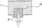
마지막으로, 제 14 양태에 따른 본 발명은 2 개 이상의 패널 형상의 요소들을 포함하는 조립된 요소로서, 패널들 중 적어도 2 개는 각각 결합 영역을 포함하고, 이 결합 영역에서는 결합 부분들이 각각의 결합 영역의 종방향으로 연장하는 각각 프로파일의 형태로 제공되고; 프로파일들은, 패널 형상의 요소들이 기계적 로킹 방식으로 그리고 각도를 이루어 상호 결합될 수 있는 것을 허용하고; 프로파일들은 텅 및 요홈을 포함하고; 조립된 요소는 패널 형상의 요소들의 정확한 상호 조립을 보조하는 보조 수단을 포함하고, 보조 수단은 대응하는 오목부와 협동할 수 있는 돌출부의 형태의 3 차원 형태의 요소에 의해 형성되고, 각각의 프로파일의 단면의 방향에서 볼 때 돌출부는 바람직하게는 돌출 플러그의 형태로 텅의 프로파일을 통해 전적으로 또는 주요 부분에 대해 연장하고, 반면에 오목부들은 요홈을 포함하는 패널 형상의 요소에 위치되고, 바람직하게는 보어의 형태로 실현되는 것을 특징으로 하는 조립된 요소에 관한 것이다. 단면에서 볼 때 텅에 대한 돌출부의 특정의 위치는 상세한 설명으로부터 명백해지는 바와 같이 다양한 이점들을 제공한다.Finally, the present invention according to the fourteenth aspect is an assembled element comprising two or more panel-shaped elements, wherein at least two of the panels each comprise a coupling region, Each being provided in the form of a profile extending in the longitudinal direction of the region; The profiles allow the elements of the panel shape to be interlocked in a mechanical locking manner and at an angle; The profiles include tongues and grooves; The assembled element comprises auxiliary means for assisting accurate interassembly of the elements in the form of a panel and the auxiliary means is formed by a three dimensional element in the form of a protrusion cooperable with the corresponding recess, In the direction of the cross section of the tongue, the protrusions preferably extend entirely or through the profile of the tongue in the form of projecting plugs, while the recesses are located in the panel-shaped element comprising the recesses, Is realized in the form of a bore. The particular location of the protrusion relative to the tongue in cross-section provides various advantages as will be apparent from the detailed description.
보조 수단은, 패널 형상의 요소들이 상호 변위된 위치에 결합되는 것을 저지하도록 및/또는 제작자가 부적절한 패널들을 함께 결합하려고 시도하는 것을 저지하도록 설계된다.The auxiliary means are designed to prevent the panel-shaped elements from being engaged in mutually displaced positions and / or to prevent the manufacturer from attempting to join the improper panels together.
본 발명의 추가의 특징들은 이하의 설명 및 첨부된 청구항들로부터 명확해질 것이다.Further features of the present invention will become apparent from the following description and appended claims.
이하, 본 발명의 특징들을 더 잘 설명하기 위한 목적에서, 첨부한 도면을 참조하여, 임의의 제한적인 특성이 없는 실시예로서의 일부의 바람직한 실시형태들이 설명된다.BRIEF DESCRIPTION OF THE DRAWINGS For a better understanding of the features of the present invention, reference will now be made, by way of example, to the accompanying drawings, in which there are illustrated some preferred embodiments as embodiments without any limiting features.
도 1 은 본 발명에 따른 조립된 요소를 개략적으로 도시한다;
도 2 는 도 1 의 II-II 선에 따른 확대 단면도를 도시한다;
도 3 은 도 2 에서 F3 으로 표시된 부분의 확대도를 도시한다;
도 4 및 도 5 는 도 3 의 연결부를 실현하는 2 가지 방법을 도시한다;
도 6 은 도 5 에서 F6 으로 표시된 부분의 확대도를 도시한다;
도 7 은 요홈을 포함하는 패널만의 도 4 의 VII-VII 선에 따른 단면도를 도시한다;
도 8 은 본 발명에 따른 다른 조립된 요소를 도시한다;
도 9 는 도 8 의 IX-IX 선에 따른 확대 단면도를 도시한다;
도 10 은 도 9 의 것과 유사하지만 변형예를 위한 도면을 도시한다;
도 11 은 결합될 부분들이 분해된 상태에 있는, 결합부의 특정의 실시형태를 도시한다;
도 12 는 도 11 에 도시된 요홈을 실현하기 위한 특정의 기법을 도시한다;
도 13 은 도 11 의 것과 유사하지만 결합된 상태에 있는 도면을 도시한다;
도 14 는 도 13 의 것과 같은 2 개의 연결부가 적용된 사무용 가구 형태의 조립된 요소를 도시한다;
도 15 내지 도 19 는 서랍의 형태로 실현된 본 발명에 따른 조립된 요소에 관한 것으로서, 여기서 도 17 은 도 15 에서 F17 로 표시된 부분을 확대하여 도시하고, 도 18 은 화살표 F18 에 따른 축소도이고, 도 19 는 F19 로 표시된 부분을 확대 및 조립된 상태에서 도시한다;
도 20 은 필름 힌지들에 의해 상호 연결되는 한 세트의 4 개의 직립 벽들의 평면도를 도시한다;
도 21 은 서랍을 형성하기 위해 조립된 상태인 도 20 의 한 세트의 벽들을 도시한다;
도 22 는 도 22 의 것과 유사한 도면으로 본 발명에 따른 서랍의 변형예를 도시한다;
도 23 은 본 발명의 조립된 요소의 부분을 도시한다;
도 24 는 본 발명에 따라 실현되는 프레임을 구비하는 가구 패널을 도시한다;
도 25 는 그와 같이 도 24 에 F25 로 표시된 구성부분을 도시한다;
도 26 은 도 25 에서 화살표 F26 에 따른 도면을 도시한다;
도 27 은 도 24 에서 F27 로 도시된 부분을 도시한다;
도 28 은 도 24 의 XXVIII-XXVIII 선을 따른 더 확대된 단면도를 도시한다;
도 29 및 도 30 은 본 발명에 따라 적용될 수 있는 코너 연결부들의 다른 2 개의 특정의 실시형태들을 도시한다.Figure 1 schematically shows an assembled element according to the invention;
2 shows an enlarged cross-sectional view along the line II-II in Fig. 1;
Fig. 3 shows an enlarged view of the portion indicated by F3 in Fig. 2; Fig.
Figures 4 and 5 illustrate two ways of realizing the connection of Figure 3;
Fig. 6 shows an enlarged view of a portion indicated by F6 in Fig. 5;
Figure 7 shows a cross-sectional view along the line VII-VII of Figure 4 of the panel only including the grooves;
Figure 8 shows another assembled element according to the invention;
9 shows an enlarged cross-sectional view along the line IX-IX of Fig. 8;
Figure 10 shows a view similar to that of Figure 9 but for a modification;
Fig. 11 shows a specific embodiment of the coupling part in which the parts to be joined are in a disassembled state;
Figure 12 shows a specific technique for realizing the groove shown in Figure 11;
Figure 13 shows a view similar to that of Figure 11 but in an engaged state;
Figure 14 shows an assembled element in the form of an office furniture to which two connections as in Figure 13 are applied;
Figs. 15 to 19 relate to an assembled element according to the present invention realized in the form of a drawer, wherein Fig. 17 is an enlarged view of a portion denoted by F17 in Fig. 15, Fig. 18 is a reduced view of an arrow F18 , Fig. 19 shows a portion indicated by F19 in an enlarged and assembled state; Fig.
Figure 20 shows a top view of a set of four upstanding walls interconnected by film hinges;
Figure 21 shows a set of walls of Figure 20 in an assembled state to form a drawer;
Figure 22 shows a variant of a drawer according to the invention in a view similar to that of Figure 22;
Figure 23 shows a portion of the assembled element of the present invention;
Figure 24 shows a furniture panel with a frame realized according to the invention;
Fig. 25 shows the constituent parts indicated by F25 in Fig. 24 as such;
Figure 26 shows the view according to arrow F26 in Figure 25;
Figure 27 shows the portion shown as F27 in Figure 24;
Figure 28 shows a further enlarged cross-sectional view along line XXVIII-XXVIII in Figure 24;
29 and 30 illustrate two other specific embodiments of corner connections that may be applied in accordance with the present invention.
도 1 및 도 2 에서, 본 발명에 따른 조립된 요소 (1) 의 실시예는 각도를 이루어 상호 연결된 패널 형상의 요소들로 실질적으로 구성되는 한 점의 가구의 형태, 더 구체적으로 캐비닛의 형태로 도시되어 있다. 이 패널 형상의 요소들은 도면부호 2 를 일반적으로 가지지만, 구별을 위해 2A, 2B, 2C 및 2D 로 표시되고, 여기서 이 실시예에서 이들 도면부호는 우측벽 (3), 저벽 (4), 좌측벽 (5) 및 상벽 (6) 을 형성한다. 더욱이, 이 가구는 스커팅 보드 (7), 후 부분 (8) 및 2 개의 선반들 (9, 10) 을 포함한다.1 and 2, an embodiment of the assembled
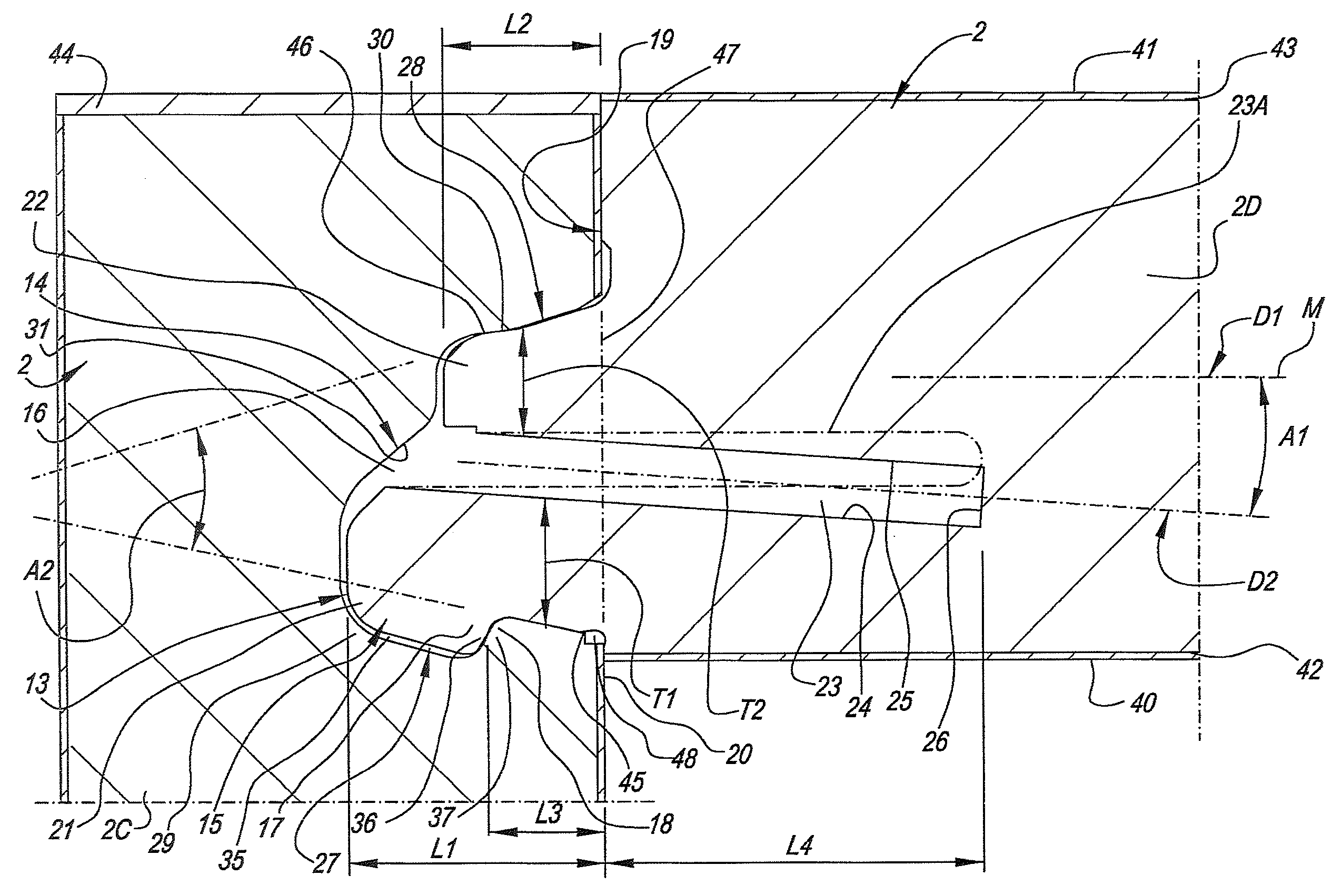
도 2 내지 도 6 의 상이한 도면으로부터 명확해지는 바와 같이, 이 각각의 패널 형상의 요소들 (2) 은, 결합 부분들 (13, 14) 이 각각의 결합 영역의 종방향으로 각각 연장하는 프로파일의 형태로 존재하는, 결합 영역들 (11, 12) 을 포함하고, 여기서 이 프로파일들은, 2 개의 패널 형상의 요소들 (2) 이 항상 로킹 방식으로 또 각도를 이루어 상호 결합될 수 있는 것을 허용한다. 도시된 실시예에서, 요홈 (16) 과 협동하는 분할 텅 (15) 의 형태의 프로파일들을 구비하는 결합 부분들 (13, 14) 이 사용된다. 그와 같이 분할 텅 및 요홈을 이용하는 결합 부분들을 구비하는 코너 연결부의 이와 같은 유형은 이미 DE 20 2009 008 825 U1 으로부터 그와 같이 공지되어 있다.2 to 6, each of these panel-shaped
더 구체적으로, 결합 부분들 (13, 14) 은 로킹 수단 (17, 18) 을 포함하는 텅 (15) 및 요홈 (16) 의 형태의 프로파일들로서 실질적으로 실현되고, 로킹 수단은 결합된 상태에서 텅 (15) 및 요홈 (16) 의 이동 부분에 대해 반대 작용을 하고, 더 바람직하게는 그 이동을 방지한다. 도시된 바와 같이, 이 로킹 부분들 (17, 18) 은 상기 프로파일들의 부분을 형성하는 리브들 (ribs) 또는 엣지들 (eD ges) 로서 실현되는 것이 바람직하다.More specifically, the engaging
도시된 바와 같이, 텅 (15) 은 각각의 패널 형상의 요소 (2), 더 바람직하게는 도 3 의 2D 의 원위 단부 (19) 상에 각각 위치되고, 반면에 요홈 (16) 은 다른 패널 형상의 요소 (2), 더 바람직하게는 도 3 의 2C 의 측면 (20) 에, 다시 말하면 패널 형상의 요소의 큰 표면들 중 하나에 위치되는 것이 도시되어 있다. 이 실시예에서, 결합 영역 (11) 은 이 경우에 텅이 위치되는 각각의 패널 형상의 요소의 작은 단부의 엣지부에 의해 형성된다. 이 경우에 결합 영역 (12) 은 이와 같은 패널 형상의 엣지부의 요소의 상기 작은 단부 엣지부가 접촉하는 각각 다른 패널 형상의 요소의 하나의 영역으로 이루어진다.As shown, the
텅 (15) 은 분할 텅으로 이루어지고, 따라서 적어도 2 개의 부분들 (21, 22) 및 이 부분들 사이에 위치되는 슬릿 (23) 을 구비한다. 슬릿은 부분들 (21, 22) 상에 각각 위치되는 측면 (24, 25) 및 저면 (26) 에 의해 경계가 형성된다. 이하에서 각각 제 1 부분 (21) 및 제 2 부분 (21) 으로 명명되는, 도시된 실시예의 상기 2 개의 부분들 (21, 22) 은 각각 상이한 길이 (L1, L2) 를 갖는다. The
도시되지 않은 변형예들에 따르면, 텅은, 예를 들면 여분 재료 (extra material) 의 부분이 슬릿과 평행하게 존재해야 하는 경우, 2 개 이상의 부분들로 이루어질 수도 있다는 것이 주목된다. 이 경우 이전에 대상으로 되는 슬릿은, 말하자면, 2개의 슬릿으로 분할된다.It is noted that according to variants not shown, the tongue may consist of two or more parts, for example if the part of the extra material must be parallel to the slit. In this case, the previously-targeted slit is divided into two slits, so to speak.
도면들에 도시된 부분들 (21, 22) 의 외측부 (27, 28) 는 요홈 (16) 의 측벽 (29, 30) 과 협동한다. 더욱이, 요홈 (16) 은 저벽 (31) 을 갖는다. 도시된 바와 같이, 이 저벽은 형상에 대하여 상이한 길이 L1 및 L2 에 적합되는 것이 바람직하고, 따라서 더 깊은 부분 (32), 및 여분 재료 (34) 가 덜 깊은 부분 (33) 의 위치에 유지되는 덜 깊은 부분 (33) 을 보인다. 이와 같은 재료 부분 (34) 을 유지하는 것은 T 자형 연결부들을 위해서는 덜 중요하지만, 싱글 폴드 (single-fold) 코너 연결부의 경우에는, 이 방법으로 더 안정한 전체를 유지하기 위해, 또 요홈의 경계를 형성하는 재료의 측방향 파단의 위험을 회피하기 위해, 실제로 중요하다. 그러므로, 저벽 (31) 의 부분들 (32, 33) 은 결합된 상태에서 부분들 (21, 22) 의 최원위 단부들 (farthest distal ends) 로부터 2 mm 이하로 이격된 상태로 유지되는 것이, 다시 말하면 텅 (15) 의 전체적인 형상을 따르는 것이 바람직하다.The
측벽 (29) 에 오목부 (35) 가 형성되고, 그 결과 이 오목부의 전방에 위치된 부분은 로킹 부분 (18) 으로서 기능한다. 로킹 부분들 (17, 18) 은 결합하는 로킹 표면들 (36, 37) 을 한정한다.The
로킹 부분 (17) 은 텅의 상기 제 1 부분 (21) 상에 위치된다.The locking
도면들에 도시된 바와 같이, 제 1 부분 (21) 은 상기 로킹 부분 (17) 을 구비하고, 반면에 제 2 부분 (22) 은, 도시된 바와 같이, 로킹 부분이 없는 것이 바람직하다는 것이 주목된다. 이와 같은 구성은, 도 5 에 도시된 바와 같이, 텅이 결합 부분들 내에 큰 힘을 생성함이 없이 선회 운동 (W) 에 의해 요홈 내로 쉽게 선회될 수 있는 것을 허용한다. 그러나, 본 발명은 로킹 부분이 제 2 부분 (22) 상에도 존재하는 것을 배제하지 않고, 이 경우 이 로킹 부분은 로킹 부분 (17) 보다 덜 현저한 것이 바람직하다. 이와 같은 덜 현저한 또는 따라서 더 작은 로킹 부분은 도 4 에 실시예로서 점선으로 도시되어 있고, 또 도면부호 38 로 표시되어 있고, 여기서 이 로킹 부분은 국부 돌출부로서 실현되고, 이 국부 돌출부는 역시 점선으로 도시되어 있는 오목부 (39) 와 협동할 수 있다.It is noted that, as shown in the figures, the
본 발명에 따라, 텅 (15) 의 단면에서 볼 때 슬릿 (23) 은 적어도 하나의 측부를 포함하고, 단면에서 볼 때 이 측부의 배향은 텅에 관한 주 방향 (D1) 으로부터 편향되고, 또 상기 주 방향 (D1) 에 대하여 각도를 이루어 연장하는 것이 바람직하다. 도시된 실시예에서, 공통적으로 양 측면 (24, 25) 은 상호 평행한 실시예에서 경사지게 실현되고, 그 결과 전체적으로 도시된 텅 내의 슬릿 (23) 은 상기 주 방향에 대하여 경사지게 연장한다.According to the invention, the
여기서, 전체적으로 도시된 텅 (15) 의 제 1 부분 (21) 의 경계를 이루는 측부 (24) 는, 이 측부 (24) 가, 슬릿 (23) 의 원위 단부로부터 근위 단부까지, 분할 텅의 제 1 부분 (21) 과 동일한 측면 상에 위치된 표면 (40) 에 접근하도록, 상기 주 방향 (D1) 에 대하여 경사진 방향으로, 다시 말하면, 제 1 부분 (21) 및/또는 제 1 부분 (21) 이 제공되는 패널 형상의 요소의 부분이, 슬릿이 경사지지 않은 실시형태들에 비해 근위 단부를 향해 전체적으로 더 얇아지도록 경사진 방향으로 연장한다. 이것에 의해 제 1 부분 (21) 은 비교적 원활한 방법으로 탄성적으로 변위 가능하다는 것이 명백하다.The
전체적으로 도시된 제 2 부분 (22) 의 경계를 이루는 슬릿 (23) 의 측부 (25) 는 주 방향 (D1) 에 대하여 경사지게 연장되고, 그 결과 이 측부는, 슬릿의 원위 단부로부터 근위 단부까지, 제 2 부분 (22) 과 동일한 측면 상에 위치되는 표면 (41) 로부터 멀어지고, 다시 말하면, 이 측부 (25) 는 측부 (24) 와 동일한 방향으로 경사진 방식으로 연장한다. 도시된 실시예에서, 이것은 제 1 부분 (22) 의 베이스가 더욱 강고하고 안정해지는데 기여한다.The
여기서, 전체는, 제 1 부분 (21) 및 특히 그 로킹 부분 (17) 이 제 2 부분 (22) 보다 더 원활한 방법으로 탄성적으로 변위 가능하도록 설계되고, 제 2 부분은 비교적 강성이다. 로킹 부분 (17) 의 원활한 탄성 변위는, 제 1 부분 (21) 이 그와 같이 제 2 부분 (22) 보다 길기 때문에, 그러나 그 보다는 제 1 부분 (21) 이 패널 형상의 요소 (2d) 의, 즉 슬릿의 측부 (24) 및 표면 (40) 사이에 위치된 패널 형상의 요소의, 슬릿 (23) 에 의해 분리된, 얇은 재료 부분에 인접하고 또 이 얇은 재료 부분에 의해 지지되기 때문에 얻어진다. 측부 (24) 는 도시된 방향으로 경사지게 연장하므로, 상대적으로 얇은 재료 부분은 슬릿의 가장 내측에 위치되는 단부에 인접하여 유지되고, 이 상대적으로 얇은 재료 부분은 더욱 로킹 부분으로부터 상대적으로 먼 거리에 위치되고, 이것은 이 재료 부분의 높이에서 원활한 탄성 굴곡 변형을 촉진한다.Here, the whole is designed such that the
"슬릿" 이라 함은 텅을 분할하는 부분 및 패널 형상 내의 더 깊은 연장부의 양 부분으로 이해되어야 한다.The term "slit " should be understood as both the part dividing the tongue and both parts of the deeper extension within the panel shape.
본 실시예의 측부 (24) 의 전체적인 방향 및/또는 슬릿 (23) 의 전체적인 또는 평균적인 방향 (D2) 은 A1 으로 표시된 각도에 걸쳐 주 방향 (D1) 으로부터 편향된다. 이 각도의 크기는 2 ~ 20 도 범위에 위치되는 것이 바람직하다. 결합이 정상의 강도를 가지는 경우, 바람직하게는 2 ~ 8 도 범위의 각도 (A1) 가 사용되고, 약 4 도 정도가 바람직하다. 강성이 낮은 결합이 요구되는 경우, 다시 말하면, 원활하게 상호 스냅 결합될 수 있는 결합이 요구되는 경우, 8 ~ 20 도의 각도 (A1) 가 사용되는 것이 바람직하다.The overall direction of the
도시된 실시예에서, 텅 (15) 은 각각의 패널 형상의 요소의 작은 면에 위치된다. 여기서, 텅에 속하는 주 방향 (D1) 은 패널 형상의 요소 (2d) 가 위치되는 평면의 방향으로 이해되어야 한다.In the illustrated embodiment, the
도시된 바와 같이, 텅 (15) 은 이 텅이 위치되는 패널 형상의 요소의 중심면 (M) 에 대하여 편심으로 위치되고, 여기서 조립된 요소 (1) 는, 적어도 텅이 편심으로 변위되는 방향의 측부에서, 패널 형상의 요소들 사이의 내측 코너부를 형성한다. 더 구체적으로, 전체적으로 도시된 텅은, 텅이 대향측 보다 내측 코너부 (22) 에 접촉하여 위치된 측에 더 근접하여 위치되는 것과 같은 방식으로 패널 형상의 요소 (1) 의 중심의 외측에 위치된다.As shown, the
텅 (15) 은 도 5 에 도시된 바와 같은 선회 운동 (W) 에 의해 요홈 (16) 내에 끼워맞춤되고, 여기서 선회 진입된 패널 형상의 요소 (이 경우 2B) 는 직각의 상태로 그 최종 위치를 얻는다. 이 선회 운동 (W) 은 도시된 조립된 요소의 내측 코너부의 측부를 따라 발생한다. 양 패널 형상의 요소들의 분해는 반대 방향으로의 선회 운동에 의해, 또는 패널 형상의 요소들을 상호로부터 텅에 평행한 방향으로 당기거나 가볍게 두드리는 것 (tapping) 에 의해 발생한다.The
패널 형상의 요소들은 또한, 도 4 에 도시된 바와 같이, 상호 병진 운동에 의해 패널 형상의 요소들을 변위시키는 것에 의한 스냅 (snap) 운동에 의해 상호 접합될 수 있다는 것이 주목된다.It is noted that the panel-shaped elements can also be joined together by a snap motion by displacing panel-shaped elements by reciprocal translational motion, as shown in Fig.
여기서, 텅 (15) 은, 텅 (15) 을 가진 각각의 패널 형상의 요소들을 그 면 내에서 요홈 (16) 을 향하여 가압하는 것과 같은 스냅 운동에 의해 요홈 (16) 내에 끼워맞춤된다. 도시된 실시형태에서, 이 끼워맞춤은 로킹 부분 (17) 이 2 개의 로킹 부분들 (17, 18) 의 재료 내에서 가능한 경미한 탄성 압축과 조합하여 측방향 탄성 운동을 실행할 수 있으므로 달성되고, 이 방법에서 로킹 부분 (17) 은 로킹 부분 (18) 의 후방에 맞물릴 수 있고, 이 모두는 텅 및 요홈의 재료 내의 약간의 추가의 압축과의 조합 여부에 무관하다.Here, the
슬릿 (23) 은, 상호 스냅 결합 중에, 로킹 요소가 속하는 패널 형상의 요소들에 대하여 로킹 요소 (17) 에 의해 실행되는 최대 측방향 변위와 동일하거나 또는 더 큰 폭을 갖는 것이 바람직하다.The
더욱이, 요홈 (16) 의 입구는 작은 삽입 각도 (A2) 를 갖고, 이 각도는 40 도 미만인 것이 바람직하고, 더 바람직한 것은 약 30 도이다.Moreover, the entrance of the
전체적으로 보았을 때, 텅은 제 2 부분 (22) 의 외측부 및 제 1 부분 (21) 의 로킹 부분의 외측부에 의해 형성되는 원추형 측부를 구비하는 원추형으로 제작된다.As a whole, the tongue is conically shaped with a conical side formed by the outer portion of the
도면들에 도시된 실시예들은 텅 (15) 및 요홈 (16) 이 선회 운동에 의해서 뿐만 아니라 병진 운동을 통한 스냅 운동에 의해, 따라서 설치하는 사람의 선택에 따라 2 가지 방법으로 상호 결합될 수 있도록 구성되는 텅 (15) 및 요홈 (16) 을 도시하는 것이 명백하다. 이것은 각각 동일한 형태의 텅 및 요홈에 대한 2 가지 결합 기법을 도시하는 도 4 및 도 5 로부터 명확해진다. The embodiments shown in the figures are designed so that the
도시된 바와 같이, 텅 (15) 및 요홈 (16) 은 예를 들면 밀링 가공 처리에 의해 패널 형상의 요소들 내에 일체로 실현되는 것이 바람직하다. 여기서, 텅 (15) 은 각각의 패널 형상의 요소들의 작은 면 상에 위치되고, 반면에 요홈은 각각의 패널 형상의 요소들의 측부에 제공된다.As shown, it is preferred that the
도면들에 도시된 바와 같이, 패널 형상의 요소들은 양측에 각각 피복층 (42, 43) 을 구비하는 것이 바람직한 피복 보드 (covereDBoard) 로 형성되는 것이 바람직하다. 이것은 멜라민 피복 (melaminated) 보드, 따라서 적층 피복을 구비하는 보드에 관한 것이 바람직하다. 특히, 이 적층 층은, 다른 층들과의 조합 여부와 무관하게, 수지가 제공되고 또 그 보드 상에 가압된 장식 층으로 적어도 이루어지는 것으로 한다. 그 예들은 HPL (High Pressure Laminate) 또는 DPL (direct Pressure Laminate) 이다. 또한, 필름, 래커 층 등, 또는 임의의 다른 형태의 피복도 적용될 수 있다.As shown in the drawings, it is preferable that the panel-shaped elements are formed of a cover board which is preferably provided with
기본적인 보드 자체는 MDF, HDF 또는 파티클 보드로 이루어지는 것이 바람직하다. 파티클 보드는 MDF 또는 HDF 만큼 안정적이지 않은 경우가 종종 있고, 더 쉽게 분쇄되지만, 파티클 보드는 더 경량이고, 이 경량은 심미적 이유로 예를 들면 18 mm 이상의 두께의 비교적 두꺼운 벽으로 작업하기 위해 선택되는 경우에 더욱 중요하다는 것을 고려하면, 파티클 보드는 가구용으로 바람직하다. 본 발명은 이와 같은 프로파일들이 효율적인 방법으로 파티클 보드의 재료 내에서 실행될 수도 있다는 것에 기여한다.The basic board itself is preferably made of MDF, HDF or particle board. Particle boards are often not as stable as MDF or HDF and are easier to break up, but particle boards are lighter and this lightweight is chosen for aesthetic reasons to work with relatively thick walls, for example, 18 mm thick or thicker , The particle board is preferable for furniture. The present invention contributes that such profiles may be implemented in the material of the particle board in an efficient manner.
엣지부 상에서, 패널 형상의 요소들은 예를 들면 적층 테이프 또는 합성 재료의 마감 테이프 (예를 들면, ABS 테이프) 와 같은 마감 테이프 (44) 를 구비할 수 있다. 도 1 및 도 7 은 또한 텅들 및 요홈들의 단부들이 이와 같은 마감 테이프를 요홈 (16) 의 원위 단부들을 초과하여 연장하도록 함으로써, 다시 말하면, DE 20 2009 008 825 U1 에 기재된 것과 같은 방식으로 직선상 테이프 피복을 제공함으로써, 이와 같은 마감 테이프에 의해 은폐될 수 있다는 것을 보여준다. 이와 같은 테이프 피복은 제작회사에서 실시된다.On the edge portion, the panel-shaped elements may have a finishing
본 발명의 상기 제 2 양태에 따라, 도시된 실시예에서는 또한 텅의 돌출 부분들보다 적어도 더 깊게, 다시 말하면 폐쇄면 (47) 을 초과하는 위치까지 연장하는 슬릿 (23) 과 조합하여, 지지점들 (45,46) 의 특정의 분포가 적용된다. 여기서, 제 1 접촉점은 요홈과 텅 (15) 의 제 1 부분 (21) 사이에서 폐쇄면 (47) 에 가장 근접하여 위치되는 접촉부로서 정의되고, 반면에 제 2 접촉점 (46) 은 요홈과 텅의 제 2 부분 (22) 사이에서 폐쇄면 (47) 으로부터 가장 멀리 위치된 접촉부로서 정의된다. 이 특수성은 제 1 접촉점 (45) 이 제 2 접촉점 (46) 보다 폐쇄면 (47) 에 더 근접하여 위치되는 것으로 이루어진다. 다른 한편, 이것에 의해 더 양호한 힘의 분포가 결합에서의 힘을 위해 얻어진다. 또한, 하나의 패널 형상의 요소들이 요홈 (16) 을 상방으로 향한 상태로 배치되고, 반면에 다른 패널 형상의 요소들은 텅 (15) 을 하방으로 향한 상태로 제공되는 한 점의 가구의 조립작업 시에 중간 위치들에서, 이 제 2 패널은 방치해 두더라도 매우 신속하게 기울어져서 꺾여 넘어지지 않는 것이 얻어진다.According to the second aspect of the invention, in the illustrated embodiment, in combination with a
결합된 상태에서, 폐쇄면 (47) 은 요홈 (16) 의 단부가 위치하는 패널 표면 (40) 과 일치하는 면으로 일반적으로 이루어지는 것이 주목된다.It is noted that in the engaged condition, the closing
도시된 바와 같이, 텅이 요홈 내로 선회하는 기점이 되는 측부의 요홈 (16) 의 입구 상에는, 각도 절결부 (48) 가 엣지부 (49) 상에서 실현될 수 있는 것이 바람직하고, 이 절결부는 더 원활한 선회 결합 (turning-in) 을 가능하게 한다.As shown, on the entrance of the
또한 도면에 도시된 실시형태는 본 발명의 제 3 의 독립된 양태를 적용한다. 그것과 관련하여, 텅 (15) 의 제 1 부분 (21) 및 제 2 부분 (22) 의 길이는 각각 L1 및 L2 로 표시되고, 반면에 폐쇄면 (37) 의 중앙부가 각각의 보드의 표면 내에 위치되는 거리는 L3 로 표시된다. 제 3 양태에 따라, 텅 (15) 은 슬릿을 구비하고, 로킹 부분 (17) 은 제 1 부분 (21) 의 외측부 상에 존재하고, 반면에 제 2 부분의 외측 상에는 덜 현저한 로킹 부분이 존재하고, 또 심지어 로킹 부분이 존재하지 않는 것이 바람직하다. 여전히 제 3 양태의 특징에 따라, 텅 (15) 의 제 2 부분 (22) 은 폐쇄면 (47) 으로부터 길이 L2 만큼 돌출하고, 이 길이는 텅 (15) 의 제 1 부분 (21) 이 폐쇄면 (47) 으로부터 돌출하는 길이 L1 의 0.75 배 미만이다. 이 비율을 중시함으로써, 상대적으로 본 제 2 부분이 과도하게 방해하지 않음에 따라, 한편으로, 텅이 원활하게 선회 진입될 수 있고, 반면에 제 1 부분에서 실제로 이와 같은 결합 및 로킹이 실현될 수 있다는 이점이 얻어진다. 또한, 이 경우에 비례적으로 요홈의 저벽의 덜 깊게 위치된 부분은 더 얕은 깊이로 실행될 수 있고, 이것에 의해 요홈의 벽은 매우 강고해 진다.The embodiments shown in the drawings also apply to the third independent aspect of the present invention. The length of the
또한 도시된 실시형태는, 그 중에서도, 슬릿 (23) 이 폐쇄면 (47) 을 초과하여 연장하는 깊이에 뻗는다는 점에서, 그리고 더욱 텅 (15) 의 제 2 부분 (22) 은 로킹 표면들 (36, 37) 이 폐쇄면으로부터 이격된 평균 거리 L3의 1.5배 미만인 폐쇄면 (47) 으로부터의 길이 L2 만큼 돌출하는 점에서, 본 발명의 제 4 의 독립된 양태를 도시한다. 이것에 의해, 제 2 부분 (22) 이 돌출하는 거리는 제 1 부분 (21) 이 결합하는 위치에 대하여 제한되는 것이 얻어진다. 이 제한에 의해, 과도하게 멀리 돌출하는 부분 (22) 이 결합 중 불편으로서 경험되는 것이 배제된다. 안정한 결합을 보장하기 위해, 이 경우에 길이 L2 는 L3 보다 큰 것이 바람직하다.The illustrated embodiment also has the advantage that the
도시된 실시형태에서, 특히, 폐쇄면 (47) 과 로킹 표면 (36, 37) 사이에 연장하는 제 1 부분 (21) 의 부분이 제 2 부분 (22) 의 평균 두께 T2 보다 큰 평균 두께를 보이는 특징을 또한 보이므로, 이 실시형태는 본 발명의 제 5 양태의 실시예를 또한 형성한다. 텅 (15) 의 동일한 전체 두께로부터 출발하는 이와 같은 돌출에 의해, 제 1 부분 (21) 은 더욱 강고하고 안정해지는 것이 얻어지고, 이것은, 이 제 1 부분이 로킹 부분을 구비하고 따라서 힘에 대해 상당한 부하를 받는다는 사실을 고려하면 중요하다는 것이 명백하다. 제 5 양태는 특히, 도시된 바와 같이, 텅이 편심으로 설치되고 또 슬릿이 텅의 베이스보다 패널 형상의 요소들 내로 더 깊게 연장하는 실시형태들에서 특히 유리하다는 것이 명백하다. 따라서, 이것에 의해, 이 경우에 제 1 부분 (21) 이 이 제 1 부분 (21) 이 접촉하는 패널 형상의 요소들의 절결 재료의 부분 만큼 말하자면 연장되므로, 비록 제 1 부분이 그와 같이 더 안정하고 강고하지만 그럼에도 상당한 탄성 가동성이 생성될 수 있는 것이 얻어진다.Particularly in the depicted embodiment a portion of the
T1 은 거리 L1 에 걸쳐 연장하는 부분의 평균 두께 및/또는 길이 L의 중간에서 측정된 그 두께인 것이 바람직하고, 반면에 T2 는 제 2 부분 (22) 의 평균 두께 및/또는 길이 L2 의 중간에서 측정된 그 두께인 것이 주목된다. 양 선택 (possibilities) 는 제작회사가 사용하기를 원하는 기준에 따라 적용될 수 있다.T1 is preferably the average thickness of the portion extending over the distance L1 and / or its thickness measured in the middle of the length L, while T2 is preferably the average thickness of the
제 6 양태에 따라, 깊이, 다시 말하면, 슬릿 (23) 이 폐쇄면 (47) 으로부터 패널 형상의 요소 (2) 의 내부를 향해 뻗는 거리 L4 는 텅 (15) 이 폐쇄면으로부터 뻗는 최대 거리 L1 보다 길다. 이것은 제 1 부분 (21) 의 가동성에 유리하다는 것이 명백하다. 더욱이, 이것에 의해 발행하는 변형은 더욱 후방을 향해 전달될 수 있고, 그 결과 제 1 부분 (21) 의 선단부는 로킹 부분의 위치에서 변형에 대하여 더 작은 부하를 받는다.According to the sixth aspect, the depth L4, in other words the distance L4 from which the
서두에서 언급된 제 7 양태에 따라, 텅 및 요홈은, 선회 결합 운동의 말기를 향한 상호에 대한 선회 시에, 힘의 최대치가 극복되어야 하는 구성을 갖고, 그 결과 또한 다시 상호로부터 선회 시에, 도 6 의 접촉점들 (50, 51) 로 표시되는 바와 같이, 여기서 선회 운동 (W) 의 경우에 접촉이 엣지부 (49) 에 인접하여 유지되는 것과 같이, 힘은 극복되어야 한다. 이 방법에서, 유지 수단 또는 저지 수단은 그 결합부 자체 내에 일체화되고, 이 경우에 유지 수단 또는 저지 수단은 텅 및 요홈, 따라서 패널 형상의 요소들의 상호 분리되는 방향으로의 선회에 반대 작용을 하는 감속 효과를 적어도 제공하는 것이 얻어진다. 가구의 조립 중에 특정의 중간 위치들에서, 이 경우에 일시적으로 직립 상태로 제공되는 하나의 패널 형상의 요소들이 다른 것에 대하여 꺾여 넘어지는 것을 전술한 바와 같이 방지하기 위해, 이 경우에 이것은 또한 조립 중에 유용하다.According to the seventh aspect mentioned at the beginning, the tongue and groove have a configuration in which the maximum of the force must be overcome at the time of turning relative to the mutual toward the end of the swiveling motion, and as a result, As indicated by the contact points 50, 51 in Fig. 6, the force must be overcome here, as in the case of the pivotal movement W here, the contact is held adjacent the
도 6 에 도시된 바와 같이, 이것은 로킹 부분이 존재하지 않는 측부의 텅에, 상호 결합 또는 분리되는 방향으로의 선회 중에 요홈 상에 부분 (53) 으로 이론적으로 중첩되는 부분 (52) 을 제공하고, 그 결과 사점 (dead point) 의 힘, 더 바람직하게는 변형력이 극복될 수 있도록 함으로써 실현될 수 있다.As shown in Fig. 6, this provides a
또한 도 6 에 도시된 대안에 따라, 로킹 부분들의 높이에서 텅 및 요홈은, 선회 중 이론적 중첩부 (36A) 에 의해 변형력이 사점에서 극복되도록 제공되는 부분들을 포함할 수 있다.Also according to the alternative shown in FIG. 6, the tongue and groove at the height of the locking portions may include portions provided that the deformation force is overcome at the dead point by the theoretical overlapping
양 선택들이 조합될 수 있거나 조합되지 않을 수 있다는 것은 명백하다.It is clear that both choices may or may not be combined.
또한, 결합된 상태에서 장력이 특히 소위 프리텐션 (pretension) 을 유지하도록 프로파일들은 실행될 수 있다.Also, the profiles can be executed so that tension is maintained, particularly in the so-called pretension, in the combined state.
상기 결합은, 일반적인 코너 연결부, T 자형 연결부, 또는 심지어 십자형 연결부의 코너 연결부를 실현하기 위해, 가구와 같은 조립된 요소 상의 다양한 위치 상에 적용될 수 있다는 것은 명백하다. 그러나, 이것은 이와 같은 조립된 요소 (1) 의 모든 코너 연결부들이 그와 같이 실현되어야 한다는 것을 의미하지 않는다.It is clear that the coupling can be applied on various locations on assembled elements, such as furniture, in order to realize a corner connection of a typical corner connection, a T-connection, or even a cross connection. However, this does not mean that all corner connections of such assembled
본 발명은 특히 텅이 그와 같이 결합 효과를 제공하고, 따라서 텅이 결합 중에 그 중에서도 예를 들면 US 7,654,055 로부터 공지된 것과 같은 텅의 슬릿 내로 구동되는 쐐기 등과 같은 텅 상에 영향을 주는 외부 요소들이 없는 상태에 유지되는 실시형태들을 목적으로 하는 것이 주목된다. 실제로, 그와 같이 텅은 텅에 고정된 상태로 속하는, 그리고 예를 들면 탄성 스트립 또는 텅 내의 슬릿 내에 제공되는 매스 (mass) 와 같은 텅에 의해 공급되는 결합력을 지지할 수 있는 요소들을 포함할 수 있다.The invention is particularly applicable to tongue-like external elements such as wedges or the like which are driven into a tongue slit, for example, as known from US 7,654,055, while the tongue provides such a coupling effect, The present invention is directed to embodiments that are maintained in a non-existent state. Indeed, as such, the tongue may include elements that are attached to the tongue in a fixed state and that can support the tensions provided by the tongue, such as, for example, a mass provided in an elastic strip or a slit in the tongue have.
더욱이, 필요에 따라, 본 발명은 조립된 사용 상태에서 수평 방향들로 연장하고, 그러나 예를 들면 수직 방향과 같은 다른 방향들로 연장하는 코너 연결부들에 대해서도 적용될 수 있는 코너 연결부들에 한정되지 않는다는 것이 주목된다. 결합 영역이 수직 방향으로 연장하는 것을 의미하는 수직 방향으로 연장하는 연결부의 실시예는, 예를 들면 전술한 DE 20 2009 008 825 U1 의 도 54 및 도 55 에 도시된 것과 유사한, 캐비닛의 2 개의 측벽들이 본 발명의 코너 연결부에 의해 후벽에 연결되는 경우에 얻어진다.Moreover, if desired, the present invention is not limited to corner connections that extend in horizontal directions in an assembled state of use, but may also be applied to corner connections extending in other directions, e.g., vertical . An embodiment of the vertically extending connection, meaning that the coupling area extends in the vertical direction, is similar to that shown in Figs. 54 and 55 of
여기서 위에서 적용된 "결합 영역 (coupling zone)" 이라는 용어는 상기 프로파일, 예를 들면, 요홈 프로파일 또는 텅 프로파일이 연장되는 패널 형상의 요소의 부분으로서 이해되어야 한다. 여기서, 이것은 엣지 영역, 따라서 예를 들면 패널 형상의 요소들 사이에서 T 자형 결합의 형성을 목적으로 하는 경우 패널 형상의 요소의 엣지부로부터 명백하게 이격된 영역 뿐만 아니라 패널 형상의 요소의 엣지부 상에 위치되거나 엣지부에 직접 인접하여 위치되는 영역에 관련될 수 있다.Herein, the term "coupling zone ", as applied above, should be understood as part of the profile, e. G., A groove-like profile or a panel-shaped element in which the tongue profile extends. Here, this is not only an area clearly separated from the edge portion of the panel-shaped element, but also an edge portion of the panel-shaped element, for example, for the purpose of forming a T- Or may be related to an area located directly adjacent to the edge.
또한 본 발명에 따라 "조립된 요소" 라 함은 "조립되지 않은" 의 상태 뿐만 아니라 "조립된"의 상태에 있는 요소로 이해되어야 한다. 이것은 이 경우에 또한 예를 들면 조립된 상태에서 본 발명의 하나 이상의 특징을 보이는, 아직 조립되지 않고 여전히 포장되어 있는 가구의 플랫 팩 부재도 또한 이미 조립된 요소로서 고려되어야 한다는 것을 의미한다.Also, the term "assembled element" in accordance with the present invention should be understood as an element in the state of "assembled" This means that in this case also the flat pack member of the furniture that has not yet been assembled and still packed, which exhibits one or more of the features of the present invention, for example in the assembled state, should also be considered as an already assembled element.
"중간 부재 (intermediate piece)" 라는 용어가 사용되었을 때, 이것은 2 개의 패널 형상의 요소들 사이의 코너부 상에 적용되는 요소이고, 이 경우에 각각의 결합은 패널 형상의 요소들 중 적어도 하나와 중간 부재 사이에서 이루어진다. 중간 부재의 사용의 실시예는 WO 2010/070605 의, 예를 들면, 도 64 에 도시되어 있다.When the term "intermediate piece" is used, this is the element applied on the corner between the two panel-shaped elements, in which case each engagement is achieved by at least one of the panel- And intermediate members. An embodiment of the use of the intermediate member is shown in WO 2010/070605, for example, in Fig.
슬릿의 측부가 편향된 배향을 갖는다는 것이 언급될 때, 이것은 실제로 슬릿의 측부의 본질적인 부분을 의미하고, 따라서, 예를 들면, 슬릿의 선단 또는 단부의 곡선 부분, 경사진 부분 등을 의미하지 않는다.When it is mentioned that the side of the slit has a deflected orientation, this actually means an intrinsic part of the side of the slit, and thus does not mean, for example, a curved part at the end or end of the slit, an inclined part or the like.
또한, "로킹 표면" 은 가능하게는 선 접촉으로 이해될 수 있다는 것이 주목된다.It is also noted that the "locking surface" may possibly be understood as a line contact.
주 방향 (D1) 으로부터 편향하여 연장하는 측부는 또한 계단 형상의 배향을 갖는 측부로 이해될 수 있다. 또한, 예를 들면, 슬릿의 가장 깊은 단부에 인접하여서만 표면 (40) 을 향해 굴곡시키기 위해, 측부 (24) 는 대부분에 걸쳐 방향 D1에 대해 평행하게 연장할 수 있다.The side extending deflecting from the main direction D1 can also be understood as a side having a step-like orientation. Further, for example, the
제 7 양태로부터 2 번째에 따른 실시형태들은 경사지게 연장하는 슬릿 (23) 을 구비하는 텅 (15) 을 반드시 구비할 필요가 없다는 것이 자명하다. 이와 같은 경우, 예를 들면, 도 3 에서 일점쇄선 (23A) 으로 표시된 바와 같이, 슬릿은 예를 들면 각각의 주 방향 (D1) 에 대해 평행하게 연장할 수도 있다.It is apparent that the embodiments according to the second to seventh aspects do not necessarily have to have the
도 8 및 도 9 에 서두에 언급된 제 8 양태의 제 1 선택가 도시되어 있다. 따라서 도시된 조립된 요소 (1) 는 적어도 3 개의, 이 경우에는 3 개 이상의 패널 형상의 요소들 (2) 을 포함하고, 이들은 코너 연결부들 (54, 55 및 56, 57) 에 의해 상호 결합될 수 있다. 여기서, 조립된 요소는 결합 부분들을 구비하는 코너 연결부들을 포함하고, 결합 부분들은 로킹 텅 및 요홈 연결부를 제공한다. "제 1" 코너 연결부 (54, 55) 는 적어도 스냅 삽입 운동 (snap-insert-movement) 에 의해 상호 접합될 수 있는 결합 부분들을 포함하고, 반면에 이와 같은 "제 2" 코너 연결부 (56, 57) 는 선회 운동에 의해서만 상호 접합될 수 있는 결합 부분들 (56, 57) 을 포함하는 점에서, 이들 코너 연결부들, 즉 한편의 코너 연결부들 (54, 55) 및 다른 한편의 코너 연결부들 (56, 57) 은 서로 다르다. 여기서, "제 2" 코너 연결부 (56, 57) 뿐만 아니라 "제 1" 코너 연결부 (54, 55) 는 각각의 텅 및 요홈이 선회 운동에 의해 상호 접합될 수 있도록 허용하는 것이 주목된다. 도 9 에서, 상기 차이는 각 제 1 코너 연결부 (54, 55) 에 분할 텅 (15) 을 적용하고, 각 제 2 코너 연결부 (56, 57) 에 비분할 텅 (full tongue; 15) 을 적용함으로써 실현된다.The first choice of the eighth embodiment mentioned at the beginning of Figs. 8 and 9 is shown. The assembled
도 10 에 제 2 선택가 도시되어 있고, 여기서 양 코너 연결부들, 즉 한편의 코너 연결부들 (54, 55) 및 다른 한편의 코너 연결부들 (56, 57) 은 분할 텅을 갖고, 전술한 차이는 적어도 바람직하게는 실질적으로 이들 분할 텅 (15) 을 서로 다르게 실시함으로써, 더 바람직하게는 분할 텅들 (15) 의 슬릿들 (23A, 23B) 의 구조의 차이에 의해 실현된다.10, wherein both corner connections, i. E. One
도 10 의 실시예에서, 차이는 다음의 특징들의 조합에 의해 실현된다:In the embodiment of Figure 10, the difference is realized by a combination of the following features:
- 항상 각각의 슬릿과 가장 근접하는 측벽 사이의 가장 얇은 재료 부분들이 상이한 두께 (TA, TB) 를 보이도록, 이 경우 TA가 TB보다 작도록, 2 개의 상이한 코너 연결부들의 슬릿들 (23A, 23B), 따라서 한편의 상측의 슬릿 및 다른 한편의 하측의 슬릿이 실시된다; 23B of the two different corner connections so that the thinnest material portions between the respective slit and the closest side wall always show different thicknesses TA, TB, in this case TA is less than TB, , So that the upper slit on the one hand and the lower slit on the other hand are implemented;
- 하나의 슬릿 (23 A) 이 다른 슬릿 (23B) 에 비해 더 깊게 연장하도록, 다시 말하면, 상이한 깊이 (DA, DB) 를 가지도록, 이 경우 DA가 DB보다 크도록, 2 개의 상이한 코너 연결부들의 슬릿들 (23A, 23B), 따라서 한편의 상측의 슬릿 및 다른 한편의 하측의 슬릿이 실시된다;One of the two different corner joints 23 is arranged so that one
- 슬릿들 (23A, 23B) 이 패널 형상의 요소들에 대하여 상이한 각도들 (XA, XB) 로 연장하도록, 2 개의 상이한 코너 연결부들의 슬릿들 (23A, 23B), 따라서 한편의 상측의 슬릿 및 다른 한편의 하측의 슬릿이 실시된다.The
그 결과로서, 도 10 의 최상측의 코너 연결부들은 하측의 것들에 비해 낮은 강성으로 상호 스냅 결합될 수 있다는 것이 명백하다.As a result, it is apparent that the uppermost corner joints of Fig. 10 can be mutually snap-engaged with lower stiffness compared to the lower ones.
도 9 및 도 10 의 실시예들에서, 양 코너 연결부들의 분할 텅들은 텅의 일측부 상에만, 더 바람직하게는 텅의 최상의 이동성을 갖는 부분 상에 로킹 부분 (17) 을 구비하는 유형이다.In the embodiments of Figs. 9 and 10, the split tongues of both corner connections are of the type having the locking
도 8 , 도 9 및 도 10 은, 패널 형상의 요소들 중 적어도 하나가, 이 경우 상벽 (6) 이, 적어도 2 개의 코너 연결부들 (54, 55) 에 의해 스냅 삽입 운동에 의해 다른 패널 형상의 요소들에 결합되는 폐쇄 부재 (58) 로서의 기능을 하는 특징도 또한 도시하고, 여기서 이들 2 개의 코너 연결부들은 "제 1" 코너 연결부들로서 실시되고, 반면에 조립된 요소 내의 다수의 다른 코너 연결부들 (56, 57), 이 경우 나머지 최하측의 코너 연결부들은 "제 2" 코너 연결부들로서 실현된다. 도시된 실시예에서, 이것은, 이것에 의해 하측의 코너 연결부들이 특히 강고하게 실시될 수 있고, 반면에 상측의 코너 연결부들은 원활한 스냅 작용이 가능하다는 이점을 제공하는 것이 명백하다.8, 9 and 10 show that at least one of the panel-shaped elements is in this case the
이상은 T 자형 코너 연결부에도 적용된다는 것이 주목된다.It is noted that the above is also applied to the T-shaped corner connection portion.
도 11 내지 도 13 은 본 발명의 제 9 양태를 도시한다. 서두에서 설명된 바와 같이, 여기서 단면에서 보았을 때, 실질적으로 그리고 바람직하게, 완전히 대칭인 요홈 (56) 이 사용된다. 도 12 에 개략적으로 도시된 바와 같이, 이 요홈은 핑거 밀링 커터 (finger milling cutter; 60) 에 의해 형성될 수 있다.11 to 13 show a ninth aspect of the present invention. As described in the introduction, a substantially
이 기법의 이점은 요홈 (59) 이 연속적으로 형성될 수 없고, 적어도 일 단부 (61) 에서, 예를 들면 이하의 본 명세서에 기재되는 사무용 가구에서와 같은, 각각의 패널 형상의 요소들의 재료 내에 단부를 가져야 하는 적용을 위해 적용될 수 있다는 것이다.The advantage of this technique is that the
도시된 사무용 가구는 측 패널들 (62, 63), 상판 (64), 및 측 패널들 (62, 63) 을 평행하게 유지하기 위해 측 패널들 (62, 63) 사이에 연결부를 형성하기 위한 목적의 중간 부분 (65) 을 포함한다. 이 가구의 모든 구성 부분들은 단지 로킹 프로파일들에 의해 전체로 조립된다. 조립 중에, 측 패널들 (62, 63) 및 중간 부분 (65) 은 선회 운동에 의해 함께 접합되고, 여기서 중간 부분 (65) 의 단부들 상에 위치된 텅들 (15) 은 측 패널들 (62, 63) 의 내측부 상에 위치된 대칭형 요홈 (59) 내로 선회 진입한다. 이 전체가 직립 상태로 서 있는 경우, 요홈 (16) 이 텅 (15) 의 상측에 위치된 상태에서, 상판 (64) 은 측 패널들 (62, 63) 의 상측 엣지들 상에 하방향으로 가압될 수 있다.The illustrated office furniture has a purpose for forming a connection between the
또한 제 9 양태는 하나 이상의 직립 벽들이 로킹 프로파일들에 의해 함께 조립되는 서랍에 대해 유용하다. 여기서, 특정의 적용에서 실제로 요홈들이 연속적으로 형성되지 않는 것이 추천되고, 이와 같은 경우 대칭형 요홈들 (59) 이 적용될 수 있고, 이 요홈들 (59) 의 단부 (61) 는 원하는 위치에 위치될 수 있다. 이것의 다수의 실시예는 이하에서 설명된다.The ninth aspect is also useful for drawers in which one or more upstanding walls are assembled together by locking profiles. It is recommended here that the
또한 이와 같은 대칭형 요홈이 사실상 연속적으로 형성되는 적용들에서, 이것은 유용할 수 있다. 대칭형 요홈이 연속적으로 형성되거나 비연속적으로 형성되는 것에 무관하게 이와 같은 대칭형 요홈의 이점은 적어도 그 외형 및 심지어 전체 요홈이 단일의 밀링 가공 사이클로 실현되고, 이것은 경비를 절약한다는 점이다.Also, in applications where such symmetrical grooves are formed substantially continuously, this can be useful. Regardless of whether symmetrical grooves are formed continuously or discontinuously, the advantage of such symmetrical grooves is that at least the geometry and even the entire grooves are realized with a single milling cycle, which saves expense.
다른 이점은 로킹이 요홈의 좌측에서 발생해야 하거나 또는 우측에서 발생해야 하거나 무관하게 이 요홈이 항상 동일하다는 것이다. 상이한 요홈들이 불필요함에 따라, 특정의 적용들에서, 로킹 요홈들을 실현하기 위해 필요한 조작들이 상당히 단순화될 수 있다.Another advantage is that the locking should occur on the left side of the groove or should occur on the right side, regardless of whether the groove is always the same. As different grooves are unnecessary, in certain applications, the operations required to realize the locking grooves can be considerably simplified.
제 8 양태 또는 제 9 양태에 적용되는 텅들은, 이 텅들이 분할 텅들인 경우에, 분할 텅들에 대하여 본 명세서에 기재된 하나 이상의 특징들을 항상 선택적으로 포함할 수 있다는 것이 주목된다.It is noted that the tokens applied to the eighth or ninth aspects may always optionally include one or more features described herein with respect to the split tongues when these tokens are split tongues.
도 15 내지 도 19 는 서랍 형태의 조립된 요소 (1) 의 각각의 특정의 부분들을 도시하고, 여기서 이 조립된 요소는 본 발명의 제 10 양태를 충족시킨다. 여기서, 조립된 요소 (1) 는 패널 형상의 요소들 (2E, 2F, 2G, 2H) 을 포함하고, 이 패널 형상의 요소들 (2E, 2F, 2G, 2H) 은 각각 형성될 서랍의 제 1 측벽 (66), 후벽 (67), 제 2 측벽 (68) 및 전벽 (69) 의 역할을 하고, 요소의 결합된 형태에서 이 벽들은 4 개의 코너부를 형성하고, 패널 형상의 요소들은 코너 연결부들 (70, 71, 72, 73) 에 의해 상호 연결된다. 2 개의 후방 코너부에서, 필름 힌지 (74) 를 포함하는 코너 연결부 (70, 71) 가 각각 항상 사용되고, 반면에 전면의 코너부들의 위치에서, 기계적 로킹 결합 부분들 (13, 14), 더 바람직하게는 로킹 텅 및 요홈 연결부를 구비하는 코너 연결부들 (72, 73) 이 사용된다.Figs. 15 to 19 show respective specific parts of the assembled
도 17 의 확대도에서 볼 수 있는 바와 같이, 연속적인 피복 (75) 이 인접하는 패널 형상의 요소들 (2F, 2g) 상에 제공되는 것으로, 이와 같은 필름 힌지가 형성되는 것이 바람직하고, 반면에 그 외의 점에 관해서는 패널 형상의 요소들은 적합한 오목부 (76) 에 의해 상호 분리되어 있다. 이것의 실현을 위해, 피복 (75) 이 구비된 보드로부터 출발되는 것이 바람직하고, 이 경우에 필요한 오목부들 (76) 이 피복을 절단하지 않고 제공된다. 이것은 이와 같은 필름 힌지 (74) 가, 예를 들면 다른 방법으로, 예를 들면 열 용융성 접착제의 스트립의 접을 수 있는 (folDAble) 접착제 연결에 의해 형성되는 것을 배제하지 않는다. 또한 상호 결합하는 하나 이상의 오목부들 (76) 의 측부 (77, 78) 내에 상호 끼워맞춤되거나 다른 부분 내에 결합되는 것과 같은 결합 부분들을 형성하는 것이 또한 배제되지 않고, 이 결합 부분들은 각각의 패널 형상의 요소들이 각각의 필름 힌지를 따라 서로를 향해 선회되는 즉시 상호 협동된다.As can be seen in the enlarged view of Figure 17, it is preferred that such a film hinge be formed, with a
이 로킹 결합 부분들 (13, 14) 은 임의의 종류일 수 있으나, 이 로킹 결합 부분들 (13, 14) 은 로킹 부분들 (17, 18) 을 구비하는 텅 (15) 및 요홈 (16) 에 의해 형성되는 것이 바람직하다. 더 구체적으로, 이들은 전술한 바와 같이 실현되는 것이 바람직하고, 여기서 이 경우에 텅 내에 슬릿 (23) 의 사용 여부는 무관하고, 또 슬릿이 적용된 경우에는 이와 같은 슬릿이 반드시 경사를 이룰 필요는 없다.The locking
따라서, 모든 구성 부품들은 평탄한 상태로 유통될 수 있다. 서랍을 조립하기 위해, 패널 형상의 요소들 (2E, 2G) 은 도 15 의 상태로부터 도 1 6의 상태가 된다. 여기서, 저부 (79) 는 이 목적을 위해 제공된 요홈들 내에서 벽들 (66, 67, 68) 사이에 수용될 수 있다. 그 후, 전벽 (69) 은 텅 (13) 상에 요홈들 (14) 을 이용하여 하방향으로 스냅 결합된다. 전벽 (69) 의 후방측에, 도 18 에 도시된 바와 같이, 바람직하게는 요홈 (80) 이 제공되고, 이 요홈 (80) 은 저부의 전면의 엣지부를 위한 안착부 (seat) 를 형성한다.Thus, all components can be distributed in a flat state. To assemble the drawer, the panel-shaped
도시된 실시예에서, 전벽 (69) 은 가시적인 전면 패널을 형성하고, 이것에 의해 이 실시예는 제 11 양태의 적용을 형성한다. 그러나, 변형예에 따르면 벽 (69) 은 단순한 전벽으로서의 역할을 할 수 있고, 반면에 이 경우에 추가의 별개의 전면 패널이 그 전방에 제공되는 것이 명백하다.In the illustrated embodiment, the
도 20 및 도 21 에서, 제 10 양태의 변형예가 도시되어 있고, 여기서 모두 4 개의 벽 (66, 67, 68, 69) 은 필름 힌지들에 의해 상호 연결되고, 이 경우에 코너 연결부들 (70, 71, 73) 은 필름 힌지들에 의해 형성되고, 반면에 코너 연결부 (72) 는 벽들 (69, 66) 의 자유 단부들에 인접하여 위치되는 로킹 결합 부분들 (13, 14) 에 의해 달성된다. 점선으로 도시된 바와 같이, 추가의 전면 패널이 전벽 (69) 에 접촉하여 제공될 수 있다.20 and 21, a modification of the tenth embodiment is shown wherein all four
도 22 는 다른 실시형태를 도시하고, 여기서 전면 패널로서 실현된 전벽 (69) 은, 이 경우에는 2 개의 로킹 결합이기는 하지만, 적어도 하나의 로킹 결합에 의해 측 패널들에 직접 연결되고, 또한 이것에 의해 이 실시형태는 본 발명의 제 11 양태를 충족시킨다.22 shows another embodiment, wherein the
도 23 은 본 발명의 제 12 양태를 도시한다. 이것의 특이점은 코너 연결부가 로킹 결합 부분들 (13, 14) 로 실현되고, 이것은 이 경우에 접착제 (84) 에 의한 접착제 연결인 접착제 연결과 조합되는 것으로 이루어진다. 도시된 실시예에서 접착제 (84) 는 2 가지 기능을 갖는다. 제 1 기능은 접착제가 텅과 요홈 사이에 제공되므로 2 개의 패널 형상의 요소들 사이에 추가의 연결을 실현하는 것이다. 제 2 기능은 접착제 (84) 를 경화시킴으로써 2 개의 부분들 (21, 22) 을 상호 고정시키고, 특히 슬릿 (23) 내의 접착제의 존재에 의해, 접착제의 경화 후 부분들 (21, 22) 은 서로를 향해 이동하는 것이 곤란하고, 결국 더 강력한 결합이 얻어지는 것으로 이루어진다. 도시되지 않은 변형예들에 따르면, 접착제는 또한 제 1 기능만 또는 제 2 기능만 충족시킬 수 있는 위치에 적용될 수 있다는 것이 명백하다.Figure 23 shows a twelfth aspect of the present invention. Its singularity is realized in that the corner connection is realized as the locking
도 24 내지 도 28 은 본 발명의 제 13 양태, 또는 적어도 그 본질적인 구성 부품의 실시형태에 관한 것이다. 도 24 는 조립된 패널, 예를 들면 캐비닛의 패널, 예를 들면 동일한 평면 내에 위치된 프레임 패널 (86, 87, 88, 89) 로 구성되는 프레임 (85) 을 구비하는 캐비닛의 고정된 패널 또는 캐비닛의 도어 패널을 주로 도시한다. 프레임 (85) 내에는 중앙 패널 (90) 이 있고, 이 중앙 패널 (90) 은 프레임 패널 (86, 87, 88, 89) 의 내측의 요홈들과 같은 리베이트 (91) 내에 안착된다. 이것의 특이점은, 도 28 에서 볼 수 있는 바와 같이, 프레임 패널들이 로킹 결합부 (92) 에 의해 상호 결합될 수도 있다는 것으로 이루어진다. 또한 도 28 에서 볼 수 있는 바와 같이, 여기서 예를 들면 전술한 로킹 결합 부분들 (13, 14) 이 사용될 수 있으나 다른 형태의 결합 부분들이 배제되지 않는다. 이것이 스냅 운동 (93) 에 의해 상호 가압될 수 있는 결합 부분들에 관련된다는 것은 실제로 중요하다.Figures 24 to 28 relate to an embodiment of the thirteenth aspect of the invention, or at least its essential components. 24 shows a fixed panel or cabinet of a cabinet having a
도 24 내지 도 27 에 개략적으로 도시된 바와 같이, 텅 (15) 및 요홈들 (16) 은 결합될 각각의 엣지들에 국부적으로 존재하는 것, 다시 말하면, 그 전체 길이에 걸쳐 존재하지 않는 것이 바람직하고, 이것에 의해 텅 (15) 및 요홈들 (16) 은 프레임의 외측 엣지부에서 눈에 보이지 않는다.As shown schematically in Figures 24-27, it is preferred that the
도 29 및 도 30 은 본 발명의 제 14 양태를 도시한다. 이 코너 연결부에서, 텅 (15) 및 요홈 (16) 을 포함하는 로킹 결합 부분들을 구비하는 프로파일들 (94, 95) 이 사용되고; 여기서 전체는 패널 형상의 요소들의 정확한 상호 조립을 보조하는 보조 수단을 포함하고, 이 보조 수단은 대응하는 오목부 (97) 와 협동할 수 있는 돌출부 (96) 형태의 3 차원 형태의 요소에 의해 형성되고; 각각의 프로파일 상의 단면 방향에서 본 돌출부 (96) 는 텅의 프로파일 (94) 을 통해 완전히 또는 대부분이 바람직하게는 돌출하는 플러그의 형태로 연장하고, 반면에 오목부 (97) 는 요홈 (16) 을 포함하는 패널 형상의 요소에 위치되고, 또 바람직하게는 보어의 형태로 실현되는 특이점을 구비한다.29 and 30 show a fourteenth aspect of the present invention. At this corner connection, profiles 94, 95 are used, with locking engagement
도 29 에서, 돌출부 (96) 는 텅의 두께보다 약간 더 큰 직경을 갖고, 돌출부가 오목부 (97) 에 대해 대향하여 위치되었을 때, 전적으로 이것에 의해 패널 형상의 요소들은 함께 접합될 수 있다. 도 30 에서, 돌출부는 텅 (15) 보다 더욱 원위 (distally) 방향으로 연장하고, 결과로서 이 경우 패널 형상의 요소들도 또한 돌출부가 오목부 (97) 에 대해 대향하여 위치되었을 때에 함께 접합될 수 있을 뿐이다. 돌출부들 (96) 이 텅의 위치에 완전하게 위치되거나 또는 대략 완전하게 위치되는, 텅 (15) 에 대한 돌출부 (96) 의 도시된 위치들은, 패널들이 이와 같은 돌출부들을 결합하기 위해 특별히 더 두껍게 제작될 필요가 없다는 이점을 제공한다는 것은 명백하다. 역으로, 이것은 또한 이 일체화의 형태가 예를 들면 15 mm 미만의 얇은 패널 형상의 요소들에서 적용되는 것이 특히 적합하다는 것을 의미한다. 29, the
도 29 및 도 30 의 실시형태들에서, 이와 같은 돌출부 (96) 및 관련된 오목부 (97) 의 양자는 동일하거나 대략 동일한 직경을 갖는다. 이 경우에 이 상호 관련된 패널 형상의 요소들은 병진 운동만으로 함께 접합될 수도 있다. 이것은 제 14 양태가 다른 운동, 예를 들면 선회 운동에 의해 함께 접합될 수 있는 패널 형상의 요소들에 적용될 수도 있다는 것을 배제하지 않는다. 예를 들면 도 29 및 도 30 에서, 패널 형상의 요소들이 여전히 상호 선회를 할 수 있는 것을 허용하기 위해, 텅이 요홈 내로 선회 진입 중에 각각의 돌출부 (97) 가 오목부 (97) 내에서 틸팅 (tilting) 을 수행할 수도 있는 방식으로, 오목부들 (97) 은 단순히 각각의 관련되는 돌출부 (96) 에 비해 요홈의 횡방향 폭이 약간 더 넓게 형성될 수 있다.29 and 30, both of these
"기계적 로킹 결합 부분들" 에서 결합 부분들이라 함은 조립된 상태에서 로킹이 초래되고, 따라서 패널 형상의 요소들은 그들의 정상적인 조립된 상호 상태에서 특정의 힘을 극복하지 않고 상호 분리될 수 없는 것을 제공하는 것으로 이해되어야 하는 것이 명백하다.The term " mechanical locking engagement portions "as used herein means that locking occurs in the assembled state, so that the elements in the form of a panel can not be separated from one another without overcoming certain forces in their normal assembled state It should be understood that the term "
따라서, 도면들에 도시된 프로파일들, 따라서 텅 프로파일 및/또는 요홈 프로파일의 특징들 뿐만 아니라 본 명세서의 전술한 모든 특징들은 이와 같은 특징들 또는 특징들의 조합이 이와 같은 독립 양태의 중심적 의미와 모순되지 않는 한 각각 단독으로 또는 제 14 의 독립된 양태들 중 임의의 양태와 조합하는 임의의 가능한 조합으로 적용될 수 있다. 따라서 선택에 따라 조합될 수 있는 이들 특징들 중 일부는 그 중에서도 예를 들면 이하와 같다:Accordingly, all of the above-described features of the present invention, as well as the features of the profiles shown in the drawings, and therefore the features of the tongue profile and / or concave profile, are not intended to be inconsistent with the central meaning of such independent features May each be applied alone or in any possible combination with any of the fourteenth independent aspects. Accordingly, some of these features that can be combined according to the selection are, for example, as follows:
- 텅은 슬릿 (23) 에 의해 분리되었는지의 여부에 무관하게 2 개의 부분들 (21, 22) 을 포함하고, 이 부분들 (21, 22) 중 하나의 부분은 다른 부분보다 짧음;- the tongue comprises two parts (21, 22), whether or not separated by the slit (23), the part of one of these parts (21, 22) being shorter than the other part;
- 텅은 슬릿 (23) 을 구비함;The tongue has a slit (23);
- 텅 및/또는 요홈의 형상은 여기서 설명된 치수적 비례들 중 임의의 치수적 비례를 충족함;The shape of the tongue and / or groove meets any of the dimensional proportions of the dimensional proportions described herein;
- 텅은 일측에만 로킹 부분 (17) 을 포함함;The tongue includes a locking
- 텅은 요홈 내로 선회 진입될 수 있음;- the tongue can be turned into a groove;
- 텅은 병진 운동에 의해 요홈 내에 스냅 결합될 수 있음;The tongue can be snap-engaged in the groove by translational motion;
- 텅은 편심으로 위치됨;- The tongue is positioned eccentrically;
- 텅은 분할되어 있고, 슬릿은 패널 형상의 요소의 평면에 대하여 경사진 상태로 연장함;The tongue is divided and the slit extends obliquely with respect to the plane of the panel-shaped element;
- 텅은 슬릿 (23) 에 의해 분리되었는지의 여부에 무관하게 2 개의 부분들 (21, 22) 을 포함하고, 이 부분들 (21, 22) 중 하나의 부분은 다른 부분보다 짧고, 로킹 부분 (17) 은 가장 긴 부분 (21) 에만 제공됨.- the tongue comprises two parts (21, 22) whether or not separated by the slit (23), the part of one of these parts (21, 22) being shorter than the other parts and the
일반적으로, 전술한 모든 양태들에서 바람직하게는 결합 부분들 (17, 18) 을 포함하는 결합 부분들 (13, 14) 은 패널 형상의 요소들의 재료로 일체로 형성되는 것이 바람직하다는 것이 주목된다. 여기서, 이것은 임의의 재료에 관련될 수 있다. 그러나, 대부분의 적용들에서 MDF, HDF 또는 파티클 보드와 같은 목질계 기재를 구비하는 목질계 패널이 사용된다.Generally, it is noted that in all of the above-described aspects it is preferred that the engaging
본 발명은 또한 예를 들면 캐비닛 또는 서랍의 측벽과 같은 본 발명에 따른 조립된 요소를 실현하기 위한 개별 구성 부품에 관한 것이다.The invention also relates to discrete components for realizing an assembled element according to the invention, for example a side wall of a cabinet or a drawer.
본 발명은 실시예로서 기재된 그리고 도면들에 도시된 실시형태들에 한정되지 않고, 오히려 조립된 요소들, 더 바람직하게는 본 발명의 범위로부터 벗어나지 않는 다양한 변형예들에 따라 실현되는 상기 양태들의 실현을 제공하는 조립된 요소들의 부분들일 수 있다.It is to be understood that the invention is not to be limited to the embodiments described and illustrated in the drawings but rather to the realization of the above aspects realized in accordance with various alternatives rather than with the assembled elements, ≪ / RTI >
Claims (50)
상기 텅 (15) 은 각각의 패널 형상의 요소의 작은 면에 위치되고, 그 패널 형상의 요소의 평면의 방향에 상응하는 주 방향 (D1) 을 가지고 있으며,
상기 텅 (15) 의 단면에서 볼 때, 상기 슬릿 (23) 은 적어도 하나의 측부 (24, 25) 를 포함하고, 단면에서 볼 때 상기 측부 (24, 25) 의 배향은 상기 텅 (15) 에 속하는 주 방향 (D1) 으로부터 편향되고,
상기 슬릿 (23) 은 2 개의 패널 형상의 요소들 (2) 사이에 규정되는 폐쇄면 (47) 의 위치보다 더 깊게 연장하고, 상기 주 방향으로부터 편향되는 상기 적어도 하나의 측부 (24, 25) 는 각각 상기 폐쇄면 (47) 의 위치보다 더 깊게 뻗는 상기 슬릿 (23) 의 적어도 일부분에서 편향하는 배향을 보이며,
상기 제 1 부분 (21) 상에 위치되는 상기 슬릿 (23) 의 적어도 상기 측부 (24) 는 상기 주 방향 (D1) 으로부터 편향되는 배향을 가지고, 상기 슬릿 (23) 의 내측을 향하는 상기 측부 (24) 는 상기 텅 (15) 의 상기 제 1 부분 (21) 과 동일 측 상에 위치되는 상기 패널 형상의 요소 (2) 의 표면 (40) 에 의해 정해지는 평면에 접근하며,
상기 텅 및 상기 요홈은, 스냅 작용에 연관되며 서로를 향하는 측방향 변위에 의해 접합되도록 구성되는 것을 특징으로 하는, 조립된 요소.Characterized in that the panel-shaped elements comprise at least two panel-shaped elements (2), the elements of which are shaped by a locking tongue and a groove connection, either directly or indirectly by means of an intermediate member (2), provided on another panel-shaped element (2) or provided on said intermediate member (2), at least one of said panel-shaped elements Includes a tongue (15) or recess (16) that can cooperate with the groove (16) or tongue (15); The tongue 15 has at least a first portion 21 and a second portion 22 as well as a split tongue (not shown) having a slit 23 located between the first portion 21 and the second portion 22 15); And at least a locking portion (17) is provided on the outer side of said first portion (21)
The tongue 15 is located on the small side of each panel-shaped element and has a main direction D1 corresponding to the direction of the plane of the panel-shaped element,
Viewed from a cross-section of the tongue 15, the slit 23 includes at least one side 24, 25, wherein the orientation of the sides 24, 25, as seen in cross-section, Deviates from the main direction D1 to which it belongs,
Characterized in that the slit (23) extends deeper than the position of the closing surface (47) defined between the two panel-shaped elements (2) and the at least one side (24, 25) Each exhibiting an orientation that deflects at least a portion of the slit (23) which extends deeper than the position of the closing surface (47)
Characterized in that at least the side portion (24) of the slit (23) located on the first portion (21) has an orientation that is biased from the main direction (D1) ) Approaches a plane defined by the surface (40) of the panel-shaped element (2) located on the same side as the first portion (21) of the tongue (15)
Wherein said tongue and said groove are configured to be joined by snap displacement and by lateral displacement towards each other.
상기 텅 (15) 의 상기 제 2 부분 (22) 은 로킹 부분들이 없는 것을 특징으로 하는, 조립된 요소.The method according to claim 1,
Characterized in that said second portion (22) of said tongue (15) is free of locking portions.
상기 텅 (15) 의 상기 제 2 부분 (22) 은 로킹 부분 (38) 을 포함하고, 상기 로킹 부분 (38) 은 상기 텅 (15) 의 상기 제 1 부분 (21) 에 제공된 상기 로킹 부분 (17) 에 비해 덜 현저한 것을 특징으로 하는, 조립된 요소.The method according to claim 1,
Wherein the second portion 22 of the tongue 15 comprises a locking portion 38 and the locking portion 38 comprises a locking portion 17 provided in the first portion 21 of the tongue 15, ), ≪ / RTI >
상기 텅 (15) 및 요홈 (16) 은 상호 선회될 수 있고, 상기 텅 (15) 및 요홈 (16) 이 상호 선회될 수 있는 각도는 내측 코너부를 형성하고, 상기 텅 (15) 의 상기 부분들 양자 중에서 상기 제 1 부분 (21) 은 상기 내측 코너부에 가장 근접하여 위치되는 것을 특징으로 하는, 조립된 요소.The method according to claim 1,
The tongue 15 and the groove 16 can be pivoted and the angle at which the tongue 15 and the groove 16 can be mutually pivoted forms an inner corner and the portions of the tongue 15, Characterized in that said first portion (21) is located closest to said inner corner portion.
상기 텅 (15) 은 편심으로, 상기 내측 코너부의 방향으로 위치되는 것을 특징으로 하는, 조립된 요소.5. The method of claim 4,
Characterized in that the tongue (15) is eccentrically located in the direction of the inner corner.
2 개의 패널 형상의 요소들 (2) 사이에 규정되는 폐쇄면 (47) 으로부터 측정되었을 때, 상기 텅 (15) 의 상기 제 1 부분 (21) 은 상기 텅 (15) 의 상기 제 2 부분 (22) 보다 더 멀리 돌출하는 것을 특징으로 하는, 조립된 요소.The method according to claim 1,
The first portion 21 of the tongue 15 is positioned on the second portion 22 of the tongue 15 when measured from a closing surface 47 defined between the two panel- The projecting portion being projected further than the projecting portion.
상기 제 2 부분 (22) 에 위치되는 상기 슬릿 (23) 의 상기 측부 (25) 또한 상기 주 방향 (D1) 으로부터 편향되는 배향을 갖는 것을 특징으로 하는, 조립된 요소.The method according to claim 1,
Characterized in that said side portion (25) of said slit (23) located in said second portion (22) also has an orientation deviated from said main direction (D1).
상기 슬릿 (23) 의 내측을 향하는 상기 측부 (25) 는 상기 텅 (15) 의 상기 제 1 부분 (21) 과 동일 측 상에 위치되는 상기 패널 형상의 요소 (2) 의 표면 (44) 에 의해 정해지는 평면에 접근하는 것을 특징으로 하는, 조립된 요소.10. The method of claim 9,
The side portion 25 facing the inside of the slit 23 is supported by the surface 44 of the panel-shaped element 2 positioned on the same side as the first portion 21 of the tongue 15 And wherein the assembled element approaches the defined plane.
상기 주 방향 (D1) 으로부터 편향하는 배향을 보이는 상기 적어도 하나의 측부 (24, 25) 는 전체적으로 경사진 상태로 연장하고, 단면에서 보았을 때 측부들 길이에 걸쳐 직선인 것을 특징으로 하는, 조립된 요소.11. The method according to any one of claims 1 to 6, 9 and 10,
Characterized in that said at least one side (24, 25), which exhibits an orientation deviating from said main direction (D1), extends in a generally inclined manner and is straight across the length of the sides as viewed in cross section. .
상기 슬릿 (23) 은 평행한 측부들 (24, 25) 을 가지고, 상기 슬릿 (23) 은 전체적으로 볼 때 각도를 가지며 연장하는 것을 특징으로 하는, 조립된 요소.11. The method according to any one of claims 1 to 6, 9 and 10,
Characterized in that said slit (23) has parallel sides (24, 25) and said slit (23) extends at an angle as a whole.
상기 슬릿 (23) 이 상기 폐쇄면 (47) 으로부터 상기 패널 형상의 요소의 내측으로 연장하는 거리 (L4) 는 상기 텅 (15) 이 상기 폐쇄면 (47) 의 외측까지 뻗는 최대 거리 (L1) 보다 긴 것을 특징으로 하는, 조립된 요소.The method according to claim 1,
The distance L4 that the slit 23 extends from the closing surface 47 to the inside of the panel-shaped element is smaller than the maximum distance L1 that the tongue 15 extends to the outside of the closing surface 47 Characterized in that the first element is an elongated element.
상기 텅 (15) 은 상기 패널 형상의 요소 (2) 의 단부 벽 엣지부 상에 위치되고, 상기 텅 (15) 에 관련되는 평면은 상기 패널 형상의 요소가 위치되는 평면이 되는 것을 특징으로 하는, 조립된 요소.11. The method according to any one of claims 1 to 6, 9 and 10,
Characterized in that the tongue (15) is located on the end wall edge of the panel-shaped element (2) and the plane associated with the tongue (15) Assembled element.
상기 텅 (15) 및 요홈 (16) 은, 상기 텅 (15) 및 요홈 (16) 이 서로를 향하는 변위에 의해서 뿐만 아니라 선회 운동에 의해 상호 결합되는 상태가 될 수 있는 프로파일을 갖고, 상기 변위는 스냅 작용과 조합되는 것을 특징으로 하는, 조립된 요소.11. The method according to any one of claims 1 to 6, 9 and 10,
The tongue 15 and the groove 16 have a profile that can be brought into a state in which the tongue 15 and the groove 16 are mutually coupled not only by displacements facing each other but also by pivoting motion, Characterized in that it is combined with a snap action.
상기 텅 (15) 은 패널 형상의 요소 (2) 와 일체로 제작되고, 상기 텅은 재료 자체가 상기 패널 형상의 요소를 형성하는 기본적인 보드로부터 형성되는 것을 특징으로 하는, 조립된 요소.11. The method according to any one of claims 1 to 6, 9 and 10,
Characterized in that the tongue (15) is made integral with the panel-shaped element (2), the tongue being formed from a basic board in which the material itself forms the panel-shaped element.
상기 요홈 (16) 은 상기 패널 형상의 요소 (2) 의 측방향 면 내에 위치되는 것을 특징으로 하는, 조립된 요소.11. The method according to any one of claims 1 to 6, 9 and 10,
Characterized in that said recess (16) is located in the lateral plane of said panel-shaped element (2).
상기 요홈 (16) 은 패널 형상의 요소 (2) 에 일체로 제작되고, 상기 패널 형상의 요소를 형성하는 기본적인 보드로부터 재료 자체에 형성되는 것을 특징으로 하는, 조립된 요소.11. The method according to any one of claims 1 to 6, 9 and 10,
Characterized in that the recesses (16) are integrally formed in the panel-shaped element (2) and are formed in the material itself from the basic board forming the panel-shaped element.
상기 패널 형상의 요소들 (2) 은 그 재료에 대하여 이하의 특징들 중 하나 이상을 보이는 것을 특징으로 하는 조립된 요소:
- 상기 패널 형상의 요소들 (2) 은 목질계 압축 보드인 기본적인 보드로 이루어짐;
- 상기 패널 형상의 요소들 (2) 은 MDF 또는 HDF 로 형성되는 기본적인 보드로 이루어짐;
- 상기 패널 형상의 요소들 (2) 은 파티클 보드로 형성되는 기본적인 보드로 이루어짐;
- 상기 패널 형상의 요소들 (2) 은 멜라민 피복 (melaminated) 보드로 형성됨;
- 상기 패널 형상의 요소들 (2) 은 경량 보드를 포함함;
- 상기 패널 형상의 요소들 (2) 은 중공 보드로서 또는 중공 공간이 제공된 보드로서 설계됨.11. The method according to any one of claims 1 to 6, 9 and 10,
Characterized in that the panel-shaped elements (2) exhibit one or more of the following characteristics with respect to the material:
Said panel-shaped elements (2) consist of a basic board which is a wood-based compression board;
The panel-shaped elements 2 comprise a basic board formed of MDF or HDF;
The panel-shaped elements 2 comprise a basic board formed of a particle board;
- said panel-shaped elements (2) are formed of melamine-coated boards;
The panel-shaped elements (2) comprise a lightweight board;
- said panel-shaped elements (2) are designed as a hollow board or as a board provided with a hollow space.
상기 텅 (15) 및 요홈 (16) 은, 상기 선회 운동의 말기를 향한 상호에 대한 선회 중에 힘의 최대치가 극복되어, 또한 다시 상호로부터의 선회 시에 힘이 극복되는 구성을 가지고,
상기 텅 (15) 은, 로킹 부분 (17) 이 존재하지 않는 측부에서, 상호에 대한 또는 상호로부터의 선회 중에 상기 요홈 상의 부분 (53) 과 이론적으로 중첩되는 부분 (52) 을 포함하고, 그럼으로써 사점 (dead point) 에서의 변형력이 극복되는 것을 특징으로 하는, 조립된 요소.An assembled element comprising at least two panel-shaped elements (2), said panel-shaped elements being capable of being interconnected at an angle, either directly or indirectly, by means of a locking tongue and a groove connection And the connecting portion can cooperate with a groove (16) or tongue (15) provided on at least one of the panel-shaped elements (2), another panel-shaped element or provided on the intermediate member Comprises a tongue (15) or recess (16); The tongue (15) and the groove (16) can be coupled to each other in a mutually locked state by pivotal movement; The tongue 15 includes a locking portion 17 only on one side of the tongue 15, such as the side on which the tongue 15 can be pivoted into the groove 16; And said locking portion (17) includes a locking surface (36) cooperating with a locking surface (37) on said recess (16)
The tongue 15 and the groove 16 have a configuration in which the maximum value of the force is overcome during the turning of the tongue 15 and the groove 16 toward the end of the turning motion and the force is overcome again when turning from each other,
The tongue 15 includes a portion 52 that theoretically overlaps with the portion 53 on the groove in the side where the locking portion 17 is absent or during a turn from each other or from each other, Characterized in that the strain at the dead point is overcome.
Applications Claiming Priority (9)
| Application Number | Priority Date | Filing Date | Title |
|---|---|---|---|
| BE2010000341 | 2010-06-03 | ||
| BEBE2010/0341 | 2010-06-03 | ||
| BE2011000106 | 2011-02-17 | ||
| BEBE2011/0106 | 2011-02-17 | ||
| PCT/IB2011/051276 WO2011151737A2 (en) | 2010-06-03 | 2011-03-25 | Composed element |
| WOPCT/IB2011/051276 | 2011-03-25 | ||
| US201161468902P | 2011-03-29 | 2011-03-29 | |
| US61/468,902 | 2011-03-29 | ||
| PCT/IB2011/052240 WO2011151758A2 (en) | 2010-06-03 | 2011-05-23 | Composed element and corner connection applied herewith |
Publications (2)
| Publication Number | Publication Date |
|---|---|
| KR20130097703A KR20130097703A (en) | 2013-09-03 |
| KR101899170B1 true KR101899170B1 (en) | 2018-09-14 |
Family
ID=49449954
Family Applications (1)
| Application Number | Title | Priority Date | Filing Date |
|---|---|---|---|
| KR1020137000189A Active KR101899170B1 (en) | 2010-06-03 | 2011-05-23 | Composed element and corner connection applied herewith |
Country Status (1)
| Country | Link |
|---|---|
| KR (1) | KR101899170B1 (en) |
Families Citing this family (3)
| Publication number | Priority date | Publication date | Assignee | Title |
|---|---|---|---|---|
| EP3594514B1 (en) * | 2014-12-19 | 2023-01-25 | Välinge Innovation AB | Panels comprising a mechanical locking device |
| KR102850011B1 (en) * | 2019-01-29 | 2025-08-26 | 빌록스 에이비 | Connecting system for furniture parts |
| CN116439536B (en) * | 2023-04-28 | 2025-09-19 | 张新宇 | Connecting assembly |
Citations (2)
| Publication number | Priority date | Publication date | Assignee | Title |
|---|---|---|---|---|
| JP3721079B2 (en) * | 1999-04-30 | 2005-11-30 | ヴイルヘルム・リースマイヤー | Furniture body manufacturing method and furniture body |
| DE202009008825U1 (en) * | 2008-12-17 | 2009-10-15 | Unilin B.V.B.A. | Composite element, multilayer panel and panel-shaped member for molding such composite element |
Family Cites Families (4)
| Publication number | Priority date | Publication date | Assignee | Title |
|---|---|---|---|---|
| US1954242A (en) * | 1932-07-28 | 1934-04-10 | Thomas E Heppenstall | Dovetail spring joint |
| US2551775A (en) * | 1946-11-22 | 1951-05-08 | Canon Paul L Von | Corner joint structure for knockdown boxes |
| US6413007B1 (en) * | 2000-05-01 | 2002-07-02 | Sauder Woodworking Co. | Joint assembly |
| US6851241B2 (en) * | 2001-01-12 | 2005-02-08 | Valinge Aluminium Ab | Floorboards and methods for production and installation thereof |
-
2011
- 2011-05-23 KR KR1020137000189A patent/KR101899170B1/en active Active
Patent Citations (2)
| Publication number | Priority date | Publication date | Assignee | Title |
|---|---|---|---|---|
| JP3721079B2 (en) * | 1999-04-30 | 2005-11-30 | ヴイルヘルム・リースマイヤー | Furniture body manufacturing method and furniture body |
| DE202009008825U1 (en) * | 2008-12-17 | 2009-10-15 | Unilin B.V.B.A. | Composite element, multilayer panel and panel-shaped member for molding such composite element |
Also Published As
| Publication number | Publication date |
|---|---|
| KR20130097703A (en) | 2013-09-03 |
Similar Documents
| Publication | Publication Date | Title |
|---|---|---|
| US12000418B2 (en) | Composed element and corner connection applied herewith | |
| JP5959015B2 (en) | Assembly element and corner joint used therewith | |
| EP2811862B1 (en) | Composed element and corner connection applied herewith | |
| US11098484B2 (en) | Panels comprising a mechanical locking device and an assembled product comprising the panels | |
| EP3659468B1 (en) | Piece of furniture | |
| KR20230136231A (en) | Composed element, multi-layered board and panel-shaped element for forming this composed element | |
| KR101899170B1 (en) | Composed element and corner connection applied herewith | |
| EP4252585B1 (en) | Composed element | |
| JP2012167534A (en) | Rail member for sideboard | |
| ITMI20110382U1 (en) | COMPOSED ELEMENT AND ANGULAR FITTING APPLIED WITH THE SAME |
Legal Events
| Date | Code | Title | Description |
|---|---|---|---|
| PA0105 | International application |
Patent event date: 20130103 Patent event code: PA01051R01D Comment text: International Patent Application |
|
| PG1501 | Laying open of application | ||
| PA0201 | Request for examination |
Patent event code: PA02012R01D Patent event date: 20160115 Comment text: Request for Examination of Application |
|
| E902 | Notification of reason for refusal | ||
| PE0902 | Notice of grounds for rejection |
Comment text: Notification of reason for refusal Patent event date: 20170620 Patent event code: PE09021S01D |
|
| E902 | Notification of reason for refusal | ||
| PE0902 | Notice of grounds for rejection |
Comment text: Notification of reason for refusal Patent event date: 20180119 Patent event code: PE09021S01D |
|
| E701 | Decision to grant or registration of patent right | ||
| PE0701 | Decision of registration |
Patent event code: PE07011S01D Comment text: Decision to Grant Registration Patent event date: 20180620 |
|
| GRNT | Written decision to grant | ||
| PR0701 | Registration of establishment |
Comment text: Registration of Establishment Patent event date: 20180910 Patent event code: PR07011E01D |
|
| PR1002 | Payment of registration fee |
Payment date: 20180910 End annual number: 3 Start annual number: 1 |
|
| PG1601 | Publication of registration | ||
| PR1001 | Payment of annual fee |
Payment date: 20210827 Start annual number: 4 End annual number: 4 |
|
| PR1001 | Payment of annual fee |
Payment date: 20220826 Start annual number: 5 End annual number: 5 |
|
| PR1001 | Payment of annual fee |
Payment date: 20240827 Start annual number: 7 End annual number: 7 |