DE202009010381U1 - combination plate - Google Patents
combination plate Download PDFInfo
- Publication number
- DE202009010381U1 DE202009010381U1 DE200920010381 DE202009010381U DE202009010381U1 DE 202009010381 U1 DE202009010381 U1 DE 202009010381U1 DE 200920010381 DE200920010381 DE 200920010381 DE 202009010381 U DE202009010381 U DE 202009010381U DE 202009010381 U1 DE202009010381 U1 DE 202009010381U1
- Authority
- DE
- Germany
- Prior art keywords
- combination plate
- combination
- groove
- spring
- plate
- Prior art date
- Legal status (The legal status is an assumption and is not a legal conclusion. Google has not performed a legal analysis and makes no representation as to the accuracy of the status listed.)
- Expired - Lifetime
Links
- 239000002184 metal Substances 0.000 claims abstract description 12
- 238000001125 extrusion Methods 0.000 claims abstract description 5
- 238000000034 method Methods 0.000 claims abstract description 4
- 230000002401 inhibitory effect Effects 0.000 claims description 8
- 230000003014 reinforcing effect Effects 0.000 claims description 4
- 238000009413 insulation Methods 0.000 description 9
- XLYOFNOQVPJJNP-UHFFFAOYSA-N water Substances O XLYOFNOQVPJJNP-UHFFFAOYSA-N 0.000 description 5
- 239000000853 adhesive Substances 0.000 description 4
- 230000001070 adhesive effect Effects 0.000 description 4
- 230000004048 modification Effects 0.000 description 4
- 238000012986 modification Methods 0.000 description 4
- 230000000694 effects Effects 0.000 description 2
- 239000011521 glass Substances 0.000 description 2
- 238000002955 isolation Methods 0.000 description 2
- 238000009418 renovation Methods 0.000 description 2
- 239000002023 wood Substances 0.000 description 2
- 230000000712 assembly Effects 0.000 description 1
- 238000000429 assembly Methods 0.000 description 1
- 238000005266 casting Methods 0.000 description 1
- 238000010276 construction Methods 0.000 description 1
- 238000009408 flooring Methods 0.000 description 1
- 239000000463 material Substances 0.000 description 1
- 230000002787 reinforcement Effects 0.000 description 1
- 239000000758 substrate Substances 0.000 description 1
- 238000004381 surface treatment Methods 0.000 description 1
- 238000009736 wetting Methods 0.000 description 1
Classifications
-
- E—FIXED CONSTRUCTIONS
- E04—BUILDING
- E04F—FINISHING WORK ON BUILDINGS, e.g. STAIRS, FLOORS
- E04F13/00—Coverings or linings, e.g. for walls or ceilings
- E04F13/07—Coverings or linings, e.g. for walls or ceilings composed of covering or lining elements; Sub-structures therefor; Fastening means therefor
- E04F13/08—Coverings or linings, e.g. for walls or ceilings composed of covering or lining elements; Sub-structures therefor; Fastening means therefor composed of a plurality of similar covering or lining elements
- E04F13/18—Coverings or linings, e.g. for walls or ceilings composed of covering or lining elements; Sub-structures therefor; Fastening means therefor composed of a plurality of similar covering or lining elements of organic plastics with or without reinforcements or filling materials or with an outer layer of organic plastics with or without reinforcements or filling materials; plastic tiles
-
- E—FIXED CONSTRUCTIONS
- E04—BUILDING
- E04F—FINISHING WORK ON BUILDINGS, e.g. STAIRS, FLOORS
- E04F13/00—Coverings or linings, e.g. for walls or ceilings
- E04F13/07—Coverings or linings, e.g. for walls or ceilings composed of covering or lining elements; Sub-structures therefor; Fastening means therefor
- E04F13/08—Coverings or linings, e.g. for walls or ceilings composed of covering or lining elements; Sub-structures therefor; Fastening means therefor composed of a plurality of similar covering or lining elements
- E04F13/14—Coverings or linings, e.g. for walls or ceilings composed of covering or lining elements; Sub-structures therefor; Fastening means therefor composed of a plurality of similar covering or lining elements stone or stone-like materials, e.g. ceramics concrete; of glass or with an outer layer of stone or stone-like materials or glass
- E04F13/145—Coverings or linings, e.g. for walls or ceilings composed of covering or lining elements; Sub-structures therefor; Fastening means therefor composed of a plurality of similar covering or lining elements stone or stone-like materials, e.g. ceramics concrete; of glass or with an outer layer of stone or stone-like materials or glass with an outer layer of glass
-
- E—FIXED CONSTRUCTIONS
- E04—BUILDING
- E04F—FINISHING WORK ON BUILDINGS, e.g. STAIRS, FLOORS
- E04F15/00—Flooring
- E04F15/02—Flooring or floor layers composed of a number of similar elements
- E04F15/10—Flooring or floor layers composed of a number of similar elements of other materials, e.g. fibrous or chipped materials, organic plastics, magnesite tiles, hardboard, or with a top layer of other materials
-
- E—FIXED CONSTRUCTIONS
- E04—BUILDING
- E04F—FINISHING WORK ON BUILDINGS, e.g. STAIRS, FLOORS
- E04F2201/00—Joining sheets or plates or panels
- E04F2201/01—Joining sheets, plates or panels with edges in abutting relationship
- E04F2201/0138—Joining sheets, plates or panels with edges in abutting relationship by moving the sheets, plates or panels perpendicular to the main plane
- E04F2201/0146—Joining sheets, plates or panels with edges in abutting relationship by moving the sheets, plates or panels perpendicular to the main plane with snap action of the edge connectors
Landscapes
- Engineering & Computer Science (AREA)
- Architecture (AREA)
- Civil Engineering (AREA)
- Structural Engineering (AREA)
- Chemical & Material Sciences (AREA)
- Ceramic Engineering (AREA)
- Floor Finish (AREA)
Abstract
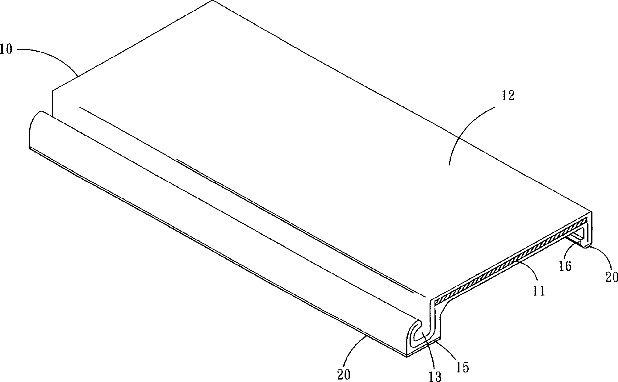
Kombinationsplatte (10), gebildet als ein einteiliger Körper unter Anwendung eines Extrusions-Formverfahrens, nachdem Metallstreifen (11) mit Kunststoff umhüllt wurden, wobei die Kombinationsplatte (10) mit einer ebenen Oberfläche (12) versehen ist, eine Seite der ebenen Oberfläche (12) unter Bildung einer C-Nut (13) nach vorn herausragt, und die Position der C-Nut (13) tiefer als die ebene Oberfläche (12) ist, wobei der untere Abschnitt der C-Nut mit einer Grundfläche (15) versehen ist und die der C-Nut (13) gegenüberliegende Seite unter Bildung einer J-Feder (16) nach unten hervorragt, und die Position der J-Feder (16) etwas höher als die der C-Nut (13) ist.A combination plate (10) formed as a one-piece body using an extrusion molding method after wrapping metal strips (11) with plastic, the combination plate (10) being provided with a flat surface (12), a side of the planar surface (12) ) protrudes forward to form a C-groove (13), and the position of the C-groove (13) is deeper than the flat surface (12), the lower portion of the C-groove being provided with a base (15) and the side opposite the C-groove (13) protrudes downward to form a J-spring (16), and the position of the J-spring (16) is slightly higher than that of the C-groove (13).
Description
Technischer Hintergrund der ErfindungTechnical background of the invention
(a) Technisches Gebiet der Erfindung(a) Technical Field of the Invention
Eine erfindungsgemäße kombinierbare Platte (”Kombinationsplatte”) bedeutet im Wesentlichen eine kombinierbare Platte, die bequem montiert und demontiert werden kann, wobei sie, wenn sie mit anderen kombiniert ist, zusammenhängende Oberflächen (wie Wandflächen, Fußböden, Dächer usw.) bilden kann.A Combinable according to the invention Plate ("combination plate") means essentially a combinable plate that is conveniently assembled and disassembled when combined with other, related surfaces (such as Wall surfaces, Floors, roofs, etc.) can form.
(b) Beschreibung des Standes der Technik(b) Description of the Related Art
Heute werden an vielen Stellen, wie Wohnungen, Büros, Dächer usw. bei der Durchführung von Renovierungen, sei es auf Fußböden oder auf Wandflächen, hauptsächlich Kombinations-Fußböden oder Kombinations-Wandpaneele gewählt, um die ursprünglichen Bauteiloberflächen nicht zu beschädigen. Unter Verwendung der Kombinations-Fußböden oder Kombinations-Wandpaneele können viele Abwandlungen geschaffen werden.today be in many places, such as apartments, offices, roofs, etc. in the implementation of Renovations, be it on floors or on wall surfaces, mainly Combination floors or Combination wall panels selected, around the original one component surfaces not to damage. Using combination flooring or combination wall panels, many can Modifications are created.
Die überwiegende Mehrzahl der Kombinations-Fußbodenplatten, wie sie verbreitet verwendet werden, sind beispielsweise aus Holz hergestellt oder verwenden Holzimitationen aus Kunststoff. Wenn man die Bequemlichkeit des Zusammenbaus berücksichtigt, sind die Kombinations-Fußbodenplatten von einer festen Größe und ermöglichen so dem Benutzer, Platten der richtigen Größe selbst auszuwählen und zu kaufen. Gleichwohl können solche Kombinations-Fußbodenplatten ausschließlich verwendet werden, um eine Anhebung des Fußbodens zu bewirken.The predominant Plurality of combination floorboards, as they are widely used, for example, are made of wood made or use wood imitations of plastic. If Taking into account the convenience of assembly, the combination floorboards are of a fixed size and allow so the user can select plates of the correct size himself and to buy. Nevertheless, you can such combination floorboards exclusively used to cause an elevation of the floor.
Daher muss der Benutzer, um einen anderen Bereich zu verkleiden, andere Kombinations-Fußbodenplatten oder Kombinations-Wandpaneele auswählen und kaufen, die zu dem Bereich, den er verkleiden möchte, passen.Therefore the user needs to disguise another area, others Combination floor panels or choose combination wall panels that come with the Area he wants to disguise fit.
Dementsprechend ist es nicht nur ein Ärgernis für den Benutzer, der die richtigen Platten auswählen und kaufen muss, wenn er Kombinations-Fußbodenplatten oder Kombinations-Wandpaneele verwenden will, sondern die Verwendung von Kombinations-Fußbodenplatten oder Kombinations-Wandpaneelen ist eingeschränkt und ihre verbreitete Verwendung für die Renovierung wird verhindert, weil jeder Typ von Kombinations-Fußbodenplatten oder Kombinations-Wandpaneelen für eine besondere Verwendung gestaltet und nicht austauschbar ist.Accordingly it's not just a nuisance for the User who needs to pick and choose the right plates, though he combination floorboards or combination wall panels but the use of combination floorboards or combination wall panels is restricted and their common use for the Renovation is prevented because every type of combination floor tiles or combination wall panels for a special use designed and not interchangeable.
Außerdem sind die meisten dieser Kombinations-Fußbodenplatten oder Kombinations-Wandpaneele aus einem einzigen Material aufgebaut, was zu einer geringen Festigkeit der Kombination-Fußbodenplatten oder Kombination-Wandpaneele führt, welche von äußeren Kräften leicht gebrochen oder beschädigt werden. Insbesondere fehlen ihnen isolierende Eigenschaften, wie Beständigkeit gegen Feuchtigkeit und Wasser, Schallisolierung und Wärmeschutz und sie können bei weitem keine Luftdichtigkeit bewirken.Besides, they are most of these combination floorboards or combination wall panels constructed from a single material, resulting in low strength of the combination floorboards or combination wall panels which leads from external forces easily broken or damaged become. In particular, they lack insulating properties, such as resistance against moisture and water, soundproofing and thermal insulation and you can far from causing airtightness.
Um daher die Verwendung von Kombinationsplatten zu steigern, hat der Erfinder der vorliegenden Erfindung eine ”Kombinationsplatte” erfunden, welche hauptsächlich eine einfache Gestaltung aufweist, um die Kombinationsplatte nicht nur mit ausgezeichneter baulicher Eignung zu versehen, was die Festigkeit der Kombinationsplatten erhöht, sondern auch die Gleitfähigkeit der Kombinationsplatten zu vermindern, sowie auch die Kombinationsplatten mit der Fähigkeit ausstattet, viele unterschiedliche Kombinationen hervorzubringen. Insbesondere ist die Kombinationsplatte wirksam mit Luftdichtigkeit und Schallisolierung, Wärmeschutz, Isolation, Beständigkeit gegen Feuchtigkeit und Wasser versehen.Around Therefore, to increase the use of combination plates, the Inventors of the present invention invented a "combination plate" which mainly has a simple design to the combination plate is not only to be provided with excellent structural suitability, what the strength the combination plates increased, but also the lubricity reduce the combination plates, as well as the combination plates with the ability equips to produce many different combinations. In particular, the combination plate is effective with airtightness and sound insulation, thermal insulation, Isolation, resistance provided against moisture and water.
Zusammenfassung der ErfindungSummary of the invention
Die wichtigste Aufgabe der vorliegenden Erfindung besteht in der Bereitstellung einer kombinierbaren Platte, die leicht montiert und demontiert werden kann und eine hervorragende bauliche Eignung zur Erleichterung der Bauausführung aufweist, gleichzeitig aber die Festigkeit der verbindbaren Platte zu steigern und Schrumpfen und Verformung zu vermeiden, sowie der Platte wirksame Luftdichtigkeit und Schallisolierung, Wärmeschutz, Isolation, sowie Beständigkeit gegen Feuchtigkeit und Wasser zu verleihen.The most important object of the present invention is to provide a combinable plate that is easily assembled and disassembled can be and excellent structural suitability to facilitate the construction but at the same time the strength of the connectable plate to increase and prevent shrinkage and deformation, as well as the Plate effective airtightness and soundproofing, thermal insulation, Isolation, as well as resistance to give against moisture and water.
Zur Lösung dieser Aufgabe wendet die erfindungsgemäße kombinierbare Platte zunächst mit Kunststoff überzogene Metallstreifen an, wonach ein Extrusionsverfahren zur Bildung eines einteiligen Körpers angewendet wird. Die Kombinationsplatte wird mit einer ebenen Oberfläche versehen, und eine Seite ragt unter Bildung einer C-förmigen Aufnahme (C-Nut) hervor. Die C-Nut liegt niedriger als die ebene Oberfläche, und ein Bodenabschnitt der C-Nut weist eine Innenfläche auf. Die der C-Nut gegenüberliegenden Seite ragt unter Bildung einer J-förmigen Feder (J-Feder) nach unten, die etwas höher als die Position der C-Nut ist. Dementsprechend ermöglicht das gegenseitige Ineinanderhaken der J-Feder und der C-Nut zwischen zwei dieser Kombinationsplatten, eine Verbindung zwischen den Kombinationsplatten zu erreichen. Darüber hinaus steigern die von der Kombinationsplatte umhüllten Metallstreifen die Festigkeit der Kombinationsplatte und verhindern gleichzeitig Schrumpfung und Verformung, wodurch eine Kombinationsplatte mit besserer baulicher Eignung ge bildet wird.To achieve this object, the combinable plate according to the invention first applies plastic-coated metal strips, after which an extrusion method is used to form a one-piece body. The combination plate is provided with a flat surface, and one side protrudes to form a C-shaped receptacle (C-groove). The C-groove is lower than the flat surface, and a bottom portion of the C-groove has an inner surface. The side opposite the C-groove projects down to form a J-shaped spring (J-spring) which is slightly higher than the position of the C-groove. Accordingly, the mutual interlocking of the J-spring and the C-groove between two of these combination plates makes it possible to achieve a connection between the combination plates. Moreover, the metal strips enveloped by the combination plate increase the strength of the combination plate while preventing shrinkage and deformation, thereby providing a combination plate with better structural properties is formed ge.
Eine weitere Aufgabe der vorliegenden Erfindung besteht darin, die Kombinationsplatte mit einer hervorragenden gleithemmenden Wirkung zu versehen.A Another object of the present invention is to provide the combination plate to provide an excellent anti-slip effect.
Um dieses Ziel zu erreichen, wendet die vorliegende Erfindung hauptsächlich eine gleithemmende Matte an, die an der Grundfläche und dem unteren Teil der J-Feder angebracht ist, so dass nach der Verbindung einer Vielzahl der Kombinationsplatten zwischen den gleithemmenden Matten am unteren Teil und der Grundfläche und einer Fußboden- oder Wandfläche eine verbesserte Reibungskraft entsteht, die verhindert, dass die Kombinationsplatten nach dem Auflegen auf eine Fußboden- oder Wandfläche verrutschen. Außerdem greifen die J-Federn und die C-Nuten gegenseitig ineinander, wenn mehrere Kombinationsplatten miteinander kombiniert werden, so dass die gleithemmenden Matten auf den unteren Teilen der J-Federn die Reibungskraft zwischen den J-Federn und den C-Nuten erhöhen, wodurch bei der Kombination mehrerer Kombinationsplatten ein Verrutschen und der durch Unebenheit der Kombinationsplatten auf der Fußboden- oder Wandfläche verursachte Ärger vermieden werdenAround To achieve this object, the present invention mainly uses one antislip mat, which at the base and the lower part of the J spring is attached, so after connecting a variety the combination plates between the anti-slip mats at the bottom Part and the base and a floor or wall surface an improved friction force is created, which prevents the Slip combination plates after placing them on a floor or wall surface. Furthermore the J-springs and the C-grooves engage each other, though several combination plates are combined with each other, so that the anti-slip mats on the lower parts of the J-springs the Increase frictional force between the J-springs and the C-grooves, thereby in the combination of several combination plates slipping and the unevenness of the combination plates on the floor or wall surface caused trouble be avoided
Noch eine weitere Aufgabe der vorliegenden Erfindung besteht darin, Kombinationsplatte mit der Eignung für viele unterschiedliche Kombinationen zu versehen.Yet Another object of the present invention is to provide a combination plate with the aptitude for to provide many different combinations.
Um dieses Ziel zu erreichen, wird die erfindungsgemäße Kombinationsplatte ferner mit einem Verbindungsglied ausgestattet, und eine Seite des Kombinationsglieds ist mit einem Hakenvorsprung versehen, welcher der C-Nut entspricht, während auf der entgegengesetzten Seite eine Haltenut angebracht ist. Dementsprechend ermöglicht das Einhaken des Hakenvorsprungs mit der C-Nut und der Haltenut die Befestigung des Verbindungsglieds an der Kombinationsplatte, und die Haltenut kann dazu dienen, Glas oder eine Türfüllung zu hal ten, wodurch die Bereitstellung vieler unterschiedlicher Kombinationen durch die Kombinationsplatte ermöglicht wird.Around To achieve this goal, the combination plate according to the invention is further equipped with a link, and one side of the combination link is provided with a hook projection which corresponds to the C-groove, while on the opposite side a retaining groove is attached. Accordingly allows the hooking of the hook projection with the C-groove and the retaining groove the attachment of the connecting member to the combination plate, and the retaining groove may serve to glass or a door panel halts, thereby providing many different combinations enabled by the combination plate becomes.
Zum weiteren Verständnis der genannten Aufgaben und der technischen Verfahren der Erfindung wird eine kurze Beschreibung der Zeichnungen gegeben, gefolgt von einer eingehenden Beschreibung der bevorzugten Ausführungsformen.To the further understanding the above objects and the technical method of the invention a brief description of the drawings is given, followed by a detailed description of the preferred embodiments.
Kurze Beschreibung der ZeichnungenBrief description of the drawings
Eingehende Beschreibung der bevorzugten AusführungsformenDetailed description of the preferred embodiments
Mit
Bezug auf die
Wie
in den Zeichnungen dargestellt, sind die Metallstreifen
Wenn
die Kombinationsplatte
Bei
der vorbeschriebenen Konfiguration kann die Kombinationsplatte
Mit
Bezug auf
Mit
Bezug auf
Mit
Bezug auf die
Um
ein Auseinanderfallen der vorderen Kombinationsplatte
Wenn
eine Mehrzahl von Kombinationsplatten
Wenn
die Kombinationsplatte
Wenn
die vordere Kombinationsplatte
Mit
Bezug auf
Mit
Bezug auf
Wie
in den Zeichnungen mit Bezug auf die
Wie
in den Zeichnungen mit Bezug auf die
Zusammengefasst
können
gegenseitige Zusammenbauten zwischen mehreren erfindungsgemäßen Kombinationsplatten
Selbstverständlich ist zu verstehen, dass die hier beschriebenen Ausführungsformen die Grundlagen der Erfindung nur beispielhaft veranschaulichen und dass der Fachmann eine große Anzahl von Abwandlungen vornehmen kann, ohne vom Gedanken und Umfang der Erfindung abzuweichen, wie sie in den folgenden Ansprüchen niedergelegt sind.Of course it is to understand that the embodiments described here are the basics illustrate the invention only by way of example and that the person skilled in the art a big Number of modifications can be made without the thought and scope to depart from the invention, as set forth in the following claims are.
- 1010
- Kombinationsplattecombination plate
- 1111
- Metallstreifenmetal strips
- 1212
- ebene Oberflächelevel surface
- 1313
- C-NutC-groove
- 1414
- Innenfläche der C-NutInner surface of the C-groove
- 1515
- Grundfläche der C-NutBase of the C-groove
- 1616
- J-FederJ-spring
- 1717
- Grundfläche der J-FederBase of the J-spring
- 1818
- Verstärkungsrippereinforcing rib
- 1919
- Ausnehmungrecess
- 2020
- gleithemmende Matteslide-inhibiting mat
- 3030
- Spaltgap
- 4040
- Klebstoffadhesive
- 5050
- Montageflächemounting surface
- 6060
- Verbindungsgliedlink
- 6161
- Hakenvorsprunghook projection
- 6262
- Haltenutretaining groove
- 7070
- Dekorplattedecorative panel
- 8080
- gleithemmende Matteslide-inhibiting mat
- 9090
- luftdichte Kammerairtight chamber
- 101101
- vordere Kombinationsplattefront combination plate
- 102102
- folgende Kombinationsplattethe following combination plate
Claims (11)
Priority Applications (1)
| Application Number | Priority Date | Filing Date | Title |
|---|---|---|---|
| DE200920010381 DE202009010381U1 (en) | 2009-07-31 | 2009-07-31 | combination plate |
Applications Claiming Priority (1)
| Application Number | Priority Date | Filing Date | Title |
|---|---|---|---|
| DE200920010381 DE202009010381U1 (en) | 2009-07-31 | 2009-07-31 | combination plate |
Publications (1)
| Publication Number | Publication Date |
|---|---|
| DE202009010381U1 true DE202009010381U1 (en) | 2009-11-19 |
Family
ID=41335413
Family Applications (1)
| Application Number | Title | Priority Date | Filing Date |
|---|---|---|---|
| DE200920010381 Expired - Lifetime DE202009010381U1 (en) | 2009-07-31 | 2009-07-31 | combination plate |
Country Status (1)
| Country | Link |
|---|---|
| DE (1) | DE202009010381U1 (en) |
Cited By (6)
| Publication number | Priority date | Publication date | Assignee | Title |
|---|---|---|---|---|
| EP2527559A1 (en) * | 2011-05-24 | 2012-11-28 | Novo-Tech GmbH & Co. KG | Panel and method for manufacturing a panel |
| US9175703B2 (en) | 2008-12-17 | 2015-11-03 | Unilin, Bvba | Composed element, multi-layered board and panel-shaped element for forming this composed element |
| US9719542B2 (en) | 2010-06-03 | 2017-08-01 | Unilin, Bvba | Composed element and corner connection applied herewith |
| EP2447442B1 (en) * | 2010-10-30 | 2018-06-06 | Herbstreith & Fox KG Pektin-Fabriken | Floor covering element |
| US10293512B2 (en) | 2011-06-29 | 2019-05-21 | Unilin Bvba | Drawer, drawer construction and method for manufacturing a drawer |
| CN119163189A (en) * | 2024-10-10 | 2024-12-20 | 中国十七冶集团有限公司 | A construction board and construction method thereof |
-
2009
- 2009-07-31 DE DE200920010381 patent/DE202009010381U1/en not_active Expired - Lifetime
Cited By (18)
| Publication number | Priority date | Publication date | Assignee | Title |
|---|---|---|---|---|
| US11085475B2 (en) | 2008-12-17 | 2021-08-10 | Flooring Industries Limited, Sarl | Composed element, multi-layered board and panel-shaped element for forming this composed element |
| US10935063B2 (en) | 2008-12-17 | 2021-03-02 | Unilin Bv | Composed element, multi-layered board and panel-shaped element for forming this composed element |
| US9347470B2 (en) | 2008-12-17 | 2016-05-24 | Unilin, Bvba | Composed element, multi-layered board and panel-shaped element for forming this composed element |
| US9695856B2 (en) | 2008-12-17 | 2017-07-04 | Unilin, Bvba | Composed element, multi-layered board and panel-shaped element for forming this composed element |
| US12123441B2 (en) | 2008-12-17 | 2024-10-22 | Unilin Bv | Composed element, multi-layered board and panel-shaped element for forming this composed element |
| US9797427B2 (en) | 2008-12-17 | 2017-10-24 | Unilin, Bvba | Composed element, multi-layered board and panel-shaped element for forming this composed element |
| US11788568B2 (en) | 2008-12-17 | 2023-10-17 | Flooring Industries Limited Sarl | Composed element, multi-layered board and panel-shaped element for forming this composed element |
| US11319977B2 (en) | 2008-12-17 | 2022-05-03 | Flooring Industries Limited, Sarl | Composed element, multi-layered board and panel-shaped element for forming this composed element |
| US9175703B2 (en) | 2008-12-17 | 2015-11-03 | Unilin, Bvba | Composed element, multi-layered board and panel-shaped element for forming this composed element |
| US10323670B2 (en) | 2008-12-17 | 2019-06-18 | Unilin, Bvba | Composed element, multi-layered board and panel-shaped element for forming this composed element |
| US10731689B2 (en) | 2008-12-17 | 2020-08-04 | Unilin, Bvba | Composed element, multi-layered board and panel-shaped element for forming this composed element |
| US10982700B2 (en) | 2010-06-03 | 2021-04-20 | Unilin Bv | Composed element and corner connection applied herewith |
| US12000418B2 (en) | 2010-06-03 | 2024-06-04 | Unilin, Bv | Composed element and corner connection applied herewith |
| US9719542B2 (en) | 2010-06-03 | 2017-08-01 | Unilin, Bvba | Composed element and corner connection applied herewith |
| EP2447442B1 (en) * | 2010-10-30 | 2018-06-06 | Herbstreith & Fox KG Pektin-Fabriken | Floor covering element |
| EP2527559A1 (en) * | 2011-05-24 | 2012-11-28 | Novo-Tech GmbH & Co. KG | Panel and method for manufacturing a panel |
| US10293512B2 (en) | 2011-06-29 | 2019-05-21 | Unilin Bvba | Drawer, drawer construction and method for manufacturing a drawer |
| CN119163189A (en) * | 2024-10-10 | 2024-12-20 | 中国十七冶集团有限公司 | A construction board and construction method thereof |
Similar Documents
| Publication | Publication Date | Title |
|---|---|---|
| EP1294995B1 (en) | Flooring system comprising a plurality of identical floorboards | |
| EP1400641A3 (en) | Panels with attachment clip | |
| EP2063047A1 (en) | Profile rail system | |
| DE102014011022B4 (en) | mounting bracket | |
| DE202014006016U1 (en) | mounting bracket | |
| DE202009010381U1 (en) | combination plate | |
| DE202009009407U1 (en) | Floor profile arrangement | |
| EP3034716B1 (en) | Connector for panelling elements | |
| DE60312728T2 (en) | Kit with a parquet rod and a mounting bracket for this | |
| DE102008055953A1 (en) | Integrated roof system, attachment of insert profiles on sandwich panels with undercut grooves | |
| EP2649254A1 (en) | U-section for mounting a railing panel in a fixed manner | |
| DE102012221746A1 (en) | Wall heating element i.e. gypsum fiber board, has grooves arranged in front side or back of plate element for retaining heating pipeline and valve arranged at rear profile with undercut for engaging with fixed wall corresponding to hooks | |
| EP0612910B1 (en) | Closing ledge for metal doors | |
| AT507059B1 (en) | WALL COMPOSITE | |
| EP2848747A1 (en) | Façade cladding | |
| DE202019101409U1 (en) | Profile system for forming a sub-frame for receiving floor coverings and connecting element | |
| DE202011003046U1 (en) | Connecting element for connecting flat components | |
| DE112017003921T5 (en) | Anchoring device for ventilated curtain walls | |
| EP3257413B1 (en) | Decorative and/or functional part for installation in a corner or a recess, for example, of an at least partly tiled room | |
| DE202005002356U1 (en) | Ventilated thermally insulated building façade | |
| AT507840B1 (en) | FACADE ELEMENT | |
| DE102005022827B4 (en) | Edging for a wall edge of a window or door reveal to form a pocket | |
| DE102004015721B4 (en) | Protective device for building parts and components | |
| DE10246968A1 (en) | Step edge profile has housing provided on horizontal step component to incorporate floor tile, and for tension and compression resistant gap-free joining housing has connecting slot conforming to connecting tongue on tile | |
| DE202019001527U1 (en) | Cleaning profile for plastering on opposite sides of wall parts which are adjacent to one or more openings |
Legal Events
| Date | Code | Title | Description |
|---|---|---|---|
| R207 | Utility model specification |
Effective date: 20091224 |
|
| R150 | Term of protection extended to 6 years | ||
| R150 | Term of protection extended to 6 years |
Effective date: 20121001 |
|
| R157 | Lapse of ip right after 6 years |