KR20090045885A - Moving object driving method and moving object driving system, pattern forming method and apparatus, exposure method and apparatus, and device manufacturing method - Google Patents
Moving object driving method and moving object driving system, pattern forming method and apparatus, exposure method and apparatus, and device manufacturing method Download PDFInfo
- Publication number
- KR20090045885A KR20090045885A KR1020087026015A KR20087026015A KR20090045885A KR 20090045885 A KR20090045885 A KR 20090045885A KR 1020087026015 A KR1020087026015 A KR 1020087026015A KR 20087026015 A KR20087026015 A KR 20087026015A KR 20090045885 A KR20090045885 A KR 20090045885A
- Authority
- KR
- South Korea
- Prior art keywords
- encoder
- head
- moving
- measurement
- movable body
- Prior art date
- Legal status (The legal status is an assumption and is not a legal conclusion. Google has not performed a legal analysis and makes no representation as to the accuracy of the status listed.)
- Granted
Links
Images


Classifications
-
- G—PHYSICS
- G03—PHOTOGRAPHY; CINEMATOGRAPHY; ANALOGOUS TECHNIQUES USING WAVES OTHER THAN OPTICAL WAVES; ELECTROGRAPHY; HOLOGRAPHY
- G03F—PHOTOMECHANICAL PRODUCTION OF TEXTURED OR PATTERNED SURFACES, e.g. FOR PRINTING, FOR PROCESSING OF SEMICONDUCTOR DEVICES; MATERIALS THEREFOR; ORIGINALS THEREFOR; APPARATUS SPECIALLY ADAPTED THEREFOR
- G03F7/00—Photomechanical, e.g. photolithographic, production of textured or patterned surfaces, e.g. printing surfaces; Materials therefor, e.g. comprising photoresists; Apparatus specially adapted therefor
- G03F7/70—Microphotolithographic exposure; Apparatus therefor
- G03F7/70216—Mask projection systems
- G03F7/70258—Projection system adjustments, e.g. adjustments during exposure or alignment during assembly of projection system
-
- G—PHYSICS
- G03—PHOTOGRAPHY; CINEMATOGRAPHY; ANALOGOUS TECHNIQUES USING WAVES OTHER THAN OPTICAL WAVES; ELECTROGRAPHY; HOLOGRAPHY
- G03F—PHOTOMECHANICAL PRODUCTION OF TEXTURED OR PATTERNED SURFACES, e.g. FOR PRINTING, FOR PROCESSING OF SEMICONDUCTOR DEVICES; MATERIALS THEREFOR; ORIGINALS THEREFOR; APPARATUS SPECIALLY ADAPTED THEREFOR
- G03F7/00—Photomechanical, e.g. photolithographic, production of textured or patterned surfaces, e.g. printing surfaces; Materials therefor, e.g. comprising photoresists; Apparatus specially adapted therefor
- G03F7/20—Exposure; Apparatus therefor
-
- G—PHYSICS
- G03—PHOTOGRAPHY; CINEMATOGRAPHY; ANALOGOUS TECHNIQUES USING WAVES OTHER THAN OPTICAL WAVES; ELECTROGRAPHY; HOLOGRAPHY
- G03F—PHOTOMECHANICAL PRODUCTION OF TEXTURED OR PATTERNED SURFACES, e.g. FOR PRINTING, FOR PROCESSING OF SEMICONDUCTOR DEVICES; MATERIALS THEREFOR; ORIGINALS THEREFOR; APPARATUS SPECIALLY ADAPTED THEREFOR
- G03F7/00—Photomechanical, e.g. photolithographic, production of textured or patterned surfaces, e.g. printing surfaces; Materials therefor, e.g. comprising photoresists; Apparatus specially adapted therefor
- G03F7/70—Microphotolithographic exposure; Apparatus therefor
- G03F7/70058—Mask illumination systems
- G03F7/70141—Illumination system adjustment, e.g. adjustments during exposure or alignment during assembly of illumination system
-
- G—PHYSICS
- G03—PHOTOGRAPHY; CINEMATOGRAPHY; ANALOGOUS TECHNIQUES USING WAVES OTHER THAN OPTICAL WAVES; ELECTROGRAPHY; HOLOGRAPHY
- G03F—PHOTOMECHANICAL PRODUCTION OF TEXTURED OR PATTERNED SURFACES, e.g. FOR PRINTING, FOR PROCESSING OF SEMICONDUCTOR DEVICES; MATERIALS THEREFOR; ORIGINALS THEREFOR; APPARATUS SPECIALLY ADAPTED THEREFOR
- G03F7/00—Photomechanical, e.g. photolithographic, production of textured or patterned surfaces, e.g. printing surfaces; Materials therefor, e.g. comprising photoresists; Apparatus specially adapted therefor
- G03F7/70—Microphotolithographic exposure; Apparatus therefor
- G03F7/70216—Mask projection systems
- G03F7/70341—Details of immersion lithography aspects, e.g. exposure media or control of immersion liquid supply
-
- G—PHYSICS
- G03—PHOTOGRAPHY; CINEMATOGRAPHY; ANALOGOUS TECHNIQUES USING WAVES OTHER THAN OPTICAL WAVES; ELECTROGRAPHY; HOLOGRAPHY
- G03F—PHOTOMECHANICAL PRODUCTION OF TEXTURED OR PATTERNED SURFACES, e.g. FOR PRINTING, FOR PROCESSING OF SEMICONDUCTOR DEVICES; MATERIALS THEREFOR; ORIGINALS THEREFOR; APPARATUS SPECIALLY ADAPTED THEREFOR
- G03F7/00—Photomechanical, e.g. photolithographic, production of textured or patterned surfaces, e.g. printing surfaces; Materials therefor, e.g. comprising photoresists; Apparatus specially adapted therefor
- G03F7/70—Microphotolithographic exposure; Apparatus therefor
- G03F7/70216—Mask projection systems
- G03F7/70358—Scanning exposure, i.e. relative movement of patterned beam and workpiece during imaging
-
- G—PHYSICS
- G03—PHOTOGRAPHY; CINEMATOGRAPHY; ANALOGOUS TECHNIQUES USING WAVES OTHER THAN OPTICAL WAVES; ELECTROGRAPHY; HOLOGRAPHY
- G03F—PHOTOMECHANICAL PRODUCTION OF TEXTURED OR PATTERNED SURFACES, e.g. FOR PRINTING, FOR PROCESSING OF SEMICONDUCTOR DEVICES; MATERIALS THEREFOR; ORIGINALS THEREFOR; APPARATUS SPECIALLY ADAPTED THEREFOR
- G03F7/00—Photomechanical, e.g. photolithographic, production of textured or patterned surfaces, e.g. printing surfaces; Materials therefor, e.g. comprising photoresists; Apparatus specially adapted therefor
- G03F7/70—Microphotolithographic exposure; Apparatus therefor
- G03F7/70483—Information management; Active and passive control; Testing; Wafer monitoring, e.g. pattern monitoring
- G03F7/70605—Workpiece metrology
- G03F7/70616—Monitoring the printed patterns
-
- G—PHYSICS
- G03—PHOTOGRAPHY; CINEMATOGRAPHY; ANALOGOUS TECHNIQUES USING WAVES OTHER THAN OPTICAL WAVES; ELECTROGRAPHY; HOLOGRAPHY
- G03F—PHOTOMECHANICAL PRODUCTION OF TEXTURED OR PATTERNED SURFACES, e.g. FOR PRINTING, FOR PROCESSING OF SEMICONDUCTOR DEVICES; MATERIALS THEREFOR; ORIGINALS THEREFOR; APPARATUS SPECIALLY ADAPTED THEREFOR
- G03F7/00—Photomechanical, e.g. photolithographic, production of textured or patterned surfaces, e.g. printing surfaces; Materials therefor, e.g. comprising photoresists; Apparatus specially adapted therefor
- G03F7/70—Microphotolithographic exposure; Apparatus therefor
- G03F7/70483—Information management; Active and passive control; Testing; Wafer monitoring, e.g. pattern monitoring
- G03F7/70605—Workpiece metrology
- G03F7/70681—Metrology strategies
- G03F7/70683—Mark designs
-
- G—PHYSICS
- G03—PHOTOGRAPHY; CINEMATOGRAPHY; ANALOGOUS TECHNIQUES USING WAVES OTHER THAN OPTICAL WAVES; ELECTROGRAPHY; HOLOGRAPHY
- G03F—PHOTOMECHANICAL PRODUCTION OF TEXTURED OR PATTERNED SURFACES, e.g. FOR PRINTING, FOR PROCESSING OF SEMICONDUCTOR DEVICES; MATERIALS THEREFOR; ORIGINALS THEREFOR; APPARATUS SPECIALLY ADAPTED THEREFOR
- G03F7/00—Photomechanical, e.g. photolithographic, production of textured or patterned surfaces, e.g. printing surfaces; Materials therefor, e.g. comprising photoresists; Apparatus specially adapted therefor
- G03F7/70—Microphotolithographic exposure; Apparatus therefor
- G03F7/70483—Information management; Active and passive control; Testing; Wafer monitoring, e.g. pattern monitoring
- G03F7/70605—Workpiece metrology
- G03F7/706835—Metrology information management or control
-
- G—PHYSICS
- G03—PHOTOGRAPHY; CINEMATOGRAPHY; ANALOGOUS TECHNIQUES USING WAVES OTHER THAN OPTICAL WAVES; ELECTROGRAPHY; HOLOGRAPHY
- G03F—PHOTOMECHANICAL PRODUCTION OF TEXTURED OR PATTERNED SURFACES, e.g. FOR PRINTING, FOR PROCESSING OF SEMICONDUCTOR DEVICES; MATERIALS THEREFOR; ORIGINALS THEREFOR; APPARATUS SPECIALLY ADAPTED THEREFOR
- G03F7/00—Photomechanical, e.g. photolithographic, production of textured or patterned surfaces, e.g. printing surfaces; Materials therefor, e.g. comprising photoresists; Apparatus specially adapted therefor
- G03F7/70—Microphotolithographic exposure; Apparatus therefor
- G03F7/70483—Information management; Active and passive control; Testing; Wafer monitoring, e.g. pattern monitoring
- G03F7/70605—Workpiece metrology
- G03F7/706843—Metrology apparatus
- G03F7/706845—Calibration, e.g. tool-to-tool calibration, beam alignment, spot position or focus
-
- G—PHYSICS
- G03—PHOTOGRAPHY; CINEMATOGRAPHY; ANALOGOUS TECHNIQUES USING WAVES OTHER THAN OPTICAL WAVES; ELECTROGRAPHY; HOLOGRAPHY
- G03F—PHOTOMECHANICAL PRODUCTION OF TEXTURED OR PATTERNED SURFACES, e.g. FOR PRINTING, FOR PROCESSING OF SEMICONDUCTOR DEVICES; MATERIALS THEREFOR; ORIGINALS THEREFOR; APPARATUS SPECIALLY ADAPTED THEREFOR
- G03F7/00—Photomechanical, e.g. photolithographic, production of textured or patterned surfaces, e.g. printing surfaces; Materials therefor, e.g. comprising photoresists; Apparatus specially adapted therefor
- G03F7/70—Microphotolithographic exposure; Apparatus therefor
- G03F7/70691—Handling of masks or workpieces
- G03F7/70716—Stages
- G03F7/70725—Stages control
-
- G—PHYSICS
- G03—PHOTOGRAPHY; CINEMATOGRAPHY; ANALOGOUS TECHNIQUES USING WAVES OTHER THAN OPTICAL WAVES; ELECTROGRAPHY; HOLOGRAPHY
- G03F—PHOTOMECHANICAL PRODUCTION OF TEXTURED OR PATTERNED SURFACES, e.g. FOR PRINTING, FOR PROCESSING OF SEMICONDUCTOR DEVICES; MATERIALS THEREFOR; ORIGINALS THEREFOR; APPARATUS SPECIALLY ADAPTED THEREFOR
- G03F7/00—Photomechanical, e.g. photolithographic, production of textured or patterned surfaces, e.g. printing surfaces; Materials therefor, e.g. comprising photoresists; Apparatus specially adapted therefor
- G03F7/70—Microphotolithographic exposure; Apparatus therefor
- G03F7/70691—Handling of masks or workpieces
- G03F7/70758—Drive means, e.g. actuators, motors for long- or short-stroke modules or fine or coarse driving
-
- G—PHYSICS
- G03—PHOTOGRAPHY; CINEMATOGRAPHY; ANALOGOUS TECHNIQUES USING WAVES OTHER THAN OPTICAL WAVES; ELECTROGRAPHY; HOLOGRAPHY
- G03F—PHOTOMECHANICAL PRODUCTION OF TEXTURED OR PATTERNED SURFACES, e.g. FOR PRINTING, FOR PROCESSING OF SEMICONDUCTOR DEVICES; MATERIALS THEREFOR; ORIGINALS THEREFOR; APPARATUS SPECIALLY ADAPTED THEREFOR
- G03F7/00—Photomechanical, e.g. photolithographic, production of textured or patterned surfaces, e.g. printing surfaces; Materials therefor, e.g. comprising photoresists; Apparatus specially adapted therefor
- G03F7/70—Microphotolithographic exposure; Apparatus therefor
- G03F7/70691—Handling of masks or workpieces
- G03F7/70775—Position control, e.g. interferometers or encoders for determining the stage position
-
- G—PHYSICS
- G03—PHOTOGRAPHY; CINEMATOGRAPHY; ANALOGOUS TECHNIQUES USING WAVES OTHER THAN OPTICAL WAVES; ELECTROGRAPHY; HOLOGRAPHY
- G03F—PHOTOMECHANICAL PRODUCTION OF TEXTURED OR PATTERNED SURFACES, e.g. FOR PRINTING, FOR PROCESSING OF SEMICONDUCTOR DEVICES; MATERIALS THEREFOR; ORIGINALS THEREFOR; APPARATUS SPECIALLY ADAPTED THEREFOR
- G03F7/00—Photomechanical, e.g. photolithographic, production of textured or patterned surfaces, e.g. printing surfaces; Materials therefor, e.g. comprising photoresists; Apparatus specially adapted therefor
- G03F7/70—Microphotolithographic exposure; Apparatus therefor
- G03F7/70691—Handling of masks or workpieces
- G03F7/70783—Handling stress or warp of chucks, masks or workpieces, e.g. to compensate for imaging errors or considerations related to warpage of masks or workpieces due to their own weight
-
- G—PHYSICS
- G03—PHOTOGRAPHY; CINEMATOGRAPHY; ANALOGOUS TECHNIQUES USING WAVES OTHER THAN OPTICAL WAVES; ELECTROGRAPHY; HOLOGRAPHY
- G03F—PHOTOMECHANICAL PRODUCTION OF TEXTURED OR PATTERNED SURFACES, e.g. FOR PRINTING, FOR PROCESSING OF SEMICONDUCTOR DEVICES; MATERIALS THEREFOR; ORIGINALS THEREFOR; APPARATUS SPECIALLY ADAPTED THEREFOR
- G03F7/00—Photomechanical, e.g. photolithographic, production of textured or patterned surfaces, e.g. printing surfaces; Materials therefor, e.g. comprising photoresists; Apparatus specially adapted therefor
- G03F7/70—Microphotolithographic exposure; Apparatus therefor
- G03F7/708—Construction of apparatus, e.g. environment aspects, hygiene aspects or materials
- G03F7/7085—Detection arrangement, e.g. detectors of apparatus alignment possibly mounted on wafers, exposure dose, photo-cleaning flux, stray light, thermal load
-
- G—PHYSICS
- G03—PHOTOGRAPHY; CINEMATOGRAPHY; ANALOGOUS TECHNIQUES USING WAVES OTHER THAN OPTICAL WAVES; ELECTROGRAPHY; HOLOGRAPHY
- G03F—PHOTOMECHANICAL PRODUCTION OF TEXTURED OR PATTERNED SURFACES, e.g. FOR PRINTING, FOR PROCESSING OF SEMICONDUCTOR DEVICES; MATERIALS THEREFOR; ORIGINALS THEREFOR; APPARATUS SPECIALLY ADAPTED THEREFOR
- G03F9/00—Registration or positioning of originals, masks, frames, photographic sheets or textured or patterned surfaces, e.g. automatically
- G03F9/70—Registration or positioning of originals, masks, frames, photographic sheets or textured or patterned surfaces, e.g. automatically for microlithography
- G03F9/7003—Alignment type or strategy, e.g. leveling, global alignment
- G03F9/7019—Calibration
-
- G—PHYSICS
- G03—PHOTOGRAPHY; CINEMATOGRAPHY; ANALOGOUS TECHNIQUES USING WAVES OTHER THAN OPTICAL WAVES; ELECTROGRAPHY; HOLOGRAPHY
- G03F—PHOTOMECHANICAL PRODUCTION OF TEXTURED OR PATTERNED SURFACES, e.g. FOR PRINTING, FOR PROCESSING OF SEMICONDUCTOR DEVICES; MATERIALS THEREFOR; ORIGINALS THEREFOR; APPARATUS SPECIALLY ADAPTED THEREFOR
- G03F9/00—Registration or positioning of originals, masks, frames, photographic sheets or textured or patterned surfaces, e.g. automatically
- G03F9/70—Registration or positioning of originals, masks, frames, photographic sheets or textured or patterned surfaces, e.g. automatically for microlithography
- G03F9/7088—Alignment mark detection, e.g. TTR, TTL, off-axis detection, array detector, video detection
-
- H10P76/2041—
Landscapes
- Physics & Mathematics (AREA)
- General Physics & Mathematics (AREA)
- Engineering & Computer Science (AREA)
- Multimedia (AREA)
- Health & Medical Sciences (AREA)
- Environmental & Geological Engineering (AREA)
- Epidemiology (AREA)
- Public Health (AREA)
- Exposure And Positioning Against Photoresist Photosensitive Materials (AREA)
- Exposure Of Semiconductors, Excluding Electron Or Ion Beam Exposure (AREA)
- Container, Conveyance, Adherence, Positioning, Of Wafer (AREA)
- Length Measuring Devices By Optical Means (AREA)
- Condensed Matter Physics & Semiconductors (AREA)
- Manufacturing & Machinery (AREA)
- Computer Hardware Design (AREA)
- Microelectronics & Electronic Packaging (AREA)
- Power Engineering (AREA)
- Optical Transform (AREA)
Abstract
스테이지 (WST) 의 구동 중에, 인코더 시스템의 X 인코더와 Y 인코더를 적어도 각 1 개 포함하는 3 개의 인코더 (Enc1, Enc2 및 Enc3) 에 의해 스테이지 (WST) 의 이동면 내의 위치 정보가 계측되고, 제어 장치에 의해 스테이지 (WST) 의 이동면 내의 위치가 전환 전후에서 유지되도록, 스테이지 (WST) 의 이동면 내의 위치 정보의 계측에 사용하는 인코더가 인코더 (Enc1, Enc2 및 Enc3) 로부터 인코더 (Enc4, Enc2 및 Enc3) 로 전환된다. 이 때문에, 스테이지의 위치 제어에 사용하는 인코더의 전환이 실시되고 있음에도 불구하고, 전환 전후에서 스테이지의 이동면 내의 위치가 유지되어, 정확한 연결이 가능해진다.During driving of the stage WST, the position information in the moving surface of the stage WST is measured by three encoders Enc1, Enc2 and Enc3 each including at least one X encoder and a Y encoder of the encoder system, and the control device The encoder used for the measurement of the positional information in the moving surface of the stage WST is moved from the encoders Enc1, Enc2 and Enc3 to the encoders Enc4, Enc2 and Enc3 so that the position in the moving surface of the stage WST is maintained before and after switching. Is switched to. For this reason, even though the switching of the encoder used for the position control of the stage is performed, the position in the moving surface of the stage is maintained before and after the switching, thereby enabling accurate connection.
노광 장치, 인코더 시스템, 이동체 구동, 패턴 형성, 리소그래피 Exposure apparatus, encoder system, moving object drive, pattern formation, lithography
Description
기술분야Field of technology
본 발명은, 이동체 구동 방법 및 이동체 구동 시스템, 패턴 형성 방법 및 장치, 노광 방법 및 장치, 그리고 디바이스 제조 방법에 관련된 것으로서, 더욱 상세하게는, 이동체를 이동면 내에서 구동시키는 이동체 구동 방법 및 이동체 구동 시스템, 상기 이동체 구동 방법을 이용한 패턴 형성 방법 및 상기 이동체 구동 시스템을 구비하는 패턴 형성 장치, 상기 이동체 구동 방법을 이용한 노광 방법 및 상기 이동체 구동 시스템을 구비하는 노광 장치, 그리고 상기 패턴 형성 방법을 이용한 디바이스 제조 방법에 관한 것이다.The present invention relates to a moving body driving method and a moving body driving system, a pattern forming method and apparatus, an exposure method and apparatus, and a device manufacturing method, and more particularly, a moving body driving method and a moving body driving system for driving a moving body in a moving plane. And a pattern forming apparatus using the moving body driving method and a pattern forming apparatus including the moving body driving system, an exposure method using the moving body driving method and an exposure apparatus including the moving body driving system, and a device manufacturing using the pattern forming method. It is about a method.
배경기술Background
종래에 반도체 소자, 액정 표시 소자 등의 마이크로 디바이스 (전자 디바이스 등) 의 제조에 있어서의 리소그래피 공정에서는, 스텝·앤드·리피트 방식의 축소 투영 노광 장치 (이른바 스테퍼) 나 스텝·앤드·스캔 방식의 축소 투영 노광 장치 (이른바 스캐닝·스테퍼 (스캐너라고도 불린다)) 등이 비교적 많이 사용되고 있다.Conventionally, in the lithography process in the manufacture of micro devices (electronic devices, etc.), such as a semiconductor element and a liquid crystal display element, the reduction of a step-and-repeat type reduction projection exposure apparatus (so-called stepper) and a step-and-scan method. Projection exposure apparatuses (so-called scanning steppers (also called scanners)) and the like have been used in relatively large numbers.
이러한 종류의 노광 장치에서는, 웨이퍼 상의 복수의 쇼트 영역에 레티클 (또는 마스크) 의 패턴을 전사하기 위해, 웨이퍼를 유지하는 웨이퍼 스테이지는 XY 2 차원 방향으로 예를 들어 리니어 모터 등에 의해 구동된다. 특히, 스캐닝·스테퍼의 경우, 웨이퍼 스테이지뿐만 아니라, 레티클 스테이지도 리니어 모터 등에 의해 주사 방향으로 소정 스트로크로 구동된다. 레티클 스테이지나 웨이퍼 스테이지의 위치 계측은, 장기간에 걸쳐 계측값의 안정성이 양호하고, 고분해능인 레이저 간섭계를 사용하여 실시되는 것이 일반적이다.In this type of exposure apparatus, in order to transfer the pattern of the reticle (or mask) to the plurality of shot regions on the wafer, the wafer stage holding the wafer is driven by, for example, a linear motor in the XY two-dimensional direction. In particular, in the case of a scanning stepper, not only the wafer stage but also the reticle stage is driven in a scanning stroke in the scanning direction by a linear motor or the like. Position measurement of the reticle stage and the wafer stage is generally performed using a laser interferometer having high stability and high resolution over a long period of time.
그런데, 반도체 소자의 고집적화에 수반되는 패턴의 미세화에 의해 보다 고정밀도의 스테이지의 위치 제어가 요구되게 되었고, 이제는 레이저 간섭계의 빔 광로 상 분위기의 온도 요동에서 기인하는 계측값의 단기적인 변동이 오버레이 버짓 중의 큰 비중을 차지하게 되었다.However, the finer the pattern accompanied by the higher integration of semiconductor elements, the more precise the position control of the stage is required. Now, the short-term fluctuation of the measured value caused by the temperature fluctuations in the atmosphere on the beam optical path of the laser interferometer is now being used. It has become a big part.
한편, 스테이지의 위치 계측에 사용되는 레이저 간섭계 이외의 계측 장치로서 인코더가 있는데, 인코더는 스케일을 사용하기 때문에, 그 스케일의 기계적인 장기 안정성 (격자 피치의 드리프트, 고정 위치 드리프트, 열팽창 등) 이 부족하고, 이 때문에 레이저 간섭계에 비해 계측값의 선형성이 부족하여, 장기 안정성이 떨어진다는 결점을 갖고 있다.On the other hand, there is an encoder as a measuring device other than the laser interferometer used to measure the position of the stage. Since the encoder uses a scale, the mechanical long-term stability of the scale (drift of the grid pitch, fixed position drift, thermal expansion, etc.) is insufficient. For this reason, the linearity of the measured value is inferior compared with a laser interferometer, and it has the disadvantage that long-term stability falls.
상기 서술한 레이저 간섭계와 인코더의 결점을 감안하여, 레이저 간섭계와 인코더 (회절 격자를 사용하는 위치 검출 센서) 를 병용하여 스테이지의 위치를 계측하는 장치가 다양하게 제안되어 있다 (특허 문헌 1, 2 등 참조).In view of the shortcomings of the above-described laser interferometer and encoder, various apparatuses for measuring the position of the stage by using a laser interferometer and an encoder (position detection sensor using a diffraction grating) have been proposed in various ways (
또, 종래의 인코더의 계측 분해능은 간섭계에 비해 떨어졌으나, 최근에는 계 측 분해능이 레이저 간섭계와 동일한 정도 이상인 인코더가 출현하였고 (예를 들어 특허 문헌 3 등 참조), 상기 서술한 레이저 간섭계와 인코더를 조합하는 기술이 주목받게 되었다.In addition, although the measurement resolution of the conventional encoder is inferior to that of the interferometer, in recent years, an encoder having a measurement resolution equal to or higher than that of a laser interferometer has appeared (see, for example, Patent Document 3, etc.). Combining techniques have come to the fore.
그런데, 예를 들어 인코더를 사용하여 웨이퍼를 유지하고 2 차원 이동하는 노광 장치의 웨이퍼 스테이지의 이동면 내의 위치 계측을 실시하는 경우에, 그 웨이퍼 스테이지 등의 필요 이상의 대형화를 피하기 위해서는, 복수의 인코더를 사용하여 웨이퍼 스테이지의 이동 중에 제어에 사용하는 인코더를 전환하는 것, 즉 복수의 인코더 사이에서 연결을 실시하는 것이 필요 불가결해진다. 그러나, 예를 들어 웨이퍼 스테이지에 그레이팅을 배치한 경우를 생각하면, 용이하게 상상되는 바와 같이, 웨이퍼 스테이지의 이동 중, 특히 소정의 경로를 따라 정확하게 웨이퍼 스테이지를 2 차원 이동시키면서, 복수의 인코더 사이에서 연결을 실시하는 것은 그렇게 간단하지는 않다.By the way, when measuring position in the moving surface of the wafer stage of the exposure apparatus which hold | maintains a wafer and moves two-dimensionally, for example using an encoder, in order to avoid the larger size than the required such as the wafer stage, several encoder is used. Therefore, it is necessary to switch the encoders used for control during the movement of the wafer stage, that is, to connect the plurality of encoders. However, considering, for example, the case where the grating is placed on the wafer stage, as can be easily imagined, during the movement of the wafer stage, in particular, between the plurality of encoders while moving the wafer stage accurately two-dimensionally along a predetermined path, Making the connection is not so simple.
또, 연결 동작을 반복함으로써, 연결시에 발생하는 오차의 누적에 의해 시간의 경과와 함께 웨이퍼 스테이지의 위치 오차가 커지고, 결과적으로 노광 정밀도 (중첩 정밀도) 가 악화될 우려도 있다.In addition, by repeating the connection operation, the position error of the wafer stage may increase with the passage of time due to the accumulation of the error occurring at the time of connection, and as a result, the exposure accuracy (overlapping precision) may deteriorate.
한편으로, 웨이퍼 스테이지의 이동 가능한 범위 전역 (全域) 에서, 반드시 인코더 시스템을 사용하여 웨이퍼 스테이지의 위치를 계측할 필요는 없다고 생각된다.On the other hand, it is thought that it is not necessary to necessarily measure the position of a wafer stage using an encoder system in the whole movable range of a wafer stage.
그런데, 인코더의 헤드의 검출 신호, 즉, 수광 소자의 광전 변환 신호 등의 전기 신호의 전선 중 전파 속도는 유한하며, 인코더의 검출 신호가 전파되는 전선 의 길이는 일반적으로 수m 내지 10m 로, 10m 를 초과하는 경우도 적지 않다. 이와 같은 길이의 전선 중을 광의 속도로 신호가 전파되는 것을 생각하면, 이 전파에 수반되는 지연 시간의 영향은 무시할 수 없는 레벨이다.By the way, the propagation speed of the detection signal of the head of the encoder, that is, the electric signal such as the photoelectric conversion signal of the light receiving element is finite, and the length of the wire through which the detection signal of the encoder is propagated is generally 10 m to 10 m. In many cases, it exceeds. Considering that a signal propagates at a speed of light in the wire of such a length, the influence of the delay time accompanying this propagation is a level which cannot be ignored.
특허 문헌 1 : 일본 공개특허공보 2002-151405호Patent Document 1: Japanese Unexamined Patent Publication No. 2002-151405
특허 문헌 2 : 일본 공개특허공보 2004-101362호Patent Document 2: Japanese Unexamined Patent Publication No. 2004-101362
특허 문헌 3 : 일본 공개특허공보 2005-308592호Patent Document 3: Japanese Unexamined Patent Publication No. 2005-308592
발명의 개시Disclosure of the Invention
과제를 해결하기 위한 수단Means to solve the problem
본 발명은, 상기 서술한 사정하에서 이루어진 것으로서, 제 1 관점에서 보면, 서로 직교하는 제 1 축 및 제 2 축을 포함하는 이동면 내에서 이동체를 구동시키는 이동체 구동 방법으로서, 그레이팅에 검출광을 조사하고, 상기 그레이팅으로부터의 검출광을 수광하는 헤드를 갖는 복수의 인코더를 포함하는 인코더 시스템의 적어도 2 개의 인코더를 사용하여, 상기 이동면 내에 있어서의 상기 이동체의 위치 정보를 계측하는 공정과 ; 상기 이동면 내에 있어서의 상기 이동체의 위치가 전환 전후에서 유지되도록, 상기 이동체의 위치 제어에 사용하는 인코더를 상기 적어도 2 개의 인코더 중 어느 하나의 인코더로부터 다른 인코더로 전환하는 공정을 포함하는 제 1 이동체 구동 방법이다.The present invention has been made under the above circumstances, and from a first viewpoint, a moving object driving method for driving a moving object in a moving surface including a first axis and a second axis orthogonal to each other, the grating is irradiated with detection light, Measuring positional information of the moving object in the moving surface by using at least two encoders of an encoder system including a plurality of encoders having a head for receiving the detection light from the grating; A first movable body driving comprising the step of switching an encoder used for position control of the movable body from one of the at least two encoders to another so that the position of the movable body in the moving surface is maintained before and after switching. It is a way.
이에 의하면, 이동체의 구동 중에 인코더 시스템의 적어도 2 개의 인코더를 사용하여 이동면 내에 있어서의 이동체의 위치 정보가 계측되고, 상기 이동면 내에 있어서의 이동체의 위치가 전환 전후에서 유지되도록, 이동체의 위치 제어에 사용 되는 인코더가 상기 적어도 2 개의 인코더 중 어느 하나의 인코더로부터 다른 인코더로 전환된다. 이 때문에, 이동체의 위치 제어에 사용되는 인코더의 전환이 실시되고 있음에도 불구하고, 전환 전후에서 이동면 내에 있어서의 이동체의 위치가 유지되어, 정확한 연결이 가능해진다. 이로써, 복수의 인코더 사이에서 연결을 실시하면서, 소정의 경로를 따라 정확하게 이동체를 2 차원 이동시킬 수 있게 된다.According to this, the positional information of the moving object in the moving surface is measured using at least two encoders of the encoder system during the driving of the moving object, and used for position control of the moving body so that the position of the moving object in the moving surface is maintained before and after switching. The encoder being converted is switched from one of the at least two encoders to another encoder. For this reason, even though switching of the encoder used for position control of a movable body is performed, the position of the movable body in a moving surface is maintained before and after switching, and accurate connection is attained. This makes it possible to accurately move the moving object two-dimensionally along a predetermined path while performing the connection between the plurality of encoders.
본 발명은, 제 2 관점에서 보면, 이동면 내에서 이동체를 구동시키는 이동체 구동 방법으로서, 상기 이동체를 상기 이동면 내의 소정 방향으로 구동시킬 때에, 상기 이동면 내에 있어서의 상기 이동체의 위치 정보를 계측하는 복수의 헤드를 포함하는 인코더 시스템의 적어도 1 개의 헤드의 검출 신호에 따른 계측 데이터를, 소정의 제어 샘플링 간격으로 취입하는 공정과 ; 마지막으로 취입한 최신의 계측 데이터와 적어도 1 개 앞의 데이터를 포함하는 과거의 계측 데이터를 포함하는 복수의 데이터와, 상기 검출 신호의 전파 경로 중의 전파에 수반되는 지연 시간의 정보에 기초하여, 상기 검출 신호의 전파에 수반되는 계측 지연에서 기인하는 상기 헤드의 계측 오차가 보정되도록 상기 이동체를 구동시키는 공정을 포함하는 제 2 이동체 구동 방법이다.According to a second aspect of the present invention, there is provided a moving object driving method for driving a moving object in a moving surface, wherein a plurality of pieces of position information of the moving object in the moving surface are measured when the moving body is driven in a predetermined direction in the moving surface. Taking measurement data corresponding to detection signals of at least one head of the encoder system including the head at predetermined control sampling intervals; On the basis of a plurality of data including the latest measurement data taken in last and the past measurement data including at least one preceding data, and the information of the delay time accompanying the propagation in the propagation path of the detection signal, A second moving body driving method comprising the step of driving the moving body so that the measurement error of the head due to the measurement delay accompanying the propagation of the detection signal is corrected.
이에 의하면, 이동체를 이동면 내의 소정 방향으로 구동시킬 때에, 이동면 내에 있어서의 이동체의 위치 정보를 계측하는 인코더 시스템의 적어도 1 개의 헤드의 검출 신호에 따른 계측 데이터를, 소정의 제어 샘플링 간격으로 취입하고, 마지막으로 취입한 최신의 계측 데이터와 적어도 1 개 앞 (1 개의 제어 샘플링 간격 앞) 의 데이터를 포함하는 과거의 계측 데이터를 포함하는 복수의 데이터와, 검출 신호의 전파 경로 중의 전파에 수반되는 지연 시간의 정보에 기초하여, 검출 신호의 전파에 수반되는 계측 지연에서 기인하는 상기 헤드의 계측 오차가 보정되도록 이동체를 구동시킨다. 따라서, 인코더 헤드의 검출 신호의 전파 경로 중의 전파에 수반되는 계측 지연에 영향을 받지 않고, 이동체를 고정밀도로 원하는 방향으로 구동시킬 수 있게 된다.According to this, when driving a moving body in the predetermined direction in a moving surface, the measurement data according to the detection signal of the at least 1 head of the encoder system which measures the positional information of the moving object in a moving surface is taken in at predetermined control sampling intervals, Delay time associated with propagation in the propagation path of the detection signal and a plurality of data including past measurement data including the latest measurement data taken last and at least one data before (a control sampling interval) Based on this information, the moving body is driven so that the measurement error of the head resulting from the measurement delay accompanying the propagation of the detection signal is corrected. Therefore, it is possible to drive the moving object in a desired direction with high accuracy without being affected by the measurement delay accompanying the propagation in the propagation path of the detection signal of the encoder head.
본 발명은, 제 3 관점에서 보면, 이동면 내에서 이동 가능한 이동체 상에 물체를 탑재하는 공정과 ; 상기 물체에 대해 패턴을 형성하기 위해, 본 발명의 제 1, 제 2 이동체 구동 방법 중 어느 하나에 의해 상기 이동체를 구동시키는 공정을 포함하는 패턴 형성 방법이다.According to a third aspect of the present invention, there is provided a method of mounting an object on a movable body movable within a moving surface; In order to form a pattern with respect to the said object, it is a pattern formation method including the process of driving the said moving body by any one of the 1st, 2nd moving body drive method of this invention.
이에 의하면, 본 발명의 제 1, 제 2 이동체 구동 방법 중 어느 하나를 이용하여 구동되는 이동체 상에 탑재된 물체에 패턴을 형성함으로써, 물체 상에 원하는 패턴을 형성할 수 있게 된다.According to this, a desired pattern can be formed on the object by forming a pattern on the object mounted on the moving body which is driven by using any one of the first and second moving body driving methods of the present invention.
본 발명은, 제 4 관점에서 보면, 패턴 형성 공정을 포함하는 디바이스 제조 방법으로서, 상기 패턴 형성 공정에서는, 본 발명의 패턴 형성 방법을 이용하여 기판 상에 패턴을 형성하는 제 1 디바이스 제조 방법이다.This invention is a device manufacturing method containing a pattern formation process from a 4th viewpoint, In a said pattern formation process, it is a 1st device manufacturing method which forms a pattern on a board | substrate using the pattern formation method of this invention.
본 발명은, 제 5 관점에서 보면, 에너지빔의 조사에 의해 물체에 패턴을 형성하는 노광 방법으로서, 상기 에너지빔과 상기 물체의 상대 이동을 위해 본 발명의 제 1, 제 2 이동체 구동 방법 중 어느 하나를 이용하여 상기 물체를 탑재하는 이동체를 구동시키는 제 1 노광 방법이다.According to a fifth aspect, the present invention provides an exposure method for forming a pattern on an object by irradiation of an energy beam, wherein any one of the first and second moving body driving methods of the present invention is used for relative movement of the energy beam and the object. It is a 1st exposure method which drives the moving object which mounts the said object using one.
이에 의하면, 물체에 조사되는 에너지빔과 상기 물체의 상대 이동을 위해 본 발명의 제 1, 제 2 이동체 구동 방법 중 어느 하나를 이용하여, 상기 물체를 탑재하는 이동체가 양호한 정밀도로 구동된다. 따라서, 주사 노광에 의해, 물체 상에 원하는 패턴을 형성할 수 있게 된다.According to this, the moving object on which the object is mounted is driven with good accuracy by using any one of the first and second moving object driving methods of the present invention for the relative movement of the energy beam irradiated to the object and the object. Therefore, by scanning exposure, a desired pattern can be formed on the object.
본 발명은, 제 6 관점에서 보면, 이동면 내에서 이동하는 이동체 상의 물체를 순차 교환하고, 교환 후의 물체를 순차 노광하여 각 물체 상에 패턴을 각각 형성하는 노광 방법으로서, 상기 이동체 상에서 물체의 교환이 실시될 때마다, 상기 이동체의 상기 이동면 내에 있어서의 위치 정보를 노광 위치를 포함하는 소정의 유효 영역 내에서 계측하는 인코더 시스템의 적어도 3 개의 인코더를 사용한 상기 이동면 내에 있어서의 상기 이동체의 위치 제어를 다시 개시하는 제 2 노광 방법이다.According to a sixth aspect, the present invention provides an exposure method of sequentially exchanging objects on a moving object moving within a moving surface, and sequentially exposing the objects after the replacement to form a pattern on each object. Each time, the positional control of the movable body in the movable surface using at least three encoders of the encoder system for measuring the positional information in the movable surface of the movable body within a predetermined effective area including an exposure position is again performed. It is a 2nd exposure method to start.
이에 의하면, 이동체 상에서 물체의 교환이 실시될 때마다, 이동체의 이동면 내에 있어서의 위치 정보를 유효 영역 내에서 계측하는 인코더 시스템의 적어도 3 개의 인코더를 사용한 상기 이동면 내에 있어서의 이동체의 위치 제어가 다시 개시된다. 이 때문에, 물체 교환이 실시될 때마다 이동체의 위치 오차가 캔슬되어, 시간의 경과와 함께 이동체의 위치 오차가 커지는 경우가 없다. 따라서, 이동체의 이동면 내에 있어서의 위치 정보를, 노광 위치를 포함하는 소정의 유효 영역 내에서 인코더 시스템에 의해 양호한 정밀도로 장기간에 걸쳐 계측할 수 있게 되고, 이로써 노광 정밀도를 장기간에 걸쳐 유지할 수 있게 된다.According to this, whenever the object is exchanged on the movable body, position control of the movable body in the movable surface using at least three encoders of the encoder system for measuring the positional information in the movable surface of the movable body in the effective area is started again. do. For this reason, the positional error of a moving body is canceled every time object exchange is performed, and a positional error of a moving body does not become large as time passes. Therefore, the positional information in the moving surface of the movable body can be measured over a long period of time by the encoder system within a predetermined effective area including the exposure position with good accuracy, thereby maintaining the exposure accuracy over a long period of time. .
본 발명은, 제 7 관점에서 보면, 이동면 내에서 이동체를 구동시키는 이동체 구동 방법으로서, 그레이팅에 검출광을 조사하고, 상기 그레이팅으로부터의 검출광을 수광하는 헤드를 각각 갖고, 상기 이동면 내에 있어서의 상기 이동체의 위치 정보를 계측하는 복수의 인코더를 포함하는 인코더 시스템의 각 인코더의 출력을 상시 취입함과 함께, 상기 이동체의 위치 제어에 사용하고 있던 인코더로부터 다른 인코더로 상기 이동체의 위치 제어에 사용하는 인코더를 전환하는 동작을, 상기 이동체의 위치 제어의 타이밍에 동기하여 실행하는 공정을 포함하는 제 3 이동체 구동 방법이다.According to a seventh aspect of the present invention, there is provided a moving object driving method for driving a moving object in a moving surface, each having a head for irradiating detection light to the grating and receiving the detection light from the grating. The encoder which takes in the output of each encoder of the encoder system including the some encoder which measures the positional information of a mobile body, and is used for the position control of the said mobile body from the encoder used for the position control of the said mobile body to another encoder. A third moving body driving method comprising the step of performing the operation of switching the synchronously in synchronization with the timing of the position control of the moving body.
이에 의하면, 이동체의 구동 중, 인코더 시스템의 각 인코더의 출력이 항상 취입됨과 함께, 이동체의 위치 제어에 사용되고 있던 인코더로부터 다른 인코더로 상기 이동체의 위치 제어에 사용되는 인코더를 전환하는 동작이, 이동체의 위치 제어의 타이밍에 동기하여 실행된다. 이 때문에, 인코더의 전환을 고속으로 실시할 필요가 없어지고, 그 전환을 위한 고정밀도의 하드웨어가 불필요해져, 비용의 저감을 도모할 수 있게 된다.According to this, the output of each encoder of the encoder system is always taken in while the moving body is being driven, and the operation of switching the encoder used for the position control of the moving body from the encoder used for the position control of the moving body to another encoder is performed. It is executed in synchronization with the timing of the position control. This eliminates the need to switch encoders at high speed, eliminates the need for high-precision hardware for switching the encoders, and reduces costs.
본 발명은, 제 8 관점에서 보면, 서로 직교하는 제 1 축 및 제 2 축을 포함하는 이동면 내에서 이동체를 구동시키는 이동체 구동 방법으로서, 그레이팅에 검출광을 조사하고, 상기 그레이팅으로부터의 검출광을 수광하는 헤드를 각각 갖는 복수의 인코더를 포함하는 인코더 시스템의 적어도 1 개의 인코더를 사용하여, 상기 이동면 내에 있어서의 상기 이동체의 위치 정보를 계측하는 공정과 ; 상기 이동체의 이동 루트에 기초하여, 상기 이동체의 위치 제어에 사용하는 인코더를 임의의 인코더로부터 다른 인코더로 전환하는 전환의 대상이 되는 인코더의 조합 및 전환 의 타이밍을 스케줄링하는 공정과 ; 상기 스케줄링된 내용에 기초하여, 상기 임의의 인코더로부터 다른 인코더로 전환하는 공정을 포함하는 제 4 이동체 구동 방법이다.According to an eighth aspect, the present invention provides a moving object driving method for driving a moving object in a moving surface including a first axis and a second axis orthogonal to each other, wherein the grating is irradiated with detection light, and the detection light from the grating is received. Measuring positional information of the moving object in the moving surface by using at least one encoder of the encoder system including a plurality of encoders each having a head to make; Scheduling combinations of the encoders to be switched and switching timings of the encoders used to control the position of the movable body from one encoder to another based on the movement route of the movable body; And a fourth moving object driving method including switching from the arbitrary encoder to the other encoder based on the scheduled contents.
이에 의하면, 이동체의 이동 루트에 기초하여, 상기 이동체의 위치 제어에 사용하는 인코더를 인코더 시스템의 임의의 인코더로부터 다른 인코더로 전환하는 전환의 대상이 되는 인코더의 조합 및 전환의 타이밍이 스케줄링된다. 그리고, 이동체의 이동 중, 이동체의 이동면 내의 위치 정보가 인코더 시스템의 적어도 1 개의 인코더를 사용하여 계측되고, 상기 스케줄링된 내용에 기초하여 임의의 인코더로부터 다른 인코더로의 전환이 실시된다. 이로써, 이동체의 목표 궤도에 따른 무리가 없는 인코더의 전환이 가능해진다.According to this, the combination of the encoder and the timing of switching which are the objects of switching which switch the encoder used for the position control of the moving object from the arbitrary encoder of an encoder system to another encoder are scheduled based on the movement route of a moving object. During the movement of the moving object, the positional information in the moving surface of the moving object is measured using at least one encoder of the encoder system, and switching from any encoder to another encoder is performed based on the scheduled contents. As a result, it is possible to switch encoders without difficulty according to the target trajectory of the moving object.
본 발명은, 제 9 관점에서 보면, 서로 직교하는 제 1 축 및 제 2 축을 포함하는 이동면 내에서 이동체를 구동시키는 이동체 구동 시스템으로서, 그레이팅에 검출광을 조사하고, 상기 그레이팅으로부터의 검출광을 수광하는 헤드를 각각 갖고, 상기 제 1 축에 평행한 방향에 관한 상기 이동체의 위치 정보를 계측하는 제 1 인코더와 상기 제 2 축에 평행한 방향에 관한 상기 이동체의 위치 정보를 계측하는 제 2 인코더를 적어도 각 1 개, 합계로 3 개 이상 포함하는 인코더 시스템과 ; 상기 이동면 내에 있어서의 상기 이동체의 위치가 전환 전후에서 유지되도록, 상기 이동면 내에 있어서의 상기 이동체의 위치 정보의 계측에 사용하는 인코더를, 상기 제 1 인코더와 상기 제 2 인코더를 적어도 각 1 개 포함하는 적어도 2 개의 인코더 중 어느 하나의 인코더로부터 다른 인코더로 전환하는 제어 장치를 구비하는 제 1 이동체 구동 시스템이다.According to a ninth aspect of the present invention, there is provided a moving object drive system for driving a moving object in a moving surface including a first axis and a second axis orthogonal to each other, wherein the grating is irradiated with detection light, and the detection light from the grating is received. A first encoder for measuring positional information of the movable body in a direction parallel to the first axis and a second encoder for measuring positional information of the movable body in a direction parallel to the second axis An encoder system including at least one in total and three or more in total; At least each of the first encoder and the second encoder are used for measuring the positional information of the movable body in the movable surface so that the position of the movable body in the movable surface is maintained before and after switching. A first moving object drive system having a control device for switching from one of at least two encoders to another encoder.
이에 의하면, 이동체의 구동 중에, 인코더 시스템의 제 1 인코더와 상기 제 2 인코더를 적어도 각 1 개 포함하는 적어도 2 개의 인코더에 의해 이동면 내에 있어서의 이동체의 위치 정보가 계측되고, 제어 장치에 의해 이동면 내에 있어서의 이동체의 위치가 전환 전후에서 유지되도록, 이동면 내에 있어서의 이동체의 위치 정보의 계측에 사용하는 인코더가, 상기 적어도 2 개의 인코더 중 어느 하나의 인코더로부터 다른 인코더로 전환된다. 이 때문에, 이동체의 위치 제어에 사용하는 인코더의 전환이 실시되고 있음에도 불구하고, 전환 전후에서 이동면 내에 있어서의 이동체의 위치가 유지되어, 정확한 연결이 가능해진다. 이로써, 복수의 인코더 사이에서 연결을 실시하면서, 소정의 경로를 따라 정확하게 이동체를 2 차원 이동시킬 수 있게 된다.According to this, during driving of the moving object, position information of the moving object in the moving plane is measured by at least two encoders each including at least one of the first encoder and the second encoder of the encoder system, and the control device controls the inside of the moving plane. The encoder used for the measurement of the positional information of the moving object in the moving surface is switched from one of the at least two encoders to the other encoder so that the position of the moving object in the moving surface is maintained before and after switching. For this reason, although the encoder used for position control of a movable body is switched, the position of the movable body in a moving surface is maintained before and after switching, and accurate connection is attained. This makes it possible to accurately move the moving object two-dimensionally along a predetermined path while performing the connection between the plurality of encoders.
본 발명은, 제 10 관점에서 보면, 이동면 내에서 이동체를 구동시키는 이동체 구동 시스템으로서, 상기 이동면 내에 있어서의 상기 이동체의 위치 정보를 계측하는 복수의 헤드를 포함하는 인코더 시스템과 ; 상기 이동체를 상기 이동면 내의 소정 방향으로 구동시킬 때에, 상기 인코더 시스템의 적어도 1 개의 헤드의 검출 신호에 따른 계측 데이터를, 소정의 제어 샘플링 간격으로 취입함과 함께, 마지막으로 취입한 최신의 계측 데이터와 적어도 1 개 앞의 데이터를 포함하는 과거의 계측 데이터를 포함하는 복수의 데이터와, 상기 검출 신호의 전파 경로 중의 전파에 수반되는 지연 시간의 정보에 기초하여, 상기 검출 신호의 전파에 수반되는 계측 지연에서 기인하는 상기 헤드의 계측 오차가 보정되도록 상기 이동체를 구동시 키는 제어 장치를 구비하는 제 2 이동체 구동 시스템이다.According to a tenth aspect of the present invention, there is provided a moving object drive system for driving a moving object in a moving surface, the encoder system including a plurality of heads for measuring position information of the moving body in the moving surface; When driving the movable body in a predetermined direction in the moving surface, measurement data according to detection signals of at least one head of the encoder system is taken in at a predetermined control sampling interval, and the latest measurement data taken in last; A measurement delay associated with propagation of the detection signal based on a plurality of data including past measurement data including at least one preceding data and information of a delay time accompanying the propagation in the propagation path of the detection signal And a control device for driving the movable body so that the measurement error of the head due to the correction is corrected.
이에 의하면, 제어 장치에 의해 이동체를 이동면 내의 소정 방향으로 구동시킬 때에, 인코더 시스템의 적어도 1 개의 헤드의 검출 신호에 따른 계측 데이터가 소정의 제어 샘플링 간격으로 취입됨과 함께, 마지막으로 취입한 최신의 계측 데이터와 적어도 1 개 앞의 데이터를 포함하는 과거의 계측 데이터를 포함하는 복수의 데이터와, 검출 신호의 전파 경로 중의 전파에 수반되는 지연 시간의 정보에 기초하여, 검출 신호의 전파에 수반되는 계측 지연에서 기인하는 상기 헤드의 계측 오차가 보정되도록 이동체가 구동된다. 이로써, 인코더 헤드의 검출 신호의 전파 경로 중의 전파에 수반되는 계측 지연에 영향을 받지 않고, 이동체를 고정밀도로 원하는 방향으로 구동시킬 수 있게 된다.According to this, the measurement data according to the detection signal of the at least one head of the encoder system is taken in at a predetermined control sampling interval when the moving device is driven by the control device in a predetermined direction in the moving surface, and the latest latest measurement taken in Measurement delay associated with propagation of the detection signal, based on a plurality of data including past measurement data including data and at least one preceding data, and information on the delay time accompanying the propagation in the propagation path of the detection signal The moving body is driven so that the measurement error of the head caused by. This makes it possible to drive the moving object in a desired direction with high accuracy without being affected by the measurement delay accompanying the propagation in the propagation path of the detection signal of the encoder head.
본 발명은, 제 11 관점에서 보면, 이동면 내에서 이동체를 구동시키는 이동체 구동 시스템으로서, 상기 이동면 내에 있어서의 상기 이동체의 위치 정보를 계측하는 복수의 헤드를 포함하는 인코더 시스템과 ; 상기 이동면 내에 있어서의 상기 이동체의 위치 정보를 계측하는 간섭계 시스템과 ; 상기 이동체를 소정 방향으로 구동시키고, 그 구동 중에 상기 인코더 시스템의 복수의 헤드에 대해, 각 헤드의 검출 신호와 상기 간섭계 시스템의 검출 신호를 소정 샘플링 타이밍으로 동시에 취입하고, 양 검출 신호에 기초하여 상기 복수의 헤드 각각의 검출 신호의 전파 경로 중의 전파에 수반되는 지연 시간의 정보를 상기 간섭계 시스템의 검출 신호를 기준으로 하여 취득하는 지연 시간 취득 처리를 실행하는 처리 장치와 ; 상기 인코더 시스템의 상기 복수의 헤드 각각의 검출 신호에 대응하는 계측 데이터와, 상기 복수의 헤드 각각에 대한 상기 지연 시간의 정보에 기초하여, 상기 이동체를 구동시키는 제어 장치를 구비하는 제 3 이동체 구동 시스템이다.According to an eleventh aspect, the present invention provides a moving body drive system for driving a moving body in a moving surface, the encoder system including a plurality of heads for measuring positional information of the moving body in the moving surface; An interferometer system for measuring positional information of the movable body in the moving surface; Drive the moving body in a predetermined direction, and simultaneously detect detection signals of each head and detection signals of the interferometer system at predetermined sampling timings for a plurality of heads of the encoder system during the driving; A processing device for performing delay time acquisition processing for acquiring information on the delay time accompanying the radio wave in the propagation path of each of the detection signals of the plurality of heads based on the detection signal of the interferometer system; A third moving object driving system comprising a control device for driving the moving object based on measurement data corresponding to detection signals of each of the plurality of heads of the encoder system and information of the delay time for each of the plurality of heads to be.
이에 의하면, 처리 장치에 의해 이동체를 소정 방향으로 구동시키고, 그 구동 중에 인코더 시스템의 복수의 헤드에 대해, 각 헤드의 검출 신호와 간섭계 시스템의 검출 신호를 소정 샘플링 타이밍으로 동시에 취입하고, 양 검출 신호에 기초하여 상기 복수의 헤드 각각의 검출 신호의 전파 경로 중의 전파에 수반되는 지연 시간의 정보를 간섭계 시스템의 검출 신호를 기준으로 하여 취득하는 지연 시간 취득 처리가 실행된다. 이로써, 처리 장치 스스로가 복수의 헤드 각각에 대한 지연 시간의 정보를 간섭계 시스템의 검출 신호를 기준으로 하여 취득할 수 있게 된다. 그리고, 제어 장치에 의해, 인코더 시스템의 복수의 헤드 각각의 검출 신호에 대응하는 계측 데이터와, 취득된 복수의 헤드 각각에 대한 상기 지연 시간의 정보에 기초하여 이동체가 구동된다. 이로써, 헤드마다 상기 지연 시간이 상이해도, 이 복수의 헤드간 지연 시간의 상이의 영향을 받지 않고, 이동체를 인코더 시스템의 각 인코더를 사용하여 양호한 정밀도로 구동시킬 수 있게 된다.According to this, the moving device is driven by the processing apparatus in a predetermined direction, and simultaneously the detection signal of each head and the detection signal of the interferometer system are simultaneously taken in at a predetermined sampling timing with respect to the plurality of heads of the encoder system during the driving. Based on the delay time acquisition process, the delay time acquisition process of acquiring the information of the delay time accompanying the radio wave in the propagation path of each of the plurality of heads based on the detected signal of the interferometer system is executed. In this way, the processing apparatus itself can acquire the information of the delay time for each of the plurality of heads based on the detection signal of the interferometer system. The moving device is driven by the control device based on the measurement data corresponding to the detection signal of each of the plurality of heads of the encoder system and the information of the delay time for each of the obtained plurality of heads. Thereby, even if the said delay time differs for every head, it becomes possible to drive a moving object with good precision using each encoder of an encoder system, without being influenced by the difference of these some head-to-head delay times.
본 발명은, 제 12 관점에서 보면, 물체가 탑재되고, 그 물체를 유지하여 이동면 내에서 이동 가능한 이동체와 ; 상기 물체에 대한 패턴 형성을 위해, 상기 이동체를 구동시키는 본 발명의 제 1 ∼ 제 3 이동체 구동 시스템 중 어느 하나를 구비하는 제 1 패턴 형성 장치이다.According to a twelfth aspect of the present invention, there is provided a movable body, on which an object is mounted and which can hold the object and move within the moving surface; It is a 1st pattern formation apparatus provided with any one of the 1st-3rd moving object drive systems of this invention which drive the said moving body for the pattern formation with respect to the said object.
이에 의하면, 본 발명의 제 1 ∼ 제 3 이동체 구동 시스템 중 어느 하나에 의해 구동되는 이동체 상의 물체에 패터닝 장치에 의해 패턴을 생성함으로써, 물체 상에 원하는 패턴을 형성할 수 있게 된다.According to this, a desired pattern can be formed on an object by generating a pattern by the patterning apparatus on the object on the moving object driven by any one of the 1st-3rd moving object drive systems of this invention.
본 발명은, 제 13 관점에서 보면, 에너지빔의 조사에 의해 물체에 패턴을 형성하는 노광 장치로서, 상기 물체에 상기 에너지빔을 조사하는 패터닝 장치와 ; 본 발명의 제 1 ∼ 제 3 이동체 구동 시스템 중 어느 하나를 구비하고, 상기 에너지빔과 상기 물체의 상대 이동을 위해, 상기 이동체 구동 시스템에 의한 상기 물체를 탑재하는 이동체의 구동을 실시하는 제 1 노광 장치이다.According to a thirteenth aspect, the present invention provides an exposure apparatus for forming a pattern on an object by irradiation with an energy beam, the apparatus comprising: a patterning device for irradiating the energy beam on the object; First exposure which comprises any one of the 1st-3rd moving object drive systems of this invention, and drives the moving object which mounts the said object by the said moving body drive system for the relative movement of the said energy beam and the said object. Device.
이에 의하면, 패터닝 장치로부터 물체에 조사되는 에너지빔과 상기 물체의 상대 이동을 위해, 본 발명의 제 1 ∼ 제 3 이동체 구동 시스템 중 어느 하나에 의해 상기 물체를 탑재하는 이동체가 구동된다. 따라서, 주사 노광에 의해 물체 상에 원하는 패턴을 형성할 수 있게 된다.According to this, the moving object which mounts the said object is driven by any one of the 1st-3rd moving object drive systems of this invention for the relative movement of the energy beam irradiated to an object from a patterning apparatus, and the said object. Therefore, a desired pattern can be formed on the object by scanning exposure.
본 발명은, 제 14 관점에서 보면, 이동면 내에서 이동하는 이동체 상의 물체를 순차 교환하고, 교환 후의 물체를 순차 노광하여 각 물체 상에 패턴을 각각 형성하는 노광 장치로서, 상기 이동체의 상기 이동면 내에 있어서의 위치 정보를 노광 위치를 포함하는 소정의 유효 영역 내에서 계측하는 적어도 3 개의 인코더를 포함하는 인코더 시스템과 ; 상기 이동체 상에서 물체의 교환이 실시될 때마다, 상기 인코더 시스템의 적어도 3 개의 인코더를 사용한 상기 이동면 내에 있어서의 상기 이동체의 위치 제어를 다시 개시하는 제어 장치를 구비하는 제 2 노광 장치이다.According to a fourteenth aspect, the present invention provides an exposure apparatus for sequentially exchanging objects on a moving object moving in a moving surface, and sequentially exposing the objects after the replacement to form a pattern on each object. An encoder system including at least three encoders for measuring positional information of a within a predetermined effective area including an exposure position; It is a 2nd exposure apparatus provided with the control apparatus which restarts the position control of the said moving body in the said moving surface using at least 3 encoders of the said encoder system every time the object exchange is performed on the said moving body.
이에 의하면, 제어 장치에 의해 이동체 상에서 물체의 교환이 실시될 때마다, 이동체의 이동면 내에 있어서의 위치 정보를 유효 영역 내에서 계측하는 인코더 시스템의 적어도 3 개의 인코더를 사용한 상기 이동면 내에 있어서의 이동체의 위치 제어가 다시 개시된다. 이 때문에, 물체 교환이 실시될 때마다 이동체의 위치 오차가 캔슬 (cancel) 되어, 시간의 경과와 함께 이동체의 위치 오차가 커지는 경우가 없다. 따라서, 이동체의 이동면 내에 있어서의 위치 정보를, 노광 위치를 포함하는 소정의 유효 영역 내에서 인코더 시스템에 의해 양호한 정밀도로 장기간에 걸쳐 계측할 수 있게 되고, 이로써 노광 정밀도를 장기간에 걸쳐 유지할 수 있게 된다.According to this, the position of the movable body in the movable surface using at least three encoders of the encoder system which measures the positional information in the movable surface of the movable body in the effective area every time the object is exchanged on the movable body by the control apparatus. Control is resumed. For this reason, whenever the object exchange is performed, the positional error of the movable body is canceled, and the positional error of the movable body does not increase with passage of time. Therefore, the positional information in the moving surface of the movable body can be measured over a long period of time by the encoder system within a predetermined effective area including the exposure position with good accuracy, thereby maintaining the exposure accuracy over a long period of time. .
본 발명은, 제 15 관점에서 보면, 이동면 내에서 이동체를 구동시키는 이동체 구동 시스템으로서, 그레이팅에 검출광을 조사하고, 상기 그레이팅으로부터의 검출광을 수광하는 헤드를 각각 갖고, 상기 이동면 내에 있어서의 상기 이동체의 위치 정보를 계측하는 복수의 인코더를 포함하는 인코더 시스템과 ; 상기 인코더 시스템의 각 인코더의 출력을 상시 취입함과 함께, 상기 이동체의 위치 제어에 사용하고 있던 인코더로부터 다른 인코더로 상기 이동체의 위치 제어에 사용하는 인코더를 전환하는 동작을, 상기 이동체의 위치 제어의 타이밍에 동기하여 실행하는 제어 장치를 구비하는 제 4 이동체 구동 시스템이다.According to a fifteenth aspect of the present invention, there is provided a moving object drive system for driving a moving object in a moving surface, each having a head for irradiating detection light to the grating and receiving the detection light from the grating, An encoder system including a plurality of encoders for measuring position information of the moving object; The output of each encoder of the encoder system is always taken in, and the operation of switching the encoder used for position control of the movable body from the encoder used for position control of the movable body to another encoder is performed. It is a 4th mobile body drive system provided with the control apparatus which synchronizes with timing.
이에 의하면, 이동체의 구동 중, 제어 장치에 의해 인코더 시스템의 각 인코더의 출력이 항상 취입됨과 함께, 이동체의 위치 제어에 사용하고 있던 인코더로부터 다른 인코더로 이동체의 위치 제어에 사용하는 인코더를 전환하는 동작이 이동체의 위치 제어의 타이밍에 동기하여 실행된다. 이 때문에, 인코더의 전환을 고속으로 실시할 필요가 없어지고, 그 전환을 위한 고정밀도의 하드웨어가 불필요해져, 비용의 저감을 도모할 수 있게 된다.According to this operation, the output of each encoder of the encoder system is always taken in by the control device during the driving of the moving object, and the operation of switching the encoder used for the position control of the moving object from the encoder used for the position control of the moving object to another encoder is performed. It is executed in synchronization with the timing of position control of this moving object. This eliminates the need to switch encoders at high speed, eliminates the need for high-precision hardware for switching the encoders, and reduces costs.
본 발명은, 제 16 관점에서 보면, 서로 직교하는 제 1 축 및 제 2 축을 포함하는 이동면 내에서 이동체를 구동시키는 이동체 구동 시스템으로서, 그레이팅에 검출광을 조사하고, 상기 그레이팅으로부터의 검출광을 수광하는 헤드를 갖고, 상기 이동면 내에 있어서의 상기 이동체의 위치 정보를 계측하는 복수의 인코더를 포함하는 인코더 시스템과 ; 상기 이동체의 이동 루트에 기초하여, 상기 이동체의 위치 제어에 사용하는 인코더를 상기 인코더 시스템의 임의의 인코더로부터 다른 인코더로 전환하는 전환의 대상이 되는 인코더의 조합 및 전환 타이밍을 스케줄링하는 제어 장치를 구비하는 제 5 이동체 구동 시스템이다.According to a sixteenth aspect, the present invention provides a moving object drive system for driving a moving object in a moving surface including a first axis and a second axis orthogonal to each other, wherein the grating is irradiated with detection light, and the detection light from the grating is received. An encoder system including a plurality of encoders each having a head configured to measure positional information of the movable body in the moving surface; And a control device that schedules a combination of encoders and switching timings that are the targets of the switching to switch the encoder used for position control of the moving object from one encoder in the encoder system to another based on the movement route of the moving object. It is a 5th mobile body drive system.
이에 의하면, 제어 장치에 의해, 이동체의 이동 루트에 기초하여, 이동체의 위치 제어에 사용하는 인코더를 인코더 시스템의 임의의 인코더로부터 다른 인코더로 전환하는 전환의 대상이 되는 인코더의 조합 및 전환의 타이밍이 스케줄링된다. 그리고, 이동체의 이동 중, 이동면 내에 있어서의 이동체의 위치 정보가 인코더 시스템의 적어도 1 개의 인코더를 사용하여 계측되고, 상기 스케줄링의 내용에 기초하여 임의의 인코더로부터 다른 인코더로의 전환이 실시된다. 이로써, 이동체의 목표 궤도에 따른 무리가 없는 인코더의 전환이 가능해진다.According to this, the combination of the encoder and the timing of the switching which are objects of the switching which switch the encoder used for position control of a moving body from the arbitrary encoder of an encoder system to another encoder based on the movement route of a moving body are made by a control apparatus. Is scheduled. During the movement of the moving object, the positional information of the moving object in the moving surface is measured using at least one encoder of the encoder system, and switching from any encoder to another encoder is performed based on the contents of the scheduling. As a result, it is possible to switch encoders without difficulty according to the target trajectory of the moving object.
본 발명은, 제 17 관점에서 보면, 물체가 탑재되고, 그 물체를 유지하여 이동면 내에서 이동 가능한 이동체와 ; 상기 물체에 대한 패턴 형성을 위해 상기 이동체를 구동시키는 본 발명의 제 4, 제 5 이동체 구동 시스템 중 어느 하나를 구비하는 제 2 패턴 형성 장치이다.According to a seventeenth aspect of the present invention, there is provided a movable body, on which an object is mounted and which can hold the object and move within the moving surface; A second pattern forming apparatus comprising any one of the fourth and fifth moving object driving systems of the present invention for driving the moving object to form a pattern on the object.
이에 의하면, 본 발명의 제 4, 제 5 이동체 구동 시스템 중 어느 하나에 의 해 원활하게 구동되는 이동체 상의 물체에 패터닝 장치에 의해 패턴을 생성함으로써, 물체 상에 양호한 정밀도로 패턴을 형성할 수 있게 된다.According to this, the pattern can be formed on the object by the patterning device on the object on the moving body which is smoothly driven by any one of the fourth and fifth moving object drive systems of the present invention, thereby making it possible to form the pattern on the object with good precision. .
본 발명은, 제 18 관점에서 보면, 에너지빔의 조사에 의해 물체에 패턴을 형성하는 노광 장치로서, 상기 물체에 상기 에너지빔을 조사하는 패터닝 장치와 ; 본 발명의 제 4, 제 5 이동체 구동 시스템 중 어느 하나를 구비하고, 상기 에너지빔과 상기 물체의 상대 이동을 위해, 상기 이동체 구동 시스템에 의한 상기 물체를 탑재하는 이동체의 구동을 실시하는 제 3 노광 장치이다.According to an eighteenth aspect of the present invention, there is provided an exposure apparatus for forming a pattern on an object by irradiation of an energy beam, comprising: a patterning device for irradiating the energy beam on the object; A third exposure including any one of the fourth and fifth moving object driving systems of the present invention and for driving the moving object mounting the object by the moving object driving system for the relative movement of the energy beam and the object; Device.
이에 의하면, 패터닝 장치로부터 물체에 조사되는 에너지빔과 상기 물체의 상대 이동을 위해, 본 발명의 제 4, 제 5 이동체 구동 시스템 중 어느 하나에 의해 상기 물체를 탑재하는 이동체가 양호한 정밀도로 구동된다. 따라서, 주사 노광에 의해 물체 상에 양호한 정밀도로 패턴을 형성할 수 있게 된다.According to this, for the relative movement of the energy beam irradiated to an object from a patterning apparatus and the said object, the movable body which mounts the said object is driven with good precision by either of the 4th and 5th moving object drive systems of this invention. Therefore, the pattern can be formed on the object by the scanning exposure with good precision.
본 발명은, 제 19 관점에서 보면, 에너지빔으로 물체를 노광하는 노광 장치로서, 상기 물체를 유지하고, 적어도 소정 평면 내에서 직교하는 제 1 및 제 2 방향으로 이동 가능한 이동체와 ; 상기 물체가 유지되는 상기 이동체의 일면에 격자부와 헤드 유닛의 일방이 형성되고, 또한 타방이 상기 이동체의 일면과 대향하여 형성됨과 함께, 상기 헤드 유닛의 복수의 헤드 중 상기 격자부와 대향하는 헤드에 의해, 상기 소정 평면 내에서의 상기 이동체의 위치 정보를 계측하는 인코더 시스템과 ; 상기 이동체의 이동에 수반되는 상기 계측에 사용하는 헤드의 전환시, 그 전환 전의 헤드에 의해 계측되는 위치 정보와, 상기 제 1 및 제 2 방향과 상이한 방향에 관한 상기 이동체의 위치 정보에 기초하여, 상기 전환 후의 헤드에 의해 계 측되어야 할 위치 정보를 결정하는 제어 장치를 구비하는 제 4 노광 장치이다.According to a nineteenth aspect of the present invention, there is provided an exposure apparatus for exposing an object with an energy beam, the apparatus comprising: a movable body that holds the object and is movable in at least first and second directions perpendicular to each other in a predetermined plane; One of the lattice portion and the head unit is formed on one surface of the movable body on which the object is held, and the other is formed to face one surface of the movable body, and the head facing the lattice portion among the plurality of heads of the head unit. An encoder system for measuring positional information of the movable body in the predetermined plane; On the basis of the positional information measured by the head before the switching and the positional information of the movable body in directions different from the first and second directions when the head used for the measurement accompanying the movement of the movable body is switched, It is a 4th exposure apparatus provided with the control apparatus which determines the positional information which should be measured by the head after the said switching.
이에 의하면, 이동체의 이동에 수반되는 이동체의 위치 계측에 사용되는 헤드의 전환 전후에서 이동체의 위치가 유지되어, 원활한 헤드의 전환이 가능해진다. 이로써, 복수의 헤드간에서 전환을 실시하면서, 적어도 소정 평면 내에서 정확하게 이동체를 2 차원 이동시킬 수 있게 되고, 나아가서는 이동체 상의 물체를 양호한 정밀도로 노광할 수 있게 된다.According to this, the position of a movable body is maintained before and after switching of the head used for the position measurement of the movable body accompanying movement of a movable body, and smooth switching of a head is attained. This makes it possible to accurately move the moving object two-dimensionally at least within a predetermined plane while switching between the plurality of heads, and furthermore, it is possible to expose the object on the moving object with good accuracy.
본 발명은, 제 20 관점에서 보면, 에너지빔으로 물체를 노광하는 노광 장치로서, 상기 물체를 유지하고, 적어도 소정 평면 내에서 직교하는 제 1 및 제 2 방향으로 이동 가능한 이동체와 ; 상기 물체가 유지되는 상기 이동체의 일면에 격자부와 헤드 유닛의 일방이 형성되고, 또한 타방이 상기 이동체의 일면과 대향하여 형성됨과 함께, 상기 헤드 유닛의 복수의 헤드 중 상기 격자부와 대향하는 헤드에 의해, 상기 소정 평면 내에서의 상기 이동체의 위치 정보를 계측하는 인코더 시스템과 ; 상기 이동체의 이동 중, 상기 계측에 사용하는 헤드를 다른 헤드로 전환하여, 상기 계측을 계속함과 함께, 상기 다른 헤드에 의해 계측되는 상기 인코더 시스템의 계측 정보와, 상기 전환시의 상기 제 1 및 제 2 방향과 상이한 방향에 관한 상기 이동체의 위치 정보에 기초하여, 상기 소정 평면 내에서의 상기 이동체의 위치를 제어하는 제어 장치를 구비하는 제 5 노광 장치이다.According to a twentieth aspect of the present invention, there is provided an exposure apparatus for exposing an object with an energy beam, the apparatus comprising: a movable body that holds the object and is movable in at least first and second directions perpendicular to each other in a predetermined plane; One of the lattice portion and the head unit is formed on one surface of the movable body on which the object is held, and the other is formed to face one surface of the movable body, and the head facing the lattice portion among the plurality of heads of the head unit. An encoder system for measuring positional information of the movable body in the predetermined plane; During the movement of the movable body, the head used for the measurement is switched to another head to continue the measurement, and the measurement information of the encoder system measured by the other head, and the first and the switching time. It is a 5th exposure apparatus provided with the control apparatus which controls the position of the said moving body in the said predetermined plane based on the positional information of the said moving object regarding the direction different from a 2nd direction.
이에 의하면, 복수의 헤드간에서 전환을 실시하면서, 적어도 소정 평면 내에서 정확하게 이동체를 2 차원 이동시킬 수 있게 되고, 나아가서는 이동체 상의 물체를 양호한 정밀도로 노광할 수 있게 된다.This makes it possible to accurately move the moving object two-dimensionally at least within a predetermined plane while switching between the plurality of heads, and furthermore, it is possible to expose the object on the moving object with good accuracy.
본 발명은, 제 21 관점에서 보면, 에너지빔으로 물체를 노광하는 노광 장치로서, 상기 물체를 유지하고, 적어도 소정 평면 내에서 직교하는 제 1 및 제 2 방향으로 이동 가능한 이동체와 ; 상기 물체가 유지되는 상기 이동체의 일면에 격자부와 헤드 유닛의 일방이 형성되고, 또한 타방이 상기 이동체의 일면과 대향하여 형성됨과 함께, 상기 헤드 유닛의 복수의 헤드 중 상기 격자부와 대향하는 적어도 3 개의 헤드에 의해, 상기 제 1 방향, 상기 제 2 방향, 및 상기 소정 평면 내의 회전 방향에 관한 상기 이동체의 위치 정보를 계측하는 인코더 시스템과 ; 상기 이동체의 이동 중, 상기 계측에 사용하는 3 개의 헤드를 적어도 1 개가 상이한 3 개의 헤드로 전환하여 상기 계측을 계속함과 함께, 상기 전환시, 상기 전환 전의 3 개의 헤드에 의해 계측되는 위치 정보에 기초하여, 상기 전환 전의 3 개의 헤드와 상이한 상기 전환 후의 3 개의 헤드의 적어도 1 개에 의해 계측되어야 할 위치 정보를 결정하는 제어 장치를 구비하는 제 6 노광 장치이다.According to a twenty-first aspect of the present invention, there is provided an exposure apparatus for exposing an object with an energy beam, the apparatus comprising: a movable body that holds the object and is movable in at least first and second directions perpendicular to each other in a predetermined plane; One of the grid portion and the head unit is formed on one surface of the movable body on which the object is held, and the other is formed to face one surface of the movable body, and at least facing the grid portion of the plurality of heads of the head unit. An encoder system for measuring positional information of the movable body with respect to the first direction, the second direction, and the rotational direction in the predetermined plane by three heads; During the movement of the moving body, the three heads used for the measurement are switched to three heads at least one different from each other, and the measurement is continued, and at the time of switching, the position information measured by the three heads before the switching is used. And a sixth exposure apparatus provided with a control device that determines positional information to be measured by at least one of the three heads after the switching different from the three heads before the switching.
이에 의하면, 이동체의 이동에 수반되는 이동체의 위치 계측에 사용되는 헤드의 전환 전후에서 이동체의 소정면 내의 위치 (소정면 내의 회전을 포함한다) 가 유지되어, 원활한 헤드의 전환이 가능해진다. 이로써, 복수의 헤드간에서 전환을 실시하면서, 적어도 소정 평면 내에서 정확하게 이동체를 2 차원 이동시킬 수 있게 되고, 나아가서는 이동체 상의 물체를 양호한 정밀도로 노광할 수 있게 된다.According to this, the position (including rotation in predetermined surface) of the predetermined surface of a movable body is maintained before and after switching of the head used for the position measurement of the movable body accompanying movement of a movable body, and smooth head switching is attained. This makes it possible to accurately move the moving object two-dimensionally at least within a predetermined plane while switching between the plurality of heads, and furthermore, it is possible to expose the object on the moving object with good accuracy.
본 발명은, 제 22 관점에서 보면, 에너지빔으로 물체를 노광하는 노광 장치로서, 상기 물체를 유지하고, 적어도 소정 평면 내에서 직교하는 제 1 및 제 2 방향으로 이동 가능한 이동체와 ; 상기 물체가 유지되는 상기 이동체의 일면에 격자 부와 헤드 유닛의 일방이 형성되고, 또한 타방이 상기 이동체의 일면과 대향하여 형성됨과 함께, 상기 헤드 유닛의 복수의 헤드 중 상기 격자부와 대향하는 헤드에 의해, 상기 소정 평면 내에서의 상기 이동체의 위치 정보를 계측하는 인코더 시스템과 ; 상기 위치 정보의 계측에 사용되는 헤드의 상기 소정 평면과 평행한 면 내에서의 위치 정보와, 상기 인코더 시스템의 계측 정보에 기초하여, 상기 이동체의 상기 소정 평면 내에서의 위치를 제어하는 제어 장치를 구비하는 제 7 노광 장치이다.According to a twenty-second aspect of the present invention, there is provided an exposure apparatus for exposing an object with an energy beam, the apparatus comprising: a movable body that holds the object and is movable in at least first and second directions perpendicular to each other in a predetermined plane; One of the lattice portion and the head unit is formed on one surface of the movable body on which the object is held, and the other is formed to face one surface of the movable body, and the head facing the lattice portion among the plurality of heads of the head unit. An encoder system for measuring positional information of the movable body in the predetermined plane; A control device for controlling the position in the predetermined plane of the moving body based on the positional information in a plane parallel to the predetermined plane of the head used for the measurement of the positional information and the measurement information of the encoder system; It is a 7th exposure apparatus provided.
이에 의하면, 위치 정보의 계측에 사용되는 헤드의 소정 평면과 평행한 면 내에서의 위치의 편차 (예를 들어 설계상 위치로부터의 편차) 에서 기인하는 인코더 시스템의 계측 오차에 영향을 받지 않고, 적어도 소정 평면 내에서 정확하게 이동체를 2 차원 이동시킬 수 있게 되고, 나아가서는 이동체 상의 물체를 양호한 정밀도로 노광할 수 있게 된다.Thereby, at least without being affected by the measurement error of the encoder system resulting from the deviation of the position (for example, the deviation from the design position) in the plane parallel to the predetermined plane of the head used for the measurement of the position information, The moving object can be moved two-dimensionally accurately within a predetermined plane, and furthermore, the object on the moving body can be exposed with good accuracy.
본 발명은, 제 23 관점에서 보면, 에너지빔으로 물체를 노광하는 노광 장치로서, 상기 물체를 유지하고, 적어도 소정 평면 내에서 직교하는 제 1 및 제 2 방향으로 이동 가능한 이동체와 ; 상기 물체가 유지되는 상기 이동체의 일면에 격자부와 헤드 유닛의 일방이 형성되고, 또한 타방이 상기 이동체의 일면과 대향하여 형성됨과 함께, 상기 헤드 유닛의 복수의 헤드 중 상기 격자부와 대향하는 헤드에 의해, 상기 소정 평면 내에서의 상기 이동체의 위치 정보를 계측하는 인코더 시스템과 ; 상기 헤드 유닛의 복수의 헤드의 상기 소정 평면과 평행한 면 내에서의 위치 정보를 계측하고, 계측된 위치 정보와, 상기 인코더 시스템의 계측 정보에 기초 하여, 상기 이동체의 상기 소정 평면 내에서의 위치를 제어하는 제어 장치를 구비하는 제 8 노광 장치이다.According to a twenty third aspect of the present invention, there is provided an exposure apparatus for exposing an object with an energy beam, the apparatus comprising: a movable body that holds the object and is movable in at least first and second directions perpendicular to each other in a predetermined plane; One of the lattice portion and the head unit is formed on one surface of the movable body on which the object is held, and the other is formed to face one surface of the movable body, and the head facing the lattice portion among the plurality of heads of the head unit. An encoder system for measuring positional information of the movable body in the predetermined plane; The position information in the plane parallel to the predetermined plane of the plurality of heads of the head unit is measured, and the position in the predetermined plane of the movable body based on the measured position information and measurement information of the encoder system. It is an 8th exposure apparatus provided with the control apparatus which controls the.
이에 의하면, 적어도 소정 평면 내에서 정확하게 이동체를 2 차원 이동시킬 수 있게 되고, 나아가서는 이동체 상의 물체를 양호한 정밀도로 노광할 수 있게 된다.This makes it possible to accurately move the moving object in two dimensions at least within a predetermined plane, and furthermore, it is possible to expose the object on the moving object with good accuracy.
본 발명은, 제 24 관점에서 보면, 에너지빔으로 물체를 노광하는 노광 방법으로서, 적어도 소정 평면 내에서 직교하는 제 1 및 제 2 방향으로 이동 가능한 이동체에 상기 물체를 탑재하고, 상기 물체가 탑재되는 상기 이동체의 일면에 격자부와 헤드 유닛의 일방이 형성되고, 또한 타방이 상기 이동체의 일면과 대향하여 형성됨과 함께, 상기 헤드 유닛의 복수의 헤드 중 상기 격자부와 대향하는 헤드에 의해 상기 소정 평면 내에서의 상기 이동체의 위치 정보를 계측하는 인코더 시스템을 사용하여 상기 이동체의 위치 정보를 계측하고, 상기 이동체의 이동에 수반되는 상기 계측에 사용하는 헤드의 전환시, 그 전환 전의 헤드에 의해 계측되는 위치 정보와, 상기 제 1 및 제 2 방향과 상이한 방향에 관한 상기 이동체의 위치 정보에 기초하여, 상기 전환 후의 헤드에 의해 계측되어야 할 위치 정보를 결정하는 제 3 노광 방법이다.According to a twenty-fourth aspect, the present invention provides an exposure method for exposing an object with an energy beam, wherein the object is mounted on a movable body that is movable in at least a first plane and a second direction perpendicular to each other in a predetermined plane, and the object is mounted. One of the grid portion and one head unit is formed on one surface of the movable body, and the other is formed to face one surface of the movable body, and the predetermined plane is formed by a head facing the grid portion among the plurality of heads of the head unit. The position information of the movable body is measured using an encoder system for measuring the positional information of the movable body in the inside, and is measured by the head before the switching at the time of switching of the head used for the measurement accompanying the movement of the movable body. After the switching based on the positional information and the positional information of the movable body in a direction different from the first and second directions A third exposure method of determining the location information to be measured by the DE.
이에 의하면, 이동체의 이동에 수반되는 이동체의 위치 계측에 사용되는 헤드의 전환 전후에서 이동체의 위치가 유지되어, 원활한 헤드의 전환이 가능해진다. 이로써, 복수의 헤드간에서 전환을 실시하면서, 적어도 소정 평면 내에서 정확하게 이동체를 2 차원 이동시킬 수 있게 되고, 나아가서는 이동체 상의 물체를 양 호한 정밀도로 노광할 수 있게 된다.According to this, the position of a movable body is maintained before and after switching of the head used for the position measurement of the movable body accompanying movement of a movable body, and smooth switching of a head is attained. This makes it possible to accurately move the moving object two-dimensionally at least within a predetermined plane while switching between the plurality of heads, and furthermore, it is possible to expose the object on the moving object with good accuracy.
본 발명은, 제 25 관점에서 보면, 에너지빔으로 물체를 노광하는 노광 방법으로서, 적어도 소정 평면 내에서 직교하는 제 1 및 제 2 방향으로 이동 가능한 이동체에 상기 물체를 탑재하고, 상기 물체가 탑재되는 상기 이동체의 일면에 격자부와 헤드 유닛의 일방이 형성되고, 또한 타방이 상기 이동체의 일면과 대향하여 형성됨과 함께, 상기 헤드 유닛의 복수의 헤드 중 상기 격자부와 대향하는 헤드에 의해, 상기 소정 평면 내에서의 상기 이동체의 위치 정보를 계측하는 인코더 시스템을 사용하여 상기 이동체의 위치 정보를 계측하고, 상기 이동체의 이동 중, 상기 계측에 사용하는 헤드를 다른 헤드로 전환하여, 상기 계측을 계속함과 함께, 상기 다른 헤드에 의해 계측되는 상기 인코더 시스템의 계측 정보와, 상기 전환시의 상기 제 1 및 제 2 방향과 상이한 방향에 관한 상기 이동체의 위치 정보에 기초하여, 상기 소정 평면 내에서의 상기 이동체의 위치를 제어하는 제 4 노광 방법이다.According to a twenty-fifth aspect of the present invention, there is provided an exposure method for exposing an object with an energy beam, wherein the object is mounted on a movable body that is movable in at least a first plane and a second direction orthogonal in at least a predetermined plane, and the object is mounted. The predetermined portion is formed on one surface of the movable body, and the other side is formed to face one surface of the movable body, and the head is opposed to the grid portion among the plurality of heads of the head unit. The position information of the movable body is measured using an encoder system for measuring the positional information of the movable body in the plane, and during the movement of the movable body, the head used for the measurement is switched to another head to continue the measurement. Is different from the measurement information of the encoder system measured by the other head and the first and second directions at the time of switching. It is a 4th exposure method which controls the position of the said moving body in the said predetermined plane based on the positional information of the said moving object regarding one direction.
이에 의하면, 복수의 헤드간에서 전환을 실시하면서, 적어도 소정 평면 내에서 정확하게 이동체를 2 차원 이동시킬 수 있게 되고, 나아가서는 이동체 상의 물체를 양호한 정밀도로 노광할 수 있게 된다.This makes it possible to accurately move the moving object two-dimensionally at least within a predetermined plane while switching between the plurality of heads, and furthermore, it is possible to expose the object on the moving object with good accuracy.
본 발명은, 제 26 관점에서 보면, 에너지빔으로 물체를 노광하는 노광 방법으로서, 적어도 소정 평면 내에서 직교하는 제 1 및 제 2 방향으로 이동 가능한 이동체에 상기 물체를 탑재하고, 상기 물체가 탑재되는 상기 이동체의 일면에 격자부와 헤드 유닛의 일방이 형성되고, 또한 타방이 상기 이동체의 일면과 대향하여 형성됨과 함께, 상기 헤드 유닛의 복수의 헤드 중 상기 격자부와 대향하는 적어도 3 개의 헤드에 의해, 상기 제 1 방향, 상기 제 2 방향, 및 상기 소정 평면 내의 회전 방향에 관한 상기 이동체의 위치 정보를 계측하는 인코더 시스템을 사용하여 상기 이동체의 위치 정보를 계측하고, 상기 이동체의 이동 중, 상기 계측에 사용하는 3 개의 헤드를 적어도 1 개가 상이한 3 개의 헤드로 전환하여 상기 계측을 계속함과 함께, 상기 전환시, 상기 전환 전의 3 개의 헤드에 의해 계측되는 위치 정보에 기초하여, 상기 전환 전의 3 개의 헤드와 상이한 상기 전환 후의 3 개의 헤드 중 적어도 1 개의 헤드에 의해 계측되어야 할 위치 정보를 결정하는 제 5 노광 방법이다.According to a twenty sixth aspect of the present invention, there is provided an exposure method for exposing an object with an energy beam, wherein the object is mounted on a movable body that is movable in at least a first plane and a second direction orthogonal in at least a predetermined plane, and the object is mounted. One of the grating portion and one head unit is formed on one surface of the movable body, and the other is formed to face one surface of the movable body, and at least three heads facing the grating portion among the plurality of heads of the head unit. And measure position information of the movable body by using an encoder system for measuring position information of the movable body with respect to the first direction, the second direction, and the rotational direction within the predetermined plane, and measuring the movable body during movement of the movable body. At least one of the three heads used for switching to at least three different heads to continue the measurement and at the time of switching, It is a 5th exposure method which determines the positional information which should be measured by at least 1 of the 3 heads after the switch different from the 3 heads before the switch, based on the positional information measured by the 3 heads before the exchange.
이에 의하면, 이동체의 이동에 수반되는 이동체의 위치 계측에 사용되는 헤드의 전환 전후에서 이동체의 소정면 내의 위치 (소정면 내의 회전을 포함한다) 가 유지되어, 원활한 헤드의 전환이 가능해진다. 이로써, 복수의 헤드간에서 전환을 실시하면서, 적어도 소정 평면 내에서 정확하게 이동체를 2 차원 이동시킬 수 있게 되고, 나아가서는 이동체 상의 물체를 양호한 정밀도로 노광할 수 있게 된다.According to this, the position (including rotation in predetermined surface) of the predetermined surface of a movable body is maintained before and after switching of the head used for the position measurement of the movable body accompanying movement of a movable body, and smooth head switching is attained. This makes it possible to accurately move the moving object two-dimensionally at least within a predetermined plane while switching between the plurality of heads, and furthermore, it is possible to expose the object on the moving object with good accuracy.
본 발명은, 제 27 관점에서 보면, 에너지빔으로 물체를 노광하는 노광 방법으로서, 적어도 소정 평면 내에서 직교하는 제 1 및 제 2 방향으로 이동 가능한 이동체에 상기 물체를 탑재하고, 상기 물체가 유지되는 상기 이동체의 일면에 격자부와 헤드 유닛의 일방이 형성되고, 또한 타방이 상기 이동체의 일면과 대향하여 형성됨과 함께, 상기 헤드 유닛의 복수의 헤드 중 상기 격자부와 대향하는 헤드에 의해, 상기 소정 평면 내에서의 상기 이동체의 위치 정보를 계측하는 인코더 시스템의 계측 정보와, 상기 위치 정보의 계측에 사용되는 헤드의 상기 소정 평면과 평행 한 면 내에서의 위치 정보에 기초하여, 상기 이동체의 상기 소정 평면 내에서의 위치를 제어하는 제 6 노광 방법이다.According to a twenty-seventh aspect of the present invention, there is provided an exposure method for exposing an object with an energy beam, wherein the object is mounted on a movable body movable in at least a first plane and a second direction orthogonal in at least a predetermined plane, and the object is held. The predetermined portion is formed on one surface of the movable body, and the other side is formed to face one surface of the movable body, and the head is opposed to the grid portion among the plurality of heads of the head unit. The predetermined position of the movable body based on measurement information of an encoder system for measuring positional information of the movable body in a plane and positional information in a plane parallel to the predetermined plane of the head used for measuring the positional information A sixth exposure method of controlling the position in the plane.
이에 의하면, 위치 정보의 계측에 사용되는 헤드의 소정 평면과 평행한 면 내에서의 위치의 편차 (예를 들어 설계상 위치로부터의 편차) 에서 기인하는 인코더 시스템의 계측 오차에 영향을 받지 않고, 적어도 소정 평면 내에서 정확하게 이동체를 2 차원 이동시킬 수 있게 되고, 나아가서는 이동체 상의 물체를 양호한 정밀도로 노광할 수 있게 된다.Thereby, at least without being affected by the measurement error of the encoder system resulting from the deviation of the position (for example, the deviation from the design position) in the plane parallel to the predetermined plane of the head used for the measurement of the position information, The moving object can be moved two-dimensionally accurately within a predetermined plane, and furthermore, the object on the moving body can be exposed with good accuracy.
본 발명은, 제 28 관점에서 보면, 에너지빔으로 물체를 노광하는 노광 방법으로서, 적어도 소정 평면 내에서 직교하는 제 1 및 제 2 방향으로 이동 가능한 이동체에 상기 물체를 탑재하고, 상기 물체가 탑재되는 상기 이동체의 일면에 격자부와 헤드 유닛의 일방이 형성되고, 또한 타방이 상기 이동체의 일면과 대향하여 형성됨과 함께, 상기 헤드 유닛의 복수의 헤드 중 상기 격자부와 대향하는 헤드에 의해, 상기 소정 평면 내에서의 상기 이동체의 위치 정보를 계측하는 인코더 시스템의 상기 헤드 유닛의 복수의 헤드의 상기 소정 평면과 평행한 면 내에서의 위치 정보를 계측하고, 계측된 위치 정보와, 상기 인코더 시스템의 계측 정보에 기초하여, 상기 이동체의 상기 소정 평면 내에서의 위치를 제어하는 제 7 노광 방법이다.According to a twenty eighth aspect of the present invention, there is provided an exposure method for exposing an object with an energy beam, wherein the object is mounted on a movable body that is movable in at least a first plane and a second direction perpendicular to each other in a predetermined plane, and the object is mounted. The predetermined portion is formed on one surface of the movable body, and the other side is formed to face one surface of the movable body, and the head is opposed to the grid portion among the plurality of heads of the head unit. The positional information in the plane parallel to the predetermined plane of the plurality of heads of the head unit of the encoder system for measuring the positional information of the moving object in the plane, the measured positional information and the measurement of the encoder system It is a 7th exposure method which controls the position in the said predetermined plane of the said moving body based on information.
이에 의하면, 적어도 소정 평면 내에서 정확하게 이동체를 2 차원 이동시킬 수 있게 되고, 나아가서는 이동체 상의 물체를 양호한 정밀도로 노광할 수 있게 된다.This makes it possible to accurately move the moving object in two dimensions at least within a predetermined plane, and furthermore, it is possible to expose the object on the moving object with good accuracy.
본 발명은, 제 29 관점에서 보면, 리소그래피 공정을 포함하는 디바이스 제 조 방법으로서, 상기 리소그래피 공정에서는, 본 발명의 제 3 내지 제 7 노광 방법 중 어느 하나를 이용하여 상기 이동체 상에 탑재된 감응 물체를 노광하고, 그 감응 물체 상에 패턴을 형성하는 제 2 디바이스 제조 방법이다.The present invention relates to a device manufacturing method comprising a lithography process, in view of the twenty-ninth aspect, wherein in the lithography process, a sensitive object mounted on the movable body using any one of the third to seventh exposure methods of the present invention. Is exposed, and a second device manufacturing method for forming a pattern on the sensitive object.
도면의 간단한 설명Brief description of the drawings
도 1 은 일 실시형태에 관련된 노광 장치의 구성을 개략적으로 나타내는 도면이다.1 is a diagram schematically showing a configuration of an exposure apparatus according to an embodiment.
도 2 는 도 1 의 스테이지 장치를 나타내는 평면도이다.FIG. 2 is a plan view illustrating the stage device of FIG. 1.
도 3 은 도 1 의 노광 장치가 구비하는 각종 계측 장치 (인코더, 얼라인먼트계, 다점 AF 계, Z 센서 등) 의 배치를 나타내는 평면도이다.3 is a plan view showing the arrangement of various measuring devices (encoder, alignment system, multi-point AF system, Z sensor, etc.) included in the exposure apparatus of FIG. 1.
도 4(A) 는 웨이퍼 스테이지를 나타내는 평면도이고, 도 4(B) 는 웨이퍼 스테이지 (WST) 를 나타내는 일부 단면된 개략 측면도이다.FIG. 4A is a plan view showing the wafer stage, and FIG. 4B is a partially cross-sectional schematic side view showing the wafer stage WST.
도 5(A) 는 계측 스테이지를 나타내는 평면도이고, 도 5(B) 는 계측 스테이지를 나타내는 일부 단면된 개략 측면도이다.FIG. 5A is a plan view showing the measurement stage, and FIG. 5B is a partially cross-sectional schematic side view showing the measurement stage.
도 6 은 일 실시형태에 관련된 노광 장치의 제어계의 주요한 구성을 나타내는 블록도이다.6 is a block diagram showing a main configuration of a control system of the exposure apparatus according to the embodiment.
도 7(A) 는 인코더의 구성의 일례를 나타내는 도면이고, 도 7(B) 는 검출광으로서 격자 (RG) 의 주기 방향으로 길게 연장되는 단면 형상의 레이저빔 (LB) 이 사용된 경우를 나타내는 도면이다.Fig. 7A is a diagram showing an example of the configuration of an encoder, and Fig. 7B shows a case where a cross-sectional laser beam LB extending in the periodic direction of the grating RG is used as the detection light. Drawing.
도 8(A) 는 이동면에 의해 산란되는 광이 받는 도플러 효과를 나타내는 도면이고, 도 8(B) 는 인코더 헤드 내의 빔의 반사형 회절 격자에 대한 입사광, 회절광 의 관계를 설명하기 위한 도면이다.FIG. 8 (A) is a diagram showing the Doppler effect received by light scattered by the moving surface, and FIG. 8 (B) is a diagram for explaining the relationship between incident light and diffracted light with respect to the reflective diffraction grating of the beam in the encoder head. .
도 9(A) 는 인코더의 헤드와 스케일 사이에 비계측 방향의 상대 운동이 발생한 경우라도 계측값이 변화하지 않는 케이스를 나타내는 도면이고, 도 9(B) 는 인코더의 헤드와 스케일 사이에 비계측 방향의 상대 운동이 발생한 경우에 계측값이 변화하는 케이스의 일례를 나타내는 도면이다.Fig. 9 (A) shows a case where the measured value does not change even when relative motion in the non-measurement direction occurs between the head and the scale of the encoder, and Fig. 9 (B) shows the non-measurement between the head and the scale of the encoder. It is a figure which shows an example of the case where a measured value changes when the relative motion of a direction arises.
도 10(A) ∼ 도 10(D) 는 헤드와 스케일 사이에 비계측 방향의 상대 운동이 발생한 경우에 있어서, 인코더의 계측값이 변화하는 경우와 계측값이 변화하지 않는 경우를 설명하기 위한 도면이다.10 (A) to 10 (D) are diagrams for explaining the case where the measured value of the encoder and the measured value do not change when relative movement in the non-measurement direction occurs between the head and the scale. to be.
도 11(A) 및 도 11(B) 는 비계측 방향에 대한 헤드와 스케일의 상대 운동에서 기인하는 인코더 (제 1 번째 인코더) 의 계측 오차를 보정하는 보정 정보를 취득하기 위한 동작을 설명하기 위한 도면이다.11A and 11B are views for explaining the operation for acquiring correction information for correcting the measurement error of the encoder (first encoder) resulting from the relative motion of the head and scale with respect to the non-measurement direction. Drawing.
도 12 는 피칭량 θx = α 에 있어서의 Z 위치의 변화에 대한 인코더의 계측 오차를 나타내는 그래프이다.12 is a graph showing measurement error of an encoder with respect to a change in Z position in the pitching amount θx = α.
도 13 은 헤드와 스케일의 비계측 방향에 대한 상대 운동에서 기인하는 다른 인코더 (제 2 번째 인코더) 의 계측 오차를 보정하는 보정 정보를 취득하기 위한 동작을 설명하기 위한 도면이다.FIG. 13 is a diagram for explaining an operation for acquiring correction information for correcting measurement error of another encoder (second encoder) resulting from relative motion in the non-measuring direction of the head and scale.
도 14 는 헤드 위치의 캘리브레이션 처리에 대해 설명하기 위한 도면이다.It is a figure for demonstrating the calibration process of a head position.
도 15 는 아베 이탈량을 구하기 위한 캘리브레이션 처리에 대해 설명하기 위한 도면이다.It is a figure for demonstrating the calibration process for calculating | removing abbe amount.
도 16 은 복수의 헤드에서 동일한 스케일 상의 복수의 계측점을 계측하는 경 우에 발생하는 문제를 설명하기 위한 도면이다.FIG. 16 is a diagram for explaining a problem that occurs when a plurality of measuring points on the same scale are measured by a plurality of heads.
도 17 은 스케일의 요철을 측정하는 방법을 설명하기 위한 제 1 도면이다.17 is a first diagram for explaining a method for measuring unevenness of a scale.
도 18(A) ∼ 도 18(D) 는 스케일의 요철을 측정하는 방법을 설명하기 위한 제 2 도면이다.18 (A) to 18 (D) are second drawings for explaining a method of measuring the unevenness of the scale.
도 19 는 스케일의 격자 피치의 보정 정보 및 격자 변형의 보정 정보의 취득 동작에 대해 설명하기 위한 도면이다.It is a figure for demonstrating the acquisition operation | movement of the correction information of the grating pitch of a scale, and the correction information of a grating | strain distortion.
도 20 은 각 Y 헤드의 검출 신호의 전선 중의 전파에 수반되는 지연 시간을 구하는 방법을 설명하기 위한 도면이다.It is a figure for demonstrating the method of obtaining the delay time accompanying a propagation in the electric wire of the detection signal of each Y head.
도 21 은 각 헤드의 검출 신호의 전선 중의 전파에 수반되는 계측 지연에서 기인하는 인코더의 계측 오차의 보정 방법의 일례에 대해 설명하기 위한 도면이다.It is a figure for demonstrating an example of the correction method of the measurement error of the encoder resulting from the measurement delay accompanying the propagation in the wire of the detection signal of each head.
도 22(A) 및 도 22(B) 는 보정이 완료된 인코더의 계측값을 웨이퍼 스테이지 (WST) 의 위치로 변환하는 구체적 방법을 설명하기 위한 도면이다.22 (A) and 22 (B) are diagrams for explaining a specific method of converting the measured values of the corrected encoder to the position of the wafer stage WST.
도 23(A) 및 도 23(B) 는 어레이상으로 배치된 복수의 헤드를 각각 포함하는 복수의 인코더에 의한 연속적인 웨이퍼 테이블의 XY 평면 내의 위치 계측 및 헤드간의 계측값에 대해 설명하기 위한 도면이다.23 (A) and 23 (B) are views for explaining position measurement in the XY plane and measured values between the heads of a continuous wafer table by a plurality of encoders each including a plurality of heads arranged in an array; to be.
도 24(A) ∼ 도 24(E) 는 인코더 전환의 순서를 설명하기 위한 도면이다.24A to 24E are diagrams for explaining the procedure of encoder switching.
도 25 는 웨이퍼 스테이지의 XY 평면 내의 위치 제어에 사용되는 인코더의 전환 처리를 설명하기 위한 도면이다.It is a figure for demonstrating the switching process of the encoder used for position control in the XY plane of a wafer stage.
도 26 은 웨이퍼 스테이지의 위치 제어, 인코더의 카운트값의 취입 및 인코더 전환의 타이밍을 개념적으로 나타내는 도면이다.Fig. 26 is a diagram conceptually showing the timing of the position control of the wafer stage, the acquisition of the count value of the encoder, and the encoder switching.
도 27 은 웨이퍼 스테이지 상의 웨이퍼에 대한 스텝·앤드·스캔 방식의 노광이 실시되고 있는 상태의 웨이퍼 스테이지 및 계측 스테이지 상태를 나타내는 도면이다.It is a figure which shows the state of the wafer stage and the measurement stage of the state in which exposure of the step-and-scan system was performed with respect to the wafer on the wafer stage.
도 28 은 노광 종료 후에, 웨이퍼 스테이지와 계측 스테이지가 이간된 상태에서 양 스테이지가 접촉하는 상태로 이행한 직후의 양 스테이지의 상태를 나타내는 도면이다.It is a figure which shows the state of both stages immediately after transition to the state which both stages contact in the state which separated the wafer stage and the measurement stage after completion | finish of exposure.
도 29 는 웨이퍼 테이블과 계측 테이블의 Y 축 방향의 위치 관계를 유지하면서, 계측 스테이지가 -Y 방향으로 이동하고, 웨이퍼 스테이지가 언로딩 포지션을 향하여 이동하고 있을 때의 양 스테이지의 상태를 나타내는 도면이다.FIG. 29 is a view showing states of both stages when the measurement stage moves in the -Y direction and the wafer stage moves toward the unloading position while maintaining the positional relationship between the wafer table and the measurement table in the Y axis direction. .
도 30 은 계측 스테이지가 Sec-BCHK (인터벌) 를 실시하는 위치에 도달하였을 때의 웨이퍼 스테이지와 계측 스테이지의 상태를 나타내는 도면이다.It is a figure which shows the state of a wafer stage and a measurement stage when a measurement stage reaches the position which performs Sec-BCHK (interval).
도 31 은 Sec-BCHK (인터벌) 가 실시되는 것과 병행하여, 웨이퍼 스테이지가 언로딩 포지션으로부터 로딩 포지션으로 이동하였을 때의 웨이퍼 스테이지와 계측 스테이지의 상태를 나타내는 도면이다.FIG. 31 is a diagram showing the state of the wafer stage and the measurement stage when the wafer stage moves from the unloading position to the loading position in parallel with Sec-BCHK (interval).
도 32 는 계측 스테이지가 최적 스크럼 대기 위치로 이동하고, 웨이퍼가 웨이퍼 테이블 상에 로딩되었을 때의 웨이퍼 스테이지와 계측 스테이지의 상태를 나타내는 도면이다.FIG. 32 is a view showing the state of the wafer stage and the measurement stage when the measurement stage moves to the optimum scrum waiting position and the wafer is loaded on the wafer table.
도 33 은 계측 스테이지가 최적 스크럼 대기 위치에서 대기 중에, 웨이퍼 스테이지가 Pri-BCHK 의 전반 (前半) 의 처리를 실시하는 위치로 이동하였을 때의 양 스테이지의 상태를 나타내는 도면이다.FIG. 33 is a view showing states of both stages when the measurement stage moves to a position where the first stage of the Pri-BCHK is processed while the measurement stage is waiting at the optimum scrum waiting position.
도 34 는 얼라인먼트계 (AL1, AL22, AL23) 를 사용하여, 3 개의 퍼스트 (first) 얼라인먼트 쇼트 영역에 부설된 얼라인먼트 마크를 동시 검출하고 있을 때의 웨이퍼 스테이지와 계측 스테이지의 상태를 나타내는 도면이다.Fig. 34 is a diagram showing the state of the wafer stage and the measurement stage when the alignment marks laid in three first alignment short regions are simultaneously detected using the alignment systems AL1, AL2 2 , AL2 3 . .
도 35 는 포커스 캘리브레이션 전반의 처리가 실시되고 있을 때의 웨이퍼 스테이지와 계측 스테이지의 상태를 나타내는 도면이다.It is a figure which shows the state of the wafer stage and the measurement stage when the process of focus calibration whole process is performed.
도 36 은 얼라인먼트계 (AL1, AL21 ∼ AL24) 를 사용하여, 5 개의 세컨드 (second) 얼라인먼트 쇼트 영역에 부설된 얼라인먼트 마크를 동시 검출하고 있을 때의 웨이퍼 스테이지와 계측 스테이지의 상태를 나타내는 도면이다.FIG. 36 is a view showing the state of the wafer stage and the measurement stage when the alignment marks placed in the five second alignment short regions are simultaneously detected using the alignment systems AL1 and AL2 1 to AL2 4 . .
도 37 은 Pri-BCHK 후반 (後半) 의 처리 및 포커스 캘리브레이션 후반의 처리 중 적어도 일방이 실시되고 있을 때의 웨이퍼 스테이지와 계측 스테이지의 상태를 나타내는 도면이다.It is a figure which shows the state of the wafer stage and the measurement stage when at least one of the process of the latter half of Pri-BCHK and the process of the latter half of focus calibration is performed.
도 38 은 얼라인먼트계 (AL1, AL21 ∼ AL24) 를 사용하여, 5 개의 서드 (third) 얼라인먼트 쇼트 영역에 부설된 얼라인먼트 마크를 동시 검출하고 있을 때의 웨이퍼 스테이지와 계측 스테이지의 상태를 나타내는 도면이다.FIG. 38 is a diagram illustrating the state of the wafer stage and the measurement stage when the alignment marks laid in five third alignment short regions are simultaneously detected using the alignment systems AL1 and AL2 1 to AL2 4 . .
도 39 는 얼라인먼트계 (AL1, AL22 ∼ AL23) 를 사용하여, 3 개의 포스 (fourth) 얼라인먼트 쇼트 영역에 부설된 얼라인먼트 마크를 동시 검출하고 있을 때의 웨이퍼 스테이지와 계측 스테이지의 상태를 나타내는 도면이다.FIG. 39 is a view showing the state of the wafer stage and the measurement stage when the alignment marks laid in three force alignment short regions are simultaneously detected using the alignment systems AL1 and AL2 2 to AL2 3. FIG. .
도 40 은 포커스 맵핑이 종료되었을 때의 웨이퍼 스테이지와 계측 스테이지의 상태를 나타내는 도면이다.40 is a diagram illustrating states of a wafer stage and a measurement stage when focus mapping is completed.
도 41 은 디바이스 제조 방법의 실시형태를 설명하기 위한 플로우 차트이다.41 is a flowchart for describing an embodiment of a device manufacturing method.
도 42 는 도 41 의 단계 204 의 구체예를 나타내는 플로우 차트이다.FIG. 42 is a flowchart illustrating a specific example of
발명을 실시하기 위한 최선의 형태Best Mode for Carrying Out the Invention
이하, 본 발명의 일 실시형태를 도 1 ∼ 도 40 에 기초하여 설명한다.EMBODIMENT OF THE INVENTION Hereinafter, one Embodiment of this invention is described based on FIG.
도 1 에는, 일 실시형태에 관련된 노광 장치 (100) 의 구성이 개략적으로 나타나 있다. 이 노광 장치 (100) 는, 스텝·앤드·스캔 방식의 주사형 노광 장치, 즉 이른바 스캐너이다. 후술하는 바와 같이 본 실시형태에서는, 투영 광학계 (PL) 가 형성되어 있고, 이하에 있어서는, 이 투영 광학계 (PL) 의 광축 (AX) 과 평행한 방향을 Z 축 방향, 이것에 직교하는 면 내에서 레티클과 웨이퍼가 상대 주사되는 방향을 Y 축 방향, Z 축 및 Y 축에 직교하는 방향을 X 축 방향으로 하고, X 축, Y 축 및 Z 축 둘레의 회전 (경사) 방향을 각각 θx, θy 및 θz 방향으로 하여 설명한다.In FIG. 1, the structure of the
노광 장치 (100) 는 조명계 (10), 그 조명계 (10) 로부터의 노광용 조명광 (이하,「조명광」또는「노광광」이라고 부른다) (IL) 에 의해 조명되는 레티클 (R) 을 유지하는 레티클 스테이지 (RST), 레티클 (R) 로부터 사출된 조명광 (IL) 을 웨이퍼 (W) 상에 투사하는 투영 광학계 (PL) 를 포함하는 투영 유닛 (PU), 웨이퍼 스테이지 (WST) 및 계측 스테이지 (MST) 를 갖는 스테이지 장치 (50) 및 이들의 제어계 등을 포함하고 있다. 웨이퍼 스테이지 (WST) 상에는 웨이퍼 (W) 가 탑재되어 있다.The
조명계 (10) 는, 예를 들어 일본 공개특허공보 2001-313250호 (대응하는 미 국 특허출원공개 제2003/0025890호 명세서) 등에 개시되는 바와 같이, 광원과, 옵티컬 인터그레이터 등을 포함하는 조도 균일화 광학계 및 레티클 블라인드 등 (모두 도시 생략) 을 갖는 조명 광학계를 포함하고 있다. 이 조명계 (10) 에서는, 레티클 블라인드 (마스킹 시스템) 로 규정된 레티클 (R) 상에서 X 축 방향으로 연장되는 슬릿상의 조명 영역을 조명광 (노광광) (IL) 에 의해 거의 균일한 조도로 조명한다. 여기서, 조명광 (IL) 으로는, 일례로서 ArF 엑시머 레이저광 (파장 193㎚) 이 사용되고 있다. 또, 옵티컬 인터그레이터로는, 예를 들어 플라이 아이 렌즈, 로드 인터그레이터 (내면 반사형 인터그레이터) 혹은 회절 광학 소자 등을 사용할 수 있다.The
레티클 스테이지 (RST) 상에는, 회로 패턴 등이 그 패턴면 (도 1 에 있어서의 하면) 에 형성된 레티클 (R) 이, 예를 들어 진공 흡착에 의해 고정되어 있다. 레티클 스테이지 (RST) 는, 예를 들어 리니어 모터 등을 포함하는 레티클 스테이지 구동계 (11) (도 1 에서는 도시 생략, 도 6 참조) 에 의해, XY 평면 내에서 미소 구동 가능함과 함께, 소정의 주사 방향 (도 1 에 있어서의 지면 내 좌우 방향인 Y 축 방향) 으로 지정된 주사 속도로 구동 가능하게 되어 있다.On the reticle stage RST, the reticle R in which a circuit pattern etc. were formed in the pattern surface (lower surface in FIG. 1) is fixed by vacuum suction, for example. The reticle stage RST is micro-driven in the XY plane, for example, by the reticle stage drive system 11 (not shown in FIG. 1, see FIG. 6) including a linear motor and the like, and in a predetermined scanning direction. It is possible to drive at the scanning speed specified by (the Y-axis direction which is the left-right direction in the paper in FIG. 1).
레티클 스테이지 (RST) 의 이동면 내의 위치 정보 (θz 방향의 회전 정보를 포함한다) 는, 레티클 레이저 간섭계 (이하,「레티클 간섭계」라고 한다) (116) 에 의해, 이동경 (15) (실제로는, Y 축 방향에 직교하는 반사면을 갖는 Y 이동경과 X 축 방향에 직교하는 반사면을 갖는 X 이동경이 형성되어 있다) 을 통해, 예를 들어 0.5 ∼ 1㎚ 정도의 분해능으로 상시 검출된다. 레티클 간섭계 (116) 의 계측값 은, 주제어 장치 (20) (도 1 에서는 도시 생략, 도 6 참조) 에 보내진다. 주제어 장치 (20) 는, 레티클 간섭계 (116) 의 계측값에 기초하여 레티클 스테이지 (RST) 의 X 축 방향, Y 축 방향 및 θz 방향의 위치를 산출함과 함께, 이 산출 결과에 기초하여 레티클 스테이지 구동계 (11) 를 제어함으로써, 레티클 스테이지 (RST) 의 위치 (및 속도) 를 제어한다. 또한, 이동경 (15) 대신에, 레티클 스테이지 (RST) 의 단면을 경면 가공하여 반사면 (이동경 (15) 의 반사면에 상당) 을 형성하는 것으로 해도 된다. 또, 레티클 간섭계 (116) 는 Z 축, θx 및 θy 방향의 적어도 1 개에 관한 레티클 스테이지 (RST) 의 위치 정보 역시 계측 가능하게 해도 된다.The positional information (including rotation information in the θz direction) in the moving surface of the reticle stage RST is moved by the reticle laser interferometer (hereinafter referred to as a "reticle interferometer") 116 to the moving mirror 15 (actually, Y). A Y moving mirror having a reflective surface orthogonal to the axial direction and an X moving mirror having a reflective surface orthogonal to the X axis direction are formed), for example, always detected at a resolution of about 0.5 to 1 nm. The measured values of the
투영 유닛 (PU) 은, 레티클 스테이지 (RST) 의 도 1 에 있어서의 하방에 배치되어 있다. 투영 유닛 (PU) 은, 경통 (40) 과, 그 경통 (40) 내에 소정의 위치 관계로 유지된 복수의 광학 소자를 갖는 투영 광학계 (PL) 를 포함한다. 투영 광학계 (PL) 로는, 예를 들어 Z 축 방향과 평행한 광축 (AX) 을 따라 배열되는 복수의 렌즈 (렌즈 엘리먼트) 로 이루어지는 굴절 광학계가 사용되고 있다. 투영 광학계 (PL) 는, 예를 들어 양측 텔레센트릭하고 소정의 투영 배율 (예를 들어 1/4 배, 1/5 배 또는 1/8 배 등) 을 갖는다. 이 때문에, 조명계 (10) 로부터의 조명광 (IL) 에 의해 조명 영역 (IAR) 이 조명되면, 투영 광학계 (PL) 의 제 1 면 (물체면) 과 패턴면이 거의 일치하여 배치되는 레티클 (R) 을 통과한 조명광 (IL) 에 의해, 투영 광학계 (PL) (투영 유닛 (PU)) 및 액체 (Lq) (도 1 참조) 를 통해 그 조명 영역 (IAR) 내의 레티클의 회로 패턴의 축소 이미지 (회로 패턴의 일부의 축소 이미지) 가, 그 제 2 면 (이미지면) 측에 배치되는, 표면에 레지스트 (감광제) 가 도포된 웨이퍼 (W) 상의 상기 조명 영역 (IAR) 에 공액인 영역 (노광 영역) (IA) 에 형성된다. 그리고, 레티클 스테이지 (RST) 와 웨이퍼 스테이지 (WST) 의 동기 구동에 의해, 조명 영역 (IAR) (조명광 (IL)) 에 대해 레티클을 주사 방향 (Y 축 방향) 으로 상대 이동시킴과 함께 노광 영역 (조명광 (IL)) 에 대해 웨이퍼 (W) 를 주사 방향 (Y 축 방향) 으로 상대 이동시킴으로써 웨이퍼 (W) 상의 1 개의 쇼트 영역 (구획 영역) 의 주사 노광이 실시되고, 그 쇼트 영역에 레티클의 패턴이 전사된다. 즉, 본 실시형태에서는 조명계 (10), 레티클 및 투영 광학계 (PL) 에 의해 웨이퍼 (W) 상에 패턴이 생성되고, 조명광 (IL) 에 의한 웨이퍼 (W) 상의 감응층 (레지스트층) 의 노광에 의해 웨이퍼 (W) 상에 그 패턴이 형성된다. 도시하고 있지 않지만, 투영 유닛 (PU) 은 방진 기구를 통해 3 개의 지주로 지지되는 경통 정반에 탑재되는데, 예를 들어 국제공개 제2006/038952호 팜플렛에 개시되어 있는 바와 같이, 투영 유닛 (PU) 의 상방에 배치되는 도시 생략된 메인 프레임 부재, 혹은 레티클 스테이지 (RST) 가 배치되는 베이스 부재 등에 대해 투영 유닛 (PU) 을 매달아 지지해도 된다.Projection unit PU is arrange | positioned below the reticle stage RST in FIG. Projection unit PU includes a
또, 본 실시형태의 노광 장치 (100) 에서는 액침법을 적용한 노광을 실시하기 때문에, 투영 광학계 (PL) 를 구성하는 가장 이미지면측 (웨이퍼 (W) 측) 에 가까운 광학 소자, 여기서는 렌즈 (이하,「선단 (先端) 렌즈」라고도 한다) (191) 를 유지하는 경통 (40) 의 하단부 주위를 둘러싸도록, 국소 액침 장치 (8) 의 일부를 구성하는 노즐 유닛 (32) 이 형성되어 있다. 본 실시형태에서는, 노즐 유닛 (32) 은 도 1 에 나타내는 바와 같이, 그 하단면이 선단 렌즈 (191) 의 하단면과 거의 면일 (面一) 하게 설정되어 있다. 또, 노즐 유닛 (32) 은 액체 (Lq) 의 공급구 및 회수구와, 웨이퍼 (W) 가 대향하여 배치되고, 또한 회수구가 형성되는 하면과, 액체 공급관 (31A) 및 액체 회수관 (31B) 과 각각 접속되는 공급 유로 및 회수 유로를 구비하고 있다. 액체 공급관 (31A) 과 액체 회수관 (31B) 은, 도 3 에 나타내는 바와 같이, 평면에서 보았을 때 (상방에서 보았을 때) X 축 방향 및 Y 축 방향에 대해 45°경사지고, 투영 광학계 (PL) 의 광축 (AX) 을 통과하는 Y 축 방향의 직선 (LV) 에 관해 대칭인 배치로 되어 있다.In addition, in the
액체 공급관 (31A) 에는, 그 일단이 액체 공급 장치 (5) (도 1 에서는 도시 생략, 도 6 참조) 에 접속된 도시 생략된 공급관의 타단이 접속되어 있고, 액체 회수관 (31B) 에는, 그 일단이 액체 회수 장치 (6) (도 1 에서는 도시 생략, 도 6 참조) 에 접속된 도시 생략된 회수관의 타단이 접속되어 있다.The other end of the supply pipe (not shown), one end of which is connected to the liquid supply device 5 (not shown in FIG. 1, see FIG. 6), is connected to the
액체 공급 장치 (5) 는 액체의 탱크, 가압 펌프, 온도 제어 장치, 그리고 액체 공급관 (31A) 에 대한 액체의 공급·정지를 제어하기 위한 밸브 등을 포함하고 있다. 밸브로는, 예를 들어 액체의 공급·정지뿐만 아니라, 유량의 조정도 가능해지도록 유량 제어 밸브를 사용하는 것이 바람직하다. 상기 온도 제어 장치는 액체 탱크 내의 액체의 온도를 노광 장치가 수납되어 있는 챔버 (도시 생략) 내의 온도와 동일한 정도의 온도로 조정한다. 또한, 액체를 공급하기 위한 탱크, 가압 펌프, 온도 제어 장치, 밸브 등은, 그 전부를 노광 장치 (100) 에서 구비하고 있을 필요는 없고, 적어도 일부를 노광 장치 (100) 가 설치되는 공장 등의 설비로 대체할 수도 있다.The
액체 회수 장치 (6) 는, 액체의 탱크 및 흡인 펌프, 그리고 액체 회수관 (31B) 을 통한 액체의 회수·정지를 제어하기 위한 밸브 등을 포함하고 있다. 밸브로는, 액체 공급 장치 (5) 의 밸브에 대응하여 유량 제어 밸브를 사용하는 것이 바람직하다. 또한, 액체를 회수하기 위한 탱크, 흡인 펌프, 밸브 등은 그 전부를 노광 장치 (100) 에서 구비하고 있을 필요는 없고, 적어도 일부를 노광 장치 (100) 가 설치되는 공장 등의 설비로 대체할 수도 있다.The
본 실시형태에서는, 상기 액체로서, ArF 엑시머 레이저광 (파장 193㎚ 의 광) 이 투과하는 순수 (이하, 특별히 필요한 경우를 제외하고, 단순히「물」이라고 기술한다) 를 사용하는 것으로 한다. 순수는, 반도체 제조 공장 등에서 용이하게 대량으로 입수할 수 있음과 함께, 웨이퍼 상의 포토레지스트 및 광학 렌즈 등에 대한 악영향이 없는 이점이 있다.In the present embodiment, pure water (hereinafter, simply described as “water”) through which ArF excimer laser light (light having a wavelength of 193 nm) is transmitted is used as the liquid. Pure water can be easily obtained in large quantities in semiconductor manufacturing plants and the like, and has the advantage of not adversely affecting the photoresist on the wafer, the optical lens, and the like.
ArF 엑시머 레이저광에 대한 물의 굴절률 (n) 은 거의 1.44 이다. 이 물 중에서는, 조명광 (IL) 의 파장은 193㎚ × 1/n = 약 134㎚ 로 단파장화된다.The refractive index n of water with respect to the ArF excimer laser light is approximately 1.44. In this water, the wavelength of illumination light IL is shortened to 193 nm x 1 / n = about 134 nm.
액체 공급 장치 (5) 및 액체 회수 장치 (6) 는 각각 컨트롤러를 구비하고 있고, 각각의 컨트롤러는 주제어 장치 (20) 에 의해 제어된다 (도 6 참조). 액체 공급 장치 (5) 의 컨트롤러는, 주제어 장치 (20) 로부터의 지시에 따라 액체 공급관 (31A) 에 접속된 밸브를 소정 개도 (開度) 로 열고, 액체 공급관 (31A), 공급 유로 및 공급구를 통해 선단 렌즈 (191) 와 웨이퍼 (W) 사이에 물 (Lq) (도 1 참조) 을 공급한다. 또, 이 때 액체 회수 장치 (6) 의 컨트롤러는, 주제어 장치 (20) 로부터의 지시에 따라 액체 회수관 (31B) 에 접속된 밸브를 소정 개도로 열고, 회수구, 회수 유로 및 액체 회수관 (31B) 을 통해, 선단 렌즈 (191) 와 웨이퍼 (W) 사이로부터 액체 회수 장치 (6) (액체의 탱크) 의 내부로 물 (Lq) 을 회수한다. 이 때, 주제어 장치 (20) 는 선단 렌즈 (191) 와 웨이퍼 (W) 사이에 공급되는 물 (Lq) 의 양과 회수되는 물 (Lq) 의 양이 항상 동등해지도록, 액체 공급 장치 (5) 의 컨트롤러, 액체 회수 장치 (6) 의 컨트롤러에 대해 지령을 부여한다. 따라서, 선단 렌즈 (191) 와 웨이퍼 (W) 사이에 일정량의 물 (Lq) 이 유지된다 (도 1 참조). 이 경우, 선단 렌즈 (191) 와 웨이퍼 (W) 사이에 유지된 물 (Lq) 은 항상 교체되고 있다.The
상기 설명으로부터 분명한 바와 같이, 본 실시형태에서는 노즐 유닛 (32), 액체 공급 장치 (5), 액체 회수 장치 (6), 액체 공급관 (31A) 및 액체 회수관 (31B) 등을 포함하고, 국소 액침 장치 (8) 가 구성되어 있다. 국소 액침 장치 (8) 는, 노즐 유닛 (32) 에 의해 선단 렌즈 (191) 와 웨이퍼 (W) 사이를 액체 (Lq) 로 채워, 조명광 (IL) 의 광로 공간을 포함하는 국소적인 액침 공간 (액침 영역 (14) 에 상당) 을 형성한다. 따라서, 노즐 유닛 (32) 은 액침 공간 형성 부재 혹은 봉쇄 (contai㎚ent) 부재 (또는 한정 (confinement) 부재) 등이라고도 불린다. 또한, 국소 액침 장치 (8) 의 일부, 예를 들어 적어도 노즐 유닛 (32) 은, 투영 유닛 (PU) 을 유지하는 메인 프레임 (전술한 경통 정반을 포함한다) 에 매달아 지지되어도 되고, 메인 프레임과는 다른 프레임 부재에 형성해도 된다. 혹은, 전술한 바와 같이 투영 유닛 (PU) 이 매달려서 지지되는 경우에는, 투영 유닛 (PU) 과 일체로 노즐 유닛 (32) 을 매달아 지지해도 되는데, 본 실시형태에서는 투영 유닛 (PU) 과는 독립적으로 매달아 지지되는 계측 프레임에 노즐 유닛 (32) 을 형성하고 있다. 이 경우, 투영 유닛 (PU) 을 매달아 지지하고 있지 않아도 된다.As is apparent from the above description, the present embodiment includes a
또한, 투영 유닛 (PU) 하방에 계측 스테이지 (MST) 가 위치하는 경우에도, 상기와 동일하게 후술하는 계측 테이블과 선단 렌즈 (191) 사이에 물 (Lq) 을 채울 수 있다.In addition, even when the measurement stage MST is located under the projection unit PU, water Lq can be filled between the measurement table mentioned later and the front-
또한, 상기 설명에서는 일례로서 액체 공급관 (노즐) 과 액체 회수관 (노즐) 이 각각 1 개씩 형성되어 있는 것으로 하였으나, 이에 한정되지 않고, 주위의 부재와의 관계를 고려해도 배치가 가능하다면, 예를 들어 국제공개 제99/49504호 팜플렛에 개시되어 있는 바와 같이, 노즐을 다수 갖는 구성을 채용하는 것으로 해도 된다. 또, 노즐 유닛 (32) 의 하면을, 선단 렌즈 (191) 의 사출면보다 투영 광학계 (PL) 의 이미지면 (즉, 웨이퍼) 의 근처에 배치하거나, 혹은 선단 렌즈 (191) 의 이미지면측 광로에 추가하여, 선단 렌즈 (191) 의 물체면측 광로도 액체로 채우는 구성을 채용해도 된다. 요점은, 적어도 투영 광학계 (PL) 를 구성하는 최하단의 광학 부재 (선단 렌즈) (191) 와 웨이퍼 (W) 사이에 액체를 공급할 수 있다면, 그 구성은 어떠한 것이어도 된다. 예를 들어 국제공개 제2004/053955호 팜플렛에 개시되어 있는 액침 기구, 혹은 유럽 특허출원공개 제1420298호 명세서에 개시되어 있는 액침 기구 등도 본 실시형태의 노광 장치에 적용할 수 있다.In the above description, the liquid supply pipe (nozzle) and the liquid recovery pipe (nozzle) are each formed as an example, but the present invention is not limited thereto, and the arrangement is possible even if the relationship with the surrounding members is considered. For example, as disclosed in International Publication No. 99/49504, the configuration having a plurality of nozzles may be adopted. Further, the lower surface of the
도 1 로 되돌아와, 상기 스테이지 장치 (50) 는, 베이스반 (12) 의 상방에 배치된 웨이퍼 스테이지 (WST) 및 계측 스테이지 (MST), 이들 스테이지 (WST, MST) 의 위치 정보를 계측하는 Y 간섭계 (16, 18) 등을 포함하는 간섭계 시스템 (118) (도 6 참조), 및 노광시 등에 웨이퍼 스테이지 (WST) 의 위치 정보를 계측하는 데 사용되는 후술하는 인코더 시스템, 그리고 스테이지 (WST, MST) 를 구동시키는 스테이지 구동계 (124) (도 6 참조) 등을 구비하고 있다.Returning to FIG. 1, the said
웨이퍼 스테이지 (WST), 계측 스테이지 (MST) 각각의 저면에는, 도시 생략된 비접촉 베어링, 예를 들어 진공 예압형 공기 정압 베어링 (이하,「에어 패드」라고 부른다) 이 복수 지점에 형성되어 있다. 이들 에어 패드로부터 베이스반 (12) 의 상면을 향하여 분출된 가압 공기의 정압에 의해, 베이스반 (12) 의 상방에 웨이퍼 스테이지 (WST), 계측 스테이지 (MST) 가 수㎛ 정도의 클리어런스를 사이에 두고 비접촉으로 지지되어 있다. 또, 스테이지 (WST, MST) 는, 스테이지 구동계 (124) 에 의해 소정 평면 (XY 평면) 내의 Y 축 방향 (도 1 에 있어서의 지면 내 좌우 방향) 및 X 축 방향 (도 1 에 있어서의 지면 직교 방향) 으로 독립적으로 2 차원 구동 가능하다.On the bottom of each of the wafer stage WST and the measurement stage MST, a non-contact bearing (not shown), for example, a vacuum preload type air static pressure bearing (hereinafter referred to as "air pad") is formed at a plurality of points. By the positive pressure of the pressurized air blown out from these air pads toward the upper surface of the
이것을 더욱 상세히 서술하면, 플로어면 상에는 도 2 의 평면도에 나타내는 바와 같이, 베이스반 (12) 을 사이에 두고 X 축 방향의 일측과 타측에, Y 축 방향으로 연장되는 한 쌍의 Y 축 고정자 (86, 87) 가 각각 배치되어 있다. Y 축 고정자 (86, 87) 는, 예를 들어 Y 축 방향을 따라 소정 간격으로 또한 교대로 배치된 N 극 자석과 S 극 자석의 복수의 세트로 이루어지는 영구 자석군을 내장하는 자극 유닛에 의해 구성되어 있다. Y 축 고정자 (86, 87) 에는, 각 2 개의 Y 축 가동 자 (82, 84 및 83, 85) 가 각각 비접촉으로 걸어맞춘 상태로 형성되어 있다. 즉, 합계 4 개의 Y 축 가동자 (82, 84, 83, 85) 는, XZ 단면 U 자상의 Y 축 고정자 (86 또는 87) 의 내부 공간에 삽입된 상태로 되어 있고, 대응하는 Y 축 고정자 (86 또는 87) 에 대해 도시 생략된 에어 패드를 각각 통해 예를 들어 수㎛ 정도의 클리어런스를 사이에 두고 비접촉으로 지지되어 있다. Y 축 가동자 (82, 84, 83, 85) 의 각각은, 예를 들어 Y 축 방향을 따라 소정 간격으로 배치된 전기자 코일을 내장하는 전기자 유닛에 의해 구성되어 있다. 즉, 본 실시형태에서는, 전기자 유닛으로 이루어지는 Y 축 가동자 (82, 84) 와 자극 유닛으로 이루어지는 Y 축 고정자 (86) 에 의해, 무빙 코일형의 Y 축 리니어 모터가 각각 구성되어 있다. 동일하게 Y 축 가동자 (83, 85) 와 Y 축 고정자 (87) 에 의해, 무빙 코일형의 Y 축 리니어 모터가 각각 구성되어 있다. 이하에 있어서는, 상기 4 개의 Y 축 리니어 모터 각각을, 각각의 가동자 (82, 84, 83, 85) 와 동일한 부호를 사용하여, 적절히 Y 축 리니어 모터 (82), Y 축 리니어 모터 (84), Y 축 리니어 모터 (83) 및 Y 축 리니어 모터 (85) 라고 부르는 것으로 한다.In more detail, on the floor surface, as shown in the plan view of FIG. 2, a pair of Y-
상기 4 개의 Y 축 리니어 모터 중, 2 개의 Y 축 리니어 모터 (82, 83) 의 가동자 (82, 83) 는, X 축 방향으로 연장되는 X 축 고정자 (80) 의 길이 방향의 일단과 타단에 각각 고정되어 있다. 또, 나머지 2 개의 Y 축 리니어 모터 (84, 85) 의 가동자 (84, 85) 는, X 축 방향으로 연장되는 X 축 고정자 (81) 의 일단과 타단에 고정되어 있다. 따라서, X 축 고정자 (80, 81) 는, 각 한 쌍의 Y 축 리니어 모터 (82, 83, 84, 85) 에 의해 Y 축을 따라 각각 구동된다.Of the four Y-axis linear motors, the
X 축 고정자 (80, 81) 의 각각은, 예를 들어 X 축 방향을 따라 소정 간격으로 배치된 전기자 코일을 각각 내장하는 전기자 유닛에 의해 구성되어 있다.Each of the
일방의 X 축 고정자 (81) 는, 웨이퍼 스테이지 (WST) 의 일부를 구성하는 스테이지 본체 (91) (도 2 에서는 도시 생략, 도 1 참조) 에 형성된 도시 생략된 개구에 삽입 상태로 형성되어 있다. 이 스테이지 본체 (91) 의 상기 개구의 내부에는, 예를 들어 X 축 방향을 따라 소정 간격으로 또한 교대로 배치된 N 극 자석과 S 극 자석의 복수의 세트로 이루어지는 영구 자석군을 갖는 자극 유닛이 형성되어 있다. 이 자극 유닛과 X 축 고정자 (81) 에 의해, 스테이지 본체 (91) 를 X 축 방향으로 구동시키는 무빙 마그넷형의 X 축 리니어 모터가 구성되어 있다. 동일하게, 타방의 X 축 고정자 (80) 는, 계측 스테이지 (MST) 의 일부를 구성하는 스테이지 본체 (92) (도 2 에서는 도시 생략, 도 1 참조) 에 형성된 개구에 삽입 상태로 형성되어 있다. 이 스테이지 본체 (92) 의 상기 개구의 내부에는, 웨이퍼 스테이지 (WST) 측 (스테이지 본체 (91) 측) 과 동일한 자극 유닛이 형성되어 있다. 이 자극 유닛과 X 축 고정자 (80) 에 의해, 계측 스테이지 (MST) 를 X 축 방향으로 구동시키는 무빙 마그넷형의 X 축 리니어 모터가 구성되어 있다.One
본 실시형태에서는, 스테이지 구동계 (124) 를 구성하는 상기 각 리니어 모터가 도 6 에 나타내는 주제어 장치 (20) 에 의해 제어된다. 또한, 각 리니어 모터는 각각 무빙 마그넷형이나 무빙 코일형의 어느 일방으로 한정되는 것은 아니며, 필요에 따라 적절히 선택할 수 있다.In this embodiment, each said linear motor which comprises the stage drive system 124 is controlled by the
또한, 한 쌍의 Y 축 리니어 모터 (84, 85) 가 각각 발생하는 추력 (推力) 을 약간 다르게 함으로써, 웨이퍼 스테이지 (WST) 의 요잉량 (θz 방향의 회전량) 의 제어가 가능하다. 또, 한 쌍의 Y 축 리니어 모터 (82, 83) 가 각각 발생하는 추력을 약간 다르게 함으로써, 계측 스테이지 (MST) 의 요잉량의 제어가 가능하다.Further, by slightly changing the thrust generated by the pair of Y-axis
웨이퍼 스테이지 (WST) 는 전술한 스테이지 본체 (91) 와, 그 스테이지 본체 (91) 상에 탑재된 웨이퍼 테이블 (WTB) 을 포함한다. 이 웨이퍼 테이블 (WTB) 및 스테이지 본체 (91) 는, 도시 생략된 Z 레벨링 기구 (예를 들어 보이스 코일 모터 등을 포함한다) 에 의해, 베이스반 (12) 및 X 축 고정자 (81) 에 대해 Z 축 방향, θx 방향 및 θy 방향으로 상대적으로 미소 구동된다. 즉, 웨이퍼 테이블 (WTB) 은 XY 평면 (또는 투영 광학계 (PL) 의 이미지면) 에 대해 Z 축 방향으로 미동 (微動) 가능하고 또한 경사 (틸트) 가능하게 되어 있다. 또한, 도 6 에서는, 상기 각 리니어 모터 및 Z 레벨링 기구, 그리고 계측 스테이지 (MST) 의 구동계를 포함하여, 스테이지 구동계 (124) 로서 나타내고 있다. 또, 웨이퍼 테이블 (WTB) 은 X 축, Y 축 및 θz 방향의 적어도 1 개에 대해서도 미동 가능하게 구성해도 된다.The wafer stage WST includes the stage
상기 웨이퍼 테이블 (WTB) 상에는, 웨이퍼 (W) 를 진공 흡착 등에 의해 유지하는 웨이퍼 홀더 (도시 생략) 가 형성되어 있다. 웨이퍼 홀더는 웨이퍼 테이블 (WTB) 과 일체로 형성해도 되지만, 본 실시형태에서는 웨이퍼 홀더와 웨이퍼 테이블 (WTB) 을 따로 따로 구성하고, 예를 들어 진공 흡착 등에 의해 웨이퍼 홀더를 웨이퍼 테이블 (WTB) 의 오목부 내에 고정시키고 있다. 또, 웨이퍼 테이블 (WTB) 의 상면에는, 웨이퍼 홀더 상에 탑재되는 웨이퍼의 표면과 거의 면일하게 되 는, 액체 (Lq) 에 대해 발액화 처리된 표면 (발액면) 을 갖고, 또한 외형 (윤곽) 이 직사각형이고 그 중앙부에 웨이퍼 홀더 (웨이퍼의 탑재 영역) 보다 한층 큰 원형의 개구가 형성된 플레이트 (발액판) (28) 가 형성되어 있다. 플레이트 (28) 는, 저열팽창률의 재료, 예를 들어 유리 또는 세라믹스 (쇼트사의 제로듀어 (상품명), Al2O3 혹은 TiC 등) 로 이루어지고, 그 표면에는, 예를 들어 불소 수지 재료, 폴리4불화에틸렌 (테플론 (등록상표)) 등의 불소계 수지 재료, 아크릴계 수지 재료 혹은 실리콘계 수지 재료 등에 의해 발액막이 형성된다. 또한 플레이트 (28) 는, 도 4(A) 의 웨이퍼 테이블 (WTB) (웨이퍼 스테이지 (WST)) 의 평면도에 나타내는 바와 같이, 원형의 개구를 둘러싸는, 외형 (윤곽) 이 직사각형인 제 1 발액 영역 (28a) 과, 제 1 발액 영역 (28a) 의 주위에 배치되는 직사각형 프레임상 (고리상) 의 제 2 발액 영역 (28b) 을 갖는다. 제 1 발액 영역 (28a) 은, 예를 들어 노광 동작시, 웨이퍼의 표면으로부터 비어져 나오는 액침 영역 (14) 의 적어도 일부가 형성되고, 제 2 발액 영역 (28b) 은 후술하는 인코더 시스템을 위한 스케일 (격자부) 이 형성된다. 또한, 플레이트 (28) 는 그 표면의 적어도 일부가 웨이퍼의 표면과 면일하지 않아도 되고, 즉 상이한 높이이어도 된다. 또, 플레이트 (28) 는 단일 플레이트이어도 되지만, 본 실시형태에서는 복수의 플레이트, 예를 들어 제 1 및 제 2 발액 영역 (28a, 28b) 에 각각 대응하는 제 1 및 제 2 발액판을 조합하여 구성한다. 본 실시형태에서는, 전술한 바와 같이 액체 (Lq) 로서 순수를 사용하므로, 이하에서는 제 1 및 제 2 발액 영역 (28a, 28b) 을 각각 제 1 및 제 2 발수판 (28a, 28b) 이라고도 부른다.On the wafer table WTB, a wafer holder (not shown) for holding the wafer W by vacuum suction or the like is formed. Although the wafer holder may be formed integrally with the wafer table WTB, in this embodiment, the wafer holder and the wafer table WTB are separately configured, and the wafer holder is recessed in the wafer table WTB by, for example, vacuum suction or the like. It is fixed in the part. In addition, the upper surface of the wafer table WTB has a surface (liquid repellent surface) that has been liquefied to the liquid Lq, which is almost in line with the surface of the wafer mounted on the wafer holder, and also has an appearance (contour). A plate (liquid repellent plate) 28 is formed in the center thereof and has a circular opening larger than the wafer holder (wafer mounting area). The
이 경우, 내측의 제 1 발수판 (28a) 에는 노광광 (IL) 이 조사되는 데 반해, 외측의 제 2 발수판 (28b) 에는 노광광 (IL) 이 대부분 조사되지 않는다. 이것을 고려하여, 본 실시형태에서는, 제 1 발수판 (28a) 의 표면에는 노광광 (IL) (이 경우, 진공 자외역의 광) 에 대한 내성이 충분히 있는 발수 코팅이 실시된 제 1 발수 영역이 형성되고, 제 2 발수판 (28b) 에는, 그 표면에 제 1 발수 영역에 비해 노광광 (IL) 에 대한 내성이 떨어지는 발수 코팅이 실시된 제 2 발수 영역이 형성되어 있다. 일반적으로 유리판에는, 노광광 (IL) (이 경우, 진공 자외역의 광) 에 대한 내성이 충분히 있는 발수 코팅을 실시하기 어렵기 때문에, 이와 같이 제 1 발수판 (28a) 과 그 주위의 제 2 발수판 (28b) 의 2 개 부분으로 분리하는 것은 효과적이다. 또한, 이에 한정되지 않고, 동일한 플레이트의 상면에 노광광 (IL) 에 대한 내성이 상이한 2 종류의 발수 코팅을 실시하여, 제 1 발수 영역, 제 2 발수 영역을 형성해도 된다. 또, 제 1 및 제 2 발수 영역에서 발수 코팅의 종류가 동일해도 된다. 예를 들어 동일한 플레이트에 1 개의 발수 영역을 형성하기만 해도 된다.In this case, while exposure light IL is irradiated to the inner 1st
또, 도 4(A) 로부터 분명한 바와 같이, 제 1 발수판 (28a) 의 +Y 측의 단부에는, 그 X 축 방향의 중앙부에 직사각형의 노치가 형성되고, 이 노치와 제 2 발수판 (28b) 으로 둘러싸이는 직사각형의 공간의 내부 (노치의 내부) 에 계측 플레이트 (30) 가 매립되어 있다. 계측 플레이트 (30) 의 길이 방향의 중앙 (웨이퍼 테이블 (WTB) 의 센터 라인 (LL) 상) 에는 기준 마크 (FM) 가 형성됨과 함께, 그 기준 마크 (FM) 의 X 축 방향의 일측과 타측에, 기준 마크 (FM) 의 중심에 관해 대칭인 배치로 한 쌍의 공간 이미지 계측 슬릿 패턴 (SL) 이 형성되어 있다. 각 공간 이미지 계측 슬릿 패턴 (SL) 으로는, 일례로서 Y 축 방향과 X 축 방향을 따른 변을 갖는 L 자상의 슬릿 패턴을 사용할 수 있다.4 (A), a rectangular notch is formed at the center of the X-axis direction at the end of the first
그리고, 상기 각 공간 이미지 계측 슬릿 패턴 (SL) 하방의 웨이퍼 스테이지 (WST) 부분에는, 도 4(B) 에 나타내는 바와 같이, 그 내부에 대물 렌즈, 미러, 릴레이 렌즈 등을 포함하는 광학계가 수납된 L 자상의 케이스 (36) 가, 웨이퍼 테이블 (WTB) 로부터 스테이지 본체 (91) 내부의 일부를 관통하는 상태로, 일부 매립 상태로 장착되어 있다. 케이스 (36) 는 도시는 생략되어 있지만, 상기 한 쌍의 공간 이미지 계측 슬릿 패턴 (SL) 에 대응하여 한 쌍 형성되어 있다.In the wafer stage WST portion below each of the spatial image measurement slit patterns SL, as shown in FIG. 4B, an optical system including an objective lens, a mirror, a relay lens, and the like is housed therein. The L-shaped
상기 케이스 (36) 내부의 광학계는, 공간 이미지 계측 슬릿 패턴 (SL) 을 상방으로부터 하방으로 투과한 조명광 (IL) 을, L 자상의 경로를 따라 유도하여 -Y 방향을 향하여 사출한다. 또한, 이하에 있어서는, 편의상 케이스 (36) 내부의 광학계를 케이스 (36) 와 동일한 부호를 사용하여 송광계 (36) 라고 기술한다.The optical system inside the
또한, 제 2 발수판 (28b) 의 상면에는, 그 4 변의 각각을 따라 소정 피치로 다수의 격자선이 직접 형성되어 있다. 이것을 더욱 상세히 서술하면, 제 2 발수판 (28b) 의 X 축 방향 일측과 타측 (도 4(A) 에 있어서의 좌우 양측) 의 영역에는, Y 스케일 (39Y1, 39Y2) 이 각각 형성되어 있다. Y 스케일 (39Y1, 39Y2) 은 각각, 예를 들어 X 축 방향을 길이 방향으로 하는 격자선 (38) 이 소정 피치로 Y 축에 평행한 방향 (Y 축 방향) 을 따라 형성되는, Y 축 방향을 주기 방향으로 하는 반사형의 격자 (예를 들어 회절 격자) 에 의해 구성되어 있다.In addition, on the upper surface of the second
동일하게, 제 2 발수판 (28b) 의 Y 축 방향 일측과 타측 (도 4(A) 에 있어서의 상하 양측) 의 영역에는, X 스케일 (39X1, 39X2) 이 각각 형성되어 있다. X 스케일 (39X1, 39X2) 은 각각, 예를 들어 Y 축 방향을 길이 방향으로 하는 격자선 (37) 이 소정 피치로 X 축에 평행한 방향 (X 축 방향) 을 따라 형성되는, X 축 방향을 주기 방향으로 하는 반사형의 격자 (예를 들어 회절 격자) 에 의해 구성되어 있다.A region (upper and lower sides of the 4 (A degree)) Similarly, the second water-repellent Y-axis direction side and the other side of the plate (28b), there X scale (
상기 각 스케일로는, 제 2 발수판 (28b) 의 표면에 예를 들어 홀로그램 등에 의해 반사형의 회절 격자 (RG) (도 7 참조) 가 제조된 것이 사용되고 있다. 이 경우, 각 스케일에는 좁은 슬릿이나 홈 등으로 이루어지는 격자가 눈금으로서 소정 간격 (피치) 으로 새겨져 있다. 각 스케일에 사용되는 회절 격자의 종류는 한정되는 것은 아니며, 기계적으로 홈 등이 형성된 것뿐만 아니라, 예를 들어 감광성 수지에 간섭 무늬를 베이킹하여 제조한 것이어도 된다. 단, 각 스케일은, 예를 들어 박판 형상의 유리에 상기 회절 격자의 눈금을, 예를 들어 138㎚ ∼ 4㎛ 사이의 피치, 예를 들어 1㎛ 피치로 새겨 제조되어 있다. 이들 스케일은 전술한 발액막 (발수막) 으로 덮여 있다. 또한, 도 4(A) 에서는 도시의 편의상, 격자의 피치는 실제의 피치에 비해 현격히 넓게 도시되어 있다. 그 밖의 도면에 있어서도 동일하다.As each said scale, the thing in which the reflective diffraction grating RG (refer FIG. 7) was manufactured by the hologram etc. on the surface of the 2nd
이와 같이, 본 실시형태에서는 제 2 발수판 (28b) 그 자체가 스케일을 구성하므로, 제 2 발수판 (28b) 으로서 저열팽창의 유리판을 사용하는 것으로 한 것이다. 그러나, 이에 한정되지 않고, 격자가 형성된 저열팽창의 유리판 등으로 이루어지는 스케일 부재를, 국소적인 신축이 발생하지 않도록 판스프링 (또는 진공 흡착) 등에 의해 웨이퍼 테이블 (WTB) 의 상면에 고정시켜도 되고, 이 경우에는, 전체면에 동일한 발수 코팅이 실시된 발수판을 플레이트 (28) 대신에 사용해도 된다. 혹은, 웨이퍼 테이블 (WTB) 을 저열팽창 재료로 형성할 수도 있고, 이러한 경우에는, 한 쌍의 Y 스케일과 X 스케일은 그 웨이퍼 테이블 (WTB) 의 상면에 직접 형성해도 된다.Thus, in this embodiment, since the 2nd
또한, 회절 격자를 보호하기 위해, 발액성을 구비한 저열팽창률의 유리판으로 커버하는 것도 유효하다. 여기서, 유리판은 그 두께가 예를 들어 1㎜ 이고, 그 표면이 웨이퍼면과 동일한 높이가 되도록 웨이퍼 테이블 (WST) 상면에 설치된다. 이 때문에, 웨이퍼 스테이지 (WST) 에 유지되는 웨이퍼 (W) 의 표면과 스케일의 격자면의 Z 축 방향 간격은 1㎜ 가 된다.Moreover, in order to protect the diffraction grating, it is also effective to cover with the glass plate of the low thermal expansion coefficient provided with liquid repellency. Here, a glass plate is installed in the upper surface of the wafer table WST so that the thickness may be 1 mm, for example, and the surface may be the same height as the wafer surface. For this reason, the space | interval of the Z-axis direction of the surface of the wafer W hold | maintained at the wafer stage WST, and the lattice surface of a scale becomes 1 mm.
또한, 스케일의 단부 부근에는, 후술하는 인코더 헤드와 스케일간의 상대 위치를 결정하기 위한 위치 정하기 패턴이 형성되어 있다. 이 위치 정하기 패턴은 반사율이 상이한 격자선으로 구성되고, 이 패턴 상을 인코더 헤드가 주사하면, 인코더의 출력 신호의 강도가 변화한다. 그래서, 미리 임계값을 정해 두고, 출력 신호의 강도가 그 임계값을 초과하는 위치를 검출한다. 이 검출된 위치를 기준으로 인코더 헤드와 스케일간의 상대 위치를 설정한다.Further, near the end of the scale, a positioning pattern for determining the relative position between the encoder head and the scale, which will be described later, is formed. This positioning pattern consists of grating lines with different reflectances, and when the encoder head scans the pattern image, the intensity of the output signal of the encoder changes. Thus, a threshold value is determined in advance, and the position where the intensity of the output signal exceeds the threshold value is detected. The relative position between the encoder head and the scale is set based on this detected position.
본 실시형태에서는, 주제어 장치 (20) 는 간섭계 시스템 (118) (도 6 참조) 의 계측 결과로부터, 전체 스트로크 영역에 있어서의 웨이퍼 스테이지 (WST) 의 6 자유도 방향 (Z, X, Y, θz, θx, θy 방향) 의 변위를 구할 수 있다. 여기서, 간섭계 시스템 (118) 은 X 간섭계 (126 ∼ 128) 와, Y 간섭계 (16) 와, Z 간섭계 (43A, 43B) 를 포함한다.In the present embodiment, the
상기 웨이퍼 테이블 (WTB) 의 -Y 단면, -X 단면에는 각각 경면 가공이 실시되고, 도 2 에 나타내는 반사면 (17a), 반사면 (17b) 이 형성되어 있다. 간섭계 시스템 (118) (도 6 참조) 의 일부를 구성하는 Y 간섭계 (16) 및 X 간섭계 (126, 127, 128) (도 1 에서는, X 간섭계 (126 ∼ 128) 는 도시 생략, 도 2 참조) 는, 이들의 반사면 (17a, 17b) 에 각각 간섭계 빔 (측장빔) 을 투사하여 각각의 반사광을 수광함으로써, 각 반사면의 기준 위치 (일반적으로는 투영 유닛 (PU) 측면에 고정 미러를 배치하고, 그것을 기준면으로 한다) 로부터의 변위, 즉 웨이퍼 스테이지 (WST) 의 XY 평면 내의 위치 정보를 계측하고, 이 계측한 위치 정보를 주제어 장치 (20) 에 공급한다. 본 실시형태에서는 후술하는 바와 같이, 상기 각 간섭계로는, 일부를 제외하고 측장축 (側長軸) 을 복수 갖는 다축 간섭계가 사용되고 있다.Mirror surface processing is given to the -Y cross section and -X cross section of the said wafer table WTB, and the reflecting
한편, 스테이지 본체 (91) 의 -Y 측의 측면에는, 도 1 및 도 4(B) 에 나타내는 바와 같이, X 축 방향을 길이 방향으로 하는 이동경 (41) 이, 도시 생략된 키네마틱 지지 기구를 통해 장착되어 있다.On the other hand, on the side surface of the stage
이동경 (41) 에 대향하여, 그 이동경 (41) 에 측장빔을 조사하는, 간섭계 시 스템 (118) (도 6 참조) 의 일부를 구성하는 한 쌍의 Z 간섭계 (43A, 43B) 가 형성되어 있다 (도 1 및 도 2 참조). 이것을 더욱 상세히 서술하면, 이동경 (41) 은 도 2 및 도 4(B) 를 종합하면 알 수 있는 바와 같이, X 축 방향의 길이가 웨이퍼 테이블 (WTB) 의 반사면 (17a) 보다 적어도 Z 간섭계 (43A, 43B) 의 간격만큼 길게 설계되어 있다. 또, 이동경 (41) 은, 직사각형과 등각 사다리꼴을 일체화한 육각형의 단면 형상을 갖는 부재로 이루어진다. 이동경 (41) 의 -Y 측의 면에 경면 가공이 실시되어, 3 개의 반사면 (41b, 41a, 41c) 이 형성되어 있다.Opposite the
반사면 (41a) 은 이동경 (41) 의 -Y 측의 단면을 구성하고, XZ 평면과 평행으로 또한 X 축 방향으로 연장되어 있다. 반사면 (41b) 은 반사면 (41a) 의 + Z 측에 인접하는 면을 구성하고, XZ 평면에 대해 소정 각도만큼 도 4(B) 에 있어서의 시계 회전 방향으로 경사된 면과 평행으로 또한 X 축 방향으로 연장되어 있다. 반사면 (41c) 은 반사면 (41a) 의 -Z 측에 인접하는 면을 구성하고, 반사면 (41a) 을 사이에 끼우고 반사면 (41b) 과 대칭으로 형성되어 있다.The reflecting
Z 간섭계 (43A, 43B) 는 도 1 및 도 2 를 종합하면 알 수 있는 바와 같이, Y 간섭계 (16) 의 X 축 방향의 일측과 타측에 거의 동일 거리 떨어져, 또한 Y 간섭계 (16) 보다 약간 낮은 위치에 각각 배치되어 있다.The
Z 간섭계 (43A, 43B) 각각으로부터, 도 1 에 나타내는 바와 같이, Y 축 방향을 따른 측장빔 (B1) 이 반사면 (41b) 을 향하여 투사됨과 함께, Y 축 방향을 따른 측장빔 (B2) 이 반사면 (41c) (도 4(B) 참조) 을 향하여 투사된다. 본 실시형태에서는, 반사면 (41b) 에서 반사된 측장빔 (B1) 과 직교하는 반사면을 갖는 고정 경 (47A) 및 반사면 (41c) 에서 반사된 측장빔 (B2) 과 직교하는 반사면을 갖는 고정경 (47B) 이, 이동경 (41) 으로부터 -Y 방향으로 소정 거리 떨어진 위치에 측장빔 (B1, B2) 에 간섭하지 않는 상태에서, 각각 X 축 방향으로 연장되어 있다.From each of the
고정경 (47A, 47B) 은, 예를 들어 투영 유닛 (PU) 을 지지하는 프레임 (도시 생략) 에 형성된 동일한 지지체 (도시 생략) 에 지지되어 있다. 또한, 고정경 (47A, 47B) 은 전술한 계측 프레임 등에 형성해도 된다. 또, 본 실시형태에서는, 3 개의 반사면 (41b, 41a, 41c) 을 갖는 이동경 (41) 과, 고정경 (47A, 47B) 을 형성하는 것으로 하였으나, 이에 한정되지 않고, 예를 들어 45 도의 경사면을 갖는 이동경을 스테이지 본체 (91) 의 측면에 형성하고, 웨이퍼 스테이지 (WST) 의 상방에 고정경을 배치하는 구성으로 해도 된다. 이 경우, 고정경을 전술한 지지체 혹은 계측 프레임 등에 형성하면 된다.The fixed mirrors 47A and 47B are supported by the same support body (not shown) formed in the frame (not shown) which supports the projection unit PU, for example. The fixed
Y 간섭계 (16) 는 도 2 에 나타내는 바와 같이, 투영 광학계 (PL) 의 투영 중심 (광축 (AX), 도 1 참조) 을 통과하는 Y 축에 평행한 직선으로부터 동일 거리 -X 측, +X 측으로 떨어져 있는 Y 축 방향의 측장축을 따라 측장빔 (B41, B42) 을 웨이퍼 테이블 (WTB) 의 반사면 (17a) 에 투사하고, 각각의 반사광을 수광함으로써, 웨이퍼 테이블 (WTB) 의 측장빔 (B41, B42) 의 조사점에 있어서의 Y 축 방향의 위치 (Y 위치) 를 검출하고 있다. 또한, 도 1 에서는, 측장빔 (B41, B42) 이 대표적으로 측장빔 (B4) 으로서 나타나 있다.As shown in FIG. 2, the
또, Y 간섭계 (16) 는, 측장빔 (B41, B42) 과의 사이에 Z 축 방향으로 소정 간격을 두고 Y 축 방향의 측장축을 따라 측장빔 (B3) 을 반사면 (41a) 을 향하여 투사하고, 반사면 (41a) 에서 반사된 측장빔 (B3) 을 수광함으로써, 이동경 (41) 의 반사면 (41a) (즉 웨이퍼 스테이지 (WST)) 의 Y 위치를 검출하고 있다.Moreover, the
주제어 장치 (20) 는, Y 간섭계 (16) 의 측장빔 (B41, B42) 에 대응하는 측장축의 계측값의 평균값에 기초하여 반사면 (17a), 즉 웨이퍼 테이블 (WTB) (웨이퍼 스테이지 (WST)) 의 Y 위치 (보다 정확하게는, Y 축 방향의 변위 (ΔY)) 를 산출한다. 또, 주제어 장치 (20) 는 측장빔 (B41, B42) 에 대응하는 측장축의 계측값의 차이로부터, 웨이퍼 스테이지 (WST) 의 θz 방향의 변위 (요잉량) (Δθz(Y)) 를 산출한다. 또, 주제어 장치 (20) 는, 반사면 (17a) 및 반사면 (41a) 의 Y 위치 (Y 축 방향의 변위 (ΔY)) 에 기초하여, 웨이퍼 스테이지 (WST) 의 θx 방향의 변위 (피칭량) (Δθx) 를 산출한다.The
또, X 간섭계 (126) 는 도 2 에 나타내는 바와 같이, 전술한 직선 (LH) 에 관해 동일 거리 떨어진 2 축의 측장축을 따라 측장빔 (B51, B52) 을 웨이퍼 테이블 (WTB) 에 투사하고 있고, 주제어 장치 (20) 는 측장빔 (B51, B52) 에 대응하는 측장축의 계측값에 기초하여, 웨이퍼 스테이지 (WST) 의 X 축 방향의 위치 (X 위치, 보다 정확하게는 X 축 방향의 변위 (ΔX)) 를 산출한다. 또, 주제어 장치 (20) 는, 측장빔 (B51, B52) 에 대응하는 측장축의 계측값의 차이로부터, 웨이퍼 스테이지 (WST) 의 θz 방향의 변위 (요잉량) (Δθz(x)) 를 산출한다. 또한, X 간섭 계 (126) 로부터 얻어지는 Δθz(x) 와 Y 간섭계 (16) 로부터 얻어지는 Δθz(Y) 는 서로 동등하고, 웨이퍼 스테이지 (WST) 의 θz 방향에 대한 변위 (요잉량) (Δθz) 를 대표한다.In addition, as shown in FIG. 2, the
또, 도 2 에 점선으로 나타내는 바와 같이, X 간섭계 (128) 로부터 X 축에 평행한 측장축을 따라 측장빔 (B7) 이 사출된다. 이 X 간섭계 (128) 는, 실제로는 후술하는 언로딩 포지션 (UP) 과 로딩 포지션 (LP) (도 3 참조) 을 연결하는 X 축에 평행한 측장축을 따라, 언로딩 포지션 (UP) 과 로딩 포지션 (LP) 의 근방에 위치하는 웨이퍼 테이블 (WTB) 의 반사면 (17b) 에 측장빔 (B7) 을 투사한다. 또, 도 2 에 나타내는 바와 같이, X 간섭계 (127) 로부터 측장빔 (B6) 이 웨이퍼 테이블 (WTB) 의 반사면 (17b) 에 투사된다. 실제로는, 측장빔 (B6) 은 프라이머리 얼라인먼트계 (AL1) 의 검출 중심을 통과하는 X 축에 평행한 측장축을 따라, 웨이퍼 테이블 (WTB) 의 반사면 (17b) 에 투사된다.2, the side beam B7 is emitted from the
주제어 장치 (20) 는, X 간섭계 (127) 의 측장빔 (B6) 의 계측값 및 X 간섭계 (128) 의 측장빔 (B7) 의 계측값으로부터도, 웨이퍼 테이블 (WTB) 의 X 축 방향의 변위 (ΔX) 를 구할 수 있다. 단, 3 개의 X 간섭계 (126, 127, 128) 의 배치가 Y 축 방향에 관해 상이하여, X 간섭계 (126) 는 도 27 에 나타내는 노광시에, X 간섭계 (127) 는 도 34 등에 나타내는 웨이퍼 얼라인먼트시에, X 간섭계 (128) 는 도 32 에 나타내는 웨이퍼의 로딩시 및 도 30 에 나타내는 언로딩시에 사용된다.The
또, Z 간섭계 (43A, 43B) 각각으로부터는, Y 축을 따르는 측장빔 (B1, B2) 이 이동경 (41) 을 향하여 투사된다. 이들 측장빔 (B1, B2) 은, 이동경 (41) 의 반사면 (41b, 41c) 각각에 소정의 입사각 (θ/2 로 한다) 으로 입사된다. 그리고, 측장빔 (B1, B2) 은 반사면 (41b, 41c) 에서 각각 반사되어, 고정경 (47A, 47B) 의 반사면에 수직으로 입사된다. 그리고, 고정경 (47A, 47B) 의 반사면에서 반사된 측장빔 (B1, B2) 은, 다시 반사면 (41b, 41c) 에서 각각 반사되어 (입사시의 광로를 역방향으로 되돌아와) Z 간섭계 (43A, 43B) 에서 수광된다.Moreover, from each of the
여기서, 웨이퍼 스테이지 (WST) (즉 이동경 (41)) 의 Y 축 방향에 대한 변위를 ΔYo, Z 축 방향에 대한 변위를 ΔZo 로 하면, Z 간섭계 (43A, 43B) 에서 수광되는 측장빔 (B1) 의 광로 길이 변화 (ΔL1) 및 측장빔 (B2) 의 광로 길이 변화 (ΔL2) 는 각각 이하의 식 (1), (2) 로 나타낸다.Here, when the displacement in the Y-axis direction of the wafer stage WST (that is, the moving mirror 41) is ΔYo and the displacement in the Z-axis direction is ΔZo, the side beam B1 received by the
ΔL1 = ΔYo × (1 + cosθ) - ΔZo × sinθ …(1)ΔL1 = ΔYo × (1 + cos θ)-ΔZo × sin θ. (One)
ΔL2 = ΔYo × (1 + cosθ) + ΔZo × sinθ …(2)ΔL2 = ΔYo × (1 + cos θ) + ΔZo × sin θ. (2)
따라서, 식 (1), (2) 로부터 ΔZo 및 ΔYo 는 다음 식 (3), (4) 로 구해진다.Therefore, ΔZo and ΔYo are obtained from the following equations (3) and (4) from equations (1) and (2).
ΔZo = (ΔL2 - ΔL1)/2sinθ …(3)ΔZo = (ΔL 2 -ΔL 1) / 2 sin θ. (3)
ΔYo = (ΔL1 + ΔL2)/{2(1 + cosθ)} …(4)ΔYo = (ΔL1 + ΔL2) / {2 (1 + cosθ)}... (4)
상기 변위 (ΔZo, ΔYo) 는 Z 간섭계 (43A, 43B) 각각에서 구해진다. 그래서, Z 간섭계 (43A) 에서 구해지는 변위를 ΔZoR, ΔYoR 로 하고, Z 간섭계 (43B) 에서 구해지는 변위를 ΔZoL, ΔYoL 로 한다. 그리고, Z 간섭계 (43A, 43B) 각각이 투사하는 측장빔 (B1, B2) 이 X 축 방향으로 이간되는 거리를 D 로 한다 (도 2 참조). 이러한 전제하에서, 이동경 (41) (즉 웨이퍼 스테이지 (WST)) 의 θz 방향에 대한 변위 (요잉량) (Δθz), 및 이동경 (41) (즉 웨이퍼 스테이지 (WST)) 의 θy 방향에 대한 변위 (롤링량) (Δθy) 는 다음 식 (5), (6) 으로 구해진다.The displacements ΔZo and ΔYo are obtained in each of the
Δθz ≒ (ΔYoR - ΔYoL)/D …(5)Δθz ≒ (ΔYoR-ΔYoL) / D... (5)
Δθy ≒ (ΔZoL - ΔZoR)/D …(6)Δθy ≒ (ΔZoL-ΔZoR) / D... (6)
따라서, 주제어 장치 (20) 는 상기 식 (3) ∼ 식 (6) 을 사용함으로써, Z 간섭계 (43A, 43B) 의 계측 결과에 기초하여, 웨이퍼 스테이지 (WST) 의 4 자유도의 변위 (ΔZo, ΔYo, Δθz, Δθy) 를 산출할 수 있다.Accordingly, the
이와 같이, 주제어 장치 (20) 는 간섭계 시스템 (118) 의 계측 결과로부터, 6 자유도 방향 (Z, X, Y, θz, θx, θy 방향) 에 관한 웨이퍼 스테이지 (WST) 의 변위를 구할 수 있다. 또한, 본 실시형태에서는 간섭계 시스템 (118) 이 웨이퍼 스테이지 (WST) 의 6 자유도 방향의 위치 정보를 계측 가능한 것으로 하였으나, 계측 방향은 6 자유도 방향으로 한정되지 않고 5 자유도 이하의 방향이어도 된다.In this way, the
또한, 간섭계의 주요한 오차 요인으로서, 빔 광로 상의 분위기의 온도 변화와 온도 구배에 의해 발생하는 공기 요동의 효과가 있다. 공기 요동에 의해, 광의 파장 λ 이 λ + Δλ 로 변화한 것으로 한다. 이 파장의 미소 변화 (Δλ) 에 의한 위상차 (KΔL) 의 변화는, 파수 K = 2π/λ 이므로, 2πΔLΔλ/λ2 로 구해진다. 여기서, 가령 광의 파장 λ = 1㎛, 미소 변화 Δλ = 1㎚ 로 하면, 광로차 ΔL = 100㎜ 에 대해, 위상 변화는 2π × 100 이 된다. 이 위상 변화는, 계측 단위의 100 배의 변위에 대응한다. 이와 같이, 광로 길이가 길게 설정되는 경우에는, 간섭계는 단시간에 일어나는 공기 요동의 영향이 커, 단기 안정성이 떨어진다. 그와 같은 경우에는 인코더를 사용하는 것이 바람직하다.In addition, as a major error factor of the interferometer, there is an effect of air fluctuations caused by temperature changes and temperature gradients in the atmosphere on the beam optical path. It is assumed that the wavelength λ of the light changes to λ + Δλ due to air fluctuations. The change in phase difference KΔL due to the small change Δλ of this wavelength is obtained by 2πΔLΔλ / λ 2 , because the wave number K = 2π / λ. Here, for example, when the wavelength λ = 1 μm of light and the small change Δλ = 1 nm, the phase change is 2π × 100 with respect to the optical path difference ΔL = 100 mm. This phase change corresponds to 100 times the displacement of the measurement unit. In this way, when the optical path length is set long, the interferometer has a large influence of air fluctuations occurring in a short time, and thus short-term stability is inferior. In such cases, it is preferable to use an encoder.
또한, 본 실시형태에서는, 웨이퍼 스테이지 (WST) (91, WTB) 가 6 자유도로 이동 가능한 단일의 스테이지인 경우에 대해 설명하였으나, 이에 한정되지 않고, XY 평면 내에서 자유롭게 이동 가능한 스테이지 본체 (91) 와, 그 스테이지 본체 (91) 상에 탑재되고, 스테이지 본체 (91) 에 대해 적어도 Z 축 방향, θx 방향 및 θy 방향으로 상대적으로 미소 구동 가능한 웨이퍼 테이블 (WTB) 을 포함하여 웨이퍼 스테이지 (WST) 를 구성해도 된다. 이 경우, 전술한 이동경 (41) 은 웨이퍼 테이블 (WTB) 에 형성된다. 또, 반사면 (17a), 반사면 (17b) 대신에, 웨이퍼 테이블 (WTB) 에 평면 미러로 이루어지는 이동경을 형성해도 된다.In addition, in this embodiment, although the case where the wafer stage (WST) 91, WTB is a single stage which can move in 6 degrees of freedom was demonstrated, it is not limited to this, The stage
단, 본 실시형태에서는, 웨이퍼 스테이지 (WST) (웨이퍼 테이블 (WTB)) 의 XY 평면 내의 위치 정보 (θz 방향의 회전 정보를 포함하는 3 자유도 방향의 위치 정보) 는 주로 후술하는 인코더 시스템에 의해 계측되고, 간섭계 (16, 126, 127) 의 계측값은, 그 인코더 시스템의 계측값의 장기적 변동 (예를 들어, 스케일의 시간 경과적인 변형 등에 의함) 을 보정 (교정) 하는 경우, 인코더 시스템의 출력 이상시의 백업 경우 등에 보조적으로 사용된다. 또한, 본 실시형태에서는, 웨이퍼 스테이지 (WST) 의 6 자유도 방향의 위치 정보 중, X 축 방향, Y 축 방향 및 θ z 방향을 포함하는 3 자유도 방향의 위치 정보는 후술하는 인코더 시스템에 의해 계측하고, 나머지 3 자유도 방향, 즉 Z 축 방향, θx 방향 및 θy 방향의 위치 정보는, 후술하는 복수의 Z 센서를 갖는 계측 시스템에 의해 계측된다. 여기서, 나머지 3 자유도 방향의 위치 정보는, 계측 시스템과 간섭계 시스템 (118) 의 양방에 의해 계측해도 된다. 예를 들어 계측 시스템에 의해 Z 축 방향 및 θy 방향의 위치 정보를 계측하고, 간섭계 시스템 (118) 에 의해 θx 방향의 위치 정보를 계측해도 된다.In the present embodiment, however, the position information (position information in three degrees of freedom including rotation information in the θz direction) in the XY plane of the wafer stage WST (wafer table WTB) is mainly used by an encoder system described later. The measured values of the
또한, 간섭계 시스템 (118) 은 그 적어도 일부 (예를 들어 광학계 등) 가 투영 유닛 (PU) 을 유지하는 메인 프레임에 형성되거나, 혹은 전술한 바와 같이 매달아 지지되는 투영 유닛 (PU) 과 일체로 형성되어도 되지만, 본 실시형태에서는 전술한 계측 프레임에 형성되는 것으로 한다.In addition, the
계측 스테이지 (MST) 는 전술한 스테이지 본체 (92) 와, 그 스테이지 본체 (92) 상에 탑재된 계측 테이블 (MTB) 을 포함하고 있다. 계측 테이블 (MTB) 은, 도시 생략된 Z 레벨링 기구를 통해 스테이지 본체 (92) 상에 탑재되어 있다. 그러나, 이에 한정되지 않고, 예를 들어 계측 테이블 (MTB) 을, 스테이지 본체 (92) 에 대해 X 축 방향, Y 축 방향 및 θz 방향으로 미동 가능하게 구성한 이른바 조(粗) 미동 구조의 계측 스테이지 (MST) 를 채용해도 되고, 혹은 계측 테이블 (MTB) 을 스테이지 본체 (92) 에 고정시키고, 그 계측 테이블 (MTB) 과 스테이지 본체 (92) 를 포함하는 계측 스테이지 (MST) 의 전체를 6 자유도 방향으로 구동 가능한 구성으로 해도 된다.The measurement stage MST includes the stage
계측 테이블 (MTB) (및 스테이지 본체 (92)) 에는, 각종 계측용 부재가 형성되어 있다. 이 계측용 부재로는, 예를 들어 도 2 및 도 5(A) 에 나타내는 바와 같이, 투영 광학계 (PL) 의 이미지면 상에서 조명광 (IL) 을 수광하는 핀홀상의 수광부를 갖는 조도 불균일 센서 (94), 투영 광학계 (PL) 에 의해 투영되는 패턴의 공간 이미지 (투영 이미지) 를 계측하는 공간 이미지 계측기 (96), 및 예를 들어 국제공개 제03/065428호 팜플렛 등에 개시되어 있는 샤크-하트만 (Shack-Hartman) 방식의 파면 수차 계측기 (98) 등이 채용되어 있다. 파면 수차 계측기 (98) 로는, 예를 들어 국제공개 제99/60361호 팜플렛 (대응 유럽 특허출원공개 제1079223호 명세서) 에 개시되는 것도 사용할 수 있다.Various measurement members are formed in the measurement table MTB (and the stage main body 92). As this measurement member, for example, as shown to FIG. 2 and FIG. 5A, the illumination
조도 불균일 센서 (94) 로는, 예를 들어 일본 공개특허공보 소57-117238호 (대응하는 미국 특허 제4,465,368호 명세서) 등에 개시되는 것과 동일한 구성인 것을 사용할 수 있다. 또, 공간 이미지 계측기 (96) 로는, 예를 들어 일본 공개특허공보 2002-14005호 (대응하는 미국 특허출원공개 제2002/0041377호 명세서) 등에 개시되는 것과 동일한 구성인 것을 사용할 수 있다. 또한, 본 실시형태에서는 3 개의 계측용 부재 (94, 96, 98) 를 계측 스테이지 (MST) 에 형성하는 것으로 하였으나, 계측용 부재의 종류 및/또는 수 등은 이에 한정되지 않는다. 계측용 부재로서, 예를 들어 투영 광학계 (PL) 의 투과율을 계측하는 투과율 계측기 및/또는 전술한 국소 액침 장치 (8), 예를 들어 노즐 유닛 (32) (혹은 선단 렌즈 (191)) 등을 관찰하는 계측기 등을 사용해도 된다. 또한, 계측용 부재와 상이한 부재, 예를 들어 노즐 유닛 (32), 선단 렌즈 (191) 등을 청소하는 청소 부재 등을 계측 스테이지 (MST) 에 탑재해도 된다.As the
본 실시형태에서는, 도 5(A) 로부터도 알 수 있는 바와 같이, 사용 빈도가 높은 센서류, 조도 불균일 센서 (94) 나 공간 이미지 계측기 (96) 등은, 계측 스테이지 (MST) 의 센터 라인 (CL) (중심을 통과하는 Y 축) 상에 배치되어 있다. 이 때문에, 본 실시형태에서는 이들 센서류를 사용한 계측을, 계측 스테이지 (MST) 를 X 축 방향으로 이동시키지 않고, Y 축 방향으로만 이동시켜 실시할 수 있다.In this embodiment, as can also be seen from FIG. 5 (A), the sensors having a high frequency of use, the
상기 각 센서에 추가하여, 예를 들어 일본 공개특허공보 평11-16816호 (대응하는 미국 특허출원공개 제2002/0061469호 명세서) 등에 개시되는, 투영 광학계 (PL) 의 이미지면 상에서 조명광 (IL) 을 수광하는 소정 면적의 수광부를 갖는 조도 모니터를 채용해도 되고, 이 조도 모니터도 센터 라인 상에 배치하는 것이 바람직하다.In addition to the above sensors, the illumination light IL is disclosed on the image plane of the projection optical system PL, for example, disclosed in Japanese Patent Laid-Open No. 11-16816 (corresponding US Patent Application Publication No. 2002/0061469) or the like. The illuminance monitor which has a light receiving part of the predetermined area which receives the light may be employ | adopted, and it is preferable to arrange this illuminance monitor also on a center line.
또한, 본 실시형태에서는, 투영 광학계 (PL) 와 액체 (물) (Lq) 를 통해 노광광 (조명광) (IL) 에 의해 웨이퍼 (W) 를 노광하는 액침 노광이 실시되는 데 대응하여, 조명광 (IL) 을 사용하는 계측에 사용되는 상기 조도 불균일 센서 (94) (및 조도 모니터), 공간 이미지 계측기 (96), 그리고 파면 수차 계측기 (98) 에서는, 투영 광학계 (PL) 및 물 (Lq) 을 통해 조명광 (IL) 을 수광하게 된다. 또, 각 센서는, 예를 들어 광학계 등의 일부만이 계측 테이블 (MTB) (및 스테이지 본체 (92)) 에 탑재되어 있어도 되고, 센서 전체를 계측 테이블 (MTB) (및 스테이지 본체 (92)) 에 배치하도록 해도 된다.In addition, in the present embodiment, the illumination light (corresponding to the liquid immersion exposure for exposing the wafer W by the exposure light (illumination light) IL through the projection optical system PL and the liquid (water) Lq) is performed. In the above-mentioned illuminance nonuniformity sensor 94 (and illuminance monitor), spatial
계측 스테이지 (MST) 의 스테이지 본체 (92) 에는, 도 5(B) 에 나타내는 바 와 같이, 그 -Y 측의 단면에 프레임상의 장착 부재 (42) 가 고정되어 있다. 또, 스테이지 본체 (92) 의 -Y 측의 단면에는, 장착 부재 (42) 의 개구 내부의 X 축 방향의 중심 위치 근방에, 전술한 한 쌍의 송광계 (36) 에 대향할 수 있는 배치로 한 쌍의 수광계 (44) 가 고정되어 있다. 각 수광계 (44) 는, 릴레이 렌즈 등의 광학계와, 수광 소자, 예를 들어 포토 멀티플라이어 튜브 등과, 이들을 수납하는 케이스에 의해 구성되어 있다. 도 4(B) 및 도 5(B), 그리고 지금까지의 설명으로부터 용이하게 상상되는 바와 같이, 본 실시형태에서는, 웨이퍼 스테이지 (WST) 와 계측 스테이지 (MST) 가, Y 축 방향에 관해 소정 거리 이내에 근접한 상태 (접촉 상태를 포함한다) 에서는, 계측 플레이트 (30) 의 각 공간 이미지 계측 슬릿 패턴 (SL) 을 투과한 조명광 (IL) 이 전술한 각 송광계 (36) 에 의해 안내되고, 각 수광계 (44) 내부의 각 수광 소자에서 수광된다. 즉, 계측 플레이트 (30), 송광계 (36) 및 수광계 (44) 에 의해, 전술한 일본 공개특허공보 2002-14005호 (대응하는 미국 특허출원공개 제2002/0041377호 명세서) 등에 개시되는 것과 동일한 공간 이미지 계측 장치 (45) 가 구성된다 (도 6 참조).The frame-shaped mounting
상기 장착 부재 (42) 위에는, 단면 직사각형의 막대상 부재로 이루어지는 기준 부재로서의 컨피덴셜 바 (이하,「CD 바」라고 약술한다) (46) 가 X 축 방향으로 연장되어 있다. 이 CD 바 (46) 는, 풀 키네마틱 마운트 구조에 의해 계측 스테이지 (MST) 상에 키네마틱하게 지지되어 있다.On the mounting
CD 바 (46) 는 원기 (原器) (계측 기준) 가 되기 때문에, 저열팽창의 광학 유리 세라믹스, 예를 들어 쇼트사의 제로듀어 (상품명) 등이 그 소재로서 채용되어 있다. 이 CD 바 (46) 의 상면 (표면) 은, 이른바 기준 평면판과 동일한 정도로 그 평탄도가 높게 설정되어 있다. 또, 이 CD 바 (46) 의 길이 방향의 일측과 타측의 단부 근방에는, 도 5(A) 에 나타내는 바와 같이, Y 축 방향을 주기 방향으로 하는 기준 격자 (예를 들어 회절 격자) (52) 가 각각 형성되어 있다. 이 한 쌍의 기준 격자 (52) 는, 서로 소정 거리 (L 로 한다) 를 두고 CD 바 (46) 의 X 축 방향의 중심, 즉 전술한 센터 라인 (CL) 에 관해 대칭인 배치로 형성되어 있다. 또한, 거리 (L) 는 예를 들어 400㎜ 이상의 거리이다.Since the
또, 이 CD 바 (46) 의 상면에는, 도 5(A) 에 나타내는 바와 같은 배치로 복수의 기준 마크 (M) 가 형성되어 있다. 이 복수의 기준 마크 (M) 는 동일 피치로 Y 축 방향에 관해 3 행의 배열로 형성되고, 각 행의 배열이 X 축 방향에 관해 서로 소정 거리만큼 어긋나 형성되어 있다. 각 기준 마크 (M) 로는, 후술하는 프라이머리 얼라인먼트계, 세컨더리 얼라인먼트계에 의해 검출 가능한 치수의 2 차원 마크가 사용되고 있다. 기준 마크 (M) 는 그 형상 (구성) 이 전술한 기준 마크 (FM) 와 상이해도 되는데, 본 실시형태에서는 기준 마크 (M) 와 기준 마크 (FM) 는 동일한 구성이고, 또한 웨이퍼 (W) 의 얼라인먼트 마크와도 동일한 구성이 되어 있다. 또한, 본 실시형태에서는 CD 바 (46) 의 표면 및 계측 테이블 (MTB) (전술한 계측용 부재를 포함해도 된다) 의 표면도 각각 발액막 (발수막) 으로 덮여 있다.Moreover, the some reference mark M is formed in the upper surface of this
계측 테이블 (MTB) 의 +Y 단면, -X 단면도 전술한 웨이퍼 테이블 (WTB) 과 동일한 반사면 (19a, 19b) 이 형성되어 있다 (도 2 및 도 5(A) 참조). 간섭계 시스템 (118) (도 6 참조) 의 Y 간섭계 (18), X 간섭계 (130) (도 1 에서는, X 간섭계 (130) 는 도시 생략, 도 2 참조) 는, 이들 반사면 (19a, 19b) 에 도 2 에 나타내는 바와 같이, 간섭계 빔 (측장빔) 을 투사하여 각각의 반사광을 수광함으로써, 각 반사면의 기준 위치로부터의 변위, 즉 계측 스테이지 (MST) 의 위치 정보 (예를 들어 적어도 X 축 및 Y 축 방향의 위치 정보와 θz 방향의 회전 정보를 포함한다) 를 계측하고, 이 계측값이 주제어 장치 (20) 에 공급된다.+ Y cross section, -X cross section of measurement table MTB The reflecting surfaces 19a and 19b are formed similarly to the wafer table WTB mentioned above (refer FIG. 2 and FIG. 5 (A)). The
본 실시형태의 노광 장치 (100) 에서는, 도 1 에서는 도면의 착종 (錯綜) 을 피하는 관점에서 도시가 생략되어 있지만, 실제로는 도 3 에 나타내는 바와 같이, 투영 유닛 (PU) 의 중심 (투영 광학계 (PL) 의 광축 (AX), 본 실시형태에서는 전술한 노광 영역 (IA) 의 중심과도 일치) 을 통과하고 또한 Y 축과 평행한 직선 (LV) 상에서, 그 광축으로부터 -Y 측으로 소정 거리를 둔 위치에 검출 중심을 갖는 프라이머리 얼라인먼트계 (AL1) 가 배치되어 있다. 이 프라이머리 얼라인먼트계 (AL1) 는, 지지 부재 (54) 를 통해 도시 생략된 메인 프레임의 하면에 고정되어 있다. 이 프라이머리 얼라인먼트계 (AL1) 를 사이에 끼우고, X 축 방향의 일측과 타측에는 그 직선 (LV) 에 관해 거의 대칭으로 검출 중심이 배치되는 세컨더리 얼라인먼트계 (AL21, AL22 와 AL23, AL24) 가 각각 형성되어 있다. 즉, 5 개의 얼라인먼트계 (AL1, AL21 ∼ AL24) 는 그 검출 중심이 X 축 방향에 관해 상이한 위치에 배치되어 있고, 즉 X 축 방향을 따라 배치되어 있다.In the
각 세컨더리 얼라인먼트계 (AL2n) (n = 1 ∼ 4) 는, 세컨더리 얼라인먼트계 (AL24) 에 대해 대표적으로 나타내는 바와 같이, 회전 중심 (O) 을 중심으로 하여 도 3 에 있어서의 시계 방향 및 반시계 방향으로 소정 각도 범위에서 회전 운동 가능한 아암 (56n) (n = 1 ∼ 4) 의 선단 (회전 운동 단부) 에 고정되어 있다. 본 실시형태에서는, 각 세컨더리 얼라인먼트계 (AL2n) 는 그 일부 (예를 들어 얼라인먼트광을 검출 영역에 조사하고, 또한 검출 영역 내의 대상 마크로부터 발생하는 광을 수광 소자로 유도하는 광학계를 적어도 포함한다) 가 아암 (56n) 에 고정되고, 나머지의 일부는 투영 유닛 (PU) 을 유지하는 메인 프레임에 형성된다. 세컨더리 얼라인먼트계 (AL21, AL22, AL23, AL24) 는 각각 회전 중심 (O) 을 중심으로 하여 회전 운동함으로써 X 위치가 조정된다. 즉, 세컨더리 얼라인먼트계 (AL21, AL22, AL23, AL24) 는 그 검출 영역 (또는 검출 중심) 이 독립적으로 X 축 방향으로 가동이다. 따라서, 프라이머리 얼라인먼트계 (AL1) 및 세컨더리 얼라인먼트계 (AL21, AL22, AL23, AL24) 는 X 축 방향에 관해 그 검출 영역의 상대 위치가 조정 가능하게 되어 있다. 또한, 본 실시형태에서는, 아암의 회전 운동에 의해 세컨더리 얼라인먼트계 (AL21, AL22, AL23, AL24) 의 X 위치가 조정되는 것으로 하였으나, 이에 한정되지 않고, 세컨더리 얼라인먼트계 (AL21, AL22, AL23, AL24) 를 X 축 방향으로 왕복 구동시키는 구동 기구를 형성해도 된다. 또, 세컨더리 얼라인먼트계 (AL21, AL22, AL23, AL24) 의 적어도 1 개를 X 축 방향뿐만이 아니라 Y 축 방향으로 도 가동으로 해도 된다. 또한, 각 세컨더리 얼라인먼트계 (AL2n) 는 그 일부가 아암 (56n) 에 의해 이동되므로, 도시 생략된 센서, 예를 들어 간섭계, 혹은 인코더 등에 의해 아암 (56n) 에 고정되는 그 일부의 위치 정보가 계측 가능하게 되어 있다. 이 센서는, 세컨더리 얼라인먼트계 (AL2n) 의 X 축 방향의 위치 정보를 계측하기만 해도 되지만, 다른 방향, 예를 들어 Y 축 방향 및/또는 회전 방향 (θx 및 θy 방향의 적어도 일방을 포함한다) 의 위치 정보도 계측 가능하게 해도 된다.Each secondary alignment system AL2 n (n = 1 to 4) is the clockwise direction and half in FIG. 3 centering on the rotation center O as shown typically with respect to the secondary alignment system AL2 4 . It is fixed to the tip (rotational movement end) of the arm 56 n (n = 1 to 4) capable of rotational movement in a predetermined angle range in the clockwise direction. In the present embodiment, each of the secondary alignment systems AL2 n includes at least part of an optical system that irradiates a portion (for example, alignment light to the detection region and guides light generated from the target mark in the detection region to the light receiving element). ) Is fixed to the arm 56 n , and a part of the rest is formed in the main frame holding the projection unit PU. The secondary alignment systems AL2 1 , AL2 2 , AL2 3 , and AL2 4 are each rotated about the rotation center O so that the X position is adjusted. That is, the secondary alignment system AL2 1 , AL2 2 , AL2 3 , AL2 4 has its detection area (or detection center) independently movable in the X-axis direction. Therefore, in the primary alignment system AL1 and the secondary alignment system AL2 1 , AL2 2 , AL2 3 , AL2 4 , the relative position of the detection area can be adjusted with respect to the X axis direction. In the present embodiment, but to be by the rotational motion of the arm X position adjustment of secondary alignment system (AL2 1, AL2 2, AL2 3, AL2 4), not limited to this, the secondary alignment system (AL2 1, AL2 2, AL2 3, AL2 4 may be) to form a drive mechanism for reciprocally driving the X-axis direction. In addition, at least one of the secondary alignment systems AL2 1 , AL2 2 , AL2 3 , AL2 4 may be operated not only in the X axis direction but also in the Y axis direction. In addition, each of the secondary alignment system (AL2 n) is so moved by that part of the arm (56 n), not shown sensors, such as interferometers, or any portion thereof the position of which is fixed to the arm (56 n) by the encoder Information can be measured. The sensor may only measure positional information in the X-axis direction of the secondary alignment system AL2 n , but includes at least one of another direction, for example, the Y-axis direction and / or the rotation direction (θx and θy directions). Position information) may also be measured.
각 아암 (56n) 의 상면에는, 차동 배기형의 에어 베어링으로 이루어지는 배큠 패드 (58n) (n = 1 ∼ 4) 가 형성되어 있다. 또, 아암 (56n) 은, 모터 등을 포함하는 회전 구동 기구 (60n) (n = 1 ∼ 4, 도 3 에서는 도시 생략, 도 6 참조) 에 의해, 주제어 장치 (20) 의 지시에 따라 회전 운동된다. 주제어 장치 (20) 는, 아암 (56n) 의 회전 조정 후에, 각 배큠 패드 (58n) 를 작동시켜 각 아암 (56n) 을 도시 생략된 메인 프레임에 흡착 고정시킨다. 이로써, 각 아암 (56n) 의 회전 각도 조정 후의 상태, 즉, 프라이머리 얼라인먼트계 (AL1) 에 대한 4 개의 세컨더리 얼라인먼트계 (AL21 ∼ AL24) 의 원하는 위치 관계가 유지된다.On the upper surface of each arm (56 n), it is vacuum pad made of an air bearing (58 n) (n = 1 ~ 4) is formed of a differential exhaust type. Moreover, the arm 56 n is in accordance with the instruction of the
또한, 메인 프레임의 아암 (56n) 에 대향하는 부분이 자성체라면, 배큠 패드 (58) 대신에 전자석을 채용해도 된다.In addition, if the portion facing the arm (56 n) of the main frame magnetic body, an electromagnet may be employed instead of vacuum pad (58).
본 실시형태에서는, 프라이머리 얼라인먼트계 (AL1) 및 4 개의 세컨더리 얼 라인먼트계 (AL21 ∼ AL24) 의 각각으로서, 예를 들어 웨이퍼 상의 레지스트를 감광시키지 않는 브로드밴드 검출 광속을 대상 마크에 조사하고, 그 대상 마크로부터의 반사광에 의해 수광면에 결상된 대상 마크의 이미지와 도시 생략된 지표 (각 얼라인먼트계 내에 형성된 지표판 상의 지표 패턴) 의 이미지를 촬상 소자 (CCD 등) 를 사용하여 촬상하고, 그들의 촬상 신호를 출력하는 화상 처리 방식의 FIA (Field Image Alig㎚ent) 계가 사용되고 있다. 프라이머리 얼라인먼트계 (AL1) 및 4 개의 세컨더리 얼라인먼트계 (AL21 ∼ AL24) 의 각각으로부터의 촬상 신호는 도 6 의 주제어 장치 (20) 에 공급된다.In this embodiment, as each of the primary alignment system AL1 and the four secondary alignment systems AL2 1 to AL2 4 , a target detection beam is irradiated to the target mark, for example, which does not expose the resist on the wafer. An image of the target mark formed on the light receiving surface by the reflected light from the target mark and an image (not shown) of the indicator (indicator pattern on the indicator plate formed in each alignment system) using an imaging device (CCD, etc.), A FIA (Field Image Alignment) system of an image processing method for outputting these imaging signals is used. The imaging signals from each of the primary alignment system AL1 and the four secondary alignment systems AL2 1 to AL2 4 are supplied to the
또한, 상기 각 얼라인먼트계로는 FIA 계에 한정하지 않고, 코히런트한 검출광을 대상 마크에 조사하고, 그 대상 마크로부터 발생하는 산란광 또는 회절광을 검출하거나, 혹은 그 대상 마크로부터 발생하는 2 개의 회절광 (예를 들어 동일 차수의 회절광, 혹은 동일 방향으로 회절하는 회절광) 을 간섭시켜 검출하는 얼라인먼트 센서를 단독으로 혹은 적절히 조합하여 사용하는 것은 물론 가능하다. 또, 본 실시형태에서는 5 개의 얼라인먼트계 (AL1, AL21 ∼ AL24) 를 형성하는 것으로 하고 있지만, 그 수는 5 개에 한정되는 것은 아니며, 2 개 이상 또한 4 개 이하, 혹은 6 개 이상이어도 되고, 홀수가 아니라 짝수이어도 된다. 또한, 본 실시형태에서는, 5 개의 얼라인먼트계 (AL1, AL21 ∼ AL24) 는, 지지 부재 (54) 를 통해 투영 유닛 (PU) 을 유지하는 메인 프레임의 하면에 고정되는 것으로 하였으나, 이에 한정되지 않고, 예를 들어 전술한 계측 프레임에 형성해도 된다. 또, 얼 라인먼트계 (AL1, AL21 ∼ AL24) 는 웨이퍼 (W) 의 얼라인먼트 마크 및 CD 바 (46) 의 기준 마크를 검출하므로, 본 실시형태에서는 단순히 마크 검출계라고도 불린다.The alignment system is not limited to the FIA system, but irradiates a target mark with coherent detection light, detects scattered light or diffracted light generated from the target mark, or two diffractions generated from the target mark. It is of course possible to use an alignment sensor that detects by interfering with light (for example, diffracted light of the same order or diffracted light diffracted in the same direction) alone or in appropriate combination. In this embodiment, five alignment systems AL1 and AL2 1 to AL2 4 are formed, but the number is not limited to five, and two or more, four or less, or six or more. It may be an even number rather than an odd number. In addition, in the present embodiment, the five alignment systems AL1 and AL2 1 to AL2 4 are fixed to the lower surface of the main frame holding the projection unit PU via the
본 실시형태의 노광 장치 (100) 에서는, 도 3 에 나타내는 바와 같이, 전술한 노즐 유닛 (32) 의 주위를 사방에서 둘러싸는 상태에서, 인코더 시스템의 4 개의 헤드 유닛 (62A ∼ 62D) 이 배치되어 있다. 이들 헤드 유닛 (62A ∼ 62D) 은, 도 3 에서는 도면의 착종을 피하는 관점에서 도시가 생략되어 있지만, 실제로는 지지 부재를 통해 전술한 투영 유닛 (PU) 을 유지하는 메인 프레임에 매단 상태로 고정되어 있다. 또한, 헤드 유닛 (62A ∼ 62D) 은, 예를 들어 투영 유닛 (PU) 이 매달아 지지되는 경우에는 투영 유닛 (PU) 과 일체로 매달아 지지해도 되고, 혹은 전술한 계측 프레임에 형성해도 된다.In the
헤드 유닛 (62A, 62C) 은, 투영 유닛 (PU) 의 +X 측, -X 측에 각각 X 축 방향을 길이 방향으로 하고, 또한 투영 광학계 (PL) 의 광축 (AX) 에 관해 대칭으로 광축 (AX) 으로부터 거의 동일 거리를 두고 배치되어 있다. 또, 헤드 유닛 (62B, 62D) 은, 투영 유닛 (PU) 의 +Y 측, -Y 측에 각각 Y 축 방향을 길이 방향으로 하고, 또한 투영 광학계 (PL) 의 광축 (AX) 으로부터 거의 동일 거리를 두고 배치되어 있다.The
헤드 유닛 (62A 및 62C) 은, 도 3 에 나타내는 바와 같이, X 축 방향을 따라 투영 광학계 (PL) 의 광축 (AX) 을 통과하고 또한 X 축과 평행한 직선 (LH) 상에 소정 간격으로 배치된 복수 (여기서는 6 개) 의 Y 헤드 (64) 를 구비하고 있다. 헤드 유닛 (62A) 은, 전술한 Y 스케일 (39Y1) 을 사용하여, 웨이퍼 스테이지 (WST) (웨이퍼 테이블 (WTB)) 의 Y 축 방향의 위치 (Y 위치) 를 계측하는 다안 (多眼) (여기서는, 6 안) 의 Y 리니어 인코더 (이하, 적절히「Y 인코더」또는「인코더」라고 약술한다) (70A) (도 6 참조) 를 구성한다. 동일하게, 헤드 유닛 (62C) 은 전술한 Y 스케일 (39Y2) 을 사용하여, 웨이퍼 스테이지 (WST) (웨이퍼 테이블 (WTB)) 의 Y 위치를 계측하는 다안 (여기서는, 6 안) 의 Y 인코더 (70C) (도 6 참조) 를 구성한다. 여기서, 헤드 유닛 (62A, 62C) 이 구비하는 인접하는 Y 헤드 (64) (즉, 계측빔) 의 간격은, 전술한 Y 스케일 (39Y1, 39Y2) 의 X 축 방향의 폭 (보다 정확하게는, 격자선 (38) 의 길이) 보다 좁게 설정되어 있다. 또, 헤드 유닛 (62A, 62C) 이 각각 구비하는 복수의 Y 헤드 (64) 중, 가장 내측에 위치하는 Y 헤드 (64) 는, 투영 광학계 (PL) 의 광축에 가능한 한 가까이 배치하기 위해, 투영 광학계 (PL) 의 경통 (40) 의 하단부 (보다 정확하게는 선단 렌즈 (191) 를 둘러싸는 노즐 유닛 (32) 의 가로측) 에 고정되어 있다.As shown in FIG. 3, the
헤드 유닛 (62B) 은, 도 3 에 나타내는 바와 같이, 상기 직선 (LV) 상에 Y 축 방향을 따라 소정 간격으로 배치된 복수, 여기서는 7 개의 X 헤드 (66) 를 구비하고 있다. 또, 헤드 유닛 (62D) 은, 상기 직선 (LV) 상에 소정 간격으로 배치된 복수, 여기서는 11 개 (단, 도 3 에서는 프라이머리 얼라인먼트계 (AL1) 와 겹치는 11 개 중 3 개는 도시 생략) 의 X 헤드 (66) 를 구비하고 있다. 헤드 유닛 (62B) 은, 전술한 X 스케일 (39X1) 을 사용하여, 웨이퍼 스테이지 (WST) (웨이퍼 테이블 (WTB)) 의 X 축 방향의 위치 (X 위치) 를 계측하는, 다안 (여기서는, 7 안) 의 X 리니어 인코더 (이하, 적절히「X 인코더」또는「인코더」라고 약술한다) (70B) (도 6 참조) 를 구성한다. 또, 헤드 유닛 (62D) 은, 전술한 X 스케일 (39X2) 을 사용하여, 웨이퍼 스테이지 (WST) (웨이퍼 테이블 (WTB)) 의 X 위치를 계측하는, 다안 (여기서는, 11 안) 의 X 인코더 (70D) (도 6 참조) 를 구성한다. 또, 본 실시형태에서는, 예를 들어 후술하는 얼라인먼트시 등에 헤드 유닛 (62D) 이 구비하는 11 개의 X 헤드 (66) 중 2 개의 X 헤드 (66) 가, X 스케일 (39X1), X 스케일 (39X2) 에 동시에 각각 대향하는 경우가 있다. 이 경우에는, X 스케일 (39X1) 과 이에 대향하는 X 헤드 (66) 에 의해 X 리니어 인코더 (70B) 가 구성되고, X 스케일 (39X2) 과 이에 대향하는 X 헤드 (66) 에 의해 X 리니어 인코더 (70D) 가 구성된다.As shown in FIG. 3, the
여기서, 11 개의 X 헤드 (66) 중 일부, 여기서는 3 개의 X 헤드는, 프라이머리 얼라인먼트계 (AL1) 의 지지 부재 (54) 의 하면측에 장착되어 있다. 또, 헤드 유닛 (62B, 62D) 이 각각 구비하는 인접하는 X 헤드 (66) (계측빔) 상호의 간격은, 전술한 X 스케일 (39X1, 39X2) 의 Y 축 방향의 폭 (보다 정확하게는, 격자선 (37) 의 길이) 보다 좁게 설정되어 있다. 또, 헤드 유닛 (62B, 62D) 이 각각 구비하는 복수의 X 헤드 (66) 중 가장 내측에 위치하는 X 헤드 (66) 는, 투영 광학계 (PL) 의 광축에 가능한 한 가까이 배치하기 위해, 투영 광학계 (PL) 의 경통의 하단부 (보다 정확하게는 선단 렌즈 (191) 를 둘러싸는 노즐 유닛 (32) 의 가로측) 에 고정되어 있다.Here, a part of eleven X heads 66, here three X heads are attached to the lower surface side of the
또한, 세컨더리 얼라인먼트계 (AL21) 의 -X 측, 세컨더리 얼라인먼트계 (AL24) 의 +X 측에, 프라이머리 얼라인먼트계 (AL1) 의 검출 중심을 통과하는 X 축에 평행한 직선 상 또한 그 검출 중심에 대해 거의 대칭으로 검출점이 배치되는 Y 헤드 (64y1, 64y2) 가 각각 형성되어 있다. Y 헤드 (64y1, 64y2) 의 간격은, 전술한 거리 (L) 에 거의 동등하게 설정되어 있다. Y 헤드 (64y1, 64y2) 는, 웨이퍼 스테이지 (WST) 상의 웨이퍼 (W) 의 중심이 상기 직선 (LV) 상에 있는 도 3 에 나타내는 상태에서는, Y 스케일 (39Y2, 39Y1) 에 각각 대향하도록 되어 있다. 후술하는 얼라인먼트 동작시 등에서는, Y 헤드 (64y1, 64y2) 에 대향하여 Y 스케일 (39Y2, 39Y1) 이 각각 배치되고, 이 Y 헤드 (64y1, 64y2) (즉, 이들 Y 헤드 (64y1, 64y2) 에 의해 구성되는 Y 인코더 (70C, 70A)) 에 의해 웨이퍼 스테이지 (WST) 의 Y 위치 (및 θz 회전) 가 계측된다.Furthermore, the secondary alignment system (AL2 1) of the -X side, the secondary alignment system (AL2 4) in the + X-side, a primary alignment system (AL1) detecting a center of the detected straight line also parallel to the X axis passing through the The Y heads 64y 1 and 64y 2 are respectively formed with the detection points arranged substantially symmetrically with respect to the center. The intervals of the Y heads 64y 1 and 64y 2 are set almost equal to the distance L described above. The Y heads 64y 1 and 64y 2 are respectively positioned on the Y scales 39Y 2 and 39Y 1 in the state shown in FIG. 3 in which the center of the wafer W on the wafer stage WST is on the straight line LV. It is intended to face. Etc. during the alignment operation to be described later is, Y head (64y 1, 64y 2) Y scale opposite the (39Y 2, 39Y 1) are arranged, respectively, the Y head (64y 1, 64y 2) (i.e., Y head thereof The Y position (and θz rotation) of the wafer stage WST is measured by the Y encoders 70C and 70A constituted by 64y 1 and 64y 2 .
또, 본 실시형태에서는, 세컨더리 얼라인먼트계의 후술하는 베이스 라인 계측시 등에, CD 바 (46) 의 한 쌍의 기준 격자 (52) 와 Y 헤드 (64y1, 64y2) 가 각각 대향하고, Y 헤드 (64y1, 64y2) 와 대향하는 기준 격자 (52) 에 의해, CD 바 (46) 의 Y 위치가 각각의 기준 격자 (52) 의 위치에서 계측된다. 이하에서는, 기준 격자 (52) 에 각각 대향하는 Y 헤드 (64y1, 64y2) 에 의해 구성되는 인코더를 Y 축 리니어 인코더 (70E, 70F) (도 6 참조) 라고 부른다.In the present embodiment, the pair of
상기 서술한 6 개의 리니어 인코더 (70A ∼ 70F) 는, 예를 들어 0.1㎚ 정도의 분해능으로 웨이퍼 스테이지 (WST) 의 각각의 계측 방향의 위치 정보를 계측하고, 그들의 계측값 (계측 정보) 은 주제어 장치 (20) 에 공급된다. 주제어 장치 (20) 는 리니어 인코더 (70A ∼ 70D) 의 계측값에 기초하여 웨이퍼 테이블 (WTB) 의 XY 평면 내의 위치를 제어함과 함께, 리니어 인코더 (70E, 70F) 의 계측값에 기초하여 CD 바 (46) 의 θz 방향의 회전을 제어한다. 또한, 리니어 인코더의 구성 등에 대해서는 추가로 후술한다.The six
본 실시형태의 노광 장치 (100) 에서는, 웨이퍼 (W) 의 Z 축 방향의 위치 정보를 계측하는 위치 계측 장치가 형성된다. 본 실시형태에서는 이 위치 계측 장치로서, 도 3 에 나타내는 바와 같이, 조사계 (90a) 및 수광계 (90b) 로 이루어지는, 예를 들어 일본 공개특허공보 평6-283403호 (대응하는 미국 특허 제5,448,332호 명세서) 등에 개시되는 것과 동일한 구성의 사입사 (斜入射) 방식의 다점 초점 위치 검출계 (이하,「다점 AF 계」라고 약술한다) 가 형성되어 있다. 본 실시형태에서는 일례로서, 전술한 헤드 유닛 (62C) 의 -X 단부의 -Y 측에 조사계 (90a) 가 배치되고, 이에 대치하는 상태에서, 전술한 헤드 유닛 (62A) 의 + X 단부의 -Y 측에 수광계 (90b) 가 배치되어 있다.In the
이 다점 AF 계 (90a, 90b) 의 복수의 검출점은, 도시는 생략되어 있지만, 피 검면 상에서 X 축 방향을 따라 소정 간격으로 배치된다. 본 실시형태에서는, 예를 들어 1 행 M 열 (M 은 검출점의 총수) 또는 2 행 N 열 (N 은 검출점의 총수의 1/2) 의 매트릭스상으로 배치된다. 도 3 중에서는, 각각 검출빔이 조사되는 복수의 검출점을 개별적으로 도시 생략하고, 조사계 (90a) 및 수광계 (90b) 사이에서 X 축 방향으로 연장되는 가늘고 긴 검출 영역 (빔 영역) (AF) 으로서 나타내고 있다. 이 검출 영역 (AF) 은, X 축 방향의 길이가 웨이퍼 (W) 의 직경과 동일한 정도로 설정되어 있으므로, 웨이퍼 (W) 를 Y 축 방향으로 1 회 스캔하는 것만으로, 웨이퍼 (W) 의 거의 전체면에서 Z 축 방향의 위치 정보 (면 위치 정보) 를 계측할 수 있다. 또, 이 검출 영역 (AF) 은 Y 축 방향에 관해, 전술한 액침 영역 (14) (노광 영역 (IA)) 과 얼라인먼트계 (AL1, AL21, AL22, AL23, AL24) 의 검출 영역 사이에 배치되어 있으므로, 다점 AF 계와 얼라인먼트계에서 그 검출 동작을 병행하여 실시할 수 있게 되어 있다. 다점 AF 계는, 투영 유닛 (PU) 을 유지하는 메인 프레임 등에 형성해도 되는데, 본 실시형태에서는 전술한 계측 프레임에 형성하는 것으로 한다.Although the illustration is abbreviate | omitted, the some detection point of this
또한, 복수의 검출점은 1 행 M 열 또는 2 행 N 열로 배치되는 것으로 하였으나, 행수 및/또는 열수는 이에 한정되지 않는다. 단, 행수가 2 이상인 경우에는, 상이한 행 사이에서도 검출점의 X 축 방향의 위치를 다르게 하는 것이 바람직하다. 또한, 복수의 검출점은 X 축 방향을 따라 배치되는 것으로 하였으나, 이에 한정되지 않고, 복수의 검출점의 전부 또는 일부를 Y 축 방향에 관해 상이한 위 치에 배치해도 된다. 예를 들어 X 축 및 Y 축의 양방과 교차하는 방향을 따라 복수의 검출점을 배치해도 된다. 즉, 복수의 검출점은 적어도 X 축 방향에 관해 위치가 상이하면 된다. 또, 본 실시형태에서는 복수의 검출점에 검출빔을 조사하는 것으로 하였으나, 예를 들어 검출 영역 (AF) 의 전역에 검출빔을 조사해도 된다. 또한, 검출 영역 (AF) 은 X 축 방향의 길이가 웨이퍼 (W) 의 직경과 동일한 정도가 아니어도 된다.The plurality of detection points are arranged in one row M column or two rows N columns, but the number of rows and / or columns is not limited thereto. However, when the number of rows is two or more, it is preferable to change the position of the detection point in the X-axis direction even between different rows. The plurality of detection points are arranged along the X axis direction, but the present invention is not limited thereto, and all or part of the plurality of detection points may be disposed at different positions with respect to the Y axis direction. For example, you may arrange | position a some detection point along the direction which cross | intersects both X-axis and Y-axis. In other words, the plurality of detection points may have different positions at least with respect to the X axis direction. In the present embodiment, the detection beam is irradiated to a plurality of detection points, but the detection beam may be irradiated to the entire area of the detection area AF, for example. In addition, the detection area AF may not be about the same length as the diameter of the wafer W in the length of an X-axis direction.
본 실시형태에서는, 다점 AF 계의 복수의 검출점 중의 양단에 위치하는 검출점의 근방, 즉 빔 영역 (AF) 의 양단부 근방에, 전술한 직선 (LV) 에 관해 대칭인 배치로 각 한 쌍의 Z 위치 계측용 면 위치 센서 (이하,「Z 센서」라고 약술한다) (72a, 72b 및 72c, 72d) 가 형성되어 있다. 이들 Z 센서 (72a ∼ 72d) 는, 도시 생략된 메인 프레임의 하면에 고정되어 있다. Z 센서 (72a ∼ 72d) 로는, 웨이퍼 테이블 (WTB) 에 대해 상방으로부터 광을 조사하고, 그 반사광을 수광하여 그 광의 조사점에 있어서의 웨이퍼 테이블 (WTB) 표면의 XY 평면에 직교하는 Z 축 방향의 위치 정보를 계측하는 센서, 일례로서 CD 드라이브 장치 등에서 사용되는 광 픽업과 같은 구성의 광학식 변위 센서 (광 픽업 방식의 센서) 가 사용되고 있다. 또한, Z 센서 (72a ∼ 72d) 는 전술한 계측 프레임 등에 형성해도 된다.In this embodiment, each pair of pairs is arranged in a symmetrical arrangement with respect to the above-described straight line LV in the vicinity of the detection points located at both ends of the plurality of detection points of the multi-point AF system, that is, in the vicinity of both ends of the beam area AF. Surface position sensors (hereinafter abbreviated as "Z sensors") 72a, 72b and 72c, 72d for Z position measurement are formed. These
또한, 전술한 헤드 유닛 (62C) 은, 복수의 Y 헤드 (64) 를 연결하는 X 축 방향의 직선 (LH) 을 사이에 두고 일측과 타측에 위치하는, 직선 (LH) 에 평행한 2 개의 직선 상을 각각 따라 또한 서로 대응하여 소정 간격으로 배치된 복수 (여기서 는 각 6 개, 합계로 12 개) 의 Z 센서 (74i,j) (i = 1, 2, j = 1, 2, ……, 6) 를 구비하고 있다. 이 경우, 쌍을 이루는 Z 센서 (741,j, 742,j) 는 상기 직선 (LH) 에 관해 대칭으로 배치되어 있다. 또한, 복수쌍 (여기서는 6 쌍) 의 Z 센서 (741,j, 742,j) 와 복수의 Y 헤드 (64) 는 X 축 방향에 관해 교대로 배치되어 있다. 각 Z 센서 (74i,j) 로는, 전술한 Z 센서 (72a ∼ 72d) 와 동일한 광 픽업 방식의 센서가 사용되고 있다.In addition, the
여기서, 직선 (LH) 에 관해 대칭인 위치에 있는 각 쌍의 Z 센서 (741,j, 742,j) 의 간격은, 전술한 Z 센서 (72a, 72b) 의 간격과 동일 간격으로 설정되어 있다. 또, 한 쌍의 Z 센서 (741,4, 742,4) 는, Z 센서 (72a, 72b) 와 동일한 Y 축 방향의 직선 상에 위치하고 있다.Here, the space | interval of each pair of Z sensor 74 1, j , 74 2, j in the position symmetrical with respect to the straight line LH is set to the same space | interval as the space | interval of
또, 전술한 헤드 유닛 (62A) 은 전술한 직선 (LV) 에 관해, 상기 서술한 복수의 Z 센서 (74i,j) 와 대칭으로 배치된 복수, 여기서는 12 개의 Z 센서 (76p,q) (p = 1, 2, q = 1, 2, ……, 6) 를 구비하고 있다. 각 Z 센서 (76p,q) 로는, 전술한 Z 센서 (72a ∼ 72d) 와 동일한 광 픽업 방식의 센서가 사용되고 있다. 또, 한 쌍의 Z 센서 (761,3, 762,3) 는 Z 센서 (72c, 72d) 와 동일한 Y 축 방향의 직선 상에 위치하고 있다. 또한, Z 센서 (74i,j, 76p,q) 는 예를 들어 전술한 메인 프레임 혹은 계측 프레임에 형성된다. 또, 본 실시형태에서는, Z 센서 (72a ∼ 72d, 74i,j, 76p,q) 를 갖는 계측 시스템은, 전술한 스케일과 대향하는 1 개 또는 복수의 Z 센서에 의해 웨이퍼 스테이지 (WST) 의 Z 축 방향의 위치 정보를 계측한다. 이 때문에, 노광 동작에서는, 웨이퍼 스테이지 (WST) 의 이동에 따라 위치 계측에 사용하는 Z 센서 (74i,j, 76p,q) 가 전환된다. 또한 노광 동작에서는, Y 스케일 (39Y1) 과 적어도 1 개의 Z 센서 (76p,q) 가 대향하고, 또한 Y 스케일 (39Y2) 과 적어도 1 개의 Z 센서 (74i,j) 가 대향한다. 따라서, 계측 시스템은 웨이퍼 스테이지 (WST) 의 Z 축 방향의 위치 정보뿐만이 아니라 θy 방향의 위치 정보 (롤링) 도 계측 가능하다. 또, 본 실시형태에서는, 계측 시스템의 각 Z 센서가 스케일의 격자면 (회절 격자의 형성면) 을 검출하는 것으로 하고 있지만, 격자면과 상이한 면, 예를 들어 격자면을 덮는 커버 유리의 일면을 검출하는 것으로 해도 된다.In addition, the
또한, 도 3 에서는, 계측 스테이지 (MST) 의 도시가 생략됨과 함께, 그 계측 스테이지 (MST) 와 선단 렌즈 (191) 사이에 유지되는 물 (Lq) 로 형성되는 액침 영역이 부호 14 로 나타나 있다. 또, 이 도 3 에 있어서, 부호 78 은 다점 AF 계 (90a, 90b) 의 빔로 근방에 소정 온도로 온도 조정된 드라이 에어를, 도 3 중의 백색 화살표로 나타내는 바와 같이 예를 들어 다운 플로우로 송풍하는 국소 공조 시스템을 나타낸다. 또, 부호 UP 는, 웨이퍼 테이블 (WTB) 상의 웨이퍼의 언로딩가 실시되는 언로딩 포지션을 나타내고, 부호 LP 는 웨이퍼 테이블 (WTB) 상으로의 웨이퍼의 로딩이 실시되는 로딩 포지션을 나타낸다. 본 실시형태에서는, 언로 딩 포지션 (UP) 과 로딩 포지션 (LP) 은, 직선 (LV) 에 관해 대칭으로 설정되어 있다. 또한, 언로딩 포지션 (UP) 과 로딩 포지션 (LP) 을 동일 위치로 해도 된다.In addition, while illustration of the measurement stage MST is abbreviate | omitted, the liquid immersion area | region formed with the water Lq hold | maintained between the measurement stage MST and the front-
도 6 에는 노광 장치 (100) 의 제어계의 주요한 구성이 나타나 있다. 이 제어계는, 장치 전체를 통괄적으로 제어하는 마이크로 컴퓨터 (또는 워크 스테이션) 로 이루어지는 주제어 장치 (20) 를 중심으로 하여 구성되어 있다. 이 주제어 장치 (20) 에 접속된 외부 기억 장치인 메모리 (34) 에는, 후술하는 보정 정보가 기억되어 있다. 또한, 도 6 에 있어서는, 전술한 조도 불균일 센서 (94), 공간 이미지 계측기 (96) 및 파면 수차 계측기 (98) 등의 계측 스테이지 (MST) 에 형성된 각종 센서가, 통합하여 센서군 (99) 으로서 나타나 있다.The main structure of the control system of the
본 실시형태에서는, 주제어 장치 (20) 는 인코더 시스템 (70A ∼ 70F) (도 6 참조) 을 사용함으로써, 웨이퍼 스테이지 (WST) 의 유효 스트로크 영역, 즉 얼라인먼트 및 노광 동작을 위해 웨이퍼 스테이지 (WST) 가 이동하는 영역에 있어서, 그 3 자유도 (X, Y, θz) 방향의 위치 좌표를 계측할 수 있다.In the present embodiment, the
여기서, 인코더 (70A ∼ 70F) 의 구성 등에 대해, 도 7(A) 에 확대하여 나타내는 Y 인코더 (70A) 를 대표적으로 들어 설명한다. 이 도 7(A) 에는, Y 스케일 (39Y1) 에 검출광 (계측빔) 을 조사하는 헤드 유닛 (62A) 의 1 개의 Y 헤드 (64) 가 나타나 있다.Here, the configuration of the
Y 헤드 (64) 는 크게 나누면, 조사계 (64a), 광학계 (64b) 및 수광계 (64c) 의 3 부분으로 구성되어 있다.The
조사계 (64a) 는, 레이저빔 (LB) 을 Y 축 및 Z 축에 대해 45˚ 를 이루는 방향으로 사출하는 광원, 예를 들어 반도체 레이저 (LD) 와, 그 반도체 레이저 (LD) 로부터 사출되는 레이저빔 (LB) 의 광로 상에 배치된 수속 렌즈 (L1) 를 포함한다.The
광학계 (64b) 는, 그 분리면이 XZ 평면과 평행인 편광 빔 스플리터 (PBS), 한 쌍의 반사 미러 (R1a, R1b), 렌즈 (L2a, L2b), 4 분의 1 파장판 (이하, λ/4 판이라고 기술한다) (WP1a, WP1b) 및 반사 미러 (R2a, R2b) 등을 구비하고 있다.The
수광계 (64c) 는, 편광자 (검광자) 및 광 검출기 등을 포함한다.The
이 Y 인코더 (70A) 에 있어서, 반도체 레이저 (LD) 로부터 사출된 레이저빔 (LB) 은 렌즈 (L1) 를 통해 편광 빔 스플리터 (PBS) 에 입사되고, 편광 분리되어 2 개의 빔 (LB1, LB2) 이 된다. 편광 빔 스플리터 (PBS) 를 투과한 빔 (LB1) 은 반사 미러 (R1a) 를 통해 Y 스케일 (39Y1) 에 형성된 반사형 회절 격자 (RG) 에 도달하고, 편광 빔 스플리터 (PBS) 에서 반사된 빔 (LB2) 은 반사 미러 (R1b) 를 통해 반사형 회절 격자 (RG) 에 도달한다. 또한, 여기서「편광 분리」란, 입사빔을 P 편광 성분과 S 편광 성분으로 분리하는 것을 의미한다.In the Y encoder (70A), a laser beam (LB) emitted from the semiconductor laser (LD) is incident on a polarizing beam splitter (PBS) through the lens (L1), separated polarized two beams (LB 1, LB 2 ) becomes. The beam LB 1 transmitted through the polarizing beam splitter PBS reaches the reflective diffraction grating RG formed on the Y scale 39Y 1 through the reflection mirror R1a and is reflected by the polarizing beam splitter PBS. The beam LB 2 reaches the reflective diffraction grating RG through the reflection mirror R1b. In addition, "polarization separation" here means separating an incident beam into a P polarization component and an S polarization component.
빔 (LB1, LB2) 의 조사에 의해 회절 격자 (RG) 로부터 발생하는 소정 차수의 회절빔, 예를 들어 1 차 회절빔은 각각 렌즈 (L2b, L2a) 를 통해 λ/4 판 (WP1b, WP1a) 에 의해 원편광으로 변환된 후, 반사 미러 (R2b, R2a) 에 의해 반사되어 다시 λ/4 판 (WP1b, WP1a) 을 통과하고, 왕로와 동일한 광로를 역방향으로 거슬러 가 편광 빔 스플리터 (PBS) 에 도달한다.The diffraction beams of a predetermined order, for example, the first-order diffraction beams generated from the diffraction grating RG by irradiation of the beams LB 1 , LB 2 are respectively passed through the lenses L2b and L2a by the λ / 4 plate WP1b, After being converted into circularly polarized light by WP1a, it is reflected by the reflection mirrors R2b and R2a and passes again through the λ / 4 plate WP1b and WP1a, and goes backward through the same optical path as the path of the polarization beam splitter PBS. ) Is reached.
편광 빔 스플리터 (PBS) 에 도달한 2 개의 빔은, 각각 그 편광 방향이 본래의 방향에 대해 90 도 회전하고 있다. 이 때문에, 먼저 편광 빔 스플리터 (PBS) 를 투과한 빔 (LB1) 의 1 차 회절빔은, 편광 빔 스플리터 (PBS) 에서 반사되어 수광계 (64c) 에 입사됨과 함께, 먼저 편광 빔 스플리터 (PBS) 에서 반사된 빔 (LB2) 의 1 차 회절빔은, 편광 빔 스플리터 (PBS) 를 투과하여 상기 빔 (LB1) 의 1 차 회절빔과 동축으로 합성되어 수광계 (64c) 에 입사된다.The two beams which have reached the polarizing beam splitter PBS are each rotated by 90 degrees with respect to the original direction. Therefore, the 1st-order diffracted beam of the beam (LB 1) is first transmitted through the polarizing beam splitter (PBS), along soon as incident on the polarization beam splitter (PBS) is reflected can PSII (64c) in, first polarizing beam splitter (PBS The first diffraction beam of the beam LB 2 reflected from the beam passes through the polarization beam splitter PBS, is synthesized coaxially with the first diffraction beam of the beam LB 1 , and is incident on the
그리고, 상기 2 개의 1 차 회절빔은 수광계 (64c) 의 내부에서 검광자에 의해 편광 방향이 정렬되고, 서로 간섭하여 간섭광이 되고, 이 간섭광이 광 검출기에 의해 검출되어, 간섭광의 강도에 따른 전기 신호로 변환된다.Then, the two primary diffraction beams are aligned in the polarization direction by the analyzer inside the
그리고, Y 스케일 (39Y1) (즉 웨이퍼 스테이지 (WST)) 이 계측 방향 (이 경우, Y 축 방향) 으로 이동하면, 2 개의 빔 각각의 위상이 변화하여 간섭광의 강도가 변화한다. 이 간섭광의 강도 변화가 수광계 (64c) 에 의해 검출되고, 그 강도 변화에 따른 위치 정보가 Y 인코더 (70A) 의 계측값으로서 출력된다. 그 밖의 인코더 (70B, 70C, 70D, 70E, 70F) 도 인코더 (70A) 와 동일하게 하여 구성되어 있다.Then, when the Y scale 39Y 1 (that is, the wafer stage WST) moves in the measurement direction (in this case, the Y axis direction), the phase of each of the two beams changes to change the intensity of the interference light. The intensity change of this interference light is detected by the
상기 설명으로부터 알 수 있는 바와 같이, 인코더 (70A ∼ 70F) 에서는, 간섭시키는 2 개의 광속의 광로 길이가 극히 짧고 또한 거의 동등하기 때문에, 공기 요동의 영향을 거의 무시할 수 있다. 또한, 각 인코더로는, 분해능이 예를 들 어 0.1㎚ 정도인 것이 사용되고 있다.As can be seen from the above description, in the
또한, 본 실시형태의 인코더에서는 도 7(B) 에 나타내는 바와 같이, 검출광으로서 격자 (RG) 의 주기 방향으로 길게 연장되는 단면 형상의 레이저빔 (LB) 을 사용해도 된다. 도 7(B) 에서는, 격자 (RG) 와 비교하여 빔 (LB) 이 과장되어 크게 도시되어 있다.In addition, in the encoder of this embodiment, as shown to FIG. 7 (B), you may use the laser beam LB of cross-sectional shape extended in the periodic direction of the grating | lattice RG as detection light. In FIG. 7B, the beam LB is exaggerated and large compared with the grating RG.
또한, 다른 형태로서, 인코더 헤드에는 광학계 (64b) 만이 포함되고, 조사계 (64a) 와 수광계 (64c) 가 광학계 (64b) 로부터 물리적으로 분리되어 있는 타입도 있다. 이 타입의 경우, 이들 3 부분 사이는 광 화이버를 통해 광학적으로 접속된다.In another embodiment, the encoder head includes only the
다음으로, 인코더의 계측 원리를, 도 7(A) 에 나타내는 Y 인코더 (70A) 를 예로 하여 상세하게 설명한다. 먼저, 2 개의 복귀 광속 (LB1, LB2) 으로부터 합성되는 간섭광의 강도와, Y 스케일 (39Y2) 의 변위 (Y 헤드 (64) 와의 상대 변위) 의 관계를 도출한다.Next, the measurement principle of an encoder is demonstrated in detail using the
2 개의 광속 (빔) (LB1, LB2) 은, 이동하는 반사형 회절 격자 (RG) 에 산란되면, 도플러 효과에 의한 주파수의 시프트, 즉 도플러 시프트를 수용한다. 도 8(A) 에 이동하는 반사면 (DS) 에 의한 광의 산란을 나타낸다. 단, 도면 중의 벡터 (k0, k1) 는 YZ 면에 대해 평행, 반사면 (DS) 은 Y 축에 대해 평행으로 Z 축에 대해 수직으로 한다.The two light beams (beams LB 1 , LB 2 ), when scattered by the moving reflective diffraction grating RG, receive a shift in frequency due to the Doppler effect, that is, a Doppler shift. The scattering of light by the reflecting surface DS moving to FIG. 8 (A) is shown. However, the vectors k 0 and k 1 in the figure are parallel to the YZ plane, and the reflection surface DS is parallel to the Y axis and perpendicular to the Z axis.
반사면 (DS) 은 속도 벡터 v = vy + vz, 즉 +Y 방향으로 속도 Vy (= |vy|) 또한 +Z 방향으로 속도 Vz (=|vz|) 로 이동하고 있는 것으로 한다. 이 반사면에 대해, 파수 벡터 (k0) 의 광이 각도 θ0 로 입사되고, 파수 벡터 (k1) 의 광이 각도 θ1 로 산란된다. 단, |k0| = |k1| = K 로 한다. 입사광 (k0) 이 받는 도플러 시프트 (산란광 (k1) 과 입사광 (K0) 의 주파수의 차이) (fD) 는, 다음 식 (7) 로 부여된다.It is assumed that the reflecting surface DS is moving at the velocity vector v = vy + vz, that is, the velocity Vy (= | vy |) in the + Y direction and the velocity Vz (= | vz |) in the + Z direction. On the reflecting surface, the wave number vector of the light (k 0) is incident at an angle θ 0, the light of wave number vector (k 1) is scattered at an angle θ 1. K 0 | = | k 1 | Let = K. Incident light (k 0) (the difference between the frequencies of the scattered light (k 1) with incident light (K 0)) receiving a Doppler shift (f D) is, is given by the following equation (7).
2πfD = (k1 - k0)·v2πf D = (k 1 -k 0 )
= 2KVycos[(θ1 - θ0)/2]cosθ= 2KVycos [(θ 1 -θ 0 ) / 2] cosθ
+ 2KVzcos[(θ1 - θ0)/2]sinθ …(7)+ 2 KVzcos [(θ 1 -θ 0 ) / 2] sin θ. (7)
여기서, θ = π/2 - (θ1 + θ0)/2 이므로, 상기 식을 변형하여 다음 식 (8) 을 얻는다.Since θ = π / 2-(θ 1 + θ 0 ) / 2, the above equation is modified to obtain the following equation (8).
2πfD = KVy(sinθ1 + sinθ0) + KVz(cosθ1 + cosθ0) …(8)2πf D = KVy (sinθ 1 + sinθ 0 ) + KVz (cosθ 1 + cosθ 0 ). (8)
반사면 (DS) 은, 시간 Δt 동안에, 변위 벡터 (vΔt), 즉 +Y 방향으로 거리 ΔY = VyΔt, +Z 방향으로 거리 ΔZ = VzΔt 변위한다. 그에 수반하여 산란광 (k1) 의 위상은 Ф = 2πfDΔt 시프트한다. 식 (8) 을 대입하면, 위상 시프트 (Ф) 는 다음 식 (9) 으로부터 구해진다.The reflection surface DS displaces the displacement vector vΔt, that is, the distance ΔY = VyΔt in the + Y direction and the distance ΔZ = VzΔt in the + Z direction during the time Δt. Along with this, the phase of the scattered light k 1 is shifted by Φ = 2πf D Δt. Substituting equation (8), the phase shift? Is obtained from the following equation (9).
Ф = KΔY(sinθ1 + sinθ0) + KΔZ(cosθ1 + cosθ0) …(9)Φ = KΔY (sinθ 1 + sinθ 0 ) + KΔZ (cosθ 1 + cosθ 0 ). (9)
여기서, 입사각 (θ0) 과 산란각 (θ1) 에는 다음 식의 관계 (회절 조건) 가 성립된다.Here, a relationship (diffraction condition) of the following equation is established at the incident angle θ 0 and the scattering angle θ 1 .
sinθ1 + sinθ0 = nλ/p …(10)sin θ 1 + sin θ 0 = nλ / p. 10
단, λ 은 광의 파장, p 는 회절 격자의 피치, n 은 회절 차수이다. 또한, 회절 차수 (n) 는 산란각 (회절각) - θ0 의 0 차 회절광을 기준으로 하여, +Y 방향으로 산란 (발생) 되는 회절광에 대해 정 (正), -Y 방향으로 발생되는 회절광에 대해 부 (負) 가 된다. 식 (9) 에 식 (10) 을 대입하면, 위상 시프트 (Ф) 는 다음 식 (11) 과 같이 고쳐 쓸 수 있다.Is the wavelength of light, p is the pitch of the diffraction grating, and n is the diffraction order. Further, the diffraction order n is generated in the positive and -Y directions with respect to the diffracted light scattered (generated) in the + Y direction based on the 0th order diffracted light of the scattering angle (diffraction angle)-θ 0 . It becomes negative with respect to the diffracted light which becomes. Substituting equation (10) into equation (9), the phase shift? Can be rewritten as in the following equation (11).
Ф = 2πnΔY/p + KΔZ(cosθ1 + cosθ0) …(11)Φ = 2π nΔY / p + KΔZ (cosθ 1 + cosθ 0 ). (11)
상기 식 (11) 로부터 분명한 바와 같이, 반사면 (DS) 이 정지되어 있으면, 즉 ΔY = ΔZ = 0 이라면, 위상 시프트 (Ф) 도 0 이 된다.As is apparent from the above formula (11), if the reflection surface DS is stopped, that is, if ΔY = ΔZ = 0, the phase shift? Is also zero.
식 (11) 을 사용하여, 2 개의 광속 (LB1, LB2) 의 위상 시프트를 구한다. 먼저, 광속 (LB1) 의 위상 시프트를 생각한다. 도 8(B) 에 있어서, 반사경 (R1a) 에서 반사된 광속 (LB1) 은, 반사형 회절 격자 (RG) 에 각도 θa0 으로 입사되고, na 차 회절광이 각도 θa1 로 발생하는 것으로 한다. 이 때, 회절광이 받는 위상 시프트는 식 (11) 의 우변과 동일한 형태가 된다. 그리고, 반사경 (R2a) 에 의해 반사되어 복로를 거슬러 가는 복귀 광속은, 반사형 회절 격자 (RG) 에 각도 θa1 로 입사된다. 그리고 다시 회절광이 발생한다. 여기서, 각도 θa 0 으로 발생하고, 본래의 광로를 거슬러 가 반사경 (R1a) 을 향하는 회절광은, 왕로에 있어서 발생한 회절광과 동일 차수의 na 차 회절광이다. 따라서, 광속 (LB1) 이 복로에서 받는 위상 시프트는, 왕로에서 받는 위상 시프트와 동등하다. 따라서, 광속 (LB1) 이 받는 전체 위상 시프트는, 다음 식 (12) 와 같이 구해진다.Using equation (11), the phase shifts of the two luminous fluxes LB 1 and LB 2 are obtained. First, the phase shift of the light beam LB 1 is considered. In FIG. 8B, the light beam LB 1 reflected by the reflector R1a is incident on the reflective diffraction grating RG at an angle θ a0 , and the n a- order diffracted light is generated at an angle θ a1 . do. At this time, the phase shift received by the diffracted light becomes the same shape as the right side of Equation (11). The returned light beam reflected by the reflector R2a and traveling back is incident on the reflective diffraction grating RG at an angle θ a1 . And diffracted light is again generated. Here, the diffracted light generated at the angle θ a 0 and traveling back to the original optical path toward the reflecting mirror R1a is the n a -order diffracted light of the same order as the diffracted light generated in the backward path. Therefore, the light beam (LB 1) the phase shift is received from the return path, is equal to the phase shift in the received forward. Therefore, the light beam (LB 1), the entire phase shift is received, is obtained as the following equation (12).
Ф1 = 4πnaΔY/p + 2KΔZ(cosθa1 + cosθa0) …(12)Phi 1 = 4πn a ΔY / p + 2KΔZ (cosθ a1 + cosθ a0 ). (12)
단, 회절 조건을 다음 식 (13) 으로 부여하였다.However, diffraction conditions were given by the following formula (13).
sinθa1 + sinθa0 = naλ/p …(13)sin θ a1 + sin θ a0 = n a λ / p. (13)
한편, 광속 (LB2) 은 각도 θb0 으로 반사형 회절 격자 (RG) 에 입사되고, nb 차 회절광이 각도 θb1 로 발생된다. 이 회절광이, 반사경 (R2b) 에 의해 반사되고, 동일한 광로를 거슬러 가 반사경 (R1b) 으로 되돌아가는 것으로 한다. 광속 (LB2) 이 받는 전체 위상 시프트는 식 (12) 와 동일하게, 다음 식 (14) 와 같이 구해진다.On the other hand, the light beam LB 2 is incident on the reflective diffraction grating RG at an angle θ b0 , and n- b order diffracted light is generated at an angle θ b1 . It is assumed that this diffracted light is reflected by the reflector R2b and returns to the reflector R1b against the same optical path. The total phase shift received by the light beam LB 2 is obtained as in the following formula (14), in the same manner as in the formula (12).
Ф2 = 4πnbΔY/p + 2KΔZ(cosθb1 + cosθb0) …(14)Ρ 2 = 4πn b ΔY / p + 2KΔZ (cosθ b1 + cosθ b0 ). (14)
단, 회절 조건을 다음 식 (15) 로 부여한다.However, diffraction conditions are given by the following equation (15).
sinθb1 + sinθb0 = nbλ/p …(15)sin θ b1 + sin θ b0 = n b λ / p. (15)
2 개의 복귀 광속 (LB1, LB2) 으로부터 합성되는 간섭광의 강도 (I) 는, 광 검출기의 수광 위치에 있어서의 2 개의 복귀 광속 (LB1, LB2) 간의 위상의 차이 (Ф) 에, I∝1 + cosФ 로 의존한다. 단, 2 개의 광속 (LB1, LB2) 의 강도는 서로 동등한 것으로 하였다. 여기서, 위상차 (Ф) 는, 2 개의 광속 (LB1, LB2) 의 각각의 반사형 회절 격자 (RG) 의 Y, Z 변위에서 기인하는 위상 시프트의 차이 (즉 Ф2 - Ф1) 와, 2 개의 광속 (LB1, LB2) 의 광로차 (ΔL) 에서 기인하는 위상차 (KΔL) 의 합으로서, 식 (12) 와 식 (14) 를 사용하여 다음 식 (16) 과 같이 구해진다.Interference light intensity (I) is synthesized from the two return light beams (LB 1, LB 2) is the phase difference (Ф) in between the two return light beams (LB 1, LB 2) at the light receiving position of the light detector, Depends on I +1 + cosФ. However, the intensity of the two light beams (LB 1, LB 2) was to be equal to one another. Here, the phase difference? Is the difference between the phase shifts resulting from the Y and Z displacements of the reflective diffraction gratings RG of the two light beams LB 1 and LB 2 (that is, Ф 2 -Ф 1 ), 2 as the sum of the retardation (KΔL) caused by the optical path difference (ΔL) of the two light beams (LB 1, LB 2), it is obtained as shown in the
Ф = KΔL + 4π(nb - na)ΔY/pФ = KΔL + 4π (n b -n a ) ΔY / p
+ 2KΔZf(θa0, θa1, θb0, θb1) + Ф0 …(16)+ 2KΔZf (θ a0 , θ a1 , θ b0 , θ b1 ) + Ф 0 . (16)
여기서, 반사경 (R1a, R1b, R2a, R2b) 의 배치와 회절 조건 (13), (15) 에서 정해지는 기하학적 인자를, 다음 식 (17) 과 같이 표기하였다.Here, the arrangement of the reflecting mirrors R1a, R1b, R2a, and R2b and the geometric factors determined by the diffraction conditions (13) and (15) were expressed as in the following formula (17).
f(θa0, θa1, θb0, θb1)f (θ a0 , θ a1 , θ b0 , θ b1 )
= cosθb1 + cosθb0 - cosθa1 - cosθa0 …(17)= cosθ b1 + cosθ b0 -cosθ a1 -cosθ a0 . (17)
또, 상기 식 (16) 에 있어서, 그 밖의 요인 (예를 들어 변위 (ΔL, ΔY, ΔZ) 의 기준 위치의 정의 등) 으로부터 정해지는 정위상 항을 Ф0 로 표기하였다.Further, in the above formula (16), and the in-phase representation wherein the set based on the other factors (for example, the displacement (the definition of the reference position of the ΔL, ΔY, ΔZ), and so on) to Ф 0.
여기서, 인코더는 광로차 ΔL = 0 및 다음 식 (18) 로 나타내는 대칭성을 만족하도록 구성되어 있는 것으로 한다.It is assumed here that the encoder is configured to satisfy the optical path difference ΔL = 0 and the symmetry represented by the following expression (18).
θa0 = θb0, θa1 = θb1 …(18)θ a0 = θ b0 , θ a1 = θ b1 . (18)
그 경우, 식 (16) 의 우변 제 3 항의 괄호 안은 0 이 되고, 동시에 nb = -na(= n) 을 만족하므로, 다음 식 (19) 가 얻어진다.In that case, since the inside of the parentheses of right side Claim 3 of Formula (16) becomes 0, and satisfy | fills n b = -n a (= n) simultaneously, following Formula (19) is obtained.
Фsym(ΔY) = 2πΔY/(p/4n) + Ф0 …(19)Ф sym (ΔY) = 2πΔY / (p / 4n) + Ф 0 ... (19)
상기 식 (19) 로부터, 위상차 (Фsym) 는 광의 파장 (λ) 에 의존하지 않는 것을 알 수 있다. 그리고, 간섭광의 강도 (I) 는, 변위 (ΔY) 가 계측 단위 (계측 피치라고도 부른다) p/4n 증가 혹은 감소할 때마다 강약을 반복하는 것을 알 수 있다. 그래서, 미리 정해진 기준 위치로부터의 변위 (ΔY) 에 수반되는 간섭광의 강도의 강약 횟수를 계측한다. 그리고, 그 계수값 (카운트값) (cΔY) 을 사용함으로써, 변위 (ΔY) 의 계측값 (CΔY) 이 다음 식 (20) 으로부터 산출된다.From the equation (19), the phase difference (Ф sym) may be seen that that is not dependent on the wavelength (λ). And it turns out that intensity | strength (I) of interference light repeats strength and weakness every time the displacement (DELTA) Y increases or decreases by measurement unit (also called measurement pitch) p / 4n. Therefore, the number of strengths and weaknesses of the intensity | strength of the interference light accompanying the displacement (DELTA) Y from a predetermined reference position is measured. And, by using the count value (count value) (ΔY c), the measured value (ΔY C) of the displacement (ΔY) is calculated from the following equation (20).
CΔY = (p/4n) × cΔY …(20)C ΔY = (p / 4n) × c ΔY ... 20
또한, 내삽기 (인터포레이터) 를 사용하여 간섭광의 정현적인 강도 변화를 분할함으로써, 그 위상 (Ф') (= Фsym%2π) 을 계측할 수 있다. 그 경우, 변위 (ΔY) 의 계측값 (CΔY) 은, 다음 식 (21) 에 의해 산출된다.In addition, the phase? '(= Ф sym % 2π) can be measured by dividing the sinusoidal intensity change of the interference light using an interpolator (interoperator). Measured value in this case, the displacement (ΔY) (C ΔY) is calculated using the equation (21).
CΔY = (p/4n) × [cΔY + (Ф' - Ф0)/2π] …(21)C ΔY = (p / 4n) × [c ΔY + (Ф ′ − Ф 0 ) / 2π]... (21)
상기 식 (21) 에 있어서, 정위상 항 (Ф0) 을 위상 오프셋 (단, 0 ≤ Ф0 < 2π 로 정의한다) 으로 하고, 변위 (ΔY) 의 기준 위치에서의 위상 (Фsym) (ΔY = 0) 을 유지하는 것으로 한다.In the above formula (21), the positive phase term Ф 0 is a phase offset (where 0 ≤ Ф 0 <2π), and the phase φ sym (ΔY) at the reference position of the displacement ΔY. = 0).
이상의 설명으로부터 알 수 있는 바와 같이, 내삽기를 병용함으로써, 변위 (ΔY) 를 계측 단위 (p/4n) 이하의 계측 분해능으로 계측할 수 있다. 여기서, 계측 분해능은, 위상 (Ф') 의 분할 단위로부터 정해지는 이산화 오차 (양자화 오차라고도 부른다), 변위 (ΔY) 에 의한 간섭광의 강도 변화 (I) (ΔY) = I(Фsym(ΔY)) 의 이상적인 정현파형으로부터의 편차에서 기인하는 내삽 오차 등으로부터 정해진다. 또한, 변위 (ΔY) 의 이산화 단위는, 예를 들어 계측 단위 (p/4n) 의 수 1000 분의 1 로서, 약 0.1㎚ 로 충분히 작기 때문에, 특별히 언급하지 않는 한, 인코더의 계측값 (CΔY) 을 연속량으로 간주한다.As can be seen from the above description, by using the interpolator in combination, the displacement ΔY can be measured with a measurement resolution of not more than the measurement unit (p / 4n). Here, the measurement resolution is the intensity change (I) (ΔY) = I (Ф sym (ΔY) of the interference light due to a discretization error (also called a quantization error) determined from the division unit of the phase (Ф ′) and the displacement (ΔY). ) Is determined from interpolation error resulting from deviation from the ideal sinusoidal waveform. In addition, since the discretization unit of the displacement ΔY is sufficiently small at about 0.1 nm, for example, as one thousandth of the measurement unit p / 4n, the measured value C ΔY of the encoder unless otherwise specified. ) Is regarded as a continuous quantity.
한편, 웨이퍼 스테이지 (WST) 가 Y 축 방향과는 상이한 방향으로 이동하고, 헤드 (64) 와 Y 스케일 (39Y1) 사이에 계측하고자 하는 방향 이외의 상대 운동 (비계측 방향의 상대 운동) 이 발생하면, 대부분의 경우, 그에 따라 Y 인코더 (70A) 에 계측 오차가 발생한다. 이하, 상기 서술한 인코더의 계측 원리에 기초하여, 계측 오차의 발생 메커니즘을 생각해 본다.On the other hand, the wafer stage WST moves in a direction different from the Y axis direction, and a relative motion (relative motion in the non-measurement direction) other than the direction to be measured is generated between the
여기서, 간단한 예로서, 도 9(A) 및 도 9(B) 에 나타나는 2 개의 케이스에 있어서, 상기 식 (16) 으로 나타내는 위상차 (Ф) 의 변화를 생각해 본다. 먼저, 도 9(A) 의 케이스에서는, 헤드 (64) 의 광축이 Z 축 방향과 일치하고 있다 (헤드 (64) 가 기울지 않았다). 여기서, 웨이퍼 스테이지 (WST) 가 Z 축 방향으로 변위한 것으로 한다 (ΔZ ≠ 0, ΔY = 0). 이 경우, 광로차 (ΔL) 에 변 화는 없기 때문에, 식 (16) 우변 제 1 항에 변화는 없다. 제 2 항은, 가정 ΔY = 0 으로부터 0 이 된다. 그리고, 제 3 항은 식 (18) 의 대칭성을 만족하고 있으므로 0 이 된다. 따라서, 위상차 (Ф) 에 변화는 발생하지 않고, 또 간섭광의 강도 변화도 발생하지 않는다. 결과적으로, 인코더의 계측값도 변화하지 않는다.Here, as a simple example, in the two cases shown in FIG. 9 (A) and FIG. 9 (B), a change in the phase difference? Represented by the above formula (16) is considered. First, in the case of FIG. 9A, the optical axis of the
한편, 도 9(B) 의 케이스에서는, 헤드 (64) 의 광축이 Z 축에 대해 기울어져 있다 (헤드 (64) 가 기울어져 있다). 이 상태로부터, 웨이퍼 스테이지 (WST) 가 Z 축 방향으로 변위한 것으로 한다 (ΔZ ≠ 0, ΔY = 0). 이 경우도, 광로차 (ΔL) 에 변화는 발생하지 않기 때문에, 식 (16) 우변 제 1 항에 변화는 없다. 그리고 제 2 항은, 가정 ΔY = 0 으로부터 0 이 된다. 그러나, 헤드가 기울어져 있음으로써 식 (18) 의 대칭성이 깨지므로, 제 3 항은 0 이 되지 않고, Z 변위 (ΔZ) 에 비례하여 변화한다. 따라서, 위상차 (Ф) 에 변화가 발생하고, 결과적으로 계측값이 변화한다. 또한, 헤드 (64) 에 전도 (falling) 가 발생하지 않아도, 예를 들어 헤드의 광학 특성 (텔레센트리시티 등) 등에 따라서는, 식 (18) 의 대칭성이 무너져 동일하게 카운트값이 변화한다. 즉, 인코더 시스템의 계측 오차의 발생 요인이 되는 헤드 유닛의 특성 정보는 헤드의 전도뿐만이 아니라 그 광학 특성 등도 포함한다.On the other hand, in the case of Fig. 9B, the optical axis of the
또, 도시는 생략하지만, 계측 방향 (Y 축 방향) 과 광축 방향 (Z 축 방향) 에 수직인 방향으로 웨이퍼 스테이지 (WST) 가 변위하는 경우 (ΔX ≠ 0, ΔY = 0, ΔZ = 0), 회절 격자 (RG) 의 격자선이 향하는 방향 (길이 방향) 이 계측 방향과 직교하고 있는 한 계측값은 변화하지 않지만, 직교하고 있지 않으면 각도에 비례한 게인에 의해 감도 (感度) 가 발생한다.Although not shown, when the wafer stage WST is displaced in a direction perpendicular to the measurement direction (Y axis direction) and the optical axis direction (Z axis direction) (ΔX ≠ 0, ΔY = 0, ΔZ = 0), As long as the direction (length direction) of the grating line of the diffraction grating RG is orthogonal to the measurement direction, the measured value does not change, but if it is not orthogonal, sensitivity is caused by a gain proportional to the angle.
다음으로, 도 10(A) ∼ 도 10(D) 를 사용하여, 웨이퍼 스테이지 (WST) 가 회전 (경사가 변화) 하는 케이스를 생각해 본다. 먼저, 도 10(A) 의 경우, 헤드 (64) 의 광축이 Z 축 방향과 일치하고 있다 (헤드 (64) 가 기울지 않았다). 이 상태로부터, 웨이퍼 스테이지 (WST) 가 +Z 방향으로 변위하여 도 10(B) 의 상태가 되어도, 앞의 도 9(A) 와 동일한 케이스이므로, 인코더의 계측값은 변화하지 않는다.Next, a case in which the wafer stage WST rotates (inclination changes) will be considered using FIGS. 10A to 10D. First, in FIG. 10A, the optical axis of the
다음으로, 도 10(B) 의 상태로부터, 웨이퍼 스테이지 (WST) 가 X 축 둘레로 회전하여 도 10(C) 에 나타내는 상태가 된다고 한다. 이 경우, 헤드와 스케일이 상대 운동하고 있지 않고, 즉 ΔY = ΔZ = 0 임에도 불구하고, 웨이퍼 스테이지 (WST) 의 회전에 의해 광로차 (ΔL) 에 변화가 발생하기 때문에, 인코더의 계측값이 변화한다. 즉, 웨이퍼 스테이지 (WST) 의 경사 (틸트) 에서 기인하여 인코더 시스템에 계측 오차가 발생한다.Next, it is assumed that the wafer stage WST rotates around the X axis from the state of FIG. 10B to become the state shown in FIG. 10C. In this case, although the head and the scale do not move relative to each other, that is, ΔY = ΔZ = 0, since the change in the optical path difference ΔL occurs due to the rotation of the wafer stage WST, the measured value of the encoder changes. do. That is, measurement errors occur in the encoder system due to the inclination (tilt) of the wafer stage WST.
다음으로, 도 10(C) 의 상태로부터, 웨이퍼 스테이지 (WST) 가 하방으로 이동하여 도 10(D) 의 상태가 되는 것으로 한다. 이 경우, 웨이퍼 스테이지 (WST) 는 회전하지 않기 때문에, 광로차 (ΔL) 에 변화는 발생하지 않는다. 그러나, 식 (18) 의 대칭성이 깨져 있기 때문에, 식 (16) 의 우변 제 3 항을 통해 Z 변위 (ΔZ) 에 의해 위상차 (Ф) 가 변화한다. 그로써, 인코더의 계측값이 변화한다. 또한, 도 10(D) 의 경우의 인코더의 카운트값은, 도 10(A) 와 동일한 카운트값이 된다.Next, the wafer stage WST moves downward from the state of FIG. 10C to become the state of FIG. 10D. In this case, since the wafer stage WST does not rotate, no change occurs in the optical path difference ΔL. However, since the symmetry of the formula (18) is broken, the phase difference? Is changed by the Z displacement ΔZ through the right side third term of the formula (16). As a result, the measured value of the encoder changes. In addition, the count value of the encoder in the case of FIG. 10 (D) becomes the same count value as that of FIG. 10 (A).
발명자들이 실시한 시뮬레이션의 결과, 인코더의 계측값은 계측 방향인 Y 축 방향의 스케일의 변위뿐만 아니라, θx 방향 (피칭 방향), θz 방향 (요잉 방향) 의 자세 변화에 대해 감도를 가지는 데다, 전술한 대칭성이 무너져 있는 경우 등에서는, Z 축 방향의 위치 변화에도 의존하는 것이 판명되었다. 즉, 상기 서술한 이론적인 설명과 시뮬레이션의 결과가 일치하였다.As a result of the simulations carried out by the inventors, the measured values of the encoder have sensitivity not only to the displacement of the scale in the Y-axis direction, which is the measurement direction, but also to the posture change in the θx direction (pitching direction) and the θz direction (yawing direction). In the case where the symmetry is broken down, it has been found to depend on the positional change in the Z axis direction. That is, the theoretical explanation mentioned above and the result of simulation matched.
그래서, 본 실시형태에서는, 상기 서술한 비계측 방향에 대한 헤드와 스케일의 상대 운동에서 기인하는 각 인코더의 계측 오차를 보정하는 보정 정보를 다음과 같이 하여 취득하고 있다.Therefore, in the present embodiment, correction information for correcting measurement errors of the respective encoders caused by the relative motion of the head and the scale with respect to the non-measurement direction described above is obtained as follows.
a. 먼저, 주제어 장치 (20) 는 간섭계 시스템 (118) 의 Y 간섭계 (16), X 간섭계 (126) 및 Z 간섭계 (43A, 43B) 의 계측값을 모니터하면서, 스테이지 구동계 (124) 를 통해 웨이퍼 스테이지 (WST) 를 구동시키고, 도 11(A) 및 도 11(B) 에 나타내는 바와 같이, 헤드 유닛 (62A) 의 가장 -X 측의 Y 헤드 (64) 를, 웨이퍼 테이블 (WTB) 상면의 Y 스케일 (39Y1) 의 임의의 영역 (도 11(A) 중에 원으로 둘러싸 나타내는 영역) (AR) 에 대향시킨다.a. First, the
b. 그리고, 주제어 장치 (20) 는 Y 간섭계 (16) 및 Z 간섭계 (43A, 43B) 의 계측값에 기초하여, 웨이퍼 테이블 (WTB) (웨이퍼 스테이지 (WST)) 의 롤링량 (θy) 및 요잉량 (θz) 을 함께 제로, 또한 피칭량 (θx) 이 원하는 값 (α0) (여기서는, α0 = 200μrad 인 것으로 한다) 이 되도록, 웨이퍼 테이블 (WTB) (웨이퍼 스테 이지 (WST)) 을 구동시키고, 그 구동 후에 상기 헤드 (64) 로부터 Y 스케일 (39Y1) 의 영역 (AR) 에 검출광을 조사하고, 그 반사광을 수광한 헤드 (64) 로부터의 광전 변환 신호에 따른 계측값을 내부 메모리에 기억한다.b. And the
c. 다음으로, 주제어 장치 (20) 는, Y 간섭계 (16) 및 Z 간섭계 (43A, 43B) 의 계측값에 기초하여 웨이퍼 테이블 (WTB) (웨이퍼 스테이지 (WST)) 의 자세 (피칭량 θx = α0, 요잉량 θz = 0, 롤링량 θy = 0) 를 유지하면서, 도 11(B) 중의 화살표로 나타내는 바와 같이, 웨이퍼 테이블 (WTB) (웨이퍼 스테이지 (WST)) 을 소정 범위 내, 예를 들어 -100㎛ ∼ +100㎛ 의 범위 내에서 Z 축 방향으로 구동시키고, 그 구동 중에 상기 헤드 (64) 로부터 Y 스케일 (39Y1) 의 영역 (AR) 에 검출광을 조사하면서, 소정의 샘플링 간격으로, 그 반사광을 수광한 헤드 (64) 로부터의 광전 변환 신호에 따른 계측값을 순차 취입하고, 내부 메모리에 기억한다.c. Next, the
d. 이어서, 주제어 장치 (20) 는, Y 간섭계 (16) 의 계측값에 기초하여 웨이퍼 테이블 (WTB) (웨이퍼 스테이지 (WST)) 의 피칭량 (θx) 을 (α = α0 - Δα) 로 변경한다.d. Subsequently, the
e. 이어서, 그 변경 후의 자세에 대해, 상기 c. 와 동일한 동작을 반복한다.e. Then, for the posture after the change, c. Repeat the same operation with.
f. 그 후, 상기 d. 와 e. 의 동작을 교대로 반복하여, 피칭량 (θx) 이 예를 들어 -200μrad < θx < +200μrad 인 범위에 대해, Δα (rad), 예를 들어 40μrad 간격으로 상기 Z 구동 범위 내의 헤드 (64) 의 계측값을 취입한다.f. Thereafter, d. And e. Of the
g. 다음으로, 상기 b. ∼ e. 의 처리에 의해 얻어진 내부 메모리 내의 각 데 이터를, 가로축을 Z 위치, 세로축을 인코더 카운트값으로 하는 2 차원 좌표계 상으로 플롯하고, 피칭량이 동일할 때의 플롯점을 순차 연결하여, 피칭량이 제로인 라인 (중앙의 가로 라인) 이 원점을 통과하도록, 세로축 방향에 관해 가로축을 시프트함으로써, 도 12 에 나타내는 바와 같은, 그래프 (웨이퍼 스테이지의 Z 레벨링에 따른 인코더 (헤드) 의 계측값의 변화 특성을 나타내는 그래프) 가 얻어진다.g. Next, b. E. A line in which each data in the internal memory obtained by the processing is plotted on a two-dimensional coordinate system in which the horizontal axis is the Z position and the vertical axis is the encoder count value, and the plotting points when the pitching amounts are the same are sequentially connected to each other. By shifting the horizontal axis with respect to the vertical axis direction so that the (central horizontal line) passes through the origin, the graph (a graph showing the change characteristic of the measured value of the encoder (head) according to the Z leveling of the wafer stage) as shown in FIG. ) Is obtained.
이 도 12 의 그래프 상의 각 점의 세로축의 값은, 피칭량 θx = α 에 있어서의, 각 Z 위치에 있어서의 인코더의 계측 오차이다. 그래서, 주제어 장치 (20) 에서는, 이 도 12 의 그래프 상의 각 점의 피칭량 (θx), Z 위치, 인코더 계측 오차를 테이블 데이터로 하고, 그 테이블 데이터를 스테이지 위치 기인 오차 보정 정보로서 메모리 (34) (도 6 참조) 에 기억한다. 혹은, 주제어 장치 (20) 는, 계측 오차를 Z 위치 (z), 피칭량 (θx) 의 함수로 하고, 예를 들어 최소 제곱법에 의해 미정 계수를 산출함으로써 그 함수를 구하고, 그 함수를 스테이지 위치 기인 오차 보정 정보로서 메모리 (34) 에 기억한다.The value of the vertical axis of each point on the graph of this FIG. 12 is the measurement error of the encoder in each Z position in pitching amount (theta) x = (alpha). Therefore, in the
h. 다음으로, 주제어 장치 (20) 는, 간섭계 시스템 (118) 의 X 간섭계 (126) 의 계측값을 모니터하면서, 스테이지 구동계 (124) 를 통해 웨이퍼 스테이지 (WST) 를 -X 방향으로 소정량 구동시키고, 도 13 에 나타내는 바와 같이, 헤드 유닛 (62A) 의 -X 측의 단부로부터 2 번째 Y 헤드 (64) (위에서 데이터의 취득이 종료된 Y 헤드 (64) 옆의 Y 헤드) 를, 웨이퍼 테이블 (WTB) 상면의 Y 스케일 (39Y1) 의 전술한 영역 (AR) (도 13 중에 원으로 둘러싸 나타내는 영역) 에 대향시킨다.h. Next, the
i. 그리고, 주제어 장치 (20) 는, 그 Y 헤드 (64) 에 대해 상기 서술과 동일한 처리를 실시하고, 그 헤드 (64) 와 Y 스케일 (39Y1) 에 의해 구성되는 Y 인코더 (70A) 의 보정 정보를 메모리 (34) 에 기억한다.i. Then, the
j. 이후 동일하게 하여, 헤드 유닛 (62A) 의 나머지 각 Y 헤드 (64) 와 Y 스케일 (39Y1) 에 의해 구성되는 Y 인코더 (70A) 의 보정 정보, 헤드 유닛 (62B) 의 각 X 헤드 (66) 와 X 스케일 (39X1) 에 의해 구성되는 X 인코더 (70B) 의 보정 정보, 헤드 유닛 (62C) 의 각 X 헤드 (64) 와 Y 스케일 (39Y2) 에 의해 구성되는 Y 인코더 (70C) 의 보정 정보 및 헤드 유닛 (62D) 의 각 X 헤드 (66) 와 X 스케일 (39X2) 에 의해 구성되는 X 인코더 (70D) 의 보정 정보를 각각 구하고, 메모리 (34) 에 기억한다.j. Then, in the same manner, correction information of the
여기서, 헤드 유닛 (62B) 의 각 X 헤드 (66) 를 사용한 상기 서술한 계측시에는, 전술과 같이 X 스케일 (39X1) 상의 동일한 영역을 사용하고, 헤드 유닛 (62C) 의 각 Y 헤드 (64) 를 사용한 상기 서술한 계측시에는, Y 스케일 (39Y2) 상의 동일한 영역을 사용하고, 헤드 유닛 (62D) 의 각 Y 헤드 (66) 를 사용한 상기 서술한 계측시에는, X 스케일 (39X2) 상의 동일한 영역을 사용하는 것이 중요하다. 그 이유는, 간섭계 시스템 (118) 의 각 간섭계의 보정 (반사면 (17a, 17b) 및 반사면 (41a, 41b, 41c) 의 휨 보정을 포함한다) 이 종료되어 있으면, 그들 간섭계의 계측값에 기초하여 웨이퍼 스테이지 (WST) 의 자세를 원하는 자세로 언제라도 설정할 수 있고, 각 스케일의 동일 부위를 사용함으로써, 스케일면이 경사져 있어도 그 영향을 받아 각 헤드간에서 계측 오차가 발생하는 경우가 없기 때문이다.Here, in the above-mentioned measurement using each
또, 주제어 장치 (20) 는, Y 헤드 (64y1, 64y2) 에 대해서는 상기 서술한 헤드 유닛 (62C, 64A) 의 각 Y 헤드 (64) 와 동일한 Y 스케일 (39Y2, 39Y1) 상의 동일한 영역을 각각 사용하여 상기 서술한 계측을 실시하고, Y 스케일 (39Y2) 에 대향하는 Y 헤드 (64y1) 에 의해 구성되는 인코더 (70C) 의 보정 정보, 및 Y 스케일 (39Y1) 에 대향하는 Y 헤드 (64y2) 에 의해 구성되는 인코더 (70A) 의 보정 정보를 구하고, 메모리 (34) 에 기억한다.The
다음으로, 주제어 장치 (20) 는 상기 서술한 피칭량을 변화시킨 경우와 동일한 순서로, 웨이퍼 스테이지 (WST) 의 피칭량 및 롤링량을 함께 제로로 유지한 채로, 웨이퍼 스테이지 (WST) 의 요잉량 (θz) 을 -200μrad < θz < +200μrad 의 범위에 대해 순차 변화시키고, 각 위치에서 웨이퍼 테이블 (WTB) (웨이퍼 스테이지 (WST)) 을 소정 범위 내, 예를 들어 -100㎛ ∼ +100㎛ 의 범위 내에서 Z 축 방향으로 구동시키고, 그 구동 중에 소정의 샘플링 간격으로 헤드의 계측값을 순차 취입하여, 내부 메모리에 기억한다. 이와 같은 계측을 모든 헤드 (64 또는 66) 에 대해 실시하고, 전술과 동일한 순서로 내부 메모리 내의 각 데이터를, 가로축을 Z 위치, 세로축을 인코더 카운트값으로 하는 2 차원 좌표 상에 플롯하고, 요잉량이 동일할 때의 플롯점을 순차 연결하여, 요잉량이 제로인 라인 (중앙의 가로 라인) 이 원점을 통과하도록 가로축을 시프트함으로써, 도 12 와 동일한 그래프를 얻는다. 그리고, 주제어 장치 (20) 는 얻어진 그래프 상의 각 점의 요잉량 (θz), Z 위치 (z), 계측 오차를 테이블 데이터로 하고, 그 테이블 데이터를 보정 정보로서 메모리 (34) 에 기억한다. 혹은, 주제어 장치 (20) 는 계측 오차를, Z 위치 (z), 요잉량 (θz) 의 함수로 하고, 예를 들어 최소 제곱법에 의해 미정 계수를 산출함으로써 그 함수를 구하고, 그 함수를 보정 정보로서 메모리 (34) 에 기억한다.Next, the
여기서, 웨이퍼 스테이지 (WST) 의 피칭량이 제로가 아니고, 또한 요잉량이 제로가 아닌 경우에 있어서의, 웨이퍼 스테이지 (WST) 가 Z 위치 (z) 일 때의 각 인코더의 계측 오차는, 그 Z 위치 (z) 일 때의 상기 피칭량에 따른 계측 오차와, 요잉량에 따른 계측 오차의 단순한 합 (선형 합) 이라고 생각해도 지장없다. 그 이유는, 시뮬레이션의 결과, 요잉을 변화시키는 경우에도 Z 위치의 변화에 따라 계측 오차 (카운트값) 가 선형으로 변화하는 것이 확인되고 있기 때문이다.Here, the measurement error of each encoder when the wafer stage WST is at the Z position z when the pitching amount of the wafer stage WST is not zero and the yaw amount is not zero is the Z position ( It may be considered as a simple sum (linear sum) of the measurement error according to the above-described pitching amount and the measurement error according to the yawing amount at z). This is because, as a result of the simulation, even when the yawing is changed, it is confirmed that the measurement error (count value) changes linearly with the change of the Z position.
이하에서는, 설명의 간략화를 위해, 각 Y 인코더의 Y 헤드에 대해 다음 식 (22) 로 나타내는 바와 같은, 계측 오차 (Δy) 를 나타내는 웨이퍼 스테이지 (WST) 의 피칭량 (θx), 요잉량 (θz), Z 위치 (z) 의 함수가 구해져, 메모리 (34) 내에 기억되어 있는 것으로 한다. 또, 각 X 인코더의 X 헤드에 대해, 다음 식 (23) 으로 나타내는 바와 같은, 계측 오차 (Δx) 를 나타내는 웨이퍼 스테이지 (WST) 의 롤링량 (θy), 요잉량 (θz), Z 위치 (z) 의 함수가 구해져, 메모리 (34) 내에 기억되어 있는 것으로 한다.Hereinafter, for the sake of simplicity, the pitching amount θx and yaw amount θz of the wafer stage WST indicating the measurement error Δy as represented by the following equation (22) for the Y head of each Y encoder. ), A function of the Z position (z) is determined and stored in the
Δy = f(z, θx, θz) = θx(z - a) + θz(z - b) ……(22)Δy = f (z, θx, θz) = θx (z-a) + θz (z-b). … (22)
Δx = g(z, θy, θz) = θy(z - c) + θz(z - d) ……(23)Δx = g (z, θy, θz) = θy (z-c) + θz (z-d). … (23)
상기 식 (22) 에 있어서, a 는 도 12 의 그래프의 각 직선이 교차하는 점의 Z 좌표이고, b 는 Y 인코더의 보정 정보의 취득을 위해 요잉량을 변화시킨 경우의 도 12 와 동일한 그래프의 각 직선이 교차하는 점의 Z 좌표이다. 또, 상기 식 (23) 에 있어서, c 는 X 인코더의 보정 정보의 취득을 위해 롤링량을 변화시킨 경우의 도 12 와 동일한 그래프의 각 직선이 교차하는 점의 Z 좌표이고, d 는 X 인코더의 보정 정보의 취득을 위해 요잉량을 변화시킨 경우의 도 12 와 동일한 그래프의 각 직선이 교차하는 점의 Z 좌표이다.In the above formula (22), a is the Z coordinate of the point where each straight line of the graph of FIG. 12 intersects, and b is the same graph as in FIG. 12 when the yaw amount is changed to obtain correction information of the Y encoder. The Z coordinate of the point where each straight line intersects. In Equation (23), c is the Z coordinate of the point where each straight line of the same graph as in FIG. 12 intersects when the rolling amount is changed for acquiring the correction information of the X encoder. It is the Z coordinate of the point which each straight line of the same graph as FIG. 12 when the yaw amount changed for acquisition of correction information cross | intersects.
또한, 상기 Δy 나 Δx 는, Y 인코더 또는 X 인코더의 비계측 방향 (예를 들어 θx 방향 또는 θy 방향, θz 방향 및 Z 축 방향) 에 관한 웨이퍼 스테이지 (WST) 의 위치가 Y 인코더 또는 X 인코더의 계측값에 영향을 미치는 정도를 나타내는 것이기 때문에, 본 명세서에서는 스테이지 위치 기인 오차라고 부르고, 이 스테이지 위치 기인 오차를 그대로 보정 정보로서 사용할 수 있으므로, 이 보정 정보를 스테이지 위치 기인 오차 보정 정보로 부르는 것으로 하고 있다.Further, Δy or Δx is the position of the wafer stage WST relative to the non-measurement direction (for example, θx direction or θy direction, θz direction and Z axis direction) of the Y encoder or X encoder. Since this indicates the degree of influence on the measured value, in the present specification, the error due to the stage position is referred to, and since the error due to the stage position can be used as the correction information as it is, the correction information is referred to as the error correction information due to the stage position. have.
다음으로, 후술하는 인코더의 계측값을 웨이퍼 스테이지 (WST) 의 XY 평면 내의 위치 정보로 변환하는 처리, 및 복수의 인코더 사이에서의 연결 처리 등의 전제가 되는, 각 헤드의 XY 평면 내의 위치 좌표, 특히 비계측 방향의 위치 좌표를 취득하는 헤드 위치의 캘리브레이션 처리에 대해 설명한다. 여기서는, 일례로서 헤드 유닛 (62A, 62C) 을 각각 구성하는 Y 헤드 (64) 의 계측 방향에 직교하는 비계측 방향 (X 축 방향) 에 관한 위치 좌표의 캘리브레이션 처리에 대해 설명한 다.Next, the position coordinates in the XY plane of each head, which is a premise of the process of converting the measured value of the encoder to be described later into position information in the XY plane of the wafer stage WST, the linking process between the plurality of encoders, and the like, In particular, the calibration process of the head position which acquires the position coordinate of a non-measurement direction is demonstrated. Here, as an example, the calibration process of the position coordinate about the non-measurement direction (X-axis direction) orthogonal to the measurement direction of the
먼저, 이 캘리브레이션 처리의 개시에 있어서, 주제어 장치 (20) 는 웨이퍼 스테이지 (WST) 를 구동시켜, Y 스케일 (39Y1, 39Y2) 을 각각 헤드 유닛 (62A, 62C) 의 하방에 위치시킨다. 예를 들어 도 14 에 나타내는 바와 같이, 헤드 유닛 (62A) 의 좌측으로부터 3 번째 Y 헤드 (64A3), 헤드 유닛 (62C) 의 우측으로부터 2 번째 Y 헤드 (64C5) 를 Y 스케일 (39Y1, 39Y2) 에 각각 대향시킨다.First, at the start of this calibration process,
다음으로, 주제어 장치 (20) 는, Y 간섭계 (16) 의 측장빔 (B41, B42) 각각의 계측값 또는 Z 간섭계 (43A, 43B) 의 계측값에 기초하여, 웨이퍼 스테이지 (WST) 를 도 14 중에 화살표 RV 로 나타내는 바와 같이, 소정 각도 (θ 로 한다) 만큼 투영 광학계 (PL) 의 광축 (AX) 을 중심으로 하여 XY 평면 내에서 회전시키고, 이 회전 중에 얻어지는 Y 헤드 (64A3, 64C5) 와 대향하는 Y 스케일 (39Y1, 39Y2) 에 의해 각각 구성되는 인코더 (70A, 70C) 의 계측값을 취득한다. 도 14 중에는, 이 웨이퍼 스테이지 (WST) 의 회전 중에, Y 헤드 (64A3, 64C5) 에서 계측되는 계측값에 대응하는 벡터 (MA, MB) 가 각각 나타나 있다.Next, the
이 경우, θ 는 미소각이기 때문에 MA = b·θ 및 MB = a·θ 이 성립하고, 벡터 (MA, MB) 의 크기의 비 MA/MB 는 회전 중심부터 Y 헤드 (64A3, 64C5) 까지의 거리 (a, b) 의 비 a/b 와 동등하다.In this case, since θ is a small angle, MA = b · θ and MB = a · θ, and the ratio MA / MB of the magnitude of the vector (MA, MB) is Y head (64 A3 , 64 C5 ) from the center of rotation. Equivalent to the ratio a / b of the distances (a, b) to
그래서, 주제어 장치 (20) 는 상기 인코더 (70A, 70C) 의 계측값과, Y 간섭 계 (16) 의 간섭계 빔 (B41, B42) 각각의 계측값으로부터 얻어지는 상기 소정 각도 (θ) 에 기초하여, 거리 (b, a), 즉, Y 헤드 (64A3, 64C5) 의 X 좌표값을 산출하거나, 혹은 그 산출된 X 좌표값에 기초하여 추가로 계산을 실시하고, Y 헤드 (64A3, 64C5) 의 설계상 위치에 대한 X 축 방향에 관한 위치 편차량 (즉, 그 위치 편차량의 보정 정보) 을 산출한다.Thus, the
또, 도 14 에 나타내는 위치에 웨이퍼 스테이지 (WST) 가 있는 경우에는, 실제로는 X 스케일 (39X1, 39X2) 에 헤드 유닛 (62B, 62D) 이 각각 대향한다. 따라서, 주제어 장치 (20) 는 상기 웨이퍼 스테이지 (WST) 의 회전시에 X 스케일 (39X1, 39X2) 과, X 스케일 (39X1, 39X2) 에 각각 대향하는 헤드 유닛 (62B, 62D) 의 각 1 개의 X 헤드 (66) 에 의해 구성되는 인코더 (70B, 70D) 의 계측값을 동시에 취득하고 있다. 그리고, 상기와 동일하게 하여, X 스케일 (39X1, 39X2) 에 각각 대향하는 각 1 개의 X 헤드 (66) 의 Y 좌표값을 산출하거나, 혹은 그 산출 결과에 기초하여 추가로 계산을 실시하고, 그들 X 헤드의 설계상 위치에 대한 Y 축 방향에 관한 위치 편차량 (즉, 그 위치 편차량의 보정 정보) 을 산출한다.In the case that the wafer stage (WST) to the position shown in Figure 14, in practice an opposing each head unit (62B, 62D) to X scale (
다음으로, 주제어 장치 (20) 는 웨이퍼 스테이지 (WST) 를 X 축 방향으로 소정 피치로 이동시키고, 각 위치 결정 위치에서 상기 서술과 동일한 순서의 처리를 실시함으로써, 헤드 유닛 (62A, 62C) 의 나머지의 Y 헤드에 대해서도, X 좌표값, 혹은 설계상 위치에 대한 X 축 방향에 관한 위치 편차량 (즉, 그 위치 편차량의 보 정 정보) 을 구할 수 있다.Next, the
또, 주제어 장치 (20) 는 도 14 의 위치로부터 Y 축 방향으로 소정 피치로 이동하고, 각 위치 결정 위치에서 상기 서술과 동일한 순서의 처리를 실시함으로써, 헤드 유닛 (62B, 62D) 의 나머지의 X 헤드에 대해서도, Y 좌표값, 혹은 설계상 위치에 대한 Y 축 방향에 관한 위치 편차량 (즉, 그 위치 편차량의 보정 정보) 을 구할 수 있다.In addition, the
또, 주제어 장치 (20) 는 Y 헤드 (64y1, 64y2) 에 대해서도, 상기 서술한 Y 헤드 (64) 와 동일한 수법으로 X 좌표값 혹은 설계상 위치에 대한 X 축 방향에 관한 위치 편차량 (즉, 그 위치 편차량의 보정 정보) 을 취득한다.In addition, the
이와 같이 하여, 주제어 장치 (20) 는 모든 Y 헤드 (64, 64y1, 64y2) 에 대한 X 좌표값 혹은 설계상 위치에 대한 X 축 방향에 관한 위치 편차량 (즉, 그 위치 편차량의 보정 정보) 및 모든 X 헤드 (66) 에 대한 Y 좌표값 혹은 설계상 위치에 대한 Y 축 방향에 관한 위치 편차량 (즉, 그 위치 편차량의 보정 정보) 을 취득할 수 있으므로, 그들 취득한 정보를 기억 장치, 예를 들어 메모리 (34) 에 기억한다. 이 메모리 (34) 내에 기억된 각 헤드의 X 좌표값 또는 Y 좌표값, 혹은 설계상 위치에 대한 X 축 방향 또는 Y 축 방향에 관한 위치 편차량이, 후술하는 인코더의 계측값을 웨이퍼 스테이지 (WST) 의 XY 평면 내의 위치 정보로 변환할 때 등에 사용되게 된다. 또한, 후술하는 인코더의 계측값을 웨이퍼 스테이지 (WST) 의 XY 평면 내의 위치 정보로 변환할 때 등에는, 각 Y 헤드에 대한 Y 좌표값, 각 X 헤드 에 대한 X 좌표값으로는 설계값이 사용된다. 이것은, 이들 각 헤드의 계측 방향에 관한 위치 좌표가 웨이퍼 스테이지 (WST) 의 위치 제어 정밀도에 주는 영향은 매우 약하므로 (제어 정밀도에 대한 효능이 매우 느리다) 설계값을 사용해도 충분하기 때문이다.In this way, the
그런데, 웨이퍼 테이블 (WTB) 상의 각 스케일 표면 (그레이팅 표면) 의 높이 (Z 위치) 와, 노광 중심 (전술한 노광 영역 (IA) 의 중심으로서, 본 실시형태에서는 투영 광학계 (PL) 의 광축 (AX) 과 일치) 을 포함하는 기준면의 높이에 오차 (또는 갭) 가 있으면, 웨이퍼 스테이지 (WST) 의 XY 평면과 평행한 축 (X 축 또는 Y 축) 둘레의 회전 (피칭 또는 롤링) 시에 인코더의 계측값에 이른바 아베 오차가 발생하므로, 이 오차를 보정하는 것이 필요하다. 여기서, 기준면이란, 간섭계 시스템 (118) 에서 계측되는 웨이퍼 스테이지 (WST) 의 Z 축 방향의 변위 (ΔZo) 의 기준이 되는 면으로서, 본 실시형태에서는 투영 광학계 (PL) 의 이미지면에 일치하고 있는 것으로 한다.By the way, the height (Z position) of each scale surface (grating surface) on the wafer table WTB, and the optical center (AX) of the projection optical system PL in this embodiment as the center of an exposure center (the above-mentioned exposure area IA). If there is an error (or gap) in the height of the reference plane, including the rotation of the encoder during rotation (pitching or rolling) about an axis (X axis or Y axis) parallel to the XY plane of the wafer stage (WST) Since a so-called Abbe error occurs in the measured value, it is necessary to correct this error. Here, the reference plane is a plane that serves as a reference for the displacement ΔZo in the Z axis direction of the wafer stage WST measured by the
상기 오차의 보정을 위해서는, 웨이퍼 스테이지 (WST) 의 기준면에 대한 각 스케일 표면 (그레이팅 표면) 의 높이의 차이 (이른바 아베 이탈량) 를 정확하게 구해 둘 필요가 있다. 이것은, 상기 아베 이탈량에서 기인하는 아베 오차를 보정하는 것이, 인코더 시스템을 사용하여 웨이퍼 스테이지 (WST) 의 XY 평면 내의 위치를 정확하게 제어하기 위해서는 필요하기 때문이다. 이러한 점을 고려하여, 본 실시형태에서는, 주제어 장치 (20) 가 다음과 같은 순서로 상기 아베 이탈량을 구하기 위한 캘리브레이션을 실시하고 있다.In order to correct the error, it is necessary to accurately determine the difference in the height of each scale surface (grating surface) with respect to the reference surface of the wafer stage WST (so-called ablation amount). This is because it is necessary to correct the Abbe error resulting from the above-mentioned ablation amount in order to accurately control the position in the XY plane of the wafer stage WST using the encoder system. In view of such a point, in this embodiment, the
먼저, 이 캘리브레이션 처리의 개시에 있어서, 주제어 장치 (20) 는 웨이퍼 스테이지 (WST) 를 구동시켜, Y 스케일 (39Y1, 39Y2) 을 각각 헤드 유닛 (62A, 62C) 의 하방에 위치시킨다. 이 때, 예를 들어 도 15 에 나타내는 바와 같이, 헤드 유닛 (62A) 의 좌측으로부터 3 번째 Y 헤드 (64A3) 가, 전술한 스테이지 위치 기인 오차 보정 정보의 취득시에, 그 Y 헤드 (64A3) 를 대향시킨 Y 스케일 (39Y1) 상의 특정한 영역 (AR) 에 대향하고 있다. 또, 이 때, 도 15 에 나타내는 바와 같이, 헤드 유닛 (62C) 의 좌측으로부터 4 번째 Y 헤드 (64C4) 가, 전술한 스테이지 위치 기인 오차 보정 정보의 취득시에, 그 Y 헤드 (64C4) 를 대향시킨 Y 스케일 (39Y2) 상의 특정한 영역에 대향하고 있다.First, at the start of this calibration process,
다음으로, 주제어 장치 (20) 는 전술한 간섭계 빔 (B41, B42 및 B3) 을 이용한 Y 간섭계 (16) 의 계측 결과에 기초하여, 웨이퍼 스테이지 (WST) 의 XY 평면에 대한 θx 방향의 변위 (피칭량) (Δθx) 가 0 이 아닌 경우에는, 간섭계 시스템 (118) 의 Y 간섭계 (16) 의 계측 결과에 기초하여, 그 피칭량 (Δθx) 이 0 이 되도록 웨이퍼 스테이지 (WST) 를, 노광 중심을 통과하는 X 축에 평행한 축 둘레로 경사시킨다. 이 때, 간섭계 시스템 (118) 의 각 간섭계는 모든 보정이 완료되어 있으므로, 이와 같은 웨이퍼 스테이지 (WST) 의 피칭 제어는 가능하다.Next, the
그리고, 이와 같은 웨이퍼 스테이지 (WST) 의 피칭량의 조정 후, Y 스케일 (39Y1, 39Y2) 과, 대향하는 Y 헤드 (64A3, 64C4) 로 각각 구성되는 인코더 (70A, 70C) 의 계측값 (yA0, yC0) 을 취득한다.And, on the other after the adjustment of the pitch of such a wafer stage (WST) amount, Y-scale (39Y 1, 39Y 2) and a measurement of the counter Y head (64 A3, 64 C4) encoder (70A, 70C) consisting respectively in which Get the values (y A0 , y C0 ).
다음으로, 주제어 장치 (20) 는 간섭계 빔 (B41, B42 및 B3) 을 이용한 Y 간섭계 (16) 의 계측 결과에 기초하여, 도 15 중에 화살표 RX 로 나타내는 바와 같이, 웨이퍼 스테이지 (WST) 를 각도 Ф 만큼 노광 중심을 통과하는 X 축에 평행한 축 둘레로 경사시킨다. 그리고, Y 스케일 (39Y1, 39Y2) 과, 대향하는 Y 헤드 (64A3, 64C4) 로 각각 구성되는 인코더 (70A, 70C) 의 계측값 (yA1, yC1) 을 취득한다.Next, the
그리고, 주제어 장치 (20) 는, 위에서 취득한 인코더 (70A, 70C) 의 계측값 (yA0, yC0 및 yA1, yC1), 그리고 상기 각도 Ф 에 기초하여, Y 스케일 (39Y1, 39Y2) 의 이른바 아베 이탈량 (hA, hC) 을 산출한다. 이 경우, Ф 는 미소각이기 때문에 sinФ = 0, cosФ = 1 이 성립한다.And the
hA = (yA1 - yA0)/Ф ……(24)h A = (y A1 -y A0 ) / Ф. … (24)
hC = (yC1 - yC0)/Ф ……(25)h C = (y C1 -y C0 ) /? … (25)
다음으로, 주제어 장치 (20) 는 그 피칭량 (Δθx) 이 0 이 되도록 웨이퍼 스테이지 (WST) 의 피칭량을 조정 후, 필요에 따라 웨이퍼 스테이지 (WST) 를 X 축 방향으로 구동시키고, 전술한 스테이지 위치 기인 오차 보정 정보의 취득시에, 각 X 헤드 (66) 를 대향시킨 X 스케일 (39X1, 39X2) 상의 특정 영역에 헤드 유닛 (62B, 62D) 의 소정의 X 헤드 (66) 를 대향시킨다.Next, the
다음으로, 주제어 장치 (20) 는, 전술한 Z 간섭계 (43A, 43B) 의 출력을 사용하여 전술한 식 (6) 의 계산을 실시하고, 웨이퍼 스테이지 (WST) 의 XY 평면에 대한 θy 방향의 변위 (롤링량) (Δθy) 가 0 이 아닌 경우에는, 그 롤링량 (Δθy) 이 0 이 되도록 웨이퍼 스테이지 (WST) 를, 노광 중심을 통과하는 Y 축에 평행한 축 둘레로 경사시킨다. 그리고, 이와 같은 웨이퍼 스테이지 (WST) 의 롤링량의 조정 후, X 스케일 (39X1, 39X2) 과, 대향하는 각 X 헤드 (66) 로 각각 구성되는 인코더 (70B, 70D) 의 계측값 (xB0, xD0) 을 취득한다.Next, the
다음으로, 주제어 장치 (20) 는 Z 간섭계 (43A, 43B) 의 출력에 기초하여, 웨이퍼 스테이지 (WST) 를 각도 Ф 만큼 노광 중심을 통과하는 Y 축에 평행한 축 둘레로 경사시키고, X 스케일 (39X1, 39X2) 과, 대향하는 각 X 헤드 (66) 로 각각 구성되는 인코더 (70B, 70D) 의 계측값 (xB1, xD1) 을 취득한다.Next, the
그리고, 주제어 장치 (20) 는 위에서 취득한 인코더 (70B, 70D) 의 계측값 (XB0, XD0 및 XB1, XD1), 그리고 상기 각도 Ф 에 기초하여, X 스케일 (39X1, 39X2) 의 이른바 아베 이탈량 (hB, hD) 을 산출한다. 이 경우, Ф 는 미소각이다.Then, the
hB = (xB1 - xB0)/Ф ……(26)h B = (x B1 -x B0 ) /? … (26)
hD = (xD1 - xD0)/Ф ……(27)h D = (x D1 -x D0 ) /? … (27)
상기 식 (24), (25) 로부터 알 수 있는 바와 같이, 웨이퍼 스테이지 (WST) 의 피칭량을 Фx 로 하면, 웨이퍼 스테이지 (WST) 의 피칭에 수반되는 Y 인코더 (70A, 70C) 의 아베 오차 (ΔAA, ΔAC) 는, 다음 식 (28), (29) 로 나타낼 수 있다.As can be seen from the equations (24) and (25), when the pitching amount of the wafer stage WST is set to Фx, the Abbe error of the Y encoders 70A and 70C accompanying the pitching of the wafer stage WST ( ΔA A , ΔA C ) can be represented by the following formulas (28) and (29).
ΔAA = hA·Фx ……(28)ΔA A = h A … (28)
ΔAC = hC·Фx ……(29)ΔA C = h C. … (29)
상기 식 (26), (27) 로부터 알 수 있는 바와 같이, 웨이퍼 스테이지 (WST) 의 롤링량을 Фy 로 하면, 웨이퍼 스테이지 (WST) 의 롤링에 수반되는 X 인코더 (70B, 70D) 의 아베 오차 (ΔAB, ΔAD) 는, 다음 식 (30), (31) 로 나타낼 수 있다.As can be seen from the equations (26) and (27), when the rolling amount of the wafer stage WST is set to Фy, the Abbe errors of the X encoders 70B and 70D accompanying the rolling of the wafer stage WST ( ΔA B , ΔA D ) can be represented by the following formulas (30) and (31).
ΔAB = hB·Фy ……(30)ΔA B = h B … (30)
ΔAD = hD·Фy ……(31)ΔA D = h D. … (31)
주제어 장치 (20) 는, 상기 서술한 바와 같이 하여 구한 hA ∼ hD 또는 식 (28) ∼ 식 (31) 을 메모리 (34) 에 기억한다. 이로써, 주제어 장치 (20) 는, 로트 처리 중 등의 실제의 웨이퍼 스테이지 (WST) 의 위치 제어시에, 인코더 시스템에 의해 계측된 XY 평면 (이동면) 내에 있어서의 웨이퍼 스테이지 (WST) 의 위치 정보에 포함되는 아베 오차, 즉 Y 스케일 (39Y1, 39Y2) 표면 (그레이팅 표면) 의 전술한 기준면에 대한 아베 이탈량에서 기인하는, 웨이퍼 스테이지 (WST) 의 피칭량에 따른 Y 인코더 (70A, 70C) 의 계측 오차, 또는 X 스케일 (39X1, 39X2) 표면 (그레이팅 표면) 의 전술한 기준면에 대한 아베 이탈량에서 기인하는, 웨이퍼 스테이 지 (WST) 의 롤링량에 따른 X 인코더 (70B, 70D) 의 계측 오차를 보정하면서, XY 평면 내의 임의의 방향에 관해 웨이퍼 스테이지 (WST) 를 고정밀도로 구동 (위치 제어) 시킬 수 있게 된다.The
그런데, 인코더의 헤드의 광축이 Z 축에 거의 일치하고 있고, 또한 웨이퍼 스테이지 (WST) 의 피칭량, 롤링량 및 요잉량이 모두 제로인 경우에는, 상기 식 (22), 식 (23) 으로부터도 분명한 바와 같이, 웨이퍼 테이블 (WTB) 의 자세에서 기인하는 상기 서술한 인코더의 계측 오차는 발생하지 않겠지만, 실제로는 이와 같은 경우에도 인코더의 계측 오차는 제로는 되지 않는다. 이것은, Y 스케일 (39Y1, 39Y2), X 스케일 (39X1, 39X2) 의 표면 (제 2 발수판 (28b) 의 표면) 이 이상적인 평면이 아니라, 다소의 요철이 존재하기 때문이다. 스케일의 표면 (정확하게는, 회절 격자 표면 및 회절 격자가 커버 유리로 덮여 있는 경우에는, 그 커버 유리의 면을 포함한다) 에 요철이 있으면, 웨이퍼 스테이지 (WST) 가 XY 평면에 평행한 면을 따라 움직인 경우에도, 인코더의 헤드에 대해 스케일면은 Z 축 방향으로 변위하거나 (상하동하거나), 경사지게 된다. 이것은, 결과적으로 헤드와 스케일에 비계측 방향에 관한 상대 운동이 발생하는 것이며, 이와 같은 상대 운동은 계측 오차의 요인이 되는 것은 전술한 바와 같다.By the way, when the optical axis of the head of the encoder is substantially coincident with the Z axis, and the pitching amount, rolling amount and yaw amount of the wafer stage WST are all zero, it is clear from the above formulas (22) and (23). Similarly, although the measurement error of the above-mentioned encoder resulting from the attitude | position of the wafer table WTB will not generate | occur | produce, however, even in such a case, the measurement error of an encoder does not become zero. This is because the surfaces of the Y scale 39Y 1 , 39Y 2 and the
또, 도 16 에 나타내는 바와 같이, 예를 들어 복수의 헤드 (66A, 66B) 에서 동일한 스케일 (39X) 상의 복수의 계측점 (P1, P2) 을 계측하는 경우에 있어서, 그 복수의 헤드 (66A, 66B) 의 광축의 기울기가 상이하고, 또한 스케일 (39X) 의 표면 에 요철 (경사를 포함한다) 이 있으면, 도 16 에 있어서 ΔXA ≠ ΔXB 인 점에서 분명한 바와 같이, 그 기울기의 상이에 의해 요철이 계측값에 주는 영향이 헤드마다 상이하게 된다. 따라서, 이 영향의 상이를 배제하기 위해서는, 스케일 (39X) 표면의 요철을 구해 둘 필요가 있다. 이 스케일 (39X) 표면의 요철을, 예를 들어 전술한 Z 센서 등의 인코더 이외의 계측 장치를 사용하여 계측해도 되는데, 이와 같이 한 경우에는, 그 계측 장치의 계측 분해능에 의해 요철의 계측 정밀도가 규정되기 때문에, 요철을 고정밀도로 계측하기 위해서는, Z 센서로서 본래의 목적에 필요한 센서보다 고정밀도이고 또한 고가의 센서를 사용해야 할 가능성이 있다.In addition, as shown in Fig. 16, for example in the case of measuring a plurality of measurement points (P 1, P 2) on the same scale (39X) in the plurality of heads (66A, 66B), the plurality of heads (66A , 66B) have different inclinations of the optical axis, and if the surface of the
그래서, 본 실시형태에서는, 인코더 시스템 그 자체를 사용하여 스케일 표면의 요철을 계측하는 수법을 채용하고 있다. 이하, 이에 대해 설명한다.Therefore, in this embodiment, the method of measuring the unevenness | corrugation of the scale surface using the encoder system itself is employ | adopted. This will be described below.
전술한 웨이퍼 스테이지 (WST) 의 Z 레벨링에 따른 인코더 (헤드) 의 계측값의 변화 특성을 나타내는 도 12 의 그래프 (오차 특성 곡선) 에 나타내는 바와 같이, 각 인코더 헤드에 대해, 웨이퍼 스테이지 (WST) 의 틸트 동작에 대해 감도를 가지지 않는 점, 즉 웨이퍼 스테이지 (WST) 의 XY 평면에 대한 경사 각도에 의하지 않고, 인코더의 계측 오차가 제로가 되는 특이점이 Z 축 방향에 1 점만 존재한다. 웨이퍼 스테이지 (WST) 를, 전술한 스테이지 위치 기인 오차 보정 정보의 취득시와 동일하게 움직여 이 점을 찾아내면, 그 점 (Z 위치) 은 그 인코더 헤드에 대한 특이점으로 평가할 수 있다. 이 특이점을 찾아내는 동작을 스케일 상의 복수의 계측점에 대해 실시하면, 그 스케일의 면의 형상 (요철) 을 구할 수 있다.As shown in the graph (error characteristic curve) of FIG. 12 showing the change characteristic of the measured value of the encoder (head) according to the Z leveling of the wafer stage WST described above, the wafer stage WST There is only one point in the Z-axis direction that the singular point at which the measurement error of the encoder becomes zero is independent of the point having no sensitivity to the tilt operation, that is, the tilt angle with respect to the XY plane of the wafer stage WST. When the wafer stage WST is moved in the same manner as in the acquisition of the error correction information attributable to the stage position described above, the point (Z position) can be evaluated as a singularity with respect to the encoder head. When the operation for finding this singular point is performed for a plurality of measurement points on the scale, the shape (unevenness) of the surface of the scale can be obtained.
(a) 그래서, 주제어 장치 (20) 는, 먼저 간섭계 시스템 (118) 의 Y 간섭계 (16), X 간섭계 (126) 및 Z 간섭계 (43A, 43B) 의 계측값을 모니터하면서, 스테이지 구동계 (124) 를 통해 웨이퍼 스테이지 (WST) 를 구동시키고, 도 17 에 나타내는 바와 같이, 헤드 유닛 (62A) 의 임의의 Y 헤드, 예를 들어 동일 도 17 중의 Y 헤드 (64A2) 를 Y 스케일 (39Y1) 의 +Y 측의 단부 근방에 대향시킨다. 그리고, 주제어 장치 (20) 는 전술과 동일하게, 그 위치에서 웨이퍼 스테이지 (WST) 의 피칭량 (θx 회전량) 을 적어도 2 단계로 변경시키고, 변경시마다, 그 때의 웨이퍼 스테이지 (WST) 의 자세를 유지한 상태에서 Y 헤드 (64A2) 로부터 Y 스케일 (39Y1) 의 대상으로 하는 계측점에 검출광을 조사하면서, 웨이퍼 스테이지 (WST) 를 소정 스트로크 범위에서 Z 축 방향으로 스캔하고 (이동시키고), 그 스캔 (이동) 중에 Y 스케일 (39Y1) 에 대향하는 Y 헤드 (64A2) (인코더 (70A)) 의 계측 결과를 샘플링한다. 또한, 상기 샘플링은, 웨이퍼 스테이지 (WST) 의 요잉량 (및 롤링량) 을 제로로 유지한 채로 실시된다.(a) So, the
그리고, 주제어 장치 (20) 는 그 샘플링 결과에 기초하여 소정의 연산을 실시함으로써, 웨이퍼 스테이지 (WST) 의 Z 위치에 따른 상기 인코더 (70A) 의 상기 대상으로 하는 계측점에 있어서의 오차 특성 곡선 (도 12 참조) 을 복수의 자세 각각에 대해 구하고, 그 복수의 오차 특성 곡선의 교점, 즉 웨이퍼 스테이지 (WST) 의 XY 평면에 대한 경사 각도에 의하지 않고, 상기 인코더 (70A) 의 계측 오차가 제로가 되는 점을, 대상으로 하는 계측점에 있어서의 특이점으로 하고, 이 특이점 의 Z 위치 정보 (z1) (도 18(A) 참조) 를 구한다.Then, the
(b) 다음으로, 주제어 장치 (20) 는, 간섭계 시스템 (118) 의 Y 간섭계 (16), X 간섭계 (126) 및 Z 간섭계 (43A, 43B) 의 계측값을 모니터하면서, 웨이퍼 스테이지 (WST) 의 피칭량 및 롤링량을 제로로 유지한 채로, 스테이지 구동계 (124) 를 통해 웨이퍼 스테이지 (WST) 를 +Y 방향으로 소정량 스텝 이동시킨다. 이 이동은, 간섭계의 공기 요동에 의한 계측 오차를 무시할 수 있는 정도의 저속으로 실시된다.(b) Next, the
(c) 그리고, 그 단계 이동 후의 위치에서 상기 (a) 와 동일하게 하여, 그 위치에 있어서의 상기 인코더 (70A) 의 특이점의 Z 위치 정보 (zp) (여기서는, p = 2) 를 구한다.(c) And at the position after the step movement, in the same manner as in the above (a), Z position information (z p ) (here, p = 2) of the singular point of the
그 후, 주제어 장치 (20) 는, 상기 (b) 및 (c) 와 동일한 동작을 반복하여 실시함으로써, 스케일 (39Y1) 상의 Y 축 방향으로 소정 간격으로 설정된 복수 (예를 들어 n-1 개) 의 계측점에 있어서의 Z 위치 정보 (zp) (p = 2, 3……, i, ……k, ……n) 를 구한다.Subsequently, the
도 18(B) 에는, 상기 서술한 바와 같이 하여 구해진 제 i 번째 계측점에 있어서의 특이점의 z 위치 정보 (zi) 가 나타나고, 도 18(C) 에는, 제 k 번째 계측점에 있어서의 특이점의 z 위치 정보 (zk) 가 나타나 있다.18B shows z position information z i of the singular point in the i-th measurement point obtained as described above, and in FIG. 18C, z of the singular point in the k-th measurement point. Positional information z k is shown.
(d) 그리고, 주제어 장치 (20) 는, 상기 복수의 계측점 각각에 대해 구한 특 이점의 Z 위치 정보 (z1, z2, ……zn) 에 기초하여, 스케일 (39Y1) 의 요철을 구한다. 도 18(D) 에 나타내는 바와 같이, 스케일 (39Y1) 상의 각 계측점에 있어서의 특이점의 Z 위치 (zp) 를 나타내는 양 화살표의 일단을 소정의 기준선에 일치시키면, 각 양 화살표의 타단을 연결하는 곡선이 스케일 (39Y1) 의 표면 형상 (요철) 을 나타낸다. 따라서, 주제어 장치 (20) 에서는 이 요철을 나타내는 함수 z = f1(y) 를, 각 양 화살표의 타단의 점을 커브 피트 (최소 제곱 근사) 하여 구하고, 메모리 (34) 에 기억한다. 또한, y 는 Y 간섭계 (16) 에서 계측되는 웨이퍼 스테이지 (WST) 의 Y 좌표이다.(d) Then, the
(e) 주제어 장치 (20) 는, 상기와 동일하게 하여 Y 스케일 (39Y2) 의 요철을 나타내는 함수 z = f2(y), X 스케일 (39X1) 의 요철을 나타내는 함수 z = g1(x) 및 X 스케일 (39X2) 의 요철을 나타내는 함수 z = g2(x) 를 각각 구하고, 메모리 (34) 에 기억한다. 또한, x 는 X 간섭계 (126) 에서 계측되는 웨이퍼 스테이지 (WST) 의 X 좌표이다.(e) The
여기서, 각 스케일 상의 각 계측점에 있어서, 상기 서술한 오차 특성 곡선 (도 12 참조) 을 구할 때에, Z 의 변화에도 불구하고 계측 오차가 항상 제로가 되는 오차 특성 곡선을 구하면, 그 오차 특성 곡선을 얻었을 때의 웨이퍼 스테이지 (WST) 의 피칭량 (또는 롤링량) 이 스케일면의 그 계측점에 있어서의 경사량에 대응한다. 따라서, 상기 방법에서는 스케일면의 높이 정보에 추가하여, 각 계측 점에서의 경사의 정보도 얻는 것으로 해도 된다. 이와 같이 하면, 상기 서술한 커브 피트시에 보다 정밀도가 높은 피팅이 가능해진다.Here, when obtaining the error characteristic curve (refer FIG. 12) mentioned above in each measurement point on each scale, when the error characteristic curve which measurement error always becomes zero despite the change of Z was calculated | required, the error characteristic curve was obtained. The pitching amount (or rolling amount) of the wafer stage WST at the time of making corresponds to the inclination amount at the measurement point of the scale surface. Therefore, in the said method, in addition to the height information of a scale surface, you may also acquire the information of the inclination at each measurement point. In this way, a more accurate fitting at the time of the curve fitting mentioned above is attained.
그런데, 인코더의 스케일은, 사용 시간의 경과와 함께 열팽창, 그 외에 의해 회절 격자가 변형되거나, 회절 격자의 피치가 부분적 또는 전체적으로 변화하는 등, 기계적인 장기 안정성이 부족하다. 이 때문에, 그 계측값에 포함되는 오차가 사용 시간의 경과와 함께 커지므로, 이것을 보정할 필요가 있다. 이하, 본 실시형태의 노광 장치 (100) 에서 실시되는 스케일의 격자 피치의 보정 정보 및 격자 변형의 보정 정보의 취득 동작에 대해, 도 19 에 기초하여 설명한다.By the way, the scale of an encoder lacks mechanical long-term stability, such as thermal expansion and other deformation of a diffraction grating, or the pitch of a diffraction grating partly or entirely changes with use time. For this reason, since the error contained in the measured value becomes large with passage of use time, it is necessary to correct this. Hereinafter, the acquisition operation of the correction information of the lattice pitch of the scale and the correction information of the lattice deformation which are performed in the
이 도 19 에 있어서, 측장빔 (B41, B42) 은 전술한 직선 (LV) 에 관해 대칭으로 배치되고, Y 간섭계 (16) 의 실질적인 측장축은 투영 광학계 (PL) 의 광축을 통과하는, Y 축 방향과 평행한 직선 (LV) 에 일치한다. 이 때문에, Y 간섭계 (16) 에 의하면, 아베 오차없이 웨이퍼 테이블 (WTB) 의 Y 위치를 계측할 수 있다. 동일하게, 측장빔 (B51, B52) 은 전술한 직선 (LH) 에 관해 대칭으로 배치되고, X 간섭계 (126) 의 실질적인 측장축은 투영 광학계 (PL) 의 광축을 통과하는, X 축 방향과 평행한 직선 (LH) 에 일치한다. 이 때문에, X 간섭계 (126) 에 의하면, 아베 오차없이 웨이퍼 테이블 (WTB) 의 X 위치를 계측할 수 있다.In this FIG. 19, the side beams B4 1 , B4 2 are arranged symmetrically with respect to the straight line LV described above, and the substantial side length axis of the
먼저, X 스케일의 격자선의 변형 (격자선의 휨) 의 보정 정보와, Y 스케일의 격자 피치의 보정 정보의 취득 동작에 대해 설명한다. 여기서는, 설명을 간단하게 하기 위해, 반사면 (17b) 은 이상적인 평면인 것으로 한다. 또, 이 취득 동작에 앞서, 상기 서술한 각 스케일 표면의 요철 정보의 계측이 실시되고, Y 스케일 (39Y1) 의 요철을 나타내는 함수 z = f1(y), Y 스케일 (39Y2) 의 요철을 나타내는 함수 z = f2(y), X 스케일 (39X1) 의 요철을 나타내는 함수 z = g1(x) 및 X 스케일 (39X2) 의 요철을 나타내는 함수 z = g2(x) 가 메모리 (34) 내에 기억되어 있는 것으로 한다.First, the acquisition operation of the correction information of the deformation | transformation (bending of a grid line) of the grating | lattice of the X scale and the correction information of the grating pitch of the Y scale is demonstrated. Here, for the sake of simplicity, the
주제어 장치 (20) 는, 먼저 메모리 (34) 내에 기억되어 있는 함수 z = f1(y), 함수 z = f2(y), 함수 z = g1(x) 및 함수 z = g2(x) 를 내부 메모리에 판독 입력한다.The
다음으로, 주제어 장치 (20) 는, Y 간섭계 (16) 의 계측값의 단기 변동을 무시할 수 있는 정도의 저속으로, 또한 X 간섭계 (126) 의 계측값을 소정값에 고정시킨 상태에서, 웨이퍼 스테이지 (WST) 를 Y 간섭계 (16) 및 Z 간섭계 (43A, 43B) 의 계측값에 기초하여, 피칭량, 롤링량 및 요잉량을 모두 제로로 유지한 상태에서, 도 19 중에 화살표 F, F' 로 나타내는 바와 같이, 예를 들어 전술한 유효 스트로크 범위에서 +Y 방향 및 -Y 방향의 적어도 일방의 방향으로 이동시킨다. 이 이동 중에, 주제어 장치 (20) 는, 상기 서술한 함수 z = f1(y), 함수 z = f2(y) 를 각각 사용하여 Y 리니어 인코더 (70A, 70C) 의 계측값 (출력) 을 보정하면서, 그 보정 후의 계측값과 Y 간섭계 (16) 의 계측값 (보다 정확하게는 간섭계 빔 (B41, B42) 의 계측값) 을 소정의 샘플링 간격으로 취입하고, 그 취입한 각 계측값에 기초하여 Y 리니어 인코더 (70A, 70C) 의 계측값 (인코더 (70A) 의 출력-함수 f1(y) 에 대응하는 계측값, 인코더 (70C) 의 출력-함수 f2(y) 에 대응하는 계측값) 과 Y 간섭계 (16) 의 계측값의 관계를 구한다. 즉, 이와 같이 하여, 주제어 장치 (20) 는 웨이퍼 스테이지 (WST) 의 이동에 수반하여 헤드 유닛 (62A 및 62C) 에 순차 대향 배치되는 Y 스케일 (39Y1 및 39Y2) 의 격자 피치 (인접하는 격자선의 간격) 및 그 격자 피치의 보정 정보를 구한다. 이 격자 피치의 보정 정보로는, 예를 들어 가로축이 간섭계의 계측값, 세로축이 인코더의 계측값 (스케일면의 요철에서 기인하는 오차가 보정된 계측값) 으로 한 경우의 양자의 관계를 곡선으로 나타내는 보정 맵 등을 구할 수 있다. 이 경우의 Y 간섭계 (16) 의 계측값은, 전술한 극저속으로 웨이퍼 스테이지 (WST) 를 스캔하였을 때에 얻어지는 것이기 때문에, 장기적인 변동 오차는 물론, 공기 요동에서 기인하는 단기적인 변동 오차도 대부분 포함되지 않아, 오차를 무시할 수 있는 정확한 값으로 생각해도 지장없다.Subsequently, the
또, 주제어 장치 (20) 는 상기 웨이퍼 스테이지 (WST) 의 이동 중에, 그 이동에 수반하여 상기 X 스케일 (39X1, 39X2) 에 순차 대향 배치되는 헤드 유닛 (62B 및 62D) 의 복수의 X 헤드 (66) 로부터 얻어지는 계측값 (X 리니어 인코더 (70B 및 70D) 의 계측값) 을 통계적으로 처리, 예를 들어 평균 (또는 가중 평균한다) 함으로써, 그 복수의 X 헤드 (66) 에 순차 대향한 격자선 (37) 의 변형 (휨) 의 보정 정보도 구하고 있다. 이것은, 반사면 (17b) 이 이상적인 평면인 경우에는, 웨이퍼 스테이지 (WST) 를 +Y 방향 또는 -Y 방향으로 보내는 과정에서, 반복적으로 동일 흔들림 패턴이 출현할 것이기 때문에, 복수의 X 헤드 (66) 에서 취득한 계측 데이터를 평균화 등을 하면, 그 복수의 X 헤드 (66) 에 순차 대향한 격자선 (37) 의 변형 (휨) 의 보정 정보를 정확하게 구할 수 있기 때문이다.In addition, the
또한, 반사면 (17b) 이 이상적인 평면이 아닌 통상적인 경우에는, 미리 그 반사면의 요철 (휨) 을 계측하여 그 휨의 보정 데이터를 구해 두고, 상기 서술한 웨이퍼 스테이지 (WST) 의 +Y 방향 또는 -Y 방향으로의 이동시에, X 간섭계 (126) 의 계측값을 소정값에 고정시키는 대신에 그 보정 데이터에 기초하여, 웨이퍼 스테이지 (WST) 의 X 위치를 제어하면서 웨이퍼 스테이지 (WST) 의 +Y 방향 또는 -Y 방향으로의 이동을 실시함으로써, 웨이퍼 스테이지 (WST) 를 정확하게 Y 축 방향으로 이동시키는 것으로 하면 된다. 이와 같이 하면, 상기와 완전히 동일한, Y 스케일의 격자 피치의 보정 정보 및 격자선 (37) 의 변형 (휨) 의 보정 정보를 얻을 수 있다. 또한, 상기 서술한 복수의 X 헤드 (66) 에서 취득한 계측 데이터는, 반사면 (17b) 이 상이한 부위 기준에서의 복수의 데이터로서, 어느 X 헤드 (66) 도 동일한 격자선 (37) 의 변형 (휨) 을 계측하고 있는 것이기 때문에, 상기 평균화 등에 의해 반사면의 휨 보정 잔차 (殘差) 가 평균화되어 참값에 가까워진다 (바꿔 말하면 복수의 X 헤드에서 취득한 계측 데이터 (격자선 (37) 의 휨 정보) 를 평균화함으로써, 휨 잔차의 영향을 약하게 할 수 있다) 는 부수적인 효과도 있다.In addition, when the
다음으로, Y 스케일의 격자선의 변형 (격자선의 휨) 의 보정 정보 및 X 스케일의 격자 피치의 보정 정보의 취득 동작에 대해 설명한다. 여기서는, 설명을 간단하게 하기 위해, 반사면 (17a) 은 이상적인 평면인 것으로 한다. 이 경우, 상기 서술한 보정의 경우와, X 축 방향과 Y 축 방향을 바꾼 처리를 실시하면 된다.Next, the acquisition operation of the correction information of the deformation | transformation (bending of a grid line) of the grating | lattice of the Y scale and the correction information of the grating pitch of the X scale is demonstrated. Here, in order to simplify description, the reflecting
즉, 주제어 장치 (20) 는, X 간섭계 (126) 의 계측값의 단기 변동을 무시할 수 있는 정도의 저속으로, 또한 Y 간섭계 (16) 의 계측값을 소정값에 고정시킨 상태에서, 웨이퍼 스테이지 (WST) 를 X 간섭계 (126), Y 간섭계 (16) 및 Z 간섭계 (43A, 43B) 의 계측값에 기초하여, 피칭량, 롤링량 및 요잉량을 모두 제로로 유지한 상태에서, 예를 들어 전술한 유효 스트로크 범위에서 +X 방향 및 -X 방향의 적어도 일방의 방향으로 이동시킨다. 이 이동 중에, 주제어 장치 (20) 는 상기 서술한 함수 z = g1(x), 함수 z = g2(x) 를 각각 사용하여 X 리니어 인코더 (70B, 70D) 의 계측값을 보정하면서, 그 보정 후의 계측값과 X 간섭계 (126) 의 계측값을 소정의 샘플링 간격으로 취입하고, 그 취입한 각 계측값에 기초하여 X 리니어 인코더 (70B, 70D) 의 계측값 (인코더 (70B) 의 출력-함수 g1(x) 에 대응하는 계측값, 인코더 (70D) 의 출력-함수 g2(x) 에 대응하는 계측값) 과 X 간섭계 (126) 의 계측값의 관계를 구하는 것으로 하면 된다. 즉, 이와 같이 하여, 주제어 장치 (20) 는 웨이퍼 스테이지 (WST) 의 이동에 수반하여 헤드 유닛 (62B 및 62D) 에 순차 대향 배치되는 X 스케일 (39X1 및 39X2) 의 격자 피치 (인접하는 격자선의 간격) 및 그 격자 피치의 보정 정보를 구한다. 이 격자 피치의 보정 정보로는, 예를 들어 가로축이 간섭계의 계측값, 세로축이 인코더의 계측값 (스케일면의 요철에서 기인하는 오차가 보정된 계측값) 으로 한 경우의 양자의 관계를 곡선으로 나타내는 맵 등을 구할 수 있다. 이 경우의 X 간섭계 (126) 의 계측값은, 전술한 극저속 으로 웨이퍼 스테이지 (WST) 를 스캔하였을 때에 얻어지는 것이기 때문에, 장기적인 변동 오차는 물론, 공기 요동에서 기인하는 단기적인 변동 오차도 대부분 포함되지 않아, 오차를 무시할 수 있는 정확한 값으로 생각해도 지장없다.In other words, the
또, 주제어 장치 (20) 는 상기 웨이퍼 스테이지 (WST) 의 이동 중에, 그 이동에 수반하여 상기 Y 스케일 (39Y1, 39Y2) 에 순차 대향 배치되는 헤드 유닛 (62A 및 62C) 의 복수의 Y 헤드 (64) 로부터 얻어지는 계측값 (Y 리니어 인코더 (70A 및 70C) 의 계측값) 을 통계적으로 처리, 예를 들어 평균 (또는 가중 평균한다) 함으로써, 그 복수의 Y 헤드 (64) 에 순차 대향한 격자선 (38) 의 변형 (휨) 의 보정 정보도 구하고 있다. 이것은, 반사면 (17a) 이 이상적인 평면인 경우에는, 웨이퍼 스테이지 (WST) 를 +X 방향 또는 -X 방향으로 보내는 과정에서, 반복적으로 동일 흔들림 패턴이 출현할 것이기 때문에, 복수의 Y 헤드 (64) 에서 취득한 계측 데이터를 평균화 등을 하면, 그 복수의 Y 헤드 (64) 에 순차 대향한 격자선 (38) 의 변형 (휨) 의 보정 정보를 정확하게 구할 수 있기 때문이다.In addition, the
또한, 반사면 (17a) 이 이상적인 평면이 아닌 통상적인 경우에는, 미리 그 반사면의 요철 (휨) 을 계측하여 그 휨의 보정 데이터를 구해 두고, 상기 서술한 웨이퍼 스테이지 (WST) 의 +X 방향 또는 -X 방향으로의 이동시에, Y 간섭계 (16) 의 계측값을 소정값에 고정시키는 대신에 그 보정 데이터에 기초하여, 웨이퍼 스테이지 (WST) 의 Y 위치를 제어하면서 웨이퍼 스테이지 (WST) 의 +X 방향 또는 -X 방향으로의 이동을 실시함으로써, 웨이퍼 스테이지 (WST) 를 정확하게 X 축 방향으로 이동시키는 것으로 하면 된다. 이와 같이 하면, 상기와 완전히 동일한, X 스케일의 격자 피치의 보정 정보 및 격자선 (38) 의 변형 (휨) 의 보정 정보를 얻을 수 있다.In addition, when the
이와 같이 하여, 주제어 장치 (20) 는 소정의 타이밍마다, 예를 들어 로트 선두마다 등에, Y 스케일의 격자 피치의 보정 정보 및 격자선 (37) 의 변형 (휨) 의 보정 정보, 그리고 X 스케일의 격자 피치의 보정 정보 및 격자선 (38) 의 변형 (휨) 의 보정 정보를 얻는다.In this way, the
그리고, 로트의 처리 중 등에는, 주제어 장치 (20) 는 헤드 유닛 (62A, 62C) 으로부터 얻어지는 계측값 (즉, 인코더 (70A, 70C) 의 계측값) 을 상기 격자 피치의 보정 정보 및 상기 서술한 격자선 (38) 의 변형 (휨) 의 보정 정보, 간섭계 시스템 (118) 에 의해 계측되는 웨이퍼 스테이지 (WST) 의 Z 위치, 피칭량 (Δθx) 및 요잉량 (Δθz) 에 따른 스테이지 위치 기인 오차 보정 정보, 그리고 Y 스케일 (39Y1, 39Y2) 표면의 아베 이탈량에서 기인하는 웨이퍼 스테이지 (WST) 의 피칭량 (Δθx) 에 따른 아베 오차의 보정 정보에 기초하여 보정하면서, 웨이퍼 스테이지 (WST) 의 Y 축 방향으로의 이동 제어를, Y 스케일 (39Y1, 39Y2) 과 헤드 유닛 (62A, 62C) 을 사용하여, 즉 Y 리니어 인코더 (70A, 70C) 를 사용하여 실시한다. 이로써, Y 스케일의 격자 피치의 시간 경과적인 변화 및 Y 스케일을 구성하는 각 격자 (선) 의 휨의 영향을 받지 않고, 웨이퍼 스테이지 (WST) 의 비계측 방향에 관한 위치의 변화 (헤드와 스케일의 비계측 방향에 관한 상대 운동) 에 영향을 받지 않 고, 또한 아베 오차의 영향을 받지 않고, Y 리니어 인코더 (70A, 70C) 를 사용하여 웨이퍼 스테이지 (WST) 의 Y 축 방향의 이동 제어를 양호한 정밀도로 실시할 수 있게 된다.During the processing of the lot, the
또, 로트의 처리 중 등에는, 주제어 장치 (20) 는 헤드 유닛 (62B, 62D) 으로부터 얻어지는 계측값 (즉, 인코더 (70B, 70D) 의 계측값) 을 상기 격자 피치의 보정 정보 및 상기 서술한 격자선 (37) 의 변형 (휨) 의 보정 정보, 간섭계 시스템 (118) 에 의해 계측되는 웨이퍼 스테이지 (WST) 의 Z 위치 (z), 롤링량 (θy) 및 요잉량 (θz) 에 따른 스테이지 위치 기인 오차 보정 정보, 그리고 X 스케일 (39X1, 39X2) 표면의 아베 이탈량에서 기인하는 웨이퍼 스테이지 (WST) 의 롤링량 (Δθy) 에 따른 아베 오차의 보정 정보에 기초하여 보정하면서, 웨이퍼 스테이지 (WST) 의 X 축 방향으로의 이동 제어를, X 스케일 (39X1, 39X2) 과 헤드 유닛 (62B, 62D) 을 사용하여, 즉 X 리니어 인코더 (70B, 70D) 를 사용하여 실시한다. 이로써, X 스케일의 격자 피치의 시간 경과적인 변화 및 X 스케일을 구성하는 각 격자 (선) 의 휨의 영향을 받지 않고, 웨이퍼 스테이지 (WST) 의 비계측 방향에 관한 위치의 변화 (헤드와 스케일의 비계측 방향에 관한 상대 운동) 에 영향을 받지 않고, 또한 아베 오차의 영향을 받지 않고, X 리니어 인코더 (70B, 70D) 를 사용하여 웨이퍼 스테이지 (WST) 의 X 축 방향의 이동 제어를 양호한 정밀도로 실시할 수 있게 된다.In addition, during the processing of the lot, the
또한, 상기 서술한 설명에서는 Y 스케일, X 스케일 모두에 대해서 격자 피 치, 격자선 휨의 보정 정보의 취득을 실시하는 것으로 하였으나, 이에 한정되지 않고, Y 스케일 및 X 스케일 중 어느 하나에 대해서만 격자 피치 및 격자선 휨의 보정 정보의 취득을 실시해도 되고, Y 스케일 및 X 스케일의 양자에 대해, 격자 피치, 격자선 휨 중 어느 하나에 대한 보정 정보만을 취득해도 된다. 예를 들어 X 스케일의 격자선 (37) 의 휨의 보정 정보의 취득만을 실시하는 경우에는, 반드시 Y 간섭계 (16) 를 사용하지는 않고, Y 리니어 인코더 (70A, 70C) 의 계측값에 기초하여 웨이퍼 스테이지 (WST) 를 Y 축 방향으로 이동시켜도 된다. 동일하게, 예를 들어 Y 스케일의 격자선 (38) 의 휨의 보정 정보의 취득만을 실시하는 경우에는, 반드시 X 간섭계 (126) 를 사용하지는 않고, X 리니어 인코더 (70B, 70D) 의 계측값에 기초하여 웨이퍼 스테이지 (WST) 를 X 축 방향으로 이동시켜도 된다. 또, 전술한 스테이지 위치 기인 오차와, 스케일 (예를 들어 격자면의 평면도 (평탄성) 및/또는 격자의 형성 오차 (피치 오차, 격자선 휨 등을 포함한다) 등) 에서 기인하여 발생하는 인코더의 계측 오차 (이하, 스케일 기인 오차라고도 부른다) 중 어느 일방을 보상하기만 해도 된다.In the above description, the correction information of the lattice pitch and the lattice warpage is acquired for both the Y scale and the X scale, but the present invention is not limited thereto, and the lattice pitch is only for either the Y scale or the X scale. And correction information for grid warpage may be obtained, or only correction information for any one of the grid pitch and the grid warpage may be acquired for both the Y scale and the X scale. For example, when only the acquisition of the correction information of the warpage of the
그런데, 실제의 노광시 등에는, 간섭계의 빔의 광로 상의 공기 요동에서 기인하는 계측값의 단기적인 변동을 무시할 수 없는 속도로, 웨이퍼 스테이지 (WST) 가 주제어 장치 (20) 에 의해 스테이지 구동계 (124) 를 통해 구동된다. 따라서, 인코더 시스템의 계측값에 기초하여 웨이퍼 스테이지 (WST) 의 위치 제어를 실시하는 것이 중요해진다. 예를 들어 웨이퍼 스테이지 (WST) 를 노광 중에 Y 축 방향으로 스캔시킬 때에는, 주제어 장치 (20) 는 Y 스케일 (39Y1, 39Y2) 에 각각 대향하는 한 쌍의 Y 헤드 (64) (Y 인코더) 의 계측값에 기초하여 스테이지 구동계 (124) 를 구동시킨다. 이 때, 한 쌍의 Y 헤드 (64) (Y 인코더) 의 계측값에 기초하여 웨이퍼 스테이지 구동계 (124) 를 통해 웨이퍼 스테이지 (WST) 를 정확하게 Y 축 방향으로 이동시키기 위해서는, 그 한 쌍의 Y 헤드 (64) 각각의 검출 신호 (수광 소자에 의한 광전 변환 신호) 의 전선 중의 전파에 수반되는 계측 지연에 의한 계측 오차가 웨이퍼 스테이지 (WST) 의 위치 제어에 영향을 주지 않게 할 필요가 있다. 또, 예를 들어 웨이퍼 (W) 상의 1 개의 쇼트 영역의 노광과 인접하는 쇼트 영역의 노광 사이에서 실시되는, 웨이퍼 스테이지 (WST) 의 쇼트간 스테핑 동작시 등에, 주제어 장치 (20) 는, X 스케일 (39X1, 39X2) 에 각각 대향하는 한 쌍의 X 헤드 (66) (X 인코더) 의 계측값에 기초하여 웨이퍼 스테이지 (WST) 의 X 축 방향의 위치를 제어할 필요도 있다. 이 경우에는, 그 한 쌍의 X 헤드 (66) 각각의 검출 신호 (수광 소자에 의한 광전 변환 신호) 의 전선 중의 전파에 수반되는 계측 지연에 의한 계측 오차가 웨이퍼 스테이지 (WST) 의 위치 제어에 영향을 주지 않게 할 필요가 있다. 또, 웨이퍼 (W) 상의 모든 쇼트 영역을 노광하기 위해서는, 후술하는 복수의 인코더 사이의 연결 동작이 필수이다. 따라서, 인코더 시스템의 모든 Y 헤드 (64) 및 X 헤드 (66), 그리고 한 쌍의 Y 헤드 (64y1, 64y2) 의 검출 신호 (수광 소자에 의한 광전 변환 신호) 의 전선 중의 전파에 수반되는 지연 시간의 정보를 미리 구해 둘 필요가 있다.By the way, during the actual exposure, the wafer stage WST is driven by the
한편으로, 본 실시형태의 노광 장치 (100) 는 인코더 시스템에 추가로, 간섭계 시스템 (118) 에 의해서도 웨이퍼 스테이지 (WST) 의 XY 평면 내에 있어서의 위치 정보를 계측 가능하다. 즉, 노광 장치 (100) 에서는, 인코더 시스템의 각 Y 헤드와 Y 간섭계 (16) 에 의한, 웨이퍼 스테이지 (WST) 의 Y 축 방향에 관한 위치 정보의 동시 계측, 및 인코더 시스템의 각 X 헤드와 X 간섭계 (126) 에 의한, 웨이퍼 스테이지 (WST) 의 X 축 방향에 관한 위치 정보의 동시 계측이 가능하다.On the other hand, the
그래서, 주제어 장치 (20) 는 다음과 같은 순서로, 인코더 시스템의 모든 Y 헤드 (64) 및 X 헤드 (66), 그리고 한 쌍의 Y 헤드 (64y1, 64y2) 의 검출 신호 (수광 소자에 의한 광전 변환 신호) 의 전선 중의 전파에 수반되는 지연 시간의 정보를, 예를 들어 장치의 기동시 등에 취득한다.Thus, the
먼저, 주제어 장치 (20) 는 Y 스케일 (39Y1, 39Y2) 각각에, 헤드 유닛 (62A, 62C) 각각의 1 개의 Y 헤드 (64) 가 대향하는 위치에 웨이퍼 스테이지 (WST) 를 이동시킨다.First, the
다음으로, 주제어 장치 (20) 는 Y 간섭계 (16) 및 X 간섭계 (126), 그리고 반사면 (17b) 의 휨의 보정 데이터에 기초하여, 웨이퍼 스테이지 (WST) 의 X 위치를 제어하면서, 또한 Y 간섭계 (16) 및 Z 간섭계 (43A, 43B) 의 계측값에 기초하여, 피칭량, 롤링량 및 요잉량을 모두 제로로 유지한 상태에서, 웨이퍼 스테이지 (WST) 를 +Y 방향 또는 -Y 방향으로 소정의 속도, 예를 들어 주사 노광시와 동일한 속도로 구동시킨다. 이 구동 중에, 주제어 장치 (20) 는, Y 스케일 (39Y1, 39Y2) 각각에 대향하는 2 개의 Y 헤드 (64) 로부터의 검출 신호와, Y 간섭계 (16) 의 출력 신호를 동시에 또한 소정의 샘플링 간격으로 예를 들어 메모리 (34) 등의 기억 장치에 취입한다.Next, the
이 결과, 예를 들어 도 20 에 나타내는 바와 같이, 함께 사인 커브로 나타내는 Y 간섭계 (16) 의 출력 신호 (C1) 와, 각 Y 헤드 (64) 의 검출 신호 (C2) 가 얻어진다. 도 20 에 있어서, 가로축은 시간 (t) 을 나타내고, 세로축은 신호 강도 (I) 를 나타낸다. 또한, 이 도 20 에는 양 신호 (C1, C2) 의 피크값과 보텀값이 함께 동일한 값이 되도록, 적어도 일방의 신호를 정규화한 후의 양 신호가 나타나 있다.As a result, for example, as shown in FIG. 20, the output signal C1 of the
그리고, 주제어 장치 (20) 는, 도 20 중에 나타내는 세로축에 평행한 직선과 양 신호 (C1, C2) 각각의 교점 (Q1, Q2) 을 구하고, 점 (Q1, Q2) 의 거리 (강도의 차이) (ΔI) 를 구하고, 그 강도차 (ΔI) 에 소정의 계수 (γ) 를 곱해, 신호 (C1) 를 기준으로 하는, 신호 (C2) 의 전선 중의 전파에 수반되는 각 Y 헤드 (64) 에 대한 지연 시간 (δ) 을 구한다. 여기서, 계수 (γ) 는 미리 실험 등으로 구한 강도의 차이 (ΔI) 를 상기 지연 시간 (δ) 으로 변환하기 위한 계수이다.The
여기서, 주제어 장치 (20) 는 Y 스케일 (39Y1, 39Y2) 각각에 대향하는 2 개의 Y 헤드 (64) 의 각각에 대해 지연 시간 (δ) 을 구하는 것은 물론이다.Here, of course, the
다음으로, 주제어 장치 (20) 는 웨이퍼 스테이지 (WST) 를 인접하는 Y 헤드의 간격만큼 -X 방향( 또는 +X 방향) 으로 이동시켜, 상기와 동일한 순서로 Y 스케 일 (39Y1, 39Y2) 각각에 대향하는 2 개의 Y 헤드 (64) 의 각각에 대해 지연 시간 (δ) 을 구한다. 이후, 주제어 장치 (20) 는 동일한 순서를 반복하여 모든 Y 헤드 (64) 및 Y 헤드 (64y1, 64y2) 에 대해, 지연 시간 (δ) 을 구한다. 또한, 상기 설명에서는, 2 개의 Y 헤드를 1 세트로 하여 한 번에 지연 시간 (δ) 을 구하는 것으로 하였으나, 이에 한정되지 않고, Y 헤드마다 상기와 동일한 순서로 지연 시간 (δ) 을 구해도 된다.Next, the
또, 인코더 시스템의 각 X 헤드 (66) 에 대해 검출 신호 (수광 소자에 의한 광전 변환 신호) 의 전선 중의 전파에 수반되는 지연 시간의 정보를 구하는 경우에는, 주제어 장치 (20) 는, 상기 서술한 보정의 경우와 X 축 방향과 Y 축 방향을 바꾼 처리를 실시한다. 또한, 이 처리의 상세한 것에 대해서는 생략한다.In addition, when obtaining the information of the delay time accompanying the propagation in the wire of the detection signal (photoelectric conversion signal by the light receiving element), for each
주제어 장치 (20) 는 상기 서술한 바와 같이 하여, Y 간섭계 (16) 의 계측값을 기준으로 하는 인코더 시스템의 각 Y 헤드의 검출 신호의 전선 중의 전파에 수반되는 지연 시간의 정보, X 간섭계 (126) 의 계측값을 기준으로 하는 인코더 시스템의 각 X 헤드의 검출 신호의 전선 중의 전파에 수반되는 지연 시간의 정보를 각각 구하고, 메모리 (34) 에 기억한다.The
다음으로, 상기 서술한 각 헤드의 검출 신호의 전선 중의 전파에 수반되는 계측 지연에서 기인하는 인코더의 계측 오차의 보정 방법의 일례에 대해, 도 21 에 기초하여 설명한다. 이 도 21 에는, 소정의 속도 (v0) 로부터 소정의 가속도 (감속도) (a) 로 감속 중의 웨이퍼 스테이지 (WST) 의 Y 축 방향에 관한 위치의 시 간 변화의 일례를 나타내는 시간 변화 곡선 y = y(t) 와, 상기 계측 오차를 보정하기 위해 사용되는 근사 직선 y = ycal(t) 가 나타나 있다. 여기서, 시간 변화 곡선 y = y(t) 는, 전술한 각 Y 헤드의 검출 신호의 전선 중의 전파에 수반되는 지연 시간 (δ) 의 기준이 되는 계측 장치, 여기서는 Y 간섭계 (16) 에서 계측되는 웨이퍼 스테이지 (WST) 의 Y 축 방향에 관한 위치의 변화를 나타내는 곡선 (소정의 계측 샘플링 간격으로 얻어지는 Y 간섭계 (16) 의 계측값을 최소 제곱 근사한 곡선) 이다. 근사 직선 y = ycal(t) 는, 시간 변화 곡선 y = y(t) 상의 점 (S1) 과 점 (S2) 을 연결한 직선이다. 점 (S1) 은, 현재 시각을 t 로 하고, 현재 시각 (t) 에 있어서 주제어 장치 (20) 가 취득하는 최신의 Y 인코더 (Y 헤드) 의 계측값에 대응하는, 상기 지연 시간 (δ) 만큼 전의 시각 (t - δ) 에 있어서의 시간 변화 곡선 y = y(t) 상의 점이다. 또, 점 (S2) 은, 현재 시각 (t) 으로부터 1 제어 샘플링 간격 (Δt) (Δt 는, 예를 들어 96㎲) 앞의 시각 (t - Δt) 에 있어서 주제어 장치 (20) 가 취득한 Y 인코더 (Y 헤드) 의 계측값, 즉 1 개 앞의 Y 인코더 (Y 헤드) 의 계측값에 대응하는, 시각 (t - Δt - δ) 에 있어서의 시간 변화 곡선 y = y(t) 상의 점이다. 따라서, 주제어 장치 (20) 는, 현재 시각 (t) 에 있어서 주제어 장치 (20) 가 취득하는 최신의 Y 인코더 (Y 헤드) 의 계측값과, 1 개 앞의 Y 인코더 (Y 헤드) 의 계측값에 기초하여 근사 직선 y = ycal(t) 를 산출할 수 있다.Next, an example of the correction method of the measurement error of the encoder resulting from the measurement delay accompanying the propagation in the wire of the detection signal of each head mentioned above is demonstrated based on FIG. In FIG. 21, a time change curve y showing an example of a time change of a position with respect to the Y axis direction of the wafer stage WST during deceleration from a predetermined speed v 0 to a predetermined acceleration (deceleration) (a). = y (t) and the approximate straight line y = y cal (t) used to correct the measurement error are shown. Here, the time change curve y = y (t) is a measuring device which is a reference of the delay time δ accompanying the propagation in the wire of the detection signal of each of the above-described Y heads, here the wafer measured by the
이 경우, 근사 직선 y = ycal(t) 는 다음 식 (32) 로 나타낼 수 있다.In this case, the approximate straight line y = y cal (t) can be expressed by the following equation (32).

또, 시간 변화 곡선 y = y(t) 는, 소정의 속도 (v0) 로부터 소정의 가속도 (감속도) (a) 로 감속 중의 웨이퍼 스테이지 (WST) 의 Y 축 방향에 관한 위치 변화의 일례를 나타내는 곡선이기 때문에, 일례로서 다음 식 (33) 으로 나타낼 수 있다.Moreover, the time change curve y = y (t) shows an example of the positional change regarding the Y-axis direction of the wafer stage WST during deceleration from the predetermined speed v 0 to the predetermined acceleration (deceleration) a. Since it is a curve shown, it can represent with following formula (33) as an example.
y = y(t) = v0t - 1/2at2……(33)y = y (t) = v 0 t-1 / 2at 2 ... … (33)
따라서, 도 21 중에 나타내는 보정 오차, 즉 현재 시각 (t) 에 있어서의 y = y(t) 와 y = ycal(t) 의 차이 (ycal(t) - y(t)) 는 다음 식 (34) 로 나타낼 수 있다.Therefore, the correction error shown in Fig. 21, i.e., the difference (y cal (t)-y (t)) of y = y (t) and y = y cal (t) at the current time t is expressed by the following equation ( 34).
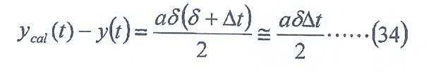
감속도 (가속도) a = 20[m/s2], 지연 시간 δ = 100[ns], 1 제어 샘플링 간격 Δt = 96[μsec] 인 경우, 보정 오차는 0.1㎚ 가 되고, 이 양이면 당분간은 문제가 되지 않는다고 할 수 있다. 즉, 각 Y 헤드에 대해 지연 시간 (δ) 이 정확하게 구해져 있으면, 상기 서술한 수법에 의해 계측 지연 (지연 시간) 에서 기인하는 인코더의 계측 오차를 소프트하게 보정할 수 있다.When deceleration (acceleration) a = 20 [m / s 2 ], delay time δ = 100 [ns], and 1 control sampling interval Δt = 96 [μsec], the correction error is 0.1 nm, and for this amount, It doesn't matter. That is, if the delay time δ is accurately determined for each Y head, the measurement error of the encoder resulting from the measurement delay (delay time) can be softly corrected by the above-described method.
즉, 주제어 장치 (20) 는 인코더 시스템의 각 Y 헤드의 계측값과, 1 제어 샘플링 간격 앞의 계측값에 기초하여, 시각 (t), 시각 (t - Δt) 에 있어서의 시간 변화 곡선 y = y(t) 상의 점 (S1, S2) 을 찾아내고, 그들 점 (S1, S2) 을 통과하는 근사 직선 y = ycal(t) 를 산출하고, 시각 (t) 에 있어서의 근사 직선 y = ycal(t) 상의 점의 y 좌표값을 구함으로써, 각 Y 헤드의 검출 신호의 전선 중의 전파에 수반되는 계측 지연에 의한 계측 오차를 보정할 수 있고, 인코더 시스템의 각 Y 헤드에 대한 계측 지연의 영향을 보정할 수 있다.In other words, the
또, 주제어 장치 (20) 는, 인코더 시스템의 각 X 헤드 (66) 에 대한 계측 지연 (지연 시간 (δ)) 의 영향도, 상기 서술과 동일하게 하여 보정할 수 있다.In addition, the
그 밖의 계측 오차의 발생 요인으로서, 빔 광로 상의 분위기의 온도 요동 (공기 요동) 을 생각할 수 있다. 2 개의 복귀 광속 (LB1, LB2) 간의 위상차 (Ф) 는, 식 (16) 우변 제 1 항으로부터, 2 개의 광속의 광로차 (ΔL) 에 의존한다. 여기서, 공기 요동에 의해 광의 파장 λ 이 λ + Δλ 으로 변화한 것으로 한다. 이 파장의 미소 변화 (Δλ) 에 의해, 위상차는 미소량 ΔФ = 2πΔLΔλ/λ2 변화한다. 여기서, 만일 광의 파장 λ = 1㎛, 미소 변화 Δλ = 1㎚ 로 하면, 광로차 ΔL = 1㎜ 에 대해, 위상 변화 ΔФ = 2π 가 된다. 이 위상 변화는, 인코더의 카운트값으로 환산하면 1 에 상당한다. 또, 변위로 환산하면 p/2(nb - na) 에 상당한다. 따라서, nb = -na = 1 로 하면, p = 1㎛ 인 경우, 0.25㎛ 의 계측 오차가 발생하게 된다.As a cause of other measurement errors, temperature fluctuations (air fluctuations) of the atmosphere on the beam optical path can be considered. The phase difference? Between two return light beams LB 1 and LB 2 depends on the optical path difference ΔL of the two light beams from the
실제의 인코더에서는, 간섭시키는 2 개의 광속의 광로 길이가 극히 짧기 때문에, 공기 요동에 의한 파장 변화 (Δλ) 는 매우 작다. 또한, 광로차 (ΔL) 는 광축이 반사면에 대해 직교하는 이상 (理想) 상태에 있어서, 거의 0 이 되도록 설계되어 있다. 그 때문에, 공기 요동에서 기인하는 계측 오차는 거의 무시할 수 있다. 간섭계와 비교해도 현격히 작고, 단기 안정성이 우수하다.In the actual encoder, since the optical path lengths of the two luminous fluxes interfering are extremely short, the wavelength change Δλ due to air fluctuations is very small. The optical path difference ΔL is designed to be almost zero in an ideal state in which the optical axis is orthogonal to the reflective surface. Therefore, the measurement error resulting from air fluctuation can be almost ignored. Compared with an interferometer, it is significantly smaller and has excellent short-term stability.
본 실시형태의 노광 장치 (100) 에서는, 예를 들어 장치의 기동시 등에, 주제어 장치 (20) 는 전술한 일련의 캘리브레이션 처리, 즉 A. 스테이지 위치 기인 오차 보정 정보의 취득 처리, B. 헤드 위치 캘리브레이션 처리, C. 아베 이탈량을 구하기 위한 캘리브레이션 처리, D. 스케일의 면의 형상 (요철) 을 구하는 처리, E. 스케일의 격자 피치의 보정 정보 및 격자 변형의 보정 정보의 취득 처리 및 F. 계측 지연에 의한 계측 오차의 보정 정보의 취득 처리를 복수 회, 전술한 순서 혹은 상이한 순서로 반복해도 된다. 이 반복시에, 전회까지 계측한 각종 정보를 사용하여, 2 회째 이후의 각종 캘리브레이션 처리를 실시하는 것으로 해도 된다.In the
예를 들어 상기 서술한 스테이지 위치 기인 오차 보정 정보의 취득 처리시에는, 예를 들어 웨이퍼 테이블 (WTB) (웨이퍼 스테이지 (WST)) 의 피칭 (또는 롤링) 의 조정은, Z 위치 z = 0 의 점을 중심으로 하여 웨이퍼 스테이지 (WST) 를 θx 회전 (또는 θy 회전) 시켜야 하고, 그 전제로는, Y 스케일 (39Y1, 39Y2) (또는 X 스케일 (39X1, 39X2)) 의 전술한 아베 이탈량이 이미 알려져 있어야 한다. 그래서, 제 1 회째의 스테이지 위치 기인 오차 보정 정보의 취득 처리에서는, Y 스케일 (39Y1, 39Y2) (또는 X 스케일 (39X1, 39X2)) 의 아베 이탈량으로서 설계값을 사용하여, 전술한 순서로 A. 스테이지 위치 기인 오차 보정 정보의 취득 처리를 실시하고, 그 후 B. 헤드 위치 캘리브레이션 처리 및 C. 아베 이탈량을 구하기 위한 캘리브레이션 처리를 실시한 후, D. 스케일의 면의 형상 (요철) 을 구하는 처리, 그리고 E. 스케일의 격자 피치의 보정 정보 및 격자 변형의 보정 정보의 취득 처리를 실시하고, 그 후에, 제 2 회째의 A. 스테이지 위치 기인 오차 보정 정보의 취득 처리를 실시할 때에, 위에서 실제로 구한 아베 이탈량에 기초하여, Z 위치 z = 0 의 점을 중심으로 하여 웨이퍼 스테이지 (WST) 를 θx 회전 (또는 θy 회전) 시켜, 전술한 순서로 스테이지 위치 기인 오차 보정 정보를 취득해도 된다. 이와 같이 함으로써, 2 회째의 계측으로 아베 이탈량의 설계값에 대한 오차의 영향을 받지 않는 스테이지 위치 기인 오차 보정 정보를 취득할 수 있게 된다.For example, at the time of acquisition process of the error correction information which is the stage position mentioned above, the adjustment of the pitching (or rolling) of the wafer table WTB (wafer stage WST) is a point of Z position z = 0, for example. The wafer stage WST should be rotated θx (or θy) with respect to the above, and as a premise, the above-described Abbe of the Y scale 39Y 1 , 39Y 2 (or the
다음으로, 상기 서술한 스테이지 위치 기인 오차 보정 정보의 취득, 스케일 표면의 요철 계측, 스케일의 격자 피치의 보정 정보 및 격자 변형의 보정 정보의 취득, 그리고 스케일 표면의 아베 이탈량의 취득 등의 처리가 미리 실시된 후에, 실제의 로트의 처리 중 등에 실행되는, 웨이퍼 스테이지 (WST) 의 XY 평면 내의 위치 제어에 사용되는 인코더의 전환 처리, 즉 복수의 인코더 사이에서의 연결 처리에 대해 설명한다.Next, processing such as acquisition of error correction information attributable to the stage position described above, measurement of unevenness of the scale surface, correction information of the grating pitch of the scale and correction information of the grating deformation, and acquisition of the ablation amount of the scale surface are performed. After performing in advance, the switching processing of the encoder used for the position control in the XY plane of the wafer stage WST, which is executed during the actual lot processing or the like, will be described.
여기서, 먼저 복수의 인코더 사이에서의 연결 처리의 설명에 앞서, 그 전제가 되는, 보정이 완료된 인코더의 계측값을 웨이퍼 스테이지 (WST) 의 위치로 변환 하는 구체적 방법에 대해 도 22(A) 및 도 22(B) 를 사용하여 설명한다. 여기서는, 설명을 간단하게 하기 위해, 웨이퍼 스테이지 (WST) 의 자유도가 3 자유도 (X, Y, θz) 인 것으로 한다.Here, prior to the description of the connection processing between the plurality of encoders, a specific method of converting the measured value of the corrected encoder to the position of the wafer stage WST, which is a premise, will be described with reference to FIGS. 22A and FIG. It demonstrates using 22 (B). Here, for the sake of simplicity, it is assumed that the degree of freedom of the wafer stage WST is three degrees of freedom (X, Y, θz).
도 22(A) 에는, 웨이퍼 스테이지 (WST) 가 좌표 원점 (X, Y, θz) = (0, 0, 0) 에 있는 기준 상태가 나타나 있다. 이 기준 상태로부터, 인코더 (Y 헤드) (Enc1, Enc2) 및 인코더 (X 헤드) (Enc3) 모두가, 각각이 대향하는 스케일 (39Y1, 39Y2 및 39X1) 의 주사 영역으로부터 벗어나지 않는 범위 내에서 웨이퍼 스테이지 (WST) 를 구동시킨다. 이와 같이 하여, 웨이퍼 스테이지 (WST) 가 위치 (X, Y, θz) 로 이동한 상태가 도 22(B) 에 나타나 있다.In FIG. 22A, the reference state in which the wafer stage WST is located at the coordinate origin (X, Y, θz) = (0, 0, 0) is shown. From this reference state, both the encoder (Y head) Enc1, Enc2 and the encoder (X head) Enc3 do not deviate from the scanning areas of the
여기서, XY 좌표계에 있어서의, 인코더 (Enc1, Enc2, Enc3) 의 계측점의 위치 좌표 (X, Y) 를 각각 (p1, q1), (p2, q2), (p3, q3) 으로 한다. 인코더 (Enc1, Enc2) 의 X 좌표값 (p1, p2) 및 인코더 (Enc3) 의 Y 좌표값 (q3) 으로는, 전술한 헤드 위치의 캘리브레이션시에 취득한 위치 정보가, 인코더 (Enc1, Enc2) 의 Y 좌표값 (q1, q2) 및 인코더 (Enc3) 의 X 좌표값 (p3) 으로는, 설계상 위치 정보가, 메모리 (34) 내로부터 각각 판독 출력되어 사용된다.Here, the position coordinates (X, Y) of the measurement points of the encoders (Enc1, Enc2, Enc3) in the XY coordinate system are respectively (p 1 , q 1 ), (p 2 , q 2 ), (p 3 , q 3). ) As the X coordinate values (p 1 , p 2 ) of the encoders (Enc1, Enc2) and the Y coordinate values (q 3 ) of the encoder (Enc3), the position information acquired at the time of calibration of the head position described above is obtained from the encoder (Enc1, As the Y coordinate values q 1 and q 2 of Enc2 and the X coordinate values p 3 of the encoder Enc3, positional information is read out from the
X 헤드와 Y 헤드는, 각각 웨이퍼 스테이지 (WST) 의 중심축 (LL 과 LW) 으로부터의 상대 거리를 계측한다. 따라서, X 헤드와 Y 헤드의 계측값 (CX, CY) 은, 각각 다음 식 (35a), (35b) 로 나타낼 수 있다.The X head and the Y head measure relative distances from the central axes LL and LW of the wafer stage WST, respectively. Therefore, the measured values C X and C Y of the X head and the Y head can be represented by the following equations (35a) and (35b), respectively.
CX = r'·ex' …(35a)C X = r'ex '... (35a)
CY = r'·ey' …(35b)C Y = r'ey '... (35b)
여기서, ex', ey' 는 웨이퍼 스테이지 (WST) 에 놓인 상대 좌표계 (X', Y', θz') 에 있어서의 X', Y' 단위 벡터로서, 기준 좌표계 (X, Y, θz) 에 있어서의 X, Y 단위 벡터 (ex, ey) 와, 다음 식 (36) 의 관계가 있다.Here, ex 'and ey' are X 'and Y' unit vectors in the relative coordinate systems X ', Y' and θz 'placed on the wafer stage WST, and in reference coordinate systems X, Y and θz, The relationship between the X, Y unit vectors (ex, ey) of the following equation (36) is given.
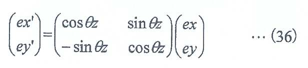
또, r' 는 상대 좌표계에 있어서의 인코더의 위치 벡터로서, 기준 좌표계에 있어서의 위치 벡터 r = (p, q) 를 사용하여, r' = r - (O' - O) 로 부여된다. 따라서, 식 (35a), (35b) 는 다음 식 (37a), (37b) 와 같이 고쳐 쓸 수 있다.Also, r 'is a position vector of the encoder in the relative coordinate system, and r' = r-(O '-O) is given using the position vector r = (p, q) in the reference coordinate system. Therefore, equations (35a) and (35b) can be rewritten as in the following equations (37a) and (37b).
CX = (p - X)cosθz + (q - Y)sinθz ……(37a)C x = (p-X) cos θ z + (q-Y) sin θ z. … (37a)
CY = -(p - X)sinθz + (q - Y)cosθz ……(37b)C Y =-(p-X) sinθz + (q-Y) cosθz... … (37b)
따라서, 도 22(B) 에 나타내는 바와 같이, 웨이퍼 스테이지 (WST) 가 좌표 (X, Y, θz) 에 위치하는 경우, 3 개의 인코더의 계측값은 이론상 다음의 식 (38a) ∼ (38c) (아핀 변환의 관계라고도 부른다) 로 나타낼 수 있다.Therefore, as shown in Fig. 22B, when the wafer stage WST is located at the coordinates (X, Y, θz), the measured values of the three encoders are theoretically expressed by the following equations (38a) to (38c) ( Also referred to as affine transformation relationship).
C1 = -(p1 - X)sinθz + (q1 - Y)cosθz ……(38a)C 1 =-(p 1 -X) sinθz + (q 1 -Y) cosθz... … (38a)
C2 = -(p2 - X)sinθz + (q2 - Y)cosθz ……(38b)C 2 = − (p 2 −X) sinθz + (q 2 -Y) cosθz... … (38b)
C3 = (p3 - X)cosθz + (q3 - Y)sinθz ……(38c)C 3 = (p 3 -X) cos θ z + (q 3 -Y) sin θ z. … (38c)
또한, 도 22(A) 의 기준 상태에서는, 연립 방정식 (38a) ∼ (38c) 로부터, C1 = q1, C2 = q2, C3 = p3 이 된다. 따라서, 기준 상태에 있어서, 3 개의 인코더 (Enc1, Enc2, Enc3) 의 계측값을 각각 q1, q2, p3 으로 초기 설정하면, 이후 웨이퍼 스테이지 (WST) 의 변위 (X, Y, θz) 에 대해, 3 개의 인코더는 식 (38a) ∼ (38c) 로 부여되는 이론값을 제시하게 된다.In addition, in the reference state of FIG. 22A, C 1 = q 1 , C 2 = q 2 , and C 3 = p 3 from simultaneous equations (38a) to (38c). Therefore, in the reference state, when the measured values of the three encoders Enc1, Enc2, Enc3 are initially set to q 1 , q 2 , and p 3 , the displacements (X, Y, θz) of the wafer stage WST are subsequently set. For three encoders, the theoretical values given by equations (38a) to (38c) are presented.
연립 방정식 (38a) ∼ (38c) 에서는, 변수가 3 개 (X, Y, θz) 에 대해 3 개의 식이 부여되어 있다. 따라서, 반대로, 연립 방정식 (38a) ∼ (38c) 에 있어서의 종속 변수 (C1, C2, C3) 가 부여되면, 변수 (X, Y, θz) 를 구할 수 있다. 여기서, 근사 sinθz ≒ θz 를 적용하거나, 혹은 보다 고차의 근사를 적용해도, 용이하게 방정식을 풀 수 있다. 따라서, 인코더의 계측값 (C1, C2, C3) 으로부터 웨이퍼 스테이지 (WST) 의 위치 (X, Y, θz) 를 산출할 수 있다.In the simultaneous equations (38a) to (38c), three equations are given for three variables (X, Y, θz). Therefore, on the contrary, when the simultaneous equations (38a) ~ The dependent variables (C 1, C 2, C 3) in (38c) assigned, it is possible to obtain the parameters (X, Y, θz). Here, the equation can be easily solved even if an approximation sinθz ≒ θz is applied or a higher order approximation is applied. Therefore, the position (X, Y, θz) of the wafer stage WST can be calculated from the measured values C 1 , C 2 , C 3 of the encoder.
상기 서술한 바와 같이 하여 구성된 본 실시형태의 노광 장치 (100) 에서는, 전술한 바와 같은 웨이퍼 테이블 (WTB) 상의 X 스케일, Y 스케일의 배치 및 전술한 바와 같은 X 헤드, Y 헤드의 배치를 채용한 점에서, 도 23(A) 및 도 23(B) 등에 예시되는 바와 같이, 웨이퍼 스테이지 (WST) 의 유효 스트로크 범위 (즉, 본 실시형태에서는, 얼라인먼트 및 노광 동작을 위해 이동하는 범위) 에서는, 반드시 X 스케일 (39X1, 39X2) 중 적어도 일방에 헤드 유닛 (62B, 62D) 에 속하는 합계 18 개의 X 헤드 중 적어도 1 지점의 X 헤드 (66) 가 대향하고, 또한 Y 스케일 (39Y1, 39Y2) 에 헤드 유닛 (62A, 62C) 에 각각 속하는 적어도 각 1 개의 Y 헤드 (64), 또는 Y 헤드 (64y1, 64y2) 가 각각 대향하게 되어 있다. 즉, 4 개의 스케일 중 적어도 3 개에, 대응하는 헤드가 적어도 각 1 개 대향하게 되어 있다.In the
또한, 도 23(A) 및 도 23(B) 중에서는, 대응하는 X 스케일 또는 Y 스케일에 대향한 헤드가 원으로 둘러싸여 나타나 있다.In addition, in FIG. 23A and FIG. 23B, the head facing the corresponding X scale or Y scale is shown enclosed by a circle.
이 때문에, 주제어 장치 (20) 는 전술한 웨이퍼 스테이지 (WST) 의 유효 스트로크 범위에서는, 인코더 (70A 및 70C) 와, 인코더 (70B 및 70D) 의 적어도 일방의 적어도 합계 3 개의 인코더의 계측값에 기초하여, 스테이지 구동계 (124) 를 구성하는 각 모터를 제어함으로써, 웨이퍼 스테이지 (WST) 의 XY 평면 내의 위치 정보 (θz 방향의 회전을 포함한다) 를 고정밀도로 제어할 수 있다. 인코더 (70A ∼ 70D) 의 계측값이 수용하는 공기 요동의 영향은 간섭계에 비하면 무시할 수 있을만큼 작기 때문에, 공기 요동의 영향을 수용하는 계측의 단기 안정성은 간섭계에 비해 현격히 양호하다.For this reason, the
또, 도 23(A) 중에 백색 화살표로 나타내는 바와 같이 웨이퍼 스테이지 (WST) 를 X 축 방향으로 구동시킬 때, 그 웨이퍼 스테이지 (WST) 의 Y 축 방향의 위치를 계측하는 Y 헤드 (64) 가, 도 23(A) 중에 화살표 e1, e2 로 나타내는 바와 같이, 옆의 Y 헤드 (64) 로 순차 전환된다. 예를 들어 실선의 원으로 둘러싸이는 Y 헤드 (64) 로부터 점선의 원으로 둘러싸이는 Y 헤드 (64) 로 전환된다. 이 때문에, 그 전환 전후에서, 후술하는 계측값의 연결 처리가 실시된다.Moreover, as shown by a white arrow in FIG. 23A, when the wafer stage WST is driven in the X-axis direction, the
또, 도 23(B) 중에 백색 화살표로 나타내는 바와 같이 웨이퍼 스테이지 (WST) 를 Y 축 방향으로 구동시킬 때, 그 웨이퍼 스테이지 (WST) 의 X 축 방향의 위치를 계측하는 X 헤드 (66) 가, 순차 옆의 X 헤드 (66) 로 전환된다. 예를 들어 실선의 원으로 둘러싸이는 X 헤드 (66) 로부터 점선의 원으로 둘러싸이는 X 헤드 (66) 로 전환된다. 이 때문에, 그 전환 전후에서 계측값의 연결 처리가 실시된다.Moreover, as shown by a white arrow in FIG. 23B, when driving the wafer stage WST in the Y-axis direction, the
여기서, 도 23(A) 중에 화살표 e1 로 나타내는 Y 헤드 643 으로부터 644 로의 전환을 예로, 인코더 헤드의 전환 순서를 도 24(A) ∼ 도 24(E) 에 기초하여 설명한다.Here, FIG. 23 (A) in Examples 4 to 64 transition to from the Y heads 64 3 indicated by the arrow e 1, 24 the transition order of the encoder head (A) ~ will be explained with reference to FIGs based on the 24 (E).
도 24(A) 에는, 전환 전의 상태가 나타나 있다. 이 상태에서는, Y 스케일 (39Y2) 상의 주사 영역 (회절 격자가 형성되어 있는 영역) 에 대향하고 있는 Y 헤드 (643) 가 작동하고 있어, 주사 영역으로부터 벗어나 있는 Y 헤드 (644) 는 정지되어 있다. 여기서, 작동하고 있는 헤드를 흑색 원, 정지되어 있는 헤드를 백색 원으로 나타낸다. 그리고, 주제어 장치 (20) 는 작동 중의 Y 헤드 (643) 의 계측값을 감시하고 있다. 여기서, 계측값이 감시되고 있는 헤드를 2 중의 직사각형 프레임으로 나타냈다.The state before switching is shown by FIG. 24 (A). In this state, the
여기서, 웨이퍼 스테이지 (WST) 가 +X 방향으로 이동한다. 그로써, Y 스 케일 (39Y2) 이 우측 방향으로 변위한다. 여기서, 본 실시형태에서는 전술한 바와 같이, 인접하는 2 개의 Y 헤드의 간격은, Y 스케일 (39Y2) 의 X 축 방향의 유효폭 (주사 영역의 폭) 보다 좁게 설정되어 있다. 그 때문에, 도 24(B) 에 나타내는 바와 같이, Y 헤드 (643, 644) 가 Y 스케일 (39Y2) 의 주사 영역에 대향하는 상태가 있다. 그래서, 주제어 장치 (20) 는 작동 중의 Y 헤드 (643) 와 함께, 정지 중의 Y 헤드 (644) 가 주사 영역에 대향한 것을 확인하여 Y 헤드 (644) 를 복귀시킨다. 단, 주제어 장치 (20) 는 이 시점에서는 아직 계측값의 감시를 개시하지 않는다.Here, the wafer stage WST moves in the + X direction. As a result, the Y scale 39Y 2 is displaced in the right direction. Here, the interval between two adjacent Y head, as described above, in the present embodiment is, Y-scale (39Y 2) is narrower than the effective width of the set up (the width of the scanning area) of the X-axis direction. Therefore, the state opposite to the scan region of the, Y heads (64 3, 64 4) the Y-scale (39Y 2) as shown in Fig. 24 (B). Thus, the
다음으로, 도 24(C) 에 나타내는 바와 같이, 나중에 정지되는 Y 헤드 (643) 가 주사 영역에 대향하고 있는 동안에, 주제어 장치 (20) 는 Y 헤드 (643) 를 포함하는 작동 중의 인코더 헤드의 계측값으로부터, 복귀한 Y 헤드 (644) 의 기준 위치를 산출한다. 그리고, 주제어 장치 (20) 는, 그 기준 위치를 Y 헤드 (644) 의 계측값의 초기값으로서 설정한다. 또한, 기준 위치의 산출과 초기값의 설정에 관해서는, 다음에 상세하게 설명한다.Next, as shown in FIG. 24 (C), while the
주제어 장치 (20) 는 상기 초기값의 설정과 동시에, 계측값을 감시하는 인코더 헤드를, Y 헤드 643 으로부터 644 로 전환한다. 전환 종료 후, 주제어 장치 (20) 는 도 24(D) 에 나타내는 바와 같이, Y 헤드 (643) 를 주사 영역으로부터 벗어 나기 전에 정지시킨다. 이상에 의해, 인코더 헤드의 전환 전체 작업이 종료되고, 이후, 도 24(E) 에 나타내는 바와 같이, Y 헤드 (644) 의 계측값이 주제어 장치 (20) 에 의해 감시된다.At the same time as the initial value setting, the
본 실시형태에서는, 헤드 유닛 (62A, 62C) 이 각각 구비하는 인접하는 Y 헤드 (64) 의 간격은, 예를 들어 70㎜ (일부 예외 있음) 로서, Y 스케일 (39Y1, 39Y2) 의 주사 영역의 X 축 방향의 유효폭 (예를 들어 76㎜) 보다 좁게 설정되어 있다. 또, 동일하게, 헤드 유닛 (62B, 62D) 이 각각 구비하는 인접하는 X 헤드 (66) 의 간격은, 예를 들어 70㎜ (일부 예외 있음) 로서, X 스케일 (39X1, 39X2) 의 주사 영역의 Y 축 방향의 유효폭 (예를 들어 76㎜) 보다 좁게 설정되어 있다. 이로써, 상기 서술한 바와 같이, Y 헤드 (64) 및 X 헤드 (66) 의 전환을 원활하게 실행할 수 있다.Interval of the present embodiment, the head unit (62A, 62C), the
또한, 본 실시형태에서는, 인접하는 양 헤드가 스케일에 대향하는 범위, 즉 도 24(B) 에 나타내는 상태부터 도 24(D) 에 나타내는 상태까지의 웨이퍼 스테이지 (WST) 의 이동 거리가 예를 들어 6㎜ 이다. 그 중앙, 즉, 도 24(C) 에 나타내는 웨이퍼 스테이지 (WST) 의 위치에서 계측값을 감시하는 헤드가 전환된다. 이 전환 작업은, 정지되는 헤드가 주사 영역으로부터 벗어날 때까지, 즉 웨이퍼 스테이지 (WST) 가 도 24(C) 에 나타내는 상태부터 도 24(D) 에 나타내는 상태까지로 거리 3㎜ 의 영역을 이동하는 동안에 완료된다. 예를 들어 스테이지의 이동 속도 1m/sec 인 경우, 3msec 의 시간 내에 헤드의 전환 작업이 완료되게 된다.In addition, in this embodiment, the movement distance of the wafer stage WST from the range which the two adjacent heads oppose to the scale, ie, the state shown in FIG. 24 (B) to the state shown in FIG. 24 (D), is mentioned, for example. 6 mm. The head which monitors a measured value at the center, ie, the position of the wafer stage WST shown in FIG. 24C, is switched. This switching operation moves an area of 3 mm in distance until the stationary head is out of the scanning area, that is, the state where the wafer stage WST is shown in Fig. 24C to the state shown in Fig. 24D. Is completed during. For example, when the moving speed of the stage is 1 m / sec, the head switching operation is completed within a time of 3 msec.
다음으로, 인코더 헤드의 전환시에 있어서의 연결 처리, 즉 계측값의 초기 설정에 대해, 주제어 장치 (20) 의 동작을 중심으로 하여 설명한다.Next, the connection process at the time of switching of an encoder head, ie, initial setting of a measured value, is demonstrated centering on operation | movement of
본 실시형태에서는, 전술한 바와 같이, 웨이퍼 스테이지 (WST) 의 유효 스트로크 범위에서는 항상 3 개의 인코더 (X 헤드 및 Y 헤드) 가 웨이퍼 스테이지 (WST) 를 관측하고 있고, 인코더의 전환 처리를 실시할 때에는 도 25 에 나타내는 바와 같이, 4 개의 인코더가 웨이퍼 스테이지 (WST) 를 관측하고 있게 된다.In the present embodiment, as described above, in the effective stroke range of the wafer stage WST, three encoders (X head and Y head) are always observing the wafer stage WST, and when the encoder switch processing is performed. As shown in FIG. 25, four encoders are observing the wafer stage WST.
웨이퍼 스테이지 (WST) 의 XY 평면 내의 위치 제어에 사용되는 인코더의 전환 처리 (연결) 를 실시하고자 하는 순간에 있어서, 도 25 에 나타내는 바와 같이, 인코더 (Enc1, Enc2, Enc3 및 Enc4) 가, 각각 스케일 (39Y1, 39Y2, 39X1, 39X2) 위에 위치하고 있다. 이 도 25 를 언뜻 보면, 인코더 (Enc1) 로부터 인코더 (Enc4) 로 전환하고자 하는 것처럼 보이지만, 인코더 (Enc1) 와 인코더 (Enc4) 에서는, 계측 방향이 상이한 점에서도 분명한 바와 같이, 연결을 실시하고자 하는 타이밍에 있어서 인코더 (Enc1) 의 계측값 (카운트값) 을 그대로 인코더 (Enc4) 의 계측값의 초기값으로서 부여해도 아무 의미도 없다.At the moment when the switching processing (connection) of the encoder used for the position control in the XY plane of the wafer stage WST is to be performed, as shown in FIG. 25, the encoders Enc1, Enc2, Enc3 and Enc4 are each scaled. (39Y 1 , 39Y 2 , 39X 1 , 39X 2 ) At first glance, this figure seems to attempt to switch from the encoder Enc1 to the encoder Enc4. However, in the encoder Enc1 and the encoder Enc4, the timing at which the connection is to be made is clear, even from the point where the measurement directions are different. In this case, the measured value (count value) of the encoder Enc1 is given as an initial value of the measured value of the encoder Enc4 without any meaning.
그래서, 본 실시형태에서는, 주제어 장치 (20) 가 3 개의 인코더 (Enc1, Enc2 및 Enc3) 에 의한 계측·서보로부터, 3 개의 인코더 (Enc2, Enc3 및 Enc4) 에 의한 계측·서보로 전환하게 되어 있다. 즉, 도 25 로부터 알 수 있는 바와 같이, 이 방식은 통상적인 인코더 연결의 개념과는 상이하고, 어느 헤드로부터 다른 헤드로 연결한다는 것이 아니고, 3 개의 헤드 (인코더) 의 조합으로부터 다른 3 개 의 헤드 (인코더) 의 조합으로 연결하는 것이다. 또한, 3 개의 헤드와 다른 3 개의 헤드에서 상이한 헤드는 1 개에 한정되지 않는다. 또, 도 25 에서는 인코더 (Enc3) 를 인코더 (Enc4) 로 전환하는 것으로 하였으나, 인코더 (Enc4) 대신에, 예를 들어 인코더 (Enc3) 에 인접하는 인코더로 전환하는 것으로 해도 된다.Therefore, in the present embodiment, the
주제어 장치 (20) 는, 먼저 인코더 (Enc1, Enc2 및 Enc3) 의 계측값 (C1, C2, C3) 에 기초하여, 상기 연립 방정식 (38a) ∼ (38c) 를 풀어, 웨이퍼 스테이지 (WST) 의 XY 평면 내의 위치 정보 (X, Y, θz) 를 산출한다.The
다음으로, 주제어 장치 (20) 는, 다음 식 (39) 의 아핀 변환의 식에, 위에서 산출한 X, θz 를 대입하여, 인코더 (X 헤드) (Enc4) 의 계측값의 초기값을 결정한다.Next, the
C4 = (p4 - X)cosθz + (q4 - Y)sinθz ……(39)C 4 = (p 4 -X) cos θ z + (q 4 -Y) sin θ z. … (39)
상기 식 (39) 에 있어서, p4, q4 는 인코더 (Enc4) 의 계측점의 X 좌표값, Y 좌표값이다. 인코더 (Enc4) 의 Y 좌표값 (q4) 으로서 전술한 헤드 위치의 캘리브레이션시에 취득한 위치 정보가, 인코더 (Enc4) 의 X 좌표값 (p4) 으로는 설계상 위치 정보가, 메모리 (34) 내로부터 각각 판독 출력되어 사용된다.In the formula (39), p 4 and q 4 are X coordinate values and Y coordinate values of the measurement points of the encoder Enc4. As the Y coordinate value q 4 of the encoder Enc4, the position information acquired at the time of calibration of the head position described above is used as the X coordinate value p 4 of the encoder Enc4. Each read out from the inside is used.
상기 초기값 (C4) 을 인코더 (Enc4) 의 초기값으로서 부여함으로써, 웨이퍼 스테이지 (WST) 의 3 자유도 방향의 위치 (X, Y, θz) 를 유지한 채로, 모순없이 연결이 완료되게 된다. 그 이후에는, 전환 후에 사용하는 인코더 (Enc2, Enc3 및 Enc4) 의 계측값 (C2, C3, C4) 을 사용하여, 다음의 연립 방정식 (38b) ∼ (38d) 를 풀어, 웨이퍼 스테이지 (WST) 의 위치 좌표 (X, Y, θz) 를 산출한다.By giving the initial value C 4 as the initial value of the encoder Enc4, the connection is completed without contradiction while maintaining the positions X, Y, and θz in the three degrees of freedom direction of the wafer stage WST. . After that, the following simultaneous equations (38b) to (38d) are solved using the measured values (C 2 , C 3 , C 4 ) of the encoders Enc2, Enc3 and Enc4 used after the switching, and the wafer stage ( The position coordinates (X, Y, θz) of WST) are calculated.
C2 = -(p2 - X)sinθz + (q2 - Y)cosθz …(38b)C 2 = − (p 2 −X) sinθz + (q 2 -Y) cosθz... (38b)
C3 = (p3 - X)cosθz + (q3 - Y)sinθz …(38c)C 3 = (p 3 -X) cos θ z + (q 3 -Y) sin θ z. (38c)
C4 = (p4 - X)cosθz + (q4 - Y)sinθz …(38d)C 4 = (p 4 -X) cos θ z + (q 4 -Y) sin θ z. (38d)
또한, 4 개째의 인코더가 Y 헤드인 경우에는, 이론식 (38d) 대신에 다음의 이론식 (38e) 를 사용한 연립 방정식 (38b) (38c) (38e) 를 사용하면 된다.In the case where the fourth encoder is the Y head, the simultaneous equations (38b) (38c) (38e) using the following equation (38e) may be used instead of the equation (38d).
C4 = -(p4 - X)sinθz + (q4 - Y)cosθz …(38e)C 4 =-(p 4 -X) sin θ z + (q 4 -Y) cos θ z. (38e)
단, 위에서 산출된 계측값 (C4) 은, 전술한 각종 인코더의 계측 오차가 보정된 보정 완료된 인코더의 계측값이기 때문에, 주제어 장치 (20) 는, 전술한 스테이지 위치 기인 오차 보정 정보, 스케일의 격자 피치의 보정 정보 (및 격자 변형의 보정 정보), 아베 이탈량 (아베 오차 보정 정보) 등을 사용하여, 계측값 (C4) 을 역보정하고, 보정 전의 원시값 (raw value, C4') 을 산출하고, 그 원시값 (C4') 을 인코더 (Enc4) 의 계측값의 초기값으로서 결정한다.However, since the measured value C 4 calculated above is the measured value of the corrected encoder in which the measurement error of the above-mentioned various encoders was correct | amended, the
여기서 역보정이란, 아무런 보정을 실시하지 않는 인코더의 계측값 (C4') 을, 전술한 스테이지 위치 기인 오차 보정 정보, 스케일 기인 오차 보정 정보 (예를 들어 스케일의 격자 피치의 보정 정보 (및 격자 변형의 보정 정보) 등), 및 아 베 이탈량 (아베 오차 보정 정보) 등을 사용하여 보정한 보정 후의 인코더의 계측값이 C4 라는 가정하에, 계측값 (C4) 에 기초하여 계측값 (C4') 을 산출하는 처리를 의미한다.In this case, the reverse correction means that the measured value C 4 ′ of the encoder which does not perform any correction is used for the error correction information attributable to the stage position and the error correction information attributable to the scale (for example, the correction information of the grid pitch of the scale (and the grid). correction information of the deformation) and the like), and ah chopping displacement amounts (the measured value of the Abbe error correction information) the encoder after the correction using the correction such as the assumption that C 4, on the basis of the measured value (C 4), the measured value ( C 4 ') means processing.
그런데, 웨이퍼 스테이지 (WST) 의 위치 제어의 간격 (제어 샘플링 간격) 은, 일례로서 96[μsec] 인데, 간섭계나 인코더의 계측 간격 (계측 샘플링 간격) 은 이보다 훨씬 고속으로 실시할 필요가 있다. 간섭계나 인코더의 샘플링이 제어 샘플링보다 고속인 이유는, 간섭계나 인코더도 간섭광의 강도 변화 (프린지) 를 세고 있는 것으로서, 샘플링 간격이 커지면 계측이 곤란해지기 때문이다.By the way, the interval (control sampling interval) of position control of the wafer stage WST is 96 [microsecond] as an example, but the measurement interval (measurement sampling interval) of an interferometer and an encoder needs to be performed at a much higher speed than this. The reason why sampling of the interferometer and encoder is faster than control sampling is that the interferometer and encoder also count the intensity change (fringe) of the interfering light, and the measurement becomes difficult when the sampling interval is increased.
그런데, 웨이퍼 스테이지 (WST) 의 위치 서보 제어계에서는, 96[μsec] 의 제어 샘플링 간격마다 웨이퍼 스테이지 (WST) 의 현재 위치를 갱신하고, 목표 위치에 위치 결정하기 위한 연산을 하여, 추력 지령값 등을 출력하고 있다. 따라서, 웨이퍼 스테이지의 위치 정보를 필요로 하는 것은 96[μsec] 의 제어 샘플링 간격마다이고, 그 사이의 위치 정보는 웨이퍼 스테이지 (WST) 의 위치 제어에는 필요없다. 간섭계나 인코더는 프린지를 잃지 않기 위해 고속으로 샘플링하고 있는 것에 불과하다.By the way, in the position servo control system of the wafer stage WST, the current position of the wafer stage WST is updated at every control sampling interval of 96 [μsec], a calculation is performed to determine the target position, and the thrust command value is calculated. Is outputting. Therefore, the position information of the wafer stage is required for every control sampling interval of 96 [µsec], and the position information therebetween is not necessary for the position control of the wafer stage WST. Interferometers and encoders are simply sampling at high speeds to avoid losing fringes.
그래서, 본 실시형태에서는, 주제어 장치 (20) 는 웨이퍼 스테이지 (WST) 가 전술한 유효 스트로크 범위에 있는 동안은 항상, 인코더 시스템의 각 인코더 (헤드) 로부터 스케일을 보고 있는지의 여부에 관계없이 계측값 (카운트값) 을 방류하여 계속 수취한다. 그리고, 주제어 장치 (20) 는 상기 서술한 인코더의 전환 동작 (복수 인코더 사이의 연결 동작) 을, 96[μsec] 마다 실시되는 웨이퍼 스테이지의 위치 제어의 타이밍과 동기하여 실시하고 있다. 이와 같이 함으로써, 전기적으로 고속의 인코더의 전환 동작이 불필요해져, 그러한 고속의 전환 동작을 실현하기 위한 고가의 하드웨어를 반드시 형성하지 않아도 되게 된다. 도 26 에는, 본 실시형태에 있어서 실시되는 웨이퍼 스테이지 (WST) 의 위치 제어, 인코더의 카운트값의 취입 및 인코더 전환의 타이밍이 개념적으로 나타나 있다. 이 도 26 에 있어서, 부호 CSCK 는 웨이퍼 스테이지 (WST) 의 위치 제어의 샘플링 클록의 발생 타이밍을 나타내고, 부호 MSCK 는 인코더 (및 간섭계) 의 계측 샘플링 클록의 발생 타이밍을 나타낸다. 또, 부호 CH 는 인코더의 전환 (연결) 을 모식적으로 나타낸다.Thus, in the present embodiment, the
또한, 인코더의 전환을 실시하는지의 여부에 관계없이, 주제어 장치 (20) 는 웨이퍼 스테이지의 위치 제어의 샘플링 클록의 발생 타이밍마다, 각 헤드에 대한 지연 시간 (δ) 에서 기인되는 계측 오차의 보정을 실행한다. 이로써, 계측 지연에 의한 계측 오차가 보정된 3 개의 인코더의 계측값에 기초하여, 웨이퍼 스테이지 (WST) 의 위치 (X, Y, θz) 가 제어되게 된다.Regardless of whether the encoder is switched or not, the
그런데, 상기 설명에서는, 어느 헤드 (인코더) 의 조합으로부터 어느 헤드 (인코더) 의 조합으로 전환되는지, 어느 타이밍으로 전환되는지를 알고 있는 것으로 하고 있는데, 실제의 시퀀스에서도 이와 같이 되어 있어야 한다. 연결을 실행하는 타이밍에 대해서도 사전에 스케줄링해 두는 것이 바람직하다.By the way, in the above description, it is assumed that which head (encoder) is switched from which head (encoder) combination is switched or at which timing. The actual sequence should be the same. It is also desirable to schedule the connection execution timing in advance.
그래서, 본 실시형태에서는, 주제어 장치 (20) 는 웨이퍼 스테이지 (WST) 의 이동 루트 (목표 궤도) 에 기초하여, XY 평면 내의 3 자유도 (X, Y, θz) 방향에 관한 웨이퍼 스테이지 (WST) 의 위치 정보를 계측하기 위해 사용하는 3 개의 인코더 (헤드) 의 전환 (3 개의 헤드의 조합 (예를 들어 인코더 (Enc1, Enc2 및 Enc3)) 으로부터, 다른 3 개의 헤드의 조합 (예를 들어 Enc4, Enc2 및 Enc3) 으로의 전환, 및 그 전환의 타이밍) 을 미리 스케줄링하고, 그 스케줄링 결과를 메모리 (34) 등의 기억 장치에 기억시키고 있다.Thus, in the present embodiment, the
여기서, 리트라이 (재시도) 를 생각하지 않으면, 쇼트 맵 (노광 맵) 마다 일정한 스케줄 내용이 되지만, 실제로는 리트라이를 고려해야 하기 때문에, 주제어 장치 (20) 는 노광 동작을 실시하면서 조금 앞의 스케줄을 항상 갱신해 가는 것이 바람직하다.Here, if the retry (retry) is not considered, the schedule content is constant for each short map (exposure map). However, since the retry should be considered in practice, the
또한, 위에서는, 본 실시형태에 있어서의 웨이퍼 스테이지 (WST) 의 위치 제어에 사용하는 인코더의 전환 방법에 관한 원리적인 설명을 실시하는 관계에서 인코더 (헤드) (Enc1, Enc2, Enc3, Enc4) 등으로 하고 있지만, 헤드 (Enc1, Enc2) 는 헤드 유닛 (62A, 62C) 의 Y 헤드 (64) 및 한 쌍의 Y 헤드 (64y1, 64y2) 중 어느 하나를 대표적으로 나타내고, 헤드 (Enc3, Enc4) 는 헤드 유닛 (62B, 62D) 의 X 헤드 (66) 를 대표적으로 나타내는 것임은 말할 필요도 없다. 또, 동일한 이유에서, 도 22(A), 도 22(B) 및 도 25 에서는, 인코더 (헤드) (Enc1, Enc2, Enc3) 등의 배치도 실제의 배치 (도 3 등) 와는 상이하게 나타나 있다.In the above, the encoder (head) (Enc1, Enc2, Enc3, Enc4) and the like are described in relation to giving a principle explanation regarding the method of switching the encoder used for the position control of the wafer stage WST in the present embodiment. Although the heads Enc1 and Enc2 represent either one of the
<<전환 및 연결 원리의 일반론>><< General theory of transition and connection principle >>
본 실시형태에서는, 웨이퍼 스테이지 (WST) 의 3 자유도 (X, Y, θz) 방향의 위치 좌표를 계측하기 위해, 항상 인코더 시스템 (70A ∼ 70D) 을 구성하는 X 인코더 (헤드) 및 Y 인코더 (헤드) 중, 적어도 1 개의 X 헤드와 적어도 2 개의 Y 헤드를 포함하는 적어도 3 개의 헤드를 사용하고 있다. 그 때문에, 웨이퍼 스테이지 (WST) 의 이동에 수반하여 사용하는 헤드를 전환할 때에는, 전환 전후에서 스테이지 위치의 계측 결과를 연속으로 연결하기 위해, 3 개의 헤드의 조합으로부터 다른 3 개의 헤드의 조합으로 전환하는 방식을 채용하고 있다. 이 방식을 제 1 방식이라고 부르는 것으로 한다.In the present embodiment, in order to measure the position coordinates in the three degrees of freedom (X, Y, θz) directions of the wafer stage WST, the X encoder (head) and the Y encoder (which always constitute the
그러나, 전환 및 연결 처리의 기본 원리를 상이한 관점에서 생각하면, 사용하고 있는 3 개의 헤드 중 1 개의 헤드를 다른 1 개의 헤드로 전환하는 방식으로 파악할 수도 있다. 이 방식을 제 2 방식이라고 부른다. 그래서, 도 24(A) ∼ 도 24(E) 에 나타나 있는 Y 헤드 (643) 으로부터 Y 헤드 (644) 로의 전환 및 연결 처리를 예로서, 제 2 방식을 설명한다.However, if the basic principles of the switching and linking process are considered from different viewpoints, it is possible to grasp the method of switching one head out of the three heads used to the other head. This method is called a second method. Therefore, the second method will be described by taking the switching and connection processing from the
전환 처리의 기본 순서는 앞서 서술한 순서와 동일하고, 도 24(A) ∼ 도 24(E) 에 나타내는 바와 같이, 나중에 정지되는 제 1 헤드 (643) 와 새롭게 사용되는 제 2 헤드 (644) 의 양방이 대응하는 스케일 (39Y2) 에 대향하고 있는 동안에, 제 2 헤드 (644) 의 복귀와 계측값의 설정 (연결 처리) 및 계측값을 감시하는 헤드의 전환 (및 제 1 헤드 (643) 의 정지) 이 주제어 장치 (20) 에 의해 실행된다.The basic procedure of the switching process is the same as the procedure described above, and as shown in Figs. 24A to 24E, the
계측값의 설정 (연결 처리) 시에, 주제어 장치 (20) 는 제 2 헤드 (644) 의 계측값 (CY4) 을, 제 1 헤드 (643) 의 계측값 (CY3) 을 사용하여 예측한다. 여기서, 이론식 (37b) 으로부터, Y 헤드 (643, 644) 의 계측값 (CY3, CY4) 은 다음 식 (39a) (39b) 에 따른다.Setting the measurement value at the time (connection processing), using the
CY3 = -(p3 - X)sinθz + (q3 - Y)cosθz ……(39a)C Y3 =-(p 3 -X) sinθz + (q 3 -Y) cosθz... … (39a)
CY4 = -(p4 - X)sinθz + (q4 - Y)cosθz ……(39b)C Y4 =-(p 4 -X) sinθz + (q 4 -Y) cosθz... … (39b)
여기서, (p3, q3), (p4, q4) 는 Y 헤드 (643, 644) 의 X, Y 설치 위치 (보다 정확하게는 계측점의 X, Y 위치) 이다. 간단하게 하기 위해, Y 헤드 (643, 644) 의 Y 설치 위치는 동등한 (q3 = q4) 로 가정한다. 이 가정하에, 상기 식 (39a) (39b) 로부터, 다음 식 (40) 이 얻어진다.Here, (p 3 , q 3 ) and (p 4 , q 4 ) are X and Y mounting positions (more precisely X and Y positions of measurement points) of the Y heads 64 3 and 64 4 . For simplicity, it is assumed that the Y installation positions of the Y heads 64 3 and 64 4 are equivalent (q 3 = q 4 ). Under this assumption, the following equation (40) is obtained from the above equations (39a) and (39b).
CY4 = CY3 + (p3 - p4)sinθz ……(40)C Y4 = C Y3 + (p 3 -p 4 ) sinθz... … 40
따라서, 나중에 정지되는 제 1 헤드 (643) 의 계측값을 상기 식 (40) 의 우변의 CY3 에 대입하여 좌변의 CY4 를 구함으로써, 새롭게 사용하는 제 2 헤드 (644) 의 계측값을 예측할 수 있다.Thus, by substituting the measured value of the first head (64 3) is stopped later, the right-hand side of the C Y3 in the formula (40) the measured value of the second head (64 4) to be used by taking the left-hand side of the C Y4, new Can be predicted.
얻어진 예측값 (CY4) 을 그에 적합한 타이밍으로, 제 2 헤드 (644) 의 계측값의 초기값으로서 설정한다. 설정 후, 제 1 헤드 (643) 를 스케일 (39Y2) 로부터 벗어날 때에 정지시켜, 전환 및 연결 처리가 완료된다.The obtained predicted value C Y4 is set as an initial value of the measured value of the
또한, 상기 식 (40) 을 사용하여 제 2 헤드 (644) 의 계측값을 예측할 때, 변수 (θz) 에는, 작동 중인 다른 헤드의 계측 결과로부터 얻어지는 회전각 (θz) 의 값을 대입하면 된다. 여기서, 작동 중인 다른 헤드란, 전환의 대상으로 되어 있는 제 1 헤드 (643) 에 한정하지 않고, 회전각 (θz) 을 구하는 데 필요한 계측 결과를 제공하는 헤드 전부를 포함한다. 여기서, 제 1 헤드 (643) 는 헤드 유닛 (62C) 의 1 개의 헤드이므로, 제 1 헤드 (643) 와, 예를 들어 전환시에 Y 스케일 (39Y1) 과 대향하는 헤드 유닛 (62A) 의 1 개의 헤드를 사용하여 회전각 (θz) 을 구해도 된다. 혹은, 변수 (θz) 에는, 간섭계 시스템 (118) 의 X 간섭계 (126), Y 간섭계 (16), 혹은 Z 간섭계 (43A, 43B) 등의 계측 결과로부터 얻어지는 회전각 (θz) 의 값을 대입할 수도 있다.In addition, when using the above equation (40) to predict the measurement value of the second head (64 4), variable (θz) there is Substituting the value of the rotation angle (θz) obtained from the measurement result of the other head in operation . Here, the other head in operation includes not only the
또한, 여기서는 Y 헤드끼리의 전환 및 연결 처리를 예로 설명하였으나, X 헤드끼리의 전환 및 연결 처리에 대해서도, 또 X 헤드와 Y 헤드 사이와 같이 상이한 헤드 유닛에 속하는 2 개의 헤드 사이의 전환 및 연결 처리에 대해서도, 동일하게 제 2 방식으로서 설명할 수 있다.In addition, although the switching and linking process between Y heads was demonstrated here as an example, also about the switching and connection process between X heads, the switching and connection process between two heads which belong to different head units, such as between an X head and a Y head. Also, it can be demonstrated as a 2nd system similarly.
그래서, 연결 처리의 원리를 일반화하면, 웨이퍼 스테이지 (WST) 의 위치 계측의 결과가 전환 전후에서 연속으로 이어지도록, 새롭게 사용되는 다른 헤드의 계측값을 예측하고, 그 예측값을 제 2 헤드의 계측값의 초기값으로서 설정한다. 여기서, 다른 헤드의 계측값을 예측하기 위해, 이론식 (37a) (37b) 와, 나중에 정지되는 전환 대상의 헤드를 포함하여 작동 중인 헤드의 계측값을 필요 수 사용하게 된다. 단, 연결시에 필요한 웨이퍼 스테이지 (WST) 의 θz 방향의 회전각은, 간섭계 시스템 (118) 의 계측 결과로부터 얻어지는 값을 사용해도 된다.Thus, generalizing the principle of the linking process, the measured values of the other heads newly used are predicted, and the predicted values are measured values of the second head so that the result of the position measurement of the wafer stage WST continues continuously before and after switching. Set as the initial value of. Here, in order to predict the measured value of another head, the measured value of the head in operation | movement including theoretical head (37a) 37b and the head of the switching target which will be stopped later is used as needed. However, you may use the value obtained from the measurement result of the
상기 서술한 바와 같이, 앞의 제 1 방식과 동일하게, 웨이퍼 스에이지 (WST) 의 3 자유도 (X, Y, θz) 방향의 위치를 계측하기 위해, 항상 적어도 3 개의 헤드를 사용하는 것을 전제로 해도, 새롭게 사용되는 다른 헤드의 계측값을 예측하는 구체적 순서에는 저촉되지 않고, 전환 및 연결 처리의 직접적인 대상인 2 개의 헤드에만 주목하면, 사용하고 있는 3 개의 헤드 중 1 개의 헤드를 다른 1 개의 헤드로 전환하는 제 2 방식의 착안이 성립한다.As described above, it is assumed that at least three heads are always used to measure the position in the three degrees of freedom (X, Y, θz) directions of the wafer sage WST, similarly to the first method described above. Even if it does not violate the specific order of predicting the measured values of the other heads newly used, and focuses only on the two heads which are the direct objects of the switching and connecting process, one head of the three heads used is replaced with the other head. The idea of the second method of switching to is established.
또한, 지금까지는 웨이퍼 스테이지 (WST) 의 3 자유도 (X, Y, θz) 방향의 위치를, 적어도 3 개의 헤드를 사용하여 계측하는 것을 전제로 설명하였다. 그러나, 2 개 이상의 m 개의 자유도 방향 (자유도의 선택은 임의) 의 위치를, 적어도 m 개의 헤드를 사용하여 계측하는 경우에도, 사용하고 있는 m 개의 헤드 중 1 개의 헤드를 다른 1 개의 헤드로 전환하는 제 2 방식의 착안이 상기 서술과 동일하게 성립하는 것은 분명하다.In addition, it demonstrated so far on the assumption that the position of the three degrees of freedom (X, Y, (theta) z) direction of the wafer stage WST is measured using at least 3 heads. However, even if the position of two or more m degrees of freedom directions (selection of freedom is arbitrary) is measured using at least m heads, one head of the m heads used is switched to the other head. It is clear that the idea of the second method to be established is the same as that described above.
다음으로, 특수한 조건하에서는, 2 개의 헤드의 조합으로부터 다른 2 개의 헤드의 조합으로 전환하는 방식 (제 3 방식이라고 부른다) 의 착안이, 수미일관하여 성립하는 것을 설명한다.Next, under special conditions, the idea of a method of switching from a combination of two heads to a combination of two other heads (called a third method) will be established in a consistent manner.
상기 서술한 예에서는, 도 24(A) ∼ 도 24(E) 에 나타내는 바와 같이, Y 헤 드 (643, 644) 의 각각이 대응하는 Y 스케일 (39Y2) 에 대향하고 있는 동안에, 양 헤드 (643, 644) 간의 전환 및 연결 처리가 실행된다. 이 때, 본 실시형태의 노광 장치 (100) 에서 채용하는 스케일과 헤드의 배치에 의하면, 헤드 유닛 (62A) 의 1 개의 Y 헤드 (64A 로 한다) 가 Y 스케일 (39Y1) 에 대향하여, Y 스케일 (39Y1) 의 Y 축 방향의 상대 변위를 계측하고 있다. 그래서, 제 1 조합의 Y 헤드 (643, 64A) 로부터 제 2 조합의 Y 헤드 (644, 64A) 로의 전환 및 연결 처리를 생각해 본다.While the opposite to the Y-scale (39Y 2), each corresponding a, Y heads (64 3, 64 4) as described in the above-mentioned example, as shown in FIG. 24 (A) ~ FIG. 24 (E), the amount Switching and connection processing between the
Y 헤드 (64A) 의 계측값 (CYA) 은, 이론식 (37b) 으로부터 다음 식 (39c) 에 따른다.The measured value C YA of the
CYA = -(pA - X)sinθz + (qA - Y)cosθz ……(39c)C YA =-(p A -X) sin θ z + (q A -Y) cos θ z. … (39c)
여기서, (pA, qA) 는 Y 헤드 (64A) 의 X, Y 설치 위치 (보다 정확하게는 계측점의 X, Y 위치) 이다. 간단하게 하기 위해, Y 헤드 (64A) 의 Y 설치 위치 (qA) 는, Y 헤드 (643, 644) 의 Y 설치 위치 (q3, q4) 와 동등한 (qA = q3 = q4) 로 가정한다.Here, (p A , q A ) is the X, Y mounting position of the Y head 64 A (more precisely, the X, Y position of the measurement point). For the sake of simplicity, Y installation position of the Y head (64 A) (q A) is, Y installation position of the Y head (64 3, 64 4) ( q 3, q 4) and equivalent (q A = q 3 = q 4 ).
제 1 조합의 Y 헤드 (643, 64A) 의 계측값 (CY3, CYA) 이 따르는 이론식 (39a) (39c) 을, 새롭게 사용하는 Y 헤드 (644) 의 계측값 (CY3) 이 따르는 이론식 (39b) 에 대입하면, 다음 식 (41) 이 유도된다.Measuring the value of the first combination of Y heads (64 3, 64 A), the measured value (C Y3, C YA) is following theoretical (39a) Y head (64 4) using (39c), new of (C Y3) Substituting the following equation (39b) leads to the following equation (41).
CY4 = (1 - c)CY3 - c·CYA ……(41)C Y4 = (1-c) C Y3 -c YA . … (41)
단, 상수 c = (p3 - p4)/(qA - q3) 으로 두었다. 따라서, Y 헤드 (643, 64A) 의 계측값의 각각을 상기 식 (41) 의 우변의 CY3, CYA 에 대입하여 좌변의 CY4 를 구하게 되어, 새롭게 사용하는 Y 헤드 (644) 의 계측값을 예측할 수 있다.Provided that the constant c = (p 3 -p 4 ) / (q A -q 3 ). Therefore, each of the measured values of the Y heads 64 3 and 64 A is substituted into C Y3 and C YA on the right side of the equation (41) to find C Y4 on the left side, and the newly used
얻어진 예측값 (CY4) 을, 그에 적합한 타이밍으로 Y 헤드 (644) 의 계측값으로서 설정한다. 설정 후, Y 헤드 (643) 를 Y 스케일 (39Y2) 로부터 벗어날 때에 정지시켜, 전환 및 연결 처리가 완료된다.The obtained predicted value C Y4 is set as a measured value of the
또한, 본 실시형태의 노광 장치 (100) 에 있어서 채용된 스케일과 헤드의 배치에 의하면, 적어도 1 개의 X 헤드 (66) 가 X 스케일 (39X1 또는 39X2) 에 대향하고 있고, 그 X 축 방향에 대한 상대 변위를 계측하고 있다. 그리고, 1 개의 X 헤드 (66) 와 2 개의 Y 헤드 (643, 64A) 의 3 개의 헤드의 계측 결과로부터, 웨이퍼 스테이지 (WST) 의 3 자유도 (X, Y, θz) 방향의 위치를 산출하고 있다. 그러나, 상기 서술한 전환 및 연결 처리의 예에서는, X 헤드 (66) 는 스펙테이터 (spectator) 의 역할을 하고 있을 뿐이고, 2 개의 Y 헤드 (643, 64A) 의 조합으로부터 다른 2 개의 Y 헤드 (644, 64A) 의 조합으로 전환하는 제 3 방식의 착안이 수미일관하여 성립하고 있다.Moreover, according to the arrangement | positioning of the scale and head employ | adopted in the
따라서, 웨이퍼 스테이지 (WST) 의 3 자유도 (X, Y, θz) 방향의 위치를 계측하기 위해서는 3 개의 헤드의 사용이 불가결하다는 전제하에서, 본 실시형태의 노광 장치 (100) 에 있어서 채용된 스케일과 헤드의 배치에 상관없이, 모든 케이스에 있어서 적용 가능한 전환 및 연결 처리의 일반적 방식으로서, 제 1 방식이 제안된 것이다. 그리고, 본 실시형태의 노광 장치 (100) 에 있어서 채용된 스케일과 헤드의 구체적인 배치, 그리고 연결 처리의 구체적 순서를 밟으면, 특별한 조건하에서 제 3 방식의 착안이 성립하는 경우도 있다.Therefore, the scale adopted in the
또한, 제 1 방식에 추가하여, 상기 서술한 제 2 및 제 3 방식에 의한 인코더 헤드의 전환 및 연결 처리에서는, 전환 전후에서 감시하는 웨이퍼 스테이지 (WST) 의 위치 좌표가 연속으로 이어지도록, 새롭게 사용하는 다른 헤드의 계측값을 예측하고, 이 예측값을 다른 헤드의 계측값의 초기값으로서 설정하는 것으로 하였다. 그 대신에, 전환 및 연결 처리에 의해 발생하는 계측 오차도 포함하여, 다른 헤드의 계측 오차를 산출하고, 그 보정 데이터를 작성한다. 그리고, 다른 헤드의 사용 중에는, 작성한 보정 데이터를 사용하여 웨이퍼 스테이지 (WST) 를 서보 구동 제어하는 것으로 해도 된다. 이 경우, 보정 데이터에 기초하여, 다른 헤드에 의해 계측되는 웨이퍼 스테이지 (WST) 의 위치 정보를 보정해도 되고, 서보 제어를 위한 웨이퍼 스테이지 (WST) 의 목표 위치를 보정해도 된다. 또한, 노광 동작에서는, 웨이퍼 스테이지 (WST) 의 움직임에 추종하여 레티클 스테이지를 서보 구동 제어하고 있다. 그래서, 보정 데이터에 기초하여, 웨이퍼 스테이지 (WST) 의 서보 제어를 수정하는 대신에, 레티클 스테이지의 추종 서보 제어를 수정하는 것으로 해도 된다. 또, 이들 제어 방식에 의하면, 다른 헤드의 초기값으로서 전환 전의 헤드의 계측값을 그대로 설정해도 된다. 또한, 보정 데이터를 작성할 때, 인코더 시스템에 한정하지 않고, 간섭계 시스템 등, 본 실시형태에 있어서의 노광 장치에 구비되어 있는 계측 시스템을 적절히 사용하면 된다.In addition, in addition to the first method, in the switching and connection processing of the encoder heads according to the second and third methods described above, the position coordinates of the wafer stage WST monitored before and after the switching are continuously used. The measured values of the other heads were predicted, and the predicted values were set as initial values of the measured values of the other heads. Instead, the measurement error of another head is calculated including the measurement error which arises by switching and a connection process, and the correction data is created. Incidentally, during use of the other head, the drive stage may be controlled by servo drive using the generated correction data. In this case, the positional information of the wafer stage WST measured by another head may be corrected based on the correction data, or the target position of the wafer stage WST for servo control may be corrected. In the exposure operation, the reticle stage is subjected to servo drive control in accordance with the movement of the wafer stage WST. Therefore, instead of correcting the servo control of the wafer stage WST based on the correction data, the following servo control of the reticle stage may be corrected. Moreover, according to these control systems, you may set the measured value of the head before switching as it is as an initial value of another head. In addition, when generating correction data, it is not limited to an encoder system, What is necessary is just to use suitably the measurement system with which the exposure apparatus in this embodiment, such as an interferometer system, is equipped.
다음으로, 본 실시형태의 노광 장치 (100) 에 있어서의, 웨이퍼 스테이지 (WST) 와 계측 스테이지 (MST) 를 사용한 병행 처리 동작에 대해, 도 27 ∼ 도 40 에 기초하여 설명한다. 또한, 이하의 동작 중, 주제어 장치 (20) 에 의해, 국소 액침 장치 (8) 의 액체 공급 장치 (5) 및 액체 회수 장치 (6) 의 각 밸브의 개폐 제어가 전술한 바와 같이 하여 실시되고, 투영 광학계 (PL) 의 선단 렌즈 (191) 의 바로 아래에는 항상 물이 채워져 있다. 그러나, 이하에서는, 설명을 알기 쉽게 하기 위해, 액체 공급 장치 (5) 및 액체 회수 장치 (6) 의 제어에 관한 설명은 생략한다. 또, 이후의 동작 설명은 다수의 도면을 사용하여 실시하지만, 도면마다 동일한 부재에 부호가 부여되어 있거나, 부여되어 있지 않다. 즉, 도면마다 기재되어 있는 부호가 상이하지만, 그들 도면은 부호의 유무에 상관없이 동일 구성이다. 지금까지 설명에 사용한 각 도면에 대해서도 동일하다.Next, the parallel processing operation | movement which used the wafer stage WST and the measurement stage MST in the
도 27 에는, 웨이퍼 스테이지 (WST) 상의 웨이퍼 (W) (여기서는, 일례로서 어느 로트 (1 로트는 25 장 또는 50 장) 의 중간 웨이퍼로 한다) 에 대한 스텝·앤드·스캔 방식의 노광이 실시되어 있는 상태가 나타나 있다. 이 때, 계측 스테이지 (MST) 는, 웨이퍼 스테이지 (WST) 와의 충돌이 회피되는 퇴피 위치에 대기하고 있어도 되지만, 본 실시형태에서는 웨이퍼 스테이지 (WST) 와 소정의 거리를 유 지하고 추종하여 이동하고 있다. 이 때문에, 노광 종료 후에, 웨이퍼 스테이지 (WST) 와의 접촉 상태 (또는 근접 상태) 로 이행할 때의 계측 스테이지 (MST) 의 이동 거리는, 상기 소정의 거리와 동일한 거리로 충분하게 된다.FIG. 27 is a step-and-scan exposure with respect to the wafer W on the wafer stage WST (here, as an example, a lot of wafers (one lot is 25 or 50 sheets) as an intermediate wafer). A state is shown. At this time, the measurement stage MST may be waiting at a retracted position where collision with the wafer stage WST is avoided, but in this embodiment, the measurement stage MST maintains a predetermined distance from the wafer stage WST and follows the movement. . For this reason, the movement distance of the measurement stage MST at the time of transition to the contact state (or proximity state) with the wafer stage WST after completion | finish of exposure becomes sufficient as the same distance as the said predetermined distance.
이 노광 중, 주제어 장치 (20) 에 의해, X 스케일 (39X1, 39X2) 에 각각 대향하는 도 27 중에 원으로 둘러싸여 나타나 있는 2 개의 X 헤드 (66) (X 인코더 (70B, 70D)) 와, Y 스케일 (39Y1, 39Y2) 에 각각 대향하는 도 27 중에 원으로 둘러싸여 나타나 있는 2 개의 Y 헤드 (64) (Y 인코더 (70A, 70C)) 중, 적어도 3 개의 인코더의 계측값, 및 간섭계 시스템 (118) 에 의해 계측되는 웨이퍼 스테이지 (WST) 의 피칭량 또는 롤링량 및 요잉량, 그리고 Z 위치에 따른 각 인코더의 스테이지 위치 기인 오차 보정 정보 (전술한 식 (22) 또는 식 (23) 으로 구해지는 보정 정보), 각 스케일에 대한 격자 피치의 보정 정보 및 격자선의 휨의 보정 정보, 그리고 아베 이탈량 (아베 오차 보정 정보) 에 기초하여, 웨이퍼 테이블 (WTB) (웨이퍼 스테이지 (WST)) 의 XY 평면 내의 위치 (θz 회전을 포함한다) 가 제어되어 있다. 또, 주제어 장치 (20) 에 의해, 웨이퍼 테이블 (WTB) 의 Z 축 방향의 위치와 θy 회전 (롤링) 및 θx 회전 (피칭) 은, 웨이퍼 테이블 (WTB) 표면의 X 축 방향 일측과 타측의 단부 (본 실시형태에서는 Y 스케일 (39Y1, 39Y2)) 에 각각 대향하는 각 한 쌍의 Z 센서 (741,j, 742,j, 761,q, 762,q) 의 계측값에 기초하여 제어되어 있다. 또한, 웨이퍼 테이블 (WTB) 의 Z 축 방향의 위치와 θy 회전 (롤링) 을 Z 센서 (741,j, 742,j, 761,q, 762,q) 의 계측값에 기초하여 제어하고, θx 회전 (피칭) 은 Y 간섭계 (16) 의 계측값에 기초하여 제어해도 된다. 어느 경우에 있어서도, 이 노광 중의 웨이퍼 테이블 (WTB) 의 Z 축 방향의 위치, θy 회전 및 θx 회전의 제어 (웨이퍼 (W) 의 포커스·레벨링 제어) 는, 전술한 다점 AF 계에 의해 사전에 실시된 포커스 맵핑의 결과에 기초하여 실시된다.During this exposure, the two main heads 20 (
상기 노광 동작은, 주제어 장치 (20) 에 의해, 사전에 실시된 웨이퍼 얼라인먼트 (예를 들어, EGA; Enhanced Globla Alignment) 의 결과 및 얼라인먼트계 (AL1, AL21 ∼ AL24) 의 최신 베이스 라인 등에 기초하여, 웨이퍼 (W) 상의 각 쇼트 영역의 노광을 위한 주사 개시 위치 (가속 개시 위치) 로 웨이퍼 스테이지 (WST) 가 이동되는 쇼트간 이동 동작과, 각 쇼트 영역에 대해 레티클 (R) 에 형성된 패턴을 주사 노광 방식으로 전사하는 주사 노광 동작을 반복함으로써 실시된다. 또한, 상기 노광 동작은 선단 렌즈 (191) 와 웨이퍼 (W) 사이에 물을 유지한 상태에서 실시된다. 또, 도 27 에 있어서의 -Y 측에 위치하는 쇼트 영역으로부터 +Y 측에 위치하는 쇼트 영역의 순서로 노광이 실시된다. 또한, EGA 방식은 예를 들어 미국 특허 제4,780,617호 명세서 등에 개시되어 있다.The exposure operation is based on the result of the wafer alignment (for example, EGA; Enhanced Globla Alignment) performed in advance by the
그리고, 주제어 장치 (20) 는 웨이퍼 (W) 상의 최종 쇼트 영역이 노광되기 전에, X 간섭계 (130) 의 계측값을 일정값으로 유지하면서 Y 간섭계 (18) 의 계측값에 기초하여 스테이지 구동계 (124) 를 제어하여, 계측 스테이지 (MST) (계측 테이블 (MTB)) 를 도 28 에 나타내는 위치까지 이동시킨다. 이 때, CD 바 (46) (계측 테이블 (MTB)) 의 -Y 측의 단면과 웨이퍼 테이블 (WTB) 의 +Y 측의 단면은 접촉하고 있다. 또한, 예를 들어 각 테이블의 Y 축 방향 위치를 계측하는 간섭계 또는 인코더의 계측값을 모니터하여 계측 테이블 (MTB) 과 웨이퍼 테이블 (WTB) 을 Y 축 방향으로 예를 들어 300㎛ 정도 이간시켜, 비접촉 상태 (근접 상태) 를 유지해도 된다. 웨이퍼 스테이지 (WST) 와 계측 스테이지 (MST) 는, 웨이퍼 (W) 의 노광 중에 도 28 에 나타내는 위치 관계로 설정된 후, 이 위치 관계가 유지되도록 이동된다.The
이어서, 도 29 에 나타내는 바와 같이, 주제어 장치 (20) 는 웨이퍼 테이블 (WTB) 과 계측 테이블 (MTB) 의 Y 축 방향의 위치 관계를 유지하면서, 계측 스테이지 (MST) 를 -Y 방향으로 구동시키는 동작을 개시함과 함께, 웨이퍼 스테이지 (WST) 를 언로딩 포지션 (UP) 을 향하여 구동시키는 동작을 개시한다. 이 동작이 개시되면, 본 실시형태에서는 계측 스테이지 (MST) 가 -Y 방향만으로 이동되고, 웨이퍼 스테이지 (WST) 가 -Y 방향 및 -X 방향으로 이동된다. 또, 이 이동 개시의 단계에서는, 주제어 장치 (20) 에 의해 3 개의 인코더의 계측값에 기초하여, 웨이퍼 테이블 (WTB) (웨이퍼 스테이지 (WST)) 의 XY 평면 내의 위치 (θz 회전을 포함한다) 가 제어되어 있다.Subsequently, as shown in FIG. 29, the
이와 같이 하여, 주제어 장치 (20) 에 의해 웨이퍼 스테이지 (WST), 계측 스테이지 (MST) 가 동시에 구동되면, 투영 유닛 (PU) 의 선단 렌즈 (191) 와 웨이퍼 (W) 사이에 유지되어 있던 물 (도 29 중에 나타내는 액침 영역 (14) 의 물) 이, 웨이퍼 스테이지 (WST) 및 계측 스테이지 (MST) 의 -Y 측으로의 이동에 수반하여, 웨 이퍼 (W) → 플레이트 (28) → CD 바 (46) → 계측 테이블 (MTB) 상을 순차 이동한다. 또한, 상기 이동하는 동안, 웨이퍼 테이블 (WTB), 계측 테이블 (MTB) 은 전술한 접촉 상태 (또는 근접 상태) 를 유지하고 있다. 또한, 도 29 에는, 액침 영역 (14) 의 물이 플레이트 (28) 로부터 CD 바 (46) 에 전달되기 직전의 상태가 나타나 있다. 또, 이 도 29 에 나타내는 상태에서는, 주제어 장치 (20) 에 의해 3 개의 인코더 (70A, 70B, 70D) 의 계측값 (및 간섭계 시스템 (118) 에 의해 계측되는 웨이퍼 스테이지 (WST) 의 피칭량, 롤링량, 요잉량 및 Z 위치에 따른 메모리 (34) 내에 기억된 인코더 (70A, 70B 또는 70D) 의 스테이지 위치 기인 오차 보정 정보, 그리고 스케일의 격자 피치의 보정 정보 및 격자선의 보정 정보 등) 에 기초하여, 웨이퍼 테이블 (WTB) (웨이퍼 스테이지 (WST)) 의 XY 평면 내의 위치 (θz 회전을 포함한다) 가 제어되어 있다.In this way, when the wafer stage WST and the measurement stage MST are driven simultaneously by the
도 29 의 상태로부터, 추가로 웨이퍼 스테이지 (WST), 계측 스테이지 (MST) 가 각각 상기 방향으로 동시에 약간 구동되면, Y 인코더 (70A) (및 70C) 에 의한 웨이퍼 스테이지 (WST) (웨이퍼 테이블 (WTB)) 의 위치 계측을 할 수 없게 되므로, 이 직전에 주제어 장치 (20) 는 웨이퍼 스테이지 (WST) (웨이퍼 테이블 (WTB)) 의 Y 위치 및 θz 회전의 제어를, Y 인코더 (70A, 70C) 의 계측값에 기초하는 제어로부터 Y 간섭계 (16) 및 Z 간섭계 (43A, 43B) 의 계측값에 기초하는 제어로 전환한다. 그리고, 소정 시간 후, 도 30 에 나타내는 바와 같이, 계측 스테이지 (MST) 가 소정의 인터벌 (여기서는 웨이퍼 교환마다) 로 실시되는 세컨더리 얼라인먼트계의 베이스 라인 계측 (이하, 적절히 Sec-BCHK (인터벌) 라고도 부른다) 을 실시하는 위치에 도달한다. 그리고, 주제어 장치 (20) 는 그 위치에서 계측 스테이지 (MST) 를 정지시킴과 함께, X 스케일 (39X1) 에 대향하는 도 30 중에 원으로 둘러싸여 나타나는 X 헤드 (66) (X 리니어 인코더 (70B)) 에 의해 웨이퍼 스테이지 (WST) 의 X 위치를 계측하고 또한 Y 축 방향 및 θz 회전 등은 Y 간섭계 (16) 및 Z 간섭계 (43A, 43B) 에 의해 계측하면서, 웨이퍼 스테이지 (WST) 를 추가로 언로딩 포지션 (UP) 을 향하여 구동시키고, 언로딩 포지션 (UP) 에서 정지시킨다. 또한, 도 30 의 상태에서는, 계측 테이블 (MTB) 과 선단 렌즈 (191) 사이에 물이 유지되어 있다.From the state of FIG. 29, when the wafer stage WST and the measurement stage MST are each slightly driven simultaneously in the above directions, the wafer stage WST by the
이어서, 주제어 장치 (20) 는 도 30 및 도 31 에 나타내는 바와 같이, 계측 스테이지 (MST) 에 지지된 CD 바 (46) 상의 한 쌍의 기준 격자 (52) 에 각각 대향하는 도 31 중에 원으로 둘러싸여 나타나는 Y 헤드 (64y1, 64y2) 에 의해 구성되는 전술한 Y 축 리니어 인코더 (70E, 70F) 의 계측값에 기초하여, CD 바 (46) 의 θz 회전을 조정함과 함께, 계측 테이블 (MTB) 의 센터 라인 (CL) 상 또는 그 근방에 위치하는 기준 마크 (M) 를 검출하는 프라이머리 얼라인먼트계 (AL1) 의 계측값에 기초하여 CD 바 (46) 의 XY 위치를 조정한다. 그리고, 이 상태에서 주제어 장치 (20) 는, 4 개의 세컨더리 얼라인먼트계 (AL21 ∼ AL24) 를 사용하여, 각각의 세컨더리 얼라인먼트계의 시야 내에 있는 CD 바 (46) 상의 기준 마크 (M) 를 동시에 계측함으로써, 4 개의 세컨더리 얼라인먼트계 (AL21 ∼ AL24) 의 베이스 라인 (프라이머리 얼라인먼트계 (AL1) 에 대한 4 개의 세컨더리 얼라인먼트계의 상대 위치) 을 각각 구하는 Sec-BCHK (인터벌) 를 실시한다. 이 Sec-BCHK (인터벌) 와 병행하여, 주제어 장치 (20) 는 언로딩 포지션 (UP) 에 정지되어 있는 웨이퍼 스테이지 (WST) 상의 웨이퍼 (W) 를, 도시 생략된 언로딩 아암의 구동계에 지령을 주어 언로딩시킴과 함께, 그 언로딩시에 상승 구동시킨 상하동 핀 (CT) (도 30 에서는 도시 생략, 도 31 참조) 을 소정량 상승시킨 채로, 웨이퍼 스테이지 (WST) 를 +X 방향으로 구동시켜 로딩 포지션 (LP) 으로 이동시킨다.Subsequently, as shown in FIGS. 30 and 31, the
다음으로, 주제어 장치 (20) 는 도 32 에 나타내는 바와 같이, 계측 스테이지 (MST) 를 웨이퍼 스테이지 (WST) 로부터 떨어진 상태로부터 웨이퍼 스테이지 (WST) 와의 전술한 접촉 상태 (또는 근접 상태) 로 이행시키기 위한 최적의 대기 위치 (이하,「최적 스크럼 대기 위치」라고 부른다) 로 이동시킨다. 이와 병행하여, 주제어 장치 (20) 는 도시 생략된 로딩 아암의 구동계에 지령을 주어, 웨이퍼 테이블 (WTB) 상에 새로운 웨이퍼 (W) 를 로딩시킨다. 이 경우, 상하동 핀 (CT) 이 소정량 상승한 상태를 유지하고 있으므로, 상하동 핀 (CT) 이 하강 구동되어 웨이퍼 홀더의 내부에 수납되어 있는 경우에 비해 웨이퍼 로딩을 단시간에 실시할 수 있다. 또한, 도 32 에는 웨이퍼 (W) 가 웨이퍼 테이블 (WTB) 상에 로딩된 상태가 나타나 있다.Next, as shown in FIG. 32, the
본 실시형태에 있어서, 상기 서술한 계측 스테이지 (MST) 의 최적 스크럼 대기 위치는, 웨이퍼 상의 얼라인먼트 쇼트 영역에 부설된 얼라인먼트 마크의 Y 좌표에 따라 적절히 설정된다. 또, 본 실시형태에서는, 웨이퍼 스테이지 (WST) 가 웨이퍼 얼라인먼트를 위해 정지하는 위치에서, 접촉 상태 (또는 근접 상태) 로 이 행할 수 있도록, 최적 스크럼 대기 위치가 정해진다.In this embodiment, the optimum scrum waiting position of the above-mentioned measurement stage MST is suitably set according to the Y coordinate of the alignment mark attached to the alignment short area | region on a wafer. In addition, in this embodiment, the optimum scrum waiting position is determined so that the wafer stage WST can be performed in the contact state (or the proximity state) at the position where the wafer stage WST stops for wafer alignment.
다음으로, 주제어 장치 (20) 는, 웨이퍼 스테이지 (WST) 를 로딩 포지션 (LP) 으로부터, 도 33 에 나타내는, 계측 플레이트 (30) 상의 기준 마크 (FM) 가 프라이머리 얼라인먼트계 (AL1) 의 시야 (검출 영역) 내에 위치 결정되는 위치 (즉, 프라이머리 얼라인먼트계의 베이스 라인 계측 (Pri-BCHK) 의 전반의 처리를 실시하는 위치) 로 이동시킨다. 이 때, 주제어 장치 (20) 는, X 축 방향에 대해서는 인코더 (70B), Y 축 방향 및 θz 회전에 대해서는 Y 간섭계 (16) 및 Z 간섭계 (43A, 43B) 의 계측값에 기초하는 변칙 제어에 의해, 웨이퍼 테이블 (WTB) (웨이퍼 스테이지 (WST)) 의 XY 평면 내의 위치를 제어한다. 그리고, 도 33 에 나타내는 Pri-BCHK 의 전반의 처리를 실시하는 위치에 웨이퍼 스테이지 (WST) 가 도달하면, 주제어 장치 (20) 는 다음과 같은 순서로, 주제어 장치 (20) 는 웨이퍼 스테이지 (WST) 의 XY 평면 내의 위치 제어를 상기 서술한 변칙 제어로부터 3 개의 인코더 (헤드) 를 사용한 위치 제어로 전환한다.Next, in the
웨이퍼 스테이지 (WST) 가 도 33 에 나타내는 Pri-BCHK 의 전반의 처리를 실시하는 위치로 이동한 상태에서는, X 스케일 (39X1, 39X2) 에 헤드 유닛 (62D) 의 2 개의 X 헤드 (66) (그 중, X 스케일 (39X2) 에 대향하는 헤드 (66) 가 원으로 둘러싸여 나타나 있다) 가 각각 대향하고, Y 스케일 (39Y1, 39Y2) 에는 도 33 중에 원으로 둘러싸여 나타나는 2 개의 Y 헤드 (64y2, 64y1) 가 각각 대향하고 있다. 이 상태에서, 주제어 장치 (20) 는 2 개의 Y 헤드 (64y2, 64y1) 와, X 스케일 (39X2) 에 대향하고 있는 X 헤드 (66) 를 선택하고 (이 선택된 3 개의 헤드를 이하에서는 원점 헤드라고 부른다), 각 원점 헤드의 절대 위상이 각 원점 헤드에 대해 미리 정한 초기값이 되도록 웨이퍼 스테이지 (WST) 를 XY 평면 내에서 미동시킨다. 여기서, 각 원점 헤드의 절대 위상의 초기값은, 웨이퍼 스테이지 (WST) 의 θz 회전 오차가 가능한 한 0 에 가까운 값이 되도록 미리 웨이퍼 스테이지 (WST) 의 θz 회전을 조정하고, 그 조정 후에 얻은 Y 헤드 (64y2, 64y1) 의 절대 위상의 계측값과, 이와 동시에 계측한 나머지 원점 헤드 (66) 의 절대 위상의 계측값이 정해져 있다. 또한, 상기 미동이 개시되는 시점에서는, 각 원점 헤드의 계측값이 미리 정한 값에 대해 간섭 무늬의 1 프린지의 범위 내에 들어가도록, 웨이퍼 스테이지 (WST) 의 XY 평면 내의 위치가 몰려 있다.In the state where the wafer stage WST has moved to the position for performing the first half processing of Pri-BCHK shown in FIG. 33, the two X heads 66 of the
그리고, 주제어 장치 (20) 는 3 개의 원점 헤드 (66, 64y2, 64y1) 의 절대 위상이 각각의 초기값이 된 시점에서, Y 스케일 (39Y1, 39Y2) 에 각각 대향하는 원점 헤드 (Y 헤드) (64y2, 64y1) (인코더 (70A, 70C)) 및 X 스케일 (39X2) 에 대향하는 원점 헤드 (X 헤드) (66) (인코더 (70D)) 를 사용한 XY 평면 내에 있어서의 웨이퍼 스테이지 (WST) 의 위치 제어를 다시 개시한다. 즉, 이와 같이 하여, 주제어 장치 (20) 에서는, Pri-BCHK 의 전반의 처리를 실시하는 위치에서 웨이퍼 스테이지 (WST) 의 XY 평면 내에 있어서의 위치 제어를 전술한 변칙 제어로부터, 3 개의 원점 헤드 (66, 64y2 및 64y1) 에 대응하는 인코더 (70A, 70C 및 70D) 의 계측값에 기초하는 위치 제어로 전환한다. 이 인코더 (70A, 70C 및 70D) 의 계측값에 기초하는 위치 제어는, 인코더 (70A, 70C 및 70D) 의 계측값 및 간섭계 시스템 (118) 에 의해 계측되는 웨이퍼 스테이지 (WST) 의 피칭량 또는 롤링량, 요잉량, 및 Z 위치에 따른 각 인코더의 스테이지 위치 기인 오차 보정 정보 (전술한 식 (22), 식 (23) 으로 구해지는 보정 정보), 각 스케일의 격자 피치의 보정 정보 및 격자선의 보정 정보, 그리고 아베 이탈량 (아베 오차 보정 정보) 에 기초하여, 웨이퍼 스테이지 (WST) 의 XY 평면 내의 위치를 제어함으로써 실시된다.Then, the
이어서, 주제어 장치 (20) 는, 기준 마크 (FM) 를 프라이머리 얼라인먼트계 (AL1) 를 사용하여 검출하는 Pri-BCHK 의 전반의 처리를 실시한다. 이 때, 계측 스테이지 (MST) 는 전술한 최적 스크럼 대기 위치에서 대기 중이다.Subsequently, the
다음으로, 주제어 장치 (20) 는, 상기 서술한 적어도 3 개의 인코더의 계측값과 상기 각 보정 정보에 기초하여, 웨이퍼 스테이지 (WST) 의 위치를 관리하면서, 3 개의 퍼스트 얼라인먼트 쇼트 영역에 부설된 얼라인먼트 마크를 검출하는 위치를 향하여 웨이퍼 스테이지 (WST) 의 +Y 방향으로의 이동을 개시한다.Subsequently, the
그리고, 웨이퍼 스테이지 (WST) 가 도 34에 나타내는 위치에 도달하면, 주제어 장치 (20) 는 웨이퍼 스테이지 (WST) 를 정지시킨다. 이에 앞서, 주제어 장치 (20) 는, Z 센서 (72a ∼ 72d) 가 웨이퍼 테이블 (WTB) 상에 닿은 시점 또는 그 전의 시점에서, 그들 Z 센서 (72a ∼ 72d) 를 작동시켜 (온으로 하여), 웨이퍼 테 이블 (WTB) 의 Z 위치 및 경사 (θy 회전 및 θx 회전) 를 계측하고 있다.And when the wafer stage WST reaches the position shown in FIG. 34, the
상기 웨이퍼 스테이지 (WST) 의 정지 후, 주제어 장치 (20) 는 프라이머리 얼라인먼트계 (AL1), 세컨더리 얼라인먼트계 (AL22, AL23) 를 사용하여, 3 개의 퍼스트 얼라인먼트 쇼트 영역에 부설된 얼라인먼트 마크를 거의 동시에 또한 개별적으로 검출하고 (도 34 중의 별 마크 참조), 상기 3 개의 얼라인먼트계 (AL1, AL22, AL23) 의 검출 결과와 그 검출시의 상기 적어도 3 개의 인코더의 계측값 (상기 각 보정 정보에 의한 보정 후의 계측값) 을 관련지어 내부 메모리에 기억한다.After the wafer stage WST is stopped, the
상기 서술한 바와 같이 본 실시형태에서는, 퍼스트 얼라인먼트 쇼트 영역의 얼라인먼트 마크의 검출을 실시하는 위치에서, 계측 스테이지 (MST) 와 웨이퍼 스테이지 (WST) 의 접촉 상태 (또는 근접 상태) 로의 이행이 완료되고, 그 위치로부터, 주제어 장치 (20) 에 의해 그 접촉 상태 (또는 근접 상태) 에서의 양 스테이지 (WST, MST) 의 +Y 방향으로의 이동 (5 개의 세컨드 얼라인먼트 쇼트 영역에 부설된 얼라인먼트 마크를 검출하는 위치를 향한 스텝 이동) 이 개시된다. 이 양 스테이지 (WST, MST) 의 +Y 방향으로의 이동 개시에 앞서, 주제어 장치 (20) 는 도 34 에 나타내는 바와 같이, 다점 AF 계 (90a, 90b) 의 조사계 (90a) 로부터 검출빔을 웨이퍼 테이블 (WTB) 을 향하여 조사를 개시하고 있다. 이로써, 웨이퍼 테이블 (WTB) 상에 다점 AF 계의 검출 영역이 형성된다.As described above, in the present embodiment, the transition to the contact state (or proximity state) between the measurement stage MST and the wafer stage WST is completed at the position where the alignment mark of the first alignment short region is detected. From the position, the
그리고, 상기 양 스테이지 (WST, MST) 의 +Y 방향으로의 이동 중에, 도 35 에 나타내는 위치에 양 스테이지 (WST, MST) 가 도달하면, 주제어 장치 (20) 는 포 커스 캘리브레이션의 전반의 처리를 실시하고, 전술한 직선 (LV) 에 웨이퍼 테이블 (WTB) 의 중심 (웨이퍼 (W) 의 중심과 거의 일치) 을 통과하는 Y 축 방향의 직선 (센터 라인) 이 일치한 상태에 있어서의 Z 센서 (72a, 72b, 72c, 72d) 의 계측값 (웨이퍼 테이블 (WTB) 의 X 축 방향의 일측과 타측의 단부에 있어서의 면 위치 정보) 과, 다점 AF 계 (90a, 90b) 의 계측 플레이트 (30) 표면의 검출점 (복수의 검출점 중 중앙 또는 그 근방에 위치하는 검출점) 에 있어서의 검출 결과 (면 위치 정보) 의 관계를 구한다. 이 때, 액침 영역 (14) 은 CD 바 (46) 와 웨이퍼 테이블 (WTB) 의 경계 부근에 위치하고 있다. 즉, 액침 영역 (14) 이 CD 바 (46) 로부터 웨이퍼 테이블 (WTB) 에 전달되기 직전의 상태로 되어 있다.And when both stages WST and MST reach | attain the position shown in FIG. 35 during the movement to the + Y direction of the said both stages WST and MST,
그리고, 양 스테이지 (WST, MST) 가 접촉 상태 (또는 근접 상태) 를 유지한 채로 +Y 방향으로 더욱 이동하여, 도 36 에 나타내는 위치에 도달하면, 5 개의 얼라인먼트계 (AL1, AL21 ∼ AL24) 를 사용하여, 5 개의 세컨드 얼라인먼트 쇼트 영역에 부설된 얼라인먼트 마크를 거의 동시에 또한 개별적으로 검출하고 (도 35 중의 별 마크 참조), 상기 5 개의 얼라인먼트계 (AL1, AL21 ∼ AL24) 의 검출 결과와 그 검출시의 3 개의 인코더 (70A, 70C, 70D) 의 계측값 (보정 정보에 의한 보정 후의 계측값) 을 관련지어 내부 메모리에 기억한다. 이 때, X 스케일 (39X1) 에 대향하고, 또한 투영 광학계 (PL) 의 광축을 통과하는 Y 축 방향의 직선 (LV) 상에 위치하는 X 헤드가 존재하지 않기 때문에, 주제어 장치 (20) 는, X 스케일 (39X2) 에 대향하는 X 헤드 (66) (X 리니어 인코더 (70D)) 및 Y 리니어 인코더 (70A, 70C) 의 계측값에 기초하여, 웨이퍼 테이블 (WTB) 의 XY 평면 내의 위치를 제어하고 있다.Then, when both stages WST and MST move in the + Y direction while maintaining the contact state (or proximity state), and reach the position shown in Fig. 36, the five alignment systems AL1, AL2 1 to AL2 4 ), The alignment marks attached to the five second alignment short regions are detected almost simultaneously and separately (see the star marks in FIG. 35), and the detection results of the five alignment systems AL1, AL2 1 to AL2 4 are used . And the measured values (measured values after correction by correction information) of the three
상기 서술한 바와 같이, 본 실시형태에서는, 세컨드 얼라인먼트 쇼트 영역의 얼라인먼트 마크의 검출이 종료된 시점에서, 합계 8 점의 얼라인먼트 마크의 위치 정보 (2 차원 위치 정보) 를 검출할 수 있다. 그래서, 이 단계에서 주제어 장치 (20) 는 이들 위치 정보를 사용하여 예를 들어 일본 공개특허공보 소61-44429호 (대응하는 미국 특허 제4,780,617호 명세서) 등에 개시되는 통계 연산을 실시하여 웨이퍼 (W) 의 스케일링 (쇼트 배율) 을 구하고, 그 산출한 쇼트 배율에 기초하여, 조정 장치 (68) (도 6 참조) 를 제어하여 투영 광학계 (PL) 의 광학 특성, 예를 들어 투영 배율을 조정해도 된다. 조정 장치 (68) 는, 예를 들어 투영 광학계 (PL) 를 구성하는 특정한 가동 렌즈를 구동시키거나, 혹은 투영 광학계 (PL) 를 구성하는 특정 렌즈간에 형성된 기밀실 내부의 기체 압력을 변경하는 등 하여, 투영 광학계 (PL) 의 광학 특성을 조정한다.As described above, in this embodiment, the positional information (two-dimensional positional information) of the alignment marks of eight points in total can be detected when the detection of the alignment mark of the second alignment short region is completed. Thus, in this step, the
또, 주제어 장치 (20) 는, 상기 5 개의 세컨드 얼라인먼트 쇼트 영역에 부설된 얼라인먼트 마크의 동시 검출의 종료 후, 접촉 상태 (또는 근접 상태) 에서의 양 스테이지 (WST, MST) 의 +Y 방향으로의 이동을 다시 개시함과 동시에, 도 36 에 나타내는 바와 같이, Z 센서 (72a ∼ 72d) 와 다점 AF 계 (90a, 90b) 를 동시에 사용한 포커스 맵핑을 개시한다.In addition, the
그리고, 양 스테이지 (WST, MST) 가, 도 37 에 나타내는 계측 플레이트 (30) 가 투영 광학계 (PL) 의 바로 아래에 배치되는 위치에 도달하면, 주제어 장치 (20) 는 Pri-BCHK 후반의 처리 및 포커스 캘리브레이션의 후반의 처리를 실시한다. 여기서, Pri-BCHK 후반의 처리란, 투영 광학계 (PL) 에 의해 투영된 레티클 (R) 상의 한 쌍의 계측 마크의 투영 이미지 (공간 이미지) 를, 공간 이미지 계측 슬릿 패턴 (SL) 이 계측 플레이트 (30) 에 형성되는 전술한 공간 이미지 계측 장치 (45) 를 사용하여 계측하고, 그 계측 결과 (웨이퍼 테이블 (WTB) 의 XY 위치에 따른 공간 이미지 강도) 를 내부 메모리에 기억하는 처리를 가리킨다. 이 처리에서는, 미국 특허출원공개 제2002/0041377호 명세서 등에 개시되는 방법과 동일하게, 한 쌍의 공간 이미지 계측 슬릿 패턴 (SL) 을 각각 사용한 슬릿 스캔 방식의 공간 이미지 계측 동작으로 한 쌍의 계측 마크의 투영 이미지가 계측된다. 또, 포커스 캘리브레이션의 후반의 처리란, 주제어 장치 (20) 가 도 37 에 나타내는 바와 같이, Z 센서 (72a, 72b, 72c, 72d) 에 의해 계측되는 웨이퍼 테이블 (WTB) (웨이퍼 스테이지 (WST)) 의 면 위치 정보에 기초하여, 계측 플레이트 (30) (웨이퍼 테이블 (WTB)) 의 투영 광학계 (PL) 의 광축 방향에 관한 위치 (Z 위치) 를 제어하면서, 공간 이미지 계측 장치 (45) 를 사용하여 레티클 (R) 또는 레티클 스테이지 (RST) 상의 도시 생략된 마크판에 형성된 계측 마크의 공간 이미지를 계측하고, 그 계측 결과에 기초하여 투영 광학계 (PL) 의 베스트 포커스 위치를 계측하는 처리를 가리킨다. 이 계측 마크의 투영 이미지의 계측 동작은, 예를 들어 국제공개 제05/124834호 팜플렛 등에 개시되어 있다. 주제어 장치 (20) 는 계측 플레이트 (30) 를 Z 축 방향으로 이동시키면서, 공간 이미지 계측 장치 (45) 로부터의 출력 신호의 취입과 동기하여, Z 센서 (741,4, 742,4, 761,3, 762,3) 의 계측값을 취입한다. 그리고, 투영 광학계 (PL) 의 베스트 포커스 위치에 대응하는 Z 센서 (741,4, 742,4, 761,3, 762,3) 의 값을 도시 생략된 메모리에 기억한다. 또한, 포커스 캘리브레이션의 후반의 처리에서, Z 센서 (72a, 72b, 72c, 72d) 에 의해 계측되는 면 위치 정보를 사용하여, 계측 플레이트 (30) (웨이퍼 스테이지 (WST)) 의 투영 광학계 (PL) 의 광축 방향에 관한 위치 (Z 위치) 를 제어하는 것은, 이 포커스 캘리브레이션의 후반의 처리가 전술한 포커스 맵핑 도중에 실시되기 때문이다.And when both stages WST and MST reach the position where the
이 경우, 액침 영역 (14) 이 투영 광학계 (PL) 와 계측 플레이트 (30) (웨이퍼 테이블 (WTB)) 사이에 형성되어 있으므로, 상기 공간 이미지의 계측은 투영 광학계 (PL) 및 물 (Lq) 을 통해 실시된다. 또, 계측 플레이트 (30) 등은 웨이퍼 스테이지 (WST) (웨이퍼 테이블 (WTB)) 에 탑재되고, 수광 소자 등은 계측 스테이지 (MST) 에 탑재되어 있으므로, 상기 공간 이미지의 계측은 도 37 에 나타내는 바와 같이, 웨이퍼 스테이지 (WST) 와 계측 스테이지 (MST) 가 접촉 상태 (또는 근접 상태) 를 유지한 채로 실시된다. 상기 계측에 의해, 투영 광학계 (PL) 의 베스트 포커스 위치에 대응하는, 전술한 직선 (LV) 에 웨이퍼 테이블 (WTB) 의 중심을 통과하는 Y 축 방향의 직선 (센터 라인) 이 일치한 상태에 있어서의 Z 센서 (741,4, 742,4, 761,3, 762,3) 의 계측값 (즉, 웨이퍼 테이블 (WTB) 의 면 위치 정보) 이 구해진다.In this case, since the
그리고, 주제어 장치 (20) 는 상기 서술한 Pri-BCHK 의 전반의 처리 결과와 Pri-BCHK 의 후반의 처리 결과에 기초하여, 프라이머리 얼라인먼트계 (AL1) 의 베 이스 라인을 산출한다. 이와 함께, 주제어 장치 (20) 는, 전술한 포커스 캘리브레이션 전반의 처리에서 얻어진 Z 센서 (72a, 72b, 72c, 72d) 의 계측값 (웨이퍼 테이블 (WTB) 의 면 위치 정보) 과, 다점 AF 계 (90a, 90b) 의 계측 플레이트 (30) 표면의 검출점에 있어서의 검출 결과 (면 위치 정보) 의 관계와, 전술한 포커스 캘리브레이션 후반의 처리에서 얻어진 투영 광학계 (PL) 의 베스트 포커스 위치에 대응하는 Z 센서 (741,4, 742,4, 761,3, 762,3) 의 계측값 (즉, 웨이퍼 테이블 (WTB) 의 면 위치 정보) 에 기초하여, 투영 광학계 (PL) 의 베스트 포커스 위치에 대한 다점 AF 계 (90a, 90b) 의 대표적인 검출점 (이 경우, 복수의 검출점 중 중앙 또는 그 근방에 위치하는 검출점) 에 있어서의 오프셋을 구하고, 그 오프셋이 0 이 되도록 예를 들어 광학적 수법에 의해 다점 AF 계의 검출 원점을 조정한다.And
이 경우에 있어서, 스루풋을 향상시키는 관점에서, 상기 서술한 Pri-BCHK 의 후반의 처리 및 포커스 캘리브레이션 후반의 처리의 일방의 처리만을 실시해도 되고, 양방의 처리를 실시하지 않고, 다음의 처리로 이행해도 된다. 물론, Pri-BCHK 의 후반의 처리를 실시하지 않는 경우에는, 전술한 Pri-BCHK 의 전반의 처리를 실시할 필요도 없고, 이 경우에는, 주제어 장치 (20) 는 전술한 로딩 포지션 (LP) 으로부터 퍼스트 얼라인먼트 쇼트 영역에 부설된 얼라인먼트 마크를 검출하는 위치로 웨이퍼 스테이지 (WST) 를 이동시키면 된다. 또한, Pri-BCHK 처리를 실시하지 않는 경우, 노광 대상의 웨이퍼 (W) 보다 앞의 웨이퍼의 노광 직전에 동일한 동작으로 계측된 베이스 라인이 사용된다. 또, 포커스 캘리브레이션의 후반 의 처리를 실시하지 않는 경우, 베이스 라인과 동일하게 앞의 웨이퍼의 노광 직전에 계측된 투영 광학계 (PL) 의 베스트 포커스 위치가 사용된다.In this case, from the viewpoint of improving the throughput, only one process of the above-described process of Pri-BCHK and the second process of focus calibration may be performed, and the process proceeds to the next process without performing both processes. You may also Of course, when not performing the latter process of Pri-BCHK, it is not necessary to perform the process of the first half of Pri-BCHK mentioned above, In this case, the
또한, 이 도 37 의 상태에서는, 전술한 포커스 캘리브레이션은 속행되고 있다.In this state of Fig. 37, the above-described focus calibration is continued.
상기 접촉 상태 (또는 근접 상태) 에서의 양 스테이지 (WST, MST) 의 +Y 방향으로의 이동에 의해, 소정 시간 후, 웨이퍼 스테이지 (WST) 가 도 38 에 나타내는 위치에 도달하면, 주제어 장치 (20) 는 웨이퍼 스테이지 (WST) 를 그 위치에서 정지시킴과 함께, 계측 스테이지 (MST) 에 대해서는 그대로 +Y 방향으로의 이동을 속행시킨다. 그리고, 주제어 장치 (20) 는 5 개의 얼라인먼트계 (AL1, AL21 ∼ AL24) 를 사용하여, 5 개의 서드 얼라인먼트 쇼트 영역에 부설된 얼라인먼트 마크를 거의 동시에 또한 개별적으로 검출하고 (도 38 중의 별 마크 참조), 상기 5 개의 얼라인먼트계 (AL1, AL21 ∼ AL24) 의 검출 결과와 그 검출시의 상기 4 개의 인코더 중, 적어도 3 개의 인코더의 계측값 (상기 각 보정 정보에 의한 보정 후의 계측값) 을 관련지어 내부 메모리에 기억한다. 이 때, 포커스 맵핑은 속행되고 있다.When the wafer stage WST reaches the position shown in FIG. 38 after a predetermined time by the movement in the + Y direction of both stages WST and MST in the contact state (or the proximity state), the main controller 20 ) Stops the wafer stage WST at the position and continues the movement in the + Y direction with respect to the measurement stage MST. Then, the
한편, 상기 웨이퍼 스테이지 (WST) 의 정지로부터 소정 시간 후에, 계측 스테이지 (MST) 와 웨이퍼 스테이지 (WST) 는 접촉 (또는 근접 상태) 으로부터 이간 상태로 이행한다. 이 이간 상태로 이행 후, 주제어 장치 (20) 는 계측 스테이지 (MST) 가 노광 개시까지 대기하는 노광 개시 대기 위치에 도달하면, 그 위치에서 정지시킨다.On the other hand, after a predetermined time from the stop of the wafer stage WST, the measurement stage MST and the wafer stage WST shift from the contact (or the proximity state) to the separated state. After the transition to this separation state, the
다음으로, 주제어 장치 (20) 는, 3 개의 포스 얼라인먼트 쇼트 영역에 부설된 얼라인먼트 마크를 검출하는 위치를 향한 웨이퍼 스테이지 (WST) 의 +Y 방향으로의 이동을 개시한다. 이 때, 포커스 맵핑은 속행되고 있다. 한편, 계측 스테이지 (WST) 는 상기 노광 개시 대기 위치에서 대기하고 있다.Next, the
그리고, 웨이퍼 스테이지 (WST) 가 도 39 에 나타내는 위치에 도달하면, 주제어 장치 (20) 는 즉시 웨이퍼 스테이지 (WST) 를 정지시키고, 프라이머리 얼라인먼트계 (AL1), 세컨더리 얼라인먼트계 (AL22, AL23) 를 사용하여, 웨이퍼 (W) 상의 3 개의 포스 얼라인먼트 쇼트 영역에 부설된 얼라인먼트 마크를 거의 동시에 또한 개별적으로 검출하고 (도 39 중의 별 마크 참조), 상기 3 개의 얼라인먼트계 (AL1, AL22, AL23) 의 검출 결과와 그 검출시의 상기 4 개의 인코더 중, 적어도 3 개의 인코더의 계측값 (보정 정보에 의한 보정 후의 계측값) 을 관련지어 내부 메모리에 기억한다. 이 시점에서도, 포커스 맵핑은 속행되고, 계측 스테이지 (MST) 는 상기 노광 개시 대기 위치에서 대기한 그대로이다. 그리고, 주제어 장치 (20) 는, 이와 같이 하여 얻은 합계 16 개의 얼라인먼트 마크의 검출 결과와 대응하는 인코더의 계측값 (상기 각 보정 정보에 의한 보정 후의 계측값) 을 사용하여, 예를 들어 미국 특허 제4,780,617호 명세서 등에 개시되는 EGA 방식에 의해, 상기 4 개의 인코더의 계측축에 의해 규정되는 좌표계 (예를 들어 웨이퍼 테이블 (WTB) 의 중심을 원점으로 하는 XY 좌표계) 상에 있어서의 웨이퍼 (W) 상의 모든 쇼트 영역의 배열 정보 (좌표값) 를 산출한다.Then, the wafer stage when (WST) to reach the position shown in Figure 39, the
다음으로, 주제어 장치 (20) 는 웨이퍼 스테이지 (WST) 를 다시 +Y 방향으로 이동시키면서, 포커스 맵핑을 속행한다. 그리고, 다점 AF 계 (90a, 90b) 로부터의 검출빔이 웨이퍼 (W) 표면으로부터 벗어나면, 도 40 에 나타내는 바와 같이 포커스 맵핑을 종료한다. 그 후, 주제어 장치 (20) 는, 사전에 실시된 전술한 웨이퍼 얼라인먼트 (EGA) 의 결과 및 최신의 5 개의 얼라인먼트계 (AL1, AL21 ∼ AL24) 의 베이스 라인 등에 기초하여, 스텝·앤드·스캔 방식의 노광을 액침 노광으로 실시하고, 웨이퍼 (W) 상의 복수의 쇼트 영역에 레티클 패턴을 순차 전사한다. 이후, 로트 내의 나머지 웨이퍼를 노광하기 위해, 동일한 동작이 반복하여 실시된다.Next, the
이상 상세하게 설명한 바와 같이, 본 실시형태에 관련된 노광 장치 (100) 에 의하면, 웨이퍼 스테이지 (WST) 의 구동 중에, 인코더 시스템의 X 인코더와 Y 인코더를 적어도 각 1 개 포함하는 3 개의 인코더에 의해 XY 평면 내에 있어서의 웨이퍼 스테이지 (WST) 의 위치 정보 (θz 회전을 포함한다) 가 계측된다. 그리고, 주제어 장치 (20) 에 의해, XY 평면 내에 있어서의 웨이퍼 스테이지 (WST) 의 위치가 전환 전후에서 유지되도록, XY 평면 내에 있어서의 웨이퍼 스테이지 (WST) 의 위치 정보의 계측에 사용하는 인코더 (헤드) 가, 상기 3 개의 인코더 중 어느 하나의 인코더로부터 다른 인코더로 전환된다. 이 때문에, 웨이퍼 스테이지 (WST) 의 위치 제어에 사용하는 인코더의 전환이 실시되고 있음에도 불구하고, 전환 전후에서 웨이퍼 스테이지 (WST) 의 XY 평면 내의 위치가 유지되어, 정확한 연결이 가 능해진다. 또, 주제어 장치 (20) 는 이 인코더의 전환시에도, 전술한 계측 지연에서 기인하는 헤드 (인코더) 의 계측 오차를 보정한 각 인코더의 계측값을 사용한다. 따라서, 복수의 인코더 사이에서 연결을 실시하면서, 소정의 경로를 따라 정확하게 웨이퍼 스테이지 (WST) 를 2 차원 이동시킬 수 있게 된다.As described above in detail, according to the
또, 본 실시형태에 관련된 노광 장치 (100) 에 의하면, 예를 들어 로트 처리 중, 주제어 장치 (20) 에 의해, 인코더 시스템의 X 헤드 (X 인코더) 와 Y 헤드 (Y 인코더) 를 적어도 각 1 개 포함하는 3 개의 헤드 (인코더) 에 의해 XY 평면 (이동면) 내에 있어서의 웨이퍼 스테이지 (WST) 의 위치 정보 (θz 회전을 포함한다) 가 계측된다. 그리고, 주제어 장치 (20) 에 의해, 그 위치 정보의 계측 결과와 그 위치 정보의 계측에 사용된 3 개의 헤드의 이동면 내에 있어서의 위치 정보 ((X, Y) 좌표값) 에 기초하여, XY 평면 내에서 웨이퍼 스테이지 (WST) 가 구동된다. 이 경우, 주제어 장치 (20) 는, 아핀 변환의 관계를 이용하여 XY 평면 내에 있어서의 웨이퍼 스테이지 (WST) 의 위치 정보를 산출하면서 XY 평면 내에서 웨이퍼 스테이지 (WST) 를 구동시킨다. 이로써, 복수의 Y 헤드 (64) 또는 복수의 X 헤드 (66) 를 각각 갖는 헤드 유닛 (62A ∼ 62D) 을 포함하는 인코더 시스템을 사용하여 웨이퍼 스테이지 (WST) 의 이동 중에 제어에 사용하는 헤드 (인코더) 를 전환하면서, 웨이퍼 스테이지 (WST) 의 이동을 양호한 정밀도로 제어할 수 있게 된다.Moreover, according to the
또, 본 실시형태의 노광 장치 (100) 에 의하면, 웨이퍼 스테이지 (WST) 의 구동 중, 주제어 장치 (20) 에 의해, 인코더 시스템의 각 인코더 (헤드) 의 출력이 상시 (소정의 계측 샘플링 간격으로) 취입됨과 함께, 웨이퍼 스테이지 (WST) 의 위 치 제어에 사용하고 있던 인코더 (헤드) 로부터 다른 인코더 (헤드) 로 웨이퍼 스테이지 (WST) 의 위치 제어에 사용하는 인코더를 전환하는 동작이, 웨이퍼 스테이지 (WST) 의 위치 제어 타이밍에 동기하여 실행된다. 이 때문에, 인코더의 전환을, 간섭계나 인코더의 출력의 취입이 실시되는 계측 샘플링과 동기하여 고속으로 실시할 필요가 없어지고, 그 전환을 위한 고정밀도의 하드웨어가 불필요해져, 비용의 저감을 도모할 수 있게 된다.In addition, according to the
또, 본 실시형태의 노광 장치 (100) 에 의하면, 주제어 장치 (20) 에 의해 웨이퍼 스테이지 (WST) 의 이동 루트에 기초하여, 웨이퍼 스테이지 (WST) 의 위치 제어에 사용하는 인코더를 인코더 시스템의 임의의 인코더로부터 다른 인코더로 전환하는 전환의 대상이 되는 인코더의 조합 및 전환의 타이밍이 미리 스케줄링된다. 그리고, 웨이퍼 스테이지 (WST) 의 이동 중, 주제어 장치 (20) 에 의해 웨이퍼 스테이지 (WST) 의 XY 평면 내의 위치 정보가 인코더 시스템의 3 개 인코더를 사용하여 계측되고, 상기 스케줄링된 내용에 기초하여, 임의의 인코더로부터 다른 인코더로의 전환이 실시된다. 이로써, 웨이퍼 스테이지 (WST) 의 목표 궤도에 따른 무리가 없는 인코더의 전환이 가능해진다.Moreover, according to the
또, 본 실시형태의 노광 장치 (100) 에 의하면, 웨이퍼 얼라인먼트시나 노광시 등에, 웨이퍼 스테이지 (WST) 를 소정 방향, 예를 들어 Y 축 방향으로 이동하는 경우, 인코더 시스템의 계측 정보와, 웨이퍼 스테이지 (WST) 의 Y 축 방향과 상이한 방향의 위치 정보 (경사 정보를 포함하고, 예를 들어 θx 방향의 회전 정보 등) 와, 스케일의 특성 정보 (예를 들어 격자면의 평면도 및/또는 격자 형성 오차 등) 와, 스케일의 아베 이탈량에서 기인하는 아베 오차의 보정 정보에 기초하여, 웨이퍼 스테이지 (WST) 가 Y 축 방향으로 구동된다. 즉, Y 축 방향과 상이한 방향에 대한 웨이퍼 스테이지 (WST) 의 변위 (경사를 포함한다) 와 스케일에서 기인하여 발생하는 인코더 시스템 (인코더 (70A, 70C)) 의 계측 오차를 보상하도록 웨이퍼 스테이지 (WST) 가 구동된다. 본 실시형태에서는, 주제어 장치 (20) 에 의해 소정 방향, 예를 들어 Y 축 방향에 관한 웨이퍼 스테이지 (WST) 의 위치 정보를 계측하는 인코더 (70A, 70C) 의 계측값과, 그 계측시의 Y 축 방향과는 상이한 방향 (비계측 방향) 에 관한 웨이퍼 스테이지 (WST) 의 위치 정보, 예를 들어 간섭계 시스템 (118) 의 Y 간섭계 (16), Z 간섭계 (43A, 43B) 에서 계측되는 웨이퍼 스테이지 (WST) 의 θx 방향, θz 방향 및 Z 축 방향의 위치 정보에 따른 스테이지 위치 기인 오차 보정 정보 (전술한 식 (22) 에서 산출되는 보정 정보) 와, Y 스케일의 격자 피치의 보정 정보 (이것은 Y 스케일의 요철 (평면도) 이 고려된 보정 정보이다) 와, Y 스케일의 격자선 (38) 의 휨의 보정 정보와, Y 스케일의 아베 이탈량에서 기인하는 아베 오차의 보정 정보에 기초하여 웨이퍼 스테이지 (WST) 가 Y 축 방향으로 구동된다. 이와 같이 하여, 스케일 (39Y1, 39Y2) 과 Y 헤드 (64) 의 비계측 방향에 대한 상대 변위, Y 스케일 (39Y1, 39Y2) 의 격자 피치 및 격자선 (38) 의 휨에서 기인하는 인코더 (70A, 70C) 의 계측 오차, 그리고 Y 스케일의 아베 이탈량에서 기인하는 아베 오차가, 각각의 보정 정보에 의해 보정된 인코더 (70A, 70C) 의 계측값에 기초하여 스테이지 구동계 (124) 가 제어되고, 웨이퍼 스테이지 (WST) 가 Y 축 방향으로 구동된다. 이 경우, 인코더 (70A, 70C) 의 계측값 (카운트값) 는, 이상적인 격자 (회절 격자) 를 이상적인 인코더 (헤드) 에서 계측하고 있는 것과 동일한 결과가 되어 있다. 여기서, 이상적인 격자 (회절 격자) 란, 그 격자의 면이 스테이지의 이동면 (XY 평면) 에 평행하며 또한 완전한 평면이고, 격자의 피치 방향이 간섭계의 빔에 평행하며 격자선의 간격이 완전하게 등간격이 되어 있다는 것이다. 이상적인 인코더 (헤드) 란, 광축이 스테이지의 이동면에 수직이고, 또한 Z 변위, 레벨링, 요잉 등에 의해 계측값이 변화하지 않는 것이다.Moreover, according to the
또, 웨이퍼 스테이지 (WST) 를 X 축 방향으로 이동시키는 경우, 인코더 시스템의 계측 정보와, 웨이퍼 스테이지 (WST) 의 X 축 방향과 상이한 방향의 위치 정보 (경사 정보를 포함하고, 예를 들어 θy 방향의 회전 정보 등) 와, 스케일의 특성 정보 (예를 들어 격자면의 평면도 및/또는 격자 형성 오차 등) 와, 스케일의 아베 이탈량에서 기인하는 아베 오차의 보정 정보에 기초하여, 웨이퍼 스테이지 (WST) 가 X 축 방향으로 구동된다. 즉, X 축 방향과 상이한 방향에 대한 웨이퍼 스테이지 (WST) 의 변위 (경사를 포함한다) 에서 기인하여 발생하는 인코더 시스템 (인코더 (70B, 70D)) 의 계측 오차를 보상하도록 웨이퍼 스테이지 (WST) 가 구동된다. 본 실시형태에서는, 주제어 장치 (20) 에 의해, X 축 방향에 관한 웨이퍼 스테이지 (WST) 의 위치 정보를 계측하는 인코더 (70B, 70D) 의 계측값과, 그 계측시의 웨이퍼 스테이지 (WST) 의 X 축 방향과는 상이한 방향 (비계측 방향) 의 위치 정보, 예를 들어 간섭계 시스템 (118) 의 Z 간섭계 (43A, 43B) 에서 계측되는 웨이퍼 스테이지 (WST) 의 θy 방향, θz 방향 및 Z 축 방향의 위치 정보에 따른 스테이지 위치 기인 오차 보정 정보 (전술한 식 (23) 으로 산출되는 보정 정보) 와, X 스케일의 격자 피치의 보정 정보 (이것은 스케일의 요철 (평면도) 이 고려된 보정 정보이다) 와, X 스케일의 격자선 (37) 의 휨의 보정 정보와, X 스케일 (39X1, 39X2) 의 아베 이탈량에서 기인하는 아베 오차의 보정 정보에 기초하여, 웨이퍼 스테이지 (WST) 가 X 축 방향으로 구동된다. 이와 같이 하여, X 스케일 (39X1, 39X2) 과 X 헤드 (66) 의 비계측 방향에 대한 상대 변위, X 스케일 (39X1, 39X2) 의 격자 피치 및 격자선 (37) 의 휨에서 기인하는 인코더 (70B, 70D) 의 계측 오차, 그리고 X 스케일 (39X1, 39X2) 의 아베 이탈량에서 기인하는 아베 오차가 각각의 보정 정보에 의해 보정된 인코더 (70B, 70D) 의 계측값에 기초하여, 스테이지 구동계 (124) 가 제어되고, 웨이퍼 스테이지 (WST) 가 X 축 방향으로 구동된다. 이 경우, 인코더 (70B, 70D) 의 계측값은, 이상적인 격자 (회절 격자) 를 이상적인 인코더 (헤드) 에서 계측하고 있는 것과 동일한 결과가 되어 있다.In addition, when the wafer stage WST is moved in the X axis direction, the measurement information of the encoder system and the position information (tilt information in a direction different from the X axis direction of the wafer stage WST are included, for example, the θy direction). Rotation information, etc.), characteristic information of the scale (e.g., flatness of the grating plane and / or grating formation error, etc.), and correction information of the Abbe error resulting from the ablation amount of the scale, the wafer stage (WST ) Is driven in the X-axis direction. That is, the wafer stage WST is adapted to compensate for measurement errors of the encoder system (encoders 70B, 70D) that arise due to displacement (including tilt) of the wafer stage WST in a direction different from the X axis direction. Driven. In the present embodiment, the
따라서, 헤드와 스케일 사이의 계측하고자 하는 방향 (계측 방향) 이외의 상대 운동에 영향을 받지 않고, 아베 오차의 영향을 받지 않고, 스케일의 요철의 영향을 받지 않고, 또한 스케일의 격자 피치 및 격자 휨의 영향을 받지 않고서, 인코더를 사용하여 웨이퍼 스테이지 (WST) 를 원하는 방향으로 양호한 정밀도로 구동시킬 수 있게 된다.Therefore, it is not influenced by the relative motion other than the direction (measurement direction) to be measured between the head and the scale, is not affected by Abbe error, is not affected by unevenness of the scale, and also the lattice pitch and lattice deflection of the scale. It is possible to drive the wafer stage WST in a desired direction with good precision using an encoder without being affected by.
또, 본 실시형태의 노광 장치 (100) 에 의하면, 웨이퍼 상의 각 쇼트 영역에 레티클 (R) 의 패턴을 형성할 때에 스텝·앤드·스캔 방식의 노광이 실시되는데, 이 스텝·앤드·스캔 방식의 노광 동작 중에, 주제어 장치 (20) 는 복수의 인코더 사이에서의 연결 동작을 미리 설정된 스케줄에 따른 인코더 사이 (인코더의 조합간) 에서, 상기 스케줄에 따른 타이밍으로 웨이퍼 스테이지 (WST) 의 위치 제어의 타이밍에 동기하여 실시한다.Moreover, according to the
또, 본 실시형태에 관련된 노광 장치 (100) 에 의하면, 주제어 장치 (20) 에 의해 웨이퍼 스테이지 (WST) 를 XY 평면 내의 소정 방향으로 구동시킬 때에, 인코더 시스템의 적어도 1 개, 예를 들어 X 헤드와 Y 헤드를 포함하여 합계로 3 개의 헤드의 검출 신호에 따른 계측 데이터가 소정의 제어 샘플링 간격 (예를 들어 96[μsec]) 으로 각각 취입됨과 함께, 각 헤드에 대해, 마지막으로 취입한 최신의 계측 데이터 및 1 개 앞 (1 개의 제어 샘플링 간격 앞) 의 데이터와, 검출 신호의 전선 (전파 경로) 중의 전파에 수반되는 지연 시간 (δ) 의 정보에 기초하여, 검출 신호의 전선 (전파 경로) 중의 전파에 수반되는 계측 지연에서 기인하는 헤드 (인코더) 의 계측 오차가 보정되도록 웨이퍼 스테이지 (WST) 가 구동된다. 이로써, 인코더 헤드의 검출 신호의 전선 (전파 경로) 중의 전파에 수반되는 계측 지연에 영향을 받지 않고, 웨이퍼 스테이지 (WST) 를 고정밀도로 원하는 방향으로 구동시킬 수 있게 된다.Moreover, according to the
예를 들어 본 실시형태의 노광 장치 (100) 에서는, 웨이퍼 스테이지 (WST) 를 Y 축 쪽으로 구동시키는 경우, Y 스케일 (39Y1, 39Y2) 에 각각 대향하는 한 쌍의 Y 헤드 (64) 를 각각 갖는 인코더 (70A, 70C) 를 포함하는 합계 3 개의 헤드 (인코 더) 를 사용하여 웨이퍼 스테이지 (WST) 의 위치 정보가 계측된다. 이 때, Y 스케일 (39Y1, 39Y2) 에 각각 대향하는 한 쌍의 Y 헤드 (64) 상호간의 상기 지연 시간 (δ) 이 상이하다고 해도, 주제어 장치 (20) 에 의해 지연 시간 (δ) 에서 기인하는 헤드 (인코더) 의 계측 오차가 보정되도록 웨이퍼 스테이지 (WST) 가 구동되므로, 결과적으로 한 쌍의 Y 헤드 (64) 상호간의 상기 지연 시간 (δ) 의 상이에 의해 웨이퍼 스테이지 (WST) 에 θz 회전 오차가 발생할 우려가 없다.For example, in the
또, 본 실시형태에서는, 상기 웨이퍼 스테이지 (WST) 의 구동에 앞서, 예를 들어 장치의 기동시 등에 주제어 장치 (20) 에 의해 웨이퍼 스테이지 (WST) 를 XY 평면 내의 소정 방향 (예를 들어 Y 축 방향 (또는 X 축 방향)) 으로 구동시키고, 그 구동 중에 인코더 시스템의 복수, 예를 들어 한 쌍의 Y 헤드 (64) (또는 X 헤드 (66)) 의 각각에 대해 그 각 헤드의 검출 신호와 간섭계 시스템 (118) 의 Y 간섭계 (16) (또는 X 간섭계 (126)) 의 검출 신호를 소정 샘플링 타이밍으로 동시에 메모리 (34) 등에 취입하고, 양 검출 신호에 기초하여 각 헤드에 대한 지연 시간의 정보를 대응하는 간섭계의 검출 신호를 기준으로 하여 취득하는 지연 시간 취득 처리가 실행된다. 이와 같이 하여, 노광 장치 (100) (주제어 장치 (20)) 스스로가, 복수의 헤드 각각의 검출 신호의 지연 시간의 정보를 간섭계 시스템 (118) 의 대응하는 간섭계의 검출 신호를 기준으로 하여 취득할 수 있게 된다.In addition, in this embodiment, prior to the drive of the wafer stage WST, the
그리고, 그 취득한 인코더 시스템의 복수의 헤드 각각에 대한 지연 시간의 정보와, 복수의 헤드 각각의 검출 신호에 대응하는 계측 데이터에 기초하여, 주제 어 장치 (20) 에 의해 웨이퍼 스테이지 (WST) 가 상기 서술한 바와 같이 하여 구동된다. 이로써, 헤드마다 지연 시간이 상이해도, 이 복수의 헤드간의 지연 시간의 상이의 영향을 받지 않고, 웨이퍼 스테이지 (WST) 를 인코더 시스템의 각 인코더를 사용하여 양호한 정밀도로 구동시킬 수 있게 된다.Then, based on the information of the delay time for each of the plurality of heads of the obtained encoder system and the measurement data corresponding to the detection signal of each of the plurality of heads, the
또, 본 실시형태의 노광 장치 (100) 에 의하면, 주제어 장치 (20) 에 의해 웨이퍼 스테이지 (WST) 상의 웨이퍼 (W) 에 대한 노광이 종료되면, 웨이퍼 스테이지 (WST) 가 언로딩 포지션 (UP), 로딩 포지션 (LP) 으로 순차 이동되고, 노광이 완료된 웨이퍼 (W) 의 웨이퍼 스테이지 (WST) 상으로부터의 언로딩, 및 웨이퍼 스테이지 (WST) 상에 대한 새로운 웨이퍼 (W) 의 로딩, 즉 웨이퍼 스테이지 (WST) 상에서의 웨이퍼 (W) 의 교환이 실시된다. 이 웨이퍼 (W) 의 교환이 종료될 때마다, 주제어 장치 (20) 에 의해 웨이퍼 스테이지 (WST) 가 전술한 Pri-BCHK 의 전반의 처리를 실시하는 위치에 위치 결정되고, 인코더 시스템의 3 개의 인코더를 사용한 XY 평면 내에 있어서의 웨이퍼 스테이지 (WST) 의 위치 제어가 전술한 순서에 따라 다시 개시된다. 이 때문에, 전술한 복수의 인코더 사이에서의 연결 처리 (웨이퍼 스테이지 (WST) 의 XY 평면 내의 위치 제어에 사용되는 인코더의 전환 처리) 등을 반복하여 실시해도, 웨이퍼 (W) 의 교환이 실시될 때마다, 그 연결 처리에 수반되는 웨이퍼 스테이지 (WST) 의 위치 오차 (연결 처리할 때마다 누적된 누적 오차) 가 캔슬되어, 웨이퍼 스테이지 (WST) 의 위치 오차가 허용 레벨을 초과할 때까지 누적되는 경우가 없다. 따라서, 인코더 시스템에 의해 웨이퍼 스테이지 (WST) 의 XY 평면 내에 있어서의 위치 정보를, 노광 위치를 포함하는 전술한 유효 영역 내에서 양호한 정밀도로 장기간에 걸쳐 계측할 수 있게 되고, 이로써 노광 정밀도를 장기간에 걸쳐 유지할 수 있게 된다.Moreover, according to the
또, 본 실시형태에서는, 주제어 장치 (20) 에 의해 서로 거리 (L) (≥ 400㎜) 떨어진 한 쌍의 원점 헤드 (64y2, 64y1) 의 절대 위상이, 미리 정한 초기값이 되는 위치에 웨이퍼 스테이지 (WST) 의 요잉이 조정된 상태에서, 인코더 시스템의 3 개의 인코더를 사용한 XY 평면 내에 있어서의 웨이퍼 스테이지 (WST) 의 위치 제어가 다시 개시된다. 이 때문에, 3 개의 원점 헤드의 계측값에 기초하는, 웨이퍼 스테이지 (WST) 의 XY 평면 내 위치의 제어 개시 시점에 있어서의 웨이퍼 스테이지 (WST) 의 요잉 오차를 거의 0 으로 설정할 수 있고, 결과적으로 그 웨이퍼 스테이지 (WST) 의 요잉 오차에 수반하는, 프라이머리 얼라인먼트계의 베이스 라인의 X 축 방향에 관한 편차 및 칩 로테이션 (웨이퍼 (W) 상의 쇼트 영역의 회전 오차), 그리고 그 칩 로테이션에 수반되는 중첩 오차의 발생을 효과적으로 억제할 수 있다.In the present embodiment, the absolute phases of the pair of origin heads 64y 2 and 64y 1 separated by the distance L (≥400mm) from each other by the
또, 본 실시형태에서는, 주제어 장치 (20) 에 의해 웨이퍼 스테이지 (WST) 상에서 웨이퍼 (W) 의 교환이 실시될 때마다, EGA 얼라인먼트 계측의 개시에 앞서, 구체적으로는 얼라인먼트계 (AL1, AL22, AL23) 에 의한 웨이퍼 (W) 상의 3 개의 퍼스트 얼라인먼트 쇼트 영역에 부설된 얼라인먼트 마크의 계측에 앞서, 3 개의 인코더를 사용한 XY 평면 내에 있어서의 웨이퍼 스테이지 (WST) 의 위치 제어가 다시 개시된다. 이 때문에, 상기 3 개의 인코더를 사용한 XY 평면 내에 있어서의 웨 이퍼 스테이지 (WST) 의 위치 제어가 다시 개시된 시점에서, 인코더에 의해 계측되는 웨이퍼 스테이지 (WST) 의 X 위치 및 Y 위치의 계측값에 다소의 오차가 존재해도, 이후의 EGA 에 의해 그 오차가 결과적으로 캔슬된다.In this embodiment, specifically, the alignment system (AL1, AL2 2 each time the exchange of the wafer (W) carried out on a wafer stage (WST) by the
또, 본 실시형태에서는, 도 30, 도 31 및 도 32 에 나타내는 바와 같이, 주제어 장치 (20) 에 의해, 인코더 시스템의 X 인코더 (70B) (X 스케일 (39X2) 에 대향하는 헤드 유닛 (62D) 의 1 개의 X 헤드 (66)) 를 사용하여, 웨이퍼 스테이지 (WST) 상에서 웨이퍼 (W) 의 교환이 실시되고 있는 동안에도, 그 X 인코더 (70B) 의 계측 방향인 X 축 방향에 관한 웨이퍼 스테이지 (WST) 의 위치 정보의 계측이 계속되고 있다. 이 때문에, 언로딩 포지션 (UP) 및 로딩 포지션 (LP) 근방에 있어서의 웨이퍼 스테이지 (WST) 의 X 위치를 계측하는 X 간섭계 (128) 는 반드시 형성할 필요는 없다. 단, 본 실시형태에서는, 그 인코더의 이상시 등의 백업의 목적 등으로 X 간섭계 (128) 를 형성하고 있다.In this embodiment, Figure 30, Figure 31, and the head unit (62D opposite to as shown in Figure 32, the
또, 본 실시형태의 노광 장치 (100) 에 의하면, 조명계 (10) 로부터 레티클 (R), 투영 광학계 (PL) 및 물 (Lq) 을 통해 웨이퍼 (W) 에 조사되는 조명광 (IL) 과 웨이퍼 (W) 의 상대 이동을 위해, 주제어 장치 (20) 에 의해, 상기 서술한 각 인코더의 계측값, 그 계측시에 있어서의 웨이퍼 스테이지의 비계측 방향의 위치 정보에 따른 각 인코더의 스테이지 위치 기인 오차 보정 정보, 각 스케일의 격자 피치의 보정 정보 및 격자선의 보정 정보, 그리고 각 스케일의 아베 이탈량에서 기인하는 아베 오차의 보정 정보에 기초하여 웨이퍼 (W) 를 탑재하는 웨이퍼 스테이지 (WST) 가 양호한 정밀도로 구동된다.Moreover, according to the
따라서, 주사 노광 또한 액침 노광에 의해, 웨이퍼 상의 각 쇼트 영역에 양호한 정밀도로 레티클 (R) 의 원하는 패턴을 형성할 수 있게 된다.Therefore, the scanning exposure and the liquid immersion exposure make it possible to form a desired pattern of the reticle R in each shot region on the wafer with good accuracy.
또, 본 실시형태에서는, 먼저 도 33 및 도 34 에 기초하여 설명한 바와 같이, 주제어 장치 (20) 가, 얼라인먼트계 (AL1, AL22, AL23) 에 의한 웨이퍼 (W) 상의 3 개의 퍼스트 얼라인먼트 쇼트 영역에 부설된 얼라인먼트 마크의 계측 (EGA 얼라인먼트 계측) 에 앞서, 웨이퍼 스테이지 (WST) 의 위치 제어에 사용하는 계측 장치를 간섭계 시스템 (118) 으로부터 인코더 시스템으로 전환한다 (웨이퍼 테이블 (WTB) 의 XY 평면 내의 위치 제어를 전술한 변칙 제어로부터 인코더 (70B, 70D) 와 인코더 (70A, 70C) 중 적어도 3 개의 인코더의 계측값에 기초하는 제어로 전환한다). 이로써, 전환 직후의 인코더 시스템에 의한 웨이퍼 스테이지 (WST) 의 X 위치 및 Y 위치의 계측값에 다소의 오차가 존재해도, 이후의 EGA 에 의해 그 오차가 결과적으로 캔슬된다는 이점이 있다.In addition, in the present embodiment, as described first with reference to FIGS. 33 and 34, the
또, 본 실시형태에 의하면, 주제어 장치 (20) 는 전술한 인코더의 계측값의 스테이지 위치 기인 오차 보정 정보의 취득시에, 웨이퍼 스테이지 (WST) 를 상이한 복수의 자세로 변화시키고, 각 자세에 대해, 간섭계 시스템 (118) 의 계측 결과에 기초하여 웨이퍼 스테이지 (WST) 의 자세를 유지한 상태에서, 인코더의 헤드 (64 또는 66) 로부터 스케일 (39Y1, 39Y2, 39X1 또는 39X2) 의 특정 영역에 검출광을 조사하면서, 웨이퍼 스테이지 (WST) 를 Z 축 방향으로 소정 스트로크 범위에서 이동 시키고, 그 이동 중에 인코더의 계측 결과를 샘플링한다. 이로써, 각 자세에 대한, 웨이퍼 스테이지 (WST) 의 이동면에 직교하는 방향 (Z 축 방향) 의 위치에 따른 인코더의 계측값의 변화 정보 (예를 들어 도 12 의 그래프에 나타내는 바와 같은 오차 특성 곡선) 가 얻어진다.According to the present embodiment, the
그리고, 주제어 장치 (20) 는 이 샘플링 결과, 즉 각 자세에 대한, 웨이퍼 스테이지 (WST) 의 Z 축 방향의 위치에 따른 인코더의 계측값의 변화 정보에 기초하여 소정의 연산을 실시함으로써, 웨이퍼 스테이지 (WST) 의 비계측 방향의 위치 정보에 따른 인코더의 계측값의 보정 정보를 구한다. 따라서, 간단한 방법으로 비계측 방향에 관한 헤드와 스케일의 상대 변화에서 기인하는 인코더의 계측 오차를 보정하는 스테이지 위치 기인 오차 보정 정보를 결정할 수 있다.Then, the
또, 본 실시형태에서는, 동일한 헤드 유닛을 구성하는 복수의 헤드, 예를 들어 헤드 유닛 (62A) 을 구성하는 복수의 Y 헤드 (64) 에 대해, 상기 보정 정보를 결정하는 경우에, 대응하는 Y 스케일 (39Y1) 의 동일한 특정 영역에 각 Y 헤드 (64) 로부터 검출광을 조사하여, 상기 서술한 인코더의 계측 결과의 샘플링을 실시하고, 그 샘플링 결과에 기초하여, 각 Y 헤드 (64) 와 Y 스케일 (39Y1) 로 구성되는 각 인코더의 스테이지 위치 기인 오차 보정 정보를 결정하고 있으므로, 결과적으로 이 보정 정보를 사용함으로써 헤드의 전도에 의해 발생하는 기하학적인 오차도 보정된다. 바꿔 말하면, 주제어 장치 (20) 는, 동일한 스케일에 대응하는 복수의 인코더를 대상으로 하여 상기 보정 정보를 구할 때에, 웨이퍼 스테이지 (WST) 를 Z 축 방향으로 이동시켰을 때에 대상으로 하는 인코더의 헤드의 전도에 의해 발생하는 기하학적인 오차를 고려하여 상기 대상으로 하는 인코더의 보정 정보를 구하고 있다. 따라서, 본 실시형태에서는, 복수의 헤드의 전도각이 상이한 것에서 기인하는 코사인 오차도 발생하는 경우가 없다. 또, Y 헤드 (64) 에 전도가 발생하지 않아도, 예를 들어 헤드의 광학 특성 (텔레센트리시티 등) 등에서 기인하여 인코더에 계측 오차가 발생하는 경우, 동일하게 상기 보정 정보를 구함으로써, 계측 오차의 발생, 나아가서는 웨이퍼 스테이지 (WST) 의 위치 제어 정밀도의 저하를 방지할 수 있다. 즉 본 실시형태에서는, 헤드 유닛에서 기인하여 발생하는 인코더 시스템의 계측 오차 (이하, 헤드 기인 오차라고도 부른다) 를 보상하도록 웨이퍼 스테이지 (WST) 가 구동된다. 또한, 헤드 유닛의 특성 정보 (예를 들어 헤드의 전도 및/또는 광학 특성 등을 포함한다) 에 기초하여, 예를 들어 인코더 시스템의 계측값의 보정 정보를 산출하도록 해도 된다.Moreover, in this embodiment, when the said correction information is determined about the some head which comprises the same head unit, for example, the some
또한, 상기 실시형태에서는, 웨이퍼 스테이지 (WST) 의 위치 제어에 사용하는 인코더의 전환시에, XY 평면 (이동면) 내의 3 자유도 방향에 관한 웨이퍼 스테이지 (WST) 의 위치 (X, Y, θz) 가 전환 전후에서 유지되도록, 이동면 내의 3 자유도 방향에 관한 웨이퍼 스테이지 (WST) 의 위치 정보를 계측하는 3 개의 인코더 (헤드) 중 어느 하나의 인코더 (헤드) 로부터 다른 인코더 (헤드) 로 전환하는 경우에 대해 설명하였으나, 본 발명이 이에 한정되는 것은 아니다. 예를 들어 이동체가 이동면 내에서 회전이 허용되어 있지 않은 경우에는, 그 이동체는 이동면 내에서는 2 자유도 (X, Y) 밖에 자유도를 가지지 않지만, 이러한 경우에도 본 발명 은 적용이 가능하다. 즉, 이 경우, 이동면 내의 제 1 축에 평행한 방향에 관한 이동체의 위치 정보를 계측하는 제 1 인코더와 상기 이동면 내에 있어서 상기 제 1 축에 직교하는 제 2 축에 평행한 방향에 관한 이동체의 위치 정보를 계측하는 제 2 인코더를 적어도 각 1 개, 합계로 3 개 이상 포함하는 인코더 시스템을 사용하고, 제어 장치가, 이동면 내에 있어서의 이동체의 위치가 전환 전후에서 유지되도록, 이동면 내에 있어서의 이동체의 위치 정보의 계측에 사용하는 인코더를, 제 1 인코더와 제 2 인코더를 적어도 각 1 개 포함하는 적어도 2 개의 인코더 중 어느 하나의 인코더로부터 다른 인코더로 전환하는 것으로 하면 된다. 이와 같이 한 경우에는, 이동체의 위치 제어에 사용하는 인코더의 전환이 실시되고 있음에도 불구하고, 전환 전후에서 이동체의 이동면 내의 위치가 유지되어 정확한 연결이 가능해지고, 이로써 복수의 인코더 사이에서 연결을 실시하면서, 소정의 경로를 따라 정확하게 이동체를 2 차원 이동시킬 수 있게 된다. 또, 제어 장치는, 상기 실시형태와 동일하게, 이동체의 이동 루트에 기초하여, 상기 전환의 대상이 되는 인코더의 조합 및 전환 타이밍을 스케줄링하는 것으로 할 수 있음과 함께, 인코더 시스템의 각 인코더의 계측값을 상시 취입함과 함께, 이동체의 위치 제어에 사용하고 있던 적어도 2 개의 인코더 중 어느 하나의 인코더로부터 다른 인코더로 이동체의 제어에 사용하는 인코더를 전환하는 동작을, 이동체의 위치 제어의 타이밍에 동기하여 실행하는 것으로 할 수 있다.Moreover, in the said embodiment, the position (X, Y, (theta) z) of the wafer stage WST with respect to three degrees of freedom direction in an XY plane (moving surface) at the time of switching of the encoder used for the position control of the wafer stage WST. Is switched from one encoder (head) of the three encoders (heads) for measuring the positional information of the wafer stage (WST) with respect to the three degrees of freedom in the moving plane so that is maintained before and after the switching. Although described, the present invention is not limited thereto. For example, when the movable body is not allowed to rotate in the moving plane, the movable body has only two degrees of freedom (X, Y) in the moving plane, but the present invention can be applied even in such a case. That is, in this case, the position of the 1st encoder which measures the positional information of the moving body about the direction parallel to a 1st axis in a moving surface, and the moving object regarding the direction parallel to the 2nd axis orthogonal to the 1st axis in the said moving surface. Using an encoder system including at least one second encoder for measuring information and three or more in total, the control apparatus of the movable body in the movable surface so that the position of the movable body in the movable surface is maintained before and after switching. What is necessary is just to switch the encoder used for the measurement of position information from any one of at least 2 encoders which contains at least 1 each of a 1st encoder and a 2nd encoder from another encoder. In this case, although the encoder used to control the position of the movable body is switched, the position in the moving surface of the movable body is maintained before and after the switching, so that accurate connection is possible, thereby making the connection between the plurality of encoders. Therefore, it is possible to accurately move the moving object two-dimensionally along a predetermined path. In addition, similarly to the above embodiment, the control device can schedule the combination and switching timing of the encoder to be switched based on the movement route of the moving object, and measure each encoder of the encoder system. Synchronizes the operation of switching the encoder used for controlling the moving object from one of the at least two encoders used for position control of the moving object to another encoder while taking in the value at all times. Can be executed.
또, 전술한 전환시에, 제어 장치는 전환 전에 이동체의 위치 제어에 사용하고 있던 적어도 2 개의 인코더의 계측값에 기초하여 아핀 변환의 관계를 이용한 연 산식에 의해 이동체의 이동면 내의 위치 정보를 산출하고, 그 산출 결과를 만족하도록 상기 다른 인코더의 계측값의 초기값을 결정하는 것으로 할 수 있다.In addition, at the time of the above-mentioned switching, the control device calculates the positional information in the moving surface of the moving body by an arithmetic expression using the affine transformation relationship based on the measured values of at least two encoders used for position control of the moving body before switching. The initial value of the measured value of the other encoder can be determined so as to satisfy the calculation result.
또한, 상기 실시형태에서는, 2 차원면 내에서 이동하는 웨이퍼 스테이지의 위치 정보를 계측하는 복수의 인코더를 포함하는 인코더 시스템을 구비하고, 주제어 장치 (20) 가 인코더 시스템의 각 인코더의 출력을 상시 취입함과 함께, 이동체의 위치 제어에 사용하고 있던 인코더로부터 다른 인코더로 이동체의 위치 제어에 사용하는 인코더를 전환하는 동작을 이동체의 위치 제어의 타이밍에 동기하여 실행하는 이동체 구동 시스템에 대해 예시하였으나, 이에 한정되지 않고, 예를 들어 1 차원 방향으로만 이동하는 이동체의 위치 정보를 계측하는 복수의 인코더를 포함하는 인코더 시스템을 구비한 이동체 구동 시스템에 있어서, 제어 장치가 인코더 시스템의 각 인코더의 출력을 상시 취입함과 함께, 이동체의 위치 제어에 사용하고 있던 인코더로부터 다른 인코더로 이동체의 위치 제어에 사용하는 인코더를 전환하는 동작을, 이동체의 위치 제어의 타이밍에 동기하여 실행하는 것으로 해도 된다. 이러한 경우에도, 인코더의 전환을 고속으로 실시할 필요가 없어지고, 그 전환을 위한 고정밀도의 하드웨어가 불필요해져, 비용의 저감을 도모할 수 있게 된다.Moreover, in the said embodiment, it is provided with the encoder system containing the some encoder which measures the positional information of the wafer stage moving in a two-dimensional plane, and the
또, 상기 실시형태에서는, 주제어 장치 (20) 가 웨이퍼 스테이지 (WST) 의 이동 루트에 기초하여, 이동면 (XY 평면) 내의 3 자유도 방향에 관한 웨이퍼 스테이지 (WST) 의 위치 정보를 계측하는 인코더 시스템의 3 개의 인코더 중 임의의 인코더로부터 다른 인코더로 전환하는 전환의 대상이 되는 인코더의 조합 및 전환 타이밍을 스케줄링하는 경우에 대해 설명하였으나, 본 발명이 이에 한정되는 것은 아 니다. 예를 들어 이동면 내에 있어서의 2 자유도 방향 또는 1 자유도 방향만의 이동밖에 허용되어 있지 않은 이동체도 있지만, 이러한 이동체를 이동면 내에서 구동시키는 이동체 구동 시스템이어도, 이동면 내에 있어서의 이동체의 위치 정보를 계측하는 복수의 인코더를 포함하는 인코더 시스템을 구비하고 있으면, 상기 실시형태와 동일하게, 제어 장치가 이동체의 이동 루트에 기초하여, 이동체의 위치 제어에 사용하는 인코더를 상기 인코더 시스템의 임의의 인코더로부터 다른 인코더로 전환하는 전환의 대상이 되는 인코더의 조합 및 전환 타이밍을 스케줄링하는 것이 바람직하다. 이로써, 이동체의 목표 궤도에 따른 무리가 없는 인코더의 전환이 가능해진다. 또, 이 경우에도, 제어 장치는 인코더 시스템의 각 인코더의 출력을 상시 취입함과 함께, 이동체의 위치 제어에 사용하고 있던 임의의 인코더로부터 다른 인코더로의 전환 동작을 상기 이동체의 위치 제어의 타이밍에 동기하여 실행하는 것으로 할 수 있다.In addition, in the said embodiment, the
웨이퍼 스테이지 (WST) 를 X 축 방향으로 이동하면, 상기 실시형태에서는, 예를 들어 헤드 유닛 (62A) 과 헤드 유닛 (62C) 에서 헤드의 전환 및 연결 처리가 동시에, 혹은 일부가 병행하여 실시되는데, 헤드 유닛 (62A, 62C) 에서 그 처리를 상이한 타이밍으로 실시하도록 해도 된다. 이 경우, 예를 들어 헤드 유닛 (62A, 62C) 에서, 인접하는 헤드의 간격은 동일하게 하고, 그 X 축 방향의 위치를 어긋나게 하여 배치해도 된다.When the wafer stage WST is moved in the X axis direction, in the above embodiment, the head switching and connecting processing of the
또한, 상기 실시형태에서는, 동일한 노광 장치에 의해 인코더의 헤드의 전환 및 계측값의 연결에 관한 발명, 인코더 시스템의 각종 계측 오차 (예를 들어 스테 이지 위치 기인 오차, 헤드 기인 오차, 스케일 기인 오차 및 아베 오차 등) 의 보정에 관한 발명, 인코더 시스템을 사용한 웨이퍼 스테이지의 위치 제어를 웨이퍼 교환마다 다시 개시하는 발명 (인코더 시스템의 리셋에 관한 발명), 인코더 (헤드) 의 전환 동작을 웨이퍼 스테이지의 위치 제어의 타이밍에 동기하여 실행하는, 전환 타이밍에 관한 발명, 웨이퍼 스테이지의 이동 루트에 기초하여 그 전환 타이밍을 스케줄링하는 발명, 및 검출 신호의 전파에 수반되는 계측 지연에서 기인하는 인코더 헤드의 계측 오차의 보정에 관련된 발명 등이 실시되는 것으로 하였다. 그러나, 이들 발명은 각각 단독으로, 혹은 임의로 조합하여 실시해도 된다.Further, in the above embodiment, the invention relates to the switching of the head of the encoder and the connection of measured values by the same exposure apparatus, various measurement errors of the encoder system (e.g., stage position error, head cause error, scale cause error, and Invention related to correction of Abbe error, etc., invention of restarting the position control of the wafer stage using the encoder system for each wafer exchange (invention related to the reset of the encoder system), and the position control of the wafer stage by the switching operation of the encoder (head). The invention relates to the switching timing executed in synchronization with the timing of the timing, the invention of scheduling the switching timing based on the movement route of the wafer stage, and the correction of the measurement error of the encoder head resulting from the measurement delay accompanying the propagation of the detection signal. Let inventions related to etc. be performed. However, these inventions may be implemented alone or in any combination.
또, 전술한 헤드의 전환·연결 처리와 조합하여, 전술한 스테이지 위치 기인 오차, 헤드 기인 오차, 스케일 기인 오차 및 아베 오차의 1 개 또는 2 개 이상의 조합의 보정을 실시해도 된다.In addition, in combination with the above-described head switching / connection processing, one or two or more combinations of the stage position error, the head error, the scale error, and the Abbe error may be corrected.
또한, 상기 실시형태에서는 주제어 장치 (20) 가, 현재 시각 (t) 에 있어서 취득한 각 인코더 (헤드) 의 최신의 계측값과 1 개 앞 (1 개의 제어 샘플링 간격) 의 계측값에 기초하여 웨이퍼 스테이지 (WST) 의 위치의 시간 변화 (예를 들어 도 10 에 나타내는 시간 변화 곡선 y = y(t) 참조) 에 대한 근사 직선 (예를 들어 도 10 에 나타내는 직선 y = ycal(t) 참조) 을 산출하고, 그 근사 직선을 사용하여, 인코더 시스템의 각 헤드의 검출 신호의 전파 경로 중의 전파에 수반되는 계측 지연에서 기인하는 계측 오차가 보정되도록 웨이퍼 스테이지 (WST) 를 구동시키는 것으로 하였으나, 본 발명이 이에 한정되는 경우는 없다. 즉, 본 발명에 있어서는, 제어 장치는 최신의 계측 데이터 및 1 개 앞 (1 개의 제어 샘플링 간격) 앞의 계측 데이터에 추가로, 2 개 앞 (2 개의 제어 샘플링 간격 앞) 의 계측 데이터도 사용하여, 이동체의 위치의 시간 변화 곡선의 2 차의 근사 곡선을 산출하고, 그 근사 곡선에 기초하여 인코더 시스템의 각 헤드의 검출 신호의 전파 경로 중의 전파에 수반되는 계측 지연에 의한 계측 오차가 보정되도록 웨이퍼 스테이지 (WST) 를 구동시키는 것으로 해도 된다. 요점은, 제어 장치는, 인코더 시스템의 헤드에 있어서의 최신의 계측 데이터와 적어도 1 개 앞의 데이터를 포함하는 과거의 계측 데이터를 포함하는 복수의 데이터와, 상기 헤드의 검출 신호의 전선 중의 전파에 수반되는 지연 시간의 정보에 기초하여, 상기 헤드의 계측 지연에 의한 계측 오차가 보정되도록 이동체를 구동시키면 된다.In addition, in the said embodiment, the
또, 상기 실시형태에서는, 주제어 장치 (20) 가 인코더 시스템의 각 Y 헤드 (또는 각 X 헤드) 의 검출 신호와 Y 간섭계 (16) (또는 X 간섭계 (126)) 의 검출 신호에 기초하여 각 Y 헤드 (또는 각 X 헤드) 의 상기 지연 시간의 정보를 Y 간섭계 (16) (또는 X 간섭계 (126)) 의 검출 신호를 기준으로 하여 취득하는 지연 시간 취득 처리를 실행하는 것으로 하였으나, 이에 한정되지 않고, 어느 하나의 X 헤드 (또는 Y 헤드) 의 검출 신호의 전선 중의 전파에 수반되는 지연 시간과 다른 X 헤드 (또는 Y 헤드) 의 검출 신호의 전선 중의 전파에 수반되는 지연 시간의 차이를 구함으로써, 1 개의 X 헤드 (또는 Y 헤드) 의 검출 신호를 기준으로 하여 다른 X 헤드 (또는 Y 헤드) 에 대한 상기 지연 시간의 정보를 취득해도 된다.In addition, in the above embodiment, the
또, 상기 실시형태에서는, 주제어 장치 (20) 가 인코더 시스템의 모든 헤드 에 대해 상기 지연 시간 취득 처리를 실행하는 것으로 하였으나, 이에 한정되지 않고, 일부의 헤드에 대해 지연 시간 취득 처리를 실행하는 것으로 해도 된다.In the above embodiment, the
또, 상기 실시형태에서는, 도 20 을 사용하여 설명한 바와 같이, 주제어 장치 (20) 가 상기 지연 시간 취득 처리시에, 각 헤드, 예를 들어 Y 헤드 (64) 의 검출 신호 (C2) 와 대응하는 간섭계, 예를 들어 Y 간섭계 (16) 의 출력 신호 (C1) 와의 강도의 차이 (ΔI) 에 기초하여, 그 Y 헤드 (64) 에 대한 상기 지연 시간 (δ) 의 정보를 산출하는 것으로 하였으나, 이에 한정되지 않고, 양 신호의 시간축 방향의 편차로부터 지연 시간의 정보를 직접 구해도 된다.Moreover, in the said embodiment, as demonstrated using FIG. 20, the
또한, 상기 실시형태에서는, 언로딩 포지션 및 로딩 포지션에서 헤드 유닛 (62D) 의 1 개의 헤드 (66) 이외의 나머지의 모든 헤드가 스케일에 대향하지 않게 되어, 인코더 시스템에 의한 웨이퍼 스테이지의 XY 평면 내의 위치 계측이 물리적으로 불가능해지는 경우에 대해 설명하였으나, 본 발명이 이에 한정되는 것은 아니다. 즉, 인코더 시스템에 의한 웨이퍼 스테이지의 XY 평면 내의 위치 계측이 언로딩 포지션 및 로딩 포지션에서도 계속하여 가능한 경우에도, 상기 실시형태와 동일하게, 웨이퍼 스테이지 (WST) 가 웨이퍼 교환 위치로부터 얼라인먼트 영역으로 복귀할 때까지의 동안 중 어느 하나의 시점에서, 3 개의 인코더를 사용한 웨이퍼 스테이지 (WST) 의 위치 계측 및 위치 제어를 다시 개시하는 것이 바람직하다. 이와 같이 함으로써, 복수의 인코더 사이의 연결 처리를 반복하는 것에 수반되는 웨이퍼 스테이지 위치의 누적 오차를 정기적으로 캔슬할 수 있다.Further, in the above embodiment, all the remaining heads other than one
또한, 상기 실시형태에서는 설명을 간략화하기 위해, 주제어 장치 (20) 가 스테이지계, 간섭계 시스템, 인코더 시스템 등, 노광 장치의 구성 각 부의 제어를 실시하는 것으로 하였으나, 이에 한정되지 않고, 상기 주제어 장치 (20) 가 실시하는 제어의 적어도 일부를, 복수의 제어 장치에서 분담하여 실시해도 되는 것은 물론이다. 예를 들어 인코더 시스템, Z 센서 및 간섭계 시스템의 계측값에 기초하여 웨이퍼 스테이지 (WST) 등의 제어를 실시하는 스테이지 제어 장치를 주제어 장치 (20) 의 지배하에 형성해도 된다. 또한, 상기 주제어 장치 (20) 가 실시하는 제어는 반드시 하드웨어에 의해 실현할 필요는 없고, 주제어 장치 (20) 또는 전술한 바와 같이 분담하여 제어를 실시하는 몇 가지의 제어 장치 각각의 동작을 규정하는 컴퓨터·프로그램에 의해 소프트웨어적으로 실현되어도 된다.In addition, in the said embodiment, in order to simplify description, although the
또한, 상기 실시형태에 있어서의 인코더 시스템, 간섭계 시스템, 다점 AF 계 및 Z 센서 등의 구성이나 배치는 일례로서, 본 발명이 이에 한정되지 않는 것은 물론이다. 예를 들어 상기 실시형태에서는, Y 축 방향 위치의 계측에 사용되는 한 쌍의 Y 스케일 (39Y1, 39Y2) 과, X 축 방향 위치의 계측에 사용되는 한 쌍의 X 스케일 (39X1, 39X2) 이 웨이퍼 테이블 (WTB) 상에 형성되고, 이에 대응하여 한 쌍의 헤드 유닛 (62A, 62C) 이 투영 광학계 (PL) 의 X 축 방향의 일측과 타측에 배치되고, 한 쌍의 헤드 유닛 (62B, 62D) 이 투영 광학계 (PL) 의 Y 축 방향의 일측과 타측에 배치되는 경우에 대해 예시하였다. 그러나, 이에 한정되지 않고, Y 축 방향 위치의 계측용의 Y 스케일 (39Y1, 39Y2) 및 X 축 방향 위치 계측용의 X 스케일 (39X1, 39X2) 중 적어도 일방이 한 쌍이 아니라 1 개만 웨이퍼 테이블 (WTB) 상에 형성되어 있어도 되고, 혹은 한 쌍의 헤드 유닛 (62A, 62C) 및 한 쌍의 헤드 유닛 (62B, 62D) 중 적어도 일방의 1 개만 형성되어 있어도 된다. 또, 스케일의 연장 방향 및 헤드 유닛의 연장 방향은, 상기 실시형태의 X 축 방향, Y 축 방향과 같은 직교 방향에 한정하지 않고, 서로 교차하는 방향이면 된다. 또, 회절 격자의 주기 방향이 각 스케일의 길이 방향과 직교하는 (또는 교차하는) 방향이어도 되고, 이 경우에는, 회절 격자의 주기 방향과 직교하는 방향으로, 대응하는 헤드 유닛의 복수의 헤드가 배치되어 있으면 된다. 또, 각 헤드 유닛이 상기 회절 격자의 주기 방향과 직교하는 방향으로 간극 없이 배치된 복수의 헤드를 갖고 있어도 된다.In addition, the structure and arrangement | positioning of the encoder system, an interferometer system, a multipoint AF system, a Z sensor, etc. in the said embodiment are an example, Of course, this invention is not limited to this. For example the embodiment, Y-axis, a pair of Y-scale (39Y 1, 39Y 2) and a pair of X used in the measurement of the X-axis direction position scale (
또, 상기 실시형태에서는, 웨이퍼 스테이지 (WST) 의 XY 평면에 평행한 면, 구체적으로는 상면에 X 스케일, Y 스케일이 배치된 경우에 대해 설명하였으나, 이에 한정되지 않고, 웨이퍼 스테이지 (WST) 의 하면은 물론, 측면에 그레이팅을 배치해도 된다. 혹은 웨이퍼 스테이지에 헤드를 형성하고, 이동체의 외부에 2 차원 격자 (또는 2 차원 배치된 1 차원의 격자부) 를 배치하는 구성의 인코더 시스템을 채용해도 된다. 이 경우, 웨이퍼 스테이지 상면에 Z 센서도 배치하는 경우에는, 그 2 차원 격자 (또는 2 차원 배치된 1 차원의 격자부) 를, Z 센서로부터의 계측빔을 반사하는 반사면으로서 겸용해도 된다.Moreover, in the said embodiment, although the case where the X scale and the Y scale were arrange | positioned on the surface parallel to the XY plane of the wafer stage WST, specifically the upper surface was demonstrated, it is not limited to this, but of the wafer stage WST The grating may be disposed on the side as well as the lower surface. Or you may employ | adopt the encoder system of the structure which forms a head in a wafer stage, and arrange | positions a two-dimensional grating | lattice (or the one-dimensional grating part arrange | positioned two-dimensionally) outside the movable body. In this case, when the Z sensor is also arranged on the upper surface of the wafer stage, the two-dimensional grating (or the one-dimensional grating portion arranged in two dimensions) may be used as a reflecting surface reflecting the measurement beam from the Z sensor.
또한, 상기 실시형태에서는, 웨이퍼 스테이지 (WST) 의 θx 방향의 회전 정보 (피칭량) 를 간섭계 시스템 (118) 에서 계측하는 것으로 하였으나, 예를 들어 1 쌍의 Z 센서 (74i,j 또는 76p,q) 의 계측값으로부터 피칭량을 구해도 된다. 혹은, 헤드 유닛 (62A, 62C) 과 동일하게, 예를 들어 헤드 유닛 (62B, 62D) 의 각 헤드에 근접하여 1 개 또는 한 쌍의 Z 센서를 형성하고, X 스케일 (39X1, 39X2) 과 각각 대향하는 Z 센서의 계측값으로부터 피칭량을 구해도 된다. 이로써, 간섭계 시스템 (118) 을 사용하지 않고, 전술한 인코더와 Z 센서를 사용하여 웨이퍼 스테이지 (WST) 의 6 자유도의 방향, 즉 X 축, Y 축, Z 축, θx, θy 및 θz 방향의 위치 정보를 계측할 수 있게 된다. 전술한 인코더와 Z 센서에 의한 웨이퍼 스테이지 (WST) 의 6 자유도 방향의 위치 정보의 계측은, 노광 동작뿐만이 아니라 전술한 얼라인먼트 동작 및/또는 포커스 맵핑 동작으로 실시해도 된다.In the above embodiment, the rotation information (pitching amount) in the θx direction of the wafer stage WST is measured by the
또, 상기 실시형태에서는, 웨이퍼 스테이지 (WST) 를 구동시키는 소정 방향과 상이한 방향에 대한 웨이퍼 스테이지 (WST) 의 변위 (헤드와 스케일의 상대 변위) 에서 기인하여 발생하는 인코더 시스템의 계측 오차를 보상하도록, 전술한 보정 정보에 기초하여 인코더 시스템의 계측값을 보정하는 것으로 하였으나, 이에 한정되지 않고, 예를 들어 인코더 시스템의 계측값에 기초하여 웨이퍼 스테이지 (WST) 를 구동시키면서, 전술한 보정 정보에 기초하여 웨이퍼 스테이지 (WST) 를 위치 결정하는 목표 위치를 보정하는 것으로 해도 된다. 혹은, 특히 노광 동작에서는, 예를 들어 인코더 시스템의 계측값에 기초하여 웨이퍼 스테이지 (WST) 를 구동시키면서, 전술한 보정 정보에 기초하여 레티클 스테이지 (RST) 의 위치를 보정해도 된다.In the above embodiment, the measurement error of the encoder system caused by the displacement (relative displacement of the head and the scale) of the wafer stage WST with respect to a direction different from the predetermined direction for driving the wafer stage WST is compensated for. Although the measured values of the encoder system are corrected based on the above-described correction information, the present invention is not limited thereto. For example, the wafer stage WST is driven based on the measured values of the encoder system. The target position for positioning the wafer stage WST may be corrected. Alternatively, in the exposure operation, for example, the position of the reticle stage RST may be corrected based on the correction information described above while driving the wafer stage WST based on the measured value of the encoder system, for example.
또, 상기 실시형태에서는, 예를 들어 노광시 등에 웨이퍼 스테이지 (WST) 만이 인코더 시스템의 계측값에 기초하여 구동되는 것으로 하였으나, 예를 들어 레티클 스테이지 (RST) 의 위치를 계측하는 인코더 시스템을 추가하고, 그 인코더 시스템의 계측값과 레티클 간섭계 (116) 에 의해 계측되는 레티클 스테이지의 비계측 방향의 위치 정보에 따른 보정 정보에 기초하여, 레티클 스테이지 (RST) 를 구동시키는 것으로 해도 된다.In the above embodiment, for example, only the wafer stage WST is driven based on the measured value of the encoder system at the time of exposure. For example, an encoder system for measuring the position of the reticle stage RST is added. The reticle stage RST may be driven based on the measured value of the encoder system and the correction information according to the position information in the non-measurement direction of the reticle stage measured by the
또, 상기 실시형태에서는, 1 개의 고정 프라이머리 얼라인먼트계와 4 개의 가동 세컨더리 얼라인먼트계를 구비하고, 이들 5 개의 얼라인먼트계에 따른 시퀀스로 웨이퍼 상의 16 개의 얼라인먼트 쇼트 영역에 부설된 얼라인먼트 마크를 검출하는 경우에 대해 설명하였다. 그러나, 세컨더리 얼라인먼트계는 가동이 아니어도 되고, 또 세컨더리 얼라인먼트계의 수는 불문한다. 요점은, 웨이퍼 상의 얼라인먼트 마크를 검출 가능한 적어도 1 개의 얼라인먼트계가 있으면 된다.Moreover, in the said embodiment, when it is equipped with one fixed primary alignment system and four movable secondary alignment systems, and when the alignment mark attached to 16 alignment short areas on a wafer is detected by the sequence according to these five alignment systems, It was described. However, the secondary alignment system may not be movable, and the number of secondary alignment systems may be any. The point is just to have at least one alignment system capable of detecting the alignment mark on the wafer.
또한, 상기 실시형태에서는, 예를 들어 국제공개 제2005/074014호 팜플렛 등에 개시되어 있는 노광 장치와 동일하게, 웨이퍼 스테이지 (WST) 와는 별도로 계측 스테이지 (MST) 를 구비하고 있는 노광 장치에 대해 설명하였으나, 이에 한정되지 않고, 예를 들어 일본 공개특허공보 평10-214783호 및 대응하는 미국 특허 제6,341,007호 명세서, 그리고 국제공개 제98/40791호 팜플렛 및 대응하는 미국 특허 제6,262,796호 명세서 등에 개시되어 있는 바와 같이, 2 개의 웨이퍼 스테이지를 사용하여 노광 동작과 계측 동작 (예를 들어 얼라인먼트계에 의한 마크 검출 등) 을 거의 병행하여 실행 가능한 트윈 웨이퍼 스테이지 방식의 노광 장치에서도, 전 술한 인코더 시스템 (도 3 등 참조) 을 사용하여 각 웨이퍼 스테이지의 위치 제어를 실시할 수 있다. 여기서, 노광 동작시뿐만이 아니라 계측 동작시라도, 각 헤드 유닛의 배치, 길이 등을 적절히 설정함으로써, 전술한 인코더 시스템을 그대로 사용하여 각 웨이퍼 스테이지의 위치 제어를 실시할 수 있으나, 전술한 헤드 유닛 (62A ∼ 62D) 과는 별도로, 그 계측 동작 중에 사용 가능한 헤드 유닛을 형성해도 된다. 예를 들어 1 개 또는 2 개의 얼라인먼트계를 중심으로 하여 십자상으로 배치되는 4 개의 헤드 유닛을 형성하고, 상기 계측 동작시에는 이들 헤드 유닛과 대응하는 스케일에 의해 각 웨이퍼 스테이지 (WST) 의 위치 정보를 계측하도록 해도 된다. 트윈 웨이퍼 스테이지 방식의 노광 장치에서는, 2 개의 웨이퍼 스테이지에 각각 적어도 각 2 개의 스케일이 형성됨과 함께, 일방의 웨이퍼 스테이지에 탑재된 웨이퍼의 노광 동작이 종료되면, 그 일방의 웨이퍼 스테이지와의 교환으로, 계측 위치에서 마크 검출 등이 실시된 다음의 웨이퍼를 탑재하는 타방의 웨이퍼 스테이지가 노광 위치에 배치된다. 또, 노광 동작과 병행하여 실시되는 계측 동작은, 얼라인먼트계에 의한 웨이퍼 등의 마크 검출에 한정되는 것은 아니고, 그 대신에, 혹은 그것과 조합하여 웨이퍼의 면 정보 (단차 (段差) 정보 등) 를 검출해도 된다.In addition, in the said embodiment, the exposure apparatus provided with the measurement stage MST separately from the wafer stage WST was demonstrated similarly to the exposure apparatus disclosed by the international publication 2005/074014 pamphlet etc., for example. And, but are not limited to, for example, disclosed in Japanese Patent Application Laid-Open No. H10-214783 and the corresponding U.S. Patent No. 6,341,007, and International Publication No. 98/40791 pamphlets and the corresponding U.S. Patent No. 6,262,796 specifications and the like. As described above, even in the twin wafer stage type exposure apparatus which can perform the exposure operation and the measurement operation (for example, the mark detection by the alignment system) using two wafer stages in parallel, the encoder system described above (Fig. 3, etc.) Can be used to control the position of each wafer stage. Here, not only during the exposure operation but also during the measurement operation, by appropriately setting the arrangement, the length, and the like of each head unit, the position control of each wafer stage can be performed using the above-described encoder system as it is. Apart from 62A to 62D), a head unit which can be used during the measurement operation may be formed. For example, four head units arranged in a cross shape around one or two alignment systems are formed, and in the measurement operation, the position information of each wafer stage WST by a scale corresponding to these head units May be measured. In the twin wafer stage type exposure apparatus, at least two scales are formed on each of the two wafer stages, and when the exposure operation of the wafer mounted on the one wafer stage is completed, the exchange is performed with the one wafer stage. The other wafer stage on which the next wafer on which the mark detection or the like has been performed at the measurement position is mounted is arranged at the exposure position. In addition, the measurement operation performed in parallel with the exposure operation is not limited to the detection of a mark such as a wafer by the alignment system, and instead, or in combination with it, the surface information (step information, etc.) of the wafer is obtained. You may detect.
또한, 상기 실시형태에서는, 웨이퍼 스테이지 (WST) 측에서 각 웨이퍼의 교환을 실시하고 있는 동안에, 계측 스테이지 (MST) 측에서는 CD 바 (46) 를 사용하여 Sec-BCHK (인터벌) 를 실시하는 경우에 대해 설명하였으나, 이에 한정되지 않고, 계측 스테이지 (MST) 의 계측기 (계측용 부재) 를 사용하여, 조도 불균일 계측 (및 조도 계측), 공간 이미지 계측, 파면 수차 계측 등의 적어도 1 개를 실시하고, 그 계측 결과를 그 후에 실시되는 웨이퍼의 노광에 반영시키는 것으로 해도 된다. 구체적으로는, 예를 들어 계측 결과에 기초하여 조정 장치 (68) 에 의해 투영 광학계 (PL) 의 조정을 실시하는 것으로 할 수 있다.In addition, in the said embodiment, while performing each wafer exchange on the wafer stage WST side, while performing the Sec-BCHK (interval) using the
또, 상기 실시형태에서는 계측 스테이지 (MST) 에도 스케일을 배치하고, 전술한 인코더 시스템 (헤드 유닛) 을 사용하여 계측 스테이지의 위치 제어를 실시하도록 해도 된다. 즉, 인코더 시스템에 의한 위치 정보의 계측을 실시하는 이동체는 웨이퍼 스테이지에 한정되는 것은 아니다.In addition, in the said embodiment, you may arrange | position a scale also in measurement stage MST, and perform position control of a measurement stage using the above-mentioned encoder system (head unit). That is, the movable body which measures the positional information by the encoder system is not limited to the wafer stage.
또한, 웨이퍼 스테이지 (WST) 의 소형화나 경량화 등을 고려하면, 웨이퍼 스테이지 (WST) 상에서 웨이퍼 (W) 에 가능한 한 접근하여 스케일을 배치하는 것이 바람직하지만, 웨이퍼 스테이지를 크게 하는 것이 허용될 때에는, 웨이퍼 스테이지를 크게 하고, 대향하여 배치되는 한 쌍 스케일의 간격을 넓힘으로써, 적어도 웨이퍼의 노광 동작 중에는 항상 X 축 및 Y 축 방향에 관해 각각 2 개씩, 합계 4 개의 위치 정보를 계측 가능하게 해도 된다. 또, 웨이퍼 스테이지를 크게 하는 대신에, 예를 들어 스케일을 그 일부가 웨이퍼 스테이지로부터 비어져 나오도록 형성하거나, 혹은 적어도 1 개의 스케일이 형성되는 보조 플레이트를 사용하여 웨이퍼 스테이지 본체보다 외측에 스케일을 배치함으로써, 동일하게 대향하여 배치되는 한 쌍의 스케일의 간격을 넓히도록 해도 된다.In addition, in consideration of miniaturization, light weight, and the like of the wafer stage WST, it is preferable to arrange the scale as close as possible to the wafer W on the wafer stage WST. By increasing the stage and widening the interval between the pair of scales arranged opposite to each other, four positional information may be measured in total, at least each of two in the X-axis and Y-axis directions, at least during the exposure operation of the wafer. Further, instead of making the wafer stage larger, for example, the scale is formed so that a part thereof is protruded from the wafer stage, or the scale is arranged outside the wafer stage body using an auxiliary plate on which at least one scale is formed. By doing so, you may make it possible to enlarge the space | interval of a pair of scale arrange | positioned similarly.
또, 상기 실시형태에 있어서, Y 스케일 (39Y1, 39Y2), X 스케일 (39X1, 39X2) 에 대한 이물질의 부착, 오염 등에 의한 계측 정밀도의 저하를 방지하기 위해, 예를 들어 적어도 회절 격자를 덮도록 표면에 코팅을 실시하거나, 혹은 커버 유리를 형성해도 된다. 이 경우, 특히 액침형의 노광 장치에서는, 발액성의 보호막을 스케일 (격자면) 에 코팅해도 되고, 커버 유리의 표면 (상면) 에 발액막을 형성해도 된다. 또한, 각 스케일은 그 길이 방향의 거의 전역에 걸쳐 회절 격자가 연속적으로 형성되는 것으로 하였으나, 예를 들어 회절 격자를 복수의 영역으로 나누어 단속적 (斷續的) 으로 형성해도 되고, 혹은 각 스케일을 복수의 스케일로 구성해도 된다. 또, 상기 실시형태에서는, 인코더로서, 회절 간섭 방식의 인코더를 사용하는 경우에 대해 예시하였으나, 이에 한정되지 않고, 이른바 픽업 방식, 자기 방식 등의 방식도 사용할 수 있고, 예를 들어 미국 특허 제6,639,686호 명세서 등에 개시되는 이른바 스캔 인코더 등도 사용할 수 있다.In addition, in the embodiment, Y-scale (39Y 1, 39Y 2), attachment of foreign matter to the X scale (
또, 상기 실시형태에서는, Z 센서로서, 전술한 광 픽업 방식의 센서 대신에, 예를 들어 프로브빔을 계측 대상면에 투사하고, 그 반사광을 수광함으로써 계측 대상면의 Z 축 방향의 변위를 광학적으로 판독하는 제 1 센서 (광 픽업 방식의 센서이어도 되고, 그 밖의 광학식의 변위 센서이어도 된다) 와, 그 제 1 센서를 Z 축 방향으로 구동시키는 구동부와, 제 1 센서의 Z 축 방향의 변위를 계측하는 제 2 센서 (예를 들어 인코더 등) 를 구비한 구성의 센서를 사용해도 된다. 이러한 구성의 Z 센서에서는, 계측 대상면, 예를 들어 스케일의 면과 제 1 센서의 Z 축 방향의 거리가 항상 일정해지도록, 제 1 센서의 출력에 기초하여 구동부가 제 1 센서를 Z 축 방향으로 구동시키는 모드 (제 1 서보 제어 모드) 와, 외부 (제어 장치) 로부 터 제 2 센서의 목표값을 부여하고, 이 목표값에 제 2 센서의 계측값이 일치하도록 구동부가 제 1 센서의 Z 축 방향의 위치를 유지하는 모드 (제 1 서보 제어 모드) 를 설정할 수 있다. 제 1 서보 제어 모드의 경우, Z 센서의 출력으로는 계측부 (제 2 센서) 의 출력을 사용할 수 있고, 제 2 서보 제어 모드의 경우, 제 2 센서의 출력을 사용할 수 있다. 또, 이와 같은 Z 센서를 사용하는 경우에서, 제 2 센서로서 인코더를 채용하는 경우, 결과적으로 웨이퍼 스테이지 (WST) (웨이퍼 테이블 (WTB)) 의 6 자유도 방향의 위치 정보를, 인코더를 사용하여 계측할 수 있다. 또, 상기 실시형태에서는, Z 센서로서 그 밖의 검출 방식의 센서를 채용할 수도 있다.In addition, in the said embodiment, instead of the sensor of the optical pickup system mentioned above as a Z sensor, for example, a probe beam is projected on a measurement target surface, and the reflected light is received, and the displacement of the measurement target surface in the Z-axis direction is optically performed. The first sensor (which may be an optical pick-up type sensor or another optical displacement sensor) to be read by the sensor, a drive unit for driving the first sensor in the Z-axis direction, and a displacement in the Z-axis direction of the first sensor. You may use the sensor of the structure provided with the 2nd sensor (for example, encoder etc.) to measure. In the Z sensor having such a configuration, the driving unit moves the first sensor in the Z axis direction based on the output of the first sensor so that the distance to be measured, for example, the surface of the scale and the Z axis direction of the first sensor is always constant. The driving unit is configured to give a target value of the second sensor from a mode (first servo control mode) and an external (control device), and the drive unit Z of the first sensor to match the measured value of the second sensor with this target value. The mode (first servo control mode) for maintaining the position in the axial direction can be set. In the case of the first servo control mode, the output of the measuring unit (second sensor) can be used as the output of the Z sensor, and in the case of the second servo control mode, the output of the second sensor can be used. In the case of using such a Z sensor, and in the case of employing the encoder as the second sensor, as a result, the position information in the six degrees of freedom direction of the wafer stage WST (wafer table WTB) is obtained using the encoder. I can measure it. Moreover, in the said embodiment, the sensor of another detection system can also be employ | adopted as Z sensor.
또, 상기 실시형태에 있어서, 웨이퍼 스테이지 (WST) 의 위치 정보를 계측하는 복수의 간섭계의 구성이나 조합은, 전술한 구성 및 조합으로 한정되는 것은 아니다. 요점은, 인코더 시스템의 계측 방향을 제외한 방향의 웨이퍼 스테이지 (WST) 의 위치 정보를 계측할 수 있다면, 간섭계의 구성 및 조합은 특별히 불문한다. 요점은, 상기 서술한 인코더 시스템 이외에, 인코더 시스템의 계측 방향을 제외한 방향의 웨이퍼 스테이지 (WST) 의 위치 정보를 계측할 수 있는 계측 장치 (간섭계인지의 여부도 불문한다) 가 있으면 된다. 예를 들어 전술한 Z 센서를 계측 장치로서 사용해도 된다.In addition, in the said embodiment, the structure and combination of several interferometer which measure the positional information of the wafer stage WST are not limited to the structure and combination which were mentioned above. The point is that if the positional information of the wafer stage WST in the direction other than the measurement direction of the encoder system can be measured, the configuration and combination of the interferometer are not particularly limited. The point is that in addition to the encoder system described above, a measuring device (whether or not it is an interferometer) capable of measuring the positional information of the wafer stage WST in the direction excluding the measuring direction of the encoder system may be used. For example, you may use the above-mentioned Z sensor as a measuring apparatus.
또, 상기 실시형태에서는, 다점 AF 계 외에 Z 센서가 형성되는 것으로 하였으나, 예를 들어 다점 AF 계에서 노광시에 웨이퍼 (W) 의 노광 대상 쇼트 영역에 있어서의 면 위치 정보를 검출할 수 있다면, Z 센서는 반드시 형성할 필요는 없다.In the above embodiment, a Z sensor is formed in addition to the multi-point AF system. For example, if the surface position information in the exposure target short region of the wafer W can be detected at the time of exposure in the multi-point AF system, The Z sensor does not necessarily need to be formed.
또한, 상기 실시형태에서는, 액체로서 순수 (물) 를 사용하는 것으로 하였으나, 본 발명이 이에 한정되지 않는 것은 물론이다. 액체로는, 화학적으로 안정적이고, 조명광 (IL) 의 투과율이 높고 안전한 액체, 예를 들어 불소계 불활성 액체를 사용해도 된다. 이 불소계 불활성 액체로는, 예를 들어 플루오리너트 (fluorinert, 미국 3M 사의 상품명) 를 사용할 수 있다. 이 불소계 불활성 액체는 냉각 효과면에서도 우수하다. 또, 액체로서, 조명광 (IL) 에 대한 굴절률이 순수 (굴절률은 1.44 정도) 보다 높은, 예를 들어 1.5 이상의 액체를 사용해도 된다. 이 액체로는, 예를 들어 굴절률이 약 1.50 인 이소프로판올, 굴절률이 약 1.61 인 글리세롤 (글리세린) 과 같은 C-H 결합 혹은 O-H 결합을 가지는 소정 액체, 헥산, 헵탄, 데칸 등의 소정 액체 (유기 용제) 또는 굴절률이 약 1.60 인 데칼린 (Decalin : Decahydronaphthalene) 등을 들 수 있다. 혹은, 이들 소정 액체 중 임의의 2 종류 이상의 액체가 혼합된 것이어도 되고, 순수에 상기 소정 액체가 첨가 (혼합) 된 것이어도 된다. 혹은, 액체로는, 순수에 H+, Cs+, K+, Cl-, SO4 2-, PO4 2- 등의 염기 또는 산을 첨가 (혼합) 한 것이어도 된다. 나아가서는, 순수에 Al 산화물 등의 미립자를 첨가 (혼합) 한 것이어도 된다. 이들 액체는, ArF 엑시머 레이저광을 투과 가능하다. 또, 액체로는, 광의 흡수 계수가 작고, 온도 의존성이 적고, 투영 광학계 (선단의 광학 부재) 및/또는 웨이퍼의 표면에 도포되어 있는 감광재 (또는 보호막 (탑코트막) 혹은 반사 방지막 등) 에 대해 안정 적인 것인 것이 바람직하다. 또, F2 레이저를 광원으로 하는 경우에는, 폼블린 오일을 선택하면 된다.In addition, in the said embodiment, although pure water (water) was used as a liquid, it cannot be overemphasized that this invention is not limited to this. As the liquid, a liquid which is chemically stable and has a high transmittance of illumination light IL and is safe, for example, a fluorine-based inert liquid, may be used. As this fluorine-type inert liquid, fluorinert (trade name of US 3M company) can be used, for example. This fluorine-based inert liquid is also excellent in cooling effect. As the liquid, a liquid having a refractive index higher than that of pure light (refractive index of about 1.44), for example, 1.5 or more may be used. Examples of the liquid include a predetermined liquid (organic solvent) such as isopropanol having a refractive index of about 1.50, a CH bond or an OH bond such as glycerol (glycerine) having a refractive index of about 1.61, hexane, heptane, decane, or the like. Decalin (Decalin: Decahydronaphthalene) etc. which have a refractive index of about 1.60 are mentioned. Alternatively, any two or more kinds of liquids among these predetermined liquids may be mixed, or those in which the predetermined liquid is added (mixed) to pure water. Alternatively, a liquid is, the pure H +, Cs +, K + , Cl - It may be one, SO 4 the base or acid is added, such as 2-, PO 4 2- (mixture). Furthermore, what added (mixed) fine particles, such as Al oxide, to pure water may be sufficient. These liquids can transmit ArF excimer laser light. Moreover, as a liquid, the absorption coefficient of light is small, temperature dependency is small, and the photosensitive material (or protective film (top coat film), antireflection film, etc.) apply | coated to the projection optical system (optical member of a tip) and / or the wafer It is preferred to be stable against. In addition, when the F 2 laser as the light source, may be selected to form Dublin oil.
또, 상기 실시형태에서, 회수된 액체를 재이용하도록 해도 되고, 이 경우에는 회수된 액체로부터 불순물을 제거하는 필터를 액체 회수 장치 또는 회수관 등에 형성해 두는 것이 바람직하다.In the above embodiment, the recovered liquid may be reused, and in this case, it is preferable to form a filter for removing impurities from the recovered liquid, such as a liquid recovery device or a recovery tube.
또한, 상기 실시형태에서는, 노광 장치가 액침형의 노광 장치인 경우에 대해 설명하였으나, 이에 한정되는 것은 아니며, 액체 (물) 를 통하지 않고 웨이퍼 (W) 의 노광을 실시하는 드라이 타입의 노광 장치에도 본 발명은 바람직하게 적용할 수 있다.Moreover, in the said embodiment, although the case where the exposure apparatus was the liquid immersion type exposure apparatus was demonstrated, it is not limited to this, It also applies to the dry type exposure apparatus which exposes the wafer W without passing through liquid (water). The present invention can be preferably applied.
또, 상기 실시형태에서는, 스텝·앤드·스캔 방식 등의 주사형 노광 장치에 본 발명이 적용된 경우에 대해 설명하였으나, 이에 한정되지 않고, 스테퍼 등의 정지 (靜止) 형 노광 장치에 본 발명을 적용해도 된다. 스테퍼 등이어도, 노광 대상의 물체가 탑재된 스테이지의 위치를 인코더로 계측함으로써, 동일하게, 공기 요동에서 기인하는 위치 계측 오차의 발생을 대부분 0 으로 할 수 있다. 또, 스테퍼 등이어도, 전술과 동일하게, 그 스테이지의 위치 제어에 사용되는 인코더의 전환을 실시할 수 있고, 그 전환의 대상이 되는 인코더 (헤드) 의 조합 및 전환 타이밍의 스케줄링을 실시할 수 있다. 또, 전환 동작의 타이밍은, 스테이지의 위치 제어의 타이밍과 동기하여 실시하는 것으로 할 수 있다. 또한, 인코더의 계측값과 전술한 각 보정 정보에 기초하여, 스테이지를 고정밀도로 위치 결정할 수 있게 되고, 결과적으로 고정밀도의 레티클 패턴의 물체 상에 대한 전사가 가능해진다. 또, 쇼트 영역과 쇼트 영역을 합성하는 스텝·앤드·스티치 방식의 축소 투영 노광 장치, 프록시미티 방식의 노광 장치, 또는 미러 프로젝션·얼라이너 등에도 본 발명은 적용할 수 있다.Moreover, although the said embodiment demonstrated the case where this invention was applied to scanning type exposure apparatuses, such as a step-and-scan system, it is not limited to this, The present invention is applied to stationary type exposure apparatuses, such as a stepper. You may also Even with a stepper or the like, by measuring the position of the stage on which the object to be exposed is mounted with an encoder, the occurrence of position measurement error caused by air fluctuation can be set to 0 in the same manner. Moreover, even if it is a stepper etc., the encoder used for position control of the stage can be switched similarly to the above, and the combination of the encoder (head) used as the object of switching and scheduling of switching timing can be performed. . In addition, the timing of the switching operation can be performed in synchronization with the timing of the position control of the stage. Further, based on the measured values of the encoder and the respective correction information described above, the stage can be accurately positioned, and as a result, the transfer onto the object of the highly accurate reticle pattern is possible. Moreover, this invention is applicable also to the reduction projection exposure apparatus of the step-and-stitch system which synthesize | combines a shot region and a shot region, an exposure apparatus of a proximity system, or a mirror projection aligner.
또, 상기 실시형태의 노광 장치에 있어서의 투영 광학계의 배율은 축소계뿐만 아니라 등배 및 확대계 중 어느 것이어도 되고, 투영 광학계 (PL) 는 굴절계뿐만 아니라, 반사계 및 반사 굴절계 중 어느 것이어도 되고, 그 투영 이미지는 도립상 및 정립상 중 어느 것이어도 된다. 또한, 투영 광학계 (PL) 를 통해 조명광 (IL) 이 조사되는 노광 영역은, 투영 광학계 (PL) 의 시야 내에서 광축 (AX) 을 포함하는 온 액시스 (ON AXIS) 영역인데, 예를 들어 국제공개 제2004/107011호 팜플렛에 개시되는 바와 같이, 복수의 반사면을 갖고 또한 중간 이미지를 적어도 1 회 형성하는 광학계 (반사계 또는 반사 굴절계) 가 그 일부에 형성되고, 또한 단일의 광축을 갖는, 이른바 인라인형의 반사 굴절계와 동일하게, 그 노광 영역은 광축 (AX) 을 포함하지 않는 오프 액시스 (OFF AXIS)영역이어도 된다. 또, 전술한 조명 영역 및 노광 영역은 그 형상이 직사각형인 것으로 하였으나, 이에 한정되지 않고, 예를 들어 원호, 사다리꼴 혹은 평행사변형 등이어도 된다.In addition, the magnification of the projection optical system in the exposure apparatus of the above embodiment may be not only a reduction system but also an equal magnification and a magnification system, and the projection optical system PL may be any of a reflection system and a reflection refraction system as well as a refraction system. The projection image may be either an inverted image or an upright image. The exposure area irradiated with the illumination light IL through the projection optical system PL is an ON AXIS area including the optical axis AX within the field of view of the projection optical system PL. As disclosed in pamphlet No. 2004/107011, an so-called optical system (reflectometer or reflective refractometer) having a plurality of reflecting surfaces and forming at least one intermediate image is formed in a part thereof, and also has a single optical axis. Similar to the inline reflective refractometer, the exposure area may be an OFF AXIS area that does not include the optical axis AX. In addition, although the shape of the illumination area | region and exposure area | region mentioned above is rectangular, it is not limited to this, For example, circular arc, trapezoid, a parallelogram, etc. may be sufficient.
또한, 상기 실시형태의 노광 장치의 광원은, ArF 엑시머 레이저에 한정하지 않고, KrF 엑시머 레이저 (출력 파장 248㎚), F2 레이저 (출력 파장 157㎚), Ar2 레이저 (출력 파장 126㎚), Kr2 레이저 (출력 파장 146㎚) 등의 펄스 레이저 광원, 혹 은 g 선 (파장 436㎚), i 선 (파장 365㎚) 등의 휘선을 발하는 초고압 수은 램프 등을 사용할 수도 있다. 또, YAG 레이저의 고조파 발생 장치 등을 사용할 수도 있다. 이 외에, 예를 들어 국제공개 제1999/46835호 팜플렛 (대응 미국 특허 7,023,610호 명세서) 에 개시되어 있는 바와 같이, 진공 자외광으로서 DFB 반도체 레이저 또는 화이버 레이저로부터 발진되는 적외역, 또는 가시역의 단일 파장 레이저광을, 예를 들어 에르븀 (또는 에르븀과 이테르븀의 양방) 이 도프된 화이버 앰프로 증폭하고, 비선형 광학 결정을 사용하여 자외광으로 파장 변환한 고조파를 사용해도 된다.In addition, the light source, is not limited to ArF excimer laser, KrF excimer laser (output wavelength 248㎚), F 2 laser (output wavelength 157㎚), Ar 2 laser (
또, 상기 실시형태에서는, 노광 장치의 조명광 (IL) 으로는 파장 100㎚ 이상의 광에 한정하지 않고, 파장 100㎚ 미만의 광을 사용해도 되는 것은 말할 필요도 없다. 예를 들어 최근, 70㎚ 이하의 패턴을 노광하기 위해, SOR 이나 플라즈마 레이저를 광원으로 하여, 연 X 선 영역 (예를 들어 5 ∼ 15㎚ 의 파장역) 의 EUV (Extreme Ultraviolet) 광을 발생시킴과 함께, 그 노광 파장 (예를 들어 13.5㎚) 하에서 설계된 전반사 축소 광학계 및 반사형 마스크를 사용한 EUV 노광 장치의 개발이 실시되고 있다. 이 장치에 있어서는, 원호 조명을 사용하여 마스크와 웨이퍼를 동기 주사하여 스캔 노광하는 구성을 생각할 수 있으므로, 이러한 장치에도 본 발명을 바람직하게 적용할 수 있다. 이 외에, 전자선 또는 이온빔 등의 하전 입자선을 사용하는 노광 장치에도 본 발명은 적용할 수 있다.In addition, in the said embodiment, it is needless to say that the illumination light IL of an exposure apparatus is not limited to the light of wavelength 100nm or more, and may use the light of wavelength less than 100nm. For example, in recent years, in order to expose a pattern of 70 nm or less, EUV (Extreme Ultraviolet) light in a soft X-ray region (for example, a wavelength range of 5 to 15 nm) is generated using a SOR or a plasma laser as a light source. In addition, development of the EUV exposure apparatus using the total reflection reduction optical system and the reflection type mask designed under the exposure wavelength (for example, 13.5 nm) is performed. In this apparatus, a configuration in which the mask and the wafer are synchronously scanned and scanned and exposed using arc illumination can be considered. Therefore, the present invention can also be preferably applied to such apparatus. In addition, this invention is applicable also to the exposure apparatus using charged particle beams, such as an electron beam or an ion beam.
또, 상기 서술한 실시형태에 있어서는, 광 투과성의 기판 상에 소정의 차광 패턴 (또는 위상 패턴·감광 패턴) 을 형성한 광 투과형 마스크 (레티클) 를 사용 하였으나, 이 레티클 대신에, 예를 들어 미국 특허 제6,778,257호 명세서에 개시되어 있는 바와 같이, 노광해야 할 패턴의 전자 데이터에 기초하여, 투과 패턴 또는 반사 패턴 혹은 발광 패턴을 형성하는 전자 마스크 (가변 성형 마스크, 액티브 마스크 혹은 이미지 제너레이터라고도 불리고, 예를 들어 비발광형 화상 표시 소자 (공간 광 변조기) 의 일종인 DMD (Digital Micro-mirror Device) 등을 포함한다) 를 사용해도 된다. 이러한 가변 성형 마스크를 사용하는 경우에는, 웨이퍼 또는 유리 플레이트 등이 탑재되는 스테이지가 가변 성형 마스크에 대해 상대 이동하므로, 그 스테이지의 이동면 내의 위치를 인코더 시스템을 사용하여 계측하고, 전술한 복수의 인코더 사이에서의 연결 동작을 실시하면서, 인코더의 계측값과 전술한 각 보정 정보에 기초하여 그 스테이지를 구동시킴으로써, 상기 실시형태와 동등한 효과를 얻을 수 있다.In the above-described embodiment, a light transmitting mask (reticle) in which a predetermined light shielding pattern (or a phase pattern and a photosensitive pattern) was formed on a light transmissive substrate was used. Instead, for example, the United States As disclosed in the specification of Patent No. 6,778,257, an electronic mask (also referred to as a variable shaping mask, an active mask or an image generator) which forms a transmission pattern, a reflection pattern or a light emission pattern based on the electronic data of the pattern to be exposed, For example, you may use DMD (Digital Micro-mirror Device) etc. which is a kind of non-emission type image display element (spatial light modulator). In the case of using such a variable shaping mask, since the stage on which the wafer or the glass plate or the like is mounted moves relative to the variable shaping mask, the position in the moving surface of the stage is measured using an encoder system, and the plurality of encoders described above are used. By carrying out the connection operation in, by driving the stage based on the measured values of the encoder and the respective correction information described above, an effect equivalent to the above embodiment can be obtained.
또, 예를 들어 국제공개 제2001/035168호 팜플렛에 개시되어 있는 바와 같이, 간섭 무늬를 웨이퍼 상에 형성함으로써, 웨이퍼 상에 라인·앤드·스페이스 패턴을 형성하는 노광 장치 (리소그래피 시스템) 에도 본 발명을 적용할 수 있다.In addition, as disclosed in, for example, International Publication No. 2001/035168 pamphlet, the present invention also includes an exposure apparatus (lithography system) that forms a line and space pattern on a wafer by forming an interference fringe on the wafer. Can be applied.
또한, 예를 들어 일본 공표특허공보 2004-519850호 (대응 미국 특허 제6,611,316호 명세서) 에 개시되어 있는 바와 같이, 2 개의 레티클 패턴을 투영 광학계를 통해 웨이퍼 상에서 합성하고, 1 회의 스캔 노광에 의해 웨이퍼 상의 1 개의 쇼트 영역을 거의 동시에 이중 노광하는 노광 장치에도 본 발명을 적용할 수 있다.Further, as disclosed in, for example, Japanese Patent Application Laid-Open No. 2004-519850 (corresponding to U.S. Patent No. 6,611,316), two reticle patterns are synthesized on a wafer through a projection optical system, and the wafer is subjected to one scan exposure. The present invention can also be applied to an exposure apparatus that performs double exposure of one shot region of an image almost simultaneously.
또, 물체 상에 패턴을 형성하는 장치는 전술한 노광 장치 (리소그래피 시스 템) 에 한정되지 않고, 예를 들어 잉크젯 방식으로 물체 상에 패턴을 형성하는 장치에도 본 발명을 적용할 수 있다.The apparatus for forming a pattern on an object is not limited to the above-described exposure apparatus (lithography system), and the present invention can also be applied to an apparatus for forming a pattern on an object by, for example, an inkjet method.
또한, 상기 실시형태 및 변형예에서 패턴을 형성해야 할 물체 (에너지빔이 조사되는 노광 대상의 물체) 는 웨이퍼에 한정되는 것은 아니며, 유리 플레이트, 세라믹 기판, 필름 부재 혹은 마스크 블랭크스 등 다른 물체이어도 된다.In addition, in the said embodiment and a modification, the object which should form a pattern (object to be exposed to which an energy beam is irradiated) is not limited to a wafer, and other objects, such as a glass plate, a ceramic substrate, a film member, or a mask blank, may be sufficient. .
노광 장치의 용도로는 반도체 제조용의 노광 장치에 한정되지 않고, 예를 들어 사각형의 유리 플레이트에 액정 표시 소자 패턴을 전사하는 액정용의 노광 장치나 유기 EL, 박막 자기 헤드, 촬상 소자 (CCD 등), 마이크로 머신 및 DNA 칩 등을 제조하기 위한 노광 장치에도 널리 적용할 수 있다. 또, 반도체 소자 등의 마이크로 디바이스뿐만이 아니라, 광 노광 장치, EUV 노광 장치, X 선 노광 장치 및 전자선 노광 장치 등으로 사용되는 레티클 또는 마스크를 제조하기 위해, 유리 기판 또는 실리콘 웨이퍼 등에 회로 패턴을 전사하는 노광 장치에도 본 발명을 적용할 수 있다.The use of the exposure apparatus is not limited to the exposure apparatus for semiconductor manufacturing, and for example, an exposure apparatus for organic liquid crystals, organic EL, thin film magnetic heads, and imaging elements (CCD, etc.) for transferring a liquid crystal display element pattern to a rectangular glass plate. It can also be widely applied to an exposure apparatus for manufacturing micro machines, DNA chips and the like. Moreover, in order to manufacture the reticle or mask used not only for a microdevice, such as a semiconductor element, but an optical exposure apparatus, an EUV exposure apparatus, an X-ray exposure apparatus, an electron beam exposure apparatus, etc., a circuit pattern is transferred to a glass substrate or a silicon wafer, etc. The present invention can also be applied to an exposure apparatus.
또한, 본 발명의 이동체 구동 시스템, 이동체 구동 방법 혹은 결정 방법은, 노광 장치에 한정하지 않고, 그 밖의 기판의 처리 장치 (예를 들어 레이저 리페어 장치, 기판 검사 장치 기타), 혹은 그 밖의 정밀 기계에 있어서의 시료의 위치 결정 장치, 와이어 본딩 장치 등의 2 차원 면 내에서 이동하는 스테이지 등의 이동체를 구비한 장치에도 널리 적용할 수 있다.In addition, the moving object drive system, moving object drive method, or determination method of the present invention is not limited to an exposure apparatus, but may be applied to other substrate processing apparatuses (for example, laser repair apparatuses, substrate inspection apparatuses, etc.) or other precision machines. The present invention can also be widely applied to devices equipped with moving bodies such as stages that move within two-dimensional planes such as a sample positioning device and a wire bonding device.
또, 상기 실시형태의 노광 장치 (패턴 형성 장치) 는, 본원 청구의 범위에 거론된 각 구성 요소를 포함하는 각종 서브 시스템을, 소정의 기계적 정밀도, 전기 적 정밀도, 광학적 정밀도를 유지하도록 조립함으로써 제조된다. 이들 각종 정밀도를 확보하기 위해, 이 조립 전후에는, 각종 광학계에 대해서는 광학적 정밀도를 달성하기 위한 조정, 각종 기계계에 대해서는 기계적 정밀도를 달성하기 위한 조정, 각종 전기계에 대해서는 전기적 정밀도를 달성하기 위한 조정이 실시된다. 각종 서브 시스템으로부터 노광 장치에 대한 조립 공정은, 각종 서브 시스템 상호의 기계적 접속, 전기 회로의 배선 접속, 기압 회로의 배관 접속 등이 포함된다. 이 각종 서브 시스템으로부터 노광 장치에 대한 조립 공정 전에, 각 서브 시스템 개개의 조립 공정이 있는 것은 말할 필요도 없다. 각종 서브 시스템의 노광 장치에 대한 조립 공정이 종료되면, 종합 조정이 실시되어, 노광 장치 전체로서의 각종 정밀도가 확보된다. 또한, 노광 장치의 제조는 온도 및 클린도 등이 관리된 클린 룸에서 실시하는 것이 바람직하다.Moreover, the exposure apparatus (pattern forming apparatus) of the said embodiment is manufactured by assembling various sub-systems containing each component mentioned in the claim of this application so as to maintain predetermined mechanical precision, electrical precision, and optical precision. do. In order to secure these various precisions, before and after this assembly, adjustments for achieving optical precision for various optical systems, adjustments for achieving mechanical precision for various mechanical systems, and adjustments for achieving electrical precision for various electric systems This is carried out. The assembling process from the various subsystems to the exposure apparatus includes mechanical connections of various subsystems, wiring connections of electrical circuits, piping connections of air pressure circuits, and the like. It goes without saying that there is an assembling process for each of the subsystems before the assembling process for the exposure apparatus from these various subsystems. When the assembly process with respect to the exposure apparatus of various subsystems is complete | finished, comprehensive adjustment is performed and the various precision as the whole exposure apparatus is ensured. In addition, it is preferable to perform manufacture of exposure apparatus in the clean room where temperature, a clean degree, etc. were managed.
또한, 상기 실시형태에서 인용한 노광 장치 등에 관한 모든 공보, 국제공개 팜플렛, 미국 특허출원 공개 명세서 및 미국 특허 명세서의 개시를 원용하여 본 명세서의 기재의 일부로 한다.In addition, all the publications concerning the exposure apparatus etc. which were quoted by the said embodiment, the international publication pamphlet, a US patent application publication, and the indication of a US patent specification are used as a part of description of this specification.
다음으로 상기 서술한 노광 장치 (패턴 형성 장치) 를 리소그래피 공정에서 사용하는 디바이스의 제조 방법의 실시형태에 대해 설명한다.Next, embodiment of the manufacturing method of the device which uses the above-mentioned exposure apparatus (pattern forming apparatus) in a lithography process is described.
도 41 에는, 디바이스 (IC 나 LSI 등의 반도체 칩, 액정 패널, CCD, 박막 자기 헤드, 마이크로 머신 등) 의 제조예의 플로우 차트가 나타나 있다. 도 41 에 나타내는 바와 같이, 먼저 단계 201 (설계 단계) 에 있어서, 디바이스의 기능·성능 설계 (예를 들어 반도체 디바이스의 회로 설계 등) 를 실시하고, 그 기능을 실현하기 위한 패턴 설계를 실시한다. 이어서, 단계 202 (마스크 제작 단계) 에 있어서, 설계한 회로 패턴을 형성한 마스크를 제작한다. 한편, 단계 203 (웨이퍼 제조 단계) 에 있어서, 실리콘 등의 재료를 사용하여 웨이퍼를 제조한다.41, the flowchart of the manufacture example of a device (semiconductor chips, such as IC and LSI, a liquid crystal panel, a CCD, a thin film magnetic head, a micromachine, etc.) is shown. As shown in FIG. 41, first, in step 201 (design step), the function and performance design of the device (for example, the circuit design of a semiconductor device, etc.) are performed, and pattern design for realizing the function is performed. Next, in step 202 (mask fabrication step), a mask on which the designed circuit pattern is formed is fabricated. On the other hand, in step 203 (wafer manufacturing step), a wafer is manufactured using a material such as silicon.
다음으로, 단계 204 (웨이퍼 처리 단계) 에 있어서, 단계 201 ∼ 단계 203 에서 준비한 마스크와 웨이퍼를 사용하여, 후술하는 바와 같이, 리소그래피 기술 등에 의해 웨이퍼 상에 실제 회로 등을 형성한다. 이어서, 단계 205 (디바이스 조립 단계) 에 있어서, 단계 204 에서 처리된 웨이퍼를 사용하여 디바이스 조립을 실시한다. 이 단계 205 에는, 다이싱 공정, 본딩 공정 및 패키지 공정 (칩 봉입) 등의 공정이 필요에 따라 포함된다.Next, in step 204 (wafer processing step), using a mask and a wafer prepared in
마지막으로, 단계 206 (검사 단계) 에 있어서, 단계 205 에서 제조된 디바이스의 동작 확인 테스트, 내구 테스트 등의 검사를 실시한다. 이러한 공정을 거친 후에 디바이스가 완성되고, 이것이 출하된다.Finally, in step 206 (inspection step), inspections such as an operation confirmation test and a durability test of the device manufactured in
도 42 에는, 반도체 디바이스에 있어서의 상기 단계 204 의 상세한 플로우예가 나타나 있다. 도 42 에 있어서, 단계 211 (산화 단계) 에 있어서는 웨이퍼의 표면을 산화시킨다. 단계 212 (CVD 단계) 에 있어서는 웨이퍼 표면에 절연막을 형성한다. 단계 213 (전극 형성 단계) 에 있어서는 웨이퍼 상에 전극을 증착에 의해 형성한다. 단계 214 (이온 주입 단계) 에 있어서는 웨이퍼에 이온을 주입한다. 이상의 단계 211 ∼ 단계 214 각각은, 웨이퍼 처리의 각 단계의 전처리 공정을 구성하고 있고, 각 단계에 있어서 필요한 처리에 따라 선택되어 실행된다.42 shows a detailed flow example of the
웨이퍼 프로세스의 각 단계에 있어서, 상기 서술한 전처리 공정이 종료되면, 이하와 같이 하여 후처리 공정이 실행된다. 이 후처리 공정에서는, 먼저 단계 215 (레지스트 형성 단계) 에 있어서, 웨이퍼에 감광제를 도포한다. 이어서, 단계 216 (노광 단계) 에 있어서, 위에서 설명한 노광 장치 (패턴 형성 장치) 및 그 노광 방법 (패턴 형성 방법) 에 의해 마스크의 회로 패턴을 웨이퍼에 전사한다. 다음으로, 단계 217 (현상 단계) 에 있어서는 노광된 웨이퍼를 현상하고, 단계 218 (에칭 단계) 에 있어서, 레지스트가 잔존하고 있는 부분 이외의 부분의 노출 부재를 에칭에 의해 제거한다. 그리고, 단계 219 (레지스트 제거 단계) 에 있어서, 에칭이 완료되어 불필요해진 레지스트를 없앤다.In each step of the wafer process, when the above-described pretreatment step is completed, the post-treatment step is executed as follows. In this post-treatment step, first, in step 215 (resist formation step), a photosensitive agent is applied to the wafer. Next, in step 216 (exposure step), the circuit pattern of the mask is transferred to the wafer by the exposure apparatus (pattern forming apparatus) and the exposure method (pattern forming method) described above. Next, in step 217 (development step), the exposed wafer is developed, and in step 218 (etching step), the exposed members of portions other than the portion where the resist remains are removed by etching. Then, in step 219 (resist removal step), etching is completed to eliminate the unnecessary resist.
이들 전처리 공정과 후처리 공정을 반복하여 실시함으로써, 웨이퍼 상에 다중으로 회로 패턴이 형성된다.By repeating these pretreatment steps and post-treatment steps, a circuit pattern is formed on the wafer multiplely.
이상 설명한 본 실시형태의 디바이스 제조 방법을 사용하면, 노광 공정 (단계 216) 에 있어서 상기 실시형태의 노광 장치 (패턴 형성 장치) 및 그 노광 방법 (패턴 형성 방법) 이 사용되므로, 중첩하여 정밀도를 높게 유지하면서, 고스루풋인 노광을 실시할 수 있다. 따라서, 미세 패턴이 형성된 고집적도의 마이크로 디바이스의 생산성을 향상시킬 수 있다.When the device manufacturing method of this embodiment explained above is used, since the exposure apparatus (pattern forming apparatus) and the exposure method (pattern forming method) of the said embodiment are used in an exposure process (step 216), it overlaps and raises a precision While maintaining, high-throughput exposure can be performed. Therefore, the productivity of the highly integrated microdevice in which a fine pattern was formed can be improved.
산업상이용가능성Industrial availability
이상 설명한 바와 같이, 본 발명의 이동체 구동 시스템 및 이동체 구동 방법은 이동면 내에서 이동체를 구동시키는 데 적합하다. 또, 본 발명의 패턴 형성 장치 및 패턴 형성 방법은 물체 상에 패턴을 형성하는 데 적합하다. 또, 본 발 명의 노광 장치 및 노광 방법, 그리고 디바이스 제조 방법은 마이크로 디바이스의 제조에 적합하다.As described above, the movable body drive system and the movable body drive method of the present invention are suitable for driving the movable body in the moving surface. Moreover, the pattern forming apparatus and pattern forming method of the present invention are suitable for forming a pattern on an object. Moreover, the exposure apparatus, exposure method, and device manufacturing method of this invention are suitable for manufacture of a microdevice.
Claims (152)
Applications Claiming Priority (7)
| Application Number | Priority Date | Filing Date | Title |
|---|---|---|---|
| JPJP-P-2006-237045 | 2006-08-31 | ||
| JP2006237045 | 2006-08-31 | ||
| JP2006237491 | 2006-09-01 | ||
| JPJP-P-2006-237491 | 2006-09-01 | ||
| JP2006237606 | 2006-09-01 | ||
| JPJP-P-2006-237606 | 2006-09-01 | ||
| PCT/JP2007/067074 WO2008026742A1 (en) | 2006-08-31 | 2007-08-31 | Mobile body drive method and mobile body drive system, pattern formation method and apparatus, exposure method and apparatus, and device manufacturing method |
Related Child Applications (2)
| Application Number | Title | Priority Date | Filing Date |
|---|---|---|---|
| KR1020137020821A Division KR101477448B1 (en) | 2006-08-31 | 2007-08-31 | Mobile body drive method and mobile body drive system, pattern formation method and apparatus, exposure method and apparatus, and device manufacturing method |
| KR1020137020822A Division KR101409011B1 (en) | 2006-08-31 | 2007-08-31 | Mobile body drive method and mobile body drive system, pattern formation method and apparatus, exposure method and apparatus, and device manufacturing method |
Publications (2)
| Publication Number | Publication Date |
|---|---|
| KR20090045885A true KR20090045885A (en) | 2009-05-08 |
| KR101400615B1 KR101400615B1 (en) | 2014-05-27 |
Family
ID=39136023
Family Applications (14)
| Application Number | Title | Priority Date | Filing Date |
|---|---|---|---|
| KR1020147034199A Expired - Fee Related KR101565275B1 (en) | 2006-08-31 | 2007-08-31 | Mobile body drive method and mobile body drive system, pattern formation method and apparatus, exposure method and apparatus, and device manufacturing method |
| KR1020147034198A Expired - Fee Related KR101585370B1 (en) | 2006-08-31 | 2007-08-31 | Mobile body drive method and mobile body drive system, pattern formation method and apparatus, exposure method and apparatus, and device manufacturing method |
| KR1020087026015A Expired - Fee Related KR101400615B1 (en) | 2006-08-31 | 2007-08-31 | Mobile body drive method and mobile body drive system, pattern formation method and apparatus, exposure method and apparatus, and device manufacturing method |
| KR1020137020821A Expired - Fee Related KR101477448B1 (en) | 2006-08-31 | 2007-08-31 | Mobile body drive method and mobile body drive system, pattern formation method and apparatus, exposure method and apparatus, and device manufacturing method |
| KR1020187002349A Expired - Fee Related KR101933360B1 (en) | 2006-08-31 | 2007-08-31 | Mobile body drive method and mobile body drive system, pattern formation method and apparatus, exposure method and apparatus, and device manufacturing method |
| KR1020167000307A Expired - Fee Related KR101670638B1 (en) | 2006-08-31 | 2007-08-31 | Mobile body drive method and mobile body drive system, pattern formation method and apparatus, exposure method and apparatus, and device manufacturing method |
| KR1020177000847A Expired - Fee Related KR101824374B1 (en) | 2006-08-31 | 2007-08-31 | Mobile body drive method and mobile body drive system, pattern formation method and apparatus, exposure method and apparatus, and device manufacturing method |
| KR1020187036725A Ceased KR20180137600A (en) | 2006-08-31 | 2007-08-31 | Mobile body drive method and mobile body drive system, pattern formation method and apparatus, exposure method and apparatus, and device manufacturing method |
| KR1020147017741A Expired - Fee Related KR101529845B1 (en) | 2006-08-31 | 2007-08-31 | Mobile body drive method and mobile body drive system, pattern formation method and apparatus, exposure method and apparatus, and device manufacturing method |
| KR1020137020822A Expired - Fee Related KR101409011B1 (en) | 2006-08-31 | 2007-08-31 | Mobile body drive method and mobile body drive system, pattern formation method and apparatus, exposure method and apparatus, and device manufacturing method |
| KR1020157036553A Expired - Fee Related KR101711323B1 (en) | 2006-08-31 | 2007-08-31 | Mobile body drive method and mobile body drive system, pattern formation method and apparatus, exposure method and apparatus, and device manufacturing method |
| KR1020157019884A Expired - Fee Related KR101645909B1 (en) | 2006-08-31 | 2007-08-31 | Mobile body drive method and mobile body drive system, pattern formation method and apparatus, exposure method and apparatus, and device manufacturing method |
| KR1020167000308A Expired - Fee Related KR101670639B1 (en) | 2006-08-31 | 2007-08-31 | Mobile body drive method and mobile body drive system, pattern formation method and apparatus, exposure method and apparatus, and device manufacturing method |
| KR1020157036552A Expired - Fee Related KR101698291B1 (en) | 2006-08-31 | 2007-08-31 | Mobile body drive method and mobile body drive system, pattern formation method and apparatus, exposure method and apparatus, and device manufacturing method |
Family Applications Before (2)
| Application Number | Title | Priority Date | Filing Date |
|---|---|---|---|
| KR1020147034199A Expired - Fee Related KR101565275B1 (en) | 2006-08-31 | 2007-08-31 | Mobile body drive method and mobile body drive system, pattern formation method and apparatus, exposure method and apparatus, and device manufacturing method |
| KR1020147034198A Expired - Fee Related KR101585370B1 (en) | 2006-08-31 | 2007-08-31 | Mobile body drive method and mobile body drive system, pattern formation method and apparatus, exposure method and apparatus, and device manufacturing method |
Family Applications After (11)
| Application Number | Title | Priority Date | Filing Date |
|---|---|---|---|
| KR1020137020821A Expired - Fee Related KR101477448B1 (en) | 2006-08-31 | 2007-08-31 | Mobile body drive method and mobile body drive system, pattern formation method and apparatus, exposure method and apparatus, and device manufacturing method |
| KR1020187002349A Expired - Fee Related KR101933360B1 (en) | 2006-08-31 | 2007-08-31 | Mobile body drive method and mobile body drive system, pattern formation method and apparatus, exposure method and apparatus, and device manufacturing method |
| KR1020167000307A Expired - Fee Related KR101670638B1 (en) | 2006-08-31 | 2007-08-31 | Mobile body drive method and mobile body drive system, pattern formation method and apparatus, exposure method and apparatus, and device manufacturing method |
| KR1020177000847A Expired - Fee Related KR101824374B1 (en) | 2006-08-31 | 2007-08-31 | Mobile body drive method and mobile body drive system, pattern formation method and apparatus, exposure method and apparatus, and device manufacturing method |
| KR1020187036725A Ceased KR20180137600A (en) | 2006-08-31 | 2007-08-31 | Mobile body drive method and mobile body drive system, pattern formation method and apparatus, exposure method and apparatus, and device manufacturing method |
| KR1020147017741A Expired - Fee Related KR101529845B1 (en) | 2006-08-31 | 2007-08-31 | Mobile body drive method and mobile body drive system, pattern formation method and apparatus, exposure method and apparatus, and device manufacturing method |
| KR1020137020822A Expired - Fee Related KR101409011B1 (en) | 2006-08-31 | 2007-08-31 | Mobile body drive method and mobile body drive system, pattern formation method and apparatus, exposure method and apparatus, and device manufacturing method |
| KR1020157036553A Expired - Fee Related KR101711323B1 (en) | 2006-08-31 | 2007-08-31 | Mobile body drive method and mobile body drive system, pattern formation method and apparatus, exposure method and apparatus, and device manufacturing method |
| KR1020157019884A Expired - Fee Related KR101645909B1 (en) | 2006-08-31 | 2007-08-31 | Mobile body drive method and mobile body drive system, pattern formation method and apparatus, exposure method and apparatus, and device manufacturing method |
| KR1020167000308A Expired - Fee Related KR101670639B1 (en) | 2006-08-31 | 2007-08-31 | Mobile body drive method and mobile body drive system, pattern formation method and apparatus, exposure method and apparatus, and device manufacturing method |
| KR1020157036552A Expired - Fee Related KR101698291B1 (en) | 2006-08-31 | 2007-08-31 | Mobile body drive method and mobile body drive system, pattern formation method and apparatus, exposure method and apparatus, and device manufacturing method |
Country Status (9)
| Country | Link |
|---|---|
| US (6) | US20080094592A1 (en) |
| EP (8) | EP3418807A1 (en) |
| JP (13) | JP5035245B2 (en) |
| KR (14) | KR101565275B1 (en) |
| CN (3) | CN102520589B (en) |
| HK (2) | HK1248325B (en) |
| SG (2) | SG10201407395SA (en) |
| TW (8) | TWI602032B (en) |
| WO (1) | WO2008026742A1 (en) |
Cited By (4)
| Publication number | Priority date | Publication date | Assignee | Title |
|---|---|---|---|---|
| KR20120024800A (en) * | 2009-05-20 | 2012-03-14 | 가부시키가이샤 니콘 | Movable body apparatus, exposure apparatus and method, and device manufacturing method |
| KR20150024923A (en) * | 2009-08-25 | 2015-03-09 | 가부시키가이샤 니콘 | Exposure apparatus, exposure method, and device manufacturing method |
| KR20170134151A (en) * | 2016-05-26 | 2017-12-06 | 비아 메카닉스 가부시키가이샤 | Pattern writing apparatus and pattern writing method |
| KR20180030260A (en) * | 2009-08-25 | 2018-03-21 | 가부시키가이샤 니콘 | Exposure method, exposure apparatus, and device manufacturing method |
Families Citing this family (117)
| Publication number | Priority date | Publication date | Assignee | Title |
|---|---|---|---|---|
| TWI605491B (en) | 2006-01-19 | 2017-11-11 | 尼康股份有限公司 | Exposure apparatus and exposure method, and component manufacturing method |
| TWI655517B (en) | 2006-08-31 | 2019-04-01 | 日商尼康股份有限公司 | Exposure apparatus and method, and component manufacturing method |
| EP3418807A1 (en) | 2006-08-31 | 2018-12-26 | Nikon Corporation | Exposure apparatus, exposure method, and device manufacturing method |
| KR101634893B1 (en) | 2006-08-31 | 2016-06-29 | 가부시키가이샤 니콘 | Mobile body drive method and mobile body drive system, pattern formation method and apparatus, exposure method and apparatus, and device manufacturing method |
| TWI434326B (en) | 2006-09-01 | 2014-04-11 | 尼康股份有限公司 | Mobile body driving method and moving body driving system, pattern forming method and apparatus, exposure method and apparatus, component manufacturing method, and correcting method |
| TWI623825B (en) | 2006-09-01 | 2018-05-11 | Nikon Corporation | Exposure device and method, and element manufacturing method |
| US8264669B2 (en) * | 2007-07-24 | 2012-09-11 | Nikon Corporation | Movable body drive method, pattern formation method, exposure method, and device manufacturing method for maintaining position coordinate before and after switching encoder head |
| US8237919B2 (en) * | 2007-08-24 | 2012-08-07 | Nikon Corporation | Movable body drive method and movable body drive system, pattern formation method and apparatus, exposure method and apparatus, and device manufacturing method for continuous position measurement of movable body before and after switching between sensor heads |
| US9013681B2 (en) * | 2007-11-06 | 2015-04-21 | Nikon Corporation | Movable body apparatus, pattern formation apparatus and exposure apparatus, and device manufacturing method |
| US9256140B2 (en) * | 2007-11-07 | 2016-02-09 | Nikon Corporation | Movable body apparatus, pattern formation apparatus and exposure apparatus, and device manufacturing method with measurement device to measure movable body in Z direction |
| US8665455B2 (en) * | 2007-11-08 | 2014-03-04 | Nikon Corporation | Movable body apparatus, pattern formation apparatus and exposure apparatus, and device manufacturing method |
| US8422015B2 (en) | 2007-11-09 | 2013-04-16 | Nikon Corporation | Movable body apparatus, pattern formation apparatus and exposure apparatus, and device manufacturing method |
| US8711327B2 (en) * | 2007-12-14 | 2014-04-29 | Nikon Corporation | Exposure apparatus, exposure method, and device manufacturing method |
| TWI643035B (en) | 2007-12-28 | 2018-12-01 | 日商尼康股份有限公司 | Exposure apparatus, exposure method, and component manufacturing method |
| US8792079B2 (en) * | 2007-12-28 | 2014-07-29 | Nikon Corporation | Exposure apparatus, exposure method, and device manufacturing method having encoders to measure displacement between optical member and measurement mount and between measurement mount and movable body |
| US8237916B2 (en) * | 2007-12-28 | 2012-08-07 | Nikon Corporation | Movable body drive system, pattern formation apparatus, exposure apparatus and exposure method, and device manufacturing method |
| US8269945B2 (en) | 2007-12-28 | 2012-09-18 | Nikon Corporation | Movable body drive method and apparatus, exposure method and apparatus, pattern formation method and apparatus, and device manufacturing method |
| JP5126594B2 (en) * | 2008-04-04 | 2013-01-23 | 株式会社ニコン | Calibration method, exposure method, device manufacturing method, and exposure apparatus |
| US8817236B2 (en) | 2008-05-13 | 2014-08-26 | Nikon Corporation | Movable body system, movable body drive method, pattern formation apparatus, pattern formation method, exposure apparatus, exposure method, and device manufacturing method |
| US8786829B2 (en) * | 2008-05-13 | 2014-07-22 | Nikon Corporation | Exposure apparatus, exposure method, and device manufacturing method |
| US8228482B2 (en) * | 2008-05-13 | 2012-07-24 | Nikon Corporation | Exposure apparatus, exposure method, and device manufacturing method |
| US8994923B2 (en) * | 2008-09-22 | 2015-03-31 | Nikon Corporation | Movable body apparatus, exposure apparatus, exposure method, and device manufacturing method |
| JP5151852B2 (en) * | 2008-09-22 | 2013-02-27 | 株式会社ニコン | Correction information creation method, exposure method, exposure apparatus, and device manufacturing method |
| US8508735B2 (en) * | 2008-09-22 | 2013-08-13 | Nikon Corporation | Movable body apparatus, movable body drive method, exposure apparatus, exposure method, and device manufacturing method |
| US8325325B2 (en) | 2008-09-22 | 2012-12-04 | Nikon Corporation | Movable body apparatus, movable body drive method, exposure apparatus, exposure method, and device manufacturing method |
| US8902402B2 (en) | 2008-12-19 | 2014-12-02 | Nikon Corporation | Movable body apparatus, exposure apparatus, exposure method, and device manufacturing method |
| US8599359B2 (en) | 2008-12-19 | 2013-12-03 | Nikon Corporation | Exposure apparatus, exposure method, device manufacturing method, and carrier method |
| US8760629B2 (en) | 2008-12-19 | 2014-06-24 | Nikon Corporation | Exposure apparatus including positional measurement system of movable body, exposure method of exposing object including measuring positional information of movable body, and device manufacturing method that includes exposure method of exposing object, including measuring positional information of movable body |
| US8773635B2 (en) * | 2008-12-19 | 2014-07-08 | Nikon Corporation | Exposure apparatus, exposure method, and device manufacturing method |
| US8837545B2 (en) | 2009-04-13 | 2014-09-16 | Soraa Laser Diode, Inc. | Optical device structure using GaN substrates and growth structures for laser applications |
| US8634442B1 (en) | 2009-04-13 | 2014-01-21 | Soraa Laser Diode, Inc. | Optical device structure using GaN substrates for laser applications |
| DE112010001615T5 (en) | 2009-04-13 | 2012-08-02 | Soraa, Inc. | Structure of an optical element using GaN substrates for laser applications |
| US8792084B2 (en) * | 2009-05-20 | 2014-07-29 | Nikon Corporation | Exposure apparatus, exposure method, and device manufacturing method |
| US8970820B2 (en) | 2009-05-20 | 2015-03-03 | Nikon Corporation | Object exchange method, exposure method, carrier system, exposure apparatus, and device manufacturing method |
| CN104795303B (en) | 2009-05-20 | 2017-12-05 | 迈普尔平版印刷Ip有限公司 | Method for pattern Processing data |
| US8488109B2 (en) | 2009-08-25 | 2013-07-16 | Nikon Corporation | Exposure method, exposure apparatus, and device manufacturing method |
| WO2011031792A1 (en) * | 2009-09-08 | 2011-03-17 | Im Chai S | A polarity sequenced electro magnetic head gasket engine and replacement kit |
| NL2005322A (en) * | 2009-09-11 | 2011-03-14 | Asml Netherlands Bv | A shutter member, a lithographic apparatus and device manufacturing method. |
| US20110096312A1 (en) * | 2009-09-28 | 2011-04-28 | Nikon Corporation | Exposure apparatus and device fabricating method |
| US20110096318A1 (en) * | 2009-09-28 | 2011-04-28 | Nikon Corporation | Exposure apparatus and device fabricating method |
| US20110096306A1 (en) * | 2009-09-28 | 2011-04-28 | Nikon Corporation | Stage apparatus, exposure apparatus, driving method, exposing method, and device fabricating method |
| US20110102761A1 (en) * | 2009-09-28 | 2011-05-05 | Nikon Corporation | Stage apparatus, exposure apparatus, and device fabricating method |
| US20110128523A1 (en) * | 2009-11-19 | 2011-06-02 | Nikon Corporation | Stage apparatus, exposure apparatus, driving method, exposing method, and device fabricating method |
| US20110123913A1 (en) * | 2009-11-19 | 2011-05-26 | Nikon Corporation | Exposure apparatus, exposing method, and device fabricating method |
| TWI402641B (en) * | 2009-12-04 | 2013-07-21 | Ind Tech Res Inst | Apparatus and method of synchronizing and interpolating axes of multi-system |
| US8488106B2 (en) * | 2009-12-28 | 2013-07-16 | Nikon Corporation | Movable body drive method, movable body apparatus, exposure method, exposure apparatus, and device manufacturing method |
| NL2006004A (en) * | 2010-03-25 | 2011-09-27 | Asml Netherlands Bv | Imprint lithography. |
| NL2006913A (en) | 2010-07-16 | 2012-01-17 | Asml Netherlands Bv | Lithographic apparatus and method. |
| NL2007818A (en) * | 2010-12-20 | 2012-06-21 | Asml Netherlands Bv | Method of updating calibration data and a device manufacturing method. |
| NL2007802A (en) | 2010-12-21 | 2012-06-25 | Asml Netherlands Bv | A substrate table, a lithographic apparatus and a device manufacturing method. |
| JP6038882B2 (en) | 2011-04-20 | 2016-12-07 | マッパー・リソグラフィー・アイピー・ビー.ブイ. | Optical fiber constructs and methods of forming such constructs |
| US9207549B2 (en) | 2011-12-29 | 2015-12-08 | Nikon Corporation | Exposure apparatus and exposure method, and device manufacturing method with encoder of higher reliability for position measurement |
| JP6219320B2 (en) | 2012-03-08 | 2017-10-25 | マッパー・リソグラフィー・アイピー・ビー.ブイ. | Lithographic system and method for processing a target such as a wafer |
| US8779635B2 (en) * | 2012-04-10 | 2014-07-15 | Kla-Tencor Corporation | Arrangement of reticle positioning device for actinic inspection of EUV reticles |
| JP5936478B2 (en) * | 2012-08-03 | 2016-06-22 | キヤノン株式会社 | Measuring apparatus, lithography apparatus, and article manufacturing method |
| JP5936479B2 (en) * | 2012-08-03 | 2016-06-22 | キヤノン株式会社 | Measuring apparatus, lithography apparatus, and article manufacturing method |
| CN108613638B (en) | 2012-10-02 | 2020-09-18 | 株式会社尼康 | Exposure apparatus, exposure method, and device manufacturing method |
| WO2014122223A1 (en) * | 2013-02-08 | 2014-08-14 | Asml Netherlands B.V. | Lithographic apparatus and device manufacturing method |
| JP6381184B2 (en) * | 2013-07-09 | 2018-08-29 | キヤノン株式会社 | Calibration method, measuring apparatus, exposure apparatus, and article manufacturing method |
| US20160336101A1 (en) | 2013-09-04 | 2016-11-17 | Ckd Corporation | Armature coil for electromagnetic actuator, electromagnetic actuator, exposure apparatus, and device manufacturing method |
| JP6452086B2 (en) * | 2013-10-31 | 2019-01-16 | キヤノン株式会社 | Shape calculating apparatus and method, measuring apparatus, article manufacturing method, and program |
| DE102014205523A1 (en) * | 2014-03-25 | 2015-10-01 | Etel S.A. | Positioning device in gantry design |
| WO2015147039A1 (en) * | 2014-03-26 | 2015-10-01 | 株式会社ニコン | Moving body device, exposure device, method for manufacturing flat panel display, and method for manufacturing device |
| KR102254557B1 (en) | 2014-03-28 | 2021-05-21 | 가부시키가이샤 니콘 | Mobile body apparatus, exposure apparatus, production method for flat panel display, production method for device, and drive method for mobile body |
| JP6465565B2 (en) | 2014-05-19 | 2019-02-06 | キヤノン株式会社 | Exposure apparatus, alignment method, and device manufacturing method |
| JP6342738B2 (en) * | 2014-07-24 | 2018-06-13 | 株式会社Screenホールディングス | Data correction apparatus, drawing apparatus, inspection apparatus, data correction method, drawing method, inspection method, and program |
| NL2015211A (en) * | 2014-08-29 | 2016-07-12 | Asml Netherlands Bv | Encoder system calibration method, object positioning system, lithographic apparatus and device device manufacturing method. |
| TWI878938B (en) | 2015-02-23 | 2025-04-01 | 日商尼康股份有限公司 | Measurement device, exposure apparatus, lithography system, measurement method and exposure method |
| KR102873223B1 (en) | 2015-02-23 | 2025-10-17 | 가부시키가이샤 니콘 | Substrate processing system and substrate processing method, and device manufacturing method |
| EP3742109A1 (en) | 2015-02-23 | 2020-11-25 | Nikon Corporation | Measurement device, lithography system and exposure apparatus, and device manufacturing method |
| CN112415863B (en) | 2015-09-30 | 2023-05-23 | 株式会社尼康 | Exposure apparatus, method for manufacturing flat panel display, method for manufacturing device, and exposure method |
| US10520834B2 (en) | 2015-09-30 | 2019-12-31 | Nikon Corporation | Movable body apparatus, exposure apparatus, manufacturing method of flat-panel display and device manufacturing method, and movement method of object |
| HK1249196A1 (en) * | 2015-09-30 | 2018-10-26 | 株式会社尼康 | Exposure device, exposure method, and flat-panel display manufacturing method |
| WO2017057465A1 (en) * | 2015-09-30 | 2017-04-06 | 株式会社ニコン | Mobile device, exposure device, method for manufacturing flat panel display, method for manufacturing device, and measuring method |
| CN108139680B (en) | 2015-09-30 | 2021-12-07 | 株式会社尼康 | Exposure apparatus, exposure method, method for manufacturing flat panel display, and method for manufacturing device |
| CN113900361B (en) * | 2015-09-30 | 2024-02-09 | 株式会社尼康 | Exposure device, exposure method, and flat display manufacturing method |
| CN113359395B (en) | 2015-09-30 | 2024-07-09 | 株式会社尼康 | Exposure apparatus, method for manufacturing flat panel display, and method for manufacturing device |
| US20180356739A1 (en) | 2015-09-30 | 2018-12-13 | Nikon Corporation | Exposure apparatus, manufacturing method of flat-panel display, device manufacturing method, and exposure method |
| CN111812949A (en) * | 2015-09-30 | 2020-10-23 | 株式会社尼康 | Exposure apparatus, exposure method, and flat panel display manufacturing method |
| CN108139689B (en) | 2015-09-30 | 2021-06-15 | 株式会社尼康 | Exposure apparatus, exposure method, and flat-panel display manufacturing method |
| NL2017584A (en) * | 2015-10-27 | 2017-05-19 | Asml Holding Nv | Polarization independent metrology system |
| WO2017114652A1 (en) | 2015-12-28 | 2017-07-06 | Asml Netherlands B.V. | Alternative target design for metrology using modulation techniques |
| CN205427436U (en) * | 2016-03-23 | 2016-08-03 | 北京京东方光电科技有限公司 | Alignment detection equipment and exposure process system for display devices |
| JP6438441B2 (en) * | 2016-08-04 | 2018-12-12 | ファナック株式会社 | Encoder signal processing apparatus, encoder, signal processing method, and program |
| CN119414669A (en) * | 2016-08-24 | 2025-02-11 | 株式会社 尼康 | Measuring system, substrate processing system, and device manufacturing method |
| WO2018062500A1 (en) * | 2016-09-30 | 2018-04-05 | 株式会社ニコン | Movable body device, displacement method, exposure device, exposure method, flat-panel display manufacturing method, and device manufacturing method |
| KR102291688B1 (en) | 2016-09-30 | 2021-08-19 | 가부시키가이샤 니콘 | Exposure apparatus, manufacturing method of flat panel display, device manufacturing method, and exposure method |
| US20200019071A1 (en) | 2016-09-30 | 2020-01-16 | Nikon Corporation | Carrier device, exposure apparatus, exposure method, manufacturing method of flat-panel display, device manufacturing method, and carrying method |
| KR102318643B1 (en) * | 2016-09-30 | 2021-10-27 | 가부시키가이샤 니콘 | A movable body apparatus, a moving method, an exposure apparatus, an exposure method, a manufacturing method of a flat panel display, and a device manufacturing method |
| WO2018077873A1 (en) * | 2016-10-27 | 2018-05-03 | Asml Netherlands B.V. | System and method for determining and calibrating a position of a stage |
| US10754049B2 (en) * | 2016-11-01 | 2020-08-25 | Shimadzu Corporation | Method for calibrating imaging magnification of radiation computed tomography scanner |
| JP6845917B2 (en) * | 2017-03-14 | 2021-03-24 | パイオニア株式会社 | Display device |
| US10877370B2 (en) * | 2017-07-31 | 2020-12-29 | Taiwan Semiconductor Manufacturing Co., Ltd. | Stretchable layout design for EUV defect mitigation |
| CN107806822B (en) * | 2017-09-21 | 2020-06-09 | 中国科学院长春光学精密机械与物理研究所 | Measuring device |
| CN107687814B (en) * | 2017-09-21 | 2020-05-12 | 中国科学院长春光学精密机械与物理研究所 | Measuring device |
| TWI663845B (en) * | 2017-11-09 | 2019-06-21 | 美商Tt電子公司 | Optical encoding device and method |
| WO2019166879A1 (en) * | 2018-03-02 | 2019-09-06 | Gooch & Housego Plc | Mounting ring for maintaining optical device alignment |
| JP7137363B2 (en) * | 2018-06-11 | 2022-09-14 | キヤノン株式会社 | Exposure method, exposure apparatus, article manufacturing method and measurement method |
| DE102019210274A1 (en) * | 2019-07-11 | 2021-01-14 | Dr. Johannes Heidenhain Gmbh | Optical position measuring device |
| US11764111B2 (en) * | 2019-10-24 | 2023-09-19 | Texas Instruments Incorporated | Reducing cross-wafer variability for minimum width resistors |
| CN113155053B (en) | 2020-01-22 | 2024-09-06 | 株式会社三丰 | Three-dimensional geometry measuring device and three-dimensional geometry measuring method |
| JP7360978B2 (en) * | 2020-03-18 | 2023-10-13 | 株式会社日立ハイテクサイエンス | Charged particle beam device |
| CN111580455B (en) * | 2020-06-05 | 2021-06-25 | 广东省智能制造研究所 | A Reliability Evaluation Method for Positioning Accuracy of Numerical Control Equipment |
| US11874144B2 (en) * | 2020-07-28 | 2024-01-16 | Li Lin | Displacement measurement system |
| JP7633045B2 (en) * | 2021-03-09 | 2025-02-19 | 株式会社Screenホールディングス | Exposure method and exposure apparatus |
| JP7633044B2 (en) * | 2021-03-09 | 2025-02-19 | 株式会社Screenホールディングス | Exposure method and exposure apparatus |
| WO2022215385A1 (en) * | 2021-04-09 | 2022-10-13 | 株式会社ニコン | Exposure device and wiring pattern formation method |
| JP2023000112A (en) * | 2021-06-17 | 2023-01-04 | キオクシア株式会社 | Measuring device and measuring program |
| CN113552534B (en) * | 2021-08-05 | 2022-02-01 | 中国人民解放军战略支援部队航天工程大学 | Phase calibration method of rotating baseline interferometer based on pulse signal |
| TWI791343B (en) * | 2021-12-01 | 2023-02-01 | 財團法人工業技術研究院 | Obtaining method and obtaining apparatus for geometric error of rotation axis |
| JP2023087446A (en) | 2021-12-13 | 2023-06-23 | キヤノン株式会社 | Conveyor |
| WO2024023885A1 (en) * | 2022-07-25 | 2024-02-01 | 株式会社ニコン | Pattern exposure apparatus and device production method |
| CN115372365B (en) * | 2022-09-30 | 2025-12-12 | 华东光电集成器件研究所 | A chip testing device |
| KR20240058311A (en) | 2022-10-26 | 2024-05-03 | 삼성전자주식회사 | Substrate processing apparatus |
| CN116674205B (en) * | 2023-08-01 | 2023-12-15 | 易加三维增材技术(杭州)有限公司 | Displacement control method and device, nonvolatile storage medium and electronic equipment |
| CN117733873B (en) * | 2024-02-19 | 2024-04-19 | 深圳市德富莱智能科技股份有限公司 | A three-dimensional automatic calibration system |
| CN118565393B (en) * | 2024-07-29 | 2024-10-18 | 汇丰金属科技(溧阳)有限公司 | Powder metallurgy bearing precision detection device |
Family Cites Families (210)
| Publication number | Priority date | Publication date | Assignee | Title |
|---|---|---|---|---|
| DE224448C (en) | ||||
| US368A (en) | 1837-08-31 | John williamson | ||
| DE221563C (en) | ||||
| US4465A (en) | 1846-04-18 | Improvement in plows | ||
| US4215938A (en) * | 1978-09-28 | 1980-08-05 | Farrand Industries, Inc. | Method and apparatus for correcting the error of a position measuring interferometer |
| US4346164A (en) * | 1980-10-06 | 1982-08-24 | Werner Tabarelli | Photolithographic method for the manufacture of integrated circuits |
| JPS57117238A (en) | 1981-01-14 | 1982-07-21 | Nippon Kogaku Kk <Nikon> | Exposing and baking device for manufacturing integrated circuit with illuminometer |
| JPS57153433A (en) * | 1981-03-18 | 1982-09-22 | Hitachi Ltd | Manufacturing device for semiconductor |
| JPS58202448A (en) | 1982-05-21 | 1983-11-25 | Hitachi Ltd | exposure equipment |
| JPS5919912A (en) | 1982-07-26 | 1984-02-01 | Hitachi Ltd | Immersion distance holding device |
| DD221563A1 (en) | 1983-09-14 | 1985-04-24 | Mikroelektronik Zt Forsch Tech | IMMERSIONS OBJECTIVE FOR THE STEP-BY-STEP PROJECTION IMAGING OF A MASK STRUCTURE |
| JPS60119407A (en) * | 1983-11-30 | 1985-06-26 | Nippon Kogaku Kk <Nikon> | Comparing and inspecting device |
| DD224448A1 (en) | 1984-03-01 | 1985-07-03 | Zeiss Jena Veb Carl | DEVICE FOR PHOTOLITHOGRAPHIC STRUCTURAL TRANSMISSION |
| US4780617A (en) | 1984-08-09 | 1988-10-25 | Nippon Kogaku K.K. | Method for successive alignment of chip patterns on a substrate |
| JPS6144429A (en) | 1984-08-09 | 1986-03-04 | Nippon Kogaku Kk <Nikon> | Alignment method |
| JPS6265326A (en) | 1985-09-18 | 1987-03-24 | Hitachi Ltd | Exposure device |
| JPS63157419A (en) | 1986-12-22 | 1988-06-30 | Toshiba Corp | Fine pattern transfer apparatus |
| JPS63292005A (en) * | 1987-05-25 | 1988-11-29 | Nikon Corp | Travel amount detection device with running error correction |
| US5489986A (en) * | 1989-02-28 | 1996-02-06 | Nikon Corporation | Position detecting apparatus |
| US5070250A (en) | 1989-02-28 | 1991-12-03 | Nikon Corporation | Position detection apparatus with adjustable beam and interference fringe positions |
| US5021649A (en) * | 1989-03-28 | 1991-06-04 | Canon Kabushiki Kaisha | Relief diffraction grating encoder |
| JP2784225B2 (en) | 1989-11-28 | 1998-08-06 | 双葉電子工業株式会社 | Relative displacement measurement device |
| JP3077149B2 (en) * | 1990-01-22 | 2000-08-14 | 株式会社ニコン | Measuring apparatus, measuring method, exposure apparatus, exposure method, and circuit pattern chip |
| US5523843A (en) * | 1990-07-09 | 1996-06-04 | Canon Kabushiki Kaisha | Position detecting system |
| DE4033556A1 (en) * | 1990-10-22 | 1992-04-23 | Suess Kg Karl | MEASURING ARRANGEMENT FOR X, Y, (PHI) COORDINATE TABLES |
| JPH04305915A (en) | 1991-04-02 | 1992-10-28 | Nikon Corp | Adhesion type exposure device |
| JPH04305917A (en) | 1991-04-02 | 1992-10-28 | Nikon Corp | Adhesion type exposure device |
| US5506684A (en) | 1991-04-04 | 1996-04-09 | Nikon Corporation | Projection scanning exposure apparatus with synchronous mask/wafer alignment system |
| JP3149472B2 (en) * | 1991-08-30 | 2001-03-26 | 株式会社ニコン | Scanning exposure apparatus and object movement measurement apparatus |
| JP3030386B2 (en) | 1991-05-15 | 2000-04-10 | 敏一 中村 | Anticancer agent |
| DE4219311C2 (en) * | 1991-06-13 | 1996-03-07 | Sony Magnescale Inc | Displacement detector |
| JPH0562877A (en) | 1991-09-02 | 1993-03-12 | Yasuko Shinohara | Optical system for lsi manufacturing contraction projection aligner by light |
| JPH05129184A (en) * | 1991-10-30 | 1993-05-25 | Canon Inc | Projection exposure device |
| JPH05173639A (en) * | 1991-12-20 | 1993-07-13 | Fujitsu Ltd | Position control device and control method thereof |
| JPH06124873A (en) | 1992-10-09 | 1994-05-06 | Canon Inc | Immersion projection exposure system |
| JP2753930B2 (en) * | 1992-11-27 | 1998-05-20 | キヤノン株式会社 | Immersion type projection exposure equipment |
| JP3316833B2 (en) | 1993-03-26 | 2002-08-19 | 株式会社ニコン | Scanning exposure method, surface position setting device, scanning type exposure device, and device manufacturing method using the method |
| KR100300618B1 (en) | 1992-12-25 | 2001-11-22 | 오노 시게오 | EXPOSURE METHOD, EXPOSURE DEVICE, AND DEVICE MANUFACTURING METHOD USING THE DEVICE |
| JP3303386B2 (en) | 1993-02-03 | 2002-07-22 | 株式会社ニコン | Projection exposure apparatus and method |
| US5461237A (en) * | 1993-03-26 | 1995-10-24 | Nikon Corporation | Surface-position setting apparatus |
| US5583609A (en) | 1993-04-23 | 1996-12-10 | Nikon Corporation | Projection exposure apparatus |
| JP3309871B2 (en) * | 1993-04-27 | 2002-07-29 | 株式会社ニコン | Projection exposure method and apparatus, and element manufacturing method |
| JP3375076B2 (en) | 1993-04-27 | 2003-02-10 | 株式会社ニコン | Projection exposure method and apparatus, and element manufacturing method |
| US5581324A (en) | 1993-06-10 | 1996-12-03 | Nikon Corporation | Thermal distortion compensated projection exposure method and apparatus for manufacturing semiconductors |
| JP3319819B2 (en) * | 1993-06-25 | 2002-09-03 | 株式会社リコー | Image forming device management system |
| US6122036A (en) | 1993-10-21 | 2000-09-19 | Nikon Corporation | Projection exposure apparatus and method |
| JPH09223650A (en) | 1996-02-15 | 1997-08-26 | Nikon Corp | Exposure equipment |
| US5625453A (en) * | 1993-10-26 | 1997-04-29 | Canon Kabushiki Kaisha | System and method for detecting the relative positional deviation between diffraction gratings and for measuring the width of a line constituting a diffraction grating |
| JP3382389B2 (en) * | 1993-10-26 | 2003-03-04 | キヤノン株式会社 | Position shift detecting method and position shift detecting apparatus using the same |
| JPH07190741A (en) * | 1993-12-27 | 1995-07-28 | Nippon Telegr & Teleph Corp <Ntt> | Measurement error correction method |
| JPH07220990A (en) | 1994-01-28 | 1995-08-18 | Hitachi Ltd | Pattern forming method and exposure apparatus thereof |
| JPH07270122A (en) * | 1994-03-30 | 1995-10-20 | Canon Inc | Displacement detecting device, exposure apparatus including the displacement detecting device, and device manufacturing method |
| JPH07318699A (en) * | 1994-05-27 | 1995-12-08 | Canon Inc | Stage apparatus, exposure apparatus having the same, and device manufacturing method |
| US6018384A (en) | 1994-09-07 | 2000-01-25 | Nikon Corporation | Projection exposure system |
| JP3379238B2 (en) | 1994-09-08 | 2003-02-24 | 株式会社ニコン | Scanning exposure equipment |
| JPH0883753A (en) * | 1994-09-13 | 1996-03-26 | Nikon Corp | Focal point detecting method |
| JPH08316124A (en) * | 1995-05-19 | 1996-11-29 | Hitachi Ltd | Projection exposure method and exposure apparatus |
| JPH08316125A (en) | 1995-05-19 | 1996-11-29 | Hitachi Ltd | Projection exposure method and exposure apparatus |
| JPH09115820A (en) * | 1995-10-13 | 1997-05-02 | Nikon Corp | Scanning exposure apparatus and exposure method |
| JPH09318321A (en) * | 1996-05-30 | 1997-12-12 | Olympus Optical Co Ltd | Length-measuring apparatus |
| JPH1022218A (en) * | 1996-07-02 | 1998-01-23 | Nikon Corp | Substrate alignment method |
| EP0985206B1 (en) * | 1996-08-12 | 2012-03-14 | Tyco Electronics Coroporation | Acoustic touch sensor |
| JPH1063011A (en) | 1996-08-14 | 1998-03-06 | Nikon Corp | Scanning exposure apparatus and scanning exposure method |
| US5917580A (en) * | 1996-08-29 | 1999-06-29 | Canon Kabushiki Kaisha | Scan exposure method and apparatus |
| US5825043A (en) * | 1996-10-07 | 1998-10-20 | Nikon Precision Inc. | Focusing and tilting adjustment system for lithography aligner, manufacturing apparatus or inspection apparatus |
| JP4029183B2 (en) | 1996-11-28 | 2008-01-09 | 株式会社ニコン | Projection exposure apparatus and projection exposure method |
| IL130137A (en) * | 1996-11-28 | 2003-07-06 | Nikon Corp | Exposure apparatus and an exposure method |
| JPH10223528A (en) | 1996-12-30 | 1998-08-21 | Nikon Corp | Projection exposure apparatus and alignment method |
| DE69829614T2 (en) | 1997-03-10 | 2006-03-09 | Asml Netherlands B.V. | LITHOGRAPHY DEVICE WITH A POSITIONING DEVICE WITH TWO OBJECTS |
| JP3963037B2 (en) * | 1997-03-19 | 2007-08-22 | ソニー株式会社 | Recording apparatus and reproducing apparatus |
| JPH10270535A (en) | 1997-03-25 | 1998-10-09 | Nikon Corp | Moving stage device and circuit device manufacturing method using the stage device |
| JP3747566B2 (en) | 1997-04-23 | 2006-02-22 | 株式会社ニコン | Immersion exposure equipment |
| JP3817836B2 (en) | 1997-06-10 | 2006-09-06 | 株式会社ニコン | EXPOSURE APPARATUS, ITS MANUFACTURING METHOD, EXPOSURE METHOD, AND DEVICE MANUFACTURING METHOD |
| JPH1116816A (en) * | 1997-06-25 | 1999-01-22 | Nikon Corp | Projection exposure apparatus, exposure method using the apparatus, and method for manufacturing circuit device using the apparatus |
| JPH11121325A (en) * | 1997-09-03 | 1999-04-30 | Canon Inc | Projection exposure equipment |
| JP4210871B2 (en) * | 1997-10-31 | 2009-01-21 | 株式会社ニコン | Exposure equipment |
| US6020964A (en) | 1997-12-02 | 2000-02-01 | Asm Lithography B.V. | Interferometer system and lithograph apparatus including an interferometer system |
| JPH11176727A (en) | 1997-12-11 | 1999-07-02 | Nikon Corp | Projection exposure equipment |
| JP3809268B2 (en) | 1997-12-19 | 2006-08-16 | キヤノン株式会社 | Device manufacturing method |
| JPH11191585A (en) * | 1997-12-26 | 1999-07-13 | Canon Inc | Stage apparatus, exposure apparatus using the same, and device manufacturing method |
| JPH11233420A (en) | 1998-02-18 | 1999-08-27 | Nikon Corp | Projection exposure apparatus and position detection method |
| IL138374A (en) | 1998-03-11 | 2004-07-25 | Nikon Corp | Ultraviolet laser apparatus and exposure apparatus comprising the ultraviolet laser apparatus |
| US6008610A (en) | 1998-03-20 | 1999-12-28 | Nikon Corporation | Position control apparatus for fine stages carried by a coarse stage on a high-precision scanning positioning system |
| AU2747999A (en) | 1998-03-26 | 1999-10-18 | Nikon Corporation | Projection exposure method and system |
| AU3849199A (en) | 1998-05-19 | 1999-12-06 | Nikon Corporation | Aberration measuring instrument and measuring method, projection exposure apparatus provided with the instrument and device-manufacturing method using the measuring method, and exposure method |
| JP2000058436A (en) | 1998-08-11 | 2000-02-25 | Nikon Corp | Projection exposure apparatus and exposure method |
| JP2000068192A (en) | 1998-08-18 | 2000-03-03 | Nikon Corp | Exposure apparatus, exposure method and position detection method |
| US6144118A (en) * | 1998-09-18 | 2000-11-07 | General Scanning, Inc. | High-speed precision positioning apparatus |
| DE69943311D1 (en) | 1998-12-24 | 2011-05-12 | Canon Kk | Carrier plate control apparatus, exposure apparatus and method of manufacturing a semiconductor device |
| US6924884B2 (en) * | 1999-03-08 | 2005-08-02 | Asml Netherlands B.V. | Off-axis leveling in lithographic projection apparatus |
| TW490596B (en) * | 1999-03-08 | 2002-06-11 | Asm Lithography Bv | Lithographic projection apparatus, method of manufacturing a device using the lithographic projection apparatus, device manufactured according to the method and method of calibrating the lithographic projection apparatus |
| US6381004B1 (en) * | 1999-09-29 | 2002-04-30 | Nikon Corporation | Exposure apparatus and device manufacturing method |
| JP2001118768A (en) * | 1999-10-15 | 2001-04-27 | Nikon Corp | Mask alignment method and exposure apparatus |
| WO2001035168A1 (en) | 1999-11-10 | 2001-05-17 | Massachusetts Institute Of Technology | Interference lithography utilizing phase-locked scanning beams |
| JP4428781B2 (en) | 1999-12-28 | 2010-03-10 | キヤノン株式会社 | Optical rotary encoder and motor control device |
| CA2396259A1 (en) * | 2000-01-11 | 2001-07-19 | Electro Scientific Industries, Inc. | Abbe error correction system and method |
| JP2001308003A (en) * | 2000-02-15 | 2001-11-02 | Nikon Corp | Exposure method and apparatus, and device manufacturing method |
| SG107560A1 (en) | 2000-02-25 | 2004-12-29 | Nikon Corp | Exposure apparatus and exposure method capable of controlling illumination distribution |
| JP2001313250A (en) | 2000-02-25 | 2001-11-09 | Nikon Corp | Exposure apparatus, adjustment method thereof, and device manufacturing method using the exposure apparatus |
| JP2001332490A (en) * | 2000-03-14 | 2001-11-30 | Nikon Corp | Alignment method, exposure method, exposure apparatus, and device manufacturing method |
| US6639686B1 (en) | 2000-04-13 | 2003-10-28 | Nanowave, Inc. | Method of and apparatus for real-time continual nanometer scale position measurement by beam probing as by laser beams and the like of atomic and other undulating surfaces such as gratings or the like relatively moving with respect to the probing beams |
| JP2002014005A (en) | 2000-04-25 | 2002-01-18 | Nikon Corp | Aerial image measurement method, imaging characteristic measurement method, aerial image measurement device, and exposure device |
| US20020041377A1 (en) | 2000-04-25 | 2002-04-11 | Nikon Corporation | Aerial image measurement method and unit, optical properties measurement method and unit, adjustment method of projection optical system, exposure method and apparatus, making method of exposure apparatus, and device manufacturing method |
| US6970245B2 (en) * | 2000-08-02 | 2005-11-29 | Honeywell International Inc. | Optical alignment detection system |
| JP2002090114A (en) * | 2000-07-10 | 2002-03-27 | Mitsutoyo Corp | Optical spot position sensor and displacement measuring device |
| JP2002031895A (en) | 2000-07-18 | 2002-01-31 | Nikon Corp | Exposure equipment |
| US7561270B2 (en) * | 2000-08-24 | 2009-07-14 | Asml Netherlands B.V. | Lithographic apparatus, device manufacturing method and device manufactured thereby |
| TW527526B (en) * | 2000-08-24 | 2003-04-11 | Asml Netherlands Bv | Lithographic apparatus, device manufacturing method, and device manufactured thereby |
| US7289212B2 (en) * | 2000-08-24 | 2007-10-30 | Asml Netherlands B.V. | Lithographic apparatus, device manufacturing method and device manufacturing thereby |
| US6557190B2 (en) | 2001-08-31 | 2003-05-06 | National Rv Holdings, Inc. | Storable bed assembly |
| JP2002164269A (en) * | 2000-11-27 | 2002-06-07 | Nikon Corp | Exposure method and apparatus, and device manufacturing method |
| KR100815222B1 (en) | 2001-02-27 | 2008-03-19 | 에이에스엠엘 유에스, 인크. | A method of exposing a field on a substrate stage with an image from a lithographic apparatus and at least two patterns formed on at least one reticle |
| AU2002244845A1 (en) | 2001-03-27 | 2002-10-08 | 1... Limited | Method and apparatus to create a sound field |
| JP2002305140A (en) * | 2001-04-06 | 2002-10-18 | Nikon Corp | Exposure apparatus and substrate processing system |
| JP4198338B2 (en) * | 2001-07-09 | 2008-12-17 | 株式会社 東北テクノアーチ | Stage equipment |
| JP2003031474A (en) * | 2001-07-16 | 2003-01-31 | Oki Electric Ind Co Ltd | Projection aligner and exposure method |
| TW529172B (en) | 2001-07-24 | 2003-04-21 | Asml Netherlands Bv | Imaging apparatus |
| KR20010112204A (en) * | 2001-12-01 | 2001-12-20 | 엄경미 | A pad |
| JP2003249443A (en) | 2001-12-21 | 2003-09-05 | Nikon Corp | Stage apparatus, stage position management method, exposure method, exposure apparatus, and device manufacturing method |
| TWI223132B (en) | 2002-01-29 | 2004-11-01 | Nikon Corp | Image formation state adjustment system, exposing method and exposing device and data recording medium |
| US6987555B2 (en) * | 2002-04-23 | 2006-01-17 | Asml Netherlands B.V. | Lithographic apparatus, device manufacturing method, and device manufactured thereby |
| JP4168665B2 (en) | 2002-05-22 | 2008-10-22 | 株式会社ニコン | Exposure method, exposure apparatus, and device manufacturing method |
| JP2004014876A (en) * | 2002-06-07 | 2004-01-15 | Nikon Corp | Adjustment method, method for measuring spatial image, method for measuring image surface, and exposure device |
| JP3833148B2 (en) | 2002-06-25 | 2006-10-11 | キヤノン株式会社 | Positioning apparatus and control method thereof, exposure apparatus, device manufacturing method, semiconductor manufacturing factory, exposure apparatus maintenance method |
| JP2004041362A (en) | 2002-07-10 | 2004-02-12 | Sankyo Kk | Pinball game machine and slot machine |
| JPWO2004012245A1 (en) * | 2002-07-31 | 2005-11-24 | 株式会社ニコン | Position measurement method, position control method, exposure method and exposure apparatus, and device manufacturing method |
| EP1532489A2 (en) | 2002-08-23 | 2005-05-25 | Nikon Corporation | Projection optical system and method for photolithography and exposure apparatus and method using same |
| JP2004101362A (en) | 2002-09-10 | 2004-04-02 | Canon Inc | Stage position measurement and positioning device |
| SG152898A1 (en) * | 2002-09-20 | 2009-06-29 | Asml Netherlands Bv | Alignment systems and methods for lithographic systems |
| CN1245668C (en) * | 2002-10-14 | 2006-03-15 | 台湾积体电路制造股份有限公司 | Exposure system and exposure method thereof |
| DE60335595D1 (en) | 2002-11-12 | 2011-02-17 | Asml Netherlands Bv | Immersion lithographic apparatus and method of making a device |
| CN101424881B (en) * | 2002-11-12 | 2011-11-30 | Asml荷兰有限公司 | Lithography projection apparatus |
| EP2495613B1 (en) | 2002-11-12 | 2013-07-31 | ASML Netherlands B.V. | Lithographic apparatus |
| US7393804B2 (en) * | 2002-11-18 | 2008-07-01 | Ict Co., Ltd. | Exhaust gas purifying catalyst and process for purification of exhaust gas |
| JPWO2004051184A1 (en) * | 2002-12-03 | 2006-04-06 | 株式会社ニコン | Shape measuring method, shape measuring apparatus, tilt measuring method, stage apparatus, exposure apparatus, exposure method, and device manufacturing method |
| CN101872135B (en) | 2002-12-10 | 2013-07-31 | 株式会社尼康 | Exposure system and device producing method |
| KR101157002B1 (en) * | 2002-12-10 | 2012-06-21 | 가부시키가이샤 니콘 | Exposure apparatus and method for manufacturing device |
| EP1611486B1 (en) | 2003-04-10 | 2016-03-16 | Nikon Corporation | Environmental system including a transport region for an immersion lithography apparatus |
| CN101980087B (en) * | 2003-04-11 | 2013-03-27 | 株式会社尼康 | Immersion exposure appratus and method |
| KR101516142B1 (en) | 2003-05-06 | 2015-05-04 | 가부시키가이샤 니콘 | Projection optical system, and exposure apparatus and exposure method |
| US7025498B2 (en) * | 2003-05-30 | 2006-04-11 | Asml Holding N.V. | System and method of measuring thermal expansion |
| TWI564933B (en) * | 2003-06-19 | 2017-01-01 | 尼康股份有限公司 | An exposure apparatus, an exposure method, and an element manufacturing method |
| US20050027487A1 (en) * | 2003-07-15 | 2005-02-03 | Supriya Iyer | Product defect analysis and resolution system |
| CN104122760B (en) | 2003-07-28 | 2017-04-19 | 株式会社尼康 | Exposure apparatus and device manufacturing method |
| JP4492239B2 (en) * | 2003-07-28 | 2010-06-30 | 株式会社ニコン | Exposure apparatus, device manufacturing method, and exposure apparatus control method |
| KR101915921B1 (en) * | 2003-08-21 | 2019-01-07 | 가부시키가이샤 니콘 | Exposure apparatus, exposure method, and device producing method |
| JP4524601B2 (en) * | 2003-10-09 | 2010-08-18 | 株式会社ニコン | Exposure apparatus, exposure method, and device manufacturing method |
| TWI295408B (en) * | 2003-10-22 | 2008-04-01 | Asml Netherlands Bv | Lithographic apparatus and device manufacturing method, and measurement system |
| JP2005159322A (en) * | 2003-10-31 | 2005-06-16 | Nikon Corp | Surface plate, stage apparatus, exposure apparatus and exposure method |
| US7589822B2 (en) | 2004-02-02 | 2009-09-15 | Nikon Corporation | Stage drive method and stage unit, exposure apparatus, and device manufacturing method |
| US7102729B2 (en) * | 2004-02-03 | 2006-09-05 | Asml Netherlands B.V. | Lithographic apparatus, measurement system, and device manufacturing method |
| JP2005252246A (en) | 2004-02-04 | 2005-09-15 | Nikon Corp | Exposure apparatus and method, position control method, and device manufacturing method |
| US20070058146A1 (en) | 2004-02-04 | 2007-03-15 | Nikon Corporation | Exposure apparatus, exposure method, position control method, and method for producing device |
| JP4429037B2 (en) * | 2004-02-27 | 2010-03-10 | キヤノン株式会社 | Stage device and control method thereof |
| JP2005249452A (en) | 2004-03-02 | 2005-09-15 | Konica Minolta Medical & Graphic Inc | Linear encoder, image reading device and image recording device |
| JP4622340B2 (en) | 2004-03-04 | 2011-02-02 | 株式会社ニコン | Exposure apparatus and device manufacturing method |
| JP2005268608A (en) | 2004-03-19 | 2005-09-29 | Sumitomo Heavy Ind Ltd | Stage equipment |
| JP2005283357A (en) * | 2004-03-30 | 2005-10-13 | Sendai Nikon:Kk | Photoelectric encoder |
| US7898642B2 (en) | 2004-04-14 | 2011-03-01 | Asml Netherlands B.V. | Lithographic apparatus and device manufacturing method |
| JP4751032B2 (en) * | 2004-04-22 | 2011-08-17 | 株式会社森精機製作所 | Displacement detector |
| US20050241694A1 (en) | 2004-04-29 | 2005-11-03 | Red Flame Hot Tap Services Ltd. | Hot tapping method, system and apparatus |
| US7126109B2 (en) * | 2004-06-14 | 2006-10-24 | Gsi Group Corporation | Encoder scale error compensation employing comparison among multiple detectors |
| US7566893B2 (en) | 2004-06-22 | 2009-07-28 | Nikon Corporation | Best focus detection method, exposure method, and exposure apparatus |
| US20060013959A1 (en) * | 2004-07-15 | 2006-01-19 | Morales Hector D | Process to apply a polimeric coating on non-ferrous substrates |
| US7256871B2 (en) * | 2004-07-27 | 2007-08-14 | Asml Netherlands B.V. | Lithographic apparatus and method for calibrating the same |
| US7701550B2 (en) * | 2004-08-19 | 2010-04-20 | Asml Netherlands B.V. | Lithographic apparatus and device manufacturing method |
| JP4852951B2 (en) * | 2004-09-17 | 2012-01-11 | 株式会社ニコン | Exposure apparatus, exposure method, and device manufacturing method |
| SG188914A1 (en) | 2004-09-17 | 2013-04-30 | Nikon Corp | Exposure apparatus, exposure method, and method for manufacturing device |
| CN101052916B (en) | 2004-09-30 | 2010-05-12 | 株式会社尼康 | Projection optics and exposure devices |
| EP1806772B1 (en) * | 2004-10-15 | 2014-08-06 | Nikon Corporation | Exposure apparatus and device manufacturing method |
| JP4424739B2 (en) | 2004-10-19 | 2010-03-03 | キヤノン株式会社 | Stage equipment |
| US7388663B2 (en) * | 2004-10-28 | 2008-06-17 | Asml Netherlands B.V. | Optical position assessment apparatus and method |
| CN100533662C (en) * | 2004-11-01 | 2009-08-26 | 株式会社尼康 | Exposure apparatus and device manufacturing method |
| TW201837984A (en) * | 2004-11-18 | 2018-10-16 | 日商尼康股份有限公司 | Exposure method and exposure apparatus, and semiconductor device manufacturing methods |
| EP1840943A4 (en) | 2004-11-25 | 2010-04-21 | Nikon Corp | MOBILE BODY SYSTEM, EXPOSURE APPARATUS, AND DEVICE PRODUCTION METHOD |
| US20060139595A1 (en) * | 2004-12-27 | 2006-06-29 | Asml Netherlands B.V. | Lithographic apparatus and method for determining Z position errors/variations and substrate table flatness |
| JP4450739B2 (en) | 2005-01-21 | 2010-04-14 | 富士フイルム株式会社 | Exposure equipment |
| JP2006210570A (en) | 2005-01-27 | 2006-08-10 | Nikon Corp | Adjustment method and exposure apparatus |
| US7515281B2 (en) | 2005-04-08 | 2009-04-07 | Asml Netherlands B.V. | Lithographic apparatus and device manufacturing method |
| US7161659B2 (en) * | 2005-04-08 | 2007-01-09 | Asml Netherlands B.V. | Dual stage lithographic apparatus and device manufacturing method |
| US7349069B2 (en) * | 2005-04-20 | 2008-03-25 | Asml Netherlands B.V. | Lithographic apparatus and positioning apparatus |
| US7405811B2 (en) * | 2005-04-20 | 2008-07-29 | Asml Netherlands B.V. | Lithographic apparatus and positioning apparatus |
| JP2007054987A (en) * | 2005-08-23 | 2007-03-08 | Soshiodaiya Systems Kk | Printing apparatus and printing method |
| US7348574B2 (en) * | 2005-09-02 | 2008-03-25 | Asml Netherlands, B.V. | Position measurement system and lithographic apparatus |
| US7362446B2 (en) * | 2005-09-15 | 2008-04-22 | Asml Netherlands B.V. | Position measurement unit, measurement system and lithographic apparatus comprising such position measurement unit |
| JP2007093546A (en) * | 2005-09-30 | 2007-04-12 | Nikon Corp | Encoder system, stage apparatus and exposure apparatus |
| JP4164508B2 (en) * | 2005-10-04 | 2008-10-15 | キヤノン株式会社 | Exposure apparatus and device manufacturing method |
| US7978339B2 (en) * | 2005-10-04 | 2011-07-12 | Asml Netherlands B.V. | Lithographic apparatus temperature compensation |
| TWI605491B (en) * | 2006-01-19 | 2017-11-11 | 尼康股份有限公司 | Exposure apparatus and exposure method, and component manufacturing method |
| SG178816A1 (en) * | 2006-02-21 | 2012-03-29 | Nikon Corp | Measuring apparatus and method, processing apparatus and method, pattern forming apparatus and method, exposure appararus and method, and device manufacturing method |
| KR101495471B1 (en) * | 2006-02-21 | 2015-02-23 | 가부시키가이샤 니콘 | Pattern forming apparatus, mark detecting apparatus, exposure apparatus, pattern forming method, exposure method and device manufacturing method |
| KR101346581B1 (en) | 2006-02-21 | 2014-01-02 | 가부시키가이샤 니콘 | Pattern forming apparatus, pattern forming method, mobile object driving system, mobile body driving method, exposure apparatus, exposure method and device manufacturing method |
| KR20090015888A (en) * | 2006-02-21 | 2009-02-12 | 가부시키가이샤 니콘 | Position measuring apparatus and position measuring method, moving body driving system and moving body driving method, pattern forming apparatus and pattern forming method, exposure apparatus and exposure method, and device manufacturing method |
| US7602489B2 (en) * | 2006-02-22 | 2009-10-13 | Asml Netherlands B.V. | Lithographic apparatus and device manufacturing method |
| US7253875B1 (en) * | 2006-03-03 | 2007-08-07 | Asml Netherlands B.V. | Lithographic apparatus and device manufacturing method |
| US7636165B2 (en) * | 2006-03-21 | 2009-12-22 | Asml Netherlands B.V. | Displacement measurement systems lithographic apparatus and device manufacturing method |
| US7576832B2 (en) | 2006-05-04 | 2009-08-18 | Asml Netherlands B.V. | Lithographic apparatus and device manufacturing method |
| US7483120B2 (en) * | 2006-05-09 | 2009-01-27 | Asml Netherlands B.V. | Displacement measurement system, lithographic apparatus, displacement measurement method and device manufacturing method |
| JP4393540B2 (en) | 2006-08-01 | 2010-01-06 | シャープ株式会社 | Method for producing aggregate of resin-containing particles, toner, developer, developing device and image forming apparatus |
| US20080050680A1 (en) * | 2006-08-24 | 2008-02-28 | Stefan Brandl | Lithography systems and methods |
| EP3418807A1 (en) * | 2006-08-31 | 2018-12-26 | Nikon Corporation | Exposure apparatus, exposure method, and device manufacturing method |
| TWI655517B (en) * | 2006-08-31 | 2019-04-01 | 日商尼康股份有限公司 | Exposure apparatus and method, and component manufacturing method |
| KR101634893B1 (en) * | 2006-08-31 | 2016-06-29 | 가부시키가이샤 니콘 | Mobile body drive method and mobile body drive system, pattern formation method and apparatus, exposure method and apparatus, and device manufacturing method |
| TWI623825B (en) | 2006-09-01 | 2018-05-11 | Nikon Corporation | Exposure device and method, and element manufacturing method |
| TWI434326B (en) * | 2006-09-01 | 2014-04-11 | 尼康股份有限公司 | Mobile body driving method and moving body driving system, pattern forming method and apparatus, exposure method and apparatus, component manufacturing method, and correcting method |
| US7619207B2 (en) * | 2006-11-08 | 2009-11-17 | Asml Netherlands B.V. | Lithographic apparatus and device manufacturing method |
| US7903866B2 (en) | 2007-03-29 | 2011-03-08 | Asml Netherlands B.V. | Measurement system, lithographic apparatus and method for measuring a position dependent signal of a movable object |
| US7710540B2 (en) * | 2007-04-05 | 2010-05-04 | Asml Netherlands B.V. | Lithographic apparatus and device manufacturing method |
| US8547527B2 (en) * | 2007-07-24 | 2013-10-01 | Nikon Corporation | Movable body drive method and movable body drive system, pattern formation method and pattern formation apparatus, and device manufacturing method |
| TWI643035B (en) * | 2007-12-28 | 2018-12-01 | 日商尼康股份有限公司 | Exposure apparatus, exposure method, and component manufacturing method |
-
2007
- 2007-08-31 EP EP18184704.7A patent/EP3418807A1/en not_active Withdrawn
- 2007-08-31 TW TW105113707A patent/TWI602032B/en not_active IP Right Cessation
- 2007-08-31 TW TW102132751A patent/TWI529501B/en not_active IP Right Cessation
- 2007-08-31 KR KR1020147034199A patent/KR101565275B1/en not_active Expired - Fee Related
- 2007-08-31 TW TW105100232A patent/TWI594083B/en not_active IP Right Cessation
- 2007-08-31 KR KR1020147034198A patent/KR101585370B1/en not_active Expired - Fee Related
- 2007-08-31 CN CN201110386387.5A patent/CN102520589B/en not_active Expired - Fee Related
- 2007-08-31 KR KR1020087026015A patent/KR101400615B1/en not_active Expired - Fee Related
- 2007-08-31 EP EP15182526.2A patent/EP2993688B1/en not_active Not-in-force
- 2007-08-31 KR KR1020137020821A patent/KR101477448B1/en not_active Expired - Fee Related
- 2007-08-31 KR KR1020187002349A patent/KR101933360B1/en not_active Expired - Fee Related
- 2007-08-31 KR KR1020167000307A patent/KR101670638B1/en not_active Expired - Fee Related
- 2007-08-31 KR KR1020177000847A patent/KR101824374B1/en not_active Expired - Fee Related
- 2007-08-31 KR KR1020187036725A patent/KR20180137600A/en not_active Ceased
- 2007-08-31 TW TW096132674A patent/TWI416269B/en not_active IP Right Cessation
- 2007-08-31 TW TW106129977A patent/TWI653511B/en not_active IP Right Cessation
- 2007-08-31 KR KR1020147017741A patent/KR101529845B1/en not_active Expired - Fee Related
- 2007-08-31 KR KR1020137020822A patent/KR101409011B1/en not_active Expired - Fee Related
- 2007-08-31 KR KR1020157036553A patent/KR101711323B1/en not_active Expired - Fee Related
- 2007-08-31 WO PCT/JP2007/067074 patent/WO2008026742A1/en not_active Ceased
- 2007-08-31 EP EP17200084.6A patent/EP3312676B1/en not_active Not-in-force
- 2007-08-31 US US11/896,448 patent/US20080094592A1/en not_active Abandoned
- 2007-08-31 TW TW102132750A patent/TWI537687B/en not_active IP Right Cessation
- 2007-08-31 SG SG10201407395SA patent/SG10201407395SA/en unknown
- 2007-08-31 KR KR1020157019884A patent/KR101645909B1/en not_active Expired - Fee Related
- 2007-08-31 EP EP07806547.1A patent/EP2065920B1/en not_active Not-in-force
- 2007-08-31 JP JP2008532138A patent/JP5035245B2/en not_active Expired - Fee Related
- 2007-08-31 EP EP16164422.4A patent/EP3067748B1/en not_active Not-in-force
- 2007-08-31 EP EP15182527.0A patent/EP2991101B1/en not_active Not-in-force
- 2007-08-31 KR KR1020167000308A patent/KR101670639B1/en not_active Expired - Fee Related
- 2007-08-31 CN CN2007800102592A patent/CN101405840B/en not_active Expired - Fee Related
- 2007-08-31 EP EP14153959.3A patent/EP2738608B9/en not_active Not-in-force
- 2007-08-31 CN CN201110384985.9A patent/CN102520588B/en not_active Expired - Fee Related
- 2007-08-31 TW TW105100233A patent/TWI596444B/en not_active IP Right Cessation
- 2007-08-31 EP EP16163509.9A patent/EP3064999B1/en not_active Not-in-force
- 2007-08-31 KR KR1020157036552A patent/KR101698291B1/en not_active Expired - Fee Related
- 2007-08-31 TW TW105100234A patent/TWI649631B/en not_active IP Right Cessation
- 2007-08-31 SG SG2011060241A patent/SG174091A1/en unknown
-
2012
- 2012-03-30 JP JP2012078997A patent/JP5522488B2/en active Active
- 2012-04-20 JP JP2012096250A patent/JP5522489B2/en active Active
-
2013
- 2013-08-01 JP JP2013160145A patent/JP5686164B2/en not_active Expired - Fee Related
- 2013-10-30 US US14/067,503 patent/US9983486B2/en not_active Expired - Fee Related
- 2013-10-30 US US14/067,110 patent/US9958792B2/en not_active Expired - Fee Related
-
2014
- 2014-05-29 JP JP2014110768A patent/JP5729578B2/en active Active
-
2015
- 2015-01-08 JP JP2015002486A patent/JP5999392B2/en not_active Expired - Fee Related
- 2015-06-17 JP JP2015121621A patent/JP6143122B2/en not_active Expired - Fee Related
- 2015-09-14 JP JP2015180800A patent/JP6029037B2/en not_active Expired - Fee Related
- 2015-09-14 JP JP2015180799A patent/JP6143125B2/en not_active Expired - Fee Related
-
2016
- 2016-01-13 JP JP2016004087A patent/JP6339599B2/en not_active Expired - Fee Related
- 2016-02-23 JP JP2016031588A patent/JP6143138B2/en not_active Expired - Fee Related
- 2016-09-15 JP JP2016180108A patent/JP6241632B2/en not_active Expired - Fee Related
-
2017
- 2017-10-17 JP JP2017200693A patent/JP6508285B2/en not_active Expired - Fee Related
-
2018
- 2018-04-24 US US15/961,061 patent/US10338482B2/en not_active Expired - Fee Related
- 2018-06-15 HK HK18107772.9A patent/HK1248325B/en not_active IP Right Cessation
- 2018-08-28 US US16/114,498 patent/US10353301B2/en not_active Expired - Fee Related
- 2018-08-30 US US16/117,893 patent/US10353302B2/en not_active Expired - Fee Related
-
2019
- 2019-01-29 HK HK19101492.0A patent/HK1259005A1/en unknown
Cited By (4)
| Publication number | Priority date | Publication date | Assignee | Title |
|---|---|---|---|---|
| KR20120024800A (en) * | 2009-05-20 | 2012-03-14 | 가부시키가이샤 니콘 | Movable body apparatus, exposure apparatus and method, and device manufacturing method |
| KR20150024923A (en) * | 2009-08-25 | 2015-03-09 | 가부시키가이샤 니콘 | Exposure apparatus, exposure method, and device manufacturing method |
| KR20180030260A (en) * | 2009-08-25 | 2018-03-21 | 가부시키가이샤 니콘 | Exposure method, exposure apparatus, and device manufacturing method |
| KR20170134151A (en) * | 2016-05-26 | 2017-12-06 | 비아 메카닉스 가부시키가이샤 | Pattern writing apparatus and pattern writing method |
Also Published As
Similar Documents
| Publication | Publication Date | Title |
|---|---|---|
| KR20090045885A (en) | Moving object driving method and moving object driving system, pattern forming method and apparatus, exposure method and apparatus, and device manufacturing method | |
| KR20090060213A (en) | Moving object driving method and moving object driving system, pattern forming method and apparatus, exposure method and apparatus, and device manufacturing method | |
| KR20090063179A (en) | Moving object driving method and moving object driving system, pattern forming method and apparatus, exposure method and apparatus, device manufacturing method, and calibration method | |
| KR20090063178A (en) | Moving object driving method and moving object driving system, pattern forming method and apparatus, exposure method and apparatus, and device manufacturing method | |
| KR20090069256A (en) | Moving object driving system and moving object driving method, pattern forming apparatus and method, exposure apparatus and method, device manufacturing method, and determination method |
Legal Events
| Date | Code | Title | Description |
|---|---|---|---|
| PA0105 | International application |
St.27 status event code: A-0-1-A10-A15-nap-PA0105 |
|
| PG1501 | Laying open of application |
St.27 status event code: A-1-1-Q10-Q12-nap-PG1501 |
|
| R18-X000 | Changes to party contact information recorded |
St.27 status event code: A-3-3-R10-R18-oth-X000 |
|
| A201 | Request for examination | ||
| PA0201 | Request for examination |
St.27 status event code: A-1-2-D10-D11-exm-PA0201 |
|
| A107 | Divisional application of patent | ||
| E13-X000 | Pre-grant limitation requested |
St.27 status event code: A-2-3-E10-E13-lim-X000 |
|
| P11-X000 | Amendment of application requested |
St.27 status event code: A-2-2-P10-P11-nap-X000 |
|
| P13-X000 | Application amended |
St.27 status event code: A-2-2-P10-P13-nap-X000 |
|
| PA0104 | Divisional application for international application |
St.27 status event code: A-0-1-A10-A18-div-PA0104 St.27 status event code: A-0-1-A10-A16-div-PA0104 |
|
| E902 | Notification of reason for refusal | ||
| PE0902 | Notice of grounds for rejection |
St.27 status event code: A-1-2-D10-D21-exm-PE0902 |
|
| T11-X000 | Administrative time limit extension requested |
St.27 status event code: U-3-3-T10-T11-oth-X000 |
|
| P11-X000 | Amendment of application requested |
St.27 status event code: A-2-2-P10-P11-nap-X000 |
|
| P13-X000 | Application amended |
St.27 status event code: A-2-2-P10-P13-nap-X000 |
|
| E701 | Decision to grant or registration of patent right | ||
| PE0701 | Decision of registration |
St.27 status event code: A-1-2-D10-D22-exm-PE0701 |
|
| GRNT | Written decision to grant | ||
| PR0701 | Registration of establishment |
St.27 status event code: A-2-4-F10-F11-exm-PR0701 |
|
| PR1002 | Payment of registration fee |
St.27 status event code: A-2-2-U10-U12-oth-PR1002 Fee payment year number: 1 |
|
| PG1601 | Publication of registration |
St.27 status event code: A-4-4-Q10-Q13-nap-PG1601 |
|
| R18-X000 | Changes to party contact information recorded |
St.27 status event code: A-5-5-R10-R18-oth-X000 |
|
| FPAY | Annual fee payment |
Payment date: 20170421 Year of fee payment: 4 |
|
| PR1001 | Payment of annual fee |
St.27 status event code: A-4-4-U10-U11-oth-PR1001 Fee payment year number: 4 |
|
| FPAY | Annual fee payment |
Payment date: 20180502 Year of fee payment: 5 |
|
| PR1001 | Payment of annual fee |
St.27 status event code: A-4-4-U10-U11-oth-PR1001 Fee payment year number: 5 |
|
| FPAY | Annual fee payment |
Payment date: 20190429 Year of fee payment: 6 |
|
| PR1001 | Payment of annual fee |
St.27 status event code: A-4-4-U10-U11-oth-PR1001 Fee payment year number: 6 |
|
| PC1903 | Unpaid annual fee |
St.27 status event code: A-4-4-U10-U13-oth-PC1903 Not in force date: 20200522 Payment event data comment text: Termination Category : DEFAULT_OF_REGISTRATION_FEE |
|
| PC1903 | Unpaid annual fee |
St.27 status event code: N-4-6-H10-H13-oth-PC1903 Ip right cessation event data comment text: Termination Category : DEFAULT_OF_REGISTRATION_FEE Not in force date: 20200522 |
|
| R18-X000 | Changes to party contact information recorded |
St.27 status event code: A-5-5-R10-R18-oth-X000 |
|
| P22-X000 | Classification modified |
St.27 status event code: A-4-4-P10-P22-nap-X000 |