JP6150757B2 - 負荷駆動装置 - Google Patents
負荷駆動装置 Download PDFInfo
- Publication number
- JP6150757B2 JP6150757B2 JP2014068066A JP2014068066A JP6150757B2 JP 6150757 B2 JP6150757 B2 JP 6150757B2 JP 2014068066 A JP2014068066 A JP 2014068066A JP 2014068066 A JP2014068066 A JP 2014068066A JP 6150757 B2 JP6150757 B2 JP 6150757B2
- Authority
- JP
- Japan
- Prior art keywords
- switching element
- phase
- failure
- voltage
- motor
- Prior art date
- Legal status (The legal status is an assumption and is not a legal conclusion. Google has not performed a legal analysis and makes no representation as to the accuracy of the status listed.)
- Active
Links
- 238000001514 detection method Methods 0.000 claims description 55
- 230000001172 regenerating effect Effects 0.000 claims description 29
- 238000000034 method Methods 0.000 description 35
- 230000008929 regeneration Effects 0.000 description 22
- 238000011069 regeneration method Methods 0.000 description 22
- 230000002159 abnormal effect Effects 0.000 description 11
- 230000005856 abnormality Effects 0.000 description 3
- 230000003071 parasitic effect Effects 0.000 description 3
- 238000006243 chemical reaction Methods 0.000 description 2
- 238000010586 diagram Methods 0.000 description 2
- 230000015556 catabolic process Effects 0.000 description 1
- 239000002131 composite material Substances 0.000 description 1
- 230000003247 decreasing effect Effects 0.000 description 1
- 230000005669 field effect Effects 0.000 description 1
- 230000020169 heat generation Effects 0.000 description 1
- 230000007704 transition Effects 0.000 description 1
Images


Classifications
-
- H—ELECTRICITY
- H02—GENERATION; CONVERSION OR DISTRIBUTION OF ELECTRIC POWER
- H02M—APPARATUS FOR CONVERSION BETWEEN AC AND AC, BETWEEN AC AND DC, OR BETWEEN DC AND DC, AND FOR USE WITH MAINS OR SIMILAR POWER SUPPLY SYSTEMS; CONVERSION OF DC OR AC INPUT POWER INTO SURGE OUTPUT POWER; CONTROL OR REGULATION THEREOF
- H02M7/00—Conversion of AC power input into DC power output; Conversion of DC power input into AC power output
- H02M7/42—Conversion of DC power input into AC power output without possibility of reversal
- H02M7/44—Conversion of DC power input into AC power output without possibility of reversal by static converters
- H02M7/48—Conversion of DC power input into AC power output without possibility of reversal by static converters using discharge tubes with control electrode or semiconductor devices with control electrode
- H02M7/53—Conversion of DC power input into AC power output without possibility of reversal by static converters using discharge tubes with control electrode or semiconductor devices with control electrode using devices of a triode or transistor type requiring continuous application of a control signal
- H02M7/537—Conversion of DC power input into AC power output without possibility of reversal by static converters using discharge tubes with control electrode or semiconductor devices with control electrode using devices of a triode or transistor type requiring continuous application of a control signal using semiconductor devices only, e.g. single switched pulse inverters
- H02M7/5387—Conversion of DC power input into AC power output without possibility of reversal by static converters using discharge tubes with control electrode or semiconductor devices with control electrode using devices of a triode or transistor type requiring continuous application of a control signal using semiconductor devices only, e.g. single switched pulse inverters in a bridge configuration
-
- H—ELECTRICITY
- H02—GENERATION; CONVERSION OR DISTRIBUTION OF ELECTRIC POWER
- H02M—APPARATUS FOR CONVERSION BETWEEN AC AND AC, BETWEEN AC AND DC, OR BETWEEN DC AND DC, AND FOR USE WITH MAINS OR SIMILAR POWER SUPPLY SYSTEMS; CONVERSION OF DC OR AC INPUT POWER INTO SURGE OUTPUT POWER; CONTROL OR REGULATION THEREOF
- H02M1/00—Details of apparatus for conversion
- H02M1/32—Means for protecting converters other than automatic disconnection
- H02M1/325—Means for protecting converters other than automatic disconnection with means for allowing continuous operation despite a fault, i.e. fault tolerant converters
Landscapes
- Engineering & Computer Science (AREA)
- Power Engineering (AREA)
- Inverter Devices (AREA)
- Control Of Ac Motors In General (AREA)
Description
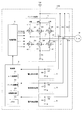
2 駆動回路
3 制御部
4、5、6 電圧検出回路(第1電圧検出手段)
7 電圧検出回路(第2電圧検出手段)
33 故障検出部(故障検出手段)
100 モータ駆動装置(負荷駆動装置)
a1、b1、c1 上アーム
a2、b2、c2 下アーム
D1〜D6 ダイオード
Q1〜Q6 スイッチング素子
Vd 電源
M モータ(負荷)
Claims (4)
- 3相以上の複数相の各相ごとに設けられた上下一対のアームを有し、各相の上アームと下アームのそれぞれにスイッチング素子が設けられたインバータ回路と、
前記各スイッチング素子のオン・オフを制御する制御部と、を備え、
前記各スイッチング素子には、電源に対して逆方向となるようにダイオードが並列に接続されており、
前記各スイッチング素子のオン・オフに基づいて、電源から前記インバータ回路を介して負荷に電流が供給される負荷駆動装置において、
前記スイッチング素子の故障、および当該スイッチング素子に並列接続された前記ダイオードの故障を検出する故障検出手段をさらに備え、
前記制御部は、
前記故障検出手段が、ある相の上下いずれかのアームに設けられたスイッチング素子が導通しない故障を検出し、かつ、当該スイッチング素子に並列接続された前記ダイオードが導通しない故障を検出しなかった場合は、前記故障したスイッチング素子と対をなす当該相のスイッチング素子、および他の相の各スイッチング素子をそれぞれオン・オフ制御し、
前記故障検出手段が、ある相の上下いずれかのアームに設けられたスイッチング素子が導通しない故障を検出し、かつ、当該スイッチング素子に並列接続された前記ダイオードが導通しない故障を検出した場合は、前記故障したスイッチング素子と対をなす当該相のスイッチング素子をオフ状態に維持するとともに、他の相の各スイッチング素子をオン・オフ制御することを特徴とする負荷駆動装置。 - 請求項1に記載の負荷駆動装置において、
前記負荷の端子電圧を検出する第1電圧検出手段をさらに備え、
前記故障検出手段は、前記インバータ回路が力行状態から回生状態に切り替わったタイミングで、前記第1電圧検出手段により検出された電圧が閾値電圧を超えるサージ電圧か否かを判定し、前記電圧がサージ電圧である場合に、前記スイッチング素子と、当該スイッチング素子に並列接続された前記ダイオードとが共に故障したと判定することを特徴とする負荷駆動装置。 - 請求項2に記載の負荷駆動装置において、
前記故障検出手段は、前記タイミングで検出された前記負荷の端子電圧をサージ電圧と判定した回数が所定回数連続した場合に、前記スイッチング素子と、当該スイッチング素子に並列接続された前記ダイオードとが共に故障したと判定することを特徴とする負荷駆動装置。 - 請求項1ないし請求項3のいずれかに記載の負荷駆動装置において、
前記スイッチング素子の両端の電圧を検出する第2電圧検出手段をさらに備え、
前記故障検出手段は、前記制御部が前記スイッチング素子をオン制御している状態で、前記第2電圧検出手段により検出された当該スイッチング素子の両端の電圧が所定値以上である場合に、当該スイッチング素子が故障したと判定することを特徴とする負荷駆動装置。
Priority Applications (4)
| Application Number | Priority Date | Filing Date | Title |
|---|---|---|---|
| JP2014068066A JP6150757B2 (ja) | 2014-03-28 | 2014-03-28 | 負荷駆動装置 |
| US14/669,384 US9543857B2 (en) | 2014-03-28 | 2015-03-26 | Load driving device with failure detection |
| CN201510142090.2A CN104953906B (zh) | 2014-03-28 | 2015-03-27 | 负载驱动装置 |
| DE102015205627.9A DE102015205627B4 (de) | 2014-03-28 | 2015-03-27 | Lastantriebsgerät |
Applications Claiming Priority (1)
| Application Number | Priority Date | Filing Date | Title |
|---|---|---|---|
| JP2014068066A JP6150757B2 (ja) | 2014-03-28 | 2014-03-28 | 負荷駆動装置 |
Publications (2)
| Publication Number | Publication Date |
|---|---|
| JP2015192526A JP2015192526A (ja) | 2015-11-02 |
| JP6150757B2 true JP6150757B2 (ja) | 2017-06-21 |
Family
ID=54067177
Family Applications (1)
| Application Number | Title | Priority Date | Filing Date |
|---|---|---|---|
| JP2014068066A Active JP6150757B2 (ja) | 2014-03-28 | 2014-03-28 | 負荷駆動装置 |
Country Status (4)
| Country | Link |
|---|---|
| US (1) | US9543857B2 (ja) |
| JP (1) | JP6150757B2 (ja) |
| CN (1) | CN104953906B (ja) |
| DE (1) | DE102015205627B4 (ja) |
Families Citing this family (14)
| Publication number | Priority date | Publication date | Assignee | Title |
|---|---|---|---|---|
| JP6150757B2 (ja) | 2014-03-28 | 2017-06-21 | オムロンオートモーティブエレクトロニクス株式会社 | 負荷駆動装置 |
| US10574172B2 (en) * | 2016-03-04 | 2020-02-25 | Nidec Corporation | Power conversion device, motor drive unit, and electric power steering device |
| GB2557295B (en) * | 2016-12-05 | 2022-07-20 | Trw Ltd | Control for electric power steering |
| JP6822907B2 (ja) * | 2017-06-26 | 2021-01-27 | 株式会社東芝 | 半導体装置、電力変換装置、駆動装置、車両、及び、昇降機 |
| CN109143109A (zh) * | 2017-06-26 | 2019-01-04 | 蔚来汽车有限公司 | 电动车辆逆变器故障检测及处理方法、装置及存储介质 |
| WO2019058672A1 (ja) * | 2017-09-25 | 2019-03-28 | 日本電産株式会社 | 故障診断方法、モータ制御方法、電力変換装置、モータモジュールおよび電動パワーステアリング装置 |
| WO2019058671A1 (ja) * | 2017-09-25 | 2019-03-28 | 日本電産株式会社 | 故障診断方法、モータ制御方法、電力変換装置、モータモジュールおよび電動パワーステアリング装置 |
| JP6770986B2 (ja) * | 2018-03-06 | 2020-10-21 | 日本電産モビリティ株式会社 | 誘導性負荷制御装置 |
| JP2019187187A (ja) * | 2018-04-17 | 2019-10-24 | 日本電産エレシス株式会社 | インバータ回路の故障診断方法 |
| DE102018006382A1 (de) * | 2018-08-11 | 2020-02-13 | Diehl Ako Stiftung & Co. Kg | Verfahren zum Erkennen eines Isolationsfehlers an einer Motoranordnung, Verfahren zum Erkennen einer Motorphasenunterbrechung an einer Motoranordnung und Antriebsschaltung zum Antreiben eines elektronisch kommutierten Motors |
| JP2020182308A (ja) * | 2019-04-25 | 2020-11-05 | 三菱電機株式会社 | 電力変換器 |
| DE102019216139A1 (de) * | 2019-09-25 | 2021-03-25 | Continental Teves Ag & Co. Ohg | Verfahren zum Betreiben eines Treiberschaltkreises für einen Elektromotor, Treiberschaltkreis, Motoranordnung und Speichermedium |
| EP4091241A1 (de) | 2020-01-13 | 2022-11-23 | KK Wind Solutions A/S | Verfahren zum phasengetrennten überstromschutz einer dreiphasigen brückenschaltung |
| US11211928B1 (en) * | 2021-02-01 | 2021-12-28 | Infineon Technologies Ag | Apparatus and method for power switch status check |
Family Cites Families (26)
| Publication number | Priority date | Publication date | Assignee | Title |
|---|---|---|---|---|
| JPH04210779A (ja) * | 1990-12-14 | 1992-07-31 | Mitsubishi Electric Corp | インバータ装置の地絡検出器及び地絡検出方法 |
| JP2719859B2 (ja) * | 1991-11-05 | 1998-02-25 | 富士通株式会社 | モータ駆動装置およびモータ駆動装置の異常検出方法 |
| JPH07163155A (ja) * | 1993-12-01 | 1995-06-23 | Hitachi Ltd | インバータ装置の故障予知装置 |
| JP2004236371A (ja) * | 2003-01-28 | 2004-08-19 | Hitachi Ltd | インバータを用いる電動機制御装置 |
| JP2005094873A (ja) | 2003-09-16 | 2005-04-07 | Nissan Motor Co Ltd | 3相交流電動機の制御装置 |
| JP4498353B2 (ja) | 2004-03-19 | 2010-07-07 | 三菱電機株式会社 | 電動機制御装置 |
| KR200409218Y1 (ko) * | 2005-12-02 | 2006-02-22 | 엘에스산전 주식회사 | 인버터 |
| JP4757815B2 (ja) * | 2007-03-05 | 2011-08-24 | 本田技研工業株式会社 | 電動機の制御装置および車両 |
| EP2164169B1 (en) * | 2007-04-16 | 2017-08-09 | Mitsubishi Electric Corporation | Electric motor control apparatus |
| JP2009071975A (ja) | 2007-09-13 | 2009-04-02 | Daikin Ind Ltd | インバータ装置及びそれを用いたパワーステアリング装置 |
| JP5146133B2 (ja) * | 2008-06-18 | 2013-02-20 | 株式会社ジェイテクト | モータ制御装置及び電動パワーステアリング装置 |
| JP2010119268A (ja) * | 2008-11-14 | 2010-05-27 | Toyota Motor Corp | インバータの異常検出装置および異常検出方法 |
| AU2009342065B2 (en) | 2009-03-11 | 2015-07-16 | Abb Technology Ag | A modular voltage source converter |
| JP5402403B2 (ja) * | 2009-08-28 | 2014-01-29 | 日産自動車株式会社 | 電動機制御システム |
| JP4998836B2 (ja) * | 2009-09-30 | 2012-08-15 | 株式会社デンソー | 多相回転機の制御装置、および、これを用いた電動パワーステアリング装置 |
| DE102009045351A1 (de) | 2009-10-06 | 2011-04-14 | Robert Bosch Gmbh | Verfahren zum Betreiben eines Antriebsaggregats sowie Antriebsaggregat |
| JP5083305B2 (ja) * | 2009-12-24 | 2012-11-28 | 株式会社デンソー | 電動機駆動装置、および、これを用いた電動パワーステアリング装置 |
| WO2011122482A1 (ja) * | 2010-03-29 | 2011-10-06 | 株式会社ジェイテクト | モータ制御装置 |
| DE102010030856A1 (de) * | 2010-07-02 | 2012-01-05 | Robert Bosch Gmbh | Verfahren zum Betrieb einer als Antriebsaggregat in einem Kraftfahrzeug dienenden mindestens dreiphasigen elektrischen Maschine und Steuergerät für einen Wechselrichter |
| JP5726012B2 (ja) * | 2011-08-02 | 2015-05-27 | オムロンオートモーティブエレクトロニクス株式会社 | モータ制御装置 |
| JP5436592B2 (ja) * | 2012-02-07 | 2014-03-05 | 三菱電機株式会社 | モータ制御装置、モータ制御装置に適用される電流制御方法、およびモータ制御装置を用いた電動パワーステアリング装置 |
| US20130285584A1 (en) * | 2012-04-27 | 2013-10-31 | Samsung Electro-Mechanics Co., Ltd. | Motor driving apparatus and method |
| US8872455B2 (en) * | 2012-05-22 | 2014-10-28 | Deere & Company | Method and controller for an electric motor with fault detection |
| JP6050643B2 (ja) | 2012-09-24 | 2016-12-21 | アルインコ株式会社 | 断線検知回路及び方法、無線送受信装置並びに電子機器 |
| US9698654B2 (en) * | 2013-09-25 | 2017-07-04 | Silicon Laboratories Inc. | Soft shutdown for isolated drivers |
| JP6150757B2 (ja) | 2014-03-28 | 2017-06-21 | オムロンオートモーティブエレクトロニクス株式会社 | 負荷駆動装置 |
-
2014
- 2014-03-28 JP JP2014068066A patent/JP6150757B2/ja active Active
-
2015
- 2015-03-26 US US14/669,384 patent/US9543857B2/en not_active Expired - Fee Related
- 2015-03-27 DE DE102015205627.9A patent/DE102015205627B4/de not_active Expired - Fee Related
- 2015-03-27 CN CN201510142090.2A patent/CN104953906B/zh not_active Expired - Fee Related
Also Published As
| Publication number | Publication date |
|---|---|
| CN104953906B (zh) | 2017-12-19 |
| DE102015205627B4 (de) | 2021-07-01 |
| US20150280609A1 (en) | 2015-10-01 |
| DE102015205627A1 (de) | 2015-10-01 |
| CN104953906A (zh) | 2015-09-30 |
| US9543857B2 (en) | 2017-01-10 |
| JP2015192526A (ja) | 2015-11-02 |
Similar Documents
| Publication | Publication Date | Title |
|---|---|---|
| JP6150757B2 (ja) | 負荷駆動装置 | |
| US10998842B2 (en) | Power conversion device, motor drive unit, and electric power steering device | |
| JP5579495B2 (ja) | モータ駆動装置 | |
| US9793849B2 (en) | Inverter apparatus for polyphase AC motor drive | |
| JP5751152B2 (ja) | インバータ用短絡故障検出装置及びモータ制御装置 | |
| JP5606506B2 (ja) | 駆動制御装置及び駆動制御方法 | |
| US10742137B2 (en) | Power conversion device, motor drive unit, and electric power steering device | |
| JP2011244611A (ja) | モータ駆動装置 | |
| JP7014183B2 (ja) | 電力変換装置、モータ駆動ユニットおよび電動パワーステアリング装置 | |
| JPWO2018163591A1 (ja) | 電力変換装置、モータ駆動ユニットおよび電動パワーステアリング装置 | |
| JP2011067065A (ja) | モータ駆動装置 | |
| CN106031021A (zh) | 电动机的驱动控制装置及驱动控制方法 | |
| JP2016165199A (ja) | インバータの故障診断装置及び故障診断方法 | |
| JP2016019385A (ja) | モータ装置 | |
| US20200274461A1 (en) | Electric power conversion device, motor driver, and electric power steering device | |
| US20200021205A1 (en) | Electric power conversion apparatus, motor drive unit and electric motion power steering apparatus | |
| US10833614B2 (en) | Motor drive device and electric power steering device | |
| US10829147B2 (en) | Power conversion device, motor drive unit, and electric power steering device | |
| JP2015089294A (ja) | 負荷駆動装置 | |
| WO2015019786A1 (ja) | 電動モータの制御装置及び制御方法 | |
| JP2010028984A (ja) | 電力変換器 | |
| JPWO2018180238A1 (ja) | 電力変換装置、モータ駆動ユニットおよび電動パワーステアリング装置 | |
| JP6131874B2 (ja) | インバータ回路の故障検出方法、駆動装置及びモータ駆動システム | |
| US20190315388A1 (en) | Power conversion device, motor drive unit, and electric power steering device | |
| JP2019134550A (ja) | モータ制御装置 |
Legal Events
| Date | Code | Title | Description |
|---|---|---|---|
| A621 | Written request for application examination |
Free format text: JAPANESE INTERMEDIATE CODE: A621 Effective date: 20160715 |
|
| TRDD | Decision of grant or rejection written | ||
| A01 | Written decision to grant a patent or to grant a registration (utility model) |
Free format text: JAPANESE INTERMEDIATE CODE: A01 Effective date: 20170518 |
|
| A977 | Report on retrieval |
Free format text: JAPANESE INTERMEDIATE CODE: A971007 Effective date: 20170517 |
|
| A61 | First payment of annual fees (during grant procedure) |
Free format text: JAPANESE INTERMEDIATE CODE: A61 Effective date: 20170523 |
|
| R150 | Certificate of patent or registration of utility model |
Ref document number: 6150757 Country of ref document: JP Free format text: JAPANESE INTERMEDIATE CODE: R150 |
|
| R250 | Receipt of annual fees |
Free format text: JAPANESE INTERMEDIATE CODE: R250 |
|
| R250 | Receipt of annual fees |
Free format text: JAPANESE INTERMEDIATE CODE: R250 |
|
| R250 | Receipt of annual fees |
Free format text: JAPANESE INTERMEDIATE CODE: R250 |
|
| R250 | Receipt of annual fees |
Free format text: JAPANESE INTERMEDIATE CODE: R250 |
|
| R250 | Receipt of annual fees |
Free format text: JAPANESE INTERMEDIATE CODE: R250 |