JP2009500542A - Ceiling formwork system - Google Patents
Ceiling formwork system Download PDFInfo
- Publication number
- JP2009500542A JP2009500542A JP2008518739A JP2008518739A JP2009500542A JP 2009500542 A JP2009500542 A JP 2009500542A JP 2008518739 A JP2008518739 A JP 2008518739A JP 2008518739 A JP2008518739 A JP 2008518739A JP 2009500542 A JP2009500542 A JP 2009500542A
- Authority
- JP
- Japan
- Prior art keywords
- longitudinal
- beams
- lattice
- correction
- vertical
- Prior art date
- Legal status (The legal status is an assumption and is not a legal conclusion. Google has not performed a legal analysis and makes no representation as to the accuracy of the status listed.)
- Granted
Links
- 238000009415 formwork Methods 0.000 title claims abstract description 62
- 230000002093 peripheral effect Effects 0.000 claims description 34
- 238000000034 method Methods 0.000 description 13
- 239000011120 plywood Substances 0.000 description 9
- 238000009434 installation Methods 0.000 description 6
- 238000010586 diagram Methods 0.000 description 2
- 230000008878 coupling Effects 0.000 description 1
- 238000010168 coupling process Methods 0.000 description 1
- 238000005859 coupling reaction Methods 0.000 description 1
- 238000003780 insertion Methods 0.000 description 1
- 230000037431 insertion Effects 0.000 description 1
- 239000002023 wood Substances 0.000 description 1
Images


Classifications
-
- E—FIXED CONSTRUCTIONS
- E04—BUILDING
- E04G—SCAFFOLDING; FORMS; SHUTTERING; BUILDING IMPLEMENTS OR AIDS, OR THEIR USE; HANDLING BUILDING MATERIALS ON THE SITE; REPAIRING, BREAKING-UP OR OTHER WORK ON EXISTING BUILDINGS
- E04G11/00—Forms, shutterings, or falsework for making walls, floors, ceilings, or roofs
- E04G11/36—Forms, shutterings, or falsework for making walls, floors, ceilings, or roofs for floors, ceilings, or roofs of plane or curved surfaces end formpanels for floor shutterings
- E04G11/48—Supporting structures for shutterings or frames for floors or roofs
- E04G11/50—Girders, beams, or the like as supporting members for forms
- E04G11/54—Girders, beams, or the like as supporting members for forms of extensible type, with or without adjustable supporting shoes, fishplates, or the like
-
- E—FIXED CONSTRUCTIONS
- E04—BUILDING
- E04G—SCAFFOLDING; FORMS; SHUTTERING; BUILDING IMPLEMENTS OR AIDS, OR THEIR USE; HANDLING BUILDING MATERIALS ON THE SITE; REPAIRING, BREAKING-UP OR OTHER WORK ON EXISTING BUILDINGS
- E04G11/00—Forms, shutterings, or falsework for making walls, floors, ceilings, or roofs
- E04G11/36—Forms, shutterings, or falsework for making walls, floors, ceilings, or roofs for floors, ceilings, or roofs of plane or curved surfaces end formpanels for floor shutterings
- E04G11/38—Forms, shutterings, or falsework for making walls, floors, ceilings, or roofs for floors, ceilings, or roofs of plane or curved surfaces end formpanels for floor shutterings for plane ceilings of concrete
-
- E—FIXED CONSTRUCTIONS
- E04—BUILDING
- E04G—SCAFFOLDING; FORMS; SHUTTERING; BUILDING IMPLEMENTS OR AIDS, OR THEIR USE; HANDLING BUILDING MATERIALS ON THE SITE; REPAIRING, BREAKING-UP OR OTHER WORK ON EXISTING BUILDINGS
- E04G11/00—Forms, shutterings, or falsework for making walls, floors, ceilings, or roofs
- E04G11/36—Forms, shutterings, or falsework for making walls, floors, ceilings, or roofs for floors, ceilings, or roofs of plane or curved surfaces end formpanels for floor shutterings
- E04G11/48—Supporting structures for shutterings or frames for floors or roofs
- E04G11/50—Girders, beams, or the like as supporting members for forms
- E04G11/52—Girders, beams, or the like as supporting members for forms of several units arranged one after another
Landscapes
- Engineering & Computer Science (AREA)
- Architecture (AREA)
- Mechanical Engineering (AREA)
- Civil Engineering (AREA)
- Structural Engineering (AREA)
- Forms Removed On Construction Sites Or Auxiliary Members Thereof (AREA)
- Rod-Shaped Construction Members (AREA)
- Joining Of Building Structures In Genera (AREA)
Abstract
本発明は、数個の格子要素を備え、これらの格子要素のそれぞれが、複数の平行な縦梁と、垂直支柱に取付または配置することができ、かつ縦梁に垂直に延びる、少なくとも1つの横梁と、から成る天井型枠システムに関する。格子要素の縦梁および横梁は、互いに堅固に連結される。標準格子要素は、縦梁の両端の領域に2つの横梁を備えており、横補正格子要素は、標準格子要素に対して内側にオフセットされた2つの横梁を備える。The present invention comprises several grid elements, each of these grid elements being attached to or arranged on a plurality of parallel longitudinal beams and vertical struts and extending perpendicular to the longitudinal beams. The present invention relates to a ceiling formwork system comprising a horizontal beam. The longitudinal and transverse beams of the lattice element are firmly connected to each other. The standard lattice element includes two transverse beams in the regions at both ends of the longitudinal beam, and the lateral correction lattice element includes two transverse beams offset inward with respect to the standard lattice element.
Description
本発明は、複数の格子要素を備え、これらの格子要素のそれぞれが、互いに平行に延びる複数の縦梁と、垂直支柱上に取付または配置することができ、かつ縦梁を横切って延びる少なくとも1つの横梁と、から成るスラブ型枠システムに関する。 The present invention comprises a plurality of grid elements, each of these grid elements being mounted or arranged on a vertical column with a plurality of longitudinal beams extending parallel to each other and at least one extending across the longitudinal beams. It relates to a slab formwork system consisting of two transverse beams.
このタイプのスラブ型枠システムは、独国特許出願公開第DE 102 34 445 A1明細書より知られている。このシステムにおいては、互いに平行に延びる複数の縦梁は、縦梁の相対的な位置が互いに固定されるように、縦梁の下側に設けられたレールによって互いに接続されて格子要素を形成する。このレールは、縦梁の端面の端部から比較的長い距離を置いて設けられる。 A slab formwork system of this type is known from German Offenlegungsschrift DE 102 34 445 A1. In this system, a plurality of longitudinal beams extending in parallel to each other are connected to each other by rails provided on the lower side of the longitudinal beams so that the relative positions of the longitudinal beams are fixed to each other to form a lattice element. . This rail is provided at a relatively long distance from the end of the end face of the longitudinal beam.
既知のスラブ型枠システムの組立においては、最初に、横梁を垂直支柱上に設置する。この横梁において横梁に垂直に延びる複数の縦梁を有する格子梁を形成し、この格子梁は、これらの縦梁と、これらの縦梁の下側に位置するレールと、を備える。これらの縦梁とレールが同様に上方から横梁に設置される。縦梁が横梁に固定して接続されず、レールが、縦梁の端面の端部から離間して設けられるという事実から見て、各場合において、格子要素の縦梁の部分が、共に噛み合う格子要素の2つの縦梁間に位置し、縦方向に隣り合う格子要素が互いに噛み合うことは可能である。この方法においては、縦補正は、前述のように格子要素が噛み合うことによって行うことができる。つまり、このスラブ型枠システムでは、個々の寸法は、縦梁の縦方向で適合させることができ、これらの個々の寸法は、格子要素の格子寸法とは別に選択することができる。 In the assembly of the known slab formwork system, the cross beam is first installed on a vertical column. A lattice beam having a plurality of longitudinal beams extending perpendicularly to the transverse beam is formed in the transverse beam, and the lattice beam includes these longitudinal beams and a rail positioned below the longitudinal beams. These vertical beams and rails are similarly installed on the horizontal beams from above. From the fact that the longitudinal beam is not fixedly connected to the transverse beam and the rail is provided at a distance from the end of the end face of the longitudinal beam, in each case the lattice element's longitudinal beam part meshes together. It is possible for lattice elements located between two longitudinal beams of an element and adjacent in the longitudinal direction to mesh with each other. In this method, the vertical correction can be performed by meshing the lattice elements as described above. That is, in this slab formwork system, the individual dimensions can be adapted in the longitudinal direction of the longitudinal beam, and these individual dimensions can be selected separately from the grid dimensions of the grid elements.
本発明の目的は、スラブ型枠が、縦梁方向に個々のサイズに適合させることができるだけでなく、縦梁に垂直な方向にも適合させることができ、特に、できるだけ早く、容易で、安全なスラブ型枠システムの組立および分解を保証することができるスラブ型枠システムを開発することである。 The object of the present invention is that the slab formwork can be adapted not only to the individual size in the longitudinal beam direction but also to the direction perpendicular to the longitudinal beam, in particular as fast, easy and safe as possible Is to develop a slab formwork system that can guarantee the assembly and disassembly of a new slab formwork system.
この目的は、本発明による請求項1の特徴、特に、格子要素の縦梁および横梁が、互いに堅固に連結され、標準格子要素は、縦梁の両端部の領域に設けられた2つの横梁を有しており、横補正格子要素は、標準格子要素と比較して内側にオフセットして配置された1つまたは2つの横梁を有するという特徴によって満足される。
This object is achieved by the features of
従って、本発明によると、格子要素の縦梁は、既知の方法を用いて個別のレールによって互いに連結されるのではなく、格子要素の縦梁の連結は、縦梁に固定的に連結された1つまたは複数の横梁によって直接実現され、垂直支柱上への配置または取付に適している。従って、この点において、本発明によると、横梁および縦梁が、それぞれ、互いに固く連結されたユニットすなわち格子要素を形成するので、横梁および縦梁を別々に取り扱う必要がなく、既知のスラブ型枠システムと比べて取り扱う部品数が少なくなる。 Thus, according to the invention, the longitudinal beams of the lattice elements are not connected to each other by individual rails using known methods, but the connection of the longitudinal beams of the lattice elements is fixedly connected to the longitudinal beams. It is realized directly by one or more cross beams and is suitable for placement or mounting on a vertical column. Therefore, in this respect, according to the present invention, the transverse beam and the longitudinal beam respectively form a unit or lattice element that is rigidly connected to each other, so that it is not necessary to handle the transverse beam and the longitudinal beam separately, and the known slab formwork The number of parts handled is reduced compared to the system.
さらに、本発明によるシステムの型枠では、少なくとも2つの異なる実施形態の格子要素が利用可能であり、前述の横補正格子要素と同様に、上に定義した標準格子要素と共に本明細書において詳細に実現される。全方向のサイズが標準格子要素の各格子寸法の整数倍に一致するスラブ型枠システムの設置において、互いに噛み合わない標準格子要素のみを用いることは可能である。しかし、例えば、格子寸法の外側に、縦梁に垂直に延びる方向に個々に寸法を作る必要がある場合、本発明によると、標準格子要素に加えて横補正格子要素も用いられる。この横補正格子要素は、1つまたは複数の横梁が、標準格子要素より内側にオフセットして配置されるという点で標準格子要素と異なる。この驚くほど簡単な方法によって、1つまたは複数の横補正格子要素の外側の縦梁が、それぞれ、標準格子要素の隣り合う2つの縦梁の間に位置するように、標準格子要素および横補正格子要素が互いに噛み合うことが可能になる。この場合、標準格子要素の縦梁と横補正格子要素の縦梁は全て、互いに平行に延び、縦方向を横切る方向に互いに離間して配置されるか、または縦方向の側面で互いに隣接して配置される。従って、横補正格子要素のそれぞれ所望の数の縦梁を、標準格子要素のそれぞれ隣り合う2つの縦梁の間に位置させることによって、縦梁に垂直に延びる横方向において、格子寸法に拘束されることなく、かつ個々に連続的に調整可能な寸法を実現することができる。標準格子要素と、横補正格子要素と、に互いに別々に横梁を取り付けることによって、互いに噛み合う標準格子要素および横補正格子要素の横梁同士が衝突しないことが保証される。互いに噛み合う全ての格子要素の横梁は、互いに垂直方向に離間して延びるか、互いに接触して延びる。 In addition, in the formwork of the system according to the invention, at least two different embodiments of the grid elements are available, as well as the previously described lateral correction grid elements, in detail here together with the standard grid elements defined above. Realized. In the installation of a slab formwork system in which the omnidirectional sizes coincide with integer multiples of the respective grid dimensions of the standard grid elements, it is possible to use only standard grid elements that do not mesh with each other. However, for example, if it is necessary to make the dimensions individually in the direction extending perpendicular to the longitudinal beam outside the grid dimensions, according to the invention, lateral correction grid elements are also used in addition to the standard grid elements. This lateral correction grid element differs from the standard grid element in that one or more horizontal beams are arranged offset inside the standard grid element. With this surprisingly simple method, the standard grid element and the lateral correction are arranged such that the longitudinal beam outside the one or more lateral correction grid elements is located between two adjacent longitudinal beams of the standard grid element, respectively. The lattice elements can be engaged with each other. In this case, the longitudinal beams of the standard lattice elements and the transverse beams of the lateral correction lattice elements all extend parallel to each other and are spaced apart from each other in the direction transverse to the longitudinal direction, or adjacent to each other on the longitudinal sides. Be placed. Therefore, by placing each desired number of longitudinal beams of the lateral correction grid element between two adjacent longitudinal beams of the standard grid element, the lateral dimension extending perpendicular to the longitudinal beam is constrained to the grid dimensions. And dimensions that can be adjusted individually and continuously. By attaching the transverse beams separately to the standard lattice element and the lateral correction lattice element, it is ensured that the transverse beams of the standard lattice element and the lateral correction lattice element that mesh with each other do not collide with each other. The cross beams of all lattice elements that mesh with each other extend vertically apart from each other or in contact with each other.
標準格子要素の縦梁は、横補正格子要素の縦梁と同じ長さを有することが好ましい。しかし、スラブ型枠システムの型枠内で、寸法が互いに異なる2つまたはそれ以上の種類つまりタイプの格子要素を容易に用いることができる。例えば、標準格子要素と、この標準格子要素の縦梁と同じ寸法の縦梁を有する少なくとも対応する横補正格子要素と、が各種類に関して存在する。例えば、2つの異なる種類の標準格子要素と、これに対応して形成された横補正格子要素と、を用いるこのタイプのシステムを図の記述の型枠内でより詳細に記述する。 The longitudinal beam of the standard lattice element preferably has the same length as the longitudinal beam of the lateral correction lattice element. However, within the formwork of the slab formwork system, two or more types or types of grid elements with different dimensions can be easily used. For example, a standard grid element and at least a corresponding lateral correction grid element having a vertical beam of the same dimensions as the vertical beam of this standard grid element exist for each type. For example, this type of system using two different types of standard grid elements and correspondingly formed lateral correction grid elements will be described in more detail within the form of the figure description.
あるタイプの標準格子要素の縦梁が、同じタイプの横補正格子要素の縦梁と同じ長さを有する場合、既に設置された標準格子要素に横補正格子要素を下から直線的に案内することは不可能であり、純粋に直線的に動く型枠内で標準格子要素と噛み合うことも不可能である。というのは、この場合、横補正格子要素の縦梁の両端部が、標準格子要素の横梁と衝突してしまうからである。この場合、本発明による横補正格子要素では、下から標準格子要素に「通す」。すなわち、最初に、横補正格子要素のそれぞれ所望の数の縦梁の一方の端面の端部を標準格子要素の各縦梁の間を通して下から案内し、標準格子要素の1つの横梁の上に位置するように内側から外側に移動させる。次に、横補正格子要素の縦梁の他方の端部が、標準格子要素の他方の横梁の上まで上昇して、この横梁で支持されることができるまで、この動きを縦梁の方向に続ける。この「通す」プロセスを、図の記述の型枠内でより詳しく説明する。 If a vertical beam of one type of standard grid element has the same length as the vertical beam of the same type of horizontal correction grid element, the horizontal correction grid element should be guided linearly from below to the already installed standard grid element. Is impossible, and it is impossible to mesh with standard grid elements in a form that moves purely linearly. This is because in this case, both ends of the longitudinal beam of the lateral correction lattice element collide with the lateral beam of the standard lattice element. In this case, the lateral correction grid element according to the invention “passes” through the standard grid element from below. That is, first, the end of one end face of each desired number of longitudinal beams of each of the lateral correction lattice elements is guided from below through each longitudinal beam of the standard lattice element, and is placed on one lateral beam of the standard lattice element. Move from inside to outside to be positioned. Next, move this motion in the direction of the longitudinal beam until the other end of the longitudinal beam of the laterally corrected lattice element rises above the other lateral beam of the standard lattice element and can be supported by this transverse beam. to continue. This “pass through” process will be described in more detail within the figure description form.
格子要素の隣り合う縦梁の間隔が多くとも20cmに達すると、さらに有利である。この間隔にすると、取り付けを行う人が隣り合う2つの縦梁間から落下することを最大限の安全性を持って回避することができ、本発明による組み立てられた格子要素が、落下に対して信頼できる安全性を備えることを示す。しかし、横補正格子要素の縦梁が標準格子要素の隣り合う2つの縦梁間を通ることができるように、隣り合う縦梁の間隔は、縦梁の幅と少なくとも同じ長さでなければならない。格子要素の隣り合う縦梁の間隔は、縦梁の幅の少なくとも2倍または3倍に達することが特に好ましい。この場合、縦補正格子要素および/または縦横補正格子要素と、さらに共働することが可能である。これに関しては、以下に、より詳細に考察する。通常は、隣り合う縦梁の間隔を縦梁の幅の少なくとも5倍まで増やすことも可能である。このように、全ての利用できる格子要素のさらなる組合せの可能性が実現する。 It is further advantageous if the spacing between adjacent longitudinal beams of the lattice element reaches at most 20 cm. With this spacing, it is possible to avoid with maximum safety that the person performing the installation falls from between two adjacent longitudinal beams, and the assembled grid element according to the invention is reliable against the fall. It shows that it has the safety that can be done. However, the spacing between adjacent longitudinal beams must be at least as long as the width of the longitudinal beams so that the longitudinal beams of the lateral correction lattice element can pass between two adjacent longitudinal beams of the standard lattice element. It is particularly preferred that the spacing between adjacent longitudinal beams of the lattice element reaches at least twice or three times the width of the longitudinal beam. In this case, it is possible to further cooperate with the vertical correction lattice element and / or the vertical and horizontal correction lattice element. This will be discussed in more detail below. Usually, it is possible to increase the interval between adjacent longitudinal beams to at least 5 times the width of the longitudinal beams. In this way, the possibility of further combinations of all available grid elements is realized.
本発明によるスラブ型枠システムの型枠内で、標準格子要素および横補正格子要素に加えて、縦梁の両端部の領域の一方に1つまたは複数の横梁を有する前述の縦補正格子要素も利用できるようにすると特に好ましい。そうすると、スラブ型枠システムは、格子寸法に拘束されず、縦梁方向に個々に連続的に調整可能な寸法を有する縦補正格子要素を用いて組み立てることもできる。詳細には、1つまたは複数の横梁を縦梁の一方の端部領域のみに配置することによって、横梁のない方の縦補正格子要素の側部を押し、これをそれぞれ必要な経路にわたって、標準格子要素の隣り合う2つの縦梁または横補正格子要素の隣り合う2つの縦梁の間に位置させることが可能になる。横梁のない方の縦補正格子要素の端部が、標準格子要素の横梁または横補正格子要素の横梁上に少なくとも位置するまでは押さなければならない。縦補正格子要素は、最大限、これらの1つまたは複数の横梁が、標準格子要素の横梁または横補正格子要素の横梁に当接するまで押されることができる。縦梁の方向にそれぞれ個々の寸法を設定できるように、2つの横梁の取り得る間隔において、段階的にではなく任意の所望の挿入位置を選択することができる。 Within the formwork of the slab formwork system according to the present invention, in addition to the standard lattice element and the lateral correction lattice element, the above-mentioned longitudinal correction lattice element having one or more transverse beams in one of the regions at both ends of the longitudinal beam It is particularly preferable to make it available. The slab formwork system can then be assembled using longitudinal correction grid elements that are not constrained by the grid dimensions and have dimensions that can be individually and continuously adjusted in the longitudinal beam direction. Specifically, by placing one or more transverse beams in only one end region of the longitudinal beam, push the side of the longitudinal correction grid element without the transverse beam, which is standardized over the required path respectively. It is possible to locate between two adjacent longitudinal beams of the lattice element or between two adjacent longitudinal beams of the lateral correction lattice element. It must be pushed until the end of the vertical correction grid element without the cross beam is at least positioned on the cross beam of the standard grid element or the horizontal correction grid element. The longitudinal correction grid elements can be pushed up to a maximum until these one or more cross beams abut against the cross beams of the standard grid elements or the lateral correction grid elements. Any desired insertion position can be selected rather than stepwise in the possible spacing of the two transverse beams so that each dimension can be set in the direction of the longitudinal beam.
標準格子要素および/または標準格子要素に隣接する横補正格子要素が設置されると、縦補正格子要素を挿入することができる。縦補正格子要素の縦梁を内側に向けて、縦補正格子要素の1つまたは複数の横梁を、設置されたスラブ型枠を伴う型枠全体に対して外側に配置することが、この連結においては可能である。しかし、この配置に替えて、縦補正格子要素の縦梁が、設置された位置において、他方の格子要素の横梁から外側に最終的に突出するように、縦補正格子要素の横梁のない前方の端部を他方の格子要素の下側から、その横梁の上に位置するように内側から押し上げることも可能である。 Once a standard grid element and / or a lateral correction grid element adjacent to the standard grid element is installed, a vertical correction grid element can be inserted. In this connection, the longitudinal beam of the longitudinal correction lattice element faces inward and one or more transverse beams of the longitudinal compensation lattice element are arranged outside with respect to the entire formwork with the installed slab formwork. Is possible. However, instead of this arrangement, the longitudinal correction lattice element's longitudinal beam without the transverse beam of the longitudinal correction lattice element is finally projected outwardly from the lateral beam of the other lattice element at the installed position. It is also possible to push the end up from the inside so that it lies above the cross beam from the underside of the other grid element.
縦補正格子要素と比較して内側にオフセットして配置された1つまたは複数の横梁を、縦梁の両端部の領域の一方にのみ有する縦横補正格子要素が、本発明によるスラブ型枠システムの型枠内で利用できるとさらに好ましい。これにより、このタイプの縦横補正格子要素を用いて、横補正および縦補正を同時に行うことができる。これは、図の記述の型枠内で図解する。 A vertical and horizontal correction grid element having one or more horizontal beams arranged offset inward relative to the vertical correction grid element in only one of the regions at both ends of the vertical beam is provided in the slab formwork system according to the present invention. More preferably, it can be used in a mold. Thereby, horizontal correction and vertical correction can be simultaneously performed using this type of vertical and horizontal correction lattice element. This is illustrated in the form of the figure description.
本発明によると、標準格子要素に加えて、横補正格子要素、縦補正格子要素および縦横補正格子要素を用いる場合、横補正格子要素の縦梁と、縦補正格子要素の縦梁と、縦横補正格子要素の縦梁とが、標準格子要素の隣り合う2つの縦梁の間に来る配置が、特定の設置状況と共に存在することがある。この場合、標準格子要素の隣り合う縦梁の間隔は、縦梁の幅の少なくとも3倍に達する必要がある。 According to the present invention, when using a horizontal correction lattice element, a vertical correction lattice element, and a vertical and horizontal correction lattice element in addition to a standard lattice element, the vertical beam of the horizontal correction lattice element, the vertical beam of the vertical correction lattice element, and the vertical and horizontal correction An arrangement in which the grid element longitudinal beams lie between two adjacent longitudinal beams of a standard grid element may exist with certain installation situations. In this case, the interval between adjacent vertical beams of the standard lattice element needs to reach at least three times the width of the vertical beam.
全ての格子要素の隣り合う縦梁は、各場合で、互いに等しく離間すること、および/または全ての格子要素の縦梁は、互いに等しい長さを有すること、が通常好ましい。 It is usually preferred that the adjacent longitudinal beams of all grid elements are in each case equally spaced from each other and / or the longitudinal beams of all grid elements have equal lengths to each other.
隣り合う2つの縦梁の端部領域の間のバルク型枠支柱を縦梁に固定することができると、さらに有利である。これにより、実際の合板に垂直に延びるバルク型枠支柱上にバルク型枠要素を設置することができるので、合板に貼り付けられるコンクリートを受ける領域を結合し、フレームを作ることができる。設置されたスラブ型枠の周縁領域、特に周縁領域の周縁部が、実質的に各周縁領域に垂直に延びる縦梁のみによって形成されていると、このタイプのバルク型枠支柱は、特に簡単に設置することができる。この場合、バルク型枠支柱は、隣り合う縦梁間の任意の所望の位置に設置することができる。 It is further advantageous if the bulk formwork column between the end regions of two adjacent longitudinal beams can be fixed to the longitudinal beam. Thereby, since a bulk formwork element can be installed on a bulk formwork column extending perpendicularly to an actual plywood, a region for receiving the concrete to be affixed to the plywood can be joined to make a frame. This type of bulk formwork column is particularly easy if the peripheral area of the installed slab formwork, in particular the peripheral edge of the peripheral area, is formed only by longitudinal beams extending substantially perpendicular to each peripheral area. Can be installed. In this case, the bulk formwork column can be installed at any desired position between adjacent vertical beams.
少なくとも1つの横補正格子要素の1つの縦梁を、標準格子要素の2つの横梁の間隔より長くするとともに、各横補正格子要素の残りの縦梁を、標準格子要素の2つの横梁の間隔より短い寸法にすることが特に好ましい。横補正格子要素をこのように設計することによって、設置時、横補正格子要素を標準格子要素内に上から完全に通す必要がなくなる。横補正格子要素を長い縦梁を標準格子要素の横梁の上にして実質的に垂直に並ぶように位置させ、次に、横補正格子要素を引き続き連続的に垂直な位置で上方に枢動させ、長い方の縦梁の他方の端部が標準格子要素の他方の横梁の上に位置するように、横補正格子要素を位置させ、結果として、横補正格子要素が、垂直に吊り下げられた形で標準格子要素に連結される。次に、横補正格子要素を枢動させて、実質的に水平位置にすることができる。最後に述べた枢動の手順において、取り付けを行う人が最終的に再び頭上で作業しなければならない端部において、横補正格子要素の重量の大部分が、標準格子要素の横梁によって取り除かれているので、取り付けを行う人にとって取り扱いが大幅に簡単になる。次に、図9〜図12を参照して、この原理をより詳細に説明する。 One longitudinal beam of at least one lateral correction lattice element is made longer than the distance between the two lateral beams of the standard lattice element, and the remaining longitudinal beam of each lateral correction lattice element is made larger than the distance between the two lateral beams of the standard lattice element. It is particularly preferred to have a short dimension. By designing the lateral correction grid element in this way, it is not necessary to pass the lateral correction grid element completely through the standard grid element from above during installation. Position the lateral correction grid element so that the long vertical beam is aligned substantially vertically with the horizontal beam of the standard grid element on top of it, and then continue to pivot the horizontal correction grid element upward in a continuous vertical position. The lateral correction grid element is positioned so that the other end of the longer vertical beam is positioned on the other horizontal beam of the standard grid element, and as a result, the horizontal correction grid element is suspended vertically. Connected to standard grid elements in the form. The lateral correction grid element can then be pivoted to a substantially horizontal position. In the last mentioned pivoting procedure, at the end where the installer must finally work overhead again, most of the weight of the laterally corrected grid element is removed by the transverse beam of the standard grid element. As a result, handling is greatly simplified for the person performing the installation. Next, this principle will be described in more detail with reference to FIGS.
本発明の最後に述べた好ましい実施形態によると、完全に外側にある横補正格子要素の縦梁の1つのみを各横補正格子要素の残りの縦梁より長くすると、さらに有利である。この方法によって、標準格子要素に長い縦梁を通す場合、横補正格子要素を上昇させる高さを可能な限り低くすることができる。 According to the preferred embodiment described at the end of the invention, it is further advantageous if only one of the longitudinal beams of the lateral correction grid elements that are completely outside is longer than the remaining longitudinal beams of each lateral correction grid element. By this method, when a long vertical beam is passed through the standard lattice element, the height for raising the lateral correction lattice element can be made as low as possible.
横補正格子要素の長い縦梁は、両端部の領域で、この長い縦梁に隣接する各横補正格子要素の短い縦梁の両端部から突出することができる。従って、横補正格子要素を水平位置に枢動させる場合、横補正格子要素の残りの短い縦梁は、標準格子要素の横梁と衝突しないことが保証される。 The long vertical beam of the lateral correction lattice element can protrude from both ends of the short vertical beam of each lateral correction lattice element adjacent to the long vertical beam in the region of both ends. Therefore, when the lateral correction grid element is pivoted to a horizontal position, it is ensured that the remaining short vertical beam of the lateral correction grid element does not collide with the horizontal beam of the standard grid element.
横補正格子要素の長い縦梁の縦方向範囲は、標準格子要素の互いに離れた2つの横梁の外側の間隔に実質的に一致させることができる。この方法によって、横補正格子要素の長い縦梁は、組み立てられた状態において、通された標準格子要素の縦梁から突出しないようにすることができる。 The longitudinal extent of the long longitudinal beam of the lateral correction grid element can be substantially matched to the outer spacing of two spaced apart lateral beams of the standard grid element. In this way, the long longitudinal beam of the lateral correction grid element can be prevented from projecting from the longitudinal beam of the passed standard grid element in the assembled state.
長い縦梁は、横補正格子要素の残りの縦梁より、断面が小さく、特に、高さが低くなっており、断面が長方形であることが好ましい。長い縦梁の対角寸法は、残りの縦梁の高さより短いと特に有利である。こうすると、合板が標準格子要素上にあり、横補正格子要素がこの標準格子要素に連結されている、または連結される場合に、横補正格子要素の設置、取り外しが可能になる。すなわち、長い縦梁は、この縦梁の寸法のために、横補正格子要素が枢動する際に、この合板の下側に当接しない。 The long vertical beam has a smaller cross-section than the remaining vertical beams of the lateral correction lattice element, in particular, has a lower height, and preferably has a rectangular cross section. It is particularly advantageous if the diagonal dimension of the long longitudinal beam is shorter than the height of the remaining longitudinal beams. In this way, when the plywood is on the standard grid element and the lateral correction grid element is connected to or connected to the standard grid element, the lateral correction grid element can be installed and removed. That is, the long longitudinal beam does not contact the lower side of the plywood when the lateral correction grid element pivots due to the dimensions of the longitudinal beam.
設置されたスラブ型枠では、各場合において各型枠にある全ての格子要素の横梁は、縦梁の下に配置されることが好ましい。これにより、縦梁の上側が、それぞれ、上方に延びる横梁に設けられる溝、凹み等によって妨げられない滑らかな合板との接触面を形成することが可能になる。従って、本発明によると、縦梁の上面のみが合板との接触面を形成するので、合板と横梁が直接接触することはない。 In the installed slab formwork, in each case it is preferable that the transverse beams of all lattice elements in each formwork are arranged below the longitudinal beam. Thereby, it becomes possible to form the contact surface with the smooth plywood which the upper side of a vertical beam is not obstructed by the groove | channel, dent, etc. which are each provided in the horizontal beam extended upwards. Therefore, according to the present invention, since only the upper surface of the vertical beam forms a contact surface with the plywood, the plywood and the horizontal beam are not in direct contact.
さらに、縦梁の下に横梁を配置することによって、補正格子要素の縦梁を標準格子要素の横梁に設置することができるので、横梁が、下から補正格子要素を支持することが可能になる。 Furthermore, by placing the transverse beam under the longitudinal beam, the longitudinal beam of the correction lattice element can be installed on the transverse beam of the standard lattice element, so that the transverse beam can support the compensation lattice element from below. .
本発明のこれ以外の好ましい実施形態は、請求項に記述する。 Other preferred embodiments of the invention are described in the claims.
本発明を、実施形態を参照して以下に詳細に記述する。 The invention is described in detail below with reference to embodiments.
図1は、互いに平行に延び、かつ互いに離間した6つの縦梁4と、2つの横梁5と、から成る標準格子要素2を示している。2つの横梁5は、縦梁4に垂直に延び、各横梁5は、縦梁4の両端部の領域のそれぞれに固定される。
FIG. 1 shows a
図2は、横補正格子要素6を示す。同様に、横補正格子要素6も互いに平行に延び、かつ互いに離間した6つの縦梁8と、これらの縦梁8に垂直に延びる2つの横梁10と、から成る。しかし、横補正格子要素の横梁10は、図1の標準格子要素2と比較して内側にオフセットして配置されており、この結果、横梁10は、縦梁8の端面の端部領域に位置しない。この横梁10のオフセットは、標準格子要素2の横梁5の幅よりずっと大きい。このオフセットは、横梁5の幅の約3倍(例えば、約13cm)に達することが好ましい。
FIG. 2 shows the lateral correction grid element 6. Similarly, the lateral correction lattice element 6 includes six
図2の配置に替えて、前述の方法で内側にオフセットして配置される1つの横梁のみを設けることも可能である。このような単一の横梁は、特に、縦梁8の中央に設けることもできる。
Instead of the arrangement in FIG. 2, it is also possible to provide only one transverse beam arranged in an offset manner in the above-described manner. Such a single transverse beam can also be provided in the center of the
図3は、縦補正格子要素12を示す。同様に、縦補正格子要素12も互いに平行に延び、かつ互いに離間した6つの縦梁14と、これらの縦梁14に垂直に延びる2つの横梁16と、から成る。しかし、この場合、2つの横梁16は、縦梁14の同じ端面の端部領域に配置され、縦梁14の反対側の端面の端部領域には横梁が存在しない。図3のように2つの横梁16を用いる代わりに、横梁16を1つだけ用いてもよい。しかし、2つの横梁16を用いる実施形態は、縦補正格子要素12の安定性に有利である。
FIG. 3 shows the vertical
隣り合う縦梁4,8,14の互いの間隔は、全ての格子要素2,6,12で同じサイズである。同様に、全ての格子要素2,6,12の縦梁4,8,14は同じ長さである。この結果、各場合において、互いに等しいサイズの面を、それぞれ、格子要素2,6,12の縦梁4,8,14の全体によって覆うことができる。従って、最終的に、格子要素2,6,12は全て、互いに同じサイズを有する。
The interval between the adjacent
格子要素2,6,12における組み立てられた状態の縦梁4,8,14の上面は、最終的に貼り付けられる合板との接触面を形成する。合板は、例えば、木被覆(wood sheathing)から成り、縦梁4,8,14の上面に適切な方法で連結される。
The upper surfaces of the assembled
各開口部分つまり中空部分は、縦梁4,8,14および横梁5,10,16の両方に用いることができ、縦梁4,8,14の全てに同じ断面形状を用いることができる。同様に、特定の断面形状も横梁5,10,16の全てに用いることができる。しかし、縦梁4,8,14の断面形状は、横梁5,10,16の断面形状と異なる場合がある。
Each opening portion or hollow portion can be used for both the
格子要素2,6,12の全てにおいて、横梁5,10,16の各々は、スラブ型枠が完全に組み立てられた状態で縦梁4,8,14の下に位置する。つまり、縦梁4,8,14は、横梁5,10,16と異なる平面に延びるが、これらの2つの平面は、互いに隣り合う。
In all of the
縦梁4,8,14および横梁5,10,16は、互いに、例えば、溶接、ねじ留めまたはリベット留めすることができる。
The
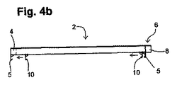
図4aのように、横補正格子要素6を既に設置された標準格子要素2に連結する場合、横補正格子要素6の所望の数の縦梁8を、それぞれ、標準格子要素2の各隣り合う縦梁4の間に、横補正格子要素6の縦梁8に通された端部が標準格子要素2の横梁5の上に位置するまで通す。この位置を図4aに示す。この位置から始めて、横補正格子要素6の縦梁8が標準格子要素2の縦梁4と同じ平面に位置するまで、横梁5の領域に延びる軸を中心に矢印の方向に上方に横補正格子要素6を枢動させることができる。この位置を図4bに示す。2つの格子要素2,6の縦梁4,8が、この組立段階で互いに端部が一致せず、横補正格子要素6の縦梁8の端部が、標準格子要素2の縦梁4の端部から突出することが、図4bより明らかである。
As shown in FIG. 4 a, when the lateral correction lattice element 6 is connected to the already installed
図4bに示された位置から始まって、格子要素2,6の両方における縦梁4,8の端面が図4cに示すように互いに一列に並ぶまで、横補正格子要素6は、図4bの矢印の方向に直線的に動かされる。横補正格子要素6の横梁10を内側にオフセットした配置によって、格子要素2,6の両方の横梁5,10が互いに衝突することなく、図4に関して記述した横補正格子要素6を標準格子要素2に通すことが可能になる。
Starting from the position shown in FIG. 4b, the lateral correction grid element 6 is shown in FIG. 4b until the end faces of the
図5は、サイズの異なる2種類の格子要素を用いる、本発明による完全に組み立てられたスラブ型枠システムの平面図を示す。格子要素の縦梁が互いに異なる長さを有するという点で、一方のサイズの格子要素2,6,12と、他方のサイズの格子要素2’,6’が実現される。具体的には、格子要素2’,6’の縦梁の長さは、格子要素2,6,12の縦梁の長さの約半分である。隣り合う縦梁の間隔は、全ての格子要素2,6,12,2’,6’で同じである。格子要素2,6,12,2’,6’は全て、それぞれ、6つの縦梁を有し、格子要素2,6,12,2’,6’は全て、等しい幅を有する。
FIG. 5 shows a plan view of a fully assembled slab formwork system according to the present invention using two types of grid elements of different sizes. One size of the
図5のスラブ型枠は、壁18に隣接し、この壁18は、それぞれ互いに直角に配置された合計7つの部分から成る。さらに、図示のスラブ型枠システムは、壁18から離間して配置された2つの自立型(freestanding)の柱20,20’に隣接する。
The slab form of FIG. 5 is adjacent to a wall 18, which consists of a total of seven parts, each arranged perpendicular to each other. Furthermore, the illustrated slab formwork system is adjacent to two
図5のスラブ型枠システムの構造をより簡単に説明するために、スラブ型枠システムの互いに隣り合う周縁部分を一連の文字で示し、以下で参照する。 To more easily describe the structure of the slab formwork system of FIG. 5, the adjacent peripheral portions of the slab formwork system are indicated by a series of characters and are referred to below.
図5のスラブ型枠システムのベースは、4×4の配列で配置された互いに隣り合う合計16の標準格子要素2で形成されるので、図5のスラブ型枠システムの表面の大部分を覆う。これらの標準格子要素2の5つは、周縁部分A,Bを形成する。
The base of the slab formwork system of FIG. 5 is formed with a total of 16
周縁部分Cの領域には、縦梁の方向に互いに隣り合う2つの横補正格子要素6が設けられ、それぞれ、図4の横補正格子要素6が標準格子要素2に通されるので標準格子要素2と噛み合う。両方の横補正格子要素6の2つの縦梁は、各標準格子要素2の隣り合う縦梁の間に位置する。
In the region of the peripheral portion C, two lateral correction lattice elements 6 adjacent to each other in the direction of the longitudinal beam are provided, and the lateral correction lattice element 6 of FIG. Mesh with 2 The two longitudinal beams of both lateral correction lattice elements 6 are located between adjacent longitudinal beams of each
周縁部分D,Fは、縦補正格子要素12によって形成され、この縦補正格子要素12は、縦補正格子要素12の縦梁の自由端部が、横補正格子要素6の横梁で支持されるように横補正格子要素6内に挿入される。縦補正格子要素12の3つの縦梁は、横補正格子要素6のそれぞれ隣り合う2つの縦梁の間に位置する。縦補正格子要素12の他の3つの縦梁は、それぞれ、横補正格子要素6の縦梁と、この横補正格子要素6と噛み合う標準格子要素2の縦梁との間に位置し、これらの横梁によって縦補正格子要素12の縦梁は支持される。
The peripheral portions D and F are formed by the vertical
周縁部分Gは、他の縦補正格子要素12によって形成される。この縦補正格子要素12は、2つの縦梁がDの縦補正格子要素12内に押されて、周縁部分で、2つの縦補正格子要素12の横梁が互いに部分的に接触する。周縁部分Gを形成する縦補正格子要素12の自由端部は、周縁部分Cの一部を形成する横補正格子要素6と噛み合う標準格子要素2の横梁で支持される。
The peripheral portion G is formed by other vertical
周縁部分Hは、別の2つの縦補正格子要素12によって形成される。この縦補正格子要素12は、互いに横方向に隣り合う2つの標準格子要素2内に押されて、この縦補正格子要素12の縦梁の大部分が、この縦補正格子要素12が挿入された標準格子要素2の2つの横梁の間に位置する。
The peripheral portion H is formed by two other vertical
別の縦補正格子要素12が比較的短い周縁部分Iを形成し、同様に、別の縦補正格子要素12が周縁部分Kを形成する。周縁部分H,I,Kを形成する縦補正格子要素12の組立において、最初に、周縁部分Kを形成する縦補正格子要素12、次に、周縁部分Iを形成する縦補正格子要素12、最後に、周縁部分Hを形成する2つの縦補正格子要素12を、それぞれ、既に組み立てられた格子要素2に挿入するように進める必要がある。
Another vertical
これまでに説明した周縁部分A〜Kは、第1のタイプの格子要素に属する格子要素2,6,12によって形成される。一方、次に述べる周縁部分L〜Qは、第2のタイプの格子要素に属する格子要素2’,6’によって形成される。第2のタイプの格子要素は、各縦梁の長さを除いては、第1のタイプの格子要素に対応する。第1のタイプの格子要素2,6,12の縦梁は、第2のタイプの格子要素2’,6’の縦梁の約2倍の長さである。
The peripheral portions A to K described so far are formed by the
周縁部分L〜Pを形成する格子要素2’,6’においては、縦梁は、周縁部分A〜Kを形成する格子要素2,6,12の縦梁に垂直に延びる。しかし、格子要素2’,6’は、格子要素2,12に直接隣接するので、第1のタイプの格子要素2,12と、第2のタイプの格子要素2’,6’との間に隙間はない。
In the lattice elements 2 ', 6' forming the peripheral portions L-P, the longitudinal beams extend perpendicular to the longitudinal beams of the
周縁部分Mは、2つの標準格子要素2’によって形成され、各横補正格子要素6’が、この2つの標準格子要素2’のそれぞれに既に説明した方法で通される。周縁部分Lを形成する横補正格子要素6’は、この横補正格子要素6’の3つの縦梁が、標準格子要素2’の各縦梁の間に位置するように対応する標準格子要素2’に通される。一方、概略的に図示した柱20’に隣接する、比較的短い周縁部分Nを形成する横補正格子要素6’は、合計5つの縦梁が標準格子要素2’の各縦梁の間に位置するように配置される。
The peripheral portion M is formed by two standard grid elements 2 ', and each lateral correction grid element 6' is passed through each of the two standard grid elements 2 'in the manner already described. The lateral correction lattice element 6 ′ forming the peripheral portion L has the corresponding
図5に示すスラブ型枠において、格子要素の隣り合う2つの縦梁の間隔は、縦梁の幅の3倍に相当するので、最終的に横補正を細かく調整するために、標準格子要素に通された横補正格子要素を縦梁に垂直に延びる方向に最大で縦梁の幅の2倍だけ移動させることができる。従って、例えば、図5から分かるように、周縁部分Nを形成する横補正格子要素6’の縦梁は、各標準格子要素2’の隣り合う2つの縦梁のほぼ中央に位置し、周縁部分Lを形成する横補正要素6’の縦梁は、関連する標準格子要素2’の各縦梁に直接接触する。
In the slab form shown in FIG. 5, the distance between two adjacent vertical beams of the lattice element is equivalent to three times the width of the vertical beam. Therefore, in order to finely adjust the lateral correction, a standard lattice element is used. The threaded lateral correction grid element can be moved up to twice the width of the longitudinal beam in a direction extending perpendicular to the longitudinal beam. Therefore, for example, as can be seen from FIG. 5, the longitudinal beam of the laterally corrected lattice element 6 ′ forming the peripheral portion N is located substantially at the center of the two adjacent vertical beams of each
周縁部分Pは、横梁が端面に当接する5つの互いに直接隣り合う標準格子要素2’によって形成される。周縁部分Oを形成する横補正格子要素6’は、柱20’の最も近くに配置された標準格子要素2’に同様に通される。 The peripheral portion P is formed by five standard lattice elements 2 'that are directly adjacent to each other, with which the cross beam abuts the end face. The lateral correction grid element 6 'forming the peripheral portion O is likewise passed through the standard grid element 2' arranged closest to the column 20 '.
別の柱20に隣接する周縁部分Qは、第2のタイプの別の横補正格子要素6’によって最後に形成されて、第1のタイプの標準格子要素2に通される。このことから、第1のタイプの標準格子要素に第2のタイプの横補正格子要素を導入することも可能なことが分かる。
The peripheral portion Q adjacent to another
図6aおよび図6bは、既に組み立てられた標準格子要素2を示す。この標準格子要素2は、縦梁4および横梁5を有し、図6aによると、縦補正格子要素12が、これらの縦梁4および横梁5に以下のように下から通される。すなわち、縦補正格子要素12の縦梁14の自由端部を最初に標準格子要素2の縦梁4の間に挿入し、次に、標準格子要素2の横梁5の上に押し出し、最後に、図6bの縦補正格子要素12の縦梁14が、最終的に、標準格子要素2の縦梁4から突出するように枢動される。図6bの完全に組み立てられた位置では、縦補正格子要素12の横梁16の上側が、標準格子要素2の縦梁4の下側に接触する。この方法においては、縦梁4から突出する縦補正格子要素12の縦梁14の端部に圧力がかかるので、縦梁14が傾かないことが保証される。
Figures 6a and 6b show a
図7は、図3の縦補正格子要素12の設計と実質的に一致する設計の縦横補正格子要素22を示す。唯一の相違は、縦横補正格子要素の横梁26が、縦補正格子要素12に対して内側にオフセットして配置されることで、このオフセットは、横補正格子要素の横梁10が内側にオフセットされる寸法に一致させることができることである。あるいは、縦横補正格子要素22は、1つの横梁26のみで取り付けることもできる。
FIG. 7 shows a vertical and horizontal
図8は、図7の縦横補正格子要素22を用いて、縦補正および横補正を同時に実現することができる方法を示す。
FIG. 8 shows a method in which vertical correction and horizontal correction can be realized simultaneously by using the vertical / horizontal
図8によると、縦補正格子要素12の縦梁は、標準格子要素2内に挿入されて、縦補正格子要素12の縦梁の長い領域が、標準格子要素2の縦梁間に位置する。さらに、横補正格子要素6は、横補正格子要素6の2つの縦梁が標準格子要素2の縦梁間のほぼ中央に位置するように標準格子要素2に通される。従って、縦補正格子要素12によって、標準格子要素2の縦梁の方向に個々の寸法が実現され、縦梁に垂直な個々の寸法は、横補正格子要素6を用いて実現される。
According to FIG. 8, the vertical beam of the vertical
個々の長さと個々の幅を有する全体として長方形の格子領域を最終的に提供するために、図8で既に説明した配置に縦横補正格子要素22を挿入することも必要である。縦横補正格子要素22の縦梁の自由端部は、最初に、縦補正格子要素12の縦梁間に下から挿入され、次に、標準格子要素2の横梁および横補正格子要素6の横梁にわたって、縦横補正格子要素22が、既に組み立てられた格子要素2,6,12が配置される平面に枢動されることができるまで押される。この枢動の後、縦横補正格子要素22の横梁は、縦補正格子要素12の横梁に部分的に接触する。縦横補正格子要素22の横梁が縦補正格子要素12の横梁に対して内側にオフセットされるので、それぞれの縦梁が互いに一列に並ぶように縦補正格子要素12および縦横補正格子要素22を配置することが可能である。
In order to finally provide a generally rectangular grid area with individual lengths and individual widths, it is also necessary to insert vertical and horizontal
図9は、4つのコーナー領域の底部をそれぞれ1つの垂直支柱28によって支持された標準格子要素2の3次元図である。従って、図9の標準格子要素2は、水平方向に位置する。
FIG. 9 is a three-dimensional view of a
さらに、図9は、好ましい横補正格子要素30を示す。この横補正格子要素30は、6つの短い縦梁32と、1つの長い縦梁34と、下から縦梁32,34を支持する2つの横梁10と、から成る。横梁10は、縦梁32,34に垂直に延び、短い縦梁32の端面に対して幾らか内側にオフセットして配置される。短い縦梁32は、標準格子要素2の横梁5の互いに向き合う内側面の間隔より寸法が短い。長い縦梁34は、標準格子要素2の縦梁4とほぼ同じ長さを有する。
Furthermore, FIG. 9 shows a preferred lateral
前述した配置と寸法に基づくと、横補正格子要素30の図9に示すほぼ垂直の配列で、長い縦梁34の一方の端部を標準格子要素2の横梁5の上に位置させることが可能になる。
Based on the arrangement and dimensions described above, one end of the long
次に、ほぼ垂直な配列で上方に横補正格子要素30を枢動させることができ、その後、図10に示すように、縦梁34の他方の端部が標準格子要素2の他方の横梁5の上に来るまで、長い縦梁34の縦方向に動かすことができる。この位置で、横補正格子要素30の縦梁34は、標準格子要素2に実質的に垂直に下方に垂れ下がる。
Next, the lateral
図10の位置から始まって、次に、横補正格子要素30は、図11に描かれた矢印が示すように、縦梁34の縦軸を中心に上方に枢動することができる。図11の矢印の方向に横補正格子要素30を上方に引き続き枢動させると、横補正格子要素2の横梁10の上面は、最終的に、標準格子要素2の縦梁4の下面に当接して、標準格子要素2と横補正格子要素30との両方が、実質的に水平に並んだ位置で共通の平面に位置する。
Starting from the position of FIG. 10, the lateral
図12に最終位置を示す。これによると、3つの横補正格子要素30は、3つの標準格子要素2と連結され、この連結は、図9〜図11に関して記述した方法のステップに従って達成された。
FIG. 12 shows the final position. According to this, the three lateral
最後に記述した連結手順は、図2の横補正格子要素6の全ての縦梁8を上から同時に通すより、取り付けを行う人にとって取り扱いが簡単であることは容易に分かる。
It can be easily understood that the connecting procedure described at the end is easier for the person performing the installation than passing all the
2 標準格子要素
2’標準格子要素
4 標準格子要素の縦梁
5 標準格子要素の横梁
6 横補正格子要素
6’横補正格子要素
8 横補正格子要素の縦梁
10 横補正格子要素の横梁
12 縦補正格子要素
14 縦補正格子要素の縦梁
16 縦補正格子要素の横梁
18 壁
20 柱
20’柱
22 縦横補正格子要素
24 縦横補正格子要素の縦梁
26 縦横補正格子要素の横梁
28 垂直支柱
30 横補正格子要素
32 短い縦梁
34 長い縦梁
2 Standard lattice element 2 'Standard lattice element 4 Standard lattice element
Claims (18)
前記格子要素は、それぞれ、
互いに平行に延びる複数の縦梁(4,8,14,24,32,34)と、
垂直支柱(28)に取付または配置されるとともに、前記縦梁(4,8,14,24,32,34)を横切るように延びる少なくとも1つの横梁(5,10,16,26)と、
から成り、
前記格子要素(2,2’,6,6’,12,22)の前記縦梁(4,8,14,24,32,34)および前記横梁(5,10,16,26)は、互いに堅固に接続され、標準格子要素(2,2’)は、縦梁(4)の両端部の領域に設けられた2つの横梁(5)を有し、横補正格子要素(6,6’,30)は、前記標準格子要素(2,2’)と比較して内側にオフセットして配置された1つまたは2つの横梁(10)を有することを特徴とするスラブ型枠システム。 A slab formwork system comprising a plurality of grid elements (2, 2 ', 6, 6', 12, 22, 30),
The lattice elements are respectively
A plurality of longitudinal beams (4, 8, 14, 24, 32, 34) extending in parallel with each other;
At least one transverse beam (5, 10, 16, 26) mounted or disposed on a vertical column (28) and extending across the longitudinal beam (4, 8, 14, 24, 32, 34);
Consisting of
The longitudinal beams (4, 8, 14, 24, 32, 34) and the transverse beams (5, 10, 16, 26) of the lattice elements (2, 2 ', 6, 6', 12, 22) are mutually connected. Solidly connected, the standard lattice element (2, 2 ') has two transverse beams (5) provided in the region of both ends of the longitudinal beam (4), and the lateral correction lattice elements (6, 6', 30) A slab formwork system characterized in that it has one or two transverse beams (10) arranged offset inward compared to the standard grid element (2, 2 ').
が、標準格子要素(2,2’)の隣り合う2つの縦梁(4)の間に位置することを特徴とする請求項1に記載のスラブ型枠システム。 In the installed slab formwork, the longitudinal beam (8, 32, 34) of the lateral correction grid element (6, 6 ', 30)
The slab formwork system according to claim 1, characterized in that is located between two adjacent longitudinal beams (4) of a standard grid element (2, 2 ').
Applications Claiming Priority (5)
| Application Number | Priority Date | Filing Date | Title |
|---|---|---|---|
| DE102005031153.9 | 2005-07-04 | ||
| DE200510031153 DE102005031153A1 (en) | 2005-07-04 | 2005-07-04 | Boarding for ceilings has rigidly interlinked grid elements made up of longitudinal and transverse spars each fitted on vertical supports |
| DE102006015054.6 | 2006-03-31 | ||
| DE200610015054 DE102006015054A1 (en) | 2006-03-31 | 2006-03-31 | Ceiling formwork structure comprises standard grid elements having longitudinal supports and transversal supports which are rigidly interconnected |
| PCT/EP2006/006366 WO2007003364A1 (en) | 2005-07-04 | 2006-06-30 | Ceiling formwork system |
Publications (2)
| Publication Number | Publication Date |
|---|---|
| JP2009500542A true JP2009500542A (en) | 2009-01-08 |
| JP5033797B2 JP5033797B2 (en) | 2012-09-26 |
Family
ID=36910898
Family Applications (1)
| Application Number | Title | Priority Date | Filing Date |
|---|---|---|---|
| JP2008518739A Active JP5033797B2 (en) | 2005-07-04 | 2006-06-30 | Slab formwork system |
Country Status (13)
| Country | Link |
|---|---|
| US (1) | US8276874B2 (en) |
| EP (1) | EP1899553B1 (en) |
| JP (1) | JP5033797B2 (en) |
| KR (1) | KR101139853B1 (en) |
| AU (1) | AU2006265309B2 (en) |
| BR (1) | BRPI0612700B1 (en) |
| CA (1) | CA2612193C (en) |
| ES (1) | ES2557162T3 (en) |
| HK (1) | HK1118884A1 (en) |
| IL (1) | IL188423A (en) |
| PT (1) | PT1899553E (en) |
| RU (1) | RU2387771C2 (en) |
| WO (1) | WO2007003364A1 (en) |
Cited By (1)
| Publication number | Priority date | Publication date | Assignee | Title |
|---|---|---|---|---|
| JP2016211237A (en) * | 2015-05-11 | 2016-12-15 | アキレス株式会社 | Lightweight banking structure |
Families Citing this family (18)
| Publication number | Priority date | Publication date | Assignee | Title |
|---|---|---|---|---|
| DE102007021159B4 (en) | 2007-05-05 | 2009-01-08 | Peri Gmbh | Rostdeckenschalung for the integration of a column |
| KR100811748B1 (en) * | 2007-06-29 | 2008-03-11 | 한양대학교 산학협력단 | Triple closed section steel for concrete slab formwork and installation structure of formwork |
| ITUD20090190A1 (en) * | 2009-10-26 | 2011-04-27 | Pilosio S P A Con Unico Socio | FORMWORK FOR FLOORS, AND ITS INSTALLATION PROCEDURE |
| US9204757B2 (en) * | 2013-02-19 | 2015-12-08 | Yohannes Atlaw | Adjustable pitch cooking grate |
| US9801496B1 (en) * | 2013-09-16 | 2017-10-31 | Progressive Home Hardware Inc | Expandable barbeque grill grate |
| EP3231961A1 (en) | 2016-04-12 | 2017-10-18 | ULMA C y E, S. COOP. | Horizontal formwork system and safety method for installing formwork panels in a a horizontal formwork system |
| US12195961B2 (en) | 2016-06-24 | 2025-01-14 | Apache Industrial Services, Inc. | Formwork system |
| US11976483B2 (en) | 2016-06-24 | 2024-05-07 | Apache Industrial Services, Inc | Modular posts of an integrated construction system |
| US10472823B2 (en) | 2016-06-24 | 2019-11-12 | Apache Industrial Services, Inc. | Formwork system |
| US11624196B2 (en) | 2016-06-24 | 2023-04-11 | Apache Industrial Services, Inc | Connector end fitting for an integrated construction system |
| US11306492B2 (en) | 2016-06-24 | 2022-04-19 | Apache Industrial Services, Inc | Load bearing components and safety deck of an integrated construction system |
| DE102016212282A1 (en) * | 2016-07-06 | 2018-01-11 | Peri Gmbh | compensation element |
| US10487521B2 (en) * | 2017-07-10 | 2019-11-26 | Doka Gmbh | Formwork support system and method of installing a formwork support system |
| US10407925B2 (en) * | 2017-07-10 | 2019-09-10 | Doka Gmbh | Method of installing a formwork support system, formwork support system and longitudinal beam |
| EP3438365A1 (en) * | 2017-08-02 | 2019-02-06 | DOKA GmbH | Ceiling formwork and method for producing a ceiling element |
| ES2719113B2 (en) * | 2019-02-26 | 2020-05-19 | Sist Tecnicos De Encofrados Sa | Formwork system and method for roof slabs |
| EP3702550A1 (en) * | 2019-02-27 | 2020-09-02 | DOKA GmbH | Formwork frame, shuttering element, formwork and method |
| CN115030482A (en) * | 2022-06-30 | 2022-09-09 | 中国一冶集团有限公司 | Air-permeable type partitioning compensation type aluminum die tool and construction method |
Citations (2)
| Publication number | Priority date | Publication date | Assignee | Title |
|---|---|---|---|---|
| DE2352949A1 (en) * | 1973-10-23 | 1975-04-30 | Walter Kuemmerlin | Extendable flooring board with transverse slats - has telescopically adjustable light metal side beams to which slats are attached |
| DE10234445A1 (en) * | 2002-07-29 | 2004-02-12 | Peri Gmbh | Slab formwork element of a slab formwork system |
Family Cites Families (15)
| Publication number | Priority date | Publication date | Assignee | Title |
|---|---|---|---|---|
| US622666A (en) * | 1899-04-11 | Extensible platform | ||
| US1118282A (en) * | 1913-11-10 | 1914-11-24 | Jesse E Hodges | Temporary flooring for concrete floors. |
| US1294264A (en) | 1917-04-19 | 1919-02-11 | Maer Herman | Trestle. |
| US1997432A (en) * | 1932-02-01 | 1935-04-09 | Copeland Refrigeration Corp | Shelf construction |
| DE812015C (en) | 1949-07-26 | 1951-08-27 | Erich Packhaeuser | Adjustable support for ceiling formwork |
| DE928912C (en) | 1952-11-29 | 1955-06-13 | Willy Bergmann | Formwork for the production of ceilings, walls or the like made of concrete |
| US2888305A (en) * | 1957-07-08 | 1959-05-26 | George W Perry | Extendable supported platform article of furniture |
| US3670351A (en) * | 1971-01-18 | 1972-06-20 | William R Drury | Structural span |
| US3889779A (en) * | 1973-10-23 | 1975-06-17 | Kuemmerlin Walter | Length adjustable plank |
| US4036466A (en) * | 1973-12-20 | 1977-07-19 | Symons Corporation | Flying deck-type concrete form installation |
| SE406105B (en) | 1978-03-02 | 1979-01-22 | Dahlstrom C I S | VALVE TABLE WITH ADJUSTABLE WIDTH FOR CASTING CONCRETE BEAM COVER |
| US4353140A (en) * | 1980-11-14 | 1982-10-12 | Graber Wolfram G | Frame for electric blanket support |
| US4553523A (en) * | 1982-11-29 | 1985-11-19 | Harper-Wyman Company | Two-way adjustable grate and method for adjusting the length and width |
| ES2143377B1 (en) * | 1997-09-15 | 2000-12-01 | Ulma C Y E S Coop | PERFECTED HORIZONTAL FORMWORK. |
| US6189527B1 (en) * | 1999-03-09 | 2001-02-20 | James Patrick Walsh | Adjustable grid assembly for a barbecue grill |
-
2006
- 2006-06-30 AU AU2006265309A patent/AU2006265309B2/en active Active
- 2006-06-30 CA CA2612193A patent/CA2612193C/en active Active
- 2006-06-30 ES ES06762301.7T patent/ES2557162T3/en active Active
- 2006-06-30 WO PCT/EP2006/006366 patent/WO2007003364A1/en active Application Filing
- 2006-06-30 EP EP06762301.7A patent/EP1899553B1/en active Active
- 2006-06-30 PT PT67623017T patent/PT1899553E/en unknown
- 2006-06-30 US US11/988,061 patent/US8276874B2/en active Active
- 2006-06-30 KR KR1020067017779A patent/KR101139853B1/en active IP Right Grant
- 2006-06-30 BR BRPI0612700A patent/BRPI0612700B1/en not_active IP Right Cessation
- 2006-06-30 RU RU2008104022/03A patent/RU2387771C2/en active
- 2006-06-30 JP JP2008518739A patent/JP5033797B2/en active Active
-
2007
- 2007-12-25 IL IL188423A patent/IL188423A/en active IP Right Grant
-
2008
- 2008-09-18 HK HK08110345.3A patent/HK1118884A1/en not_active IP Right Cessation
Patent Citations (2)
| Publication number | Priority date | Publication date | Assignee | Title |
|---|---|---|---|---|
| DE2352949A1 (en) * | 1973-10-23 | 1975-04-30 | Walter Kuemmerlin | Extendable flooring board with transverse slats - has telescopically adjustable light metal side beams to which slats are attached |
| DE10234445A1 (en) * | 2002-07-29 | 2004-02-12 | Peri Gmbh | Slab formwork element of a slab formwork system |
Cited By (1)
| Publication number | Priority date | Publication date | Assignee | Title |
|---|---|---|---|---|
| JP2016211237A (en) * | 2015-05-11 | 2016-12-15 | アキレス株式会社 | Lightweight banking structure |
Also Published As
| Publication number | Publication date |
|---|---|
| PT1899553E (en) | 2016-02-10 |
| RU2387771C2 (en) | 2010-04-27 |
| AU2006265309A1 (en) | 2007-01-11 |
| CA2612193A1 (en) | 2007-01-11 |
| IL188423A0 (en) | 2008-08-07 |
| RU2008104022A (en) | 2009-08-10 |
| CA2612193C (en) | 2013-09-17 |
| AU2006265309B2 (en) | 2011-03-10 |
| KR101139853B1 (en) | 2012-05-02 |
| EP1899553B1 (en) | 2015-12-09 |
| HK1118884A1 (en) | 2009-02-20 |
| ES2557162T3 (en) | 2016-01-22 |
| KR20070041667A (en) | 2007-04-19 |
| BRPI0612700A2 (en) | 2012-10-02 |
| US20090211195A1 (en) | 2009-08-27 |
| WO2007003364A1 (en) | 2007-01-11 |
| JP5033797B2 (en) | 2012-09-26 |
| EP1899553A1 (en) | 2008-03-19 |
| IL188423A (en) | 2011-06-30 |
| US8276874B2 (en) | 2012-10-02 |
| BRPI0612700B1 (en) | 2016-12-27 |
Similar Documents
| Publication | Publication Date | Title |
|---|---|---|
| JP5033797B2 (en) | Slab formwork system | |
| US10501948B2 (en) | Horizontal formwork allowing for extension of support base | |
| KR101388823B1 (en) | Form device | |
| KR101007539B1 (en) | Slab foam device | |
| JP6301290B2 (en) | Stair structure | |
| JP5645334B2 (en) | Structure dismantling system | |
| JP2009179993A (en) | Wall structure and wall construction method | |
| JP7171399B2 (en) | Strut installation structure and its construction method | |
| KR101947431B1 (en) | Slab panel system | |
| JP5308168B2 (en) | Unit building | |
| KR102150222B1 (en) | Truss support and formwork using same | |
| JP6377238B1 (en) | Assembling staircase | |
| JP2007126821A (en) | Spiral staircase, and construction method and staircase unit therefor | |
| JP6909008B2 (en) | Reinforced wall support structure | |
| KR200488141Y1 (en) | Soffit concrete mold | |
| JP2007100496A (en) | Stair device | |
| KR101270076B1 (en) | A soundproof facilities which is simply maintained | |
| JP2591368Y2 (en) | Surface lighting device | |
| JP5629138B2 (en) | Building unit and remodeling method of building unit | |
| JP2010180615A (en) | Building unit and unit building | |
| JPH0813735A (en) | Handrail and its construction method | |
| JP2015137515A (en) | Stair structure | |
| JP2012007368A (en) | Scaffolding device | |
| JP2009197525A (en) | Stair | |
| JP2006002542A (en) | Auxiliary member for form |
Legal Events
| Date | Code | Title | Description |
|---|---|---|---|
| A621 | Written request for application examination |
Free format text: JAPANESE INTERMEDIATE CODE: A621 Effective date: 20090121 |
|
| A131 | Notification of reasons for refusal |
Free format text: JAPANESE INTERMEDIATE CODE: A131 Effective date: 20110705 |
|
| A521 | Request for written amendment filed |
Free format text: JAPANESE INTERMEDIATE CODE: A523 Effective date: 20110929 |
|
| TRDD | Decision of grant or rejection written | ||
| A01 | Written decision to grant a patent or to grant a registration (utility model) |
Free format text: JAPANESE INTERMEDIATE CODE: A01 Effective date: 20120605 |
|
| A01 | Written decision to grant a patent or to grant a registration (utility model) |
Free format text: JAPANESE INTERMEDIATE CODE: A01 |
|
| A61 | First payment of annual fees (during grant procedure) |
Free format text: JAPANESE INTERMEDIATE CODE: A61 Effective date: 20120702 |
|
| R150 | Certificate of patent or registration of utility model |
Free format text: JAPANESE INTERMEDIATE CODE: R150 Ref document number: 5033797 Country of ref document: JP Free format text: JAPANESE INTERMEDIATE CODE: R150 |
|
| FPAY | Renewal fee payment (event date is renewal date of database) |
Free format text: PAYMENT UNTIL: 20150706 Year of fee payment: 3 |
|
| R250 | Receipt of annual fees |
Free format text: JAPANESE INTERMEDIATE CODE: R250 |
|
| R250 | Receipt of annual fees |
Free format text: JAPANESE INTERMEDIATE CODE: R250 |
|
| R250 | Receipt of annual fees |
Free format text: JAPANESE INTERMEDIATE CODE: R250 |
|
| R250 | Receipt of annual fees |
Free format text: JAPANESE INTERMEDIATE CODE: R250 |
|
| R250 | Receipt of annual fees |
Free format text: JAPANESE INTERMEDIATE CODE: R250 |
|
| R250 | Receipt of annual fees |
Free format text: JAPANESE INTERMEDIATE CODE: R250 |
|
| R250 | Receipt of annual fees |
Free format text: JAPANESE INTERMEDIATE CODE: R250 |
|
| R250 | Receipt of annual fees |
Free format text: JAPANESE INTERMEDIATE CODE: R250 |
|
| S533 | Written request for registration of change of name |
Free format text: JAPANESE INTERMEDIATE CODE: R313533 |
|
| R350 | Written notification of registration of transfer |
Free format text: JAPANESE INTERMEDIATE CODE: R350 |
|
| R250 | Receipt of annual fees |
Free format text: JAPANESE INTERMEDIATE CODE: R250 |
|
| R250 | Receipt of annual fees |
Free format text: JAPANESE INTERMEDIATE CODE: R250 |