CN102645815A - Lens holder drive apparatus, and camera equipped therewith - Google Patents
Lens holder drive apparatus, and camera equipped therewith Download PDFInfo
- Publication number
- CN102645815A CN102645815A CN2012100521315A CN201210052131A CN102645815A CN 102645815 A CN102645815 A CN 102645815A CN 2012100521315 A CN2012100521315 A CN 2012100521315A CN 201210052131 A CN201210052131 A CN 201210052131A CN 102645815 A CN102645815 A CN 102645815A
- Authority
- CN
- China
- Prior art keywords
- lens holder
- driving device
- lens
- unit
- coil
- Prior art date
- Legal status (The legal status is an assumption and is not a legal conclusion. Google has not performed a legal analysis and makes no representation as to the accuracy of the status listed.)
- Granted
Links
Images


Classifications
-
- H—ELECTRICITY
- H04—ELECTRIC COMMUNICATION TECHNIQUE
- H04N—PICTORIAL COMMUNICATION, e.g. TELEVISION
- H04N23/00—Cameras or camera modules comprising electronic image sensors; Control thereof
- H04N23/60—Control of cameras or camera modules
- H04N23/68—Control of cameras or camera modules for stable pick-up of the scene, e.g. compensating for camera body vibrations
- H04N23/682—Vibration or motion blur correction
- H04N23/685—Vibration or motion blur correction performed by mechanical compensation
- H04N23/687—Vibration or motion blur correction performed by mechanical compensation by shifting the lens or sensor position
-
- G—PHYSICS
- G03—PHOTOGRAPHY; CINEMATOGRAPHY; ANALOGOUS TECHNIQUES USING WAVES OTHER THAN OPTICAL WAVES; ELECTROGRAPHY; HOLOGRAPHY
- G03B—APPARATUS OR ARRANGEMENTS FOR TAKING PHOTOGRAPHS OR FOR PROJECTING OR VIEWING THEM; APPARATUS OR ARRANGEMENTS EMPLOYING ANALOGOUS TECHNIQUES USING WAVES OTHER THAN OPTICAL WAVES; ACCESSORIES THEREFOR
- G03B5/00—Adjustment of optical system relative to image or object surface other than for focusing
- G03B5/06—Swinging lens about normal to the optical axis
-
- G—PHYSICS
- G02—OPTICS
- G02B—OPTICAL ELEMENTS, SYSTEMS OR APPARATUS
- G02B13/00—Optical objectives specially designed for the purposes specified below
- G02B13/001—Miniaturised objectives for electronic devices, e.g. portable telephones, webcams, PDAs, small digital cameras
-
- G—PHYSICS
- G02—OPTICS
- G02B—OPTICAL ELEMENTS, SYSTEMS OR APPARATUS
- G02B27/00—Optical systems or apparatus not provided for by any of the groups G02B1/00 - G02B26/00, G02B30/00
- G02B27/64—Imaging systems using optical elements for stabilisation of the lateral and angular position of the image
- G02B27/646—Imaging systems using optical elements for stabilisation of the lateral and angular position of the image compensating for small deviations, e.g. due to vibration or shake
-
- G—PHYSICS
- G02—OPTICS
- G02B—OPTICAL ELEMENTS, SYSTEMS OR APPARATUS
- G02B7/00—Mountings, adjusting means, or light-tight connections, for optical elements
- G02B7/02—Mountings, adjusting means, or light-tight connections, for optical elements for lenses
- G02B7/04—Mountings, adjusting means, or light-tight connections, for optical elements for lenses with mechanism for focusing or varying magnification
- G02B7/08—Mountings, adjusting means, or light-tight connections, for optical elements for lenses with mechanism for focusing or varying magnification adapted to co-operate with a remote control mechanism
-
- G—PHYSICS
- G02—OPTICS
- G02B—OPTICAL ELEMENTS, SYSTEMS OR APPARATUS
- G02B7/00—Mountings, adjusting means, or light-tight connections, for optical elements
- G02B7/02—Mountings, adjusting means, or light-tight connections, for optical elements for lenses
- G02B7/04—Mountings, adjusting means, or light-tight connections, for optical elements for lenses with mechanism for focusing or varying magnification
- G02B7/09—Mountings, adjusting means, or light-tight connections, for optical elements for lenses with mechanism for focusing or varying magnification adapted for automatic focusing or varying magnification
-
- G—PHYSICS
- G03—PHOTOGRAPHY; CINEMATOGRAPHY; ANALOGOUS TECHNIQUES USING WAVES OTHER THAN OPTICAL WAVES; ELECTROGRAPHY; HOLOGRAPHY
- G03B—APPARATUS OR ARRANGEMENTS FOR TAKING PHOTOGRAPHS OR FOR PROJECTING OR VIEWING THEM; APPARATUS OR ARRANGEMENTS EMPLOYING ANALOGOUS TECHNIQUES USING WAVES OTHER THAN OPTICAL WAVES; ACCESSORIES THEREFOR
- G03B13/00—Viewfinders; Focusing aids for cameras; Means for focusing for cameras; Autofocus systems for cameras
- G03B13/32—Means for focusing
- G03B13/34—Power focusing
- G03B13/36—Autofocus systems
-
- G—PHYSICS
- G03—PHOTOGRAPHY; CINEMATOGRAPHY; ANALOGOUS TECHNIQUES USING WAVES OTHER THAN OPTICAL WAVES; ELECTROGRAPHY; HOLOGRAPHY
- G03B—APPARATUS OR ARRANGEMENTS FOR TAKING PHOTOGRAPHS OR FOR PROJECTING OR VIEWING THEM; APPARATUS OR ARRANGEMENTS EMPLOYING ANALOGOUS TECHNIQUES USING WAVES OTHER THAN OPTICAL WAVES; ACCESSORIES THEREFOR
- G03B17/00—Details of cameras or camera bodies; Accessories therefor
- G03B17/02—Bodies
-
- G—PHYSICS
- G03—PHOTOGRAPHY; CINEMATOGRAPHY; ANALOGOUS TECHNIQUES USING WAVES OTHER THAN OPTICAL WAVES; ELECTROGRAPHY; HOLOGRAPHY
- G03B—APPARATUS OR ARRANGEMENTS FOR TAKING PHOTOGRAPHS OR FOR PROJECTING OR VIEWING THEM; APPARATUS OR ARRANGEMENTS EMPLOYING ANALOGOUS TECHNIQUES USING WAVES OTHER THAN OPTICAL WAVES; ACCESSORIES THEREFOR
- G03B3/00—Focusing arrangements of general interest for cameras, projectors or printers
- G03B3/10—Power-operated focusing
-
- G—PHYSICS
- G03—PHOTOGRAPHY; CINEMATOGRAPHY; ANALOGOUS TECHNIQUES USING WAVES OTHER THAN OPTICAL WAVES; ELECTROGRAPHY; HOLOGRAPHY
- G03B—APPARATUS OR ARRANGEMENTS FOR TAKING PHOTOGRAPHS OR FOR PROJECTING OR VIEWING THEM; APPARATUS OR ARRANGEMENTS EMPLOYING ANALOGOUS TECHNIQUES USING WAVES OTHER THAN OPTICAL WAVES; ACCESSORIES THEREFOR
- G03B5/00—Adjustment of optical system relative to image or object surface other than for focusing
-
- H—ELECTRICITY
- H04—ELECTRIC COMMUNICATION TECHNIQUE
- H04N—PICTORIAL COMMUNICATION, e.g. TELEVISION
- H04N23/00—Cameras or camera modules comprising electronic image sensors; Control thereof
- H04N23/50—Constructional details
- H04N23/54—Mounting of pick-up tubes, electronic image sensors, deviation or focusing coils
-
- H—ELECTRICITY
- H04—ELECTRIC COMMUNICATION TECHNIQUE
- H04N—PICTORIAL COMMUNICATION, e.g. TELEVISION
- H04N23/00—Cameras or camera modules comprising electronic image sensors; Control thereof
- H04N23/50—Constructional details
- H04N23/55—Optical parts specially adapted for electronic image sensors; Mounting thereof
-
- H—ELECTRICITY
- H04—ELECTRIC COMMUNICATION TECHNIQUE
- H04N—PICTORIAL COMMUNICATION, e.g. TELEVISION
- H04N23/00—Cameras or camera modules comprising electronic image sensors; Control thereof
- H04N23/57—Mechanical or electrical details of cameras or camera modules specially adapted for being embedded in other devices
-
- H—ELECTRICITY
- H04—ELECTRIC COMMUNICATION TECHNIQUE
- H04N—PICTORIAL COMMUNICATION, e.g. TELEVISION
- H04N23/00—Cameras or camera modules comprising electronic image sensors; Control thereof
- H04N23/60—Control of cameras or camera modules
- H04N23/68—Control of cameras or camera modules for stable pick-up of the scene, e.g. compensating for camera body vibrations
- H04N23/682—Vibration or motion blur correction
- H04N23/685—Vibration or motion blur correction performed by mechanical compensation
-
- H—ELECTRICITY
- H04—ELECTRIC COMMUNICATION TECHNIQUE
- H04N—PICTORIAL COMMUNICATION, e.g. TELEVISION
- H04N25/00—Circuitry of solid-state image sensors [SSIS]; Control thereof
-
- G—PHYSICS
- G03—PHOTOGRAPHY; CINEMATOGRAPHY; ANALOGOUS TECHNIQUES USING WAVES OTHER THAN OPTICAL WAVES; ELECTROGRAPHY; HOLOGRAPHY
- G03B—APPARATUS OR ARRANGEMENTS FOR TAKING PHOTOGRAPHS OR FOR PROJECTING OR VIEWING THEM; APPARATUS OR ARRANGEMENTS EMPLOYING ANALOGOUS TECHNIQUES USING WAVES OTHER THAN OPTICAL WAVES; ACCESSORIES THEREFOR
- G03B2205/00—Adjustment of optical system relative to image or object surface other than for focusing
- G03B2205/0007—Movement of one or more optical elements for control of motion blur
- G03B2205/0015—Movement of one or more optical elements for control of motion blur by displacing one or more optical elements normal to the optical axis
-
- G—PHYSICS
- G03—PHOTOGRAPHY; CINEMATOGRAPHY; ANALOGOUS TECHNIQUES USING WAVES OTHER THAN OPTICAL WAVES; ELECTROGRAPHY; HOLOGRAPHY
- G03B—APPARATUS OR ARRANGEMENTS FOR TAKING PHOTOGRAPHS OR FOR PROJECTING OR VIEWING THEM; APPARATUS OR ARRANGEMENTS EMPLOYING ANALOGOUS TECHNIQUES USING WAVES OTHER THAN OPTICAL WAVES; ACCESSORIES THEREFOR
- G03B2205/00—Adjustment of optical system relative to image or object surface other than for focusing
- G03B2205/0053—Driving means for the movement of one or more optical element
- G03B2205/0069—Driving means for the movement of one or more optical element using electromagnetic actuators, e.g. voice coils
Landscapes
- Physics & Mathematics (AREA)
- General Physics & Mathematics (AREA)
- Engineering & Computer Science (AREA)
- Multimedia (AREA)
- Signal Processing (AREA)
- Optics & Photonics (AREA)
- Adjustment Of Camera Lenses (AREA)
- Lens Barrels (AREA)
- Studio Devices (AREA)
Abstract
本发明提供能够实现小型且薄型化的透镜保持架驱动装置以及安装有该装置的相机。透镜保持架驱动装置(10)包括:透镜保持架(24),能够安装透镜单元(12);第一驱动单元(26、28),使透镜保持架(24)沿光轴的方向即第一方向(O)移动;第二驱动单元(18、28),使透镜保持架(24)沿与光轴(O)正交且彼此不同的第二方向(X)和/或第三方向(Y)移动;支承单元,包括基座(14)和支承部件(16),该基座(14)配置在与透镜保持架(24)隔开的位置,该支承部件(16)以透镜保持架(24)能够沿第二方向(X)和/或第三方向(Y)移动的方式支承该透镜保持架(24);以及位置检测单元(50),配置在支承单元,以检测透镜保持架(24)相对于基座(14)的第二方向(X)上和/或第三方向(Y)上的位置。
The present invention provides a small and thin lens holder driving device and a camera equipped with the device. The lens holder driving device (10) comprises: a lens holder (24), which can install the lens unit (12); The direction (O) moves; the second driving unit (18, 28) makes the lens holder (24) move along the second direction (X) and/or the third direction (Y) which are perpendicular to the optical axis (O) and are different from each other. ) to move; the support unit includes a base (14) and a support member (16), the base (14) is configured at a position separated from the lens holder (24), and the support member (16) uses the lens holder ( 24) supporting the lens holder (24) in a manner capable of moving along the second direction (X) and/or the third direction (Y); and a position detection unit (50), configured on the support unit, to detect the lens holder ( 24) Position in the second direction (X) and/or in the third direction (Y) relative to the base (14).
Description
本申请是国家申请号为201080035041.4、进入国家阶段日期为2012年2月7日、发明名称为“相机的抖动校正装置”的发明专利申请的分案申请。This application is a divisional application of an invention patent application with the national application number 201080035041.4, the date of entering the national phase is February 7, 2012, and the invention title is "camera shake correction device".
技术领域 technical field
本发明涉及透镜保持架驱动装置以及安装有该装置的相机,特别是涉及通过校正利用移动电话用小型相机拍摄静止图像时产生的抖动(振动)而能够拍摄无像模糊的图像的透镜保持架驱动装置以及安装有该装置的相机。The present invention relates to a lens holder drive device and a camera equipped with the same, and more particularly to a lens holder drive capable of taking images without image blur by correcting the shake (vibration) generated when a still image is taken with a compact camera for a mobile phone device and the camera on which it is installed.
背景技术 Background technique
以往以来,提出有各种即使在拍摄静止图像时抖动(振动)也能够防止成像面上的像模糊而进行清晰拍摄的抖动校正装置(像模糊校正装置)。Conventionally, various shake correction devices (image blur correction devices) have been proposed that can prevent image blurring on an imaging surface and enable clear shooting even when shaking (vibration) when shooting a still image.
作为抖动校正方式,已知传感器移动方式、透镜移动方式等光学方式、以及通过利用软件进行的图像处理而校正抖动的软件方式。As the shake correction method, optical methods such as a sensor shift method and a lens shift method, and a software method for correcting shake by image processing by software are known.
传感器移动方式例如公开于日本特开2004-274242号公报(专利文献1)中。专利文献1所公开的数码相机构成为,摄像元件(CCD:电荷耦合器件)能够利用致动器以标准位置(中央)为中心移动。致动器使CCD与通过振动传感器检测到的抖动对应地移动,从而进行抖动校正。CCD设置于CCD移动单元内。通过该CCD移动单元,CCD能够在与Z轴正交的XY平面内移动。CCD移动单元主要包括固定地设于壳体的底板、相对于底板沿X轴方向移动的第一滑动件、和相对于第一滑动件沿Y轴方向移动的第二滑动件这三个部件。The sensor movement method is disclosed in, for example, Japanese Patent Laid-Open No. 2004-274242 (Patent Document 1). In the digital camera mechanism disclosed in
在专利文献1所公开的传感器移动方式中,CCD移动单元(可动机构)会变大。因此,将传感器移动方式的抖动校正装置运用于移动电话用小型相机在尺寸(外形、高度)方面是困难的。In the sensor moving system disclosed in
接着,说明透镜移动方式。Next, the lens movement method will be described.
例如,日本特开2009-145771号公报(专利文献2)公开了包含用于驱动校正透镜的抖动校正单元的像模糊校正装置。抖动校正单元包括:作为固定部件的底板;能够移动地保持校正透镜的可动镜筒;被底板与可动镜筒夹持的三个球;相对于底板弹性支承可动镜筒的多个弹性体;固定在底板上的两个线圈;以及固定在可动镜筒上的两个磁体。For example, Japanese Patent Laid-Open No. 2009-145771 (Patent Document 2) discloses an image blur correction device including a shake correction unit for driving a correction lens. The shake correction unit includes: a bottom plate as a fixed part; a movable lens barrel capable of movably holding a correction lens; three balls sandwiched by the bottom plate and the movable lens barrel; a plurality of elastic lenses elastically supporting the movable lens barrel relative to the bottom plate. body; two coils affixed to the base plate; and two magnets affixed to the movable barrel.
另外,日本特开2006-65352号公报(专利文献3)公开了“像模糊校正装置”,通过对包括多个透镜组的摄像光学系统(成像光学系统)中的特定的一个透镜组(以下称为“校正透镜”),在与光轴垂直的面内彼此正交的两个方向上进行移动控制而校正像模糊的。在专利文献3所公开的像模糊校正装置中,通过纵摇移动框架以及横摇移动框架,相对于固定框架沿上下方向(纵向)以及左右方向(横向)移动自如地支承校正透镜。In addition, Japanese Unexamined Patent Application Publication No. 2006-65352 (Patent Document 3) discloses an "image blur correction device" that corrects a specific lens group (hereinafter referred to as "image blur correction device") in an imaging optical system (imaging optical system) including a plurality of lens groups. "Correcting lens"), which corrects image blur by performing movement control in two directions perpendicular to each other in a plane perpendicular to the optical axis. In the image blur correction device disclosed in Patent Document 3, the correction lens is movably supported vertically (longitudinal) and horizontally (horizontally) with respect to a fixed frame by a pitch moving frame and a rolling moving frame.
日本特开2008-26634号公报(专利文献4)公开了“抖动校正单元”,包含通过沿与成像光学系统的光轴交叉的方向移动而校正由成像光学系统所形成的像的模糊的校正光学部件。在专利文献4所公开的校正光学部件中,保持校正透镜的透镜保持框架借助纵滑动件以及横滑动件,相对于收容筒沿纵向以及横向移动自如地被支承。Japanese Patent Application Laid-Open No. 2008-26634 (Patent Document 4) discloses a "shake correction unit" including correction optics that correct blur of an image formed by an imaging optical system by moving in a direction intersecting the optical axis of the imaging optical system. part. In the correcting optical component disclosed in Patent Document 4, a lens holding frame holding a correcting lens is movably supported in the longitudinal direction and the lateral direction relative to the housing cylinder via vertical sliders and lateral sliders.
日本特开2006-215095号公报(专利文献5)公开了“像模糊校正装置”,能够以小的驱动力使校正透镜移动,能够迅速且高精度地进行像模糊校正。专利文献5所公开的像模糊校正装置包括:保持校正透镜的保持框架;以该保持框架沿第一方向(纵向)滑动自如的方式支承该保持框架的第一滑动件;以保持框架沿第二方向(横向)滑动自如的方式支承该保持框架的第二滑动件;沿第一方向驱动第一滑动件的第一线圈电机;以及沿第二方向驱动第二滑动件的第二线圈电机。Japanese Unexamined Patent Application Publication No. 2006-215095 (Patent Document 5) discloses an "image blur correction device" capable of moving a correction lens with a small driving force and performing image blur correction quickly and with high precision. The image blur correction device disclosed in Patent Document 5 includes: a holding frame holding the correction lens; A second slider supporting the holding frame in a slidable manner in a direction (transverse direction); a first coil motor driving the first slider in the first direction; and a second coil motor driving the second slider in the second direction.
日本特开2008-15159号公报(专利文献6)公开了包括能够沿与光轴正交的方向移动地设置的模糊校正光学系统的透镜镜筒。在专利文献6所公开的模糊校正光学系统中,设置于VR(Vibration Reduction:抖动校正)主体单元内的可动VR单元被设置成保持校正透镜(第三透镜组),并能够在与光轴正交的XY平面内移动。Japanese Patent Application Laid-Open No. 2008-15159 (Patent Document 6) discloses a lens barrel including a blur correction optical system provided so as to be movable in a direction perpendicular to the optical axis. In the blur correction optical system disclosed in Patent Document 6, the movable VR unit provided in the VR (Vibration Reduction: Shake Correction) main body unit is provided to hold the correction lens (third lens group), and it can be aligned with the optical axis Orthogonal XY plane movement.
日本特开2007-212876号公报(专利文献7)公开了“像模糊校正装置”,使保持于移动框架的校正透镜能够相对于透镜系统的光轴沿彼此正交的第一方向以及第二方向移动,并通过驱动单元控制成使校正透镜的光轴与透镜系统的光轴重合,从而能够校正像模糊。Japanese Unexamined Patent Application Publication No. 2007-212876 (Patent Document 7) discloses an "image blur correction device" that enables a correction lens held by a moving frame to move in a first direction and a second direction that are orthogonal to each other with respect to the optical axis of the lens system. It is moved and controlled by the drive unit so that the optical axis of the correction lens coincides with the optical axis of the lens system, so that image blur can be corrected.
日本特开2007-17957号公报(专利文献8)公开了“像模糊校正装置”,通过透镜驱动单元的动作,向与透镜系统的光轴正交的方向并且彼此正交的第一方向以及第二方向,驱动用于校正由透镜系统形成的像的模糊的校正透镜,从而校正像模糊。在专利文献8所公开的像模糊校正装置中,将透镜驱动单元设置于与校正透镜的光轴正交的方向的一侧。Japanese Unexamined Patent Application Publication No. 2007-17957 (Patent Document 8) discloses an "image blur correcting device". By the operation of the lens driving unit, the first direction and the second direction which are perpendicular to the optical axis of the lens system and are perpendicular to each other In both directions, a correction lens for correcting blur of an image formed by the lens system is driven, thereby correcting image blur. In the image blur correction device disclosed in Patent Document 8, the lens drive unit is provided on one side in a direction perpendicular to the optical axis of the correction lens.
日本特开2007-17874号公报(专利文献9)公开了“像模糊校正装置”,使保持于移动框架的校正透镜能够沿与透镜系统的光轴正交的方向并且彼此正交的第一方向以及第二方向移动,并控制成使校正透镜的光轴与透镜系统的光轴重合,从而能够校正像模糊的。该专利文献9所公开的像模糊校正装置包括具有能够相对地移动的线圈和磁体的驱动单元。线圈和磁体中的一者固定于移动框架,另一者固定于支承框架,该支承框架以移动框架能够移动的方式支承该移动框架。另外,该专利文献9所公开的像模糊校正装置包括:第一霍尔元件,通过检测磁体的磁力而检测校正透镜有关第一方向的位置信息;以及第二霍尔元件,通过检测磁体的磁力而检测校正透镜有关第二方向的位置信息。Japanese Unexamined Patent Application Publication No. 2007-17874 (Patent Document 9) discloses an "image blur correction device" that allows the correction lens held by the moving frame to be aligned in a first direction that is perpendicular to the optical axis of the lens system and is perpendicular to each other. And move in the second direction, and control to make the optical axis of the correction lens coincide with the optical axis of the lens system, so as to correct image blur. The image blur correction device disclosed in this patent document 9 includes a driving unit having a relatively movable coil and a magnet. One of the coil and the magnet is fixed to the movable frame, and the other is fixed to a support frame that supports the movable frame in a movable manner. In addition, the image blur correction device disclosed in Patent Document 9 includes: a first Hall element for detecting the position information of the correction lens in the first direction by detecting the magnetic force of the magnet; and a second Hall element for detecting the magnetic force of the magnet And the position information of the correction lens related to the second direction is detected.
上述专利文件2至9所公开的透镜移动方式的像模糊校正装置(抖动校正装置)均具有在与光轴垂直的平面内对校正透镜进行移动调整的构造。可是,这样的构造的像模糊校正装置(抖动校正装置)具有构造复杂且不适宜小型化的问题。即,与上述传感器移动方式的抖动校正装置同样,将透镜移动方式的抖动校正装置运用于移动电话用小型相机在尺寸(外形、高度)方面是困难的。The lens-moving image blur correction devices (shake correction devices) disclosed in the above-mentioned
软件方式例如公开于日本特开第平11-64905号公报(专利文献10)中。在专利文献10所公开的抖动校正方法中,从检测单元的检测结果中去除噪点成分,根据去除了该噪点成分的检测信号,计算校正摄像装置的因抖动而造成的图像模糊所需的特定信息,从而在摄像装置静止并无抖动的状态下,拍摄图像也静止。The software method is disclosed in, for example, Japanese Patent Application Laid-Open No. Hei 11-64905 (Patent Document 10). In the shake correction method disclosed in
可是,对于该专利文献10所公开的软件方式,存在与上述光学式相比画质较差的问题。而且,对于软件方式,由于还包含软件的处理,所以存在拍摄时间花费较长时间的缺点。However, the software method disclosed in this
为了解决上述问题,已提出了通过使保持透镜和摄像元件(图像传感器)的透镜组件(相机组件)自身摇动而校正抖动(像模糊)的抖动校正装置(像模糊校正装置)。在此将那样的方式称为“光学单元倾斜(tilt)方式”。In order to solve the above problems, a shake correction device (image blur correction device) that corrects shake (image blur) by shaking a lens assembly (camera assembly) itself holding a lens and an image pickup element (image sensor) has been proposed. Such a method is referred to herein as an "optical unit tilt method".
以下,就“光学单元倾斜方式”进行说明。Hereinafter, the "optical unit tilting method" will be described.
例如,日本特开2007-41455号公报(专利文献11)公开了“光学装置的像模糊校正装置”,该光学装置的像模糊校正装置包括:透镜组件,保持透镜和摄像元件;框架构造,利用转动轴以该透镜组件能够转动的方式支承该透镜组件;驱动单元(致动器),通过对转动轴的被驱动单元(转动件)赋予驱动力,使透镜组件相对于框架构造转动;以及施力单元(板簧),将驱动单元(致动器)压靠于转动轴的被驱动单元(转动件)。框架构造包括内框架和外框架。驱动单元(致动器)被设置为相对于转动轴的被驱动单元(转动件)自与光轴垂直的方向抵接。驱动单元(致动器)包括压电元件和转动轴侧的作用单元。作用单元利用压电元件的纵振动以及弯曲振动驱动转动轴。For example, Japanese Unexamined Patent Application Publication No. 2007-41455 (Patent Document 11) discloses an "image blur correction device for an optical device". The image blur correction device for an optical device includes: a lens assembly holding a lens and an imaging element; The rotating shaft supports the lens assembly in a rotatable manner; the driving unit (actuator) rotates the lens assembly relative to the frame structure by imparting a driving force to the driven unit (rotating member) of the rotating shaft; and The force unit (leaf spring) presses the driving unit (actuator) against the driven unit (rotary member) of the rotating shaft. The frame structure includes an inner frame and an outer frame. The driving unit (actuator) is provided so as to abut against the driven unit (rotating member) of the rotating shaft from a direction perpendicular to the optical axis. The drive unit (actuator) includes a piezoelectric element and an action unit on the rotation shaft side. The action unit uses the longitudinal vibration and bending vibration of the piezoelectric element to drive the rotating shaft.
另外,日本特开2007-93953号公报(专利文献12)公开了“相机的抖动校正装置”,通过将摄像透镜以及图像传感器一体化而成的相机组件收容于壳体的内部,并且利用轴将相机组件以与摄像光轴正交且彼此垂直交叉的第一轴和第二轴为中心摇动自如地支承于壳体,与由抖动传感器检测到的壳体的抖动对应地在壳体内部控制相机组件整体的姿势,从而校正拍摄静止图像时的抖动。专利文献12所公开的相机的抖动校正装置包括:中间框架,从固定有相机组件的内框架的外侧支承该内框架,使该内框架以第一轴为中心摇动自如;外框架,固定于壳体,从中间框架的外侧支承该中间框架,使该中间框架以第二轴为中心摇动自如;第一驱动单元,组装于中间框架,使内框架与来自抖动传感器(检测纵向的抖动的第一传感器组件)的抖动信号对应地绕第一轴摇动;以及第二驱动单元,组装于外框架,使中间框架与来自抖动传感器(检测横向的抖动的第二传感器组件)的抖动信号对应地绕第二轴摇动。第一驱动单元包括:第一步进电机;使该第一步进电机减速的第一减速齿轮机构;以及与最后级的齿轮一体旋转,并通过设于内框架的第一凸轮从动件使内框架摇动的第一凸轮。第二驱动单元包括:第二步进电机;使该第二步进电机减速的第二减速齿轮机构;以及与最后级的齿轮一体旋转,并通过设于中间框架的第二凸轮从动件使中间框架摇动的第二凸轮。In addition, Japanese Unexamined Patent Application Publication No. 2007-93953 (Patent Document 12) discloses a "camera shake correction device". A camera unit in which an imaging lens and an image sensor are integrated is housed inside a housing, and the The camera unit is swingably supported on the casing around a first axis and a second axis that are perpendicular to the imaging optical axis and intersect perpendicularly with each other, and the camera is controlled inside the casing in response to the shaking of the casing detected by the shake sensor. The pose of the unit as a whole, thereby correcting shakes when shooting still images. The camera shake correction device disclosed in
还有,日本特开2009-288770号公报(专利文献13)公开了通过改善对摄像单元的摇动校正用的摄像单元驱动机构的结构而能够可靠地校正摇动的摄像用光学装置。在专利文献13所公开的摄像用光学装置中,在固定罩的内侧构成了摄像单元(可动组件)和用于使该摄像单元位移而进行摇动校正的摇动校正机构。摄像单元用于使透镜沿光轴的方向移动。摄像单元具有:在内侧保持透镜以及固定光圈的移动体、使该移动体沿光轴方向移动的透镜驱动机构、和搭载透镜驱动机构以及移动体的支承体。透镜驱动机构包括:透镜驱动用线圈、透镜驱动用磁体和磁轭。摄像单元利用4根吊线被支承于固定体上。两个成为一对的摇动校正用的第一摄像单元驱动机构以及第二摄像单元驱动机构分别设于中间隔着光轴的两侧的两个部位。在这些摄像单元驱动机构中,在可动体侧保持摄像单元驱动用磁体,在固定体侧保持摄像单元驱动用线圈。Also, Japanese Patent Application Laid-Open No. 2009-288770 (Patent Document 13) discloses an imaging optical device capable of reliably correcting shake by improving the structure of an imaging unit drive mechanism for shake correction of the imaging unit. In the imaging optical device disclosed in Patent Document 13, an imaging unit (movable unit) and a shake correction mechanism for displacing the imaging unit and performing shake correction are formed inside a fixed cover. The imaging unit is used to move the lens along the direction of the optical axis. The imaging unit includes a movable body holding a lens and a fixed aperture inside, a lens drive mechanism for moving the movable body in the optical axis direction, and a support body on which the lens drive mechanism and the movable body are mounted. The lens driving mechanism includes: a coil for driving the lens, a magnet for driving the lens, and a yoke. The imaging unit is supported on the fixed body by four suspension wires. A pair of first camera unit drive mechanism and second camera unit drive mechanism for shake correction is respectively provided at two positions on both sides of the optical axis. In these imaging unit driving mechanisms, a magnet for driving the imaging unit is held on the side of the movable body, and a coil for driving the imaging unit is held on the side of the fixed body.
另外,日本特开2007-142938号公报(专利文献14)公开了具有使用陀螺仪等角速度传感器而校正拍摄时的抖动的功能的移动信息终端设备。为了进行摄像图像的抖动的校正,需要在与相机透镜的光轴正交的面内,设定彼此正交的、作为基准的纵轴和横轴,并检测以纵轴为旋转的中心轴线的旋转和以横轴为旋转的中心轴线的旋转这两者的角速度。专利文献14公开了在摄像装置的侧面配置有检测绕纵轴旋转的旋转角速度的第一陀螺仪、和检测绕横轴旋转的旋转角速度的第二陀螺仪的装置。Also, Japanese Patent Application Laid-Open No. 2007-142938 (Patent Document 14) discloses a mobile information terminal device having a function of correcting camera shake using an angular velocity sensor such as a gyroscope. In order to correct the shake of the captured image, it is necessary to set the vertical axis and the horizontal axis that are orthogonal to each other as a reference in a plane that is perpendicular to the optical axis of the camera lens, and to detect the vertical axis as the central axis of rotation. The angular velocity of both the rotation and the rotation about the horizontal axis as the center axis of the rotation.
另外,日本特开2008-20668号公报(专利文献15)公开了沿光轴方向驱动透镜的透镜驱动装置。该专利文献15所公开的透镜驱动装置包括:固定于透镜支承体的外周的多个线圈体、和与线圈体相对设置的磁体单元。磁体单元在径向上分极为N极和S极且在透镜的光轴方向上具有不同的磁极N、S。线圈体与磁极对应地设于磁体单元,在相邻的线圈体中流过彼此相反方向的电流。In addition, Japanese Patent Laid-Open No. 2008-20668 (Patent Document 15) discloses a lens driving device that drives a lens in the optical axis direction. The lens drive device disclosed in Patent Document 15 includes a plurality of coil bodies fixed to the outer periphery of a lens support, and a magnet unit provided to face the coil bodies. The magnet unit is divided into N poles and S poles in the radial direction and has different magnetic poles N and S in the direction of the optical axis of the lens. The coil bodies are provided on the magnet unit corresponding to the magnetic poles, and currents in opposite directions flow through adjacent coil bodies.
现有技术文献prior art literature
专利文献patent documents
专利文献1:日本特开2004-274242号公报Patent Document 1: Japanese Patent Laid-Open No. 2004-274242
专利文献2:日本特开2009-145771号公报Patent Document 2: Japanese Patent Laid-Open No. 2009-145771
专利文献3:日本特开2006-65352号公报Patent Document 3: Japanese Patent Laid-Open No. 2006-65352
专利文献4:日本特开2008-26634号公报Patent Document 4: Japanese Patent Laid-Open No. 2008-26634
专利文献5:日本特开2006-215095号公报Patent Document 5: Japanese Patent Laid-Open No. 2006-215095
专利文献6:日本特开2008-15159号公报Patent Document 6: Japanese Patent Laid-Open No. 2008-15159
专利文献7:日本特开2007-212876号公报Patent Document 7: Japanese Patent Laid-Open No. 2007-212876
专利文献8:日本特开2007-17957号公报Patent Document 8: Japanese Patent Laid-Open No. 2007-17957
专利文献9:日本特开2007-17874号公报Patent Document 9: Japanese Patent Laid-Open No. 2007-17874
专利文献10:日本特开平11-64905号公报Patent Document 10: Japanese Patent Application Laid-Open No. 11-64905
专利文献11:日本特开2007-41455号公报Patent Document 11: Japanese Patent Laid-Open No. 2007-41455
专利文献12:日本特开2007-93953号公报Patent Document 12: Japanese Patent Laid-Open No. 2007-93953
专利文献13:日本特开2009-288770号公报(图1至图5)Patent Document 13: Japanese Patent Laid-Open No. 2009-288770 (FIGS. 1 to 5)
专利文献14:日本特开2007-142938号公报(段落0005、段落0006、图2)Patent Document 14: Japanese Patent Laid-Open No. 2007-142938 (paragraph 0005, paragraph 0006, FIG. 2 )
专利文献15:日本特开2008-20668号公报Patent Document 15: Japanese Patent Laid-Open No. 2008-20668
发明内容 Contents of the invention
发明要解决的问题The problem to be solved by the invention
因为上述专利文献1所公开的“传感器移动方式”的抖动校正装置(数码相机)中,CCD移动单元(可动机构)较大,所以在尺寸(外形、高度)方面难以将其适用于移动电话用小型相机。In the shake correction device (digital camera) of the "sensor moving method" disclosed in the above-mentioned
另一方面,因为上述专利文献2至9所公开的“透镜移动方式”的像模糊校正装置(抖动校正装置)均是在与光轴垂直的平面内对校正透镜进行移动调整,所以存在构造复杂且不适宜小型化的问题。On the other hand, because the image blur correction devices (shake correction devices) of the "lens movement method" disclosed in the above-mentioned
另外,由于专利文献10所公开的“软件方式”的抖动校正方法存在与光学式相比画质较差的问题,还存在拍摄时间也包括软件的处理,花费较长时间的缺点。In addition, since the "software method" shake correction method disclosed in
另一方面,在专利文献11所公开的“光学单元倾斜方式”的像模糊校正装置中,需要以包括内框架和外框架的框架构造覆盖透镜组件。其结果,存在像模糊校正装置成为大型的问题。在专利文献12所公开的“光学单元倾斜方式”的抖动校正装置中,也需要以内框架、中间框架和外框架覆盖相机组件。其结果,抖动校正装置成为大型。而且,在“光学单元倾斜方式”中,还存在:由于存在旋转轴,产生孔-轴之间的摩擦,所以产生磁滞(hysteresis)的问题。在专利文献13所公开的“光学单元倾斜方式”的摄像用光学装置中,除了需要透镜驱动用磁体之外,还需要摄像单元驱动用磁体。其结果,存在摄像用光学装置成为大型的问题。On the other hand, in the image blur correction device of the "optical unit tilting method" disclosed in Patent Document 11, it is necessary to cover the lens assembly with a frame structure including an inner frame and an outer frame. As a result, there is a problem that the image blur correction device becomes large. Also in the shake correction device of the "optical unit tilting method" disclosed in
另外,专利文献14所公开的移动信息终端设备仅公开了使用陀螺仪等角速度传感器作为抖动传感器。In addition, the mobile information terminal device disclosed in
另外,专利文献15仅公开了沿光轴方向驱动透镜的透镜驱动装置。In addition, Patent Document 15 only discloses a lens driving device that drives a lens in the optical axis direction.
因而,本发明的解决课题在于提供能够实现小型且薄型化的透镜保持架驱动装置(抖动校正装置)。Therefore, the problem to be solved by the present invention is to provide a lens holder drive device (shake correction device) capable of achieving a smaller and thinner lens holder.
本发明的其他的目的随着说明的进行而明确。Other objects of the present invention will become clear as the description proceeds.
本发明的透镜保持架驱动装置包括:透镜保持架,能够安装透镜单元;第一驱动单元,使所述透镜保持架沿光轴方向即第一方向移动;第二驱动单元,使所述透镜保持架沿与所述光轴正交且彼此不同的第二方向和/或第三方向移动;支承单元,包括基座和支承部件,该基座配置在与所述透镜保持架隔开的位置,该支承部件以所述透镜保持架能够沿所述第二方向和/或所述第三方向移动的方式支承该透镜保持架;以及位置检测单元,配置在所述支承单元,以检测所述透镜保持架相对于所述基座的所述第二方向上和/或所述第三方向上的位置。The lens holder drive device of the present invention comprises: a lens holder capable of mounting a lens unit; a first drive unit for moving the lens holder along the optical axis direction, that is, a first direction; a second drive unit for holding the lens The frame moves along a second direction and/or a third direction which are perpendicular to the optical axis and are different from each other; the supporting unit includes a base and a supporting member, the base is arranged at a position spaced from the lens holder, The support member supports the lens holder in such a manner that the lens holder can move in the second direction and/or the third direction; and a position detection unit is arranged on the support unit to detect the lens The position of the cage relative to the base in the second direction and/or in the third direction.
本发明的透镜保持架驱动装置包括:透镜保持架,能够安装透镜单元;第一驱动单元,使所述透镜保持架沿光轴方向即第一方向移动;第二驱动单元,使所述透镜保持架沿与所述光轴正交且彼此不同的第二方向和/或第三方向移动;基座电路板,配置在与所述透镜保持架隔开的位置;以及位置检测单元,连接到所述基座电路板,以检测所述透镜保持架与所述基座电路板的所述第二方向上和/或所述第三方向上的相对位置。The lens holder drive device of the present invention comprises: a lens holder capable of mounting a lens unit; a first drive unit for moving the lens holder along the optical axis direction, that is, a first direction; a second drive unit for holding the lens a frame moves in a second direction and/or a third direction which are orthogonal to the optical axis and are different from each other; a base circuit board is arranged at a position spaced from the lens holder; and a position detection unit is connected to the and the base circuit board to detect the relative positions of the lens holder and the base circuit board in the second direction and/or in the third direction.
本发明的透镜保持架驱动装置包括:透镜保持架,能够安装透镜单元;第一驱动单元,使所述透镜保持架沿光轴方向即第一方向移动;第二驱动单元,使所述透镜保持架沿与所述光轴正交且彼此不同的第二方向和/或第三方向移动;支承单元,包括基座和支承部件,该基座配置在与所述透镜保持架隔开的位置,该支承部件以透镜保持架能够沿所述第二方向和/或所述第三方向移动的方式支承该透镜保持架;以及位置检测单元,配置在所述支承单元,以检测所述透镜保持架相对于所述基座的所述第二方向上和/或所述第三方向上的位置,所述透镜保持架以能够沿所述第一方向移动的方式被透镜保持架支承单元支承,所述透镜保持架支承单元包括:配置在所述透镜保持架的外侧的透镜保持架支承框,以及在所述透镜保持架与所述透镜保持架支承框之间连接并被固定的板簧,所述第一驱动单元和所述第二驱动单元分别包括线圈和磁体,一方所述线圈形成在线圈基板,并且包括在所述线圈基板的平面内相互隔开的多个的线圈部分,通过所述线圈与所述磁体的协同相互作用,使所述透镜保持架移动,所述支承部件的一端固定于所述基座,另一端固定于所述透镜保持架支承单元。The lens holder drive device of the present invention comprises: a lens holder capable of mounting a lens unit; a first drive unit for moving the lens holder along the optical axis direction, that is, a first direction; a second drive unit for holding the lens The frame moves along a second direction and/or a third direction which are perpendicular to the optical axis and are different from each other; the supporting unit includes a base and a supporting member, the base is arranged at a position spaced from the lens holder, The support member supports the lens holder in such a manner that the lens holder can move in the second direction and/or the third direction; and a position detection unit is disposed on the support unit to detect the lens holder The lens holder is supported by a lens holder supporting unit in a movable manner in the first direction with respect to a position in the second direction and/or in the third direction of the base, the The lens holder support unit includes: a lens holder support frame arranged outside the lens holder, and a leaf spring connected and fixed between the lens holder and the lens holder support frame. The first driving unit and the second driving unit respectively include a coil and a magnet, and one side of the coil is formed on a coil substrate, and includes a plurality of coil parts spaced apart from each other in the plane of the coil substrate, through which the coil Cooperating with the magnet, the lens holder is moved, and one end of the support member is fixed to the base, and the other end is fixed to the lens holder support unit.
本发明的相机安装有上述透镜保持架驱动装置。The camera of the present invention is equipped with the above-mentioned lens holder driving device.
根据本发明,因为采用镜筒移动方式,所以与以往的光学式抖动校正方式(透镜移动方式、传感器移动方式、光学单元倾斜方式)相比,能够更缩小透镜保持架驱动装置的尺寸(主要是高度)。According to the present invention, since the lens barrel moving method is adopted, the size of the lens holder driving device can be further reduced (mainly high).
附图说明 Description of drawings
图1是表示本发明的第一实施方式的透镜保持架驱动装置的分解立体图。FIG. 1 is an exploded perspective view showing a lens holder driving device according to a first embodiment of the present invention.
图2是表示图1所示的透镜保持架驱动装置所使用的自动聚焦用透镜驱动装置20的分解立体图。FIG. 2 is an exploded perspective view showing an autofocus
图3是表示去除了保护罩而表示图1所示的透镜保持架驱动装置的组装立体图。3 is an assembled perspective view showing the lens holder driving device shown in FIG. 1 with the protective cover removed.
图4是表示对图1至图3所示的透镜保持架驱动装置进行控制的抖动校正致动器的结构的方框图。4 is a block diagram showing the configuration of a shake correction actuator that controls the lens holder driving device shown in FIGS. 1 to 3 .
图5是本发明的第二实施方式的透镜保持架驱动装置的外观立体图。5 is an external perspective view of a lens holder driving device according to a second embodiment of the present invention.
图6是图5所示的透镜保持架驱动装置的纵剖视图。Fig. 6 is a longitudinal sectional view of the lens holder driving device shown in Fig. 5 .
图7是表示图5所示的透镜保持架驱动装置的分解立体图。FIG. 7 is an exploded perspective view showing the lens holder driving device shown in FIG. 5 .
图8是表示图5所示的透镜保持架驱动装置所使用的自动聚焦用透镜驱动装置的分解立体图。8 is an exploded perspective view showing an autofocus lens driving device used in the lens holder driving device shown in FIG. 5 .
图9是图6以及图7所示的透镜保持架驱动装置所使用的磁路的立体图。9 is a perspective view of a magnetic circuit used in the lens holder driving device shown in FIGS. 6 and 7 .
图10是图9所示的磁回路的纵剖视图。Fig. 10 is a longitudinal sectional view of the magnetic circuit shown in Fig. 9 .
图11是省略了图9所示的磁回路中的4片第一永磁体片和第一聚焦线圈而表示的俯视图。FIG. 11 is a plan view omitting four first permanent magnet pieces and a first focusing coil in the magnetic circuit shown in FIG. 9 .
图12是本发明的第三实施方式的透镜保持架驱动装置的外观立体图。12 is an external perspective view of a lens holder driving device according to a third embodiment of the present invention.
图13是图12所示的透镜保持架驱动装置的纵剖视图。Fig. 13 is a longitudinal sectional view of the lens holder driving device shown in Fig. 12 .
图14是表示图12所示的透镜保持架驱动装置的分解立体图。Fig. 14 is an exploded perspective view showing the lens holder driving device shown in Fig. 12 .
图15是表示图12所示的透镜保持架驱动装置所使用的自动聚焦用透镜驱动装置的可动部的分解立体图。15 is an exploded perspective view showing a movable portion of the autofocus lens driving device used in the lens holder driving device shown in FIG. 12 .
图16是表示图12的透镜保持架驱动装置所使用的位置检测单元的位置信息单元的俯视图。16 is a plan view showing a position information unit of a position detection unit used in the lens holder driving device of FIG. 12 .
图17是表示在图6所示的透镜保持架驱动装置中使用光学式位置检测单元作为位置检测单元的变形例的纵剖视图。FIG. 17 is a longitudinal sectional view showing a modification example using an optical position detection unit as the position detection unit in the lens holder driving device shown in FIG. 6 .
具体实施方式 Detailed ways
以下,参照附图说明本发明的实施方式。Hereinafter, embodiments of the present invention will be described with reference to the drawings.
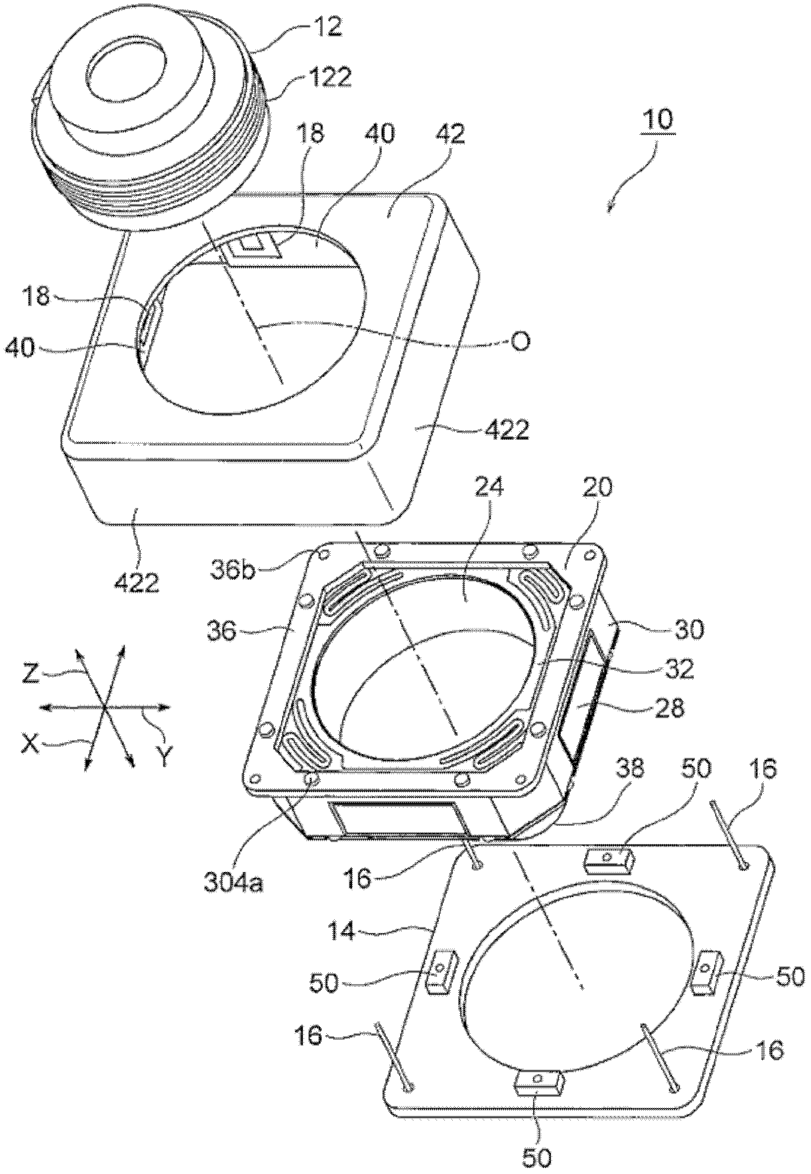
参照图1至图3,说明本发明的第一实施方式的抖动校正装置(透镜保持架驱动装置)10。图1是表示抖动校正装置10的分解立体图。图2是表示图1所示的抖动校正装置10所使用的自动聚焦用透镜驱动装置20的分解立体图。图3是表示去除了保护罩而表示图1所示的抖动校正装置10的组装立体图。A shake correction device (lens holder driving device) 10 according to a first embodiment of the present invention will be described with reference to FIGS. 1 to 3 . FIG. 1 is an exploded perspective view showing a
在此,如图1至图3所示那样,使用正交坐标系(X、Y、Z)。在图1至图3所示的状态下,正交坐标系(X、Y、Z)中,X轴方向是前后方向(进深方向),Y轴方向是左右方向(宽度方向),Z轴方向是上下方向(高度方向)。并且,在图1至图3所示的例子中,上下方向Z是透镜的光轴O方向。另外,在本第一实施方式中,X轴方向(前后方向)也称为第一方向,Y轴方向(左右方向)也称为第二方向。Here, as shown in FIGS. 1 to 3 , an orthogonal coordinate system (X, Y, Z) is used. In the states shown in Figures 1 to 3, in the orthogonal coordinate system (X, Y, Z), the X-axis direction is the front-back direction (depth direction), the Y-axis direction is the left-right direction (width direction), and the Z-axis direction is is the up-down direction (height direction). In addition, in the examples shown in FIGS. 1 to 3 , the vertical direction Z is the direction of the optical axis O of the lens. In addition, in the first embodiment, the X-axis direction (front-rear direction) is also referred to as the first direction, and the Y-axis direction (left-right direction) is also referred to as the second direction.
但是,实际使用状况下,光轴O方向即Z轴方向成为前后方向。换言之,Z轴的上方向成为前方向,Z轴的下方向成为后方向。However, in actual use, the direction of the optical axis O, that is, the Z-axis direction becomes the front-rear direction. In other words, the upward direction of the Z axis becomes the front direction, and the downward direction of the Z axis becomes the rear direction.
图示的抖动校正装置10是通过校正利用移动电话用小型相机拍摄静止图像时所产生的抖动(振动)而能够拍摄无像模糊的图像的装置。抖动校正装置10是通过使自动聚焦用透镜驱动装置20整体沿与光轴O正交且彼此正交的第一方向(前后方向)X和第二方向(左右方向)移动而校正抖动的装置。The illustrated
自动聚焦用透镜驱动装置20用于使透镜镜筒(透镜单元)12沿光轴O移动。从自动聚焦用透镜驱动装置20的底面隔开地设置基座印刷电路板(基座)14。该基座印刷电路板14的下部(后部)搭载有未图示的设置于摄像基板上的摄像元件。该摄像元件摄像由透镜镜筒12成像的被摄体并变换为电信号。摄像元件例如由CCD(charge coupled device,电荷耦合器件)型图像传感器、CMOS(complementary metal oxide semiconductor,互补金属氧化物半导体)型图像传感器等构成。因而,通过组合透镜驱动装置20、摄像基板和摄像元件构成相机组件。The autofocus
接着,参照图2说明自动聚焦用透镜驱动装置20。Next, the autofocus
自动聚焦用透镜驱动装置20包括:具有用于保持透镜镜筒12的筒状部240的透镜保持架24;以位于筒状部240的周围的方式固定于该透镜保持架24的聚焦线圈26;保持与该聚焦线圈26相对地设置于聚焦线圈26的外侧的永磁体28的磁体保持架(透镜保持架支承框)30;以及设于透镜保持架24的筒状部240的光轴O方向两侧的一对板簧32、34。一对板簧32、34以透镜保持架24在径向被定位的状态下透镜保持架24能够沿光轴O方向位移的方式支承该透镜保持架24。一对板簧32、34中的一侧的板簧32被称为上侧板簧,另一侧的板簧34被称为下侧板簧。The
另外,磁体保持架30、一对板簧32、34和后述的上侧印刷电路板36构成透镜保持架支承单元。In addition, the
另外,如上述那样,在实际的使用状况下,Z轴方向(光轴O方向)的上方向成为前方向,Z轴方向(光轴O方向)的下方向成为后方向。因而,上侧板簧32也被称为前侧弹簧,下侧板簧34也被称为后侧弹簧。In addition, as described above, in actual usage conditions, the upward direction in the Z-axis direction (direction of the optical axis O) is the front direction, and the downward direction in the Z-axis direction (direction of the optical axis O) is the rearward direction. Therefore, the
磁体保持架30呈八边筒状。即,磁体保持架30具有八边筒形状的外筒部302;设于该外筒部302的上端(前端)的八边形的上侧环状端部304;以及设于外筒部302的下端(后端)的八边形的下侧环状端部306。上侧环状端部304具有向上方突出的八个上侧突起304a。下侧环状端部306也具有向下方突出的八个下侧突起306a。The
聚焦线圈26呈与八边筒状的磁体保持架30的形状相匹配的八边筒状。永磁体28包含沿第一方向(前后方向)X和第二方向(左右方向)Y彼此隔开地设置于磁体保持架30的八边筒形状的外筒部302的4片矩形状的永磁体片282。总之,永磁体28与聚焦线圈26隔有间隔地设置。The focusing coil 26 has an octagonal cylindrical shape matching the shape of the octagonal
上侧板簧(前侧弹簧)32设置于透镜保持架24的光轴O方向上侧(前侧),下侧板簧(后侧弹簧)34设置于透镜保持架24的光轴O方向下侧(后侧)。上侧板簧(前侧弹簧)32与下侧板簧(后侧弹簧)34具有大致相同的结构。The upper leaf spring (front spring) 32 is provided on the upper side (front side) of the
上侧板簧(前侧弹簧)32具有安装于透镜保持架24的上端部的上侧内圈部322、和安装于磁体保持架30的上侧环状端部304的上侧外圈部324。在上侧内圈部322与上侧外圈部324之间设有四个上侧臂部326。即,四个臂部326连接上侧内圈部322与上侧外圈部324。The upper leaf spring (front spring) 32 has an upper inner ring portion 322 attached to the upper end portion of the
上侧外圈部324具有分别与磁体保持架30的八个上侧突起304a卡合的八个卡合缺口324a。在上侧板簧(前侧弹簧)32的上部设置环状的上侧印刷电路板(上侧基板)36。上侧印刷电路板36具有分别供磁体保持架30的八个上侧突起304a压入(嵌入)的八个上侧基板孔36a。即,磁体保持架30的八个上侧突起304a分别经由上侧外圈部324的八个卡合缺口324a,压入(嵌入)上侧印刷电路板36的八个上侧基板孔36a。即,上侧板簧(前侧弹簧)32的上侧外圈部324被夹持而固定在磁体保持架30的上侧环状端部304与上侧印刷电路板36之间。The upper outer ring portion 324 has eight engaging notches 324 a respectively engaged with the eight
同样,下侧板簧(后侧弹簧)34具有安装于透镜保持架24的下端部的下侧内圈部(未图示)、和安装于磁体保持架30的下侧环状端部306的下侧外圈部344。在下侧内圈部与上侧外圈部344之间设有四个下侧臂部(未图示)。即,四个下侧臂部连接下侧内圈部与下侧外圈部344。Similarly, the lower leaf spring (rear spring) 34 has a lower inner ring portion (not shown) attached to the lower end portion of the
下侧外圈部344具有分别与磁体保持架30的八个下侧突起306a卡合的八个下侧卡合缺口344a。在下侧板簧(后侧弹簧)34的下部设置环状的止动件38。止动件38具有分别供磁体保持架30的八个下侧突起306a压入(嵌入)的八个止动件缺口38a。即,磁体保持架30的八个下侧突起306a分别经由下侧外圈部344的八个卡合缺口344a,压入(嵌入)止动件38的八个止动件缺口38a。即,下侧板簧(后侧弹簧)34的下侧外圈部344被夹持而固定在磁体保持架30的下侧环状端部306与止动件38之间。The lower outer ring portion 344 has eight lower engaging notches 344 a respectively engaged with the eight lower protrusions 306 a of the
包括上侧板簧32和下侧板簧34的弹性部件作为引导透镜保持架24使其仅沿光轴O方向移动的引导单元而发挥作用。上侧板簧32和下侧板簧34分别由铍青铜、磷青铜等构成。The elastic member including the
在透镜保持架24的筒状部240的内周壁上切削有内螺纹242。另一方面,在透镜镜筒12的外周壁上切削有与上述内螺纹242相配的外螺纹122。因而,为了在透镜保持架24上安装透镜镜筒12,通过使透镜镜筒12相对于透镜保持架24的筒状部240绕光轴O旋转并沿光轴O方向旋入,将透镜镜筒12收容于透镜保持架24内,并利用粘接剂等彼此接合。Internal threads 242 are cut into the inner peripheral wall of the cylindrical portion 240 of the
另外,聚焦线圈26和永磁体28(第一驱动单元)通过对聚焦线圈26通电,在永磁体28的磁场与由聚焦线圈26中流过的电流产生的磁场相互作用下,能够对透镜保持架24(透镜镜筒12)沿光轴O方向进行位置调整。In addition, the focus coil 26 and the permanent magnet 28 (the first drive unit) can energize the
接着,参照图1以及图3,说明抖动校正装置10。Next, the
抖动校正装置10具有一端被固定于基座印刷电路板(基座)14的四角部的4根吊线16(支承部件)、和与上述自动聚焦用透镜驱动装置20的永磁体28相对地设置于永磁体28的外侧的抖动校正用线圈18。The
另外,基座印刷电路板14和吊线16构成支承单元。In addition, the base printed
4根吊线16沿光轴O延伸,以自动聚焦用透镜驱动装置20整体能够沿第一方向(前后方向)X和第二方向(左右方向)Y摇动的方式支承该自动聚焦用透镜驱动装置20整体。4根吊线16的另一端固定于上述自动聚焦用透镜驱动装置20的上侧印刷电路板36。详细而言,上侧印刷电路板36具有供4根吊线16的另一端插入(嵌入)的四个线固定用孔36b。将4根吊线16的另一端插入(嵌入)到上述四个线固定用孔36b中,并利用粘接剂、焊锡等固定。Four
4根吊线16中的两根吊线也使用于对聚焦线圈26供电。Two of the four
如上述那样,永磁体28由沿第一方向(前后方向)X和第二方向(左右方向)Y彼此相对地设置的4片永磁体片282构成。As described above, the
抖动校正装置10包括与4片永磁体片282分别相对地隔开设置的四个线圈基板40。在上述四个线圈基板40上形成有上述抖动校正用线圈18。The
详细而言,在各线圈基板40的两端部形成有一对抖动校正用线圈18。因而,合计具有八个抖动校正用线圈18。Specifically, a pair of shake correction coils 18 are formed at both ends of each
形成于在第二方向(左右方向)Y上彼此相对设置的两个线圈基板40上的四个抖动校正用线圈18用于使自动聚焦用透镜驱动装置20沿第一方向(前后方向)X移动(摇动)。The four shake correction coils 18 formed on two
这样的四个抖动校正用线圈18被称为第一方向致动器18(1)。Such four shake correction coils 18 are referred to as first direction actuators 18 ( 1 ).
另一方面,形成于在第一方向(前后方向)X上彼此相对设置的两个线圈基板40上的四个抖动校正用线圈18用于使自动聚焦用透镜驱动装置20沿第二方向(左右方向)Y移动(摇动)。这样的四个抖动校正用线圈18被称为第二方向致动器18(2)。On the other hand, the four shake correction coils 18 formed on the two
总之,抖动校正用线圈18与永磁体28(第二驱动单元)配合,沿X轴方向(第一方向)和Y轴方向(第二方向)驱动自动聚焦用透镜驱动装置20整体。另外,抖动校正用线圈18与永磁体28的组合作为音圈电机而发挥作用。In short, the
这样,图示的抖动校正装置10通过使收容于自动聚焦用透镜驱动装置20的透镜镜筒12本身沿第一方向(前后方向)X和第二方向(左右方向)Y移动,校正抖动。因而,抖动校正装置10被称为“镜筒移动方式”的抖动校正装置。Thus, the illustrated
抖动校正装置10还包括:包含了覆盖四个线圈基板40的四边筒部422的保护罩42。在图示的例子中,如图1所示那样,四个线圈基板40安装于保护罩42的四边筒部422的内壁上。The
图示的抖动校正装置10还包括用于检测自动聚焦用透镜驱动装置20相对于基座印刷电路板14的位置的位置检测单元50。图示的位置检测单元50由安装在基座印刷电路板14上的四个霍尔元件50构成。上述四个霍尔元件50分别与4片永磁体片282隔开地相对设置。The illustrated
在第一方向(前后方向)X上相对设置的一对霍尔元件50通过检测与该一对霍尔元件50相对的一对永磁体片282的磁力,检测跟随第一方向(前后方向)X的移动(摇动)的第一位置。在第二方向(左右方向)Y上相对设置的一对霍尔元件50通过检测与该一对霍尔元件50相对的一对永磁体片282的磁力,检测跟随第二方向(左右方向)Y的移动(摇动)的第二位置。A pair of
图4是表示对抖动校正装置10进行控制的抖动校正致动器600的结构的方框图。抖动校正装置10搭载于带相机的移动电话(未图示)中。FIG. 4 is a block diagram showing the configuration of a
在带相机的移动电话的壳体(未图示)中,设有用于检测第一方向(前后方向)X的抖动的第一方向陀螺仪602、和用于检测第二方向(左右方向)Y的抖动的第二方向陀螺仪604。In a housing (not shown) of a mobile phone with a camera, a
第一方向陀螺仪602检测第一方向(前后方向)X的角速度,并输出表示检测到的第一方向(前后方向)X的角速度的第一角速度信号。第二方向陀螺仪604检测第二方向(左右方向)Y的角速度,并输出表示检测到的第二方向(左右方向)Y的角速度的第二角速度信号。第一角速度信号以及第二角速度信号被提供给抖动校正控制单元606。快门按钮608将快门操作指令信号提供给抖动校正控制单元606。The
抖动校正控制单元606具有根据第一角速度信号以及第二角速度信号检测带相机的移动电话的壳体的抖动的抖动检测电路612、和接受快门操作指令信号的时序控制电路614。抖动检测电路612包含滤波电路和放大电路。抖动检测电路612将抖动检测信号提供给抖动量检测电路616。抖动量检测电路616根据抖动检测信号检测带相机的移动电话的壳体的抖动量,并将抖动量检测信号输出到系数变换电路618。系数变换电路618对抖动量检测信号进行系数变换,并将系数变换了的信号输出到控制电路620。来自设于抖动校正装置10的位置检测单元(位置传感器)50的位置检测信号被提供给该控制电路620。The shake
控制电路620响应系数变换了的信号,基于位置检测信号,输出控制信号以抵消由抖动检测电路612检测到的抖动。时序控制电路614响应快门操作指令信号,控制抖动量检测电路616、系数变换电路618和控制电路620的动作时机。控制信号被提供给驱动电路622。The
如上述那样,抖动校正装置10,包括用于使自动聚焦用透镜驱动装置20整体沿第一方向(前后方向)X移动(摇动)的第一方向致动器18(1)、和用于使自动聚焦用透镜驱动装置20整体沿第二方向(左右方向)Y移动(摇动)的第二方向致动器18(2)作为音圈电机。总之,抖动校正装置10包含第一方向致动器18(1)和第二方向致动器18(2)。As described above, the
驱动电路622响应控制信号,驱动第一方向致动器18(1)和第二方向致动器18(2)。The drive circuit 622 drives the first directional actuator 18(1) and the second directional actuator 18(2) in response to the control signal.
通过这样的结构,抖动校正装置10能够使自动聚焦用透镜驱动装置20整体移动(摇动)从而抵消带相机的移动电话的壳体的抖动。其结果,能够校正抖动。With such a configuration, the
如上所述的本发明的第一实施方式的抖动校正装置10发挥以下说明的效果。The
因为在自动聚焦用透镜驱动装置20上设置抖动校正装置10,共用永磁体28,所以能够削减元件件数。其结果,能够缩小(降低)抖动校正装置10的尺寸(主要是高度)。Since the
在光学单元倾斜方式的抖动校正装置中,由于存在旋转轴,所以产生孔-轴之间的摩擦从而产生磁滞。相对于此,在本第一实施方式的抖动校正装置10中,因为利用4根吊线16机械地支承自动聚焦用透镜驱动装置20整体,所以不易产生磁滞。In the shake correction device of the optical unit tilting method, due to the existence of the rotation axis, friction occurs between the hole and the axis, thereby generating hysteresis. In contrast, in the
与以往的光学式抖动校正方式(透镜移动方式、传感器移动方式、光学单元倾斜方式)的抖动校正装置相比,因为采用镜筒移动方式,所以能够使抖动校正装置10的尺寸(主要是高度)与自动聚焦用透镜驱动装置20大致相等。其结果,能够将本第一实施方式的抖动校正装置10搭载于移动电话用光学抖动校正相机中。Compared with the shake correction device of the conventional optical shake correction method (lens shift method, sensor shift method, optical unit tilt method), since the lens barrel shift method is adopted, the size (mainly height) of the
另外,在第一实施方式中,作为位置检测单位(位置传感器),使用了由霍尔元件50构成的磁式位置检测单元,但是也可以使用光反射器等光学式位置检测单元那样的其他位置检测单元(位置传感器)替代霍尔元件50。In addition, in the first embodiment, as the position detection unit (position sensor), a magnetic position detection unit composed of a
另外,在上述第一实施方式中,永磁体28由在第一方向X和第二方向Y上彼此相对设置的4片永磁体片282构成,但是永磁体片的数量不限定于4片,例如也可以由不仅在第一方向和第二方向上而且在对角线方向上也相对设置的8片永磁体片构成。在该情况下,抖动校正用线圈18的个数、线圈基板40的个数也与永磁体片282的片数对应地变更。另外,在上述第一实施方式中,4根吊线16的一端固定于基座14的四角部,但是也可以固定于基座14的外周部。而且,吊线16的根数也不限定于4根,也可以是多根。In addition, in the above-mentioned first embodiment, the
参照图5至图8,说明本发明的第二实施方式的抖动校正装置(透镜保持架驱动装置)10A。图5是抖动校正装置10A的外观立体图。图6是抖动校正装置10A的纵剖视图。图7是表示抖动校正装置10A的分解立体图。图8是表示图5所示的抖动校正装置10A所使用的自动聚焦用透镜驱动装置20A的分解立体图。A shake correction device (lens holder driving device) 10A according to a second embodiment of the present invention will be described with reference to FIGS. 5 to 8 . FIG. 5 is an external perspective view of the
在此,如图5至图8所示那样,使用正交坐标系(X、Y、Z)。在图5至图8所示的状态下,正交坐标系(X、Y、Z)中,X轴方向是前后方向(进深方向),Y轴方向是左右方向(宽度方向),Z轴方向是上下方向(高度方向)。并且,在图5至图8所示的例子中,上下方向Z是透镜的光轴O方向。另外,在本第二实施方式中,X轴方向(前后方向)也称为第一方向,Y轴方向(左右方向)也称为第二方向。Here, as shown in FIGS. 5 to 8 , an orthogonal coordinate system (X, Y, Z) is used. In the states shown in Figures 5 to 8, in the orthogonal coordinate system (X, Y, Z), the X-axis direction is the front-back direction (depth direction), the Y-axis direction is the left-right direction (width direction), and the Z-axis direction is is the up-down direction (height direction). In addition, in the examples shown in FIGS. 5 to 8 , the up-down direction Z is the direction of the optical axis O of the lens. In addition, in the second embodiment, the X-axis direction (front-rear direction) is also referred to as the first direction, and the Y-axis direction (left-right direction) is also referred to as the second direction.
但是,实际使用状况下,光轴O方向即Z轴方向成为前后方向。换言之,Z轴的上方向成为前方向,Z轴的下方向成为后方向。However, in actual use, the direction of the optical axis O, that is, the Z-axis direction becomes the front-rear direction. In other words, the upward direction of the Z axis becomes the front direction, and the downward direction of the Z axis becomes the rear direction.
图示的抖动校正装置10A是通过校正利用移动电话用小型相机拍摄静止图像时所产生的抖动(振动)而能够拍摄无像模糊的图像的装置。抖动校正装置10A是通过使自动聚焦用透镜驱动装置20A整体沿与光轴O正交且彼此正交的第一方向(前后方向)X和第二方向(左右方向)移动而校正抖动的装置。The illustrated
自动聚焦用透镜驱动装置20A用于使透镜镜筒(透镜单元)12A沿光轴O移动。从自动聚焦用透镜驱动装置20A的底部向径向外侧隔开地设置基座14A。在该基座14A的下部(后部)搭载有未图示的设置于摄像基板上的摄像元件。该摄像元件摄像由透镜镜筒12A成像的被摄体并变换为电信号。摄像元件例如由CCD型图像传感器、CMOS型图像传感器等构成。因而,通过组合透镜驱动装置20A、摄像基板和摄像元件构成相机组件。The autofocus
基座14A由外形是四边形且内部具有圆形开口的环形状的基部142A和从该基部142A的外缘向光轴O方向的上侧突出的四边筒形状的筒状部144A构成。The
抖动校正装置10A具有:4根吊线16A,其一端固定于基座14A的基部142A的四角部;以及抖动校正用线圈18A,其如后述那样地与后述的自动聚焦用透镜驱动装置20A的永磁体28A相对设置。The
4根吊线16A沿光轴O延伸,以自动聚焦用透镜驱动装置20A整体能够沿第一方向(前后方向)X和第二方向(左右方向)Y摇动的方式支承该自动聚焦用透镜驱动装置20A整体。4根吊线16A的另一端如后述那样地固定于上述自动聚焦用透镜驱动装置20A的上端部。The four
抖动校正装置10A如后述那样包括与永磁体28A相对地隔开设置的一个四边环形状的线圈基板40A。该线圈基板40A安装于基座14A的筒状部144A的上端。在该线圈基板40A上形成有上述抖动校正用线圈18A。The
接着,参照图8说明自动聚焦用透镜驱动装置20A。Next, the autofocus
自动聚焦用透镜驱动装置20A包括:具有用于保持透镜镜筒12A的筒状部240A的透镜保持架24A;以位于筒状部240A的周围的方式固定于该透镜保持架24A上的第一聚焦线圈26A-1和第二聚焦线圈26A-2;保持与这些第一聚焦线圈26A-1和第二聚焦线圈26A-2相对地设置于第一聚焦线圈26A-1和第二聚焦线圈26A-2的外侧的永磁体28A的磁体保持架(透镜保持架支承框)30A;以及设于透镜保持架24A的筒状部240A的光轴O方向两侧的一对板簧32A、34A。The
另外,磁体保持架30A和一对板簧32A、34A构成透镜保持架支承单元。In addition, the
第一聚焦线圈26A-1安装于透镜保持架24A的筒状部240A的光轴O方向的上侧,第二聚焦线圈26A-2安装于透镜保持架24A的筒状部240A的光轴O方向的下侧。The first focusing
一对板簧32A、34A以透镜保持架24A在径向被定位的状态下透镜保持架24A能够沿光轴O方向位移的方式支承该透镜保持架24A。一对板簧32A、34A中的一侧的板簧32A被称为上侧板簧,另一侧的板簧34A被称为下侧板簧。The pair of plate springs 32A and 34A support the
另外,如上述那样,在实际的使用状况下,Z轴方向(光轴O方向)的上方向成为前方向,Z轴方向(光轴O方向)的下方向成为后方向。因而,上侧板簧32A也被称为前侧弹簧,下侧板簧34A也被称为后侧弹簧。In addition, as described above, in actual usage conditions, the upward direction in the Z-axis direction (direction of the optical axis O) is the front direction, and the downward direction in the Z-axis direction (direction of the optical axis O) is the rearward direction. Therefore, the
磁体保持架30A呈八边筒状。即,磁体保持架30A具有八边筒形状的外筒部302A;设于该外筒部302A的上端(前端)的四边形的上侧环状端部304A;以及设于外筒部302A的下端(后端)的八边形的下侧环状端部306A。The
第一聚焦线圈26A-1和第二聚焦线圈26A-2分别呈与八边筒状的磁体保持架30A的形状相匹配的八边筒状。永磁体28A由在第一方向(前后方向)X、第二方向(左右方向)Y和上下方向Z彼此隔开地设置于磁体保持架30A的八边筒形状的外筒部302A的8片矩形状的永磁体片构成。在上述8片矩形状永磁体中,4片第一永磁体片282A-1设置于外筒部302A的光轴O方向的上侧,其余的4片第二永磁体片282A-2设置于外筒部302A的光轴O方向的下侧。4片第一永磁体片282A-1与第一聚焦线圈26A-1隔有间隔地设置,4片第二永磁体片282A-2与第二聚焦线圈26A-2隔有间隔地设置。The first focusing
上侧板簧(前侧弹簧)32A设置于透镜保持架24A的光轴O方向上侧(前侧),下侧板簧(后侧弹簧)34A设置于透镜保持架24A的光轴O方向下侧(后侧)。上侧板簧(前侧弹簧)32A与下侧板簧(后侧弹簧)34A具有大致相同的结构。The upper leaf spring (front spring) 32A is provided on the upper side (front side) of the
上侧板簧(前侧弹簧)32A具有安装于透镜保持架24A的上端部的上侧内圈部322A、和安装于磁体保持架30A的上侧环状端部304A的上侧外圈部324A。在上侧内圈部322A与上侧外圈部324A之间设有四个上侧臂部326A。即,四个臂部326A连接上侧内圈部322A与上侧外圈部324A。The upper leaf spring (front spring) 32A has an upper
上侧外圈部324A具有供上述4根吊线16A的另一端插入(嵌入)的四个线固定用孔324Aa。The upper
同样,下侧板簧(后侧弹簧)34A具有安装于透镜保持架24A的下端部的下侧内圈部342A、和安装于磁体保持架30A的下侧环状端部306A的下侧外圈部344A。在下侧内圈部342A与上侧内圈部344A之间设有四个下侧臂部346A。即,四个下侧臂部346A连接下侧内圈部342A与下侧外圈部344。Similarly, the lower leaf spring (rear spring) 34A has a lower
包括上侧板簧32A和下侧板簧34A的弹性部件作为引导透镜保持架24A使其仅沿光轴O方向移动的引导单元而发挥作用。上侧板簧32A和下侧板簧34A分别由铍青铜、磷青铜等构成。The elastic member including the
在透镜保持架24A的筒状部240A的内周壁上切削有内螺纹(未图示)。另一方面,在透镜镜筒12A的外周壁上切削有与上述内螺纹相配的外螺纹(未图示)。因而,为了在透镜保持架24A上安装透镜镜筒12A,通过使透镜镜筒12A相对于透镜保持架24A的筒状部240A绕光轴O旋转并沿光轴O方向旋入,将透镜镜筒12A收容于透镜保持架24A内,并利用粘接剂等彼此接合。Internal threads (not shown) are cut into the inner peripheral wall of the
如后述那样,第一聚焦线圈26A-1、第二聚焦线圈26A-2和永磁体28A(第一驱动单元)通过在第一聚焦线圈26A-1和第二聚焦线圈26A-2中分别流过第一自动聚焦(AF)电流和第二自动聚焦(AF)电流,在永磁体28A的磁场与由第一聚焦线圈26A-1和第二聚焦线圈26A-2中流过的AF电流产生的磁场相互作用下,能够对透镜保持架24A(透镜镜筒12A)沿光轴O方向进行位置调整。As will be described later, the
接着,参照图6和图7,更详细地说明抖动校正装置10A。Next, the
抖动校正装置10A如上述那样具有一端被固定于基座14A的基部142A的四角部的4根吊线(支承部件)16A、和与上述自动聚焦用透镜驱动装置20A的永磁体28A相对设置的抖动校正用线圈18A。
另外,基座14A和吊线16A构成支承单元。In addition, the
4根吊线16A沿光轴O延伸,以自动聚焦用透镜驱动装置20A整体能够沿第一方向(前后方向)X和第二方向(左右方向)Y摇动的方式支承该自动聚焦用透镜驱动装置20A整体。4根吊线16A的另一端固定于上述自动聚焦用透镜驱动装置20A的上端部。The four
详细而言,如上述那样,上侧板簧32A的上侧外圈部324A具有供4根吊线16A的另一端插入(嵌入)的四个线固定用孔324Aa(参照图8)。另外,磁体保持架30A的上侧环状端部304A具有供4根吊线16A的另一端插入的四个线插入用孔304Aa(参照图8)。将4根吊线16A的另一端经由上述四个线插入用孔304Aa插入(嵌入)四个线固定用孔324Aa中,并利用粘接剂、焊锡等固定。Specifically, as described above, the upper
4根吊线16A也用于对第一聚焦线圈26A-1和第二聚焦线圈26A-2进行供电。The four
如上述那样,永磁体28A由在第一方向(前后方向)X和第二方向(左右方向)Y彼此相对且沿光轴O方向上下隔开地设置的4片第一永磁体片282A-1和4片第二永磁体片282A-2构成。As described above, the
抖动校正装置10A包括插入4片第一永磁体片282A-1与4片第二永磁体片282A-2之间,并隔开地设置的一个环状线圈基板40A。线圈基板40A在其四角具有供4根吊线16A穿过的贯穿孔40Aa。在该一个线圈基板40A上形成有上述抖动校正用线圈18A。The
详细而言,在线圈基板40A上作为抖动校正用线圈18A形成有四个抖动校正用线圈18Af、18Ab、18Al和18Ar(参照图9)。Specifically, four shake correction coils 18Af, 18Ab, 18Al, and 18Ar are formed on the
在第一方向(前后方向)X上彼此相对设置的两个抖动校正用线圈18Af和18Ab用于使自动聚焦用透镜驱动装置20A沿第一方向(前后方向)X移动(摇动)。这样的两个抖动校正用线圈18Af和18Ab被称为第一方向致动器。另外,在此,将对于光轴O位于前侧的抖动校正用线圈18Af称为“前侧抖动校正用线圈”,将对于光轴O位于后侧的抖动校正用线圈18Ab称为“后侧抖动校正用线圈”。The two shake correction coils 18Af and 18Ab disposed opposite to each other in the first direction (front-rear direction) X are used to move (sway) the autofocus
另一方面,在第二方向(左右方向)Y上彼此相对设置的两个抖动校正用线圈18Al和18Ar用于使自动聚焦用透镜驱动装置20A沿第二方向(左右方向)Y移动(摇动)。这样的两个抖动校正用线圈18Al和18Ar被称为第二方向致动器。另外,在此,将对于光轴O位于左侧的抖动校正用线圈18Al称为“左侧抖动校正用线圈”,将对于光轴O位于右侧的抖动校正用线圈18Ar称为“右侧抖动校正用线圈”。On the other hand, the two shake correction coils 18A1 and 18Ar arranged opposite to each other in the second direction (left-right direction) Y are used to move (sway) the autofocus
总之,抖动校正用线圈18A和永磁体28A(第二驱动单元)中,四个抖动校正用线圈18Af、18Ab、18Al和18Ar用于与永磁体28A配合,沿X轴方向(第一方向)和Y轴方向(第二方向)驱动自动聚焦用透镜驱动装置20A整体。另外,抖动校正用线圈18Af、18Ab、18Al和18Ar与永磁体28A的组合作为音圈电机发挥作用。In short, of the
这样,图示的抖动校正装置10A通过使收容于自动聚焦用透镜驱动装置20A的透镜镜筒12A本身沿第一方向(前后方向)X和第二方向(左右方向)Y移动,校正抖动。因而,抖动校正装置10A被称为“镜筒移动方式”的抖动校正装置。Thus, the illustrated
抖动校正装置10A还包括:包含了覆盖自动聚焦用透镜驱动装置20A的上部(4片第一永磁体片282A-1)的四边筒部422A的罩42A。The
图示的抖动校正装置10A还包括用于检测自动聚焦用透镜驱动装置20A相对于基座14A的位置的位置检测单元50A。图示的位置检测单元50A包括磁式位置检测单元,该磁式位置检测单元由安装在基座14A的基部142A上的两个霍尔元件50A构成。上述两个霍尔元件50A与4片第二永磁体片282A-2中的两片永磁体片分别隔开地相对设置。如图10所示那样,各霍尔元件50A被设置成横穿从第二永磁体片282A-2的N极至S极的方向。The illustrated
在相对于光轴O第一方向(前后方向)X上设置的一个霍尔元件50A通过检测与该一个霍尔元件50A相对的一片第二永磁体片282A-2的磁力,检测跟随第一方向(前后方向)X的移动(摇动)的第一位置。相对于光轴O在第二方向(左右方向)Y上设置的一个霍尔元件50A通过检测与该一个霍尔元件50A相对的一片第二永磁体片282A-2的磁力,检测跟随第二方向(左右方向)Y的移动(摇动)的第二位置。One
另外,在第二实施方式的抖动校正装置10A中,使用了由两个霍尔元件50A构成的磁式位置检测单元作为位置检测单元50A,但是也可以如上述第一实施方式的抖动校正装置10那样,采用由四个霍尔元件50构成的磁式位置检测单元。In addition, in the
参照图9至图11,详细地说明图6和图7所示的抖动校正装置10A所使用的磁路。图9是磁路的立体图,图10是磁路的纵剖视图。图11是省略了磁路中的4片第一永磁体片282A-2和第一聚焦线圈26A-1而表示的俯视图。The magnetic circuit used in the
4片第一永磁体片282A-1和4片第二永磁体片282A-2在透镜保持架24A的径向外侧和内侧,分别磁化为相邻彼此不同的磁极。例如,如图10所示那样,第一永磁体片282A-1内侧磁化为S极,外侧磁化为N极,第二永磁体片282A-2内侧磁化为N极,外侧磁化为S极。图10所示的箭头表示由这些永磁体片282A-1、282A-2产生的磁通量的方向。The four first
接着,参照图9说明对透镜保持架24A(透镜镜筒12A)沿光轴O方向进行位置调整的情况的动作。Next, the operation of adjusting the position of the
在第一聚焦线圈26A-1和第二聚焦线圈26A-2中,沿彼此相反方向分别流过第一AF电流和第二AF电流。例如,如图9所示那样,在第一聚焦线圈26A-1中,以顺时针旋转的方式流过以箭头IAF1所示那样的第一AF电流,在第二聚焦线圈26A-2中,以逆时针旋转的方式流过以箭头IAF2所示那样的第二AF电流。In the
在该情况下,按照弗来明左手定则,如图9所示那样,在第一聚焦线圈26A-1中作用为以箭头IAF1所示那样的上方向的电磁力,也在第二聚焦线圈26A-2中作用为以箭头IAF2所示那样的上方向的电磁力。其结果,能够使透镜保持架24A(透镜镜筒12A)向光轴O方向的上方移动。In this case, according to Fleming's left-hand rule, as shown in FIG. In 26A-2, an upward electromagnetic force acts as indicated by arrow IAF2. As a result, the
相反地,通过在第一聚焦线圈26A-1中以逆时针旋转的方式流过第一AF电流,在第二聚焦线圈26A-2中以顺时针旋转的方式流过第二AF电流,能够使透镜保持架24A(透镜镜筒12A)向光轴O方向的下方移动。Conversely, by flowing the first AF current in counterclockwise rotation in the
接着,参照图11,说明使自动聚焦用透镜驱动装置20A整体沿第一方向(前后方向)X或第二方向(左右方向)Y移动的情况的动作。Next, the operation in the case of moving the entire autofocus
首先,说明使自动聚焦用透镜驱动装置20A整体向第二方向(左右方向)Y的右侧移动的情况的动作。在该情况下,如图11所示那样,在左侧抖动校正用线圈18Al中,以顺时针旋转的方式流过如箭头IIS1所示那样的第一抖动校正(IS)电流,在右侧抖动校正用线圈18Ar中,以逆时针旋转的方式流过如箭头IIS2所示那样的第二抖动校正(IS)电流。First, the operation in the case of moving the entire autofocus
在该情况下,按照弗来明左手定则,在左侧抖动校正用线圈18Al中作用为左方向的电磁力,也在右侧抖动校正用线圈18Ar中作用为左方向的电磁力。可是,因为这些抖动校正用线圈18Al和18Ar固定于基座14A,所以作为其反作用力,在自动聚焦用透镜驱动装置20A整体中作用为如图11的箭头FIS1和FIS2所示那样的、右方向的电磁力。其结果,能够使自动聚焦用透镜驱动装置20A整体向右方向移动。In this case, according to Fleming's left-hand rule, a leftward electromagnetic force acts on the left shake correction coil 18A1, and a leftward electromagnetic force acts on the right shake correction coil 18Ar. However, since these shake correction coils 18A1 and 18Ar are fixed to the
相反地,通过在左侧抖动校正用线圈18Al中以逆时针旋转的方式流过第一IS电流,在右侧抖动校正用线圈18Ar中以顺时针旋转的方式流过第二IS电流,能够使自动聚焦用透镜驱动装置20A整体向左方向移动。Conversely, by flowing the first IS current to the left shake correction coil 18A1 to rotate counterclockwise and flowing the second IS current to the right shake correction coil 18Ar to rotate clockwise, it is possible to The entire autofocus
另一方面,通过在后侧抖动校正用线圈18Ab中以顺时针旋转的方式流过第三IS电流,在前侧抖动校正用线圈18Af中以逆时针旋转的方式流过第四IS电流,能够使自动聚焦用透镜驱动装置20A整体向前方向移动。On the other hand, by flowing the third IS current so as to rotate clockwise to the rear side shake correction coil 18Ab and flowing the fourth IS current so as to rotate counterclockwise to the front side shake correction coil 18Af, it is possible to The entire autofocus
另外,通过在后侧抖动校正用线圈18Ab中以逆时针旋转的方式流过第三IS电流,在前侧抖动校正用线圈18Af中以顺时针旋转的方式流过第四IS电流,能够使自动聚焦用透镜驱动装置20A整体向后方向移动。In addition, by flowing the third IS current to the rear side shake correction coil 18Ab so as to rotate counterclockwise and flowing the fourth IS current to the front side shake correction coil 18Af so as to rotate clockwise, it is possible to automatically The focusing
这样,能够校正相机的抖动。In this way, camera shake can be corrected.
对于如上述那样的、本发明的第二实施方式的抖动校正装置10A,发挥如下说明那样的效果。As described above, the
因为在自动聚焦用透镜驱动装置20A上设置抖动校正装置10A,共用永磁体28A,所以能够削减元件件数。其结果,能够缩小(降低)抖动校正装置10A的尺寸(主要是高度)。Since the
在光学单元倾斜方式的抖动校正装置中,由于存在旋转轴,所以产生孔-轴之间的摩擦从而产生磁滞。相对于此,在本第二实施方式的抖动校正装置10A中,因为利用4根吊线16A机械地支承自动聚焦用透镜驱动装置20A整体,所以不易产生磁滞。In the shake correction device of the optical unit tilting method, due to the existence of the rotation axis, friction occurs between the hole and the axis, thereby generating hysteresis. In contrast, in the
与以往的光学式抖动校正方式(透镜移动方式、传感器移动方式、光学单元倾斜方式)的抖动校正装置相比,因为采用镜筒移动方式,所以能够使抖动校正装置10A的尺寸(主要是高度)与自动聚焦用透镜驱动装置20A大致相等。其结果,能够将本第二实施方式的抖动校正装置10A搭载于移动电话用光学抖动校正相机中。Compared with the shake correction device of the conventional optical shake correction method (lens shift method, sensor shift method, optical unit tilt method), since the lens barrel shift method is adopted, the size (mainly height) of the
另外,因为在上侧的4片第一永磁体片282A-1与下侧的4片第二永磁体片282A-2之间设置抖动校正用线圈18A,所以能够实现高灵敏度的致动器。In addition, since the
另外,在第二实施方式中,作为位置检测单位(位置传感器),使用了由两个霍尔元件50A构成的磁式位置检测单元,但是,如后述,也可以使用光反射器等光学式位置检测单元那样的其他位置检测单元(位置传感器)替代霍尔元件50A。In addition, in the second embodiment, as the position detection unit (position sensor), a magnetic type position detection unit composed of two
在上述第二实施方式中,永磁体片28A由在第一方向X和第二方向Y上彼此相对并沿光轴O方向上下隔开地设置的4片第一永磁体片282A-1和4片第二永磁体片282A-2构成,但是第一永磁体片和第二永磁体片各自的片数不限定于4片,例如也可以由不仅在第一方向和第二方向上而且在对角线方向上也相对地设置的8片永磁体片构成。在该情况下,抖动校正用线圈18A的个数也变更为八个。另外,在上述第二实施方式中,4根吊线16A自基座14A的基部142A的四角部竖立设置,但是可以自基部142A的外周部竖立设置。而且,吊线16A的根数也不限定于4根,可以是多根。In the above-mentioned second embodiment, the
上述第一实施方式和第二实施方式的抖动校正装置10和10A采用永磁体18和18A移动(可动)的“移动磁体方式”。可是,作为抖动校正装置,也可以采用线圈移动(可动)的“移动线圈方式”。由此,能够实现自动聚焦用透镜驱动装置的可动部的轻量化。The
参照图12至图15,说明本发明的第三实施方式的抖动校正装置(透镜保持架驱动装置)10B。图12是抖动校正装置10B的外观立体图。图13是抖动校正装置10B的纵剖视图。图14是表示抖动校正装置10B的分解立体图。图15是表示图12所示的抖动校正装置10B所使用的自动聚焦用透镜驱动装置20B的可动部的分解立体图。A shake correction device (lens holder driving device) 10B according to a third embodiment of the present invention will be described with reference to FIGS. 12 to 15 . FIG. 12 is an external perspective view of the
在此,如图12至图15所示,使用正交坐标系(X、Y、Z)。在图12至图15所示的状态下,正交坐标系(X、Y、Z)中,X轴方向是前后方向(进深方向),Y轴方向是左右方向(宽度方向),Z轴方向是上下方向(高度方向)。并且,在图12至图15所示的例子中,上下方向Z是透镜的光轴O方向。另外,在本第三实施方式中,X轴方向(前后方向)也称为第一方向,Y轴方向(左右方向)也称为第二方向。Here, as shown in FIGS. 12 to 15 , an orthogonal coordinate system (X, Y, Z) is used. In the states shown in Figures 12 to 15, in the orthogonal coordinate system (X, Y, Z), the X-axis direction is the front-back direction (depth direction), the Y-axis direction is the left-right direction (width direction), and the Z-axis direction is is the up-down direction (height direction). In addition, in the examples shown in FIGS. 12 to 15 , the up-down direction Z is the direction of the optical axis O of the lens. In addition, in the third embodiment, the X-axis direction (front-rear direction) is also referred to as the first direction, and the Y-axis direction (left-right direction) is also referred to as the second direction.
但是,实际使用状况下,光轴O方向即Z轴方向成为前后方向。换言之,Z轴的上方向成为前方向,Z轴的下方向成为后方向。However, in actual use, the direction of the optical axis O, that is, the Z-axis direction becomes the front-rear direction. In other words, the upward direction of the Z axis becomes the front direction, and the downward direction of the Z axis becomes the rear direction.
图示的抖动校正装置10B是通过校正利用移动电话用小型相机拍摄静止图像时所产生的抖动(振动)而能够拍摄无像模糊的图像的装置。抖动校正装置10B是通过使自动聚焦用透镜驱动装置20B的可动部沿与光轴O正交且彼此正交的第一方向(前后方向)X和第二方向(左右方向)移动而校正抖动的装置。图示的抖动校正装置10B是采用了“移动线圈方式”的抖动校正装置。The illustrated
自动聚焦用透镜驱动装置20B用于使透镜镜筒(未图示)沿光轴O移动。从自动聚焦用透镜驱动装置20B的底部向径向外侧隔开地设置基座14B。在该基座14B的下部(后部)搭载未图示的设置于摄像基板上的摄像元件。该摄像元件拍摄由透镜镜筒成像的被摄体并变换为电信号。摄像元件例如由CCD型图像传感器、CMOS型图像传感器等构成。因而,由透镜驱动装置20B、摄像基板和摄像元件的组合构成相机组件。The autofocus
基座14B由外形是四边形且内部具有圆形开口的环形状的基部142B和从该基部142B的外缘向光轴O方向的上侧突出的具有四个矩形开口144Ba的四边筒形状的筒状部144B。The
抖动校正装置10B具有成对地一端固定于基座14B的基部142B的四角部的8根吊线16B、和如后述那样地与后述的自动聚焦用透镜驱动装置20B的永磁体28B相对设置的抖动校正用线圈18B。The
8根吊线16B沿光轴O延伸,以自动聚焦用透镜驱动装置20B的可动部能够沿第一方向(前后方向)X和第二方向(左右方向)Y摇动的方式支承该自动聚焦用透镜驱动装置20B的可动部。8根吊线16B的另一端如后述那样固定于上述自动聚焦用透镜驱动装置20B的上端部。Eight
抖动校正装置10B如后述那样包括与永磁体28B相对地隔开设置的一个四边环形状的线圈基板40B。该线圈基板40B安装在线圈保持架44B上。在该线圈基板40B上形成有上述抖动校正用线圈18B。The
线圈保持架44B在四角具有与光轴O方向平行地延伸的四个柱部442B、设于上述四个柱部442B的上端(前端)的大致四边形的上侧环状端部444B、和设于四个柱部442B的下端(后端)的下侧环状端部446B。上侧环状端部444B在四角具有向上方突出的四个上侧突起444Ba。下侧环状端部446B也具有向上方突出的四个下侧突起446Ba。The
接着,参照图14和图15说明自动聚焦用透镜驱动装置20B。Next, the autofocus
自动聚焦用透镜驱动装置20B包括:具有用于保持透镜镜筒的筒状部240B的透镜保持架24B;以位于筒状部240B的周围的方式固定于该透镜保持架24B上的第一聚焦线圈26B-1和第二聚焦线圈26B-2;保持与这些第一聚焦线圈26B-1和第二聚焦线圈26B-2相对地设置于第一聚焦线圈26B-1和第二聚焦线圈26B-2的外侧的永磁体28B的四个磁体保持架(透镜保持架支承框)30B;以及设于透镜保持架24B的筒状部240B的光轴O方向两侧的一对板簧32B、34B。The
另外,磁体保持架30B和一对板簧32B、34B构成透镜保持架支承单元。In addition, the
第一聚焦线圈26B-1安装于透镜保持架24B的筒状部240B的光轴O方向的上侧,第二聚焦线圈26B-2安装于透镜保持架24B的筒状部240B的光轴O方向的下侧。The first focusing
一对板簧32B、34B以透镜保持架24B在径向被定位的状态下透镜保持架24B能够沿光轴O方向位移的方式支承该透镜保持架24B。一对板簧32B、34B中的一侧的板簧32B被称为上侧板簧,另一侧的板簧34B被称为下侧板簧。The pair of plate springs 32B and 34B support the
另外,如上述那样,在实际的使用状况下,Z轴方向(光轴O方向)的上方向成为前方向,Z轴方向(光轴O方向)的下方向成为后方向。因而,上侧板簧32B也被称为前侧弹簧,下侧板簧34B也被称为后侧弹簧。In addition, as described above, in actual usage conditions, the upward direction in the Z-axis direction (direction of the optical axis O) is the front direction, and the downward direction in the Z-axis direction (direction of the optical axis O) is the rearward direction. Therefore, the
四个磁体保持架30B嵌入(插入地固定于)基座14B的筒状部144B的四个矩形开口144Ba中。永磁体28B由在四个磁体保持架30B上分别各两个在第一方向(前后方向)X、第二方向(左右方向)和上下方向Z彼此隔开地设置的、8片矩形状的永磁体片构成。在上述8片矩形状永磁体中,4片第一永磁体片282B-1设置于四个磁体保持架30B的光轴O方向的上侧,其余的4片第二永磁体片282B-2设置于四个磁体保持架30B的光轴O方向的下侧。4片第一永磁体片282B-1与第一聚焦线圈26B-1隔有间隔地设置,4片第二永磁体片282B-2与第二聚焦线圈26B-2隔有间隔地设置。The four
上侧板簧(前侧弹簧)32B设置于透镜保持架24B的光轴O方向上侧(前侧),下侧板簧(后侧弹簧)34B设置于透镜保持架24B的光轴O方向下侧(后侧)。上侧板簧(前侧弹簧)32B与下侧板簧(后侧弹簧)34B具有大致相同的结构。The upper leaf spring (front spring) 32B is provided on the upper side (front side) of the
上侧板簧(前侧弹簧)32B具有安装于透镜保持架24B的上端部的上侧内圈部322A、和安装于线圈保持架44B的上侧环状端部444B的上侧外圈部324B。在上侧内圈部322B与上侧外圈部324B之间设有四个上侧臂部326B。即,四个臂部326B连接上侧内圈部322B与上侧外圈部324B。The upper leaf spring (front spring) 32B has an upper
上侧外圈部324B具有供线圈保持架44B的四个上侧突起444Ba分别压入(装入)的四个上侧孔324Ba。即,线圈保持架44B的四个上侧突起444Ba分别压入(装入)上侧板簧32B的上侧外圈部324B的四个上侧孔324Ba。另一方面,在透镜保持架24B的筒状部240B的上端具有四个上侧突起240Ba。上侧内圈部322B具有供该筒状部240B的四个上侧突起240Ba分别压入(装入)的四个上侧孔322Ba。即,透镜保持架24B的筒状部240B的四个上侧突起240Ba分别压入(装入)上侧板簧32B的上侧内圈部322B的四个上侧孔322Ba。The upper outer ring portion 324B has four upper holes 324Ba into which the four upper protrusions 444Ba of the
同样,下侧板簧(后侧弹簧)34B具有安装于透镜保持架24B的下端部的下侧内圈部342B、和安装于线圈保持架44B的下侧环状端部446B的下侧外圈部344B。在下侧内圈部342B与下侧外圈部344B之间设有四个下侧臂部346B。即,四个下侧臂部346B连接下侧内圈部342B与下侧外圈部344B。Similarly, the lower leaf spring (rear spring) 34B has a lower
下侧外圈部344B具有供线圈保持架44B的四个下侧突起446Ba分别压入(装入)的四个下侧孔344Ba。即,线圈保持架44B的四个下侧突起446Ba分别压入(装入)下侧板簧34B的下侧外圈部344B的四个下侧孔344Ba。The lower
包括上侧板簧32B和下侧板簧34B的弹性部件作为能够引导透镜保持架24B使其仅沿光轴O方向移动的引导单元而发挥作用。上侧板簧32B和下侧板簧34B分别由铍青铜、磷青铜等构成。The elastic member including the
在透镜保持架24B的筒状部240B的内周壁上切削有内螺纹(未图示)。另一方面,在透镜镜筒的外周壁上切削有与上述内螺纹相配的外螺纹(未图示)。因而,为了在透镜保持架24B上安装透镜镜筒,通过使透镜镜筒相对于透镜保持架24B的筒状部240B绕光轴O旋转并沿光轴O方向旋入,将透镜镜筒收容于透镜保持架24B内,并利用粘接剂等彼此接合。Internal threads (not shown) are cut into the inner peripheral wall of the
第一聚焦线圈26B-1、第二聚焦线圈26B-2和永磁体28B(第一驱动单元)通过在第一聚焦线圈26B-1和第二聚焦线圈26B-2中分别流过第一自动聚焦(AF)电流和第二自动聚焦(AF)电流,在永磁体28B的磁场与由第一聚焦线圈26B-1和第二聚焦线圈26B-2中流过的第一AF电流和第二AF电流产生的磁场相互作用下,能够对透镜保持架24B(透镜镜筒)沿光轴O方向进行位置调整。The first focusing
接着,参照图13和图14,更详细地说明抖动校正装置10B。Next, the
抖动校正装置10B如上述那样具有成对地一端固定于基座14B的基部142B的四角部的8根吊线16B(支承部件)、和与上述自动聚焦用透镜驱动装置20B的永磁体28B相对设置的抖动校正用线圈18B。As described above, the
另外,基座14B和吊线16B构成支承单元。In addition, the
因此,基部142B在其四角部具有供成对的8根吊线16B的一端插入(嵌入)的八个线固定用孔142Ba。Therefore, the
8根吊线16B沿光轴O延伸,以自动聚焦用透镜驱动装置20B的可动部能够沿第一方向(前后方向)X和第二方向(左右方向)Y摇动的方式支承该自动聚焦用透镜驱动装置20B的可动部。8根吊线16B的另一端固定于上述自动聚焦用透镜驱动装置20B的上端部。Eight
详细而言,线圈保持架44B在上侧环状端部444B的四角还具有向径向外侧突出的四个突出部448B(参照图15)。四个突出部448B分别具有供两根吊线16B的另一端插入(嵌入)的两个线固定用孔448Ba。因而,将8根吊线16B的另一端插入(嵌入)到上述八个线固定用孔448Ba中,并利用粘接剂、焊锡等固定。Specifically, the
另外,在本第三实施方式中,使吊线16B的根数为8根是为了借助上述8根吊线16B,向第一聚焦线圈26B-1和第二聚焦线圈26B-2、以及抖动校正用线圈18B供电。In addition, in the third embodiment, the number of
如上述那样,永磁体28B由在第一方向(前后方向)X和第二方向(左右方向)Y彼此相对并沿光轴O方向上下隔开地设置的4片第一永磁体片282B-1和4片第二永磁体片282B-2构成。As described above, the
抖动校正装置10B包括插入4片第一永磁体片282B-1与4片第二永磁体片282B-2之间,并隔开地设置的一个环状线圈基板40B。在该一个线圈基板40B上形成有上述抖动校正用线圈18B。The
详细而言,在线圈基板40B上形成有四个抖动校正用线圈18B。Specifically, four shake correction coils 18B are formed on the
在第一方向(前后方向)X上彼此相对地设置的两个抖动校正用线圈18B用于使自动聚焦用透镜驱动装置20B的可动部沿第一方向(前后方向)X移动(摇动)。这样的两个抖动校正用线圈18B被称为第一方向致动器。Two shake correction coils 18B provided facing each other in the first direction (front-back direction) X are used to move (swing) the movable part of the autofocus
另一方面,在第二方向(左右方向)Y上彼此相对地设置的两个抖动校正用线圈18B用于使自动聚焦用透镜驱动装置20B的可动部沿第二方向(左右方向)Y移动(摇动)。这样的两个抖动校正用线圈18B被称为第二方向致动器。On the other hand, the two shake correction coils 18B provided facing each other in the second direction (left-right direction) Y are used to move the movable part of the autofocus
总之,抖动校正用线圈18B用于与永磁体28B配合,沿X轴方向(第一方向)和Y轴方向(第二方向)驱动自动聚焦用透镜驱动装置20B的可动部。另外,抖动校正用线圈18B与永磁体28B的组合作为音圈电机而发挥作用。In short, the
这样,图示的抖动校正装置10B通过使收容于自动聚焦用透镜驱动装置20B的透镜镜筒本身沿第一方向(前后方向)X和第二方向(左右方向)Y移动,校正抖动。因而,抖动校正装置10B被称为“镜筒移动方式”的抖动校正装置。Thus, the illustrated
抖动校正装置10B还包括覆盖了自动聚焦用透镜驱动装置20B的上部的罩42B。The
另外,除了参照图13和图14之外,还参照图16,抖动校正装置10B还包括用于检测自动聚焦用透镜驱动装置20B的可动部相对于基座14B的位置的位置检测单元50B、51B。In addition to referring to FIGS. 13 and 14 , referring also to FIG. 16 , the
详细而言,图示的位置检测单元50B、51B由光学式位置检测单元构成。位置检测单元50B、51B由两个位置检测器构成,各位置检测器由彼此相对设置的光反射器50B和位置信息单元51B构成。两个位置信息单元51B沿第一方向X和第二方向Y设置于线圈保持架44B的下侧环状端部446B的下表面(在图13中,仅图示了沿第二方向Y设置的一个位置信息单元)。Specifically, the illustrated
如图16所示那样,各位置信息单元51B由反射带(胶带)构成,贴附于下侧环状端部446B的下表面。反射带51B具有沿第一方向X或第二方向Y以基准位置为界白黑明暗清晰地区分的图案。As shown in FIG. 16 , each
另一方面,如图14所示那样,两个光反射器50B安装于基座14B的基部142B上。两个光反射器50B与两个位置信息单元51B分别隔开地相对设置。On the other hand, as shown in FIG. 14 , two
相对于光轴O沿第一方向(前后方向)X设置的一个光反射器50B如图16的箭头所示那样横穿与其相对的一个位置信息单元51B的明暗,接受来自该位置信息单元51B的反射光(检测反射光的光强度),由此检测跟随第一方向(前后方向)X的移动(摇动)的第一位置作为电压电平。相对于光轴O沿第二方向(左右方向)Y设置的一个光反射器50B如图16的箭头所示那样横穿与其相对的一个位置信息单元51B的明暗,接受来自该位置信息单元51B的反射光(检测反射光的光强度),由此检测跟随第二方向(左右方向)Y的移动(摇动)的第二位置作为电压电平。A
另外,在第三实施方式的抖动校正装置10B中,作为位置检测单元50B使用了包含两个光反射器50B的光学式位置检测单元,但是也可以采用包含四个光反射器的光学式位置检测单元。另外,位置信息单元51B的图案也不限定于白黑的明暗(2值)图案,可以是色彩层次连续的图案、面积比变化连续的图案等各种图案。In addition, in the
在这样的结构的抖动校正装置10B中,因为对透镜保持架24B(透镜镜筒)沿光轴O方向进行位置调整的情况下的动作与参照图9说明了的第二实施方式的抖动校正装置10A相同,所以省略其说明。另外,因为使自动聚焦用透镜驱动装置20B的可动部沿第一方向(前后方向)X或第二方向(左右方向)Y移动的情况下的动作也与参照图11说明了的第二实施方式的抖动校正装置10A相同,所以省略其说明。In the
如上述那样的、本发明的第三实施方式的抖动校正装置10B,发挥以下所述那样的效果。As described above, the
因为在自动聚焦用透镜驱动装置20B上设置抖动校正装置10B,共用永磁体28B,所以能够削减元件件数。其结果,能够缩小(降低)抖动校正装置10B的尺寸(主要是高度)。Since the
在光学单元倾斜方式的抖动校正装置中,由于存在旋转轴,所以产生孔-轴之间的摩擦从而产生磁滞。相对于此,在本第三实施方式的抖动校正装置10B中,因为利用8根吊线16B机械地支承自动聚焦用透镜驱动装置20B的可动部,所以不易产生磁滞。In the shake correction device of the optical unit tilting method, due to the existence of the rotation axis, friction occurs between the hole and the axis, thereby generating hysteresis. In contrast, in the
与以往的光学式抖动校正方式(透镜移动方式、传感器移动方式、光学单元倾斜方式)的抖动校正装置相比,因为采用镜筒移动方式,所以能够使抖动校正装置10B的尺寸(主要是高度)与自动聚焦用透镜驱动装置20B大致相等。其结果,能够将本第三实施方式的抖动校正装置10B搭载于移动电话用光学抖动校正相机中。Compared with the shake correction device of the conventional optical shake correction method (lens shift method, sensor shift method, optical unit tilt method), since the lens barrel shift method is adopted, the size (mainly height) of the
另外,因为在上侧的4片第一永磁体片282B-1与下侧的4片第二永磁体片282B-2之间设置抖动校正用线圈18B,所以能够实现高灵敏度的致动器。In addition, since the
而且,因为采用移动线圈方式,所以与移动磁体方式相比,能够使自动聚焦用透镜驱动装置20B的可动部轻量化。Furthermore, since the moving coil system is adopted, the weight of the movable portion of the autofocus
详细而言,在第二实施方式的“移动磁体方式”的抖动校正装置10A中,自动聚焦用透镜驱动装置20B整体作为可动部动作。即,如图8所示那样,可动部的元件包括透镜镜筒12A、透镜保持架24A、第一聚焦线圈26A-1和第二聚焦线圈26A-2、上侧板簧32A、下侧板簧34A、永磁体28A和磁体保持架30A。因此,移动磁体方式的可动部的总重量例如成为1620mg。Specifically, in the
相对于此,在第三实施方式的“移动线圈方式”的抖动校正装置10B中,其可动部的元件如图15所示那样,包括透镜镜筒、透镜保持架24B、第一聚焦线圈26B-1和第二聚焦线圈26B-2、抖动校正用线圈18B和线圈保持架44B。因此,移动线圈方式的可动部的总重量例如成为765mg。On the other hand, in the
这样,能够削减可动部的重量,因此能够改善偏置校正电流值,其结果,能够提高可动部的推力。In this way, the weight of the movable part can be reduced, so the offset correction current value can be improved, and as a result, the thrust of the movable part can be increased.
在上述第三实施方式中,永磁体片28B由在第一方向X和第二方向Y上彼此相对并沿光轴O方向上下隔开地设置的4片第一永磁体片282B-1和4片第二永磁体片282B-2构成,但是第一永磁体片和第二永磁体片各自的片数不限定于4片,例如也可以由不仅在第一方向和第二方向而且在对角线方向上也相对地设置的8片永磁体片构成。在该情况下,抖动校正用线圈18B的个数也变更为八个。另外,在上述第三实施方式中,8根吊线16B自基座14B的基部142B的四角部成对地竖立设置,但是也可以自基部142B的外周部成对地竖立设置。而且,吊线16B的根数也不限定于8根,也可以是多根。In the above-mentioned third embodiment, the
图17是表示在上述第二实施方式的抖动校正装置10A中作为位置检测单元使用了在上述第三实施方式的抖动校正装置10B中采用的光学式位置检测单元的变形例的纵剖视图。17 is a vertical cross-sectional view showing a modified example of the
在该变形例中,代替两个霍尔元件50A,在设置它们的位置设有两个光反射器50B。即,上述两个光反射器50B与4片第二永磁体片282A-2中的两片第二永磁体片分别隔开地相对设置。并且,在与上述两个光反射器50B相对的可动部(自动聚焦用透镜驱动装置20A)上,分别贴附了两个位置信息单元(反射带)51B。在图示的例子中,两个位置信息单元(反射带)51B设于(贴附于)下侧板簧34A的下表面。In this modified example, instead of the two
因为该光学式位置检测单元的位置检测动作与上述第三实施方式的光学式位置检测单元的位置检测动作相同,所以为了简化说明,省略了其说明。Since the position detection operation of this optical position detection unit is the same as the position detection operation of the optical position detection unit of the third embodiment described above, description thereof will be omitted for simplification.
另外,虽未图示,但是毋庸置疑,在上述第一实施方式的抖动校正装置10中也可以使用上述光学式位置检测单元以代替磁式位置检测单元。In addition, although not shown, it goes without saying that the optical position detection unit described above may be used instead of the magnetic position detection unit in the
以下,说明本发明的典型的形态。Typical aspects of the present invention will be described below.
上述本发明的典型的形态的抖动校正装置中,自动聚焦用透镜驱动装置可以包括:透镜保持架,具有用于保持透镜镜筒的筒状部,聚焦线圈以位于筒状部的周围的方式固定于透镜保持架;磁体保持架,设置于该透镜保持架的外周,保持永磁体;以及一对板簧,以透镜保持架在径向被定位的状态下该透镜保持架能够沿光轴方向位移的方式支承该透镜保持架。In the shake correction device of the typical aspect of the present invention described above, the lens driving device for autofocus may include: a lens holder having a cylindrical portion for holding the lens barrel, and the focusing coil is fixed so as to be positioned around the cylindrical portion. a lens holder; a magnet holder arranged on the outer periphery of the lens holder to hold a permanent magnet; and a pair of plate springs capable of displacing the lens holder along the optical axis in a state where the lens holder is radially positioned The lens holder is supported in a manner.
根据本发明的第一形态的抖动校正装置,自动聚焦用透镜驱动装置可以具有安装于磁体保持架的上端的上侧基板。在该情况下,多根吊线的另一端固定于上侧基板。另外,一对板簧可以在透镜保持架与磁体保持架之间连接并被固定。永磁体可以包含在第一方向和第二方向上彼此相对设置的多个永磁体片。在该情况下,抖动校正线圈设置于多个永磁体片的外侧,抖动校正装置可以包括与多个永磁体片分别相对地隔开设置并形成有抖动校正用线圈的多个线圈基板。抖动校正装置还可以包括覆盖多个线圈基板的保护罩。在该情况下,多个线圈基板可以安装在保护罩的内壁上。抖动校正装置优选具有用于检测自动聚焦用透镜驱动装置相对于基座的位置的位置检测单元。位置检测单元例如可以由与永磁体片隔开地相对设置,安装在基座上的霍尔元件构成。According to the camera shake correction device according to the first aspect of the present invention, the autofocus lens driving device may have the upper substrate attached to the upper end of the magnet holder. In this case, the other ends of the plurality of suspension wires are fixed to the upper substrate. In addition, a pair of leaf springs may be connected and fixed between the lens holder and the magnet holder. The permanent magnet may include a plurality of permanent magnet pieces disposed opposite to each other in the first direction and the second direction. In this case, the shake correction coils are provided outside the plurality of permanent magnet pieces, and the shake correction device may include a plurality of coil substrates that are spaced apart from the plurality of permanent magnet pieces and formed with the shake correction coils. The shake correction device may further include a protective cover covering the plurality of coil substrates. In this case, a plurality of coil substrates may be mounted on the inner wall of the protective cover. The shake correction device preferably has position detection means for detecting the position of the autofocus lens drive device with respect to the base. The position detection unit may be formed of, for example, a Hall element mounted on a base, which is spaced apart from the permanent magnet piece and oppositely arranged.
根据本发明的其他形态的抖动校正装置,永磁体由在第一方向和第二方向上彼此相对设置且在光轴方向上彼此隔开地设置的、多个第一永磁体片和多个第二永磁体片构成。第一永磁体片和第二永磁体片的各个永磁体片沿径向分极为N极和S极,第一永磁体片和第二永磁体片沿光轴方向具有不同的磁极。聚焦线圈由第一聚焦线圈和第二聚焦线圈构成,该第一聚焦线圈和第二聚焦线圈分别固定为与多个第一永磁体片和多个第二永磁体片相对并位于透镜保持架的筒状部的周围。抖动校正用线圈由在多片第一永磁体片与4片第二永磁体片之间插入设置的多个抖动校正用线圈构成。抖动校正装置包括形成有多个抖动校正用线圈的环形状的线圈基板。According to another form of the shake correction device of the present invention, the permanent magnets are formed of a plurality of first permanent magnet pieces and a plurality of second permanent magnet pieces arranged opposite to each other in the first direction and the second direction and spaced apart from each other in the direction of the optical axis. It consists of two permanent magnet pieces. Each permanent magnet piece of the first permanent magnet piece and the second permanent magnet piece is radially divided into N pole and S pole, and the first permanent magnet piece and the second permanent magnet piece have different magnetic poles along the optical axis direction. The focus coil is composed of a first focus coil and a second focus coil, and the first focus coil and the second focus coil are respectively fixed to be opposite to a plurality of first permanent magnet pieces and a plurality of second permanent magnet pieces and located in the lens holder. around the barrel. The shake correction coil is composed of a plurality of shake correction coils interposed between a plurality of first permanent magnet pieces and four second permanent magnet pieces. The shake correction device includes a ring-shaped coil substrate on which a plurality of shake correction coils are formed.
根据本发明的第二形态的抖动校正装置,基座可以由环形状的基部和从该基部的外缘向光轴方向的上侧突出的筒状部构成。在该情况下,线圈基板被固定在基座的筒状部的上端,一对板簧在透镜保持架与磁体保持架之间连接并被固定。另外,多根吊线可以自基部的外周部竖立设置。在该情况下,磁体保持架可以具有上侧环状端部,该上侧环状端部具有供多根吊线的另一端插入的多个线插入用孔,一对板簧中的位于光轴方向的上侧的上侧板簧可以具有供多根吊线的另一端嵌入的多个线固定用孔。线圈基板可以具有供多根吊线穿过的多个贯穿孔。抖动校正装置优选具有用于检测自动聚焦用透镜驱动装置相对于基座的位置的位置检测单元。位置检测单元例如可以由至少两个霍尔元件构成,该至少两个霍尔元件分别与多个第二永磁体片中的沿第一方向和第二方向设置的至少两片第二永磁体片隔开地相对设置,安装在基部上。取而代之,位置检测单元可以由彼此相对设置的、至少两个光反射器和至少两个位置信息单元构成。在该情况下,至少两个位置信息单元沿第一方向和第二方向设置于一对板簧中的位于光轴方向的下侧的下侧板簧的下表面,至少两个光反射器分别与至少两个位置信息单元隔开地相对设置,安装在基部上。According to the shake correction device according to the second aspect of the present invention, the base may include a ring-shaped base and a cylindrical portion protruding upward in the optical axis direction from an outer edge of the base. In this case, the coil substrate is fixed to the upper end of the cylindrical portion of the base, and a pair of leaf springs are connected and fixed between the lens holder and the magnet holder. In addition, a plurality of suspension wires may be erected from the outer peripheral portion of the base. In this case, the magnet holder may have an upper annular end portion having a plurality of wire insertion holes into which the other ends of the plurality of suspension wires are inserted, and one of the pair of leaf springs is located on the optical axis. The upper leaf spring on the upper side in the direction may have a plurality of wire fixing holes into which the other ends of the plurality of suspension wires are fitted. The coil substrate may have a plurality of through holes through which a plurality of suspension wires pass. The shake correction device preferably has position detection means for detecting the position of the autofocus lens drive device with respect to the base. The position detection unit may be composed of at least two Hall elements, for example, the at least two Hall elements are respectively connected with at least two second permanent magnet pieces arranged along the first direction and the second direction among the plurality of second permanent magnet pieces. They are spaced apart from each other and installed on the base. Instead, the position detection unit may be composed of at least two light reflectors and at least two position information units disposed opposite to each other. In this case, at least two position information units are provided on the lower surface of the lower side leaf spring of the pair of leaf springs located on the lower side in the direction of the optical axis along the first direction and the second direction, and the at least two light reflectors are respectively The at least two positional information units are spaced and oppositely arranged, and installed on the base.
根据本发明的第三形态的抖动校正装置,抖动校正装置可以还包括保持线圈基板的线圈保持架,基座可以由环形状的基部、和从该基部的外缘向光轴方向的上侧突出的具有多个开口的筒状部构成。在该情况下,磁体保持架由分别保持一片第一永磁体片和一片第二永磁体片的多个磁体保持架构成。多个磁体保持架插入地固定于基座的筒状部的多个开口中,一对板簧在透镜保持架与线圈保持架之间连接并被固定。另外,多根吊线可以自基部的外周部成对地竖立设置。在该情况下,线圈保持架可以具有上侧环状端部、和从该上侧环状端部的外周部向径向外侧突出的多个突出部,所述多个突出部具有供多根吊线的另一端嵌入的多个线固定用孔。抖动校正装置优选具有用于检测自动聚焦用透镜驱动装置的可动部相对于基座的位置的位置检测单元。线圈保持架可以还包括下侧环状端部,所述位置检测单元可以由彼此相对设置的、至少两个光反射器和至少两个位置信息单元构成。在该情况下,至少两个位置信息单元沿第一方向和第二方向设置于线圈保持架的下侧环状端部的下表面,至少两个光反射器分别与至少两个位置信息单元隔开地相对设置,安装在基部上。According to the shake correction device of the third aspect of the present invention, the shake correction device may further include a coil holder for holding the coil substrate, and the base may be formed of a ring-shaped base and protrude upward in the direction of the optical axis from the outer edge of the base. It is composed of a cylindrical part with a plurality of openings. In this case, the magnet holder is composed of a plurality of magnet holders that respectively hold one first permanent magnet piece and one second permanent magnet piece. A plurality of magnet holders are fixed to be inserted into a plurality of openings of the cylindrical portion of the base, and a pair of leaf springs are connected and fixed between the lens holder and the coil holder. In addition, a plurality of suspension wires may be erected in pairs from the outer peripheral portion of the base. In this case, the coil holder may have an upper annular end portion and a plurality of protrusions protruding radially outward from the outer peripheral portion of the upper annular end portion, the plurality of protrusions having a plurality of The other end of the suspension wire is fitted with a plurality of wire fixing holes. The shake correction device preferably has position detection means for detecting the position of the movable part of the autofocus lens drive device with respect to the base. The coil holder may further include a lower annular end portion, and the position detection unit may be composed of at least two light reflectors and at least two position information units disposed opposite to each other. In this case, at least two position information units are arranged on the lower surface of the lower ring-shaped end portion of the coil holder along the first direction and the second direction, and at least two light reflectors are separated from the at least two position information units respectively. The ground is oppositely arranged and installed on the base.
以上,参照本发明的实施方式特别表示并说明了本发明,但是本发明不限定于这些实施方式。可以了解在不脱离由权利要求书规定的本发明的主旨和范围之下,本领域技术人员能够在形式或详细结构上作到各种变形。例如,在上述实施方式中,作为位置检测单元(位置传感器),使用了由霍尔元件构成的磁式位置检测单元、或者包括光反射器的光学式位置检测单元,但也可以使用其他的位置检测单元(位置传感器)。As mentioned above, although this invention was especially shown and demonstrated with reference to embodiment of this invention, this invention is not limited to these embodiment. It can be understood that various changes in form or detailed structure can be made by those skilled in the art without departing from the spirit and scope of the present invention defined by the claims. For example, in the above-mentioned embodiments, as the position detection unit (position sensor), a magnetic position detection unit composed of a Hall element or an optical position detection unit including a photo reflector is used, but other position detection units may also be used. Detection unit (position sensor).
本发明基于2009年8月21日提交的日本专利申请第2009-191619号以及2010年7月13日提交的日本专利申请第2010-158602号,主张优先权的权利,它们的公开内容作为参考文献全部援用于本发明。The present invention is based on Japanese Patent Application No. 2009-191619 filed on August 21, 2009 and Japanese Patent Application No. 2010-158602 filed on July 13, 2010, claiming the right of priority, and their disclosures are taken as references All are used in the present invention.
Claims (28)
Applications Claiming Priority (5)
| Application Number | Priority Date | Filing Date | Title |
|---|---|---|---|
| JP2009191619 | 2009-08-21 | ||
| JP2009-191619 | 2009-08-21 | ||
| JP2010-158602 | 2010-07-13 | ||
| JP2010158602A JP5846346B2 (en) | 2009-08-21 | 2010-07-13 | Camera shake correction device |
| CN201080035041.4A CN102472944B (en) | 2009-08-21 | 2010-08-12 | camera shake correction device |
Related Parent Applications (1)
| Application Number | Title | Priority Date | Filing Date |
|---|---|---|---|
| CN201080035041.4A Division CN102472944B (en) | 2009-08-21 | 2010-08-12 | camera shake correction device |
Publications (2)
| Publication Number | Publication Date |
|---|---|
| CN102645815A true CN102645815A (en) | 2012-08-22 |
| CN102645815B CN102645815B (en) | 2016-01-20 |
Family
ID=43607014
Family Applications (18)
| Application Number | Title | Priority Date | Filing Date |
|---|---|---|---|
| CN201510171168.3A Active CN104793439B (en) | 2009-08-21 | 2010-08-12 | Shake correction device and mobile phone with camera |
| CN201510170534.3A Pending CN104793434A (en) | 2009-08-21 | 2010-08-12 | Lens drive apparatus, camera assembly and camera |
| CN201510171243.6A Pending CN104793443A (en) | 2009-08-21 | 2010-08-12 | Lens drive apparatus, camera module and camera |
| CN201510170502.3A Pending CN104793432A (en) | 2009-08-21 | 2010-08-12 | Lens drive apparatus, camera assembly and camera |
| CN201510170523.5A Pending CN104765221A (en) | 2009-08-21 | 2010-08-12 | Lens drive apparatus, camera module and camera |
| CN201510171242.1A Pending CN104793442A (en) | 2009-08-21 | 2010-08-12 | Lens drive apparatus, camera assembly, and camera |
| CN201510169985.5A Pending CN104793430A (en) | 2009-08-21 | 2010-08-12 | Lens drive apparatus, camera assembly and camera |
| CN201510170579.0A Pending CN104793436A (en) | 2009-08-21 | 2010-08-12 | Lens drive apparatus, camera assembly and camera |
| CN201510170589.4A Pending CN104793437A (en) | 2009-08-21 | 2010-08-12 | Lens drive apparatus, camera assembly and camera |
| CN201510171259.7A Pending CN104793444A (en) | 2009-08-21 | 2010-08-12 | Lens drive apparatus, camera module and camera |
| CN201510170013.8A Pending CN104793431A (en) | 2009-08-21 | 2010-08-12 | Lens drive apparatus, camera assembly and camera |
| CN201510171239.XA Pending CN104793441A (en) | 2009-08-21 | 2010-08-12 | Lens drive apparatus, camera module and camera |
| CN201510170639.9A Pending CN104793438A (en) | 2009-08-21 | 2010-08-12 | Lens drive apparatus, camera assembly and camera |
| CN201510171228.1A Pending CN104793440A (en) | 2009-08-21 | 2010-08-12 | Lens drive apparatus, camera module and camera |
| CN201210052131.5A Active CN102645815B (en) | 2009-08-21 | 2010-08-12 | Lens holder drive unit and be provided with the camera of this device |
| CN201080035041.4A Active CN102472944B (en) | 2009-08-21 | 2010-08-12 | camera shake correction device |
| CN201510170578.6A Pending CN104793435A (en) | 2009-08-21 | 2010-08-12 | Lens drive apparatus, camera assembly and camera |
| CN201510170533.9A Pending CN104793433A (en) | 2009-08-21 | 2010-08-12 | Lens drive apparatus, camera assembly and camera |
Family Applications Before (14)
| Application Number | Title | Priority Date | Filing Date |
|---|---|---|---|
| CN201510171168.3A Active CN104793439B (en) | 2009-08-21 | 2010-08-12 | Shake correction device and mobile phone with camera |
| CN201510170534.3A Pending CN104793434A (en) | 2009-08-21 | 2010-08-12 | Lens drive apparatus, camera assembly and camera |
| CN201510171243.6A Pending CN104793443A (en) | 2009-08-21 | 2010-08-12 | Lens drive apparatus, camera module and camera |
| CN201510170502.3A Pending CN104793432A (en) | 2009-08-21 | 2010-08-12 | Lens drive apparatus, camera assembly and camera |
| CN201510170523.5A Pending CN104765221A (en) | 2009-08-21 | 2010-08-12 | Lens drive apparatus, camera module and camera |
| CN201510171242.1A Pending CN104793442A (en) | 2009-08-21 | 2010-08-12 | Lens drive apparatus, camera assembly, and camera |
| CN201510169985.5A Pending CN104793430A (en) | 2009-08-21 | 2010-08-12 | Lens drive apparatus, camera assembly and camera |
| CN201510170579.0A Pending CN104793436A (en) | 2009-08-21 | 2010-08-12 | Lens drive apparatus, camera assembly and camera |
| CN201510170589.4A Pending CN104793437A (en) | 2009-08-21 | 2010-08-12 | Lens drive apparatus, camera assembly and camera |
| CN201510171259.7A Pending CN104793444A (en) | 2009-08-21 | 2010-08-12 | Lens drive apparatus, camera module and camera |
| CN201510170013.8A Pending CN104793431A (en) | 2009-08-21 | 2010-08-12 | Lens drive apparatus, camera assembly and camera |
| CN201510171239.XA Pending CN104793441A (en) | 2009-08-21 | 2010-08-12 | Lens drive apparatus, camera module and camera |
| CN201510170639.9A Pending CN104793438A (en) | 2009-08-21 | 2010-08-12 | Lens drive apparatus, camera assembly and camera |
| CN201510171228.1A Pending CN104793440A (en) | 2009-08-21 | 2010-08-12 | Lens drive apparatus, camera module and camera |
Family Applications After (3)
| Application Number | Title | Priority Date | Filing Date |
|---|---|---|---|
| CN201080035041.4A Active CN102472944B (en) | 2009-08-21 | 2010-08-12 | camera shake correction device |
| CN201510170578.6A Pending CN104793435A (en) | 2009-08-21 | 2010-08-12 | Lens drive apparatus, camera assembly and camera |
| CN201510170533.9A Pending CN104793433A (en) | 2009-08-21 | 2010-08-12 | Lens drive apparatus, camera assembly and camera |
Country Status (6)
| Country | Link |
|---|---|
| US (22) | US9013588B2 (en) |
| EP (18) | EP2945003A3 (en) |
| JP (1) | JP5846346B2 (en) |
| CN (18) | CN104793439B (en) |
| HK (16) | HK1212471A1 (en) |
| WO (1) | WO2011021559A1 (en) |
Cited By (17)
| Publication number | Priority date | Publication date | Assignee | Title |
|---|---|---|---|---|
| CN103792758A (en) * | 2012-10-26 | 2014-05-14 | 阿尔卑斯电气株式会社 | Lens driving device |
| CN103969916A (en) * | 2013-06-20 | 2014-08-06 | 惠州市大亚湾永昶电子工业有限公司 | Lens driving device with anti-shake function |
| CN105204176A (en) * | 2013-03-07 | 2015-12-30 | 磁化电子株式会社 | Camera Lens Module In Portable Terminal |
| CN106054346A (en) * | 2015-04-03 | 2016-10-26 | Lg伊诺特有限公司 | Lens driving device, camera module and optical device |
| CN106464859A (en) * | 2014-06-09 | 2017-02-22 | Lg伊诺特有限公司 | Camera module and mobile terminal including the camera module |
| CN107407788A (en) * | 2015-02-04 | 2017-11-28 | Lg伊诺特有限公司 | Lens driving device and camera module including the lens driving device |
| CN109073857A (en) * | 2016-05-09 | 2018-12-21 | Lg伊诺特有限公司 | Lens driving device, camera module and optical device |
| TWI667508B (en) * | 2014-12-26 | 2019-08-01 | 日商三美電機股份有限公司 | Lens driving device, camera module, and camera mounting device |
| CN110383133A (en) * | 2017-02-08 | 2019-10-25 | 阿尔卑斯阿尔派株式会社 | lens driver |
| CN110445996A (en) * | 2012-12-26 | 2019-11-12 | 三美电机株式会社 | Lens driver, camera module, and portable terminal with camera |
| CN111399247A (en) * | 2014-07-03 | 2020-07-10 | Lg伊诺特有限公司 | lens drive |
| CN111443454A (en) * | 2014-06-11 | 2020-07-24 | Lg伊诺特有限公司 | Lens movers and camera modules |
| US10788646B2 (en) | 2017-06-27 | 2020-09-29 | Largan Digital Co., Ltd. | Lens driving apparatus, photographing module and electronic device |
| CN112799200A (en) * | 2019-11-13 | 2021-05-14 | 新思考电机有限公司 | Lens driving device, camera device and electronic equipment |
| CN113759487A (en) * | 2014-03-05 | 2021-12-07 | Lg伊诺特有限公司 | Lens moving device and camera module including the same |
| CN115145089A (en) * | 2021-03-31 | 2022-10-04 | 日本电产三协株式会社 | Optical unit with shake correction function |
| JP2023160882A (en) * | 2011-10-28 | 2023-11-02 | エルジー イノテック カンパニー リミテッド | The camera module |
Families Citing this family (341)
| Publication number | Priority date | Publication date | Assignee | Title |
|---|---|---|---|---|
| JP5846346B2 (en) | 2009-08-21 | 2016-01-20 | ミツミ電機株式会社 | Camera shake correction device |
| US9042042B2 (en) | 2009-11-18 | 2015-05-26 | Nidec Sankyo Corporation | Lens drive device |
| JP5620672B2 (en) * | 2009-12-01 | 2014-11-05 | 日本電産サンキョー株式会社 | Lens drive device |
| JP5461981B2 (en) * | 2009-12-25 | 2014-04-02 | 日本電産サンキョー株式会社 | Lens drive device |
| JP5411691B2 (en) * | 2009-12-28 | 2014-02-12 | 日本電産コパル株式会社 | Lens drive device |
| TWI461825B (en) * | 2010-08-20 | 2014-11-21 | Hon Hai Prec Ind Co Ltd | Image stabilizing module and image capturing device |
| KR101085645B1 (en) * | 2010-10-04 | 2011-11-22 | 삼성전기주식회사 | Imaging device with image stabilization |
| US8982464B2 (en) | 2010-10-22 | 2015-03-17 | Tdk Taiwan Corporation | Tilt-type anti-shake compensation structure for auto-focus module |
| KR101214708B1 (en) | 2010-12-14 | 2012-12-21 | 엘지이노텍 주식회사 | Camera Module |
| JP2012177753A (en) * | 2011-02-25 | 2012-09-13 | Shicoh Engineering Co Ltd | Lens driving device, autofocus camera and mobile terminal device with camera |
| JP5828660B2 (en) | 2011-04-11 | 2015-12-09 | 日本電産サンキョー株式会社 | Optical unit with shake correction function |
| CN102789036A (en) * | 2011-05-18 | 2012-11-21 | 亚洲光学股份有限公司 | Focusing mechanism |
| JP2012242801A (en) * | 2011-05-24 | 2012-12-10 | Micro Uintekku Kk | Electromagnetically driven device |
| CN103890629B (en) | 2011-06-16 | 2016-06-01 | 松下知识产权经营株式会社 | Camera head |
| JP5849483B2 (en) | 2011-07-15 | 2016-01-27 | ミツミ電機株式会社 | Lens drive device |
| JP5821356B2 (en) * | 2011-07-15 | 2015-11-24 | ミツミ電機株式会社 | Lens drive device |
| JP5261548B2 (en) | 2011-07-29 | 2013-08-14 | シャープ株式会社 | The camera module |
| JP5405622B2 (en) | 2011-08-12 | 2014-02-05 | シャープ株式会社 | The camera module |
| JP2013044924A (en) * | 2011-08-24 | 2013-03-04 | Mitsumi Electric Co Ltd | Lens drive device |
| US9151963B2 (en) * | 2011-08-24 | 2015-10-06 | Mitsumi Electric Co., Ltd. | Lens holder driving device including damper compound suppressing undesired resonance |
| JP5849830B2 (en) * | 2012-03-30 | 2016-02-03 | ミツミ電機株式会社 | Lens holder driving device, camera module, and portable terminal with camera |
| JP5329629B2 (en) | 2011-09-26 | 2013-10-30 | シャープ株式会社 | The camera module |
| US8698952B2 (en) | 2011-10-31 | 2014-04-15 | Lg Innotek Co., Ltd. | Camera module |
| KR101920314B1 (en) * | 2011-10-31 | 2019-02-08 | 엘지이노텍 주식회사 | Camara module |
| JP6129513B2 (en) * | 2011-11-08 | 2017-05-17 | シャープ株式会社 | Camera module with camera shake correction function and electronic device equipped with the same |
| JP5824338B2 (en) * | 2011-11-16 | 2015-11-25 | 日本電産サンキョー株式会社 | Lens drive device |
| JP2013125048A (en) | 2011-12-13 | 2013-06-24 | Semiconductor Components Industries Llc | Lens position detection circuit |
| JP2013125760A (en) | 2011-12-13 | 2013-06-24 | Semiconductor Components Industries Llc | Photodetector control circuit |
| JP2013125049A (en) | 2011-12-13 | 2013-06-24 | Semiconductor Components Industries Llc | Photodetection circuit |
| JP5905275B2 (en) * | 2012-01-30 | 2016-04-20 | 日本電産コパル株式会社 | Lens drive device |
| JP5905276B2 (en) * | 2012-01-30 | 2016-04-20 | 日本電産コパル株式会社 | Lens drive device |
| CN104204934B (en) | 2012-02-14 | 2017-06-20 | 三美电机株式会社 | Lens driver and camera |
| JP5007373B1 (en) * | 2012-03-14 | 2012-08-22 | アルプス電気株式会社 | Lens drive device |
| JP5007372B1 (en) * | 2012-03-14 | 2012-08-22 | アルプス電気株式会社 | Lens drive device |
| TWI435110B (en) * | 2012-04-03 | 2014-04-21 | Tdk Taiwan Corp | Suspension mechanism for optical image anti-shake device |
| JP2013228610A (en) | 2012-04-26 | 2013-11-07 | Panasonic Corp | Camera module |
| WO2013168898A1 (en) * | 2012-05-09 | 2013-11-14 | Lg Innotek Co., Ltd. | Voice coil motor |
| CN104081272B (en) * | 2012-06-07 | 2017-10-17 | 旭化成微电子株式会社 | position detecting device |
| JP5985259B2 (en) * | 2012-06-08 | 2016-09-06 | シャープ株式会社 | Electronic devices equipped with camera modules with image stabilization |
| KR101500034B1 (en) | 2012-06-29 | 2015-03-06 | 엘지이노텍 주식회사 | Camera module |
| US9134503B2 (en) | 2012-07-06 | 2015-09-15 | Apple Inc. | VCM OIS actuator module |
| CN104428711B (en) * | 2012-07-09 | 2017-12-12 | Lg伊诺特有限公司 | camera module |
| KR101343197B1 (en) * | 2012-09-07 | 2013-12-19 | 삼성전기주식회사 | Camera module |
| JP5961083B2 (en) * | 2012-09-11 | 2016-08-02 | 旭化成エレクトロニクス株式会社 | Position detection device |
| WO2014076957A1 (en) * | 2012-11-16 | 2014-05-22 | パナソニック株式会社 | Camera drive device |
| CN112911252B (en) | 2012-11-28 | 2023-07-04 | 核心光电有限公司 | Multi-aperture imaging system |
| US10423003B2 (en) | 2012-11-29 | 2019-09-24 | Nidec Sankyo Corporation | Photographing optical device |
| KR101960493B1 (en) * | 2012-12-12 | 2019-07-15 | 삼성전자주식회사 | Optical adjusting apparatus |
| KR102079758B1 (en) * | 2012-12-14 | 2020-02-20 | 엘지이노텍 주식회사 | Voice coil motor |
| KR102123582B1 (en) * | 2012-12-14 | 2020-06-16 | 엘지이노텍 주식회사 | Camera Module |
| JP5524319B2 (en) * | 2012-12-19 | 2014-06-18 | シャープ株式会社 | The camera module |
| AU2021290351B2 (en) * | 2012-12-20 | 2023-08-17 | Apple Inc. | Voice coil motor optical image stabilization |
| WO2014100516A1 (en) | 2012-12-20 | 2014-06-26 | Bynlac Laboratories Llc | Voice coil motor optical image stabilization |
| AU2015100962B4 (en) * | 2012-12-20 | 2016-04-14 | Apple Inc. | Voice coil motor optical image stabilization |
| US9055207B2 (en) * | 2012-12-31 | 2015-06-09 | Digitaloptics Corporation | Auto-focus camera module with MEMS distance measurement |
| CN105009562B (en) * | 2012-12-31 | 2018-11-16 | 数码光学公司 | Auto-focusing camera module with MEMS closed loop compensation device |
| KR101535548B1 (en) * | 2013-03-29 | 2015-07-09 | 자화전자(주) | Camera lens module for mobile phone |
| JP6133092B2 (en) * | 2013-03-22 | 2017-05-24 | 日本電産サンキョー株式会社 | Optical device for photography |
| WO2014157998A1 (en) | 2013-03-29 | 2014-10-02 | Ja Hwa Electronics Co., Ltd. | Camera lens module |
| KR101389375B1 (en) | 2013-03-29 | 2014-04-28 | 자화전자(주) | Camera lens module driving device |
| KR101320339B1 (en) * | 2013-04-04 | 2013-10-23 | (주)테라에너지시스템 | Security camera system using of electromagnetic inductive power supply |
| WO2014174376A2 (en) | 2013-04-09 | 2014-10-30 | Oliveira Rui Pedro | Attachable smartphone camera |
| US9703068B2 (en) * | 2013-04-19 | 2017-07-11 | Hong Kong Applied Science and Technology Research Institute, Co., Ltd. | Lens moving apparatus |
| US9910241B2 (en) * | 2013-04-19 | 2018-03-06 | Hong Kong Applied Science & Technology Research Institute Co., Ltd. | Lens moving apparatus |
| EP2992714B1 (en) | 2013-05-02 | 2021-07-07 | Samsung Electronics Co., Ltd. | Method and apparatus for controlling uplink power in wireless communication system |
| JP5802796B2 (en) | 2013-05-06 | 2015-11-04 | 台湾東電化股▲ふん▼有限公司 | Electromagnetic lens driving device having a three-axis closed loop feedback control unit |
| CN110187590B (en) | 2013-05-29 | 2022-06-10 | Lg伊诺特有限公司 | Lens driving device, camera module and mobile phone |
| JP6057839B2 (en) * | 2013-06-04 | 2017-01-11 | オリンパス株式会社 | Blur correction device |
| KR102166262B1 (en) * | 2013-06-10 | 2020-10-15 | 삼성전자주식회사 | Camera lens assembly |
| US9319574B2 (en) * | 2013-06-10 | 2016-04-19 | Samsung Electronics Co., Ltd. | Camera lens assembly |
| CN109040552B (en) | 2013-06-13 | 2021-06-22 | 核心光电有限公司 | Dual Aperture Zoom Digital Camera |
| WO2015001440A1 (en) | 2013-07-04 | 2015-01-08 | Corephotonics Ltd. | Miniature telephoto lens assembly |
| KR102148988B1 (en) * | 2013-07-12 | 2020-08-27 | 엘지이노텍 주식회사 | Camera module |
| DE102013107759B4 (en) * | 2013-07-19 | 2018-05-03 | Trelleborgvibracoustic Gmbh | Vibration damper and vibration damper arrangement |
| CN108718376B (en) | 2013-08-01 | 2020-08-14 | 核心光电有限公司 | Thin multi-aperture imaging system with auto-focus and method of use thereof |
| US9285566B2 (en) * | 2013-08-08 | 2016-03-15 | Apple Inc. | Mirror tilt actuation |
| JP6094423B2 (en) * | 2013-08-09 | 2017-03-15 | ミツミ電機株式会社 | Lens holder driving device, camera module, and portable terminal with camera |
| KR102125558B1 (en) * | 2013-08-19 | 2020-06-22 | 삼성전자주식회사 | Camera module, position detector and position detection method |
| US9372352B2 (en) | 2013-08-23 | 2016-06-21 | Samsung Electro-Mechanics Co., Ltd. | Lens driving device and camera module including the same |
| KR101681366B1 (en) | 2013-08-23 | 2016-11-30 | 삼성전기주식회사 | Lens driving device and camera module including the same |
| KR101504024B1 (en) * | 2013-08-27 | 2015-03-18 | 삼성전기주식회사 | Lens driving device and camera module including the same |
| US9599836B2 (en) * | 2013-09-13 | 2017-03-21 | Sunming Technologies (Hk) Limited | Compact electromagnetic actuator |
| JP6199398B2 (en) * | 2013-09-27 | 2017-09-20 | シャープ株式会社 | The camera module |
| US10185155B2 (en) * | 2013-09-30 | 2019-01-22 | G2Hysonic Co., Ltd. | Camera actuator for portable terminal having autofocusing and image stabilization functions |
| WO2015048928A1 (en) * | 2013-10-04 | 2015-04-09 | Elpis Technology Limited | Lens driving apparatus |
| US9531953B2 (en) * | 2013-10-11 | 2016-12-27 | Samsung Electro-Mechanics Co., Ltd. | Camera module and portable electronic device including the same |
| KR101543717B1 (en) * | 2013-11-01 | 2015-08-11 | (주)옵티스 | OIS Camera Module |
| CN104698566B (en) * | 2013-12-04 | 2019-12-17 | Lg伊诺特有限公司 | lens drive motor |
| DE102013225287A1 (en) * | 2013-12-09 | 2015-06-11 | Carl Zeiss Microscopy Gmbh | Image recording device with a displacement device for a digital microscope and a digital microscope |
| KR102136994B1 (en) * | 2013-12-09 | 2020-07-23 | 엘지이노텍 주식회사 | Camera module |
| US10613342B2 (en) | 2013-12-11 | 2020-04-07 | Asahi Kasei Microdevices Corporation | Image stabilizer and adjustment method thereof, image stabilizing circuit, image stabilizing method, and camera module and position control method of optical component thereof |
| JP2015118115A (en) * | 2013-12-16 | 2015-06-25 | 江西磊源永磁材料有限公司Jiangxi Leiyuan Permanent Magnetic Materials Co.,Ltd | Camera shake correction device |
| CN110488449B (en) * | 2014-01-02 | 2021-12-24 | Lg伊诺特有限公司 | Lens driving device and camera module including the same |
| KR102490563B1 (en) * | 2020-09-22 | 2023-01-19 | 엘지이노텍 주식회사 | Motor for actuating lens |
| KR102306000B1 (en) * | 2014-01-02 | 2021-09-28 | 엘지이노텍 주식회사 | Camera module |
| KR102160773B1 (en) * | 2014-01-02 | 2020-09-29 | 엘지이노텍 주식회사 | Motor for actuating lens and camera module |
| KR20150085611A (en) | 2014-01-16 | 2015-07-24 | 삼성전기주식회사 | Camera Module |
| CN103760656B (en) * | 2014-01-23 | 2015-08-05 | 苏州久易光电科技有限公司 | The optical axis degree method of testing of lens driver |
| CN103792642B (en) * | 2014-01-23 | 2015-12-09 | 苏州久易光电科技有限公司 | Lens driver |
| US9451167B2 (en) | 2014-01-28 | 2016-09-20 | Lg Innotek Co., Ltd. | Lens moving unit and camera module having the same |
| JP2015143802A (en) * | 2014-01-31 | 2015-08-06 | 惠州市大亜湾永昶電子工業有限公司 | Lens drive device |
| CH709292A3 (en) * | 2014-02-20 | 2015-10-15 | Miniswys Sa | Positioning device for an image stabilizer. |
| WO2015129120A1 (en) * | 2014-02-26 | 2015-09-03 | 富士フイルム株式会社 | Method for manufacturing image-capturing module, and device for manufacturing image-capturing module |
| WO2015133759A1 (en) * | 2014-03-05 | 2015-09-11 | 엘지이노텍(주) | Lens driving device and camera module comprising same |
| KR101725442B1 (en) * | 2014-03-07 | 2017-04-11 | 자화전자(주) | Camera lens module |
| KR102232029B1 (en) | 2014-03-17 | 2021-03-26 | 엘지이노텍 주식회사 | Lens moving unit and camera module having the same |
| JP6513903B2 (en) * | 2014-03-31 | 2019-05-15 | 旭化成エレクトロニクス株式会社 | Camera module, position control method of optical element thereof and portable device |
| US9618770B2 (en) | 2014-04-11 | 2017-04-11 | Samsung Electro-Mechanics Co., Ltd. | Camera module with function of auto-focus and image stabilize |
| JP6311434B2 (en) * | 2014-04-25 | 2018-04-18 | ミツミ電機株式会社 | Actuator, camera module, and mobile terminal with camera |
| US9560247B2 (en) * | 2014-05-30 | 2017-01-31 | Apple Inc. | Optical image stabilization compensations |
| US9921458B2 (en) | 2014-05-30 | 2018-03-20 | Samsung Electro-Mechanics Co., Ltd. | Camera module |
| JP6414396B2 (en) * | 2014-06-16 | 2018-10-31 | ミツミ電機株式会社 | Lens holder driving device and camera-equipped mobile terminal |
| JP6297432B2 (en) | 2014-06-30 | 2018-03-20 | 日本電産コパル株式会社 | Lens drive device |
| KR102330672B1 (en) * | 2014-07-03 | 2021-11-24 | 엘지이노텍 주식회사 | Lens moving unit |
| KR102220503B1 (en) * | 2014-08-22 | 2021-02-25 | 엘지이노텍 주식회사 | Lens moving unit |
| KR101651458B1 (en) * | 2014-07-08 | 2016-08-26 | 자화전자(주) | Camera lens module |
| KR20170032242A (en) * | 2014-07-11 | 2017-03-22 | 미쓰미덴기가부시기가이샤 | Lens Driving Device, Camera Module, and Camera Mounting Device |
| US9392188B2 (en) | 2014-08-10 | 2016-07-12 | Corephotonics Ltd. | Zoom dual-aperture camera with folded lens |
| KR102305996B1 (en) | 2014-08-14 | 2021-09-28 | 엘지이노텍 주식회사 | Lens moving unit and camera module including the same |
| KR102311664B1 (en) * | 2014-08-22 | 2021-10-13 | 엘지이노텍 주식회사 | Lens moving unit |
| CN204086644U (en) * | 2014-08-25 | 2015-01-07 | 瑞声精密制造科技(常州)有限公司 | Lens driving apparatus |
| JP2016051078A (en) * | 2014-08-29 | 2016-04-11 | 日本電産コパル株式会社 | Lens drive device |
| JP2015018268A (en) * | 2014-09-01 | 2015-01-29 | 台灣東電化股▲ふん▼有限公司 | Resonance suppression method for camera shake prevention autofocus module and structure therefor |
| KR20160029592A (en) * | 2014-09-05 | 2016-03-15 | 삼성전자주식회사 | OPTICAL IMAGE STABILIZING APPARATUS and photographing apparatus having the same |
| US9684184B2 (en) * | 2014-09-08 | 2017-06-20 | Apple Inc. | Upright mounted camera actuator component with trapezoidal magnet for optical image stabilization |
| KR102262676B1 (en) * | 2014-09-23 | 2021-06-10 | 삼성전자주식회사 | Camera lens module |
| EP3086185A4 (en) * | 2014-09-26 | 2016-11-09 | Afc Technology Co Ltd | Holographic three-dimensional display system and method |
| KR102334197B1 (en) * | 2014-10-08 | 2021-12-02 | 엘지이노텍 주식회사 | Lens moving apparatus |
| US10168545B2 (en) * | 2014-10-16 | 2019-01-01 | Tdk Taiwan Corp. | Optical image stabilizer with improved magnetic disposition |
| US10451891B2 (en) * | 2014-10-17 | 2019-10-22 | Lg Innotek Co., Ltd. | Lens moving apparatus |
| US9766426B2 (en) * | 2014-10-20 | 2017-09-19 | Summing Technologies (HK) Limited | Miniature lens driving apparatus |
| TWI537628B (en) * | 2014-11-12 | 2016-06-11 | 台灣東電化股份有限公司 | Slimed lens module |
| EP3370105B1 (en) | 2014-11-14 | 2025-09-03 | LG Innotek Co., Ltd. | Lens moving apparatus |
| JP6785661B2 (en) * | 2014-11-28 | 2020-11-18 | 日本電産コパル株式会社 | Lens drive device |
| US9366879B1 (en) | 2014-12-02 | 2016-06-14 | Hutchinson Technology Incorporated | Camera lens suspension with polymer bearings |
| TWM504958U (en) * | 2014-12-02 | 2015-07-11 | Largan Precision Co Ltd | Lens actuation module |
| KR101825731B1 (en) * | 2014-12-04 | 2018-03-23 | 에이에이씨 어쿠스틱 테크놀로지스(심천)컴퍼니 리미티드 | Camera lens module with structure for optical image stabilization |
| CN104460180B (en) * | 2014-12-19 | 2017-05-10 | 深圳市世尊科技有限公司 | Open-loop voice coil motor achieving optical anti-vibration in horizontal moving mode |
| JP6593990B2 (en) * | 2014-12-24 | 2019-10-23 | キヤノン株式会社 | Image shake correction apparatus, imaging apparatus, and optical apparatus |
| WO2016103713A1 (en) * | 2014-12-26 | 2016-06-30 | ミツミ電機株式会社 | Lens-driving device, camera module, and camera mount device |
| CN104460025B (en) * | 2014-12-26 | 2017-02-22 | 东莞市东勤电子有限公司 | Tilt-shift optical anti-jitter lens driving device |
| EP3040753B1 (en) | 2014-12-30 | 2024-02-21 | LG Innotek Co., Ltd. | Lens moving apparatus |
| WO2016108093A1 (en) | 2015-01-03 | 2016-07-07 | Corephotonics Ltd. | Miniature telephoto lens module and a camera utilizing such a lens module |
| EP3045949B1 (en) | 2015-01-16 | 2020-03-25 | LG Innotek Co., Ltd. | Lens driving device, camera module and optical apparatus |
| JP6056883B2 (en) * | 2015-01-23 | 2017-01-11 | ミツミ電機株式会社 | Lens driving device, camera module, and mobile terminal with camera |
| US10365121B2 (en) | 2015-02-06 | 2019-07-30 | Apple Inc. | Magnetic sensing for auto focus position detection |
| US11381747B2 (en) | 2015-02-13 | 2022-07-05 | Apple Inc. | Dual camera magnet arrangement |
| US9781345B1 (en) | 2015-02-13 | 2017-10-03 | Apple Inc. | Dual camera magnet arrangement |
| JP6476981B2 (en) * | 2015-02-20 | 2019-03-06 | ミツミ電機株式会社 | Lens driving device, camera module, and camera mounting device |
| KR101730010B1 (en) | 2015-02-23 | 2017-04-25 | 자화전자(주) | Optical Image Stabilizer device and Camera module containing the same |
| KR101696172B1 (en) | 2015-02-23 | 2017-01-23 | 자화전자(주) | Optical Image Stabilizer device and Camera module containing the same |
| US9454016B1 (en) | 2015-03-06 | 2016-09-27 | Hutchinson Technology Incorporated | Camera lens suspension with integrated electrical leads |
| WO2016149412A1 (en) * | 2015-03-16 | 2016-09-22 | Flir Systems, Inc. | Anti-rotation mount |
| US10375311B2 (en) * | 2015-03-16 | 2019-08-06 | Flir Systems, Inc. | Anti-rotation mount |
| KR102311663B1 (en) * | 2015-03-18 | 2021-10-13 | 엘지이노텍 주식회사 | A lens moving unit and a camera module including the same |
| CN104698722B (en) * | 2015-03-27 | 2017-06-30 | 中山联合光电科技股份有限公司 | Camera lens anti-shake device |
| JP6637668B2 (en) * | 2015-03-30 | 2020-01-29 | 惠州市大亜湾永昶電子工業有限公司 | Lens drive |
| US10015384B2 (en) | 2015-04-02 | 2018-07-03 | Corephotonics Ltd. | Dual voice coil motor structure in a dual-optical module camera |
| CN107533990B (en) | 2015-04-02 | 2020-09-22 | 哈钦森技术股份有限公司 | Lead Feed and Attachment System for Camera Lens Mounts |
| TWI560483B (en) * | 2015-04-08 | 2016-12-01 | Tdk Taiwan Corp | Lens driving apparatus with closed-loop anti-shake structure |
| CN112394467B (en) * | 2015-04-16 | 2023-06-09 | 核心光电有限公司 | Autofocus and Optical Image Stabilization in a Compact Folding Camera |
| TWI572937B (en) | 2015-04-17 | 2017-03-01 | 台灣東電化股份有限公司 | Optical image anti-shake device with yoke |
| US9989779B2 (en) | 2015-04-23 | 2018-06-05 | Tdk Corporation | Lens driving device |
| US10345614B2 (en) | 2015-04-23 | 2019-07-09 | Tdk Corporation | Lens driving device |
| KR102536825B1 (en) * | 2015-04-24 | 2023-05-25 | 엘지이노텍 주식회사 | Lens moving unit |
| US10257433B2 (en) | 2015-04-27 | 2019-04-09 | Microsoft Technology Licensing, Llc | Multi-lens imaging apparatus with actuator |
| CN113885163B (en) * | 2015-04-29 | 2024-04-26 | Lg伊诺特有限公司 | Lens driving device, camera module and mobile phone |
| CN110687655B (en) | 2015-05-28 | 2022-10-21 | 核心光电有限公司 | Bi-directional stiffness for optical image stabilization and auto-focus in dual aperture digital cameras |
| KR101709854B1 (en) | 2015-05-28 | 2017-02-23 | 삼성전기주식회사 | Actuator driving apparatus, camera module, electronic apparatus and controlling method for actuator driving |
| CN107615160B (en) * | 2015-05-29 | 2020-06-16 | 三美电机株式会社 | Actuator, camera module, and camera-mounted device |
| US11036027B2 (en) | 2015-06-12 | 2021-06-15 | Nidec Copal Corporation | Housing, lens drive device provided with same, imaging device, electronic apparatus, and housing production method |
| WO2016199775A1 (en) | 2015-06-12 | 2016-12-15 | 日本電産コパル株式会社 | Lens drive device, and imaging device and electronic apparatus provided with same |
| CN105022206A (en) * | 2015-07-09 | 2015-11-04 | 林小军 | Micro lens driving device |
| CN106707659A (en) * | 2015-07-17 | 2017-05-24 | 三鸣科技(香港)有限公司 | Micro lens driving device and electronic image capturing equipment |
| JP6542059B2 (en) * | 2015-07-23 | 2019-07-10 | アルプスアルパイン株式会社 | Lens drive |
| WO2017024584A1 (en) * | 2015-08-13 | 2017-02-16 | 爱佩仪光电技术(深圳)有限公司 | Anti-magnetic-interference translational type optical anti-shake voice coil motor and assembly method therefor |
| CN112672022B (en) | 2015-08-13 | 2022-08-02 | 核心光电有限公司 | Dual aperture zoom camera with video support and switching/non-switching dynamic control |
| US10021280B2 (en) * | 2015-08-18 | 2018-07-10 | Apple Inc. | Camera module electrical architecture |
| CN112415706A (en) * | 2015-08-31 | 2021-02-26 | Lg伊诺特有限公司 | Lens Drivers, Camera Modules, and Optical Instruments |
| KR102143730B1 (en) | 2015-09-06 | 2020-08-12 | 코어포토닉스 리미티드 | Auto focus and optical image stabilization with roll compensation in a compact folded camera |
| TWI600939B (en) * | 2015-09-11 | 2017-10-01 | 國立中正大學 | Camera module |
| KR102356805B1 (en) * | 2015-09-18 | 2022-01-28 | 삼성전기주식회사 | Camera Module |
| US10082638B2 (en) | 2015-09-21 | 2018-09-25 | Lg Innotek Co., Ltd. | Lens driving unit, and a camera module and an optical appliance including the same |
| US10063783B2 (en) * | 2015-09-30 | 2018-08-28 | Apple Inc. | Mobile zoom using multiple optical image stabilization cameras |
| US10382698B2 (en) | 2015-09-30 | 2019-08-13 | Apple Inc. | Mobile zoom using multiple optical image stabilization cameras |
| US9769389B2 (en) * | 2015-09-30 | 2017-09-19 | Apple Inc. | Mobile zoom using multiple optical image stabilization cameras |
| JP6264353B2 (en) * | 2015-10-05 | 2018-01-24 | ミツミ電機株式会社 | Lens drive device |
| JP6086140B2 (en) * | 2015-10-07 | 2017-03-01 | ミツミ電機株式会社 | Lens drive device |
| JP6012834B1 (en) | 2015-10-15 | 2016-10-25 | 東京特殊電線株式会社 | Suspension wire |
| CN105204268A (en) * | 2015-10-20 | 2015-12-30 | 南昌欧菲光电技术有限公司 | Camera module |
| CN105404077A (en) * | 2015-10-30 | 2016-03-16 | 金龙机电股份有限公司东莞分公司 | An image stabilization device |
| JP6549020B2 (en) * | 2015-10-30 | 2019-07-24 | アルプスアルパイン株式会社 | Lens drive |
| KR102421717B1 (en) | 2015-11-24 | 2022-07-18 | 삼성전자주식회사 | Photographing apparatus module, user terminal comprising the photographing apparatus |
| JP6008038B2 (en) * | 2015-12-01 | 2016-10-19 | ミツミ電機株式会社 | Lens driving device, camera module and camera |
| JP6172250B2 (en) * | 2015-12-03 | 2017-08-02 | ミツミ電機株式会社 | Lens driving device, camera module, and mobile terminal with camera |
| KR20170067581A (en) * | 2015-12-08 | 2017-06-16 | 삼성전기주식회사 | Apparatus for optical image stabilization |
| CN106856553B (en) * | 2015-12-09 | 2019-12-17 | 台湾东电化股份有限公司 | Optical Image Stabilization Mechanism |
| CN106855652B (en) * | 2015-12-09 | 2019-08-06 | 台湾东电化股份有限公司 | Lens Driver Module |
| JP2017116663A (en) * | 2015-12-22 | 2017-06-29 | オリンパス株式会社 | Tremor correction device |
| WO2017115179A1 (en) | 2015-12-29 | 2017-07-06 | Corephotonics Ltd. | Dual-aperture zoom digital camera with automatic adjustable tele field of view |
| CN105499159A (en) * | 2016-01-26 | 2016-04-20 | 安徽捷迅光电技术有限公司 | Calibration tool for laser head of color sorter |
| TWI579629B (en) * | 2016-02-05 | 2017-04-21 | 台灣東電化股份有限公司 | Electromagnetic driving module and lens driving device using the same |
| JP6705992B2 (en) * | 2016-02-10 | 2020-06-03 | ミツミ電機株式会社 | Lens drive device, camera module, and camera mounting device |
| JP6709071B2 (en) * | 2016-02-17 | 2020-06-10 | 日本電産サンキョー株式会社 | Optical unit with shake correction function |
| TWI644128B (en) * | 2016-03-29 | 2018-12-11 | 台灣東電化股份有限公司 | Lens driving device |
| US10747088B2 (en) | 2016-04-08 | 2020-08-18 | Tdk Taiwan Corp. | Camera module |
| JP6847745B2 (en) | 2016-04-08 | 2021-03-24 | 台湾東電化股▲ふん▼有限公司 | The camera module |
| CN107315232B (en) * | 2016-04-26 | 2023-10-31 | 新思考电机有限公司 | Lens driving device, camera device and electronic equipment equipped with lens driving device |
| CN113448047B (en) | 2016-04-28 | 2024-07-09 | Lg伊诺特有限公司 | Lens drive mechanism, camera module and optical device |
| US10979641B2 (en) * | 2016-05-16 | 2021-04-13 | Sony Corporation | Imaging device and image shake correcting method |
| US10670878B2 (en) | 2016-05-19 | 2020-06-02 | Hutchinson Technology Incorporated | Camera lens suspensions |
| EP3758356B1 (en) | 2016-05-30 | 2021-10-20 | Corephotonics Ltd. | Actuator |
| US10578886B1 (en) | 2016-05-31 | 2020-03-03 | Apple Inc. | Lens position adjustment using compressed optical image stabilization coils having bi-concave shape |
| WO2017214583A1 (en) | 2016-06-09 | 2017-12-14 | Hutchinson Technology Incorporated | Shape memory alloy wire attachment structures with adhesive for a suspension assembly |
| KR101939958B1 (en) | 2016-06-19 | 2019-01-17 | 코어포토닉스 리미티드 | Frame synchronization in a dual-aperture camera system |
| JP6643720B2 (en) * | 2016-06-24 | 2020-02-12 | ミツミ電機株式会社 | Lens driving device, camera module and camera mounting device |
| WO2018007951A1 (en) | 2016-07-07 | 2018-01-11 | Corephotonics Ltd. | Dual-camera system with improved video smooth transition by image blending |
| US10845565B2 (en) | 2016-07-07 | 2020-11-24 | Corephotonics Ltd. | Linear ball guided voice coil motor for folded optic |
| US10165184B2 (en) * | 2016-07-13 | 2018-12-25 | Olympus Corporation | Image stabilization device |
| CN106027871B (en) * | 2016-07-19 | 2023-06-09 | 上海寅家电子科技股份有限公司 | Vehicle-mounted camera fixing device and vehicle with same |
| JP6709125B2 (en) * | 2016-07-29 | 2020-06-10 | アルプスアルパイン株式会社 | Lens driving device and method of manufacturing the lens driving device |
| JP6252640B2 (en) * | 2016-09-14 | 2017-12-27 | ミツミ電機株式会社 | Lens driving device, camera module and camera |
| CN107838843B (en) * | 2016-09-21 | 2019-09-03 | 光宝电子(广州)有限公司 | Positioning device assembled by image capture module |
| DE102016219055A1 (en) * | 2016-09-30 | 2018-04-05 | Carl Zeiss Microscopy Gmbh | Actuator for adjusting an element to be moved, uses and method for adjustment |
| US10520697B2 (en) | 2016-09-30 | 2019-12-31 | Tdk Taiwan Corp. | Camera module |
| US11163211B2 (en) * | 2016-10-04 | 2021-11-02 | Samsung Electro-Mechanics Co., Ltd. | Camera module actuator |
| US10901171B2 (en) * | 2016-11-14 | 2021-01-26 | Tdk Taiwan Corp. | Lens driving mechanism |
| CN108072957B (en) * | 2016-11-14 | 2022-05-24 | 台湾东电化股份有限公司 | Optical drive mechanism |
| US11209661B2 (en) * | 2016-11-29 | 2021-12-28 | Mitsumi Electric Co., Ltd. | Lens driving device, camera module, and camera-equipped device |
| TWI615651B (en) * | 2016-12-07 | 2018-02-21 | 台灣東電化股份有限公司 | Integrated structure of auto focus and optical image stabilizer mechanisms |
| US11070152B2 (en) * | 2016-12-21 | 2021-07-20 | Tdk Taiwan Corp. | Optical driving mechanism |
| KR102269547B1 (en) * | 2016-12-28 | 2021-06-25 | 코어포토닉스 리미티드 | Folded camera structure with extended light-folding-element scanning range |
| EP4145206A1 (en) | 2017-01-12 | 2023-03-08 | Corephotonics Ltd. | Compact folded camera |
| KR101960343B1 (en) * | 2017-01-26 | 2019-03-20 | 자화전자(주) | Camera lens module |
| JP6567020B2 (en) * | 2017-01-30 | 2019-08-28 | キヤノン株式会社 | DRIVE DEVICE, OPTICAL DEVICE, AND IMAGING DEVICE |
| JP6852433B2 (en) * | 2017-02-09 | 2021-03-31 | Tdk株式会社 | Lens drive device and electromagnetic drive unit |
| KR102046472B1 (en) | 2017-02-15 | 2019-11-19 | 삼성전기주식회사 | Mirror Module for OIS and Camera module including the same |
| EP4357832B1 (en) | 2017-03-15 | 2025-12-24 | Corephotonics Ltd. | Camera with panoramic scanning range |
| KR102340275B1 (en) * | 2017-03-29 | 2021-12-15 | 엘지이노텍 주식회사 | A lens moving unit, and camera module and optical instrument including the same |
| WO2018194047A1 (en) * | 2017-04-17 | 2018-10-25 | パナソニックIpマネジメント株式会社 | Camera device, camera system, and program |
| CN108810362B (en) | 2017-04-27 | 2020-10-16 | 爱佩仪光电技术有限公司 | Lens control device configured in imaging equipment |
| CN208143351U (en) * | 2017-06-07 | 2018-11-23 | 台湾东电化股份有限公司 | Optical system |
| JP6989759B2 (en) * | 2017-07-06 | 2022-01-12 | ミツミ電機株式会社 | Lens drive device, camera module, and camera mount device |
| KR102485461B1 (en) * | 2017-08-07 | 2023-01-06 | 엘지이노텍 주식회사 | Lens driving device, camera module and optical apparatus |
| US10904512B2 (en) | 2017-09-06 | 2021-01-26 | Corephotonics Ltd. | Combined stereoscopic and phase detection depth mapping in a dual aperture camera |
| KR102560085B1 (en) * | 2017-09-29 | 2023-07-27 | 엘지이노텍 주식회사 | Lens driving device, camera module and optical apparatus |
| US10951834B2 (en) | 2017-10-03 | 2021-03-16 | Corephotonics Ltd. | Synthetically enlarged camera aperture |
| KR102104761B1 (en) | 2017-11-23 | 2020-04-27 | 코어포토닉스 리미티드 | Compact folded camera structure |
| CN107765392A (en) * | 2017-11-29 | 2018-03-06 | 瑞声声学科技(苏州)有限公司 | Twin-lens module group drive device |
| TWI638220B (en) * | 2017-11-30 | 2018-10-11 | 大陽科技股份有限公司 | Lens driving apparatus, photographing module and electronic device |
| TWI653523B (en) * | 2017-12-04 | 2019-03-11 | 宏碁股份有限公司 | Portable electronic device |
| JP7057492B2 (en) * | 2017-12-28 | 2022-04-20 | ミツミ電機株式会社 | Lens drive device, camera module, and camera mount device |
| USD902980S1 (en) * | 2018-01-12 | 2020-11-24 | Tdk Taiwan Corp. | Driving unit for a camera lens |
| CN114609746A (en) | 2018-02-05 | 2022-06-10 | 核心光电有限公司 | Folding camera device |
| CN108224001A (en) * | 2018-02-06 | 2018-06-29 | 重庆睿恩光电子有限责任公司 | A kind of camera lens lifting device and its communication equipment |
| CN113467031B (en) | 2018-02-12 | 2023-07-14 | 核心光电有限公司 | Folded camera with optical image stabilization, digital camera and method |
| JP2019144336A (en) * | 2018-02-19 | 2019-08-29 | オリンパス株式会社 | Lens barrel and imaging apparatus |
| JP7046653B2 (en) * | 2018-03-06 | 2022-04-04 | 日本電産サンキョー株式会社 | Optical unit with runout correction function |
| KR102603709B1 (en) * | 2018-03-15 | 2023-11-17 | 엘지이노텍 주식회사 | A lens moving unit, and camera module and optical instrument including the same |
| US10694168B2 (en) | 2018-04-22 | 2020-06-23 | Corephotonics Ltd. | System and method for mitigating or preventing eye damage from structured light IR/NIR projector systems |
| US11268829B2 (en) | 2018-04-23 | 2022-03-08 | Corephotonics Ltd | Optical-path folding-element with an extended two degree of freedom rotation range |
| JP2019191371A (en) | 2018-04-25 | 2019-10-31 | ソニーセミコンダクタソリューションズ株式会社 | Lens module, camera module, electronic device, and method for driving lens |
| TWI673531B (en) | 2018-05-03 | 2019-10-01 | 大陽科技股份有限公司 | Lens assembly actuating module and electronic device |
| KR20210003856A (en) | 2018-07-04 | 2021-01-12 | 코어포토닉스 리미티드 | Camera with scanning optical path folding elements for automotive or surveillance applications |
| EP3830623A1 (en) | 2018-07-27 | 2021-06-09 | Datalogic IP Tech S.r.l. | Device and method for focusing a light beam |
| WO2020031005A1 (en) | 2018-08-04 | 2020-02-13 | Corephotonics Ltd. | Switchable continuous display information system above camera |
| KR102538913B1 (en) * | 2018-08-13 | 2023-06-01 | 삼성전기주식회사 | Camera module |
| WO2020039302A1 (en) | 2018-08-22 | 2020-02-27 | Corephotonics Ltd. | Two-state zoom folded camera |
| CN111142213B (en) * | 2018-11-02 | 2025-10-03 | 新思考电机有限公司 | Lens driving device, camera device, and electronic equipment |
| TWI682611B (en) | 2018-11-06 | 2020-01-11 | 大陽科技股份有限公司 | Photographing module with leaf spring and electronic device including same module |
| JP6889378B2 (en) * | 2018-11-29 | 2021-06-18 | ミツミ電機株式会社 | How to calibrate the camera module, camera mount device and camera module |
| JP7143034B2 (en) * | 2018-12-12 | 2022-09-28 | 新思考電機有限公司 | Camera shake correction device, camera device and electronic device |
| US10754123B2 (en) * | 2018-12-31 | 2020-08-25 | Datalogic Usa, Inc. | Flex member actuator |
| US11287081B2 (en) | 2019-01-07 | 2022-03-29 | Corephotonics Ltd. | Rotation mechanism with sliding joint |
| KR102234859B1 (en) * | 2019-01-15 | 2021-04-01 | 주식회사 엠씨넥스 | camera apparatus having stabilizing feature |
| CN111971956B (en) | 2019-03-09 | 2021-12-03 | 核心光电有限公司 | Method and system for dynamic stereo calibration |
| CN111722454B (en) * | 2019-03-19 | 2025-09-05 | 新思考电机有限公司 | Driving device, camera module, electronic device and driving device assembly method |
| WO2020189478A1 (en) * | 2019-03-19 | 2020-09-24 | ローム株式会社 | Coil module and actuator equipped with same |
| US11722759B2 (en) | 2019-03-20 | 2023-08-08 | Ticona Llc | Actuator assembly for a camera module |
| US11086200B2 (en) | 2019-03-20 | 2021-08-10 | Ticona Llc | Polymer composition for use in a camera module |
| JP6776392B2 (en) * | 2019-03-29 | 2020-10-28 | エーエーシー コミュニケーション テクノロジーズ(ジョウシュウ)カンパニーリミテッド | Camera lens drive |
| USD905784S1 (en) * | 2019-04-05 | 2020-12-22 | Noah Systems, Llc | Camera lens adapter |
| USD905785S1 (en) * | 2019-04-05 | 2020-12-22 | Noah Systems, Llc | Optical filter holder |
| KR102776131B1 (en) * | 2019-04-11 | 2025-03-07 | 엘지이노텍 주식회사 | Lens driving device |
| US11424374B2 (en) * | 2019-04-19 | 2022-08-23 | Tdk Taiwan Corp. | Camera module optical system |
| CN211698368U (en) * | 2019-05-17 | 2020-10-16 | 台湾东电化股份有限公司 | Optical assembly drive mechanism |
| CN110426807B (en) * | 2019-06-28 | 2021-09-21 | 瑞声光学解决方案私人有限公司 | Lens module |
| CN114174917B (en) * | 2019-07-26 | 2024-09-03 | 阿尔卑斯阿尔派株式会社 | Lens driving device and camera module |
| CN121309748A (en) | 2019-07-31 | 2026-01-09 | 核心光电有限公司 | Method for creating background blur in camera panning or motion |
| CN112532862B (en) * | 2019-09-18 | 2025-02-11 | 新思考电机有限公司 | Actuator, camera module, and camera mounting device |
| CN112532860B (en) * | 2019-09-18 | 2025-06-06 | 新思考电机有限公司 | Actuator, camera module, and camera mounting device |
| KR102782156B1 (en) | 2019-10-16 | 2025-03-17 | 삼성전자주식회사 | Camera module including position sensor |
| US11659135B2 (en) | 2019-10-30 | 2023-05-23 | Corephotonics Ltd. | Slow or fast motion video using depth information |
| KR102187734B1 (en) * | 2019-11-12 | 2020-12-07 | 삼성전기주식회사 | Mirror Module for OIS and Camera module including the same |
| US11770618B2 (en) | 2019-12-09 | 2023-09-26 | Corephotonics Ltd. | Systems and methods for obtaining a smart panoramic image |
| US11949976B2 (en) | 2019-12-09 | 2024-04-02 | Corephotonics Ltd. | Systems and methods for obtaining a smart panoramic image |
| JP7344785B2 (en) * | 2019-12-10 | 2023-09-14 | ニデックインスツルメンツ株式会社 | Optical unit with shake correction function |
| KR102910217B1 (en) * | 2019-12-11 | 2026-01-09 | 삼성전자 주식회사 | Camera module and electronic device including the same |
| JP7378287B2 (en) * | 2019-12-16 | 2023-11-13 | アルプスアルパイン株式会社 | Lens drive device and camera module |
| JP7426816B2 (en) | 2019-12-20 | 2024-02-02 | ローム株式会社 | The camera module |
| WO2021165764A1 (en) | 2020-02-22 | 2021-08-26 | Corephotonics Ltd. | Split screen feature for macro photography |
| US11906810B2 (en) | 2020-03-06 | 2024-02-20 | Tdk Taiwan Corp. | Optical element driving mechanism |
| KR102311694B1 (en) * | 2020-03-13 | 2021-10-12 | 삼성전기주식회사 | Camera Module |
| TWI728769B (en) | 2020-03-31 | 2021-05-21 | 大陽科技股份有限公司 | Lens driving apparatus and electronic device |
| US11483460B2 (en) | 2020-04-06 | 2022-10-25 | Apple Inc. | Multi-coil voice coil motor drive architecture |
| KR20210129608A (en) * | 2020-04-20 | 2021-10-28 | 엘지이노텍 주식회사 | Camera module |
| WO2021220080A1 (en) | 2020-04-26 | 2021-11-04 | Corephotonics Ltd. | Temperature control for hall bar sensor correction |
| JP7516101B2 (en) * | 2020-05-12 | 2024-07-16 | キヤノン株式会社 | Lens barrel, imaging device |
| KR20240096759A (en) | 2020-05-17 | 2024-06-26 | 코어포토닉스 리미티드 | Image stitching in the presence of a full field of view reference image |
| TWI730781B (en) | 2020-05-22 | 2021-06-11 | 大陽科技股份有限公司 | Imaging camera driving module and electronic device |
| KR102617779B1 (en) | 2020-05-30 | 2023-12-22 | 코어포토닉스 리미티드 | System and method for obtaining super macro images |
| CN111628623A (en) * | 2020-06-23 | 2020-09-04 | 新思考电机有限公司 | An upper spring structure, an OIS motor, and a camera device |
| US11172131B1 (en) | 2020-06-29 | 2021-11-09 | Western Digital Technologies, Inc. | Optical devices for tilt in camera systems |
| US11212447B1 (en) | 2020-06-29 | 2021-12-28 | Western Digital Technologies, Inc. | Optical devices for tilt in camera systems |
| US11277565B2 (en) | 2020-06-29 | 2022-03-15 | Western Digital Technologies, Inc. | Optical devices for independent movement control of lenses and image sensors in camera systems |
| US11277566B2 (en) | 2020-06-29 | 2022-03-15 | Western Digital Technologies, Inc. | Optical devices for independent movement control of lenses and image sensors in camera systems |
| KR20220003833A (en) * | 2020-07-02 | 2022-01-11 | 엘지이노텍 주식회사 | Camera module |
| US11637977B2 (en) | 2020-07-15 | 2023-04-25 | Corephotonics Ltd. | Image sensors and sensing methods to obtain time-of-flight and phase detection information |
| CN119583939A (en) | 2020-07-15 | 2025-03-07 | 核心光电有限公司 | Mobile electronic devices |
| CN113992814A (en) * | 2020-07-27 | 2022-01-28 | 华为技术有限公司 | Voice coil motor, camera module and electronic equipment |
| KR102778426B1 (en) | 2020-07-31 | 2025-03-06 | 코어포토닉스 리미티드 | Hall sensor - magnet geometry for large stroke linear position sensing |
| WO2022034402A1 (en) | 2020-08-12 | 2022-02-17 | Corephotonics Ltd. | Optical image stabilization in a scanning folded camera |
| CN114296295B (en) * | 2020-09-22 | 2025-07-11 | 新思考电机有限公司 | Optical component driving device, camera device, and electronic device |
| CN114295104A (en) * | 2020-09-22 | 2022-04-08 | 新思考电机有限公司 | Inclination detection device, camera device, and electronic apparatus |
| KR20220073257A (en) * | 2020-11-26 | 2022-06-03 | 엘지이노텍 주식회사 | A lens moving unit, and camera device and optical instrument including the same |
| KR102241321B1 (en) * | 2020-11-30 | 2021-04-16 | 삼성전기주식회사 | Mirror Module for OIS and Camera module including the same |
| JP7237914B2 (en) * | 2020-12-21 | 2023-03-13 | ジョウシュウシ レイテック オプトロニクス カンパニーリミテッド | Anti-vibration mechanisms for imaging devices, optical systems, cameras and electronic devices |
| JP7137610B2 (en) * | 2020-12-21 | 2022-09-14 | ジョウシュウシ レイテック オプトロニクス カンパニーリミテッド | Anti-vibration mechanisms for imaging devices, optical systems, cameras and electronic devices |
| CN120166282A (en) | 2020-12-26 | 2025-06-17 | 核心光电有限公司 | Mobile devices |
| CN112616003B (en) * | 2020-12-30 | 2022-05-06 | 维沃移动通信有限公司 | Camera module and electronic equipment |
| CN116710839A (en) * | 2021-01-26 | 2023-09-05 | 阿尔卑斯阿尔派株式会社 | Lens driving device and camera module |
| KR102438025B1 (en) * | 2021-02-19 | 2022-08-30 | 엘지이노텍 주식회사 | Lens moving unit |
| TWI888016B (en) | 2021-03-11 | 2025-06-21 | 以色列商核心光電有限公司 | Systems for pop-out camera |
| KR20220157815A (en) * | 2021-05-21 | 2022-11-29 | 엘지이노텍 주식회사 | camera device |
| CN115484358B (en) * | 2021-05-31 | 2025-09-19 | 北京小米移动软件有限公司 | Actuator, camera module and electronic equipment |
| KR20240025049A (en) | 2021-06-08 | 2024-02-26 | 코어포토닉스 리미티드 | Systems and cameras for tilting a focal plane of a super-macro image |
| WO2023002371A1 (en) | 2021-07-21 | 2023-01-26 | Corephotonics Ltd. | Pop-out mobile cameras and actuators |
| TR2021020657A2 (en) * | 2021-12-22 | 2023-07-21 | Asi̇sguard Savunma Sanayi̇ Ti̇caret Anoni̇m Şi̇rketi̇ | TWO-AXIS CAMERA MODULE VIBRATION DAMPING SYSTEM |
| CN121115373A (en) | 2022-03-24 | 2025-12-12 | 核心光电有限公司 | Thin compact lens optical image stabilization |
| CN117650680A (en) * | 2022-08-19 | 2024-03-05 | 华为技术有限公司 | Motors, camera modules and electronic equipment |
| JP7763862B2 (en) * | 2023-04-04 | 2025-11-04 | チャンジョウ エーエーシー レイテック オプトロニクス カンパニーリミテッド | Lens Module and Electronics |
Citations (5)
| Publication number | Priority date | Publication date | Assignee | Title |
|---|---|---|---|---|
| JPH0973111A (en) * | 1995-09-06 | 1997-03-18 | Nikon Corp | Image stabilizer |
| WO2006046350A1 (en) * | 2004-10-25 | 2006-05-04 | Mitsubishi Denki Kabushiki Kaisha | Imaging device |
| KR20060084130A (en) * | 2005-01-17 | 2006-07-24 | 주식회사 씨티전자 | Compact camera device for information and communication equipment |
| JP2008020668A (en) * | 2006-07-13 | 2008-01-31 | Shicoh Eng Co Ltd | Lens drive device |
| CN101154013A (en) * | 2006-09-29 | 2008-04-02 | 富士能株式会社 | camera device |
Family Cites Families (112)
| Publication number | Priority date | Publication date | Assignee | Title |
|---|---|---|---|---|
| JPS56137532A (en) | 1980-03-28 | 1981-10-27 | Hitachi Ltd | Optical pickup driving device |
| JPS58137140A (en) | 1982-02-05 | 1983-08-15 | Pioneer Video Corp | Optical system driving device of optical information recording and reproducing device |
| JPS61258345A (en) | 1985-05-13 | 1986-11-15 | Toshiba Corp | Supporting and driving device for objective lens of optical pickup |
| JPH0714268B2 (en) | 1985-12-16 | 1995-02-15 | ソニー株式会社 | Camera motor |
| JP2676342B2 (en) * | 1987-04-17 | 1997-11-12 | パイオニア株式会社 | Optical component drive for optical pickup |
| GB2205003B (en) * | 1987-05-18 | 1991-05-29 | Sony Corp | Magnetic circuits of linear motors |
| JPS6464905A (en) | 1987-09-01 | 1989-03-10 | Nitto Denko Corp | Work stock device |
| JP2787772B2 (en) | 1987-12-22 | 1998-08-20 | 三菱レイヨン 株式会社 | Manufacturing method of plastic optical fiber |
| JPH0668841B2 (en) | 1988-09-02 | 1994-08-31 | 松下電器産業株式会社 | Head transfer device |
| JPH0298828A (en) | 1988-10-06 | 1990-04-11 | Mitsubishi Electric Corp | Optical information recording and reproducing device |
| US5266988A (en) * | 1989-12-18 | 1993-11-30 | Canon Kabushiki Kaisha | Image shake suppressing device for camera |
| JPH0714268A (en) | 1993-06-25 | 1995-01-17 | Matsushita Electric Ind Co Ltd | Tape loading device |
| JPH0798468A (en) * | 1993-09-28 | 1995-04-11 | Canon Inc | Anti-vibration device for camera |
| JP3246241B2 (en) * | 1994-11-17 | 2002-01-15 | キヤノン株式会社 | Optical device |
| JPH08170838A (en) | 1994-12-15 | 1996-07-02 | Toshiba Corp | Indoor unit structure of air conditioner |
| JPH0969231A (en) | 1995-08-31 | 1997-03-11 | Matsushita Electric Ind Co Ltd | Optical pickup device |
| US5717960A (en) | 1995-09-06 | 1998-02-10 | Nikon Corporation | Image vibration correcting device |
| JPH0980550A (en) * | 1995-09-13 | 1997-03-28 | Nikon Corp | Image stabilizer |
| JPH1090587A (en) | 1996-09-10 | 1998-04-10 | Canon Inc | Lens barrel, camera and image blur prevention device |
| JP3791144B2 (en) | 1997-08-20 | 2006-06-28 | ソニー株式会社 | Imaging apparatus and image stabilization method |
| JP2001110075A (en) | 1999-10-08 | 2001-04-20 | Matsushita Electric Ind Co Ltd | Optical pickup device |
| JP3969927B2 (en) * | 2000-04-06 | 2007-09-05 | キヤノン株式会社 | Lens barrel, photographing device, and observation device |
| JP2001297460A (en) | 2000-04-18 | 2001-10-26 | Matsushita Electric Ind Co Ltd | Objective lens drive |
| JP4706105B2 (en) * | 2001-01-09 | 2011-06-22 | 株式会社ニコン | Imaging device |
| JP2002252797A (en) * | 2001-02-26 | 2002-09-06 | Sony Corp | Solid-state imaging device |
| JP2003172961A (en) | 2001-09-27 | 2003-06-20 | Nikon Corp | Image stabilization device and photographing device |
| JP4319797B2 (en) | 2001-11-12 | 2009-08-26 | 三菱電機株式会社 | Objective lens drive |
| JP3725118B2 (en) * | 2002-11-21 | 2005-12-07 | 三菱電機株式会社 | Objective lens drive |
| KR100505673B1 (en) | 2003-02-21 | 2005-08-03 | 삼성전자주식회사 | Optical pickup actuator capable of driving tilt and optical recording and/or reproducing apparatus employing it |
| JP2004274242A (en) | 2003-03-06 | 2004-09-30 | Minolta Co Ltd | Digital camera |
| EP2287844A3 (en) | 2003-07-07 | 2011-04-13 | Panasonic Corporation | Objective lens, optical pick-up device, and optical disk device |
| CN1617040A (en) * | 2003-11-13 | 2005-05-18 | 阿尔卑斯电气株式会社 | Lens device |
| WO2005060242A1 (en) * | 2003-12-19 | 2005-06-30 | Hysonic Co., Ltd. | Image photographing apparatus |
| KR100522232B1 (en) * | 2003-12-24 | 2005-10-17 | 엘지전자 주식회사 | Optical pick-up actuator of slim type |
| JP2005250284A (en) | 2004-03-05 | 2005-09-15 | Pentax Corp | Stage device and camera shake correction device using the stage device |
| US7291942B2 (en) | 2004-08-13 | 2007-11-06 | Mitsumi Electric Co., Ltd. | Autofocus actuator |
| JP4606105B2 (en) * | 2004-09-24 | 2011-01-05 | Hoya株式会社 | Image blur correction device |
| JP4336302B2 (en) * | 2004-12-13 | 2009-09-30 | 三菱電機株式会社 | Imaging device |
| JP3952207B2 (en) * | 2004-12-15 | 2007-08-01 | 株式会社タムロン | Actuator and lens unit and camera provided with the same |
| JP2006215095A (en) | 2005-02-01 | 2006-08-17 | Fujinon Corp | Image blur correcting device |
| CN100570434C (en) * | 2005-06-07 | 2009-12-16 | 索尼株式会社 | Image Stabilizer, Lens Barrel and Imaging Device |
| JP4802871B2 (en) | 2005-06-07 | 2011-10-26 | ソニー株式会社 | Image blur correction device, lens device, and imaging device |
| EP1732312A3 (en) | 2005-06-07 | 2014-12-10 | Sony Corporation | Image stabilizer, lens barrel and imager apparatus |
| JP4792844B2 (en) | 2005-07-11 | 2011-10-12 | ソニー株式会社 | Image blur correction device, lens device, and imaging device |
| JP2007041418A (en) * | 2005-08-04 | 2007-02-15 | Konica Minolta Opto Inc | Rotation support mechanism and imaging apparatus using the same |
| JP2007041455A (en) | 2005-08-05 | 2007-02-15 | Matsushita Electric Ind Co Ltd | Image blur correction device for optical device |
| JP4712480B2 (en) * | 2005-08-10 | 2011-06-29 | オリンパスイメージング株式会社 | Lens drive device |
| JP4774873B2 (en) * | 2005-08-30 | 2011-09-14 | 日立金属株式会社 | Actuator |
| JP2007093953A (en) | 2005-09-28 | 2007-04-12 | Ftc:Kk | Camera shake correction device |
| JP4582415B2 (en) | 2005-10-17 | 2010-11-17 | ソニー株式会社 | Lens unit and imaging device |
| JP4551863B2 (en) * | 2005-10-21 | 2010-09-29 | シコー株式会社 | Lens drive device |
| JP4732853B2 (en) * | 2005-10-28 | 2011-07-27 | セイコーインスツル株式会社 | LENS DRIVE DEVICE AND ELECTRONIC DEVICE |
| JP2006065352A (en) | 2005-10-31 | 2006-03-09 | Matsushita Electric Ind Co Ltd | Image blur correction device |
| JP2007139965A (en) * | 2005-11-16 | 2007-06-07 | Konica Minolta Opto Inc | Drive unit |
| JP2007142938A (en) | 2005-11-21 | 2007-06-07 | Nec Tokin Corp | Portable information terminal apparatus |
| JP2007156062A (en) | 2005-12-05 | 2007-06-21 | Tamron Co Ltd | Parallel displacement device and actuator equipped therewith, lens unit and camera |
| JP2007156352A (en) * | 2005-12-08 | 2007-06-21 | Sony Corp | LENS DEVICE AND IMAGING DEVICE |
| JP4908848B2 (en) | 2006-01-10 | 2012-04-04 | キヤノン株式会社 | Optical member driving device and imaging device |
| JP2007212876A (en) | 2006-02-10 | 2007-08-23 | Sony Corp | Image blur correction device, lens device, and imaging device |
| US20070236577A1 (en) * | 2006-03-30 | 2007-10-11 | Chau-Yaun Ke | Systems and methods for providing image stabilization |
| JP2007293125A (en) | 2006-04-26 | 2007-11-08 | Canon Inc | Imaging device |
| JP4857021B2 (en) * | 2006-05-08 | 2012-01-18 | 株式会社タムロン | Actuator and lens unit and camera provided with the same |
| KR101255207B1 (en) * | 2006-06-19 | 2013-04-23 | 삼성전자주식회사 | Shake correction module for camera |
| JP2008003182A (en) * | 2006-06-21 | 2008-01-10 | Pentax Corp | Blur detection device |
| KR101404843B1 (en) * | 2006-06-22 | 2014-06-09 | 가부시키가이샤 니콘 | Positioning Apparatus, Shake Correction Device, and Electronic Apparatus |
| JP2008015159A (en) | 2006-07-05 | 2008-01-24 | Nikon Corp | Lens barrel, optical equipment |
| JP2008026634A (en) | 2006-07-21 | 2008-02-07 | Fujinon Corp | Driving unit, driving device, hand blurring correction unit and photographing device |
| JP2008052196A (en) * | 2006-08-28 | 2008-03-06 | Alps Electric Co Ltd | Lens drive device |
| JP2008058391A (en) * | 2006-08-29 | 2008-03-13 | Samsung Yokohama Research Institute Co Ltd | Imaging lens unit and imaging apparatus |
| JP4963387B2 (en) * | 2006-09-11 | 2012-06-27 | キヤノン株式会社 | Portable device |
| JP4823837B2 (en) | 2006-09-29 | 2011-11-24 | 富士フイルム株式会社 | Imaging device |
| JP4612064B2 (en) * | 2006-10-04 | 2011-01-12 | 日本電産サンキョー株式会社 | Lens drive device |
| JP4844829B2 (en) | 2006-10-27 | 2011-12-28 | ソニー株式会社 | The camera module |
| JP5159090B2 (en) * | 2006-11-13 | 2013-03-06 | キヤノン株式会社 | Optical equipment |
| JP2008160947A (en) * | 2006-12-22 | 2008-07-10 | Hoya Corp | Stage device and camera shake compensator for camera |
| JP2008170838A (en) * | 2007-01-15 | 2008-07-24 | Casio Comput Co Ltd | Camera shake correction device |
| JP2008170839A (en) | 2007-01-15 | 2008-07-24 | Konica Minolta Business Technologies Inc | Image forming apparatus |
| JP4483869B2 (en) | 2007-02-01 | 2010-06-16 | ソニー株式会社 | Image blur correction device, lens barrel, and imaging device |
| GB0702835D0 (en) * | 2007-02-14 | 2007-03-28 | Johnson Electric Sa | Lens module |
| JP5245256B2 (en) | 2007-02-19 | 2013-07-24 | 株式会社ニコン | camera |
| JP4918385B2 (en) | 2007-03-19 | 2012-04-18 | 台灣東電化股▲ふん▼有限公司 | Focusing structure of octagonal microlens |
| KR20100018547A (en) | 2007-05-11 | 2010-02-17 | 가부시키가이샤 니콘 | Optical element driver, lens-barrel and exposure apparatus and method for fabricating device |
| JP2008310175A (en) * | 2007-06-15 | 2008-12-25 | Fujinon Corp | Image blur correction unit, image blur correction device, photographing device and portable apparatus |
| JP2009009027A (en) * | 2007-06-29 | 2009-01-15 | Canon Inc | Image blur correction device, lens barrel, and imaging device |
| US20090027506A1 (en) | 2007-07-27 | 2009-01-29 | Fujinon Corporation | XY stage and image-taking apparatus |
| US20090027507A1 (en) | 2007-07-27 | 2009-01-29 | Fujinon Corporation | XY stage and image-taking apparatus |
| JP2009071495A (en) * | 2007-09-12 | 2009-04-02 | Fujinon Corp | Mobile terminal |
| JP4642053B2 (en) * | 2007-09-14 | 2011-03-02 | 三洋電機株式会社 | Lens drive device |
| JP2009080217A (en) | 2007-09-26 | 2009-04-16 | Shicoh Engineering Co Ltd | Lens driving device, camera and mobil phone with camera |
| JP2009109583A (en) * | 2007-10-26 | 2009-05-21 | Nidec Sankyo Corp | Lens drive device |
| JP2009109683A (en) | 2007-10-30 | 2009-05-21 | Tsujiden Co Ltd | Antiglare and anti-newton film |
| JP4910998B2 (en) * | 2007-11-19 | 2012-04-04 | ソニー株式会社 | Image blur correction device, lens barrel, and imaging device |
| JP2009145852A (en) * | 2007-11-22 | 2009-07-02 | Fujifilm Corp | Autofocus device, camera and autofocus method |
| JP5132295B2 (en) | 2007-12-17 | 2013-01-30 | キヤノン株式会社 | Imaging apparatus and optical apparatus |
| JP2009163089A (en) * | 2008-01-09 | 2009-07-23 | Canon Inc | Lens barrel and optical apparatus having the same |
| JP2009191619A (en) | 2008-02-12 | 2009-08-27 | Sankei Giken Kogyo Co Ltd | Silencer and manufacturing method thereof |
| US8041201B2 (en) * | 2008-04-03 | 2011-10-18 | Nokia Corporation | Camera module having movable lens |
| WO2009133691A1 (en) | 2008-04-30 | 2009-11-05 | 日本電産サンキョー株式会社 | Optical unit with vibration correction function |
| JP5140573B2 (en) | 2008-04-30 | 2013-02-06 | 日本電産サンキョー株式会社 | Optical unit with shake correction function |
| CN102016708B (en) | 2008-04-30 | 2013-07-31 | 日本电产三协株式会社 | Optical unit having deflection correcting function |
| JP2009271204A (en) | 2008-05-01 | 2009-11-19 | Minebea Co Ltd | Lens drive unit |
| WO2009139543A1 (en) | 2008-05-14 | 2009-11-19 | (주)하이소닉 | Photography device with anti-shake function |
| KR100935315B1 (en) * | 2008-06-09 | 2010-01-06 | 삼성전기주식회사 | Camera Shake Correction Device |
| CN101644811A (en) | 2008-08-08 | 2010-02-10 | 鸿富锦精密工业(深圳)有限公司 | Imaging device |
| JP5517431B2 (en) | 2008-09-29 | 2014-06-11 | キヤノン株式会社 | Optical apparatus and imaging apparatus |
| US8249440B2 (en) * | 2008-10-01 | 2012-08-21 | Hong Kong Applied Science And Technology Research Institute Co. Ltd. | Multi-drive mechanism lens actuator |
| US8279289B2 (en) | 2008-10-14 | 2012-10-02 | Nidec Sankyo Corporation | Optical unit with shake correcting function |
| US8060424B2 (en) | 2008-11-05 | 2011-11-15 | Consumerinfo.Com, Inc. | On-line method and system for monitoring and reporting unused available credit |
| JP5369687B2 (en) | 2009-01-06 | 2013-12-18 | 株式会社リコー | Image forming apparatus and foam coating apparatus |
| JP5448630B2 (en) | 2009-08-06 | 2014-03-19 | キヤノン株式会社 | Lens barrel and optical apparatus having the same |
| JP5846346B2 (en) | 2009-08-21 | 2016-01-20 | ミツミ電機株式会社 | Camera shake correction device |
| JP5620672B2 (en) | 2009-12-01 | 2014-11-05 | 日本電産サンキョー株式会社 | Lens drive device |
-
2010
- 2010-07-13 JP JP2010158602A patent/JP5846346B2/en not_active Expired - Fee Related
- 2010-08-12 CN CN201510171168.3A patent/CN104793439B/en active Active
- 2010-08-12 CN CN201510170534.3A patent/CN104793434A/en active Pending
- 2010-08-12 EP EP15168440.4A patent/EP2945003A3/en not_active Withdrawn
- 2010-08-12 CN CN201510171243.6A patent/CN104793443A/en active Pending
- 2010-08-12 CN CN201510170502.3A patent/CN104793432A/en active Pending
- 2010-08-12 CN CN201510170523.5A patent/CN104765221A/en active Pending
- 2010-08-12 CN CN201510171242.1A patent/CN104793442A/en active Pending
- 2010-08-12 EP EP15168391.9A patent/EP3001244B1/en not_active Not-in-force
- 2010-08-12 EP EP15168438.8A patent/EP2957940A3/en not_active Withdrawn
- 2010-08-12 EP EP15168357.0A patent/EP2945014B1/en active Active
- 2010-08-12 EP EP15168396.8A patent/EP2942664B1/en active Active
- 2010-08-12 WO PCT/JP2010/063683 patent/WO2011021559A1/en not_active Ceased
- 2010-08-12 CN CN201510169985.5A patent/CN104793430A/en active Pending
- 2010-08-12 CN CN201510170579.0A patent/CN104793436A/en active Pending
- 2010-08-12 EP EP12157959.3A patent/EP2487896B1/en not_active Not-in-force
- 2010-08-12 US US13/390,603 patent/US9013588B2/en not_active Expired - Fee Related
- 2010-08-12 CN CN201510170589.4A patent/CN104793437A/en active Pending
- 2010-08-12 CN CN201510171259.7A patent/CN104793444A/en active Pending
- 2010-08-12 EP EP15168403.2A patent/EP2942665B1/en not_active Not-in-force
- 2010-08-12 CN CN201510170013.8A patent/CN104793431A/en active Pending
- 2010-08-12 EP EP15168405.7A patent/EP2942666B1/en not_active Not-in-force
- 2010-08-12 EP EP15168427.1A patent/EP2955572A1/en not_active Withdrawn
- 2010-08-12 EP EP15168407.3A patent/EP2955571B1/en not_active Not-in-force
- 2010-08-12 EP EP15168419.8A patent/EP2944995B1/en not_active Not-in-force
- 2010-08-12 EP EP10809904.5A patent/EP2469333B1/en active Active
- 2010-08-12 CN CN201510171239.XA patent/CN104793441A/en active Pending
- 2010-08-12 CN CN201510170639.9A patent/CN104793438A/en active Pending
- 2010-08-12 CN CN201510171228.1A patent/CN104793440A/en active Pending
- 2010-08-12 EP EP15168350.5A patent/EP2983041B1/en active Active
- 2010-08-12 CN CN201210052131.5A patent/CN102645815B/en active Active
- 2010-08-12 CN CN201080035041.4A patent/CN102472944B/en active Active
- 2010-08-12 EP EP15168416.4A patent/EP2944994B1/en not_active Not-in-force
- 2010-08-12 EP EP15168408.1A patent/EP2944993B1/en not_active Not-in-force
- 2010-08-12 EP EP15168436.2A patent/EP2957939A3/en not_active Withdrawn
- 2010-08-12 CN CN201510170578.6A patent/CN104793435A/en active Pending
- 2010-08-12 EP EP15168413.1A patent/EP2960716B1/en not_active Not-in-force
- 2010-08-12 CN CN201510170533.9A patent/CN104793433A/en active Pending
- 2010-08-12 EP EP15168369.5A patent/EP2944992A3/en not_active Withdrawn
-
2012
- 2012-02-29 US US13/408,259 patent/US9001224B2/en active Active
-
2015
- 2015-03-20 US US14/663,710 patent/US9766474B2/en active Active
- 2015-03-20 US US14/663,666 patent/US9753301B2/en active Active
- 2015-03-20 US US14/664,174 patent/US9459465B2/en not_active Expired - Fee Related
- 2015-03-20 US US14/663,744 patent/US9477093B2/en active Active
- 2015-03-20 US US14/664,184 patent/US9769386B2/en not_active Expired - Fee Related
- 2015-03-20 US US14/663,705 patent/US10075641B2/en active Active
- 2015-03-20 US US14/663,720 patent/US9651797B2/en not_active Expired - Fee Related
- 2015-03-20 US US14/664,138 patent/US20150192792A1/en not_active Abandoned
- 2015-03-20 US US14/663,750 patent/US9753302B2/en active Active
- 2015-03-20 US US14/664,165 patent/US20150192794A1/en not_active Abandoned
- 2015-03-20 US US14/663,733 patent/US9766475B2/en active Active
- 2015-03-20 US US14/664,151 patent/US20150192793A1/en not_active Abandoned
- 2015-03-20 US US14/664,198 patent/US10321061B2/en active Active
- 2015-03-20 US US14/664,192 patent/US10097760B2/en active Active
- 2015-03-20 US US14/663,686 patent/US9798159B2/en active Active
- 2015-03-20 US US14/664,188 patent/US9658466B2/en active Active
-
2016
- 2016-01-06 HK HK16100072.3A patent/HK1212471A1/en unknown
- 2016-01-06 HK HK16100071.4A patent/HK1212470A1/en unknown
- 2016-01-06 HK HK16100069.8A patent/HK1212468A1/en unknown
- 2016-01-06 HK HK16100070.5A patent/HK1212469A1/en unknown
- 2016-01-06 HK HK16100064.3A patent/HK1212463A1/en unknown
- 2016-01-06 HK HK16100067.0A patent/HK1212466A1/en unknown
- 2016-01-06 HK HK16100065.2A patent/HK1212464A1/en unknown
- 2016-01-06 HK HK16100059.0A patent/HK1212460A1/en unknown
- 2016-01-06 HK HK16100066.1A patent/HK1212465A1/en unknown
- 2016-01-06 HK HK16100068.9A patent/HK1212467A1/en unknown
- 2016-01-06 HK HK16100062.5A patent/HK1212461A1/en unknown
- 2016-01-06 HK HK16100076.9A patent/HK1212474A1/en unknown
- 2016-01-06 HK HK16100074.1A patent/HK1212473A1/en unknown
- 2016-01-06 HK HK16100063.4A patent/HK1212462A1/en unknown
- 2016-01-06 HK HK16100058.1A patent/HK1212459A1/en unknown
- 2016-01-06 HK HK16100073.2A patent/HK1212472A1/en unknown
- 2016-04-29 US US15/141,899 patent/US9625737B2/en not_active Expired - Fee Related
-
2019
- 2019-04-24 US US16/392,795 patent/US10721406B2/en active Active
-
2020
- 2020-06-16 US US16/902,294 patent/US11159728B2/en active Active
-
2021
- 2021-09-23 US US17/482,668 patent/US20220014678A1/en not_active Abandoned
Patent Citations (5)
| Publication number | Priority date | Publication date | Assignee | Title |
|---|---|---|---|---|
| JPH0973111A (en) * | 1995-09-06 | 1997-03-18 | Nikon Corp | Image stabilizer |
| WO2006046350A1 (en) * | 2004-10-25 | 2006-05-04 | Mitsubishi Denki Kabushiki Kaisha | Imaging device |
| KR20060084130A (en) * | 2005-01-17 | 2006-07-24 | 주식회사 씨티전자 | Compact camera device for information and communication equipment |
| JP2008020668A (en) * | 2006-07-13 | 2008-01-31 | Shicoh Eng Co Ltd | Lens drive device |
| CN101154013A (en) * | 2006-09-29 | 2008-04-02 | 富士能株式会社 | camera device |
Cited By (54)
| Publication number | Priority date | Publication date | Assignee | Title |
|---|---|---|---|---|
| JP2023160882A (en) * | 2011-10-28 | 2023-11-02 | エルジー イノテック カンパニー リミテッド | The camera module |
| JP7635321B2 (en) | 2011-10-28 | 2025-02-25 | エルジー イノテック カンパニー リミテッド | Camera Module |
| CN103792758B (en) * | 2012-10-26 | 2016-09-28 | 阿尔卑斯电气株式会社 | Lens driver |
| CN103792758A (en) * | 2012-10-26 | 2014-05-14 | 阿尔卑斯电气株式会社 | Lens driving device |
| CN110445996A (en) * | 2012-12-26 | 2019-11-12 | 三美电机株式会社 | Lens driver, camera module, and portable terminal with camera |
| CN105204176A (en) * | 2013-03-07 | 2015-12-30 | 磁化电子株式会社 | Camera Lens Module In Portable Terminal |
| CN105204176B (en) * | 2013-03-07 | 2018-02-02 | 磁化电子株式会社 | The camera module of portable terminal device |
| CN103969916A (en) * | 2013-06-20 | 2014-08-06 | 惠州市大亚湾永昶电子工业有限公司 | Lens driving device with anti-shake function |
| CN113759487B (en) * | 2014-03-05 | 2024-06-14 | Lg伊诺特有限公司 | Lens moving device and camera module including the same |
| US12174450B2 (en) | 2014-03-05 | 2024-12-24 | Lg Innotek Co., Ltd. | Lens moving apparatus with a bobbin comprising a groove and elastic members and camera module including the same |
| CN113759487A (en) * | 2014-03-05 | 2021-12-07 | Lg伊诺特有限公司 | Lens moving device and camera module including the same |
| CN106464859B (en) * | 2014-06-09 | 2019-11-19 | Lg伊诺特有限公司 | Camera module and mobile terminal including the camera module |
| US10554949B2 (en) | 2014-06-09 | 2020-02-04 | Lg Innotek Co., Ltd. | Camera module and mobile terminal including same |
| CN106464859A (en) * | 2014-06-09 | 2017-02-22 | Lg伊诺特有限公司 | Camera module and mobile terminal including the camera module |
| CN111443454A (en) * | 2014-06-11 | 2020-07-24 | Lg伊诺特有限公司 | Lens movers and camera modules |
| US11474369B2 (en) | 2014-06-11 | 2022-10-18 | Lg Innotek Co., Ltd. | Lens moving device, camera module and optical apparatus |
| US11131830B2 (en) | 2014-07-03 | 2021-09-28 | Lg Innotek Co., Ltd. | Lens driving device |
| US12298589B2 (en) | 2014-07-03 | 2025-05-13 | Lg Innotek Co., Ltd. | Lens driving device |
| US11726296B2 (en) | 2014-07-03 | 2023-08-15 | Lg Innotek Co., Ltd. | Lens driving device |
| CN111399247A (en) * | 2014-07-03 | 2020-07-10 | Lg伊诺特有限公司 | lens drive |
| US10495844B2 (en) | 2014-12-26 | 2019-12-03 | Mitsumi Electric Co., Ltd. | Lens drive device, camera module, and camera-mounting device |
| TWI667508B (en) * | 2014-12-26 | 2019-08-01 | 日商三美電機股份有限公司 | Lens driving device, camera module, and camera mounting device |
| CN112363295B (en) * | 2015-02-04 | 2022-11-22 | Lg伊诺特有限公司 | Lens driving device and camera module including the same |
| CN112363294B (en) * | 2015-02-04 | 2022-10-11 | Lg伊诺特有限公司 | Lens driving device and camera module including the same |
| US12381465B2 (en) | 2015-02-04 | 2025-08-05 | Lg Innotek Co., Ltd. | Lens moving apparatus and camera module including same |
| CN107407788A (en) * | 2015-02-04 | 2017-11-28 | Lg伊诺特有限公司 | Lens driving device and camera module including the lens driving device |
| US11824418B2 (en) | 2015-02-04 | 2023-11-21 | Lg Innotek Co., Ltd. | Lens moving apparatus and camera module including same |
| CN112363295A (en) * | 2015-02-04 | 2021-02-12 | Lg伊诺特有限公司 | Lens driving device and camera module including the same |
| CN112363294A (en) * | 2015-02-04 | 2021-02-12 | Lg伊诺特有限公司 | Lens driving device and camera module including the same |
| CN115327734A (en) * | 2015-02-04 | 2022-11-11 | Lg伊诺特有限公司 | Lens driving device |
| CN112198619B (en) * | 2015-04-03 | 2023-01-13 | Lg伊诺特有限公司 | Lens driving device |
| US11675158B2 (en) | 2015-04-03 | 2023-06-13 | Lg Innotek Co., Ltd. | Lens driving device, camera module and optical apparatus |
| US11307378B2 (en) | 2015-04-03 | 2022-04-19 | Lg Innotek Co., Ltd. | Lens driving device, camera module and optical apparatus |
| CN106054346A (en) * | 2015-04-03 | 2016-10-26 | Lg伊诺特有限公司 | Lens driving device, camera module and optical device |
| US11940665B2 (en) | 2015-04-03 | 2024-03-26 | Lg Innotek Co., Ltd. | Lens driving device, camera module and optical apparatus |
| CN112198619A (en) * | 2015-04-03 | 2021-01-08 | Lg伊诺特有限公司 | lens drive |
| US10634869B2 (en) | 2015-04-03 | 2020-04-28 | Lg Innotek Co., Ltd. | Lens driving device, camera module and optical apparatus |
| CN112198620A (en) * | 2015-04-03 | 2021-01-08 | Lg伊诺特有限公司 | Lens Drivers and Camera Modules |
| CN112198621B (en) * | 2015-04-03 | 2023-01-31 | Lg伊诺特有限公司 | Lens driving device, camera module and optical device |
| CN112198620B (en) * | 2015-04-03 | 2023-04-14 | Lg伊诺特有限公司 | Lens driver and camera module |
| CN112198621A (en) * | 2015-04-03 | 2021-01-08 | Lg伊诺特有限公司 | Lens driving device, camera module, and optical equipment |
| CN116299947A (en) * | 2015-04-03 | 2023-06-23 | Lg伊诺特有限公司 | Lens driver and camera module |
| US11675157B2 (en) | 2016-05-09 | 2023-06-13 | Lg Innotek Co., Ltd. | Lens driving device, camera module, and optical device |
| CN109073857B (en) * | 2016-05-09 | 2021-12-17 | Lg伊诺特有限公司 | Lens driving device, camera module and optical device |
| US11280979B2 (en) | 2016-05-09 | 2022-03-22 | Lg Innotek Co., Ltd. | Lens driving device, camera module, and optical device |
| CN109073857A (en) * | 2016-05-09 | 2018-12-21 | Lg伊诺特有限公司 | Lens driving device, camera module and optical device |
| US12078866B2 (en) | 2016-05-09 | 2024-09-03 | Lg Innotek Co., Ltd. | Lens driving device, camera module, and optical device |
| CN110383133B (en) * | 2017-02-08 | 2021-09-14 | 阿尔卑斯阿尔派株式会社 | Lens driving device |
| CN110383133A (en) * | 2017-02-08 | 2019-10-25 | 阿尔卑斯阿尔派株式会社 | lens driver |
| US11550118B2 (en) | 2017-06-27 | 2023-01-10 | Largan Digital Co., Ltd. | Lens driving apparatus, photographing module and electronic device |
| US10788646B2 (en) | 2017-06-27 | 2020-09-29 | Largan Digital Co., Ltd. | Lens driving apparatus, photographing module and electronic device |
| CN112799200A (en) * | 2019-11-13 | 2021-05-14 | 新思考电机有限公司 | Lens driving device, camera device and electronic equipment |
| CN115145089A (en) * | 2021-03-31 | 2022-10-04 | 日本电产三协株式会社 | Optical unit with shake correction function |
| CN115145089B (en) * | 2021-03-31 | 2023-05-16 | 日本电产三协株式会社 | Optical unit with jitter correction function |
Also Published As
Similar Documents
| Publication | Publication Date | Title |
|---|---|---|
| CN102645815B (en) | Lens holder drive unit and be provided with the camera of this device | |
| JP6916455B2 (en) | Lens drive, camera module and camera |
Legal Events
| Date | Code | Title | Description |
|---|---|---|---|
| C06 | Publication | ||
| PB01 | Publication | ||
| C10 | Entry into substantive examination | ||
| SE01 | Entry into force of request for substantive examination | ||
| C14 | Grant of patent or utility model | ||
| GR01 | Patent grant |