JP2009271204A - Lens drive unit - Google Patents
Lens drive unit Download PDFInfo
- Publication number
- JP2009271204A JP2009271204A JP2008119860A JP2008119860A JP2009271204A JP 2009271204 A JP2009271204 A JP 2009271204A JP 2008119860 A JP2008119860 A JP 2008119860A JP 2008119860 A JP2008119860 A JP 2008119860A JP 2009271204 A JP2009271204 A JP 2009271204A
- Authority
- JP
- Japan
- Prior art keywords
- movable coil
- lens
- lens holder
- magnet
- yoke
- Prior art date
- Legal status (The legal status is an assumption and is not a legal conclusion. Google has not performed a legal analysis and makes no representation as to the accuracy of the status listed.)
- Pending
Links
- 230000002093 peripheral effect Effects 0.000 claims abstract description 45
- 230000008859 change Effects 0.000 claims abstract description 12
- 230000003287 optical effect Effects 0.000 claims description 36
- 238000013016 damping Methods 0.000 claims description 7
- BGPVFRJUHWVFKM-UHFFFAOYSA-N N1=C2C=CC=CC2=[N+]([O-])C1(CC1)CCC21N=C1C=CC=CC1=[N+]2[O-] Chemical compound N1=C2C=CC=CC2=[N+]([O-])C1(CC1)CCC21N=C1C=CC=CC1=[N+]2[O-] BGPVFRJUHWVFKM-UHFFFAOYSA-N 0.000 abstract description 24
- 238000001514 detection method Methods 0.000 abstract description 14
- 230000001133 acceleration Effects 0.000 abstract description 6
- 230000004907 flux Effects 0.000 description 19
- 238000000034 method Methods 0.000 description 10
- 239000000853 adhesive Substances 0.000 description 9
- 230000001070 adhesive effect Effects 0.000 description 9
- 239000003795 chemical substances by application Substances 0.000 description 6
- 239000000463 material Substances 0.000 description 5
- XEEYBQQBJWHFJM-UHFFFAOYSA-N Iron Chemical compound [Fe] XEEYBQQBJWHFJM-UHFFFAOYSA-N 0.000 description 4
- 230000010354 integration Effects 0.000 description 4
- 230000008878 coupling Effects 0.000 description 3
- 238000010168 coupling process Methods 0.000 description 3
- 238000005859 coupling reaction Methods 0.000 description 3
- DMFGNRRURHSENX-UHFFFAOYSA-N beryllium copper Chemical compound [Be].[Cu] DMFGNRRURHSENX-UHFFFAOYSA-N 0.000 description 2
- 230000007423 decrease Effects 0.000 description 2
- 238000009826 distribution Methods 0.000 description 2
- 238000003384 imaging method Methods 0.000 description 2
- 238000009434 installation Methods 0.000 description 2
- 230000003993 interaction Effects 0.000 description 2
- 229910052742 iron Inorganic materials 0.000 description 2
- 239000004033 plastic Substances 0.000 description 2
- 239000004417 polycarbonate Substances 0.000 description 2
- 229920000515 polycarbonate Polymers 0.000 description 2
- 239000011347 resin Substances 0.000 description 2
- 229920005989 resin Polymers 0.000 description 2
- RYGMFSIKBFXOCR-UHFFFAOYSA-N Copper Chemical compound [Cu] RYGMFSIKBFXOCR-UHFFFAOYSA-N 0.000 description 1
- 238000004458 analytical method Methods 0.000 description 1
- 238000004364 calculation method Methods 0.000 description 1
- 230000000052 comparative effect Effects 0.000 description 1
- 230000000295 complement effect Effects 0.000 description 1
- 239000004020 conductor Substances 0.000 description 1
- 229910052802 copper Inorganic materials 0.000 description 1
- 239000010949 copper Substances 0.000 description 1
- 230000003247 decreasing effect Effects 0.000 description 1
- 230000000694 effects Effects 0.000 description 1
- 230000007274 generation of a signal involved in cell-cell signaling Effects 0.000 description 1
- 230000012447 hatching Effects 0.000 description 1
- 238000004519 manufacturing process Methods 0.000 description 1
- 229910052751 metal Inorganic materials 0.000 description 1
- 239000002184 metal Substances 0.000 description 1
- 229910044991 metal oxide Inorganic materials 0.000 description 1
- 150000004706 metal oxides Chemical class 0.000 description 1
- 230000004048 modification Effects 0.000 description 1
- 238000012986 modification Methods 0.000 description 1
- 230000010363 phase shift Effects 0.000 description 1
- 238000003825 pressing Methods 0.000 description 1
- 230000008569 process Effects 0.000 description 1
- 229910052761 rare earth metal Inorganic materials 0.000 description 1
- 150000002910 rare earth metals Chemical class 0.000 description 1
- 230000001105 regulatory effect Effects 0.000 description 1
- 230000000630 rising effect Effects 0.000 description 1
- 239000004065 semiconductor Substances 0.000 description 1
- 229910001220 stainless steel Inorganic materials 0.000 description 1
- 239000010935 stainless steel Substances 0.000 description 1
- 230000003068 static effect Effects 0.000 description 1
- 239000013585 weight reducing agent Substances 0.000 description 1
- 238000004804 winding Methods 0.000 description 1
Images


Landscapes
- Lens Barrels (AREA)
- Reciprocating, Oscillating Or Vibrating Motors (AREA)
Abstract
【課題】レンズ駆動の加速性能に優れ、位置センサを使用することなくレンズ位置の検出を可能としたレンズ駆動ユニットを提供する。
【解決手段】レンズ駆動ユニット1は、内側にレンズを保持する円筒状のレンズホルダ2と、レンズホルダ2に対して同軸状に取り付けられる断面8角形状の可動コイル4と、可動コイル4の8つの外周側面部に対向して配置される8つのマグネット片5aからなるマグネット5と、可動コイル4とマグネット5を内部に収容する断面コ字状のヨーク体6と、レンズホルダ2を弾性支持する一対のスプリング8,9と、可動コイル4の位置を検出する位置検出回路部20とを備えている。位置検出回路部20は、ヨーク体6に対する可動コイル4の相対位置が変わることにより可動コイル4に発生するインダクタンス変化を検出する。このインダクタンス変化から可動コイル4、ひいてはレンズホルダの位置が算出される。
【選択図】図2
Provided is a lens driving unit that has excellent lens driving acceleration performance and can detect a lens position without using a position sensor.
A lens driving unit 1 includes a cylindrical lens holder 2 that holds a lens inside, a movable coil 4 having an octagonal cross section attached coaxially to the lens holder 2, and 8 of the movable coil 4. A magnet 5 composed of eight magnet pieces 5a arranged to face two outer peripheral side portions, a movable coil 4 and a yoke body 6 having a U-shaped cross section for accommodating the magnet 5 therein, and a lens holder 2 are elastically supported. A pair of springs 8 and 9 and a position detection circuit unit 20 for detecting the position of the movable coil 4 are provided. The position detection circuit unit 20 detects an inductance change generated in the movable coil 4 when the relative position of the movable coil 4 with respect to the yoke body 6 changes. From this inductance change, the position of the movable coil 4 and thus the lens holder is calculated.
[Selection] Figure 2
Description
本発明は、レンズのアクチュエータとしてボイスコイルモータを用いたレンズ駆動ユニットに関し、特に、小型カメラに適したレンズ駆動ユニットに関する。 The present invention relates to a lens driving unit using a voice coil motor as a lens actuator, and more particularly to a lens driving unit suitable for a small camera.
レンズを光軸方向に駆動させるアクチュエータとして、いわゆるボイスコイルモータが騒音および消費電力が小さいことなどから、自動焦点合わせ(オートフォーカス)機能を要する携帯用の小型カメラを中心に広く使用されている。(例えば、特許文献1参照)。 As an actuator for driving a lens in the optical axis direction, a so-called voice coil motor is widely used mainly for portable small cameras that require an autofocus function because of low noise and power consumption. (For example, refer to Patent Document 1).
また、フォーカスレンズ(以下、レンズと略す)の合焦位置を特定する制御方式として、CMOS(Complementary Metal-Oxide Semiconductor)イメージセンサなどの撮像素子からの映像信号に含まれる高周波信号成分が最大となるようにレンズを移動させる、いわゆる山登り法が広く採用されている。(例えば、特許文献2参照)。 In addition, as a control method for specifying a focus position of a focus lens (hereinafter abbreviated as “lens”), a high-frequency signal component included in a video signal from an imaging element such as a complementary metal-oxide semiconductor (CMOS) image sensor is maximized. A so-called hill-climbing method in which the lens is moved is widely adopted. (For example, refer to Patent Document 2).
また、山登り法により合焦位置を特定する際に、フォトインタラプタなどの位置センサによってレンズ位置を検出しながら自動焦点合わせを行なう方法が、デジタルカメラを中心に採用されている。 A method of performing automatic focusing while detecting a lens position by a position sensor such as a photo interrupter when a focus position is specified by a hill-climbing method is mainly used for digital cameras.
ボイスコイルモータは、円筒状の可動コイルと、可動コイルに対して外周側から磁界を印加する円筒状のマグネットと、マグネットを保持し磁路を形成するヨークとを備え、それぞれを同軸状に配置することによって構成されるものである。可動コイルに流れる電流とマグネットが形成する磁界との相互作用により、可動コイルの内周側に保持されているレンズホルダを、可動コイルとともに光軸方向に直線移動させることができる。 The voice coil motor includes a cylindrical movable coil, a cylindrical magnet that applies a magnetic field to the movable coil from the outer peripheral side, and a yoke that holds the magnet and forms a magnetic path, and is arranged coaxially. It is constituted by doing. Due to the interaction between the current flowing through the movable coil and the magnetic field formed by the magnet, the lens holder held on the inner peripheral side of the movable coil can be linearly moved together with the movable coil in the optical axis direction.
特許文献1が開示するカメラ用アクチュエータとしてのボイスコイルモータは、マグネットを保持するヨークが、光軸に直交する方向における断面形状が6角形以上の多角形状をなすように構成されている。これにより、マグネットを複数の平板状のマグネットを用いて構成することができる。
A voice coil motor as a camera actuator disclosed in
平板状のマグネットは、円弧状の曲面を有するマグネットと比較して安価に作製できることから、平板状のマグネットを使用することにより部品コストの低減を実現することができる。しかしながら、ボイスコイルモータには、部品コストの低減とともに、絶えず磁気効率の高効率化による加速性能の向上、低消費電力化、および小型化が求められているという問題がある。 Since a flat magnet can be manufactured at a lower cost than a magnet having an arcuate curved surface, the use of a flat magnet can reduce the cost of components. However, the voice coil motor has problems that it is required to improve the acceleration performance, reduce the power consumption, and reduce the size by constantly increasing the magnetic efficiency as well as reducing the component cost.
一方、合焦位置にレンズホルダを移動させる制御方式として、撮像素子からの画像情報とともにフォトインタラプタなどの位置センサからの位置情報を参照して行なう方式を採用する場合には、比較的短い時間で正確な合焦位置を特定することができるとされている。しかしながら、位置センサを必要とすることから、パッケージ内に位置センサを設置するスペースを確保する必要が生じるとともに、部品コストが増大するという問題がある。 On the other hand, as a control method for moving the lens holder to the in-focus position, a method in which position information from a position sensor such as a photo interrupter is referred to together with image information from an image sensor is used in a relatively short time. It is supposed that an accurate in-focus position can be specified. However, since the position sensor is required, it is necessary to secure a space for installing the position sensor in the package, and there is a problem that the cost of parts increases.
本発明は、このような問題点に鑑みてなされたものであり、第1の目的は、位置センサを用いることなくレンズホルダの位置情報が得られる小型なレンズ駆動ユニットを提供することにある。また、第2の目的は、ボイスコイルモータの磁気効率を改善することによってレンズの加速性能を向上させ、これにより所定位置へのレンズの移動に要する時間が短縮できるとともに、低消費電力化および小型化が実現できるレンズ駆動ユニットを提供することにある。 The present invention has been made in view of such problems, and a first object is to provide a small lens driving unit that can obtain position information of a lens holder without using a position sensor. The second object is to improve the acceleration performance of the lens by improving the magnetic efficiency of the voice coil motor, thereby reducing the time required to move the lens to a predetermined position, reducing power consumption and reducing the size. It is to provide a lens driving unit that can be realized.
そこで、本願発明者は、上記課題を解決するために検討を重ねた結果、機構学的な観点から導かれた構造が、電磁気学的な観点から見ると、レンズホルダの位置を検出する有効な手段として活用できるという知見を得るに至った。そして、更なる検討を重ねた結果、以下に示す複数の発明を完成するに至ったものである。 Therefore, the inventor of the present application, as a result of repeated studies to solve the above problems, the structure derived from a mechanistic viewpoint is effective in detecting the position of the lens holder from an electromagnetic viewpoint. It came to the knowledge that it could utilize as a means. As a result of further studies, the inventors have completed the following inventions.
上記課題を解決するために、本発明の請求項1に記載のレンズ駆動ユニットは、レンズを保持するレンズホルダと、同レンズホルダの外周側に配置され、同レンズホルダとともに光軸方向(上下方向)に可動自在な可動コイルと、同可動コイルの外周側に配置され磁界を形成するマグネットと、同マグネットを内周面に保持するヨーク外側壁部、および前記可動コイルの内周側に配置されるヨーク内側壁部を有するヨーク体と、前記レンズホルダを弾性支持するスプリングと、前記レンズホルダの位置を検出する位置検出手段と、を備えるレンズ駆動ユニットであって、前記ヨーク内側壁部は、その下側端面が前記マグネットの下側端面より上方に位置するように形成され、前記位置検出手段は、前記可動コイルが前記光軸方向に変位することによって前記可動コイルに生じるインダクタンス変化から、前記レンズホルダの位置を検出することを特徴とするものである。
In order to solve the above-mentioned problem, a lens driving unit according to
この場合、前記可動コイルを、前記光軸方向に対する可動範囲の全範囲にわたって移動させた場合に、前記可動コイルの内周面の一部が、前記ヨーク内側壁部の外周面と常に対向するように構成されているのが好ましい。 In this case, when the movable coil is moved over the entire movable range with respect to the optical axis direction, a part of the inner peripheral surface of the movable coil always faces the outer peripheral surface of the inner wall of the yoke. It is preferable that it is comprised.
また、この場合、前記位置検出手段には、前記可動コイルに印加される駆動信号に重畳させて正弦波状の基準信号を前記可動コイルに印加させる入力部と、同基準信号に対応する前記可動コイルからの出力信号を検出する出力部と、同基準信号と同出力信号とを差分する比較部と、を有する位置検出回路部を用いることができる。 In this case, the position detecting means includes an input unit that applies a sinusoidal reference signal to the movable coil so as to be superimposed on the drive signal applied to the movable coil, and the movable coil corresponding to the reference signal. It is possible to use a position detection circuit unit that includes an output unit that detects an output signal from and a comparison unit that performs a difference between the reference signal and the output signal.
かかる発明によれば、マグネットの下端位置よりも、マグネットの内周側に配置されるヨーク内側壁部の下端位置の方が上方に位置するように、マグネットとヨーク体とが構成されている。これにより、マグネットとヨーク内側壁部との間に形成される磁界には分布(勾配)が生じる。この分布は、ヨーク内側壁部の下側端面の位置よりも下側で顕著であり、ヨーク内側壁部の下側端面の位置よりも下側ほど、マグネットからヨーク内側壁部に向かう磁束が光軸方向(上下方向)に傾く。マグネットとヨーク内側壁部との間に配置された可動コイルは光軸方向に移動することから、移動にともなって可動コイルを鎖交する磁束の向きおよび磁束密度が連続的に変化する。鎖交する磁束が変化することによって可動コイルのインダクタンスが変化する。したがって、可動コイルのインダクタンスには、ヨーク体に対する可動コイルの相対位置が反映される。よって、可動コイルのインダクタンス変化を電気的に検出することにより、可動コイルとともに光軸方向に移動するレンズホルダ(レンズ)の位置を検出することができる。これにより、位置センサを用いることなく、レンズホルダの位置を正確に検出することができる。位置センサが不要となることから、位置センサの設置スペースを削減することができ、レンズ駆動ユニットの小型化が実現される。また、レンズの位置検出が可能となることから、画像情報とともにレンズホルダの位置情報に基づいて自動焦点合わせができ、正確な合焦位置を特定するまでの所要時間が短縮されることが期待できる。 According to this invention, the magnet and the yoke body are configured such that the lower end position of the yoke inner wall portion disposed on the inner peripheral side of the magnet is positioned higher than the lower end position of the magnet. As a result, a distribution (gradient) is generated in the magnetic field formed between the magnet and the inner wall of the yoke. This distribution is conspicuous below the position of the lower end surface of the yoke inner wall, and the magnetic flux from the magnet toward the inner wall of the yoke becomes lighter below the position of the lower end surface of the yoke inner wall. Tilt in the axial direction (vertical direction). Since the movable coil disposed between the magnet and the inner wall of the yoke moves in the optical axis direction, the direction and magnetic flux density of the magnetic flux that links the movable coil change continuously with the movement. The inductance of the moving coil changes as the interlinkage magnetic flux changes. Therefore, the relative position of the movable coil with respect to the yoke body is reflected in the inductance of the movable coil. Therefore, the position of the lens holder (lens) moving in the optical axis direction together with the movable coil can be detected by electrically detecting the inductance change of the movable coil. Thereby, the position of the lens holder can be accurately detected without using a position sensor. Since the position sensor becomes unnecessary, the installation space for the position sensor can be reduced, and the lens drive unit can be downsized. In addition, since the position of the lens can be detected, automatic focusing can be performed based on the position information of the lens holder together with the image information, and it can be expected that the time required to specify an accurate in-focus position is shortened. .
また、請求項4に記載のレンズ駆動ユニットは、前記可動コイルは、前記光軸に垂直な断面形状が多角形状に形成され、前記マグネットは、隣接配置される複数の平板状のマグネット片からなるとともに、前記コイルの多角形状の外周面を構成する各側面部に対して各マグネット片を対向配置することによって構成されていることを特徴とするものである。 According to a fourth aspect of the present invention, in the lens driving unit, the movable coil has a polygonal cross-sectional shape perpendicular to the optical axis, and the magnet is composed of a plurality of flat magnet pieces arranged adjacent to each other. In addition, each magnet piece is arranged so as to face each side portion constituting the polygonal outer peripheral surface of the coil.
この場合、前記コイルは、前記光軸に垂直な断面形状が8角形とするのが好ましい。 In this case, the coil preferably has an octagonal cross section perpendicular to the optical axis.
かかる発明によれば、可動コイルの平面視形状(光軸に垂直な断面形状)を多角形状とするとともに、可動コイルの外周面を構成する各側面部に対して、複数の平板状のマグネット片を対向配置させている。また、複数の平板状のマグネット片は、周方向対する両側のマグネット片と互いに隣接して配置させている。これにより、平面視形状が円形状の可動コイルを使用した場合と比較して、磁気効率が向上し、可動コイルに発生する駆動力が大きくなる。駆動力が大きくなることにより、レンズホルダが所定位置に直線移動する際の加速性能が向上し、所定位置へのレンズの移動に要する時間が短縮される。したがって、合焦位置の特定に要する時間をより短縮することができる。また、磁気効率の向上による低消費電力化、および構成部品の小型化を実現することができる。 According to this invention, the planar view shape (cross-sectional shape perpendicular to the optical axis) of the movable coil is a polygonal shape, and a plurality of plate-like magnet pieces are provided on each side surface portion constituting the outer peripheral surface of the movable coil. Are arranged opposite to each other. The plurality of flat magnet pieces are disposed adjacent to the magnet pieces on both sides in the circumferential direction. This improves the magnetic efficiency and increases the driving force generated in the movable coil as compared with the case where a movable coil having a circular shape in plan view is used. By increasing the driving force, the acceleration performance when the lens holder linearly moves to a predetermined position is improved, and the time required for moving the lens to the predetermined position is shortened. Therefore, the time required for specifying the in-focus position can be further shortened. Further, it is possible to realize low power consumption by improving magnetic efficiency and downsizing of components.
また、請求項6に記載のレンズ駆動ユニットは、前記スプリングは、前記ヨークに固定されるリング状の外側リングと、同外側リングの内縁側に配置され前記レンズホルダに固定されるリング状の内側リングと、同外側リングと同内側リングとを連結するとともに弾性変形が可能に構成された複数の弾性連結部とを有し、同弾性連結部の前記内側リング寄りの部位にダンピング剤が塗布されていることを特徴とするものである。
The lens driving unit according to
かかる発明によれば、レンズホルダを弾性支持するスプリングにダンピング剤が塗布されていることから、レンズホルダが所定位置に到達した後の不要振動を速やかに減衰させることができる。これにより、自動焦点合わせをする際の画像のブレを低減することができるとともに、合焦位置の特定に要する時間を更に短縮することができる。また、落下衝撃のような過剰な外力がスプリングに加わった場合に発生するおそれのある塑性変形が抑制されることが期待できる。 According to this invention, since the damping agent is applied to the spring that elastically supports the lens holder, unnecessary vibration after the lens holder reaches the predetermined position can be quickly damped. As a result, it is possible to reduce image blurring during automatic focusing, and to further shorten the time required to specify the in-focus position. In addition, it can be expected that plastic deformation that may occur when an excessive external force such as a drop impact is applied to the spring is suppressed.
以下、本発明に係るレンズ駆動ユニットの好ましい実施形態の一例について、図面を参照しながら説明する。図1は本発明の実施形態に係るレンズ駆動ユニット1の概略構成を示す分解斜視図であり、図2はレンズ駆動ユニット1の縦断面図であり、図3はレンズ駆動ユニット1の横断面図である。
Hereinafter, an example of a preferred embodiment of a lens driving unit according to the present invention will be described with reference to the drawings. 1 is an exploded perspective view showing a schematic configuration of a
〔ユニットの構成〕
レンズ駆動ユニット1は、レンズ(不図示)を保持するレンズホルダ2と、レンズホルダ2を上下方向(図2に示す光軸L方向)に直線移動させる磁気回路部3と、磁気回路部3の下部側(結像側)に配置される略リング形状をしたフレーム7と、レンズホルダ2の下部側および上部側(被写体側)をそれぞれ弾性支持する一対のスプリング8,9と、磁気回路部3を搭載するベース10と、ベース10とともにパッケージを構成するカバー11と、レンズホルダの位置を検出する位置検出手段としての位置検出回路部20(図2に破線で示す)とを備えている。
[Unit configuration]
The
レンズホルダ2は、例えばポリカーボネートなどの樹脂を用いて形成され、円筒状に形成された円筒部2aと、円筒部2aの下部寄りの外周面から外側に向かって張り出して形成された鍔部2bと、鍔部2bの上面側に形成された階段部2cとから構成されている。
The
円筒部2aは、その内側に、円筒の中心軸に光軸を一致させるようにしてレンズが配置されている。なお、本実施形態における円筒部2aは、鍔部2bから上側部分と下側部分とで外径が異なり、下側部分の外径を上側部分の外形よりも小径にしている。
The
鍔部2bは、後述する可動コイル4の形状に対応させて、外縁が8角形状をなすように形成されている。なお、鍔部2bには、軽量化のための中抜き加工を施してもよい。
The
階段部2cは、円筒部2aと鍔部2bの上面側との境界に、略直方体状に形成されており、円周方向に対して等間隔に複数(本実施形態では4つ)設けられている。階段部2cは、後述するように、レンズホルダ2に可動コイル4を組み付ける際の位置決め手段となるともに、レンズホルダ2の限界可動範囲の上限を規制する手段となるものである。
The
磁気回路部3は、パッケージの外部に配置される制御回路部(不図示)からの駆動信号に基づいてレンズホルダ2を光軸方向に直線移動させるものである。磁気回路部3は、電流を流す可動コイル4と、磁界を形成するマグネット5と、磁路を形成するヨーク体6とから構成され、レンズホルダ2を中心にしてそれぞれ同軸状に配置されている。
The
可動コイル4は、例えば銅などの導電性を有する材料からなる線材を、略筒状に巻回して形成さている。可動コイル4の光軸に垂直な断面形状(以下、平面視形状、または、単に断面形状という)は、内縁および外縁ともに8角形である。すなわち、可動コイル4は、それぞれ8つの側面部からなる外周面4aおよび内周面4bを有している。可動コイル4は、内周側にレンズホルダ2の円筒部2aが挿通された状態で、鍔部2bの外縁側に例えば接着剤で固定されている。このとき、可動コイル4の下側端面4c寄りの内周面4bを、4つの階段部2cの外側面に対向させることにより、光軸に垂直な平面方向の位置決めが行なわれている。
The
マグネット5は、例えば希土類焼結磁石であり、矩形平板状をした8つのマグネット片5aから構成されている。8つのマグネット片5aは、厚み方向に磁化(厚み方向の両端面に磁極面が形成)されている。そして、8つのマグネット片5aは、可動コイル4の外周面4aを構成する8つの側面部に対して、所定の間隔を置きながらそれぞれ対向配置されている。また、8つのマグネット片5aは、周方向対する両側に配置されるマグネット片5aと隣接する程度の幅寸法に形成されている。すなわち、マグネット5は、全体を通して見ると、平面視形状が内縁および外縁ともに8角形状となるように構成されている。また、マグネット5は、その高さ寸法が可動コイル4の高さ寸法よりも大きくなるように構成されている。
The
ヨーク体6は、例えば鉄などの磁束を通し易い材料を用いて形成されている。ヨーク体6は、全体としては筒状に形成されているが、図2に示すように、側面部の縦断面形状がコ字状に形成されている。すなわち、ヨーク体6は、略円筒状のヨーク外側壁部6aと、ヨーク外側壁部6aの内周側に配置される略円筒状のヨーク内側壁部6bと、ヨーク外側壁部6aの上側端面およびヨーク内側壁部6bの上側端面を連結する略リング状のヨーク連結部6cとから構成されている。
The
ヨーク外側壁部6aは、平面視形状が8角形に形成され、内周面6aaを構成する8つの側面部に対して8つのマグネット片5aが例えば接着剤を用いてそれぞれ固定されている。また、ヨーク外側壁部6aは、その高さ寸法がマグネット5の高さ寸法とほぼ同寸法である。なお、本実施形態では、ヨーク連結部6cの下面にマグネット5の上側端面を突き当てた状態で、ヨーク外側壁部6aの下側部分がマグネット5(マグネット片5a)の下側端面5bから幾分張り出す高さ寸法に形成されている。
The yoke
ヨーク内側壁部6bは、平面視形状が8角形に形成され、レンズホルダ2を構成する円筒部2a(鍔部2bよりも上側の部分)と可動コイル4との間に、それぞれに対して所定の間隔を置きながら配置されている。また、ヨーク内側壁部6bは、ヨーク連結部6cを基準とする高さ寸法をヨーク外側壁部6aの高さ寸法およびマグネット5の高さ寸法よりも小さくなるように形成されている。すなわち、ヨーク内側壁部6bは、その下側端面6baがマグネット5の下側端面5bよりも上方に位置するように形成されている。そして、ヨーク内側壁部6bは、その下側端面6baが、レンズホルダ2に形成された階段部2cの上面2caの上方に位置するように配置されている。このように構成することにより、レンズホルダ2は、階段部2cの上面2caがヨーク内側壁部6bの下側端面6baと接触するまで最大限上昇することが可能になる。言い換えれば、ヨーク内側壁部6bは、レンズホルダ2の限界可動範囲の上限を規定し、レンズホルダ2の上方への過剰な移動を規制するストッパの役割を果たすように構成されている。
The yoke
磁気回路部3は、上面側から見ると、図3に示すように、レンズホルダ2の外周側に、ヨーク内側壁部6bと、可動コイル4と、マグネット5と、ヨーク外側壁部6aとを、互いに対応する側面部同士を対向させ、かつ互いの軸中心を光軸Lに略一致させるように対称配置させることによって構成されている。これにより、マグネット5が形成する磁界が、可動コイル4の8つの側面部に対して上面視して略垂直にそれぞれ印加される。
When viewed from the upper surface side, the
フレーム7は、例えば鉄などの磁束を通し易い材料を用いて形成され、平面視形状が8角形のリング状に形成されている。フレーム7は、ヨーク外側壁部6aの下側端面6abの全周に沿って例えば接着剤を用いて固定されている。なお、フレーム7は、下側スプリング8をベース10側に押さえて固定するためのものであるが、磁束を通し易い材料を用いてフレーム7を形成することにより、磁路を形成するヨークとしての機能を備えている。
The
下側スプリング8は、例えばベリリウム銅などのバネ材で構成された2重リング状の板バネである。下側スプリング8は、図4(A)に示すように、外側リング8aと、外側リング8aの内縁側に所定の間隔を置いて配置される内側リング8bと、外側リング8aと内側リング8bとを連結し、円周方向に等間隔に配置された複数(本実施形態においては、3つ)の弾性変形が可能な弾性連結部8cとから構成されている。
The
外側リング8aは、図2に示すように、フレーム7とベース10に挟まれた状態で例えば接着剤を用いて固定されている。内側リング8bは、レンズホルダ2を構成する鍔部2bの下面側に例えば接着剤を用いて固定されている。弾性連結部8cは、いずれの部材にも固定されることなく、変形可能な状態におかれている。また、本実施形態においては、弾性連結部8cには、内側リング8b寄りの細線部分(図4(A)に示す破線Dで囲まれた部分)のレンズホルダ2側の面に、円滑な弾性変形が阻害されない程度のダンピング剤が塗布されている
As shown in FIG. 2, the
上側スプリング9は、下側スプリング8と同様に、例えばベリリウム銅などのバネ材で構成された2重リング状の板バネである。上側スプリング9は、図4(B)に示すように、外側リング9aと、外側リング9aの内周側に所定の間隔を置いて配置される内側リング9bと、外側リング9aと内側リング9bとを連結し、円周方向に等間隔に配置された複数(本実施形態においては3つ)の弾性連結部9cとから構成されている。外側リング9aは、図2に示すように、ヨーク連結部6cの上面に例えば接着剤を用いて固定されている。内側リング9bは、レンズホルダ2の円筒部2bの上側端面に例えば接着剤を用いて固定されている。弾性連結部9cは、いずれの部材にも固定されることなく、変形可能な状態におかれている。
Similar to the
これにより、レンズホルダ2は、一対のスプリング8,9(下側スプリング8および上側スプリング9)により、光軸方向に対して可動自在にヨーク体6に保持される。
Thereby, the
ベース10は、例えばポリカーボネートなどの樹脂で形成され、矩形状の平板部10aと、平板部10aの四隅から上方に向かって起立する断面が略直角三角形状の柱部10bとを備えている。
The
平板部10aは、中央部に形成された円形の透孔10cと、透孔10cの外縁に沿って上方に向かって突出するリング状の突起部10dと、平板部10aの外縁において上方に向かって平坦状に隆起する平坦部10eとを備えている。なお、透孔10cの下側には、撮像素子としてのCMOSイメージセンサ(不図示)が配置される。
The
突起部10dは、その内側に、レンズホルダ2の円筒部2aの下側端面寄りの部分(鍔部2bよりも下側部分)が光軸方向に対して可動自在に挿通されている。また、突起部10dは、その上方にレンズホルダ2の鍔部2bが位置するように配置されている。このように構成することにより、レンズホルダ2は、鍔部2bの下面が突起部10dの上側端面と接触するまで最大限下降することが可能になる。言い換えれば、突起部10dは、レンズホルダ2の限界可動範囲(一般的には、現実に許容される可動範囲よりも広い可動範囲)の下限を規定し、レンズホルダ2の下方への過剰な移動を規制するストッパの役割を果たすように構成されている。なお、本実施形態では、可動コイル4に通電していない状態では、レンズホルダ2を構成する鍔部2bの下面が突起部10cの上側端面に載置される。また、このとき、可動コイル4の上側端面4dは、ヨーク内側壁部6bの下側端面6baよりも上方に位置している。
In the
平坦部10eは、その上面に、下側スプリング8の外側リング8aが例えば接着剤を用いて固定されている。これにより、ベース10に対して、下側スプリング8の外側リング8aと、フレーム7と、ヨーク体6と、マグネット5と、上側スプリング9の外側リング9aとが一体化される。
An
カバー11は、例えばステンレスなどの板金を用いて形成され、外縁が矩形状の平板部11aと、平板部11aの四隅から下方に向かって延びる脚部11bと、平板部11aの中央部を開口する開口部11cとを備えている。
The
平板部11aは、上側スプリング9の外側リング9aを間に介在さるようにして、ヨーク連結部6c上に例えば接着剤を用いて固定されている。すなわち、平板部11aは、上側スプリング9の外側リング9aをヨーク連結部6cに固定する押さえとなっている。 4本の脚部11bは、ベース10の対応する4本の柱部10bとそれぞれ係合固定される。これにより、ベース10とケース11とが一体化され、レンズホルダ2や磁気回路部3などを収容するパッケージが構成される。開口部11cは、切頭円錐状に形成され、上面の中央部には採光用の開口11caが形成されている。開口11caは、円形状に形成され、その径がレンズホルダ2の円筒部2aの上端側の外径よりも小径で内径よりも大径に形成されている。
The
次に、位置検出回路部20について説明する。位置検出回路部20は、可動コイル4のインダクタンス(インダクタンス変化)を電気的に検出する回路であり、本実施形態では、パッケージの外部に配置されている。位置検出回路部20は、図5に可動コイル4とともに示すように、入力部21と、出力部22と、比較部23と、積分回路部24とを備えている。
Next, the position
入力部21は、可動コイル4を駆動するための例えばパルス状の駆動信号に、可動コイル4のインダクタンスを検出するための正弦波状の基準信号(基準信号発生回路部から発生する基準信号)を重畳させるための回路であり、3つの抵抗と、加算器としてのオペアンプ21aを備えている。オペアンプ21aにより重畳された駆動信号および基準信号は、可動コイル4に送信される。
The
出力部22は、可動コイル4からの基準信号に対応する出力信号を検出するための回路であり、フィルタと、3つの抵抗と、増幅器としてのオペアンプ22aとを備えている。フィルタには、可動コイル4からの出力信号が入力され、基準信号に相当する出力成分が濾波される。この基準信号に相当する出力成分には、入力部21に入力された基準信号と比較して、可動コイル4のインダクタンスの大きさに応じた位相のずれが生じている。検出された出力信号は、オペアンプ22aにより増幅されて、比較部23に送信される。
The
比較部23は、出力部22からの出力信号と入力部21に入力された基準信号とを差分するための回路であり、3つの抵抗と、比較器としてのオペアンプ23aとを備えている。オペアンプ23aにより差分された信号には、可動コイル4のインダクタンスが反映されている。差分された信号は、積分回路部24に送信される。
The
積分回路部24は、比較部23から出力された交流の差分信号を積分して直流(DC)信号に変換する回路である。DC変換された信号は、可動コイル4のインダクタンスに相当する信号として、可動コイル4の駆動信号を発生させる駆動信号回路部(不図示)に送信される。
The
〔ユニットの作動・効果〕
次に、本発明の実施形態に係るレンズ駆動ユニット1の作動を図面を参照しながら説明する。パッケージの外部に配置されている駆動信号回路部からの駆動信号が可動コイル4に入力されると、可動コイル4に流れる電流と、マグネット5から可動コイル4に印加される磁界との相互作用により、可動コイル4は光軸方向に直線移動する。可動コイル4にはレンズを内側に保持するレンズホルダ2が一体化されていることから、可動コイル4の移動にともなってレンズホルダ2も光軸方向に移動する。
[Operation and effect of unit]
Next, the operation of the
被写体からの光情報は、レンズにより集光されながら、レンズ駆動ユニット1の下側に配置されているCMOSイメージセンサに入射され、画像信号に変換される。この画像信号の高周波成分を解析することにより、合焦状態が評価される。一方、位置検出回路部20が検出する可動コイル4のインダクタンスから、合焦状態が評価された画像信号に対応するレンズホルダの位置が算出される。
Light information from the subject is incident on a CMOS image sensor disposed on the lower side of the
ここで、位置検出回路部20が検出する可動コイル4のインダクタンスから、可動コイル4の光軸方向の位置が導出される原理について、図6(A),(B),(C)を参照して説明する。なお、同図における矢印付き2点鎖線は、可動コイル4に鎖交する磁束を模式的に示している。また、同図は断面図であるが、図を見やすくするために断面であることを示すハッチングを省略している。
Here, the principle of deriving the position of the
はじめに、可動コイル4とヨーク内側壁部6bとの位置関係を説明する。前述のように、ヨーク内側壁部6bの下側端面6baは、レンズホルダ2の限界可動範囲の上限を規定するように、レンズホルダ2に形成された階段部2cの上面2caの上方に位置している(図2参照)。また、可動コイル4は、その上側端面4dが、ヨーク内側壁部6bの下側端面6baよりも上方に位置するように構成されている。これにより、光軸と直交する方向から投影して見ると、可動コイル4の上側部分(同図(A)のL1部分)のみがヨーク内側壁部6bと重なっており、下側部分(同図(A)のL2部分)は重なっていない。
First, the positional relationship between the
また、可動コイル4の下側端面4cは、レンズホルダ2に形成された階段部2cの高さ寸法ほど階段部2cの上面2caから下方に位置している。したがって、仮にヨーク内側壁部6bの下側端面6baに階段部2cの上面2caを接触させるまで、すなわち限界可動範囲の上限まで可動コイル4を上昇させた場合であっても、可動コイル4の内周面4bの一部のみがヨーク内側壁部6bと重なることになる。つまり、可動コイル4の内周面4b全体がヨーク内側壁部6bと重なることはない。言い換えれば、可動コイル4を、光軸方向に対する限界可動範囲の全範囲にわたって移動させた場合に、可動コイル4の内周面4bの一部が、ヨーク内側壁部6bの外周面6bbと常に対向するようにレンズ駆動ユニット1が構成されている。
Further, the
次に、可動コイル4を鎖交する磁束について説明する。ヨーク内側壁部6bは、前述のように、その下側端面6baがマグネット5の下側端面5bよりも上方に位置するように構成されている。これにより、マグネット5からヨーク内側壁部6bに向かう磁束は、マグネット5の下側部分ほど上方に向かって傾く(断面内における光軸となす角度が小さくなる)ことになる。その傾向は、ヨーク内側壁部6bの下側端面6baの高さ位置から下側の領域で顕著である。
Next, the magnetic flux that links the
したがって、図6(A),(B),(C)に示すように、ヨーク内側壁部6bに対して可動コイル4が移動する場合には、可動コイル4とヨーク内側壁部6bとの重なり程度に応じて、可動コイル4を鎖交する磁束が異なることになる。具体的に説明すれば、可動コイル4が下降して、可動コイル4とヨーク内側壁部6bの重なり程度が小さくなるほど、可動コイル4の法線に対する傾き角の大きい磁束が増加する。逆に、可動コイル4が上昇して、重なり程度が大きくなるほど、可動コイル4の法線に対する傾き角の小さい磁束、すなわち垂直な磁束が増加する。仮に、可動コイル4の全体がヨーク内側壁部6bと重なるまで可動コイル4を上昇させた場合には、垂直な磁束が占める割合が多くなり、可動コイル4の位置が変化しても、可動コイル4を鎖交する磁束がほとんど変化しない状態となる。
Accordingly, as shown in FIGS. 6A, 6B, and 6C, when the
この点、先に明らかにしたように、可動コイル4が、光軸方向に対する限界可動範囲の全範囲にわたって移動したとしても、可動コイル4の全体がヨーク内側壁部6bと重なることはなく、可動コイル4の内周面4bの一部が、ヨーク内側壁部6bの外周面6bbと常に対向する。したがって、可動コイル4を限界可動範囲の全範囲にわたって移動させた場合には、可動コイル4に対して垂直に鎖交する磁束成分が連続的に変化することになる。(可動コイル4を現実に許容される可動範囲の全範囲にわたって可動させた場合には、なおのことである。)
In this regard, as previously described, even when the
ここで、可動コイル4に対して垂直に鎖交する磁束が多くなるほど、可動コイル4のインダクタンスが大きくなる。したがって、可動コイル4が上方に向かって移動するにしたがってインダクタンスが連続的に大きくなる。逆に、可動コイル4が下方に向かって移動するにしたがってインダクタンスが連続的に小さくなる。つまり、可動コイル4の光軸方向に対する位置に応じて可動コイル4のインダクタンスが変化する。したがって、可動コイル4のインダクタンス(インダクタンス変化)を検出することにより、可動コイル4の位置、ひいては可動コイル4と一体に移動するレンズホルダの位置を算出することができる。
Here, the inductance of the
このようにして、位置検出回路部20により検出されたレンズホルダの位置情報と、CMOSイメージセンサによる画像情報(画像信号の高周波成分)とから、山登り法により合焦位置が特定される。具体的には、まず駆動電流を段階的に増加または減少させることにより所定のステップでレンズを光軸方向に移動させる。この際、駆動信号回路部の演算処理部に、ステップ毎の画像情報およびレンズホルダの位置情報を記憶させるとともに、画像信号の高周波成分を演算させる。そして、最大の高周波成分が得られた位置にレンズホルダを移動させることにより、レンズの自動焦点合わせが完了する。
In this way, the focus position is specified by the hill-climbing method from the position information of the lens holder detected by the position
上記の作動説明からも明らかないように、本実施形態に係るレンズ駆動ユニット1は、位置センサを用いることなく、可動コイル4の位置、ひいてはレンズホルダ(レンズホルダに保持されたレンズ)の位置を正確に検出することができる。位置センサが不要となることから、パッケージ内の位置センサの設置スペースを削減することができ、レンズ駆動ユニット1の小型化が促進される。また、レンズホルダの正確な位置を検出できることにより、山登り法による合焦位置の特定に要する時間が短縮されることが期待できる。
As is clear from the above description of the operation, the
また、レンズ駆動ユニット1においては、可動コイル4は、断面形状が8角形になるように形成されている。そして、可動コイル4の外周面4aを構成する8つの側面部に対して8つの平板状のマグネット片5aを対向配置させている。また、8つの平板状のマグネット片5aは、周方向に対する両側のマグネット片5aと互いに隣接配置され、全体を通して見ると、上面視形状が8角形状のリング状に構成されている。この構成により、平面視形状が円形状の可動コイルを使用した場合と比較して、磁気効率が向上し、可動コイルに発生する駆動力が大きくなる。
Further, in the
ここで、本発明者が、可動コイル4の断面形状が磁気効率に及ぼす影響を、静磁場解析によって定量的に調べた結果を説明する。表1は、8個のマグネット片5aを8角形状に配置して構成されたマグネット5に、断面形状が8角形状の可動コイル4(本実施例品)と、断面形状が円形状の可動コイル(比較品)とを組み合わせた場合の、各可動コイル4に発生するローレンツ力を対比して示す。
Here, the result of quantitatively examining the influence of the cross-sectional shape of the
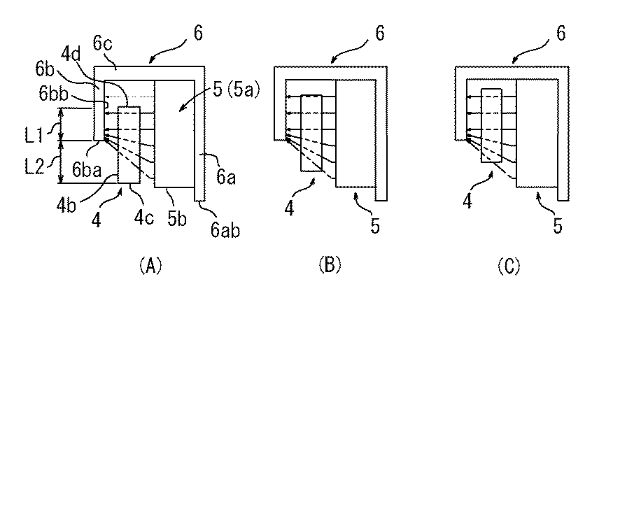
表1から分かるように、可動コイル4の断面形状を円形状から8角形状とすることにより、可動コイル4を光軸方向に駆動するローレンツ力が大きくなることが分かる。これは、可動コイル4の断面形状を8角形状とすることで、マグネット5との間隙が狭小かつ一定化され、可動コイル4を鎖交する有効磁束が多くなったからである。
As can be seen from Table 1, the Lorentz force for driving the
このように、磁気回路部の磁気効率が改善されると、レンズホルダの加速性能が向上する。レンズホルダの加速性能が向上することにより、所定の位置までレンズを移動させるのに要する時間が短縮される。これにより、合焦位置を特定するまでの所要時間をより短縮することができる。また、可動コイルに通電する駆動電流を低減でき、低消費電力化を実現することができる。さらに、可動コイルなどの構成部品の小型化を実現することができる。 Thus, when the magnetic efficiency of the magnetic circuit unit is improved, the acceleration performance of the lens holder is improved. By improving the acceleration performance of the lens holder, the time required to move the lens to a predetermined position is shortened. As a result, the time required to specify the in-focus position can be further shortened. In addition, it is possible to reduce the drive current energized to the movable coil, and to realize low power consumption. Further, it is possible to reduce the size of components such as a moving coil.
また、本実施形態においては、下側スプリング8の弾性連結部8cの内側リング8a寄りの部分に、ダンピング剤が塗布されている。これにより、レンズホルダ2を高速に移動させた後に発生する不要な振動現象を短時間に収束させることができる。この結果、合焦位置の探索に要する時間がさらに短縮される。また、落下衝撃のような外力が加わった場合に発生するおそれのある下側スプリング8の弾性連結部8cでの塑性変形が抑制されることが期待できる。
In the present embodiment, a damping agent is applied to a portion of the
〔変形例〕
以上、本発明の好ましい実施形態の一例について説明したが、実施の形態については上記に限定されるものではなく、種々の変更および組み合わせが可能である。
例えば、位置検出回路部20は、上記実施形態に限定されるものではなく、コルピッツ発振器回路を適用することにより、インダクタンス変化を周波数変化として検出するようにしてもよい。
[Modification]
As mentioned above, although an example of preferable embodiment of this invention was demonstrated, about embodiment, it is not limited above, A various change and combination are possible.
For example, the position
また、レンズ駆動ユニット1は、可動コイル4を光軸方向に対する限界可動範囲の全範囲にわたって移動させた場合に、可動コイル4の内周面4bの一部が、ヨーク内側壁部6bの外周面6bbと常に対向するように構成されているが、これに限定されない。例えば、可動コイル4の外周面の一部が、マグネット5の内周面と対向していれば、インダクタンス変化を検出することができる。
In addition, when the
また、本発明に係るレンズ駆動ユニット1は、オートフォーカス用のレンズ駆動ユニットに限定されるものではなく、例えばマクロ撮影(接写モード)のような固定の位置にレンズを直線移動させる目的のレンズ駆動ユニットとしても適用することができる。
The
また、可動コイル4の断面形状は、磁気効率の改善の観点および製造の容易さの観点からは8角形状が好ましいが、これに限定されるものではなく、8角形以外の多角形形状であってもよい。また、可動コイル4の断面形状は、多角形形状に限定されるものではなく、円形状であってもよい。
Further, the cross-sectional shape of the
さらに、マグネット5を構成する平板状のマグネット片5aの数は、8つに限定されるものではなく、可動コイル4の外周面4aを構成する各側面部の数に対応した任意の数にすることができる。また、マグネット5は、必ずしも多面体形状に構成する必要はなく、可動コイル4の断面形状が円形状の場合には、マグネット5の断面形状も円形状としてもよい。
Furthermore, the number of the
そして、下側スプリング8へのダンピング剤の塗布についても、上記実施形態に限定されるものではなく、一対のスプリング8,9にダンピング剤のいずれにも塗布してもよいし、いずれにも塗布しなくてもよい。
Further, the application of the damping agent to the
1 レンズ駆動ユニット
2 レンズホルダ
2a 円筒部
2b 鍔部
2c 突起部
3 磁気回路部
4 可動コイル
4a 外周面
4b 内周面
4c 下側端面
4d 上側端面
5 マグネット
5a マグネット片
5b 下側端面
6 ヨーク体
6a ヨーク外側壁部
6aa 内周面
6ab 下側端面
6b ヨーク内側壁部
6ba 下側端面
6bb 外周面
6c ヨーク連結部
7 フレーム
8 上側スプリング
9 下側スプリング
10 ベース
11 カバー
20 位置検出回路部
21 入力部
22 出力部
23 比較部
24 積分回路部
L 光軸
DESCRIPTION OF
Claims (6)
同レンズホルダの外周側に配置され、同レンズホルダとともに光軸方向(上下方向)に可動自在な可動コイルと、
同可動コイルの外周側に配置され磁界を形成するマグネットと、
同マグネットを内周面に保持するヨーク外側壁部、および前記可動コイルの内周側に配置されるヨーク内側壁部を有するヨーク体と、
前記レンズホルダを弾性支持するスプリングと、
前記レンズホルダの位置を検出する位置検出手段と、を備えるレンズ駆動ユニットであって、
前記ヨーク内側壁部は、その下側端面が前記マグネットの下側端面より上方に位置するように形成され、
前記位置検出手段は、前記可動コイルが前記光軸方向に変位することによって前記可動コイルに生じるインダクタンス変化から、前記レンズホルダの位置を検出することを特徴とするレンズ駆動ユニット。 A lens holder for holding the lens;
A movable coil disposed on the outer peripheral side of the lens holder and movable in the optical axis direction (vertical direction) together with the lens holder;
A magnet that is arranged on the outer peripheral side of the movable coil and forms a magnetic field;
A yoke body having a yoke outer wall portion for holding the magnet on the inner peripheral surface, and a yoke inner wall portion disposed on the inner peripheral side of the movable coil;
A spring that elastically supports the lens holder;
A lens driving unit comprising: position detecting means for detecting the position of the lens holder;
The yoke inner wall portion is formed such that its lower end surface is located above the lower end surface of the magnet,
The lens driving unit, wherein the position detecting means detects the position of the lens holder from an inductance change generated in the movable coil when the movable coil is displaced in the optical axis direction.
前記可動コイルを駆動させる駆動信号に重畳させて正弦波状の基準信号を前記可動コイル入力させる入力部と、
同基準信号に対応する前記可動コイルからの出力信号を検出する出力部と、
同基準信号と同出力信号とを差分する比較部と、を有することを特徴とする請求項1または2に記載のレンズ駆動ユニット。 The position detecting means includes
An input unit that inputs a sine wave reference signal superimposed on a drive signal that drives the movable coil;
An output unit for detecting an output signal from the movable coil corresponding to the reference signal;
The lens driving unit according to claim 1, further comprising a comparison unit that makes a difference between the reference signal and the output signal.
前記マグネットは、隣接して配置される複数の平板状のマグネット片からなるとともに、前記可動コイルの外周面を構成する各側面部に対して各マグネット片を対向配置することによって構成されていることを特徴とする請求項1から3のいずれか1項に記載のレンズ駆動ユニット。 The movable coil has a polygonal cross-sectional shape perpendicular to the optical axis,
The magnet is composed of a plurality of flat magnet pieces arranged adjacent to each other, and is configured by disposing each magnet piece so as to face each side portion constituting the outer peripheral surface of the movable coil. The lens driving unit according to claim 1, wherein:
前記ヨーク体に固定されるリング状の外側リングと、
同外側リングの内縁側に配置され前記レンズホルダに固定されるリング状の内側リングと、
同外側リングと同内側リングとを連結するとともに弾性変形が可能に構成された複数の弾性連結部とを有し、
同弾性連結部の前記内側リング寄りの部位にダンピング剤が塗布されていることを特徴とする請求項1から5のいずれか1項に記載のレンズ駆動ユニット。 The spring is
A ring-shaped outer ring fixed to the yoke body;
A ring-shaped inner ring disposed on the inner edge side of the outer ring and fixed to the lens holder;
A plurality of elastic connecting portions configured to connect the outer ring and the inner ring and be elastically deformable;
The lens driving unit according to any one of claims 1 to 5, wherein a damping agent is applied to a portion of the elastic connecting portion near the inner ring.
Priority Applications (1)
| Application Number | Priority Date | Filing Date | Title |
|---|---|---|---|
| JP2008119860A JP2009271204A (en) | 2008-05-01 | 2008-05-01 | Lens drive unit |
Applications Claiming Priority (1)
| Application Number | Priority Date | Filing Date | Title |
|---|---|---|---|
| JP2008119860A JP2009271204A (en) | 2008-05-01 | 2008-05-01 | Lens drive unit |
Publications (1)
| Publication Number | Publication Date |
|---|---|
| JP2009271204A true JP2009271204A (en) | 2009-11-19 |
Family
ID=41437829
Family Applications (1)
| Application Number | Title | Priority Date | Filing Date |
|---|---|---|---|
| JP2008119860A Pending JP2009271204A (en) | 2008-05-01 | 2008-05-01 | Lens drive unit |
Country Status (1)
| Country | Link |
|---|---|
| JP (1) | JP2009271204A (en) |
Cited By (46)
| Publication number | Priority date | Publication date | Assignee | Title |
|---|---|---|---|---|
| CN102075056A (en) * | 2009-11-20 | 2011-05-25 | Lg伊诺特有限公司 | Voice coil motor |
| KR20120006364A (en) * | 2010-07-12 | 2012-01-18 | 엘지이노텍 주식회사 | Voice coil motor |
| JP2012047794A (en) * | 2010-08-24 | 2012-03-08 | Nidec Sankyo Corp | Lens drive device |
| WO2012060521A1 (en) | 2010-11-02 | 2012-05-10 | Lg Innotek Co., Ltd. | Voice coil motor and driving method thereof |
| KR101164731B1 (en) | 2010-02-01 | 2012-07-12 | 엘지이노텍 주식회사 | Voice coil motor |
| CN102629815A (en) * | 2011-02-07 | 2012-08-08 | Lg伊诺特有限公司 | Multifunctional voice coil motor |
| CN103051144A (en) * | 2012-01-09 | 2013-04-17 | 金龙机电股份有限公司 | Voice coil motor |
| CN103176331A (en) * | 2011-12-22 | 2013-06-26 | 三星电机株式会社 | Optical image stabilizer |
| CN103309120A (en) * | 2012-03-14 | 2013-09-18 | 阿尔卑斯电气株式会社 | Lens driving device |
| CN103676402A (en) * | 2012-09-07 | 2014-03-26 | 三星电机株式会社 | Camera module |
| CN103728712A (en) * | 2013-12-30 | 2014-04-16 | 上海比路电子有限公司 | Lens driving motor structure |
| CN104283368A (en) * | 2014-10-28 | 2015-01-14 | 宜兴市贵鑫磁电高科技有限公司 | Anti-shake voice coil motor |
| JP2015031815A (en) * | 2013-08-02 | 2015-02-16 | 惠州市大亜湾永昶電子工業有限公司 | Lens driving device |
| CN104755642A (en) * | 2012-10-25 | 2015-07-01 | Jx日矿日石金属株式会社 | High-strength titanium-copper alloy |
| US20150192791A1 (en) * | 2009-08-21 | 2015-07-09 | Mitsumi Electric Co Ltd | Lens drive apparatus, camera module and camera |
| WO2015111884A1 (en) | 2014-01-22 | 2015-07-30 | Lg Electronics Inc. | Camera module and method for auto focusing thereof |
| KR20150087611A (en) * | 2014-01-22 | 2015-07-30 | 엘지전자 주식회사 | Camera module and method for auto focus thereof |
| US20150229814A1 (en) * | 2014-02-13 | 2015-08-13 | Nxp B.V. | Voice coil motor sensor and controller |
| KR20150097998A (en) * | 2014-02-19 | 2015-08-27 | 엘지전자 주식회사 | Camera module and method for auto focus thereof |
| JP2016004108A (en) * | 2014-06-16 | 2016-01-12 | ミツミ電機株式会社 | Lens holder drive device and portable terminal with camera |
| CN106533063A (en) * | 2016-09-29 | 2017-03-22 | 格科微电子(上海)有限公司 | Closed loop voice coil motor (VCM) realizing method |
| JP2017076020A (en) * | 2015-10-14 | 2017-04-20 | 新シコー科技株式会社 | Lens drive device, camera device, and electronic equipment |
| JP2017107212A (en) * | 2015-12-09 | 2017-06-15 | 台湾東電化股▲ふん▼有限公司 | Lens drive module |
| US9883098B2 (en) | 2016-03-09 | 2018-01-30 | Lg Electronics Inc. | Apparatus and method for controlling auto focus of camera module |
| US9900495B2 (en) | 2016-05-10 | 2018-02-20 | Lg Electronics Inc. | Camera module and auto focusing method thereof |
| CN107807487A (en) * | 2016-09-08 | 2018-03-16 | 三星电机株式会社 | Camera model actuator |
| CN107894645A (en) * | 2016-10-04 | 2018-04-10 | 三星电机株式会社 | The actuator of camera model |
| US20180152608A1 (en) * | 2016-11-28 | 2018-05-31 | Samsung Electro-Mechanics Co., Ltd. | Actuator of camera module |
| CN108121130A (en) * | 2016-11-30 | 2018-06-05 | 三星电机株式会社 | The actuator of camera model |
| CN108474995A (en) * | 2016-01-11 | 2018-08-31 | Lg伊诺特有限公司 | Lens driving device, camera module and optical device |
| KR20180109182A (en) * | 2017-03-27 | 2018-10-08 | 삼성전기주식회사 | Actuator and drivng apparatus of camera module |
| CN109639086A (en) * | 2018-12-24 | 2019-04-16 | 南京航空航天大学 | The voice coil motor of induction power supply |
| CN109814228A (en) * | 2017-11-22 | 2019-05-28 | 三星电机株式会社 | Utilize the device and method of the position of single coil control camera model |
| US10331013B2 (en) | 2017-04-03 | 2019-06-25 | Samsung EIectro-Mechanics Co., Ltd. | Actuator of camera module |
| WO2019202669A1 (en) * | 2018-04-17 | 2019-10-24 | オリンパス株式会社 | Position detection mechanism, imaging device, and endoscope |
| CN111323885A (en) * | 2018-12-13 | 2020-06-23 | 新思考电机有限公司 | Lens driving device, camera device and electronic equipment |
| US10698174B2 (en) | 2017-04-17 | 2020-06-30 | Samsung Electro-Mechanics Co., Ltd. | Camera module and sensing unit to detect a detection target |
| KR20200110036A (en) * | 2019-03-15 | 2020-09-23 | 삼성전기주식회사 | Camera module and actuator thereof |
| CN111708244A (en) * | 2016-07-29 | 2020-09-25 | 台湾东电化股份有限公司 | mobile mechanism |
| WO2020246820A1 (en) * | 2019-06-04 | 2020-12-10 | 엘지이노텍 주식회사 | Camera module and camera device comprising same |
| KR20200142268A (en) * | 2019-06-12 | 2020-12-22 | 엘지이노텍 주식회사 | Camera module and Camera Apparatus including the same |
| CN113064314A (en) * | 2014-12-17 | 2021-07-02 | Lg伊诺特有限公司 | Lens moving device |
| CN114609739A (en) * | 2020-12-04 | 2022-06-10 | 台湾东电化股份有限公司 | Optical element driving mechanism |
| WO2022153629A1 (en) * | 2021-01-13 | 2022-07-21 | 株式会社村田製作所 | Auto-focusing mechanism and camera module having same |
| CN115550630A (en) * | 2022-01-21 | 2022-12-30 | 荣耀终端有限公司 | A lens position detection system, detection method, voice coil motor and equipment |
| WO2025131178A1 (en) | 2023-12-22 | 2025-06-26 | Leica Camera Aktiengesellschaft | Motorised adjusting drive for an objective |
-
2008
- 2008-05-01 JP JP2008119860A patent/JP2009271204A/en active Pending
Cited By (142)
| Publication number | Priority date | Publication date | Assignee | Title |
|---|---|---|---|---|
| US10097760B2 (en) | 2009-08-21 | 2018-10-09 | Mitsumi Electric Co., Ltd. | Lens drive apparatus, camera module and camera |
| US9753301B2 (en) | 2009-08-21 | 2017-09-05 | Mitsumi Electric Co., Ltd. | Lens drive apparatus, camera module and camera |
| US10721406B2 (en) | 2009-08-21 | 2020-07-21 | Mitsumi Electric Co., Ltd. | Lens drive apparatus, camera module and camera |
| US9459465B2 (en) | 2009-08-21 | 2016-10-04 | Mitsumi Electric Co., Ltd. | Lens drive apparatus, camera module and camera |
| US9798159B2 (en) | 2009-08-21 | 2017-10-24 | Mitsumi Electronics Co., Ltd. | Lens drive apparatus, camera module and camera |
| US9766475B2 (en) | 2009-08-21 | 2017-09-19 | Mitsumi Electric Co., Ltd. | Lens drive apparatus, camera module and camera |
| US9766474B2 (en) | 2009-08-21 | 2017-09-19 | Mitsumi Electric Co., Ltd. | Lens drive apparatus, camera module and camera |
| US9477093B2 (en) | 2009-08-21 | 2016-10-25 | Mitsumi Electric Co., Ltd. | Lens drive apparatus, camera module and camera |
| US20150192791A1 (en) * | 2009-08-21 | 2015-07-09 | Mitsumi Electric Co Ltd | Lens drive apparatus, camera module and camera |
| US9625737B2 (en) | 2009-08-21 | 2017-04-18 | Mitsumi Electric Co., Ltd. | Lens drive apparatus, camera module and camera |
| US10321061B2 (en) | 2009-08-21 | 2019-06-11 | Mitsumi Electric Co., Ltd. | Camera-shake correction apparatus, camera module and camera |
| US9753302B2 (en) * | 2009-08-21 | 2017-09-05 | Mitsumi Electric Co., Ltd. | Lens drive apparatus, camera module and camera |
| US9658466B2 (en) | 2009-08-21 | 2017-05-23 | Mitsumi Electric Co., Ltd. | Lens drive apparatus, camera module and camera |
| US9651797B2 (en) | 2009-08-21 | 2017-05-16 | Mitsumi Electric Co., Ltd. | Lens drive apparatus, camera module and camera |
| US10075641B2 (en) | 2009-08-21 | 2018-09-11 | Mitsumi Electric Co., Ltd. | Lens drive apparatus, camera module and camera |
| US11159728B2 (en) | 2009-08-21 | 2021-10-26 | Mitsumi Electric Co., Ltd. | Lens drive apparatus, camera module and camera |
| US9769386B2 (en) | 2009-08-21 | 2017-09-19 | Mitsumi Electric Co., Ltd. | Lens drive apparatus, camera module and camera |
| JP2017070209A (en) * | 2009-11-20 | 2017-04-06 | エルジー イノテック カンパニー リミテッド | Voice coil motor |
| US8368255B2 (en) * | 2009-11-20 | 2013-02-05 | Lg Innotek Co., Ltd. | Voice coil motor |
| CN102075056B (en) * | 2009-11-20 | 2015-03-25 | Lg伊诺特有限公司 | Voice coil motor |
| CN104702080A (en) * | 2009-11-20 | 2015-06-10 | Lg伊诺特有限公司 | Voice coil motor |
| CN104702077A (en) * | 2009-11-20 | 2015-06-10 | Lg伊诺特有限公司 | Voice coil motor |
| CN104702081A (en) * | 2009-11-20 | 2015-06-10 | Lg伊诺特有限公司 | Voice coil motor |
| CN104702079A (en) * | 2009-11-20 | 2015-06-10 | Lg伊诺特有限公司 | Voice coil motor |
| US20110121666A1 (en) * | 2009-11-20 | 2011-05-26 | Lg Innotek Co., Ltd. | Voice Coil Motor |
| JP2018139490A (en) * | 2009-11-20 | 2018-09-06 | エルジー イノテック カンパニー リミテッド | Voice coil motor |
| CN102075056A (en) * | 2009-11-20 | 2011-05-25 | Lg伊诺特有限公司 | Voice coil motor |
| JP2020014381A (en) * | 2009-11-20 | 2020-01-23 | エルジー イノテック カンパニー リミテッド | Voice coil motor |
| KR101081630B1 (en) * | 2009-11-20 | 2011-11-09 | 엘지이노텍 주식회사 | Voice coil motor |
| JP2015146731A (en) * | 2009-11-20 | 2015-08-13 | エルジー イノテック カンパニー リミテッド | Voice coil motor |
| JP2011109908A (en) * | 2009-11-20 | 2011-06-02 | Lg Innotek Co Ltd | Voice coil motor |
| KR101164731B1 (en) | 2010-02-01 | 2012-07-12 | 엘지이노텍 주식회사 | Voice coil motor |
| KR101691231B1 (en) * | 2010-07-12 | 2016-12-29 | 엘지이노텍 주식회사 | Voice coil motor |
| KR20120006364A (en) * | 2010-07-12 | 2012-01-18 | 엘지이노텍 주식회사 | Voice coil motor |
| JP2012047794A (en) * | 2010-08-24 | 2012-03-08 | Nidec Sankyo Corp | Lens drive device |
| KR101164755B1 (en) | 2010-11-02 | 2012-07-12 | 엘지이노텍 주식회사 | Voice coil motor and method of driving thereof |
| US10254504B2 (en) | 2010-11-02 | 2019-04-09 | Lg Innotek Co., Ltd. | Voice coil motor and driving method thereof |
| CN105720783A (en) * | 2010-11-02 | 2016-06-29 | Lg伊诺特有限公司 | Voice coil motor and driving method thereof |
| CN105763016A (en) * | 2010-11-02 | 2016-07-13 | Lg伊诺特有限公司 | Voice coil motor and driving method thereof |
| US9429734B2 (en) | 2010-11-02 | 2016-08-30 | Lg Innotek Co., Ltd. | Voice coil motor and driving method thereof |
| US9448383B2 (en) | 2010-11-02 | 2016-09-20 | Lg Innotek Co., Ltd. | Voice coil motor and driving method thereof |
| CN103201934A (en) * | 2010-11-02 | 2013-07-10 | Lg伊诺特有限公司 | Voice coil motor and driving method thereof |
| WO2012060521A1 (en) | 2010-11-02 | 2012-05-10 | Lg Innotek Co., Ltd. | Voice coil motor and driving method thereof |
| CN102629815B (en) * | 2011-02-07 | 2016-04-06 | Lg伊诺特有限公司 | Multifunctional voice coil motor |
| CN102629815A (en) * | 2011-02-07 | 2012-08-08 | Lg伊诺特有限公司 | Multifunctional voice coil motor |
| US9455617B2 (en) | 2011-02-07 | 2016-09-27 | Lg Innotek Co., Ltd. | Multifunctional voice coil motor having a rotor including a bobbin and a plurality of magnets |
| CN103176331A (en) * | 2011-12-22 | 2013-06-26 | 三星电机株式会社 | Optical image stabilizer |
| CN103051144A (en) * | 2012-01-09 | 2013-04-17 | 金龙机电股份有限公司 | Voice coil motor |
| CN103309120A (en) * | 2012-03-14 | 2013-09-18 | 阿尔卑斯电气株式会社 | Lens driving device |
| US9360735B2 (en) | 2012-09-07 | 2016-06-07 | Samsung Electro-Mechanics Co., Ltd. | Camera module |
| CN103676402A (en) * | 2012-09-07 | 2014-03-26 | 三星电机株式会社 | Camera module |
| CN104755642B (en) * | 2012-10-25 | 2017-03-22 | Jx日矿日石金属株式会社 | High-strength titanium-copper alloy |
| CN104755642A (en) * | 2012-10-25 | 2015-07-01 | Jx日矿日石金属株式会社 | High-strength titanium-copper alloy |
| JP2015031815A (en) * | 2013-08-02 | 2015-02-16 | 惠州市大亜湾永昶電子工業有限公司 | Lens driving device |
| CN103728712A (en) * | 2013-12-30 | 2014-04-16 | 上海比路电子有限公司 | Lens driving motor structure |
| CN104937482B (en) * | 2014-01-22 | 2018-07-13 | Lg电子株式会社 | Camera model and its auto focusing method |
| US9983380B2 (en) | 2014-01-22 | 2018-05-29 | Lg Electronics Inc. | Camera module and method for auto focusing thereof |
| EP3097452A4 (en) * | 2014-01-22 | 2017-06-28 | LG Electronics Inc. | Camera module and method for auto focusing thereof |
| CN104937482A (en) * | 2014-01-22 | 2015-09-23 | Lg电子株式会社 | Camera module and method for auto focusing thereof |
| WO2015111884A1 (en) | 2014-01-22 | 2015-07-30 | Lg Electronics Inc. | Camera module and method for auto focusing thereof |
| JP2016537665A (en) * | 2014-01-22 | 2016-12-01 | エルジー エレクトロニクス インコーポレイティド | Camera module and autofocus method thereof |
| KR20150087611A (en) * | 2014-01-22 | 2015-07-30 | 엘지전자 주식회사 | Camera module and method for auto focus thereof |
| KR102138528B1 (en) * | 2014-01-22 | 2020-07-28 | 엘지전자 주식회사 | Camera module and method for auto focus thereof |
| CN104852643B (en) * | 2014-02-13 | 2018-04-17 | 恩智浦有限公司 | Voice coil motor sensor and controller |
| US9661198B2 (en) | 2014-02-13 | 2017-05-23 | Nxp B.V. | Voice coil motor displacement sensor and controller |
| CN104852643A (en) * | 2014-02-13 | 2015-08-19 | 恩智浦有限公司 | Voice coil motor sensor and controller |
| US20150229814A1 (en) * | 2014-02-13 | 2015-08-13 | Nxp B.V. | Voice coil motor sensor and controller |
| EP2908428A1 (en) * | 2014-02-13 | 2015-08-19 | Nxp B.V. | Voice coil motor sensor and controller |
| KR102169957B1 (en) * | 2014-02-19 | 2020-10-26 | 엘지전자 주식회사 | Camera module and method for auto focus thereof |
| KR20150097998A (en) * | 2014-02-19 | 2015-08-27 | 엘지전자 주식회사 | Camera module and method for auto focus thereof |
| US10451834B2 (en) | 2014-06-16 | 2019-10-22 | Mitsumi Electric Co., Ltd. | Lens holder driving device and mobile terminal with camera |
| JP2016004108A (en) * | 2014-06-16 | 2016-01-12 | ミツミ電機株式会社 | Lens holder drive device and portable terminal with camera |
| KR20170017919A (en) | 2014-06-16 | 2017-02-15 | 미쓰미덴기가부시기가이샤 | Lens Holder Driving Device and Mobile Terminal with Camera |
| US11137568B2 (en) | 2014-06-16 | 2021-10-05 | Mitsumi Electric Co., Ltd. | Lens holder driving device and mobile terminal with camera |
| KR20230028597A (en) | 2014-06-16 | 2023-02-28 | 미쓰미덴기가부시기가이샤 | Lens Holder Driving Device and Mobile Terminal with Camera |
| CN104283368A (en) * | 2014-10-28 | 2015-01-14 | 宜兴市贵鑫磁电高科技有限公司 | Anti-shake voice coil motor |
| CN113064314A (en) * | 2014-12-17 | 2021-07-02 | Lg伊诺特有限公司 | Lens moving device |
| US11360321B2 (en) | 2014-12-17 | 2022-06-14 | Lg Innotek Co., Ltd. | Lens moving apparatus |
| CN113064314B (en) * | 2014-12-17 | 2022-09-27 | Lg伊诺特有限公司 | Lens moving device |
| US11774775B2 (en) | 2014-12-17 | 2023-10-03 | Lg Innotek Co., Ltd. | Lens moving apparatus |
| US12529901B2 (en) | 2014-12-17 | 2026-01-20 | Lg Innotek Co., Ltd. | Lens moving apparatus |
| US10884215B2 (en) | 2015-10-14 | 2021-01-05 | New Shicoh Technology Co., Ltd. | Lens driving device, camera device, and electronic apparatus |
| JP2017076020A (en) * | 2015-10-14 | 2017-04-20 | 新シコー科技株式会社 | Lens drive device, camera device, and electronic equipment |
| JP2017107212A (en) * | 2015-12-09 | 2017-06-15 | 台湾東電化股▲ふん▼有限公司 | Lens drive module |
| CN108474995B (en) * | 2016-01-11 | 2021-06-08 | Lg伊诺特有限公司 | Lens driving device, camera module, and optical device |
| CN113341526A (en) * | 2016-01-11 | 2021-09-03 | Lg伊诺特有限公司 | Lens driving device, camera module, and optical device |
| US11079567B2 (en) | 2016-01-11 | 2021-08-03 | Lg Innotek Co., Ltd. | Lens driving device, camera module, and optical device |
| CN108474995A (en) * | 2016-01-11 | 2018-08-31 | Lg伊诺特有限公司 | Lens driving device, camera module and optical device |
| EP3404477A4 (en) * | 2016-01-11 | 2019-08-28 | LG Innotek Co., Ltd. | LENS TRAINING DEVICE, SHOOTING APPARATUS MODULE, AND OPTICAL DEVICE |
| CN113341525A (en) * | 2016-01-11 | 2021-09-03 | Lg伊诺特有限公司 | Lens driving device, camera module, and optical device |
| US11815734B2 (en) | 2016-01-11 | 2023-11-14 | Lg Innotek Co., Ltd. | Lens driving device, camera module, and optical device |
| CN113341526B (en) * | 2016-01-11 | 2024-04-09 | Lg伊诺特有限公司 | Lens driving device, camera module and optical device |
| CN113341525B (en) * | 2016-01-11 | 2023-10-27 | Lg伊诺特有限公司 | Lens driving devices, camera modules and optical devices |
| US9883098B2 (en) | 2016-03-09 | 2018-01-30 | Lg Electronics Inc. | Apparatus and method for controlling auto focus of camera module |
| US9942462B2 (en) | 2016-03-09 | 2018-04-10 | Lg Electronics Inc. | Apparatus and method for controlling auto focus of camera module |
| US9930223B2 (en) | 2016-03-09 | 2018-03-27 | Lg Electronics Inc. | Apparatus and method for controlling auto focus of camera module |
| US9900495B2 (en) | 2016-05-10 | 2018-02-20 | Lg Electronics Inc. | Camera module and auto focusing method thereof |
| CN111708244A (en) * | 2016-07-29 | 2020-09-25 | 台湾东电化股份有限公司 | mobile mechanism |
| CN111708244B (en) * | 2016-07-29 | 2022-03-29 | 台湾东电化股份有限公司 | Moving mechanism |
| US10830983B2 (en) | 2016-09-08 | 2020-11-10 | Samusng Electro-Mechanics Co., Ltd. | Camera module actuator |
| KR101892811B1 (en) * | 2016-09-08 | 2018-10-05 | 삼성전기주식회사 | Actuator of camera module |
| CN107807487A (en) * | 2016-09-08 | 2018-03-16 | 三星电机株式会社 | Camera model actuator |
| CN107807487B (en) * | 2016-09-08 | 2021-02-02 | 三星电机株式会社 | Camera module actuator |
| CN106533063A (en) * | 2016-09-29 | 2017-03-22 | 格科微电子(上海)有限公司 | Closed loop voice coil motor (VCM) realizing method |
| CN107894645A (en) * | 2016-10-04 | 2018-04-10 | 三星电机株式会社 | The actuator of camera model |
| US11163211B2 (en) | 2016-10-04 | 2021-11-02 | Samsung Electro-Mechanics Co., Ltd. | Camera module actuator |
| US20180152608A1 (en) * | 2016-11-28 | 2018-05-31 | Samsung Electro-Mechanics Co., Ltd. | Actuator of camera module |
| CN108121131A (en) * | 2016-11-28 | 2018-06-05 | 三星电机株式会社 | The actuator of camera model |
| KR20180060212A (en) * | 2016-11-28 | 2018-06-07 | 삼성전기주식회사 | Actuator of camera module |
| US10868946B2 (en) | 2016-11-28 | 2020-12-15 | Samsung Electro-Mechanics Co., Ltd. | Actuator of camera module |
| KR102194710B1 (en) * | 2016-11-28 | 2020-12-23 | 삼성전기주식회사 | Actuator of camera module |
| US10451835B2 (en) | 2016-11-30 | 2019-10-22 | Samsung Electro-Mechanics Co., Ltd. | Actuator of camera module |
| KR20180061848A (en) * | 2016-11-30 | 2018-06-08 | 삼성전기주식회사 | Actuator of camera module |
| KR102059820B1 (en) * | 2016-11-30 | 2019-12-27 | 삼성전기주식회사 | Actuator of camera module |
| CN108121130A (en) * | 2016-11-30 | 2018-06-05 | 三星电机株式会社 | The actuator of camera model |
| KR102059821B1 (en) * | 2017-03-27 | 2019-12-27 | 삼성전기주식회사 | Actuator and drivng apparatus of camera module |
| KR20180109182A (en) * | 2017-03-27 | 2018-10-08 | 삼성전기주식회사 | Actuator and drivng apparatus of camera module |
| US10331013B2 (en) | 2017-04-03 | 2019-06-25 | Samsung EIectro-Mechanics Co., Ltd. | Actuator of camera module |
| US10698174B2 (en) | 2017-04-17 | 2020-06-30 | Samsung Electro-Mechanics Co., Ltd. | Camera module and sensing unit to detect a detection target |
| KR102029541B1 (en) * | 2017-11-22 | 2019-10-07 | 삼성전기주식회사 | Position control apparatus of camera module using single coil |
| CN109814228B (en) * | 2017-11-22 | 2021-11-23 | 三星电机株式会社 | Apparatus and method for controlling position of camera module using single coil |
| KR20190059101A (en) * | 2017-11-22 | 2019-05-30 | 삼성전기주식회사 | Position control apparatus of camera module using single coil |
| CN109814228A (en) * | 2017-11-22 | 2019-05-28 | 三星电机株式会社 | Utilize the device and method of the position of single coil control camera model |
| US11036026B2 (en) | 2017-11-22 | 2021-06-15 | Samsung Electro-Mechanics Co., Ltd. | Apparatus and method controlling position of camera module with a single coil |
| WO2019202669A1 (en) * | 2018-04-17 | 2019-10-24 | オリンパス株式会社 | Position detection mechanism, imaging device, and endoscope |
| CN111323885A (en) * | 2018-12-13 | 2020-06-23 | 新思考电机有限公司 | Lens driving device, camera device and electronic equipment |
| CN109639086A (en) * | 2018-12-24 | 2019-04-16 | 南京航空航天大学 | The voice coil motor of induction power supply |
| KR20200110036A (en) * | 2019-03-15 | 2020-09-23 | 삼성전기주식회사 | Camera module and actuator thereof |
| KR102653204B1 (en) | 2019-03-15 | 2024-04-01 | 삼성전기주식회사 | Camera module and actuator thereof |
| US12294777B2 (en) | 2019-06-04 | 2025-05-06 | Lg Innotek Co., Ltd. | Camera module and camera device comprising same |
| WO2020246820A1 (en) * | 2019-06-04 | 2020-12-10 | 엘지이노텍 주식회사 | Camera module and camera device comprising same |
| US11902643B2 (en) | 2019-06-04 | 2024-02-13 | Lg Innotek Co., Ltd. | Camera module and camera device comprising same |
| CN114080563B (en) * | 2019-06-04 | 2024-04-30 | Lg伊诺特有限公司 | Camera module and camera device including the same |
| CN114080563A (en) * | 2019-06-04 | 2022-02-22 | Lg伊诺特有限公司 | Camera module and camera apparatus including the same |
| KR20200142268A (en) * | 2019-06-12 | 2020-12-22 | 엘지이노텍 주식회사 | Camera module and Camera Apparatus including the same |
| KR102863114B1 (en) * | 2019-06-12 | 2025-09-24 | 엘지이노텍 주식회사 | Camera module and Camera Apparatus including the same |
| CN114609739A (en) * | 2020-12-04 | 2022-06-10 | 台湾东电化股份有限公司 | Optical element driving mechanism |
| WO2022153629A1 (en) * | 2021-01-13 | 2022-07-21 | 株式会社村田製作所 | Auto-focusing mechanism and camera module having same |
| CN115550630A (en) * | 2022-01-21 | 2022-12-30 | 荣耀终端有限公司 | A lens position detection system, detection method, voice coil motor and equipment |
| WO2025131178A1 (en) | 2023-12-22 | 2025-06-26 | Leica Camera Aktiengesellschaft | Motorised adjusting drive for an objective |
| DE102023136676A1 (en) * | 2023-12-22 | 2025-06-26 | Leica Camera Aktiengesellschaft | Motorized adjustment drive for lenses |
| DE102023136676B4 (en) * | 2023-12-22 | 2025-08-28 | Leica Camera Aktiengesellschaft | Motorized adjustment drive for lenses |
Similar Documents
| Publication | Publication Date | Title |
|---|---|---|
| JP2009271204A (en) | Lens drive unit | |
| CN112114468B (en) | Lens driving device, camera module and optical apparatus | |
| JP6666538B2 (en) | Lens driving device, camera module, and mobile terminal with camera | |
| CN100570425C (en) | camera module | |
| KR101717207B1 (en) | Combined plate spring and camera lens module capable of optical image stabilization with the same | |
| KR101073442B1 (en) | Leaf spring, lens driver and method for manufacturing the leaf spring | |
| US7751134B2 (en) | Lens actuator, and electronic device using the same | |
| JP5105080B2 (en) | Lens drive device | |
| KR102214331B1 (en) | Camera module | |
| KR20100125978A (en) | Lens Actuator for Magnet Movement Type Image Imaging | |
| KR20160059143A (en) | Lens driving unit and camera module including the same | |
| JP5591571B2 (en) | Lens drive device | |
| KR100987934B1 (en) | Lens drive | |
| JP2013250299A (en) | Lens driving device with camera shake correcting function | |
| KR20180119595A (en) | A lens driving device, a camera module, and a camera mounting device | |
| JP2010160435A (en) | Lens driving device and camera module mounted with the lens driving device | |
| KR101333185B1 (en) | Auto focus camera module | |
| JP5827923B2 (en) | Lens drive magnetic circuit | |
| KR102775840B1 (en) | Lens moving unit and camera module having the same | |
| JP2013246301A (en) | Lens actuator | |
| JP5424000B2 (en) | Lens holder driving device | |
| KR100926686B1 (en) | Small camera | |
| KR20150087611A (en) | Camera module and method for auto focus thereof | |
| KR20140100740A (en) | Lens drive device | |
| CN113671657B (en) | Lens driving device, camera device and electronic equipment |