KR20180119595A - A lens driving device, a camera module, and a camera mounting device - Google Patents
A lens driving device, a camera module, and a camera mounting device Download PDFInfo
- Publication number
- KR20180119595A KR20180119595A KR1020187026039A KR20187026039A KR20180119595A KR 20180119595 A KR20180119595 A KR 20180119595A KR 1020187026039 A KR1020187026039 A KR 1020187026039A KR 20187026039 A KR20187026039 A KR 20187026039A KR 20180119595 A KR20180119595 A KR 20180119595A
- Authority
- KR
- South Korea
- Prior art keywords
- magnet
- section
- rectilinear section
- autofocus
- coil
- Prior art date
- Legal status (The legal status is an assumption and is not a legal conclusion. Google has not performed a legal analysis and makes no representation as to the accuracy of the status listed.)
- Withdrawn
Links
Images


Classifications
-
- G—PHYSICS
- G03—PHOTOGRAPHY; CINEMATOGRAPHY; ANALOGOUS TECHNIQUES USING WAVES OTHER THAN OPTICAL WAVES; ELECTROGRAPHY; HOLOGRAPHY
- G03B—APPARATUS OR ARRANGEMENTS FOR TAKING PHOTOGRAPHS OR FOR PROJECTING OR VIEWING THEM; APPARATUS OR ARRANGEMENTS EMPLOYING ANALOGOUS TECHNIQUES USING WAVES OTHER THAN OPTICAL WAVES; ACCESSORIES THEREFOR
- G03B13/00—Viewfinders; Focusing aids for cameras; Means for focusing for cameras; Autofocus systems for cameras
- G03B13/32—Means for focusing
- G03B13/34—Power focusing
- G03B13/36—Autofocus systems
-
- G—PHYSICS
- G02—OPTICS
- G02B—OPTICAL ELEMENTS, SYSTEMS OR APPARATUS
- G02B7/00—Mountings, adjusting means, or light-tight connections, for optical elements
- G02B7/02—Mountings, adjusting means, or light-tight connections, for optical elements for lenses
- G02B7/04—Mountings, adjusting means, or light-tight connections, for optical elements for lenses with mechanism for focusing or varying magnification
- G02B7/09—Mountings, adjusting means, or light-tight connections, for optical elements for lenses with mechanism for focusing or varying magnification adapted for automatic focusing or varying magnification
-
- G—PHYSICS
- G02—OPTICS
- G02B—OPTICAL ELEMENTS, SYSTEMS OR APPARATUS
- G02B7/00—Mountings, adjusting means, or light-tight connections, for optical elements
- G02B7/02—Mountings, adjusting means, or light-tight connections, for optical elements for lenses
- G02B7/04—Mountings, adjusting means, or light-tight connections, for optical elements for lenses with mechanism for focusing or varying magnification
- G02B7/08—Mountings, adjusting means, or light-tight connections, for optical elements for lenses with mechanism for focusing or varying magnification adapted to co-operate with a remote control mechanism
-
- G—PHYSICS
- G03—PHOTOGRAPHY; CINEMATOGRAPHY; ANALOGOUS TECHNIQUES USING WAVES OTHER THAN OPTICAL WAVES; ELECTROGRAPHY; HOLOGRAPHY
- G03B—APPARATUS OR ARRANGEMENTS FOR TAKING PHOTOGRAPHS OR FOR PROJECTING OR VIEWING THEM; APPARATUS OR ARRANGEMENTS EMPLOYING ANALOGOUS TECHNIQUES USING WAVES OTHER THAN OPTICAL WAVES; ACCESSORIES THEREFOR
- G03B15/00—Special procedures for taking photographs; Apparatus therefor
-
- G—PHYSICS
- G03—PHOTOGRAPHY; CINEMATOGRAPHY; ANALOGOUS TECHNIQUES USING WAVES OTHER THAN OPTICAL WAVES; ELECTROGRAPHY; HOLOGRAPHY
- G03B—APPARATUS OR ARRANGEMENTS FOR TAKING PHOTOGRAPHS OR FOR PROJECTING OR VIEWING THEM; APPARATUS OR ARRANGEMENTS EMPLOYING ANALOGOUS TECHNIQUES USING WAVES OTHER THAN OPTICAL WAVES; ACCESSORIES THEREFOR
- G03B17/00—Details of cameras or camera bodies; Accessories therefor
- G03B17/02—Bodies
-
- G—PHYSICS
- G03—PHOTOGRAPHY; CINEMATOGRAPHY; ANALOGOUS TECHNIQUES USING WAVES OTHER THAN OPTICAL WAVES; ELECTROGRAPHY; HOLOGRAPHY
- G03B—APPARATUS OR ARRANGEMENTS FOR TAKING PHOTOGRAPHS OR FOR PROJECTING OR VIEWING THEM; APPARATUS OR ARRANGEMENTS EMPLOYING ANALOGOUS TECHNIQUES USING WAVES OTHER THAN OPTICAL WAVES; ACCESSORIES THEREFOR
- G03B30/00—Camera modules comprising integrated lens units and imaging units, specially adapted for being embedded in other devices, e.g. mobile phones or vehicles
-
- H—ELECTRICITY
- H04—ELECTRIC COMMUNICATION TECHNIQUE
- H04N—PICTORIAL COMMUNICATION, e.g. TELEVISION
- H04N23/00—Cameras or camera modules comprising electronic image sensors; Control thereof
- H04N23/50—Constructional details
- H04N23/55—Optical parts specially adapted for electronic image sensors; Mounting thereof
-
- H04N5/2253—
-
- H04N5/2254—
-
- G—PHYSICS
- G06—COMPUTING OR CALCULATING; COUNTING
- G06F—ELECTRIC DIGITAL DATA PROCESSING
- G06F1/00—Details not covered by groups G06F3/00 - G06F13/00 and G06F21/00
- G06F1/16—Constructional details or arrangements
- G06F1/1613—Constructional details or arrangements for portable computers
- G06F1/1633—Constructional details or arrangements of portable computers not specific to the type of enclosures covered by groups G06F1/1615 - G06F1/1626
- G06F1/1684—Constructional details or arrangements related to integrated I/O peripherals not covered by groups G06F1/1635 - G06F1/1675
- G06F1/1686—Constructional details or arrangements related to integrated I/O peripherals not covered by groups G06F1/1635 - G06F1/1675 the I/O peripheral being an integrated camera
Landscapes
- Physics & Mathematics (AREA)
- General Physics & Mathematics (AREA)
- Optics & Photonics (AREA)
- Engineering & Computer Science (AREA)
- Multimedia (AREA)
- Signal Processing (AREA)
- Lens Barrels (AREA)
Abstract
원하는 추력 및 리니어리티 성능을 가짐과 함께, 소형화, 박형화를 도모할 수 있는 렌즈 구동 장치, 카메라 모듈 및 카메라 탑재 장치를 제공한다. 렌즈 구동 장치는, 광축 방향 수광 측에 위치하는 제1 직선부 및 광축 방향 결상 측에 위치하는 제2 직선부를 갖는 편평형의 AF용 코일과, 제1 직선부에 대향하는 제1 마그넷 및 제2 직선부에 대향하는 제2 마그넷으로 구성되어 이루어지는 편면 이극의 AF용 마그넷과, 제1 마그넷의 광축 방향 수광 측의 면을 덮도록 배치되는 요크를 구비한다. 제1 마그넷의 제1 직선부와 대향하는 면의 면적은, 제2 마그넷의 제2 직선부와 대향하는 면의 면적보다 크고, AF 가동부의 가동 범위 전체 영역에 걸쳐서, 제1 직선부를 횡단하는 자속이, 제2 직선부를 횡단하는 자속보다 많다.Provided are a lens driving device, a camera module, and a camera mounting device capable of achieving a desired thrust and a linearity performance as well as downsizing and thinning. The lens driving apparatus includes a flat AF coil having a first linear portion positioned on the light receiving side in the optical axis direction and a second linear portion positioned on the image side in the optical axis direction, a first magnet and a second straight line opposed to the first linear portion, And a yoke disposed so as to cover the surface on the light receiving side of the first magnet in the direction of the optical axis. The AF magnet is composed of a first magnet and a second magnet opposed to each other. The area of the surface of the first magnet facing the first rectilinear section is larger than the area of the surface of the second magnet facing the second rectilinear section and the magnetic flux crossing the first rectilinear section across the entire movable range of the AF moving section Is larger than the magnetic flux crossing the second rectilinear section.
Description
본 발명은, 오토 포커스용의 렌즈 구동 장치, 오토 포커스 기능을 갖는 카메라 모듈, 및 카메라 탑재 장치에 관한 것이다.The present invention relates to a lens driving apparatus for autofocus, a camera module having an autofocus function, and a camera mounting apparatus.
일반적으로, 스마트폰 등의 휴대 단말에는, 소형의 카메라 모듈이 탑재되어 있다. 이와 같은 카메라 모듈에는, 피사체를 촬영할 때의 핀트 맞춤을 자동적으로 행하는 오토 포커스 기능(이하 "AF 기능"이라고 칭함, AF: Auto Focus)을 갖는 렌즈 구동 장치가 적용된다(예를 들면 특허문헌 1, 2).Generally, a small camera module is mounted on a portable terminal such as a smart phone. Such a camera module is applied to a lens driving apparatus having an autofocus function (hereinafter referred to as "AF function ", AF: Auto Focus) for automatically performing a focus adjustment when a subject is photographed (for example, 2).
오토 포커스용의 렌즈 구동 장치는, 예를 들면 렌즈부의 주위에 배치되는 오토 포커스용 코일(이하 "AF용 코일"이라고 칭함)과, AF용 코일에 대하여 직경 방향으로 이간하여 배치되는 오토 포커스용 마그넷(이하 "AF용 마그넷"이라고 칭함)과, 예를 들면 AF용 마그넷을 포함하는 오토 포커스 고정부(이하 "AF 고정부"라고 칭함)에 대하여 렌즈부 및 AF용 코일을 포함하는 오토 포커스 가동부(이하 "AF 가동부"라고 칭함)를 탄성 지지하는 탄성 지지부(예를 들면 판 스프링)를 구비한다. AF용 코일과 AF용 마그넷으로 구성되는 보이스 코일 모터의 구동력을 이용하여, AF 고정부에 대하여 AF 가동부를 광축 방향으로 이동시킴으로써, 자동적으로 핀트 맞춤이 행해진다. 또한, AF 고정부가 AF용 코일을 포함하고, AF 가동부가 AF용 마그넷을 포함하는 경우도 있다.The lens driving device for autofocus includes, for example, an autofocus coil (hereinafter referred to as "AF coil") disposed around the lens portion, and an autofocus magnet disposed apart from the AF coil in the radial direction (Hereinafter referred to as " AF magnet ") including an AF magnet and an AF focusing magnet (hereinafter referred to as " AF magnet" (Hereinafter referred to as "AF moving part"). The focusing operation is automatically performed by moving the AF moving portion in the optical axis direction with respect to the AF fixing portion by using the driving force of the voice coil motor constituted by the AF coil and the AF magnet. In some cases, the AF fixing section includes an AF coil, and the AF moving section includes an AF magnet.
특허문헌 1, 2에 기재된 렌즈 구동 장치에 있어서는, AF용 마그넷과 함께 자기 회로를 형성하는 요크가 마련되어 있고, 이 요크가 렌즈 구동 장치의 케이싱이 되고 있다. 또, 요크는 AF용 보이스 코일 모터의 추력을 높이기 위하여, 천장면의 내주연(內周緣)이 전체적으로 내측으로 돌출되어 형성되고, AF용 코일을 사이에 두고 AF용 마그넷과 대향하는 위치에는 대향 요크부가 마련되어 있다.In the lens driving apparatus described in
그런데, 스마트폰이나 태블릿 PC 등의 휴대 단말에 탑재되는 카메라 모듈에 있어서는, 추가적인 소형, 박형화가 요구되고 있다. 그러나, 카메라 모듈의 소형화, 박형화에는, 통상, 추력의 저하나 리니어리티 성능의 악화가 수반되기 때문에, 이들의 특성 열화를 회피하면서 실현되는 것이 중요해진다. 리니어리티 성능이란, AF 가동부의 스트로크와, 필요한 구동력의 관계를 나타내는 지표이고, 선형성을 갖는 경우에 리니어리티 성능이 높다. 카메라 모듈에 있어서는, AF용 코일에 대한 통전 전류를 제어함에 있어서, 리니어리티 성능은 높은 것이 바람직하다.However, a camera module mounted on a portable terminal such as a smart phone or a tablet PC is required to be further reduced in size and thickness. However, since miniaturization and thinning of the camera module generally involve a decrease in thrust and a deterioration in linearity performance, it is important to realize such reduction while avoiding deterioration of these characteristics. The linearity performance is an index indicating the relationship between the stroke of the AF moving part and the required driving force, and the linearity performance is high when the linearity is satisfied. In the camera module, it is preferable that the linearity performance is high in controlling the energizing current for the AF coil.
본 발명의 목적은, 원하는 추력 및 리니어리티 성능을 가짐과 함께, 소형화, 박형화를 도모할 수 있는 렌즈 구동 장치, 카메라 모듈 및 카메라 탑재 장치를 제공하는 것이다.An object of the present invention is to provide a lens driving apparatus, a camera module, and a camera mounting apparatus which have a desired thrust and linearity performance and are capable of downsizing and thinning.
본 발명의 일 측면을 반영한 렌즈 구동 장치는, 렌즈부의 주위에 배치되는 오토 포커스용 코일과, 상기 오토 포커스용 코일에 대하여 직경 방향으로 이간하여 배치되는 오토 포커스용 마그넷과, 상기 오토 포커스용 마그넷과 함께 자기 회로를 형성하는 요크를 갖고, 상기 오토 포커스용 코일과 상기 오토 포커스용 마그넷으로 구성되는 보이스 코일 모터의 구동력을 이용하여, 상기 오토 포커스용 마그넷 및 상기 요크를 포함하는 오토 포커스 고정부에 대하여, 상기 오토 포커스용 코일을 포함하는 오토 포커스 가동부를 광축 방향으로 이동시킴으로써 자동적으로 핀트 맞춤을 행하는 렌즈 구동 장치로서,A lens driving apparatus that reflects one aspect of the present invention includes an autofocus coil disposed around a lens portion, an autofocus magnet disposed apart from the autofocus coil in the radial direction, And a yoke for forming a magnetic circuit together, wherein a driving force of a voice coil motor composed of the autofocusing coil and the autofocusing magnet is used to drive the autofocus fixing unit including the autofocusing magnet and the yoke , And a lens driving apparatus for performing automatic focusing by moving an autofocus movable section including the autofocus coil in an optical axis direction,
상기 오토 포커스용 코일은, 제1 직선부 및 제2 직선부를 갖는 타원형상의 편평 코일이고, 상기 제1 직선부가 광축 방향 수광 측, 상기 제2 직선부가 광축 방향 결상 측이 되도록 배치되며,Wherein the autofocus coil is an elliptical flat coil having a first rectilinear section and a second rectilinear section and the first rectilinear section is disposed on the light receiving side in the optical axis direction and the second rectilinear section is disposed on the optical axis direction imaging side,
상기 오토 포커스용 마그넷은, 제1 마그넷 및 제2 마그넷으로 구성되어 이루어지는 편면 이극의 마그넷이고, 상기 제1 마그넷이 상기 제1 직선부에 대향하며, 상기 제2 마그넷이 상기 제2 직선부에 대향하도록 배치되고,Wherein the autofocus magnet is a one-sided magnet having a first magnet and a second magnet, the first magnet is opposed to the first rectilinear portion, and the second magnet is opposed to the second rectilinear portion, Lt; / RTI >
상기 요크는, 상기 제1 마그넷의 광축 방향 수광 측의 면을 덮도록 배치되며,The yoke is disposed so as to cover a surface on the light receiving side of the first magnet in the optical axis direction,
상기 제1 마그넷의 상기 제1 직선부와 대향하는 면의 면적은, 상기 제2 마그넷의 상기 제2 직선부와 대향하는 면의 면적보다 크고,The area of the surface of the first magnet facing the first rectilinear section is larger than the area of the surface of the second magnet facing the second rectilinear section,
상기 오토 포커스 가동부의 가동 범위 전체 영역에 걸쳐서, 상기 제1 직선부를 횡단하는 자속이, 상기 제2 직선부를 횡단하는 자속보다 많은 것을 특징으로 한다.And the magnetic flux traversing the first rectilinear section is greater than the magnetic flux traversing the second rectilinear section over the entire movable range of the autofocus moving section.
본 발명의 일 측면을 반영한 카메라 모듈은, 상기의 렌즈 구동 장치와,The camera module, which reflects one aspect of the present invention,
상기 렌즈 구동 장치에 장착되는 렌즈부와,A lens unit mounted on the lens driving device,
상기 렌즈부에 의하여 결상된 피사체상을 촬상하는 촬상부를 구비하는 것을 특징으로 한다.And an image pickup section for picking up an image of a subject image formed by the lens section.
본 발명의 일 측면을 반영한 카메라 탑재 장치는, 정보 기기 또는 수송 기기인 카메라 탑재 장치로서,A camera mounting apparatus reflecting one aspect of the present invention is a camera mounting apparatus which is an information apparatus or a transportation apparatus,
상기의 카메라 모듈을 구비하는 것을 특징으로 한다.And the camera module described above.
본 발명에 의하면, 원하는 추력 및 리니어리티 성능을 가짐과 함께, 소형화, 박형화를 도모할 수 있는 렌즈 구동 장치, 카메라 모듈 및 카메라 탑재 장치가 제공된다.According to the present invention, there is provided a lens driving apparatus, a camera module, and a camera mounting apparatus which have a desired thrust and linearity performance and are capable of downsizing and thinning.
도 1은 본 발명의 일 실시형태에 관한 카메라 모듈을 탑재하는 스마트폰을 나타내는 도이다.
도 2는 카메라 모듈의 외관 사시도이다.
도 3은 렌즈 구동 장치의 상방에서 본 분해 사시도이다.
도 4는 렌즈 구동 장치의 하방에서 본 분해 사시도이다.
도 5는 AF용 코일과 AF용 마그넷의 위치 관계를 나타내는 사시도이다.
도 6은 AF용 코일과 AF용 마그넷의 위치 관계를 나타내는 측면도이다.
도 7은 AF용 코일과 AF용 마그넷의 위치 관계를 나타내는 Y방향을 따르는 단면도이다.
도 8a, 도 8b는 차재용 카메라 모듈을 탑재하는 카메라 탑재 장치로서의 자동차를 나타내는 도이다.1 is a diagram showing a smart phone equipped with a camera module according to an embodiment of the present invention.
2 is an external perspective view of the camera module.
3 is an exploded perspective view of the lens driving apparatus viewed from above.
4 is an exploded perspective view of the lens driving device viewed from below.
5 is a perspective view showing the positional relationship between the AF coil and the AF magnet.
6 is a side view showing the positional relationship between the AF coil and the AF magnet.
7 is a sectional view along the Y direction showing the positional relationship between the AF coil and the AF magnet.
8A and 8B are diagrams showing an automobile as a camera mounting apparatus on which a vehicle-mounted camera module is mounted.
이하, 본 발명의 실시형태를 도면에 근거하여 상세하게 설명한다.BEST MODE FOR CARRYING OUT THE INVENTION Hereinafter, embodiments of the present invention will be described in detail with reference to the drawings.
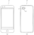
도 1은, 본 발명의 일 실시형태에 관한 카메라 모듈(A)를 탑재하는 스마트폰(M)(카메라 탑재 장치)을 나타내는 도이다. 카메라 모듈(A)은, 오토 포커스 기능을 구비하고, 피사체를 촬영할 때의 핀트 맞춤을 자동적으로 행한다.1 is a diagram showing a smartphone M (a camera-equipped device) on which a camera module A according to an embodiment of the present invention is mounted. The camera module A is provided with an autofocus function and automatically performs a focus alignment when a subject is photographed.
도 2는, 카메라 모듈(A)의 외관 사시도이다. 도 2에 나타내는 바와 같이, 본 실시형태에서는, 직교 좌표계(X, Y, Z)를 사용하여 설명한다. 후술하는 도에 있어서도 공통의 직교 좌표계(X, Y, Z)로 나타내고 있다. 렌즈 구동 장치(1)는, 스마트폰(M)에서 실제로 촬영이 행해지는 경우에, Z방향이 전후 방향이 되도록 탑재된다. 즉, Z방향이 광축 방향이고, 도 중 상측이 광축 방향 수광 측("매크로 위치 측"이라고도 함), 하측이 광축 방향 결상 측("무한원 위치 측"이라고도 함)이 된다. 또, Z축에 직교하는 X방향 및 Y방향을 "광축 직교 방향"이라고 칭한다.2 is an external perspective view of the camera module A. Fig. As shown in Fig. 2, the present embodiment will be described using an orthogonal coordinate system (X, Y, Z). In the drawings described later, they are also represented by a common orthogonal coordinate system (X, Y, Z). The
카메라 모듈(A)은, 원통형상의 렌즈 배럴에 렌즈가 수용되어 이루어지는 렌즈부(2), AF용의 렌즈 구동 장치(1), 및 렌즈부(2)에 의하여 결상된 피사체상을 촬상하는 촬상부(도시 생략) 등을 구비한다.The camera module A includes a
촬상부(도시 생략)는, 촬상 소자(도시 생략) 및 촬상 소자가 실장되는 이미지 센서 기판(도시 생략)을 갖고, 렌즈 구동 장치(1)의 광축 방향 결상 측에 배치된다. 촬상 소자(도시 생략)는, 예를 들면 CCD(charge-coupled device)형 이미지 센서, 또는 CMOS(complementary metal oxide semiconductor)형 이미지 센서 등에 의하여 구성된다. 촬상 소자(도시 생략)는, 렌즈부(2)에 의하여 결상된 피사체상을 촬상하고, 광신호를 전기 신호로 변환하여 화상 처리 등을 행하는 제어부(도시 생략)에 출력한다.An image pickup unit (not shown) has an image sensor substrate (not shown) on which an image pickup element (not shown) and an image pickup element are mounted, and is disposed on the image side in the optical axis direction of the
도 3, 도 4는 렌즈 구동 장치(1)의 분해 사시도이다. 도 3은 광축 방향 수광 측에서 본 상방시 분해 사시도이고, 도 4는 광축 방향 결상 측에서 본 하방시 분해 사시도이다. 도 3, 도 4에 나타내는 바와 같이, 렌즈 구동 장치(1)는, AF 가동부(10), AF 고정부(20), 및 탄성 지지 부재(30) 등을 구비한다. AF 가동부(10)는, AF 고정부(20)에 대하여 직경 방향 내측으로 이간하여 배치되고, 탄성 지지 부재(30)에 의하여 AF 고정부(20)과 연결된다.Figs. 3 and 4 are exploded perspective views of the
AF 가동부(10)는, AF용 보이스 코일 모터를 구성하는 AF용 코일을 갖고, 핀트 맞춤 시에 광축 방향으로 이동하는 부분이다. AF 고정부(20)는, AF용 보이스 코일 모터를 구성하는 AF용 마그넷을 갖는 부분이다. 즉, 렌즈 구동 장치(1)에는, 무빙 코일 방식이 채용되고 있다.The
본 실시형태에서는, 렌즈 홀더(11) 및 AF용 코일(12A, 12B)이 AF 가동부(10)를 구성한다. 베이스(21), AF용 마그넷(22A, 22B), 요크(23), 및 스페이서(24)가 AF 고정부(20)를 구성한다. 상측 탄성 지지 부재(31) 및 하측 탄성 지지 부재(32)가 탄성 지지 부재(30)을 구성한다.In this embodiment, the
렌즈 홀더(11)는, 평면에서 보아 팔각형상의 통형상의 부재이고, 중앙에 렌즈 수용부(11a)를 갖는다. 렌즈 수용부(11a)에는, 렌즈부(2)(도 2 참조)가 접착 또는 나사 결합에 의하여 고정된다.The
렌즈 홀더(11)는, 상면에 있어서, Y방향을 따르는 2개의 부위에, 상측 탄성 지지 부재(31)이 고정되는 상측 스프링 고정부(11b)를 갖는다. 상측 스프링 고정부(11b)는, 광축 방향 수광 측에 돌출하는 위치 결정편(11c)를 갖는다. 위치 결정편(11c)에 의하여, 상측 탄성 지지 부재(31)이 위치 결정된다. 렌즈 홀더(11)는, 상면에 있어서, 대각(對角)의 4개의 부위에, 요크(23)의 삽입편(23c)가 삽입되는 요크 삽입부(11h)를 갖는다.The
렌즈 홀더(11)는, 하면에 있어서, Y방향을 따르는 2개의 부위에, 하측 탄성 지지 부재(32)가 고정되는 하측 스프링 고정부(11d)를 갖는다. 하측 스프링 고정부(11d)는, 광축 방향 결상 측에 돌출하는 위치 결정편(11e)를 갖는다. 위치 결정편(11e)에 의하여, 하측 탄성 지지 부재(32)가 위치 결정된다.The
렌즈 홀더(11)는, Y방향을 따르는 2개의 측면에, AF용 코일(12A, 12B)의 단부가 접속되는 결합부(11g)를 갖는다. 렌즈 홀더(11)는, X방향을 따르는 2개의 측면에, AF용 코일(12A, 12B)이 배치되는 타원형상(모서리가 둥근 직사각형상)의 코일 장착부(11f)를 갖는다.The
AF용 코일(12A, 12B)은, 핀트 맞춤 시에 통전되는 편평형의 공심(空芯) 코일이고, 코일 장착부(11f)를 따라 권선된다. AF용 코일(12A, 12B)과 같이, 편평형 코일을 채용함으로써, AF용 마그넷(22A, 22B)에 의한 자기 회로의 부분에만 배치할 수 있다. 따라서, 렌즈 홀더(11)의 전체 둘레에 권선하여 AF용 코일을 형성하는 경우와 비교하여 구동 효율이 향상되므로, 경량화 및 전력 절약화를 도모할 수 있다.The AF coils 12A and 12B are flat, air-core coils energized at the time of focusing, and are wound along the
AF용 코일(12A, 12B)은, 타원형상을 갖고, 각각 제1 직선부(121) 및 제2 직선부(122)를 갖는다. AF용 코일(12A, 12B)은, 코일면이 광축과 평행이 되도록, 여기에서는 XZ면이 코일면이 되도록 배치된다. 즉, AF용 코일(12A, 12B)은, 제1 직선부(121)가 광축 방향 수광 측(상측), 제2 직선부(122)가 광축 방향 결상 측(하측)이 되도록 배치된다. AF용 코일(12A, 12B)의 단부는, 렌즈 홀더(11)의 결합부(11g)에 감겨, 하측 탄성 지지 부재(32)와 전기적으로 접속된다.The AF coils 12A and 12B have an elliptical shape and have a first
AF용 코일(12A, 12B)은, 바람직하게는 알루미늄 선재의 주위를 구리로 피복한 구리 클래드 알루미늄선으로 형성된다. 이로써, AF용 코일(12A, 12B)을 구리선으로 형성하는 경우와 비교하여, 경량화를 도모할 수 있다.The AF coils 12A and 12B are preferably formed of a copper clad aluminum wire coated with copper around the aluminum wire material. As a result, the AF coils 12A and 12B can be made lighter in weight as compared with the case where the AF coils 12A and 12B are formed of copper wires.
베이스(21)는, 평면에서 보아 정사각형상의 부재이고, 중앙에 원형의 개구(21a)를 갖는다. 베이스(21)는, 렌즈 홀더(11)의 하부에 대응하는 형상의 오목부(21b)를 갖는다. 카메라 모듈(A)에 있어서, 베이스(21)의 광축 방향 결상 측에, 촬상부(도시 생략)가 배치된다.The
베이스(21)는, 네 귀퉁이에, 하측 탄성 지지 부재(32)가 고정되는 하측 스프링 고정부(21c)를 갖는다. 하측 스프링 고정부(21c)는, 렌즈 홀더(11) 측(광축 방향 수광 측)에 돌출하는 위치 결정 보스(21d)를 갖는다. 위치 결정 보스(21d)에 의하여, 하측 탄성 지지 부재(32)가 위치 결정된다.The
2개의 하측 스프링 고정부(21c)에는, 예를 들면 인서트 성형에 의하여 단자 금구(21e)가 배치된다. 단자 금구(21e)의 일단부는, 하측 탄성 지지 부재(32)와 전기적으로 접속되고, 타단부는, 이미지 센서 기판(도시 생략)의 전원 라인(도시 생략)과 전기적으로 접속된다.The
베이스(21)는, 둘레면에, 요크(23)를 배치하는 요크 장착편(21f, 21g)를 갖는다. 요크 장착편(21f)에 의하여, 요크(23)가 위치 결정된다. 요크(23)는, 요크 장착편(21f, 21g)에 배치된 상태에서, 예를 들면 접착에 의하여 고정된다.The
AF용 마그넷(22A, 22B)은, 각각 제1 마그넷(221)과 제2 마그넷(222)으로 구성되어 이루어지는 편면 이극의 마그넷이다. 제1 마그넷(221) 및 제2 마그넷(222)은, 내외 방향에 서로 역방향으로 착자(着磁)되어 있다.The
AF용 마그넷(22A, 22B)은, 각각 AF용 코일(12A, 12B)의 외측에 위치한다(도 5 참조). AF용 마그넷(22A, 22B)은, 제1 마그넷(221)이 광축 방향 수광 측에 위치하고, 제2 마그넷(222)이 광축 방향 결상 측에 위치하도록 배치된다. 즉, 제1 마그넷(221)이 AF용 코일(12A, 12B)의 제1 직선부(121)에 대향하고, 제2 마그넷(222)이 AF용 코일(12A, 12B)의 제2 직선부(122)에 대향한다.The
제1 마그넷(221)에 의한 자계가 제1 직선부(121)를 횡단하고, 제2 마그넷(222)에 의한 자계가 제2 직선부(122)를 횡단한다. 제1 마그넷(221)에 의한 자계의 방향과 제2 마그넷(222)에 의한 자계의 방향은 역방향이므로, AF용 코일(12A, 12B)에 통전이 행해졌을 때, 제1 직선부(121)와 제2 직선부(122)에는, Z방향에 동일한 방향의 로렌츠 힘이 발생한다. 이와 같이, AF용 마그넷(22A, 22B) 및 AF용 코일(12A, 12B)에 의하여, AF용 보이스 코일 모터가 구성된다.The magnetic field generated by the
또한, 통전 시에, AF용 코일(12A, 12B)에 발생하는 로렌츠 힘이 동일한 방향이 되도록, AF용 마그넷(22A, 22B)에 있어서의 착자 방향 및 AF용 코일(12A, 12B)에 있어서의 전류 방향이 설정된다.The magnetizing direction of the
제1 마그넷(221)과 제2 마그넷(222)의 사이에는 비자성층(223)이 개재된다. 비자성층(223)의 높이를 조정함으로써, AF용 마그넷(22A, 22B)의 전체의 높이를 유지 하면서, 제1 마그넷(221)과 제2 마그넷(222)이 차지하는 영역(제1 직선부(121) 및 제2 직선부(122)와 대향하는 대향면의 면적)을 용이하게 조정할 수 있다.A
요크(23)는, 평면에서 보아 정사각형상의 자성체로 이루어지는 부재이고, 렌즈 구동 장치(1)의 케이싱 커버로서 기능한다. 요크(23)를 케이싱 커버로서 이용함으로써, 부품수가 적어지므로, 경량화를 도모할 수 있음과 함께, 조립 공정수를 저감시킬 수 있다.The
요크(23)는, 천장면에, 렌즈 홀더(11)에 장착된 렌즈부(2)(도 2 참조)에 대응하는 형상의 개구(23a)를 갖는다. 이 개구(23a)로부터 렌즈부(2)가 외부에 면한다. 요크(23)의 천장면의 이측에는, 상측 탄성 지지 부재(31)이 고정된다.The
요크(23)는, 개구(23a)의 주연에 있어서, 대각의 4개의 부위에, Z방향으로 늘어지는 삽입편(23c)을 갖는다. 삽입편(23c)은, 렌즈 홀더(11)의 요크 삽입부(11h)에 삽입된다. 삽입편(23c)은, 제1 마그넷(221)에 대향하도록 배치된다. AF용 코일(12A, 12B)에 통전이 행해지고 있지 않은 중립 상태에 있어서는, 삽입편(23c)은, 요크 삽입부(11h)의 바닥면으로부터 이간한다. 통전이 행해져 렌즈 홀더(11)가 광축 방향 수광 측으로 이동하면, 삽입편(23c)은 요크 삽입부(11h)의 바닥면에 접근하지만, 당접은 하지 않는다.The
요크(23)는, X방향을 따르는 2개의 측면에 있어서, AF용 마그넷(22A, 22B)를 유지한다. AF용 마그넷(22A, 22B)은, 예를 들면 접착에 의하여 요크(23)의 측면에 고정된다. AF용 마그넷(22A, 22B)의 광축 방향 수광 측은, 요크(23)의 개구(23a) 주연의 가림부(23b)에 의하여 덮인다. 요크(23) 및 AF용 마그넷(22A, 22B)에 의하여 자기 회로가 형성되므로, 구동 효율이 향상된다. AF용 마그넷(22A, 22B)에 있어서, 제1 마그넷(221)의 상방이 요크(23)의 가림부(23b)로 덮여 있고, 또한 요크(23)의 삽입편(23c)가 제1 마그넷(221)에 대향하여 배치되어 있으므로, 제1 마그넷(221)에 의한 자기 회로에 있어서의 자속 밀도는, 제2 마그넷(222)에 의한 자기 회로에 있어서의 자속 밀도보다 높아진다.The
상측 탄성 지지 부재(31)은, 예를 들면 베릴륨 구리, 니켈 구리, 스테인리스 등으로 이루어지는 판 스프링이다(이하 "상측 스프링(31)"이라고 칭함). 상측 스프링(31)은, AF 고정부(20)(요크(23))에 대하여 AF 가동부(10)(렌즈 홀더(11))를 탄성 지지한다.The upper
상측 스프링(31)은, 예를 들면 한 장의 판금을 펀칭하여 성형된다. 상측 스프링(31)은, 렌즈 홀더 고정부(31a), 요크 고정부(31b), 및 암부(31c)를 갖는다. 렌즈 홀더 고정부(31a)는, 렌즈 홀더(11)의 상측 스프링 고정부(11b)를 따르는 형상을 갖고, 위치 결정편(11c)에 대응하는 부분이 절결되어 있다. 암부(31c)는, 렌즈 홀더 고정부(31a)와 요크 고정부(31b)를 연결한다. 암부(31c)는, 만곡 형상을 갖고, AF 가동부(10)가 이동할 때에 탄성 변형한다.The
상측 스프링(31)은, 렌즈 홀더 고정부(31a)의 절결부(부호 생략)가, 렌즈 홀더(11)의 위치 결정편(11c)에 계합됨으로써, 렌즈 홀더(11)에 대하여 위치 결정되어, 고정된다. 또, 상측 스프링(31)은, 요크 고정부(31b)가 요크(23)의 천장면 이측에 접착됨으로써, 요크(23)에 대하여 고정된다. 상측 스프링(31)은, 요크(23)와 스페이서(24)로 협지된다. AF 가동부(10)가 광축 방향으로 이동할 때, 렌즈 홀더 고정부(31a)는, AF 가동부(10)와 함께 변위한다.The
하측 탄성 지지 부재(32)는, 예를 들면 베릴륨 구리, 니켈 구리, 스테인리스 등으로 이루어지는 2개의 판 스프링으로 구성된다(이하 "하측 스프링(32A, 32B)"이라고 칭함). 하측 스프링(32A, 32B)은, AF 고정부(20)(베이스(21))에 대하여 AF 가동부(10)(렌즈 홀더(11))를 탄성 지지한다.The lower
하측 스프링(32A, 32B)은, 예를 들면 한 장의 판금을 펀칭하여 성형된다. 하측 스프링(32A, 32B)은 각각 렌즈 홀더 고정부(32a), 베이스 고정부(32b) 및 암부(32c)를 갖는다. 렌즈 홀더 고정부(32a)는, 렌즈 홀더(11)의 하측 스프링 고정부(11d)를 따르는 형상을 갖는다. 암부(32c)는, 렌즈 홀더 고정부(32a)와 베이스 고정부(32b)를 연결한다. 암부(32c)는, 일부에 구불구불한 형상을 갖고, AF 가동부(10)가 이동할 때에 탄성 변형한다.The
하측 스프링(32A, 32B)은, 렌즈 홀더 고정부(32a)에, 결합 접속부(32d)를 갖는다. 결합 접속부(32d)는, 렌즈 홀더(11)의 결합부(11g)에 감겨진 AF용 코일(12A, 12B)과 전기적으로 접속된다. 베이스 고정부(32b)는, 베이스(21)에 배치된 단자 금구(21e)와 전기적으로 접속된다. 하측 스프링(32A, 32B)을 통하여, AF용 코일(122)에 대한 급전이 행해진다.The
하측 스프링(32A, 32B)은, 렌즈 홀더 고정부(32a)의 고정 구멍(부호 생략)에 렌즈 홀더(11)의 위치 결정편(11e)이 삽입 감합됨으로써, 렌즈 홀더(11)에 대하여 위치 결정되어, 고정된다. 또, 하측 스프링(32A, 32B)은, 베이스 고정부(32b)의 고정 구멍(부호 생략)에, 베이스(21)의 위치 결정 보스(21d)가 삽입 감합됨으로써, 베이스(21)에 대하여 위치 결정되어, 고정된다. AF 가동부(10)가 광축 방향으로 이동할 때, 렌즈 홀더 고정부(32a)는, AF 가동부(10)와 함께 변위한다.The
렌즈 구동 장치(1)에 있어서 자동 핀트 맞춤을 행하는 경우에는, AF용 코일(12A, 12B)에 통전이 행해진다. AF용 코일(12A, 12B)에 통전하면, AF용 마그넷(22A, 22B)의 자계와 AF용 코일(12A, 12B)에 흐르는 전류의 상호 작용에 의하여, AF용 코일(12A, 12B)에 로렌츠 힘이 발생한다. 로렌츠 힘의 방향은, AF용 마그넷(22A, 22B)에 의한 자계의 방향과 AF용 코일(12A, 12B)에 흐르는 전류의 방향에 직교하는 방향(Z방향)이다. AF용 마그넷(22A, 22B)은 고정되어 있으므로, AF용 코일(12A, 12B)에 반력이 작용한다. 이 반력이 AF용 보이스 코일 모터의 구동력이 되고, AF용 코일(12A, 12B)을 갖는 AF 가동부(10)가 광축 방향으로 이동하여, 핀트 맞춤이 행해진다.When automatic focusing is performed in the
핀트 맞춤을 행하지 않는 무통전 시에는, AF 가동부(10)는, 예를 들면 상측 탄성 지지 부재(31) 및 하측 탄성 지지 부재(32)에 의하여, 무한원 위치와 매크로 위치의 사이에 매달린 상태(이하 "기준 상태"라고 칭함)로 유지된다. 즉, AF 가동부(10)가, 상측 탄성 지지 부재(31) 및 하측 탄성 지지 부재(32)에 의하여, AF 고정부(20)에 대하여 위치 결정된 상태에서, Z방향 양측으로 변위 가능하게 탄성 지지된다. 핀트 맞춤을 행할 때에는, AF 가동부(10)를 기준 상태로부터 매크로 위치 측으로 이동시킬지, 무한원 위치 측으로 이동시킬지에 따라, 전류의 방향이 제어된다. 또, AF 가동부(10)의 기준 상태로부터의 이동 거리(스트로크)에 따라, 전류의 크기가 제어된다.The AF
도 6은, AF용 코일(12A, 12B)과 AF용 마그넷(22A, 22B)의 위치 관계를 나타내는 측면도이다. 도 7은, AF용 코일(12A, 12B)과 AF용 마그넷(22A, 22B)의 위치 관계를 나타내는 Y방향을 따르는 단면도이다.6 is a side view showing the positional relationship between the AF coils 12A and 12B and the
도 6, 도 7에 나타내는 바와 같이, 본 실시형태에서는, AF용 마그넷(22A, 22B)에 있어서, 제1 마그넷(221)의 비율이 제2 마그넷(222)의 비율보다 크게 되어 있다. 즉, 제1 마그넷(221)의 제1 직선부(121)와 대향하는 면의 면적은, 제2 마그넷(222)의 제2 직선부(122)와 대향하는 면의 면적보다 크다.6 and 7, in the present embodiment, the ratio of the
제1 마그넷(221)의 면적은, AF 가동부(10)의 가동 범위 전체 영역에 걸쳐서, 제1 마그넷(221)이 제1 직선부(121)와 대향하도록 설정된다. 이로써, AF 가동부(10)의 가동 범위 전체 영역에 걸쳐서, 제1 마그넷(221)에 의한 자속과, AF용 코일(12A, 12B)의 제1 직선부(121)은 수직으로 교차한다.The area of the
한편, 제2 마그넷(222)의 면적은, 리니어리티 성능이 얻어지도록 설정된다. 제2 마그넷(222)은, AF 가동부(10)가 광축 방향으로 이동했을 때, 제2 직선부(122)의 대향 영역으로부터 어긋나도 된다. 즉, 제2 직선부(122)는, AF 가동부(10)의 가동 범위의 일부에 있어서, 제2 마그넷(222)과 대향하지 않아도 된다.On the other hand, the area of the
AF용 마그넷(22A, 22B)에 있어서, 제1 마그넷(221)의 상방은 요크(23)의 가림부(23b)로 덮여 있으므로, 제1 마그넷(221)에 의한 자기 회로에 있어서의 자속 밀도는, 제2 마그넷(222)에 의한 자기 회로에 있어서의 자속 밀도보다 높다. 즉, AF용 코일(12A, 12B)의 제1 직선부(121)를 횡단하는 자속의 밀도는, 제2 직선부(122)와 교차하는 자속의 밀도보다 높다. 또한, AF용 코일(12A, 12B)과 AF용 마그넷(22A, 22B)이 상술한 위치 관계가 되도록 배치됨으로써, AF 가동부(10)의 가동 범위 전체 영역에 걸쳐서, 제1 직선부(121)를 횡단하는 자속은, 제2 직선부(122)를 횡단하는 자속보다 더 많아진다. 따라서, AF 가동부(10)의 추력은, AF용 코일(12A, 12B)의 제1 직선부(121)에 발생하는 로렌츠 힘(F1)과 제2 직선부(122)에 발생하는 로렌츠 힘(F2)의 합으로 나타나지만, 로렌츠 힘(F2)의 영향은 작아, 로렌츠 힘(F1)이 지배적이 된다.The magnetic flux density in the magnetic circuit by the
소형화, 박형화를 도모하기 위하여 AF용 마그넷(22A, 22B)의 사이즈가 제한되는 가운데, 렌즈 구동 장치(1)에 있어서 원하는 추력을 얻기 위하여 제1 마그넷(221)의 사이즈를 설정한 후, 리니어리티 성능이 확보되도록 제2 마그넷(222)의 사이즈를 조정하고, 추력 밸런스의 최적화를 행하면 되기 때문에, 설계가 용이해진다.The size of the
이와 같이, 렌즈 구동 장치(1)는, 렌즈부(2)의 주위에 배치되는 AF용 코일(12A, 12B)과, AF용 코일(12A, 12B)에 대하여 직경 방향으로 이간하여 배치되는 AF용 마그넷(22A, 22B)과, AF용 마그넷(22A, 22B)과 함께 자기 회로를 형성하는 요크(23)를 갖는다. 렌즈 구동 장치(1)는, AF용 코일(12A, 12B)과 AF용 마그넷(22A, 22B)로 구성되는 보이스 코일 모터의 구동력을 이용하여, AF용 마그넷(22A, 22B) 및 요크(23)를 포함하는 AF 고정부(20)에 대하여, AF용 코일(12A, 12B)을 포함하는 AF 가동부(10)를 광축 방향으로 이동시킴으로써 자동적으로 핀트 맞춤을 행한다. AF용 코일(12A, 12B)은, 제1 직선부(121) 및 제2 직선부(122)를 갖는 타원형상의 편평 코일이고, 제1 직선부(121)가 광축 방향 수광 측, 제2 직선부(122)가 광축 방향 결상 측이 되도록 배치된다. AF용 마그넷(22A, 22B)은, 제1 마그넷(221) 및 제2 마그넷(222)으로 구성되어 이루어지는 편면 이극의 마그넷이고, 제1 마그넷(221)이 제1 직선부(121)에 대향하고, 제2 마그넷(222)이 제2 직선부(122)에 대향하도록 배치된다. 요크(23)는, 제1 마그넷(221)의 광축 방향 수광 측의 면을 덮도록 배치된다. 제1 마그넷(221)의 제1 직선부(121)와 대향하는 면의 면적은, 제2 마그넷(222)의 제2 직선부(122)와 대향하는 면의 면적보다 크고, AF 가동부(10)의 가동 범위 전체 영역에 걸쳐서, 제1 직선부(121)를 횡단하는 자속이, 제2 직선부(122)를 횡단하는 자속보다 많다.As described above, the
렌즈 구동 장치(1)에 의하면, AF 가동부(10)의 추력은, AF용 코일(12A, 12B)의 제1 직선부(121)에 발생하는 로렌츠 힘(F1)이 지배적이 되므로, 소형화, 박형화를 도모할 때의 설계가 용이해진다. 따라서, 렌즈 구동 장치(1)에 의하면, 원하는 추력 및 리니어리티 성능(선형성)을 가짐과 함께, 소형화, 박형화를 도모할 수 있다. 또, 소형화, 박형화된 렌즈 구동 장치(1)를 구비하는 카메라 모듈(A)은, 레이아웃의 자유도가 높기 때문에, 스마트폰 등의 모바일 단말에 탑재하는 경우에 유용하고, 특히 복수 탑재하는 경우에 유용하다.The Lorentz force F1 generated in the first
이상, 본 발명자에 의하여 이루어진 발명을 실시형태에 근거하여 구체적으로 설명했지만, 본 발명은 상기 실시형태에 한정되는 것은 아니고, 그 요지를 일탈하지 않는 범위에서 변경 가능하다.While the invention made by the present inventors has been specifically described based on the embodiments, the present invention is not limited to the above embodiments, and can be changed without departing from the gist of the invention.
예를 들면, AF용 코일과 AF용 마그넷의 세트는, 실시형태와 같이 2세트에 한정되지 않고, 1세트여도 되며, 3세트 이상이어도 된다. AF용 코일과 AF용 마그넷의 세트를 복수 세트 배치하는 경우는, 광축에 관하여 서로 점대칭이 되도록 배치하는 것이 바람직하다. 이로써, 핀트 맞춤 시의 안정성이 향상된다. 또, AF용 마그넷(22A, 22B)은, 제1 마그넷(221) 및 제2 마그넷(222)이 일체로 구성되어 있어도 되고, 별체에 적층되어 있어도 된다.For example, the set of the AF coil and the AF magnet is not limited to two sets as in the embodiment, but may be one set or three sets or more. When a plurality of sets of AF coils and AF magnets are arranged, it is preferable that they are arranged so as to be symmetrical with respect to each other with respect to the optical axis. Thereby, stability at the time of focusing is improved. The
예를 들면, 실시형태에서는, 카메라 모듈(A)를 구비하는 카메라 탑재 장치로서, 스마트폰을 예로 들어 설명했지만, 본 발명은, 정보 기기 또는 수송 기기인 카메라 탑재 장치에 적용할 수 있다. 정보 기기인 카메라 탑재 장치란, 카메라 모듈과 카메라 모듈로 얻어진 화상 정보를 처리하는 제어부를 갖는 정보 기기이고, 예를 들면 카메라 장착 휴대 전화기, 노트북 컴퓨터, 태블릿 단말, 휴대형 게임기, web 카메라, 카메라 장착 차재 장치(예를 들면, 백 모니터 장치, 드라이브 레코더 장치)를 포함한다. 또, 수송 기기인 카메라 탑재 장치란, 카메라 모듈과 카메라 모듈로 얻어지는 화상을 처리하는 제어부를 갖는 수송 기기이고, 예를 들면 자동차를 포함한다.For example, in the embodiments, a smartphone is described as an example of a camera-equipped device having a camera module (A), but the present invention can be applied to a camera-equipped device that is an information device or a transportation device. A camera-equipped device which is an information device is an information device having a control unit for processing image information obtained by a camera module and a camera module. For example, the device is a camera-equipped mobile phone, a notebook computer, a tablet terminal, a portable game machine, Device (e.g., a back monitor device, a drive recorder device). A camera-equipped device as a transportation device is a transportation device having a control section for processing an image obtained by a camera module and a camera module, and includes, for example, an automobile.
도 8a, 도 8b는, 카메라 모듈(VC)(Vehicle Camera)를 탑재하는 카메라 탑재 장치로서의 자동차(V)를 나타내는 도이다. 도 8a는 자동차(V)의 정면도이고, 도 8b는 자동차(V)의 후방 사시도이다. 자동차(V)는, 차재용 카메라 모듈(VC)로서, 실시형태에서 설명한 카메라 모듈(A)를 탑재한다. 도 8a, 도 8b에 나타내는 바와 같이, 차재용 카메라 모듈(VC)는, 예를 들면 전방을 향하여 프론트 유리에 장착되거나, 후방을 향하여 리어 게이트에 장착된다. 이 차재용 카메라 모듈(VC)는, 백 모니터용, 드라이브 레코더용, 충돌 회피 제어용, 자동 운전 제어용 등으로서 사용된다.8A and 8B are diagrams showing an automobile V as a camera-equipped device for mounting a camera module (VC) (Vehicle Camera). Fig. 8A is a front view of the automobile V, and Fig. 8B is a rear perspective view of the automobile V. Fig. The vehicle V mounts the camera module A described in the embodiment as a vehicle-mounted camera module VC. As shown in Figs. 8A and 8B, the vehicle-mounted camera module VC is attached to the front glass, for example, toward the front, or to the rear gate toward the rear. The vehicle-mounted camera module VC is used as a back monitor, a drive recorder, a collision avoidance control, an automatic operation control, and the like.
이번에 개시된 실시형태는 모든 점에서 예시이며 제한적인 것이 아니라고 생각되어야 한다. 본 발명의 범위는 상기한 설명이 아닌 특허청구의 범위에 의하여 나타나, 특허청구의 범위와 균등한 의미 및 범위 내에서의 모든 변경이 포함되는 것이 의도된다.The embodiments disclosed herein are to be considered in all respects as illustrative and not restrictive. It is intended that the scope of the invention be indicated by the appended claims rather than the foregoing description, and that all changes that come within the meaning and range of equivalency of the claims are intended to be embraced therein.
2016년 3월 7일 출원의 일본 특허출원 2016-043907의 일본 출원에 포함되는 명세서, 도면 및 요약서의 개시 내용은, 모두 본원에 원용된다.The disclosures of the specification, drawings and abstract included in the Japanese application of Japanese Patent Application No. 2016-043907 filed on March 7, 2016 are all incorporated herein by reference.
1 : 렌즈 구동 장치
2 : 렌즈부
10 : AF 가동부(오토 포커스 가동부)
11 : 렌즈 홀더
12A, 12B : AF용 코일(오토 포커스용 코일)
121 : 제1 직선부
122 : 제2 직선부
20 : AF 고정부(오토 포커스 고정부)
21 : 베이스
22A, 22B : AF용 마그넷(오토 포커스용 마그넷)
221 : 제1 마그넷
222 : 제2 마그넷
223 : 비자성층
23 : 요크
30 : 탄성 지지 부재
31 : 상측 탄성 지지 부재
32 : 하측 탄성 지지 부재
M : 스마트폰(카메라 탑재 장치)
A : 카메라 모듈1: lens driving device 2: lens part
10: AF moving part (autofocus moving part)
11: Lens holder
12A, 12B: AF coil (autofocus coil)
121: first rectilinear section 122: second rectilinear section
20: AF fixing part (autofocus fixing part)
21: Base
22A, 22B: Magnet for AF (autofocus magnet)
221: first magnet 222: second magnet
223: nonmagnetic layer 23: yoke
30: elastic supporting member 31: upper elastic supporting member
32: lower elastic support member M: smart phone (camera equipped device)
A: Camera module
Claims (7)
상기 오토 포커스용 코일은, 제1 직선부 및 제2 직선부를 갖는 타원형상의 편평 코일이고, 상기 제1 직선부가 광축 방향 수광 측, 상기 제2 직선부가 광축 방향 결상 측이 되도록 배치되며,
상기 오토 포커스용 마그넷은, 제1 마그넷 및 제2 마그넷으로 구성되어 이루어지는 편면 이극의 마그넷이고, 상기 제1 마그넷이 상기 제1 직선부에 대향하며, 상기 제2 마그넷이 상기 제2 직선부에 대향하도록 배치되고,
상기 요크는, 상기 제1 마그넷의 광축 방향 수광 측의 면을 덮도록 배치되며,
상기 제1 마그넷의 상기 제1 직선부와 대향하는 면의 면적은, 상기 제2 마그넷의 상기 제2 직선부와 대향하는 면의 면적보다 크고,
상기 오토 포커스 가동부의 가동 범위 전체 영역에 걸쳐서, 상기 제1 직선부를 횡단하는 자속이, 상기 제2 직선부를 횡단하는 자속보다 많은 것을 특징으로 하는 렌즈 구동 장치.And a yoke for forming a magnetic circuit together with the autofocusing magnet. The autofocusing apparatus according to any one of claims 1 to 3, wherein the auto-focusing coil is disposed around the lens portion, the autofocusing magnet disposed at a distance from the autofocusing coil in the radial direction, An autofocus operation including the autofocus coil is performed on the autofocus fixing unit including the autofocusing magnet and the yoke using the driving force of the voice coil motor composed of the focusing coil and the autofocusing magnet The lens driving apparatus according to claim 1,
Wherein the autofocus coil is an elliptical flat coil having a first rectilinear section and a second rectilinear section and the first rectilinear section is disposed on the light receiving side in the optical axis direction and the second rectilinear section is disposed on the optical axis direction imaging side,
Wherein the autofocus magnet is a one-sided magnet having a first magnet and a second magnet, the first magnet is opposed to the first rectilinear portion, and the second magnet is opposed to the second rectilinear portion, Lt; / RTI >
The yoke is disposed so as to cover a surface on the light receiving side of the first magnet in the optical axis direction,
The area of the surface of the first magnet facing the first rectilinear section is larger than the area of the surface of the second magnet facing the second rectilinear section,
Wherein the magnetic flux traversing the first rectilinear section is greater than the magnetic flux traversing the second rectilinear section over the entire range of the movable range of the autofocus moving section.
상기 제2 직선부는, 상기 오토 포커스 가동부의 가동 범위의 일부에 있어서, 상기 제2 마그넷과 대향하지 않는 것을 특징으로 하는 렌즈 구동 장치.2. The autofocus system according to claim 1, wherein the first rectilinear section is arranged to face the first magnet over an entire range of the movable range of the autofocus movable section,
And the second rectilinear section does not face the second magnet in a part of the movable range of the autofocus moving section.
상기 복수의 세트는, 광축에 관하여 점대칭으로 배치되는 것을 특징으로 하는 렌즈 구동 장치.2. The image forming apparatus according to claim 1, further comprising a plurality of sets each comprising the autofocusing magnet and the autofocusing coil,
Wherein the plurality of sets are arranged in point symmetry with respect to the optical axis.
상기 렌즈 구동 장치에 장착되는 렌즈부와,
상기 렌즈부에 의하여 결상된 피사체상을 촬상하는 촬상부
를 구비하는 것을 특징으로 하는 카메라 모듈.The lens driving apparatus according to claim 1,
A lens unit mounted on the lens driving device,
An image pickup section for picking up an image of a subject image formed by the lens section,
And a camera module.
제6항에 기재된 카메라 모듈을 구비하는 것을 특징으로 하는 카메라 탑재 장치.As a camera-equipped device which is an information device or a transportation device,
A camera-equipped apparatus comprising the camera module according to claim 6.
Applications Claiming Priority (3)
| Application Number | Priority Date | Filing Date | Title |
|---|---|---|---|
| JP2016043907A JP2017161609A (en) | 2016-03-07 | 2016-03-07 | Lens driving device, camera module, and camera mounting device |
| JPJP-P-2016-043907 | 2016-03-07 | ||
| PCT/JP2017/008535 WO2017154781A1 (en) | 2016-03-07 | 2017-03-03 | Lens drive device, camera module, and camera mount device |
Publications (1)
| Publication Number | Publication Date |
|---|---|
| KR20180119595A true KR20180119595A (en) | 2018-11-02 |
Family
ID=59790307
Family Applications (1)
| Application Number | Title | Priority Date | Filing Date |
|---|---|---|---|
| KR1020187026039A Withdrawn KR20180119595A (en) | 2016-03-07 | 2017-03-03 | A lens driving device, a camera module, and a camera mounting device |
Country Status (7)
| Country | Link |
|---|---|
| US (1) | US20190101722A1 (en) |
| EP (1) | EP3428705A4 (en) |
| JP (1) | JP2017161609A (en) |
| KR (1) | KR20180119595A (en) |
| CN (1) | CN109073854A (en) |
| TW (1) | TWI687731B (en) |
| WO (1) | WO2017154781A1 (en) |
Cited By (1)
| Publication number | Priority date | Publication date | Assignee | Title |
|---|---|---|---|---|
| KR102131597B1 (en) | 2019-10-18 | 2020-08-05 | (주)아이엠 | Folded camera module and method for manufacturing thereof |
Families Citing this family (11)
| Publication number | Priority date | Publication date | Assignee | Title |
|---|---|---|---|---|
| CN111095095B (en) * | 2017-08-01 | 2022-08-19 | Lg伊诺特有限公司 | Lens moving device, camera module including the same, and optical apparatus |
| CN116165762A (en) | 2018-01-10 | 2023-05-26 | Lg伊诺特有限公司 | Lens driving device, camera module and optical apparatus including the same |
| JP7104301B2 (en) * | 2018-03-19 | 2022-07-21 | ミツミ電機株式会社 | Rangefinder camera |
| US12212832B2 (en) | 2018-12-13 | 2025-01-28 | Lg Innotek Co., Ltd. | Camera module |
| KR102189884B1 (en) | 2019-05-15 | 2020-12-11 | 주식회사 옵티맥 | Lens driving apparatus |
| CN114174917B (en) * | 2019-07-26 | 2024-09-03 | 阿尔卑斯阿尔派株式会社 | Lens driving device and camera module |
| WO2021115604A1 (en) * | 2019-12-12 | 2021-06-17 | Huawei Technologies Co., Ltd. | Voice coil actuator with multistep movement |
| CN113325543A (en) * | 2021-06-21 | 2021-08-31 | 河源友华微机电科技有限公司 | Camera motor, camera and electronic device |
| GB2609614A (en) * | 2021-08-02 | 2023-02-15 | Geovisual Tech Inc | Variable rate herbicide application maps using UAV images |
| CN114488659B (en) * | 2022-01-07 | 2023-12-29 | 宁波法里奥光学科技发展有限公司 | High-precision self-checking anti-shake optical lens shell |
| KR20240030455A (en) * | 2022-08-30 | 2024-03-07 | 엘지이노텍 주식회사 | lens drive unit, camera module and optics |
Family Cites Families (15)
| Publication number | Priority date | Publication date | Assignee | Title |
|---|---|---|---|---|
| JP3359157B2 (en) * | 1994-08-05 | 2002-12-24 | キヤノン株式会社 | Positioning device |
| JP2004326885A (en) * | 2003-04-23 | 2004-11-18 | Funai Electric Co Ltd | Objective lens driving device of optical head |
| TWI302629B (en) * | 2005-08-25 | 2008-11-01 | Powergate Optical Inc | A vcm auto-focusing device having position feedback and an auto-focusing method |
| JP4811724B2 (en) * | 2006-07-13 | 2011-11-09 | シコー株式会社 | Lens drive device |
| JP5904392B2 (en) * | 2010-05-24 | 2016-04-13 | 新シコー科技株式会社 | Lens driving device, autofocus camera, and mobile terminal device with camera |
| JP5440796B2 (en) * | 2010-06-16 | 2014-03-12 | ミツミ電機株式会社 | Lens drive device |
| JP2012032778A (en) * | 2010-07-02 | 2012-02-16 | Sharp Corp | Camera module |
| JP5327478B2 (en) * | 2010-10-18 | 2013-10-30 | ミツミ電機株式会社 | Lens drive device |
| JP2012103373A (en) * | 2010-11-09 | 2012-05-31 | Shicoh Engineering Co Ltd | Lens drive device, autofocus camera and camera-equipped mobile terminal |
| US8670195B2 (en) * | 2011-06-09 | 2014-03-11 | Panasonic Corporation | Lens actuator |
| JP2013097028A (en) * | 2011-10-28 | 2013-05-20 | Micro Uintekku Kk | Electromagnetic drive device |
| US9300196B2 (en) * | 2011-11-16 | 2016-03-29 | Lg Innotek Co., Ltd. | Voice coil motor |
| US9134503B2 (en) * | 2012-07-06 | 2015-09-15 | Apple Inc. | VCM OIS actuator module |
| US9910241B2 (en) * | 2013-04-19 | 2018-03-06 | Hong Kong Applied Science & Technology Research Institute Co., Ltd. | Lens moving apparatus |
| KR102148988B1 (en) * | 2013-07-12 | 2020-08-27 | 엘지이노텍 주식회사 | Camera module |
-
2016
- 2016-03-07 JP JP2016043907A patent/JP2017161609A/en active Pending
-
2017
- 2017-03-03 WO PCT/JP2017/008535 patent/WO2017154781A1/en not_active Ceased
- 2017-03-03 US US16/083,014 patent/US20190101722A1/en not_active Abandoned
- 2017-03-03 KR KR1020187026039A patent/KR20180119595A/en not_active Withdrawn
- 2017-03-03 EP EP17763121.5A patent/EP3428705A4/en not_active Withdrawn
- 2017-03-03 CN CN201780015716.0A patent/CN109073854A/en not_active Withdrawn
- 2017-03-07 TW TW106107315A patent/TWI687731B/en not_active IP Right Cessation
Cited By (1)
| Publication number | Priority date | Publication date | Assignee | Title |
|---|---|---|---|---|
| KR102131597B1 (en) | 2019-10-18 | 2020-08-05 | (주)아이엠 | Folded camera module and method for manufacturing thereof |
Also Published As
| Publication number | Publication date |
|---|---|
| EP3428705A4 (en) | 2019-11-20 |
| JP2017161609A (en) | 2017-09-14 |
| EP3428705A1 (en) | 2019-01-16 |
| TW201732343A (en) | 2017-09-16 |
| TWI687731B (en) | 2020-03-11 |
| WO2017154781A1 (en) | 2017-09-14 |
| US20190101722A1 (en) | 2019-04-04 |
| CN109073854A (en) | 2018-12-21 |
Similar Documents
| Publication | Publication Date | Title |
|---|---|---|
| KR20180119595A (en) | A lens driving device, a camera module, and a camera mounting device | |
| EP4224233B1 (en) | Linear ball guided voice coil motor for folded optic | |
| JP6565911B2 (en) | Lens driving device, camera module, and camera mounting device | |
| JP6458378B2 (en) | Lens driving device, camera module, and mobile terminal with camera | |
| KR102128223B1 (en) | Reduced height penalty for folded camera | |
| CN101288011B (en) | lens drive | |
| KR102608087B1 (en) | Lens drive devices, camera modules, and camera mounting devices | |
| JP2018018021A (en) | Lens drive device, camera module, and camera loading device | |
| JPWO2015104908A1 (en) | The camera module | |
| CN101308240A (en) | Actuator, manufacturing method thereof, imaging device, and portable electronic device | |
| JP2014206590A (en) | Lens holder device | |
| JP7401746B2 (en) | Lens drive device, camera module, and camera mounting device | |
| CN107683429B (en) | Lens driving device, camera module, and camera-mounted device | |
| CN102262280B (en) | Lens driving device, auto focus camera and mobile terminal device | |
| JP7495647B1 (en) | Optical element driving device, camera module, and camera-mounted device | |
| CN111308831B (en) | Optical component guiding device, camera device and electronic device | |
| JP2025006717A (en) | Lens drive device and camera module | |
| CN118945454A (en) | Camera modules and electronics |
Legal Events
| Date | Code | Title | Description |
|---|---|---|---|
| PA0105 | International application |
Patent event date: 20180907 Patent event code: PA01051R01D Comment text: International Patent Application |
|
| PG1501 | Laying open of application | ||
| PA0201 | Request for examination |
Patent event code: PA02012R01D Patent event date: 20191029 Comment text: Request for Examination of Application |
|
| PC1202 | Submission of document of withdrawal before decision of registration |
Comment text: [Withdrawal of Procedure relating to Patent, etc.] Withdrawal (Abandonment) Patent event code: PC12021R01D Patent event date: 20200901 |
|
| WITB | Written withdrawal of application |