The present application is a divisional application, and its parent application is an application entitled "lens driving device and camera module including the same", filed on 4/7/2016 (priority date: 1/2/2014), and application No. 201480072254.2.
Detailed Description
Exemplary embodiments will be described in detail below with reference to the accompanying drawings, which are helpful in understanding the embodiments. However, the embodiments may be changed in various ways, but the scope of the embodiments should not be construed as being limited to the following description. The examples are intended to provide a more complete explanation to those skilled in the art.
In the following description of the embodiments, it will be understood that, when each element is referred to as being formed "on" or "under" another element, it can be directly "on" or "under" the other element or one or more intermediate elements may be indirectly formed therebetween. Further, it will be understood that "on" or "under" the element can mean upward and downward directions relative to the element.
Furthermore, the relative terms "first," "second," "top/upper/above," "bottom/lower/below," and the like in the description and in the claims may be used for distinguishing between any substance or element and another substance or element and not necessarily for describing any physical or logical relationship or particular order between the substances or elements.
In the drawings, the size of layers may be exaggerated, omitted, or schematically illustrated for clarity and convenience of description. Further, the sizes of constituent elements do not mean that actual sizes are accurately reflected.
Hereinafter, the lens driving device 100 or 400 according to an embodiment will be described with reference to the drawings. For convenience of description, although the lens driving device 100 or 400 according to the embodiment is described using a cartesian coordinate system (x, y, z), the lens driving device 100 or 400 may be described using other coordinate systems, and the embodiment is not limited thereto. In the respective drawings, the x-axis and the y-axis mean directions perpendicular to the optical axis, i.e., the z-axis, and the optical axis (z-axis) direction may be referred to as a "first direction", the x-axis direction may be referred to as a "second direction", and the y-axis direction may be referred to as a "third direction".
One embodiment of the invention
A hand shake correction apparatus applied to a small camera module of a mobile device such as a smartphone or a tablet computer may refer to an apparatus for preventing an outline of a photographed image from not being clearly formed due to user hand shake vibration when photographing a still image.
In addition, the auto-focusing device is used to automatically focus an object image on the surface of the image sensor. The hand shake correction apparatus and the autofocus apparatus may be configured in various ways. The lens driving apparatus 100 according to the embodiment may perform the handshake correction and/or the auto-focus operation by: an optical module comprising at least one lens is moved in a first direction parallel to the optical axis and/or in a plane defined by a second direction and a third direction perpendicular to the first direction.
Fig. 1 is a schematic perspective view illustrating a lens driving apparatus 100 according to an embodiment. Fig. 2 is an exploded perspective view of the lens driving device 100 shown in fig. 1.
Referring to fig. 1 and 2, the lens driving device 100 according to the embodiment may include a first lens driving unit, a second lens driving unit, and a cover member 300.
The first lens driving unit may function as the above-described auto-focusing device. In other words, the first lens driving unit may function to move the bobbin 110 in the first direction by means of interaction between the magnet 130 and the first coil 120.
The second lens driving unit may function as the handshake correction apparatus. In other words, the second lens driving unit may be used to move all or a portion of the first lens driving unit in the second and third directions by means of interaction between the magnet 130 and the second coil 230.
The cover member 300 may be configured to have a general box shape to accommodate the first and second lens driving units therein.
Fig. 3 is a perspective view illustrating the lens driving apparatus according to the embodiment with the cover member 300 shown in fig. 1 and 2 removed.
The first lens driving unit may include a bobbin 110, a first coil 120, a magnet 130, a housing 140, an upper elastic member 150, a lower elastic member 160, a first sensor 170, and a sensor substrate 180.
Fig. 4 is an exploded perspective view of the lens driving apparatus according to the embodiment, which shows the bobbin 110, the first coil 120, the magnets 130(130-1, 130-2, 130-3, and 130-4), the first sensor 170, and the sensor substrate 180.
Fig. 5a is a plan view illustrating the bobbin 110 and the magnets 130(130-1, 130-2, 130-3, and 130-4) shown in fig. 4. Fig. 5b is a perspective view illustrating another embodiment of the sensor substrate 180 illustrated in fig. 4. Fig. 5c is a rear perspective view illustrating an embodiment of the first sensor 170 and the sensor substrate 180 illustrated in fig. 4.
Referring to the above-described drawings, the bobbin 110 may be disposed in an inner space defined by the housing 140 to reciprocate in a first direction (which is an optical axis direction) or in a direction parallel to the first direction. As shown in fig. 4, the bobbin 110 may have the first coil 120 wound thereon such that the first coil 120 and the magnet 130 electromagnetically interact. To this end, the magnet 130 may be disposed around the bobbin 110 to face the first coil 120.
When the bobbin 110 performs an upward and/or downward movement in a first direction (which is an optical axis direction) or a direction parallel to the first direction to realize an auto-focus function, the bobbin 110 may be elastically supported by the upper elastic member 150 and the lower elastic member 160. To this end, the upper and lower elastic members 150 and 160 may be coupled to the bobbin 110 and the housing 140, as will be described below.
Although not shown in the drawings, the lens driving device may include a lens barrel (not shown) disposed on an inner side surface (i.e., an inner surface) of the wire barrel 110 and mounting at least one lens thereon. The lens barrel may be mounted on the inner surface of the wire barrel 110 in various ways. For example, the lens barrel may be directly fastened to the inside of the wire barrel 110, or a single lens may be formed integrally with the wire barrel 110 without using the lens barrel. The lens mounted on the lens barrel may include a single lens, or may include two or more lenses constituting an optical system.
According to another embodiment, although not shown in the drawings, the bobbin 110 may be provided at an inner circumferential surface thereof with an internal threaded portion while the lens barrel may be provided at an outer circumferential surface thereof with an external threaded portion corresponding to the internal threaded portion, such that the lens barrel is coupled to the bobbin 110 by threaded engagement between the internal threaded portion and the external threaded portion. However, the embodiments are not limited thereto. According to another embodiment, the wire barrel 110 and the lens barrel may be coupled to each other using an adhesive without using a threaded engagement. In this case, after the threaded engagement, the bobbin 110 and the lens barrel may also be reliably coupled to each other using an adhesive.
The bobbin 110 may include a first protrusion 111 and a second protrusion 112.
The first protrusion 111 may include a guide portion 111a and a first stopper 111 b. The guide portion 111a may be used to guide the installation of the upper elastic member 150 at a predetermined position. For example, as shown in fig. 3, the guide portion 111a may guide the passage of the first frame connector 153 of the upper elastic member 150. For this, according to a specific embodiment, the plurality of guide portions 111a may protrude in a second direction and a third direction perpendicular to the first direction. The guide portion 111a may be disposed in a plane defined by the x-axis and the y-axis to be symmetrical with respect to a center point of the bobbin 110 as shown in the drawings, or may be disposed asymmetrically with respect to the center point of the bobbin 110 so as not to interfere with other components, unlike the embodiment shown in the drawings.
The second protrusion 112 may protrude in a second direction and a third direction perpendicular to the first direction. The upper surface 112a of the second protrusion 112 may be configured such that a first inner frame 151 (to be described later) of the upper elastic member 150 is mounted on the upper surface 112 a.
Fig. 6 is a plan view of the housing 140 according to this embodiment. Fig. 7 is a bottom exploded perspective view of the housing 140 and the magnet 130 according to this embodiment.
Referring to fig. 6, the case 140 may include a first mounting recess 146, the first mounting recess 146 being formed at a position corresponding to the positions of the first and second protrusions 111 and 112.
The first stopper 111b and the second protrusion 112 of the first protrusion 111 serve to prevent the bottom surface of the body of the bobbin 110 from directly colliding with the upper surface of the base 210 and the circuit board 250 when the bobbin 110 moves in the first direction, which is the optical axis direction, or in a direction parallel to the first direction to perform the auto-focus function, even when the bobbin 110 moves beyond a predetermined range due to external impact or the like. For this, the first stopper 111b may protrude from the outer circumferential surface of the bobbin 110 in a radial direction, i.e., the second direction or the third direction, to be longer than the guide portion 111a, and the second protrusion 112 may also protrude in a lateral direction to be larger than the upper surface of the bobbin 110 to which the upper elastic member 150 is mounted.
Referring to fig. 6, when a state in which the bottom surfaces of the first and second protrusions 111 and 112 are in contact with the bottom surface 146a of the first mounting recess 146 is set to an initial position, the auto-focus function may be controlled in accordance with a one-way control of a conventional Voice Coil Motor (VCM). Specifically, the autofocus function can also be realized by: when current is applied to the first coil 120, the bobbin 110 is lifted, and when the current supply is interrupted, the bobbin 110 is lowered.
However, when a state in which the bottom surfaces of the first and second protrusions 111 and 112 are spaced apart from the bottom surface 146a of the first mounting recess 146 by a predetermined distance is set as an initial position, the auto-focusing function may be controlled according to the current direction in accordance with the bidirectional control of the conventional voice coil motor. Specifically, the auto-focusing function may be realized by moving the bobbin 110 in an upward or downward direction parallel to the optical axis. For example, the bobbin 110 may move upward when a forward current is applied and downward when a reverse current is applied.
The housing 140 may include a third protrusion 148. The third protrusion 148 has a protruding shape at a position of the case 140 corresponding to intervals defined between the first protrusion 111 and the second protrusion 112, each having the first width W1. The surface of the third protrusion 148 facing the bobbin 110 may have the same shape as the side surface of the bobbin 110. At this time, a first width W1 between the first protrusion 111 and the second protrusion 112 shown in fig. 4 and a second width W2 between the third protrusion 148 shown in fig. 6 may be set to have a predetermined tolerance therebetween. Therefore, the rotation of the third protrusion 148 between the first protrusion 111 and the second protrusion 112 may be restricted. Therefore, even if the bobbin 110 is subjected to a force tending to rotate the bobbin 110 about the optical axis rather than a force tending to move the bobbin 110 in the optical axis direction, the bobbin 110 can be prevented from rotating by the third protrusion 148.
According to this embodiment, the first sensor 170 may be disposed, coupled, or mounted on the bobbin 110, and may thus move with the bobbin 110. The first sensor 170 may detect (or sense) displacement of the bobbin 110 in a first direction (which is an optical axis direction) or a direction parallel to the first direction, and may output the detection result as a feedback signal. By using a detection result obtained by detecting the displacement of the bobbin 110 in the first direction or a direction parallel to the first direction as a feedback signal, the displacement of the bobbin 110 in the first direction or a direction parallel to the first direction can be adjusted.
The first sensor 170 may be disposed, coupled, or mounted on the bobbin 110 or the housing 140 in various ways, and may receive the current in various ways according to the manner in which the first sensor 170 is disposed, coupled, or mounted.
According to one embodiment, the first sensor 170 may be coupled to the housing 140, and an additional sensor magnet (not shown) facing the first sensor 170 may be disposed on the bobbin 110. The first sensor 170 may be disposed, coupled, or mounted at a side surface or a corner (e.g., a surface of the third protrusion 148) of the first mounting recess 146 of the housing 140 shown in fig. 6. In this case, the bobbin 110 moving in the first direction (which is the optical axis direction) or a direction parallel to the first direction may be inclined due to the magnetic force applied to the magnet 130 by the additional sensor magnet, and the accuracy of the feedback signal may be deteriorated. In this regard, another additional sensor magnet may be disposed, coupled or mounted on the bobbin 110 and in a position that minimizes interaction between the first additional sensor magnet and the magnet 130.
According to another embodiment, the first sensor 170 may be directly disposed, coupled, or mounted on the outer circumferential surface of the bobbin 110. In this case, surface electrodes (not shown) may be provided on the outer circumferential surface of the bobbin 110, and the first sensor 170 may receive current through the surface electrodes.
According to yet another embodiment, the first sensor 170 may be indirectly disposed, coupled, or mounted on the bobbin 110, as shown in the drawings. For example, the first sensor 170 may be disposed, coupled, or mounted on the sensor substrate 180, and the sensor substrate 180 may be coupled to the bobbin 110. In other words, the first sensor 170 may be indirectly disposed, coupled, or mounted on the bobbin 110 through the sensor substrate 180.
When the first sensor 170 is disposed directly or indirectly on the bobbin 110, as shown in another and yet another embodiment, the sensor magnet may be disposed independently of the magnet 130, or the magnet 130 may serve as the sensor magnet.
Hereinafter, although a case where the first sensor 170 is indirectly disposed, coupled, or mounted on the bobbin 110 through the sensor substrate 180 and the magnet 130 serves as a sensor magnet will be described, the embodiment is not limited thereto.
Referring to fig. 4 and 5a, the bobbin 110 may be provided at an outer side surface thereof with a seating groove 114, and the sensor substrate 180 may be fitted into the seating groove 114 to be coupled to the bobbin 110. Although the sensor substrate 180 may have, for example, a ring shape as shown in the drawings, the shape of the sensor substrate 180 is not limited to the embodiment. A seating groove 114 may be defined between the outer circumferential surface of the bobbin 110 and the first and second protrusions 111 and 112. At this time, the first sensor 170 may have a shape capable of being disposed, coupled, or mounted on the sensor substrate 180. As shown in fig. 4 and 5b, the first sensor 170 may be disposed, coupled or mounted in various ways, for example, an upper region a1, a middle region a2 and a lower region A3 of the outer circumferential surface of the sensor substrate 180. The first sensor 170 may receive current from the outside through the circuit of the sensor substrate 180. For example, a mounting hole 183 may be formed in the outer circumferential surface of the sensor substrate 180, and the first sensor 170 may be disposed, coupled, or mounted in the mounting hole 183, as shown in fig. 5 b. At least one surface of the mounting hole 183 may be configured to have a tapered inclined surface (not shown) to allow more efficient injection of epoxy or the like to assemble the first sensor 170. Although it is not necessary to inject additional epoxy or the like into the mounting hole 183, the injection of epoxy or the like may increase the seating stability, the coupling force, and/or the mounting force of the first sensor 170.
Alternatively, the first sensor 170 may be attached to or supported by the outer front surface of the sensor substrate 180 by means of an adhesive such as epoxy or double-sided tape, as shown in fig. 4. As shown in fig. 4, the first sensor 170 may be disposed, coupled, or mounted at the center of the sensor substrate 180.
The bobbin 110 may have a receiving recess 116, the receiving recess 116 being adapted to receive the first sensor 170, and the first sensor 170 being disposed, coupled or mounted on the sensor substrate 180. The receiving recess 116 may be formed in a space between the first protrusion 111 and the second protrusion 112.
The sensor substrate 180 may include: a main body 182; elastic member contact portions 184-1, 184-2, 184-3, and 184-4; and circuit patterns L1, L2, L3, and L4.
When the seating groove 114 defined between the outer circumferential surface of the bobbin 110 and the first and second protrusions 111 and 112 has the same shape as the outer circumferential surface of the bobbin 110, the main body 182 of the sensor substrate 180 may have a shape capable of being inserted and securely fitted into the seating groove 114. Although the supporting groove 114 and the main body 182 may have a circular plan view shape as shown in fig. 3 to 5a, the embodiment is not limited thereto. According to another embodiment, the seating groove 114 and the body 182 may have a polygonal plan view shape.
The body 812 of the sensor substrate 180 may include: a first section, the first sensor 170 being disposed, coupled or mounted on an outer circumferential surface of the first section; a second section contacting and extending from the first section. Although the sensor substrate 180 may have an opening 181 in a region facing the first section so as to be easily fitted into the seating groove 114, the embodiment is not limited to the sensor substrate 180 having any particular shape.
The elastic member contact parts 184-1, 184-2, 184-3, and 184-4 may protrude from the main body 182 in a direction that allows the elastic member contact parts 184-1, 184-2, 184-3, and 184-4 to contact the first frame 151, for example, in a first direction (which is an optical axis direction) or a direction parallel to the first direction. The elastic member contact portions 184-1, 184-2, 184-3 and 184-4 are portions connected to the first inner frame 151 of the upper elastic member 150, which will be described later.
The circuit patterns L1, L2, L3, and L4 may be formed on the main body 182, and may conductively connect the first sensor 170 and the elastic member contacts 184-1, 184-2, 184-3, and 184-4. For example, the first sensor 170 may be implemented as a hall sensor, but may be alternatively implemented as any kind of sensor as long as it can detect a change in magnetic force.
If the first sensor 170 is implemented as a hall sensor, the hall sensor 170 may have a plurality of pins (pins). For example, the plurality of stitches may include a first stitch and a second stitch. Referring to fig. 5c, the first pin may include, for example, a first pin P11 and a second pin P12 connected to voltage and ground, respectively, and the second pin may include a first pin P21 and a second pin P22 for outputting a detection result. At this time, although the detection result, that is, the feedback signal output through the first and second part second pins P21 and P22 may be a current type, the embodiment does not limit the type of the feedback signal.
The first, second, first, second and second pins P11, P12, P21 and P22 of the first sensor 170 may be electrically connected to the elastic member contacts 184-1, 184-2, 184-3 and 184-4 through circuit patterns L1, L2, L3 and L4, respectively. Referring to fig. 5c, the first, second, first and second pins P11, P12, P21 and P22 may be connected to the fourth, third, second and first elastic member contacts 184-4, 184-3, 184-2 and 184-1, respectively, through circuit patterns, i.e., first, second, third and fourth lines L1, L2, L3 and L4. According to an embodiment, the first line L1, the second line L2, the third line L3, and the fourth line L4 may be constructed to be visible to the naked eye. According to another embodiment, the first line L1, the second line L2, the third line L3, and the fourth line L4 may be formed in the main body 182 to be invisible to the naked eye.
Fig. 8 is a sectional view taken along line I-I' in fig. 3.
Referring to fig. 8, the first sensor 170 may be disposed to face the magnet 130 such that an imaginary central horizontal line 172 extending through the center of the first sensor 170 in the optical axis direction and formed in a direction perpendicular to the optical axis is aligned with the upper end 131 of the magnet 130.
At this time, although the bobbin 110 may be moved upward and downward in the optical axis direction, i.e., the first direction or in a direction parallel to the first direction, with respect to a reference point where the imaginary central horizontal line 172 meets the upper end 131 of the first magnet 130, the embodiment is not limited thereto.
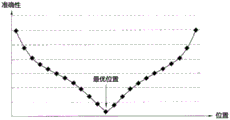
Fig. 9 is a graph illustrating the accuracy of the first sensor 170 at the optimal position of the first sensor 170, in which the horizontal axis represents the position of the first sensor 170 and the vertical axis represents the accuracy of the first sensor 170.
Referring to fig. 8 and 9, it can be seen that the detection accuracy of the first sensor 170 is highest when the imaginary central horizontal line 172 is merged with the upper end 131 of the magnet 130.
Fig. 10 is a top perspective view of the bobbin 110, the housing 140, the upper elastic member 150, the first sensor 170, the sensor substrate 180, and the plurality of support members 220, all of which are coupled to each other.
Fig. 11 is a bottom perspective view of the bobbin 110, the housing 140, the lower elastic member 160, and the plurality of support members 220, all of which are coupled to each other.
The first coil 120 may be wound on the outer circumferential surface of the bobbin 110 by a worker or a machine, and then both ends of the first coil 120, i.e., the start wire and the end wire, may be wound on a pair of winding protrusions 119 protruding in the first direction from the bottom surface of the bobbin 110, respectively, and fastened thereto. At this time, the end wire of the first coil 120 wound on the winding protrusion 119 may vary according to a specific worker. Although the pair of winding protrusions 119 may be disposed at positions symmetrical with respect to the center of the bobbin 110 as shown in fig. 11, the embodiment is not limited thereto.
As shown in fig. 8, the first coil 120 may be fitted and coupled in a coil groove 118 formed in the outer surface of the bobbin 110. As shown in fig. 2, although the first coil 120 may be implemented as an angled coil unit having a ring shape, embodiments are not limited thereto. According to another embodiment, the first coil 120 may be directly wound on the outer circumferential surface of the bobbin 110, or may be wound through a coil ring (not shown). The coil ring, on which the first coil 120 may be wound instead of being wound or disposed on the outer surface of the bobbin 110, may be coupled to the bobbin 110 in the same manner as the sensor substrate 180 is inserted and fixed in the supporting groove 114. In any case, the start and end wires of the first coil 120 may be wound around and fastened to the winding protrusion 119, respectively, and other configurations may be used.
As shown in fig. 2, the first coil 120 may be configured to have a generally octagonal shape. As shown in fig. 5a, the first coil 120 has a shape corresponding to the outer circumferential surface of the bobbin 110 having an octagonal shape. At least four surfaces of the first coil 120 may be configured in a straight line shape, and corner surfaces connecting the four surfaces may also be configured in a straight line shape. However, embodiments are not limited thereto, and the surfaces may be rounded.
The rectilinear surface of the first coil 120 may be configured to correspond to the magnet 130. The surface of the magnet 130 corresponding to the surface of the first coil 120 may have the same radius of curvature as the surface of the first coil 120. Specifically, when the surface of the first coil 120 is linear, the surface of the magnet 130 corresponding to the surface of the first coil 120 may be linear, and when the surface of the first coil 120 is a rounded surface, the surface of the magnet 130 corresponding to the surface of the first coil 120 may be a rounded surface. However, even when the surface of the first coil 120 is a rounded surface, the surface of the magnet 130 corresponding to the surface of the first coil 120 may be linear, and vice versa.
The first coil 120 is configured to move the bobbin 110 in a first direction parallel to the optical axis or in a direction parallel to the first direction to implement an autofocus function. The first coil 120 may generate an electromagnetic force by interaction with the magnet 130 when supplied with current. The generated electromagnetic force may move the bobbin 110 in a first direction or a direction parallel to the first direction.
The first coil 120 may be configured to correspond to the magnet 130. In other words, if the magnet 130 is constructed to form a single magnet body and the entire inner surface of the magnet 130 facing the outer surface of the first coil 120 has the same polarity, the outer surface of the first coil 120 corresponding to the inner surface of the magnet 130 may have the same polarity.
Alternatively, the magnet 130 may be divided into two or four magnets with respect to a surface perpendicular to the optical axis, and thus, the inner surface of the magnet 130 facing the outer surface of the first coil 120 may also be divided into two or four surfaces. In this case, the first coil 120 may also be divided into the number of coils corresponding to the number of magnets 130 resulting from the division.
The magnet 130 may be disposed at a position corresponding to the position of the first coil 120. Referring to fig. 8, the magnet 130 may be disposed to face the first coil 120 and the first sensor 170. This is the case where the magnet 130 serves as the magnet of the first sensor 170 and no additional magnet for the first sensor 170 needs to be provided, as in one embodiment.
In this case, the magnet 130 may be received and supported in the first side portion 141 of the case 140, as shown in fig. 7. The magnet 130 may be configured to have a substantially cubic shape corresponding to the shape of the first side portion 141 of the case 140, and a surface of the magnet 130 facing the first coil 120 may be configured to have a curvature corresponding to a curvature of a corresponding surface of the first coil 120.
The magnet 130 may be composed of a single magnet body. Referring to fig. 5a showing this embodiment, the magnet 130 may be disposed such that the inner surface of the magnet 130 facing the first coil 120 serves as an S pole 132 and the outer surface of the magnet 130 serves as an N pole 134. However, the embodiment is not limited thereto, and the reverse arrangement is also possible.
Two or more magnets 130 may be provided. According to this embodiment, four magnets 130 may be provided. As shown in fig. 5a, the magnet 130 may be configured to have a substantially rectangular shape when viewed in a plan view. Alternatively, the magnet 130 may be configured to have a triangular shape or a diamond shape.
Although the surface of the magnet 130 facing the first coil 120 may be linear, the embodiment is not limited thereto. If the corresponding surface of the first coil 120 is a rounded surface, the magnet 130 may be rounded to have a curvature corresponding to that of the rounded surface of the first coil 120. With this configuration, a constant distance between the magnet 130 and the first coil 120 can be maintained. In this embodiment, the magnet 130 may be provided with one magnet at each of the four first side portions 141 of the case 140. However, the embodiments are not limited thereto. In some designs, only one of the surface of the magnet 130 and the surface of the first coil 120 may be a flat surface, while the other surface may be a curved surface. In addition, the mating surfaces of the first coil 120 and the magnet 130 may both be curved surfaces. In this case, the matching surfaces of the first coil 120 and the magnet 130 may have the same curvature.
When the magnets 130 have a rectangular shape when viewed in a plan view as shown in fig. 5a, one pair of magnets 130 among the plurality of magnets 130 may be oriented to be parallel to each other in the second direction, and the other pair of magnets 130 may be oriented to be parallel to each other in the third direction. With this configuration, the movement of the housing 140 may be controlled to achieve hand shake correction as discussed below.
The case 140 may have a polygonal shape when viewed in a plan view. Although the outer contour of the upper end of the housing 140 may have a square plan view shape, as shown in fig. 6 of the illustrated embodiment, the inner contour of the lower end of the housing 140 may have an octagonal plane shape, as shown in fig. 6 and 7. Accordingly, the case 140 may include a plurality of side portions, for example, four first side portions 141 and four second side portions 142.
The first side portion 141 may be a portion where the magnet 130 is mounted, and the second side portion 142 may be a portion where a support member 220 described below is provided. The first side portions 141 may connect the second side portions 142 to each other, and may include a flat surface having a predetermined depth.
According to a particular embodiment, the first side portion 141 may be configured to have a surface area equal to or greater than a surface area of the magnet 130. Referring to fig. 7, the magnet 130 may be held in a magnet mounting portion 141a formed at a lower portion of an inner surface of the first side portion 141. The magnet mounting portion 141a may be implemented as a recess having a size corresponding to the size of the magnet 130, and may be disposed to face at least three surfaces, i.e., opposite lateral side surfaces and an upper surface of the magnet 130. The magnet mounting portion 141a may have an opening provided in a bottom surface thereof to face the second coil 230 described below such that the bottom surface of the magnet 130 directly faces the second coil 230.
Although the magnet 130 may be fastened to the magnet mounting portion 141a using an adhesive, an adhesive member such as a double-sided tape may be used instead, without limitation. Alternatively, unlike the recess structure shown in fig. 7, the magnet mounting portion 141a may be implemented as a magnet mounting hole into which the magnet 130 is partially fitted or through which the magnet 130 is partially exposed.
The first side portion 141 may be disposed in parallel with a side surface of the cover member 300. The first side portion 141 may be configured to have a larger area than the second side portion 142. The second side portion 142 may define a channel through which the support member extends. An upper portion of the second side portion 142 may include a first through hole 147. The supporting member 220 may extend through the first through hole 147 and may be connected to the upper elastic member 150.
The housing 140 may further include a second stopper 144. The second stopper 144 may prevent the upper surface of the body of the case 140 from directly colliding with the inner surface of the cover member 300 shown in fig. 1.
The case 140 may further include a plurality of first upper supporting protrusions 143 formed on the second side portion 142. The plurality of first upper supporting protrusions 143 may have a hemispherical shape as shown in the drawings, or may have a cylindrical shape or a rectangular pillar shape. However, the shape of the first upper supporting protrusion 143 is not limited to this embodiment.
Referring to fig. 6 and 7, the case 140 may be provided with a first recess 142a formed in the second side portion 142. The first recess 142a is provided to provide a path through which the supporting member 220 extends and a space for filling gel-type silicone that may function as a shock absorber. In other words, the first recess 142a may be filled with shock-absorbing silicone.
Fig. 12 is a perspective view of the upper elastic member 150, the lower elastic member 160, the first sensor 170, the sensor substrate 180, the base 210, the supporting member 220, and the circuit board 250 according to this embodiment, all of which are coupled to each other.
According to this embodiment, the upper elastic member 150 may include at least four upper elastic members 150, i.e., first to fourth upper elastic members 150-1, 150-2, 150-3 and 150-4, which are electrically isolated from each other. The elastic member contact parts 184-1, 184-2, 184-3, and 184-4 connected to the first sensor 170 may be connected to the plurality of supporting members 220 through the first to fourth upper elastic members 150-1, 150-2, 150-3, and 150-4. Specifically, the first upper elastic member 150-1 connected with the elastic member contact part 184-4 may be connected to the first supporting member 220-1, i.e., the first and second first supporting members 220-1a and 220-1b, and the second upper elastic member 150-2 connected with the elastic member contact part 184-3 may be connected to the second supporting member 220-2. In addition, the third upper elastic member 150-3 connected with the elastic member contact portion 184-2 may be connected to the third supporting member 220-3, i.e., the first and second third supporting members 220-3a and 220-3b, and the fourth upper elastic member 150-4 connected with the elastic member contact portion 184-1 may be connected to the fourth supporting member 220-4.
Each element 150a of the first and third upper elastic members 150-1 and 150-3 may include a first inner frame 151, a first portion first outer frame 152a, and a first frame connector 153, and each element 150b of the second and fourth upper elastic members 150-2 and 150-4 may include a first inner frame 151, a first portion first outer frame 152b, and a first frame connector 153. The first inner frame 151 may be coupled to the wire barrel 110 and to the associated elastic member contact portions 184-1, 184-2, 184-3, and 184-4. As shown in fig. 4, when the upper surface 112a of the second protrusion 112 is flat, the first inner frame 151 may be disposed on the upper surface 112a and may be fastened on the upper surface 112a by an adhesive member. According to another embodiment, when a supporting protrusion (not shown) is formed on the upper surface 112a, unlike the embodiment shown in fig. 4, the supporting protrusion may be inserted into a first and second through-hole 151a formed in the first inner frame 151 and then may be fastened therein by thermal fusion or by means of an adhesive such as epoxy.
The first portion first outer frames 152a and 152b may be coupled to the case 140 and may be connected to the support member 220. The first frame connector 153 may connect the first inner frame 151 with the first outer frames 152a and 152 b. Although the first portion first outer frame 152b has a configuration in which the first portion first outer frame 152a is divided into two sections, the embodiment is not limited thereto. In other words, in another embodiment, the first portion first outer frame 152a may also be divided into two sections in the same manner as the first portion first outer frame 152 b.
The first frame connector 153 may be bent at least once to form a predetermined pattern. The upward and/or downward movement of the bobbin 110 in the first direction parallel to the optical axis may be elastically supported by a position change and a slight deformation of the first frame connector 153.
The plurality of first upper supporting protrusions 143 of the case 140 may couple and fasten the first portion first outer frames 152a and 152b of the upper elastic member 150 to the case 140, as shown in fig. 12. In this embodiment, the first portion first outer frames 152a and 152b may be provided with second portion second through holes 157 at positions corresponding to the first upper supporting protrusions 143 of the first portion first outer frames 152a and 152b, the second portion second through holes 152 having shapes corresponding to the first upper supporting protrusions 143. The upper supporting protrusion 143 and the second through hole 157 may be coupled to each other by thermal fusion or by means of an adhesive such as epoxy. In order to fasten the plurality of first to fourth upper elastic members 150-1, 150-2, 150-3 and 150-4, a sufficient number of first upper supporting protrusions 143 may be provided. Accordingly, the first to fourth upper elastic members 150-1, 150-2, 150-3 and 150-4 and the case 140 may be prevented from being coupled to each other without fail.
The distance between the plurality of first upper supporting protrusions 143 may be appropriately set such that the first upper supporting protrusions 143 do not interfere with surrounding components. Specifically, the first upper supporting protrusions 143 may be disposed at the corners of the housing 140 at regular intervals to be symmetrical with respect to the center of the bobbin 110, or may be disposed at irregular intervals to be symmetrical with respect to a certain imaginary line extending through the center of the bobbin 110.
After the first inner frame 151 is coupled to the wire barrel 110 and the first portion first outer frames 152a and 152b are coupled to the case 140, conductive connection members CP11, CP12, CP13, and CP14 made of, for example, solder may be disposed between the elastic member contact portions 184-1, 184-2, 184-3, and 184-4 of the sensor substrate 180 and the first inner frame 151, as shown in fig. 10, so that power having different polarities is applied to two pins P11 and P12 of the four pins P11, P12, P13, and P14 of the first sensor 170, and so that different feedback signals are output from the other two pins P21 and P22. In order to enable application of power having different polarities and output of feedback signals having different polarities in this manner, the upper elastic member 150 may be divided into first to fourth upper elastic members 150-1, 150-2, 150-3 and 150-4.
The first to fourth upper elastic members 150-1, 150-2, 150-3 and 150-4 are connected to the circuit board 250 via the supporting member 220. Specifically, the first upper elastic member 150-1 may be connected to the circuit board 250 via at least one of the first or second first supporting members 220-1a or 220-1b, and the second upper elastic member 150-2 may be connected to the circuit board 250 via the second supporting member 220-2. In addition, the third upper elastic member 150-3 may be connected to the circuit board 250 via at least one of the first and second third supporting members 220-3a and 220-3b, and the fourth upper elastic member 150-4 may be connected to the circuit board 250 via the fourth supporting member 220-4. Accordingly, the first sensor 170 may receive power supplied from the circuit board 250 through the supporting member 220 and the upper elastic member 150, or may output feedback signals and provide the feedback signals to the circuit board 250.
The lower elastic member 160 may include a first lower elastic member 160-1 and a second lower elastic member 160-2 electrically isolated from each other. The first coil 120 may be connected to the plurality of supporting members 220 through the first lower elastic member 160-1 and the second lower elastic member 160-2.
Each of the first lower elastic member 160-1 and the second lower elastic member 160-2 may include: at least one of the second inner frames 161-1 or 161-2; at least one of the second outer frames 162-1 or 162-2; and at least one of the second frame connectors 163-1, 163-2, 163-3, or 163-4.
The second inner frames 161-1 and 161-2 may be coupled to the bobbin 110, and the second outer frames 162-1 and 162-2 may be coupled to the case 140. The first second frame connector 163-1 may connect the second inner frame 161-1 with the second outer frame 162-1, the second frame connector 163-2 may connect the two second outer frames 162-1 and 162-2 to each other, and the third second frame connector 163-3 may connect the second inner frame 161-2 with the second outer frame 162-2.
The first lower elastic member 160-1 may further include a first coil frame 164-1, and the second lower elastic member 160-2 may further include a second coil frame 164-2. Referring to fig. 11, the first and second coil frames 164-1 and 164-2 may be electrically connected to the two end wires of the first coil 120 at positions on the upper surface thereof near the pair of winding protrusions 119 by a conductive connection member such as solder, and the two end wires of the first coil 120 are wound on the pair of winding protrusions 119, so that the first and second lower elastic members 160-1 and 160-2 may receive electric power having different polarities and may transmit the electric power to the first coil 120. In order to be able to apply electric power having different polarities and transfer the electric power to the first coil 120 in this manner, the lower elastic member 160 may be divided into a first lower elastic member 160-1 and a second lower elastic member 160-2.
Each of the first and second lower elastic members 160-1 and 160-2 may further include a fourth second frame connector 163-4. The fourth second frame connector 163-4 may connect the first and second coil frames 164-1 and 164-2 with the second inner frame 161-2.
At least one of the first to fourth second frame connectors 163-1, 163-2, 163-3 and 163-4 may be bent at least once to form a predetermined pattern. Specifically, the upward and/or downward movement of the bobbin 110 in the first direction parallel to the optical axis may be elastically supported by the position change and the slight deformation of the first and third portion second frame connectors 163-1 and 163-3.
According to one embodiment, each of the first and second lower elastic members 160-1 and 160-2 may further include a bent portion 165. The bent portion 165 is bent in the first direction from the second frame connector 163-2 toward the upper elastic member 150. The upper elastic member 150 may further include a fifth upper elastic member 150-5 and a sixth upper elastic member 150-6 electrically isolated from each other. Each of the fifth upper elastic member 150-5 and the sixth upper elastic member 150-6 may further include a connection frame 154 and a second first outer frame 155. The connection frame 154 may be connected to the bent portion 165 and may extend in the first direction. The second portion first outer frame 155 may be bent in a direction perpendicular to the first direction at the connection frame 154, may be coupled to the case 140, and may be connected to the support member 220. In other words, the fifth upper elastic member 150-5 may be coupled to the fifth supporting member 220-5, and the sixth upper elastic member 150-6 may be coupled to the sixth supporting member 220-6. Here, the respective bent portions 165 of the first and second lower elastic members 160-1 and 160-2 and the coupling frames 154 and the second portion first outer frame 155 of the fifth and sixth upper elastic members 150-5 and 150-6 may be integrally formed. Thus, each of the first and second lower elastic members 160-1 and 160-2 and each of the fifth and sixth upper elastic members 150-5 and 150-6 may have portions 165 and 154 bent in the first direction.
According to another embodiment, unlike the embodiment shown in fig. 12, the connection frame 154 of each of the fifth and sixth upper elastic members 150-5 and 150-6 may be bent at the second portion first outer frame 155 and may extend from the second portion first outer frame 155 to the second portion second frame connector 163-2 in the first direction. In this case, the bent portions 165 of the first and second lower elastic members 160-1 and 160-2 shown in fig. 12 may be omitted. As such, each of the first and second lower elastic members 160-1 and 160-2 may not include a bent portion bent in the first direction, and each of the fifth and sixth upper elastic members 150-5 and 150-6 may include a bent portion 154 bent in the first direction.
According to yet another embodiment, unlike the embodiment shown in fig. 12, the bent portion 165 of each of the first and second lower elastic members 160-1 and 160-2 may be bent in the first direction at the second portion second frame connector 163-2 and may extend from the second portion second frame connector 163-2 to the second portion first outer frame 155. In this case, the bent portion 154 of each of the fifth and sixth upper elastic members 150-5 and 150-6 shown in fig. 12 may be omitted. Therefore, even though each of the first and second lower elastic members 160-1 and 160-2 includes the bent portion 165 bent in the first direction, each of the fifth and sixth upper elastic members 150-5 and 150-6 may not include the bent portion bent in the first direction.
According to another embodiment, unlike the embodiment shown in fig. 12, the case 140 may be additionally provided with an insert or a metal attachment (not shown). In this case, the second portion first outer frame 155 and the second portion second frame connector 163-2 may be connected to each other via the metal attachment. In this case, the bent portion 155 and the connection frame 154 shown in fig. 12 may be omitted. Thus, each of the first and second lower elastic members 160-1 and 160-2 and each of the fifth and sixth upper elastic members 150-5 and 150-6 may not include a bent portion bent in the first direction.
As described above, at least one of the upper elastic member or the lower elastic member may include a bent portion bent in the first direction, and any one of the upper elastic member and the lower elastic member may not include the bent portion bent in the first direction.
The second portion first outer frame 155 may further include a second portion second through hole 157, similar to the first portion first outer frame 152 b.
According to an embodiment, the first portion first outer frames 152a and 152b of the first to sixth upper elastic members 150-1, 150-2, 150-3, 150-4, 150-5 and 150-6 may be disposed to face each other in a diagonal direction, and the second portion first outer frame 155 may be disposed to face each other in a diagonal direction. Specifically, the first portion first outer frame 152a of the first upper elastic member 150-1 and the first portion first outer frame 152a of the third upper elastic member 150-3 may be disposed to face each other in a diagonal direction. In addition, the first portion first outer frame 152b of the second upper elastic member 150-2 and the first portion first outer frame 152b of the fourth upper elastic member 150-4 may be disposed to face each other in a diagonal direction. Further, the second portion first outer frame 155 of the fifth upper elastic member 150-5 and the second portion first outer frame 155 of the sixth upper elastic member 150-6 may be disposed to face each other in a diagonal direction.
Alternatively, according to another embodiment, although not shown in the drawings, the first portion first outer frames 152a and 152b of the first to sixth upper elastic members 150-1, 150-2, 150-3, 150-4, 150-5 and 150-6 may be disposed at any two of the four corners shown in fig. 12 instead of being disposed to face each other in a diagonal direction, and the second portion first outer frames 155 may be disposed at the remaining two of the four corners instead of being disposed to face each other in a diagonal direction.
It should be understood that the first and second lower elastic members 160-1 and 160-2 receive power from the circuit board 250 through the fifth and sixth upper elastic members 150-5 and 150-6 connected with the plurality of supporting members 220 and supply the power to the first coil 120. Specifically, the first lower elastic member 160-1 may be connected to the circuit board 250 through the sixth upper elastic member 150-6 and the sixth supporting member 220-6, and the second lower elastic member 160-2 may be connected to the circuit board 250 through the fifth upper elastic member 150-5 and the fifth supporting member 220-5.
Referring to fig. 11, the lower surface of the wire barrel 110 may be provided with a plurality of first lower supporting protrusions 117 to couple and fasten the second inner frames 161-1 and 161-2 of the lower elastic member 160 and the wire barrel 110 to each other. The lower surface of the case 140 may be provided with a plurality of second lower supporting protrusions 145 to couple and fasten the second outer frames 162-1 and 162-2 of the lower elastic member 160 with the case 140.
The number of the second lower supporting protrusions 145 may be greater than the number of the first lower supporting protrusions 117. This is because the second frame connector 163-2 of the lower elastic member 160 is longer than the first frame connector 163-1.
As described above, since the lower elastic member 160 is divided into two lower elastic members, the first lower supporting protrusions 117 and the second lower supporting protrusions 145 are provided in a sufficient number according to the number of the first upper supporting protrusions 143, so that a gap that may be generated when the lower elastic member 160 is separated may be prevented from occurring.
In the case where the lower elastic member 160 is composed of a single body instead of divided sections, it is not necessary to provide a large number of the first lower supporting protrusions 117 and the second lower supporting protrusions 145 in the number equal to the number of the first upper supporting protrusions 143. This is because the lower elastic member 160 can be reliably coupled to the case 140 only by the small number of the first and second lower supporting protrusions 117 and 145.
However, when the lower elastic member 160 is divided into the first and second lower elastic members 160-1 and 160-2 electrically isolated from each other (as in this embodiment), the first and second lower supporting protrusions 117 and 145 may be provided in a number sufficient to hold the divided first and second lower elastic members 160-1 and 160-2. Accordingly, the first and second lower elastic members 160-1 and 160-2 and the case 140 may be prevented from being incompletely coupled to each other.
Still referring to fig. 11, the first lower supporting protrusion 117 and the second lower supporting protrusion 145 may have a hemispherical shape similar to the first upper supporting protrusion 143, or may have a cylindrical shape or a rectangular pillar shape. However, there is no limitation in the shape of the first and second lower supporting protrusions 117 and 145.
Referring to fig. 12, according to the embodiment, the second inner frames 161-1 and 161-2 of the first and second lower elastic members 160-1 and 160-2 may be provided with third through holes 161a formed at positions corresponding to the first lower supporting protrusions 117, and the third through holes 161a may have shapes corresponding to the first lower supporting protrusions 117. The first lower supporting protrusion 117 and the third through-hole 161a may be coupled to each other by thermal fusion or by means of an adhesive such as epoxy.
In addition, the second outer frames 162-1 and 162-2 of each of the first and second lower elastic members 160-1 and 160-2 may be provided with fourth through holes 162a formed at positions corresponding to the second lower supporting protrusions 145. The second lower supporting protrusion 145 and the fourth through-hole 162a may be coupled to each other by thermal fusion or by means of an adhesive such as epoxy.
The distance between adjacent ones of the plurality of first lower supporting protrusions 117 and 145 may be appropriately set such that the first lower supporting protrusions do not interfere with surrounding components. Specifically, the first lower supporting protrusion 117 and the second lower supporting protrusion 145 may be disposed at regular intervals to be symmetrical with respect to the center point of the wire barrel 110.
Although each of the upper and lower elastic members 150 and 160 may be implemented as a leaf spring, there is no limitation in material embodiments of the upper and lower elastic members 150 and 160.
The bobbin 110, the case 140, and the upper and lower elastic members 150 and 160 may be assembled with each other by thermal fusion and/or a bonding process using an adhesive. Here, the assembly may be performed by thermal fusion and then a bonding process using an adhesive, according to a specific assembly sequence.
For example, when the wire barrel 110 and the second inner frames 161-1 and 161-2 of the lower elastic member 160 are first assembled with each other in a first assembly and then the housing 140 and the second outer frames 162-1 and 162-2 of the lower elastic member 160 are assembled with each other in a second assembly, the first lower supporting protrusion 117 of the wire barrel 110 may be coupled to the third through-hole 161a and the second lower supporting protrusion 145 of the housing 140 may be coupled to the fourth through-hole 162a by thermal fusion. When the first inner frame 151 of the upper elastic member 150 is first assembled in the third assembly, the elastic member contact parts 184-1, 184-2, 184-3, and 184-4 of the sensor substrate 180 and the first inner frame 151 of each of the first to fourth upper elastic members 150-1, 150-2, 150-3, and 150-4 may be coupled to each other by thermal fusion. Then, when the case 140 and the first and second outer frames 152a and 152b and 155 of the upper elastic member 150 are coupled to each other in the fourth assembly, the second portion second through hole 157 may be bonded to the first upper supporting protrusion 143 of the case 140 by applying an adhesive such as epoxy. However, the assembly sequence may also be changed. In other words, the first to third assembling may be performed by thermal fusion, and the fourth assembling may be performed by bonding. Although thermal fusion may cause deformation, i.e., warping, bonding in the fourth assembly may compensate for such deformation.
In the above-described embodiment, power may be supplied to the first sensor 170 through two of the four upper elastic members 150 electrically isolated from each other, the feedback signal output from the first sensor 170 may be transmitted to the circuit board 250 through the remaining two upper elastic members 150 electrically isolated from each other, and power may be supplied to the first coil 120 through the two lower elastic members 160 electrically isolated from each other. However, the embodiments are not limited thereto.
According to another embodiment, the roles of the plurality of upper resilient members 150 and the plurality of lower resilient members 160 may be interchanged. Specifically, power may be supplied to the first coil 120 through two of the four upper elastic members 150 electrically isolated from each other, power may be supplied to the first sensor 170 through two of the four lower elastic members 160 electrically isolated from each other, and the feedback signal output from the first sensor 170 may be transmitted to the circuit board 250 through the remaining two lower elastic members 160 electrically isolated from each other. Although not shown, it is easily understood from the foregoing drawings.
Hereinafter, the upper elastic member 150 and the lower elastic member 160 when the roles of the upper elastic member 150 and the lower elastic member 160 are interchanged with each other will be briefly described. In this case, the lower elastic member may be divided in the same manner as the upper elastic member 150 shown in fig. 10, and the upper elastic member may be divided in the same manner as the lower elastic member 160 shown in fig. 11. The sensor substrate 180 may be coupled to the bobbin 110, and the elastic member contact portion of the sensor substrate 180 may protrude to face the lower elastic member 160 instead of the upper elastic member 150 and may be coupled to the corresponding lower elastic member 160.
The lower elastic member may include at least four lower elastic members, i.e., first to fourth lower elastic members spaced apart from each other, and the first sensor 170 may be connected to the plurality of supporting members 220 via the first to fourth lower elastic members.
Each of the first to fourth lower elastic members may include: a first inner frame coupled to the bobbin 110; a first outer frame coupled to the case 140 and connected to the support member 220; and a first frame connector connecting the first inner frame to the first outer frame.
The upper elastic member may include at least two upper elastic members, i.e., a first upper elastic member and a second upper elastic member that are separated from each other, and the first coil 120 may be connected to the plurality of supporting members 220 via the first upper elastic member and the second upper elastic member.
Each of the first and second upper elastic members may include: at least one second inner frame coupled with the wire drum 110; at least one second outer frame coupled with the case 140; and a first portion second frame connector connecting the at least one second inner frame to the at least one second outer frame.
The at least one second outer frame may include a plurality of second outer frames, and each of the first upper elastic member and the second upper elastic member may further include a second frame connector connecting the plurality of second outer frames to each other.
The at least four lower elastic members may further include fifth and sixth lower elastic members spaced apart from each other, and each of the fifth and sixth lower elastic members may include a second first outer frame formed in a direction perpendicular to the first direction and coupled to the case 140 and connected to the supporting member 220.
Each of the first and second upper elastic members may further include a bent portion bent toward the lower elastic member at the second portion second frame connector in the first direction. Each of the fifth lower elastic member and the sixth lower elastic member may further include a connection frame connecting the bent portion with the second portion first outer frame.
Alternatively, each of the fifth lower elastic member and the sixth lower elastic member may further include a connection frame bent at the second portion first outer frame and extending to the second portion second frame connector in the first direction. Here, the bending portion, the connection frame, and the second first outer frame may be integrally formed with each other.
Alternatively, each of the first and second upper elastic members may further include a bent portion bent at the second portion second frame connector and extending in the first direction to the second portion first outer frame.
Alternatively, the lens driving device may further include an insert or a metal attachment in the case 140, via which the second portion first outer frame and the third portion second frame connector may be connected to each other.
Each of the first upper elastic member and the second upper elastic member may further include: a coil frame connected to a corresponding one of both ends of the first coil 120; a third portion of second frame connectors connecting the coil frame to at least one second inner frame.
Referring to fig. 3, 6, 7, 10, and 11, a side surface of the case 140 may be provided with a plurality of third stoppers 149. The third stopper 149 serves to prevent the main body of the housing 140 from colliding with the cover member 300 when the first lens driving unit moves in the second and/or third directions, and may prevent the side surface of the housing 140 from directly colliding with the inner surface of the cover member 300 when external impact is applied. Although the third stoppers 149 are provided two on each outer surface of the case 140 and are constantly spaced apart from each other as shown in the drawings, there is no limitation in the position or number of the third stoppers 149.
Although not shown in the drawings, the housing 140 may be further provided with a fourth stopper on a lower surface thereof. The fourth stopper may protrude from a lower surface of the case 140. The fourth stopper may serve to prevent the lower surface of the housing 140 from colliding with the base 210 and/or the circuit board 250, which will be described below. In addition, the fourth stopper may be maintained in a state of being spaced apart from the base 210 and/or the circuit board 250 by a predetermined distance in the initial position and function normally. With this configuration, the case 140 may be spaced downward with respect to the base 210 and may be spaced upward with respect to the cover member 300, so that the case 140 may be maintained at a constant height in the optical axis direction without interfering with other components. Accordingly, the housing 140 can be displaced in the second and/or third directions, which are the front-rear direction and the left-right direction, in the plane perpendicular to the optical axis.
The first lens driving unit according to this embodiment can precisely control the movement of the bobbin 110 by detecting the position of the bobbin 110 in the optical axis direction, i.e., the first direction on the z-axis or the direction parallel to the first direction, by the first sensor 170. This may be accomplished by feedback provided to the outside through the circuit board 250 by information about the position detected by the first sensor 170.
According to an embodiment, in order to move the bobbin 110 in the optical axis direction, i.e., the first direction or a direction parallel to the first direction, a magnet (hereinafter, referred to as a detection magnet, not shown in the drawing) facing the first sensor 170 may be further provided in addition to the magnet 130 (hereinafter, referred to as an auto-focus magnet) facing the first coil 120. In this embodiment, the interaction between the autofocus magnet 130 and the first coil 120 may be impeded by the detection magnet. This is because the detection magnet may generate a magnetic field. Accordingly, in order to prevent the separately provided detection magnet from interacting with the auto-focus magnet 130 or to prevent the bobbin 110 from being tilted and to allow interaction between the detection magnet and the auto-focus magnet 130, the first sensor 170 may be disposed to face the detection magnet. In this case, the first sensor 170 may be disposed, coupled or mounted on the bobbin 110, and the detection magnet may be disposed, coupled or mounted on the housing 140. Alternatively, the first sensor 170 may be disposed, coupled or mounted on the housing 140 and the sensing magnet may be disposed, coupled or mounted on the bobbin 110.
According to another embodiment, the auto-focus magnet may also be used as a detection magnet to move the bobbin 110 in the optical axis direction, i.e., the first direction or a direction parallel to the first direction, in addition to the detection magnet being additionally provided. For example, in order for the autofocus magnet 130 to also function as a detection magnet, the first sensor 170 may not be disposed on the housing 140 but may be disposed, coupled, or mounted on the bobbin 110 to move with the bobbin 110. Thus, when the autofocus magnet and the detection magnet are present together, the problems caused by the interaction between the two magnets are fundamentally solved. For example, a piece of magnetic field compensation metal (not shown) for minimizing the interaction between the autofocus magnet and the detection magnet need not be provided.
In some cases, the first lens driving unit may further include various means for improving an auto-focus function of the first lens driving unit in addition to the first sensor 170. In this case, the position of the device or the method or process of receiving power through the circuit board 250 and supplying the feedback signal to the circuit board 250 may be the same as the first sensor 170.
Referring again to fig. 2, the second lens driving unit, which is the aforementioned handshake correction lens driving unit, may include a first lens driving unit, a base 210, a plurality of supporting parts 220, a second coil 230, a second sensor 240, and a circuit board 250.
Although the first lens driving unit may include the above-described components, the above-described components may be replaced with another optical system capable of implementing an auto-focus function. Specifically, the first lens driving unit may be constituted by an optical module using a single lens moving actuator or a variable refractive index actuator, instead of the auto-focus actuator using a voice coil motor. In other words, the first lens driving unit may employ any optical actuator as long as it can realize the auto-focus function. However, it is necessary to mount the magnet 130 at a position corresponding to the second coil 230, as will be described below.
Fig. 13 is an exploded perspective view of the base 210, the second coil 230, and the circuit board 250.
As shown in fig. 2 and 13, the base 210 of the second lens driving unit may have a substantially rectangular shape when viewed in a plan view. The base 210 may be provided with a stepped portion 211 on which an adhesive is coated when the cover member 300 is adhesively fastened to the base 210, as shown in fig. 13. The stepped portion 211 may guide the cover member 300 coupled to the upper side of the base 210, and may allow the end of the cover member 300 to contact the base 210 in a surface contact manner. The stepped portion 211 and the end of the cover member 300 may be adhesively fastened to each other, and may be sealed closed using an adhesive or the like.
The base 210 may be disposed to be spaced apart from the first lens driving unit by a predetermined distance. The base 210 may be provided with a supporting portion 255, the supporting portion 255 being located at a portion of the base 210 facing a portion of the circuit board 250 where the terminal 251 is formed, and the supporting portion 255 having a size corresponding to the portion of the circuit board 250 where the terminal 251 is formed. The holding portion 255 may be configured to have a constant cross-sectional area from the outer surface of the base 210 not including the step portion 211 to hold the terminal pad 253 having the terminal 251.
The base 210 may have second recesses 212 formed at corners thereof. When the cover member 300 includes protrusions formed at corners thereof, the protrusions on the cover member 300 may be fitted into the second recesses 212 to be combined with the base 210.
The base 210 may be provided in the upper surface thereof with second mounting recesses 215-1 and 215-2, and the second sensor 240 is disposed in the second mounting recesses 215-1 and 215-2. According to this embodiment, two second mounting recesses 215-1 and 215-2 are provided, and the second sensor 240 is disposed in the second mounting recesses 215-1 and 215-2, respectively, so that the second sensor 240 can detect the range of movement of the housing 140 in the second and/or third directions. To this end, the two second mounting recesses 215-1 and 215-2 may be disposed such that an angle defined by two imaginary lines connecting the two second mounting recesses 215-1 and 215-2 and the center of the base 210 is 90 degrees.
Each of the second mounting recesses 215-1 and 215-2 may be provided with a tapered inclined surface (not shown) on at least one surface thereof to allow the second sensor 240 to be assembled by more easily injecting epoxy or the like through the inclined surface. The above-mentioned additional epoxy or the like may not be injected into the second mounting recesses 215-1 and 215-2, or may be injected to secure the second sensor 240 in place. The second mounting recesses 215-1 and 215-2 may be disposed at the center of the second coil 230 and its vicinity. The center of the second coil 230 and the center of the second sensor 240 may coincide with each other. According to this embodiment, the second mounting recesses 215-1 and 215-2 may be formed on the side of the base 210.
The cover member 300 may be provided with a groove at a position corresponding to the stepped portion 211 of the base 210 to allow injection of an adhesive or the like through the groove. At this time, since the adhesive injected through the groove has a low viscosity, the adhesive can easily penetrate between the stepped portion 211 and the end surface of the cover member 300. The adhesive applied to the groove may fill the gap between the mating surfaces of the cover member 300 and the base 210 through the groove, and thus, the cover member 300 may be sealingly coupled to the base 210.
The base 210 may be further provided on a lower surface thereof with a mount (not shown) for mounting the optical filter. The filter may be an infrared filter. However, the embodiment is not limited thereto, and the base 210 may be provided on a lower surface thereof with an additional sensor holder on which the optical filter is disposed. As described below, the base 210 may be provided on a lower surface thereof with a sensor substrate on which an image sensor is mounted to constitute a camera module.
The plurality of support members 220 may be disposed on the second side portion 142 of the housing 140. As described above, when the case 140 has a polygonal shape, for example, when viewed in a plan view, the case 140 may have a plurality of second side portions 142. If the inner side of the lower end of the case 140 has an octagonal shape in the bottom view, the plurality of supporting members 220 may be provided in four second side portions 142 of the eight side portions. For example, each of the four second side portions 142 may be provided with two supporting members 220, and thus a total of eight supporting members 220 may be provided.
Alternatively, among the four second side portions 142 of the case 140, two second side portions 142 may be provided with only one supporting member 220 each, and the remaining two second side portions 142 may be provided with two supporting members 220 each, so that a total of six supporting members 220 may be provided.
As described above, the supporting member 220 may serve as a path for transmitting power required for the first sensor 170 and the first coil 120 and a path for providing the circuit board 250 with a feedback signal output from the first sensor 170.
In addition, since the supporting members 220 serve to return the housing 140 to its original position after the housing 140 is moved in the second and/or third direction in the first lens driving unit, the elastic modulus can be balanced when the same number of supporting members 220 are disposed in the diagonal direction. Specifically, when the housing 140 moves in the second and/or third direction in the plane perpendicular to the optical axis direction, the supporting member 220 may be slightly and elastically deformed in the direction in which the housing 140 moves or in the length direction of the supporting member 220. Here, the term "length direction" may refer to a direction in which the upper and lower ends of each wire of the supporting member 220 are connected. Accordingly, the housing 140 may be moved only in the second and/or third directions substantially perpendicular to the optical axis with almost no displacement in the first direction parallel to the optical axis, and thus the accuracy of hand-shake correction may be improved. This may be achieved by the property that the supporting member 220 can be stretched in the longitudinal direction.
As shown in fig. 12, each of the first to fourth supporting members 220-1, 220-2, 220-3 and 220-4 includes a pair of supporting members and is respectively provided at each of four second side portions 142 of eight side portions of the case 140 to support the case 140 in a state of being spaced apart from the base 210 by a predetermined distance.
The first to fourth supporting members 220-1, 220-2, 220-3 and 220-4 according to the embodiment may be respectively provided at the second side portion 142 of the case 140 to be symmetrical to each other. However, the embodiments are not limited thereto. In other words, the plurality of supporting parts 220 may be shaped and numbered to be symmetrical to each other in the second direction and the third direction perpendicular to the first direction. In consideration of the above-described elastic coefficient, the number of the supporting members 220 may be the aforementioned eight.
Although it is described in the above embodiment that the supporting member 220 is implemented as a suspension wire not including a predetermined pattern, the embodiment is not limited thereto. According to another embodiment, the supporting member 200 may be implemented as a plate member (not shown) having an elastically deforming portion.
Referring to fig. 13, the second coil 230 may include a fifth through hole 230a formed by penetrating a corner region of the circuit part 231. The supporting member 220 may extend through the fifth through hole 230a and may be connected to the circuit board 250. Alternatively, when the second coil 230 is an FP coil, an Optical Image Stabilizer (OIS) coil 232 may be formed or disposed on a local area of the FP coil. In addition, the support member 220 may be conductively welded to an area of the second coil 230 where the fifth through hole 230a is originally formed, without forming the fifth through hole 230 a.
The second coil 230 may be disposed to face the magnet 130 fastened to the case 140. For example, the second coil 230 may be disposed outside the magnet 130. Alternatively, the second coil 230 may be disposed below the magnet 130 and spaced apart from the magnet 130 by a predetermined distance.
In this embodiment, although the second coils 230 may include a total of four second coils disposed on four sides of the circuit board 250 as shown in fig. 13, the embodiment is not limited thereto. Only two coils 230, i.e., a second coil for the second direction and a second coil for the third direction, may be provided, or four or more second coils 230 may be alternatively provided. According to this embodiment, a circuit pattern may be formed on the circuit board 250 to have the shape of the second coil 230, and an additional second coil 230 may be disposed on the circuit board 250. However, the embodiment is not limited thereto, and only the independent second coil 230 may be provided on the circuit board 250 without forming a circuit pattern having the shape of the second coil 230 on the circuit board 250. Alternatively, the second coil 230 configured by winding a wire into a circular ring shape or the second coil 230 configured by an FP (fine pattern) coil may be conductively connected to the circuit board 250.
The circuit part 231 including the second coil 230 may be mounted to a circuit board 250 disposed above the base 210. However, the embodiment is not limited thereto, and the second coil 230 may be closely disposed on the base or may be spaced apart from the base 210 by a predetermined distance. In addition, the second coil 230 may be formed on an additional substrate, which may be stacked on the circuit board 250 and connected to the circuit board 250.
As described above, the housing 140 may be moved in the second and/or third directions by the interaction between the magnets 130 and the second coils 230 disposed to face each other, thereby implementing hand trembling correction. To this end, the first to fourth supporting parts 220 may support the housing 140 with respect to the base 210 such that the housing 140 may move in the second and/or third directions perpendicular to the first direction.
The second sensor 240 may detect a displacement of the first lens driving unit relative to the base 210 in a second and/or third direction perpendicular to the optical axis. To this end, the second sensor 240 may be disposed at the center of the second coil 230, and the circuit board 250 is disposed between the second sensor 240 and the second coil 230 to detect the movement of the case 140. In other words, the second sensor 240 may not be directly connected to the second coil 230, and the circuit board 250 may be provided with the second coil 230 on an upper surface thereof and the second sensor 240 on a lower surface thereof. According to this embodiment, the second sensor 240, the second coil 230, and the magnet 130 may be disposed on the same axis.
The second sensor 240 may be implemented as a hall sensor, but may alternatively be implemented as any kind of sensor as long as it can detect a change in magnetic force. As shown in fig. 13, two second sensors 240 may be disposed at the side of the base 210 disposed under the circuit board 250 and may be fitted into second mounting recesses 215-1 and 215-2 formed in the base 210.
The circuit board 250 may include sixth through holes 250a1 and 250a2, and the supporting member 220 may extend through the sixth through holes 250a1 and 250a 2. The supporting member 220 may extend through the sixth through holes 250a1 and 250a2 in the circuit board 250, and may be conductively connected to an associated circuit pattern, which may be provided on the lower surface of the circuit board 250, via soldering.
The circuit board 250 may further include a seventh via 250 b. The second upper supporting protrusion 217 and the seventh through hole 250b of the base 210 may be coupled as shown in fig. 12, and may be fastened to each other by thermal fusion or by means of an adhesive such as epoxy.
The circuit board 250 may further include a plurality of terminals 251. The circuit board 250 may be provided with bent terminal pads 253. According to a specific embodiment, the one bent terminal pad 253 of the circuit board 250 may be provided with at least one terminal 251.
According to a specific embodiment, the plurality of terminals 251 provided on the terminal pad 253 may receive external power and may supply power to the first and second coils 120 and 130 and the first and second sensors 170 and 240. In addition, the plurality of terminals 251 may output the feedback signal output from the first sensor 170 to the outside. The number of terminals 251 provided on the terminal pad 252 may be increased or decreased according to the kind of components to be controlled.
According to the embodiment, although the circuit board 250 may be implemented as an FPCB, the embodiment is not limited thereto. The terminals of the circuit board 250 may be directly formed on the surface of the base 210 through a process of forming surface electrodes.
As described above, the circuit board 250 may supply power (or current) required for the first coil 120 and the first sensor 170, and may receive a feedback signal from the first sensor 170 to adjust the displacement of the bobbin 110.
The lens driving device according to the embodiment may be included in other devices in various fields, such as a camera module. For example, such a camera module may be applied to mobile devices such as cellular phones (or mobile phones), and may be further applied to various multimedia fields including personal notebook computers, video phones, PDAs, smart phones, and toys, and image input devices such as information terminals of monitoring cameras and video tape recorders.
The camera module according to this embodiment may include a lens barrel coupled with the bobbin 110, an image sensor (not shown), a circuit board 250, and an optical system.
The lens barrel may be constructed as described above, and the circuit board 250 may constitute a bottom surface of the camera module from an area where the image sensor is mounted.
The optical system may comprise at least one lens for transmitting an image to the image sensor. The optical system may be provided with an actuator module capable of implementing an auto-focus and a hand-shake correction function. The actuator module for implementing the auto-focus function may be constructed in various ways, but mainly employs a voice coil unit motor. The lens driving apparatus according to this embodiment may serve as an actuator module for simultaneously implementing the auto-focus and the handshake correction functions.
The camera module may further include an infrared light (IR) filter (not shown). The infrared light filter is used to filter light in the infrared light range for the image sensor. In this case, the base 210 shown in fig. 2 may be provided with the infrared light filter at a position corresponding to the image sensor, and the infrared light filter may be coupled to a holder part (not shown). In addition, the base 210 may support a lower portion of the holder member.
The base 210 may be provided with an additional terminal part for connection with the circuit board 250, and the terminal part may be integrally formed using a surface electrode. The base 210 may serve as a sensor holder for protecting the image sensor. In this case, although the base 210 may be provided with downward-protruding protrusions along lateral side surfaces thereof, these are not essential components. Although not shown in the figures, additional sensor holders disposed under the base 210 may perform these protruding functions.
In the lens driving device according to this embodiment configured as described above, since the first lens driving unit and the second lens driving unit share the magnet 130, the auto-focusing and hand-shake correction functions can be implemented using only the magnet 130.
In the lens driving device 100 and the camera module including the lens driving device 100 according to the embodiment, the first sensor 170 may be provided, coupled or mounted on the housing 140 or the bobbin 110, and the auto-focus magnet 130 may also serve as a detection magnet, or a detection magnet may be additionally provided. If the autofocus magnet 130 is also used as the detection magnet or the detection magnet is set so as not to interact with the autofocus magnet 130, the detection magnet does not affect the autofocus magnet 130. Therefore, the inclination of the bobbin 110 does not occur, improving the accuracy of the feedback signal. In addition, the number of parts is not increased, and the weight of the housing 140 is reduced, thereby improving the response capability. Alternatively, the auto-focus magnet and the hand shake correction magnet may be provided separately.
Another embodiment
Fig. 14 is a schematic cross-sectional view of a lens driving apparatus 400 according to another embodiment. Fig. 15 is a perspective view of the first elastic part 441 shown in fig. 14 according to the embodiment. Fig. 16 is a perspective view of the second elastic part 442 shown in fig. 14 according to the embodiment.
Referring to fig. 14 to 16, the lens driving device 400 according to this embodiment may include a mover 410, a stator 420, a first sensor 430, and an elastic unit 440. The lens driving device 400 according to this embodiment may further include a cover case 450 and a substrate (not shown).
The cover case 450 may house the mover 410, the stator 420, the first sensor 430, and an elastic member (or elastic unit) 440 (to be described later), and may be mounted on the base 423 to define an external appearance of the lens driving apparatus 400.
The cover case 450 may be mounted on the base 423 such that an inner surface of the cover case 450 closely contacts lateral side portions of the base 423 (to be described later), protecting internal components from external impact and preventing external contaminants from being infiltrated.
In addition, the cover case 450 must implement a function of protecting components (described below) of the camera module from external radio waves generated by a cellular phone or the like. Accordingly, the cover case 450 may be made of metal.
The cover shell 450 may be constructed of the housing 422 (described below) itself, or the housing 422 may be molded on an inner surface of the cover shell 450. In this embodiment, the cover case 450 may be provided at an upper wall thereof with an opening (not shown) capable of exposing the lens unit.
The mover 410 may include a lens unit (not shown) and a bobbin 411, and may further include a coil 412.
The lens unit (not shown) may be a lens barrel, but the embodiment is not limited thereto. The lens unit may be constituted by any structure as long as it is a holder structure capable of holding a lens. In this embodiment, a case where the lens unit is a lens barrel will be described. The lens unit may be mounted on a base 423 (described below), and may be disposed at a position corresponding to the image sensor. The lens unit may include one or more lenses (not shown).
A bobbin 411 may be coupled to the lens unit to hold the lens unit. The lens unit may be coupled to the bobbin 411 in the same manner as the lens barrel shown in fig. 2 is coupled to the bobbin 110.
The bobbin 411 may be provided on an outer circumferential surface thereof with a guide 411a for guiding the coil 412, the coil 412 being wound or mounted on the guide 411 a. The guides 411a may be integrally formed with the outer side surface of the bobbin 411, may be continuously formed along the outer surface of the bobbin 411, or may be formed on the outer surface of the bobbin 411 at regular intervals.
At least one of an upper surface or a lower surface of the bobbin 411 may be provided with a coupling protrusion to which at least one of the first elastic portion 441 or the second elastic portion 442 is coupled to support the bobbin 411 on the base 423, which will be described later.
The coil 412 may be wound on the outer surface of the bobbin 411 while being guided by the guide 411a, or may be wound in advance and then mounted on the guide 411 a. Alternatively, four independent coils may be disposed on the outer surface of the bobbin 411 at 90 degree intervals. Power is applied from the substrate to the first elastic part 441 (to be described later), and the coil 412 may receive power from the first elastic part 441 to generate an electromagnetic field. In other words, when power is applied to the coil 412, the magnet unit 421 and the coil 412 may electromagnetically interact with each other.
The stator 420 may support the mover 410, and may include a magnet unit 421, a case 422, and a base 423.
The magnet unit 421 may be mounted on the housing 4522 using an adhesive or the like such that the magnet unit 421 is disposed at a position corresponding to the outer surface of the coil 412. The magnet unit 421 may include a plurality of magnet units installed at four corners inside the case 422 at regular intervals to achieve sufficient utilization of the inner space of the case 422.
Alternatively, the magnet units 421 may be mounted on the four inner side surfaces of the case 422 to face the coils 412.
The magnet included in the magnet unit 421 may be configured to have a polygonal column form, such as a triangular column, a rectangular column, or a trapezoidal column, and the polygonal column may locally include a curved surface. Some of the corner edges of the magnet may be made curved.
The housing 422 may be configured to correspond to an inner surface of the cover case 450, and the cover case 450 forms an external appearance of the lens driving apparatus 400. The housing 422 and the cover case 450 may not be separately provided but integrally formed with each other to form the external appearance of the lens driving device 400.
In this embodiment, the case 422 or the cover case 450 may be open at one of the upper or lower sides thereof and may be coupled to the elastic member 440 at one end thereof to support the mover 410. The housing 422 may include a magnet unit mounting hole or a magnet unit mounting recess formed at an inner side surface or corner of the housing to have a shape corresponding to the magnet unit 421. For example, the magnet unit mounting hole or the magnet unit mounting recess may have a shape similar to that of the magnet mounting portion 141a shown in fig. 7.
The housing 422 may be made of an insulating material, similar to the housing 140 described above, and may be injection molded in consideration of production efficiency.
The case 422 may be provided on an upper surface thereof with a stopper 422a protruding a predetermined length. Therefore, when an external impact is applied to the case 422, the stopper 422a can absorb the impact by contacting the upper surface of the cover case 450. The stopper 422a may be integrally formed with the housing 422 and may be further provided on the bobbin 411.
The base 423 may be provided at the center with a circular recess 423a, the circular recess 423a being downwardly concave to support at least one of the mover 410 or the case 422 and to space the bobbin 411 from the base 423. The recess 423a may be provided at the center thereof with a restricting protrusion 423b to restrict the downward movement of the bobbin 411.
The base 423 may serve as a sensor holder (to be described later) for protecting an image sensor (not shown). Here, the base 423 may be provided on a side surface thereof with a protrusion extending downward to position an infrared light (IR) filter (not shown) thereon.
In this case, the IR filter may be installed in a through hole formed in the center of the base 423, and may include a blue light filter. The IR filter may be made of, for example, a film or a glass material, and the infrared light filter coating material may be applied to a flat-plate-shaped optical filter such as a glass cover to protect the imaging region and the glass cover. In addition to the base 423, an additional sensor holder may be disposed under the base 423.
The base 423 may be provided with one or more holding protrusions protruding from an upper corner of the base 423 to be in surface contact with an inner surface of the cover case 450 or coupled to the inner surface of the cover case 450. The holding protrusion serves to guide the cover case 450 so that the cover case 450 is more easily coupled and to securely maintain the cover case 450 after coupling.
Specifically, the stator 420 according to this embodiment holds the mover 410 therein, and moves the lens unit to adjust the focus of the image.
The first sensor 430 may be used not only to detect a change in a magnetic field of the magnet unit 421 to detect movement of the mover 410, but also to precisely control the actuator. For example, the first sensor 430 may function the same as the first sensor 170 shown in fig. 2.
In this embodiment, the first sensor 430 may be disposed on an outer surface of the bobbin 411 to detect a change in a magnetic field of the magnet unit 421 disposed on the housing 422, and may include one or more first sensors. Therefore, according to this embodiment, it is possible to reduce the weight of the mover 410 and the power required to drive the lens unit, and to reduce the volume of the lens driving device 400 by disposing the magnet unit 421 on the stator 420.
The first sensor 430 may be disposed in a recess formed in a portion of the outer surface of the bobbin 411. The coil 412 may be disposed on the outer surface of the bobbin 411, and the first sensor 430 may be disposed in the coil 412. The first sensor 430 may be shielded from external view by the coil 412. Alternatively, the first sensor 430 may also be disposed outside the coil 412.
Although the first sensor 430 is illustrated in the drawings as having four terminals 431 to 434, the terminals of the first sensor 430 may vary according to the type of the first sensor 430. For example, the four terminals 431 to 434 may be a positive (+) electrode, a negative (-) electrode, a ground, and an output terminal. Accordingly, the second elastic portion 442 (to be described later) may be constituted by at least two leaf springs to match the number of terminals of the first sensor 430.
Although the first sensor 430 may be disposed closer to the coil 412 than the magnet unit 421, the coil 412 may have a negligible influence on detecting the motion of the mover 410, considering that the magnetic field strength generated in the magnet of the magnet unit 421 is several hundred times as high as the electromagnetic field strength generated in the coil.
The elastic member 440 may include a first elastic portion 441 and a second elastic portion 442.
The first elastic part 441 may be connected to the bobbin 411 and a first side of the stator 420 at respective ends thereof to allow power to be applied to the coil 412 of the stator 420. The second elastic portion 442 may be connected to the bobbin 411 and the second side of the stator 420 at respective ends thereof to be conductively connected to the first sensor 430.
Here, although the first and second elastic parts 441 and 442 may be constructed of separate springs provided on respective sides of the case 422, they may be constructed of one leaf spring that may be prepared by bending and cutting a plate to facilitate efficient mass production.
The first sides of the bobbin 411 and the stator 420 connected with the first elastic part 441 may be upper or lower sides of the bobbin 411 and the stator 420. Likewise, the second sides of the bobbin 411 and the stator 420 connected with the second elastic part 442 may be lower or upper sides of the bobbin 411 and the stator 420.
For example, the first elastic part 441 may be disposed at an upper side of the bobbin 411, and the second elastic part 442 may be disposed at a lower side of the bobbin 411. In this case, for example, the first elastic part 441 may be disposed similarly to the upper elastic member 150, and the second elastic part 442 may be disposed similarly to the lower elastic member 160.
Alternatively, the first elastic part 441 may be disposed at a lower side of the bobbin 411, and the second elastic part 442 may be disposed at an upper side of the bobbin 411. In this case, for example, the first elastic part 441 may be disposed similarly to the lower elastic member 160, and the second elastic part 442 may be disposed similarly to the upper elastic member 150.
Since the first elastic portion 441 is shown to be disposed at a lower side of the bobbin 411 and the second elastic portion 442 is shown to be disposed at an upper side of the bobbin 411, the following description will be made based on this arrangement.
Referring to fig. 15 and 16, each of the first and second elastic parts 441 and 442 may be configured to have a substantially annular shape. An inner circumference of each of the first and second elastic parts 441 and 442 may have a substantially circular shape to correspond to the mover 410, and an outer circumference may have a substantially rectangular shape to correspond to the shape of the case 422 or the base 423.
In detail, each of the first and second elastic parts 441 and 442 may include: outer portions 441a and 442a coupled to the stator 420; inner portions 441b and 442b, the inner portions 441b and 442b having coupling holes corresponding to the coupling protrusions of the bobbin 411 to be coupled to the bobbin 411; and coupling portions 441c and 442c that couple the outer portions 441a and 442a to the inner portions 441b and 442b and provide elastic force. As shown in the drawings, each of the connection portions 441c and 442c may be formed of one or more bent portions connecting the inner portions 441b and 442b with the outer portions 441a and 442a, and the one or more bent portions may be integrally formed with each other.
The outer portion 441a of the first elastic portion 441 may be disposed between the lower end of the case 422 and the base 423 or on the base 423; the inner portion 441b of the first elastic portion 441 may be coupled to the lower surface of the bobbin 411 to support the bobbin 411 and provide a restoring force to the bobbin 411.
The first elastic part 441 may include a first spring 441aa and a second spring 441bb spaced apart from each other. Electric power (described below) applied from the substrate may be input to or output from the first and second springs 441aa and 441 bb.
The first and second springs 441aa and 441bb may be constituted by leaf springs configured to be symmetrical to each other. Although the first and second springs 441aa and 441bb may be formed of a single leaf spring together, they are preferably formed of separate, independent leaf springs to input and output electric power. The first and second springs 441aa and 441bb may be symmetrical to each other in a second direction (e.g., an x-axis direction) or a third direction (e.g., a y-axis direction) perpendicular to the first direction (e.g., a z-axis direction) in which the mover 410 moves.
The first and second springs 441aa and 441bb may be provided with respective terminals 441d, which are bent and welded to the substrate at the outer portions 441a and 442 a. For example, the coil 412 wound on the bobbin 411 may be conductively connected at both ends thereof to inner portions 441b of the first and second springs 441aa and 441bb, and terminals 441d formed at the first and second springs 441aa and 441bb, respectively, may be fastened to side surfaces of the base 423 and may be conductively connected to a substrate (to be described later). With this wiring structure, power can be supplied to the coil 412.
Meanwhile, the second elastic portion 442 may be composed of at least two springs to match the number of terminals of the first sensor 430. Since the first sensor 430 is provided with the four terminals 431, 432, 433 and 434 in this embodiment, the second elastic portion 442 may be divided into four sections which are spaced apart from each other and symmetrical to each other.
Specifically, the respective leaf springs 442aa, 442bb, 442cc, and 442dd of the second elastic portion 442 may be configured such that the respective inner portions 442b of the leaf springs 442aa, 442bb, 442cc, and 442dd are electrically conductively connected to the first sensor 430, and the respective outer portions 442a of the leaf springs 442aa, 442bb, 442cc, and 442dd are electrically conductively connected to a substrate (to be described later), via an electric wire (not shown) or a metal member (not shown) provided outside the case 422 or a surface metal layer formed on the case 422.
In this embodiment, the electrically conductive connection of the individual elements can be carried out by soldering.
Similar to the lens driving device 100 shown in fig. 1 and 2, the lens driving device 400 according to this embodiment can be applied to various fields, for example, in a camera module.
As in the camera module including the lens driving device 100, the camera module including the lens driving device 400 according to this embodiment may further include a printed circuit board, an image sensor, and the like, and a lens driving device (although not shown in the drawings).
The printed circuit board (not shown) may be provided at the center of the upper surface thereof with an image sensor (not shown) and various elements (not shown) for driving the camera module. In order to apply power required to drive the lens driving device 400 according to this embodiment, the printed circuit board may be conductively connected to the coil 412 via the terminal 441c or 441d of the first elastic portion 441.
The image sensor (not shown) may be mounted at the center of the upper surface of the printed circuit board to be positioned in an optical axis direction in which one or more lenses (not shown) accommodated in the lens unit are disposed. The image sensor may convert an optical signal of an object introduced through the lens into an electrical signal.
The description of the lens driving device 100 according to one embodiment may also be applied to the lens driving device 400 according to another embodiment as long as the description thereof does not contradict the description of the lens driving device 400 according to another embodiment. In addition, the description of the lens driving device 400 according to another embodiment may also be applied to the lens driving device 100 according to the one embodiment as long as the description thereof does not contradict the description of the lens driving device 100 according to the one embodiment.
Although embodiments have been described with reference to a number of illustrative embodiments thereof, it should be understood that numerous other modifications and embodiments can be devised by those skilled in the art that will fall within the spirit and scope of the principles of this invention. More particularly, various changes and modifications are possible in the component parts and/or arrangements of the subject combination arrangement within the scope of the disclosure, the drawings and the appended claims. In addition to variations and modifications in the component parts and/or arrangements, alternative uses will also be apparent to those skilled in the art.
[ embodiment ]
The embodiments of the invention have been described in sufficient detail to practice the invention.
[ Industrial Applicability ]
The lens driving device and the camera module according to the embodiment may be applied to mobile devices such as cellular phones (or mobile phones), and may be further applied to various multimedia fields including personal notebook computers, video phones, PDAs, smart phones, and toys, and image input devices such as information terminals of monitoring cameras and video tape recorders.