CN101420076A - Connector component - Google Patents
Connector component Download PDFInfo
- Publication number
- CN101420076A CN101420076A CNA2007102021869A CN200710202186A CN101420076A CN 101420076 A CN101420076 A CN 101420076A CN A2007102021869 A CNA2007102021869 A CN A2007102021869A CN 200710202186 A CN200710202186 A CN 200710202186A CN 101420076 A CN101420076 A CN 101420076A
- Authority
- CN
- China
- Prior art keywords
- connector
- connector assembly
- groove
- camera module
- metal shell
- Prior art date
- Legal status (The legal status is an assumption and is not a legal conclusion. Google has not performed a legal analysis and makes no representation as to the accuracy of the status listed.)
- Pending
Links
Images


Classifications
-
- H—ELECTRICITY
- H01—ELECTRIC ELEMENTS
- H01R—ELECTRICALLY-CONDUCTIVE CONNECTIONS; STRUCTURAL ASSOCIATIONS OF A PLURALITY OF MUTUALLY-INSULATED ELECTRICAL CONNECTING ELEMENTS; COUPLING DEVICES; CURRENT COLLECTORS
- H01R13/00—Details of coupling devices of the kinds covered by groups H01R12/70 or H01R24/00 - H01R33/00
- H01R13/02—Contact members
- H01R13/22—Contacts for co-operating by abutting
- H01R13/24—Contacts for co-operating by abutting resilient; resiliently-mounted
- H01R13/2442—Contacts for co-operating by abutting resilient; resiliently-mounted with a single cantilevered beam
-
- H—ELECTRICITY
- H05—ELECTRIC TECHNIQUES NOT OTHERWISE PROVIDED FOR
- H05K—PRINTED CIRCUITS; CASINGS OR CONSTRUCTIONAL DETAILS OF ELECTRIC APPARATUS; MANUFACTURE OF ASSEMBLAGES OF ELECTRICAL COMPONENTS
- H05K7/00—Constructional details common to different types of electric apparatus
- H05K7/02—Arrangements of circuit components or wiring on supporting structure
- H05K7/10—Plug-in assemblages of components, e.g. IC sockets
- H05K7/1053—Plug-in assemblages of components, e.g. IC sockets having interior leads
- H05K7/1061—Plug-in assemblages of components, e.g. IC sockets having interior leads co-operating by abutting
- H05K7/1069—Plug-in assemblages of components, e.g. IC sockets having interior leads co-operating by abutting with spring contact pieces
-
- H—ELECTRICITY
- H01—ELECTRIC ELEMENTS
- H01R—ELECTRICALLY-CONDUCTIVE CONNECTIONS; STRUCTURAL ASSOCIATIONS OF A PLURALITY OF MUTUALLY-INSULATED ELECTRICAL CONNECTING ELEMENTS; COUPLING DEVICES; CURRENT COLLECTORS
- H01R12/00—Structural associations of a plurality of mutually-insulated electrical connecting elements, specially adapted for printed circuits, e.g. printed circuit boards [PCB], flat or ribbon cables, or like generally planar structures, e.g. terminal strips, terminal blocks; Coupling devices specially adapted for printed circuits, flat or ribbon cables, or like generally planar structures; Terminals specially adapted for contact with, or insertion into, printed circuits, flat or ribbon cables, or like generally planar structures
- H01R12/70—Coupling devices
- H01R12/71—Coupling devices for rigid printing circuits or like structures
- H01R12/712—Coupling devices for rigid printing circuits or like structures co-operating with the surface of the printed circuit or with a coupling device exclusively provided on the surface of the printed circuit
- H01R12/716—Coupling device provided on the PCB
Landscapes
- Engineering & Computer Science (AREA)
- Microelectronics & Electronic Packaging (AREA)
- Details Of Connecting Devices For Male And Female Coupling (AREA)
- Connecting Device With Holders (AREA)
Abstract
本发明涉及一种连接器组件,其包括相机模组及连接器。该相机模组具有位于其底部的基板,该连接器包括具有一个凹槽的绝缘本体及金属壳体,该金属壳体包覆该绝缘本体,该凹槽用于收容该相机模组。该基板朝该连接器的表面上设置有电性接地点,该凹槽的底面上对应所述电性接地点处设置有弹性元件,该连接器进一步包括连接导线,该连接导线一端与该金属壳体电性连接,另一端延伸至该凹槽内并与该弹性元件连接,使所述电性接地点电性连接所述连接导线。所述的连接器组件,增强了该金属壳体抗电磁干扰能力(EMI)使影像传输不受干扰同时满足该连接器组件的小型化要求。
The invention relates to a connector assembly, which includes a camera module and a connector. The camera module has a base plate at its bottom, the connector includes an insulating body with a groove and a metal shell, the metal shell covers the insulating body, and the groove is used for accommodating the camera module. An electrical grounding point is provided on the surface of the substrate facing the connector, and an elastic element is provided on the bottom surface of the groove corresponding to the electrical grounding point. The connector further includes a connecting wire, and one end of the connecting wire is connected to the metal The housing is electrically connected, and the other end extends into the groove and is connected with the elastic element, so that the electrical grounding point is electrically connected to the connecting wire. The connector assembly enhances the anti-electromagnetic interference (EMI) capability of the metal shell so that image transmission will not be disturbed and at the same time meets the miniaturization requirements of the connector assembly.
Description
技术领域 technical field
本发明涉及一种连接器组件,尤其涉及一种相机用连接器组件。The invention relates to a connector assembly, in particular to a camera connector assembly.
背景技术 Background technique
随着电子照相技术的突飞猛进,移动电话、个人数位助理器(PDA,Personal DigitalAssistant)、台式电脑及便携式电脑等电子设备,普遍应用了相机模组以实现照相功能。在这些电子设备中,就需要用到使相机模组与对应电路板达成电性连接的连接器。With the rapid development of electronic photography technology, electronic devices such as mobile phones, personal digital assistants (PDA, Personal Digital Assistant), desktop computers and portable computers generally use camera modules to realize the camera function. In these electronic devices, a connector for electrically connecting the camera module and the corresponding circuit board is required.
目前的连接器组件包括有相机模组、连接器,该连接器是安装于该对应电路板上,并用以收容该相机模组。为了降低电磁干扰(EMI,Electromagnetic Interference),使影像传输讯号不受干扰,设计一个以金属材料制成的遮蔽壳体,该遮蔽壳体包覆相机模组及连接器,起到抗EMI作用,达到更佳的遮蔽保护效果,从而使影像传输不受干扰。The current connector assembly includes a camera module and a connector, and the connector is installed on the corresponding circuit board to accommodate the camera module. In order to reduce electromagnetic interference (EMI, Electromagnetic Interference), so that the image transmission signal is not disturbed, a shielding case made of metal material is designed. The shielding case covers the camera module and connector to play an anti-EMI role. To achieve a better shielding protection effect, so that the image transmission will not be disturbed.
但是,上述连接器组件,其遮蔽壳体制造不便且组装费工费时,占用电子设备空间增加整体体积,不利于电子产品的小型化。However, the shielding shell of the above-mentioned connector assembly is inconvenient to manufacture and labor-intensive and time-consuming to assemble, occupies the space of the electronic equipment and increases the overall volume, which is not conducive to the miniaturization of electronic products.
发明内容 Contents of the invention
有鉴于此,有必要提供一种既能有效降低EMI又能满足小型化要求的连接器组件。In view of this, it is necessary to provide a connector assembly that can effectively reduce EMI and meet miniaturization requirements.
一种连接器组件,其包括相机模组及连接器。该相机模组具有位于其底部的基板,该连接器包括具有一个凹槽的绝缘本体及金属壳体,该金属壳体包覆该绝缘本体,该凹槽用于收容该相机模组。该基板朝该连接器的表面上设置有电性接地点,该凹槽的底面上对应上述电性接地点处设置有弹性元件,该连接器进一步包括连接导线,该连接导线一端与该金属壳体电性连接,另一端延伸至该凹槽内并与该弹性元件连接,使所述电性接地点电性连接所述连接导线。A connector assembly includes a camera module and a connector. The camera module has a base plate at its bottom, the connector includes an insulating body with a groove and a metal shell, the metal shell covers the insulating body, and the groove is used for accommodating the camera module. The surface of the substrate facing the connector is provided with an electrical grounding point, and the bottom surface of the groove is provided with an elastic element corresponding to the above-mentioned electrical grounding point. The connector further includes a connecting wire, and one end of the connecting wire is connected to the metal shell The body is electrically connected, and the other end extends into the groove and is connected to the elastic element, so that the electrical grounding point is electrically connected to the connecting wire.
与现有的连接器组件相比,所述连接器组件,通过该相机模组的基板的表面上的电性接地点与该金属壳体达成电性地连接,使该连接器的金属壳体产生接地包覆作用,同时充分利用该相机模组的基板的表面上的空闲部分及该连接器的凹槽的底面上的空闲部分,在增强该金属壳体抗电磁干扰能力(EMI)使影像传输不受干扰的同时满足该连接器组件的小型化要求。Compared with the existing connector assembly, the connector assembly is electrically connected to the metal shell through the electrical grounding point on the surface of the substrate of the camera module, so that the metal shell of the connector Produce ground covering effect, make full use of the vacant part on the surface of the base plate of this camera module and the vacant part on the bottom surface of the groove of this connector at the same time, enhance this metal shell anti-electromagnetic interference ability (EMI) and make image The miniaturization requirements of this connector assembly are met while the transmission is not disturbed.
附图说明 Description of drawings
图1为本发明第一实施例提供的连接器组件的立体图。FIG. 1 is a perspective view of a connector assembly provided by a first embodiment of the present invention.
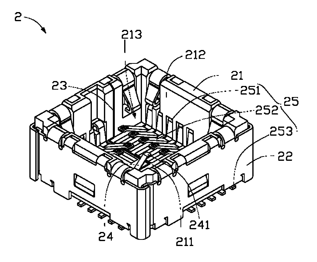
图2为图1中连接器组件的连接器的立体图。FIG. 2 is a perspective view of a connector of the connector assembly in FIG. 1 .
图3为图1中连接器组件的相机模组的仰视图。FIG. 3 is a bottom view of the camera module of the connector assembly in FIG. 1 .
图4为本发明第二实施例提供的连接器组件的连接器的立体图。Fig. 4 is a perspective view of the connector of the connector assembly provided by the second embodiment of the present invention.
具体实施方式 Detailed ways
下面将结合附图对本发明实施例作进一步的详细说明。The embodiments of the present invention will be further described in detail below in conjunction with the accompanying drawings.
请参阅图1,本发明第一实施例提供一种连接器组件100,该连接器组件100包括一个相机模组1及一个连接器2,连接器2用来收容相机模组1。Referring to FIG. 1 , the first embodiment of the present invention provides a
请参阅图2,该连接器2包括一个绝缘本体21、一个金属壳体22、一个连接导线23、一个弹性元件24及多个讯号端子25。金属壳体22包覆绝缘本体21,该绝缘本体21具有一个凹槽213,在本实施例中,凹槽213为一个长方体,该凹槽213由绝缘本体21的一个底面211及四个侧面212围成,该凹槽213用于收容相机模组1。每个讯号端子25包括本体部251、导电片252及焊接部253。弹性元件24由导电材料制成,设置在凹槽213的底面211上,该弹性元件24可为类似于导电片252的导电弹片也可为弹簧,且该弹性元件24具有一个接触面241,该接触面241的高度与讯号端子25的最高高度一致。讯号端子25的本体部251固定在绝缘本体21的四个侧面212上,导电片252深入凹槽213的内部,焊接部253伸出连接器2的外部并焊接在对应印刷电路板(图未示),这样,相机模组1通过讯号端子25与该对应印刷电路板达成电性连接。连接导线23一端固定在金属壳体22的内侧面212上并与金属壳体22达成电性连接,另一端沿凹槽213的侧面212延伸至底面211并焊接在底面211上的弹性元件24上,使金属壳体22与弹性元件24达成电性连接,连接导线23的材料选自导电材料,优选为金属导体,起电性连接作用。Please refer to FIG. 2 , the connector 2 includes an
请参阅图3,该相机模组1具有一个基板10,该基板10朝连接器2的表面11具有一个电性接地点12及多个导电垫13。电性接地点12设置在表面11上对应于连接器2的弹性元件24处,该电性接地点12与相机模组1的电路板的接地线路(图未示)相连接,作为接地讯号点,在本实施例中,电性接地点12的形状为矩形,当然在其它实施例中也可以为圆形、三角形或其他形状的电性接地点。导电垫13分布在基板10的表面11的四周,电性接地点12位于表面11的中央,在本实施例中,导电垫13嵌入表面11,与表面11处于同一平面,当然在其它实施例中导电垫13也可以贴在表面11上,此时,电性接地点12也相应贴在表面11上。Please refer to FIG. 3 , the
组装时,连接器2的凹槽213收容相机模组1,相机模组1的导电垫13分别对应压接于讯号端子25的导电片252,使相机模组1与连接器2达成电性连接,基板10的表面11上的电性接地点12压接于凹槽213的底面211上的弹性元件24,这样,连接于连接导线23的金属壳体22通过弹性元件24与相机模组1的电性接地点12达成电性地连接。During assembly, the
请参阅图4,本实施例与第一实施例的区别在于,弹性元件24由塑料等非导电材料制成,连接导线23一端固定在金属壳体22的侧面212上并与金属壳体22达成电性连接,另一端沿凹槽213的侧面212延伸至底面211内并固定在弹性元件24与该基板10相接触的接触面241上。Please refer to Fig. 4, the difference between this embodiment and the first embodiment is that the
组装时,连接器2的凹槽213收容相机模组1,相机模组1的导电垫13分别对应压接于讯号端子25的导电片252,使相机模组1与连接器2达成电性连接,基板10的表面11上的电性接地点12电性压接于固定在弹性元件24的接触面241上的连接导线23,这样,连接于连接导线23的金属壳体22与相机模组1的电性接地点12达成电性地连接。During assembly, the
本发明实施例提供的连接器组件,该连接器的金属壳体通过该连接导线且电性接地点压接于该弹性元件达成电性地连接,使该金属壳体产生接地包覆作用,从而可有效降低EMI,使影像传输不受干扰,且充分利用该相机模组的基板的表面的空闲部分及该连接器的底面的空闲部分,响应了该连接器组件的小型化要求。In the connector assembly provided by the embodiment of the present invention, the metal shell of the connector is electrically connected to the elastic element through the connecting wire and the electrical ground point is crimped, so that the metal shell produces a grounding covering effect, thereby It can effectively reduce EMI, make image transmission uninterrupted, and make full use of the idle portion on the surface of the substrate of the camera module and the idle portion on the bottom surface of the connector, responding to the miniaturization requirement of the connector assembly.
需要指出的是,上述连接器组件并不局限应用于相机模组,也可适用于其它领域,如各类与连接器配接的插入模组或卡类元件等。It should be pointed out that the above-mentioned connector assembly is not limited to be used in camera modules, but can also be applied in other fields, such as various plug-in modules or card components mated with the connector.
另外,本领域技术人员还可以在本发明精神内做其它变化等。当然,这些依据本发明精神所做的变化,都应包含在本发明所要求保护的范围之内。In addition, those skilled in the art can also make other changes within the spirit of the present invention. Of course, these changes made according to the spirit of the present invention should all be included within the scope of protection claimed by the present invention.
Claims (10)
- [claim 1] a kind of connector assembly, it comprises:The camera module, it has the substrate that is positioned at this camera module bottom; AndConnector, it comprises insulating body and the metal shell with a groove, and this metal shell coats this insulating body, and this groove is used to accommodate this camera module;It is characterized in that, this substrate is provided with electrical earth point towards the surface of this connector, corresponding described electrical earth point place is provided with flexible member on the bottom surface of this groove, this connector further comprises the connection lead, this connects lead one end and this metal shell electrically connects, the other end extends in this groove and with this flexible member and is connected, and makes described electrical earth point electrically connect described connection lead.
- [claim 2] connector assembly as claimed in claim 1 is characterized in that, described electrical earth point is as the ground connection signal point of this camera module.
- [claim 3] connector assembly as claimed in claim 1 is characterized in that, described flexible member is made by the elastomeric material of conduction.
- [claim 4] connector assembly as claimed in claim 3 is characterized in that, described flexible member is connected lead respectively with this and this electrical earth point electrically connects.
- [claim 5] connector assembly as claimed in claim 3 is characterized in that, described flexible member is electroconductive elastic sheet or spring.
- [claim 6] connector assembly as claimed in claim 1 is characterized in that, described connection lead electrically connects by welding and this flexible member.
- [claim 7] connector assembly as claimed in claim 1 is characterized in that described flexible member is made by non-conductive elastomeric material.
- [claim 8] connector assembly as claimed in claim 7 is characterized in that, the other end that extends in the groove of described connection lead is fixed on this flexible member and the contacted contact-making surface of this substrate.
- [claim 9] connector assembly as claimed in claim 1 is characterized in that, described connection lead is drawn by this metal shell and extended on the bottom surface of this groove along the medial surface of this groove.
- [claim 10] connector assembly as claimed in claim 1 is characterized in that, described electrical earth point is arranged on the lip-deep middle position of this substrate towards this connector.
Priority Applications (2)
| Application Number | Priority Date | Filing Date | Title |
|---|---|---|---|
| CNA2007102021869A CN101420076A (en) | 2007-10-22 | 2007-10-22 | Connector component |
| US12/125,880 US7553189B2 (en) | 2007-10-22 | 2008-05-22 | Electrical socket for interconnecting camera module with substrate |
Applications Claiming Priority (1)
| Application Number | Priority Date | Filing Date | Title |
|---|---|---|---|
| CNA2007102021869A CN101420076A (en) | 2007-10-22 | 2007-10-22 | Connector component |
Publications (1)
| Publication Number | Publication Date |
|---|---|
| CN101420076A true CN101420076A (en) | 2009-04-29 |
Family
ID=40563912
Family Applications (1)
| Application Number | Title | Priority Date | Filing Date |
|---|---|---|---|
| CNA2007102021869A Pending CN101420076A (en) | 2007-10-22 | 2007-10-22 | Connector component |
Country Status (2)
| Country | Link |
|---|---|
| US (1) | US7553189B2 (en) |
| CN (1) | CN101420076A (en) |
Cited By (1)
| Publication number | Priority date | Publication date | Assignee | Title |
|---|---|---|---|---|
| CN110488449A (en) * | 2014-01-02 | 2019-11-22 | Lg伊诺特有限公司 | Lens driving device and camera module including the same |
Families Citing this family (18)
| Publication number | Priority date | Publication date | Assignee | Title |
|---|---|---|---|---|
| JP4799327B2 (en) * | 2006-09-06 | 2011-10-26 | モレックス インコーポレイテド | Module socket |
| JP2008113066A (en) * | 2006-10-27 | 2008-05-15 | Sony Corp | Imaging device |
| CN102082330A (en) * | 2009-11-26 | 2011-06-01 | 深圳富泰宏精密工业有限公司 | Grounding elastic slice and portable electronic device applying same |
| FI4122383T3 (en) | 2010-05-08 | 2025-05-19 | Univ California | Sem scanner sensing apparatus for early detection of ulcers |
| KR101208599B1 (en) * | 2010-12-03 | 2012-12-06 | 엘지이노텍 주식회사 | Camera Module |
| US9188605B2 (en) * | 2013-11-12 | 2015-11-17 | Xcerra Corporation | Integrated circuit (IC) test socket with Faraday cage |
| SG11201708108VA (en) * | 2015-04-01 | 2017-10-30 | Xcerra Corp | Integrated circuit (ic) test socket with faraday cage background |
| NZ736278A (en) | 2015-04-24 | 2022-05-27 | Bruin Biometrics Llc | Apparatus and methods for determining damaged tissue using sub-epidermal moisture measurements |
| JP6390664B2 (en) * | 2016-05-20 | 2018-09-19 | Smk株式会社 | Optical electronic component and socket connection structure |
| CN118177725A (en) | 2017-02-03 | 2024-06-14 | 布鲁恩医疗创新有限责任公司 | Measurement of susceptibility to diabetic foot ulcers |
| US11304652B2 (en) | 2017-02-03 | 2022-04-19 | Bbi Medical Innovations, Llc | Measurement of tissue viability |
| MX2019004926A (en) | 2017-02-03 | 2019-06-20 | Bruin Biometrics Llc | Measurement of edema. |
| GB2574945A (en) | 2017-11-16 | 2019-12-25 | Bruin Biometrics Llc | Providing a continuity of care across multiple care settings |
| EP4331480B1 (en) | 2018-02-09 | 2025-07-30 | Bruin Biometrics, LLC | Detection of tissue damage |
| KR102903190B1 (en) | 2018-10-11 | 2025-12-23 | 브루인 바이오메트릭스, 엘엘씨 | Devices with disposable elements |
| DE102018127814A1 (en) * | 2018-11-07 | 2020-05-07 | Ept Gmbh | Connectors |
| JP7202937B2 (en) * | 2018-12-19 | 2023-01-12 | モレックス エルエルシー | Connectors and connector assemblies |
| US11642075B2 (en) | 2021-02-03 | 2023-05-09 | Bruin Biometrics, Llc | Methods of treating deep and early-stage pressure induced tissue damage |
Family Cites Families (3)
| Publication number | Priority date | Publication date | Assignee | Title |
|---|---|---|---|---|
| FI20020992L (en) | 2002-05-27 | 2003-11-28 | Nokia Corp | Component mounting structure |
| US20060189216A1 (en) * | 2005-02-18 | 2006-08-24 | Ming-Hsun Yang | Camera module connector keying structure |
| TWM293571U (en) * | 2006-03-01 | 2006-07-01 | Jess Link Products Co Ltd | Socket device |
-
2007
- 2007-10-22 CN CNA2007102021869A patent/CN101420076A/en active Pending
-
2008
- 2008-05-22 US US12/125,880 patent/US7553189B2/en not_active Expired - Fee Related
Cited By (3)
| Publication number | Priority date | Publication date | Assignee | Title |
|---|---|---|---|---|
| CN110488449A (en) * | 2014-01-02 | 2019-11-22 | Lg伊诺特有限公司 | Lens driving device and camera module including the same |
| CN110488449B (en) * | 2014-01-02 | 2021-12-24 | Lg伊诺特有限公司 | Lens driving device and camera module including the same |
| US12235470B2 (en) | 2014-01-02 | 2025-02-25 | Lg Innotek Co., Ltd. | Lens driving device and camera module comprising same |
Also Published As
| Publication number | Publication date |
|---|---|
| US7553189B2 (en) | 2009-06-30 |
| US20090104797A1 (en) | 2009-04-23 |
Similar Documents
| Publication | Publication Date | Title |
|---|---|---|
| CN101420076A (en) | Connector component | |
| CN111416246B (en) | Connectors and Connector Devices | |
| CN202888404U (en) | Electronic communication device with antenna structure | |
| TWM468799U (en) | Electrical connector | |
| JP2015135816A (en) | Terminal, electrical connector, and electrical connector assembly | |
| CN107547787B (en) | Camera assembly and mobile terminal | |
| CN110692169B (en) | Portable Electronic Devices | |
| US20060189183A1 (en) | Camera module connector | |
| CN112187970B (en) | Camera module and electronic device thereof | |
| CN110113871B (en) | Circuit board assemblies and electronic equipment | |
| US8630096B2 (en) | Large capacity memory module mounting device for portable terminal | |
| US20090305561A1 (en) | Electrical connector with electrical device incorporated therein | |
| CN201112976Y (en) | electrical connector | |
| CN203445353U (en) | Electric connector | |
| US8251751B2 (en) | Plug and connector assembly using same | |
| CN201113134Y (en) | electrical connector | |
| CN207398397U (en) | Board-to-Board Connector | |
| US8076592B2 (en) | Electromagnetic interference preventing module | |
| US8391024B2 (en) | Electronic device with card connection mechanism | |
| CN105990768B (en) | Electrical connector | |
| US20090321111A1 (en) | Flexible printed circuit module | |
| CN107484403A (en) | Shields, circuit board assemblies, and electronic devices | |
| CN209766683U (en) | BTB connector socket, BTB connector and electronic equipment | |
| CN201717388U (en) | Flexible structure for electrical connection | |
| TWI345341B (en) | Connector assembly |
Legal Events
| Date | Code | Title | Description |
|---|---|---|---|
| C06 | Publication | ||
| PB01 | Publication | ||
| C10 | Entry into substantive examination | ||
| SE01 | Entry into force of request for substantive examination | ||
| C12 | Rejection of a patent application after its publication | ||
| RJ01 | Rejection of invention patent application after publication |
Open date: 20090429 |