KR20220073257A - A lens moving unit, and camera device and optical instrument including the same - Google Patents
A lens moving unit, and camera device and optical instrument including the same Download PDFInfo
- Publication number
- KR20220073257A KR20220073257A KR1020200161163A KR20200161163A KR20220073257A KR 20220073257 A KR20220073257 A KR 20220073257A KR 1020200161163 A KR1020200161163 A KR 1020200161163A KR 20200161163 A KR20200161163 A KR 20200161163A KR 20220073257 A KR20220073257 A KR 20220073257A
- Authority
- KR
- South Korea
- Prior art keywords
- coil
- magnet
- circuit board
- housing
- disposed
- Prior art date
- Legal status (The legal status is an assumption and is not a legal conclusion. Google has not performed a legal analysis and makes no representation as to the accuracy of the status listed.)
- Pending
Links
Images


Classifications
-
- H—ELECTRICITY
- H04—ELECTRIC COMMUNICATION TECHNIQUE
- H04N—PICTORIAL COMMUNICATION, e.g. TELEVISION
- H04N23/00—Cameras or camera modules comprising electronic image sensors; Control thereof
- H04N23/57—Mechanical or electrical details of cameras or camera modules specially adapted for being embedded in other devices
-
- G—PHYSICS
- G03—PHOTOGRAPHY; CINEMATOGRAPHY; ANALOGOUS TECHNIQUES USING WAVES OTHER THAN OPTICAL WAVES; ELECTROGRAPHY; HOLOGRAPHY
- G03B—APPARATUS OR ARRANGEMENTS FOR TAKING PHOTOGRAPHS OR FOR PROJECTING OR VIEWING THEM; APPARATUS OR ARRANGEMENTS EMPLOYING ANALOGOUS TECHNIQUES USING WAVES OTHER THAN OPTICAL WAVES; ACCESSORIES THEREFOR
- G03B5/00—Adjustment of optical system relative to image or object surface other than for focusing
- G03B5/04—Vertical adjustment of lens; Rising fronts
-
- G—PHYSICS
- G03—PHOTOGRAPHY; CINEMATOGRAPHY; ANALOGOUS TECHNIQUES USING WAVES OTHER THAN OPTICAL WAVES; ELECTROGRAPHY; HOLOGRAPHY
- G03B—APPARATUS OR ARRANGEMENTS FOR TAKING PHOTOGRAPHS OR FOR PROJECTING OR VIEWING THEM; APPARATUS OR ARRANGEMENTS EMPLOYING ANALOGOUS TECHNIQUES USING WAVES OTHER THAN OPTICAL WAVES; ACCESSORIES THEREFOR
- G03B17/00—Details of cameras or camera bodies; Accessories therefor
- G03B17/02—Bodies
- G03B17/12—Bodies with means for supporting objectives, supplementary lenses, filters, masks, or turrets
-
- G—PHYSICS
- G03—PHOTOGRAPHY; CINEMATOGRAPHY; ANALOGOUS TECHNIQUES USING WAVES OTHER THAN OPTICAL WAVES; ELECTROGRAPHY; HOLOGRAPHY
- G03B—APPARATUS OR ARRANGEMENTS FOR TAKING PHOTOGRAPHS OR FOR PROJECTING OR VIEWING THEM; APPARATUS OR ARRANGEMENTS EMPLOYING ANALOGOUS TECHNIQUES USING WAVES OTHER THAN OPTICAL WAVES; ACCESSORIES THEREFOR
- G03B3/00—Focusing arrangements of general interest for cameras, projectors or printers
- G03B3/10—Power-operated focusing
-
- G—PHYSICS
- G03—PHOTOGRAPHY; CINEMATOGRAPHY; ANALOGOUS TECHNIQUES USING WAVES OTHER THAN OPTICAL WAVES; ELECTROGRAPHY; HOLOGRAPHY
- G03B—APPARATUS OR ARRANGEMENTS FOR TAKING PHOTOGRAPHS OR FOR PROJECTING OR VIEWING THEM; APPARATUS OR ARRANGEMENTS EMPLOYING ANALOGOUS TECHNIQUES USING WAVES OTHER THAN OPTICAL WAVES; ACCESSORIES THEREFOR
- G03B30/00—Camera modules comprising integrated lens units and imaging units, specially adapted for being embedded in other devices, e.g. mobile phones or vehicles
-
- G—PHYSICS
- G03—PHOTOGRAPHY; CINEMATOGRAPHY; ANALOGOUS TECHNIQUES USING WAVES OTHER THAN OPTICAL WAVES; ELECTROGRAPHY; HOLOGRAPHY
- G03B—APPARATUS OR ARRANGEMENTS FOR TAKING PHOTOGRAPHS OR FOR PROJECTING OR VIEWING THEM; APPARATUS OR ARRANGEMENTS EMPLOYING ANALOGOUS TECHNIQUES USING WAVES OTHER THAN OPTICAL WAVES; ACCESSORIES THEREFOR
- G03B5/00—Adjustment of optical system relative to image or object surface other than for focusing
-
- H—ELECTRICITY
- H04—ELECTRIC COMMUNICATION TECHNIQUE
- H04N—PICTORIAL COMMUNICATION, e.g. TELEVISION
- H04N23/00—Cameras or camera modules comprising electronic image sensors; Control thereof
- H04N23/50—Constructional details
- H04N23/54—Mounting of pick-up tubes, electronic image sensors, deviation or focusing coils
-
- H—ELECTRICITY
- H04—ELECTRIC COMMUNICATION TECHNIQUE
- H04N—PICTORIAL COMMUNICATION, e.g. TELEVISION
- H04N23/00—Cameras or camera modules comprising electronic image sensors; Control thereof
- H04N23/50—Constructional details
- H04N23/55—Optical parts specially adapted for electronic image sensors; Mounting thereof
-
- H—ELECTRICITY
- H04—ELECTRIC COMMUNICATION TECHNIQUE
- H04N—PICTORIAL COMMUNICATION, e.g. TELEVISION
- H04N23/00—Cameras or camera modules comprising electronic image sensors; Control thereof
- H04N23/60—Control of cameras or camera modules
- H04N23/68—Control of cameras or camera modules for stable pick-up of the scene, e.g. compensating for camera body vibrations
- H04N23/682—Vibration or motion blur correction
- H04N23/685—Vibration or motion blur correction performed by mechanical compensation
- H04N23/687—Vibration or motion blur correction performed by mechanical compensation by shifting the lens or sensor position
-
- H04N5/2253—
-
- H04N5/2254—
-
- H04N5/23287—
-
- G—PHYSICS
- G03—PHOTOGRAPHY; CINEMATOGRAPHY; ANALOGOUS TECHNIQUES USING WAVES OTHER THAN OPTICAL WAVES; ELECTROGRAPHY; HOLOGRAPHY
- G03B—APPARATUS OR ARRANGEMENTS FOR TAKING PHOTOGRAPHS OR FOR PROJECTING OR VIEWING THEM; APPARATUS OR ARRANGEMENTS EMPLOYING ANALOGOUS TECHNIQUES USING WAVES OTHER THAN OPTICAL WAVES; ACCESSORIES THEREFOR
- G03B2205/00—Adjustment of optical system relative to image or object surface other than for focusing
- G03B2205/0007—Movement of one or more optical elements for control of motion blur
-
- G—PHYSICS
- G03—PHOTOGRAPHY; CINEMATOGRAPHY; ANALOGOUS TECHNIQUES USING WAVES OTHER THAN OPTICAL WAVES; ELECTROGRAPHY; HOLOGRAPHY
- G03B—APPARATUS OR ARRANGEMENTS FOR TAKING PHOTOGRAPHS OR FOR PROJECTING OR VIEWING THEM; APPARATUS OR ARRANGEMENTS EMPLOYING ANALOGOUS TECHNIQUES USING WAVES OTHER THAN OPTICAL WAVES; ACCESSORIES THEREFOR
- G03B2205/00—Adjustment of optical system relative to image or object surface other than for focusing
- G03B2205/0053—Driving means for the movement of one or more optical element
- G03B2205/0069—Driving means for the movement of one or more optical element using electromagnetic actuators, e.g. voice coils
Landscapes
- Engineering & Computer Science (AREA)
- Multimedia (AREA)
- Signal Processing (AREA)
- Physics & Mathematics (AREA)
- General Physics & Mathematics (AREA)
- Lens Barrels (AREA)
- Adjustment Of Camera Lenses (AREA)
Abstract
실시 예는 측부와 코너부를 포함하는 하우징, 하우징 내에 배치되는 보빈, 보빈에 배치되는 제1 코일, 하우징의 코너부에 배치되고 제1 코일에 대향하는 제1면과 제1면의 반대면인 제2면을 포함하는 제1 마그네트, 및 제1 마그네트의 제2면에 대향하도록 배치되고 제1 마그네트와의 상호 작용으로 하우징을 광축과 수직한 방향으로 이동시키는 제2 코일을 포함한다.An embodiment includes a housing including side portions and corner portions, a bobbin disposed within the housing, a first coil disposed on the bobbin, and a first surface disposed at a corner portion of the housing and opposite to the first coil and a first surface opposite the first surface A first magnet including two surfaces, and a second coil disposed to face the second surface of the first magnet and moving the housing in a direction perpendicular to the optical axis by interaction with the first magnet.
Description
실시 예는 렌즈 구동 장치 및 이를 포함하는 카메라 장치 및 광학 기기에 관한 것이다.The embodiment relates to a lens driving device, a camera device and an optical device including the same.
초소형, 저전력 소모를 위한 카메라 모듈은 기존의 일반적인 카메라 모듈에 사용된 보이스 코일 모터(VCM:Voice Coil Motor)의 기술을 적용하기 곤란하여, 이와 관련 연구가 활발히 진행되어 왔다.Since it is difficult to apply the technology of a voice coil motor (VCM) used in an existing general camera module to a camera module for ultra-small size and low power consumption, research related thereto has been actively conducted.
스마트폰 및 카메라가 장착된 휴대폰과 같은 전자 제품의 수요 및 생산이 증가되고 있다. 휴대폰용 카메라는 고화소화 및 소형화 추세이며, 그에 따라 액츄에이터도 소형화, 대구경화, 멀티 기능화되고 있다. 고화소화의 휴대폰용 카메라를 구현하기 위하여 휴대폰용 카메라의 성능 향상 및 오토 포커싱, 셔터 흔들림 개선, 및 줌(Zoom) 기능 등의 추가적인 기능이 요구된다.Demand and production of electronic products such as smartphones and camera-equipped cell phones are increasing. Cameras for mobile phones are on the trend of high resolution and miniaturization, and accordingly, actuators are becoming smaller, larger diameter, and multi-functional. In order to implement a high-resolution mobile phone camera, additional functions such as performance improvement of mobile phone camera, auto focusing, shutter shake improvement, and zoom function are required.
실시 예는 광축 방향으로의 높이를 줄일 수 있고, 대구경의 렌즈 장착이 가능한 렌즈 구동 장치, 및 이를 포함하는 카메라 장치 및 광학 기기를 제공한다.The embodiment provides a lens driving device capable of reducing a height in an optical axis direction and capable of mounting a large-diameter lens, and a camera device and an optical device including the same.
실시 예에 따른 렌즈 구동 장치는 측부와 코너부를 포함하는 하우징; 상기 하우징 내에 배치되는 보빈; 상기 보빈에 배치되는 제1 코일; 상기 하우징의 상기 코너부에 배치되고 상기 제1 코일에 대향하는 제1면과 상기 제1면의 반대면인 제2면을 포함하는 제1 마그네트; 및 상기 제1 마그네트의 상기 제2면에 대향하도록 배치되고, 상기 제1 마그네트와의 상호 작용으로 상기 하우징을 광축과 수직한 방향으로 이동시키는 제2 코일을 포함한다.A lens driving device according to an embodiment includes a housing including side portions and corner portions; a bobbin disposed within the housing; a first coil disposed on the bobbin; a first magnet disposed in the corner of the housing and including a first surface opposite to the first coil and a second surface opposite to the first surface; and a second coil disposed to face the second surface of the first magnet and configured to move the housing in a direction perpendicular to the optical axis by interaction with the first magnet.
상기 렌즈 구동 장치는 상판과 측판을 포함하고, 상기 하우징이 내부에 배치되는 커버 부재를 포함할 수 있고, 상기 제2 코일은 상기 제1 마그네트의 상기 제2면과 상기 커버 부재의 상기 측판 사이에 배치될 수 있다.The lens driving device may include an upper plate and a side plate, and a cover member having the housing disposed therein, and the second coil is disposed between the second surface of the first magnet and the side plate of the cover member. can be placed.
상기 제2면의 면적은 상기 제1면의 면적보다 작을 수 있고, 상기 제1 마그네트는 상기 제1면에서 상기 제2면 방향으로 갈수록 가로 방향의 길이가 감소하는 부분을 포함할 수 있다.An area of the second surface may be smaller than an area of the first surface, and the first magnet may include a portion whose length in a horizontal direction decreases from the first surface toward the second surface.
상기 렌즈 구동 장치는 상기 커버 부재의 상기 측판과 상기 하우징 사이에 배치되고, 상기 제2 코일과 전기적으로 연결되는 제1 회로 기판을 포함할 수 있다.The lens driving device may include a first circuit board disposed between the side plate of the cover member and the housing and electrically connected to the second coil.
상기 제1 회로 기판은 상기 제2 코일이 배치되는 안착부와 상기 커버 부재의 상기 측판에 결합되는 고정부를 포함할 수 있다.The first circuit board may include a seating part on which the second coil is disposed and a fixing part coupled to the side plate of the cover member.
상기 제1 회로 기판의 상기 안착부는 상기 커버 부재의 상기 측판으로부터 이격될 수 있다.The seating portion of the first circuit board may be spaced apart from the side plate of the cover member.
상기 렌즈 구동 장치는 상기 보빈의 상부 및 상기 하우징의 상부에 결합되는 상부 탄성 부재; 상기 하우징 아래에 배치되는 제2 회로 기판; 및 일단이 상기 상부 탄성 부재와 결합되고, 타단이 상기 제2 회로 기판에 전기적으로 연결되는 지지 부재를 포함할 수 있다.The lens driving device may include an upper elastic member coupled to an upper portion of the bobbin and an upper portion of the housing; a second circuit board disposed under the housing; and a support member having one end coupled to the upper elastic member and the other end electrically connected to the second circuit board.
상기 제2 코일의 적어도 일부는 상기 지지 부재와 상기 제1 마그네트의 상기 제2면 사이에 배치될 수 있다.At least a portion of the second coil may be disposed between the support member and the second surface of the first magnet.
상기 제2 코일은 상기 제1 마그네트의 상기 제2면에 대향하는 중공을 포함할 수 있다.The second coil may include a hollow opposite to the second surface of the first magnet.
상기 렌즈 구동 장치는 상기 제2 회로 기판 아래에 배치되는 베이스를 포함할 수 있고, 상기 제1 회로 기판은 상기 베이스에 결합될 수 있다.The lens driving device may include a base disposed under the second circuit board, and the first circuit board may be coupled to the base.
상기 하우징의 코너부에는 홈이 형성될 수 있고, 상기 제2 코일은 상기 홈 내에 배치될 수 있다.A groove may be formed in a corner portion of the housing, and the second coil may be disposed in the groove.
다른 실시 예에 따른 렌즈 구동 장치는 측부와 코너부를 포함하는 하우징; 상기 하우징 내에 배치되는 보빈; 상기 보빈에 배치되는 제1 코일; 상기 하우징의 상기 코너부에 배치되고, 상기 제1 코일에 대향하는 제1면, 상기 제1면의 반대면인 제2면, 상기 제1면의 일측과 상기 제2면의 일측 사이에 위치하는 제3면, 및 상기 제1면의 타측과 상기 제2면의 타측 사이에 위치하는 제4면을 포함하는 제1 마그네트; 및 상기 제3면 및 상기 제4면 중 어느 하나에 제1 수평 방향으로 대향하도록 배치되는 제1 코일 유닛과 상기 제3면 및 상기 제4면 중 나머지 다른 하나에 상기 제1 수평 방향과 수직인 제2 수평 방향으로 대향하도록 배치되는 제2 코일 유닛을 포함하는 제2 코일을 포함하고, 상기 제2 코일은 상기 제1 마그네트와의 상호 작용으로 상기 하우징을 광축과 수직한 방향으로 이동시킨다.A lens driving device according to another embodiment includes a housing including side portions and corner portions; a bobbin disposed within the housing; a first coil disposed on the bobbin; disposed in the corner of the housing, a first surface facing the first coil, a second surface opposite to the first surface, and located between one side of the first surface and one side of the second surface a first magnet including a third surface and a fourth surface positioned between the other side of the first surface and the other side of the second surface; and a first coil unit disposed to face one of the third and fourth surfaces in a first horizontal direction, and the other one of the third and fourth surfaces perpendicular to the first horizontal direction. and a second coil including a second coil unit disposed to face a second horizontal direction, wherein the second coil moves the housing in a direction perpendicular to the optical axis by interaction with the first magnet.
다른 실시 예에 따른 렌즈 구동 장치는 상판과 측판을 포함하고, 상기 하우징이 내부에 배치되는 커버 부재를 포함할 수 있고, 상기 제1 코일 유닛과 상기 제2 코일 유닛은 상기 제1 마그네트와 상기 커버 부재의 상기 측판 사이에 배치될 수 있다.A lens driving device according to another embodiment may include a top plate and a side plate, and a cover member disposed therein, wherein the first coil unit and the second coil unit include the first magnet and the cover. It may be disposed between the side plates of the member.
상기 제1 마그네트는 상기 제1면에서 상기 제2면 방향으로 갈수록 가로 방향의 길이가 감소하는 부분을 포함할 수 있다.The first magnet may include a portion whose length in a horizontal direction decreases from the first surface to the second surface direction.
다른 실시 예에 따른 렌즈 구동 장치는 상기 커버 부재의 상기 측판과 상기 하우징 사이에 배치되고, 상기 제1 코일 유닛 및 상기 제2 코일 유닛과 전기적으로 연결되는 제1 회로 기판을 포함할 수 있다. 상기 제1 회로 기판은 상기 커버 부재의 상기 측판에 결합될 수 있다.The lens driving apparatus according to another embodiment may include a first circuit board disposed between the side plate of the cover member and the housing and electrically connected to the first coil unit and the second coil unit. The first circuit board may be coupled to the side plate of the cover member.
다른 실시 예에 따른 렌즈 구동 장치는 상기 보빈의 상부 및 상기 하우징의 상부에 결합되는 상부 탄성 부재; 상기 하우징 아래에 배치되는 제2 회로 기판; 및 일단이 상기 상부 탄성 부재와 결합되고, 타단이 상기 제2 회로 기판에 전기적으로 연결되는 지지 부재를 포함할 수 있다. 상기 제1 회로 기판은 상기 제2 회로 기판과 전기적으로 연결될 수 있다.A lens driving device according to another embodiment includes an upper elastic member coupled to an upper portion of the bobbin and an upper portion of the housing; a second circuit board disposed under the housing; and a support member having one end coupled to the upper elastic member and the other end electrically connected to the second circuit board. The first circuit board may be electrically connected to the second circuit board.
상기 하우징의 상기 코너부의 일측에는 제1홈이 형성될 수 있고, 상기 하우징의 상기 코너부의 타측에는 제2홈이 형성될 수 있고, 상기 제1 코일 유닛을 상기 제1홈 내에 배치될 수 있고, 상기 제2 코일 유닛은 상기 제2홈 내에 배치될 수 있다.A first groove may be formed on one side of the corner portion of the housing, a second groove may be formed on the other side of the corner portion of the housing, and the first coil unit may be disposed in the first groove, The second coil unit may be disposed in the second groove.
상기 제1 코일 유닛은 상기 제1 수평 방향으로 상기 제1 마그네트의 일부와 대향하는 중공을 포함하고, 상기 제2 코일 유닛은 상기 제2 수평 방향으로 상기 제1 마그네트의 다른 일부와 대향하는 중공을 포함할 수 있다.The first coil unit includes a hollow portion facing a portion of the first magnet in the first horizontal direction, and the second coil unit includes a hollow portion facing another portion of the first magnet in the second horizontal direction may include
상기 제1 수평 방향으로 상기 제1 코일 유닛은 상기 제1 마그네트의 상기 제1면과 오버랩될 수 있고, 상기 제2 수평 방향으로 상기 제2 코일 유닛은 상기 제1 마그네트의 상기 제1면과 오버랩될 수 있다.In the first horizontal direction, the first coil unit may overlap the first surface of the first magnet, and in the second horizontal direction, the second coil unit overlaps the first surface of the first magnet. can be
실시 예는 OIS 코일을 하우징의 코너부와 커버 부재의 측판 사이에 배치시킴으로써, 광축 방향으로의 높이를 줄일 수 있고 대구경의 렌즈 장착이 가능할 수 있다.In the embodiment, by disposing the OIS coil between the corner portion of the housing and the side plate of the cover member, the height in the optical axis direction may be reduced and a large-diameter lens may be mounted.
도 1은 실시 예에 따른 렌즈 구동 장치의 분해 사시도를 나타낸다.
도 2는 도 1의 커버 부재를 제외한 렌즈 구동 장치의 결합 사시도를 나타낸다.
도 3a는 도 1에 도시된 보빈, 제2 마그네트 및 제3 마그네트의 사시도를 나타낸다.
도 3b는 보빈에 결합된 제1 코일을 나타낸다.
도 4a는 도 1에 도시된 하우징, 회로 기판, 제1 위치 센서, 및 커패시터의 사시도를 나타낸다.
도 4b는 하우징의 저면 사시도이다.
도 4c는 하우징, 제1 마그네트, 회로 기판, 제1 위치 센서, 및 커패시터의 결합 사시도를 나타낸다.
도 5는 도 2에 도시된 렌즈 구동 장치의 AB 방향으로의 단면도이다.
도 6은 도 2에 도시된 렌즈 구동 장치의 CD 방향으로의 단면도이다.
도 7은 도 2에 도시된 렌즈 구동 장치의 EF 방향의 단면도이다.
도 8a는 회로 기판과 제1 위치 센서의 확대도이다.
도 8b는 도 8a에 도시된 제1 위치 센서의 일 실시 예에 따른 구성도이다.
도 9a는 도 1에 도시된 상부 탄성 부재를 나타낸다.
도 9b는 도 1에 도시된 하부 탄성 부재를 나타낸다.
도 10은 상부 탄성 부재, 하부 탄성 부재, 베이스, 지지 부재, 회로 기판, 및 제2 위치 센서의 결합 사시도를 나타낸다.
도 11a는 회로 기판의 제1 내지 제4 단자들과 상부 탄성 유닛들 간의 결합을 나타낸다.
도 11b는 회로 기판의 제5 및 제6 단자들과 하부 탄성 유닛의 저면도이다.
도 12는 베이스, 회로 기판, 지지 부재 및 제2 위치 센서의 분리 사시도이다.
도 13은 제1 마그네트, 제2 코일, 회로 기판, 및 커버 부재의 저면도이다.
도 14a는 실시 예에 따른 제1 마그네트 및 제2 코일의 배치를 나타낸다.
도 14b는 다른 실시 예에 따른 제1 마그네트 및 제2 코일의 배치를 나타낸다.
도 15는 렌즈 구동 장치의 저면도이다.
도 16은 하우징의 어느 한 코너부에 배치된 제1 마그넷 유닛, 제1 마그넷 유닛에 대응되는 제2 코일 유닛, 및 제1 지지 부재의 저면도이다.
도 17a는 제1 회로 기판, 제2 코일 유닛들, 지지 부재, 및 제2 회로 기판의 제1 사시도이다.
도 17b는 제1 회로 기판, 제2 코일 유닛들, 지지 부재, 및 회로 기판의 제2 사시도이다.
도 18은 다른 실시 예에 따른 렌즈 구동 장치의 분리 사시도이다.
도 19는 도 18의 제1 마그네트, 제2 코일, 회로 기판, 및 커버 부재의 저면도이다.
도 20은 도 18의 실시 예에 따른 제1 마그네트 및 제2 코일의 배치를 나타낸다.
도 21은 도 18의 하우징, 제1 마그네트, 및 제2 코일의 저면도이다.
도 22a는 도 18의 제1 회로 기판, 제2 코일의 코일 유닛들, 지지 부재, 및 제2 회로 기판의 제1 사시도이다.
도 22b는 도 18의 제1 회로 기판, 제2 코일 유닛들, 지지 부재, 및 회로 기판의 제2 사시도이다.
도 23a 내지 도 23d는 다른 실시 예들에서 따른 마그넷 유닛들과 코일 유닛들의 배치를 나타낸다.
도 24a 내지 도 24b는 또 다른 실시 예에서 따른 마그넷 유닛들과 코일 유닛들의 배치를 나타낸다.
도 25a는 제1 마그네트와 제2 코일 간의 상호 작용에 의한 OIS 가동부의 제1 수평 방향으로의 이동을 나타낸다.
도 25b는 제1 마그네트와 제2 코일 간의 상호 작용에 의한 OIS 가동부의 제2 수평 방향으로의 이동을 나타낸다.
도 25c는 제1 마그네트와 제2 코일 간의 상호 작용에 의한 OIS 가동부의 시계 방향으로의 틸트 동작을 나타낸다.
도 25d는 제1 마그네트와 제2 코일 간의 상호 작용에 의한 OIS 가동부의 반시계 방향으로의 틸트 동작을 나타낸다.
도 26은 실시 예에 따른 카메라 장치의 분해 사시도를 나타낸다.
도 27은 실시 예에 따른 광학 기기의 사시도를 나타낸다.
도 28은 도 27에 도시된 광학 기기의 구성도를 나타낸다.1 is an exploded perspective view of a lens driving device according to an embodiment.
FIG. 2 is a combined perspective view of the lens driving device excluding the cover member of FIG. 1 .
3A is a perspective view of a bobbin, a second magnet, and a third magnet shown in FIG. 1 .
3B shows a first coil coupled to a bobbin.
4A is a perspective view of the housing, the circuit board, the first position sensor, and the capacitor shown in FIG. 1 ;
4B is a bottom perspective view of the housing;
4C shows a combined perspective view of the housing, the first magnet, the circuit board, the first position sensor, and the capacitor.
FIG. 5 is a cross-sectional view in the AB direction of the lens driving device shown in FIG. 2 .
FIG. 6 is a cross-sectional view in the CD direction of the lens driving device shown in FIG. 2 .
FIG. 7 is a cross-sectional view in the EF direction of the lens driving device shown in FIG. 2 .
8A is an enlarged view of the circuit board and the first position sensor.
8B is a configuration diagram of the first position sensor shown in FIG. 8A according to an exemplary embodiment.
FIG. 9A shows the upper elastic member shown in FIG. 1 .
FIG. 9B shows the lower elastic member shown in FIG. 1 .
10 is a combined perspective view of an upper elastic member, a lower elastic member, a base, a support member, a circuit board, and a second position sensor.
11A shows the coupling between the first to fourth terminals of the circuit board and the upper elastic units.
11B is a bottom view of the fifth and sixth terminals of the circuit board and the lower elastic unit;
12 is an exploded perspective view of a base, a circuit board, a support member, and a second position sensor;
13 is a bottom view of a first magnet, a second coil, a circuit board, and a cover member;
14A illustrates an arrangement of a first magnet and a second coil according to an embodiment.
14B illustrates an arrangement of a first magnet and a second coil according to another exemplary embodiment.
15 is a bottom view of the lens driving device.
16 is a bottom view of a first magnet unit disposed at one corner of the housing, a second coil unit corresponding to the first magnet unit, and a first support member;
17A is a first perspective view of a first circuit board, second coil units, a support member, and a second circuit board;
17B is a second perspective view of the first circuit board, the second coil units, the support member, and the circuit board;
18 is an exploded perspective view of a lens driving device according to another exemplary embodiment.
19 is a bottom view of the first magnet, the second coil, the circuit board, and the cover member of FIG. 18 .
20 is a diagram illustrating an arrangement of a first magnet and a second coil according to the embodiment of FIG. 18 .
21 is a bottom view of the housing, the first magnet, and the second coil of FIG. 18 .
22A is a first perspective view of the first circuit board of FIG. 18 , coil units of a second coil, a support member, and a second circuit board;
22B is a second perspective view of the first circuit board, the second coil units, the support member, and the circuit board of FIG. 18 .
23A to 23D show arrangement of magnet units and coil units according to other embodiments.
24A to 24B show the arrangement of magnet units and coil units according to another embodiment.
25A shows the movement of the OIS movable part in the first horizontal direction by the interaction between the first magnet and the second coil.
25B shows the movement of the OIS movable part in the second horizontal direction by the interaction between the first magnet and the second coil.
25C illustrates a clockwise tilting operation of the OIS movable part due to the interaction between the first magnet and the second coil.
25D illustrates a counterclockwise tilting operation of the OIS moving part due to the interaction between the first magnet and the second coil.
26 is an exploded perspective view of a camera device according to an embodiment.
27 is a perspective view of an optical device according to an embodiment.
FIG. 28 is a block diagram of the optical device shown in FIG. 27 .
이하, 첨부된 도면을 참조하여 본 발명의 실시 예를 상세히 설명한다.Hereinafter, embodiments of the present invention will be described in detail with reference to the accompanying drawings.
다만, 본 발명의 기술 사상은 설명되는 일부 실시 예에 한정되는 것이 아니라 서로 다른 다양한 형태로 구현될 수 있고, 본 발명의 기술 사상 범위 내에서라면, 실시 예들 간 그 구성 요소들 중 하나 이상을 선택적으로 결합, 치환하여 사용할 수 있다.However, the technical spirit of the present invention is not limited to some embodiments described, but may be implemented in various different forms, and within the scope of the technical spirit of the present invention, one or more of the components may be selected between the embodiments. It can be combined and substituted for use.
또한 본 발명의 실시 예에서 사용되는 용어(기술 및 과학적 용어를 포함)는, 명백하게 특별히 정의되어 기술되지 않는 한, 본 발명이 속하는 기술 분야에서 통상의 지식을 가진 자에게 일반적으로 이해될 수 있는 의미로 해석될 수 있으며, 사전에 정의된 용어와 같이 일반적으로 사용되는 용어들은 관련 기술의 문맥상의 의미를 고려하여 그 의미를 해석할 수 있을 것이다.In addition, the terms (including technical and scientific terms) used in the embodiments of the present invention have meanings that can be generally understood by those of ordinary skill in the art to which the present invention belongs, unless specifically defined and described explicitly. may be interpreted, and the meanings of commonly used terms such as predefined terms may be interpreted in consideration of the contextual meaning of the related art.
또한, 본 발명의 실시 예에서 사용된 용어는 실시 예들을 설명하기 위한 것이며 본 발명을 제한하고자 하는 것은 아니다. 본 명세서에서, 단수형은 문구에서 특별히 언급하지 않는 한 복수형도 포함할 수 있고, "A 및(와) B, C중 적어도 하나(또는 한개이상)"로 기재되는 경우 A,B,C로 조합할 수 있는 모든 조합중 하나 이상을 포함할 수 있다.In addition, the terms used in the embodiments of the present invention are for describing the embodiments and are not intended to limit the present invention. In this specification, the singular form may also include the plural form unless otherwise specified in the phrase, and when it is described as "at least one (or one or more) of A and (and) B, C", it can be combined with A, B, and C. It may include one or more of all possible combinations.
또한, 본 발명의 실시 예의 구성 요소를 설명하는 데 있어서, 제1, 제2, A, B, (a), (b) 등의 용어를 사용할 수 있다. 이러한 용어는 그 구성 요소를 다른 구성 요소와 구별하기 위한 것일 뿐, 그 용어에 의해 해당 구성 요소의 본질이나 차례 또는 순서 등으로 한정되지 않는다.In addition, in describing the components of the embodiment of the present invention, terms such as first, second, A, B, (a), (b), etc. may be used. These terms are only for distinguishing the component from other components, and are not limited to the essence, order, or order of the component by the term.
그리고, 어떤 구성 요소가 다른 구성 요소에 '연결', '결합' 또는 '접속'된다고 기재된 경우, 그 구성 요소는 그 다른 구성 요소에 직접적으로 연결, 결합 또는 접속되는 경우 뿐만 아니라, 그 구성 요소와 그 다른 구성 요소 사이에 있는 또 다른 구성 요소로 인해 '연결', '결합' 또는 '접속'되는 경우도 포함할 수 있다. 또한, 각 구성 요소의 " 상(위) 또는 하(아래)"에 형성 또는 배치되는 것으로 기재되는 경우, 상(위) 또는 하(아래)는 두개의 구성 요소들이 서로 직접 접촉되는 경우 뿐만 아니라 하나 이상의 또 다른 구성 요소가 두 개의 구성 요소들 사이에 형성 또는 배치되는 경우도 포함한다. 또한 "상(위) 또는 하(아래)"으로 표현되는 경우 하나의 구성 요소를 기준으로 위쪽 방향뿐만 아니라 아래쪽 방향의 의미도 포함할 수 있다. And, when it is described that a component is 'connected', 'coupled' or 'connected' to another component, the component is not only directly connected, coupled or connected to the other component, but also with the component It may also include a case of 'connected', 'coupled' or 'connected' due to another element between the other elements. In addition, when it is described as being formed or disposed on "above (above) or under (below)" of each component, top (above) or under (below) is one as well as when two components are in direct contact with each other. Also includes a case in which another component as described above is formed or disposed between two components. In addition, when expressed as "upper (upper) or lower (lower)", a meaning of not only an upper direction but also a lower direction based on one component may be included.
이하 렌즈 구동 장치는 렌즈 구동부, VCM(Voice Coil Motor), 액츄에이터(Actuator) 또는 렌즈 무빙 디바이스(lens moving device)등으로 대체하여 호칭될 수 있고, 이하 "코일"이라는 용어는 코일 유닛(coil unit)으로 대체하여 표현될 수 있고, "탄성 부재"라는 용어는 탄성 유닛, 또는 스프링으로 대체하여 표현될 수 있다.Hereinafter, the lens driving device may be replaced with a lens driving unit, a VCM (Voice Coil Motor), an actuator, or a lens moving device, and the like, and the term “coil” hereinafter refers to a coil unit. may be replaced with , and the term “elastic member” may be replaced with an elastic unit or a spring.
또한 이하 설명에서 "단자(terminal)"는 패드(pad), 전극(electrode), 도전층(conductive layer), 또는 본딩부 등으로 대체하여 표현될 수 있다.Also, in the following description, the term “terminal” may be replaced with a pad, an electrode, a conductive layer, or a bonding part.
설명의 편의상, 실시 예에 의한 렌즈 구동 장치는 데카르트 좌표계(x, y, z)를 사용하여 설명하지만, 다른 좌표계를 사용하여 설명할 수도 있으며, 실시 예는 이에 국한되지 않는다. 각 도면에서 x축과 y축은 광축 방향인 z축에 대하여 수직한 방향을 의미하며, 광축(OA) 방향인 z축 방향을 '제1 방향'이라 칭하고, x축 방향을 '제2 방향'이라 칭하고, y축 방향을 '제3 방향'이라 칭할 수 있다.For convenience of description, the lens driving apparatus according to the embodiment is described using a Cartesian coordinate system (x, y, z), but may be described using other coordinate systems, and the embodiment is not limited thereto. In each figure, the x-axis and y-axis refer to directions perpendicular to the z-axis, which is the optical axis direction, the z-axis direction, which is the optical axis (OA) direction, is referred to as a 'first direction', and the x-axis direction is referred to as a 'second direction'. and the y-axis direction may be referred to as a 'third direction'.
실시 예에 따른 렌즈 구동 장치는 '오토 포커싱 기능'을 수행할 수 있다. 여기서 오토 포키싱 기능이란 피사체의 화상의 초점을 자동으로 이미지 센서 면에 결상시키는 것을 말한다. The lens driving apparatus according to the embodiment may perform an 'auto-focusing function'. Here, the auto-focusing function refers to automatically focusing the image of the subject on the image sensor surface.
또한 실시 예에 따른 렌즈 구동 장치는 '손떨림 보정 기능'을 수행할 수 있다. 여기서 손떨림 보정 기능이란 정지 화상의 촬영 시 사용자의 손떨림에 의해 기인한 진동으로 인해 촬영된 이미지의 외곽선이 또렷하게 형성되지 못하는 것을 방지할 수 있는 것을 말한다.In addition, the lens driving apparatus according to the embodiment may perform a 'hand shake correction function'. Here, the hand shake correction function refers to a function that can prevent the outline of a photographed image from being clearly formed due to vibration caused by a user's hand shake during photographing of a still image.
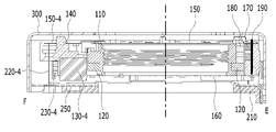
도 1은 실시 예에 따른 렌즈 구동 장치(100)의 분해 사시도를 나타내고, 도 2는 도 1의 커버 부재(300)를 제외한 렌즈 구동 장치(100)의 결합 사시도를 나타낸다.1 is an exploded perspective view of a
도 1 및 도 2를 참조하면, 렌즈 구동 장치(100)는 보빈(bobbin, 110), 제1 코일(120), 제1 마그네트(magnet, 130), 하우징(140), 및 제2 코일(230)을 포함할 수 있다.1 and 2 , the
렌즈 구동 장치(100)는 제2 코일(230)과 연결되는 회로 기판(310)을 더 포함할 수 있다.The
렌즈 구동 장치(100)는 상부 탄성 부재(150), 하부 탄성 부재(160), 지지 부재(220), 제1 위치 센서(170), 회로 기판(190) 및 제2 마그네트(180) 중 적어도 하나를 더 포함할 수 있다.The
또한 렌즈 구동 장치(100)는 제2 위치 센서(240)를 더 포함할 수 있다.Also, the
또한 렌즈 구동 장치(100)는 제3 마그네트(185), 베이스(210), 회로 기판(250), 및 커버 부재(300) 중 적어도 하나를 더 포함할 수 있다.In addition, the
또한 렌즈 구동 장치(100)는 회로 기판(190)에 장착되는 커패시터(195)를 더 포함할 수 있다.Also, the
이하, 회로 기판(310)은 제1 내지 제3 회로 기판들 중 어느 하나로 대체하여 표현될 수 있고, 회로 기판(250)은 제1 내지 제3 회로 기판들 중 다른 어느 하나로 대체하여 표현될 수 있고, 회로 기판(190)은 제1 내지 제3 회로 기판들 중 나머지 다른 어느 하나로 대체하여 표현될 수 있다.Hereinafter, the
먼저 보빈(110)에 대하여 설명한다.First, the
보빈(110)은 하우징(140)의 내측에 배치되고, 제1 코일(120)과 제1 마그네트(130) 간의 전자기적 상호 작용에 의하여 광축(OA) 방향 또는 제1 방향(예컨대, Z축 방향)으로 이동될 수 있다.The
도 3a는 도 1에 도시된 보빈(110), 제2 마그네트(180) 및 제3 마그네트(185)의 사시도를 나타내고, 도 3b는 보빈(110)에 결합된 제1 코일(120)을 나타낸다.FIG. 3A is a perspective view of the
도 3a 및 도 3b를 참조하면, 보빈(110)은 렌즈 또는 렌즈 배럴을 장착하기 위한 개구(110a)을 가질 수 있다. 예컨대, 예컨대, 보빈(110)의 개구(110a)는 보빈(110)을 광축 방향으로 관통하는 관통홀일 수 있으며, 보빈(110)의 개구(110a)의 형상은 원형, 타원형, 또는 다각형일 수 있으나, 이에 한정되는 것은 아니다.3A and 3B , the
보빈(110)의 개구(110a)에는 렌즈가 직접 장착될 수 있으나, 이에 한정되는 것은 아니며, 다른 실시 예에서는 적어도 하나의 렌즈가 장착 또는 결합되기 위한 렌즈 배럴이 보빈(110)의 개구에 결합 또는 장착될 수 있다. 렌즈 또는 렌즈 배럴은 보빈(110)의 내주면에 다양한 방식으로 결합될 수 있다.A lens may be directly mounted on the opening 110a of the
보빈(110)은 서로 이격하는 제1 측부들(110b1-1 내지 110b1-4) 및 서로 이격하는 제2 측부들(110b2-1 내지 110b2-4)을 포함할 수 있으며, 제2 측부들(110b2-1 내지 110b2-4) 각각은 인접하는 2개의 제1 측부들을 서로 연결할 수 있다. 예컨대, 보빈(110)의 제1 측부들(110b1-1 내지 110b1-4) 각각의 수평 방향 또는 가로 방향의 길이는 제2 측부들(110b2-1 내지 110b2-4) 각각의 수평 방향 또는 가로 방향의 길이와 다를 수 있으나, 이에 한정되는 것은 아니며, 다른 실시 예에서는 양자는 동일할 수도 있다.The
보빈(110)은 외측면에 마련되는 돌출부(115)를 구비할 수 있다. 예컨대, 돌출부(115)는 보빈(110)의 제2 측부들(110b2-1 내지 110b2-4) 중 적어도 하나의 외측면에 배치될 수 있으나, 이에 한정되는 것은 아니다. 돌출부(115)는 보빈(110)의 개구(110a)의 중심을 지나고 광축과 수직한 직선에 평행한 방향으로 돌출될 수 있으나, 이에 한정되는 것은 아니다.The
보빈(110)의 돌출부(115)는 하우징(140)의 홈부(25a)와 대응하고, 하우징(140)의 홈부(25a) 내에 삽입 또는 배치될 수 있으며, 보빈(110)이 광축을 중심으로 일정한 범위 이상으로 회전하는 것을 억제 또는 방지할 수 있다.The
또한 돌출부(115)는 외부 충격 등에 의해 보빈(110)이 광축 방향(예컨대, 상부 탄성 부재(150)에서 하부 탄성 부재(160)로 향하는 방향으로 규정된 범위 이상으로 움직이더라도, 보빈(110)의 하면이 베이스(210), 또는 회로 기판(250)에 직접 충돌되는 것을 억제 또는 방지하는 스토퍼 역할을 할 수 있다.In addition, even if the
보빈(110)의 상면에는 상부 탄성 부재(150)의 제1 프레임 연결부(153)와 공간적 간섭을 회피하기 위한 제1 도피홈(112a)이 마련될 수 있다. 예컨대, 제1 도피홈(112a)은 보빈(110)의 제2 측부들(110b-2)에 배치될 수 있으나, 이에 한정되는 것은 아니다.A
보빈(110)의 상면에는 상부 탄성 부재(150)의 설치 위치를 가이드하기 위한 가이드부(111)가 마련될 수 있다. 예를 들어, 도 3a에 예시된 바와 같이, 보빈(110)의 가이드부(111)는 상부 탄성 부재(150)의 프레임 연결부(153)가 지나가는 경로를 가이드하기 위하여 제1 도피홈(112a)에 배치될 수 있다. 예컨대, 가이드부(111)는 제1 도피홈(112a)의 바닥면으로부터 광축 방향으로 돌출될 수 있다.A
또한 보빈(110)의 가이드부(111)와 상부 탄성 부재(150)(예컨대, 제1 프레임 연결부(153)) 사이에는 댐퍼가 배치될 수 있고, 이때 댐퍼는 가이드부(111)와 상부 탄성 부재(150)(예컨대, 제1 연결부(153))에 결합 또는 부착될 수 있다.In addition, a damper may be disposed between the
보빈(110)은 상면으로부터 돌출되는 스토퍼(116)를 포함할 수 있다.The
보빈(110)의 스토퍼(116)는 보빈(110)이 오토 포커싱 기능을 위해 제1 방향으로 움직일 때, 외부 충격 등에 의해 보빈(110)이 규정된 범위 이상으로 움직이더라도, 보빈(110)의 상면이 커버 부재(300)의 상판의 내측과 직접 충돌하는 것을 방지하는 역할을 수행할 수 있다.The
보빈(110)은 상부 탄성 부재(150)에 결합 및 고정되기 위한 제1 결합부(113)를 포함할 수 있다. 예컨대, 도 3a에서 보빈(110)의 제1 결합부(113)는 돌기 형태이나, 이에 한정되는 것은 아니며, 다른 실시 예에서는 보빈(110)의 제1 결합부(113)는 홈 또는 평면 형상일 수 있다.The
또한 보빈(110)은 하부 탄성 부재(160)에 결합 및 고정되기 위한 제2 결합부(117)를 포함할 수 있으며, 도 3b에서 보빈(110)의 제2 결합부(117)는 돌기 형태이나, 이에 한정되는 것은 아니며, 다른 실시 예에서는 보빈(110)의 제2 결합부는 홈, 또는 평면 형상일 수 있다.In addition, the
보빈(110)의 외측면에는 제1 코일(120)이 안착, 삽입, 또는 배치되는 안착홈(105)이 마련될 수 있다. 안착홈(105)은 보빈(110)의 제1 및 제2 측부들(110b1 내지 110b1-4, 110b2-1 내지 110b2-4)의 외측면으로부터 함몰된 홈 구조일 수 있으며, 제1 코일(120)의 형상과 일치하는 형상, 폐곡선 형상, 예컨대, 원형, 타원형, 또는 다각형의 링 형상을 가질 수 있다.A
또한 제1 코일(120)을 하부 탄성 부재들(160-1, 160-2)과 연결할 때 제1 코일(120)의 이탈을 억제하고 제1 코일(120)의 양단을 가이드하기 위하여, 보빈(110)의 반대편에 위치하는 2개의 제1 측부들(예컨대, 110b1-2, 110b1-4) 또는 2개의 제2 측부들의 하면에는 가이드 홈(116a, 116b)이 마련될 수 있다.In addition, when connecting the
또한 보빈(110)의 외측면에는 제2 마그네트(180)가 안착, 삽입, 고정, 또는 배치되는 안착홈(180a)이 마련될 수 있다. 예컨대, 보빈(110)의 안착홈(180a)은 보빈(110)의 외측면으로부터 함몰된 구조일 수 있으며, 보빈(110)의 상면 또는 하면 중 적어도 하나로 개방된 개구를 가질 수 있으나, 이에 한정되는 것은 아니다.In addition, a
또한 보빈(110)의 외측면에는 제3 마그네트(185)가 안착, 삽입, 고정, 또는 배치되기 위한 안착홈(185a)이 마련될 수 있다. 예컨대, 보빈(110)의 안착홈(185a)은 보빈(110)의 외측면으로부터 함몰된 구조일 수 있으며, 보빈(110)의 상면 또는 하면 중 적어도 하나로 개방된 개구를 가질 수 있으나, 이에 한정되는 것은 아니다.In addition, a
보빈(110)의 안착홈들(180a, 185a) 각각은 제1 코일(120)이 배치되는 안착홈(105)의 상측에 위치할 수 있고, 안착홈(105)과 연결되거나 접할 수 있으나, 이에 한정되는 것은 아니며, 다른 실시 예에서는 양자는 서로 이격될 수도 있다.Each of the
보빈(110)의 안착홈(180a)은 보빈(110)의 제1 측부들(110b1-1 내지 110b-4) 중 어느 하나(예컨대, 110b1-1)에 형성될 수 있고, 보빈(110)의 안착홈(185a)은 보빈(110)의 제1 측부들(110b1 내지 110b1-4) 중 다른 어느 하나(예컨대, 110b1-3)에 형성될 수 있다.The
예컨대, 안착홈들(180a, 185a)은 보빈(110)의 서로 마주보는 2개의 제1 측부들 또는 반대편에 위치하는 2개의 제1 측부들에 배치될 수 있다.For example, the
제2 마그네트(180)와 제3 마그네트(185)가 보빈(110)의 반대편에 위치하는 2개의 제1 측부들에 마련된 안착홈들(180a, 185a) 내에 배치됨으로써, 제2 마그네트(180)와 제3 마그네트(185)의 무게 균형을 맞출 수 있고, 제1 마그네트(130)와 제2 마그네트(180) 간의 자계 간섭에 따른 AF 구동력의 영향과 제1 마그네트(130)와 제3 마그네트(185) 간의 자계 간섭에 따른 AF 구동력의 영향이 서로 상쇄되도록 할 수 있고, 이로 인하여 실시 예는 AF(Auto Focusing) 구동의 정확성을 향상시킬 수 있다.The
보빈(110)의 내주면에는 렌즈 또는 렌즈 배럴과 결합을 위한 나사선(11)이 마련될 수 있다. 지그(jig) 등에 의하여 보빈(110)을 고정시킨 상태에서 보빈(110)의 내주면에 나사선(11)을 형성할 수 있는데, 보빈(110)의 상면에는 지그(jig) 고정용 홈(15a, 15b)이 마련될 수 있다. 예컨대, 지그 고정용 홈(15a, 15b)은 보빈(110)의 반대편에 위치하는 2개의 제1 측부들(110b-1) 또는 2개의 제2 측부들(110b-1)의 상면에 마련될 수 있으나, 이에 한정되는 것은 아니다. 지그 고정용 홈(15a, 15b)은 이물질을 포집하는 이물 포집부의 기능을 할 수도 있다.A
다음으로 제1 코일(120)에 대하여 설명한다.Next, the
제1 코일(120)은 보빈(110)에 배치 또는 결합될 수 있다. 예컨대, 제1 코일(120)은 보빈(110)의 외측면 상에 배치될 수 있다.The
예컨대, 제1 코일(120)은 제2 및 제3 마그네트들(180, 185) 아래에 배치될 수 있으나, 이에 한정되는 것은 아니다. 예컨대, 제1 코일(120)은 보빈(110)의 돌출부(115) 아래에 배치될 수 있으나, 이에 한정되는 것은 아니다.For example, the
예컨대, 제1 코일(120)은 광축과 수직한 방향으로 제2 및 제3 마그네트들(180, 185)과 중첩되지 않을 수 있으나, 이에 한정되는 것은 아니다.For example, the
예컨대, 제1 코일(130)은 보빈(110)의 안착홈(105) 내에 배치될 수 있고, 제2 마그네트(180)는 보빈(110)의 안착홈(180a) 내에 삽입 또는 배치될 수 있고, 제3 마그네트(185)는 보빈(110)의 안착홈(185a) 내에 삽입 또는 배치될 수 있다.For example, the
예컨대, 보빈(110)에 배치된 제2 마그네트(180)와 제3 마그네트(185) 각각은 광축(OA) 방향으로 제1 코일(120)과 이격될 수 있으나, 이에 한정되는 것은 아니며, 다른 실시 예에서는 보빈(110)에 배치된 제2 마그네트(180), 및 제3 마그네트(185) 각각은 제1 코일(120)과 접하거나, 광축과 수직한 방향으로 제1 코일(120)과 중첩될 수도 있다. 또는 예컨대, 제2 마그네트(180), 및 제3 마그네트(185) 각각의 적어도 일부는 제1 코일(120)의 안쪽에 배치될 수 있다.For example, each of the
예컨대, 제1 코일(120)은 광축(OA)을 중심으로 회전하는 방향으로 보빈(110)의 외측면을 감쌀 수 있다.For example, the
제1 코일(120)은 보빈(110)의 외측면에 직접 권선될 수도 있으나, 이에 한정되는 것은 아니다. 다른 실시 예에 의하면, 제1 코일(120)은 코일 링 또는 코일 블록 형태로 보빈(110)에 결합될 수도 있다. 제1 코일(120)은 각진 링 형상이거나 라운드진 형태의 코일 링 또는 코일 블록 형태일 수 있다.The
제1 코일(120)에는 전원 또는 구동 신호가 제공될 수 있다.Power or a driving signal may be provided to the
제1 코일(120)에 제공되는 전원 또는 구동 신호는 직류 신호 또는 교류 신호이거나 또는 직류 신호와 교류 신호를 포함할 수 있으며, 전압 또는 전류 형태일 수 있다.The power or driving signal provided to the
제1 코일(120)은 구동 신호(예컨대, 구동 전류)가 공급되면 제1 마그네트(130)와 전자기적 상호 작용을 통해 전자기력을 형성할 수 있으며, 형성된 전자기력에 의하여 광축(OA) 방향으로 보빈(110)이 이동될 수 있다.The
AF 가동부(또는 AF 이동부)의 초기 위치에서, 보빈(110)은 상측 방향 또는 하측 방향으로 이동될 수 있으며, 이를 AF 가동부의 양방향 구동이라 한다. 또는 AF 가동부의 초기 위치에서, 보빈(110)은 상측 방향으로 이동될 수 있으며, 이를 AF 가동부의 단방향 구동이라 한다.At the initial position of the AF movable unit (or the AF moving unit), the
AF 가동부의 초기 위치에서, 광축(OA)과 수직하고 광축을 지나는 직선과 평행한 방향으로 제1 코일(120)은 하우징(140)에 배치되는 제1 마그네트(130)와 서로 대응하거나 오버랩되도록 배치될 수 있다.In the initial position of the AF movable part, the
예컨대, AF 가동부는 보빈(110), 및 보빈(110)에 결합된 구성들(예컨대, 제1 코일(120), 제2 및 제3 마그네트들(180, 185)을 포함할 수 있다. 예컨대, AF 가동부는 렌즈 또는/및 렌즈 배럴을 포함할 수도 있다.For example, the AF movable unit may include a
그리고 AF 가동부의 초기 위치는 제1 코일(1120)에 전원을 인가하지 않은 상태에서 AF 가동부의 최초 위치이거나 또는 상부 및 하부 탄성 부재들(150,160)이 단지 AF 가동부의 무게에 의해서만 탄성 변형됨에 따라 AF 가동부가 놓이는 위치일 수 있다.And the initial position of the AF movable part is the initial position of the AF movable part in a state where power is not applied to the first coil 1120 or the upper and lower
이와 더불어 보빈(110)의 초기 위치는 중력이 보빈(110)에서 베이스(210) 방향으로 작용할 때, 또는 이와 반대로 중력이 베이스(210)에서 보빈(110) 방향으로 작용할 때의 AF 가동부가 놓이는 위치일 수 있다.In addition to this, the initial position of the
다음으로 제2 및 제3 마그네트들(180, 185)에 대하여 설명한다.Next, the second and
제2 마그네트(180)는 제1 위치 센서(170)가 감지하기 위한 자기장을 제공한다는 점에서 "센싱 마그네트(sensing magnet)"로 표현될 수 있고, 제3 마그네트(185)는 센싱 마그네트(180)의 자계 영향을 상쇄시키고, 센싱 마그네트(180)와 무게 균형을 맞추기 위한 것으로라는 점에서 밸런싱 마그네트(balancing magnet)로 표현될 수도 있다.The
제2 마그네트(180) 및 제3 마그네트(185)는 보빈(110)에 배치되거나 보빈(110)에 결합될 수 있다.The
제1 위치 센서(170)를 마주보는 제2 마그네트(180)의 어느 한 면의 일부는 안착홈(180a)으로부터 노출될 수 있으나, 이에 한정되는 것은 아니며, 다른 실시 예에서는 제1 위치 센서(170)를 마주보는 제2 마그네트(180)의 어느 한 면의 일부는 안착홈(180a)으로부터 노출되지 않을 수도 있다.A part of any one surface of the
예컨대, 보빈(110)에 배치된 제2 및 제3 마그네트들(180, 185) 각각은 N극과 S극의 경계면이 광축(OA)과 수직인 방향과 평행할 수 있다. 예컨대, 제1 위치 센서(170)를 마주보는 제2 및 제3 마그네트들(180, 185) 각각의 면은 N극과 S극으로 구분될 수 있으나, 이에 한정되는 것은 아니다.For example, in each of the second and
예컨대, 다른 실시 예에서는 보빈(110)에 배치된 제2 및 제3 마그네트들(180, 185) 각각은 N극과 S극의 경계면이 광축(OA)과 팽행할 수도 있다.For example, in another embodiment, in each of the second and
예컨대, 제2 및 제3 마그네트들(180, 185) 각각은 하나의 N극과 하나의 S극을 갖는 단극 착자 마그네트일 수 있으나, 이에 한정되는 것은 아니다. 다른 실시 예에서는 제2 및 제3 마그네트들(180, 185) 각각은 2개의 N극과 2개의 S극을 포함하는 양극 착자 마그네트 또는 4극 마그네트일 수도 있다.For example, each of the second and
제2 및 제3 마그네트들(180, 185) 각각은 제1 마그넷부(17a), 제2 마그넷부(17b), 및 제1 마그넷부(17a)와 제2 마그넷부(17b) 사이에 배치되는 격벽(17c)을 포함할 수 있다. 여기서 격벽(17c)은 "비자성체 격벽"으로 대체하여 표현될 수도 있다.Each of the second and
제1 마그넷부(17a)는 N극, S극, N극과 S극 사이의 제1 경계부를 포함할 수 있다. 제1 경계부는 실질적으로 자성을 갖지 않는 부분으로 극성이 거의 없는 구간을 포함할 수 있으며, 하나의 N극과 하나의 S극으로 이루어진 자석을 형성하기 위하여 자연적으로 발생되는 부분일 수 있다.The
제2 마그넷부(17b)는 N극, S극, N극과 S극 사이의 제2 경계면을 포함할 수 있다. 제2 경계부는 실질적으로 자성을 갖지 않는 부분으로 극성이 거의 없는 구간을 포함할 수 있으며, 하나의 N극과 하나의 S극으로 이루어진 자석을 형성하기 위하여 자연적으로 발생되는 부분일 수 있다.The
격벽(17c)은 제1 마그넷부(17a)과 제2 마그넷부(17b)를 분리 또는 격리시키며, 실질적으로 자성을 갖지 않는 부분으로 극성이 거의 없는 부분일 수 있다. 예컨대, 격벽은 비자성체 물질, 또는 공기 등일 수 있다. 비자성체 격벽은 "뉴트럴 존(Neutral Zone)", 또는 "중립 영역"으로 표현될 수 있다.The
격벽(17c)은 제1 마그넷부(17a)와 제2 마그넷부(17b)를 착자할 때, 인위적으로 형성되는 부분으로, 격벽(17c)의 폭은 제1 경계부의 폭(또는 제2 경계부의 폭)보다 클 수 있다. 여기서 격벽(17c)의 폭은 제1 마그넷부(17a)에서 제2 마그넷부(17b)를 향하는 방향으로의 길이일 수 있다. 제1 경계부(또는 제2 경계부)의 폭은 제1 및 제2 마그넷부들(17a, 17b) 각각의 N극에서 S극 방향으로의 제1 경계부의 길이일 수 있다.The
제2 마그네트(180)는 보빈(110)과 함께 광축 방향으로 이동할 수 있으며, 제1 위치 센서(170)는 광축 방향으로 이동하는 제2 마그네트(180)의 자기장의 세기 또는 자기력을 감지할 수 있고, 감지된 결과에 따른 출력 신호를 출력할 수 있다.The
예컨대, 광축 방향으로의 보빈(110)의 변위에 따라 제1 위치 센서(170)가 감지한 자기장의 세기 또는 자기력이 변화할 수 있고, 제1 위치 센서(170)는 감지된 자기장의 세기에 비례하는 출력 신호를 출력할 수 있고, 제1 위치 센서(170)의 출력 신호를 이용하여 보빈(110)의 광축 방향으로의 변위가 감지될 수 있다.For example, the strength or magnetic force of the magnetic field sensed by the
다음으로 하우징(140)에 대하여 설명한다.Next, the
하우징(140)은 커버 부재(300) 내측에 배치될 수 있다.The
하우징(140)은 내측에 보빈(110)을 수용하며, 제1 마그네트(130), 제1 위치 센서(170), 및 회로 기판(190)을 지지한다.The
도 4a는 도 1에 도시된 하우징(140), 회로 기판(190), 제1 위치 센서(170), 및 커패시터(195)의 사시도를 나타내고, 도 4b는 하우징(140)의 저면 사시도이고, 도 4c는 하우징(140), 제1 마그네트(130), 회로 기판(190), 제1 위치 센서(170), 및 커패시터(195)의 결합 사시도를 나타낸다.4A is a perspective view of the
도 4a 및 도 4b를 참조하면, 하우징(140)은 전체적으로 중공 기둥 형상일 수 있다. 예컨대, 하우징(140)은 다각형(예컨대, 사각형, 또는 팔각형) 또는 원형의 개구(140a)을 구비할 수 있으며, 하우징(140)의 개구(140a)는 광축 방향으로 하우징(140)을 관통하는 관통 홀 형태일 수 있다. 예컨대, 보빈(110)의 적어도 일부는 하우징(140)의 개구(140a) 내에 배치될 수 있다.4A and 4B , the
하우징(140)은 복수의 측부들(141-1 내지 141-4) 및 복수의 코너부들(142-1 내지 142-4)을 포함할 수 있다.The
예를 들어, 하우징(140)은 서로 이격하는 제1 내지 제4 측부들(141-1 내지 141-4 측부들 및 제1 내지 제4 코너부들(142-1 내지 142-4)을 포함할 수 있다.For example, the
하우징(140)의 코너부들(142-1 내지 142-4) 각각은 인접하는 2개의 측부들(141-1과 141-2, 141-2와 141-3, 141-3과 141-4, 141-4와 141-1) 사이에 배치 또는 위치할 수 있고, 측부들(141-1 내지 141-4)을 서로 연결시킬 수 있다.Each of the corner portions 142-1 to 142-4 of the
예컨대, 코너부들(142-1 내지 142-4)은 하우징(140)의 코너 또는 모서리에 위치할 수 있다. 예컨대, 하우징(140)의 측부들의 개수는 4개이고, 코너부들의 개수는 4개이나, 이에 한정되는 것은 아니며, 5개 이상일 수도 있다.For example, the corner parts 142-1 to 142-4 may be located at a corner or a corner of the
하우징(140)의 측부들(141-1 내지 141-4) 각각은 커버 부재(300)의 측판들(302; 302A 내지 302D) 중 대응하는 어느 하나와 평행하게 배치될 수 있다.Each of the side portions 141-1 to 141-4 of the
예컨대, 하우징(140)의 측부들(141-1 내지 141-4)은 보빈(110)의 제1 측부들(110b1-1 내지 110b1-4)에 대응하거나 또는 대향할 수 있고, 하우징(140)의 코너부들(142-1 내지 142-4)은 보빈(110)의 제2 측부들(110b2-1 내지 110b2-4)에 대응하거나 또는 대향할 수 있다.For example, the side portions 141-1 to 141-4 of the
하우징(140)의 코너부들(142-1 내지 142-4)에는 제1 마그네트(130)가 배치 또는 설치될 수 있다.The
예컨대, 하우징(140)의 코너들 또는 코너부들(142-1 내지 142-4)에는 마그네트(130)를 수용하기 위한 안착부(141a) 또는 수용부가 형성될 수 있다.For example, a
예컨대, 하우징(140)의 안착부(141a)는 하우징(140)의 코너부들(142-1 내지 142-4) 중 적어도 하나의 하부, 또는 하단에 마련될 수 있다.For example, the
예컨대, 하우징(140)의 안착부(141a)는 4개의 코너부들(142-1 내지 142-4) 각각의 하부 또는 하단의 내측에 마련될 수 있다.For example, the
하우징(140)의 안착부(141a)는 제1 마그네트(130)와 대응되는 형상을 갖는 홈, 예컨대, 요홈으로 형성될 수 있으나, 이에 한정되는 것은 아니다.The
예컨대, 제1 코일(120)을 마주보는 하우징(140)의 안착부(141a)의 측면에는 제1 개구가 형성될 수 있고, 회로 기판(250)의 상면 또는 베이스(210)의 상면을 마주보는 하우징(140)의 안착부(141a)의 하면에는 제2 개구가 형성될 수 있으며, 이는 제1 마그네트(130)의 장착을 용이하게 하기 위함이다.For example, a first opening may be formed in a side surface of the
예컨대, 하우징(140)의 안착부(141a)에 고정 또는 배치된 제1 마그네트(130)의 제1면(3C)은 안착부(141a)의 제1 개구를 통하여 노출될 수 있다. 또한 하우징(140)의 안착부(141a)에 고정 또는 배치된 제1 마그네트(130)의 하면(3B)은 안착부(141a)의 제2 개구를 통하여 노출될 수 있다.For example, the
하우징(140)은 상부 탄성 부재(150)의 제1 프레임 연결부(153)와의 공간적 간섭을 회피하기 위하여 코너부들(142-1 내지 142-4)의 상면에 마련되는 도피홈(41)을 구비할 수 있다.The
예컨대, 하우징(140)의 도피홈(41)은 하우징(140)의 상면으로부터 함몰된 형태일 수 있고, 스토퍼(145) 또는 홀(147)보다 하우징(140)의 중심에 더 인접하여 위치할 수 있다. 예컨대, 하우징(140)의 스토퍼(145)를 기준으로 하우징(140)의 중심 방향인 안쪽에는 도피홈(41)이 위치할 수 있고, 그 반대편인 바깥쪽에는 홀(147)이 위치할 수 있다.For example, the
하우징(140)의 코너부들(142-1 내지 142-4)에는 보빈(110)의 돌출부(115)에 대응 또는 대향하여 홈부(25a)가 구비될 수 있다. 예컨대, 하우징(140)의 홈부(25a)는 하우징(140)의 안착부(141a) 상에 위치할 수 있다. 예컨대, 하우징(140)의 홈부(25a)는 도피홈(41)의 바닥면에 형성될 수 있다. 예컨대, 홈부(25a)의 바닥면은 도피홈(41)의 바닥면보다 낮게 위치할 수 있고, 하우징(140)의 안착홈(141a)은 도피홈(41)의 바닥면보다 낮게 위치할 수 있다.The corner portions 142-1 to 142-4 of the
제1 마그네트(130)는 접착제에 의하여 안착부(141a)에 고정될 수 있으나, 이에 한정되는 것은 아니다.The
예컨대, 하우징(140)의 코너부들(142-1 내지 142-4)에는 접착제를 주입하기 위한 적어도 하나의 접착제 주입홀(146a, 146b)이 구비될 수 있다. 적어도 하나의 접착제 주입홀(146a, 146b)은 코너부들(142-1 내지 142-4)의 상면으로부터 함몰된 형태일 수 있다.For example, at least one
적어도 하나의 접착제 주입홀(146a, 146b)은 코너부들(142-1 내지 142-4)을 관통하는 관통홀을 포함할 수 있으며, 접착제 주입홀(146a, 146b)은 하우징(140)의 안착홈(141a)과 연결 또는 연통될 수 있고, 제1 마그네트(130)의 적어도 일부(예컨대, 마그네트(130)의 상면(3A)의 적어도 일부)를 노출할 수 있다. 접착제 주입홀(146a, 146b)이 제1 마그네트(130)의 적어도 일부(예컨대, 마그네트(130)의 상면(3A)의 적어도 일부)를 노출함으로써, 접착제가 제1 마그네트(130)에 잘 도포될 수 있고, 이로 인하여 제1 마그네트(130)와 하우징(140) 간의 고정력이 향상될 수 있다.The at least one adhesive injection hole (146a, 146b) may include a through hole penetrating the corner parts (142-1 to 142-4), the adhesive injection hole (146a, 146b) is a seating groove of the housing (140). It may be connected or communicated with the 141a, and at least a portion of the first magnet 130 (eg, at least a portion of the
하우징(140)은 측부들(141-1 내지 141-4)의 외측면으로부터 돌출된 적어도 하나의 스토퍼(147a)를 구비할 수 있으며, 적어도 하나의 스토퍼(147a)는 하우징(140)이 광축과 수직한 방향으로 움직일 때 하우징(140)의 외측면이 커버 부재(300)의 측판(302)과 충돌하는 것을 방지할 수 있다.The
하우징(140)의 하면이 베이스(210) 및/또는 회로 기판(250)과 충돌하는 것을 방지하기 위하여, 하우징(140)은 하면으로부터 돌출되는 스토퍼(미도시)를 더 구비할 수도 있다.In order to prevent the lower surface of the
하우징(140)은 회로 기판(190)를 수용하기 위한 장착홈(14a)(또는 안착홈), 제1 위치 센서(170)를 수용하기 위한 장착홈(14b)(또는 안착홈), 및 커패시터(195)를 수용하기 위한 장착홈(14c)(또는 안착홈)을 구비할 수 있다.The
하우징(140)의 장착홈(14a)은 하우징(140)의 측부들(141-1 내지 141-4) 중 어느 하나(예컨대, 141-1)의 상부 또는 상단에 마련될 수 있다.The mounting
회로 기판(190)의 장착을 용이하게 하기 위하여 하우징(140)의 장착홈(14a)은 상부가 개방되고, 측면과 바닥을 구비하는 홈 형태일 수 있으며, 하우징(140)의 내측으로 개방되는 개구를 가질 수 있다. 하우징(140)의 장착홈(14a)의 형상은 회로 기판(190)의 형상에 대응 또는 일치하는 형상을 가질 수 있다.In order to facilitate the mounting of the
하우징(140)의 장착홈(14b)은 하우징(140)의 제1 측부(141-1)의 내측면에 마련될 수 있고, 장착홈(14a)과 연결될 수 있다.The mounting
하우징(140)의 장착홈(14c)은 장착홈(14b)의 일측에 배치될 수 있고, 장착홈(14b)와 장착홈(14c) 사이에는 커패시터(195)와 제1 위치 센서(170)를 분리 또는 이격시키기 위한 돌기 또는 돌출부가 마련될 수 있다. 이는 커패시터(195)와 위치 센서(170)를 인접하여 위치시킴으로써 양자의 전기적 연결을 위한 패스의 길이를 줄여, 경로 증가에 따른 노이즈를 감소시키기 위함이다.The mounting
커패시터(195)는 회로 기판(190)의 제1면(19b)에 배치 또는 실장될 수 있다.The
커패시터(195)는 칩(chip) 형태일 수 있으며, 이때 칩은 커패시터(195)의 일단에 해당하는 제1 단자(195a, 도 8b 참조) 및 커패시터(195)의 타단에 해당하는 제2 단자(195b, 도 8b 참조)를 포함할 수 있다. 커패시터(195)는 "용량성 소자" 또는 콘덴서(condensor)로 대체하여 표현될 수도 있다.The
다른 실시 예에서는 커패시터는 회로 기판(190)에 포함되도록 구현될 수 있다. 예컨대, 회로 기판(190)은 제1 도전층, 제2 도전층, 및 제1 도전층과 제2 도전층 사이에 배치되는 절연층(예컨대, 유전층)을 포함하는 커패시터를 구비할 수도 있다.In another embodiment, the capacitor may be implemented to be included in the
커패시터(195)는 외부로부터 위치 센서(170)에 전원(또는 구동 신호)를 제공하기 위한 회로 기판(190)의 제1 및 제2 단자들(B1, B2)에 전기적으로 병렬 연결될 수 있다.The
또는 예컨대, 커패시터(195)는 회로 기판(190)의 제1 및 제2 단자들(B1, B2)에 전기적으로 연결되는 제1 위치 센서(170)의 단자들에 전기적으로 병렬 연결될 수도 있다.Alternatively, for example, the
예컨대, 커패시터(195)의 일단(또는 커패시터 칩의 제1 단자)는 회로 기판(190)의 제1 단자(B1)에 전기적으로 연결될 수 있고, 커패시터(195)의 타단(또는 커패시터 칩의 단자)는 회로 기판(190)의 제2 단자(B2)에 전기적으로 연결될 수 있다.For example, one end of the capacitor 195 (or the first terminal of the capacitor chip) may be electrically connected to the first terminal B1 of the
커패시터(195)는 회로 기판(190)의 제1 및 제2 단자들(B1, B2)에 전기적으로 병렬 연결됨으로써, 외부로부터 제1 위치 센서(170)에 제공되는 전원 신호(GND, VDD) 포함된 리플(ripple) 성분를 제거시키는 평활 회로 역할을 할 수 있고, 이로 인하여 제1 위치 센서(170)에 안정적이고 일정한 전원 신호를 제공할 수 있다.The
커패시터(195)는 회로 기판(190)의 제1 및 제2 단자들(B1,B2)에 전기적으로 병렬 연결됨으로써, 외부로부터 유입되는 고주파 성분의 노이즈 또는 ESD(ElectroStatic Discharge) 등으로부터 제1 위치 센서(170)를 보호할 수도 있다.The
또한 커패시터(195)는 외부로부터 유입되는 고주파 성분의 노이즈 또는 ESD 등에 기인한 과전류가 제1 위치 센서(170)에 인가되는 것을 방지할 수 있고, 과전류에 기인하여 제1 위치 센서(170)의 출력 신호에 기초하여 획득한 보빈(110)의 변위에 대한 캘리브레이션(calibration) 값이 리셋(reset)되는 현상을 방지할 수 있다.In addition, the
또한 제1 위치 센서(170)의 장착을 용이하게 하기 위하여 하우징(140)의 장착홈(14b)은 상부가 개방될 수 있으며, 센싱 감도를 높이기 위하여 하우징(140)의 제1 측부(141-1)의 내측면으로 개방되는 개구를 가질 수 있다. 하우징(140)의 장착홈(14b)은 제1 위치 센서(170)의 형상에 대응 또는 일치하는 형상을 가질 수 있다.In addition, in order to facilitate the mounting of the
예컨대, 접착 부재에 의하여 회로 기판(190)은 하우징(140)의 장착홈(14a)에 고정될 있다. 예컨대, 접착 부재는 에폭시 또는 양면 테이프 등일 수 있으나, 이에 한정되는 것은 아니다.For example, the
하우징(140)의 코너부들(142-1 내지 142-4)에는 지지 부재(220-1 내지 220-4)가 배치될 수 있다. Support members 220 - 1 to 220 - 4 may be disposed at the corners 142-1 to 142-4 of the
하우징(140)의 코너부들(142-1 내지 142-4)에는 지지 부재(220-1 내지 220-4)가 지나가는 경로를 형성하는 홀(147)이 구비될 수 있다. 예컨대, 하우징(140)은 코너부들(142-1 내지 142-4)의 상부를 관통하는 홀(147)을 포함할 수 있다.The corner portions 142-1 to 142-4 of the
다른 실시 예에서 하우징(140)의 코너부들(142-1 내지 142-4)에 마련되는 홀은 하우징(140)의 코너부의 외측면으로부터 함몰되는 홀 형태일 수도 있으며, 홀의 적어도 일부는 코너부의 외측면으로 개방될 수도 있다. 하우징(140)의 홀(147)의 개수는 지지 부재의 개수와 동일할 수 있다.In another embodiment, the hole provided in the corner portions 142-1 to 142-4 of the
지지 부재(220)의 일단은 홀(147)을 통과하여 상부 탄성 부재(150)(예컨대, 제1 외측 프레임(152)에 연결 또는 본딩될 수 있다.One end of the
예컨대, 댐퍼를 용이하게 도포하기 위하여 하우징(140)의 상면에서 하면 방향으로 홀(147)의 직경이 점차 증가하는 형태일 수 있으나, 이에 한정되는 것은 아니며, 다른 실시 예에서는 홀(147)은 직경이 일정할 수도 있다. 예컨대, 댐퍼는 홀(147) 내에 배치될 수 있고, 지지 부재(220)의 적어도 일부에 배치되거나 결합될 수 있다.For example, in order to easily apply the damper, the diameter of the
하우징(140)의 코너부(142-1 내지 142-4)의 하부에는 홈(148) 또는 단차부가 형성될 수 있다. 제2 코일(230), 지지 부재(220), 및 회로 기판(310) 중 적어도 하나와 공간적 간섭을 피하기 위하여, 홈(148)은 하우징(140)의 코너부(142-1 내지 142-4)의 외측면으로부터 함몰된 형태일 수 있다.A
예컨대, 홈(148)은 홀(147)이 형성되는 제1면(148-1) 및 제1면(148-1)과 코너부(142-1 내지 142-4)의 하면 사이에 위치하는 제2면(148-2)을 포함할 수 있다.For example, the
예컨대, 예컨대, 홀(147)은 코너부(142-1 내지 142-4)의 상면과 제1면(148-1)을 관통할 수 있다.For example, the
또한 홈(148)은 하우징(140)의 안착부(141a)와 연결 또는 연통되는 개구(48)를 포함할 수 있고, 개구(48)를 통하여 안착부(141a)에 배치된 제1 마그네트(130)의 제2면(3D)이 노출될 수 있다. 제1 마그네트(130)의 제2면(3D)이 노출되므로, 제2 코일(230)과 제1 마그네트(130) 간에 전자기력을 향상시킬 수 있다. 다른 실시 예에서는 개구(48)가 생략될 수 있고, 제1 마그네트(130)의 제2면(3D)과 제2 코일(230) 사이에는 하우징(140)의 적어도 일부가 배치될 수도 있다. In addition, the
또한, 커버 부재(300)의 상판의 내면에 직접 충돌하는 것을 방지하기 위하여, 하우징(140)은 상부, 상단, 또는 상면에는 스토퍼(145)가 마련될 수 있다. 예컨대, 스토퍼(145)는 하우징(140)의 코너부들(142-1 내지 142-4) 각각의 상면에 배치될 수 있으나, 이에 한정되는 것은 아니다.In addition, in order to prevent a direct collision with the inner surface of the upper plate of the
그리고 하우징(140)의 하면이 베이스(210) 및/또는 회로 기판(250)과 충돌하는 것을 방지하기 위하여, 하우징(140)의 하부, 하단, 또는 하면에 마련되는 스토퍼(미도시)를 더 구비할 수도 있다.And in order to prevent the lower surface of the
또한 하우징(140)의 코너부들(142-1 내지 142-4)의 상면의 모서리에는 댐퍼가 흘러넘치는 것을 방지하기 위하여 가이드 돌출부(146)가 마련될 수 있다.In addition, a
예컨대, 하우징(140)의 홀(147)은 하우징(140)의 코너부들(142-1 내지 142-4)의 상면의 모서리(예컨대, 가이드 돌출부(146))와 스토퍼(145) 사이에 위치할 수 있다.For example, the
하우징(140)의 상부, 상단, 또는 상면에는 상부 탄성 부재(150)의 제1 외측 프레임(152)과 결합하는 적어도 하나의 제1 결합부(143)가 구비될 수 있다. 예컨대, 하우징(140)의 제1 결합부(143)는 하우징(140)의 측부(141-1 내지 141-4) 또는 코너부(142-1 내지 142-4) 중 적어도 하나에 배치될 수 있다. 하우징(140)의 하부, 하단, 또는 하면에는 하부 탄성 부재(160)의 제2 외측 프레임(162)에 결합 및 고정되는 제2 결합부(149)가 구비될 수 있다. At least one
예컨대, 하우징(140)의 제1 및 제2 결합부들(143, 149) 각각은 돌기 형상일 수 있으나, 이에 한정되는 것은 아니며, 다른 실시 예에서는 홈 또는 평면 형상일 수도 있다.For example, each of the first and
예컨대, 접착 부재(예컨대, 솔더) 또는 열 융착을 이용하여, 하우징(140)의 제1 결합부(143)와 상부 탄성 부재(150)의 제1 외측 프레임(152)의 홀(152a)은 결합될 수 있고, 하우징(140)의 제2 결합부(149)와 하부 탄성 부재(160)의 제2 외측 프레임(162)의 홀(162a)은 결합될 수 있다.For example, by using an adhesive member (eg, solder) or thermal fusion, the
하부 탄성 부재(160)의 제2 외측 프레임(162-1 내지 162-3)과 제2 프레임 연결부(163)가 만나는 부분과의 공간적 간섭을 피하기 위하여 하우징(140)의 측부들(141-1) 중 적어도 하나의 하면에는 도피홈(44a)이 마련될 수 있다.Side portions 141-1 of the
다음으로 제1 마그네트(130)에 대하여 설명한다.Next, the
제1 마그네트(130)는 하우징(140)에 배치 또는 결합될 수 있다.The
제1 마그네트(130)는 하우징(140)의 코너들(또는 코너부들(142-1 내지 142-4) 중 적어도 하나에 배치될 수 있다. 예컨대, 제1 마그네트(130)는 하우징(140)의 코너부들 각각에 배치될 수 있다.The
AF 가동부의 초기 위치에서 제1 마그네트(130)는 광축(OA)과 수직이고, 광축(OA)을 지나는 직선과 평행한 방향으로 제1 코일(120)과 적어도 일부가 오버랩되도록 하우징(140)에 배치될 수 있다.In the initial position of the AF movable part, the
예컨대, 제1 마그네트(130)는 하우징(140)의 코너부(141-1 내지 141-4)의 안착부(141a) 내에 삽입 또는 배치될 수 있다. 다른 실시 예에서 제1 마그네트(130)는 하우징(140)의 코너부(141-1 내지 141-4)의 외측면에 배치될 수도 있다.For example, the
예컨대, 제1 마그네트(130)는 하우징(140)의 코너부들(예컨대, 142-1 내지 142-4)에 배치되는 복수의 마그넷 유닛들(예컨대, 130-1 내지 130-4)을 포함할 수 있다. 복수의 마그넷 유닛들(130-1 내지 130-4) 각각의 형상은 하우징(140)의 코너부들에 안착되기 용이한 다면체 형상일 수 있다. 예컨대, 복수의 마그넷 유닛들(130-1 내지 130-4)의 형상은 서로 동일할 수 있다.For example, the
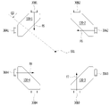
도 14a는 실시 예에 따른 제1 마그네트(130) 및 제2 코일(230)의 배치를 나타낸다.14A shows the arrangement of the
도 14a를 참조하면, 제1 마그네트(130)는 상면(3A), 상면(3A)의 반대면인 하면(3B), 및 상면(3A)과 하면(3B) 사이에 위치하는 측면(예컨대, 3C, 3D, 3E, 3F, 3G,3H)을 포함할 수 있다. 예컨대, 상면(3A)과 하면(3B)은 서로 평행할 수 있다.Referring to FIG. 14A , the
제1 마그네트(130)는 제1 코일(120)의 어느 한 면(또는 보빈(110)의 외측면)과 마주보는 제1면(3C) 및 제1면(3C)의 반대면인 제2면(3D)을 포함할 수 있다. 제2면(3D)은 제2 코일(230; 230-1 내지 230-4)에 대향하는 면일 수 있다. 예컨대, 제1면(3C1)과 제2면(3D1)은 서로 평행할 수 있다.The
예컨대, 제1 마그네트(130)는 제1면(3C)에서 제2면(3D)을 향하는 방향으로 갈수록 가로 방향의 길이(L1)가 감소하는 제1 부분(M1) 및 또한 제1 마그네트(130)는 제1면(3C)에서 제2면(3D)을 향하는 방향으로 갈수록 가로 방향의 길이(L2)가 증가하는 제2 부분(M2)을 포함할 수 있다. 예컨대, 가로 방향은 광축과 수직하고 제1면(3C)과 평행한 방향일 수 있다. 또는 가로 방향은 제1 마그네트(130)의 제1면(3C)과 평행하고, 제1 마그네트(130)의 상면(3A)에서 하면(3B)으로 향하는 방향과 수직한 방향일 수 있다.For example, the
즉, 제1 마그네트(130)는 제1면(3C)에서 제2면(3D)을 향하는 방향으로 갈수록 가로 방향의 길이가 증가하다가 감소할 수 있다.That is, the length of the
예컨대, 제2 부분(M2)은 제1 부분(M1)보다 제1 코일(120) 또는 보빈(110)에 더 가까울 수 있다. 또는 제1 부분(M1)은 제2 부분(M2)보다 제2 코일(230)에 더 가까울 수 있다.For example, the second part M2 may be closer to the
또는 예컨대, 제1 마그네트(130)의 제1 부분(M1)은 제2면(3D)을 포함하거나 또는 제2면(3C)에 접할 수 있다. 그리고 제1 마그네트(130)의 제2 부분(M2)은 제1면(3C)을 포함하거나 또는 제1면(3C)에 접할 수 있다.Alternatively, for example, the first portion M1 of the
예컨대, 제1 마그네트(130)는 제2면(3D)의 일측과 연결되는 제3면(3E), 제2면(3D)의 타측과 연결되는 제4면(3F), 제3면(3E)과 제1면(3C)의 일측을 연결하는 제5면(3G) 및 제4면(3F)과 제1면(3C)의 타측을 연결하는 제6면(3H)을 포함할 수 이다. 예컨대, 제3면(3E)과 제4면(3F)은 제1면(3C)(또는 제2면(3D))을 기준으로 서로 대칭적일 수 있고, 제5면(3G)과 제6면(3H)은 제1면(3C)(또는 제2면(3D))을 기준으로 서로 대칭적일 수 있다.For example, the
예컨대, 제1 마그네트(130)의 제1면(3C)의 면적은 제2면(3D)의 면적보다 클 수 있다. 예컨대, 제1 마그네트(130)의 제2면(3D)의 가로 방향의 길이는 제1면(3C)의 가로 방향의 길이보다 작을 수 있다. 예컨대, 제1 내지 제6면들(3C 내지 3H) 중에서 제1면(3C)의 면적이 제2 내지 제6면들(3D 내지 3H) 각각의 면적보다 클 수 있다.For example, the area of the
제1면(3C)에서 제2면(3D)을 향하는 방향으로 제1 마그네트(130)의 제1 부분(M1)의 가로 방향의 길이(L1)가 감소하는 이유는 제1 마그네트(130)가 하우징(140)의 코너부(142-1 내지 142-4)에 배치되기 때문이다.The reason why the length L1 in the transverse direction of the first part M1 of the
제1 마그네트(130)의 제2 부분(M2)의 길이가 증가하는 이유는 하우징(140)의 안착부(141a)에 배치된 제1 마그네트(130)가 하우징(140)의 내측으로 이탈되는 것을 방지하기 위함이다.The reason that the length of the second part M2 of the
또한 제2면(3D)에서 제1면(3C)을 향하는 방향으로 갈수록 제2 부분(M2)의 가로 방향의 길이(L2)가 감소하기 때문에, 제1 마그네트(130)와 제2 마그네트(180) 간의 자계 간섭 및 제1 마그네트(130)와 제3 마그네트(185) 간의 자계 간섭의 영향을 감소시킬 수 있다.In addition, since the length L2 in the horizontal direction of the second part M2 decreases in the direction from the
또한 제1면(3C)에서 제2면(3D)을 향하는 방향으로의 제1 마그네트(130)의 제2 부분(M2)의 길이(d2)는 제1면(3C)에서 제2면(3D)을 향하는 방향으로의 제1 마그네트(130)의 제1 부분(M1)의 길이(d1)보다 작을 수 있다(d2<d1).Also, the length d2 of the second part M2 of the
만약 d2>d1인 경우에는 제1 마그네트의 제1면의 면적이 감소할 수 있고, 이로 인하여 제1 코일(120)과 제1 마그네트 사이의 상호 작용에 의한 전자기력이 감소될 수 있고, AF 구동을 위하여 요구되는 전자기력을 확보할 수 없다.If d2>d1, the area of the first surface of the first magnet may be reduced, thereby reducing the electromagnetic force due to the interaction between the
도 14b는 다른 실시 예에 따른 제1 마그네트(130A) 및 제2 코일(230)의 배치를 나타낸다.14B shows the arrangement of the
도 14b를 참조하면, 제1 마그네트(130A)는 상면(3A1), 상면(3A1)의 반대면인 하면(3B1), 및 상면(3A1)과 하면(3B1) 사이에 위치하는 측면(예컨대, 3C1, 3D1, 3E1, 3F1)을 포함할 수 있다. 예컨대, 상면(3A1)과 하면(3B1)은 서로 평행할 수 있다.14B, the
예컨대, 제1 마그네트(130A)는 제1 코일(120)의 어느 한 면(또는 보빈(110)의 외측면)과 마주보는 제1면(3C1) 및 제1면(3C1)의 반대면인 제2면(3D1)을 포함할 수 있다. 제2면(3D1)은 제2 코일(230; 230-1 내지 230-4)에 대향하는 면일 수 있다. 예컨대, 제1면(3C1)과 제2면(3D1)은 서로 평행할 수 있다.For example, the
또한 제1 마그네트(130A)는 제1면(3C1)의 일측과 제2면(3D1)의 일측을 연결하는 제3면(3E1) 및 제1면(3C1)의 타측과 제2면(3D1)의 타측을 연결하는 제4면(3F1)을 포함할 수 있다.In addition, the
예컨대, 제1 마그네트(130A)의 제1면(3C1)의 면적은 제2면(3D1)의 면적보다 클 수 있다. 예컨대, 제1 마그네트(130A)의 제2면(3D1)의 가로 방향의 길이는 제1면(3C1)의 가로 방향의 길이보다 작을 수 있다. 예컨대, 제1 내지 제4면들(3C1 내지 3F1) 중에서 제1면(3C1)의 면적이 제2 내지 제4면들(3D1 내지 3F1) 각각의 면적보다 클 수 있다.For example, an area of the first surface 3C1 of the
예컨대, 제3면(3E1)과 제4면(3F1)은 제1면(3C)(또는 제2면(3D))을 기준으로 서로 대칭적일 수 있다.For example, the third surface 3E1 and the fourth surface 3F1 may be symmetrical to each other with respect to the
예컨대, 제1 마그네트(130A)는 제1면(3C1)에서 제2면(3D1)을 향하는 방향으로 갈수록 가로 방향의 길이가 감소하는 부분을 포함할 수 있다. 예컨대, 제1 마그네트(130A)의 가로 방향은 제1 마그네트(130)의 제1면(3C1)과 평행인 방향일 수 있다. 예컨대, 위에서 바라볼 때, 제1 마그네트(130A)는 사다리꼴 형상을 가질 수 있다.For example, the
제1 마그네트(130, 130A)는 한 몸으로 구성될 수 있으며, 제1 코일(120)을 마주보는 제1 마그네트(130)의 제1면(3C, 3C1)은 S극, 제2면(3D, 3D1)은 N극이 되도록 배치될 수 있다. 그러나 이를 한정하는 것은 아니며, 다른 실시 예에서는 제1 마그네트(130, 130A))의 제1면(3C, 3C1)은 N극, 제2면(3D, 3D1)은 S극이 될 수도 있다.The
제1 마그네트는 적어도 2개 이상이 서로 마주보도록 하우징(140)의 코너부들에 배치 또는 설치될 수 있다.At least two of the first magnets may be disposed or installed at the corners of the
예컨대, 교차하도록 서로 마주보는 2쌍의 제1 마그네트들이 하우징(140)의 코너부들(142-1 내지 142-4)에 배치될 수 있다. 예컨대, 위에서 바라볼 때, 제1 마그네트의 평면 형상은 삼각형, 오각형, 육각형, 또는 마름모 형상 등의 다각형일 수 있다.For example, two pairs of first magnets facing each other to cross may be disposed in the corner portions 142-1 to 142-4 of the
다른 실시 예에서는 서로 마주보는 한 쌍의 제1 마그네트들이 하우징(140)의 서로 마주보는 2개의 코너부들에만 배치될 수도 있다.In another embodiment, a pair of first magnets facing each other may be disposed only at two corners of the
제1 내지 제4 마그넷 유닛들(130-1 내지 130-4, 130A-1 내지 130A-4) 각각은 단극 착자 마그네트일 수 있으나, 이에 한정되는 것은 아니다. 다른 실시 예에서는 제1 마그네트들 각각은 2개의 N극과 2개의 S극을 포함하는 양극 착자 마그네트 또는 4극 마그네트일 수 있다.Each of the first to fourth magnet units 130-1 to 130-4 and 130A-1 to 130A-4 may be a unipolar magnetized magnet, but is not limited thereto. In another embodiment, each of the first magnets may be a positively polarized magnet or a four-pole magnet including two N poles and two S poles.
도 5는 도 2에 도시된 렌즈 구동 장치(100)의 AB 방향으로의 단면도이고, 도 6은 도 2에 도시된 렌즈 구동 장치(100)의 CD 방향으로의 단면도이고, 도 7은 도 2에 도시된 렌즈 구동 장치(100)의 EF 방향의 단면도이다.FIG. 5 is a cross-sectional view in the AB direction of the
도 5 내지 도 7을 참조하면, 광축(OA)과 수직한 방향(또는 광축과 수직하고 광축을 지나는 직선과 평행한 방향)으로 제2 및 제3 마그네트들(180, 185) 각각은 제1 코일(120)과 오버랩되지 않을 수 있으나, 이에 한정되는 것은 아니다. 다른 실시 예에서는 광축(OA)과 수직한 방향(또는 광축과 수직하고 광축을 지나는 직선과 평행한 방향)으로 제2 및 제3 마그네트들(180, 185) 각각의 적어도 일부는 제1 코일(120)과 오버랩될 수도 있다.5 to 7 , each of the second and
AF 가동부의 초기 위치에서, 광축(OA)과 수직한 방향, 또는 광축과 수직하고 광축을 지나는 직선과 평행한 방향으로 제1 마그네트(130)와 제1 코일(120)은 오버랩될 수 있다.At the initial position of the AF movable part, the
또한 AF 가동부의 초기 위치에서, 광축(OA)과 수직한 방향, 또는 광축과 수직하고 광축을 지나는 직선과 평행한 방향으로 제2 마그네트(180)는 제3 마그네트(185)에 오버랩되거나 정렬될 수 있으나, 이에 한정되는 것은 아니다.In addition, in the initial position of the AF movable part, the
또한 AF 가동부의 초기 위치에서, 광축(OA)과 수직한 방향, 또는 광축과 수직하고 광축을 지나는 직선과 평행한 방향으로 제1 위치 센서(170)는 제2 마그네트(180)와 제2 마그네트(185) 중 적어도 하나와 오버랩될 수 있다.In addition, in the initial position of the AF moving part, the
다른 실시 예에서는 제1 위치 센서(170)는 광축(OA)과 수직한 방향, 또는 광축과 수직하고 광축을 지나는 직선과 평행한 방향으로 제2 및 제3 마그네트들(180, 185) 중 적어도 하나와 오버랩되지 않을 수도 있다.In another embodiment, the
다음으로 회로 기판(190)과 제1 위치 센서(170)에 대하여 설명한다.Next, the
회로 기판(190)은 하우징(140)의 어느 한 측부(141-1)에 배치될 수 있고, 제1 위치 센서(170)는 회로 기판(190)에 배치 또는 실장될 수 있다. 예컨대, 회로 기판(190)은 하우징(140)의 장착홈(14a) 내에 배치될 수 있다.The
예컨대, 회로 기판(190)은 하우징(140)의 제1 코너부(142-1)와 제2 코너부(142-2) 사이에 배치될 수 있고, 회로 기판(190)의 제1 내지 제4 단자들(B1 내지 B4)은 제1 위치 센서(170)와 전기적으로 연결될 수 있다.For example, the
예컨대, 회로 기판(190)은 하우징(140)의 코너부(예컨대, 제1 코너부(142-1))(또는 코너)와 광축(OA)을 잇는 가상의 선과 오버랩되지 않을 수 있다. 이는 지지 부재(220)와 회로 기판(190) 간의 공간적 간섭을 방지하기 위함이다.For example, the
예컨대, 제1 위치 센서(170)는 홀 센서 단독으로 구현되거나 또는 홀 센서를 포함하는 드라이버 형태로 구현될 수 있다.For example, the
제1 위치 센서(170)가 홀 센서 단독일 경우에는 제1 위치 센서(170)는 2개의 입력 단자들과 2개의 출력 단자들을 포함할 수 있다. 2개의 입력 단자들에는 구동 신호 또는 전원 신호가 공급될 수 있고, 제1 위치 센서(170)의 출력 신호는 2개의 출력 단자들로 출력될 수 있다. 그리고 제1 위치 센서(170)의 2개의 입력 단자들과 2개의 출력 단자들은 제1 내지 제4 상부 탄성 유닛들(150-1 내지 150-4) 중 대응하는 어느 하나와 전기적으로 연결될 수 있다.When the
제1 위치 센서(170)가 드라이버 형태일 경우에는 제1 위치 센서(170)는 전원 신호들이 공급되기 위한 어느 2개의 단자들과 클럭 신호 및 데이터 신호를 송수신하기 위한 다른 2개의 단자들을 포함할 수 있고, 제1 코일(120)에 구동 신호를 제공하기 위한 또 다른 2개의 단자들을 포함할 수 있다.When the
도 8a는 회로 기판(190)과 제1 위치 센서(170)의 확대도이고, 도 8b는 도 8a에 도시된 제1 위치 센서(170)의 일 실시 예에 따른 구성도이다.8A is an enlarged view of the
도 8a 및 도 8b를 참조하면, 회로 기판(190)은 외부 단자 또는 외부 장치와 전기적으로 연결되기 위한 단자들(B1 내지 B6)을 구비할 수 있다.8A and 8B , the
제1 위치 센서(170)는 회로 기판(190)의 제1면(19b)에 배치될 수 있고, 단자들(B1 내지 B6)은 회로 기판(190)의 제2면(19a)에 배치될 수 있다.The
여기서 회로 기판(190)의 제2면(19a)은 회로 기판(190)의 제1면(19b)의 반대면일 수 있다. 예컨대, 회로 기판(190)의 제2면(19a)은 보빈(110)을 마주보는 회로 기판(190)의 어느 한 면일 수 있다.Here, the
회로 기판(190)은 몸체부(S1), 및 몸체부(S1) 아래에 위치하는 연장부(S2)를 포함할 수 있다. 몸체부(S1)는 "상단부"로 대체하여 표현될 수 있고, 연장부(S2)는 "하단부"로 대체하여 표현될 수도 있다.The
연장부(S2)는 몸체부(S1)에서 아래 방향으로 연장될 수 있다.The extension portion S2 may extend downward from the body portion S1 .
몸체부(S1)는 연장부(S2)의 측면(16a, 16b)을 기준으로 돌출된 형태일 수 있다. 예컨대, 연장부(S2)의 측면(16a, 16b)은 연장부(S2)의 제1면(19b)과 제2면(19a)을 연결하는 면일 수 있다.The body portion S1 may have a protruding shape based on the side surfaces 16a and 16b of the extension portion S2. For example, the side surfaces 16a and 16b of the extension portion S2 may be a surface connecting the
몸체부(S1)는 하우징(140)의 제1 코너부(142-1)를 향하는 방향으로 연장되는 제1 연장 영역(A1) 및 하우징(140)의 제2 코너부(142-2)를 향하는 방향으로 연장되는 제2 연장 영역(A2)을 포함할 수 있다. 예컨대, 제1 연장 영역(A1)은 연장부(S2)의 제1 측면(16a)으로부터 연장되거나 또는 돌출될 수 있고, 제2 연장 영역(A2)은 연장부(S2)의 제2 측면(16b)으로부터 연장되거나 또는 돌출될 수 있다.The body portion S1 has a first extension area A1 extending in a direction toward the first corner portion 142-1 of the
예컨대, 도 8a에서는 제1 연장 영역(A1)의 가로 방향의 길이는 제2 연장 영역(A2)의 가로 방향의 길이보다 크지만, 이에 한정되는 것은 아니며, 다른 실시 예에서는 제1 연장 영역(A1)의 가로 방향의 길이는 제2 연장 영역(A2)의 가로 방향의 길이와 동일하거나 또는 작을 수도 있다.For example, in FIG. 8A , the length of the first extension area A1 in the horizontal direction is greater than the length of the second extension area A2 in the horizontal direction, but the present invention is not limited thereto. ) may be equal to or smaller than the length of the second extension area A2 in the horizontal direction.
예컨대, 회로 기판(190)의 몸체부(S1)의 가로 방향의 길이는 연장부(S2)의 가로 방향의 길이보다 클 수 있다.For example, the length of the body portion S1 of the
예컨대, 회로 기판(190)의 제1 내지 제4 단자들(B1 내지 B4)은 몸체부(S1)의 제1면(19b)에 서로 이격되어 배치될 수 있다. 예컨대, 4개의 단자들(B1 내지 B4)은 회로 기판(190)의 가로 방향으로 일렬로 배열될 수 있다.For example, the first to fourth terminals B1 to B4 of the
제1 내지 제4 단자들(B1 내지 B4)은 회로 기판(190)의 하면보다 상면(19c)에 더 인접하여 위치하도록 배치될 수 있다. 예컨대, 제1 내지 제4 단자들(B1 내지 B4)은 회로 기판(190)의 제2면(19a) 및 제2면(19a)에 접하는 회로 기판(190)의 몸체부(S1)의 상면(19c)에 접하도록 형성될 수 있다.The first to fourth terminals B1 to B4 may be disposed to be positioned closer to the
또한 예컨대, 제1 내지 제4 단자들(B1 내지 B4) 중 적어도 하나는 회로 기판(190)의 상면(19c)에 형성되는 홈(7a) 또는 비아(via)를 포함할 수 있다. 이러한 홈(7a)에 의하여 납땜과 단자들(B3, B4) 간의 접촉 면적으로 증가시켜 접착력과 납땜성을 향상시킬 수 있다.Also, for example, at least one of the first to fourth terminals B1 to B4 may include a
회로 기판(190)의 제5 단자(B5)와 제6 단자(B6)는 회로 기판(190)의 연장부(S2)의 제2면(19a)에 서로 이격되어 배치될 수 있다.The fifth terminal B5 and the sixth terminal B6 of the
회로 기판(190)은 제5 단자(B5)와 제6 단자(B6) 사이에 마련되는 홈(8a) 또는 홀을 구비할 수 있다. 홈(8a)은 회로 기판(190)의 하면으로부터 함몰된 형태일 수 있고, 회로 기판(190)의 제1면(19b)과 제2면(19a)으로 모두 개방될 수 있다.The
외부와의 전기적 연결을 위한 납땜시, 홈(8a)에 의하여 제5 단자(B5)와 제6 단자(B6) 사이에는 납땜이 형성되지 않도록 함으로써, 제5 단자(B5)와 제6 단자(B6) 간의 전기적 단락을 방지할 수 있다.When soldering for electrical connection to the outside, solder is not formed between the fifth terminal B5 and the sixth terminal B6 by the
또한 예컨대, 제5 및 제6 단자들(B5, B6) 중 적어도 하나는 회로 기판(190)의 하면에 형성되는 홈(7b) 또는 비아(via)를 포함할 수 있다. 이러한 홈(7b)에 의하여 납땜과 제5 및 제6 단자들(B5,B6) 간의 접촉 면적으로 증가시켜 접착력과 납땜성을 향상시킬 수 있다.Also, for example, at least one of the fifth and sixth terminals B5 and B6 may include a
회로 기판(190)은 제2 단자(B2)와 제3 단자(B3) 사이에 배치되는 홈(90a), 및 제1 단자(B1)와 제4 단자(B4) 사이에 배치되는 홈(90b)을 구비할 수 있다. 여기서 홈(90a, 90b)은 "도피홈"으로 대체하여 표현될 수 있다.The
제1홈(90a)과 제2홈(90b) 각각은 회로 기판(190)의 상면(19c)으로부터 함몰된 형태일 수 있고, 회로 기판(190)의 제1면(19b)과 제2면(19a) 모두로 개방될 수 있다.Each of the
회로 기판(190)의 제1홈(90a)은 제3 상부 탄성 유닛(150-3)의 제1 외측 프레임(151)과의 공간적 간섭을 피하기 위하여 형성될 수 있고, 회로 기판(190)의 제2홈(90b)은 제4 상부 탄성 유닛(150-4)의 제1 외측 프레임(151)과의 공간적 간섭을 피하기 위하여 형성될 수 있다.The
예컨대, 회로 기판(190)는 인쇄 회로 기판, 또는 FPCB일 수 있다.For example, the
회로 기판(190)은 제1 내지 제6 단자들(B1 내지 B6)과 제1 위치 센서(170)를 전기적으로 연결하기 위한 회로 패턴 또는 배선(미도시)을 포함할 수 있다.The
제1 위치 센서(170)는 보빈(110)의 이동에 따라 보빈(110)에 장착된 제2 마그네트(180)의 자기장 또는 자기장의 세기를 감지할 수 있고, 감지된 결과에 따른 출력 신호를 출력할 수 있다.The
제1 위치 세너(170)는 하우징(140)에 배치 또는 결합될 수 있다.The
예컨대, 제1 위치 센서(170)는 하우징(140)에 배치되는 회로 기판(190)에 장착될 수 있고, 하우징(140)에 고정될 수 있다. 예컨대, 제1 위치 센서(170)는 하우징(190)의 장착홈(14b) 내에 배치될 수 있고, 손떨림 보정시 하우징(140)과 함께 이동할 수 있다.For example, the
제1 위치 센서(170)는 회로 기판(190)의 제1면(19b)에 배치될 수 있다. 다른 실시 예에서는 제1 위치 센서(170)는 회로 기판(190)의 제2면(19a)에 배치될 수도 있다.The
제1 위치 센서(170)는 홀 센서(Hall sensor, 61A), 및 드라이버(Driver, 62A)를 포함할 수 있다.The
예컨대, 홀 센서(61A)는 실리콘 계열로 이루어질 수 있으며, 주위 온도가 증가할수록 홀 센서(61A)의 출력(VH1)은 증가할 수 있다. 예컨대, 주위 온도는 렌즈 구동 장치의 온도, 예컨대, 회로 기판(190)의 온도, 홀 센서(61A)의 온도, 또는 드라이버(62A)의 온도일 수 있다.For example, the
또한 다른 실시 예에서 홀 센서(61A)는 GaAs로 이루어질 수 있으며, 주위 온도에 대하여 홀 센서(61A)의 출력(VH)은 감소할 수 있다. 예컨대, 다른 실시 예에서는 홀 센서(61A)의 출력은 주위 온도에 대하여 약 -0.06%/℃의 기울기를 가질 수 있다.Also, in another embodiment, the
제1 위치 센서(170)는 주위 온도를 감지할 수 있는 온도 센싱 소자(63A)를 더 포함할 수도 있다. 온도 센싱 소자(63A)는 제1 위치 센서(170A) 주위의 온도를 측정한 결과에 따른 온도 감지 신호(Ts1)를 드라이버(62A)로 출력할 수 있다.The
예컨대, 제1 위치 센서(190)의 홀 센서(61A)는 제2 마그네트(180)의 자기력의 세기를 감지한 결과에 따른 출력(VH1)을 발생할 수 있다. 예컨대, 제1 위치 센서(190)의 출력의 크기는 제2 마그네트(180)의 자기력의 세기에 비례할 수 있다.For example, the
드라이버(62A)는 홀 센서(61A)를 구동하기 구동 신호(dV1), 및 제1 코일(120)을 구동하기 위한 구동 신호(Id1)를 출력할 수 있다.The
예컨대, 프토토콜(protocol)을 이용한 데이터 통신, 예컨대, I2C 통신을 이용하여 드라이버(62A)는 제어부(830 또는 780)로부터 클럭 신호(SCL), 데이터 신호(SDA), 전원 신호(VDD, GND)를 수신할 수 있다.For example, using data communication using a protocol, for example, I2C communication, the
여기서 제1 전원 신호(GND)는 그라운드 전압 또는 0[V]일 수 있고, 제2 전원 신호(VDD)는 드라이버(62)를 구동하기 위한 기설정된 전압일 수 있고, 직류 전압 또는/및 교류 전압일 수 있으나, 이에 한정되는 것은 아니다.Here, the first power signal GND may be a ground voltage or 0 [V], and the second power signal VDD may be a preset voltage for driving the
또한 드라이버(62A)는 홀 센서(61A)의 출력(VH1)을 수신하고, 프로토콜(protocol)을 이용한 데이터 통신, 예컨대, I2C 통신을 이용하여, 홀 센서(61A)의 출력(VH1)과 관련된 클럭 신호(SCL) 및 데이터 신호(SDA)를 제어부(830, 또는 780)로 전송할 수 있다.In addition, the
또한 드라이버(62A)는 온도 센싱 소자(63A)가 측정한 온도 감지 신호(Ts1)를 수신하고, 프토토콜(protocol)을 이용한 데이터 통신, 예컨대, I2C 통신을 이용하여 온도 감지 신호(Ts1)를 제어부(830, 또는 780)로 전송할 수 있다.In addition, the
예컨대, 드라이버(62A)는 홀 센서(61A)의 출력(VH1)을 수신하고, 제어 신호에 기초하여 수신된 홀 센서(61A)의 출력(VH1)을 증폭하여 출력하는 증폭기를 더 포함할 수 있다. 예컨대, 증폭기는 제어 신호에 의하여 이득이 가변될 수 있는 가변 이득 증폭기일 수 있다.For example, the
또한 예컨대, 드라이버(62A)는 증폭기의 출력을 아날로그-디지털 변환하고, 디지털 신호를 출력하는 아날로그-디지털 변환기를 더 포함할 수 있다. 드라이버(62A)는 외부의 호스트(Host)와 프토토콜(protocol)을 이용한 데이터 통신, 예컨대, I2C 통신을 수행할 수 있고, 클럭 신호(SCL) 및 데이터 신호(SDA)를 송수신할 수 있는 인터페이스부를 더 포함할 수 있다.Also, for example, the
예컨대, 드라이버(62A)는 가동부(예컨대, 보빈(110))의 변위에 관한 제1 위치 센서(170)의 초기 레지스터 설정값, 및 캘큘레이션(calculation) 값이 저장된 메모리, 예컨대, EEPROM을 더 포함할 수 있다. 드라이버(62A)는 증폭기의 이득을 제어하는 제어 신호를 생성하는 논리 제어부를 더 포함할 수 있다. 드라이버(62A)는 아날로그-디지털 변환기의 출력에 대하여 위상 보상(phase compensation), 또는/및 이득 보상(Gain compensation)을 하기 위한 PID 제어기(Proportional-Integral-Derivative controller)를 더 포함할 수 있다. 또한 논리 제어부는 PID 제어기의 위상 또는/및 이득 보상을 제어할 수 있다. 또한 드라이버(62A)는 PID 제어기의 출력에 기초하여 구동 신호(Id1)를 생성하는 구동 신호 생성부를 더 포함할 수 있다.For example, the
제어부(830, 또는 780)는 제1 위치 센서(170)의 온도 센싱 소자(63A)에 의하여 측정된 주위 온도 변화에 기초하여 홀 센서(61A)의 출력(VH1)에 대한 온도 보상을 수행할 수 있다.The
제1 위치 센서(170)는 전원 신호(VDD, GND), 클럭 신호(SCL), 및 데이터(SDA)를 위한 제1 내지 제4 단자들(N1 내지 N4), 및 제1 코일(120)에 구동 신호(Id1)를 제공하기 위한 제5 및 제6 단자들(N5,N6)을 포함할 수 있다.The
제1 위치 센서(170)의 제1 내지 제4 단자들(N1 내지 N4)은 회로 기판(190)의 제1 내지 제4 단자들(B1 내지 B4) 중 대응하는 어느 하나와 전기적으로 연결될 수 있고, 제1 위치 센서(170)의 제5 및 제6 단자들(N5,,N6)은 회로 기판(190)의 제5 및 제6 단자들(B5, B6) 중 대응하는 어느 하나와 전기적으로 연결될 수 있다.The first to fourth terminals N1 to N4 of the
회로 기판(190)의 제1 내지 제6 단자들(B1 내지 B6) 각각은 상부 탄성 부재(150)(또는/및 하부 탄성 부재(160)), 및 지지 부재(220)에 의하여 회로 기판(250)의 단자들(21-1 내지 21-n) 중 대응하는 어느 하나와 전기적으로 연결될 수 있다.Each of the first to sixth terminals B1 to B6 of the
예컨대, 회로 기판(190)의 제1 내지 제4 단자들(B1 내지 B4) 각각은 상부 탄성 유닛들(150-1 내지 150-4) 및 지지 부재들(220-1 내지 220-4)과 전기적으로 연결될 수 있고, 이로 인하여 제1 위치 센서(170)의 제1 내지 제4 단자들(B1 내지 B4) 각각은 회로 기판(250)의 단자들(21-1 내지 21-n, 예컨대, n=4) 중 대응하는 어느 하나와 전기적으로 연결될 수 있다.For example, each of the first to fourth terminals B1 to B4 of the
또한 예컨대, 회로 기판(190)의 제5 및 제6 단자들(B5, B6)은 하부 탄성 유닛들(160-1, 160-2)과 전기적으로 연결될 수 있고, 하부 탄성 유닛들(160-1, 160-2)에 의하여 제1 위치 센서(170)의 제5 및 제6 단자들(B5,B6)은 제1 코일(120)과 전기적으로 연결될 수 있다.Also, for example, the fifth and sixth terminals B5 and B6 of the
예컨대, 회로 기판(190)의 제5 단자(B5)는 제1 하부 탄성 유닛(160-1)에 결합될수 있고, 회로 기판(190)의 제6 단자(B6)는 제2 하부 탄성 유닛(160-2)에 결합될 수 있다For example, the fifth terminal B5 of the
다음으로 상부 탄성 부재(150), 하부 탄성 부재(160), 및 지지 부재(220)에 대하여 설명한다. 상부 탄성 부재(150) 및 하부 탄성 부재(160)는 보빈을 지지하는 탄성 부재를 구성할 수 있다.Next, the upper
도 9a는 도 1에 도시된 상부 탄성 부재(150)를 나타내고, 도 9b는 도 1에 도시된 하부 탄성 부재(160)를 나타내고, 도 10은 상부 탄성 부재(150), 하부 탄성 부재(160), 베이스(210), 지지 부재(220), 회로 기판(250), 및 제2 위치 센서(240)의 결합 사시도를 나타내고, 도 11a는 회로 기판(190)의 제1 내지 제4 단자들(B1 내지 B4)과 상부 탄성 유닛들(150-1 내지 150-4) 간의 결합을 나타내고, 도 11b는 회로 기판(190)의 제5 및 제6 단자들(B5, B6)과 하부 탄성 유닛(160-1, 160-2)의 저면도이고, 도 12는 베이스(210), 회로 기판(250), 지지 부재(220-1 내지 220-4) 및 제2 위치 센서(240)의 분리 사시도이고, 도 13은 제1 마그네트(130), 제2 코일(230), 회로 기판(310), 및 커버 부재(300)의 저면도이고, 도 14a는 실시 예에 따른 제1 마그네트(130) 및 제2 코일(230)의 배치를 나타내고, 도 14b는 다른 실시 예에 따른 제1 마그네트(130A) 및 제2 코일(230)의 배치를 나타내고, 도 15는 렌즈 구동 장치(100)의 저면도이고, 도 16은 하우징(140)의 어느 한 코너부에 배치된 제1 마그넷 유닛(130-1), 제1 마그넷 유닛(130-1)에 대응되는 제2 코일 유닛(230-1), 및 제1 지지 부재(220-1)의 저면도이고, 도 17a는 회로 기판(310), 제2 코일 유닛들(230-1 내지 230-4), 지지 부재(220), 및 회로 기판(250)의 제1 사시도이고, 도 17b는 회로 기판(310), 제2 코일 유닛들(230-1 내지 230-4), 지지 부재(220), 및 회로 기판(250)의 제2 사시도이다.FIG. 9A shows the upper
도 9a 내지 도 17b를 참조하면, 상부 탄성 부재(150)는 보빈(110)의 상부, 상단, 또는 상면과 결합될 수 있고, 하부 탄성 부재(160)는 보빈(110)의 하부, 하단, 또는 하면과 결합될 수 있다.Referring to FIGS. 9A to 17B , the upper
예컨대, 상부 탄성 부재(150)는 보빈(110)의 상부, 상단, 또는 상면과 하우징(140)의 상부, 상단, 또는 상면과 결합될 수 있고, 하부 탄성 부재(160)는 보빈(110)의 하부, 하단, 또는 하면과 하우징(140)의 하부, 하단, 또는 하면과 결합될 수 있다.For example, the upper
상부 탄성 부재(150) 및 하부 탄성 부재(160)는 하우징(140)에 대하여 보빈(110)을 탄성 지지할 수 있다.The upper
지지 부재(220)는 하우징(140)을 베이스(210)에 대하여 광축과 수직인 방향으로 이동 가능하게 지지할 수 있고, 상부 탄성 부재(150)와 회로 기판(250)을 전기적으로 연결할 수 있다.The
도 9a를 참조하면, 상부 탄성 부재(150)는 서로 전기적으로 분리된 복수의 상부 탄성 유닛들(150-1 내지 150-4)을 포함할 수 있다. 도 9a에서는 전기적으로 분리된 4개의 상부 탄성 유닛들을 도시하나, 그 개수가 이에 한정되는 것은 아니며, 2개 이상일 수도 있다.Referring to FIG. 9A , the upper
상부 탄성 부재(150)는 회로 기판(190)의 제1 내지 제4 단자들(B1 내지 B4)과 직접 본딩되어 전기적으로 연결되는 제1 내지 제4 상부 탄성 유닛들(150-1 내지 150-4)을 포함할 수 있다.The upper
예컨대, 회로 기판(190)이 배치된 하우징(140)의 제1 측부(141-1)에 복수 개의 상부 탄성 유닛들 각각의 일부가 배치될 수 있고, 하우징(140)의 제1 측부(141-1)를 제외한 나머지인 제2 내지 제4 측부들(141-2 내지 141-4) 각각에 적어도 하나의 상부 탄성 유닛이 배치될 수 있다.For example, a portion of each of the plurality of upper elastic units may be disposed on the first side portion 141-1 of the
제1 내지 제4 상부 탄성 유닛들(150-1 내지 150-4) 각각은 하우징(140)과 결합되는 제1 외측 프레임(152)을 포함할 수 있다.Each of the first to fourth upper elastic units 150 - 1 to 150 - 4 may include a first outer frame 152 coupled to the
제1 내지 제4 상부 탄성 유닛들(150-1 내지 150-4) 중 적어도 하나는 보빈(110)과 결합되는 제1 내측 프레임(151) 및 제1 내측 프레임(151)과 제1 외측 프레임(152)을 연결하는 제1 프레임 연결부(153)를 더 포함할 수 있다.At least one of the first to fourth upper elastic units 150-1 to 150-4 includes a first
예컨대, 도 9a의 실시 예에서는 제1 및 제2 상부 탄성 유닛들(150-1, 150-2) 각각은 제1 외측 프레임만을 구비하고, 제1 내측 프레임 및 제1 프레임 연결부는 구비하지 않을 수 있고, 제1 및 제2 상부 탄성 유닛들(150-1, 150-2) 각각은 보빈(110)으로부터 이격될 수 있다.For example, in the embodiment of FIG. 9A , each of the first and second upper elastic units 150-1 and 150-2 may include only the first outer frame, and may not include the first inner frame and the first frame connection unit. And, each of the first and second upper elastic units 150 - 1 and 150 - 2 may be spaced apart from the
예컨대, 제3 및 제4 상부 탄성 유닛들(150-3, 150-4) 각각은 제1 내측 프레임(151), 제1 외측 프레임, 및 제1 프레임 연결부(153)를 포함할 수 있으나, 이에 한정되는 것은 아니다.For example, each of the third and fourth upper elastic units 150 - 3 and 150 - 4 may include a first
예컨대, 제3 및 제4 상부 탄성 유닛들(150-3, 150-4)의 제1 내측 프레임(151)에는 보빈(110)의 제1 결합부(113)와 결합되기 위한 홀(151a)이 마련될 수 있으나, 이에 한정되는 것은 아니다. 예컨대, 제1 내측 프레임(151)의 홀(152a)은 보빈(110)의 제1 결합부(113)과 홀(151a) 사이에 접착 부재가 스며들기 위한 적어도 하나의 절개부(51a)를 가질 수 있다.For example, in the first
제1 내지 제4 상부 탄성 부재들(150-1 내지 150-4)의 제1 외측 프레임(152)에는 하우징(140)의 제1 결합부(143)와 결합되기 위한 홀(152a)이 마련될 수 있다.The first outer frame 152 of the first to fourth upper elastic members 150-1 to 150-4 may be provided with a
제1 내지 제4 상부 탄성 유닛들(150-1 내지 150-4) 각각의 제1 외측 프레임(151)은 하우징(140)과 결합되는 몸체부, 및 회로 기판(190)의 제1 내지 제4 단자들(B1 내지 B4) 중 대응하는 어느 하나와 연결되는 연결 단자(P1 내지 P4)를 포함할 수 있다. 여기서 연결 단자(P1 내지 P4)는 "연장부"로 대체하여 표현될 수도 있다.The first to fourth upper elastic units 150-1 to 150-4, the first
제1 내지 제4 상부 탄성 유닛들(150-1 내지 150-4) 각각은 하우징(140)과 결합되는 제1 결합부(520), 지지 부재들(220-1 내지 220-4) 중 대응하는 어느 하나와 결합되는 제2 결합부(510), 제1 결합부(520)와 제2 결합부(510)를 연결하는 연결부(530), 및 제2 결합부(510)와 연결되고 하우징(140)의 제1 측부(141-1)로 확장되는 연장부(P1 내지 P4)를 포함할 수 있다. 예컨대, 제1 외측 프레임(152)은 제1 결합부(520), 제2 결합부(510), 및 연결부(530)를 포함할 수 있다.Each of the first to fourth upper elastic units 150-1 to 150-4 has a corresponding one of the
제1 내지 제4 상부 탄성 유닛들(150-1 내지 150-4) 각각의 몸체부는 제1 결합부(520)를 포함할 수 있다. 또한 제1 내지 제4 상부 탄성 유닛들(150-1 내지 150-4) 각각의 몸체부는 제2 결합부(510) 및 연결부(530) 중 적어도 하나를 더 포함할 수 있다.The body portion of each of the first to fourth upper elastic units 150 - 1 to 150 - 4 may include a
예컨대, 솔더 또는 전도성 접착 부재에 의하여 제1 지지 부재(220-1)의 일단은 제1 상부 탄성 유닛(150-1)의 제2 결합부(510)와 결합될 수 있고, 제2 지지 부재(220-2)의 일단은 제2 상부 탄성 유닛(150-1)의 제2 결합부(510)와 결합될 수 있고, 제3 지지 부재(220-3)의 일단은 제3 상부 탄성 유닛(150-3)의 제2 결합부(510)와 결합될 수 있고, 제4 지지 부재(220-4)의 일단은 제4 상부 탄성 유닛(150-4)의 제2 결합부(510)와 결합될 수 있다.For example, one end of the first support member 220-1 may be coupled to the
제2 결합부(510)는 지지 부재(220-1 내지 220-4)가 통과하는 홀(52)을 구비할 수 있다. 홀(52)을 통과한 지지 부재(220-1 내지 220-4)의 일단은 전도성 접착 부재 또는 솔더(910, 도 10 참조)에 의하여 제2 결합부(510)에 직접 결합될 수 있고, 제2 결합부(510)와 지지 부재(220-1 내지 220-4)는 전기적으로 연결될 수 있다.The
예컨대, 제2 결합부(510)는 지지 부재(220-1 내지 220-4)와의 결합을 위하여 솔더(910)가 배치되는 영역으로서, 홀(52) 및 홀(52) 주위의 일 영역을 포함할 수 있다.For example, the
제1 결합부(520)는 하우징(140)(예컨대, 코너부(142-1 내지 142-4))와 결합되는 적어도 하나의 결합 영역(예컨대, 5a, 5b)을 포함할 수 있다.The
예컨대, 제1 결합부(520)의 결합 영역(예컨대, 5a, 5b)은 하우징(140)의 제1 결합부(143)와 결합되는 적어도 하나의 홀(152a)을 포함할 수 있다. 예컨대, 결합 영역들(5a, 5b) 각각은 1개 이상의 홀을 구비할 수 있다.For example, the coupling regions (eg, 5a and 5b) of the
예컨대, 하우징(140)을 어느 한쪽으로 치우지 않도록 균형있게 지지하기 위하여 제1 내지 제4 상측 탄성 유닛들(150-1 내지 150-4)의 제1 결합부(520)의 결합 영역들(5a, 5b)은 기준선(예컨대, 501, 502)을 기준으로 좌우대칭일 수 있으나, 이에 한정되는 것은 아니다.For example, the
또한 하우징(140)의 제1 결합부들(143)은 기준선(예컨대, 501, 502)을 기준으로 좌우 대칭일 수 있고, 기준선 양측 각각에 2개가 마련될 수 있으나, 그 수가 이에 한정되는 것은 아니다.In addition, the
기준선(501, 502)은 중심점(101)과 하우징(140)의 코너부들(142-1 내지 142-4)의 모서리들 중 어느 하나를 지나는 직선일 수 있다. 예컨대, 기준선(501, 502)은 중심점(101)과 하우징(140)의 코너부들(142-1 내지 142-4)의 모서리들 중 하우징(140)의 대각선 방향으로 서로 마주보는 2개의 모서리를 지나는 직선일 수 있다.The reference lines 501 and 502 may be straight lines passing through the
여기서 중심점(101)은 하우징(140)의 중앙, 보빈(110)의 중앙, 또는 상부 탄성 부재(150)의 중앙일 수 있다. 또한, 예컨대, 하우징(140)의 코너부의 모서리는 하우징(140)의 코너부의 중앙에 정렬 또는 대응되는 모서리일 수 있다.Here, the
도 9a의 실시 예에서 제1 결합부(520)의 결합 영역들(5a, 5b) 각각은 홀(152a)을 포함하도록 구현되나, 이에 한정되는 것은 아니며, 다른 실시 예에서 결합 영역들은 하우징(140)과 결합하기 충분한 다양한 형태, 예컨대, 홈 형태 등으로 구현될 수도 있다.In the embodiment of FIG. 9A , each of the
예컨대, 제1 결합부(520)의 홀(152a)은 하우징(140)의 제1 결합부(143)과 홀(152a) 사이에 접착 부재가 스며들기 위한 적어도 하나의 절개부(52a)를 가질 수 있다.For example, the
연결부(530)는 제2 결합부(510)와 제1 결합부(520)를 서로 연결할 수 있다.The
예컨대, 연결부(530)는 제2 결합부(510)와 제1 결합부(520)의 결합 영역(5a, 5b)을 연결할 수 있다.For example, the
예컨대, 연결부(530)는 제1 내지 제4 상측 탄성 유닛들(150-1 내지 150-4) 각각의 제1 결합부(520)의 제1 결합 영역(5a)과 제2 결합부(510)를 연결하는 제1 연결부(530a), 및 제1 결합부(520)의 제2 결합 영역(5b)과 제2 결합부(510)를 연결하는 제2 연결부(530b)를 포함할 수 있다.For example, the
예컨대, 제1 외측 프레임(151)은 제1 결합 영역(5a)과 제2 결합 영역(5b)을 직접 연결하는 연결 영역을 포함할 수 있으나, 이에 한정되는 것은 아니다.For example, the first
제1 및 제2 연결부들(530a, 530b) 각각은 적어도 한 번 절곡되는 절곡부 또는 적어도 한 번 휘어지는 곡선부를 포함할 수 있으나, 이에 한정되는 것은 아니며, 다른 실시 예에서는 직선 형태를 포함할 수도 있다.Each of the first and
연결부(530)의 폭은 제1 결합부(520)의 폭보다 작을 수 있다. 또한 연결부(530)의 폭은 제1 결합부의 폭(또는 직경)보다 작을 수 있다. 다른 실시 예에서는 연결부(530)의 폭은 제1 결합부(520)의 폭과 동일할 수도 있고, 제1 결합부의 폭(또는 직경)과 동일할 수도 있다.The width of the
예컨대, 제1 결합부(520)는 하우징(140)의 코너부들(142-1 내지 142-4)의 상면과 접촉할 수 있고, 하우징(140)의 코너부들(142-1 내지 142-4)에 의하여 지지될 수 있다. 예컨대, 연결부(530)는 하우징(140)의 상면에 의해 지지되지 않으며, 하우징(140)으로부터 이격될 수 있다. 또한 진동에 의한 발진을 방지하기 위하여 댐퍼(damper, 미도시)는 연결부(530)와 하우징(140) 사이에는 배치될 수 있고, 연결부(530)와 하우징(140)에 결합 또는 부착될 수 있다.For example, the
제1 및 제2 연결부들(530a, 530b) 각각의 폭은 제1 결합부(520)의 폭보다 좁을 수 있으며, 이로 인하여 연결부(530)는 제1 방향으로 움직임이 용이할 수 있고, 이로 인하여 상부 탄성 유닛들(150-1 내지 150-4)에 인가되는 응력, 및 지지 부재들(220-1 내지 220-4)에 인가되는 응력을 분산시킬 수 있다.The width of each of the first and
예컨대, 제1 및 제2 상부 탄성 유닛들(150-1, 150-2)의 제1 외측 프레임들의 제1 및 제2 연장부들(P1, P2) 각각은 제1 결합부(520)(예컨대, 제1 결합 영역(5a))으로부터 하우징(140)의 제1 측부(141-1)에 위치한 회로 기판(190)의 제1 및 제2 단자들(B1, B2) 중 대응하는 어느 하나를 향하여 연장될 수 있다.For example, each of the first and second extensions P1 and P2 of the first outer frames of the first and second upper elastic units 150-1 and 150-2 is a first coupling portion 520 (eg, extending from the
제3 상부 탄성 유닛(150-3)의 제1 결합부(520)는 하우징(140)의 제4 측부(141-4) 및 제2 코너부(142-2) 중 적어도 하나와 연결되는 적어도 하나의 결합 영역(6a, 6b)을 더 포함할 수 있다.The
또한 제4 상부 탄성 유닛(150-4)의 제1 결합부(520)는 하우징(140)의 제2 측부(141-2) 및 제1 코너부(142-1) 중 적어도 하나와 연결되는 적어도 하나의 결합 영역(6c, 6d)을 더 포함할 수 있다.In addition, the
제3 및 제4 상부 탄성 유닛들(150-3, 150-4)의 제1 외측 프레임들의 제3 및 제4 연장부들(P3, P4) 각각은 제1 결합부(520)(예컨대, 결합 영역(6b, 6d))로부터 하우징(140)의 제1 측부(141-1)에 위치한 회로 기판(190)의 제3 및 제4 단자들(B3, B4) 중 대응하는 어느 하나를 향하여 연장될 수 있다.Each of the third and fourth extensions P3 and P4 of the first outer frames of the third and fourth upper elastic units 150-3 and 150-4 is a first coupling part 520 (eg, a coupling region). (6b, 6d) may extend toward a corresponding one of the third and fourth terminals B3 and B4 of the
제1 내지 제4 연장부들(P1 내지 P4) 각각의 일단은 납땜 또는 도전성 접착 부재에 의하여 회로 기판(190)의 제1 내지 제4 단자들(B1 내지 B4) 중 대응하는 어느 하나에 결합될 수 있고, 전기적으로 연결될 수 있다.One end of each of the first to fourth extensions P1 to P4 may be coupled to a corresponding one of the first to fourth terminals B1 to B4 of the
예컨대, 제1 및 제2 연장부들(P1, P2) 각각은 직선 형태의 라인 형상일 수 있으나, 이에 한정되는 것은 아니며, 다른 실시 에에서는 직선 및 곡선 중 적어도 하나를 포함할 수도 있다.For example, each of the first and second extension parts P1 and P2 may have a straight line shape, but is not limited thereto, and may include at least one of a straight line and a curved line in another embodiment.
회로 기판(190)의 제3 및 제4 단자들(B3, B4) 중 대응하는 어느 하나와 결합을 용이하게 하기 위하여, 제3 및 제4 연장부들(P3, P4)은 절곡되거나 또는 휘어진 부분을 포함할 수 있다.In order to facilitate coupling with a corresponding one of the third and fourth terminals B3 and B4 of the
제3 상부 탄성 유닛(150-3)의 제1 외측 프레임은 제1 결합부(520)와 연장부(P3) 사이에 연결되고, 하우징(140)의 제4 측부(141-4)와 제4 코너부(142-4)에 위치하는 제1 연장 프레임(154-1)을 더 포함할 수 있다.The first outer frame of the third upper elastic unit 150-3 is connected between the
하우징(140)과의 결합력을 강화하여 제3 상부 탄성 유닛(150-3)이 들뜨는 것을 방지하기 위하여, 제1 연장 프레임(154-1)은 하우징(140)과 결합되는 적어도 하나의 결합 영역(6a, 6b)을 포함할 수 있으며, 결합 영역(6a, 6b)은 하우징(140)의 제1 결합부(143)와 결합되기 위한 홀을 구비할 수 있다.In order to prevent lifting of the third upper elastic unit 150-3 by strengthening the coupling force with the
제4 상부 탄성 유닛(150-4)의 제1 외측 프레임은 제1 결합부(520)와 연장부(P4) 사이에 연결되고, 하우징(140)의 제2 측부(141-2)와 제1 코너부(142-1)에 위치하는 제2 연장 프레임(154-2)을 더 포함할 수 있다.The first outer frame of the fourth upper elastic unit 150-4 is connected between the
하우징(140)과의 결합력을 강화하여 제4 상부 탄성 유닛(150-4)이 들뜨는 것을 방지하기 위하여, 제2 연장 프레임(154-2)은 하우징(140)과 결합되는 적어도 하나의 결합 영역(6c, 6d)을 포함할 수 있으며, 결합 영역(6c, 6d)은 하우징(140)의 제1 결합부(143)와 결합되기 위한 홀을 구비할 수 있다.In order to prevent lifting of the fourth upper elastic unit 150-4 by strengthening the coupling force with the
도 9a에서는 제3 상부 탄성 유닛(150-3) 및 제4 상부 탄성 유닛(150-4) 각각은 2개의 제1 프레임 연결부들을 포함하지만, 이에 한정되는 것은 아니며, 제1 프레임 연결부의 개수는 1개 또는 3개 이상일 수 있다.9A, each of the third upper elastic unit 150-3 and the fourth upper elastic unit 150-4 includes two first frame connection parts, but is not limited thereto, and the number of the first frame connection part is 1 It may be a dog or three or more.
상술한 바와 같이, 제1 내지 제4 상부 탄성 유닛들 각각은 하우징(140)의 제1 측부(141-1) 상에 배치된 연장부(P1 내지 P4)를 포함할 수 있으며, 연장부(P1 내지 P4)에 의하여 회로 기판(190)의 몸체부(S1)에 마련된 제1 내지 제4 단자들(B1 내지 B4)에 상부 탄성 유닛들(150-1 내지 150-4)이 용이하게 결합될 수 있다.As described above, each of the first to fourth upper elastic units may include extension portions P1 to P4 disposed on the first side portion 141-1 of the
하우징(140)의 제1 측부(141-1)에 배치되는 회로 기판(190)의 몸체부(S1)에 마련된 4개의 단자들(B1 내지 B4)이 제1 내지 제4 상부 탄성 유닛들(150-1 내지 150-4)과 전기적으로 직접 연결되는 구조이기 때문에, 하우징(140)의 제1 측부(141-1)에 제1 내지 제4 상부 탄성 유닛들(150-1 내지 150-4)의 각각의 제1 외측 프레임(151)의 일부가 배치될 수 있다.The four terminals B1 to B4 provided on the body portion S1 of the
상부 탄성 유닛들(150-1 내지 150-4) 각각은 하우징(140)의 코너부들(142-1 내지 142-4) 중 대응하는 어느 하나에 배치될 수 있고, 하우징(140)의 제1 측부(141-1)로 연장되는 연장부(P1 내지 P4)를 구비할 수 있다.Each of the upper elastic units 150-1 to 150-4 may be disposed on a corresponding one of the corner parts 142-1 to 142-4 of the
상부 탄성 유닛들(150-1 내지 150-4) 각각의 연장부(P1 내지 P4)는 솔더(solder) 등의 전도성 접착 부재(71)에 의하여 회로 기판(190)의 몸체부(S1)에 마련된 4개의 단자들(B1 내지 B4) 중 대응하는 어느 하나에 직접 결합될 수 있다.The extension parts P1 to P4 of each of the upper elastic units 150-1 to 150-4 are provided on the body part S1 of the
제1 상부 탄성 유닛(150-1)의 제1 외측 프레임(151)은 하우징(140)의 제1 코너부(142-1)에 배치될 수 있고, 제2 상부 탄성 유닛(150-2)의 제1 외측 프레임(151)은 하우징(140)의 제2 코너부(142-2)에 배치될 수 있고, 제3 상부 탄성 유닛(150-3)의 제1 외측 프레임(151)은 하우징(140)의 제3 코너부(142-3)에 배치될 수 있고, 제4 상부 탄성 유닛(150-4)의 제1 외측 프레임(151)은 하우징(140)의 제4 코너부(142-4)에 배치될 수 있다.The first
제3 상부 탄성 유닛(150-3)의 일부는 회로 기판(190)의 제1홈(90a) 내에 배치될 수 있고, 제3 상부 탄성 유닛(150-3)의 상기 일부의 끝단은 회로 기판(190)의 제3 단자(B3)에 결합되 수 있다. 제4 상부 탄성 유닛(150-4)의 일부는 회로 기판(190)의 제2홈(90b) 내에 배치될 수 있고, 제4 상부 탄성 유닛(150-4)의 일부의 끝단은 회로 기판(190)의 제4 단자(B4)에 결합될 수 있다.A portion of the third upper elastic unit 150-3 may be disposed in the
제3 상부 탄성 유닛(150-3)의 제3 연장부(P3)는 회로 기판(190)의 제1홈(90a)을 통과하여 회로 기판(190)의 제3 단자(B3)를 향하여 연장될 수 있고, 적어도 2번 절곡될 수 있다. 또한 제4 상부 탄성 유닛(150-4)의 제4 연장부(P4)는 회로 기판(190)의 제2홈(90b)을 통과하여 회로 기판(190)의 제4 단자(B4)를 향하여 연장될 수 있고, 적어도 2번 절곡될 수 있다.The third extension portion P3 of the third upper elastic unit 150 - 3 passes through the
제3 상부 탄성 유닛(150-3)의 제3 연장부(P3)(또는 "제3 연결 단자")는 적어도 두 개의 절곡 영역들(2a, 2b)을 포함할 수 있다.The third extension P3 (or “third connection terminal”) of the third upper elastic unit 150 - 3 may include at least two
예컨대, 제3 상부 탄성 유닛(150-3)의 제3 연장부(P3)는 제3 상부 탄성 유닛(150-3)의 제1 결합부(520)(예컨대, 결합 영역(6b))로부터 연장되는 제1 부분(1a), 제1 부분(1a)에서 절곡되는 제1 절곡 영역(2a)(또는 "제1 절곡부"), 제1 절곡 영역(2a)에서 연장되는 제2 부분(1b), 제2 부분(1b)에서 절곡되는 제2 절곡 영역(2b)(또는 "제2 절곡부"), 및 제2 절곡 영역(2b)에서 제3 단자(B3) 방향으로 연장되는 제3 부분(1c)을 포함할 수 있다.For example, the third extension P3 of the third upper elastic unit 150-3 extends from the first engaging portion 520 (eg, the
예컨대, 제3 연장부(P3)(또는 제3 연결 단자)의 제2 부분(1b)은 제1 부분(1a)에서 절곡될 수 있고, 제3 부분(1c)은 제2 부분(1b)에서 절곡될 수 있다. 제3 연장부(P3)의 제2 부분(1b)은 제1 절곡 영역(2a)과 제2 절곡 영역(2b) 사이에 배치되고, 제1 및 제2 절곡 영역들(2a, 2b)을 연결할 수 있다.For example, the
예컨대, 제3 연장부(P3)의 제1 부분(1a) 및 제3 부분(1c) 각각은 하우징(140)의 제2 코너부(142-2)에서 제1 코너부(141-1)로 향하는 방향으로 연장될 수 있다. 예컨대, 제3 연장부(P3)의 제2 부분(1b)은 하우징(140)의 내측면에서 외측면 방향으로 연장될 수 있다. 예컨대, 제3 상부 탄성 유닛(150-3)의 제3 연장부(P3)의 일부(예컨대, 제2 부분(1b))는 회로 기판(190)의 제1홈(90a) 내에 위치하거나 또는 제1홈(90a)을 통과할 수 있다.For example, each of the
제4 상부 탄성 유닛(150-4)의 제4 연장부(P4)(또는 "제4 연결 단자")는 적어도 두 개의 절곡 영역들(2c, 2d)을 포함할 수 있다.The fourth extension portion P4 (or “fourth connection terminal”) of the fourth upper elastic unit 150 - 4 may include at least two
예컨대, 제4 상부 탄성 유닛(150-4)의 제4 연장부(P4)는 제4 상부 탄성 유닛(150-4)의 제1 결합부(520)(예컨대, 결합 영역(6d))로부터 연장되는 제4 부분(1d), 제4 부분(1d)에서 절곡되는 제3 절곡 영역(2c)(또는 "제3 절곡부"), 제3 절곡 영역(2c)에서 연장되는 제5 부분(1e), 제5 부분(1e)에서 절곡되는 제4 절곡 영역(2d)(또는 "제4 절곡부"), 및 제4 절곡 영역(2d)에서 제4 단자(B4) 방향으로 연장되는 제6 부분(1f)을 포함할 수 있다.For example, the fourth extension portion P4 of the fourth upper elastic unit 150-4 extends from the first engaging portion 520 (eg, the engaging
예컨대, 제4 연장부(P4)(또는 제4 연결 단자)의 제5 부분(1e)은 제4 부분(1d)에서 절곡될 수 있고, 제6 부분(1f)은 제5 부분(1e)에서 절곡될 수 있다. 예컨대, 제4 연장부(P4)의 제5 부분(1e)은 제3 절곡 영역(2c)과 제4 절곡 영역(2d) 사이에 배치되고, 제3 및 제4 절곡 영역들(2c, 2d)을 연결할 수 있다.For example, the fifth portion 1e of the fourth extension P4 (or the fourth connection terminal) may be bent at the
예컨대, 제4 연장부(P4)의 제4 부분(1d) 및 제6 부분(1f) 각각은 하우징(140)의 제1 코너부(142-1)에서 제2 코너부(141-2)로 향하는 방향으로 연장될 수 있다. 예컨대, 제4 연장부(P4)의 제5 부분(1e)은 하우징(140)의 내측면에서 외측면 방향으로 연장될 수 있다. 예컨대, 제4 상부 탄성 유닛(150-4)의 제4 연장부(P4)의 일부(예컨대, 제5 부분(1e))는 회로 기판(190)의 제2홈(90b) 내에 위치하거나 또는 제2홈(90b)을 통과할 수 있다.For example, each of the
도 9b를 참조하면, 하부 탄성 부재(160)는 복수의 하부 탄성 유닛들을 포함할 수 있다. 예컨대, 하부 탄성 부재(160)는 제1 및 제2 하부 탄성 유닛들(160-1, 160-2)을 포함할 수 있다.Referring to FIG. 9B , the lower
예컨대, 제1 및 제2 하부 탄성 유닛들(160-1, 160-2) 각각은 보빈(110)의 하부, 하면, 또는 하단에 결합 또는 고정되는 제2 내측 프레임(161), 하우징(140)의 하부, 하면, 또는 하단에 결합 또는 고정되는 제2 외측 프레임(162-1 내지 162-3), 및 제2 내측 프레임(161)과 제2 외측 프레임(162-1 내지 162-3)을 서로 연결하는 제2 프레임 연결부(163)를 포함할 수 있다.For example, each of the first and second lower elastic units 160 - 1 and 160 - 2 is a second
제2 내측 프레임(161)에는 보빈(110)의 제2 결합부(117)와 결합되기 위한 홀(161a)이 마련될 수 있고, 제2 외측 프레임(162-1 내지 162-3)에는 하우징(140)의 제2 결합부(149)와 결합되기 위한 홀(162a)이 마련될 수 있다.The second
예컨대, 제1 및 제2 하부 탄성 유닛들(160-1, 160-2) 각각은 하우징(140)과 결합되는 3개의 제2 외측 프레임들(162-1 내지 162-3) 및 2개의 제2 프레임 연결부들(163)을 포함할 수 있으나, 이에 한정되는 것은 아니다. 다른 실시 예에서는 제1 및 제2 하부 탄성 유닛들 각각은 1개 이상의 제2 외측 프레임과 1개 이상의 제2 프레임 연결부를 포함할 수 있다.For example, each of the first and second lower elastic units 160-1 and 160-2 includes three second outer frames 162-1 to 162-3 coupled to the
제1 및 제2 하부 탄성 유닛들(160-1, 160-2) 각각은 제2 외측 프레임들(162-1 내지 162-3)을 서로 연결하는 연결 프레임(164-1 내지 164-4)을 포함할 수 있다. 연결 프레임들(164-1 내지 164-4) 각각의 폭은 제2 외측 프레임들(162-1 내지 162-3)의 폭보다 작을 수 있으나, 이에 한정되는 것은 아니다.Each of the first and second lower elastic units 160-1 and 160-2 includes connecting frames 164-1 to 164-4 connecting the second outer frames 162-1 to 162-3 to each other. may include The width of each of the connection frames 164-1 to 164-4 may be smaller than the width of the second outer frames 162-1 to 162-3, but is not limited thereto.
연결 프레임들(164-1 내지 164-4)은 제1 내지 제4 마그넷 유닛들(130-1 내지 130-4)과의 공간적 간섭을 피하기 위하여, 제1 내지 제4 마그넷 유닛들(130-1 내지 130-4)을 기준으로 제1 내지 제4 마그넷 유닛들(130-1 내지 130-4)의 바깥쪽에 위치할 수 있다. 이때 제1 내지 제4 마그넷 유닛들(130-1 내지 130-4)의 바깥쪽은 제1 내지 제4 마그넷 유닛들(130-1 내지 130-4)을 기준으로 보빈(110)의 중심 또는 하우징(140)의 중심이 위치한 영역의 반대편일 수 있다.The connection frames 164-1 to 164-4 are connected to the first to fourth magnet units 130-1 to 130-4 to avoid spatial interference with the first to fourth magnet units 130-1. to 130-4) may be located outside the first to fourth magnet units 130-1 to 130-4. At this time, the outside of the first to fourth magnet units 130-1 to 130-4 is the center or housing of the
또한 예컨대, 연결 프레임(164-1 내지 164-4)은 광축 방향으로 마그넷 유닛들(130-1 내지 130-4)과 오버랩되지 않도록 위치할 수 있으나, 이에 한정되는 것은 아니며, 다른 실시 예에서는 연결 프레임의 적어도 일부는 광축 방향으로 마그넷 유닛에 정렬되거나 또는 오버랩될 수도 있다.Also, for example, the connection frames 164-1 to 164-4 may be positioned so as not to overlap the magnet units 130-1 to 130-4 in the optical axis direction, but the present invention is not limited thereto. At least a portion of the frame may be aligned or overlapped with the magnet unit in the optical axis direction.
상부 탄성 유닛들(150-1 내지 150-4) 및 하부 탄성 유닛들(160-1, 160-2)은 판 스프링으로 이루어질 수 있으나, 이에 한정되는 것은 아니며, 코일 스프링 등으로 구현될 수도 있다. 상기 표현된 "탄성 유닛(예컨대, 150, 또는 160)"은 "스프링"으로 대체하여 표현될 수 있고, "외측 프레임(예컨대, 152, 또는 162)"은 "외측부"로 대체하여 표현될 수 있고, "내측 프레임(예컨대, 151 또는 161)"은 "내측부"로 대체하여 표현될 수 있고, 지지 부재(예컨대, 220)는 와이어(wire)로 대체하여 표현될 수 있다.The upper elastic units 150-1 to 150-4 and the lower elastic units 160-1 and 160-2 may be formed of a leaf spring, but are not limited thereto, and may be implemented as a coil spring or the like. The expressed “elastic unit (eg, 150, or 160)” may be replaced with “spring”, and “outer frame (eg, 152, or 162)” may be expressed by replacing “outside” and , "inner frame (eg, 151 or 161)" may be expressed by replacing "inner part", and the supporting member (eg, 220) may be expressed by replacing with wire.
다음으로 지지 부재(220; 220-1 내지 220-4)에 대하여 설명한다.Next, the support members 220 (220-1 to 220-4) will be described.
지지 부재(220)는 하우징(140)의 코너부에 배치될 수 있고, 상부 탄성 유닛(150)에 결합될 수 있다. 지지 부재(220)는 복수의 지지 부재들(220-1 내지 220-4)을 포함할 수 있다.The
지지 부재들(220-1 내지 220-4)은 하우징(140)의 코너부들(142-1 내지 142-4)에 배치될 수 있고, 상부 탄성 유닛들(150-1 내지 150-4)과 회로 기판(250)을 서로 전기적으로 연결할 수 있다.The support members 220-1 to 220-4 may be disposed at the corner portions 142-1 to 142-4 of the
지지 부재들(220-1 내지 220-4) 각각은 제1 내지 제4 상부 탄성 유닛들(150-1 내지 150-4) 중 대응하는 어느 하나와 결합될 수 있고, 제1 내지 제4 상부 탄성 유닛들(150-1 내지 150-4) 중 대응하는 어느 하나와 회로 기판(250)의 단자들(251-1 내지 251-n, 예컨대, n=4) 중 대응하는 어느 하나를 전기적으로 연결할 수 있다.Each of the support members 220-1 to 220-4 may be coupled to a corresponding one of the first to fourth upper elastic units 150-1 to 150-4, and the first to fourth upper elastic units It is possible to electrically connect a corresponding one of the units 150-1 to 150-4 and a corresponding one of the terminals 251-1 to 251-n (eg, n=4) of the
지지 부재들(220-1 내지 220-4)은 하우징(140)과 이격될 수 있고, 하우징(140)에 고정되는 것이 아니라, 지지 부재들(220-1 내지 220-4)의 일단은 상부 탄성 부재(150)의 제2 결합부(510)에 직접 연결 또는 결합될 수 있다.The support members 220-1 to 220-4 may be spaced apart from the
또한 예컨대, 지지 부재들(220-1 내지 220-4)의 타단은 회로 기판(250)에 직접 연결 또는 결합될 수 있으나, 이에 한정되는 것은 아니다. 다른 실시 예에서는 지지 부재들(220-1 내지 220-4)의 타단은 베이스(210)에 배치된 단자들 중 대응하는 어느 하나에 연결 또는 결합될 수도 있다.Also, for example, the other ends of the support members 220-1 to 220-4 may be directly connected or coupled to the
예컨대, 지지 부재(220-1 내지 220-4)는 하우징(140)의 코너부(142-1 내지 142-4)에 마련된 홀(147)을 통과할 수 있으나, 이에 한정되는 것은 아니다. 다른 실시 예에서는 지지 부재는 하우징(140)의 측부(141-1 내지 141-4)와 코너부(142-1 내지 142-4)의 경계선에 인접하여 배치될 수 있고, 하우징(140)의 코너부(142-1 내지 142-4)를 통과하지 않을 수도 있다.For example, the support members 220-1 to 220-4 may pass through the
제1 코일(120)은 제1 및 제2 하부 탄성 유닛들(160-1, 160-2)에 결합되고, 전기적으로 연결될 수 있다.The
예컨대, 전도성 접착제 또는 납땝에 의하여 제1 코일(120)의 일단은 제1 하부 탄성 유닛(160-1)의 제2 내측 프레임에 결합될 수 있고, 제1 코일(120)의 타단은 제2 하부 탄성 유닛(160-2)의 제2 내측 프레임에 결합될 수 있다.For example, one end of the
예컨대, 제1 하부 탄성 유닛(160-1)의 제2 내측 프레임(161)은 제1 코일(120)의 일단과 결합되는 제1 본딩부(43a)를 포함할 수 있고, 제2 하부 탄성 유닛(160-2)의 제2 내측 프레임(161)은 제1 코일(120)의 타단과 결합되는 제2 본딩부(43b)를 포함할 수 있다. 제1 및 제2 본딩부들(43a) 각각에는 코일(120)을 가이드하기 위한 홈(8a)을 구비할 수 있다.For example, the second
회로 기판(190)의 제1 단자(B1)는 제1 상부 탄성 유닛(150-1)에 의하여 제1 지지 부재(220-1)와 전기적으로 연결될 수 있고, 회로 기판(190)의 제2 단자(B2)는 제2 상부 탄성 유닛(150-2)에 의하여 제2 지지 부재(220-2)와 전기적으로 연결될 수 있고, 회로 기판(190)의 제3 단자(B3)는 제4 상부 탄성 유닛(150-4)에 의하여 제3 지지 부재(220-3)와 전기적으로 연결될 수 있고, 회로 기판(190)의 제4 단자(B4)는 제3 상부 탄성 유닛(150-3)에 의하여 제4 지지 부재(220-4)와 전기적으로 연결될 수 있다. The first terminal B1 of the
제1 내지 제4 상부 탄성 유닛들(150-1 내지 150-4) 각각은 제1 내지 제4 지지 부재들(220-1 내지 220-4) 중 대응하는 어느 하나와 결합될 수 있고, 제1 내지 제4 지지 부재들(220-1 내지 220-4) 각각은 회로 기판(250)의 제1 내지 제4 단자들(251-1 내지 241-n, n=4) 중 대응하는 어느 하나와 전기적으로 연결될 수 있다.Each of the first to fourth upper elastic units 150-1 to 150-4 may be coupled to a corresponding one of the first to fourth support members 220-1 to 220-4, and the first Each of the to fourth supporting members 220-1 to 220-4 is electrically connected to a corresponding one of the first to fourth terminals 251-1 to 241-n, n=4 of the
제1 및 제2 하부 탄성 유닛들(160-1 내지 160-4) 각각은 제1 코일(120)과 전기적으로 연결될 수 있고, 회로 기판(190)의 제5 및 제6 단자들(B5, B6) 중 대응하는 어느 하나에 연결 또는 결합될 수 있다.Each of the first and second lower elastic units 160 - 1 to 160 - 4 may be electrically connected to the
예컨대, 회로 기판(250)의 제1 및 제2 단자들(251-1 내지 251-2)을 통하여 제1 및 제2 지지 부재들(220-1, 220-2)에는 전원 신호(VDD, GND)가 공급될 수 있다.For example, power signals VDD and GND are provided to the first and second support members 220-1 and 220-2 through the first and second terminals 251-1 to 251-2 of the
예컨대, 제1 및 제2 지지 부재들(220-1, 220-2)과 연결된 제1 및 제2 상부 탄성 유닛들(150-1, 150-2)을 통하여 회로 기판(190)의 제1 및 제2 단자들(B1, B2)에는 전원 신호(VDD,GND)가 공급될 수 있다. 그리고 제1 위치 센서(170)는 회로 기판(190)의 제1 및 제2 단자들(B1,B2)을 통하여 전원 신호(VDD,GND)를 수신할 수 있다.For example, first and second of the
예컨대, 회로 기판(190)의 제1 단자(B1)는 VDD 단자와 GND 단자 중 어느 하나의 단자일 수 있고, 회로 기판(190)의 제2 단자(B2)는 VDD 단자와 GND 단자 중 나머지 하나의 단자일 수 있다. For example, the first terminal B1 of the
또한 회로 기판(250)의 제3 및 제4 단자들(21-3 내지 21-4)를 통하여 제3 및 제4 지지 부재들(220-3, 220-4)에는 클럭 신호(SCL)와 데이터 신호(SDA)가 공급될 수 있다. 제3 및 제4 지지 부재들(220-3,220-4)과 연결된 제3 및 제4 상부 탄성 유닛들(150-3, 150-4)을 통하여 회로 기판(190)의 제3 및 제4 단자들(B3, B4)에는 클럭 신호(SCL)와 데이터 신호(SDA)가 공급될 수 있다. 그리고 제1 위치 센서(170)는 회로 기판(190)의 제3 및 제4 단자들(B3,B4)을 통하여 클럭 신호(SCL)와 데이터 신호(SDA)를 수신할 수 있다.In addition, the clock signal SCL and data are transmitted to the third and fourth support members 220-3 and 220-4 through the third and fourth terminals 21-3 to 21-4 of the
회로 기판(190)의 제5 및 제6 단자들(B5, B6) 각각은 제1 및 제2 하부 탄성 유닛들(160-1, 160-2) 중 대응하는 어느 하나의 제2 외측 프레임(162-1)에 연결 또는 결합된다.Each of the fifth and sixth terminals B5 and B6 of the
제1 하부 탄성 유닛(160-1)의 제2 외측 프레임(162-1)은 납땜 또는 전도성 접착 부재에 의하여 회로 기판(190)의 제5 단자(B5)가 결합되기 위한 제1 본딩부(81a)를 구비할 수 있다. 또한 제2 하부 탄성 유닛(160-2)의 제2 외측 프레임(162-1)은 납땜 또는 전도성 접착 부재에 의하여 회로 기판(190)의 제6 단자(B5)가 결합되기 위한 제2 본딩부(81b)를 구비할 수 있다. The second outer frame 162-1 of the first lower elastic unit 160-1 has a
예컨대, 제1 하부 탄성 유닛(160-1)의 제2 외측 프레임(162-1)은 회로 기판(190)의 제5 단자(B5)가 삽입 또는 배치되는 제1홀(82a)(또는 제1홈)을 구비할 수 있고, 제2 하부 탄성 유닛(160-2)의 제2 외측 프레임(162-1)은 회로 기판(190)의 제6 단자(B6)가 삽입 또는 배치되는 제2홀(82b)(또는 제2홈)을 구비할 수 있다.For example, the second outer frame 162-1 of the first lower elastic unit 160-1 has the
예컨대, 제1 및 제2 홀들(82a, 82b) 각각은 제2 외측 프레임(161-1)을 관통할 수 있고, 제2 외측 프레임(161-1)의 일 측면으로 개방되는 개구를 가질 수 있으나, 이에 한정되는 것은 아니며, 다른 실시 예에서는 제2 외측 프레임(161-1)의 일 측면으로 개방되는 개구를 가지지 않을 수도 있다.For example, each of the first and
회로 기판(190)의 제5 단자(B5)(또는 제6 단자(B6))가 제1 하부 탄성 유닛(160-1)의 제2 외측 프레임(162-1)의 제1홈(82a)(또는 제2홈(82b)) 내에 삽입된 상태에서, 납땜 또는 전도성 접착 부재에 의하여 제5 단자(B5)(또는 제6 단자(B6))가 제1홈(82a)(또는 제2홈(82b))이 마련된 제1 본딩부(81a)(또는 제2 본딩부(81b))와 결합되기 때문에, 결합 면적을 증가시켜 양자 간의 결합력과 납땜성을 향상시킬 수 있다.The fifth terminal B5 (or the sixth terminal B6) of the
도 11b를 참조하면, 제5 및 제6 단자들(B5, B6) 각각의 일단(예컨대, 하단 또는 하면)은 제1 및 제2 하부 탄성 유닛(160-1, 160-2)의 제2 외측 프레임(162-1)의 하단 또는 하면보다 낮게 위치할 수 있다. 도 11b는 저면도이므로, 제5 및 제6 단자들(B5, B6) 각각의 하면 또는 하단이 제2 외측 프레임(162-1)의 하단 또는 하면보다 낮게 위치하는 것으로 표현될 수 있다. 이는 제5 및 제6 단자들(B5, B6) 각각의 일단과 제1 및 제2 하부 탄성 유닛(160-1, 160-2)의 제1 및 제2 본딩부(81a, 81b) 간의 납땜성을 향상시키기 위함이다.Referring to Figure 11b, the fifth and sixth terminals (B5, B6) each end (eg, lower or lower surface) is the second outer side of the first and second lower elastic units (160-1, 160-2) It may be positioned lower than the lower or lower surface of the frame 162-1. Since FIG. 11B is a bottom view, it may be expressed that a lower surface or a lower end of each of the fifth and sixth terminals B5 and B6 is positioned lower than a lower end or lower surface of the second outer frame 162-1. This is solderability between one end of each of the fifth and sixth terminals B5 and B6 and the first and
또한 도 11b를 참조하면, 하우징(140)은 제1 측부(141-1)의 하면으로부터 함몰되는 홈(31)를 포함할 수 있다. 예컨대, 하우징(140)의 홈(31)의 바닥면은 광축 방향으로 하우징(140)의 하면과 단자를 가질 수 있다. 예컨대, 하우징(140)의 홈(31)의 바닥면은 하우징(140)의 하면보다 높게 위치할 수 있다.Also, referring to FIG. 11B , the
하우징(140)의 홈(31)은 광축 방향으로 제1 및 제2 하부 탄성 유닛들(160-1, 160-2)의 제1 및 제2 본딩부들(81a, 81b)과 오버랩될 수 있다.The
또한 예컨대, 하우징(140)의 홈(31)은 광축 방향으로 제1 및 제2 하부 탄성 유닛들(160-1, 160-2)의 제2 외측 프레임(162-1)의 홀들(82a, 82b)과 오버랩될 수 있다.Also, for example, the
하우징(140)의 홈(31)에 의하여 회로 기판(190)의 제5 및 제6 단자들(B5,B6)이 하우징으로부터 개방되는 면적을 증가시킬 수 있고, 납땜 또는 전도성 접착 부재가 안착될 수 있는 공간을 확보할 수 있어 납땜성을 향상시킬 수 있다. 또한 홈(31)에 의하여 제5 및 제6 단자들에 결합된 납땜 또는 전도성 접착 부재가 제2 외측 프레임(162-1)의 하면 아래로 돌출되는 정도를 낮출 수 있고, 이로 인하여 하부 탄성 유닛(160-1, 160-2) 아래에 위치하는 회로 기판(250) 또는 베이스(210)와의 공간적 간섭을 억제 또는 방지할 수 있다.The opening area of the fifth and sixth terminals B5 and B6 of the
또한 하우징(140)의 안착부(141a)에 배치된 제1 마그네트(130)의 하면(11c)은 하우징(140)의 하면과 제1 및 제2 하부 탄성 유닛들(160-1, 160-2)의 제2 외측 프레임(162-1 내지 162-3)의 하면보다 낮게 위치할 수 있으나, 이에 한정되는 것은 아니다. 다른 실시 예에서는 제2 위치 센서(240)와의 공간적 간섭을 줄이기 위하여 제1 마그네트(130)의 하면(11c)은 하우징(140)의 하면보다 높을 수도 있다. 또 다른 실시 예에서는 제1 마그네트(130)의 하면(11c)은 하우징(140)의 하면과 동일 높이를 갖거나 또는 동일 평면 상에 위치할 수도 있다.In addition, the lower surface 11c of the
제1 마그네트(130)가 제2 코일(230) 및 회로 기판(250)과 이격되도록 하기 위하여 지지 부재(220)의 타단은 제1 마그네트(130)의 하면(11c)보다 낮은 위치에서 회로 기판(250)(또는 회로 부재(231))과 결합될 수 있다.In order for the
상부 탄성 부재(150), 하부 탄성 부재(160), 및 지지 부재(220) 중 적어도 하나는 전도성일 수 있다.At least one of the upper
예컨대, 지지 부재(220)는 탄성에 의하여 지지할 수 있는 부재, 예컨대, 서스펜션와이어(suspension wire), 판스프링(leaf spring), 또는 코일스프링(coil spring) 등으로 구현될 수 있다. 또한 다른 실시 예에 지지 부재(220)는 상부 탄성 부재(150)와 일체로 형성될 수도 있다.For example, the
다음으로 베이스(210), 회로 기판(250), 및 제2 코일(230)에 대하여 설명한다.Next, the
도 12를 참조하면, 베이스(210)는 보빈(110)의 개구(110a), 또는/및 하우징(140)의 개구(140a)에 대응하는 개구(201) 또는 중공을 구비할 수 있고, 커버 부재(300)와 일치 또는 대응되는 형상, 예컨대, 사각형 형상일 수 있다. 예컨대, 베이스(210)의 개구(201)는 광축 방향으로 베이스(210)를 관통하는 관통 홀 형태일 수 있다.Referring to FIG. 12 , the
베이스(210)는 커버 부재(300)를 접착 고정할 때, 접착제가 도포될 수 있는 단턱(211)을 구비할 수 있다. 예컨대, 단턱(211은 베이스(210)의 외측면에 형성될 수 있다. 이때, 단턱(211)은 상측에 결합되는 커버 부재(300)의 측판(302)을 가이드할 수 있으며, 단턱(211)에는 커버 부재(300)의 측판(302)의 하단이 접촉될 수 있다. 베이스(210)의 단턱(211)과 커버 부재(300)의 측판(302)의 하단은 접착제 등에 의해 접착, 고정될 수 있다.The base 210 may include a
회로 기판(250)의 단자들(251-1 내지 251-n)이 마련된 단자면(253)과 마주하는 베이스(210)의 영역에는 받침부(255) 또는 지지부가 마련될 수 있다. 예컨대, 받침부(255)는 회로 기판(250)의 단자들(251-1 내지 251-n)이 형성된 회로 기판(250)의 단자면(253)을 지지할 수 있다.A
베이스(210)는 커버 부재(300)의 모서리에 대응하는 모서리 영역에 요홈(212)를 가질 수 있다. 요홈(212)은 지지 부재(220)의 하단 및 이에 결합된 납땜 또는 전도성 접착제와의 공간적 간섭을 회피하기 위하여 베이스(210)에 형성될 수 있다.The base 210 may have a
베이스(210)의 하면에는 카메라 장치(200)의 필터(610)가 설치되는 안착부(미도시)가 형성될 수도 있다.A seating portion (not shown) in which the
또한 베이스(210)의 개구(201) 주위의 상면에는 회로 기판(250)의 개구(205)와 결합하기 위한 돌출부(19)가 마련될 수 있다. 돌출부(19)는 베이스(210) 상면으로부터 광축 방향으로 돌출될 수 있다. 위에서 바라본 돌출부(19)의 형상은 원형, 타원형 또는 다각형 형상일 수 있다. In addition, a
베이스(210)의 상면에는 제2 위치 센서(240)가 배치 또는 안착되기 위한 안착홈(215-1, 215-2)이 형성될 수 있다. Seating grooves 215 - 1 and 215 - 2 for placing or seated the
제2 위치 센서(240)는 베이스(210)에 배치될 수 있다. 예컨대, 제2 위치 센서(240)는 회로 기판(250)과 베이스(210) 사이에 배치될 수 있다. 예컨대, 제2 위치 센서(240)는 회로 기판(250)의 하면에 배치 또는 실장될 수 있다. 제1 위치 센서(170)는 "AF 위치 센서"로 대체하여 표현될 수 있고, 제2 위치 센서(240)는 "OIS 위치 센서"로 대체하여 표현될 수도 있다.The
제2 위치 센서(240)는 제1 센서(240a) 및 제2 센서(240b)를 포함할 수 있다.The
제1 및 제2 센서들(240a, 240b)은 광축과 수직인 방향으로 OIS 가동부의 변위를 감지할 수 있다. 예컨대, 제1 및 제2 센서들(240a, 240b)은 광축과 수직인 방향으로 OIS 가동부의 쉬프트 또는 틸트를 감지할 수 있다.The first and
제1 및 제2 센서들(240a, 240b)은 회로 기판(250)에 전기적으로 연결될 수 있다.The first and
예컨대, 제1 센서(240a)는 광축 방향으로 제1 및 제3 마그넷 유닛들(130-1과 130-3, 130A-1과 130A-3) 중 어느 하나(예컨대, 130-3, 130A-3)와 오버랩될 수 있고, 제2 센서(240b)는 광축 방향으로 제2 및 제4 마그넷 유닛들(130-2과 130-4, 130A-2과 130A-4) 중 어느 하나(예컨대, 130-4, 130A-4)와 오버랩될 수 있다.For example, the
예컨대, 제1 센서(240a)는 제3 마그넷 유닛(예컨대, 130-3, 130A-3)의 자기장의 세기를 감지한 결과에 따른 제1 출력 신호를 출력할 수 있고, 제2 센서(240b)는 제4 마그넷 유닛(예컨대, 130-4, 130A-4)의 자기장의 세기를 감지한 결과에 따른 제2 출력 신호를 출력할 수 있다. For example, the
OIS 가동부는 AF 가동부 및 하우징(140)에 장착되는 구성 요소들을 포함할 수 있다. 예컨대, OIS 가동부는 AF 가동부, 하우징(140), 제1 마그네트(130), 제1 위치 센서(170), 회로 기판(190), 및 커패시터(195)를 포함할 수 있다.The OIS moving unit may include the AF moving unit and components mounted on the
제1 및 제2 센서들(240a, 240b) 각각은 홀 센서일 수 있다. 또는 제1 및 제2 센서들(240a, 240b) 각각은 홀 센서(Hall sensor)를 포함하는 드라이버 형태일 수 있다. 제1 위치 센서(170)에 대한 설명은 제1 및 제2 센서들(240a, 240b) 각각에 적용되거나 유추 적용될 수 있다.Each of the first and
회로 기판(250)은 베이스(210)의 상면 상에 배치될 수 있고, 보빈(110)의 개구(110a), 하우징(140)의 개구(140a), 또는/및 베이스(210)의 개구(201)에 대응하는 개구(205)를 포함할 수 있다. 회로 기판(250)의 개구(205)는 관통홀 형태일 수 있다.The
회로 기판(250)은 베이스(210)의 상면에 배치되는 몸체(252) 및 몸체(252)와 연결되는 적어도 하나의 단자면(253)(또는 단자부)을 포함할 수 있다. 예컨대, 단자면(253)은 몸체(252)로부터 절곡될 수 있고 베이스(210)의 외측면에 배치될 수 있다.The
회로 기판(250)의 몸체(252)의 형상은 베이스(210)의 상면과 일치 또는 대응되는 형상, 예컨대, 사각형 형상일 수 있다.The shape of the
회로 기판(250)은 단자면(253)에 형성되는 복수 개의 단자들(terminals. 251-1 내지 251-n, n>1인 자연수)을 포함할 수 있다.The
복수 개의 단자들(251-1 내지 251-n)을 통하여 홀 센서 단독형의 제1 위치 센서(170)에 전원 신호가 제공될 수 있고, 제1 위치 센서(170)의 출력 신호가 출력될 수 있다.A power signal may be provided to the
또는 복수 개의 단자들(251-1 내지 251-n)을 통하여 드라이버형의 제1 위치 센서(170)와 외부 간의 데이터 통신을 위한 신호들(SCL, SDA, VDD, GND)이 송수신될 수 있다.Alternatively, signals SCL, SDA, VDD, and GND for data communication between the driver-type
또한 제1 및 제2 센서들(240a, 240b) 각각이 드라이버 IC 형태인 때, 회로 기판(250)의 단자면(253)에 설치된 복수 개의 단자들(251-1 내지 251-n)을 통하여 제1 및 제2 센서들(240a, 240b) 각각과 데이터 통신을 위한 신호들이 송수신될 수 있다.In addition, when each of the first and
또한 제1 및 제2 센서들(240a, 240b) 각각이 홀 센서 단독으로 구현된 때에는, 회로 기판(250)의 단자면(253)에 설치된 복수 개의 단자들(251-1 내지 251-n)을 통하여 제1 및 제2 센서들(240a,240b) 각각에 구동 신호가 공급될 수 있고, 제 및 제2 센서들(240a, 240b) 각각의 출력 신호가 외부로 출력될 수 있다.In addition, when each of the first and
실시 예에 따르면, 회로 기판(250)은 인쇄 회로 기판 또는 연성 인쇄 회로 기판(FPCB)으로 마련될 수 있으나 이를 한정하는 것은 아니며, 다른 실시 예에서는 회로 기판(250)의 단자들(251-1 내지 251-n)은 베이스(210)의 표면에 표면 전극 방식 등을 이용하여 직접 형성될 수도 있다.According to an embodiment, the
회로 기판(250)은 지지 부재들(220-1 내지 220-4)이 통과하는 홀(250a, 도 25 참조)을 포함할 수 있다. 홀(250a)의 위치 및 수는 지지 부재들(220-1 내지 220-4)의 위치 및 수에 대응 또는 일치할 수 있다.The
납땜 또는 전도성 접착 부재에 의하여 지지 부재들(220-1 내지 220-4)의 적어도 일부(예컨대, 타단)는 회로 기판(250)의 홀(250a)을 통과하여 회로 기판(250)의 하면에 형성된 패드(28A 내지 28D)와 결합될 수 있고, 회로 기판(250)과 전기적으로 연결될 수 있다.At least a portion (eg, the other end) of the supporting members 220-1 to 220-4 by soldering or a conductive adhesive member passes through the
도 15를 참조하면, 베이스(210)의 도피홈(212)을 통하여 회로 기판(250)의 패드(28A 내지 28D) 및 패드(28A 내지 28D)에 결합된 납땜 또는 전도성 접착 부재는 베이스(210)의 하면으로 노출될 수 있다. 15, the solder or conductive adhesive member coupled to the
다른 실시 예에서 회로 기판(250)은 홀을 구비하지 않을 수 있으며, 지지 부재들(220-1 내지 220-4)은 회로 기판(250)의 상면에 형성되는 회로 패턴 또는 패드에 납땜 또는 전도성 접착 부재 등을 통하여 전기적으로 연결될 수도 있다.In another embodiment, the
또는 다른 실시 예에서 지지 부재들(220-1 내지 220-4) 각각은 베이스(210)에 배치되거나 베이스(210)에 형성된 단자들 중 대응하는 어느 하나와 결합되고 전기적으로 연결될 수 있고, 베이스(210)에 형성된 단자들은 회로 기판(250)과 전기적으로 연결될 수 있다.Or in another embodiment, each of the support members 220-1 to 220-4 may be coupled to and electrically connected to a corresponding one of the terminals disposed on the base 210 or formed on the
실시 예에서는 제1 위치 센서(170)로부터 제1 코일(120)에 구동 신호가 직접 제공되는 구조이기 때문에, 회로 기판(250)을 통하여 제1 코일(120)에 구동 신호가 직접 제공되는 경우와 비교할 때, 지지 부재들의 수를 줄일 수 있고, 전기적인 연결 구조가 단순화될 수 있다.In the embodiment, since the driving signal is directly provided from the
커버 부재(300)는 베이스(210)와 함께 형성되는 수용 공간 내에 OIS 가동부를 수용할 수 있다.The
커버 부재(300)는 하부가 개방되고, 상판(301) 및 측판들(302)을 포함하는 상자 형태일 수 있으며, 커버 부재(300)의 하부는 베이스(210)의 상부와 결합될 수 있다. 커버 부재(300)의 상판(301)의 형상은 다각형, 예컨대, 사각형 또는 팔각형 등일 수 있다.The
커버 부재(300)는 보빈(110)과 결합하는 렌즈(미도시)를 외부광에 노출시키는 개구(303)를 상판에(301) 구비할 수 있다. 커버 부재(300)의 재질은 제1 마그네트(130)와 붙는 현상을 방지하기 위하여 SUS 등과 같은 비자성체일 수 있으나,이에 한정되는 것은 아니며, 다른 실시 예에서는 커버 부재(300)는 자성 재질로 형성하여 제1 코일(120)과 제1 마그네트(130) 간의 전자기력을 향상시키는 요크(yoke) 기능을 할 수도 있다.The
제2 코일(230)은 제1 마그네트(130)와 커버 부재(300)의 측판(302) 사이에 배치될 수 있다.The second coil 230 may be disposed between the
도 13 내지 도 17b를 참조하면, 제2 코일(230)의 적어도 일부는 광축(OA)과 수직하고 광축을 지나는 직선과 평행한 방향 또는 대각선 방향으로 제1 마그네트(130, 130A)의 제2면(3D, 3D1)과 대향하거나 또는 오버랩될 수 있다. 여기서 대각선 방향은 커버 부재(300)의 어느 한 코너(예컨대, CA1 또는 CA2)에서 이와 대각선으로 마주보는 다른 한 개의 코너(예컨대, CA3 또는 CA4)를 향하는 방향일 수 있다.13 to 17B, at least a portion of the second coil 230 is perpendicular to the optical axis OA and the second surface of the
예컨대, 제2 코일(230)은 제1 마그네트(130, 130A)의 제2면(3D, 3D1)과 커버 부재(300)의 측판(302)의 코너(CA1 내지 CA4) 사이에 배치될 수 있다.For example, the second coil 230 may be disposed between the
또는 예컨대, 제2 코일(230)은 제1 마그네트(130, 130A)의 제2면(3D, 3D1)과 회로 기판(310) 사이에 배치될 수 있다.Alternatively, for example, the second coil 230 may be disposed between the
예컨대, 제2 코일(230)은 회로 기판(310)의 제1면(310A)에 배치될 수 있다. 이때 회로 기판(310)의 제1면(310A)은 하우징(140)의 외측면 또는/및 제1 마그네트(130)를 마주보는 면일 수 있다. 그리고 회로 기판(310)의 제2면(310B)는 제1면(310A)의 반대면일 수 있다.For example, the second coil 230 may be disposed on the
예컨대, 제2 코일(230)은 회로 기판(310)의 제1면(310A)과 제1 마그네트(130, 130A)의 제2면(3D, 3D1) 사이에 배치될 수 있다.For example, the second coil 230 may be disposed between the
예컨대, 광축 방향으로 제2 코일(230)은 제1 마그네트(130)와 오버랩되지 않을 수 있다.For example, the second coil 230 may not overlap the
광축과 수직하고 광축을 지나는 직선과 평행한 방향 또는 대각선 방향으로 제2 코일(230)은 제1 마그네트(130, 130A)의 제2면(3D, 3D1)과 오버랩될 수 있다.The second coil 230 may overlap the
예컨대, 광축과 수직하고 광축을 지나는 직선과 평행한 방향 또는 대각선 방향으로 제2 코일(230)은 커버 부재(300)의 측판(302)의 코너(CA1 내지 CA4)와 오버랩될 수 있다.For example, the second coil 230 may overlap the corners CA1 to CA4 of the
또한 예컨대, 광축과 수직하고 광축을 지나는 직선과 평행한 방향 또는 대각선 방향으로 제1 마그네트(130, 130A)는 커버 부재(300)의 측판(302)의 코너(CA1 내지 CA4)와 오버랩될 수 있다.Also, for example, the
예컨대, 예컨대, 광축과 수직하고 광축을 지나는 직선과 평행한 방향 또는 대각선 방향으로 제1 마그네트(130, 130A)의 제1면(3C, 3C1) 또는/및 제2면(3D, 3D1)은 커버 부재(300)의 측판(302)의 코너(CA1 내지 CA4)와 오버랩될 수 있다.For example, for example, the
커버 부재(300)의 측판(302)은 복수의 측판들(302A 내지 302D)을 포함할 수 있다. 또한 커버 부재(300)는 이웃하는 2개의 측판들 사이에 위치하는 코너(CA1 내지 CA4)를 포함할 수 있다. 코너(CA1 내지 CA4)는 이웃하는 2개의 측판들이 서로 만나는 부분일 수 있다.The
회로 기판(310)의 적어도 일부는 커버 부재(300)에 결합, 부착 또는 고정될 수 있다.At least a portion of the
회로 기판(310)은 커버 부재(300)의 측판(302)의 내면에 배치, 결합, 부착, 또는 고정될 수 있다. 예컨대, 회로 기판(310)의 제2면(310B)은 커버 부재(300)의 측판(302)의 내면에 배치, 결합, 부착, 또는 고정될 수 있다.The
예컨대, 회로 기판(310)은 하우징(140)의 측부의 외측면을 감싸도록 배치될 수 있다. 또한 예컨대, 회로 기판(310)은 서로 이격되는 일단과 타단을 포함할 수 있으나, 이에 한정되는 것은 아니다. 다른 실시 예에서는 회로 기판(310)은 폐루프 형태, 예컨대, 링 또는 밴드 형태일 수도 있다.For example, the
도 13 및 도 17b를 참조하면, 회로 기판(310)은 커버 부재(300)의 측판(302)에 결합 또는 부착되는 고정부(10A 내지 10D) 및 커버 부재(300)의 측판(302)으로부터 이격되고 제2 코일(230)이 결합 또는 배치되는 안착부(31A 내지 31D)를 포함할 수 있다. 예컨대, 안착부(31A 내지 31D)는 이웃하는 2개의 고정부들을 서로 연결할 수 있다.13 and 17B , the
예컨대, 접착제에 의하여 회로 기판(310)(예컨대, 고정부(10A 내지 10D))은 커버 부재(300)의 측판(302)에 결합될 수 있으나, 이에 한정되는 것은 아니다. 커버 부재(300)의 측판(302)에는 결합 돌기 또는 결합 홈 등이 형성될 수 있고, 회로 기판(310)은 커버 부재(300)의 측판(302)의 결합 돌기 또는 결합 홈에 결합되는 홀(또는 홈) 또는 돌기가 형성될 수도 있다.For example, the circuit board 310 (eg, the fixing
안착부(31A 내지 31D)는 대각선 방향으로 커버 부재(300)의 코너(CA1 내지 CA4), 제2 코일(230), 및 제1 마그네트(130) 중 적어도 하나와 오버랩될 수 있다.The
예컨대, 회로 기판(310)은 커버 부재(300)의 측판들 중 적어도 하나에 결합 또는 고정되는 적어도 하나의 고정부 및 적어도 하나의 고정부와 연결되는 적어도 하나의 안착부를 포함할 수 있다.For example, the
예컨대, 회로 기판(310)의 고정부들(10A 내지 10D) 각각은 커버 부재(300)의 측판들(302A 내지 302D) 중 대응하는 어느 하나와 평행할 수 있고, 안착부(31A 내지 31D)는 고정부(10A 내지 10D)로부터 절곡될 수 있다. 예컨대, 안착부(31A 내지 31D)와 고정부(10A 내지 10D) 사이의 내각은 둔각일 수 있으나, 이에 한정되는 것은 아니며, 다른 실시 예에서는 직각일 수도 있다.For example, each of the fixing
도 13에서는 회로 기판(310)은 커버 부재(300)에 결합 또는 고정되지만, 이에 한정되는 것은 아니며, 다른 실시 예에서는 회로 기판(310)의 적어도 일부는 베이스(210)에 결합 또는 고정될 수도 있다. 예컨대, 베이스(210)는 회로 기판(310)과 결합되거나 회로 기판(310)을 고정시키기 위한 고정부를 포함할 수 있다. 예컨대, 고정부는 베이스(210)의 상면으로부터 상측 방향으로 돌출된 돌출부 형태일 수 있다.In FIG. 13 , the
제2 코일(230)은 회로 기판(310)에 배치 또는 실장되는 복수의 코일 유닛들(230-1 내지 230-4)을 포함할 수 있다. 코일 유닛들(230-1 내지 230-4) 각각은 회로 기판(310)과 전기적으로 연결될 수 있다.The second coil 230 may include a plurality of coil units 230 - 1 to 230 - 4 disposed or mounted on the
예컨대, 회로 기판(310)을 통하여 코일 유닛들(230-1 내지 230-4)에는 전원 또는 구동 신호가 제공될 수 있다. 제2 코일 유닛들(230-1 내지 230-4)에 제공되는 전원 또는 구동 신호는 직류 신호 또는 교류 신호이거나 또는 직류 신호와 교류 신호를 포함할 수 있고, 전류 또는 전압 형태일 수 있다.For example, power or a driving signal may be provided to the coil units 230 - 1 to 230 - 4 through the
예컨대, 복수의 코일 유닛들(230-1 내지 230-4) 각각은 회로 기판(310)의 안착부들(31A 내지 31D) 중 대응하는 어느 하나에 배치될 수 있다. 또한 코일 유닛들(230-1 내지 230-4) 각각은 광축과 수직하고 광축을 지나는 직선과 평행한 방향 또는 대각선 방향으로 제1 마그넷 유닛들(130-1 내지 130-4) 중 대응하는 어느 하나와 대응, 대향, 또는 오버랩될 수 있다.For example, each of the plurality of coil units 230 - 1 to 230 - 4 may be disposed on a corresponding one of the mounting
코일 유닛들(230-1 내지 230-4) 각각은 회로 기판(310)과 별개의 코일 블록 형태일 수 있으나, 이에 한정되는 것은 아니다.Each of the coil units 230 - 1 to 230 - 4 may be in the form of a coil block separate from the
다른 실시 예에서는 제2 코일(230)의 코일 유닛들은 회로 기판(310) 내에 FP 코일 형태로 직접 형성될 수도 있다.In another embodiment, the coil units of the second coil 230 may be directly formed in the
예컨대, 제1 마그네트(130)의 제2면(3D)을 향하여 바라볼 때, 4개의 코일 유닛들(230-1 내지 230-4) 각각은 다각형(예컨대, 사각형)의 형상을 가질 수 있으나, 이에 한정되는 것은 아니며, 원형 또는 타원형 형상을 가질 수도 있다.For example, when viewed toward the
또한 예컨대, 제1 마그네트(130)의 제2면(3D)을 향하여 바라볼 때, 제2 코일 유닛들(230-1 내지 230-4) 각각의 면적은 대응하는 마그네트 유닛(230-1 내지 230-4)의 제2면(3D)의 면적보다 작을 수 있다. 다른 실시 예에서는 전자가 후자와 동일하거나 클 수도 있다.Also, for example, when viewed toward the
예컨대, 코일 유닛들(230-1 내지 230-4) 각각은 중공을 가질 수 있다. 예컨대, 코일 유닛(230-1 내지 230-4) 각각은 중공을 갖는 폐곡선 또는 링 형상을 가질 수 있다. 코일 유닛들(230-1 내지 230-4) 각각의 중공은 광축과 수직하고 광축을 지나는 직선과 평행한 방향 또는 대각선 방향으로 제1 마그네트(130) 또는 제1 마그네트(130, 130A)의 제2면(3D, 3D1)(또는 제1면(3C, 3C1)과 오버랩될 수 있다.For example, each of the coil units 230-1 to 230-4 may have a hollow. For example, each of the coil units 230 - 1 to 230 - 4 may have a hollow closed curve or a ring shape. The hollow of each of the coil units (230-1 to 230-4) is perpendicular to the optical axis and the
예컨대, 제2 코일(230)은 제1 대각선 방향의 2개의 코일 유닛들(230-1, 230-3) 및 제2 대각선 방향의 2개의 코일 유닛들(230-2, 230-4)을 포함할 수 있다. 여기서 제1 대각선 방향의 코일 유닛은 마그넷 유닛과 제1 대각선 방향으로 대응, 대향, 또는 오버랩될 수 있고, 양자 간의 전자기력에 의하여 OIS 가동부가 제1 대각선 방향으로 이동될 수 있다. 또한 제2 대각선 방향의 코일 유닛은 마그넷 유닛과 제2 대각선 방향으로 대응, 대향, 또는 오버랩될 수 있고, 양자 간의 전자기력에 의하여 OIS 가동부가 제2 대각선 방향으로 이동될 수 있다.For example, the second coil 230 includes two coil units 230 - 1 and 230 - 3 in a first diagonal direction and two coil units 230 - 2 and 230 - 4 in a second diagonal direction. can do. Here, the coil unit in the first diagonal direction may correspond to, oppose, or overlap the magnet unit in the first diagonal direction, and the OIS movable part may be moved in the first diagonal direction by an electromagnetic force between them. In addition, the coil unit in the second diagonal direction may correspond to, oppose, or overlap the magnet unit in the second diagonal direction, and the OIS movable part may be moved in the second diagonal direction by an electromagnetic force between the two.
예컨대, 제1 대각선 방향은 커버 부재(300)의 제1 코너(CA1)(또는 제3 코너(CA3))에서 제3 코너(CA3)(또는 제1 코너(CA1))를 향하는 방향일 수 있다. 제2 대각선 방향은 커버 부재(300)의 제2 코너(CA2)(또는 제4 코너(CA4))에서 제4 코너(CA4)(또는 제2 코너(CA2))를 향하는 방향일 수 있고, 제1 대각선 방향과 수직일 수 있다. For example, the first diagonal direction may be a direction from the first corner CA1 (or the third corner CA3) of the
다른 실시 예에서 제1 대각선 방향의 2개의 코일 유닛들(230-1, 230-3) 중 어느 하나 및 제2 대각선 방향의 2개의 코일 유닛들(230-2, 230-4) 중 어느 하나가 생략될 수 있다. 예컨대, 제2 코일(230)은 제1 대각선 방향용의 1개의 코일 유닛(예컨대, 230-3) 및 제2 대각선 방향용의 1개의 코일 유닛(230-4)만을 구비할 수도 있다.In another embodiment, any one of the two coil units 230-1 and 230-3 in the first diagonal direction and any one of the two coil units 230-2 and 230-4 in the second diagonal direction may be omitted. For example, the second coil 230 may include only one coil unit (eg, 230 - 3 ) for the first diagonal direction and one coil unit 230 - 4 for the second diagonal direction.
제1 대각선 방향용 코일 유닛들(230-1, 230-3)은 이와 대응하는 제1 및 제3 마그넷 유닛들(130-1, 130-3)과의 상호 작용에 의한 전자기력이 동일한 방향(예컨대, 제1 대각선 방향)으로 작용될 수 있다. 또한 제2 대각선 방향용 코일 유닛들(230-2, 230-4)은 이와 대응하는 제2 및 제4 마그넷 유닛들(130-2, 130-4)과의 상호 작용에 의한 전자기력이 동일한 방향(예컨대,제2 대각선 방향)으로 작용될 수 있다.The first diagonal coil units (230-1, 230-3) have the same electromagnetic force due to interaction with the corresponding first and third magnet units (130-1, 130-3) in the same direction (eg, , in the first diagonal direction). In addition, the second diagonal direction coil units (230-2, 230-4) have the same electromagnetic force due to interaction with the corresponding second and fourth magnet units (130-2, 130-4) in the same direction ( For example, in the second diagonal direction).
제1 마그넷 유닛들(130-1 내지 130-4)과 구동 신호가 제공된 코일 유닛들(230-1 내지 230-4) 간의 상호 작용에 의해 OIS 가동부(예컨대, 하우징(140))이 광축과 수직한 방향, 예컨대, 제1 대각선 방향 또는 제2 대각선 방향으로 움직일 수 있다. 제어부(830, 780)는 이와 같이 OIS 가동부의 움직임을 제어함으로써 카메라 모듈에 대한 손떨림 보정이 수행될 수 있다.The OIS movable part (eg, the housing 140) is perpendicular to the optical axis by the interaction between the first magnet units 130-1 to 130-4 and the coil units 230-1 to 230-4 to which the driving signal is provided. It can move in one direction, for example in a first diagonal direction or in a second diagonal direction. By controlling the movement of the OIS movable unit as described above, the
도 17a 및 도 17b를 참조하면, 회로 기판(310)은 코일 유닛들(230-1 내지 230-4)과 전기적으로 연결되기 위한 패드들(17A 내지 17H)을 포함할 수 있다. 여기서 패드들(17A 내지 17H)은 "단자들"로 대체하여 표현될 수도 있다. 도 17a는 전방에서 바라본 사시도이고, 도 17(b)는 후방에서 바라 본 사시도일 수 있다.17A and 17B , the
예컨대, 패드들(17A 내지 17H)은 회로 기판(310)의 제1면(310A)에 형성될 수 있다. 예컨대, 패드들(17A 내지 17D)은 회로 기판(310)의 고정부(10A 내지 10D) 또는 안착부(31A 내지 31D) 중 적어도 하나의 제1면(310A)에 형성될 수 있다.For example, the
예컨대, 제1 코일 유닛(230-1)의 일단은 제1 패드(17A)에 연결될 수 있고, 제1 코일 유닛(230-1)의 타단은 제2 패드(17B)에 연결될 수 있다. 제3 코일 유닛(230-3)의 일단은 제3 패드(17C)에 연결될 수 있고, 제3 코일 유닛(230-3)의 타단은 제4 패드(17D)에 연결될 수 있다.For example, one end of the first coil unit 230-1 may be connected to the
또한 예컨대, 제2 코일 유닛(230-2)의 일단은 제5 패드(17E)에 연결될 수 있고, 제2 코일 유닛(230-2)의 타단은 제6 패드(17F)에 연결될 수 있다. 제4 코일 유닛(230-4)의 일단은 제7 패드(17G)에 연결될 수 있고, 제4 코일 유닛(230-4)의 타단은 제8 패드(17H)에 연결될 수 있다.Also, for example, one end of the second coil unit 230 - 2 may be connected to the
회로 기판(250)은 회로 기판(310)의 패드들(17A 내지 17H)과 결합하고 전기적으로 연결되는 패드들(Y1 내지 Y8)을 포함할 수 있다. 예컨대, 패드들(Y1 내지 Y8)은 회로 기판(250)의 몸체(252)에 형성될 수 있다. 예컨대, 패드들(Y1 내지 Y8)은 회로 기판(250)의 몸체(252)의 상면에 형성될 수 있다.The
예컨대, 솔더 또는 전도성 접착제에 의하여 회로 기판(250)의 패드들(Y1 내지 Y8) 각각은 회로 기판(310)의 패드들(17A 내지 17H) 중 대응하는 어느 하나와 결합되고 전기적으로 연결될 수 있다.For example, each of the pads Y1 to Y8 of the
예컨대, 제1 대각선 방향용의 2개의 코일 유닛들(230-1, 230-3)은 서로 직렬 연결될 수 있고, 제2 대각선 방향용의 2개의 코일 유닛들(230-2, 230-4)은 서로 직렬 연결될 수 있다.For example, the two coil units 230 - 1 and 230 - 3 for the first diagonal direction may be connected in series with each other, and the two coil units 230 - 2 and 230 - 4 for the second diagonal direction are They may be connected in series with each other.
예컨대, 회로 기판(250)의 제2 패드(Y2)와 제3 패드(Y3)는 회로 기판(250) 내에 형성되는 제1 회로 패턴(또는 제1 배선)에 의하여 서로 전기적으로 연결될 수 있다. 따라서 제1 대각선 방향용의 2개의 코일 유닛들(230-1, 230-3)은 회로 기판(250)의 제1 내지 제4 패드들(Y1 내지 Y4)에 의하여 서로 직렬 연결될 수 있다.For example, the second pad Y2 and the third pad Y3 of the
예컨대, 회로 기판(250)의 제1 패드(Y1)와 제4 패드(Y4)에는 제1 대각선 방향용의 2개의 코일 유닛들(230-1, 230-3)을 위한 제1 구동 신호가 제공될 수 있다. 예컨대, 회로 기판(250)의 제1 패드(Y1)와 제4 패드(Y4)는 회로 기판(250)의 단자들(251-1 내지 251-n) 중 제1 구동 신호가 공급되는 2개의 단자들에 전기적으로 연결될 수 있다.For example, first driving signals for the two coil units 230 - 1 and 230 - 3 for a first diagonal direction are provided to the first pad Y1 and the fourth pad Y4 of the
또한 예컨대, 회로 기판(250)의 제6 패드(Y6)와 제7 패드(Y7)는 회로 기판(250) 내에 형성되는 제2 회로 패턴(또는 제2 배선)에 의하여 서로 전기적으로 연결될 수 있다. 따라서 제2 대각선 방향용의 2개의 코일 유닛들(230-2, 230-4)은 회로 기판(250)의 제5 내지 제8 패드들(Y5 내지 Y8)에 의하여 서로 직렬 연결될 수 있다.Also, for example, the sixth pad Y6 and the seventh pad Y7 of the
예컨대, 회로 기판(250)의 제5 패드(Y5)와 제8 패드(Y8)에는 제2 대각선 방향용의 2개의 코일 유닛들(230-2, 230-4)을 위한 제2 구동 신호가 제공될 수 있으며, 제2 구동 신호는 제1 구동 신호와 다른 독립적인 신호일 수 있다.For example, second driving signals for the two coil units 230 - 2 and 230 - 4 for the second diagonal direction are provided to the fifth pad Y5 and the eighth pad Y8 of the
예컨대, 회로 기판(250)의 제5 패드(Y5)와 제8 패드(Y8)는 회로 기판(250)의 단자들(251-1 내지 251-n) 중 제2 구동 신호가 공급되는 다른 2개의 단자들에 전기적으로 연결될 수 있다.For example, the fifth pad Y5 and the eighth pad Y8 of the
다른 실시 예에서는 제1 내지 제4 코일 유닛들(230-1 내지 230-4) 각각은 서로 분리되거나 또는 독립적일 수 있으며, 제1 내지 제4 코일 유닛들(230-1 내지 230-4) 각각에는 서로 다른 독립적인 신호가 공급될 수 있다. 예컨대, 회로 기판(250)의 제1 및 제2 패드들(Y1, Y2)에는 제1 구동 신호가 공급될 수 있고, 회로 기판(250)의 제3 및 제4 패드들(Y3, Y4)에는 제2 구동 신호가 공급될 수 있고, 회로 기판(250)의 제5 및 제6 패드들(Y5, Y6)에는 제3 구동 신호가 공급될 수 있고, 회로 기판(250)의 제7 및 제8 패드들(Y7, Y8)에는 제4 구동 신호가 공급될 수 있으며, 제1 내지 제4 구동 신호들 각각은 개별적이고 독립적인 신호일 수 있다. 예컨대, 회로 기판(250)의 제1 내지 제8 패드들(Y1 내지 Y8)은 회로 기판(250)의 단자들(251- 내지 251-n) 중 제1 내지 제4 구동 신호들이 공급되는 단자들과 전기적으로 연결될 수 있다.In another embodiment, each of the first to fourth coil units 230-1 to 230-4 may be separated or independent from each other, and each of the first to fourth coil units 230-1 to 230-4 can be supplied with different independent signals. For example, the first driving signal may be supplied to the first and second pads Y1 and Y2 of the
도 17a 및 도 17b에서는 회로 기판(310)의 패드들(17A 내지 17H)이 회로 기판(250)의 패드들(Y1 내지 Y8)과 전기적으로 연결되고, 회로 기판(250)의 단자들(215-1 내지 251-n)을 통하여 코일 유닛들(230-1 내지 230-4)에 구동 신호가 제공되지만, 이에 한정되는 것은 아니다.17A and 17B , the
다른 실시 예에서는 회로 기판(310)은 제2 코일 유닛들(230-1 내지 230-4)에 구동 신호를 제공하기 위하여 제2 코일 유닛들과 전기적으로 연결되는 단자들을 포함할 수 있고, 이때 단자들은 회로 기판(250)과 전기적으로 연결되는 것이 아니라, 외부와 직접 전기적으로 연결될 수 있다. 이를 위하여 회로 기판(310)의 단자들은 회로 기판(310)의 제2면(310B)에 배치될 수 있고, 커버 부재(300)의 측판(302)으로부터 노출될 수 있다.In another embodiment, the
광축 방향으로 제1 센서(240a) 및 제2 센서(240b)는 코일 유닛들(230-1 내지 230-4)과 오버랩되지 않을 수 있다.In the optical axis direction, the
도 1 및 도 12에서는 제1 센서(240a) 및 제2 센서(240b)는 회로 기판(250)의 하면에 실장되고, 베이스(210)의 안착홈(215-1, 215-2) 내에 배치되지만, 이에 한정되는 것은 아니며, 다른 실시 예에서는 제2 위치 센서는 회로 기판(310)에 배치될 수도 있으며, 이 경우 베이스(210)의 안착홈(215-1,215-2)은 생략될 수 있다.1 and 12 , the
예컨대, 다른 실시 예에서는 제1 센서는 제1 마그네트(130-3, 130A-3)와 대응되는 회로 기판(310)의 제3 안착부(31C)에 배치될 수 있고, 제2 센서는 제1 마그네트(130-4, 130A-4)와 대응되는 회로 기판(310)의 제4 안착부(31D)에 배치될 수 있다. 다른 실시 예에서는 광축과 수직하고 광축을 지나는 직선과 평행한 방향 또는 대각선 방향으로 제1 센서는 제1 마그네트(130-3, 130A-3)와 적어도 일부가 오버랩될 수 있고, 제2 센서는 제1 마그네트(130-4, 130A-4)와 오버랩될 수 있다.For example, in another embodiment, the first sensor may be disposed on the
다른 실시 예에서는 제2 위치 센서(240)는 제2 코일의 중공 내에 배치될 수 있다. 예컨대, 제1 센서는 제3 코일 유닛(230-3)의 중공 내에 배치될 수 있고, 제2 센서는 제4 코일 유닛(230-4)의 중공 내에 배치될 수 있다. 또 다른 실시 예에서는 제1 센서는 제3 코일 유닛(230-3)의 중공 밖에 배치될 수 있고, 제2 센서는 제4 코일 유닛(230-4)의 중공 밖에 배치될 수도 있다.In another embodiment, the
도 13, 도 16, 도 17a, 및 도 17b를 참조하면, 제2 코일(230)은 지지 부재(220)의 안쪽에 위치할 수 있다. 예컨대, 회로 기판(310)의 안착부(31A 내지 31D)는 지지 부재(220)의 안쪽에 위치할 수 있다.13, 16, 17A, and 17B , the second coil 230 may be located inside the
예컨대, 광축(OA)으로부터 제2 코일(230)까지의 이격 거리는 광축으로부터 지지 부재(220)까지의 이격 거리보다 작을 수 있다. 또한 예컨대, 광축(OA)으로부터 회로 기판(310)의 안착부(31A 내지 31D)까지의 이격 거리는 광축으로부터 지지 부재(220)까지의 이격 거리보다 작을 수 있다.For example, the separation distance from the optical axis OA to the second coil 230 may be smaller than the separation distance from the optical axis to the
제2 코일(230)은 광축과 수직하고 광축을 지나는 직선과 평행한 방향 또는 대각선 방향으로 제2 코일(230)은 지지 부재(220)의 적어도 일부와 오버랩될 수 있다.The second coil 230 may overlap at least a portion of the
예컨대, 제2 코일(230)의 적어도 일부는 마그넷 유닛(130-1 내지 130-4)의 제2면(3D)과 지지 부재(220-1 내지 220-4) 사이에 배치될 수 있다.For example, at least a portion of the second coil 230 may be disposed between the
예컨대, 광축과 수직하고 광축을 지나는 직선과 평행한 방향 또는 대각선 방향으로 회로 기판(310)의 안착부(31A 내지 31D)는 지지 부재(220)의 적어도 일부와 오버랩될 수 있다.For example, the
제2 코일(230)은 하우징(140)의 홈(148) 내에 배치될 수 있다.The second coil 230 may be disposed in the
예컨대, 제2 코일 유닛들(230-1 내지 230-4) 각각은 하우징(140)의 코너들(142-1 내지 142-4)에 형성된 홈들(148) 중 대응하는 어느 하나에 배치될 수 있다.For example, each of the second coil units 230-1 to 230-4 may be disposed in a corresponding one of the
예컨대, 제2 코일 유닛(230-1 내지 230-4)의 중공은 홈(148)의 제2면(148-2) 또는/및 제1 마그네트(130)의 제2면(3D)에 대향하도록 배치될 수 있다.For example, the hollow of the second coil units 230 - 1 to 230 - 4 faces the second surface 148 - 2 of the
도 16을 참조하면, 제2 코일 유닛(230; 230-1 내지 230-4)의 하단 또는 하면(33A)은 제1 마그네트(130, 130A)의 하면(3B, 3B1)보다 높게 위치할 수 있으나, 이에 한정되는 것은 아니다.Referring to FIG. 16 , the lower or lower surface 33A of the second coil unit 230 (230-1 to 230-4) may be located higher than the
다른 실시 예에서는 제2 코일 유닛(230; 230-1 내지 230-4)의 하단 또는 하면(33A)은 제1 마그네트의 하면과 높이가 동일하거나 제1 마그네트의 하면보다 낮게 위치할 수도 있다.In another embodiment, the lower or lower surface 33A of the second coil unit 230 (230-1 to 230-4) may have the same height as the lower surface of the first magnet or may be located lower than the lower surface of the first magnet.
제1 마그네트(130)의 하면(3B, 3B1)은 하우징(140)의 하단 또는 하면보다 아래에 위치하거나 높이가 낮을 수 있다. 다른 실시 예에서는 제1 마그네트의 하면은 하우징(140)의 하단 또는 하면보다 위에 위치하거나 높이가 높을 수도 있다.The
카메라 장치의 높이는 휴대폰 높이와 밀접한 관계가 있으며, 카메라 장치의 높이 축소에 대한 요구가 크지만, 카메라 장치의 신뢰성 및 기술적 한계로 인하여 카메라 모듈의 높이 축소가 용이하지 않다.The height of the camera device is closely related to the height of the mobile phone, and there is a great demand for reducing the height of the camera device, but it is not easy to reduce the height of the camera module due to the reliability and technical limitations of the camera device.
비교 예에 따른 렌즈 구동 장치에서는 본원 발명의 제2 코일에 대응되는 제2 코일이 회로 기판(250)의 상면과 제1 마그네트의 하면 사이에 배치될 수 있다. 비교 예에서는 제2 코일이 광축 방향으로 회로 기판(250) 상에 위치하므로 렌즈 구동 장치 및 카메라 장치의 광축 방향으로의 높이를 줄이는 데 제약이 있다.In the lens driving apparatus according to the comparative example, the second coil corresponding to the second coil of the present invention may be disposed between the upper surface of the
그러나 실시 예에서는 제2 코일이 회로 기판(250)의 상면과 제1 마그네트의 하면 사이에 배치되는 것이 아니라, 제1 마그네트(130, 130A)의 제2면(3D, 3D1)과 커버 부재(300)의 측판(302) 사이에 배치된다. 이로 인하여 실시 예에서는 비교 예에서 제2 코일의 광축 방향으로의 길이만큼 렌즈 구동 장치의 사이즈(예컨대, 높이)를 줄일 수 있다.However, in the embodiment, the second coil is not disposed between the upper surface of the
또한 비교 예에 따른 렌즈 구동 장치에서는 본원 발명의 제1 마그네트(130, 130A)에 대응되는 제1 마그네트가 하우징의 측부와 커버 부재의 측판 사이에 배치될 수 있다. 비교 예에서는 제1 마그네트가 하우징(140)의 측부에 배치되므로, 제1 마그네트에 의하여 보빈의 개구의 사이즈가 제약을 받게 되고 이로 인하여 대구경의 렌즈를 장착하는데 제약이 있다.In addition, in the lens driving device according to the comparative example, the first magnet corresponding to the
그러나 실시 예에서는 제1 마그네트(130, 130A)가 하우징(140)의 코너부(142-1 내지 142-4)에 배치되고, 코너부(142-1 내지 142-4)에 배치되기에 적합한 형상을 갖도록 제1 마그네트(130, 130A)는 가로 방향의 길이가 감소하는 부분(예컨대, M1)을 포함할 수 있다. 또한 실시 예에서는 제2 코일(230)이 하우징(140)의 코너부(142-1 내지 142-4)와 커버 부재(300)의 측판(302) 사이에 배치될 수 있다. 이로 인하여 실시 예는 렌즈를 장착시키기 위한 보빈(110)의 개구(110a)의 크기를 증가시킬 수 있고, 대구경을 갖는 렌즈를 장착할 수 있다.However, in the embodiment, the
도 18은 다른 실시 예에 따른 렌즈 구동 장치(100A)의 분리 사시도이고, 도 19는 도 18의 제1 마그네트(130), 제2 코일(230A), 회로 기판(310-1), 및 커버 부재(300)의 저면도이고, 도 20은 도 18의 실시 예에 따른 제1 마그네트(130) 및 제2 코일(230A)의 배치를 나타내고, 도 21은 도 18의 하우징(140), 제1 마그네트(130), 및 제2 코일(230A)의 저면도이고, 도 22a는 도 18의 회로 기판(310-1), 제2 코일(230A)의 코일 유닛들(30A1 내지 30A4, 30B1 내지 30B4), 지지 부재(220), 및 회로 기판(250)의 제1 사시도이고, 도 22b는 도 18의 회로 기판(310-1), 제2 코일 유닛들(230-1A 내지 230-4A), 지지 부재(220), 및 회로 기판(250)의 제2 사시도이다.18 is an exploded perspective view of a
도 18 내지 도 22b에서 도 1 내지 도 17과 동일한 도면 부호는 동일한 구성을 나타내며, 동일한 구성에 대해서는 도 1 내지 도 17의 각 구성에 관한 상술한 설명이 적용 또는 유추 적용될 수 있다. 또한 도 14b에 도시된 제1 마그네트(130A)는 도 18 내지 도 22b의 실시 예에 적용되거나 유추 적용될 수 있다.In FIGS. 18 to 22B , the same reference numerals as those of FIGS. 1 to 17 indicate the same configuration, and for the same configuration, the above description of each configuration of FIGS. 1 to 17 may be applied or analogically applied. Also, the
도 18 내지 도 22b를 참조하면, 코일(230A)은 제1 마그네트(130)와 커버 부재(300)의 측판(302) 사이에 배치될 수 있다.18 to 22B , the
제2 코일(230A)의 적어도 일부는 제1 수평 방향(401) 또는/및 제2 수평 방향(402)으로 제1 마그네트(130, 130A)와 대향하거나 또는 오버랩될 수 있다.At least a portion of the
여기서 제1 수평 방향(401)은 커버 부재(300)의 제1 측판(302A)(또는 제3 측판(302C))과 평행한 방향일 수 있고, 제2 수평 방향(402)은 커버 부재(300)의 제2 측판(302B)(또는 제4 측판(302D))과 평행한 방향일 수 있다.Here, the first
예컨대, 제1 수평 방향(401)은 커버 부재(300)의 제2 측판(302B)(또는 제4 측판(302D))에서 이와 마주보는 제4 측판(302D)(또는 제2 측판(302B))을 향하는 방향일 수 있다.For example, the first
예컨대, 제2 수평 방향(402)은 커버 부재(300)의 제1 측판(302A)(또는 제3 측판(302C))에서 이와 마주보는 제3 측판(302C)(또는 제1 측판(302A))을 향하는 방향일 수 있다. 예컨대, 제2 수평 방향(402)은 제1 수평 방향(401)과 수직일 수 있다.For example, the second
예컨대, 제2 코일(230A)은 제1 마그넷 유닛들(130-1 내지 130-4) 중 적어도 하나에 대응되는 2개의 코일 유닛들을 포함할 수 있다.For example, the
예컨대, 제2 코일(230A)은 제1 마그넷 유닛들(130-1 내지 130-4) 각각에 대응되는 제1 코일 유닛(30A1 내지 30A4) 및 제2 코일 유닛(30B1 내지 30B4)를 포함할 수 있다.For example, the
제1 코일 유닛(30A1 내지 30A4)은 "제1 수평 방향용 코일 유닛" 또는 "제2 방향용 코일 유닛"으로 대체하여 표현될 수 있고, 제1 코일 유닛(30A1 내지 30A4)은 마그넷 유닛과 제1 수평 방향으로 대응, 대향, 또는 오버랩될 수 있고, 대응하는 마그넷 유닛과의 상호 작용에 의하여 OIS 가동부를 제1 수평 방향(401)으로 이동시킬 수 있다.The first coil units 30A1 to 30A4 may be replaced with “a coil unit for a first horizontal direction” or a “coil unit for a second direction”, and the first coil units 30A1 to 30A4 include a magnet unit and a second coil unit. 1 may correspond, face, or overlap in the horizontal direction, and may move the OIS movable part in the first
제2 코일 유닛(30B1 내지 30B4)는 "제2 수평 방향용 코일 유닛" 또는 "제3 방향용 코일 유닛"으로 대체하여 표현될 수 있고, 제2 코일 유닛(30B1 내지 30B4)은 마그넷 유닛과 제2 수평 방향으로 대응, 대향, 또는 오버랩될 수 있고, 대응하는 마그넷 유닛과 상호 작용에 의하여 OIS 가동부를 제2 수평 방향(402)으로 이동시킬 수 있다.The second coil units 30B1 to 30B4 may be replaced with “a coil unit for a second horizontal direction” or a “coil unit for a third direction”, and the second coil units 30B1 to 30B4 include a magnet unit and a second coil unit. The two horizontal directions may correspond, face, or overlap, and the OIS movable unit may be moved in the second
또한 제1 코일 유닛(30A1 내지 30A4)과 제2 코일 유닛(30B1 내지 30B4)과 이와 대응되는 마그넷 유닛들과 상호 작용에 의하여 OIS 가동부는 틸트되거나 또는 광축을 중심으로 일정한 각도만큼 회전할 수 있다.In addition, the first coil units 30A1 to 30A4 and the second coil units 30B1 to 30B4 and the corresponding magnet units interact with each other so that the OIS movable part can be tilted or rotated by a predetermined angle about the optical axis.
예컨대, 제1 코일 유닛(30A1 내지 30A4)은 이와 대응되는 제1 마그네트(130, 130A)의 제1 측면에 제1 수평 방향(401)으로 대응, 대향, 또는 오버랩되도록 배치될 수 있다.For example, the first coil units 30A1 to 30A4 may be disposed to correspond to, face, or overlap the first side surface of the
제2 코일 유닛(30B1 내지 30B4)는 이와 대응되는 제1 마그네트(130, 130A)의 제2 측면에 제2 수평 방향으로 대응, 대향, 또는 오버랩되도록 배치될 수 있다.The second coil units 30B1 to 30B4 may be disposed to correspond to, face, or overlap the second side surface of the
예컨대, 제1 마그네트(130, 130A)의 제1 측면은 제1 마그네트의 제3면(3E, 3E1)과 제4면(3F,3F1) 중 어느 하나일 수 있고, 제1 마그네트(130, 130A)의 제2 측면은 제1 마그네트(130,130A)의 제3면(3E, 3E1)과 제4면(3F,3F1) 중 나머지 다른 하나일 수 있다. For example, the first side of the first magnet (130, 130A) may be any one of the third surface (3E, 3E1) and the fourth surface (3F, 3F1) of the first magnet, the first magnet (130, 130A) ) may be the other of the
예컨대, 제1 마그네트(130, 130A)의 제1 측면은 커버 부재(300)의 제2 측판(302B) 또는 제4 측판(302D)에 대응 또는 대향하는 면일 수 있고, 제1 마그네트(130, 130A)의 제2 측면은 커버 부재(300)의 제1 측판(302A) 또는 제3 측판(302C)에 대응 또는 대향하는 면일 수 있다.For example, the first side of the
제1 코일 유닛(30A1 내지 30A4)은 제1 수평 방향(401)으로 제1 마그네트(130, 130A)의 제1면(3C, 3C1)과 오버랩될 수 있고, 제2 코일 유닛(30B1 내지 30B4)은 제2 수평 방향(402)으로 제1 마그네트(130,130A)의 제1면(3C, 3C1)과 오버랩될 수 있다.The first coil units 30A1 to 30A4 may overlap the
예컨대, 제1 코일 유닛(30A1 내지 30A4) 및 제2 코일 유닛(30B1 내지 30B4)은 제1 수평 방향(401) 및 제2 수평 방향(402) 중 적어도 하나의 방향으로 제1 마그네트(130, 130A)의 제2면(3D, 3D1)과 오버랩되지 않을 수 있다.For example, the first coil units 30A1 to 30A4 and the second coil units 30B1 to 30B4 have the
제1 및 제2 마그넷 유닛들(130-1 또는 130-2)에 대응하는 제1 코일 유닛(30A1, 30A2)은 제3 및 제4 마그넷 유닛들(130-3 130-4)에 대응하는 제1 코일 유닛(30A3, 30A4)과 제1 수평 방향(401)으로 대향 또는 오버랩될 수 있다.The first coil units 30A1 and 30A2 corresponding to the first and second magnet units 130-1 or 130-2 are the first coil units 30A1 and 30A2 corresponding to the third and fourth magnet units 130-3 and 130-4. The first coil units 30A3 and 30A4 may face or overlap each other in the first
제1 및 제2 마그넷 유닛들(130-1 또는 130-2)에 대응하는 제2 코일 유닛(30B1, 30B2)은 제3 및 제4 마그넷 유닛들(130-3, 130-4)에 대응하는 제2 코일 유닛(30B3, 30B4)과 제2 수평 방향(402)으로 대향 또는 오버랩될 수 있다.The second coil units 30B1 and 30B2 corresponding to the first and second magnet units 130 - 1 or 130 - 2 correspond to the third and fourth magnet units 130 - 3 and 130 - 4 . The second coil units 30B3 and 30B4 may face or overlap with each other in the second
예컨대, 제1 코일 유닛(30A1 내지 30A4)과 제2 코일 유닛(30B1 내지 30B4)은 광축 방향으로 마그네트(130, 130A)와 오버랩되지 않을 수 있다.For example, the first coil units 30A1 to 30A4 and the second coil units 30B1 to 30B4 may not overlap the
제1 코일 유닛(30A1 내지 30A4) 및 제2 코일 유닛(30B1 내지 30B4)은 회로 기판(310-1)의 제1면(310A)에 배치, 결합, 또는 고정될 수 있다. 또한 제1 및 제2 코일 유닛들(30A1 내지 30A4, 30B1 내지 30B4)은 회로 기판(310-1)과 전기적으로 연결될 수 있다.The first coil units 30A1 to 30A4 and the second coil units 30B1 to 30B4 may be disposed, coupled, or fixed to the
회로 기판(310-1)의 적어도 일부는 커버 부재(300)에 결합될 수 있다. 예컨대, 회로 기판(310-1)의 적어도 일부는 커버 부재(300)의 측판(302)의 내면에 결합, 부착, 또는 고정될 수 있다.At least a portion of the circuit board 310-1 may be coupled to the
회로 기판(310-1)은 회로 기판(310)과 형상이 다를 뿐이고, 회로 기판(310)에 대한 설명이 적용 또는 준용될 수 있다. 회로 기판(310-1)은 코너 부분이 커버 부재(300)의 측판의 코너에 고정 또는 부착될 수 있으나, 이에 한정되는 것은 아니다.The circuit board 310-1 is only different in shape from the
도 18의 실시 예에서는 회로 기판(310-1)은 커버 부재(300)에 결합 또는 고정되지만, 이에 한정되는 것은 아니며, 다른 실시 예에서는 회로 기판(310-1)의 적어도 일부는 베이스(210)에 결합 또는 고정될 수도 있다. 예컨대, 베이스(210)는 회로 기판(310-1)과 결합되거나 회로 기판(310-1)을 고정시키기 위한 고정부를 포함할 수 있다. 예컨대, 고정부는 베이스(210)의 상면으로부터 상측 방향으로 돌출된 돌출부 형태일 수 있다.In the embodiment of FIG. 18 , the circuit board 310-1 is coupled or fixed to the
예컨대, 회로 기판(310-1)을 통하여 코일 유닛들(30A1 내지 30A4, 30B1 내지 30B4)에는 전원 또는 구동 신호가 제공될 수 있다. 코일 유닛들(30A1 내지 30A4, 30B1 내지 30B4) 각각은 회로 기판(310-1)과 별개의 코일 블록 형태일 수 있으나, 이에 한정되는 것은 아니며, 다른 실시 예에서는 제2 코일(230A)의 제1 및 제2 코일 유닛들(30A1 내지 30A4, 30B1 내지 30B4)은 회로 기판(310-1) 내에 FP 코일 형태로 직접 형성될 수도 있다.For example, power or a driving signal may be provided to the coil units 30A1 to 30A4 and 30B1 to 30B4 through the circuit board 310-1. Each of the coil units 30A1 to 30A4 and 30B1 to 30B4 may be in the form of a coil block separate from the circuit board 310-1, but is not limited thereto. In another embodiment, the first coil of the
예컨대, 제1 및 제2 코일 유닛들(30A1 내지 30A4, 30B1 내지 30B4) 각각은 다각형(예컨대, 사각형)의 형상을 가질 수 있으나, 이에 한정되는 것은 아니며, 원형 또는 타원형 형상을 가질 수도 있다. For example, each of the first and second coil units 30A1 to 30A4 and 30B1 to 30B4 may have a polygonal (eg, quadrangular) shape, but is not limited thereto, and may have a circular or elliptical shape.
예컨대, 코일 유닛들(30A1 내지 30A4, 30B1 내지 30B4) 각각은 중공을 가질 수 있다. 예컨대, 코일 유닛(30A1 내지 30A4, 30B1 내지 30B4) 각각은 중공을 갖는 폐곡선 또는 링 형상을 가질 수 있다. 코일 유닛들(30A1 내지 30A4, 30B1 내지 30B4) 각각의 중공은 제1 수평 방향(401) 또는 제2 수평 방향(402)으로 대응하는 마그넷 유닛의 제3 및 제4면들(3E와 3E1, 3F와 3F1)과 대향하거나 오버랩될 수 있다.For example, each of the coil units 30A1 to 30A4 and 30B1 to 30B4 may have a hollow. For example, each of the coil units 30A1 to 30A4 and 30B1 to 30B4 may have a hollow closed curve or a ring shape. The hollow of each of the coil units 30A1 to 30A4 and 30B1 to 30B4 is formed with the third and
제1 마그넷 유닛들(130-1 내지 130-4)과 구동 신호가 제공된 코일 유닛들(30A1 내지 30A4, 30B1 내지 30B4) 간의 상호 작용에 의해 OIS 가동부(예컨대, 하우징(140))가 광축과 수직한 방향, 예컨대, 제1 수평 방향(401), 제2 수평 방향(402), 제1 대각선 방향, 또는 제2 대각선 방향으로 움직일 수 있다. 제어부(830, 780)는 이와 같이 OIS 가동부의 움직임을 제어함으로써 카메라 모듈에 대한 손떨림 보정이 수행될 수 있다.The OIS movable part (eg, the housing 140) is perpendicular to the optical axis by the interaction between the first magnet units 130-1 to 130-4 and the coil units 30A1 to 30A4 and 30B1 to 30B4 to which the driving signal is provided. It can move in one direction, for example, a first
도 21을 참조하면, 제1 및 제2 코일 유닛들(30A1 내지 30A4, 30B1 내지 30B4)과의 공간적 간섭을 피하기 위하여, 하우징(140)에는 홈(41A, 41B) 또는 홀이 형성될 수 있다.Referring to FIG. 21 , in order to avoid spatial interference with the first and second coil units 30A1 to 30A4 and 30B1 to 30B4 ,
예컨대, 제1 및 제2 홈들(41A, 41B)은 하우징(140)의 코너부(142-1 내지 142-4)에 형성될 수 있다. 다른 실시 예에서는 제1 및 제2 홈들(41A, 41B)은 하우징(140)의 코너부(142-1 내지 1442-4) 및 측부(141-1 내지 141-4)에 형성될 수도 있다.For example, the first and
예컨대, 하우징(140)의 코너부(142-1 내지 142-4)의 일측에는 제1 코일 유닛(30A1 내지 30A4)과 공간적 간섭을 회피하기 위한 제1홈(41A)이 형성될 수 있고, 하우징(140)의 코너부(142-1 내지 142-4)의 타측에는 제2 코일 유닛(30B1 내지 30B4)과 공간적 간섭을 회피하기 위한 제2홈(41B)이 형성될 수 있다.For example, a
예컨대, 제1홈(41A) 및 제2홈(41B) 각각은 하우징(140)의 코너부(142-1 내지 142-4)의 외측면(또는 측부(141-1 내지 141-4)의 외측면)으로부터 함몰될 수 있다.For example, each of the
예컨대, 제1홈(41A) 및 제2홈(41B) 각각은 하우징(140)의 안착부(141a)와 연결되거나 또는 연통될 수 있으나, 이에 한정되는 것은 아니며, 다른 실시 예에서는 제1홈 및 제2홈 각각은 안착부(141a)와 연통되지 않을 수 있고, 양자 사이에는 하우징(140)의 일부가 배치될 수도 있다.For example, each of the
제1 코일 유닛(30A)의 적어도 일부는 제1홈(41A) 내에 배치될 수 있고, 제2 코일 유닛(30B)의 적어도 일부는 제2홈(41B) 내에 배치될 수 있다.At least a portion of the first coil unit 30A may be disposed in the
제1 및 제2 코일 유닛들(30A, 30B)의 하단 또는 하면은 제1 마그네트(130, 130A)의 하면(3B, 3B1)보다 높게 위치할 수 있으나, 이에 한정되는 것은 아니다.Lower or lower surfaces of the first and second coil units 30A and 30B may be positioned higher than
다른 실시 예에서는 제1 및 제2 코일 유닛들(30A, 30B)의 하단 또는 하면은 제1 마그네트의 하면과 높이가 동일하거나 제1 마그네트의 하면보다 낮게 위치할 수도 있다.In another embodiment, the lower or lower surfaces of the first and second coil units 30A and 30B may have the same height as the lower surface of the first magnet or may be positioned lower than the lower surface of the first magnet.
하우징(140A)은 코너부(142-1 내지 142-4)의 외측면으로부터 함몰되는 홈(148A)을 포함할 수 있으며, 홈(148A)은 홀(147)이 형성되는 제1면(148-1) 및 제1면(148-1)과 코너부(142-1 내지 142-4)의 하면 사이에 위치하는 제2면(148-2)을 포함할 수 있다.The
지지 부재(220-1 내지 220-4)가 지나가는 경로를 형성하기 위해서일 뿐만 아니라, 지지 부재(220-1 내지 220-4)와 하우징(140)의 코너부들(142-1 내지 142-4) 간의 공간적 간섭을 회피하기 위하여 코너부(142-1 내지 142-4)의 외측면, 예컨대, 홈(148)의 제2면(148-2)에는 도피 홈(148a)이 형성될 수 있다.Not only to form a path through which the support members 220-1 to 220-4 pass, but also the support members 220-1 to 220-4 and the corner portions 142-1 to 142-4 of the
예컨대, 도피 홈(148a)은 하우징(140)의 홀(147)과 연결될 수 있고, 반구 또는 반타원형 형태일 수 있으나, 이에 한정되는 것은 아니다. 또한 예컨대, 도피 홈(148a)의 하부 또는 하단은 하우징(140)의 하면과 연결될 수 있다. 예컨대, 도피 홈(148a)의 직경은 상부에서 하부 방향으로 점차 감소될 수 있으나, 이에 한정되는 것은 아니다.For example, the
도 22a 및 도 22b를 참조하면, 회로 기판(310-1)은 각 마그넷 유닛(130-1 내지 130-4)에 대응되는 제1 및 제2 코일 유닛들(30A1 내지 30A4, 30B1 내지 30B4)과 전기적으로 연결되기 위한 패드들(R1와 R2, K1와 K2)을 포함할 수 있다. 여기서 패드들(R1과 R2, K1과 K2)은 "단자들"로 대체하여 표현될 수도 있다. 도 22a는 전방에서 바라본 사시도이고, 도 22b는 후방에서 바라 본 사시도일 수 있다.22A and 22B , the circuit board 310-1 includes first and second coil units 30A1 to 30A4 and 30B1 to 30B4 corresponding to each magnet unit 130-1 to 130-4, and It may include pads R1 and R2 and K1 and K2 for being electrically connected. Here, the pads R1 and R2 and K1 and K2 may be expressed by replacing “terminals”. 22A may be a perspective view seen from the front, and FIG. 22B may be a perspective view seen from the rear.
예컨대, 회로 기판(310-1)은 제1 코일 유닛들(30A1 내지 30A4) 각각의 일단에 전기적으로 연결되는 제1 패드(R1), 제1 코일 유닛들(30A1 내지 30A4) 각각의 타단에 전기적으로 연결되는 제2 패드(R2), 제2 코일 유닛들(30B1 내지 30B4) 각각의 일단에 전기적으로 연결되는 제3 패드(K1), 및 제2 코일 유닛들(30B1 내지 30B4) 각각의 타단에 전기적으로 연결되는 제4 패드(K2)를 포함할 수 있다. 예컨대, 제1 내지 제4 패드들(R1,R2,K1,K2) 각각의 수는 4개일 수 있다.For example, the circuit board 310-1 is a first pad R1 electrically connected to one end of each of the first coil units 30A1 to 30A4, and the other end of each of the first coil units 30A1 to 30A4. A second pad R2 connected to , a third pad K1 electrically connected to one end of each of the second coil units 30B1 to 30B4, and the other end of each of the second coil units 30B1 to 30B4 It may include a fourth pad K2 that is electrically connected. For example, the number of each of the first to fourth pads R1, R2, K1, and K2 may be four.
제1 내지 제4 패드들(R1,R2,K1,K2)은 회로 기판(310-1)의 제1면(310A)에 형성될 수 있다.The first to fourth pads R1 , R2 , K1 , and K2 may be formed on the
회로 기판(250)은 회로 기판(310-1)의 패드들(R1,R2,K1,K2)과 결합하고 전기적으로 연결되는 패드들(Q1 내지 Q16)을 포함할 수 있다. 예컨대, 패드들(Q1 내지 Q16)은 회로 기판(250)의 몸체(252)에 형성될 수 있다. 예컨대, 패드들(Q1 내지 Q16)은 회로 기판(250)의 몸체(252)의 상면에 형성될 수 있다.The
예컨대, 솔더 또는 전도성 접착제에 의하여 회로 기판(250)의 패드들(Q1 내지 Q16) 각각은 회로 기판(310-1)의 패드들(R1,R2,K1,K2) 중 대응하는 어느 하나와 결합되고 전기적으로 연결될 수 있다.For example, each of the pads Q1 to Q16 of the
예컨대, 제1 수평 방향용(또는 제2 방향용)의 코일 유닛들(30A1 내지 30A4)은 서로 직렬 연결될 수 있다. 예컨대, 직렬 연결을 위하여 회로 기판(250)의 제2 패드(Q2)와 제3 패드(Q3)는 제1 회로 패턴(또는 제1 배선)에 의하여 서로 전기적으로 연결될 수 있고, 제4 패드(Q4)와 제5 패드(Q5)는 제1 회로 패턴(또는 제3 배선)에 의하여 서로 전기적으로 연결될 수 있고, 제6 패드(Q6)와 제7 패드(Q7)는 제4 회로 패턴(또는 제4 배선)에 의하여 서로 전기적으로 연결될 수 있다. 또한 예컨대, 회로 기판(250)의 제1 패드(Q1)와 제8 패드(Q8)에는 제1 수평 방향용 코일 유닛들(30A1 내지 30A4)을 구동하기 위한 제1 구동 신호가 제공될 수 있다. 또한 제1 패드(Q1)와 제8 패드(Q8)는 회로 기판(250)의 단자들(251-1 내지 251-n) 중에서 제1 구동 신호가 공급되는 단자들에 전기적으로 연결될 수 있다.For example, the coil units 30A1 to 30A4 for the first horizontal direction (or for the second direction) may be connected in series with each other. For example, for serial connection, the second pad Q2 and the third pad Q3 of the
또한 예컨대, 제2 수평 방향용(또는 제3 방향용)의 코일 유닛들(30B1 내지 30B4)은 서로 직렬 연결될 수 있다. 예컨대, 직렬 연결을 위하여 회로 기판(250)의 제10 패드(Q10)와 제11 패드(Q11)는 제5 회로 패턴(또는 제5 배선)에 의하여 서로 전기적으로 연결될 수 있고, 제12 패드(Q12)와 제13 패드(Q13)는 제6 회로 패턴(또는 제6 배선)에 의하여 서로 전기적으로 연결될 수 있고, 제14 패드(Q14)와 제15 패드(Q15)는 제7 회로 패턴(또는 제7 배선)에 의하여 서로 전기적으로 연결될 수 있다. 또한 예컨대, 회로 기판(250)의 제9 패드(Q9)와 제16 패드(Q16)에는 제2 수평 방향용 코일 유닛들(30B1 내지 30B4)을 구동하기 위한 제2 구동 신호가 제공될 수 있다. 또한 또한 제9 패드(Q9)와 제16 패드(Q16)는 회로 기판(250)의 단자들(251-1 내지 251-n) 중에서 제2 구동 신호가 공급되는 단자들에 전기적으로 연결될 수 있다.Also, for example, the coil units 30B1 to 30B4 for the second horizontal direction (or for the third direction) may be connected in series with each other. For example, for serial connection, the tenth pad Q10 and the eleventh pad Q11 of the
다른 실시 예에서는 제1 수평 방향용 코일 유닛들(30A1 내지 30A4) 및 제2 수평 방향용 코일 유닛들(30B1 내지 30B4) 각각은 서로 분리되거나 또는 독립적일 수 있으며, 제1 수평 방향용 코일 유닛들(30A1 내지 30A4) 및 제2 수평 방향용 코일 유닛들(30B1 내지 30B4) 각각에는 서로 다른 독립적인 신호가 공급될 수 있다.In another embodiment, each of the first horizontal direction coil units 30A1 to 30A4 and the second horizontal direction coil units 30B1 to 30B4 may be separated or independent from each other, and the first horizontal direction coil units Different independent signals may be supplied to each of the coil units 30A1 to 30A4 and the second horizontal direction coil units 30B1 to 30B4.
예컨대, 회로 기판(250)의 제1 내지 제16 패드들(Q1 내지 Q16)은 회로 기판(250)의 단자들(251- 내지 251-n) 중 코일 유닛들(30A1 내지 30A4, 30B1 내지 30B4)를 구동하기 위한 구동 신호들이 공급되는 단자들과 전기적으로 연결될 수 있다.For example, the first to sixteenth pads Q1 to Q16 of the
다른 실시 예에서는 회로 기판(310-1)은 제1 수평 방향용 코일 유닛들(30A1 내지 30A4) 및 제2 수평 방향용 코일 유닛들(30B1 내지 30B4)에 구동 신호들을 제공하기 위한 단자들을 포함할 수 있고, 이때 단자들은 회로 기판(250)과 전기적으로 연결되는 것이 아니라, 외부와 직접 전기적으로 연결될 수 있다. 이를 위하여 회로 기판(310-1)의 단자들은 회로 기판(310-1)의 제2면(310B)에 배치될 수 있고, 커버 부재(300)의 측판(302)으로부터 노출될 수 있다.In another embodiment, the circuit board 310-1 may include terminals for providing driving signals to the first horizontal direction coil units 30A1 to 30A4 and the second horizontal direction coil units 30B1 to 30B4. In this case, the terminals may not be electrically connected to the
다른 실시 예에서는 제2 코일(230A)의 제1 코일 유닛과 제2 코일 유닛은 4개의 마그넷 유닛들(130-1 내지 130-4)) 중에서 선택된 2개의 마그넷 유닛들에 대응 또는 대향하여 배치될 수 있고, 나머지 2개의 마그넷 유닛들에는 대응 또는 대향하여 배치되지 않을 수 있다.In another embodiment, the first coil unit and the second coil unit of the
도 23a는 다른 실시 예에서 따른 마그넷 유닛들(130-1 내지 130-4)과 코일 유닛들(30A1과 30A2, 30B1과 30B2)의 배치를 나타낸다.23A shows the arrangement of the magnet units 130-1 to 130-4 and the coil units 30A1 and 30A2, 30B1 and 30B2 according to another embodiment.
도 23a를 참조하면, 제2 코일(230A)은 제1 수평 방향(401)으로 서로 마주보는 어느 2개의 마그넷 유닛들(예컨대, 130-1와 130-2) 중 어느 하나(예컨대, 130-1)에 대응하는 제1 코일 유닛(30A1)과 제2 코일 유닛(30B1) 및 상기 2개의 마그넷 유닛들(130-1, 130-2) 중 나머지 다른 하나(예컨대, 130-2)에 대응하는 제1 코일 유닛(30A2)과 제2 코일 유닛(30B2)을 포함할 수 있다.Referring to FIG. 23A , the
다른 실시 예에서는 제2 코일 유닛(230A)은 제1 수평 방향(401)으로 서로 마주보는 다른 어느 2개의 마그넷 유닛들(예컨대, 130-3와 130-4) 각각에 대응하는 제1 코일 유닛 및 제2 코일 유닛을 포함할 수도 있다.In another embodiment, the
도 23b는 또 다른 실시 예에서 따른 마그넷 유닛들(130-1 내지 130-4)과 코일 유닛들(30A1과 30A4, 30B1과 30B4)의 배치를 나타낸다.23B shows the arrangement of the magnet units 130-1 to 130-4 and the coil units 30A1 and 30A4 and 30B1 and 30B4 according to another embodiment.
도 23b를 참조하면, 제2 코일(230A)은 제2 수평 방향(402)으로 서로 마주보는 어느 2개의 마그넷 유닛들(예컨대, 130-1와 130-4) 중 어느 하나(예컨대, 130-1)에 대응하는 제1 코일 유닛(30A1)과 제2 코일 유닛(30B1), 및 상기 2개의 마그넷 유닛들(130-1, 130-4) 중 나머지 다른 하나(예컨대, 130-4)에 대응하는 제1 코일 유닛(30A4)과 제2 코일 유닛(30B4)을 포함할 수 있다.Referring to FIG. 23B , the
다른 실시 예에서는 제2 코일 유닛(230A)은 제2 수평 방향(402)으로 서로 마주보는 다른 2개의 마그넷 유닛들(예컨대, 130-2와 130-3) 각각에 대응하는 제1 코일 유닛 및 제2 코일 유닛을 포함할 수도 있다.In another embodiment, the
도 23c는 또 다른 실시 예에서 따른 마그넷 유닛들(130-1 내지 130-4)과 코일 유닛들(30A1과 30A3, 30B1과 30B3)의 배치를 나타낸다.23C shows the arrangement of the magnet units 130-1 to 130-4 and the coil units 30A1 and 30A3 and 30B1 and 30B3 according to another embodiment.
도 23c를 참조하면, 제2 코일(230A)은 제1 대각선 방향(403)으로 서로 마주보는 2개의 마그넷 유닛들(예컨대, 130-1와 130-3) 중 어느 하나(예컨대, 130-1)에 대응하는 제1 코일 유닛(30A1)과 제2 코일 유닛(30B1), 및 상기 2개의 마그넷 유닛들(130-1, 130-3) 중 나머지 다른 하나(130-3)에 대응하는 제1 코일 유닛(30A3)과 제2 코일 유닛(30B3)을 포함할 수 있다.Referring to FIG. 23C , the
다른 실시 예에서는 제2 코일 유닛(230A)은 제2 대각선 방향(404)으로 서로 마주보는 2개의 마그넷 유닛들(예컨대, 130-2와 130-4) 각각에 대응하는 제1 코일 유닛 및 제2 코일 유닛을 포함할 수도 있다.In another embodiment, the
도 23d는 또 다른 실시 예에서 따른 마그넷 유닛들(130-1 내지 130-4)과 코일 유닛들(30A1과 30A4, 30B1과 30B2)의 배치를 나타낸다.23D shows the arrangement of the magnet units 130-1 to 130-4 and the coil units 30A1 and 30A4, 30B1 and 30B2 according to another embodiment.
도 23d를 참조하면, 제2 코일(230A)은 어느 하나의 마그넷 유닛(예컨대, 130-1)에 대응하는 제1 코일 유닛(30A1)과 제2 코일 유닛(30B1), 상기 어느 하나의 마그넷 유닛(130-1)과 인접하는 2개의 마그넷 유닛들(130-2, 130-4) 중 어느 하나(예컨대, 130-4)에 대응하는 제1 코일 유닛(30A4), 및 상기 어느 하나의 마그넷 유닛(130-1)과 인접하는 2개의 마그넷 유닛들(130-2, 130-4) 중 나머지 다른 하나(예컨대, 130-2)에 대응하는 제2 코일 유닛(30B2)을 포함할 수 있다.Referring to FIG. 23D , the
도 23d에서는 제1 마그넷 유닛(130-1)에 2개의 코일 유닛들이 배치되지만, 이에 한정되는 것은 아니며, 다른 실시 예에서는 제2 내지 제4 마그넷 유닛들(130-2 내지 130-4) 중 어느 하나의 마그넷 유닛에 제1 코일 유닛과 제2 코일 유닛이 대응될 수 있고, 상기 어느 하나의 마그넷 유닛에 인접하는 2개의 마그넷 유닛들 중 어느 하나에 제1 코일 유닛이 대응될 수 있고, 상기 2개의 마그넷 유닛들 중 나머지 다른 하나에 제2 코일 유닛이 대응될 수도 있다.In FIG. 23D , two coil units are disposed in the first magnet unit 130-1, but the present invention is not limited thereto, and in another embodiment, any one of the second to fourth magnet units 130-2 to 130-4 A first coil unit and a second coil unit may correspond to one magnet unit, and the first coil unit may correspond to any one of two magnet units adjacent to the one magnet unit, and the two The second coil unit may correspond to the other one of the magnet units.
도 24a는 또 다른 실시 예에서 따른 마그넷 유닛들(130-1 내지 130-4)과 코일 유닛들(30A1, 30A2, 30B3과 30B4)의 배치를 나타낸다.24A shows the arrangement of the magnet units 130-1 to 130-4 and the coil units 30A1, 30A2, 30B3 and 30B4 according to another embodiment.
도 24a를 참조하면, 제2 코일(230A)은 제1 수평 방향(401)으로 서로 마주보는 어느 2개의 마그넷 유닛들(130-1와 130-2)(또는 130-3와 130-4) 각각에 대응하는 제1 코일 유닛(30A1, 30A2)(또는 30A3, 30A4), 및 제1 수평 방향(401)으로 서로 마주보는 나머지 다른 2개의 마그넷 유닛들(130-3와 130-4)(또는 130-1와 130-2) 각각에 대응하는 제2 코일 유닛(30B3, 30B4)(또는 30B1, 30B2)를 포함할 수 있다.Referring to FIG. 24A , the
다른 실시 예에서는 제2 코일(230A)은 제2 수평 방향(402)으로 서로 마주보는 어느 2개의 마그넷 유닛들(예컨대, 130-2와 130-3)(또는 130-1와 130-4) 각각에 대응하는 제1 코일 유닛, 및 제2 수평 방향(402)으로 서로 마주보는 나머지 다른 2개의 마그넷 유닛들(예컨대, 130-1와 130-4)(또는 130-2와 130-3) 각각에 대응하는 제2 코일 유닛을 포함할 수 있다.In another embodiment, the
도 24b는 또 다른 실시 예에서 따른 마그넷 유닛들(130-1 내지 130-4)과 코일 유닛들(30A1, 30B2, 30A3과 30B4)의 배치를 나타낸다.24B shows the arrangement of the magnet units 130 - 1 to 130 - 4 and the coil units 30A1 , 30B2 , 30A3 and 30B4 according to another embodiment.
도 24b를 참조하면, 제2 코일(230A)은 제1 대각선 방향(403)으로 서로 마주보는 어느 2개의 마그넷 유닛들(130-1와 130-3) 각각에 대응하는 제1 코일 유닛(30A1, 30A3) 및 제2 대각선 방향(404)으로 서로 마주보는 나머지 다른 어느 2개의 마그넷 유닛들(130-2와 130-4) 각각에 대응하는 제2 코일 유닛(30B2, 30B4)를 포함할 수 있다.24B, the
다른 실시 예에서는 제2 코일(230A)은 제2 대각선 방향(404)으로 서로 마주보는 어느 2개의 마그넷 유닛들(130-2와 130-4) 각각에 대응하는 제1 코일 유닛 및 제1 대각선 방향(403)으로 서로 마주보는 나머지 다른 어느 2개의 마그넷 유닛들(130-1와 130-3) 각각에 대응하는 제2 코일 유닛를 포함할 수도 있다.In another embodiment, the
도 24a 내지 도 24b에서 제2 코일(230A)은 총 2개의 제1 코일 유닛들과 총 2개의 제2 코일 유닛들을 포함할 수 있다. 또한 예컨대, 도 1, 도 18, 및 도 24a 및 도 24b에서 제1 코일 유닛들과 제2 코일 유닛들은 광축을 기준으로 회전 대칭되도록 배치될 수 있다.24A to 24B , the
도 25a는 제1 마그네트(130)와 제2 코일(230) 간의 상호 작용에 의한 OIS 가동부의 제1 수평 방향(401)으로의 이동을 나타낸다.25A shows the movement of the OIS movable part in the first
도 25a를 참조하면, 제1 코일 유닛들(30A1 내지 30A4)에 구동 신호를 공급하고, 제1 코일 유닛들(30A1 내지 30A4)과 제1 내지 제4 마그넷 유닛들(130-1 내지 130-4) 간의 상호 작용에 의한 전자기력에 의하여 OIS 가동부는 제1 수평 방향(401)으로 이동될 수 있다.Referring to FIG. 25A , a driving signal is supplied to the first coil units 30A1 to 30A4 , and the first coil units 30A1 to 30A4 and the first to fourth magnet units 130-1 to 130-4 are ) may be moved in the first
도 25b는 제1 마그네트(130)와 제2 코일(230) 간의 상호 작용에 의한 OIS 가동부의 제2 수평 방향(402)으로의 이동을 나타낸다.25B illustrates the movement of the OIS movable part in the second
도 25b를 참조하면, 제2 코일 유닛들(30B1 내지 30B4)에 구동 신호를 공급하고, 제2 코일 유닛들(30B1 내지 30B4)과 제1 내지 제4 마그넷 유닛들(130-1 내지 130-4) 간의 상호 작용에 의한 전자기력에 의하여 OIS 가동부는 제2 수평 방향(402)으로 이동될 수 있다.Referring to FIG. 25B , a driving signal is supplied to the second coil units 30B1 to 30B4 , and the second coil units 30B1 to 30B4 and the first to fourth magnet units 130-1 to 130-4 are ) may be moved in the second
또한 도 25a 및 도 25b에서와 같이, 제1 코일 유닛들(A1 내지 A4)과 제2 코일 유닛들(30B1 내지 30B4)에 동시에 구동 신호를 제공하고, 제1 코일 유닛들(30A1 내지 30A4)과 제1 내지 제4 마그넷 유닛들(130-1 내지 130-4) 간의 상호 작용에 의한 제1 전자기력과 제2 코일 유닛들(30B1 내지 30B4)과 제1 내지 제4 마그넷 유닛들(130-1 내지 130-4) 간의 상호 작용에 의한 제2 전자기력에 의하여 OIS 가동부는 제1 대각선 방향 또는 제2 대각선 방향으로 이동될 수 있다. Also, as in FIGS. 25A and 25B , a driving signal is simultaneously provided to the first coil units A1 to A4 and the second coil units 30B1 to 30B4, and the first coil units 30A1 to 30A4 and The first electromagnetic force due to the interaction between the first to fourth magnet units 130-1 to 130-4 and the second coil units 30B1 to 30B4 and the first to fourth magnet units 130-1 to 130-4 130-4), the movable part of the OIS may be moved in the first diagonal direction or the second diagonal direction by the second electromagnetic force due to the interaction between the two.
도 25c는 제1 마그네트(130)와 제2 코일(230) 간의 상호 작용에 의한 OIS 가동부의 시계 방향으로의 틸트 동작을 나타낸다.25C illustrates a clockwise tilting operation of the OIS movable part due to the interaction between the
도25c를 참조하면, 제1 마그네트(130-1)와 제1 코일 유닛(30A1) 사이의 상호 작용에 의한 제1 전자기력(F1), 제2 마그네트(130-2)와 제2 코일 유닛(30B2) 사이의 상호 작용에 의한 제2 전자기력(F2), 제3 마그네트(130-3)와 제1 코일 유닛(30A3) 사이의 상호 작용에 의한 제3 전자기력(F3), 및 제4 마그네트(130-4)와 제2 코일 유닛(30B4) 사이의 상호 작용에 의한 제4 전자기력(F4)에 의하여 OIS 가동부는 중심축(501)을 기준으로 시계 방향으로 제2 각도(θ1)만큼 틸트 또는 회전할 수 있다. 예컨대, 중심축(501)은 광축(OA)이거나 또는 OIS 가동부(예컨대, 하우징(140A)))의 중심축일 수 있다.Referring to FIG. 25C , the first electromagnetic force F1 due to the interaction between the first magnet 130-1 and the first coil unit 30A1, the second magnet 130-2 and the second coil unit 30B2 ) The second electromagnetic force F2 by the interaction between, the third electromagnetic force F3 by the interaction between the third magnet 130-3 and the first coil unit 30A3, and the fourth magnet 130- 4) The OIS movable part can be tilted or rotated by a second angle θ1 in the clockwise direction with respect to the
도 25d는 제1 마그네트(130)와 제2 코일(230) 간의 상호 작용에 의한 OIS 가동부의 반시계 방향으로의 틸트 동작을 나타낸다.25D illustrates a counterclockwise tilting operation of the OIS movable part due to the interaction between the
도 25d를 참조하면, 제1 마그네트(130-1)와 제2 코일 유닛(30B1) 사이의 상호 작용에 의한 제5 전자기력(F5), 제2 마그네트(130-2)와 제1 코일 유닛(30A2) 사이의 상호 작용에 의한 제6 전자기력(F6), 제3 마그네트(130-3)와 제2 코일 유닛(30B3) 사이의 상호 작용에 의한 제7 전자기력(F7), 및 제4 마그네트(130-4)와 제1 코일 유닛(30A4) 사이의 상호 작용에 의한 제8 전자기력(F8)에 의하여 OIS 가동부는 중심축(501)을 기준으로 반시계 방향으로 제2 각도(θ2)만큼 틸트 또는 회전할 수 있다. Referring to FIG. 25D , the fifth electromagnetic force F5 due to the interaction between the first magnet 130-1 and the second coil unit 30B1, the second magnet 130-2 and the first coil unit 30A2 ) by the interaction between the sixth electromagnetic force F6, the third magnet 130-3 and the second coil unit 30B3, the seventh electromagnetic force F7, and the fourth magnet 130- 4) and the first coil unit 30A4 can be tilted or rotated by a second angle θ2 in the counterclockwise direction with respect to the
도 18에 따른 실시 예에서는 제2 코일 유닛들(30A1 내지 30A4, 30B1 내지 30B4)이 제1 마그네트(130, 130A)의 제3면(3E, 3E1)과 커버 부재(300)의 측판(302) 사이, 및 제1 마그네트의 제4면(3F,3F1)과 커버 부재(300)의 측판(302) 사이에 배치된다. 이로 인하여 실시 예에서는 렌즈 구동 장치의 광축 방향으로의 사이즈(예컨대, 높이)를 줄일 수 있다.In the embodiment according to FIG. 18 , the second coil units 30A1 to 30A4 and 30B1 to 30B4 are the
또한 도 18에 따른 실시 예에 따른 마그넷 유닛들(130-1 내지 130-4, 130A-1 내지 130A-4))은 하우징(140)의 코너부(142-1 내지 142-4)에 배치되고, 코너부(142-1 내지 142-4)에 배치되기에 적합한 형상을 갖도록 가로 방향의 길이가 감소하는 부분(예컨대, M1)을 포함할 수 있다. 이로 인하여 실시 예는 렌즈를 장착시키기 위한 보빈(110)의 개구(110a)의 크기를 증가시킬 수 있고, 대구경을 갖는 렌즈를 장착할 수 있다.In addition, the magnet units 130-1 to 130-4, 130A-1 to 130A-4) according to the embodiment according to FIG. 18 are disposed in the corner portions 142-1 to 142-4 of the
또한 도 18에 따른 실시 예에서는 제1 수평 방향용 코일 유닛들(30A1 내지 30A4)과 제2 수평 방향용 코일 유닛들(30B1 내지 30B4)을 동시에 구동함으로써, OIS 가동부를 제1 대각선 방향 또는 제2 대각선 방향으로 이동시킬 수 있다. 또한 도 18에 따른 실시 예에서는 제1 수평 방향용 코일 유닛들(30A1 내지 30A4)과 제2 수평 방향용 코일 유닛들(30B1 내지 30B4)을 선택적으로 구동함으로써, OIS 가동부를 제1 수평 방향 또는 제2 수평 방향으로 이동시킬 수 있다. 즉 수평 방향 이동과 대각 방향 이동이 모두 가능하므로, 실시 예는 OIS 구동을 보다 정확하게 수행할 수 있고, 이로 인하여 OIS 구동에 의한 카메라 장치의 성능을 향상시킬 수 있다. In addition, in the embodiment according to FIG. 18 , by simultaneously driving the first horizontal direction coil units 30A1 to 30A4 and the second horizontal direction coil units 30B1 to 30B4 , the OIS movable unit in the first diagonal direction or the second It can be moved diagonally. In addition, in the embodiment according to FIG. 18 , by selectively driving the first horizontal direction coil units 30A1 to 30A4 and the second horizontal direction coil units 30B1 to 30B4 , the OIS movable unit may be moved in the first horizontal direction or in the first horizontal direction. 2 It can be moved in the horizontal direction. That is, since both horizontal and diagonal movement are possible, the embodiment can more accurately perform OIS driving, thereby improving the performance of the camera device by OIS driving.
또한 도 18에 따른 실시 예에서는 제1 수평 방향용 코일 유닛들(30A1 내지 30A4)과 제2 수평 방향용 코일 유닛들(30B1 내지 30B4)의 구동을 제어함으로써, 광축을 중심으로 OIS 가동부를 틸트시키거나, 일정 각도만큼 회전시킬 수 있다.In addition, in the embodiment according to FIG. 18, by controlling the driving of the first horizontal direction coil units 30A1 to 30A4 and the second horizontal direction coil units 30B1 to 30B4, the OIS movable unit is tilted around the optical axis. Or, it can be rotated by a certain angle.
실시 예에 따른 렌즈 구동 장치는 카메라 장치, 카메라 모듈, 또는 카메라 기기 등에 적용 또는 포함될 수 있다.The lens driving device according to the embodiment may be applied to or included in a camera device, a camera module, or a camera device.
도 26은 실시 예에 따른 카메라 장치(200)의 분해 사시도를 나타낸다.26 is an exploded perspective view of the
도 26을 참조하면, 카메라 장치(200)는 렌즈 배럴(400), 렌즈 구동 장치(100), 접착 부재(612), 필터(610), 제1 홀더(600), 제2 홀더(800), 이미지 센서(810), 모션 센서(motion sensor, 820), 제어부(830), 및 커넥터(connector, 840)를 포함할 수 있다.Referring to FIG. 26 , the
렌즈 모듈(400)은 렌즈 구동 장치(100, 100A)의 보빈(110)에 장착될 수 있다. 렌즈 모듈(400)은 렌즈 배럴 또는/및 적어도 하나의 렌즈를 포함할 수 있다.The
제1 홀더(600)는 렌즈 구동 장치(100, 100A)의 베이스(210) 아래에 배치될 수 있다. 필터(610)는 제1 홀더(600)에 장착되며, 제1 홀더(600)는 필터(610)가 안착되는 돌출부(500)를 구비할 수 있다.The
접착 부재(612)는 렌즈 구동 장치(100, 100A)의 베이스(210)를 제1 홀더(600)에 결합 또는 부착시킬 수 있다. 접착 부재(710)는 상술한 접착 역할 외에 렌즈 구동 장치(100) 내부로 이물질이 유입되지 않도록 하는 역할을 할 수도 있다.The
예컨대, 접착 부재(612)는 에폭시, 열경화성 접착제, 자외선 경화성 접착제 등일 수 있다.For example, the
필터(610)는 렌즈 배럴(400)을 통과하는 광에서의 특정 주파수 대역의 광이 이미지 센서(810)로 입사하는 것을 차단하는 역할을 할 수 있다. 필터(610)는 적외선 차단 필터일 수 있으나, 이에 한정되는 것은 아니다. 이때, 필터(610)는 x-y평면과 평행하도록 배치될 수 있다.The
필터(610)가 실장되는 제1 홀더(600)의 부위에는 필터(610)를 통과하는 광이 이미지 센서(810)에 입사할 수 있도록 개구가 형성될 수 있다.An opening may be formed in a portion of the
제2 홀더(800)는 제1 홀더(600)의 하부에 배치되고, 제2 홀더(600)에는 이미지 센서(810)가 실장될 수 있다. 이미지 센서(810)는 필터(610)를 통과한 광이 입사하여 광이 포함하는 이미지가 결상되는 부위이다.The
제2 홀더(800)는 이미지 센서(810)에 결상되는 이미지를 전기적 신호로 변환하여 외부장치로 전송하기 위해, 각종 회로, 소자, 제어부 등이 구비될 수도 있다.The
제2 홀더(800)는 이미지 센서가 실장될 수 있고, 회로 패턴이 형성될 수 있고, 각종 소자가 결합하는 회로 기판 또는 인쇄 회로 기판으로 구현될 수 있다. 제1 홀더(600)는 "홀더" 또는 "센서 베이스"로 대체하여 표현될 수 있고, 제2 홀더(800)는 "기판" 또는 "회로 기판"으로 대체하여 표현될 수 있다.The
이미지 센서(810)는 렌즈 구동 장치(100)를 통하여 입사되는 광에 포함되는 이미지를 수신하고, 수신된 이미지를 전기적 신호로 변환할 수 있다.The
필터(610)와 이미지 센서(810)는 제1 방향으로 서로 대향되도록 이격하여 배치될 수 있다.The
모션 센서(820)는 제2 홀더(800)에 실장되며, 제2 홀더(800)에 마련되는 회로 패턴을 통하여 제어부(830)와 전기적으로 연결될 수 있다.The
모션 센서(820)는 카메라 장치(200)의 움직임에 의한 회전 각속도 정보를 출력한다. 모션 센서(820)는 2축, 3축, 4축, 또는 5축 자이로 센서(Gyro Sensor), 또는 각속도 센서로 구현될 수 있다.The
제어부(830)는 제2 홀더(800)에 실장되며, 렌즈 구동 장치(100, 100A)의 제2 위치 센서(240) 및 제2 코일(230, 230A)과 전기적으로 연결될 수 있다. 예컨대, 제2 홀더(800)는 렌즈 구동 장치(100)의 회로 기판(250)과 전기적으로 연결될 수 있고, 제2 홀더(800)에 실장된 제어부(830)는 회로 기판(250)을 통하여 제2 위치 센서(240), 및 제2 코일(230)과 전기적으로 연결될 수 있다.The
또한 제어부(830)(또는 제어부(780))는 제1 위치 센서(170)로부터 제공되는 출력에 기초하여, 렌즈 구동 장치(100, 100A)의 AF 가동부에 대한 피드백 오토 포커싱 동작을 수행할 수 있다. 또한 제어부(830)(또는 제어부(780))는 제2 위치 센서(240)로부터 제공되는 출력에 기초하여, 렌즈 구동 장치(100, 100A)의 OIS 가동부에 대한 손떨림 보정 동작을 수행할 수 있다.Also, the control unit 830 (or the control unit 780 ) may perform a feedback autofocusing operation on the AF movable unit of the
커넥터(840)는 제2 홀더(800)와 전기적으로 연결되며, 외부 장치와 전기적으로 연결되기 위한 포트(port)를 구비할 수 있다.The
또한 실시 예에 따른 렌즈 구동 장치(100)는 빛의 특성인 반사, 굴절, 흡수, 간섭, 회절 등을 이용하여 공간에 있는 물체의 상을 형성시키고, 눈의 시각력 증대를 목표로 하거나, 렌즈에 의한 상의 기록과 그 재현을 목적으로 하거나, 광학적인 측정, 상의 전파나 전송 등을 목적으로 하는 광학 기기(opticla instrument)에 포함될 수 있다.In addition, the
예컨대, 실시 예에 따른 광학 기기는 핸드폰, 휴대폰, 스마트폰(smart phone), 휴대용 스마트 기기, 디지털 카메라, 노트북 컴퓨터(laptop computer), 디지털방송용 단말기, PDA(Personal Digital Assistants), PMP(Portable Multimedia Player), 네비게이션 등일 수 있으나, 이에 제한되는 것은 아니며 영상 또는 사진을 촬영하기 위한 어떠한 장치도 가능하다.For example, the optical device according to the embodiment is a mobile phone, a mobile phone, a smart phone, a portable smart device, a digital camera, a laptop computer, a digital broadcasting terminal, a personal digital assistant (PDA), a portable multimedia player (PMP) ), navigation, etc., but is not limited thereto, and any device for taking an image or photo is possible.
도 27은 실시 예에 따른 광학 기기(200)(예컨대, 휴대용 단말기)의 사시도를 나타내고, 도 28은 도 27에 도시된 광학 기기의 구성도를 나타낸다.27 is a perspective view of an optical device 200 (eg, a portable terminal) according to an embodiment, and FIG. 28 is a configuration diagram of the optical device shown in FIG. 27 .
도 27 및 도 28을 참조하면, 광학 기기(200A, 이하 "단말기"라 한다.)는 몸체(850), 무선 통신부(710), A/V 입력부(720), 센싱부(740), 입/출력부(750), 메모리부(760), 인터페이스부(770), 제어부(780), 및 전원 공급부(790)를 포함할 수 있다.27 and 28, the
도 27에 도시된 몸체(850)는 바(bar) 형태이지만, 이에 한정되지 않고, 2개 이상의 서브 몸체(sub-body)들이 상대 이동 가능하게 결합하는 슬라이드 타입, 폴더 타입, 스윙(swing) 타입, 스위블(swirl) 타입 등 다양한 구조일 수 있다.The
몸체(850)는 외관을 이루는 케이스(케이싱, 하우징, 커버 등)를 포함할 수 있다. 예컨대, 몸체(850)는 프론트(front) 케이스(851)와 리어(rear) 케이스(852)로 구분될 수 있다. 프론트 케이스(851)와 리어 케이스(852)의 사이에 형성된 공간에는 단말기의 각종 전자 부품들이 내장될 수 있다.The
무선 통신부(710)는 단말기(200A)와 무선 통신시스템 사이 또는 단말기(200A)와 단말기(200A)가 위치한 네트워크 사이의 무선 통신을 가능하게 하는 하나 이상의 모듈을 포함하여 구성될 수 있다. 예를 들어, 무선 통신부(710)는 방송 수신 모듈(711), 이동통신 모듈(712), 무선 인터넷 모듈(713), 근거리 통신 모듈(714) 및 위치 정보 모듈(715)을 포함하여 구성될 수 있다.The
A/V(Audio/Video) 입력부(720)는 오디오 신호 또는 비디오 신호 입력을 위한 것으로, 카메라(721) 및 마이크(722) 등을 포함할 수 있다.The A/V (Audio/Video)
카메라(721)는 실시 예에 따른 카메라 장치(200)를 포함할 수 있다.The
센싱부(740)는 단말기(200A)의 개폐 상태, 단말기(200A)의 위치, 사용자 접촉 유무, 단말기(200A)의 방위, 단말기(200A)의 가속/감속 등과 같이 단말기(200A)의 현 상태를 감지하여 단말기(200A)의 동작을 제어하기 위한 센싱 신호를 발생시킬 수 있다. 예를 들어, 단말기(200A)가 슬라이드 폰 형태인 경우 슬라이드 폰의 개폐 여부를 센싱할 수 있다. 또한, 전원 공급부(790)의 전원 공급 여부, 인터페이스부(770)의 외부 기기 결합 여부 등과 관련된 센싱 기능을 담당한다.The
입/출력부(750)는 시각, 청각 또는 촉각 등과 관련된 입력 또는 출력을 발생시키기 위한 것이다. 입/출력부(750)는 단말기(200A)의 동작 제어를 위한 입력 데이터를 발생시킬 수 있으며, 또한 단말기(200A)에서 처리되는 정보를 표시할 수 있다.The input/
입/출력부(750)는 키 패드부(730), 디스플레이 모듈(751), 음향 출력 모듈(752), 및 터치 스크린 패널(753)을 포함할 수 있다. 키 패드부(730)는 키 패드 입력에 의하여 입력 데이터를 발생시킬 수 있다. The input/
디스플레이 모듈(751)은 전기적 신호에 따라 색이 변화하는 복수 개의 픽셀들을 포함할 수 있다. 예컨대, 디스플레이 모듈(751)는 액정 디스플레이(liquid crystal display), 박막 트랜지스터 액정 디스플레이(thin film transistor-liquid crystal display), 유기 발광 다이오드(organic light-emitting diode), 플렉시블 디스플레이(flexible display), 3차원 디스플레이(3D display) 중에서 적어도 하나를 포함할 수 있다.The
음향 출력 모듈(752)은 호(call) 신호 수신, 통화 모드, 녹음 모드, 음성 인식 모드, 또는 방송 수신 모드 등에서 무선 통신부(710)로부터 수신되는 오디오 데이터를 출력하거나, 메모리부(760)에 저장된 오디오 데이터를 출력할 수 있다.The
터치 스크린 패널(753)은 터치 스크린의 특정 영역에 대한 사용자의 터치에 기인하여 발생하는 정전 용량의 변화를 전기적인 입력 신호로 변환할 수 있다.The
메모리부(760)는 제어부(780)의 처리 및 제어를 위한 프로그램이 저장될 수도 있고, 입/출력되는 데이터들(예를 들어, 전화번호부, 메시지, 오디오, 정지영상, 사진, 동영상 등)을 임시 저장할 수 있다. 예컨대, 메모리부(760)는 카메라(721)에 의해 촬영된 이미지, 예컨대, 사진 또는 동영상을 저장할 수 있다.The
인터페이스부(770)는 단말기(200A)에 연결되는 외부 기기와의 연결되는 통로 역할을 한다. 인터페이스부(770)는 외부 기기로부터 데이터를 전송받거나, 전원을 공급받아 단말기(200A) 내부의 각 구성 요소에 전달하거나, 단말기(200A) 내부의 데이터가 외부 기기로 전송되도록 한다. 예컨대, 인터페이스부(770)는 유/무선 헤드셋 포트, 외부 충전기 포트, 유/무선 데이터 포트, 메모리 카드(memory card) 포트, 식별 모듈이 구비된 장치를 연결하는 포트, 오디오 I/O(Input/Output) 포트, 비디오 I/O(Input/Output) 포트, 및 이어폰 포트 등을 포함할 수 있다.The
제어부(controller, 780)는 단말기(200A)의 전반적인 동작을 제어할 수 있다. 예를 들어 제어부(780)는 음성 통화, 데이터 통신, 화상 통화 등을 위한 관련된 제어 및 처리를 수행할 수 있다.The
제어부(780)는 멀티 미디어 재생을 위한 멀티미디어 모듈(781)을 구비할 수 있다. 멀티미디어 모듈(781)은 제어부(180) 내에 구현될 수도 있고, 제어부(780)와 별도로 구현될 수도 있다. The
제어부(780)는 터치스크린 상에서 행해지는 필기 입력 또는 그림 그리기 입력을 각각 문자 및 이미지로 인식할 수 있는 패턴 인식 처리를 행할 수 있다.The
카메라 장치(200)의 제어부(830) 대신에 광학 기기(200A)의 제어부(780)는 제1 및 제2 위치 센서들(170, 240)에 구동 신호(또는 전원)을 제공하고, 제1 및 제2 위치 센서들(170, 240)의 출력을 수신하거나 I2C 통신을 위한 클럭 신호(SCL), 데이터 신호(SDA)를 송수신할 수 있다.Instead of the
전원 공급부(790)는 제어부(780)의 제어에 의해 외부의 전원, 또는 내부의 전원을 인가받아 각 구성 요소들의 동작에 필요한 전원을 공급할 수 있다.The
이상에서 실시 예들에 설명된 특징, 구조, 효과 등은 본 발명의 적어도 하나의 실시 예에 포함되며, 반드시 하나의 실시 예에만 한정되는 것은 아니다. 나아가, 각 실시 예에서 예시된 특징, 구조, 효과 등은 실시 예들이 속하는 분야의 통상의 지식을 가지는 자에 의해 다른 실시 예들에 대해서도 조합 또는 변형되어 실시 가능하다. 따라서 이러한 조합과 변형에 관계된 내용들은 본 발명의 범위에 포함되는 것으로 해석되어야 할 것이다.Features, structures, effects, etc. described in the above embodiments are included in at least one embodiment of the present invention, and are not necessarily limited to only one embodiment. Furthermore, features, structures, effects, etc. illustrated in each embodiment can be combined or modified for other embodiments by a person skilled in the art to which the embodiments belong. Accordingly, the contents related to such combinations and modifications should be interpreted as being included in the scope of the present invention.
Claims (21)
상기 하우징 내에 배치되는 보빈;
상기 보빈에 배치되는 제1 코일;
상기 하우징의 상기 코너부에 배치되고 상기 제1 코일에 대향하는 제1면과 상기 제1면의 반대면인 제2면을 포함하는 제1 마그네트; 및
상기 제1 마그네트의 상기 제2면에 대향하도록 배치되고, 상기 제1 마그네트와의 상호 작용으로 상기 하우징을 광축과 수직한 방향으로 이동시키는 제2 코일을 포함하는 렌즈 구동 장치.a housing including sides and corners;
a bobbin disposed within the housing;
a first coil disposed on the bobbin;
a first magnet disposed in the corner of the housing and including a first surface opposite to the first coil and a second surface opposite to the first surface; and
and a second coil disposed to face the second surface of the first magnet and configured to move the housing in a direction perpendicular to an optical axis by interaction with the first magnet.
상판과 측판을 포함하고, 상기 하우징이 내부에 배치되는 커버 부재를 포함하고,
상기 제2 코일은 상기 제1 마그네트의 상기 제2면과 상기 커버 부재의 상기 측판 사이에 배치되는 렌즈 구동 장치.According to claim 1,
A cover member including a top plate and a side plate, the housing being disposed therein,
The second coil is disposed between the second surface of the first magnet and the side plate of the cover member.
상기 제2면의 면적은 상기 제1면의 면적보다 작고,
상기 제1 마그네트는 상기 제1면에서 상기 제2면 방향으로 갈수록 가로 방향의 길이가 감소하는 부분을 포함하는 렌즈 구동 장치.According to claim 1,
The area of the second surface is smaller than the area of the first surface,
The first magnet includes a portion in which a length in a horizontal direction decreases from the first surface to the second surface direction.
상기 커버 부재의 상기 측판과 상기 하우징 사이에 배치되고, 상기 제2 코일과 전기적으로 연결되는 제1 회로 기판을 포함하는 렌즈 구동 장치.3. The method of claim 2,
and a first circuit board disposed between the housing and the side plate of the cover member and electrically connected to the second coil.
상기 제1 회로 기판은 상기 제2 코일이 배치되는 안착부와 상기 커버 부재의 상기 측판에 결합되는 고정부를 포함하는 렌즈 구동 장치5. The method of claim 4,
The first circuit board may include a seating part on which the second coil is disposed and a fixing part coupled to the side plate of the cover member.
상기 제1 회로 기판의 상기 안착부는 상기 커버 부재의 상기 측판으로부터 이격되는 렌즈 구동 장치.6. The method of claim 5,
The seating portion of the first circuit board is spaced apart from the side plate of the cover member.
상기 보빈의 상부 및 상기 하우징의 상부에 결합되는 상부 탄성 부재;
상기 하우징 아래에 배치되는 제2 회로 기판; 및
일단이 상기 상부 탄성 부재와 결합되고, 타단이 상기 제2 회로 기판에 전기적으로 연결되는 지지 부재를 포함하는 렌즈 구동 장치.5. The method of claim 4,
an upper elastic member coupled to an upper portion of the bobbin and an upper portion of the housing;
a second circuit board disposed under the housing; and
and a support member having one end coupled to the upper elastic member and the other end electrically connected to the second circuit board.
상기 제2 코일의 적어도 일부는 상기 지지 부재와 상기 제1 마그네트의 상기 제2면 사이에 배치되는 렌즈 구동 장치.8. The method of claim 7,
At least a portion of the second coil is disposed between the support member and the second surface of the first magnet.
상기 제2 코일은 상기 제1 마그네트의 상기 제2면에 대향하는 중공을 포함하는 렌즈 구동 장치.According to claim 1,
The second coil includes a hollow opposite to the second surface of the first magnet.
상기 제2 회로 기판 아래에 배치되는 베이스를 포함하고,
상기 제1 회로 기판은 상기 베이스에 결합되는 렌즈 구동 장치.8. The method of claim 7,
a base disposed under the second circuit board;
The first circuit board is a lens driving device coupled to the base.
상기 하우징의 코너부에는 홈이 형성되고, 상기 제2 코일은 상기 홈 내에 배치되는 렌즈 구동 장치.According to claim 1,
A groove is formed in a corner portion of the housing, and the second coil is disposed in the groove.
상기 하우징 내에 배치되는 보빈;
상기 보빈에 배치되는 제1 코일;
상기 하우징의 상기 코너부에 배치되고, 상기 제1 코일에 대향하는 제1면, 상기 제1면의 반대면인 제2면, 상기 제1면의 일측과 상기 제2면의 일측 사이에 위치하는 제3면, 및 상기 제1면의 타측과 상기 제2면의 타측 사이에 위치하는 제4면을 포함하는 제1 마그네트; 및
상기 제3면 및 상기 제4면 중 어느 하나에 제1 수평 방향으로 대향하도록 배치되는 제1 코일 유닛과 상기 제3면 및 상기 제4면 중 나머지 다른 하나에 상기 제1 수평 방향과 수직인 제2 수평 방향으로 대향하도록 배치되는 제2 코일 유닛을 포함하는 제2 코일을 포함하고,
상기 제2 코일은 상기 제1 마그네트와의 상호 작용으로 상기 하우징을 광축과 수직한 방향으로 이동시키는 렌즈 구동 장치.a housing including sides and corners;
a bobbin disposed within the housing;
a first coil disposed on the bobbin;
disposed in the corner of the housing, a first surface facing the first coil, a second surface opposite to the first surface, and located between one side of the first surface and one side of the second surface a first magnet including a third surface and a fourth surface positioned between the other side of the first surface and the other side of the second surface; and
a first coil unit disposed to face one of the third and fourth surfaces in a first horizontal direction, and a first coil unit perpendicular to the other one of the third and fourth surfaces in the first horizontal direction 2 Containing a second coil including a second coil unit disposed to face in the horizontal direction,
The second coil interacts with the first magnet to move the housing in a direction perpendicular to the optical axis.
상판과 측판을 포함하고, 상기 하우징이 내부에 배치되는 커버 부재를 포함하고,
상기 제1 코일 유닛과 상기 제2 코일 유닛은 상기 제1 마그네트와 상기 커버 부재의 상기 측판 사이에 배치되는 렌즈 구동 장치.13. The method of claim 12,
A cover member including a top plate and a side plate, the housing being disposed therein,
The first coil unit and the second coil unit are disposed between the first magnet and the side plate of the cover member.
상기 제1 마그네트는 상기 제1면에서 상기 제2면 방향으로 갈수록 가로 방향의 길이가 감소하는 부분을 포함하는 렌즈 구동 장치.13. The method of claim 12,
The first magnet includes a portion in which a length in a horizontal direction decreases from the first surface to the second surface direction.
상기 커버 부재의 상기 측판과 상기 하우징 사이에 배치되고, 상기 제1 코일 유닛 및 상기 제2 코일 유닛과 전기적으로 연결되는 제1 회로 기판을 포함하는 렌즈 구동 장치.14. The method of claim 13,
and a first circuit board disposed between the side plate of the cover member and the housing and electrically connected to the first coil unit and the second coil unit.
상기 제1 회로 기판은 상기 커버 부재의 상기 측판에 결합되는 렌즈 구동 장치.16. The method of claim 15,
The first circuit board is coupled to the side plate of the cover member.
상기 보빈의 상부 및 상기 하우징의 상부에 결합되는 상부 탄성 부재;
상기 하우징 아래에 배치되는 제2 회로 기판; 및
일단이 상기 상부 탄성 부재와 결합되고, 타단이 상기 제2 회로 기판에 전기적으로 연결되는 지지 부재를 포함하는 렌즈 구동 장치.16. The method of claim 15,
an upper elastic member coupled to an upper portion of the bobbin and an upper portion of the housing;
a second circuit board disposed under the housing; and
and a support member having one end coupled to the upper elastic member and the other end electrically connected to the second circuit board.
상기 제1 회로 기판은 상기 제2 회로 기판과 전기적으로 연결되는 렌즈 구동 장치.18. The method of claim 17,
The first circuit board is electrically connected to the second circuit board.
상기 하우징의 상기 코너부의 일측에는 제1홈이 형성되고, 상기 하우징의 상기 코너부의 타측에는 제2홈이 형성되고, 상기 제1 코일 유닛을 상기 제1홈 내에 배치되고, 상기 제2 코일 유닛은 상기 제2홈 내에 배치되는 렌즈 구동 장치.13. The method of claim 12,
A first groove is formed on one side of the corner portion of the housing, a second groove is formed on the other side of the corner portion of the housing, and the first coil unit is disposed in the first groove, and the second coil unit includes: A lens driving device disposed in the second groove.
상기 제1 코일 유닛은 상기 제1 수평 방향으로 상기 제1 마그네트의 일부와 대향하는 중공을 포함하고, 상기 제2 코일 유닛은 상기 제2 수평 방향으로 상기 제1 마그네트의 다른 일부와 대향하는 중공을 포함하는 렌즈 구동 장치.13. The method of claim 12,
The first coil unit includes a hollow portion facing a portion of the first magnet in the first horizontal direction, and the second coil unit includes a hollow portion facing another portion of the first magnet in the second horizontal direction A lens drive comprising:
상기 제1 수평 방향으로 상기 제1 코일 유닛은 상기 제1 마그네트의 상기 제1면과 오버랩되고, 상기 제2 수평 방향으로 상기 제2 코일 유닛은 상기 제1 마그네트의 상기 제1면과 오버랩되는 렌즈 구동 장치.13. The method of claim 12,
In the first horizontal direction, the first coil unit overlaps the first surface of the first magnet, and in the second horizontal direction, the second coil unit overlaps the first surface of the first magnet. drive.
Priority Applications (5)
| Application Number | Priority Date | Filing Date | Title |
|---|---|---|---|
| KR1020200161163A KR20220073257A (en) | 2020-11-26 | 2020-11-26 | A lens moving unit, and camera device and optical instrument including the same |
| CN202180092012.XA CN116806324A (en) | 2020-11-26 | 2021-11-09 | Lens driving device, camera device including the same, and optical instrument |
| PCT/KR2021/016251 WO2022114602A1 (en) | 2020-11-26 | 2021-11-09 | Lens driving device, and camera device and optical instrument that include same |
| US18/254,650 US20230418130A1 (en) | 2020-11-26 | 2021-11-09 | Lens driving device, and camera device and optical instrument that include same |
| EP21898428.4A EP4254061A4 (en) | 2020-11-26 | 2021-11-09 | LENS DRIVE DEVICE, AS WELL AS CAMERA DEVICE AND OPTICAL INSTRUMENT COMPRISING THE SAME |
Applications Claiming Priority (1)
| Application Number | Priority Date | Filing Date | Title |
|---|---|---|---|
| KR1020200161163A KR20220073257A (en) | 2020-11-26 | 2020-11-26 | A lens moving unit, and camera device and optical instrument including the same |
Publications (1)
| Publication Number | Publication Date |
|---|---|
| KR20220073257A true KR20220073257A (en) | 2022-06-03 |
Family
ID=81756072
Family Applications (1)
| Application Number | Title | Priority Date | Filing Date |
|---|---|---|---|
| KR1020200161163A Pending KR20220073257A (en) | 2020-11-26 | 2020-11-26 | A lens moving unit, and camera device and optical instrument including the same |
Country Status (5)
| Country | Link |
|---|---|
| US (1) | US20230418130A1 (en) |
| EP (1) | EP4254061A4 (en) |
| KR (1) | KR20220073257A (en) |
| CN (1) | CN116806324A (en) |
| WO (1) | WO2022114602A1 (en) |
Family Cites Families (11)
| Publication number | Priority date | Publication date | Assignee | Title |
|---|---|---|---|---|
| JP5846346B2 (en) * | 2009-08-21 | 2016-01-20 | ミツミ電機株式会社 | Camera shake correction device |
| JP5905275B2 (en) * | 2012-01-30 | 2016-04-20 | 日本電産コパル株式会社 | Lens drive device |
| KR102230966B1 (en) * | 2014-05-09 | 2021-03-23 | 엘지이노텍 주식회사 | Lens moving apparatus |
| KR101643160B1 (en) * | 2013-12-31 | 2016-08-23 | (주)옵티스 | Tilting type optical image stabilizer camera module |
| TWI516855B (en) * | 2014-05-15 | 2016-01-11 | 台灣東電化股份有限公司 | Tri-axis closed-loop anti-shake structure |
| KR102179867B1 (en) * | 2014-07-11 | 2020-11-17 | 엘지이노텍 주식회사 | Motor for actuating lens |
| KR102481507B1 (en) * | 2017-10-16 | 2022-12-26 | 엘지이노텍 주식회사 | Lens driving device, camera module and optical apparatus |
| KR102463864B1 (en) * | 2017-11-27 | 2022-11-04 | 엘지이노텍 주식회사 | A lens moving unit, and camera module and optical instrument including the same |
| KR102532317B1 (en) * | 2018-05-23 | 2023-05-12 | 엘지이노텍 주식회사 | A lens moving apparatus, camera module and optical instrument including the same |
| KR102119389B1 (en) * | 2018-10-23 | 2020-06-05 | (주)캠시스 | Auto focusing actuator for small camera which is applied particle prevention structure and making method thereof |
| CN116953879A (en) * | 2018-11-26 | 2023-10-27 | Lg伊诺特有限公司 | Lens driving device, camera module and optical apparatus including the same |
-
2020
- 2020-11-26 KR KR1020200161163A patent/KR20220073257A/en active Pending
-
2021
- 2021-11-09 EP EP21898428.4A patent/EP4254061A4/en active Pending
- 2021-11-09 US US18/254,650 patent/US20230418130A1/en active Pending
- 2021-11-09 CN CN202180092012.XA patent/CN116806324A/en active Pending
- 2021-11-09 WO PCT/KR2021/016251 patent/WO2022114602A1/en not_active Ceased
Also Published As
| Publication number | Publication date |
|---|---|
| WO2022114602A1 (en) | 2022-06-02 |
| CN116806324A (en) | 2023-09-26 |
| EP4254061A4 (en) | 2024-05-08 |
| US20230418130A1 (en) | 2023-12-28 |
| EP4254061A1 (en) | 2023-10-04 |
Similar Documents
| Publication | Publication Date | Title |
|---|---|---|
| EP3798724B1 (en) | Lens driving apparatus, and camera module and optical device comprising same | |
| JP7553444B2 (en) | Lens driving device, camera module including same, and optical device | |
| JP2025098132A (en) | Lens driving device, camera module, and optical device | |
| KR20250016379A (en) | A lens moving unit, and camera module and optical instrument including the same | |
| KR102876464B1 (en) | A lens moving unit, and camera module and optical instrument including the same | |
| KR102665370B1 (en) | A lens moving unit, and camera module and optical instrument including the same | |
| KR20250055479A (en) | A lens moving unit, and camera module and optical instrument including the same | |
| KR20210093613A (en) | A lens moving unit, and camera module and optical instrument including the same | |
| CN113348660A (en) | Lens driving apparatus, and camera module and optical apparatus including the same | |
| KR20250053036A (en) | A lens moving unit, and camera module and optical instrument including the same | |
| KR20240156589A (en) | A lens moving unit, and camera module and optical instrument including the same | |
| KR20200051998A (en) | A lens moving unit, and camera module and optical instrument including the same | |
| KR20230069075A (en) | A lens moving apparatus, camera module and optical instrument including the same | |
| KR20190117972A (en) | A lens moving apparatus, camera module and optical instrument including the same | |
| KR20220073257A (en) | A lens moving unit, and camera device and optical instrument including the same | |
| KR102463864B1 (en) | A lens moving unit, and camera module and optical instrument including the same | |
| KR102804330B1 (en) | A lens moving unit, and camera module and optical instrument including the same | |
| KR102899725B1 (en) | A lens moving unit, and camera module and optical instrument including the same | |
| KR102923910B1 (en) | A lens moving unit, and camera module and optical instrument including the same | |
| KR20260020453A (en) | A lens moving unit, and camera module and optical instrument including the same | |
| KR20210073795A (en) | A lens moving unit, and camera module and optical instrument including the same | |
| KR102432737B1 (en) | A lens moving unit, and camera module and optical instrument including the same | |
| KR20250037933A (en) | A lens moving apparatus, and camera device and optical instrument including the same | |
| CN119183544A (en) | Lens driving device, camera module and optical device including the same |
Legal Events
| Date | Code | Title | Description |
|---|---|---|---|
| PA0109 | Patent application |
St.27 status event code: A-0-1-A10-A12-nap-PA0109 |
|
| PN2301 | Change of applicant |
St.27 status event code: A-3-3-R10-R13-asn-PN2301 St.27 status event code: A-3-3-R10-R11-asn-PN2301 |
|
| R17-X000 | Change to representative recorded |
St.27 status event code: A-3-3-R10-R17-oth-X000 |
|
| PG1501 | Laying open of application |
St.27 status event code: A-1-1-Q10-Q12-nap-PG1501 |
|
| P22-X000 | Classification modified |
St.27 status event code: A-2-2-P10-P22-nap-X000 |
|
| P22-X000 | Classification modified |
St.27 status event code: A-2-2-P10-P22-nap-X000 |
|
| PA0201 | Request for examination |
St.27 status event code: A-1-2-D10-D11-exm-PA0201 |
|
| D21 | Rejection of application intended |
Free format text: ST27 STATUS EVENT CODE: A-1-2-D10-D21-EXM-PE0902 (AS PROVIDED BY THE NATIONAL OFFICE) |
|
| PE0902 | Notice of grounds for rejection |
St.27 status event code: A-1-2-D10-D21-exm-PE0902 |