WO2021048601A1 - Magnetoelastic torque sensor assembly for reducing magnetic error due to harmonics - Google Patents
Magnetoelastic torque sensor assembly for reducing magnetic error due to harmonics Download PDFInfo
- Publication number
- WO2021048601A1 WO2021048601A1 PCT/IB2019/057751 IB2019057751W WO2021048601A1 WO 2021048601 A1 WO2021048601 A1 WO 2021048601A1 IB 2019057751 W IB2019057751 W IB 2019057751W WO 2021048601 A1 WO2021048601 A1 WO 2021048601A1
- Authority
- WO
- WIPO (PCT)
- Prior art keywords
- signals
- sensor assembly
- sensors
- average
- torque sensor
- Prior art date
- Legal status (The legal status is an assumption and is not a legal conclusion. Google has not performed a legal analysis and makes no representation as to the accuracy of the status listed.)
- Ceased
Links
Classifications
-
- G—PHYSICS
- G01—MEASURING; TESTING
- G01L—MEASURING FORCE, STRESS, TORQUE, WORK, MECHANICAL POWER, MECHANICAL EFFICIENCY, OR FLUID PRESSURE
- G01L3/00—Measuring torque, work, mechanical power, or mechanical efficiency, in general
- G01L3/02—Rotary-transmission dynamometers
- G01L3/04—Rotary-transmission dynamometers wherein the torque-transmitting element comprises a torsionally-flexible shaft
- G01L3/10—Rotary-transmission dynamometers wherein the torque-transmitting element comprises a torsionally-flexible shaft involving electric or magnetic means for indicating
- G01L3/101—Rotary-transmission dynamometers wherein the torque-transmitting element comprises a torsionally-flexible shaft involving electric or magnetic means for indicating involving magnetic or electromagnetic means
- G01L3/102—Rotary-transmission dynamometers wherein the torque-transmitting element comprises a torsionally-flexible shaft involving electric or magnetic means for indicating involving magnetic or electromagnetic means involving magnetostrictive means
-
- G—PHYSICS
- G01—MEASURING; TESTING
- G01L—MEASURING FORCE, STRESS, TORQUE, WORK, MECHANICAL POWER, MECHANICAL EFFICIENCY, OR FLUID PRESSURE
- G01L5/00—Apparatus for, or methods of, measuring force, work, mechanical power, or torque, specially adapted for specific purposes
- G01L5/22—Apparatus for, or methods of, measuring force, work, mechanical power, or torque, specially adapted for specific purposes for measuring the force applied to control members, e.g. control members of vehicles, triggers
- G01L5/221—Apparatus for, or methods of, measuring force, work, mechanical power, or torque, specially adapted for specific purposes for measuring the force applied to control members, e.g. control members of vehicles, triggers to steering wheels, e.g. for power assisted steering
Definitions
- the present disclosure relates generally to systems, sensors, and methods of measuring applied torque using magnetoelastic techniques.
- a magnetoelastic torque sensor assembly measures applied torque.
- the magnetoelastic torque sensor assembly comprises a shaft which receives the applied torque.
- the shaft comprises magnetoelastic regions, the magnetic characteristics of which change in response to the applied torque.
- a plurality of sensors are disposed along the shaft, near the magnetoelastic regions, and measure the magnetic fields generated by the magnetoelastic regions. In this way, the torque sensor assembly is able to detect changes in applied torque via the measured magnetic fields.
- a torque sensor assembly configured to receive an applied torque.
- the shaft includes at least one region being magnetoelastic and configured to generate a magnetic field in response to the applied torque.
- the torque sensor assembly includes a plurality of sensors, circumferentially positioned around the at least one region, that are configured to generate a plurality of signals that are indicative of the magnetic field.
- Each of the plurality of signals includes multiple harmonic components.
- the torque sensor assembly includes a controller connected with the plurality of sensors and being configured to receive the plurality of signals and determine (i) an average of the plurality of signals in order to cancel at least one of the harmonic components of the multiple harmonic components for each of the plurality of signals, and (ii) a magnitude of the applied torque based on the average of the plurality of signals.
- the torque sensor assembly comprising a shaft that is configured to receive an applied torque.
- the shaft includes at least one region being magnetoelastic, a plurality of sensors circumferentially positioned around the at least one region and being spaced equidistant from each other, and a controller connected with the plurality of sensors.
- the method includes sensing a magnetic field in response to the applied torque.
- the method further includes generating a plurality of signals that are indicative of the magnetic field. Each of the plurality of signals includes multiple harmonic components.
- the method further includes receiving the plurality of signals.
- the method further includes determining an average of the plurality of signals in order to cancel at least one of the harmonic components of the multiple harmonic components for each of the plurality of signals.
- the method further includes determining a magnitude of the applied torque based on the average of the plurality of signals.
- the system includes a vehicular component that is configured to provide an applied torque and a torque sensor assembly configured to be coupled with the vehicular component.
- the torque sensor assembly includes a shaft configured to receive an applied torque.
- the shaft includes at least one region being magnetoelastic and configured to generate a magnetic field in response to the applied torque.
- the torque sensor assembly also includes a plurality of sensors circumferentially positioned around the at least one region and being configured to generate a plurality of signals that are indicative of the magnetic field.
- Each of the plurality of signals includes multiple harmonic components.
- the torque sensor assembly also includes a controller connected with the plurality of sensors and being configured to receive the plurality of signals, and determine (i) an average of the plurality of signals in order to cancel at least one of the harmonic components of the multiple harmonic components for each of the plurality of signals, and (ii) a magnitude of the applied torque based on the average of the plurality of signals.
- FIG. 1 is a perspective view of an example magnetoelastic torque sensor assembly according to the teaching of the present disclosure.
- FIG. 2 is a perspective view of an example vehicle which may incorporate a magnetoelastic torque sensor assembly according to the teachings of the present disclosure.
- FIG. 3 is a perspective view of another example vehicle which may incorporate a magnetoelastic torque sensor assembly according to the teachings of the present disclosure.
- FIG. 4 is a perspective view of a power steering system including a magnetoelastic torque sensor assembly according to the teachings of the present disclosure.
- FIG. 5 depicts a diagrammatic view of one example of the magnetoelastic torque sensor assembly according to the teachings of the present disclosure.
- FIG. 6 depicts a diagrammatic view of an example embodiment of the magnetoelastic torque sensor assembly according to the teachings of the present disclosure.
- FIG. 7 depicts a perspective view of one example of the magnetoelastic torque sensor assembly according to the teachings of the present disclosure.
- FIG. 8 depicts a perspective view of one example of the magnetoelastic torque sensor assembly according to the teachings of the present disclosure.
- FIG. 9 depicts harmonic components of magnetic error for a first sensor of the magnetoelastic torque sensor assembly according to the teachings of the present disclosure.
- FIG. 10 depicts the magnetic error for one, two, three, and four sensor configurations of the magnetoelastic torque sensor assembly according to the teachings of the present disclosure.
- FIG. 11 is a method of determining applied torque with the magnetoelastic torque sensor assembly according to the teachings of the present disclosure.
- FIG. 1 illustrates a perspective view of a torque sensor assembly 10 for measuring a magnitude of the applied torque 104.
- the torque sensor assembly 10 may be utilized in a suitable component or system where an applied torque 104 is measured.
- the torque sensor assembly 10 may be utilized in, but not limited to, vehicular systems, such as electric power steering systems.
- the shaft 12 of the torque sensor assembly 10 includes a magnetoelastic region 120 and non-magnetoelastic regions 132.
- a region may be magnetoelastic if it generates a change in a magnetic field under mechanical stress.
- a region may not be magnetoelastic if it generates a negligible change in a magnetic field under mechanical stress.
- a plurality of sensors 188 of the torque sensor assembly 10 may be disposed next to the magnetoelastic region 120 and may be configured to generate a magnetic field signal indicative of the magnitude of the magnetic field generated by the magnetoelastic region 120.
- the magnetoelastic region 120 may generate a magnetic field signal 123 that is non-uniform and has an offset angle that is dependent on an angular position of the plurality of sensors 188.
- the non-uniformity of the magnetic field signal 123 may be caused by the manufacturing process of the shaft 12, the microstructure of material of the shaft 12, or caused during the magnetization process of the magnetoelastic region 120 of the shaft 12.
- a magnetic error can be defined as the difference between the ideal waveform of the magnetic field detected by the plurality of sensors 188 and the actual waveform for the magnetic field detected by the plurality of sensors 188.
- the magnetic error may be caused by the non uniformity of the magnetic field signal 123.
- a torque sensor assembly 10 is provided that reduces the magnetic error by removing one or more harmonic components from the magnetic field signal 123 of the torque sensor assembly 10 which is discussed in more detail herewith.
- the torque sensor assembly 10 may be used in an example vehicle 1.
- the vehicle 1 may be a snowmobile, an all-terrain vehicle (ATV) such as a four wheeler or a three wheeler, a motorcycle, a standard car, a full size or standard size truck, a semi-truck, etc. While examples of the vehicle 1 are provided, the vehicle 1 is not limited to these examples, the vehicle 1 may be another suitable type of vehicle.
- ATV all-terrain vehicle
- the torque sensor assembly 10 may be utilized in a steering assembly 19 of the vehicle 1.
- the steering assembly 19 additionally includes a power steering system 25.
- the power steering system 25 is an electric power steering system. However, it is contemplated that the power steering system 25 may be any power steering system.
- the power steering system 25 includes a controller 72 which may receive and deliver various inputs and outputs to and from various portions of the vehicle 1.
- the controller may be configured to communicate with various components in the vehicle 1 using a communication protocol such as a local interconnect network (LIN), a controller area network (CAN), or another suitable communication protocol.
- the controller 72 may be configured to control the torque sensor assembly 10.
- the controller 72 may perform various control operations in order to determine an amount of applied torque, as described in more detail herewith.
- the steering assembly 19 includes a steering column 21 coupled to a steering rack 23 which is coupled to ground engaging members 6. It is also contemplated that the steering assembly 19 may comprise any mechanical link between the steering column 21 and the ground engaging members 6, but not limited to, linkages.
- the ground engaging members 6 may include a sled or tire, as shown in FIGS. 2 and 3, or another suitable ground engaging members. Generally, the ground engaging members 6 are coupled to steering rods 20. Movement of a user operated steering element 22, such as a steering wheel 22 in FIG. 4 or handlebars 4 as illustrated in FIGS. 2 and 3, on the vehicle 1 causes movement of the steering rods 20 which turn the ground engaging members 6. It is additionally contemplated that the steering assembly 19 may be another suitable user operated steering assembly 19.
- FIG. 5 a diagrammatic view of one example of a magnetoelastic torque sensor assembly 10 according to the teachings of the present disclosure.
- the applied torque 104 having magnitude t is applied to a first end 108 of the shaft 12 of the torque sensor assembly 10.
- the applied torque 104 may be applied to any section of the torque sensor assembly 10.
- the applied torque 104 may be applied to a second end 116 of the torque sensor assembly 10 or at any point between ends 108, 116 of the torque sensor assembly 10.
- the applied torque 104 may be applied to more than one section of the torque sensor assembly 10.
- the applied torque 104 may be applied in clockwise or counterclockwise direction when looking at the first end 108 of the shaft 12.
- the applied torque 104 may be applied in either or both directions.
- the shaft 12 may have any suitable shape defining any suitable cross-sectional area (e.g. a square, a triangle, an oval, an octagon, etc.) for enabling the torque sensor assembly 10 to properly function.
- the shaft 12 may be hollow or solid.
- the shaft 12 may be stationary and fixed at ends 108, 116 to a larger system, which enables application of the applied torque 104 to deform the shaft 12. In other embodiments, the shaft 12 may rotate upon application of the applied torque 104.
- the shaft 12 includes the magnetoelastic region 120 that may be magnetized to generate a magnetic field in response to the applied torque 104 being applied to the shaft 12.
- the magnetoelastic region 120 may be magnetized circumferentially to carry a positive or negative polarity.
- the magnetoelastic region 120 may generate a magnetic field 170, which may be composed of an axial magnetic field component and a radial magnetic field component.
- the applied torque 104 may alter a magnitude of the axial and radial components of the magnetic field in proportion to the magnitude of the applied torque 104.
- the shaft 12 may include multiple sequences of the magnetoelastic region 120 and multiple sequences of non-magnetoelastic portions as discussed in further detail with respect to FIG. 6.
- the torque sensor assembly 10 may also include a plurality of sensors 188 disposed surrounding the magnetoelastic region 120.
- the plurality of sensors 188 may include any suitable sensor for sensing a magnetic field.
- the plurality of sensors 188 may include at least one of a Hall Effect sensor, a giant magnetoresistance magnetometer, an AMR magnetometer, a magneto-optical sensor, a search coil magnetic field sensor, a magnetodiode, a fluxgate magnetometer, or any other sensor suitable for sensing a magnetic field.
- the plurality of sensors 188 may be configured to sense the magnetic field 170 generated by the magnetoelastic region 120.
- the plurality of sensors 188 may be configured to sense the magnitude of the axial magnetic field component of the magnetic field 170. It should be noted that, in other embodiments, the plurality of sensors 188 may be configured to sense the magnitude of the radial component of the magnetic field 170 or the axial and radial components of the magnetic field 170. As such, the plurality of sensors 188 may be configured to produce a reading of the magnetic field 170. The plurality of sensors 188 may also be configured to sense the magnitude of the ambient magnetic field in addition to the magnetic fields 170. As such, the plurality of sensors 188 may be configured to produce a reading of the ambient magnetic field in addition to a reading of the magnetic field 170.
- FIG. 6 shows that the toque sensor assembly 10 may include multiple sequences of the magnetoelastic region 120 and multiple sequences of the non-magnetoelastic regions 132.
- the shaft 12 includes three non-magnetized regions 132 and two magnetoelastic regions 120.
- the non-magnetized regions 132 are configured to generate a substantially negligible magnetic field in response to the applied torque 104.
- the magnetic field may be minimal when compared to the magnetic field generated by the magnetoelastic portions 120 and may be treated as negligible when determining the applied torque 104.
- the plurality of sensors need not be directly connected to the shaft 12.
- the plurality of sensors 188 may be disposed in a housing that may be adjacent to, but spaced from, the shaft 12. As such, the plurality of sensors 188 and the housing do not influence the applied torque 104 through friction.
- the plurality of sensors 188 may include any number of sensors, in particular three and four sensors as described with respect to FIGS. 7 and 8, and may be configured to sense a magnetic field of any polarity.
- the plurality of sensors 188 may be configured to sense an ambient magnetic field.
- the ambient magnetic field may be generated by sources external to the torque sensor assembly 10, such that the applied torque 104 has a minimal effect on the ambient magnetic field.
- the torque sensor assembly 10 may be utilized by an electric power steering unit
- the ambient magnetic field may be a magnetic field generated by components of the electric power steering unit not including the torque sensor assembly 10.
- FIG. 7 an example implementation of the torque sensor assembly 10 is shown. While FIGS. 6 shows a different configuration of the magnetoelastic region 120, the remainder of the disclosure will be discussed in terms of a single magnetoelastic region 120; however, it is understood that the teachings disclosed hereinafter are applicable to the various configurations disclosed in FIG. 6 and may be extended to any configuration of the shaft 12.
- the plurality of sensors 188 includes a first sensor 188-1, a second sensor 188-2, a third sensor 188-3, and a fourth sensor 188-4 that are positioned at substantially equal distances circumferentially surrounding the shaft 12.
- the first sensor 188-1 and the third sensor 188-3 may be diametrically opposed to each other while the second sensor 188-2 and the fourth sensor 188-4 may also be diametrically opposed to each other.
- the first sensor 188-1 may be positioned at 0°
- the second sensor 188-2 may be positioned at 90°
- the third sensor 188-3 may be positioned at 180°
- the fourth sensor 188-4 may be positioned at 270°.
- the spacing or distance between each sensor of the plurality of sensors 188 may be defined as follows: where D s is the distance in degrees between each sensor and n is equal to a number of the plurality of sensors 188.
- the plurality of sensors 188 includes three sensors.
- the first sensor 188-1, the second sensor 188-2, and the third sensor 188-3 are shown spaced equidistance from each other at 120° apart.
- the first sensor 188-1 is positioned at 0°
- the second sensor 188-2 is positioned at 120°
- the third sensor is positioned at 240°.
- the plurality of sensors 188 output a plurality of signals indicative of the detected magnetic field 170.
- the first sensor 188-1 outputs a first signal that is indicative of the magnetic field 170 as detected by the first sensor 188-1.
- the second sensor 188-2 outputs a second signal that is indicative of the magnetic field 170 as detected by the second sensor 188-2.
- the third sensor 188-3 outputs a third signal that is indicative of the magnetic field 170 as detected by the third sensor 188-3.
- the fourth sensor 188-4 outputs a fourth signal that is indicative of the magnetic field 170 as detected by the fourth sensor 188-4.
- the controller 72 determines an amount of applied torque 104 based on the plurality of first signals.
- the controller may include an averaging module and a torque determination module.
- the remainder of the disclosure describes various embodiments of the controller 72 in terms of the plurality of sensors 188 and the magnetic field 170; however, it is understood that the various embodiments as described hereinafter are equally applicable to the different configurations described above.
- Each of the plurality of signals includes multiple harmonics components.
- the multiple harmonics components of each of the plurality of signals generally result in distortion of each the plurality of signals and are undesirable.
- the magnetic error as previously discussed, may be defined as the difference between the ideal waveform for each of the plurality of signals and the actual waveform for each of the plurality of signals.
- the multiple harmonics components may be exacerbated by the non-uniformity of the magnetoelastic region 120 of the shaft 12.
- the sensor averaging module may include an error module that calculates an error for each of the plurality of signals.
- the error module may also calculate a total error for the average magnetic field.
- the total error for the average magnetic field may be expressed as a function of the number of sensors used to detect the magnetic field.
- the total error for the average magnetic field of the plurality of sensors 188 may be expressed by the following equation: where S is the number of sensors, n is the order of harmonics, and a n is the amplitude of the harmonic error.
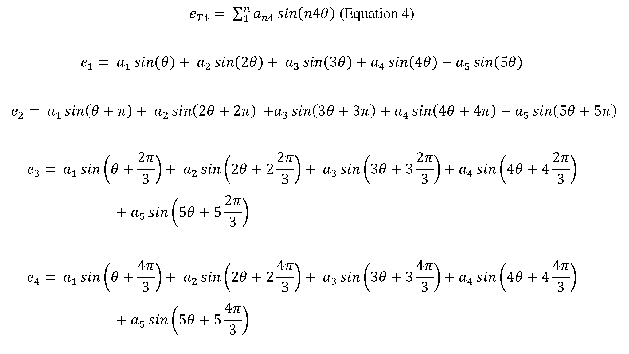
- the total error (e 1) when a single sensor, such as the first sensor 188- 1, is used to detect the magnetic field 170 may expressed as follows: where the first term represents the error due to the first harmonic component, the second term represents the error due to the second harmonic component, the third term represents the error due to the third harmonic component, the fourth term represents the error due to the fourth harmonic component, and the fifth term represents the error due to the fifth harmonic component.
- FIG. 9 shows the multiple harmonic components of magnetic error for the first signal in terms of the error amplitude (volts) relative to phase angle (Q).
- the magnetic error for the first signal includes a first harmonic component 304, a second harmonic component 308, a third harmonic component 312, a fourth harmonic component 316, and a fifth harmonic component 320.
- Each of the plurality of signals may include higher order harmonics than the fifth order, but for the purposes of this disclosure, the effect of each harmonic component after the fifth order may be neglected since with each increase in order of harmonics after the fifth order, the distortion effect may be considered to be minimal.
- FIG. 10 shows the magnetic error expressed in terms of error amplitude (volts) relative to phase angle (Q) for different configurations of the plurality of sensors 188.
- a first error signal (E T1 ) 330 is the error that results when only a single sensor, such as the first sensor 188-1, is used to sense the magnetic field 170.
- a second error signal (E T2 ) 334 is the error that results when the plurality of sensors 188 includes two sensors, such as the first sensor 188-1 and the second sensor 188-2, to sense the magnetic field 170.
- a third error signal (E T3 ) 338 is the error that results when the plurality of sensors 188 includes three sensors, such as the first sensor 188- 1, the second sensor 188-2, and the third sensor 188-3, to sense the magnetic field 170.
- a fourth error signal (E T4 ) 342 is the error that results when the plurality of sensors 188 includes four sensors, such as the first 188-1, the second sensor 188-2, the third sensor 188-3, and the fourth sensor 188-4, to sense the magnetic field 170.
- the sensor averaging module determines the average magnetic field based on the plurality of signals.
- the sensor averaging module may include one or more circuits (e.g., a passive average circuit, a noninverting summing circuit, an inverting summing circuit, a voltage divider, etc.) and/or software code or instructions for outputting the average of the plurality of signals.
- the average of the plurality of signals is indicative of the magnetic field 170 with the multiple harmonic components of the plurality of signals removed.
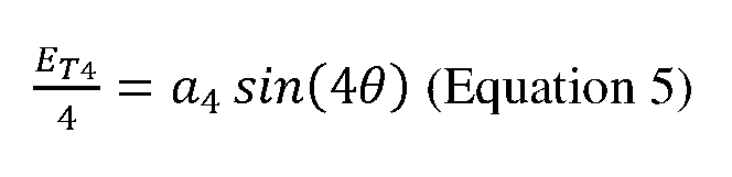
- the magnetic error (i.e., the fourth error signal (E T4 ) 342) of the average magnetic field signal includes only the fourth harmonic component 316.
- the fourth error signal (E T4 ) 342 may be expressed by the following equation: where e and e 4 represent the total error in the first signal generated by the first sensor 188- 1 positioned at 0° (i.e., Q), the second signal generated by the second sensor 188-2 positioned at , the third signal generated by the third sensor 188-3 positioned at 180° (i.e., , and the fourth signal generated by the fourth sensor 188-4 positioned at 270° (i.e., q + After simplifying using trigonometric equivalencies, the total error (ET) of the average magnetic field signal simples to:
- the sensor averaging module may also include a comparison module, an analog-to- digital converter (AC/DC), and a fast fourier transform (FFT) module.
- the FFT module may perform a FFT of one or more signals in order to identify the various harmonic components of the one or more signals.
- the FFT module may perform an FFT of the first signal, the second signal, the third signal, the fourth signal, and/or the average magnetic field signal.
- the comparison module may compare one or more characteristics of the FFT of the average magnetic field with the FFT of the first signal, the FFT of the second signal, the FFT of the third signal, the FFT of the fourth signal and/or another calculated parameter such as the calculated total error in order to verify that at least one of the harmonic components have been removed.
- a fault signal may be generated when the FFT of the average magnetic field includes one or more unwanted harmonic components. For example, when the plurality of sensors 188 includes the four sensor configuration, the presence of the second or third harmonic components may indicate a fault has occurred.
- the AC/DC converter may convert the first signal, the second signal, the third signal, and the fourth signal from analog to digital signals prior to determining the average magnetic field.
- the AC/DC converter may sample the plurality of signals in accordance with the Nyquist Theorem in order to reduce aliasing. For example, the sampling rate may be set equal to at least twice the highest frequency component of the plurality of signals.
- the one or more circuits used to output the average of the plurality of signals may be bypassed and the sensor averaging module may be configured to calculate an average of the first, second, third, and fourth digital signals in any suitable manner.
- the torque determination module may determine the amount of applied torque 104 based on the average magnetic field.
- the torque determination module may determine the amount of applied torque in any suitable manner. For example, the torque determination module may determine the applied torque 104 using one or more lookup tables that relates the average magnetic field to the amount of the applied torque 104.
- FIG. 11 demonstrates a method 500 of determining the magnitude of the applied torque 104.
- the method 500 begins at step 508 where the applied torque 104 is received by the shaft 12.
- the plurality of sensors 188 senses the magnetic field 170 and the ambient magnetic field.
- the plurality of signals indicative of the magnetic field are received by the controller.
- the controller determines the average magnetic field based on the plurality of signals.
- the controller determines the magnitude of the applied torque 104 based on the average magnetic field, and the method ends. While the method 500 is described as ending after 524, the method 500 may be a continuous control loop that is performed repeatedly. [0052] Several embodiments have been discussed in the foregoing description.
- the phrase at least one of A, B, and C should be construed to mean a logical (A OR B OR C), using a non-exclusive logical OR, and should not be construed to mean “at least one of A, at least one of B, and at least one of C.”
- the term subset does not necessarily require a proper subset. In other words, a first subset of a first set may be coextensive with (equal to) the first set.
- module or the term “controller” may be replaced with the term “circuit.”
- the term “module” may refer to, be part of, or include: an Application Specific Integrated Circuit (ASIC); a digital, analog, or mixed analog/digital discrete circuit; a digital, analog, or mixed analog/digital integrated circuit; a combinational logic circuit; a field programmable gate array (FPGA); a processor circuit (shared, dedicated, or group) that executes code; a memory circuit (shared, dedicated, or group) that stores code executed by the processor circuit; other suitable hardware components that provide the described functionality; or a combination of some or all of the above, such as in a system-on-chip.
- the module may include one or more interface circuits.
- the interface circuit(s) may implement wired or wireless interfaces that connect to a local area network (LAN) or a wireless personal area network (WPAN).
- LAN local area network
- WPAN wireless personal area network
- the module may communicate with other modules using the interface circuit(s). Although the module may be depicted in the present disclosure as logically communicating directly with other modules, in various implementations the module may actually communicate via a communications system.
- the communications system includes physical and/or virtual networking equipment such as hubs, switches, routers, and gateways.
- the communications system connects to or traverses a wide area network (WAN) such as the Internet.
- WAN wide area network
- the communications system may include multiple LANs connected to each other over the Internet or point-to-point leased lines using technologies including Multiprotocol Label Switching (MPLS) and virtual private networks (VPNs).
- MPLS Multiprotocol Label Switching
- VPNs virtual private networks
- code may include software, firmware, and/or microcode, and may refer to programs, routines, functions, classes, data structures, and/or objects.
- shared processor circuit encompasses a single processor circuit that executes some or all code from multiple modules.
- group processor circuit encompasses a processor circuit that, in combination with additional processor circuits, executes some or all code from one or more modules. References to multiple processor circuits encompass multiple processor circuits on discrete dies, multiple processor circuits on a single die, multiple cores of a single processor circuit, multiple threads of a single processor circuit, or a combination of the above.
- shared memory circuit encompasses a single memory circuit that stores some or all code from multiple modules.
- group memory circuit encompasses a memory circuit that, in combination with additional memories, stores some or all code from one or more modules.
- the term memory circuit is a subset of the term computer-readable medium.
- the term computer-readable medium does not encompass transitory electrical or electromagnetic signals propagating through a medium (such as on a carrier wave); the term computer-readable medium may therefore be considered tangible and non-transitory.
- Non-limiting examples of a non-transitory computer-readable medium are nonvolatile memory circuits (such as a flash memory circuit, an erasable programmable read-only memory circuit, or a mask read-only memory circuit), volatile memory circuits (such as a static random access memory circuit or a dynamic random access memory circuit), magnetic storage media (such as an analog or digital magnetic tape or a hard disk drive), and optical storage media (such as a CD, a DVD, or a Blu-ray Disc).
- nonvolatile memory circuits such as a flash memory circuit, an erasable programmable read-only memory circuit, or a mask read-only memory circuit
- volatile memory circuits such as a static random access memory circuit or a dynamic random access memory circuit
- magnetic storage media such as an analog or digital magnetic tape or a hard disk drive
- optical storage media such as a CD, a DVD, or a Blu-ray Disc
- the apparatuses and methods described in this application may be partially or fully implemented by a special purpose computer created by configuring a general purpose computer to execute one or more particular functions embodied in computer programs.
- the functional blocks and flowchart elements described above serve as software specifications, which can be translated into the computer programs by the routine work of a skilled technician or programmer.
- the computer programs include processor-executable instructions that are stored on at least one non-transitory computer-readable medium.
- the computer programs may also include or rely on stored data.
- the computer programs may include: (i) descriptive text to be parsed, such as HTML (hypertext markup language), XML (extensible markup language), or JSON (JavaScript Object Notation), (ii) assembly code, (iii) object code generated from source code by a compiler, (iv) source code for execution by an interpreter, (v) source code for compilation and execution by a just-in-time compiler, etc.
- source code may be written using syntax from any suitable programming language.
Landscapes
- Physics & Mathematics (AREA)
- General Physics & Mathematics (AREA)
- Electromagnetism (AREA)
- Power Steering Mechanism (AREA)
- Force Measurement Appropriate To Specific Purposes (AREA)
Abstract
Description

Claims
Priority Applications (7)
| Application Number | Priority Date | Filing Date | Title |
|---|---|---|---|
| PCT/IB2019/057751 WO2021048601A1 (en) | 2019-09-13 | 2019-09-13 | Magnetoelastic torque sensor assembly for reducing magnetic error due to harmonics |
| US17/753,716 US12292350B2 (en) | 2019-09-13 | 2019-09-13 | Magnetoelastic torque sensor assembly for reducing magnetic error due to harmonics |
| CA3150873A CA3150873C (en) | 2019-09-13 | 2019-09-13 | Magnetoelastic torque sensor assembly for reducing magnetic error due to harmonics |
| AU2019466071A AU2019466071A1 (en) | 2019-09-13 | 2019-09-13 | Magnetoelastic torque sensor assembly for reducing magnetic error due to harmonics |
| EP19773186.2A EP4028739B1 (en) | 2019-09-13 | 2019-09-13 | Magnetoelastic torque sensor assembly for reducing magnetic error due to harmonics |
| MX2022002951A MX2022002951A (en) | 2019-09-13 | 2019-09-13 | Magnetoelastic torque sensor assembly for reducing magnetic error due to harmonics. |
| JP2022516028A JP2022548852A (en) | 2019-09-13 | 2019-09-13 | Magnetoelastic torque sensor assembly for reducing magnetic errors due to harmonics |
Applications Claiming Priority (1)
| Application Number | Priority Date | Filing Date | Title |
|---|---|---|---|
| PCT/IB2019/057751 WO2021048601A1 (en) | 2019-09-13 | 2019-09-13 | Magnetoelastic torque sensor assembly for reducing magnetic error due to harmonics |
Publications (1)
| Publication Number | Publication Date |
|---|---|
| WO2021048601A1 true WO2021048601A1 (en) | 2021-03-18 |
Family
ID=68000000
Family Applications (1)
| Application Number | Title | Priority Date | Filing Date |
|---|---|---|---|
| PCT/IB2019/057751 Ceased WO2021048601A1 (en) | 2019-09-13 | 2019-09-13 | Magnetoelastic torque sensor assembly for reducing magnetic error due to harmonics |
Country Status (7)
| Country | Link |
|---|---|
| US (1) | US12292350B2 (en) |
| EP (1) | EP4028739B1 (en) |
| JP (1) | JP2022548852A (en) |
| AU (1) | AU2019466071A1 (en) |
| CA (1) | CA3150873C (en) |
| MX (1) | MX2022002951A (en) |
| WO (1) | WO2021048601A1 (en) |
Cited By (3)
| Publication number | Priority date | Publication date | Assignee | Title |
|---|---|---|---|---|
| EP4328560A1 (en) * | 2022-08-22 | 2024-02-28 | Melexis Technologies SA | Magnetoelastic torque sensor system and method |
| WO2024042058A1 (en) * | 2022-08-22 | 2024-02-29 | Melexis Technologies Sa | Magneto-elastic torque sensor device, system and method |
| US12292350B2 (en) | 2019-09-13 | 2025-05-06 | Brp Megatech Industries Inc. | Magnetoelastic torque sensor assembly for reducing magnetic error due to harmonics |
Citations (1)
| Publication number | Priority date | Publication date | Assignee | Title |
|---|---|---|---|---|
| US20020162403A1 (en) * | 2001-05-05 | 2002-11-07 | Cripe David W. | Magnetoelastic torque sensor |
Family Cites Families (192)
| Publication number | Priority date | Publication date | Assignee | Title |
|---|---|---|---|---|
| US3263796A (en) | 1964-12-18 | 1966-08-02 | Franklin E Parke | Magnetic conveyor |
| JPS57179302A (en) | 1981-04-25 | 1982-11-04 | Toyoda Autom Loom Works Ltd | Positive displacement type fluid compressor |
| US4414855A (en) | 1981-06-01 | 1983-11-15 | Aisin Seiki Kabushiki Kaisha | Torque sensor |
| DE3206503C1 (en) | 1982-02-24 | 1983-08-25 | Licentia Patent-Verwaltungs-Gmbh, 6000 Frankfurt | Method for compensating for the electrical interference voltage which occurs during torque measurement in accordance with the eddy-current principle on shafts, and is generated by the heterogeneous nature of the permeability of the surface of the shaft |
| DE3437379A1 (en) * | 1983-10-12 | 1985-04-25 | Bently Nevada Corp., Minden, Nev. | Device for measuring the rotary or bending force exerted on a shaft |
| GB2159278B (en) | 1984-05-23 | 1988-04-13 | Stc Plc | Heading sensor |
| JPS6141935A (en) | 1984-08-02 | 1986-02-28 | Matsushita Electric Ind Co Ltd | torque sensor |
| JPS6275328A (en) | 1985-09-30 | 1987-04-07 | Toshiba Corp | Torque sensor |
| JP2545365B2 (en) * | 1986-04-21 | 1996-10-16 | 株式会社豊田中央研究所 | Torque measuring device |
| US4760745A (en) | 1986-12-05 | 1988-08-02 | Mag Dev Inc. | Magnetoelastic torque transducer |
| US4896544A (en) | 1986-12-05 | 1990-01-30 | Mag Dev Inc. | Magnetoelastic torque transducer |
| JPH0754273B2 (en) | 1987-12-26 | 1995-06-07 | 大同特殊鋼株式会社 | Torxense |
| JPH01187425A (en) | 1988-01-22 | 1989-07-26 | Toshiba Corp | Torque sensor for steering shaft |
| US4996890A (en) | 1988-10-07 | 1991-03-05 | Koyo Seiko Co. Ltd. | Torque sensor |
| JP2512552B2 (en) | 1989-04-20 | 1996-07-03 | 株式会社クボタ | Magnetostrictive torque sensor shaft manufacturing method |
| JP2512553B2 (en) | 1989-04-20 | 1996-07-03 | 株式会社クボタ | Magnetostrictive torque sensor shaft manufacturing method |
| JP2800347B2 (en) | 1990-02-07 | 1998-09-21 | 株式会社豊田自動織機製作所 | Magnetostrictive torque sensor |
| JP2983246B2 (en) | 1990-04-18 | 1999-11-29 | 三菱製鋼株式会社 | Manufacturing method of magnetostrictive torque sensor shaft |
| JPH04191630A (en) | 1990-11-26 | 1992-07-09 | Japan Electron Control Syst Co Ltd | Magnetostrictive torque sensor |
| US5307690A (en) | 1991-07-29 | 1994-05-03 | Kubota Corporation | Temperature compensating device for torque measuring apparatus |
| US5520059A (en) | 1991-07-29 | 1996-05-28 | Magnetoelastic Devices, Inc. | Circularly magnetized non-contact torque sensor and method for measuring torque using same |
| US5351555A (en) | 1991-07-29 | 1994-10-04 | Magnetoelastic Devices, Inc. | Circularly magnetized non-contact torque sensor and method for measuring torque using same |
| US5591925A (en) | 1991-07-29 | 1997-01-07 | Garshelis; Ivan J. | Circularly magnetized non-contact power sensor and method for measuring torque and power using same |
| JPH0545240A (en) | 1991-08-21 | 1993-02-23 | Kubota Corp | Magnetostrictive torque sensor overload prevention device |
| JPH0566164A (en) | 1991-09-05 | 1993-03-19 | Japan Electron Control Syst Co Ltd | Magnet-striction type torque sensor |
| JP2608498B2 (en) | 1991-11-05 | 1997-05-07 | 株式会社ユニシアジェックス | Magnetostrictive torque sensor |
| JP2529980Y2 (en) | 1991-11-08 | 1997-03-26 | 株式会社ユニシアジェックス | Magnetostrictive torque sensor |
| JPH0543040U (en) | 1991-11-14 | 1993-06-11 | 日本電子機器株式会社 | Magnetostrictive torque sensor |
| JPH0545537U (en) | 1991-11-22 | 1993-06-18 | 日本電子機器株式会社 | Magnetostrictive torque sensor |
| JPH0545538U (en) | 1991-11-22 | 1993-06-18 | 日本電子機器株式会社 | Magnetostrictive torque sensor |
| JPH05231966A (en) | 1992-02-19 | 1993-09-07 | Yaskawa Electric Corp | Magnetostrictive torque sensor |
| JPH05231967A (en) | 1992-02-19 | 1993-09-07 | Yaskawa Electric Corp | Magnetostrictive torque sensor |
| JP2673636B2 (en) | 1992-06-01 | 1997-11-05 | 株式会社ユニシアジェックス | Processing circuit for magnetostrictive torque sensor |
| JP2722296B2 (en) | 1992-06-16 | 1998-03-04 | 株式会社ユニシアジェックス | Magnetostrictive torque sensor |
| JP2584419Y2 (en) | 1992-07-29 | 1998-11-05 | 株式会社ユニシアジェックス | Magnetostrictive torque sensor |
| DE69327037T2 (en) | 1992-08-24 | 2000-05-25 | Kubota Corp., Osaka | METHOD FOR PRODUCING THE SHAFT OF A MAGNETOSTRICTIVE TORQUE SENSOR AND SHAFT PRODUCED BY THIS METHOD |
| JPH0674844A (en) | 1992-08-24 | 1994-03-18 | Unisia Jecs Corp | Magnetostrictive type torque sensor |
| JPH0628673U (en) | 1992-09-14 | 1994-04-15 | 日本電子機器株式会社 | Magnetostrictive torque sensor |
| JPH0647832U (en) | 1992-12-02 | 1994-06-28 | 日本電子機器株式会社 | Magnetostrictive torque sensor |
| JPH06258158A (en) | 1993-03-03 | 1994-09-16 | Unisia Jecs Corp | Magnetostriction-type torque sensor |
| JP3161867B2 (en) | 1993-04-19 | 2001-04-25 | 株式会社ユニシアジェックス | Magnetostrictive torque sensor |
| JPH0719971A (en) | 1993-05-07 | 1995-01-20 | Unisia Jecs Corp | Torque detector |
| JPH06323930A (en) | 1993-05-12 | 1994-11-25 | Yaskawa Electric Corp | Disturbance magnetic field noise compensator for magnetostrictive torque sensor |
| JPH072943U (en) | 1993-06-14 | 1995-01-17 | 株式会社ユニシアジェックス | Magnetostrictive torque sensor |
| JPH0780756A (en) | 1993-09-16 | 1995-03-28 | Omron Corp | Chuck with built-in sensor |
| US5589645A (en) | 1993-11-30 | 1996-12-31 | Unisia Jecs Corporation | Structure of magnetostrictive shaft applicable to magnetostriction-type torque sensor for detecting torque applied to rotatable shaft and method for manufacturing the same |
| JPH07159258A (en) | 1993-12-09 | 1995-06-23 | Unisia Jecs Corp | Magnetostrictive torque sensor |
| JPH0743521U (en) | 1993-12-28 | 1995-08-22 | 株式会社ユニシアジェックス | Magnetostrictive torque sensor |
| JPH07316658A (en) | 1994-05-30 | 1995-12-05 | Unisia Jecs Corp | Magnetostrictive shaft manufacturing method |
| JPH085477A (en) | 1994-06-16 | 1996-01-12 | Unisia Jecs Corp | Magnetostrictive torque sensor |
| JPH0843216A (en) | 1994-08-03 | 1996-02-16 | Yaskawa Electric Corp | Multi-function torque sensor device |
| US5786690A (en) | 1994-08-18 | 1998-07-28 | International Business Machines Corporation | High resolution three-axis scanning squid microscope having planar solenoids |
| US5526704A (en) | 1994-11-01 | 1996-06-18 | Unisia Jecs Corporation | Structure of magnetostrictive torque sensor applicable to sensor for detecting torque applied to rotatable shaft |
| JPH0985587A (en) | 1995-09-28 | 1997-03-31 | Mitsubishi Materials Corp | Detecting device and detecting method of cutting state by rotary cutting tool |
| JP3655951B2 (en) | 1995-09-29 | 2005-06-02 | ティーアールダブリュ オートモーティブ ジャパン株式会社 | Electric power steering device |
| JPH09189624A (en) | 1996-01-10 | 1997-07-22 | Seiko Epson Corp | Torque sensor |
| US6145387A (en) | 1997-10-21 | 2000-11-14 | Magna-Lastic Devices, Inc | Collarless circularly magnetized torque transducer and method for measuring torque using same |
| US5939881A (en) | 1997-11-13 | 1999-08-17 | Raytheon Company | High dynamic range digital fluxgate magnetometer |
| EP0947846B1 (en) | 1998-03-30 | 2005-11-02 | Sentron Ag | Magnetic field sensor |
| GB9808792D0 (en) | 1998-04-23 | 1998-06-24 | Effective Torque Technologies | Magnetising arrangements for torque/force sensor |
| US6522130B1 (en) | 1998-07-20 | 2003-02-18 | Uqm Technologies, Inc. | Accurate rotor position sensor and method using magnet and sensors mounted adjacent to the magnet and motor |
| US6222363B1 (en) * | 1999-01-08 | 2001-04-24 | Methode Electronics, Inc. | Switch-mode flux-gate magnetometer |
| JP2001050830A (en) | 1999-08-12 | 2001-02-23 | Suzuki Motor Corp | Power steering torque sensor |
| DE19943128A1 (en) | 1999-09-09 | 2001-04-12 | Fraunhofer Ges Forschung | Hall sensor arrangement for offset-compensated magnetic field measurement |
| GB9923894D0 (en) | 1999-10-08 | 1999-12-08 | Fast Technology Gmbh | Accelerometer |
| GB9924046D0 (en) | 1999-10-11 | 1999-12-15 | Fast Technology Gmbh | Torque measurement apparatus |
| JP2003534180A (en) | 1999-12-29 | 2003-11-18 | デルファイ・テクノロジーズ・インコーポレーテッド | Method and system for improving vehicle stability incorporating an electric power steering system |
| US6341534B1 (en) | 2000-03-03 | 2002-01-29 | Ford Motor Company | Integrated two-channel torque sensor |
| JP2001296193A (en) | 2000-04-17 | 2001-10-26 | Suzuki Motor Corp | Magnetostrictive torque sensor for detecting steering force |
| US6454911B1 (en) | 2000-06-01 | 2002-09-24 | Honeywell International Inc. | Method and apparatus for determining the pass through flux of magnetic materials |
| WO2001096826A2 (en) | 2000-06-14 | 2001-12-20 | Fast Technology Ag. | Magnetic transducer torque measurement |
| DE10041096A1 (en) * | 2000-08-22 | 2002-03-07 | Bosch Gmbh Robert | Method for correcting angle measurements using at least two code tracks |
| GB0028385D0 (en) | 2000-11-21 | 2001-01-03 | Inertia Switch Ltd | Torque sensing apparatus and method |
| DE10114218A1 (en) | 2001-03-23 | 2002-10-02 | Bosch Gmbh Robert | Method and device for evaluating signals from magnetoelastic sensors |
| JP2002333375A (en) | 2001-05-10 | 2002-11-22 | Hitachi Metals Ltd | Magnetostrictive torque sensor material, magnetostrictive torque sensor shaft using the same and magnetostrictive torque sensor using the shaft |
| JP2002340701A (en) | 2001-05-18 | 2002-11-27 | Hitachi Metals Ltd | Method for manufacturing magnetostrictive torque sensor shaft |
| GB0116757D0 (en) | 2001-07-10 | 2001-08-29 | Hall Effect Technologies Ltd | Apparatus for determining orientation relative to a magnetic field in a three dimensional space |
| DE10161803A1 (en) | 2001-12-15 | 2003-07-10 | Hilti Ag | Electromagnetic torque sensor |
| GB0204213D0 (en) | 2002-02-22 | 2002-04-10 | Fast Technology Ag | Pulsed torque measurement |
| AU2003208759A1 (en) | 2002-02-22 | 2003-09-09 | Fast Technology Ag | Magnetically neutral displacement (torque) transducer for a ferromagnetic member with coil(s) and magnetic field sensor(s) |
| JP2003307460A (en) | 2002-04-15 | 2003-10-31 | Toyoda Mach Works Ltd | Torque sensor |
| WO2004003585A1 (en) | 2002-07-01 | 2004-01-08 | European Organisation For Nuclear Research - Cern | Device for calibration of magnetic sensors in three dimensions |
| JP2004037240A (en) | 2002-07-03 | 2004-02-05 | Suzuki Motor Corp | Magnetostrictive torque sensor shaft and method of manufacturing the same |
| JP2004053433A (en) | 2002-07-22 | 2004-02-19 | Suzuki Motor Corp | Magnetostrictive torque sensor |
| JP2004053434A (en) | 2002-07-22 | 2004-02-19 | Suzuki Motor Corp | Manufacturing method of magnetostrictive torque sensor shaft |
| JP2004053435A (en) | 2002-07-22 | 2004-02-19 | Suzuki Motor Corp | Magnetostrictive torque sensor shaft and method of manufacturing the same |
| US20040119470A1 (en) | 2002-09-13 | 2004-06-24 | Sankyo Seiki Mfg. Co., Ltd. | Winding type magnetic sensor device and coin discriminating sensor device |
| JP3898610B2 (en) | 2002-09-18 | 2007-03-28 | 本田技研工業株式会社 | Torque sensor |
| JP2004225096A (en) | 2003-01-22 | 2004-08-12 | Aisin Seiki Co Ltd | Magnetostrictive material and magnetostrictive torque sensor |
| JP2004264188A (en) | 2003-03-03 | 2004-09-24 | Moric Co Ltd | Magnetostriction torque sensor |
| JP2004340783A (en) | 2003-05-16 | 2004-12-02 | Ntn Corp | Torque detecting device |
| KR100779487B1 (en) | 2003-07-16 | 2007-11-26 | 주식회사 만도 | Torque detection device |
| US7235968B2 (en) | 2003-08-22 | 2007-06-26 | Melexis Technologies Sa | Sensor for detecting the direction of a magnetic field in a plane |
| JP4292967B2 (en) | 2003-12-05 | 2009-07-08 | 日立電線株式会社 | Magnetostrictive torque sensor |
| KR20050075880A (en) | 2004-01-16 | 2005-07-25 | 주식회사 만도 | Torqur sensor for steering system of vehicle |
| KR20050093025A (en) | 2004-03-18 | 2005-09-23 | 부광석 | A torque sensor using transformer type position sensor |
| US7225686B2 (en) | 2004-03-22 | 2007-06-05 | Tdk Corporation | Torque sensing apparatus |
| JP4305271B2 (en) | 2004-05-07 | 2009-07-29 | 日立電線株式会社 | Magnetostrictive torque sensor |
| JP2006010669A (en) | 2004-05-28 | 2006-01-12 | Aisin Seiki Co Ltd | Torque sensor device |
| US7506554B2 (en) | 2004-08-25 | 2009-03-24 | Honda Motor Co., Ltd. | Magnetostrictive torque sensor system and electric steering system |
| CN1871496B (en) | 2004-09-29 | 2010-04-28 | 阿莫善斯有限公司 | Magnetic sensor control method, control device, and mobile terminal device |
| JP2006126130A (en) | 2004-11-01 | 2006-05-18 | Hitachi Cable Ltd | Magnetostrictive torque sensor |
| WO2006053244A2 (en) | 2004-11-12 | 2006-05-18 | Stoneridge Control Devices, Inc. | Torque sensor assembly |
| KR20060054775A (en) | 2004-11-16 | 2006-05-23 | 현대모비스 주식회사 | Steering Device for Motor Driven Vehicle |
| US7409878B2 (en) | 2005-04-08 | 2008-08-12 | Honeywell International Inc. | Torqueshaft magnetic field measurement systems for gas turbine engines |
| CN100554885C (en) | 2005-04-19 | 2009-10-28 | 松下电器产业株式会社 | Position sensor, optical head device, head moving mechanism and position control system |
| KR100694201B1 (en) | 2005-07-04 | 2007-03-14 | 주식회사 만도 | Torque sensor and electric power assist steering device of automobile |
| JP4877905B2 (en) | 2005-08-03 | 2012-02-15 | 日産自動車株式会社 | Shift position detector for automatic manual transmission |
| US7640814B2 (en) | 2005-08-12 | 2010-01-05 | Continental Automotive Systems Us, Inc. | Demagnetization-field enhancing magnetometer |
| US7308835B2 (en) | 2005-09-22 | 2007-12-18 | Siemens Vdo Automotive Corporation | Reduction of hysteresis in a magnetoelastic torque sensor |
| JP2007101427A (en) | 2005-10-06 | 2007-04-19 | Hitachi Metals Ltd | Magnetic head for magnetostrictive type torque detector |
| US7308825B2 (en) | 2005-10-14 | 2007-12-18 | Rosemount Tank Radar Ab | Tank gauging system |
| US7469604B2 (en) | 2005-10-21 | 2008-12-30 | Stoneridge Control Devices, Inc. | Sensor system including a magnetized shaft |
| US7362096B2 (en) | 2005-10-21 | 2008-04-22 | Delphi Technologies, Inc. | Robust detection of strain with temperature correction |
| US7363827B2 (en) | 2005-10-21 | 2008-04-29 | Stoneridge Control Devices, Inc. | Torque sensor system including an elliptically magnetized shaft |
| US7391211B2 (en) | 2005-11-08 | 2008-06-24 | Continental Automotive Systems Us, Inc. | Digital fluxgate magnetometer |
| JP4713335B2 (en) | 2005-12-28 | 2011-06-29 | 株式会社日立産機システム | Motor and electric power steering device |
| US7805270B2 (en) | 2006-02-03 | 2010-09-28 | Moog Inc. | Encoder signal analysis system for high-resolution position measurement |
| CN101936749A (en) | 2006-03-06 | 2011-01-05 | 日本电产三协株式会社 | Magnetic encoder device |
| SE529789C8 (en) | 2006-03-10 | 2007-12-27 | Abb Ab | Measuring device comprising a layer of a magnetoelastic alloy and method for manufacturing the measuring device |
| CN2903949Y (en) | 2006-06-08 | 2007-05-23 | 株洲卓越高科技实业有限公司 | Electromagnetic torque sensor for automobile electric boosting steering system |
| JP4936811B2 (en) | 2006-07-21 | 2012-05-23 | 株式会社東芝 | Magnetostrictive torque sensor shaft manufacturing method |
| DE102006037226B4 (en) | 2006-08-09 | 2008-05-29 | Fraunhofer-Gesellschaft zur Förderung der angewandten Forschung e.V. | Calibratable magnetic 3D-point sensor during measuring operation |
| KR100852182B1 (en) | 2006-08-22 | 2008-08-13 | 한국과학기술연구원 | Hybrid semiconductor-ferromagnet device with a junction of positive and negative magnetic-field regions |
| FR2909170B1 (en) | 2006-11-28 | 2010-01-29 | Moving Magnet Tech Mmt | LINER OR ROTARY POSITION SENSOR WITH VARIABLE MAGNETIC PROFILE PREFERENTIALLY AS WELL AS SINUSOIDAL. |
| US20080173102A1 (en) | 2007-01-24 | 2008-07-24 | Nehl Thomas W | Villari torque sensor excitation and pickup arrangement for magnetrostrictive shafts |
| US20080221399A1 (en) | 2007-03-05 | 2008-09-11 | Triage Wireless, Inc. | Monitor for measuring vital signs and rendering video images |
| JP5044372B2 (en) | 2007-11-16 | 2012-10-10 | 株式会社東芝 | Magnetostrictive torque sensor shaft manufacturing method |
| JP4572227B2 (en) | 2007-11-29 | 2010-11-04 | 本田技研工業株式会社 | Magnetostrictive torque sensor and electric steering device |
| JP2009204533A (en) | 2008-02-28 | 2009-09-10 | Honda Motor Co Ltd | Magnetostrictive torque sensor, its manufacturing method, and electric power steering device |
| CA2718284C (en) | 2008-03-14 | 2017-02-07 | Seong-Jae Lee | Magnetoelastic torque sensor with ambient field rejection |
| DE102008050236A1 (en) | 2008-10-02 | 2010-04-08 | Schaeffler Kg | bottom bracket |
| US8159219B2 (en) | 2008-10-20 | 2012-04-17 | University Of North Carolina At Charlotte | MEMS 2D and 3D magnetic field sensors and associated manufacturing method |
| US9222992B2 (en) | 2008-12-18 | 2015-12-29 | Infineon Technologies Ag | Magnetic field current sensors |
| US8486723B1 (en) | 2010-08-19 | 2013-07-16 | MCube Inc. | Three axis magnetic sensor device and method |
| US8001849B2 (en) | 2009-03-28 | 2011-08-23 | Wensheng Weng | Self-compensating magnetoelastic torque sensor system |
| WO2010119958A1 (en) | 2009-04-16 | 2010-10-21 | 株式会社アミテック | Torque sensor |
| WO2010119773A1 (en) | 2009-04-17 | 2010-10-21 | 本田技研工業株式会社 | Magnetostrictive torque sensor and electrical power steering device |
| JP4866437B2 (en) * | 2009-04-17 | 2012-02-01 | 本田技研工業株式会社 | Magnetostrictive torque sensor and manufacturing method thereof |
| US8259409B2 (en) | 2009-06-25 | 2012-09-04 | Hitachi Global Storage Technologies Netherlands B.V. | Spin torque oscillator sensor |
| FR2947902B1 (en) | 2009-07-07 | 2011-07-22 | Moving Magnet Technologies M M T | ABSOLUTE AND MULTI-PERIODIC POSITION SENSOR |
| US20110106557A1 (en) | 2009-10-30 | 2011-05-05 | iHAS INC | Novel one integrated system for real-time virtual face-to-face encounters |
| US20110162464A1 (en) | 2010-01-02 | 2011-07-07 | Smts Llc | Reduced Ambient Fields Error In A Magnetoelastic Torque Sensor System |
| WO2011085400A1 (en) | 2010-01-11 | 2011-07-14 | Magcanica, Inc. | Magnetoelastic force sensors, transducers, methods, and systems for assessing bending stress |
| CN105277303A (en) | 2010-03-23 | 2016-01-27 | 翁庄明 | Magnetoelastic torque sensor with self compensation function |
| US20110234218A1 (en) | 2010-03-24 | 2011-09-29 | Matthieu Lagouge | Integrated multi-axis hybrid magnetic field sensor |
| US20120007597A1 (en) | 2010-07-09 | 2012-01-12 | Invensense, Inc. | Micromachined offset reduction structures for magnetic field sensing |
| US8395381B2 (en) | 2010-07-09 | 2013-03-12 | Invensense, Inc. | Micromachined magnetic field sensors |
| US20120029303A1 (en) | 2010-07-30 | 2012-02-02 | Fawzi Shaya | System, method and apparatus for performing real-time virtual medical examinations |
| DE102010033308A1 (en) | 2010-08-04 | 2012-02-09 | Nctengineering Gmbh | Wind turbine with torque detection |
| US8203334B2 (en) | 2010-10-28 | 2012-06-19 | General Electric Company | Magnetically spirally encoded shaft for measuring rotational angel, rotational speed and torque |
| US8468898B2 (en) | 2010-10-28 | 2013-06-25 | General Electric Company | Method and apparatus for continuous sectional magnetic encoding to measure torque on large shafts |
| US8844379B2 (en) | 2011-05-24 | 2014-09-30 | Ford Global Technologies, Llc | Transmissions with electronics interface assembly for torque sensor |
| US20120299587A1 (en) | 2011-05-26 | 2012-11-29 | Honeywell International Inc. | Three-axis magnetic sensors |
| EP2559986B1 (en) | 2011-06-21 | 2016-04-06 | NSK Ltd. | Torque detection device, and electric power steering device |
| JP2013053957A (en) | 2011-09-05 | 2013-03-21 | Honda Motor Co Ltd | Magnetostrictive torque sensor |
| JP5597608B2 (en) | 2011-09-05 | 2014-10-01 | 本田技研工業株式会社 | Magnetostrictive torque sensor |
| DE102011115566A1 (en) | 2011-10-10 | 2013-04-11 | Austriamicrosystems Ag | Hall sensor |
| US8635917B2 (en) | 2011-10-18 | 2014-01-28 | Methode Electronics, Inc. | Magnetic torque sensor for transmission converter drive plate |
| US8424393B1 (en) | 2011-10-18 | 2013-04-23 | Methode Electronics, Inc. | Magnetic torque sensor for transmission converter drive plate |
| US8893562B2 (en) | 2011-11-21 | 2014-11-25 | Methode Electronics, Inc. | System and method for detecting magnetic noise by applying a switching function to magnetic field sensing coils |
| CN102519633B (en) | 2011-11-30 | 2014-07-16 | 浙江大学 | Magneto-elastic and magneto-electric effect type stress monitoring device |
| US9494556B2 (en) | 2012-01-13 | 2016-11-15 | Polyresearch Ag | Active mechanical force and axial load sensor |
| DE102012202404B4 (en) | 2012-02-16 | 2018-04-05 | Infineon Technologies Ag | Angle of rotation sensor for absolute rotation angle determination even with multiple revolutions |
| JP5752322B2 (en) | 2012-04-26 | 2015-07-22 | 三菱電機株式会社 | Magnetic position detector |
| US9205717B2 (en) | 2012-11-07 | 2015-12-08 | Polaris Industries Inc. | Vehicle having suspension with continuous damping control |
| DE102013000431A1 (en) | 2013-01-14 | 2014-07-17 | Micronas Gmbh | Circuit and measuring system |
| DE102013000430A1 (en) | 2013-01-14 | 2014-07-17 | Micronas Gmbh | measuring system |
| EP2793009B1 (en) | 2013-04-15 | 2021-03-17 | Methode Electronics Malta Ltd. | Magneto-elastic sensor, load pin, ball-joint and tow coupling comprising this sensor, method of determining a direction of a load vector |
| EP2799827B1 (en) | 2013-04-30 | 2017-12-06 | Methode Electronics Malta Ltd. | Magnetoelastic torque sensor and method |
| EP2799327B1 (en) | 2013-05-03 | 2016-05-25 | Methode Electronics Malta Ltd. | A freewheel hub comprising a magneto-elastic sensor and bicycle, pedelec, fast pedelec or e-bike comprising the freewheel hub |
| DE102013209514A1 (en) | 2013-05-22 | 2014-11-27 | Micronas Gmbh | Three-dimensional Hall sensor for detecting a spatial magnetic field |
| JP6061799B2 (en) | 2013-06-27 | 2017-01-18 | ブリヂストンサイクル株式会社 | Torque sensor rotation prevention structure and electric assist bicycle having the same |
| JP6047451B2 (en) | 2013-06-27 | 2016-12-21 | ブリヂストンサイクル株式会社 | Torque sensor positioning structure and electric assist bicycle equipped with the same |
| JP6406829B2 (en) | 2014-02-10 | 2018-10-17 | トクデン株式会社 | Induction heating roller device and induction coil temperature detection mechanism |
| US9733317B2 (en) | 2014-03-10 | 2017-08-15 | Dmg Mori Seiki Co., Ltd. | Position detecting device |
| JP2015194430A (en) | 2014-03-31 | 2015-11-05 | 本田技研工業株式会社 | Vehicle power steering system and manufacturing method of the same |
| CA2965309C (en) | 2014-10-31 | 2024-01-23 | Polaris Industries Inc. | System and method for controlling a vehicle |
| DE102015202240B3 (en) | 2015-02-09 | 2016-02-25 | Schaeffler Technologies AG & Co. KG | Arrangement for measuring a force or a moment with at least three magnetic field sensors |
| DE202015105090U1 (en) | 2015-02-18 | 2015-11-23 | Methode Electronics Malta Ltd. | Redundant torque sensor - multiple band arrangement |
| DE102015102337B4 (en) | 2015-02-18 | 2016-11-17 | Methode Electronics Malta Ltd. | Redundant torque sensor - multiple band arrangement |
| CN108024823B (en) | 2015-07-15 | 2021-02-02 | 史赛克公司 | System and method for controlling an ultrasonic tool |
| DE102015122154B4 (en) | 2015-12-17 | 2018-09-27 | Methode Electronics Malta Ltd. | Device for detecting external magnetic stray fields on a magnetic field sensor |
| US20190178683A1 (en) | 2016-05-17 | 2019-06-13 | Kongsberg Inc. | System, Method And Object For High Accuracy Magnetic Position Sensing |
| US10634573B2 (en) | 2016-06-08 | 2020-04-28 | Methode Electronic, Inc. | Torque sensor component pairing and assembly |
| US10836429B2 (en) | 2016-07-20 | 2020-11-17 | Tdk Corporation | Angle sensor and angle sensor system |
| WO2018109674A1 (en) | 2016-12-12 | 2018-06-21 | Kongsberg Inc. | Dual-band magnetoelastic torque sensor |
| EP3364163B1 (en) | 2017-02-15 | 2020-04-08 | Ncte Ag | Magnetoelastic torque sensor |
| US10983019B2 (en) | 2019-01-10 | 2021-04-20 | Ka Group Ag | Magnetoelastic type torque sensor with temperature dependent error compensation |
| WO2021048601A1 (en) | 2019-09-13 | 2021-03-18 | Ka Group Ag | Magnetoelastic torque sensor assembly for reducing magnetic error due to harmonics |
| DE102021101344A1 (en) | 2020-01-23 | 2021-07-29 | Methode Electronics, Inc | DIFFERENTIAL TRANSFER TORQUE SENSOR DEVICE AND METHOD |
| US12281951B2 (en) * | 2020-02-11 | 2025-04-22 | Brp Megatech Industries Inc. | Magnetoelastic torque sensor with local measurement of ambient magnetic field |
-
2019
- 2019-09-13 WO PCT/IB2019/057751 patent/WO2021048601A1/en not_active Ceased
- 2019-09-13 MX MX2022002951A patent/MX2022002951A/en unknown
- 2019-09-13 US US17/753,716 patent/US12292350B2/en active Active
- 2019-09-13 JP JP2022516028A patent/JP2022548852A/en active Pending
- 2019-09-13 AU AU2019466071A patent/AU2019466071A1/en not_active Abandoned
- 2019-09-13 EP EP19773186.2A patent/EP4028739B1/en active Active
- 2019-09-13 CA CA3150873A patent/CA3150873C/en active Active
Patent Citations (1)
| Publication number | Priority date | Publication date | Assignee | Title |
|---|---|---|---|---|
| US20020162403A1 (en) * | 2001-05-05 | 2002-11-07 | Cripe David W. | Magnetoelastic torque sensor |
Cited By (3)
| Publication number | Priority date | Publication date | Assignee | Title |
|---|---|---|---|---|
| US12292350B2 (en) | 2019-09-13 | 2025-05-06 | Brp Megatech Industries Inc. | Magnetoelastic torque sensor assembly for reducing magnetic error due to harmonics |
| EP4328560A1 (en) * | 2022-08-22 | 2024-02-28 | Melexis Technologies SA | Magnetoelastic torque sensor system and method |
| WO2024042058A1 (en) * | 2022-08-22 | 2024-02-29 | Melexis Technologies Sa | Magneto-elastic torque sensor device, system and method |
Also Published As
| Publication number | Publication date |
|---|---|
| AU2019466071A1 (en) | 2022-03-31 |
| US20220349762A1 (en) | 2022-11-03 |
| CA3150873A1 (en) | 2021-03-18 |
| JP2022548852A (en) | 2022-11-22 |
| MX2022002951A (en) | 2022-05-10 |
| CA3150873C (en) | 2024-11-05 |
| EP4028739C0 (en) | 2024-10-30 |
| EP4028739B1 (en) | 2024-10-30 |
| EP4028739A1 (en) | 2022-07-20 |
| US12292350B2 (en) | 2025-05-06 |
Similar Documents
| Publication | Publication Date | Title |
|---|---|---|
| EP4028739B1 (en) | Magnetoelastic torque sensor assembly for reducing magnetic error due to harmonics | |
| JP7087001B2 (en) | Magnetic field sensor with error calculation function | |
| CN113447699B (en) | Tunnel magnetoresistance annular array current sensor and current measuring method | |
| US9429632B2 (en) | Magnetic position detection device | |
| US11237022B2 (en) | Correction apparatus for angle sensor, and angle sensor | |
| US10309803B2 (en) | Detecting sensor error | |
| US10254135B2 (en) | Correction apparatus and method for angle sensor, and angle sensor | |
| US10267870B2 (en) | Detecting sensor error | |
| US8593139B2 (en) | Magnetic sensor | |
| EP2284555A1 (en) | Magnetic sensor including a bridge circuit | |
| US10352728B2 (en) | Angle sensor, correction method for use therewith, and angle sensor system | |
| JP6074988B2 (en) | Rotation magnetism detection circuit and rotation magnetic sensor | |
| CN111624529A (en) | Magnetic field sensor device | |
| WO2018168203A1 (en) | Rotation sensor | |
| JP6319067B2 (en) | Magnetic sensor and current detector | |
| US11774234B2 (en) | Angle sensor calibration method for safety measure without full rotation | |
| JP2008051815A (en) | Detection system of velocity/acceleration of rotation wheel, and calculating method of velocity/acceleration of rotation wheel | |
| US12174271B2 (en) | Adaptive switching frequency selection | |
| JP2020016439A (en) | Angle sensor correction device and angle sensor | |
| WO2023281696A1 (en) | Current leakage sensor and circuit protection system | |
| WO2012029437A1 (en) | Current sensor | |
| JP5614046B2 (en) | Look-up table generation method, angle sensor, and scale | |
| US20220390257A1 (en) | Auto-calibration for multi-pole angle sensors with mechanical modulation |
Legal Events
| Date | Code | Title | Description |
|---|---|---|---|
| 121 | Ep: the epo has been informed by wipo that ep was designated in this application |
Ref document number: 19773186 Country of ref document: EP Kind code of ref document: A1 |
|
| ENP | Entry into the national phase |
Ref document number: 3150873 Country of ref document: CA |
|
| ENP | Entry into the national phase |
Ref document number: 2022516028 Country of ref document: JP Kind code of ref document: A |
|
| NENP | Non-entry into the national phase |
Ref country code: DE |
|
| ENP | Entry into the national phase |
Ref document number: 2019466071 Country of ref document: AU Date of ref document: 20190913 Kind code of ref document: A |
|
| ENP | Entry into the national phase |
Ref document number: 2019773186 Country of ref document: EP Effective date: 20220413 |
|
| WWG | Wipo information: grant in national office |
Ref document number: 17753716 Country of ref document: US |