WO2020112688A1 - Systems and methods for enhancing efficacy of ultrasound treatment - Google Patents
Systems and methods for enhancing efficacy of ultrasound treatment Download PDFInfo
- Publication number
- WO2020112688A1 WO2020112688A1 PCT/US2019/063095 US2019063095W WO2020112688A1 WO 2020112688 A1 WO2020112688 A1 WO 2020112688A1 US 2019063095 W US2019063095 W US 2019063095W WO 2020112688 A1 WO2020112688 A1 WO 2020112688A1
- Authority
- WO
- WIPO (PCT)
- Prior art keywords
- power
- transducer
- output
- ultrasound
- power amplifier
- Prior art date
- Legal status (The legal status is an assumption and is not a legal conclusion. Google has not performed a legal analysis and makes no representation as to the accuracy of the status listed.)
- Ceased
Links
Classifications
-
- A—HUMAN NECESSITIES
- A61—MEDICAL OR VETERINARY SCIENCE; HYGIENE
- A61N—ELECTROTHERAPY; MAGNETOTHERAPY; RADIATION THERAPY; ULTRASOUND THERAPY
- A61N7/00—Ultrasound therapy
- A61N7/02—Localised ultrasound hyperthermia
-
- A—HUMAN NECESSITIES
- A61—MEDICAL OR VETERINARY SCIENCE; HYGIENE
- A61B—DIAGNOSIS; SURGERY; IDENTIFICATION
- A61B18/00—Surgical instruments, devices or methods for transferring non-mechanical forms of energy to or from the body
- A61B18/04—Surgical instruments, devices or methods for transferring non-mechanical forms of energy to or from the body by heating
-
- H—ELECTRICITY
- H03—ELECTRONIC CIRCUITRY
- H03F—AMPLIFIERS
- H03F3/00—Amplifiers with only discharge tubes or only semiconductor devices as amplifying elements
- H03F3/189—High-frequency amplifiers, e.g. radio frequency amplifiers
- H03F3/19—High-frequency amplifiers, e.g. radio frequency amplifiers with semiconductor devices only
- H03F3/193—High-frequency amplifiers, e.g. radio frequency amplifiers with semiconductor devices only with field-effect devices
-
- H—ELECTRICITY
- H03—ELECTRONIC CIRCUITRY
- H03F—AMPLIFIERS
- H03F3/00—Amplifiers with only discharge tubes or only semiconductor devices as amplifying elements
- H03F3/20—Power amplifiers, e.g. Class B amplifiers, Class C amplifiers
- H03F3/21—Power amplifiers, e.g. Class B amplifiers, Class C amplifiers with semiconductor devices only
- H03F3/217—Class D power amplifiers; Switching amplifiers
- H03F3/2173—Class D power amplifiers; Switching amplifiers of the bridge type
-
- A—HUMAN NECESSITIES
- A61—MEDICAL OR VETERINARY SCIENCE; HYGIENE
- A61B—DIAGNOSIS; SURGERY; IDENTIFICATION
- A61B18/00—Surgical instruments, devices or methods for transferring non-mechanical forms of energy to or from the body
- A61B2018/00315—Surgical instruments, devices or methods for transferring non-mechanical forms of energy to or from the body for treatment of particular body parts
- A61B2018/00452—Skin
-
- A—HUMAN NECESSITIES
- A61—MEDICAL OR VETERINARY SCIENCE; HYGIENE
- A61B—DIAGNOSIS; SURGERY; IDENTIFICATION
- A61B18/00—Surgical instruments, devices or methods for transferring non-mechanical forms of energy to or from the body
- A61B2018/00636—Sensing and controlling the application of energy
- A61B2018/00696—Controlled or regulated parameters
- A61B2018/00702—Power or energy
-
- A—HUMAN NECESSITIES
- A61—MEDICAL OR VETERINARY SCIENCE; HYGIENE
- A61B—DIAGNOSIS; SURGERY; IDENTIFICATION
- A61B18/00—Surgical instruments, devices or methods for transferring non-mechanical forms of energy to or from the body
- A61B2018/00636—Sensing and controlling the application of energy
- A61B2018/00773—Sensed parameters
- A61B2018/00827—Current
-
- A—HUMAN NECESSITIES
- A61—MEDICAL OR VETERINARY SCIENCE; HYGIENE
- A61B—DIAGNOSIS; SURGERY; IDENTIFICATION
- A61B18/00—Surgical instruments, devices or methods for transferring non-mechanical forms of energy to or from the body
- A61B2018/00636—Sensing and controlling the application of energy
- A61B2018/00773—Sensed parameters
- A61B2018/00892—Voltage
-
- A—HUMAN NECESSITIES
- A61—MEDICAL OR VETERINARY SCIENCE; HYGIENE
- A61B—DIAGNOSIS; SURGERY; IDENTIFICATION
- A61B2560/00—Constructional details of operational features of apparatus; Accessories for medical measuring apparatus
- A61B2560/02—Operational features
- A61B2560/0204—Operational features of power management
-
- A—HUMAN NECESSITIES
- A61—MEDICAL OR VETERINARY SCIENCE; HYGIENE
- A61N—ELECTROTHERAPY; MAGNETOTHERAPY; RADIATION THERAPY; ULTRASOUND THERAPY
- A61N7/00—Ultrasound therapy
- A61N2007/0004—Applications of ultrasound therapy
- A61N2007/0021—Neural system treatment
-
- A—HUMAN NECESSITIES
- A61—MEDICAL OR VETERINARY SCIENCE; HYGIENE
- A61N—ELECTROTHERAPY; MAGNETOTHERAPY; RADIATION THERAPY; ULTRASOUND THERAPY
- A61N7/00—Ultrasound therapy
- A61N2007/0004—Applications of ultrasound therapy
- A61N2007/0034—Skin treatment
-
- A—HUMAN NECESSITIES
- A61—MEDICAL OR VETERINARY SCIENCE; HYGIENE
- A61N—ELECTROTHERAPY; MAGNETOTHERAPY; RADIATION THERAPY; ULTRASOUND THERAPY
- A61N7/00—Ultrasound therapy
- A61N2007/0086—Beam steering
-
- A—HUMAN NECESSITIES
- A61—MEDICAL OR VETERINARY SCIENCE; HYGIENE
- A61N—ELECTROTHERAPY; MAGNETOTHERAPY; RADIATION THERAPY; ULTRASOUND THERAPY
- A61N7/00—Ultrasound therapy
- A61N2007/0086—Beam steering
- A61N2007/0095—Beam steering by modifying an excitation signal
-
- B—PERFORMING OPERATIONS; TRANSPORTING
- B06—GENERATING OR TRANSMITTING MECHANICAL VIBRATIONS IN GENERAL
- B06B—METHODS OR APPARATUS FOR GENERATING OR TRANSMITTING MECHANICAL VIBRATIONS OF INFRASONIC, SONIC, OR ULTRASONIC FREQUENCY, e.g. FOR PERFORMING MECHANICAL WORK IN GENERAL
- B06B1/00—Methods or apparatus for generating mechanical vibrations of infrasonic, sonic, or ultrasonic frequency
- B06B1/02—Methods or apparatus for generating mechanical vibrations of infrasonic, sonic, or ultrasonic frequency making use of electrical energy
- B06B1/0207—Driving circuits
-
- B—PERFORMING OPERATIONS; TRANSPORTING
- B06—GENERATING OR TRANSMITTING MECHANICAL VIBRATIONS IN GENERAL
- B06B—METHODS OR APPARATUS FOR GENERATING OR TRANSMITTING MECHANICAL VIBRATIONS OF INFRASONIC, SONIC, OR ULTRASONIC FREQUENCY, e.g. FOR PERFORMING MECHANICAL WORK IN GENERAL
- B06B1/00—Methods or apparatus for generating mechanical vibrations of infrasonic, sonic, or ultrasonic frequency
- B06B1/02—Methods or apparatus for generating mechanical vibrations of infrasonic, sonic, or ultrasonic frequency making use of electrical energy
- B06B1/06—Methods or apparatus for generating mechanical vibrations of infrasonic, sonic, or ultrasonic frequency making use of electrical energy operating with piezoelectric effect or with electrostriction
- B06B1/0644—Methods or apparatus for generating mechanical vibrations of infrasonic, sonic, or ultrasonic frequency making use of electrical energy operating with piezoelectric effect or with electrostriction using a single piezoelectric element
-
- B—PERFORMING OPERATIONS; TRANSPORTING
- B06—GENERATING OR TRANSMITTING MECHANICAL VIBRATIONS IN GENERAL
- B06B—METHODS OR APPARATUS FOR GENERATING OR TRANSMITTING MECHANICAL VIBRATIONS OF INFRASONIC, SONIC, OR ULTRASONIC FREQUENCY, e.g. FOR PERFORMING MECHANICAL WORK IN GENERAL
- B06B2201/00—Indexing scheme associated with B06B1/0207 for details covered by B06B1/0207 but not provided for in any of its subgroups
- B06B2201/70—Specific application
- B06B2201/76—Medical, dental
-
- H—ELECTRICITY
- H03—ELECTRONIC CIRCUITRY
- H03F—AMPLIFIERS
- H03F1/00—Details of amplifiers with only discharge tubes, only semiconductor devices or only unspecified devices as amplifying elements
- H03F1/56—Modifications of input or output impedances, not otherwise provided for
- H03F1/565—Modifications of input or output impedances, not otherwise provided for using inductive elements
Definitions
- RF radio-frequency
- Ultrasound has been used in the past for both diagnostic and therapeutic applications. Ultrasound imaging and therapy has been described for various medical applications, including dermatology. Cosmetic treatments with ultrasound have also been described.
- Several embodiments described herein provide systems and methods that overcome certain shortcomings in using ultrasound for therapeutic purposes, including for example, excess variance, error production, and reduction in efficiency and effectiveness of the treatment.
- several enhancements are described that reduce signal harmonics that can interfere with the signaling controls that feed into the ultrasound transducer. Such reductions (e.g., via monitoring and calibration techniques) can ultimately reduce undesired variability when using different ultrasound frequencies, powers and/or depths, thus enhancing the overall efficacy and efficacy of ultrasound therapy.
- high efficiency control systems are provided for directing power, voltage, current, and RF signals to one or more transducers included in the ultrasound therapy systems described in this application.
- the RF module can comprise electronic devices, sub-systems and/or assemblies integrated on one or more printed circuit board assemblies.
- an ultrasound therapy board comprises a power assurance system for high intensity focused ultrasound (HIFU) monitoring includes a power assurance measurement and calibration system for making accurate, phase-sensitive measurements of electrical drive power to a high-intensity focused ultrasound transducer.
- HIFU high intensity focused ultrasound
- an ultrasound therapy board comprises a HIFU switch-mode power amplifier incorporating one or more high efficiency transistors, such as III-V semiconductors (e.g., III-V compound semiconductors combining group III elements (e.g., Ga, In, Al) with group V elements (e.g., N, As, Sb, P), such as Gallium Nitride (GaN), Gallium arsenide (GaAs), Gallium antimonide (GaSb), Indium phosphide (InP), Indium arsenide (InAs), Indium antimonide (InSb), Indium gallium arsenide (InGaAs), Aluminium antimonide (AlSb), Aluminium gallium arsenide (AlGaAs), Aluminium gallium nitride (AlGaN), etc.
- III-V semiconductors e.g., III-V compound semiconductors combining group III elements (e.g., Ga, In, Al) with group V elements (e.g., N, As,
- a radio-frequency (RF) therapy power amplifier that uses any of the III-V (e.g., gallium nitride (GaN), etc. field-effect transistors and a power transformer (e.g., Guanella transformer or other type of transformer) to deliver high-power RF energy to a high-intensity focused ultrasound transducer.
- RF radio-frequency
- III-V gallium nitride
- a power transformer e.g., Guanella transformer or other type of transformer
- GaN transistors are described, though in other contemplated embodiments, any one, two, three or more of GaN, GaAs, GaSb, InP, InAs, InSb, InGaAs, AlSb, AlGaAs, and/or AlGaN transistors may be used.
- an ultrasound therapy board comprises system and methods for predicting the output power into an arbitrary HIFU transducer load, wherein systems for using calibration information are stored with a power amplifier and with a transducer in order to predict the output power that will be delivered into the transducer by the amplifier prior to delivery of therapy.
- an ultrasound therapy system comprises resistive current sense and voltage sense components, a demodulator capable of operating at arbitrary frequencies, a phase-shifting harmonic cancellation scheme, and/or a self-calibrating two-port compensation scheme.
- ultrasound therapy board can include a variety of health monitoring systems configured to ensure patient safety during operation. Additionally, systems and methods that can suppress and/or reduce harmonics in the electrical signal output from the ultrasound therapy board to ensure patient safety are also contemplated in this application.
- the invention provides one or more advantages, such as, for example, reducing treatment time and/or errors, creating unique heating patterns, leveraging multiple channels for greater power, the option to treat the region at two or more depths with the same or different power levels, (e.g., a thermal coagulation, ablation, instant necrosis focus zone and another defocused energy, or other combinations), optional simultaneous or sequential treatment at different depths (e.g., such as at depths below a skin surface of 1.5 mm, 3 mm and/or 4.5 mm thermal coagulation points simultaneously or in an overlapping or sequential time period); and/or treatment with one, two, or more simultaneous point, linear or line foci, such as at different depths below a region or spaced apart.
- a thermal coagulation, ablation, instant necrosis focus zone and another defocused energy, or other combinations e.g., a thermal coagulation, ablation, instant necrosis focus zone and another defocused energy, or other combinations
- simultaneous or sequential treatment at different depths e.g., such
- advantages include modulation of the effective amplitude driving the transducer with a signal driving the field effect transistor that is generated by comparing the output sinusoid of a direct digital synthesis circuit to a DC voltage.
- the electronic devices, sub-systems and/or assemblies of the RF module can be configured to generate and deliver about 0.1 W to 200 W (e.g., about 20-100 W) of RF power with high efficiency over a range of frequencies from 1 MHz to 20 MHz (e.g., about 1 MHz, 1.75 MHz, 1.75-12 MHz, 4-12 MHz, 4 MHz, 7 MHz, 10 MHz, 12 MHz) to the one or more ultrasound transducers.
- 1 MHz to 20 MHz e.g., about 1 MHz, 1.75 MHz, 1.75-12 MHz, 4-12 MHz, 4 MHz, 7 MHz, 10 MHz, 12 MHz
- the RF module can comprise a power amplifier comprising III-V (e.g., Gallium Nitride (GaN) GaAs, GaSb, InP, InAs, InSb, InGaAs, AlSb, AlGaAs, and/or AlGaN) field-effect transistors (FETs) to generate one or more narrow band RF signals at a frequency 1.0 MHz to 12.0 MHz with high efficiency (e.g., greater than or equal to 75%, 50% - 90%, 95%, 99%, or any value therein).
- III-V Gallium Nitride
- GaSb GaSb
- InP InAs, InSb, InGaAs, AlSb, AlGaAs, and/or AlGaN
- FETs field-effect transistors
- the RF module can include a power measurement system that is configured to monitor the amplitude and the phase of the one or more RF signals generated by the III-V (e.g., GaN or other) FETs.
- III-V e.g., GaN or other
- GaN transistors are described, though in other contemplated embodiments, any of the GaN, GaAs, GaSb, InP, InAs, InSb, InGaAs, AlSb, AlGaAs, and/or AlGaN transistors may be used.
- an ultrasound treatment system comprises an ultrasonic probe comprising an ultrasound therapy transducer adapted to apply ultrasonic therapy to tissue; and an electrical power system configured to provide electrical power to the ultrasound therapy transducer, the electrical power system comprising a power amplifier device and a circuit; wherein the power amplifier device comprises at least one semiconductor transistor, wherein the semiconductor transistor is a field effect transistor, wherein the field effect transistor is configured to operate with an efficiency of at least 75% at a radio frequency (RF) in a range between 200 kHz and 20 MHz.
- RF radio frequency
- the semiconductor transistor comprises a III- V compound.
- the semiconductor transistor comprises Gallium Nitride (GaN).
- the power amplifier device includes a switch-mode amplifier design comprising at least semiconductor and a circuit configured to generate digital waveforms to drive the semiconductor to drive the ultrasound therapy transducer.
- the power amplifier device includes: a switch-mode amplifier design comprising at least one semiconductor, wherein in one embodiment, each semiconductor comprises a plurality of gates (in another embodiment, each gallium nitride field effect transistor does not comprise a plurality of gates); and a circuit configured to generate digital waveforms to drive the semiconductors to drive the ultrasound therapy transducer.
- the power amplifier device includes: a switch-mode amplifier design comprising at least one gallium nitride field effect transistor, wherein in one embodiment, each gallium nitride field effect transistor comprises a plurality of gates (in another embodiment, each gallium nitride field effect transistor does not comprise a plurality of gates); and a circuit configured to generate digital waveforms to drive the plurality of gates of the gallium nitride field effect transducers to drive the ultrasound therapy transducer, which in one embodiment is a piezoelectric ultrasound therapy transducer.
- a signal driving the field effect transistor is generated by comparing the output of a sinusoidal direct digital synthesis circuit to a DC voltage.
- the system includes a signal driving the field effect transistor is generated by comparing the output sinusoid of a direct digital synthesis circuit to a DC voltage, configured for modulation of the effective amplitude driving the transducer.
- the output power is in the range from 5 W to 50 W or 30 W to 100 W in one embodiment.
- the circuit comprises four transistors configured in an H-bridge configuration.
- the circuit comprises four gallium nitride transistors configured in an H-bridge configuration.
- the circuit comprises two transistors configured in a half bridge configuration.
- the circuit comprises two gallium nitride transistors configured in a half bridge configuration.
- a gate drive signal has a variable duty cycle that is used to control a harmonic content and a power in the output signal.
- a power amplifier converter supplies power to a radio frequency output signal power with an efficiency greater than 75%.
- a supply voltage to the power amplifier is modulated using a switch-mode DC- DC converter that reduces a fixed high voltage input to a lower supply voltage.
- the system includes two or more power amplifiers, wherein a single power amplifier is configured to drive at a single piezoelectric transduction element of a high-intensity focused ultrasound transducer.
- the high-intensity focused ultrasound transducer is configured for driving by a separate power amplifier.
- the high- intensity focused ultrasound transducer comprises a plurality of piezoelectric transduction elements, each of the plurality of piezoelectric transduction elements being configured for driving by a separate power amplifier.
- the power amplifier is configured to drive output at two or more different amplitudes.
- the power amplifier is configured to drive output at two or more different phases.
- the amplifier is configured to drive output at two or more different frequencies.
- a phase and a frequency are controlled by a direct digital synthesizer.
- the system is configured to drive transducers with an impedance in the range from 20 ohms to 120 ohms and a phase angle from +45 degrees to -45 degrees.
- the power amplifier device includes: a switch-mode amplifier design comprising at least one field effect transistor; and a circuit configured to generate digital waveforms to drive the plurality of gates of the field effect transducers to drive a piezoelectric ultrasound transducer; wherein the circuit comprises four transistors configured in an H-bridge configuration.
- the power amplifier device includes a switch-mode amplifier design comprising at least one field effect transistor; and a circuit configured to generate digital waveforms to drive a plurality of gates of the field effect transducers to drive a piezoelectric ultrasound transducer; wherein a signal driving the field effect transistor is generated by comparing the output of a sinusoidal direct digital synthesis circuit to a DC voltage; wherein an output power is in the range from 30 W to 100 W; wherein the circuit comprises four transistors configured in an H-bridge configuration.
- the semiconductor is gallium nitride
- power amplifier device includes a switch-mode amplifier design comprising at least one gallium nitride field effect transistor, wherein each gallium nitride field effect transistor comprises a plurality of gates; and a circuit configured to generate digital waveforms to drive the plurality of gates of the gallium nitride field effect transducers to drive a piezoelectric ultrasound transducer; wherein a signal driving the field effect transistor is generated by comparing the output of a sinusoidal direct digital synthesis circuit to a DC voltage; wherein an output power is in the range from 30 W to 100 W; wherein the circuit comprises four gallium nitride transistors configured in an H- bridge configuration; wherein a gate drive signal has a variable duty cycle that is used to control a harmonic content and a power in the output signal; wherein a power amplifier converter supplies power to a radio frequency output signal power with an efficiency greater than 75%; wherein a supply voltage to the power amplifier is modulated
- a power amplifier device for driving high intensity ultrasound transducers comprising: a switch-mode amplifier design comprising at least one field effect transistor; and a circuit configured to generate digital waveforms to drive the at least one field effect transistor.
- a power amplifier device for driving high intensity ultrasound transducers comprising: a switch-mode amplifier design comprising at least one gallium nitride field effect transistor; and a circuit configured to generate digital waveforms to drive the at least one gallium nitride field effect transistor.
- a power amplifier device for driving a high intensity ultrasound transducer comprising: a switch-mode amplifier design comprising at least one gallium nitride field effect transistor, wherein each gallium nitride field effect transistor comprises a plurality of gates; and a circuit configured to generate digital waveforms to drive the plurality of gates of the gallium nitride field effect transducers to drive a piezoelectric ultrasound transducer.
- a power amplifier device for driving high intensity ultrasound transducers comprises a switch-mode amplifier design comprising a plurality of gallium nitride field effect transistors, and a circuit configured to generate digital waveforms to drive the plurality of gallium nitride field effect transducers to drive a piezoelectric ultrasound transducer.
- a power amplifier device includes one or more of the following features: wherein the power amplifier is configured to drive output at two or more different amplitudes, wherein the power amplifier is configured to drive output at two or more different phases. In one embodiment, the power amplifier is configured to drive output at two or more different frequencies.
- a method of controlling electrical power in an ultrasound system for delivering a desired amount of focused acoustic power by an ultrasound transducer comprising: providing an electrical power control system comprising a circuit comprising a control system microprocessor, and a control system look-up table (LUT); providing an ultrasound transducer comprising a transducer controller, a transducer microprocessor, and a transducer LUT; determining with the transducer microprocessor, from the transducer LUT, an amount of electrical power delivered to a load equivalent to a desired amount of acoustic power delivered to a tissue by the ultrasound transducer; determining with the control system microprocessor, from the control system LUT, an amplitude of an electrical signal output from a power amplifier of the electrical power system that would deliver the equivalent amount of electrical power delivered to the load; and setting at least one parameter of the electrical power system output the determined amplitude of the electrical signal output.
- an electrical power control system comprising a circuit comprising a control system microprocessor, and a
- the load is in a range of 10 to 100 ohms or 20 to 120 ohms (e.g., 10-40, 40-80, 80-120, and overlapping ranges therein) which permits a wider range of transducer impedances which may occur during phasing/focusing of transducers.
- the load is 50 ohms.
- an ultrasound treatment system comprising: an ultrasonic probe comprising a housing containing a piezoelectrically active ultrasound therapy transducer adapted to focus acoustic ultrasonic waves a depth from the housing in a focal zone in a tissue; an electrical power system configured to provide electrical power to the ultrasound therapy transducer, the electrical power system comprising a power amplifier; and an electrical power measurement system configured to monitor electrical output power from an output signal from the power amplifier, wherein the electrical power measurement system comprises: a resistive current sensing circuit configured to monitor an electrical current output from the power amplifier; and a resistive voltage sensing circuit configured to monitor an electrical voltage output from the power amplifier, and wherein the electrical power measurement system is configured to monitor electrical output power from the power amplifier in a frequency range spanning at least two octaves for the ultrasound therapy transducer.
- a system for measuring a radio frequency (RF) electrical current and voltage of a drive circuit in a high-intensity focused ultrasound system comprising: a current sense resistor in series with a load; a shunt voltage sense resistor network in parallel with the load; and an electrical power output voltage and current monitoring circuit (IQ demodulator circuit) with a local oscillator clock synchronized in a phase and a frequency to a signal driving a power amplifier and configured to demodulate an output signal to a carrier frequency lower than an ultrasound drive frequency.
- RF radio frequency
- the measurement system is configured to take multiple measurements at different relative phase shifts between the local oscillator and the power amplifier.
- the local oscillator clock is generated from an independently controlled direct digital synthesizer.
- the measurement system is configured to take multiple measurements at local oscillator frequencies.
- the number of phase measurements is six.
- the method for determining the number of measurements adequately measures the harmonics by assessing a number of harmonics of the lowest frequency in the passband that exceed the system noise floor.
- method to calculate the complex harmonic components of the voltage and current waveforms by forming linear combination of the multiple measurements.
- a method for calibrating high intensity ultrasound transducers comprising: calibrating an acoustic output power delivered by a transducer for a driver configuration corresponding to an electrical power delivered by a driver into one or more reference loads for the driver configuration where a calibration information is stored with the transducer; calibrating the electrical driver configuration against the electrical power delivered into one or more reference loads where the calibration information is stored with the driver; and calculating with a processor of a driver configuration to achieve a desired acoustic output power that uses the transducer calibration information to determine a power level into one or more reference loads for a desired acoustic power setting and that uses the driver calibration information to determine a driver configuration for the desired acoustic output power level into the reference load.
- the transducer calibration information also includes the electrical power delivered by the transducer at each acoustic power level, wherein the stored power information includes a complex power component or a real power component.
- the dynamic measurements of electrical power delivered from the driver are made during tissue insonification and verified against electrical power stored in the transducer calibration for the desired acoustic power level.
- a method for tuning high intensity focused ultrasound transducers by sweeping the frequency while measuring the voltage standing wave ratio at the driver and selecting for operating frequency that frequency which minimizes the voltage standing wave ratio.
- the acoustic output power is generated by performing measurements using a force balance.
- the transducer calibration is stored as a lookup table in a non-volatile memory chip inside the transducer.
- at least one of the voltage or current measured at the driver is adjusted using a transfer matrix describing the two-port network between the therapy driving circuit output and the transducer.
- the calibration information is stored in a look-up table (LUT).
- a target electrical voltage is calculated from the calibration information and a desired acoustic power set in the clinic by interpolating the values in one or more look-up tables.
- the storage within the transducer calibration information of electrical power thresholds at each acoustic power level defining an acceptable range of electrical drive power to achieve an acceptable range of acoustic output power.
- a system for confirming that dynamically measured electrical power is within the range specified comprising dynamically measuring the power delivered by the driver and comparing that power against the threshold values stored in the transducer.
- the transfer matrix of a handpiece and cable assembly that can be interchanged between transducers and drivers is stored on a non-volatile memory chip inside the handpiece and cable assembly.
- a method for dynamically adjusting the power by: measuring the electrical power delivered from the driver; comparing the measured electrical power to the desired electrical power as determined from the calibration information and adjusting the driver configuration to reduce the error between the desired and measured electrical power.
- a method for dynamically adjusting the power by: measuring the electrical impedance of the load and calculating the transducer impedance based on known impedances of other system components; calculating the required electrical power from the driver to maintain the same amount of dissipated power across the real transducer impedance; and adjusting the driver configuration satisfy the electrical power required to reduce the error between the desired and measured electrical power.
- the power is dynamically adjusted whenever therapy is delivered.
- the transducer calibration information also includes the electrical power delivered to the transducer at each acoustic power level, wherein the stored power information includes a complex power component or a real power component; wherein dynamic measurements of electrical power delivered from the driver are made during tissue insonification and verified against electrical power stored in the transducer calibration for the desired acoustic power level.
- the transducer calibration information also includes the electrical power delivered to the transducer at each acoustic power level, wherein the stored power information includes a complex power component or a real power component; wherein dynamic measurements of electrical power delivered from the driver are made during tissue insonification and verified against electrical power stored in the transducer calibration for the desired acoustic power level; wherein the acoustic output power is generated by performing measurements using a force balance; wherein the transducer calibration is stored as a lookup table in a non-volatile memory chip inside the transducer; wherein at least one of the voltage or current measured at the driver is adjusted using a transfer matrix describing the two-port network between the therapy driving circuit output and the transducer; wherein the calibration information is stored in a look-up table (LUT); wherein a target electrical voltage is calculated from the calibration information and a desired acoustic power set in the clinic by interpolating the values in one or more look-up tables.
- LUT look-up table
- a method for detecting the quality of the acoustic coupling of a high intensity focused ultrasound transducer through a skin surface by measuring an amount of back reflected energy comprising: measuring an amount of back reflected energy using a therapy transducer sensor; determining a distance between a piezoelectric therapy transduction bowl and a coupling surface; measuring a first power measurement before a reflection occurs off of the coupling surface; measuring a second power measurement after the reflection occurs off of the coupling surface; and calculating a difference calculation to determine the amount of back reflected power.
- an amount of back reflected energy is measured by a secondary transducer not used for therapy. In one embodiment, upon calculating a change in
- the therapy temporarily halts until a sufficient time passes to eliminate reflection off of the coupling surface as detected by either the secondary transducer or therapy transducer.
- the therapy driver re-engages and excites the therapy transducer once the reflected energy subsides below a threshold.
- the high intensity ultrasound transducer comprises a multiple element array transducer and the calibration information is stored for each element in the array.
- the drivers are housed in a system console and the transducers are interchangeable between system consoles.
- transducers are interchangeable between handpieces and handpieces are interchangeable between consoles.
- a method for calibrating high intensity focused ultrasound transducers comprising: modeling a driver as a Thevenin-equivalent source with frequency-dependent source voltage and source impedance and storing calibration information comprising the source voltage and source impedance with the driver, measuring and storing the transducer impedance in calibration information on the transducer, and calculating the electrical power that will be delivered to transducer by the driver using the source voltage and source impedance stored in the driver calibration into the load impedance stored in the transducer calibration and treating the combined system as a voltage divider network.
- a method to measure the transducer impedance calibrating the driver using one or more known reference impedances; measuring the transducer impedance at one or more frequencies and one or more amplitudes; fitting the measured transducer to a resonance circuit in order to calculate transducer parameters such as clamped capacitance, coupling coefficient, and radiation resistance; using the characterization to determine the transducer age, operating acceptability and required amplitude and phase.
- a fixed distance is between the transducer and intended treatment region.
- the therapy beam is temporarily moved to an untreated region to determine the amount of backscatter from the treatment region using a difference method.
- an ultrasound treatment system includes an ultrasonic probe comprising an ultrasound therapy transducer adapted to apply ultrasonic therapy to tissue; and an electrical power system configured to provide electrical power to the ultrasound therapy transducer, the electrical power system comprising a power amplifier device and a circuit; wherein the power amplifier device comprises at least one III-V semiconductor power transistor configured to operate with an efficiency of at least 75% at a radio frequency (RF) in a range between 200 kHz and 20 MHz.
- RF radio frequency
- the at least one III-V semiconductor power transistor is selected from the group consisting of: GaN, GaAs, GaSb, InP, InAs, InSb, InGaAs, AlSb, AlGaAs, and AlGaN.
- the at least one III-V semiconductor power transistor is Gallium Nitride. In one embodiment, the at least one III-V semiconductor power transistor is not one of GaN, GaAs, GaSb, InP, InAs, InSb, InGaAs, AlSb, AlGaAs, and AlGaN.
- the power amplifier device includes a switch-mode amplifier design comprising a plurality of III-V semiconductor power transistors; and a circuit configured to generate digital waveforms to drive the plurality of III-V semiconductor power transistors to drive a piezoelectric ultrasound transducer.
- a signal driving the power transistor is generated by comparing the output of a sinusoidal direct digital synthesis circuit to a DC voltage.
- an output power is in the range from 30 W to 100 W.
- an output power is in the range from 5 W to 50 W.
- the circuit comprises four power transistors configured in an H-bridge configuration.
- a gate drive signal has a variable duty cycle that is used to control a harmonic content and a power in the output signal.
- a power amplifier converter supplies power to a radio frequency output signal power with an efficiency greater than 75%.
- a supply voltage to the power amplifier is modulated using a switch-mode DC-DC converter that reduces a fixed high voltage input to a lower supply voltage.
- the system includes two or more power amplifiers, wherein a single power amplifier is configured to drive a single piezoelectric transduction element of a high-intensity focused ultrasound transducer.
- the power amplifier is configured to drive output at two or more different amplitudes.
- the power amplifier is configured to drive output at two or more different phases.
- a phase and a frequency are controlled by a direct digital synthesizer.
- the system is configured to drive transducers with an impedance in the range from 20 ohms to 120 ohms and a phase angle from +45 degrees to -45 degrees.
- a power amplifier device for driving high intensity ultrasound transducers includes a switch-mode amplifier design comprising at least one III-V semiconductor power transistor; and a circuit configured to generate digital waveforms to drive the at least one III-V semiconductor power transistor.
- a device with a plurality of power amplifiers for driving high intensity ultrasound transducers including a switch-mode amplifier design comprising a plurality of III-V semiconductor power transistors; and a circuit configured to generate digital waveforms to drive the plurality of III-V semiconductor power transistors to drive a piezoelectric ultrasound transducer.
- the III-V semiconductor power transistor is a gallium nitride field effect transistor.
- the power amplifier is configured to drive output at two or more different amplitudes, and/or the power amplifier is configured to drive output at two or more different phases.
- a method of controlling electrical power in an ultrasound system for delivering a desired amount of focused acoustic power by an ultrasound transducer including providing an electrical power control system comprising a circuit comprising a control system microprocessor, and a control system look-up table (LUT); providing an ultrasound transducer comprising a transducer controller, a transducer microprocessor, and a transducer LUT; determining with the transducer microprocessor, from the transducer LUT, an amount of electrical power delivered to a load equivalent to a desired amount of acoustic power delivered to a tissue by the ultrasound transducer; determining with the control system microprocessor, from the control system LUT, an amplitude of an electrical signal output from a power amplifier of the electrical power system that would deliver the equivalent amount of electrical power delivered to the load; and setting at least one parameter of the electrical power system output the determined amplitude of the electrical signal output, wherein the load is in a range of 20 to 120 oh
- an ultrasound treatment system includes an ultrasonic probe comprising a housing containing a piezoelectrically active ultrasound therapy transducer adapted to focus acoustic ultrasonic waves a depth from the housing in a focal zone in a tissue; an electrical power system configured to provide electrical power to the ultrasound therapy transducer, the electrical power system comprising a power amplifier; and an electrical power measurement system configured to monitor electrical output power from an output signal from the power amplifier, wherein the electrical power measurement system includes a resistive current sensing circuit configured to monitor an electrical current output from the power amplifier; and a resistive voltage sensing circuit configured to monitor an electrical voltage output from the power amplifier, and wherein the electrical power measurement system is configured to monitor electrical output power from the power amplifier in a frequency range spanning at least two octaves for the ultrasound therapy transducer.
- a system for measuring a radio frequency (RF) electrical current and voltage of a drive circuit in a high-intensity focused ultrasound system including a current sense resistor in series with a load; a shunt voltage sense resistor network in parallel with the load; and an electrical power output voltage and current monitoring circuit (IQ demodulator circuit) with a local oscillator clock synchronized in a phase and a frequency to a signal driving a power amplifier and configured to demodulate an output signal to a carrier frequency lower than an ultrasound drive frequency.
- RF radio frequency
- the measurement system is configured to take multiple measurements at different relative phase shifts between the local oscillator and the power amplifier.
- the local oscillator clock is generated from an independently controlled direct digital synthesizer.
- the number of phase measurements is six.
- the measurement system is configured to modify a gate drive signal so as to achieve a desired harmonic content in the output signal.
- the method for determining the number of measurements is configured to adequately measure the harmonics by assessing a number of harmonics of the lowest frequency in the passband that exceed the system noise floor.
- an ultrasound treatment system has one or more of the features described in the description.
- a power amplifier device for driving a high intensity ultrasound transducer has one or more of the features described in the description.
- a method of controlling electrical power in an ultrasound system has one or more of the features described in the description.
- a system for measuring a radio frequency (RF) electrical current and voltage of a drive circuit in a high-intensity focused ultrasound system has one or more of the features described in the description.
- a method for calibrating a high intensity ultrasound transducer has one or more of the features described in the description.
- a method of method for detecting the quality of the acoustic coupling of a high intensity focused ultrasound transducer through a skin surface has one or more of the features described in the description.
- the system comprises various features that are present as single features (as opposed to multiple features). For example, multiple features or components are provided in alternate embodiments.
- the system comprises, consists essentially of, or consists of one, two, three, or more embodiments of any features or components disclosed herein.
- a feature or component is not included and can be negatively disclaimed from a specific claim, such that the system is without such feature or component.
- FIG. 1A is a schematic illustration of an ultrasound system according to various embodiments of the present invention.
- Fig. IB is a schematic illustration of an ultrasound system according to various embodiments of the present invention.
- FIG. 1C is a schematic illustration of an ultrasound system according to various embodiments of the present invention.
- FIG. 2 is a schematic illustration of an ultrasound system coupled to a region of interest according to various embodiments of the present invention.
- Fig. 3 illustrates a block diagram of an embodiment of a radio-frequency (RF) therapy (TH) module comprising a driving sub-system configured to generate RF signals at a desired RF power and over a desired frequency range to drive an ultrasound transducer.
- RF radio-frequency
- TH radio-frequency
- Fig. 4 depicts an embodiment of a transmission line transformer configured to convert the balanced H-bridge output to a Ground referenced source and act as an impedance matching stage from the low-impedance GaN FET to the impedance presented by one or more ultrasound transducers.
- a transmission line transformer is configured to increase the source impedance seen by an ultrasound transducer when driven by a GaN FET to the impedance presented by one or more ultrasound transducers.
- FIG. 5A illustrates an embodiment of an H-bridge design topology.
- Figs. 5B and 5C illustrate the operation of the H-bridge in two different configurations.
- Fig. 6 shows a drive signal generated by the H-bridge when the duty cycle of the positive part of the waveform and the negative part of the waveform is set to 0.3 according to various embodiments of the present invention.
- Fig. 7 shows the variation of the amplitude of higher odd-order harmonics for different duty cycles of the positive part of the waveform and the negative part of the waveform according to various embodiments of the present invention.
- Figs. 8A - 8D show the signal output from an implementation of a power amplifier employing an H-bridge design at 2.0 MHz, 4.0 MHz, 7.0 MHz and 12.0 MHz respectively, according to various embodiments of the present invention.
- Fig. 9 shows a simplified schematic of a comparator circuit used to generate two drive waveforms that are 180 degrees out of phase with each other according to various embodiments of the present invention.
- Fig. 10 graphically illustrates the two drive waveforms generated by the circuit of Fig. 9.
- Fig. 11A illustrates a simplified circuit diagram of a switch-mode power amplifier comprising an H-bridge formed by four (4) GaN FETs driving the balanced side of a 1 :9 Guanella transmission line transformer according to various embodiments of the present invention.
- Fig. 1 IB depicts an implementation of a protection circuit included in various implementations of a switch-mode power amplifier according to various embodiments of the present invention.
- Fig. l lC illustrates an implementation of a voltage-controlled buck converter according to various embodiments of the present invention.
- Fig. 12 illustrates a differential measurement scheme comprising wideband small-signal RF transformers according to various embodiments of the present invention.
- Fig. 13 shows an implementation of a power measurement circuit configured to measure the RF signal output from an implementation of a power amplifier according to various embodiments of the present invention.
- Fig. 14 shows a block diagram of an IQ demodulator according to various embodiments of the present invention.
- Fig. 15 shows two internal clocks generated by an embodiment of an IQ demodulator.
- Fig. 16 illustrates a circuit operation of multiplying a RF signal by a square wave having a maximum value of 1 and a minimum value of -1 according to various embodiments of the present invention.
- Fig. 17 shows the I and Q demodulation of a sinusoidal signal according to various embodiments of the present invention.
- Fig. 18A shows the scope trace of the output from an implementation of a power amplifier into a 50 ohm load operating at an operating frequency of about 12.0 MHz.
- Fig. 18B shows the scope trace of the output from the implementation of the power amplifier into a 50 ohm load operating at an operating frequency of about 1.75 MHz according to various embodiments of the present invention.
- on board calibration allows the system to modify drive circuit based on operating conditions (temperature) or aging of the device without requiring a factory calibration.
- Figs. 19A and 19B shows the magnitude of the fast Fourier transform (FFT) of a RF signal at the low-frequency end of the passband (normalized to a fundamental frequency of 1) and the magnitude of the fast Fourier transform (FFT) of a square wave according to various embodiments of the present invention.
- FFT fast Fourier transform
- Fig. 20 illustrates a harmonic cancellation scheme using phase-shifted clocks according to various embodiments of the present invention.
- Fig. 21 shows the output signals from an implementation of a demodulator according to various embodiments of the present invention.
- Figs. 22A - 22C show examples of reconstructing the RF signal at three different frequencies output from the power amplifier according to various embodiments of the present invention.
- Fig. 23A schematically illustrates various mechanisms that effect RF signal propagation (e.g., RF signal loss that can reduce power of a RF signal output, phase change, etc.) from an implementation of a power amplifier delivered to an ultrasound transducer.
- Fig. 23B shows an equivalent two-port network that takes into account the various mechanisms of RF signal propagation (e.g., loss, phase change, etc.) according to various embodiments of the present invention.
- Fig. 24 shows an implementation of power measurement system comprising the equivalent two-port network that takes into account the various mechanisms of RF signal propagation (e.g., loss, phase change, etc.) according to various embodiments of the present invention.
- a 2-port network is not necessarily‘loss’, some components could just introduce a phase change, for example.
- control system comprises electronic devices, sub-systems and/or assemblies integrated on one or more printed circuit board assemblies.
- the system architecture, circuitry, modeling, design, implementation and validation is directed to improvements for providing high efficiency power, voltage, and current to direct ultrasound therapy systems.
- an energy-based system includes interchangeable components (e.g., console, hand piece, transducer probe modules, etc.) calibrated to efficiently effectively, operate and communicate with each other to provide a desired treatment result.
- Efficient, effective focusing performance of ultrasound at specific distances from an ultrasound transducer are improved by reducing deviation, error, and harmonics that can interfere with optimal performance.
- dermatological applications including for example, cosmetic and non-cosmetic dermatological applications
- non-dermatological applications such as, for example, orthopedic, neurological, cardiac, etc.
- an ultrasound therapy system 20 includes a hand wand (e.g., handpiece) 100, module (e.g., transducer module, cartridge, probe) 200, and a controller (e.g., console) 300.
- a cart 301 provides mobility and/or position of the system 20, and can include wheels, surfaces to write on or place components, and/or compartments 302 (e.g., drawers, containers, shelves, etc.) to, for example, store or organize components.
- the controller 300 can be adapted to and/or configured for operation with the hand wand 100 and the module 200, as well as the overall ultrasound system 20 functionality.
- controllers 300, 300', 300", etc. can be adapted to and/or configured for operation with multiple hand wands 100, 100', 100", etc. and or multiple modules 200, 200', 200", etc.
- the controller 300 can include a system processor and various analog and/or digital control logic, such as one or more of microcontrollers, microprocessors, field-programmable gate arrays, computer boards, and associated components, including firmware and control software, which may be capable of interfacing with user controls and interfacing circuits as well as input/output circuits and systems for communications, displays, interfacing, storage, documentation, and other useful functions.
- System software running on the system process may be adapted to and/or configured to control all initialization, timing, level setting, monitoring, safety monitoring, and all other ultrasound system functions for accomplishing user-defined treatment objectives.
- the controller 300 can include various input/output modules, such as switches, buttons, etc., that may also be suitably adapted to and/or configured to control operation of the ultrasound system 20.
- Fig. 2 is a schematic illustration of the ultrasound system 20 coupled to a region of interest 10 (not shown) of subject 500 (with a skin surface 501, an epidermal layer 502, a dermal layer 503, a fat layer 505, a superficial muscular aponeurotic system 507 (hereinafter“SMAS 507”), and a muscle layer 509).
- SMAS 507 superficial muscular aponeurotic system 507
- the controller 300 can be adapted to and/or configured to include, for example, a microprocessor with software and input/output devices, systems and devices for controlling electronic and/or mechanical scanning and/or multiplexing of transducers and/or multiplexing of transducer modules, a system for power delivery, systems for monitoring, systems for sensing the spatial position of the probe and/or transducers and/or multiplexing of transducer modules, and/or systems for handling user input and recording treatment results, among others.
- the controller 300 can be configured to provide radio-frequency (RF) power to drive the one or more ultrasound transducers.
- RF radio-frequency
- the controller 300 can comprise a RF therapy (RFTH) module comprising electronic devices and/or electronic sub-systems that are configured to generate RF power in a desired range of RF power and over a desired range of frequencies that can drive the one or more ultrasound transducers.
- RFTH RF therapy
- the RFTH module can comprise a printed circuit board (PCB) assembly comprising subsystems for the delivery and monitoring the RF signals that drive the one or more ultrasound transducers.
- PCB printed circuit board
- the PCB assembly can comprise one more RF signal generators, one or more RF power amplifiers, one or more oscillators, one or more temperature monitors, one or more power monitors, one or more power supplies, one or more timing circuits, and/or other electronic components that are configured to generate RF signals in a desired range of power and over a desired range of frequencies, systems that can measure the RF signal power and/or calibration systems that can predict the RF power that will be delivered to the one or more ultrasound transducers.
- Fig. 3 illustrates a block diagram of an implementation embodiment of a RFTH module comprising a driving sub-system 3000 configured to generate RF signals at a desired RF power and over a desired frequency range to drive an ultrasound transducer.
- the RFTH module can comprise eight (8) driving sub-systems that are configured to generate eight (8) RF signals at a desired RF power and over a desired frequency range to drive eight (8) ultrasound transducers.
- the number of driving sub-systems of the RFTH module can be less than eight (e.g., 7, 6, 5, 4, 3, 2, 1) or greater than eight (e.g., 9, 10, 11, 12, 13, 15, 20, or more).
- the driving sub-system 3000 comprises a power amplifier (PA) 3001 that generates a RF output signal at a desired frequency and phase and having a desired amount of RF power.
- the driving sub-system 3000 can further comprise a power supply system 3011 configured to supply power to the power amplifier 3001.
- the generated RF signal can be directed to an onboard 50W load 3003 for diagnostics and calibration or to the output connector 3005 connected to the hand wand 100 and/or an ultrasound transducer of the module 200.
- the driving sub-system 3000 further comprises a power measurement system 3007 that monitors the electrical output power from a power amplifier to an ultrasound transducer.
- the power measurement system 3007 can be configured to sample the complex voltage across and current into the output connector 3005.
- an IQ demodulator is an electrical power output voltage and current monitoring circuit.
- the power measurement system 3007 comprises an IQ demodulator that demodulates the RF signal to baseband using a synchronous clock. This can help in real-time, high-resolution monitoring of the phase of the RF power output from the output connector 3005 and/or help in estimation of the thermal dose delivered to the patient.
- Some embodiments of the RFTH module comprising a plurality of driving sub-systems 3000 may be configured to provide phase-locked drive signals with controllable frequency and phase to the plurality of driving sub-systems 3000.
- a clock distribution circuit 3010 including three 4-channel dynamic digital synthesizer (DDS) integrated circuits (ICs) can be used to provide the phase-locked drive signals with controllable frequency and phase.
- Two of the three DDSs can provide drive signals to the power amplifier 3001 of the plurality of driving sub-systems 3000 while the third DDS provides reference clock signals to the demodulator ICs in the power measurement system 3007 for synchronous demodulation.
- DDS dynamic digital synthesizer
- the RFTH module can include a variety of health monitoring systems configured to ensure correct operation of the RFTH module.
- the RFTH module can comprise one or more temperature monitors 3009 which monitors the temperature at various portions of the RFTH module.
- the one or more temperature monitors can be configured to monitor temperature at thirty two (32) different locations around the RFTH module.
- the one or more temperature monitors 3009 may be configured to receive temperature measurements from one or more sensors disposed at various locations of the RFTH module.
- the RFTH module can comprise one or more power supply monitors 3013 to monitor the voltage and/or current provided to the power amplifier 3001 by the power supply system 3011.
- the RFTH module can comprise a controlled current limit (ICTRL) device 3015 that controls the maximum current supply provided to the power amplifier 3001.
- the RFTH module can comprise relay monitors 3017 that are configured to ensure that various relays (e.g., relay 3018) switch when commanded to switch. Monitors can be provided to monitor the current and/or voltage for different low voltage supplies as well to enable/disable controls and discharge circuits.
- the RFTH module can comprise a Board Module Controller (BMC) 3019 that provides communication interfaces with a system real-time controller (RTC) and receives data from the power measurement system 3007, onboard health monitoring systems and power supply monitoring systems.
- BMC Board Module Controller
- the BMC 3019 can be configured to generate faults whenever it detects erroneous readings from the health monitoring system. These faults can be reported to the RTC and logged to an onboard EEPROM device.
- the BMC 3019 can be programmed either via a JTAG header 3021 or by a JTAG interface to the RTC.
- the RFTH module can be configured to connect to the backplane of the controller 300 through a PCIe connector. Control of the power amplifier 3001 can be performed directly through the RTC over this PCIe connector. The RTC controls the amplitude of each channel and, through control of the DDSs, the frequency and phase. ICs on the board are powered by buck converter DC-DC supplies and Low-Dropout regulators that run off a 24VDC master supply. In various embodiments, a separate 39 VDC supply can be included to provide power to the power amplifier. This separate power supply can be enabled and disabled separately in various embodiments. Various innovative aspects of the different components, circuits, and/or sub-systems of the RFTH module are described below in greater detail.
- Various embodiments of the power amplifier contemplated in this application can be capable of providing up to 100 W of RF power with high efficiency over a range of frequencies from 1.0 MHz to 12.0 MHz.
- various embodiments of the power amplifier included in the RFTH module can be configured to provide RF output power in a range between about 1W and about 10 W, between about 5 W and about 15 W, between about 10W and about 20W, between about 25 W and about 35W, between about 30 W and about 40 W, between about 35 W and about 45 W, between about 40 W and about 50 W, between about 45 W and about 55 W, between about 50 W and about 60 W, between about 55 W and about 65 W, between about 60 W and about 70 W, between about 65 W and about 75 W, between about 70 W and about 80 W, between about 75 W and about 85 W, between about 80 W and about 90 W, between about 85 W and about 95 W, between about 90 W and about 100 W, or any RF output power in any range/sub -range defined by any of these values over
- Various embodiments of the power amplifier 3001 included in the RFTH module can be configured for operation over a wide frequency tuning range.
- various embodiments of the power amplifier can be configured to provide up to 100 W of RF output power over a frequency range spanning at least 2 octaves.
- the power amplifier can be configured to provide RF output power in any range/sub -range defined by values between about 1 W and about 100 W over a wide range of frequencies between about 1.0 MHz and about 5 MHz, between about 2.5 MHz (e.g., 2.0 MHz, 2.2 MHz, 2.4 MHz, 2.6 MHz, 2.8 MHz, 3.0 MHz)and about 7.5 MHz (e.g, 7.0 MHz, 7.2 MHz, 7.4 MHz, 7.6 MHz, 7.8 MHz, 8.0 MHz), between about 3.0 MHz (e.g., 2.5 MHz, 2.7 MHz, 2.9 MHz, 3.1 MHz, 3.3 MHz, 3.5 MHz) and about 9.0 MHz (e.g, 8.0 MHz, 8.2 MHz, 8.4 MHz, 8.6 MHz, 8.8 MHz, 9.0 MHz), between about 3.5 MHz and about 10.5 MHz, between about 4.0 MHz and about 8.0 MHz, between about 5.0 MHz and about 10.0 MHz,
- the power amplifier can be configured to operate with an efficiency of at least 75% at different frequencies in a frequency range/sub -range defined by values between about 1.0 MHz and about 12.0 MHz.
- Various embodiments of the power amplifier 3001 included in the RFTH module can be configured to provide reliable operation by preventing short circuit and open- circuit conditions.
- Various embodiments of the power amplifier included in the RFTH module can be optimized to drive 50 W loads.
- Various embodiments of the power amplifier included in the RFTH module can be configured to drive loads with impedance having a magnitude between about 20 W and about 200 W and a phase between about -60 degrees and about 60 degrees.
- various embodiments of the power amplifier can be configured to drive transducers with an impedance in the range from 20 W and 120 W and a phase angle between +45 degrees and - 45 degrees.
- the power amplifier 3001 can have a switch-mode design.
- Switch-mode amplifiers can be classified as either resonance devices with zero-voltage switching (e.g. Class E) or devices without zero-voltage switching (e.g. Class D).
- Many embodiments of the power amplifier 3001 described in this application that are configured to be operated in a frequency range between 1.0 MHz and 12.0 MHz employ a non-resonant switch mode amplifier design.
- One implementation of a switch-mode amplifier comprises a switching circuit and a low pass filter. The output of the switch-mode amplifier is a square wave.
- MOS field-effect transistor (FET) devices comprising silicon may not be capable of achieving power efficiency greater than 75% in the desired operation frequency range between 1.0 MHz and 12.0 MHz.
- III-V semiconductor materials e.g., III-V compound semiconductors obtained by combining group III elements (e.g., Al, Ga, In) with group V elements (e.g., N, P , As, Sb), such as Gallium Nitride (GaN), Gallium arsenide (GaAs), Gallium antimonide (GaSb), Indium phosphide (InP), Indium arsenide (InAs), Indium antimonide (InSb), Indium gallium arsenide (InGaAs), Aluminium antimonide (AlSb), Aluminium gallium arsenide (AlGaAs), Aluminium gallium nitride (AlGaN), etc.) have an output capacitance and a switching time at a given operating voltage that is about an order of magnitude lower than the output capacitance of silicon MOSFETs.
- group III elements e.g., Al, Ga, In
- group V elements e.g., N, P , As, S
- GaN transistors are described, though in other contemplated embodiments, any of the GaN, GaAs, GaSb, InP, InAs, InSb, InGaAs, AlSb, AlGaAs, and/or AlGaN transistors may be used. In one embodiment, only one semiconductor is used. Accordingly, GaN FETs are capable of achieving power efficiency greater than about 75% in a frequency range between about frequency range between 1.0 MHz and 12.0 MHz. GaN FETs comprise a thin layer of GaN grown on a silicon wafer.
- GaN FETs can have several advantages including but not limited to (i) high dielectric strength which can be attributed to GaN being a wide bandgap semiconductor; (ii) high operating temperature which can be attributed to GaN being a wide bandgap semiconductor and/or having a high potential barrier; (iii) high current density which can be attributed to high electron mobility; (iv) high speed switching which can be attributed to high electric field saturation speed and high electron mobility; (v) low on-resistance as compared to conventional silicon (Si) devices which can be attributed to high electron mobility; and (vi) low output capacitance as compared to conventional Si devices which can also be attributed to high electron mobility.
- FETs made from GaN can exhibit about ten (10) times lower input and output capacitance for the same current handling capability as silicon FETs. This feature can allow GaN FETs to operate efficiently at much higher frequencies than silicon FETs. Thus, GaN FETs can be capable of achieving power efficiencies greater than about 75% in a switch-mode RF amplifier over a desired operation frequency range between 1.0 MHz and 12.0 MHz.
- GaN FETs can have a low output impedance (e.g., less than lOOmQ).
- the RFTH module comprising the GaN FETs is configured to drive one or more ultrasound transducers that present an impedance having a magnitude between 20W and 200W (e.g., 50W impedance) to the RFTH module.
- a transmission line transformer is used to match the input impedance of the GaN FET to the impedance presented by the one or more ultrasound transducers.
- Fig. 4 depicts an implementation of a transmission line transformer that can be used to match impedance of the GaN FET to the impedance presented by the one or more ultrasound transducers.
- the implementation of the transmission line transformer shown in Fig. 4 is a Guanella type transmission line with a 4: 1 impedance ratio.
- the transmission line transformer comprises a set of common-mode chokes 4001a, 4001b, 4001c, and 4001d that are connected in parallel on the low impedance side (e.g., the side facing the GaN FET device 4005) and in series on the high-impedance side (e.g., the side facing the load 4003).
- the common-mode chokes 4001a - 400 Id can comprise wires wound on a ferrite core.
- a positive current 21 flowing out of the power amplifier 3001 having an output voltage V branches into a current I through common-mode choke 400 Id and a current I through common-mode choke 4001b.
- the common-mode chokes are configured to only allow differential signals to pass. Accordingly, the positive current in the common-mode choke 4001b creates a negative current -I in the common-mode choke 4001a that returns the current in the common-mode choke 400 Id. Because a current 21 flows out into the left side of the transmission line transformer and a current I flows through the load 4003, by conservation of energy the voltage across the load 4003 must be 2V . This is the basic principle of operation of the Guanella transmission line transformer.
- the implementation of the Guanella transmission line transformer depicted in Fig. 4 provides a 2: 1 turns ratio which results in a 4: 1 impedance ratio.
- a higher impedance ratio can be achieved by adding more common-mode chokes in parallel on the left side and in series on the right.
- the common-mode chokes can be on different cores.
- the windings can all be wound on the same core.
- Various embodiment of the power amplifier 3001 comprise a Guanella transmission line transformer with three (3) pairs of windings on a single Amidon FT-87A-43 ferrite core.
- the three (3) pairs of windings can comprise bifilar windings which can advantageously minimize or reduce parasitics. Additionally, each pair of bifilar windings can present a large common-mode impedance and a small differential-mode impedance.
- Such an embodiment of the Guanella transmission line transformer can provide a 9: 1 impedance ratio that transforms the 50W output impedance into a 5.6W impedance at the transistors. By transforming the nominally 50W load impedance to 5.6W on the side facing the GaN FET, the embodiment of the Guanella transmission line transformer can provide a load which the GaN FETs can drive more efficiently than they could drive a 50W load directly. This can be attributed to the quadratic increase in output capacitance charging losses experienced with voltage increases.
- the embodiment of the Guanella transmission line transformer can allow large output voltages in excess of 200 Vpp to be generated from a low voltage supply (e.g., nominally 39 VDC).
- a low voltage supply e.g., nominally 39 VDC.
- the Guanella transmission line transformer can allow a balanced H-bridge driver to be used to drive the ultrasound transducer with a ground referenced signal.
- the balanced H-bridge design provides an effective doubling of the drive voltage and eliminates even-order harmonics from the output waveform due to the left-right symmetry of the bridge.
- the balanced H-bridge driver design is discussed in detail below.
- Various embodiments of the power amplifier 3001 comprising GaN FETs can be driven by a H-bridge driver.
- the H-bridge design topology is illustrated in Fig. 5A.
- the H- bridge operates by placing a load 5003 at the midpoint between a first pair of FETs 5001a and 5001b and a second pair of FETs 5001c and 5001d.
- Diagonally opposite FETs (e.g., 5001a and 500 Id or 5001b and 5001c) on the bridge are configured to switch to the same state.
- FETs 5001a and 500 Id are configured to be in a closed configuration while FETs 5001b and 5001c are configured to be in an open configuration as shown in Fig. 3B.
- the first switching configuration current is driven through the load 5003 from left to right.
- FETs 5001b and 5001c are configured to be in a closed configuration while FETs 5001a and 500 Id are configured to be in an open configuration as shown in Fig. 3C.
- current is driven through the load 5003 from right to left. Due to the left-right symmetry of the H-bridge design, the negative-going part of the signal can have substantially the same form as the positive-going part of the signal. This property can advantageously suppress even-order harmonics in the signal, leaving only odd-order harmonics.
- the H-bridge driver design is optimized to achieve an average power efficiency greater than about 75% in a range of frequencies between about 1.0 MHz to 12.0 MHz.
- the average power efficiency achieved by various embodiments of the power amplifier 3001 comprising a GaN FET can be greater than about 80%, greater than about 85%, greater than about 90%, greater than about 95% and/or less than about 100% in a range of frequencies between about 1.0 MHz to 12.0 MHz.
- the optimized H-bridge design can be configured to achieve a peak power efficiency greater than about 85% in a range of frequencies between about 1.0 MHz to 12.0 MHz.
- the average power efficiency achieved by various embodiments of the power amplifier 3001 comprising GaN FET can be greater than about 90%, greater than about 95% and/or less than about 100% in a range of frequencies between about 1.0 MHz to 12.0 MHz.
- a functional requirement of the ultrasound therapy system 20 described herein is to produce an output signal that is instantaneously narrow band but that can operate at any frequency within a wide range spanning at least 2 octaves (e.g., spanning at least 3 - 4 octaves.)
- the ultrasound therapy system 20 described herein may be configured to produce an output signal at a fundamental frequency fi having a value in the frequency range between 1.0 MHz and 12.0 MHz and having a bandwidth (e.g., 3-dB bandwidth) of the output signal.
- the output from the H-bridge driver is a filtered square wave which includes a signal component at the fundamental frequency fi and components at higher order harmonics.
- the higher order harmonics can distort the RF signal output from the power amplifier 3001 and/or also affect the accuracy of measurement of RF power of the output RF signal. Additionally, if the one or more ultrasound transducers were driven with a signal containing harmonics then the acoustic emission might also contain the harmonics. Because of the frequency-dependence of ultrasound absorption in tissue, this may result in heating proximal to the intended focus, possibly presenting a hazard to the patient. Furthermore, harmonics at frequencies in excess of 30MHz may present a risk for generating radiated emissions in excess of the limits prescribed by the basic safety and performance of medical equipment.
- One approach to reduce the amplitude of higher order harmonics in the signal output from the H-bridge driver can include providing a low-pass filter to remove higher order harmonics.
- providing a low- pass filter that filters out the higher order harmonics for lower values of frequency fi can result in reducing the amplitude of the output RF signal having a fundamental frequency fi greater than the cut-off frequency of the low-pass filter.
- the cut-off frequency of the low-pass filter should be greater than about 12.0 MHz, such as, for example 16.0 MHz.
- a low-pass filter having a cut off frequency greater than about 12.0 MHz is not capable of attenuating the amplitude of higher- order harmonics for lower values of frequency fi (e.g., between 1.0 MHz and about 6.0 MHz).
- frequency fi e.g., between 1.0 MHz and about 6.0 MHz.
- multiple higher-order harmonics may be present in the passband.
- the H-bridge design employs waveforms that are symmetric under inversion - in which the negative part of the waveform looks like the positive part of the waveform - to eliminate higher even-order harmonics (e.g., signals at 2/o, 4/o, 6/o, or other higher even-order harmonics).
- higher even-order harmonics e.g., signals at 2/o, 4/o, 6/o, or other higher even-order harmonics.
- the H-bridge design uses a unique drive signal scheme in which the duty cycle of the positive part of the waveform and the negative part of the waveform is selected to suppress higher odd-order harmonics.
- Fig. 6 shows a drive signal generated by the H-bridge when the duty cycle of the positive part of the waveform and the negative part of the waveform is set to 0.3.
- Fig. 7 shows the variation of the amplitude of higher odd-order harmonics for different duty cycles of the positive part of the waveform and the negative part of the waveform. From Fig. 7 it is noted that the fundamental power increases with increasing duty cycle, reaching its peak value at a duty cycle of 50%. Accordingly, duty cycle can be used to modulate output power at the fundamental frequency. It is further noted from Fig. 7 that different harmonics reach their minimum value at different duty cycle values. Accordingly, if suppression of a particular harmonic is desired, there are one or more duty cycle values for which that harmonic is heavily suppressed.
- both the 3 rd and 9 th harmonics are suppressed.
- the duty cycle of the positive and negative parts of the waveform are selected to have the same value to suppress even-order harmonics. It is further noted from Fig. 7 that the minimum total harmonic content occurs at a duty cycle of 0.386.
- a low-pass filter having a cut-off frequency greater than or equal to about 80% of the maximum frequency of operation of the power amplifier can be provided to suppress higher odd- order harmonics.
- a low-pass filter having a cut off frequency greater than or equal to about 12.0 MHz e.g., between about 10 MHz and about 16.0 MHz
- the GaN FETs in the power amplifier included in such an implementation of an ultrasound therapy system are driven by a H-bridge driver in which the duty cycle of the positive part of the waveform and the negative part of the waveform are selected to suppress the 3 rd order harmonic (e.g., duty cycle of about 0.33).
- the power amplifier comprises a low-pass filter (e.g., a 5 th order Chebyshev filter with a 0.1 dB ripple) with a cut-off frequency of about 16 MHz.
- FIGS. 8A - 8D show the signal output from such an implementation of the power amplifier at 2.0 MHz, 4.0 MHz, 7.0 MHz and 12.0 MHz.
- references numerals 8001a, 8003a, 8005a and 8007a refer to the output signal before the low-pass filter and references numerals 8001b, 8003b, 8005b and 8007b refer to the output signal after the low-pass filter.
- output signal after the low-pass filter in Fig. 8A is distorted from a sinusoidal shape indicating that the low-pass filter allows some higher odd-order harmonic in the passband at a frequency of 2.0 MHz.
- various embodiments of the H-bridge driver configured to drive the GaN FETs of the power amplifier 3001 are configured to be operated at a duty cycle that suppresses 3 rd order harmonics and has a low-pass filter having a cut-off frequency designed to suppress higher odd-order harmonics having a frequency greater than about 12.0 MHz.
- the H-bridge drive signal is generated from analog comparison between a DC signal set by a digital-to-analog converter (DAC) and a pair of out-of-phase sine wave signal from a balanced differential output stage of a direct-digital synthesizer (DDS).
- DAC digital-to-analog converter
- DDS direct-digital synthesizer
- Fig. 9 shows, a simplified schematic of a comparator circuit used to generate the two drive waveforms.
- the battery 9001 represents the DC voltage supply and the transformer 9003 provides the balanced signal.
- Fig. 10 graphically shows the H-bridge drive signals plotted on the same plot with waveform 10001a depicting the waveform produced by the in-phase sine wave and 10001b depicting the waveform produced by the out-of-phase sine wave.
- the two drive signals represented by waveforms 10001a and 10001b are delayed by 180 degrees.
- An advantage of the H-bridge design represented by the circuit of Fig. 9 is that it can provide a convenient mechanism for modulating the gate drive duty cycle by changing the value of the DC signal which corresponds to the output from the battery 9001.
- this DC signal is controlled by a 12-bit DAC, and can modulate the duty cycle from 0% to 50%.
- control of duty cycle provides a number of advantages including but not limited to adjusting the power level of the fundamental frequency and suppressing amplitude of higher order harmonics.
- setting the gate drive duty cycle to 0% or 100% can provide a convenient method to prevent switching off the H-bridge FETs during a TCP for measuring VSWR sensitivity.
- setting the gate drive duty cycle to 0% or 100% can provide a mechanism for disabling unused channels during testing.
- Fig. 11A illustrates a simplified circuit diagram of a switch-mode power amplifier 3001 comprising an H-bridge formed by four (4) GaN FETs 11001a, 11001b, 11001c and l lOOld driving the balanced side of a 1 :9 Guanella transmission line transformer 11003.
- GaN FETs can be prone to damage from inductive spikes due to their relatively delicate gate- channel insulation layers and small range of the breakdown voltage.
- a protection circuit including a parallel 5.6V Zener diode 11005 and a fast Schottky diode 11007 on the H- bridge high-side FET gates 11001c and 1100 Id can ensure that the threshold turn-on voltage VGS does not exceed 5.6V on the positive side and that the gate does not go more than 0.3 V below the source on the negative side.
- An implementation of such a protection circuit is shown in Fig. 1 IB.
- Such a protection circuit can protect GaN FETs against inductive spikes and short circuit surges (or discharges) in excess of 20A can be tolerated for over 1ms (e.g., 2 ms, 5 ms, 10 ms, or more).
- the Schottky diode 11007 can ensure that in the event of an inductive spike that generates a negative VGS, the gate voltage stays clamped to the source voltage. In some embodiments, without the presence of the Schottky diode 11007 current surges exceeding 8 A (as can be encountered in a short circuit event) could cause the GaN FETs to fail. Amplitude Control
- Various embodiments of the power amplifier 3001 can comprise a voltage controlled buck converter to provide amplitude control.
- An implementation of a voltage- controlled buck converter is shown in Fig. 11C.
- the voltage-controlled buck converter can also be referred to as a feedback-controlled buck converter.
- the amplitude can be controlled by injecting current into a summing node of the voltage-controlled buck converter which imparts a stepwise and/or low-bandwidth modulation (e.g., less than or equal to about 3 kHz) on the output of the voltage-controlled buck converter.
- a deployed system uses discrete amplitude changes.
- discrete amplitude changes are important to control power for any therapy mode-imaging mode scenarios.
- the low-bandwidth modulated output from the voltage-controlled buck converter is provided to the H-bridge which causes the RF power output from the power amplifier to have a low-bandwidth modulation.
- the low low-bandwidth modulated output from the voltage-controlled buck converter can change the drive voltage provided to the FETs which can change the voltage applied to the load when the high side FETs are on. This is described in further detail below.
- the H-bridge output is modulated by changing the voltage supplied at the drain of the high-side FETs. that is delivered to the load when the high-side FETs are on. In one embodiment, the H-bridge output is modulated by changing the voltage supplied at the drain of the high-side FETs that is delivered to the load when the high-side FETs is closed. In some embodiments, this voltage is generated as the output from a step-down DC-DC buck converter capable of efficiently stepping the voltage down from a high voltage supply. The output voltage of a buck converter is controlled by the duty cycle and frequency of switching events. Some embodiments of the basic Buck converter circuit include a feedback loop in which the output is measured and compared against a threshold value.
- the buck converter modifies its switching behavior to deliver more power to the load.
- the output of the buck converter is controlled by injecting a current in the summing input of the feedback loop. As more current is delivered to the summing node, less current is provided by the output of the Buck converter which causes the output voltage to drop. Conversely as less current is delivered to the summing node, more current is provided by the output of the buck converter which causes the output voltage to rise. The voltage at the output of the buck converter can rise until the voltage at the summing node exceeds the threshold.
- the RFTH module described herein comprises a power measurement system 3007 that is configured to monitor the electrical power output from the power amplifier 3001 to one or more ultrasound transducers.
- the power measurement system 3007 can be configured to measure power of RF signal output from power amplifier in different driving sub-systems 3000 of the RFTH module. Additionally, the power measurement system 3007 can also be configured to measure the relative phase between the RF signal output from the power amplifier 3001 of different driving sub systems 3000.
- the power measurement system 3007 can be implemented as a high-density printed circuit board (PCB) design.
- the PCB design may be configured to have a small size and/or low thermal dissipation.
- Various embodiments of the power measurement system 3007 may be configured to measure the RF signal power output from the power amplifier 3001 delivered to a wide range of load impedance Z having a magnitude
- various embodiments of the power measurement system 3007 may be configured to measure the RF signal power output from the power amplifier 3001 delivered to a wide range of load impedance Z having a magnitude
- Various embodiments of the power measurement system 3007 may be configured to measure the power of the RF signal output from power amplifier in different driving sub-systems 3000 with an accuracy of about ⁇ 0.5 dB.
- Various embodiments of the power measurement system 3007 may be configured to measure the power of the RF signal output from power amplifier in different driving sub-systems 3000 with an accuracy of about ⁇ 0.5 dB even in the presence of significant contribution to the RF signal power from higher order harmonics.
- the power measurement system 3007 may be configured to operate over a wide frequency range.
- the power measurement system 3007 may be configured to operate over at least the same frequency range as the power amplifier 3001.
- the power measurement system 3007 may be configured to operate in a wide range of frequencies between about 1.0 MHz and about 12.0 MHz.
- Various embodiments of the power measurement system 3007 may comprise resistive current sense and voltage sense components.
- various embodiments of the power measurement system 3007 may employ small-signal transformers for common-mode rejection.
- resistive current sense and voltage sense components can have several advantages compared to magnetic devices (e.g., RF directional couplers, RF circulators and other magnetic devices) more commonly used for monitoring RF power including but not limited to smaller circuit size, lower cost, lower thermal dissipation and/or improved interference immunity.
- magnetic devices e.g., RF directional couplers, RF circulators and other magnetic devices
- the power measurement system 3007 can comprise a differential measurement scheme comprising wideband small-signal RF transformers as shown in Fig. 12.
- the differential measurement scheme can remove the large common-mode component from a signal and can advantageously isolate the measurement circuitry from the current sense resistor 12001.
- the differential measurement scheme can provide immunity against interference arising from capacitive and magnetic coupling between components of the power measurement system 3007 and the components of the power amplifier 3001. In particular, magnetic fields radiated from the power transformer and parasitic mutual capacitance and inductance on the PCB can couple to the amplifier inputs.
- This interference is common-mode and will generate nearly identical couplings on the two inputs of the differential amplifier. Accordingly, employing a differential amplifier can advantageously subtract/remove the common-mode couplings at the two inputs of the differential amplifier while enhancing the differential current or voltage signal.
- the power measurement system 3007 comprises a heterodyne IQ demodulator (e.g., demodulator AD8333 from Analog Devices).
- each driving sub-system 3000 can comprise a heterodyne IQ demodulator configured to accept sampled current and voltage waveforms of a portion of the RF signal output from the power amplifier included in that driving sub-system 3000.
- Fig. 13 shows an implementation of power measurement system 3007. As shown in Fig. 13, portion of the output from the power amplifier 3001 are measured by resistive current sense and voltage sense components arranged in a differential measurement scheme shown in block 13003. The output from the resistive current sense and voltage sense components in block 13003 is input to a heterodyne IQ demodulator 13000.
- the heterodyne IQ demodulator 13000 comprises a local oscillator (LO) clock 13001; current demodulator elements 13005a and 13005b; voltage demodulator elements 13005c and 13005d; filtering elements 13007a, 13007b, 13007c, and 13007d; and analog to digital converters (ADCs) 13009a, 13009b, 13009c, and 13009d.
- the heterodyne IQ demodulator 13000 is configured to operate at arbitrary frequencies.
- the heterodyne IQ demodulator 13000 can provide magnitude and phase measurements of the RF signal output from the power amplifier 3001.
- the heterodyne IQ demodulator 13000 can be configured to make measurements at baseband where the measurements may be immune to interferences.
- the heterodyne IQ demodulator 13000 can comprise high bit-depth and slow-sampling rate ADCs which can potentially lower cost, increase accuracy and permit multiplexing of different RF channels.
- the low-pass filters of the IQ demodulator 13000 can allow narrow-band filtering that can be independent of the frequency of the RF signal which can span a wide frequency range.
- Fig. 14 shows a block diagram of the AD8333 IQ demodulator from ANALOG DEVICES.
- the IQ demodulator 13000 is configured to mix the sampled current and voltage waveforms down to baseband so that they can be digitized with a high-resolution analog- to-digital converter (e.g., ADCs 13009a-13009d).
- the IQ demodulator can be configured to demodulate the input signal in a phase-sensitive manner so that the phase of the RF signal relative to a reference clock can be faithfully reproduced as the phase of an analytic signal whose real and imaginary components are the two outputs of the IQ demodulator in the narrowband limit.
- the IQ demodulator 13000 is a two-channel device that accepts two input RF signals and an input from the local oscillator (LO) clock 13001.
- the LO 13001 is at a frequency four (4) times that of the RF signals. For example, if the power amplifier 3001 is running at a frequency / 0 having a value between 1.0 MHz and 12.0 MHz, then the frequency of the LO 13001 is at 4/ 0.
- the IQ demodulator 13000 uses the input from the LO clock 13001 to generate two internal LO clocks running at / 0.
- the first internal clock can be referred to as the I clock and the second internal clock can be referred to as the Q clock.
- the two internal LO clocks can be obtained by digitizing the LO clock and using it to run two divide- by-four logic circuits each of which triggers on every fourth rising edge of the input LO clock, but with the Q clock delayed by one cycle of the input LO clock relative the I clock.
- Fig. 15 shows the two internal clocks generated by an implementation of the demodulator 13000.
- waveform 15001 shows the signal output from the power amplifier 3001
- waveform 15003 shows the output of the LO clock 13001
- waveform 15005 shows the I clock
- waveform 15007 shows the Q clock.
- the I clock and the Q clocks can be used to demodulate and reconstruct the signal output from the power amplifier 13000 as discussed below.
- the demodulator works by having the I and Q clocks control whether the power amplifier 3001 amplifying the RF signal is inverting or not. This operation is equivalent to multiplying the RF signal output from the power amplifier 3001 by a square wave having a maximum value of 1 and a minimum value of -1 as shown in Fig. 16.
- Fig. 17 shows the I and Q demodulation of a sinusoidal signal.
- signal 17001 is the output of a sinusoidal signal mixed with the I clock
- 17003 is the output of a sinusoidal signal mixed with the Q clock.
- the mean values of the mixed signals are just their baseband values and can be extracted by low pass filtering.
- the IQ demodulator employs a phase-shifting harmonic cancellation scheme that allows the measurement of magnitude and phase of the fundamental frequency component in the presence of higher order harmonics.
- the heterodyne LO clock 13001 is discretely phase-shifted relative to the RF signal output from the power amplifier 3001 to produce a set of LO phase-dependent IQ samples. Samples are reconstructed into fundamental and harmonic power using linear inversion. This is described in greater detail below.
- the power amplifier 3001 is configured to operate in a wide frequency range spanning at least two (2) octaves.
- the power amplifier 3001 is configured to operate in a wide frequency range from about 1.0 MHz to about 12.0 MHz.
- the low-pass filter may have a cut-off frequency greater than or equal to about 16 MHz. Accordingly, higher order harmonics of lower operating frequencies (e.g., operating frequencies between about 1.0 MHz and about 6 MHz) will be in the pass band of the low-pass filter and thus cannot be filtered out without affecting the frequency bandwidth of the power amplifier 3001. As an example of this, Fig.
- 18A shows the oscilloscope trace of the output from the power amplifier 3001 into a 10 - 100 ohm (e.g., 25 ohm, 50 ohm, 75 ohm) load operating at an operating frequency of about 1.0 MHz
- Fig. 18B shows the scope trace of the output from the power amplifier 3001 into a 50 ohm load operating at an operating frequency of about 12.0 MHz.
- Traces 18001a and 18001b shows the output waveform at the two operating frequencies respectively. At 12.0 MHz all the higher order harmonics above the cutoff frequency (e.g., 16 MHz) of the low pass filter and so the output waveform is a clean sinusoid.
- the output from the power amplifier 3001 cannot be considered narrowband. Instead, the output from the power amplifier 3001 is composed of a sum of several narrowband signals with frequencies centered at the harmonics nxcoo where n is an integer and coo is the fundamental frequency.
- the RF signal at the output of the power amplifier 3001 can be described as a Fourier decomposition as given by equation (1) below:
- An and Bn are the in-phase and in-quadrature components of each of the harmonics of the signal.
- the power assurance circuit which is configured to measure the amplitude and the phase of the RF signal output from the power amplifier comprises an IQ demodulator.
- the action of the IQ demodulator can be thought of as multiplication of the RF output from the power amplifier 3001 by a square wave followed by low pass filtering.
- a square wave comprises a signal component at a fundamental frequency and signal components at harmonics of the fundamental frequency and can be described as a Fourier decomposition given by equation (2) below:
- Fig. 19 shows the magnitude of the fast Fourier transform (FFT) of a RF signal at the low-frequency end of the passband (normalized to a fundamental frequency of 1 MHz) and the magnitude of the fast Fourier transform (FFT) of a square wave.
- FFT fast Fourier transform
- waveform 19001 shows the FFT of a RF signal
- waveform 19003 shows the FFT of a square wave. It is noted from Fig. 19 that the fundamental, fifth and seventh harmonics of the RF signal are present.
- the square wave has significant components at all odd- order harmonics.
- the harmonics at which both the square wave and the RF signal have non-zero magnitude of the FFT will contribute to the measured baseband signal.
- the IQ demodulator of the power assurance circuit can be considered to have I and Q local oscillators.
- the output from the I and Q local oscillators can be considered as square waves. Accordingly, the output from the I and Q local oscillators can be Fourier decomposed as presented in equations (3a) and (3b).
- the baseband signals depend not only on the Fourier amplitudes at the fundamental frequency but also on all the non-zero odd-order harmonics in the RF signal.
- the measured I and Q values may not return the correct phase value or amplitudes.
- the measured signal amplitude may be dependent on the phase between the I and Q local oscillators and the RF signal.
- the beamforming delays can comprise phase delays that are introduced between the different channels in order to obtain a desired focusing effect from a multi-element transducer.
- the error associated with this effect can be as high as 6% in amplitude for voltage and current and +/-3 degrees for phase. This may result in significant inaccuracy in the measured voltage and/or phase.
- one method of reducing inaccuracies in the measured voltage and/or phase of the output RF signal from the power amplifier 3001 includes correcting the amplitudes and phases of the portion of the RF signal output from the power amplifier 3001 received at the power assurance circuit 3007 to remove the effect of the harmonics.
- the amplitudes and phases of the portion of the RF signal output from the power amplifier 3001 received at the power assurance circuit 3007 are corrected by acquiring I and Q data at multiple phase shifts of the I and Q clocks relative to the portion of the RF signal output from the power amplifier 3001 received at the power assurance circuit 3007.
- Collection of I and Q data measured at N different phase offsets is sufficient to disentangle the contributions of the first N harmonics, but more measurements may be useful in obtaining better estimates of the harmonics in the presence of noise.
- the effect of the harmonics can be reduced to a level below the system noise floor if six (6) different phase offsets are measured.
- one method of reducing the effect of harmonic includes measuring I and Q data for internal I and Q clock phases at 0°, 15°, 30°, 45°, 60° and 75° relative to the portion of the RF signal output from the power amplifier 3001 received at the power assurance circuit 3007.
- the input local oscillator (LO) clock included in the power assurance circuit 3007 can have a frequency about four (4) times higher than the internal clocks. Accordingly, the phases for the input LO clock can be four times larger, than the I and Q clock phases.
- the phases for the input LO clock can be 0°, 60°, 120°, 180°, 240° and 300° relative to the portion of the RF signal output from the power amplifier 3001 received at the power assurance circuit 3007 when the I and Q clock phases are 0°, 15°, 30°, 45°, 60° and 75° relative to the portion of the RF signal output from the power amplifier 3001 received at the power assurance circuit 3007.
- Fig. 20 illustrates the six (6) phase shifted sets of I and Q clocks that are used to demodulate a non-sinusoidal drive signal in accordance with the method discussed above. After mixing the demodulator outputs twelve (12) signals that can be used to reconstruct the RF signal output from the power amplifier 3001 as shown in Fig. 21.
- I and Q are quadrature components
- the I samples are taken at a set of 6 phases equally distributed in a range between 0° and 75° in 15° steps (e.g., 0°, 15°, 30°, 45°, 60°, 75°)
- the Q samples will be phase shifted from the I samples by 90°.
- the Q samples will be at 90°, 105°, 120°, 135°, 150°, 165°.
- the discrete Fourier transform (DFT) coefficients for the non-zero odd harmonics are calculated.
- a matrix F that maps the twelve (12) measured I and Q sample values to the real and imaginary parts of the DFT of the RF signal output from the power amplifier 3001 is determined using the equation (6) presented below.
- the elements of the matrix F can be obtained by application of equations (3a) and (3b) for each phase value.
- the elements of the matrix F can be obtained from equations (7a) and (7b) below: where the index k has values 1, 3, 5, 7, 9 and 11, and wherein m is a phase index having values 0, 1, 2, 3, 4, 5, 6, 7, 8, 9, 10 and 11.
- equation (6) can be rewritten as presented in equation (8) below:
- the matrix F can be pre-computed and hard-coded into the Board Module Controller (BMC) 3019 since it depends only on the selected phases and harmonic orders.
- BMC Board Module Controller
- Figs. 22A - 22C show examples of reconstructing the RF signal at three different frequencies output from the power amplifier 3001 by the power assurance circuit by reducing the contribution from the higher order harmonics described herein.
- Fig. 22A shows the reconstruction of RF signal at a frequency of 1.0 MHz.
- Fig. 22B shows the reconstruction of RF signal at a frequency of 2.0 MHz.
- Fig. 22C shows the reconstruction of RF signal at a frequency of 3.0 MHz.
- waveform 22001a is the reconstructed waveform using equation (9) and waveform 22003a is the output of a differential oscilloscope probe that measured the signal input to the demodulator.
- waveform 22003a is the output of a differential oscilloscope probe that measured the signal input to the demodulator.
- waveform 22001b is the reconstructed waveform using equation (9) and waveform 22003b is the output of a differential oscilloscope probe that measured the signal input to the demodulator.
- waveform 22001c is the reconstructed waveform using equation (9) and waveform 22003c is the output of a differential oscilloscope probe that measured the signal input to the demodulator. It is noted from Figs. 22A - 22C that the reconstructed waveforms closely match the measured waveforms.
- the above described embodiments of methods of multiple phase shifting employed by the power assurance circuit to reconstruct the RF signal output from the power amplifier 3001 can reduce the requirement on the frequency of operation of the LO clock requirement.
- the operating frequency of the LO clock using the traditional method is to operate at a frequency corresponding to second, third, fourth, fifth, sixth or other higher harmonic frequencies.
- the clock frequency for the demodulator is then set to be about four (4) times the harmonic frequency at which the LO clock is operating. This setting can increase circuit complexity, noise and/or costs.
- the multiple phase shift method described herein can be applied to the higher order harmonic frequencies without increasing the operating frequency of the LO clock frequency and/or making any other changes to the electronic hardware.
- the RF power that is delivered to an ultrasound transducer 200 can be different from the RF power that is output from the power amplifier 3001 as measured by the power measurement system 3007.
- the difference in the RF power delivered to the ultrasound transducer 200 and the RF output power measured by the power measurement system 3007 can be attributed to one or more of (i) errors due to parasitic reactances on the circuit board of the RFTH module; (ii) errors due to parasitic reactances in the current and voltage sense resistors used in the power measurement system 3007; (iii) deviations from nominal gain in the IQ demodulator of the power measurement system 3007 and/or the power amplifier 3001; (iv) insertion loss in the transformers used in the power measurement system 3007; (v) undesirable impedance-transformation effects in the cables connecting the RFTH module and the ultrasound transducer; and/or (vi) phase errors between the voltage and current measurement in the IQ demodulator.
- Fig. 23A illustrates the different sources of errors that can cause a difference between the RF power delivered to the ultrasound transducer 200 and the RF output power measured by the power measurement system 3007.
- deviations from the nominal gain in IQ demodulator and amplifier are shown in block 23001
- errors due to the parasitic reactances in current sense resistor and voltage sense components and the PCB are shown in blocks 23003 and 23005
- the errors due to undesirable cable effects are shown in block 23007.
- the different sources of errors can be modelled by an equivalent two-port network 23009 disposed between the power amplifier 3001 and the ultrasound transducer 200 as shown in Fig. 23B.
- the power measurement system 3007 can include a self-calibrating two-port network compensation module 24001 as shown in Fig. 24 which captures the different sources of error discussed above which leads to a difference between the RF power delivered to the ultrasound transducer 200 and the RF output power measured by the power measurement system 3007.
- the two-port network parameters of the two- port network compensation module 24001 are obtained using the following approach.
- a RF signal is delivered to a set of N known load impedances ZL,N in an impedance range having a magnitude
- the N known load impedances are attached to Port 2 of a two-port network and the power measurement system 3007 is attached to Port 1 of the two-port network.
- the voltage V2,N across each load ZL,N at Port 2 is measured (e.g., using an oscilloscope) while simultaneously measuring voltage VI,N and current II,N with the power measurement system 3007 at Port 1.
- a least-squares fit is performed to obtain the two-port network parameters from the values of voltage VI,N and current II,N measured by the power measurement system at Port 1 and the voltage V2,N across each load ZL,N and the corresponding current I2,N given by a ratio of V2,N and ZL,N for each of the N known loads.
- a series of mathematical operations are carried out to determine a set of estimated complex valued two-port network parameters that minimizes the discrepancy between the measurements obtained by the power measurement system 3007 and the measured voltages across the known impedances.
- the two-port network parameters When the two-port network parameters are obtained with a set of N known loads that spans the intended operating impedance range, the resulting values of the two-port network parameters can be robust and predictive of impedances not lying in the set of N impedances used to obtain the estimates. Since the two-port network parameters can be frequency-dependent quantities, the calculation is performed at each frequency for which the correction is to be applied. If measurements of voltage and impedance are densely sampled in frequency, then linear interpolation of the two-port network parameters can be applied to obtain accurate estimates of values at frequencies in between the sampled frequencies. For example, measuring at a number of frequencies between 32 and 256 spanning the operating frequency range from 1.0 MHz to 12.0 MHz can provide smooth functions suitable for accurate linear interpolation.
- the RFTH module can comprise a calibration EEPROM integrated circuit (IC) that can store the two-port network parameters.
- the stored two-port network parameters can be used to correct the measurements obtained by the power measurement system 3007 to reduce the difference between the RF power delivered to the ultrasound transducer 200 and the RF output power measured by the power measurement system 3007.
- the plurality of N calibrated impedances ZL can be greater than or equal to 4.
- some desirable requirements for the systems and methods for predicting output power can include (i) prediction of delivered electrical power with an error of less than 0.3 dB; (ii) any transducer can be paired with any power amplifier and the power delivered by the transducer is within a margin of error of a commanded power; and (iii) the power delivered by the transducer is within a margin of error of a commanded power for a wide range of transducer impedances
- the RF power output by the power amplifier can be selected to output a RF signal at a desired output power which when provided to the ultrasound transducer would deliver the desired acoustic energy.
- This application contemplates two different prediction methods. A first method assumes low variance in power amplifier output impedance. A second method is assumption-free but requires more complex calibration steps
- the ultrasound transducer is configured to access a first lookup table (LUT) which stores a correspondence between acoustic power output by the ultrasound transducer and electrical power delivered into a 50W load at same amplitude settings.
- the first LUT can be generated during factory calibration of ultrasound transducer with a reference power amplifier.
- the first LUT can be stored in the ultrasound transducer.
- the power amplifier in the driving sub-system 3000 of the RFTH module can access a second LUT which stores a correspondence between the amplitude of the RF signal output from the power amplifier and power into 50W load obtained during factory calibration of the power amplifier.
- the second LUT can be stored in the power amplifier, the driving sub system 3000 or the RFTH module.
- a first lookup table including correspondence between impedance and electrical to acoustic conversion efficiency is generated during factory calibration of the ultrasound transducer.
- the first LUT can be stored in the ultrasound transducer.
- a second LUT including the power amplifier output impedance and the Thevenin-equivalent source voltage as a function of amplitude setting is generated.
- the second LUT can be stored in the power amplifier, the driving sub-system 3000 or the RFTH module.
- An electronic processing system can be configured to calculate electrical power into transducer load impedance that would be required to generate a desired acoustic power.
- the electronic processing system can be further configured to calculate the amplitude setting for the power amplifier that would output the electrical power that generates the desired acoustic power.
- Transducers used for HIFU often exhibit a tolerance in their resonance frequency.
- the tolerance on the resonance frequency across a large number of manufactured transducers may be +/7%.
- Transducer resonance frequency may also change as transducers age and with temperature.
- the frequency of the drive signal may be swept over a range of frequencies that contains the resonance frequency while a measurement is made of the transducer reflected power or impedance.
- Proximity to the center frequency may be determined by finding the frequency that reduces/minimizes the deviation of the impedance phase from zero, reduces/minimizes or increases/maximizes the impedance amplitude, reduces/minimizes the voltage standing wave ratio, reduces/minimizes the reflected power or the minimizes reflection coefficient.
- the range of frequency sweep can be set to +/-100KHz around a nominal resonance frequency while monitoring the voltage standing wave ratio at each frequency and selecting the frequency at which the voltage standing wave ratio is lowest or minimal.
- the transducer impedance seen at a fixed frequency can change as the resonance frequency changes due to, for example, aging and/or temperature, it is beneficial to be able to dynamically adjust the power to compensate for these changes.
- the power assurance measurements can be used to measure the electric power delivered to the transducer, compare the electric power to a desired electric power and adjust the driver amplitude or the drive frequency so as to reduce the error between the measured and desired power.
- the power assurance system can be used to the measure the load impedance.
- Prior knowledge of the impedance of other system components located between the power assurance system and the transducer can be used to transform the power assurance measurements through a two-port network representing the system to determine the impedance looking into the transducer.
- the transducer impedance obtained in this manner can be used to determine the electrical power required to achieve a desired acoustic power from the transducer.
- measurement of the transducer impedance obtained during therapy delivery can be used to adjust the drive amplitude so as to achieve a desired electric power delivery to the transducer and hence a desired acoustic power output from the transducer.
- the therapeutic efficacy of HIFU can depend on having an acoustically transparent coupling between the transducer and the tissue being treated. Usually this coupling can be achieved by using a gel placed between the transducer and the skin. However, poor seating of the transducer in the gel or bubbles in the gel can make the coupling poor. It is therefore desirable to measure the quality of coupling prior to initiating therapy delivery and to monitor the quality of the coupling throughout the treatment.
- a characteristic of well-coupled tissue is that the interface between the tissue and the coupling medium will create a small reflectance of the ultrasound energy. For example, a well-coupled ultrasound transducer will reflect less than 5% of the incident power at the tissue, gel interface.
- the quality of the coupling is monitored during delivery of therapy by monitoring the level of reflected ultrasound energy.
- the ultrasound used to observe the reflected energy may be pulsed rather than continuous in nature. Using a pulsed waveform allows the distance from the transducer to a reflecting surface to be measured.
- the therapy transducer may be used in pulse-echo mode as a sensor to detect the reflection of the coupling. In other embodiments, the therapy transducer may be used to excite the coupling material and a secondary transducer may be used to measure the reflected signal.
- a reflection from a reference surface in the power delivery pathway can be used as an amplitude reference and the reflection from the coupling surface is compared to it to determine if the coupling is acceptable. In some embodiments the system can cease to deliver therapy until the reflected power is lower than an acceptable threshold.
- a calibrated power assurance system can be used to measure the impedance of a transducer.
- the measured impedance is fit to a model of the transducer impedance.
- the model of the transducer impedance can be a circuit model like, for example, a Butterworth-van Dyke model.
- the model of the transducer impedance can be a transmission line model like a Krimholtz, Leedom, and Matthaei (KLM) model.
- the model of the transducer impedance can comprise a clamped capacitance, coupling coefficient and radiation resistance as parameters.
- changes to model parameters can be indicative of changes in the transducers characteristics due to aging. Accordingly, changes to model parameters can be used to track aging or temperature of the transducer over time. In some embodiments, model parameters can be used as an acceptability criterion. In some embodiments changes to model parameters can be used to estimate required drive power to obtain a desired acoustic power.
- a console 300 comprises a communication system (e.g., wifi, Bluetooth, modem, etc. to communicate with another party, a manufacturer, a supplier, a service provider, the Internet, and/or a cloud.
- the cart 301 has a power supply, such as a power connection to a battery and/or one or more cords to connect power, communications (e.g., Ethernet) to the system 20.
- the system 20 comprises a cart 301.
- the system 20 does not comprise a cart 301.
- the hand wand 100 can be coupled to the controller 300 by an interface 130, which may be a wired or wireless interface.
- the interface 130 can be coupled to the hand wand 100 by a connector 145.
- the distal end of the interface 130 can be connected to a controller connector on a circuit 345 (not shown).
- the interface 130 can transmit controllable power from the controller 300 to the hand wand 100.
- the system 20 has multiple imaging channels (e.g., 8 channels) for ultra-clear HD (high definition) visualization of subcutaneous structures to improve imaging.
- the system 20 multiple therapy channels (e.g., 8 channels) and a precision linear-drive motor that doubles treatment accuracy while increasing speed (e.g., by 25%, 40%, 50%, 60%, 75%, 100% or more). Together, these features establish one of the most versatile system platforms in the industry and provide a foundation for unprecedented future possibilities.
- the controller 300 can include connectivity to one or more interactive graphical display 310, which can include a touchscreen monitor and Graphic User Interface (GUI) that allows the user to interact with the ultrasound system 20.
- GUI Graphic User Interface
- a second smaller, more mobile display that allows the user to more easily position and view the treatment screen.
- a second display that allows the system user to view a treatment screen (e.g., on a wall, on a mobile device, large screen, remote screen).
- the graphical display 310 includes a touchscreen interface 315 (not shown).
- the display 310 sets and displays the operating conditions, including equipment activation status, treatment parameters, system messages and prompts, and ultrasound images.
- the controller 300 can be adapted to and/or configured to include, for example, a microprocessor with software and input/output devices, systems and devices for controlling electronic and/or mechanical scanning and/or multiplexing of transducers and/or multiplexing of transducer modules, a system for power delivery, systems for monitoring, systems for sensing the spatial position of the probe and/or transducers and/or multiplexing of transducer modules, and/or systems for handling user input and recording treatment results, among others.
- the hand wand 100 includes one or more finger activated controllers or switches, such as 150 and 160.
- one or more thermal treatment controllers 160 e.g., switch, button activates and/or stops treatment.
- one or more imaging controllers 150 activates and/or stops imaging.
- the hand wand 100 can include a removable module 200.
- the module 200 may be non-removable.
- the module 200 can be mechanically coupled to the hand wand 100 using a latch or coupler 140.
- an interface guide 235 or multiple interface guides 235 can be used for assisting the coupling of the module 200 to the hand wand 100.
- the module 200 can include one or more ultrasound transducers 280.
- an ultrasound transducer 280 includes one or more ultrasound elements.
- the module 200 can include one or more ultrasound elements.
- the hand wand 100 can include imaging-only modules, treatment-only modules, imaging-and- treatment modules, and the like.
- the ultrasound transducer 280 is movable in one or more directions 290 within the module 200.
- the transducer 280 is connected to a motion mechanism 400.
- the motion mechanism comprises zero, one, or more bearings, shafts, rods, screws, lead screws 401, encoders 402 (e.g., optical encoder to measure position of the transducer 280), motors 403 (e.g., a step motor) to help ensure accurate and repeatable movement of the transducer 280 within the module 200.
- module 200 can include a transducer 280 which can emit energy through an acoustically transparent member 230.
- the control module 300 can be coupled to the hand wand 100 via the interface 130, and the graphic user interface 310 can be adapted to and/or configured for controlling the module 200.
- the control module 300 can provide power to the hand wand 100.
- the hand wand 100 can include a power source.
- the switch 150 can be adapted to and/or configured for controlling a tissue imaging function and the switch 160 can be adapted to and/or configured for controlling a tissue treatment function.
- delivery of emitted energy 50 at a suitable focal depth, distribution, timing, and energy level is provided by the module 200 through controlled operation by the control system 300 of the transducer 280 to achieve the desired therapeutic effect with a thermal coagulation zone 550.
- the module 200 can be coupled to the hand wand 100.
- the module 200 can emit and receive energy, such as ultrasonic energy.
- the module 200 can be electronically coupled to the hand wand 100 and such coupling may include an interface which is in communication with the controller 300.
- the interface guide 235 can be adapted to and/or configured to provide electronic communication between the module 200 and the hand wand 100.
- the module 200 can comprise various probe and/or transducer configurations.
- the module 200 can be adapted to and/or configured for a combined dual-mode imaging/therapy transducer, coupled or co-housed imaging/therapy transducers, separate therapy and imaging probes, and the like.
- the controller 300 automatically detects it and updates the interactive graphical display 310.
- an access key 320 (e.g., a secure USB drive, key) is removably connected to a system 20 to permit the system 20 to function.
- the access key is programmed to be customer specific, and serves multiple functions, including system security, country/region specific access to treatment guidelines and functionality, software upgrades, support log transfers and /or credit transfer and/or storage.
- the system 20 has internet and/or data connectivity.
- connectivity provides a method by which data is transferred between the system 20 provider and the customer.
- data includes credits, software updates and support logs. Connectivity is divided into different model embodiments, based on how a user’s console is connected to the internet.
- Disconnected Model connectivity comprises a console that is disconnected from the internet and customer doesn’t have internet access. Credit transfers and software upgrades are conducted by shipping access key(s), (e.g., USB drives) to the customer.
- Semi-Connected Model connectivity comprises a console that is disconnected from the internet but customer has internet access. Credit transfers, software upgrades and support log transfers are conducted using the customer’ s personal computer, smart phone, or other computing device in conjunction with the system access key to transfer data.
- Fully-Connected Model connectivity comprises a console that is wirelessly connected to the internet using wifi, cellular modem, Bluetooth, or other protocol. Credit transfers, software upgrades and support log transfers are made directly between the console and the cloud.
- Fig. 2 is a schematic illustration of the ultrasound system 20 coupled to a region of interest 10.
- tissue below or even at a skin surface such as epidermis, dermis, hypodermis, fascia, and superficial muscular aponeurotic system (“SMAS”), and/or muscle are treated non-invasively with ultrasound energy.
- Tissue may also include blood vessels and/or nerves.
- tissue layers of the region of interest 10 can be at any part of the body of a subject. In one embodiment, the tissue layers are in the head and face region of the subject.
- the cross-sectional portion of the tissue of the region of interest 10 includes a skin surface 501, an epidermal layer 502, a dermal layer 503, a fat layer 505, a superficial muscular aponeurotic system 507 (hereinafter“SMAS 507”), and a muscle layer 509.
- the tissue can also include the hypodermis 504, which can include any tissue below the dermal layer 503.
- the combination of these layers in total may be known as subcutaneous tissue 510.
- a treatment zone 525 which is below the surface 501.
- the surface 501 can be a surface of the skin of a subject 500.
- the system and/or methods may be used on tissue (including but not limited to one or a combination of muscles, fascia, SMAS, dermis, epidermis, fat, adipose cells, cellulite, which may be called gynoid lipodystrophy, (e.g., non-dimple type female gynoid lipodystrophy), collagen, skin, blood vessels, of the face, neck, head, arms, legs, or any other location on or in the body (including bodily cavities).
- tissue including but not limited to one or a combination of muscles, fascia, SMAS, dermis, epidermis, fat, adipose cells, cellulite, which may be called gynoid lipodystrophy, (e.g., non-dimple type female gynoid lipodystrophy), collagen, skin, blood vessels, of the face, neck, head, arms, legs, or any other location on or in the body (including bodily cavities).
- cellulite (e.g., non-dimple type female gynoid lipodystrophy) reduction is achieved in an amount of 2%, 5%, 10%, 15%, 20%, 25%, 30%, 40%, 50%, 75%, 80%, 90%, 95%, and any ranges therein.
- an embodiment of the ultrasound system 20 includes the hand wand 100, the module 200, and the controller 300.
- the module 200 includes a transducer 280.
- the transducer 280 of various embodiments of an ultrasound system 20 can be adapted to and/or configured to treat tissue at a focal depth which is a distance between the transducer 280 and the target tissue for treatment.
- the focal depth can be fixed for a given transducer 280.
- a focal depth is variable for a given transducer 280.
- a transducer 280 is configured to treat simultaneously at multiple depths below a skin surface (e.g., 1.5 mm, 3.0 mm, 4.5 mm, or other depths).
- the module 200 can include a transducer which can emit energy through an acoustically transparent member 230.
- the transducer 280 can have an offset distance, which is the distance between the transducer 280 and a surface of the acoustically transparent member 230.
- the focal depth of a transducer 280 is a fixed distance from the transducer.
- a transducer 280 may have a fixed offset distance from the transducer to the acoustically transparent member 230.
- an acoustically transparent member 230 is adapted to and/or configured at a position on the module 200 or the ultrasound system 20 for contacting the skin surface 501.
- the focal depth exceeds the offset distance by an amount to correspond to treatment at a target area located at a tissue depth below a skin surface 501.
- the tissue depth is a distance between the acoustically transparent member 230 and the target area, measured as the distance from the portion of the hand wand 100 or module 200 surface that contacts skin (with or without an acoustic coupling gel, medium, etc.) and the depth in tissue from that skin surface contact point to the target area.
- the focal depth can correspond to the sum of an offset distance (as measured to the surface of the acoustically transparent member 230 in contact with a coupling medium and/or skin 501) in addition to a tissue depth under the skin surface 501 to the target region.
- the acoustically transparent member 230 is not used.
- Coupling components can comprise various substances, materials, and/or devices to facilitate coupling of the transducer 280 or module 200 to a region of interest.
- coupling components can comprise an acoustic coupling system adapted to and/or configured for acoustic coupling of ultrasound energy and signals.
- Acoustic coupling system with possible connections such as manifolds may be utilized to couple sound into the region of interest, provide liquid- or fluid-filled lens focusing.
- the coupling system may facilitate such coupling through use of one or more coupling media, including air, gases, water, liquids, fluids, gels, solids, non-gels, and/or any combination thereof, or any other medium that allows for signals to be transmitted between the transducer 280 and a region of interest.
- one or more coupling media is provided inside a transducer.
- a fluid-filled module 200 contains one or more coupling media inside a housing.
- a fluid- filled module 200 contains one or more coupling media inside a sealed housing, which is separable from a dry portion of an ultrasonic device.
- a coupling medium is used to transmit ultrasound energy between one or more devices and tissue with a transmission efficiency of 100%, 99% or more, 98% or more, 95% or more, 90% or more, 80% or more, 75% or more, 60% or more, 50% or more, 40% or more, 30% or more, 25% or more, 20% or more, 10% or more, and/or 5% or more.
- the transducer 280 can image and treat a region of interest at any suitable tissue depths.
- the transducer module 280 can provide an acoustic power in a range of about 1 W or less, between about 1 W to about 100 W, and more than about 100 W, e.g., 200 W, 300 W, 400 W, 500 W.
- the transducer module 280 can provide an acoustic power at a frequency of about 1 MHz or less, between about 1 MHz to about 10 MHz (e.g., 3 MHz, 4 MHz, 4.5 MHz, 7 MHz, 10 MHz), and more than about 10 MHz.
- the module 200 has a focal depth for a treatment at a tissue depth of about 4.5 mm below the skin surface 501. In one embodiment, the module 200 has a focal depth for a treatment at a tissue depth of about 3 mm below the skin surface 501. In one embodiment, the module 200 has a focal depth for a treatment at a tissue depth of about 1.5 mm below the skin surface 501.
- transducers 280 or modules 200 can be adapted to and/or configured for delivering ultrasonic energy at a tissue depth of 1.5 mm, 3 mm, 4.5 mm, 6 mm, 7 mm, less than 3 mm, between 3 mm and 4.5 mm, between 4.5 mm and 6 mm, more than more than 4.5 mm, more than 6 mm, etc., and anywhere in the ranges of 0-3 mm, 0-4.5 mm, 0-6 mm, 0-25 mm, 0-100 mm, etc. and any depths therein.
- the ultrasound system 20 is provided with two or more transducer modules 280.
- a first transducer module can apply treatment at a first tissue depth (e.g., about 4.5 mm) and a second transducer module can apply treatment at a second tissue depth (e.g., of about 3 mm), and a third transducer module can apply treatment at a third tissue depth (e.g., of about 1.5-2 mm).
- at least some or all transducer modules can be adapted to and/or configured to apply treatment at substantially same depths.
- changing the number of focus point locations for an ultrasonic procedure can be advantageous because it permits treatment of a patient at varied tissue depths even if the focal depth of a transducer 280 is fixed.
- This can provide synergistic results and maximizing the clinical results of a single treatment session.
- treatment at multiple depths under a single surface region permits a larger overall volume of tissue treatment, which results in enhanced collagen formation and tightening.
- treatment at different depths affects different types of tissue, thereby producing different clinical effects that together provide an enhanced overall cosmetic result. For example, superficial treatment may reduce the visibility of wrinkles and deeper treatment may induce formation of more collagen growth.
- treatment at various locations at the same or different depths can improve a treatment.
- treatment of a subject at different locations in one session may be advantageous in some embodiments, sequential treatment over time may be beneficial in other embodiments.
- a subject may be treated under the same surface region at one depth in time one, a second depth in time two, etc.
- the time can be on the order of nanoseconds, microseconds, milliseconds, seconds, minutes, hours, days, weeks, months, or other time periods.
- the new collagen produced by the first treatment may be more sensitive to subsequent treatments, which may be desired for some indications.
- multiple depth treatment under the same surface region in a single session may be advantageous because treatment at one depth may synergistically enhance or supplement treatment at another depth (due to, for example, enhanced blood flow, stimulation of growth factors, hormonal stimulation, etc.).
- different transducer modules provide treatment at different depths.
- a single transducer module can be adjusted or controlled for varied depths. Safety features to minimize the risk that an incorrect depth will be selected can be used in conjunction with the single module system.
- a method of treating the lower face and neck area e.g., the submental area
- a method of treating (e.g., softening) mentolabial folds is provided.
- a method of treating the eye region e.g., malar bags, treat infraorbital laxity
- Upper lid laxity improvement and periorbital lines and texture improvement will be achieved by several embodiments by treating at variable depths.
- optimal clinical effects e.g., softening, tightening
- the treatment methods described herein are non-invasive cosmetic procedures.
- the methods can be used in conjunction with invasive procedures, such as surgical facelifts or liposuction, where skin tightening is desired.
- the methods can be applied to any part of the body.
- a transducer module 200 permits a treatment sequence at a fixed depth at or below the skin surface.
- a transducer module permits a treatment sequence at one, two, or more variable or fixed depths below the dermal layer.
- the transducer module comprises a movement mechanism adapted to and/or configured to direct ultrasonic treatment in a sequence of individual thermal lesions (hereinafter“thermal coagulation points” or“TCPs”) at a fixed focal depth.
- the sequence of individual TCPs has a treatment spacing in a range from about 0.01 mm to about 25 mm (e.g., 1 mm, 1.5 mm, 2 mm, 2,5 mm, 3 mm, 5 mm, 10 mm, 20 mm and any value ranges therein), with a dithering alteration of the spacing by 1 - 50% (e.g., 1%, 5%, 10%, 15%, 20%, 25%, 30%, 35%, 40%, 45%, 50% and any range therein).
- the spacing can be 1.1 mm or less, 1.5 mm or more, between about 1.1 mm and about 1.5 mm, etc.
- the individual TCPs are discrete. In one embodiment, the individual TCPs are overlapping.
- a transducer module comprises a movement mechanism adapted to and/or configured to direct ultrasonic treatment in a sequence so that TCPs are formed in linear or substantially linear sequences separated by a treatment distance.
- a transducer module can be adapted to and/or configured to form TCPs along a first linear sequence and a second linear sequence separated by a treatment distance from the first linear sequence.
- treatment distance between adjacent linear sequences of individual TCPs is in a range from about 0.01 mm to about 25 mm. In one embodiment, treatment distance between adjacent linear sequences of individual TCPs is in a range from about 0.01 mm to about 50 mm. For example, the treatment distance can be 2 mm or less, 3 mm or more, between about 2 mm and about 3 mm, etc.
- a transducer module can comprise one or more movement mechanisms 400 adapted to and/or configured to direct ultrasonic treatment in a sequence so that TCPs are formed in linear or substantially linear sequences of individual thermal lesions separated by a treatment distance from other linear sequences. In one embodiment a treatment is applied in a first direction 290 (e.g., push).
- a treatment is applied opposite the first direction 290 (e.g., pull). In one embodiment, treatment is applied in both a first direction 290 and opposite the first direction (e.g., push and pull). In one embodiment, the treatment distance separating linear or substantially linear TCPs sequences is the same or substantially the same. In one embodiment, the treatment distance separating linear or substantially linear TCPs sequences is different or substantially different for various adjacent pairs of linear TCPs sequences.
- first and second removable transducer modules are provided.
- each of the first and second transducer modules are adapted to and/or configured for both ultrasonic imaging and ultrasonic treatment.
- a transducer module is adapted to and/or configured for treatment only.
- an imaging transducer may be attached to a handle of a probe or a hand wand.
- the first and second transducer modules are adapted to and/or configured for interchangeable coupling to a hand wand.
- the first transducer module is adapted to and/or configured to apply ultrasonic therapy to a first layer of tissue
- the second transducer module is adapted to and/or configured to apply ultrasonic therapy to a second layer of tissue.
- the second layer of tissue is at a different depth than the first layer of tissue.
- delivery of emitted energy at a suitable focal depth, distribution, timing, and energy level is provided by the module 200 through controlled operation by the control system 300 to achieve the desired therapeutic effect of controlled thermal injury to treat at least one of the epidermis layer 502, dermis layer 503, fat layer 505, the SMAS layer 507, the muscle layer 509, and/or the hypodermis 504.
- the emitted energy can be focused at a depth that corresponds to a depth for treating muscle.
- the depth can correspond to any tissue, tissue layer, skin, epidermis, dermis, hypodermis, fat, SMAS, muscle, blood vessel, nerve, or other tissue.
- the module 200 and/or the transducer 280 can also be mechanically and/or electronically scanned along the surface 501 to treat an extended area.
- monitoring of the treatment area and surrounding structures can be provided to plan and assess the results and/or provide feedback to the controller 300 and the user via a graphical interface 310.
- an ultrasound system 20 generates ultrasound energy which is directed to and focused below the surface 501. This controlled and focused ultrasound energy 50 creates the thermal coagulation point or zone (TCP) 550.
- TCP thermal coagulation point or zone
- the ultrasound energy 50 creates a void in subcutaneous tissue 510.
- the emitted energy 50 targets the tissue below the surface 501 which cuts, ablates, coagulates, micro- ablates, manipulates, and/or causes a TCP 550 in the tissue portion 10 below the surface 501 at a specified focal depth.
- the transducer 280 can be moved in a direction denoted by the arrow marked 290 at specified intervals to create a series of treatment zones each of which receives an emitted energy 50 to create one or more TCPs 550.
- the TCP’s can be spaced orthogonally to the motion direction of the transducer 280.
- an orientation of the spaced TCP’s can be set at any angle 0 - 180 degrees from arrow 290. In some embodiments, an orientation of the spaced TCP’s can be set at any angle 0 - 180 degrees based on the orientation of poled areas on the transducer 280.
- transducer modules can comprise one or more transduction elements.
- the transduction elements can comprise a piezoelectrically active material, such as lead zirconante titanate (PZT), or any other piezoelectrically active material, such as a piezoelectric ceramic, crystal, plastic, and/or composite materials, as well as lithium niobate, lead titanate, barium titanate, and/or lead metaniobate.
- PZT lead zirconante titanate
- transducer modules in addition to, or instead of, a piezoelectrically active material, can comprise any other materials adapted to and/or configured for generating radiation and/or acoustical energy.
- transducer modules can be adapted to and/or configured to operate at different frequencies and treatment depths.
- Transducer properties can be defined by an outer diameter (“OD”) and focal length (FL).
- OD outer diameter
- FL focal length
- other suitable values of OD and FL can be used, such as OD of less than about 19 mm, greater than about 19 mm, etc. and FL of less than about 15 mm, greater than about 15 mm, etc.
- Transducer modules can be adapted to and/or configured to apply ultrasonic energy at different target tissue depths.
- transducer modules comprise movement mechanisms adapted to and/or configured to direct ultrasonic treatment in a linear or substantial linear sequence of individual TCPs with a treatment spacing between individual TCPs.
- treatment spacing can be about 1.1 mm, 1.5 mm, etc.
- transducer modules can further comprise movement mechanisms adapted to and/or configured to direct ultrasonic treatment in a sequence so that TCPs are formed in linear or substantially linear sequences separated by a treatment spacing.
- a transducer module can be adapted to and/or configured to form TCPs along a first linear sequence and a second linear sequence separated by treatment spacing between about 2 mm and 3 mm from the first linear sequence.
- a user can manually move the transducer modules across the surface of a treatment area so that adjacent linear sequences of TCPs are created.
- a movement mechanism can automatically move the transducer modules across the surface of a treatment area so that adjacent linear sequences of TCPs are created.
- Various embodiments relate to devices or methods of controlling the delivery of energy to a target region (such as tissue).
- various forms of energy can include acoustic, ultrasound, light, laser, radio-frequency (RF), microwave, electromagnetic, radiation, thermal, cryogenic, electron beam, photon-based, magnetic, magnetic resonance, and/or other energy forms.
- Various embodiments relate to devices or methods of splitting an ultrasonic energy beam into multiple beams.
- devices or methods can be used to alter the delivery of ultrasound acoustic energy in any procedures such as, but not limited to, therapeutic ultrasound, diagnostic ultrasound, ultrasonic welding, any application that involves coupling mechanical waves to an object, and other procedures.
- a tissue effect is achieved by concentrating the acoustic energy using focusing techniques from the aperture.
- high intensity focused ultrasound HIFU
- a tissue effect created by application of therapeutic ultrasound at a particular depth to can be referred to as creation of a thermal coagulation point (TCP).
- TCP thermal coagulation point
- a zone can include a point.
- a zone is a line, plane, spherical, elliptical, cubical, or other one-, two-, or three-dimensional shape. It is through creation of TCPs at particular positions that thermal and/or mechanical ablation of tissue can occur non-invasively or remotely.
- an ultrasound treatment does not include cavitation and/or shock waves.
- an ultrasound treatment includes cavitation and/or shock waves.
- TCPs can be created in a linear or substantially linear, curved or substantially curved, zone or sequence, with each individual TCP separated from neighboring TCPs by a treatment spacing.
- multiple sequences of TCPs can be created in a treatment region.
- TCPs can be formed along a first sequence and a second sequence separated by a treatment distance from the first sequence.
- Treatment with therapeutic ultrasound can be administered through creation of individual TCPs in a sequence and sequences of individual TCPs, it may be desirable to reduce treatment time and corresponding risk of pain and/or discomfort experienced by a patient.
- Therapy time can be reduced by forming multiple TCPs simultaneously, nearly simultaneously, or sequentially.
- a treatment time can be reduced 10%, 20%, 25%, 30%, 35%, 40%, 45%, 50%, 55%, 60%, 65%, 70%, 75%, 80% or more by creating multiple TCPs.
- power systems for transducers can be configured for focusing at a tissue depth of 0.5 mm, 1.0 mm, 1.5 mm, 2 mm, 3 mm, 4.5 mm, 6 mm, less than 3 mm, between 0.5 mm and 5 mm, between 1.5 mm and 4.5 mm, more than more than 4.5 mm, more than 6 mm, and anywhere in the ranges of 0.1 mm -3 mm, 0.1 mm - 4.5 mm, 0.1 mm - 25 mm, 0.1 mm - 100 mm, and any depths therein (e.g., 6 mm, 10 mm, 13 mm, 15 mm).
- tissue is treated at a depth below a skin surface and the skin surface is not impaired. Instead, the therapeutic effect achieved at the depth below the skin surface results in a favorable cosmetic appearance of the skin surface.
- the skin surface is treated with ultrasound (e.g., at a depth less than 0.5 mm).
- a motion mechanism can provide for a more efficient, accurate and precise use of an ultrasound transducer, for imaging and/or therapy purposes.
- this type of motion mechanism has over conventional fixed arrays of multiple transducers fixed in space in a housing is that the fixed arrays are a fixed distance apart.
- the transducer module is configured to provide an acoustic power of the ultrasonic therapy in a range of between about 1 W to about 100 W (e.g., 3-30 W, 7-30 W, 21-33 W) and a frequency of about 1 MHz to about 10 MHz to thermally heat the tissue to cause coagulation.
- the transducer module is configured to provide an acoustic power of the ultrasonic therapy in a range of between about 1 W to about 500 W for peak or average energy, (e.g., 3-30 W, 7-30 W, 21-33 W, 100 W, 220 W, or more) and a frequency of about 1 MHz to about 12 MHz to thermally heat the tissue to cause coagulation.
- peak or average energy e.g., 3-30 W, 7-30 W, 21-33 W, 100 W, 220 W, or more
- a frequency of about 1 MHz to about 12 MHz to thermally heat the tissue to cause coagulation.
- an instantaneous energy is delivered.
- an average energy is delivered.
- the acoustic power can be from a range of 1 W to about 100 W in a frequency range from about 1 MHz to about 12 MHz (e.g., 1 MHz, 3 MHz, 4 MHz, 4.5 MHz, 7 MHz, 10 MHz, 2-12 MHz), or from about 10 W to about 50 W at a frequency range from about 3 MHz to about 8 MHz (e.g., 3 MHz, 4 MHz, 4.5 MHz, 7 MHz).
- the acoustic power can be from a range of 1 W to about 500 W in a frequency range from about 1 MHz to about 12 MHz (e.g., 1 MHz, 4 MHz, 7 MHz, 10 MHz, 2-12 MHz), or from about 10 W to about 220 W at a frequency range from about 3 MHz to about 8 MHz, or 3 MHz to 10 MHz.
- the acoustic power and frequencies are about 40 W at about 4.3 MHz and about 30 W at about 7.5 MHz (e.g., 7.0 MHz, 7.2 MHz, 7.4 MHz, 7.6 MHz, 7.8 MHz, 8.0 MHz).
- An acoustic energy produced by this acoustic power can be between about 0.01 joule (“J”) to about 10 J (e.g., 0.25 J, 0.45 J, 0.5 J, 1.0 J, 1.05 J, 1.20 J, 1.25 J, 1.50 J, 4 J, 6 J, 8 J, 9 J) or about 2 J to about 5 J.
- An acoustic energy produced by this acoustic power can be between about 0.01 J to about 60,000 J (e.g., via bulk heating, for body shaping, submental fat, abdomen and/or flanks, arms, inner thigh, outer thigh, buttocks, abdominal laxity, cellulite), about 10 J or about 2 J to about 5 J.
- the acoustic energy is in a range less than about 3 J (e.g., 0.25 J, 0.45 J, 0.5 J, 1.0 J, 1.05 J, 1.20 J, 1.25 J, 1.50 J, 2.0 J, 2.5 J).
- a treatment power intensity is 10 kW/cm 2 to 100 kW/cm 2 , 15 kW/cm 2 to 70 kW/cm 2 , 10 kW/cm 2 to 15 kW/cm 2 , 15 kW/cm 2 to 20 kW/cm 2 , 17 kW/cm 2 to 40 kW/cm 2 , 15 kW/cm 2 to 50 kW/cm 2 , 20 kW/cm 2 to 40 kW/cm 2 , 15 kW/cm 2 to 35 kW/cm 2 , 15 kW/cm 2 to 25 kW/cm 2 , 25 kW/cm 2 to 70 kW/cm 2 , and/or 40 kW/cm 2 to 80 kW/cm 2 .
- the procedure is entirely cosmetic and not a medical act.
- the methods described herein need not be performed by a doctor, but at a spa or other aesthetic institute.
- a system can be used for the non-invasive cosmetic treatment of skin.
- the ultrasound is used for diagnostic and/or therapeutic purposes in the medical field, including but not limited to dermatology.
- ultrasound imaging is employed to ensure sufficient acoustic coupling during delivery of an ultrasound therapy treatment.
- ultrasound imaging is employed to prevent treatment at an undesired area in a body, such as a bone or an implant. Sound, unlike light, needs a medium for propagation.
- an ultrasound treatment system acoustically couples ultrasound energy from the transducer to the body through an acoustic window using gel.
- the gel is the medium which mimics the acoustic impedance properties of tissue so there is efficient transfer of energy from the device into tissue.
- any pockets of air between the transducer and tissue prevent proper coupling in some situations, and can therefore cause an inadequate transfer of the ultrasound therapy energy.
- the ultrasound imaging checks this coupling.
- Inadequate coupling may show up as shadows or vertical stripes in the ultrasound images or a completely dark image.
- tissues or objects, such as bone or an implant can cause challenges since these objects can have a different acoustic impedance and absorption characteristics than soft tissue (e.g. skin, muscle).
- soft tissue e.g. skin, muscle.
- objects (such as bone or an implant) in between the device and intended therapy focus may cause significant reflection and the appearance heating at a shallower depth than intended.
- Objects (e.g., bone, etc.) slightly beyond the focus may also cause issues since the object reflects and readily absorbs the ultrasound from the soft tissue. The reflected energy may inadvertently add to the energy already at the therapy focus causing a higher temperature rise than intended. The absorbed energy at the bone may cause heating or discomfort in the bone.
- the invention improves safety characteristics, improves efficacy performance, provides a component of safety and efficacy for bulk heating devices (such as a band treatment, a linear focal treatment zone, a cylindrical focal line, a plane and/or a volume, etc.) for body shaping, submental fat, abdomen and/or flanks, arms, inner thigh, outer thigh, buttocks, laxity, abdominal laxity, etc., provides qualitative and/or quantitative assessment of coupling, provides for blending of high resolution image(s) with coupling image(s), is employed for assessing out-of-plane impediments post-focally (e.g. bone, intestine, implants), and/or can be used to reduce the need for sonographer equivalent skills.
- a band treatment such as a band treatment, a linear focal treatment zone, a cylindrical focal line, a plane and/or a volume, etc.
- body shaping submental fat, abdomen and/or flanks, arms, inner thigh, outer thigh, buttocks
- non-invasive ultrasound systems are adapted to be used in achieving one or more of the following beneficial aesthetic and/or cosmetic improvement effects: a face lift, a brow lift, a chin lift, an eye treatment (e.g., malar bags, treat infraorbital laxity), a wrinkle reduction, fat reduction (e.g., treatment of adipose and/or cellulite), cellulite (which may be called gynoid lipodystrophy) treatment (e.g., dimple or non-dimple type female gynoid lipodystrophy), decolletage improvement (e.g., upper chest), a buttock lift (e.g., buttock tightening), skin tightening (for example, treating laxity to cause tightening on the face or body, such as the face, neck, chest, arms, thighs, abdomen, buttocks, etc.), a scar reduction, a burn treatment, a tattoo removal, a
- a thermal coagulation zone is directed to a tissue below the skin, such as the superficial muscular aponeurotic system (“SMAS”) and another defocused energy at the surface of the skin is provided.
- an ultrasound system is configured for focusing ultrasound to produce localized, mechanical motion within tissues and cells for the purpose of producing either localized heating for tissue coagulation, ablation, and/or or for mechanical cellular membrane disruption.
- an ultrasound system is configured for lifting a brow (e.g., an eyebrow).
- an ultrasound system is configured for lifting lift lax tissue, such as submental (beneath the chin) and neck tissue.
- an ultrasound system is configured for improving lines and wrinkles of the decollete.
- an ultrasound system is configured for reducing fat. In various embodiments, an ultrasound system is configured for reducing the appearance of cellulite. In various embodiments, tissue below or even at a skin surface such as epidermis, dermis, fascia, muscle, fat, and superficial muscular aponeurotic system (“SMAS”), are treated non-invasively with ultrasound energy.
- the ultrasound energy can be focused at one or more treatment points and/or zones, can be unfocused and/or defocused, and can be applied to a region of interest containing at least one of epidermis, dermis, hypodermis, fascia, muscle, fat, cellulite, and SMAS to achieve a cosmetic and/or therapeutic effect.
- systems and/or methods provide non-invasive dermatological treatment to tissue through thermal treatment, coagulation, ablation, and/or tightening.
- fat reduction is achieved.
- cellulite (e.g., dimple or non-dimple type gynoid lipodystrophy) reduction or amelioration of one or more characteristics (such as dimples, nodularity,“orange peel” appearance, etc., is achieved by about 10-20%, 20-40%, 40-60%, 60-80% or higher (as well as overlapping ranging therein) as compared to, for example, untreated tissue.
- decolletage is treated.
- two, three or more beneficial effects are achieved during the same treatment session, and may be achieved simultaneously.
- target tissue is, but is not limited to, any of skin, eyelids, eye lash, eye brow, caruncula lacrimalis, crow’s feet, wrinkles, eye, nose, mouth (e.g., nasolabial fold, perioral wrinkles), tongue, teeth, gums, ears, brain, heart, lungs, ribs, abdomen (e.g., for abdominal laxity), stomach, liver, kidneys, uterus, breast, vagina, prostrate, testicles, glands, thyroid glands, internal organs, hair, muscle, bone, ligaments, cartilage, fat, fat labuli, adipose tissue, subcutaneous tissue, implanted tissue, an implanted organ, lymphoid, a tumor,
- actions such as“coupling a transducer module with an ultrasonic probe” include “instructing the coupling of a transducer module with an ultrasonic probe.”
- the ranges disclosed herein also encompass any and all overlap, sub-ranges, disclosed values, and combinations thereof.
- Language such as“up to,”“at least,”“greater than,”“less than,”“between,” and the like includes the number recited. Numbers preceded by a term such as“about” or“approximately” include the recited numbers. For example,“about 25 mm” includes“25 mm.” Titles and/or headings herein are provided for convenience and are not limiting to the claimed subject matter.
Landscapes
- Health & Medical Sciences (AREA)
- Engineering & Computer Science (AREA)
- Life Sciences & Earth Sciences (AREA)
- Biomedical Technology (AREA)
- Nuclear Medicine, Radiotherapy & Molecular Imaging (AREA)
- Animal Behavior & Ethology (AREA)
- General Health & Medical Sciences (AREA)
- Public Health (AREA)
- Veterinary Medicine (AREA)
- Radiology & Medical Imaging (AREA)
- Power Engineering (AREA)
- Surgery (AREA)
- Physics & Mathematics (AREA)
- Plasma & Fusion (AREA)
- Otolaryngology (AREA)
- Heart & Thoracic Surgery (AREA)
- Medical Informatics (AREA)
- Molecular Biology (AREA)
- Surgical Instruments (AREA)
- Amplifiers (AREA)
- Apparatuses For Generation Of Mechanical Vibrations (AREA)
- Ultra Sonic Daignosis Equipment (AREA)
- Junction Field-Effect Transistors (AREA)
Abstract
Description

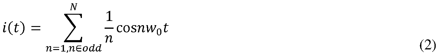


Claims
Priority Applications (19)
| Application Number | Priority Date | Filing Date | Title |
|---|---|---|---|
| MX2021004271A MX2021004271A (en) | 2018-11-30 | 2019-11-25 | Systems and methods for enhancing efficacy of ultrasound treatment. |
| CA3116332A CA3116332A1 (en) | 2018-11-30 | 2019-11-25 | Systems and methods for enhancing efficacy of ultrasound treatment |
| EP19891602.5A EP3886981A4 (en) | 2018-11-30 | 2019-11-25 | SYSTEMS AND METHODS FOR IMPROVING THE EFFECTIVENESS OF ULTRASOUND TREATMENT |
| BR112021006999-2A BR112021006999A2 (en) | 2018-11-30 | 2019-11-25 | systems and methods for improving the effectiveness of ultrasound treatment |
| CN202510141480.1A CN119951055A (en) | 2018-11-30 | 2019-11-25 | Systems and methods for enhancing the efficacy of ultrasound therapy |
| IL282095A IL282095B2 (en) | 2018-11-30 | 2019-11-25 | Systems and methods for increasing the effectiveness of ultrasound therapy |
| AU2019385902A AU2019385902B2 (en) | 2018-11-30 | 2019-11-25 | Systems and methods for enhancing efficacy of ultrasound treatment |
| JP2021520412A JP2022513577A (en) | 2018-11-30 | 2019-11-25 | Systems and methods to enhance the efficacy of ultrasound treatment |
| CN201980086756.3A CN113260414B (en) | 2018-11-30 | 2019-11-25 | Systems and methods for enhancing the efficacy of ultrasound therapy |
| US17/297,145 US12521574B2 (en) | 2018-11-30 | 2019-11-25 | Systems and methods for enhancing efficacy of ultrasound treatment |
| IL321967A IL321967A (en) | 2018-11-30 | 2019-11-25 | Systems and methods for enhancing efficacy of ultrasound treatment |
| SG11202102775VA SG11202102775VA (en) | 2018-11-30 | 2019-11-25 | Systems and methods for enhancing efficacy of ultrasound treatment |
| KR1020217018644A KR20210110578A (en) | 2018-11-30 | 2019-11-25 | Systems and Methods for Improving Efficacy of Ultrasound Therapy |
| MX2024013930A MX2024013930A (en) | 2018-11-30 | 2021-04-13 | Systems and methods for enhancing efficacy of ultrasound treatment |
| MX2024013932A MX2024013932A (en) | 2018-11-30 | 2021-04-13 | SYSTEMS AND METHODS TO IMPROVE THE EFFICACY OF ULTRASOUND TREATMENT |
| MX2024013931A MX2024013931A (en) | 2018-11-30 | 2021-04-13 | Systems and methods for enhancing efficacy of ultrasound treatment |
| US19/029,312 US20250325842A1 (en) | 2018-11-30 | 2025-01-17 | Systems and methods for enhancing efficacy of ultrasound treatment |
| JP2025041354A JP2025094033A (en) | 2018-11-30 | 2025-03-14 | Systems and methods for enhancing the efficacy of ultrasound treatments - Patents.com |
| AU2025242261A AU2025242261A1 (en) | 2018-11-30 | 2025-10-06 | Systems and methods for enhancing efficacy of ultrasound treatment |
Applications Claiming Priority (2)
| Application Number | Priority Date | Filing Date | Title |
|---|---|---|---|
| US201862773948P | 2018-11-30 | 2018-11-30 | |
| US62/773,948 | 2018-11-30 |
Related Child Applications (2)
| Application Number | Title | Priority Date | Filing Date |
|---|---|---|---|
| US17/297,145 A-371-Of-International US12521574B2 (en) | 2018-11-30 | 2019-11-25 | Systems and methods for enhancing efficacy of ultrasound treatment |
| US19/029,312 Continuation US20250325842A1 (en) | 2018-11-30 | 2025-01-17 | Systems and methods for enhancing efficacy of ultrasound treatment |
Publications (1)
| Publication Number | Publication Date |
|---|---|
| WO2020112688A1 true WO2020112688A1 (en) | 2020-06-04 |
Family
ID=70853069
Family Applications (1)
| Application Number | Title | Priority Date | Filing Date |
|---|---|---|---|
| PCT/US2019/063095 Ceased WO2020112688A1 (en) | 2018-11-30 | 2019-11-25 | Systems and methods for enhancing efficacy of ultrasound treatment |
Country Status (13)
| Country | Link |
|---|---|
| US (2) | US12521574B2 (en) |
| EP (1) | EP3886981A4 (en) |
| JP (2) | JP2022513577A (en) |
| KR (1) | KR20210110578A (en) |
| CN (2) | CN119951055A (en) |
| AU (2) | AU2019385902B2 (en) |
| BR (1) | BR112021006999A2 (en) |
| CA (1) | CA3116332A1 (en) |
| IL (2) | IL282095B2 (en) |
| MX (4) | MX2021004271A (en) |
| SG (1) | SG11202102775VA (en) |
| TW (1) | TWI843770B (en) |
| WO (1) | WO2020112688A1 (en) |
Cited By (10)
| Publication number | Priority date | Publication date | Assignee | Title |
|---|---|---|---|---|
| CN113457003A (en) * | 2021-08-05 | 2021-10-01 | 广东光声医疗科技有限公司 | Multi-frequency vibration ultrasonic leading-in device for large-depth transvaginal mucosa |
| WO2022164459A1 (en) | 2021-02-01 | 2022-08-04 | Sonogen Medical, Inc. | Ultrasound transducer for medical applications |
| JP2023516040A (en) * | 2020-03-02 | 2023-04-17 | カルテラ | Method and system for detecting poor acoustic coupling between an ultrasound device and tissue to be treated |
| EP4494578A1 (en) * | 2023-07-20 | 2025-01-22 | Olympus Winter & Ibe GmbH | Electrosurgical generator for controlling an ultrasonic transducer of an electrosurgical instrument |
| US12318636B2 (en) | 2022-10-28 | 2025-06-03 | Histosonics, Inc. | Histotripsy systems and methods |
| EP4351447A4 (en) * | 2021-06-07 | 2025-07-16 | Univ Michigan Regents | ALL-IN-ONE ULTRASOUND SYSTEMS AND PROCEDURES WITH HISTOTRIPSY |
| WO2025088213A3 (en) * | 2023-10-27 | 2025-07-17 | Biotekon Ab | Resonance matched and power compensated actuator device for acoustic particle manipulation |
| US12446905B2 (en) | 2023-04-20 | 2025-10-21 | Histosonics, Inc. | Histotripsy systems and associated methods including user interfaces and workflows for treatment planning and therapy |
| US12491382B2 (en) | 2018-11-28 | 2025-12-09 | Histosonics, Inc. | Histotripsy systems and methods |
| US12527976B2 (en) | 2020-06-18 | 2026-01-20 | Histosonics, Inc. | Histotripsy acoustic and patient coupling systems and methods |
Families Citing this family (13)
| Publication number | Priority date | Publication date | Assignee | Title |
|---|---|---|---|---|
| US20220000509A1 (en) * | 2018-10-26 | 2022-01-06 | Applaud Medical, Inc. | Ultrasound Device for Use with Synthetic Cavitation Nuclei |
| US20230310268A1 (en) * | 2020-06-11 | 2023-10-05 | Yunnan Liheng Medical Technology Co., Ltd. | Treatment pen, main machine, and limb pain treatment instrument |
| TWI741846B (en) * | 2020-10-21 | 2021-10-01 | 詠業科技股份有限公司 | Ultrasonic sensing device and component |
| US20220160421A1 (en) * | 2020-11-25 | 2022-05-26 | Biosense Webster (Israel) Ltd. | Single frequency switch mode power supply generator with phase shifter |
| WO2023211207A1 (en) * | 2022-04-28 | 2023-11-02 | (주)아이엠지티 | Focused ultrasound treatment apparatus operating in conjunction with nanodrug carrier, ultrasound control method, and nanodrug carrier thereof |
| CN114614798A (en) * | 2022-05-11 | 2022-06-10 | 河北普尼医疗科技有限公司 | Control circuit of electric field therapeutic apparatus for interfering cell division and electric field therapeutic apparatus |
| EP4527452A4 (en) * | 2022-06-14 | 2025-10-15 | Jeisys Medical Inc | ULTRASOUND GENERATING DEVICE |
| CN116673202B (en) * | 2023-06-25 | 2025-11-14 | 桂林电子科技大学 | An ultrasonic drive source transducer based on gallium nitride devices and its control method. |
| TWI851455B (en) * | 2023-10-24 | 2024-08-01 | 佳世達科技股份有限公司 | Ultrasonic transducer device and manufacturing method thereof |
| TWI870209B (en) * | 2024-01-17 | 2025-01-11 | 光點生醫股份有限公司 | Laser treatment system for skin |
| CN118170058B (en) * | 2024-02-02 | 2024-11-26 | 沈阳长江源科技发展有限公司 | Spherical focused ultrasonic transducer control system, method, terminal and treatment equipment |
| WO2025260179A1 (en) * | 2024-06-17 | 2025-12-26 | Daxsonics Ultrasound Inc. | Accelerated chemical decalcification of bone in vivo to improve ultrasound signal transmission |
| CN119015618A (en) * | 2024-08-21 | 2024-11-26 | 深圳大学总医院 | Ultrasonic power output method and focused ultrasonic treatment equipment |
Citations (12)
| Publication number | Priority date | Publication date | Assignee | Title |
|---|---|---|---|---|
| US5113116A (en) * | 1989-10-05 | 1992-05-12 | Firma J. Eberspacher | Circuit arrangement for accurately and effectively driving an ultrasonic transducer |
| US5931836A (en) * | 1996-07-29 | 1999-08-03 | Olympus Optical Co., Ltd. | Electrosurgery apparatus and medical apparatus combined with the same |
| US20030039173A1 (en) * | 2001-03-16 | 2003-02-27 | Yurchenko Oleksandr V. | Methods for reducing ringing of ultrasonic transducers |
| US20050007879A1 (en) * | 2003-06-03 | 2005-01-13 | Masaru Nishida | Ultrasonic transmitter, ultrasonic transceiver and sounding apparatus |
| US20060238068A1 (en) * | 2005-02-28 | 2006-10-26 | Sulphco, Inc. | Power driving circuit for controlling a variable load ultrasonic transducer |
| US20070016022A1 (en) * | 2003-01-14 | 2007-01-18 | University Of Virginia Patent Foundation | Ultrasound imaging beam-former apparatus and method |
| US20100126275A1 (en) * | 2008-11-24 | 2010-05-27 | Greg Leyh | Self-calibrating ultrasound systems and methods |
| US20130035679A1 (en) * | 2011-08-01 | 2013-02-07 | TYCO Healthare Group LP | Electrosurgical Apparatus with Real-Time RF Tissue Energy Control |
| US20140376269A1 (en) * | 2013-06-24 | 2014-12-25 | Covidien Lp | Dead-time optimization of resonant inverters |
| US20150032096A1 (en) * | 2013-07-24 | 2015-01-29 | Covidien Lp | Systems and methods for generating electrosurgical energy using a multistage power converter |
| US20170090507A1 (en) * | 2015-09-30 | 2017-03-30 | Ethicon Endo-Surgery, Llc | Generator for digitally generating electrical signal waveforms for electrosurgical and ultrasonic surgical instruments |
| US20170209202A1 (en) * | 2016-01-23 | 2017-07-27 | Covidien Lp | System and method for harmonic control of dual-output generators |
Family Cites Families (1108)
| Publication number | Priority date | Publication date | Assignee | Title |
|---|---|---|---|---|
| US2427348A (en) | 1941-08-19 | 1947-09-16 | Bell Telephone Labor Inc | Piezoelectric vibrator |
| US2792829A (en) | 1952-02-06 | 1957-05-21 | Raytheon Mfg Co | Frequency modulated ultrasonic therapeutic apparatus |
| FR2190364B1 (en) | 1972-07-04 | 1975-06-13 | Patru Marcel | |
| FR2214378A5 (en) | 1973-01-16 | 1974-08-09 | Commissariat Energie Atomique | |
| FR2254030B1 (en) | 1973-12-10 | 1977-08-19 | Philips Massiot Mat Medic | |
| US3965455A (en) | 1974-04-25 | 1976-06-22 | The United States Of America As Represented By The Secretary Of The Navy | Focused arc beam transducer-reflector |
| US4059098A (en) | 1975-07-21 | 1977-11-22 | Stanford Research Institute | Flexible ultrasound coupling system |
| JPS5343987A (en) | 1976-09-30 | 1978-04-20 | Tokyo Shibaura Electric Co | Ultrasonic diagnostic device |
| AT353506B (en) | 1976-10-19 | 1979-11-26 | List Hans | PIEZOELECTRIC RESONATOR |
| JPS5353393A (en) | 1976-10-25 | 1978-05-15 | Matsushita Electric Ind Co Ltd | Ultrasonic probe |
| US4213344A (en) | 1978-10-16 | 1980-07-22 | Krautkramer-Branson, Incorporated | Method and apparatus for providing dynamic focussing and beam steering in an ultrasonic apparatus |
| US4211949A (en) | 1978-11-08 | 1980-07-08 | General Electric Company | Wear plate for piezoelectric ultrasonic transducer arrays |
| US4211948A (en) | 1978-11-08 | 1980-07-08 | General Electric Company | Front surface matched piezoelectric ultrasonic transducer array with wide field of view |
| US4276491A (en) | 1979-10-02 | 1981-06-30 | Ausonics Pty. Limited | Focusing piezoelectric ultrasonic medical diagnostic system |
| US4343301A (en) | 1979-10-04 | 1982-08-10 | Robert Indech | Subcutaneous neural stimulation or local tissue destruction |
| US4325381A (en) | 1979-11-21 | 1982-04-20 | New York Institute Of Technology | Ultrasonic scanning head with reduced geometrical distortion |
| JPS5686121A (en) | 1979-12-14 | 1981-07-13 | Teijin Ltd | Antitumor proten complex and its preparation |
| US4315514A (en) | 1980-05-08 | 1982-02-16 | William Drewes | Method and apparatus for selective cell destruction |
| US4381787A (en) | 1980-08-15 | 1983-05-03 | Technicare Corporation | Ultrasound imaging system combining static B-scan and real-time sector scanning capability |
| US4372296A (en) | 1980-11-26 | 1983-02-08 | Fahim Mostafa S | Treatment of acne and skin disorders and compositions therefor |
| US4484569A (en) | 1981-03-13 | 1984-11-27 | Riverside Research Institute | Ultrasonic diagnostic and therapeutic transducer assembly and method for using |
| US4381007A (en) | 1981-04-30 | 1983-04-26 | The United States Of America As Represented By The United States Department Of Energy | Multipolar corneal-shaping electrode with flexible removable skirt |
| EP0068961A3 (en) | 1981-06-26 | 1983-02-02 | Thomson-Csf | Apparatus for the local heating of biological tissue |
| US4409839A (en) | 1981-07-01 | 1983-10-18 | Siemens Ag | Ultrasound camera |
| US4397314A (en) | 1981-08-03 | 1983-08-09 | Clini-Therm Corporation | Method and apparatus for controlling and optimizing the heating pattern for a hyperthermia system |
| US4622972A (en) | 1981-10-05 | 1986-11-18 | Varian Associates, Inc. | Ultrasound hyperthermia applicator with variable coherence by multi-spiral focusing |
| US4441486A (en) | 1981-10-27 | 1984-04-10 | Board Of Trustees Of Leland Stanford Jr. University | Hyperthermia system |
| US4417170A (en) | 1981-11-23 | 1983-11-22 | Imperial Clevite Inc. | Flexible circuit interconnect for piezoelectric element |
| DE3300121A1 (en) | 1982-01-07 | 1983-07-14 | Technicare Corp., 80112 Englewood, Col. | METHOD AND DEVICE FOR IMAGING AND THERMALLY TREATING TISSUE BY MEANS OF ULTRASOUND |
| US4528979A (en) | 1982-03-18 | 1985-07-16 | Kievsky Nauchno-Issledovatelsky Institut Otolaringologii Imeni Professora A.S. Kolomiiobenka | Cryo-ultrasonic surgical instrument |
| US4431008A (en) | 1982-06-24 | 1984-02-14 | Wanner James F | Ultrasonic measurement system using a perturbing field, multiple sense beams and receivers |
| US4534221A (en) | 1982-09-27 | 1985-08-13 | Technicare Corporation | Ultrasonic diagnostic imaging systems for varying depths of field |
| US4507582A (en) | 1982-09-29 | 1985-03-26 | New York Institute Of Technology | Matching region for damped piezoelectric ultrasonic apparatus |
| US4452084A (en) | 1982-10-25 | 1984-06-05 | Sri International | Inherent delay line ultrasonic transducer and systems |
| DE3374522D1 (en) | 1982-10-26 | 1987-12-23 | University Of Aberdeen | |
| US4513749A (en) | 1982-11-18 | 1985-04-30 | Board Of Trustees Of Leland Stanford University | Three-dimensional temperature probe |
| US4527550A (en) | 1983-01-28 | 1985-07-09 | The United States Of America As Represented By The Department Of Health And Human Services | Helical coil for diathermy apparatus |
| JPH064074B2 (en) | 1983-02-14 | 1994-01-19 | 株式会社日立製作所 | Ultrasonic diagnostic device and sound velocity measuring method using the same |
| FR2543437B1 (en) | 1983-03-30 | 1987-07-10 | Duraffourd Alain | COMPOSITION FOR REGENERATING COLLAGEN OF CONNECTIVE TISSUE OF THE SKIN AND METHOD FOR PREPARING SAME |
| JPS605133A (en) | 1983-05-26 | 1985-01-11 | アドバンスト・テクノロジ−・ラボラトリ−ズ・インコ−ポレイテツド | Ultrasonic converter improved in vibration mode |
| US4900540A (en) | 1983-06-20 | 1990-02-13 | Trustees Of The University Of Massachusetts | Lipisomes containing gas for ultrasound detection |
| EP0129878B1 (en) | 1983-06-23 | 1989-01-11 | Matsushita Electric Industrial Co., Ltd. | Ultrasonic probe having dual-motion transducer |
| FR2551611B1 (en) | 1983-08-31 | 1986-10-24 | Labo Electronique Physique | NOVEL ULTRASONIC TRANSDUCER STRUCTURE AND ULTRASONIC ECHOGRAPHY MEDIA EXAMINATION APPARATUS COMPRISING SUCH A STRUCTURE |
| US4601296A (en) | 1983-10-07 | 1986-07-22 | Yeda Research And Development Co., Ltd. | Hyperthermia apparatus |
| US5150711A (en) | 1983-12-14 | 1992-09-29 | Edap International, S.A. | Ultra-high-speed extracorporeal ultrasound hyperthermia treatment device |
| US5143074A (en) | 1983-12-14 | 1992-09-01 | Edap International | Ultrasonic treatment device using a focussing and oscillating piezoelectric element |
| US4513750A (en) | 1984-02-22 | 1985-04-30 | The United States Of America As Represented By The Administrator Of The National Aeronautics And Space Administration | Method for thermal monitoring subcutaneous tissue |
| US4567895A (en) | 1984-04-02 | 1986-02-04 | Advanced Technology Laboratories, Inc. | Fully wetted mechanical ultrasound scanhead |
| US4620546A (en) | 1984-06-30 | 1986-11-04 | Kabushiki Kaisha Toshiba | Ultrasound hyperthermia apparatus |
| US4587971A (en) | 1984-11-29 | 1986-05-13 | North American Philips Corporation | Ultrasonic scanning apparatus |
| DE3447440A1 (en) | 1984-12-27 | 1986-07-03 | Siemens AG, 1000 Berlin und 8000 München | SHOCK SHAFT PIPE FOR THE CRUSHING OF CONCRETE |
| DE3501808A1 (en) | 1985-01-21 | 1986-07-24 | Siemens AG, 1000 Berlin und 8000 München | ULTRASONIC CONVERTER |
| JPS61209643A (en) | 1985-03-15 | 1986-09-17 | 株式会社東芝 | Ultrasonic diagnostic and medical treatment apparatus |
| DE3611669A1 (en) | 1985-04-10 | 1986-10-16 | Hitachi Medical Corp., Tokio/Tokyo | ULTRASONIC CONVERTER |
| JPH0678460B2 (en) | 1985-05-01 | 1994-10-05 | 株式会社バイオマテリアル・ユニバース | Porous transparent polyvinyl alcohol gel |
| DE3650004T2 (en) | 1985-05-20 | 1995-02-23 | Matsushita Electric Ind Co Ltd | Ultrasound probe. |
| US4865042A (en) | 1985-08-16 | 1989-09-12 | Hitachi, Ltd. | Ultrasonic irradiation system |
| US5054310A (en) | 1985-09-13 | 1991-10-08 | The California Province Of The Society Of Jesus | Test object and method of measurement of an ultrasonic beam |
| US5304169A (en) | 1985-09-27 | 1994-04-19 | Laser Biotech, Inc. | Method for collagen shrinkage |
| US4976709A (en) | 1988-12-15 | 1990-12-11 | Sand Bruce J | Method for collagen treatment |
| EP0226466B1 (en) | 1985-12-13 | 1993-07-14 | Matsushita Electric Industrial Co., Ltd. | Ultrasonic diagnostic apparatus based on variations of acoustic characteristic |
| JPS6323126A (en) | 1986-02-13 | 1988-01-30 | Bio Material Yunibaasu:Kk | Soft contact lens and its production |
| JPS62249644A (en) | 1986-04-22 | 1987-10-30 | 日石三菱株式会社 | pseudo biological structure |
| JPS62258597A (en) | 1986-04-25 | 1987-11-11 | Yokogawa Medical Syst Ltd | Ultrasonic transducer |
| US4875487A (en) | 1986-05-02 | 1989-10-24 | Varian Associates, Inc. | Compressional wave hyperthermia treating method and apparatus |
| US4807633A (en) | 1986-05-21 | 1989-02-28 | Indianapolis Center For Advanced Research | Non-invasive tissue thermometry system and method |
| US4803625A (en) | 1986-06-30 | 1989-02-07 | Buddy Systems, Inc. | Personal health monitor |
| US4867169A (en) | 1986-07-29 | 1989-09-19 | Kaoru Machida | Attachment attached to ultrasound probe for clinical application |
| JPS6336171A (en) | 1986-07-29 | 1988-02-16 | Toshiba Corp | Ultrasonic coupler |
| US4801459A (en) | 1986-08-05 | 1989-01-31 | Liburdy Robert P | Technique for drug and chemical delivery |
| JPS63122923A (en) | 1986-11-13 | 1988-05-26 | Agency Of Ind Science & Technol | Ultrasonic thermometric apparatus |
| US4865041A (en) | 1987-02-04 | 1989-09-12 | Siemens Aktiengesellschaft | Lithotripter having an ultrasound locating system integrated therewith |
| JPS63220847A (en) | 1987-03-10 | 1988-09-14 | 松下電器産業株式会社 | ultrasonic probe |
| US5178135A (en) | 1987-04-16 | 1993-01-12 | Olympus Optical Co., Ltd. | Therapeutical apparatus of extracorporeal type |
| BG46024A1 (en) | 1987-05-19 | 1989-10-16 | Min Na Narodnata Otbrana | Method and device for treatment of bone patology |
| US4891043A (en) | 1987-05-28 | 1990-01-02 | Board Of Trustees Of The University Of Illinois | System for selective release of liposome encapsulated material via laser radiation |
| US4932414A (en) | 1987-11-02 | 1990-06-12 | Cornell Research Foundation, Inc. | System of therapeutic ultrasound and real-time ultrasonic scanning |
| US5040537A (en) | 1987-11-24 | 1991-08-20 | Hitachi, Ltd. | Method and apparatus for the measurement and medical treatment using an ultrasonic wave |
| US4917096A (en) | 1987-11-25 | 1990-04-17 | Laboratory Equipment, Corp. | Portable ultrasonic probe |
| US4860732A (en) | 1987-11-25 | 1989-08-29 | Olympus Optical Co., Ltd. | Endoscope apparatus provided with endoscope insertion aid |
| US5163421A (en) | 1988-01-22 | 1992-11-17 | Angiosonics, Inc. | In vivo ultrasonic system with angioplasty and ultrasonic contrast imaging |
| US5251127A (en) | 1988-02-01 | 1993-10-05 | Faro Medical Technologies Inc. | Computer-aided surgery apparatus |
| US5143063A (en) | 1988-02-09 | 1992-09-01 | Fellner Donald G | Method of removing adipose tissue from the body |
| US4951653A (en) | 1988-03-02 | 1990-08-28 | Laboratory Equipment, Corp. | Ultrasound brain lesioning system |
| US4955365A (en) | 1988-03-02 | 1990-09-11 | Laboratory Equipment, Corp. | Localization and therapy system for treatment of spatially oriented focal disease |
| US5036855A (en) | 1988-03-02 | 1991-08-06 | Laboratory Equipment, Corp. | Localization and therapy system for treatment of spatially oriented focal disease |
| US4858613A (en) | 1988-03-02 | 1989-08-22 | Laboratory Equipment, Corp. | Localization and therapy system for treatment of spatially oriented focal disease |
| US5054470A (en) | 1988-03-02 | 1991-10-08 | Laboratory Equipment, Corp. | Ultrasonic treatment transducer with pressurized acoustic coupling |
| US5665141A (en) | 1988-03-30 | 1997-09-09 | Arjo Hospital Equipment Ab | Ultrasonic treatment process |
| JP2615132B2 (en) | 1988-05-19 | 1997-05-28 | 富士通株式会社 | Ultrasonic probe |
| US4947046A (en) | 1988-05-27 | 1990-08-07 | Konica Corporation | Method for preparation of radiographic image conversion panel and radiographic image conversion panel thereby |
| US4966953A (en) | 1988-06-02 | 1990-10-30 | Takiron Co., Ltd. | Liquid segment polyurethane gel and couplers for ultrasonic diagnostic probe comprising the same |
| US5018508A (en) | 1988-06-03 | 1991-05-28 | Fry Francis J | System and method using chemicals and ultrasound or ultrasound alone to replace more conventional surgery |
| US4893624A (en) | 1988-06-21 | 1990-01-16 | Massachusetts Institute Of Technology | Diffuse focus ultrasound hyperthermia system |
| US4938216A (en) | 1988-06-21 | 1990-07-03 | Massachusetts Institute Of Technology | Mechanically scanned line-focus ultrasound hyperthermia system |
| US4938217A (en) | 1988-06-21 | 1990-07-03 | Massachusetts Institute Of Technology | Electronically-controlled variable focus ultrasound hyperthermia system |
| US4896673A (en) | 1988-07-15 | 1990-01-30 | Medstone International, Inc. | Method and apparatus for stone localization using ultrasound imaging |
| EP0413028B1 (en) | 1988-08-30 | 1995-07-12 | Fujitsu Limited | Acoustic coupler |
| US5054491A (en) | 1988-10-17 | 1991-10-08 | Olympus Optical Co., Ltd. | Ultrasonic endoscope apparatus |
| US5159931A (en) | 1988-11-25 | 1992-11-03 | Riccardo Pini | Apparatus for obtaining a three-dimensional reconstruction of anatomic structures through the acquisition of echographic images |
| FR2643770B1 (en) | 1989-02-28 | 1991-06-21 | Centre Nat Rech Scient | MICROECHOGRAPHIC ULTRASONIC COLLIMATION PROBE THROUGH A DEFORMABLE SURFACE |
| JP2745147B2 (en) | 1989-03-27 | 1998-04-28 | 三菱マテリアル 株式会社 | Piezoelectric transducer |
| DE69015400T2 (en) | 1989-03-27 | 1995-05-24 | Toshiba Kawasaki Kk | Mechanical ultrasound scanner. |
| DE3914619A1 (en) | 1989-05-03 | 1990-11-08 | Kontron Elektronik | DEVICE FOR TRANSOESOPHAGEAL ECHOCARDIOGRAPHY |
| US6016255A (en) | 1990-11-19 | 2000-01-18 | Dallas Semiconductor Corp. | Portable data carrier mounting system |
| US5057104A (en) | 1989-05-30 | 1991-10-15 | Cyrus Chess | Method and apparatus for treating cutaneous vascular lesions |
| US5212671A (en) | 1989-06-22 | 1993-05-18 | Terumo Kabushiki Kaisha | Ultrasonic probe having backing material layer of uneven thickness |
| US5435311A (en) | 1989-06-27 | 1995-07-25 | Hitachi, Ltd. | Ultrasound therapeutic system |
| US5115814A (en) | 1989-08-18 | 1992-05-26 | Intertherapy, Inc. | Intravascular ultrasonic imaging probe and methods of using same |
| EP0491685A4 (en) | 1989-08-28 | 1993-10-13 | K. Michael Sekins | Lung cancer hyperthermia via ultrasound and/or convection with perfluorocarbon liquids |
| US5240003A (en) | 1989-10-16 | 1993-08-31 | Du-Med B.V. | Ultrasonic instrument with a micro motor having stator coils on a flexible circuit board |
| US5156144A (en) | 1989-10-20 | 1992-10-20 | Olympus Optical Co., Ltd. | Ultrasonic wave therapeutic device |
| JPH03136642A (en) | 1989-10-20 | 1991-06-11 | Olympus Optical Co Ltd | Ultrasonic treatment device |
| DE69019289T2 (en) | 1989-10-27 | 1996-02-01 | Storz Instr Co | Method for driving an ultrasonic transducer. |
| EP0427358B1 (en) | 1989-11-08 | 1996-03-27 | George S. Allen | Mechanical arm for and interactive image-guided surgical system |
| US5070879A (en) | 1989-11-30 | 1991-12-10 | Acoustic Imaging Technologies Corp. | Ultrasound imaging method and apparatus |
| DE69027284T2 (en) | 1989-12-14 | 1996-12-05 | Aloka Co Ltd | Three-dimensional ultrasound scanner |
| US5149319A (en) | 1990-09-11 | 1992-09-22 | Unger Evan C | Methods for providing localized therapeutic heat to biological tissues and fluids |
| US5580575A (en) | 1989-12-22 | 1996-12-03 | Imarx Pharmaceutical Corp. | Therapeutic drug delivery systems |
| US5209720A (en) | 1989-12-22 | 1993-05-11 | Unger Evan C | Methods for providing localized therapeutic heat to biological tissues and fluids using gas filled liposomes |
| US5305757A (en) | 1989-12-22 | 1994-04-26 | Unger Evan C | Gas filled liposomes and their use as ultrasonic contrast agents |
| US5469854A (en) | 1989-12-22 | 1995-11-28 | Imarx Pharmaceutical Corp. | Methods of preparing gas-filled liposomes |
| US5012797A (en) | 1990-01-08 | 1991-05-07 | Montefiore Hospital Association Of Western Pennsylvania | Method for removing skin wrinkles |
| JP3015481B2 (en) | 1990-03-28 | 2000-03-06 | 株式会社東芝 | Ultrasonic probe system |
| IN172208B (en) | 1990-04-02 | 1993-05-01 | Sint Sa | |
| JPH03297475A (en) | 1990-04-16 | 1991-12-27 | Ken Ishihara | Controlling method for emission of medicine by means of resonance sound wave |
| US5205287A (en) | 1990-04-26 | 1993-04-27 | Hoechst Aktiengesellschaft | Ultrasonic contrast agents, processes for their preparation and the use thereof as diagnostic and therapeutic agents |
| DE4117638A1 (en) | 1990-05-30 | 1991-12-05 | Toshiba Kawasaki Kk | SHOCK WAVE GENERATOR WITH A PIEZOELECTRIC ELEMENT |
| US5215680A (en) | 1990-07-10 | 1993-06-01 | Cavitation-Control Technology, Inc. | Method for the production of medical-grade lipid-coated microbubbles, paramagnetic labeling of such microbubbles and therapeutic uses of microbubbles |
| US5191880A (en) | 1990-07-31 | 1993-03-09 | Mcleod Kenneth J | Method for the promotion of growth, ingrowth and healing of bone tissue and the prevention of osteopenia by mechanical loading of the bone tissue |
| US5174929A (en) | 1990-08-31 | 1992-12-29 | Ciba-Geigy Corporation | Preparation of stable polyvinyl alcohol hydrogel contact lens |
| DE4029175C2 (en) | 1990-09-13 | 1993-10-28 | Lauerer Friedrich | Electrical protection device |
| SE501045C2 (en) | 1990-09-17 | 1994-10-24 | Roofer Int Ab | Method of laying roofing board and device for carrying out the procedure |
| US5117832A (en) | 1990-09-21 | 1992-06-02 | Diasonics, Inc. | Curved rectangular/elliptical transducer |
| JPH04150847A (en) | 1990-10-12 | 1992-05-25 | Katsuya Takasu | Armpit smell surgical apparatus and chip for operation |
| US5685820A (en) | 1990-11-06 | 1997-11-11 | Partomed Medizintechnik Gmbh | Instrument for the penetration of body tissue |
| GB9025431D0 (en) | 1990-11-22 | 1991-01-09 | Advanced Tech Lab | Three dimensional ultrasonic imaging |
| US5997497A (en) | 1991-01-11 | 1999-12-07 | Advanced Cardiovascular Systems | Ultrasound catheter having integrated drug delivery system and methods of using same |
| US5957882A (en) | 1991-01-11 | 1999-09-28 | Advanced Cardiovascular Systems, Inc. | Ultrasound devices for ablating and removing obstructive matter from anatomical passageways and blood vessels |
| FR2672486A1 (en) | 1991-02-11 | 1992-08-14 | Technomed Int Sa | Ultrasound apparatus for extracorporeal therapeutic treatment of superficial varicose veins |
| FR2679125B1 (en) | 1991-07-19 | 1993-11-26 | Technomed International | USE OF AT LEAST ONE COMPOSITE PIEZOELECTRIC TRANSDUCER FOR THE MANUFACTURE OF AN ULTRASONIC THERAPY APPARATUS FOR THERAPY IN PARTICULAR OF CONCRETIONS, FABRICS OR BONES OF A LIVING BEING. |
| US5255681A (en) | 1991-03-20 | 1993-10-26 | Olympus Optical Co., Ltd. | Ultrasonic wave diagnosing apparatus having an ultrasonic wave transmitting and receiving part transmitting and receiving ultrasonic waves |
| US5358466A (en) | 1991-04-15 | 1994-10-25 | Kabushiki Kaisha Toshiba | Apparatus for destroying a calculus |
| US5150714A (en) | 1991-05-10 | 1992-09-29 | Sri International | Ultrasonic inspection method and apparatus with audible output |
| US5429582A (en) | 1991-06-14 | 1995-07-04 | Williams; Jeffery A. | Tumor treatment |
| JP3123559B2 (en) | 1991-06-29 | 2001-01-15 | 東芝ライテック株式会社 | Lighting equipment |
| US5383917A (en) | 1991-07-05 | 1995-01-24 | Jawahar M. Desai | Device and method for multi-phase radio-frequency ablation |
| US5327895A (en) | 1991-07-10 | 1994-07-12 | Kabushiki Kaisha Toshiba | Ultrasonic probe and ultrasonic diagnosing system using ultrasonic probe |
| JP3095835B2 (en) | 1991-10-30 | 2000-10-10 | 株式会社町田製作所 | Gravity direction indicator for endoscopes |
| US5704361A (en) | 1991-11-08 | 1998-01-06 | Mayo Foundation For Medical Education And Research | Volumetric image ultrasound transducer underfluid catheter system |
| US5524620A (en) | 1991-11-12 | 1996-06-11 | November Technologies Ltd. | Ablation of blood thrombi by means of acoustic energy |
| US5329202A (en) | 1991-11-22 | 1994-07-12 | Advanced Imaging Systems | Large area ultrasonic transducer |
| WO1993012742A1 (en) | 1991-12-20 | 1993-07-08 | Technomed International | Ultrasonic therapy apparatus delivering ultrasonic waves with thermal and cavitational effects |
| FR2685872A1 (en) | 1992-01-07 | 1993-07-09 | Edap Int | APPARATUS OF EXTRACORPOREAL ULTRASONIC HYPERTHERMIA WITH VERY HIGH POWER AND ITS OPERATING METHOD. |
| US5230334A (en) | 1992-01-22 | 1993-07-27 | Summit Technology, Inc. | Method and apparatus for generating localized hyperthermia |
| WO1993016641A1 (en) | 1992-02-21 | 1993-09-02 | Diasonics, Inc. | Ultrasound intracavity system for imaging therapy planning and treatment of focal disease |
| US5269297A (en) | 1992-02-27 | 1993-12-14 | Angiosonics Inc. | Ultrasonic transmission apparatus |
| JP3386488B2 (en) | 1992-03-10 | 2003-03-17 | 株式会社東芝 | Ultrasound therapy equipment |
| WO1993019705A1 (en) | 1992-03-31 | 1993-10-14 | Massachusetts Institute Of Technology | Apparatus and method for acoustic heat generation and hyperthermia |
| US5690608A (en) | 1992-04-08 | 1997-11-25 | Asec Co., Ltd. | Ultrasonic apparatus for health and beauty |
| US5257970A (en) | 1992-04-09 | 1993-11-02 | Health Research, Inc. | In situ photodynamic therapy |
| US5295484A (en) | 1992-05-19 | 1994-03-22 | Arizona Board Of Regents For And On Behalf Of The University Of Arizona | Apparatus and method for intra-cardiac ablation of arrhythmias |
| JPH0773576B2 (en) | 1992-05-27 | 1995-08-09 | アロカ株式会社 | Ultrasonic probe for 3D data acquisition |
| JP3257640B2 (en) | 1992-06-09 | 2002-02-18 | オリンパス光学工業株式会社 | Stereoscopic endoscope device |
| US5321520A (en) | 1992-07-20 | 1994-06-14 | Automated Medical Access Corporation | Automated high definition/resolution image storage, retrieval and transmission system |
| DE4229817C2 (en) | 1992-09-07 | 1996-09-12 | Siemens Ag | Method for the non-destructive and / or non-invasive measurement of a temperature change in the interior of a living object in particular |
| US5523058A (en) | 1992-09-16 | 1996-06-04 | Hitachi, Ltd. | Ultrasonic irradiation apparatus and processing apparatus based thereon |
| US5626631A (en) | 1992-10-20 | 1997-05-06 | Esc Medical Systems Ltd. | Method and apparatus for therapeutic electromagnetic treatment |
| JP3224286B2 (en) | 1992-11-02 | 2001-10-29 | 株式会社日本自動車部品総合研究所 | Temperature measurement device using ultrasonic waves |
| US6537306B1 (en) | 1992-11-13 | 2003-03-25 | The Regents Of The University Of California | Method of manufacture of a transurethral ultrasound applicator for prostate gland thermal therapy |
| US5391197A (en) | 1992-11-13 | 1995-02-21 | Dornier Medical Systems, Inc. | Ultrasound thermotherapy probe |
| US5620479A (en) | 1992-11-13 | 1997-04-15 | The Regents Of The University Of California | Method and apparatus for thermal therapy of tumors |
| US5370122A (en) | 1992-11-18 | 1994-12-06 | Kunig; Horst E. | Method and apparatus for measuring myocardial impairment, dysfunctions, sufficiency, and insufficiency |
| DE4241161C2 (en) | 1992-12-07 | 1995-04-13 | Siemens Ag | Acoustic therapy facility |
| JP3272792B2 (en) | 1992-12-15 | 2002-04-08 | フクダ電子株式会社 | Ultrasonic coupler manufacturing method |
| FR2717942B1 (en) | 1994-03-01 | 1996-05-31 | Technomed Int Sa | Method and apparatus for therapy generating high intensity ultrasound with controlled cavitation effect. |
| US5573497A (en) | 1994-11-30 | 1996-11-12 | Technomed Medical Systems And Institut National | High-intensity ultrasound therapy method and apparatus with controlled cavitation effect and reduced side lobes |
| DE4302537C1 (en) | 1993-01-29 | 1994-04-28 | Siemens Ag | Ultrasound imaging and therapy device - generates imaging waves and focussed treatment waves having two differing frequencies for location and treatment of e.g tumours |
| US5423220A (en) | 1993-01-29 | 1995-06-13 | Parallel Design | Ultrasonic transducer array and manufacturing method thereof |
| DE4302538C1 (en) | 1993-01-29 | 1994-04-07 | Siemens Ag | Ultrasonic therapy device for tumour treatment lithotripsy or osteorestoration - with ultrasonic imaging and ultrasonic treatment modes using respective acoustic wave frequencies |
| US5453575A (en) | 1993-02-01 | 1995-09-26 | Endosonics Corporation | Apparatus and method for detecting blood flow in intravascular ultrasonic imaging |
| US5267985A (en) | 1993-02-11 | 1993-12-07 | Trancell, Inc. | Drug delivery by multiple frequency phonophoresis |
| DE69431741T2 (en) | 1993-03-12 | 2003-09-11 | Kabushiki Kaisha Toshiba, Kawasaki | Device for medical treatment with ultrasound |
| US5307812A (en) | 1993-03-26 | 1994-05-03 | General Electric Company | Heat surgery system monitored by real-time magnetic resonance profiling |
| DE4310924C2 (en) | 1993-04-02 | 1995-01-26 | Siemens Ag | Therapy device for the treatment of pathological tissue with ultrasound waves and a catheter |
| US5305756A (en) | 1993-04-05 | 1994-04-26 | Advanced Technology Laboratories, Inc. | Volumetric ultrasonic imaging with diverging elevational ultrasound beams |
| JP3578217B2 (en) | 1993-04-15 | 2004-10-20 | シーメンス アクチエンゲゼルシヤフト | Treatment device for treating heart disease and blood vessels near the heart |
| DE69433588T2 (en) | 1993-04-26 | 2005-02-03 | St. Louis University | DISPLAY OF THE POSITION OF A PROBE |
| US5460595A (en) | 1993-06-01 | 1995-10-24 | Dynatronics Laser Corporation | Multi-frequency ultrasound therapy systems and methods |
| DE4318237A1 (en) | 1993-06-01 | 1994-12-08 | Storz Medical Ag | Device for the treatment of biological tissue and body concretions |
| US5392259A (en) | 1993-06-15 | 1995-02-21 | Bolorforosh; Mir S. S. | Micro-grooves for the design of wideband clinical ultrasonic transducers |
| US5398689A (en) | 1993-06-16 | 1995-03-21 | Hewlett-Packard Company | Ultrasonic probe assembly and cable therefor |
| US5526812A (en) | 1993-06-21 | 1996-06-18 | General Electric Company | Display system for enhancing visualization of body structures during medical procedures |
| US5413550A (en) | 1993-07-21 | 1995-05-09 | Pti, Inc. | Ultrasound therapy system with automatic dose control |
| IL110468A (en) | 1993-07-26 | 1999-04-11 | Technomed Medical Systems | Intracavity probe for therapy and imaging and apparatus for therapeutic treatment including application |
| JP2998505B2 (en) | 1993-07-29 | 2000-01-11 | 富士写真光機株式会社 | Radial ultrasonic scanner |
| US5503320A (en) | 1993-08-19 | 1996-04-02 | United States Surgical Corporation | Surgical apparatus with indicator |
| US5792058A (en) | 1993-09-07 | 1998-08-11 | Acuson Corporation | Broadband phased array transducer with wide bandwidth, high sensitivity and reduced cross-talk and method for manufacture thereof |
| US5438998A (en) | 1993-09-07 | 1995-08-08 | Acuson Corporation | Broadband phased array transducer design with frequency controlled two dimension capability and methods for manufacture thereof |
| US5379773A (en) | 1993-09-17 | 1995-01-10 | Hornsby; James J. | Echographic suction cannula and electronics therefor |
| US5661235A (en) | 1993-10-01 | 1997-08-26 | Hysitron Incorporated | Multi-dimensional capacitive transducer |
| US20050288748A1 (en) | 1993-10-04 | 2005-12-29 | Huan-Chen Li | Medical device for treating skin problems |
| IL107523A (en) | 1993-11-07 | 2000-01-31 | Ultraguide Ltd | Articulated needle guide for ultrasound imaging and method of using same |
| US5526814A (en) | 1993-11-09 | 1996-06-18 | General Electric Company | Automatically positioned focussed energy system guided by medical imaging |
| US5380280A (en) | 1993-11-12 | 1995-01-10 | Peterson; Erik W. | Aspiration system having pressure-controlled and flow-controlled modes |
| US20020169394A1 (en) | 1993-11-15 | 2002-11-14 | Eppstein Jonathan A. | Integrated tissue poration, fluid harvesting and analysis device, and method therefor |
| US5814599A (en) | 1995-08-04 | 1998-09-29 | Massachusetts Insitiute Of Technology | Transdermal delivery of encapsulated drugs |
| US5445611A (en) | 1993-12-08 | 1995-08-29 | Non-Invasive Monitoring Company (Nimco) | Enhancement of transdermal delivery with ultrasound and chemical enhancers |
| US5609562A (en) | 1993-11-16 | 1997-03-11 | Worldwide Optical Trocar Licensing Corporation | Visually directed trocar and method |
| JPH07136162A (en) | 1993-11-17 | 1995-05-30 | Fujitsu Ltd | Ultrasonic coupler |
| US5842473A (en) | 1993-11-29 | 1998-12-01 | Life Imaging Systems | Three-dimensional imaging system |
| US5371483A (en) | 1993-12-20 | 1994-12-06 | Bhardwaj; Mahesh C. | High intensity guided ultrasound source |
| DE69432510T2 (en) | 1993-12-24 | 2003-12-24 | Olympus Optical Co., Ltd. | Device for ultrasound diagnosis and treatment, wherein the focal point of the therapeutic ultrasound wave is locked in a predetermined position within the ultrasound observation area |
| JPH07184907A (en) | 1993-12-28 | 1995-07-25 | Toshiba Corp | Ultrasonic therapy equipment |
| DE4443947B4 (en) | 1994-01-14 | 2005-09-22 | Siemens Ag | endoscope |
| FR2715313B1 (en) | 1994-01-27 | 1996-05-31 | Edap Int | Method for controlling a hyperthermia treatment device using ultrasound. |
| AU1889595A (en) | 1994-03-07 | 1995-09-25 | Medisonic A/S | Apparatus for non-invasive tissue destruction by means of ultrasound |
| US5507790A (en) | 1994-03-21 | 1996-04-16 | Weiss; William V. | Method of non-invasive reduction of human site-specific subcutaneous fat tissue deposits by accelerated lipolysis metabolism |
| US5471488A (en) | 1994-04-05 | 1995-11-28 | International Business Machines Corporation | Clock fault detection circuit |
| US5511296A (en) | 1994-04-08 | 1996-04-30 | Hewlett Packard Company | Method for making integrated matching layer for ultrasonic transducers |
| US5492126A (en) | 1994-05-02 | 1996-02-20 | Focal Surgery | Probe for medical imaging and therapy using ultrasound |
| AU2373695A (en) | 1994-05-03 | 1995-11-29 | Board Of Regents, The University Of Texas System | Apparatus and method for noninvasive doppler ultrasound-guided real-time control of tissue damage in thermal therapy |
| US5524624A (en) | 1994-05-05 | 1996-06-11 | Amei Technologies Inc. | Apparatus and method for stimulating tissue growth with ultrasound |
| US5458596A (en) | 1994-05-06 | 1995-10-17 | Dorsal Orthopedic Corporation | Method and apparatus for controlled contraction of soft tissue |
| US5549638A (en) | 1994-05-17 | 1996-08-27 | Burdette; Everette C. | Ultrasound device for use in a thermotherapy apparatus |
| US5396143A (en) | 1994-05-20 | 1995-03-07 | Hewlett-Packard Company | Elevation aperture control of an ultrasonic transducer |
| US5496256A (en) | 1994-06-09 | 1996-03-05 | Sonex International Corporation | Ultrasonic bone healing device for dental application |
| US5575807A (en) | 1994-06-10 | 1996-11-19 | Zmd Corporation | Medical device power supply with AC disconnect alarm and method of supplying power to a medical device |
| US5560362A (en) | 1994-06-13 | 1996-10-01 | Acuson Corporation | Active thermal control of ultrasound transducers |
| US5540235A (en) | 1994-06-30 | 1996-07-30 | Wilson; John R. | Adaptor for neurophysiological monitoring with a personal computer |
| FR2722358B1 (en) | 1994-07-08 | 1996-08-14 | Thomson Csf | BROADBAND MULTI-FREQUENCY ACOUSTIC TRANSDUCER |
| NO300407B1 (en) | 1994-08-30 | 1997-05-26 | Vingmed Sound As | Apparatus for endoscope or gastroscope examination of patients |
| US5829444A (en) | 1994-09-15 | 1998-11-03 | Visualization Technology, Inc. | Position tracking and imaging system for use in medical applications |
| US5694936A (en) | 1994-09-17 | 1997-12-09 | Kabushiki Kaisha Toshiba | Ultrasonic apparatus for thermotherapy with variable frequency for suppressing cavitation |
| US5443068A (en) | 1994-09-26 | 1995-08-22 | General Electric Company | Mechanical positioner for magnetic resonance guided ultrasound therapy |
| US5810009A (en) | 1994-09-27 | 1998-09-22 | Kabushiki Kaisha Toshiba | Ultrasonic probe, ultrasonic probe device having the ultrasonic probe, and method of manufacturing the ultrasonic probe |
| US5503152A (en) | 1994-09-28 | 1996-04-02 | Tetrad Corporation | Ultrasonic transducer assembly and method for three-dimensional imaging |
| US5487388A (en) | 1994-11-01 | 1996-01-30 | Interspec. Inc. | Three dimensional ultrasonic scanning devices and techniques |
| US5520188A (en) | 1994-11-02 | 1996-05-28 | Focus Surgery Inc. | Annular array transducer |
| US5577507A (en) | 1994-11-21 | 1996-11-26 | General Electric Company | Compound lens for ultrasound transducer probe |
| US6100626A (en) | 1994-11-23 | 2000-08-08 | General Electric Company | System for connecting a transducer array to a coaxial cable in an ultrasound probe |
| DE4446429C1 (en) | 1994-12-23 | 1996-08-22 | Siemens Ag | Device for treating an object with focused ultrasound waves |
| US5999843A (en) | 1995-01-03 | 1999-12-07 | Omnicorder Technologies, Inc. | Detection of cancerous lesions by their effect on the spatial homogeneity of skin temperature |
| US5626554A (en) | 1995-02-21 | 1997-05-06 | Exogen, Inc. | Gel containment structure |
| US6019724A (en) | 1995-02-22 | 2000-02-01 | Gronningsaeter; Aage | Method for ultrasound guidance during clinical procedures |
| DE59600577D1 (en) | 1995-03-10 | 1998-10-22 | Karlsruhe Forschzent | DEVICE FOR GUIDING SURGICAL INSTRUMENTS FOR ENDOSCOPIC SURGERY |
| US6246898B1 (en) | 1995-03-28 | 2001-06-12 | Sonometrics Corporation | Method for carrying out a medical procedure using a three-dimensional tracking and imaging system |
| US5658328A (en) | 1995-03-30 | 1997-08-19 | Johnson; Gerald W. | Endoscopic assisted mastopexy |
| US5655535A (en) | 1996-03-29 | 1997-08-12 | Siemens Medical Systems, Inc. | 3-Dimensional compound ultrasound field of view |
| EP0734742B1 (en) | 1995-03-31 | 2005-05-11 | Kabushiki Kaisha Toshiba | Ultrasound therapeutic apparatus |
| US5873902A (en) | 1995-03-31 | 1999-02-23 | Focus Surgery, Inc. | Ultrasound intensity determining method and apparatus |
| US5899861A (en) | 1995-03-31 | 1999-05-04 | Siemens Medical Systems, Inc. | 3-dimensional volume by aggregating ultrasound fields of view |
| US5577502A (en) | 1995-04-03 | 1996-11-26 | General Electric Company | Imaging of interventional devices during medical procedures |
| US5644085A (en) | 1995-04-03 | 1997-07-01 | General Electric Company | High density integrated ultrasonic phased array transducer and a method for making |
| US5924989A (en) | 1995-04-03 | 1999-07-20 | Polz; Hans | Method and device for capturing diagnostically acceptable three-dimensional ultrasound image data records |
| JPH08280098A (en) | 1995-04-07 | 1996-10-22 | Olympus Optical Co Ltd | Piezoelectric element for ultrasonic probe |
| US5701900A (en) | 1995-05-01 | 1997-12-30 | Cedars-Sinai Medical Center | Ultrasonic transducer orientation sensing and display apparatus and method |
| US5735280A (en) | 1995-05-02 | 1998-04-07 | Heart Rhythm Technologies, Inc. | Ultrasound energy delivery system and method |
| US6470216B1 (en) | 1995-05-05 | 2002-10-22 | Thermage, Inc. | Method for smoothing contour irregularities of skin surface |
| US6241753B1 (en) | 1995-05-05 | 2001-06-05 | Thermage, Inc. | Method for scar collagen formation and contraction |
| US5755753A (en) | 1995-05-05 | 1998-05-26 | Thermage, Inc. | Method for controlled contraction of collagen tissue |
| US5660836A (en) | 1995-05-05 | 1997-08-26 | Knowlton; Edward W. | Method and apparatus for controlled contraction of collagen tissue |
| US6425912B1 (en) | 1995-05-05 | 2002-07-30 | Thermage, Inc. | Method and apparatus for modifying skin surface and soft tissue structure |
| US5558092A (en) | 1995-06-06 | 1996-09-24 | Imarx Pharmaceutical Corp. | Methods and apparatus for performing diagnostic and therapeutic ultrasound simultaneously |
| US5605154A (en) | 1995-06-06 | 1997-02-25 | Duke University | Two-dimensional phase correction using a deformable ultrasonic transducer array |
| US5755228A (en) | 1995-06-07 | 1998-05-26 | Hologic, Inc. | Equipment and method for calibration and quality assurance of an ultrasonic bone anaylsis apparatus |
| DE19681455T1 (en) | 1995-06-15 | 1998-07-02 | Regent Of The University Of Mi | Method and device for a composition and a representation of a three-dimensional image of two-dimensional ultrasound (scanning data) |
| US5655538A (en) | 1995-06-19 | 1997-08-12 | General Electric Company | Ultrasonic phased array transducer with an ultralow impedance backfill and a method for making |
| US6248073B1 (en) | 1995-06-29 | 2001-06-19 | Teratech Corporation | Ultrasound scan conversion with spatial dithering |
| CA2226938A1 (en) | 1995-07-16 | 1997-02-06 | Yoav Paltieli | Free-hand aiming of a needle guide |
| US5706564A (en) | 1995-07-27 | 1998-01-13 | General Electric Company | Method for designing ultrasonic transducers using constraints on feasibility and transitional Butterworth-Thompson spectrum |
| JPH0947458A (en) | 1995-08-09 | 1997-02-18 | Toshiba Corp | Ultrasonic treatment device and applicator |
| US5638819A (en) | 1995-08-29 | 1997-06-17 | Manwaring; Kim H. | Method and apparatus for guiding an instrument to a target |
| US5662116A (en) | 1995-09-12 | 1997-09-02 | Fuji Photo Optical Co., Ltd. | Multi-plane electronic scan ultrasound probe |
| US5964749A (en) | 1995-09-15 | 1999-10-12 | Esc Medical Systems Ltd. | Method and apparatus for skin rejuvenation and wrinkle smoothing |
| US5622175A (en) | 1995-09-29 | 1997-04-22 | Hewlett-Packard Company | Miniaturization of a rotatable sensor |
| US5615091A (en) | 1995-10-11 | 1997-03-25 | Biochem International, Inc. | Isolation transformer for medical equipment |
| US5618275A (en) | 1995-10-27 | 1997-04-08 | Sonex International Corporation | Ultrasonic method and apparatus for cosmetic and dermatological applications |
| US6135971A (en) | 1995-11-09 | 2000-10-24 | Brigham And Women's Hospital | Apparatus for deposition of ultrasound energy in body tissue |
| US5895356A (en) | 1995-11-15 | 1999-04-20 | American Medical Systems, Inc. | Apparatus and method for transurethral focussed ultrasound therapy |
| JP3053069B2 (en) | 1995-12-23 | 2000-06-19 | 川崎重工業株式会社 | Laminated actuator and its wiring method |
| FR2743194B1 (en) | 1995-12-29 | 1998-03-20 | Sgs Thomson Microelectronics | POINTED CARD IDENTIFICATION FOR COMPUTER-AIDED MANUFACTURING |
| US7473251B2 (en) | 1996-01-05 | 2009-01-06 | Thermage, Inc. | Methods for creating tissue effect utilizing electromagnetic energy and a reverse thermal gradient |
| US7006874B2 (en) | 1996-01-05 | 2006-02-28 | Thermage, Inc. | Treatment apparatus with electromagnetic energy delivery device and non-volatile memory |
| US20030212393A1 (en) | 1996-01-05 | 2003-11-13 | Knowlton Edward W. | Handpiece with RF electrode and non-volatile memory |
| US7189230B2 (en) | 1996-01-05 | 2007-03-13 | Thermage, Inc. | Method for treating skin and underlying tissue |
| US6350276B1 (en) | 1996-01-05 | 2002-02-26 | Thermage, Inc. | Tissue remodeling apparatus containing cooling fluid |
| US7115123B2 (en) | 1996-01-05 | 2006-10-03 | Thermage, Inc. | Handpiece with electrode and non-volatile memory |
| US20040000316A1 (en) | 1996-01-05 | 2004-01-01 | Knowlton Edward W. | Methods for creating tissue effect utilizing electromagnetic energy and a reverse thermal gradient |
| US5603323A (en) | 1996-02-27 | 1997-02-18 | Advanced Technology Laboratories, Inc. | Medical ultrasonic diagnostic system with upgradeable transducer probes and other features |
| US5715823A (en) | 1996-02-27 | 1998-02-10 | Atlantis Diagnostics International, L.L.C. | Ultrasonic diagnostic imaging system with universal access to diagnostic information and images |
| AU1983397A (en) | 1996-02-29 | 1997-09-16 | Acuson Corporation | Multiple ultrasound image registration system, method and transducer |
| US6190323B1 (en) | 1996-03-13 | 2001-02-20 | Agielnt Technologies | Direct contact scanner and related method |
| US5817013A (en) | 1996-03-19 | 1998-10-06 | Enable Medical Corporation | Method and apparatus for the minimally invasive harvesting of a saphenous vein and the like |
| US5676692A (en) | 1996-03-28 | 1997-10-14 | Indianapolis Center For Advanced Research, Inc. | Focussed ultrasound tissue treatment method |
| US5673699A (en) | 1996-05-31 | 1997-10-07 | Duke University | Method and apparatus for abberation correction in the presence of a distributed aberrator |
| US5749364A (en) | 1996-06-21 | 1998-05-12 | Acuson Corporation | Method and apparatus for mapping pressure and tissue properties |
| US5746762A (en) | 1996-06-24 | 1998-05-05 | Bass; Lawrence S. | Device and method for surgical flap dissection |
| JP2002515786A (en) | 1996-06-28 | 2002-05-28 | ソントラ メディカル,エル.ピー. | Ultrasound enhancement of transdermal delivery |
| US5671746A (en) | 1996-07-29 | 1997-09-30 | Acuson Corporation | Elevation steerable ultrasound transducer array |
| US5763886A (en) | 1996-08-07 | 1998-06-09 | Northrop Grumman Corporation | Two-dimensional imaging backscatter probe |
| US5984882A (en) | 1996-08-19 | 1999-11-16 | Angiosonics Inc. | Methods for prevention and treatment of cancer and other proliferative diseases with ultrasonic energy |
| US5971949A (en) | 1996-08-19 | 1999-10-26 | Angiosonics Inc. | Ultrasound transmission apparatus and method of using same |
| DE59712045D1 (en) | 1996-08-22 | 2004-12-02 | Storz Medical Ag Kreuzlingen | DEVICE FOR TREATING THE HEART |
| US6605041B2 (en) | 1996-08-22 | 2003-08-12 | Synthes (U.S.A.) | 3-D ultrasound recording device |
| US5844140A (en) | 1996-08-27 | 1998-12-01 | Seale; Joseph B. | Ultrasound beam alignment servo |
| DE19635593C1 (en) | 1996-09-02 | 1998-04-23 | Siemens Ag | Ultrasound transducer for diagnostic and therapeutic use |
| US5795297A (en) | 1996-09-12 | 1998-08-18 | Atlantis Diagnostics International, L.L.C. | Ultrasonic diagnostic imaging system with personal computer architecture |
| US5727554A (en) | 1996-09-19 | 1998-03-17 | University Of Pittsburgh Of The Commonwealth System Of Higher Education | Apparatus responsive to movement of a patient during treatment/diagnosis |
| US5665053A (en) | 1996-09-27 | 1997-09-09 | Jacobs; Robert A. | Apparatus for performing endermology with ultrasound |
| US5879303A (en) | 1996-09-27 | 1999-03-09 | Atl Ultrasound | Ultrasonic diagnostic imaging of response frequency differing from transmit frequency |
| US6283919B1 (en) | 1996-11-26 | 2001-09-04 | Atl Ultrasound | Ultrasonic diagnostic imaging with blended tissue harmonic signals |
| US5957941A (en) | 1996-09-27 | 1999-09-28 | Boston Scientific Corporation | Catheter system and drive assembly thereof |
| US5740804A (en) | 1996-10-18 | 1998-04-21 | Esaote, S.P.A | Multipanoramic ultrasonic probe |
| US5746005A (en) | 1996-10-22 | 1998-05-05 | Powerhorse Corporation | Angular position sensor |
| US6719755B2 (en) | 1996-10-22 | 2004-04-13 | Epicor Medical, Inc. | Methods and devices for ablation |
| US5769790A (en) | 1996-10-25 | 1998-06-23 | General Electric Company | Focused ultrasound surgery system guided by ultrasound imaging |
| EP0840139B1 (en) | 1996-10-29 | 2005-02-16 | Koninklijke Philips Electronics N.V. | Processing method for signals from objects having moving parts and echographic device carrying out the method |
| US6216704B1 (en) | 1997-08-13 | 2001-04-17 | Surx, Inc. | Noninvasive devices, methods, and systems for shrinking of tissues |
| US5827204A (en) | 1996-11-26 | 1998-10-27 | Grandia; Willem | Medical noninvasive operations using focused modulated high power ultrasound |
| US5810008A (en) | 1996-12-03 | 1998-09-22 | Isg Technologies Inc. | Apparatus and method for visualizing ultrasonic images |
| FR2756741B1 (en) | 1996-12-05 | 1999-01-08 | Cird Galderma | USE OF A CHROMOPHORE IN A COMPOSITION INTENDED TO BE APPLIED TO THE SKIN BEFORE LASER TREATMENT |
| US5820564A (en) | 1996-12-16 | 1998-10-13 | Albatross Technologies, Inc. | Method and apparatus for surface ultrasound imaging |
| IL120079A (en) | 1997-01-27 | 2001-03-19 | Technion Res & Dev Foundation | Ultrasound system and cosmetic methods utilizing same |
| US7108663B2 (en) | 1997-02-06 | 2006-09-19 | Exogen, Inc. | Method and apparatus for cartilage growth stimulation |
| US7789841B2 (en) | 1997-02-06 | 2010-09-07 | Exogen, Inc. | Method and apparatus for connective tissue treatment |
| US5904659A (en) | 1997-02-14 | 1999-05-18 | Exogen, Inc. | Ultrasonic treatment for wounds |
| JPH10248850A (en) | 1997-03-11 | 1998-09-22 | Olympus Optical Co Ltd | Ultrasonic probe |
| US5853367A (en) | 1997-03-17 | 1998-12-29 | General Electric Company | Task-interface and communications system and method for ultrasound imager control |
| JP4322322B2 (en) | 1997-03-31 | 2009-08-26 | 株式会社東芝 | Ultrasonic therapy device |
| US5938612A (en) | 1997-05-05 | 1999-08-17 | Creare Inc. | Multilayer ultrasonic transducer array including very thin layer of transducer elements |
| US5840032A (en) | 1997-05-07 | 1998-11-24 | General Electric Company | Method and apparatus for three-dimensional ultrasound imaging using transducer array having uniform elevation beamwidth |
| JP3816960B2 (en) | 1997-05-15 | 2006-08-30 | 松下電工株式会社 | Ultrasonic equipment |
| EP0998217B1 (en) | 1997-05-23 | 2009-01-07 | ProRhythm, Inc. | Disposable high intensity focused ultrasound applicator |
| US5931805A (en) | 1997-06-02 | 1999-08-03 | Pharmasonics, Inc. | Catheters comprising bending transducers and methods for their use |
| JP3783339B2 (en) | 1997-06-13 | 2006-06-07 | 松下電工株式会社 | Ultrasonic beauty device |
| ES2129364B1 (en) | 1997-06-20 | 2000-01-16 | Medicina En Forma S L | A TEAM FOR THE TREATMENT OF CAPSULAR CONTRACTS IN BREAST FACILITIES AND ITS APPLICATION PROCEDURE. |
| US5968034A (en) | 1997-06-24 | 1999-10-19 | Laser Aesthetics, Inc. | Pulsed filament lamp for dermatological treatment |
| US5810888A (en) | 1997-06-26 | 1998-09-22 | Massachusetts Institute Of Technology | Thermodynamic adaptive phased array system for activating thermosensitive liposomes in targeted drug delivery |
| US5876341A (en) | 1997-06-30 | 1999-03-02 | Siemens Medical Systems, Inc. | Removing beam interleave effect on doppler spectrum in ultrasound imaging |
| US6547788B1 (en) | 1997-07-08 | 2003-04-15 | Atrionx, Inc. | Medical device with sensor cooperating with expandable member |
| US6093883A (en) | 1997-07-15 | 2000-07-25 | Focus Surgery, Inc. | Ultrasound intensity determining method and apparatus |
| TW370458B (en) | 1997-08-11 | 1999-09-21 | Matsushita Electric Works Ltd | Ultrasonic facial apparatus |
| US7981112B1 (en) | 1997-08-12 | 2011-07-19 | Joseph Neev | Home use device and methods for treating skin conditions |
| US20020169442A1 (en) | 1997-08-12 | 2002-11-14 | Joseph Neev | Device and a method for treating skin conditions |
| US6413253B1 (en) | 1997-08-16 | 2002-07-02 | Cooltouch Corporation | Subsurface heating of material |
| US6126619A (en) | 1997-09-02 | 2000-10-03 | Transon Llc | Multiple transducer assembly and method for coupling ultrasound energy to a body |
| US5990598A (en) | 1997-09-23 | 1999-11-23 | Hewlett-Packard Company | Segment connections for multiple elevation transducers |
| US6113558A (en) | 1997-09-29 | 2000-09-05 | Angiosonics Inc. | Pulsed mode lysis method |
| US5923099A (en) | 1997-09-30 | 1999-07-13 | Lam Research Corporation | Intelligent backup power controller |
| US6049159A (en) | 1997-10-06 | 2000-04-11 | Albatros Technologies, Inc. | Wideband acoustic transducer |
| US6050943A (en) | 1997-10-14 | 2000-04-18 | Guided Therapy Systems, Inc. | Imaging, therapy, and temperature monitoring ultrasonic system |
| US6500121B1 (en) | 1997-10-14 | 2002-12-31 | Guided Therapy Systems, Inc. | Imaging, therapy, and temperature monitoring ultrasonic system |
| US6623430B1 (en) | 1997-10-14 | 2003-09-23 | Guided Therapy Systems, Inc. | Method and apparatus for safety delivering medicants to a region of tissue using imaging, therapy and temperature monitoring ultrasonic system |
| JPH11123226A (en) | 1997-10-21 | 1999-05-11 | Prism Rira:Kk | Aesthetic probe using pure titanium |
| US6071239A (en) | 1997-10-27 | 2000-06-06 | Cribbs; Robert W. | Method and apparatus for lipolytic therapy using ultrasound energy |
| US6325758B1 (en) | 1997-10-27 | 2001-12-04 | Nomos Corporation | Method and apparatus for target position verification |
| US6007499A (en) | 1997-10-31 | 1999-12-28 | University Of Washington | Method and apparatus for medical procedures using high-intensity focused ultrasound |
| US20020040199A1 (en) | 1997-12-29 | 2002-04-04 | Klopotek Peter J. | Method and apparatus for therapeutic treatment of skin |
| US20060184071A1 (en) | 1997-12-29 | 2006-08-17 | Julia Therapeutics, Llc | Treatment of skin with acoustic energy |
| US6325769B1 (en) | 1998-12-29 | 2001-12-04 | Collapeutics, Llc | Method and apparatus for therapeutic treatment of skin |
| US6113559A (en) | 1997-12-29 | 2000-09-05 | Klopotek; Peter J. | Method and apparatus for therapeutic treatment of skin with ultrasound |
| US20080027328A1 (en) | 1997-12-29 | 2008-01-31 | Julia Therapeutics, Llc | Multi-focal treatment of skin with acoustic energy |
| US6575956B1 (en) | 1997-12-31 | 2003-06-10 | Pharmasonics, Inc. | Methods and apparatus for uniform transcutaneous therapeutic ultrasound |
| US6171244B1 (en) | 1997-12-31 | 2001-01-09 | Acuson Corporation | Ultrasonic system and method for storing data |
| JPH11244386A (en) | 1998-01-01 | 1999-09-14 | Ge Yokogawa Medical Systems Ltd | Method for stopping blood circulation and heater |
| DE19800416C2 (en) | 1998-01-08 | 2002-09-19 | Storz Karl Gmbh & Co Kg | Device for the treatment of body tissue, in particular soft tissue close to the surface, by means of ultrasound |
| CN1058905C (en) | 1998-01-25 | 2000-11-29 | 重庆海扶(Hifu)技术有限公司 | High-intensity focus supersonic tumor scanning therapy system |
| CN1163211C (en) | 1998-02-05 | 2004-08-25 | 有限会社三轮科学研究所 | Ultrasonic irradiation equipment |
| EP0973454B1 (en) | 1998-02-10 | 2007-01-17 | Biosense Webster, Inc. | Probe assembly for improved catheter calibration |
| US20020055702A1 (en) | 1998-02-10 | 2002-05-09 | Anthony Atala | Ultrasound-mediated drug delivery |
| US6101407A (en) | 1998-02-13 | 2000-08-08 | Eastman Kodak Company | Method and system for remotely viewing and configuring output from a medical imaging device |
| US6325798B1 (en) | 1998-02-19 | 2001-12-04 | Curon Medical, Inc. | Vacuum-assisted systems and methods for treating sphincters and adjoining tissue regions |
| US6039689A (en) | 1998-03-11 | 2000-03-21 | Riverside Research Institute | Stripe electrode transducer for use with therapeutic ultrasonic radiation treatment |
| US6013032A (en) | 1998-03-13 | 2000-01-11 | Hewlett-Packard Company | Beamforming methods and apparatus for three-dimensional ultrasound imaging using two-dimensional transducer array |
| CA2326120C (en) | 1998-03-27 | 2015-01-13 | The General Hospital Corporation | Method and apparatus for the selective targeting of lipid-rich tissues |
| WO1999049788A1 (en) | 1998-03-30 | 1999-10-07 | Focus Surgery, Inc. | Ablation system |
| US6685640B1 (en) | 1998-03-30 | 2004-02-03 | Focus Surgery, Inc. | Ablation system |
| US6432057B1 (en) | 1998-03-31 | 2002-08-13 | Lunar Corporation | Stabilizing acoustic coupler for limb densitometry |
| US6030374A (en) | 1998-05-29 | 2000-02-29 | Mcdaniel; David H. | Ultrasound enhancement of percutaneous drug absorption |
| US6039048A (en) | 1998-04-08 | 2000-03-21 | Silberg; Barry | External ultrasound treatment of connective tissue |
| US6022327A (en) | 1998-05-04 | 2000-02-08 | Chang; Henry Ping | Facial steamer machine with detachable function units |
| US6004262A (en) | 1998-05-04 | 1999-12-21 | Ad-Tech Medical Instrument Corp. | Visually-positioned electrical monitoring apparatus |
| US5977538A (en) | 1998-05-11 | 1999-11-02 | Imarx Pharmaceutical Corp. | Optoacoustic imaging system |
| US6186951B1 (en) | 1998-05-26 | 2001-02-13 | Riverside Research Institute | Ultrasonic systems and methods for fluid perfusion and flow rate measurement |
| US6440121B1 (en) | 1998-05-28 | 2002-08-27 | Pearl Technology Holdings, Llc. | Surgical device for performing face-lifting surgery using radiofrequency energy |
| US6432101B1 (en) | 1998-05-28 | 2002-08-13 | Pearl Technology Holdings, Llc | Surgical device for performing face-lifting using electromagnetic radiation |
| US7494488B2 (en) | 1998-05-28 | 2009-02-24 | Pearl Technology Holdings, Llc | Facial tissue strengthening and tightening device and methods |
| US6077294A (en) | 1998-06-11 | 2000-06-20 | Cynosure, Inc. | Method for non-invasive wrinkle removal and skin treatment |
| US6425865B1 (en) | 1998-06-12 | 2002-07-30 | The University Of British Columbia | Robotically assisted medical ultrasound |
| US6322532B1 (en) | 1998-06-24 | 2001-11-27 | 3M Innovative Properties Company | Sonophoresis method and apparatus |
| US6036646A (en) | 1998-07-10 | 2000-03-14 | Guided Therapy Systems, Inc. | Method and apparatus for three dimensional ultrasound imaging |
| US6889089B2 (en) | 1998-07-28 | 2005-05-03 | Scimed Life Systems, Inc. | Apparatus and method for treating tumors near the surface of an organ |
| BR9912587A (en) | 1998-07-29 | 2002-06-11 | Pharmasonics Inc | System and device process for enhancing cellular absorption of a substance, processes for enhancing gene transfection of a gene transferred to a target region of a patient's body and to promote angiogenesis in ischemic limbs, and, kit |
| US20030009153A1 (en) | 1998-07-29 | 2003-01-09 | Pharmasonics, Inc. | Ultrasonic enhancement of drug injection |
| US6443914B1 (en) | 1998-08-10 | 2002-09-03 | Lysonix, Inc. | Apparatus and method for preventing and treating cellulite |
| US6042556A (en) | 1998-09-04 | 2000-03-28 | University Of Washington | Method for determining phase advancement of transducer elements in high intensity focused ultrasound |
| JP4828699B2 (en) | 1998-09-11 | 2011-11-30 | ジーアール インテレクチュアル リザーブ リミティド ライアビリティ カンパニー | Use of resonant acoustics and / or resonant acoustic-EM energy to detect and / or act on structures |
| IL126236A0 (en) | 1998-09-16 | 1999-05-09 | Ultra Cure Ltd | A method device and system for skin peeling |
| US7686763B2 (en) | 1998-09-18 | 2010-03-30 | University Of Washington | Use of contrast agents to increase the effectiveness of high intensity focused ultrasound therapy |
| US6425867B1 (en) | 1998-09-18 | 2002-07-30 | University Of Washington | Noise-free real time ultrasonic imaging of a treatment site undergoing high intensity focused ultrasound therapy |
| JP3330092B2 (en) | 1998-09-30 | 2002-09-30 | 松下電器産業株式会社 | Ultrasound diagnostic equipment |
| JP4460691B2 (en) | 1998-09-30 | 2010-05-12 | 株式会社東芝 | Ultrasonic therapy device |
| IL126505A0 (en) | 1998-10-09 | 1999-08-17 | Ultra Cure Ltd | A method and device for hair removal |
| US6302848B1 (en) | 1999-07-01 | 2001-10-16 | Sonotech, Inc. | In vivo biocompatible acoustic coupling media |
| JP2000126310A (en) | 1998-10-26 | 2000-05-09 | Ya Man Ltd | Ultrasonic friction cosmetic therapy device |
| JP4095729B2 (en) | 1998-10-26 | 2008-06-04 | 株式会社日立製作所 | Therapeutic ultrasound system |
| US6540700B1 (en) | 1998-10-26 | 2003-04-01 | Kabushiki Kaisha Toshiba | Ultrasound treatment apparatus |
| US6719449B1 (en) | 1998-10-28 | 2004-04-13 | Covaris, Inc. | Apparatus and method for controlling sonic treatment |
| US6948843B2 (en) | 1998-10-28 | 2005-09-27 | Covaris, Inc. | Method and apparatus for acoustically controlling liquid solutions in microfluidic devices |
| US6080108A (en) | 1998-11-17 | 2000-06-27 | Atl Ultrasound, Inc. | Scanning aid for quantified three dimensional ultrasonic diagnostic imaging |
| US6605043B1 (en) | 1998-11-19 | 2003-08-12 | Acuson Corp. | Diagnostic medical ultrasound systems and transducers utilizing micro-mechanical components |
| US6645145B1 (en) | 1998-11-19 | 2003-11-11 | Siemens Medical Solutions Usa, Inc. | Diagnostic medical ultrasound systems and transducers utilizing micro-mechanical components |
| AU1128600A (en) | 1998-11-20 | 2000-06-13 | Joie P. Jones | Methods for selectively dissolving and removing materials using ultra-high frequency ultrasound |
| US6159150A (en) | 1998-11-20 | 2000-12-12 | Acuson Corporation | Medical diagnostic ultrasonic imaging system with auxiliary processor |
| US6142946A (en) | 1998-11-20 | 2000-11-07 | Atl Ultrasound, Inc. | Ultrasonic diagnostic imaging system with cordless scanheads |
| US6936044B2 (en) | 1998-11-30 | 2005-08-30 | Light Bioscience, Llc | Method and apparatus for the stimulation of hair growth |
| US6887260B1 (en) | 1998-11-30 | 2005-05-03 | Light Bioscience, Llc | Method and apparatus for acne treatment |
| US6676655B2 (en) | 1998-11-30 | 2004-01-13 | Light Bioscience L.L.C. | Low intensity light therapy for the manipulation of fibroblast, and fibroblast-derived mammalian cells and collagen |
| JP4089058B2 (en) | 1998-12-10 | 2008-05-21 | ソニー株式会社 | Cleaning device and cleaning method for printing screen |
| US6309355B1 (en) | 1998-12-22 | 2001-10-30 | The Regents Of The University Of Michigan | Method and assembly for performing ultrasound surgery using cavitation |
| US6428532B1 (en) | 1998-12-30 | 2002-08-06 | The General Hospital Corporation | Selective tissue targeting by difference frequency of two wavelengths |
| US6296619B1 (en) | 1998-12-30 | 2001-10-02 | Pharmasonics, Inc. | Therapeutic ultrasonic catheter for delivering a uniform energy dose |
| US6183773B1 (en) | 1999-01-04 | 2001-02-06 | The General Hospital Corporation | Targeting of sebaceous follicles as a treatment of sebaceous gland disorders |
| JP2000214966A (en) | 1999-01-20 | 2000-08-04 | Ricoh Co Ltd | Portable information processing device |
| US6200308B1 (en) | 1999-01-29 | 2001-03-13 | Candela Corporation | Dynamic cooling of tissue for radiation treatment |
| JP2000233009A (en) | 1999-02-16 | 2000-08-29 | Ya Man Ltd | Temperature-controlled probe of ultrasonic cosmetic unit |
| US6139499A (en) | 1999-02-22 | 2000-10-31 | Wilk; Peter J. | Ultrasonic medical system and associated method |
| JP2002537013A (en) | 1999-02-22 | 2002-11-05 | ファーマソニックス,インコーポレイテッド | Method and apparatus for uniform transdermal therapeutic ultrasound |
| KR20000059516A (en) | 1999-03-04 | 2000-10-05 | 임영환 | Method of transmitting and executing multimedia presentation mail and apparatus thereby |
| WO2000053113A1 (en) | 1999-03-09 | 2000-09-14 | Thermage, Inc. | Apparatus and method for treatment of tissue |
| US6508774B1 (en) | 1999-03-09 | 2003-01-21 | Transurgical, Inc. | Hifu applications with feedback control |
| US6775404B1 (en) | 1999-03-18 | 2004-08-10 | University Of Washington | Apparatus and method for interactive 3D registration of ultrasound and magnetic resonance images based on a magnetic position sensor |
| US6375672B1 (en) | 1999-03-22 | 2002-04-23 | Board Of Trustees Of Michigan State University | Method for controlling the chemical and heat induced responses of collagenous materials |
| US6461304B1 (en) | 1999-03-30 | 2002-10-08 | Fuji Photo Optical Co., Ltd. | Ultrasound inspection apparatus detachably connected to endoscope |
| US6488626B1 (en) | 1999-04-07 | 2002-12-03 | Riverside Research Institute | Ultrasonic sensing by induced tissue motion |
| US6408212B1 (en) | 1999-04-13 | 2002-06-18 | Joseph Neev | Method for treating acne |
| US6210327B1 (en) | 1999-04-28 | 2001-04-03 | General Electric Company | Method and apparatus for sending ultrasound image data to remotely located device |
| US6268405B1 (en) | 1999-05-04 | 2001-07-31 | Porex Surgical, Inc. | Hydrogels and methods of making and using same |
| US6251088B1 (en) | 1999-05-12 | 2001-06-26 | Jonathan J. Kaufman | Ultrasonic plantar fasciitis therapy: apparatus and method |
| US20030060736A1 (en) | 1999-05-14 | 2003-03-27 | Martin Roy W. | Lens-focused ultrasonic applicator for medical applications |
| US6217530B1 (en) | 1999-05-14 | 2001-04-17 | University Of Washington | Ultrasonic applicator for medical applications |
| US6666835B2 (en) | 1999-05-14 | 2003-12-23 | University Of Washington | Self-cooled ultrasonic applicator for medical applications |
| US6233476B1 (en) | 1999-05-18 | 2001-05-15 | Mediguide Ltd. | Medical positioning system |
| US6241679B1 (en) | 1999-05-24 | 2001-06-05 | Medwave, Inc. | Non-invasive blood pressure sensing device and method using transducer with associate memory |
| US7399279B2 (en) | 1999-05-28 | 2008-07-15 | Physiosonics, Inc | Transmitter patterns for multi beam reception |
| US20040015079A1 (en) | 1999-06-22 | 2004-01-22 | Teratech Corporation | Ultrasound probe with integrated electronics |
| US6193658B1 (en) | 1999-06-24 | 2001-02-27 | Martin E Wendelken | Method and kit for wound evaluation |
| US6287257B1 (en) | 1999-06-29 | 2001-09-11 | Acuson Corporation | Method and system for configuring a medical diagnostic ultrasound imaging system |
| WO2003053266A2 (en) | 1999-06-30 | 2003-07-03 | Thermage, Inc. | Liquid cooled rf handpiece |
| GB9915707D0 (en) | 1999-07-05 | 1999-09-08 | Young Michael J R | Method and apparatus for focused treatment of subcutaneous blood vessels |
| US20030216795A1 (en) | 1999-07-07 | 2003-11-20 | Yoram Harth | Apparatus and method for high energy photodynamic therapy of acne vulgaris, seborrhea and other skin disorders |
| WO2001005306A1 (en) | 1999-07-19 | 2001-01-25 | Epicor, Inc. | Apparatus and method for ablating tissue |
| AU764768B2 (en) | 1999-07-23 | 2003-08-28 | University Of Florida | Ultrasonic guidance of target structures for medical procedures |
| US6307302B1 (en) | 1999-07-23 | 2001-10-23 | Measurement Specialities, Inc. | Ultrasonic transducer having impedance matching layer |
| US6451007B1 (en) | 1999-07-29 | 2002-09-17 | Dale E. Koop | Thermal quenching of tissue |
| JP3409051B2 (en) | 1999-08-04 | 2003-05-19 | 技術研究組合医療福祉機器研究所 | Ultrasound therapy applicator |
| US20030130657A1 (en) | 1999-08-05 | 2003-07-10 | Tom Curtis P. | Devices for applying energy to tissue |
| US6533726B1 (en) | 1999-08-09 | 2003-03-18 | Riverside Research Institute | System and method for ultrasonic harmonic imaging for therapy guidance and monitoring |
| US20020173721A1 (en) | 1999-08-20 | 2002-11-21 | Novasonics, Inc. | User interface for handheld imaging devices |
| KR20010019317A (en) | 1999-08-26 | 2001-03-15 | 황현배 | A method and an apparatus of beauty using supersonic wave |
| AU7362400A (en) | 1999-09-10 | 2001-04-10 | Transurgical, Inc. | Occlusion of tubular anatomical structures by energy application |
| US7510536B2 (en) | 1999-09-17 | 2009-03-31 | University Of Washington | Ultrasound guided high intensity focused ultrasound treatment of nerves |
| US6123081A (en) | 1999-09-22 | 2000-09-26 | Durette; Jean-Francois | Ocular surgical protective shield |
| US6654642B2 (en) * | 1999-09-29 | 2003-11-25 | Medtronic, Inc. | Patient interactive neurostimulation system and method |
| US6301989B1 (en) | 1999-09-30 | 2001-10-16 | Civco Medical Instruments, Inc. | Medical imaging instrument positioning device |
| US6198956B1 (en) | 1999-09-30 | 2001-03-06 | Oti Ophthalmic Technologies Inc. | High speed sector scanning apparatus having digital electronic control |
| US20040158150A1 (en) | 1999-10-05 | 2004-08-12 | Omnisonics Medical Technologies, Inc. | Apparatus and method for an ultrasonic medical device for tissue remodeling |
| US6287304B1 (en) | 1999-10-15 | 2001-09-11 | Neothermia Corporation | Interstitial cauterization of tissue volumes with electrosurgically deployed electrodes |
| US6440071B1 (en) | 1999-10-18 | 2002-08-27 | Guided Therapy Systems, Inc. | Peripheral ultrasound imaging system |
| WO2001028623A2 (en) | 1999-10-18 | 2001-04-26 | Focus Surgery, Inc. | Split beam transducer |
| AU2619301A (en) | 1999-10-25 | 2001-06-06 | Therus Corporation | Use of focused ultrasound for vascular sealing |
| US20050240170A1 (en) | 1999-10-25 | 2005-10-27 | Therus Corporation | Insertable ultrasound probes, systems, and methods for thermal therapy |
| JP2001136599A (en) | 1999-11-02 | 2001-05-18 | Toshiba Corp | Ultrasound source for treatment and ultrasonic treatment device |
| US20030229331A1 (en) | 1999-11-05 | 2003-12-11 | Pharmasonics, Inc. | Methods and apparatus for uniform transcutaneous therapeutic ultrasound |
| US6338716B1 (en) | 1999-11-24 | 2002-01-15 | Acuson Corporation | Medical diagnostic ultrasonic transducer probe and imaging system for use with a position and orientation sensor |
| US6626855B1 (en) | 1999-11-26 | 2003-09-30 | Therus Corpoation | Controlled high efficiency lesion formation using high intensity ultrasound |
| US6325540B1 (en) | 1999-11-29 | 2001-12-04 | General Electric Company | Method and apparatus for remotely configuring and servicing a field replaceable unit in a medical diagnostic system |
| US6356780B1 (en) | 1999-12-22 | 2002-03-12 | General Electric Company | Method and apparatus for managing peripheral devices in a medical imaging system |
| US6719694B2 (en) | 1999-12-23 | 2004-04-13 | Therus Corporation | Ultrasound transducers for imaging and therapy |
| US6436061B1 (en) | 1999-12-29 | 2002-08-20 | Peter D. Costantino | Ultrasound treatment of varicose veins |
| JP4618964B2 (en) | 1999-12-30 | 2011-01-26 | パール テクノロジー ホールディングス リミテッド ライアビリティ カンパニー | Facial wrinkle removal device |
| US6699237B2 (en) | 1999-12-30 | 2004-03-02 | Pearl Technology Holdings, Llc | Tissue-lifting device |
| US6409720B1 (en) | 2000-01-19 | 2002-06-25 | Medtronic Xomed, Inc. | Methods of tongue reduction using high intensity focused ultrasound to form an ablated tissue area containing a plurality of lesions |
| US7338434B1 (en) | 2002-08-21 | 2008-03-04 | Medtronic, Inc. | Method and system for organ positioning and stabilization |
| US6595934B1 (en) | 2000-01-19 | 2003-07-22 | Medtronic Xomed, Inc. | Methods of skin rejuvenation using high intensity focused ultrasound to form an ablated tissue area containing a plurality of lesions |
| US6692450B1 (en) | 2000-01-19 | 2004-02-17 | Medtronic Xomed, Inc. | Focused ultrasound ablation devices having selectively actuatable ultrasound emitting elements and methods of using the same |
| US7706882B2 (en) | 2000-01-19 | 2010-04-27 | Medtronic, Inc. | Methods of using high intensity focused ultrasound to form an ablated tissue area |
| US6447443B1 (en) | 2001-01-13 | 2002-09-10 | Medtronic, Inc. | Method for organ positioning and stabilization |
| US6413254B1 (en) | 2000-01-19 | 2002-07-02 | Medtronic Xomed, Inc. | Method of tongue reduction by thermal ablation using high intensity focused ultrasound |
| US8241274B2 (en) | 2000-01-19 | 2012-08-14 | Medtronic, Inc. | Method for guiding a medical device |
| US6451013B1 (en) | 2000-01-19 | 2002-09-17 | Medtronic Xomed, Inc. | Methods of tonsil reduction using high intensity focused ultrasound to form an ablated tissue area containing a plurality of lesions |
| US6361531B1 (en) | 2000-01-21 | 2002-03-26 | Medtronic Xomed, Inc. | Focused ultrasound ablation devices having malleable handle shafts and methods of using the same |
| US6517484B1 (en) | 2000-02-28 | 2003-02-11 | Wilk Patent Development Corporation | Ultrasonic imaging system and associated method |
| US6428477B1 (en) | 2000-03-10 | 2002-08-06 | Koninklijke Philips Electronics, N.V. | Delivery of theraputic ultrasound by two dimensional ultrasound array |
| US6511427B1 (en) | 2000-03-10 | 2003-01-28 | Acuson Corporation | System and method for assessing body-tissue properties using a medical ultrasound transducer probe with a body-tissue parameter measurement mechanism |
| US6613004B1 (en) | 2000-04-21 | 2003-09-02 | Insightec-Txsonics, Ltd. | Systems and methods for creating longer necrosed volumes using a phased array focused ultrasound system |
| US6419648B1 (en) | 2000-04-21 | 2002-07-16 | Insightec-Txsonics Ltd. | Systems and methods for reducing secondary hot spots in a phased array focused ultrasound system |
| WO2001082778A2 (en) | 2000-04-28 | 2001-11-08 | Focus Surgery, Inc. | Ablation system with visualization |
| AU2001255724A1 (en) | 2000-04-29 | 2001-11-12 | Focus Surgery, Inc. | Non-invasive tissue characterization |
| US6312385B1 (en) | 2000-05-01 | 2001-11-06 | Ge Medical Systems Global Technology Company, Llc | Method and apparatus for automatic detection and sizing of cystic objects |
| EP1312423A4 (en) | 2000-05-22 | 2005-08-31 | Miwa Science Lab Inc | Ultrasonic irradiation apparatus |
| AU2001271586A1 (en) | 2000-07-10 | 2002-01-21 | The Government Of The United States Of America, Represented By The Secretary Department Of Health And Human Services National Institutes Of Health | Radiofrequency probes for tissue treatment and methods of use |
| US6506171B1 (en) | 2000-07-27 | 2003-01-14 | Insightec-Txsonics, Ltd | System and methods for controlling distribution of acoustic energy around a focal point using a focused ultrasound system |
| US6582381B1 (en) | 2000-07-31 | 2003-06-24 | Txsonics Ltd. | Mechanical positioner for MRI guided ultrasound therapy system |
| AU2000264703A1 (en) | 2000-07-31 | 2002-02-13 | El. En. S.P.A. | Method and device for epilation by ultrasound |
| JP3556582B2 (en) | 2000-08-02 | 2004-08-18 | 松下電器産業株式会社 | Ultrasound diagnostic equipment |
| DE60141758D1 (en) | 2000-08-16 | 2010-05-20 | Gen Hospital Corp | Topische aminolevulinsäure-photodynamische therapie für akne vulgaris |
| CN2460061Y (en) | 2000-08-23 | 2001-11-21 | 范英 | Multi-focal rotary ultrosonic focusing device for high intensity ultrosonic therapying tumor |
| CA2421005A1 (en) | 2000-08-24 | 2002-02-28 | Timi 3 Systems, Inc. | Systems and method for applying ultrasonic energy |
| US20020082529A1 (en) | 2000-08-24 | 2002-06-27 | Timi 3 Systems, Inc. | Systems and methods for applying pulsed ultrasonic energy |
| US7335169B2 (en) | 2000-08-24 | 2008-02-26 | Timi 3 Systems, Inc. | Systems and methods for delivering ultrasound energy at an output power level that remains essentially constant despite variations in transducer impedance |
| US20020072691A1 (en) | 2000-08-24 | 2002-06-13 | Timi 3 Systems, Inc. | Systems and methods for applying ultrasonic energy to the thoracic cavity |
| US20040073115A1 (en) | 2000-08-24 | 2004-04-15 | Timi 3 Systems, Inc. | Systems and methods for applying ultrasound energy to increase tissue perfusion and/or vasodilation without substantial deep heating of tissue |
| US6790187B2 (en) | 2000-08-24 | 2004-09-14 | Timi 3 Systems, Inc. | Systems and methods for applying ultrasonic energy |
| JP2002078764A (en) | 2000-09-06 | 2002-03-19 | Purotec Fuji:Kk | Portable cosmetic massage machine |
| US6524250B1 (en) | 2000-09-19 | 2003-02-25 | Pearl Technology Holdings, Llc | Fat layer thickness mapping system to guide liposuction surgery |
| EP1339311A4 (en) | 2000-09-19 | 2008-04-30 | Focus Surgery Inc | METHOD AND APPARATUS FOR PERFORMING TISSUE TREATMENT |
| US6910139B2 (en) | 2000-10-02 | 2005-06-21 | Fujitsu Limited | Software processing apparatus with a switching processing unit for displaying animation images in an environment operating base on type of power supply |
| KR100400870B1 (en) | 2000-10-10 | 2003-10-08 | 김영애 | remote dermal diagnosing and curing device |
| US6882884B1 (en) | 2000-10-13 | 2005-04-19 | Soundskin, L.L.C. | Process for the stimulation of production of extracellular dermal proteins in human tissue |
| JP2001170068A (en) | 2000-10-16 | 2001-06-26 | Toshiba Corp | Ultrasound therapy equipment |
| ATE493070T1 (en) | 2000-10-18 | 2011-01-15 | Paieon Inc | SYSTEM FOR POSITIONING A DEVICE IN A TUBULAR ORGAN |
| US6485420B1 (en) | 2000-11-07 | 2002-11-26 | James K. Bullis | Attenuation leveling method and apparatus for improved ultrasonic wave propagation |
| US6540685B1 (en) | 2000-11-09 | 2003-04-01 | Koninklijke Philips Electronics N.V. | Ultrasound diagnostic device |
| US6821274B2 (en) | 2001-03-07 | 2004-11-23 | Gendel Ltd. | Ultrasound therapy for selective cell ablation |
| JP3490390B2 (en) | 2000-11-17 | 2004-01-26 | 松下電器産業株式会社 | Ultrasonic probe and manufacturing method thereof |
| US6618620B1 (en) | 2000-11-28 | 2003-09-09 | Txsonics Ltd. | Apparatus for controlling thermal dosing in an thermal treatment system |
| WO2002043564A2 (en) | 2000-11-28 | 2002-06-06 | Allez Physionix Limited | Systems and methods for making non-invasive physiological assessments |
| GB0030449D0 (en) | 2000-12-13 | 2001-01-24 | Deltex Guernsey Ltd | Improvements in or relating to doppler haemodynamic monitors |
| US6746444B2 (en) | 2000-12-18 | 2004-06-08 | Douglas J. Key | Method of amplifying a beneficial selective skin response to light energy |
| US6761729B2 (en) | 2000-12-22 | 2004-07-13 | Advanced Medicalapplications, Inc. | Wound treatment method and device with combination of ultrasound and laser energy |
| US6645162B2 (en) | 2000-12-27 | 2003-11-11 | Insightec - Txsonics Ltd. | Systems and methods for ultrasound assisted lipolysis |
| US6626854B2 (en) | 2000-12-27 | 2003-09-30 | Insightec - Txsonics Ltd. | Systems and methods for ultrasound assisted lipolysis |
| US20080172047A1 (en) | 2000-12-28 | 2008-07-17 | Palomar Medical Technologies, Inc. | Methods And Devices For Fractional Ablation Of Tissue |
| ATE345092T1 (en) | 2000-12-28 | 2006-12-15 | Palomar Medical Tech Inc | APPARATUS FOR THERAPEUTIC ELECTROMAGNETIC RADIATION THERAPY OF THE SKIN |
| US6540679B2 (en) | 2000-12-28 | 2003-04-01 | Guided Therapy Systems, Inc. | Visual imaging system for ultrasonic probe |
| US7914453B2 (en) | 2000-12-28 | 2011-03-29 | Ardent Sound, Inc. | Visual imaging system for ultrasonic probe |
| US6607498B2 (en) | 2001-01-03 | 2003-08-19 | Uitra Shape, Inc. | Method and apparatus for non-invasive body contouring by lysing adipose tissue |
| US7347855B2 (en) | 2001-10-29 | 2008-03-25 | Ultrashape Ltd. | Non-invasive ultrasonic body contouring |
| ATE395948T1 (en) | 2001-01-03 | 2008-06-15 | Ultrashape Inc | INTRODUCTION-FREE ULTRASONIC BODY CONTOURING |
| WO2002054827A2 (en) | 2001-01-05 | 2002-07-11 | Angelsen Bjoern A J | Wideband transducer |
| US6569099B1 (en) | 2001-01-12 | 2003-05-27 | Eilaz Babaev | Ultrasonic method and device for wound treatment |
| JP2002209905A (en) | 2001-01-22 | 2002-07-30 | Hitachi Medical Corp | Ultrasonic therapy probe and ultrasonic therapy apparatus |
| US6626834B2 (en) | 2001-01-25 | 2003-09-30 | Shane Dunne | Spiral scanner with electronic control |
| US6740040B1 (en) | 2001-01-30 | 2004-05-25 | Advanced Cardiovascular Systems, Inc. | Ultrasound energy driven intraventricular catheter to treat ischemia |
| JP2002238919A (en) | 2001-02-20 | 2002-08-27 | Olympus Optical Co Ltd | Control apparatus for medical care system and medical care system |
| JP2002248153A (en) | 2001-02-23 | 2002-09-03 | Matsushita Electric Works Ltd | Ultrasonic cosmetic device |
| US6569108B2 (en) | 2001-03-28 | 2003-05-27 | Profile, Llc | Real time mechanical imaging of the prostate |
| US6804327B2 (en) | 2001-04-03 | 2004-10-12 | Lambda Physik Ag | Method and apparatus for generating high output power gas discharge based source of extreme ultraviolet radiation and/or soft x-rays |
| US20020165529A1 (en) | 2001-04-05 | 2002-11-07 | Danek Christopher James | Method and apparatus for non-invasive energy delivery |
| US6478754B1 (en) | 2001-04-23 | 2002-11-12 | Advanced Medical Applications, Inc. | Ultrasonic method and device for wound treatment |
| US6663627B2 (en) | 2001-04-26 | 2003-12-16 | Medtronic, Inc. | Ablation system and method of use |
| WO2002087692A1 (en) | 2001-04-26 | 2002-11-07 | The Procter & Gamble Company | A method and apparatus for the treatment of cosmetic skin conditioins |
| GB0111440D0 (en) | 2001-05-10 | 2001-07-04 | Procter & Gamble | Method and kit for the treatment or prevention of cosmetic skin conditions |
| JP3937755B2 (en) | 2001-05-28 | 2007-06-27 | 松下電工株式会社 | Ultrasonic beauty device |
| US20030013972A1 (en) | 2001-05-29 | 2003-01-16 | Makin Inder Raj. S. | Treatment of lung lesions using ultrasound |
| US7846096B2 (en) | 2001-05-29 | 2010-12-07 | Ethicon Endo-Surgery, Inc. | Method for monitoring of medical treatment using pulse-echo ultrasound |
| JP2003000592A (en) | 2001-06-18 | 2003-01-07 | Omron Corp | Bonding material and probe used for inspection equipment using ultrasonic waves, and inspection equipment equipped with this probe |
| US7058440B2 (en) | 2001-06-28 | 2006-06-06 | Koninklijke Philips Electronics N.V. | Dynamic computed tomography imaging using positional state modeling |
| US7056331B2 (en) | 2001-06-29 | 2006-06-06 | Quill Medical, Inc. | Suture method |
| US6659956B2 (en) | 2001-06-29 | 2003-12-09 | Barzell-Whitmore Maroon Bells, Inc. | Medical instrument positioner |
| US6932771B2 (en) | 2001-07-09 | 2005-08-23 | Civco Medical Instruments Co., Inc. | Tissue warming device and method |
| FR2827149B1 (en) | 2001-07-13 | 2003-10-10 | Technomed Medical Systems | FOCUSED ULTRASOUND TREATMENT PROBE |
| JP2003050298A (en) | 2001-08-06 | 2003-02-21 | Fuji Photo Film Co Ltd | Radiographic image conversion panel and its manufacturing method |
| US7018396B2 (en) | 2001-08-07 | 2006-03-28 | New England Medical Center Hospitals, Inc. | Method of treating acne |
| US20030032900A1 (en) | 2001-08-08 | 2003-02-13 | Engii (2001) Ltd. | System and method for facial treatment |
| DE10140064A1 (en) | 2001-08-16 | 2003-03-13 | Rainer Weismueller | Cosmetic or medical treatment of the skin using ultrasound waves, e.g. permanent hair removal using a simple device comprising a mechanical oscillator and focussing lenses with a spacer for varying the distance to the skin |
| US7094252B2 (en) | 2001-08-21 | 2006-08-22 | Cooltouch Incorporated | Enhanced noninvasive collagen remodeling |
| US6537220B1 (en) | 2001-08-31 | 2003-03-25 | Siemens Medical Solutions Usa, Inc. | Ultrasound imaging with acquisition of imaging data in perpendicular scan planes |
| US6773409B2 (en) | 2001-09-19 | 2004-08-10 | Surgrx Llc | Surgical system for applying ultrasonic energy to tissue |
| US6638226B2 (en) | 2001-09-28 | 2003-10-28 | Teratech Corporation | Ultrasound imaging system |
| CA2406684A1 (en) | 2001-10-05 | 2003-04-05 | Queen's University At Kingston | Ultrasound transducer array |
| US6659223B2 (en) | 2001-10-05 | 2003-12-09 | Collins & Aikman Products Co. | Sound attenuating material for use within vehicles and methods of making same |
| US6709397B2 (en) | 2001-10-16 | 2004-03-23 | Envisioneering, L.L.C. | Scanning probe |
| US6920883B2 (en) | 2001-11-08 | 2005-07-26 | Arthrocare Corporation | Methods and apparatus for skin treatment |
| US7115093B2 (en) | 2001-11-21 | 2006-10-03 | Ge Medical Systems Global Technology Company, Llc | Method and system for PDA-based ultrasound system |
| US7317818B2 (en) | 2001-11-26 | 2008-01-08 | L'ORéAL S.A. | Method of enabling an analysis of an external body portion |
| ES2314108T3 (en) | 2001-11-30 | 2009-03-16 | Petro Moilanen | METHOD FOR NON-INVASIVE EVALUATION OF BONES. |
| US6554771B1 (en) | 2001-12-18 | 2003-04-29 | Koninklijke Philips Electronics N.V. | Position sensor in ultrasound transducer probe |
| US6746402B2 (en) | 2002-01-02 | 2004-06-08 | E. Tuncay Ustuner | Ultrasound system and method |
| JP2003204982A (en) | 2002-01-09 | 2003-07-22 | Byeong Gon Kim | Abdomen warming and vibrating belt |
| SE520857C2 (en) | 2002-01-15 | 2003-09-02 | Ultrazonix Dnt Ab | Device with both therapeutic and diagnostic sensors for mini-invasive ultrasound treatment of an object, where the therapeutic sensor is thermally insulated |
| EP1465701A4 (en) | 2002-01-15 | 2008-08-13 | Univ California | SYSTEM AND METHOD FOR DIRECTIONAL ULTRASONIC THERAPY OF SKELETAL JOINTS |
| TWI220386B (en) | 2002-01-21 | 2004-08-21 | Matsushita Electric Works Ltd | Ultrasonic transdermal permeation device |
| WO2003061756A2 (en) | 2002-01-23 | 2003-07-31 | The Regents Of The University Of California | Implantable thermal treatment method and apparatus |
| EP1470546B1 (en) | 2002-01-29 | 2013-11-27 | SRA Developments Limited | Method and apparatus for focussing ultrasonic energy |
| US6755789B2 (en) | 2002-02-05 | 2004-06-29 | Inceptio Medical Technologies, Llc | Ultrasonic vascular imaging system and method of blood vessel cannulation |
| JP2005517183A (en) | 2002-02-07 | 2005-06-09 | ベーリンガー インゲルハイム (カナダ) リミテッド | E2 displacement assay to identify inhibitors of HPV |
| JP4265139B2 (en) | 2002-02-18 | 2009-05-20 | コニカミノルタホールディングス株式会社 | Radiation image conversion panel and radiation image reading apparatus |
| EP1476080A4 (en) | 2002-02-20 | 2010-06-02 | Medicis Technologies Corp | Ultrasonic treatment and imaging of adipose tissue |
| JP2003248097A (en) | 2002-02-25 | 2003-09-05 | Konica Corp | Radiation image conversion panel and its production method |
| US6648839B2 (en) | 2002-02-28 | 2003-11-18 | Misonix, Incorporated | Ultrasonic medical treatment device for RF cauterization and related method |
| US20030171701A1 (en) | 2002-03-06 | 2003-09-11 | Eilaz Babaev | Ultrasonic method and device for lypolytic therapy |
| US6824516B2 (en) | 2002-03-11 | 2004-11-30 | Medsci Technologies, Inc. | System for examining, mapping, diagnosing, and treating diseases of the prostate |
| US8840608B2 (en) | 2002-03-15 | 2014-09-23 | The General Hospital Corporation | Methods and devices for selective disruption of fatty tissue by controlled cooling |
| IL148791A0 (en) | 2002-03-20 | 2002-09-12 | Yoni Iger | Method and apparatus for altering activity of tissue layers |
| US6662054B2 (en) | 2002-03-26 | 2003-12-09 | Syneron Medical Ltd. | Method and system for treating skin |
| US7534211B2 (en) | 2002-03-29 | 2009-05-19 | Sonosite, Inc. | Modular apparatus for diagnostic ultrasound |
| US6887239B2 (en) | 2002-04-17 | 2005-05-03 | Sontra Medical Inc. | Preparation for transmission and reception of electrical signals |
| JP2003309890A (en) | 2002-04-17 | 2003-10-31 | Matsushita Electric Ind Co Ltd | Ultrasonic probe |
| JP2003305050A (en) | 2002-04-17 | 2003-10-28 | Olympus Optical Co Ltd | Ultrasonic operation apparatus |
| US7000126B2 (en) | 2002-04-18 | 2006-02-14 | Intel Corporation | Method for media content presentation in consideration of system power |
| DE10219297A1 (en) | 2002-04-25 | 2003-11-06 | Laser & Med Tech Gmbh | Medical instrument for generation of scar tissue to stiffen soft tissue, combines an ultrasound generator with a laser so that electromagnetic and or ultrasound energy can be coupled into the tissue via an opto-acoustic coupler |
| US20030236487A1 (en) | 2002-04-29 | 2003-12-25 | Knowlton Edward W. | Method for treatment of tissue with feedback |
| DE10219217B3 (en) | 2002-04-29 | 2004-02-12 | Creative-Line Gmbh | Object with picture built up from lines, e.g. for decoration, has line pattern eroded into main surface |
| US6992305B2 (en) | 2002-05-08 | 2006-01-31 | Konica Corporation | Radiation image converting panel and production method of the same |
| US20030212129A1 (en) | 2002-05-13 | 2003-11-13 | Liu Kay Miyakawa | System and method for revitalizing human skin |
| US6846290B2 (en) | 2002-05-14 | 2005-01-25 | Riverside Research Institute | Ultrasound method and system |
| US7359745B2 (en) | 2002-05-15 | 2008-04-15 | Case Western Reserve University | Method to correct magnetic field/phase variations in proton resonance frequency shift thermometry in magnetic resonance imaging |
| AU2003261073A1 (en) | 2002-05-16 | 2003-12-02 | Barbara Ann Karmanos Cancer Institute | Combined diagnostic and therapeutic ultrasound system |
| US7967839B2 (en) | 2002-05-20 | 2011-06-28 | Rocky Mountain Biosystems, Inc. | Electromagnetic treatment of tissues and cells |
| US6958043B2 (en) | 2002-05-21 | 2005-10-25 | Medtronic Xomed, Inc. | Apparatus and method for displacing the partition between the middle ear and the inner ear using a manually powered device |
| US7179238B2 (en) | 2002-05-21 | 2007-02-20 | Medtronic Xomed, Inc. | Apparatus and methods for directly displacing the partition between the middle ear and inner ear at an infrasonic frequency |
| ATE412447T1 (en) | 2002-05-23 | 2008-11-15 | Gendel Ltd | ABLATION DEVICE |
| US20070213696A1 (en) | 2006-03-10 | 2007-09-13 | Palomar Medical Technologies, Inc. | Photocosmetic device |
| CA2484515A1 (en) | 2002-05-30 | 2003-12-11 | University Of Washington | Solid hydrogel coupling for ultrasound imaging and therapy |
| US20030233085A1 (en) | 2002-06-18 | 2003-12-18 | Pedro Giammarusti | Optimization of transcutaneous active permeation of compounds through the synergistic use of ultrasonically generated mechanical abrasion of the skin, chemical enhancers and simultaneous application of sonophoresis, iontophoresis, electroporation, mechanical vibrations and magnetophoresis through single application devices |
| US7276058B2 (en) | 2002-06-19 | 2007-10-02 | Palomar Medical Technologies, Inc. | Method and apparatus for treatment of cutaneous and subcutaneous conditions |
| US7331951B2 (en) | 2002-06-25 | 2008-02-19 | Ultrashape Inc. | Devices and methodologies useful in body aesthetics |
| US20040001809A1 (en) | 2002-06-26 | 2004-01-01 | Pharmasonics, Inc. | Methods and apparatus for enhancing a response to nucleic acid vaccines |
| US7022080B2 (en) | 2002-06-27 | 2006-04-04 | Acuson Corporation | Electrical and mechanical enhancements for a modular transducer system |
| US20040082859A1 (en) | 2002-07-01 | 2004-04-29 | Alan Schaer | Method and apparatus employing ultrasound energy to treat body sphincters |
| US20040049134A1 (en) | 2002-07-02 | 2004-03-11 | Tosaya Carol A. | System and methods for treatment of alzheimer's and other deposition-related disorders of the brain |
| US6673017B1 (en) | 2002-08-28 | 2004-01-06 | Acuson Corporation | Temporal resolution method and systems for ultrasound imaging |
| KR100872242B1 (en) | 2002-08-29 | 2008-12-05 | 엘지전자 주식회사 | Portable hybrid computer |
| JP3728283B2 (en) | 2002-08-30 | 2005-12-21 | キヤノン株式会社 | Recording device |
| JP2004147719A (en) | 2002-10-29 | 2004-05-27 | Toshiba Corp | Ultrasonic irradiation equipment |
| US20040122493A1 (en) | 2002-09-09 | 2004-06-24 | Kabushiki Kaisha Toshiba | Ultrasonic irradiation apparatus |
| US7234106B2 (en) | 2002-09-10 | 2007-06-19 | Simske Steven J | System for and method of generating image annotation information |
| US20070219605A1 (en) | 2006-03-20 | 2007-09-20 | Palomar Medical Technologies, Inc. | Treatment of tissue volume with radiant energy |
| US6709392B1 (en) | 2002-10-10 | 2004-03-23 | Koninklijke Philips Electronics N.V. | Imaging ultrasound transducer temperature control system and method using feedback |
| US7004940B2 (en) | 2002-10-10 | 2006-02-28 | Ethicon, Inc. | Devices for performing thermal ablation having movable ultrasound transducers |
| US6669638B1 (en) | 2002-10-10 | 2003-12-30 | Koninklijke Philips Electronics N.V. | Imaging ultrasound transducer temperature control system and method |
| US6921371B2 (en) | 2002-10-14 | 2005-07-26 | Ekos Corporation | Ultrasound radiating members for catheter |
| KR100516899B1 (en) | 2002-10-17 | 2005-09-26 | 주식회사 헬스피아 | An ultrasonic generator with several probe for a skin stimulus |
| US6860852B2 (en) | 2002-10-25 | 2005-03-01 | Compex Medical S.A. | Ultrasound therapeutic device |
| CA2543725A1 (en) | 2002-10-28 | 2004-05-06 | John Perrier | Ultrasonic medical device |
| JP4059752B2 (en) | 2002-11-05 | 2008-03-12 | オリンパス株式会社 | Ultrasonic treatment device |
| EP1573361A1 (en) | 2002-11-06 | 2005-09-14 | Koninklijke Philips Electronics N.V. | Phased array acoustic system for 3d imaging of moving parts----- |
| US7676047B2 (en) | 2002-12-03 | 2010-03-09 | Bose Corporation | Electroacoustical transducing with low frequency augmenting devices |
| US8088067B2 (en) | 2002-12-23 | 2012-01-03 | Insightec Ltd. | Tissue aberration corrections in ultrasound therapy |
| US20040143297A1 (en) | 2003-01-21 | 2004-07-22 | Maynard Ramsey | Advanced automatic external defibrillator powered by alternative and optionally multiple electrical power sources and a new business method for single use AED distribution and refurbishment |
| US7150716B2 (en) | 2003-02-20 | 2006-12-19 | Siemens Medical Solutions Usa, Inc. | Measuring transducer movement methods and systems for multi-dimensional ultrasound imaging |
| US20120035473A1 (en) | 2003-03-10 | 2012-02-09 | Focus Surgery, Inc. | Laparoscopic hifu probe |
| US20030191396A1 (en) | 2003-03-10 | 2003-10-09 | Sanghvi Narendra T | Tissue treatment method and apparatus |
| BRPI0408740B8 (en) | 2003-03-13 | 2021-06-22 | Alfatech Medical Systems Ltd | "non-therapeutic treatment system to reduce the perimeter of the body in a treatment region" |
| US6918907B2 (en) | 2003-03-13 | 2005-07-19 | Boston Scientific Scimed, Inc. | Surface electrode multiple mode operation |
| US6733449B1 (en) | 2003-03-20 | 2004-05-11 | Siemens Medical Solutions Usa, Inc. | System and method for real-time streaming of ultrasound data to a diagnostic medical ultrasound streaming application |
| JP2004297951A (en) | 2003-03-27 | 2004-10-21 | Olympus Corp | Ultrasonic vibrator and ultrasonic motor |
| US20040206365A1 (en) | 2003-03-31 | 2004-10-21 | Knowlton Edward Wells | Method for treatment of tissue |
| US9149322B2 (en) | 2003-03-31 | 2015-10-06 | Edward Wells Knowlton | Method for treatment of tissue |
| EP1608267A4 (en) | 2003-03-31 | 2007-04-25 | Liposonix Inc | Vortex transducer |
| DE602004017248D1 (en) | 2003-05-19 | 2008-12-04 | Ust Inc | Geometrically shaped hydrogel coupling bodies for high intensity focused ultrasound treatment |
| US20070087060A1 (en) | 2003-05-21 | 2007-04-19 | Dietrich Rene H | Ultrasound coupling medium for use in medical diagnostics |
| US7611462B2 (en) | 2003-05-22 | 2009-11-03 | Insightec-Image Guided Treatment Ltd. | Acoustic beam forming in phased arrays including large numbers of transducer elements |
| ITSV20030023A1 (en) | 2003-05-22 | 2004-11-23 | Esaote Spa | METHOD FOR THE OPTIMIZATION OF ULTRASONIC IMPULSES IN |
| US6896657B2 (en) | 2003-05-23 | 2005-05-24 | Scimed Life Systems, Inc. | Method and system for registering ultrasound image in three-dimensional coordinate system |
| JP4041014B2 (en) | 2003-06-06 | 2008-01-30 | オリンパス株式会社 | Ultrasonic surgical device |
| KR101025490B1 (en) | 2003-06-12 | 2011-04-04 | 브라코 인터내셔날 비.브이. | Blood Flow Estimation with Supplemental Curve Fitting in Ultrasound Contrast Contrast |
| ATE347920T1 (en) | 2003-06-13 | 2007-01-15 | Matsushita Electric Works Ltd | SKIN TREATMENT DEVICE USING ULTRASOUND |
| US7074218B2 (en) | 2003-06-30 | 2006-07-11 | Ethicon, Inc. | Multi-modality ablation device |
| US7303555B2 (en) | 2003-06-30 | 2007-12-04 | Depuy Products, Inc. | Imaging and therapeutic procedure for carpal tunnel syndrome |
| US20050033316A1 (en) | 2003-07-14 | 2005-02-10 | M. Glen Kertz | Ultrasonic skin cleaner |
| US20050070961A1 (en) | 2003-07-15 | 2005-03-31 | Terumo Kabushiki Kaisha | Energy treatment apparatus |
| WO2005011804A2 (en) | 2003-07-31 | 2005-02-10 | Costantino Peter D | Ultasound treatment and imaging system |
| JP4472395B2 (en) | 2003-08-07 | 2010-06-02 | オリンパス株式会社 | Ultrasonic surgery system |
| US7375455B2 (en) | 2003-08-08 | 2008-05-20 | Matsushita Electric Industrial Co., Ltd. | Ultrasonic motor driving device and ultrasonic diagnosis apparatus |
| US7398116B2 (en) | 2003-08-11 | 2008-07-08 | Veran Medical Technologies, Inc. | Methods, apparatuses, and systems useful in conducting image guided interventions |
| US7294125B2 (en) | 2003-08-22 | 2007-11-13 | Scimed Life Systems, Inc. | Methods of delivering energy to body portions to produce a therapeutic response |
| US20080086056A1 (en) | 2003-08-25 | 2008-04-10 | Industrial Technology Research Institute | Micro ultrasonic transducers |
| US20050080469A1 (en) | 2003-09-04 | 2005-04-14 | Larson Eugene A. | Treatment of cardiac arrhythmia utilizing ultrasound |
| US20050055018A1 (en) | 2003-09-08 | 2005-03-10 | Michael Kreindel | Method and device for sub-dermal tissue treatment |
| EP1663394B1 (en) | 2003-09-08 | 2014-05-21 | The Board Of Trustees Of The University Of Arkansas | Ultrasound apparatus for augmented clot lysis |
| DE20314479U1 (en) | 2003-09-13 | 2004-02-12 | Peter Krauth Gmbh | Low frequency ultrasound treatment unit for wet use has electronic unit with detachable connection to sealed titanium or stainless steel membrane ultrasound head |
| FR2859983B1 (en) | 2003-09-22 | 2006-03-10 | Valois Sas | FIXING DEVICE AND MOUNTING METHOD FOR FIXING A DISTRIBUTION MEMBER ON A TANK OPENING |
| US20050074407A1 (en) | 2003-10-01 | 2005-04-07 | Sonotech, Inc. | PVP and PVA as in vivo biocompatible acoustic coupling medium |
| MXPA06003466A (en) | 2003-10-14 | 2006-06-05 | Gregg S Homer | Method and device for dermal retraction and collagen and elastin generation. |
| US20050085731A1 (en) | 2003-10-21 | 2005-04-21 | Miller David G. | Ultrasound transducer finger probe |
| US7332985B2 (en) | 2003-10-30 | 2008-02-19 | Avago Technologies Wireless Ip (Singapore) Pte Ltd. | Cavity-less film bulk acoustic resonator (FBAR) devices |
| WO2005044129A2 (en) | 2003-11-04 | 2005-05-19 | University Of Washington | Toothbrush employing an acoustic waveguide |
| JP2004130145A (en) | 2003-11-11 | 2004-04-30 | Toshiba Corp | Ultrasound therapy equipment |
| US20050113689A1 (en) | 2003-11-21 | 2005-05-26 | Arthur Gritzky | Method and apparatus for performing multi-mode imaging |
| US20110040171A1 (en) | 2003-12-16 | 2011-02-17 | University Of Washington | Image guided high intensity focused ultrasound treatment of nerves |
| US20050131302A1 (en) | 2003-12-16 | 2005-06-16 | Poland Mckee D. | Ultrasonic probe having a selector switch |
| US20050137656A1 (en) | 2003-12-23 | 2005-06-23 | American Environmental Systems, Inc. | Acoustic-optical therapeutical devices and methods |
| US8337407B2 (en) | 2003-12-30 | 2012-12-25 | Liposonix, Inc. | Articulating arm for medical procedures |
| CA2546265A1 (en) | 2003-12-30 | 2005-07-21 | Liposonix, Inc. | Systems and methods for the destruction of adipose tissue |
| KR20060121277A (en) | 2003-12-30 | 2006-11-28 | 리포소닉스 인코포레이티드 | Component ultrasonic transducer |
| WO2005065407A2 (en) | 2003-12-30 | 2005-07-21 | Liposonix, Inc. | Position tracking device |
| US8343051B2 (en) | 2003-12-30 | 2013-01-01 | Liposonix, Inc. | Apparatus and methods for the destruction of adipose tissue |
| US20050193451A1 (en) | 2003-12-30 | 2005-09-01 | Liposonix, Inc. | Articulating arm for medical procedures |
| US20050154308A1 (en) | 2003-12-30 | 2005-07-14 | Liposonix, Inc. | Disposable transducer seal |
| US7857773B2 (en) | 2003-12-30 | 2010-12-28 | Medicis Technologies Corporation | Apparatus and methods for the destruction of adipose tissue |
| AU2004311459B2 (en) | 2003-12-30 | 2011-07-14 | Medicis Technologies Corporation | Ultrasound therapy head with movement control |
| US20050154332A1 (en) | 2004-01-12 | 2005-07-14 | Onda | Methods and systems for removing hair using focused acoustic energy |
| US7914523B2 (en) | 2004-02-06 | 2011-03-29 | Clinique Dr Daniel Barolet Inc. | Method for the treatment of mammalian tissues |
| US7905836B2 (en) | 2004-02-06 | 2011-03-15 | Technion Research And Development Foundation | Localized production of microbubbles and control of cavitational and heating effects by use of enhanced ultrasound |
| US7993331B2 (en) | 2004-02-24 | 2011-08-09 | Applisonix Ltd. | Method and device for removing hair |
| JP2005245521A (en) | 2004-03-01 | 2005-09-15 | Japan Natural Laboratory Co Ltd | Beautiful skin or beauty system using iontophoresis device, ultrasonic facial device and cosmetic additives. |
| US7662114B2 (en) | 2004-03-02 | 2010-02-16 | Focus Surgery, Inc. | Ultrasound phased arrays |
| CN100563100C (en) | 2004-03-02 | 2009-11-25 | 株式会社村田制作所 | surface acoustic wave device |
| US20050193820A1 (en) | 2004-03-04 | 2005-09-08 | Siemens Medical Solutions Usa, Inc. | Integrated sensor and motion sensing for ultrasound and other devices |
| JP4828518B2 (en) | 2004-03-12 | 2011-11-30 | ユニバーシティ オブ ヴァージニア パテント ファウンデーション | Electron transfer dissociation for biopolymer sequence analysis |
| US20050228281A1 (en) | 2004-03-31 | 2005-10-13 | Nefos Thomas P | Handheld diagnostic ultrasound system with head mounted display |
| CA2561344A1 (en) | 2004-04-09 | 2005-10-27 | Palomar Medical Technologies, Inc. | Methods and products for producing lattices of emr-treated islets in tissues, and uses therefor |
| US20070219448A1 (en) | 2004-05-06 | 2007-09-20 | Focus Surgery, Inc. | Method and Apparatus for Selective Treatment of Tissue |
| JP4100372B2 (en) | 2004-05-10 | 2008-06-11 | 松下電工株式会社 | Ultrasonic beauty equipment |
| US8235909B2 (en) | 2004-05-12 | 2012-08-07 | Guided Therapy Systems, L.L.C. | Method and system for controlled scanning, imaging and/or therapy |
| EP1750804B1 (en) | 2004-05-14 | 2008-07-02 | Medtronic, Inc. | System of using high intensity focused ultrasound to form an ablated tissue area |
| US7951095B2 (en) | 2004-05-20 | 2011-05-31 | Ethicon Endo-Surgery, Inc. | Ultrasound medical system |
| US7806839B2 (en) | 2004-06-14 | 2010-10-05 | Ethicon Endo-Surgery, Inc. | System and method for ultrasound therapy using grating lobes |
| US7837675B2 (en) | 2004-07-22 | 2010-11-23 | Shaser, Inc. | Method and device for skin treatment with replaceable photosensitive window |
| US7713203B2 (en) | 2004-07-23 | 2010-05-11 | Inserm And Theraclion | Ultrasound treatment device and method |
| JP4581545B2 (en) | 2004-08-02 | 2010-11-17 | 株式会社デンソー | Ultrasonic sensor mounting structure |
| US7699780B2 (en) | 2004-08-11 | 2010-04-20 | Insightec—Image-Guided Treatment Ltd. | Focused ultrasound system with adaptive anatomical aperture shaping |
| US7310928B2 (en) | 2004-08-24 | 2007-12-25 | Curry Janine V | Retractable spurs |
| US7105986B2 (en) | 2004-08-27 | 2006-09-12 | General Electric Company | Ultrasound transducer with enhanced thermal conductivity |
| US7824348B2 (en) | 2004-09-16 | 2010-11-02 | Guided Therapy Systems, L.L.C. | System and method for variable depth ultrasound treatment |
| US7393325B2 (en) | 2004-09-16 | 2008-07-01 | Guided Therapy Systems, L.L.C. | Method and system for ultrasound treatment with a multi-directional transducer |
| US9011336B2 (en) | 2004-09-16 | 2015-04-21 | Guided Therapy Systems, Llc | Method and system for combined energy therapy profile |
| WO2006030408A1 (en) | 2004-09-19 | 2006-03-23 | Bio Scan Ltd. | Intravascular ultrasound imaging device |
| US20160016015A1 (en) | 2004-09-24 | 2016-01-21 | Guided Therapy Systems, Llc | Systems and methods for improving an outside appearance of skin using ultrasound as an energy source |
| US20130096471A1 (en) | 2010-08-02 | 2013-04-18 | Guided Therapy Systems, Llc | Systems and methods for treating injuries to joints and connective tissue |
| US10864385B2 (en) | 2004-09-24 | 2020-12-15 | Guided Therapy Systems, Llc | Rejuvenating skin by heating tissue for cosmetic treatment of the face and body |
| US7530958B2 (en) | 2004-09-24 | 2009-05-12 | Guided Therapy Systems, Inc. | Method and system for combined ultrasound treatment |
| US20150165243A1 (en) | 2004-09-24 | 2015-06-18 | Guided Therapy Systems, Llc | System and Method for Treating Cartilage and Injuries to Joints and Connective Tissue |
| US8444562B2 (en) | 2004-10-06 | 2013-05-21 | Guided Therapy Systems, Llc | System and method for treating muscle, tendon, ligament and cartilage tissue |
| US8535228B2 (en) | 2004-10-06 | 2013-09-17 | Guided Therapy Systems, Llc | Method and system for noninvasive face lifts and deep tissue tightening |
| US9827449B2 (en) | 2004-10-06 | 2017-11-28 | Guided Therapy Systems, L.L.C. | Systems for treating skin laxity |
| KR20190040105A (en) | 2004-10-06 | 2019-04-16 | 가이디드 테라피 시스템스, 엘.엘.씨. | Ultrasound treatment system |
| US7758524B2 (en) | 2004-10-06 | 2010-07-20 | Guided Therapy Systems, L.L.C. | Method and system for ultra-high frequency ultrasound treatment |
| US20150217141A1 (en) | 2004-10-06 | 2015-08-06 | Guided Therapy Systems, Llc | Energy-based tissue tightening system |
| US8690778B2 (en) | 2004-10-06 | 2014-04-08 | Guided Therapy Systems, Llc | Energy-based tissue tightening |
| US20150025420A1 (en) | 2004-10-06 | 2015-01-22 | Guided Therapy Systems, Llc | Ultrasound treatment device and methods of use |
| US11235179B2 (en) | 2004-10-06 | 2022-02-01 | Guided Therapy Systems, Llc | Energy based skin gland treatment |
| US11883688B2 (en) | 2004-10-06 | 2024-01-30 | Guided Therapy Systems, Llc | Energy based fat reduction |
| US20060111744A1 (en) | 2004-10-13 | 2006-05-25 | Guided Therapy Systems, L.L.C. | Method and system for treatment of sweat glands |
| WO2006042168A1 (en) | 2004-10-06 | 2006-04-20 | Guided Therapy Systems, L.L.C. | Method and system for controlled thermal treatment of human superficial tissue |
| US7530356B2 (en) | 2004-10-06 | 2009-05-12 | Guided Therapy Systems, Inc. | Method and system for noninvasive mastopexy |
| EP2279697A3 (en) | 2004-10-06 | 2014-02-19 | Guided Therapy Systems, L.L.C. | Method and system for non-invasive cosmetic enhancement of blood vessel disorders |
| US20120046547A1 (en) | 2004-10-06 | 2012-02-23 | Guided Therapy Systems, Llc | System and method for cosmetic treatment |
| US9694212B2 (en) | 2004-10-06 | 2017-07-04 | Guided Therapy Systems, Llc | Method and system for ultrasound treatment of skin |
| US8133180B2 (en) | 2004-10-06 | 2012-03-13 | Guided Therapy Systems, L.L.C. | Method and system for treating cellulite |
| US20060079868A1 (en) | 2004-10-07 | 2006-04-13 | Guided Therapy Systems, L.L.C. | Method and system for treatment of blood vessel disorders |
| US11207548B2 (en) | 2004-10-07 | 2021-12-28 | Guided Therapy Systems, L.L.C. | Ultrasound probe for treating skin laxity |
| GB0422525D0 (en) | 2004-10-11 | 2004-11-10 | Luebcke Peter | Dermatological compositions and methods |
| US7235592B2 (en) | 2004-10-12 | 2007-06-26 | Zimmer Gmbh | PVA hydrogel |
| US20060089688A1 (en) | 2004-10-25 | 2006-04-27 | Dorin Panescu | Method and apparatus to reduce wrinkles through application of radio frequency energy to nerves |
| US20060094988A1 (en) | 2004-10-28 | 2006-05-04 | Tosaya Carol A | Ultrasonic apparatus and method for treating obesity or fat-deposits or for delivering cosmetic or other bodily therapy |
| US20060122509A1 (en) | 2004-11-24 | 2006-06-08 | Liposonix, Inc. | System and methods for destroying adipose tissue |
| US20060116583A1 (en) | 2004-11-26 | 2006-06-01 | Yoichi Ogasawara | Ultrasonic diagnostic apparatus and control method thereof |
| US8162858B2 (en) | 2004-12-13 | 2012-04-24 | Us Hifu, Llc | Ultrasonic medical treatment device with variable focal zone |
| CN100542635C (en) | 2005-01-10 | 2009-09-23 | 重庆海扶(Hifu)技术有限公司 | High intensity focused ultrasound therapy device and method |
| US7918795B2 (en) | 2005-02-02 | 2011-04-05 | Gynesonics, Inc. | Method and device for uterine fibroid treatment |
| US7553284B2 (en) | 2005-02-02 | 2009-06-30 | Vaitekunas Jeffrey J | Focused ultrasound for pain reduction |
| US20100100014A1 (en) | 2005-02-06 | 2010-04-22 | Yoram Eshel | Non-Thermal Acoustic Tissue Modification |
| US20060241440A1 (en) | 2005-02-07 | 2006-10-26 | Yoram Eshel | Non-thermal acoustic tissue modification |
| US7771418B2 (en) | 2005-03-09 | 2010-08-10 | Sunnybrook Health Sciences Centre | Treatment of diseased tissue using controlled ultrasonic heating |
| US7931611B2 (en) | 2005-03-23 | 2011-04-26 | Misonix, Incorporated | Ultrasonic wound debrider probe and method of use |
| US20060224090A1 (en) | 2005-03-29 | 2006-10-05 | Isaac Ostrovsky | Apparatus and method for stiffening tissue |
| US7335997B2 (en) | 2005-03-31 | 2008-02-26 | Ethicon Endo-Surgery, Inc. | System for controlling ultrasonic clamping and cutting instruments |
| US9623265B2 (en) | 2005-04-07 | 2017-04-18 | Boston Scientific Scimed, Inc. | Device for controlled tissue treatment |
| JP4695188B2 (en) | 2005-04-25 | 2011-06-08 | アーデント サウンド, インコーポレイテッド | Method and apparatus for improving the safety of computer peripherals |
| US7909836B2 (en) | 2005-05-20 | 2011-03-22 | Neotract, Inc. | Multi-actuating trigger anchor delivery system |
| US8454511B2 (en) | 2005-05-27 | 2013-06-04 | Board Of Regents, The University Of Texas System | Magneto-motive ultrasound detection of magnetic nanoparticles |
| US8038631B1 (en) | 2005-06-01 | 2011-10-18 | Sanghvi Narendra T | Laparoscopic HIFU probe |
| WO2007063425A2 (en) | 2005-06-16 | 2007-06-07 | University Health Network | Methods of monitoring cellular death using low frequency ultrasound |
| US20070016039A1 (en) | 2005-06-21 | 2007-01-18 | Insightec-Image Guided Treatment Ltd. | Controlled, non-linear focused ultrasound treatment |
| US7785277B2 (en) | 2005-06-23 | 2010-08-31 | Celleration, Inc. | Removable applicator nozzle for ultrasound wound therapy device |
| US7330578B2 (en) | 2005-06-23 | 2008-02-12 | Accuray Inc. | DRR generation and enhancement using a dedicated graphics device |
| US7727156B2 (en) | 2005-07-26 | 2010-06-01 | Angelsen Bjoern A J | Dual frequency band ultrasound transducer arrays |
| US8182428B2 (en) | 2005-07-26 | 2012-05-22 | Surf Technology As | Dual frequency band ultrasound transducer arrays |
| US7955262B2 (en) | 2005-07-26 | 2011-06-07 | Syneron Medical Ltd. | Method and apparatus for treatment of skin using RF and ultrasound energies |
| WO2007019365A2 (en) | 2005-08-03 | 2007-02-15 | Massachusetts Eye & Ear Infirmary | Targeted muscle ablation for reducing signs of aging |
| US7621873B2 (en) | 2005-08-17 | 2009-11-24 | University Of Washington | Method and system to synchronize acoustic therapy with ultrasound imaging |
| US20070065420A1 (en) | 2005-08-23 | 2007-03-22 | Johnson Lanny L | Ultrasound Therapy Resulting in Bone Marrow Rejuvenation |
| US7517315B2 (en) | 2005-08-26 | 2009-04-14 | Boston Scientific Scimed, Inc. | System and method for determining the proximity between a medical probe and a tissue surface |
| US20090093737A1 (en) | 2007-10-09 | 2009-04-09 | Cabochon Aesthetics, Inc. | Ultrasound apparatus with treatment lens |
| US8518069B2 (en) | 2005-09-07 | 2013-08-27 | Cabochon Aesthetics, Inc. | Dissection handpiece and method for reducing the appearance of cellulite |
| US20070083120A1 (en) | 2005-09-22 | 2007-04-12 | Cain Charles A | Pulsed cavitational ultrasound therapy |
| US8057408B2 (en) | 2005-09-22 | 2011-11-15 | The Regents Of The University Of Michigan | Pulsed cavitational ultrasound therapy |
| JP2009510889A (en) | 2005-09-27 | 2009-03-12 | 株式会社 メディソン | Ultrasonic diagnostic probe and ultrasonic diagnostic system using the same |
| US20070078290A1 (en) | 2005-09-30 | 2007-04-05 | Esenaliev Rinat O | Ultrasound-based treatment methods for therapeutic treatment of skin and subcutaneous tissues |
| US20070088346A1 (en) | 2005-10-14 | 2007-04-19 | Mirizzi Michael S | Method and apparatus for varicose vein treatment using acoustic hemostasis |
| WO2007047726A2 (en) | 2005-10-20 | 2007-04-26 | The General Hospital Corporation | Non-invasive treatment of fascia |
| JP2009514569A (en) | 2005-11-07 | 2009-04-09 | シグノスティックス ピーティーワイ エルティーディー | Ultrasonic measurement system and method |
| DE102005053918A1 (en) | 2005-11-11 | 2007-05-16 | Zimmer Elektromedizin Gmbh | Method and device for irradiating ultrasound in tissue |
| US20080146970A1 (en) | 2005-12-06 | 2008-06-19 | Julia Therapeutics, Llc | Gel dispensers for treatment of skin with acoustic energy |
| US8287337B2 (en) | 2006-01-11 | 2012-10-16 | Hcr Incorporated | Cold storage doorway with airflow control system and method |
| US9017717B2 (en) | 2006-01-16 | 2015-04-28 | Peach Technologies Llc | Bandage for facilitating transdermal respiration and healing |
| EP2532321A1 (en) | 2006-01-17 | 2012-12-12 | Endymed Medical Ltd. | Electrosurgical methods and devices employing phase-controlled radiofrequency energy |
| JP2007203199A (en) * | 2006-02-02 | 2007-08-16 | Kaijo Corp | Ultrasonic oscillator driver |
| CA2535276A1 (en) | 2006-02-06 | 2007-08-06 | John Kennedy | Therapy device and system and method for reducing harmful exposure to electromagnetic radiation |
| US8133191B2 (en) | 2006-02-16 | 2012-03-13 | Syneron Medical Ltd. | Method and apparatus for treatment of adipose tissue |
| US7828734B2 (en) | 2006-03-09 | 2010-11-09 | Slender Medical Ltd. | Device for ultrasound monitored tissue treatment |
| US20090048514A1 (en) | 2006-03-09 | 2009-02-19 | Slender Medical Ltd. | Device for ultrasound monitored tissue treatment |
| US9107798B2 (en) | 2006-03-09 | 2015-08-18 | Slender Medical Ltd. | Method and system for lipolysis and body contouring |
| US20110251524A1 (en) | 2006-03-09 | 2011-10-13 | Slender Medical, Ltd. | Device for ultrasound treatment and monitoring tissue treatment |
| US8920320B2 (en) | 2006-03-10 | 2014-12-30 | Liposonix, Inc. | Methods and apparatus for coupling a HIFU transducer to a skin surface |
| ITBO20060221A1 (en) | 2006-03-30 | 2006-06-29 | Massimo Santangelo | METHOD AND EQUIPMENT TO INDUCE OSTEOGENESIS IN A BONE REGION OF THE PATIENT. |
| EP2010288A2 (en) | 2006-04-07 | 2009-01-07 | The General Hospital Corporation | Method and apparatus for selective treatment of biological tissue using ultrasound energy |
| US20070264625A1 (en) | 2006-05-11 | 2007-11-15 | Reliant Technologies, Inc. | Apparatus and Method for Ablation-Related Dermatological Treatment of Selected Targets |
| US8298144B2 (en) | 2006-06-23 | 2012-10-30 | Koninklijke Philips Electronics N.V. | Timing controller for combined photoacoustic and ultrasound imager |
| FR2903316B1 (en) | 2006-07-05 | 2009-06-26 | Edap S A | THERAPY PROBE AND THERAPY APPARATUS INCLUDING SUCH A PROBE |
| US20100030076A1 (en) | 2006-08-01 | 2010-02-04 | Kobi Vortman | Systems and Methods for Simultaneously Treating Multiple Target Sites |
| US20080039724A1 (en) | 2006-08-10 | 2008-02-14 | Ralf Seip | Ultrasound transducer with improved imaging |
| FR2905277B1 (en) | 2006-08-29 | 2009-04-17 | Centre Nat Rech Scient | DEVICE FOR THE VOLUMIC TREATMENT OF BIOLOGICAL TISSUES |
| US20080097214A1 (en) | 2006-09-05 | 2008-04-24 | Capistrano Labs, Inc. | Ophthalmic ultrasound probe assembly |
| US20080195000A1 (en) | 2006-09-06 | 2008-08-14 | Spooner Gregory J R | System and Method for Dermatological Treatment Using Ultrasound |
| US20080183110A1 (en) | 2006-09-06 | 2008-07-31 | Davenport Scott A | Ultrasound system and method for hair removal |
| US8262591B2 (en) | 2006-09-07 | 2012-09-11 | Nivasonix, Llc | External ultrasound lipoplasty |
| US7955281B2 (en) | 2006-09-07 | 2011-06-07 | Nivasonix, Llc | External ultrasound lipoplasty |
| US9566454B2 (en) | 2006-09-18 | 2017-02-14 | Guided Therapy Systems, Llc | Method and sysem for non-ablative acne treatment and prevention |
| US8334637B2 (en) | 2006-09-18 | 2012-12-18 | Liposonix, Inc. | Transducer with shield |
| US7652411B2 (en) | 2006-09-18 | 2010-01-26 | Medicis Technologies Corporation | Transducer with shield |
| WO2008036773A1 (en) | 2006-09-19 | 2008-03-27 | Guided Therapy Systems, Llc | Method and system for treating muscle, tendon, ligament and cartilage tissue |
| US9241683B2 (en) | 2006-10-04 | 2016-01-26 | Ardent Sound Inc. | Ultrasound system and method for imaging and/or measuring displacement of moving tissue and fluid |
| US20080183077A1 (en) | 2006-10-19 | 2008-07-31 | Siemens Corporate Research, Inc. | High intensity focused ultrasound path determination |
| US8758253B2 (en) | 2006-11-08 | 2014-06-24 | Hitachi Medical Corporation | Ultrasonic probe and ultrasonic diagnostic apparatus using the same |
| US8656783B2 (en) | 2006-11-10 | 2014-02-25 | Siemens Medical Solutions Usa, Inc. | Transducer array imaging system |
| US20100056925A1 (en) | 2006-11-28 | 2010-03-04 | Chongqing Ronghai Medical Ultrasound Industry Ltd. | Ultrasonic Therapeutic Device Capable of Multipoint Transmitting |
| US9492686B2 (en) | 2006-12-04 | 2016-11-15 | Koninklijke Philips N.V. | Devices and methods for treatment of skin conditions |
| US20080139943A1 (en) | 2006-12-07 | 2008-06-12 | Industrial Technology Research Institute | Ultrasonic wave device |
| US8382689B2 (en) | 2007-02-08 | 2013-02-26 | St. Jude Medical, Atrial Fibrillation Division, Inc. | Device and method for high intensity focused ultrasound ablation with acoustic lens |
| US20120046553A9 (en) | 2007-01-18 | 2012-02-23 | General Electric Company | Ultrasound catheter housing with electromagnetic shielding properties and methods of manufacture |
| US9706976B2 (en) | 2007-02-08 | 2017-07-18 | Siemens Medical Solutions Usa, Inc. | Ultrasound imaging systems and methods of performing ultrasound procedures |
| US8231533B2 (en) | 2007-02-16 | 2012-07-31 | Buchalter Neal | Ultrasound coupling device |
| DK1970059T3 (en) | 2007-03-12 | 2009-12-21 | Dobavet Gmbh | Calcium dobesilate drug for the treatment and prophylaxis of tendon disorders |
| EP2139560B1 (en) | 2007-03-19 | 2012-05-30 | Syneron Medical Ltd. | Device for soft tissue destruction |
| US20080243035A1 (en) | 2007-03-26 | 2008-10-02 | Liposonix, Inc. | Interchangeable high intensity focused ultrasound transducer |
| US10183183B2 (en) | 2007-04-13 | 2019-01-22 | Acoustic Medsystems, Inc. | Acoustic applicators for controlled thermal modification of tissue |
| WO2008131302A2 (en) | 2007-04-19 | 2008-10-30 | The Foundry, Inc. | Methods and apparatus for reducing sweat production |
| US8038619B2 (en) | 2007-04-30 | 2011-10-18 | General Electric Company | Motor driver for ultrasound system |
| US20150174388A1 (en) | 2007-05-07 | 2015-06-25 | Guided Therapy Systems, Llc | Methods and Systems for Ultrasound Assisted Delivery of a Medicant to Tissue |
| ES2699477T3 (en) | 2007-05-07 | 2019-02-11 | Guided Therapy Systems Llc | Methods and systems for coupling and focusing acoustic energy using a coupling member |
| EP2152351B1 (en) | 2007-05-07 | 2016-09-21 | Guided Therapy Systems, L.L.C. | Methods and systems for modulating medicants using acoustic energy |
| WO2008144274A2 (en) | 2007-05-14 | 2008-11-27 | Sono Esthetx, Inc. | Method, system, and apparatus for line-focused ultrasound therapy |
| US20080294072A1 (en) | 2007-05-24 | 2008-11-27 | Crutchfield Dermatology | Mesotherapy with ultrasound |
| RU2502470C2 (en) | 2007-06-01 | 2013-12-27 | Конинклейке Филипс Электроникс, Н.В. | Light-weight wireless ultrasonic sensor |
| US7734321B2 (en) | 2007-07-13 | 2010-06-08 | All Protect, Llc | Apparatus for non-invasive spectroscopic measurement of analytes, and method of using the same |
| JP5453259B2 (en) | 2007-07-26 | 2014-03-26 | シネロン メディカル リミテッド | Ultrasound tissue treatment method and apparatus |
| JP2010535595A (en) | 2007-08-10 | 2010-11-25 | エレメ メディカル インコーポレイテッド | Multi-module skin or body treatment system and use thereof |
| US8235902B2 (en) | 2007-09-11 | 2012-08-07 | Focus Surgery, Inc. | System and method for tissue change monitoring during HIFU treatment |
| US20100256489A1 (en) | 2007-09-28 | 2010-10-07 | Nivasonix, Llc | Handheld Transducer Scanning Speed Guides and Position Detectors |
| WO2009050719A2 (en) | 2007-10-15 | 2009-04-23 | Slender Medical, Ltd. | Implosion techniques for ultrasound |
| US20090240146A1 (en) | 2007-10-26 | 2009-09-24 | Liposonix, Inc. | Mechanical arm |
| EP2211915B1 (en) * | 2007-11-06 | 2016-01-27 | Creo Medical Limited | Hydroxyl radical producing plasma sterilisation apparatus |
| EP2230904B1 (en) | 2007-12-06 | 2020-05-20 | Measurement Specialties, Inc. | Multilayer backing absorber for ultrasonic transducer |
| US20090163807A1 (en) | 2007-12-21 | 2009-06-25 | Sliwa John W | Finger-mounted or robot-mounted transducer device |
| WO2009085241A2 (en) | 2007-12-28 | 2009-07-09 | Celleration, Inc. | Methods for treating inflammatory skin disorders |
| US20090177123A1 (en) | 2007-12-28 | 2009-07-09 | Celleration, Inc. | Methods for treating inflammatory disorders |
| US20090171266A1 (en) | 2008-01-01 | 2009-07-02 | Dagan Harris | Combination therapy |
| US20090198157A1 (en) | 2008-02-01 | 2009-08-06 | Eilaz Babaev | Ultrasound moxibustion method and device |
| CA2713939C (en) | 2008-02-01 | 2017-12-05 | Alma Lasers Ltd. | Apparatus and method for selective ultrasonic damage of adipocytes |
| EP2254665B1 (en) | 2008-02-01 | 2014-07-23 | LipoSonix, Inc. | Therapy head for use with an ultrasound system |
| US8461108B2 (en) | 2008-03-07 | 2013-06-11 | Myoscience, Inc. | Subdermal tissue remodeling using myostatin, methods and related systems |
| US20090230823A1 (en) | 2008-03-13 | 2009-09-17 | Leonid Kushculey | Operation of patterned ultrasonic transducers |
| US7709997B2 (en) | 2008-03-13 | 2010-05-04 | Ultrashape Ltd. | Multi-element piezoelectric transducers |
| WO2009144389A1 (en) | 2008-05-30 | 2009-12-03 | Serge Bernstein | Method for aesthetically treating cellulite skin by lipotomy, and device for implementing said method |
| RU2519811C2 (en) | 2008-06-05 | 2014-06-20 | Конинклейке Филипс Электроникс, Н.В. | Generation of ultrasonic images with extended field of vision by means of directed scanning with efov |
| DK2282675T3 (en) | 2008-06-06 | 2016-05-17 | Ulthera Inc | Cosmetic treatment and imaging system |
| US12102473B2 (en) | 2008-06-06 | 2024-10-01 | Ulthera, Inc. | Systems for ultrasound treatment |
| US20090312693A1 (en) | 2008-06-13 | 2009-12-17 | Vytronus, Inc. | System and method for delivering energy to tissue |
| US20090318853A1 (en) | 2008-06-18 | 2009-12-24 | Jenu Biosciences, Inc. | Ultrasound based cosmetic therapy method and apparatus |
| CN102149429B (en) * | 2008-07-10 | 2016-10-12 | 康奈尔大学 | Produce the device of ultrasound wave |
| US20100022919A1 (en) | 2008-07-22 | 2010-01-28 | Celleration, Inc. | Methods of Skin Grafting Using Ultrasound |
| US20100042020A1 (en) | 2008-08-13 | 2010-02-18 | Shmuel Ben-Ezra | Focused energy delivery apparatus method and system |
| WO2010029555A1 (en) | 2008-09-12 | 2010-03-18 | Slender Medical, Ltd. | Virtual ultrasonic scissors |
| US20100113983A1 (en) | 2008-10-31 | 2010-05-06 | Microsoft Corporation | Utilizing ultrasound to disrupt pathogens |
| US20100130891A1 (en) | 2008-11-21 | 2010-05-27 | Taggart Rebecca M | Wearable Therapeutic Ultrasound Article |
| US8585618B2 (en) | 2008-12-22 | 2013-11-19 | Cutera, Inc. | Broad-area irradiation of small near-field targets using ultrasound |
| CA2748362A1 (en) | 2008-12-24 | 2010-07-01 | Michael H. Slayton | Methods and systems for fat reduction and/or cellulite treatment |
| US20100191120A1 (en) | 2009-01-28 | 2010-07-29 | General Electric Company | Apparatus and method for controlling an ultrasound system based on contact with an ultrasound probe |
| JP5305517B2 (en) | 2009-01-30 | 2013-10-02 | 東日本旅客鉄道株式会社 | Trough lid fixing structure and fixing method |
| JP2010187467A (en) | 2009-02-12 | 2010-08-26 | Omron Corp | Battery charger for vehicle and method for controlling power supply port |
| AR076081A1 (en) | 2009-03-04 | 2011-05-18 | Medicis Technologies Corp | PROVISION FOR THE TREATMENT BY ULTRASOUND OF TISSUE ADIPOSE TO MULTIPLE DEPTHS |
| US8486001B2 (en) | 2009-03-12 | 2013-07-16 | Tim Weyant | Method of treating capsular contracture |
| US7905007B2 (en) | 2009-03-18 | 2011-03-15 | General Electric Company | Method for forming a matching layer structure of an acoustic stack |
| US8208346B2 (en) | 2009-03-23 | 2012-06-26 | Liposonix, Inc. | Selectable tuning transformer |
| US8298163B1 (en) | 2009-05-01 | 2012-10-30 | Body Beam Research Inc. | Non-invasive ultrasonic soft-tissue treatment apparatus |
| US20100286518A1 (en) | 2009-05-11 | 2010-11-11 | General Electric Company | Ultrasound system and method to deliver therapy based on user defined treatment spaces |
| US20120123304A1 (en) | 2009-06-16 | 2012-05-17 | Wavomed Ltd. | Moving standing waves |
| US20100331715A1 (en) | 2009-06-30 | 2010-12-30 | Nellcor Puritan Bennett Ireland | Systems and methods for detecting effort events |
| KR101358374B1 (en) | 2009-07-30 | 2014-02-05 | 알마 레이저 엘티디. | A sonotrode |
| US8348966B2 (en) | 2009-08-07 | 2013-01-08 | Thayer Intellectual Property, Inc. | Systems and methods for treatment of compressed nerves |
| CA2770743C (en) | 2009-08-14 | 2018-05-01 | Ethicon Endo-Surgery, Inc. | Ultrasonic surgical apparatus and silicon waveguide and methods for use thereof |
| WO2011020104A2 (en) | 2009-08-14 | 2011-02-17 | University Of Southern California | Extended depth-of-focus high intensity ultrasonic transducer |
| JP5850837B2 (en) | 2009-08-17 | 2016-02-03 | ヒストソニックス,インコーポレーテッド | Disposable acoustic coupling media container |
| BR112012002204A2 (en) | 2009-08-20 | 2019-09-24 | Syneron Medical Ltd | method and apparatus for non-invasive aesthetic treatment of skin and subdermis. |
| US8264126B2 (en) | 2009-09-01 | 2012-09-11 | Measurement Specialties, Inc. | Multilayer acoustic impedance converter for ultrasonic transducers |
| GB2473265A (en) | 2009-09-07 | 2011-03-09 | Sonovia Ltd | Flexible PCB mounting for ultrasonic transducers |
| US20110077514A1 (en) | 2009-09-29 | 2011-03-31 | Medicis Technologies Corporation | Variable treatment site body contouring using an ultrasound therapy device |
| US11103213B2 (en) | 2009-10-08 | 2021-08-31 | C. R. Bard, Inc. | Spacers for use with an ultrasound probe |
| US8761862B2 (en) | 2009-10-09 | 2014-06-24 | Stephen F. Ridley | Ultrasound guided probe device and sterilizable shield for same |
| JP2013508065A (en) | 2009-10-24 | 2013-03-07 | シネロン メディカル リミテッド | Method and apparatus for real-time monitoring of organizational layers |
| JP5647990B2 (en) | 2009-10-28 | 2015-01-07 | 株式会社日立メディコ | Ultrasonic diagnostic apparatus and image construction method |
| KR101027600B1 (en) | 2009-11-23 | 2011-04-06 | (주)메디슨 | Ultrasound Diagnostic Device and Control Method |
| US8715186B2 (en) | 2009-11-24 | 2014-05-06 | Guided Therapy Systems, Llc | Methods and systems for generating thermal bubbles for improved ultrasound imaging and therapy |
| US20110190745A1 (en) | 2009-12-04 | 2011-08-04 | Uebelhoer Nathan S | Treatment of sweat glands |
| US20110144490A1 (en) | 2009-12-10 | 2011-06-16 | General Electric Company | Devices and methods for adipose tissue reduction and skin contour irregularity smoothing |
| US20110319794A1 (en) | 2010-01-15 | 2011-12-29 | Michael Gertner | Convective Energy Transfer into the Eye |
| KR101214458B1 (en) | 2010-01-18 | 2012-12-21 | 주식회사 휴먼스캔 | Ultrasound probe |
| US8398549B2 (en) | 2010-02-16 | 2013-03-19 | Duke University | Ultrasound methods, systems and computer program products for imaging contrasting objects using combined images |
| IL303697A (en) | 2010-03-03 | 2023-08-01 | Lumenis Be Ltd | System and method for tissue microablation using minimal treatment patterns |
| US9211106B2 (en) | 2010-04-29 | 2015-12-15 | Neorad As | Coupling an ultrasound probe to the skin |
| US20110270137A1 (en) | 2010-04-29 | 2011-11-03 | Applisonix Ltd. | Method and system for treating skin tissue |
| US20130051178A1 (en) | 2010-05-03 | 2013-02-28 | Wavomed Ltd. | Resonantly amplified shear waves |
| FR2960789B1 (en) | 2010-06-07 | 2013-07-19 | Image Guided Therapy | ULTRASOUND TRANSDUCER FOR MEDICAL USE |
| US10576304B2 (en) | 2010-06-29 | 2020-03-03 | Sunnybrook Research Institute | Thermal therapy apparatus and method using focused ultrasonic sound fields |
| AR082336A1 (en) | 2010-07-24 | 2012-11-28 | Medicis Technologies Corp | APPARATUS AND COSMETIC METHODS FOR NON-INVASIVE BODY REMODELING |
| US9504446B2 (en) | 2010-08-02 | 2016-11-29 | Guided Therapy Systems, Llc | Systems and methods for coupling an ultrasound source to tissue |
| EP2600937B8 (en) | 2010-08-02 | 2024-03-06 | Guided Therapy Systems, L.L.C. | Systems for treating acute and/or chronic injuries in soft tissue |
| US8686335B2 (en) | 2011-12-31 | 2014-04-01 | Seno Medical Instruments, Inc. | System and method for adjusting the light output of an optoacoustic imaging system |
| US8573392B2 (en) | 2010-09-22 | 2013-11-05 | Liposonix, Inc. | Modified atmosphere packaging for ultrasound transducer cartridge |
| US8753278B2 (en) | 2010-09-30 | 2014-06-17 | Siemens Medical Solutions Usa, Inc. | Pressure control in medical diagnostic ultrasound imaging |
| US9492645B2 (en) | 2010-10-12 | 2016-11-15 | La Pierres, Inc. | Skin treatment device with an integrated specimen dispenser |
| US8679039B2 (en) | 2010-10-12 | 2014-03-25 | La Pierres, Inc. | Ultrasonic device with integrated specimen dispenser |
| US8857438B2 (en) | 2010-11-08 | 2014-10-14 | Ulthera, Inc. | Devices and methods for acoustic shielding |
| JP5514089B2 (en) * | 2010-11-30 | 2014-06-04 | 株式会社 オリエントマイクロウェーブ | Microwave surgical device |
| EP2654896B1 (en) | 2010-12-22 | 2019-10-16 | BRH Medical Ltd. | Skin ulcer treatment |
| WO2012099573A1 (en) | 2011-01-18 | 2012-07-26 | Halliburton Energy Services, Inc. | An improved focused acoustic transducer |
| US20120191020A1 (en) | 2011-01-25 | 2012-07-26 | Shuki Vitek | Uniform thermal treatment of tissue interfaces |
| US9220915B2 (en) | 2011-02-03 | 2015-12-29 | Tria Beauty, Inc. | Devices and methods for radiation-based dermatological treatments |
| EP2670334A1 (en) | 2011-02-03 | 2013-12-11 | Tria Beauty, Inc. | Radiation-based dermatological devices and methods |
| US8968205B2 (en) | 2011-02-10 | 2015-03-03 | Siemens Medical Solutions Usa, Inc. | Sub-aperture control in high intensity focused ultrasound |
| US20120271202A1 (en) | 2011-03-23 | 2012-10-25 | Cutera, Inc. | Ultrasonic therapy device with diffractive focusing |
| FR2973250B1 (en) | 2011-03-29 | 2015-01-02 | Edap Tms France | THERAPY PROBE FOR TREATING TISSUE THROUGH CROSS-FOCUSED ULTRASONIC WAVE |
| US9498651B2 (en) | 2011-04-11 | 2016-11-22 | University Of Washington | Methods of soft tissue emulsification using a mechanism of ultrasonic atomization inside gas or vapor cavities and associated systems and devices |
| KR101075536B1 (en) | 2011-05-17 | 2011-10-20 | 주식회사 하이로닉 | High Intensity Focused Ultrasound Generator with Marking Recognition |
| KR101075878B1 (en) | 2011-05-17 | 2011-10-25 | 주식회사 하이로닉 | High Intensity Focused Ultrasound Generator with Close Contact Detection Function |
| KR101118480B1 (en) | 2011-05-17 | 2012-03-12 | 주식회사 하이로닉 | High intensity focused ultrasound generating device with a function of operating multiple path simultaneously |
| KR101154520B1 (en) | 2011-05-17 | 2012-06-13 | 주식회사 하이로닉 | High intensity focused ultrasound generating device having separated type image sensor |
| CA2836706C (en) | 2011-05-19 | 2018-01-30 | Alma Lasers Ltd. | Concurrent treatment with thermal and acoustic energy |
| US20120296240A1 (en) | 2011-05-20 | 2012-11-22 | Slender Medical Ltd. | Ultrasound eye bag treatment |
| KR20120131552A (en) | 2011-05-25 | 2012-12-05 | 삼성전자주식회사 | Method and system for diagnosis and treatment using ultrasound |
| US20120330284A1 (en) | 2011-06-23 | 2012-12-27 | Elwha LLC, a limited liability corporation of the State of Delaware | Systems, devices, and methods to induce programmed cell death in adipose tissue |
| US8746123B2 (en) | 2011-06-30 | 2014-06-10 | Elwha Llc | Wearable air blast protection device having at least two reflective regions |
| US12194320B2 (en) | 2011-07-10 | 2025-01-14 | Guided Therapy Systems, Llc | Systems and methods for improving an outside appearance of skin using ultrasound as an energy source |
| US9452302B2 (en) | 2011-07-10 | 2016-09-27 | Guided Therapy Systems, Llc | Systems and methods for accelerating healing of implanted material and/or native tissue |
| KR20140047709A (en) | 2011-07-11 | 2014-04-22 | 가이디드 테라피 시스템스, 엘.엘.씨. | Systems and methods for coupling an ultrasound source to tissue |
| KR20130009138A (en) | 2011-07-14 | 2013-01-23 | 삼성전자주식회사 | Focused ultrasound therapy apparatus and focal point controlling method thereof |
| US8583211B2 (en) | 2011-08-10 | 2013-11-12 | Siemens Aktiengesellschaft | Method for temperature control in magnetic resonance-guided volumetric ultrasound therapy |
| JP5979559B2 (en) * | 2011-08-29 | 2016-08-24 | 国立大学法人電気通信大学 | High efficiency power amplifier |
| KR20130026327A (en) | 2011-09-05 | 2013-03-13 | 삼성전자주식회사 | Medical treatment apparutus using ultrasound and controlling method thereof |
| US9532832B2 (en) | 2011-09-05 | 2017-01-03 | Venus Concept Ltd. | Esthetic device for beautifying skin and methods thereof |
| US20130066237A1 (en) | 2011-09-09 | 2013-03-14 | Palomar Medical Technologies, Inc. | Methods and devices for inflammation treatment |
| US8954155B2 (en) | 2011-09-19 | 2015-02-10 | Biotalk Technologies Inc | Apparatus and method for rejuvenating skin |
| WO2013048912A2 (en) | 2011-09-26 | 2013-04-04 | Guided Therapy Systems, Llc | Reflective ultrasound technology for dermatological treatments |
| EP2768414B1 (en) | 2011-10-17 | 2018-09-26 | Sound Surgical Technologies LLC | Ultrasonic probe for treating cellulite |
| US20130338475A1 (en) | 2012-06-13 | 2013-12-19 | Seno Medical Instruments, Inc. | Optoacoustic imaging system with fiber optic cable |
| WO2013106794A2 (en) | 2012-01-12 | 2013-07-18 | Sensus Healthcare, Llc | Hybrid ultrasound-guided superficial radiotherapy system and method |
| US9392992B2 (en) | 2012-02-28 | 2016-07-19 | Siemens Medical Solutions Usa, Inc. | High intensity focused ultrasound registration with imaging |
| JP5766355B2 (en) | 2012-03-05 | 2015-08-19 | ボムテック エレクトロニクス カンパニー リミテッドBomtech Electronics Co., Ltd. | Skin beauty equipment |
| EP2636428A1 (en) | 2012-03-08 | 2013-09-11 | INSERM (Institut National de la Santé et de la Recherche Médicale) | Method for determining parameters to generate ultrasound intensity and device for the same |
| US8836203B2 (en) | 2012-03-30 | 2014-09-16 | Measurement Specialties, Inc. | Signal return for ultrasonic transducers |
| US9263663B2 (en) | 2012-04-13 | 2016-02-16 | Ardent Sound, Inc. | Method of making thick film transducer arrays |
| US20130278111A1 (en) | 2012-04-19 | 2013-10-24 | Masdar Institute Of Science And Technology | Piezoelectric micromachined ultrasound transducer with patterned electrodes |
| US20130296743A1 (en) | 2012-05-02 | 2013-11-07 | Siemens Medical Solutions Usa, Inc. | Ultrasound for Therapy Control or Monitoring |
| KR101365946B1 (en) | 2012-05-07 | 2014-02-24 | 주식회사 하이로닉 | High intensity focused ultrasound generating device for the deduction of fat tissue |
| EP2857066A4 (en) | 2012-05-29 | 2016-03-23 | Lissot Mailin Auxiliadora Franco | Method and apparatus for treating periprosthetic capsular contracture |
| WO2013184798A1 (en) | 2012-06-07 | 2013-12-12 | Ulthera, Inc. | Devices and methods for ultrasound focal depth control |
| WO2014043206A2 (en) | 2012-09-11 | 2014-03-20 | Histosonics, Inc. | Histotripsy therapy system |
| WO2014045216A1 (en) | 2012-09-20 | 2014-03-27 | Koninklijke Philips N.V. | Skin treatment method and apparatus |
| US9510802B2 (en) | 2012-09-21 | 2016-12-06 | Guided Therapy Systems, Llc | Reflective ultrasound technology for dermatological treatments |
| WO2014055708A1 (en) | 2012-10-02 | 2014-04-10 | Ardent Sound, Inc. | Motion mechanisms for ultrasound transducer modules |
| TWI507228B (en) | 2012-10-12 | 2015-11-11 | Nat Health Research Institutes | System for destroying adipose tissue non-invasively and accelerating lipid metabolism |
| ES2732575T3 (en) | 2012-10-12 | 2019-11-25 | Profound Medical Inc | Multifocal sonication for hyperthermia treatments using magnetic resonance-focused focused ultrasound |
| US9289188B2 (en) | 2012-12-03 | 2016-03-22 | Liposonix, Inc. | Ultrasonic transducer |
| US9710607B2 (en) | 2013-01-15 | 2017-07-18 | Itrace Biomedical Inc. | Portable electronic therapy device and the method thereof |
| US20150297188A1 (en) | 2013-01-17 | 2015-10-22 | The Trustees Of Columbia University In The City Of New York | Systems and methods for estimating acoustic attentuation in a tissue |
| WO2014127091A1 (en) | 2013-02-14 | 2014-08-21 | Thync, Inc. | Transcranial ultrasound systems |
| KR102189678B1 (en) | 2013-02-15 | 2020-12-11 | 삼성전자주식회사 | A method, apparatus and HIFU system for generating ultrasound forming multi-focuses using medical image in region of interest |
| KR101335476B1 (en) | 2013-02-25 | 2013-12-11 | 주식회사 코러스트 | Line-focus type ultrasound transducer and high intensity focused ultrasound generating apparatus including the same |
| CN204637350U (en) | 2013-03-08 | 2015-09-16 | 奥赛拉公司 | Aesthstic imaging and processing system, multifocal processing system and perform the system of aesthetic procedure |
| CN104936517B (en) | 2013-03-09 | 2020-06-05 | 科纳医药股份有限公司 | Transducers, systems and manufacturing techniques for focused ultrasound therapy |
| WO2014146022A2 (en) | 2013-03-15 | 2014-09-18 | Guided Therapy Systems Llc | Ultrasound treatment device and methods of use |
| DK3446742T3 (en) | 2013-03-15 | 2023-09-04 | Carewear Corp | Light therapy unit |
| EP3013421B8 (en) | 2013-06-28 | 2020-04-08 | Koninklijke Philips N.V. | Transducer placement and registration for image-guided sonothrombolysis |
| US10034657B2 (en) | 2013-07-26 | 2018-07-31 | Siemens Medical Solutions Usa, Inc. | Motion artifact suppression for three-dimensional parametric ultrasound imaging |
| US10780298B2 (en) | 2013-08-22 | 2020-09-22 | The Regents Of The University Of Michigan | Histotripsy using very short monopolar ultrasound pulses |
| US10117892B2 (en) | 2013-08-29 | 2018-11-06 | Allergan, Inc. | Devices and methods for reducing the appearance of cellulite |
| GB201317711D0 (en) | 2013-10-07 | 2013-11-20 | Lumenis Ltd | Treatment device |
| CN203643398U (en) * | 2013-11-18 | 2014-06-11 | 厦门艾帝尔电子科技有限公司 | Pulsed eddy current array imaging detection system |
| WO2015089426A1 (en) | 2013-12-12 | 2015-06-18 | Guided Therapy Systems, Llc | System and method for cosmetic enhancement of lips |
| WO2015089425A1 (en) | 2013-12-13 | 2015-06-18 | Guided Therapy Systems, Llc | System and method for non-invasive treatment with improved efficiency |
| EP2886159A1 (en) | 2013-12-23 | 2015-06-24 | Theraclion SA | Method for operating a device for treatment of a tissue and device for treatment of a tissue |
| WO2015106118A1 (en) | 2014-01-09 | 2015-07-16 | Sonitec Llc | Systems and methods using ultrasound for treatment |
| US11185719B2 (en) | 2014-01-20 | 2021-11-30 | Guided Therapy Systems Llc | Methods and systems for controlling and acoustic energy deposition in various media |
| CN205235196U (en) | 2014-03-18 | 2016-05-18 | 海罗尼克株式会社 | High Intensity Focused Ultrasound Surgical Device |
| WO2015148966A1 (en) | 2014-03-28 | 2015-10-01 | Khokhlova Vera | Boiling histotripsy methods and systems for uniform volumetric ablation of an object by high-intensity focused ultrasound waves with shocks |
| US20170028227A1 (en) | 2014-04-18 | 2017-02-02 | Ulthera, Inc. | Band transducer ultrasound therapy |
| WO2015192046A1 (en) | 2014-06-13 | 2015-12-17 | Guided Therapy Systems, Llc | System for fast ultrasound treatment |
| WO2015200762A1 (en) | 2014-06-27 | 2015-12-30 | Guided Therapy Systems, Llc | Methods and systems for tattoo removal |
| JP2017520596A (en) | 2014-07-10 | 2017-07-27 | ボーナ スーポート アーベー | Bone substitute for injection to reinforce implant fixation |
| US9919167B2 (en) | 2014-08-01 | 2018-03-20 | Lumenis Ltd. | Multiwavelength ultrasonic tissue treatment apparatus |
| US9642593B2 (en) | 2014-09-19 | 2017-05-09 | MuscleSound, LLC | System and method for non-invasive determination of human body fat |
| WO2016054155A1 (en) | 2014-09-30 | 2016-04-07 | Primegen Biotech, Llc. | Treatment of fibrosis using deep tissue heating and stem cell therapy |
| JP2018500075A (en) | 2014-11-26 | 2018-01-11 | アティーブ ビューティー カンパニー リミテッドATTIBE Beauty CO. LTD. | Ultrasonic generator and treatment method using the same |
| CN208355951U (en) | 2014-12-19 | 2019-01-11 | 海罗尼克株式会社 | It focuses ultrasonic wave and applies art device |
| WO2016115363A1 (en) | 2015-01-16 | 2016-07-21 | The Regents Of The University Of California | Piezoelectric transducers and methods of making and using the same |
| US20160206341A1 (en) | 2015-01-20 | 2016-07-21 | Guided Therapy Systems, Llc | Methods and Systems for Removal of a Targeted Tissue from the Body |
| WO2016118583A1 (en) | 2015-01-20 | 2016-07-28 | Guided Therapy Systems, Llc | Methods and system for removal of a foreign object from tissue |
| US9351945B1 (en) | 2015-02-27 | 2016-05-31 | John Daniel Dobak, III | Reduction of adipose tissue |
| US10765851B2 (en) | 2015-03-03 | 2020-09-08 | Guided Therapy Systems Llc | Methods and systems for material transport across an impermeable or semi-permeable membrane via artificially created microchannels |
| US20160296769A1 (en) | 2015-04-08 | 2016-10-13 | Guided Therapy Systems, Llc | System and Method for Increased Control of Ultrasound Treatments |
| US10492862B2 (en) | 2015-04-27 | 2019-12-03 | Lumenis Ltd. | Ultrasound technology for hair removal |
| US20180099162A1 (en) | 2015-06-15 | 2018-04-12 | Mattioli Engineering Corporation | Apparatus and method for treating electile disfunction applying transversal ultrasound waves |
| US20180099163A1 (en) | 2015-06-15 | 2018-04-12 | Mattioli Engineering Corporation | Apparatus and method for damaging or destroying adipocytes |
| US20160361571A1 (en) | 2015-06-15 | 2016-12-15 | Gian Franco Bernabei | Apparatus and method for damaging or destroying adipocytes |
| US11147534B2 (en) | 2015-07-13 | 2021-10-19 | Furuno Electric Co., Ltd. | Probe adapter, ultrasonic imaging apparatus, ultrasonic imaging method and ultrasonic imaging program |
| EP3124047A1 (en) | 2015-07-28 | 2017-02-01 | Merz Pharma GmbH & Co. KGaA | Pentacyclic triterpenoids for injection lipolysis |
| US12383768B2 (en) | 2015-08-10 | 2025-08-12 | Fus Mobile Inc. | Image guided focused ultrasound treatment device and aiming apparatus |
| KR101574951B1 (en) | 2015-08-13 | 2015-12-07 | 김유인 | High Intensity Focused Ultrasonic Portable Medical Instrument |
| CN108025185A (en) | 2015-09-22 | 2018-05-11 | 强生消费者公司 | Method for the topical application for strengthening beneficial agent |
| PT3355795T (en) | 2015-09-29 | 2019-11-04 | Univ Claude Bernard Lyon | Device and system for generating ultrasonic waves in a target region of a soft solid and method for locally treating a tissue |
| US10888301B2 (en) | 2015-10-13 | 2021-01-12 | Arcscan, Inc. | Ultrasonic scanning apparatus |
| US11426611B2 (en) | 2015-10-13 | 2022-08-30 | Arcscan, Inc. | Ultrasound therapeutic and scanning apparatus |
| WO2017066625A1 (en) | 2015-10-16 | 2017-04-20 | Madorra Inc. | Ultrasound device for vulvovaginal rejuvenation |
| US20170136263A1 (en) | 2015-11-18 | 2017-05-18 | Julie Ann Reil | Circumferential neck toning method |
| US11224769B2 (en) | 2015-12-01 | 2022-01-18 | Classys Inc. | Therapeutic ultrasonic wave generating device |
| WO2017101290A2 (en) | 2015-12-17 | 2017-06-22 | 南京广慈医疗科技有限公司 | Use of high-intensity focused ultrasound system in treatment of essential hypertension |
| JP6967001B2 (en) | 2016-01-18 | 2021-11-17 | ウルセラ インコーポレイテッド | A compact ultrasonic device with an annular ultrasonic array that is electrically connected around a flexible printed circuit board, and how to assemble it. |
| IL306143A (en) | 2016-02-13 | 2023-11-01 | Lumenis Be Ltd | Device and cosmetic method to treat excessive sweating |
| ES2933557T3 (en) | 2016-03-03 | 2023-02-10 | Alma Lasers Ltd | sonotrode |
| KR102536964B1 (en) | 2016-03-23 | 2023-05-30 | 솔리톤, 인코포레이티드 | Pulsing acoustic wave dermal clearing system and method |
| WO2017189732A1 (en) | 2016-04-26 | 2017-11-02 | Textural Concepts, LLC | A method and apparatus for the treatment of cellulite with the combination of low level light, ultrasound, and vacuum |
| US12290488B2 (en) | 2016-04-26 | 2025-05-06 | Raymond R. Blanche | Method and apparatus for the treatment of cellulite with the combination of low level light, ultrasound, and vacuum |
| WO2017197171A1 (en) * | 2016-05-11 | 2017-11-16 | EchoNous, Inc. | Systems and methods for ultrasound pulse generation using gallium nitride field effect transistors |
| US10583287B2 (en) | 2016-05-23 | 2020-03-10 | Btl Medical Technologies S.R.O. | Systems and methods for tissue treatment |
| AU2017278615B2 (en) | 2016-06-06 | 2022-06-16 | Sofwave Medical Ltd. | Ultrasound transducer and system |
| WO2017223312A1 (en) | 2016-06-22 | 2017-12-28 | Duke University | Ultrasound transducers for constructive shear wave interference and related methods and systems |
| US20180001113A1 (en) | 2016-06-30 | 2018-01-04 | L'oreal | Ultrasound device with topical conducting medium |
| EP3487429A4 (en) | 2016-07-25 | 2020-03-18 | Med-Aesthetic Solutions, Inc. | Positive pressure flow skin abrasion system and method for dermal rejuvenation |
| AU2017312527B2 (en) | 2016-08-16 | 2022-03-17 | Ulthera, Inc. | Systems and methods for cosmetic ultrasound treatment of skin |
| WO2018057580A1 (en) | 2016-09-23 | 2018-03-29 | SonaCare Medical, LLC | System, apparatus and method for high-intensity focused ultrasound (hifu) and/or ultrasound delivery while protecting critical structures |
| WO2018067654A1 (en) | 2016-10-04 | 2018-04-12 | Sanchez Hector Daniel Romo | Devices and methods for selectively activating afferent nerve fibers |
| WO2018071908A1 (en) | 2016-10-16 | 2018-04-19 | Vibrato Medical, Inc. | Extracorporeal therapeutic ultrasound for promoting angiogenesis |
| CN106730424B (en) | 2016-12-19 | 2018-10-30 | 西安交通大学 | Hundred microsecond pulse ultrasonic tissue of confocal harmonic superposition damages mode control method |
| WO2018126166A1 (en) | 2016-12-31 | 2018-07-05 | Sanuwave, Inc. | Acoustic pressure shock waves used for personalized medical treatment of tissue conditions |
| US10539667B2 (en) * | 2017-01-06 | 2020-01-21 | General Electric Company | High power, high frequency pulser for use in ultrasound |
| US11096658B2 (en) | 2017-02-02 | 2021-08-24 | Musclesound, Inc. | Non-invasive determination of pennation angle and/or fascicle length |
| EP3577491B1 (en) | 2017-02-27 | 2023-10-04 | ETH Zurich | System and method for speed and attenuation reconstruction in ultrasound imaging |
| CN109890463B (en) | 2017-03-01 | 2022-03-08 | 托索尼克斯股份有限公司 | Acoustic device for skin treatment |
| US11701092B2 (en) | 2017-05-10 | 2023-07-18 | Regents Of The University Of Michigan | Automated ultrasound apparatus and methods to non-invasively monitor fluid responsiveness |
| WO2018207276A1 (en) | 2017-05-10 | 2018-11-15 | 本多電子株式会社 | Ultrasound image construction method, ultrasound image construction apparatus, ultrasound image construction program, and method for evaluating skin |
| US20190009111A1 (en) | 2017-06-08 | 2019-01-10 | Gunnar Myhr | Non-invasive and optimized system for the rejuvenation and removal of wrinkles of the skin |
| US11272904B2 (en) | 2017-06-20 | 2022-03-15 | Insightec, Ltd. | Ultrasound focusing using a cross-point switch matrix |
| US20190009110A1 (en) | 2017-07-06 | 2019-01-10 | Slender Medical Ltd. | Ultrasound energy applicator |
| US11413018B2 (en) | 2017-09-13 | 2022-08-16 | Bard Access Systems, Inc. | Ultrasound finger probe |
| CN108023552B (en) * | 2017-11-30 | 2021-04-13 | 电子科技大学 | A radio frequency power amplifier system for microwave wireless power transmission device |
| US20190184202A1 (en) | 2017-12-15 | 2019-06-20 | Gholam Hossein Zereshkian | Hand-held Battery-Operated Therapeutic Ultrasonic Device |
| US10751246B2 (en) | 2017-12-26 | 2020-08-25 | Sanjeev Kaila | Acoustic shock wave therapeutic methods |
| TWI883390B (en) | 2018-01-26 | 2025-05-11 | 美商奧賽拉公司 | Systems and methods for simultaneous multi-focus ultrasound therapy in multiple dimensions |
| KR102160828B1 (en) | 2018-02-06 | 2020-09-29 | (주) 레지에나 | Method, system and non-transitory computer-readable recording medium for supporting a skin procedure using ultrasound |
| US10856326B2 (en) | 2018-02-12 | 2020-12-01 | Huawei Technologies Co., Ltd. | Channel access in BSS PCP/AP cluster service set |
| US11944849B2 (en) | 2018-02-20 | 2024-04-02 | Ulthera, Inc. | Systems and methods for combined cosmetic treatment of cellulite with ultrasound |
| JP7080087B2 (en) | 2018-03-30 | 2022-06-03 | 太平洋セメント株式会社 | Ridge creation method |
| KR102124422B1 (en) | 2018-06-05 | 2020-06-18 | 한국과학기술연구원 | High-low intensity focused ultrasound treatment apparatus |
| KR101964257B1 (en) | 2018-07-03 | 2019-04-01 | 김동수 | A high intensity focused ultrasound device with built-in unit for detecting the transducer's movement position |
| WO2020012883A1 (en) | 2018-07-13 | 2020-01-16 | 古野電気株式会社 | Ultrasound imaging device, ultrasound imaging system, ultrasound imaging method, and ultrasound imaging program |
| RU2736805C1 (en) | 2018-10-11 | 2020-11-20 | Медисон Ко., Лтд. | Hifu device and cartridge for skin care |
| KR102149061B1 (en) | 2018-10-15 | 2020-08-28 | 주식회사 하이로닉 | Apparatus for cosmetic and medical treatment |
| US12029924B2 (en) | 2018-10-31 | 2024-07-09 | Bioinfra Life Science Inc. | Method for increasing viability of cell by irradiating cell with ultrasonic waves and ultrasonic irradiation apparatus using same |
| GB201817747D0 (en) * | 2018-10-31 | 2018-12-19 | Leonardo Mw Ltd | A radio frequency power amplifier |
| WO2020091466A1 (en) | 2018-10-31 | 2020-05-07 | (주)바이오인프라생명과학 | Method for increasing cell viability by using drug delivery system and ultrasound irradiation, and ultrasound irradiation appratus using same |
| WO2020121307A1 (en) | 2018-12-11 | 2020-06-18 | Verner Rashkovsky Ines | Ultrasonic system for skin-tightening or body-shaping treatment |
| US10525277B1 (en) | 2019-01-08 | 2020-01-07 | Laluer Llc | Skin treatment device |
| KR102284490B1 (en) | 2019-02-22 | 2021-08-02 | 엘지전자 주식회사 | Skin care device |
| BR112021019149A2 (en) | 2019-03-27 | 2021-11-30 | Stryker Corp | System, method, and container for wirelessly sterilizing a rechargeable battery, containers configured to receive a battery and for sterilizing an object, method for removing sterile contents housed in a container, polymeric container, and, wirelessly rechargeable battery |
| JP7222782B2 (en) | 2019-03-27 | 2023-02-15 | 株式会社Subaru | Traffic management system |
| EP3955824A4 (en) | 2019-04-18 | 2022-12-21 | The Regents of the University of California | SYSTEM AND METHOD FOR CONTINUOUS NON-INVASIVE ULTRASOUND MONITORING OF BLOOD VESSELS AND VITAL ORGANS |
| CN114025841A (en) | 2019-06-10 | 2022-02-08 | 台湾卫生研究院 | Focused ultrasound device and method for skin treatment |
| CN110313938B (en) | 2019-08-01 | 2021-03-23 | 无锡海斯凯尔医学技术有限公司 | Subcutaneous tissue thickness measurement method, device, equipment and storage medium |
| WO2021096992A1 (en) | 2019-11-14 | 2021-05-20 | Bruin Biometrics, Llc | Ultrasound imaging |
| CN114727806A (en) | 2019-11-21 | 2022-07-08 | 皇家飞利浦有限公司 | Point-of-care ultrasound (POCUS) scan assistance and related devices, systems, and methods |
| BR112022010042A2 (en) | 2019-11-26 | 2022-08-16 | Standard Of Care Corp | HYALURONIDASE COMPOSITIONS AND METHODS OF USING IT TO TREAT CELLULITIS |
| WO2021142267A1 (en) | 2020-01-08 | 2021-07-15 | Scarpmap Llc | Methods and computing system for processing ultrasound image to determine health of subdermal tissue |
| ES2793798B2 (en) | 2020-02-13 | 2022-04-29 | Julia Jose Manuel Saenz | ULTRASOUND EMITTING DEVICE FOR THE APPLICATION OF SELECTIVE TREATMENTS ON ADIPOSE TISSUE IN PROCESSES OF BODY REMODELING / REJUVENATION |
| US11944488B2 (en) | 2020-02-24 | 2024-04-02 | Verathon Inc. | Systems and methods for 3D ultrasound imaging of extended targets using interchangeable track stands |
| JP2023530477A (en) | 2020-06-18 | 2023-07-18 | ヒストソニックス,インコーポレーテッド | Tissue-tripping acoustic/patient coupling system and method |
| GB2598179A (en) | 2020-07-16 | 2022-02-23 | Alma Lasers Ltd | Sonotrode |
| US20240074735A1 (en) | 2021-01-14 | 2024-03-07 | The Regents Of The University Of California | Point of care ultrasound as a tool to assess wound size and tissue regenration after skin grafting |
| US20220288426A1 (en) | 2021-03-15 | 2022-09-15 | Guided Therapy Systems, Llc | System for mid-intensity, non-ablative acoustic treatment of injured tissue |
| KR102566502B1 (en) | 2021-03-30 | 2023-08-16 | (주)무티 | Multiple focusing apparatus by ultrasonic depth including micro-machined ultrasonic transducer array and the operating method thereof |
| US20220331613A1 (en) | 2021-04-16 | 2022-10-20 | One Chica Medical Devices, LLC | Wearable ultrasonic treatment device |
| JP7667600B2 (en) | 2021-04-26 | 2025-04-23 | ジェイシス メディカル インコーポレイテッド | Device and method for controlling movement of ultrasonic generating unit |
| EP4335495A4 (en) | 2021-05-06 | 2025-05-14 | ViOL Co., Ltd. | High intensity focused ultrasound-based ultrasound probe and device for skin treatment |
| CN117295453A (en) | 2021-05-11 | 2023-12-26 | 加利福尼亚大学董事会 | Wearable ultrasound imaging device for imaging heart and other visceral tissue |
| KR102583983B1 (en) | 2021-06-04 | 2023-10-06 | 한국과학기술연구원 | Cavitation based tissue removal device using focused ultrasound |
| US20240181277A1 (en) | 2021-07-12 | 2024-06-06 | Cortery AB | Wearable and automated ultrasound therapy devices and methods |
| US12053652B2 (en) | 2021-07-12 | 2024-08-06 | CSW Therapeutics AB | Wearable and automated ultrasound therapy devices and methods |
| CN115670502A (en) | 2021-07-23 | 2023-02-03 | 巴德阿克塞斯系统股份有限公司 | Stabilization system for medical devices |
| WO2023014118A1 (en) | 2021-08-04 | 2023-02-09 | 주식회사 스킨그랩 | Skin care device for use in both ultrasonic delivery and drug application |
| WO2023059512A1 (en) | 2021-10-04 | 2023-04-13 | Bard Access Systems, Inc. | Non-uniform ultrasound image modification of targeted sub-regions |
| WO2023063494A1 (en) | 2021-10-15 | 2023-04-20 | Lutronic Corporation | Skin treatment apparatus using high-intensity focused ultrasound, control method thereof, and skin treatment method using the same |
| EP4218593A1 (en) | 2022-01-31 | 2023-08-02 | Cortex Technology Aps | Ultrasound scanhead adapter |
| US11524183B1 (en) | 2022-03-11 | 2022-12-13 | Sonablate Corp. | System, apparatus, and method for delivering ultrasound |
| CN220695279U (en) | 2022-03-22 | 2024-04-02 | 巴德阿克塞斯系统股份有限公司 | Ultrasound imaging system with disinfection system |
| KR20230150078A (en) | 2022-04-21 | 2023-10-30 | 원텍 주식회사 | High Frequency And Ultrasonic Fusion Treatment Device |
| US20240359038A1 (en) | 2022-05-05 | 2024-10-31 | Shenzhen Peninsula Medical Group | Ultrasonic treatment device with large focused area and ultrasonic treatment tip |
| CN114984469A (en) | 2022-06-06 | 2022-09-02 | 深圳半岛医疗有限公司 | Control method, controller, system and therapeutic apparatus of ultrasonic therapy system |
| US12419612B2 (en) | 2022-09-19 | 2025-09-23 | John T. Lindsey | Preoperative method and system for minimizing wound complications |
| JP2025538279A (en) | 2022-09-21 | 2025-11-27 | リバンナ メディカル アイエヌシー | Ultrasound transparent products |
| KR20240064179A (en) | 2022-11-04 | 2024-05-13 | 주식회사 루트로닉 | Hifu device capable of three-dimensional treatment, its control method and treatment method using the same |
| KR102551710B1 (en) | 2022-12-08 | 2023-07-05 | (주)쉬엔비 | Handpiece that can relieve pain and swelling of the skin of the person receiving treatment |
| CN120417841A (en) | 2022-12-20 | 2025-08-01 | 奥赛拉公司 | System and method for high-resolution ultrasound imaging artifact reduction |
| CN119455281A (en) | 2024-10-31 | 2025-02-18 | 以诺康医疗科技(合肥)有限公司 | A control method and control system of ultrasonic therapeutic device and ultrasonic therapeutic device |
-
2019
- 2019-11-25 EP EP19891602.5A patent/EP3886981A4/en active Pending
- 2019-11-25 SG SG11202102775VA patent/SG11202102775VA/en unknown
- 2019-11-25 JP JP2021520412A patent/JP2022513577A/en active Pending
- 2019-11-25 AU AU2019385902A patent/AU2019385902B2/en active Active
- 2019-11-25 IL IL282095A patent/IL282095B2/en unknown
- 2019-11-25 KR KR1020217018644A patent/KR20210110578A/en active Pending
- 2019-11-25 WO PCT/US2019/063095 patent/WO2020112688A1/en not_active Ceased
- 2019-11-25 BR BR112021006999-2A patent/BR112021006999A2/en unknown
- 2019-11-25 CN CN202510141480.1A patent/CN119951055A/en active Pending
- 2019-11-25 MX MX2021004271A patent/MX2021004271A/en unknown
- 2019-11-25 IL IL321967A patent/IL321967A/en unknown
- 2019-11-25 CA CA3116332A patent/CA3116332A1/en active Pending
- 2019-11-25 US US17/297,145 patent/US12521574B2/en active Active
- 2019-11-25 CN CN201980086756.3A patent/CN113260414B/en active Active
- 2019-11-26 TW TW108142923A patent/TWI843770B/en active
-
2021
- 2021-04-13 MX MX2024013931A patent/MX2024013931A/en unknown
- 2021-04-13 MX MX2024013932A patent/MX2024013932A/en unknown
- 2021-04-13 MX MX2024013930A patent/MX2024013930A/en unknown
-
2025
- 2025-01-17 US US19/029,312 patent/US20250325842A1/en active Pending
- 2025-03-14 JP JP2025041354A patent/JP2025094033A/en active Pending
- 2025-10-06 AU AU2025242261A patent/AU2025242261A1/en active Pending
Patent Citations (12)
| Publication number | Priority date | Publication date | Assignee | Title |
|---|---|---|---|---|
| US5113116A (en) * | 1989-10-05 | 1992-05-12 | Firma J. Eberspacher | Circuit arrangement for accurately and effectively driving an ultrasonic transducer |
| US5931836A (en) * | 1996-07-29 | 1999-08-03 | Olympus Optical Co., Ltd. | Electrosurgery apparatus and medical apparatus combined with the same |
| US20030039173A1 (en) * | 2001-03-16 | 2003-02-27 | Yurchenko Oleksandr V. | Methods for reducing ringing of ultrasonic transducers |
| US20070016022A1 (en) * | 2003-01-14 | 2007-01-18 | University Of Virginia Patent Foundation | Ultrasound imaging beam-former apparatus and method |
| US20050007879A1 (en) * | 2003-06-03 | 2005-01-13 | Masaru Nishida | Ultrasonic transmitter, ultrasonic transceiver and sounding apparatus |
| US20060238068A1 (en) * | 2005-02-28 | 2006-10-26 | Sulphco, Inc. | Power driving circuit for controlling a variable load ultrasonic transducer |
| US20100126275A1 (en) * | 2008-11-24 | 2010-05-27 | Greg Leyh | Self-calibrating ultrasound systems and methods |
| US20130035679A1 (en) * | 2011-08-01 | 2013-02-07 | TYCO Healthare Group LP | Electrosurgical Apparatus with Real-Time RF Tissue Energy Control |
| US20140376269A1 (en) * | 2013-06-24 | 2014-12-25 | Covidien Lp | Dead-time optimization of resonant inverters |
| US20150032096A1 (en) * | 2013-07-24 | 2015-01-29 | Covidien Lp | Systems and methods for generating electrosurgical energy using a multistage power converter |
| US20170090507A1 (en) * | 2015-09-30 | 2017-03-30 | Ethicon Endo-Surgery, Llc | Generator for digitally generating electrical signal waveforms for electrosurgical and ultrasonic surgical instruments |
| US20170209202A1 (en) * | 2016-01-23 | 2017-07-27 | Covidien Lp | System and method for harmonic control of dual-output generators |
Non-Patent Citations (1)
| Title |
|---|
| See also references of EP3886981A4 * |
Cited By (14)
| Publication number | Priority date | Publication date | Assignee | Title |
|---|---|---|---|---|
| US12491384B2 (en) | 2018-11-28 | 2025-12-09 | Histosonics, Inc. | Histotripsy systems and methods |
| US12491382B2 (en) | 2018-11-28 | 2025-12-09 | Histosonics, Inc. | Histotripsy systems and methods |
| JP7634019B2 (en) | 2020-03-02 | 2025-02-20 | カルテラ | Method and system for detecting acoustic coupling failure between an ultrasound device and treated tissue - Patents.com |
| JP2023516040A (en) * | 2020-03-02 | 2023-04-17 | カルテラ | Method and system for detecting poor acoustic coupling between an ultrasound device and tissue to be treated |
| US12527976B2 (en) | 2020-06-18 | 2026-01-20 | Histosonics, Inc. | Histotripsy acoustic and patient coupling systems and methods |
| US12365007B2 (en) | 2021-02-01 | 2025-07-22 | Sonogen Medical, Inc. | Ultrasound transducer for medical applications |
| EP4271278A4 (en) * | 2021-02-01 | 2024-09-18 | Sonogen Medical, Inc. | ULTRASONIC TRANSDUCER FOR MEDICAL APPLICATIONS |
| WO2022164459A1 (en) | 2021-02-01 | 2022-08-04 | Sonogen Medical, Inc. | Ultrasound transducer for medical applications |
| EP4351447A4 (en) * | 2021-06-07 | 2025-07-16 | Univ Michigan Regents | ALL-IN-ONE ULTRASOUND SYSTEMS AND PROCEDURES WITH HISTOTRIPSY |
| CN113457003A (en) * | 2021-08-05 | 2021-10-01 | 广东光声医疗科技有限公司 | Multi-frequency vibration ultrasonic leading-in device for large-depth transvaginal mucosa |
| US12318636B2 (en) | 2022-10-28 | 2025-06-03 | Histosonics, Inc. | Histotripsy systems and methods |
| US12446905B2 (en) | 2023-04-20 | 2025-10-21 | Histosonics, Inc. | Histotripsy systems and associated methods including user interfaces and workflows for treatment planning and therapy |
| EP4494578A1 (en) * | 2023-07-20 | 2025-01-22 | Olympus Winter & Ibe GmbH | Electrosurgical generator for controlling an ultrasonic transducer of an electrosurgical instrument |
| WO2025088213A3 (en) * | 2023-10-27 | 2025-07-17 | Biotekon Ab | Resonance matched and power compensated actuator device for acoustic particle manipulation |
Also Published As
| Publication number | Publication date |
|---|---|
| CN119951055A (en) | 2025-05-09 |
| KR20210110578A (en) | 2021-09-08 |
| AU2019385902B2 (en) | 2025-07-10 |
| SG11202102775VA (en) | 2021-04-29 |
| CN113260414B (en) | 2025-02-25 |
| EP3886981A1 (en) | 2021-10-06 |
| MX2024013931A (en) | 2024-12-06 |
| AU2025242261A1 (en) | 2025-10-30 |
| TW202434335A (en) | 2024-09-01 |
| AU2019385902A1 (en) | 2021-05-20 |
| IL282095A (en) | 2021-05-31 |
| US20220023670A1 (en) | 2022-01-27 |
| JP2022513577A (en) | 2022-02-09 |
| MX2021004271A (en) | 2021-05-31 |
| CA3116332A1 (en) | 2020-06-04 |
| US12521574B2 (en) | 2026-01-13 |
| MX2024013930A (en) | 2024-12-06 |
| BR112021006999A2 (en) | 2021-07-20 |
| TWI843770B (en) | 2024-06-01 |
| EP3886981A4 (en) | 2022-12-21 |
| TW202023646A (en) | 2020-07-01 |
| US20250325842A1 (en) | 2025-10-23 |
| IL321967A (en) | 2025-09-01 |
| MX2024013932A (en) | 2024-12-06 |
| JP2025094033A (en) | 2025-06-24 |
| IL282095B2 (en) | 2025-12-01 |
| IL282095B1 (en) | 2025-08-01 |
| CN113260414A (en) | 2021-08-13 |
Similar Documents
| Publication | Publication Date | Title |
|---|---|---|
| US20250325842A1 (en) | Systems and methods for enhancing efficacy of ultrasound treatment | |
| AU2022204098B2 (en) | Systems and methods for cosmetic ultrasound treatment of skin | |
| TWI883390B (en) | Systems and methods for simultaneous multi-focus ultrasound therapy in multiple dimensions | |
| TWI864044B (en) | Systems and methods for measuring elasticity with imaging of ultrasound multi-focus shearwaves in multiple dimensions | |
| JP2026502094A (en) | Systems and methods for high resolution ultrasound imaging artifact reduction | |
| RU2840846C2 (en) | Systems and methods for increasing efficiency of ultrasonic treatment | |
| TWI910639B (en) | Storage within transducer, system for ultrasound treatment, device with power amplifiers, power amplifier device for driving high intensity ultrasound transducers, controlling, determining, calculating, calibrating, adjusting, tuning and measuring methods thereof, and measuring and confirming systems thereof | |
| HK40049650A (en) | Systems and methods for enhancing efficacy of ultrasound treatment | |
| HK40049650B (en) | Systems and methods for enhancing efficacy of ultrasound treatment | |
| AU2024213113B2 (en) | Systems and methods for cosmetic ultrasound treatment of skin | |
| RU2785827C2 (en) | Systems and methods for cosmetic ultrasonic treatment of skin | |
| RU2800076C2 (en) | Systems and methods of simultaneous multi-focus ultrasound therapy at multiple points | |
| HK40069642A (en) | Systems and methods for cosmetic ultrasound treatment of skin | |
| HK40000186A (en) | Systems and methods for cosmetic ultrasound treatment of skin | |
| HK40000186B (en) | Systems and methods for cosmetic ultrasound treatment of skin |
Legal Events
| Date | Code | Title | Description |
|---|---|---|---|
| 121 | Ep: the epo has been informed by wipo that ep was designated in this application |
Ref document number: 19891602 Country of ref document: EP Kind code of ref document: A1 |
|
| ENP | Entry into the national phase |
Ref document number: 2021520412 Country of ref document: JP Kind code of ref document: A Ref document number: 3116332 Country of ref document: CA |
|
| REG | Reference to national code |
Ref country code: BR Ref legal event code: B01A Ref document number: 112021006999 Country of ref document: BR |
|
| ENP | Entry into the national phase |
Ref document number: 2019385902 Country of ref document: AU Date of ref document: 20191125 Kind code of ref document: A |
|
| NENP | Non-entry into the national phase |
Ref country code: DE |
|
| ENP | Entry into the national phase |
Ref document number: 2019891602 Country of ref document: EP Effective date: 20210630 |
|
| ENP | Entry into the national phase |
Ref document number: 112021006999 Country of ref document: BR Kind code of ref document: A2 Effective date: 20210413 |
|
| WWG | Wipo information: grant in national office |
Ref document number: 201980086756.3 Country of ref document: CN |
|
| WWG | Wipo information: grant in national office |
Ref document number: MX/A/2021/004271 Country of ref document: MX |
|
| WWG | Wipo information: grant in national office |
Ref document number: 2021105640 Country of ref document: RU |
|
| WWD | Wipo information: divisional of initial pct application |
Ref document number: 321967 Country of ref document: IL |
|
| WWG | Wipo information: grant in national office |
Ref document number: 17297145 Country of ref document: US |