EP1663394B1 - Ultrasound apparatus for augmented clot lysis - Google Patents
Ultrasound apparatus for augmented clot lysis Download PDFInfo
- Publication number
- EP1663394B1 EP1663394B1 EP04783246.4A EP04783246A EP1663394B1 EP 1663394 B1 EP1663394 B1 EP 1663394B1 EP 04783246 A EP04783246 A EP 04783246A EP 1663394 B1 EP1663394 B1 EP 1663394B1
- Authority
- EP
- European Patent Office
- Prior art keywords
- acoustic
- transducers
- target anatomical
- anatomical portion
- signal generator
- Prior art date
- Legal status (The legal status is an assumption and is not a legal conclusion. Google has not performed a legal analysis and makes no representation as to the accuracy of the status listed.)
- Expired - Lifetime
Links
- 238000002604 ultrasonography Methods 0.000 title claims description 65
- 230000009089 cytolysis Effects 0.000 title description 3
- 230000003190 augmentative effect Effects 0.000 title description 2
- 230000002934 lysing effect Effects 0.000 claims description 15
- 241001465754 Metazoa Species 0.000 claims description 4
- 238000010408 sweeping Methods 0.000 claims description 2
- KJLLKLRVCJAFRY-UHFFFAOYSA-N mebutizide Chemical compound ClC1=C(S(N)(=O)=O)C=C2S(=O)(=O)NC(C(C)C(C)CC)NC2=C1 KJLLKLRVCJAFRY-UHFFFAOYSA-N 0.000 claims 1
- 210000001519 tissue Anatomy 0.000 description 21
- 210000003625 skull Anatomy 0.000 description 15
- 210000000988 bone and bone Anatomy 0.000 description 13
- 230000000694 effects Effects 0.000 description 12
- 210000003484 anatomy Anatomy 0.000 description 10
- 239000003795 chemical substances by application Substances 0.000 description 9
- 238000000034 method Methods 0.000 description 9
- 239000003527 fibrinolytic agent Substances 0.000 description 7
- 210000002532 foramen magnum Anatomy 0.000 description 7
- 230000001225 therapeutic effect Effects 0.000 description 7
- 230000001066 destructive effect Effects 0.000 description 6
- 230000008021 deposition Effects 0.000 description 5
- 230000005284 excitation Effects 0.000 description 5
- 208000007536 Thrombosis Diseases 0.000 description 4
- 210000001367 artery Anatomy 0.000 description 4
- 210000004556 brain Anatomy 0.000 description 4
- 238000009826 distribution Methods 0.000 description 4
- 230000002123 temporal effect Effects 0.000 description 4
- 241000358276 Cryptoprocta ferox Species 0.000 description 3
- 208000006011 Stroke Diseases 0.000 description 3
- 230000002238 attenuated effect Effects 0.000 description 3
- 230000007423 decrease Effects 0.000 description 3
- 238000005516 engineering process Methods 0.000 description 3
- 238000010438 heat treatment Methods 0.000 description 3
- 230000002829 reductive effect Effects 0.000 description 3
- 230000003068 static effect Effects 0.000 description 3
- 208000032382 Ischaemic stroke Diseases 0.000 description 2
- 238000013459 approach Methods 0.000 description 2
- 238000003491 array Methods 0.000 description 2
- 210000001841 basilar artery Anatomy 0.000 description 2
- 230000017531 blood circulation Effects 0.000 description 2
- 210000004204 blood vessel Anatomy 0.000 description 2
- 230000002490 cerebral effect Effects 0.000 description 2
- 230000001627 detrimental effect Effects 0.000 description 2
- 238000009792 diffusion process Methods 0.000 description 2
- 210000003111 iliac vein Anatomy 0.000 description 2
- 210000003657 middle cerebral artery Anatomy 0.000 description 2
- 230000003534 oscillatory effect Effects 0.000 description 2
- 210000004197 pelvis Anatomy 0.000 description 2
- 230000035515 penetration Effects 0.000 description 2
- 238000002560 therapeutic procedure Methods 0.000 description 2
- 230000002537 thrombolytic effect Effects 0.000 description 2
- 238000009827 uniform distribution Methods 0.000 description 2
- 210000003462 vein Anatomy 0.000 description 2
- 206010018852 Haematoma Diseases 0.000 description 1
- 241000264091 Petrus Species 0.000 description 1
- 230000003466 anti-cipated effect Effects 0.000 description 1
- 230000005540 biological transmission Effects 0.000 description 1
- 210000000275 circle of willis Anatomy 0.000 description 1
- 230000002301 combined effect Effects 0.000 description 1
- 238000007796 conventional method Methods 0.000 description 1
- 239000013078 crystal Substances 0.000 description 1
- 230000003111 delayed effect Effects 0.000 description 1
- 238000013461 design Methods 0.000 description 1
- 238000011161 development Methods 0.000 description 1
- 238000010586 diagram Methods 0.000 description 1
- 238000000502 dialysis Methods 0.000 description 1
- 239000006185 dispersion Substances 0.000 description 1
- 230000002708 enhancing effect Effects 0.000 description 1
- 210000003414 extremity Anatomy 0.000 description 1
- 210000003608 fece Anatomy 0.000 description 1
- 238000010304 firing Methods 0.000 description 1
- 239000012530 fluid Substances 0.000 description 1
- 238000002347 injection Methods 0.000 description 1
- 239000007924 injection Substances 0.000 description 1
- 238000007917 intracranial administration Methods 0.000 description 1
- 239000007788 liquid Substances 0.000 description 1
- 230000002101 lytic effect Effects 0.000 description 1
- 238000013507 mapping Methods 0.000 description 1
- 239000004005 microsphere Substances 0.000 description 1
- 239000000203 mixture Substances 0.000 description 1
- 238000013021 overheating Methods 0.000 description 1
- 230000036961 partial effect Effects 0.000 description 1
- 230000000737 periodic effect Effects 0.000 description 1
- 230000000644 propagated effect Effects 0.000 description 1
- 230000005855 radiation Effects 0.000 description 1
- 210000004872 soft tissue Anatomy 0.000 description 1
- 239000013598 vector Substances 0.000 description 1
- 210000002385 vertebral artery Anatomy 0.000 description 1
- XLYOFNOQVPJJNP-UHFFFAOYSA-N water Substances O XLYOFNOQVPJJNP-UHFFFAOYSA-N 0.000 description 1
Images


Classifications
-
- A—HUMAN NECESSITIES
- A61—MEDICAL OR VETERINARY SCIENCE; HYGIENE
- A61B—DIAGNOSIS; SURGERY; IDENTIFICATION
- A61B17/00—Surgical instruments, devices or methods
- A61B17/22—Implements for squeezing-off ulcers or the like on inner organs of the body; Implements for scraping-out cavities of body organs, e.g. bones; for invasive removal or destruction of calculus using mechanical vibrations; for removing obstructions in blood vessels, not otherwise provided for
- A61B17/22004—Implements for squeezing-off ulcers or the like on inner organs of the body; Implements for scraping-out cavities of body organs, e.g. bones; for invasive removal or destruction of calculus using mechanical vibrations; for removing obstructions in blood vessels, not otherwise provided for using mechanical vibrations, e.g. ultrasonic shock waves
- A61B2017/22005—Effects, e.g. on tissue
- A61B2017/22007—Cavitation or pseudocavitation, i.e. creation of gas bubbles generating a secondary shock wave when collapsing
- A61B2017/22008—Cavitation or pseudocavitation, i.e. creation of gas bubbles generating a secondary shock wave when collapsing used or promoted
-
- A—HUMAN NECESSITIES
- A61—MEDICAL OR VETERINARY SCIENCE; HYGIENE
- A61B—DIAGNOSIS; SURGERY; IDENTIFICATION
- A61B17/00—Surgical instruments, devices or methods
- A61B17/22—Implements for squeezing-off ulcers or the like on inner organs of the body; Implements for scraping-out cavities of body organs, e.g. bones; for invasive removal or destruction of calculus using mechanical vibrations; for removing obstructions in blood vessels, not otherwise provided for
- A61B17/22004—Implements for squeezing-off ulcers or the like on inner organs of the body; Implements for scraping-out cavities of body organs, e.g. bones; for invasive removal or destruction of calculus using mechanical vibrations; for removing obstructions in blood vessels, not otherwise provided for using mechanical vibrations, e.g. ultrasonic shock waves
- A61B2017/22027—Features of transducers
-
- A—HUMAN NECESSITIES
- A61—MEDICAL OR VETERINARY SCIENCE; HYGIENE
- A61B—DIAGNOSIS; SURGERY; IDENTIFICATION
- A61B17/00—Surgical instruments, devices or methods
- A61B17/22—Implements for squeezing-off ulcers or the like on inner organs of the body; Implements for scraping-out cavities of body organs, e.g. bones; for invasive removal or destruction of calculus using mechanical vibrations; for removing obstructions in blood vessels, not otherwise provided for
- A61B2017/22082—Implements for squeezing-off ulcers or the like on inner organs of the body; Implements for scraping-out cavities of body organs, e.g. bones; for invasive removal or destruction of calculus using mechanical vibrations; for removing obstructions in blood vessels, not otherwise provided for after introduction of a substance
- A61B2017/22084—Implements for squeezing-off ulcers or the like on inner organs of the body; Implements for scraping-out cavities of body organs, e.g. bones; for invasive removal or destruction of calculus using mechanical vibrations; for removing obstructions in blood vessels, not otherwise provided for after introduction of a substance stone- or thrombus-dissolving
-
- A—HUMAN NECESSITIES
- A61—MEDICAL OR VETERINARY SCIENCE; HYGIENE
- A61B—DIAGNOSIS; SURGERY; IDENTIFICATION
- A61B17/00—Surgical instruments, devices or methods
- A61B17/22—Implements for squeezing-off ulcers or the like on inner organs of the body; Implements for scraping-out cavities of body organs, e.g. bones; for invasive removal or destruction of calculus using mechanical vibrations; for removing obstructions in blood vessels, not otherwise provided for
- A61B2017/22082—Implements for squeezing-off ulcers or the like on inner organs of the body; Implements for scraping-out cavities of body organs, e.g. bones; for invasive removal or destruction of calculus using mechanical vibrations; for removing obstructions in blood vessels, not otherwise provided for after introduction of a substance
- A61B2017/22089—Gas-bubbles
-
- A—HUMAN NECESSITIES
- A61—MEDICAL OR VETERINARY SCIENCE; HYGIENE
- A61N—ELECTROTHERAPY; MAGNETOTHERAPY; RADIATION THERAPY; ULTRASOUND THERAPY
- A61N7/00—Ultrasound therapy
- A61N2007/0073—Ultrasound therapy using multiple frequencies
-
- A—HUMAN NECESSITIES
- A61—MEDICAL OR VETERINARY SCIENCE; HYGIENE
- A61N—ELECTROTHERAPY; MAGNETOTHERAPY; RADIATION THERAPY; ULTRASOUND THERAPY
- A61N7/00—Ultrasound therapy
- A61N2007/0078—Ultrasound therapy with multiple treatment transducers
-
- A—HUMAN NECESSITIES
- A61—MEDICAL OR VETERINARY SCIENCE; HYGIENE
- A61N—ELECTROTHERAPY; MAGNETOTHERAPY; RADIATION THERAPY; ULTRASOUND THERAPY
- A61N7/00—Ultrasound therapy
- A61N2007/0086—Beam steering
- A61N2007/0095—Beam steering by modifying an excitation signal
-
- A—HUMAN NECESSITIES
- A61—MEDICAL OR VETERINARY SCIENCE; HYGIENE
- A61N—ELECTROTHERAPY; MAGNETOTHERAPY; RADIATION THERAPY; ULTRASOUND THERAPY
- A61N7/00—Ultrasound therapy
- A61N7/02—Localised ultrasound hyperthermia
Definitions
- the present invention relates to an apparatus and method for using ultrasound augmented with microbubbles, thrombolytic drugs or other lysing agents for clot lysis, and in particular to such an apparatus and method using time, phase and frequency modulation of multiple acoustic signals from at least three transducers to provide uniform power delivery with fewer gaps in the ultrasound field.
- Thrombosis is the development of a blood clot within a blood vessel.
- a thrombosis can cause serious, even life threatening, conditions due to partial or total blockage of a blood vessel.
- Various techniques are known for lysing or removal of the clot. These techniques include the injection of various clot dissolving agents.
- Ultrasound has been found to be useful in lysing clots and enhancing the effectiveness of a lysing agent, such as a thrombolytic drug.
- microbubbles have been found to be effective as a lysing agent when used in conjunction with ultrasound.
- Microbubbles are used in the form of a liquid containing stable microspheres of an insoluble, preferably inert, gas.
- conventional techniques are limited in the size and range of the ultrasound field and suffer from gaps in the field and shadowing caused by differential propagation of the ultrasound field through various shapes, compositions and densities of anatomical structures.
- U.S. Patent No. 6,514,220 discloses that the effect of ultrasound irradiation of a portion of a human or animal body is enhanced by operating a portion of the human or animal body as a trapped mode resonator.
- the prior art teaches focusing or concentrating ultrasound energy.
- ultrasound energy focused or concentrated at a single location may produce excessive heating or cavitation, particularly when the acoustic field is static.
- Static acoustic fields may also suffer from insufficient energy levels or gaps in portions of the field.
- GB 2,263,406 A discloses ultrasound therapy apparatus comprising a piezoelectric crystal driven by an alternating signal which is frequency modulated.
- JP 2000 254139 A discloses an ultrasonic therapeutic device having different transducers which are driven at different frequencies.
- US 6 419 648 B1 discloses an ultrasound therapeutic system with a plurality of transducers which are selectively driven at one of a plurality of discrete RF frequencies.
- the present invention overcomes the problems of the prior art by using at least three transducers generating a plurality of acoustic signals at similar or different frequencies to produce traveling interference patterns. Also, the frequency, amplitude and phase from the transducers may be modulated so that any interference pattern will be constantly shifting in position, thereby insuring uniform coverage.
- a phased array of transducers may generate a beam that is swept over the area to be treated.
- an array of transducers may generate ultrasound at a number of slightly varying frequencies to produce an interference pattern that sweeps in and out through the targeted tissue. A single array may be used to produce both effects simultaneously or separately.
- ultrasound causes a temperature increase within the targeted tissue.
- the amplitude of the excitation voltage may be manipulated to reduce the heating effect.
- short bursts of ultrasound may be produced so that the average power delivered to the targeted tissue may be reduced while the intensity of the ultrasound may be kept relatively high during the short ultrasound burst.
- the duration between the ultrasound bursts may be adjusted so as to allow even minimal blood flow to replenish the supply of microbubbles at the surface of the clot that will have been ruptured by the ultrasonic action.
- certain embodiments of the invention may use phased arrays of transducers to move an ultrasound beam around the targeted tissue.
- one or more transducers may generate a plurality of varying frequencies to produce interference patterns of traveling waves of ultrasound that sweep through the targeted tissue.
- a gating circuit may not be required when either of these embodiments or a combination allow the average power lever to be kept low enough in the targeted tissue to avoid overheating.
- Variations in the spatial arrangement of the transducers may be used to change the field shape.
- the transducers may be moved to continually vary the field.
- the beam from the ultrasound transducers may be designed in such a way that the beam is dispersed at wide angles, obviating the need for an ultrasound transducer to be aimed directly at a clot. Focusing devices or phased array technology may be used to more widely disperse the beam in a "search light sweep" manner.
- an array of a large number of transducers would have each transducer excited by a slightly different frequency.
- the resulting pressure waveform would have periodic large peaks with less average power and the pressure peaks would sweep through the targeted tissue in an in and out manner.
- this phased array could direct the beam through a wide volume of targeted tissue without moving the transducers.
- the resulting maxima and minima of the power deposition moving rapidly through all points in the beam while the beam is sweeping the targeted tissue would result in a much better penetration by this focused beam than by a diffused beam.
- Known therapeutic ultrasound thrombolysis techniques based on microbubbles, thrombolytic drugs or the like lysing a clot in ultrasound fields are limited in field size and range. Also, ultrasound is absorbed by tissue. Multiple transducers decrease the problems of shadowing and suboptimal energy levels seen with single transducers.
- the present invention overcomes the limitations of the prior art by using at least three transducers and by frequency, phase and timing modulation of a plurality of acoustic signals to provide more uniform power delivery through traveling waves without the gaps in the fields caused by standing waves.
- the ultrasound field is manipulated, both temporally and spatially, to maximize both effect and ease of use. Wide application to stroke and problem clots in various applications is expected.
- the present invention is unique in that it may be effective in treating ischemic stroke in the brain where the technique of lysing clots with microbubbles in combination with ultrasound has not been applied.
- the apparatus of the present invention may be used in combination with microbubbles, thrombolytic drugs or other lysing agents.
- Interference occurs when two or more ultrasound waves intersect.
- the waves may be produced directly from an ultrasound transducer or from a reflection from an anatomical structure, such as the surface of the head.
- Interference may be either constructive or destructive in nature depending upon the relative phase and amplitudes of the combining waves. If the interference is destructive, then when microbubbles are used as the lysing agent, the microbubbles may not expand and contract sufficiently to produce the desired therapeutic effect.
- the present invention contemplates that the ultrasound frequency and phase from one or more transducers may be modulated so that any interference pattern will be constantly shifting in position, thereby insuring uniform coverage of the targeted anatomical portion of a human or animal body.
- FIG. 5 shows the predicted pressure wave of ultrasound delivered to a point, where ten ultrasound transducers are operating at slightly different frequencies.
- the interference pattern of nodes and anti-nodes created thereby is not static but travels through the targeted tissue.
- the frequencies of the acoustic signals are selected to avoid standing waves from resonance of the anatomical portion into which the acoustics signals are delivered.
- the ultrasound transducers be designed in such a way that the beam is dispersed at wide angles obviating the need for the ultrasound transducer to be aimed directly at a clot. Precise aiming is less important with the present invention than with older technology. Focusing devices as well as phased array technology allow the beam to be more widely dispersed in a "search light sweep" manner.
- Figs. 1A, 1B and 1C show a signal generator 11 feeding multiple transducers on the head of a patient, the transducers including temple transducers 12, auxiliary transducers 13 for the skull, neck transducers 14, and posterior neck (suboccipital or occipital) transducers 16.
- Fig. 2 is a graph of ultrasound power distribution in a cross section of the skull showing how the power distribution varies depending on the number of transducers: one transducer is shown by line 21, two transducers by line 22 or multiple transducers by line 23.
- the amplitude, phase, and nominal excitation frequency may all be changed continuously so that destructive interference, created by a plurality of ultrasonic waves or by reflected waves or by a combination of both, will not allow nodes of destructive interference to remain constantly in one position.
- the interference pattern will move, exchanging nodes and anti-nodes at a frequency that is the difference between the two excitation frequencies.
- This concept can be expanded to a large number of transducers.
- the objective of the present Invention is to use this well known phenomenon to prevent nodes of destructive interference or constructive interference from holding a constant position.
- the original wave interferes with a time delayed version of the same wave.
- the relative phases are quite sensitive to slight changes in the operating frequency of the ultrasonic transducer, especially at higher frequencies.
- Optimum performance is achieved by simultaneously changing the nominal operating frequency while operating multiple transducers at slightly different frequencies. It is preferable for the frequencies of the acoustic waves to be in a range of 500 kHz and above and more preferably in a range from 500 kHz to 2 MHz. The frequencies are selected so as not to resonate and produce standing waves in the anatomical portion being treated.
- low frequency acoustic waves when directed at a small opening in an anatomical structure, tend to be dispersed since the small opening acts similar to a diverging lens because of diffraction. This effect is not significant at higher frequencies where the wavelength is small relative to the scale of the opening. For example, a beam of 40-100 kHz directed at the foramen magnum in the skull will be significantly dispersed, while a beam of 1 MHz will experience little dispersion when passing through the foramen magnum. Second, acoustic waves are attenuated by bone. This effect is much greater for higher frequencies than for lower frequencies.
- the losses can be overcome by using multiple transducers that are spatially distributed and where the frequency, amplitude and phase of the acoustic signals from each transducer are controlled to produce a more uniform acoustic energy field in the anatomical structure at therapeutically effective levels.
- frequencies and combinations of frequencies may be desirable in particular circumstances to both avoid standing waves with excessively concentrated energy deposition in particular locations and to provide more uniform distribution of the energy at therapeutic levels.
- lower frequency acoustic waves such as 40kHz
- the lower frequency provides longer range and better coverage than higher frequencies.
- lower frequencies also pass through bone more efficiently than higher frequencies.
- acoustic waves at higher frequencies penetrate less well, degrade faster, and are much shorter than lower frequency waves; together these characteristics of higher frequency waves avoid a problem of low frequency waves that may match the scale of anatomical structures and thereby tend to form detrimental large standing waves in such anatomical structures.
- higher frequencies do not disperse to the same extent as lower frequencies and may therefore be more effective as a straight beam, either aimed at a target or swept through a range of vectors to cover a volume.
- higher frequencies above 500 kHz and particularly between 500 kHz and 2 MHz, are helpful in avoiding unanticipated peaks in the energy deposition pattern and standing waves.
- Combinations of frequencies from spatially dispersed transducers may be employed to effectively treat complex structures.
- An example would be the combination of a 40kHz transducer at the back of the skull along with a pair of 1 MHz transducers at the sides of the skull as shown in Figs. 1A-C and 7A-D .
- Another example would be a linear array of transducers for treating veins in an extremity.
- Fig. 6 illustrates an arrangement of transducers suitable for treating clots 40 in the iliac veins.
- Fig. 6 is an axial view of the human pelvis.
- Transducers 41 are arranged to avoid shadowing by bone 42 and by bowel 43.
- the bowel 43 also produces shadowing of the acoustic wave from a transducer 41 due to the presence of air or feces in the bowel 43.
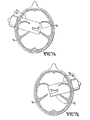
- Figs. 7A-D also illustrate an arrangement of transducers to avoid shadowing effects and to produce a more uniform, therapeutically effective acoustic field in a complex anatomical structure.
- Figs. 1 illustrates an arrangement of transducers suitable for treating clots 40 in the iliac veins.
- Fig. 6 is an axial view of the human pelvis.
- Transducers 41 are arranged to avoid shadowing by bone 42 and by bowel 43.
- the bowel 43 also produces shadowing of the acoustic wave from a transducer 41 due
- FIG. 7A-D show an axial view of a human skull 50 with one or more transducers 51, 52, 53 placed in various locations around the skull 50 for treating the anterior, middle and posterior fossas where major vessels supply the brain.
- transducer 51 is located to cover the right middle cerebral artery and right internal carotid bifurcation.
- the solid line 54 shows the range of the acoustic wave from transducer 51 where bone shadowing limits the depth of penetration of the acoustic wave.
- the dotted line 55 shows the range of the acoustic wave in the absence of bone shadowing.
- FIG. 7B shows a transducer 52 located to cover the left middle cerebral artery and left internal carotid bifurcation, where the solid line 56 shows the range as limited by bone shadowing while the dotted line 57 shows the range without bone shadowing.
- Fig. 7C shows a transducer 53 placed to cover the basiliar artery and some branches.
- the solid line 58 shows the range of the acoustic wave from transducer 53 as limited by shadowing and the dotted line 59 shows the range in the absence of shadowing.
- Fig. 7D shows the combined effect of transducers 51, 52, 53 to avoid shadowing problems and fill in the gaps low in the intracranial vessels.
- the overlapping fields of the transducers 51, 52, 53 are shown in Fig. 7D by shading.
- a signal generator 11 may comprise a frequency synthesizer module 10 producing an oscillatory output at a frequency suitable to excite the ultrasonic transducer 20.
- the oscillatory signal is then amplified by an amplifier and gate 15 to a voltage needed to excite the ultrasonic transducer 20.
- the excitation signal may be switched off by the gating circuit of the amplifier and gate 15.
- the frequency synthesizer 10 and the amplifier and gate 15 are programmable and can be controlled by an eight bit embedded microcontroller (not shown) or other programmable means.
- the ultrasonic transducer 20 may be excited in a manner so as to force a more uniform coverage of tissue with ultrasound.
- 3B is an example of an array 30 of ultrasound transducers 31.
- the pattern of interference between the individual waves as they are propagated outwardly produces a beam which may be directed in any desired pattern to sweep the area being treated.
- each transducer may be excited at a slightly different frequency to produce an interference pattern where the pressure peaks sweep in and out along the beam.
- the two embodiments may be combined to produce a beam that sweeps through the targeted tissue while the pressure peaks sweep along the beam.
- signal generator may also be used to generate a plurality of acoustic signals having randomly generated frequencies, phases and amplitudes. The signal generator may also use a white noise source to generate the acoustics signals.
- Ultrasound is absorbed by tissue and at high power causes a temperature increase within the tissue.
- the amplitude of the excitation voltage may be manipulated to reduce the heating effect.
- short bursts of ultrasound may be produced so that the average power delivered to the targeted tissue may be reduced while the intensity of the ultrasound may be kept relatively high during the short ultrasound burst. It is known that ultrasound will rupture and destroy microbubbles in the process of clot lysis. This requires repeated delivery of microbubbles for continued lytic effect.
- the duration between the ultrasound bursts may be adjusted so as to allow even minimal blood flow to replenish the supply of microbubbles at the surface of the clot that will have been ruptured by the ultrasonic action.
- certain embodiments of the invention may use phased arrays of transducers to move an ultrasound beam around the targeted tissue.
- the patterns of ultrasound generated by these embodiments may also be used to allowed repeated delivery and replenishment of microbubbles.
- transducers emit ultrasound into a focused columnar beam.
- the transducer would have to be directed at the location of the clot, which in turn could have to first be located by other means.
- the present invention would use dispersive elements when the location of the clot was unknown.
- a phased array of transducers may be employed to produce a beam that can be aimed by appropriate selection of the respective phases of the acoustic signals.
- Such a beam may be employed to sweep the area to be treated or can be directed to the location of a clot.
- Data using a human skull in a water bath and hydrophone mapping show ultrasound delivery through the foramen magnum using 20 to 80 KHz performs very well (30% of foramen magnum levels) all the way to a point 1 cm above the anterior clinoids. It is still present at the anterior margin of the anterior fossa (18 to 20 cm range) at reduced levels. At the anterior clinoids' 12 to 14 cm range the power levels are nearly equivalent to levels at 5 to 7 cm range through the temporal approach. Shadowing occurs along the inferior aspects of the anterior fossa, which are well filled in by temporal transducers. The shadows posterior to the petrus pyramids when using the temporal approach are well filled in by the foramen magnum transducer.
- Frequency agile and interval agile combinations of pulsed wave (each transducer firing in 2 to 20% of the time cycle) ultrasound can be sequenced to avoid mutual interference and completely fill the skull with therapeutic levels of the ultrasound required to lyse a clot with microbubbles, thrombolytic drugs or other lysing agents.
- Known therapeutic ultrasound thrombolysis techniques based on microbubbles, thrombolytic drugs or the like lysing a clot in ultrasound fields are limited in field size and range. Also, ultrasound is absorbed by tissue. Multiple transducers decrease the problems of shadowing and suboptimal energy levels seen with single transducers.
- the present invention overcomes the limitations of the prior art by using one or more transducers and by frequency, phase and timing modulation of a plurality of acoustic signals to provide more uniform power delivery through traveling waves without the gaps in the fields caused by standing waves.
- the ultrasound field is manipulated, both temporally and spatially, to maximize both effect and ease of use. Wide application to stroke and problem clots in various applications is expected.
- the present invention is unique in that it may be effective in treating ischemic stroke in the brain where the technique of lysing clots with microbubbles in combination with ultrasound has not been applied.
- the apparatus of the present invention may be used in combination with microbubbles, thrombolytic drugs or other lysing agents.
Landscapes
- Health & Medical Sciences (AREA)
- Surgery (AREA)
- Engineering & Computer Science (AREA)
- Life Sciences & Earth Sciences (AREA)
- Biomedical Technology (AREA)
- Nuclear Medicine, Radiotherapy & Molecular Imaging (AREA)
- Vascular Medicine (AREA)
- Orthopedic Medicine & Surgery (AREA)
- Mechanical Engineering (AREA)
- Heart & Thoracic Surgery (AREA)
- Medical Informatics (AREA)
- Molecular Biology (AREA)
- Animal Behavior & Ethology (AREA)
- General Health & Medical Sciences (AREA)
- Public Health (AREA)
- Veterinary Medicine (AREA)
- Surgical Instruments (AREA)
Description
- The present invention relates to an apparatus and method for using ultrasound augmented with microbubbles, thrombolytic drugs or other lysing agents for clot lysis, and in particular to such an apparatus and method using time, phase and frequency modulation of multiple acoustic signals from at least three transducers to provide uniform power delivery with fewer gaps in the ultrasound field.
- Thrombosis is the development of a blood clot within a blood vessel. A thrombosis can cause serious, even life threatening, conditions due to partial or total blockage of a blood vessel. Various techniques are known for lysing or removal of the clot. These techniques include the injection of various clot dissolving agents.
- Ultrasound has been found to be useful in lysing clots and enhancing the effectiveness of a lysing agent, such as a thrombolytic drug.
- More recently, microbubbles have been found to be effective as a lysing agent when used in conjunction with ultrasound. Microbubbles are used in the form of a liquid containing stable microspheres of an insoluble, preferably inert, gas. However, conventional techniques are limited in the size and range of the ultrasound field and suffer from gaps in the field and shadowing caused by differential propagation of the ultrasound field through various shapes, compositions and densities of anatomical structures.
-
U.S. Patent No. 6,514,220 discloses that the effect of ultrasound irradiation of a portion of a human or animal body is enhanced by operating a portion of the human or animal body as a trapped mode resonator. - The prior art teaches focusing or concentrating ultrasound energy. However, ultrasound energy focused or concentrated at a single location may produce excessive heating or cavitation, particularly when the acoustic field is static. Static acoustic fields may also suffer from insufficient energy levels or gaps in portions of the field.
-
GB 2,263,406 A JP 2000 254139 A US 6 419 648 B1 discloses an ultrasound therapeutic system with a plurality of transducers which are selectively driven at one of a plurality of discrete RF frequencies. - The present invention overcomes the problems of the prior art by using at least three transducers generating a plurality of acoustic signals at similar or different frequencies to produce traveling interference patterns. Also, the frequency, amplitude and phase from the transducers may be modulated so that any interference pattern will be constantly shifting in position, thereby insuring uniform coverage. In one embodiment, a phased array of transducers may generate a beam that is swept over the area to be treated. In another embodiment, an array of transducers may generate ultrasound at a number of slightly varying frequencies to produce an interference pattern that sweeps in and out through the targeted tissue. A single array may be used to produce both effects simultaneously or separately.
- At high power, ultrasound causes a temperature increase within the targeted tissue. The amplitude of the excitation voltage may be manipulated to reduce the heating effect. By using a gating circuit, short bursts of ultrasound may be produced so that the average power delivered to the targeted tissue may be reduced while the intensity of the ultrasound may be kept relatively high during the short ultrasound burst. Further, when microbubbles are employed as the lysing agent, the duration between the ultrasound bursts may be adjusted so as to allow even minimal blood flow to replenish the supply of microbubbles at the surface of the clot that will have been ruptured by the ultrasonic action. As noted above, certain embodiments of the invention may use phased arrays of transducers to move an ultrasound beam around the targeted tissue. Likewise, one or more transducers may generate a plurality of varying frequencies to produce interference patterns of traveling waves of ultrasound that sweep through the targeted tissue. A gating circuit may not be required when either of these embodiments or a combination allow the average power lever to be kept low enough in the targeted tissue to avoid overheating.
- Variations in the spatial arrangement of the transducers may be used to change the field shape. The transducers may be moved to continually vary the field. Also, the beam from the ultrasound transducers may be designed in such a way that the beam is dispersed at wide angles, obviating the need for an ultrasound transducer to be aimed directly at a clot. Focusing devices or phased array technology may be used to more widely disperse the beam in a "search light sweep" manner. In one embodiment of the present invention, an array of a large number of transducers would have each transducer excited by a slightly different frequency. The resulting pressure waveform would have periodic large peaks with less average power and the pressure peaks would sweep through the targeted tissue in an in and out manner. Also, by sequenced phasing across the array such that each transducer is driven at the same frequency but differing in phase, this phased array could direct the beam through a wide volume of targeted tissue without moving the transducers. By combining these two embodiments, the resulting maxima and minima of the power deposition moving rapidly through all points in the beam while the beam is sweeping the targeted tissue would result in a much better penetration by this focused beam than by a diffused beam.
-
-
Fig. 1A is a top view of the head of a patient showing a signal generator G feeding multiple transducers. -
Fig. 1B is a side view of the head of the patient ofFig. 1A . -
Fig. 1C is a front view of the head of the patient ofFig. 1A . -
Fig. 2 is a graph of ultrasound power distribution in a cross section of a skull showing how the power distribution varies depending on the number of transducers: one transducer, two transducers or multiple transducers. -
Fig. 3A is a schematic diagram of the apparatus of the present invention.Fig. 3B is an example of an array of ultrasound transducers. -
Figs. 4A, 4B , and4C are cross sections through the spine and base of the skull illustrating how diffusion of the ultrasound beam makes precise aiming unnecessary.Fig. 4A shows a beam too low,Fig. 4B shows a beam too high; andFig. 4C shows a properly aimed beam. In each case, the basiliar artery is still covered. -
Fig. 5 is a graph showing the predicted pressure wave of ultrasound delivered to a point, where ten ultrasound transducers are each operating at slightly different frequencies. -
Fig. 6 is an axial view of a human pelvis showing an arrangement of transducers for treating clots in the iliac veins. -
Figs. 7A, 7B ,7C and 7D are axial views of a human skull showing the effect of bone shadowing on the coverage from each of three transducer locations.Figs. 7A, 7B and7C illustrate the coverage of a single transducer, whileFig. 7D illustrates the effect of multiple transducers with overlapping coverage so that no shadowed areas are left without coverage. Also illustrated is the limited range of higher frequency acoustic waves. The effective range in the absence of bone shadowing is shown by the dotted line in each figure. The range as limited by bone shadowing is shown by the solid line in each figure. - Known therapeutic ultrasound thrombolysis techniques based on microbubbles, thrombolytic drugs or the like lysing a clot in ultrasound fields are limited in field size and range. Also, ultrasound is absorbed by tissue. Multiple transducers decrease the problems of shadowing and suboptimal energy levels seen with single transducers. The present invention overcomes the limitations of the prior art by using at least three transducers and by frequency, phase and timing modulation of a plurality of acoustic signals to provide more uniform power delivery through traveling waves without the gaps in the fields caused by standing waves. The ultrasound field is manipulated, both temporally and spatially, to maximize both effect and ease of use. Wide application to stroke and problem clots in various applications is expected.
- The present invention is unique in that it may be effective in treating ischemic stroke in the brain where the technique of lysing clots with microbubbles in combination with ultrasound has not been applied. The apparatus of the present invention may be used in combination with microbubbles, thrombolytic drugs or other lysing agents.
- Interference occurs when two or more ultrasound waves intersect. The waves may be produced directly from an ultrasound transducer or from a reflection from an anatomical structure, such as the surface of the head. Interference may be either constructive or destructive in nature depending upon the relative phase and amplitudes of the combining waves. If the interference is destructive, then when microbubbles are used as the lysing agent, the microbubbles may not expand and contract sufficiently to produce the desired therapeutic effect. The present invention contemplates that the ultrasound frequency and phase from one or more transducers may be modulated so that any interference pattern will be constantly shifting in position, thereby insuring uniform coverage of the targeted anatomical portion of a human or animal body.
Fig. 5 shows the predicted pressure wave of ultrasound delivered to a point, where ten ultrasound transducers are operating at slightly different frequencies. The interference pattern of nodes and anti-nodes created thereby is not static but travels through the targeted tissue. The frequencies of the acoustic signals are selected to avoid standing waves from resonance of the anatomical portion into which the acoustics signals are delivered. - In some applications it will be desirable that the ultrasound transducers be designed in such a way that the beam is dispersed at wide angles obviating the need for the ultrasound transducer to be aimed directly at a clot. Precise aiming is less important with the present invention than with older technology. Focusing devices as well as phased array technology allow the beam to be more widely dispersed in a "search light sweep" manner.
- Simple variations in transducer arrangement may also be used to change the field shape to match thrombosed arteries, veins, dialysis grafts, and hematomas or collections of thick fluid almost anywhere in the human body. This is illustrated in
Figs. 1A, 1B and1C , which show a signal generator 11 feeding multiple transducers on the head of a patient, the transducers includingtemple transducers 12,auxiliary transducers 13 for the skull,neck transducers 14, and posterior neck (suboccipital or occipital)transducers 16.Fig. 2 is a graph of ultrasound power distribution in a cross section of the skull showing how the power distribution varies depending on the number of transducers: one transducer is shown by line 21, two transducers by line 22 or multiple transducers by line 23. - If a node of destructive interference occurs and remains in a single spatial location in the brain, then the effectiveness of a microbubble's dispersive action upon a blood clot is suppressed in that location. Likewise, constructive interference could produce detrimental foci of increased power deposition. In the apparatus of the present invention, the amplitude, phase, and nominal excitation frequency may all be changed continuously so that destructive interference, created by a plurality of ultrasonic waves or by reflected waves or by a combination of both, will not allow nodes of destructive interference to remain constantly in one position. If two similar ultrasound transducers are operated at slightly different frequencies and the ultrasonic waves so developed are brought together in a medium, then the interference pattern will move, exchanging nodes and anti-nodes at a frequency that is the difference between the two excitation frequencies. This concept can be expanded to a large number of transducers. The objective of the present Invention is to use this well known phenomenon to prevent nodes of destructive interference or constructive interference from holding a constant position. In the case of a reflected wave the original wave interferes with a time delayed version of the same wave. However, in a system as complicated as the human head, the relative phases are quite sensitive to slight changes in the operating frequency of the ultrasonic transducer, especially at higher frequencies. Optimum performance is achieved by simultaneously changing the nominal operating frequency while operating multiple transducers at slightly different frequencies. It is preferable for the frequencies of the acoustic waves to be in a range of 500 kHz and above and more preferably in a range from 500 kHz to 2 MHz. The frequencies are selected so as not to resonate and produce standing waves in the anatomical portion being treated.
- In order to obtain a more uniform distribution of energy deposition in a volume, certain characteristics related to high versus low frequency acoustic radiation must be considered. First, low frequency acoustic waves, when directed at a small opening in an anatomical structure, tend to be dispersed since the small opening acts similar to a diverging lens because of diffraction. This effect is not significant at higher frequencies where the wavelength is small relative to the scale of the opening. For example, a beam of 40-100 kHz directed at the foramen magnum in the skull will be significantly dispersed, while a beam of 1 MHz will experience little dispersion when passing through the foramen magnum. Second, acoustic waves are attenuated by bone. This effect is much greater for higher frequencies than for lower frequencies. While higher frequencies may experience 90% losses, a beam of 40 kHz may only see a 60% loss. Third, this attenuation effect is true for tissues other than bone. The significance here is that all acoustic waves will be reflected from structures where the speed of transmission of the acoustic wave changes; e.g., from a less dense medium to a more dense medium as when a wave traveling through soft tissue encounters bone. Since lower frequency waves are attenuated to a lesser extent than higher frequencies, a lower frequency wave may be reflected again and again from anatomical structures before it is attenuated to the point where its contribution to the overall energy field is negligible. Such reflections will interfere constructively and destructively, leading to a buildup in energy levels in the anatomical structure with undesirable peaks in the acoustic energy patterns and standing waves. Higher frequency acoustic waves, in contrast, are more likely to attenuate before multiple reflections can occur. The shorter range of such high frequency waves therefore decreases the uncertainty associated with predicting and controlling the levels of acoustic energy in the anatomical structure. In particular, standing waves may be avoided more easily. The drawback to the use of higher frequencies is the losses due to the higher attenuation compared to lower frequencies. The losses can be overcome by using multiple transducers that are spatially distributed and where the frequency, amplitude and phase of the acoustic signals from each transducer are controlled to produce a more uniform acoustic energy field in the anatomical structure at therapeutically effective levels.
- Various frequencies and combinations of frequencies may be desirable in particular circumstances to both avoid standing waves with excessively concentrated energy deposition in particular locations and to provide more uniform distribution of the energy at therapeutic levels. For example, lower frequency acoustic waves, such as 40kHz, may be better dispersed by refraction of the beam when directed through a small opening in a bone structure, such as the foramen magnum in the skull. The lower frequency provides longer range and better coverage than higher frequencies. In relation to the skull in particular, lower frequencies also pass through bone more efficiently than higher frequencies. In general, acoustic waves at higher frequencies penetrate less well, degrade faster, and are much shorter than lower frequency waves; together these characteristics of higher frequency waves avoid a problem of low frequency waves that may match the scale of anatomical structures and thereby tend to form detrimental large standing waves in such anatomical structures. Also, higher frequencies do not disperse to the same extent as lower frequencies and may therefore be more effective as a straight beam, either aimed at a target or swept through a range of vectors to cover a volume. As discussed above, higher frequencies, above 500 kHz and particularly between 500 kHz and 2 MHz, are helpful in avoiding unanticipated peaks in the energy deposition pattern and standing waves. Combinations of frequencies from spatially dispersed transducers may be employed to effectively treat complex structures. An example would be the combination of a 40kHz transducer at the back of the skull along with a pair of 1 MHz transducers at the sides of the skull as shown in
Figs. 1A-C and 7A-D . Another example would be a linear array of transducers for treating veins in an extremity. -
Fig. 6 illustrates an arrangement of transducers suitable for treating clots 40 in the iliac veins.Fig. 6 is an axial view of the human pelvis. Transducers 41 are arranged to avoid shadowing bybone 42 and by bowel 43. The bowel 43 also produces shadowing of the acoustic wave from a transducer 41 due to the presence of air or feces in the bowel 43.Figs. 7A-D also illustrate an arrangement of transducers to avoid shadowing effects and to produce a more uniform, therapeutically effective acoustic field in a complex anatomical structure.Figs. 7A-D show an axial view of ahuman skull 50 with one ormore transducers skull 50 for treating the anterior, middle and posterior fossas where major vessels supply the brain. InFig. 7A , transducer 51 is located to cover the right middle cerebral artery and right internal carotid bifurcation. Thesolid line 54 shows the range of the acoustic wave from transducer 51 where bone shadowing limits the depth of penetration of the acoustic wave. The dottedline 55 shows the range of the acoustic wave in the absence of bone shadowing. Likewise,Fig. 7B shows atransducer 52 located to cover the left middle cerebral artery and left internal carotid bifurcation, where thesolid line 56 shows the range as limited by bone shadowing while the dottedline 57 shows the range without bone shadowing.Fig. 7C shows atransducer 53 placed to cover the basiliar artery and some branches. Thesolid line 58 shows the range of the acoustic wave fromtransducer 53 as limited by shadowing and the dottedline 59 shows the range in the absence of shadowing.Fig. 7D shows the combined effect oftransducers transducers Fig. 7D by shading. - As shown in
Fig. 3A , a signal generator 11 may comprise afrequency synthesizer module 10 producing an oscillatory output at a frequency suitable to excite theultrasonic transducer 20. The oscillatory signal is then amplified by an amplifier and gate 15 to a voltage needed to excite theultrasonic transducer 20. Finally, the excitation signal may be switched off by the gating circuit of the amplifier and gate 15. Thefrequency synthesizer 10 and the amplifier and gate 15 are programmable and can be controlled by an eight bit embedded microcontroller (not shown) or other programmable means. Thus theultrasonic transducer 20 may be excited in a manner so as to force a more uniform coverage of tissue with ultrasound.Fig. 3B is an example of anarray 30 of ultrasound transducers 31. By controlling the phase of the ultrasound wave generated by each transducer 31 in thearray 30, the pattern of interference between the individual waves as they are propagated outwardly produces a beam which may be directed in any desired pattern to sweep the area being treated. Also, each transducer may be excited at a slightly different frequency to produce an interference pattern where the pressure peaks sweep in and out along the beam. The two embodiments may be combined to produce a beam that sweeps through the targeted tissue while the pressure peaks sweep along the beam. signal generator may also be used to generate a plurality of acoustic signals having randomly generated frequencies, phases and amplitudes. The signal generator may also use a white noise source to generate the acoustics signals. - Ultrasound is absorbed by tissue and at high power causes a temperature increase within the tissue. The amplitude of the excitation voltage may be manipulated to reduce the heating effect. By using the gating circuit of the amplifier and gate 15, short bursts of ultrasound may be produced so that the average power delivered to the targeted tissue may be reduced while the intensity of the ultrasound may be kept relatively high during the short ultrasound burst. It is known that ultrasound will rupture and destroy microbubbles in the process of clot lysis. This requires repeated delivery of microbubbles for continued lytic effect. The duration between the ultrasound bursts may be adjusted so as to allow even minimal blood flow to replenish the supply of microbubbles at the surface of the clot that will have been ruptured by the ultrasonic action. Also, as noted above, certain embodiments of the invention may use phased arrays of transducers to move an ultrasound beam around the targeted tissue. Likewise, an array employing varying frequencies to produce interference patterns of traveling waves of ultrasound that move through the targeted tissue. The patterns of ultrasound generated by these embodiments may also be used to allowed repeated delivery and replenishment of microbubbles.
- Many ultrasonic transducers emit ultrasound into a focused columnar beam. In such a design, the transducer would have to be directed at the location of the clot, which in turn could have to first be located by other means. The present invention would use dispersive elements when the location of the clot was unknown. However, it is not intended to exclude from the scope of the present invention the use of transducers that emit ultrasound into a columnar beam if the location of the clot is known. Furthermore, in certain embodiments of the present invention, a phased array of transducers may be employed to produce a beam that can be aimed by appropriate selection of the respective phases of the acoustic signals. Such a beam may be employed to sweep the area to be treated or can be directed to the location of a clot.
- Data using a human skull in a water bath and hydrophone mapping show ultrasound delivery through the foramen magnum using 20 to 80 KHz performs very well (30% of foramen magnum levels) all the way to a point 1 cm above the anterior clinoids. It is still present at the anterior margin of the anterior fossa (18 to 20 cm range) at reduced levels. At the anterior clinoids' 12 to 14 cm range the power levels are nearly equivalent to levels at 5 to 7 cm range through the temporal approach. Shadowing occurs along the inferior aspects of the anterior fossa, which are well filled in by temporal transducers. The shadows posterior to the petrus pyramids when using the temporal approach are well filled in by the foramen magnum transducer. Good diffusing of the beam through the foramen along with good reflections from various structures fill much more of the skull than a linear beam would suggest. Ultrasound diffusion makes aiming the beam unnecessary. With reference to
Figs. 4A, 4B and4C , it is shown that a beam too low (Fig. 4A ), too high (Fig. 4B ), or properly aimed (Fig. 4C ) still covers the basiliar artery. - Moreover, we have experimentally shown that by changing the frequency about 10% up or down from the primary frequency of 40KHz, the nodes and anodes are swept completely across every particular point in the beam. This is about half of the change we anticipated and is probably due to the multiple harmonics our current transducers produce. This completely covers the targeted tissue and negates the problem of shadowed areas produced by the longer wavelength that is required to get the diffusing refraction of the beam through the foramen magnum.
- Frequency agile and interval agile combinations of pulsed wave (each transducer firing in 2 to 20% of the time cycle) ultrasound can be sequenced to avoid mutual interference and completely fill the skull with therapeutic levels of the ultrasound required to lyse a clot with microbubbles, thrombolytic drugs or other lysing agents.
- The entire basilar artery and upper portions of the vertebral arteries can now be added to the coverage of the internal carotids, middle cerebrals, anterior cerebrals, and Circle of Willis previously covered with 1 MHz temporal transducers. This is important due to the high mortality of basilar artery strokes and the absence of any good therapy for them.
- Known therapeutic ultrasound thrombolysis techniques based on microbubbles, thrombolytic drugs or the like lysing a clot in ultrasound fields are limited in field size and range. Also, ultrasound is absorbed by tissue. Multiple transducers decrease the problems of shadowing and suboptimal energy levels seen with single transducers. The present invention overcomes the limitations of the prior art by using one or more transducers and by frequency, phase and timing modulation of a plurality of acoustic signals to provide more uniform power delivery through traveling waves without the gaps in the fields caused by standing waves. The ultrasound field is manipulated, both temporally and spatially, to maximize both effect and ease of use. Wide application to stroke and problem clots in various applications is expected.
- The present invention is unique in that it may be effective in treating ischemic stroke in the brain where the technique of lysing clots with microbubbles in combination with ultrasound has not been applied. The apparatus of the present invention may be used in combination with microbubbles, thrombolytic drugs or other lysing agents.
Claims (11)
- An apparatus for generating acoustic fields in an a target anatomical portion of a human or animal body, comprising:a signal generator (11) generating a plurality of acoustic signals, each of the signals being characterized by a respective frequencies, phases, and amplitudes; andat least three acoustic transducers (12, 13, 14, 16; 31; 41; 51, 52, 53) operably connected to the signal generator and configured to inject a plurality of acoustic beams into the target anatomical portion;characterised in that:the signal generator is configured to continuously change the frequencies, phases and amplitudes, and the transducers are configured to irradiate said target anatomical portion in a spatially dispersed fashion and to form, in the target anatomical portion, an interference acoustic pattern that travels therethrough.
- The apparatus of claim 1, wherein said at least three acoustic transducers are further configured to inject a plurality of acoustic beams into the target anatomical portion in such a fashion as to irradiate said target anatomical portion with said interference pattern that continually spatially varies throughout said target anatomical portion, and wherein the respective frequencies, characterizing each of the plurality of acoustic signals, differ from one another by about plus or minus ten percent from a primary frequency of 40kHz.
- The apparatus of claim 1 wherein said respective frequencies are selectable to avoid resonance of said plurality of acoustic signals in said target anatomical portion.
- The apparatus of claim 1, wherein said signal generator (11) comprises means for selecting said respective frequencies from a range of 500 kHz and above.
- The apparatus of claim 4, wherein said signal generator (11) comprises means for selecting said respective frequencies from a range of 500 kHz to 2 MHz.
- The apparatus of claim 1, wherein said signal generator comprises means for randomly generating said respective frequencies, phases and amplitudes of said plurality of acoustic signals.
- The apparatus of claim 1, wherein said signal generator comprises means for generating said plurality of acoustic signals from a white noise generator.
- The apparatus of claim 1, wherein said signal generator further comprises means for sweeping said respective frequencies over a range of frequencies.
- The apparatus of claim 1, further comprising an array (30) of transducers and wherein said signal generator comprises means for controlling said respective phases of said plurality of acoustic signals whereby said plurality of acoustics signals form a directed beam.
- The apparatus of claim 1, wherein said at least three acoustic transducers are further configured to inject a plurality of acoustic beams into the target anatomical portion in such a fashion as to avoid continuous standing waves in said target anatomical portion, wherein the signal parameters are adjusted randomly.
- The apparatus according to claim 10, wherein the at least three acoustic transducers are configured to inject a plurality of ultrasound bursts temporally separated from one another by such a duration of time that is sufficient for replenishing a surface of the target anatomical portion with lysing microbubbles.
Priority Applications (1)
| Application Number | Priority Date | Filing Date | Title |
|---|---|---|---|
| PL04783246T PL1663394T3 (en) | 2003-09-08 | 2004-09-03 | Ultrasound apparatus for augmented clot lysis |
Applications Claiming Priority (2)
| Application Number | Priority Date | Filing Date | Title |
|---|---|---|---|
| US50100003P | 2003-09-08 | 2003-09-08 | |
| PCT/US2004/028934 WO2005025403A2 (en) | 2003-09-08 | 2004-09-03 | Ultrasound apparatus and method for augmented clot lysis |
Publications (3)
| Publication Number | Publication Date |
|---|---|
| EP1663394A2 EP1663394A2 (en) | 2006-06-07 |
| EP1663394A4 EP1663394A4 (en) | 2011-05-04 |
| EP1663394B1 true EP1663394B1 (en) | 2014-05-21 |
Family
ID=34312239
Family Applications (1)
| Application Number | Title | Priority Date | Filing Date |
|---|---|---|---|
| EP04783246.4A Expired - Lifetime EP1663394B1 (en) | 2003-09-08 | 2004-09-03 | Ultrasound apparatus for augmented clot lysis |
Country Status (9)
| Country | Link |
|---|---|
| US (1) | US6945937B2 (en) |
| EP (1) | EP1663394B1 (en) |
| JP (1) | JP5004584B2 (en) |
| AU (1) | AU2004272023B2 (en) |
| CA (1) | CA2535981C (en) |
| DK (1) | DK1663394T3 (en) |
| ES (1) | ES2474160T3 (en) |
| PL (1) | PL1663394T3 (en) |
| WO (1) | WO2005025403A2 (en) |
Families Citing this family (119)
| Publication number | Priority date | Publication date | Assignee | Title |
|---|---|---|---|---|
| US6723063B1 (en) | 1998-06-29 | 2004-04-20 | Ekos Corporation | Sheath for use with an ultrasound element |
| US6582392B1 (en) | 1998-05-01 | 2003-06-24 | Ekos Corporation | Ultrasound assembly for use with a catheter |
| US6050943A (en) | 1997-10-14 | 2000-04-18 | Guided Therapy Systems, Inc. | Imaging, therapy, and temperature monitoring ultrasonic system |
| US7037267B1 (en) | 1999-11-10 | 2006-05-02 | David Lipson | Medical diagnostic methods, systems, and related equipment |
| US7914453B2 (en) | 2000-12-28 | 2011-03-29 | Ardent Sound, Inc. | Visual imaging system for ultrasonic probe |
| AU2002359576A1 (en) | 2001-12-03 | 2003-06-17 | Ekos Corporation | Catheter with multiple ultrasound radiating members |
| US8226629B1 (en) | 2002-04-01 | 2012-07-24 | Ekos Corporation | Ultrasonic catheter power control |
| EP1713537A4 (en) | 2004-01-29 | 2009-04-29 | Ekos Corp | Method and apparatus for detecting vascular conditions with a catheter |
| US7645244B2 (en) * | 2004-07-09 | 2010-01-12 | Boston Scientific Scimed, Inc. | Ultrasound systems and methods for treating ischemic limbs or tissue affected by peripheral arterial disease |
| US7393325B2 (en) | 2004-09-16 | 2008-07-01 | Guided Therapy Systems, L.L.C. | Method and system for ultrasound treatment with a multi-directional transducer |
| US7824348B2 (en) | 2004-09-16 | 2010-11-02 | Guided Therapy Systems, L.L.C. | System and method for variable depth ultrasound treatment |
| US9011336B2 (en) | 2004-09-16 | 2015-04-21 | Guided Therapy Systems, Llc | Method and system for combined energy therapy profile |
| US8444562B2 (en) | 2004-10-06 | 2013-05-21 | Guided Therapy Systems, Llc | System and method for treating muscle, tendon, ligament and cartilage tissue |
| US8535228B2 (en) | 2004-10-06 | 2013-09-17 | Guided Therapy Systems, Llc | Method and system for noninvasive face lifts and deep tissue tightening |
| US10864385B2 (en) | 2004-09-24 | 2020-12-15 | Guided Therapy Systems, Llc | Rejuvenating skin by heating tissue for cosmetic treatment of the face and body |
| EP2279697A3 (en) | 2004-10-06 | 2014-02-19 | Guided Therapy Systems, L.L.C. | Method and system for non-invasive cosmetic enhancement of blood vessel disorders |
| US20060111744A1 (en) | 2004-10-13 | 2006-05-25 | Guided Therapy Systems, L.L.C. | Method and system for treatment of sweat glands |
| US11235179B2 (en) | 2004-10-06 | 2022-02-01 | Guided Therapy Systems, Llc | Energy based skin gland treatment |
| US7758524B2 (en) | 2004-10-06 | 2010-07-20 | Guided Therapy Systems, L.L.C. | Method and system for ultra-high frequency ultrasound treatment |
| KR20190040105A (en) | 2004-10-06 | 2019-04-16 | 가이디드 테라피 시스템스, 엘.엘.씨. | Ultrasound treatment system |
| US8133180B2 (en) | 2004-10-06 | 2012-03-13 | Guided Therapy Systems, L.L.C. | Method and system for treating cellulite |
| US11883688B2 (en) | 2004-10-06 | 2024-01-30 | Guided Therapy Systems, Llc | Energy based fat reduction |
| US8690778B2 (en) | 2004-10-06 | 2014-04-08 | Guided Therapy Systems, Llc | Energy-based tissue tightening |
| US9827449B2 (en) | 2004-10-06 | 2017-11-28 | Guided Therapy Systems, L.L.C. | Systems for treating skin laxity |
| US9694212B2 (en) | 2004-10-06 | 2017-07-04 | Guided Therapy Systems, Llc | Method and system for ultrasound treatment of skin |
| US11724133B2 (en) | 2004-10-07 | 2023-08-15 | Guided Therapy Systems, Llc | Ultrasound probe for treatment of skin |
| US11207548B2 (en) | 2004-10-07 | 2021-12-28 | Guided Therapy Systems, L.L.C. | Ultrasound probe for treating skin laxity |
| AU2005295261A1 (en) * | 2004-10-19 | 2006-04-27 | The Government Of The United States Of America, As Represented By The Secretary, Department Of Health And Human Services, National Institutes Of Health | Methods and compositions for protecting cells from ultrasound-mediated cytolysis |
| JP4695188B2 (en) | 2005-04-25 | 2011-06-08 | アーデント サウンド, インコーポレイテッド | Method and apparatus for improving the safety of computer peripherals |
| US20120078140A1 (en) * | 2005-06-24 | 2012-03-29 | Penumbra, Inc. | Method and Apparatus for Removing Blood Clots and Tissue from the Patient's Head |
| CN102307620B (en) * | 2005-08-30 | 2014-10-29 | 皇家飞利浦电子股份有限公司 | Ultrasound system that dissolves blood clots using combined imaging and therapy transducers |
| US9486274B2 (en) | 2005-09-07 | 2016-11-08 | Ulthera, Inc. | Dissection handpiece and method for reducing the appearance of cellulite |
| AU2006287633A1 (en) * | 2005-09-07 | 2007-03-15 | The Foundry, Inc. | Apparatus and method for disrupting subcutaneous structures |
| US8518069B2 (en) | 2005-09-07 | 2013-08-27 | Cabochon Aesthetics, Inc. | Dissection handpiece and method for reducing the appearance of cellulite |
| US9358033B2 (en) | 2005-09-07 | 2016-06-07 | Ulthera, Inc. | Fluid-jet dissection system and method for reducing the appearance of cellulite |
| US10548659B2 (en) | 2006-01-17 | 2020-02-04 | Ulthera, Inc. | High pressure pre-burst for improved fluid delivery |
| US7967763B2 (en) * | 2005-09-07 | 2011-06-28 | Cabochon Aesthetics, Inc. | Method for treating subcutaneous tissues |
| US9011473B2 (en) | 2005-09-07 | 2015-04-21 | Ulthera, Inc. | Dissection handpiece and method for reducing the appearance of cellulite |
| US20070078290A1 (en) * | 2005-09-30 | 2007-04-05 | Esenaliev Rinat O | Ultrasound-based treatment methods for therapeutic treatment of skin and subcutaneous tissues |
| DE102005053918A1 (en) * | 2005-11-11 | 2007-05-16 | Zimmer Elektromedizin Gmbh | Method and device for irradiating ultrasound in tissue |
| US20080262350A1 (en) * | 2005-11-18 | 2008-10-23 | Imarx Therapeutics, Inc. | Ultrasound Apparatus and Method to Treat an Ischemic Stroke |
| US7885793B2 (en) | 2007-05-22 | 2011-02-08 | International Business Machines Corporation | Method and system for developing a conceptual model to facilitate generating a business-aligned information technology solution |
| US9248317B2 (en) | 2005-12-02 | 2016-02-02 | Ulthera, Inc. | Devices and methods for selectively lysing cells |
| US20070196282A1 (en) * | 2006-02-21 | 2007-08-23 | Siemens Medical Solutions Usa, Inc. | Medical diagnostic ultrasound with temperature-dependent contrast agents |
| US20070249938A1 (en) * | 2006-04-20 | 2007-10-25 | Donald J. Shields | Systems, devices, and methods employing therapeutic ultrasound of living tissues |
| EP2015846A2 (en) | 2006-04-24 | 2009-01-21 | Ekos Corporation | Ultrasound therapy system |
| WO2008018019A2 (en) * | 2006-08-09 | 2008-02-14 | Koninklijke Philips Electronics N. V. | A device for and a method of activating a physiologically effective substance by ultrasonic waves, and a capsule |
| JP5336369B2 (en) * | 2006-08-11 | 2013-11-06 | コーニンクレッカ フィリップス エヌ ヴェ | Ultrasound system for cerebral blood flow imaging and microbubble improvement thrombus resolution |
| US9630028B2 (en) * | 2006-08-11 | 2017-04-25 | Koninklijke Philips N.V. | Ultrasound system for cerebral blood flow imaging and microbubble-enhanced blood clot lysis |
| US9566454B2 (en) | 2006-09-18 | 2017-02-14 | Guided Therapy Systems, Llc | Method and sysem for non-ablative acne treatment and prevention |
| PL2111261T3 (en) | 2007-01-08 | 2015-08-31 | Ekos Corp | Power parameters for ultrasonic catheter |
| US10182833B2 (en) | 2007-01-08 | 2019-01-22 | Ekos Corporation | Power parameters for ultrasonic catheter |
| US20150174388A1 (en) | 2007-05-07 | 2015-06-25 | Guided Therapy Systems, Llc | Methods and Systems for Ultrasound Assisted Delivery of a Medicant to Tissue |
| EP2152351B1 (en) | 2007-05-07 | 2016-09-21 | Guided Therapy Systems, L.L.C. | Methods and systems for modulating medicants using acoustic energy |
| JP5038022B2 (en) | 2007-05-29 | 2012-10-03 | バイオマップ有限会社 | Ultrasonic therapy device and program |
| ES2471118T3 (en) | 2007-06-22 | 2014-06-25 | Ekos Corporation | Method and apparatus for the treatment of intracranial hemorrhages |
| US8439940B2 (en) | 2010-12-22 | 2013-05-14 | Cabochon Aesthetics, Inc. | Dissection handpiece with aspiration means for reducing the appearance of cellulite |
| US20090240146A1 (en) * | 2007-10-26 | 2009-09-24 | Liposonix, Inc. | Mechanical arm |
| US20090230823A1 (en) * | 2008-03-13 | 2009-09-17 | Leonid Kushculey | Operation of patterned ultrasonic transducers |
| US12102473B2 (en) | 2008-06-06 | 2024-10-01 | Ulthera, Inc. | Systems for ultrasound treatment |
| DK2282675T3 (en) | 2008-06-06 | 2016-05-17 | Ulthera Inc | Cosmetic treatment and imaging system |
| ES2736276T3 (en) | 2008-07-14 | 2019-12-27 | Arizona Board Of Regents For And On Behalf Of Arizona State Univ | Cellular activity modulation devices using ultrasound |
| US8215173B2 (en) * | 2008-08-05 | 2012-07-10 | Roger Spencer | UT method of identifying a stuck joint |
| CA2748362A1 (en) | 2008-12-24 | 2010-07-01 | Michael H. Slayton | Methods and systems for fat reduction and/or cellulite treatment |
| US20120130288A1 (en) * | 2009-03-20 | 2012-05-24 | University Of Cincinnati | Ultrasound-mediated inducement, detection, and enhancement of stable cavitation |
| US9504824B2 (en) | 2009-06-23 | 2016-11-29 | Board Of Regents, The University Of Texas System | Noninvasive therapies in the absence or presence of exogenous particulate agents |
| WO2011003031A1 (en) | 2009-07-03 | 2011-01-06 | Ekos Corporation | Power parameters for ultrasonic catheter |
| US11096708B2 (en) | 2009-08-07 | 2021-08-24 | Ulthera, Inc. | Devices and methods for performing subcutaneous surgery |
| US9358064B2 (en) | 2009-08-07 | 2016-06-07 | Ulthera, Inc. | Handpiece and methods for performing subcutaneous surgery |
| WO2011057028A1 (en) * | 2009-11-04 | 2011-05-12 | Arizona Board Of Regents For And On Behalf Of Arizona State University | Devices and methods for modulating brain activity |
| US8715186B2 (en) | 2009-11-24 | 2014-05-06 | Guided Therapy Systems, Llc | Methods and systems for generating thermal bubbles for improved ultrasound imaging and therapy |
| US8740835B2 (en) | 2010-02-17 | 2014-06-03 | Ekos Corporation | Treatment of vascular occlusions using ultrasonic energy and microbubbles |
| EP2600937B8 (en) | 2010-08-02 | 2024-03-06 | Guided Therapy Systems, L.L.C. | Systems for treating acute and/or chronic injuries in soft tissue |
| US9504446B2 (en) | 2010-08-02 | 2016-11-29 | Guided Therapy Systems, Llc | Systems and methods for coupling an ultrasound source to tissue |
| WO2012027722A2 (en) | 2010-08-27 | 2012-03-01 | Ekos Corporation | Method and apparatus for treatment of intracranial hemorrhages |
| US8603014B2 (en) * | 2010-10-05 | 2013-12-10 | Cerevast Therapeutics, Inc. | Hands-free operator-independent transcranial ultrasound apparatus and methods |
| US8613714B2 (en) * | 2010-10-05 | 2013-12-24 | Cerevast Therapeutics, Inc. | Non-invasive transcranial ultrasound apparatus |
| US8857438B2 (en) | 2010-11-08 | 2014-10-14 | Ulthera, Inc. | Devices and methods for acoustic shielding |
| JP5175328B2 (en) * | 2010-12-22 | 2013-04-03 | 学校法人慈恵大学 | Medical ultrasonic transducer |
| KR101928946B1 (en) | 2011-05-10 | 2019-03-12 | 에디슨 웰딩 인스티튜트, 인코포레이티드 | Three-dimensional matrix phased array spot weld inspection system |
| US11458290B2 (en) | 2011-05-11 | 2022-10-04 | Ekos Corporation | Ultrasound system |
| US9452302B2 (en) | 2011-07-10 | 2016-09-27 | Guided Therapy Systems, Llc | Systems and methods for accelerating healing of implanted material and/or native tissue |
| KR20140047709A (en) | 2011-07-11 | 2014-04-22 | 가이디드 테라피 시스템스, 엘.엘.씨. | Systems and methods for coupling an ultrasound source to tissue |
| WO2013059833A1 (en) | 2011-10-21 | 2013-04-25 | Neurotrek, Inc. | Method and system for direct communication |
| WO2013152035A1 (en) * | 2012-04-02 | 2013-10-10 | Neurotrek, Inc. | Device and methods for targeting of transcranial ultrasound neuromodulation by automated transcranial doppler imaging |
| US9263663B2 (en) | 2012-04-13 | 2016-02-16 | Ardent Sound, Inc. | Method of making thick film transducer arrays |
| EA021139B1 (en) * | 2012-05-11 | 2015-04-30 | Владимир Валентинович ХОМЧЕНКО | Method for renewal of biologic tissues and device therefor (variants) |
| WO2013170223A1 (en) * | 2012-05-11 | 2013-11-14 | The Regents Of The University Of California | Portable device to initiate and monitor treatment of stroke victims in the field |
| EP2861300A4 (en) * | 2012-06-13 | 2016-03-16 | David W Newell | TREATMENT OF SUB-ARACHNOIDAL HEMATOMA BY SONOTHROMBOLYSIS, AND DEVICES, SYSTEMS AND METHODS THEREOF |
| WO2014036170A1 (en) | 2012-08-29 | 2014-03-06 | Thync, Inc. | Systems and devices for coupling ultrasound energy to a body |
| US9510802B2 (en) | 2012-09-21 | 2016-12-06 | Guided Therapy Systems, Llc | Reflective ultrasound technology for dermatological treatments |
| US9173667B2 (en) | 2012-10-16 | 2015-11-03 | Med-Sonics Corporation | Apparatus and methods for transferring ultrasonic energy to a bodily tissue |
| US9339284B2 (en) * | 2012-11-06 | 2016-05-17 | Med-Sonics Corporation | Systems and methods for controlling delivery of ultrasonic energy to a bodily tissue |
| US20140194740A1 (en) * | 2013-01-07 | 2014-07-10 | Cerebrosonics, Llc | Emboli detection in the brain using a transcranial doppler photoacoustic device capable of vasculature and perfusion measurement |
| CN204637350U (en) | 2013-03-08 | 2015-09-16 | 奥赛拉公司 | Aesthstic imaging and processing system, multifocal processing system and perform the system of aesthetic procedure |
| HK1220151A1 (en) | 2013-03-14 | 2017-04-28 | Ekos Corporation | Method and apparatus for drug delivery to a target site |
| US11006932B2 (en) * | 2013-03-15 | 2021-05-18 | The Regents Of The University Of California | Methods and devices for diagnosis of blood vessel blockage or hemorrhage |
| WO2014146022A2 (en) | 2013-03-15 | 2014-09-18 | Guided Therapy Systems Llc | Ultrasound treatment device and methods of use |
| US20170028227A1 (en) | 2014-04-18 | 2017-02-02 | Ulthera, Inc. | Band transducer ultrasound therapy |
| US10092742B2 (en) | 2014-09-22 | 2018-10-09 | Ekos Corporation | Catheter system |
| US20170209215A1 (en) * | 2014-11-19 | 2017-07-27 | Uladzimir Valiantinavich Khomchanka | Method and device for biological tissue regeneration (embodiments) |
| CN107106870B (en) * | 2014-12-11 | 2020-06-05 | 皇家飞利浦有限公司 | Ultrasonic Thrombolysis Ultrasonic Output Power Settings |
| US9763684B2 (en) | 2015-04-02 | 2017-09-19 | Med-Sonics Corporation | Devices and methods for removing occlusions from a bodily cavity |
| EP3307388B1 (en) | 2015-06-10 | 2022-06-22 | Ekos Corporation | Ultrasound catheter |
| US10940335B2 (en) * | 2015-10-15 | 2021-03-09 | National Yang-Ming University | Ultrasound stimulation helmet |
| JP7534839B2 (en) | 2015-12-09 | 2024-08-15 | コーニンクレッカ フィリップス エヌ ヴェ | Interleaved beam patterns for sonothrombolysis and other therapies via vascular acoustic resonators |
| JP6967001B2 (en) | 2016-01-18 | 2021-11-17 | ウルセラ インコーポレイテッド | A compact ultrasonic device with an annular ultrasonic array that is electrically connected around a flexible printed circuit board, and how to assemble it. |
| AU2017312527B2 (en) | 2016-08-16 | 2022-03-17 | Ulthera, Inc. | Systems and methods for cosmetic ultrasound treatment of skin |
| EP4272818B1 (en) | 2017-01-24 | 2025-03-05 | Boston Scientific Scimed, Inc. | Thrombolytic agent for the treatment of thromboembolism |
| TWI883390B (en) | 2018-01-26 | 2025-05-11 | 美商奧賽拉公司 | Systems and methods for simultaneous multi-focus ultrasound therapy in multiple dimensions |
| US11944849B2 (en) | 2018-02-20 | 2024-04-02 | Ulthera, Inc. | Systems and methods for combined cosmetic treatment of cellulite with ultrasound |
| WO2020000080A1 (en) * | 2018-06-29 | 2020-01-02 | Unsworth John D | System to prevent and treat the bends and blockages of blood flows |
| EP3886981A4 (en) | 2018-11-30 | 2022-12-21 | Ulthera, Inc. | SYSTEMS AND METHODS FOR IMPROVING THE EFFECTIVENESS OF ULTRASOUND TREATMENT |
| KR20220035151A (en) | 2019-07-15 | 2022-03-21 | 얼테라, 인크 | System and device for measuring elasticity by multi-dimensional imaging of ultrasound multifocal shear wave |
| CN119074130A (en) * | 2019-09-30 | 2024-12-06 | 捷锐士阿希迈公司(以奥林巴斯美国外科技术名义) | Ultrasound probe |
| JP7775564B2 (en) | 2021-01-22 | 2025-11-26 | ウルトラテレッジ ユーエスエー カンパニー リミテッド | Dual Ultrasound Catheter |
| US20230152066A1 (en) * | 2021-02-09 | 2023-05-18 | Will Ragan | Efficient transmission of matter and energy via quantum phase modulation |
| US20230293193A1 (en) * | 2022-03-17 | 2023-09-21 | Open Water Internet Inc. | Clotlysis from ultrasonic harmonic excitation |
| CN116585002A (en) * | 2023-04-26 | 2023-08-15 | 北京荷清和创医疗科技有限公司 | Ultrasonic application method and ultrasonic thrombolysis device |
Family Cites Families (33)
| Publication number | Priority date | Publication date | Assignee | Title |
|---|---|---|---|---|
| AT384544B (en) * | 1984-12-11 | 1987-11-25 | Siemens Ag Oesterreich | METHOD FOR DETERMINING THE MOBILITY OF BODY PARTS |
| FR2620294B1 (en) * | 1987-09-07 | 1990-01-19 | Technomed Int Sa | PIEZOELECTRIC DEVICE WITH REDUCED NEGATIVE WAVES, AND USE THEREOF FOR EXTRA-BODY LITHOTRITIS OR FOR THE DESTRUCTION OF SPECIAL TISSUES |
| JPH02274247A (en) * | 1989-04-17 | 1990-11-08 | Asahi Chem Ind Co Ltd | Ultrasonic radiating device for treatment |
| JPH04113222A (en) * | 1990-09-04 | 1992-04-14 | Hitachi Metals Ltd | Coating-type magnetic recording body and magnetic encoder |
| US5524620A (en) | 1991-11-12 | 1996-06-11 | November Technologies Ltd. | Ablation of blood thrombi by means of acoustic energy |
| GB2263406A (en) * | 1992-01-16 | 1993-07-28 | Shrewsbury Technology Limited | Ultrasound therapy apparatus |
| US6113570A (en) | 1994-09-09 | 2000-09-05 | Coraje, Inc. | Method of removing thrombosis in fistulae |
| US5509896A (en) | 1994-09-09 | 1996-04-23 | Coraje, Inc. | Enhancement of thrombolysis with external ultrasound |
| US6139819A (en) | 1995-06-07 | 2000-10-31 | Imarx Pharmaceutical Corp. | Targeted contrast agents for diagnostic and therapeutic use |
| US5582176A (en) | 1995-08-15 | 1996-12-10 | Medasonics | Methods and apparatus for automatically determining edge frequency in doppler ultrasound signals |
| US5648098A (en) | 1995-10-17 | 1997-07-15 | The Board Of Regents Of The University Of Nebraska | Thrombolytic agents and methods of treatment for thrombosis |
| US5632277A (en) * | 1996-06-28 | 1997-05-27 | Siemens Medical Systems, Inc. | Ultrasound imaging system employing phase inversion subtraction to enhance the image |
| GB9617749D0 (en) * | 1996-08-23 | 1996-10-02 | Young Michael J R | Improved apparatus for ultrasonic therapeutic trteatment |
| US6416740B1 (en) * | 1997-05-13 | 2002-07-09 | Bristol-Myers Squibb Medical Imaging, Inc. | Acoustically active drug delivery systems |
| US6193659B1 (en) * | 1997-07-15 | 2001-02-27 | Acuson Corporation | Medical ultrasonic diagnostic imaging method and apparatus |
| US6126619A (en) | 1997-09-02 | 2000-10-03 | Transon Llc | Multiple transducer assembly and method for coupling ultrasound energy to a body |
| US6548047B1 (en) | 1997-09-15 | 2003-04-15 | Bristol-Myers Squibb Medical Imaging, Inc. | Thermal preactivation of gaseous precursor filled compositions |
| US6071239A (en) * | 1997-10-27 | 2000-06-06 | Cribbs; Robert W. | Method and apparatus for lipolytic therapy using ultrasound energy |
| EP1054633A1 (en) * | 1998-02-10 | 2000-11-29 | Angiosonics Inc. | Apparatus and method for inhibiting restenosis by applying ultrasound energy together with drugs |
| JP4406107B2 (en) * | 1999-03-09 | 2010-01-27 | 株式会社東芝 | Ultrasonic therapy device |
| JP2000254137A (en) * | 1999-03-11 | 2000-09-19 | Olympus Optical Co Ltd | Ultrasonic treatment device |
| US6398772B1 (en) | 1999-03-26 | 2002-06-04 | Coraje, Inc. | Method and apparatus for emergency treatment of patients experiencing a thrombotic vascular occlusion |
| US6419648B1 (en) * | 2000-04-21 | 2002-07-16 | Insightec-Txsonics Ltd. | Systems and methods for reducing secondary hot spots in a phased array focused ultrasound system |
| US20020072690A1 (en) | 2000-08-24 | 2002-06-13 | Timi 3 | Transportable systems for applying ultrasound energy to the thoracic cavity |
| US20020082529A1 (en) | 2000-08-24 | 2002-06-27 | Timi 3 Systems, Inc. | Systems and methods for applying pulsed ultrasonic energy |
| US6575922B1 (en) | 2000-10-17 | 2003-06-10 | Walnut Technologies | Ultrasound signal and temperature monitoring during sono-thrombolysis therapy |
| US7547283B2 (en) * | 2000-11-28 | 2009-06-16 | Physiosonics, Inc. | Methods for determining intracranial pressure non-invasively |
| WO2002043564A2 (en) * | 2000-11-28 | 2002-06-06 | Allez Physionix Limited | Systems and methods for making non-invasive physiological assessments |
| US7022077B2 (en) * | 2000-11-28 | 2006-04-04 | Allez Physionix Ltd. | Systems and methods for making noninvasive assessments of cardiac tissue and parameters |
| US6514220B2 (en) | 2001-01-25 | 2003-02-04 | Walnut Technologies | Non focussed method of exciting and controlling acoustic fields in animal body parts |
| US6866631B2 (en) * | 2001-05-31 | 2005-03-15 | Zonare Medical Systems, Inc. | System for phase inversion ultrasonic imaging |
| US20040049134A1 (en) * | 2002-07-02 | 2004-03-11 | Tosaya Carol A. | System and methods for treatment of alzheimer's and other deposition-related disorders of the brain |
| US6740037B1 (en) * | 2002-12-10 | 2004-05-25 | Myron R. Schoenfeld | High Frequency ultrasonagraphy utilizing constructive interference |
-
2004
- 2004-09-03 EP EP04783246.4A patent/EP1663394B1/en not_active Expired - Lifetime
- 2004-09-03 US US10/934,916 patent/US6945937B2/en not_active Expired - Lifetime
- 2004-09-03 DK DK04783246.4T patent/DK1663394T3/en active
- 2004-09-03 WO PCT/US2004/028934 patent/WO2005025403A2/en not_active Ceased
- 2004-09-03 PL PL04783246T patent/PL1663394T3/en unknown
- 2004-09-03 AU AU2004272023A patent/AU2004272023B2/en not_active Expired
- 2004-09-03 ES ES04783246.4T patent/ES2474160T3/en not_active Expired - Lifetime
- 2004-09-03 JP JP2006525498A patent/JP5004584B2/en not_active Expired - Fee Related
- 2004-09-03 CA CA2535981A patent/CA2535981C/en not_active Expired - Lifetime
Also Published As
| Publication number | Publication date |
|---|---|
| CA2535981C (en) | 2014-10-28 |
| ES2474160T3 (en) | 2014-07-08 |
| DK1663394T3 (en) | 2014-07-14 |
| AU2004272023A1 (en) | 2005-03-24 |
| EP1663394A2 (en) | 2006-06-07 |
| US20050085748A1 (en) | 2005-04-21 |
| EP1663394A4 (en) | 2011-05-04 |
| WO2005025403A3 (en) | 2005-08-18 |
| JP5004584B2 (en) | 2012-08-22 |
| AU2004272023B2 (en) | 2008-06-26 |
| US6945937B2 (en) | 2005-09-20 |
| WO2005025403A2 (en) | 2005-03-24 |
| JP2007517534A (en) | 2007-07-05 |
| CA2535981A1 (en) | 2005-03-24 |
| PL1663394T3 (en) | 2014-10-31 |
Similar Documents
| Publication | Publication Date | Title |
|---|---|---|
| EP1663394B1 (en) | Ultrasound apparatus for augmented clot lysis | |
| US5665054A (en) | Control method for hyperthermia treatment apparatus using ultrasound | |
| US6514220B2 (en) | Non focussed method of exciting and controlling acoustic fields in animal body parts | |
| US10576304B2 (en) | Thermal therapy apparatus and method using focused ultrasonic sound fields | |
| US8585618B2 (en) | Broad-area irradiation of small near-field targets using ultrasound | |
| US8162858B2 (en) | Ultrasonic medical treatment device with variable focal zone | |
| US8235901B2 (en) | Focused ultrasound system with far field tail suppression | |
| US20240366965A1 (en) | Multi-focus histotripsy method and system based on pulsed ultrasound phased array with hundred elements | |
| US11896853B2 (en) | Transrectal ultrasound probe for boiling histotripsy ablation of prostate, and associated systems and methods | |
| US20110251527A1 (en) | Operation of patterned ultrasonic transducers | |
| EP2409731A1 (en) | System for controlled thermal treatment of human superficial tissue | |
| CN101690677B (en) | Focused ultrosound therapy combined array element phased array and multifocal shear wave imaging system | |
| Chapelon et al. | The feasibility of tissue ablation using high intensity electronically focused ultrasound | |
| CN117018483B (en) | Differential multi-focus ultrasonic cavitation device with enhanced temperature | |
| CN115999082A (en) | Ultrasound Therapy Equipment | |
| JP4406107B2 (en) | Ultrasonic therapy device | |
| WO2008080151A1 (en) | Optimized diffraction zone for ultrasound therapy | |
| Liu et al. | Close-loop lesion formation control using multiple-focus dual mode ultrasound array | |
| CA2132432A1 (en) | Adjustable focusing therapeutic apparatus with no secondary focusing | |
| KR20240078035A (en) | Ultrasonic signal generation method for cavitation bubble control and ultrasonic treatment device using same | |
| Umemura et al. | High-throughput coagulation by heating with laterally enlarged focus, enhanced by mircobubble clouds created by electronically scanned trigger pulses |
Legal Events
| Date | Code | Title | Description |
|---|---|---|---|
| PUAI | Public reference made under article 153(3) epc to a published international application that has entered the european phase |
Free format text: ORIGINAL CODE: 0009012 |
|
| 17P | Request for examination filed |
Effective date: 20060220 |
|
| AK | Designated contracting states |
Kind code of ref document: A2 Designated state(s): AT BE BG CH CY CZ DE DK EE ES FI FR GB GR HU IE IT LI LU MC NL PL PT RO SE SI SK TR |
|
| DAX | Request for extension of the european patent (deleted) | ||
| A4 | Supplementary search report drawn up and despatched |
Effective date: 20110331 |
|
| RIC1 | Information provided on ipc code assigned before grant |
Ipc: A61N 7/00 20060101ALI20110325BHEP Ipc: A61B 17/22 20060101AFI20110325BHEP |
|
| 17Q | First examination report despatched |
Effective date: 20130321 |
|
| REG | Reference to a national code |
Ref country code: DE Ref legal event code: R079 Ref document number: 602004045168 Country of ref document: DE Free format text: PREVIOUS MAIN CLASS: A61N0007000000 Ipc: A61B0017220000 |
|
| GRAP | Despatch of communication of intention to grant a patent |
Free format text: ORIGINAL CODE: EPIDOSNIGR1 |
|
| RIC1 | Information provided on ipc code assigned before grant |
Ipc: A61N 7/02 20060101ALN20131125BHEP Ipc: A61B 17/22 20060101AFI20131125BHEP |
|
| INTG | Intention to grant announced |
Effective date: 20131217 |
|
| GRAS | Grant fee paid |
Free format text: ORIGINAL CODE: EPIDOSNIGR3 |
|
| GRAA | (expected) grant |
Free format text: ORIGINAL CODE: 0009210 |
|
| AK | Designated contracting states |
Kind code of ref document: B1 Designated state(s): AT BE BG CH CY CZ DE DK EE ES FI FR GB GR HU IE IT LI LU MC NL PL PT RO SE SI SK TR |
|
| REG | Reference to a national code |
Ref country code: GB Ref legal event code: FG4D |
|
| REG | Reference to a national code |
Ref country code: CH Ref legal event code: EP Ref country code: CH Ref legal event code: NV Representative=s name: ISLER AND PEDRAZZINI AG, CH |
|
| REG | Reference to a national code |
Ref country code: AT Ref legal event code: REF Ref document number: 669188 Country of ref document: AT Kind code of ref document: T Effective date: 20140615 |
|
| REG | Reference to a national code |
Ref country code: IE Ref legal event code: FG4D |
|
| REG | Reference to a national code |
Ref country code: ES Ref legal event code: FG2A Ref document number: 2474160 Country of ref document: ES Kind code of ref document: T3 Effective date: 20140708 |
|
| REG | Reference to a national code |
Ref country code: DE Ref legal event code: R096 Ref document number: 602004045168 Country of ref document: DE Effective date: 20140710 |
|
| REG | Reference to a national code |
Ref country code: DK Ref legal event code: T3 Effective date: 20140711 |
|
| REG | Reference to a national code |
Ref country code: NL Ref legal event code: T3 |
|
| REG | Reference to a national code |
Ref country code: SE Ref legal event code: TRGR |
|
| PG25 | Lapsed in a contracting state [announced via postgrant information from national office to epo] |
Ref country code: GR Free format text: LAPSE BECAUSE OF FAILURE TO SUBMIT A TRANSLATION OF THE DESCRIPTION OR TO PAY THE FEE WITHIN THE PRESCRIBED TIME-LIMIT Effective date: 20140822 |
|
| REG | Reference to a national code |
Ref country code: PL Ref legal event code: T3 |
|
| PG25 | Lapsed in a contracting state [announced via postgrant information from national office to epo] |
Ref country code: PT Free format text: LAPSE BECAUSE OF FAILURE TO SUBMIT A TRANSLATION OF THE DESCRIPTION OR TO PAY THE FEE WITHIN THE PRESCRIBED TIME-LIMIT Effective date: 20140922 |
|
| PG25 | Lapsed in a contracting state [announced via postgrant information from national office to epo] |
Ref country code: EE Free format text: LAPSE BECAUSE OF FAILURE TO SUBMIT A TRANSLATION OF THE DESCRIPTION OR TO PAY THE FEE WITHIN THE PRESCRIBED TIME-LIMIT Effective date: 20140521 Ref country code: RO Free format text: LAPSE BECAUSE OF FAILURE TO SUBMIT A TRANSLATION OF THE DESCRIPTION OR TO PAY THE FEE WITHIN THE PRESCRIBED TIME-LIMIT Effective date: 20140521 Ref country code: SK Free format text: LAPSE BECAUSE OF FAILURE TO SUBMIT A TRANSLATION OF THE DESCRIPTION OR TO PAY THE FEE WITHIN THE PRESCRIBED TIME-LIMIT Effective date: 20140521 |
|
| REG | Reference to a national code |
Ref country code: DE Ref legal event code: R097 Ref document number: 602004045168 Country of ref document: DE |
|
| PLBE | No opposition filed within time limit |
Free format text: ORIGINAL CODE: 0009261 |
|
| STAA | Information on the status of an ep patent application or granted ep patent |
Free format text: STATUS: NO OPPOSITION FILED WITHIN TIME LIMIT |
|
| 26N | No opposition filed |
Effective date: 20150224 |
|
| REG | Reference to a national code |
Ref country code: DE Ref legal event code: R097 Ref document number: 602004045168 Country of ref document: DE Effective date: 20150224 |
|
| PG25 | Lapsed in a contracting state [announced via postgrant information from national office to epo] |
Ref country code: SI Free format text: LAPSE BECAUSE OF FAILURE TO SUBMIT A TRANSLATION OF THE DESCRIPTION OR TO PAY THE FEE WITHIN THE PRESCRIBED TIME-LIMIT Effective date: 20140521 |
|
| PGFP | Annual fee paid to national office [announced via postgrant information from national office to epo] |
Ref country code: CH Payment date: 20150916 Year of fee payment: 12 Ref country code: LU Payment date: 20150929 Year of fee payment: 12 Ref country code: CZ Payment date: 20150901 Year of fee payment: 12 Ref country code: FI Payment date: 20150918 Year of fee payment: 12 Ref country code: IE Payment date: 20150827 Year of fee payment: 12 |
|
| PGFP | Annual fee paid to national office [announced via postgrant information from national office to epo] |
Ref country code: AT Payment date: 20150925 Year of fee payment: 12 Ref country code: SE Payment date: 20150922 Year of fee payment: 12 Ref country code: PL Payment date: 20150820 Year of fee payment: 12 |
|
| PGFP | Annual fee paid to national office [announced via postgrant information from national office to epo] |
Ref country code: DK Payment date: 20150902 Year of fee payment: 12 |
|
| PGFP | Annual fee paid to national office [announced via postgrant information from national office to epo] |
Ref country code: MC Payment date: 20151006 Year of fee payment: 12 Ref country code: BE Payment date: 20150930 Year of fee payment: 12 |
|
| PG25 | Lapsed in a contracting state [announced via postgrant information from national office to epo] |
Ref country code: BG Free format text: LAPSE BECAUSE OF FAILURE TO SUBMIT A TRANSLATION OF THE DESCRIPTION OR TO PAY THE FEE WITHIN THE PRESCRIBED TIME-LIMIT Effective date: 20140521 |
|
| PG25 | Lapsed in a contracting state [announced via postgrant information from national office to epo] |
Ref country code: CY Free format text: LAPSE BECAUSE OF FAILURE TO SUBMIT A TRANSLATION OF THE DESCRIPTION OR TO PAY THE FEE WITHIN THE PRESCRIBED TIME-LIMIT Effective date: 20140521 |
|
| PG25 | Lapsed in a contracting state [announced via postgrant information from national office to epo] |
Ref country code: HU Free format text: LAPSE BECAUSE OF FAILURE TO SUBMIT A TRANSLATION OF THE DESCRIPTION OR TO PAY THE FEE WITHIN THE PRESCRIBED TIME-LIMIT; INVALID AB INITIO Effective date: 20040903 Ref country code: TR Free format text: LAPSE BECAUSE OF FAILURE TO SUBMIT A TRANSLATION OF THE DESCRIPTION OR TO PAY THE FEE WITHIN THE PRESCRIBED TIME-LIMIT Effective date: 20140521 |
|
| REG | Reference to a national code |
Ref country code: FR Ref legal event code: PLFP Year of fee payment: 13 |
|
| PG25 | Lapsed in a contracting state [announced via postgrant information from national office to epo] |
Ref country code: BE Free format text: LAPSE BECAUSE OF NON-PAYMENT OF DUE FEES Effective date: 20160930 |
|
| REG | Reference to a national code |
Ref country code: DK Ref legal event code: EBP Effective date: 20160930 |
|
| PG25 | Lapsed in a contracting state [announced via postgrant information from national office to epo] |
Ref country code: FI Free format text: LAPSE BECAUSE OF NON-PAYMENT OF DUE FEES Effective date: 20160903 Ref country code: MC Free format text: LAPSE BECAUSE OF NON-PAYMENT OF DUE FEES Effective date: 20160930 Ref country code: SE Free format text: LAPSE BECAUSE OF NON-PAYMENT OF DUE FEES Effective date: 20160904 |
|
| REG | Reference to a national code |
Ref country code: CH Ref legal event code: PL |
|
| REG | Reference to a national code |
Ref country code: SE Ref legal event code: EUG |
|
| REG | Reference to a national code |
Ref country code: AT Ref legal event code: MM01 Ref document number: 669188 Country of ref document: AT Kind code of ref document: T Effective date: 20160903 |
|
| PG25 | Lapsed in a contracting state [announced via postgrant information from national office to epo] |
Ref country code: CZ Free format text: LAPSE BECAUSE OF NON-PAYMENT OF DUE FEES Effective date: 20160903 |
|
| REG | Reference to a national code |
Ref country code: IE Ref legal event code: MM4A |
|
| PG25 | Lapsed in a contracting state [announced via postgrant information from national office to epo] |
Ref country code: CH Free format text: LAPSE BECAUSE OF NON-PAYMENT OF DUE FEES Effective date: 20160930 Ref country code: LI Free format text: LAPSE BECAUSE OF NON-PAYMENT OF DUE FEES Effective date: 20160930 Ref country code: IE Free format text: LAPSE BECAUSE OF NON-PAYMENT OF DUE FEES Effective date: 20160903 |
|
| PG25 | Lapsed in a contracting state [announced via postgrant information from national office to epo] |
Ref country code: AT Free format text: LAPSE BECAUSE OF NON-PAYMENT OF DUE FEES Effective date: 20160903 Ref country code: LU Free format text: LAPSE BECAUSE OF NON-PAYMENT OF DUE FEES Effective date: 20160903 |
|
| REG | Reference to a national code |
Ref country code: FR Ref legal event code: PLFP Year of fee payment: 14 |
|
| REG | Reference to a national code |
Ref country code: BE Ref legal event code: MM Effective date: 20160930 |
|
| PG25 | Lapsed in a contracting state [announced via postgrant information from national office to epo] |
Ref country code: DK Free format text: LAPSE BECAUSE OF NON-PAYMENT OF DUE FEES Effective date: 20160930 |
|
| PG25 | Lapsed in a contracting state [announced via postgrant information from national office to epo] |
Ref country code: PL Free format text: LAPSE BECAUSE OF NON-PAYMENT OF DUE FEES Effective date: 20160903 |
|
| REG | Reference to a national code |
Ref country code: FR Ref legal event code: PLFP Year of fee payment: 15 |
|
| PGFP | Annual fee paid to national office [announced via postgrant information from national office to epo] |
Ref country code: NL Payment date: 20230926 Year of fee payment: 20 Ref country code: IT Payment date: 20230921 Year of fee payment: 20 Ref country code: GB Payment date: 20230927 Year of fee payment: 20 |
|
| PGFP | Annual fee paid to national office [announced via postgrant information from national office to epo] |
Ref country code: FR Payment date: 20230925 Year of fee payment: 20 Ref country code: DE Payment date: 20230927 Year of fee payment: 20 |
|
| PGFP | Annual fee paid to national office [announced via postgrant information from national office to epo] |
Ref country code: ES Payment date: 20231002 Year of fee payment: 20 |
|
| REG | Reference to a national code |
Ref country code: DE Ref legal event code: R071 Ref document number: 602004045168 Country of ref document: DE |
|
| REG | Reference to a national code |
Ref country code: NL Ref legal event code: MK Effective date: 20240902 |
|
| REG | Reference to a national code |
Ref country code: GB Ref legal event code: PE20 Expiry date: 20240902 |
|
| PG25 | Lapsed in a contracting state [announced via postgrant information from national office to epo] |
Ref country code: GB Free format text: LAPSE BECAUSE OF EXPIRATION OF PROTECTION Effective date: 20240902 |
|
| PG25 | Lapsed in a contracting state [announced via postgrant information from national office to epo] |
Ref country code: GB Free format text: LAPSE BECAUSE OF EXPIRATION OF PROTECTION Effective date: 20240902 |
|
| REG | Reference to a national code |
Ref country code: ES Ref legal event code: FD2A Effective date: 20241107 |
|
| PG25 | Lapsed in a contracting state [announced via postgrant information from national office to epo] |
Ref country code: ES Free format text: LAPSE BECAUSE OF EXPIRATION OF PROTECTION Effective date: 20240904 |
|
| PG25 | Lapsed in a contracting state [announced via postgrant information from national office to epo] |
Ref country code: ES Free format text: LAPSE BECAUSE OF EXPIRATION OF PROTECTION Effective date: 20240904 |