Priority of U.S. provisional patent application serial No. 62/465,742 filed on 3/1/2017, U.S. provisional patent application serial No. 62/541,634 filed on 8/4/2017, and U.S. provisional patent application serial No. 62/542,217 filed on 8/7/2017, the entire contents of which are incorporated herein by reference.
Detailed Description
The following detailed description teaches methods, systems, and devices for treating skin. In particular, methods, systems, and devices are described for creating lesions in layers of skin using focused acoustic energy. While one of the primary purposes of the methods, systems and apparatus taught herein is to remove tattoos, those skilled in the art will appreciate that those same methods, systems and apparatus may have many applications. The methods, devices, and systems taught herein may be used for other skin treatments, such as wart removal, and even for non-skin treatments, as just a few examples.
Fig. 1 shows a cross-section of a schematic structure of human skin 6, comprising epidermis 1, basement membrane 2, dermis 3 and deeper subcutaneous tissue 4 at the surface. The lymphatic capillary network 5 connects the dermis 3 to the deeper lymphatic system 4.
Fig. 2 shows a cross section of the skin 6, wherein the position of permanently visible tattoo pigments 7 is shown in the skin 6. The pigment 7 is usually concentrated in the upper layer of the dermis 3 and is prevented from further transfer to the epidermis 1 by the basement membrane 2.
Fig. 3 shows a cross-section of skin 6 with small lesions 48 formed at treatment points ("PoT") 8 located between dermis 2 and epidermis 1 and through basal layer 2. As used herein, the term "lesion" refers to a volume of tissue in the epidermal layer 1, dermal layer 3, and/or subcutaneous layer 4 that has been modified (coagulated, denatured, ablated, etc.) by focused ultrasound energy as shown in fig. 3. In the application described herein, the damage 48 is the result of thermal heating and/or cavitation caused by acoustic intensities above 1000W/cm 2. During thermal heating, the volume of tissue within the lesion 48 may be heated to a temperature greater than 42 ℃.
In this patent document, the position of the damage 48 is referred to as a treatment point (PoT) 8. Creating the lesion 48 may be considered a first step in the basic function of the treatment methods described herein. One advantage of the method taught herein is that the size and position of PoT can be precisely controlled. Because the size and location of the lesion 48 corresponds directly to the size and location of PoT, the methods taught herein can accurately place the lesion at the desired location. In contrast, previous methods or devices for skin treatment and tattoo removal have primarily involved individual pigments and pigment agglomerates in the three outer layers of the skin 6 (dermis, basement membrane, and epidermis), rather than the usual volume. To this end, the methods, apparatus and systems taught herein have unique advantages over previous methods, apparatus and systems.
As shown in fig. 3, PoT 8 and thus the lesion 48 may be centrally created in the dermal layer 3 and extend outward through the basement membrane 2 into the epidermal layer 1. The punctured basement membrane will allow pigment particles and pigment-containing cells to be expelled into the epidermal layer.
As shown in fig. 4, the lesion will allow tattoo pigment 7 and dead pigmented cells to be expelled directly through the pierced basement membrane 2 to the epidermis 1. The epidermis layer 1 is subsequently renewed by the normal renewal process of the human body, whereby the discharged pigments as well as dead pigmented cells can be permanently removed.
In addition to the excretion of pigments 7 by the body's natural turnover processes, pigments can also be excreted by an immune reaction. Figure 5 illustrates the immune response elicited by injury 48 at PoT 8. During the immune response, activated macrophages 16 will phagocytose the foreign pigment particles 7 located in PoT 8 and the dead pigment-containing cells and transfer the foreign pigment particles 7 and the dead pigment-containing cells from the dermal layer 3 to the lymphatic system by phagocytosis.
Although we have so far discussed a single PoT and its associated lesions, in a preferred embodiment, multiple PoT are used to form the same number of lesions. Fig. 6 shows a series of lesions 48 positioned closely together so as to cover an area of skin 6. The injury will open the basement membrane 2, denaturing and coagulating the protein content in the dermis 3 and epidermis 1, thereby reducing the internal adhesion between cells in the dermis and epidermis surrounding the PoT 8 boundary. In a preferred embodiment, a plurality PoT is used to form a plurality of lesions. The lesions may be spaced any distance apart and created in any pattern. Various treatment methods, including PoT and the number and spacing of lesions, will be discussed in more detail later herein.
Multiple closely spaced lesions produce a volume of isolated cells 100, as shown in FIG. 7. As shown in fig. 7, the lesion creates a separation within the dermis and epidermis, where the treated volume within PoT and between the dermis and epidermis is no longer completely connected and nourished by the deeper layers of the dermis. After a period of time, the body will expel the isolated and disconnected cells 100, as shown in fig. 8. The normal healing process will then replace the already-discharged cells in the dermis 3 and epidermis 2 with new cells without pigments, as shown in figure 9.
In addition to the efflux and replacement of cells comprising pigment particles 7, pigment particles 7 that accumulate in the dermal layer 3 can also be dispersed into smaller particles and then transported away by one of the three methods described above.
Focusing transducer
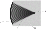
Fig. 10 shows a plan view of an ultrasound wave 10 emitted by the acoustic generation apparatus 9. The ultrasonic waves 10 are concentrated into small PoT 8. As shown in fig. 10 and 11, the lesion 48 located in the predefined PoT 8 is created by transmitting ultrasound waves 10 through the coupling medium 40 and into a concentrated focus. In a preferred embodiment, the acoustic generation means 9 is made of a piezoelectric material that generates ultrasound waves 10. Typically, the acoustic generation means 9 are connected to an electrical matching circuit 13 and housed in a dedicated housing 12, referred to in combination as a transducer 11, as shown in fig. 12.
Fig. 12 shows an exploded three-dimensional isometric cross-section of a transducer 11 that may be used for skin treatment. As can be seen in fig. 12, housing 12 includes an angled lip, edge or flange 50 to hold sound generating device 9 and to maintain sound generating device 9 at a fixed distance from the end of housing 51 that is designed to contact the skin. In some embodiments, the housing 50 has a window 49 in the end of the housing 51 that is designed to contact the skin. The window 49 may typically be smaller than the aperture of the sound generating means 9, since the sound waves will be focused. In the embodiment shown in fig. 12, the window 49 is simply a hole in the end of the housing 51. However, in other embodiments, the housing 12 may have a window 49, the window 49 being constructed of a transparent material integrated into the head 12.
In a preferred embodiment, the housing 12 also has a cavity 52 located between the acoustic generation means 9 and the end of the housing 51. As will be explained in more detail later, the cavity 52 is preferably filled with a coupling medium 40 to facilitate the transmission of acoustic waves from the acoustic generation means 9 to the end of the housing 51.
In a preferred embodiment, the transducer 11 comprises an acoustic generation means 9, the acoustic generation means 9 consisting of a piezoelectric element manufactured as a segment of a spherical shell with a specific geometrical focal length, an element thickness defining its thickness resonance frequency and a diameter defining its aperture. In one embodiment, the focal length is in the range of 5 to 30mm, and the thickness of the element is in the range of 0.1mm to 2mm, while the aperture is in the range of 4mm to 40 mm. In another embodiment, the focal length is in the range of 2mm to 15mm, and the thickness of the element is in the range of 0.05mm to 1mm, while the aperture is in the range of 4mm to 20 mm.
In yet another embodiment, the focal length is in the range of 10mm to 200mm, the thickness of the piezoelectric element is in the range of 0.1mm to 2mm, and the aperture is in the range of 20mm to 100 mm. In this geometry, the acoustic generating piezoelectric element 9 can convert an electrical signal into an acoustic wave 10 having a defined focal point. The acoustic wave 10 generated by the piezoelectric element 9 is coupled to the surface of the end of the housing 51 of the transducer 11 using the coupling medium 40. An example of an acoustic transducer element is given in example 1.
Example 1
An acoustic transducer for skin treatment comprises the following piezoelectric components:
in some embodiments, the coupling medium 40 is a low loss medium capable of conducting the acoustic waves from the focusing transducer 9 to the skin surface above PoT 8. The coupling medium preferably matches the acoustic impedance of the skin tissue, so in a preferred embodiment, water is used as the coupling medium 40.
In another embodiment, the low-loss medium 40 is comprised of an acoustic coupling medium, which may be selected from at least the following group: aqueous media, acoustic coupling gels, aqueous polyacrylamides, hydrogels, methylmethacrylate, collagen/polymer (polyacrylic acid) blends, polyvinyl alcohol, and the like.
Acoustic window
Fig. 13 shows an exploded three-dimensional isometric cross-sectional view of a transducer head 11 having an acoustic window 200. The acoustic window 200 may provide acoustic coupling and physical protection during treatment of the skin. As mentioned above, the coupling medium 40 is ideally placed in the cavity 52 between the acoustic generation means 9 and the end of the housing 51. The coupling medium 40 is preferably held in the cavity 52 and in embodiments where the end of the housing 51 comprises an aperture 49, a further acoustic window 200 may be used to cover the aperture 49 and hold the coupling medium 49 in the cavity 52. In the embodiment shown in fig. 3, the acoustic window is integrated as part of the acoustic coupler 18.
The acoustic coupler 18 may be permanently fixed to the housing 11 or, as shown in fig. 13 and more preferably, may be releasably coupled to the housing 12. In the embodiment shown in fig. 13, acoustic coupler 18 includes a protrusion or ridge 53 extending around the inner periphery. The projection 53 is designed to releasably couple to a groove 54 extending around the perimeter of the housing 12. Thus, with the proper amount of force, acoustic coupler 18 can be snapped onto housing 12 or disengaged from housing 12. The releasably coupled acoustic coupler 18 may be advantageous for a variety of reasons, including hygienic reasons. For example, because acoustic coupler 18 may be in contact with the skin of a patient, it may be disposable and vary from patient to patient. In other embodiments, the acoustic coupler 18 is not itself disposable, and may be wrapped in a disposable wrap that is discarded after each use. In yet another embodiment, the acoustic coupler 18 is secured using an adhesive layer that allows for easy removal.
Because the acoustic coupler 18 holds the coupling medium 40 in the cavity 52 between the skin surfaces above the elements 9 and PoT 8, the acoustic coupler is preferably suitably sealed to the housing 12 to prevent leakage of the coupling medium 40.
In one embodiment, the acoustic window 200 is designed to allow imaging capabilities integrated with the therapy transducer with sufficient imaging access to the skin surface above PoT 8. The placement of the therapy transducer can thus be guided by visual observation through the acoustic window.
In a preferred embodiment, acoustic window 200 is made of a thin acoustically and optically transparent material such as acrylic polymer, polyethylene, polyurethane polycarbonate, polypropylene, polymethylmethacrylate, polysulfone, polystyrene, styrene-butadiene copolymer, cellulose, thermoplastic polyester, glass, sapphire, other types of crystals, silicone, and the like. In other embodiments, the acoustic window 200 may be made of a non-optically transparent material, such as silicone rubber, latex, polyurethane, polyester, epoxy (with various fillers), polyamide, PTFE, and the like.
In a preferred embodiment, the acoustic window is made of a 1-1000 μm thick film made of optically and acoustically transparent polyethylene, polyurethane or a mixture of polyurethane and polyester elastomer.
Piezoelectric element
In a preferred embodiment, the acoustic generation means 9 may be a piezoelectric element. The piezoelectric element 9 may be made of a piezoelectric material such as doped lead zirconate titanate (PZT). PZT is preferable because it has good energy conversion performance (high coupling coefficient k)33And high d33Value) and relatively low cost.
In other embodiments, the element 9 is made of alternative piezoelectric materials, such as, but not limited to, a single crystal made of lithium niobate (LNb), aluminum nitride (AlN), lead magnesium niobate-lead titanate (PMN-PT), or quartz; a polycrystalline ceramic material made of lead niobate, potassium niobate (KNN), barium titanate (BaT), Bismuth Titanate (BT), bismuth sodium titanate (BNT), bismuth sodium titanate-bismuth titanate (BNT-BT); or a polymer material made of polyvinylidene fluoride (PVDF).
In other embodiments, the acoustic generation means 9 may be replaced by alternative active elements, such as Capacitive Micromachined Ultrasonic Transducers (CMUT), Piezoelectric Micromachined Ultrasonic Transducers (PMUT) or the like.
In other embodiments, other materials may be used for the sound-generating device 9, including combinations of materials and layers. In other embodiments, a piezoelectric composite material may be used for the focusing transducer 9.
In some embodiments where the acoustic generation apparatus 9 is a piezoelectric element, the apparatus has a mechanical quality factor (Q) higher than 1000m). In other embodiments, a Q of greater than 100 may be usedm。
In some embodiments, the acoustic generation means 9 is a planar element with an additional element (acoustic lens) attached for focusing the acoustic signal into a defined focal point. In some configurations, the lens is made of a low acoustic loss material characterized by an acoustic speed lower than that in medium 40 (e.g., water). In this case, the lens is convex in shape, typically made of a polymer, such as PDMS (polydimethylsiloxane), typically having a sound velocity of 950 m/s. In another configuration, the acoustic lens has a concave shape characterized by a speed of sound higher than the speed of sound in the medium 40. This can be achieved by using composite materials, such as polymers filled with metal fillers. In one embodiment, the polymer is an epoxy filled with a tungsten filler.
In yet another embodiment, the focusing of the ultrasound waves 10 is achieved by other methods than those described above, for example using an electronic focusing technique. In this configuration, the acoustic generation means 9 is composed of a plurality of piezoelectric elements driven by a multi-output power driver. Focusing is achieved by introducing a certain delay between the drive signals so that the focused wave reaches PoT 8 in a predetermined manner. In some embodiments, the multi-element transducer includes more than one element. In another embodiment, the transducer comprises between 2 and 256 elements.
Figure 14 shows an isometric three-dimensional cross-sectional view of the transducer 11 as shown in figure 13. As can be seen in fig. 14, the acoustic generation device 9 can be fabricated with a bore 14, whether the acoustic generation device 9 is configured as a single focusing piezoelectric element, a multi-element assembly, or is composed of planar elements with attached elements for focusing acoustic signals. In a preferred embodiment, the hole 14 is located in the center of the acoustic generating means 9 along the focal or acoustic axis 55. It will be appreciated that in the embodiment shown in figure 14, the acoustic axis 55 is also the longitudinal axis of the device. The holes 14 allow mechanical stress relief during high power operation of the piezoelectric element 9. In addition, the aperture 14 may be used to enable optical access by an auxiliary imaging system.
Fig. 15 shows a three-dimensional cross-sectional view of the basic arrangement of the main internal components 24 and 25 of a focusing piezoelectric transducer with an optical monitoring system 56, wherein the optical monitoring system 56 is fitted with an optically transparent path 14 through the piezoceramic element 9. It will be appreciated that the optical monitoring system may comprise at least one lens 25. In some embodiments, the optical monitoring system may include a CCD 24 or other type of optical imaging device. In a preferred embodiment, the optical axis of the optical monitoring system 56 is aligned with the acoustic axis 55 and creates a line of sight to the skin surface 6, as schematically shown in fig. 15.
In order to form the optically transparent path 14, the acoustic generation means 9 need to have an aperture 14. In one embodiment, the diameter of the holes 14 is in the range of 1mm to 10 mm. In another embodiment, the diameter of the holes is in the range of 0.2mm to 20 mm. Preferably, the pore diameter is limited by the pore diameter of the piezoelectric element, so that the diameter of the optically transparent path 14 is no more than 50% of the pore diameter of the piezoelectric element. In other embodiments, the diameter of the holes 14 is no greater than 70% of the total diameter of the acoustic generation apparatus 9.
Fig. 16 depicts a plan cross-sectional view of the basic configuration of the transducer head 11 in contact with the skin surface. In a preferred embodiment, the transducer 11 comprises a piezoelectric element 9, the piezoelectric element 9 being characterized by an acoustic focal length 42. The acoustic focal length 42 is greater than the distance from the surface of the piezoelectric element 9 along the line 44 of its piezoelectric element 9 to the transducer front face 45, thereby defining a transducer penetration depth 43. In this way PoT 8 is located in the dermal layer 3 and/or epidermal layer 1, and the lesion 48 will extend through the base film 2 towards the skin surface and into the epidermal layer during treatment. As shown, the front face 45 of the transducer 12 is in contact with the skin surface 6 during treatment, as shown in fig. 16 and 17.
As previously mentioned, the volume between the piezoelectric element 9 and the face contacting the skin 45 within the transducer housing 12 may be filled with the coupling medium 40. In such embodiments, the aperture 14 may also include a transparent window to prevent the coupling medium 40 from escaping through the aperture 14 into the device 11. The windows in the apertures 14 may be made of similar materials as the other windows disclosed herein.
Fig. 17 depicts a plan cross-sectional view of the basic construction of the transducer 11 with optical monitoring capability in contact with the skin surface. In a preferred embodiment PoT 8 is located 0.1mm to 10.0mm below the skin surface depending on the skin type and the location of the treatment area on the human body. PoT 8 should be fixed to index a selected depth of 0.1mm to 10.0mm into the dermis layer 3 where most of the pigment 7 and pigment-containing cells from the tattoo are located (see fig. 3). Both the location of the tattoo and the skin type are considerations for determining PoT 8 the exact depth below the skin surface. In some embodiments, the penetration depth of any particular transducer head 11 is fixed, and different transducer heads 11 with different insonification depths are employed as needed to remove the tattooed body part from the skin. To this end, the transducer head 11 may be detachably coupled from a higher-level hand held assembly. In other embodiments, electron beam steering is used to electronically control the penetration depth on a single transducer head 11. In this configuration, one or more multi-element transducers may be used.
Wavelength and resonance
The ability to determine and/or control lesion size is an important part of the embodiments described herein. Assuming that the lesion shape can be approximated by an ellipsoid elongated along an axis perpendicular to the skin surface (Z-direction), the size of the lesion defined by the diameter in the X-Y plane should be no greater than 10.0mm in some embodiments.
In a preferred embodiment, the size of the lesion, as defined by the lesion diameter, is 2.0mm or less. In view of the fact that the resonance frequency for generating lesions below 1mm is higher than 10MHz, the corresponding ultrasonic wave length must be below 150 μm, as shown in fig. 18. This in turn implies some limitations on the size of the piezoelectric spherical focusing element.
In a preferred embodiment, the operating frequency of the system is 7MHz or higher. In a more preferred embodiment, the frequency is 15MHz or higher. This patent application teaches how to achieve these higher operating frequencies by designing the piezoelectric element using the relationship between wavelength, resonant frequency and element size.
Fig. 19 is a graph showing an example of an impedance diagram of the piezoelectric element. As shown in fig. 19, the piezoelectric element exhibits a specific thickness resonance mode corresponding to some vibration phenomena. This manifests itself in the specific impedance spectrum as shown in fig. 19. Fundamental thickness resonance frequency f of piezoelectric element 1500 can be calculated by:
wherein h is the thickness of the piezoelectric element and cpIs the speed of sound in the piezoelectric material. Higher order resonance modes can also be found under the following conditions:
fn=α n f1wherein n is 3,5,7,9, …
Where a is a factor that depends on the actual geometrical configuration of the piezoelectric element. For practical applications a value of 1.1 may be used.
In a preferred embodiment, the system operates at a frequency above 15 MHz. In order to realize frequencies above 15MHz using the focusing transducer 9 made of a piezoelectric element operating in the fundamental mode, the piezoelectric element needs to be less than 0.1mm thick as described in example 2. Piezoelectric elements with a thickness of less than 0.1mm are very difficult and/or costly to manufacture. Thus, a more creative approach may be implemented when designing the focusing transducer.
In some embodiments, the fundamental resonance mode is used to drive the piezoelectric spherical focusing element 9 at a resonance frequency between 1MHz and 50 MHz. In a preferred embodiment, the third harmonic resonance mode 502 is used to drive the piezoelectric element at a resonance frequency between 1 and 50 MHz. It will also be appreciated that other harmonic resonance modes may be used, including second harmonic modes and fourth harmonic modes. In other embodiments, the piezoelectric element is driven at a resonant frequency between 10 and 100MHz using higher order resonance modes such as 5,7,9, etc.
Example 2
The piezoelectric spherical focusing element needs to operate at a fundamental thickness resonance frequency of 20 MHz. Therefore, it is assumed that the sound velocity in the piezoelectric element is equal to cpThe necessary wall thickness h can be calculated from the following equation, 4000 m/s:
example 3
The piezoelectric spherical focusing element as in example 2 needs to have a third harmonic resonance frequency f at a thickness of about 20MHz3And (5) operating. Thus, the necessary wall thickness h can be calculated by the following formula:
table 1:
the piezoelectric element is typically machined from a brittle piezoelectric ceramic to achieve the desired thickness and shape. At thicknesses below 200 μm, the piezoelectric ceramic itself is very difficult to handle and process due to its low mechanical integrity. Thus, it is advantageous to use third harmonic resonance since the thickness of the element is about three times that of an element operating at the fundamental frequency. This is especially true for frequency ranges above 10 MHz.
In view of the relatively small size characteristics of skin, small and well-controlled lesions are required at PoT. Therefore, it is necessary to control the concentration and focusing of the ultrasonic waves as precisely as possible.
According to the O 'Neil model (O' Neil. H.T theory of focused radiators, J.Acoust. Soc.am.,21,616-526,1949), the ultrasonic pressure field generated by the piezoelectric focusing element can be well modeled by the focusing cylinder. A structure shown in fig. 20, in which the aperture is a and the radius of curvature is R, may be considered0Rigid surface S of the focusing pistonfAt a vibration speed V0And an angular frequency ω 2 π f into a fluid of density ρ and speed of sound c. Then in any point x in space, the pressure p (x, ω) in front of the piston can be described as follows:
where y is the coordinate of the radiating point on the focusing piston surface, r is the distance between y and the point of interest x, and k is the wave number
While
Is the wavelength. Assuming that the conditions are satisfied
It may be assumed that effective focusing occurs and that the pressure field may be schematically depicted in fig. 21.
As shown in fig. 22, it is very useful to evaluate the pressure distribution along the central axis of the focusing piston. For a given point x along the central axis, the pressure resulting from equation 1 is given by:
wherein
Another important pressure distribution is in the plane near the geometric focus, as shown in fig. 23. For a given point x along a line perpendicular to the central axis and coincident with the geometric focus, the pressure is represented by the following equation derived from equation 1
Wherein J1(x) Is a first order bessel function.
Defining the F number of the radiator as
Is useful.
Example 4
The focused radiator, with an aperture equal to 10mm and a radius of curvature equal to 15mm, is driven by three different frequencies, 5MHz, 10MHz, 20 MHz. The radiator has acoustic velocity equal to 1480m/s and 1000kg/m3Radiates acoustic energy into the water. The pressure distribution along the central axis and in the focal plane calculated according to equations 2 and 3 is given in fig. 24. It can be understood that the effect of frequency near the focal point on the magnitude of the pressure peak.
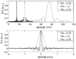
Example 5
A focused radiator with three different apertures equal to 10mm (FN ═ 0.75), 7.5mm (FN ═ 1), and 5mm (FN ═ 1.5) and with a radius of curvature equal to 15mm is driven at a frequency equal to 20 MHz. The radiator has acoustic velocity equal to 1480m/s and 1000kg/m3Radiates acoustic energy into the water. The pressure distribution along the central axis and in the focal plane calculated according to equations 2 and 3 is given in fig. 25. It can be understood that the effect of aperture size near the focal point on the magnitude of the pressure peak at a constant radius of curvature, with radiators with lower F-numbers being more suitable for producing small but highly focused pressure peaks.
Example 6
A focused radiator with three different radii of curvature equal to 15mm (FN ═ 0.75), 30mm (FN ═ 1) and 75mm (FN ═ 1.5) and an aperture equal to 10mm is driven at a frequency equal to 20 MHz. The radiator has acoustic velocity equal to 1480m/s and 1000kg/m3Radiates acoustic energy into the water. The pressure distribution along the central axis and in the focal plane calculated according to equations 2 and 3 is given in fig. 26. It can be understood that the effect of the radius of curvature on the magnitude of the pressure peak near the focal point, a radiator with a lower F-number is more suitable for generating small but highly focused pressure peaks.
The size of the focal zone, defined as the volume at which the pressure drops by 6dB with respect to the peak, can be evaluated using equations 2 and 3. As shown in fig. 21, the distance along the central axis at which the pressure drops by 6dB is referred to as the depth of focus (DoF), and similarly, the distance along the focal plane is referred to as the Focal Diameter (FD).
From equation 3, it can be derived that the focal diameter FD of the focused ultrasound wave can be approximated as:
wherein a is a radius of curvature R0And λ is the wavelength of the acoustic wave emitted from the focusing element having an F-number FN.
Similarly, the depth of focus DoF of a piezoelectric spherical focusing element can be derived from equation 2 and approximated by the following equation:
example 7
Piezoelectric spherical focusing elements made of hard PZT material (e.g., Navy type I) operate in water under the following conditions (c-is comparable to the speed of sound in tissue):
given the above formula, the wavelength of the acoustic wave in tissue (like water) can be calculated to be 148 μm. This will produce a 6dB focal region characterized by a focal diameter of 240 μm and a focal depth of 1210 μm.
Example 8
Under the same conditions as example 2, a piezoelectric spherical focusing element made of a hard PZT material (e.g., Navy type I) operates in water (c-is comparable to the speed of sound in tissue), but at a third harmonic frequency of 20 MHz:
using the above formula, the wavelength of the acoustic wave in tissue (like water) can be calculated to be 74 μm. This smaller wavelength will result in a smaller 6dB focal region characterized by a focal diameter of 80 μm and a focal depth of 403 μm compared to the wavelength produced by the 6.66MHz element.
A small and well-defined lesion is required at PoT 8. This means that the focal diameter and depth of focus of the lesion are balanced with the size constraints of the dermis and epidermis layers surrounding PoT. As shown in the above example, this can be achieved by using a high resonance frequency for the piezoelectric spherical focusing element.
In one embodiment, the frequency used to obtain a small and well-defined lesion in PoT 8 at a resonant frequency 500 of 15 to 50MHz is thus used to drive the piezoelectric focusing element.
In a preferred embodiment, the frequency used to obtain a small and well-defined lesion in PoT 8 at a resonant frequency of 7 to 50MHz is used to drive a piezoelectric focusing element operating at the third harmonic frequency in the parallel resonance 503.
In another preferred embodiment, the frequency used to obtain a small and well-defined lesion in PoT 8 at a resonant frequency of 15 to 100MHz is used to drive a piezoelectric focusing element operating at an odd harmonic frequency of 5 or more in parallel resonance.
For other embodiments, the resonant frequency for driving the piezoelectric focusing elements may range from 5 to 15MHz to achieve greater thermal damage in body areas where the dermis layer is relatively thick.
For still other embodiments, the resonant frequency for driving the piezoelectric focusing elements may be in the range of 20 to 50MHz to achieve very little thermal damage in body areas with thin dermal layers.
Impedance matching
The efficiency of power and energy transfer between the energy source and the transducer is determined by the electrical impedance of the source (e.g., RF power amplifier) and the input impedance of the transducer. Complex output impedance z of the sourceoutEqual to the input impedance z of the receiver as shown ininThe optimal energy transfer is obtained at complex conjugation:
where denotes the complex conjugate operator.
In a preferred embodiment, it is required that the input impedance of the piezoelectric element is matched to the output impedance of the energy source (e.g., power amplifier) in the manner described above. In a more preferred embodiment, the impedance matching is equal to the characteristic impedance typical of high frequency devices, equal to 50 Ω.
In general, piezoelectric components in the form of discs or preferably focusing elements exhibit a so-called series resonance fsAnd parallel resonance fp. These two resonances are defined in particular by the thickness of the component and are linked together and represented by the following formula:
wherein k ist 2Is the thickness coupling coefficient of the selected piezoelectric material.
In the frequency range under consideration, it would be advantageous to use series resonance when the device is operating at the fundamental frequency 500. In this case, the impedance modulus at the series resonance is in the range of several hundred ohms (Ω), which makes it easier to match a characteristic impedance of 50 Ω compared to the impedance at the parallel resonance 501, which impedance at the parallel resonance 501 will reach for a high Q for a component similar to that described in example 2mA resistance of several tens or hundreds of k omega of the piezoelectric material.
Components operating at higher harmonics, e.g., the third harmonic, are more challenging than components operating at the fundamental frequency. Typically, the impedance at the series resonance 502 is at the level of tens or hundreds of m Ω. This makes it difficult to match the 50 Ω impedance of the energy source.
Thus, in a preferred embodiment, the piezoelectric members are driven at a parallel resonant frequency 503 when operating at higher harmonics (e.g., third harmonic frequencies). In these preferred embodiments, the parallel impedance level is low and can reach several Ω of an assembly similar to that described in example 9.
Electrical impedance matching can be achieved by several different methods using a network of passive electrical components, such as capacitors, inductors, and transformers. Examples 9 and 10 present selected impedance matching solutions.
Example 9
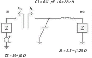
The focusing piezoelectric member exhibits parallel resonance at a third harmonic frequency equal to 20MHz, and is characterized by a complex impedance z of 2.50-j1.25 Ω. From L088.8nH series inductor and C1A matching network of parallel capacitors of 662pF will result in an impedance equal to 50 Ω from the energy source, as shown in fig. 27.
Example 10
The focusing piezoelectric member exhibits parallel resonance at a third harmonic frequency equal to 20MHz, and is characterized by a complex impedance z of 2.00-j1.25 Ω. A matching network consisting of a high frequency transformer T1 with a turn ratio n-5 (e.g. a 10-turn primary and a 2-turn secondary connected to the piezoelectric element) transforms the impedance from the secondary into z 2-n2X (2.00-j1.25) ═ 50.00-j 31.25. In a practical circuit, this impedance will be further affected by the self and mutual inductance of transformer T1, which in fig. 28 is represented by the bulk series inductance L s645 nH. Thus, considering the parasitic inductance of T1 (a combination of the self-inductance and mutual inductance of the transformer), the actual impedance originating from the primary winding of the transformer connected to the piezoelectric component will be equal to about z 3-50 + j49 Ω. To return the imaginary part of the impedance to zero, a series capacitor C is added2160 pF. This will result in an impedance from the energy source equal to 50 Ω, as shown in fig. 28, which will be the best impedance match.
In one embodiment, an electrical impedance matching network for a transducer operating at a third or higher harmonic frequency is made up of many passive electronic components, such as capacitors, inductors, and transformers.
In another embodiment, an electrical impedance matching network for a transducer operating at a third or higher harmonic frequency is comprised of a series inductor and a parallel capacitor.
In a preferred embodiment, the electrical impedance matching network for transducers operating at third or higher harmonic frequencies consists of a high frequency transformer with series capacitors. In another preferred embodiment, the series capacitor is a variable capacitor for the fine adjustment circuit.
Power unit
As shown in fig. 29, in one embodiment, the handpiece 35 is connected to the cable assembly 34 and is driven by a power unit 39. In the embodiment shown in fig. 29, the power unit 39 includes: a signal generator 31, a front amplifier 32 and a power amplifier 33. The system is controlled by a control unit 30, which control unit 30 preferably consists of a microcontroller or other computer system.
In a preferred embodiment, the power unit 39 is designed to provide a specific combination of power and frequency for a predefined period of time in response to a trigger (e.g., a foot switch or the like). This is to ensure that a consistent lesion pattern is produced when used in combination with the acoustic transducer described above.
The control unit 30 is integrated in a system configured to select operating parameters of the system, such as frequency and duty cycle.
In a preferred embodiment, the control system includes a user interface that allows a user to select primary operating parameters, such as operating frequency, duty cycle time, output power from the transducer, and the like. In other embodiments, the control system will only allow a user very limited control over the operating parameters.
The selected operating parameter, whether selected by the user or fixedly set, drives a signal generator that generates the request signal characteristic. Depending on the particular requirements of the signal, the signal generator 31 may not be able to directly provide the required power level without the need for an amplifier to output the signal.
In a preferred embodiment, the control unit 30 is connected to a signal generator 31 for generating specific signal frequencies, burst times, power levels, etc.
In one embodiment, the power unit 39 is capable of generating over 1W of high frequency power in the frequency range of 1MHz to 30 MHz. In a more preferred embodiment, the power unit 39 is designed such that it can deliver more than 1W of power to the impedance matched ultrasound transducer in the frequency range of 1 to 100 MHz.
Sound production energy
Although the focusing characteristics and concentration of the ultrasound signal emitted from the piezoelectric element depend on geometry and frequency, as shown in examples 7 and 8, the final size of the lesion created by the focused ultrasound is determined by the energy of the sounding signal. The higher the energy, the greater the volume of denatured tissue. For example, at constant power, the energy will depend linearly on the time of sound production. In a simple case, the energy of one sounding cycle (pulse train) is determined by the output power P adjusted for the electro-acoustic conversion efficiency given by η and the signal duration t, as follows:
E=ηPt.
in one embodiment, energy is delivered for a predetermined duration period. In another embodiment, the signal may be further modulated to optimize the tattoo removal process, and may consist of a limited number of short periods, thereby producing a final sounding energy that is a superposition of the energy of each individual period, as shown in fig. 30.
Mechanism of lesion formation
It should be understood that the lesion 48 created by the high intensity focused ultrasound is the result of thermal heating or cavitation or a combination of both. Thus, the size of the lesion created in PoT depends on the energy emitted from the transducer and deposited in the tissue.
Typically, there is an energy threshold below which no damage occurs, which in turn does not trigger phagocytosis. Furthermore, the basement membrane is not punctured, thereby preventing the transport of pigments and pigment-containing cells into the epidermis. In a preferred embodiment, the energy level of deposition should be higher than 0.1J.
On the other hand, too high a level of energy emitted into PoT will generate excessive heating and/or cavitation, thus damaging a larger volume of the skin than the original target PoT. The expanding thermal damage may extend through the epidermis and form an open wound on the skin, thereby increasing the risk of infection.
Example 11
The electrically matched transducers are driven by connected power units. The settings in the control system are as follows:
by means of these parameters, the electric energy E from the power unit can be estimatedelAnd acoustic energy E transmitted into PoTPoT:
EPoT=ηEe1=1J
In some embodiments, the acoustic energy level transmitted from the transducer is between 0.01J and 100J delivered for a burst duration of 1 to 100000 ms. In other embodiments, the acoustic energy level transmitted from the transducer is between 0.1J and 25J delivered for a burst duration of no more than 5000 ms. In a preferred embodiment, the acoustic energy transmitted from the transducer is said to be delivered at a level of between 0.1J and 10J for a burst duration of between 1ms and 2000 ms. In other embodiments, the acoustic energy level transmitted from the transducer may be continuous at acoustic power levels of 1W to 100W.
In order to create lesions around and within the focal zone, a certain acoustic energy density and/or acoustic intensity threshold needs to be reached. It is useful to define the average acoustic energy density around the 6dB focal zone as follows:
where β is the shape factor, indicating that not all energy is focused within the 6dB focal region. For the pressure profile given in fig. 24, this factor is about 65% -72%. Likewise, the average acoustic intensity within the 6dB focal region may be defined as:
PPoTis the acoustic power transmitted by the transducer to the focal point. Depending on the phonation conditions, the lesions may be generated primarily by thermally heating the tissue to a temperature above 42 ℃. In this case, a certain energy density threshold needs to be reached. At high acoustic intensities, the damage is mainly generated by cavitation. It is also expected that loud sounds occur simultaneouslyCombined thermal and mechanical effects at chemical strength and high energy density.
The combination of acoustic power, burst duration and drive frequency results in different types of energy transfer functions and lesion sizes generated in and around the 6dB focal zone as defined above and calculated in examples 7 and 8. Using the same assumptions of F-number and speed of sound in water as in these examples, the resulting lesion shape and size can then be estimated as shown in example 12.
Example 12
In a preferred embodiment, the combination of settings is selected to produce a lesion in and around the focal region, the lesion being characterized by a diameter in a plane perpendicular to the central axis in the range of 0.01mm and 2.0mm and a length in a plane along the central axis in the range of 0.01mm and 4.0 mm. In other embodiments, a lesion is created in and around the focal region, the lesion being characterized by a diameter in a plane perpendicular to the central axis in the range of 0.01mm and 1.0mm and a length in a plane along the central axis in the range of 0.1mm and 2.0 mm. In a preferred embodiment, a lesion is created in and around the focal zone, the lesion being characterized by a diameter in a plane perpendicular to the central axis in the range of 0.03mm and 0.6mm and a length in a plane along the central axis in the range of 0.2mm and 1.5 mm.
Processing method
In order to achieve removal of tattoos having pigments distributed over a large area of the body, it is necessary to consider the effect of sound emission time for each lesion, as compared to a few repeated short sound emissions.
Since several effects of sound production include convection and increased attenuation, etc., extended sound production times over a single area will result in extended lesion sites towards the skin surface rather than extending to deeper portions of the subcutaneous layer of skin 4, as shown in fig. 31 and example 12.
To cover a large treatment area (greater than one damage point), more than one POT is required. These PoT may be patterned or placed in a variety of different ways to obtain the best results in different embodiments of methods of treating skin. In one embodiment, the individual PoT are laterally spaced apart to create lesions in an appropriate pattern with a spacing of 0.1mm to 5mm between the circumferences of each lesion. In other embodiments, the distance between the circumferences of each lesion in the pattern is separated by a spacing of no more than 4 mm. In a preferred embodiment, each lesion is separated by no more than 2 mm.
In some embodiments, 1mm2To 1000mm2The intermittent pattern of treated areas is interleaved with similarly sized untreated areas. In the preferred embodiment, 1mm as shown in FIG. 322To 25mm2The intermittent pattern of treated areas is interleaved with untreated areas of similar size, for example in a checkerboard or hexagonal pattern or the like. In another embodiment, the vocalization is administered in a semi-continuous or fully continuous manner. This means that energy is deposited at a rate that matches the motion of the handpiece.
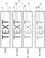
The PoT pattern and treatment method selected on the selected area of skin must be repeated several times to cover all of the target area and gradually reduce the concentration of pigment in the skin. If a processing method is used that includes interleaving or spacing PoT, such as in a checkerboard pattern or the like, then subsequent processing should be used on the unprocessed regions and previously processed regions skipped to complete coverage on the contiguous regions. In this way, subsequent processing can alternate between processed and unprocessed regions within the same overall processed region. An example of a processing strategy for tattoos containing text or other fine-pitch graphical elements is shown in fig. 33. Preferably, the treatment is performed at intervals where the different pigment removing functions have had sufficient time to be completed and where possible redistribution of the pigments has had time to occur within the skin.
In a preferred embodiment, a treatment session comprising a number of PoT was repeated at intervals of 1 to 12 weeks between each treatment session, depending on age and other characteristics of the skin and treatment settings as shown in example 13.
Example 13
Disposable transducer head
Figure 34 shows an exploded isometric view of one embodiment of a handpiece with an easily replaceable ultrasound transducer head 11. Aging can be a problem in piezoelectric elements as the power pulse train is repeatedly emitted at the above-described levels. The aging of piezoelectric materials and transducers is inherently difficult to predict accurately because it is related to many external independent factors such as drive voltage, frequency, temperature, mechanical stress, corrosion conditions, and any combination of these factors.
To ensure predictable conversion efficiency between the electrical signal transmitted to the transducer and the acoustic signal received at PoT, the piezoelectric element and a portion of the transducer may need to be replaced at regular intervals. In some embodiments, a specially designed algorithm may be used to predict the life of the replaceable transducer and notify the user.
In the preferred embodiment, the handpiece 35 is designed in such a way that it is easy to replace the transducer when needed. The replaceable transducer 11 should preferably comprise a piezoelectric element 9, a housing 12 and an integrated electrical matching circuit 13. The transducer head 11 includes a releasable coupling interface that mates with the rest of the handpiece containing the camera, optics, connectors, cables and electronic components. In the embodiment shown in fig. 34, a threaded interface is used, but other interfaces, such as interference fits, fasteners, etc., may also be used.
In another preferred embodiment, the transducer comprises means for monitoring the use and the function of deactivating the transducer when a preset limit is exceeded. The monitoring may be, for example but not limited to, signal cycle count, active processing time, or reflected power measurement.
Optical monitoring
Advantageously, the method comprises an additional optical monitoring system to assist the user in performing the skin treatment, in particular the tattoo removal process, with appropriate optical feedback. By allowing the user of the device to view the treated area of skin, more accurate placement of PoT may be achieved. This can improve the processing accuracy and shorten the processing time and the number of times of repetition of the processing necessary to completely remove the tattoo.
Fig. 35 and 36 show an embodiment of a handpiece 36 comprising an optical system with components 21, 22, 23, 24. The optical system 36 integrated with the acoustic transducer 11 provides visual information about PoT placement under the skin. In some embodiments, the handpiece 36 is equipped with a light source 15 to appropriately illuminate the skin surface, as shown in fig. 13, 14 and 17. In one embodiment, the light source 15 is comprised of one or more light bulbs. In a preferred embodiment, an LED (light emitting diode) or a plurality of LEDs is used as the light source 15.
Returning to fig. 13, it will be appreciated that in the embodiment shown in fig. 13, two light sources 15 are used. Any number of light sources may be used, including a single light source 15 or multiple light sources 15, depending on the embodiment. In the embodiment shown in fig. 13, the light sources extend down the outer wall of the cavity 52 such that only the front ends of the light sources protrude into the cavity 52. Thus, the walls of the cavity 52 may have one or more light source openings. This allows light from the light source 15 to illuminate the coupling medium 40 and thus the skin surface above PoT. In a preferred embodiment, the light source 15 is sealed to the walls of the cavity 52 with an O-ring or other type of seal so that the coupling medium 40 cannot escape from the cavity 52 through the light source opening.
In another embodiment, the light source 15 may be located outside the cavity wall. In particular, the light source may be integrated behind the acoustic generation means 9 and be illuminated downwards through the same opening 14 designed to allow the optical system to image the skin surface above PoT 8. This provides a simplified design as it creates fewer openings in the cavity 52 through which the coupling medium may escape.
As already discussed with reference to fig. 15, some embodiments of the handheld device 36 may include an optical monitoring system 56. Fig. 36 shows an exploded isometric cross-sectional view of one embodiment of a handpiece 36 with an easily replaceable ultrasound transducer 11 including an optical monitoring system 56 with an adjustable optical focus objective. In some embodiments, an optical monitoring system 56 for presenting the optical signal is integrated into the handpiece and transducer, thereby providing easy visibility for the operator of the device during treatment. The monitoring system may use any number of optical components including, but not limited to, lenses, displays, CCD arrays, and/or fiber optic image conduits, to name a few.
In a preferred embodiment, the optical monitoring system is integrated in the handpiece concentrically with the focusing piezoelectric element, i.e., the optical axis of the optical system is aligned with the longitudinal axis of the handpiece 36 and/or with the axis of symmetry of the focusing transducer through PoT. In such an embodiment, the focusing piezoelectric element is designed to have a hole in the center that physically allows the optical signal to pass from the skin 6 to the image sensor through the lens system, as shown in fig. 36.
Preferably, as shown in fig. 17, the optical system is protected from the liquid content of the medium 40 by a transparent path 14. In one embodiment, the transparent path 14 separates the medium 40 from the optical system by a thin optically transparent barrier 46 made of polyethylene, polypropylene, polycarbonate, polyester, epoxy, or the like. The transparent path 14 may then be fixed and the optically transparent path may be made watertight by a suitable glue.
In some embodiments, the transparent path 14 between the optical system and the medium is made of 0.01-10mm silicate or borate glass. In a preferred embodiment, the transparent path 14 between the optical system 56 and the medium 40 is made of 0.05-0.3mm silicate or borate glass.
As can be seen in fig. 36, the optical monitoring system 56 may include the image sensor 24. The image sensor 24 may be mounted with image sensor support electronics 23. In an exemplary embodiment, the image sensor support electronics will be mounted on the PCB board along with the image sensor 24. As is well known in the art, image sensor support electronics provide the necessary support for the image sensor 24, including power, power conditioning, signal and signal conditioning, and any required drivers. In some embodiments, the image sensor 24 is a CMOS sensor, and in other embodiments, the image sensor 24 is a CCD camera or any other device that can convert an image into an electrical or digital signal. In some embodiments, image sensor 24 is not included, and the optical monitoring system allows PoT above the skin surface to be imaged directly on the operator's eye via the lens system.
In a system including the image sensor 24, it is necessary to match the field of view and resolution in the optical system to the type of optical imaging sensor 24 and its resolution. This can be done by selecting an imaging sensor 24 with the correct pixel size and number and pairing it with the correct type of optical lens 25, and adjusting the distance between these individual components.
As seen in fig. 36, the system 36 may include a lens holder 21. The lens holder 21 resides along an optical axis, in this case a longitudinal axis, and contains one or more lenses fixed relative to the lens holder 21. As can be seen in fig. 34, the lens holding portion has a hole passing through the middle downward along the optical axis. The optical monitoring system 56 may have an image sensor holding portion 22 in addition to the lens holding portion 21. In a preferred embodiment, the image sensor 24 is fixed to the image sensor holder 22. In operation, the image sensor holder 22 or the lens holder 21 is designed to be able to translate along the optical axis relative to the other component. This allows the focus of the lens to be adjusted relative to the image sensor and allows focusing.
In a preferred embodiment, the optical monitoring system 56 includes a threaded interface 20 with threads extending longitudinally along the optical axis. The threaded interface is coupled to the lens holder 21 or the image sensor holder 22 such that when the threaded interface 20 is rotated, the lens holder 21 or the image sensor holder 22 is made to traverse the optical axis. Translation along the optical axis changes the relative distance between the lens holder 21 and the sensor holder 22 and allows the skin surface above PoT to be imaged.
As can be appreciated, the optical monitoring system 56 may include other components including additional lenses or other optical components. In any event, the integrated optical monitoring system 56 requires an optical path from the image sensor 24 all the way through the handset to the skin surface above PoT.
In some embodiments, the image sensor 24 is located between 0 to 500mm from the acoustic generation element 9 and comprises a set of one or more optical lenses 25 to provide a focal point on the skin surface above PoT, as shown in fig. 15.
In one embodiment, the focus of the optical system is adjusted so that the field of view through the aperture in the element covers 1 × 1mm2And 100X 100mm2The visible region in between. In a preferred embodiment, the optical system provides an image through an aperture in the focusing transducer 9, which has dimensions of 10 x 15mm2And has a resolution of not less than 20 μm.
Although the optical system is shown along the longitudinal axis in the above embodiments, the optical system may be off-axis. It is important that the field of view is the skin surface above PoT. To this end, systems comprising off-axis optical systems are envisaged. Such a system may be partially or completely off-axis. For example, one or more mirrors may be used in an optical monitoring system to control the image and create a non-linear optical path.
Example 14
The pixel size is 3x3 μm2The 200 ten thousand pixel 1/2.7"CMOS sensor of (1/2.7") is mounted with an optical lens characterized by a focal length of 10mm, an aperture of 2.0mm, a field of view of 37.5 degrees, and an F-number of 1.6. With a working distance of about 15mm between the lens 25 and the aperture in the element 9 and further 10-15mm between the aperture in the element 9 and the surface of the transducer 45, a resolution of about 5 μm and about 7 x 11mm can be obtained2The field of view of (a).
In a preferred embodiment, the handheld assembly 36 includes a second housing 19 that couples the optical monitoring assembly 56 with the transducer head 11. In the embodiment shown in fig. 36, the transducer head 11 is coupled to the second housing 19 by a screw thread. Thus, the transducer head 11 may be easily removed from the second housing 19 by simply unscrewing the transducer head 11. Thus, the second transducer head (not shown) can be easily swapped into place. The second transducer head may have a different acoustic monitoring device with different parameters or may simply be a newer version of the transducer head 11 it replaces.
During some processes, it may be more useful to use other excitation and reception wavelengths in the optical system than wavelengths used for ordinary visible light in the wavelength range of about 400nm to 700 nm. In some embodiments, the transducer system is provided with a light source 15 having an emission wavelength starting in the ultraviolet spectrum of about 290 nm. In other embodiments, the light source 15 is selected to have an emission range extending into the infrared spectrum up to about 1100 nm. In other embodiments, the light source 15 has a broad emission range extending from the ultraviolet spectrum to the infrared spectrum.
In one embodiment, the camera system is selected to be capable of detecting wavelengths ranging up to the ultraviolet spectrum as described in one of the above embodiments. In other embodiments, the camera system is selected to be capable of detecting wavelengths in the range up to the infrared spectrum as described in one of the above embodiments. In other embodiments, the camera is selected to be capable of detecting the full range of ultraviolet light from 290nm to up to 1100nm infrared light.
Fig. 37 shows an isometric cross-sectional view of a transducer head 11 with an integrated optical filter 300, the integrated optical filter 300 allowing the optical monitoring system to selectively filter wavelengths of received light. In embodiments including an optical monitoring assembly, one or more optical filters 300 may be incorporated into the optical path so that only selective wavelengths can be detected by the camera. In these embodiments, the light source 15 is used in conjunction with a filter 300, which ensures that the camera system primarily receives wavelengths outside the emission spectrum of the light source. In this configuration, the fluorochromes or areas in PoT 8 may be more easily visualized.
In the embodiment shown in fig. 37, the optical filter 300 is integrated in the transducer head 11. This means that when the transducer head 11 is removed or changed, the optical filter 300 will also be changed. Because optical filter 300 will typically match the wavelength of light source 15, embodiments preferably mount optical filter 30 on the same portion of the assembly as light source 15 so that optical filter 30 remains with light source 15. However, in other embodiments, the optical filter 300 may be mounted on other portions of the hand held assembly. For example, the optical filter 300 may be integrated into the optical assembly 56.
As can be seen by returning to fig. 35, in some embodiments, the visual information is communicated to the control unit 37 by a link 38. The link 38 may be a wired or wireless connection. The preferred system will use a wireless link 38. The visual information may then be displayed on a display integrated within the handheld device. If the display is integrated in a handheld device, it needs to have a limited size. For example, a small LCD display may be employed. In other embodiments, the monitoring system is separate from the handheld device and may be connected to or provided by a separate computer. Thus, the display may be larger, such as a large flat panel display or a television. In other embodiments, a combination of the above monitoring systems may be used.
Various scanning functions
During the tattoo removal process, it may be necessary to remove large uniform tattoo areas and very fine lines of tattoo pigment. Therefore, the processing strategies to handle these two extreme events may be relevant. Treatment of both types of tattooed areas can be achieved by manually changing the transducer type to have the best transducer type in terms of focal spot size, depth and frequency. In other embodiments, this may be accomplished by including different scanning and physical operations in the transducer or processing method.
In some embodiments, the mechanical scanning function is integrated into the transducer, providing a number of individual PoT from one contact point on the skin. In some embodiments, a scanning function may be used to move PoT in the X, Y, and Z directions. In other embodiments, mechanical scanning integrated in the transducer is used to continuously move PoT over the dermal surface to provide a continuous lesion. In some embodiments, the mechanical scanning function is an external robot that operates the transducer. In yet other embodiments, a specific image analysis algorithm is used to control the mechanical scanning function to move PoT systematically for optimization processing. The image analysis algorithm may receive images from an optical monitoring system integrated into the system. The image analysis program will analyze the received image and determine the processing area and proceed accordingly.
Other applications of the method
The above methods and apparatus focus on tattoo removal. However, the method and apparatus are not limited thereto, but may also be applied to other indications and areas.
In some embodiments, the functions described herein are used to remove warts on skin, which are generally characterized by cells infected with a Human Papilloma Virus (HPV), such as verruca vulgaris, verruca plana, condyloma acuminatum, and verruca plantaris. Returning to fig. 6, in the wart removal embodiment, a series of lesions 8 are positioned closely together so as to cover the area of skin 6 containing the warts. The lesion will open the basement membrane 2, denature and coagulate the protein content in the dermis 3 and epidermis 1 where the wart is located, thereby reducing the internal adhesion between cells in the dermis and epidermis around the PoT 8 boundary. A volume of isolated cells 100 containing the affected cells will thus be formed similar to that shown in fig. 7. After a period of time, the body will expel the isolated and disconnected cells 100, as shown in fig. 8. The normal healing process will then replace the efflux cells in dermis 3 and epidermis 2 with new HPV virus free cells as shown in figure 9.
In another application, the methods taught herein may be used to permanently remove unwanted hair. Referring to fig. 38, in these embodiments PoT 8 are positioned at the location of the hair roots 400 and hair follicles 401 of the hairs 402. These features are typically located at or near the boundary between the dermal layer 3 and the subcutaneous layer 4 and can therefore be located relatively accurately using the optical systems shown in figures 15, 17 and 36. As shown in fig. 5, the damaged cells in PoT will be removed by phagocytosis by the lymphatic system 5. It is known that cells responsible for hair growth and regrowth are located in and around the hair follicle of hair 400, and that these cells do not spontaneously regenerate once removed from the skin. During the healing of the lesion created in this area by the present method, new hair is therefore not regenerated by the body, so that permanent hair removal can be obtained.
In another embodiment, the method is used to treat various cancers located in or near the skin. Examples of such disorders include, but are not limited to, malignant melanoma, squamous cell carcinoma, basal skin carcinoma, lymphoma, and breast cancer. In an embodiment for treating cancer, the basic functions of the method are similar to those shown in fig. 2-9. The lesion is localized inside the affected area, whereby all three functions of direct efflux and lymphatic clearance can occur to remove malignant cells and replace them with healthy cells after the healing process is complete. These methods may be used in combination with other drug treatments, such as chemotherapy and/or antibody treatment, and the like. In these types of processes, the imaging system shown in FIG. 37 can be used to selectively image and process the fluorescence regions generated by the various functional molecules incorporated into the drug. In some embodiments, the method may be used at a low energy setting to selectively increase the temperature by 10 to 15K in well-defined regions to increase the specific drug efficiency.
In other embodiments, the methods can be used to treat more benign conditions such as, but not limited to, hyperpigmentation, birthmarks, actinic keratosis, rosacea, telangiectasia, common scars, psoriasis, sunburn, dermatoglyphs, and the like. In these embodiments, as shown in FIG. 6, a series of lesions 8 are positioned closely together to cover the affected area of skin 6. The injury will open the basement membrane 2, denaturing and coagulating the protein content in the dermis 3 and epidermis 1, reducing the internal adhesion between cells in the dermis and epidermis around the PoT 8 boundary. A volume of isolated cells 100 containing the affected cells will thus be formed similar to that shown in fig. 7. After a period of time, the body will expel the isolated and disconnected cells 100, as shown in fig. 8. The normal healing process will then replace the efflux cells in dermis 3 and epidermis 2 with new normal cells, as shown in figure 9.