WO2020072643A1 - Privacy display control apparatus - Google Patents
Privacy display control apparatusInfo
- Publication number
- WO2020072643A1 WO2020072643A1 PCT/US2019/054291 US2019054291W WO2020072643A1 WO 2020072643 A1 WO2020072643 A1 WO 2020072643A1 US 2019054291 W US2019054291 W US 2019054291W WO 2020072643 A1 WO2020072643 A1 WO 2020072643A1
- Authority
- WO
- WIPO (PCT)
- Prior art keywords
- display apparatus
- display
- privacy
- mode
- control system
- Prior art date
- Legal status (The legal status is an assumption and is not a legal conclusion. Google has not performed a legal analysis and makes no representation as to the accuracy of the status listed.)
- Ceased
Links
Classifications
-
- G—PHYSICS
- G02—OPTICS
- G02F—OPTICAL DEVICES OR ARRANGEMENTS FOR THE CONTROL OF LIGHT BY MODIFICATION OF THE OPTICAL PROPERTIES OF THE MEDIA OF THE ELEMENTS INVOLVED THEREIN; NON-LINEAR OPTICS; FREQUENCY-CHANGING OF LIGHT; OPTICAL LOGIC ELEMENTS; OPTICAL ANALOGUE/DIGITAL CONVERTERS
- G02F1/00—Devices or arrangements for the control of the intensity, colour, phase, polarisation or direction of light arriving from an independent light source, e.g. switching, gating or modulating; Non-linear optics
- G02F1/01—Devices or arrangements for the control of the intensity, colour, phase, polarisation or direction of light arriving from an independent light source, e.g. switching, gating or modulating; Non-linear optics for the control of the intensity, phase, polarisation or colour
- G02F1/13—Devices or arrangements for the control of the intensity, colour, phase, polarisation or direction of light arriving from an independent light source, e.g. switching, gating or modulating; Non-linear optics for the control of the intensity, phase, polarisation or colour based on liquid crystals, e.g. single liquid crystal display cells
- G02F1/137—Devices or arrangements for the control of the intensity, colour, phase, polarisation or direction of light arriving from an independent light source, e.g. switching, gating or modulating; Non-linear optics for the control of the intensity, phase, polarisation or colour based on liquid crystals, e.g. single liquid crystal display cells characterised by the electro-optical or magneto-optical effect, e.g. field-induced phase transition, orientation effect, guest-host interaction or dynamic scattering
- G02F1/13725—Devices or arrangements for the control of the intensity, colour, phase, polarisation or direction of light arriving from an independent light source, e.g. switching, gating or modulating; Non-linear optics for the control of the intensity, phase, polarisation or colour based on liquid crystals, e.g. single liquid crystal display cells characterised by the electro-optical or magneto-optical effect, e.g. field-induced phase transition, orientation effect, guest-host interaction or dynamic scattering based on guest-host interaction
-
- G—PHYSICS
- G02—OPTICS
- G02F—OPTICAL DEVICES OR ARRANGEMENTS FOR THE CONTROL OF LIGHT BY MODIFICATION OF THE OPTICAL PROPERTIES OF THE MEDIA OF THE ELEMENTS INVOLVED THEREIN; NON-LINEAR OPTICS; FREQUENCY-CHANGING OF LIGHT; OPTICAL LOGIC ELEMENTS; OPTICAL ANALOGUE/DIGITAL CONVERTERS
- G02F1/00—Devices or arrangements for the control of the intensity, colour, phase, polarisation or direction of light arriving from an independent light source, e.g. switching, gating or modulating; Non-linear optics
- G02F1/01—Devices or arrangements for the control of the intensity, colour, phase, polarisation or direction of light arriving from an independent light source, e.g. switching, gating or modulating; Non-linear optics for the control of the intensity, phase, polarisation or colour
- G02F1/13—Devices or arrangements for the control of the intensity, colour, phase, polarisation or direction of light arriving from an independent light source, e.g. switching, gating or modulating; Non-linear optics for the control of the intensity, phase, polarisation or colour based on liquid crystals, e.g. single liquid crystal display cells
- G02F1/1323—Arrangements for providing a switchable viewing angle
-
- G—PHYSICS
- G02—OPTICS
- G02F—OPTICAL DEVICES OR ARRANGEMENTS FOR THE CONTROL OF LIGHT BY MODIFICATION OF THE OPTICAL PROPERTIES OF THE MEDIA OF THE ELEMENTS INVOLVED THEREIN; NON-LINEAR OPTICS; FREQUENCY-CHANGING OF LIGHT; OPTICAL LOGIC ELEMENTS; OPTICAL ANALOGUE/DIGITAL CONVERTERS
- G02F1/00—Devices or arrangements for the control of the intensity, colour, phase, polarisation or direction of light arriving from an independent light source, e.g. switching, gating or modulating; Non-linear optics
- G02F1/01—Devices or arrangements for the control of the intensity, colour, phase, polarisation or direction of light arriving from an independent light source, e.g. switching, gating or modulating; Non-linear optics for the control of the intensity, phase, polarisation or colour
- G02F1/13—Devices or arrangements for the control of the intensity, colour, phase, polarisation or direction of light arriving from an independent light source, e.g. switching, gating or modulating; Non-linear optics for the control of the intensity, phase, polarisation or colour based on liquid crystals, e.g. single liquid crystal display cells
- G02F1/133—Constructional arrangements; Operation of liquid crystal cells; Circuit arrangements
- G02F1/1333—Constructional arrangements; Manufacturing methods
- G02F1/1335—Structural association of cells with optical devices, e.g. polarisers or reflectors
- G02F1/133509—Filters, e.g. light shielding masks
-
- G—PHYSICS
- G09—EDUCATION; CRYPTOGRAPHY; DISPLAY; ADVERTISING; SEALS
- G09G—ARRANGEMENTS OR CIRCUITS FOR CONTROL OF INDICATING DEVICES USING STATIC MEANS TO PRESENT VARIABLE INFORMATION
- G09G3/00—Control arrangements or circuits, of interest only in connection with visual indicators other than cathode-ray tubes
- G09G3/20—Control arrangements or circuits, of interest only in connection with visual indicators other than cathode-ray tubes for presentation of an assembly of a number of characters, e.g. a page, by composing the assembly by combination of individual elements arranged in a matrix no fixed position being assigned to or needed to be assigned to the individual characters or partial characters
- G09G3/34—Control arrangements or circuits, of interest only in connection with visual indicators other than cathode-ray tubes for presentation of an assembly of a number of characters, e.g. a page, by composing the assembly by combination of individual elements arranged in a matrix no fixed position being assigned to or needed to be assigned to the individual characters or partial characters by control of light from an independent source
- G09G3/3406—Control of illumination source
-
- G—PHYSICS
- G09—EDUCATION; CRYPTOGRAPHY; DISPLAY; ADVERTISING; SEALS
- G09G—ARRANGEMENTS OR CIRCUITS FOR CONTROL OF INDICATING DEVICES USING STATIC MEANS TO PRESENT VARIABLE INFORMATION
- G09G3/00—Control arrangements or circuits, of interest only in connection with visual indicators other than cathode-ray tubes
- G09G3/20—Control arrangements or circuits, of interest only in connection with visual indicators other than cathode-ray tubes for presentation of an assembly of a number of characters, e.g. a page, by composing the assembly by combination of individual elements arranged in a matrix no fixed position being assigned to or needed to be assigned to the individual characters or partial characters
- G09G3/34—Control arrangements or circuits, of interest only in connection with visual indicators other than cathode-ray tubes for presentation of an assembly of a number of characters, e.g. a page, by composing the assembly by combination of individual elements arranged in a matrix no fixed position being assigned to or needed to be assigned to the individual characters or partial characters by control of light from an independent source
- G09G3/36—Control arrangements or circuits, of interest only in connection with visual indicators other than cathode-ray tubes for presentation of an assembly of a number of characters, e.g. a page, by composing the assembly by combination of individual elements arranged in a matrix no fixed position being assigned to or needed to be assigned to the individual characters or partial characters by control of light from an independent source using liquid crystals
- G09G3/3611—Control of matrices with row and column drivers
-
- G—PHYSICS
- G02—OPTICS
- G02F—OPTICAL DEVICES OR ARRANGEMENTS FOR THE CONTROL OF LIGHT BY MODIFICATION OF THE OPTICAL PROPERTIES OF THE MEDIA OF THE ELEMENTS INVOLVED THEREIN; NON-LINEAR OPTICS; FREQUENCY-CHANGING OF LIGHT; OPTICAL LOGIC ELEMENTS; OPTICAL ANALOGUE/DIGITAL CONVERTERS
- G02F1/00—Devices or arrangements for the control of the intensity, colour, phase, polarisation or direction of light arriving from an independent light source, e.g. switching, gating or modulating; Non-linear optics
- G02F1/01—Devices or arrangements for the control of the intensity, colour, phase, polarisation or direction of light arriving from an independent light source, e.g. switching, gating or modulating; Non-linear optics for the control of the intensity, phase, polarisation or colour
- G02F1/13—Devices or arrangements for the control of the intensity, colour, phase, polarisation or direction of light arriving from an independent light source, e.g. switching, gating or modulating; Non-linear optics for the control of the intensity, phase, polarisation or colour based on liquid crystals, e.g. single liquid crystal display cells
- G02F1/133—Constructional arrangements; Operation of liquid crystal cells; Circuit arrangements
- G02F1/13306—Circuit arrangements or driving methods for the control of single liquid crystal cells
- G02F1/13318—Circuits comprising a photodetector
-
- G—PHYSICS
- G02—OPTICS
- G02F—OPTICAL DEVICES OR ARRANGEMENTS FOR THE CONTROL OF LIGHT BY MODIFICATION OF THE OPTICAL PROPERTIES OF THE MEDIA OF THE ELEMENTS INVOLVED THEREIN; NON-LINEAR OPTICS; FREQUENCY-CHANGING OF LIGHT; OPTICAL LOGIC ELEMENTS; OPTICAL ANALOGUE/DIGITAL CONVERTERS
- G02F1/00—Devices or arrangements for the control of the intensity, colour, phase, polarisation or direction of light arriving from an independent light source, e.g. switching, gating or modulating; Non-linear optics
- G02F1/01—Devices or arrangements for the control of the intensity, colour, phase, polarisation or direction of light arriving from an independent light source, e.g. switching, gating or modulating; Non-linear optics for the control of the intensity, phase, polarisation or colour
- G02F1/13—Devices or arrangements for the control of the intensity, colour, phase, polarisation or direction of light arriving from an independent light source, e.g. switching, gating or modulating; Non-linear optics for the control of the intensity, phase, polarisation or colour based on liquid crystals, e.g. single liquid crystal display cells
- G02F1/137—Devices or arrangements for the control of the intensity, colour, phase, polarisation or direction of light arriving from an independent light source, e.g. switching, gating or modulating; Non-linear optics for the control of the intensity, phase, polarisation or colour based on liquid crystals, e.g. single liquid crystal display cells characterised by the electro-optical or magneto-optical effect, e.g. field-induced phase transition, orientation effect, guest-host interaction or dynamic scattering
- G02F1/13712—Devices or arrangements for the control of the intensity, colour, phase, polarisation or direction of light arriving from an independent light source, e.g. switching, gating or modulating; Non-linear optics for the control of the intensity, phase, polarisation or colour based on liquid crystals, e.g. single liquid crystal display cells characterised by the electro-optical or magneto-optical effect, e.g. field-induced phase transition, orientation effect, guest-host interaction or dynamic scattering the liquid crystal having negative dielectric anisotropy
-
- G—PHYSICS
- G09—EDUCATION; CRYPTOGRAPHY; DISPLAY; ADVERTISING; SEALS
- G09G—ARRANGEMENTS OR CIRCUITS FOR CONTROL OF INDICATING DEVICES USING STATIC MEANS TO PRESENT VARIABLE INFORMATION
- G09G2320/00—Control of display operating conditions
- G09G2320/06—Adjustment of display parameters
- G09G2320/0626—Adjustment of display parameters for control of overall brightness
-
- G—PHYSICS
- G09—EDUCATION; CRYPTOGRAPHY; DISPLAY; ADVERTISING; SEALS
- G09G—ARRANGEMENTS OR CIRCUITS FOR CONTROL OF INDICATING DEVICES USING STATIC MEANS TO PRESENT VARIABLE INFORMATION
- G09G2320/00—Control of display operating conditions
- G09G2320/06—Adjustment of display parameters
- G09G2320/068—Adjustment of display parameters for control of viewing angle adjustment
-
- G—PHYSICS
- G09—EDUCATION; CRYPTOGRAPHY; DISPLAY; ADVERTISING; SEALS
- G09G—ARRANGEMENTS OR CIRCUITS FOR CONTROL OF INDICATING DEVICES USING STATIC MEANS TO PRESENT VARIABLE INFORMATION
- G09G2358/00—Arrangements for display data security
-
- G—PHYSICS
- G09—EDUCATION; CRYPTOGRAPHY; DISPLAY; ADVERTISING; SEALS
- G09G—ARRANGEMENTS OR CIRCUITS FOR CONTROL OF INDICATING DEVICES USING STATIC MEANS TO PRESENT VARIABLE INFORMATION
- G09G2360/00—Aspects of the architecture of display systems
- G09G2360/14—Detecting light within display terminals, e.g. using a single or a plurality of photosensors
- G09G2360/144—Detecting light within display terminals, e.g. using a single or a plurality of photosensors the light being ambient light
Definitions
- This disclosure generally relates to illumination from light modulation devices, and more specifically relates to control of privacy display.
- Privacy displays provide image visibility to a primary user that is typically in an on- axis position and reduced visibility of image content to a snooper, that is typically in an off- axis position.
- a privacy function may be provided by micro-louvre optical films that transmit some light from a display in an on-axis direction with low luminance in off-axis positions.
- Such films have high losses for head-on illumination and the micro louvres may cause Moire artefacts due to beating with the pixels of the spatial light modulator.
- the pitch of the micro-louvre may need selection for panel resolution, increasing inventory and cost.
- Switchable privacy displays may be provided by control of the off-axis optical output.
- Control may be provided by means of luminance reduction, for example by means of switchable backlights for a liquid crystal display (LCD) spatial light modulator.
- Display backlights in general employ waveguides and edge emitting sources.
- Certain imaging directional backlights have the additional capability of directing the illumination through a display panel into viewing windows.
- An imaging system may be formed between multiple sources and the respective window images.
- One example of an imaging directional backlight is an optical valve that may employ a folded optical system and hence may also be an example of a folded imaging directional backlight.
- Light may propagate substantially without loss in one direction through the optical valve while counter-propagating light may be extracted by reflection off tilted facets as described in U.S. Patent No. 9,519,153, which is incorporated by reference herein in its entirety.
- a removable louver film such as marketed by 3M Corporation, which may not be fitted or removed by users reliably and therefore in practice, is not assiduously attached by the user every time they are outside the office.
- control of privacy mode is electronically activated but control is vested in the user who must execute a keystroke to enter privacy mode.
- a display apparatus comprising: a display device arranged to display an image and capable of operating in at least a public mode and a privacy mode, wherein the visibility of the image to an off-axis viewer is reduced in the privacy mode compared to the public mode; and the visibility of the image on-axis is maintained in the privacy mode; and a control system arranged to control the display device, the control system being capable of selectively operating the display device in the public mode or the privacy mode.
- the privacy mode can be used in public places such as cafes or trains in order to enable the primary user to keep working but preventing onlookers or snoopers from being able to see or photograph data from the screen.
- the public mode can be used when discussing the contents on the screen with colleagues, for example within the corporate office.
- the display apparatus may be arranged to connect to a network and the control system is arranged to selectively operate the display device in the public mode or the privacy mode in response to the nature of the network.
- the operation of the privacy mode may be independent of user preference such that organisations may be provided with control of exposure of private data when used in a public place without the consent of the user.
- the display apparatus may be arranged to receive the identity of the user and the control system is arranged to selectively operate the display device in the public mode or the privacy mode in response to the received identity of the user.
- the privacy operation of the display may be dependent on the identity of the user, so that an organisation may have control of use of public mode of operation of displayed data.
- the display apparatus may comprise a location system arranged to detect the location of the display apparatus and the control system is arranged to selectively operate the display device in the public mode or the privacy mode in response to the detected location.
- privacy mode may be automatically configured in high risk locations, reducing risk of display of private data and increasing productivity of workers operating in public places.
- the display apparatus may be capable of executing application software and the control system is arranged to selectively operate the display device in the public mode or the privacy mode in response to the context of the application software being executed.
- the display apparatus may be capable of executing application software for displaying a document, and the control system is arranged to selectively operate the display device in the public mode or the privacy mode in response to the content of the document and/or metadata associated with the document.
- Advantageously some high risk applications and data may be provided with increased Visual Security Level in comparison to low risk applications and data.
- the display apparatus may be arranged to receive user input and the control system is arranged to selectively operate the display device in the public mode or the privacy mode in response to the received user input.
- the user may override the privacy operation in allowed circumstances.
- the display apparatus may comprise an ambient light sensor arrange to detect the level of the ambient light.
- the control system may be arranged to selectively operate the display device in the public mode or the privacy mode in response to the detected level of the ambient light.
- the control system may be arranged to selectively control any one or more of luminance, contrast, white point and spatial frequency of the image in the privacy mode in response to the detected level of the ambient light.
- the control system may be arranged to selectively control any one or more of luminance, contrast, white point and spatial frequency of the image in the public mode in response to the detected level of the ambient light.
- the Visual Security Level of operation of the display may be optimised for the illuminated environment. Further image appearance to the primary user during privacy display operation may be increased in response to the type of private image displayed.
- the control system may be arranged to selectively control the display apparatus to display information representing the visibility of the image to an off-axis viewer taking into account the detected level of the ambient light.
- a display user may be provided with information regarding the visual security of the environment to achieve reliable decision making to view confidential data.
- the control system may be arranged to control the display apparatus to display information representing changes to user-controllable parameters capable of reducing the visibility of the image to an off-axis viewer.
- the control system may be arranged to selectively control any one or more of luminance, contrast, white point and spatial frequency of the image in the privacy mode.
- Advantageously the Visual Security Level may be reduced while achieving comfortable viewing of image data for a primary user that is dependent on the user preference of image viewing.
- the control system may be arranged to selectively control luminance of the displayed image in the public mode and the privacy mode in response to the detected level of the ambient light, using different transfer functions relating levels of luminance to detected levels of the ambient light in the public mode and in the privacy mode.
- the transfer function in the public mode may relate higher levels of luminance to detected levels of the ambient light than the transfer function in the privacy mode.
- a high visual security level may be provided in privacy mode to snoopers for a wide range of ambient light conditions and a high image visibility may be provided in public mode to users for a wide range of ambient light conditions.
- the control system may be arranged to selectively control luminance of the displayed image in the privacy mode in response to the detected level of the ambient light, in accordance with a transfer function that maintains a relationship Y0 / 1 > 1 lux/nit, where Y0 is the maximum output luminance of the display apparatus measured in nits and I is the detected ambient light level measured in lux.
- Y0 is the maximum output luminance of the display apparatus measured in nits
- I is the detected ambient light level measured in lux.
- Advantageously high visual security level is observed for varying ambient light levels and desirable image visibility is provided to the display user.
- the control system may be arranged to selectively control luminance of the displayed image in the privacy mode in response to the detected level of the ambient light, in accordance with a transfer function that maintains a relationship Y0 ⁇ Y0
- the control system may be arranged to control the display apparatus to display information representing the visibility of the image to an off-axis viewer.
- Advantageously the Visual Security Level of the display apparatus may be optimised.
- the display apparatus may be arranged to receive time data input and ambient light sensor input and the control system is arranged to selectively operate the display device in the public mode or the privacy mode in response to the received time input and ambient light sensor input in order to reduce light pollution generated by the display apparatus.
- the light level and angular light output range may be reduced so that the display is less distracting to others in the environment.
- the display apparatus may be arranged where the content and/or metadata includes the security status of the transfer protocol of the document and determining it to be Hypertext Transfer Protocol or Hypertext Transfer Protocol Secure.
- the display apparatus when accessing a web page or similar document may use meta data associated with that document or associated with the transfer process, for example if it is set to be transferred using a secure or an open transfer protocol to determine if the display apparatus should be set to privacy mode and therefore maintain good data privacy.
- public and privacy refer to the mode of the display rather than the nature of the location.
- privacy (display) mode is typically selected in public places such as coffee shops and public (display) mode is typically selected in private location such as at home.
- Embodiments of the present disclosure may be used in a variety of optical systems.
- the embodiments may include or work with a variety of projectors, projection systems, optical components, displays, microdisplays, computer systems, processors, self-contained projector systems, visual and/or audio-visual systems and electrical and/or optical devices.
- aspects of the present disclosure may be used with practically any apparatus related to optical and electrical devices, optical systems, presentation systems or any apparatus that may contain any type of optical system. Accordingly, embodiments of the present disclosure may be employed in optical systems, devices used in visual and/or optical presentations, visual peripherals and so on and in a number of computing environments.
- FIGURE 1 is a schematic diagram illustrating a front view of a privacy display comprising a privacy control system operating in privacy mode with a first visual security level;
- FIGURE 2 is a schematic diagram illustrating a look-down perspective of a privacy display comprising a privacy control system operating in privacy mode with a first visual security level;
- FIGURE 3 is a schematic diagram illustrating a front view of a privacy display comprising a privacy control system operating in public mode;
- FIGURE 4 is a schematic diagram illustrating a look-down perspective of a privacy display comprising a privacy control system in public mode
- FIGURE 5A illustrates a flowchart for a privacy display comprising a privacy control system
- FIGURE 5B illustrates a flowchart of the privacy control system of FIGURES 1-2;
- FIGURE 6A is a schematic graph illustrating variation of output luminance with viewing angle for a typical collimated backlight arranged to cooperate with a switchable retarder to provide high visual security level to a wide range of snooper locations;
- FIGURE 6B is a schematic graph illustrating variation of Visual Security Level with off-axis relative luminance of a switchable privacy display operating in privacy mode
- FIGURE 6C is a schematic graph illustrating variation of reflectivity with polar viewing angle for two types of privacy display
- FIGURE 6D is a schematic graph illustrating variation of Visual Security Level with polar viewing angle for the two types of privacy display of FIGURE 6C;
- FIGURE 7A is a schematic graph illustrating transfer functions between head-on display luminance and ambient illuminance
- FIGURE 7B is a schematic graph illustrating transfer functions between the ratio of measured ambient illuminance to head-on display luminance and ambient illuminance
- FIGURE 7C is a schematic graph illustrating the variation of perceived privacy with visual security level
- FIGURE 8A is a schematic diagram illustrating a front view of a privacy display comprising a privacy control system operating in privacy mode with a second visual security level;
- FIGURE 8B is a schematic diagram illustrating a look-down perspective of a privacy display comprising a privacy control system operating in privacy mode with a second visual security level;
- FIGURE 9 is a schematic graph of CIE 1931 x-y coordinates illustrating variation in image white point with Visual Security Level
- FIGURE 10 illustrates a flowchart of the privacy control system of FIGURES 1-2 and FIGURES 3-4;
- FIGURE 11A illustrates a flowchart for control of a privacy display by means of calculation of Visual Security Level
- FIGURE 11B illustrates a flowchart for control of a privacy display by means of calculation of Visual Security Level and user feedback on preferred improvements
- FIGURE 11C illustrates a flowchart for control of a privacy display comprising an allowable visual security level for a working document
- FIGURE 11D illustrates a flowchart for control of a privacy display comprising an allowable visual security level for a password protected document
- FIGURE 12A and FIGURE 12B are schematic diagrams illustrating a front view of a privacy display comprising a privacy control system for adjustment of image visibility in public mode;
- FIGURE 13 is a schematic graph illustrating variation of image visibility with off- axis relative luminance of a switchable privacy display operating in public mode
- FIGURE 14 illustrates a flowchart for control of a switchable privacy display operating in public mode by means of calculation of image visibility for off-axis users
- FIGURE 15 is a schematic diagram illustrating in front perspective view a switchable directional display apparatus comprising a switchable directional backlight and a switchable liquid crystal retarder
- FIGURE 16A is a schematic diagram illustrating in perspective side view an arrangement of a switchable liquid crystal retarder comprising a passive negative C-plate compensation retarder in a privacy mode of operation;
- FIGURE 16B is a schematic diagram illustrating in side view propagation of output light from a spatial light modulator through the optical stack of FIGURE 15 in a privacy mode of operation;
- FIGURE 16C is a schematic graph illustrating the variation of output luminance with polar direction for the transmitted light rays in FIGURE 16B;
- FIGURE 16D is a schematic diagram illustrating in top view propagation of ambient illumination light through the optical stack of FIGURE 15 in a privacy mode of operation;
- FIGURE 16E is a schematic graph illustrating the variation of reflectivity with polar direction for the reflected light rays in FIGURE 16D;
- FIGURE 17A is a schematic diagram illustrating in perspective side view an arrangement of a switchable retarder in a public mode of operation wherein the switchable retarder comprises a switchable liquid crystal layer with homeotropic alignment and a passive C-plate compensation retarder;
- FIGURE 17B is a schematic diagram illustrating in side view propagation of output light from a spatial light modulator through the optical stack of FIGURE 15 in a public mode of operation;
- FIGURE 17C is a schematic graph illustrating the variation of output luminance with polar direction for the transmitted light rays in FIGURE 17B;
- FIGURE 17D is a schematic diagram illustrating in top view propagation of ambient illumination light through the optical stack of FIGURE 15 in a public mode of operation.
- FIGURE 17E is a schematic graph illustrating the variation of reflectivity with polar direction for the reflected light rays in FIGURE 17D.
- a private mode of operation of a display is one in which an observer sees a low contrast sensitivity such that an image is not clearly visible.
- Contrast sensitivity is a measure of the ability to discern between luminances of different levels in a static image.
- Inverse contrast sensitivity may be used as a measure of visual security, in that a high visual security level (VSL) corresponds to low image visibility.
- VSL visual security level
- V (Y + R) / (Y - K) eqn. 1
- V is the visual security level (VSL)
- Y is the luminance of the white state of the display at a snooper viewing angle
- K is the luminance of the black state of the display at the snooper viewing angle
- R is the luminance of reflected light from the display.
- the visual security level may be further given as:
- V (P.L + I.r/p) / (P.(L - L/C)) eqn. 3
- P is typically defined as the percentage of head-on luminance
- L at the snooper angle and the display may have image contrast ratio C and the surface reflectivity is p.
- the off-axis relative luminance, P is sometimes referred to as the privacy level.
- P describes relative luminance of a display at a given polar angle compared to head-on luminance, and is not a measure of privacy appearance.
- the display may be illuminated by Lambertian ambient illuminance I.
- a high contrast display has VSL of approximately 1.0.
- VSL increases and a private image is perceived.
- V 1 + I.r/(p.RA) eqn. 4
- V may be provided, for example to include the effect on image visibility to a snooper of snooper location, image contrast, image colour and white point and subtended image feature size.
- the Visual Security Level may be a measure of the degree of privacy of the display but may not be restricted to the parameter V.
- VSL visual security level
- FIGURE 1 is a schematic diagram illustrating a front view of a privacy display apparatus 100 comprising a privacy control system 500 operating in privacy mode with a first visual security level.
- the control system 500 is capable of selectively operating the display apparatus 100 in the public mode or the privacy mode.
- Display system 200 may comprise privacy mode capable display apparatus 100 and control system 500.
- the display apparatus comprises a display apparatus 100 arranged to display an image and capable of operating in at least a public mode and a privacy mode, wherein the visibility of the image to an off-axis viewer is reduced in the privacy mode compared to the public mode and the visibility of the image to the primary user in an on-axis position remains visible in both the privacy and public modes. Examples of suitable types of display device are described further below.
- the display apparatus 100 provides a displayed image 101 that has a luminance to achieve high image visibility, W in both privacy and public modes of operation.
- the display system 200 may also comprise inputs related to desirable circumstances to provide privacy images, or conversely by undesirable circumstances to provide public images.
- desirable and undesirable circumstances may be determined by policy 240 that is provided for example by a corporate policy, government policy, medical ethical policy or by user preference settings.
- Time signal 262 may be provided to correlate with expected working or usage patterns. For example, at night time, privacy mode may be automatically enabled to achieve reduced stray light to other users. Further privacy operation can be coordinated with known calendar entries for the user, for example to coincide with known travel arrangements.
- Network ID 201 may be provided to wireless network 202 by means of communication 204.
- the network ID 201 and wireless network 202 may be determined to be an external network and privacy mode enabled.
- the display apparatus 100 is arranged to connect to a network and the network name or identity ID 201 can be used by the control system 500 to recognise the location of the display apparatus 100. For example if a known network with the attribute of“home” or“office” is detected, the display apparatus may be controlled to enable the public display mode. Conversely unknown network connections or no network connection may be recognised as inferring that the privacy display mode should be activated automatically.
- a private network such as a cell phone connection is in use and the user is not in a private location privacy mode may be enabled for example. Further, if the display is operated in“airplane mode” privacy operation may be automatically enabled.
- Location 206 may be determined by measurement 260 from GPS 258. Some locations may be defined as requiring privacy mode operation. The location may further be detected from data on the geographical location of the cell phone base station tower provided by the network ID 201 that the mobile data connection to the device is using. The variation in the position of the GPS sensor 206 signal with time may be used by the control system 500 to determine that the device is moving beyond a certain speed and therefore to infer that the display apparatus 100 is for example on a train and that the display apparatus 100 should be controlled to enter privacy mode. Similarly, GPS sensor 206 may be used to determine the altitude of the device and thereby to infer that the device is on an airplane and that the display apparatus 100 should automatically switch to privacy mode.
- the doppler effect on the radio signals may be used to determine the speed of movement and thereby to infer that the device is in motion such as on a train and therefore switch automatically to privacy mode.
- the control system 500 may be arranged to selectively operate the display apparatus 100 in the public mode or the privacy mode in response to the detected level of the ambient light.
- the ambient light level may be detected by an Ambient Light Sensor 232 such as a photodiode which may have a photopic filter or a photopic light response current or voltage or digital value.
- Some types of display have multiple optical effects to improve privacy performance, with exemplary optical effects described below. If more than one privacy optical effect is available, the mode that gives the widest viewing freedom for the primary user while still maintaining adequate Visual Security Level at the ambient light level experienced can be selected by the control system 500. Advantageously privacy is protected, and user productivity is maintained.
- Visible applications 274 may be analysed to determine whether content of images 101 is suitable for public display. If private application 276 is visible on the display, then privacy mode operation is provided.
- Visible applications 276 may also be provided with text 224 and images that have feature sizes (such as font sizes) that have controlled modulation transfer functions when the applications are operated in privacy mode. For example in privacy mode of operation text size may be reduced.
- Camera 230 and user identification system may be used to determine that the user is not permitted to operate the display in public mode.
- the control system may selectively operate the display device in the public mode or the privacy mode in response to the received identity of the user.
- the display apparatus 100 may be arranged to receive the identity of the user, for example by means of face detection from images provided by the camera 230. Other known means of identifying the user including but not limited to fingerprint or retina scan may also be used.
- External command 243 may be provided by a remote user to lock the display to privacy mode, for example to control privacy to defined groups of display users.
- Airplane mode 270 may be selected, indicating that the device is in a public space and privacy operation may be required by the policy 240. Further, airplane viewing conditions at night time may be a specifically demanding snooping environment, and so the control system 500 may trigger additional privacy enhancement including contrast reduction, white point shift and spatial frequency changes as will be described further below.
- Local command to over-ride public display operation may be provided by user override 46 by means of key 47 press for example. It may be desirable for the user to override the default privacy settings under conditions allowed by policy 240.
- the control system 500 selectively operates the display apparatus 100 in the public mode or the privacy mode in response to the received user override 46. The user may determine that whilst in flight or in a train his specific location is not vulnerable to being overlooked and so it may be preferable to operate the display apparatus 100 in public mode.
- the display apparatus 100 may have greater image uniformity and viewing freedom for the primary user as well as being visible from multiple viewing locations.
- Visual security level indicator 280 may be provided on the display which is a measure of the privacy level achieved.
- the indicator 282 may be an amber privacy warning that indicates there may be some residual image visibility to an off-axis snooper.
- the control system 500 may be arranged to control the display apparatus 100 to display image 101 with information such as indicator 280 representing the visibility of the image to an off-axis viewer, for example to provide Visual Security Level, V.
- the user or their supervisor may be confident in the privacy level being achieved in the specific environment in which they are operating.
- FIGURE 2 is a schematic diagram illustrating a look-down perspective of a privacy display comprising a privacy control system 500 operating in privacy mode with a first visual security level.
- off-axis privacy may be provided by control of off-axis luminance, reflectivity and image contrast of the image 103 provided by a switchable privacy display apparatus 100 to an undesirable snooper.
- a limited output cone angle 402C that is typically centred on the optical axis 199 that is a typically a surface normal to the display apparatus 100 is provided. Off-axis luminance is reduced.
- Ambient light sources 604 illuminate the display surface with light rays 610. Reflected light 606 from the display provides increased visual security level, V as described above.
- Some light rays 608 may be incident on Ambient Light Sensor, ALS 232.
- the ALS 232 may be a separate element or may be incorporated in the camera 230 detection system.
- Ambient illuminance detection 234 provides a calculation of ambient illuminance and is input into the control system 500.
- VSL calculation 250 is used to determine desirable display setting characteristics and output to display control 710.
- the display control 710 may control display luminance setting 278 and may be further used to provide visual security level indicator 280 level 282. Display control 710 is further described below in relation to an example of a privacy display.
- a corporate privacy policy may be enforced when the display apparatus 100 is displaying data and is not in the office or at home. In this display apparatus the security of data on the display apparatus 100 is not reliant on the user fitting a louver screen or on the user pressing a privacy button or key.
- Advantageously corporate privacy policy may be reliably enforced without dependence on the diligence of the user.
- FIGURE 3 is a schematic diagram illustrating a front view of a privacy display comprising a privacy control system operating in public mode
- FIGURE 4 is a schematic diagram illustrating a look-down perspective of a privacy display comprising a privacy control system in public mode.
- the output light cone 402D from the switchable privacy display apparatus 100 may be adjusted to be larger than in privacy mode, such that off-axis display luminance is increased.
- Time signal 262 may be provided to correlate with expected working or usage patterns, for example, in usual working hours.
- the wireless ID 201 and wireless network 202 may be determined to be an internal network.
- Certain office locations or other allowed spatial locations for the display system 200 may be permitted.
- Visible applications 274 may be analysed to determine whether content is suitable for public display.
- All applications 274 may also be provided with desirable text 224 size and image properties with high image contrast.
- Camera 230 and user identification system may be used to determine that all visible users are permitted.
- Visual security level indicator 280 may be provided on the display which is a measure of the privacy level achieved.
- the indicator 282 may be a red privacy warning that indicates there is high image visibility to an off-axis snooper.
- FIGURE 5A illustrates a flowchart for a privacy display comprising a privacy control system.
- a control system 500 is arranged to control the display apparatus 100.
- FIGURE 5B illustrates a flowchart of the privacy control system 500 that selectively operates the display apparatus 100 in the public mode or the privacy mode in response to the nature of the network to which it is connected or the output of sensors or corporate privacy policy 240. Thus FIGURE 5B illustrates further the control system 500 that selectively operates the display apparatus 100 in the public mode or the privacy mode in response to the detected location.
- FIGURE 6A is a schematic graph illustrating variation of output luminance with viewing angle for a typical collimated backlight arranged to cooperate with plural retarders 300 to provide high visual security level from a wide range of snooper locations.
- Features of the embodiment of FIGURE 6A not discussed in further detail may be assumed to correspond to the features with equivalent reference numerals as discussed above, including any potential variations in the features.
- FIGURE 6A illustrates a desirable luminance profile 486 of a backlight 20 operated in privacy mode for use with the switchable liquid crystal retarder 300 of FIGURE 15 in privacy mode.
- the profile 486 is modified by switchable liquid crystal retarder 300 to provide an illustrative profile 490 that advantageously achieves an off-axis relative luminance of less than 0.5% at 45 degrees lateral angle and zero degrees elevation, that may be the target snooper viewing polar locations 27L, 27R illustrated in FIGURE 16C for example.
- FIGURE 6B is a schematic graph illustrating variation of Visual Security Level with off-axis relative luminance of a switchable privacy display operating in privacy mode and with reference to the privacy display of FIGURE 15 and with reference to FIGURES 16A- 16E and FIGURES 17A-17E, as exemplary embodiments of a switchable privacy display 100.
- FIGURE 6B not discussed in further detail may be assumed to correspond to the features with equivalent reference numerals as discussed above, including any potential variations in the features.
- FIGURE 6B illustrates the profiles for visual security level, V (calculated in each illustrative embodiment from eqn. 4, above) and with the illustrative embodiments as illustrated in TABLE 1 for varying privacy levels achieved at the target snooper viewing locations 26L, 26R.
- Display reflectivity of 30% or more may be achieved for displays comprising reflective polariser 302, while display reflectivity of approximately 5% may be achieved for displays not comprising reflective polariser 302.
- Visual Security Level points 458 may be provided depending on display structure, ambient illuminance and display luminance.
- the present embodiments further provide indicator 280 for display of Visual Security Level that may be provided for example by means of traffic light indicators.
- FIGURE 6C is a schematic graph illustrating variation of reflectivity with polar viewing angle for two types of privacy display.
- Profile 820 illustrates the variation of reflectivity for an illustrative embodiment of FIGURES 16D-E and profile 822 illustrates the variation of reflectivity for an embodiment without the reflective polariser 302 of FIGURE 15 and FIGURE 16A. Both profiles include Fresnel reflectivity at the outer polariser 318 and thus increase at high polar angles.
- FIGURE 6D is a schematic graph illustrating variation of visual Security Level with polar viewing angle for the two types of privacy display of FIGURE 6C.
- VSL profile 824 illustrates an output for a display of the type of FIGURE 15 with reflective polariser 302
- VSL profile 826 illustrates an output for the display of FIGURE 15 with the reflective polariser 302 omitted.
- VSL profiles are illustrated for the same ambient illuminance, /.
- the limit V ii m above which no image visibility is present is described further below.
- the angular range 825 of snooper locations for the profile 824 is thus greater than the angular range 827 for the profile 826.
- the reflective polariser 302 achieves above threshold visual security level over a wider polar range, advantageously achieving increased protection from snoopers. Further, head-on luminance may be increased for a given ambient illuminance, increasing image visibility for the display user.
- FIGURE 7A is a schematic diagram illustrating exemplary transfer functions 802, 804 between display head-on luminance and detected ambient illuminance; and FIGURE 7B is a schematic graph illustrating transfer functions between the ratio of measured ambient illuminance to head-on display luminance and ambient illuminance.
- Variations 802, 803 are illustrative profiles for public mode of operation and variations 804, 805 are illustrative profiles for privacy mode of operation.
- the control system 500 is arranged to selectively control luminance of the displayed image in the public mode and the privacy mode in response to the detected level of the ambient light, in accordance with different transfer functions 802, 804 relating levels of luminance to detected levels of the ambient light in the public mode and in the privacy mode respectively.
- the transfer function 802 in the public mode relates higher levels of luminance to detected levels of the ambient light than the transfer function 804 in the privacy mode.
- the privacy transfer function 804 When operating in the privacy mode the privacy transfer function 804 is selected and the control system uses the measured ambient light level to control the display luminance so that a desirable Visual Security Level, V at at-least one off-axis snooper observation angle is provided for different ambient illumination levels.
- Advantageously display security may be maintained in different or varying lighting conditions.
- the public transfer function 802 may be selected to provide a desirable image visibility, W for different ambient illumination levels.
- Advantageously display visibility may be maintained in different lighting conditions for off- axis observers.
- FIGURE 7C is a schematic graph illustrating the variation 806 of perceived visual security with visual security level, V at an observation angle Q.
- Visual security level V is a measured quantity of any given display and varies with polar viewing angle.
- perceived visual security is a subjective judgement of the visibility of a displayed privacy image arising from the human visual system response at the observation angle.
- the maximum display output luminance Y0 (typically the head-on luminance) is prevented from exceeding a luminance limit Y0ii m at which the visual security level V is above the threshold limit Vii m so that the image is not perceived as visible at that observation angle Q, the luminance limit Y0ii m being given by:
- R0 is the reflected ambient illuminance at the observation angle q
- KQ is the display black state luminance at the observation angle
- RQ is the relative luminance at the observation angle Q compared to the maximum display output luminance Y0 (typically the head-on luminance and is measured in nits).
- the luminance limit Y0ii m is also given by:
- the luminance of the display apparatus may be controlled by the control system 500 in accordance with these relationships.
- the privacy transfer function 804 used by the control system 500 as described above may be selected to maintain the relationship Y0 ⁇ Y0ii m in order that the image is not perceived as visible at a desired observation angle Q, for example at an observation angle Q of 45 degrees laterally and zero degrees in elevation from the normal to the display apparatus.
- the luminance is preferably as high as possible in order to optimise the performance for the head-on view.
- the privacy transfer function 804 used by the control system 500 as described above may additionally be selected to maintain the relationship Y0 / IQ > 1 lux/nit as illustrated by the profile 805 in FIGURE 8.
- the illuminance IQ may be the sensed ambient illuminance that is averaged from the illuminated scene.
- a display may be provided that has high image security to off-axis snoopers while achieving high image visibility for the head-on user for different illuminance levels may be provided.
- FIGURE 8A is a schematic diagram illustrating a front view of a privacy display comprising a privacy control system operating in privacy mode with a second visual security level
- FIGURE 8B is a schematic diagram illustrating a look-down perspective of a privacy display comprising a privacy control system operating in privacy mode with a second visual security level.
- ambient light sensor 232 may provide a measurement of ambient illuminance.
- the illuminance of light rays 608 may be lower, and thus the ratio I/L reduces, reducing Visual Security Level for a given head-on luminance.
- the control system 500 may be arranged to perform calculation of Visual Security Level, and reduce display luminance, L to increase VSL to desirable levels by means of display control 710.
- the luminance 278 seen by the head-on user reduces.
- Such an improvement may be highlighted by a change in the indicator 280 from red to green or amber, depending on desirable levels of Visual Security Level.
- the desirable levels of Visual Security Level for display operation may be set by policy 240, and said policy may vary said desirable levels of Visual Security Level related to the nature of the viewing environment. For example, in high risk environments, the allowable head-on luminance 278 may be lower than in low risk environments. At threshold environments, for example in very low levels of ambient illumination 604 illuminance, I then viewing of certain content may be prohibited.
- FIGURE 9 is a schematic graph of CIE 1931 x-y coordinates illustrating variation in image white point with Visual Security Level.
- the white point of the display may be adjusted along an illustrative locus 602 in dependence on the calculated Visual Security Level.
- the display when operating in privacy mode may be arranged with white point 605 when the calculated VSL is high, and the white point may be adjusted to locations 606, 608 in dependence on the calculated VSL.
- the display may appear more yellow as the VSL reduces.
- the image contrast of black on yellow images is lower than for white on black images, thus reducing image visibility to the off-axis snooper.
- a colour adjusted VSL parameter may further be defined based on the white point selected, so that the indicator 280 may be adjusted accordingly.
- Colour adjustment may also be automatically made when a device is adjusted to airplane mode and is operating with privacy images for example.
- FIGURE 10 illustrates a flowchart of the privacy control system of FIGURES 1-2 and FIGURES 3-4.
- the display operating environment 261 may include (but is not limited to) network ID 201, Date/Time 262, GPS 206 data, Ambient Light Sensor 232 detection and Airplane mode 270 seting.
- Corporate privacy policy 240 may include definitions under which the display should be operated in privacy mode including time and location; documents and applications; and Visual Security Level specifications.
- Other inputs may include display design parameters 272 and information on viewed documents and applications 274.
- Data processor 290 is used to analyse display operating environment 261, display design parameters 272, viewed documents and applications 274 and compare against corporate privacy policy 240. The output determines whether to operate the display in privacy or public mode such that switch 292 is set for privacy or public mode operation based on data processor 290 output.
- the appropriate illumination control including cone angle change by display control system 710 and luminance using LED driver 715 are provided to the display apparatus 100.
- the controller 500 may continue to monitor the status of the display operating environment 261 and appropriate changes in policy 240 and adjust display apparatus 100 and images 101 appropriately to maintain the target Visual Security Level.
- control system 500 may enable the Visual Security Level, that may be the Visual Security Level to be reliably calculated and compared to a corporate policy 240 level set for the device’s current environment.
- the Visual Security Level may be adjusted to the level required for the display apparatus 100 environment so that the primary user retains optimal viewing freedom and comfort consistent with achieving the prescribed corporate privacy policy privacy level.
- FIGURE 11A illustrates a flowchart for control of a privacy display by means of calculation of Visual Security Level.
- the display apparatus 100 may be provided wherein the control system 500 is arranged to selectively control any one or more of luminance of the display 100 or contrast, white point and spatial frequency of the image 101 in the privacy mode in response to the measured level of the ambient light using Ambient Light Sensor 232.
- a luminance evaluation system 904 may be provided to determine output luminance to the head-on user and snooper based on measurement of LED current and display apparatus 100 calibrated characteristics for example, that may be provided as display design parameters 272.
- An image analysis engine 906 may provide information on images 101 including but not limited to text sizes, image spatial resolution, colour, and contrast.
- Such data may be collected by VSL input data unit 910 and Visual Security Level calculated accordingly in VSL calculator 914.
- the display apparatus 100 and image 101 may be set automatically by controller 919 to achieve a certain desired or mandated privacy level specified by policy 240.
- LED driver 715 may be used to adjust display luminance.
- step colour controller 922 may be used to adjust the colour of the image 101 as illustrated in FIGURE 9 for example.
- step contrast controller 918 may provide reduced image 101 contrast for example by adjustment of image gamma curve to achieve an improved Visual Security Level.
- spatial frequency controller 924 may provide image 101 with reduced font sizes, and image blur for large areas of image to reduce visibility of features at snooper viewing distances and achieve an improved Visual Security Level.
- the spatial frequencies in the image (in another example by zooming out or reducing the screen magnification), can make the off-axis image more difficult to read as the snooper is typically further from the display apparatus 100 than the primary user.
- the control system 500 may display the currently achieved privacy score or level as a number or as a traffic light colour 282 on indicator 280. [185] It may be desirable to provide some choice to the user for optimum image performance while providing Visual Security Level within policy 240 limits.
- FIGURE 11B illustrates a flowchart for control of a switchable privacy display apparatus 100 by means of calculation of Visual Security Level and user feedback on preferred improvements.
- the display achieves the correct Visual Security Level after notifying the user of the Visual Security Level in indicator 280 switch 923 provides the current settings to the display, otherwise improvements 921 may be proposed that are based on policy 240 for different types of image 101.
- the controller 919 is arranged to provide display luminance, contrast, white points and spatial frequencies to the users’ selection.
- the Visual Security Level is recalculated and the result given to the user. When the performance is adequate in user preference and Visual Security Level the display can proceed to display desired confidential data.
- adjustments to the display apparatus 100 and image 101 may be set automatically or recommendations to the user to set values in order to maintain a certain desired or mandated privacy level based on image preferences for the user. For example, a user may have little concern about the colour of an image but may desire large text size, or a user may prefer a well rendered colour image but with reduced luminance. The choice may depend on the application being used and be different for say images and text. Visual Security Level may be set to provide similar performance for both situations, based on said user preference.
- a privacy display apparatus 100 the setting of a privacy mode will have some effect on the viewing experience of the primary user, such as narrowing their viewing freedom or comfort. If this effect is more severe than necessary for the primary user, they may be inhibited from using the privacy display apparatus 100.
- the Visual Security Level may be set at an adequate amount while maintaining minimum changes to the viewing experience of the primary user.
- the display apparatus 100 may be desirable for the display apparatus 100 to provide adequate Visual Security Level when a sensitive document or information is to be displayed. It may further be desirable for the display apparatus 100 to switch to a privacy mode when sensitive data is entered by the primary user.
- FIGURE 11C illustrates a flowchart for control of a privacy display comprising an allowable visual security level for a working document.
- the control system 500 may selectively operate the display apparatus 100 in the public mode or the privacy mode in response to the context of the application software being executed.
- the controller may provide inspection 930 of document security flags, or notification 932 of confidential data entry, for example by noting the use of an appropriate dialog box.
- the document may also have inspection 934 of document keywords that flag use of privacy operation.
- the controller may provide inspection 931 of the data transfer security protocol used for example when a web page is accessed. With a secure hypertext transfer protocol for example https is used the display apparatus may be controlled to enter privacy mode. When an open hypertext transfer protocol for example http is used the display apparatus may be controlled to be in public mode.
- the control system 500 may process data sources including if personal data dialog entry 1070 is underway such as a software application requesting a user name or password or a date of birth for example. Based on this information the display apparatus 100 may be switched to a privacy mode automatically during data entry and then switched back to the public mode when such data entry is finished. In this way the user is not troubled to manually switch the display in and out of privacy mode.
- the Visual Security Level may be adjusted to maximise privacy achieved in comparison to other less sensitive documents. Such adjustment may be by means of luminance control, contrast, colour and spatial frequency adjustment as described elsewhere herein.
- the acceptable Visual Security Level policy 240 may be adjusted dependent on the application in use. After calculation of Visual Security Level switch 923 may be arranged to allow 938 the document or application to be used or deny 940 the document or application use.
- the display apparatus 100 is capable of executing application software and from the context of that software to recognise if the user is being asked to enter sensitive information such as passwords or personal identity information via for example a dialog box.
- the display apparatus 100 is capable of executing application software for displaying a document and the display apparatus 100 is arranged to receive user input.
- the control system 500 may automatically switch the display apparatus 100 in to privacy mode and then automatically switch out of privacy mode when such dialog entry has finished.
- the typed characters do not appear on the screen so it may not be necessary to switch to privacy mode for this, however the fact that a document may require a password is an indication that the document should be kept secure and that privacy mode should be automatically entered after completion of password entry as the document is opened.
- control system 500 selectively operates the display device in the public mode or the privacy mode in response to the content of the document and/or metadata associated with the document.
- the control system 500 may inspect the document classification or document security flags 1068 or other meta-data and/or may inspect 934 the document for keywords and process these data sources in order to reliably determine if the document about to be displayed on the screen contains sensitive data and before displaying the image, automatically switch the display apparatus 100 to an appropriate privacy level as required by corporate policy and as appropriate for the location determined by the Network ID 201, GPS sensor 206 and ambient light level determined by Ambient Light Sensor 232.
- the application running, for example a screen share initiated from a remote person or a video call from a remote person may request the primary user’s display apparatus 100 to enter a privacy mode.
- the display apparatus 100 may be set to a privacy mode before sensitive data is displayed.
- the display apparatus 100 may switch to a privacy mode when sensitive data is entered by the primary user or when a sensitive document or information is to be displayed.
- Advantageously the overall vulnerability to data loss from snooping is reduced.
- FIGURE 11D illustrates a flowchart for control of a privacy display comprising an allowable visual security level for a password protected document.
- a user may attempt to open a document.
- a second step 952 it is determined whether a password protected document is used. If not, then the privacy settings of the display are determined by other policy 240 requirements of the display system.
- step 958 if the document is opened then then the display is operated in privacy mode with control 919. After closing the document in step 960, the privacy operating mode is reset in step 962.
- the operation in privacy mode may be determined by password protection documents.
- FIGURE 11A and FIGURE 11B and FIGURE 11C and FIGURE 11D may be assumed to correspond to the features with equivalent reference numerals as discussed above, including any potential variations in the features.
- FIGURES 12A-12B are schematic diagrams illustrating a front view of a privacy display comprising a privacy control system for adjustment of image visibility in public mode.
- FIGURE 12A In a high ambient luminance environment as illustrated in FIGURE 12A it may be desirable to have a high display luminance setting 278 to overcome reflections from ambient illumination 604. However, in low risk environments, it may still be desirable to provide some low level of privacy and to reduce stray light while achieving increased uniformity to the user in comparison to privacy mode operation with a high Visual Security Level. Such illuminance may reduce the time between charging intervals of the battery.
- control system 500 of the present embodiments may also achieve controllable performance in public mode of operation as illustrated in FIGURE 12B, for example with reduced ambient illuminance. In such arrangements, it may be desirable to reduce the off- axis luminance to increase display apparatus 100 efficiency.
- the output to an off-axis viewer can be adjusted to provide a high quality image with high efficiency as will now be described further.
- FIGURE 13 is a schematic graph illustrating variation of image visibility, W with off-axis relative luminance P of a switchable privacy display 100 operating in public mode for two different ratios of head-on luminance to illuminance ratios respectively.
- Profile 470 illustrates the variation of image visibility W with off-axis relative luminance, P for a ratio of 1 nit head-on luminance per 1 lux of ambient Lambertian illuminance (for example a 300 nit head-on luminance display illuminated by 300 lux) and profile 472 illustrates the variation of W with P for 2 nit head-on luminance per 1 lux of ambient Lambertian illuminance (for example a 300 nit head-on luminance display illuminated by 150 lux).
- a value of W of greater than 0.85, preferably greater than 0.9 and most preferably greater than 0.95 is desirable for an easily observed image.
- Displays that desirably achieve high image contrast have contrast sensitivities of greater than 90% and preferably greater than 95%.
- a switchable privacy display achieves an off- axis relative luminance for an off-axis viewer (for example at a lateral viewing angle of 45 degrees) of greater than 15% and most preferably an off-axis relative luminance, P of greater than 30% as illustrated by line 475 for an image visibility W of greater than 0.95.
- increasing display luminance to 2 nits/lux provides increased image visibility W, as would be expected.
- FIGURE 14 illustrates a flowchart for control of a switchable privacy display operating in public mode by means of calculation of image visibility for off-axis users.
- the ambient light sensor 232 determines ambient illuminance, and illuminance controller 715 can be used to determine display luminance.
- illuminance controller 715 can be used to determine display luminance.
- contrast, spatial frequency and colour properties of image 101 may be determined by image analysis engine 906.
- Control system 482 is used to determine image visibility, W for an off-axis user and the display luminance and image contrast is adjusted to provide an appropriate image visibility that overcomes ambient illuminance.
- a display with reduced off-axis luminance in public mode may be provided, so that the Visual Security Level when operated in privacy mode is enhanced. Further, the image appearance to an off-axis user in public mode is enhanced.
- FIGURE 15 is a schematic diagram illustrating a front perspective view a switchable directional display apparatus 100 comprising a backlight 20, switchable liquid crystal retarder 300 and a spatial light modulator 48.
- Display device 100 comprises a switchable directional backlight 20 arranged to output light, the backlight 20 comprising a directional waveguide 1; and plural light sources 15 arranged to input input light into the waveguide 1, the waveguide 1, a rear reflector and light control films 5 being arranged to direct light from light sources 15, 17 into solid angular extent 402A.
- Light control films 5 may comprise turning films and diffusers for example.
- a solid angular extent is the solid angle of a light cone within which the luminance is greater than a given relative luminance to the peak luminance.
- the luminance roll-off may be to a 50% relative luminance so that the solid angular extent has an angular width in a given direction (such as the lateral direction) that is the same as the full-width half maximum (FWHM).
- the backlight 20 may be arranged to provide an angular light solid angular extent 402A that has reduced luminance for off-axis viewing positions in comparison to head-on luminance.
- Display control system 710 is arranged to provide control of light source driver 715.
- Luminance of LEDs 15 may be controlled by control system, such that absolute off-axis luminance to a snooper may be controlled.
- the spatial light modulator 48 may comprise a liquid crystal display comprising substrates 212, 216, and liquid crystal layer 214 having red, green and blue pixels 220, 222, 224.
- the spatial light modulator 48 has an input display polariser 210 and an output display polariser 218 on opposite sides thereof.
- the output display polariser 218 is arranged to provide high extinction ratio for light from the pixels 220, 222, 224 of the spatial light modulator 48.
- Typical polarisers 210, 218 may be absorbing polarisers such as dichroic polarisers.
- a reflective polariser 208 may be provided between the dichroic input display polariser 210 and backlight 210 to provide recirculated light and increase display efficiency.
- Advantageously efficiency may be increased.
- Reflective polariser 302 plural retarders 300 and additional polariser 318 are arranged to receive output light from the spatial light modulator 48.
- the plural retarders 300 are arranged between the reflective polariser 302 and an additional polariser 318.
- the polarisers 210, 218, 318 may be absorbing type polarisers such as iodine polarisers while the reflective polariser 302 may be a stretched birefringent film stack such as APF from 3M Corporation or a wire grid polariser.
- Plural retarders 300 comprise a switchable liquid crystal retarder 301 comprising a layer 314 of liquid crystal material, and substrates 312, 316 arranged between the reflective polariser 302 and the additional polariser 318.
- Retarder 300 further comprises a passive retarder 330 as will be described further below.
- plural retarders 300 do not affect the luminance of light passing through the reflective polariser 302, the retarders 300 and the additional polariser 318 along an axis along a normal to the plane of the retarders 300 but the retarders 300 do reduce the luminance of light passing therethrough along an axis inclined to a normal to the plane of the retarders 300, at least in one of the switchable states of the switchable retarder 301. This arises from the presence or absence of a phase shift introduced by the retarders 300 to light along axes that are angled differently with respect to the liquid crystal material of the retarders 300.
- Transparent substrates 312, 316 of the switchable liquid crystal retarder 301 comprise electrodes arranged to provide a voltage across a layer 314 of liquid crystal material 414 therebetween.
- Control system 752 is arranged to control the voltage applied by voltage driver 350 across the electrodes of the switchable liquid crystal retarder 301.
- the additional polariser 318, plural retarders 300 and reflective polariser 302 may be arranged to provide polar control of output luminance and frontal reflectivity from ambient illumination 604.
- FIGURE 16A is a schematic diagram illustrating in perspective side view an arrangement of the plural retarders 300 in a privacy mode of operation comprising a negative C-plate passive retarder 330 and homeotropically aligned switchable liquid crystal retarder 301 in a privacy mode of operation.
- some layers of the optical stack are omitted for clarity.
- the switchable liquid crystal retarder 301 is shown omitting the substrates 312, 316.
- the electric vector transmission direction of the reflective polariser 302 is parallel to the electric vector transmission direction of the output polariser 218. Further the electric vector transmission direction 303 of the reflective polariser 302 is parallel to the electric vector transmission direction 319 of the additional polariser 318.
- the switchable liquid crystal retarder 301 comprises a layer 314 of liquid crystal material 414 with a negative dielectric anisotropy.
- the passive retarder 330 comprises a negative C-plate having an optical axis perpendicular to the plane of the retarder 330, illustrated schematically by the orientation of the discotic material 430.
- the liquid crystal retarder 301 further comprises transmissive electrodes 413, 415 arranged to control the liquid crystal material, the layer of liquid crystal material being switchable by means of adjusting the voltage being applied to the electrodes.
- the electrodes 413, 415 may be across the layer 314 and are arranged to apply a voltage for controlling the liquid crystal retarder 301.
- the transmissive electrodes are on opposite sides of the layer of liquid crystal material 414 and may for example be ITO electrodes.
- Alignment layers may be formed between electrodes 413, 415 and the liquid crystal material 414 of the layer 314.
- the orientation of the liquid crystal molecules in the x-y plane is determined by the pretilt direction of the alignment layers so that each alignment layer has a pretilt wherein the pretilt of each alignment layer has a pretilt direction with a component 4l7a, 4l7b in the plane of the layer 314 that is parallel or anti-parallel or orthogonal to the electric vector transmission direction 303 of the reflective polariser 302.
- Driver 350 provides a voltage V to electrodes 413, 415 across the layer 314 of switchable liquid crystal material 414 such that liquid crystal molecules are inclined at a tilt angle to the vertical.
- the plane of the tilt is determined by the pretilt direction of alignment layers formed on the inner surfaces of substrates 312, 316.
- the layer of liquid crystal material is switchable between two states, the first state being a public mode so that the display may be used by multiple users, the second state being a privacy mode for use by a primary user with minimal visibility by snoopers.
- the switching may be by means of a voltage being applied across the electrodes.
- such a display may be considered having a first wide angle state and a second reduced off-axis luminance state.
- FIGURE 16B is a schematic diagram illustrating in side view propagation of output light from a spatial light modulator through the optical stack of FIGURE 15 in a privacy mode of operation; and
- FIGURE 16C is a schematic graph illustrating the variation of output luminance with polar direction for the transmitted light rays in FIGURE 16B.
- the retarders 300 provide no overall transformation of polarisation component 360 to output light rays 400 passing therethrough along an axis perpendicular to the plane of the switchable retarder, but provides an overall transformation of polarisation component 361 to light rays 402 passing therethrough for some polar angles which are at an acute angle to the perpendicular to the plane of the retarders.
- Polarisation component 360 from the output polariser 218 is transmitted by reflective polariser 302 and incident on retarders 300.
- On-axis light has a polarisation component 362 that is unmodified from component 360 while off-axis light has a polarisation component 364 that is transformed by the retarders 300.
- the polarisation component 361 is transformed to a linear polarisation component 364 and absorbed by additional polariser 318. More generally, the polarisation component 361 is transformed to an elliptical polarisation component, that is partially absorbed by additional polariser 318.
- the polar distribution of light transmission illustrated in FIGURE 16C modifies the polar distribution of luminance output of the underlying spatial light modulator 48.
- the spatial light modulator 48 comprises a directional backlight 20 then off-axis luminance may be further be reduced as described above.
- a privacy display that has low luminance to an off-axis snooper while maintaining high luminance for an on-axis observer.
- FIGURE 16C further illustrates target snooper polar location points 27L, 27R that may be used for evaluation of Visual Security Level as will be described further below.
- the operation of the reflective polariser 302 for light from ambient light source 604 will now be described for the display operating in privacy mode.
- FIGURE 16D is a schematic diagram illustrating in top view propagation of ambient illumination light through the optical stack of FIGURE 15 in a privacy mode of operation; and FIGURE 16E is a schematic graph illustrating the variation of reflectivity with polar direction for the reflected light rays in FIGURE 16D.
- Ambient light source 604 illuminates the display apparatus 100 with unpolarised light.
- Additional polariser 318 transmits light ray 410 normal to the display surface with a first polarisation component 372 that is a linear polarisation component parallel to the electric vector transmission direction 319 of the additional polariser 318.
- the polarisation component 372 remains unmodified by the retarders 300 and so transmitted polarisation component 382 is parallel to the transmission axis of the reflective polariser 302 and the output polariser 218, so ambient light is directed through the spatial light modulator 48 and lost.
- the reflective polariser 302 provides no reflected light for ambient light rays 410 passing through the additional polariser 318 and then the retarders 300 along an axis perpendicular to the plane of the retarders 300, but provides reflected light rays 412 for ambient light passing through the additional polariser 318 and then the retarders 300 at some polar angles which are at an acute angle to the perpendicular to the plane of the retarders 300; wherein the reflected light 412 passes back through the retarders 300 and is then transmitted by the additional polariser 318.
- the retarders 300 thus provide no overall transformation of polarisation component 380 to ambient light rays 410 passing through the additional polariser 318 and then the retarder 300 along an axis perpendicular to the plane of the switchable retarder, but provides an overall transformation of polarisation component 372 to ambient light rays 412 passing through the absorptive polariser 318 and then the retarders 300 at some polar angles which are at an acute angle to the perpendicular to the plane of the retarders 300.
- the polar distribution of light reflection illustrated in FIGURE 16E thus illustrates that high reflectivity can be provided at typical snooper locations by means of the privacy state of the retarders 300.
- the reflectivity for off-axis viewing positions is increased, and the luminance for off-axis light from the spatial light modulator is reduced as illustrated in FIGURE 16C.
- control system 710, 752, 350 is arranged to switch the switchable liquid crystal retarder 301 into a second retarder state in which a phase shift is introduced to polarisation components of light passing therethrough along an axis inclined to a normal to the plane of the switchable liquid crystal retarder 301.
- solid angular extent 402D may be substantially the same as solid angular extent 402B in a public mode of operation.
- Such control of output solid angular extents 402C, 402D may be achieved by synchronous control of the sets 15, 17 of light sources and the at least one switchable liquid crystal retarder 300.
- a privacy mode may be achieved with low image visibility for off- axis viewing and a large solid angular extent may be provided with high efficiency for a public mode of operation, for sharing display imagery between multiple users and increasing image spatial uniformity.
- Additional polariser 318 is arranged on the same output side of the spatial light modulator 48 as the display output polariser 218 which may be an absorbing dichroic polariser.
- the display polariser 218 and the additional polariser 318 have electric vector transmission directions 219, 319 that are parallel. As will be described below, such parallel alignment provides high transmission for central viewing locations.
- a transmissive spatial light modulator 48 arranged to receive the output light from the backlight; an input polariser 210 arranged on the input side of the spatial light modulator between the backlight 20 and the spatial light modulator 48; an output polariser 218 arranged on the output side of the spatial light modulator 48; an additional polariser 318 arranged on the output side of the output polariser 218; and a switchable liquid crystal retarder 300 comprising a layer 314 of liquid crystal material arranged between the at least one additional polariser 318 and the output polariser 318 in this case in which the additional polariser 318 is arranged on the output side of the output polariser 218; and a control system 710 arranged to synchronously control the light sources 15, 17 and the at least one switchable liquid crystal retarder 300.
- Control system 710 further comprises control of voltage controller 752 that is arranged to provide control of voltage driver 350, in order to achieve control of switchable liquid crystal retarder 301.
- a privacy display that has high reflectivity to an off-axis snooper while maintaining low reflectivity for an on-axis observer. As will be described below, such increased reflectivity provides enhanced privacy performance for the display in an ambiently illuminated environment.
- FIGURE 17A is a schematic diagram illustrating in perspective side view an arrangement of the retarders 300 in a public mode of operation. In the present embodiment, zero volts is provided across the liquid crystal retarder 301; and TABLE 2 describes an illustrative embodiment for the arrangement of FIGURE 17 A.
- the switchable liquid crystal retarder 301 comprises two surface alignment layers disposed on electrodes 413, 415 and adjacent to the layer of liquid crystal material 414 and on opposite sides thereof and each arranged to provide homeotropic alignment in the adjacent liquid crystal material 414.
- the layer of liquid crystal material 414 of the switchable liquid crystal retarder 301 comprises a liquid crystal material with a negative dielectric anisotropy.
- the liquid crystal molecules 414 may be provided with a pretilt, for example 88 degrees from the horizontal to remove degeneracy in switching.
- the layer 314 of liquid crystal material has a retardance for light of a wavelength of 550nm in a range from 500nm to lOOOnm, preferably in a range from 600nm to 900nm and most preferably in a range from 700nm to 850nm; and the retarder 330 further comprises a passive retarder having an optical axis perpendicular to the plane of the retarder, the passive retarder having a retardance for light of a wavelength of 550nm in a range from -300nm to - 900nm, preferably in a range from -450nm to -800nm and most preferably in a range from - 500nm to -725nm.
- FIGURE 17B is a schematic diagram illustrating in side view propagation of output light from a spatial light modulator through the optical stack of FIGURE 1 in a public mode of operation; and
- FIGURE 17C is a schematic graph illustrating the variation of output luminance with polar direction for the transmitted light rays in FIGURE 17B.
- the retarders 300 provide no overall transformation of polarisation component 360, 361 to output light passing therethrough perpendicular to the plane of the switchable retarder 301 or at an acute angle to the perpendicular to the plane of the switchable retarder 301. That is polarisation component 362 is substantially the same as polarisation component 360 and polarisation component 364 is substantially the same as polarisation component 361.
- polarisation component 362 is substantially the same as polarisation component 360
- polarisation component 364 is substantially the same as polarisation component 361.
- the angular transmission profile of FIGURE 17C is substantially uniformly transmitting across a wide polar region.
- a display may be switched to a wide field of view.
- FIGURE 17D is a schematic diagram illustrating in top view propagation of ambient illumination light through the optical stack of FIGURE 1 in a public mode of operation; and FIGURE 17E is a schematic graph illustrating the variation of reflectivity with polar direction for the reflected light rays in FIGURE 17D.
- the retarders 300 provide no overall transformation of polarisation component 372 to ambient light rays 412 passing through the additional polariser 318 and then the retarders 300, that is perpendicular to the plane of the retarders 300 or at an acute angle to the perpendicular to the plane of the retarders 300.
- input light ray 412 has polarisation state 372 after transmission through the additional polariser 318.
- the reflectivity for light rays 402 from the reflective polariser 302 is low.
- Light ray 412 is transmitted by reflective polariser 302 and lost in the display polarisers 218, 210 or the backlight of FIGURE 1 or optical isolator 218, 518 in an emissive spatial light modulator 38 of FIGURE 2.
- a display apparatus 100 that may be switched between privacy and public modes of operation comprises an imaging waveguide and an array of light sources as described in U.S. Patent No. 9,519,153, which is incorporated by reference herein in its entirety.
- the imaging waveguide images an array of light sources to optical windows that may be controlled to provide high luminance on axis and low luminance off axis in a privacy mode, and high luminance with a large solid angle cone for public operation.
- Switchable angular contrast profile liquid crystal displays are described in Japanese Patent Publ. No. JPH1130783 and in U.S. Patent Publ. No. 2017-0123241, both of which are incorporated by reference herein in their entireties. Such displays may provide out-of-plane tilt of liquid crystal molecules in the liquid crystal layer 214 of a liquid crystal display and may achieve reduced off-axis image contrast in privacy mode of operation.
- the display apparatus 100 control system 500 may further comprise control of out-of-plane tilt of the liquid crystal molecules.
- the terms“substantially” and“approximately” provide an industry-accepted tolerance for its corresponding term and/or relativity between items. Such an industry-accepted tolerance ranges from zero percent to ten percent and corresponds to, but is not limited to, component values, angles, et cetera. Such relativity between items ranges between approximately zero percent to ten percent.
Landscapes
- Physics & Mathematics (AREA)
- Nonlinear Science (AREA)
- General Physics & Mathematics (AREA)
- Chemical & Material Sciences (AREA)
- Crystallography & Structural Chemistry (AREA)
- Optics & Photonics (AREA)
- Engineering & Computer Science (AREA)
- Computer Hardware Design (AREA)
- Theoretical Computer Science (AREA)
- Mathematical Physics (AREA)
- Controls And Circuits For Display Device (AREA)
- Control Of Indicators Other Than Cathode Ray Tubes (AREA)
Abstract
A control system for a switchable privacy display apparatus comprises sensors arranged to determine device location, operating environment, document type, application type and further comprises a privacy policy for control of privacy images. High image visibility is provided for public mode operation while in privacy mode a high visual security level may be obtained by means of control of image luminance, contrast and white point in response to the privacy policy.
Description
Privacy display control apparatus
TECHNICAL FIELD
[01] This disclosure generally relates to illumination from light modulation devices, and more specifically relates to control of privacy display.
BACKGROUND
[02] Privacy displays provide image visibility to a primary user that is typically in an on- axis position and reduced visibility of image content to a snooper, that is typically in an off- axis position. A privacy function may be provided by micro-louvre optical films that transmit some light from a display in an on-axis direction with low luminance in off-axis positions. However such films have high losses for head-on illumination and the micro louvres may cause Moire artefacts due to beating with the pixels of the spatial light modulator. The pitch of the micro-louvre may need selection for panel resolution, increasing inventory and cost.
[03] Switchable privacy displays may be provided by control of the off-axis optical output.
[04] Control may be provided by means of luminance reduction, for example by means of switchable backlights for a liquid crystal display (LCD) spatial light modulator. Display backlights in general employ waveguides and edge emitting sources. Certain imaging directional backlights have the additional capability of directing the illumination through a display panel into viewing windows. An imaging system may be formed between multiple sources and the respective window images. One example of an imaging directional backlight is an optical valve that may employ a folded optical system and hence may also be an example of a folded imaging directional backlight. Light may propagate substantially without loss in one direction through the optical valve while counter-propagating light may be extracted by reflection off tilted facets as described in U.S. Patent No. 9,519,153, which is incorporated by reference herein in its entirety.
[05] In a known privacy display the privacy mode is provided by the addition of a removable louver film, such as marketed by 3M Corporation, which may not be fitted or removed by users reliably and therefore in practice, is not assiduously attached by the user every time they are outside the office. In another known privacy display the control of privacy mode is electronically activated but control is vested in the user who must execute a keystroke to enter privacy mode.
BRIEF SUMMARY
[06] According to the present disclosure, there is provided a display apparatus comprising: a display device arranged to display an image and capable of operating in at least a public mode and a privacy mode, wherein the visibility of the image to an off-axis viewer is reduced in the privacy mode compared to the public mode; and the visibility of the image on-axis is maintained in the privacy mode; and a control system arranged to control the display device, the control system being capable of selectively operating the display device in the public mode or the privacy mode.
[07] The privacy mode can be used in public places such as cafes or trains in order to enable the primary user to keep working but preventing onlookers or snoopers from being able to see or photograph data from the screen. The public mode can be used when discussing the contents on the screen with colleagues, for example within the corporate office.
[08] The display apparatus may be arranged to connect to a network and the control system is arranged to selectively operate the display device in the public mode or the privacy mode in response to the nature of the network.
[09] Advantageously the operation of the privacy mode may be independent of user preference such that organisations may be provided with control of exposure of private data when used in a public place without the consent of the user.
[10] The display apparatus may be arranged to receive the identity of the user and the control system is arranged to selectively operate the display device in the public mode or the privacy mode in response to the received identity of the user. Advantageously the privacy operation of the display may be dependent on the identity of the user, so that an organisation may have control of use of public mode of operation of displayed data.
[11] The display apparatus may comprise a location system arranged to detect the location of the display apparatus and the control system is arranged to selectively operate the display device in the public mode or the privacy mode in response to the detected location. Advantageously, privacy mode may be automatically configured in high risk locations, reducing risk of display of private data and increasing productivity of workers operating in public places.
[12] The display apparatus may be capable of executing application software and the control system is arranged to selectively operate the display device in the public mode or the privacy mode in response to the context of the application software being executed. The
display apparatus may be capable of executing application software for displaying a document, and the control system is arranged to selectively operate the display device in the public mode or the privacy mode in response to the content of the document and/or metadata associated with the document. Advantageously some high risk applications and data may be provided with increased Visual Security Level in comparison to low risk applications and data.
[13] The display apparatus may be arranged to receive user input and the control system is arranged to selectively operate the display device in the public mode or the privacy mode in response to the received user input. Advantageously the user may override the privacy operation in allowed circumstances.
[14] The display apparatus may comprise an ambient light sensor arrange to detect the level of the ambient light. The control system may be arranged to selectively operate the display device in the public mode or the privacy mode in response to the detected level of the ambient light. The control system may be arranged to selectively control any one or more of luminance, contrast, white point and spatial frequency of the image in the privacy mode in response to the detected level of the ambient light. The control system may be arranged to selectively control any one or more of luminance, contrast, white point and spatial frequency of the image in the public mode in response to the detected level of the ambient light. Advantageously the Visual Security Level of operation of the display may be optimised for the illuminated environment. Further image appearance to the primary user during privacy display operation may be increased in response to the type of private image displayed.
[15] The control system may be arranged to selectively control the display apparatus to display information representing the visibility of the image to an off-axis viewer taking into account the detected level of the ambient light. Advantageously a display user may be provided with information regarding the visual security of the environment to achieve reliable decision making to view confidential data.
[16] The control system may be arranged to control the display apparatus to display information representing changes to user-controllable parameters capable of reducing the visibility of the image to an off-axis viewer. The control system may be arranged to selectively control any one or more of luminance, contrast, white point and spatial frequency of the image in the privacy mode. Advantageously the Visual Security Level may be reduced while achieving comfortable viewing of image data for a primary user that is dependent on the user preference of image viewing.
[17] The control system may be arranged to selectively control luminance of the displayed image in the public mode and the privacy mode in response to the detected level of the ambient light, using different transfer functions relating levels of luminance to detected levels of the ambient light in the public mode and in the privacy mode. The transfer function in the public mode may relate higher levels of luminance to detected levels of the ambient light than the transfer function in the privacy mode. Advantageously a high visual security level may be provided in privacy mode to snoopers for a wide range of ambient light conditions and a high image visibility may be provided in public mode to users for a wide range of ambient light conditions.
[18] The control system may be arranged to selectively control luminance of the displayed image in the privacy mode in response to the detected level of the ambient light, in accordance with a transfer function that maintains a relationship Y0 / 1 > 1 lux/nit, where Y0 is the maximum output luminance of the display apparatus measured in nits and I is the detected ambient light level measured in lux. Advantageously high visual security level is observed for varying ambient light levels and desirable image visibility is provided to the display user.
[19] The control system may be arranged to selectively control luminance of the displayed image in the privacy mode in response to the detected level of the ambient light, in accordance with a transfer function that maintains a relationship Y0 < Y0|im where Y0iim is given by the equation:
 where Viim has a value of 10, R0 is the reflected ambient illuminance at an observation angle Q of 45 degrees laterally and zero degrees in elevation from the normal to the display apparatus, KQ is the display black state luminance at the observation angle, and RQ is the relative luminance at the observation angle Q compared to the maximum display output luminance Y0.
[20] The control system may be arranged to control the display apparatus to display information representing the visibility of the image to an off-axis viewer. Advantageously the Visual Security Level of the display apparatus may be optimised.
[21] The display apparatus may be arranged to receive time data input and ambient light sensor input and the control system is arranged to selectively operate the display device in the public mode or the privacy mode in response to the received time input and ambient light sensor input in order to reduce light pollution generated by the display apparatus.
[22] Advantageously at night time in a private location such as a bedroom, the light level and angular light output range may be reduced so that the display is less distracting to others in the environment.
[23] The display apparatus may be arranged where the content and/or metadata includes the security status of the transfer protocol of the document and determining it to be Hypertext Transfer Protocol or Hypertext Transfer Protocol Secure.
[24] Advantageously the display apparatus, when accessing a web page or similar document may use meta data associated with that document or associated with the transfer process, for example if it is set to be transferred using a secure or an open transfer protocol to determine if the display apparatus should be set to privacy mode and therefore maintain good data privacy.
[25] In this document, public and privacy refer to the mode of the display rather than the nature of the location. For example privacy (display) mode is typically selected in public places such as coffee shops and public (display) mode is typically selected in private location such as at home.
[26] Any of the aspects of the present disclosure may be applied in any combination.
[27] Embodiments of the present disclosure may be used in a variety of optical systems. The embodiments may include or work with a variety of projectors, projection systems, optical components, displays, microdisplays, computer systems, processors, self-contained projector systems, visual and/or audio-visual systems and electrical and/or optical devices. Aspects of the present disclosure may be used with practically any apparatus related to optical and electrical devices, optical systems, presentation systems or any apparatus that may contain any type of optical system. Accordingly, embodiments of the present disclosure may be employed in optical systems, devices used in visual and/or optical presentations, visual peripherals and so on and in a number of computing environments.
[28] Before proceeding to the disclosed embodiments in detail, it should be understood that the disclosure is not limited in its application or creation to the details of the particular arrangements shown, because the disclosure is capable of other embodiments. Moreover, aspects of the disclosure may be set forth in different combinations and arrangements to
define embodiments unique in their own right. Also, the terminology used herein is for the purpose of description and not of limitation.
[29] These and other advantages and features of the present disclosure will become apparent to those of ordinary skill in the art upon reading this disclosure in its entirety.
BRIEF DESCRIPTION OF THE DRAWINGS
[30] Embodiments are illustrated by way of example in the accompanying FIGURES, in which like reference numbers indicate similar parts, and in which:
[31] FIGURE 1 is a schematic diagram illustrating a front view of a privacy display comprising a privacy control system operating in privacy mode with a first visual security level;
[32] FIGURE 2 is a schematic diagram illustrating a look-down perspective of a privacy display comprising a privacy control system operating in privacy mode with a first visual security level;
[33] FIGURE 3 is a schematic diagram illustrating a front view of a privacy display comprising a privacy control system operating in public mode;
[34] FIGURE 4 is a schematic diagram illustrating a look-down perspective of a privacy display comprising a privacy control system in public mode;
[35] FIGURE 5A illustrates a flowchart for a privacy display comprising a privacy control system;
[36] FIGURE 5B illustrates a flowchart of the privacy control system of FIGURES 1-2;
[37] FIGURE 6A is a schematic graph illustrating variation of output luminance with viewing angle for a typical collimated backlight arranged to cooperate with a switchable retarder to provide high visual security level to a wide range of snooper locations;
[38] FIGURE 6B is a schematic graph illustrating variation of Visual Security Level with off-axis relative luminance of a switchable privacy display operating in privacy mode;
[39] FIGURE 6C is a schematic graph illustrating variation of reflectivity with polar viewing angle for two types of privacy display;
[40] FIGURE 6D is a schematic graph illustrating variation of Visual Security Level with polar viewing angle for the two types of privacy display of FIGURE 6C;
[41] FIGURE 7A is a schematic graph illustrating transfer functions between head-on display luminance and ambient illuminance;
[42] FIGURE 7B is a schematic graph illustrating transfer functions between the ratio of measured ambient illuminance to head-on display luminance and ambient illuminance;
[43] FIGURE 7C is a schematic graph illustrating the variation of perceived privacy with visual security level;
[44] FIGURE 8A is a schematic diagram illustrating a front view of a privacy display comprising a privacy control system operating in privacy mode with a second visual security level;
[45] FIGURE 8B is a schematic diagram illustrating a look-down perspective of a privacy display comprising a privacy control system operating in privacy mode with a second visual security level;
[46] FIGURE 9 is a schematic graph of CIE 1931 x-y coordinates illustrating variation in image white point with Visual Security Level;
[47] FIGURE 10 illustrates a flowchart of the privacy control system of FIGURES 1-2 and FIGURES 3-4;
[48] FIGURE 11A illustrates a flowchart for control of a privacy display by means of calculation of Visual Security Level;
[49] FIGURE 11B illustrates a flowchart for control of a privacy display by means of calculation of Visual Security Level and user feedback on preferred improvements;
[50] FIGURE 11C illustrates a flowchart for control of a privacy display comprising an allowable visual security level for a working document;
[51] FIGURE 11D illustrates a flowchart for control of a privacy display comprising an allowable visual security level for a password protected document;
[52] FIGURE 12A and FIGURE 12B are schematic diagrams illustrating a front view of a privacy display comprising a privacy control system for adjustment of image visibility in public mode;
[53] FIGURE 13 is a schematic graph illustrating variation of image visibility with off- axis relative luminance of a switchable privacy display operating in public mode;
[54] FIGURE 14 illustrates a flowchart for control of a switchable privacy display operating in public mode by means of calculation of image visibility for off-axis users;
[55] FIGURE 15 is a schematic diagram illustrating in front perspective view a switchable directional display apparatus comprising a switchable directional backlight and a switchable liquid crystal retarder;
[56] FIGURE 16A is a schematic diagram illustrating in perspective side view an arrangement of a switchable liquid crystal retarder comprising a passive negative C-plate compensation retarder in a privacy mode of operation;
[57] FIGURE 16B is a schematic diagram illustrating in side view propagation of output light from a spatial light modulator through the optical stack of FIGURE 15 in a privacy mode of operation;
[58] FIGURE 16C is a schematic graph illustrating the variation of output luminance with polar direction for the transmitted light rays in FIGURE 16B;
[59] FIGURE 16D is a schematic diagram illustrating in top view propagation of ambient illumination light through the optical stack of FIGURE 15 in a privacy mode of operation;
[60] FIGURE 16E is a schematic graph illustrating the variation of reflectivity with polar direction for the reflected light rays in FIGURE 16D;
[61] FIGURE 17A is a schematic diagram illustrating in perspective side view an arrangement of a switchable retarder in a public mode of operation wherein the switchable retarder comprises a switchable liquid crystal layer with homeotropic alignment and a passive C-plate compensation retarder;
[62] FIGURE 17B is a schematic diagram illustrating in side view propagation of output light from a spatial light modulator through the optical stack of FIGURE 15 in a public mode of operation;
[63] FIGURE 17C is a schematic graph illustrating the variation of output luminance with polar direction for the transmitted light rays in FIGURE 17B;
[64] FIGURE 17D is a schematic diagram illustrating in top view propagation of ambient illumination light through the optical stack of FIGURE 15 in a public mode of operation; and
[65] FIGURE 17E is a schematic graph illustrating the variation of reflectivity with polar direction for the reflected light rays in FIGURE 17D.
DETAILED DESCRIPTION
[66] Terms related to privacy display appearance will now be described.
[67] A private mode of operation of a display is one in which an observer sees a low contrast sensitivity such that an image is not clearly visible. Contrast sensitivity is a measure of the ability to discern between luminances of different levels in a static image. Inverse contrast sensitivity may be used as a measure of visual security, in that a high visual security level (VSL) corresponds to low image visibility.
[68] For a privacy display providing an image to an observer, visual security may be given as:
V = (Y + R) / (Y - K) eqn. 1
[69] where V is the visual security level (VSL), Y is the luminance of the white state of the display at a snooper viewing angle, K is the luminance of the black state of the display at the snooper viewing angle and R is the luminance of reflected light from the display.
[70] Panel contrast ratio is given as:
C = Y / K eqn. 2
[71] so the visual security level may be further given as:
V = (P.L + I.r/p) / (P.(L - L/C)) eqn. 3
[72] where off-axis relative luminance, P is typically defined as the percentage of head-on luminance, L at the snooper angle and the display may have image contrast ratio C and the surface reflectivity is p.
[73] The off-axis relative luminance, P is sometimes referred to as the privacy level. However, such privacy level P describes relative luminance of a display at a given polar angle compared to head-on luminance, and is not a measure of privacy appearance.
[74] The display may be illuminated by Lambertian ambient illuminance I. Thus in a perfectly dark environment, a high contrast display has VSL of approximately 1.0. As ambient illuminance increases, the perceived image contrast degrades, VSL increases and a private image is perceived.
[75] For typical liquid crystal displays the panel contrast C is above 100: 1 for almost all viewing angles allowing the visual security level to be approximated to:
V = 1 + I.r/(p.RA) eqn. 4
[76] In the present embodiments, in addition to the exemplary definition of eqn. 4, other measurements of Visual Security Level, V may be provided, for example to include the effect
on image visibility to a snooper of snooper location, image contrast, image colour and white point and subtended image feature size. Thus the Visual Security Level may be a measure of the degree of privacy of the display but may not be restricted to the parameter V.
[77] In comparison to privacy displays, desirably wide angle displays are easily observed in standard ambient illuminance conditions. One measure of image visibility is given by the contrast sensitivity such as the Michelson contrast which is given by:
M (Imax— Imin) / (Imax I min. eqn. 5
[78] and so:
M = ((Y+R) - (K+R)) / ((Y+R) + (K+R)) = (Y-K) / (Y+K+2.R) eqn. 6
[79] Thus the visual security level (VSL), V is equivalent (but not identical to) l/M. In the present discussion, for a given off-axis relative luminance, P the wide angle image visibility, W is approximated as
W = l/V = 1/(1 + I.p/(Tt.P.L)) eqn. 7
[80] It would be desirable to provide control of a switchable privacy display that is determined by user environment and operating function.
[81] FIGURE 1 is a schematic diagram illustrating a front view of a privacy display apparatus 100 comprising a privacy control system 500 operating in privacy mode with a first visual security level.
[82] It may be desirable for the display apparatus 100 to enter privacy mode automatically so that managers may reliably enforce the implementation of a corporate policy 240. The control system 500 is capable of selectively operating the display apparatus 100 in the public mode or the privacy mode.
[83] Display system 200 may comprise privacy mode capable display apparatus 100 and control system 500. The display apparatus comprises a display apparatus 100 arranged to display an image and capable of operating in at least a public mode and a privacy mode, wherein the visibility of the image to an off-axis viewer is reduced in the privacy mode compared to the public mode and the visibility of the image to the primary user in an on-axis
position remains visible in both the privacy and public modes. Examples of suitable types of display device are described further below.
[84] Means to determine privacy mode operation will now be described.
[85] For a head-on user in typical ambient illuminance environments, desirably the display apparatus 100 provides a displayed image 101 that has a luminance to achieve high image visibility, W in both privacy and public modes of operation.
[86] The display system 200 may also comprise inputs related to desirable circumstances to provide privacy images, or conversely by undesirable circumstances to provide public images. Such desirable and undesirable circumstances may be determined by policy 240 that is provided for example by a corporate policy, government policy, medical ethical policy or by user preference settings.
[87] Time signal 262 may be provided to correlate with expected working or usage patterns. For example, at night time, privacy mode may be automatically enabled to achieve reduced stray light to other users. Further privacy operation can be coordinated with known calendar entries for the user, for example to coincide with known travel arrangements.
[88] Network ID 201 may be provided to wireless network 202 by means of communication 204. The network ID 201 and wireless network 202 may be determined to be an external network and privacy mode enabled. The display apparatus 100 is arranged to connect to a network and the network name or identity ID 201 can be used by the control system 500 to recognise the location of the display apparatus 100. For example if a known network with the attribute of“home” or“office” is detected, the display apparatus may be controlled to enable the public display mode. Conversely unknown network connections or no network connection may be recognised as inferring that the privacy display mode should be activated automatically.
[89] If a private network such as a cell phone connection is in use and the user is not in a private location privacy mode may be enabled for example. Further, if the display is operated in“airplane mode” privacy operation may be automatically enabled.
[90] Location 206 may be determined by measurement 260 from GPS 258. Some locations may be defined as requiring privacy mode operation. The location may further be detected from data on the geographical location of the cell phone base station tower provided by the network ID 201 that the mobile data connection to the device is using. The variation in the position of the GPS sensor 206 signal with time may be used by the control system 500 to determine that the device is moving beyond a certain speed and therefore to infer that the
display apparatus 100 is for example on a train and that the display apparatus 100 should be controlled to enter privacy mode. Similarly, GPS sensor 206 may be used to determine the altitude of the device and thereby to infer that the device is on an airplane and that the display apparatus 100 should automatically switch to privacy mode. When GPS sensor 206 is unavailable and when the device is connected to a corporate network with Network ID 201 via a mobile data connection e.g. 3G, 4G or 5G, the doppler effect on the radio signals may be used to determine the speed of movement and thereby to infer that the device is in motion such as on a train and therefore switch automatically to privacy mode.
[91] The control system 500 may be arranged to selectively operate the display apparatus 100 in the public mode or the privacy mode in response to the detected level of the ambient light. The ambient light level may be detected by an Ambient Light Sensor 232 such as a photodiode which may have a photopic filter or a photopic light response current or voltage or digital value.
[92] Some types of display have multiple optical effects to improve privacy performance, with exemplary optical effects described below. If more than one privacy optical effect is available, the mode that gives the widest viewing freedom for the primary user while still maintaining adequate Visual Security Level at the ambient light level experienced can be selected by the control system 500. Advantageously privacy is protected, and user productivity is maintained.
[93] Visible applications 274 may be analysed to determine whether content of images 101 is suitable for public display. If private application 276 is visible on the display, then privacy mode operation is provided.
[94] Visible applications 276 may also be provided with text 224 and images that have feature sizes (such as font sizes) that have controlled modulation transfer functions when the applications are operated in privacy mode. For example in privacy mode of operation text size may be reduced.
[95] Camera 230 and user identification system (not shown) may be used to determine that the user is not permitted to operate the display in public mode. Thus the control system may selectively operate the display device in the public mode or the privacy mode in response to the received identity of the user.
[96] The display apparatus 100 may be arranged to receive the identity of the user, for example by means of face detection from images provided by the camera 230. Other known means of identifying the user including but not limited to fingerprint or retina scan may also
be used. External command 243 may be provided by a remote user to lock the display to privacy mode, for example to control privacy to defined groups of display users.
[97] Airplane mode 270 may be selected, indicating that the device is in a public space and privacy operation may be required by the policy 240. Further, airplane viewing conditions at night time may be a specifically demanding snooping environment, and so the control system 500 may trigger additional privacy enhancement including contrast reduction, white point shift and spatial frequency changes as will be described further below.
[98] Local command to over-ride public display operation may be provided by user override 46 by means of key 47 press for example. It may be desirable for the user to override the default privacy settings under conditions allowed by policy 240. The control system 500 selectively operates the display apparatus 100 in the public mode or the privacy mode in response to the received user override 46. The user may determine that whilst in flight or in a train his specific location is not vulnerable to being overlooked and so it may be preferable to operate the display apparatus 100 in public mode. Advantageously in public mode the display apparatus 100 may have greater image uniformity and viewing freedom for the primary user as well as being visible from multiple viewing locations.
[99] Visual security level indicator 280 may be provided on the display which is a measure of the privacy level achieved. In the illustrative example of FIGURE 1, the indicator 282 may be an amber privacy warning that indicates there may be some residual image visibility to an off-axis snooper. When switched in to privacy mode the control system 500 may be arranged to control the display apparatus 100 to display image 101 with information such as indicator 280 representing the visibility of the image to an off-axis viewer, for example to provide Visual Security Level, V. Advantageously the user or their supervisor may be confident in the privacy level being achieved in the specific environment in which they are operating.
[100] The display appearance in privacy mode as seen by a snooper will now be described together with further inputs for the control of visual security level.
[101] FIGURE 2 is a schematic diagram illustrating a look-down perspective of a privacy display comprising a privacy control system 500 operating in privacy mode with a first visual security level.
[102] As will be described below, off-axis privacy may be provided by control of off-axis luminance, reflectivity and image contrast of the image 103 provided by a switchable privacy display apparatus 100 to an undesirable snooper.
[103] In operation in privacy mode, a limited output cone angle 402C that is typically centred on the optical axis 199 that is a typically a surface normal to the display apparatus 100 is provided. Off-axis luminance is reduced. Ambient light sources 604 illuminate the display surface with light rays 610. Reflected light 606 from the display provides increased visual security level, V as described above.
[104] Some light rays 608 may be incident on Ambient Light Sensor, ALS 232. The ALS 232 may be a separate element or may be incorporated in the camera 230 detection system.
[105] Ambient illuminance detection 234 provides a calculation of ambient illuminance and is input into the control system 500. VSL calculation 250 is used to determine desirable display setting characteristics and output to display control 710. The display control 710 may control display luminance setting 278 and may be further used to provide visual security level indicator 280 level 282. Display control 710 is further described below in relation to an example of a privacy display.
[106] Features of the embodiment of FIGURE 2 not discussed in further detail may be assumed to correspond to the features with equivalent reference numerals as discussed above, including any potential variations in the features.
[107] Advantageously a corporate privacy policy may be enforced when the display apparatus 100 is displaying data and is not in the office or at home. In this display apparatus the security of data on the display apparatus 100 is not reliant on the user fitting a louver screen or on the user pressing a privacy button or key. Advantageously corporate privacy policy may be reliably enforced without dependence on the diligence of the user.
[108] It would be desirable to provide high image visibility to multiple display users in protected environments such as office environments or the home.
[109] FIGURE 3 is a schematic diagram illustrating a front view of a privacy display comprising a privacy control system operating in public mode; and FIGURE 4 is a schematic diagram illustrating a look-down perspective of a privacy display comprising a privacy control system in public mode.
[110] In comparison to FIGURE 1, conditions that individually or in combination provide allowable public display use will now be described. In public display mode, the output light cone 402D from the switchable privacy display apparatus 100 may be adjusted to be larger than in privacy mode, such that off-axis display luminance is increased.
[111] Time signal 262 may be provided to correlate with expected working or usage patterns, for example, in usual working hours.
[112] The wireless ID 201 and wireless network 202 may be determined to be an internal network.
[113] Certain office locations or other allowed spatial locations for the display system 200 may be permitted.
[114] Visible applications 274 may be analysed to determine whether content is suitable for public display.
[115] All applications 274 may also be provided with desirable text 224 size and image properties with high image contrast.
[116] Camera 230 and user identification system (not shown) may be used to determine that all visible users are permitted.
[117] Visual security level indicator 280 may be provided on the display which is a measure of the privacy level achieved. In the illustrative example of FIGURE 3, the indicator 282 may be a red privacy warning that indicates there is high image visibility to an off-axis snooper.
[118] Control of a switchable privacy display will now be further described.
[119] Features of the embodiment of FIGURE 3 and FIGURE 4 not discussed in further detail may be assumed to correspond to the features with equivalent reference numerals as discussed above, including any potential variations in the features.
[120] FIGURE 5A illustrates a flowchart for a privacy display comprising a privacy control system. Thus a control system 500 is arranged to control the display apparatus 100.
[121] FIGURE 5B illustrates a flowchart of the privacy control system 500 that selectively operates the display apparatus 100 in the public mode or the privacy mode in response to the nature of the network to which it is connected or the output of sensors or corporate privacy policy 240. Thus FIGURE 5B illustrates further the control system 500 that selectively operates the display apparatus 100 in the public mode or the privacy mode in response to the detected location.
[122] Features of the embodiment of FIGURE 5A and FIGURE 5B not discussed in further detail may be assumed to correspond to the features with equivalent reference numerals as discussed above, including any potential variations in the features.
[123] Switching between exemplary privacy and public luminance profiles will now be described.
[124] FIGURE 6A is a schematic graph illustrating variation of output luminance with viewing angle for a typical collimated backlight arranged to cooperate with plural retarders
300 to provide high visual security level from a wide range of snooper locations. Features of the embodiment of FIGURE 6A not discussed in further detail may be assumed to correspond to the features with equivalent reference numerals as discussed above, including any potential variations in the features.
[125] FIGURE 6A illustrates a desirable luminance profile 486 of a backlight 20 operated in privacy mode for use with the switchable liquid crystal retarder 300 of FIGURE 15 in privacy mode. The profile 486 is modified by switchable liquid crystal retarder 300 to provide an illustrative profile 490 that advantageously achieves an off-axis relative luminance of less than 0.5% at 45 degrees lateral angle and zero degrees elevation, that may be the target snooper viewing polar locations 27L, 27R illustrated in FIGURE 16C for example.
[126] Control of Visual Security Level will now be further described.
[127] FIGURE 6B is a schematic graph illustrating variation of Visual Security Level with off-axis relative luminance of a switchable privacy display operating in privacy mode and with reference to the privacy display of FIGURE 15 and with reference to FIGURES 16A- 16E and FIGURES 17A-17E, as exemplary embodiments of a switchable privacy display 100. Features of the embodiment of FIGURE 6B not discussed in further detail may be assumed to correspond to the features with equivalent reference numerals as discussed above, including any potential variations in the features.
[128] FIGURE 6B illustrates the profiles for visual security level, V (calculated in each illustrative embodiment from eqn. 4, above) and with the illustrative embodiments as illustrated in TABLE 1 for varying privacy levels achieved at the target snooper viewing locations 26L, 26R. Display reflectivity of 30% or more may be achieved for displays comprising reflective polariser 302, while display reflectivity of approximately 5% may be achieved for displays not comprising reflective polariser 302.
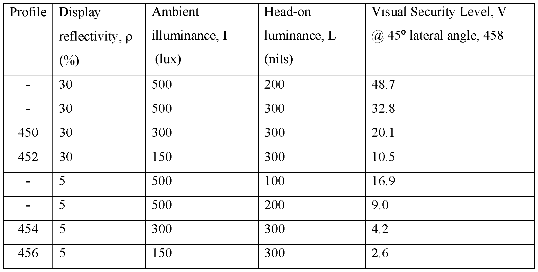
TABLE 1
[129] At 0.5% privacy level, various Visual Security Level points 458 may be provided depending on display structure, ambient illuminance and display luminance. The present embodiments further provide indicator 280 for display of Visual Security Level that may be provided for example by means of traffic light indicators.
[130] The variation of display reflectivity with viewing angle will now be described.
[131] FIGURE 6C is a schematic graph illustrating variation of reflectivity with polar viewing angle for two types of privacy display. Profile 820 illustrates the variation of reflectivity for an illustrative embodiment of FIGURES 16D-E and profile 822 illustrates the variation of reflectivity for an embodiment without the reflective polariser 302 of FIGURE 15 and FIGURE 16A. Both profiles include Fresnel reflectivity at the outer polariser 318 and thus increase at high polar angles.
[132] The variation of visual security level, V with viewing angle will now be described.
[133] FIGURE 6D is a schematic graph illustrating variation of visual Security Level with polar viewing angle for the two types of privacy display of FIGURE 6C. VSL profile 824 illustrates an output for a display of the type of FIGURE 15 with reflective polariser 302, and VSL profile 826 illustrates an output for the display of FIGURE 15 with the reflective polariser 302 omitted. VSL profiles are illustrated for the same ambient illuminance, /. The limit V iim above which no image visibility is present is described further below. The angular range 825 of snooper locations for the profile 824 is thus greater than the angular range 827
for the profile 826. The reflective polariser 302 achieves above threshold visual security level over a wider polar range, advantageously achieving increased protection from snoopers. Further, head-on luminance may be increased for a given ambient illuminance, increasing image visibility for the display user.
[134] Selective control of the relationship between desirable display luminance and ambient light illuminance will now be described.
[135] FIGURE 7A is a schematic diagram illustrating exemplary transfer functions 802, 804 between display head-on luminance and detected ambient illuminance; and FIGURE 7B is a schematic graph illustrating transfer functions between the ratio of measured ambient illuminance to head-on display luminance and ambient illuminance.
[136] Variations 802, 803 are illustrative profiles for public mode of operation and variations 804, 805 are illustrative profiles for privacy mode of operation.
[137] The control system 500 is arranged to selectively control luminance of the displayed image in the public mode and the privacy mode in response to the detected level of the ambient light, in accordance with different transfer functions 802, 804 relating levels of luminance to detected levels of the ambient light in the public mode and in the privacy mode respectively. The transfer function 802 in the public mode relates higher levels of luminance to detected levels of the ambient light than the transfer function 804 in the privacy mode.
[138] When operating in the privacy mode the privacy transfer function 804 is selected and the control system uses the measured ambient light level to control the display luminance so that a desirable Visual Security Level, V at at-least one off-axis snooper observation angle is provided for different ambient illumination levels. Advantageously display security may be maintained in different or varying lighting conditions.
[139] When operating in the public mode the public transfer function 802 may be selected to provide a desirable image visibility, W for different ambient illumination levels. Advantageously display visibility may be maintained in different lighting conditions for off- axis observers.
[140] Desirable limits for head-on luminance of the display operating in privacy mode will now be described.
[141] FIGURE 7C is a schematic graph illustrating the variation 806 of perceived visual security with visual security level, V at an observation angle Q. Visual security level V is a measured quantity of any given display and varies with polar viewing angle.
[142] By comparison with visual security level V, perceived visual security is a subjective judgement of the visibility of a displayed privacy image arising from the human visual system response at the observation angle.
[143] In operation it has been discovered that above a threshold limit Viim of visual security level V then no image information is perceived. This transition in the perceived visibility with changes in the visual security level V is very rapid, as shown by the steepness of the graph in FIGURE 8 around the threshold limit Viim. That is, as the visual security level V increases, initially the perceived visibility degrades only gradually and the image is essentially viewable. However, on reaching the threshold limit Viim, the perceived image rapidly ceases to be visible in a manner that is in practice surprising to watch.
[144] In observation of the surprising result, for a text document image that is of concern for privacy applications it was found that the perceived image seen by a snooper rapidly ceased to be visible for V of 10. In the region 810 for values of V above 10, all the displayed text had zero visibility. In other words the perceived text rapidly ceases to be visible in a manner that is in practice surprising to watch for V of 10 or greater.
[145] In regions 812 below Viim text was visible with low contrast and in region 814 below V’ text was clearly visible.
[146] It would be desirable to maximise head-on display luminance to achieve high image visibility to the primary display user. It would be further desirable to achieve high image security level for a snooper at the observation angle. The selective control of the head-on luminance will now be described in further detail.
[147] For an observation angle Q, the maximum display output luminance Y0 (typically the head-on luminance) is prevented from exceeding a luminance limit Y0iim at which the visual security level V is above the threshold limit Viim so that the image is not perceived as visible at that observation angle Q, the luminance limit Y0iim being given by:
eqn. 8
 where R0 is the reflected ambient illuminance at the observation angle q, KQ is the display black state luminance at the observation angle, and RQ is the relative luminance at the observation angle Q compared to the maximum display output luminance Y0 (typically the head-on luminance and is measured in nits). For display reflectivity rq and a Lambertian
illuminant with illuminance IQ measured in lux that is reflected by the display at the observation angle, the luminance limit Y0iim is also given by:
where R0 is the reflected ambient illuminance at the observation angle q, KQ is the display black state luminance at the observation angle, and RQ is the relative luminance at the observation angle Q compared to the maximum display output luminance Y0 (typically the head-on luminance and is measured in nits). For display reflectivity rq and a Lambertian
illuminant with illuminance IQ measured in lux that is reflected by the display at the observation angle, the luminance limit Y0iim is also given by:
eqn. 9

[148] Since the illuminance IQ is dependent on the amount of ambient light, the luminance of the display apparatus may be controlled by the control system 500 in accordance with these relationships. Specifically, the privacy transfer function 804 used by the control system 500 as described above may be selected to maintain the relationship Y0 < Y0iim in order that the image is not perceived as visible at a desired observation angle Q, for example at an observation angle Q of 45 degrees laterally and zero degrees in elevation from the normal to the display apparatus.
[149] Subject to that limit, the luminance is preferably as high as possible in order to optimise the performance for the head-on view. Accordingly, the privacy transfer function 804 used by the control system 500 as described above may additionally be selected to maintain the relationship Y0 / IQ > 1 lux/nit as illustrated by the profile 805 in FIGURE 8. The illuminance IQ may be the sensed ambient illuminance that is averaged from the illuminated scene.
[150] Advantageously a display may be provided that has high image security to off-axis snoopers while achieving high image visibility for the head-on user for different illuminance levels may be provided.
[151] FIGURE 8A is a schematic diagram illustrating a front view of a privacy display comprising a privacy control system operating in privacy mode with a second visual security level; and FIGURE 8B is a schematic diagram illustrating a look-down perspective of a privacy display comprising a privacy control system operating in privacy mode with a second visual security level.
[152] In operation, ambient light sensor 232 may provide a measurement of ambient illuminance. In comparison to FIGURES 1-2, the illuminance of light rays 608 may be lower, and thus the ratio I/L reduces, reducing Visual Security Level for a given head-on luminance. The control system 500 may be arranged to perform calculation of Visual Security Level, and reduce display luminance, L to increase VSL to desirable levels by means
of display control 710. Thus the luminance 278 seen by the head-on user reduces. Such an improvement may be highlighted by a change in the indicator 280 from red to green or amber, depending on desirable levels of Visual Security Level.
[153] The desirable levels of Visual Security Level for display operation may be set by policy 240, and said policy may vary said desirable levels of Visual Security Level related to the nature of the viewing environment. For example, in high risk environments, the allowable head-on luminance 278 may be lower than in low risk environments. At threshold environments, for example in very low levels of ambient illumination 604 illuminance, I then viewing of certain content may be prohibited.
[154] Features of the embodiment of FIGURE 8A and FIGURE 8B not discussed in further detail may be assumed to correspond to the features with equivalent reference numerals as discussed above, including any potential variations in the features.
[155] FIGURE 9 is a schematic graph of CIE 1931 x-y coordinates illustrating variation in image white point with Visual Security Level.
[156] In operation, the white point of the display may be adjusted along an illustrative locus 602 in dependence on the calculated Visual Security Level.
[157] Thus the display when operating in privacy mode may be arranged with white point 605 when the calculated VSL is high, and the white point may be adjusted to locations 606, 608 in dependence on the calculated VSL. Thus the display may appear more yellow as the VSL reduces.
[158] Advantageously the image contrast of black on yellow images is lower than for white on black images, thus reducing image visibility to the off-axis snooper.
[159] A colour adjusted VSL parameter may further be defined based on the white point selected, so that the indicator 280 may be adjusted accordingly.
[160] Colour adjustment may also be automatically made when a device is adjusted to airplane mode and is operating with privacy images for example.
[161] Features of the embodiment of FIGURE 9 not discussed in further detail may be assumed to correspond to the features with equivalent reference numerals as discussed above, including any potential variations in the features.
[162] Further description of the control of a privacy display will now be described.
[163] FIGURE 10 illustrates a flowchart of the privacy control system of FIGURES 1-2 and FIGURES 3-4.
[164] The display operating environment 261 may include (but is not limited to) network ID 201, Date/Time 262, GPS 206 data, Ambient Light Sensor 232 detection and Airplane mode 270 seting.
[165] Corporate privacy policy 240 may include definitions under which the display should be operated in privacy mode including time and location; documents and applications; and Visual Security Level specifications.
[166] Other inputs may include display design parameters 272 and information on viewed documents and applications 274.
[167] Data processor 290 is used to analyse display operating environment 261, display design parameters 272, viewed documents and applications 274 and compare against corporate privacy policy 240. The output determines whether to operate the display in privacy or public mode such that switch 292 is set for privacy or public mode operation based on data processor 290 output.
[168] In the case of privacy mode operation the setings to apply to the display apparatus 100 using display control system 710 and images 101 using image control system 296 in order to achieve desirable Visual Security Level are provided. Further indication of Visual Security Level using indicator 280 may be provided.
[169] In the case of public mode operation, the appropriate illumination control including cone angle change by display control system 710 and luminance using LED driver 715 are provided to the display apparatus 100.
[170] The controller 500 may continue to monitor the status of the display operating environment 261 and appropriate changes in policy 240 and adjust display apparatus 100 and images 101 appropriately to maintain the target Visual Security Level.
[171] Advantageously the control system 500 may enable the Visual Security Level, that may be the Visual Security Level to be reliably calculated and compared to a corporate policy 240 level set for the device’s current environment. The Visual Security Level may be adjusted to the level required for the display apparatus 100 environment so that the primary user retains optimal viewing freedom and comfort consistent with achieving the prescribed corporate privacy policy privacy level.
[172] Features of the embodiment of FIGURE 10 not discussed in further detail may be assumed to correspond to the features with equivalent reference numerals as discussed above, including any potential variations in the features.
[173] The control of a privacy display in response to a measured Visual Security Level will now be described.
[174] FIGURE 11A illustrates a flowchart for control of a privacy display by means of calculation of Visual Security Level.
[175] The display apparatus 100 may be provided wherein the control system 500 is arranged to selectively control any one or more of luminance of the display 100 or contrast, white point and spatial frequency of the image 101 in the privacy mode in response to the measured level of the ambient light using Ambient Light Sensor 232.
[176] A luminance evaluation system 904 may be provided to determine output luminance to the head-on user and snooper based on measurement of LED current and display apparatus 100 calibrated characteristics for example, that may be provided as display design parameters 272.
[177] An image analysis engine 906 may provide information on images 101 including but not limited to text sizes, image spatial resolution, colour, and contrast.
[178] Such data may be collected by VSL input data unit 910 and Visual Security Level calculated accordingly in VSL calculator 914.
[179] The display apparatus 100 and image 101 may be set automatically by controller 919 to achieve a certain desired or mandated privacy level specified by policy 240.
[180] In one optional step LED driver 715 may be used to adjust display luminance.
[181] In further optional step colour controller 922 may be used to adjust the colour of the image 101 as illustrated in FIGURE 9 for example.
[182] In further optional step contrast controller 918 may provide reduced image 101 contrast for example by adjustment of image gamma curve to achieve an improved Visual Security Level.
[183] In further optional step spatial frequency controller 924 may provide image 101 with reduced font sizes, and image blur for large areas of image to reduce visibility of features at snooper viewing distances and achieve an improved Visual Security Level. The spatial frequencies in the image, (in another example by zooming out or reducing the screen magnification), can make the off-axis image more difficult to read as the snooper is typically further from the display apparatus 100 than the primary user.
[184] The control system 500 may display the currently achieved privacy score or level as a number or as a traffic light colour 282 on indicator 280.
[185] It may be desirable to provide some choice to the user for optimum image performance while providing Visual Security Level within policy 240 limits.
[186] FIGURE 11B illustrates a flowchart for control of a switchable privacy display apparatus 100 by means of calculation of Visual Security Level and user feedback on preferred improvements.
[187] If the display achieves the correct Visual Security Level after notifying the user of the Visual Security Level in indicator 280 switch 923 provides the current settings to the display, otherwise improvements 921 may be proposed that are based on policy 240 for different types of image 101. The controller 919 is arranged to provide display luminance, contrast, white points and spatial frequencies to the users’ selection. The Visual Security Level is recalculated and the result given to the user. When the performance is adequate in user preference and Visual Security Level the display can proceed to display desired confidential data.
[188] Thus adjustments to the display apparatus 100 and image 101 may be set automatically or recommendations to the user to set values in order to maintain a certain desired or mandated privacy level based on image preferences for the user. For example, a user may have little concern about the colour of an image but may desire large text size, or a user may prefer a well rendered colour image but with reduced luminance. The choice may depend on the application being used and be different for say images and text. Visual Security Level may be set to provide similar performance for both situations, based on said user preference.
[189] In a privacy display apparatus 100 the setting of a privacy mode will have some effect on the viewing experience of the primary user, such as narrowing their viewing freedom or comfort. If this effect is more severe than necessary for the primary user, they may be inhibited from using the privacy display apparatus 100. Advantageously the Visual Security Level may be set at an adequate amount while maintaining minimum changes to the viewing experience of the primary user.
[190] It may be desirable for the display apparatus 100 to provide adequate Visual Security Level when a sensitive document or information is to be displayed. It may further be desirable for the display apparatus 100 to switch to a privacy mode when sensitive data is entered by the primary user.
[191] FIGURE 11C illustrates a flowchart for control of a privacy display comprising an allowable visual security level for a working document.
[192] The control system 500 may selectively operate the display apparatus 100 in the public mode or the privacy mode in response to the context of the application software being executed.
[193] The controller may provide inspection 930 of document security flags, or notification 932 of confidential data entry, for example by noting the use of an appropriate dialog box. The document may also have inspection 934 of document keywords that flag use of privacy operation. The controller may provide inspection 931 of the data transfer security protocol used for example when a web page is accessed. With a secure hypertext transfer protocol for example https is used the display apparatus may be controlled to enter privacy mode. When an open hypertext transfer protocol for example http is used the display apparatus may be controlled to be in public mode.
[194] The control system 500 may process data sources including if personal data dialog entry 1070 is underway such as a software application requesting a user name or password or a date of birth for example. Based on this information the display apparatus 100 may be switched to a privacy mode automatically during data entry and then switched back to the public mode when such data entry is finished. In this way the user is not troubled to manually switch the display in and out of privacy mode. Thus, for certain documents, the Visual Security Level may be adjusted to maximise privacy achieved in comparison to other less sensitive documents. Such adjustment may be by means of luminance control, contrast, colour and spatial frequency adjustment as described elsewhere herein.
[195] The acceptable Visual Security Level policy 240 may be adjusted dependent on the application in use. After calculation of Visual Security Level switch 923 may be arranged to allow 938 the document or application to be used or deny 940 the document or application use.
[196] The display apparatus 100 is capable of executing application software and from the context of that software to recognise if the user is being asked to enter sensitive information such as passwords or personal identity information via for example a dialog box. The display apparatus 100 is capable of executing application software for displaying a document and the display apparatus 100 is arranged to receive user input. In that context the control system 500 may automatically switch the display apparatus 100 in to privacy mode and then automatically switch out of privacy mode when such dialog entry has finished. Typically in a dialog box for a password the typed characters do not appear on the screen so it may not be necessary to switch to privacy mode for this, however the fact that a document may require a
password is an indication that the document should be kept secure and that privacy mode should be automatically entered after completion of password entry as the document is opened.
[197] Further the control system 500 selectively operates the display device in the public mode or the privacy mode in response to the content of the document and/or metadata associated with the document. The control system 500 may inspect the document classification or document security flags 1068 or other meta-data and/or may inspect 934 the document for keywords and process these data sources in order to reliably determine if the document about to be displayed on the screen contains sensitive data and before displaying the image, automatically switch the display apparatus 100 to an appropriate privacy level as required by corporate policy and as appropriate for the location determined by the Network ID 201, GPS sensor 206 and ambient light level determined by Ambient Light Sensor 232.
[198] Alternatively, the application running, for example a screen share initiated from a remote person or a video call from a remote person may request the primary user’s display apparatus 100 to enter a privacy mode.
[199] The display apparatus 100 may be set to a privacy mode before sensitive data is displayed. The display apparatus 100 may switch to a privacy mode when sensitive data is entered by the primary user or when a sensitive document or information is to be displayed. Advantageously the overall vulnerability to data loss from snooping is reduced.
[200] The control of a privacy display for use with documents comprising entry of a password will now be further described.
[201] FIGURE 11D illustrates a flowchart for control of a privacy display comprising an allowable visual security level for a password protected document.
[202] In a first step 950 a user may attempt to open a document. In a second step 952 it is determined whether a password protected document is used. If not, then the privacy settings of the display are determined by other policy 240 requirements of the display system.
[203] In step 958 if the document is opened then then the display is operated in privacy mode with control 919. After closing the document in step 960, the privacy operating mode is reset in step 962.
[204] Advantageously, the operation in privacy mode may be determined by password protection documents.
[205] Features of the embodiment of FIGURE 11A and FIGURE 11B and FIGURE 11C and FIGURE 11D not discussed in further detail may be assumed to correspond to the
features with equivalent reference numerals as discussed above, including any potential variations in the features.
[206] The desirable visibility of images in public mode for an off-axis viewer will now be further described.
[207] FIGURES 12A-12B are schematic diagrams illustrating a front view of a privacy display comprising a privacy control system for adjustment of image visibility in public mode.
[208] In a high ambient luminance environment as illustrated in FIGURE 12A it may be desirable to have a high display luminance setting 278 to overcome reflections from ambient illumination 604. However, in low risk environments, it may still be desirable to provide some low level of privacy and to reduce stray light while achieving increased uniformity to the user in comparison to privacy mode operation with a high Visual Security Level. Such illuminance may reduce the time between charging intervals of the battery.
[209] The control system 500 of the present embodiments may also achieve controllable performance in public mode of operation as illustrated in FIGURE 12B, for example with reduced ambient illuminance. In such arrangements, it may be desirable to reduce the off- axis luminance to increase display apparatus 100 efficiency.
[210] Features of the embodiment of FIGURE 12A and FIGURE 12B not discussed in further detail may be assumed to correspond to the features with equivalent reference numerals as discussed above, including any potential variations in the features.
[211] Further, the output to an off-axis viewer can be adjusted to provide a high quality image with high efficiency as will now be described further.
[212] FIGURE 13 is a schematic graph illustrating variation of image visibility, W with off-axis relative luminance P of a switchable privacy display 100 operating in public mode for two different ratios of head-on luminance to illuminance ratios respectively.
[213] Profile 470 illustrates the variation of image visibility W with off-axis relative luminance, P for a ratio of 1 nit head-on luminance per 1 lux of ambient Lambertian illuminance (for example a 300 nit head-on luminance display illuminated by 300 lux) and profile 472 illustrates the variation of W with P for 2 nit head-on luminance per 1 lux of ambient Lambertian illuminance (for example a 300 nit head-on luminance display illuminated by 150 lux).
[214] For desirable wide angle image visibility, a value of W of greater than 0.85, preferably greater than 0.9 and most preferably greater than 0.95 is desirable for an easily
observed image. Displays that desirably achieve high image contrast have contrast sensitivities of greater than 90% and preferably greater than 95%.
[215] Thus for typical wide angle displays operating in ambient illumination, it is desirable to provide an off-axis luminance such that the image visibility is slowly varying and above a desirable image visibility such as illustrated by line 474 at which a 1 nit/lux display condition provides an image visibility of 0.9. Preferably a switchable privacy display achieves an off- axis relative luminance for an off-axis viewer (for example at a lateral viewing angle of 45 degrees) of greater than 15% and most preferably an off-axis relative luminance, P of greater than 30% as illustrated by line 475 for an image visibility W of greater than 0.95. As illustrated by line 472, increasing display luminance to 2 nits/lux provides increased image visibility W, as would be expected.
[216] Features of the embodiment of FIGURE 13 not discussed in further detail may be assumed to correspond to the features with equivalent reference numerals as discussed above, including any potential variations in the features.
[217] FIGURE 14 illustrates a flowchart for control of a switchable privacy display operating in public mode by means of calculation of image visibility for off-axis users.
[218] After setting 480 of public mode, the ambient light sensor 232 determines ambient illuminance, and illuminance controller 715 can be used to determine display luminance. Optionally contrast, spatial frequency and colour properties of image 101 may be determined by image analysis engine 906.
[219] Control system 482 is used to determine image visibility, W for an off-axis user and the display luminance and image contrast is adjusted to provide an appropriate image visibility that overcomes ambient illuminance.
[220] Advantageously a display with reduced off-axis luminance in public mode may be provided, so that the Visual Security Level when operated in privacy mode is enhanced. Further, the image appearance to an off-axis user in public mode is enhanced.
[221] Features of the embodiment of FIGURE 14 not discussed in further detail may be assumed to correspond to the features with equivalent reference numerals as discussed above, including any potential variations in the features.
[222] Examples of displays that are capable of switching between privacy mode and a public mode will now be described.
[223] FIGURE 15 is a schematic diagram illustrating a front perspective view a switchable directional display apparatus 100 comprising a backlight 20, switchable liquid crystal retarder 300 and a spatial light modulator 48.
[224] Display device 100 comprises a switchable directional backlight 20 arranged to output light, the backlight 20 comprising a directional waveguide 1; and plural light sources 15 arranged to input input light into the waveguide 1, the waveguide 1, a rear reflector and light control films 5 being arranged to direct light from light sources 15, 17 into solid angular extent 402A. Light control films 5 may comprise turning films and diffusers for example.
[225] In the present disclosure a solid angular extent is the solid angle of a light cone within which the luminance is greater than a given relative luminance to the peak luminance. For example the luminance roll-off may be to a 50% relative luminance so that the solid angular extent has an angular width in a given direction (such as the lateral direction) that is the same as the full-width half maximum (FWHM).
[226] The backlight 20 may be arranged to provide an angular light solid angular extent 402A that has reduced luminance for off-axis viewing positions in comparison to head-on luminance.
[227] Display control system 710 is arranged to provide control of light source driver 715. Luminance of LEDs 15 may be controlled by control system, such that absolute off-axis luminance to a snooper may be controlled.
[228] The spatial light modulator 48 may comprise a liquid crystal display comprising substrates 212, 216, and liquid crystal layer 214 having red, green and blue pixels 220, 222, 224. The spatial light modulator 48 has an input display polariser 210 and an output display polariser 218 on opposite sides thereof. The output display polariser 218 is arranged to provide high extinction ratio for light from the pixels 220, 222, 224 of the spatial light modulator 48. Typical polarisers 210, 218 may be absorbing polarisers such as dichroic polarisers.
[229] Optionally a reflective polariser 208 may be provided between the dichroic input display polariser 210 and backlight 210 to provide recirculated light and increase display efficiency. Advantageously efficiency may be increased.
[230] The optical stack to provide control off-axis luminance will now be described.
[231] Reflective polariser 302, plural retarders 300 and additional polariser 318 are arranged to receive output light from the spatial light modulator 48.
[232] The plural retarders 300 are arranged between the reflective polariser 302 and an additional polariser 318. The polarisers 210, 218, 318 may be absorbing type polarisers such as iodine polarisers while the reflective polariser 302 may be a stretched birefringent film stack such as APF from 3M Corporation or a wire grid polariser.
[233] Plural retarders 300 comprise a switchable liquid crystal retarder 301 comprising a layer 314 of liquid crystal material, and substrates 312, 316 arranged between the reflective polariser 302 and the additional polariser 318. Retarder 300 further comprises a passive retarder 330 as will be described further below.
[234] As described below, plural retarders 300 do not affect the luminance of light passing through the reflective polariser 302, the retarders 300 and the additional polariser 318 along an axis along a normal to the plane of the retarders 300 but the retarders 300 do reduce the luminance of light passing therethrough along an axis inclined to a normal to the plane of the retarders 300, at least in one of the switchable states of the switchable retarder 301. This arises from the presence or absence of a phase shift introduced by the retarders 300 to light along axes that are angled differently with respect to the liquid crystal material of the retarders 300.
[235] Transparent substrates 312, 316 of the switchable liquid crystal retarder 301 comprise electrodes arranged to provide a voltage across a layer 314 of liquid crystal material 414 therebetween. Control system 752 is arranged to control the voltage applied by voltage driver 350 across the electrodes of the switchable liquid crystal retarder 301.
[236] Features of the embodiment of FIGURE 15 not discussed in further detail may be assumed to correspond to the features with equivalent reference numerals as discussed above, including any potential variations in the features.
[237] As will be described further below, the additional polariser 318, plural retarders 300 and reflective polariser 302 may be arranged to provide polar control of output luminance and frontal reflectivity from ambient illumination 604.
[238] The optical stack to provide control of off-axis luminance will now be described.
[239] FIGURE 16A is a schematic diagram illustrating in perspective side view an arrangement of the plural retarders 300 in a privacy mode of operation comprising a negative C-plate passive retarder 330 and homeotropically aligned switchable liquid crystal retarder 301 in a privacy mode of operation. In FIGURE 16A, some layers of the optical stack are omitted for clarity. For example the switchable liquid crystal retarder 301 is shown omitting the substrates 312, 316.
[240] The electric vector transmission direction of the reflective polariser 302 is parallel to the electric vector transmission direction of the output polariser 218. Further the electric vector transmission direction 303 of the reflective polariser 302 is parallel to the electric vector transmission direction 319 of the additional polariser 318.
[241] The switchable liquid crystal retarder 301 comprises a layer 314 of liquid crystal material 414 with a negative dielectric anisotropy. The passive retarder 330 comprises a negative C-plate having an optical axis perpendicular to the plane of the retarder 330, illustrated schematically by the orientation of the discotic material 430.
[242] The liquid crystal retarder 301 further comprises transmissive electrodes 413, 415 arranged to control the liquid crystal material, the layer of liquid crystal material being switchable by means of adjusting the voltage being applied to the electrodes. The electrodes 413, 415 may be across the layer 314 and are arranged to apply a voltage for controlling the liquid crystal retarder 301. The transmissive electrodes are on opposite sides of the layer of liquid crystal material 414 and may for example be ITO electrodes.
[243] Alignment layers may be formed between electrodes 413, 415 and the liquid crystal material 414 of the layer 314. The orientation of the liquid crystal molecules in the x-y plane is determined by the pretilt direction of the alignment layers so that each alignment layer has a pretilt wherein the pretilt of each alignment layer has a pretilt direction with a component 4l7a, 4l7b in the plane of the layer 314 that is parallel or anti-parallel or orthogonal to the electric vector transmission direction 303 of the reflective polariser 302.
[244] Driver 350 provides a voltage V to electrodes 413, 415 across the layer 314 of switchable liquid crystal material 414 such that liquid crystal molecules are inclined at a tilt angle to the vertical. The plane of the tilt is determined by the pretilt direction of alignment layers formed on the inner surfaces of substrates 312, 316.
[245] In typical use for switching between a public mode and a privacy mode, the layer of liquid crystal material is switchable between two states, the first state being a public mode so that the display may be used by multiple users, the second state being a privacy mode for use by a primary user with minimal visibility by snoopers. The switching may be by means of a voltage being applied across the electrodes. In general such a display may be considered having a first wide angle state and a second reduced off-axis luminance state.
[246] Features of the embodiment of FIGURE 16A not discussed in further detail may be assumed to correspond to the features with equivalent reference numerals as discussed above, including any potential variations in the features.
[247] The propagation of polarised light from the output polariser 218 will now be considered for on-axis and off-axis directions for a display operating in privacy mode.
[248] FIGURE 16B is a schematic diagram illustrating in side view propagation of output light from a spatial light modulator through the optical stack of FIGURE 15 in a privacy mode of operation; and FIGURE 16C is a schematic graph illustrating the variation of output luminance with polar direction for the transmitted light rays in FIGURE 16B.
[249] When the layer 314 of liquid crystal material 414 is driven to operate in the privacy mode, the retarders 300 provide no overall transformation of polarisation component 360 to output light rays 400 passing therethrough along an axis perpendicular to the plane of the switchable retarder, but provides an overall transformation of polarisation component 361 to light rays 402 passing therethrough for some polar angles which are at an acute angle to the perpendicular to the plane of the retarders.
[250] Polarisation component 360 from the output polariser 218 is transmitted by reflective polariser 302 and incident on retarders 300. On-axis light has a polarisation component 362 that is unmodified from component 360 while off-axis light has a polarisation component 364 that is transformed by the retarders 300. At a minimum, the polarisation component 361 is transformed to a linear polarisation component 364 and absorbed by additional polariser 318. More generally, the polarisation component 361 is transformed to an elliptical polarisation component, that is partially absorbed by additional polariser 318.
[251] Thus in a polar representation of transmission by the retarders 300 and additional polariser 318 in a privacy mode, regions of high transmission and regions of low transmission are provided as illustrated in FIGURE 16C.
[252] The polar distribution of light transmission illustrated in FIGURE 16C modifies the polar distribution of luminance output of the underlying spatial light modulator 48. In the case that the spatial light modulator 48 comprises a directional backlight 20 then off-axis luminance may be further be reduced as described above.
[253] Features of the embodiment of FIGURE 16B and FIGURE 16C not discussed in further detail may be assumed to correspond to the features with equivalent reference numerals as discussed above, including any potential variations in the features.
[254] Advantageously, a privacy display is provided that has low luminance to an off-axis snooper while maintaining high luminance for an on-axis observer. FIGURE 16C further illustrates target snooper polar location points 27L, 27R that may be used for evaluation of Visual Security Level as will be described further below.
[255] The operation of the reflective polariser 302 for light from ambient light source 604 will now be described for the display operating in privacy mode.
[256] FIGURE 16D is a schematic diagram illustrating in top view propagation of ambient illumination light through the optical stack of FIGURE 15 in a privacy mode of operation; and FIGURE 16E is a schematic graph illustrating the variation of reflectivity with polar direction for the reflected light rays in FIGURE 16D.
[257] Ambient light source 604 illuminates the display apparatus 100 with unpolarised light. Additional polariser 318 transmits light ray 410 normal to the display surface with a first polarisation component 372 that is a linear polarisation component parallel to the electric vector transmission direction 319 of the additional polariser 318.
[258] In both states of operation, the polarisation component 372 remains unmodified by the retarders 300 and so transmitted polarisation component 382 is parallel to the transmission axis of the reflective polariser 302 and the output polariser 218, so ambient light is directed through the spatial light modulator 48 and lost.
[259] By comparison, for ray 412, off-axis light is directed through the retarders 300 such that polarisation component 374 incident on the reflective polariser 302 may be reflected. Such polarisation component is re-converted into component 376 after passing through retarders 300 and is transmitted through the additional polariser 318.
[260] Thus when the layer 314 of liquid crystal material is in the second state of said two states, the reflective polariser 302 provides no reflected light for ambient light rays 410 passing through the additional polariser 318 and then the retarders 300 along an axis perpendicular to the plane of the retarders 300, but provides reflected light rays 412 for ambient light passing through the additional polariser 318 and then the retarders 300 at some polar angles which are at an acute angle to the perpendicular to the plane of the retarders 300; wherein the reflected light 412 passes back through the retarders 300 and is then transmitted by the additional polariser 318.
[261] The retarders 300 thus provide no overall transformation of polarisation component 380 to ambient light rays 410 passing through the additional polariser 318 and then the retarder 300 along an axis perpendicular to the plane of the switchable retarder, but provides an overall transformation of polarisation component 372 to ambient light rays 412 passing through the absorptive polariser 318 and then the retarders 300 at some polar angles which are at an acute angle to the perpendicular to the plane of the retarders 300.
[262] The polar distribution of light reflection illustrated in FIGURE 16E thus illustrates that high reflectivity can be provided at typical snooper locations by means of the privacy state of the retarders 300. Thus, in the privacy mode of operation, the reflectivity for off-axis viewing positions is increased, and the luminance for off-axis light from the spatial light modulator is reduced as illustrated in FIGURE 16C.
[263] In the public mode of operation, the control system 710, 752, 350 is arranged to switch the switchable liquid crystal retarder 301 into a second retarder state in which a phase shift is introduced to polarisation components of light passing therethrough along an axis inclined to a normal to the plane of the switchable liquid crystal retarder 301.
[264] By way of comparison, solid angular extent 402D may be substantially the same as solid angular extent 402B in a public mode of operation. Such control of output solid angular extents 402C, 402D may be achieved by synchronous control of the sets 15, 17 of light sources and the at least one switchable liquid crystal retarder 300.
[265] Advantageously a privacy mode may be achieved with low image visibility for off- axis viewing and a large solid angular extent may be provided with high efficiency for a public mode of operation, for sharing display imagery between multiple users and increasing image spatial uniformity.
[266] Additional polariser 318 is arranged on the same output side of the spatial light modulator 48 as the display output polariser 218 which may be an absorbing dichroic polariser. The display polariser 218 and the additional polariser 318 have electric vector transmission directions 219, 319 that are parallel. As will be described below, such parallel alignment provides high transmission for central viewing locations.
[267] A transmissive spatial light modulator 48 arranged to receive the output light from the backlight; an input polariser 210 arranged on the input side of the spatial light modulator between the backlight 20 and the spatial light modulator 48; an output polariser 218 arranged on the output side of the spatial light modulator 48; an additional polariser 318 arranged on the output side of the output polariser 218; and a switchable liquid crystal retarder 300 comprising a layer 314 of liquid crystal material arranged between the at least one additional polariser 318 and the output polariser 318 in this case in which the additional polariser 318 is arranged on the output side of the output polariser 218; and a control system 710 arranged to synchronously control the light sources 15, 17 and the at least one switchable liquid crystal retarder 300.
[268] Control system 710 further comprises control of voltage controller 752 that is arranged to provide control of voltage driver 350, in order to achieve control of switchable liquid crystal retarder 301.
[269] Features of the embodiment of FIGURE 16D and FIGURE 16E not discussed in further detail may be assumed to correspond to the features with equivalent reference numerals as discussed above, including any potential variations in the features.
[270] Advantageously, a privacy display is provided that has high reflectivity to an off-axis snooper while maintaining low reflectivity for an on-axis observer. As will be described below, such increased reflectivity provides enhanced privacy performance for the display in an ambiently illuminated environment.
[271] FIGURE 17A is a schematic diagram illustrating in perspective side view an arrangement of the retarders 300 in a public mode of operation. In the present embodiment, zero volts is provided across the liquid crystal retarder 301; and TABLE 2 describes an illustrative embodiment for the arrangement of FIGURE 17 A.
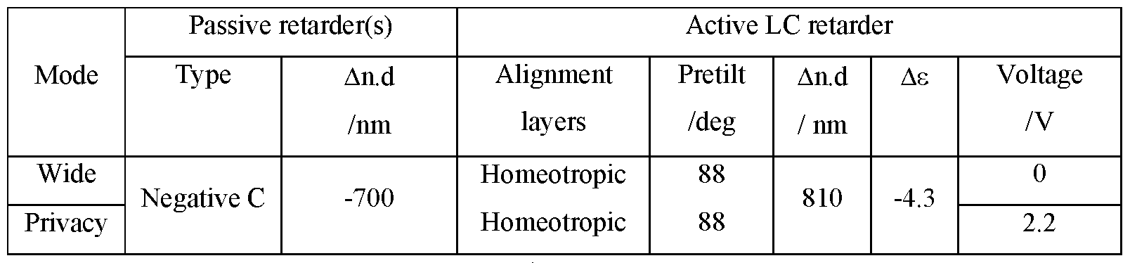
TABLE 2
[272] The switchable liquid crystal retarder 301 comprises two surface alignment layers disposed on electrodes 413, 415 and adjacent to the layer of liquid crystal material 414 and on opposite sides thereof and each arranged to provide homeotropic alignment in the adjacent liquid crystal material 414. The layer of liquid crystal material 414 of the switchable liquid crystal retarder 301 comprises a liquid crystal material with a negative dielectric anisotropy. The liquid crystal molecules 414 may be provided with a pretilt, for example 88 degrees from the horizontal to remove degeneracy in switching.
[273] In the present embodiments, desirable ranges for retardations and voltages have been established by means of simulation of retarder stacks and experiment with display optical stacks. Ranges for retardances will now be described that provide design configurations for various optical layers.
[274] The layer 314 of liquid crystal material has a retardance for light of a wavelength of 550nm in a range from 500nm to lOOOnm, preferably in a range from 600nm to 900nm and most preferably in a range from 700nm to 850nm; and the retarder 330 further comprises a passive retarder having an optical axis perpendicular to the plane of the retarder, the passive retarder having a retardance for light of a wavelength of 550nm in a range from -300nm to - 900nm, preferably in a range from -450nm to -800nm and most preferably in a range from - 500nm to -725nm.
[275] Features of the embodiment of FIGURE 17A not discussed in further detail may be assumed to correspond to the features with equivalent reference numerals as discussed above, including any potential variations in the features.
[276] The propagation of polarised light from the output polariser 218 will now be considered for on-axis and off-axis directions for a display operating in public mode for an arrangement of plural retarders 300 as illustrated in FIGURE 17A.
[277] FIGURE 17B is a schematic diagram illustrating in side view propagation of output light from a spatial light modulator through the optical stack of FIGURE 1 in a public mode of operation; and FIGURE 17C is a schematic graph illustrating the variation of output luminance with polar direction for the transmitted light rays in FIGURE 17B.
[278] Features of the embodiment of FIGURE 17B and FIGURE 17C not discussed in further detail may be assumed to correspond to the features with equivalent reference numerals as discussed above, including any potential variations in the features.
[279] When the liquid crystal retarder 301 is in a first state of said two states, the retarders 300 provide no overall transformation of polarisation component 360, 361 to output light passing therethrough perpendicular to the plane of the switchable retarder 301 or at an acute angle to the perpendicular to the plane of the switchable retarder 301. That is polarisation component 362 is substantially the same as polarisation component 360 and polarisation component 364 is substantially the same as polarisation component 361. Thus the angular transmission profile of FIGURE 17C is substantially uniformly transmitting across a wide polar region. Advantageously a display may be switched to a wide field of view.
[280] FIGURE 17D is a schematic diagram illustrating in top view propagation of ambient illumination light through the optical stack of FIGURE 1 in a public mode of operation; and FIGURE 17E is a schematic graph illustrating the variation of reflectivity with polar direction for the reflected light rays in FIGURE 17D.
[281] Thus when the liquid crystal retarder 301 is in the first state of said two states, the retarders 300 provide no overall transformation of polarisation component 372 to ambient light rays 412 passing through the additional polariser 318 and then the retarders 300, that is perpendicular to the plane of the retarders 300 or at an acute angle to the perpendicular to the plane of the retarders 300.
[282] In operation in the public mode, input light ray 412 has polarisation state 372 after transmission through the additional polariser 318. For both head-on and off-axis directions no polarisation transformation occurs and thus the reflectivity for light rays 402 from the reflective polariser 302 is low. Light ray 412 is transmitted by reflective polariser 302 and lost in the display polarisers 218, 210 or the backlight of FIGURE 1 or optical isolator 218, 518 in an emissive spatial light modulator 38 of FIGURE 2.
[283] Features of the embodiment of FIGURE 17D and FIGURE 17E not discussed in further detail may be assumed to correspond to the features with equivalent reference numerals as discussed above, including any potential variations in the features.
[284] Advantageously in a public mode of operation, high luminance and low reflectivity is provided across a wide field of view. Such a display can be conveniently viewed with high contrast by multiple observers.
[285] Other types of switchable privacy display will now be described.
[286] A display apparatus 100 that may be switched between privacy and public modes of operation comprises an imaging waveguide and an array of light sources as described in U.S. Patent No. 9,519,153, which is incorporated by reference herein in its entirety. The imaging waveguide images an array of light sources to optical windows that may be controlled to provide high luminance on axis and low luminance off axis in a privacy mode, and high luminance with a large solid angle cone for public operation.
[287] Switchable angular contrast profile liquid crystal displays are described in Japanese Patent Publ. No. JPH1130783 and in U.S. Patent Publ. No. 2017-0123241, both of which are incorporated by reference herein in their entireties. Such displays may provide out-of-plane tilt of liquid crystal molecules in the liquid crystal layer 214 of a liquid crystal display and may achieve reduced off-axis image contrast in privacy mode of operation. The display apparatus 100 control system 500 may further comprise control of out-of-plane tilt of the liquid crystal molecules.
[288] As may be used herein, the terms“substantially” and“approximately” provide an industry-accepted tolerance for its corresponding term and/or relativity between items. Such
an industry-accepted tolerance ranges from zero percent to ten percent and corresponds to, but is not limited to, component values, angles, et cetera. Such relativity between items ranges between approximately zero percent to ten percent.
[289] While various embodiments in accordance with the principles disclosed herein have been described above, it should be understood that they have been presented by way of example only, and not limitation. Thus, the breadth and scope of this disclosure should not be limited by any of the above-described exemplary embodiments, but should be defined only in accordance with any claims and their equivalents issuing from this disclosure. Furthermore, the above advantages and features are provided in described embodiments, but shall not limit the application of such issued claims to processes and structures accomplishing any or all of the above advantages.
[290] Additionally, the section headings herein are provided for consistency with the suggestions under 37 CFR 1.77 or otherwise to provide organizational cues. These headings shall not limit or characterize the embodiment(s) set out in any claims that may issue from this disclosure. Specifically and by way of example, although the headings refer to a “Technical Field,” the claims should not be limited by the language chosen under this heading to describe the so-called field. Further, a description of a technology in the “Background” is not to be construed as an admission that certain technology is prior art to any embodiment(s) in this disclosure. Neither is the“Summary” to be considered as a characterization of the embodiment(s) set forth in issued claims. Furthermore, any reference in this disclosure to“invention” in the singular should not be used to argue that there is only a single point of novelty in this disclosure. Multiple embodiments may be set forth according to the limitations of the multiple claims issuing from this disclosure, and such claims accordingly define the embodiment(s), and their equivalents, that are protected thereby. In all instances, the scope of such claims shall be considered on their own merits in light of this disclosure, but should not be constrained by the headings set forth herein.
Claims
1. A display apparatus comprising:
a display device arranged to display an image and capable of operating in at least a public mode and a privacy mode, wherein the visibility of the image to an off-axis viewer is reduced in the privacy mode compared to the public mode; and
a control system arranged to control the display device, the control system being capable of selectively operating the display device in the public mode or the privacy mode.
2. A display apparatus according to claim 1, wherein the display apparatus is arranged to connect to a network and the control system is arranged to selectively operate the display device in the public mode or the privacy mode in response to the nature of the network.
3. A display apparatus according to claim 1 or 2, wherein the display apparatus is arranged to receive the identity of the user and the control system is arranged to selectively operate the display device in the public mode or the privacy mode in response to the received identity of the user.
4. A display apparatus according to any one of the preceding claims, wherein the display apparatus comprises a location system arranged to detect the location of the display apparatus and the control system is arranged to selectively operate the display device in the public mode or the privacy mode in response to the detected location.
5. A display apparatus according to any one of the preceding claims, wherein the display apparatus is capable of executing application software and the control system is arranged to selectively operate the display device in the public mode or the privacy mode in response to the context of the application software being executed.
6. A display apparatus according to claim 5, wherein the display apparatus is capable of executing application software for displaying a document, and the control system is arranged to selectively operate the display device in the public mode or the privacy mode in response to the content of the document and/or metadata associated with the document.
7. A display apparatus according to claim 6, wherein the content and/or metadata includes the security status of the transfer protocol of the document and determining it to be Hypertext Transfer Protocol or Hypertext Transfer Protocol Secure.
8. A display apparatus according to any one of the preceding claims, wherein the display apparatus is arranged to receive user input and the control system is arranged to selectively operate the display device in the public mode or the privacy mode in response to the received user input.
9. A display apparatus according to any one of the preceding claims, wherein the display apparatus comprises an ambient light sensor arranged to detect the illuminance level of the ambient light.
10. A display apparatus according to claim 9, wherein the control system is arranged to selectively operate the display device in the public mode or the privacy mode in response to the detected level of the ambient light.
11. A display apparatus according to claim 9 or 10, wherein the control system is arranged to selectively control any one or more of the luminance, contrast, white point and spatial frequency of the displayed image to maintain a selected privacy level in response to the detected level of the ambient light.
12. A display apparatus according to any one of claims 9 to 11, wherein the control system is arranged to selectively control any one or more of luminance, contrast, white point and spatial frequency of the displayed image in the privacy mode in response to the detected level of the ambient light.
13. A display apparatus according to any one of claims 9 to 12, wherein the control system is arranged to selectively control any one or more of luminance, contrast, white point and spatial frequency of the displayed image in the public mode in response to the detected level of the ambient light.
14. A display apparatus according to any one of claims 9 to 13, wherein the control
system is arranged to selectively control luminance of the displayed image in the public mode and the privacy mode in response to the detected level of the ambient light, in accordance with different transfer functions relating levels of luminance to detected levels of the ambient light in the public mode and in the privacy mode.
15. A display device according to claim 14, wherein the transfer function in the public mode relates higher levels of luminance to detected levels of the ambient light than the transfer function in the privacy mode.
16. A display apparatus according to any one of claims 9 to 15, wherein the control system is arranged to selectively control luminance of the displayed image in the privacy mode in response to the detected level of the ambient light, in accordance with a transfer function that maintains a relationship Y 0/IQ > 1 lux/nit where Y0 is the maximum output luminance of the display apparatus and IQ is the detected ambient light level.
17. A display apparatus according to any one of claims 9 to 16, wherein the control system is arranged to selectively control luminance of the displayed image in the privacy mode in response to the detected level of the ambient light, in accordance with a transfer function that maintains a relationship Y0 £ Y0|im where Y0 is the maximum output luminance of the display apparatus and Y0iim is given by the equation:
 where Viim has a value of 10, R0 is the reflected ambient illuminance at an observation angle Q of 45 degrees laterally and zero degrees in elevation from the normal to the display apparatus, KQ is the display black state luminance at the observation angle, and RQ is the relative luminance at the observation angle Q compared to the maximum display output luminance Y0.
18. A display apparatus according to any one of claims 9 to 17, wherein the control system is arranged to control the display apparatus to display information representing the visibility of the image to an off-axis viewer taking into account the detected level of the
ambient light.
19. A display apparatus according to any one of the preceding claims, wherein the control system is arranged to control the display apparatus to display information representing changes to user-controllable parameters capable of reducing the visibility of the image to an off-axis viewer.
20. A display apparatus according to any one of the preceding claims, wherein the control system is arranged to control any one or more of luminance, contrast, white point and spatial frequency of the image in the privacy mode.
21. A display apparatus according to any one of the preceding claims, wherein the control system is arranged to control the display apparatus to display information representing the visibility of the image to an off-axis viewer.
22. A display apparatus according to any one of the preceding claims, wherein the display apparatus is arranged to receive time data input and ambient light sensor input and the control system is arranged to selectively operate the display device in the public mode or the privacy mode in response to the received time input and ambient light sensor input in order to reduce light pollution generated by the display apparatus.
Applications Claiming Priority (4)
| Application Number | Priority Date | Filing Date | Title |
|---|---|---|---|
| US201862740586P | 2018-10-03 | 2018-10-03 | |
| US62/740,586 | 2018-10-03 | ||
| US201962789049P | 2019-01-07 | 2019-01-07 | |
| US62/789,049 | 2019-01-07 |
Publications (1)
| Publication Number | Publication Date |
|---|---|
| WO2020072643A1 true WO2020072643A1 (en) | 2020-04-09 |
Family
ID=70051069
Family Applications (1)
| Application Number | Title | Priority Date | Filing Date |
|---|---|---|---|
| PCT/US2019/054291 Ceased WO2020072643A1 (en) | 2018-10-03 | 2019-10-02 | Privacy display control apparatus |
Country Status (2)
| Country | Link |
|---|---|
| US (3) | US11106103B2 (en) |
| WO (1) | WO2020072643A1 (en) |
Families Citing this family (38)
| Publication number | Priority date | Publication date | Assignee | Title |
|---|---|---|---|---|
| US11079619B2 (en) | 2016-05-19 | 2021-08-03 | Reald Spark, Llc | Wide angle imaging directional backlights |
| US10817066B2 (en) * | 2016-12-05 | 2020-10-27 | Google Llc | Information privacy in virtual reality |
| US20210199879A1 (en) | 2017-05-08 | 2021-07-01 | Reald Spark, Llc | Optical stack for imaging directional backlights |
| TWI878209B (en) | 2017-09-15 | 2025-04-01 | 美商瑞爾D斯帕克有限責任公司 | Display device and a view angle control optical element for application to a display device |
| CN118672006A (en) | 2018-01-25 | 2024-09-20 | 瑞尔D斯帕克有限责任公司 | Touch screen for privacy display |
| WO2019147762A1 (en) | 2018-01-25 | 2019-08-01 | Reald Spark, Llc | Reflective optical stack for privacy display |
| JP7495027B2 (en) | 2018-03-22 | 2024-06-04 | リアルディー スパーク エルエルシー | Optical waveguide, backlight device and display device |
| WO2020005748A1 (en) | 2018-06-29 | 2020-01-02 | Reald Spark, Llc | Optical stack for privacy display |
| WO2020018552A1 (en) | 2018-07-18 | 2020-01-23 | Reald Spark, Llc | Optical stack for switchable directional display |
| WO2020072643A1 (en) * | 2018-10-03 | 2020-04-09 | Reald Spark, Llc | Privacy display control apparatus |
| KR102697371B1 (en) * | 2018-10-31 | 2024-08-22 | 삼성전자주식회사 | Method for displaying contents responding to voice command and electronic device thereof |
| CN113167953B (en) | 2018-11-07 | 2023-10-24 | 瑞尔D斯帕克有限责任公司 | Directional display device |
| US11450069B2 (en) | 2018-11-09 | 2022-09-20 | Citrix Systems, Inc. | Systems and methods for a SaaS lens to view obfuscated content |
| US11201889B2 (en) | 2019-03-29 | 2021-12-14 | Citrix Systems, Inc. | Security device selection based on secure content detection |
| EP3994878A4 (en) | 2019-07-02 | 2023-06-14 | RealD Spark, LLC | DIRECTIONAL DISPLAY DEVICE |
| WO2021058140A1 (en) * | 2019-09-27 | 2021-04-01 | Continental Automotive Gmbh | Control of the image reproduction of a display apparatus |
| CN114846393B (en) | 2019-11-13 | 2024-12-03 | 瑞尔D斯帕克有限责任公司 | Off-axis display device |
| JP7433866B2 (en) * | 2019-11-28 | 2024-02-20 | キヤノン株式会社 | Sheet conveyance device and image reading device |
| WO2021118936A1 (en) | 2019-12-10 | 2021-06-17 | Reald Spark, Llc | Control of reflections of a display device |
| US11544415B2 (en) | 2019-12-17 | 2023-01-03 | Citrix Systems, Inc. | Context-aware obfuscation and unobfuscation of sensitive content |
| US11539709B2 (en) | 2019-12-23 | 2022-12-27 | Citrix Systems, Inc. | Restricted access to sensitive content |
| US11582266B2 (en) | 2020-02-03 | 2023-02-14 | Citrix Systems, Inc. | Method and system for protecting privacy of users in session recordings |
| US11361113B2 (en) | 2020-03-26 | 2022-06-14 | Citrix Systems, Inc. | System for prevention of image capture of sensitive information and related techniques |
| EP4143042B1 (en) | 2020-04-30 | 2025-09-24 | RealD Spark, LLC | Directional display apparatus |
| US11624944B2 (en) | 2020-07-29 | 2023-04-11 | Reald Spark, Llc | Backlight for switchable directional display |
| TWI898003B (en) | 2020-07-29 | 2025-09-21 | 美商瑞爾D斯帕克有限責任公司 | Pupillated illumination apparatus |
| WO2022041058A1 (en) | 2020-08-27 | 2022-03-03 | Citrix Systems, Inc. | Privacy protection during video conferencing screen share |
| WO2022041163A1 (en) * | 2020-08-29 | 2022-03-03 | Citrix Systems, Inc. | Identity leak prevention |
| US11892717B2 (en) * | 2021-09-30 | 2024-02-06 | Reald Spark, Llc | Marks for privacy display |
| DE102022102390B3 (en) * | 2022-02-02 | 2022-06-30 | Sioptica Gmbh | Screen with changeable relative luminance distribution curve |
| EP4476588A4 (en) | 2022-02-09 | 2025-12-31 | Reald Spark Llc | OBSERVER-TRANSFERRED PRIVACY DISPLAY |
| EP4505240A1 (en) | 2022-04-07 | 2025-02-12 | RealD Spark, LLC | Directional display apparatus |
| DE102022116315A1 (en) * | 2022-06-30 | 2024-01-04 | Sioptica Gmbh | Data processing device and method for activating a security mode of a data processing device with a screen |
| CN116101036A (en) * | 2023-03-20 | 2023-05-12 | 长城汽车股份有限公司 | Windshield multifunctional control method and vehicle |
| WO2024226506A1 (en) | 2023-04-25 | 2024-10-31 | Reald Spark, Llc | Switchable privacy display |
| US20250217522A1 (en) * | 2023-05-24 | 2025-07-03 | The Regents Of The University Of Michigan | Real-Time Protection For Mobile Devices From Shoulder |
| US12393066B2 (en) | 2023-08-03 | 2025-08-19 | Reald Spark, Llc | Privacy displays |
| US20250384801A1 (en) * | 2024-06-18 | 2025-12-18 | Elizabeth B. Jacoby | Dynamic Digital Mask for Enhanced Privacy on Electronic Displays through Mimicry of Polarization Effects |
Citations (3)
| Publication number | Priority date | Publication date | Assignee | Title |
|---|---|---|---|---|
| US8973149B2 (en) * | 2013-01-14 | 2015-03-03 | Lookout, Inc. | Detection of and privacy preserving response to observation of display screen |
| WO2018035492A1 (en) * | 2016-08-18 | 2018-02-22 | Rushline, LLC | Systems and methods for enabling dialog amongst different participant groups with variable and association-based privacy |
| US20180082068A1 (en) * | 2016-09-20 | 2018-03-22 | Intel Corporation | Dynamic electronic display privacy filter |
Family Cites Families (431)
| Publication number | Priority date | Publication date | Assignee | Title |
|---|---|---|---|---|
| US3914022A (en) | 1974-07-02 | 1975-10-21 | Gen Electric | Quasi-homeotropic twisted nematic liquid crystal device |
| US4059916A (en) | 1975-01-30 | 1977-11-29 | Copal Company Limited | Light diffusing device |
| JPS58143305A (en) | 1982-02-22 | 1983-08-25 | Hitachi Ltd | Display panel |
| US4621898A (en) | 1983-03-17 | 1986-11-11 | Allied Corporation | Directional optical filter |
| CA1312320C (en) | 1987-11-12 | 1993-01-05 | Makoto Oe | Plane light source unit |
| JPH06142Y2 (en) | 1988-02-29 | 1994-01-05 | 株式会社三洋物産 | Pachinko machine game board |
| US5005108A (en) | 1989-02-10 | 1991-04-02 | Lumitex, Inc. | Thin panel illuminator |
| US4974941A (en) | 1989-03-08 | 1990-12-04 | Hercules Incorporated | Process of aligning and realigning liquid crystal media |
| AU628953B2 (en) | 1989-04-03 | 1992-09-24 | Canon Kabushiki Kaisha | Liquid crystal apparatus |
| US5671994A (en) | 1994-06-08 | 1997-09-30 | Clio Technologies, Inc. | Flat and transparent front-lighting system using microprisms |
| DE19521254A1 (en) | 1994-06-24 | 1996-01-04 | Minnesota Mining & Mfg | Display system with brightness boosting film |
| US5835166A (en) | 1994-08-17 | 1998-11-10 | Hall; Dennis R. | Chiral nematic liquid crystal polarization modulated color display for stereoscopic viewing device |
| US5808784A (en) | 1994-09-06 | 1998-09-15 | Dai Nippon Printing Co., Ltd. | Lens array sheet surface light source, and transmission type display device |
| US6380997B1 (en) | 1995-04-07 | 2002-04-30 | Colorlink, Inc. | Achromatic polarization inverters for displaying inverse frames in DC balanced liquid crystal displays |
| US5658490A (en) | 1995-04-07 | 1997-08-19 | Board Of Regents Of The University Of Colorado | Liquid crystal achromatic compound retarder |
| WO1996036956A2 (en) | 1995-05-09 | 1996-11-21 | Monsanto Company | Conductive font |
| US5579139A (en) | 1995-06-07 | 1996-11-26 | Ois Optical Imaging Systems, Inc. | LCD with reduced canopy reflection having a retarder of 220-320 nm retardation outside a polarizer |
| US5726729A (en) | 1995-08-01 | 1998-03-10 | Casio Computer Co., Ltd. | Liquid crystal display device |
| JPH09113911A (en) | 1995-10-15 | 1997-05-02 | Semiconductor Energy Lab Co Ltd | Display device |
| JPH09197405A (en) | 1995-11-14 | 1997-07-31 | Sharp Corp | Viewing angle control type liquid crystal display device |
| TW331593B (en) | 1996-05-13 | 1998-05-11 | Konika Co Ltd | Planer light source device and light guide plate |
| US5914760A (en) | 1996-06-21 | 1999-06-22 | Casio Computer Co., Ltd. | Surface light source device and liquid crystal display device using the same |
| GB2314640A (en) | 1996-06-26 | 1998-01-07 | Sharp Kk | Liquid crystal devices |
| US6046849A (en) | 1996-09-12 | 2000-04-04 | Sharp Kabushiki Kaisha | Parallax barrier, display, passive polarisation modulating optical element and method of making such an element |
| US6642981B1 (en) | 1996-09-30 | 2003-11-04 | Fujitsu Display Technologies Corporation | Liquid crystal display device operating in a vertically aligned mode including at least one retardation film |
| US5854872A (en) | 1996-10-08 | 1998-12-29 | Clio Technologies, Inc. | Divergent angle rotator system and method for collimating light beams |
| GB2318878A (en) | 1996-10-31 | 1998-05-06 | Sharp Kk | Reflective liquid crystal device |
| CA2222313C (en) | 1996-12-12 | 2001-04-03 | Gregory P. Crawford | Liquid crystal display employing dual negative retarders and a brightness enhancing film |
| JPH10268251A (en) | 1997-03-27 | 1998-10-09 | Advanced Display:Kk | Control method for liquid crystal display device |
| US5791757A (en) | 1997-04-01 | 1998-08-11 | Ford Global Technologies, Inc. | Vehicle lighting system utilizing a uniform thickness thin sheet optical element |
| US6280043B1 (en) | 1997-05-14 | 2001-08-28 | Enplas Corporation | Surface light source device of side light type |
| JP3615355B2 (en) | 1997-06-04 | 2005-02-02 | 株式会社エンプラス | Sidelight type surface light source device and light guide plate |
| US6141070A (en) | 1997-06-13 | 2000-10-31 | Citizen Watch Co., Ltd. | Normally black liquid crystal display with twisted compensator and . .DELTAnd of 1500-1800 nm |
| US6055103A (en) | 1997-06-28 | 2000-04-25 | Sharp Kabushiki Kaisha | Passive polarisation modulating optical element and method of making such an element |
| US6099758A (en) | 1997-09-17 | 2000-08-08 | Merck Patent Gesellschaft Mit Beschrankter Haftung | Broadband reflective polarizer |
| US6411306B1 (en) | 1997-11-14 | 2002-06-25 | Eastman Kodak Company | Automatic luminance and contrast adustment for display device |
| GB2331883A (en) | 1997-11-26 | 1999-06-02 | Sharp Kk | Dual image viewing system |
| JP3322197B2 (en) | 1997-12-17 | 2002-09-09 | 松下電器産業株式会社 | Liquid crystal display |
| US5949933A (en) | 1998-03-03 | 1999-09-07 | Alliedsignal Inc. | Lenticular illumination system |
| FI106323B (en) | 1998-12-30 | 2001-01-15 | Nokia Mobile Phones Ltd | The backlight light guide for a flat screen |
| US6392727B1 (en) | 1998-12-31 | 2002-05-21 | Honeywell International Inc. | Reduced reflectance polarized display |
| US6256447B1 (en) | 1998-12-31 | 2001-07-03 | Physical Optics Corporation | Backlight for correcting diagonal line distortion |
| US6752505B2 (en) | 1999-02-23 | 2004-06-22 | Solid State Opto Limited | Light redirecting films and film systems |
| US6364497B1 (en) | 1999-03-24 | 2002-04-02 | L G Chemical Ltd. | Backlight system |
| JP3405972B2 (en) | 2000-01-11 | 2003-05-12 | 株式会社東芝 | Liquid crystal display |
| JP2003519817A (en) | 2000-01-14 | 2003-06-24 | コーニンクレッカ フィリップス エレクトロニクス エヌ ヴィ | Display device |
| US6347874B1 (en) | 2000-02-16 | 2002-02-19 | 3M Innovative Properties Company | Wedge light extractor with risers |
| US6801263B2 (en) | 2000-04-10 | 2004-10-05 | Sony Corporation | Liquid crystal display, liquid crystal device and liquid crystal display system |
| KR100514011B1 (en) | 2000-07-24 | 2005-09-13 | 미츠비시 레이온 가부시키가이샤 | Surface illuminant device and prism sheet used therefor |
| JP2002050219A (en) | 2000-07-25 | 2002-02-15 | Internatl Business Mach Corp <Ibm> | Planar light source device, light guide plate, display device |
| JP4266551B2 (en) | 2000-12-14 | 2009-05-20 | 三菱レイヨン株式会社 | Surface light source system and light deflection element used therefor |
| US7495719B2 (en) | 2001-02-28 | 2009-02-24 | Hitachi Displays, Ltd. | Device capable of switching between an image display status and a mirror status, and an instrument disposed therewith |
| US6734617B2 (en) | 2001-03-28 | 2004-05-11 | Intel Corporation | Stiffening flat-panel displays |
| JP4148657B2 (en) | 2001-04-04 | 2008-09-10 | シャープ株式会社 | Liquid crystal display |
| GB0114998D0 (en) | 2001-06-20 | 2001-08-08 | Secr Defence | Liquid crystal device |
| KR100799156B1 (en) | 2001-07-13 | 2008-01-29 | 삼성전자주식회사 | Light guide plate, manufacturing method thereof, liquid crystal display device using the same |
| GB0119176D0 (en) | 2001-08-06 | 2001-09-26 | Ocuity Ltd | Optical switching apparatus |
| JP2003150073A (en) | 2001-08-27 | 2003-05-21 | Omron Corp | Image display device and front light |
| US20030089956A1 (en) | 2001-09-27 | 2003-05-15 | Allen Richard Charles | Polarization rotators, articles containing the polarization rotators, and methods of making and using the same |
| JP2003107476A (en) | 2001-09-28 | 2003-04-09 | Nippon Oil Corp | Liquid crystal display device |
| WO2003056876A2 (en) | 2001-12-14 | 2003-07-10 | Digital Optics International Corporation | Uniform illumination system |
| US6837588B2 (en) | 2001-12-25 | 2005-01-04 | Minebea Co., Ltd. | Spread illuminating apparatus with means for reflecting light dispersely |
| US7372510B2 (en) | 2002-03-01 | 2008-05-13 | Planar Systems, Inc. | Reflection resistant touch screens |
| JP2003262734A (en) | 2002-03-08 | 2003-09-19 | Citizen Electronics Co Ltd | Light guide plate |
| US6831786B2 (en) | 2002-03-11 | 2004-12-14 | Eastman Kodak Company | Surface formed complex multi-layered polymer lenses for light diffusion |
| CN1643439A (en) | 2002-03-14 | 2005-07-20 | 日本电气株式会社 | Light modulation display device, manufacturing method thereof, and display device equipped with the light modulation display device |
| US6791639B2 (en) | 2002-05-14 | 2004-09-14 | International Business Machines Corporation | Direct view display with lenticular lens for improved brightness and wide viewing angle |
| US7437765B2 (en) | 2002-06-04 | 2008-10-14 | Sap Aktiengesellschaft | Sensitive display system |
| JP4027164B2 (en) | 2002-06-21 | 2007-12-26 | 株式会社日立製作所 | Display device |
| GB2390172A (en) | 2002-06-28 | 2003-12-31 | Sharp Kk | Polarising optical element and display |
| JP3937945B2 (en) | 2002-07-04 | 2007-06-27 | セイコーエプソン株式会社 | Display device and electronic apparatus equipped with the same |
| KR100526402B1 (en) | 2002-11-22 | 2005-11-08 | 주식회사 엘지화학 | Negative c-plate type optical anisotropic film comprising poly cycloolefin and method for preparing the same |
| US7125131B2 (en) | 2002-12-06 | 2006-10-24 | General Electric Company | Brightness enhancement film with improved view angle |
| US6779893B2 (en) | 2003-01-24 | 2004-08-24 | Intel Corporation | Non-collinear light engine for color imaging systems |
| KR100462326B1 (en) | 2003-01-28 | 2004-12-18 | 주식회사 엘지화학 | Vertically aligned liquid crystal display having a negative compensation film |
| GB2398130A (en) | 2003-02-05 | 2004-08-11 | Ocuity Ltd | Switchable active lens for display apparatus |
| JP4294992B2 (en) | 2003-03-31 | 2009-07-15 | シャープ株式会社 | Reflective liquid crystal display |
| CN1768537B (en) | 2003-03-31 | 2012-01-18 | 皇家飞利浦电子股份有限公司 | Display devices and methods for displaying data on them |
| KR100468860B1 (en) | 2003-04-15 | 2005-01-29 | 삼성전자주식회사 | Light guide panel having light deflection member and edge light type backlight apparatus |
| US6937310B2 (en) | 2003-05-16 | 2005-08-30 | Eastman Kodak Company | Compensation films for LCDs |
| JP2005017489A (en) | 2003-06-24 | 2005-01-20 | Olympus Corp | Optical antenna |
| US6997595B2 (en) | 2003-08-18 | 2006-02-14 | Eastman Kodak Company | Brightness enhancement article having trapezoidal prism surface |
| GB2405542A (en) | 2003-08-30 | 2005-03-02 | Sharp Kk | Multiple view directional display having display layer and parallax optic sandwiched between substrates. |
| GB2405519A (en) | 2003-08-30 | 2005-03-02 | Sharp Kk | A multiple-view directional display |
| KR100677050B1 (en) | 2003-10-22 | 2007-01-31 | 주식회사 엘지화학 | Planar switching liquid crystal display comprising a viewing angle compensation film using + A-plate and + C-plate |
| CN100451693C (en) | 2003-11-06 | 2009-01-14 | 住友化学株式会社 | Dichroic guest-host polarizers comprising oriented polymer films |
| WO2005052673A2 (en) | 2003-11-21 | 2005-06-09 | Sharp Laboratories Of America, Inc. | Liquid crystal display with adaptive color |
| IL165376A0 (en) | 2003-12-02 | 2006-01-15 | Electro Optics Ind Ltd | Vehicle display system |
| US7052168B2 (en) | 2003-12-17 | 2006-05-30 | 3M Innovative Properties Company | Illumination device |
| KR100561066B1 (en) | 2004-01-08 | 2006-03-15 | 주식회사 엘지화학 | Vertically oriented liquid crystal display with improved viewing angle |
| US7307679B2 (en) | 2004-01-16 | 2007-12-11 | Fujifilm Corporation | Liquid-crystal display and polarizing plate |
| GB2410116A (en) | 2004-01-17 | 2005-07-20 | Sharp Kk | Illumination system and display device |
| US8154686B2 (en) | 2004-01-20 | 2012-04-10 | Sharp Kabushiki Kaisha | Directional backlight, a multiple view display and a multi-direction display |
| JP4285350B2 (en) | 2004-02-26 | 2009-06-24 | セイコーエプソン株式会社 | Viewing angle control element and manufacturing method thereof, liquid crystal display device, electronic device |
| JP2005266215A (en) | 2004-03-18 | 2005-09-29 | Toshiba Matsushita Display Technology Co Ltd | Liquid crystal display device and resistance detection type touch panel |
| US20050219693A1 (en) | 2004-04-02 | 2005-10-06 | David Hartkop | Scanning aperture three dimensional display device |
| GB2413394A (en) | 2004-04-20 | 2005-10-26 | Sharp Kk | Display |
| JP4668549B2 (en) | 2004-04-21 | 2011-04-13 | 大日本印刷株式会社 | Optical compensation element with variable phase difference and liquid crystal display using the same |
| JP4717494B2 (en) | 2004-05-20 | 2011-07-06 | セイコーインスツル株式会社 | LIGHTING DEVICE AND DISPLAY DEVICE USING THE SAME |
| JP4800304B2 (en) | 2004-05-24 | 2011-10-26 | リアルディー インコーポレイテッド | High durability and high performance polarizing optical element using low elastic organic layer |
| US7349043B2 (en) | 2004-05-24 | 2008-03-25 | Nec Corporation | Light source, display device, portable terminal device, and ray direction switching element |
| US7160017B2 (en) | 2004-06-03 | 2007-01-09 | Eastman Kodak Company | Brightness enhancement film using a linear arrangement of light concentrators |
| JP2005345799A (en) | 2004-06-03 | 2005-12-15 | Toshiba Electronic Engineering Corp | Visual field angle control panel and display apparatus |
| GB2415850A (en) | 2004-06-29 | 2006-01-04 | Sharp Kk | Multiple view directional display operable in two orientations. |
| JP4510023B2 (en) | 2004-08-31 | 2010-07-21 | シャープ株式会社 | Display element and display device |
| JP4123208B2 (en) | 2004-09-03 | 2008-07-23 | セイコーエプソン株式会社 | Liquid crystal display device, electronic equipment |
| WO2006027995A1 (en) | 2004-09-07 | 2006-03-16 | Sharp Kabushiki Kaisha | Display, view angle controller, and electronic apparatus |
| US7817106B2 (en) | 2004-09-15 | 2010-10-19 | Sharp Kabushiki Kaisha | Display device, viewing angle control device, and electronic apparatus |
| GB2418518A (en) | 2004-09-24 | 2006-03-29 | Sharp Kk | A Display |
| JP4506412B2 (en) | 2004-10-28 | 2010-07-21 | ウシオ電機株式会社 | Polarizing element unit and polarized light irradiation device |
| US7450204B1 (en) | 2004-11-02 | 2008-11-11 | University Of Central Florida Research Foundation, Inc. | Multi-film compensated liquid crystal display with initial homogeneous alignment |
| JP4536489B2 (en) | 2004-11-15 | 2010-09-01 | 株式会社 日立ディスプレイズ | Optical element and display device using the same |
| US7170680B2 (en) | 2005-01-06 | 2007-01-30 | E. I. Du Pont De Nemours And Company | Privacy screen for a display |
| JP4225279B2 (en) | 2005-01-19 | 2009-02-18 | セイコーエプソン株式会社 | Liquid crystal display device and electronic device |
| TWI255896B (en) | 2005-01-19 | 2006-06-01 | Au Optronics Corp | Backlight module |
| JP2006251050A (en) | 2005-03-08 | 2006-09-21 | Toshiba Matsushita Display Technology Co Ltd | Liquid crystal display element |
| EP1881266A4 (en) | 2005-03-17 | 2013-06-12 | Fujitsu Ltd | ILLUMINATOR AND LIQUID CRYSTAL DISPLAY |
| GB2426351A (en) | 2005-05-19 | 2006-11-22 | Sharp Kk | A dual view display |
| US8542334B2 (en) | 2005-05-20 | 2013-09-24 | Institut Jozef Stefan | Variable contrast, wide viewing angle LCD light-switching filter |
| US7633583B2 (en) | 2005-05-23 | 2009-12-15 | Ran-Hong Raymond Wang | Controlling polarization for liquid crystal displays |
| DE102006023993A1 (en) | 2005-05-23 | 2007-03-08 | Wang, Ran-Hong, Tustin | Polarization control for liquid crystal displays |
| JP2006330164A (en) | 2005-05-24 | 2006-12-07 | Casio Comput Co Ltd | Liquid crystal display |
| US8237876B2 (en) | 2005-05-25 | 2012-08-07 | Kim Leong Tan | Tilted C-plate retarder compensator and display systems incorporating the same |
| GB2427033A (en) | 2005-06-07 | 2006-12-13 | Sharp Kk | A display switchable between public and private modes |
| JP2006350106A (en) | 2005-06-17 | 2006-12-28 | Casio Comput Co Ltd | Liquid crystal display |
| US7965268B2 (en) | 2005-07-08 | 2011-06-21 | Sharp Kabushiki Kaisha | Display device and liquid crystal display panel |
| GB2428100A (en) | 2005-07-08 | 2007-01-17 | Sharp Kk | Display device and optical device |
| GB2428345A (en) | 2005-07-13 | 2007-01-24 | Sharp Kk | A display having multiple view and single view modes |
| JP4831729B2 (en) | 2005-08-05 | 2011-12-07 | Nltテクノロジー株式会社 | Variable viewing angle liquid crystal display device, method and terminal |
| TWI464494B (en) | 2005-08-27 | 2014-12-11 | 3M新設資產公司 | Lighting components and systems |
| EP1764644B1 (en) | 2005-09-09 | 2017-08-30 | Viavi Solutions Inc. | Optimally oriented trim retarders |
| US7628502B2 (en) | 2005-09-22 | 2009-12-08 | Dai Nippon Printing Co., Ltd. | Light controlling sheet and surface light source device |
| JP2007148279A (en) | 2005-10-31 | 2007-06-14 | Optrex Corp | Display apparatus |
| US7859753B2 (en) | 2005-12-21 | 2010-12-28 | Chem Image Corporation | Optical birefringence filters with interleaved absorptive and zero degree reflective polarizers |
| CN100498389C (en) | 2006-03-25 | 2009-06-10 | 鸿富锦精密工业(深圳)有限公司 | Light conducting plate and back light module |
| JP4385031B2 (en) | 2006-03-31 | 2009-12-16 | 日本ライツ株式会社 | Light guide plate and flat illumination device |
| JP2007311325A (en) | 2006-04-17 | 2007-11-29 | Citizen Electronics Co Ltd | Light guide plate and its manufacturing method, and back light unit using its light guide plate |
| US8446548B2 (en) | 2006-05-19 | 2013-05-21 | Nlt Technologies, Ltd. | Light source device, display device, terminal device, and transparent/scattering state switching element |
| GB2439563A (en) | 2006-06-13 | 2008-01-02 | Sharp Kk | A thermally re-writeable optical element and a display, reflector and backlight incorporating the same. |
| KR20070118765A (en) | 2006-06-13 | 2007-12-18 | 쓰리엠 이노베이티브 프로퍼티즈 컴파니 | Circular Polarizer Composite and Optical System Comprising the Same |
| WO2008001896A1 (en) | 2006-06-30 | 2008-01-03 | Sharp Kabushiki Kaisha | Display and field-of-view angle control device used for the same |
| KR100830340B1 (en) | 2006-07-04 | 2008-05-16 | 삼성에스디아이 주식회사 | Light guide plate of backlight unit and backlight unit having same |
| WO2008004361A1 (en) | 2006-07-05 | 2008-01-10 | Sharp Kabushiki Kaisha | Liquid crystal display and angle-of-field control panel |
| CN101427177B (en) | 2006-08-09 | 2010-12-29 | 夏普株式会社 | Liquid crystal display device and viewing angle control unit |
| KR101259011B1 (en) | 2006-09-15 | 2013-04-29 | 삼성전자주식회사 | Multiview autosterescopic display apparatus with lnterlaced image |
| JP4572888B2 (en) | 2006-10-30 | 2010-11-04 | ソニー株式会社 | Liquid crystal device and electronic device |
| GB2443648A (en) | 2006-11-07 | 2008-05-14 | Sharp Kk | LC display having public and private viewing modes arranged to display a first image in the public mode and second and third spatially interlaced images in th |
| GB2443649A (en) | 2006-11-07 | 2008-05-14 | Sharp Kk | Liquid crystal device having splay-twist and splay-bend mode |
| JP4986582B2 (en) | 2006-11-15 | 2012-07-25 | シチズンホールディングス株式会社 | Liquid crystal light modulation device, liquid crystal light modulation device, and liquid crystal light modulation device driving method |
| WO2008067558A2 (en) | 2006-11-30 | 2008-06-05 | Real D | High performance shutter glasses for multifunctional display |
| TWI427374B (en) | 2006-12-27 | 2014-02-21 | Fujifilm Corp | Retardation compensation element, van liquid crystal display device, and liquid crystal projector |
| TWI340259B (en) | 2006-12-29 | 2011-04-11 | Ind Tech Res Inst | Light guide plate |
| US8169567B2 (en) | 2007-01-31 | 2012-05-01 | Sharp Kabushiki Kaisha | Viewing angle controlling liquid crystal panel and display device |
| JP2008197132A (en) | 2007-02-08 | 2008-08-28 | Seiko Epson Corp | Directional display |
| EP3133438A1 (en) | 2007-02-09 | 2017-02-22 | Viavi Solutions Inc. | Single-layer birefringent crystal optical retarders |
| JP4148299B1 (en) | 2007-02-13 | 2008-09-10 | ソニー株式会社 | Optical package and manufacturing method thereof, lighting device, and display device |
| US7780330B2 (en) | 2007-05-16 | 2010-08-24 | Rohm And Haas Electronics Materials Llc | Elongated illuminators configuration for LCD displays |
| US7991257B1 (en) | 2007-05-16 | 2011-08-02 | Fusion Optix, Inc. | Method of manufacturing an optical composite |
| US7528893B2 (en) | 2007-05-18 | 2009-05-05 | 3M Innovative Properties Company | Backlight for liquid crystal display |
| CN101681056B (en) | 2007-05-20 | 2013-03-27 | 3M创新有限公司 | Backlight and display system using same |
| CN101681572B (en) | 2007-05-21 | 2012-11-07 | 夏普株式会社 | Display and viewing angle control element used for same |
| GB2449682A (en) | 2007-06-01 | 2008-12-03 | Sharp Kk | Optical system for converting a flat image to a non-flat image |
| JP2008305713A (en) | 2007-06-08 | 2008-12-18 | Fujifilm Corp | Surface lighting device |
| JP2008310271A (en) | 2007-06-18 | 2008-12-25 | Sharp Corp | Liquid crystal display device and viewing angle control panel |
| US20090009894A1 (en) | 2007-07-05 | 2009-01-08 | Chin-Lun Chuang | Combined prismatic condenser board |
| US20100149459A1 (en) | 2007-07-09 | 2010-06-17 | Koji Yabuta | View angle control element and display device provided with the same |
| JP2009020293A (en) | 2007-07-11 | 2009-01-29 | Sharp Corp | Display and viewing angle control device used therefor |
| CN101681577B (en) | 2007-07-19 | 2011-08-24 | 夏普株式会社 | Display and view angle control element employed therein |
| TWI356937B (en) | 2007-07-20 | 2012-01-21 | Chimei Innolux Corp | Viewing angle controllable liquid crystal display |
| JP5066741B2 (en) | 2007-09-27 | 2012-11-07 | スタンレー電気株式会社 | Light guide plate for surface light source |
| US8587559B2 (en) | 2007-09-28 | 2013-11-19 | Samsung Electronics Co., Ltd. | Multipoint nanostructure-film touch screen |
| US9335449B2 (en) | 2007-10-16 | 2016-05-10 | 3M Innovative Properties Company | Higher transmission light control film |
| JP2009104061A (en) | 2007-10-25 | 2009-05-14 | Seiko Epson Corp | Electro-optical device and electronic apparatus |
| JP5299757B2 (en) | 2007-10-30 | 2013-09-25 | Nltテクノロジー株式会社 | Display device and electronic device |
| TWM332872U (en) | 2007-10-31 | 2008-05-21 | Nano Prec Corp | Light guide plate and side-emitting backlight module having the same |
| US7791683B2 (en) | 2007-11-19 | 2010-09-07 | Honeywell International Inc. | Backlight systems for liquid crystal displays |
| JP4996433B2 (en) | 2007-11-27 | 2012-08-08 | ミネベア株式会社 | Surface lighting device |
| CN101458347B (en) | 2007-12-14 | 2011-12-21 | 鸿富锦精密工业(深圳)有限公司 | Prism lens, method for making same, and LCD device employing the prism lens |
| US8721149B2 (en) | 2008-01-30 | 2014-05-13 | Qualcomm Mems Technologies, Inc. | Illumination device having a tapered light guide |
| US8848132B2 (en) | 2008-02-07 | 2014-09-30 | 3M Innovative Properties Company | Hollow backlight with structured films |
| GB2457690A (en) | 2008-02-21 | 2009-08-26 | Sharp Kk | Viewer position tracking display |
| GB2457693A (en) | 2008-02-21 | 2009-08-26 | Sharp Kk | Display comprising a parallax optic for providing private and public viewing modes |
| WO2009105450A1 (en) | 2008-02-22 | 2009-08-27 | 3M Innovative Properties Company | Backlights having selected output light flux distributions and display systems using same |
| GB2457106A (en) * | 2008-03-04 | 2009-08-05 | Sharp Kk | LCD device with luminance variations perceivable only by off-axis viewers |
| KR101467192B1 (en) | 2008-04-04 | 2014-12-01 | 엘지이노텍 주식회사 | Image separation display device |
| KR100932211B1 (en) | 2008-04-11 | 2009-12-16 | 한양대학교 산학협력단 | Transverse electric field type liquid crystal display device |
| JP5027734B2 (en) | 2008-05-15 | 2012-09-19 | 日東電工株式会社 | Video viewing equipment |
| GB2461907A (en) | 2008-07-17 | 2010-01-20 | Sharp Kk | Angularly restricted display |
| US8621635B2 (en) | 2008-08-18 | 2013-12-31 | Microsoft Corporation | Web page privacy risk detection |
| US7660047B1 (en) | 2008-09-03 | 2010-02-09 | Microsoft Corporation | Flat panel lens |
| KR20110086067A (en) | 2008-10-22 | 2011-07-27 | 가부시키가이샤 구라레 | Surface light source element and image display apparatus provided with the same |
| JP4817080B2 (en) | 2008-10-29 | 2011-11-16 | 奇美電子股▲ふん▼有限公司 | Horizontal drive type liquid crystal display device |
| WO2010101697A2 (en) | 2009-02-06 | 2010-09-10 | Oculis Labs, Inc. | Video-based privacy supporting system |
| WO2010101141A1 (en) | 2009-03-04 | 2010-09-10 | 林テレンプ株式会社 | Vehicle-mounted display device |
| ES2880475T3 (en) | 2009-04-01 | 2021-11-24 | Tobii Ab | Visual representation system with illuminators for gaze tracking |
| KR101253049B1 (en) | 2009-05-07 | 2013-04-11 | 엘지디스플레이 주식회사 | Liquid crystal display device and method for fabricating the same |
| KR20150044976A (en) | 2009-06-11 | 2015-04-27 | 니폰 제온 가부시키가이샤 | Surface light source device, lighting equipment, backlight device |
| RU2491474C1 (en) | 2009-06-30 | 2013-08-27 | Шарп Кабусики Кайся | Illumination device, display device and television receiver |
| JP5563250B2 (en) | 2009-06-30 | 2014-07-30 | 株式会社ジャパンディスプレイ | Stereoscopic image display device |
| EP2282231A3 (en) | 2009-08-07 | 2011-05-04 | JDS Uniphase Corporation | Multi-segment optical retarder for creating 3d images |
| US20110044582A1 (en) | 2009-08-21 | 2011-02-24 | Microsoft Corporation | Efficient collimation of light with optical wedge |
| JP5656055B2 (en) | 2009-09-29 | 2015-01-21 | Nltテクノロジー株式会社 | Optical element manufacturing method, optical element exposure apparatus, optical element, illumination optical apparatus, display apparatus, and electronic apparatus |
| JP5429625B2 (en) | 2009-11-11 | 2014-02-26 | 大日本印刷株式会社 | Light guide plate, surface light source device and display device |
| DE112010004660T5 (en) | 2009-12-02 | 2012-10-11 | Mitsubishi Electric Corporation | Liquid crystal display device |
| JP4985787B2 (en) | 2010-01-12 | 2012-07-25 | オムロン株式会社 | Surface light source device and liquid crystal display device |
| US9285589B2 (en) | 2010-02-28 | 2016-03-15 | Microsoft Technology Licensing, Llc | AR glasses with event and sensor triggered control of AR eyepiece applications |
| US8922480B1 (en) | 2010-03-05 | 2014-12-30 | Amazon Technologies, Inc. | Viewer-based device control |
| US20160067931A1 (en) | 2010-03-26 | 2016-03-10 | Ubright Optronics Corporation | Optical substrates having light collimating and diffusion structures |
| US9851479B2 (en) | 2010-03-26 | 2017-12-26 | Ubright Optronics Corporation | Optical substrates having light collimating and diffusion structures |
| US9180609B2 (en) | 2010-03-26 | 2015-11-10 | Ubright Optronics Corporation | Optical substrates having light collimating and diffusion structures |
| TW201135688A (en) | 2010-04-02 | 2011-10-16 | Wistron Corp | Method of providing privacy for a display apparatus and display apparatus |
| TWI424206B (en) | 2010-04-06 | 2014-01-21 | Coretronic Corp | Light guide plate and light source module |
| EP2561275A4 (en) | 2010-04-23 | 2016-02-24 | Martin Professional Aps | LUMINAIRE HAVING BACKLIGHT DISPLAY DEVICE USING PIXELS DIFFUSED BETWEEN SOURCES OF NON-DIFFUSED LIGHT |
| KR20130117645A (en) | 2010-05-31 | 2013-10-28 | 다이니폰 인사츠 가부시키가이샤 | Light-guide panel, planar light-source device, and display device |
| US8539560B2 (en) | 2010-06-24 | 2013-09-17 | International Business Machines Corporation | Content protection using automatically selectable display surfaces |
| US8848136B2 (en) | 2010-07-12 | 2014-09-30 | Dai Nippon Printing Co., Ltd. | Display device having enlarged viewing angle |
| GB201011829D0 (en) | 2010-07-14 | 2010-09-01 | Two Trees Photonics Ltd | Display system |
| CN101886764A (en) | 2010-07-26 | 2010-11-17 | 鸿富锦精密工业(深圳)有限公司 | LED surface light source device |
| KR101198185B1 (en) | 2010-07-27 | 2012-11-12 | 전북대학교산학협력단 | Liquid Crystal Display and method for making thereof |
| KR101131983B1 (en) | 2010-07-28 | 2012-03-29 | 안희경 | A head-up display device for vehicle moving the projecting position of virtual images by the vehicle velocity |
| US8820937B2 (en) | 2010-08-17 | 2014-09-02 | Lc-Tec Displays Ab | Optical polarization state modulator assembly for use in stereoscopic three-dimensional image projection system |
| JP5803320B2 (en) | 2010-09-14 | 2015-11-04 | 大日本印刷株式会社 | Surface light source device, liquid crystal display device, and optical member |
| EP3537204A1 (en) | 2010-09-22 | 2019-09-11 | Koninklijke Philips N.V. | Multi-view display device |
| US10176781B2 (en) | 2010-09-30 | 2019-01-08 | Apple Inc. | Ambient display adaptation for privacy screens |
| US20130144657A1 (en) | 2011-11-16 | 2013-06-06 | Flextronics Ap, Llc | Insurance tracking |
| TWI448789B (en) | 2010-10-07 | 2014-08-11 | Innolux Corp | Photo alignment process and liquid crystal display using the same |
| JP2012108311A (en) | 2010-11-17 | 2012-06-07 | Toshiba Mobile Display Co Ltd | Liquid crystal display device |
| US20130328866A1 (en) | 2010-11-19 | 2013-12-12 | Reald Inc. | Spatially multiplexed imaging directional backlight displays |
| US9250448B2 (en) | 2010-11-19 | 2016-02-02 | Reald Inc. | Segmented directional backlight and related methods of backlight illumination |
| KR101775068B1 (en) | 2010-11-19 | 2017-09-06 | 리얼디 스파크, 엘엘씨 | Directional flat illuminators |
| US8801964B2 (en) | 2010-12-22 | 2014-08-12 | Photon Dynamics, Inc. | Encapsulated polymer network liquid crystal material, device and applications |
| US20120162763A1 (en) | 2010-12-28 | 2012-06-28 | Lg Display Co., Ltd. | Image display device |
| TWI421596B (en) | 2010-12-31 | 2014-01-01 | Au Optronics Corp | Three-dimensional display apparatus and backlight module thereof |
| US9501036B2 (en) | 2011-01-14 | 2016-11-22 | Levent Onural | Apparatus and methods for holographic display |
| TWI442110B (en) | 2011-01-26 | 2014-06-21 | Coretronic Corp | Light guide plate and light source module |
| EP4343525A3 (en) | 2011-02-10 | 2024-06-26 | Samsung Electronics Co., Ltd. | Portable device comprising a touch-screen display, and method for controlling same |
| CN103688211B (en) | 2011-05-12 | 2017-02-15 | 瑞尔D股份有限公司 | Polarization compensated stereoscopic systems |
| US9164216B2 (en) | 2011-07-06 | 2015-10-20 | Sharp Kabushiki Kaisha | Illumination device and display device |
| US8801260B2 (en) | 2011-07-11 | 2014-08-12 | Seiko Epson Corporation | Display device, electronic apparatus and lighting device |
| US8752200B2 (en) | 2011-07-12 | 2014-06-10 | At&T Intellectual Property I, L.P. | Devices, systems and methods for security using magnetic field based identification |
| US20140133181A1 (en) | 2011-07-13 | 2014-05-15 | Sharp Kabushiki Kaisha | Illumination device and display device |
| US20130050610A1 (en) | 2011-08-23 | 2013-02-28 | Sharp Kabushiki Kaisha | Liquid crystal display |
| KR101227145B1 (en) | 2011-09-16 | 2013-02-07 | 전북대학교산학협력단 | Stereoscopic image display device and manufacturing method of the same |
| CN103827726A (en) | 2011-09-30 | 2014-05-28 | 3M创新有限公司 | Electronically switchable privacy film and display device with electronically switchable privacy film |
| US9097826B2 (en) | 2011-10-08 | 2015-08-04 | Svv Technology Innovations, Inc. | Collimating illumination systems employing a waveguide |
| US20130100097A1 (en) | 2011-10-21 | 2013-04-25 | Qualcomm Mems Technologies, Inc. | Device and method of controlling lighting of a display based on ambient lighting conditions |
| KR20130046116A (en) | 2011-10-27 | 2013-05-07 | 삼성디스플레이 주식회사 | 2 dimension/3 dimension switchable display apparatus |
| KR101507202B1 (en) | 2011-11-16 | 2015-04-08 | 엘지디스플레이 주식회사 | Spatial Light Modulating Panel Using Transparent Type Liquid Crystal Display Panel And 3D Display Device Using The Same |
| US20140140091A1 (en) | 2012-11-20 | 2014-05-22 | Sergiy Victorovich Vasylyev | Waveguide illumination system |
| JP5839211B2 (en) | 2011-12-06 | 2016-01-06 | エルジー・ケム・リミテッド | Liquid crystal cell |
| KR101282125B1 (en) | 2012-01-18 | 2013-07-04 | 주식회사 지앤씨에스 | Back-light assembly and display device having the same |
| CN107664838B (en) | 2012-01-26 | 2020-10-02 | 视瑞尔技术公司 | Display with observer tracking function |
| HK1201331A1 (en) | 2012-01-31 | 2015-08-28 | Alphamicron Incorporated | Electronically dimmable optical device |
| JP5915888B2 (en) | 2012-02-02 | 2016-05-11 | 株式会社リコー | Alignment film processing equipment |
| US8937604B2 (en) | 2012-02-28 | 2015-01-20 | Eastman Kodak Company | Touch-responsive capacitor with polarizing dielectric structure |
| CN102645778B (en) | 2012-03-08 | 2016-01-27 | 北京京东方光电科技有限公司 | A kind of display panels and preparation method thereof |
| EP2639498A1 (en) | 2012-03-14 | 2013-09-18 | Samsung Electronics Co., Ltd | Light Guide Panel and Backlight Unit having the same |
| JP5556837B2 (en) | 2012-03-15 | 2014-07-23 | オムロン株式会社 | Surface light source device and liquid crystal display device |
| TWI485453B (en) | 2014-01-02 | 2015-05-21 | Radiant Opto Electronics Corp | Light guide plate |
| TWI481915B (en) | 2013-08-20 | 2015-04-21 | Radiant Opto Electronics Corp | Light guide plate with multidirectional structures |
| JP5816115B2 (en) | 2012-03-21 | 2015-11-18 | 株式会社ジャパンディスプレイ | Display device and electronic device |
| JP5532075B2 (en) | 2012-04-18 | 2014-06-25 | 凸版印刷株式会社 | Liquid crystal display |
| TW201346341A (en) | 2012-05-03 | 2013-11-16 | Ind Tech Res Inst | Display apparatus and control method thereof |
| US20130300985A1 (en) | 2012-05-14 | 2013-11-14 | Marcus Bulda | Integrated privacy filter |
| US9188731B2 (en) | 2012-05-18 | 2015-11-17 | Reald Inc. | Directional backlight |
| TWI636283B (en) | 2012-05-18 | 2018-09-21 | 美商瑞爾D斯帕克有限責任公司 | Directional backlight, directional display device and control method thereof |
| US9594261B2 (en) | 2012-05-18 | 2017-03-14 | Reald Spark, Llc | Directionally illuminated waveguide arrangement |
| US9235057B2 (en) | 2012-05-18 | 2016-01-12 | Reald Inc. | Polarization recovery in a directional display device |
| US9678267B2 (en) | 2012-05-18 | 2017-06-13 | Reald Spark, Llc | Wide angle imaging directional backlights |
| WO2013179828A1 (en) | 2012-05-29 | 2013-12-05 | シャープ株式会社 | Display device and television receiver device |
| JP2015530607A (en) | 2012-07-09 | 2015-10-15 | コーニング インコーポレイテッド | Anti-glare and anti-glare transparent structure |
| WO2014018269A1 (en) | 2012-07-23 | 2014-01-30 | Reald Inc. | Observer tracking autostereoscopic display |
| CN102819144B (en) | 2012-07-30 | 2014-11-12 | 北京京东方光电科技有限公司 | Preparation method and orienting realizing method of orienting membrane, and liquid crystal display device |
| KR20140018742A (en) | 2012-08-03 | 2014-02-13 | 삼성디스플레이 주식회사 | Backlight unit and display apparatus having the same |
| CN104641269B (en) | 2012-08-21 | 2020-03-06 | 张大海 | Light guide plate surface structure and application and manufacturing method thereof |
| JP2015200681A (en) | 2012-08-27 | 2015-11-12 | シャープ株式会社 | liquid crystal display device |
| WO2014037036A1 (en) | 2012-09-05 | 2014-03-13 | Seereal Technologies S.A. | Controllable diffraction device for a light modulator device |
| US9057808B2 (en) | 2012-09-11 | 2015-06-16 | Apple Inc. | Textured light guide to reduce friction with film |
| WO2014055695A1 (en) | 2012-10-02 | 2014-04-10 | Reald Inc. | Temporally multiplexed display with landscape and portrait operation modes |
| TWI496453B (en) | 2012-10-05 | 2015-08-11 | Zhangjiagang Kangde Xin Optronics Material Co Ltd | A method of displaying a three - dimensional image in both directions |
| JP5532109B2 (en) | 2012-11-15 | 2014-06-25 | オムロン株式会社 | Light guide plate and surface light source device |
| CN103047581B (en) | 2012-12-04 | 2015-04-01 | 京东方科技集团股份有限公司 | Backlight module and display device with same |
| JP6237998B2 (en) | 2012-12-26 | 2017-11-29 | オムロン株式会社 | Light guide plate and surface light source device |
| CN105074552B (en) | 2012-12-27 | 2018-01-02 | 凸版印刷株式会社 | The manufacture method of liquid crystal display device, base plate for liquid crystal display device and base plate for liquid crystal display device |
| CN103901526A (en) | 2012-12-28 | 2014-07-02 | 群创光电股份有限公司 | Light guide plate, backlight module and display device |
| JP5915556B2 (en) | 2013-01-30 | 2016-05-11 | オムロン株式会社 | Light guide plate |
| JP6584008B2 (en) | 2013-02-22 | 2019-10-02 | リアルディー スパーク エルエルシー | Directional backlight |
| US9262648B2 (en) | 2013-02-22 | 2016-02-16 | Fujitsu Limited | Display device with automatic viewing angle control |
| JP6207850B2 (en) | 2013-03-13 | 2017-10-04 | 株式会社日立エルジーデータストレージ | Virtual image display device |
| US9261641B2 (en) | 2013-03-25 | 2016-02-16 | 3M Innovative Properties Company | Dual-sided film with compound prisms |
| US9784902B2 (en) | 2013-03-25 | 2017-10-10 | 3M Innovative Properties Company | Dual-sided film with split light spreading structures |
| CN105102879A (en) | 2013-03-29 | 2015-11-25 | 夏普株式会社 | Illumination device and display device |
| CN104071010B (en) | 2013-03-29 | 2018-02-13 | 株式会社斯巴鲁 | Display device for transportation equipment |
| KR102147520B1 (en) | 2013-07-29 | 2020-08-25 | 삼성디스플레이 주식회사 | Curved display apparatus |
| CN103473494B (en) | 2013-09-03 | 2016-08-17 | 小米科技有限责任公司 | A kind of run the method for application, device and terminal unit |
| JP6115420B2 (en) | 2013-09-17 | 2017-04-19 | 株式会社Jvcケンウッド | Image display device |
| US10012884B2 (en) | 2013-09-23 | 2018-07-03 | Lc-Tec Displays Ab | High contrast electro-optic liquid crystal camera iris providing angle independent transmission for uniform gray shades |
| US20150088284A1 (en) | 2013-09-25 | 2015-03-26 | Board Of Trustees Of The University Of Alabama | Miniature Surface EMG/EKG |
| US20160259115A1 (en) | 2013-09-26 | 2016-09-08 | Dai Nippon Printing Co., Ltd. | Prism sheet, surface light source device, image source unit, and liquid crystal display device |
| US9740034B2 (en) | 2013-10-14 | 2017-08-22 | Reald Spark, Llc | Control of directional display |
| WO2015072193A1 (en) | 2013-11-15 | 2015-05-21 | シャープ株式会社 | Display device |
| WO2015073438A1 (en) | 2013-11-15 | 2015-05-21 | Reald Inc. | Directional backlights with light emitting element packages |
| CN105960609A (en) | 2013-12-03 | 2016-09-21 | 埃西勒国际通用光学公司 | Transparent thin film, process for manufacturing film and spatial phase modulator |
| KR102271203B1 (en) | 2013-12-23 | 2021-06-30 | 삼성디스플레이 주식회사 | Display device |
| GB2524233A (en) | 2014-03-04 | 2015-09-23 | Nokia Technologies Oy | A method, apparatus and/or computer program for controlling light output of a display |
| KR102377759B1 (en) | 2014-03-21 | 2022-03-23 | 리얼디 스파크, 엘엘씨 | Directional backlight |
| JP2015195181A (en) | 2014-03-28 | 2015-11-05 | 大日本印刷株式会社 | Surface light source device and display device |
| CN106537234A (en) | 2014-04-07 | 2017-03-22 | 加利福尼亚大学董事会 | Highly tunable magnetic liquid crystals |
| US9147068B1 (en) * | 2014-04-08 | 2015-09-29 | Vysk Communications, Inc. | Internal signal diversion apparatus and method for mobile communication devices |
| KR20150116974A (en) | 2014-04-08 | 2015-10-19 | 삼성디스플레이 주식회사 | Image display apparatus |
| JP6288442B2 (en) | 2014-04-09 | 2018-03-07 | オムロン株式会社 | Light guide plate and surface light source device |
| US9638841B2 (en) | 2014-04-10 | 2017-05-02 | Microsoft Technology Licensing, Llc | Laminated diffuser |
| US9494726B2 (en) | 2014-05-27 | 2016-11-15 | Microsoft Technology Licensing, Llc | Switchable backlight unit |
| KR20150137217A (en) | 2014-05-28 | 2015-12-09 | 삼성디스플레이 주식회사 | Liquid crystal display apparatus |
| JP6688744B2 (en) | 2014-05-30 | 2020-04-28 | スリーエム イノベイティブ プロパティズ カンパニー | Optical system with variable viewing angle |
| CN105320314B (en) | 2014-06-04 | 2019-07-16 | 宸盛光电有限公司 | Touch control display device |
| JP6540988B2 (en) | 2014-06-09 | 2019-07-10 | 日本精機株式会社 | Head-up display device |
| WO2015200814A1 (en) | 2014-06-26 | 2015-12-30 | Reald Inc. | Directional privacy display |
| WO2016017487A1 (en) | 2014-07-29 | 2016-02-04 | シャープ株式会社 | Illumination device and display device |
| WO2016017492A1 (en) | 2014-07-29 | 2016-02-04 | シャープ株式会社 | Illumination device and display device |
| US20160109760A1 (en) | 2014-09-05 | 2016-04-21 | Valerie A. Finnemeyer | Methods and apparatus for liquid crystal photoalignment |
| KR20160044145A (en) | 2014-10-14 | 2016-04-25 | 삼성디스플레이 주식회사 | Backlight unit and display apparatus having the same |
| KR102145981B1 (en) | 2014-10-31 | 2020-08-20 | 엘지디스플레이 주식회사 | Compound for alignment layer, Alignment layer, Method of fabricating alignment layer and Liquid crystal display device including alignment layer |
| US9727741B2 (en) | 2014-11-11 | 2017-08-08 | International Business Machines Corporation | Confidential content display in flexible display devices |
| CN104597661B (en) | 2014-11-21 | 2017-06-27 | 深圳市华星光电技术有限公司 | Homeotropic liquid crystal display and preparation method thereof |
| CN104618705B (en) | 2014-11-28 | 2017-04-05 | 深圳市魔眼科技有限公司 | Different distance self adaptation holography display methods and equipment based on eyeball tracking |
| EP3029519B1 (en) | 2014-12-02 | 2018-03-07 | LG Display Co., Ltd. | Light controlling apparatus and method of fabricating the same |
| CN107429884B (en) | 2014-12-10 | 2019-06-18 | 夏普株式会社 | Lighting device and display device |
| KR20160092150A (en) | 2015-01-26 | 2016-08-04 | 삼성디스플레이 주식회사 | Display device and driving method for display device |
| CN107077212B (en) | 2015-01-30 | 2020-03-24 | 惠普发展公司,有限责任合伙企业 | Electronic display illumination |
| US20160224106A1 (en) | 2015-02-03 | 2016-08-04 | Kobo Incorporated | Method and system for transitioning to private e-reading mode |
| KR101596848B1 (en) | 2015-03-02 | 2016-02-23 | 엘지전자 주식회사 | Display panel and mobile terminal |
| WO2016152311A1 (en) | 2015-03-20 | 2016-09-29 | シャープ株式会社 | Mirror display |
| US10061370B2 (en) | 2015-05-15 | 2018-08-28 | Intel Corporation | Micro louvers for active privacy screen |
| WO2016191598A1 (en) | 2015-05-27 | 2016-12-01 | Reald Inc. | Wide angle imaging directional backlights |
| WO2016195786A1 (en) | 2015-06-03 | 2016-12-08 | Apple Inc | Electronic device display with switchable film structures |
| US10247982B2 (en) | 2015-06-03 | 2019-04-02 | Apple Inc. | Electronic device display with switchable film structures |
| WO2016206013A1 (en) | 2015-06-24 | 2016-12-29 | Intel Corporation | Touch sensitive active privacy screen |
| JP6618289B2 (en) | 2015-07-23 | 2019-12-11 | スタンレー電気株式会社 | Surface light source device and prism sheet |
| US10591767B2 (en) | 2015-07-29 | 2020-03-17 | Sharp Kabushiki Kaisha | Sunlight readable LCD with uniform in-cell retarder |
| KR101721325B1 (en) | 2015-08-10 | 2017-03-30 | 엘지디스플레이 주식회사 | Polarization switching touch screen panel, switchable lens touch screen panel, and 2-dimensional and 3-dimensional image display device having the same |
| CN105068337B (en) | 2015-08-26 | 2018-04-20 | 昆山龙腾光电有限公司 | The changeable liquid crystal display device in visual angle |
| DE102015011933B3 (en) | 2015-09-14 | 2017-02-02 | Sioptica Gmbh | Method and use of a screen for the secure presentation of information |
| WO2017050631A1 (en) | 2015-09-23 | 2017-03-30 | Koninklijke Philips N.V. | Display device and driving method |
| KR102447099B1 (en) | 2015-09-23 | 2022-09-26 | 삼성전자주식회사 | Light source device, display apparatus comprising the same, display method using the same |
| US20170090103A1 (en) | 2015-09-25 | 2017-03-30 | Qualcomm Mems Technologies, Inc. | Illumination system with overlapping light guiding units |
| CN108027535B (en) | 2015-09-30 | 2021-06-15 | 日本瑞翁株式会社 | Liquid crystal display device |
| CN106873209B (en) | 2015-09-30 | 2021-05-11 | 乐金显示有限公司 | Light control device, transparent display device including the same, and manufacturing method thereof |
| KR102069487B1 (en) | 2015-10-05 | 2020-01-23 | 주식회사 엘지화학 | Optical Film |
| WO2017065745A1 (en) | 2015-10-13 | 2017-04-20 | Hewlett-Packard Development Company, L.P. | Privacy backlight module |
| EP3369034B1 (en) | 2015-10-26 | 2023-07-05 | RealD Spark, LLC | Intelligent privacy system, apparatus, and method thereof |
| CN105372883B (en) | 2015-11-03 | 2018-05-29 | 昆山龙腾光电有限公司 | The changeable liquid crystal display device in visual angle |
| KR101990286B1 (en) | 2015-12-18 | 2019-06-18 | 주식회사 엘지화학 | Vertical Alignment Layer |
| CN105446014B (en) | 2015-12-24 | 2019-05-14 | 昆山龙腾光电有限公司 | The liquid crystal display device of view angle switch can be achieved |
| AU2016381367A1 (en) | 2015-12-31 | 2018-07-05 | Surewerx Usa Inc. | Two mode electro-optic filter |
| CN105607347B (en) | 2016-02-18 | 2018-12-11 | 武汉华星光电技术有限公司 | Color membrane substrates, liquid crystal display panel and liquid crystal display |
| WO2017154979A1 (en) | 2016-03-08 | 2017-09-14 | 凸版印刷株式会社 | Display body and method for manufacturing display body |
| TWI592722B (en) | 2016-03-16 | 2017-07-21 | 揚昇照明股份有限公司 | Backlight module and display apparatus |
| EP3436871B1 (en) | 2016-03-28 | 2020-04-22 | LC-TEC Displays AB | Electro-optic guest-host liquid crystal variable transmission filter with wide viewing angle |
| US20170299941A1 (en) | 2016-04-13 | 2017-10-19 | Boulder Nonlinear Systems, Inc. | Compact liquid crystal beam steering devices including multiple polarization gratings |
| US11079619B2 (en) * | 2016-05-19 | 2021-08-03 | Reald Spark, Llc | Wide angle imaging directional backlights |
| CN109496258A (en) | 2016-05-23 | 2019-03-19 | 瑞尔D斯帕克有限责任公司 | Wide-angle image directional backlight |
| TWI606286B (en) | 2016-05-24 | 2017-11-21 | 揚昇照明股份有限公司 | Composite film and display device |
| CN105867007A (en) | 2016-05-31 | 2016-08-17 | 京东方科技集团股份有限公司 | Display device and control method thereof |
| CN105842909B (en) | 2016-06-16 | 2019-02-26 | 京东方科技集团股份有限公司 | Liquid crystal display device and method of making the same |
| TWI598669B (en) | 2016-06-20 | 2017-09-11 | 明基材料股份有限公司 | Liquid crystal device |
| US10845522B2 (en) | 2016-06-20 | 2020-11-24 | Dai Nippon Printing Co., Ltd. | Light control film, method for driving light control film, light control member, and vehicle |
| JP6719558B2 (en) | 2016-06-30 | 2020-07-08 | 富士フイルム株式会社 | Optical device and display device |
| US11034335B2 (en) | 2016-07-07 | 2021-06-15 | Nio Usa, Inc. | Low-profile imaging system with enhanced viewing angles |
| KR102630256B1 (en) | 2016-09-30 | 2024-01-25 | 엘지디스플레이 주식회사 | Organic light emitting display apparatus |
| TWM537663U (en) | 2016-10-25 | 2017-03-01 | 揚昇照明股份有限公司 | Viewing angle control device and viewing angle controllable display apparatus |
| CN106557711B (en) | 2016-11-04 | 2018-07-24 | 深圳大学 | The screen privacy guard method of mobile terminal device and system |
| US10754073B2 (en) | 2016-11-29 | 2020-08-25 | 3M Innovative Properties Company | Optical stack having reflective polarizer with polymeric layers and specified reflectance and transmittance |
| US9955144B2 (en) | 2016-12-11 | 2018-04-24 | Lightscope Media, Llc | 3D display system |
| TWI605287B (en) | 2016-12-29 | 2017-11-11 | 揚昇照明股份有限公司 | Display Device |
| CN106483694B (en) | 2017-01-03 | 2019-09-27 | 京东方科技集团股份有限公司 | Display screen, display device and display method |
| US10401638B2 (en) | 2017-01-04 | 2019-09-03 | Reald Spark, Llc | Optical stack for imaging directional backlights |
| US10649248B1 (en) | 2017-01-17 | 2020-05-12 | Apple Inc. | Displays with adjustable privacy levels |
| CN107065371B (en) | 2017-01-23 | 2023-10-10 | 京东方科技集团股份有限公司 | Double-sided multifunctional device and display method thereof |
| CN108345139B (en) | 2017-01-25 | 2022-04-22 | 中强光电股份有限公司 | Viewing angle switchable display device |
| JP2018147759A (en) | 2017-03-06 | 2018-09-20 | 恵和株式会社 | Optical sheet and backlight unit |
| JP7394625B2 (en) | 2017-03-31 | 2023-12-08 | スリーエム イノベイティブ プロパティズ カンパニー | light guide |
| WO2018187154A1 (en) | 2017-04-03 | 2018-10-11 | Reald Spark, Llc | Segmented imaging directional backlights |
| US10488705B2 (en) | 2017-04-19 | 2019-11-26 | Apple Inc. | Electronic devices with backlit displays |
| US10303030B2 (en) | 2017-05-08 | 2019-05-28 | Reald Spark, Llc | Reflective optical stack for privacy display |
| US20210199879A1 (en) | 2017-05-08 | 2021-07-01 | Reald Spark, Llc | Optical stack for imaging directional backlights |
| US10126575B1 (en) | 2017-05-08 | 2018-11-13 | Reald Spark, Llc | Optical stack for privacy display |
| CN110785694B (en) | 2017-05-08 | 2023-06-23 | 瑞尔D斯帕克有限责任公司 | Optical stacks for directional displays |
| CN110662996B (en) | 2017-05-29 | 2022-04-19 | 富士胶片株式会社 | Display device |
| CN107102460B (en) | 2017-07-06 | 2023-02-17 | 京东方科技集团股份有限公司 | Anti-peeping device, display and driving method of display |
| TWI878209B (en) | 2017-09-15 | 2025-04-01 | 美商瑞爾D斯帕克有限責任公司 | Display device and a view angle control optical element for application to a display device |
| WO2019067846A1 (en) | 2017-09-29 | 2019-04-04 | Reald Spark, Llc | Optical stack for directional backlights |
| US10948648B2 (en) | 2017-09-29 | 2021-03-16 | Reald Spark, Llc | Backlights having stacked waveguide and optical components with different coefficients of friction |
| EP3707554B1 (en) | 2017-11-06 | 2023-09-13 | RealD Spark, LLC | Privacy display apparatus |
| KR102461160B1 (en) | 2017-11-22 | 2022-10-31 | 삼성디스플레이 주식회사 | Display Device |
| US10424232B2 (en) | 2017-12-21 | 2019-09-24 | X Development Llc | Directional light emitters and electronic displays featuring the same |
| CN207650518U (en) | 2017-12-26 | 2018-07-24 | 扬升照明股份有限公司 | Viewing angle switchable device and viewing angle switchable display module |
| JP7067077B2 (en) | 2018-01-18 | 2022-05-16 | Agc株式会社 | Glass plate and display device |
| WO2019147762A1 (en) | 2018-01-25 | 2019-08-01 | Reald Spark, Llc | Reflective optical stack for privacy display |
| CN118672006A (en) | 2018-01-25 | 2024-09-20 | 瑞尔D斯帕克有限责任公司 | Touch screen for privacy display |
| JP2019158953A (en) | 2018-03-08 | 2019-09-19 | シャープ株式会社 | Circularly polarizing plate, display device, and laminated retardation plate |
| AU2019236460B2 (en) | 2018-03-12 | 2024-10-03 | Magic Leap, Inc. | Tilting array based display |
| JP7495027B2 (en) | 2018-03-22 | 2024-06-04 | リアルディー スパーク エルエルシー | Optical waveguide, backlight device and display device |
| CN208126055U (en) | 2018-04-28 | 2018-11-20 | 扬升照明股份有限公司 | Display device |
| US10823990B2 (en) * | 2018-05-16 | 2020-11-03 | Sharp Kabushiki Kaisha | Bistable switchable liquid crystal private device |
| WO2020005748A1 (en) | 2018-06-29 | 2020-01-02 | Reald Spark, Llc | Optical stack for privacy display |
| WO2020018552A1 (en) | 2018-07-18 | 2020-01-23 | Reald Spark, Llc | Optical stack for switchable directional display |
| CN209171779U (en) | 2018-07-27 | 2019-07-30 | 麒盛科技股份有限公司 | A kind of fan assembly structure for beddo |
| WO2020072643A1 (en) * | 2018-10-03 | 2020-04-09 | Reald Spark, Llc | Privacy display control apparatus |
| US20200132904A1 (en) | 2018-10-30 | 2020-04-30 | Sharp Kabushiki Kaisha | Thin circular polarizer for display applications |
| CN113167953B (en) | 2018-11-07 | 2023-10-24 | 瑞尔D斯帕克有限责任公司 | Directional display device |
| US11233189B2 (en) | 2018-12-11 | 2022-01-25 | Facebook Technologies, Llc | Nanovoided tunable birefringence |
| WO2020146091A1 (en) | 2019-01-07 | 2020-07-16 | Reald Spark, Llc | Optical stack for privacy display |
| CN111474619B (en) | 2019-01-23 | 2022-02-18 | 诚屏科技股份有限公司 | Light guide plate and light source module |
| EP3994878A4 (en) | 2019-07-02 | 2023-06-14 | RealD Spark, LLC | DIRECTIONAL DISPLAY DEVICE |
| EP4007930B1 (en) | 2019-08-02 | 2025-10-08 | RealD Spark, LLC | Optical stack for privacy display |
| US11467332B2 (en) | 2019-09-10 | 2022-10-11 | Meta Platforms Technologies, Llc | Display with switchable retarder array |
| WO2021050967A1 (en) | 2019-09-11 | 2021-03-18 | Reald Spark, Llc | Directional illumination apparatus and privacy display |
| CN114846393B (en) | 2019-11-13 | 2024-12-03 | 瑞尔D斯帕克有限责任公司 | Off-axis display device |
| JP7395328B2 (en) | 2019-11-14 | 2023-12-11 | 株式会社ジャパンディスプレイ | Vehicle display device |
| TWI732476B (en) | 2020-03-02 | 2021-07-01 | 友達光電股份有限公司 | Display apparatus |
| JP7467220B2 (en) | 2020-04-28 | 2024-04-15 | 株式会社ジャパンディスプレイ | Display system and vehicle |
| EP4143632A4 (en) | 2020-04-30 | 2024-08-14 | RealD Spark, LLC | DIRECTION INDICATOR |
| EP4143042B1 (en) | 2020-04-30 | 2025-09-24 | RealD Spark, LLC | Directional display apparatus |
| CN113741084B (en) | 2020-05-29 | 2024-11-26 | 夏普株式会社 | Liquid crystal display device and polarizing plate |
| TWI898003B (en) | 2020-07-29 | 2025-09-21 | 美商瑞爾D斯帕克有限責任公司 | Pupillated illumination apparatus |
| WO2022271582A1 (en) | 2021-06-22 | 2022-12-29 | Reald Spark, Llc | Illumination apparatus |
| JP7642455B2 (en) | 2021-06-23 | 2025-03-10 | 株式会社ジャパンディスプレイ | Electronics |
| US11892717B2 (en) | 2021-09-30 | 2024-02-06 | Reald Spark, Llc | Marks for privacy display |
| TW202332973A (en) | 2022-02-09 | 2023-08-16 | 美商瑞爾D斯帕克有限責任公司 | Display device with uniform off-axis luminance reduction |
| EP4476588A4 (en) | 2022-02-09 | 2025-12-31 | Reald Spark Llc | OBSERVER-TRANSFERRED PRIVACY DISPLAY |
-
2019
- 2019-10-02 WO PCT/US2019/054291 patent/WO2020072643A1/en not_active Ceased
- 2019-10-02 US US16/591,105 patent/US11106103B2/en active Active
-
2021
- 2021-08-03 US US17/390,063 patent/US12140847B2/en active Active
-
2024
- 2024-10-25 US US18/926,951 patent/US20250284166A1/en active Pending
Patent Citations (3)
| Publication number | Priority date | Publication date | Assignee | Title |
|---|---|---|---|---|
| US8973149B2 (en) * | 2013-01-14 | 2015-03-03 | Lookout, Inc. | Detection of and privacy preserving response to observation of display screen |
| WO2018035492A1 (en) * | 2016-08-18 | 2018-02-22 | Rushline, LLC | Systems and methods for enabling dialog amongst different participant groups with variable and association-based privacy |
| US20180082068A1 (en) * | 2016-09-20 | 2018-03-22 | Intel Corporation | Dynamic electronic display privacy filter |
Also Published As
| Publication number | Publication date |
|---|---|
| US11106103B2 (en) | 2021-08-31 |
| US12140847B2 (en) | 2024-11-12 |
| US20200110301A1 (en) | 2020-04-09 |
| US20250284166A1 (en) | 2025-09-11 |
| US20220091455A1 (en) | 2022-03-24 |
Similar Documents
| Publication | Publication Date | Title |
|---|---|---|
| US20250284166A1 (en) | Privacy display control apparatus | |
| US11462193B2 (en) | Privacy display apparatus | |
| US11191146B2 (en) | Control of ambient light for a privacy display | |
| EP4143041B1 (en) | Directional display apparatus | |
| US12013603B2 (en) | Pupillated illumination apparatus | |
| US11070791B2 (en) | Privacy display apparatus | |
| US20220146867A1 (en) | Optical stack for privacy display | |
| US10429679B2 (en) | Display device | |
| US10303030B2 (en) | Reflective optical stack for privacy display | |
| EP4143632A1 (en) | Directional display apparatus | |
| US20210341798A1 (en) | Directional display apparatus | |
| EP2159631A2 (en) | Liquid crystal display and method for manufacturing the same | |
| US20250164845A1 (en) | Reflective optical stack for switchable directional display |
Legal Events
| Date | Code | Title | Description |
|---|---|---|---|
| 121 | Ep: the epo has been informed by wipo that ep was designated in this application |
Ref document number: 19868986 Country of ref document: EP Kind code of ref document: A1 |
|
| NENP | Non-entry into the national phase |
Ref country code: DE |
|
| 122 | Ep: pct application non-entry in european phase |
Ref document number: 19868986 Country of ref document: EP Kind code of ref document: A1 |