KR20160044145A - Backlight unit and display apparatus having the same - Google Patents
Backlight unit and display apparatus having the same Download PDFInfo
- Publication number
- KR20160044145A KR20160044145A KR1020140138446A KR20140138446A KR20160044145A KR 20160044145 A KR20160044145 A KR 20160044145A KR 1020140138446 A KR1020140138446 A KR 1020140138446A KR 20140138446 A KR20140138446 A KR 20140138446A KR 20160044145 A KR20160044145 A KR 20160044145A
- Authority
- KR
- South Korea
- Prior art keywords
- light
- height
- projection
- protrusion
- width
- Prior art date
- Legal status (The legal status is an assumption and is not a legal conclusion. Google has not performed a legal analysis and makes no representation as to the accuracy of the status listed.)
- Withdrawn
Links
- 239000000463 material Substances 0.000 claims description 5
- 230000007423 decrease Effects 0.000 description 6
- 230000003287 optical effect Effects 0.000 description 6
- 238000009792 diffusion process Methods 0.000 description 5
- 239000000758 substrate Substances 0.000 description 5
- 239000004973 liquid crystal related substance Substances 0.000 description 4
- 230000001681 protective effect Effects 0.000 description 4
- 239000004952 Polyamide Substances 0.000 description 2
- 239000000470 constituent Substances 0.000 description 2
- 229920003229 poly(methyl methacrylate) Polymers 0.000 description 2
- 229920002647 polyamide Polymers 0.000 description 2
- 239000004926 polymethyl methacrylate Substances 0.000 description 2
- 239000000853 adhesive Substances 0.000 description 1
- 230000001070 adhesive effect Effects 0.000 description 1
- 230000000052 comparative effect Effects 0.000 description 1
- 238000005530 etching Methods 0.000 description 1
- 238000001746 injection moulding Methods 0.000 description 1
- 230000001678 irradiating effect Effects 0.000 description 1
- ADFPJHOAARPYLP-UHFFFAOYSA-N methyl 2-methylprop-2-enoate;styrene Chemical compound COC(=O)C(C)=C.C=CC1=CC=CC=C1 ADFPJHOAARPYLP-UHFFFAOYSA-N 0.000 description 1
- 238000012986 modification Methods 0.000 description 1
- 230000004048 modification Effects 0.000 description 1
- 239000004417 polycarbonate Substances 0.000 description 1
- 229920000515 polycarbonate Polymers 0.000 description 1
- 238000009736 wetting Methods 0.000 description 1
Images


Classifications
-
- G—PHYSICS
- G02—OPTICS
- G02B—OPTICAL ELEMENTS, SYSTEMS OR APPARATUS
- G02B6/00—Light guides; Structural details of arrangements comprising light guides and other optical elements, e.g. couplings
- G02B6/0001—Light guides; Structural details of arrangements comprising light guides and other optical elements, e.g. couplings specially adapted for lighting devices or systems
- G02B6/0011—Light guides; Structural details of arrangements comprising light guides and other optical elements, e.g. couplings specially adapted for lighting devices or systems the light guides being planar or of plate-like form
- G02B6/0033—Means for improving the coupling-out of light from the light guide
- G02B6/0035—Means for improving the coupling-out of light from the light guide provided on the surface of the light guide or in the bulk of it
- G02B6/0038—Linear indentations or grooves, e.g. arc-shaped grooves or meandering grooves, extending over the full length or width of the light guide
-
- G—PHYSICS
- G02—OPTICS
- G02B—OPTICAL ELEMENTS, SYSTEMS OR APPARATUS
- G02B6/00—Light guides; Structural details of arrangements comprising light guides and other optical elements, e.g. couplings
- G02B6/0001—Light guides; Structural details of arrangements comprising light guides and other optical elements, e.g. couplings specially adapted for lighting devices or systems
- G02B6/0011—Light guides; Structural details of arrangements comprising light guides and other optical elements, e.g. couplings specially adapted for lighting devices or systems the light guides being planar or of plate-like form
- G02B6/0013—Means for improving the coupling-in of light from the light source into the light guide
- G02B6/0015—Means for improving the coupling-in of light from the light source into the light guide provided on the surface of the light guide or in the bulk of it
- G02B6/0018—Redirecting means on the surface of the light guide
-
- G—PHYSICS
- G02—OPTICS
- G02B—OPTICAL ELEMENTS, SYSTEMS OR APPARATUS
- G02B6/00—Light guides; Structural details of arrangements comprising light guides and other optical elements, e.g. couplings
- G02B6/0001—Light guides; Structural details of arrangements comprising light guides and other optical elements, e.g. couplings specially adapted for lighting devices or systems
- G02B6/0011—Light guides; Structural details of arrangements comprising light guides and other optical elements, e.g. couplings specially adapted for lighting devices or systems the light guides being planar or of plate-like form
- G02B6/0013—Means for improving the coupling-in of light from the light source into the light guide
- G02B6/0015—Means for improving the coupling-in of light from the light source into the light guide provided on the surface of the light guide or in the bulk of it
- G02B6/002—Means for improving the coupling-in of light from the light source into the light guide provided on the surface of the light guide or in the bulk of it by shaping at least a portion of the light guide, e.g. with collimating, focussing or diverging surfaces
- G02B6/0021—Means for improving the coupling-in of light from the light source into the light guide provided on the surface of the light guide or in the bulk of it by shaping at least a portion of the light guide, e.g. with collimating, focussing or diverging surfaces for housing at least a part of the light source, e.g. by forming holes or recesses
-
- G—PHYSICS
- G02—OPTICS
- G02B—OPTICAL ELEMENTS, SYSTEMS OR APPARATUS
- G02B6/00—Light guides; Structural details of arrangements comprising light guides and other optical elements, e.g. couplings
- G02B6/0001—Light guides; Structural details of arrangements comprising light guides and other optical elements, e.g. couplings specially adapted for lighting devices or systems
- G02B6/0011—Light guides; Structural details of arrangements comprising light guides and other optical elements, e.g. couplings specially adapted for lighting devices or systems the light guides being planar or of plate-like form
- G02B6/0066—Light guides; Structural details of arrangements comprising light guides and other optical elements, e.g. couplings specially adapted for lighting devices or systems the light guides being planar or of plate-like form characterised by the light source being coupled to the light guide
-
- G—PHYSICS
- G02—OPTICS
- G02B—OPTICAL ELEMENTS, SYSTEMS OR APPARATUS
- G02B6/00—Light guides; Structural details of arrangements comprising light guides and other optical elements, e.g. couplings
- G02B6/0001—Light guides; Structural details of arrangements comprising light guides and other optical elements, e.g. couplings specially adapted for lighting devices or systems
- G02B6/0011—Light guides; Structural details of arrangements comprising light guides and other optical elements, e.g. couplings specially adapted for lighting devices or systems the light guides being planar or of plate-like form
- G02B6/0081—Mechanical or electrical aspects of the light guide and light source in the lighting device peculiar to the adaptation to planar light guides, e.g. concerning packaging
- G02B6/0086—Positioning aspects
- G02B6/0091—Positioning aspects of the light source relative to the light guide
-
- G—PHYSICS
- G02—OPTICS
- G02F—OPTICAL DEVICES OR ARRANGEMENTS FOR THE CONTROL OF LIGHT BY MODIFICATION OF THE OPTICAL PROPERTIES OF THE MEDIA OF THE ELEMENTS INVOLVED THEREIN; NON-LINEAR OPTICS; FREQUENCY-CHANGING OF LIGHT; OPTICAL LOGIC ELEMENTS; OPTICAL ANALOGUE/DIGITAL CONVERTERS
- G02F1/00—Devices or arrangements for the control of the intensity, colour, phase, polarisation or direction of light arriving from an independent light source, e.g. switching, gating or modulating; Non-linear optics
- G02F1/01—Devices or arrangements for the control of the intensity, colour, phase, polarisation or direction of light arriving from an independent light source, e.g. switching, gating or modulating; Non-linear optics for the control of the intensity, phase, polarisation or colour
- G02F1/13—Devices or arrangements for the control of the intensity, colour, phase, polarisation or direction of light arriving from an independent light source, e.g. switching, gating or modulating; Non-linear optics for the control of the intensity, phase, polarisation or colour based on liquid crystals, e.g. single liquid crystal display cells
- G02F1/133—Constructional arrangements; Operation of liquid crystal cells; Circuit arrangements
- G02F1/1333—Constructional arrangements; Manufacturing methods
- G02F1/1335—Structural association of cells with optical devices, e.g. polarisers or reflectors
- G02F1/1336—Illuminating devices
- G02F1/133615—Edge-illuminating devices, i.e. illuminating from the side
-
- F—MECHANICAL ENGINEERING; LIGHTING; HEATING; WEAPONS; BLASTING
- F21—LIGHTING
- F21Y—INDEXING SCHEME ASSOCIATED WITH SUBCLASSES F21K, F21L, F21S and F21V, RELATING TO THE FORM OR THE KIND OF THE LIGHT SOURCES OR OF THE COLOUR OF THE LIGHT EMITTED
- F21Y2115/00—Light-generating elements of semiconductor light sources
- F21Y2115/10—Light-emitting diodes [LED]
-
- G—PHYSICS
- G02—OPTICS
- G02B—OPTICAL ELEMENTS, SYSTEMS OR APPARATUS
- G02B6/00—Light guides; Structural details of arrangements comprising light guides and other optical elements, e.g. couplings
- G02B6/0001—Light guides; Structural details of arrangements comprising light guides and other optical elements, e.g. couplings specially adapted for lighting devices or systems
- G02B6/0011—Light guides; Structural details of arrangements comprising light guides and other optical elements, e.g. couplings specially adapted for lighting devices or systems the light guides being planar or of plate-like form
- G02B6/0066—Light guides; Structural details of arrangements comprising light guides and other optical elements, e.g. couplings specially adapted for lighting devices or systems the light guides being planar or of plate-like form characterised by the light source being coupled to the light guide
- G02B6/0068—Arrangements of plural sources, e.g. multi-colour light sources
Landscapes
- Physics & Mathematics (AREA)
- General Physics & Mathematics (AREA)
- Optics & Photonics (AREA)
- Planar Illumination Modules (AREA)
- Nonlinear Science (AREA)
- Mathematical Physics (AREA)
- Chemical & Material Sciences (AREA)
- Crystallography & Structural Chemistry (AREA)
Abstract
도광판은 광을 수광하여 표시 패널로 상기 광을 제공한다. 상기 도광판은 몸체, 및 돌출부들을 포함한다. 상기 몸체는 제1 측면, 상기 제1 측면과 마주하는 제2 측면, 및 상부면을 갖는다. 상기 돌출부들 각각은 상기 제1 측면으로부터 상기 제2 측면을 향하여 순차적으로 배열된 제1 돌출부 및 제2 돌출부를 포함한다. 상기 제1 돌출부의 상기 제1 측면과 나란한 방향의 제1 폭은 상기 제1 측면으로부터 멀어질수록 작아지고, 상기 제2 돌출부의 상기 제1 측면과 나란한 방향의 제2 폭은 상기 제1 측면으로부터 멀어질수록 커져, 상기 제1 돌출부와 상기 제2 돌출부의 하부에 배치된 상기 상부면의 일부가 노출된다.The light guide plate receives the light and provides the light to the display panel. The light guide plate includes a body and protrusions. The body has a first side, a second side facing the first side, and an upper side. Each of the protrusions includes a first protrusion and a second protrusion sequentially arranged from the first side toward the second side. Wherein a first width in a direction parallel to the first side of the first projection is smaller as the distance from the first side is smaller and a second width in a direction parallel to the first side of the second projection is smaller than a distance from the first side And the first projecting portion and a part of the upper surface disposed below the second projecting portion are exposed.
Description
본 발명은 백라이트 유닛 및 이를 포함하는 표시 장치에 관한 것으로, 보다 상세하게는 균일한 휘도를 제공하는 백라이트 유닛 및 이를 포함하는 표시 장치에 관한 것이다.BACKGROUND OF THE
액정 표시장치, 전기영동 표시장치, 및 전기습윤 표시장치와 같은 비자발광형 표시장치는 광을 조사하기 위한 별도의 백라이트 유닛이 필요하다. 백라이트 유닛은 영상이 표시되는 표시면에 대한 발광 다이오드의 위치에 따라 엣지형과 직하형으로 구분된다.A non-electroluminescent display device such as a liquid crystal display device, an electrophoretic display device, and an electrowetting display device requires a separate backlight unit for irradiating light. The backlight unit is divided into the edge type and the direct type according to the position of the light emitting diode with respect to the display surface on which the image is displayed.
엣지형 백라이트 유닛은 직하형 백라이트 유닛에 비해 얇은 두께를 갖는 장점이 있다. 따라서, 휴대형 표시장치의 경우 엣지형 백라이트 유닛을 많이 채용하고 있다.The edge type backlight unit is advantageous in that it has a thinner thickness than the direct type backlight unit. Therefore, in the case of a portable display device, many edge type backlight units are employed.
본 발명의 목적은 균일한 휘도를 제공하는 백라이트 유닛을 제공하는데 있고, 본 발명의 다른 목적은 표시 품질이 향상된 표시장치를 제공하는데 있다.It is an object of the present invention to provide a backlight unit that provides uniform brightness, and another object of the present invention is to provide a display device with improved display quality.
본 발명의 일 실시예 따른 표시장치는 표시 패널, 광원, 및 도광판을 포함한다. 상기 표시 패널은 광을 제공받아 영상을 표시한다. 상기 광원은 상기 광을 발생한다. 상기 도광판은 상기 광을 수광하여 상기 표시 패널로 상기 광을 제공한다. A display device according to an embodiment of the present invention includes a display panel, a light source, and a light guide plate. The display panel receives light and displays an image. The light source generates the light. The light guide plate receives the light and provides the light to the display panel.
상기 도광판은 몸체, 및 돌출부들을 포함한다. 상기 몸체는 제1 측면, 상기 제1 측면과 마주하는 제2 측면, 및 상부면을 갖는다. 상기 돌출부들 각각은 상기 제1 측면으로부터 상기 제2 측면을 향하여 순차적으로 배열된 제1 돌출부 및 제2 돌출부를 포함한다. 상기 제1 돌출부의 상기 제1 측면과 나란한 방향의 제1 폭은 상기 제1 측면으로부터 멀어질수록 작아지고, 상기 제2 돌출부의 상기 제1 측면과 나란한 방향의 제2 폭은 상기 제1 측면으로부터 멀어질수록 커져, 상기 몸체의 상기 상부면의 일부가 노출된다. The light guide plate includes a body and protrusions. The body has a first side, a second side facing the first side, and an upper side. Each of the protrusions includes a first protrusion and a second protrusion sequentially arranged from the first side toward the second side. Wherein a first width in a direction parallel to the first side of the first projection is smaller as the distance from the first side is smaller and a second width in a direction parallel to the first side of the second projection is smaller than a distance from the first side And a portion of the upper surface of the body is exposed.
본 발명의 일 실시예에 따른 백라이트 유닛은 광을 발생하는 광원, 및 상기 광을 수광하여 상기 광을 가이드하는 도광판을 포함한다. The backlight unit according to an embodiment of the present invention includes a light source that generates light and a light guide plate that receives the light and guides the light.
상기 도광판은 몸체, 및 돌출부들을 포함한다. 상기 몸체는 제1 측면, 상기 제1 측면과 마주하는 제2 측면, 및 상부면을 갖는다. 상기 돌출부들 각각은 상기 제1 측면으로부터 상기 제2 측면을 향하여 순차적으로 배열된 제1 돌출부 및 제2 돌출부를 포함한다. 상기 제1 돌출부의 상기 제1 측면과 나란한 방향의 제1 폭은 상기 제1 측면으로부터 멀어질수록 작아지고, 상기 제2 돌출부의 상기 제1 측면과 나란한 방향의 제2 폭은 상기 제1 측면으로부터 멀어질수록 커져, 상기 몸체의 상기 상부면의 일부가 노출된다.The light guide plate includes a body and protrusions. The body has a first side, a second side facing the first side, and an upper side. Each of the protrusions includes a first protrusion and a second protrusion sequentially arranged from the first side toward the second side. Wherein a first width in a direction parallel to the first side of the first projection is smaller as the distance from the first side is smaller and a second width in a direction parallel to the first side of the second projection is smaller than a distance from the first side And a portion of the upper surface of the body is exposed.
본 발명에 따르면, 도광판의 출광면에서 도광판의 입광면과 인접한 일 영역은 돌출부와 수평면이 교대로 제공될 수 있다. 따라서 광원에서 발생한 광은 돌출부 또는 수평면을 통해 출광되어 출광면의 특정 영역에 핫 스팟이 발생되는 것을 최소화할 수 있다. 그 결과, 백라이트 유닛은 표시 패널로 균일한 휘도의 광을 제공할 수 있고, 표시장치의 표시품질이 향상될 수 있다. According to the present invention, a projecting portion and a horizontal plane can be alternately provided in a region adjacent to the light incidence plane of the light guide plate on the light exiting face of the light guiding plate. Therefore, the light emitted from the light source can be emitted through the protruding portion or the horizontal surface to minimize the occurrence of hot spot in a specific region of the light exiting surface. As a result, the backlight unit can provide light of uniform luminance to the display panel, and the display quality of the display device can be improved.
또한, 본 발명에 따르면, 입광면의 높이는 도광판의 몸체의 제1 측면의 높이와 제1 돌출부의 일면의 높이의 합으로 정의될 수 있다. 따라서, 도광판의 광이 입사되는 면의 면적이 넓어질 수 있고, 그 결과 도광판의 입광 효율이 향상되어 백라이트 유닛의 광 이용 효율이 향상될 수 있다.According to the present invention, the height of the light incidence surface can be defined as the sum of the height of the first side surface of the body of the light guide plate and the height of one surface of the first projection. Therefore, the area of the light incident surface of the light guide plate can be widened, and as a result, the light incident efficiency of the light guide plate is improved, and the light utilization efficiency of the backlight unit can be improved.
도 1은 본 발명의 일 실시예에 따른 표시 장치의 분해 사시도이다.
도 2는 도 1에 도시된 도광판 및 광원의 평면도이다.
도 3은 도 2에 도시된 절단선 I - I`에 따라 절단된 단면도이다.
도 4a는 도 2에 도시된 절단선 II - II`에 따라 절단된 단면도이다.
도 4b는 도 2에 도시된 절단선 III - III`에 따라 절단된 단면도이다.
도 4c는 도 2에 도시된 절단선 IV - IV`에 따라 절단된 단면도이다.
도 5a는 도1에 도시된 도광판의 사시도이다.
도 5b는 도 2에 도시된 절단선 V - V`에 따라 절단된 단면도이다.
도 6은 도광판의 평면도이다.
도 7은 도 5b의 돌출면의 높이에 따른 도 6의 가상선 P-P` 위치에서의 휘도를 나타낸 그래프이다.1 is an exploded perspective view of a display device according to an embodiment of the present invention.
2 is a plan view of the light guide plate and the light source shown in Fig.
3 is a cross-sectional view taken along the section line I-I 'shown in Fig.
4A is a cross-sectional view taken along the cutting line II - II 'shown in FIG.
4B is a cross-sectional view cut along a cutting line III-III 'shown in FIG.
4C is a cross-sectional view cut along the cutting line IV-IV 'shown in FIG.
5A is a perspective view of the light guide plate shown in FIG.
5B is a sectional view cut along the cutting line V - V 'shown in FIG.
6 is a plan view of the light guide plate.
FIG. 7 is a graph showing the luminance at the position of imaginary line PP` in FIG. 6 according to the height of the protruding surface of FIG. 5b.
이하 첨부한 도면들을 참조하여 본 발명의 실시예들을 상세히 살펴보기로 한다. 본 발명의 목적, 특징 및 효과는 도면과 관련된 실시예들을 통해서 용이하게 이해될 수 있을 것이다. 다만, 본 발명은 여기서 설명되는 실시예들에 한정되지 않고, 다양한 형태로 응용되어 변형될 수도 있다. 오히려 후술될 본 발명의 실시예들은 본 발명에 의해 개시된 기술 사상을 보다 명확히 하고, 나아가 본 발명이 속하는 분야에서 평균적인 지식을 가진 당업자에게 본 발명의 기술 사상이 충분히 전달될 수 있도록 제공되는 것이다. 따라서, 본 발명의 범위가 후술될 실시예들에 의해 한정되는 것으로 해석되어서는 안 될 것이다. 한편, 하기 실시예와 도면 상에 동일한 참조 번호들은 동일한 구성 요소를 나타낸다.Hereinafter, embodiments of the present invention will be described in detail with reference to the accompanying drawings. The objects, features and advantages of the present invention can be easily understood through the embodiments related to the drawings. However, the present invention is not limited to the embodiments described herein, but may be modified in various forms. Rather, the embodiments of the present invention will be described in greater detail with reference to the accompanying drawings, in which: FIG. Accordingly, the scope of the present invention should not be construed as being limited by the embodiments described below. In the following embodiments and the drawings, the same reference numerals denote the same elements.
또한, 본 명세서에서 `제1`, `제2` 등의 용어는 한정적인 의미가 아니라 하나의 구성 요소를 다른 구성 요소와 구별하는 목적으로 사용되었다. 또한, 막, 영역, 구성 요소 등의 부분이 다른 부분 `위에` 또는 `상에` 있다고 할 때, 다른 부분 바로 위에 있는 경우뿐만 아니라, 그 중간에 다른 막, 영역, 구성 요소 등이 개재되어 있는 경우도 포함한다.In addition, the terms `first`,` second`, and the like in the present specification are used for the purpose of distinguishing one component from another component, not limiting. It is also to be understood that when a film, an area, a component, or the like is referred to as being "on" or "on" another part, .
도 1은 본 발명의 일 실시예에 따른 표시 장치의 분해 사시도이다. 1 is an exploded perspective view of a display device according to an embodiment of the present invention.
도 1을 참조하면, 표시장치(100)는 표시 패널(110), 백라이트 유닛(120), 및 탑 샤시(130)를 포함한다. Referring to FIG. 1, a
표시 패널(110)은 영상을 표시한다. 표시 패널(110)은 액정 표시 패널(liquid crystal display panel), 전기습윤 표시 패널(electro wetting display panel), 전기영동 표시 패널 (electrophoretic display panel) 및 MEMS 표시 패널(micro electro mechanical system display panel) 중 어느 하나일 수 있다. 본 실시예에서는 액정 표시 패널을 예로서 설명한다.The
표시 패널(110)은 두 쌍의 변들을 가지는 사각형의 판상일 수 있다. 이 실시예에서 표시 패널(110)은 한 쌍의 장변과 한 쌍의 단변을 가지는 직사각형일 수 있다. 표시 패널(110)은 표시 기판(111), 표시 기판(111)에 대향하는 대향 기판(112), 및 표시 기판(111)과 대향 기판(112) 사이에 개재된 액정층(미도시)을 포함한다. 표시 패널(110)은 평면상에서 볼 때 영상이 표시되는 표시 영역과, 표시 영역을 둘러싸며 영상이 표시되지 않는 비표시 영역을 가질 수 있다.The
백라이트 유닛(120)은 표시 패널(110)에 광을 제공하고, 백라이트 유닛(120)은 표시 패널(110)의 하부에 배치된다. 백라이트 유닛(120)은 수납부(140), 광원(150), 도광판(160), 광학시트들(170), 반사시트(180), 및 몰드 프레임(190)을 포함할 수 있다. The
수납부(140)는 바닥부(141), 바닥부(141)로부터 연장된 측벽(142), 및 측벽(142)으로부터 바닥부(141)와 평행하게 연장되어 광원(150)을 커버하는 커버부(143)를 포함할 수 있다. 측벽(142)은 바닥부(141)로부터 상부방향으로 연장될 수 있다. The
수납부(140)는 광원(150) 및 도광판(160)을 수납하며, 바닥부(141)에는 광원(150)과 도광판(160)이 안착될 수 있다. The
광원(150)은 도광판(160)의 적어도 하나의 측면으로 광을 제공할 수 있다. 광원(150)과 바닥부(141) 사이에는 인쇄회로기판(151)이 배치될 수 있다. 광원(150)은 인쇄회로기판(151) 위에 실장되어 인쇄회로기판(151)으로부터 구동 전압을 제공받을 수 있다. The
도광판(160)은 광원(150)으로부터 광을 제공받아, 제공받은 광을 표시 패널(110) 측으로 가이드 할 수 있다. 도광판(160)은 몸체(161), 및 돌출부들(200)을 포함할 수 있고, 이 실시예에서는 돌출부들(200) 각각은 제1 돌출부(210), 제2 돌출부(220) 및 제3 돌출부(230)를 포함할 수 있다. The
몸체(161)는 플레이트 형상을 가질 수 있다. 돌출부들(200) 각각은 몸체(161)의 상부면에 배치될 수 있다. 몸체(161)와 돌출부들(200)은 일체의 형상을 가질 수 있고, 몸체(161)와 돌출부들(200)은 서로 동일한 물질을 포함할 수 있다. 예컨대, 몸체(161)와 돌출부들(200)은 폴리아미드(Polyamide, PA), 폴리메틸 메타크릴레이트(Polymethyl methacrylate, PMMA), 메틸 메타크릴레이트-스티렌(Methyl methacrylate-styrene, MS), 및 폴리카보네이트(polycarbonate, PC) 중 적어도 어느 하나를 포함할 수 있다.The
도광판(160)은 몸체(161)와 돌출부들(200)이 단일의 사출 금형 공정으로 형성되어 제공될 수도 있고, 다른 실시예에서는 도광판(160)은 플레이트 형상의 판을 압출 또는 사출 공정을 이용하여 형성한 후, 상기 판을 레이저를 이용한 식각 공정을 진행하여 돌출부들(200)이 형성될 수 있다.The
광학시트들(170)은 도광판(160)과 표시 패널(110) 사이에 배치될 수 있다. 광학시트들(170)은 도광판(160)으로부터 가이드 된 광의 경로를 제어하는 역할을 할 수 있다. 이 실시예에서는, 광학시트들(170)은 확산 시트(171), 프리즘 시트(172), 및 보호 시트(173)를 포함할 수 있다. The optical sheets 170 may be disposed between the
확산 시트(171)는 광을 확산시키고, 프리즘 시트(172)는 확산 시트(171)에서 확산된 광의 진행방향이 표시 패널(110)의 법선 방향과 가까워지도록 광을 집광한다. 보호 시트(173)는 프리즘 시트(172)를 외부의 충격으로부터 보호한다. 이 실시예에서는 광학시트들(170)이 확산 시트(171), 프리즘 시트(172) 및 보호 시트(173)를 한 매씩 구비한 것을 예로 들었으나, 본 발명이 이에 한정되는 것은 아니다. 예를 들어 본 발명의 다른 실시예에서는 광학시트들(170)은 확산 시트(171), 프리즘 시트(172), 및 보호 시트(173) 중 적어도 어느 하나를 복수 매 겹쳐서 사용할 수 있으며, 필요에 따라 어느 하나 이상의 시트가 생략될 수 도 있다. The diffusion sheet 171 diffuses the light and the prism sheet 172 condenses the light such that the traveling direction of the light diffused by the diffusion sheet 171 is close to the normal direction of the
반사시트(180)는 도광판(160)과 바닥부(141) 사이에 배치될 수 있다. 반사시트(180)는 도광판(160)으로부터 누설된 광을 반사하여 누설된 광을 도광판(160) 측으로 재입사시킬 수 있다.The
몰드 프레임(190)은 표시 패널(110) 및 백라이트 유닛(120) 사이에 배치될 수 있다. 몰드 프레임(190)은 지지부(191) 및 지지부(191)로부터 상부 방향으로 연장된 프레임측벽(192)을 포함할 수 있다. 몰드 프레임(190)의 지지부(191) 위에 표시 패널(110)이 배치될 수 있다. 이 실시예에서 표시 패널(110)을 지지하기 위한 부재로 몰드 프레임(190)이 도시되었으나, 본 발명이 이에 한정되는 것은 아니다. 예컨대, 본 발명의 다른 실시예에서는 몰드 프레임(190)이 생략될 수 있다. 이 경우, 표시 패널(110)은 수납부(140)에 의해 지지되며, 수납부(140)와 표시 패널(110)이 접착부재(미도시)에 의해 고정될 수 있다.The
탑 샤시(130)는 표시 패널(110)의 상부에 배치되어 표시 패널(110)의 비표시 영역을 커버할 수 있다. 탑 샤시(130)는 수납부(140)와 결합하여 표시 패널(110)의 가장자리를 커버하고, 탑 샤시(130)에는 표시 패널(110)의 표시 영역을 노출시키는 표시창이 정의될 수 있다.The
도 2는 도 1에 도시된 도광판 및 광원의 평면도이고, 도 3은 도 2에 도시된 절단선 I - I`에 따라 절단된 단면도이다. 도 2 및 도 3을 설명함에 있어, 도 1에 도시한 도면부호를 병기하고 이에 대한 설명은 생략된다.FIG. 2 is a plan view of the light guide plate and the light source shown in FIG. 1, and FIG. 3 is a sectional view taken along the cutting line I - I 'shown in FIG. 2 and 3, reference numerals shown in FIG. 1 are referred to, and a description thereof will be omitted.
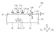
도 2 및 도 3를 참조하면, 도광판(160)의 몸체(161)는 제1 측면(SF1), 제2 측면(SF2), 상부면(UF), 및 바닥면(BF)을 포함한다.2 and 3, the
제2 측면(SF2)은 제1 측면(SF1)과 마주하는 면이고, 상부면(UF)은 제1 측면(SF1)을 제2 측면(SF2)에 연결하며 표시 패널(도 1의 110)을 향하는 면이고, 바닥면(BF)은 제1 측면(SF1)을 제2 측면(SF2)에 연결하며 상부면(UF)과 마주하는 면일 수 있다.The second side surface SF2 is a surface facing the first side surface SF1 and the upper surface UF connects the first side surface SF1 to the second side surface SF2 and the
돌출부들(200) 각각은 제1 측면(SF1)으로부터 제2 측면(SF2)을 향하는 제1 방향(DR1)으로 연장되며, 돌출부들(200)은 제1 측면(SF1)이 연장된 방향과 나란한 제2 방향(DR2)을 따라 나란히 배열될 수 있다. 이 실시예에서 제1 방향(DR1)과 제2 방향(DR2)은 서로 직교할 수 있다. Each of the
이 실시예에서는, 돌출부들(200) 각각은 제1 돌출부(210), 제2 돌출부(220), 및 제3 돌출부(230)를 포함한다. 제1 돌출부(210), 제2 돌출부(220), 및 제3 돌출부(230)는 제1 측면(SF1)으로부터 제2 측면(SF2)을 향하여 순차적으로 배열될 수 있다. 제2 돌출부(220)는 제1 돌출부(210) 및 제3 돌출부(230) 사이에 위치하여 제1 돌출부(210)를 제3 돌출부(230)에 연결할 수 있다.In this embodiment, each of the
이 실시예에서, 제1 돌출부(210)의 제2 방향(DR2)의 제1 폭(WT1)은 제1 측면(SF1)으로부터 멀어질수록 작아지고, 제2 돌출부(220)의 제2 방향(DR2)의 제2 폭(WT2)은 제1 측면(SF1)으로부터 멀어질수록 커지고, 제3 돌출부(230)의 제2 방향(DR2)의 제3 폭(WT3)은 일정할 수 있다.The first width WT1 of the
제1 폭(WT1) 및 제2 폭(WT2) 각각은 가변적일 수 있고, 제1 폭(WT1) 및 제2 폭(WT2) 각각은 제3 폭(WT3)보다 작거나 같은 값을 가질 수 있다. 따라서, 제1 돌출부(210) 및 제2 돌출부(220) 하부에 배치된 상부면(UF)의 일부가 노출될 수 있다. 이하에서, 노출된 상부면(UF)의 일부를 수평면(HF)이라 정의한다.Each of the first width WT1 and the second width WT2 may be variable and each of the first width WT1 and the second width WT2 may have a value less than or equal to the third width WT3 . Accordingly, a part of the upper surface UF disposed under the
이 실시예에서, 제1 돌출부(210)의 제1 높이(HT1)는 제1 측면(SF1)과 멀어질수록 작아지고, 제2 돌출부(220)의 제2 높이(HT2)는 제1 측면(SF1)과 멀어질수록 커지고, 제3 돌출부(230)의 제3 높이(HT3)는 일정할 수 있다. In this embodiment, the first height HT1 of the
제1 폭(WT1)의 최소값과 제2 폭(WT2)의 최소값은 서로 동일하고, 제1 높이(HT1)의 최소값과 제2 높이(HT2)의 최소값은 서로 동일할 수 있다. 따라서, 제1 돌출부(210)와 제2 돌출부(220)가 서로 결합하는 부분의 높이 및 폭 각각의 변화는 연속적(continuity)일 수 있다. 또한, 제2 폭(WT2)의 최대값은 제3 폭(WT3)과 동일하고, 제2 높이(HT2)의 최대값은 제3 높이(HT3)와 동일할 수 있다. 따라서, 제2 돌출부(220)와 제3 돌출부(230)가 서로 결합하는 부분의 높이 및 폭 각각의 변화는 연속적(continuity)일 수 있다.The minimum value of the first width WT1 and the minimum value of the second width WT2 are equal to each other and the minimum value of the first height HT1 and the minimum value of the second height HT2 may be equal to each other. Accordingly, the change in height and width of the portion where the
광원(150)은 제1 측면(SF1)에 인접하여 배열될 수 있다. 광원(150)에서 발생한 광이 입사되는 입광면(LS)은 제1 측면(SF1)과 제1 돌출부(210)의 일면(201)으로 정의될 수 있다. The
이 실시예에 따르면, 입광면(LS)이 제1 측면(SF1)으로만 정의되는 경우보다, 입광면(LS)의 면적이 일면(201)만큼 증가되어 입광면(LS)의 높이가 증가되므로, 도광판(160)의 입광 효율이 향상되어 광원(150)으로부터 발생된 광의 이용 효율이 향상될 수 있다. According to this embodiment, the area of the light incidence surface LS is increased by one
이 실시예에서, 제1 돌출부(210)의 길이는 제2 돌출부(220)의 길이의 1.5배 이상일 수 있다. 그 결과, 제1 돌출부(210)가 갖는 경사면(210T)의 경사도는 제2 돌출부(220)가 갖는 경사면(220T)의 경사도보다 작다. 따라서, 제1 돌출부(210)의 경사면(210T)의 경사도가 작기 때문에, 제1 돌출부(210)의 경사면(210T)에서 광의 전반사가 용이하게 발생할 수 있다. 따라서, 제1 돌출부(210)의 경사면(210T)을 통해 도광판(160) 외부로 광이 누설되는 확률이 감소될 수 있다.In this embodiment, the length of the
본 발명의 다른 실시예에서는, 바닥면(BF)에 광을 표시패널(110) 측으로 반사하는 반사 패턴(미도시)이 더 포함될 수 있다. 반사 패턴(미도시)은 바닥면(BF)을 가공하여 볼록한 형상 또는 오목한 형상으로 제공될 수 있다. 또 다른 실시예에서는 광을 반사하는 물질을 바닥면(BF)에 인쇄하여 반사패턴(미도시)이 형성될 수 있다.In another embodiment of the present invention, the bottom surface BF may further include a reflection pattern (not shown) for reflecting the light toward the
도 4a는 도 2에 도시된 절단선 II - II`에 따라 절단된 단면도이고, 도 4b는 도 2에 도시된 절단선 III - III`에 따라 절단된 단면도이고, 도 4c는 도 2에 도시된 절단선 IV - IV`에 따라 절단된 단면도이다. 도 4a, 도 4b, 및 도 4c를 설명함에 있어서, 도 2 및 도 3을 참조하여 설명된 구성 요소들에 대해서는 도면 부호를 병기하고, 상기 구성 요소들에 대해 중복된 설명은 생략된다.FIG. 4A is a cross-sectional view taken along the line II-II shown in FIG. 2, FIG. 4B is a cross-sectional view taken along the line III-III shown in FIG. 2, Sectional view taken along section line IV - IV. In describing FIGS. 4A, 4B and 4C, the components described with reference to FIGS. 2 and 3 are denoted by the same reference numerals, and redundant description of the components is omitted.
도 4a, 도 4b, 및 도 4c 각각은 제1 측면(도 2의 SF1)과 평행하게 절단된 단면도로, 제1 돌출부(210)의 제1 단면(CS1), 제2 돌출부(220)의 제2 단면(CS2), 및 제3 돌출부(230)의 제3 단면(CS3) 각각의 외곽은 라운드 형상을 가질 수 있다. 제1 돌출부(210), 제2 돌출부(220), 및 제3 돌출부(230)는 도광판(160)의 입광면(도 3의 LS)을 통해 몸체(161)에 대해 경사져 입사된 광을 표시 패널(도 1의 110)에 대략적으로 수직하게 진행하도록 광을 집광한다.Each of Figs. 4A, 4B and 4C is a cross-sectional view taken in parallel with the first side (SF1 in Fig. 2). The first end face CS1 of the
이 실시예에서, 제1 돌출부(210)의 제1 곡률 반경(DA1), 제2 돌출부(220)의 제2 곡률 반경(DA2), 및 제3 돌출부(230)의 제3 곡률 반경(DA3)은 서로 동일할 수 있다. 제1 곡률 반경(DA1), 제2 곡률 반경(DA2), 및 제3 곡률 반경(DA3)의 값에 따라 제1 돌출부(210), 제2 돌출부(220), 및 제3 돌출부(230)를 통과한 광이 표시 패널(도 1의 110) 측으로 집광되는 정도가 상이할 수 있다. 예컨대, 제1 곡률 반경(DA1), 제2 곡률 반경(DA2), 및 제3 곡률 반경(DA3) 각각의 값이 작아질수록 돌출부들(200)을 통해 출광되는 광이 표시패널(도 1의 110)에 대해 대략적으로 수직한 방향으로 진행하는 경향이 증가하게 되어, 표시 패널(도 1의 110) 측으로 광이 집광되어 광 이용 효율이 증가될 수 있다. 그러나, 제1 곡률 반경(DA1), 제2 곡률 반경(DA2), 및 제3 곡률 반경(DA3) 각각의 값이 작아질수록 도광판(160)의 광이 입사되는 영역에서 빛샘 현상이 증가할 수 있으므로, 표시장치(도 1 의 100)의 사이즈와 도광판(160)의 재질 등을 고려하여 적절한 곡률 반경을 선택할 수 있다. In this embodiment, the first radius of curvature DA1 of the
이 실시예에서, 제1 돌출부(210), 제2 돌출부(220), 및 제3 돌출부(230)들 각각의 외곽은 단면상에서 라운드 형상을 가질 수 있으나, 다른 실시예에서는 제1 돌출부(210), 제2 돌출부(220) 및 제3 돌출부(230) 들 각각은 프리즘 형상일 수 있다. In this embodiment, the outline of each of the
도 5a는 도 1에 도시된 도광판의 사시도이고, 도 5b는 도 2에 도시된 절단선 V - V`에 따라 절단된 단면도이다. 도 5a 및 도 5b를 설명함에 있어서, 도 2 및 도 3을 참조하여 설명된 구성 요소들에 대해서는 도면 부호를 병기하고, 상기 구성 요소들에 대해 중복된 설명은 생략된다.FIG. 5A is a perspective view of the light guide plate shown in FIG. 1, and FIG. 5B is a sectional view cut along a cutting line V - V 'shown in FIG. In describing FIGS. 5A and 5B, the constituent elements described with reference to FIGS. 2 and 3 are denoted by the same reference numerals, and redundant description of the constituent elements is omitted.
도 5a 및 도 5b를 참조하면, 도광판(160)의 몸체(161)의 상부면(UF) 및 몸체(161)의 제1 측면(SF1) 각각과 수직한 단면인 수직면(VS)이 정의된다. 수직면(VS)은 가상의 면으로, 수직면(VS)은 상부면(UF)과 제1 측면(SF1) 각각과 수직한 모든 면일 수 있다.5A and 5B, a vertical surface VS having a cross section perpendicular to the upper surface UF of the
이 실시예에서는, 도 5a에 도시된 바와 같이, 수직면(VS) 상에서 정의되는 방향들 각각을 제1 방향(D1)으로 정의한다. 즉, 제1 방향(D1)은 어느 하나의 방향으로 정의되는 것이 아니라, 제1 방향(D1)은 수직면(VS) 상에서 정의되는 방향들을 대표하는 방향일 수 있다. 또한, 제2 방향(D2)은 수직면(VS)에 포함되지 않은 모든 방향으로 정의될 수 있다. 제1 방향(D1)과 제2 방향(D2)의 구분을 명확히 하기 위해, 제1 방향(D1)은 점선으로, 제2 방향(D2)은 실선으로 도시된다.In this embodiment, as shown in Fig. 5A, each of the directions defined on the vertical plane VS is defined as a first direction D1. That is, the first direction D1 is not defined as any one direction, but the first direction D1 may be a direction representing directions defined on the vertical surface VS. In addition, the second direction D2 can be defined as any direction not included in the vertical plane VS. In order to clarify the distinction between the first direction D1 and the second direction D2, the first direction D1 is shown by a dotted line and the second direction D2 is shown by a solid line.
도 5b는 제1 돌출부(210)와 제2 돌출부(220)가 결합된 부분을 제1 측면(SF1)과 평행하게 절단한 단면도이다. 이하에서, 설명의 편의를 위해 제1 돌출부(210)와 제2 돌출부(220)가 만나는 면을 돌출면(215)이라 정의한다.5B is a cross-sectional view of a portion where the
돌출면(215)의 높이(HT0)는 제1 높이(도 3의 HT1)의 최소값 및 제2 높이(도 3의 HT2)의 최소값 각각과 동일하고, 돌출면(215)의 폭(WT0)은 제1 폭(도 2의 WT1)의 최소값 및 제2 폭(도 2의 WT2)의 최소값 각각과 동일할 수 있다.The height HT0 of the protruding
이 실시예에서, 돌출면(215)에 인접하여 수평면(HF)이 배치될 수 있다. 수평면(HF)은 몸체(161)의 상부면(UF) 중 돌출부들(도 1의 200)이 배치되지 않은 면일 수 있다. In this embodiment, the horizontal plane HF may be disposed adjacent to the projecting
본 발명의 실시예와 달리, 수평면(HF)이 존재하지 않는 경우에는 서로 인접한 두 개의 광원들 사이에 대응하는 도광판(160)의 제2 영역(도 6의 AR2)의 휘도가 광원의 위치와 대응하는 도광판(160)의 제1 영역(도 6의 AR1)의 휘도보다 커서 핫 스팟(hot spot) 현상이 나타날 수 있다. 핫 스팟(hot spot) 현상이 나타나는 이유는 다음과 같다. 입광면(도 3의 LS)에 제1 방향(D1)으로 입사되어 돌출부들(도 1의 200)을 통해 출광되는 광(L0)은 제1 방향(D1)으로 출광되는 광(L0a)의 광량보다 제2 방향(D2)으로 출광되는 광(L0b)의 광량이 많다. 또한, 입광면(도 3의 LS)에 제2 방향(D2)으로 입사되어 돌출부들(도 1의 200)을 통해 출광되는 광(L1)은 제1 방향(D1)으로 출광되는 광(L1a)의 광량이 제2 방향(D2)으로 출광되는 광(L1b)의 광량보다 많다. 따라서, 도광판(160)의 제1 영역(도 6의 AR1)에는 제1 방향(D1)으로 입사되어, 제2 방향(D2)으로 출사되는 광의 량이 많고, 도광판(160)의 제2 영역(도 6의 AR2)에는 제2 방향(D2)으로 입사되어 제1 방향(D1)으로 출사되는 광의 량이 많다. 따라서, 제2 영역(도 6의 AR2)으로 광이 집중될 수 있고, 그 결과 제2 영역(도 6의 AR2)에서 측정되는 휘도가 제1 영역(도 6의 AR1)의 휘도보다 밝게 나타나는 핫 스팟(hot spot) 현상이 발생할 수 있다. Unlike the embodiment of the present invention, when the horizontal plane HF does not exist, the brightness of the second region (AR2 in Fig. 6) of the
하지만, 본 발명의 실시예에 따르면, 돌출부들(도 1의 200) 사이에 수평면(HF)이 배치된다. 제1 방향(D1)으로 입사된 광 중 일부의 광(L2)은 수평면(HF)을 통해 출사되어 표시 패널(도 1의 110) 측으로 가이드 된다. 수평면(HF)을 통해 출광되는 광(L2) 중 제1 방향(D1)으로 출광되는 광(L2a)의 광량은 제2 방향(D2)으로 출광되는 광(L2b)의 광량보다 많다. 따라서, 앞서 설명한 도광판(160)의 제2 영역(도 6의 AR2)에 광이 집중되는 것이 방지될 수 있고, 그 결과 핫 스팟(hot spot) 현상이 최소화될 수 있다. However, according to the embodiment of the present invention, a horizontal plane HF is disposed between the projections (200 in Fig. 1). Some of the light L2 incident on the first direction D1 is emitted through the horizontal plane HF and guided to the
도 6은 도광판의 평면도이고, 도 7은 도 5b의 돌출면(도 5b의 215)의 높이에 따른 도 6의 가상선 P-P` 위치에서 측정한 휘도를 나타낸 그래프이다.FIG. 6 is a plan view of the light guide plate, and FIG. 7 is a graph showing the luminance measured at the position of the imaginary line P-P 'in FIG. 6 according to the height of the protruding surface (215 of FIG.
도 6 및 도 7을 참조하면, 도광판(LGP)에서 광이 출사되는 출사면(OS) 중 광원들(250)과 인접한 영역을 인접 출광 영역(AR)이라 정의할 때, 인접 출광 영역(AR)은 제1 영역(AR1) 및 제2 영역(AR2)으로 정의될 수 있다. 제1 영역(AR1)은 광원(150)의 위치와 대응하는 영역으로 정의될 수 있고, 제2 영역(AR2)은 서로 인접한 두 개의 광원들(250) 사이의 위치와 대응하는 영역으로 정의될 수 있다.6 and 7, when an area adjacent to the
제1 그래프(GP1) 및 제4 그래프(GP4)는 본 발명의 비교예에 따른 것이고, 제2 그래프(GP2) 및 제3 그래프(GP3)는 본 발명의 실시예에 따른 것이다. 보다 상세하게는, 제1 그래프(GP1)는 돌출면(도 5b의 215)의 높이(도 5b의 HT0)가 제3 높이(도 4c의 HT3)의 100%인 경우의 휘도를 나타내고, 제2 그래프(GP2)는 돌출면(도 5b의 215)의 높이(도 5b의 HT0)가 제3 높이(도 4c의 HT3)의 25%인 경우의 휘도를 나타내고, 제3 그래프(GP3)는 돌출면(도 5b의 215)의 높이(도 5b의 HT0)가 제3 높이(도 4c의 HT3)의 18%인 경우의 휘도를 나타내고, 제4 그래프(GP4)는 돌출면(도 5b의 215)의 높이(도 5b의 HT0)가 제3 높이(도 4c의 HT3)의 0%인 경우의 휘도를 나타낸다.The first graph GP1 and the fourth graph GP4 are according to the comparative example of the present invention and the second graph GP2 and the third graph GP3 are according to the embodiment of the present invention. 5B) is 100% of the third height (HT3 in FIG. 4C), and the second graph GP1 shows the brightness when the height (HT0 in FIG. 5B) of the protruding surface 5B) is 25% of the third height (HT3 in FIG. 4C), and the third graph GP3 shows the brightness when the height (HT0 in FIG. 5B) of the protruding surface (215 in FIG. 5B) is 18% of the third height (HT3 in FIG. 4C), and the fourth graph GP4 shows the brightness in the case where the height of the protruding surface (215 in FIG. 5B) And the height (HT0 in FIG. 5B) is 0% of the third height (HT3 in FIG. 4C).
제1 그래프(GP1), 제2 그래프(GP2), 제3 그래프(GP3) 및 제4 그래프(GP4)를 참조하면, 돌출면(도 5b의 215)의 높이(도 5b의 HT0)에 따라 도 6의 가상선 P-P` 위치에서 측정되는 휘도가 변화되는 것을 볼 수 있다.Referring to the first graph (GP1), the second graph (GP2), the third graph (GP3) and the fourth graph (GP4), depending on the height (HT0 in FIG. 6, the luminance measured at the virtual line PP 'position is changed.
제1 그래프(GP1)를 참조하면, 돌출면(도 5b의 215)의 높이(도 5b의 HT0)가 제3 높이(도 4c의 HT3)와 동일하므로, 가상선 P - P`의 위치에서 수평면(도 5b의 HF)이 없을 수 있다. 따라서, 앞서 도 5b에서 설명한 바에 따라, 제2 영역(AR2)에서 측정된 휘도는 제1 영역(AR1)에서 측정된 휘도보다 높을 수 있다. 예컨대, 제1 영역(AR1)에서 측정된 휘도는 약 600 니트이고, 제2 영역(AR2)에서 측정된 휘도는 약 750 니트로, 광원들(250) 사이의 위치와 대응되는 제2 영역(AR2)의 휘도가 제1 영역(AR1)의 휘도보다 150니트 가량 밝게 나타나는 핫 스팟(hot spot) 현상이 발생될 수 있다. 5B) of the protruding surface (HT0 in FIG. 5B) is equal to the third height (HT3 in FIG. 4C), the horizontal plane at the position of the imaginary line P - P ' (HF in FIG. 5B). Therefore, as described above with reference to FIG. 5B, the luminance measured in the second area AR2 may be higher than the luminance measured in the first area AR1. For example, the luminance measured in the first area AR1 is about 600 knits, the luminance measured in the second area AR2 is about 750 N, the second area AR2 corresponding to the position between the
제4 그래프(GP4)를 참조하면, 돌출면(도 5b의 215)의 높이(도 5b의 HT0)가 제3 높이(도 4c의 HT3)의 0%인 경우, 가상선 P - P`의 위치와 대응되는 출사면(OS)에는 돌출된 부분 없이 모두 수평구간일 수 있다. 광원(150)에서 출사된 광은 도광판(LGP)으로 입사되고 돌출부들(도 1의 200)이 없는 제1 영역(AR1) 및 제2 영역(AR2)을 통해 출사될 수 있다. 돌출부들(도 1의 200)이 없는 경우 광은 입사된 방향을 따라 출사될 수 있다. 따라서, 광원(150)의 위치와 대응되는 제1 영역(AR1)으로 광이 집중될 수 있다. 예컨대, 제1 영역(AR1)의 휘도는 약 1300 니트이고, 제2 영역(AR2)의 휘도는 약 800 니트로, 제1 영역(AR1)의 휘도가 제2 영역(AR2)의 휘도보다 500니트 가량 밝게 나타나는 핫 스팟(hot spot) 현상이 발생될 수 있다. 5B) is 0% of the third height (HT3 in FIG. 4C), the position of the imaginary line P - P ' And the corresponding emission surface OS may be all horizontal sections without protruding portions. The light emitted from the
제2 그래프(GP2)를 참조하면, 돌출면(도 5a의 215)의 높이(도 5b의 HT0)가 제3 높이(도 4c의 HT3)의 25%인 경우, 수직면(도 5a의 VS)에 포함되는 제1 방향(도 5a의 D1)으로 입사된 광 중 일부의 광(도 5b의 L2)은 수평면(도 5a의 HF)을 통해 출광되고, 다른 일부의 광(도 5b의 L0)은 돌출부들(도 1의 200)을 통해 출광 될 수 있다. 5B) of 25% of the third height (HT3 in FIG. 4C) is larger than the height (HT2 in FIG. 5B) of the protruding surface 5B) of the light incident in the first direction (D1 in FIG. 5A) is emitted through the horizontal plane (HF in FIG. 5A), and another part of light (L0 in FIG. (200 in Fig. 1).
수평면(도 5b의 HF)을 통해 출광되는 광(도 5b의 L2)은 제1 방향(도 5b의 D1)으로 출광되는 광(L2a)의 광량이 제2 방향(도 5b의 D2)으로 출광되는 광(L2b)의 광량보다 많다. 따라서, 광원들(250) 사이의 위치와 대응되는 제2 영역(AR2)에 광이 집중되지 않는다. 또한, 제1 방향(도 5b의 D1)으로 입사된 광 중 돌출부들(도 1의 200)을 통해 출광되는 광(도 5b의 L0)은 제1 방향(도 5b의 D1)으로 출광 되는 광(도 5b의 L0a)의 광량보다 제2 방향(도 5a의 D2)으로 출광 되는 광(도 5b의 L0b)의 광량이 많다. 따라서, 광원(150)의 위치와 대응되는 제1 영역(AR1)으로 광이 집중되지 않는다. 5B) of the light output through the horizontal plane (HF in FIG. 5B) is emitted in the second direction (D2 in FIG. 5B) when the light amount of the light L2a emitted in the first direction Is larger than the light amount of the light L2b. Therefore, light is not concentrated in the second area AR2 corresponding to the position between the
따라서, 제1 영역(AR1)에서 측정된 휘도와 제2 영역(AR2)에서 측정된 휘도의 차이가 감소될 수 있고, 핫 스팟(hot spot) 현상이 감소될 수 있다. 그 결과, 백라이트 유닛(도 1의 120)은 표시패널(도 1의 110)로 균일한 휘도의 광을 제공할 수 있고, 표시장치(100)의 표시품질이 향상될 수 있다.Therefore, the difference between the luminance measured in the first area AR1 and the luminance measured in the second area AR2 can be reduced, and the hot spot phenomenon can be reduced. As a result, the backlight unit (120 in FIG. 1) can provide light of uniform luminance to the display panel (110 in FIG. 1), and the display quality of the
제3 그래프(GP3)를 참조하면, 돌출면(도 5b의 215)의 높이(도 5b의 HT0)가 제3 높이(도 4c의 HT3)의 18%인 경우, 제2 그래프(GP2)에서 설명한 바와 같이, 광원(150)의 위치와 대응하는 제1 영역(AR1)에서 측정된 휘도와 광원들(250) 사이의 위치와 대응하는 제2 영역(AR2)에서 측정된 휘도의 차이가 감소될 수 있고, 핫 스팟(hot spot) 현상이 감소될 수 있다. 그 결과 백라이트 유닛(도 1의 120)은 표시 패널(도 1의 110)로 균일한 휘도의 광을 제공할 수 있고, 표시장치(도 1의 100)의 표시품질이 향상될 수 있다.5B) is 18% of the third height (HT3 in FIG. 4C), the height of the protruding surface (215 in FIG. 5B) The difference between the luminance measured in the first area AR1 corresponding to the position of the
돌출면(도 5a의 215)의 높이(도 5b의 HT0)가 제3 높이(도 4c의 HT3)와 동일해질수록, 제2 영역(AR2)에서 측정되는 휘도가 제1 영역(AR1)에서 측정되는 휘도보다 상대적으로 높게 측정되고, 돌출면(도 5a의 215)의 높이(도 5b의 HT0)가 0에 가까워질수록 제1 영역(AR1)에서 측정되는 휘도가 제2 영역(AR2)에서 측정되는 휘도보다 상대적으로 높게 측정될 수 있다. 따라서 돌출면(도 5a의 215)의 높이(도 5b의 HT0)는 제1 영역(AR1)에서 측정되는 휘도와 제2 영역(AR2)에서 측정되는 휘도의 차이가 최소화될 수 있는 높이로 제공될 수 있다. 예컨대, 이 실시예에서 돌출면(도 5a의 215)의 높이(도 5b의 HT0)는 제3 높이(도 4c의 HT3)의 15% 내지 28%일 수 있으며, 보다 상세하게는 18% 내지 25%일 수 있다.As the height (HT0 in FIG. 5B) of the protruding surface (215 in FIG. 5A) becomes equal to the third height (HT3 in FIG. 4C), the luminance measured in the second area AR2 is measured in the first area AR1 And the luminance measured in the first area AR1 is measured in the second area AR2 as the height of the protruding surface (215 in Fig. 5A) becomes closer to 0 (HT0 in Fig. 5B) The luminance can be measured relatively higher than the luminance. Therefore, the height (HT0 in FIG. 5B) of the protruding surface (215 in FIG. 5A) is provided at a height at which the difference between the luminance measured in the first area AR1 and the luminance measured in the second area AR2 can be minimized . For example, in this embodiment, the height (HT0 in FIG. 5B) of the protruding surface (215 in FIG. 5A) may be between 15% and 28% of the third height (HT3 in FIG. 4C) %. ≪ / RTI >
이상에서는 본 발명의 바람직한 실시예를 참조하여 설명하였지만, 해당 기술 분야의 숙련된 당업자 또는 해당 기술 분야에 통상의 지식을 갖는 자라면, 후술될 특허청구범위에 기재된 본 발명의 사상 및 기술 영역으로부터 벗어나지 않는 범위 내에서 본 발명을 다양하게 수정 및 변경시킬 수 있음을 이해할 수 있을 것이다. 따라서, 본 발명의 기술적 범위는 명세서의 상세한 설명에 기재된 내용으로 한정되는 것이 아니라 특허청구범위에 의해 정하여져야만 할 것이다.While the present invention has been described in connection with what is presently considered to be the most practical and preferred embodiment, it is to be understood that the invention is not limited to the disclosed embodiments, but, on the contrary, It will be understood that various modifications and changes may be made thereto without departing from the scope of the present invention. Therefore, the technical scope of the present invention should not be limited to the contents described in the detailed description of the specification, but should be defined by the claims.
100: 표시 장치
110: 표시 패널
120: 백라이트 유닛
130: 탑 샤시
140: 수납부
150: 광원
160: 도광판
161: 몸체
170: 광학시트들
180: 반사시트
190: 몰드 프레임
200: 돌출부들
210: 제1 돌출부
220: 제2 돌출부
230: 제3 돌출부
215: 돌출면
SF1: 제1 측면
SF2: 제2 측면
UF: 상부면
BF: 바닥면
LS: 입광면100: display device 110: display panel
120: backlight unit 130: top chassis
140: storage part 150: light source
160: light guide plate 161: body
170: optical sheets 180: reflective sheet
190: mold frame 200: protrusions
210: first protrusion 220: second protrusion
230: third protrusion 215: protruding surface
SF1: first side SF2: second side
UF: Upper side BF: Lower side
LS: incoming light surface
Claims (19)
상기 광을 발생하는 광원; 및
상기 광을 수광하여 상기 표시 패널로 상기 광을 제공하는 도광판을 포함하며,
상기 도광판은
제1 측면, 상기 제1 측면과 마주하는 제2 측면, 및 상부면을 갖는 몸체; 및
상기 상부면 위에 배치되는 돌출부들을 포함하고,
상기 돌출부들 각각은 상기 제1 측면으로부터 상기 제2 측면을 향하여 순차적으로 배열된 제1 돌출부 및 제2 돌출부를 포함하며, 상기 제1 돌출부의 상기 제1 측면과 나란한 방향의 제1 폭은 상기 제1 측면으로부터 멀어질수록 작아지고, 상기 제2 돌출부의 상기 제1 측면과 나란한 방향의 제2 폭은 상기 제1 측면으로부터 멀어질수록 커져 상기 몸체의 상기 상부면의 일부가 노출되는 표시장치.A display panel that receives light and displays an image;
A light source for generating the light; And
And a light guide plate for receiving the light and providing the light to the display panel,
The light-
A body having a first side, a second side facing the first side, and an upper side; And
And protrusions disposed on the upper surface,
Wherein each of the protrusions includes a first protrusion and a second protrusion sequentially arranged from the first side face to the second side face, and a first width in a direction parallel to the first side face of the first protrusion, And a second width of the second projection in a direction parallel to the first side increases as the distance from the first side increases to expose a part of the upper surface of the body.
상기 제1 폭의 최소값과 상기 제2 폭의 최소값은 동일한 표시장치.The method according to claim 1,
Wherein the minimum value of the first width and the minimum value of the second width are the same.
상기 돌출부들 각각은 상기 제2 돌출부를 사이에 두고 상기 제1 돌출부와 마주하는 제3 돌출부를 더 포함하고,
상기 제3 돌출부의 상기 제1 측면과 나란한 방향의 제3 폭은 일정한 표시장치.The method according to claim 1,
Each of the protrusions further includes a third protrusion facing the first protrusion with the second protrusion interposed therebetween,
And a third width in a direction parallel to the first side face of the third projection is constant.
상기 제2 폭의 최대값은 상기 제3 폭과 동일한 표시장치.The method of claim 3,
And the maximum value of the second width is equal to the third width.
상기 제1 돌출부, 상기 제2 돌출부 및 상기 제3 돌출부 각각의 상기 제1 측면과 평행한 단면의 외곽은 라운드 형상을 갖는 표시장치.The method of claim 3,
Wherein the outline of the cross section of each of the first projecting portion, the second projecting portion and the third projecting portion parallel to the first side face has a round shape.
상기 제1 돌출부의 상기 제1 측면과 평행한 제1 단면의 제1 곡률 반경, 상기 제2 돌출부의 상기 제1 측면과 평행한 제2 단면의 제2 곡률 반경, 및 상기 제3 돌출부의 상기 제1 측면과 평행한 제3 단면의 제3 곡률 반경은 서로 동일한 표시장치.6. The method of claim 5,
A first radius of curvature of the first section parallel to the first side of the first projection, a second radius of curvature of the second section parallel to the first side of the second projection, and a second radius of curvature of the second projection, And the third curvature radii of the third cross-section parallel to the first side are equal to each other.
상기 제1 돌출부의 제1 높이는 상기 제1 측면과 멀어질수록 작아지고, 상기 제2 돌출부의 제2 높이는 상기 제1 측면과 멀어질수록 커지고, 상기 제3 돌출부의 제3 높이는 일정한 표시장치.The method of claim 3,
Wherein the first height of the first projection is smaller as the distance from the first side increases and the second height of the second projection becomes larger as the distance from the first side increases and the third height of the third projection is constant.
상기 제1 높이의 최대값은 상기 제3 높이와 동일한 표시장치.8. The method of claim 7,
Wherein the maximum value of the first height is equal to the third height.
상기 제2 높이의 최대값은 상기 제3 높이와 동일한 표시장치.8. The method of claim 7,
And the maximum value of the second height is equal to the third height.
상기 제1 높이의 최소값은 상기 제2 높이의 최소값과 동일한 표시장치. 8. The method of claim 7,
Wherein the minimum value of the first height is equal to the minimum value of the second height.
상기 제1 높이의 최소값 및 상기 제2 높이의 최소값 각각은 상기 제3 높이의 15% 내지 28%인 표시장치.8. The method of claim 7,
Wherein each of the minimum value of the first height and the minimum value of the second height is 15% to 28% of the third height.
상기 제1 돌출부는 상기 제2 돌출부와 연결되고, 상기 제2 돌출부는 상기 제3 돌출부와 연결되어, 상기 돌출부들 각각은 상기 제1 측면으로부터 상기 제2 측면을 향하는 방향으로 연장된 표시장치.The method of claim 3,
Wherein the first projection is connected to the second projection and the second projection is connected to the third projection so that each of the projections extends in a direction from the first side to the second side.
상기 도광판에서 상기 광원으로부터 발생된 상기 광이 입사되는 입광면은 상기 제1 측면과 상기 제1 돌출부의 일면으로 정의되는 표시장치.The method of claim 3,
Wherein a light incident surface on which the light generated from the light source is incident on the light guide plate is defined as one surface of the first side surface and the first projection.
상기 상부면은 상기 제1 측면을 상기 제2 측면에 연결하여 상기 표시 패널을 향하는 표시장치.The method according to claim 1,
Wherein the upper surface connects the first side surface to the second side surface and faces the display panel.
상기 광을 수광하여 상기 광을 가이드하는 도광판을 포함하며,
상기 도광판은
제1 측면, 상기 제1 측면과 마주하는 제2 측면 및 상부면을 갖는 몸체; 및
상기 상부면 위에 배치되는 돌출부들을 포함하고,
상기 돌출부들 각각은 상기 제1 측면으로부터 상기 제2 측면을 향하여 순차적으로 배열된 제1 돌출부 및 제2 돌출부를 포함하며, 상기 제1 돌출부의 상기 제1 측면과 나란한 방향의 제1 폭은 상기 제1 측면으로부터 멀어질수록 작아지고, 상기 제2 돌출부의 상기 제1 측면과 나란한 방향의 제2 폭은 상기 제1 측면으로부터 멀어질수록 커져 상기 몸체의 상기 상부면의 일부가 노출되는 백라이트 유닛.A light source for generating light; And
And a light guide plate for receiving the light and guiding the light,
The light-
A body having a first side, a second side facing the first side, and an upper side; And
And protrusions disposed on the upper surface,
Wherein each of the protrusions includes a first protrusion and a second protrusion sequentially arranged from the first side face to the second side face, and a first width in a direction parallel to the first side face of the first protrusion, And a second width of the second projection in a direction parallel to the first side increases as the distance from the first side increases so that a part of the upper surface of the body is exposed.
상기 돌출부들 각각은 상기 제2 돌출부를 사이에 두고 상기 제1 돌출부와 마주하는 제3 돌출부를 더 포함하고,
상기 제3 돌출부의 상기 제1 측면과 나란한 방향의 제3 폭은 일정한 백라이트 유닛.16. The method of claim 15,
Each of the protrusions further includes a third protrusion facing the first protrusion with the second protrusion interposed therebetween,
And a third width in a direction parallel to the first side surface of the third projection is constant.
상기 제1 돌출부의 제1 높이는 상기 제1 측면과 멀어질수록 작아지고, 상기 제2 돌출부의 제2 높이는 상기 제1 측면과 멀어질수록 커지고, 상기 제3 돌출부의 제3 높이는 일정한 백라이트 유닛.17. The method of claim 16,
Wherein the first height of the first projection is smaller as the distance from the first side increases, the second height of the second projection becomes larger as the distance from the first side increases, and the third height of the third projection is constant.
상기 제1 높이의 최소값 및 상기 제2 높이의 최소값 각각은 상기 제3 높이의 15% 내지 28%인 백라이트 유닛.18. The method of claim 17,
Wherein each of the minimum value of the first height and the minimum value of the second height is 15% to 28% of the third height.
상기 돌출부들과 상기 몸체는 서로 동일한 물질을 포함하는 백라이트 유닛.16. The method of claim 15,
Wherein the protrusions and the body comprise the same material.
Priority Applications (2)
| Application Number | Priority Date | Filing Date | Title |
|---|---|---|---|
| KR1020140138446A KR20160044145A (en) | 2014-10-14 | 2014-10-14 | Backlight unit and display apparatus having the same |
| US14/819,063 US9759853B2 (en) | 2014-10-14 | 2015-08-05 | Backlight unit and display apparatus having the same |
Applications Claiming Priority (1)
| Application Number | Priority Date | Filing Date | Title |
|---|---|---|---|
| KR1020140138446A KR20160044145A (en) | 2014-10-14 | 2014-10-14 | Backlight unit and display apparatus having the same |
Publications (1)
| Publication Number | Publication Date |
|---|---|
| KR20160044145A true KR20160044145A (en) | 2016-04-25 |
Family
ID=55655317
Family Applications (1)
| Application Number | Title | Priority Date | Filing Date |
|---|---|---|---|
| KR1020140138446A Withdrawn KR20160044145A (en) | 2014-10-14 | 2014-10-14 | Backlight unit and display apparatus having the same |
Country Status (2)
| Country | Link |
|---|---|
| US (1) | US9759853B2 (en) |
| KR (1) | KR20160044145A (en) |
Families Citing this family (36)
| Publication number | Priority date | Publication date | Assignee | Title |
|---|---|---|---|---|
| EP3369034B1 (en) | 2015-10-26 | 2023-07-05 | RealD Spark, LLC | Intelligent privacy system, apparatus, and method thereof |
| TWI582501B (en) * | 2016-01-04 | 2017-05-11 | 揚昇照明股份有限公司 | Light source module and display device |
| US11079619B2 (en) | 2016-05-19 | 2021-08-03 | Reald Spark, Llc | Wide angle imaging directional backlights |
| JP6808031B2 (en) * | 2016-10-11 | 2021-01-06 | ラディアント オプト‐エレクトロニクス (スーチョウ) カンパニー リミテッド | Light guide plate, backlight module and display device |
| US20210199879A1 (en) | 2017-05-08 | 2021-07-01 | Reald Spark, Llc | Optical stack for imaging directional backlights |
| CN110785694B (en) | 2017-05-08 | 2023-06-23 | 瑞尔D斯帕克有限责任公司 | Optical stacks for directional displays |
| US10126575B1 (en) | 2017-05-08 | 2018-11-13 | Reald Spark, Llc | Optical stack for privacy display |
| TWI878209B (en) | 2017-09-15 | 2025-04-01 | 美商瑞爾D斯帕克有限責任公司 | Display device and a view angle control optical element for application to a display device |
| US10948648B2 (en) | 2017-09-29 | 2021-03-16 | Reald Spark, Llc | Backlights having stacked waveguide and optical components with different coefficients of friction |
| EP3707554B1 (en) | 2017-11-06 | 2023-09-13 | RealD Spark, LLC | Privacy display apparatus |
| CN118672006A (en) | 2018-01-25 | 2024-09-20 | 瑞尔D斯帕克有限责任公司 | Touch screen for privacy display |
| WO2019147762A1 (en) | 2018-01-25 | 2019-08-01 | Reald Spark, Llc | Reflective optical stack for privacy display |
| JP7495027B2 (en) | 2018-03-22 | 2024-06-04 | リアルディー スパーク エルエルシー | Optical waveguide, backlight device and display device |
| WO2020005748A1 (en) | 2018-06-29 | 2020-01-02 | Reald Spark, Llc | Optical stack for privacy display |
| WO2020018552A1 (en) | 2018-07-18 | 2020-01-23 | Reald Spark, Llc | Optical stack for switchable directional display |
| WO2020072643A1 (en) | 2018-10-03 | 2020-04-09 | Reald Spark, Llc | Privacy display control apparatus |
| CN113167953B (en) | 2018-11-07 | 2023-10-24 | 瑞尔D斯帕克有限责任公司 | Directional display device |
| WO2020146091A1 (en) | 2019-01-07 | 2020-07-16 | Reald Spark, Llc | Optical stack for privacy display |
| WO2020167680A1 (en) | 2019-02-12 | 2020-08-20 | Reald Spark, Llc | Diffuser for privacy display |
| EP3994878A4 (en) | 2019-07-02 | 2023-06-14 | RealD Spark, LLC | DIRECTIONAL DISPLAY DEVICE |
| EP4007930B1 (en) | 2019-08-02 | 2025-10-08 | RealD Spark, LLC | Optical stack for privacy display |
| EP4438945B1 (en) | 2019-10-02 | 2025-09-03 | RealD Spark, LLC | Privacy display apparatus |
| CN114846393B (en) | 2019-11-13 | 2024-12-03 | 瑞尔D斯帕克有限责任公司 | Off-axis display device |
| WO2021118936A1 (en) | 2019-12-10 | 2021-06-17 | Reald Spark, Llc | Control of reflections of a display device |
| EP4440248A3 (en) | 2019-12-18 | 2024-10-16 | RealD Spark, LLC | Control of ambient light for a privacy display |
| EP4143042B1 (en) | 2020-04-30 | 2025-09-24 | RealD Spark, LLC | Directional display apparatus |
| EP4143632A4 (en) | 2020-04-30 | 2024-08-14 | RealD Spark, LLC | DIRECTION INDICATOR |
| US11506939B2 (en) | 2020-04-30 | 2022-11-22 | Reald Spark, Llc | Directional display apparatus |
| US11624944B2 (en) | 2020-07-29 | 2023-04-11 | Reald Spark, Llc | Backlight for switchable directional display |
| TWI898003B (en) | 2020-07-29 | 2025-09-21 | 美商瑞爾D斯帕克有限責任公司 | Pupillated illumination apparatus |
| CN112859435A (en) * | 2021-01-12 | 2021-05-28 | 扬昕科技(苏州)有限公司 | Light guide plate and light source module |
| US11892717B2 (en) | 2021-09-30 | 2024-02-06 | Reald Spark, Llc | Marks for privacy display |
| EP4476588A4 (en) | 2022-02-09 | 2025-12-31 | Reald Spark Llc | OBSERVER-TRANSFERRED PRIVACY DISPLAY |
| EP4505240A1 (en) | 2022-04-07 | 2025-02-12 | RealD Spark, LLC | Directional display apparatus |
| WO2024226506A1 (en) | 2023-04-25 | 2024-10-31 | Reald Spark, Llc | Switchable privacy display |
| US12393066B2 (en) | 2023-08-03 | 2025-08-19 | Reald Spark, Llc | Privacy displays |
Family Cites Families (8)
| Publication number | Priority date | Publication date | Assignee | Title |
|---|---|---|---|---|
| KR20080051941A (en) | 2006-12-07 | 2008-06-11 | 엘지디스플레이 주식회사 | LGP for liquid crystal display and liquid crystal display using same |
| KR100868922B1 (en) | 2007-01-29 | 2008-11-17 | 제일모직주식회사 | LGP for liquid crystal display device including irregular shape main prism and cross prism |
| KR101240253B1 (en) | 2008-05-16 | 2013-03-07 | (주)쓰리에스엠케이 | Light Guide Plate with patterns replacing optical film's functions, and Backlight Unit and LCD employing the same |
| KR101066755B1 (en) | 2009-06-18 | 2011-09-21 | 희성전자 주식회사 | Side Dimming Backlight Unit |
| CN102411164B (en) * | 2010-07-23 | 2013-07-31 | 颖台科技股份有限公司 | Light guide device, backlight module and liquid crystal display with light guide device |
| JP5363535B2 (en) | 2011-07-05 | 2013-12-11 | 住友化学株式会社 | Light guide plate |
| KR20130037111A (en) | 2011-10-05 | 2013-04-15 | 코오롱인더스트리 주식회사 | Diffuser plate and backlight unit comprising the same |
| KR20140018742A (en) | 2012-08-03 | 2014-02-13 | 삼성디스플레이 주식회사 | Backlight unit and display apparatus having the same |
-
2014
- 2014-10-14 KR KR1020140138446A patent/KR20160044145A/en not_active Withdrawn
-
2015
- 2015-08-05 US US14/819,063 patent/US9759853B2/en not_active Expired - Fee Related
Also Published As
| Publication number | Publication date |
|---|---|
| US20160103264A1 (en) | 2016-04-14 |
| US9759853B2 (en) | 2017-09-12 |
Similar Documents
| Publication | Publication Date | Title |
|---|---|---|
| KR20160044145A (en) | Backlight unit and display apparatus having the same | |
| US11067738B2 (en) | Surface features for imaging directional backlights | |
| US9678264B2 (en) | Light guide plate and surface light source device | |
| US8182131B2 (en) | Light guide plate and backlight unit having the same | |
| KR102222433B1 (en) | Backlight unit and display apparatus having the same | |
| US20160216435A1 (en) | Curved display device | |
| KR102015363B1 (en) | Back light unit and display apparatus including the same | |
| JP2014038306A (en) | Display device | |
| TWM604898U (en) | Backlight module and display apparatus | |
| WO2017164117A1 (en) | Display device and head mounted display | |
| KR20170126070A (en) | Display device | |
| US20140126236A1 (en) | Optical sheet and backlight assembly having the same | |
| KR20150098707A (en) | Backlight unit and display apparatus having the same | |
| CN204494198U (en) | Light source module and light guide plate | |
| KR20170080924A (en) | Display apparatus | |
| KR20160117848A (en) | Prism plate, display device having the same, and method of manufacturing prism plate | |
| KR20160067274A (en) | Display apparatus | |
| KR20110083007A (en) | Composite light guide plate and backlight unit using same | |
| KR20160070903A (en) | Display apparatus | |
| KR20170124676A (en) | Display apparatus | |
| CN111694084A (en) | Backlight module and display device | |
| KR20150018253A (en) | Display device | |
| KR20170044804A (en) | Display apparatus | |
| KR20170020589A (en) | Light guide plate having mirror pattern and display apparatus including the same | |
| KR20170069352A (en) | Backlight unit and display apparatus having the same |
Legal Events
| Date | Code | Title | Description |
|---|---|---|---|
| PA0109 | Patent application |
Patent event code: PA01091R01D Comment text: Patent Application Patent event date: 20141014 |
|
| PG1501 | Laying open of application | ||
| PC1203 | Withdrawal of no request for examination | ||
| WITN | Application deemed withdrawn, e.g. because no request for examination was filed or no examination fee was paid |