KR20140051284A - Needle length determination and calibration for insertion guidance system - Google Patents
Needle length determination and calibration for insertion guidance system Download PDFInfo
- Publication number
- KR20140051284A KR20140051284A KR20147002789A KR20147002789A KR20140051284A KR 20140051284 A KR20140051284 A KR 20140051284A KR 20147002789 A KR20147002789 A KR 20147002789A KR 20147002789 A KR20147002789 A KR 20147002789A KR 20140051284 A KR20140051284 A KR 20140051284A
- Authority
- KR
- South Korea
- Prior art keywords
- needle
- probe
- catheter
- magnetic
- sensor
- Prior art date
- Legal status (The legal status is an assumption and is not a legal conclusion. Google has not performed a legal analysis and makes no representation as to the accuracy of the status listed.)
- Ceased
Links
Images


Classifications
-
- A—HUMAN NECESSITIES
- A61—MEDICAL OR VETERINARY SCIENCE; HYGIENE
- A61B—DIAGNOSIS; SURGERY; IDENTIFICATION
- A61B5/00—Measuring for diagnostic purposes; Identification of persons
- A61B5/68—Arrangements of detecting, measuring or recording means, e.g. sensors, in relation to patient
- A61B5/6846—Arrangements of detecting, measuring or recording means, e.g. sensors, in relation to patient specially adapted to be brought in contact with an internal body part, i.e. invasive
-
- A—HUMAN NECESSITIES
- A61—MEDICAL OR VETERINARY SCIENCE; HYGIENE
- A61B—DIAGNOSIS; SURGERY; IDENTIFICATION
- A61B5/00—Measuring for diagnostic purposes; Identification of persons
- A61B5/24—Detecting, measuring or recording bioelectric or biomagnetic signals of the body or parts thereof
- A61B5/25—Bioelectric electrodes therefor
- A61B5/279—Bioelectric electrodes therefor specially adapted for particular uses
- A61B5/28—Bioelectric electrodes therefor specially adapted for particular uses for electrocardiography [ECG]
- A61B5/283—Invasive
-
- A—HUMAN NECESSITIES
- A61—MEDICAL OR VETERINARY SCIENCE; HYGIENE
- A61B—DIAGNOSIS; SURGERY; IDENTIFICATION
- A61B34/00—Computer-aided surgery; Manipulators or robots specially adapted for use in surgery
- A61B34/20—Surgical navigation systems; Devices for tracking or guiding surgical instruments, e.g. for frameless stereotaxis
-
- A—HUMAN NECESSITIES
- A61—MEDICAL OR VETERINARY SCIENCE; HYGIENE
- A61B—DIAGNOSIS; SURGERY; IDENTIFICATION
- A61B5/00—Measuring for diagnostic purposes; Identification of persons
- A61B5/06—Devices, other than using radiation, for detecting or locating foreign bodies ; Determining position of diagnostic devices within or on the body of the patient
- A61B5/061—Determining position of a probe within the body employing means separate from the probe, e.g. sensing internal probe position employing impedance electrodes on the surface of the body
- A61B5/062—Determining position of a probe within the body employing means separate from the probe, e.g. sensing internal probe position employing impedance electrodes on the surface of the body using magnetic field
-
- A—HUMAN NECESSITIES
- A61—MEDICAL OR VETERINARY SCIENCE; HYGIENE
- A61B—DIAGNOSIS; SURGERY; IDENTIFICATION
- A61B8/00—Diagnosis using ultrasonic, sonic or infrasonic waves
- A61B8/08—Clinical applications
-
- A—HUMAN NECESSITIES
- A61—MEDICAL OR VETERINARY SCIENCE; HYGIENE
- A61B—DIAGNOSIS; SURGERY; IDENTIFICATION
- A61B8/00—Diagnosis using ultrasonic, sonic or infrasonic waves
- A61B8/08—Clinical applications
- A61B8/0833—Clinical applications involving detecting or locating foreign bodies or organic structures
- A61B8/0841—Clinical applications involving detecting or locating foreign bodies or organic structures for locating instruments
-
- A—HUMAN NECESSITIES
- A61—MEDICAL OR VETERINARY SCIENCE; HYGIENE
- A61B—DIAGNOSIS; SURGERY; IDENTIFICATION
- A61B8/00—Diagnosis using ultrasonic, sonic or infrasonic waves
- A61B8/12—Diagnosis using ultrasonic, sonic or infrasonic waves in body cavities or body tracts, e.g. by using catheters
-
- A—HUMAN NECESSITIES
- A61—MEDICAL OR VETERINARY SCIENCE; HYGIENE
- A61B—DIAGNOSIS; SURGERY; IDENTIFICATION
- A61B90/00—Instruments, implements or accessories specially adapted for surgery or diagnosis and not covered by any of the groups A61B1/00 - A61B50/00, e.g. for luxation treatment or for protecting wound edges
- A61B90/10—Instruments, implements or accessories specially adapted for surgery or diagnosis and not covered by any of the groups A61B1/00 - A61B50/00, e.g. for luxation treatment or for protecting wound edges for stereotaxic surgery, e.g. frame-based stereotaxis
- A61B90/11—Instruments, implements or accessories specially adapted for surgery or diagnosis and not covered by any of the groups A61B1/00 - A61B50/00, e.g. for luxation treatment or for protecting wound edges for stereotaxic surgery, e.g. frame-based stereotaxis with guides for needles or instruments, e.g. arcuate slides or ball joints
-
- A—HUMAN NECESSITIES
- A61—MEDICAL OR VETERINARY SCIENCE; HYGIENE
- A61B—DIAGNOSIS; SURGERY; IDENTIFICATION
- A61B34/00—Computer-aided surgery; Manipulators or robots specially adapted for use in surgery
- A61B34/20—Surgical navigation systems; Devices for tracking or guiding surgical instruments, e.g. for frameless stereotaxis
- A61B2034/2046—Tracking techniques
- A61B2034/2051—Electromagnetic tracking systems
-
- A—HUMAN NECESSITIES
- A61—MEDICAL OR VETERINARY SCIENCE; HYGIENE
- A61B—DIAGNOSIS; SURGERY; IDENTIFICATION
- A61B34/00—Computer-aided surgery; Manipulators or robots specially adapted for use in surgery
- A61B34/20—Surgical navigation systems; Devices for tracking or guiding surgical instruments, e.g. for frameless stereotaxis
- A61B2034/2072—Reference field transducer attached to an instrument or patient
-
- A—HUMAN NECESSITIES
- A61—MEDICAL OR VETERINARY SCIENCE; HYGIENE
- A61B—DIAGNOSIS; SURGERY; IDENTIFICATION
- A61B90/00—Instruments, implements or accessories specially adapted for surgery or diagnosis and not covered by any of the groups A61B1/00 - A61B50/00, e.g. for luxation treatment or for protecting wound edges
- A61B90/06—Measuring instruments not otherwise provided for
- A61B2090/061—Measuring instruments not otherwise provided for for measuring dimensions, e.g. length
-
- A—HUMAN NECESSITIES
- A61—MEDICAL OR VETERINARY SCIENCE; HYGIENE
- A61B—DIAGNOSIS; SURGERY; IDENTIFICATION
- A61B90/00—Instruments, implements or accessories specially adapted for surgery or diagnosis and not covered by any of the groups A61B1/00 - A61B50/00, e.g. for luxation treatment or for protecting wound edges
- A61B90/36—Image-producing devices or illumination devices not otherwise provided for
- A61B90/37—Surgical systems with images on a monitor during operation
- A61B2090/378—Surgical systems with images on a monitor during operation using ultrasound
- A61B2090/3782—Surgical systems with images on a monitor during operation using ultrasound transmitter or receiver in catheter or minimal invasive instrument
- A61B2090/3788—Surgical systems with images on a monitor during operation using ultrasound transmitter or receiver in catheter or minimal invasive instrument transmitter only
-
- A—HUMAN NECESSITIES
- A61—MEDICAL OR VETERINARY SCIENCE; HYGIENE
- A61B—DIAGNOSIS; SURGERY; IDENTIFICATION
- A61B90/00—Instruments, implements or accessories specially adapted for surgery or diagnosis and not covered by any of the groups A61B1/00 - A61B50/00, e.g. for luxation treatment or for protecting wound edges
- A61B90/39—Markers, e.g. radio-opaque or breast lesions markers
- A61B2090/3954—Markers, e.g. radio-opaque or breast lesions markers magnetic, e.g. NMR or MRI
-
- A—HUMAN NECESSITIES
- A61—MEDICAL OR VETERINARY SCIENCE; HYGIENE
- A61B—DIAGNOSIS; SURGERY; IDENTIFICATION
- A61B2562/00—Details of sensors; Constructional details of sensor housings or probes; Accessories for sensors
- A61B2562/02—Details of sensors specially adapted for in-vivo measurements
-
- A—HUMAN NECESSITIES
- A61—MEDICAL OR VETERINARY SCIENCE; HYGIENE
- A61B—DIAGNOSIS; SURGERY; IDENTIFICATION
- A61B90/00—Instruments, implements or accessories specially adapted for surgery or diagnosis and not covered by any of the groups A61B1/00 - A61B50/00, e.g. for luxation treatment or for protecting wound edges
- A61B90/90—Identification means for patients or instruments, e.g. tags
- A61B90/98—Identification means for patients or instruments, e.g. tags using electromagnetic means, e.g. transponders
Landscapes
- Health & Medical Sciences (AREA)
- Life Sciences & Earth Sciences (AREA)
- Engineering & Computer Science (AREA)
- Surgery (AREA)
- Public Health (AREA)
- Veterinary Medicine (AREA)
- Biomedical Technology (AREA)
- Heart & Thoracic Surgery (AREA)
- Medical Informatics (AREA)
- Molecular Biology (AREA)
- Animal Behavior & Ethology (AREA)
- General Health & Medical Sciences (AREA)
- Pathology (AREA)
- Physics & Mathematics (AREA)
- Biophysics (AREA)
- Nuclear Medicine, Radiotherapy & Molecular Imaging (AREA)
- Radiology & Medical Imaging (AREA)
- Human Computer Interaction (AREA)
- Cardiology (AREA)
- Oral & Maxillofacial Surgery (AREA)
- Robotics (AREA)
- Electromagnetism (AREA)
- Ultra Sonic Daignosis Equipment (AREA)
- Media Introduction/Drainage Providing Device (AREA)
Abstract
환자의 신체 내로 바늘 또는 다른 의료용 구성요소를 삽입하는 것을 보조하기 위한 유도 시스템이 개시된다. 유도 시스템은 초음파 이미징 또는 다른 적합한 이미징 기술을 이용한다. 일 실시예에서, 유도 시스템은, 혈관과 같은, 내부 신체 부분 표적의 이미지를 생성하기 위한 프로브를 포함하는 이미징 장치를 포함한다. 하나 이상의 센서가 프로브에 포함된다. 센서는, 바늘에 포함된 자석의 자기장과 같은, 바늘과 관련된 검출가능한 특성을 감지한다. 시스템은, 바늘의 위치 및/또는 배향을 3개의 공간적인 차원으로 결정하기 위해서 센서에 의해서 감지된 검출가능한 특성과 관련된 데이터를 이용한다. 또 다른 실시예에서, 유도 시스템에 의해서 유도하고자 하는 바늘의 길이를 결정하기 위한 시스템 및 방법이 개시된다. An induction system for assisting insertion of a needle or other medical component into a patient ' s body is disclosed. The guidance system utilizes ultrasonic imaging or other suitable imaging techniques. In one embodiment, the guidance system includes an imaging device that includes a probe for generating an image of an internal body part target, such as a blood vessel. One or more sensors are included in the probe. The sensor senses a detectable characteristic associated with the needle, such as the magnetic field of the magnet contained in the needle. The system uses data related to the detectable characteristics sensed by the sensor to determine the position and / or orientation of the needle in three spatial dimensions. In yet another embodiment, a system and method for determining a length of a needle to be guided by an induction system is disclosed.
Description
관련 출원의 상호 참조Cross reference of related application
본 출원은, 2010년 5월 28일에 출원한 미국 가특허 출원 제 61/349,771 호로서 명칭이 "Needle Insertion Guidance System"인 출원의 이익 향유를 주장하고, 그리고 2008년 11월 25일에 출원한 미국 특허 출원 제 12/323,273 호로서 명칭이 "Integrated System for Intravascular Placement of a Catheter"인 출원의 일부 계속 출원이며, 2011년 5월 27일자로 출원한 미국 특허출원 제 13/118,033 호로서 명칭이 "Insertion Guidance System for Needles and Medical Components"인 출원의 일부-계속 출원이다. 본원은 또한 2011년 7월 6일자로 출원된 미국 가특허 출원 제 61/505,036 호로서 명칭이 "Determination of Needle Length and Calibration for a Needle Insertion Guidance System"인 출원의 이익 향유를 주장한다. 전술한 출원의 각각은 그 전체가 참조에 의해서 본 명세서에 포함된다. This application claims the benefit of the filing of United States Patent Application Serial No. 61 / 349,771, filed May 28, 2010, entitled "Needle Insertion Guidance System ", filed on November 25, 2008, U.S. Patent Application No. 12 / 323,273, filed on May 27, 2011, which is a continuation-in-part of the application entitled "Integrated System for Intravascular Placement of a Catheter ", U.S. Patent Application No. 13 / 118,033, filed May 27, Quot; Insertion Guidance System for Needles and Medical Components ". The present application also claims the benefit of U.S. Provisional Application No. 61 / 505,036, filed July 6, 2011, entitled "Determination of Needle Length and Calibration for a Needle Insertion Guidance System ". Each of the foregoing applications is incorporated herein by reference in its entirety.
간단하게 요약하면, 본 발명의 실시예는 카테터를 환자의 맥관구조(vasculature) 내에 정확하게 위치하도록 구성된 통합된 카테터 위치 시스템에 관한 것이다. 통합된 시스템은 카테터 위치 정확도를 개선하기 위해 적어도 2 개의 양상(modality)을 채용하고 있으며: 그중 하나는 1) 환자의 맥관구조 내로 카테터를 도입하기 위한 초음파-보조 유도(ultrasound-assisted guidance)이고; 그리고 다른 하나는 2) 선단부 위치확인(location) 시스템("TLS"), 또는 전진 중에 임의 선단부의 위치이상(malposition)을 감지하고 그 교정을 돕기 위해서 맥관구조 내를 통해서 전진하는 동안 카테터의 선단부를 자기적-기반으로(예를 들어, 영구자석(들) 또는 전자석(들)을 통해서) 트랙킹(track)하는 것이다.Briefly summarized, embodiments of the present invention relate to an integrated catheter positioning system configured to accurately position a catheter within a vasculature of a patient. The integrated system employs at least two modalities to improve catheter position accuracy: 1) ultrasound-assisted guidance for introducing the catheter into the vasculature of the patient; And 2) to detect the malposition of the distal tip location system ("TLS") or any tip during advancement and to guide the tip of the catheter during advancement through the vasculature to aid in its correction (E.g., through permanent magnet (s) or electromagnet (s)) on a magnetic-based basis.
일 실시예에서, 통합된 시스템은 제어 프로세서, 환자의 신체의 일부 상에서의 일시적인 위치를 위한 선단부 위치확인 센서, 및 초음파 프로브를 포함하는 시스템 콘솔(console)을 포함한다. 선단부 위치확인 센서는 카테터가 맥관구조 내에 배치될 때, 카테터의 루멘에 배치되는 탐침(stylet)의 자기장을 감지한다. 초음파 프로브는, 카테터를 맥관구조 내로 도입하기에 앞서, 맥관구조의 일부를 초음파적으로 이미지화한다. 또한, 초음파 프로브는 초음파 모드에서의 초음파 프로브의 이용 및 선단부 위치확인 모드에서 선단부 위치확인 센서의 이용을 제어하기 위한 사용자 입력 제어부를 포함한다.In one embodiment, the integrated system includes a control processor, a tip position locating sensor for a temporary position on a portion of the patient's body, and a system console including an ultrasound probe. The tip positioning sensor senses the magnetic field of the stylet placed in the lumen of the catheter when the catheter is placed in the vasculature structure. Ultrasonic probes ultrasonically image a portion of the vasculature structure prior to introducing the catheter into the vasculature structure. The ultrasonic probe also includes a user input control unit for controlling the use of the ultrasonic probe in the ultrasonic mode and the use of the tip position locating sensor in the tip position determining mode.
다른 실시예에서, 제 3 양상 즉, ECG 신호-기반의 카테터 선단부 유도가 시스템에 포함되어, ECG 신호들이 기원하는 환자의 심장의 노드(node)에 대한 희망 위치로 카테터 선단부를 유도할 수 있게 한다. In another embodiment, a third aspect, an ECG signal-based catheter tip derivation, is included in the system to enable the catheter tip to be directed to the desired location for the patient's cardiac node from which the ECG signals originate .
또한, 본 발명의 실시예는 바늘 또는 다른 의료 구성요소를 환자의 신체 내로 삽입하는 것을 보조하는 유도 시스템에 관한 것이다. 유도 시스템은 초음파 이미징 또는 다른 적합한 이미징 기술을 이용한다.Embodiments of the present invention also relate to an induction system that assists in inserting a needle or other medical component into a patient's body. The guidance system utilizes ultrasonic imaging or other suitable imaging techniques.
일 실시예에서, 유도 시스템은, 예를 들어, 피하 혈관과 같은 내부 신체 부분의 표적의 이미지를 생성하기 위한 프로브를 포함하는 이미징 장치를 포함한다. 하나 이상의 센서가 프로브와 함께 포함된다. 센서는, 바늘에 포함된 자석의 자기장과 같이, 바늘에 관련된 검출가능한 특성을 감지한다.In one embodiment, the guidance system includes an imaging device that includes a probe for generating an image of a target of an internal body part, such as, for example, a subcutaneous vein. One or more sensors are included with the probe. The sensor senses a detectable characteristic associated with the needle, such as the magnetic field of the magnet contained in the needle.
시스템은 3개의 공간적 차원(dimension)으로 바늘의 위치 및/또는 배향을 결정하기 위해서 센서에 의해서 감지된 검출가능 특성에 관련된 데이터를 이용하는 프로세서를 포함한다. 시스템은 표적의 이미지와 함께 바늘의 위치 및/또는 배향을 나타내기 위한 디스플레이를 포함한다.The system includes a processor that utilizes data related to the detectable characteristics sensed by the sensor to determine the position and / or orientation of the needle in three spatial dimensions. The system includes a display for indicating the position and / or orientation of the needle with the image of the target.
자석-기반 검출에 더하여, 광학-기반 및 전자기 신호-기반의 시스템을 포함하는, 의료용 구성요소를 검출하기 위한 다른 양상이 개시된다. 또 다른 실시예에서, 유도 시스템에 의해서 유도하고자 하는 바늘 또는 다른 의료용 구성요소의 길이를 결정하기 위한 시스템 및 방법이 개시된다. 또한 추가적인 실시예는 자기적 요소를 포함하는 다른 의료용 구성요소의 바늘의 존재하에서 유도 시스템을 교정하기 위한 기술을 개시한다. In addition to magnet-based detection, other aspects for detecting a medical component, including optical-based and electromagnetic signal-based systems, are disclosed. In another embodiment, a system and method for determining the length of a needle or other medical component to be guided by an induction system is disclosed. A further embodiment also discloses a technique for calibrating an induction system in the presence of a needle of another medical component comprising a magnetic element.
본원 발명의 실시예의 이러한 그리고 다른 특징은 이하의 설명 및 첨부된 청구항에 의해서 보다 더 자명하게 될 것이고, 또는 이하에서 설명되는 발명의 실시예의 실시에 의해서 학습될 수 있을 것이다.These and other features of embodiments of the present invention will become more apparent from the following description and appended claims, or may be learned by practice of the embodiments of the invention described below.
본원 개시 내용에 대한 보다 구체적인 설명이, 첨부 도면에 도시된 본원 개시 내용의 구체적인 실시예를 참조하여 이루어질 것이다. 이러한 도면은 본원 발명의 전형적인 실시예 만을 도시한 것이고, 따라서 이러한 도면은 본원 발명의 범위를 제한하는 것으로 여겨지는 안 된다는 것을 이해할 수 있을 것이다. 본 발명의 예시적인 실시예는 첨부된 도면의 이용을 통해서 보다 구체적으로 그리고 상세하게 기술되고 설명될 것이다.
도 1은 본원 발명의 예시적인 실시예에 따른, 카테터의 맥관구조 내 위치를 위한 통합된 시스템의 다양한 요소를 나타내는 블록도이다.
도 2는 환자, 및 도 1의 통합된 시스템의 도움으로 삽입된 카테터의 간략도이다.
도 3a 및 3b는 도 1의 통합된 시스템의 프로브를 도시한 도면이다.
도 4는 도 1의 통합된 시스템의 디스플레이에 나타나는 바와 같은 초음파 이미지의 스크린 샷이다.
도 5는 환자의 맥관구조 내에 카테터를 위치할 때 도 1의 시스템과 관련하여 사용되는 탐침의 사시도이다.
도 6은 카테터 선단부 위치 처리 중에 도 5 탐침의 원위(distal) 단부의 위치를 나타내는, 도 1의 통합된 시스템의 디스플레이에 나타나는 것 같은 아이콘을 도시한 도면이다.
도 7a-7e는 카테터 선단부 위치 과정 중에 도 1의 통합된 시스템의 디스플레이에 도시될 수 있는 아이콘의 여러 가지 예를 도시한 도면이다.
도 8a-8c는 카테터 선단부 위치 과정 중에 도 1의 통합된 시스템의 디스플레이에 도시되는 이미지의 스크린 샷이다.
도 9는 본 발명의 다른 예시적인 실시예에 따른, 카테터의 맥관구조 내 위치를 위한 통합된 시스템의 다양한 요소를 나타내는 블록도이다.
도 10은 환자, 및 도 9의 통합된 시스템의 도움으로 내부로 삽입되는 카테터의 간략도이다.
도 11은 환자의 맥관구조에 카테터를 위치할 때 도 9의 통합된 시스템과 관련하여 채용되는 탐침의 사시도이다.
도 12a-12e는 도 11의 탐침의 부분의 여러 도면이다.
도 13a-13d는 도 9의 통합된 시스템과 함께 사용되는 핀(fin) 커넥터 조립체의 여러 도면이다.
도 14a-14c는 탐침 밧줄(tether) 및 핀 커넥터의 도 9의 통합된 시스템의 센서에 대한 연결을 나타내는 도면이다.
도 15는 도 14c에 도시된 탐침 밧줄, 핀 커넥터, 센서의 연결의 단면도이다.
도 16은 환자의 ECG 트레이스(trace)의 간략도이다.
도 17은 카테터 선단부 위치 과정 중에 도 9의 통합된 시스템의 디스플레이에 표시된 이미지의 스크린 샷이다.
도 18은 일 실시예에 따른, 바늘 및 다른 의료용 구성요소에 대한 초음파-기반 유도 시스템의 다양한 요소를 나타내는 블록도이다.
도 19는 환자, 및 그 내부에 삽입되는 카테터의 간략도로서, 도 18의 유도 시스템이 실행될 수 있는 하나의 가능한 환경을 나타내는 도면이다.
도 20은 도 18의 유도 시스템의 초음파 프로브의 평면도이다.
도 21a는 일 실시예에 따른, 도 18의 유도 시스템과 함께 사용하기 위한 바늘의 측면도이다.
도 21b는 도 21a의 바늘의 단부도이다.
도 22a 및 22b는 환자의 신체 내의 혈관을 향해서 바늘을 유도하기 위해서 사용되는 유도 시스템의 초음파 프로브의 간략도이다.
도 23a 및 23b는, 일 실시예에 따른 바늘의 위치 및 배향을 도시한, 유도 시스템의 디스플레이 상에 도시하기 위한 가능한 스크린 샷을 나타내는 도면이다.
도 24는 일 실시예에 따른 환자의 신체 내의 원하는 표적에 바늘을 유도하기 위한 방법의 다양한 스테이지를 도시한 도면이다.
도 25는 일 실시예에 따른, 초음파 프로브 및 관련 디스플레이에 부착하기 위한 센서 어레이의 도면이다.
도 26은 일 실시예에 따른, 도 18의 유도 시스템과 함께 사용하기 위한 바늘 홀더 건(gun)의 간략도이다.
도 27은 일 실시예에 따른, 광학 유도 시스템의 요소를 포함하는 초음파 프로브 및 바늘의 간략도이다.
도 28은 일 실시예에 따른, 도 27의 초음파 프로브 및 바늘의 동작을 도시한 도면이다.
도 29는 일 실시예에 따른, 전자기 신호에-기반 유도 시스템의 요소를 포함하는 초음파 프로브 및 바늘의 간략도이다.
도 30은 다른 실시예에 따른, 전자기 신호에-기반 유도 시스템의 요소를 포함하는 초음파 프로브 및 바늘의 간략도이다.
도 31a-31d는 일 실시예에 따른, 바늘 유도 시스템과 함께 사용하기 위한 바늘 및 관련 구성요소의 여러 도면이다.
도 32는 일 실시예에 따른, 바늘 유도 시스템과 함께 사용하기 위한 바늘의 측면도이다.
도 33a 및 33b는 일 실시예에 따른, 바늘 유도 시스템과 함께 사용하기 위한 바늘의 여러 도면이다.
도 34a-34g는 일 실시예에 따른, 바늘 유도 시스템과 함께 사용하기 위한 다양한 형상의 자기 요소의 도면이다.
도 35는 일 실시예에 따른 구성요소 길이 결정 시스템을 포함한, 도 18의 유도 시스템의 초음파 프로브의 단순화된 측면도이다.
도 36a-36c는 일 실시예에 따른 구성요소 길이 결정 시스템의 일부로서 바늘을 홀딩하기 위한 고정구(fixture)를 포함하는 바늘 유도 시스템의 여러 도면이다.
도 37은 도 35의 프로브에 부착된 바늘 유도/고정구 조립체의 사시도이다. BRIEF DESCRIPTION OF THE DRAWINGS A more particular description of the disclosure will now be given, with reference to the specific embodiments thereof, as illustrated in the accompanying drawings. It is to be understood that these drawings depict only typical embodiments of the invention and, therefore, should not be construed as limiting the scope of the invention. BRIEF DESCRIPTION OF THE DRAWINGS Exemplary embodiments of the present invention will be described and explained in more detail and detail through the use of the accompanying drawings.
1 is a block diagram illustrating various elements of an integrated system for location within the vasculature of a catheter, in accordance with an exemplary embodiment of the present invention.
Figure 2 is a simplified diagram of a patient and a catheter inserted with the help of the integrated system of Figure 1;
Figures 3a and 3b are views showing probes of the integrated system of Figure 1;
Figure 4 is a screen shot of an ultrasound image as shown in the display of the integrated system of Figure 1;
5 is a perspective view of a probe used in connection with the system of FIG. 1 when positioning the catheter within the vasculature of a patient;
Figure 6 is a diagram showing the icon as it appears on the display of the integrated system of Figure 1, showing the position of the distal end of the probe in Figure 5 during catheter tip positioning;
Figures 7A-7E illustrate various examples of icons that may be shown on the display of the integrated system of Figure 1 during the catheter tip positioning.
8A-8C are screen shots of the images shown on the display of the integrated system of FIG. 1 during the catheter tip location process.
9 is a block diagram illustrating various elements of an integrated system for location within the vasculature of a catheter, in accordance with another exemplary embodiment of the present invention.
10 is a simplified view of a patient and a catheter inserted internally with the help of the integrated system of FIG.
FIG. 11 is a perspective view of a probe employed in connection with the integrated system of FIG. 9 when positioning the catheter in the vasculature of a patient.
Figures 12A-12E are several views of the portion of the probe of Figure 11;
Figures 13A-13D are several views of a pin connector assembly for use with the integrated system of Figure 9;
Figures 14a-14c show the connection of the probe tether and pin connector to the sensor of the integrated system of Figure 9;
15 is a cross-sectional view of the connection of the probe rope, the pin connector, and the sensor shown in Fig. 14C.
Figure 16 is a simplified diagram of an ECG trace of a patient.
Figure 17 is a screenshot of the image displayed on the display of the integrated system of Figure 9 during the catheter tip location process.
18 is a block diagram illustrating various elements of an ultrasound-based guidance system for needles and other medical components, in accordance with one embodiment.
FIG. 19 is a simplified diagram of a patient, and a catheter inserted therein, showing one possible environment in which the guidance system of FIG. 18 may be performed.
20 is a plan view of an ultrasonic probe of the induction system of Fig. 18;
Figure 21A is a side view of a needle for use with the guidance system of Figure 18, in accordance with one embodiment.
Figure 21B is an end view of the needle of Figure 21A.
Figures 22a and 22b are simplified diagrams of an ultrasound probe of an inductive system used to direct a needle towards a blood vessel in a patient's body.
Figures 23A and 23B show possible screen shots for illustration on the display of the guidance system, showing the position and orientation of the needles according to one embodiment.
24 is a diagram illustrating various stages of a method for directing a needle to a desired target within the body of a patient according to one embodiment.
25 is a diagram of a sensor array for attachment to an ultrasonic probe and associated display, in accordance with one embodiment.
Figure 26 is a simplified diagram of a needle holder gun for use with the guidance system of Figure 18, in accordance with one embodiment.
27 is a simplified diagram of an ultrasonic probe and needle including elements of an optical guidance system, according to one embodiment.
FIG. 28 is a view showing the operation of the ultrasonic probe and the needle of FIG. 27 according to an embodiment.
29 is a simplified diagram of an ultrasonic probe and needle including elements of an electromagnetic signal-based guided system, according to one embodiment.
30 is a simplified diagram of an ultrasonic probe and needle including elements of an electromagnetic signal-based guided system, according to another embodiment.
31A-31D are several views of a needle and associated components for use with a needle guide system, in accordance with one embodiment.
32 is a side view of a needle for use with a needle guide system, in accordance with one embodiment.
33A and 33B are several views of a needle for use with a needle guiding system, in accordance with one embodiment.
Figures 34A-34G are views of magnetic elements of various shapes for use with a needle guiding system, in accordance with one embodiment.
35 is a simplified side view of an ultrasonic probe of the guidance system of FIG. 18, including a component length determination system according to one embodiment.
36A-36C are several views of a needle guidance system including a fixture for holding a needle as part of a component length determination system according to an embodiment.
37 is a perspective view of the needle guide / fixture assembly attached to the probe of FIG. 35;
이제, 유사한 구조물에 유사한 참조 표시가 제공되는 도면을 참조한다. 도면은 본원 발명의 예시적인 실시예의 개략적이고 도식적인 표현이고, 그리고 제한적인 것도 아니고 그리고 반드시 실척(scale)으로 도시된 것도 아님을 이해할 수 있을 것이다. Reference is now made to the drawings, in which like references are provided for like structures. It is to be understood that the drawings are schematic and illustrative representations of exemplary embodiments of the invention and are not intended to be limiting and not necessarily drawn to scale.
명료함을 위해서, "근위"라는 단어는 여기에서 설명되는 장치를 사용하는 의료진에 비교적 가까운 방향을 지칭하는 한편, "원위"라는 단어는 의료진으로부터 비교적 더 먼 방향을 지칭한다는 것을 이해할 수 있을 것이다. 예를 들어, 환자의 신체 내에 위치된 바늘의 단부가 바늘의 원위 단부로서 간주되는 한편, 신체의 외부에 남아 있는 바늘의 단부는 바늘의 근위 단부가 된다. 또한, 청구항을 포함하여 여기에서 사용된 바와 같은, "구비하는", "가진다", 및 "가지는" 이라는 단어는 "포함하는"이라는 단어와 동일한 의미를 가질 것이다.For clarity, it will be understood that the word "proximal" refers to a direction relatively close to a medical staff using the apparatus described herein, while the word "distal" refers to a direction relatively farther away from a medical staff. For example, the end of the needle located within the patient's body is considered the distal end of the needle while the end of the needle that remains outside of the body becomes the proximal end of the needle. Also, the terms "having," "having," and "having," as used herein, including the claims, shall have the same meaning as the word "comprising".
I. 보조 카테터 위치I. Secondary Catheter Position
본원 발명의 실시예는 전반적으로 카테터를 환자의 맥관구조에 정확하게 위치하도록 구성된 카테터 위치 시스템에 관한 것이다. 일 실시예에서, 카테터 위치 시스템은 카테터 위치 정확도를 개선하기 위해 적어도 2 개의 양상을 채용하고 있으며: 그 중 하나는 1) 환자의 맥관구조에 카테터를 도입하기 위한 초음파-보조 유도이고 다른 하나는 2) 선단부 위치확인/네비게이션(항해) 시스템("TLS"), 또는 전진 중에 임의 선단부의 위치이상을 검출하고 그 교정을 돕기 위해서 구불구불한 맥관구조 경로를 통해서 전진하는 동안 카테터의 선단부를 자기적-기반으로 트랙킹하는 것이다. 일 실시예에 따른 본 시스템의 초음파 유도 및 선단부 위치 확인 특징은 카테터를 배치하는 의료진에 의한 사용을 위해서 단일 장치 내로 통합된다. 이러한 두 양상을 단일 장치에 통합하는 것은 카테터 위치 프로세스를 단순화하고 그리고 결과적으로 비교적 신속한 카테터 위치를 초래한다. 예를 들어, 통합된 카테터 위치 시스템은 초음파 및 TLS 활동이 통합된 시스템의 단일 디스플레이에서 관찰될 수 있게 한다. 또한, 통합된 장치의 초음파 프로브로서, 카테터 위치 중에 환자의 멸균 필드(field) 내에서 유지되는 프로브에 위치된 제어부는 시스템의 제어 기능을 제어하기 위해서 이용될 수 있고, 그에 따라, 시스템을 제어하기 위해서 의료진이 멸균 필드 외부에 도달하여야 할 필요성을 배제한다. Embodiments of the present invention generally relate to a catheter positioning system configured to accurately position a catheter in a patient's vasculature. In one embodiment, the catheter positioning system employs at least two aspects to improve catheter position accuracy: one of 1) an ultrasound-assisted induction for introducing the catheter into the patient's vasculature, and the other for 2 ) Tip position of the catheter during advancement through a meandering vasculature path to detect and / or position the distal tip positioning / navigation system ("TLS") or any tip during advancement, Based tracking. The ultrasound guidance and tip localization features of the system according to one embodiment are incorporated into a single device for use by medical personnel deploying the catheter. Integrating these two aspects into a single device simplifies the catheter placement process and results in a relatively rapid catheter placement. For example, an integrated catheter position system allows ultrasound and TLS activity to be observed on a single display of an integrated system. Also, as an ultrasound probe of an integrated device, a control located in a probe held within the sterile field of the patient during the catheter position may be used to control the control function of the system, This avoids the need for medical personnel to reach outside the sterilization field.
다른 실시예에서, 제 3 양상 즉, ECG 신호를-기반의 카테터 선단부 유도가 통합된 시스템에 포함되어, ECG 신호들이 기원하는 환자의 심장의 노드에 대한 희망 위치로 카테터 선단부를 유도할 수 있게 한다. 그러한 ECG-기반의 위치 보조는 여기에서 "선단부 확인"이라 지칭된다.In another embodiment, a third aspect, i.e., an ECG signal-based catheter tip derivation, is included in the integrated system to enable the catheter tip to be directed to the desired location for the node of the heart of the patient from which the ECG signals originate . Such ECG-based position assistance is referred to herein as "tip verification. &Quot;
일 실시예에 따른 전술한 세 가지 양상의 조합으로 인해서, 카테터 위치 시스템은 비교적 높은 레벨의 정확도로 환자의 맥관구조 내로 카테터를 배치하는 것, 즉 카테터의 원위 단부를 미리 결정된 그리고 희망하는 위치 내에 위치하는 것을 도울 수 있다. 또한, 카테터 선단부의 ECG-기반 유도로 인해서, 확인용 X-선을 필요로 하지 않고도, 정확한 선단부 위치를 확인할 수 있을 것이다. 이는, 다시, 잠재적으로 유해할 수 있는 X-선에 대한 환자의 노출, 환자를 x-선 부서 내외로 이송하는 것과 관련된 비용 및 시간, 비용이 많이 소요되고 불편한 카테터 재위치 과정, 등을 감소시킨다. Due to the combination of the above three aspects in accordance with one embodiment, the catheter positioning system can be configured to position the catheter into the vasculature of the patient with a relatively high level of accuracy, i.e. to position the distal end of the catheter in a predetermined and desired position Can help. In addition, due to the ECG-based induction of the catheter tip, accurate tip location can be identified without the need for X-ray for identification. This again reduces the exposures of the patient to potentially harmful X-rays, the cost and time associated with transferring the patient into and out of the x-ray department, the costly and inconvenient catheter repositioning procedure, and the like .
먼저 도 1 및 2를 참조하며, 상기 도 1 및 2는 본 발명의 하나의 예시적인 실시예에 따라 구성되고 전체적으로 '10'으로 표시된 카테터 위치 시스템("시스템")의 다양한 구성요소를 도시한다. 도시된 바와 같이, 시스템(10)은 일반적으로 콘솔(20), 디스플레이(30), 프로브(40) 및 센서(50)를 구비하고, 이들 각각은 이하에서 더욱 상세히 설명된다.Referring first to Figures 1 and 2, Figures 1 and 2 illustrate various components of a catheter position system ("system") constructed in accordance with one exemplary embodiment of the present invention and indicated generally as '10'. As shown, the
도 2는 피부 삽입 사이트(73)를 통해서 환자의 맥관구조 내로 카테터(72)를 위치하기 위한 과정 중의 환자(70)에 대한 이러한 구성요소의 전반적인 관계를 도시한다. 도 2는, 카테터(72)가 일반적으로 환자의 외부에서 유지되는 근위 부분(74) 및 위치가 완료된 후 환자의 맥관구조 내에 존재하는 원위 부분(76)을 포함하는 것을 도시한다. 시스템(10)은 환자의 맥관구조 내의 원하는 위치에 카테터(72)의 원위 선단부(76A)를 최종적으로 위치하기 위해서 채용된다. 일 실시예에서, 카테터 원위 선단부(76A)의 희망 위치는 상대대정맥(superior vena cava; "SVC")의 하부 3 분의 1(1/3) 내와 같이 환자의 심상에 근접한다. 물론, 시스템(10)은 다른 위치 내에 카테터 말초 선단부를 위치하기 위해서 채용될 수 있다. 카테터 근위 부분(74)은 카테터(72)의 하나 이상의 루멘과 허브(74A)로부터 근위 쪽으로 연장하는 하나 이상의 연장 다리(74B) 사이의 유체 소통을 제공하는 허브를 더 포함한다. Figure 2 shows the overall relationship of this component to the patient 70 during the process for placing the
콘솔(20)의 구현예가 도 8c에 도시되어 있지만, 그러한 콘솔이 다양한 형태 중 하나를 취할 수 있다는 것을 이해할 수 있을 것이다. 예를 들어, EEPROM 과 같은 비-휘발성 메모리를 포함하는 프로세서(22)가 시스템(10) 작동 중에 시스템 기능을 제어하기 위해서 콘솔(20) 내에 포함되고, 그에 따라 제어 프로세서로서 작용한다. 디지털 제어기/아날로그 인터페이스(24)가 또한 콘솔(20)에 포함되고 그리고 프로세서(22) 및 다른 시스템 구성요소 모두와 통신하여, 프로브(40), 센서(50) 및 다른 시스템 구성요소 사이의 인터페이스를 관리한다. Although an example implementation of the
시스템(10)은 센서(50), 및 프린터, 저장 매체, 키보드 등을 포함하는 선택적인 구성요소(54)와 연결하기 위한 포트(52)를 더 포함한다. 일 실시예의 포트는 USB 포트이나, 여기에서 설명된 이러한 및 다른 인터페이스 연결을 위해서 다른 포트 타입 또는 포트 타입의 조합이 이용될 수 있다. 외부 전원(58)에 대한 동작 가능한 연결을 가능하게 하기 위해서, 전력 연결부(56)가 콘솔(20)에 포함된다. 외부 전원과 함께 또는 외부 전원 없이, 내부 배터리(60)가 또한 채용될 수 있다. 전력 사용 및 분배를 제어하기 위해서, 전력 관리 회로망(59)이 콘솔의 디지털 제어부/아날로그 인터페이스(24)에 포함된다.The
본 실시예의 디스플레이(30)는 콘솔(20)과 통합되고 그리고 카테터 위치 과정 중에 의료진에게 정보를 디스플레이하기 위해서 이용된다. 다른 실시예에서, 디스플레이가 콘솔로부터 분리될 수 있을 것이다. 확인될 수 있는 바와 같이, 카테터 위치 시스템이 US, TLS 또는 다른 실시예에서 ECG 선단부 확인 중 어떠한 모드에 있는지에 따라서, 디스플레이(30)에 의해 표시되는 내용이 변화된다. 일 실시예에서, 콘솔 버튼 인터페이스(32)(도 1, 8c 참조) 및 프로브(40) 상에 포함된 버튼을 이용하여, 위치 과정을 돕기 위해서 의료진에 의해서 디스플레이(30)로 희망 모드를 즉각적으로 호출할 수 있다. 일 실시예에서, TLS 및 ECG 와 같은 복수 모드로부터의 정보가, 도 17에 표시된 것과 같이, 동시에 디스플레이될 수 있을 것이다. 따라서, 시스템 콘솔(20)의 단일 디스플레이(30)는, 환자의 맥관구조 내에서의 접근 중의 초음파 유도, 맥관구조를 통한 카테터 진행 중의 TLS 유도, 및 (후술되는 실시예와 같이) 환자의 심장의 노드에 대한 카테터 원위 선단부 위치의 ECG-기반의 확인을 위해서 이용될 수 있다. 일 실시예에서, 디스플레이(30)가 LCD 장치이다.The
도 3a 및 3b는 일 실시예에 따른 프로브(40)의 특징을 보여준다. 프로브(40)는 전술한 제 1 양상과 관련하여, 즉 카테터(72)를 맥관구조 내로 삽입하기 위한 준비 중에, 정맥과 같은, 혈관의 초음파("US")-기반의 가시화와 관련하여 채용된다. 이러한 가시화는 환자의 맥관구조 내로 카테터를 도입하기 위한 실시간 초음파 유도 기능을 제공하고 그리고 부주의로 인한 동맥(arterial) 천공, 혈종(hematoma), 기흉(pneumothorax) 등을 포함하는 전형적으로 도입과 연관된 합병증(complication)을 감소시키는 것을 돕는다. 3A and 3B show the features of the
핸드헬드(handheld) 프로브(40)는, 예상되는 삽입 사이트(73)(도 2)에 근접한 환자의 피부에 대해서 헤드가 놓일 때, 초음파 펄스를 생성하고 그리고 환자의 신체에 의한 반사 후 그 반향을 수신하기 위한 압전 어레이를 수용하는 헤드(80)를 포함한다. 프로브(40)는, 버튼 패드(82) 상에 포함될 수 있는 복수의 제어 버튼(84)을 더 포함한다. 본 실시예에서, 시스템(10)의 양상은 제어 버튼(84)에 의해서 제어될 수 있고, 따라서 콘솔 버튼 인터페이스(32)의 이용을 통해서 모드를 변경하기 위해서, 카테터 위치에 앞서 환자의 삽입 사이트 주위에 구축되는 멸균 필드의 외부에 의료진이 도달하여야 할 필요성을 배제한다. The
따라서, 일 실시예에서, 의료진은 적합한 삽입 사이트를 결정하고 그리고 바늘 또는 도입기를 이용한 그리고 이어서 카테터를 이용한 것과 같은 맥관 접근을 구축하기 위해서 제 1 (US) 양상을 채용한다. 이어서, 의료진은, 멸균 필드 외부에 도달할 필요 없이, 프로브 버튼 패드(82) 상의 버튼 누름을 통해서, 제 2(TLS) 양상으로 매끄럽게(seamlessly) 전환할 수 있다. 이어서, TLS 모드를 이용하여, 맥관구조를 통해서 의도된 목적지를 향해서 카테터(72)를 진행시키는 것을 도울 수 있다. Thus, in one embodiment, the practitioner employs a first aspect to determine a suitable insertion site and establish a vascular approach such as using a needle or introducer and then using a catheter. The medical personnel can then seamlessly switch to the second (TLS) aspect through the push of a button on the
도 1은 프로브(40)가 버튼 및 프로브 동작을 통제하기 위한 버튼 및 메모리 제어기(42)를 더 포함한다는 것을 보여준다. 일 실시예에서, 버튼 및 메모리 제어기(42)는 EEPROM 과 같은 비-휘발성 메모리를 포함할 수 있다. 버튼 및 메모리 제어기(42)는 콘솔(20)의 프로브 인터페이스(44)와 동작가능하게 통신하며, 상기 프로브 인터페이스(44)는 프로브 압전 어레이와 인터페이스하기 위한 압전 입/출력 구성요소(44A), 그리고 버튼 및 메모리 제어기(42)와 인터페이스하기 위한 버튼 및 메모리 입/출력 구성요소(44B)를 포함한다.1 shows that
도 4는 시스템(10)이 그 제 1 초음파 양상에 있는 동안 디스플레이(30)에 도시된 바와 같은 예시적인 스크린샷(88)을 보여준다. 환자(70)의 피하 영역의 이미지(90)가 도시되어, 혈관(92)의 단면을 보여준다. 이미지(90)는 프로브(40)의 압전 어레이의 동작에 의해서 생성된다. 또한, 디스플레이 스크린 샷(88)에 깊이 스케일 표시기(94)가 포함되어, 환자의 피부 아래의 이미지(90)의 깊이와 관련한 정보, 표준 카테터 루멘 크기에 대한 정맥(92)의 크기에 관한 정보를 제공하는 루멘 크기 스케일(96), 및 시스템(10)의 상태 또는 취할 수 있는 가능한 작용과 관련한 정보, 예를 들어, 정지 프레임, 이미지 형판(template), 데이터 저장, 이미지 인쇄, 전력 상태, 이미지 밝기 등을 제공하는 다른 지표(indicia)(98)를 제공한다. FIG. 4 shows an exemplary screen shot 88 as shown in
정맥이 이미지(90) 내에 도시되어 있지만, 다른 신체 내강 또는 부분이 다른 실시예에서 이미지화될 수 있다는 것을 알 수 있을 것이다. 도 4에 도시된 US 모드가, 필요한 경우에, TLS 모드와 같은 다른 모드와 함께 디스플레이(30) 상에서 동시에 도시될 수 있음을 알 수 있을 것이다. 이미징 디스플레이(30) 더하여, 카테터 위치 중에 의료진을 보조하기 위해서, 부저(beep), 신호음(tone) 등과 같은 청각적인 정보가 또한 시스템(10)에 의해서 채용될 수 있을 것이다. 또한, 프로브(40) 및 콘솔 버튼 인터페이스(32)에 포함되는 버튼은, 슬라이드 스위치, 토글 스위치, 전자 또는 터치 감응형 패드와 같은 버튼에 더하여, 사용자 입력 제어부의 이용을 포함하여, 다양한 같은 방식으로 구성될 수 있다. 또한, US 및 TLS 모두의 활동이 시스템(10) 사용 중에 동시적으로 또는 배타적으로 발생할 수 있다.Although the vein is shown in the
전술한 바와 같이, 핸드헬드 초음파 프로브(40)는, 카테터의 경피적(transcutaneous) 도입을 위한 준비 중에 환자의 주변 맥관구조의 US 가시화를 가능하게 하기 위해서, 통합된 카테터 위치 시스템(10) 일부로서 채용된다. 그러나 예시적인 본 실시예에서, 후술되는 바와 같이, 맥관구조 내의 희망하는 목적지를 향해서 카테터가 항해할 때, 시스템(10)의 TLS 부분, 또는 제 2 양상의 기능을 제어하기 위해서 프로브가 또한 채용된다. 다시, 환자의 멸균 필드 내에서 프로브(40)가 사용되므로, 이러한 특징은 멸균 필드 내로부터 TLS 기능이 완전히 제어될 수 있게 한다. 따라서, 프로브(40)는, 멸균 필드로부터 시스템(10)의 US 및 TLS 기능 모두를 편리하게 제어할 수 있게 하는 두 가지-목적의 장치가 된다. 일 실시예에서, 이하에서 더 자세히 설명되는 바와 같이, 프로브는 카테터 위치 시스템(10)의 부분적인 또는 전체적인 ECG-관련 기능, 또는 제 3 양상을 제어하기 위해서 또한 채용될 수 있다. As described above, the
카테터 위치 시스템(10)은 상기 제 2 양상, 즉 자기-기반 카테터 TLS, 또는 선단부 위치확인 시스템을 추가적으로 포함한다. TLS은, 의료진으로 하여금, 환자(70)의 맥관구조 내로의 초기 위치 및 맥관구조를 통한 진행 중에, 주변-삽입 중앙 카테터("PICC"), 중심 정맥 카테터("CVC"), 또는 다른 적절한 카테터 등과 같은 카테터(72)의 위치 및/또는 배향을 신속하게 위치시키고 확인할 수 있게 한다. 특히, TLS 양상은, 일 실시예에서 카테터(72)의 길이방향으로 형성된 루멘 내로 예비-로드(pre-load)되는 자기 요소-탑재 선단부 위치확인 탐침에 의해 발생되는 자기장을 검출하고, 그에 따라 환자 신체 내의 카테터 선단부의 전반적인 위치 및 배향을 의료진이 확인할 수 있게 한다. 일 실시예에서, 이하의 미국 특허 제 5,775,322 호, 제 5,879,297 호, 제 6,129,668 호, 제 6,216,028 호 및 제 6, 263,230 호 중 하나 이상의 교시내용을 이용하여, 자기 조립을 트랙킹할 수 있다. 상기 미국 특허의 내용은 그 전체가 참조에 의해서 본 명세서에 포함된다. TLS은 또한 카테터 선단부가 지향하는 방향을 디스플레이하고, 따라서 정확한 카테터 위치를 추가적으로 보조한다. TLS는, 선단부가 희망하는 정맥 경로로부터 다른 정맥 내로 벗어나는 경우와 같이, 카테터 선단부의 위치이상이 발생한 경우를 결정하는데 있어서 의료진을 추가적으로 보조한다. The
전술한 바와 같이, TLS는 맥관구조를 통한 진행 중에 카테터(72)의 원위 단부가 트랙킹될 수 있도록 하기 위해서 탐침을 이용한다. 도 5는, 근위 단부(100A) 및 원위 단부(100B)를 포함하는 그와 같은 탐침(100)의 예를 제공한다. 핸들이 탐침의 근위 단부(100A)에 포함되고, 코어 와이어(104)가 그로부터 원위 쪽으로 연장한다. 자기 조립체가 코어 와이어(104)의 원위 쪽에 배치된다. 자기 조립체는 상기 탐침 원위 단부(100B)에 근접하여 다른 자기 요소(106)에 근접하여 배치되고 그리고 튜빙(108)에 의해서 캡슐화되는 하나 이상의 자기 요소(106)를 포함한다. 본 실시예에서, 복수의 자기 요소(106)가 포함되고, 각각의 자기 요소는 다른 자기 요소에 대해서 단부-대-단부로 적층된 중실형의(solid), 원통형 형상의 강자성체를 포함한다. 접착 선단부(110)가, 자기 요소(106)에 대해서 원위 쪽으로, 튜빙(108)의 원위 선단부를 충진할 수 있다. As discussed above, the TLS utilizes a probe to allow the distal end of the
다른 실시예에서, 자기 요소는 형상뿐만 아니라 조성, 수, 크기, 자기 타입, 및 탐침의 원심 세그먼트 내의 위치가 디자인마다 상이할 수 있을 것이다. 예를 들어, 일 실시예에서, 상기 복수의 강자성 자기 요소가, 센서에 의한 검출을 위한 자기장을 생성하는, 전자기 코일과 같은, 전자기 조립체로 대체된다. 여기에서 이용될 수 있는 다른 조립체의 예가 미국 특허 제 5,099,845 호로서 명칭이 "Medical Instrument Location Means"에 기술되어 있으며, 그 특허 전체가 여기에서 참조로서 포함된다. TLS 양상과 함께 채용될 수 있는 자기 요소를 포함하는 탐침의 또 다른 예가, 참조로서 전체가 여기에 포함되는, 2006년 8월 23일에 출원한 미국 특허 출원 제 11/466,602 호로서 명칭이 "Stylet Apparatuses and Methods of Manufacture"인 특허출원에 기술되어 있다. 그에 따라, 이러한 그리고 다른 변경예가 본원 발명의 실시예에 의해서 고려된다. 여기에서 사용된 바와 같은 "탐침"은, 환자의 맥관구조 내의 희망 위치 내에 카테터의 원위 단부를 위치하는 것을 돕기 위해서, 카테터의 루멘 내의 제거가능한 위치를 위해서 구성된 다양한 장치 중 임의의 하나를 포함할 수 있다는 것을 이해하여야 할 것이다. In other embodiments, the magnetic elements may be different in design, as well as in composition, number, size, magnetic type, and location in the centrifugal segment of the probe. For example, in one embodiment, the plurality of ferromagnetic magnetic elements is replaced by an electromagnetic assembly, such as an electromagnetic coil, that generates a magnetic field for detection by a sensor. An example of another assembly that can be used herein is described in U.S. Patent No. 5,099,845, entitled " Medical Instrument Location Means ", the entirety of which is incorporated herein by reference. Another example of a probe that includes magnetic elements that can be employed with the TLS aspect is disclosed in U.S. Patent Application No. 11 / 466,602, filed August 23, 2006, entitled "Stylet Apparatuses and Methods of Manufacture ". Accordingly, these and other modifications are contemplated by embodiments of the present invention. As used herein, a "probe" may include any one of a variety of devices configured for a removable position within the lumen of the catheter, to assist in positioning the distal end of the catheter within the desired location within the vasculature of the patient .
도 2는, 근위 부분이 카테터 루멘으로부터, 허브(74A)를 통해서 그리고 연장 다리(74B) 중에서 선택된 하나를 통해서 외부로 근위 쪽으로 연장하도록, 탐침(100)을 카테터(72)의 루멘 내에 실질적으로 배치하는 것을 도시한다. 그렇게 카테터의 루멘 내에 배치되면, 탐침(100)의 원위 단부(100B)가 원위 쪽 카테터 끝 부분(76A)과 실질적으로 공통-말단(co-terminal)을 가지고, 그에 따라 탐침 원위 단부의 TLS에 의한 검출이 상응하게 카테터 원위 단부의 위치를 나타낸다. FIGURE 2 shows the
TLS 센서(50)는 탐침(100)의 자기 요소(106)에 의해 생성되는 자기장을 검출하기 위한 TLS 동작 중에 시스템(10)에 의해 채용된다. 도 2에 도시된 바와 같이, TLS 센서(50)는 카테터 삽입 동안 환자의 가슴에 위치된다. 환자의 맥관구조를 통해서 카테터를 이동시키는 동안, 전술한 바와 같이 카테터(72) 내에 배치된, 탐침 자기 요소(106)의 자기장이 검출될 수 있게 하기 위해서, TLS 센서(50)가, 예를 들어 외부 신체 이정표의 이용을 통해서, 미리 결정된 위치에서 환자의 가슴 상에 위치된다. 다시, 탐침 자기 조립체의 자기 요소(106)가 카테터(72)(도 2)의 원위 단부(76A)와 공통-말단이 됨에 따라, 자기 요소의 자기장의 TLS 센서(50)에 의한 검출은 카테터 원위 단부의 이동 중에 카테터 원위 단부의 위치 및 배향과 관련한 정보를 의료진에게 제공한다. The
보다 상세하게, TLS 센서(50)는, 도 1에 도시된 바와 같이, 하나 이상의 포트(52)를 통해서 시스템(10)의 콘솔(20)에 동작가능하게 연결된다. TLS 센서와 시스템 콘솔간에 다른 연결 방식도 제한 없이 사용할 수 있다는 것을 알 수 있을 것이다. 전술한 바와 같이, 환자의 흉부에 위치된 TLS 센서(50)에 대한 카테터 원위 단부(76A)(도 2)의 위치를 관찰 가능하게 하기 위해서, 자기 요소(106)가 탐침(100) 내에 채용된다. 탐침 자기 요소(106)의 TLS 센서(50)에 의한 검출은 TLS 모드 중에 콘솔(20)의 디스플레이(30)에서 그래픽으로 디스플레이된다. 이러한 방식으로, 카테터를 배치하는 의료진이 TLS 센서(50)에 대한 환자의 맥관구조 내의 카테터 원위 단부(76A)의 위치를 대체적으로 결정할 수 있고 그리고, 원치 않는 정맥을 따른 카테터의 진행과 같은 카테터 위치이상이 발생되는 경우를 검출할 수 있다. In more detail, the
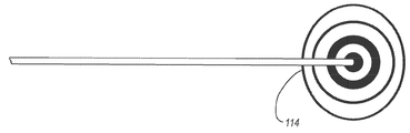
도 6 및 도 7a-7e는, TLS 센서(50)에 의한 탐침 자기 요소(106)의 검출을 나타내기 위해서 콘솔 디스플레이(30)에 의해 이용될 수 있는 아이콘의 예를 나타낸다. 특히, 도 6은, 자기 요소가 TLS 센서 아래에 위치해 있을 때, TLS 센서(50)에 의해 검출되는 것과 같은 자기 요소(106)를 포함하여 탐침(100)의 원위 부분을 나타내는 아이콘(114)을 보여준다. 탐침의 원위 단부(100B)가 카테터(72)의 원위 단부(76A)와 실질적으로 공통-말단적임에 따라, 아이콘은 카테터의 원위 단부의 위치 및 배향을 나타낸다. 도 7a-7e는, 탐침(100)의 자기 요소(106)가 TLS 센서(50)의 부분의 바로 아래에 위치되지 않으나, 그럼에도 불구하고 근처에서 감지될 때, 콘솔 디스플레이(30)에 표시될 수 있는 다양한 아이콘을 보여준다. 이러한 아이콘은 TLS 센서(50)에 대한 탐침의 자기 조립체, 즉, 본 실시예에서는 자기 요소(106)의 위치에 따라 디스플레이되는 절반-아이콘(114A) 및 1/4-아이콘(114B)을 포함할 수 있다.Figures 6 and 7A-7E illustrate examples of icons that may be used by the
도 8a-8c는 TLS 모드에 있는 동안 시스템(10)의 디스플레이(30)로부터 취한 스크린샷을 나타내며, 이것은 탐침(100)의 자기 조립체가 어떻게 표시되는지를 보여 준다. 도 8a의 스크린샷(118)은 TLS 센서(50)의 대표적인 이미지(120)를 보여준다. 깊이 스케일 표시기(124), 상태/작용 지표(126), 및 콘솔(20) 상에 포함된 버튼 인터페이스(32)에 상응하는 아이콘(128)을 포함한, 다른 정보가 디스플레이 스크린샷(118)에서 제공된다(도 8c). 본 실시예의 아이콘(128)은 버튼 인터페이스(32)의 상응하는 버튼의 목적을 식별하는 사용자를 유도하기 위한 단순한 지표이지만, 다른 실시예에서, 아이콘 자체가 버튼 인터페이스로서 기능할 수 있도록 그리고 시스템의 모드에 따라서 변화될 수 있도록, 디스플레이가 터치-감응형으로 제조될 수 있을 것이다. Figures 8A-8C show screen shots taken from the
삽입 후 환자의 맥관구조를 통한 카테터 진행의 초기 스테이지 중에, 실질적으로 공통-말단적인 탐침 원위 단부(100B)를 가지는, 카테터(72)의 원위 단부(76A)가 TLS 센서(50)로부터 비교적 거리를 두고 있다. 따라서, 디스플레이의 스크린샷은, 탐침의 자기 조립체로부터의 자기장이 검출되지 않았음을 나타내는 "신호 없음"을 표시할 것이다. 도 8b에서, 탐침의 원위 단부(100B)에 근접한 자기 조립체가, 아직 센서의 아래는 아니지만, 검출될 수 있을 정도로 충분히 TLS 센서(50)에 근접하여 진행하였다. 이는 이미지 센서(120)의 좌측의 절반-아이콘(114A)에 의해서 표시되고 있으며, 탐침 자기 조립체가 환자의 관점으로부터 TLS 센서(50)의 오른쪽에 위치된 것을 나타낸다.During the initial stage of catheter advancement through the patient's vasculature following insertion, the
도 8c에서, 탐침 원위 단부(100B)에 근접한 자기 조립체가 TLS 센서(50) 아래로 진행하였고, 그에 따라 TLS 센서(50)에 대한 상기 원위 단부의 위치 및 배향이 TLS 센서에 의해서 검출된다. 이는, 이미지 센서(120)의 아이콘(114)에 의해 나타나고 있다. 버튼 아이콘(128)이 콘솔 버튼 인터페이스(32)의 상응하는 버튼을 누름으로서 실시될 수 있는 작용의 표시를 제공한다는 것을 알 수 있을 것이다. 따라서, 버튼 아이콘(128)은 시스템(10)이 어떤 양상에 있는지에 따라서 변화될 수 있고, 그에 따라 버튼 인터페이스(32) 이용에 있어서의 융통성을 제공한다. 프로브(40)의 버튼 패드(82)(도 3a, 3b)가 버튼 인터페이스(32)의 몇 개의 버튼을 모방한 버튼(84)을 포함하기 때문에, 디스플레이(30) 상의 버튼 아이콘(128)은 의료진이, 멸균 필드에서 유지되는 동안, 프로브 버튼(84)으로 시스템(10)을 제어할 수 있게 하는 유도 기능을 제공한다는 것을 알 수 있을 것이다. 예를 들어, 만약 의료진이 TLS 모드를 떠나고 그리고 US(초음파) 모드로 복귀될 필요가 있다면, 프로브 버튼 패드(82) 상의 적절한 제어 버튼(84)이 눌려질 수 있고, 그리고 US 모드가 즉시 호출될 수 있으며, 디스플레이(30)는, 도 4에 도시된 바와 같이, US 기능에 필요한 가시적인 정보를 수용하도록 리프레싱(refreshing)한다. 이는, 의료진이 멸균 필드 외부에 도달할 필요가 없이 달성된다. 8C, a self-assembly proximate the probe
이제, 도 9 및 10을 참조하여 다른 예시적인 실시예에 따른 통합된 카테터 위치 시스템(10)을 설명한다. 이전과 마찬가지로, 통합된 시스템(10)은, 전술한 바와 같이, 콘솔(20), 디스플레이(30), US 기능을 위한 프로브(40), 및 선단부 위치확인 기능을 위한 TLS 센서(50)를 포함한다. 도 9 및 10에 도시된 시스템(10)은 여러 측면에서 도 1 및 2에 도시된 시스템과 유사하다는 것을 알 수 있을 것이다. 따라서, 선택된 차이만을 이하에서 설명할 것이다. 도 9 및 10의 시스템(10)은 환자(70) 굴심방(sino-atrial)("SA") 또는 심장의 다른 전기적 임펄스-방출 노드에 대한 카테터 원위 선단부(76A)의 근접도를 결정하는 부가적인 기능을 포함하며, 그에 따라 노드에 근접한 희망 위치에서 카테터 원위 선단부를 정확하게 위치할 수 있는 향상된 능력을 제공한다. 여기에서 "ECG" 또는 "ECG-기반 선단부 확인" 이라고도 지칭되는, 시스템(10)의 제 3 양상은, 카테터 원위 선단부를 환자의 맥관구조 내의 원하는 위치에 위치하기 위해서, SA 노드로부터 ECG 신호를 검출할 수 있게 한다. US, TLS 및 ECG 양상은 본 시스템(10)에서 매끄럽게 조합되고 그리고 협력적으로 또는 개별적으로 카테터 위치를 보조하기 위해서 채용될 수 있다는 것을 알 수 있을 것이다. An integrated
도 9 및 10은 본 실시예에 따라서 구성된 탐침(130)을 시스템(10)에 부가한 것을 도시한다. 개략적으로 설명하면, 카테터 탐침(130)은 삽입 사이트(73)를 통해서 환자(70) 내부로 삽입되는 카테터(72)의 루멘 내에 제거 가능하게 미리 배치된다. 탐침(130)은, 자기-기반의 TLS 양상을 위한 자기 조립체를 포함하는 것에 더하여, 그 원위 단부에 근접하고 그리고 SA 노드에 의해 생성된 ECG 신호를 감지하기 위한 카테터 선단부의 원위 단부와 공통-말단적인 부분을 포함하는 ECG 센서 조립체를 포함한다. 이전 실시예와 대조적으로, 탐침(130)은 TLS 센서(50)에 동작가능하게 연결되는 근위 단부로부터 연장되는 밧줄(134)을 포함한다. 보다 구체적으로 후술되는 바와 같이, 탐침 밧줄(134)은, ECG 신호-기판의 선단부 확인 양상의 일부로서의 카테터 선단부 위치 확인 중에 탐침(130)의 원위 부분 상에 포함된 ECG 센서 조립체에 의해서 검출된 ECG 신호가 TLS 센서(50)로 이송될 수 있도록 한다. 기준 및 접지 ECG 리드/전극 쌍(158)은 환자(70)의 신체에 부착되고 그리고 TLS 센서(50)에 동작가능하게 부착되어 시스템이 심장의 SA 노드의 전기적 활동과 관련되지 않은 높은 레벨의 전기적 활동을 필터링하여 제거할 수 있게 하며, 그에 따라 ECG-기반의 선단부 확인 기능을 가능하게 한다. 환자의 피부에 위치된 ECG 리드/전극 쌍(158)으로부터 수신된 기준 및 접지 신호와 함께, 탐침 ECG 센서 조립체에 의해서 감지된 ECG 신호가 환자의 가슴에 위치된 TLS 센서(50)에 의해서 수신된다(도 10). TLS 센서(50) 및/또는 콘솔 프로세서(22)는, 후술하는 바와 같이, 디스플레이(30) 상의 심전도 파형을 생성하기 위해서 ECG 신호 데이터를 프로세스할 수 있다. TLS 센서(50)가 ECG 신호 데이터를 프로세스하는 경우에, 의도된 기능을 수행하도록 프로세서가 내부에 포함된다. 만약 콘솔(20)이 ECG 신호 데이터를 프로세스한다면, 데이터를 프로세스하기 위해서 프로세서(22), 제어기(24) 또는 다른 프로세서가 콘솔에서 사용될 수 있다.Figures 9 and 10 illustrate the addition of the
따라서, 환자의 맥관구조를 통해서 진행함에 따라, 전술한 바와 같은 탐침(130)을 구비하는 카테터(72)가, 도 10에 도시된 바와 같이 환자의 흉부 상에 위치되는, TLS 센서(50) 아래로 진행할 수 있다. 이는, 환자의 맥관구조 내에 위치됨에 따라 카테터의 원위 선단부(76A)와 실질적으로 공통-말단적인, 탐침(130)의 자기 조립체의 위치를 TLS 센서(50)가 검출할 수 있게 한다. 탐침 자기 조립체의 TLS 센서(50)에 의한 검출은 ECG 모드 중에 디스플레이(30) 상에 표시된다. 디스플레이(30)는, ECG 모드 중에, 탐침(130)의 ECG 센서 조립체에 의해서 검출되는 바와 같은 환자 심장의 전기적 활동의 결과로서 생성되는 ECG 심전도 파형을 추가적으로 보여준다. 보다 상세하게, P-파의 파형을 포함하는, SA 노드의 ECG 전기적 활동은 탐침의 ECG 센서 조립체(후술함)에 의해 검출되고 그리고 TLS 센서(50) 및 콘솔(20)로 이송된다. 이어서, 디스플레이(30)에 표시하기 위해서 ECG 전기적 활동이 프로세스된다. 이어서, 카테터를 배치하는 의료진은, 일 실시예에서, SA 노드 근처와 같이, 카테터(72)의 원위 선단부(76A)의 최적 위치를 결정하기 위해서 ECG 데이터를 관찰할 수 있다. 일 실시예에서, 콘솔(20)은 탐침의 ECG 센서 조립체에 의해 검출된 신호를 수신 및 프로세스하기 위해서 필요한 프로세서(22)(도 9)와 같은 전자 구성요소를 포함한다. 다른 실시예에서, TLS 센서(50)가 ECG 신호를 프로세싱하는 필수 전자 구성요소를 포함할 수 있다.Thus, as the patient proceeds through the vasculature, a
이미 설명된 바와 같이, 카테터 위치 과정 중에 의료진에게 정보를 디스플레이하기 위해서 디스플레이(30)가 사용된다. 디스플레이(30)의 내용은 카테터 위치 시스템의 모드: US, TLS 또는 ECG에 따라서 변화된다. 3가지 모드 중 임의의 것이 의료진에 의해서 디스플레이(30) 상으로 즉각적으로 호출될 수 있고, 그리고 일부 경우에서, TLS 와 ECG와 같은 복수 모드로부터의 정보가 동시에 디스플레이될 수 있다. 일 실시예에서, 이전과 같이, 시스템의 모드가 핸드헬드 프로브(40)에 포함된 제어 버튼(84)에 의해 제어될 수 있고, 그에 따라 (콘솔(20)의 버튼 인터페이스(32)를 터치하는 것과 같이) 모드를 변경하기 위해서 의료진이 멸균 필드 밖에 도달할 필요성을 배제한다. 따라서, 본 실시예에서, 시스템(10)의 일부 또는 전부의 ECG-관련 기능을 제어하기 위해서 프로브(40)가 또한 채용된다. 버튼 인터페이스(32) 또는 다른 입력 구성이 또한 시스템 기능을 제어하기 위해서 사용될 수 있다는 것을 알 수 있을 것이다. 또한, 시각적 디스플레이(30)에 더하여, 부저, 신호음, 등과 같은 청각적 정보도 카테터 위치 중에 의료진을 보조하기 위해 시스템에 의해서 사용될 수 있다.As previously described, the
이제, 다음 도 11-12e를 참조하여, 카테터(72) 내로 제거가능하게 로딩되고 그리고 환자의 맥관구조 내의 희망 위치 내로 카테터의 원위 선단부(76A)를 위치하기 위한 삽입 중에 이용되는 탐침(130)의 일 실시예의 여러 가지 상세 내용을 설명한다. 도시된 바와 같이, 카테터로부터 제거됨에 따라 탐침(130)은 근위 단부(130A) 및 원위 단부(130B)를 규정한다. 커넥터(132)가 근위 쪽의 탐침 단부(130A)에 포함되고, 그리고 밧줄(134)이 커넥터로부터 원위 쪽으로 연장하고 그리고 핸들(136)에 부착된다. 코어 와이어(138)가 핸들(136)로부터 원위 쪽으로 연장한다. 일 실시예에서, 탐침(130)이 카테터(72)의 루멘 내에 미리-로딩되고, 그에 따라 원위 단부(130B)가 그 원위 단부(76A)에서 카테터 개구부와 실질적으로 같은 높이가 되거나 공통-말단적이 되고(도 10), 그에 따라 코어 와이어(138)의 근위 부분, 핸들(136), 및 밧줄(134)이 연장 튜브(74B) 중에서 선택된 하나의 튜브로부터 근위 쪽으로 연장한다. 비록 여기에서 탐침으로 설명되지만, 다른 실시예에서, 유도 와이어 또는 다른 카테터 유도 장치가 여기에서 설명된 실시예의 원리에 포함될 수 있다는 것을 주목하여야 할 것이다.Now, referring now to Figures 11-12e, a portion of the
코어 와이어(138)는 세장형 형상을 형성하고 그리고, 일 실시예에서, "니티놀(nitinol)"라는 줄임말로 일반적으로 공지된 니켈 및 티타늄-함유 합금과 같은 형상 기억 재료 또는 스테인리스 스틸을 포함하는 적합한 탐침 재료로 이루어진다. 비록 여기에서 도시하지는 않았지만, 일 실시예에서, 니티놀로 코어 와이어(138)를 제조하는 것은 탐침의 원위 세그먼트에 상응하는 코어 와이어의 부분이 미리-성형된 벤딩된 구성을 가질 수 있게 하고, 그에 따라 카테터(72)의 원위 부분을 유사하게 벤딩된 구성으로 가압할 수 있게 한다. 다른 실시예들에서, 코어 와이어는 미리-성형되지 않는다. 또한, 니티놀 구성에 의해서, 코어 와이어(138)에 대한 토크인가 가능성으로 인해서, 카테터(72)의 루멘 내에 배치되는 동안 탐침(130)의 원위 세그먼트가 조작될 수 있게 되고, 이는 다시 카테터의 원위 부분이 카테터 삽입 중에 맥관구조를 통해서 항해될 수 있게 한다.The
카테터(72)에 대한 탐침의 삽입/제거를 가능하게 하기 위해서 핸들(136)이 제공된다. 탐침 코어 와이어(138)가 토크를 인가할 수 있는 실시예에서, 환자(70)의 맥관구조를 통한 카테터 원위 부분의 항해를 보조하기 위해서, 핸들(136)은 추가적으로 코어 와이어가 카테터(72)의 루멘 내에서 회전될 수 있게 한다. A
핸들(136)은 밧줄(134)의 원위 단부에 부착된다. 본 실시예에서, 밧줄(134)은, 전술한 바와 같이 ECG 센서 조립체로서 작용하는 코어 와이어(138) 및 밧줄 커넥터(132) 모두에 전기적으로 연결된 하나 이상의 전도성 와이어를 수용하는 가요성의, 차폐된 케이블이다. 따라서, 밧줄(134)은 코어 와이어(138)의 원위 부분으로부터 탐침(130)의 근위 단부(130A)에서 밧줄 커넥터(132)를 통하는 전도성 경로를 제공한다. 이하에서 설명되는 바와 같이, 밧줄 커넥터(132)는, 카테터 원위 선단부(76A)가 환자 맥관구조 내의 희망 위치로 항해하는 것을 보조하기 위해서, 환자의 흉부 상의 TLS 센서(50)에 동작적으로 연결되도록 구성된다. The
도 12b-12d에 도시된 바와 같이, 코어 와이어(138)의 원위 부분이, 접합 지점(142)으로부터 원위 쪽으로, 점진적으로 테이퍼링되거나 또는 직경이 감소된다. 슬리브(140)가 감소된-직경의 코어 와이어 부분 위로 슬라이딩된다. 여기에서 비교적 큰 직경이지만, 다른 실시예에서, 슬리브가 탐침 코어 와이어의 근위 부분의 직경과 실질적으로 매칭되도록 크기가 결정될 수 있다. 탐침(130)은 TLS 모드 중의 사용을 위해서 원위 단부(130B)에 근접하여 배치된 자기 조립체를 더 포함한다. 설명된 실시예에서, 자기 조립체는 감소된-직경의 코어 와이어(138)의 외측 표면과 탐침 원위 단부(130B)에 근접한 슬리브(140)의 내측 표면 사이에 개재된 복수의 자기 요소(144)를 포함한다. 본 실시예에서, 자기 요소(144)는 도 2의 탐침(100)과 유사하게 단부-대-단부 방식으로 적층된 중실형의 원통형 형상의 20개의 강자성체 자석을 포함한다. 그러나, 다른 실시예에서, 자기 요소(들)가 형상뿐만 아니라, 조성, 수, 크기, 자기 타입, 및 탐침 내의 위치와 관련하여 이러한 디자인과 상이할 수 있을 것이다. 예를 들어, 일 실시예에서, 자기 조립체의 복수의 자석이 TLS 센서에 의한 검출을 위한 자기장을 생성하는 전자기 코일로 대체된다. 그에 따라, 이러한 그리고 다른 변경들이 본원 발명의 실시예에 의해서 고려된다. As shown in Figures 12b-12d, the distal portion of the
탐침 원위 단부(130B)의 위치가 환자의 흉부에 위치된 TLS 센서(50)에 대해서 관찰될 수 있도록, 자기 요소(144)가 탐침(130) 내에 채용된다. 전술한 바와 같이, 탐침이 환자의 맥관구조를 통해서 카테터(72)와 함께 진행함에 따라 자기 요소(144)의 자기장을 검출하도록 TLS 센서(50)가 구성된다. 이러한 방식에서, 카테터(72)를 위치하는 의료진은 환자의 맥관구조 내의 카테터 원위 단부(76A)의 위치를 대략적으로 결정할 수 있고 그리고, 예를 들어, 카테터가 원치 않는 정맥을 따라서 진행하는 것과 같이, 카테터의 위치이상이 발생하는 경우를 검출할 수 있다.A
일 실시예에 따라서, 탐침(130)은 전술한 ECG 센서 조립체를 더 포함한다. ECG 센서 조립체는, 삽입 중에 카테터(72)의 루멘 내에 배치되는 탐침(130)이 환자의 심장의 SA 또는 다른 노드에 의해서 생성되는 심방내(intra-atrial) ECG 신호를 검출하는데 있어서 채용될 수 있게 하며, 그에 의해서 환자의 심장에 근접한 맥관구조 내의 미리 결정된 위치로 카테터(72)의 원위 선단부(76A)가 항해하는 것을 허용할 수 있다. 따라서, ECG 센서 조립체는 카테터 원위 선단부(76A)의 적절한 위치를 확인하는데 있어서 보조장치로서의 역할을 한다. According to one embodiment, the
도 11-12e에 도시된 실시예에서, ECG 센서 조립체는 탐침 원위 단부(130B)에 근접하여 배치된 코어 와이어(138)의 원위 부분을 포함한다. 전기 전도성인 코어 와이어(138)는, 그 원위 단부에 의해서 ECG 신호가 검출될 수 있게 하고 그리고 코어 와이어를 따라서 근위 쪽으로 전송될 수 있게 한다. 전도성 에폭시와 같은 전도성 재료(146)가 코어 와이어(138)의 원위 말단부에 인접한 슬리브(140)의 원위 부분을 충진하며, 그에 따라 코어 와이어의 원위 단부와 전도적으로 소통하게 한다. 이는 다시 탐침(130)의 원위 단부(130B)의 전도성 표면을 증가시키고, 그에 따라 ECG 신호를 검출할 수 있는 능력을 향상시킨다. In the embodiment shown in Figures 11-12e, the ECG sensor assembly includes a distal portion of the
카테터 위치 이전에, 탐침(130)이 카테터(72)의 루멘 내로 로딩된다. 탐침(130)이 제조자로부터의 카테터 루멘 내에 미리 로딩될 수 있거나, 또는 카테터 삽입에 앞서서 의료진에 의해서 카테터 내로 로딩될 수 있다는 것을 주목하여야 할 것이다. 탐침(130)이 카테터 루멘 내에 배치되고, 그에 따라 탐침(130)의 원위 단부(130B)가 카테터(72)의 원위 선단부(76A)와 실질적으로 공통-말단적이 되며, 따라서 탐침 침 카테터 모두의 원위 선단부를 서로 실질적으로 정렬되게 위치한다. 카테터(72) 및 탐침(130)의 공통-말단성은, 전술한 바와 같이, 카테터 원위 선단부(76A)가 환자의 맥관구조 내에서 진행할 때, TLS 모드에서 자기 조립체가 TLS 센서(50)와 함께 카테터 원위 선단부(76A)의 위치를 트랙킹하는 기능을 할 수 있게 한다. 그러나, 시스템(10)의 선단부 확인 기능의 경우에, 탐침(130)의 원위 단부(130B)가 카테터 원위 단부(76A)와 공통-말단적일 필요가 없다는 것을 주목하여야 한다. 오히려, 요구되는 모든 것은, 환자의 심장의 SA 노드 또는 다른 노드의 전기적 임펄스가 검출될 수 있도록 맥관구조와 ECG 센서 조립체 사이의 전도성 경로(이러한 경우에, 코어 와이어(138))가 구축되는 것이다. 일 실시예에서, 이러한 전도성 경로가 실란 용액, 혈액, 등을 포함하는 여러 가지 성분을 포함할 수 있다.Prior to the catheter position, the
일 실시예에서, 카테터(72)가 삽입 사이트(73)(도 10)를 통해서 환자의 맥관구조 내로 일단 도입되면, 전술한 바와 같이, 카테터 원위 선단부(76A)가 SA 노드에 근접한 의도된 목적지를 향해서 진행되도록 시스템(10)의 TLS 모드가 채용될 수 있다. 심장 영역에 접근할 때, SA 노드에 의해서 방출되는 ECG 신호가 검출될 수 있도록, 시스템(10)이 ECG 모드로 전환될 수 있다. 탐침-로딩된 카테터가 환자의 심장을 향해서 진행함에 따라, 코어 와이어(138)의 원위 단부 및 전도성 재료(146)를 포함하는 전기 전도성 ECG 센서 조립체가 SA 노드에 의해서 생성된 전기적 임펄스를 검출하기 시작한다. 따라서, ECG 센서 조립체는 ECG 신호를 검출하기 위한 전극으로서의 역할을 한다. 코어 와이어 원위 단부에 근접한 세장형 코어 와이어(138)는, SA 노드에 의해서 생성되고 ECG 센서 조립체에 의해서 수신된 전기적 임펄스를 밧줄(134)로 이송하기 위한 전도성 경로로서의 역할을 한다. In one embodiment, once the
밧줄(134)은 ECG 신호를 환자의 흉부에 일시적으로 위치되는 TLS 센서(50)로 이송한다. 밧줄(134)은 밧줄 커넥터(132) 또는 다른 적합한 직접적 또는 간접적 연결 구성을 통해서 TLS 센서(50)로 동작적으로 연결된다. 설명한 바와 같이, 이어서, ECG 신호가 프로세스될 수 있고 그리고 시스템 디스플레이(30) 상에서 표시될 수 있다(도 9, 10). TLS 센서(50)에 의해서 수신되고 디스플레이(30)에 의해서 디스플레이되는 ECG 신호를 모니터링하는 것은, 의료진으로 하여금 카테터 원위 선단부(76A)가 SA 노드를 향해서 진행할 때 신호의 변화를 관찰 및 분석할 수 있게 한다. 수신된 ECG 신호가 희망하는 프로파일에 매칭될 때, 의료진은 카테터 원위 선단부(76A)가 SA 노드에 대한 희망 위치에 도달하였다는 것을 결정할 수 있다. 전술한 바와 같이, 일 실시예에서, 이러한 희망 위치는 SVC의 하부 삼분의 일(1/3) 부분 내에 놓인다. The
ECG 센서 조립체 및 자기 조립체가 협력하여, 의료진이 카테터를 맥관구조 내에 위치하는 것을 보조하는 역할을 할 수 있다. 일반적으로, 탐침(130)의 자기 조립체는, 일반적으로, 환자의 심장의 일반적인 영역 내에 카테터(72)의 원위 단부(76A)를 위치하기 위해서 의료진이 초기 카테터 삽입으로부터 맥관구조를 항해하는 것을 보조한다. 이어서, ECG 센서 조립체가 SA 노드에 접근할 때 심장에 의해서 생성되는 ECG 신호의 변화를 의료진이 관찰할 수 있게 함으로써, 카테터 원위 단부(76A)를 SVC 내의 희망 위치로 유도하기 위해서 ECG 센서 조립체가 채용될 수 있다. 다시, 적합한 ECG 신호 프로파일이 일단 관찰되면, 의료진은, 탐침(130) 및 카테터(72) 모두의 원위 단부가 환자의 심장에 대한 희망 위치에 도달하였다는 것을 결정할 수 있다. 희망하는 대로 일단 위치되면, 카테터(72)가 제 위치에서 고정될 수 있고 그리고 탐침(130)이 카테터 루멘으로부터 제거될 수 있을 것이다. 여기에서, 탐침이, 여기에서 명시적으로 설명한 것 이외에, 다양한 구성 중 하나를 포함할 수 있다는 것을 주목하여야 할 것이다. 일 실시예에서, 탐침이 TLS 센서를 통한 간접적인 부착 대신에 콘솔에 직접적으로 부착될 수 있다. 다른 실시예에서, TLS 및 ECG-관련 기능을 가능하게 하는 탐침(130)의 구조가 카테터 구조 자체 내로 통합될 수 있다. 예를 들어, 자기 조립체 및/또는 ECG 센서 조립체가, 일 실시예에서, 카테터의 벽 내로 통합될 수 있다. The ECG sensor assembly and the magnetic assembly may cooperate to assist the medical staff in positioning the catheter within the vasculature structure. Generally, the self-assembly of the
도 13a-15는, 본 실시예에 따른, 탐침 밧줄(134)로부터 환자의 흉부 상에 위치되는 TLS 센서(50)까지의 ECG 신호 데이터의 통과와 관련한 여러 가지 상세 내용을 도시한다. 특히, 이러한 실시예는 탐침(130) 및 밧줄(134)을 포함하는 카테터(72) 및 삽입 사이트(73) 주위의 멸균 필드, 및 TLS 센서가 상부에 위치되는 환자의 흉부와 같은 비-멸균 필드로부터의 ECG 신호 데이터의 통과와 관련된다. 그러한 통과는, 멸균성이 손상되지 않도록, 멸균 필드를 단절시키지 않아야 한다. 카테터 삽입 과정 중에 환자(70)의 상부에 위치되는 멸균 드레이프(drape)는 멸균 필드의 대부분을 형성하고; 드레이프 위의 지역이 멸균되는 반면, 그 아래의 지역(삽입 사이트 및 인접하여 둘러싸는 영역을 제외한다)은 비-멸균적이다. 확인되는 바와 같이, 이하의 설명은, ECG 신호 데이터가 사이에서 전달될 수 있게 하기 위해서 서로 동작적으로 연결되는, 적어도 탐침(130)과 연관된 제 1 통신 노드, 및 TLS 센서(50)와 연관된 제 2 통신 노드를 포함한다. 13A-15 show various details regarding the passage of ECG signal data from the
멸균 필드의 멸균성을 손상시키지 않고 멸균 필드로부터 비-멸균 필드로 ECG 신호 데이터를 통과시키는 것을 해결하는 하나의 실시예가 도 13a-15에 도시되어 있고, 그러한 도 13a-15는 "상어 지느러미" 구현예로서 또한 지칭되는 "드레이프-관통" 구현예를 도시한다. 특히, 도 14a는, 전술한 바와 같이, 카테터 삽입 과정 중에 환자의 흉부 상에 위치하기 위한 TLS 센서(50)를 도시한다. TLS 센서(50)는 그 상단부 표면 상에 커넥터 베이스(152)를 포함하고, 상기 커넥터 베이스는 3개의 전기 베이스 콘택(154)이 내부에 배치되는 채널(152A)을 형성한다. 도 13a-13d에 또한 도시된 지느러미 커넥터(156)는, 도 14b 및 15에 도시된 바와 같이, 커넥터 베이스(152)의 채널(152A)에 의해서 슬라이딩식으로 수용되도록 그 크기가 결정된다. 2개의 ECG 리드/전극 쌍(158)이, 어깨 또는 몸통 또는 환자의 신체 상의 다른 적합한 외부 위치에서의 위치를 위해서, 지느러미 커넥터(156)로부터 연장한다. 이하에서 추가적으로 설명하는 바와 같이, 탐침(130)으로부터 멸균 필드를 통해서 TLS 센서(50)까지의 전도성 경로를 완성하기 위해서, 드레이프-천공 밧줄 커넥터(132)가 지느러미 커넥터(156)의 부분과 슬라이딩식으로 짝을 이루도록 구성된다. One embodiment of solving the passing of ECG signal data from the sterilization field to the non-sterilization field without compromising the sterility of the sterilization field is shown in Figures 13A-15, which illustrate the "shark fin" Quot; drape-through "embodiment, also referred to as an example. In particular, Figure 14A illustrates a
도 13a-13d는 지느러미 커넥터(156)의 추가적인 양태를 도시한다. 특히, 지느러미 커넥터(156)는 커넥터 베이스(152)의 채널(152A) 내에 수용되도록 크기가 결정되는 하부 배럴 부분(160)을 형성한다(도 14b, 15). 중심 원뿔(164)에 의해서 둘러싸인 홀(162)이 상부 배럴 부분(166)의 후방 단부 상에 포함된다. 상부 배럴 부분(166)은 탐침(130)의 밧줄 커넥터(132)를 수용하도록 크기가 결정되고(도 14c, 15), 그에 따라 밧줄 커넥터(132)의 채널(172) 내로 연장하는 핀 콘택(170)(도 15)이, 지느러미 커넥터(156)의 홀(162) 내에 안착될 때까지, 센터링 홀에 의해서 유도되고, 그에 따라 밧줄 커넥터를 지느러미 커넥터와 상호연결한다. 도 13c 및 13d에 도시된 결합 특징부(169)와 같은 결합 특징부가 지느러미 커넥터(156) 상에 포함되어 밧줄 커넥터(132) 상의 상응하는 특징부와 결합할 수 있고, 그에 따라 2개의 구성요소들 사이의 짝맞춤을 유지하는 것을 보조할 수 있다. Figs. 13A-13D show additional aspects of the
도 13d는, 핀 커넥터(156)가 복수의 전기 콘택(168)을 포함하는 것을 도시한다. 이러한 실시예에서, 3개의 콘택(168)이 포함되고: 2개의 가장-전방의 콘택의 각각이 ECG 리드(158) 중 하나의 말단 단부와 전기적으로 연결되고 그리고 후방 콘택이 홀(162)의 축방향 근접부 내로 연장하여, 밧줄 커넥터(132)가 지느러미 커넥터(156)와 짝맞춤될 때(도 15), 밧줄 커넥터(132)의 핀 콘택(170)과 전기적으로 연결된다. 지느러미 커넥터(156)의 각각이 콘택(168)의 하단부 부분이 TLS 센서 커넥터 베이스(152)의 베이스 콘택(154) 중의 상응하는 하나와 전기적으로 연결되도록 위치된다. 13D illustrates that the
도 14b는 제 1 연결 스테이지를 도시하고, 그러한 스테이지에서 지느러미 커넥터의 하단부 배럴 부분(160)과 커넥터 베이스 채널(152A)의 슬라이딩 결합에 의해서, 지느러미 커넥터(156)가 TLS 센서 커넥터 베이스(152)와 제거가능하게 짝맞춤된다. 이러한 결합은 커넥터 베이스 콘택(154)을 상응하는 지느러미 콘택(168)과 전기적으로 연결시킨다.14B shows a first connection stage in which the
도 14c는 제 2 연결 스테이지를 도시하고, 그러한 스테이지에서 밧줄 커넥터 채널(172)과 지느러미 커넥터의 상부 배럴 부분(166)의 슬라이딩 결합에 의해서, 밧줄 커넥터(132)가 지느러미 커넥터(156)와 제거가능하게 짝맞춤된다. 이러한 결합은, 도 15에 도시된 바와 같이, 밧줄 커넥터 핀 콘택(170)을 지느러미 커넥터(156)의 후방 콘택(168)과 전기적으로 연결시킨다. 본 실시예에서, 지느러미 커넥터(156)에 대한 밧줄 커넥터(132)의 수평방향 슬라이딩 운동은, 지느러미 커넥터가 센서 커넥터 베이스 채널(152A)과 짝맞춤하기 위해서 슬라이딩될 때(도 14b)와 동일한 결합 방향이다. 일 실시예에서, 탐침(130)/밧줄 커넥터(132) 중 하나 또는 양자 모두 그리고 지느러미 커넥터(156)가 일회용일 수 있다(disposable). 또한, 일 실시예에서, 지느러미 커넥터가 TLS 센서와 짝맞춤된 후에 밧줄 커넥터가 지느러미 커넥터와 짝맞춤될 수 있는 한편, 다른 실시예에서, 지느러미 커넥터가 TLS 센서와 짝맞춤되기 전에 밧줄 커넥터가 먼저 수술용 드레이프를 통해서 지느러미 커넥터와 짝맞춤될 수 있다. Figure 14c illustrates a second connection stage in which the
도 14c에 도시된 체계(scheme)와 관련하여, 탐침(130)이 밧줄 커넥터(132)를 통해서 TLS 센서(50)에 동작적으로 연결되고, 그에 따라 탐침의 ECG 센서 조립체가 TLS 센서에 대해서 ECG 신호를 통신할 수 있게 된다. 또한, ECG 리드/전극 쌍(158)이 TLS 센서(50)에 동작적으로 연결된다. 일 실시예에서, 그에 따라, 밧줄 커넥터(132)가 탐침(130)에 대한 제 1 통신 노드로서 지칭되는 한편, 지느러미 커넥터(156)가 TLS 센서(50)에 대한 제 2 통신 노드로서 지칭된다.14c, the
탐침과 TLS 센서 사이의 동작가능한 통신을 구축하기 위해서 여러 가지 다른 연결 체계 및 구조가 채용될 수 있다는 것을 주목하여야 할 것이다. 예를 들어, 밧줄 커넥터가 드레이프를 천공하기 위한 핀 대신에 슬라이싱 콘택을 이용할 수 있다. 또는, 지느러미 커넥터가 TLS 센서와 일체로 형성될 수 있다. 그에 따라, 이러한 그리고 다른 구성이 본원 개시 내용의 실시예의 범위 내에 포함된다. It should be noted that various other connection schemes and structures may be employed to establish operable communication between the probe and the TLS sensor. For example, a tether connector may use a slicing contact instead of a pin to puncture the drape. Alternatively, the fin connector may be formed integrally with the TLS sensor. Accordingly, these and other configurations are within the scope of the embodiments of the present disclosure.
도 15에 도시된 바와 같이, 멸균 필드를 구축하기 위해서 카테터 위치 중에 이용되는 멸균 드레이프(174)가 밧줄 커넥터(132)와 지느러미 커넥터(156)의 상호연결부 사이에 개재된다. 바로 전에 설명한 바와 같이, 밧줄 커넥터(132)는, 2개의 구성요소가 짝맞춤될 때 드레이프(174)를 천공하도록 구성된 핀 콘택(170)을 포함한다. 이러한 천공은, 핀 콘택(179)에 의해서 점유되는 멸균 드레이프(174) 내에 작은 홀 또는 천공부(175)를 형성하며, 그에 따라 핀 콘택에 의한 드레이프 천공의 크기를 최소화한다. 또한, 핀 콘택(170)의 천공에 의해서 만들어지는 멸균 드레이프 내의 천공부가 밧줄 커넥터 채널(172)에 의해서 둘러싸이도록, 그에 따라 드레이프의 멸균성을 보존하고 그에 의해서 형성된 멸균 필드를 손상시킬 수 있는 드레이프 내의 누출(breach)을 방지하도록, 밧줄 커넥터(132)와 지느러미 커넥터(156) 사이의 피팅이 이루어진다. 핀 콘택(170)에 의한 천공에 앞서서 멸균 드레이프(174)를 아래로 접어서, 핀 콘택이 핀 커넥터(156)의 홀(162)에 근접하여 배치될 때까지 드레이프를 천공하지 않도록, 밧줄 커넥터 채널(172)이 구성된다. 여기에서, 밧줄 커넥터(132) 및 지느러미 커넥터(156)는, 불투명한 멸균 드레이프(174)를 통해서 보여지지 않는 즉, 양 구성요소의 의료진에 의한 시각적이지 않은 촉진(palpation)을 통한 그들 사이의 정렬을 돕도록, 구성된다는 것을 주목하여야 할 것이다. As shown in FIG. 15, a
도 15에 도시된 같은 핀 커넥터(156)의 핀 콘택(168)은, 핀 커넥터를 센서-기반 채널(152A)과 결합 상태로 유지하는 것을 보조하는 방식으로 센서-기반 콘택(154)과 짝맞춤하도록 구성된다는 것을 추가적으로 주목하여야 할 것이다. 이는 다시, 핀 커넥터(156)를 TLS 센서(50)에 고정하기 위한 추가 장치의 필요성을 저감한다. The
도 16은 P-파 및 QRS 복합부를 포함하는 전형적인 ECG 파형(176)을 도시한다. 일반적으로 P-파의 진폭은 파형(176)을 생성하는 SA 노드로부터의 ECG 센서 조립체의 거리의 함수로서 변화된다. 카테터 선단부가 심장 근처에 적절히 위치되는 때를 결정하는데 있어서, 의료진이 이러한 관계를 이용할 수 있다. 예를 들어, 하나의 구현예에서, 전술한 바와 같이, 카테터 선단부는 바람직하게는 상대대정맥의 하부 3 분의 1(1/3) 내에 바람직하게 위치된다. 탐침(130)의 ECG 센서 조립체에 의해 검출된 ECG 데이터는, ECG 모드 중에 시스템(10)의 디스플레이(30) 상에서의 표시를 위해서, 파형(176)과 같은 파형을 재생하기 위해서 사용된다.Figure 16 shows a
다음 도 17을 참조하여, 실시예에 따라, 시스템(10)이 ECG 모드, 즉 전술한 제 3의 양상일 때, 디스플레이(30) 상에서의 ECG 신호 데이터의 디스플레이 양태를 설명한다. 디스플레이(30)의 스크린샷(178)은, TLS 센서(50)의 대표 이미지(120)를 포함하여, TLS 양상의 요소를 포함하고, 그리고 환자의 맥관구조를 통한 이동 중에 탐침(130)의 원위 단부의 위치에 상응하는 아이콘(114)을 포함할 수 있다. 스크린샷(178)은 탐침(130)의 ECG 센서 조립체에 의해서 캡쳐된 그리고 시스템(10)에 의해서 프로세스된 현재의 ECG 파형이 디스플레이되는 윈도우(180)를 더 포함한다. 윈도우(180)는 새로운 파형이 감지될 때 지속적으로 리프레시된다.Referring next to Fig. 17, according to an embodiment, a display mode of the ECG signal data on the
윈도우(182)는 가장 최근에 검출된 ECG 파형의 연속적인 표시를 포함하고 또한 파형이 감지될 때 파형을 리프레시하기 위해서 측방향으로 이동된, 리프레시 바아(182A)를 포함한다. 윈도우(184A)는, 원하는 카테터 선단부 위치가 달성되는 때를 의료진이 결정하는 것을 보조하기 위한 비교 목적을 위해서, ECG 센서 조립체가 SA 노드의 근접지로 이동되기 전에 캡쳐된, 기준선 ECG 파형을 디스플레이하기 위해서 이용된다. 윈도우(184B 및 184C)는, 사용자가 프로브(40) 상의 또는 콘솔 버튼 인터페이스(32)의 미리 결정된 버튼을 누를 때, 사용자-선택된 검출된 ECG 파형에 의해서 파일링될(filed) 수 있다. 윈도우(184B 및 184C)의 파형은, 버튼 누름 또는 다른 입력을 통한 사용자의 선택의 결과로 새로운 파형에 의해 덮어 쓰여질 때까지 유지된다. 이전 모드에서와 같이, 깊이 스케일(124), 상태/작동 지표(126), 및 버튼 아이콘(128)이 디스플레이(30) 상에 포함된다. ECG 리드/전극 쌍(158)이 TLS 센서(50)에 동작가능하게 연결되어 있는지의 여부를 나타내기 위해서, 무결성(integrity) 표시부(186)가 또한 디스플레이(30)에 포함된다.
따라서, 앞선 내용으로부터 확인할 수 있는 바와 같이, 디스플레이(30)는, 일 실시예에서, 하나의 화면에서 TLS 및 ECG 양상 모두의 요소를 동시에 보여주고, 그에 따라 의료진에게 카테터 원위 선단부를 원하는 위치에 위치하는 것을 보조하기 위한 풍부한 데이터를 제공할 수 있다. 일 실시예에서, 적절한 카테터 위치를 문서화할 수 있도록, 스크린샷 또는 선택된 ECG 또는 TLS 데이터의 출력물이 시스템(10)에 의해서 저장, 인쇄 또는 다른 방법으로 보존될 수 있다는 것을 주목하여야 할 것이다. Thus, as can be seen from the foregoing, the
여기에서 설명된 실시예가 PICC 또는 CVC와 같은 카테터의 특별한 구성에 관한 것이지만, 이러한 실시예는 단지 예시적인 것이다. 따라서, 본원 발명의 원리가 많은 상이한 구성 및 디자인의 카테터로 확장될 수 있다.
While the embodiment described herein is directed to a particular configuration of a catheter, such as a PICC or CVC, this embodiment is merely illustrative. Thus, the principles of the present invention can be extended to many different configurations and designs of catheters.
II. 바늘/의료용 구성요소를 위한 보조 유도II. Auxiliary induction for needles / medical components
여기에서 설명된 본원 발명의 실시예는 일반적으로, 예를 들어, 환자의 피하 혈관으로 바늘을 접근시키기 위한 초음파-기반의 또는 다른 적합한 과정 중에 바늘 또는 다른 의료 구성요소를 위치확인 유도하는 유도 시스템에 관한 것이다. 일 실시예에서, 유도 시스템은 바늘의 위치, 배향 및 진행이 혈관의 초음파 이미지에 실시간으로 중첩되게 할 수 있고, 따라서 의료진이 의도된 표적까지 바늘을 정확하게 유도하게 할 수 있다. 또한, 일 실시예에서, 유도 시스템은 x, y, z의 공간적 좌표의 공간, 바늘 피치(pitch), 및 바늘 요(yaw)의 5개의 운동 자유도에서의 바늘의 위치를 트랙킹한다. 그러한 트랙킹은, 바늘이 비교적 높은 정밀도로 유도되고 위치될 수 있게 한다.Embodiments of the invention as described herein are generally directed to an induction system for positioning a needle or other medical component during, for example, an ultrasound-based or other suitable procedure for approximating a needle to a subcutaneous vein of a patient . In one embodiment, the guidance system can cause the position, orientation, and progression of the needle to be superimposed on the ultrasound image of the blood vessel in real time, thereby allowing the medical personnel to accurately guide the needle to the intended target. Further, in one embodiment, the guidance system tracks the position of the needle in the spatial coordinates of x, y, z, the needle pitch, and the five degrees of freedom of movement of the needle yaw. Such tracking allows the needle to be guided and positioned with relatively high precision.
먼저, 본원 발명의 일 실시예에 따라 구성된, 전체적으로 '1110'로 표시된, 초음파-기반의 바늘 유도 시스템("시스템")의 다양한 구성요소를 도시한, 도 18 및 19를 참조한다. 도시된 바와 같이, 시스템(1110)은 일반적으로, 이하에서 추가적으로 각각 설명된, 콘솔(1120), 디스플레이(1130) 및 프로브(1140)를 포함하는 초음파("US") 이미징 부분을 포함한다. 시스템(1110)은, 일 실시예에서, 일부 구성요소에 대해 도 1에서 도시한 시스템(10)과 유사성을 가진다는 것을 주목하여야 할 것이다. 그러나, 그러한 초음파 이미징 부분은 여기에서 도시되고 설명된 것에 외에도 여러 가지 방법 중 하나로 구성될 수 있다는 것을 주목하여야 할 것이다. 18 and 19, which illustrate various components of an ultrasound-based needle guidance system ("system"), generally designated as 1110, constructed in accordance with an embodiment of the present invention. As shown, the
시스템(1110)의 초음파 이미징 부분은 표적에 접근하기 위하여 바늘 또는 기타 장치를 경피 삽입하기 전에 환자의 신체 내의 표적으로 하는 부분을 이미지화하기 위해서 채용된다. 이하에서 설명되는 바와 같이, 일 실시예에서, 바늘의 삽입은 환자의 정맥 또는 맥관구조의 다른 부분 내로 카테터를 후속하여 삽입하기 전에 실시된다. 그러나, 환자의 신체 내로 바늘을 삽입하는 것은 다양한 의료적 목적을 위해서 실시될 수 있다는 것을 이해하여야 할 것이다. The ultrasound imaging portion of the
도 19는, 일 실시예에 따른, 피부 삽입 사이트(1173)를 통해 환자 맥관구조 내로 카테터(1172)를 최종적으로 위치하기 위한 과정 중에 환자(1170)에 대한 전술한 구성요소들의 일반적인 관계를 나타낸다. 도 19는, 위치가 완료된 후에, 카테터(1172)가 환자의 외부에서 유지되는 근위 부분(1174) 및 환자 맥관구조 내에 존재하는 원위 부분(1176)을 포함하는 것을 나타낸다. 시스템(1110)은 환자 맥관구조 내의 원하는 위치에 카테터(1172)의 원위 선단부(1176A)를 최종적으로 위치하기 위해서 채용된다. 일 실시예에서, 카테터 원위 선단부(1176A)에 대한 희망 위치는, 상대대정맥("SVC")의 하부 삼분의 일(1/3) 부분과 같은, 환자의 심장 근위부이다. 물론, 시스템(1110)이 다른 위치에 카테터 원위 선단부를 위치하기 위해서 이용될 수 있다. Figure 19 illustrates the general relationship of the aforementioned components to a
카테터 근위 부분(1174)은 카테터(1172)의 하나 이상의 루멘들 사이의 유체 소통을 제공하는 허브(1174A), 및 상기 허브에서 근위 쪽으로 연장하는 하나 이상의 연장 다리(1174B)를 더 포함한다. 전술한 바와 같이, 삽입 사이트(1173)에서 환자 맥관구조 내에 바늘을 위치하는 것은 전형적으로 카테터 삽입 전에 실행되지만, 다른 위치 방법도 채용될 수 있다는 것을 이해할 수 있을 것이다. 또한, 위의 설명은 시스템(1110) 사용의 단지 하나의 예라는 것을 이해할 수 있을 것이고; 실제로, 전술한 바와 같은 카테터 삽입의 준비로서의 바늘 위치, 다른 용도를 위한 바늘의 삽입, 또는 x-선 또는 초음파 마커, 생검 시스(sheaths), 절제 구성요소, 방광 스캐닝 구성요소, 대정맥 필터, 등을 포함하는, 환자의 신체 내로 다른 의료용 구성요소를 삽입하기 위한 것과 같이, 다양한 용도를 위해서 채용될 수 있다. The catheter
구체적으로 설명하면, 콘솔(1120)은 시스템(1110)의 다양한 구성요소를 수용하고, 그리고 콘솔이 다양한 형태 중 하나를 취할 수 있다는 것을 이해할 수 있을 것이다. 예를 들어, EEPROM과 같은 비-휘발성 메모리를 포함하는 프로세서(1122)는 시스템(1110)의 동작 중에 시스템 기능을 제어하고 그리고 여러 가지 알고리즘을 실행하기 위해서 콘솔(1120) 내에 포함되고, 그에 따라 제어 프로세서로 작동한다. 디지털 제어기/아날로그 인터페이스(1124)가 또한 콘솔(1120)에 포함되고 그리고 프로브(1140) 및 다른 시스템 구성요소 사이의 인터페이싱을 통제하기 위해서 프로세서(1122) 및 다른 시스템 구성요소 모두와 통신한다.In particular, it will be appreciated that the
시스템(1110)은 프린터, 저장 매체, 키보드 등을 포함하는 선택적인 구성요소(1154)와 같은 부가적인 구성요소와의 연결을 위한 포트(1152)를 추가적으로 포함한다. 일 실시예에서, 포트가 USB 포트이지만, 이러한 인터페이스 연결 및 여기에서 설명된 다른 인터페이스 연결을 위해서 다른 포트 타입 또는 포트 타입의 조합이 이용될 수 있다. 외부 전원(1158)에 대한 동작가능한 연결을 가능하게 하기 위해서, 전원 연결부(1156)가 콘솔(1120)에 포함된다. 외부 전원과 함께 또는 외부 전원 없이, 내부 배터리(1160)가 또한 채용될 수 있다. 전력 사용 및 분배를 조정하기 위해서, 전력 관리 회로망(1159)이 콘솔의 디지털 제어기/아날로그 인터페이스(1124)에 포함된다.The
본 실시예의 디스플레이(1130)는 콘솔(1120)에 일체화되어 있고 그리고, 프로브(1140)에 의해서 얻어진 표적이 된 내부 신체 부분의 초음파 이미지와 같은, 정보를 위치 과정 중에 의료진에게 디스플레이하기 위해서 이용된다. 다른 실시예에서, 디스플레이가 콘솔로부터 분리될 수 있을 것이다. 일 실시예에서, 콘솔 버튼 인터페이스(1132) 및 프로브(1140)에 포함되는 제어 버튼(1184)(도 19)이, 위치 과정을 지원하기 위해서, 디스플레이(1130)로 희망 모드를 즉각적으로 요청하기 위해서 의료진에 의해서 이용될 수 있다. 일 실시예에서, 디스플레이(1130)가 LCD 장치이다.The
도 19는 삽입 사이트(1173)를 통한 환자 맥관구조에 대한 초기 접근을 획득하기 위해서 이용되는 바늘(1200)을 추가적으로 도시한다. 이하에서 더 구체적으로 설명되는 바와 같이, 초음파-기반의 위치 과정 중에 바늘의 위치, 배향 및 진행을 시스템이 검출할 수 있게 하는데 있어서, 바늘(1200)이 시스템(1110)과 협력하도록 구성된다. FIG. 19 additionally illustrates a
도 20은 일 실시예에 따른 프로브(1140)의 특징부를 보여준다. 프로브(1140)는, 바늘(1200) 및/또는 카테터(1172)를 맥관구조 내로 삽입하기 위한 준비 중에, 정맥과 같은 혈관의 초음파-기반의 가시화와 관련하여 채용된다. 이러한 가시화는 실시간 초음파 유도를 실시간으로 제공하고 그리고 부주의로 인한 동맥 천공, 혈종, 기흉 등을 포함하는, 그러한 도입과 전형적으로 연관되는 합병증을 감소시키는 데 도움을 준다. FIG. 20 shows a feature of a
핸드헬드 프로브(1140)는 예상되는 삽입 사이트(1173)(도 19)에 근접한 환자의 피부에 대해서 헤드가 놓일 때, 초음파 펄스를 생성하고 그리고 환자의 신체에 의한 반사 후 그 반향을 수신하기 위한 압전 어레이를 수용하는 헤드(1180)를 포함한다. 프로브(1140)는 시스템을 제어하기 위한 복수의 제어 버튼(1184)(도 19)을 더 포함하고, 그에 따라 시스템(1110)을 제어하기 위해서, 삽입 사이트의 구축에 앞서서 환자의 삽입 사이트 주위에 구축된 멸균 필드의 외부에 의료진이 도달하여야 할 필요성을 배제한다. The
따라서, 일 실시예에서, 의도된 목적지를 향한 맥관구조를 통한 카테터의 최종적인 진행을 위한 카테터(1172)의 도입에 앞서서, 바늘(1200)을 이용하는 것과 같이, 적절한 삽입 사이트를 결정하고 맥관 접근을 구축하기 위해서 시스템(1110)의 초음파 이미징 부분을 의료진이 채용한다. Thus, in one embodiment, prior to introducing the
도 18은 프로브(1140)가 버튼 및 프로브 동작을 통제하기 위한 버튼 및 메모리 제어기(1142)를 더 포함한다는 것을 보여준다. 일 실시예에서, 버튼 및 메모리 제어기(1142)는 EEPROM 과 같은 비-휘발성 메모리를 포함할 수 있다. 버튼 및 메모리 제어기(1142)는 콘솔(1120)의 프로브 인터페이스(1144)와 동작가능하게 통신하며, 상기 프로브 인터페이스(1144)는 프로브 압전 어레이와 인터페이스하기 위한 압전 입/출력 구성요소(1144A), 그리고 버튼 및 메모리 제어기(1142)와 인터페이스하기 위한 버튼 및 메모리 입/출력 구성요소(1144B)를 포함한다.18 shows that probe 1140 further includes a button and a memory controller 1142 for controlling button and probe operation. In one embodiment, the button and memory controller 1142 may include non-volatile memory such as an EEPROM. Button and memory controller 1142 are operably in communication with a probe interface 1144 of the
도 20에 도시된 바와 같이, 프로브(1140)는, 전술한 바와 같은, 초음파 이미징 과정 중에 바늘(1200)의 위치, 배향 및 이동을 검출하기 위한 센서 어레이(1190)를 포함한다. 이하에서 더 구체적으로 설명하는 바와 같이, 센서 어레이는 프로브의 하우징 내에 내장된 복수의 자기 센서(1192)를 포함한다. 센서(1192)는 바늘(1200)과 연관된 자기장을 검출하고 그리고 시스템(1110)이 바늘을 트랙킹하는 것을 허용하도록 구성된다. 여기에서 자기 센서로 구성되어 있지만, 센서(1192)는, 후술하는 바와 같이, 다른 타입 및 구성의 센서일 수 있다. 또한, 도 20에서 프로브(1140)에 포함되는 것으로 도시되어 있지만, 센서 어레이(1190)의 센서(1192)는, 분리된 핸드헬드 장치와 같이, 프로브로부터 분리된 구성요소 내에 포함될 수 있다. 본 실시예에서는, 센서(1192)는 프로브(1140)의 상단부 면(1182) 아래에서 평면형 구성으로 배치되어 있지만, 그러한 센서가 아치형 또는 반원형의 배열과 같은 다른 구성으로 배열될 수 있다는 것을 이해할 수 있을 것이다. As shown in FIG. 20, the
본 실시예에서, 센서(1192)의 각각은 3개의 공간적 차원으로 자기장을 검출할 수 있게 하기 위한 3개의 직교 센서 코일을 포함한다. 이러한 3차원적("3D") 자기 센서는, 예를 들어, Honeywell Sensing and Control 사(미국 뉴저지주 모리스 타운에 소재함)으로부터 구입할 수 있다. 또한, 본 실시예의 센서(1192)는 Hall-효과 센서로 구성되어 있지만, 다른 종류의 자기 센서도 채용될 수 있다. 또한 1D, 2D 또는 3D 탐지 기능을 달성하기 위해서, 3D 센서 대신에, 복수의 1차원적인 자기 센서가 필요에 따라 포함되거나 배열될 수 있다. In this embodiment, each of the
본 실시예에서, 5개의 센서(1192)가 센서 어레이(1190)에 포함되고, 그에 따라 바늘(1200)의 검출이 3개의 공간 차원(즉, X, Y, Z 좌표 공간) 뿐만 아니라, 바늘 자체의 피치 및 요 배향으로도 가능해진다. 일 실시예에서, 센서(1192) 중 둘 이상의 직교하는 감지 구성요소는 자기 요소(1210)의, 그에 따라 바늘(1200)의 피치 및 요 자세(attitude)를 결정하게 할 수 있다는 것을 주목하여야 할 것이다. In this embodiment, five
다른 실시예에서, 보다 적은 또는 보다 많은 센서가 센서 어레이에서 채용될 수 있다. 더 일반적으로, 센서 어레이의 센서의 수, 크기, 타입 및 위치가 여기에 명시적으로 제시된 것과 다를 수 있다는 것을 이해할 수 있을 것이다. In other embodiments, fewer or more sensors may be employed in the sensor array. More generally, it will be appreciated that the number, size, type, and location of the sensors in the sensor array may be different from those explicitly stated herein.
도 21a 및 21b는, 일 실시예에 따라, 도 19에 도시된 바와 같이, 환자의 표적된 내부 신체 부분으로 접근하는데 있어서 유도 시스템(1110)과 관련하여 사용될 수 있는 바늘(1200)의 하나의 예를 상세하게 도시한다. 특히 바늘(1200)은, 근위 단부(1202A) 및 원위 단부(1202B)를 규정하는, 중공형 캐뉼라(1202)를 포함한다. 본 실시예에서, 허브(1204)는 캐뉼라(1202)의 근위 단부(1202A)에 부착되고 그리고 여러 장치와의 연결을 위한 커넥터로서 구성되는 개방 단부(1204A)를 포함한다. 실제로, 허브(1204)의 개방 단부(1204A)는 유도 와이어, 탐침, 또는 다른 구성요소가 허브를 통해서 캐뉼라 내로 들어가도록 중공형 캐뉼라(1202)와 소통된다. 21A and 21B illustrate one example of a
도 21a 및 21b에 도시된 바와 같이, 자기 요소(1210)가 허브(1204)에 포함된다. 도 21b에 가장 잘 도시된 바와 같이, 본 실시예에서, 자기 요소(1210)는 예를 들어 강자성체를 포함하는 영구 자석이며, 그리고 중공형 캐뉼라(1202)와 정렬되는 홀(1212)을 형성하기 위한 링-형상을 가진다. 이렇게 구성되면, 자기 요소(1210)는, 이하에서 추가적으로 설명되는 바와 같이, 바늘(1200)의 위치, 배향 및 이동을 시스템(1110)이 트랙킹할 수 있도록 하기 위해서, 초음파 프로브(1140)의 센서 어레이(1190)에 의해서 검출가능한 자기장을 생성한다.As shown in FIGS. 21A and 21B,
다른 실시예에서, 많은 다른 타입, 수 및 크기의 자석 요소가 바늘(1200) 또는 다른 의료 구성요소와 함께 채용될 수 있고, 그에 따라, 본 유도 시스템에 의한 트랙킹을 가능하게 할 수 있다는 것을 이해할 수 있을 것이다. It will be appreciated that in other embodiments, many different types, numbers, and sizes of magnet elements can be employed with the
이제, 표적이 되는 내부 신체 부분에 대한 접근을 위해서 환자의 피부 표면(1220)을 통한 삽입을 위해서 제 위치에 있고 그리고 준비된 시스템(1110)의 초음파 프로브(1140) 및 바늘(1200)을 도시하는 도 22a 및 22b를 참조한다. 특히, 환자의 피부에 대해서 위치되고 그리고 환자 피부 표면(1220) 아래의 혈관(1226)의 일부를 초음파적으로 이미지화하기 위해서 초음파 비임(1222)을 생성하는 프로브(1140)의 헤드(1180)와 함께 프로브(1140)가 도시되어 있다. 혈관(1226)의 초음파 이미지가 시스템(1110)의 디스플레이(1130) 상에 표시될 수 있다(도 19).Now, for purposes of accessing the targeted internal body part, a view showing the
전술한 바와 같이, 본 실시예의 시스템(1110)은 전술한 바늘(1200)의 위치, 배향 및 이동을 검출하도록 구성되어 있다. 특히, 프로브(1140)의 센서 어레이(1190)는 바늘(1200)에 포함된 자기 요소(1210)의 자기장을 검출하도록 구성된다. 센서 어레이(1190)의 센서(1192)의 각각은 3차원적인 공간에서 자기 요소(1210)를 공간적으로 검출하도록 구성된다. 따라서 시스템(1110)의 동작 중에, 센서(1192)의 각각에 의해 감지되는 바늘의 자기 요소(1210)의 자기장 강도 데이터가, 자기 요소(1210) 위치 및/또는 배향을 실시간으로 연산하는 콘솔(1120)(도 18)의 프로세서(1122)와 같은 프로세서로 전달된다.As described above, the
구체적으로, 그리고 또한 도 22a 및 22b에 도시된 바와 같이, 센서 어레이(1190)에 대한 X, Y 및 Z 좌표 공간 내의 자기 요소(1210)의 위치가 센서(1192)에 의해 감지된 자기장 강도 데이터를 이용하여 시스템(1110)에 의해 결정될 수 있다. 또한 도 22a가 자기 요소(1210)의 피치가 또한 결정될 수 있다는 것을 보여주는 한편, 도 22b는 자기 요소의 요가 결정될 수 있는 것을 보여 준다. 시스템의 프로브(1140), 콘솔(1120), 또는 다른 구성요소의 바람직한 회로망은 그러한 위치/배향에 대한 필요한 계산을 제공할 수 있다. 일 실시예에서, 미국 특허 제 5,775,322 호; 제 5,879,297 호; 제 6,129,668 호; 제 6,216,028 호; 및 제 6, 263,230 호 중 하나 이상의 교시 내용을 이용하여 자기 요소(210)를 트랙킹할 수 있다. 상기 미국 특허의 내용은 그 전체가 참조에 의해 여기에 포함된다.Specifically, and as also shown in FIGS. 22A and 22B, the position of the
시스템이 알고 있는 또는 시스템으로 입력되는 바와 같은 원위 바늘 선단부에 대한 자기 요소(1210)의 위치 및 캐뉼라(1202)의 길이와 함께, 시스템(1110)에 의해서 결정되는 상기 위치 및 배향 정보는, 시스템으로 하여금 센서 어레이(1190)에 대한 바늘(1200)의 전체 길이의 위치 및 배향을 정확하게 결정할 수 있게 한다. 선택적으로, 자기 요소(1210)와 원위 바늘 선단부 사이의 거리가 알려져 있거나 또는 시스템(1110)으로 입력된다. 이는 다시, 시스템(1110)으로 하여금 바늘(1200)의 이미지를 프로브(1140)의 초음파 비임(1222)에 의해서 생성된 이미지에 중첩시킬 수 있게 한다. 구체적으로, 도 23a 및 23b는 초음파 이미지 상에서의 바늘의 그러한 중첩의 예를 도시한다. 구체적으로, 도 23a 및 23b는 각각, 예를 들어, 디스플레이(1130)(도 19)에 표시될 수 있는 스크린샷(1230)을 보여준다. 도 23a에서, 환자의 피부 표면(1220) 및 피하 혈관(1226)의 도면과 함께, 초음파 이미지(1232)가 표시되어 있다. 초음파이미지(1232)는, 예를 들어, 도 22a 및 22b에 도시된 초음파 비임(1222)에 의해서 획득된 이미지에 상응한다. The position and orientation information determined by the
스크린샷(1230), 전술한 바와 같이, 시스템(1110)에 의해 결정된 바와 같은 실제 바늘(1200)의 위치 및 배향을 나타내는 바늘 이미지(1234)를 추가적으로 보여준다. 시스템이 센서 어레이(1190)에 대해서 바늘(1200)의 위치 및 배향을 결정할 수 있기 때문에, 시스템은 초음파 이미지(1232)에 대한 바늘(1200)의 위치 및 배향을 정확하게 결정할 수 있고 그리고 디스플레이(1130) 상의 바늘 이미지(1234)로서의 표시를 위해서 중첩시킬 수 있다. 초음파 이미지(1232) 상의 바늘 이미지(1234)의 위치 조정은 프로세서(1122) 또는 시스템(1110)의 다른 적합한 구성요소에 의해서 실행되는 적합한 알고리즘에 의해 실시된다.
센서(1192)는 시스템(1110)의 동작 중에 바늘(1200)의 자기 요소(1210)의 자기장을 연속적으로 검출하도록 구성된다. 이는, 시스템(1110)으로 하여금 디스플레이(1130)에 표시하기 위한 바늘의 이미지(1234)의 위치 및 배향을 지속적으로 업데이트할 수 있게 한다. 따라서, 바늘(1200)의 진행 또는 다른 이동이 디스플레이(1130) 상의 바늘 이미지(1234)에 의해서 실시간으로 표시된다. 프로브(1140) 및 바늘(1200)의 이동이 위치 과정 또는 다른 활동 중에 발생될 때, 시스템(1110)이 디스플레이(1130) 상에서 초음파 이미징(1232) 및 바늘 이미지(1234) 모두를 지속적으로 업데이트할 수 있다는 것을 주목하여야 할 것이다. The
도 23a는, 일 실시예에서, 바늘 이미지(1234)에 의해 표시되는 같은 바늘(1200)의 현재 위치 및 배향을 기초로 투영된 경로(1236)를 시스템(1110)이 보여줄 수 있다는 것을 추가적으로 도시한다. 투영된 경로(1236)는, 디스플레이(1130) 상의 바늘 이미지(1234)에 의해 나타나는 것과 같은 바늘(1200)의 현재 배향이, 여기에서 도시된 혈관(1226)과 같은, 희망하는 내부 신체 부분 표적에 결과적으로 도달할 것인지의 여부를 결정하는데 있어서 의료진을 보조한다. 다시, 바늘 이미지(1234)의 배향 및/또는 위치가 변화됨에 따라, 투영된 경로(1236)는 그에 따라 시스템(1110)에 의해서 수정된다. 투영된 경로(1236)가 초음파 이미지(1232)의 평면과 교차하는 지점을 나타내는 표적(1238)이 또한 시스템(1110)에 의해서 디스플레이(1130) 상에 표시될 수 있다. 도 23a에 도시된 바와 같이, 본 예에서, 표적(1238)은 초음파 이미지(1232)에 표시된 혈관(1226) 내부에 위치된다. 바늘(1200) 및/또는 초음파 이미지(1232)가 조정됨에 따라, 디스플레이(1130) 상의 표적(1238)의 위치가 또한 수정될 수 있다는 것을 주목하여야 할 것이다. 스크린샷(1230)은 또한, 여기에서 상자로 표시된, 확률(probability) 영역(1239)을 포함하고, 그러한 확률 영역은 바늘 길이, 바늘 강성도, 및 유연성, 자기 요소의 자기장 강도, 자기 간섭, 자기 요소의 자기 축과 바늘의 길이방향 축의 정렬에서의 가능한 불일치, 초음파 이미징 평면에 대한 센서 어레이의 배향, 등으로 인한 시스템의 임의의 가능한 오차의 여분(margin)을 나타낸다.23A additionally shows that, in one embodiment, the
도 23b는 초음파 이미지(1232) 및 바늘 이미지(1234)가 3 차원적인 양태로 디스플레이되게끔 배향되도록, 스크린샷(1230)이 구성될 수 있다는 것을 도시한다. 이는, 바늘 이미지(1234)에 의해 표시된 바와 같이, 바늘(1200)의 각도 및 배향이 확인될 수 있게 하고 그리고 초음파 이미지(1232)에 의해 이미지화된 의도된 표적과 비교할 수 있게 한다. 스크린샷(1230)은 디스플레이를 위해서 시스템(1110)에 의해 생성된 가능한 표시내용의 단순한 예라는 것을 주목하여야 할 것이고; 사실상 다른 가시적인 표시도 이용될 수 있다. 또한, 이미지화되는 신체의 특별한 지역이 단순한 예이고; 시스템은 다양한 신체 부분을 초음파적으로 이미지화하기 위해서 이용될 수 있고, 그리고 첨부 도면에서 명시적으로 도시된 것으로 제한되지 않아야 한다는 것을 주목하여야 할 것이다. 또한, 여기에서 도시되고 설명된 바와 같은 시스템은, 필요한 경우에, 더 큰 시스템의 구성요소로 포함될 수 있고, 또는 독립형 장치로 구성될 수 있다. 또한, 가시적인 디스플레이(1130)에 더하여, 부저, 신호음, 등과 같은 청각적 정보도 바늘을 환자 내에 위치 및 삽입하는 동안 의료진을 보조하기 위해서 시스템(1110)에 의해서 채용될 수 있다는 것을 이해할 수 있을 것이다. Figure 23B illustrates that screen shot 1230 can be configured such that
전술한 바와 같이, 일 실시예에서, 도 23a 및 23b의 스크린샷(1230)의 바늘 이미지(1234) 및 다른 특징의 정확한 표시를 가능하게 하기 위해서, 시스템(1110)이 바늘(1200)의 전체 길이 및 바늘 상의 자기 요소(1210)의 위치를 알아야 할 필요가 있다. 이러한 및/또는 다른 관련 매개변수가, 바늘 상에 포함된 또는 바늘에 포함된 바코드를 시스템이 스캐닝하는 것, 시스템에 의한 스캐닝을 위해서 무선주파수 식별("RFID") 칩을 바늘에 포함시키는 것, 바늘의 색채 코딩, 의료진이 시스템으로 매개변수를 수작업으로 입력하는 것, 등을 포함하는, 다양한 방식으로 시스템(1110)으로 통지될 수 있다. 예를 들어, RFID 칩(1354)이 도 33a에 도시된 바늘(1200) 상으로 포함된다. 바늘(1200)의 타입 또는 길이, 등과 같이 RFID 칩(1354) 상에 포함되는 정보를 판독하기 위해서, 프로브(1140) 또는 시스템(1110)의 다른 구성요소가 RFID 판독기를 포함할 수 있다. 그에 따라, 바늘 매개변수를 시스템(1110)으로 입력하기 위한 또는 매개변수를 검출하기 위한 이러한 그리고 다른 수단이 고려된다. As described above, in one embodiment, in order to enable accurate display of the
일 실시예에서, 바늘의 길이(또는 의료용 구성요소의 다른 양태)가, 자기 요소의 자기장의 강도와 같은, 자기 요소의 특성에 대한 프로브/시스템에 의한 측정에 의해서 결정될 수 있다. 예를 들어, 일 실시예에서, 바늘의 자기 요소가 프로브로부터 미리 결정된 거리에 또는 프로브에 대한 미리 결정된 위치에 위치될 수 있다. 그렇게 위치된 자기 요소에서, 프로브의 센서 어레이가 자기 요소의 자기장 강도를 검출 및 측정한다. 시스템은 측정된 자기장 강도를 바늘의 상이한 길이에 상응하는 가능한 자기장 강도의 저장된 리스트와 비교할 수 있다. 시스템은 2개의 강도를 매칭시킬 수 있고 그리고 바늘 길이를 결정할 수 있다. 바늘 위치 및 후속하는 바늘 삽입이 여기에서 설명된 바와 같이 진행될 수 있다. 다른 실시예에서, 미리 결정된 위치에서 자기 요소를 정지적으로 홀딩하는 대신에, 자기 요소가 프로브 주위로 이동될 수 있고, 그에 따라 복수의 자기장 강도 판독값이 프로브에 의해서 취해질 수 있다. 자기 요소의 세트로 상이한 자기장 강도를 부여하도록 수정될 수 있는 양태들이 자기 요소의 크기, 형상 및 조성 등을 포함한다. In one embodiment, the length of the needle (or other aspect of the medical component) may be determined by a probe / system measurement of the characteristics of the magnetic element, such as the strength of the magnetic field of the magnetic element. For example, in one embodiment, the magnetic element of the needle can be positioned at a predetermined distance from the probe or at a predetermined position relative to the probe. In the magnetic element so positioned, a sensor array of probes detects and measures the magnetic field strength of the magnetic element. The system may compare the measured magnetic field strength to a stored list of possible magnetic field strengths corresponding to different lengths of needles. The system can match the two intensities and determine the needle length. The needle position and subsequent needle insertion can proceed as described herein. In another embodiment, instead of pinpointing the magnetic element at a predetermined position, the magnetic element can be moved around the probe, and thus a plurality of magnetic field strength readings can be taken by the probe. Aspects that can be modified to give different magnetic field strengths to a set of magnetic elements include the size, shape and composition of the magnetic element, and the like.
여기에서, 일 실시예에 따라, 환자의 표적화된 내부 신체 부분("표적")의 초음파 이미징과 관련하여 바늘 또는 다른 의료용 장치를 유도하는데 있어서 시스템(1110)을 사용하는 것과 관련한 추가적인 상세 내용을 설명한다. 자기 요소-구비형 바늘(1200)이 센서 어레이(1190)를 포함하는 초음파 프로브(1140)로부터 적절한 거리(예를 들어, 2 피트 이상)에 위치된 상태에서, 시스템(1110)의 디스플레이(1130) 상에서의 표시를 위해서, 경피적 삽입을 통해서 바늘이 교차하도록 의도된 환자 내의 표적을 초음파적으로 이미지화하기 위해서 프로브가 채용된다. 이어서, 시스템(1110의 교정이 개시되고, 이때 과정이 실시될 곳에 인접한 곳의 임의 주위 자기장에 대한 기준선을 결정하기 위해서 콘솔(1120)의 프로세서(1122)에 의해서 알고리즘이 실행된다. 전술한 바와 같이, 예를 들어 사용자 입력, 자동 검출, 또는 다른 적합한 방식에 의해서, 바늘(1200)의 전체 길이 및/또는 원위 바늘 선단부에 대한 자기 요소의 위치에 관한 정보가 또한 시스템(1110)으로 전달된다. Here, according to one embodiment, additional details regarding the use of
이어서, 프로브(1140)의 센서 어레이(1190)의 센서(1192)의 범위 내로 바늘(1200)이 이동된다. 센서(1192)의 각각은 바늘(1200)의 자기 요소(1210)와 연관된 자기장 강도를 검출하고, 상기 데이터는 프로세서(1122)로 전달된다. 일 실시예에서, 이러한 데이터는 프로세서에 필요하게 될 때까지 메모리에 저장될 수 있다. 센서(1192)가 자기장을 검출함에 따라, 프로브와 관련된 공간에서 예측되는 지점에서의 바늘(1200)의 자기 요소(1210)의 자기장 강도를 계산하기 위해서, 적합한 알고리즘이 프로세서(1122)에 의해서 실행된다. 이어서, 프로세서(1122)는 센서(1192)에 의해 검출된 실제 자기장 강도 데이터를 계산된 자기장 강도 값과 비교한다. 이러한 프로세스는 위에 나열된 미국 특허에 의해 더 설명된다는 것을 주목하여야 할 것이다. 이러한 프로세스는 예측되는 지점에 대한 계산 값이 측정된 데이터와 매칭될 때까지 반복적으로 실시될 수 있다. 이러한 매칭이 일단 발생하면, 자기 요소(1210)는 3차원적인 공간 내에서 위치결정되어 위치된다. 센서(1192)에 의해서 검출된 자기장 강도 데이터를 사용하여, 자기 요소(1210)의 피치 및 요(즉, 배향)도 결정될 수 있다. 바늘(1200)의 알려진 길이 및 자기 요소에 대한 바늘의 원위 선단부의 위치와 함께, 이는, 바늘의 위치 및 배향에 관한 정확한 표상을 시스템(1110)이 만들어 낼 수 있게 하고, 그리고 디스플레이(1130) 상에서 가시적인 모델로서 즉, 바늘 이미지(1234)로서 표시될 수 있게 한다. 일 실시예에서, 예측된 값과 실제 검출된 값은, 시스템(1110)으로 하여금 바늘 표시를 할 수 있게 위한 미리 결정된 공차 또는 신뢰 레벨 내에서 반드시 매칭되어야 한다는 것을 주목하여야 할 것이다. The
전술한 바와 같은 바늘(1200)의 가상 바늘 이미지(1234)의 표시는, 본 실시예에서, 디스플레이(1130)의 초음파 이미지(1232) 상에 바늘 이미지를 중첩시키는 것에 의해서 실시된다(도 23a, 23b). 프로세서(1122) 또는 다른 적합한 구성요소에 의해서 실행될 때, 시스템(1110)의 적합한 알고리즘은 추가적으로, 투영된 경로(1236), 표적(1238) 및 확률 영역(1239)(도 23a, 23b)이 결정될 수 있게 하고 그리고 디스플레이(1130) 상에서 표적의 초음파 이미지(1232) 위에서 볼 수 있게 한다. 바늘(1200)의 이동을 실시간으로 트랙킹하기 위해서, 상기 예측, 감지, 비교 및 표시 프로세스가 반복적으로 실시된다.The display of the
전술한 내용에 비추어 볼 때 그리고 도 24를 참조하면, 일 실시예에서, 바늘 또는 다른 의료용 구성요소를 유도하기 위한 방법(1240)이 다양한 스테이지를 포함한다. 스테이지(1242)에서, 환자의 표적화된 내부 신체 부분이, 예를 들어 초음파 이미징 장치와 같은, 이미징 시스템에 의해 이미지화된다.In view of the foregoing and with reference to FIG. 24, in one embodiment, a
스테이지(1244)에서, 바늘과 같은 의료용 구성요소의 검출가능한 특성이 이미징 시스템에 포함된 하나 이상의 센서에 의해 감지된다. 본 실시예에서, 바늘의 검출가능한 특성은 바늘(1200)에 포함된 자기 요소(1210)의 자기장이며, 센서는 초음파 프로브(1140)에 포함된 센서 어레이(1190) 내에 포함되는 자기 센서이다.At
스테이지(1246)에서, 표적화된 내부 신체 부분에 대한 의료용 구성요소의 위치는 검출가능한 특성의 감지를 통해 적어도 2개의 공간 차원에서 결정된다. 앞서 설명된 바와 같이, 그러한 결정은 콘솔(1120)의 프로세서(1122)에 의해서 본 실시예에서 이루어진다. At
스테이지(1248)에서, 의료용 구성요소의 위치를 나타내는 이미지는 디스플레이 상에서의 표시를 위해서 표적화된 내부 신체 부분의 이미지와 조합된다. 스테이지(1250)는, 예를 들어, 혈관(1226)(도 23a, 23b)을 향한 바늘(1200)의 피하 삽입과 같이, 이미지화된 표적에 대한 의료용 구성요소의 진행 또는 다른 이동을 나타내기 위해서 스테이지(1244-1248)가 반복적으로 되풀이될 수 있다는 것을 보여준다. At
프로세서(1122) 또는 다른 적합한 구성요소가, 디스플레이(1130) 상에서 표시하기 위한 확률 지역(1239) 및 표적(1238)(도 23a, 23b)을 포함하여, 추가적인 양태를 계산할 수 있다는 것을 이해할 수 있을 것이다. It will be appreciated that the processor 1122 or other suitable component may calculate additional aspects, including a
일 실시예에서, 센서 어레이는 초음파 이미징 장치로 본래부터 통합될 필요 는 없지만, 다른 방식으로 포함될 수 있다는 것을 이해할 수 있을 것이다. 도 25는, 이러한 것의 하나의 예를 도시하며, 여기에서 센서 어레이(1190)의 센서(1192)를 포함하는 부착가능한 센서 모듈(1260)이 초음파 프로브(1140)에 부착되어 설치된 것으로 도시되어 있다. 이러한 구성에 의해서, 여기에서 설명된 같은 바늘 유도가 표준 초음파 이미징 장치, 즉 초음파 프로브에 통합된 센서 어레이 또는 전술한 바와 같이 바늘을 위치확인 및 트랙킹하도록 구성된 프로세서 및 알고리즘을 포함하지 않는 장치와 관련하여 달성될 수 있게 된다. 따라서, 일 실시예의 센서 모듈(1260)은 바늘 또는 다른 의료 구성요소를 위치확인하고 트랙킹하기에 적합한 그리고 초음파 이미지 상에서의 중첩을 위해서 바늘의 가상 이미지를 디스플레이 상에서 표시하기에 적합한 프로세서 및 알고리즘을 포함한다. 일 실시예에서, 센서 모듈(1260)은 바늘의 트랙킹의 표시를 위한 모듈 디스플레이(1262)에 포함될 수 있다. 따라서, 유도 시스템의 이러한 그리고 다른 구성이 고려된다.In one embodiment, it will be appreciated that the sensor array need not be inherently integrated with the ultrasound imaging device, but may be included in other ways. 25 shows an example of such an arrangement in which an
도 26은, 일 실시예에서, 이미 설명된 바와 같이, 시스템(1110)에 의해 실행되는 초음파 이미징 및 바늘 유도 과정 중에 바늘(1200)을 홀딩하고 진행시키기 위해서 바늘 홀더가 채용될 수 있다는 것을 도시한다. 도시된 바와 같이, 바늘 홀더(1270)는 권총-형상이고 그리고 트리거를 눌렀을 때 홀더의 배럴로부터 길이방향으로 멀리 바늘을 이동시키는 것에 의해서 바늘(1200) 또는 다른 적합한 의료용 구성요소를 선택적으로 진행시키기 위한 트리거(1272)를 포함한다. 이렇게 구성될 때, 바늘 홀더(1270)는, 의료진이 한 손으로 바늘을 핸들링하는 것을 용이하게 하는 한편, 다른 한 손으로 초음파 프로브(1140)를 파지하고 조작하는 것을 도울 수 있다. 또한, 바늘 홀더(1270)는 모터, 래쳇팅(ratcheting), 유압/공압 구동기, 등을 통해서 바늘의 이동/회전을 보조할 수 있다. 또한, 바늘(1200)의 원위 선단부의 배향을 결정하는 것을 보조하고 바늘의 회전을 돕기 위해서, 클록킹(clocking) 특징이 바늘 홀더(1270) 상에 포함될 수 있다. 26 illustrates that, in one embodiment, a needle holder may be employed to hold and advance the
일 실시예에서, 바늘 캐뉼라(1202)의 원위 단부(1202B)가 표적화된 내부 신체 부분에 도달할 때 또는 바늘이 초음파 평면을 가로막을 때(intercept) 바늘 홀더에 의한 진행이 자동적으로 중단되도록, 바늘 홀더(1270)가 시스템(1110)에 동작적으로 연결될 수 있다. 또 다른 실시예에서, 자기 요소가 바늘 자체 대신에 바늘 홀더에 포함될 수 있다. 따라서, 바늘이 바늘 홀더 일시적으로 부착될 때, 그러한 바늘은, 자기 요소가 바늘에 직접적으로 부착될 필요가 없이, 유도 시스템에 의해서 위치되고 유도될 수 있다. In one embodiment, so that the
도 27 및 28은 다른 실시예에 따른 유도 시스템(1110)의 구성요소를 도시하며, 여기에서 바늘 트랙킹 및 유도를 가능하게 하기 위해 프로브(1140)와 바늘(1200) 사이의 광학적-기반의 상호작용이 채용된다. 특히, 프로브(1140)는 LED(1280)와 같은 광학적/광 공급원, 및 프로브 표면 상에 위치된 광 검출기(1282)를 포함한다. 광 공급원 및 검출기는 가시 광선, 적외선 등을 포함하는 다양한 범위의 광 신호를 생성하고 검출하도록 구성될 수 있다는 것을 이해할 수 있을 것이다. 27 and 28 illustrate components of an
바늘 허브(1204)는 LED(1280)에 의해서 생성되고 입사되는 광을 반사할 수 있는 반사 표면(1286)을 포함한다. 도 28에 도시된 바와 같이, LED(1280)에 의해서 방출되는 광은 바늘(1200) 상의 반사 표면(1286)에 의해 반사되고, 반사된 광의 일부는 광 검출기(1282)에 의해서 수신되고 감지된다. 이전 실시예와 같이, 광 검출기(1282)의 감지된 데이터를 수신하고 바늘(1200)의 위치 및/또는 배향을 계산하기 위해서, 시스템 콘솔(1120)의 프로세서(1122)가 채용될 수 있다. 전술한 바와 같이, 바늘(1200)의 길이 및/또는 바늘(1200)의 원위 단부에 대한 반사 표면의 위치가 시스템(1110)으로 입력되거나 다른 방법으로 검출될 수 있거나 알려진다. 반사 표면이 바늘의 다른 위치에 포함될 수 있다는 것을 주목하여야 할 것이다. The
상기에 비추어 볼 때, 본 실시예에서, 바늘(1200)의 검출가능한 특성은, 이전 실시예의 자기 요소(1210)의 자기장 특성과 대조적으로, 반사 표면(1286)의 반사성을 포함하고, 그리고 센서는, 이전 실시예의 자기 센서(1192)와 대조적으로, 광 검출기(1282)를 포함한다. 일 실시예에서, 상기 설명된 구성이 반대가 될 수 있고, 이때 광학적 공급원은 바늘 또는 의료용 구성요소에 포함된다는 것을 이해할 수 있을 것이다. 이러한 경우에, 광은 바늘로부터 방출되고 그리고 프로브(1140)에 포함된 광 검출기(1282)에 의해 감지되며, 그에 따라 바늘의 위치 및 트랙킹이 가능하게 된다. 바늘의 광 공급원에 전력을 공급하기 위해서, 시계용 배터리 등과 같은 전원이 바늘에 포함될 수 있다. In view of the above, in this embodiment, the detectable characteristics of the
보다 일반적으로, 바늘 또는 의료용 구성요소가, 환자의 신체 내의 표적을 향해 바늘이 트랙킹되고 유도될 수 있게 하는 이러한 또는 다른 검출가능 특성 중 하나 이상을 포함할 수 있다는 것을 이해할 수 있을 것이다. 다른 검출가능 특성 양상의 비제한적인 예에는, 전자기 또는 무선주파수("RF")(예를 들어, 이하의 도 29-30 참조), 및 방사선(radioactivity)이 포함된다. RF 양상에 대해서, 적합한 센서(들)에 의해서 검출될 수 있도록, 하나 이상의 동기화된 또는 비동기식 펄스형 주파수 공급원이 바늘에 포함될 수 있다는 것을 이해할 수 있을 것이다. 또는 제 1 RF 공급원이 제 2의 공급원으로서의 수동적 자석과 커플링될 수 있다.More generally, it will be appreciated that a needle or a medical component may include one or more of these or other detectable characteristics that enable the needle to be tracked and guided towards a target within the patient's body. Non-limiting examples of other detectable characteristics aspects include electromagnetic or radio frequency ("RF") (see, e.g., Figures 29-30 below), and radioactivity. It will be appreciated that for RF aspects, one or more synchronized or asynchronous pulsed frequency sources may be included in the needles so that they can be detected by suitable sensor (s). Or a first RF source may be coupled with a passive magnet as a second source.
도 29 및 30은 실시예에 따른 유도 시스템의 구성요소를 도시하며, 여기에서는 바늘 트랙킹 및 유도를 가능하게 하기 위해서, 프로브(1140)와 바늘(1200) 사이의 EM 신호 상호작용이 채용된다. 특히, 도 29에서, 바늘(1200)은 내부에 배치된 탐침(1298)을 포함한다. 탐침(1298)은 밧줄(1292)을 통해서 프로브(1140)에 동작가능하게 연결되는 EM 코일(1290)을 포함한다. 이러한 방식에서, EM 코일(1290)은 동작 중에 EM 코일이 EM 신호를 방출하도록 프로브(1140) 또는 시스템 콘솔(1120)에 포함되는 적절한 구성요소에 의해 구동될 수 있다.29 and 30 illustrate the components of an induction system according to an embodiment in which EM signal interaction between the
탐침(1298)의 EM 코일(1290)에 의해서 방출되는 EM 신호를 검출하기에 적합한 센서(1294)가 프로브(1140) 내에 포함된다. 본 실시예에서, 센서(1294)는 EM 신호의 상응하는 직교 성분을 검출하기 위한 3-축 센서이지만, 다른 코일 및 센서 구성도 또한 채용될 수 있다. 이렇게 구성되면, 바늘(1200)의 위치 및 배향이 EM 신호 삼각측량 또는 다른 적합한 프로세스에 의해서 결정될 수 있고, 그리고 이미 전술한 것과 유사한 방식으로 시스템에 의해서 디스플레이될 수 있다. 이전 실시예와 마찬가지로, EM 센서(1294)의 감지된 데이터를 수신하고 바늘(1200)의 위치 및/또는 배향을 연산하기 위해서 시스템 콘솔(1120)(도 18)의 프로세서(1122)가 채용될 수 있다. 전술한 바와 같이, 바늘(1200)의 길이 및/또는 바늘(1200)의 원위 단부에 대한 EM 코일(1290)의 위치가 시스템에 입력되거나 시스템이 다른 방법으로 검출할 수 있거나 알 수 있다.A
도 30은 도 29의 EM 구성의 변경예를 도시하며, 여기에서 EM 구성요소의 각각의 위치가 반전되고; EM 코일(1290)이 프로브(1140) 내에 포함되고 그리고 EM 센서(1294)가 바늘(1200)에 배치된 탐침(1298)에 포함된다. 도 29 및 30의 실시예에서, 밧줄(1292)을 통한 EM 코일(1290) 및 EM 센서(1294) 사이의 동작 가능한 연결을 통해서, 탐침(1298)에 배치된 구성요소가 시스템(1110)에 의해서 구동될 수 있다는 것을 주목하여야 할 것이다. 이는 또한, 특별한 EM 주파수/EM 코일(1290)에 의해 방출되고 EM 센서(1294)에 의해서 검출되는 주파수의 상응(correspondence)을 가능하게 한다. 일 실시예에서, 도 29에 표시된 구성이 변경될 수 있고, 여기에서 밧줄이 EM 코일 및 EM 센서와 작동가능하게 연결되지 않고; 오히려, 탐침의 EM 코일이 프로브 및 그 EM 센서와 분리된 구성요소로서 동작하고 그리고 배터리와 같은 독립적인 전원에 의해 전력 공급된다. 이러한 경우에, 프로브/시스템은 EM 코일에 의해서 방출되는 EM 신호를 검출하도록 그리고 그것을 바늘의 위치확인에 필요한 바에 따라서 프로세스하도록 구성된 적합한 신호 프로세싱 구성요소를 포함한다.FIG. 30 shows a modification of the EM configuration of FIG. 29, wherein each position of the EM component is reversed; An
EM 코일 및 EM 센서가 여기에 표시된 것과 다른 위치에 포함될 수 있다는 것을 주목하여야 할 것이다. 예를 들어, EM 코일이 바늘 자체에, 또는 바늘의 근위 단부에 부착될 수 있는 커넥터에 포함될 수 있다. It should be noted that the EM coils and the EM sensor may be included at different positions than those shown here. For example, an EM coil can be included in the needle itself or in a connector that can be attached to the proximal end of the needle.
도 31a-31d는 일 실시예에 따라 구성된 바늘(1200)의 추가적인 상세 내용을 제공하고, 여기에서 바늘은 허브(1304)를 포함하고, 상기 허브로부터 캐뉼라(1202)가 연장한다. 홀(1312)을 형성하는 자기 요소(1310)가 하우징(1314)의 공동(1314A) 내에 포함된다. 바늘 허브(1304) 또는 바늘이나 의료용 구성요소의 다른 적합한 구성요소에 나사식으로 결합되도록, 하우징(1314)이 나사산을 포함한다. 이러한 방식에서, 자기 요소(1310)는 하우징(1314)을 통해서 바늘(1200)에 제거가능하게 부착될 수 있다. 따라서, 자기 요소(1310)가 바늘(1200)에 영구적으로 고정되거나 포함될 필요가 없고, 오히려 자기-기반의 바늘 유도가 더 이상 필요하지 않을 때 바늘로부터 제거될 수 있다. 또한, 이는, 자기 요소가 많은 다양한 바늘의 타입과 크기로 부착될 수 있게 한다. 본 실시예에서, 바늘을 환자로부터 제거하였을 때 바늘의 원위 선단부를 안전하게 격리시키기 위해서, 바늘(1200)이 원위 쪽으로 슬라이딩 가능한 바늘 안전 구성요소(1320)를 더 포함한다는 것을 주목하여야 할 것이다. 여기에서 도시되고 설명된 것 이외의, 다른 제거가능한 자기 요소가 채용될 수 있다는 것을 또한 주목하여야 할 것이다.FIGS. 31A-31D provide additional detail of a
도 32-33b는 자기 요소를 포함하는 바늘(1200)의 추가적인 예를 제공한다. 도 32에서, 2개의 막대-유사 자기 요소(1340)가 바늘(1200)의 허브(1334)로부터 직교 방향으로 연장하도록 배치되고, 자기 요소가 바늘의 길이방향 축에 대해서 평행하게 배향될 필요가 없다는 것을 보여준다. 도 33a-33b에서, 4개의 자석 요소(1350)가 바늘 허브(1344) 내에 포함되어, 하나 초과의 자기 요소가 바늘에 포함될 수 있다는 것을 보여준다. 그러한 구성은, 예를 들어, 제한된 공간으로 인해서 하나의 자기 요소를 사용할 수 없는 경우에 채용될 수 있을 것이다. 여기에서 자기 요소의 수, 형상, 및 위치가 많은 가능한 구성의 단지 하나의 예라는 것을 주목하여야 할 것이다.Figures 32-33B provide additional examples of
도 34a-34g는 바늘의 캐뉼라를 관통 수용하기 위한 홀을 형성하는 자기 요소(1360)의 여러 가지 예시적인 구성을 제공한다. 정사각형(도 34a), 육각형(도 34b), 삼각형(도 34c), 직사각형(도 34d), 달걀 모양(도 34e), 팔각형(도 34f) 및 4-면 피라미드형(도 34g)을 포함하는, 자기 요소(1360)에 대한 여러 가지 형상 구성이 도시되어 있다. 첨부 도면에 도시된 자기 요소는, 그러한 자기 요소를 규정하기 위해서 이용될 수 있는 많은 수의 기하형태적 및 다른 형상들의 단순한 예이고; 실제적으로, 여기에서 명시적으로 제시되지 않은 다른 형상이 또한 고려된다.Figures 34A-34G provide several exemplary configurations of
도 35-37은 여기에서 설명된 유도 시스템과 함께 이용하기 위한 구성요소 길이 측정 시스템과 관련한 여러 가지 상세 내용을 설명한다. 여기에서 설명된 바와 같이, 상기 유도 시스템은, 예를 들어, 환자의 피하 혈관으로 바늘을 접근시키기 위한 초음파-기반의 또는 다른 적합한 과정 중에 바늘 또는 다른 의료용 구성요소를 위치확인하고 유도하기 위해서 채용된다. 일 실시예에서, 유도 시스템은, 바늘의 위치, 배향, 및 진행이 혈관의 초음파 이미지의 상단에 실시간으로 중첩될 수 있게 하고, 그에 따라 의료진으로 하여금 의도된 표적으로 바늘을 정확하게 유도할 수 있게 한다. 또한, 일 실시예에서, 유도 시스템은 5개의 운동 범위(degree): x, y, 및 z의 공간적 좌표 공간, 바늘 피치, 및 바늘 요로 바늘의 위치를 트랙킹한다. 그러한 트랙킹은 비교적 높은 정확도로 바늘이 유도되고 위치될 수 있게 한다. 유도 시스템(1110)의 여러 가지 상세 내용이 도 18 및 19 등과 관련하여 전술되어 있다. 35-37 illustrate several details relating to a component length measurement system for use with the guidance system described herein. As described herein, the guidance system is employed to locate and guide a needle or other medical component during, for example, an ultrasound-based or other suitable procedure for approximating the needle to the subcutaneous blood vessel of the patient . In one embodiment, the guidance system allows the position, orientation, and progression of the needle to be superimposed in real time on top of the ultrasound image of the blood vessel, thereby allowing the physician to accurately guide the needle to the intended target . Further, in one embodiment, the guidance system tracks the spatial coordinate space of five motion degrees: x, y, and z, the needle pitch, and the position of the needle urinary needle. Such tracking allows the needle to be guided and positioned with relatively high accuracy. Various details of the
전술한 바와 같이, 시스템(1110)에 의해서 결정된 위치 및 배향 정보는, 시스템에 대한 입력에 의해서 또는 시스템이 알고 있는 바늘(1200)의 길이 및 바늘 캐뉼라(1202)의 원위 선단부(1202B)에 대한 자기 요소(1210)의 위치와 함께, 시스템으로 하여금 센서 어레이(1190)에 대한 바늘(1200)의 전체 길이의 위치 및 배향을 정확하게 결정할 수 있게 한다. 본 실시예에 따라서, 바늘의 길이가 이하에서 설명되는 본 바늘 길이 결정 시스템에 의해서 신속하고 용이하게 결정될 수 있고, 그에 따라 유도 시스템에 의한 바늘의 정확한 트랙킹을 허용한다. The position and orientation information determined by the
전술한 내용에 비추어, 바늘(1200)의 길이를 결정하기 위한 바늘 길이 결정 시스템(1500)이 여기에서 설명된다. 특히, 시스템(1500)의 구성요소가 도 35에 도시되어 있고, 도 35는 또한 프로브(1140), 그 센서 어레이(1190), 바늘(1200), 및 자기 요소(1210)와 같은 유도 시스템(1110)의 많은 구성요소도 도시하고 있다. In light of the foregoing, a needle
구체적으로, 헤드 부분(1180) 근처에서 프로브(1140)에 부착되어 도시된, 바늘 유지 고정구(1510)가 포함된다. 바늘 유지 고정구(1510)는, 도 35에 도시된 바와 같이, 센서 어레이(1190)가 내부에 배치된 평면과 캐뉼라(1202)가 미리 결정된 각도(θ)를 형성하도록, 바늘(1200)의 원위 부분을 내부에 제거가능하게 수용하도록 구성된 채널 또는 다른 적합한 개구부를 포함한다. 본 실시예에서, 센서(1192)의 어레이(1190)가 센서 보드(1522) 상에 배치되고 그에 따라 센서 보드가 센서의 평면을 형성하는 것으로 간주될 수 있다. Specifically, a
도 36a-36c는 일 실시예에 따른 바늘 유지 고정구(1510)의 여러 가지 상세 내용을 도시하며, 여기에서 고정구는 바늘 유도 조립체(1516)에 포함된다. 도시된 바와 같이, 바늘 유지 고정구(1510)는, 바늘 캐뉼라(1202)가 통과하여 수용되는 개방된 근위 단부(1512A), 및 폐쇄된 원위 단부(1512B)를 포함하는 채널(1512)로서 구현된다. 채널(1512)은, 유도 채널(1518)을 자체적으로 포함하는 바늘 유도 조립체(1516)의 상단부 면 상에 배치된다. 도 37은, 캐뉼라의 원위 단부(1202B)가 채널의 폐쇄된 원위 단부(1512B)에 근접하여 배치되도록 채널(1512) 내로 수용되는 바늘 캐뉼라(1202)의 원위 부분을 도시한다. 도 35의 바늘(1200)은 채널(1512) 내에 유사하게 배치되고, 그에 따라, 이하에서 추가적으로 설명하는 바와 같이, 바늘(1200)의 길이가 시스템(1500)에 의해서 결정될 수 있게 한다.36A-36C illustrate various details of the
바늘 유도 조립체 및 바늘 유지 고정구의 특별한 크기, 형상 및 디자인이 여기에서 도시되고 설명된 것과 다를 수 있다는 것을 주목하여야 할 것이다. 또한, 센서 및/또는 센서 보드의 위치가 변화될 수 있음에 따라, 프로브 상에서의 바늘 유지 고정구의 위치가 변화될 수 있다. 또한, 의료용 구성요소의 길이가 바늘 길이 결정 시스템의 이용에 의해서 확인될 수 있다는 것을 주목하여야 할 것이다. 그러한 경우에, 적절하게 디자인된 유지 고정구가 초음파 프로브와 함께 채용될 수 있을 것이다. It should be noted that the particular size, shape, and design of the needle guide assembly and needle retainer can differ from those illustrated and described herein. Also, the position of the sensor and / or the sensor board can be changed, so that the position of the needle holding fixture on the probe can be changed. It should also be noted that the length of the medical component can be ascertained by use of a needle length determination system. In such cases, a suitably designed retaining fixture may be employed with the ultrasonic probe.
도 35에 도시된 바와 같은 바늘 유지 고정구(1510)의 채널(1512) 내에 바늘 캐뉼라(1202)의 원위 부분을 배치하는 것은, 바늘(1200)을 센서(1192)의 평면으로서 센서 보드(1522)에 실질적으로 상응하는 평면에 대해서 미리 결정된 각도(θ)로 위치하고, 그리고 또한 캐뉼라 원위 선단부(1202B)를 길이 결정 시스템(1500)이 알고 있는 위에, 즉 각도(θ)의 꼭짓점에 실질적으로 근접하여 위치한다. Arranging the distal portion of the
바늘(1200)이 도 35에 도시된 바와 같이 위치된 상태에서, 센서 어레이(1190)의 센서(1192)가 배치되는 센서 보드(1522)에 의해서 규정된 평면과 바늘 사이의 x-y-z 좌표 공간에 직각 삼각형이 형성된다는 것을 확인할 수 있을 것이다. 그에 따라, 시스템(1500)에 의해서, 센서 보드가 바늘 길이를 결정에 있어서 기준 평면으로서 간주되며, 이에 대해서는 이하에서 확인할 수 있을 것이다. 35, in the xyz coordinate space between the plane defined by the
전술한 삼각형은 센서 보드(1522)의 센서 평면과 바늘(1200)의 자기 요소(1210) 사이의 직선 거리를 나타내는 변(x), 센서 평면과 변(x)의 교차점과 각도(θ)의 꼭짓점 사이의 거리를 나타내는 변(y), 그리고 바늘(1200)의 길이를 실질적으로 나타내는 변(l)을 포함한다. 본 실시예에서, 고정구 채널(1512) 내에 배치됨에 따른 바늘 캐뉼라(1202)의 원위 선단부(1202B)와 센서 평면 사이의 오프셋으로 인해서, 변(l)이 각도(θ)의 꼭짓점까지 완전히 연장하지 않는다는 것을 주목하여야 할 것이다. 따라서, 일 실시예에서, 이하의 수학식에서 볼 수 있는 바와 같이, 바늘 길이 결정 시스템(1500)이 바늘 길이 계산에서 이러한 오프셋을 고려하도록 구성된다. 각도(θ)는 변(l)과 변(y)에 의해서 경계지어지는 한편, 직각(φ)은 변(x)과 변(y)에 의해서 경계지어진다. 그에 따라, 변(l)이 직각 삼각형의 빗변(hypotenuse)을 형성한다. The triangle described above represents a side x that represents the linear distance between the sensor plane of the
본 실시예에서, 전술한 가상의 삼각형의 변(y)이 전술한 기준 평면에 상응하고, 그러한 평면이, 본 실시예에서, 센서 보드(1522)와 동일 평면에 있다는 것을 주목하여야 할 것이다. 또한, 그러한 기준 평면, 및 그에 따른 도 35에 도시된 가상이 삼각형의 변(y)이, 시스템(1500)에 의해서, 여기에서 도시된 것과 다른 위치에 위치되도록 규정될 수 있다는 것을 주목하여야 할 것이다. 또한, 일 실시예에서, x-y-z 좌표 공간 내의 삼각형의 배향이 사용자, 바늘 길이 결정 시스템, 및/또는 유도 시스템에 의해서 여기에서 도시되고 설명된 것과 다르게 되도록 선택될 수 있다.It should be noted that in this embodiment, the side (y) of the imaginary triangle described above corresponds to the reference plane described above, and such a plane is, in this embodiment, coplanar with the
전술한 바와 같이, 바늘(1200)이 도 35에 도시된 바와 같이 고정구 채널(1512) 내에 배치될 때, 시스템이 바늘 캐뉼라(1202)의 원위 단부(1202B)의 위치 및 각도(θ)를 알 수 있다는 것을 확인할 수 있을 것이다. 일 실시예에서, 주어진 고정구(1510)의 고정 본성에서, 원위 단부(1202B) 및 각도(θ)가 일정하다. 다른 실시예에서, 고정구가 하나 이상의 위치에 대해서 조정될 수 있고; 그러한 경우에, 예를 들어, 각도(θ)를 결정할 수 있도록 시스템이 고정구의 위치에 관해서 정보를 획득할 수 있다.As described above, when the
이하에서 더 설명하는 바와 같이, 이하에서 추가적으로 설명되는 삽입 유도 시스템(1110)은 x-y-z 좌표 공간 내의 바늘(1200)의 자기 요소(1210)의 위치를 검출할 수 있다. 따라서, 시스템(1110)은 삼각형 변(x) 및 변(y)의 길이 값을 용이하게 결정할 수 있다. 고정구 채널(1512) 내의 바늘 캐뉼라(1202)의 원위 단부(1202B)의 위치를 알고 있는 것에 의해서, 변(y)의 길이에 대한 결정이 보조될 수 있다는 것을 주목하여야 할 것이다. 앞서 설명한 바와 같이, 바늘(1200)을 고정구 채널(1512) 내로 위치하는 것에 의해서 각도(θ)를 또한 알 수 있다. 직각 삼각형으로 인한 각도(φ)로 인해서, 이하의 수학식을 이용하여, x, y, 및 각도(θ)의 알고 있는 값 중 둘 이상을 이용하여 바늘(1200)의 길이(l)를 유도할 수 있다:As further described below, the
![]()
![]()
![]()
![]()
![]()
![]()
각도(θ)의 꼭짓점을 형성하는 가상 삼각형의 선단부와 바늘(1200)의 원위 선단부(1202B) 사이의 오프셋을 고려하기 위해서, 도 35에 개시된 본 실시예에서 상기 수학식에 오프셋 거리(l1)를 포함시키는 것이 필수적이라는 것을 주목하여야 할 것이다. 다른 실시예에서, 바늘 유지 고정구 내에 배치될 때 바늘의 원위 선단부와 교차하도록 라인(y)을 고려하도록, 그에 따라 상기 오프셋 인자(l1)의 필요성을 배제하도록, 시스템(1500)이 구성될 수 있다는 것을 이해할 수 있을 것이다. 따라서, 이러한 그리고 다른 오프셋 변경들이 고려된다. In order to consider the offset between the distal end of the virtual triangle forming the apex of the angle? And the
상기 계산 중 하나 이상이 유도 시스템(1110)의 프로세서(1122) 또는 다른 적합한 구성요소 또는 바늘 길이 결정 시스템(1500)에 의해서 실시되어 바늘(1200)의 길이를 결정할 수 있다. 일 실시예에서, 바늘 길이 결정 시스템(1500) 및 유도 시스템(1110)이 단일 시스템으로서 통합될 수 있다는 것을 주목하여야 할 것이다. One or more of the calculations may be performed by the processor 1122 or other suitable component of the
일 실시예에 따라서 그리고 도 35를 참조하면, 바늘(1200)의 길이 결정이 다음과 같이 이루어진다: 존재할 수 있는 임의 주위 자기장을 고려하기 위해서 유도 시스템(1110)이 먼저 교정된다. 이어서, 바늘(1200)이 바늘 유도 조립체(1516) 상에 배치된 고정구 채널(1512) 내에 위치되고, 그에 따라 캐뉼라(1202)의 원위 단부(1202B)가 채널의 폐쇄된 원위 단부(1512B)와 접촉한다. x-y-z 좌표 공간 내의 바늘(1200)의 자기 요소(1210)의 위치가 시스템(1110)에 의해서 결정되고(도 18-24와 관련하여 앞서서 설명됨), 이는 도 35의 가상 삼각형의 변(x) 및 변(y)의 길이를 산출한다. 고정구 채널(1512) 내로의 바늘(1200)의 위치로 인해서 알고 있는 각도(θ)와 함께, 변(x) 및 변(y)의 길이는, 프로세서(1122)(도 18) 또는 다른 적합한 구성요소로 하여금 상기 수학식 1-3 중 하나 이상을 이용하여 바늘의 길이를 계산할 수 있게 한다. 이러한 방식으로 바늘 길이를 결정하는 것이 또한 여기에서 삼각측량으로 지칭된다. 35, and determining the length of the
전술한 바와 같이 바늘(1200)의 길이가 일단 결정되면, 전술한 바와 같이, 시스템은 바늘을 정확하게 트랙킹하고 초음파 이미지와 함께 디스플레이 상에서 표시하는데 있어서 이러한 값을 이용한다. 그에 따라, 초음파 디스플레이 상에 표시된 바늘 이미지가 정확하게 크기 결정될 수 있고(sized), 이는 유도 시스템(1110)에 의한 정확한 유도를 돕는다. 바늘 길이 및 다른 전술한 매개변수가, 동일한 또는 유사한 바늘에서의 추후의 사용을 위해서, 예를 들어 프로세서/메모리(1122) 등에, 영구적으로 또는 일시적으로 저장될 수 있다. 일 실시예에서, 유사한 바늘이 추후에 사용될 때 시스템이 그 바늘을 용이하게 인지할 수 있도록, 사용자가 저장된 바늘을 버튼 또는 다른 시스템 인터페이스로 배당할 수 있다. Once the length of the
앞서서 기술된 것 이외에, 삼각법적(trigonometric), 대수식적(algebraic), 및 기하학적 수학식을 포함하는 다른 적합한 수학식이 바늘 길이를 결정하기 위해서 또한 채용될 수 있다는 것을 주목하여야 할 것이다. 예를 들어, 일 실시예에서, 가상 삼각형이 직각 삼각형이 아닌 경우에, 사인 법칙을 이용하여 바늘 길이를 결정할 수 있다. 본 실시예에서, 바늘 길이 유지 고정구, 예를 들어 도 35의 채널(1512)이, 프로브에 부착가능한 바늘 유도 조립체(1516)의 일부로서 포함된다. 그러나, 다른 실시예에서, 고정구가 프로브에 부착되는 독립형 장치이다. 바늘 유지 고정구는 프로브에 제거가능하게 또는 영구적으로 부착될 수 있다. 또한, 일 실시예에서, 고정구 내의 제 위치에 바늘이 이미 있는 상태에서 사용자가 고정구를 프로브에 단순히 부착할 수 있도록, 고정구가 바늘에 미리-부착될 수 있다. 각도(θ)가 도 4에 도시된 것과 크기가 달라질 수 있고 그에 따라 그러한 각도로 제한되지 않는다는 것을 주목하여야 할 것이다. It should be noted that, in addition to the ones described above, other suitable mathematical equations including trigonometric, algebraic, and geometric mathematical equations may also be employed to determine needle length. For example, in one embodiment, when the virtual triangle is not a right triangle, the sine rule may be used to determine the needle length. In this embodiment, a needle length retaining fixture, e.g.,
일 실시예에서, 예를 들어, 바늘이 고정구 내에 완전히 안착될 때 y-평면으로부터의 바늘의 원위 선단부의 임의 오프셋을 포함하여, 알려진 오프셋이 바늘 길이의 결정에 고려될 것이다. 그에 따라, 바늘 길이의 연산에 포함될 수 있는 이러한 그리고 다른 가능한 인자가 고려된다. 또한, 다른 실시예에서, 자기 요소가, 초음파 프로브의 하나 이상의 전자기적 신호-감지 센서에 의해서 검출가능한 전자기 신호-방출 공급원과 같은, 다른 구성요소를 포함할 수 있다는 것을 주목하여야 할 것이다. 또한, 다른 실시예에서, 고정구가 프로브 이외의 다른 위치에 포함될 수 있고, 또는, 예를 들어 바늘 허브와 같은, 바늘 선단부 이외의 바늘의 다른 부분을 내부에 수용하도록 구성될 수 있다. 따라서, 실시예는 명시적으로 도시되고 설명된 것으로 제한되지 않아야 한다. In one embodiment, a known offset, including any offset of the distal tip of the needle from the y-plane when the needle is fully seated in the fixture, will be considered in determining the needle length. Accordingly, these and other possible factors that may be included in the calculation of the needle length are considered. It should also be noted that in other embodiments, the magnetic element may include other components, such as an electromagnetic signal-emitting source detectable by one or more electromagnetic signal-sensing sensors of the ultrasonic probe. Further, in other embodiments, the fasteners may be included at other locations than the probe, or may be configured to receive other portions of the needle other than the needle tip, such as, for example, a needle hub. Accordingly, the embodiments should not be construed as being explicitly shown and described.
전술한 바와 같이, 바늘(1200)을 트랙킹하고 환자 내로 삽입하기 전의 바늘 길이 결정 시스템(1500)에 의한 바늘 길이의 결정이 바늘 유도 시스템(1110)에 대한 부가적인 융통성을 제공한다. 특히 그리고 전술한 바와 같이, 전형적으로, 유도 시스템(1110)의 교정은, 자기 요소(1210)를 포함하는 바늘(1200)이 프로브(1140) 내에 배치된 센서 어레이(1190)에 근접하게 이동되기(도 35) 전에 발생된다. 그러나, 다른 실시예에서, 유도 시스템(1110)의 교정은, 예를 들어 바늘이 고정구 채널(1512) 내에 배치될 때, 바늘 길이가 바늘 길이 결정 시스템(1500)에 의해서 이미 결정되었다면, 센서 어레이(1190)의 센서(1192)에 근접하여 배치된 바늘(1200)과 함께 이루어질 수 있다. Determination of the needle length by the needle
추가적인 상세 내용에서, 프로브(1140) 주변의 주위 자기장 환경이 이하와 같이 일반적으로 표현될 수 있다:In further detail, the ambient magnetic field environment around the
![]()
![]()
이때, Z'는 센서 어레이(1190)에 의해서 검출되는 주위 자기 환경이고, A는 도 35에 도시된 바와 같이 바늘의 원위 단부가 고정구 채널(1512) 내에 안착될 때 (도 35-37과 관련하여 추가적으로 앞서서 설명된 바와 같은 바늘 길이 결정과 관련하여) 센서 어레이(1190)에 의해서 감지되는 바늘(1200)의 자기 요소(1210)의 자기장이고, 그리고 Z는 희망하는 주위 자기 환경 즉, 바늘의 자기 요소(1210)의 자기장이 없는 환경이다. Where Z 'is the ambient magnetic environment as detected by the
도 35와 관련하여 추가적으로 설명된 바와 같이 바늘 길이 결정 시스템(1500)에 의한 바늘(1200)의 길이 결정은, 수학식 4에서 A로 표시된 바와 같이, 바늘(1200)의 자기 요소(1210)의 자기장을 감지하는 것을 포함한다. 따라서, 후속 교정 프로세스의 일부로서, 본 실시예의 유도 시스템(1110)은 바늘의 자기 요소(1210)의 자기장(A) - 이는 바늘 길이의 결정 중에(또는 일부 경우에서 분리된 과정에서) 발견된 것이다 - 을 고려할 수 있고 그리고, 이하의 수학식에 의해서 일반적으로 표시되는 바와 같이, 주위 자기장 환경(Z')의 검출 중에 그러한 자기장을 삭제한다: The determination of the length of the
![]()
![]()
다시 말해서, 바늘의 자기 요소(1210)의 자기장(A)을 알고 있는 유도 시스템(1110)은 해당 자기장을 고려할 수 있고 그리고 측정된 주위 자기 환경(Z')으로부터 해당 자기장을 배제하며, 그에 따라 의료진에 의한 바늘 이동이 시작된 후에 유도 시스템(1110)에 의한 바늘(1200)의 정확한 트랙킹을 위해서 필요한, 희망하는 주위 자기 환경(Z)을 결과적으로 획득할 수 있다. 따라서, 일 실시예에서, 바늘 - 자기적 요소를 포함한다 - 이 시스템의 센서 어레이에 비교적 근접하여 배치될 때에도 주위 자기 환경을 결정하기 위해서, 바늘 유도 시스템이 교정될 수 있다는 것을 이해할 수 있을 것이다. 일 실시예에서, 동일한 이미징 및 바늘 삽입 과정 중에 바늘의 자기 요소의 자기장이 결정된다. 다른 실시예에서, 자기 요소의 자기장이 사전에 결정되고 그리고 바늘 유도 시스템의 메모리 내에 저장된다. In other words, an
여기에서 설명된 바와 같은 바늘의 결정이 또한, 도 35-37과 관련하여 설명된 실시예의 자기 요소(1210) 내에 구현된 영구 자석과 같은 영구 자석을 채용하지 않는 유도 시스템을 이용하여도 획득될 수 있다는 것을 이해할 수 있을 것이다. 다른 유도 시스템의 예가, 예를 들어, 도 27-30에 도시되어 있다. 또한, 일 실시예에서, 자기 요소가 바늘의 길이를 따라서 상이한 위치에 배치될 수 있다는 것을 주목하여야 할 것이다.The determination of needles as described herein may also be achieved using an induction system that does not employ a permanent magnet, such as a permanent magnet implemented in the
본원 발명의 실시예는 본원 개시 내용의 사상으로부터 벗어나지 않고도 다른 구체적인 형태로 구현될 수 있다. 설명된 실시예가 모든 측면에서 단지 설명을 위한 것이고, 그리고 제한적이 아닌 것으로 간주되어야 한다. 따라서, 실시예의 범위는 위의 설명에 의하기 보다는 첨부된 청구항에 의해 지정된다. 청구항의 균등 범위 및 의미 내에 포함되는 모든 변화가 그 범위에 포함될 것이다.The embodiments of the present invention may be embodied in other specific forms without departing from the spirit of the disclosure. The described embodiments are to be considered in all respects only as illustrative and not restrictive. Accordingly, the scope of the embodiments is specified by the appended claims rather than by the foregoing description. All changes that come within the meaning and range of equivalency of the claims are to be embraced within their scope.
Claims (24)
제 1 각도가 상기 의료용 구성요소와 초음파 프로브 사이에 형성되도록, 상기 의료용 구성요소를 상기 초음파 프로브에 대해서 미리 결정된 배향으로 배치하는 단계;
2개의 공간적 차원으로 상기 의료용 구성요소의 위치를 결정하기 위해서 적어도 하나의 센서에 의해서 상기 의료용 구성요소와 관련된 검출가능한 특성을 검출하는 단계; 및
상기 제 1 각도 및 상기 의료용 구성요소의 일부의 결정된 2-차원적인 위치를 이용하여 상기 의료용 구성요소의 길이를 계산하는 단계를 포함하는, 길이 결정 방법.A method for determining the length of a medical component for use with an ultrasound imaging system comprising a probe, the ultrasound imaging system comprising: means for determining the position of the medical component relative to the ultrasound image generated by the ultrasound imaging system, The method comprising:
Disposing the medical component in a predetermined orientation relative to the ultrasonic probe such that a first angle is formed between the medical component and the ultrasonic probe;
Detecting a detectable characteristic associated with the medical component by at least one sensor to determine the position of the medical component in two spatial dimensions; And
Calculating the length of the medical component using the first angle and a determined two-dimensional position of a portion of the medical component.
상기 의료용 구성요소를 미리 결정된 배향으로 배치하는 단계가 상기 의료용 구성요소의 일부를 상기 초음파 프로브에 부착된 고정구 내에 배치하는 단계를 포함하는, 길이 결정 방법.The method according to claim 1,
Wherein disposing the medical component in a predetermined orientation comprises disposing a portion of the medical component within a fixture attached to the ultrasonic probe.
상기 고정구가 상기 초음파 프로브의 헤드 부분에 근접하여 위치되는, 길이 결정 방법.3. The method of claim 2,
Wherein the fixture is located close to a head portion of the ultrasonic probe.
상기 의료용 구성요소의 2-차원적인 위치 및 제 1 각도가 협력하여 삼각형을 형성하는, 길이 결정 방법.The method according to claim 1,
Wherein the two-dimensional location of the medical component and the first angle cooperate to form a triangle.
상기 검출가능한 특성을 검출하는 단계가 상기 의료용 구성요소에 포함된 자기 요소의 자기장을 검출하는 단계를 포함하는, 길이 결정 방법.The method according to claim 1,
Wherein detecting the detectable characteristic comprises detecting a magnetic field of a magnetic element included in the medical component.
상기 의료용 구성요소의 길이를 계산하는 단계가 상기 제 1 각도, 상기 2-차원적인 위치의 x-성분, 및 상기 2-차원적인 위치의 y-성분에 의해서 형성된 직각 삼각형의 빗변의 크기를 계산하는 단계를 포함하는, 길이 결정 방법.The method according to claim 1,
Wherein calculating the length of the medical component calculates a size of a hypotenuse of a right triangle formed by the first angle, the x-component of the two-dimensional position, and the y-component of the two- ≪ / RTI >
상기 의료용 구성요소가 자기 요소를 포함하는 바늘을 포함하고, 상기 적어도 하나의 센서가 상기 초음파 프로브 내의 평면 내에 배치된 복수의 자기 센서를 포함하고, 그리고 상기 2-차원적인 위치 중 적어도 하나의 차원이 상기 자기 센서의 평면과 동일 평면에 있는, 길이 결정 방법.The method according to claim 1,
Wherein the medical component comprises a needle including a magnetic element, the at least one sensor comprises a plurality of magnetic sensors disposed in a plane within the ultrasonic probe, and at least one dimension of the two- And is in the same plane as the plane of the magnetic sensor.
상기 자기 요소가 상기 바늘의 근위 단부에 근접하여 배치되는, 길이 결정 방법.8. The method of claim 7,
Wherein the magnetic element is disposed proximate a proximal end of the needle.
추후의 참조(future reference)를 위해서 상기 의료용 구성요소의 길이를 초음파 이미징 장치의 메모리 위치에 저장하는 단계를 더 포함하는, 길이 결정 방법.The method according to claim 1,
Further comprising storing the length of the medical component in a memory location of the ultrasound imaging device for future reference.
상기 바늘의 원위 단부의 제 1 위치 및 상기 바늘과 기준 평면 사이에 형성된 제 1 각도를 시스템이 인지하도록 상기 바늘을 배치하는 단계;
상기 바늘에 포함된 자기 요소의 위치를 결정하는 단계; 및
상기 제 1 위치, 제 1 각도, 및 상기 자기 요소의 결정된 위치를 이용하여 상기 바늘 길이를 계산하는 단계를 포함하는, 길이 결정 방법.CLAIMS What is claimed is: 1. A method for determining a length of a needle by a needle guiding system comprising an ultrasonic probe, comprising:
Disposing the needle so that the system recognizes a first position of the distal end of the needle and a first angle formed between the needle and the reference plane;
Determining a position of a magnetic element included in the needle; And
Calculating the needle length using the first position, the first angle, and the determined position of the magnetic element.
상기 바늘 길이를 계산하는 단계가 직각 삼각형을 형성하는 단계를 포함하고, 상기 삼각형이 제 1 위치에 위치된 꼭짓점, 상기 자기 요소의 위치, 및 상기 기준 평면 상의 지점에 의해서 형성되고, 상기 직각 삼각형이 상기 기준 평면 상의 지점에 형성되는, 길이 결정 방법.11. The method of claim 10,
Wherein the step of calculating the needle length comprises forming a right triangle, wherein the triangle is formed by a point located at a first location, a location of the magnetic element, and a point on the reference plane, Wherein the reference plane is formed at a point on the reference plane.
상기 바늘 길이를 계산하는 단계가 상기 제 1 위치와 상기 기준 평면 사이의 오프셋을 보상하는 단계를 더 포함하는, 길이 결정 방법.12. The method of claim 11,
Wherein calculating the needle length further comprises compensating for an offset between the first position and the reference plane.
상기 바늘 길이를 계산하는 단계가 적어도 하나의 삼각법적, 대수식적, 또는 기하학적 관계를 채용하는 단계를 포함하는, 길이 결정 방법.11. The method of claim 10,
Wherein the step of calculating needle length comprises employing at least one trigonometric, algebraic, or geometric relationship.
신체 내의 표적을 초음파적으로 이미지화하는 단계;
상기 자기 요소의 주기적인 결정 및 상기 계산된 바늘 길이에 의해서 적어도 2개의 공간적인 차원으로 바늘의 위치를 결정하는 단계; 및
상기 표적의 이미지와 함께 상기 표적에 대한 상기 바늘의 위치를 디스플레이하는 단계를 더 포함하는, 길이 결정 방법.11. The method of claim 10,
Imaging the target in the body ultrasonically;
Determining the position of the needle in at least two spatial dimensions by periodic determination of the magnetic element and the calculated needle length; And
And displaying the position of the needle relative to the target with the image of the target.
상기 자기 요소의 위치를 결정하는 단계가 상기 기준 평면 내에 배치된 복수의 자기 센서에 의해서 자기 요소를 검출하는 단계를 더 포함하는, 길이 결정 방법.11. The method of claim 10,
Wherein the step of determining the position of the magnetic element further comprises detecting the magnetic element by a plurality of magnetic sensors disposed in the reference plane.
상기 복수의 자기 센서가 상기 초음파 프로브 내에 배치되는, 길이 결정 방법.16. The method of claim 15,
Wherein the plurality of magnetic sensors are disposed in the ultrasonic probe.
상기 바늘의 배치단계에 앞서서 상기 복수의 자기 센서를 자기적으로 교정하는 단계를 더 포함하는, 길이 결정 방법.17. The method of claim 16,
Further comprising magnetically calibrating the plurality of magnetic sensors prior to the placement of the needles.
상기 바늘을 배치하는 단계가 상기 초음파 프로브에 부착된 고정구 내에 상기 바늘의 원위 부분을 배치하는 단계를 더 포함하는, 길이 결정 방법.11. The method of claim 10,
Wherein positioning the needle further comprises positioning a distal portion of the needle within a fixture attached to the ultrasonic probe.
상기 바늘에 포함된 상기 자기 요소의 위치를 결정하는 단계가 상기 바늘의 자기장 프로파일을 제공하고 그리고 상기 방법이:
상기 바늘의 원위 부분이 상기 고정구 내에 배치되어 있는 동안 그리고 제 1 자기 환경을 제공하기 위해서 상기 바늘에 포함된 상기 자기 요소의 위치를 결정한 후에 복수의 자기 센서를 자기적으로 교정하는 단계; 및
제 2 자기 환경을 제공하기 위해서, 상기 제 1 자기 환경으로부터 상기 바늘의 자기장 프로파일을 차감하는 단계를 더 포함하는, 길이 결정 방법.11. The method of claim 10,
Wherein determining the position of the magnetic element contained in the needle provides a magnetic field profile of the needle and the method comprises:
Magnetically calibrating the plurality of magnetic sensors after determining the position of the magnetic element contained in the needle while the distal portion of the needle is disposed within the fixture and to provide a first magnetic environment; And
Further comprising subtracting a magnetic field profile of the needle from the first magnetic environment to provide a second magnetic environment.
상기 바늘에 포함된 상기 자기 요소의 위치의 결정이 상기 바늘 유도 시스템의 메모리 위치에 저장된 데이터를 통해서 적어도 부분적으로 달성되는, 길이 결정 방법.20. The method of claim 19,
Wherein determination of the position of the magnetic element contained in the needle is achieved at least in part through data stored in a memory location of the needle guiding system.
상기 초음파 프로브 내의 기준 평면 상에 포함된 복수의 자기 센서;
상기 바늘이 상기 기준 평면에 대해서 제 1 각도를 형성하도록 상기 바늘을 제거가능하게 유지하는 고정구로서, 상기 바늘이 그 근위 단부에 근접하여 배치된 자기 요소를 포함하는, 고정구; 및
상기 바늘의 자기 요소의 x-성분 위치 및 y-성분 위치를 결정하기 위해서 상기 자기 센서에 의해서 감지된 자기장 데이터를 이용하는 프로세서로서, 상기 프로세서가 상기 제 1 각도, x-성분 위치, 및 y-성분 위치 중 적어도 2개를 기초로 상기 바늘의 길이를 계산하는, 프로세서를 포함하는, 길이 결정 시스템.A needle length determination system for an ultrasound imaging device comprising an ultrasonic probe, comprising:
A plurality of magnetic sensors included on a reference plane in the ultrasonic probe;
A fixture removably retaining the needle such that the needle forms a first angle relative to the reference plane, the needle comprising a magnetic element disposed proximate a proximal end thereof; And
A processor that uses magnetic field data sensed by the magnetic sensor to determine an x-component position and a y-component position of the magnetic element of the needle, wherein the processor determines the first angle, x- And calculating a length of the needle based on at least two of the positions.
상기 고정구가 정지적이고(stationary) 그리고 상기 초음파 프로브에 부착가능한 바늘 유도 조립체에 포함되는, 길이 결정 시스템.21. The method of claim 20,
Wherein the fixture is stationary and is included in a needle guide assembly attachable to the ultrasonic probe.
상기 고정구 내에 배치될 때의 상기 바늘의 원위 단부, x-성분 위치, 및 y-성분 위치가 가상의 직각 삼각형의 꼭짓점을 형성하고, 그리고 프로세서가 상기 가상의 직각 삼각형을 기초로 상기 바늘의 길이를 계산하기 위해서 삼각법적 수학식을 채용하는, 길이 결정 시스템.21. The method of claim 20,
Wherein the distal end, x-component position, and y-component position of the needle when placed in the fixture form a vertex of a virtual right triangle, and wherein the processor determines the length of the needle based on the virtual right triangle Employing a trigonometric equation to calculate.
상기 가상의 직각 삼각형의 x-성분 부분이 상기 바늘의 자기 요소와 상기 기준 평면 사이의 직교 거리를 규정하는, 길이 결정 시스템.
21. The method of claim 20,
Wherein the x-component portion of the virtual right-angled triangle defines an orthogonal distance between the magnetic element of the needle and the reference plane.
Applications Claiming Priority (3)
| Application Number | Priority Date | Filing Date | Title |
|---|---|---|---|
| US201161505036P | 2011-07-06 | 2011-07-06 | |
| US61/505,036 | 2011-07-06 | ||
| PCT/US2012/045814 WO2013006817A1 (en) | 2011-07-06 | 2012-07-06 | Needle length determination and calibration for insertion guidance system |
Related Child Applications (1)
| Application Number | Title | Priority Date | Filing Date |
|---|---|---|---|
| KR1020197008215A Division KR102057430B1 (en) | 2011-07-06 | 2012-07-06 | Needle length determination and calibration for insertion guidance system |
Publications (1)
| Publication Number | Publication Date |
|---|---|
| KR20140051284A true KR20140051284A (en) | 2014-04-30 |
Family
ID=47437477
Family Applications (2)
| Application Number | Title | Priority Date | Filing Date |
|---|---|---|---|
| KR20147002789A Ceased KR20140051284A (en) | 2011-07-06 | 2012-07-06 | Needle length determination and calibration for insertion guidance system |
| KR1020197008215A Active KR102057430B1 (en) | 2011-07-06 | 2012-07-06 | Needle length determination and calibration for insertion guidance system |
Family Applications After (1)
| Application Number | Title | Priority Date | Filing Date |
|---|---|---|---|
| KR1020197008215A Active KR102057430B1 (en) | 2011-07-06 | 2012-07-06 | Needle length determination and calibration for insertion guidance system |
Country Status (10)
| Country | Link |
|---|---|
| US (1) | US9492097B2 (en) |
| EP (1) | EP2729073A4 (en) |
| JP (1) | JP6008960B2 (en) |
| KR (2) | KR20140051284A (en) |
| CN (2) | CN105662402B (en) |
| AU (1) | AU2012278809B2 (en) |
| BR (1) | BR112013030348A2 (en) |
| CA (1) | CA2835890A1 (en) |
| RU (1) | RU2609203C2 (en) |
| WO (1) | WO2013006817A1 (en) |
Cited By (3)
| Publication number | Priority date | Publication date | Assignee | Title |
|---|---|---|---|---|
| KR20190035263A (en) * | 2017-09-26 | 2019-04-03 | 주식회사 에프씨유 | Ultrasonic probe for optimum postion of magnetic sensor |
| KR102142925B1 (en) * | 2019-02-19 | 2020-08-10 | (주) 비비비 | Apparatus and method of preventing a strip insertion errors |
| WO2024086234A1 (en) * | 2022-10-18 | 2024-04-25 | Worcester Polytechnic Institute | Robotic assisted imaging |
Families Citing this family (139)
| Publication number | Priority date | Publication date | Assignee | Title |
|---|---|---|---|---|
| US8784336B2 (en) | 2005-08-24 | 2014-07-22 | C. R. Bard, Inc. | Stylet apparatuses and methods of manufacture |
| US10893912B2 (en) * | 2006-02-16 | 2021-01-19 | Globus Medical Inc. | Surgical tool systems and methods |
| US8388546B2 (en) | 2006-10-23 | 2013-03-05 | Bard Access Systems, Inc. | Method of locating the tip of a central venous catheter |
| US7794407B2 (en) | 2006-10-23 | 2010-09-14 | Bard Access Systems, Inc. | Method of locating the tip of a central venous catheter |
| AU2008329807B2 (en) | 2007-11-26 | 2014-02-27 | C. R. Bard, Inc. | Integrated system for intravascular placement of a catheter |
| US12440238B2 (en) * | 2007-11-26 | 2025-10-14 | C. R. Bard, Inc. | Apparatus for use with needle insertion guidance system |
| US9521961B2 (en) | 2007-11-26 | 2016-12-20 | C. R. Bard, Inc. | Systems and methods for guiding a medical instrument |
| US8781555B2 (en) | 2007-11-26 | 2014-07-15 | C. R. Bard, Inc. | System for placement of a catheter including a signal-generating stylet |
| US10751509B2 (en) | 2007-11-26 | 2020-08-25 | C. R. Bard, Inc. | Iconic representations for guidance of an indwelling medical device |
| US9649048B2 (en) | 2007-11-26 | 2017-05-16 | C. R. Bard, Inc. | Systems and methods for breaching a sterile field for intravascular placement of a catheter |
| US8849382B2 (en) | 2007-11-26 | 2014-09-30 | C. R. Bard, Inc. | Apparatus and display methods relating to intravascular placement of a catheter |
| US10524691B2 (en) | 2007-11-26 | 2020-01-07 | C. R. Bard, Inc. | Needle assembly including an aligned magnetic element |
| US10449330B2 (en) | 2007-11-26 | 2019-10-22 | C. R. Bard, Inc. | Magnetic element-equipped needle assemblies |
| US8478382B2 (en) | 2008-02-11 | 2013-07-02 | C. R. Bard, Inc. | Systems and methods for positioning a catheter |
| WO2010022370A1 (en) | 2008-08-22 | 2010-02-25 | C.R. Bard, Inc. | Catheter assembly including ecg sensor and magnetic assemblies |
| US8437833B2 (en) | 2008-10-07 | 2013-05-07 | Bard Access Systems, Inc. | Percutaneous magnetic gastrostomy |
| EP2358278B1 (en) | 2008-12-08 | 2021-05-12 | Acist Medical Systems, Inc. | System and catheter for image guidance and methods thereof |
| US9532724B2 (en) | 2009-06-12 | 2017-01-03 | Bard Access Systems, Inc. | Apparatus and method for catheter navigation using endovascular energy mapping |
| EP3542713A1 (en) | 2009-06-12 | 2019-09-25 | Bard Access Systems, Inc. | Adapter for a catheter tip positioning device |
| EP2464407A4 (en) | 2009-08-10 | 2014-04-02 | Bard Access Systems Inc | Devices and methods for endovascular electrography |
| CN102665541B (en) | 2009-09-29 | 2016-01-13 | C·R·巴德股份有限公司 | The probe used together with the equipment that the Ink vessel transfusing for conduit is placed |
| US11103213B2 (en) | 2009-10-08 | 2021-08-31 | C. R. Bard, Inc. | Spacers for use with an ultrasound probe |
| JP2013518676A (en) | 2010-02-02 | 2013-05-23 | シー・アール・バード・インコーポレーテッド | Apparatus and method for locating catheter navigation and tip |
| CA2800813C (en) | 2010-05-28 | 2019-10-29 | C.R. Bard, Inc. | Apparatus for use with needle insertion guidance system |
| WO2011150376A1 (en) | 2010-05-28 | 2011-12-01 | C.R. Bard, Inc. | Apparatus for use with needle insertion guidance system |
| JP2013535301A (en) | 2010-08-09 | 2013-09-12 | シー・アール・バード・インコーポレーテッド | Ultrasonic probe head support / cover structure |
| EP2605699A4 (en) | 2010-08-20 | 2015-01-07 | Bard Inc C R | Reconfirmation of ecg-assisted catheter tip placement |
| US8425425B2 (en) | 2010-09-20 | 2013-04-23 | M. Dexter Hagy | Virtual image formation method for an ultrasound device |
| CN103189009B (en) | 2010-10-29 | 2016-09-07 | C·R·巴德股份有限公司 | Bioimpedance Assisted Placement of Medical Devices |
| KR20140051284A (en) | 2011-07-06 | 2014-04-30 | 씨. 알. 바드, 인크. | Needle length determination and calibration for insertion guidance system |
| USD699359S1 (en) | 2011-08-09 | 2014-02-11 | C. R. Bard, Inc. | Ultrasound probe head |
| USD724745S1 (en) | 2011-08-09 | 2015-03-17 | C. R. Bard, Inc. | Cap for an ultrasound probe |
| ES2706192T3 (en) * | 2011-09-06 | 2019-03-27 | Ezono Ag | Magnetic medical device |
| WO2013070775A1 (en) | 2011-11-07 | 2013-05-16 | C.R. Bard, Inc | Ruggedized ultrasound hydrogel insert |
| EP2861153A4 (en) | 2012-06-15 | 2016-10-19 | Bard Inc C R | Apparatus and methods for detection of a removable cap on an ultrasound probe |
| US20170258535A1 (en) * | 2012-06-21 | 2017-09-14 | Globus Medical, Inc. | Surgical robotic automation with tracking markers |
| JP2015528713A (en) * | 2012-06-21 | 2015-10-01 | グローバス メディカル インコーポレイティッド | Surgical robot platform |
| US12514456B2 (en) | 2013-01-31 | 2026-01-06 | Eximo Medical Ltd. | System and methods for lesion characterization in blood vessels |
| US9675272B2 (en) | 2013-03-13 | 2017-06-13 | DePuy Synthes Products, Inc. | Methods, systems, and devices for guiding surgical instruments using radio frequency technology |
| US10188831B2 (en) | 2013-03-14 | 2019-01-29 | Angiodynamics, Inc. | Systems and methods for catheter tip placement using ECG |
| US9702762B2 (en) * | 2013-03-15 | 2017-07-11 | Lightlab Imaging, Inc. | Calibration and image processing devices, methods, and systems |
| US20140275990A1 (en) * | 2013-03-15 | 2014-09-18 | Soma Access Systems, Llc | Ultrasound Guidance System Including Tagged Probe Assembly |
| JP5965868B2 (en) * | 2013-06-11 | 2016-08-10 | ジーイー・メディカル・システムズ・グローバル・テクノロジー・カンパニー・エルエルシー | Insertion target point setting device and ultrasonic diagnostic device |
| US10178984B2 (en) * | 2014-01-10 | 2019-01-15 | Soma Research, Llc | Needle guidance systems for use with ultrasound devices |
| WO2015120256A2 (en) | 2014-02-06 | 2015-08-13 | C.R. Bard, Inc. | Systems and methods for guidance and placement of an intravascular device |
| US20150282734A1 (en) | 2014-04-08 | 2015-10-08 | Timothy Schweikert | Medical device placement system and a method for its use |
| US20160000399A1 (en) * | 2014-07-02 | 2016-01-07 | General Electric Company | Method and apparatus for ultrasound needle guidance |
| EP3009096A1 (en) * | 2014-10-17 | 2016-04-20 | Imactis | Method and system for displaying the position and orientation of a linear instrument navigated with respect to a 3D medical image |
| EP3009091A1 (en) * | 2014-10-17 | 2016-04-20 | Imactis | Medical system for use in interventional radiology |
| US10973584B2 (en) | 2015-01-19 | 2021-04-13 | Bard Access Systems, Inc. | Device and method for vascular access |
| US10349890B2 (en) | 2015-06-26 | 2019-07-16 | C. R. Bard, Inc. | Connector interface for ECG-based catheter positioning system |
| US10018113B2 (en) * | 2015-11-11 | 2018-07-10 | General Electric Company | Ultrasonic cleaning system and method |
| AU2017205183B2 (en) | 2016-01-08 | 2021-02-25 | Boston Scientific Scimed, Inc. | Surgical guidance devices, systems and methods |
| US11000207B2 (en) | 2016-01-29 | 2021-05-11 | C. R. Bard, Inc. | Multiple coil system for tracking a medical device |
| EP3457947B1 (en) | 2016-05-19 | 2023-03-22 | Acist Medical Systems, Inc. | Position sensing in intravascular processes |
| US11109833B2 (en) | 2016-05-19 | 2021-09-07 | Acist Medical Systems, Inc. | Position sensing in intravascular processes |
| US11826522B2 (en) | 2016-06-01 | 2023-11-28 | Becton, Dickinson And Company | Medical devices, systems and methods utilizing permanent magnet and magnetizable feature |
| US20170347914A1 (en) | 2016-06-01 | 2017-12-07 | Becton, Dickinson And Company | Invasive Medical Devices Including Magnetic Region And Systems And Methods |
| US11413429B2 (en) | 2016-06-01 | 2022-08-16 | Becton, Dickinson And Company | Medical devices, systems and methods utilizing permanent magnet and magnetizable feature |
| US11116419B2 (en) | 2016-06-01 | 2021-09-14 | Becton, Dickinson And Company | Invasive medical devices including magnetic region and systems and methods |
| CN109890300B (en) * | 2016-08-12 | 2023-02-28 | 艾鲁森特医疗股份有限公司 | Surgical device guidance and monitoring devices, systems, and methods |
| US11058496B2 (en) * | 2016-08-15 | 2021-07-13 | Biosense Webster (Israel) Ltd. | Registering probe and sheath images on a display |
| EP3551074A1 (en) * | 2016-12-12 | 2019-10-16 | Koninklijke Philips N.V. | Ultrasound guided positioning of therapeutic device |
| EP4059417B1 (en) | 2017-04-27 | 2025-02-12 | Bard Access Systems, Inc. | Magnetizing system for needle assemblies |
| US11911144B2 (en) | 2017-08-22 | 2024-02-27 | C. R. Bard, Inc. | Ultrasound imaging system and interventional medical device for use therewith |
| US20200367856A1 (en) * | 2017-08-22 | 2020-11-26 | C. R. Bard, Inc. | Ultrasound imaging probe for use in an ultrasound imaging system |
| US11583249B2 (en) * | 2017-09-08 | 2023-02-21 | Biosense Webster (Israel) Ltd. | Method and apparatus for performing non-fluoroscopic transseptal procedure |
| WO2019075544A1 (en) * | 2017-10-19 | 2019-04-25 | Ventripoint Diagnostics Ltd | Positioning device and method |
| US11065064B2 (en) | 2017-11-14 | 2021-07-20 | Biosense Webster (Israel) Ltd. | Calibration of a rigid ENT tool |
| US10992078B2 (en) | 2018-01-29 | 2021-04-27 | Bard Access Systems, Inc. | Connection system for establishing an electrical connection through a drape and methods thereof |
| CN112135577B (en) | 2018-05-18 | 2024-10-15 | 巴德阿克塞斯系统股份有限公司 | Connection system and method for establishing electrical connection through a cover cloth |
| EP3801284B1 (en) | 2018-05-31 | 2025-04-23 | Faction Imaging Inc. | Medical imaging using multiple arrays |
| WO2020041622A1 (en) | 2018-08-22 | 2020-02-27 | Bard Access Systems, Inc. | Systems and methods for infrared-enhanced ultrasound visualization |
| CN112867443B (en) | 2018-10-16 | 2024-04-26 | 巴德阿克塞斯系统股份有限公司 | Safety equipment connection system and method for establishing electrical connection |
| EP3917406A4 (en) * | 2019-01-30 | 2023-01-18 | Bard Access Systems, Inc. | SYSTEMS AND METHODS FOR TRACKING MEDICAL DEVICES |
| US20200281561A1 (en) | 2019-03-05 | 2020-09-10 | Ethos Medical, Inc. | Systems, Methods, and Devices for Instrument Guidance |
| CN109805991B (en) * | 2019-03-14 | 2022-02-01 | 北京理工大学 | Blood vessel puncture auxiliary control method and device |
| US11730443B2 (en) | 2019-06-13 | 2023-08-22 | Fujifilm Sonosite, Inc. | On-screen markers for out-of-plane needle guidance |
| CN112206400B (en) | 2019-07-12 | 2025-02-28 | 巴德阿克塞斯系统股份有限公司 | Catheter tracking and placement system including a light emitting diode array |
| US11737848B2 (en) | 2019-07-29 | 2023-08-29 | Bard Access Systems, Inc. | Connection systems and methods for establishing optical and electrical connections through a drape |
| WO2021026502A1 (en) | 2019-08-08 | 2021-02-11 | Bard Access Systems, Inc. | Optical-fiber connector modules including shape-sensing systems and methods thereof |
| US11633170B2 (en) | 2019-09-04 | 2023-04-25 | Bard Access Systems, Inc. | Systems and methods for ultrasound probe needle tracking status indicators |
| US11759166B2 (en) | 2019-09-20 | 2023-09-19 | Bard Access Systems, Inc. | Automatic vessel detection tools and methods |
| CN212879457U (en) | 2019-09-27 | 2021-04-06 | 巴德阿克塞斯系统股份有限公司 | Self-advancing intraosseous access device and intraosseous access device |
| US11759235B2 (en) | 2019-09-27 | 2023-09-19 | Bard Access Systems, Inc. | Constant-torque intraosseous access devices and methods thereof |
| EP4031027B1 (en) | 2019-09-27 | 2024-10-30 | Bard Access Systems, Inc. | Various operating mechanisms for intraosseous access medical devices |
| WO2021086569A1 (en) | 2019-10-30 | 2021-05-06 | Bard Access Systems, Inc. | Catheter patency device |
| EP4393410A3 (en) | 2019-12-19 | 2024-09-04 | Bard Access Systems, Inc. | Needle sterility breach warning using magnetic needle tracking |
| EP4120906A1 (en) | 2020-03-25 | 2023-01-25 | Bard Access Systems, Inc. | Devices for usage in tracking and imaging |
| US11896264B2 (en) | 2020-04-21 | 2024-02-13 | Bard Access Systems, Inc. | Reusable push-activated intraosseous access device |
| CN113749724B (en) | 2020-06-03 | 2026-01-13 | 巴德阿克塞斯系统股份有限公司 | Intraosseous device including sensing obturator |
| EP4181791A1 (en) | 2020-07-21 | 2023-05-24 | Bard Access Systems, Inc. | System, method and apparatus for magnetic tracking of ultrasound probe and generation of 3d visualization thereof |
| CN114052905A (en) * | 2020-08-04 | 2022-02-18 | 巴德阿克塞斯系统股份有限公司 | System and method for optimized medical component insertion monitoring and imaging enhancement |
| WO2022035760A1 (en) | 2020-08-10 | 2022-02-17 | Bard Access Systems, Inc. | System and method for generating vessel representations in mixed reality/virtual reality |
| CN114098918B (en) | 2020-08-25 | 2025-12-12 | 巴德阿克塞斯系统股份有限公司 | Angled intraosseous access system |
| WO2022051657A1 (en) | 2020-09-03 | 2022-03-10 | Bard Access Systems, Inc. | Portable ultrasound systems and methods |
| WO2022055887A1 (en) | 2020-09-08 | 2022-03-17 | Bard Access Systems, Inc. | Dynamically adjusting ultrasound-imaging systems and methods thereof |
| EP4203820B1 (en) | 2020-09-09 | 2025-01-29 | Bard Access Systems, Inc. | Aspiration apparatus for intraosseous access system |
| CN114159098B (en) | 2020-09-10 | 2026-01-02 | 巴德阿克塞斯系统股份有限公司 | Ultrasonic detector with pressure measurement capability |
| WO2022203713A2 (en) | 2020-09-18 | 2022-09-29 | Bard Access Systems, Inc. | Ultrasound probe with pointer remote control capability |
| CN114246614B (en) | 2020-09-25 | 2025-09-23 | 巴德阿克塞斯系统股份有限公司 | Ultrasound imaging system and minimum catheter length tool |
| EP4199846A1 (en) | 2020-09-25 | 2023-06-28 | Bard Access Systems, Inc. | Improved magnetic trajectory prediction and position identification |
| CN216167527U (en) | 2020-09-29 | 2022-04-05 | 巴德阿克塞斯系统股份有限公司 | Hands-free ultrasound probe, assembly and system |
| WO2022072528A2 (en) | 2020-09-30 | 2022-04-07 | Bard Access Systems, Inc. | Rfid enabled medical devices and associated systems |
| CN216221488U (en) | 2020-10-02 | 2022-04-08 | 巴德阿克塞斯系统股份有限公司 | Ultrasound Probes and Ultrasound Systems |
| CN216167530U (en) | 2020-10-15 | 2022-04-05 | 巴德阿克塞斯系统股份有限公司 | Ultrasound imaging system configured to generate three-dimensional ultrasound images of a target region |
| US11937972B2 (en) | 2020-11-06 | 2024-03-26 | Bard Access Systems, Inc. | Medical devices with a quick release drive connector |
| WO2022099147A1 (en) | 2020-11-09 | 2022-05-12 | Bard Access Systems, Inc. | Medical device magnetizer |
| CN114464394A (en) | 2020-11-10 | 2022-05-10 | 巴德阿克塞斯系统股份有限公司 | Devices, systems and methods for magnetizing medical devices while maintaining their sterility |
| US12213746B2 (en) | 2020-11-24 | 2025-02-04 | Bard Access Systems, Inc. | Ultrasound system with target and medical instrument awareness |
| US12048491B2 (en) | 2020-12-01 | 2024-07-30 | Bard Access Systems, Inc. | Ultrasound probe with target tracking capability |
| US12165315B2 (en) | 2020-12-01 | 2024-12-10 | Bard Access Systems, Inc. | Ultrasound system with pressure and flow determination capability |
| WO2022132651A1 (en) | 2020-12-14 | 2022-06-23 | Bard Access Systems, Inc. | Securement of hands-free ultrasound probe |
| CN217960227U (en) | 2021-02-08 | 2022-12-06 | 巴德阿克塞斯系统股份有限公司 | Intraosseous access system |
| CN115005871A (en) | 2021-03-05 | 2022-09-06 | 巴德阿克塞斯系统股份有限公司 | Ultrasound system with ultrasound and bioimpedance-based guidance for accessing a target in a patient and method thereof |
| WO2022218773A1 (en) * | 2021-04-12 | 2022-10-20 | Koninklijke Philips N.V. | Navigating an interventional device |
| CN217960146U (en) | 2021-04-15 | 2022-12-06 | 巴德阿克塞斯系统股份有限公司 | Ultrasound imaging system |
| CN217982371U (en) | 2021-06-22 | 2022-12-06 | 巴德阿克塞斯系统股份有限公司 | Magnetizer system for use with medical devices including ferrous elements |
| US20220401157A1 (en) * | 2021-06-22 | 2022-12-22 | Bard Access Systems, Inc. | Ultrasound Detection System |
| EP4377976A1 (en) | 2021-07-26 | 2024-06-05 | Bard Access Systems, Inc. | Medical-device magnetizer systems and methods |
| WO2023059512A1 (en) | 2021-10-04 | 2023-04-13 | Bard Access Systems, Inc. | Non-uniform ultrasound image modification of targeted sub-regions |
| US20240416077A1 (en) | 2021-10-14 | 2024-12-19 | Bard Peripheral Vascular, Inc. | Multi-Function Adapter for Vascular Access Device Placement |
| US12539176B2 (en) | 2021-10-14 | 2026-02-03 | Bard Access Systems, Inc. | Fiber optic ultrasound probe |
| US12376817B2 (en) | 2021-11-03 | 2025-08-05 | Bard Access Systems, Inc. | Optimized functionality through interoperation of doppler and image based vessel differentiation |
| EP4426225A1 (en) | 2021-11-16 | 2024-09-11 | Bard Access Systems, Inc. | Ultrasound probe with integrated data collection methodologies |
| US12514532B2 (en) | 2022-03-01 | 2026-01-06 | Bard Access Systems, Inc. | Ultrasound imaging system |
| US12514533B2 (en) | 2022-03-01 | 2026-01-06 | Bard Access Systems, Inc. | Ultrasound imaging system |
| EP4489661B1 (en) | 2022-03-16 | 2025-10-29 | Bard Access Systems, Inc. | Ultrasound imaging system |
| KR102737718B1 (en) * | 2022-04-12 | 2024-12-04 | (주) 원컴퍼니 | Method, apparatus and system for providing invasion guide information of surgical tool |
| US12207967B2 (en) | 2022-04-20 | 2025-01-28 | Bard Access Systems, Inc. | Ultrasound imaging system |
| US20230346482A1 (en) | 2022-04-27 | 2023-11-02 | Bard Access Systems, Inc. | Conductor Incorporated Fiber Enabled Medical Systems |
| US12102481B2 (en) | 2022-06-03 | 2024-10-01 | Bard Access Systems, Inc. | Ultrasound probe with smart accessory |
| US12137989B2 (en) | 2022-07-08 | 2024-11-12 | Bard Access Systems, Inc. | Systems and methods for intelligent ultrasound probe guidance |
| JP2024060247A (en) * | 2022-10-19 | 2024-05-02 | 富士フイルム株式会社 | ULTRASONIC DIAGNOSTIC APPARATUS AND METHOD FOR CONTROLLING ULTRASONIC DIAGNOSTIC APPARATUS |
| CN115778602B (en) * | 2023-02-06 | 2023-06-27 | 极限人工智能有限公司 | Vehicle needle verification method, device, storage medium and equipment |
| US20240374770A1 (en) | 2023-05-09 | 2024-11-14 | Bard Access Systems, Inc. | Medical Device Sterilizer and Magnetizer |
| WO2025106756A1 (en) * | 2023-11-17 | 2025-05-22 | The Regents Of The University Of California | Vascular access device and method of use |
| WO2025207580A1 (en) | 2024-03-29 | 2025-10-02 | Bard Access Systems, Inc. | Systems and methods for medical device tracking |
| CN119199204B (en) * | 2024-11-26 | 2025-02-18 | 嘉兴翼波电子有限公司 | Radio frequency coaxial probe assembly and pulse characteristic measurement method thereof |
Family Cites Families (1343)
| Publication number | Priority date | Publication date | Assignee | Title |
|---|---|---|---|---|
| US3133244A (en) | 1960-09-15 | 1964-05-12 | Gen Precision Inc | Magnetic field detector and resolver having a two section housing for the detector |
| US3297020A (en) | 1963-09-30 | 1967-01-10 | Mathiesen Erik | Apparatus for detecting estrus in animals |
| US3625200A (en) | 1969-08-26 | 1971-12-07 | Us Catheter & Instr Corp | Controlled curvable tip member |
| SE336642B (en) | 1969-10-28 | 1971-07-12 | Astra Meditec Ab | |
| US4370983A (en) | 1971-01-20 | 1983-02-01 | Lichtenstein Eric Stefan | Computer-control medical care system |
| US3817241A (en) | 1972-02-16 | 1974-06-18 | Henry And Carol Grausz | Disposable central venous catheter and method of use |
| US3896373A (en) | 1972-11-30 | 1975-07-22 | Stein Paul D | Method and apparatus for determining cross-sectional area of a blood conduit and volumetric flow therethrough |
| US3847157A (en) | 1973-06-18 | 1974-11-12 | J Caillouette | Medico-surgical tube |
| US3902501A (en) | 1973-06-21 | 1975-09-02 | Medtronic Inc | Endocardial electrode |
| US3868565A (en) | 1973-07-30 | 1975-02-25 | Jack Kuipers | Object tracking and orientation determination means, system and process |
| US3995623A (en) | 1974-12-23 | 1976-12-07 | American Hospital Supply Corporation | Multipurpose flow-directed catheter |
| US4003369A (en) | 1975-04-22 | 1977-01-18 | Medrad, Inc. | Angiographic guidewire with safety core wire |
| US3986373A (en) | 1975-06-27 | 1976-10-19 | The Maytag Company | Drive system for a laundry apparatus |
| US4175566A (en) | 1975-08-07 | 1979-11-27 | Millar Instruments, Inc. | Catheter fluid-velocity flow probe |
| US4063561A (en) | 1975-08-25 | 1977-12-20 | The Signal Companies, Inc. | Direction control device for endotracheal tube |
| US4181120A (en) | 1976-04-23 | 1980-01-01 | Tokyo Shibaura Electric Co., Ltd. | Vessel for ultrasonic scanner |
| LU77252A1 (en) | 1976-05-06 | 1977-08-22 | ||
| US4114601A (en) | 1976-08-09 | 1978-09-19 | Micro Tec Instrumentation, Inc. | Medical and surgical implement detection system |
| US4072146A (en) | 1976-09-08 | 1978-02-07 | Howes Randolph M | Venous catheter device |
| US4173228A (en) | 1977-05-16 | 1979-11-06 | Applied Medical Devices | Catheter locating device |
| US4224949A (en) | 1977-11-17 | 1980-09-30 | Cornell Research Foundation, Inc. | Method and electrical resistance probe for detection of estrus in bovine |
| DE10130427A1 (en) | 2001-06-23 | 2003-03-27 | Reinmar Peppmoeller | Stable, water-swellable and absorbent anionic polymers with a sponge structure and their production and use |
| JPS54112585A (en) | 1978-02-22 | 1979-09-03 | Tokyo Shibaura Electric Co | Ultrasonic wave probe for ultrasonic wave diagnosis device |
| US4244362A (en) | 1978-11-29 | 1981-01-13 | Anderson Charles C | Endotracheal tube control device |
| US4327722A (en) | 1979-08-20 | 1982-05-04 | Groshong Leroy E | Methods and apparatus for intravenous therapy and hyperalimentation |
| US4317078A (en) | 1979-10-15 | 1982-02-23 | Ohio State University Research Foundation | Remote position and orientation detection employing magnetic flux linkage |
| US4380237A (en) | 1979-12-03 | 1983-04-19 | Massachusetts General Hospital | Apparatus for making cardiac output conductivity measurements |
| US4365639A (en) | 1980-02-07 | 1982-12-28 | Applied Cardiac Electrophysiology | Catheter, cardiac pacemaker and method of pacing |
| US4327723A (en) | 1980-05-13 | 1982-05-04 | Arrow International, Inc. | Catheter shield |
| US4431214A (en) | 1980-09-15 | 1984-02-14 | Federal Paper Board Co., Inc. | Data guide device |
| US4429693A (en) | 1980-09-16 | 1984-02-07 | Blake L W | Surgical fluid evacuator |
| US4362166A (en) | 1980-11-04 | 1982-12-07 | Mallinckrodt, Inc. | Disposable medical probe and connector |
| DE3109040A1 (en) | 1981-03-10 | 1982-09-30 | Siemens AG, 1000 Berlin und 8000 München | ULTRASONIC APPLICATOR |
| US4710708A (en) | 1981-04-27 | 1987-12-01 | Develco | Method and apparatus employing received independent magnetic field components of a transmitted alternating magnetic field for determining location |
| US4445501A (en) | 1981-05-07 | 1984-05-01 | Mccormick Laboratories, Inc. | Circuits for determining very accurately the position of a device inside biological tissue |
| US4431005A (en) | 1981-05-07 | 1984-02-14 | Mccormick Laboratories, Inc. | Method of and apparatus for determining very accurately the position of a device inside biological tissue |
| US4459854A (en) | 1981-07-24 | 1984-07-17 | National Research Development Corporation | Ultrasonic transducer coupling member |
| US4417886A (en) | 1981-11-05 | 1983-11-29 | Arrow International, Inc. | Catheter introduction set |
| US4407294A (en) | 1982-01-07 | 1983-10-04 | Technicare Corporation | Ultrasound tissue probe localization system |
| JPS5930213U (en) | 1982-08-17 | 1984-02-24 | 株式会社東芝 | Puncture type ultrasound probe adapter |
| US4469106A (en) | 1982-09-02 | 1984-09-04 | Advanced Technology Laboratories, Inc. | Needle guide for use with medical ultrasonic scanning apparatus |
| IL67660A (en) | 1983-01-11 | 1987-07-31 | Fidelity Medical Ltd | Signal processing apparatus and high resolution electrocardiograph equipment including same |
| DK148405C (en) | 1983-02-07 | 1986-04-21 | Medical Innovation Co | CONTINUED FOR ULTRA SOUND SCANNER HEADS |
| US4582067A (en) | 1983-02-14 | 1986-04-15 | Washington Research Foundation | Method for endoscopic blood flow detection by the use of ultrasonic energy |
| US4770185A (en) | 1983-02-14 | 1988-09-13 | The Board Of Regents Of The University Of Washington | Method and apparatus for endoscopic blood flow detection by the use of ultrasonic energy |
| US4681117A (en) | 1983-02-15 | 1987-07-21 | Brodman Richard F | Intracardiac catheter and a method for detecting myocardial ischemia |
| US4652820A (en) | 1983-03-23 | 1987-03-24 | North American Philips Corporation | Combined position sensor and magnetic motor or bearing |
| JPS59147508U (en) | 1983-03-25 | 1984-10-02 | 株式会社東芝 | Ultrasonic probe adapter |
| US4619247A (en) | 1983-03-31 | 1986-10-28 | Sumitomo Electric Industries, Ltd. | Catheter |
| FR2545349B1 (en) | 1983-05-04 | 1986-09-26 | Duret Francois | PROCESS FOR INPUT OF THE FORM OF HUMAN ORGANS OR PATHOLOGICAL ABNORMALITIES AND DEVICE FOR IMPLEMENTING SAME |
| US4608992A (en) | 1983-08-18 | 1986-09-02 | Salomon Hakim | External magnetic detection of physiopathological and other parameters |
| US4593687A (en) | 1983-10-31 | 1986-06-10 | Gray Leo C | Endotracheal catheter |
| US4577634A (en) | 1983-11-22 | 1986-03-25 | Gessman Lawrence J | Method and apparatus for alleviating paroxysmal atrail tachycardia |
| US4595012A (en) | 1984-01-13 | 1986-06-17 | American Hospital Supply Corporation | Lumen mounted electrodes for pacing and intra-cardiac ECG sensing |
| US4588394A (en) | 1984-03-16 | 1986-05-13 | Pudenz-Schulte Medical Research Corp. | Infusion reservoir and pump system |
| US4622644A (en) | 1984-05-10 | 1986-11-11 | Position Orientation Systems, Ltd. | Magnetic position and orientation measurement system |
| JPS60244161A (en) | 1984-05-18 | 1985-12-04 | Fuji Photo Optical Co Ltd | Endoscope |
| US4572198A (en) | 1984-06-18 | 1986-02-25 | Varian Associates, Inc. | Catheter for use with NMR imaging systems |
| US4587975A (en) | 1984-07-02 | 1986-05-13 | Cardiac Pacemakers, Inc. | Dimension sensitive angioplasty catheter |
| US4697595A (en) | 1984-07-24 | 1987-10-06 | Telectronics N.V. | Ultrasonically marked cardiac catheters |
| YU132884A (en) | 1984-07-26 | 1987-12-31 | Branko Breyer | Electrode cateter with ultrasonic marking |
| GB8420116D0 (en) | 1984-08-08 | 1984-09-12 | Elchemtec Ltd | Apparatus for monitoring redox reactions |
| US4798588A (en) | 1984-12-03 | 1989-01-17 | Rene Aillon | Central venous pressure catheter and method for using |
| US4601706A (en) | 1984-12-03 | 1986-07-22 | Rene Aillon | Central venous pressure catheter for preventing air embolism and method of making |
| US4733669A (en) | 1985-05-24 | 1988-03-29 | Cardiometrics, Inc. | Blood flow measurement catheter |
| US4856529A (en) | 1985-05-24 | 1989-08-15 | Cardiometrics, Inc. | Ultrasonic pulmonary artery catheter and method |
| US4660571A (en) | 1985-07-18 | 1987-04-28 | Cordis Corporation | Percutaneous lead having radially adjustable electrode |
| US4681106A (en) | 1985-08-12 | 1987-07-21 | Intravascular Surgical Instruments, Inc. | Catheter based surgical methods and apparatus therefor |
| US4790809A (en) | 1985-08-29 | 1988-12-13 | Medical Engineering Corporation | Ureteral stent |
| US4674518A (en) | 1985-09-06 | 1987-06-23 | Cardiac Pacemakers, Inc. | Method and apparatus for measuring ventricular volume |
| US4957111A (en) | 1985-09-13 | 1990-09-18 | Pfizer Hospital Products Group, Inc. | Method of using a doppler catheter |
| US4665925A (en) | 1985-09-13 | 1987-05-19 | Pfizer Hospital Products Group, Inc. | Doppler catheter |
| US4889128A (en) | 1985-09-13 | 1989-12-26 | Pfizer Hospital Products | Doppler catheter |
| US4644960A (en) | 1985-09-23 | 1987-02-24 | Arrow International, Inc. | Device for making electrical connection to an electrolyte, and system employing same |
| FR2593400A1 (en) | 1985-12-03 | 1987-07-31 | Feingold Vladimir | SUB-CUTANEOUS DELIVERY DEVICE AND METHOD FOR SUPPORTING AND GUIDING A SYRINGE NEEDLE DURING AND ONCE IT IS INSERTED IN SUCH A DEVICE |
| US4737794A (en) | 1985-12-09 | 1988-04-12 | Mcdonnell Douglas Corporation | Method and apparatus for determining remote object orientation and position |
| US4742356A (en) | 1985-12-09 | 1988-05-03 | Mcdonnell Douglas Corporation | Method and apparatus for determining remote object orientation and position |
| US5045071A (en) | 1985-12-17 | 1991-09-03 | Mbo Laboratories, Inc. | Double wall catheter with internal printing and embedded marker |
| US5000185A (en) | 1986-02-28 | 1991-03-19 | Cardiovascular Imaging Systems, Inc. | Method for intravascular two-dimensional ultrasonography and recanalization |
| US4692148A (en) | 1986-03-28 | 1987-09-08 | Aisin Seiki Kabushiki Kaisha | Intra-aortic balloon pump apparatus and method of using same |
| US4809681A (en) | 1986-03-28 | 1989-03-07 | Aisin Seiki Kabushiki Kaisha | Electrocardiographic measurement method for controlling an intra-aortic balloon pump |
| US5040548A (en) | 1989-06-01 | 1991-08-20 | Yock Paul G | Angioplasty mehtod |
| FR2597351B1 (en) | 1986-04-16 | 1994-03-25 | Celsa Composants Electriques | IMPLANTABLE DRUG DELIVERY CAPSULE AND METHOD AND DEVICE TO FACILITATE ITS USE. |
| US4821731A (en) | 1986-04-25 | 1989-04-18 | Intra-Sonix, Inc. | Acoustic image system and method |
| US5078140A (en) | 1986-05-08 | 1992-01-07 | Kwoh Yik S | Imaging device - aided robotic stereotaxis system |
| US4676249A (en) | 1986-05-19 | 1987-06-30 | Cordis Corporation | Multi-mode guidewire |
| US4798598A (en) | 1986-05-23 | 1989-01-17 | Sarcem S.A. | Guide for a catheter |
| US4771788A (en) | 1986-07-18 | 1988-09-20 | Pfizer Hospital Products Group, Inc. | Doppler tip wire guide |
| JPS6336172A (en) | 1986-07-29 | 1988-02-16 | Toshiba Corp | Ultrasonic coupler |
| US4867169A (en) | 1986-07-29 | 1989-09-19 | Kaoru Machida | Attachment attached to ultrasound probe for clinical application |
| US4741356A (en) | 1986-08-08 | 1988-05-03 | Assured Flow Sales, Inc. | Hydrant variable riser and restraint |
| US4796632A (en) | 1986-08-11 | 1989-01-10 | General Electric Company | Standoff adapter for ultrasound probe |
| US4852580A (en) | 1986-09-17 | 1989-08-01 | Axiom Medical, Inc. | Catheter for measuring bioimpedance |
| US4887606A (en) | 1986-09-18 | 1989-12-19 | Yock Paul G | Apparatus for use in cannulation of blood vessels |
| DE3733439A1 (en) | 1986-10-03 | 1988-04-14 | Toshiba Kawasaki Kk | HEADER FOR DIAGNOSTIC ULTRASONIC PROBE |
| US4945305A (en) | 1986-10-09 | 1990-07-31 | Ascension Technology Corporation | Device for quantitatively measuring the relative position and orientation of two bodies in the presence of metals utilizing direct current magnetic fields |
| US4849692A (en) | 1986-10-09 | 1989-07-18 | Ascension Technology Corporation | Device for quantitatively measuring the relative position and orientation of two bodies in the presence of metals utilizing direct current magnetic fields |
| US5046497A (en) | 1986-11-14 | 1991-09-10 | Millar Instruments, Inc. | Structure for coupling a guidewire and a catheter |
| US5231995A (en) | 1986-11-14 | 1993-08-03 | Desai Jawahar M | Method for catheter mapping and ablation |
| US4700997A (en) | 1986-11-14 | 1987-10-20 | Minnesota Mining And Manufacturing Company | Electrical connector |
| US4966148A (en) | 1986-11-14 | 1990-10-30 | Millar Instruments, Inc. | Assembly for positioning diagnostic devices in a biological vessel |
| US4850358A (en) | 1986-11-14 | 1989-07-25 | Millar Instruments, Inc. | Method and assembly for introducing multiple devices into a biological vessel |
| US4836214A (en) | 1986-12-01 | 1989-06-06 | Bomed Medical Manufacturing, Ltd. | Esophageal electrode array for electrical bioimpedance measurement |
| US5050607A (en) | 1987-03-04 | 1991-09-24 | Huntington Medical Research Institutes | High resolution magnetic resonance imaging of body cavities |
| US4793361A (en) | 1987-03-13 | 1988-12-27 | Cardiac Pacemakers, Inc. | Dual channel P-wave detection in surface electrocardiographs |
| US5174295A (en) | 1987-04-10 | 1992-12-29 | Cardiometrics, Inc. | Apparatus, system and method for measuring spatial average velocity and/or volumetric flow of blood in a vessel and screw joint for use therewith |
| US4967753A (en) | 1987-04-10 | 1990-11-06 | Cardiometrics, Inc. | Apparatus, system and method for measuring spatial average velocity and/or volumetric flow of blood in a vessel |
| US4943770A (en) | 1987-04-21 | 1990-07-24 | Mccormick Laboratories, Inc. | Device for accurately detecting the position of a ferromagnetic material inside biological tissue |
| US5025799A (en) | 1987-05-13 | 1991-06-25 | Wilson Bruce C | Steerable memory alloy guide wires |
| US4841977A (en) | 1987-05-26 | 1989-06-27 | Inter Therapy, Inc. | Ultra-thin acoustic transducer and balloon catheter using same in imaging array subassembly |
| US4787396A (en) | 1987-06-18 | 1988-11-29 | Fiberoptic Sensor Technologies, Inc. | Fiberoptic pressure transducer |
| US4989608A (en) | 1987-07-02 | 1991-02-05 | Ratner Adam V | Device construction and method facilitating magnetic resonance imaging of foreign objects in a body |
| US4840622A (en) | 1987-10-06 | 1989-06-20 | Menlo Care, Inc. | Kink resistant catheter |
| US4860757A (en) | 1987-10-28 | 1989-08-29 | Medical Parameters, Incorporated | Guidewire advancement system |
| US5273042A (en) | 1987-10-28 | 1993-12-28 | Medical Parameters, Inc. | Guidewire advancement method |
| US4809713A (en) | 1987-10-28 | 1989-03-07 | Joseph Grayzel | Catheter with magnetic fixation |
| US4911173A (en) | 1987-11-13 | 1990-03-27 | Diasonics, Inc. | Biopsy attachment for ultrasound probe |
| US4989610A (en) | 1987-11-16 | 1991-02-05 | Spacelabs, Inc. | Method and system of ECG data review and analysis |
| JPH0197440U (en) | 1987-12-22 | 1989-06-28 | ||
| US4901725A (en) | 1988-01-29 | 1990-02-20 | Telectronics N.V. | Minute volume rate-responsive pacemaker |
| US5251127A (en) | 1988-02-01 | 1993-10-05 | Faro Medical Technologies Inc. | Computer-aided surgery apparatus |
| US4869263A (en) | 1988-02-04 | 1989-09-26 | Cardiometrics, Inc. | Device and method for measuring volumetric blood flow in a vessel |
| CN2031655U (en) | 1988-02-08 | 1989-02-01 | 山东医科大学 | Multifunction composite type cardiac catheter |
| US4813729A (en) | 1988-02-10 | 1989-03-21 | Speckhart Frank H | Magnetic retrieval tool |
| US5212988A (en) | 1988-02-29 | 1993-05-25 | The Reagents Of The University Of California | Plate-mode ultrasonic structure including a gel |
| US5522878A (en) | 1988-03-25 | 1996-06-04 | Lectec Corporation | Solid multipurpose ultrasonic biomedical couplant gel in sheet form and method |
| US4869718A (en) | 1988-04-04 | 1989-09-26 | Brader Eric W | Transcricothyroid catheterization device |
| US4840182A (en) | 1988-04-04 | 1989-06-20 | Rhode Island Hospital | Conductance catheter |
| US5202985A (en) | 1988-04-14 | 1993-04-13 | Racal-Datacom, Inc. | Apparatus and method for displaying data communication network configuration after searching the network |
| US4856317A (en) | 1988-05-02 | 1989-08-15 | Fiberoptic Sensor Technologies, Inc. | Vacuum calibration system and method for fiberoptic pressure transducer |
| US4873987A (en) | 1988-06-30 | 1989-10-17 | Ljubomir Djordjevich | Noninvasive continuous monitor of arterial blood pressure waveform |
| US4899756A (en) | 1988-07-18 | 1990-02-13 | Sonek Jiri D | Articulated needle guide for ultrasound imaging and method of using same |
| US5239464A (en) | 1988-08-04 | 1993-08-24 | Blair Preston E | Interactive video system providing repeated switching of multiple tracks of actions sequences |
| US5067489A (en) | 1988-08-16 | 1991-11-26 | Flexmedics Corporation | Flexible guide with safety tip |
| EP0413028B1 (en) | 1988-08-30 | 1995-07-12 | Fujitsu Limited | Acoustic coupler |
| US4905698A (en) | 1988-09-13 | 1990-03-06 | Pharmacia Deltec Inc. | Method and apparatus for catheter location determination |
| US4947852A (en) | 1988-10-05 | 1990-08-14 | Cardiometrics, Inc. | Apparatus and method for continuously measuring volumetric blood flow using multiple transducer and catheter for use therewith |
| US5078148A (en) | 1988-10-05 | 1992-01-07 | Cardiometrics, Inc. | Apparatus and method for continuously measuring volumetric blood flow using multiple transducers and catheter for use therewith |
| JPH0299040A (en) | 1988-10-06 | 1990-04-11 | Toshiba Corp | X-ray diagnostic apparatus |
| US4961433A (en) | 1988-11-02 | 1990-10-09 | Cardiometrics, Inc. | Guide wire assembly with electrical functions and male and female connectors for use therewith |
| US4995396A (en) | 1988-12-08 | 1991-02-26 | Olympus Optical Co., Ltd. | Radioactive ray detecting endoscope |
| US4887615A (en) | 1988-12-28 | 1989-12-19 | Microtek Medical Inc. | Sterile drape for ultrasound probe |
| US4998916A (en) | 1989-01-09 | 1991-03-12 | Hammerslag Julius G | Steerable medical device |
| US4924870A (en) | 1989-01-13 | 1990-05-15 | Fiberoptic Sensor Technologies, Inc. | Fiber optic sensors |
| US5099850A (en) | 1989-01-17 | 1992-03-31 | Olympus Optical Co., Ltd. | Ultrasonic diagnostic apparatus |
| US4917669A (en) | 1989-02-08 | 1990-04-17 | Safetyject | Catheter inserter |
| US4977886A (en) | 1989-02-08 | 1990-12-18 | Olympus Optical Co., Ltd. | Position controlling apparatus |
| US4911174A (en) | 1989-02-13 | 1990-03-27 | Cardiac Pacemakers, Inc. | Method for matching the sense length of an impedance measuring catheter to a ventricular chamber |
| US5004456A (en) | 1989-03-10 | 1991-04-02 | Arrow International Investment Corporation | In-dwelling catheter |
| US4957110A (en) | 1989-03-17 | 1990-09-18 | C. R. Bard, Inc. | Steerable guidewire having electrodes for measuring vessel cross-section and blood flow |
| US5016173A (en) | 1989-04-13 | 1991-05-14 | Vanguard Imaging Ltd. | Apparatus and method for monitoring visually accessible surfaces of the body |
| US5240004A (en) | 1989-04-28 | 1993-08-31 | Thomas Jefferson University | Intravascular, ultrasonic imaging catheters and methods for making same |
| AU642647B2 (en) | 1989-05-24 | 1993-10-28 | Micronix Pty Ltd | Medical instrument location means |
| CN1049287A (en) | 1989-05-24 | 1991-02-20 | 住友电气工业株式会社 | The treatment conduit |
| US5029585A (en) | 1989-07-14 | 1991-07-09 | Baxter International Inc. | Comformable intralumen electrodes |
| US6344053B1 (en) | 1993-12-22 | 2002-02-05 | Medtronic Ave, Inc. | Endovascular support device and method |
| US5570671A (en) | 1989-09-18 | 1996-11-05 | The Research Foundation Of State University Of New York | Method for positioning esophageal catheter for determining pressures associated with the left atrium |
| US5190045A (en) | 1989-09-28 | 1993-03-02 | Frazin Leon J | Method and device for doppler-guided and imaged retrograde catheterization |
| US5220924A (en) | 1989-09-28 | 1993-06-22 | Frazin Leon J | Doppler-guided retrograde catheterization using transducer equipped guide wire |
| EP0420758B1 (en) | 1989-09-29 | 1995-07-26 | Terumo Kabushiki Kaisha | Ultrasonic coupler and method for production thereof |
| EP0419729A1 (en) | 1989-09-29 | 1991-04-03 | Siemens Aktiengesellschaft | Position finding of a catheter by means of non-ionising fields |
| US5084022A (en) | 1989-10-04 | 1992-01-28 | Lake Region Manufacturing Company, Inc. | Graduated guidewire |
| US5125410A (en) | 1989-10-13 | 1992-06-30 | Olympus Optical Co., Ltd. | Integrated ultrasonic diagnosis device utilizing intra-blood-vessel probe |
| US5005592A (en) | 1989-10-27 | 1991-04-09 | Becton Dickinson And Company | Method and apparatus for tracking catheters |
| US5105829A (en) | 1989-11-16 | 1992-04-21 | Fabian Carl E | Surgical implement detector utilizing capacitive coupling |
| US5057095A (en) | 1989-11-16 | 1991-10-15 | Fabian Carl E | Surgical implement detector utilizing a resonant marker |
| JP2976379B2 (en) | 1989-11-30 | 1999-11-10 | 株式会社島津製作所 | Ultrasound diagnostic equipment |
| US5272513A (en) | 1991-12-06 | 1993-12-21 | Optical Air Data Systems, L.P. | Laser doppler velocimeter |
| US5058595A (en) | 1990-01-31 | 1991-10-22 | St. Louis University | Judkins-type angiographic catheter with Doppler crystal, and method of use |
| US5114401A (en) | 1990-02-23 | 1992-05-19 | New England Deaconess Hospital Corporation | Method for central venous catheterization |
| US5214615A (en) | 1990-02-26 | 1993-05-25 | Will Bauer | Three-dimensional displacement of a body with computer interface |
| US5078678A (en) | 1990-03-02 | 1992-01-07 | Jefferson Katims | Method and apparatus for locating a catheter adjacent to a pacemaker node of the heart |
| US5121750A (en) | 1990-03-02 | 1992-06-16 | Katims Jefferson J | Apparatus for locating a catheter adjacent to a pacemaker node of the heart |
| US5078714A (en) | 1990-03-02 | 1992-01-07 | Jefferson Katims | Method and apparatus for placement of a probe in the body and the medical procedure for guiding and locating a catheter or probe in the body |
| US5109862A (en) | 1990-03-19 | 1992-05-05 | Del Mar Avionics | Method and apparatus for spectral analysis of electrocardiographic signals |
| CH681351A5 (en) | 1990-04-12 | 1993-03-15 | Hans Baer Dr | |
| JP2750201B2 (en) | 1990-04-13 | 1998-05-13 | オリンパス光学工業株式会社 | Endoscope insertion state detection device |
| US5360443A (en) | 1990-06-11 | 1994-11-01 | Barone Hector D | Aortic graft for repairing an abdominal aortic aneurysm |
| US5092341A (en) | 1990-06-18 | 1992-03-03 | Del Mar Avionics | Surface ecg frequency analysis system and method based upon spectral turbulence estimation |
| US5100387A (en) | 1990-07-02 | 1992-03-31 | Ng Raymond C | Disposable universal needle guide apparatus (for amniocentesis) |
| US5058583A (en) | 1990-07-13 | 1991-10-22 | Geddes Leslie A | Multiple monopolar system and method of measuring stroke volume of the heart |
| US5158086A (en) | 1990-07-20 | 1992-10-27 | W. L. Gore & Associates, Inc. | Invasive probe system |
| US5160342A (en) | 1990-08-16 | 1992-11-03 | Evi Corp. | Endovascular filter and method for use thereof |
| GB9018660D0 (en) | 1990-08-24 | 1990-10-10 | Imperial College | Probe system |
| US5076278A (en) | 1990-10-15 | 1991-12-31 | Catheter Technology Co. | Annular ultrasonic transducers employing curved surfaces useful in catheter localization |
| US5211636A (en) | 1990-10-31 | 1993-05-18 | Lake Region Manufacturing Co., Inc. | Steerable infusion guide wire |
| DE9015857U1 (en) | 1990-11-21 | 1991-02-07 | B. Braun Melsungen Ag, 3508 Melsungen | Guide probe |
| US5348020A (en) | 1990-12-14 | 1994-09-20 | Hutson William H | Method and system for near real-time analysis and display of electrocardiographic signals |
| US5531664A (en) | 1990-12-26 | 1996-07-02 | Olympus Optical Co., Ltd. | Bending actuator having a coil sheath with a fixed distal end and a free proximal end |
| US5134370A (en) | 1991-01-08 | 1992-07-28 | Northwest Marine Technology Inc. | Apparatus for the detection of magnetic tags |
| JP2953079B2 (en) | 1991-02-14 | 1999-09-27 | 富士写真光機株式会社 | Electronic endoscope device |
| US5156151A (en) | 1991-02-15 | 1992-10-20 | Cardiac Pathways Corporation | Endocardial mapping and ablation system and catheter probe |
| US5350352A (en) | 1991-02-21 | 1994-09-27 | Siemens Aktiengesellschaft | Acoustic pressure pulse generator |
| US5235987A (en) | 1991-02-22 | 1993-08-17 | Dymax Corporation | Needle guide |
| US5161536A (en) | 1991-03-22 | 1992-11-10 | Catheter Technology | Ultrasonic position indicating apparatus and methods |
| US5257636A (en) | 1991-04-02 | 1993-11-02 | Steven J. White | Apparatus for determining position of an endothracheal tube |
| DE69210395T2 (en) | 1991-04-05 | 1997-01-09 | Medtronic Inc | DETECTION SYSTEM WITH SUBCUTANEOUS MULTIPLE ELECTRODES |
| US5433729A (en) | 1991-04-12 | 1995-07-18 | Incontrol, Inc. | Atrial defibrillator, lead systems, and method |
| US5144955A (en) | 1991-04-15 | 1992-09-08 | Cordis Corporation | Doppler velocity measuring medical unit |
| US6564087B1 (en) | 1991-04-29 | 2003-05-13 | Massachusetts Institute Of Technology | Fiber optic needle probes for optical coherence tomography imaging |
| US5330496A (en) | 1991-05-06 | 1994-07-19 | Alferness Clifton A | Vascular catheter assembly for tissue penetration and for cardiac stimulation and methods thereof |
| US5233994A (en) | 1991-05-13 | 1993-08-10 | Advanced Technology Laboratories, Inc. | Detection of tissue abnormality through blood perfusion differentiation |
| WO1992021285A1 (en) | 1991-05-24 | 1992-12-10 | Ep Technologies, Inc. | Combination monophasic action potential/ablation catheter and high-performance filter system |
| US6821287B1 (en) | 1991-05-24 | 2004-11-23 | Advanced Cardiovascular Systems, Inc. | Multi-mode vascular catheter system |
| US5261409A (en) | 1991-05-27 | 1993-11-16 | Sulzer Brothers Limited | Puncturing device for blood vessels |
| US5279607A (en) | 1991-05-30 | 1994-01-18 | The State University Of New York | Telemetry capsule and process |
| US5395366A (en) | 1991-05-30 | 1995-03-07 | The State University Of New York | Sampling capsule and process |
| JP2567099Y2 (en) | 1991-06-07 | 1998-03-30 | 山形日本電気株式会社 | Gas supply device |
| US5279309A (en) | 1991-06-13 | 1994-01-18 | International Business Machines Corporation | Signaling device and method for monitoring positions in a surgical operation |
| US5184601A (en) | 1991-08-05 | 1993-02-09 | Putman John M | Endoscope stabilizer |
| US5174299A (en) | 1991-08-12 | 1992-12-29 | Cardiac Pacemakers, Inc. | Thermocouple-based blood flow sensor |
| US5275053A (en) | 1991-08-21 | 1994-01-04 | Fiberoptic Sensor Technologies, Inc. | Fiber optic pressure sensor systems |
| JP2735747B2 (en) | 1991-09-03 | 1998-04-02 | ゼネラル・エレクトリック・カンパニイ | Tracking and imaging system |
| US5265610A (en) | 1991-09-03 | 1993-11-30 | General Electric Company | Multi-planar X-ray fluoroscopy system using radiofrequency fields |
| US5251635A (en) | 1991-09-03 | 1993-10-12 | General Electric Company | Stereoscopic X-ray fluoroscopy system using radiofrequency fields |
| US5255680A (en) | 1991-09-03 | 1993-10-26 | General Electric Company | Automatic gantry positioning for imaging systems |
| US5211165A (en) | 1991-09-03 | 1993-05-18 | General Electric Company | Tracking system to follow the position and orientation of a device with radiofrequency field gradients |
| US5645065A (en) | 1991-09-04 | 1997-07-08 | Navion Biomedical Corporation | Catheter depth, position and orientation location system |
| US5425367A (en) | 1991-09-04 | 1995-06-20 | Navion Biomedical Corporation | Catheter depth, position and orientation location system |
| US5191891A (en) | 1991-09-10 | 1993-03-09 | Ralin, Inc. | Portable ECG monitor/recorder |
| US5713363A (en) | 1991-11-08 | 1998-02-03 | Mayo Foundation For Medical Education And Research | Ultrasound catheter and method for imaging and hemodynamic monitoring |
| US5325860A (en) | 1991-11-08 | 1994-07-05 | Mayo Foundation For Medical Education And Research | Ultrasonic and interventional catheter and method |
| US5205830A (en) | 1991-11-12 | 1993-04-27 | Arrow International Investment Corporation | Catheter assembly |
| US5437277A (en) | 1991-11-18 | 1995-08-01 | General Electric Company | Inductively coupled RF tracking system for use in invasive imaging of a living body |
| US5445150A (en) | 1991-11-18 | 1995-08-29 | General Electric Company | Invasive system employing a radiofrequency tracking system |
| US5289373A (en) | 1991-11-29 | 1994-02-22 | General Electric Company | Method and apparatus for real-time tracking of catheter guide wires in fluoroscopic images during interventional radiological procedures |
| US5274551A (en) | 1991-11-29 | 1993-12-28 | General Electric Company | Method and apparatus for real-time navigation assist in interventional radiological procedures |
| US5366443A (en) | 1992-01-07 | 1994-11-22 | Thapliyal And Eggers Partners | Method and apparatus for advancing catheters through occluded body lumens |
| US5280786A (en) | 1992-01-21 | 1994-01-25 | Fiberoptic Sensor Technologies, Inc. | Fiberoptic blood pressure and oxygenation sensor |
| US6187744B1 (en) | 1992-03-11 | 2001-02-13 | Michael W. Rooney | Methods and compositions for regulating the intravascular flow and oxygenating activity of hemoglobin in a human or animal subject |
| DE4207901C3 (en) | 1992-03-12 | 1999-10-07 | Aesculap Ag & Co Kg | Method and device for displaying a work area in a three-dimensional structure |
| US5246007A (en) | 1992-03-13 | 1993-09-21 | Cardiometrics, Inc. | Vascular catheter for measuring flow characteristics and method |
| US5318025A (en) | 1992-04-01 | 1994-06-07 | General Electric Company | Tracking system to monitor the position and orientation of a device using multiplexed magnetic resonance detection |
| US5217026A (en) | 1992-04-06 | 1993-06-08 | Kingston Technologies, Inc. | Guidewires with lubricious surface and method of their production |
| US5540681A (en) | 1992-04-10 | 1996-07-30 | Medtronic Cardiorhythm | Method and system for radiofrequency ablation of tissue |
| US5247171A (en) | 1992-04-17 | 1993-09-21 | Fiberoptic Sensor Technologies, Inc. | Drift correction for fiberoptic pressure sensors |
| US5422478A (en) | 1992-04-17 | 1995-06-06 | Fiberoptic Sensor Technologies, Inc. | Fiberoptic pressure sensor having drift correction means for insitu calibration |
| US5292342A (en) | 1992-05-01 | 1994-03-08 | Medtronic, Inc. | Low cost implantable medical device |
| US5423877A (en) | 1992-05-04 | 1995-06-13 | David C. Mackey | Method and device for acute pain management by simultaneous spinal cord electrical stimulation and drug infusion |
| US5536248A (en) | 1992-05-11 | 1996-07-16 | Arrow Precision Products, Inc. | Method and apparatus for electrosurgically obtaining access to the biliary tree and placing a stent therein |
| US5397302A (en) | 1992-05-11 | 1995-03-14 | Arrow Precision Products, Inc. | Method of using a dual lumen biliary catheter |
| US5246426A (en) | 1992-06-17 | 1993-09-21 | Arrow International Investment Corp. | Catheterization system |
| US5271404A (en) | 1992-06-25 | 1993-12-21 | Cardiometrics, Inc. | Method and apparatus for processing signal data to form an envelope on line |
| US5341807A (en) | 1992-06-30 | 1994-08-30 | American Cardiac Ablation Co., Inc. | Ablation catheter positioning system |
| US5449002A (en) | 1992-07-01 | 1995-09-12 | Goldman; Robert J. | Capacitive biofeedback sensor with resilient polyurethane dielectric for rehabilitation |
| US5307072A (en) | 1992-07-09 | 1994-04-26 | Polhemus Incorporated | Non-concentricity compensation in position and orientation measurement systems |
| WO1994002077A2 (en) | 1992-07-15 | 1994-02-03 | Angelase, Inc. | Ablation catheter system |
| US5476090A (en) | 1992-07-15 | 1995-12-19 | Fuji Photo Optical Co., Ltd. | Hard enclosure and sheath for same |
| US5325873A (en) | 1992-07-23 | 1994-07-05 | Abbott Laboratories | Tube placement verifier system |
| JP3204542B2 (en) | 1992-07-24 | 2001-09-04 | 株式会社東芝 | Magnetic field source measurement device |
| US5257979A (en) | 1992-07-27 | 1993-11-02 | Ravindar Jagpal | Instrument for catheterization |
| US5269759A (en) | 1992-07-28 | 1993-12-14 | Cordis Corporation | Magnetic guidewire coupling for vascular dilatation apparatus |
| WO1994003159A1 (en) | 1992-07-31 | 1994-02-17 | Daratech Pty. Ltd. | Controlled release implants |
| US5588442A (en) | 1992-08-12 | 1996-12-31 | Scimed Life Systems, Inc. | Shaft movement control apparatus and method |
| US5776080A (en) | 1992-08-12 | 1998-07-07 | Scimed Life Systems, Inc. | Shaft movement control apparatus |
| US6757557B1 (en) | 1992-08-14 | 2004-06-29 | British Telecommunications | Position location system |
| ES2115776T3 (en) | 1992-08-14 | 1998-07-01 | British Telecomm | POSITION LOCATION SYSTEM. |
| US7189208B1 (en) | 1992-09-23 | 2007-03-13 | Endocardial Solutions, Inc. | Method for measuring heart electrophysiology |
| US7930012B2 (en) | 1992-09-23 | 2011-04-19 | St. Jude Medical, Atrial Fibrillation Division, Inc. | Chamber location method |
| US5333614A (en) | 1992-09-28 | 1994-08-02 | Feiring Andrew J | Measurement of absolute vascular flow |
| US5375596A (en) | 1992-09-29 | 1994-12-27 | Hdc Corporation | Method and apparatus for determining the position of catheters, tubes, placement guidewires and implantable ports within biological tissue |
| US5666473A (en) | 1992-10-08 | 1997-09-09 | Science & Technology Corporation & Unm | Tactile computer aided sculpting device |
| US5287331A (en) | 1992-10-26 | 1994-02-15 | Queen's University | Air coupled ultrasonic transducer |
| US5456718A (en) | 1992-11-17 | 1995-10-10 | Szymaitis; Dennis W. | Apparatus for detecting surgical objects within the human body |
| US5517990A (en) | 1992-11-30 | 1996-05-21 | The Cleveland Clinic Foundation | Stereotaxy wand and tool guide |
| NL9300028A (en) | 1993-01-07 | 1994-08-01 | Academisch Ziekenhuis Utrecht | Method for measuring the electrical impedance in blood vessels and catheterization system using a catheter to carry out that method. |
| US5337678A (en) | 1993-01-07 | 1994-08-16 | Ergonomic Equipment Pty. Ltd. | Adjustable desk frame |
| US5505205A (en) | 1993-01-08 | 1996-04-09 | Hewlett-Packard Company | Interface element for medical ultrasound transducer |
| US5385146A (en) | 1993-01-08 | 1995-01-31 | Goldreyer; Bruce N. | Orthogonal sensing for use in clinical electrophysiology |
| US5311871A (en) | 1993-01-12 | 1994-05-17 | Yock Paul G | Syringe with ultrasound emitting transducer for flow-directed cannulation of arteries and veins |
| AU672668B2 (en) | 1993-01-18 | 1996-10-10 | Eric Dardel | Blood vessel locating and puncturing device |
| US5651047A (en) | 1993-01-25 | 1997-07-22 | Cardiac Mariners, Incorporated | Maneuverable and locateable catheters |
| US5706809A (en) | 1993-01-29 | 1998-01-13 | Cardima, Inc. | Method and system for using multiple intravascular sensing devices to detect electrical activity |
| US5919170A (en) | 1993-02-01 | 1999-07-06 | Mentor Corporation | Urinary catheter |
| US5453575A (en) | 1993-02-01 | 1995-09-26 | Endosonics Corporation | Apparatus and method for detecting blood flow in intravascular ultrasonic imaging |
| US5423334A (en) | 1993-02-01 | 1995-06-13 | C. R. Bard, Inc. | Implantable medical device characterization system |
| GB9302387D0 (en) | 1993-02-06 | 1993-03-24 | Osprey Metals Ltd | Production of powder |
| US5329927A (en) | 1993-02-25 | 1994-07-19 | Echo Cath, Inc. | Apparatus and method for locating an interventional medical device with a ultrasound color imaging system |
| JP3860227B2 (en) | 1993-03-10 | 2006-12-20 | 株式会社東芝 | Ultrasonic therapy device used under MRI guide |
| US5433198A (en) | 1993-03-11 | 1995-07-18 | Desai; Jawahar M. | Apparatus and method for cardiac ablation |
| US6522905B2 (en) | 1993-03-11 | 2003-02-18 | Jawahar M. Desai | Apparatus and method for cardiac ablation |
| US5394877A (en) | 1993-04-01 | 1995-03-07 | Axon Medical, Inc. | Ultrasound medical diagnostic device having a coupling medium providing self-adherence to a patient |
| US5411485A (en) | 1993-04-19 | 1995-05-02 | Hyprotek | Catheter access system and method |
| US5368048A (en) | 1993-04-19 | 1994-11-29 | Stoy; George P. | Method of making radio-opaque tipped, sleeved guidewire and product |
| EP0700269B1 (en) | 1993-04-22 | 2002-12-11 | Image Guided Technologies, Inc. | System for locating relative positions of objects |
| DE69433588T2 (en) | 1993-04-26 | 2005-02-03 | St. Louis University | DISPLAY OF THE POSITION OF A PROBE |
| US5357961A (en) | 1993-05-12 | 1994-10-25 | Hdc Corporation | Catheter guidewire and flushing apparatus and method of insertion |
| WO1994027501A1 (en) | 1993-05-24 | 1994-12-08 | Boston Scientific Corporation | Medical acoustic imaging catheter and guidewire |
| US5465724A (en) | 1993-05-28 | 1995-11-14 | Acuson Corporation | Compact rotationally steerable ultrasound transducer |
| DE4409797C2 (en) | 1993-06-02 | 1997-07-03 | Dornier Medizintechnik | Connector |
| DE4319033C1 (en) | 1993-06-08 | 1994-06-30 | Braun Melsungen Ag | Seldinger device with vein catheterisation |
| US5526812A (en) | 1993-06-21 | 1996-06-18 | General Electric Company | Display system for enhancing visualization of body structures during medical procedures |
| US5715817A (en) | 1993-06-29 | 1998-02-10 | C.R. Bard, Inc. | Bidirectional steering catheter |
| US5438873A (en) | 1993-07-01 | 1995-08-08 | Fiberoptic Sensor Technologies, Inc. | Fiberoptic sensor using tapered and bundled fibers |
| US5840031A (en) | 1993-07-01 | 1998-11-24 | Boston Scientific Corporation | Catheters for imaging, sensing electrical potentials and ablating tissue |
| US5391199A (en) | 1993-07-20 | 1995-02-21 | Biosense, Inc. | Apparatus and method for treating cardiac arrhythmias |
| US6285898B1 (en) | 1993-07-20 | 2001-09-04 | Biosense, Inc. | Cardiac electromechanics |
| US5738096A (en) | 1993-07-20 | 1998-04-14 | Biosense, Inc. | Cardiac electromechanics |
| US5427114A (en) | 1993-08-19 | 1995-06-27 | Fiberoptic Sensor Technologies, Inc. | Dual pressure sensing catheter |
| US5398691A (en) | 1993-09-03 | 1995-03-21 | University Of Washington | Method and apparatus for three-dimensional translumenal ultrasonic imaging |
| US5425382A (en) | 1993-09-14 | 1995-06-20 | University Of Washington | Apparatus and method for locating a medical tube in the body of a patient |
| US5902238A (en) | 1993-09-14 | 1999-05-11 | University Of Washington | Medical tube and apparatus for locating the same in the body of a patient |
| US5558091A (en) | 1993-10-06 | 1996-09-24 | Biosense, Inc. | Magnetic determination of position and orientation |
| US5555618A (en) | 1993-10-12 | 1996-09-17 | Arrow International Investment Corp. | Method of making electrode-carrying catheter |
| US5417208A (en) | 1993-10-12 | 1995-05-23 | Arrow International Investment Corp. | Electrode-carrying catheter and method of making same |
| US5840024A (en) | 1993-10-18 | 1998-11-24 | Olympus Optical Co., Ltd. | Endoscope form detecting apparatus in which coil is fixedly mounted by insulating member so that form is not deformed within endoscope |
| US6059718A (en) | 1993-10-18 | 2000-05-09 | Olympus Optical Co., Ltd. | Endoscope form detecting apparatus in which coil is fixedly mounted by insulating member so that form is not deformed within endoscope |
| US5695479A (en) | 1993-11-01 | 1997-12-09 | Jagpal; Ravindar | Instrument, system, kit and method for catheterization procedures |
| US5456256A (en) | 1993-11-04 | 1995-10-10 | Ultra-Scan Corporation | High resolution ultrasonic imaging apparatus and method |
| US5464629A (en) | 1993-11-16 | 1995-11-07 | Georgetown University | Method of forming hydrogel particles having a controlled size using liposomes |
| JPH07136162A (en) | 1993-11-17 | 1995-05-30 | Fujitsu Ltd | Ultrasonic coupler |
| US5429617A (en) | 1993-12-13 | 1995-07-04 | The Spectranetics Corporation | Radiopaque tip marker for alignment of a catheter within a body |
| WO1995017026A1 (en) | 1993-12-14 | 1995-06-22 | Laser Engineering, Inc. | Unitary ecg monitor lead and needle electrode system |
| EP0735842B1 (en) | 1993-12-22 | 1999-03-31 | Sulzer Osypka GmbH | Ultrasonic marked cardiac ablation catheter |
| HRP940025A2 (en) | 1994-01-14 | 1996-06-30 | Branko Breyer | A blood flow velocity measurement system perpendicular to a single probing beam |
| US6099524A (en) | 1994-01-28 | 2000-08-08 | Cardiac Pacemakers, Inc. | Electrophysiological mapping and ablation catheter and method |
| US5413107A (en) | 1994-02-16 | 1995-05-09 | Tetrad Corporation | Ultrasonic probe having articulated structure and rotatable transducer head |
| EP0673621B1 (en) | 1994-03-18 | 1998-03-04 | Schneider (Europe) Ag | A magnetic resonance imaging system for tracking a medical appliance |
| US5425370A (en) | 1994-03-23 | 1995-06-20 | Echocath, Inc. | Method and apparatus for locating vibrating devices |
| US5517989A (en) | 1994-04-01 | 1996-05-21 | Cardiometrics, Inc. | Guidewire assembly |
| US5474065A (en) | 1994-04-04 | 1995-12-12 | Graphic Controls Corporation | Non-invasive fetal probe |
| US5833622A (en) | 1994-04-04 | 1998-11-10 | Graphic Controls Corporation | Non-invasive fetal probe having improved mechanical and electrical properties |
| US5540230A (en) | 1994-04-15 | 1996-07-30 | Echocath, Inc. | Diffracting doppler-transducer |
| US5546949A (en) | 1994-04-26 | 1996-08-20 | Frazin; Leon | Method and apparatus of logicalizing and determining orientation of an insertion end of a probe within a biotic structure |
| NO942222D0 (en) | 1994-06-14 | 1994-06-14 | Vingmed Sound As | Method for determining blood flow velocity / time spectrum |
| US5394876A (en) | 1994-06-30 | 1995-03-07 | Spacelabs Medical, Inc. | Method and apparatus for aiming a doppler flow sensing device |
| US5600330A (en) | 1994-07-12 | 1997-02-04 | Ascension Technology Corporation | Device for measuring position and orientation using non-dipole magnet IC fields |
| US5623582A (en) | 1994-07-14 | 1997-04-22 | Immersion Human Interface Corporation | Computer interface or control input device for laparoscopic surgical instrument and other elongated mechanical objects |
| US5654864A (en) | 1994-07-25 | 1997-08-05 | University Of Virginia Patent Foundation | Control method for magnetic stereotaxis system |
| US5669383A (en) | 1994-07-28 | 1997-09-23 | Sims Deltec, Inc. | Polyimide sheath for a catheter detector and method |
| CA2607769C (en) | 1994-08-19 | 2012-04-24 | Biosense, Inc. | Medical diagnosis, treatment and imaging systems |
| US5492538A (en) | 1994-08-25 | 1996-02-20 | Johlin, Jr.; Frederick C. | Method for transferring the exit site of a catheter from the mouth to the nose and instrumentation useful therefor |
| US5701898A (en) | 1994-09-02 | 1997-12-30 | The United States Of America As Represented By The Department Of Health And Human Services | Method and system for Doppler ultrasound measurement of blood flow |
| EP0779790A1 (en) | 1994-09-06 | 1997-06-25 | Sims Deltec, Inc. | Method and apparatus for location of a catheter tip |
| DE69531994T2 (en) | 1994-09-15 | 2004-07-22 | OEC Medical Systems, Inc., Boston | SYSTEM FOR POSITION DETECTION BY MEANS OF A REFERENCE UNIT ATTACHED TO A PATIENT'S HEAD FOR USE IN THE MEDICAL AREA |
| US5829444A (en) | 1994-09-15 | 1998-11-03 | Visualization Technology, Inc. | Position tracking and imaging system for use in medical applications |
| US5740808A (en) | 1996-10-28 | 1998-04-21 | Ep Technologies, Inc | Systems and methods for guilding diagnostic or therapeutic devices in interior tissue regions |
| US5623931A (en) | 1994-10-11 | 1997-04-29 | Siemens Medical Systems, Inc. | Needle guide for use with ultrasound imaging systems |
| US5941251A (en) | 1994-10-11 | 1999-08-24 | Ep Technologies, Inc. | Systems for locating and guiding operative elements within interior body regions |
| US5578873A (en) | 1994-10-12 | 1996-11-26 | Micron Technology, Inc. | Integrated circuitry having a thin film polysilicon layer in ohmic contact with a conductive layer |
| US6678552B2 (en) | 1994-10-24 | 2004-01-13 | Transscan Medical Ltd. | Tissue characterization based on impedance images and on impedance measurements |
| US5453576A (en) | 1994-10-24 | 1995-09-26 | Transonic Systems Inc. | Cardiovascular measurements by sound velocity dilution |
| US5919141A (en) | 1994-11-15 | 1999-07-06 | Life Sensing Instrument Company, Inc. | Vital sign remote monitoring device |
| US5624430A (en) | 1994-11-28 | 1997-04-29 | Eton; Darwin | Magnetic device to assist transcorporeal guidewire placement |
| US5622184A (en) | 1994-11-29 | 1997-04-22 | Applied Medical Resources Corporation | Guidewire and method of manufacture |
| US5630419A (en) | 1994-12-20 | 1997-05-20 | Tetrad Corporation | Sealing connector for multiconductor cables |
| US5762064A (en) | 1995-01-23 | 1998-06-09 | Northrop Grumman Corporation | Medical magnetic positioning system and method for determining the position of a magnetic probe |
| US6690963B2 (en) | 1995-01-24 | 2004-02-10 | Biosense, Inc. | System for determining the location and orientation of an invasive medical instrument |
| US5655542A (en) * | 1995-01-26 | 1997-08-12 | Weilandt; Anders | Instrument and apparatus for biopsy and a method thereof |
| US5682890A (en) | 1995-01-26 | 1997-11-04 | Picker International, Inc. | Magnetic resonance stereotactic surgery with exoskeleton tissue stabilization |
| JP3539645B2 (en) | 1995-02-16 | 2004-07-07 | 株式会社日立製作所 | Remote surgery support device |
| US5626554A (en) | 1995-02-21 | 1997-05-06 | Exogen, Inc. | Gel containment structure |
| US6019724A (en) | 1995-02-22 | 2000-02-01 | Gronningsaeter; Aage | Method for ultrasound guidance during clinical procedures |
| JP3180605B2 (en) * | 1995-02-24 | 2001-06-25 | 富士写真光機株式会社 | Puncture ultrasound probe |
| US6374670B1 (en) | 1995-03-13 | 2002-04-23 | University Of Washington | Non-invasive gut motility monitor |
| US6246898B1 (en) | 1995-03-28 | 2001-06-12 | Sonometrics Corporation | Method for carrying out a medical procedure using a three-dimensional tracking and imaging system |
| US5797849A (en) | 1995-03-28 | 1998-08-25 | Sonometrics Corporation | Method for carrying out a medical procedure using a three-dimensional tracking and imaging system |
| US5817022A (en) | 1995-03-28 | 1998-10-06 | Sonometrics Corporation | System for displaying a 2-D ultrasound image within a 3-D viewing environment |
| US5868673A (en) | 1995-03-28 | 1999-02-09 | Sonometrics Corporation | System for carrying out surgery, biopsy and ablation of a tumor or other physical anomaly |
| US5779638A (en) | 1995-03-28 | 1998-07-14 | Sonometrics Corporation | Ultrasound-based 3-D tracking system using a digital signal processor |
| US5515853A (en) | 1995-03-28 | 1996-05-14 | Sonometrics Corporation | Three-dimensional digital ultrasound tracking system |
| US5795298A (en) | 1995-03-28 | 1998-08-18 | Sonometrics Corporation | System for sharing electrocardiogram electrodes and transducers |
| GB9506909D0 (en) | 1995-04-04 | 1995-05-24 | Scient Generics Ltd | Spatial magnetic interrogation system |
| US5730129A (en) | 1995-04-03 | 1998-03-24 | General Electric Company | Imaging of interventional devices in a non-stationary subject |
| US5666958A (en) | 1995-04-06 | 1997-09-16 | Rothenberg; Peter M. | Interface module for electrically connecting medical equipment |
| US6329139B1 (en) | 1995-04-25 | 2001-12-11 | Discovery Partners International | Automated sorting system for matrices with memory |
| US6100026A (en) | 1995-04-25 | 2000-08-08 | Irori | Matrices with memories and uses thereof |
| US5494038A (en) | 1995-04-25 | 1996-02-27 | Abbott Laboratories | Apparatus for ultrasound testing |
| US5961923A (en) | 1995-04-25 | 1999-10-05 | Irori | Matrices with memories and uses thereof |
| US6319668B1 (en) | 1995-04-25 | 2001-11-20 | Discovery Partners International | Method for tagging and screening molecules |
| US6340588B1 (en) | 1995-04-25 | 2002-01-22 | Discovery Partners International, Inc. | Matrices with memories |
| US6284459B1 (en) | 1995-04-25 | 2001-09-04 | Discovery Partners International | Solid support matrices with memories and combinatorial libraries therefrom |
| US6017496A (en) | 1995-06-07 | 2000-01-25 | Irori | Matrices with memories and uses thereof |
| US5713858A (en) | 1995-04-28 | 1998-02-03 | Medtronic, Inc. | Permanently implantable guiding catheter |
| US5742291A (en) | 1995-05-09 | 1998-04-21 | Synthonics Incorporated | Method and apparatus for creation of three-dimensional wire frames |
| AU5665996A (en) | 1995-05-16 | 1996-11-29 | Afmc Lo/Jaz | System and method for enhanced visualization of subcutaneous structures |
| US5699801A (en) | 1995-06-01 | 1997-12-23 | The Johns Hopkins University | Method of internal magnetic resonance imaging and spectroscopic analysis and associated apparatus |
| US5691898A (en) | 1995-09-27 | 1997-11-25 | Immersion Human Interface Corp. | Safe and low cost computer peripherals with force feedback for consumer applications |
| US5718241A (en) | 1995-06-07 | 1998-02-17 | Biosense, Inc. | Apparatus and method for treating cardiac arrhythmias with no discrete target |
| US5729129A (en) | 1995-06-07 | 1998-03-17 | Biosense, Inc. | Magnetic location system with feedback adjustment of magnetic field generator |
| US5752513A (en) | 1995-06-07 | 1998-05-19 | Biosense, Inc. | Method and apparatus for determining position of object |
| US6032070A (en) | 1995-06-07 | 2000-02-29 | University Of Arkansas | Method and apparatus for detecting electro-magnetic reflection from biological tissue |
| CA2224589C (en) | 1995-06-12 | 2007-05-08 | Cordis Webster, Inc. | Catheter with an electromagnetic guidance sensor |
| US5592939A (en) | 1995-06-14 | 1997-01-14 | Martinelli; Michael A. | Method and system for navigating a catheter probe |
| US5702433A (en) | 1995-06-27 | 1997-12-30 | Arrow International Investment Corp. | Kink-resistant steerable catheter assembly for microwave ablation |
| CA2226938A1 (en) * | 1995-07-16 | 1997-02-06 | Yoav Paltieli | Free-hand aiming of a needle guide |
| AU6677596A (en) | 1995-07-21 | 1997-02-18 | Respironics, Inc. | Method and apparatus for diode laser pulse oximetry using multifiber optical cables and disposable fiber optic probes |
| US6023638A (en) | 1995-07-28 | 2000-02-08 | Scimed Life Systems, Inc. | System and method for conducting electrophysiological testing using high-voltage energy pulses to stun tissue |
| US5842986A (en) | 1995-08-16 | 1998-12-01 | Proton Sciences Corp. | Ferromagnetic foreign body screening method and apparatus |
| US5700889A (en) | 1995-08-17 | 1997-12-23 | E. I. Du Pont De Nemours And Company | Process for polymerization of copolymers of tetrafluoroethylene and hexafluoropropylene |
| US5638819A (en) | 1995-08-29 | 1997-06-17 | Manwaring; Kim H. | Method and apparatus for guiding an instrument to a target |
| DE19532676C1 (en) | 1995-09-05 | 1997-05-07 | Inst Physikalische Hochtech Ev | Arrangement for determining the position of a marker in a cavity within the organism of a living being |
| US5669388A (en) | 1995-09-06 | 1997-09-23 | Echocath, Inc. | Apparatus and method for automatic placement of transducer |
| US6071300A (en) | 1995-09-15 | 2000-06-06 | Sub-Q Inc. | Apparatus and method for percutaneous sealing of blood vessel punctures |
| US6763261B2 (en) | 1995-09-20 | 2004-07-13 | Board Of Regents, The University Of Texas System | Method and apparatus for detecting vulnerable atherosclerotic plaque |
| US6615071B1 (en) | 1995-09-20 | 2003-09-02 | Board Of Regents, The University Of Texas System | Method and apparatus for detecting vulnerable atherosclerotic plaque |
| JPH0994298A (en) | 1995-09-28 | 1997-04-08 | Terumo Corp | Guide wire |
| USD375450S (en) | 1995-09-29 | 1996-11-12 | Siemens Medical Systems Inc. | Ultrasound transducer probe holder with groove |
| US6166806A (en) | 1995-09-29 | 2000-12-26 | Tjin; Swee Chuan | Fiber optic catheter for accurate flow measurements |
| USD383968S (en) | 1995-09-29 | 1997-09-23 | Siemens Medical Systems, Inc. | Ultrasound transducer probe holder |
| US6375615B1 (en) | 1995-10-13 | 2002-04-23 | Transvascular, Inc. | Tissue penetrating catheters having integral imaging transducers and their methods of use |
| US5716389A (en) | 1995-11-13 | 1998-02-10 | Walinsky; Paul | Cardiac ablation catheter arrangement with movable guidewire |
| US5733323A (en) | 1995-11-13 | 1998-03-31 | Cordis Corporation | Electrically conductive unipolar vascular sheath |
| US5697377A (en) | 1995-11-22 | 1997-12-16 | Medtronic, Inc. | Catheter mapping system and method |
| US5944023A (en) | 1995-12-07 | 1999-08-31 | Sims Deltec, Inc. | Systems and methods for determining the location of an implanted device including a magnet |
| US5598846A (en) | 1995-12-21 | 1997-02-04 | Hewlett-Packard Company | Rotatable ultrasound transducer finger probe |
| NL1001979C1 (en) | 1995-12-22 | 1997-06-24 | Cardiovasculair Research Insti | Device for determining a characteristic point in the heart cycle. |
| US6569103B2 (en) | 1995-12-22 | 2003-05-27 | Arrow International Investment Corp. | Device for determining a characteristic point in the cardiac cycle |
| US5617866A (en) | 1996-01-05 | 1997-04-08 | Acuson Corporation | Modular transducer system |
| US7452358B2 (en) | 1996-01-05 | 2008-11-18 | Thermage, Inc. | RF electrode assembly for handpiece |
| US5727552A (en) | 1996-01-11 | 1998-03-17 | Medtronic, Inc. | Catheter and electrical lead location system |
| US5711299A (en) | 1996-01-26 | 1998-01-27 | Manwaring; Kim H. | Surgical guidance method and system for approaching a target within a body |
| DE29601310U1 (en) | 1996-01-26 | 1997-06-05 | B. Braun Melsungen Ag, 34212 Melsungen | Catheter set with ECG lead possibility |
| US20020045812A1 (en) | 1996-02-01 | 2002-04-18 | Shlomo Ben-Haim | Implantable sensor for determining position coordinates |
| US5795632A (en) | 1996-02-06 | 1998-08-18 | Parker Laboratories | Protective cover set for a medical probe |
| IL125754A (en) | 1996-02-15 | 2002-12-01 | Biosense Inc | Catheter with lumen |
| AU706052B2 (en) | 1996-02-15 | 1999-06-10 | Biosense, Inc. | Movable transmit or receive coils for location system |
| DE69732362T2 (en) | 1996-02-15 | 2006-03-23 | Biosense Webster, Inc., Diamond Bar | Method for calibrating a probe |
| IL125761A (en) | 1996-02-15 | 2005-05-17 | Biosense Inc | Independently positionable transducers for location system |
| JP4166277B2 (en) | 1996-02-15 | 2008-10-15 | バイオセンス・ウェブスター・インコーポレイテッド | Medical method and apparatus using in-vivo probe |
| US5769843A (en) | 1996-02-20 | 1998-06-23 | Cormedica | Percutaneous endomyocardial revascularization |
| US5991693A (en) | 1996-02-23 | 1999-11-23 | Mindcraft Technologies, Inc. | Wireless I/O apparatus and method of computer-assisted instruction |
| DE69733341T2 (en) | 1996-02-27 | 2006-02-02 | Biosense Webster, Inc., Diamond Bar | LOCATION PROCESS WITH FIELD ASSESSMENT SEQUENCES |
| US5824031A (en) | 1996-02-28 | 1998-10-20 | Cardio Source | Apparatus and method for deflecting a tip of a lead or catheter |
| AU1983397A (en) | 1996-02-29 | 1997-09-16 | Acuson Corporation | Multiple ultrasound image registration system, method and transducer |
| US5731996A (en) | 1996-03-05 | 1998-03-24 | Hughes Electronics | Dipole moment detector and localizer |
| US5665103A (en) | 1996-03-07 | 1997-09-09 | Scimed Life Systems, Inc. | Stent locating device |
| US5727553A (en) | 1996-03-25 | 1998-03-17 | Saad; Saad A. | Catheter with integral electromagnetic location identification device |
| US6050718A (en) | 1996-03-28 | 2000-04-18 | Immersion Corporation | Method and apparatus for providing high bandwidth force feedback with improved actuator feel |
| US5727550A (en) | 1996-04-09 | 1998-03-17 | Lectec Corporation | Dual purpose ultrasonic biomedical couplant pad and electrode |
| US7678098B2 (en) | 1996-04-10 | 2010-03-16 | Endoscopic Technologies, Inc. | Venous cannula and cardiopulmonary bypass system |
| US5800410A (en) | 1996-04-19 | 1998-09-01 | Becton Dickinson And Company | Catheter with stress distribution fingers |
| US7236816B2 (en) | 1996-04-25 | 2007-06-26 | Johns Hopkins University | Biopsy and sampling needle antennas for magnetic resonance imaging-guided biopsies |
| US5928145A (en) | 1996-04-25 | 1999-07-27 | The Johns Hopkins University | Method of magnetic resonance imaging and spectroscopic analysis and associated apparatus employing a loopless antenna |
| JP4636634B2 (en) | 1996-04-26 | 2011-02-23 | ボストン サイエンティフィック サイムド,インコーポレイテッド | Intravascular stent |
| US5810733A (en) | 1996-05-07 | 1998-09-22 | Acuson Corporation | Encapsulated ultrasound transducer probe assembly |
| CA2255807C (en) | 1996-05-17 | 2009-01-27 | Biosense, Inc. | Self-aligning catheter |
| JP2000513336A (en) | 1996-05-22 | 2000-10-10 | ディバーシファイド ファーマシューティカルズ,インコーポレーテッド | Compositions, methods and devices for transdermal delivery of drugs |
| DE19622078A1 (en) | 1996-05-31 | 1997-12-04 | Siemens Ag | Active current localising appts. for heart |
| US5742394A (en) | 1996-06-14 | 1998-04-21 | Ascension Technology Corporation | Optical 6D measurement system with two fan shaped beams rotating around one axis |
| US5767669A (en) | 1996-06-14 | 1998-06-16 | Ascension Technology Corporation | Magnetic field position and orientation measurement system with dynamic eddy current rejection |
| US5767960A (en) | 1996-06-14 | 1998-06-16 | Ascension Technology Corporation | Optical 6D measurement system with three fan-shaped beams rotating around one axis |
| DE69728540T2 (en) | 1996-06-17 | 2005-02-24 | Becton Dickinson And Co. | MEDICAL TUBUS FOR INTRODUCING AND DETECTING IN THE BODY OF A PATIENT |
| US5775322A (en) * | 1996-06-27 | 1998-07-07 | Lucent Medical Systems, Inc. | Tracheal tube and methods related thereto |
| US5893363A (en) | 1996-06-28 | 1999-04-13 | Sonosight, Inc. | Ultrasonic array transducer transceiver for a hand held ultrasonic diagnostic instrument |
| US5817024A (en) | 1996-06-28 | 1998-10-06 | Sonosight, Inc. | Hand held ultrasonic diagnostic instrument with digital beamformer |
| US7819807B2 (en) | 1996-06-28 | 2010-10-26 | Sonosite, Inc. | Balance body ultrasound system |
| US6962566B2 (en) | 2001-04-19 | 2005-11-08 | Sonosite, Inc. | Medical diagnostic ultrasound instrument with ECG module, authorization mechanism and methods of use |
| US6416475B1 (en) | 1996-06-28 | 2002-07-09 | Sonosite, Inc. | Ultrasonic signal processor for a hand held ultrasonic diagnostic instrument |
| US5722412A (en) | 1996-06-28 | 1998-03-03 | Advanced Technology Laboratories, Inc. | Hand held ultrasonic diagnostic instrument |
| US6575908B2 (en) | 1996-06-28 | 2003-06-10 | Sonosite, Inc. | Balance body ultrasound system |
| WO1998000880A1 (en) | 1996-06-28 | 1998-01-08 | Superconducting Core Technologies, Inc. | Planar radio frequency filter |
| US6135961A (en) | 1996-06-28 | 2000-10-24 | Sonosite, Inc. | Ultrasonic signal processor for a hand held ultrasonic diagnostic instrument |
| SE9602574D0 (en) | 1996-06-28 | 1996-06-28 | Siemens Elema Ab | Method and arrangement for locating a measurement and / or treatment catheter in a vessel or organ of a patient |
| US6569101B2 (en) | 2001-04-19 | 2003-05-27 | Sonosite, Inc. | Medical diagnostic ultrasound instrument with ECG module, authorization mechanism and methods of use |
| US6496715B1 (en) | 1996-07-11 | 2002-12-17 | Medtronic, Inc. | System and method for non-invasive determination of optimal orientation of an implantable sensing device |
| JPH1043310A (en) | 1996-08-02 | 1998-02-17 | Terumo Corp | Catheter apparatus |
| CA2212275C (en) | 1996-08-05 | 2007-07-03 | Cordis Corporation | Guidewire having a distal tip that can change its shape within a vessel |
| US5713362A (en) | 1996-08-19 | 1998-02-03 | Echocath, Inc. | Higher-order quadrature driven diffraction grating doppler transducers |
| US5842998A (en) | 1996-08-21 | 1998-12-01 | Cleveland Clinic Foundation | Apparatus for determining the conductivity of blood |
| US5827192A (en) | 1996-08-21 | 1998-10-27 | Cleveland Clinic Foundation | Method of determining the conductivity of blood |
| US5844140A (en) | 1996-08-27 | 1998-12-01 | Seale; Joseph B. | Ultrasound beam alignment servo |
| US5744953A (en) | 1996-08-29 | 1998-04-28 | Ascension Technology Corporation | Magnetic motion tracker with transmitter placed on tracked object |
| US5997473A (en) | 1996-09-06 | 1999-12-07 | Olympus Optical Co., Ltd. | Method of locating a coil which consists of determining the space occupied by a source coil generating a magnetic field |
| US5831260A (en) | 1996-09-10 | 1998-11-03 | Ascension Technology Corporation | Hybrid motion tracker |
| US5795297A (en) | 1996-09-12 | 1998-08-18 | Atlantis Diagnostics International, L.L.C. | Ultrasonic diagnostic imaging system with personal computer architecture |
| SE9603314D0 (en) | 1996-09-12 | 1996-09-12 | Siemens Elema Ab | Method and apparatus for determining the location of a catheter within the body of a patient |
| US5971933A (en) | 1996-09-17 | 1999-10-26 | Cleveland Clinic Foundation | Method and apparatus to correct for electric field non-uniformity in conductance catheter volumetry |
| US6293955B1 (en) | 1996-09-20 | 2001-09-25 | Converge Medical, Inc. | Percutaneous bypass graft and securing system |
| US5830145A (en) | 1996-09-20 | 1998-11-03 | Cardiovascular Imaging Systems, Inc. | Enhanced accuracy of three-dimensional intraluminal ultrasound (ILUS) image reconstruction |
| US5758650A (en) | 1996-09-30 | 1998-06-02 | Siemens Medical Systems, Inc. | Universal needle guide for ultrasonic transducers |
| US6136274A (en) | 1996-10-07 | 2000-10-24 | Irori | Matrices with memories in automated drug discovery and units therefor |
| WO1998017299A1 (en) | 1996-10-18 | 1998-04-30 | The Board Of Trustees Of The Leland Stanford Junior University | Isozyme-specific activators of protein kinase c, methods and compositions |
| US5676159A (en) | 1996-11-05 | 1997-10-14 | Janin Group | Ultrasound cover |
| US6406442B1 (en) | 1996-11-07 | 2002-06-18 | Prolifix Medical, Inc. | Guidewire for precision catheter positioning |
| US7302288B1 (en) | 1996-11-25 | 2007-11-27 | Z-Kat, Inc. | Tool position indicator |
| US5967991A (en) | 1996-12-03 | 1999-10-19 | Echocath, Inc. | Drive apparatus for an interventional medical device used in an ultrasonic imaging system |
| US5810008A (en) | 1996-12-03 | 1998-09-22 | Isg Technologies Inc. | Apparatus and method for visualizing ultrasonic images |
| WO1998025513A2 (en) | 1996-12-09 | 1998-06-18 | Swee Chuan Tjin | Apparatus for continuous cardiac output monitoring |
| US6275258B1 (en) | 1996-12-17 | 2001-08-14 | Nicholas Chim | Voice responsive image tracking system |
| US5782767A (en) | 1996-12-31 | 1998-07-21 | Diagnostic Ultrasound Corporation | Coupling pad for use with medical ultrasound devices |
| USD391838S (en) | 1997-01-02 | 1998-03-10 | Siemens Medical Systems, Inc. | Fitted ultrasound transducer probe holder |
| US6063022A (en) | 1997-01-03 | 2000-05-16 | Biosense, Inc. | Conformal catheter |
| SI0901341T1 (en) | 1997-01-03 | 2005-04-30 | Biosense Webster, Inc. | Bend-responsive catheter |
| US5951598A (en) | 1997-01-14 | 1999-09-14 | Heartstream, Inc. | Electrode system |
| CA2278726C (en) | 1997-01-27 | 2004-08-31 | Immersion Corporation | Method and apparatus for providing high bandwidth, realistic force feedback including an improved actuator |
| IL120228A0 (en) | 1997-02-16 | 1997-06-10 | Technion Res & Dev Foundation | Blood vessel cross-sectional detector and compliance measurement device and method |
| US6019725A (en) | 1997-03-07 | 2000-02-01 | Sonometrics Corporation | Three-dimensional tracking and imaging system |
| JP4430744B2 (en) | 1997-03-14 | 2010-03-10 | ユニヴァーシティ・オヴ・アラバマ・アト・バーミンガム・リサーチ・ファンデイション | Implantable system for patients in need of such treatment with cardiac cardioversion |
| US6266563B1 (en) | 1997-03-14 | 2001-07-24 | Uab Research Foundation | Method and apparatus for treating cardiac arrhythmia |
| US5836882A (en) | 1997-03-17 | 1998-11-17 | Frazin; Leon J. | Method and apparatus of localizing an insertion end of a probe within a biotic structure |
| US5833605A (en) | 1997-03-28 | 1998-11-10 | Shah; Ajit | Apparatus for vascular mapping and methods of use |
| US5984908A (en) | 1997-04-10 | 1999-11-16 | Chase Medical Inc | Venous return catheter having integral support member |
| JPH10290839A (en) | 1997-04-21 | 1998-11-04 | Terumo Corp | Guide wire |
| US5876328A (en) | 1997-04-23 | 1999-03-02 | Endolap, Inc. | Surgical camera drape assembly and method |
| US5944022A (en) | 1997-04-28 | 1999-08-31 | American Cardiac Ablation Co. Inc. | Catheter positioning system |
| US5782773A (en) | 1997-05-05 | 1998-07-21 | Chih-Wei Chen | Three-dimensional electrocardiogram display method |
| US6129668A (en) | 1997-05-08 | 2000-10-10 | Lucent Medical Systems, Inc. | System and method to determine the location and orientation of an indwelling medical device |
| US6263230B1 (en) | 1997-05-08 | 2001-07-17 | Lucent Medical Systems, Inc. | System and method to determine the location and orientation of an indwelling medical device |
| US5879297A (en) | 1997-05-08 | 1999-03-09 | Lucent Medical Systems, Inc. | System and method to determine the location and orientation of an indwelling medical device |
| US6635027B1 (en) | 1997-05-19 | 2003-10-21 | Micro Therepeutics, Inc. | Method and apparatus for intramural delivery of a substance |
| AU7690598A (en) | 1997-05-21 | 1998-12-11 | Lucent Medical Systems, Inc. | Non-invasive sensing of a physical parameter |
| US5769881A (en) | 1997-05-22 | 1998-06-23 | Sulzer Intermedics Inc. | Endocardial lead with multiple branches |
| EP0880108A1 (en) | 1997-05-23 | 1998-11-25 | Koninklijke Philips Electronics N.V. | Image processing method including a chaining step and medical imaging apparatus including means for carrying out this method |
| US6514249B1 (en) | 1997-07-08 | 2003-02-04 | Atrionix, Inc. | Positioning system and method for orienting an ablation element within a pulmonary vein ostium |
| SE9702678D0 (en) | 1997-07-11 | 1997-07-11 | Siemens Elema Ab | Device for mapping electrical activity in the heart |
| US6068599A (en) | 1997-07-14 | 2000-05-30 | Matsushita Electric Industrial Co., Ltd. | Blood vessel puncturing device using ultrasound |
| US5843153A (en) | 1997-07-15 | 1998-12-01 | Sulzer Intermedics Inc. | Steerable endocardial lead using magnetostrictive material and a magnetic field |
| US5800497A (en) | 1997-07-17 | 1998-09-01 | Medtronic, Inc. | Medical electrical lead with temporarily stiff portion |
| AU8619698A (en) | 1997-07-25 | 1999-02-16 | Ban C. H. Tsui | Devices, systems and methods for determining proper placement of epidural catheters |
| US6115624A (en) | 1997-07-30 | 2000-09-05 | Genesis Technologies, Inc. | Multiparameter fetal monitoring device |
| US6490474B1 (en) | 1997-08-01 | 2002-12-03 | Cardiac Pathways Corporation | System and method for electrode localization using ultrasound |
| WO1999008597A1 (en) | 1997-08-19 | 1999-02-25 | Mendlein John D | Multi-site ultrasound methods and devices, particularly for measurement of fluid regulation |
| GB9717574D0 (en) | 1997-08-19 | 1997-10-22 | Flying Null Ltd | Catheter location |
| US5913830A (en) | 1997-08-20 | 1999-06-22 | Respironics, Inc. | Respiratory inductive plethysmography sensor |
| US6211626B1 (en) | 1997-08-26 | 2001-04-03 | Color Kinetics, Incorporated | Illumination components |
| US6016038A (en) | 1997-08-26 | 2000-01-18 | Color Kinetics, Inc. | Multicolored LED lighting method and apparatus |
| US6292901B1 (en) | 1997-08-26 | 2001-09-18 | Color Kinetics Incorporated | Power/data protocol |
| US7038398B1 (en) | 1997-08-26 | 2006-05-02 | Color Kinetics, Incorporated | Kinetic illumination system and methods |
| US7352339B2 (en) | 1997-08-26 | 2008-04-01 | Philips Solid-State Lighting Solutions | Diffuse illumination systems and methods |
| US20020113555A1 (en) | 1997-08-26 | 2002-08-22 | Color Kinetics, Inc. | Lighting entertainment system |
| US6528954B1 (en) | 1997-08-26 | 2003-03-04 | Color Kinetics Incorporated | Smart light bulb |
| US6720745B2 (en) | 1997-08-26 | 2004-04-13 | Color Kinetics, Incorporated | Data delivery track |
| US6459919B1 (en) | 1997-08-26 | 2002-10-01 | Color Kinetics, Incorporated | Precision illumination methods and systems |
| US6128174A (en) | 1997-08-29 | 2000-10-03 | Stereotaxis, Inc. | Method and apparatus for rapidly changing a magnetic field produced by electromagnets |
| US6015414A (en) | 1997-08-29 | 2000-01-18 | Stereotaxis, Inc. | Method and apparatus for magnetically controlling motion direction of a mechanically pushed catheter |
| US5941904A (en) | 1997-09-12 | 1999-08-24 | Sulzer Intermedics Inc. | Electromagnetic acceleration transducer for implantable medical device |
| US5836990A (en) | 1997-09-19 | 1998-11-17 | Medtronic, Inc. | Method and apparatus for determining electrode/tissue contact |
| US6248072B1 (en) | 1997-09-19 | 2001-06-19 | John M. Murkin | Hand controlled scanning device |
| US6027451A (en) | 1997-09-26 | 2000-02-22 | Ep Technologies, Inc. | Method and apparatus for fixing the anatomical orientation of a displayed ultrasound generated image |
| US6248074B1 (en) | 1997-09-30 | 2001-06-19 | Olympus Optical Co., Ltd. | Ultrasonic diagnosis system in which periphery of magnetic sensor included in distal part of ultrasonic endoscope is made of non-conductive material |
| WO1999016495A1 (en) | 1997-10-01 | 1999-04-08 | Boston Scientific Limited | Preinsertion measurement of catheters |
| US5953683A (en) | 1997-10-09 | 1999-09-14 | Ascension Technology Corporation | Sourceless orientation sensor |
| US6138681A (en) | 1997-10-13 | 2000-10-31 | Light Sciences Limited Partnership | Alignment of external medical device relative to implanted medical device |
| US5941889A (en) | 1997-10-14 | 1999-08-24 | Civco Medical Instruments Inc. | Multiple angle disposable needle guide system |
| US6259941B1 (en) | 1997-10-20 | 2001-07-10 | Irvine Biomedical, Inc. | Intravascular ultrasound locating system |
| JPH11128237A (en) | 1997-10-27 | 1999-05-18 | Toshiba Medical Seizo Kk | Puncture adapter |
| US5935063A (en) | 1997-10-29 | 1999-08-10 | Irvine Biomedical, Inc. | Electrode catheter system and methods thereof |
| US6099481A (en) | 1997-11-03 | 2000-08-08 | Ntc Technology, Inc. | Respiratory profile parameter determination method and apparatus |
| AU1520699A (en) | 1997-11-07 | 1999-05-31 | Johns Hopkins University, The | Methods for treatment of disorders of cardiac contractility |
| US6311082B1 (en) | 1997-11-12 | 2001-10-30 | Stereotaxis, Inc. | Digital magnetic system for magnetic surgery |
| US6157853A (en) | 1997-11-12 | 2000-12-05 | Stereotaxis, Inc. | Method and apparatus using shaped field of repositionable magnet to guide implant |
| WO1999024097A1 (en) | 1997-11-12 | 1999-05-20 | Stereotaxis, Inc. | Intracranial bolt and method of placing and using an intracranial bolt to position a medical device |
| US6212419B1 (en) | 1997-11-12 | 2001-04-03 | Walter M. Blume | Method and apparatus using shaped field of repositionable magnet to guide implant |
| US6014580A (en) | 1997-11-12 | 2000-01-11 | Stereotaxis, Inc. | Device and method for specifying magnetic field for surgical applications |
| US7066924B1 (en) | 1997-11-12 | 2006-06-27 | Stereotaxis, Inc. | Method of and apparatus for navigating medical devices in body lumens by a guide wire with a magnetic tip |
| US6224571B1 (en) | 1997-11-14 | 2001-05-01 | Venetec International, Inc. | Medical line securement device |
| GB2331807B (en) | 1997-11-15 | 2002-05-29 | Roke Manor Research | Catheter tracking system |
| GB2331365B (en) | 1997-11-15 | 2002-03-13 | Roke Manor Research | Catheter tracking system |
| US6233994B1 (en) | 1997-11-24 | 2001-05-22 | Morgan Construction Company | Apparatus for and method of processing billets in a rolling mill |
| IL122336A0 (en) | 1997-11-27 | 1998-04-05 | Ultra Guide Ltd | System and method for guiding the movements of a device to a target particularly for medical applications |
| US20030163142A1 (en) * | 1997-11-27 | 2003-08-28 | Yoav Paltieli | System and method for guiding the movements of a device to a target particularly for medical applications |
| US5931788A (en) | 1997-12-05 | 1999-08-03 | Keen; Richard R. | Method and apparatus for imaging internal organs and vascular structures through the gastrointestinal wall |
| US7132804B2 (en) | 1997-12-17 | 2006-11-07 | Color Kinetics Incorporated | Data delivery track |
| US5931863A (en) | 1997-12-22 | 1999-08-03 | Procath Corporation | Electrophysiology catheter |
| US6073043A (en) | 1997-12-22 | 2000-06-06 | Cormedica Corporation | Measuring position and orientation using magnetic fields |
| US5916209A (en) | 1997-12-24 | 1999-06-29 | Mick; Matthew J. | Coronary catheters for use in a transradial catheterization |
| DE19800416C2 (en) | 1998-01-08 | 2002-09-19 | Storz Karl Gmbh & Co Kg | Device for the treatment of body tissue, in particular soft tissue close to the surface, by means of ultrasound |
| US6052610A (en) | 1998-01-09 | 2000-04-18 | International Business Machines Corporation | Magnetic catheter tracker and method therefor |
| WO1999035977A1 (en) | 1998-01-16 | 1999-07-22 | Lumend, Inc. | Catheter apparatus for treating arterial occlusions |
| US5865748A (en) | 1998-01-16 | 1999-02-02 | Guidant Corporation | Guided directional coronary atherectomy distal linear encoder |
| ES2270502T3 (en) | 1998-01-22 | 2007-04-01 | Biosense Webster, Inc. | INTRACORPORAL MEASUREMENT. |
| JP4373605B2 (en) | 1998-01-26 | 2009-11-25 | ボストン サイエンティフィック リミテッド | Catheter assembly with remote inductive coupler and embedded transmission path |
| US6505062B1 (en) | 1998-02-09 | 2003-01-07 | Stereotaxis, Inc. | Method for locating magnetic implant by source field |
| EP0973454B1 (en) | 1998-02-10 | 2007-01-17 | Biosense Webster, Inc. | Probe assembly for improved catheter calibration |
| US5997481A (en) | 1998-02-17 | 1999-12-07 | Ultra Sound Probe Covers, Llc | Probe cover with deformable membrane gel reservoir |
| US6176829B1 (en) | 1998-02-26 | 2001-01-23 | Echocath, Inc. | Multi-beam diffraction grating imager apparatus and method |
| US6471700B1 (en) | 1998-04-08 | 2002-10-29 | Senorx, Inc. | Apparatus and method for accessing biopsy site |
| US6148228A (en) | 1998-03-05 | 2000-11-14 | Fang; Dan Oun | System and method for detecting and locating heart disease |
| US6006137A (en) | 1998-03-06 | 1999-12-21 | Medtronic, Inc. | Method for single elecrode bi-atrial pacing |
| US6165144A (en) | 1998-03-17 | 2000-12-26 | Exogen, Inc. | Apparatus and method for mounting an ultrasound transducer |
| US5910113A (en) | 1998-03-24 | 1999-06-08 | Pruter; Rick L. | Sheath for ultrasound probe |
| SE9801006D0 (en) | 1998-03-25 | 1998-03-25 | Siemens Elema Ab | Method and arrangement for determining the location of a catheter within an animal body |
| AU3453599A (en) | 1998-03-26 | 1999-10-18 | Boston Scientific Corporation | Interactive systems and methods for controlling the use of diagnostic or therapeutic instruments in interior body regions |
| GB2335744A (en) | 1998-03-27 | 1999-09-29 | Intravascular Res Ltd | Medical ultrasonic imaging |
| JP2002511292A (en) | 1998-04-13 | 2002-04-16 | プロリフィックス メディカル, インコーポレイテッド | Guidewire for accurate catheter positioning |
| US6173199B1 (en) | 1998-05-05 | 2001-01-09 | Syncro Medical Innovations, Inc. | Method and apparatus for intubation of a patient |
| US6266555B1 (en) | 1998-05-07 | 2001-07-24 | Medtronic, Inc. | Single complex electrogram display having a sensing threshold for an implantable medical device |
| US5957857A (en) | 1998-05-07 | 1999-09-28 | Cardiac Pacemakers, Inc. | Apparatus and method for automatic sensing threshold determination in cardiac pacemakers |
| US6306105B1 (en) | 1998-05-14 | 2001-10-23 | Scimed Life Systems, Inc. | High performance coil wire |
| US6107699A (en) | 1998-05-22 | 2000-08-22 | Scimed Life Systems, Inc. | Power supply for use in electrophysiological apparatus employing high-voltage pulses to render tissue temporarily unresponsive |
| US6231518B1 (en) | 1998-05-26 | 2001-05-15 | Comedicus Incorporated | Intrapericardial electrophysiological procedures |
| CA2345921C (en) | 1998-06-12 | 2005-01-25 | Cardiac Pacemakers, Inc. | Modified guidewire for left ventricular access lead |
| US6064905A (en) | 1998-06-18 | 2000-05-16 | Cordis Webster, Inc. | Multi-element tip electrode mapping catheter |
| US5910120A (en) | 1998-06-23 | 1999-06-08 | Incontrol, Inc. | Method and system for detecting dislodgment of an implanted right atrial endocardial lead |
| US6039694A (en) | 1998-06-25 | 2000-03-21 | Sonotech, Inc. | Coupling sheath for ultrasound transducers |
| US6149595A (en) | 1998-07-02 | 2000-11-21 | Seitz; Walter S. | Noninvasive apparatus and method for the determination of cardiac valve function |
| GB9814400D0 (en) | 1998-07-02 | 1998-09-02 | Nokia Telecommunications Oy | Amplifier circuitry |
| US6113504A (en) | 1998-07-10 | 2000-09-05 | Oblon, Spivak, Mcclelland, Maier & Neustadt, P.C. | Golf ball locator |
| MXPA01000787A (en) | 1998-07-23 | 2002-04-08 | Cardio Tech Inc | Digital ecg detection system. |
| US6593884B1 (en) | 1998-08-02 | 2003-07-15 | Super Dimension Ltd. | Intrabody navigation system for medical applications |
| US6950689B1 (en) | 1998-08-03 | 2005-09-27 | Boston Scientific Scimed, Inc. | Dynamically alterable three-dimensional graphical model of a body region |
| AU5548299A (en) | 1998-08-07 | 2000-02-28 | Stereotaxis, Inc. | Method and apparatus for magnetically controlling catheters in body lumens and cavities |
| US6315709B1 (en) | 1998-08-07 | 2001-11-13 | Stereotaxis, Inc. | Magnetic vascular defect treatment system |
| US6132378A (en) | 1998-08-10 | 2000-10-17 | Marino; Sharon | Cover for ultrasound probe |
| US6332874B1 (en) | 1998-08-28 | 2001-12-25 | C.R. Bard, Inc. | Coupling and stabilization system for proximal end of catheter |
| US6385472B1 (en) | 1999-09-10 | 2002-05-07 | Stereotaxis, Inc. | Magnetically navigable telescoping catheter and method of navigating telescoping catheter |
| US6379307B1 (en) | 1998-09-16 | 2002-04-30 | Roy Filly | Adjustable needle guide apparatus and method |
| US6361499B1 (en) | 1998-09-16 | 2002-03-26 | Civco Medical Instruments Inc. | Multiple angle needle guide |
| US6261231B1 (en) | 1998-09-22 | 2001-07-17 | Dupont Pharmaceuticals Company | Hands-free ultrasound probe holder |
| DE29817053U1 (en) | 1998-09-23 | 2000-02-17 | B. Braun Melsungen Ag, 34212 Melsungen | Connection device for intra-atrial ECG lead |
| AU5882599A (en) | 1998-09-24 | 2000-04-10 | Super Dimension Ltd. | System and method for determining the location of a catheter during an intra-body medical procedure |
| US6167765B1 (en) | 1998-09-25 | 2001-01-02 | The Regents Of The University Of Michigan | System and method for determining the flow rate of blood in a vessel using doppler frequency signals |
| US6200305B1 (en) | 1998-09-30 | 2001-03-13 | Medtronic Ave, Inc. | Catheter having a variable length shaft segment and method of use |
| US6428551B1 (en) | 1999-03-30 | 2002-08-06 | Stereotaxis, Inc. | Magnetically navigable and/or controllable device for removing material from body lumens and cavities |
| AU6279299A (en) | 1998-10-02 | 2000-04-26 | Stereotaxis, Inc. | Magnetically navigable and/or controllable device for removing material from body lumens and cavities |
| US6120445A (en) | 1998-10-02 | 2000-09-19 | Scimed Life Systems, Inc. | Method and apparatus for adaptive cross-sectional area computation of IVUS objects using their statistical signatures |
| US6203499B1 (en) | 1998-10-05 | 2001-03-20 | Atl Ultrasound Inc. | Multiple angle needle guide |
| US6375639B1 (en) | 1998-10-09 | 2002-04-23 | Renee F. Duplessie | Intravenous stabilizing device |
| FR2799633B1 (en) | 1999-10-14 | 2002-03-22 | Sometec | METHOD AND DEVICE FOR IMPROVING THE PRECISION OF MEASUREMENT OF A SPEED OF A FLUID |
| US6373240B1 (en) | 1998-10-15 | 2002-04-16 | Biosense, Inc. | Metal immune system for tracking spatial coordinates of an object in the presence of a perturbed energy field |
| US8788020B2 (en) | 1998-10-23 | 2014-07-22 | Varian Medical Systems, Inc. | Method and system for radiation application |
| US6132379A (en) | 1998-11-04 | 2000-10-17 | Patacsil; Estelito G. | Method and apparatus for ultrasound guided intravenous cannulation |
| US6545678B1 (en) | 1998-11-05 | 2003-04-08 | Duke University | Methods, systems, and computer program products for generating tissue surfaces from volumetric data thereof using boundary traces |
| US6277077B1 (en) | 1998-11-16 | 2001-08-21 | Cardiac Pathways Corporation | Catheter including ultrasound transducer with emissions attenuation |
| DE19854905C2 (en) | 1998-11-27 | 2002-08-14 | Siemens Ag | Method for displaying the tip of a medical instrument located in the body of a patient |
| US6522906B1 (en) | 1998-12-08 | 2003-02-18 | Intuitive Surgical, Inc. | Devices and methods for presenting and regulating auxiliary information on an image display of a telesurgical system to assist an operator in performing a surgical procedure |
| US6538634B1 (en) | 1998-12-18 | 2003-03-25 | Kent Ridge Digital Labs | Apparatus for the simulation of image-guided surgery |
| EP1161691A2 (en) | 1998-12-23 | 2001-12-12 | Peter D. Jakab | Magnetic resonance scanner with electromagnetic position and orientation tracking device |
| US6611141B1 (en) | 1998-12-23 | 2003-08-26 | Howmedica Leibinger Inc | Hybrid 3-D probe tracked by multiple sensors |
| WO2000039753A1 (en) | 1998-12-29 | 2000-07-06 | Koninklijke Philips Electronics N.V. | Image processing method and x-ray apparatus having image processing means for extracting a thread-like structure in a noisy digital image |
| US6139502A (en) | 1998-12-30 | 2000-10-31 | G.E. Vingmed Ultrasound A/S | Ultrasonic transducer probe and handle housing and stand-off pad |
| WO2000040155A1 (en) | 1999-01-01 | 2000-07-13 | Dymax Corporation | Slotted needle guide |
| JP4417459B2 (en) | 1999-01-11 | 2010-02-17 | 株式会社東芝 | X-ray diagnostic equipment |
| US6241673B1 (en) | 1999-01-26 | 2001-06-05 | Acuson Corporation | Diagnostic medical ultrasound system with wireless communication device |
| US6986744B1 (en) | 1999-02-02 | 2006-01-17 | Transonic Systems, Inc. | Method and apparatus for determining blood flow during a vascular corrective procedure |
| US6236883B1 (en) | 1999-02-03 | 2001-05-22 | The Trustees Of Columbia University In The City Of New York | Methods and systems for localizing reentrant circuits from electrogram features |
| US6330467B1 (en) | 1999-02-04 | 2001-12-11 | Stereotaxis, Inc. | Efficient magnet system for magnetically-assisted surgery |
| US6544251B1 (en) | 1999-02-10 | 2003-04-08 | Michael K. Crawford | Peripherally inserted catheter |
| US6193743B1 (en) | 1999-02-18 | 2001-02-27 | Intermedics Inc. | Apparatus for manufacturing an endocardial defibrillation lead with multi-lumen lead body and method |
| US6719724B1 (en) | 1999-02-19 | 2004-04-13 | Alsius Corporation | Central venous line catheter having multiple heat exchange elements and multiple infusion lumens |
| US6418332B1 (en) | 1999-02-25 | 2002-07-09 | Minimed | Test plug and cable for a glucose monitor |
| US6173715B1 (en) | 1999-03-01 | 2001-01-16 | Lucent Medical Systems, Inc. | Magnetic anatomical marker and method of use |
| US6112115A (en) | 1999-03-09 | 2000-08-29 | Feldman; Marc D. | Method and apparatus for determining cardiac performance in a patient |
| US6494832B1 (en) | 1999-03-09 | 2002-12-17 | Conductance Technologies, Inc. | Multifrequency conductance catheter-based system and method to determine LV function in a patient |
| US6471656B1 (en) | 1999-06-25 | 2002-10-29 | Florence Medical Ltd | Method and system for pressure based measurements of CFR and additional clinical hemodynamic parameters |
| US7174201B2 (en) | 1999-03-11 | 2007-02-06 | Biosense, Inc. | Position sensing system with integral location pad and position display |
| WO2000053078A2 (en) | 1999-03-12 | 2000-09-14 | Echocath, Inc. | Angle-independent continuous wave doppler device |
| US6375606B1 (en) | 1999-03-17 | 2002-04-23 | Stereotaxis, Inc. | Methods of and apparatus for treating vascular defects |
| US6148823A (en) | 1999-03-17 | 2000-11-21 | Stereotaxis, Inc. | Method of and system for controlling magnetic elements in the body using a gapped toroid magnet |
| US6296604B1 (en) | 1999-03-17 | 2001-10-02 | Stereotaxis, Inc. | Methods of and compositions for treating vascular defects |
| US6075442A (en) | 1999-03-19 | 2000-06-13 | Lucent Technoilogies Inc. | Low power child locator system |
| US6470207B1 (en) | 1999-03-23 | 2002-10-22 | Surgical Navigation Technologies, Inc. | Navigational guidance via computer-assisted fluoroscopic imaging |
| US6546787B1 (en) | 1999-03-25 | 2003-04-15 | Regents Of The University Of Minnesota | Means and method for modeling and treating specific tissue structures |
| FR2791249B1 (en) | 1999-03-25 | 2001-06-15 | Edap Technomed | COUPLING MEDIUM FOR POWER ULTRASOUND |
| US6466815B1 (en) | 1999-03-30 | 2002-10-15 | Olympus Optical Co., Ltd. | Navigation apparatus and surgical operation image acquisition/display apparatus using the same |
| US6911026B1 (en) | 1999-07-12 | 2005-06-28 | Stereotaxis, Inc. | Magnetically guided atherectomy |
| US6398736B1 (en) | 1999-03-31 | 2002-06-04 | Mayo Foundation For Medical Education And Research | Parametric imaging ultrasound catheter |
| US6593754B1 (en) | 1999-04-01 | 2003-07-15 | Actuant Corporation | Compact subsurface object locator |
| US6612990B1 (en) | 1999-04-08 | 2003-09-02 | Rick L. Pruter | Method and apparatus for guiding needles |
| US7452331B1 (en) | 1999-04-08 | 2008-11-18 | Rick L Pruter | Vascular adjustable multi-gauge tilt-out method and apparatus for guiding needles |
| USD424693S (en) | 1999-04-08 | 2000-05-09 | Pruter Rick L | Needle guide for attachment to an ultrasound transducer probe |
| US7563267B2 (en) | 1999-04-09 | 2009-07-21 | Evalve, Inc. | Fixation device and methods for engaging tissue |
| US6902528B1 (en) | 1999-04-14 | 2005-06-07 | Stereotaxis, Inc. | Method and apparatus for magnetically controlling endoscopes in body lumens and cavities |
| AU3985400A (en) | 1999-04-15 | 2000-11-02 | Ultra-Guide Ltd. | Apparatus and method for detecting the bending of medical invasive tools in medical interventions |
| US6031765A (en) | 1999-04-22 | 2000-02-29 | Aplus Flash Technology, Inc. | Reversed split-gate cell array |
| US6139496A (en) | 1999-04-30 | 2000-10-31 | Agilent Technologies, Inc. | Ultrasonic imaging system having isonification and display functions integrated in an easy-to-manipulate probe assembly |
| US6364839B1 (en) | 1999-05-04 | 2002-04-02 | Sonosite, Inc. | Ultrasound diagnostic instrument having software in detachable scanhead |
| US6292678B1 (en) | 1999-05-13 | 2001-09-18 | Stereotaxis, Inc. | Method of magnetically navigating medical devices with magnetic fields and gradients, and medical devices adapted therefor |
| WO2000069490A1 (en) | 1999-05-18 | 2000-11-23 | Sonometrics Corporation | System for incorporating sonomicrometer functions into medical instruments and implantable biomedical devices |
| US6233476B1 (en) | 1999-05-18 | 2001-05-15 | Mediguide Ltd. | Medical positioning system |
| US6417839B1 (en) | 1999-05-20 | 2002-07-09 | Ascension Technology Corporation | System for position and orientation determination of a point in space using scanning laser beams |
| DE19925853A1 (en) | 1999-06-02 | 2000-12-07 | Biotronik Mess & Therapieg | Cardioversion arrangement |
| NL1012223C2 (en) | 1999-06-03 | 2000-12-06 | Martil Instr B V | Cardiac pacemaker as well as pacemaker unit and electric wire therefor. |
| DE60037731T2 (en) | 1999-06-05 | 2009-01-15 | Wilson-Cook Medical Inc. | Markers for a medical endoscopic device |
| US6288704B1 (en) | 1999-06-08 | 2001-09-11 | Vega, Vista, Inc. | Motion detection and tracking system to control navigation and display of object viewers |
| US6478793B1 (en) | 1999-06-11 | 2002-11-12 | Sherwood Services Ag | Ablation treatment of bone metastases |
| US6306097B1 (en) | 1999-06-17 | 2001-10-23 | Acuson Corporation | Ultrasound imaging catheter guiding assembly with catheter working port |
| US6423002B1 (en) | 1999-06-24 | 2002-07-23 | Acuson Corporation | Intra-operative diagnostic ultrasound multiple-array transducer probe and optional surgical tool |
| US7426409B2 (en) | 1999-06-25 | 2008-09-16 | Board Of Regents, The University Of Texas System | Method and apparatus for detecting vulnerable atherosclerotic plaque |
| JP2001061861A (en) | 1999-06-28 | 2001-03-13 | Siemens Ag | System and medical workstation with image capturing means |
| US6471655B1 (en) | 1999-06-29 | 2002-10-29 | Vitalwave Corporation | Method and apparatus for the noninvasive determination of arterial blood pressure |
| US6270493B1 (en) | 1999-07-19 | 2001-08-07 | Cryocath Technologies, Inc. | Cryoablation structure |
| US6246231B1 (en) | 1999-07-29 | 2001-06-12 | Ascension Technology Corporation | Magnetic field permeable barrier for magnetic position measurement system |
| US6142987A (en) | 1999-08-03 | 2000-11-07 | Scimed Life Systems, Inc. | Guided filter with support wire and methods of use |
| US7033603B2 (en) | 1999-08-06 | 2006-04-25 | Board Of Regents The University Of Texas | Drug releasing biodegradable fiber for delivery of therapeutics |
| US6427079B1 (en) | 1999-08-09 | 2002-07-30 | Cormedica Corporation | Position and orientation measuring with magnetic fields |
| DE19938558A1 (en) | 1999-08-17 | 2001-02-22 | Axel Muntermann | Catheters with improved electrical properties and treatment methods for improving the electrical properties of catheters |
| US20020173721A1 (en) | 1999-08-20 | 2002-11-21 | Novasonics, Inc. | User interface for handheld imaging devices |
| US6360123B1 (en) | 1999-08-24 | 2002-03-19 | Impulse Dynamics N.V. | Apparatus and method for determining a mechanical property of an organ or body cavity by impedance determination |
| AU3885801A (en) | 1999-09-20 | 2001-04-24 | Stereotaxis, Inc. | Magnetically guided myocardial treatment system |
| US6368285B1 (en) | 1999-09-21 | 2002-04-09 | Biosense, Inc. | Method and apparatus for mapping a chamber of a heart |
| US6385476B1 (en) | 1999-09-21 | 2002-05-07 | Biosense, Inc. | Method and apparatus for intracardially surveying a condition of a chamber of a heart |
| US6535625B1 (en) | 1999-09-24 | 2003-03-18 | Magnetus Llc | Magneto-acoustic imaging |
| US6315727B1 (en) | 1999-09-29 | 2001-11-13 | Cornel Research Foundation, Inc. | Method and apparatus for ultrasound corneal scanning |
| US6702804B1 (en) | 1999-10-04 | 2004-03-09 | Stereotaxis, Inc. | Method for safely and efficiently navigating magnetic devices in the body |
| US7019610B2 (en) | 2002-01-23 | 2006-03-28 | Stereotaxis, Inc. | Magnetic navigation system |
| US6975197B2 (en) | 2002-01-23 | 2005-12-13 | Stereotaxis, Inc. | Rotating and pivoting magnet for magnetic navigation |
| US6672308B1 (en) | 1999-10-08 | 2004-01-06 | Jnc Medical, Llc | Endotracheal intubation control assembly |
| US6102044A (en) | 1999-10-08 | 2000-08-15 | Medical Concepts Development, Inc. | Electrode carrying surgical drape and method |
| US6463121B1 (en) | 1999-10-13 | 2002-10-08 | General Electric Company | Interactive x-ray position and exposure control using image data as reference information |
| US6381485B1 (en) | 1999-10-28 | 2002-04-30 | Surgical Navigation Technologies, Inc. | Registration of human anatomy integrated for electromagnetic localization |
| US8644907B2 (en) | 1999-10-28 | 2014-02-04 | Medtronic Navigaton, Inc. | Method and apparatus for surgical navigation |
| WO2001031466A1 (en) | 1999-10-28 | 2001-05-03 | Winchester Development Associates | Coil structures and methods for generating magnetic fields |
| US7366562B2 (en) | 2003-10-17 | 2008-04-29 | Medtronic Navigation, Inc. | Method and apparatus for surgical navigation |
| US8239001B2 (en) | 2003-10-17 | 2012-08-07 | Medtronic Navigation, Inc. | Method and apparatus for surgical navigation |
| US6379302B1 (en) | 1999-10-28 | 2002-04-30 | Surgical Navigation Technologies Inc. | Navigation information overlay onto ultrasound imagery |
| US6493573B1 (en) | 1999-10-28 | 2002-12-10 | Winchester Development Associates | Method and system for navigating a catheter probe in the presence of field-influencing objects |
| US6474341B1 (en) | 1999-10-28 | 2002-11-05 | Surgical Navigation Technologies, Inc. | Surgical communication and power system |
| US6172499B1 (en) | 1999-10-29 | 2001-01-09 | Ascension Technology Corporation | Eddy current error-reduced AC magnetic position measurement system |
| US6325540B1 (en) | 1999-11-29 | 2001-12-04 | General Electric Company | Method and apparatus for remotely configuring and servicing a field replaceable unit in a medical diagnostic system |
| US6574518B1 (en) | 1999-11-29 | 2003-06-03 | General Electric Company | Method and apparatus for communicating operational data for a system unit in a medical diagnostic system |
| GB9928695D0 (en) | 1999-12-03 | 2000-02-02 | Sinvent As | Tool navigator |
| JP4488568B2 (en) | 1999-12-14 | 2010-06-23 | 東芝メディカル製造株式会社 | Puncture adapter |
| US6366804B1 (en) | 1999-12-29 | 2002-04-02 | Ge Medical Systems Information Technologies, Inc. | Method of and apparatus for Identifying a portion of a waveform representing a physiological event |
| US6412980B1 (en) | 1999-12-30 | 2002-07-02 | Ge Medical Systems Global Technology Company, Llc | Method and apparatus for configuring and monitoring a system unit in a medical diagnostic system |
| US6552841B1 (en) | 2000-01-07 | 2003-04-22 | Imperium Advanced Ultrasonic Imaging | Ultrasonic imager |
| US20030072805A1 (en) | 2000-01-11 | 2003-04-17 | Kazuyuki Miyazawa | Microgel and external compositions containing the same |
| US6354999B1 (en) | 2000-01-14 | 2002-03-12 | Florence Medical Ltd. | System and method for detecting, localizing, and characterizing occlusions and aneurysms in a vessel |
| US6556858B1 (en) | 2000-01-19 | 2003-04-29 | Herbert D. Zeman | Diffuse infrared light imaging system |
| US8241274B2 (en) | 2000-01-19 | 2012-08-14 | Medtronic, Inc. | Method for guiding a medical device |
| US8221402B2 (en) | 2000-01-19 | 2012-07-17 | Medtronic, Inc. | Method for guiding a medical device |
| US6711428B2 (en) | 2000-01-27 | 2004-03-23 | Biosense Webster, Inc. | Catheter having mapping assembly |
| US6628976B1 (en) | 2000-01-27 | 2003-09-30 | Biosense Webster, Inc. | Catheter having mapping assembly |
| US6487916B1 (en) | 2000-02-02 | 2002-12-03 | Bechtel Bxwt Idaho, Llc | Ultrasonic flow metering system |
| US6816266B2 (en) | 2000-02-08 | 2004-11-09 | Deepak Varshneya | Fiber optic interferometric vital sign monitor for use in magnetic resonance imaging, confined care facilities and in-hospital |
| US6514226B1 (en) | 2000-02-10 | 2003-02-04 | Chf Solutions, Inc. | Method and apparatus for treatment of congestive heart failure by improving perfusion of the kidney |
| US6515657B1 (en) | 2000-02-11 | 2003-02-04 | Claudio I. Zanelli | Ultrasonic imager |
| US6401723B1 (en) | 2000-02-16 | 2002-06-11 | Stereotaxis, Inc. | Magnetic medical devices with changeable magnetic moments and method of navigating magnetic medical devices with changeable magnetic moments |
| WO2001064102A1 (en) | 2000-03-01 | 2001-09-07 | Transscan Medical Ltd. | Uniform, disposable, interface for mutli-element probe |
| US6607488B1 (en) | 2000-03-02 | 2003-08-19 | Acuson Corporation | Medical diagnostic ultrasound system and method for scanning plane orientation |
| US6406422B1 (en) | 2000-03-02 | 2002-06-18 | Levram Medical Devices, Ltd. | Ventricular-assist method and apparatus |
| US6615155B2 (en) | 2000-03-09 | 2003-09-02 | Super Dimension Ltd. | Object tracking using a single sensor or a pair of sensors |
| US6475152B1 (en) | 2000-03-13 | 2002-11-05 | Koninklijke Philips Electronics N.V. | Biopsy needle guide for attachment to an ultrasound transducer |
| US8611993B2 (en) | 2000-03-13 | 2013-12-17 | Arrow International, Inc. | Pre-loaded lockable stimulating catheter for delivery of anaesthetic drugs |
| US7386341B2 (en) | 2000-03-13 | 2008-06-10 | Arrow International, Inc. | Instrument and method for delivery of anaesthetic drugs |
| US6456874B1 (en) | 2000-03-13 | 2002-09-24 | Arrow International Inc. | Instrument for delivery of anaesthetic drug |
| US6491671B1 (en) | 2000-03-14 | 2002-12-10 | Vanderbilt University | Microcatheter with hemodynamic guide structure |
| US6584343B1 (en) | 2000-03-15 | 2003-06-24 | Resolution Medical, Inc. | Multi-electrode panel system for sensing electrical activity of the heart |
| US6238344B1 (en) | 2000-03-30 | 2001-05-29 | Acuson Corporation | Medical diagnostic ultrasound imaging system with a wirelessly-controlled peripheral |
| DE10015826A1 (en) | 2000-03-30 | 2001-10-11 | Siemens Ag | Image generating system for medical surgery |
| US6958677B1 (en) | 2000-03-31 | 2005-10-25 | Ge Medical Systems Information Technologies, Inc. | Object location monitoring system |
| US6733500B2 (en) | 2000-03-31 | 2004-05-11 | Medtronic, Inc. | Method and system for delivering a medical electrical lead within a venous system |
| WO2001076479A1 (en) | 2000-04-06 | 2001-10-18 | Martil Instruments B.V. | Catheter for measuring the impedance of surrounding blood |
| US6940379B2 (en) | 2000-04-11 | 2005-09-06 | Stereotaxis, Inc. | Magnets with varying magnetization direction and method of making such magnets |
| US6626902B1 (en) | 2000-04-12 | 2003-09-30 | University Of Virginia Patent Foundation | Multi-probe system |
| US7146209B2 (en) | 2000-05-08 | 2006-12-05 | Brainsgate, Ltd. | Stimulation for treating eye pathologies |
| US8133698B2 (en) | 2000-05-15 | 2012-03-13 | Silver James H | Sensors for detecting substances indicative of stroke, ischemia, infection or inflammation |
| US6508802B1 (en) | 2000-05-23 | 2003-01-21 | Cornell Research Foundation, Inc. | Remote sensing gene therapy delivery device and method of administering a therapeutic solution to a heart |
| US6277326B1 (en) | 2000-05-31 | 2001-08-21 | Callaway Golf Company | Process for liquid-phase sintering of a multiple-component material |
| JP2001340334A (en) | 2000-06-01 | 2001-12-11 | Ge Medical Systems Global Technology Co Llc | Piercing needle guiding utensil, ultrasonic probe and ultrasonic imaging device |
| US6689119B1 (en) | 2000-06-02 | 2004-02-10 | Scimed Life Systems, Inc. | Self-aligning medical device |
| US6961608B2 (en) | 2000-06-05 | 2005-11-01 | Kabushiki Kaisha Toshiba | Interventional MR imaging with detection and display of device position |
| US6869390B2 (en) | 2000-06-05 | 2005-03-22 | Mentor Corporation | Automated implantation system for radioisotope seeds |
| US6537192B1 (en) | 2000-06-05 | 2003-03-25 | Mentor Corporation | Automated radioisotope seed loader system for implant needles |
| WO2001093766A1 (en) | 2000-06-07 | 2001-12-13 | Stereotaxis, Inc. | Guide for medical devices |
| US6423050B1 (en) | 2000-06-16 | 2002-07-23 | Zbylut J. Twardowski | Method and apparatus for locking of central-vein catheters |
| US20020019447A1 (en) | 2000-07-03 | 2002-02-14 | Renn Donald Walter | Physical forms of clarified hydrocolloids of undiminished properties and method of producing same |
| US6569160B1 (en) | 2000-07-07 | 2003-05-27 | Biosense, Inc. | System and method for detecting electrode-tissue contact |
| US6546270B1 (en) | 2000-07-07 | 2003-04-08 | Biosense, Inc. | Multi-electrode catheter, system and method |
| DE10033723C1 (en) | 2000-07-12 | 2002-02-21 | Siemens Ag | Surgical instrument position and orientation visualization device for surgical operation has data representing instrument position and orientation projected onto surface of patient's body |
| US6511474B1 (en) | 2000-07-12 | 2003-01-28 | Corpak, Inc. | Bolus for non-occluding high flow enteral feeding tube |
| EP1299033B1 (en) | 2000-07-13 | 2009-08-05 | Wilson Cook Medical Inc. | System of indicia for a medical device |
| US6484118B1 (en) | 2000-07-20 | 2002-11-19 | Biosense, Inc. | Electromagnetic position single axis system |
| US6569097B1 (en) | 2000-07-21 | 2003-05-27 | Diagnostics Ultrasound Corporation | System for remote evaluation of ultrasound information obtained by a programmed application-specific data collection device |
| US20030184544A1 (en) | 2000-07-24 | 2003-10-02 | Prudent Jean Nicholson | Modeling human beings by symbol manipulation |
| AU2001296217A1 (en) | 2000-07-24 | 2002-02-05 | Stereotaxis, Inc. | Magnetically navigated pacing leads, and methods for delivering medical devices |
| DE10037491A1 (en) | 2000-08-01 | 2002-02-14 | Stryker Leibinger Gmbh & Co Kg | Process for three-dimensional visualization of structures inside the body |
| US8036731B2 (en) | 2001-01-22 | 2011-10-11 | Spectrum Dynamics Llc | Ingestible pill for diagnosing a gastrointestinal tract |
| EP1311226A4 (en) | 2000-08-23 | 2008-12-17 | Micronix Pty Ltd | Catheter locator apparatus and method of use |
| NL1016122C2 (en) | 2000-09-07 | 2002-03-11 | Jozef Reinier Cornelis Jansen | Method and device for determining the segmental volume and the electrical parallel conduction of a heart chamber or blood vessel of a patient, as well as a catheter for use in this method or device. |
| US6524303B1 (en) | 2000-09-08 | 2003-02-25 | Stereotaxis, Inc. | Variable stiffness magnetic catheter |
| DE60136549D1 (en) | 2000-09-14 | 2008-12-24 | Univ R | METHOD FOR MANIPULATING MEDICAL IMAGES |
| US6350160B1 (en) | 2000-09-20 | 2002-02-26 | Robert Feuersanger | Medical connector system and method of use |
| NL1016247C2 (en) | 2000-09-22 | 2002-03-25 | Martil Instr B V | Heart-lung machine provided with an electrical impedance measurement device for signaling microemboli and / or fibrinogen concentration. |
| US6398738B1 (en) | 2000-09-25 | 2002-06-04 | Millar Instruments, Inc. | Method and apparatus for reconstructing a high fidelity pressure waveform with a balloon catheter |
| NL1016320C2 (en) | 2000-10-03 | 2002-04-04 | Jozef Reinier Cornelis Jansen | Device for controlling heart supporting devices. |
| US7106479B2 (en) | 2000-10-10 | 2006-09-12 | Stryker Corporation | Systems and methods for enhancing the viewing of medical images |
| US6537196B1 (en) | 2000-10-24 | 2003-03-25 | Stereotaxis, Inc. | Magnet assembly with variable field directions and methods of magnetically navigating medical objects |
| US20030149368A1 (en) | 2000-10-24 | 2003-08-07 | Hennemann Willard W. | Method and apparatus for locating and detecting vascular plaque via impedence and conductivity measurements, and for cryogenically passivating vascular plaque and inhibiting vascular plaque progression and rupture |
| DE60141090D1 (en) | 2000-10-30 | 2010-03-04 | Gen Hospital Corp | OPTICAL SYSTEMS FOR TISSUE ANALYSIS |
| US6941166B2 (en) | 2000-11-10 | 2005-09-06 | C.R. Bard, Inc. | Software controlled electrophysiology data management |
| US6944495B2 (en) | 2000-11-10 | 2005-09-13 | C.R. Bard, Inc. | Methods for processing electrocardiac signals having superimposed complexes |
| US6662034B2 (en) | 2000-11-15 | 2003-12-09 | Stereotaxis, Inc. | Magnetically guidable electrophysiology catheter |
| EP1208799A1 (en) | 2000-11-16 | 2002-05-29 | Kretztechnik Aktiengesellschaft | Method for determining the insertion direction of a biopsy needle and for controlling its trajectory |
| US6677752B1 (en) | 2000-11-20 | 2004-01-13 | Stereotaxis, Inc. | Close-in shielding system for magnetic medical treatment instruments |
| US7103205B2 (en) | 2000-11-24 | 2006-09-05 | U-Systems, Inc. | Breast cancer screening with ultrasound image overlays |
| AU2002222102A1 (en) | 2000-11-28 | 2002-06-11 | Roke Manor Research Limited. | Optical tracking systems |
| US6517520B2 (en) | 2000-12-21 | 2003-02-11 | Ethicon Endo Surgery, Inc. | Peripherally inserted catheter with flushable guide-tube |
| US6597943B2 (en) | 2000-12-26 | 2003-07-22 | Ge Medical Systems Information Technologies, Inc. | Method of using spectral measures to distinguish among atrialfibrillation, atrial-flutter and other cardiac rhythms |
| US6540679B2 (en) | 2000-12-28 | 2003-04-01 | Guided Therapy Systems, Inc. | Visual imaging system for ultrasonic probe |
| DE10100975C1 (en) | 2001-01-11 | 2002-07-25 | Horst Pajunk | Clamping adapter for a catheter comprises an electrically conductive contact sleeve which proximally adjoins the clamping element and is provided with an electrical connection |
| US6352363B1 (en) | 2001-01-16 | 2002-03-05 | Stereotaxis, Inc. | Shielded x-ray source, method of shielding an x-ray source, and magnetic surgical system with shielded x-ray source |
| US6602241B2 (en) | 2001-01-17 | 2003-08-05 | Transvascular, Inc. | Methods and apparatus for acute or chronic delivery of substances or apparatus to extravascular treatment sites |
| CN1310617C (en) | 2001-01-22 | 2007-04-18 | V-目标技术有限公司 | swallowable device |
| US7300430B2 (en) | 2001-01-24 | 2007-11-27 | Arrow International, Inc. | Multi-lumen catheter with attachable hub |
| US20020099326A1 (en) | 2001-01-24 | 2002-07-25 | Wilson Jon S. | Multi-lumen catheter with attachable hub |
| US6626834B2 (en) | 2001-01-25 | 2003-09-30 | Shane Dunne | Spiral scanner with electronic control |
| US20020103430A1 (en) | 2001-01-29 | 2002-08-01 | Hastings Roger N. | Catheter navigation within an MR imaging device |
| US7630750B2 (en) | 2001-02-05 | 2009-12-08 | The Research Foundation For The State University Of New York | Computer aided treatment planning |
| WO2002062265A2 (en) | 2001-02-06 | 2002-08-15 | Transvacular, Inc. | Methods and apparatus for guided transluminal interventions using vessel wall penetrating catheters and other apparatus |
| DE60103360T2 (en) | 2001-03-01 | 2005-06-02 | Pulsion Medical Systems Ag | Device, computer program and central vein catheter for hemodynamic monitoring |
| US6560473B2 (en) | 2001-03-02 | 2003-05-06 | Steven Dominguez | Disposable ECG chest electrode template with built-in defibrillation electrodes |
| ITSV20010008A1 (en) | 2001-03-05 | 2002-09-05 | Esaote Spa | NEEDLE GUIDE DEVICE IN PARTICULAR FOR ECHOGRAPHIC PROBES AND COMBINATION OF ECHOGRAPHIC PROBE AND SAID NEEDLE GUIDE DEVICE |
| US6679857B1 (en) | 2001-03-06 | 2004-01-20 | Conair Corporation | Massagers having gel coverings |
| AU2002236195A1 (en) | 2001-03-13 | 2002-09-24 | Wide Horizon Holdings Inc. | Cerebral programming |
| JP2002270118A (en) | 2001-03-14 | 2002-09-20 | Hitachi Ltd | Panel ground electrode and display device |
| US6485426B2 (en) | 2001-03-14 | 2002-11-26 | Sandhu Navparkash | Needle guide for ultrasound transducer |
| US6695786B2 (en) | 2001-03-16 | 2004-02-24 | U-Systems, Inc. | Guide and position monitor for invasive medical instrument |
| US6645148B2 (en) | 2001-03-20 | 2003-11-11 | Vermon | Ultrasonic probe including pointing devices for remotely controlling functions of an associated imaging system |
| US6785571B2 (en) | 2001-03-30 | 2004-08-31 | Neil David Glossop | Device and method for registering a position sensor in an anatomical body |
| US6773412B2 (en) | 2001-04-13 | 2004-08-10 | Chf Solutions, Inc. | User interface for blood treatment device |
| US6969373B2 (en) | 2001-04-13 | 2005-11-29 | Tricardia, Llc | Syringe system |
| JP2003010138A (en) | 2001-04-16 | 2003-01-14 | Nippon Koden Corp | Medical telemeter system |
| WO2002085442A1 (en) | 2001-04-19 | 2002-10-31 | Radi Medical Systems Ab | Combined pressure-volume sensor and guide wire assembly |
| US6685644B2 (en) | 2001-04-24 | 2004-02-03 | Kabushiki Kaisha Toshiba | Ultrasound diagnostic apparatus |
| US6512958B1 (en) | 2001-04-26 | 2003-01-28 | Medtronic, Inc. | Percutaneous medical probe and flexible guide wire |
| US6605086B2 (en) | 2001-05-02 | 2003-08-12 | Cardiac Pacemakers, Inc. | Steerable catheter with torque transfer system |
| US6610058B2 (en) | 2001-05-02 | 2003-08-26 | Cardiac Pacemakers, Inc. | Dual-profile steerable catheter |
| US6652506B2 (en) | 2001-05-04 | 2003-11-25 | Cardiac Pacemakers, Inc. | Self-locking handle for steering a single or multiple-profile catheter |
| US6648875B2 (en) | 2001-05-04 | 2003-11-18 | Cardiac Pacemakers, Inc. | Means for maintaining tension on a steering tendon in a steerable catheter |
| DK1389958T3 (en) | 2001-05-06 | 2009-01-12 | Stereotaxis Inc | Catheter delivery system |
| US6511413B2 (en) | 2001-05-16 | 2003-01-28 | Levram Medical Devices, Ltd. | Single cannula ventricular-assist method and apparatus |
| US6755822B2 (en) | 2001-06-01 | 2004-06-29 | Cryocor, Inc. | Device and method for the creation of a circumferential cryogenic lesion in a pulmonary vein |
| US20040243118A1 (en) | 2001-06-01 | 2004-12-02 | Ayers Gregory M. | Device and method for positioning a catheter tip for creating a cryogenic lesion |
| JP2002368224A (en) | 2001-06-04 | 2002-12-20 | Sony Corp | Functional device and method of manufacturing the same |
| US7141812B2 (en) | 2002-06-05 | 2006-11-28 | Mikro Systems, Inc. | Devices, methods, and systems involving castings |
| IL159208A0 (en) | 2001-06-05 | 2004-06-01 | Barnev Ltd | Probe anchor |
| US20030208142A1 (en) | 2001-06-12 | 2003-11-06 | Boudewijn Alexander C | Vascular guidewire for magnetic resonance and /or fluoroscopy |
| US6473167B1 (en) | 2001-06-14 | 2002-10-29 | Ascension Technology Corporation | Position and orientation determination using stationary fan beam sources and rotating mirrors to sweep fan beams |
| WO2002103409A2 (en) | 2001-06-19 | 2002-12-27 | The Trustees Of The University Of Pennsylvania | Optical guidance system for invasive catheter placement |
| JP4854137B2 (en) | 2001-06-21 | 2012-01-18 | 株式会社東芝 | Medical diagnostic imaging equipment |
| WO2003002181A2 (en) | 2001-06-29 | 2003-01-09 | A.B. Korkor Medical, Inc. | Catheter introducer having an expandable tip |
| US6666828B2 (en) | 2001-06-29 | 2003-12-23 | Medtronic, Inc. | Catheter system having disposable balloon |
| DE10132332A1 (en) | 2001-07-02 | 2003-02-06 | Heiko Fiebig | Isometric exercise machine has two handles with holes through and joined by cable, with cable-clamps with hole through and screw fixtures |
| US6528991B2 (en) | 2001-07-03 | 2003-03-04 | Ascension Technology Corporation | Magnetic position measurement system with field containment means |
| US20030013986A1 (en) | 2001-07-12 | 2003-01-16 | Vahid Saadat | Device for sensing temperature profile of a hollow body organ |
| US6786900B2 (en) | 2001-08-13 | 2004-09-07 | Cryovascular Systems, Inc. | Cryotherapy methods for treating vessel dissections and side branch occlusion |
| AU2002324775A1 (en) | 2001-08-23 | 2003-03-10 | Sciperio, Inc. | Architecture tool and methods of use |
| JP2003061752A (en) | 2001-08-23 | 2003-03-04 | Katsuhiko Yamagishi | Rotary brush for shower hose |
| JP4443079B2 (en) | 2001-09-13 | 2010-03-31 | 株式会社日立メディコ | Magnetic resonance imaging apparatus and RF receiving coil for magnetic resonance imaging apparatus |
| JP4796275B2 (en) | 2001-09-24 | 2011-10-19 | ギブン イメージング リミテッド | System and method for controlling an in-vivo device |
| US6684176B2 (en) | 2001-09-25 | 2004-01-27 | Symbol Technologies, Inc. | Three dimensional (3-D) object locator system for items or sites using an intuitive sound beacon: system and method of operation |
| US6733458B1 (en) * | 2001-09-25 | 2004-05-11 | Acuson Corporation | Diagnostic medical ultrasound systems and methods using image based freehand needle guidance |
| IL145700A0 (en) | 2001-09-30 | 2002-06-30 | Younis Imad | Electrode system for neural applications |
| US6976962B2 (en) | 2001-10-10 | 2005-12-20 | Bullis James K | Enhanced focusing of propagating waves by compensation for medium attenuation |
| WO2003032837A1 (en) | 2001-10-12 | 2003-04-24 | University Of Florida | Computer controlled guidance of a biopsy needle |
| US6980299B1 (en) | 2001-10-16 | 2005-12-27 | General Hospital Corporation | Systems and methods for imaging a sample |
| GB0124887D0 (en) | 2001-10-17 | 2001-12-05 | Qinetiq Ltd | Metal detection apparatus |
| JP2003126093A (en) | 2001-10-23 | 2003-05-07 | Olympus Optical Co Ltd | Ultrasonic diagnostic apparatus |
| US7308303B2 (en) | 2001-11-01 | 2007-12-11 | Advanced Bionics Corporation | Thrombolysis and chronic anticoagulation therapy |
| CA2464737A1 (en) | 2001-11-02 | 2003-05-15 | Vincent B. Ho | Cardiac gating method and system |
| US20030088195A1 (en) | 2001-11-02 | 2003-05-08 | Vardi Gil M | Guidewire having measurement indicia |
| US6689067B2 (en) | 2001-11-28 | 2004-02-10 | Siemens Corporate Research, Inc. | Method and apparatus for ultrasound guidance of needle biopsies |
| US6959214B2 (en) | 2001-11-28 | 2005-10-25 | Medtronic, Inc. | Implantable medical device for measuring mechanical heart function |
| US7065403B1 (en) | 2001-12-03 | 2006-06-20 | Pacesetter, Inc. | System and method for measuring lead impedance in an implantable stimulation device employing pulse-train waveforms |
| JP4279676B2 (en) | 2001-12-03 | 2009-06-17 | イコス コーポレイション | Small vessel ultrasound catheter |
| EP1319366A1 (en) | 2001-12-14 | 2003-06-18 | BrainLAB AG | Magnetic navigation for a catheter |
| US7670302B2 (en) | 2001-12-18 | 2010-03-02 | Boston Scientific Scimed, Inc. | Super elastic guidewire with shape retention tip |
| US7729742B2 (en) | 2001-12-21 | 2010-06-01 | Biosense, Inc. | Wireless position sensor |
| KR20030058423A (en) | 2001-12-31 | 2003-07-07 | 주식회사 메디슨 | Method and apparatus for observing biopsy needle and guiding the same toward target object in three-dimensional ultrasound diagnostic system using interventional ultrasound |
| US7082325B2 (en) | 2003-07-24 | 2006-07-25 | Dune Medical Devices Ltd. | Method and apparatus for examining a substance, particularly tissue, to characterize its type |
| JP4090741B2 (en) | 2002-01-07 | 2008-05-28 | イビケン株式会社 | Shipping management system and shipping management program |
| EP1468245B1 (en) | 2002-01-11 | 2011-03-30 | The General Hospital Corporation | Apparatus for OCT imaging with axial line focus for improved resolution and depth of field |
| US7020512B2 (en) | 2002-01-14 | 2006-03-28 | Stereotaxis, Inc. | Method of localizing medical devices |
| US6999821B2 (en) | 2002-01-18 | 2006-02-14 | Pacesetter, Inc. | Body implantable lead including one or more conductive polymer electrodes and methods for fabricating same |
| WO2003096895A1 (en) | 2002-01-18 | 2003-11-27 | Std Manufacturing, Inc. | Ablation technology for catheter based delivery systems |
| TWI220386B (en) | 2002-01-21 | 2004-08-21 | Matsushita Electric Works Ltd | Ultrasonic transdermal permeation device |
| US20040210289A1 (en) | 2002-03-04 | 2004-10-21 | Xingwu Wang | Novel nanomagnetic particles |
| US7091412B2 (en) | 2002-03-04 | 2006-08-15 | Nanoset, Llc | Magnetically shielded assembly |
| US7161453B2 (en) | 2002-01-23 | 2007-01-09 | Stereotaxis, Inc. | Rotating and pivoting magnet for magnetic navigation |
| EP1409061A4 (en) | 2002-01-24 | 2006-08-23 | David G Quinn | Catheter and stylet assembly and method of catheter insertion |
| US7355716B2 (en) | 2002-01-24 | 2008-04-08 | The General Hospital Corporation | Apparatus and method for ranging and noise reduction of low coherence interferometry LCI and optical coherence tomography OCT signals by parallel detection of spectral bands |
| US7169107B2 (en) | 2002-01-25 | 2007-01-30 | Karen Jersey-Willuhn | Conductivity reconstruction based on inverse finite element measurements in a tissue monitoring system |
| DE10203372A1 (en) | 2002-01-29 | 2003-09-04 | Siemens Ag | Medical examination and / or treatment system |
| US6755789B2 (en) | 2002-02-05 | 2004-06-29 | Inceptio Medical Technologies, Llc | Ultrasonic vascular imaging system and method of blood vessel cannulation |
| US6719699B2 (en) | 2002-02-07 | 2004-04-13 | Sonotech, Inc. | Adhesive hydrophilic membranes as couplants in ultrasound imaging applications |
| US7027634B2 (en) | 2002-02-13 | 2006-04-11 | Ascension Technology Corporation | Range adaptable system for determining the angular position and distance of a radiating point source and method of employing |
| US6711431B2 (en) | 2002-02-13 | 2004-03-23 | Kinamed, Inc. | Non-imaging, computer assisted navigation system for hip replacement surgery |
| US6599249B1 (en) | 2002-02-14 | 2003-07-29 | Koninklijke Philips Electronics N.V. | Intraoperative ultrasound probe with an integrated acoustic standoff |
| US6701918B2 (en) | 2002-02-19 | 2004-03-09 | Ibionics Corporation | Magnetically guided device for insertion through a nasal passageway |
| US20030220557A1 (en) | 2002-03-01 | 2003-11-27 | Kevin Cleary | Image guided liver interventions based on magnetic tracking of internal organ motion |
| US6889091B2 (en) | 2002-03-06 | 2005-05-03 | Medtronic, Inc. | Method and apparatus for placing a coronary sinus/cardiac vein pacing lead using a multi-purpose side lumen |
| US6968846B2 (en) | 2002-03-07 | 2005-11-29 | Stereotaxis, Inc. | Method and apparatus for refinably accurate localization of devices and instruments in scattering environments |
| US7846157B2 (en) | 2002-03-15 | 2010-12-07 | C.R. Bard, Inc. | Method and apparatus for control of ablation energy and electrogram acquisition through multiple common electrodes in an electrophysiology catheter |
| US6784660B2 (en) | 2002-03-18 | 2004-08-31 | Ascension Technology Corporation | Magnetic position and orientation measurement system with magnetic field permeable attenuator |
| NL1021183C2 (en) | 2002-03-20 | 2003-09-23 | Martil Instr B V | Catheter with integrated signal processing device. |
| JP4282979B2 (en) | 2002-03-25 | 2009-06-24 | テルモ株式会社 | Guide wire |
| US6774624B2 (en) | 2002-03-27 | 2004-08-10 | Ge Medical Systems Global Technology Company, Llc | Magnetic tracking system |
| DE50209767D1 (en) | 2002-03-27 | 2007-05-03 | Brainlab Ag | Medical navigation or pre-operative treatment planning with the support of generic patient data |
| US7163533B2 (en) | 2002-04-04 | 2007-01-16 | Angiodynamics, Inc. | Vascular treatment device and method |
| US6704590B2 (en) | 2002-04-05 | 2004-03-09 | Cardiac Pacemakers, Inc. | Doppler guiding catheter using sensed blood turbulence levels |
| US20050256398A1 (en) | 2004-05-12 | 2005-11-17 | Hastings Roger N | Systems and methods for interventional medicine |
| JP3967950B2 (en) | 2002-04-10 | 2007-08-29 | ジーイー・メディカル・システムズ・グローバル・テクノロジー・カンパニー・エルエルシー | Puncture needle guide, ultrasonic probe, and ultrasonic imaging apparatus |
| WO2003088833A1 (en) | 2002-04-22 | 2003-10-30 | The Johns Hopkins University | Apparatus for insertion of a medical device during a medical imaging process |
| SE519337C2 (en) | 2002-04-26 | 2003-02-18 | Kvaerner Pulping Tech | Diffusion washer for pulp, has air removal channel extending above highest point of each screen assembly |
| EP1499380A2 (en) | 2002-05-01 | 2005-01-26 | Venetec International, Inc. | Medical line securement device |
| US7008418B2 (en) | 2002-05-09 | 2006-03-07 | Stereotaxis, Inc. | Magnetically assisted pulmonary vein isolation |
| US6908433B1 (en) | 2002-05-10 | 2005-06-21 | Rick L. Pruter | Adhesive method and apparatus for guiding needles |
| US7022082B2 (en) | 2002-05-13 | 2006-04-04 | Sonek Jiri D | Needle guide systems and methods |
| JP4388255B2 (en) | 2002-05-21 | 2009-12-24 | アロカ株式会社 | Ultrasound probe for puncture |
| CA2484515A1 (en) | 2002-05-30 | 2003-12-11 | University Of Washington | Solid hydrogel coupling for ultrasound imaging and therapy |
| US6676605B2 (en) | 2002-06-07 | 2004-01-13 | Diagnostic Ultrasound | Bladder wall thickness measurement system and methods |
| DE10225518B4 (en) | 2002-06-10 | 2004-07-08 | Rayonex Schwingungstechnik Gmbh | Method and device for controlling and determining the position of an instrument or device |
| US6875179B2 (en) | 2002-06-17 | 2005-04-05 | Board Of Trustees Of The University Of Arkansas | Ultrasonic guided catheter deployment system |
| US6856823B2 (en) | 2002-06-18 | 2005-02-15 | Ascension Technology Corporation | Spiral magnetic transmitter for position measurement system |
| US7640053B2 (en) | 2002-06-26 | 2009-12-29 | Endosense S.A. | Catheterization method and system for controlling tip displacement |
| US7248914B2 (en) | 2002-06-28 | 2007-07-24 | Stereotaxis, Inc. | Method of navigating medical devices in the presence of radiopaque material |
| US7096059B2 (en) | 2002-07-03 | 2006-08-22 | Bioanalytical Systems, Inc. | Device and method for electrocardiography on freely moving animals |
| US7189198B2 (en) | 2002-07-03 | 2007-03-13 | Stereotaxis, Inc. | Magnetically guidable carriers and methods for the targeted magnetic delivery of substances in the body |
| WO2004006774A2 (en) | 2002-07-12 | 2004-01-22 | Iscience Surgical Corporation | Ultrasound interfacing device for tissue imaging |
| US7096057B2 (en) | 2002-08-02 | 2006-08-22 | Barnes Jewish Hospital | Method and apparatus for intracorporeal medical imaging using a self-tuned coil |
| US7604608B2 (en) | 2003-01-14 | 2009-10-20 | Flowcardia, Inc. | Ultrasound catheter and methods for making and using same |
| US6860422B2 (en) | 2002-09-03 | 2005-03-01 | Ricoh Company, Ltd. | Method and apparatus for tracking documents in a workflow |
| GB0220986D0 (en) | 2002-09-10 | 2002-10-23 | Univ Bristol | Ultrasound probe |
| US7106043B1 (en) | 2002-09-17 | 2006-09-12 | Bioluminate, Inc. | Low capacitance measurement probe |
| US6962580B2 (en) | 2002-09-17 | 2005-11-08 | Transoma Medical, Inc. | Vascular access port with needle detector |
| US7123954B2 (en) | 2002-09-19 | 2006-10-17 | Sanjiv Mathur Narayan | Method for classifying and localizing heart arrhythmias |
| US7128734B1 (en) | 2002-09-20 | 2006-10-31 | Arrow International, Inc. | Apparatus and method for reverse tunneling a multi-lumen catheter in a patient |
| US7107105B2 (en) | 2002-09-24 | 2006-09-12 | Medtronic, Inc. | Deployable medical lead fixation system and method |
| US7082335B2 (en) | 2002-09-30 | 2006-07-25 | Medtronic, Inc. | Multipolar pacing method and apparatus |
| US7274958B2 (en) * | 2002-10-04 | 2007-09-25 | Orthosoft Inc. | Registration pointer with interchangeable tip and method |
| US7534223B2 (en) | 2002-10-08 | 2009-05-19 | Boston Scientific Scimed, Inc. | Catheter with formed guide wire ramp |
| US7252633B2 (en) | 2002-10-18 | 2007-08-07 | Olympus Corporation | Remote controllable endoscope system |
| JP3821435B2 (en) | 2002-10-18 | 2006-09-13 | 松下電器産業株式会社 | Ultrasonic probe |
| US20040082916A1 (en) | 2002-10-29 | 2004-04-29 | Jenkins Jane A. | Catheter support system |
| US6794667B2 (en) | 2002-10-31 | 2004-09-21 | Ge Medical Systems Global Technology Company, Llc | Source pin loading methods and apparatus for positron emission tomography |
| US6754596B2 (en) | 2002-11-01 | 2004-06-22 | Ascension Technology Corporation | Method of measuring position and orientation with improved signal to noise ratio |
| US7881769B2 (en) | 2002-11-18 | 2011-02-01 | Mediguide Ltd. | Method and system for mounting an MPS sensor on a catheter |
| US7599730B2 (en) | 2002-11-19 | 2009-10-06 | Medtronic Navigation, Inc. | Navigation system for cardiac therapies |
| US7697972B2 (en) | 2002-11-19 | 2010-04-13 | Medtronic Navigation, Inc. | Navigation system for cardiac therapies |
| US20040097803A1 (en) | 2002-11-20 | 2004-05-20 | Dorin Panescu | 3-D catheter localization using permanent magnets with asymmetrical properties about their longitudinal axis |
| CA2450971A1 (en) | 2002-11-27 | 2004-05-27 | Z-Tech (Canada) Inc. | Apparatus and method for determining adequacy of electrode-to-skin contact and electrode quality for bioelectrical measurements |
| US7153277B2 (en) | 2002-12-03 | 2006-12-26 | Scimed Life Systems, Inc. | Composite medical device with markers |
| EP1572284B1 (en) | 2002-12-04 | 2010-08-04 | Lake Region Manufacturing, Inc. | Marked guidewires |
| US7267650B2 (en) | 2002-12-16 | 2007-09-11 | Cardiac Pacemakers, Inc. | Ultrasound directed guiding catheter system and method |
| US7455660B2 (en) | 2002-12-18 | 2008-11-25 | Medical Components, Inc. | Locking guidewire straightener |
| US7043293B1 (en) | 2002-12-24 | 2006-05-09 | Cardiodynamics International Corporation | Method and apparatus for waveform assessment |
| US7351205B2 (en) | 2003-01-03 | 2008-04-01 | Civco Medical Instruments Co., Inc. | Shallow angle needle guide apparatus and method |
| US20040133130A1 (en) | 2003-01-06 | 2004-07-08 | Ferry Steven J. | Magnetically navigable medical guidewire |
| US7729743B2 (en) | 2003-01-07 | 2010-06-01 | Koninklijke Philips Electronics N.V. | Method and arrangement for tracking a medical instrument |
| US6815651B2 (en) | 2003-01-10 | 2004-11-09 | Ascension Technology Corporation | Optical position measurement system employing one or more linear detector arrays |
| US6843771B2 (en) | 2003-01-15 | 2005-01-18 | Salutron, Inc. | Ultrasonic monitor for measuring heart rate and blood flow rate |
| US7048733B2 (en) | 2003-09-19 | 2006-05-23 | Baylis Medical Company Inc. | Surgical perforation device with curve |
| US7270662B2 (en) | 2004-01-21 | 2007-09-18 | Naheed Visram | Surgical perforation device with electrocardiogram (ECG) monitoring ability and method of using ECG to position a surgical perforation device |
| US7112197B2 (en) | 2003-01-21 | 2006-09-26 | Baylis Medical Company Inc. | Surgical device with pressure monitoring ability |
| US7947040B2 (en) | 2003-01-21 | 2011-05-24 | Baylis Medical Company Inc | Method of surgical perforation via the delivery of energy |
| US7204798B2 (en) | 2003-01-24 | 2007-04-17 | Proteus Biomedical, Inc. | Methods and systems for measuring cardiac parameters |
| WO2004069032A2 (en) | 2003-01-29 | 2004-08-19 | Sandhill Scientific, Inc. | Viscous swallow medium and method of use for esophageal function testing |
| US7542791B2 (en) | 2003-01-30 | 2009-06-02 | Medtronic Navigation, Inc. | Method and apparatus for preplanning a surgical procedure |
| US7660623B2 (en) | 2003-01-30 | 2010-02-09 | Medtronic Navigation, Inc. | Six degree of freedom alignment display for medical procedures |
| US7098907B2 (en) | 2003-01-30 | 2006-08-29 | Frantic Films Corporation | Method for converting explicitly represented geometric surfaces into accurate level sets |
| US7591786B2 (en) | 2003-01-31 | 2009-09-22 | Sonosite, Inc. | Dock for connecting peripheral devices to a modular diagnostic ultrasound apparatus |
| EP1599232B1 (en) | 2003-02-21 | 2013-08-14 | Electro-Cat, LLC | System for measuring cross-sectional areas and pressure gradients in luminal organs |
| US9603545B2 (en) | 2003-02-21 | 2017-03-28 | 3Dt Holdings, Llc | Devices, systems, and methods for removing targeted lesions from vessels |
| US8185194B2 (en) | 2003-02-21 | 2012-05-22 | Dtherapeutics, Llc | Systems and methods for determining phasic cardiac cycle measurements |
| US8078274B2 (en) | 2003-02-21 | 2011-12-13 | Dtherapeutics, Llc | Device, system and method for measuring cross-sectional areas in luminal organs |
| WO2008091609A2 (en) | 2007-01-23 | 2008-07-31 | Dtherapeutics, Llc | Devices, systems, and methods for mapping organ profiles |
| US7182735B2 (en) | 2003-02-26 | 2007-02-27 | Scimed Life Systems, Inc. | Elongated intracorporal medical device |
| US20070055142A1 (en) | 2003-03-14 | 2007-03-08 | Webler William E | Method and apparatus for image guided position tracking during percutaneous procedures |
| US20040186461A1 (en) | 2003-03-17 | 2004-09-23 | Dimatteo Kristian | Catheter with an adjustable cuff |
| US20040185066A1 (en) | 2003-03-17 | 2004-09-23 | Yuh-Jye Uang | Antifreeze gel in a deformable container |
| US7054228B1 (en) | 2003-03-25 | 2006-05-30 | Robert Hickling | Sound source location and quantification using arrays of vector probes |
| US7028387B1 (en) | 2003-03-26 | 2006-04-18 | Advanced Neuromodulation Systems, Inc. | Method of making a miniaturized positional assembly |
| US20040199069A1 (en) | 2003-04-02 | 2004-10-07 | Connelly Patrick R. | Device and method for preventing magnetic resonance imaging induced damage |
| US20050149002A1 (en) | 2003-04-08 | 2005-07-07 | Xingwu Wang | Markers for visualizing interventional medical devices |
| WO2004096310A2 (en) | 2003-04-25 | 2004-11-11 | Cook, Inc. | Low friction coated marked wire guide for over the wire insertion of a catheter |
| US20040225233A1 (en) | 2003-05-09 | 2004-11-11 | Frankowski Brian J. | Magnetic guidewires |
| DE602004017248D1 (en) | 2003-05-19 | 2008-12-04 | Ust Inc | Geometrically shaped hydrogel coupling bodies for high intensity focused ultrasound treatment |
| EP2386246A1 (en) | 2003-05-21 | 2011-11-16 | Koninklijke Philips Electronics N.V. | Apparatus and method for navigating a catheter |
| CN100542489C (en) | 2003-05-21 | 2009-09-23 | 皇家飞利浦电子股份有限公司 | Devices and methods for guiding catheters |
| US6980843B2 (en) | 2003-05-21 | 2005-12-27 | Stereotaxis, Inc. | Electrophysiology catheter |
| US7909815B2 (en) | 2003-05-23 | 2011-03-22 | Civco Medical Instruments Co., Inc. | Instrument guide for use with needles and catheters |
| US7090639B2 (en) | 2003-05-29 | 2006-08-15 | Biosense, Inc. | Ultrasound catheter calibration system |
| US7850613B2 (en) | 2003-05-30 | 2010-12-14 | Orison Corporation | Apparatus and method for three dimensional ultrasound breast imaging |
| SE525289C2 (en) | 2003-06-02 | 2005-01-25 | Moelnlycke Health Care Ab | Surface product for surgical procedures |
| US7494459B2 (en) | 2003-06-26 | 2009-02-24 | Biophan Technologies, Inc. | Sensor-equipped and algorithm-controlled direct mechanical ventricular assist device |
| EP1680017B1 (en) | 2003-07-11 | 2013-01-09 | C.R. Bard, Inc. | Multi-color overlay system for processing and displaying electrocardiac signals |
| WO2005009509A2 (en) | 2003-07-22 | 2005-02-03 | Georgia Tech Research Corporation | Needle insertion systems and methods |
| US7321228B2 (en) | 2003-07-31 | 2008-01-22 | Biosense Webster, Inc. | Detection of metal disturbance in a magnetic tracking system |
| US7001341B2 (en) | 2003-08-13 | 2006-02-21 | Scimed Life Systems, Inc. | Marking biopsy sites |
| US20050159676A1 (en) | 2003-08-13 | 2005-07-21 | Taylor James D. | Targeted biopsy delivery system |
| KR100506543B1 (en) | 2003-08-14 | 2005-08-05 | 주식회사 제닉 | Temperature Sensitive State-Changing Hydrogel Composition and Method for their Preparation |
| JP4828802B2 (en) * | 2004-05-12 | 2011-11-30 | 株式会社東芝 | Ultrasonic diagnostic equipment for puncture therapy |
| US8123691B2 (en) * | 2003-08-19 | 2012-02-28 | Kabushiki Kaisha Toshiba | Ultrasonic diagnostic apparatus for fixedly displaying a puncture probe during 2D imaging |
| US20050043640A1 (en) | 2003-08-21 | 2005-02-24 | Chang Alexander C. | Remote electrocardiogram for early detection of coronary heart disease |
| US7313430B2 (en) | 2003-08-28 | 2007-12-25 | Medtronic Navigation, Inc. | Method and apparatus for performing stereotactic surgery |
| US8000771B2 (en) | 2003-09-02 | 2011-08-16 | Cardiac Pacemakers, Inc. | Method and apparatus for catheterization by detecting signals indicating proximity to anatomical features |
| DE202004021946U1 (en) | 2003-09-12 | 2013-05-29 | Vessix Vascular, Inc. | Selectable eccentric remodeling and / or ablation of atherosclerotic material |
| US20050075561A1 (en) | 2003-10-01 | 2005-04-07 | Lucent Medical Systems, Inc. | Method and apparatus for indicating an encountered obstacle during insertion of a medical device |
| US20050075696A1 (en) | 2003-10-02 | 2005-04-07 | Medtronic, Inc. | Inductively rechargeable external energy source, charger, system and method for a transcutaneous inductive charger for an implantable medical device |
| WO2005033574A1 (en) | 2003-10-03 | 2005-04-14 | Micronix Pty Ltd | Universal ball joint tensioning mechanism |
| WO2005033524A1 (en) | 2003-10-03 | 2005-04-14 | Micronix Pty Ltd | Universal equipment clamp |
| JP4167162B2 (en) | 2003-10-14 | 2008-10-15 | アロカ株式会社 | Ultrasonic diagnostic equipment |
| US7840253B2 (en) | 2003-10-17 | 2010-11-23 | Medtronic Navigation, Inc. | Method and apparatus for surgical navigation |
| US7280863B2 (en) | 2003-10-20 | 2007-10-09 | Magnetecs, Inc. | System and method for radar-assisted catheter guidance and control |
| US7951081B2 (en) | 2003-10-20 | 2011-05-31 | Boston Scientific Scimed, Inc. | Transducer/sensor assembly |
| US20050085718A1 (en) | 2003-10-21 | 2005-04-21 | Ramin Shahidi | Systems and methods for intraoperative targetting |
| US7029446B2 (en) | 2003-10-30 | 2006-04-18 | Martin Edmund Wendelken | Standoff holder and standoff pad for ultrasound probe |
| US7244234B2 (en) | 2003-11-11 | 2007-07-17 | Soma Development Llc | Ultrasound guided probe device and method of using same |
| US7285096B2 (en) | 2003-11-12 | 2007-10-23 | Esi, Inc. | Ultrasound probe positioning immersion shell |
| US7161686B2 (en) | 2003-11-13 | 2007-01-09 | Ascension Technology Corporation | Sensor for determining the angular position of a radiating point source in two dimensions and method of operation |
| US7106431B2 (en) | 2003-11-13 | 2006-09-12 | Ascension Technology Corporation | Sensor for determining the angular position of a radiating point source in two dimensions |
| US20050208095A1 (en) | 2003-11-20 | 2005-09-22 | Angiotech International Ag | Polymer compositions and methods for their use |
| KR20070011252A (en) | 2003-11-21 | 2007-01-24 | 알자 코포레이션 | Ultrasound-assisted transdermal vaccine delivery method and system |
| US20050113700A1 (en) | 2003-11-26 | 2005-05-26 | Koji Yanagihara | Ultrasonic probe |
| DE10355275B4 (en) | 2003-11-26 | 2009-03-05 | Siemens Ag | catheter device |
| EP1687587B1 (en) | 2003-11-28 | 2020-01-08 | The General Hospital Corporation | Method and apparatus for three-dimensional spectrally encoded imaging |
| US7237313B2 (en) | 2003-12-05 | 2007-07-03 | Boston Scientific Scimed, Inc. | Elongated medical device for intracorporal use |
| US7349732B1 (en) | 2003-12-12 | 2008-03-25 | Pacesetter, Inc. | System and method for emulating a surface EKG using internal cardiac signals sensed by an implantable medical device |
| US7901348B2 (en) | 2003-12-12 | 2011-03-08 | University Of Washington | Catheterscope 3D guidance and interface system |
| DE10358735B4 (en) | 2003-12-15 | 2011-04-21 | Siemens Ag | Catheter device comprising a catheter, in particular an intravascular catheter |
| JP3873285B2 (en) | 2003-12-24 | 2007-01-24 | 有限会社エスアールジェイ | Endoscope device |
| US20050154308A1 (en) | 2003-12-30 | 2005-07-14 | Liposonix, Inc. | Disposable transducer seal |
| US7026927B2 (en) | 2003-12-31 | 2006-04-11 | Calypso Medical Technologies, Inc. | Receiver used in marker localization sensing system and having dithering in excitation pulses |
| US7104980B1 (en) | 2004-01-16 | 2006-09-12 | Dennis M Laherty | Catheterization assist device and method of use |
| JP4700013B2 (en) | 2004-01-20 | 2011-06-15 | コーニンクレッカ フィリップス エレクトロニクス エヌ ヴィ | Apparatus and method for navigating a catheter |
| EP1711106A2 (en) | 2004-01-20 | 2006-10-18 | Therus Corporation | Interface for use between medical instrumentation and a patient |
| US8620406B2 (en) | 2004-01-23 | 2013-12-31 | Boston Scientific Scimed, Inc. | Medical devices visible by magnetic resonance imaging |
| US20050165313A1 (en) | 2004-01-26 | 2005-07-28 | Byron Jacquelyn M. | Transducer assembly for ultrasound probes |
| US7341569B2 (en) | 2004-01-30 | 2008-03-11 | Ekos Corporation | Treatment of vascular occlusions using ultrasonic energy and microbubbles |
| JP4631057B2 (en) | 2004-02-18 | 2011-02-16 | 国立大学法人大阪大学 | Endoscope system |
| US7299086B2 (en) | 2004-03-05 | 2007-11-20 | Cardiac Pacemakers, Inc. | Wireless ECG in implantable devices |
| US7699782B2 (en) | 2004-03-09 | 2010-04-20 | Angelsen Bjoern A J | Extended, ultrasound real time 3D image probe for insertion into the body |
| FR2867396B1 (en) | 2004-03-10 | 2006-12-22 | P2A | PERFORATING PERFORMER WITH STERILE CONNECTION |
| US20050205081A1 (en) | 2004-03-18 | 2005-09-22 | American Permanent Ware Corporation | Drawer for a heated food cabinet |
| US7565208B2 (en) | 2004-03-25 | 2009-07-21 | Boston Scientific Scimed, Inc. | Catheter with sensor tips, tool and device and methods of use of same |
| US7699829B2 (en) | 2004-03-25 | 2010-04-20 | Boston Scientific Scimed, Inc. | Catheter with sensor tip and method of use of same |
| CN1938754B (en) | 2004-04-02 | 2010-10-06 | 皇家飞利浦电子股份有限公司 | Endocavity probe with continuous shielding of the acoustic window |
| US20050256541A1 (en) | 2004-04-30 | 2005-11-17 | Medtronic, Inc. | Catheter with temporary stimulation electrode |
| US7650178B2 (en) | 2004-04-30 | 2010-01-19 | University Of Basel | Magnetic field sensor-based navigation system to track MR image-guided interventional procedures |
| DE102004022628A1 (en) | 2004-05-07 | 2005-12-15 | Sensient Imaging Technologies Gmbh | FRET bioassay |
| US20050288599A1 (en) | 2004-05-17 | 2005-12-29 | C.R. Bard, Inc. | High density atrial fibrillation cycle length (AFCL) detection and mapping system |
| US20080027320A1 (en) | 2004-05-18 | 2008-01-31 | Siemens Medical Solutions Usa, Inc. | Multidimensional transducer systems and methods for intra patient probes |
| US8204580B2 (en) | 2004-05-25 | 2012-06-19 | Kurzweil Technologies, Inc. | Use of patterns in processing on mobile monitoring device and computer system |
| EP1758501A1 (en) | 2004-05-26 | 2007-03-07 | Martil Instruments B.V. | Catheter and portable data managing device assembly |
| EP1750607A2 (en) | 2004-06-02 | 2007-02-14 | Medtronic, Inc. | Loop ablation apparatus and method |
| WO2005119505A2 (en) | 2004-06-04 | 2005-12-15 | Stereotaxis, Inc. | User interface for remote control of medical devices |
| US20080015442A1 (en) | 2004-06-16 | 2008-01-17 | Watson Malcolm J | Ultrasound Waveguide |
| USD520139S1 (en) | 2004-06-18 | 2006-05-02 | Visualsonics Inc. | Nosepiece |
| USD520140S1 (en) | 2004-06-18 | 2006-05-02 | Visualsonics Inc. | Nosepiece |
| USD525363S1 (en) | 2004-06-18 | 2006-07-18 | Visual Sonics | Nosepiece |
| USD518574S1 (en) | 2004-06-18 | 2006-04-04 | Visualsonics Inc. | Nosepiece |
| US20050283216A1 (en) | 2004-06-21 | 2005-12-22 | Pyles Stephen T | Apparatus and method for displacing tissue obstructions |
| US7850610B2 (en) | 2004-06-28 | 2010-12-14 | Medtronic, Inc. | Electrode location mapping system and method |
| JP4995720B2 (en) | 2004-07-02 | 2012-08-08 | ザ ジェネラル ホスピタル コーポレイション | Endoscopic imaging probe with double clad fiber |
| JP4109272B2 (en) | 2004-07-09 | 2008-07-02 | 直彦 徳本 | Puncture adapter |
| US7402134B2 (en) | 2004-07-15 | 2008-07-22 | Micardia Corporation | Magnetic devices and methods for reshaping heart anatomy |
| ITMI20041448A1 (en) | 2004-07-20 | 2004-10-20 | Milano Politecnico | APPARATUS FOR THE MERGER AND NAVIGATION OF ECOGRAPHIC AND VOLUMETRIC IMAGES OF A PATIENT USING A COMBINATION OF ACTIVE AND PASSIVE OPTICAL MARKERS FOR THE LOCALIZATION OF ECHOGRAPHIC PROBES AND SURGICAL INSTRUMENTS COMPARED TO THE PATIENT |
| US7373271B1 (en) | 2004-09-20 | 2008-05-13 | Ascension Technology Corporation | System and method for measuring position and orientation using distortion-compensated magnetic fields |
| WO2006037132A1 (en) | 2004-09-29 | 2006-04-06 | The General Hospital Corporation | System and method for optical coherence imaging |
| US20060068074A1 (en) | 2004-09-30 | 2006-03-30 | Stefandl Roland E | Shelf stable gelatinous product |
| US7096870B2 (en) | 2004-09-30 | 2006-08-29 | Lonnie Jay Lamprich | Disposable sterile surgical drape and attached instruments |
| US7831294B2 (en) | 2004-10-07 | 2010-11-09 | Stereotaxis, Inc. | System and method of surgical imagining with anatomical overlay for navigation of surgical devices |
| US7327872B2 (en) | 2004-10-13 | 2008-02-05 | General Electric Company | Method and system for registering 3D models of anatomical regions with projection images of the same |
| US7190819B2 (en) | 2004-10-29 | 2007-03-13 | Stereotaxis, Inc. | Image-based medical device localization |
| WO2006050453A1 (en) | 2004-11-02 | 2006-05-11 | The General Hospital Corporation | Fiber-optic rotational device, optical system and method for imaging a sample |
| US7653427B2 (en) | 2004-11-12 | 2010-01-26 | Intra-Medical Imaging LLC | Method and instrument for minimally invasive sentinel lymph node location and biopsy |
| DE102005045071A1 (en) | 2005-09-21 | 2007-04-12 | Siemens Ag | Catheter device with a position sensor system for the treatment of a partial and / or complete vascular occlusion under image monitoring |
| US7798970B2 (en) | 2004-11-17 | 2010-09-21 | Salutron, Inc | Ultrasonic monitor for measuring blood flow and pulse rates |
| US7713210B2 (en) | 2004-11-23 | 2010-05-11 | St. Jude Medical, Atrial Fibrillation Division, Inc. | Method and apparatus for localizing an ultrasound catheter |
| DE102004058008B4 (en) | 2004-12-01 | 2007-08-23 | Siemens Ag | Guidewire for vascular catheter with improved tracking and navigation |
| US20060116576A1 (en) | 2004-12-01 | 2006-06-01 | Scimed Life Systems, Inc. | System and use thereof to provide indication of proximity between catheter and location of interest in 3-D space |
| US8328837B2 (en) | 2004-12-08 | 2012-12-11 | Xlumena, Inc. | Method and apparatus for performing needle guided interventions |
| US20060142656A1 (en) | 2004-12-09 | 2006-06-29 | Don Malackowski | Wireless system for providing instrument and implant data to a surgical navigation unit |
| US7869865B2 (en) | 2005-01-07 | 2011-01-11 | Biosense Webster, Inc. | Current-based position sensing |
| US20070032746A1 (en) | 2005-01-10 | 2007-02-08 | Stereotaxis, Inc. | Guide wire with magnetically adjustable bent tip and method for using the same |
| US20070225589A1 (en) | 2005-01-11 | 2007-09-27 | Viswanathan Raju R | Single catheter diagnosis, navigation and treatment of arrhythmias |
| US7976518B2 (en) | 2005-01-13 | 2011-07-12 | Corpak Medsystems, Inc. | Tubing assembly and signal generator placement control device and method for use with catheter guidance systems |
| CA2594863A1 (en) | 2005-01-14 | 2006-07-20 | Micronix Pty Ltd | Guiding insert assembly for a catheter used with a catheter position guidance system |
| WO2006074509A1 (en) | 2005-01-14 | 2006-07-20 | Micronix Pty Ltd | Tubing assembly for use with a catheter position guidance system |
| WO2006078677A2 (en) | 2005-01-18 | 2006-07-27 | Traxtal Technologies Inc. | Electromagnetically tracked k-wire device |
| WO2006080399A1 (en) | 2005-01-26 | 2006-08-03 | Hitachi Medical Corporation | Pressing member, ultrasonic probe and ultrasonic diagnosing device |
| US20080021336A1 (en) | 2006-04-24 | 2008-01-24 | Dobak John D Iii | Devices and methods for accelerometer-based characterization of cardiac synchrony and dyssynchrony |
| US20060176242A1 (en) | 2005-02-08 | 2006-08-10 | Blue Belt Technologies, Inc. | Augmented reality device and method |
| US20060206037A1 (en) | 2005-02-24 | 2006-09-14 | Braxton Ernest E | Apparatus and method for non-invasive measurement of intracranial pressure |
| CN101133334A (en) | 2005-03-02 | 2008-02-27 | 皇家飞利浦电子股份有限公司 | Low Power Standby Mode Monitor |
| JP4734977B2 (en) * | 2005-03-11 | 2011-07-27 | オムロンヘルスケア株式会社 | Body composition measuring device |
| US10362947B2 (en) | 2005-03-15 | 2019-07-30 | Integra LifeSciences Switzerland Sarl | Pressure sensing devices |
| CA2603105A1 (en) | 2005-03-28 | 2006-10-05 | Dexcel Pharma Technologies Ltd. | Controlled absorption of statins in the intestine |
| WO2006102905A1 (en) | 2005-03-31 | 2006-10-05 | Gregersen Enterprises 2005 Aps | Apparatus and method for a global model of hollow internal organs including the determination of cross-sectional areas and volume in internal hollow organs and wall properties |
| US7542800B2 (en) | 2005-04-05 | 2009-06-02 | Cardiac Pacemakers, Inc. | Method and apparatus for synchronizing neural stimulation to cardiac cycles |
| FR2883982B1 (en) | 2005-04-05 | 2009-05-29 | Centre Nat Rech Scient | METHOD AND IMAGING DEVICE USING SHEAR WAVES |
| CN1672649A (en) | 2005-04-16 | 2005-09-28 | 何明利 | Cerebrospinal fluid puncturing drainer |
| EP3804647A1 (en) | 2005-04-21 | 2021-04-14 | Boston Scientific Scimed Inc. | Control methods and devices for energy delivery |
| ES2425388T3 (en) | 2005-05-06 | 2013-10-15 | Vasonova, Inc. | Apparatus for guiding and positioning an endovascular device |
| US20090118612A1 (en) | 2005-05-06 | 2009-05-07 | Sorin Grunwald | Apparatus and Method for Vascular Access |
| DE102005022120B4 (en) | 2005-05-12 | 2009-04-09 | Siemens Ag | Catheter, catheter device and diagnostic imaging device |
| US20070060992A1 (en) | 2005-06-02 | 2007-03-15 | Carlo Pappone | Methods and devices for mapping the ventricle for pacing lead placement and therapy delivery |
| JP2006338526A (en) | 2005-06-03 | 2006-12-14 | Dentsu Kiko Kk | Pointing device, motion sensor, character recognition device, and position data computing method |
| DE102005028226A1 (en) | 2005-06-17 | 2006-12-28 | Siemens Ag | Device for controlling a magnetic element in the body of a patient |
| JP2007000226A (en) | 2005-06-22 | 2007-01-11 | Toshiba Corp | Medical diagnostic imaging equipment |
| WO2007002541A2 (en) | 2005-06-28 | 2007-01-04 | University Of Maryland, Baltimore | Method and system for guiding a probe in a patient for a medical procedure |
| EP1906858B1 (en) | 2005-07-01 | 2016-11-16 | Hansen Medical, Inc. | Robotic catheter system |
| US7536218B2 (en) | 2005-07-15 | 2009-05-19 | Biosense Webster, Inc. | Hybrid magnetic-based and impedance-based position sensing |
| DE102005034167B4 (en) | 2005-07-21 | 2012-01-26 | Siemens Ag | Device and method for determining a position of an implant in a body |
| EP1919956A4 (en) | 2005-08-04 | 2010-02-17 | Lorraine Inst Nat Polytech | GELIFICATION OF NON-DENATURED PROTEINS WITH POLYSACCHARIDES |
| US20070038113A1 (en) | 2005-08-11 | 2007-02-15 | Kabushiki Kaisha Toshiba | Puncture adaptor, ultrasonic probe for puncture, ultrasonic diagnostic apparatus for puncture, method for detecting angle of puncture needle |
| JP2007068989A (en) | 2005-08-11 | 2007-03-22 | Toshiba Corp | Ultrasonic diagnostic device, ultrasonic probe and puncture adapter |
| US8150522B2 (en) | 2005-08-19 | 2012-04-03 | The Trustees Of The University Of Pennsylvania | Active control of epileptic seizures and diagnosis based on critical systems-like behavior |
| US8784336B2 (en) | 2005-08-24 | 2014-07-22 | C. R. Bard, Inc. | Stylet apparatuses and methods of manufacture |
| US8147408B2 (en) * | 2005-08-31 | 2012-04-03 | Sonosite, Inc. | Medical device guide locator |
| US8852111B2 (en) * | 2005-09-02 | 2014-10-07 | Ultrasound Ventures, Llc | Ultrasound guidance system |
| WO2007033379A2 (en) | 2005-09-14 | 2007-03-22 | Neoguide Systems, Inc. | Methods and apparatus for performing transluminal and other procedures |
| NL1032272C2 (en) | 2005-09-15 | 2007-05-16 | Martil Instr B V | Method and device for determining the flow in a blood vessel. |
| GB0519391D0 (en) | 2005-09-22 | 2005-11-02 | Aion Diagnostics Ltd | Imaging agents |
| WO2007040172A1 (en) * | 2005-10-04 | 2007-04-12 | Hitachi Medical Corporation | Ultrasonic probe and ultrasonic diagnostic device employing same |
| US20070087038A1 (en) | 2005-10-05 | 2007-04-19 | Fmc Biopolymer As | Gelling compositions and methods |
| US7981038B2 (en) | 2005-10-11 | 2011-07-19 | Carnegie Mellon University | Sensor guided catheter navigation system |
| US7988633B2 (en) | 2005-10-12 | 2011-08-02 | Volcano Corporation | Apparatus and method for use of RFID catheter intelligence |
| DE102005050344A1 (en) | 2005-10-20 | 2007-05-03 | Siemens Ag | Cryocatheter for medical investigation and treatment equipment for e.g. diagnosis and treatment of heart infarcts, has image capture device that maps region of vessel around balloon arranged near catheter tip |
| US7850623B2 (en) | 2005-10-27 | 2010-12-14 | Boston Scientific Scimed, Inc. | Elongate medical device with continuous reinforcement member |
| US7774055B1 (en) | 2005-11-07 | 2010-08-10 | Pacesetter, Inc. | Left atrial pressure-based criteria for monitoring intrathoracic impedance |
| US7574255B1 (en) | 2005-11-07 | 2009-08-11 | Pacesetter, Inc. | Criteria for monitoring intrathoracic impedance |
| US8303505B2 (en) | 2005-12-02 | 2012-11-06 | Abbott Cardiovascular Systems Inc. | Methods and apparatuses for image guided medical procedures |
| US7867169B2 (en) | 2005-12-02 | 2011-01-11 | Abbott Cardiovascular Systems Inc. | Echogenic needle catheter configured to produce an improved ultrasound image |
| KR20070058785A (en) | 2005-12-05 | 2007-06-11 | 주식회사 메디슨 | Ultrasound System for Interventional Procedures |
| WO2007067939A2 (en) | 2005-12-06 | 2007-06-14 | St. Jude Medical, Arial Fibrillation Division, Inc. | Assessment of electrode coupling for tissue ablation |
| DE102005059271B4 (en) | 2005-12-12 | 2019-02-21 | Siemens Healthcare Gmbh | catheter device |
| EP1962689B1 (en) | 2005-12-15 | 2014-02-26 | Koninklijke Philips N.V. | System for visualizing heart morphology during electrophysiology mapping and treatment |
| JP2007175431A (en) | 2005-12-28 | 2007-07-12 | Olympus Medical Systems Corp | Ultrasonic diagnostic equipment |
| US8060214B2 (en) | 2006-01-05 | 2011-11-15 | Cardiac Pacemakers, Inc. | Implantable medical device with inductive coil configurable for mechanical fixation |
| US8204582B2 (en) | 2006-01-12 | 2012-06-19 | Arrow International, Inc. | Adaptive real time ECG triggering and uses thereof |
| US20080294041A1 (en) | 2006-01-25 | 2008-11-27 | Kassab Ghassan S | Devices, Systems and Methods for Determining Sizes of Vessels |
| US7519424B2 (en) | 2006-01-30 | 2009-04-14 | Medtronic, Inc. | Intravascular medical device |
| US7627376B2 (en) | 2006-01-30 | 2009-12-01 | Medtronic, Inc. | Intravascular medical device |
| US7616992B2 (en) | 2006-01-30 | 2009-11-10 | Medtronic, Inc. | Intravascular medical device |
| US9186066B2 (en) | 2006-02-01 | 2015-11-17 | The General Hospital Corporation | Apparatus for applying a plurality of electro-magnetic radiations to a sample |
| JP2009537024A (en) | 2006-02-01 | 2009-10-22 | ザ ジェネラル ホスピタル コーポレイション | Apparatus for controlling at least one of at least two sites of at least one fiber |
| US7637163B2 (en) | 2006-02-02 | 2009-12-29 | The Boeing Company | Thin-film ultrasonic probe |
| US7869854B2 (en) | 2006-02-23 | 2011-01-11 | Magnetecs, Inc. | Apparatus for magnetically deployable catheter with MOSFET sensor and method for mapping and ablation |
| US7729753B2 (en) | 2006-03-14 | 2010-06-01 | Cardionet, Inc. | Automated analysis of a cardiac signal based on dynamical characteristics of the cardiac signal |
| US7792563B2 (en) | 2006-03-16 | 2010-09-07 | Massachusetts Institute Of Technology | Method and apparatus for the guided ablative therapy of fast ventricular arrhythmia |
| US20070225610A1 (en) | 2006-03-27 | 2007-09-27 | Boston Scientific Scimed, Inc. | Capturing electrical signals with a catheter needle |
| US8948845B2 (en) | 2006-03-31 | 2015-02-03 | Koninklijke Philips N.V. | System, methods, and instrumentation for image guided prostate treatment |
| US20070244413A1 (en) | 2006-04-12 | 2007-10-18 | Medtronic Vascular, Inc. | Medical guidewire tip construction |
| US20070247454A1 (en) | 2006-04-19 | 2007-10-25 | Norbert Rahn | 3D visualization with synchronous X-ray image display |
| US8112292B2 (en) | 2006-04-21 | 2012-02-07 | Medtronic Navigation, Inc. | Method and apparatus for optimizing a therapy |
| US20070255270A1 (en) | 2006-04-27 | 2007-11-01 | Medtronic Vascular, Inc. | Intraluminal guidance system using bioelectric impedance |
| US20070265526A1 (en) | 2006-05-11 | 2007-11-15 | Assaf Govari | Low-profile location pad |
| US20080009720A1 (en) | 2006-05-12 | 2008-01-10 | General Electric Company | Catheter connector |
| US7774051B2 (en) | 2006-05-17 | 2010-08-10 | St. Jude Medical, Atrial Fibrillation Division, Inc. | System and method for mapping electrophysiology information onto complex geometry |
| WO2007136784A2 (en) | 2006-05-17 | 2007-11-29 | Nuvasive, Inc. | Surgical trajectory monitoring system and related methods |
| DE102006023733A1 (en) * | 2006-05-19 | 2007-12-06 | Siemens Ag | Instrument, imaging locating system and locating method |
| US8118743B2 (en) | 2006-05-26 | 2012-02-21 | Ultrasound Ventures, Llc | Sterile cover |
| US7727143B2 (en) | 2006-05-31 | 2010-06-01 | Allergan, Inc. | Locator system for implanted access port with RFID tag |
| US7515954B2 (en) | 2006-06-13 | 2009-04-07 | Rhythmia Medical, Inc. | Non-contact cardiac mapping, including moving catheter and multi-beat integration |
| US7505810B2 (en) | 2006-06-13 | 2009-03-17 | Rhythmia Medical, Inc. | Non-contact cardiac mapping, including preprocessing |
| US8932634B2 (en) | 2006-06-15 | 2015-01-13 | Yissum Research Development Company Of The Hebrew University Of Jerusalem Ltd | Hydrocolloid carrier beads with inert filler material |
| US8560047B2 (en) | 2006-06-16 | 2013-10-15 | Board Of Regents Of The University Of Nebraska | Method and apparatus for computer aided surgery |
| US20080008745A1 (en) | 2006-06-21 | 2008-01-10 | University Of Kentucky Research Foundation | Transdermal delivery of naltrexone hydrochloride, naltrexol hydrochloride, and bis(hydroxy-methyl)propionyl-3-0 ester naltrexone using microneedles |
| US9039712B2 (en) | 2006-06-28 | 2015-05-26 | Medtronic Cryocath Lp | Shape modification system for a cooling chamber of a medical device |
| US8892196B2 (en) | 2006-07-06 | 2014-11-18 | Los Angeles Biomedial Research Institute At Harbor-Ucla Medical Center | Device and method for screening congenital heart disease |
| DE102006033229B4 (en) | 2006-07-18 | 2013-05-08 | Ezono Ag | Ultrasonic probe and method for the optical detection of ultrasonic waves |
| US20090074917A2 (en) | 2006-07-26 | 2009-03-19 | Remington Direct Lp | Low-calorie, no laxation bulking system |
| EP1886641A1 (en) * | 2006-08-11 | 2008-02-13 | BrainLAB AG | Method and system for determining the position of a medical instrument in relation to a body structure |
| US20080045908A1 (en) | 2006-08-16 | 2008-02-21 | Boston Scientific Scimed, Inc. | Medical device including a metallic tube fillet welded to a core member |
| US7833564B2 (en) | 2006-08-24 | 2010-11-16 | Boston Scientific Scimed, Inc. | Elongate medical device and method of coating the same |
| US20080051626A1 (en) | 2006-08-28 | 2008-02-28 | Olympus Medical Systems Corp. | Fistulectomy method between first duct and second duct, ultrasonic endoscope, catheter with balloon, magnet retaining device, and magnet set |
| AU2007294408B2 (en) | 2006-09-08 | 2013-06-13 | Avent, Inc. | Guide-wire and guiding insert placement assembly for over-the-wire catheter placement and method of use |
| JP5121201B2 (en) | 2006-09-28 | 2013-01-16 | オリンパスメディカルシステムズ株式会社 | Detector position detection system |
| US20080081958A1 (en) | 2006-09-28 | 2008-04-03 | Medtronic, Inc. | Implantable medical device with sensor self-test feature |
| JP4943796B2 (en) | 2006-09-29 | 2012-05-30 | テルモ株式会社 | Medical device |
| US8068920B2 (en) | 2006-10-03 | 2011-11-29 | Vincent A Gaudiani | Transcoronary sinus pacing system, LV summit pacing, early mitral closure pacing, and methods therefor |
| AU2007310988B2 (en) | 2006-10-18 | 2013-08-15 | Vessix Vascular, Inc. | Tuned RF energy and electrical tissue characterization for selective treatment of target tissues |
| US8388546B2 (en) | 2006-10-23 | 2013-03-05 | Bard Access Systems, Inc. | Method of locating the tip of a central venous catheter |
| US7794407B2 (en) | 2006-10-23 | 2010-09-14 | Bard Access Systems, Inc. | Method of locating the tip of a central venous catheter |
| US9642986B2 (en) | 2006-11-08 | 2017-05-09 | C. R. Bard, Inc. | Resource information key for an insertable medical device |
| US8155732B2 (en) | 2006-11-10 | 2012-04-10 | Draeger Medical Systems, Inc. | ECG system for use in ECG signal measurement of intra-cardiac ECG using a catheter |
| JP2008136655A (en) | 2006-12-01 | 2008-06-19 | Omron Healthcare Co Ltd | Sphygmometric electrode unit and sphygmometer |
| US20080139944A1 (en) | 2006-12-08 | 2008-06-12 | Weymer Raymond F | Devices for covering ultrasound probes of ultrasound machines |
| US20080146942A1 (en) | 2006-12-13 | 2008-06-19 | Ep Medsystems, Inc. | Catheter Position Tracking Methods Using Fluoroscopy and Rotational Sensors |
| US20080146940A1 (en) | 2006-12-14 | 2008-06-19 | Ep Medsystems, Inc. | External and Internal Ultrasound Imaging System |
| ES2361134T1 (en) | 2006-12-22 | 2011-06-14 | Pulsion Medical Systems Ag | PATIENT MONITORING DEVICE TO DETERMINE A PARAMETER THAT REPRESENTS A PATIENT INTRATORACITY VOLUME COMPARTMENT. |
| US9220439B2 (en) | 2006-12-29 | 2015-12-29 | St. Jude Medical, Atrial Fibrillation Division, Inc. | Navigational reference dislodgement detection method and system |
| CA2672621A1 (en) | 2007-01-03 | 2008-07-17 | Tyco Healthcare Group, Lp | Surgical system having a magnetic entry |
| USD585556S1 (en) | 2007-01-10 | 2009-01-27 | Kabushiki Kaisha Toshiba | Probe connector cover for an ultrasonic diagnosis apparatus |
| US8473030B2 (en) | 2007-01-12 | 2013-06-25 | Medtronic Vascular, Inc. | Vessel position and configuration imaging apparatus and methods |
| US7996057B2 (en) | 2007-01-31 | 2011-08-09 | Biosense Webster, Inc. | Ultrasound catheter calibration with enhanced accuracy |
| US20080188830A1 (en) | 2007-02-06 | 2008-08-07 | Arrow International, Inc. | Selectively reinforced medical devices |
| US20080190438A1 (en) | 2007-02-08 | 2008-08-14 | Doron Harlev | Impedance registration and catheter tracking |
| US7665893B2 (en) | 2007-02-16 | 2010-02-23 | Parker Laboratories, Inc. | Protective cover set for a medical probe |
| US8303502B2 (en) | 2007-03-06 | 2012-11-06 | General Electric Company | Method and apparatus for tracking points in an ultrasound image |
| US9468396B2 (en) | 2007-03-19 | 2016-10-18 | University Of Virginia Patent Foundation | Systems and methods for determining location of an access needle in a subject |
| JP5336465B2 (en) | 2007-03-26 | 2013-11-06 | ボストン サイエンティフィック リミテッド | High resolution electrophysiology catheter |
| US20080236598A1 (en) | 2007-03-30 | 2008-10-02 | Fred Gobel | Drape for open tracheal suctioning |
| US8715195B2 (en) | 2007-04-11 | 2014-05-06 | Elcam Medical Agricultural Cooperative | System and method for accurate placement of a catheter tip in a patient |
| JP5643085B2 (en) | 2007-04-16 | 2014-12-17 | シー・アール・バード・インコーポレーテッドC R Bard Incorporated | Guidewire-assisted catheter positioning system |
| GB0707906D0 (en) | 2007-04-24 | 2007-05-30 | Apparatus for detecting the position of a catheter | |
| US20080269581A1 (en) | 2007-04-24 | 2008-10-30 | Kim Wood | Method and apparatus for measuring blood volume |
| US20080269611A1 (en) | 2007-04-24 | 2008-10-30 | Gianni Pedrizzetti | Flow characteristic imaging in medical diagnostic ultrasound |
| US8463359B2 (en) | 2007-04-25 | 2013-06-11 | Nidus Medical, Llc | Shape-sensing expandable member |
| US20080275765A1 (en) | 2007-05-02 | 2008-11-06 | Edward Kuchar | Configurable gis data system |
| WO2008136008A2 (en) | 2007-05-08 | 2008-11-13 | Mediguide Ltd. | Method for producing an electrophysiological map of the heart |
| US8934961B2 (en) | 2007-05-18 | 2015-01-13 | Biomet Manufacturing, Llc | Trackable diagnostic scope apparatus and methods of use |
| US8480653B2 (en) | 2007-05-23 | 2013-07-09 | Biosense Webster, Inc. | Magnetically guided catheter with concentric needle port |
| US8734440B2 (en) | 2007-07-03 | 2014-05-27 | St. Jude Medical, Atrial Fibrillation Division, Inc. | Magnetically guided catheter |
| US7976469B2 (en) | 2007-06-04 | 2011-07-12 | Medtronic, Inc. | Percutaneous needle guide |
| US20100185097A1 (en) | 2007-06-22 | 2010-07-22 | Koninklijke Philips Electronics N.V. | Acoustic offset for tranducer |
| US8784338B2 (en) | 2007-06-22 | 2014-07-22 | Covidien Lp | Electrical means to normalize ablational energy transmission to a luminal tissue surface of varying size |
| DE102007029229A1 (en) | 2007-06-22 | 2008-12-24 | Pajunk Gmbh & Co. Kg Besitzverwaltung | Clamping adapter for a catheter |
| GB2462787B (en) | 2007-06-25 | 2012-07-25 | Equallogic Inc | Storage area network with target side recognition and routing table upload |
| CN101854853B (en) | 2007-06-26 | 2013-11-06 | 威索诺瓦公司 | Apparatus and method for endovascular device guiding and positioning using physiological parameters |
| DE502007001254D1 (en) * | 2007-06-29 | 2009-09-17 | Brainlab Ag | Determination of correspondence object pairs for medical navigation |
| US8057394B2 (en) | 2007-06-30 | 2011-11-15 | St. Jude Medical, Atrial Fibrillation Division, Inc. | Ultrasound image processing to render three-dimensional images from two-dimensional images |
| WO2009009064A1 (en) | 2007-07-09 | 2009-01-15 | Orison Corporation | Ultrasound coupling material |
| EP2015105B1 (en) | 2007-07-13 | 2011-06-08 | eZono AG | Opto-electrical ultrasound sensor and system |
| US20090024018A1 (en) | 2007-08-07 | 2009-01-22 | Searete Llc, A Limited Liability Corporation Of The State Of Delaware | Anatomical imaging system |
| US8226562B2 (en) | 2007-08-10 | 2012-07-24 | Ultrasonix Medical Corporation | Hand-held ultrasound system having sterile enclosure |
| JP5060204B2 (en) * | 2007-08-13 | 2012-10-31 | 株式会社東芝 | Ultrasonic diagnostic apparatus and program |
| JP5127371B2 (en) | 2007-08-31 | 2013-01-23 | キヤノン株式会社 | Ultrasound image diagnostic system and control method thereof |
| US7828528B2 (en) | 2007-09-06 | 2010-11-09 | Asante Solutions, Inc. | Occlusion sensing system for infusion pumps |
| US20090101577A1 (en) | 2007-09-28 | 2009-04-23 | Fulkerson Barry N | Methods and Systems for Controlling Ultrafiltration Using Central Venous Pressure Measurements |
| US20090082661A1 (en) | 2007-09-20 | 2009-03-26 | General Electric Company | System and method to automatically assist mobile image acquisition |
| US8485980B2 (en) | 2007-09-28 | 2013-07-16 | Maquet Critical Care Ab | Electrode positioning |
| US8088072B2 (en) | 2007-10-12 | 2012-01-03 | Gynesonics, Inc. | Methods and systems for controlled deployment of needles in tissue |
| EP2207483B1 (en) * | 2007-10-19 | 2016-06-01 | Metritrack, Inc. | Three dimensional mapping display system for diagnostic ultrasound machines and method |
| WO2009057774A1 (en) | 2007-10-31 | 2009-05-07 | Olympus Corporation | Drug solution-administration system and cannula for administering drug solution |
| GB0722406D0 (en) | 2007-11-15 | 2007-12-27 | Smiths Group Plc | Medico-surgical assemblies and methods |
| EP2222224B1 (en) | 2007-11-21 | 2017-06-28 | Edda Technology, Inc. | Method and system for interactive percutaneous pre-operation surgical planning |
| US9649048B2 (en) | 2007-11-26 | 2017-05-16 | C. R. Bard, Inc. | Systems and methods for breaching a sterile field for intravascular placement of a catheter |
| US8849382B2 (en) | 2007-11-26 | 2014-09-30 | C. R. Bard, Inc. | Apparatus and display methods relating to intravascular placement of a catheter |
| US10449330B2 (en) | 2007-11-26 | 2019-10-22 | C. R. Bard, Inc. | Magnetic element-equipped needle assemblies |
| US8781555B2 (en) | 2007-11-26 | 2014-07-15 | C. R. Bard, Inc. | System for placement of a catheter including a signal-generating stylet |
| US9521961B2 (en) | 2007-11-26 | 2016-12-20 | C. R. Bard, Inc. | Systems and methods for guiding a medical instrument |
| US10524691B2 (en) | 2007-11-26 | 2020-01-07 | C. R. Bard, Inc. | Needle assembly including an aligned magnetic element |
| US10751509B2 (en) | 2007-11-26 | 2020-08-25 | C. R. Bard, Inc. | Iconic representations for guidance of an indwelling medical device |
| AU2008329807B2 (en) | 2007-11-26 | 2014-02-27 | C. R. Bard, Inc. | Integrated system for intravascular placement of a catheter |
| CN100496423C (en) * | 2007-12-01 | 2009-06-10 | 于新福 | B-ultrasonic superficial vein puncturing gun and method for computing length of inserting needle |
| EP2067498B1 (en) | 2007-12-03 | 2012-02-01 | BrainLAB AG | Catheter with catheter receptacle lumen |
| US20090171217A1 (en) | 2007-12-27 | 2009-07-02 | Jeong Hwan Kim | Ultrasound system for diagnosing breast cancer |
| US8255035B2 (en) | 2007-12-31 | 2012-08-28 | St. Jude Medical, Atrial Fibrillation Division, Inc. | Coated hypodermic needle |
| CN101475790B (en) | 2008-01-04 | 2012-10-10 | 杨光 | Novel timber adhesive and preparation thereof |
| EP2247234A4 (en) | 2008-02-05 | 2013-07-17 | Rothenberg Peter M | Method of locating the tip of a central venous catheter |
| US8478382B2 (en) | 2008-02-11 | 2013-07-02 | C. R. Bard, Inc. | Systems and methods for positioning a catheter |
| WO2009105720A2 (en) | 2008-02-20 | 2009-08-27 | Guided Delivery Systems, Inc. | Electrophysiology catheter system |
| US20090221908A1 (en) | 2008-03-01 | 2009-09-03 | Neil David Glossop | System and Method for Alignment of Instrumentation in Image-Guided Intervention |
| US8016814B2 (en) | 2008-03-10 | 2011-09-13 | Medtronic Vascular, Inc. | Guidewires and delivery catheters having fiber optic sensing components and related systems and methods |
| EP2105107A1 (en) * | 2008-03-27 | 2009-09-30 | BrainLAB AG | Method for calibrating axial medicinal or medical technical instruments |
| US8538509B2 (en) | 2008-04-02 | 2013-09-17 | Rhythmia Medical, Inc. | Intracardiac tracking system |
| US8287520B2 (en) | 2008-04-10 | 2012-10-16 | Medtronic, Inc. | Automated integrity tests |
| ES2921476T3 (en) | 2008-04-17 | 2022-08-26 | Bard Inc C R | Systems for breaking a sterile field for intravascular placement of a catheter |
| US8457371B2 (en) | 2008-04-18 | 2013-06-04 | Regents Of The University Of Minnesota | Method and apparatus for mapping a structure |
| US8494608B2 (en) | 2008-04-18 | 2013-07-23 | Medtronic, Inc. | Method and apparatus for mapping a structure |
| WO2009129477A1 (en) | 2008-04-18 | 2009-10-22 | Medtronic, Inc. | Method and apparatus for mapping a structure |
| US8340751B2 (en) | 2008-04-18 | 2012-12-25 | Medtronic, Inc. | Method and apparatus for determining tracking a virtual point defined relative to a tracked member |
| EP2285287B1 (en) | 2008-04-22 | 2015-04-01 | eZono AG | Ultrasound imaging system and method for providing assistance in an ultrasound imaging system |
| US8814798B2 (en) | 2008-04-25 | 2014-08-26 | Medtronic, Inc. | Implantable device and method for monitoring venous diameter |
| JP5214319B2 (en) | 2008-04-30 | 2013-06-19 | オリンパスメディカルシステムズ株式会社 | Imaging device |
| US20090275828A1 (en) | 2008-05-01 | 2009-11-05 | Magnetecs, Inc. | Method and apparatus for creating a high resolution map of the electrical and mechanical properties of the heart |
| CN102105190B (en) * | 2008-05-28 | 2014-12-10 | 泰克尼恩研究和发展基金有限公司 | Ultrasound-guided robotics for flexible needle manipulation |
| JP4517004B2 (en) * | 2008-06-16 | 2010-08-04 | ノリー株式会社 | Injection needle guidance device |
| JP5543444B2 (en) | 2008-06-20 | 2014-07-09 | コーニンクレッカ フィリップス エヌ ヴェ | Method and system for performing a biopsy |
| US20100076305A1 (en) | 2008-06-25 | 2010-03-25 | Deutsches Krebsforschungszentrum Stiftung Des Offentlichen Rechts | Method, system and computer program product for targeting of a target with an elongate instrument |
| US20100004543A1 (en) | 2008-07-03 | 2010-01-07 | Ahlund Patrick | Ultrasound probe cover and method for its manufacture |
| US20100010612A1 (en) | 2008-07-09 | 2010-01-14 | Daniel Gelbart | Lumen diameter and stent apposition sensing |
| US20100016726A1 (en) | 2008-07-18 | 2010-01-21 | Meier Joseph H | Handheld Imaging Device And Method For Manufacture Thereof |
| JP2011528955A (en) | 2008-07-23 | 2011-12-01 | セント ジュード メディカル インコーポレイテッド | Catheter radio frequency adapter for wireless transmission |
| US20100041984A1 (en) | 2008-08-12 | 2010-02-18 | James Edward Shapland | Impedance sensing device and catheter system |
| US8428220B2 (en) | 2008-08-13 | 2013-04-23 | Koninklijke Philips Electronics N.V. | Dynamical visualization of coronary vessels and myocardial perfusion information |
| WO2010022370A1 (en) | 2008-08-22 | 2010-02-25 | C.R. Bard, Inc. | Catheter assembly including ecg sensor and magnetic assemblies |
| US20100057157A1 (en) | 2008-08-28 | 2010-03-04 | Assaf Govari | Pacemaker with position sensing |
| US8268345B2 (en) | 2008-09-03 | 2012-09-18 | Transdermal Innovations Inc. | Multipurpose hydrogel compositions and products |
| EP2341953B1 (en) | 2008-09-04 | 2018-11-21 | The General Hospital Corporation | Hydrogels for vocal cord and soft tissue augmentation and repair |
| US20100063401A1 (en) | 2008-09-09 | 2010-03-11 | Olympus Medical Systems Corp. | Ultrasound endoscope system and ultrasound observation method |
| US8456182B2 (en) | 2008-09-30 | 2013-06-04 | Biosense Webster, Inc. | Current localization tracker |
| US8437833B2 (en) | 2008-10-07 | 2013-05-07 | Bard Access Systems, Inc. | Percutaneous magnetic gastrostomy |
| US20100114573A1 (en) | 2008-10-30 | 2010-05-06 | Motorola, Inc. | Method and Device for Verifying a User |
| CA2742260A1 (en) | 2008-10-30 | 2010-05-27 | Troy D. Payner | Systems and methods for guiding a medical instrument |
| US8400164B2 (en) | 2008-11-12 | 2013-03-19 | Biosense Webster, Inc. | Calibration and compensation for errors in position measurement |
| US8457714B2 (en) * | 2008-11-25 | 2013-06-04 | Magnetecs, Inc. | System and method for a catheter impedance seeking device |
| US20100168557A1 (en) | 2008-12-30 | 2010-07-01 | Deno D Curtis | Multi-electrode ablation sensing catheter and system |
| USD603050S1 (en) | 2009-01-06 | 2009-10-27 | Tung Thih Electronic Co., Ltd. | Ultrasound transducer |
| US8641621B2 (en) | 2009-02-17 | 2014-02-04 | Inneroptic Technology, Inc. | Systems, methods, apparatuses, and computer-readable media for image management in image-guided medical procedures |
| US8504139B2 (en) | 2009-03-10 | 2013-08-06 | Medtronic Xomed, Inc. | Navigating a surgical instrument |
| US20100234733A1 (en) | 2009-03-13 | 2010-09-16 | Paul Wahlheim | Sterile Ultrasound Probe Cover and Method of Releasing Coupling Agent from a Sealed Compartment |
| US20100249598A1 (en) | 2009-03-25 | 2010-09-30 | General Electric Company | Ultrasound probe with replaceable head portion |
| US8298149B2 (en) | 2009-03-31 | 2012-10-30 | Boston Scientific Scimed, Inc. | Systems and methods for making and using a motor distally-positioned within a catheter of an intravascular ultrasound imaging system |
| WO2010143196A1 (en) | 2009-04-03 | 2010-12-16 | Cavinkare Pvt Ltd. | Novel synergistic transparent / translucent hydrogel composition; method of preparing it and a sheet / film made thereform |
| US8478388B2 (en) | 2009-04-07 | 2013-07-02 | Pacesetter, Inc. | Cardiac coordinate system for motion analysis |
| MX2011011514A (en) | 2009-04-28 | 2011-11-18 | Alltranz Inc | CANABIDIOL FORMULATIONS AND METHODS TO USE THEM. |
| US8608481B2 (en) | 2009-05-13 | 2013-12-17 | Medtronic Navigation, Inc. | Method and apparatus for identifying an instrument location based on measuring a characteristic |
| WO2010132857A1 (en) | 2009-05-14 | 2010-11-18 | Central Michigan University | Composition and method of preparation of polysaccharide gel-based artificial, biodegradable skin scaffolds |
| US8556815B2 (en) | 2009-05-20 | 2013-10-15 | Laurent Pelissier | Freehand ultrasound imaging systems and methods for guiding fine elongate instruments |
| US10039527B2 (en) | 2009-05-20 | 2018-08-07 | Analogic Canada Corporation | Ultrasound systems incorporating spatial position sensors and associated methods |
| US9532724B2 (en) | 2009-06-12 | 2017-01-03 | Bard Access Systems, Inc. | Apparatus and method for catheter navigation using endovascular energy mapping |
| EP3542713A1 (en) | 2009-06-12 | 2019-09-25 | Bard Access Systems, Inc. | Adapter for a catheter tip positioning device |
| US20110015527A1 (en) | 2009-07-15 | 2011-01-20 | Cardinal Health - Neurocare | Flat doppler probe and method of the same |
| EP2464407A4 (en) | 2009-08-10 | 2014-04-02 | Bard Access Systems Inc | Devices and methods for endovascular electrography |
| CA2770743C (en) | 2009-08-14 | 2018-05-01 | Ethicon Endo-Surgery, Inc. | Ultrasonic surgical apparatus and silicon waveguide and methods for use thereof |
| DK2473475T3 (en) | 2009-08-31 | 2017-06-26 | Zynerba Pharmaceuticals Inc | APPLICATION OF CANNABIDIOL PRODUCTS IN TOPIC AND TRANSDERMAL MICROWAVE ADMINISTRATION |
| US9642534B2 (en) | 2009-09-11 | 2017-05-09 | University Of Virginia Patent Foundation | Systems and methods for determining location of an access needle in a subject |
| CN102665541B (en) * | 2009-09-29 | 2016-01-13 | C·R·巴德股份有限公司 | The probe used together with the equipment that the Ink vessel transfusing for conduit is placed |
| US8215907B2 (en) | 2009-09-30 | 2012-07-10 | General Electric Company | Method and apparatus for controlling acoustic emissions of a wind turbine |
| US11103213B2 (en) | 2009-10-08 | 2021-08-31 | C. R. Bard, Inc. | Spacers for use with an ultrasound probe |
| US8496592B2 (en) | 2009-10-09 | 2013-07-30 | Stephen F. Ridley | Clamp for a medical probe device |
| US8761862B2 (en) | 2009-10-09 | 2014-06-24 | Stephen F. Ridley | Ultrasound guided probe device and sterilizable shield for same |
| US20110112396A1 (en) | 2009-11-09 | 2011-05-12 | Magnetecs, Inc. | System and method for targeting catheter electrodes |
| EP2327450A1 (en) | 2009-11-27 | 2011-06-01 | Theraclion SAS | A cover, a treatment device and a method of use of such a device |
| US8439873B1 (en) | 2009-12-17 | 2013-05-14 | Gail Marie Donovan | Catheter with position indicator |
| MX348361B (en) | 2009-12-17 | 2017-06-07 | Cima Labs Inc | Abuse-resistant formulations. |
| JP2013518676A (en) | 2010-02-02 | 2013-05-23 | シー・アール・バード・インコーポレーテッド | Apparatus and method for locating catheter navigation and tip |
| US8706209B2 (en) | 2010-02-05 | 2014-04-22 | 3Dt Holdings, Llc | Devices, systems, and methods for measuring parallel tissue conductance, luminal cross-sectional areas, fluid velocity, and/or determining plaque vulnerability using temperature |
| USD630757S1 (en) | 2010-03-10 | 2011-01-11 | Kabushiki Kaisha Toshiba | Probe for an ultrasonic diagnosis apparatus |
| USD630756S1 (en) | 2010-03-10 | 2011-01-11 | Kabushiki Kaisha Toshiba | Probe for an ultrasonic diagnosis apparatus |
| US8483802B2 (en) | 2010-03-25 | 2013-07-09 | Medtronic, Inc. | Method and apparatus for guiding an external needle to an implantable device |
| US20110245659A1 (en) | 2010-04-01 | 2011-10-06 | Sonosite, Inc. | Systems and methods to assist with internal positioning of instruments |
| DE102010014869A1 (en) | 2010-04-13 | 2011-10-13 | Lts Lohmann Therapie-Systeme Ag | Hydrogel for natural cosmetic purposes |
| USD684265S1 (en) | 2010-04-20 | 2013-06-11 | Ge Sensing & Inspection Technologies Gmbh | Ultrasonic probe device |
| US8694074B2 (en) | 2010-05-11 | 2014-04-08 | Rhythmia Medical, Inc. | Electrode displacement determination |
| US20130102890A1 (en) | 2010-05-26 | 2013-04-25 | Nabil Dib | System and Method for Visualizing Catheter Placement in a Vasculature |
| WO2011150376A1 (en) | 2010-05-28 | 2011-12-01 | C.R. Bard, Inc. | Apparatus for use with needle insertion guidance system |
| CA2800813C (en) | 2010-05-28 | 2019-10-29 | C.R. Bard, Inc. | Apparatus for use with needle insertion guidance system |
| USD629527S1 (en) | 2010-06-04 | 2010-12-21 | Medicis Technologies Corporation | Ultrasound therapy cap connection |
| USD629526S1 (en) | 2010-06-04 | 2010-12-21 | Medicis Technologies Corporation | Therapy cap for ultrasonic therapy head |
| US8494794B2 (en) | 2010-06-13 | 2013-07-23 | Angiometrix Corporation | Methods and systems for determining vascular bodily lumen information and guiding medical devices |
| CA2802345A1 (en) | 2010-06-13 | 2011-12-22 | Angiometrix Corporation | Methods and systems for determining vascular bodily lumen information and guiding medical devices |
| US8675939B2 (en) | 2010-07-13 | 2014-03-18 | Stryker Leibinger Gmbh & Co. Kg | Registration of anatomical data sets |
| US8532743B2 (en) | 2010-08-05 | 2013-09-10 | St. Jude Medical, Atrial Fibrillation Division, Inc. | Movable magnet for magnetically guided catheter |
| JP2013535301A (en) | 2010-08-09 | 2013-09-12 | シー・アール・バード・インコーポレーテッド | Ultrasonic probe head support / cover structure |
| US8244339B2 (en) | 2010-08-09 | 2012-08-14 | Medtronic, Inc. | Wireless cardiac pulsatility sensing |
| EP2605699A4 (en) | 2010-08-20 | 2015-01-07 | Bard Inc C R | Reconfirmation of ecg-assisted catheter tip placement |
| US8425425B2 (en) | 2010-09-20 | 2013-04-23 | M. Dexter Hagy | Virtual image formation method for an ultrasound device |
| US8634896B2 (en) | 2010-09-20 | 2014-01-21 | Apn Health, Llc | 3D model creation of anatomic structures using single-plane fluoroscopy |
| ES2922673T3 (en) | 2010-09-23 | 2022-09-19 | Bard Inc C R | Apparatus and method for catheter navigation using endovascular energy mapping |
| EP2433564A1 (en) | 2010-09-23 | 2012-03-28 | BIOTRONIK SE & Co. KG | Positioning catheters using impedance measurement |
| CN103189009B (en) | 2010-10-29 | 2016-09-07 | C·R·巴德股份有限公司 | Bioimpedance Assisted Placement of Medical Devices |
| US8391956B2 (en) | 2010-11-18 | 2013-03-05 | Robert D. Zellers | Medical device location systems, devices and methods |
| CN103260694A (en) | 2010-12-17 | 2013-08-21 | C·R·巴德股份有限公司 | Catheter introducer including valve and valve actuator |
| CN105796177B (en) | 2010-12-23 | 2018-05-29 | 巴德阿克塞斯系统股份有限公司 | For guiding the system and method for medical instrument |
| US20120172727A1 (en) | 2010-12-30 | 2012-07-05 | Boston Scientific Scimed, Inc. | Imaging system |
| US20130324866A1 (en) | 2011-02-14 | 2013-12-05 | Vita-Sentry Ltd. | Indications of cross-section of small branched blood vessels |
| EP2717759A4 (en) | 2011-06-13 | 2014-12-10 | Angiometrix Corp | Multifunctional guidewire assemblies and system for analyzing anatomical and functional parameters |
| CA2841388A1 (en) | 2011-07-05 | 2013-01-10 | Cardioinsight Technologies, Inc. | Localization for electrocardiographic mapping |
| KR20140051284A (en) | 2011-07-06 | 2014-04-30 | 씨. 알. 바드, 인크. | Needle length determination and calibration for insertion guidance system |
| US9615759B2 (en) | 2011-07-12 | 2017-04-11 | Bard Access Systems, Inc. | Devices and methods for ECG guided vascular access |
| WO2013022886A1 (en) | 2011-08-10 | 2013-02-14 | Cardiac Pacemakers, Inc. | Determining physiological parameters using cervical impedance |
| ES2706192T3 (en) | 2011-09-06 | 2019-03-27 | Ezono Ag | Magnetic medical device |
| US10791950B2 (en) | 2011-09-30 | 2020-10-06 | Biosense Webster (Israel) Ltd. | In-vivo calibration of contact force-sensing catheters using auto zero zones |
| US11109835B2 (en) | 2011-12-18 | 2021-09-07 | Metritrack Llc | Three dimensional mapping display system for diagnostic ultrasound machines |
| US9427172B2 (en) | 2011-12-30 | 2016-08-30 | Mediguide Ltd. | Roll detection and six degrees of freedom sensor assembly |
| US8670816B2 (en) | 2012-01-30 | 2014-03-11 | Inneroptic Technology, Inc. | Multiple medical device guidance |
| US20130296691A1 (en) | 2012-05-04 | 2013-11-07 | Ascension Technology Corporation | Magnetically tracked surgical needle assembly |
| US9375195B2 (en) | 2012-05-31 | 2016-06-28 | Siemens Medical Solutions Usa, Inc. | System and method for real-time ultrasound guided prostate needle biopsy based on biomechanical model of the prostate from magnetic resonance imaging data |
| EP2861153A4 (en) | 2012-06-15 | 2016-10-19 | Bard Inc C R | Apparatus and methods for detection of a removable cap on an ultrasound probe |
| ES2739882T3 (en) | 2012-09-28 | 2020-02-04 | Bard Inc C R | Method for manufacturing a needle assembly that includes an aligned magnetic element |
| BR112015008779A2 (en) | 2012-10-18 | 2017-07-04 | Bard Inc C R | insertion tool for inserting a catheter into a patient's body; and needle set |
| CN105072989A (en) | 2013-03-08 | 2015-11-18 | C·R·巴德股份有限公司 | Iconic representations relating to systems for placing a medical device |
| WO2014138918A1 (en) | 2013-03-13 | 2014-09-18 | The University Of British Columbia | Apparatus, system and method for imaging a medical instrument |
| US10383542B2 (en) | 2013-03-14 | 2019-08-20 | St. Jude Medical, Atrial Fibrillation Division, Inc. | Device, system, and method for intracardiac diagnosis or therapy with localization |
| US20140275990A1 (en) | 2013-03-15 | 2014-09-18 | Soma Access Systems, Llc | Ultrasound Guidance System Including Tagged Probe Assembly |
| JP2015008777A (en) | 2013-06-27 | 2015-01-19 | ジーイー・メディカル・システムズ・グローバル・テクノロジー・カンパニー・エルエルシー | Ultrasonic diagnostic apparatus and control program for the same |
| WO2015120256A2 (en) | 2014-02-06 | 2015-08-13 | C.R. Bard, Inc. | Systems and methods for guidance and placement of an intravascular device |
-
2012
- 2012-07-06 KR KR20147002789A patent/KR20140051284A/en not_active Ceased
- 2012-07-06 CA CA2835890A patent/CA2835890A1/en not_active Abandoned
- 2012-07-06 JP JP2014519081A patent/JP6008960B2/en active Active
- 2012-07-06 AU AU2012278809A patent/AU2012278809B2/en active Active
- 2012-07-06 WO PCT/US2012/045814 patent/WO2013006817A1/en not_active Ceased
- 2012-07-06 KR KR1020197008215A patent/KR102057430B1/en active Active
- 2012-07-06 EP EP20120807886 patent/EP2729073A4/en not_active Withdrawn
- 2012-07-06 CN CN201610127217.8A patent/CN105662402B/en active Active
- 2012-07-06 BR BR112013030348A patent/BR112013030348A2/en not_active IP Right Cessation
- 2012-07-06 US US13/543,586 patent/US9492097B2/en active Active
- 2012-07-06 CN CN201280033189.3A patent/CN103635146B/en active Active
- 2012-07-06 RU RU2013158008A patent/RU2609203C2/en active
Cited By (4)
| Publication number | Priority date | Publication date | Assignee | Title |
|---|---|---|---|---|
| KR20190035263A (en) * | 2017-09-26 | 2019-04-03 | 주식회사 에프씨유 | Ultrasonic probe for optimum postion of magnetic sensor |
| WO2019066164A1 (en) * | 2017-09-26 | 2019-04-04 | 주식회사 에프씨유 | Ultrasonic probe for optimum position of magnetic sensor |
| KR102142925B1 (en) * | 2019-02-19 | 2020-08-10 | (주) 비비비 | Apparatus and method of preventing a strip insertion errors |
| WO2024086234A1 (en) * | 2022-10-18 | 2024-04-25 | Worcester Polytechnic Institute | Robotic assisted imaging |
Also Published As
| Publication number | Publication date |
|---|---|
| BR112013030348A2 (en) | 2017-08-01 |
| CN105662402A (en) | 2016-06-15 |
| CA2835890A1 (en) | 2013-01-10 |
| KR102057430B1 (en) | 2019-12-18 |
| AU2012278809B2 (en) | 2016-09-29 |
| RU2609203C2 (en) | 2017-01-30 |
| RU2013158008A (en) | 2015-08-20 |
| AU2012278809A1 (en) | 2013-11-28 |
| WO2013006817A1 (en) | 2013-01-10 |
| EP2729073A1 (en) | 2014-05-14 |
| CN103635146B (en) | 2016-03-30 |
| EP2729073A4 (en) | 2015-03-11 |
| US9492097B2 (en) | 2016-11-15 |
| CN105662402B (en) | 2019-06-18 |
| KR20190034688A (en) | 2019-04-02 |
| CN103635146A (en) | 2014-03-12 |
| JP6008960B2 (en) | 2016-10-19 |
| US20130006102A1 (en) | 2013-01-03 |
| JP2014518137A (en) | 2014-07-28 |
Similar Documents
| Publication | Publication Date | Title |
|---|---|---|
| KR102057430B1 (en) | Needle length determination and calibration for insertion guidance system | |
| US12440238B2 (en) | Apparatus for use with needle insertion guidance system | |
| JP5868961B2 (en) | Device for use with a needle insertion guidance system | |
| JP6438398B2 (en) | How to attach a magnetic element to a needle assembly | |
| US10238418B2 (en) | Apparatus for use with needle insertion guidance system |
Legal Events
| Date | Code | Title | Description |
|---|---|---|---|
| PA0105 | International application |
Patent event date: 20140203 Patent event code: PA01051R01D Comment text: International Patent Application |
|
| PG1501 | Laying open of application | ||
| PA0201 | Request for examination |
Patent event code: PA02012R01D Patent event date: 20170615 Comment text: Request for Examination of Application |
|
| E902 | Notification of reason for refusal | ||
| PE0902 | Notice of grounds for rejection |
Comment text: Notification of reason for refusal Patent event date: 20180621 Patent event code: PE09021S01D |
|
| AMND | Amendment | ||
| E601 | Decision to refuse application | ||
| PE0601 | Decision on rejection of patent |
Patent event date: 20181228 Comment text: Decision to Refuse Application Patent event code: PE06012S01D Patent event date: 20180621 Comment text: Notification of reason for refusal Patent event code: PE06011S01I |
|
| E601 | Decision to refuse application | ||
| E801 | Decision on dismissal of amendment | ||
| PE0601 | Decision on rejection of patent |
Patent event date: 20190222 Comment text: Decision to Refuse Application Patent event code: PE06012S01D Patent event date: 20180621 Comment text: Notification of reason for refusal Patent event code: PE06011S01I |
|
| PE0801 | Dismissal of amendment |
Patent event code: PE08012E01D Comment text: Decision on Dismissal of Amendment Patent event date: 20190222 Patent event code: PE08011R01I Comment text: Amendment to Specification, etc. Patent event date: 20190122 Patent event code: PE08011R01I Comment text: Amendment to Specification, etc. Patent event date: 20180817 |
|
| PA0104 | Divisional application for international application |
Comment text: Divisional Application for International Patent Patent event code: PA01041R01D Patent event date: 20190321 |