KR102455671B1 - Image-Based Airway Analysis and Mapping - Google Patents
Image-Based Airway Analysis and Mapping Download PDFInfo
- Publication number
- KR102455671B1 KR102455671B1 KR1020207037570A KR20207037570A KR102455671B1 KR 102455671 B1 KR102455671 B1 KR 102455671B1 KR 1020207037570 A KR1020207037570 A KR 1020207037570A KR 20207037570 A KR20207037570 A KR 20207037570A KR 102455671 B1 KR102455671 B1 KR 102455671B1
- Authority
- KR
- South Korea
- Prior art keywords
- image
- airways
- airway
- instrument
- delete delete
- Prior art date
- Legal status (The legal status is an assumption and is not a legal conclusion. Google has not performed a legal analysis and makes no representation as to the accuracy of the status listed.)
- Active
Links
Images


Classifications
-
- A—HUMAN NECESSITIES
- A61—MEDICAL OR VETERINARY SCIENCE; HYGIENE
- A61B—DIAGNOSIS; SURGERY; IDENTIFICATION
- A61B1/00—Instruments for performing medical examinations of the interior of cavities or tubes of the body by visual or photographical inspection, e.g. endoscopes; Illuminating arrangements therefor
- A61B1/00002—Operational features of endoscopes
- A61B1/00004—Operational features of endoscopes characterised by electronic signal processing
- A61B1/00006—Operational features of endoscopes characterised by electronic signal processing of control signals
-
- A—HUMAN NECESSITIES
- A61—MEDICAL OR VETERINARY SCIENCE; HYGIENE
- A61B—DIAGNOSIS; SURGERY; IDENTIFICATION
- A61B34/00—Computer-aided surgery; Manipulators or robots specially adapted for use in surgery
- A61B34/20—Surgical navigation systems; Devices for tracking or guiding surgical instruments, e.g. for frameless stereotaxis
-
- A—HUMAN NECESSITIES
- A61—MEDICAL OR VETERINARY SCIENCE; HYGIENE
- A61B—DIAGNOSIS; SURGERY; IDENTIFICATION
- A61B1/00—Instruments for performing medical examinations of the interior of cavities or tubes of the body by visual or photographical inspection, e.g. endoscopes; Illuminating arrangements therefor
- A61B1/00002—Operational features of endoscopes
- A61B1/00004—Operational features of endoscopes characterised by electronic signal processing
- A61B1/00009—Operational features of endoscopes characterised by electronic signal processing of image signals during a use of endoscope
- A61B1/000094—Operational features of endoscopes characterised by electronic signal processing of image signals during a use of endoscope extracting biological structures
-
- A—HUMAN NECESSITIES
- A61—MEDICAL OR VETERINARY SCIENCE; HYGIENE
- A61B—DIAGNOSIS; SURGERY; IDENTIFICATION
- A61B1/00—Instruments for performing medical examinations of the interior of cavities or tubes of the body by visual or photographical inspection, e.g. endoscopes; Illuminating arrangements therefor
- A61B1/00064—Constructional details of the endoscope body
- A61B1/00071—Insertion part of the endoscope body
- A61B1/0008—Insertion part of the endoscope body characterised by distal tip features
- A61B1/00097—Sensors
-
- A—HUMAN NECESSITIES
- A61—MEDICAL OR VETERINARY SCIENCE; HYGIENE
- A61B—DIAGNOSIS; SURGERY; IDENTIFICATION
- A61B1/00—Instruments for performing medical examinations of the interior of cavities or tubes of the body by visual or photographical inspection, e.g. endoscopes; Illuminating arrangements therefor
- A61B1/00147—Holding or positioning arrangements
- A61B1/00149—Holding or positioning arrangements using articulated arms
-
- A—HUMAN NECESSITIES
- A61—MEDICAL OR VETERINARY SCIENCE; HYGIENE
- A61B—DIAGNOSIS; SURGERY; IDENTIFICATION
- A61B1/00—Instruments for performing medical examinations of the interior of cavities or tubes of the body by visual or photographical inspection, e.g. endoscopes; Illuminating arrangements therefor
- A61B1/00147—Holding or positioning arrangements
- A61B1/0016—Holding or positioning arrangements using motor drive units
-
- A—HUMAN NECESSITIES
- A61—MEDICAL OR VETERINARY SCIENCE; HYGIENE
- A61B—DIAGNOSIS; SURGERY; IDENTIFICATION
- A61B1/00—Instruments for performing medical examinations of the interior of cavities or tubes of the body by visual or photographical inspection, e.g. endoscopes; Illuminating arrangements therefor
- A61B1/012—Instruments for performing medical examinations of the interior of cavities or tubes of the body by visual or photographical inspection, e.g. endoscopes; Illuminating arrangements therefor characterised by internal passages or accessories therefor
- A61B1/018—Instruments for performing medical examinations of the interior of cavities or tubes of the body by visual or photographical inspection, e.g. endoscopes; Illuminating arrangements therefor characterised by internal passages or accessories therefor for receiving instruments
-
- A—HUMAN NECESSITIES
- A61—MEDICAL OR VETERINARY SCIENCE; HYGIENE
- A61B—DIAGNOSIS; SURGERY; IDENTIFICATION
- A61B1/00—Instruments for performing medical examinations of the interior of cavities or tubes of the body by visual or photographical inspection, e.g. endoscopes; Illuminating arrangements therefor
- A61B1/04—Instruments for performing medical examinations of the interior of cavities or tubes of the body by visual or photographical inspection, e.g. endoscopes; Illuminating arrangements therefor combined with photographic or television appliances
- A61B1/05—Instruments for performing medical examinations of the interior of cavities or tubes of the body by visual or photographical inspection, e.g. endoscopes; Illuminating arrangements therefor combined with photographic or television appliances characterised by the image sensor, e.g. camera, being in the distal end portion
-
- A—HUMAN NECESSITIES
- A61—MEDICAL OR VETERINARY SCIENCE; HYGIENE
- A61B—DIAGNOSIS; SURGERY; IDENTIFICATION
- A61B1/00—Instruments for performing medical examinations of the interior of cavities or tubes of the body by visual or photographical inspection, e.g. endoscopes; Illuminating arrangements therefor
- A61B1/06—Instruments for performing medical examinations of the interior of cavities or tubes of the body by visual or photographical inspection, e.g. endoscopes; Illuminating arrangements therefor with illuminating arrangements
- A61B1/0661—Endoscope light sources
- A61B1/0676—Endoscope light sources at distal tip of an endoscope
-
- A—HUMAN NECESSITIES
- A61—MEDICAL OR VETERINARY SCIENCE; HYGIENE
- A61B—DIAGNOSIS; SURGERY; IDENTIFICATION
- A61B1/00—Instruments for performing medical examinations of the interior of cavities or tubes of the body by visual or photographical inspection, e.g. endoscopes; Illuminating arrangements therefor
- A61B1/06—Instruments for performing medical examinations of the interior of cavities or tubes of the body by visual or photographical inspection, e.g. endoscopes; Illuminating arrangements therefor with illuminating arrangements
- A61B1/0661—Endoscope light sources
- A61B1/0684—Endoscope light sources using light emitting diodes [LED]
-
- A—HUMAN NECESSITIES
- A61—MEDICAL OR VETERINARY SCIENCE; HYGIENE
- A61B—DIAGNOSIS; SURGERY; IDENTIFICATION
- A61B1/00—Instruments for performing medical examinations of the interior of cavities or tubes of the body by visual or photographical inspection, e.g. endoscopes; Illuminating arrangements therefor
- A61B1/267—Instruments for performing medical examinations of the interior of cavities or tubes of the body by visual or photographical inspection, e.g. endoscopes; Illuminating arrangements therefor for the respiratory tract, e.g. laryngoscopes, bronchoscopes
- A61B1/2676—Bronchoscopes
-
- A—HUMAN NECESSITIES
- A61—MEDICAL OR VETERINARY SCIENCE; HYGIENE
- A61B—DIAGNOSIS; SURGERY; IDENTIFICATION
- A61B1/00—Instruments for performing medical examinations of the interior of cavities or tubes of the body by visual or photographical inspection, e.g. endoscopes; Illuminating arrangements therefor
- A61B1/273—Instruments for performing medical examinations of the interior of cavities or tubes of the body by visual or photographical inspection, e.g. endoscopes; Illuminating arrangements therefor for the upper alimentary canal, e.g. oesophagoscopes, gastroscopes
- A61B1/2736—Gastroscopes
-
- A—HUMAN NECESSITIES
- A61—MEDICAL OR VETERINARY SCIENCE; HYGIENE
- A61B—DIAGNOSIS; SURGERY; IDENTIFICATION
- A61B34/00—Computer-aided surgery; Manipulators or robots specially adapted for use in surgery
- A61B34/25—User interfaces for surgical systems
-
- A—HUMAN NECESSITIES
- A61—MEDICAL OR VETERINARY SCIENCE; HYGIENE
- A61B—DIAGNOSIS; SURGERY; IDENTIFICATION
- A61B34/00—Computer-aided surgery; Manipulators or robots specially adapted for use in surgery
- A61B34/30—Surgical robots
-
- A—HUMAN NECESSITIES
- A61—MEDICAL OR VETERINARY SCIENCE; HYGIENE
- A61B—DIAGNOSIS; SURGERY; IDENTIFICATION
- A61B90/00—Instruments, implements or accessories specially adapted for surgery or diagnosis and not covered by any of the groups A61B1/00 - A61B50/00, e.g. for luxation treatment or for protecting wound edges
- A61B90/36—Image-producing devices or illumination devices not otherwise provided for
- A61B90/361—Image-producing devices, e.g. surgical cameras
-
- A—HUMAN NECESSITIES
- A61—MEDICAL OR VETERINARY SCIENCE; HYGIENE
- A61B—DIAGNOSIS; SURGERY; IDENTIFICATION
- A61B90/00—Instruments, implements or accessories specially adapted for surgery or diagnosis and not covered by any of the groups A61B1/00 - A61B50/00, e.g. for luxation treatment or for protecting wound edges
- A61B90/36—Image-producing devices or illumination devices not otherwise provided for
- A61B90/37—Surgical systems with images on a monitor during operation
-
- A—HUMAN NECESSITIES
- A61—MEDICAL OR VETERINARY SCIENCE; HYGIENE
- A61G—TRANSPORT, PERSONAL CONVEYANCES, OR ACCOMMODATION SPECIALLY ADAPTED FOR PATIENTS OR DISABLED PERSONS; OPERATING TABLES OR CHAIRS; CHAIRS FOR DENTISTRY; FUNERAL DEVICES
- A61G13/00—Operating tables; Auxiliary appliances therefor
- A61G13/02—Adjustable operating tables; Controls therefor
-
- A—HUMAN NECESSITIES
- A61—MEDICAL OR VETERINARY SCIENCE; HYGIENE
- A61B—DIAGNOSIS; SURGERY; IDENTIFICATION
- A61B1/00—Instruments for performing medical examinations of the interior of cavities or tubes of the body by visual or photographical inspection, e.g. endoscopes; Illuminating arrangements therefor
- A61B1/00002—Operational features of endoscopes
- A61B1/0002—Operational features of endoscopes provided with data storages
-
- A—HUMAN NECESSITIES
- A61—MEDICAL OR VETERINARY SCIENCE; HYGIENE
- A61B—DIAGNOSIS; SURGERY; IDENTIFICATION
- A61B1/00—Instruments for performing medical examinations of the interior of cavities or tubes of the body by visual or photographical inspection, e.g. endoscopes; Illuminating arrangements therefor
- A61B1/307—Instruments for performing medical examinations of the interior of cavities or tubes of the body by visual or photographical inspection, e.g. endoscopes; Illuminating arrangements therefor for the urinary organs, e.g. urethroscopes, cystoscopes
-
- A—HUMAN NECESSITIES
- A61—MEDICAL OR VETERINARY SCIENCE; HYGIENE
- A61B—DIAGNOSIS; SURGERY; IDENTIFICATION
- A61B1/00—Instruments for performing medical examinations of the interior of cavities or tubes of the body by visual or photographical inspection, e.g. endoscopes; Illuminating arrangements therefor
- A61B1/313—Instruments for performing medical examinations of the interior of cavities or tubes of the body by visual or photographical inspection, e.g. endoscopes; Illuminating arrangements therefor for introducing through surgical openings, e.g. laparoscopes
- A61B1/3132—Instruments for performing medical examinations of the interior of cavities or tubes of the body by visual or photographical inspection, e.g. endoscopes; Illuminating arrangements therefor for introducing through surgical openings, e.g. laparoscopes for laparoscopy
-
- A—HUMAN NECESSITIES
- A61—MEDICAL OR VETERINARY SCIENCE; HYGIENE
- A61B—DIAGNOSIS; SURGERY; IDENTIFICATION
- A61B10/00—Instruments for taking body samples for diagnostic purposes; Other methods or instruments for diagnosis, e.g. for vaccination diagnosis, sex determination or ovulation-period determination; Throat striking implements
- A61B10/02—Instruments for taking cell samples or for biopsy
- A61B10/0233—Pointed or sharp biopsy instruments
-
- A—HUMAN NECESSITIES
- A61—MEDICAL OR VETERINARY SCIENCE; HYGIENE
- A61B—DIAGNOSIS; SURGERY; IDENTIFICATION
- A61B17/00—Surgical instruments, devices or methods
- A61B2017/00743—Type of operation; Specification of treatment sites
- A61B2017/00809—Lung operations
-
- A—HUMAN NECESSITIES
- A61—MEDICAL OR VETERINARY SCIENCE; HYGIENE
- A61B—DIAGNOSIS; SURGERY; IDENTIFICATION
- A61B34/00—Computer-aided surgery; Manipulators or robots specially adapted for use in surgery
- A61B34/10—Computer-aided planning, simulation or modelling of surgical operations
- A61B2034/101—Computer-aided simulation of surgical operations
- A61B2034/105—Modelling of the patient, e.g. for ligaments or bones
-
- A—HUMAN NECESSITIES
- A61—MEDICAL OR VETERINARY SCIENCE; HYGIENE
- A61B—DIAGNOSIS; SURGERY; IDENTIFICATION
- A61B34/00—Computer-aided surgery; Manipulators or robots specially adapted for use in surgery
- A61B34/20—Surgical navigation systems; Devices for tracking or guiding surgical instruments, e.g. for frameless stereotaxis
- A61B2034/2046—Tracking techniques
- A61B2034/2048—Tracking techniques using an accelerometer or inertia sensor
-
- A—HUMAN NECESSITIES
- A61—MEDICAL OR VETERINARY SCIENCE; HYGIENE
- A61B—DIAGNOSIS; SURGERY; IDENTIFICATION
- A61B34/00—Computer-aided surgery; Manipulators or robots specially adapted for use in surgery
- A61B34/20—Surgical navigation systems; Devices for tracking or guiding surgical instruments, e.g. for frameless stereotaxis
- A61B2034/2046—Tracking techniques
- A61B2034/2051—Electromagnetic tracking systems
-
- A—HUMAN NECESSITIES
- A61—MEDICAL OR VETERINARY SCIENCE; HYGIENE
- A61B—DIAGNOSIS; SURGERY; IDENTIFICATION
- A61B34/00—Computer-aided surgery; Manipulators or robots specially adapted for use in surgery
- A61B34/20—Surgical navigation systems; Devices for tracking or guiding surgical instruments, e.g. for frameless stereotaxis
- A61B2034/2046—Tracking techniques
- A61B2034/2055—Optical tracking systems
-
- A—HUMAN NECESSITIES
- A61—MEDICAL OR VETERINARY SCIENCE; HYGIENE
- A61B—DIAGNOSIS; SURGERY; IDENTIFICATION
- A61B34/00—Computer-aided surgery; Manipulators or robots specially adapted for use in surgery
- A61B34/20—Surgical navigation systems; Devices for tracking or guiding surgical instruments, e.g. for frameless stereotaxis
- A61B2034/2046—Tracking techniques
- A61B2034/2059—Mechanical position encoders
-
- A—HUMAN NECESSITIES
- A61—MEDICAL OR VETERINARY SCIENCE; HYGIENE
- A61B—DIAGNOSIS; SURGERY; IDENTIFICATION
- A61B34/00—Computer-aided surgery; Manipulators or robots specially adapted for use in surgery
- A61B34/20—Surgical navigation systems; Devices for tracking or guiding surgical instruments, e.g. for frameless stereotaxis
- A61B2034/2046—Tracking techniques
- A61B2034/2061—Tracking techniques using shape-sensors, e.g. fiber shape sensors with Bragg gratings
-
- A—HUMAN NECESSITIES
- A61—MEDICAL OR VETERINARY SCIENCE; HYGIENE
- A61B—DIAGNOSIS; SURGERY; IDENTIFICATION
- A61B34/00—Computer-aided surgery; Manipulators or robots specially adapted for use in surgery
- A61B34/20—Surgical navigation systems; Devices for tracking or guiding surgical instruments, e.g. for frameless stereotaxis
- A61B2034/2046—Tracking techniques
- A61B2034/2065—Tracking using image or pattern recognition
-
- A—HUMAN NECESSITIES
- A61—MEDICAL OR VETERINARY SCIENCE; HYGIENE
- A61B—DIAGNOSIS; SURGERY; IDENTIFICATION
- A61B34/00—Computer-aided surgery; Manipulators or robots specially adapted for use in surgery
- A61B34/30—Surgical robots
- A61B2034/301—Surgical robots for introducing or steering flexible instruments inserted into the body, e.g. catheters or endoscopes
-
- A—HUMAN NECESSITIES
- A61—MEDICAL OR VETERINARY SCIENCE; HYGIENE
- A61B—DIAGNOSIS; SURGERY; IDENTIFICATION
- A61B34/00—Computer-aided surgery; Manipulators or robots specially adapted for use in surgery
- A61B34/70—Manipulators specially adapted for use in surgery
- A61B34/74—Manipulators with manual electric input means
- A61B2034/742—Joysticks
-
- A—HUMAN NECESSITIES
- A61—MEDICAL OR VETERINARY SCIENCE; HYGIENE
- A61B—DIAGNOSIS; SURGERY; IDENTIFICATION
- A61B90/00—Instruments, implements or accessories specially adapted for surgery or diagnosis and not covered by any of the groups A61B1/00 - A61B50/00, e.g. for luxation treatment or for protecting wound edges
- A61B90/30—Devices for illuminating a surgical field, the devices having an interrelation with other surgical devices or with a surgical procedure
- A61B2090/306—Devices for illuminating a surgical field, the devices having an interrelation with other surgical devices or with a surgical procedure using optical fibres
-
- A—HUMAN NECESSITIES
- A61—MEDICAL OR VETERINARY SCIENCE; HYGIENE
- A61B—DIAGNOSIS; SURGERY; IDENTIFICATION
- A61B90/00—Instruments, implements or accessories specially adapted for surgery or diagnosis and not covered by any of the groups A61B1/00 - A61B50/00, e.g. for luxation treatment or for protecting wound edges
- A61B90/30—Devices for illuminating a surgical field, the devices having an interrelation with other surgical devices or with a surgical procedure
- A61B2090/309—Devices for illuminating a surgical field, the devices having an interrelation with other surgical devices or with a surgical procedure using white LEDs
-
- A—HUMAN NECESSITIES
- A61—MEDICAL OR VETERINARY SCIENCE; HYGIENE
- A61B—DIAGNOSIS; SURGERY; IDENTIFICATION
- A61B90/00—Instruments, implements or accessories specially adapted for surgery or diagnosis and not covered by any of the groups A61B1/00 - A61B50/00, e.g. for luxation treatment or for protecting wound edges
- A61B90/36—Image-producing devices or illumination devices not otherwise provided for
- A61B90/361—Image-producing devices, e.g. surgical cameras
- A61B2090/3614—Image-producing devices, e.g. surgical cameras using optical fibre
-
- A—HUMAN NECESSITIES
- A61—MEDICAL OR VETERINARY SCIENCE; HYGIENE
- A61B—DIAGNOSIS; SURGERY; IDENTIFICATION
- A61B90/00—Instruments, implements or accessories specially adapted for surgery or diagnosis and not covered by any of the groups A61B1/00 - A61B50/00, e.g. for luxation treatment or for protecting wound edges
- A61B90/36—Image-producing devices or illumination devices not otherwise provided for
- A61B90/37—Surgical systems with images on a monitor during operation
- A61B2090/376—Surgical systems with images on a monitor during operation using X-rays, e.g. fluoroscopy
-
- A—HUMAN NECESSITIES
- A61—MEDICAL OR VETERINARY SCIENCE; HYGIENE
- A61B—DIAGNOSIS; SURGERY; IDENTIFICATION
- A61B46/00—Surgical drapes
- A61B46/10—Surgical drapes specially adapted for instruments, e.g. microscopes
-
- G—PHYSICS
- G06—COMPUTING OR CALCULATING; COUNTING
- G06T—IMAGE DATA PROCESSING OR GENERATION, IN GENERAL
- G06T2207/00—Indexing scheme for image analysis or image enhancement
- G06T2207/10—Image acquisition modality
- G06T2207/10068—Endoscopic image
-
- G—PHYSICS
- G06—COMPUTING OR CALCULATING; COUNTING
- G06T—IMAGE DATA PROCESSING OR GENERATION, IN GENERAL
- G06T2207/00—Indexing scheme for image analysis or image enhancement
- G06T2207/20—Special algorithmic details
- G06T2207/20076—Probabilistic image processing
Landscapes
- Health & Medical Sciences (AREA)
- Life Sciences & Earth Sciences (AREA)
- Surgery (AREA)
- Engineering & Computer Science (AREA)
- Nuclear Medicine, Radiotherapy & Molecular Imaging (AREA)
- Public Health (AREA)
- Veterinary Medicine (AREA)
- Biomedical Technology (AREA)
- Animal Behavior & Ethology (AREA)
- General Health & Medical Sciences (AREA)
- Heart & Thoracic Surgery (AREA)
- Medical Informatics (AREA)
- Molecular Biology (AREA)
- Pathology (AREA)
- Optics & Photonics (AREA)
- Physics & Mathematics (AREA)
- Radiology & Medical Imaging (AREA)
- Biophysics (AREA)
- Robotics (AREA)
- Pulmonology (AREA)
- Signal Processing (AREA)
- Otolaryngology (AREA)
- Physiology (AREA)
- Oral & Maxillofacial Surgery (AREA)
- Microelectronics & Electronic Packaging (AREA)
- Gastroenterology & Hepatology (AREA)
- Gynecology & Obstetrics (AREA)
- Human Computer Interaction (AREA)
- Endoscopes (AREA)
- Apparatus For Radiation Diagnosis (AREA)
Abstract
내강 네트워크 내에서의 기구의 내비게이션은 이미지-기반 기도 분석 및 매핑을 포함할 수 있다. 이미지-기반 기도 분석은 내강 네트워크 내에서 캡처된 이미지에서 하나 이상의 기도를 검출하는 것 및 이미지가 캡처된 현재 기도가 검출된 "차일드" 기도로 분지되는 방법을 나타내는 분지 정보를 결정하는 것을 포함할 수 있다. 이미지-기반 기도 매핑은 하나 이상의 검출된 기도를 수술전 모델 내의 내강 네트워크의 대응하는 예상된 기도에 매핑하는 것을 포함할 수 있다.Navigation of the instrument within the lumen network may include image-based airway analysis and mapping. Image-based airway analysis may include detecting one or more airways in images captured within the luminal network and determining branching information indicative of how the current airways for which the images were captured branch into the detected "child" airways. have. Image-based airway mapping may include mapping one or more detected airways to corresponding predicted airways in a luminal network in the preoperative model.
Description
관련 출원의 상호 참조Cross-referencing of related applications
본 출원은 전체적으로 본 명세서에 참고로 포함되는, 2018년 5월 31일자로 출원된 미국 가출원 제62/678,881호의 이익을 주장한다.This application claims the benefit of U.S. Provisional Application No. 62/678,881, filed on May 31, 2018, which is incorporated herein by reference in its entirety.
기술분야technical field
본 개시는 일반적으로 의료 기구의 내비게이션(navigation)을 위한 시스템 및 방법에 관한 것으로, 더 상세하게는 로봇-제어식 의료 기구를 내비게이션하기 위한 이미지-기반 기도 분석 및 매핑(image-based airway analysis and mapping)에 관한 것이다.The present disclosure relates generally to systems and methods for navigation of medical instruments, and more particularly to image-based airway analysis and mapping for navigating robot-controlled medical instruments. is about
내시경술(예컨대, 기관지경술)과 같은 의료 절차는 진단 및/또는 치료 목적을 위해 환자의 내강(예컨대, 기도)의 내측에 접근하여 시각화하는 것을 수반할 수 있다. 절차 동안, 내시경과 같은 가요성 튜브형 도구 또는 기구가 환자의 신체 내로 삽입될 수 있다. 일부 경우에, 제2 기구가 내시경을 통해 진단 및/또는 처치를 위해 식별되는 조직 부위로 통과될 수 있다.Medical procedures, such as endoscopy (eg, bronchoscopy), may involve accessing and visualizing the inside of a patient's lumen (eg, airway) for diagnostic and/or therapeutic purposes. During the procedure, a flexible tubular instrument or instrument, such as an endoscope, may be inserted into the patient's body. In some cases, a second instrument may be passed through an endoscope to an identified tissue site for diagnosis and/or treatment.
기관지경술은 의사가 기관지 및 세기관지와 같은, 환자의 폐 내의 기도의 내측 상태를 검사하도록 허용하는 의료 절차이다. 의료 절차 동안, 기관지경으로 알려진 얇은 가요성 튜브형 도구 또는 기구가 환자의 입 내로 삽입되어 환자의 인후를 따라 그 또는 그녀의 폐 기도 내로, 후속 진단 및/또는 처치를 위해 식별되는 조직 부위를 향해 통과될 수 있다. 기관지경은 조직 부위로의 통로를 제공하는 내부 루멘(interior lumen)("작업 채널(working channel)")을 가질 수 있고, 카테터(catheter) 및 다양한 의료 도구가 작업 채널을 통해 조직 부위로 삽입될 수 있다.Bronchoscopy is a medical procedure that allows a physician to examine conditions inside the airways in a patient's lungs, such as bronchi and bronchi. During a medical procedure, a thin flexible tubular instrument or instrument known as a bronchoscope is inserted into a patient's mouth and passed along the patient's throat into his or her lung airways, towards an identified tissue site for subsequent diagnosis and/or treatment. can be The bronchoscope may have an interior lumen (“working channel”) that provides a passageway to the tissue site through which a catheter and various medical instruments may be inserted into the tissue site. can
소정 의료 절차에서, 수술 로봇 시스템(surgical robotic system)이 수술 도구의 삽입 및/또는 조작을 제어하는 데 사용될 수 있다. 수술 로봇 시스템은 절차 동안 수술 도구의 위치설정을 제어하는 데 사용되는 조작기 조립체(manipulator assembly)를 포함하는 적어도 하나의 로봇 아암(robotic arm) 또는 다른 기구 위치설정 장치(instrument positioning device)를 포함할 수 있다.In certain medical procedures, a surgical robotic system may be used to control insertion and/or manipulation of surgical tools. The surgical robotic system may include at least one robotic arm or other instrument positioning device including a manipulator assembly used to control positioning of a surgical tool during a procedure. have.
로봇식 의료 시스템(robotically-enabled medical system)은 복강경술 절차와 같은 최소 침습 절차 및 내시경술 절차와 같은 비-침습 절차 둘 모두를 비롯하여 다양한 의료 절차를 수행하는 데 사용될 수 있다. 내시경술 절차 중에, 로봇식 의료 시스템은 기관지경술, 요관경술, 위장병검사(gastroenterology) 등을 수행하는 데 사용될 수 있다. 그러한 절차 동안, 의사 및/또는 컴퓨터 시스템이 환자의 내강 네트워크(luminal network)를 통해 의료 기구를 내비게이션할 수 있다. 내강 네트워크는 복수의 분지 내강(branched lumen)(예컨대, 기관지 또는 신장 네트워크들 내에서), 또는 단일 내강(예컨대 위장관)을 포함할 수 있다. 로봇식 의료 시스템은 내강 네트워크를 통해 의료 기구를 안내하기 위한(또는 의료 기구의 안내를 보조하기 위한) 내비게이션 시스템을 포함할 수 있다.A robotically-enabled medical system can be used to perform a variety of medical procedures, including both minimally invasive procedures, such as laparoscopic procedures, and non-invasive procedures, such as endoscopic procedures. During endoscopic procedures, robotic medical systems can be used to perform bronchoscopy, ureteroscopy, gastroenterology, and the like. During such procedures, a physician and/or computer system may navigate the medical instrument through the patient's luminal network. The lumen network may include a plurality of branched lumens (eg, within bronchial or renal networks), or a single lumen (eg, the gastrointestinal tract). The robotic medical system may include a navigation system for guiding (or assisting in guiding the medical instrument) through the lumen network.
본 개시의 실시예는 이미지-기반 기도 분석 및 매핑을 위한 시스템 및 기법에 관한 것이다. 이미지-기반 기도 분석 및 매핑은 내강 네트워크를 통한 내비게이션에 도움을 줄 수 있다. 이미지-기반 기도 분석은, 기구 상의 이미징 장치로 캡처되는 이미지 내에서, 내강 네트워크의 하나 이상의 분지부(branch)들과 연관되는 하나 이상의 기도들을 식별하는 것 및 이미지가 캡처되는 현재 기도가 검출된 "차일드(child)" 기도들로 분지되는 방법을 나타내는 분지 정보를 결정하는 것을 포함할 수 있다. 이미지-기반 기도 매핑은 식별된 기도들을 내강 네트워크의 대응하는 분지부들에 매핑하는 것을 포함할 수 있다. 이들 시스템 및 기법은 내강 네트워크 내의 기구의 위치를 결정하거나 추정하는 데 사용될 수 있다. 본 개시의 시스템, 방법 및 장치는 각각 여러 혁신적인 태양을 가지며, 그 중 어떠한 단일 태양도 단독으로 본 명세서에 개시된 바람직한 속성의 원인이 되는 것은 아니다.Embodiments of the present disclosure relate to systems and techniques for image-based airway analysis and mapping. Image-based airway analysis and mapping can aid in navigation through luminal networks. Image-based airway analysis involves identifying, within an image captured with an imaging device on the instrument, one or more airways associated with one or more branches of the luminal network and in which the current airway from which the image is captured is detected. Determining branching information indicating how to branch into child" airways. Image-based airway mapping may include mapping the identified airways to corresponding branches of the luminal network. These systems and techniques can be used to determine or estimate the location of an instrument within a lumen network. The systems, methods, and apparatus of the present disclosure each have several innovative aspects, no single aspect of which is solely responsible for the desirable attributes disclosed herein.
일 태양에서, 내강 네트워크를 통해 기구를 내비게이션하는 방법으로서, 기구 상에 위치되는 이미징 장치로 내강 네트워크 내의 복수의 이미지들을 캡처하는 단계로서, 복수의 이미지들은 적어도 제1 시간에 캡처되는 제1 이미지 및 제1 시간 이후의 제2 시간에 캡처되는 제2 이미지를 포함하는, 내강 네트워크 내의 복수의 이미지들을 캡처하는 단계; 제1 이미지에서 제1 기도를 식별하는 단계; 제2 이미지에서 2개 이상의 기도들을 식별하는 단계; 제1 이미지 내의 제1 기도 및 제2 이미지 내의 2개 이상의 기도들에 기초하여, 중첩 조건(overlap condition)이 충족된다고 결정하는 단계; 제2 시간 동안 기구의 위치에 대응하는 예상된 기도들의 총수(expected count of airways)를 나타내는 수술전 모델 데이터(preoperative model data)에 액세스하는 단계; 및 수술전 모델 데이터 및 중첩 조건이 충족된다는 결정에 기초하여, 제2 이미지 내의 2개 이상의 기도들과 수술전 모델 데이터 내의 기도들 사이의 매핑을 결정하는 단계를 포함하는, 방법이 제공된다.In one aspect, there is provided a method of navigating an instrument through a luminal network, the method comprising: capturing a plurality of images in the luminal network with an imaging device positioned on the instrument, the plurality of images comprising: a first image captured at least at a first time; capturing a plurality of images in the luminal network, including a second image captured at a second time after the first time; identifying a first airway in the first image; identifying the two or more airways in the second image; determining, based on the first airway in the first image and the two or more airways in the second image, that an overlap condition is met; accessing preoperative model data representing an expected count of airways corresponding to the location of the instrument during a second time period; and determining a mapping between the two or more airways in the second image and the airways in the pre-operative model data based on the pre-operative model data and determining that the overlap condition is met.
다른 태양에서, 명령어들을 저장한 비-일시적 컴퓨터 판독가능 저장 매체로서, 명령어들은, 실행될 때, 장치의 프로세서로 하여금 적어도, 기구 상에 위치되는 이미징 장치로 내강 네트워크 내의 복수의 이미지들을 캡처하는 것으로서, 복수의 이미지들은 적어도 제1 시간에 캡처되는 제1 이미지 및 제1 시간 이후의 제2 시간에 캡처되는 제2 이미지를 포함하는, 내강 네트워크 내의 복수의 이미지들을 캡처하고; 제1 이미지에서 제1 기도를 식별하고; 제2 이미지에서 2개 이상의 기도들을 식별하고; 제1 이미지 내의 제1 기도 및 제2 이미지 내의 2개 이상의 기도들에 기초하여, 중첩 조건이 충족된다고 결정하고; 제2 시간 동안 기구의 위치에 대응하는 예상된 기도들의 총수를 나타내는 수술전 모델 데이터에 액세스하고; 수술전 모델 데이터 및 중첩 조건이 충족된다는 결정에 기초하여, 제2 이미지 내의 2개 이상의 기도들과 수술전 모델 데이터 내의 기도들 사이의 매핑을 결정하게 하는, 비-일시적 컴퓨터 판독가능 저장 매체가 제공된다.In another aspect, a non-transitory computer-readable storage medium having stored thereon instructions that, when executed, cause a processor of the device to at least capture a plurality of images in a luminal network with an imaging device positioned on the instrument; capturing a plurality of images in the luminal network, the plurality of images comprising at least a first image captured at a first time and a second image captured at a second time after the first time; identify a first airway in the first image; identify two or more airways in the second image; determine that an overlap condition is satisfied based on the first airway in the first image and the two or more airways in the second image; access pre-operative model data representing a total number of expected airways corresponding to the location of the instrument during a second time period; A non-transitory computer-readable storage medium is provided that allows determining a mapping between the two or more airways in the second image and the airways in the pre-operative model data based on the pre-operative model data and determining that an overlap condition is met do.
또 다른 태양에서, 내강 네트워크에서 하나 이상의 기도들을 매핑하기 위한 로봇 수술 시스템(robotic surgical system)으로서, 기구로서, 내강 네트워크 내로 삽입되도록 구성되는 세장형 본체, 및 세장형 본체의 원위 부분 상에 위치되는 이미징 장치를 갖는, 기구; 기구에 부착되는 기구 위치설정 장치로서, 기구를 내강 네트워크를 통해 이동시키도록 구성되는, 기구 위치설정 장치; 실행가능 명령어들을 저장한 적어도 하나의 컴퓨터-판독가능 메모리; 및 적어도 하나의 컴퓨터-판독가능 메모리와 통신하고, 명령어들을 실행하여 시스템으로 하여금 적어도, 기구 상에 위치되는 이미징 장치로 내강 네트워크 내의 복수의 이미지들을 캡처하는 것으로서, 복수의 이미지들은 적어도 제1 시간에 캡처되는 제1 이미지 및 제1 시간 이후의 제2 시간에 캡처되는 제2 이미지를 포함하는, 내강 네트워크 내의 복수의 이미지들을 캡처하고; 제1 이미지에서 제1 기도를 식별하고; 제2 이미지에서 2개 이상의 기도들을 식별하고; 제1 이미지 내의 제1 기도 및 제2 이미지 내의 2개 이상의 기도들에 기초하여, 중첩 조건이 충족된다고 결정하고; 제2 시간 동안 기구의 위치에 대응하는 예상된 기도들의 총수를 나타내는 수술전 모델 데이터에 액세스하고; 수술전 모델 데이터 및 중첩 조건이 충족된다는 결정에 기초하여, 제2 이미지 내의 2개 이상의 기도들과 수술전 모델 데이터 내의 기도들 사이의 매핑을 결정하게 하도록 구성되는 하나 이상의 프로세서들을 포함하는, 로봇 수술 시스템이 제공된다.In another aspect, a robotic surgical system for mapping one or more airways in a luminal network, comprising: an elongate body configured to be inserted into a luminal network, and positioned on a distal portion of the elongate body an instrument having an imaging device; an instrument positioning device attached to an instrument, the instrument positioning device configured to move the instrument through a luminal network; at least one computer-readable memory storing executable instructions; and in communication with the at least one computer-readable memory and executing instructions to cause the system to at least capture a plurality of images in the luminal network with an imaging device located on the instrument, wherein the plurality of images are transmitted at least at a first time. capturing a plurality of images in the luminal network, including a first image captured and a second image captured at a second time after the first time; identify a first airway in the first image; identify two or more airways in the second image; determine that an overlap condition is satisfied based on the first airway in the first image and the two or more airways in the second image; access pre-operative model data representing a total number of expected airways corresponding to the location of the instrument during a second time period; one or more processors configured to determine a mapping between the two or more airways in the second image and the airways in the preoperative model data based on the pre-operative model data and determining that the overlap condition is met. system is provided.
개시된 태양은, 개시된 태양을 제한하지 않고 예시하기 위해 제공되는 첨부 도면과 함께 본 명세서에 후술될 것이며, 여기에서 유사한 명칭은 유사한 요소를 나타낸다.
도 1은 진단 및/또는 치료 기관지경술 절차(들)를 위해 배열된 카트(cart)-기반 로봇 시스템의 일 실시예를 예시한 도면.
도 2는 도 1의 로봇 시스템의 추가의 태양을 도시한 도면.
도 3은 요관경술을 위해 배열된 도 1의 로봇 시스템의 일 실시예를 예시한 도면.
도 4는 혈관 절차를 위해 배열된 도 1의 로봇 시스템의 일 실시예를 예시한 도면.
도 5는 기관지경술 절차를 위해 배열된 테이블(table)-기반 로봇 시스템의 일 실시예를 예시한 도면.
도 6은 도 5의 로봇 시스템의 대안적인 도면을 제공한 도면.
도 7은 로봇 아암(들)을 적재하도록(stow) 구성된 예시적인 시스템을 예시한 도면.
도 8은 요관경술 절차를 위해 구성된 테이블-기반 로봇 시스템의 일 실시예를 예시한 도면.
도 9는 복강경술 절차를 위해 구성된 테이블-기반 로봇 시스템의 일 실시예를 예시한 도면.
도 10은 피치(pitch) 또는 틸트(tilt) 조절을 갖는 도 5 내지 도 9의 테이블-기반 로봇 시스템의 일 실시예를 예시한 도면.
도 11은 도 5 내지 도 10의 테이블-기반 로봇 시스템의 테이블과 칼럼(column) 사이의 인터페이스(interface)의 상세한 예시를 제공한 도면.
도 12는 예시적인 기구 드라이버(instrument driver)를 예시한 도면.
도 13은 페어링된(paired) 기구 드라이버를 갖는 예시적인 의료 기구를 예시한 도면.
도 14는 구동 유닛의 축이 기구의 세장형 샤프트의 축에 평행한 기구 드라이버 및 기구에 대한 대안적인 설계를 예시한 도면.
도 15는 예시적인 실시예에 따른, 도 13 및 도 14의 기구의 위치와 같은, 도 1 내지 도 10의 로봇 시스템의 하나 이상의 요소의 위치를 추정하는 위치결정 시스템(localization system)을 예시한 블록도를 도시한 도면.
도 16은 내강 네트워크를 내비게이션하는 기구의 예를 예시한 도면.
도 17은 로봇-제어식 수술 시스템을 위한 예시적인 명령 콘솔(command console)을 예시한 도면.
도 18은 의료 기구의 일 실시예의 원위 단부를 예시한 도면.
도 19는 이미지-기반 기도 분석 및 매핑을 위한 예시적인 방법을 예시한 흐름도를 도시한 도면.
도 20은 내강 네트워크의 분지부의 내부의 예시적인 이미지를 예시한 도면.
도 21은 내강 네트워크의 단순화된 도면을 예시한 도면.
도 22는 2개의 상이한 예시적인 기도 검출 결과를 예시한 도면.
도 23a는 예시적인 실시예에 따른 기도 분석 및 매핑 시스템을 예시한 도면.
도 23b는 예시적인 실시예에 따른 이미지-기반 기도 분석이 수행되는 시간적 문맥(temporal context)을 예시한 도면.
도 24는 예시적인 실시예에 따른 이미지-기반 기도 분석의 공간적 특성을 예시한 도면.
도 25는 2개의 연속적인 이미지에서 검출된 기도에 의해 나타나는 추가적인 예시적인 관계를 예시한 도면.
도 26은 이미지-기반 기도 분석 및 매핑을 위한 예시적인 방법을 예시한 흐름도를 도시한 도면.BRIEF DESCRIPTION OF THE DRAWINGS Disclosed aspects will be described below in conjunction with the accompanying drawings, which are provided to illustrate, but not limit, the disclosed aspects, wherein like designations refer to like elements.
1 illustrates one embodiment of a cart-based robotic system arranged for diagnostic and/or therapeutic bronchoscopy procedure(s);
FIG. 2 shows a further aspect of the robotic system of FIG. 1 ;
Fig. 3 illustrates one embodiment of the robotic system of Fig. 1 arranged for ureteroscopy;
Fig. 4 illustrates one embodiment of the robotic system of Fig. 1 arranged for a vascular procedure;
5 illustrates one embodiment of a table-based robotic system arranged for a bronchoscopy procedure.
Fig. 6 provides an alternative view of the robot system of Fig. 5;
7 illustrates an example system configured to stow the robotic arm(s).
8 illustrates one embodiment of a table-based robotic system configured for a ureteroscopy procedure.
9 illustrates one embodiment of a table-based robotic system configured for a laparoscopic procedure.
Fig. 10 illustrates one embodiment of the table-based robotic system of Figs. 5-9 with pitch or tilt adjustment;
FIG. 11 provides a detailed illustration of the interface between tables and columns of the table-based robotic system of FIGS. 5 to 10 ;
12 illustrates an exemplary instrument driver;
13 illustrates an exemplary medical instrument having a paired instrument driver.
14 illustrates an alternative design for an instrument driver and instrument in which the axis of the drive unit is parallel to the axis of the elongate shaft of the instrument;
15 is a block illustrating a localization system estimating the location of one or more elements of the robotic system of FIGS. 1-10 , such as the location of the instruments of FIGS. 13 and 14 , in accordance with an exemplary embodiment; A drawing showing a figure.
16 illustrates an example of an instrument for navigating a luminal network.
17 illustrates an exemplary command console for a robot-controlled surgical system.
18 illustrates the distal end of one embodiment of a medical instrument.
19 is a flowchart illustrating an example method for image-based airway analysis and mapping.
20 illustrates an exemplary image of the interior of a bifurcation of a luminal network.
21 illustrates a simplified diagram of a lumen network;
22 illustrates two different exemplary airway detection results.
23A illustrates an airway analysis and mapping system in accordance with an exemplary embodiment.
23B illustrates a temporal context in which image-based airway analysis is performed according to an exemplary embodiment.
24 illustrates spatial characteristics of image-based airway analysis in accordance with an exemplary embodiment.
25 illustrates an additional exemplary relationship represented by airways detected in two successive images.
26 is a flowchart illustrating an example method for image-based airway analysis and mapping.
I. 개요.I. Overview.
본 개시의 태양은 복강경술과 같은 최소 침습 절차 및 내시경술과 같은 비-침습 절차 둘 모두를 비롯하여 다양한 의료 절차를 수행할 수 있는 로봇식 의료 시스템 내에 통합될 수 있다. 내시경술 절차 중에서, 시스템은 기관지경술, 요관경술, 위내시경술(gastroscopy) 등을 수행하는 것이 가능할 수 있다.Aspects of the present disclosure may be incorporated into robotic medical systems capable of performing a variety of medical procedures, including both minimally invasive procedures such as laparoscopy and non-invasive procedures such as endoscopy. Among endoscopic procedures, the system may be capable of performing bronchoscopy, ureteroscopy, gastroscopy, and the like.
광범위한 절차를 수행하는 것에 더하여, 시스템은 의사를 보조하기 위한 향상된 이미징 및 안내와 같은 추가의 이점을 제공할 수 있다. 추가적으로, 시스템은 다루기 어려운 아암 운동 및 위치에 대한 필요 없이 인체공학적 위치로부터 절차를 수행하는 능력을 의사에게 제공할 수 있다. 더욱이, 시스템은, 시스템의 기구들 중 하나 이상이 단일 사용자에 의해 제어될 수 있도록, 개선된 사용 용이성을 갖고서 절차를 수행하는 능력을 의사에게 제공할 수 있다.In addition to performing a wide range of procedures, the system may provide additional benefits such as improved imaging and guidance to assist the physician. Additionally, the system may provide the surgeon with the ability to perform procedures from an ergonomic position without the need for cumbersome arm movements and positions. Moreover, the system may provide the physician with the ability to perform procedures with improved ease of use, such that one or more of the system's instruments may be controlled by a single user.
다양한 실시예가 예시의 목적으로 도면과 함께 후술될 것이다. 개시된 개념의 많은 다른 구현예가 가능하고, 개시된 구현예로 다양한 이점이 달성될 수 있다는 것이 인식되어야 한다. 참조를 위해 그리고 다양한 섹션을 찾는 데 도움을 주기 위해 표제가 본 명세서에 포함된다. 이들 표제는 그와 관련하여 기술되는 개념의 범주를 제한하도록 의도되지 않는다. 그러한 개념은 전체 명세서 전반에 걸쳐 적용될 수 있다.Various embodiments will be described below in conjunction with drawings for purposes of illustration. It should be appreciated that many other implementations of the disclosed concepts are possible, and that various advantages may be achieved with the disclosed implementations. Headings are included herein for reference and to aid in locating the various sections. These headings are not intended to limit the scope of the concepts described in connection therewith. Such concepts may be applied throughout the entire specification.
A. 로봇 시스템 - 카트.A. Robot system - cart.
로봇식 의료 시스템은 특정 절차에 따라 다양한 방식으로 구성될 수 있다. 도 1은 진단 및/또는 치료 기관지경술 절차를 위해 배열된 카트-기반 로봇식 시스템(10)의 일 실시예를 예시한다. 기관지경술 동안, 시스템(10)은 기관지경술을 위한 절차-특정적 기관지경일 수 있는, 조향가능 내시경(13)과 같은 의료 기구를 진단 및/또는 치료 도구를 전달하기 위한 자연 구멍 접근 지점(즉, 본 예에서 테이블 상에 위치된 환자의 입)으로 전달하기 위한 하나 이상의 로봇 아암(12)을 갖는 카트(11)를 포함할 수 있다. 도시된 바와 같이, 카트(11)는 접근 지점에 대한 접근을 제공하기 위해 환자의 상체에 근접하게 위치될 수 있다. 유사하게, 로봇 아암(12)은 접근 지점에 대해 기관지경을 위치시키도록 작동될 수 있다. 도 1의 배열은 또한, 위장(gastro-intestinal, GI) 절차를 위한 전문화된 내시경인 위내시경으로 GI 절차를 수행할 때 이용될 수 있다. 도 2는 카트의 예시적인 실시예를 더 상세히 도시한다.Robotic medical systems can be configured in a variety of ways, depending on specific procedures. 1 illustrates one embodiment of a cart-based
계속해서 도 1을 참조하면, 일단 카트(11)가 적절하게 위치되면, 로봇 아암(12)은 조향가능 내시경(13)을 로봇으로, 수동으로, 또는 이들의 조합으로 환자 내로 삽입할 수 있다. 도시된 바와 같이, 조향가능 내시경(13)은 적어도 2개의 삽통 부품(telescoping part), 예컨대 내부 리더(leader) 부분 및 외부 시스(sheath) 부분을 포함할 수 있으며, 각각의 부분은 기구 드라이버들(28)의 세트로부터의 별개의 기구 드라이버에 결합되고, 각각의 기구 드라이버는 개별 로봇 아암의 원위 단부에 결합된다. 리더 부분을 시스 부분과 동축으로 정렬시키는 것을 용이하게 하는, 기구 드라이버(28)의 이러한 선형 배열은 하나 이상의 로봇 아암(12)을 상이한 각도 및/또는 위치로 조작함으로써 공간에서 재위치될 수 있는 "가상 레일(virtual rail)"(29)을 생성한다. 본 명세서에 기술되는 가상 레일은 파선을 사용하여 도면에 도시되어 있으며, 따라서 파선은 시스템의 임의의 물리적 구조를 도시하지 않는다. 가상 레일(29)을 따른 기구 드라이버(28)의 병진은 외부 시스 부분에 대해 내부 리더 부분을 삽통식으로 이동시키거나, 환자로부터 내시경(13)을 전진 또는 후퇴시킨다. 가상 레일(29)의 각도는 임상 적용 또는 의사 선호도에 기초하여 조절, 병진, 및 피봇될(pivoted) 수 있다. 예를 들어, 기관지경술에서, 도시된 바와 같은 가상 레일(29)의 각도 및 위치는 내시경(13)을 환자의 입 안으로 구부림으로써 발생하는 마찰을 최소화하면서 내시경(13)에 대한 의사 접근을 제공하는 것 사이의 절충을 나타낸다.1 , once the
내시경(13)은 표적 목적지 또는 수술 부위에 도달할 때까지 로봇 시스템으로부터의 정확한 명령을 사용하여 삽입 후 환자의 기관 및 폐를 따라 지향될 수 있다. 환자의 폐 네트워크(lung network)를 통한 내비게이션을 향상시키고/시키거나 원하는 표적에 도달하기 위해, 내시경(13)은 향상된 관절운동 및 더 큰 굽힘 반경을 얻기 위해 외부 시스 부분으로부터 내부 리더 부분을 삽통식으로 연장시키도록 조작될 수 있다. 별개의 기구 드라이버(28)의 사용은 또한 리더 부분과 시스 부분이 서로 독립적으로 구동되도록 허용한다.The
예를 들어, 내시경(13)은, 예를 들어 환자의 폐 내의 병변 또는 결절과 같은 표적에 생검 바늘을 전달하도록 지향될 수 있다. 바늘은 병리학자에 의해 분석될 조직 샘플을 얻기 위해 내시경의 길이를 따라 연장되는 작업 채널을 따라 전개될 수 있다. 병리학 결과에 따라, 추가의 도구가 추가의 생검을 위해 내시경의 작업 채널을 따라 전개될 수 있다. 결절을 악성으로 확인한 후에, 내시경(13)은 잠재적인 암 조직을 절제하기 위한 도구를 내시경으로 전달할 수 있다. 일부 경우에, 진단 및 치료 처치제(treatment)가 별개의 절차로 전달될 수 있다. 그들 상황에서, 내시경(13)은 또한 표적 결절의 위치를 "표시"하기 위한 기준점을 전달하는 데에도 사용될 수 있다. 다른 경우에서, 진단 및 치료 처치제는 동일한 절차 동안 전달될 수 있다.For example, the
시스템(10)은 또한 이동가능 타워(tower)(30)를 포함할 수 있으며, 이는 카트(11)에 지지 케이블을 통해 연결되어 카트(11)에 제어부, 전자장치, 유체장치, 광학계, 센서, 및/또는 전력에 대한 지원을 제공할 수 있다. 그러한 기능을 타워(30) 내에 두는 것은 수술 의사 및 그/그녀의 스태프에 의해 더 용이하게 조절 및/또는 재위치될 수 있는 더 작은 형태 인자(form factor)의 카트(11)를 허용한다. 추가적으로, 카트/테이블과 지원 타워(30) 사이의 기능의 분할은 수술실의 어수선함을 감소시키고, 임상 작업흐름의 개선을 용이하게 한다. 카트(11)는 환자 가까이에 위치될 수 있지만, 타워(30)는 절차 동안 방해가 되지 않도록 원격 위치에 적재될 수 있다.The
전술된 로봇 시스템을 지원하기 위해, 타워(30)는, 예를 들어 영구 자기 저장 드라이브(persistent magnetic storage drive), 솔리드 스테이트 드라이브(solid state drive) 등과 같은 비-일시적 컴퓨터-판독가능 저장 매체 내에 컴퓨터 프로그램 명령어를 저장하는 컴퓨터-기반 제어 시스템의 구성요소(들)를 포함할 수 있다. 그들 명령어의 실행은, 실행이 타워(30)에서 이루어지든 또는 카트(11)에서 이루어지든 간에, 전체 시스템 또는 그의 서브-시스템(들)을 제어할 수 있다. 예를 들어, 컴퓨터 시스템의 프로세서에 의해 실행될 때, 명령어는 로봇 시스템의 구성요소로 하여금 관련 캐리지(carriage) 및 아암 마운트(arm mount)를 작동시키고, 로봇 아암을 작동시키고, 의료 기구를 제어하게 할 수 있다. 예를 들어, 제어 신호를 수신하는 것에 응답하여, 로봇 아암의 조인트(joint) 내의 모터는 아암을 소정 자세로 위치시킬 수 있다.In order to support the robotic system described above, the
타워(30)는 또한, 내시경(13)을 통해 전개될 수 있는 시스템에 제어된 관주 및 흡인 능력을 제공하기 위해 펌프, 유량계, 밸브 제어부, 및/또는 유체 접근부(fluid access)를 포함할 수 있다. 이들 구성요소는 또한 타워(30)의 컴퓨터 시스템을 사용하여 제어될 수 있다. 일부 실시예에서, 관주 및 흡인 능력은 별개의 케이블(들)을 통해 내시경(13)으로 직접 전달될 수 있다.
타워(30)는 카트(11)에 필터링되고 보호된 전력을 제공하도록 설계되는 전압 및 서지(surge) 보호기를 포함하여, 그에 의해 카트(11) 내에 전력 변압기 및 다른 보조 전력 구성요소를 배치하는 것을 회피하여, 더 작고 더 이동가능한 카트(11)를 생성할 수 있다.
타워(30)는 또한 로봇 시스템(10) 전체에 걸쳐 전개된 센서에 대한 지원 장비를 포함할 수 있다. 예를 들어, 타워(30)는 로봇 시스템(10) 전체에 걸쳐 광학 센서 또는 카메라로부터 수신된 데이터를 검출, 수신, 및 처리하기 위한 광전자 장비를 포함할 수 있다. 제어 시스템과 조합하여, 그러한 광전자 장비는 타워(30) 내를 비롯하여, 시스템 전체에 걸쳐 전개된 임의의 수의 콘솔에 디스플레이하기 위한 실시간 이미지를 생성하는 데 사용될 수 있다. 유사하게, 타워(30)는 또한 전개된 전자기(electromagnetic, EM) 센서로부터 수신되는 신호를 수신하고 처리하기 위한 전자 서브시스템을 포함할 수 있다. 타워(30)는 또한 의료 기구 내의 또는 그 상의 EM 센서에 의한 검출을 위한 EM 필드 발생기(field generator)를 수용하고 위치시키는 데 사용될 수 있다.
타워(30)는 또한 시스템의 나머지 부분에서 이용가능한 다른 콘솔, 예컨대 카트의 상부에 장착된 콘솔에 더하여 콘솔(31)을 포함할 수 있다. 콘솔(31)은 의사 조작자를 위한 사용자 인터페이스 및 디스플레이 스크린, 예컨대 터치스크린을 포함할 수 있다. 시스템(10) 내의 콘솔은 일반적으로 로봇 제어뿐만 아니라 절차의 수술전 및 실시간 정보, 예컨대 내시경(13)의 내비게이션 및 위치결정 정보 둘 모두를 제공하도록 설계된다. 콘솔(31)이 의사가 이용가능한 유일한 콘솔이 아닐 때, 그것은 간호사와 같은 제2 조작자에 의해, 환자의 건강 또는 바이탈(vital) 및 시스템(10)의 작동을 모니터링할 뿐만 아니라, 내비게이션 및 위치결정 정보와 같은 절차-특정적 데이터를 제공하는 데 사용될 수 있다. 다른 실시예에서, 콘솔(30)은 타워(30)와 별개인 본체 내에 수용된다.
타워(30)는 하나 이상의 케이블 또는 연결부(도시되지 않음)를 통해 카트(11) 및 내시경(13)에 결합될 수 있다. 일부 실시예에서, 타워(30)로부터의 지원 기능은 단일 케이블을 통해 카트(11)에 제공되어, 수술실을 간소화하고 정리할 수 있다. 다른 실시예에서, 특정 기능은 별개의 케이블류(cabling) 및 연결부로 결합될 수 있다. 예를 들어, 전력은 단일 전력 케이블을 통해 카트(11)에 제공될 수 있지만, 제어부, 광학계, 유체장치, 및/또는 내비게이션에 대한 지원은 별개의 케이블을 통해 제공될 수 있다.
도 2는 도 1에 도시된 카트-기반 로봇식 시스템으로부터의 카트(11)의 일 실시예의 상세한 예시를 제공한다. 카트(11)는 일반적으로 세장형 지지 구조물(14)(흔히 "칼럼"으로 지칭됨), 카트 기부(15), 및 칼럼(14)의 상부에 있는 콘솔(16)을 포함한다. 칼럼(14)은 하나 이상의 로봇 아암(12)(3개가 도 2에 도시됨)의 전개를 지원하기 위한 캐리지(17)(대안적으로 "아암 지지부")와 같은 하나 이상의 캐리지를 포함할 수 있다. 캐리지(17)는 환자에 대한 더 양호한 위치설정을 위해 로봇 아암(12)의 기부를 조절하도록 수직 축을 따라 회전하는 개별적으로 구성가능한 아암 마운트를 포함할 수 있다. 캐리지(17)는 또한 캐리지(17)가 칼럼(14)을 따라 수직으로 병진하도록 허용하는 캐리지 인터페이스(19)를 포함한다.FIG. 2 provides a detailed illustration of one embodiment of a
캐리지 인터페이스(19)는 캐리지(17)의 수직 병진을 안내하기 위해 칼럼(14)의 서로 반대편에 있는 측부들 상에 위치되는, 슬롯(slot)(20)과 같은 슬롯을 통해 칼럼(14)에 연결된다. 슬롯(20)은 캐리지(17)를 카트 기부(15)에 대해 다양한 수직 높이에 위치시키고 유지시키기 위한 수직 병진 인터페이스를 포함한다. 캐리지(17)의 수직 병진은 카트(11)가 로봇 아암(12)의 도달범위를 조절하여 다양한 테이블 높이, 환자 크기, 및 의사 선호도를 충족시키도록 허용한다. 유사하게, 캐리지(17) 상의 개별적으로 구성가능한 아암 마운트는 로봇 아암(12)의 로봇 아암 기부(21)가 다양한 구성으로 경사지도록 허용한다.The
일부 실시예에서, 슬롯(20)은 캐리지(17)가 수직으로 병진함에 따라 수직 병진 인터페이스 및 칼럼(14)의 내부 챔버 내로 먼지 및 유체가 유입되는 것을 방지하기 위해 슬롯 표면과 동일 평면상에 있고 그에 평행한 슬롯 커버로 보완될 수 있다. 슬롯 커버는 슬롯(20)의 수직 상부 및 저부 부근에 위치된 스프링 스풀(spring spool)들의 쌍을 통해 전개될 수 있다. 커버는 캐리지(17)가 상하로 수직으로 병진함에 따라 그들의 코일링된(coiled) 상태로부터 연장 및 후퇴되도록 전개될 때까지 스풀 내에 코일링된다. 스풀의 스프링-로딩(spring-loading)은 캐리지(17)가 스풀을 향해 병진할 때 커버를 스풀 내로 후퇴시키는 힘을 제공함과 동시에, 또한 캐리지(17)가 스풀로부터 멀어지게 병진할 때 밀폐 시일(tight seal)을 유지시킨다. 커버는 캐리지(17)가 병진함에 따라 커버의 적절한 연장 및 후퇴를 보장하기 위해, 예를 들어 캐리지 인터페이스(19) 내의 브래킷(bracket)을 사용하여 캐리지(17)에 연결될 수 있다.In some embodiments, the
칼럼(14)은 내부적으로, 사용자 입력, 예컨대 콘솔(16)로부터의 입력에 응답하여 생성된 제어 신호에 응답하여 기계화된 방식으로 캐리지(17)를 병진시키기 위해 수직으로 정렬된 리드 스크류(lead screw)를 사용하도록 설계되는, 기어 및 모터와 같은 메커니즘을 포함할 수 있다.
로봇 아암(12)은 일반적으로, 일련의 조인트(24)에 의해 연결되는 일련의 링크장치(linkage)(23)에 의해 분리되는 로봇 아암 기부(21) 및 엔드 이펙터(end effector)(22)를 포함할 수 있으며, 각각의 조인트는 독립적인 액추에이터(actuator)를 포함하고, 각각의 액추에이터는 독립적으로 제어가능한 모터를 포함한다. 각각의 독립적으로 제어가능한 조인트는 로봇 아암(12)이 이용가능한 독립적인 자유도(degree of freedom)를 나타낸다. 로봇 아암들(12) 각각은 7개의 조인트를 가질 수 있고, 따라서 7 자유도를 제공할 수 있다. 다수의 조인트는 다수의 자유도를 생성하여, "여분의(redundant)" 자유도를 허용한다. 여분의 자유도를 갖는 것은 로봇 아암(12)이 상이한 링크장치 위치 및 조인트 각도를 사용하여 공간에서 특정 위치, 배향, 및 궤적으로 그들 각각의 엔드 이펙터(22)를 위치시키도록 허용한다. 이는 시스템이 의료 기구를 공간에서 원하는 지점으로부터 위치시키고 지향시키도록 허용함과 동시에, 의사가 아암 충돌을 회피하면서 더 우수한 접근을 생성하기 위해 아암 조인트를 환자로부터 떨어진 임상적으로 유리한 위치로 이동시키도록 허용한다.The
카트 기부(15)는 바닥 위에서 칼럼(14), 캐리지(17), 및 로봇 아암(12)의 중량의 균형을 잡는다. 따라서, 카트 기부(15)는 전자장치, 모터, 전력 공급부와 같은 더 무거운 구성요소뿐만 아니라, 이동을 가능하게 하고/하거나 카트(11)를 움직이지 못하게 하는 구성요소를 수용한다. 예를 들어, 카트 기부(15)는 절차 전에 카트(11)가 수술실을 용이하게 돌아다니도록 허용하는 롤링가능 휠(rollable wheel)-형상의 캐스터(caster)(25)를 포함한다. 적절한 위치에 도달한 후에, 캐스터(25)는 절차 동안 카트(11)를 제위치로 유지시키기 위해 휠 로크(wheel lock)를 사용하여 움직이지 못하게 될 수 있다.
칼럼(14)의 수직 단부에 위치되어, 콘솔(16)은 사용자 입력을 수신하기 위한 사용자 인터페이스, 및 수술전 데이터 및 수술중 데이터 둘 모두를 의사 사용자에게 제공하기 위한 디스플레이 스크린 둘 모두(또는 예를 들어 터치스크린(26)과 같은 이중-목적 장치)를 허용한다. 터치스크린(26) 상의 잠재적인 수술전 데이터는 수술전 계획, 수술전 컴퓨터 단층촬영(computerized tomography, CT) 스캔으로부터 도출된 내비게이션 및 매핑 데이터, 및/또는 수술전 환자 인터뷰로부터의 기록을 포함할 수 있다. 디스플레이 상의 수술중 데이터는 도구로부터 제공되는 광학 정보, 센서로부터의 센서 및 좌표 정보뿐만 아니라, 호흡, 심박수, 및/또는 맥박과 같은 바이탈 환자 통계치를 포함할 수 있다. 콘솔(16)은 의사가 캐리지(17) 반대편에 있는 칼럼(14)의 측부로부터 콘솔(16)에 접근하게 허용하도록 위치되고 틸팅될 수 있다. 이러한 위치로부터, 의사는 카트(11) 뒤로부터 콘솔(16)을 작동시키면서 콘솔(16), 로봇 아암(12), 및 환자를 관찰할 수 있다. 도시된 바와 같이, 콘솔(16)은 또한 카트(11)를 조작하고 안정시키는 것을 보조하기 위한 손잡이(27)를 포함한다.Located at the vertical end of
도 3은 요관경술을 위해 배열된 로봇식 시스템(10)의 일 실시예를 예시한다. 요관경술 절차에서, 카트(11)는 환자의 요도 및 요관을 가로지르도록 설계된 절차-특정적 내시경인 요관경(32)을 환자의 하복부 영역으로 전달하도록 위치될 수 있다. 요관경술에서, 요관경(32)이 환자의 요도와 직접 정렬되어 그러한 영역 내의 민감한 해부학적 구조에 대한 마찰과 힘을 감소시키는 것이 바람직할 수 있다. 도시된 바와 같이, 카트(11)는 로봇 아암(12)이 환자의 요도에 대한 직접적인 선형 접근을 위해 요관경(32)을 위치시키게 허용하도록 테이블의 풋(foot)에 정렬될 수 있다. 테이블의 풋으로부터, 로봇 아암(12)은 요관경(32)을 가상 레일(33)을 따라 요도를 통해 환자의 하복부 내로 직접 삽입할 수 있다.3 illustrates one embodiment of a
요도 내로의 삽입 후에, 기관지경술에서와 유사한 제어 기법을 사용하여, 요관경(32)은 진단 및/또는 치료 응용을 위해 방광, 요관, 및/또는 신장 내로 내비게이션될 수 있다. 예를 들어, 요관경(32)은 요관경(32)의 작업 채널을 따라 전개된 레이저 또는 초음파 쇄석술 장치를 사용하여 신장 결석 축적물을 부수기 위해 요관 및 신장 내로 지향될 수 있다. 쇄석술이 완료된 후에, 생성된 결석 파편은 요관경(32)을 따라 전개된 바스켓(basket)을 사용하여 제거될 수 있다.After insertion into the urethra, using control techniques similar to those in bronchoscopy, the
도 4는 혈관 절차를 위해 유사하게 배열된 로봇식 시스템(10)의 일 실시예를 예시한다. 혈관 절차에서, 시스템(10)은 카트(11)가 조향가능 카테터와 같은 의료 기구(34)를 환자의 다리 내의 대퇴 동맥 내의 접근 지점으로 전달할 수 있도록 구성될 수 있다. 대퇴 동맥은 내비게이션을 위한 더 큰 직경뿐만 아니라 환자의 심장으로의 상대적으로 덜 우회하고 사행형인 경로 둘 모두를 나타내며, 이는 내비게이션을 단순화한다. 요관경술 절차에서와 같이, 카트(11)는 로봇 아암(12)이 환자의 대퇴부/둔부 영역 내의 대퇴 동맥 접근 지점에 대한 직접적인 선형 접근을 갖는 가상 레일(35)을 제공하게 허용하도록 환자의 다리 및 하복부를 향해 위치될 수 있다. 동맥 내로의 삽입 후에, 의료 기구(34)는 기구 드라이버(28)를 병진시킴으로써 지향되고 삽입될 수 있다. 대안적으로, 카트(11)는, 예를 들어 어깨 및 손목 부근의 경동맥 및 상완 동맥과 같은 대안적인 혈관 접근 지점에 도달하기 위해 환자의 상복부 주위에 위치될 수 있다.4 illustrates one embodiment of a
B. 로봇 시스템 - 테이블.B. Robot system - table.
로봇식 의료 시스템의 실시예는 또한 환자의 테이블을 통합할 수 있다. 테이블의 통합은 카트를 제거함으로써 수술실 내의 자본 장비의 양을 감소시키며, 이는 환자에 대한 더 우수한 접근을 허용한다. 도 5는 기관지경술 절차를 위해 배열된 그러한 로봇식 시스템의 일 실시예를 예시한다. 시스템(36)은 바닥 위에서 플랫폼(platform)(38)("테이블" 또는 "베드(bed)"로 도시됨)을 지지하기 위한 지지 구조물 또는 칼럼(37)을 포함한다. 카트-기반 시스템에서와 매우 유사하게, 시스템(36)의 로봇 아암(39)의 엔드 이펙터는 기구 드라이버(42)를 포함하며, 이는 도 5의 기관지경(40)과 같은 세장형 의료 기구를 기구 드라이버(42)의 선형 정렬로부터 형성된 가상 레일(41)을 통해 또는 그를 따라 조작하도록 설계된다. 실제로, 형광투시 이미징(fluoroscopic imaging)을 제공하기 위한 C-아암이 방출기(emitter) 및 검출기(detector)를 테이블(38) 주위에 배치함으로써 환자의 상복부 영역 위에 위치될 수 있다.Embodiments of the robotic medical system may also incorporate a patient's table. Integration of the table reduces the amount of capital equipment in the operating room by eliminating the cart, which allows for better access to the patient. 5 illustrates one embodiment of such a robotic system arranged for a bronchoscopy procedure.
도 6은 논의 목적을 위해 환자 및 의료 기구가 없는 시스템(36)의 대안적인 도면을 제공한다. 도시된 바와 같이, 칼럼(37)은 시스템(36) 내에 링(ring)-형상으로 도시된 하나 이상의 캐리지(43)를 포함할 수 있으며, 하나 이상의 로봇 아암(39)이 그로부터 기초할 수 있다. 캐리지(43)는 로봇 아암(39)이 그로부터 환자에게 도달하도록 위치될 수 있는 상이한 유리한 지점을 제공하기 위해 칼럼(37)의 길이를 따라 연장되는 수직 칼럼 인터페이스(44)를 따라 병진할 수 있다. 캐리지(들)(43)는, 로봇 아암(39)이 예를 들어 환자의 양쪽 측부와 같은 테이블(38)의 다수의 측부에 접근할 수 있도록 허용하기 위해, 칼럼(37) 내에 위치된 기계식 모터를 사용하여 칼럼(37)을 중심으로 회전할 수 있다. 다수의 캐리지를 갖는 실시예에서, 캐리지는 칼럼 상에 개별적으로 위치될 수 있고, 다른 캐리지와 독립적으로 병진 및/또는 회전할 수 있다. 캐리지(43)가 칼럼(37)을 둘러싸거나 심지어 원형일 필요는 없지만, 도시된 바와 같은 링-형상은 구조적 균형을 유지시키면서 칼럼(37)을 중심으로 하는 캐리지(43)의 회전을 용이하게 한다. 캐리지(43)의 회전 및 병진은 시스템(36)이 내시경 및 복강경과 같은 의료 기구를 환자 상의 상이한 접근 지점으로 정렬시키도록 허용한다. (도시되지 않은) 다른 실시예에서, 시스템(36)은 그 옆으로 연장되는 바아(bar) 또는 레일 형태의 조절가능 아암 지지부를 갖는 환자 테이블 또는 베드를 포함할 수 있다. 하나 이상의 로봇 아암(39)은 (예컨대, 엘보우 조인트(elbow joint)를 갖는 쇼울더(shoulder)를 통해) 조절가능 아암 지지부에 부착될 수 있고, 이는 수직으로 조절될 수 있다. 수직 조절을 제공함으로써, 로봇 아암(39)은 유리하게는 환자 테이블 또는 베드 아래에 콤팩트하게 적재되고, 후속하여 절차 동안 상승될 수 있다.6 provides an alternative view of
로봇 아암(39)은 로봇 아암(39)에 추가의 구성가능성(configurability)을 제공하기 위해 개별적으로 회전하고/하거나 삽통식으로 연장될 수 있는 일련의 조인트를 포함하는 아암 마운트들(45)의 세트를 통해 캐리지(43) 상에 장착될 수 있다. 추가적으로, 아암 마운트(45)는, 캐리지(43)가 적절하게 회전될 때, 아암 마운트(45)가 (도 6에 도시된 바와 같이) 테이블(38)의 동일한 측부 상에, (도 9에 도시된 바와 같이) 테이블(38)의 서로 반대편에 있는 측부들 상에, 또는 테이블(38)의 인접한 측부들 상에(도시되지 않음) 위치될 수 있도록 캐리지(43) 상에 위치될 수 있다.The
칼럼(37)은 테이블(38)에 대한 지지, 및 캐리지(43)의 수직 병진을 위한 경로를 구조적으로 제공한다. 내부적으로, 칼럼(37)은 캐리지(43)의 수직 병진을 안내하기 위한 리드 스크류, 및 리드 스크류에 기초하여 캐리지(43)의 병진을 기계화하기 위한 모터를 구비할 수 있다. 칼럼(37)은 또한 캐리지(43) 및 그 상에 장착된 로봇 아암(39)에 전력 및 제어 신호를 전달할 수 있다.
테이블 기부(46)는 도 2에 도시된 카트(11) 내의 카트 기부(15)와 유사한 기능을 하여, 테이블/베드(38), 칼럼(37), 캐리지(43), 및 로봇 아암(39)의 균형을 잡기 위해 더 무거운 구성요소를 수용한다. 테이블 기부(46)는 또한 절차 동안 안정성을 제공하기 위해 강성 캐스터를 통합할 수 있다. 테이블 기부(46)의 저부로부터 전개되어, 캐스터는 기부(46)의 양쪽 측부 상에서 반대 방향들로 연장될 수 있고, 시스템(36)이 이동될 필요가 있을 때 후퇴될 수 있다.
계속해서 도 6을 참조하면, 시스템(36)은 또한 타워(도시되지 않음)를 포함할 수 있으며, 이는 테이블의 형태 인자 및 부피(bulk)를 감소시키기 위해 시스템(36)의 기능을 테이블과 타워 사이에서 분할한다. 이전에 개시된 실시예에서와 같이, 타워는 처리, 컴퓨팅, 및 제어 능력, 전력, 유체장치, 및/또는 광학 및 센서 처리와 같은 다양한 지원 기능을 테이블에 제공할 수 있다. 타워는 또한, 의사 접근을 개선하고 수술실을 정리하기 위해 환자로부터 멀리 위치되도록 이동가능할 수 있다. 추가적으로, 타워 내에 구성요소를 배치하는 것은 로봇 아암(39)의 잠재적인 적재를 위한, 테이블 기부(46) 내의 더 많은 보관 공간을 허용한다. 타워는 또한, 키보드 및/또는 펜던트(pendant)와 같은, 사용자 입력을 위한 사용자 인터페이스뿐만 아니라, 실시간 이미징, 내비게이션, 및 추적 정보와 같은 수술전 및 수술중 정보를 위한 디스플레이 스크린(또는 터치스크린) 둘 모두를 제공하는 마스터 제어기 또는 콘솔을 포함할 수 있다. 일부 실시예에서, 타워는 또한 흡입법(insufflation)을 위해 사용될 가스 탱크를 위한 홀더를 포함할 수 있다.With continued reference to FIG. 6 ,
일부 실시예에서, 테이블 기부는 사용하지 않을 때 로봇 아암을 적재 및 보관할 수 있다. 도 7은 테이블-기반 시스템의 일 실시예에서 로봇 아암을 적재하는 시스템(47)을 예시한다. 시스템(47)에서, 캐리지(48)는 로봇 아암(50), 아암 마운트(51), 및 캐리지(48)를 기부(49) 내에 적재하기 위해 기부(49) 내로 수직으로 병진될 수 있다. 기부 커버(52)는 병진 및 후퇴되어 개방되어 캐리지(48), 아암 마운트(51), 및 로봇 아암(50)을 칼럼(53) 주위로 전개시킬 수 있고, 사용하지 않을 때 그들을 적재하여 보호하기 위해 폐쇄될 수 있다. 기부 커버(52)는 그의 개구의 에지를 따라 멤브레인(membrane)(54)으로 밀봉되어, 폐쇄될 때 먼지 및 유체 유입을 방지할 수 있다.In some embodiments, the table base can load and store the robotic arm when not in use. 7 illustrates a
도 8은 요관경술 절차를 위해 구성된 로봇식 테이블-기반 시스템의 일 실시예를 예시한다. 요관경술에서, 테이블(38)은 환자를 칼럼(37) 및 테이블 기부(46)로부터 벗어난 각도로 위치시키기 위한 스위블 부분(swivel portion)(55)을 포함할 수 있다. 스위블 부분(55)은 스위블 부분(55)의 저부 부분을 칼럼(37)으로부터 멀리 위치시키기 위해 피봇 지점(예컨대, 환자의 머리 아래에 위치됨)을 중심으로 회전 또는 피봇할 수 있다. 예를 들어, 스위블 부분(55)의 피봇팅(pivoting)은 C-아암(도시되지 않음)이 테이블(38) 아래의 칼럼(도시되지 않음)과 공간을 경합함이 없이 환자의 하복부 위에 위치되도록 허용한다. 캐리지(35)(도시되지 않음)를 칼럼(37)을 중심으로 회전시킴으로써, 로봇 아암(39)은 요관경(56)을 가상 레일(57)을 따라 환자의 서혜부 영역 내로 직접 삽입하여 요도에 도달하게 할 수 있다. 요관경술에서, 스터럽(stirrup)(58)이 또한 테이블(38)의 스위블 부분(55)에 고정되어, 절차 동안 환자의 다리의 위치를 지지하고 환자의 서혜부 영역에 대한 명확한 접근을 허용할 수 있다.8 illustrates one embodiment of a robotic table-based system configured for a ureteroscopy procedure. In ureteroscopy, table 38 may include a
복강경술 절차에서, 환자의 복벽 내의 작은 절개부(들)를 통해, 최소 침습 기구가 환자의 해부학적 구조 내로 삽입될 수 있다. 일부 실시예에서, 최소 침습 기구는 환자 내의 해부학적 구조에 접근하는 데 사용되는, 샤프트와 같은 세장형 강성 부재를 포함한다. 환자의 복강의 팽창 후에, 기구는 파지, 절단, 절제, 봉합 등과 같은 수술 또는 의료 작업을 수행하도록 지향될 수 있다. 일부 실시예에서, 기구는 복강경과 같은 스코프(scope)를 포함할 수 있다. 도 9는 복강경술 절차를 위해 구성된 로봇식 테이블-기반 시스템의 일 실시예를 예시한다. 도시된 바와 같이, 시스템(36)의 캐리지(43)는 로봇 아암들(39)의 쌍을 테이블(38)의 서로 반대편에 있는 측부들 상에 위치시키도록 회전되고 수직으로 조절될 수 있어서, 기구(59)가 환자의 양쪽 측부 상의 최소 절개부로 통과되어 그/그녀의 복강에 도달하도록 아암 마운트(45)를 사용하여 위치될 수 있게 한다.In a laparoscopic procedure, a minimally invasive instrument may be inserted into the patient's anatomy through small incision(s) in the patient's abdominal wall. In some embodiments, the minimally invasive instrument includes an elongate rigid member, such as a shaft, used to access anatomy within the patient. After inflation of the patient's abdominal cavity, the instrument may be directed to perform a surgical or medical operation such as gripping, cutting, excising, suturing, and the like. In some embodiments, the instrument may include a scope, such as a laparoscope. 9 illustrates one embodiment of a robotic table-based system configured for a laparoscopic procedure. As shown, the
복강경술 절차를 수용하기 위해, 로봇식 테이블 시스템은 또한 플랫폼을 원하는 각도로 틸팅되게 할 수 있다. 도 10은 피치 또는 틸트 조절을 갖는 로봇식 의료 시스템의 일 실시예를 예시한다. 도 10에 도시된 바와 같이, 시스템(36)은 테이블(38)의 틸트를 수용하여, 테이블의 하나의 부분을 다른 부분보다 바닥으로부터 더 큰 거리를 두고 위치시킬 수 있다. 추가적으로, 아암 마운트(45)는 틸트와 일치하도록 회전할 수 있어서, 로봇 아암(39)이 테이블(38)과 동일한 평면 관계를 유지시키게 한다. 더 급격한 각도를 수용하기 위해, 칼럼(37)은 또한, 칼럼(37)의 수직 연장이 테이블(38)이 바닥에 닿거나 테이블 기부(46)와 충돌하지 않게 하도록 허용하는 삽통 부분(60)을 포함할 수 있다.To accommodate laparoscopic procedures, the robotic table system may also allow the platform to be tilted to a desired angle. 10 illustrates one embodiment of a robotic medical system with pitch or tilt adjustment. As shown in FIG. 10 , the
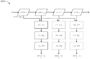
도 11은 테이블(38)과 칼럼(37) 사이의 인터페이스의 상세한 예시를 제공한다. 피치 회전 메커니즘(61)은 다중 자유도로 칼럼(37)에 대한 테이블(38)의 피치 각도를 변경하도록 구성될 수 있다. 피치 회전 메커니즘(61)은 칼럼-테이블 인터페이스에서의 직교 축(1, 2)의 위치설정에 의해 가능해질 수 있으며, 각각의 축은 전기 피치 각도 명령에 응답하여 별개의 모터(3, 4)에 의해 작동된다. 하나의 스크류(5)를 따른 회전은 하나의 축(1)에서의 틸트 조절을 가능하게 할 것인 한편, 다른 하나의 스크류(6)를 따른 회전은 다른 하나의 축(2)을 따른 틸트 조절을 가능하게 할 것이다. 일부 실시예에서, 볼 조인트(ball joint)가 다중 자유도로 칼럼(37)에 대한 테이블(38)의 피치 각도를 변경하도록 사용될 수 있다.11 provides a detailed illustration of the interface between table 38 and
예를 들어, 피치 조절은, 하복부 수술을 위해, 테이블을 트렌델렌부르크 자세(Trendelenburg position)로 위치시키려고 할 때, 즉 환자의 하복부를 환자의 상복부보다 바닥으로부터 더 높은 위치에 위치시키려고 할 때 특히 유용하다. 트렌델렌부르크 자세는 환자의 내부 장기가 중력을 통해 그/그녀의 상복부를 향해 미끄러지게 하여, 최소 침습 도구가 들어가서 복강경 전립선절제술과 같은 하복부 수술 또는 의료 절차를 수행할 복강을 비운다.For example, pitch adjustment is particularly useful when attempting to position the table in the Trendelenburg position for lower abdominal surgery, i.e. placing the patient's lower abdomen higher from the floor than the patient's upper abdomen. do. The Trendelenburg posture causes the patient's internal organs to slide through gravity towards his/her upper abdomen, leaving the abdominal cavity for a minimally invasive instrument to enter and perform lower abdominal surgery or medical procedures, such as laparoscopic prostatectomy.
C. 기구 드라이버 및 인터페이스.C. Instrument Drivers and Interfaces.
시스템의 로봇 아암의 엔드 이펙터는 (i) 의료 기구를 작동시키기 위한 전기-기계 수단을 통합하는 기구 드라이버(대안적으로 "기구 구동 메커니즘" 또는 "기구 장치 조작기"로 지칭됨), 및 (ii) 모터와 같은 임의의 전기-기계 구성요소가 없을 수 있는 제거가능 또는 탈착가능 의료 기구를 포함할 수 있다. 이러한 이분법은 의료 절차에 사용되는 의료 기구를 멸균할 필요성, 및 그들의 복잡한 기계 조립체 및 민감한 전자장치로 인해 고가의 자본 장비를 적절하게 멸균할 수 없음에 의해 주도될 수 있다. 따라서, 의료 기구는 의사 또는 의사의 스태프에 의한 개별적인 멸균 또는 폐기를 위해 기구 드라이버(및 그에 따라 시스템)로부터 탈착, 제거, 및 교환되도록 설계될 수 있다. 대조적으로, 기구 드라이버는 변경 또는 멸균될 필요가 없고, 보호를 위해 드레이핑될(draped) 수 있다.The end effector of the robotic arm of the system comprises (i) an instrument driver incorporating electro-mechanical means for actuating the medical instrument (alternatively referred to as an "instrument drive mechanism" or "instrument device manipulator"), and (ii) may include a removable or removable medical instrument that may be devoid of any electro-mechanical component such as a motor. This dichotomy may be driven by the need to sterilize medical instruments used in medical procedures, and the inability to adequately sterilize expensive capital equipment due to their complex mechanical assemblies and sensitive electronics. Accordingly, a medical instrument may be designed to be detached, removed, and exchanged from the instrument driver (and thus the system) for individual sterilization or disposal by a physician or staff of a physician. In contrast, instrument drivers need not be altered or sterilized and may be draped for protection.
도 12는 예시적인 기구 드라이버를 예시한다. 로봇 아암의 원위 단부에 위치되어, 기구 드라이버(62)는 구동 샤프트(64)를 통해 의료 기구에 제어된 토크를 제공하기 위해 평행 축으로 배열되는 하나 이상의 구동 유닛(63)을 포함한다. 각각의 구동 유닛(63)은 기구와 상호작용하기 위한 개별 구동 샤프트(64), 모터 샤프트 회전을 원하는 토크로 변환시키기 위한 기어 헤드(65), 구동 토크를 생성하기 위한 모터(66), 모터 샤프트의 속도를 측정하고 제어 회로부에 피드백을 제공하기 위한 인코더(encoder)(67), 및 제어 신호를 수신하고 구동 유닛을 작동시키기 위한 제어 회로부(68)를 포함한다. 각각의 구동 유닛(63)은 독립적으로 제어되고 동력화될 수 있고, 기구 드라이버(62)는 의료 기구에 다수의(예컨대, 도 13 및 도 14에 도시된 바와 같이 4개의) 독립적인 구동 출력부를 제공할 수 있다. 작동 시에, 제어 회로부(68)는 제어 신호를 수신할 것이고, 모터(66)에 모터 신호를 전송할 것이며, 인코더(67)에 의해 측정된 바와 같은 생성된 모터 속도를 원하는 속도와 비교할 것이고, 모터 신호를 변조하여 원하는 토크를 생성할 것이다.12 illustrates an exemplary instrument driver. Located at the distal end of the robotic arm, the
멸균 환경을 필요로 하는 절차의 경우, 로봇 시스템은 기구 드라이버와 의료 기구 사이에 있는, 멸균 드레이프(sterile drape)에 연결된 멸균 어댑터(sterile adapter)와 같은 구동 인터페이스를 통합할 수 있다. 멸균 어댑터의 주된 목적은 기구 드라이버의 구동 샤프트로부터 기구의 구동 입력부로 각도 운동을, 구동 샤프트와 구동 입력부 사이의 물리적 분리, 및 그에 따라 멸균을 유지시키면서, 전달하는 것이다. 따라서, 예시적인 멸균 어댑터는 기구 드라이버의 구동 샤프트 및 기구 상의 구동 입력부와 정합되도록 의도되는 일련의 회전 입력부 및 출력부를 포함할 수 있다. 멸균 어댑터에 연결되어, 투명 또는 반투명 플라스틱과 같은 얇은 가요성 재료로 구성된 멸균 드레이프는 기구 드라이버, 로봇 아암, (카트-기반 시스템 내의) 카트 또는 (테이블-기반 시스템 내의) 테이블과 같은 자본 장비를 덮도록 설계된다. 드레이프의 사용은 자본 장비가 멸균을 필요로 하지 않는 영역(즉, 비-멸균 영역) 내에 여전히 위치되면서 환자에게 근접하게 위치되도록 허용할 것이다. 멸균 드레이프의 다른 하나의 측부 상에서, 의료 기구는 멸균을 필요로 하는 영역(즉, 멸균 영역)에서 환자와 인터페이스할 수 있다.For procedures requiring a sterile environment, the robotic system may incorporate a drive interface, such as a sterile adapter connected to a sterile drape, between the instrument driver and the medical instrument. The primary purpose of the sterile adapter is to transfer angular motion from the drive shaft of the instrument driver to the drive input of the instrument while maintaining a physical separation between the drive shaft and the drive input, and thus sterility. Accordingly, an exemplary sterile adapter may include a drive shaft of an instrument driver and a series of rotational inputs and outputs intended to mate with drive inputs on the instrument. Connected to a sterile adapter, a sterile drape made of a thin flexible material such as transparent or translucent plastic covers capital equipment such as instrument drivers, robotic arms, carts (in cart-based systems) or tables (in table-based systems). is designed to The use of a drape will allow capital equipment to be positioned proximate to the patient while still being positioned within an area that does not require sterilization (ie, a non-sterile area). On the other side of the sterile drape, the medical instrument may interface with the patient in an area requiring sterilization (ie, a sterile area).
D. 의료 기구.D. Medical Devices.
도 13은 페어링된 기구 드라이버를 갖는 예시적인 의료 기구를 예시한다. 로봇 시스템과 함께 사용하도록 설계된 다른 기구와 마찬가지로, 의료 기구(70)는 세장형 샤프트(71)(또는 세장형 본체) 및 기구 기부(72)를 포함한다. 의사에 의한 수동 상호작용을 위한 그의 의도된 설계로 인해 "기구 손잡이"로 또한 지칭되는 기구 기부(72)는 일반적으로, 로봇 아암(76)의 원위 단부에서 기구 드라이버(75) 상의 구동 인터페이스를 통해 연장되는 구동 출력부(74)와 정합되도록 설계되는 회전가능 구동 입력부(73), 예컨대 리셉터클(receptacle), 풀리(pulley), 또는 스풀을 포함할 수 있다. 물리적으로 연결, 래칭(latched), 및/또는 결합될 때, 기구 기부(72)의 정합된 구동 입력부(73)는 기구 드라이버(75) 내의 구동 출력부(74)와 회전 축을 공유하여, 구동 출력부(74)로부터 구동 입력부(73)로의 토크의 전달을 허용할 수 있다. 일부 실시예에서, 구동 출력부(74)는 구동 입력부(73) 상의 리셉터클과 정합하도록 설계되는 스플라인(spline)을 포함할 수 있다.13 illustrates an example medical instrument having a paired instrument driver. Like other instruments designed for use with robotic systems,
세장형 샤프트(71)는, 예컨대 내시경술에서와 같이, 해부학적 개구 또는 내강, 또는 예컨대 복강경술에서와 같이, 최소 침습 절개부를 통해 전달되도록 설계된다. 세장형 샤프트(71)는 가요성(예컨대, 내시경과 유사한 특성을 가짐) 또는 강성(예컨대, 복강경과 유사한 특성을 가짐)이거나 가요성 부분 및 강성 부분 둘 모두의 맞춤형 조합을 포함할 수 있다. 복강경술을 위해 설계될 때, 강성의 세장형 샤프트의 원위 단부는, 적어도 1 자유도를 갖는 클레비스(clevis)로부터 형성되는 조인트식 리스트(jointed wrist)로부터 연장되는 엔드 이펙터, 및 구동 입력부가 기구 드라이버(75)의 구동 출력부(74)로부터 수신된 토크에 응답하여 회전함에 따라 텐돈(tendon)으로부터의 힘에 기초하여 작동될 수 있는, 예를 들어 파지기 또는 가위와 같은 수술 도구 또는 의료 기구에 연결될 수 있다. 내시경술을 위해 설계될 때, 가요성의 세장형 샤프트의 원위 단부는 기구 드라이버(75)의 구동 출력부(74)로부터 수신된 토크에 기초하여 관절운동되고 구부러질 수 있는 조향가능 또는 제어가능 굽힘 섹션을 포함할 수 있다.The
기구 드라이버(75)로부터의 토크는 세장형 샤프트(71)를 따른 텐돈을 사용하여 세장형 샤프트(71)를 따라 전달된다. 풀 와이어(pull wire)와 같은 이들 개별 텐돈은 기구 손잡이(72) 내의 개별 구동 입력부(73)에 개별적으로 고정될 수 있다. 손잡이(72)로부터, 텐돈은 세장형 샤프트(71)를 따른 하나 이상의 풀 루멘(pull lumen)을 따라 지향되고, 세장형 샤프트(71)의 원위 부분에 또는 세장형 샤프트(71)의 원위 부분에 있는 리스트 내에 고정된다. 복강경술, 내시경술 또는 하이브리드 절차와 같은 수술 절차 동안, 이들 텐돈은 리스트, 파지기, 또는 가위와 같은 원위에 장착된 엔드 이펙터에 결합될 수 있다. 그러한 배열 하에서, 구동 입력부(73)에 가해진 토크는 텐돈에 장력을 전달하여, 그에 의해 엔드 이펙터가 일정 방식으로 작동하게 할 것이다. 복강경술에서, 텐돈은 조인트가 축을 중심으로 회전하게 하여, 그에 의해 엔드 이펙터가 하나의 방향 또는 다른 방향으로 이동하게 할 수 있다. 대안적으로, 텐돈은 세장형 샤프트(71)의 원위 단부에서 파지기의 하나 이상의 조오(jaw)에 연결될 수 있으며, 여기에서 텐돈으로부터의 장력은 파지기가 폐쇄되게 한다.Torque from the
내시경술에서, 텐돈은 접착제, 제어 링, 또는 다른 기계적 고정을 통해 (예컨대, 원위 단부에서) 세장형 샤프트(71)를 따라 위치된 굽힘 또는 관절운동 섹션에 결합될 수 있다. 굽힘 섹션의 원위 단부에 고정식으로 부착될 때, 구동 입력부(73)에 가해진 토크는 텐돈을 따라 전달되어, 더 연질인 굽힘 섹션(때때로 관절운동가능 섹션 또는 영역으로 지칭됨)이 구부러지거나 관절운동하게 할 것이다. 비-굽힘 섹션을 따라, 내시경 샤프트의 벽을 따라(또는 그 내측에서) 개별 텐돈을 지향시키는 개별 풀 루멘을 나선형화 또는 나선화하여, 풀 와이어의 장력으로부터 발생하는 반경방향 힘의 균형을 잡는 것이 유리할 수 있다. 나선(spiraling)의 각도 및/또는 그들 사이의 간격은 특정 목적을 위해 변경 또는 조작될 수 있으며, 여기에서 더 조밀한 나선은 하중 힘 하에서의 더 작은 샤프트 압축을 나타내는 한편, 더 적은 양의 나선은 하중 힘 하에서의 더 큰 샤프트 압축을 가져오지만, 또한 더 제한된 굽힘을 나타낸다. 스펙트럼의 다른 단부 상에서, 풀 루멘은 원하는 굽힘 또는 관절운동가능 섹션에서의 제어된 관절운동을 허용하기 위해 세장형 샤프트(71)의 길이방향 축에 평행하게 지향될 수 있다.In endoscopy, the tendon may be coupled to a bending or articulating section positioned along the elongate shaft 71 (eg, at the distal end) via adhesive, control ring, or other mechanical fixation. When fixedly attached to the distal end of the bending section, the torque applied to the
내시경술에서, 세장형 샤프트(71)는 로봇 절차를 보조하기 위한 다수의 구성요소를 수용한다. 샤프트(71)는 샤프트(71)의 원위 단부에서 수술 영역에 수술 도구(또는 의료 기구), 관주, 및/또는 흡인을 전개시키기 위한 작업 채널을 포함할 수 있다. 샤프트(71)는 또한, 광학 카메라를 포함할 수 있는, 원위 팁(distal tip)에 있는 광학 조립체로/그로부터 신호를 전달하기 위한 와이어 및/또는 광섬유를 수용할 수 있다. 샤프트(71)는 또한, 발광 다이오드와 같은 근위에 위치된 광원으로부터 샤프트(71)의 원위 단부로 광을 전달하기 위한 광섬유를 수용할 수 있다.In endoscopy, the
기구(70)의 원위 단부에서, 원위 팁은 또한, 진단 및/또는 치료, 관주, 및 흡인을 위한 도구를 수술 부위로 전달하기 위한 작업 채널의 개구를 포함할 수 있다. 원위 팁은 또한, 내부 해부학적 공간의 이미지를 캡처하기 위한, 섬유경 또는 디지털 카메라와 같은 카메라를 위한 포트를 포함할 수 있다. 이와 관련하여, 원위 팁은 또한, 카메라를 사용할 때 해부학적 공간을 조명하기 위한 광원을 위한 포트를 포함할 수 있다.At the distal end of
도 13의 예에서, 구동 샤프트 축, 및 그에 따라 구동 입력부 축은 세장형 샤프트(71)의 축에 직교한다. 그러나, 이러한 배열은 세장형 샤프트(71)에 대한 롤(roll) 능력을 복잡하게 한다. 구동 입력부(73)를 정적으로 유지시키면서 세장형 샤프트(71)를 그의 축을 따라 롤링시키는 것은 텐돈이 구동 입력부(73)로부터 연장되고 세장형 샤프트(71) 내의 풀 루멘에 들어감에 따라 텐돈의 바람직하지 않은 엉킴을 야기한다. 그러한 텐돈의 결과적인 엉킴은 내시경술 절차 동안 가요성의 세장형 샤프트(71)의 이동을 예측하도록 의도된 임의의 제어 알고리즘을 방해할 수 있다.In the example of FIG. 13 , the drive shaft axis, and thus the drive input axis, is orthogonal to the axis of the
도 14는 구동 유닛의 축이 기구의 세장형 샤프트의 축에 평행한 기구 드라이버 및 기구에 대한 대안적인 설계를 예시한다. 도시된 바와 같이, 원형 기구 드라이버(80)는 그들의 구동 출력부(81)가 로봇 아암(82)의 단부에서 평행하게 정렬되는 4개의 구동 유닛을 포함한다. 구동 유닛, 및 그들 각각의 구동 출력부(81)는 기구 드라이버(80)의 회전 조립체(83) 내에 수용되며, 이는 조립체(83) 내의 구동 유닛들 중 하나에 의해 구동된다. 회전 구동 유닛에 의해 제공되는 토크에 응답하여, 회전 조립체(83)는 회전 조립체(83)를 기구 드라이버(80)의 비-회전 부분(84)에 연결하는 원형 베어링을 따라 회전한다. 전력 및 제어 신호가 기구 드라이버(80)의 비-회전 부분(84)으로부터, 브러시형 슬립 링 연결부(brushed slip ring connection)(도시되지 않음)에 의해 회전을 통해 유지될 수 있는 전기 접촉부를 통해 회전 조립체(83)로 전달될 수 있다. 다른 실시예에서, 회전 조립체(83)는, 비-회전가능 부분(84) 내에 통합되어, 그에 따라 다른 구동 유닛에 평행하지 않은 별개의 구동 유닛에 응답할 수 있다. 회전 메커니즘(83)은 기구 드라이버(80)가 구동 유닛, 및 그들 각각의 구동 출력부(81)를 단일 유닛으로서 기구 드라이버 축(85)을 중심으로 회전시키도록 허용한다.14 illustrates an alternative design for an instrument driver and instrument in which the axis of the drive unit is parallel to the axis of the elongate shaft of the instrument. As shown, the
이전에 개시된 실시예와 마찬가지로, 기구(86)는 세장형 샤프트 부분(88), 및 기구 드라이버(80) 내의 구동 출력부(81)를 수용하도록 구성되는 (리셉터클, 풀리, 및 스풀과 같은) 복수의 구동 입력부(89)를 포함하는 기구 기부(87)(논의 목적을 위해 투명 외부 스킨으로 도시됨)를 포함할 수 있다. 이전에 개시된 실시예와 달리, 기구 샤프트(88)는 축이 도 13의 설계에서와 같이 직교하기보다는 구동 입력부(89)의 축에 실질적으로 평행한 상태로 기구 기부(87)의 중심으로부터 연장된다.As with the previously disclosed embodiments, the
기구 드라이버(80)의 회전 조립체(83)에 결합될 때, 기구 기부(87) 및 기구 샤프트(88)를 포함하는 의료 기구(86)는 회전 조립체(83)와 조합하여 기구 드라이버 축(85)을 중심으로 회전한다. 기구 샤프트(88)가 기구 기부(87)의 중심에 위치되기 때문에, 기구 샤프트(88)는 부착될 때 기구 드라이버 축(85)과 동축이다. 따라서, 회전 조립체(83)의 회전은 기구 샤프트(88)가 그 자체의 길이방향 축을 중심으로 회전하게 한다. 더욱이, 기구 기부(87)가 기구 샤프트(88)와 함께 회전함에 따라, 기구 기부(87) 내의 구동 입력부(89)에 연결된 임의의 텐돈은 회전 동안 엉키지 않는다. 따라서, 구동 출력부(81), 구동 입력부(89), 및 기구 샤프트(88)의 축의 평행성은 임의의 제어 텐돈을 엉키게 하지 않고서 샤프트 회전을 허용한다.When coupled to the rotating
E. 내비게이션 및 제어.E. Navigation and Control.
전통적인 내시경술은 (예컨대, C-아암을 통해 전달될 수 있는 바와 같은) 형광투시법 및 다른 형태의 방사선-기반 이미징 모달리티(imaging modality)의 사용을 수반하여, 조작자 의사에게 관내 안내를 제공할 수 있다. 대조적으로, 본 개시에 의해 고려되는 로봇 시스템은 비-방사선-기반 내비게이션 및 위치결정 수단을 제공하여, 방사선에 대한 의사의 노출을 감소시키고 수술실 내의 장비의 양을 감소시킬 수 있다. 본 명세서에 사용되는 바와 같이, 용어 "위치결정"은 기준 좌표계에서 물체의 위치를 결정 및/또는 모니터링하는 것을 지칭할 수 있다. 수술전 매핑, 컴퓨터 비전(computer vision), 실시간 EM 추적, 및 로봇 명령 데이터와 같은 기법은 방사선이 없는 수술 환경을 달성하기 위해 개별적으로 또는 조합으로 사용될 수 있다. 방사선-기반 이미징 모달리티가 여전히 사용되는 다른 경우에, 수술전 매핑, 컴퓨터 비전, 실시간 EM 추적, 및 로봇 명령 데이터는 방사선-기반 이미징 모달리티만을 통해 획득된 정보를 개선하기 위해 개별적으로 또는 조합으로 사용될 수 있다.Traditional endoscopy may involve the use of fluoroscopy and other forms of radiation-based imaging modality (eg, as may be delivered via a C-arm), to provide intraluminal guidance to the operator physician. . In contrast, the robotic systems contemplated by this disclosure may provide non-radiation-based means of navigation and positioning, thereby reducing the surgeon's exposure to radiation and reducing the amount of equipment in the operating room. As used herein, the term “positioning” may refer to determining and/or monitoring the position of an object in a reference coordinate system. Techniques such as preoperative mapping, computer vision, real-time EM tracking, and robotic command data can be used individually or in combination to achieve a radiation-free surgical environment. In other cases where radiation-based imaging modality is still used, preoperative mapping, computer vision, real-time EM tracking, and robotic command data can be used individually or in combination to improve information obtained through radiation-based imaging modality alone. have.
도 15는 예시적인 실시예에 따른, 기구의 위치와 같은, 로봇 시스템의 하나 이상의 요소의 위치를 추정하는 위치결정 시스템(90)을 예시한 블록도이다. 위치결정 시스템(90)은 하나 이상의 명령어를 실행하도록 구성되는 하나 이상의 컴퓨터 장치들의 세트일 수 있다. 컴퓨터 장치는 위에서 논의된 하나 이상의 구성요소 내의 프로세서(또는 프로세서들) 및 컴퓨터-판독가능 메모리에 의해 구현될 수 있다. 제한이 아닌 예로서, 컴퓨터 장치는 도 1에 도시된 타워(30), 도 1 내지 도 4에 도시된 카트(11), 도 5 내지 도 10에 도시된 베드 등 내에 있을 수 있다.15 is a block diagram illustrating a
도 15에 도시된 바와 같이, 위치결정 시스템(90)은 의료 기구의 원위 팁에 대한 위치 데이터(96)를 생성하도록 입력 데이터(91 내지 94)를 처리하는 위치결정 모듈(95)을 포함할 수 있다. 위치 데이터(96)는 기준 프레임(frame of reference)에 대한 기구의 원위 단부의 위치 및/또는 배향을 나타내는 데이터 또는 논리일 수 있다. 기준 프레임은 환자의 해부학적 구조 또는 알려진 물체, 예컨대 EM 필드 발생기(EM 필드 발생기에 대해서는 아래의 논의 참조)에 대한 기준 프레임일 수 있다.As shown in FIG. 15 , the
이제, 다양한 입력 데이터(91 내지 94)가 더 상세히 기술된다. 수술전 매핑은 저 선량 컴퓨터 단층촬영(CT) 스캔의 집합의 사용을 통해 달성될 수 있다. 수술전 CT 스캔은 3차원 이미지로 재구성되며, 이는, 예컨대 환자의 내부 해부학적 구조의 절결도의 "슬라이스(slice)"로서 시각화된다. 전체적으로 분석될 때, 환자 폐 네트워크와 같은 환자의 해부학적 구조의 해부학적 공동, 공간, 및 구조에 대한 이미지-기반 모델이 생성될 수 있다. 중심선 기하학(center-line geometry)과 같은 기법이 CT 이미지로부터 결정되고 근사화되어, 모델 데이터(91)로 지칭되는(수술전 CT 스캔만을 사용하여 생성될 때 "수술전 모델 데이터"로 또한 지칭됨), 환자의 해부학적 구조의 3차원 볼륨(three-dimensional volume)을 개발할 수 있다. 일부 실시예에서, 수술전 모델 데이터(91)는 예컨대 형광투시법, 자기 공명 영상(magnetic resonance imaging, MRI), 초음파 영상, 및/또는 x-선으로부터의 데이터를 포함할 수 있다. 중심선 기하학의 사용은 그 내용이 전체적으로 본 명세서에 포함되는 미국 특허 출원 제14/523,760호에서 논의된다. 네트워크 위상 모델(network topological model)이 또한 CT 이미지로부터 도출될 수 있으며, 기관지경술에 특히 적절하다.The
일부 실시예에서, 기구는 비전 데이터(또는 이미지 데이터)(92)를 제공하기 위한 카메라를 구비할 수 있다. 위치결정 모듈(95)은 하나 이상의 비전-기반(또는 이미지-기반) 위치 추적 모듈 또는 특징부를 가능하게 하도록 비전 데이터(92)를 처리할 수 있다. 예를 들어, 수술전 모델 데이터(91)는 비전 데이터(92)와 함께 사용되어 의료 기구의 컴퓨터 비전-기반 추적을 가능하게 할 수 있다(예컨대, 내시경 전진 또는 내시경의 작업 채널을 통한 기구 전진). 예를 들어, 수술전 모델 데이터(91)를 사용하여, 로봇 시스템은 내시경의 예상 이동 경로에 기초하여 모델로부터 예상 내시경 이미지의 라이브러리(library)를 생성할 수 있으며, 각각의 이미지는 모델 내의 일정 위치에 링크된다. 수술중에, 이러한 라이브러리는, 카메라(예컨대, 내시경의 원위 단부에 있는 카메라)에서 캡처된 실시간 이미지를 이미지 라이브러리 내의 이미지와 비교하여 위치결정을 보조하기 위해 로봇 시스템에 의해 참조될 수 있다.In some embodiments, the instrument may include a camera to provide vision data (or image data) 92 . The
다른 컴퓨터 비전-기반 추적 기법은 특징부 추적(feature tracking)을 사용하여 카메라, 및 그에 따라 내시경의 운동을 결정한다. 위치결정 모듈(95)의 일부 특징부는 해부학적 내강에 대응하는 수술전 모델 데이터(91) 내의 원형 기하학적 구조를 식별하고 그들 기하학적 구조의 변화를 추적하여, 어느 해부학적 내강이 선택되었는지뿐만 아니라 카메라의 상대 회전 및/또는 병진 운동을 결정할 수 있다. 위상 맵(topological map)의 사용은 비전-기반 알고리즘 또는 기법을 추가로 향상시킬 수 있다.Another computer vision-based tracking technique uses feature tracking to determine the motion of the camera, and thus the endoscope. Some features of the
다른 컴퓨터 비전-기반 기법인 광학 흐름(optical flow)은 비전 데이터(92) 내의 비디오 시퀀스에서 이미지 픽셀의 변위 및 병진을 분석하여 카메라 이동을 추론할 수 있다. 광학 흐름 기법의 예는 모션 검출(motion detection), 객체 분할 계산(object segmentation calculation), 휘도(luminance), 모션 보상 인코딩(motion compensated encoding), 스테레오 디스패리티 측정(stereo disparity measurement) 등을 포함할 수 있다. 다수의 반복에 걸친 다수의 프레임의 비교를 통해, 카메라(및 그에 따라 내시경)의 이동 및 위치가 결정될 수 있다.Another computer vision-based technique, optical flow, can analyze the displacement and translation of image pixels in a video sequence within
위치결정 모듈(95)은 수술전 모델에 의해 표현되는 환자의 해부학적 구조에 정합될 수 있는 전역 좌표계에서 내시경의 실시간 위치를 생성하기 위해 실시간 EM 추적을 사용할 수 있다. EM 추적에서, 의료 기구(예컨대, 내시경 도구) 내에 하나 이상의 위치 및 배향으로 내장된 하나 이상의 센서 코일을 포함하는 EM 센서(또는 추적기)가 알려진 위치에 위치된 하나 이상의 정적 EM 필드 발생기에 의해 생성되는 EM 필드의 변화를 측정한다. EM 센서에 의해 검출된 위치 정보는 EM 데이터(93)로서 저장된다. EM 필드 발생기(또는 전송기)는 내장된 센서가 검출할 수 있는 저 강도 자기장을 생성하기 위해 환자 가까이에 배치될 수 있다. 자기장은 EM 센서의 센서 코일에 소전류(small current)를 유도하며, 이는 EM 센서와 EM 필드 발생기 사이의 거리 및 각도를 결정하기 위해 분석될 수 있다. 이들 거리 및 배향은 좌표계 내의 단일 위치를 환자의 해부학적 구조의 수술전 모델 내의 위치와 정렬시키는 기하학적 변환을 결정하기 위해 수술중에 환자 해부학적 구조(예컨대, 수술전 모델)에 "정합될" 수 있다. 일단 정합되면, 의료 기구의 하나 이상의 위치(예컨대, 내시경의 원위 팁)에 있는 내장된 EM 추적기는 환자의 해부학적 구조를 통한 의료 기구의 진행의 실시간 표시를 제공할 수 있다.The
로봇 명령 및 운동학(kinematics) 데이터(94)가 또한 위치결정 모듈(95)에 의해 사용되어, 로봇 시스템에 대한 위치결정 데이터(96)를 제공할 수 있다. 관절운동 명령으로부터 발생하는 장치 피치 및 요(yaw)는 수술전 보정 동안 결정될 수 있다. 수술중에, 이들 보정 측정치는 알려진 삽입 깊이 정보와 조합하여 사용되어 기구의 위치를 추정할 수 있다. 대안적으로, 이들 계산치는 EM, 비전, 및/또는 위상 모델링과 조합하여 분석되어 네트워크 내의 의료 기구의 위치를 추정할 수 있다.Robot commands and
도 15가 도시하는 바와 같이, 다수의 다른 입력 데이터가 위치결정 모듈(95)에 의해 사용될 수 있다. 예를 들어, 도 15에 도시되어 있지 않지만, 형상-감지 섬유를 이용하는 기구가, 위치결정 모듈(95)이 기구의 위치 및 형상을 결정하는 데 사용할 수 있는 형상 데이터를 제공할 수 있다.As FIG. 15 shows, a number of different input data may be used by the
위치결정 모듈(95)은 입력 데이터(91 내지 94)를 조합(들)으로 사용할 수 있다. 일부 경우에, 그러한 조합은 위치결정 모듈(95)이 입력 데이터(91 내지 94) 각각으로부터 결정된 위치에 신뢰 가중치(confidence weight)를 할당하는 확률적 접근법(probabilistic approach)을 사용할 수 있다. 따라서, (EM 간섭이 있는 경우 그러할 수 있는 바와 같이) EM 데이터가 신뢰가능하지 않을 수 있는 경우, EM 데이터(93)에 의해 결정된 위치의 신뢰도가 감소될 수 있고, 위치결정 모듈(95)은 비전 데이터(92) 및/또는 로봇 명령 및 운동학 데이터(94)에 더 많이 의존할 수 있다.The
위에서 논의된 바와 같이, 본 명세서에서 논의되는 로봇 시스템은 위의 기법들 중 하나 이상의 조합을 통합하도록 설계될 수 있다. 타워, 베드 및/또는 카트에 기반한 로봇 시스템의 컴퓨터-기반 제어 시스템은 예를 들어 영구 자기 저장 드라이브, 솔리드 스테이트 드라이브 등과 같은 비-일시적 컴퓨터-판독가능 저장 매체 내에 컴퓨터 프로그램 명령어를 저장할 수 있으며, 이는, 실행 시에, 시스템으로 하여금 센서 데이터 및 사용자 명령을 수신 및 분석하고, 시스템 전체에 걸쳐 제어 신호를 생성하고, 전역 좌표계, 해부학적 맵 등 내에서의 기구의 위치와 같은 내비게이션 및 위치결정 데이터를 디스플레이하게 한다.As discussed above, the robotic system discussed herein may be designed to incorporate a combination of one or more of the above techniques. A computer-based control system of a robotic system based on a tower, bed and/or cart may store computer program instructions in a non-transitory computer-readable storage medium such as, for example, a permanent magnetic storage drive, a solid state drive, etc., which , which, when executed, causes the system to receive and analyze sensor data and user commands, generate control signals throughout the system, and retrieve navigation and positioning data, such as the position of the instrument within the global coordinate system, anatomical maps, etc. to display
II. 내강 네트워크의 내비게이션.II. Navigation of the luminal network.
위에서 논의된 다양한 로봇 시스템은 내시경술 및 복강경술 절차와 같은 다양한 의료 절차를 수행하기 위해 채용될 수 있다. 소정 절차 동안, 로봇-제어식 의료 기구와 같은 의료 기구가 환자의 신체 내로 삽입된다. 환자의 신체 내에서, 기구는 환자의 내강 네트워크 내에 위치될 수 있다. 본 명세서에 사용되는 바와 같이, 용어 "내강 네트워크"는, 복수의 내강 또는 분지부(예컨대, 폐 또는 혈관에서와 같은, 복수의 분지 내강) 또는 단일 내강 또는 분지부(예컨대, 위장관 내의)를 포함하든지 간에, 신체 내의 임의의 공동 구조를 지칭한다. 절차 동안, 기구는 내강 네트워크를 통해 하나 이상의 관심 대상의 영역으로 이동(예컨대, 내비게이션, 안내, 구동 등)될 수 있다. 시스템을 통한 기구의 이동은 위에서 논의된 내비게이션 또는 위치결정 시스템(90)에 의해 도움을 받을 수 있으며, 이는 기구에 관한 위치 정보를 로봇 시스템을 제어하는 의사에게 제공할 수 있다.The various robotic systems discussed above may be employed to perform various medical procedures, such as endoscopic and laparoscopic procedures. During certain procedures, a medical instrument, such as a robot-controlled medical instrument, is inserted into the patient's body. Within the patient's body, the instrument may be positioned within the patient's lumen network. As used herein, the term “luminal network” includes a plurality of lumens or branches (eg, multiple branch lumens, such as in the lungs or blood vessels) or a single lumen or branch (eg, in the gastrointestinal tract). Regardless, it refers to any cavity structure within the body. During the procedure, the instrument may be moved (eg, navigated, guided, driven, etc.) to one or more areas of interest via the luminal network. Movement of the instrument through the system may be assisted by the navigation or
도 16은 환자의 예시적인 내강 네트워크(130)를 예시한다. 예시된 실시예에서, 내강 네트워크(130)는 환자의 폐의 기도(150)의 기관지 네트워크(즉, 내강, 분지부)이다. 예시된 내강 네트워크(130)가 환자의 폐 내의 기도의 기관지 네트워크이지만, 본 개시는 예시된 예로만 제한되지 않는다. 본 명세서에 기술된 로봇 시스템 및 방법은 기관지 네트워크, 신장 네트워크, 심혈관 네트워크(예컨대, 동맥 및 정맥), 위장관, 요로 등과 같은 임의의 유형의 내강 네트워크를 내비게이션하기 위해 사용될 수 있다.16 illustrates an example
예시된 바와 같이, 내강 네트워크(130)는 분지 구조로 배열된 복수의 기도(150)를 포함한다. 일반적으로, 내강 네트워크(130)는 3차원 구조를 포함한다. 예시의 용이함을 위해, 도 16은 2차원 구조로서 내강 네트워크(130)를 표현한다. 이는 본 개시를 임의의 방식으로든 2차원 내강 네트워크로 제한하는 것으로 해석되어서는 안 된다.As illustrated, the
도 16은 또한 내강 네트워크(130) 내에 위치된 의료 기구의 예를 예시한다. 의료 기구는 진단 및/또는 처치를 위한 관심 대상의 영역(예컨대, 결절(155))을 향해 내강 네트워크(130)를 통해 내비게이션된다. 예시된 예에서, 결절(155)은 기도(150)의 말초 부위(periphery)에 위치되지만, 관심 대상의 영역(들)은 환자 및 절차에 따라 내강 네트워크(130) 내의 어디든 위치될 수 있다.16 also illustrates an example of a medical instrument positioned within the
예시된 예에서, 의료 기구는 내시경(115)을 포함한다. 내시경(115)은 시스(120) 및 리더(145)를 포함할 수 있다. 일부 실시예에서, 시스(120) 및 리더(145)는 삽통식 방식으로 배열될 수 있다. 예를 들어, 리더(145)는 시스(120)의 작업 채널 내측에 활주가능하게 위치될 수 있다. 시스(120)는 제1 직경을 가질 수 있고, 그의 원위 단부는 결절(155) 주위에서 소-직경 기도(150)를 통해 위치되는 것이 가능하지 않을 수 있다. 따라서, 리더(145)는 결절(155)까지의 나머지 거리만큼 시스(120)의 작업 채널로부터 연장되도록 구성될 수 있다. 리더(145)는 기구, 예를 들어 생검 바늘, 세포채취용 브러시(cytology brush), 및/또는 조직 샘플링 겸자가 그것을 통해 결절(155)의 표적 조직 부위로 통과될 수 있는 루멘을 가질 수 있다. 그러한 구현예에서, 시스(120)의 원위 단부 및 리더(145)의 원위 단부 둘 모두에는 기도(150) 내에서의 그들의 위치를 추적하기 위한 EM 기구 센서(예컨대, 도 18의 EM 기구 센서(305))가 제공될 수 있다. 시스(120) 및 리더(145)의 이러한 삽통식 배열은 내시경(115)의 더 얇은 설계를 허용할 수 있고, 시스(120)를 통한 구조적 지지를 제공하면서 내시경(115)의 굽힘 반경을 개선할 수 있다.In the illustrated example, the medical instrument includes an
다른 실시예에서, 내시경(115)의 전체 직경은 삽통식 배열 없이 말초 부위에 도달하기에 충분히 작을 수 있거나, 비-조향가능 카테터를 통해 의료 기구를 전개시키도록 말초 부위에 접근하기에(예컨대, 약 2.5 내지 3 cm 이내) 충분히 작을 수 있다. 내시경(115)을 통해 전개되는 의료 기구는 EM 기구 센서(예컨대, 도 18의 EM 기구 센서(305))를 구비할 수 있고, 후술되는 이미지-기반 기도 분석 및 매핑 기법이 그러한 의료 기구에 적용될 수 있다.In other embodiments, the overall diameter of the
도시된 바와 같이, 결절(155)에 도달하기 위해, 기구(예컨대, 내시경(115))는 내강 네트워크의 기도(150)를 통해 내비게이션되거나 안내되어야 한다. 조작자(예컨대, 의사)가 로봇 시스템을 제어하여 기구를 결절(155)로 내비게이션할 수 있다. 조작자는 로봇 시스템을 제어하기 위한 입력을 제공할 수 있다.As shown, in order to reach the
도 17은 본 명세서에 기술된 로봇 시스템의 일부 구현예와 함께 사용될 수 있는 예시적인 명령 콘솔(200)을 예시한다. 조작자는 명령 콘솔(200)을 통해, 예를 들어 기구를 결절(155)과 같은 관심 대상의 영역으로 내비게이션하거나 안내하기 위해, 로봇 시스템을 제어하기 위한 입력을 제공할 수 있다. 명령 콘솔(200)은 매우 다양한 배열 또는 구성으로 구현될 수 있다. 예시된 예에서, 명령 콘솔(200)은 콘솔 기부(201), 디스플레이(202)(예컨대, 모니터), 및 하나 이상의 제어 모듈(예컨대, 키보드(203) 및 조이스틱(204))을 포함한다. 사용자(205)(예컨대, 의사 또는 다른 조작자)가 명령 콘솔(200)을 사용하여 인체공학적 위치로부터 의료 로봇 시스템(예컨대, 도 1 내지 도 15를 참조하여 기술된 시스템)을 원격으로 제어할 수 있다.17 illustrates an
디스플레이(202)는 전자 모니터(예컨대, LCD 디스플레이, LED 디스플레이, 터치-감응형 디스플레이), 가상 현실 관찰 장치(예컨대, 고글 또는 안경), 및/또는 다른 디스플레이 장치를 포함할 수 있다. 일부 실시예에서, 디스플레이들(202) 중 하나 이상이, 예를 들어 위치결정 시스템(90)(도 15)에 의해 결정되는 바와 같은, 기구에 관한 위치 정보를 디스플레이한다. 일부 실시예에서, 디스플레이들(202) 중 하나 이상이 환자의 내강 네트워크(130)의 수술전 모델을 디스플레이한다. 위치 정보는 수술전 모델 상에 오버레이될(overlaid) 수 있다. 디스플레이(202)는 또한 내강 네트워크(130) 내에서 기구 상에 위치된 카메라 또는 다른 감지 장치로부터 수신된 이미지 정보를 디스플레이할 수 있다. 일부 실시예에서, 기구의 모델 또는 표현이 수술 또는 의료 절차의 상태를 나타내는 데 도움을 주기 위해 수술전 모델과 함께 디스플레이된다.
일부 실시예에서, 콘솔 기부(201)는 카메라 이미지와 같은 신호의 해석과 처리 및 예컨대 환자의 내강 네트워크 내에 위치된 의료 기구로부터의 센서 데이터의 추적을 담당하는 중앙 처리 유닛(예컨대, CPU 또는 프로세서), 메모리 유닛(예컨대, 컴퓨터-판독가능 메모리), 데이터 버스, 및 연관 데이터 통신 포트를 포함한다.In some embodiments,
콘솔 기부(201)는 또한 제어 모듈(203, 204)을 통해 사용자(205)에 의해 제공되는 명령 및 명령어를 처리할 수 있다. 도 17에 도시된 키보드(203) 및 조이스틱(204)에 더하여, 제어 모듈은 다른 장치, 예컨대 컴퓨터 마우스, 트랙패드, 트랙볼, 제어 패드, 제어기, 예컨대 핸드헬드 원격 제어기, 및 손 제스처와 손가락 제스처를 캡처하는 센서(예컨대, 모션 센서 또는 카메라)를 포함할 수 있다. 제어기는 기구의 작동(예컨대, 관절운동, 구동, 물 관주 등)에 매핑되는 사용자 입력부들(예컨대, 버튼, 조이스틱, 지향성 패드 등)의 세트를 포함할 수 있다. 명령 콘솔(200)의 제어 모듈(203, 204)을 사용하여, 사용자(205)는 내강 네트워크(130)를 통해 기구를 내비게이션할 수 있다.
도 18은 예시적인 의료 기구(300)의 원위 단부의 상세도를 예시한다. 의료 기구(300)는 도 16의 내시경(115) 또는 조향가능 카테터(145)를 나타낼 수 있다. 의료 기구(300)는 본 개시 전반에 걸쳐 기술된 임의의 의료 기구, 예컨대 도 1의 내시경(13), 도 3의 요관경(32), 도 9의 복강경(59) 등을 나타낼 수 있다. 도 18에서, 기구(300)의 원위 단부는, EM 기구 센서를 형성하는 이미징 장치(315), 조명원(310), 및 EM 센서 코일(305)의 단부를 포함한다. 원위 단부는 생검 바늘, 세포채취용 브러시, 겸자 등과 같은 수술 기구가 그것을 통해 기구 샤프트를 따라 삽입되어 기구 팁 부근의 영역에 대한 접근을 허용할 수 있는 기구(300)의 작업 채널(320)에 대한 개구를 추가로 포함한다.18 illustrates a detailed view of the distal end of an exemplary
기구(300)의 원위 단부 상에 위치된 EM 코일(305)은 기구(300)의 원위 단부의 위치 및 배향을, 그것이 내강 네트워크 내에 위치된 상태에서 검출하도록 EM 추적 시스템과 함께 사용될 수 있다. 일부 실시예에서, 코일(305)은 상이한 축을 따라 EM 필드에 대한 감도를 제공하도록 경사져, 개시된 내비게이션 시스템에 최대 6 자유도(DoF): 3 위치 DoF 및 3 각도 DoF를 측정하는 능력을 제공할 수 있다. 다른 실시예에서, 단일 코일(305)만이, 그의 축이 기구 샤프트를 따라 배향된 상태로, 원위 단부 상에 또는 그 내에 배치될 수 있다. 그러한 시스템의 회전 대칭성으로 인해, 그것은 그의 축을 중심으로 하는 롤에 민감하지 않을 수 있고, 따라서 그러한 구현예에서 5 자유도만이 검출될 수 있다. 대안적으로 또는 추가적으로, 다른 유형의 위치 센서가 채용될 수 있다.An
조명원(310)은 해부학적 공간의 일부분을 조명하기 위한 광을 제공한다. 조명원(310)은 각각 선택된 파장 또는 파장 범위에서 광을 방출하도록 구성되는 하나 이상의 발광 장치일 수 있다. 파장은 임의의 적합한 파장, 예를 들어, 몇 가지 예를 들면 가시 스펙트럼 광, 적외선 광, x-선(예컨대, 형광투시법을 위함)일 수 있다. 일부 실시예에서, 조명원(310)은 기구(300)의 원위 단부에 위치된 발광 다이오드(light-emitting diode, LED)를 포함할 수 있다. 일부 실시예에서, 조명원(310)은 원격 광원, 예를 들어 x-선 발생기로부터 원위 단부를 통해 광을 전송하도록 내시경의 길이를 통해 연장되는 하나 이상의 광섬유 섬유를 포함할 수 있다. 원위 단부가 다수의 조명원(310)을 포함하는 경우, 이들은 각각 서로 동일한 또는 상이한 파장의 광을 방출하도록 구성될 수 있다.An
이미징 장치(315)는 수신된 광을 나타내는 에너지를 전기 신호로 변환하도록 구성되는 임의의 감광 기판(photosensitive substrate) 또는 구조물, 예를 들어 전하-결합 소자(charge-coupled device, CCD) 또는 상보형 금속-산화물 반도체(complementary metal-oxide semiconductor, CMOS) 이미지 센서를 포함할 수 있다. 이미징 장치(315)의 일부 예는 이미지를 나타내는 광을 내시경의 원위 단부(300)로부터 내시경의 근위 단부 부근의 접안렌즈(eyepiece) 및/또는 이미지 센서로 전송하도록 구성되는 하나 이상의 광섬유, 예를 들어 광섬유 번들을 포함할 수 있다. 이미징 장치(315)는 추가적으로 다양한 광학 설계에 필요로 하는 바와 같은 하나 이상의 렌즈 및/또는 파장 통과 또는 차단 필터를 포함할 수 있다. 조명원(310)으로부터 방출된 광은 이미징 장치(315)가 환자의 내강 네트워크의 내부의 이미지를 캡처하도록 허용한다. 이들 이미지는 이어서 개별 프레임 또는 일련의 연속적인 프레임(예컨대, 비디오)으로서 명령 콘솔(200)과 같은 컴퓨터 시스템으로 전송될 수 있다. 위에서 언급된 바와 같이 그리고 더 상세히 후술될 바와 같이, 이미징 장치(315)에 의해 캡처된 이미지(예컨대, 도 15의 비전 데이터(92))는 내강 네트워크 내의 기구의 위치(예컨대, 기구(300)의 원위 팁의 위치)를 결정하거나 추정하기 위해 내비게이션 또는 위치결정 시스템(95)에 의해 이용될 수 있다.
III. 이미지-기반 기도 분석 및 매핑.III. Image-based airway analysis and mapping.
본 개시의 실시예는 이미지-기반 기도 분석 및 매핑을 위한 시스템 및 기법에 관한 것이다. 본 명세서에 사용되는 바와 같이, 이미지-기반 기도 분석은 이미지 내에서 내강 네트워크의 하나 이상의 분지부와 연관된 하나 이상의 기도를 식별하는 것 및 이미지가 캡처된 현재 기도가 검출된 "차일드" 기도로 분지되는 방법을 나타내는 분지 정보를 결정하는 것을 지칭할 수 있다. 예를 들어, 이미지-기반 기도 분석 시스템이 내강 네트워크 내의 기구 상에 위치된 이미징 장치를 사용하여 내강 네트워크의 내부의 이미지를 캡처할 수 있고, 이미지-기반 기도 분석 시스템은 이미지에서 보여지는 하나 이상의 기도를 식별하기 위해 이미지를 분석할 수 있다. 본 명세서에 사용되는 바와 같이, 이미지-기반 기도 매핑은 이미지에서 식별된 기도를, 예를 들어 수술전 모델 데이터에 의해 지시되는 내강 네트워크의 대응하는 기도 또는 분지부에 매핑하는 것을 지칭할 수 있다. 예를 들어, 이미지-기반 기도 매핑 시스템은 주어진 내강 네트워크의 어느 기도 또는 분지부가 캡처된 이미지에서 식별되는 기도 또는 분지부에 대응하는지를 식별하도록 구성될 수 있다. 이들 시스템 및 기법은 내강 네트워크 내의 기구의 위치를 결정하거나 추정하는 데 사용될 수 있다. 소정 구현예에서, 이들 시스템 및 기법은 (예컨대, 도 15를 참조하여 전술된 바와 같은) 다양한 다른 내비게이션 및 위치결정 모달리티와 함께 사용될 수 있다.Embodiments of the present disclosure relate to systems and techniques for image-based airway analysis and mapping. As used herein, image-based airway analysis involves identifying, within an image, one or more airways associated with one or more branches of a luminal network and the current airway for which the image was captured branching into a detected "child" airway. may refer to determining branching information indicative of a method. For example, an image-based airway analysis system may capture an image of the interior of a luminal network using an imaging device positioned on an instrument within the luminal network, wherein the image-based airway analysis system may include one or more airways shown in the image. Images can be analyzed to identify As used herein, image-based airway mapping may refer to mapping an airway identified in an image to, for example, a corresponding airway or branch of a luminal network indicated by preoperative model data. For example, an image-based airway mapping system may be configured to identify which airway or branch in a given luminal network corresponds to an airway or branch identified in the captured image. These systems and techniques can be used to determine or estimate the location of an instrument within a lumen network. In certain implementations, these systems and techniques may be used with a variety of other navigation and positioning modalities (eg, as described above with reference to FIG. 15 ).
A. 이미지-기반 기도 분석 및 매핑의 개요.A. Overview of image-based airway analysis and mapping.
내강 네트워크 내측에서 내비게이션하는 능력은 본 명세서에 기술된 로봇-제어식 수술 시스템의 특징일 수 있다. 본 명세서에 사용되는 바와 같이, 내비게이션은 내강 네트워크 내의 기구의 위치를 찾아내거나 결정하는 것을 지칭할 수 있다. 결정된 위치는 기구를 내강 네트워크 내의 하나 이상의 특정 관심 대상의 영역으로 안내하는 데 도움을 주기 위해 사용될 수 있다. 일부 실시예에서, 로봇-제어식 수술 시스템은 기구에 대한 수술중 내비게이션을 제공하기 위해 하나 이상의 독립적인 감지 모달리티를 이용한다. 도 15에 도시된 바와 같이, 독립적인 감지 모달리티는 위치 데이터(예컨대, EM 데이터(93)), 비전 데이터(92), 및/또는 로봇 명령 및 운동학 데이터(94)를 제공할 수 있다. 이들 독립적인 감지 모달리티는 위치의 독립적인 추정치를 제공하도록 구성되는 추정 모듈을 포함할 수 있다. 독립적인 추정치는 이어서, 예를 들어 위치결정 모듈(95)을 사용하여 하나의 내비게이션 출력으로 조합될 수 있고, 이는 시스템에 의해 사용되거나 사용자에게 디스플레이될 수 있다. 이미지-기반 기도 분석 및 매핑은 위치의 독립적인 추정치를 제공할 수 있는, 비전 데이터(92)에 기초한 독립적인 감지 모달리티를 제공할 수 있다. 특히, 일부 경우에, 이미지-기반 기도 분석 및 매핑은, 이미징 장치에 의해 캡처된 하나 이상의 이미지에 기초하여 내강 네트워크의 어느 내강 또는 분지부에 기구의 이미징 장치가 위치되는지를 추정하는 상태/위치 추정 모듈과 감지 모달리티의 조합을 제공한다. 일부 실시예에서, 이미지-기반 기도 분석 및 매핑에 의해 제공되는 추정치는 단독으로 또는 다른 위치 추정치와 함께 사용되어, 시스템에 의해 사용되거나 사용자에게 디스플레이될 수 있는 최종 위치 추정치를 결정할 수 있다. 일부 실시예에서, 본 명세서에 기술된 이미지-기반 기도 분석 및 매핑 시스템 및 방법은 복수의 감지 모달리티를 사용하여 결정되는 이전 위치 추정치에 대한 그의 추정치에 기반할 수 있다.The ability to navigate inside the lumen network may be a feature of the robot-controlled surgical system described herein. As used herein, navigation may refer to locating or determining the location of an instrument within a luminal network. The determined position may be used to assist in guiding the instrument to one or more specific areas of interest within the luminal network. In some embodiments, the robot-controlled surgical system utilizes one or more independent sensing modalities to provide intraoperative navigation for instruments. 15 , the independent sensing modality may provide position data (eg, EM data 93 ),
도 19는 이미지-기반 기도 분석 및 매핑을 위한 예시적인 방법(400)을 예시한다. 방법(400)은 본 명세서에 기술된 바와 같은 다양한 로봇-제어식 수술 시스템에서 구현될 수 있다. 방법(400)은 2개의 단계 또는 블록을 포함할 수 있다: 이미지 내의 기도를 검출하는 단계(블록(402)) 및 검출된 기도를 내강 네트워크의 (예컨대, 수술전 모델 데이터에 의해 지시되는) 대응하는 기도에 매핑하는 단계(블록(404)).19 illustrates an
블록(402)에서, 방법(400)은 이미지 내의 하나 이상의 기도를 검출한다. 위에서 언급된 바와 같이, 의료 절차 동안, 기구가 내강 네트워크 내에 위치될 수 있다(도 16 참조). 도 18에 도시된 바와 같이, 기구는 그 상에 위치된 이미징 장치(315)(예컨대, 카메라)를 포함할 수 있다. 이미징 장치(315)는 내강 네트워크의 내부의 이미지를 캡처할 수 있다. 예를 들어, 특정 순간에, 이미징 장치(315)는 기구가 현재 위치된 내강 네트워크의 특정 기도의 내부의 이미지를 캡처할 수 있다. 블록(402)에서, 방법(400)은 이미지 내의 하나 이상의 기도를 검출하기 위해 이미지를 분석할 수 있다. 예를 들어, 이미지 내에서 검출된 기도가 (예컨대, 임계 값 초과의 픽셀 강도를 갖는) 기도 검출 조건을 충족시키는 픽셀들의 세트일 수 있다. 검출된 기도는 이미지가 이미징 장치(315)에 의해 캡처된 현재 기도 및/또는 현재 기도의 하나 이상의 차일드 기도(예컨대, 내강 네트워크의 후속 분지부)일 수 있다. 블록(402)은, 이미지를 처리하여 이미지에서 보여지는 기도의 수 및 위치를 결정하는 이미지 분석을 수반할 수 있다. 소정 구현예에서, 이미지가 하나 이상의 기도를 포함하는 것으로 결정되는 경우, 기도의 다양한 특징이 또한 결정될 수 있다. 그러한 특징은 검출된 기도의 형상 또는 윤곽을 결정하는 것 및/또는 검출된 기도의 중심(centroid)을 결정하는 것을 포함할 수 있다.At
블록(404)에서, 방법(400)은 하나 이상의 검출된 기도를 내강 네트워크의 특정 기도에 매핑한다. 블록(404)에서, 방법(400)은 내강 네트워크의 어느 기도가 내강 네트워크의 어느 다른 후속 기도로 분지되는지를 결정한다. 예를 들어, 소정의 수술전 모델 데이터(예컨대, CT 데이터)에 기초하여, 시스템은 (예컨대, 이미징 장치(315)의 현재 위치에 기초하여) 주어진 이미지에서 캡처될 것으로 예상되는 기도를 인지할 수 있다. 블록(402)에서 이미지 내의 하나 이상의 기도를 검출할 때, 방법(400)은 검출된 기도를 수술전 모델 데이터에 기초하여 예상된 기도에 매핑할 수 있다.At
카메라 이미지에서 검출된 기도를 내강 네트워크 내의 대응하는 예상된 기도에 매핑함으로써, 방법(400)은 기구에 대한 위치의 추정치를 제공할 수 있다. 예를 들어, 방법(400)을 사용하여, 시스템 또는 기구는 기구가 어느 기도를 "보는"지를 식별하고 이러한 정보를 사용하여, 내강 네트워크 내에서, 기구가 현재 위치된 기도 및 기구가 막 진입하려고 하는 기도를 추정할 수 있다.By mapping the airways detected in the camera image to the corresponding expected airways in the luminal network, the
B. 이미지-기반 기도 분석.B. Image-based airway analysis.
이미지-기반 기도 분석은 이미지 내의 하나 이상의 기도를 검출하기 위해 내강 네트워크 내에 위치된 기구의 이미징 장치(315)에 의해 캡처된 이미지를 분석하는 것을 포함할 수 있다. 도 20은 내강 네트워크의 분지부의 내부의 예시적인 이미지(500)를 제공한다. 예시된 예에서, 이미지(500)는 폐의 기도의 내부 이미지이지만, 이미지(500)는 임의의 유형의 내강 네트워크를 나타낼 수 있다. 2개의 후속 기도(502)가 이미지(500)에서 보여진다. 기도(502)는 이미지가 캡처된 현재 기도에 연결된다.Image-based airway analysis may include analyzing an image captured by an
이미지-기반 기도 분석은 컴퓨터 시스템이 기도(502)를 계산적으로 인식할 수 있는 방법을 포함할 수 있다. 일부 경우에, 이미지(500)는 2가지 부류의 픽셀을 포함한다: (1) 내강 네트워크의 벽(예컨대, 조직)을 나타내는 픽셀, 및 (2) 기도(예컨대, 기도 개구)를 나타내는 픽셀. 소정 실시예에 따르면, 이미지-기반 기도 분석은 이미지 내에서 기도를 식별하고 검출하기 위해 이들 2가지 부류의 픽셀을 체계적으로 검출할 수 있다. 예를 들어, 기도(502)는 픽셀을 픽셀 강도에 기초하여 이들 2가지 부류로 분류함으로써 검출될 수 있다. 픽셀 강도에 기초한 이미지 분석 및 검출 방법이, 그 내용이 전체적으로 본 명세서에 포함되는, 미국 특허 출원 제15/783,903호에 더 상세히 기술되어 있다.Image-based airway analysis may include a method by which the computer system may computationally recognize the
C. 이미지-기반 기도 매핑C. Image-Based Airway Mapping
본 명세서에 기술된 이미지-기반 기도 매핑 기법은 내강 네트워크의 어느 분지부가 검출된 분지부 또는 기도와 연관되는지를 결정하기 위해 사용될 수 있다. 즉, 이미지-기반 기도 매핑은 내강 네트워크의 어느 후속 분지부가 이미지가 캡처된 현재 분지부에 연결되는지를 결정할 수 있다. 검출된 기도를 내강 네트워크의 분지부에 매핑함으로써, 내강 네트워크 내의 기구의 위치가 결정될 수 있다. 또한, 기구가 어느 분지부 내로 이동될지의 추정치 또는 예측이 또한 획득될 수 있다.The image-based airway mapping techniques described herein can be used to determine which branch of the luminal network is associated with a detected branch or airway. That is, image-based airway mapping can determine which subsequent branches of the luminal network connect to the current branch from which the image was captured. By mapping the detected airways to the branches of the luminal network, the location of the instrument within the luminal network can be determined. In addition, an estimate or prediction into which branch the instrument will be moved may also be obtained.
일부 실시예에서, 검출된 기도는 검출된 기도의 특징을 내강 네트워크의 분지부의 특징과 비교함으로써 내강 네트워크의 분지부에 매핑될 수 있다. 검출된 기도의 특징은 전술된 바와 같이 이미지 분석을 통해 결정될 수 있다. 내강 네트워크의 분지부의 특징은 내강 네트워크의 수술전 모델과 같은 내강 네트워크의 모델로부터 결정될 수 있다. 또한, 소정 실시예에서, 검출된 기도를 내강 네트워크의 분지부에 매핑하는 것은 내강 네트워크 내의 기구의 현재 위치 추정치에 기초할 수 있다. 현재 위치 추정치는 도 15를 참조하여 전술된 바와 같은 다양한 감지 모달리티에 기초하여 결정될 수 있다. 검출된 기도를 현재 위치 추정치에 기초하여 내강 네트워크의 분지부에 매핑하는 것은 매핑 프로세스의 효율, 속도, 및/또는 정확도를 개선할 수 있다. 예를 들어, 현재 위치 추정치가 주어지면, 검출된 기도의 특징은 예상된 후속 분지부의 특징과 비교될 수 있다. 이는 매핑을 수행하고 매핑 속도를 개선하는 데 필요한 계산 부하를 최소화할 수 있다.In some embodiments, the detected airway may be mapped to a branch of the luminal network by comparing the detected characteristic of the airway to the characteristic of the branch of the luminal network. The detected airway characteristics can be determined through image analysis as described above. The characteristics of the branches of the luminal network may be determined from a model of the luminal network, such as a preoperative model of the luminal network. Also, in certain embodiments, mapping detected airways to branches of the luminal network may be based on an estimate of the current position of the instrument within the luminal network. The current position estimate may be determined based on various sensing modalities as described above with reference to FIG. 15 . Mapping the detected airway to a branch of the luminal network based on the current location estimate may improve the efficiency, speed, and/or accuracy of the mapping process. For example, given a current location estimate, the detected airway characteristics can be compared to the expected subsequent bifurcation characteristics. This can minimize the computational load required to perform the mapping and improve the mapping speed.
도 21은 내강 네트워크(1000)의 단순화된 표현을 예시한다. 내강 네트워크(1000)는 복수의 분지부(예컨대, 내강, 세그먼트(segment), 기도 등)(1002, 1004, 1006, 1008, 1010, 1012, 1014, 1016)를 포함한다. 내강 네트워크(1000)는 또한 다양한 분지부를 서로 연결하는 분기(bifurcation)(1020, 1022) 및 삼분기(trifurcation)(1024)를 포함한다. 도 21의 예에서, 분지부(1004, 1006)가 동일한 세대의 것이고, 분지부(1008, 1010, 1012, 1014, 1016)가 동일한 세대의 것이다. 일부 실시예에서, 내강 네트워크(1000)는 폐의 기관지 네트워크의 일부분을 나타낼 수 있고, 분지부는 기도를 나타낼 수 있다. 본 개시의 많은 예시적인 실시예가 기관지 네트워크에서의 기도를 참조하여 기술되지만, 실시예는 그와 같이 제한되지 않으며 다른 유형의 내강 네트워크에서의 다른 유형의 분지부로 확장될 수 있다.21 illustrates a simplified representation of the
내강 네트워크(1000)는 모델에 의해 표현될 수 있다. 일부 실시예에서, 모델은 수술전에 결정된다. 예를 들어, 수술전 모델 데이터(91)(즉, 수술전 모델에 관한 정보)가 저장되고 내비게이션 및 위치결정 시스템(90)(도 15)에 이용가능하게 될 수 있다. 다른 실시예에서, 모델의 적어도 일부분은 수술중에 결정된다. 예로서 후술될 바와 같이, 이미지-기반 기도 매핑은 검출된 분지부를 수술전 모델 데이터(91)에 기초하여 생성된 내강 네트워크(1000)의 분지부에 매핑하도록 구성될 수 있다.The
D. 이미지-기반 기도 검출에서의 잠재적인 문제D. Potential Problems in Image-Based Airway Detection
일부 경우에, 기관지경 카메라에 의해 캡처된 이미지는 상이한 세대로부터의 기도를 포함할 수 있다. 그러한 경우에, 본 명세서에 기술된 이미지-기반 기도 검출 방법에 의해 검출되는 기도의 수는 부정확할 수 있다. 예를 들어, 도 22는 도 21의 내강 네트워크(1000)의 분지부(1002)에서 캡처된 이미지(2200(a))(좌측) 및 이미지(2200(b))(우측)를 도시한다. 도 22의 예에서, 현재 카메라 위치로부터 보일 것으로 예상되는 분지부의 수 및 위치를 지시하기 위해 이미지(2200(a), 2200(b))에 기도 투영(airway projection)이 추가되었다.In some cases, images captured by a bronchoscope camera may include airways from different generations. In such cases, the number of airways detected by the image-based airway detection method described herein may be inaccurate. For example, FIG. 22 shows image 2200(a) (left) and image 2200(b) (right) captured at
이미지(2200(a)) 상에서 수행된 이미지-기반 기도 검출 방법의 결과는 이미지(2200(a))에서 보여지는 바와 같이 4개의 검출된 기도였다. 그러한 결과는 현재 기도가 4개의 검출된 분지부로 분지된다고 시스템이 결정하게 할 수 있다. 그러나, 도 21의 계층적 구조에 의해 지시된 바와 같이, 그러한 결정은 부정확할 것이다. 수술전 모델 데이터(예컨대, 도 21에 예시된 내강 네트워크(1000)의 계층적 구조)는 이미지(2200(a))가 캡처된 분지부(1002)가, 이미지(2200(a))에서 검출된 바와 같은 4개의 분지부가 아닌, 2개의 분지부(즉, 분지부(1004, 1006))로 분지될 것으로 예상되는 것을 (정확하게, 그리고 수술전 모델 데이터와 일치하는 방식으로) 지시한다. 이미지(2200(a))가 4개의 기도를 명확하게 보여주지만, 이미지(2200(a))의 저부 우측 코너에 묘사된 기도들 중 3개는, 현재 분지부(1002)에 바로 후속하는 분지부(1006)(즉, 현재 분지부(1002)의 "차일드")로부터 분지된 현재 분지부(1002)의 "그랜드차일드(grandchild)"(즉, 분지부(1012, 1014, 1016))이다.The result of the image-based airway detection method performed on image 2200(a) was four detected airways as shown in image 2200(a). Such a result may cause the system to determine that the current airway is bifurcated into four detected bifurcations. However, as indicated by the hierarchical structure of FIG. 21, such a determination will be incorrect. The pre-operative model data (eg, the hierarchical structure of the
따라서, 일부 실시예에서, 주어진 이미지에 존재할 기도의 수(즉, 총수 및/또는 위치)를 나타내는 수술전 모델 데이터를 이용함으로써, 본 개시의 기도 분석 및 매핑 시스템 및 방법은 이미지(2200(b))에 예시된 바와 같이 정확한 수의 기도를 검출할 수 있다.Accordingly, in some embodiments, by using pre-operative model data representing the number (ie, total number and/or location) of airways to be present in a given image, the airway analysis and mapping system and method of the present disclosure may include image 2200(b) ) can detect an accurate number of airways.
E. 기도 분석E. Airway Analysis
도 23a는 예시적인 기도 분석 및 매핑 시스템(2300A)을 예시한다. 도시된 바와 같이, 기도 분석 및 매핑 시스템(2300A)은 기도 추적 모듈(airway tracking module)(2300A-1), 기도 연관 모듈(airway association module)(2300A-2), 및 기도 병합 모듈(airway merging module)(2300A-3)을 포함한다. 기도 분석 및 매핑 시스템(2300A)은 (i) 이미지 데이터 저장소(2310)로부터의 이미지 데이터(예컨대, 이미징 장치를 사용하여 캡처된 이미지), (ii) 수술전 모델 데이터 저장소(2320)로부터의 모델 데이터(예컨대, 형광투시법 데이터, MRI 데이터, 초음파 이미징 데이터, x-선 데이터 등과 같은 수술전 모델 데이터), (iii) 센서 데이터 저장소(2330)로부터의 센서 데이터(예컨대, EM 데이터, 비전 데이터, 로봇 데이터, 형상 감지 섬유 데이터 등)를 입력으로서 수신하고, 기도 데이터(예컨대, 식별된 또는 병합된 기도의 위치, 크기, 및 중심, 식별된 또는 병합된 기도와 수술전 모델 데이터 사이의 매핑 등)를 기도 데이터 저장소(2340)로 출력한다. 기도 추적 모듈(2300A-1)은 이미지 데이터 내의 각각의 이미지에서 기도(들)를 식별한다. 기도 연관 모듈(2300A-2)은 현재 이미지 내의 기도(들)를 이전 이미지 내의 기도(들)와 연관시킨다. 기도 병합 모듈(2300A-3)은 2개 이상의 기도가, 예를 들어 센서 데이터 및 수술전 모델 데이터를 사용하여, 그들의 관계에 기초하여 병합되어야 하는지 여부를 결정한다. 다양한 실시예에 따른, 기도를 식별하고, 연관시키고, 병합하는 프로세스가 도 23b, 도 24 및 도 25를 참조하여 더 상세히 후술된다.23A illustrates an example airway analysis and
도 23b는 예시적인 실시예에 따른 이미지-기반 기도 분석이 수행되는 시간적 문맥을 예시한다. 간략함을 위해, 하나 이상의 단계가 시스템(예컨대, 기도 분석 및 매핑 시스템(2300A))에 의해 수행되는 것으로 기술된다.23B illustrates the temporal context in which image-based airway analysis is performed in accordance with an exemplary embodiment. For simplicity, one or more steps are described as being performed by a system (eg, airway analysis and
도시된 바와 같이, 일련의 이미지(즉, 이미지 t0, t1,. . .)는 환자의 내강 네트워크를 내비게이션하는 의료 기구 상의 이미징 장치에 의해 캡처되고, 상이한 시간에 캡처된 이미지(예컨대, t0 및 t1)는 기도 추적, 기도 연관, 및 기도 병합을 받는다. 상위 레벨에서, 기도 추적, 기도 연관, 및 기도 병합을 수행하는 이러한 프로세스는 현재 검출된 기도의 위치를 이전 이미지에서 검출된 기도의 추정된 위치와 비교하기 위해 이미징 장치에 의해 캡처된 이미지들의 스트림을 분석하고, 이어서 기도가 병합되어야 하는지 여부를 결정하기 위해 현재 이미지 및 이전 이미지에서 검출된 기도들 사이의 관계를 결정한다. 이미지들의 스트림, 또는 그로부터 도출된 데이터, 예컨대 기도 위치 정보는 분석을 수행하기 위해 시스템에 의해 저장될 수 있다. 이제, 시간적 기도 추적, 기도 연관, 및 기도 병합이 더 상세히 기술된다.As shown, a series of images (ie images t 0 , t 1 , ...) are captured by an imaging device on a medical instrument navigating the patient's lumen network, and images captured at different times (eg, t 0 and t 1 ) receive airway tracking, airway involvement, and airway merging. At a high level, this process of performing airway tracking, airway association, and airway merging uses the stream of images captured by the imaging device to compare the currently detected airway position with the estimated airway location detected in previous images. Analyze and then determine the relationship between the airways detected in the current image and the previous image to determine whether the airways should be merged. The stream of images, or data derived therefrom, such as airway location information, may be stored by the system to perform the analysis. Temporal airway tracking, airway association, and airway merging are now described in greater detail.
도 24는 예시적인 실시예에 따른 이미지-기반 기도 분석의 공간적 특성을 예시한다. 도시된 바와 같이, 이전 이미지 및 현재 이미지 내의 기도는 다양한 상이한 유형의 공간적 관계(예컨대, 일-대-일(one-to-one), 일-대-다(one-to-many), 다-대-일(many-to-one), 0-대-1(zero-to-one), 및 1-대-0(one-to-zero))를 나타낼 수 있다. 이들 예는 기도 연관과 관련하여 더 상세히 후술된다.24 illustrates spatial characteristics of image-based airway analysis in accordance with an exemplary embodiment. As shown, the airways in the previous image and the current image have a variety of different types of spatial relationships (eg, one-to-one, one-to-many, many- many-to-one, zero-to-one, and one-to-zero). These examples are described in more detail below in relation to airway involvement.
E.1. 시간적 기도 추적E.1. Temporal prayer tracking
상위 레벨에서, 이미지-기반 시간적 추적은 이전 이미지 내의 기도의 상태에 대한 현재 이미지 내의 기도의 상태(예컨대, 위치 및 크기)를 추정하는 것을 수반한다. 도 23b에 도시된 바와 같이, 기도 추적 프로세스는 t1에서의 현재 이미지 및 이전 이미지, 즉 t0에서의 이전 이미지로부터 도출된 기도 정보를 입력으로서 수신한다. 입력에 기초하여, 시스템은 현재 이미지에 대한 이전 기도의 예상된 위치를 결정하고 현재 이미지에서 검출된 기도의 현재 위치를 결정할 수 있다.At a high level, image-based temporal tracking involves estimating the state of the airway in the current image (eg, location and size) relative to the state of the airway in the previous image. As shown in FIG. 23B , the airway tracking process receives as input airway information derived from the current image at t 1 and the previous image, ie the previous image at t 0 . Based on the input, the system may determine an expected position of the previous airway relative to the current image and determine the current position of the airway detected in the current image.
기도의 현재 위치 및 과거 기도의 예상된 위치를 식별하는 이러한 프로세스가 도 25에 도시되어 있다. 예를 들어, 제1 행에서, 시간 t0에서, 기도 A 및 B의 위치가 실선 박스로 표현된 바와 같이 식별된다. 시간 t1에서, 시간적 기도 추적은 A 및 B의 검출된 위치를 입력으로서 수신하고, 선택적으로, 예를 들어, 제한이 아닌 예로서, 광학 흐름 기법을 사용하여, 스코프의 이동에 기초하여 이들 기도에 대한 업데이트된 위치를 추정할 수 있다. 광학 흐름 기법의 예는 모션 검출, 객체 분할 계산, 휘도, 모션 보상 인코딩, 스테레오 디스패리티 측정 등을 포함할 수 있다. 시간 t1에서의 이전 기도의 추정된 위치는 파선 박스로 도시되어 있다. 시간적 기도 추적은 또한 시간 t1에서 현재 이미지에서 검출가능한 기도의 위치를 검출하기 위해 현재 이미지를 분석한다. 시간 t1에서 이미지에서 검출된 기도의 현재 위치는 실선 박스로 도시되어 있다. 도 25는 기도 연관과 관련하여 더 상세히 후술된다.This process of identifying the current location of the airway and the expected location of the past airway is shown in FIG. 25 . For example, in the first row, at time t 0 , the locations of airways A and B are identified as represented by solid boxes. At time t 1 , temporal airway tracking receives as input the detected positions of A and B, and optionally, using, for example, but not limited to, optical flow techniques, based on movement of the scope, these airways based on movement of the scope. It is possible to estimate the updated position for . Examples of optical flow techniques may include motion detection, object segmentation calculation, luminance, motion compensation encoding, stereo disparity measurement, and the like. The estimated position of the previous airway at time t 1 is shown by the dashed box. Temporal airway tracking also analyzes the current image to detect detectable airway positions in the current image at time t 1 . The current position of the airway detected in the image at time t 1 is shown by the solid box. 25 is discussed in greater detail below with respect to airway involvement.
따라서, 기도 추적 프로세스는, 현재 시간에 대해, 현재 이미지에 대한 이전 기도의 추정된 위치 및 현재 시간에 대한 이미지 데이터에서 현재 검출된 기도의 위치를 결정한다.Thus, the airway tracking process determines, for the current time, the estimated location of the previous airway relative to the current image and the location of the airway currently detected in the image data for the current time.
E.2. 시간적 및 공간적 분석에 기초하는 기도 연관E.2. Airway Association Based on Temporal and Spatial Analysis
일반적으로, 시스템에 의해 실행되는 바와 같은 기도 연관은 이전 이미지에서 검출된 기도와 현재 이미지에서 검출된 기도 사이의 관계를 생성할 수 있다. 기도 연관은 기도 추적에 의해 결정될 수 있는 바와 같은 검출된 기도의 위치 및 이전 기도의 위치에 기초하여 이들 관계를 생성한다. 관계는 이전 기도가 이제 2개의 별개의 기도로서 검출되는 경우를 나타낼 수 있다. 기도가 2개의 상이한 기도로서 묘사되게 할 수 있는 그러한 상황은, 다른 기도(예컨대, 후세대 기도(descendent airway))를 통해 가시적인 기도를 검출하는 것; 및 기도가 초기에 단일 기도로서 보이지만, 이어서 단일 기도가 서로 매우 근접하게 위치된 실제로 다수의 기도임이 명백해지는 전이를 검출하는 것을 포함하지만, 이에 제한되지 않는다. 또한, 일부 경우에, 이전 이미지의 원래 부분이 아닌 기도가 가시적이게 될 수 있고, 기도 연관은 그러한 새로운 기도를 이전 기도와 관련시키는 것을 회피하기 위한 조치를 취할 수 있다.In general, airway association as implemented by the system may produce a relationship between an airway detected in a previous image and an airway detected in a current image. Airway associations create these relationships based on detected airway positions and previous airway positions as can be determined by airway tracking. The relationship may represent the case where the previous airway is now detected as two separate airways. Such circumstances that may cause an airway to be described as two different airways include detecting a visible airway through another airway (eg, a descendent airway); and detecting a transition in which the airway initially appears as a single airway, but then it becomes apparent that the single airway is actually multiple airways positioned in close proximity to each other. Also, in some cases, airways that are not an original part of the old image may become visible, and airway associations may take steps to avoid associating such new airways with old airways.
도 24는 이전 이미지 및 현재 이미지 내의 기도에 의해 나타날 수 있는 관계의 유형의 예를 예시한다. 도 24에 도시된 바와 같이, 예시적인 관계는 2400(a)에 예시된 일-대-일 (A→A) 연관 및 일-대-다 (B→C,D) 연관; 2400(b)에 예시된 일-대-일 (E→E) 연관 및 다-대-일 (F,G→H) 연관; 2400(c)에 예시된 0-대-1 (none→J) 및 일-대-일 (I→I) 연관; 및 2400(d)에 예시된 1-대-0 (L→none) 및 일-대-일 (K→K) 연관을 포함할 수 있다. 실선 직사각형은 현재 이미지(예컨대, 이미지 t1)에서 검출된 기도를 캡슐화하는(encapsulating) 경계설정 박스(bounding box)이고, 파선 직사각형은 이전 이미지(예컨대, 이미지 t0)에서 검출된 기도를 캡슐화하는 경계설정 박스이다. 일부 실시예에서 직사각형 및/또는 경계설정 박스가 사용되지만, 그러한 실시예는 그와 같이 제한되지 않으며 임의의 다각형 또는 다른 형상을 사용하는 실시예로 확장될 수 있다. 연관은 기도가 주어진 고유 식별자인 일련의 기록으로서 시스템에 의해 저장될 수 있고, 함께 연관되는 기도에 대한 고유 식별자를 링크시키는 데이터를 포함할 수 있다.24 illustrates examples of the types of relationships that may be represented by airways in previous and current images. 24 , exemplary relationships include the one-to-one (A→A) association and the one-to-many (B→C,D) association illustrated at 2400(a); the one-to-one (E→E) association and the many-to-one (F,G→H) association illustrated in 2400(b); 0-to-1 (none→J) and one-to-one (I→I) associations illustrated in 2400(c); and the 1-to-0 (L→none) and one-to-one (K→K) associations illustrated in 2400(d). The solid rectangle is the bounding box encapsulating the airway detected in the current image (eg, image t 1 ), and the dashed rectangle is the bounding box that encapsulates the airway detected in the previous image (eg, image t 0 ). It is a border setting box. Although rectangular and/or bounding boxes are used in some embodiments, such embodiments are not so limited and may be extended to embodiments using any polygon or other shape. An association may be stored by the system as a series of records in which an airway is a given unique identifier, and may include data linking unique identifiers to airways that are associated together.
시스템은 도 24에 예시된 직사각형들(또는 더 광범위하게는, 기도들의 위치 및 형상) 사이의 중첩을 비교함으로써 이전 이미지에서 검출된 기도와 현재 이미지에서 검출된 기도 사이의 대응을 결정할 수 있다. 일부 실시예에서, 주어진 기도가 다른 기도에 대응하는지 여부를 결정하기 위해 하기 중첩 비 값들(또는 이들의 임의의 조합) 중 하나 이상이 사용될 수 있다:The system can determine the correspondence between the airway detected in the previous image and the airway detected in the current image by comparing the overlap between the rectangles illustrated in FIG. 24 (or more broadly, the location and shape of the airways). In some embodiments, one or more of the following overlap ratio values (or any combination thereof) may be used to determine whether a given airway corresponds to another airway:
[수학식 1][Equation 1]

[수학식 2][Equation 2]

[수학식 3][Equation 3]
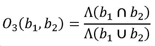
여기서 ![]()
![]()
![]()
![]()
![]()
![]()
![]()
![]()
![]()
![]()
일부 실시예에서, 2개의 직사각형(예컨대, 이전 이미지에서 검출된 하나 이상의 기도에 대응하는 직사각형, 및 현재 이미지에서 검출된 하나 이상의 기도에 대응하는 다른 직사각형) 사이의 연관이 하기 조건이 충족되는 경우 확립된다:In some embodiments, an association between two rectangles (eg, a rectangle corresponding to one or more airways detected in a previous image, and another rectangle corresponding to one or more airways detected in a current image) is established if the following conditions are met do:
[수학식 4][Equation 4]
![]()
![]()
여기서 ![]()
![]()
![]()
![]()
상기 내용이 하나의 레벨 딥(level deep)에 있는 연관(예컨대, 2개 이상의 기도들 사이의 하나의 연관)을 생성하는 것으로 기술되었지만, 다른 실시예가 하나의 레벨 딥보다 큰 체인(chain)을 생성할 수 있다는 것이 인식되어야 한다. 예를 들어, 기도 X가 기도 Y 및 Z와 연관되는 경우, 후속 이미지는 중첩 임계치를 충족시키는, Y' 및 Y''로 라벨링된, Y 내의 기도를 검출할 수 있다. 그러한 경우에, 시스템은 이어서 X→Y→Y',Y''를 포함하는 연관 체인과 같은, Y와 Y',Y'' 사이의 관계를 생성할 수 있다.Although the above has been described as creating an association that is one level deep (eg, one association between two or more airways), other embodiments create chains that are greater than one level deep. It should be recognized that it can be done. For example, if airway X is associated with airway Y and Z, subsequent images can detect airways in Y, labeled Y' and Y'', that meet the overlap threshold. In such a case, the system may then create a relationship between Y and Y',Y'', such as an association chain comprising X→Y→Y',Y''.
E.3. 중첩 임계치의 조절E.3. Adjustment of overlap threshold
도 25는 중첩 비 임계치의 부정확한 설정으로 인해 부정확한 연관이 결정될 수 있는 3개의 예를 예시한다. 예를 들어, 이미지(2500(a))에 도시된 관계는 2개의 일-대-일 연관(예컨대, A→A 및 B→B)이어야 한다. 그러나, 이미지(2500(a))의 제4 열에 예시된 중첩은 현재 이미지의 기도 B가 이전 이미지의 기도 A와 연관되게 할 수 있다(또는 기도 A,B가 이전 이미지의 기도 A,B와 연관되게 함). 그러한 경우에, 중첩 임계 값은 이미지(2500(a))의 제4 열에 예시된 중첩이 중첩 조건을 충족시키지 않도록 조절될 수 있다. 유사하게, 이미지(2500(b), 2500(c))는 부정확한 연관이 결정될 수 있는 다른 예 및 중첩 임계 값이 그러한 연관을 방지하도록 조절(예컨대, 제4 열에 예시된 중첩이 중첩 임계치를 충족시키지 않도록 조절)될 수 있는 방법을 예시한다.25 illustrates three examples where an incorrect association may be determined due to an incorrect setting of the overlap ratio threshold. For example, the relationship shown in image 2500(a) should be two one-to-one associations (eg, A→A and B→B). However, the overlap illustrated in column 4 of image 2500(a) may cause airway B in the current image to be associated with airway A in the previous image (or airway A,B to be associated with airway A,B in the previous image). make it happen). In such a case, the overlap threshold may be adjusted such that the overlap illustrated in column 4 of image 2500(a) does not satisfy the overlap condition. Similarly, images 2500(b), 2500(c) are other examples where incorrect associations may be determined and an overlap threshold adjusted to prevent such associations (e.g., the overlap illustrated in column 4 meets the overlap threshold) How it can be adjusted) is illustrated.
일부 실시예에서, 중첩 비 임계치는 시스템의 설계자에 의해 구성된 설계-시간 파라미터일 수 있다. 그러나, 다른 실시예에서, 시스템은 상이한 중첩 임계 값의 실패율을 추적하기 위해 수술 데이터를 추적하고 기록할 수 있다. 그러한 시스템은 그러한 수술 데이터를 이용하여 상이한 중첩 임계 값의 사용에 대해 시스템을 훈련시키고 더 적은 실패율로 이어질 수 있는 업데이트된 중첩 임계 값으로 시스템을 업데이트할 수 있다. 또한, 다수의 시스템이 그러한 훈련 및 중첩 임계 값의 선택에 이용가능한 수술 데이터를 증가시키기 위해 수술 데이터를 공유할 수 있다.In some embodiments, the overlap ratio threshold may be a design-time parameter configured by the designer of the system. However, in other embodiments, the system may track and record surgical data to track failure rates of different overlap thresholds. Such a system may use such surgical data to train the system on the use of different overlap thresholds and to update the system with updated overlap thresholds, which may lead to lower failure rates. Additionally, multiple systems may share surgical data to increase the surgical data available for such training and selection of overlap thresholds.
E.4. 시간적 및 공간적 분석에 기초하는 기도 병합E.4. Airway Merging Based on Temporal and Spatial Analysis
기도 병합에서, 시스템은 결정된 기도 연관(들) 및 수술전 모델 데이터로부터의 데이터에 기초하여 2개 이상의 현재 기도를 병합할 수 있다. 현재 이미지 내의 2개 이상의 기도를 병합할지 여부를 결정하기 위해, 시스템은 기구의 현재 위치를 결정하고, 이어서 수술전 모델로부터의 위치에서 예상되는 기도의 수를 결정할 수 있다. 시스템이 기구의 위치를 결정하기 위한 임의의 수의 접근법을 이용할 수 있다는 것이 인식되어야 한다. 제한이 아닌 예로서, 그러한 접근법은 전술된 센서 융합 시스템(sensor fusion system)을 포함할 수 있으며, 이는 하기 센서 유형들 중 하나 이상을 포함할 수 있다: EM, 비전, 로봇 데이터, 형상 감지 섬유 등.In airway merging, the system may merge two or more current airways based on the determined airway association(s) and data from pre-operative model data. To determine whether to merge two or more airways in the current image, the system may determine the current position of the instrument, and then determine the expected number of airways in the position from the pre-operative model. It should be appreciated that the system may utilize any number of approaches for determining the location of the instrument. By way of example and not limitation, such approaches may include the sensor fusion systems described above, which may include one or more of the following sensor types: EM, vision, robotic data, shape sensing fibers, etc. .
수술전 모델 데이터는 주어진 위치에 대한 예상된 기도의 검색을 허용하는 형태로 저장될 수 있다. 그러한 데이터는 절차 전에 생성될 수 있으며, 여기에서 예상된 기도는 수술전 모델에 대한 기구의 위치에 의해 인덱싱된다(indexed). 여기서 사용되는 바와 같이, 위치는 배향을 갖거나 갖지 않는 위치확인 위치(positional location), 세그먼트 내의 삽입 깊이를 갖거나 갖지 않는 세그먼트, 또는 임의의 다른 위치 표현일 수 있다.Preoperative model data can be stored in a form that allows for retrieval of the predicted airways for a given location. Such data may be generated prior to the procedure, where the predicted airway is indexed by the position of the instrument relative to the preoperative model. As used herein, a location may be a positional location with or without orientation, a segment with or without an insertion depth within a segment, or any other representation of a location.
일단 시스템이 현재 이미지 내의 기도들의 세트가 병합되어야 한다고 결정하면, 시스템은 병합된 기도의 새로운 기도 중심을 결정할 수 있다. 새로운 기도 중심은 이어서 전술된 이미지 기반 기도 매핑 방법에 사용될 수 있다.Once the system determines that the set of airways in the current image should be merged, the system may determine a new airway center of the merged airway. The new airway center can then be used in the image-based airway mapping method described above.
단일 페어런트 기도(parent airway)를 갖는 2개의 기도를 병합하는 예에서, 2개의 기도의 기도 중심은 각각 ![]()
![]()
![]()
![]()
[수학식 5][Equation 5]
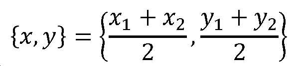
다른 예에서, 병합된 기도의 기도 중심은 현재 이미지에서 검출된 기도(예컨대, 현재 이미지 내의 기도를 나타내는 기하학적 형상)의 각각의 중심 위치의 가중된 중심으로서 계산될 수 있다. 예를 들어, 그러한 값은 하기와 같이 계산될 수 있다:In another example, the airway centroid of the merged airway may be calculated as the weighted centroid of each centroid location of the airway detected in the current image (eg, a geometric shape representing the airway in the current image). For example, such a value can be calculated as follows:
[수학식 6][Equation 6]
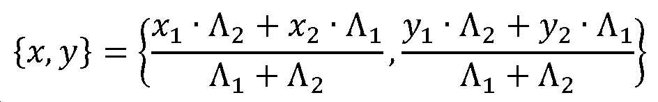
여기서 ![]()
![]()
![]()
![]()
또 다른 예에서, 병합된 기도의 기도 중심은 현재 이미지에서 검출된 기도(예컨대, 현재 이미지 내의 기도를 나타내는 기하학적 형상)를 캡슐화하는 경계설정 다각형의 중심으로서 계산될 수 있다. 예를 들어, 2개의 기도들 중 제1 기도를 캡슐화하는 직사각형의 죄측-상부 코너 및 우측-저부 코너의 좌표가 ![]()
![]()
![]()
![]()
![]()
![]()
![]()
![]()
![]()
![]()
![]()
![]()
[수학식 7][Equation 7]
![]()
![]()
[수학식 8][Equation 8]
![]()
![]()
[수학식 9][Equation 9]
![]()
![]()
[수학식 10][Equation 10]
![]()
![]()
이들 값을 사용하여, 병합된 기도의 기도 중심은 캡슐화 직사각형의 중심으로서 계산될 수 있고, 이는 하기와 같이 획득된다:Using these values, the airway center of the merged airway can be calculated as the center of the encapsulating rectangle, which is obtained as follows:
[수학식 11][Equation 11]
예를 들어, 계산되는 병합된 중심은 현재 이미지에서 검출된 기도의 임의의 다른 중심 위치와 상이할 수 있다. 도 22의 이미지(2200(b))에서 보여지는 바와 같이, 병합된 기도의 병합된 중심의 그래픽 표현이 병합된 기도로 병합되었던 기도의 중심 대신에 시스템의 디스플레이 상에 출력될 수 있다. 일부 경우에, 병합된 중심은 병합되었던 기도의 중심과 함께 디스플레이 상에 출력될 수 있다. 병합된 기도의 기도 중심을 계산하는 예시적인 기법이 전술되지만, 병합된 기도를 나타내는 기도 중심을 계산하는 다른 기법이 사용될 수 있다.For example, the calculated merged centroid may be different from any other centroid location of the airway detected in the current image. As shown in image 2200(b) of FIG. 22 , a graphical representation of the merged center of the merged airway may be output on the system's display instead of the center of the airway that was merged into the merged airway. In some cases, the merged center may be output on the display along with the center of the airway that was merged. Although exemplary techniques for calculating the airway center of a merged airway are described above, other techniques for calculating the airway center representing a merged airway may be used.
F. 예시적인 이미지-기반 기도 분석 및 매핑 방법 및 시스템F. Exemplary Image-Based Airway Analysis and Mapping Methods and Systems
도 26은 전술된 바와 같은 이미지-기반 기도 분석 및 매핑을 구현하기 위한 예시적인 방법(2600)을 예시한다. 방법(2600)은 본 개시 전반에 걸쳐 기술된 다양한 로봇-제어식 시스템에서 구현될 수 있다. 방법(2600)은 내강 네트워크 내로 삽입되도록 구성되는 세장형 본체를 갖는 기구를 포함하는 로봇 시스템으로 구현될 수 있다. 이미징 장치가 세장형 본체 상에(예컨대, 세장형 본체의 원위 단부 상에) 위치될 수 있다. 기구는 기구를 내강 네트워크를 통해 이동시키도록 구성되는 기구 위치설정 장치(예컨대, 로봇 아암)에 부착될 수 있다. 방법(2600)을 채용하는 시스템은 프로세서가 방법(2600)을 실행하게 하는 명령어로 구성되는 프로세서를 포함할 수 있다. 방법(2600)은 단지 예로서 제공되고, 이미지-기반 기도 분석 및 매핑은 도 26에 도시된 것과는 상이한 단계를 사용하여 구현될 수 있다. 간략함을 위해, 도 26에 예시된 단계는 시스템(예컨대, 본 명세서에 기술된 시스템들 중 하나 또는 여기서 기술된 기법들 중 하나 이상을 수행하도록 구성되는 시스템)에 의해 수행되는 것으로 기술된다.26 illustrates an
블록(2602)에서, 내강 네트워크 내의 하나 이상의 기도를 매핑하기 위한 시스템은 기구 상에 위치된 이미징 장치로 내강 네트워크 내에서 복수의 이미지를 캡처한다. 복수의 이미지는 적어도 2개의 이미지를 포함할 수 있으며, 여기에서 이미지들 중 하나(예컨대, 현재 이미지, 또는 제2 이미지)는 다른 이미지(예컨대, 이전 이미지, 또는 제1 이미지) 이후의 시간에 캡처된다. 제1 이미지가 캡처되는 시간은 제1 시간으로 지칭될 수 있고, 제2 이미지가 캡처되는 시간은 제2 시간으로 지칭될 수 있다.At
블록(2604)에서, 시스템은 제1 이미지에서 하나 이상의 기도를 식별한다. 일부 실시예에서, 시스템은 제1 이미지에서 단일 기도를 식별한다. 다른 실시예에서, 시스템은 제1 이미지에서 다수의 기도를 식별한다. 시스템은 본 명세서에 기술된 기도 식별 또는 검출 기법들(예컨대, 픽셀 강도 분석) 또는 다른 기법들 중 임의의 것을 이용할 수 있다. 예를 들어, 식별된 기도는, 그의 픽셀이 기도 검출 방법에 의해 지정된 픽셀 강도 임계치를 충족시키는 하나 이상의 다각형 또는 다른 기하학적 형상을 포함할 수 있다. 일부 실시예에서, 중심과 같은 지점 위치가 결정되고 검출된 기도와 연관된다.At
블록(2606)에서, 시스템은 제2 이미지에서 2개 이상의 기도를 식별한다. 일부 실시예에서, 시스템은 제2 이미지에서 단일 기도를 식별한다. 다른 실시예에서, 시스템은 제2 이미지에서 다수의 기도를 식별한다. 시스템은 블록(2604)에서 이용되는 것과 유사한 방식으로 제2 이미지에서 하나 이상의 기도를 식별할 수 있다.At
블록(2608)에서, 시스템은, 제1 이미지 내의 제1 기도 및 제2 이미지 내의 2개 이상의 기도에 기초하여, 중첩 조건이 충족된다고 결정한다. 중첩 조건이 충족된다는 결정은, 예를 들어 제1 이미지 내의 제1 기도를 나타내는 하나 이상의 기하학적 형상들의 제1 세트와 제2 이미지 내의 2개 이상의 기도를 나타내는 하나 이상의 기하학적 형상들의 제2 세트 사이의 공간적 중첩의 정도를 결정하는 것; 및 공간적 중첩의 정도가 한정된 중첩 임계 값, 파라미터, 또는 표지(indicia)를 충족하거나 초과한다고 결정하는 것을 수반할 수 있다. 블록(2602 내지 2606)이 기도 추적 및 기도 연관과 관련하여 기술된 하나 이상의 특징을 수반할 수 있다는 것이 인식되어야 한다. 즉, 시스템은 현재 이미지 내의 기도의 위치 및 크기뿐만 아니라, 이전 이미지에서 이전에 검출된 기도의 예상된 위치 및 크기를 추적할 수 있다. 중첩 조건이 충족될 때, 시스템은 이전 이미지 및 현재 이미지의 하나 이상의 이미지 내의 기도와의 연관을 생성할 수 있다. 다른 연관은, 전술된 바와 같이, 일-대-일 또는 다-대-일일수 있다.At
블록(2610)에서, 시스템은 제2 시간 동안 기구의 위치에 대응하는 예상된 기도의 총수를 나타내는 수술전 모델 데이터에 액세스한다. 예를 들어, 도 26에 예시되지 않지만, 시스템은 내강 네트워크 내에 위치된 기구에 대한 위치 상태 추정치에 액세스할 수 있다. 위치 상태 추정치는 기구가 (예컨대, 도 21의 내강 네트워크(1000)의 계층적 구조 내에서) 어느 분지부에 현재 위치되어 있는지의 식별을 포함할 수 있다. 위치 상태 추정치 및 수술전 모델 데이터(예컨대, CT 이미지)에 기초하여, 시스템은 제2 시간 동안(즉, 제2 이미지가 캡처되는 시간에) 기구의 위치에 대응하는 예상된 기도의 총수를 결정할 수 있다. 위치 상태 추정치는 예를 들어 도 15의 내비게이션 및 위치결정 시스템(90)에 의해 결정될 수 있다. 위치 상태 추정치는 다양한 및/또는 다수의 위치 감지 모달리티 및 정보, 예컨대 수술전 모델 데이터(91), 비전 데이터(92), EM 데이터(93)(또는 다른 위치 감지 데이터), 및/또는 로봇 명령 및 운동학 데이터(94)에 기초하여 결정될 수 있다.At
블록(2612)에서, 시스템은, 수술전 모델 데이터 및 중첩 조건이 충족된다는 결정에 기초하여, 제2 이미지 내의 2개 이상의 기도와 수술전 모델 데이터 내의 기도 사이의 매핑을 결정한다. 이러한 블록에서, 시스템은 기도 병합(섹션 E.4. 참조)을 사용하여 제2 이미지 내의 기도와 수술전 모델 데이터 내의 기도 사이의 매핑을 결정할 수 있다. 즉, 일부 실시예에 따르면, 시스템은 제2 이미지에서 검출된 기도를 병합할지 또는 병합하지 않을지 여부를 결정하기 위해, 수술전 모델 데이터에 의해 결정될 수 있는 바와 같이, 내강 네트워크 내의 현재 위치에 대한 예상된 기도의 수의 총수 및 블록(2602 내지 2606)(기도 추적 및 기도 연관)으로부터 도출된 데이터를 사용할 수 있다. 시스템은 이어서 수술전 모델에서 병합된 또는 병합되지 않은 기도를 매핑할 수 있다. 기도를 수술전 모델 데이터에 매핑하는 것은, 전체적으로 본 명세서에 참고로 포함되고 부록 A로서 이에 첨부된, 2017년 10월 13일자로 출원된 미국 특허 출원 제15/783,903호에 추가로 기술되어 있다.At
블록(2612)의 일부로서 방금 논의된 바와 같이, 시스템은 제2 시간 동안 기구의 위치에 대응하는 예상된 기도의 총수를 나타내는 수술전 모델 데이터에 액세스함으로써 수술전 모델에 기초하는 수술전 모델 데이터 내의 기도와 제2 이미지 내의 2개 이상의 기도 사이의 매핑을 결정할 수 있다. 예상된 기도 총수를 결정하기 위해 수술전 모델 데이터에 액세스하는 것이 이제 더 상세히 설명된다. 도 26에 예시되지 않지만, 수술전 모델 데이터는 시스템이 주어진 위치에 대해 예상되는 기도의 수를 검색하도록 허용하는 데이터 구조를 포함할 수 있다. 또한, 시스템은 내강 네트워크 내에 위치된 기구에 대한 위치 상태 추정치에 액세스할 수 있다. 위치 상태 추정치는 기구가 (예컨대, 도 21의 내강 네트워크(1000)의 계층적 구조 내에서) 어느 분지부에 현재 위치되어 있는지의 식별을 포함할 수 있다. 위치 상태 추정치 및 수술전 모델 데이터(예컨대, 일 실시예에서, CT 이미지로부터 도출된 데이터)에 기초하여, 시스템은 위에서 언급된 데이터 구조에 액세스함으로써 제2 시간 동안(즉, 제2 이미지가 캡처되는 시간에) 기구의 위치에 대응하는 예상된 기도의 총수를 결정할 수 있다. 위치 상태 추정치는 예를 들어 도 15의 내비게이션 및 위치결정 시스템(90)에 의해 결정될 수 있다. 위치 상태 추정치는 다양한 및/또는 다수의 위치 감지 모달리티 및 정보, 예컨대 수술전 모델 데이터(91), 비전 데이터(92), EM 데이터(93)(또는 다른 위치 감지 데이터), 및/또는 로봇 명령 및 운동학 데이터(94)에 기초하여 결정될 수 있다.As just discussed as part of
추가 예로서, 수술전 모델 데이터는 시스템이 내강 네트워크(1000)의 분지부(1004, 1006)를 검출할 것으로 예상됨을 지시할 수 있다. 시스템이 블록(2606)에서 2개의 기도를 검출한 경우, 시스템은 제2 이미지에서 검출된 2개 이상의 기도의 총수가 수술전 모델 데이터에 의해 지시된 예상된 기도의 총수와 동일한 것에 기초하여 병합이 필요하지 않다고 결정할 수 있다. 그러한 경우에, 시스템은 2개의 검출된 기도를, 도 21에 도시된, (예컨대, 이미지 및/또는 2개의 기도의 배향에 기초하여) 각각 분지부(1004, 1006)에 매핑할 수 있다. 도 26의 예에서, 제2 이미지에서 식별된 2개 이상의 기도의 총수가 수술전 모델 데이터에 의해 지시된 예상된 기도의 총수와 동일하다는 결정에 기초하여, 시스템은, 블록(2612)에서, 제2 이미지에서 식별된 2개 이상의 기도들 중 각각의 기도가 수술전 모델 데이터 내의 기도들 중 상이한 기도에 매핑되도록 매핑을 결정할 수 있다.As a further example, the pre-operative model data may indicate that the system is expected to detect the
다른 예에서, 도 22에 예시된 바와 같이, 수술전 모델 데이터는, 시스템이 내강 네트워크(1000)의 분지부(1004, 1006)를 검출할 것으로 예상되지만, 시스템은 블록(2606)에서 4개의 기도(예컨대, 분지부(1004, 1012, 1014, 1016))를 검출하였을 수 있음을 지시할 수 있다. 그러한 경우에, 시스템은 4개의 기도를 (예컨대, 분지부(1012, 1014, 1016)에 대응하는 검출된 기도를 단일 기도로 병합함으로써) 2개의 기도로 병합하고, 병합된 기도를 분지부(1006)에, 그리고 병합되지 않은 기도를 분지부(1004)에 매핑할 수 있다. 도 26의 예에서, 제2 이미지에서 식별된 2개 이상의 기도의 총수가 수술전 모델 데이터에 의해 지시된 예상된 기도의 총수와 상이하다는 결정에 기초하여, 시스템은, 블록(2612)에서, 제2 이미지에서 식별된 2개 이상의 기도들 중 적어도 2개가 수술전 모델 데이터 내의 단일 기도에 매핑되도록 매핑을 결정할 수 있다. 일부 실시예에서, 매핑은 2개 이상의 기도들 사이의 연관을 데이터베이스에 저장하는 것을 포함한다. 예를 들어, 시스템은 이미지에서 식별된 주어진 기도가 수술전 모델 데이터에 의해 지시된 2개 이상의 기도로 분지됨의 표시를 저장할 수 있다.In another example, as illustrated in FIG. 22 , the pre-operative model data indicates that the system is expected to detect
위에서 논의된 바와 같이, 시스템은, 제2 이미지 내의 2개 이상의 기도와 수술전 모델 데이터 내의 기도 사이의 매핑에 기초하여, 기구가 현재 위치되어 있는 내강 네트워크의 세그먼트를 확인할 수 있다. 일부 실시예에서, 시스템은, 제2 이미지 내의 2개 이상의 기도와 수술전 모델 데이터 내의 기도 사이의 매핑에 기초하여, 다른 데이터에 기초한 위치 상태 추정치의 신뢰도 값을 조절할 수 있다. 예를 들어, 이러한 다른 데이터는 EM 데이터, 로봇 데이터, 광학 형상 센서 데이터, 및 관성 측정 유닛(inertial measurement unit, IMU) 데이터, 본 명세서에 기술된 임의의 다른 입력 데이터(예컨대, 도 15의 입력 데이터(91 내지 94)), 또는 이들의 임의의 조합을 포함할 수 있다. 추가적으로 또는 대안적으로, 시스템은, 제2 이미지 내의 2개 이상의 기도와 수술전 모델 데이터 내의 기도 사이의 매핑에 기초하여, 기구가 진입하고 있을 내강 네트워크의 세그먼트를 예측할 수 있다.As discussed above, the system can identify the segment of the luminal network in which the instrument is currently located based on a mapping between the two or more airways in the second image and the airways in the pre-operative model data. In some embodiments, the system may adjust the confidence value of the position state estimate based on other data based on a mapping between the two or more airways in the second image and the airways in the pre-operative model data. For example, such other data may include EM data, robotic data, optical shape sensor data, and inertial measurement unit (IMU) data, any other input data described herein (eg, the input data of FIG. 15 ). (91 to 94)), or any combination thereof. Additionally or alternatively, the system may predict, based on a mapping between the two or more airways in the second image and the airways in the pre-operative model data, the segment of the luminal network into which the instrument will be entering.
블록(2608)의 일 실시예에서, 현재 이미지 내의 기도의 조합이 임계 양 초과만큼(또는 임계 양과 동일하게) 이전 이미지 내의 기도의 조합과 중첩된다고 결정할 때, 시스템은 병합 후의 현재 이미지 내의 기도의 수가 이전 이미지 내의 기도의 조합의 기도의 수와 일치하도록 현재 이미지 내의 기도의 조합을 하나 이상의 기도로 병합할 수 있다. 예를 들어, 시스템은 중첩 비 값(예컨대, 위의 수학식 1 내지 수학식 3에서의 중첩 비 값들 중 임의의 것)을 임계 중첩 값과 비교하여, 기도의 2개의 조합들 사이의 연관이 존재하는지 여부를 결정할 수 있다.In one embodiment of
위에서 논의된 바와 같이, 시스템은 또한 병합된 기도의 병합된 중심을 결정할 수 있다. 예를 들어, 시스템은 현재 이미지 내의 기도의 조합(예컨대, 현재 이미지 내의 기도의 조합을 나타내는 기하학적 형상들의 세트)의 병합된 중심 위치를 계산할 수 있고, 여기에서 병합된 중심 위치는 현재 이미지에서 검출된 기도(예컨대, 현재 이미지 내의 기도의 조합을 나타내는 세트 내의 기하학적 형상)의 각각의 중심 위치들 중 임의의 것과 상이하다.As discussed above, the system may also determine the merged center of the merged airway. For example, the system may calculate a merged centroid position of a combination of airways in the current image (eg, a set of geometric shapes representing a combination of airways in the current image), where the merged centroid location is a detected location in the current image. different from any of the respective central positions of the airways (eg, geometric shapes in the set representing combinations of airways in the current image).
시스템이 기도의 조합의 다수의 페어링(pairing)이 중첩 조건을 충족한다고 결정하는 경우(예컨대, A→B가 60% 중첩을 갖고 A→C가 25% 중첩을 가짐), 시스템은 더 큰 중첩을 갖는 기도의 조합의 페어링이 연관되는 것으로(예컨대, A→B) 결정할 수 있다. 일부 실시예에서, 중첩 조건이 충족되는지 여부의 결정은 정도의 결정(예컨대, 중첩 비가 임계 중첩 비 이상임)이 아니며, 대신에 이진 결정(binary determination)(예컨대, 현재 이미지 내의 기도의 조합을 캡슐화하는 직사각형의 3개 이상의 세그먼트의 중간점이 페어런트 이미지 내의 기도의 조합을 캡슐화하는 직사각형 내에 있는지 여부)이다.If the system determines that multiple pairings of a combination of airways satisfy the overlap condition (e.g., A→B has 60% overlap and A→C has 25% overlap), the system determines the greater overlap A pairing of a combination of airways with airways may be determined to be relevant (eg, A→B). In some embodiments, the determination of whether an overlap condition is met is not a determination of degree (eg, the overlap ratio is greater than or equal to a threshold overlap ratio), but is instead a binary determination (eg, encapsulating a combination of airways in the current image). whether the midpoint of three or more segments of the rectangle is within the rectangle encapsulating the combination of airways in the parent image).
일부 실시예에서, 중첩 조건이 충족되는지 여부의 결정은 이전 이미지 내의 기도의 조합(예컨대, 이전 이미지 내의 기도의 조합을 나타내는 기하학적 형상들의 세트)을 캡슐화하는 경계설정 다각형(예컨대, 직사각형 또는 다른 형상)을 결정하는 것, 현재 이미지 내의 기도의 조합(예컨대, 현재 이미지 내의 기도의 조합을 나타내는 기하학적 형상들의 세트)을 캡슐화하는 경계설정 다각형을 결정하는 것, 및 2개의 경계설정 다각형들 사이의 중첩에 기초하여 공간적 중첩의 정도를 결정하는 것을 포함할 수 있다.In some embodiments, the determination of whether an overlap condition is met is a bounding polygon (eg, a rectangle or other shape) that encapsulates a combination of airways in a previous image (eg, a set of geometric shapes representing a combination of airways in a previous image). based on determining a delimiting polygon that encapsulates a combination of airways in the current image (eg, a set of geometric shapes representing a combination of airways in the current image), and an overlap between the two delimiting polygons. to determine the degree of spatial overlap.
본 명세서에 기술된 이미지-기반 기도 분석 및 매핑 기법은 비전 분지부 예측(Vision Branch Prediction, VBP) 접근법 또는 다른 이미지-기반 분지부 예측 접근법을 보상한다. VBP는 (예컨대, 도 22의 이미지(2200(a))에 예시된 바와 같이) 주어진 이미지에서 상이한 세대로부터의 것인 기도의 가시성으로 인해 일부 경우에 정확한 기도 매핑을 수행하는 것이 가능하지 않을 수 있다. 본 명세서에 기술된 이미지-기반 기도 분석 및 매핑 기법은 내강 네트워크 내의 기도의 계층적 구조를 결정하거나 확인하고, 동일한 세대에 대응하는 기도 중심을 결정할 수 있다. 이는 도 22의 이미지(2200(b))에 예시된 바와 같이, 정확한 기도 매핑을 확립하는 데 도움을 준다.The image-based airway analysis and mapping techniques described herein compensate for the Vision Branch Prediction (VBP) approach or other image-based branch prediction approaches. VBP may not be able to perform accurate airway mapping in some cases due to visibility of airways that are from different generations in a given image (eg, as illustrated in image 2200(a) of FIG. 22 ). . The image-based airway analysis and mapping techniques described herein can determine or identify the hierarchical structure of airways within a luminal network and determine airway centers corresponding to the same generation. This helps to establish an accurate airway mapping, as illustrated in image 2200(b) of FIG. 22 .
G. 재귀 거리 검색(Recursive Distance Searching)G. Recursive Distance Searching
일부 실시예에서, 현재 이미지 내의 2개 이상의 기도가 병합되어야 한다고 결정할 때, 시스템은 재귀 거리 검색을 사용하여 기도를 병합할 수 있다. 그렇게 함에 있어서, 시스템은 기도가 다른 세대보다 그의 동일한 세대로부터의 기도에 더 가까운 것으로 가정할 수 있다. 예를 들어, 이러한 가정은, 3세대인 기도(예컨대, 도 22의 저부 우측 코너에 예시된 분지부(1012, 1014, 1016))가 2세대인 기도(예컨대, 도 22의 상부 좌측 코너에 예시된 분지부(1004))보다 서로 더 가까운, 도 21 및 도 22의 예에서 유효하다.In some embodiments, upon determining that two or more airways in the current image should be merged, the system may merge the airways using a recursive distance search. In doing so, the system may assume that the prayer is closer to the prayer from its same generation than the other generation. For example, this assumption is that an airway that is third generation (eg,
재귀 거리 검색은 집합 ![]()
![]()
![]()
![]()
[수학식 12][Equation 12]
여기서 ![]()
![]()
IV. 구현 시스템 및 용어IV. Implementation system and terminology
본 명세서에 개시된 구현예는 로봇-제어식 의료 기구의 내비게이션을 위한 이미지-기반 기도 분석 및 매핑을 위한 시스템, 방법 및 장치를 제공한다. 본 명세서에 기술된 다양한 구현예는 내강 네트워크의 개선된 내비게이션을 제공한다.Embodiments disclosed herein provide systems, methods and apparatus for image-based airway analysis and mapping for navigation of robot-controlled medical instruments. Various implementations described herein provide improved navigation of the luminal network.
본 명세서에 사용되는 바와 같은 용어 "결합하다", "결합하는", "결합된" 또는 단어 결합하다의 다른 변형은 간접적인 연결 또는 직접적인 연결을 나타낼 수 있다는 것에 유의하여야 한다. 예를 들어, 제1 구성요소가 제2 구성요소에 "결합된" 경우, 제1 구성요소는 다른 구성요소를 통해 제2 구성요소에 간접적으로 연결되거나 제2 구성요소에 직접적으로 연결될 수 있다.It should be noted that as used herein, the terms "couple", "combining", "coupled" or other variations of the word combine may refer to an indirect connection or a direct connection. For example, when a first component is “coupled” to a second component, the first component can be indirectly coupled to the second component through another component or directly coupled to the second component.
본 명세서에 기술된 위치 추정 및 로봇 운동 작동 기능은 프로세서-판독가능 또는 컴퓨터-판독가능 매체 상에 하나 이상의 명령어로서 저장될 수 있다. 용어 "컴퓨터-판독가능 매체"는 컴퓨터 또는 프로세서에 의해 액세스될 수 있는 임의의 이용가능한 매체를 지칭한다. 제한이 아닌 예로서, 그러한 매체는 랜덤 액세스 메모리(RAM), 판독-전용 메모리(ROM), 전기적 소거가능 프로그램가능 판독-전용 메모리(EEPROM), 플래시 메모리, 콤팩트 디스크 판독-전용 메모리(CD-ROM) 또는 다른 광학 디스크 저장 장치, 자기 디스크 저장 장치 또는 다른 자기 저장 장치, 또는 명령어 또는 데이터 구조의 형태로 원하는 프로그램 코드를 저장하는 데 사용될 수 있고 컴퓨터에 의해 액세스될 수 있는 임의의 다른 매체를 포함할 수 있다. 컴퓨터-판독가능 매체는 유형적이고 비-일시적일 수 있음에 유의하여야 한다. 본 명세서에 사용되는 바와 같이, 용어 "코드"는 컴퓨팅 장치 또는 프로세서에 의해 실행가능한 소프트웨어, 명령어, 코드 또는 데이터를 지칭할 수 있다.The position estimation and robot motion actuation functions described herein may be stored as one or more instructions on a processor-readable or computer-readable medium. The term “computer-readable medium” refers to any available medium that can be accessed by a computer or processor. By way of example, and not limitation, such media include random access memory (RAM), read-only memory (ROM), electrically erasable programmable read-only memory (EEPROM), flash memory, compact disk read-only memory (CD-ROM). ) or other optical disk storage device, magnetic disk storage device or other magnetic storage device, or any other medium that can be used to store the desired program code in the form of instructions or data structures and that can be accessed by a computer. can It should be noted that computer-readable media can be tangible and non-transitory. As used herein, the term “code” may refer to software, instructions, code, or data executable by a computing device or processor.
본 명세서에 개시된 방법은 기술된 방법을 달성하기 위한 하나 이상의 단계 또는 동작을 포함한다. 방법 단계 및/또는 동작은 청구범위의 범주로부터 벗어남이 없이 서로 교환될 수 있다. 다시 말하면, 기술되는 방법의 적절한 작동을 위해 특정 순서의 단계 또는 동작이 요구되지 않는 한, 특정 단계 및/또는 동작의 순서 및/또는 사용은 청구범위의 범주로부터 벗어남이 없이 수정될 수 있다.The methods disclosed herein include one or more steps or acts for achieving the described methods. Method steps and/or acts may be interchanged without departing from the scope of the claims. In other words, unless a specific order of steps or acts is required for proper operation of the described method, the order and/or use of specific steps and/or acts may be modified without departing from the scope of the claims.
본 명세서에 사용되는 바와 같이, 용어 "복수"는 2개 이상을 나타낸다. 예를 들어, 복수의 구성요소는 2개 이상의 구성요소를 나타낸다. 용어 "결정하는"은 매우 다양한 동작을 포함하며, 따라서 "결정하는"은 계산, 컴퓨팅, 처리, 도출, 조사, 검색(예컨대, 테이블, 데이터베이스 또는 다른 데이터 구조에서의 검색), 확인 등을 포함할 수 있다. 또한, "결정하는"은 수신(예컨대, 정보를 수신함), 액세스(예컨대, 메모리의 데이터에 액세스함) 등을 포함할 수 있다. 또한, "결정하는"은 해석, 선택, 선정, 설정 등을 포함할 수 있다.As used herein, the term “plurality” refers to two or more. For example, a plurality of components refers to two or more components. The term "determining" encompasses a wide variety of operations, and thus "determining" may include calculating, computing, processing, deriving, investigating, retrieving (eg, retrieving in a table, database or other data structure), verifying, and the like. can Also, “determining” may include receiving (eg, receiving information), accessing (eg, accessing data in a memory), and the like. Also, “determining” may include interpretation, selection, selection, setting, and the like.
어구 "~에 기초한"은, 달리 명백히 명시되지 않는 한, "단지 ~에 기초한"을 의미하지는 않는다. 다시 말하면, 어구 "~에 기초한"은 "단지 ~에 기초한" 및 "적어도 ~에 기초한" 둘 모두를 기술한다.The phrase “based on” does not mean “only based on” unless explicitly stated otherwise. In other words, the phrase “based on” describes both “only based on” and “at least based on”.
개시된 구현예의 이전의 설명은 당업자가 본 발명을 제조하거나 사용하는 것을 가능하게 하도록 제공된다. 이들 구현예에 대한 다양한 수정은 당업자에게 용이하게 명백해질 것이고, 본 명세서에서 정의된 일반적인 원리는 본 발명의 범주로부터 벗어남이 없이 다른 구현예에 적용될 수 있다. 예를 들어, 당업자가 다수의 대응하는 대안적인 그리고 동등한 구조적 상세사항, 예컨대 도구 구성요소를 체결, 장착, 결합, 또는 맞물리게 하는 동등한 방식, 특정 작동 운동을 생성하기 위한 동등한 메커니즘, 및 전기 에너지를 전달하기 위한 동등한 메커니즘을 채용할 수 있을 것임이 인식될 것이다. 따라서, 본 발명은 본 명세서에 도시된 구현예로 제한되도록 의도되는 것이 아니라, 본 명세서에 개시된 원리 및 신규한 특징과 일치하는 가장 넓은 범주에 따른다.The previous description of the disclosed embodiments is provided to enable any person skilled in the art to make or use the present invention. Various modifications to these embodiments will be readily apparent to those skilled in the art, and the generic principles defined herein may be applied to other embodiments without departing from the scope of the invention. For example, a number of corresponding alternative and equivalent structural details by those skilled in the art, such as equivalent ways of fastening, mounting, engaging, or engaging tool components, equivalent mechanisms for generating specific actuation motions, and transferring electrical energy It will be appreciated that equivalent mechanisms for doing so may be employed. Accordingly, the present invention is not intended to be limited to the embodiments shown herein, but is to be accorded the widest scope consistent with the principles and novel features disclosed herein.
Claims (42)
기구로서,
상기 내강 네트워크 내로 삽입되도록 구성되는 세장형 본체, 및
상기 세장형 본체의 원위 부분 상에 위치되는 이미징 장치를 갖는, 상기 기구;
상기 기구에 부착되는 기구 위치설정 장치(instrument positioning device)로서, 상기 기구를 상기 내강 네트워크를 통해 이동시키도록 구성되는, 상기 기구 위치설정 장치;
실행가능 명령어들을 저장한 적어도 하나의 컴퓨터-판독가능 메모리; 및
상기 적어도 하나의 컴퓨터-판독가능 메모리와 통신하고, 상기 명령어들을 실행하여 상기 시스템으로 하여금 적어도,
상기 기구 상에 위치되는 상기 이미징 장치로 상기 내강 네트워크 내의 복수의 이미지들을 캡처하는 것으로서, 상기 복수의 이미지들은 적어도 제1 시간에 캡처되는 제1 이미지 및 상기 제1 시간 이후의 제2 시간에 캡처되는 제2 이미지를 포함하는, 상기 내강 네트워크 내의 복수의 이미지들을 캡처하고;
상기 제1 이미지에서 제1 기도를 식별하고;
상기 제2 이미지에서 2개 이상의 기도들을 식별하고, 상기 제2 이미지 내의 상기 2개 이상의 기도들은 상기 제1 이미지 내의 상기 제1 기도와 상이하고;
상기 제1 이미지 내의 상기 제1 기도 및 상기 제2 이미지 내의 상기 2개 이상의 기도들에 기초하여, 상기 제1 이미지 내의 상기 제1 기도와 상기 제2 이미지 내의 상기 2개 이상의 기도들 사이의 공간적 중첩의 정도를 결정하고;
상기 제1 이미지 내의 상기 제1 기도와 상기 제2 이미지 내의 상기 2개 이상의 기도들 사이의 상기 공간적 중첩의 정도가 중첩 조건을 충족하는지 결정하고;
상기 제2 시간 동안 상기 기구의 위치에 대응하는 예상된 기도들의 총수를 나타내는 수술전 모델 데이터에 액세스하고;
상기 수술전 모델 데이터 및 상기 제1 이미지 내의 상기 제1 기도와 상기 제2 이미지 내의 상기 2개 이상의 기도들 사이의 상기 공간적 중첩의 정도가 상기 중첩 조건을 충족한다는 상기 결정에 기초하여, 상기 제2 이미지 내의 상기 2개 이상의 기도들과 상기 수술전 모델 데이터 내의 상기 기도들 사이의 매핑을 결정하고;
상기 제2 이미지 내의 상기 2개 이상의 기도들과 상기 수술전 모델 데이터 내의 상기 기도들 사이의 상기 매핑에 적어도 부분적으로 기초하여, 상기 기구가 상기 내강 네트워크를 통해 이동하게 하도록 구성되는 하나 이상의 프로세서들을 포함하는, 로봇 수술 시스템.A robotic surgical system for mapping one or more airways in a luminal network, comprising:
As an instrument,
an elongate body configured to be inserted into the luminal network, and
the instrument having an imaging device positioned on a distal portion of the elongate body;
an instrument positioning device attached to the instrument, the instrument positioning device configured to move the instrument through the lumen network;
at least one computer-readable memory storing executable instructions; and
in communication with the at least one computer-readable memory and executing the instructions to cause the system to at least:
capturing a plurality of images in the luminal network with the imaging device positioned on the instrument, the plurality of images being captured at least a first image captured at a first time and a second time after the first time capture a plurality of images in the luminal network, including a second image;
identify a first airway in the first image;
identify two or more airways in the second image, wherein the two or more airways in the second image are different from the first airway in the first image;
Based on the first airway in the first image and the two or more airways in the second image, a spatial overlap between the first airway in the first image and the two or more airways in the second image determine the degree of;
determine whether the degree of spatial overlap between the first airway in the first image and the two or more airways in the second image meets an overlap condition;
access preoperative model data representing a total number of expected airways corresponding to the location of the instrument during the second time period;
Based on the preoperative model data and the determination that the degree of spatial overlap between the first airway in the first image and the two or more airways in the second image meets the overlap condition, the second determine a mapping between the two or more airways in an image and the airways in the pre-operative model data;
one or more processors configured to cause the instrument to move through the lumen network based at least in part on the mapping between the two or more airways in the second image and the airways in the pre-operative model data; which is a robotic surgical system.
상기 제1 이미지 내의 상기 제1 기도를 나타내는 상기 기하학적 형상들의 제1 세트를 캡슐화하는 제1 경계설정 다각형을 결정하고;
상기 제2 이미지 내의 상기 2개 이상의 기도들을 나타내는 상기 기하학적 형상들의 제2 세트를 캡슐화하는 제2 경계설정 다각형을 결정하도록 추가로 구성되고,
상기 하나 이상의 기하학적 형상들의 상기 제1 세트와 상기 하나 이상의 기하학적 형상들의 상기 제2 세트 사이의 상기 공간적 중첩의 정도를 결정하는 것은 상기 제1 경계설정 다각형과 상기 제2 경계설정 다각형 사이의 중첩에 기초하는, 로봇 수술 시스템.3. The method of claim 2, wherein the one or more processors:
determine a first delimiting polygon encapsulating the first set of geometric shapes representing the first airway in the first image;
further configured to determine a second delimiting polygon encapsulating the second set of geometric shapes representing the two or more airways in the second image;
determining the degree of spatial overlap between the first set of one or more geometric shapes and the second set of one or more geometric shapes is based on the overlap between the first bounding polygon and the second bounding polygon which is a robotic surgical system.
상기 매핑을 결정하는 것은 상기 제2 이미지에서 식별되는 상기 2개 이상의 기도들을 나타내는 상기 기하학적 형상들의 제2 세트의 병합된 중심 위치를 계산하는 것을 포함하고,
상기 병합된 중심 위치는 상기 제2 세트 내의 상기 기하학적 형상들의 각각의 중심 위치들 중 임의의 것과 상이한, 로봇 수술 시스템.3. The method of claim 2,
determining the mapping comprises calculating a merged central position of the second set of geometries representing the two or more airways identified in the second image;
wherein the merged central position is different from any of the central positions of each of the geometries in the second set.
상기 제2 이미지에서 식별되는 상기 2개 이상의 기도들의 총수가 상기 수술전 모델 데이터에 의해 지시되는 상기 예상된 기도들의 총수와 동일하다고 결정하는 것; 및
상기 제2 이미지에서 식별되는 상기 2개 이상의 기도들의 상기 총수가 상기 수술전 모델 데이터에 의해 지시되는 상기 예상된 기도들의 총수와 동일하다고 결정하는 것에 응답하여, 상기 제2 이미지에서 식별되는 상기 2개 이상의 기도들 중 각각의 기도가 상기 수술전 모델 데이터 내의 상기 기도들 중 상이한 기도에 매핑되도록 상기 매핑을 결정하는 것을 포함하는, 로봇 수술 시스템.The method of claim 1, wherein determining the mapping comprises:
determining that the total number of the two or more airways identified in the second image is equal to the expected total number of airways indicated by the pre-operative model data; and
In response to determining that the total number of the two or more airways identified in the second image is equal to the total number of the expected airways indicated by the pre-operative model data, the two or more airways identified in the second image and determining the mapping such that each one of the airways is mapped to a different one of the airways in the pre-operative model data.
기구 상에 위치되는 이미징 장치로 내강 네트워크 내의 복수의 이미지들을 캡처하는 것으로서, 상기 복수의 이미지들은 적어도 제1 시간에 캡처되는 제1 이미지 및 상기 제1 시간 이후의 제2 시간에 캡처되는 제2 이미지를 포함하는, 상기 내강 네트워크 내의 복수의 이미지들을 캡처하고;
상기 제1 이미지에서 제1 기도를 식별하고;
상기 제2 이미지에서 2개 이상의 기도들을 식별하고, 상기 제2 이미지 내의 상기 2개 이상의 기도들은 상기 제1 이미지 내의 상기 제1 기도와 상이하고;
상기 제1 이미지 내의 상기 제1 기도 및 상기 제2 이미지 내의 상기 2개 이상의 기도들에 기초하여, 상기 제1 이미지 내의 상기 제1 기도와 상기 제2 이미지 내의 상기 2개 이상의 기도들 사이의 공간적 중첩의 정도를 결정하고;
상기 제1 이미지 내의 상기 제1 기도와 상기 제2 이미지 내의 상기 2개 이상의 기도들 사이의 상기 공간적 중첩의 정도가 중첩 조건을 충족하는지 결정하고;
상기 제2 시간 동안 상기 기구의 위치에 대응하는 예상된 기도들의 총수를 나타내는 수술전 모델 데이터에 액세스하고;
상기 수술전 모델 데이터 및 상기 제1 이미지 내의 상기 제1 기도와 상기 제2 이미지 내의 상기 2개 이상의 기도들 사이의 상기 공간적 중첩의 정도가 상기 중첩 조건을 충족한다는 상기 결정에 기초하여, 상기 제2 이미지 내의 상기 2개 이상의 기도들과 상기 수술전 모델 데이터 내의 상기 기도들 사이의 매핑을 결정하고;
상기 제2 이미지 내의 상기 2개 이상의 기도들과 상기 수술전 모델 데이터 내의 상기 기도들 사이의 상기 매핑에 적어도 부분적으로 기초하여, 상기 기구가 상기 내강 네트워크를 통해 이동하게 하는, 비-일시적 컴퓨터 판독가능 저장 매체.A non-transitory computer-readable storage medium having stored thereon instructions that, when executed, cause a processor of an apparatus to at least:
capturing a plurality of images in the luminal network with an imaging device positioned on the instrument, the plurality of images being a first image captured at least at a first time and a second image captured at a second time after the first time capturing a plurality of images within the luminal network;
identify a first airway in the first image;
identify two or more airways in the second image, wherein the two or more airways in the second image are different from the first airway in the first image;
Based on the first airway in the first image and the two or more airways in the second image, a spatial overlap between the first airway in the first image and the two or more airways in the second image determine the degree of;
determine whether the degree of spatial overlap between the first airway in the first image and the two or more airways in the second image meets an overlap condition;
access preoperative model data representing a total number of expected airways corresponding to the location of the instrument during the second time period;
Based on the preoperative model data and the determination that the degree of spatial overlap between the first airway in the first image and the two or more airways in the second image meets the overlap condition, the second determine a mapping between the two or more airways in an image and the airways in the pre-operative model data;
cause the instrument to move through the lumen network based at least in part on the mapping between the two or more airways in the second image and the airways in the pre-operative model data. storage medium.
상기 제2 이미지에서 식별되는 상기 2개 이상의 기도들의 총수가 상기 수술전 모델 데이터에 의해 지시되는 상기 예상된 기도들의 총수와 상이하다고 결정하는 것; 및
상기 공간적 중첩의 정도가 상기 중첩 조건을 충족한다는 상기 결정에 기초하여, 상기 2개 이상의 기도들이 상기 제1 기도로부터 분지된다고 결정하는 것을 포함하는, 비-일시적 컴퓨터 판독가능 저장 매체.The method of claim 11 , wherein determining the mapping comprises:
determining that the total number of the two or more airways identified in the second image is different from the expected total number of airways indicated by the pre-operative model data; and
and determining that the two or more airways branch from the first airway based on the determination that the degree of spatial overlap meets the overlap condition.
Applications Claiming Priority (3)
| Application Number | Priority Date | Filing Date | Title |
|---|---|---|---|
| US201862678881P | 2018-05-31 | 2018-05-31 | |
| US62/678,881 | 2018-05-31 | ||
| PCT/US2019/034694 WO2019232236A1 (en) | 2018-05-31 | 2019-05-30 | Image-based airway analysis and mapping |
Publications (2)
| Publication Number | Publication Date |
|---|---|
| KR20210016572A KR20210016572A (en) | 2021-02-16 |
| KR102455671B1 true KR102455671B1 (en) | 2022-10-20 |
Family
ID=68697129
Family Applications (1)
| Application Number | Title | Priority Date | Filing Date |
|---|---|---|---|
| KR1020207037570A Active KR102455671B1 (en) | 2018-05-31 | 2019-05-30 | Image-Based Airway Analysis and Mapping |
Country Status (7)
| Country | Link |
|---|---|
| US (2) | US10898275B2 (en) |
| EP (1) | EP3801348B1 (en) |
| JP (1) | JP7146949B2 (en) |
| KR (1) | KR102455671B1 (en) |
| CN (1) | CN110831538B (en) |
| MX (1) | MX2020012904A (en) |
| WO (1) | WO2019232236A1 (en) |
Families Citing this family (213)
| Publication number | Priority date | Publication date | Assignee | Title |
|---|---|---|---|---|
| US8414505B1 (en) | 2001-02-15 | 2013-04-09 | Hansen Medical, Inc. | Catheter driver system |
| EP1720480A1 (en) | 2004-03-05 | 2006-11-15 | Hansen Medical, Inc. | Robotic catheter system |
| EP1906858B1 (en) | 2005-07-01 | 2016-11-16 | Hansen Medical, Inc. | Robotic catheter system |
| US9232959B2 (en) | 2007-01-02 | 2016-01-12 | Aquabeam, Llc | Multi fluid tissue resection methods and devices |
| US12290277B2 (en) | 2007-01-02 | 2025-05-06 | Aquabeam, Llc | Tissue resection with pressure sensing |
| US8814921B2 (en) | 2008-03-06 | 2014-08-26 | Aquabeam Llc | Tissue ablation and cautery with optical energy carried in fluid stream |
| US8218847B2 (en) | 2008-06-06 | 2012-07-10 | Superdimension, Ltd. | Hybrid registration method |
| US9254123B2 (en) | 2009-04-29 | 2016-02-09 | Hansen Medical, Inc. | Flexible and steerable elongate instruments with shape control and support elements |
| US8672837B2 (en) | 2010-06-24 | 2014-03-18 | Hansen Medical, Inc. | Methods and devices for controlling a shapeable medical device |
| US20120071752A1 (en) | 2010-09-17 | 2012-03-22 | Sewell Christopher M | User interface and method for operating a robotic medical system |
| US9138166B2 (en) | 2011-07-29 | 2015-09-22 | Hansen Medical, Inc. | Apparatus and methods for fiber integration and registration |
| CN108606773B (en) | 2012-02-29 | 2020-08-11 | 普罗赛普特生物机器人公司 | Automated image-guided tissue resection and processing |
| US10383765B2 (en) | 2012-04-24 | 2019-08-20 | Auris Health, Inc. | Apparatus and method for a global coordinate system for use in robotic surgery |
| US20130317519A1 (en) | 2012-05-25 | 2013-11-28 | Hansen Medical, Inc. | Low friction instrument driver interface for robotic systems |
| US20140148673A1 (en) | 2012-11-28 | 2014-05-29 | Hansen Medical, Inc. | Method of anchoring pullwire directly articulatable region in catheter |
| US10231867B2 (en) | 2013-01-18 | 2019-03-19 | Auris Health, Inc. | Method, apparatus and system for a water jet |
| US10149720B2 (en) | 2013-03-08 | 2018-12-11 | Auris Health, Inc. | Method, apparatus, and a system for facilitating bending of an instrument in a surgical or medical robotic environment |
| US9057600B2 (en) | 2013-03-13 | 2015-06-16 | Hansen Medical, Inc. | Reducing incremental measurement sensor error |
| US9566414B2 (en) | 2013-03-13 | 2017-02-14 | Hansen Medical, Inc. | Integrated catheter and guide wire controller |
| US9173713B2 (en) | 2013-03-14 | 2015-11-03 | Hansen Medical, Inc. | Torque-based catheter articulation |
| US11213363B2 (en) | 2013-03-14 | 2022-01-04 | Auris Health, Inc. | Catheter tension sensing |
| US9326822B2 (en) | 2013-03-14 | 2016-05-03 | Hansen Medical, Inc. | Active drives for robotic catheter manipulators |
| US20140277334A1 (en) | 2013-03-14 | 2014-09-18 | Hansen Medical, Inc. | Active drives for robotic catheter manipulators |
| US10849702B2 (en) | 2013-03-15 | 2020-12-01 | Auris Health, Inc. | User input devices for controlling manipulation of guidewires and catheters |
| US9408669B2 (en) | 2013-03-15 | 2016-08-09 | Hansen Medical, Inc. | Active drive mechanism with finite range of motion |
| US20140276647A1 (en) | 2013-03-15 | 2014-09-18 | Hansen Medical, Inc. | Vascular remote catheter manipulator |
| US9283046B2 (en) | 2013-03-15 | 2016-03-15 | Hansen Medical, Inc. | User interface for active drive apparatus with finite range of motion |
| US9629595B2 (en) | 2013-03-15 | 2017-04-25 | Hansen Medical, Inc. | Systems and methods for localizing, tracking and/or controlling medical instruments |
| US10376672B2 (en) | 2013-03-15 | 2019-08-13 | Auris Health, Inc. | Catheter insertion system and method of fabrication |
| US20140276936A1 (en) | 2013-03-15 | 2014-09-18 | Hansen Medical, Inc. | Active drive mechanism for simultaneous rotation and translation |
| US9014851B2 (en) | 2013-03-15 | 2015-04-21 | Hansen Medical, Inc. | Systems and methods for tracking robotically controlled medical instruments |
| US9271663B2 (en) | 2013-03-15 | 2016-03-01 | Hansen Medical, Inc. | Flexible instrument localization from both remote and elongation sensors |
| US9452018B2 (en) | 2013-03-15 | 2016-09-27 | Hansen Medical, Inc. | Rotational support for an elongate member |
| US11020016B2 (en) | 2013-05-30 | 2021-06-01 | Auris Health, Inc. | System and method for displaying anatomy and devices on a movable display |
| WO2014201165A1 (en) | 2013-06-11 | 2014-12-18 | Auris Surgical Robotics, Inc. | System for robotic assisted cataract surgery |
| US10426661B2 (en) | 2013-08-13 | 2019-10-01 | Auris Health, Inc. | Method and apparatus for laser assisted cataract surgery |
| CN105939647B (en) | 2013-10-24 | 2020-01-21 | 奥瑞斯健康公司 | Robot-assisted endovascular surgery system and related methods |
| EP3243476B1 (en) | 2014-03-24 | 2019-11-06 | Auris Health, Inc. | Systems and devices for catheter driving instinctiveness |
| US10046140B2 (en) | 2014-04-21 | 2018-08-14 | Hansen Medical, Inc. | Devices, systems, and methods for controlling active drive systems |
| US10569052B2 (en) | 2014-05-15 | 2020-02-25 | Auris Health, Inc. | Anti-buckling mechanisms for catheters |
| US10792464B2 (en) | 2014-07-01 | 2020-10-06 | Auris Health, Inc. | Tool and method for using surgical endoscope with spiral lumens |
| US9561083B2 (en) | 2014-07-01 | 2017-02-07 | Auris Surgical Robotics, Inc. | Articulating flexible endoscopic tool with roll capabilities |
| US9744335B2 (en) | 2014-07-01 | 2017-08-29 | Auris Surgical Robotics, Inc. | Apparatuses and methods for monitoring tendons of steerable catheters |
| US9603668B2 (en) | 2014-07-02 | 2017-03-28 | Covidien Lp | Dynamic 3D lung map view for tool navigation inside the lung |
| US9633431B2 (en) | 2014-07-02 | 2017-04-25 | Covidien Lp | Fluoroscopic pose estimation |
| EP3200718A4 (en) | 2014-09-30 | 2018-04-25 | Auris Surgical Robotics, Inc | Configurable robotic surgical system with virtual rail and flexible endoscope |
| US10499999B2 (en) | 2014-10-09 | 2019-12-10 | Auris Health, Inc. | Systems and methods for aligning an elongate member with an access site |
| US10314463B2 (en) | 2014-10-24 | 2019-06-11 | Auris Health, Inc. | Automated endoscope calibration |
| US9986983B2 (en) | 2014-10-31 | 2018-06-05 | Covidien Lp | Computed tomography enhanced fluoroscopic system, device, and method of utilizing the same |
| US11819636B2 (en) | 2015-03-30 | 2023-11-21 | Auris Health, Inc. | Endoscope pull wire electrical circuit |
| US20160287279A1 (en) | 2015-04-01 | 2016-10-06 | Auris Surgical Robotics, Inc. | Microsurgical tool for robotic applications |
| WO2016164824A1 (en) | 2015-04-09 | 2016-10-13 | Auris Surgical Robotics, Inc. | Surgical system with configurable rail-mounted mechanical arms |
| US9622827B2 (en) | 2015-05-15 | 2017-04-18 | Auris Surgical Robotics, Inc. | Surgical robotics system |
| US10716525B2 (en) | 2015-08-06 | 2020-07-21 | Covidien Lp | System and method for navigating to target and performing procedure on target utilizing fluoroscopic-based local three dimensional volume reconstruction |
| US10674982B2 (en) | 2015-08-06 | 2020-06-09 | Covidien Lp | System and method for local three dimensional volume reconstruction using a standard fluoroscope |
| US10702226B2 (en) | 2015-08-06 | 2020-07-07 | Covidien Lp | System and method for local three dimensional volume reconstruction using a standard fluoroscope |
| CN113229942B (en) | 2015-09-09 | 2024-11-12 | 奥瑞斯健康公司 | Surgical instrument manipulators |
| EP3349649B1 (en) | 2015-09-18 | 2022-03-09 | Auris Health, Inc. | Navigation of tubular networks |
| US9955986B2 (en) | 2015-10-30 | 2018-05-01 | Auris Surgical Robotics, Inc. | Basket apparatus |
| US9949749B2 (en) | 2015-10-30 | 2018-04-24 | Auris Surgical Robotics, Inc. | Object capture with a basket |
| US10639108B2 (en) | 2015-10-30 | 2020-05-05 | Auris Health, Inc. | Process for percutaneous operations |
| US10143526B2 (en) | 2015-11-30 | 2018-12-04 | Auris Health, Inc. | Robot-assisted driving systems and methods |
| US10932861B2 (en) | 2016-01-14 | 2021-03-02 | Auris Health, Inc. | Electromagnetic tracking surgical system and method of controlling the same |
| US10932691B2 (en) | 2016-01-26 | 2021-03-02 | Auris Health, Inc. | Surgical tools having electromagnetic tracking components |
| US11324554B2 (en) | 2016-04-08 | 2022-05-10 | Auris Health, Inc. | Floating electromagnetic field generator system and method of controlling the same |
| US10454347B2 (en) | 2016-04-29 | 2019-10-22 | Auris Health, Inc. | Compact height torque sensing articulation axis assembly |
| US11037464B2 (en) | 2016-07-21 | 2021-06-15 | Auris Health, Inc. | System with emulator movement tracking for controlling medical devices |
| US10463439B2 (en) | 2016-08-26 | 2019-11-05 | Auris Health, Inc. | Steerable catheter with shaft load distributions |
| US11241559B2 (en) | 2016-08-29 | 2022-02-08 | Auris Health, Inc. | Active drive for guidewire manipulation |
| WO2018044306A1 (en) | 2016-08-31 | 2018-03-08 | Auris Surgical Robotics, Inc. | Length conservative surgical instrument |
| US9931025B1 (en) | 2016-09-30 | 2018-04-03 | Auris Surgical Robotics, Inc. | Automated calibration of endoscopes with pull wires |
| US10136959B2 (en) | 2016-12-28 | 2018-11-27 | Auris Health, Inc. | Endolumenal object sizing |
| US10244926B2 (en) | 2016-12-28 | 2019-04-02 | Auris Health, Inc. | Detecting endolumenal buckling of flexible instruments |
| US11793579B2 (en) | 2017-02-22 | 2023-10-24 | Covidien Lp | Integration of multiple data sources for localization and navigation |
| KR102545869B1 (en) | 2017-03-28 | 2023-06-23 | 아우리스 헬스, 인코포레이티드 | shaft operating handle |
| EP3600031A4 (en) | 2017-03-31 | 2021-01-20 | Auris Health, Inc. | ROBOTIC SYSTEMS FOR NAVIGATION OF LUMINAL NETWORKS THAT COMPENSATE FOR PHYSIOLOGICAL NOISE |
| US10285574B2 (en) | 2017-04-07 | 2019-05-14 | Auris Health, Inc. | Superelastic medical instrument |
| EP3606400B1 (en) | 2017-04-07 | 2022-03-09 | Auris Health, Inc. | Patient introducer alignment |
| WO2018208994A1 (en) | 2017-05-12 | 2018-11-15 | Auris Health, Inc. | Biopsy apparatus and system |
| KR102576296B1 (en) | 2017-05-17 | 2023-09-08 | 아우리스 헬스, 인코포레이티드 | Interchangeable working channels |
| US10022192B1 (en) | 2017-06-23 | 2018-07-17 | Auris Health, Inc. | Automatically-initialized robotic systems for navigation of luminal networks |
| US11832889B2 (en) | 2017-06-28 | 2023-12-05 | Auris Health, Inc. | Electromagnetic field generator alignment |
| CN110913788B (en) | 2017-06-28 | 2024-03-12 | 奥瑞斯健康公司 | Electromagnetic distortion detection |
| US11026758B2 (en) | 2017-06-28 | 2021-06-08 | Auris Health, Inc. | Medical robotics systems implementing axis constraints during actuation of one or more motorized joints |
| EP4437999A3 (en) | 2017-06-28 | 2024-12-04 | Auris Health, Inc. | Instrument insertion compensation |
| US10699448B2 (en) | 2017-06-29 | 2020-06-30 | Covidien Lp | System and method for identifying, marking and navigating to a target using real time two dimensional fluoroscopic data |
| US10426559B2 (en) | 2017-06-30 | 2019-10-01 | Auris Health, Inc. | Systems and methods for medical instrument compression compensation |
| US10464209B2 (en) | 2017-10-05 | 2019-11-05 | Auris Health, Inc. | Robotic system with indication of boundary for robotic arm |
| US10016900B1 (en) | 2017-10-10 | 2018-07-10 | Auris Health, Inc. | Surgical robotic arm admittance control |
| US10893843B2 (en) | 2017-10-10 | 2021-01-19 | Covidien Lp | System and method for identifying and marking a target in a fluoroscopic three-dimensional reconstruction |
| US10145747B1 (en) | 2017-10-10 | 2018-12-04 | Auris Health, Inc. | Detection of undesirable forces on a surgical robotic arm |
| US10555778B2 (en) | 2017-10-13 | 2020-02-11 | Auris Health, Inc. | Image-based branch detection and mapping for navigation |
| US11058493B2 (en) | 2017-10-13 | 2021-07-13 | Auris Health, Inc. | Robotic system configured for navigation path tracing |
| CN110831536B (en) | 2017-12-06 | 2021-09-07 | 奥瑞斯健康公司 | System and method for correcting for uncommanded instrument roll |
| KR20250041081A (en) | 2017-12-08 | 2025-03-25 | 아우리스 헬스, 인코포레이티드 | System and method for medical instrument navigation and targeting |
| WO2019113389A1 (en) | 2017-12-08 | 2019-06-13 | Auris Health, Inc. | Directed fluidics |
| CN111770736A (en) | 2017-12-11 | 2020-10-13 | 奥瑞斯健康公司 | Systems and methods for instrument-based insertion architectures |
| EP3684562B1 (en) | 2017-12-14 | 2025-03-12 | Auris Health, Inc. | System and program for estimating instrument location |
| CN110809453B (en) | 2017-12-18 | 2023-06-06 | 奥瑞斯健康公司 | Methods and systems for instrument tracking and navigation within a luminal network |
| USD873878S1 (en) | 2018-01-17 | 2020-01-28 | Auris Health, Inc. | Robotic arm |
| USD932628S1 (en) | 2018-01-17 | 2021-10-05 | Auris Health, Inc. | Instrument cart |
| USD924410S1 (en) | 2018-01-17 | 2021-07-06 | Auris Health, Inc. | Instrument tower |
| JP7463277B2 (en) | 2018-01-17 | 2024-04-08 | オーリス ヘルス インコーポレイテッド | Surgical robotic system having improved robotic arm |
| USD901694S1 (en) | 2018-01-17 | 2020-11-10 | Auris Health, Inc. | Instrument handle |
| USD901018S1 (en) | 2018-01-17 | 2020-11-03 | Auris Health, Inc. | Controller |
| JP6999824B2 (en) | 2018-01-17 | 2022-01-19 | オーリス ヘルス インコーポレイテッド | Surgical platform with adjustable arm support |
| US11364004B2 (en) | 2018-02-08 | 2022-06-21 | Covidien Lp | System and method for pose estimation of an imaging device and for determining the location of a medical device with respect to a target |
| US10930064B2 (en) | 2018-02-08 | 2021-02-23 | Covidien Lp | Imaging reconstruction system and method |
| US10905498B2 (en) | 2018-02-08 | 2021-02-02 | Covidien Lp | System and method for catheter detection in fluoroscopic images and updating displayed position of catheter |
| EP3752085A4 (en) | 2018-02-13 | 2021-11-24 | Auris Health, Inc. | SYSTEM AND METHOD FOR TRAINING A MEDICAL INSTRUMENT |
| CN110913791B (en) | 2018-03-28 | 2021-10-08 | 奥瑞斯健康公司 | System and method for displaying estimated instrument location |
| WO2019191144A1 (en) | 2018-03-28 | 2019-10-03 | Auris Health, Inc. | Systems and methods for registration of location sensors |
| CN110831480B (en) | 2018-03-28 | 2023-08-29 | 奥瑞斯健康公司 | Medical Devices with Variable Bending Stiffness Profiles |
| JP7314175B2 (en) | 2018-05-18 | 2023-07-25 | オーリス ヘルス インコーポレイテッド | Controller for robotic remote control system |
| US10905499B2 (en) | 2018-05-30 | 2021-02-02 | Auris Health, Inc. | Systems and methods for location sensor-based branch prediction |
| EP3801280B1 (en) | 2018-05-31 | 2024-10-02 | Auris Health, Inc. | Robotic systems for navigation of luminal network that detect physiological noise |
| WO2019231891A1 (en) | 2018-05-31 | 2019-12-05 | Auris Health, Inc. | Path-based navigation of tubular networks |
| KR102455671B1 (en) | 2018-05-31 | 2022-10-20 | 아우리스 헬스, 인코포레이티드 | Image-Based Airway Analysis and Mapping |
| US10751140B2 (en) | 2018-06-07 | 2020-08-25 | Auris Health, Inc. | Robotic medical systems with high force instruments |
| WO2020005370A1 (en) | 2018-06-27 | 2020-01-02 | Auris Health, Inc. | Systems and techniques for providing multiple perspectives during medical procedures |
| KR102846224B1 (en) | 2018-06-27 | 2025-08-18 | 아우리스 헬스, 인코포레이티드 | Alignment and attachment systems for medical instruments |
| US11399905B2 (en) | 2018-06-28 | 2022-08-02 | Auris Health, Inc. | Medical systems incorporating pulley sharing |
| US11071591B2 (en) | 2018-07-26 | 2021-07-27 | Covidien Lp | Modeling a collapsed lung using CT data |
| US11705238B2 (en) | 2018-07-26 | 2023-07-18 | Covidien Lp | Systems and methods for providing assistance during surgery |
| WO2020033318A1 (en) | 2018-08-07 | 2020-02-13 | Auris Health, Inc. | Combining strain-based shape sensing with catheter control |
| US10828118B2 (en) | 2018-08-15 | 2020-11-10 | Auris Health, Inc. | Medical instruments for tissue cauterization |
| CN112566567B (en) | 2018-08-17 | 2024-10-29 | 奥瑞斯健康公司 | Bipolar Medical Devices |
| AU2019326548B2 (en) | 2018-08-24 | 2023-11-23 | Auris Health, Inc. | Manually and robotically controllable medical instruments |
| JP7427654B2 (en) | 2018-09-17 | 2024-02-05 | オーリス ヘルス インコーポレイテッド | Systems and methods for performing associated medical procedures |
| CN112804933B (en) | 2018-09-26 | 2024-10-18 | 奥瑞斯健康公司 | Joint motion medical device |
| CN112770689B (en) | 2018-09-26 | 2024-07-19 | 奥瑞斯健康公司 | Systems and instruments for suction and irrigation |
| KR20250130720A (en) | 2018-09-28 | 2025-09-02 | 아우리스 헬스, 인코포레이티드 | Systems and methods for docking medical instruments |
| US11944388B2 (en) | 2018-09-28 | 2024-04-02 | Covidien Lp | Systems and methods for magnetic interference correction |
| CN112752534B (en) | 2018-09-28 | 2024-12-03 | 奥瑞斯健康公司 | Apparatus, system and method for manual and robotic actuation of medical devices |
| WO2020069404A1 (en) | 2018-09-28 | 2020-04-02 | Auris Health, Inc. | Robotic systems and methods for concomitant endoscopic and percutaneous medical procedures |
| WO2020072328A1 (en) * | 2018-10-02 | 2020-04-09 | Convergascent Llc | Endoscope with inertial measurement units and/or haptic input controls |
| WO2020076447A1 (en) | 2018-10-08 | 2020-04-16 | Auris Health, Inc. | Systems and instruments for tissue sealing |
| US11877806B2 (en) | 2018-12-06 | 2024-01-23 | Covidien Lp | Deformable registration of computer-generated airway models to airway trees |
| US11045075B2 (en) | 2018-12-10 | 2021-06-29 | Covidien Lp | System and method for generating a three-dimensional model of a surgical site |
| US11617493B2 (en) | 2018-12-13 | 2023-04-04 | Covidien Lp | Thoracic imaging, distance measuring, surgical awareness, and notification system and method |
| US11801113B2 (en) | 2018-12-13 | 2023-10-31 | Covidien Lp | Thoracic imaging, distance measuring, and notification system and method |
| EP3870075B1 (en) | 2018-12-20 | 2025-06-11 | Auris Health, Inc. | Shielding for wristed instruments |
| WO2020131186A1 (en) | 2018-12-20 | 2020-06-25 | Auris Health, Inc. | Systems and methods for robotic arm alignment and docking |
| US11925332B2 (en) | 2018-12-28 | 2024-03-12 | Auris Health, Inc. | Percutaneous sheath for robotic medical systems and methods |
| EP3870023A4 (en) | 2018-12-28 | 2022-07-27 | Auris Health, Inc. | Medical instrument with articulable segment |
| US11357593B2 (en) | 2019-01-10 | 2022-06-14 | Covidien Lp | Endoscopic imaging with augmented parallax |
| CN113347938A (en) | 2019-01-25 | 2021-09-03 | 奥瑞斯健康公司 | Vascular sealer with heating and cooling capabilities |
| US11625825B2 (en) | 2019-01-30 | 2023-04-11 | Covidien Lp | Method for displaying tumor location within endoscopic images |
| US11925333B2 (en) | 2019-02-01 | 2024-03-12 | Covidien Lp | System for fluoroscopic tracking of a catheter to update the relative position of a target and the catheter in a 3D model of a luminal network |
| US11564751B2 (en) | 2019-02-01 | 2023-01-31 | Covidien Lp | Systems and methods for visualizing navigation of medical devices relative to targets |
| US11744643B2 (en) | 2019-02-04 | 2023-09-05 | Covidien Lp | Systems and methods facilitating pre-operative prediction of post-operative tissue function |
| EP3890644A4 (en) | 2019-02-08 | 2022-11-16 | Auris Health, Inc. | ROBOTIC CLOT MANIPULATION AND REMOVAL |
| WO2020172394A1 (en) | 2019-02-22 | 2020-08-27 | Auris Health, Inc. | Surgical platform with motorized arms for adjustable arm supports |
| EP3965710A4 (en) * | 2019-03-08 | 2023-04-05 | Auris Health, Inc. | TILT MECHANISMS FOR MEDICAL APPLICATIONS AND SYSTEMS |
| US12478444B2 (en) | 2019-03-21 | 2025-11-25 | The Board Of Trustees Of The Leland Stanford Junior University | Systems and methods for localization based on machine learning |
| WO2020197671A1 (en) | 2019-03-22 | 2020-10-01 | Auris Health, Inc. | Systems and methods for aligning inputs on medical instruments |
| WO2020197625A1 (en) | 2019-03-25 | 2020-10-01 | Auris Health, Inc. | Systems and methods for medical stapling |
| US11617627B2 (en) | 2019-03-29 | 2023-04-04 | Auris Health, Inc. | Systems and methods for optical strain sensing in medical instruments |
| US11819285B2 (en) | 2019-04-05 | 2023-11-21 | Covidien Lp | Magnetic interference detection systems and methods |
| CN114173698A (en) | 2019-04-08 | 2022-03-11 | 奥瑞斯健康公司 | Systems, methods, and workflows for companion procedures |
| US12138003B2 (en) | 2019-06-25 | 2024-11-12 | Auris Health, Inc. | Medical instruments including wrists with hybrid redirect surfaces |
| US12023119B2 (en) | 2019-06-26 | 2024-07-02 | Auris Health, Inc. | Systems and methods for robotic arm alignment and docking |
| US11369386B2 (en) | 2019-06-27 | 2022-06-28 | Auris Health, Inc. | Systems and methods for a medical clip applier |
| WO2020263949A1 (en) | 2019-06-28 | 2020-12-30 | Auris Health, Inc. | Medical instruments including wrists with hybrid redirect surfaces |
| WO2020264418A1 (en) | 2019-06-28 | 2020-12-30 | Auris Health, Inc. | Console overlay and methods of using same |
| US12089902B2 (en) | 2019-07-30 | 2024-09-17 | Coviden Lp | Cone beam and 3D fluoroscope lung navigation |
| CN114554930A (en) | 2019-08-15 | 2022-05-27 | 奥瑞斯健康公司 | Medical device with multiple curved segments |
| US11896330B2 (en) | 2019-08-15 | 2024-02-13 | Auris Health, Inc. | Robotic medical system having multiple medical instruments |
| US11269173B2 (en) | 2019-08-19 | 2022-03-08 | Covidien Lp | Systems and methods for displaying medical video images and/or medical 3D models |
| US12059281B2 (en) | 2019-08-19 | 2024-08-13 | Covidien Lp | Systems and methods of fluoro-CT imaging for initial registration |
| WO2021038469A1 (en) | 2019-08-30 | 2021-03-04 | Auris Health, Inc. | Systems and methods for weight-based registration of location sensors |
| JP7451686B2 (en) | 2019-08-30 | 2024-03-18 | オーリス ヘルス インコーポレイテッド | Instrument image reliability system and method |
| WO2021044297A1 (en) | 2019-09-03 | 2021-03-11 | Auris Health, Inc. | Electromagnetic distortion detection and compensation |
| US11864935B2 (en) | 2019-09-09 | 2024-01-09 | Covidien Lp | Systems and methods for pose estimation of a fluoroscopic imaging device and for three-dimensional imaging of body structures |
| US11931111B2 (en) | 2019-09-09 | 2024-03-19 | Covidien Lp | Systems and methods for providing surgical guidance |
| US11234780B2 (en) | 2019-09-10 | 2022-02-01 | Auris Health, Inc. | Systems and methods for kinematic optimization with shared robotic degrees-of-freedom |
| US11627924B2 (en) | 2019-09-24 | 2023-04-18 | Covidien Lp | Systems and methods for image-guided navigation of percutaneously-inserted devices |
| CN114502094A (en) | 2019-09-26 | 2022-05-13 | 奥瑞斯健康公司 | System and method for collision detection and avoidance |
| WO2021059100A1 (en) | 2019-09-26 | 2021-04-01 | Auris Health, Inc. | Systems and methods for collision avoidance using object models |
| US11737845B2 (en) | 2019-09-30 | 2023-08-29 | Auris Inc. | Medical instrument with a capstan |
| US11737835B2 (en) | 2019-10-29 | 2023-08-29 | Auris Health, Inc. | Braid-reinforced insulation sheath |
| CN114786592B (en) * | 2019-11-08 | 2025-12-30 | 直观外科手术操作公司 | Systems and methods for registering instruments to images using changes in instrument orientation data. |
| US12357409B2 (en) | 2019-11-21 | 2025-07-15 | Auris Health, Inc. | Systems and methods for draping a surgical system |
| US12102298B2 (en) | 2019-12-10 | 2024-10-01 | Covidien Lp | Lymphatic system tracking |
| CN114901200A (en) | 2019-12-31 | 2022-08-12 | 奥瑞斯健康公司 | Advanced basket drive mode |
| KR20220123076A (en) | 2019-12-31 | 2022-09-05 | 아우리스 헬스, 인코포레이티드 | Alignment Techniques for Transdermal Access |
| EP4084722A4 (en) | 2019-12-31 | 2024-01-10 | Auris Health, Inc. | ALIGNMENT INTERFACES FOR PERCUTANEOUS ACCESS |
| CN114901194B (en) | 2019-12-31 | 2024-08-30 | 奥瑞斯健康公司 | Anatomical feature identification and targeting |
| US11950872B2 (en) | 2019-12-31 | 2024-04-09 | Auris Health, Inc. | Dynamic pulley system |
| US11847730B2 (en) | 2020-01-24 | 2023-12-19 | Covidien Lp | Orientation detection in fluoroscopic images |
| US11380060B2 (en) | 2020-01-24 | 2022-07-05 | Covidien Lp | System and method for linking a segmentation graph to volumetric data |
| EP4125689A4 (en) | 2020-03-30 | 2024-04-17 | Auris Health, Inc. | Workspace optimization for robotic surgery |
| US11737663B2 (en) | 2020-03-30 | 2023-08-29 | Auris Health, Inc. | Target anatomical feature localization |
| US12064191B2 (en) | 2020-06-03 | 2024-08-20 | Covidien Lp | Surgical tool navigation using sensor fusion |
| EP4171427A4 (en) | 2020-06-29 | 2024-08-07 | Auris Health, Inc. | SYSTEMS AND METHODS FOR DETECTING CONTACT BETWEEN A LINK AND AN EXTERNAL OBJECT |
| US11357586B2 (en) | 2020-06-30 | 2022-06-14 | Auris Health, Inc. | Systems and methods for saturated robotic movement |
| CN115734765A (en) | 2020-06-30 | 2023-03-03 | 奥瑞斯健康公司 | Robotic medical system with crash proximity indicator |
| US11950950B2 (en) | 2020-07-24 | 2024-04-09 | Covidien Lp | Zoom detection and fluoroscope movement detection for target overlay |
| US12256923B2 (en) | 2020-08-13 | 2025-03-25 | Covidien Lp | Endoluminal robotic systems and methods for suturing |
| US12383352B2 (en) | 2020-08-13 | 2025-08-12 | Covidien Lp | Endoluminal robotic (ELR) systems and methods |
| US20220047154A1 (en) * | 2020-08-13 | 2022-02-17 | Covidien Lp | Endoluminal robotic systems and methods employing capsule imaging techniques |
| CN112237478B (en) * | 2020-09-04 | 2022-01-14 | 北京工业大学 | Real-time navigation control method and device for medical micro-robot |
| US12161309B2 (en) | 2020-09-24 | 2024-12-10 | Covidien Lp | Articulating mechanism for the laparoscopic ablation device for blunt dissection |
| WO2022177823A1 (en) * | 2021-02-17 | 2022-08-25 | PacificMD Biotech, LLC | System and method for endoscopic imaging and analyses |
| US20230068745A1 (en) * | 2021-09-02 | 2023-03-02 | Covidien Lp | Real-time registration using near infrared fluorescence imaging |
| US20230145909A1 (en) * | 2021-11-05 | 2023-05-11 | Avent, Inc. | Configurable System and Method for Indicating Deviation from a Medical Device Placement Pathway |
| EP4190270A1 (en) * | 2021-12-03 | 2023-06-07 | Ambu A/S | Endoscope image processing device |
| US12525145B2 (en) | 2021-12-03 | 2026-01-13 | Ambu A/S | Endoscopic training system |
| CN114391950B (en) * | 2021-12-15 | 2024-02-27 | 深圳爱博合创医疗机器人有限公司 | An interventional surgical robot with anti-collision function |
| US12303220B2 (en) | 2022-01-26 | 2025-05-20 | Covidien Lp | Autonomous endobronchial access with an EM guided catheter |
| CN114494406B (en) * | 2022-04-13 | 2022-07-19 | 武汉楚精灵医疗科技有限公司 | Medical image processing method, device, terminal and computer readable storage medium |
| US12257082B2 (en) | 2022-06-30 | 2025-03-25 | Covidien Lp | Cone beam computed tomography integration for creating a navigation pathway to a target in the lung and method of navigating to the target |
| CN117238509B (en) * | 2023-11-15 | 2024-02-27 | 首都医科大学宣武医院 | Difficult airway assessment system and assessment method based on common camera data |
Citations (1)
| Publication number | Priority date | Publication date | Assignee | Title |
|---|---|---|---|---|
| WO2014058838A1 (en) | 2012-10-12 | 2014-04-17 | Intuitive Surgical Operations, Inc. | Determining position of medical device in branched anatomical structure |
Family Cites Families (404)
| Publication number | Priority date | Publication date | Assignee | Title |
|---|---|---|---|---|
| US4745908A (en) | 1987-05-08 | 1988-05-24 | Circon Corporation | Inspection instrument fexible shaft having deflection compensation means |
| JP2750201B2 (en) | 1990-04-13 | 1998-05-13 | オリンパス光学工業株式会社 | Endoscope insertion state detection device |
| US5550953A (en) | 1994-04-20 | 1996-08-27 | The United States Of America As Represented By The Administrator Of The National Aeronautics And Space Administration | On-line method and apparatus for coordinated mobility and manipulation of mobile robots |
| US5603318A (en) | 1992-04-21 | 1997-02-18 | University Of Utah Research Foundation | Apparatus and method for photogrammetric surgical localization |
| US5526812A (en) | 1993-06-21 | 1996-06-18 | General Electric Company | Display system for enhancing visualization of body structures during medical procedures |
| US6059718A (en) | 1993-10-18 | 2000-05-09 | Olympus Optical Co., Ltd. | Endoscope form detecting apparatus in which coil is fixedly mounted by insulating member so that form is not deformed within endoscope |
| AU3950595A (en) | 1994-10-07 | 1996-05-06 | St. Louis University | Surgical navigation systems including reference and localization frames |
| US6690963B2 (en) | 1995-01-24 | 2004-02-10 | Biosense, Inc. | System for determining the location and orientation of an invasive medical instrument |
| US6246898B1 (en) | 1995-03-28 | 2001-06-12 | Sonometrics Corporation | Method for carrying out a medical procedure using a three-dimensional tracking and imaging system |
| ATE221338T1 (en) | 1995-09-20 | 2002-08-15 | Texas Heart Inst | YINDICATION OF THERMAL DISCONTINUITY ON VESSEL WALLS |
| JP4130226B2 (en) | 1996-02-15 | 2008-08-06 | バイオセンス・ウェブスター・インコーポレイテッド | Precise positioning of endoscope |
| JP4166277B2 (en) | 1996-02-15 | 2008-10-15 | バイオセンス・ウェブスター・インコーポレイテッド | Medical method and apparatus using in-vivo probe |
| US6063095A (en) | 1996-02-20 | 2000-05-16 | Computer Motion, Inc. | Method and apparatus for performing minimally invasive surgical procedures |
| US6047080A (en) | 1996-06-19 | 2000-04-04 | Arch Development Corporation | Method and apparatus for three-dimensional reconstruction of coronary vessels from angiographic images |
| US5831614A (en) | 1996-07-01 | 1998-11-03 | Sun Microsystems, Inc. | X-Y viewport scroll using location of display with respect to a point |
| WO1998032388A2 (en) | 1997-01-24 | 1998-07-30 | Koninklijke Philips Electronics N.V. | Image display system |
| US6246784B1 (en) | 1997-08-19 | 2001-06-12 | The United States Of America As Represented By The Department Of Health And Human Services | Method for segmenting medical images and detecting surface anomalies in anatomical structures |
| US6810281B2 (en) | 2000-12-21 | 2004-10-26 | Endovia Medical, Inc. | Medical mapping system |
| FR2779339B1 (en) | 1998-06-09 | 2000-10-13 | Integrated Surgical Systems Sa | MATCHING METHOD AND APPARATUS FOR ROBOTIC SURGERY, AND MATCHING DEVICE COMPRISING APPLICATION |
| US6425865B1 (en) | 1998-06-12 | 2002-07-30 | The University Of British Columbia | Robotically assisted medical ultrasound |
| US6665554B1 (en) | 1998-11-18 | 2003-12-16 | Steve T. Charles | Medical manipulator for use with an imaging device |
| US6493608B1 (en) | 1999-04-07 | 2002-12-10 | Intuitive Surgical, Inc. | Aspects of a control system of a minimally invasive surgical apparatus |
| US6501981B1 (en) | 1999-03-16 | 2002-12-31 | Accuray, Inc. | Apparatus and method for compensating for respiratory and patient motions during treatment |
| US6594552B1 (en) | 1999-04-07 | 2003-07-15 | Intuitive Surgical, Inc. | Grip strength with tactile feedback for robotic surgery |
| US9572519B2 (en) | 1999-05-18 | 2017-02-21 | Mediguide Ltd. | Method and apparatus for invasive device tracking using organ timing signal generated from MPS sensors |
| US7386339B2 (en) | 1999-05-18 | 2008-06-10 | Mediguide Ltd. | Medical imaging and navigation system |
| US6466198B1 (en) | 1999-11-05 | 2002-10-15 | Innoventions, Inc. | View navigation and magnification of a hand-held device with a display |
| FI114282B (en) | 1999-11-05 | 2004-09-30 | Polar Electro Oy | Procedures, arrangements and heart rate monitors for the identification of heartbeats |
| US6755797B1 (en) | 1999-11-29 | 2004-06-29 | Bowles Fluidics Corporation | Method and apparatus for producing oscillation of a bladder |
| US7747312B2 (en) | 2000-01-04 | 2010-06-29 | George Mason Intellectual Properties, Inc. | System and method for automatic shape registration and instrument tracking |
| DE10011790B4 (en) | 2000-03-13 | 2005-07-14 | Siemens Ag | Medical instrument for insertion into an examination subject, and medical examination or treatment device |
| US7181289B2 (en) | 2000-03-20 | 2007-02-20 | Pflueger D Russell | Epidural nerve root access catheter and treatment methods |
| DE10025285A1 (en) | 2000-05-22 | 2001-12-06 | Siemens Ag | Fully automatic, robot-assisted camera guidance using position sensors for laparoscopic interventions |
| DE10033723C1 (en) | 2000-07-12 | 2002-02-21 | Siemens Ag | Surgical instrument position and orientation visualization device for surgical operation has data representing instrument position and orientation projected onto surface of patient's body |
| US6865498B2 (en) | 2001-11-30 | 2005-03-08 | Thermwood Corporation | System for calibrating the axes on a computer numeric controlled machining system and method thereof |
| US6812842B2 (en) | 2001-12-20 | 2004-11-02 | Calypso Medical Technologies, Inc. | System for excitation of a leadless miniature marker |
| WO2003077101A2 (en) | 2002-03-06 | 2003-09-18 | Z-Kat, Inc. | System and method for using a haptic device in combination with a computer-assisted surgery system |
| DE10210646A1 (en) | 2002-03-11 | 2003-10-09 | Siemens Ag | Method for displaying a medical instrument brought into an examination area of a patient |
| US20050256398A1 (en) | 2004-05-12 | 2005-11-17 | Hastings Roger N | Systems and methods for interventional medicine |
| US7998062B2 (en) * | 2004-03-29 | 2011-08-16 | Superdimension, Ltd. | Endoscope structures and techniques for navigating to a target in branched structure |
| US7233820B2 (en) | 2002-04-17 | 2007-06-19 | Superdimension Ltd. | Endoscope structures and techniques for navigating to a target in branched structure |
| WO2003091839A2 (en) | 2002-04-25 | 2003-11-06 | The John Hopkins University | Robot for computed tomography interventions |
| WO2003101300A2 (en) | 2002-06-04 | 2003-12-11 | Koninklijke Philips Electronics N.V. | Rotational angiography based hybrid 3-d reconstruction of coronary arterial structure |
| JP4439393B2 (en) | 2002-06-17 | 2010-03-24 | メイザー サージカル テクノロジーズ リミテッド | Robots for use with orthopedic inserts |
| US20040047044A1 (en) | 2002-06-25 | 2004-03-11 | Dalton Michael Nicholas | Apparatus and method for combining three-dimensional spaces |
| KR100449765B1 (en) | 2002-10-12 | 2004-09-22 | 삼성에스디아이 주식회사 | Lithium metal anode for lithium battery |
| US6899672B2 (en) | 2002-11-08 | 2005-05-31 | Scimed Life Systems, Inc. | Endoscopic imaging system including removable deflection device |
| JP4804005B2 (en) | 2002-11-13 | 2011-10-26 | コーニンクレッカ フィリップス エレクトロニクス エヌ ヴィ | Medical viewing system and method for detecting boundary structures |
| US7599730B2 (en) | 2002-11-19 | 2009-10-06 | Medtronic Navigation, Inc. | Navigation system for cardiac therapies |
| US7697972B2 (en) | 2002-11-19 | 2010-04-13 | Medtronic Navigation, Inc. | Navigation system for cardiac therapies |
| US20040186349A1 (en) | 2002-12-24 | 2004-09-23 | Usgi Medical Corp. | Apparatus and methods for achieving endoluminal access |
| FR2852226B1 (en) | 2003-03-10 | 2005-07-15 | Univ Grenoble 1 | LOCALIZED MEDICAL INSTRUMENT WITH ORIENTABLE SCREEN |
| US7203277B2 (en) | 2003-04-25 | 2007-04-10 | Brainlab Ag | Visualization device and method for combined patient and object image data |
| US7822461B2 (en) | 2003-07-11 | 2010-10-26 | Siemens Medical Solutions Usa, Inc. | System and method for endoscopic path planning |
| EP2316328B1 (en) * | 2003-09-15 | 2012-05-09 | Super Dimension Ltd. | Wrap-around holding device for use with bronchoscopes |
| US7835778B2 (en) | 2003-10-16 | 2010-11-16 | Medtronic Navigation, Inc. | Method and apparatus for surgical navigation of a multiple piece construct for implantation |
| US7901348B2 (en) | 2003-12-12 | 2011-03-08 | University Of Washington | Catheterscope 3D guidance and interface system |
| US8021301B2 (en) | 2003-12-26 | 2011-09-20 | Fujifilm Corporation | Ultrasonic image processing apparatus, ultrasonic image processing method and ultrasonic image processing program |
| JP2005192632A (en) | 2003-12-26 | 2005-07-21 | Olympus Corp | Subject interior moving state detecting system |
| US20050193451A1 (en) | 2003-12-30 | 2005-09-01 | Liposonix, Inc. | Articulating arm for medical procedures |
| WO2005079492A2 (en) | 2004-02-17 | 2005-09-01 | Traxtal Technologies Inc. | Method and apparatus for registration, verification, and referencing of internal organs |
| EP1720480A1 (en) | 2004-03-05 | 2006-11-15 | Hansen Medical, Inc. | Robotic catheter system |
| US7974681B2 (en) | 2004-03-05 | 2011-07-05 | Hansen Medical, Inc. | Robotic catheter system |
| US7811294B2 (en) | 2004-03-08 | 2010-10-12 | Mediguide Ltd. | Automatic guidewire maneuvering system and method |
| EP1737335B1 (en) | 2004-03-23 | 2013-05-15 | Boston Scientific Limited | In-vivo visualization system |
| EP1731093B1 (en) | 2004-03-29 | 2013-01-09 | Olympus Corporation | System for detecting position in examinee |
| US20070208252A1 (en) | 2004-04-21 | 2007-09-06 | Acclarent, Inc. | Systems and methods for performing image guided procedures within the ear, nose, throat and paranasal sinuses |
| US7462175B2 (en) | 2004-04-21 | 2008-12-09 | Acclarent, Inc. | Devices, systems and methods for treating disorders of the ear, nose and throat |
| US7720521B2 (en) | 2004-04-21 | 2010-05-18 | Acclarent, Inc. | Methods and devices for performing procedures within the ear, nose, throat and paranasal sinuses |
| US8155403B2 (en) | 2004-05-05 | 2012-04-10 | University Of Iowa Research Foundation | Methods and devices for airway tree labeling and/or matching |
| US7632265B2 (en) | 2004-05-28 | 2009-12-15 | St. Jude Medical, Atrial Fibrillation Division, Inc. | Radio frequency ablation servo catheter and method |
| US20060209019A1 (en) | 2004-06-01 | 2006-09-21 | Energid Technologies Corporation | Magnetic haptic feedback systems and methods for virtual reality environments |
| US7772541B2 (en) | 2004-07-16 | 2010-08-10 | Luna Innnovations Incorporated | Fiber optic position and/or shape sensing based on rayleigh scatter |
| US20060025668A1 (en) | 2004-08-02 | 2006-02-02 | Peterson Thomas H | Operating table with embedded tracking technology |
| US7536216B2 (en) | 2004-10-18 | 2009-05-19 | Siemens Medical Solutions Usa, Inc. | Method and system for virtual endoscopy with guidance for biopsy |
| US9049954B2 (en) | 2004-11-03 | 2015-06-09 | Cambridge International, Inc. | Hanger bar assembly for architectural mesh and the like |
| EP1816945B1 (en) | 2004-11-23 | 2019-08-21 | PneumRx, Inc. | Steerable device for accessing a target site |
| EP1838378B1 (en) | 2005-01-18 | 2017-03-22 | Philips Electronics LTD | Apparatus for guiding an instrument to a target in the lung |
| US8335357B2 (en) | 2005-03-04 | 2012-12-18 | Kabushiki Kaisha Toshiba | Image processing apparatus |
| US20060258935A1 (en) | 2005-05-12 | 2006-11-16 | John Pile-Spellman | System for autonomous robotic navigation |
| US10555775B2 (en) | 2005-05-16 | 2020-02-11 | Intuitive Surgical Operations, Inc. | Methods and system for performing 3-D tool tracking by fusion of sensor and/or camera derived data during minimally invasive robotic surgery |
| US7889905B2 (en) | 2005-05-23 | 2011-02-15 | The Penn State Research Foundation | Fast 3D-2D image registration method with application to continuously guided endoscopy |
| US7756563B2 (en) | 2005-05-23 | 2010-07-13 | The Penn State Research Foundation | Guidance method based on 3D-2D pose estimation and 3D-CT registration with application to live bronchoscopy |
| JP4813190B2 (en) | 2005-05-26 | 2011-11-09 | オリンパスメディカルシステムズ株式会社 | Capsule medical device |
| GB2428110A (en) | 2005-07-06 | 2007-01-17 | Armstrong Healthcare Ltd | A robot and method of registering a robot. |
| US20070123748A1 (en) | 2005-07-14 | 2007-05-31 | Dwight Meglan | Robot for minimally invasive interventions |
| US8583220B2 (en) | 2005-08-02 | 2013-11-12 | Biosense Webster, Inc. | Standardization of catheter-based treatment for atrial fibrillation |
| CN101282760A (en) | 2005-08-11 | 2008-10-08 | 纳沃特克医药有限公司 | Medical system and method utilizing radioactivity-based position sensor |
| US8657814B2 (en) | 2005-08-22 | 2014-02-25 | Medtronic Ablation Frontiers Llc | User interface for tissue ablation system |
| CA2620196A1 (en) * | 2005-08-24 | 2007-03-01 | Traxtal Inc. | System, method and devices for navigated flexible endoscopy |
| US20070073136A1 (en) | 2005-09-15 | 2007-03-29 | Robert Metzger | Bone milling with image guided surgery |
| EP1956962B1 (en) | 2005-11-22 | 2020-09-16 | Intuitive Surgical Operations, Inc. | System for determining the shape of a bendable instrument |
| US8303505B2 (en) | 2005-12-02 | 2012-11-06 | Abbott Cardiovascular Systems Inc. | Methods and apparatuses for image guided medical procedures |
| US8190238B2 (en) | 2005-12-09 | 2012-05-29 | Hansen Medical, Inc. | Robotic catheter system and methods |
| DE102005059271B4 (en) | 2005-12-12 | 2019-02-21 | Siemens Healthcare Gmbh | catheter device |
| US8672922B2 (en) | 2005-12-20 | 2014-03-18 | Intuitive Surgical Operations, Inc. | Wireless communication in a robotic surgical system |
| US9266239B2 (en) | 2005-12-27 | 2016-02-23 | Intuitive Surgical Operations, Inc. | Constraint based control in a minimally invasive surgical apparatus |
| US7930065B2 (en) | 2005-12-30 | 2011-04-19 | Intuitive Surgical Operations, Inc. | Robotic surgery system including position sensors using fiber bragg gratings |
| US9962066B2 (en) | 2005-12-30 | 2018-05-08 | Intuitive Surgical Operations, Inc. | Methods and apparatus to shape flexible entry guides for minimally invasive surgery |
| US8191359B2 (en) | 2006-04-13 | 2012-06-05 | The Regents Of The University Of California | Motion estimation using hidden markov model processing in MRI and other applications |
| JP4822142B2 (en) * | 2006-05-02 | 2011-11-24 | 国立大学法人名古屋大学 | Endoscope insertion support system and endoscope insertion support method |
| DE102006021373A1 (en) | 2006-05-08 | 2007-11-15 | Siemens Ag | X-ray diagnostic device |
| WO2007141784A2 (en) | 2006-06-05 | 2007-12-13 | Technion Research & Development Foundation Ltd. | Controlled steering of a flexible needle |
| US7505810B2 (en) | 2006-06-13 | 2009-03-17 | Rhythmia Medical, Inc. | Non-contact cardiac mapping, including preprocessing |
| KR101477125B1 (en) | 2006-06-13 | 2014-12-29 | 인튜어티브 서지컬 인코포레이티드 | Minimally invasive surgical system |
| US8040127B2 (en) | 2006-08-15 | 2011-10-18 | General Electric Company | Multi-sensor distortion mapping method and system |
| US8150498B2 (en) | 2006-09-08 | 2012-04-03 | Medtronic, Inc. | System for identification of anatomical landmarks |
| US7824328B2 (en) | 2006-09-18 | 2010-11-02 | Stryker Corporation | Method and apparatus for tracking a surgical instrument during surgery |
| CN100546540C (en) | 2006-09-19 | 2009-10-07 | 上海宏桐实业有限公司 | Endocardium three-dimension navigation system |
| US7940977B2 (en) | 2006-10-25 | 2011-05-10 | Rcadia Medical Imaging Ltd. | Method and system for automatic analysis of blood vessel structures to identify calcium or soft plaque pathologies |
| AU2007350982A1 (en) | 2006-11-10 | 2008-10-23 | Dorian Averbuch | Adaptive navigation technique for navigating a catheter through a body channel or cavity |
| US7936922B2 (en) | 2006-11-22 | 2011-05-03 | Adobe Systems Incorporated | Method and apparatus for segmenting images |
| WO2008070012A2 (en) | 2006-12-01 | 2008-06-12 | Thomson Licensing | Estimating a location of an object in an image |
| US9220439B2 (en) | 2006-12-29 | 2015-12-29 | St. Jude Medical, Atrial Fibrillation Division, Inc. | Navigational reference dislodgement detection method and system |
| US20080183068A1 (en) | 2007-01-25 | 2008-07-31 | Warsaw Orthopedic, Inc. | Integrated Visualization of Surgical Navigational and Neural Monitoring Information |
| US20080183188A1 (en) | 2007-01-25 | 2008-07-31 | Warsaw Orthopedic, Inc. | Integrated Surgical Navigational and Neuromonitoring System |
| US20080183064A1 (en) | 2007-01-30 | 2008-07-31 | General Electric Company | Multi-sensor distortion detection method and system |
| US8672836B2 (en) | 2007-01-31 | 2014-03-18 | The Penn State Research Foundation | Method and apparatus for continuous guidance of endoscopy |
| US9037215B2 (en) | 2007-01-31 | 2015-05-19 | The Penn State Research Foundation | Methods and apparatus for 3D route planning through hollow organs |
| US20080195081A1 (en) | 2007-02-02 | 2008-08-14 | Hansen Medical, Inc. | Spinal surgery methods using a robotic instrument system |
| JP4914735B2 (en) | 2007-02-14 | 2012-04-11 | オリンパスメディカルシステムズ株式会社 | Endoscope system for controlling the position of the treatment tool |
| US20080243142A1 (en) | 2007-02-20 | 2008-10-02 | Gildenberg Philip L | Videotactic and audiotactic assisted surgical methods and procedures |
| EP2358269B1 (en) | 2007-03-08 | 2019-04-10 | Sync-RX, Ltd. | Image processing and tool actuation for medical procedures |
| US10433929B2 (en) | 2007-03-09 | 2019-10-08 | St. Jude Medical, Atrial Fibrillation Division, Inc. | System and method for local deformable registration of a catheter navigation system to image data or a model |
| WO2008111070A2 (en) | 2007-03-12 | 2008-09-18 | David Tolkowsky | Devices and methods for performing medical procedures in tree-like luminal structures |
| EP2142095A1 (en) | 2007-05-02 | 2010-01-13 | Earlysense Ltd. | Monitoring, predicting and treating clinical episodes |
| US8934961B2 (en) | 2007-05-18 | 2015-01-13 | Biomet Manufacturing, Llc | Trackable diagnostic scope apparatus and methods of use |
| US20080300478A1 (en) | 2007-05-30 | 2008-12-04 | General Electric Company | System and method for displaying real-time state of imaged anatomy during a surgical procedure |
| US20090030307A1 (en) | 2007-06-04 | 2009-01-29 | Assaf Govari | Intracorporeal location system with movement compensation |
| US9138129B2 (en) | 2007-06-13 | 2015-09-22 | Intuitive Surgical Operations, Inc. | Method and system for moving a plurality of articulated instruments in tandem back towards an entry guide |
| US9084623B2 (en) | 2009-08-15 | 2015-07-21 | Intuitive Surgical Operations, Inc. | Controller assisted reconfiguration of an articulated instrument during movement into and out of an entry guide |
| US9089256B2 (en) | 2008-06-27 | 2015-07-28 | Intuitive Surgical Operations, Inc. | Medical robotic system providing an auxiliary view including range of motion limitations for articulatable instruments extending out of a distal end of an entry guide |
| US20080319491A1 (en) | 2007-06-19 | 2008-12-25 | Ryan Schoenefeld | Patient-matched surgical component and methods of use |
| US20130165945A9 (en) | 2007-08-14 | 2013-06-27 | Hansen Medical, Inc. | Methods and devices for controlling a shapeable instrument |
| ES2774799T3 (en) | 2007-08-14 | 2020-07-22 | Koninklijke Philips Nv | Robotic instrument systems using fiber optic sensors |
| US20090076476A1 (en) | 2007-08-15 | 2009-03-19 | Hansen Medical, Inc. | Systems and methods employing force sensing for mapping intra-body tissue |
| WO2009097461A1 (en) | 2008-01-29 | 2009-08-06 | Neoguide Systems Inc. | Apparatus and methods for automatically controlling an endoscope |
| EP2633810B1 (en) | 2008-02-12 | 2017-08-30 | Covidien LP | Controlled perspective guidance method |
| KR100927096B1 (en) | 2008-02-27 | 2009-11-13 | 아주대학교산학협력단 | Object position measurement method using visual image on reference coordinate |
| US8219179B2 (en) | 2008-03-06 | 2012-07-10 | Vida Diagnostics, Inc. | Systems and methods for navigation within a branched structure of a body |
| US20090228020A1 (en) | 2008-03-06 | 2009-09-10 | Hansen Medical, Inc. | In-situ graft fenestration |
| US8808164B2 (en) | 2008-03-28 | 2014-08-19 | Intuitive Surgical Operations, Inc. | Controlling a robotic surgical tool with a display monitor |
| US9002076B2 (en) | 2008-04-15 | 2015-04-07 | Medtronic, Inc. | Method and apparatus for optimal trajectory planning |
| US8532734B2 (en) | 2008-04-18 | 2013-09-10 | Regents Of The University Of Minnesota | Method and apparatus for mapping a structure |
| US8218846B2 (en) | 2008-05-15 | 2012-07-10 | Superdimension, Ltd. | Automatic pathway and waypoint generation and navigation method |
| JP5372407B2 (en) | 2008-05-23 | 2013-12-18 | オリンパスメディカルシステムズ株式会社 | Medical equipment |
| US20100030061A1 (en) | 2008-07-31 | 2010-02-04 | Canfield Monte R | Navigation system for cardiac therapies using gating |
| US8290571B2 (en) | 2008-08-01 | 2012-10-16 | Koninklijke Philips Electronics N.V. | Auxiliary cavity localization |
| US9248000B2 (en) | 2008-08-15 | 2016-02-02 | Stryker European Holdings I, Llc | System for and method of visualizing an interior of body |
| US8781630B2 (en) | 2008-10-14 | 2014-07-15 | University Of Florida Research Foundation, Inc. | Imaging platform to provide integrated navigation capabilities for surgical guidance |
| WO2010048160A2 (en) | 2008-10-20 | 2010-04-29 | The Johns Hopkins University | Environment property estimation and graphical display |
| BRPI0921731B1 (en) | 2008-10-31 | 2018-01-02 | Chevron Phillips Chemical Company Lp | "CATALYST SYSTEM, OLIGOMERIZATION PROCESS AND PROCESS FOR THE PREPARATION OF A CATALYST SYSTEM" |
| US20100121139A1 (en) | 2008-11-12 | 2010-05-13 | Ouyang Xiaolong | Minimally Invasive Imaging Systems |
| US8317746B2 (en) | 2008-11-20 | 2012-11-27 | Hansen Medical, Inc. | Automated alignment |
| WO2010068783A1 (en) | 2008-12-12 | 2010-06-17 | Corindus Inc. | Remote catheter procedure system |
| US8335590B2 (en) | 2008-12-23 | 2012-12-18 | Intuitive Surgical Operations, Inc. | System and method for adjusting an image capturing device attribute using an unused degree-of-freedom of a master control device |
| JP4585048B2 (en) | 2009-01-15 | 2010-11-24 | オリンパスメディカルシステムズ株式会社 | Endoscope system |
| KR100961661B1 (en) | 2009-02-12 | 2010-06-09 | 주식회사 래보 | Apparatus and method of operating a medical navigation system |
| US8120301B2 (en) | 2009-03-09 | 2012-02-21 | Intuitive Surgical Operations, Inc. | Ergonomic surgeon control console in robotic surgical systems |
| US8337397B2 (en) | 2009-03-26 | 2012-12-25 | Intuitive Surgical Operations, Inc. | Method and system for providing visual guidance to an operator for steering a tip of an endoscopic device toward one or more landmarks in a patient |
| US9002427B2 (en) | 2009-03-30 | 2015-04-07 | Lifewave Biomedical, Inc. | Apparatus and method for continuous noninvasive measurement of respiratory function and events |
| US9750399B2 (en) | 2009-04-29 | 2017-09-05 | Koninklijke Philips N.V. | Real-time depth estimation from monocular endoscope images |
| CN102439631A (en) * | 2009-05-08 | 2012-05-02 | 皇家飞利浦电子股份有限公司 | Real-time scope tracking and branch labeling without electro-magnetic tracking and pre-operative scan roadmaps |
| US8675736B2 (en) | 2009-05-14 | 2014-03-18 | Qualcomm Incorporated | Motion vector processing |
| WO2010131500A1 (en) | 2009-05-15 | 2010-11-18 | シャープ株式会社 | Image processing device and image processing method |
| EP2433262B1 (en) | 2009-05-18 | 2016-07-27 | Koninklijke Philips N.V. | Marker-free tracking registration and calibration for em-tracked endoscopic system |
| US20100292565A1 (en) | 2009-05-18 | 2010-11-18 | Andreas Meyer | Medical imaging medical device navigation from at least two 2d projections from different angles |
| ES2388029B1 (en) | 2009-05-22 | 2013-08-13 | Universitat Politècnica De Catalunya | ROBOTIC SYSTEM FOR LAPAROSCOPIC SURGERY. |
| GB0915200D0 (en) | 2009-09-01 | 2009-10-07 | Ucl Business Plc | Method for re-localising sites in images |
| US20110092808A1 (en) | 2009-10-20 | 2011-04-21 | Magnetecs, Inc. | Method for acquiring high density mapping data with a catheter guidance system |
| WO2011055245A1 (en) | 2009-11-04 | 2011-05-12 | Koninklijke Philips Electronics N.V. | Collision avoidance and detection using distance sensors |
| WO2011058893A1 (en) | 2009-11-10 | 2011-05-19 | オリンパスメディカルシステムズ株式会社 | Multi-joint manipulator device and endoscope system having the same |
| WO2011094518A2 (en) * | 2010-01-28 | 2011-08-04 | The Penn State Research Foundation | Image-based global registration system and method applicable to bronchoscopy guidance |
| WO2011102012A1 (en) | 2010-02-22 | 2011-08-25 | オリンパスメディカルシステムズ株式会社 | Medical device |
| DE102010012621A1 (en) | 2010-03-24 | 2011-09-29 | Siemens Aktiengesellschaft | Method and device for automatically adapting a reference image |
| US8425455B2 (en) | 2010-03-30 | 2013-04-23 | Angiodynamics, Inc. | Bronchial catheter and method of use |
| IT1401669B1 (en) | 2010-04-07 | 2013-08-02 | Sofar Spa | ROBOTIC SURGERY SYSTEM WITH PERFECT CONTROL. |
| US8581905B2 (en) | 2010-04-08 | 2013-11-12 | Disney Enterprises, Inc. | Interactive three dimensional displays on handheld devices |
| CA2797302C (en) | 2010-04-28 | 2019-01-15 | Ryerson University | System and methods for intraoperative guidance feedback |
| US8845631B2 (en) | 2010-04-28 | 2014-09-30 | Medtronic Ablation Frontiers Llc | Systems and methods of performing medical procedures |
| US8494794B2 (en) | 2010-06-13 | 2013-07-23 | Angiometrix Corporation | Methods and systems for determining vascular bodily lumen information and guiding medical devices |
| US8672837B2 (en) | 2010-06-24 | 2014-03-18 | Hansen Medical, Inc. | Methods and devices for controlling a shapeable medical device |
| US8460236B2 (en) | 2010-06-24 | 2013-06-11 | Hansen Medical, Inc. | Fiber optic instrument sensing system |
| US20120071753A1 (en) | 2010-08-20 | 2012-03-22 | Mark Hunter | Apparatus and method for four dimensional soft tissue navigation including endoscopic mapping |
| US20120071752A1 (en) | 2010-09-17 | 2012-03-22 | Sewell Christopher M | User interface and method for operating a robotic medical system |
| JP5669529B2 (en) | 2010-11-17 | 2015-02-12 | オリンパス株式会社 | Imaging apparatus, program, and focus control method |
| WO2012075631A1 (en) | 2010-12-08 | 2012-06-14 | Industrial Technology Research Institute | Methods for generating stereoscopic views from monoscopic endoscope images and systems using the same |
| US8812079B2 (en) | 2010-12-22 | 2014-08-19 | Biosense Webster (Israel), Ltd. | Compensation for magnetic disturbance due to fluoroscope |
| US9414770B2 (en) | 2010-12-29 | 2016-08-16 | Biosense Webster (Israel) Ltd. | Respiratory effect reduction in catheter position sensing |
| US20120191079A1 (en) | 2011-01-20 | 2012-07-26 | Hansen Medical, Inc. | System and method for endoluminal and translumenal therapy |
| KR101964579B1 (en) | 2011-02-18 | 2019-04-03 | 디퍼이 신테스 프로덕츠, 인코포레이티드 | Tool with integrated navigation and guidance system and related apparatus and methods |
| US10391277B2 (en) | 2011-02-18 | 2019-08-27 | Voxel Rad, Ltd. | Systems and methods for 3D stereoscopic angiovision, angionavigation and angiotherapeutics |
| JP5748520B2 (en) * | 2011-03-25 | 2015-07-15 | 富士フイルム株式会社 | Endoscope insertion support apparatus, operation method thereof, and endoscope insertion support program |
| US10786432B2 (en) | 2011-04-12 | 2020-09-29 | Sartorius Stedim Biotech Gmbh | Use of a device and a method for preparing mixtures of pharmaceutical substances |
| US10362963B2 (en) | 2011-04-14 | 2019-07-30 | St. Jude Medical, Atrial Fibrillation Division, Inc. | Correction of shift and drift in impedance-based medical device navigation using magnetic field information |
| US10918307B2 (en) | 2011-09-13 | 2021-02-16 | St. Jude Medical, Atrial Fibrillation Division, Inc. | Catheter navigation using impedance and magnetic field measurements |
| US9572481B2 (en) | 2011-05-13 | 2017-02-21 | Intuitive Surgical Operations, Inc. | Medical system with multiple operating modes for steering a medical instrument through linked body passages |
| US8900131B2 (en) | 2011-05-13 | 2014-12-02 | Intuitive Surgical Operations, Inc. | Medical system providing dynamic registration of a model of an anatomical structure for image-guided surgery |
| WO2013001388A1 (en) | 2011-06-27 | 2013-01-03 | Koninklijke Philips Electronics N.V. | Live 3d angiogram using registration of a surgical tool curve to an x-ray image |
| US9173683B2 (en) | 2011-08-31 | 2015-11-03 | DePuy Synthes Products, Inc. | Revisable orthopedic anchor and methods of use |
| CN102973317A (en) | 2011-09-05 | 2013-03-20 | 周宁新 | Arrangement structure for mechanical arm of minimally invasive surgery robot |
| SG11201400446WA (en) | 2011-09-08 | 2014-09-26 | Apn Health Llc | Automatically determining 3d catheter location and orientation using 2d fluoroscopy only |
| WO2013040498A1 (en) | 2011-09-16 | 2013-03-21 | Translucent Medical, Inc. | System and method for virtually tracking a surgical tool on a movable display |
| WO2013061225A1 (en) * | 2011-10-26 | 2013-05-02 | Koninklijke Philips Electronics N.V. | Endoscopic registration of vessel tree images |
| US9504604B2 (en) | 2011-12-16 | 2016-11-29 | Auris Surgical Robotics, Inc. | Lithotripsy eye treatment |
| WO2013093761A2 (en) * | 2011-12-21 | 2013-06-27 | Koninklijke Philips Electronics N.V. | Overlay and motion compensation of structures from volumetric modalities onto video of an uncalibrated endoscope |
| US20130246336A1 (en) | 2011-12-27 | 2013-09-19 | Mcafee, Inc. | System and method for providing data protection workflows in a network environment |
| JP6290099B2 (en) | 2012-02-03 | 2018-03-07 | インテュイティブ サージカル オペレーションズ, インコーポレイテッド | Steerable flexible needle with implantable shape sensing function |
| US20150051482A1 (en) | 2012-02-09 | 2015-02-19 | Koninklijke Philips N.V | Shaft tracker for real-time navigation tracking |
| EP2816966B1 (en) | 2012-02-22 | 2023-10-25 | Veran Medical Technologies, Inc. | Steerable surgical catheter comprising a biopsy device at the distal end portion thereof |
| US20140142591A1 (en) | 2012-04-24 | 2014-05-22 | Auris Surgical Robotics, Inc. | Method, apparatus and a system for robotic assisted surgery |
| US10383765B2 (en) | 2012-04-24 | 2019-08-20 | Auris Health, Inc. | Apparatus and method for a global coordinate system for use in robotic surgery |
| US10039473B2 (en) | 2012-05-14 | 2018-08-07 | Intuitive Surgical Operations, Inc. | Systems and methods for navigation based on ordered sensor records |
| JP2015528713A (en) | 2012-06-21 | 2015-10-01 | グローバス メディカル インコーポレイティッド | Surgical robot platform |
| BR112014031981A2 (en) | 2012-06-28 | 2017-06-27 | Koninklijke Philips Nv | method for viewing a branched lumen; and system for monitoring a blood vessel |
| DE102012220116A1 (en) | 2012-06-29 | 2014-01-02 | Fraunhofer-Gesellschaft zur Förderung der angewandten Forschung e.V. | Mobile device, in particular for processing or observation of a body, and method for handling, in particular calibration, of a device |
| US9183354B2 (en) | 2012-08-15 | 2015-11-10 | Musc Foundation For Research Development | Systems and methods for image guided surgery |
| WO2014028557A1 (en) | 2012-08-15 | 2014-02-20 | Intuitive Surgical Operations, Inc. | Phantom degrees of freedom for manipulating the movement of mechanical bodies |
| BR112015003964A2 (en) | 2012-08-24 | 2017-07-04 | Univ Houston | robotic device and systems for robot-guided and image-guided surgery |
| US9330454B2 (en) | 2012-09-12 | 2016-05-03 | Bruce Reiner | Method and apparatus for image-centric standardized tool for quality assurance analysis in medical imaging |
| US20140107390A1 (en) | 2012-10-12 | 2014-04-17 | Elekta Ab (Publ) | Implementation and experimental results of real-time 4d tumor tracking using multi-leaf collimator (mlc), and/or mlc-carriage (mlc-bank), and/or treatment table (couch) |
| US9121455B2 (en) | 2012-11-07 | 2015-09-01 | Dana Automotive Systems Group, Llc | Clutch management system |
| WO2014081725A2 (en) | 2012-11-20 | 2014-05-30 | University Of Washington Through Its Center For Commercialization | Electromagnetic sensor integration with ultrathin scanning fiber endoscope |
| LU92104B1 (en) | 2012-11-28 | 2014-05-30 | Iee Sarl | Method and system for determining a ventilatory threshold |
| JP6045417B2 (en) | 2012-12-20 | 2016-12-14 | オリンパス株式会社 | Image processing apparatus, electronic apparatus, endoscope apparatus, program, and operation method of image processing apparatus |
| US10231867B2 (en) | 2013-01-18 | 2019-03-19 | Auris Health, Inc. | Method, apparatus and system for a water jet |
| US11172809B2 (en) | 2013-02-15 | 2021-11-16 | Intuitive Surgical Operations, Inc. | Vision probe with access port |
| EA033708B1 (en) | 2013-02-26 | 2019-11-19 | Ahmet Sinan Kabakci | Robotic manipulator system |
| US9459087B2 (en) | 2013-03-05 | 2016-10-04 | Ezono Ag | Magnetic position detection system |
| JP5715311B2 (en) * | 2013-03-06 | 2015-05-07 | オリンパスメディカルシステムズ株式会社 | Endoscope system |
| US10149720B2 (en) | 2013-03-08 | 2018-12-11 | Auris Health, Inc. | Method, apparatus, and a system for facilitating bending of an instrument in a surgical or medical robotic environment |
| US9867635B2 (en) | 2013-03-08 | 2018-01-16 | Auris Surgical Robotics, Inc. | Method, apparatus and system for a water jet |
| US10080576B2 (en) | 2013-03-08 | 2018-09-25 | Auris Health, Inc. | Method, apparatus, and a system for facilitating bending of an instrument in a surgical or medical robotic environment |
| US20140296655A1 (en) | 2013-03-11 | 2014-10-02 | ROPAMedics LLC | Real-time tracking of cerebral hemodynamic response (rtchr) of a subject based on hemodynamic parameters |
| WO2014141968A1 (en) * | 2013-03-12 | 2014-09-18 | オリンパスメディカルシステムズ株式会社 | Endoscopic system |
| US9057600B2 (en) | 2013-03-13 | 2015-06-16 | Hansen Medical, Inc. | Reducing incremental measurement sensor error |
| US20170303941A1 (en) | 2013-03-14 | 2017-10-26 | The General Hospital Corporation | System and method for guided removal from an in vivo subject |
| US20170238807A9 (en) | 2013-03-15 | 2017-08-24 | LX Medical, Inc. | Tissue imaging and image guidance in luminal anatomic structures and body cavities |
| US9014851B2 (en) | 2013-03-15 | 2015-04-21 | Hansen Medical, Inc. | Systems and methods for tracking robotically controlled medical instruments |
| US9271663B2 (en) | 2013-03-15 | 2016-03-01 | Hansen Medical, Inc. | Flexible instrument localization from both remote and elongation sensors |
| US9301723B2 (en) | 2013-03-15 | 2016-04-05 | Covidien Lp | Microwave energy-delivery device and system |
| US10271810B2 (en) | 2013-04-02 | 2019-04-30 | St. Jude Medical International Holding S.à r. l. | Enhanced compensation of motion in a moving organ using processed reference sensor data |
| EP2983579B1 (en) | 2013-04-12 | 2025-07-09 | NinePoint Medical, Inc. | Multiple aperture, multiple modal optical systems and methods |
| US9592095B2 (en) | 2013-05-16 | 2017-03-14 | Intuitive Surgical Operations, Inc. | Systems and methods for robotic medical system integration with external imaging |
| US11020016B2 (en) | 2013-05-30 | 2021-06-01 | Auris Health, Inc. | System and method for displaying anatomy and devices on a movable display |
| US20140364739A1 (en) * | 2013-06-06 | 2014-12-11 | General Electric Company | Systems and methods for analyzing a vascular structure |
| WO2014201165A1 (en) | 2013-06-11 | 2014-12-18 | Auris Surgical Robotics, Inc. | System for robotic assisted cataract surgery |
| JP6037964B2 (en) | 2013-07-26 | 2016-12-07 | オリンパス株式会社 | Manipulator system |
| US10426661B2 (en) | 2013-08-13 | 2019-10-01 | Auris Health, Inc. | Method and apparatus for laser assisted cataract surgery |
| JP6785656B2 (en) | 2013-08-15 | 2020-11-18 | インテュイティブ サージカル オペレーションズ, インコーポレイテッド | Graphical user interface for catheter positioning and insertion |
| US10098565B2 (en) | 2013-09-06 | 2018-10-16 | Covidien Lp | System and method for lung visualization using ultrasound |
| CN105592790A (en) | 2013-10-02 | 2016-05-18 | 皇家飞利浦有限公司 | Hub design and methods for optical shape sensing registration |
| US9737373B2 (en) | 2013-10-24 | 2017-08-22 | Auris Surgical Robotics, Inc. | Instrument device manipulator and surgical drape |
| CN105939647B (en) | 2013-10-24 | 2020-01-21 | 奥瑞斯健康公司 | Robot-assisted endovascular surgery system and related methods |
| US9314191B2 (en) | 2013-11-19 | 2016-04-19 | Pacesetter, Inc. | Method and system to measure cardiac motion using a cardiovascular navigation system |
| EP3079625B1 (en) | 2013-12-09 | 2023-09-13 | Intuitive Surgical Operations, Inc. | Systems and non-surgical methods for device-aware flexible tool registration |
| CN103705307B (en) | 2013-12-10 | 2017-02-22 | 中国科学院深圳先进技术研究院 | Surgical navigation system and medical robot |
| CN103735313B (en) | 2013-12-11 | 2016-08-17 | 中国科学院深圳先进技术研究院 | A kind of operating robot and state monitoring method thereof |
| CN105828738B (en) | 2013-12-20 | 2018-10-09 | 奥林巴斯株式会社 | Guide member for flexible manipulator and flexible manipulator |
| EP3084747B1 (en) | 2013-12-20 | 2022-12-14 | Intuitive Surgical Operations, Inc. | Simulator system for medical procedure training |
| JP2017503593A (en) | 2014-01-24 | 2017-02-02 | コーニンクレッカ フィリップス エヌ ヴェKoninklijke Philips N.V. | Virtual image with viewpoint of optical shape detection device |
| KR20160118295A (en) | 2014-02-04 | 2016-10-11 | 인튜어티브 서지컬 오퍼레이션즈 인코포레이티드 | Systems and methods for non-rigid deformation of tissue for virtual navigation of interventional tools |
| EP3102087A4 (en) | 2014-02-05 | 2017-10-25 | National University of Singapore | Systems and methods for tracking and displaying endoscope shape and distal end orientation |
| US20150223902A1 (en) | 2014-02-07 | 2015-08-13 | Hansen Medical, Inc. | Navigation with 3d localization using 2d images |
| EP3104803B1 (en) | 2014-02-11 | 2021-09-15 | KB Medical SA | Sterile handle for controlling a robotic surgical system from a sterile field |
| JP6270537B2 (en) | 2014-02-27 | 2018-01-31 | オリンパス株式会社 | Medical system |
| KR20150103938A (en) | 2014-03-04 | 2015-09-14 | 현대자동차주식회사 | A separation membrane for lithium sulfur batteries |
| US10952751B2 (en) | 2014-03-17 | 2021-03-23 | Marksman Targeting, Inc. | Surgical targeting systems and methods |
| CN104931059B (en) | 2014-03-21 | 2018-09-11 | 比亚迪股份有限公司 | Vehicle-mounted rescue navigation system and method |
| US10912523B2 (en) | 2014-03-24 | 2021-02-09 | Intuitive Surgical Operations, Inc. | Systems and methods for anatomic motion compensation |
| US10046140B2 (en) | 2014-04-21 | 2018-08-14 | Hansen Medical, Inc. | Devices, systems, and methods for controlling active drive systems |
| US20150305650A1 (en) | 2014-04-23 | 2015-10-29 | Mark Hunter | Apparatuses and methods for endobronchial navigation to and confirmation of the location of a target tissue and percutaneous interception of the target tissue |
| CN104055520B (en) | 2014-06-11 | 2016-02-24 | 清华大学 | Human organ motion monitoring method and operation guiding system |
| US10792464B2 (en) | 2014-07-01 | 2020-10-06 | Auris Health, Inc. | Tool and method for using surgical endoscope with spiral lumens |
| US10159533B2 (en) | 2014-07-01 | 2018-12-25 | Auris Health, Inc. | Surgical system with configurable rail-mounted mechanical arms |
| US9788910B2 (en) | 2014-07-01 | 2017-10-17 | Auris Surgical Robotics, Inc. | Instrument-mounted tension sensing mechanism for robotically-driven medical instruments |
| US9744335B2 (en) | 2014-07-01 | 2017-08-29 | Auris Surgical Robotics, Inc. | Apparatuses and methods for monitoring tendons of steerable catheters |
| US9561083B2 (en) | 2014-07-01 | 2017-02-07 | Auris Surgical Robotics, Inc. | Articulating flexible endoscopic tool with roll capabilities |
| US20160270865A1 (en) | 2014-07-01 | 2016-09-22 | Auris Surgical Robotics, Inc. | Reusable catheter with disposable balloon attachment and tapered tip |
| US20170007337A1 (en) | 2014-07-01 | 2017-01-12 | Auris Surgical Robotics, Inc. | Driver-mounted torque sensing mechanism |
| US9770216B2 (en) | 2014-07-02 | 2017-09-26 | Covidien Lp | System and method for navigating within the lung |
| EP3164051B1 (en) | 2014-07-02 | 2023-08-30 | Covidien LP | System and program for providing distance and orientation feedback while navigating in 3d |
| US9603668B2 (en) | 2014-07-02 | 2017-03-28 | Covidien Lp | Dynamic 3D lung map view for tool navigation inside the lung |
| US20160000414A1 (en) | 2014-07-02 | 2016-01-07 | Covidien Lp | Methods for marking biopsy location |
| EP3200718A4 (en) | 2014-09-30 | 2018-04-25 | Auris Surgical Robotics, Inc | Configurable robotic surgical system with virtual rail and flexible endoscope |
| CA2964459A1 (en) | 2014-10-15 | 2016-04-21 | Vincent Suzara | Magnetic field structures, field generators, navigation and imaging for untethered robotic device enabled medical procedure |
| US10314463B2 (en) | 2014-10-24 | 2019-06-11 | Auris Health, Inc. | Automated endoscope calibration |
| DE102014222293A1 (en) | 2014-10-31 | 2016-05-19 | Siemens Aktiengesellschaft | Method for automatically monitoring the penetration behavior of a trocar held by a robot arm and monitoring system |
| HK1244222A1 (en) | 2014-11-11 | 2018-08-03 | Vanderbilt University | Methods for limiting acute kidney injury |
| KR102425170B1 (en) | 2014-11-13 | 2022-07-26 | 인튜어티브 서지컬 오퍼레이션즈 인코포레이티드 | Systems and methods for filtering localization data |
| US9931168B2 (en) | 2015-01-12 | 2018-04-03 | Biomet Manufacuturing. LLC | Plan implementation |
| EP3636149B1 (en) | 2015-02-20 | 2023-06-07 | Teleflex Life Sciences Limited | Medical device position location systems, devices and methods |
| JP6348078B2 (en) * | 2015-03-06 | 2018-06-27 | 富士フイルム株式会社 | Branch structure determination apparatus, operation method of branch structure determination apparatus, and branch structure determination program |
| JP6371729B2 (en) | 2015-03-25 | 2018-08-08 | 富士フイルム株式会社 | Endoscopy support apparatus, operation method of endoscopy support apparatus, and endoscope support program |
| US20160287279A1 (en) | 2015-04-01 | 2016-10-06 | Auris Surgical Robotics, Inc. | Microsurgical tool for robotic applications |
| WO2016164824A1 (en) | 2015-04-09 | 2016-10-13 | Auris Surgical Robotics, Inc. | Surgical system with configurable rail-mounted mechanical arms |
| CN104758066B (en) | 2015-05-06 | 2017-05-10 | 中国科学院深圳先进技术研究院 | Equipment for surgical navigation and surgical robot |
| US9622827B2 (en) | 2015-05-15 | 2017-04-18 | Auris Surgical Robotics, Inc. | Surgical robotics system |
| DE112015006531T5 (en) | 2015-06-11 | 2018-02-15 | Olympus Corporation | Endoscope apparatus and method for operating the endoscope apparatus |
| US10347904B2 (en) | 2015-06-19 | 2019-07-09 | Solidenergy Systems, Llc | Multi-layer polymer coated Li anode for high density Li metal battery |
| JP6750194B2 (en) | 2015-06-19 | 2020-09-02 | ソニー株式会社 | Medical image processing apparatus, medical image processing method, and medical observation system |
| GB2540757B (en) | 2015-07-22 | 2021-03-31 | Cmr Surgical Ltd | Torque sensors |
| WO2017030916A1 (en) | 2015-08-14 | 2017-02-23 | Schlumberger Technology Corporation | Inline viscosity determination technique |
| CN111887786B (en) | 2015-08-14 | 2024-09-13 | 直观外科手术操作公司 | Registration system and method for image-guided surgery |
| CN107920861B (en) | 2015-08-28 | 2021-08-17 | 皇家飞利浦有限公司 | Device for determining a kinematic relationship |
| US10448844B2 (en) | 2015-08-31 | 2019-10-22 | Masimo Corporation | Systems and methods for patient fall detection |
| CN113229942B (en) | 2015-09-09 | 2024-11-12 | 奥瑞斯健康公司 | Surgical instrument manipulators |
| JP6594133B2 (en) * | 2015-09-16 | 2019-10-23 | 富士フイルム株式会社 | Endoscope position specifying device, operation method of endoscope position specifying device, and endoscope position specifying program |
| CN113974524A (en) | 2015-09-17 | 2022-01-28 | Hoya株式会社 | Endoscope with a detachable handle |
| EP3349649B1 (en) | 2015-09-18 | 2022-03-09 | Auris Health, Inc. | Navigation of tubular networks |
| CA3000948C (en) | 2015-10-13 | 2024-02-20 | Lightlab Imaging, Inc. | Intravascular imaging system and methods to determine cut plane view angle of side branch |
| US9949749B2 (en) | 2015-10-30 | 2018-04-24 | Auris Surgical Robotics, Inc. | Object capture with a basket |
| US9955986B2 (en) | 2015-10-30 | 2018-05-01 | Auris Surgical Robotics, Inc. | Basket apparatus |
| US10639108B2 (en) | 2015-10-30 | 2020-05-05 | Auris Health, Inc. | Process for percutaneous operations |
| US10143526B2 (en) | 2015-11-30 | 2018-12-04 | Auris Health, Inc. | Robot-assisted driving systems and methods |
| US11172895B2 (en) | 2015-12-07 | 2021-11-16 | Covidien Lp | Visualization, navigation, and planning with electromagnetic navigation bronchoscopy and cone beam computed tomography integrated |
| CN105559850B (en) | 2015-12-17 | 2017-08-25 | 天津工业大学 | It is a kind of to be used for the surgical drill apparatus that robot assisted surgery has power sensing function |
| US10932861B2 (en) | 2016-01-14 | 2021-03-02 | Auris Health, Inc. | Electromagnetic tracking surgical system and method of controlling the same |
| US10932691B2 (en) | 2016-01-26 | 2021-03-02 | Auris Health, Inc. | Surgical tools having electromagnetic tracking components |
| US10470719B2 (en) | 2016-02-01 | 2019-11-12 | Verily Life Sciences Llc | Machine learnt model to detect REM sleep periods using a spectral analysis of heart rate and motion |
| CN108472086B (en) | 2016-02-26 | 2021-07-09 | 直观外科手术操作公司 | System and method for avoiding collisions using virtual boundaries |
| JP6637195B2 (en) | 2016-03-24 | 2020-01-29 | コーニンクレッカ フィリップス エヌ ヴェKoninklijke Philips N.V. | Treatment evaluation device |
| US20190105112A1 (en) | 2016-03-31 | 2019-04-11 | Koninklijke Philips N.V. | Image guided robot for catheter placement |
| US11324554B2 (en) | 2016-04-08 | 2022-05-10 | Auris Health, Inc. | Floating electromagnetic field generator system and method of controlling the same |
| US10470839B2 (en) | 2016-06-02 | 2019-11-12 | Covidien Lp | Assessment of suture or staple line integrity and localization of potential tissue defects along the suture or staple line |
| US10806516B2 (en) | 2016-06-20 | 2020-10-20 | General Electric Company | Virtual 4D stent implantation path assessment |
| EP3478161B1 (en) | 2016-06-30 | 2024-05-29 | Intuitive Surgical Operations, Inc. | Graphical user interface for displaying guidance information in a plurality of modes during an image-guided procedure |
| US11037464B2 (en) | 2016-07-21 | 2021-06-15 | Auris Health, Inc. | System with emulator movement tracking for controlling medical devices |
| WO2018044306A1 (en) | 2016-08-31 | 2018-03-08 | Auris Surgical Robotics, Inc. | Length conservative surgical instrument |
| US10238455B2 (en) | 2016-08-31 | 2019-03-26 | Covidien Lp | Pathway planning for use with a navigation planning and procedure system |
| US20180055576A1 (en) | 2016-09-01 | 2018-03-01 | Covidien Lp | Respiration motion stabilization for lung magnetic navigation system |
| US9931025B1 (en) | 2016-09-30 | 2018-04-03 | Auris Surgical Robotics, Inc. | Automated calibration of endoscopes with pull wires |
| US10278778B2 (en) | 2016-10-27 | 2019-05-07 | Inneroptic Technology, Inc. | Medical device navigation using a virtual 3D space |
| US10244926B2 (en) | 2016-12-28 | 2019-04-02 | Auris Health, Inc. | Detecting endolumenal buckling of flexible instruments |
| US10136959B2 (en) | 2016-12-28 | 2018-11-27 | Auris Health, Inc. | Endolumenal object sizing |
| US10543048B2 (en) | 2016-12-28 | 2020-01-28 | Auris Health, Inc. | Flexible instrument insertion using an adaptive insertion force threshold |
| US11842030B2 (en) | 2017-01-31 | 2023-12-12 | Medtronic Navigation, Inc. | Method and apparatus for image-based navigation |
| US11071594B2 (en) | 2017-03-16 | 2021-07-27 | KB Medical SA | Robotic navigation of robotic surgical systems |
| KR102545869B1 (en) | 2017-03-28 | 2023-06-23 | 아우리스 헬스, 인코포레이티드 | shaft operating handle |
| US10475235B2 (en) * | 2017-03-29 | 2019-11-12 | Fujifilm Corporation | Three-dimensional image processing apparatus, three-dimensional image processing method, and three-dimensional image processing program |
| EP3600031A4 (en) | 2017-03-31 | 2021-01-20 | Auris Health, Inc. | ROBOTIC SYSTEMS FOR NAVIGATION OF LUMINAL NETWORKS THAT COMPENSATE FOR PHYSIOLOGICAL NOISE |
| US10285574B2 (en) | 2017-04-07 | 2019-05-14 | Auris Health, Inc. | Superelastic medical instrument |
| EP3606400B1 (en) | 2017-04-07 | 2022-03-09 | Auris Health, Inc. | Patient introducer alignment |
| US10643330B2 (en) | 2017-04-21 | 2020-05-05 | Biosense Webster (Israel) Ltd. | Registration of an anatomical image with a position-tracking coordinate system based on proximity to bone tissue |
| US12380585B2 (en) | 2017-04-25 | 2025-08-05 | Best Medical International, Inc. | Tissue imaging system and method for tissue imaging |
| WO2018208994A1 (en) | 2017-05-12 | 2018-11-15 | Auris Health, Inc. | Biopsy apparatus and system |
| KR102576296B1 (en) | 2017-05-17 | 2023-09-08 | 아우리스 헬스, 인코포레이티드 | Interchangeable working channels |
| US10022192B1 (en) | 2017-06-23 | 2018-07-17 | Auris Health, Inc. | Automatically-initialized robotic systems for navigation of luminal networks |
| EP4437999A3 (en) | 2017-06-28 | 2024-12-04 | Auris Health, Inc. | Instrument insertion compensation |
| US11832889B2 (en) | 2017-06-28 | 2023-12-05 | Auris Health, Inc. | Electromagnetic field generator alignment |
| US11026758B2 (en) | 2017-06-28 | 2021-06-08 | Auris Health, Inc. | Medical robotics systems implementing axis constraints during actuation of one or more motorized joints |
| CN110913788B (en) | 2017-06-28 | 2024-03-12 | 奥瑞斯健康公司 | Electromagnetic distortion detection |
| US10426559B2 (en) | 2017-06-30 | 2019-10-01 | Auris Health, Inc. | Systems and methods for medical instrument compression compensation |
| EP3445048B8 (en) | 2017-08-15 | 2026-01-14 | Augmedics, Inc. | A graphical user interface for a surgical navigation system for providing an augmented reality image during operation |
| US10593052B2 (en) | 2017-08-23 | 2020-03-17 | Synaptive Medical (Barbados) Inc. | Methods and systems for updating an existing landmark registration |
| US10464209B2 (en) | 2017-10-05 | 2019-11-05 | Auris Health, Inc. | Robotic system with indication of boundary for robotic arm |
| US10016900B1 (en) | 2017-10-10 | 2018-07-10 | Auris Health, Inc. | Surgical robotic arm admittance control |
| US10145747B1 (en) | 2017-10-10 | 2018-12-04 | Auris Health, Inc. | Detection of undesirable forces on a surgical robotic arm |
| US11058493B2 (en) | 2017-10-13 | 2021-07-13 | Auris Health, Inc. | Robotic system configured for navigation path tracing |
| US10555778B2 (en) | 2017-10-13 | 2020-02-11 | Auris Health, Inc. | Image-based branch detection and mapping for navigation |
| CN107595368B (en) | 2017-10-19 | 2024-04-30 | 以诺康医疗科技(苏州)有限公司 | Ultrasonic surgical tool bit, cutter bar and ultrasonic surgical knife |
| CN110831536B (en) | 2017-12-06 | 2021-09-07 | 奥瑞斯健康公司 | System and method for correcting for uncommanded instrument roll |
| WO2019113389A1 (en) | 2017-12-08 | 2019-06-13 | Auris Health, Inc. | Directed fluidics |
| KR20250041081A (en) | 2017-12-08 | 2025-03-25 | 아우리스 헬스, 인코포레이티드 | System and method for medical instrument navigation and targeting |
| CN111770736A (en) | 2017-12-11 | 2020-10-13 | 奥瑞斯健康公司 | Systems and methods for instrument-based insertion architectures |
| EP3684562B1 (en) | 2017-12-14 | 2025-03-12 | Auris Health, Inc. | System and program for estimating instrument location |
| CN110809453B (en) | 2017-12-18 | 2023-06-06 | 奥瑞斯健康公司 | Methods and systems for instrument tracking and navigation within a luminal network |
| JP7463277B2 (en) | 2018-01-17 | 2024-04-08 | オーリス ヘルス インコーポレイテッド | Surgical robotic system having improved robotic arm |
| JP6999824B2 (en) | 2018-01-17 | 2022-01-19 | オーリス ヘルス インコーポレイテッド | Surgical platform with adjustable arm support |
| EP3752085A4 (en) | 2018-02-13 | 2021-11-24 | Auris Health, Inc. | SYSTEM AND METHOD FOR TRAINING A MEDICAL INSTRUMENT |
| MX2020009075A (en) | 2018-03-01 | 2021-03-25 | Auris Health Inc | Methods and systems for mapping and navigation. |
| JP2019154816A (en) | 2018-03-13 | 2019-09-19 | ソニー・オリンパスメディカルソリューションズ株式会社 | Medical image processor, medical observation device and operation method of medical observation device |
| CN110831480B (en) | 2018-03-28 | 2023-08-29 | 奥瑞斯健康公司 | Medical Devices with Variable Bending Stiffness Profiles |
| CN110913791B (en) | 2018-03-28 | 2021-10-08 | 奥瑞斯健康公司 | System and method for displaying estimated instrument location |
| WO2019191144A1 (en) | 2018-03-28 | 2019-10-03 | Auris Health, Inc. | Systems and methods for registration of location sensors |
| JP7322057B2 (en) | 2018-03-29 | 2023-08-07 | オーリス ヘルス インコーポレイテッド | Robotically controllable medical system with multi-function end effector with rotational offset |
| US10905499B2 (en) | 2018-05-30 | 2021-02-02 | Auris Health, Inc. | Systems and methods for location sensor-based branch prediction |
| WO2019231891A1 (en) | 2018-05-31 | 2019-12-05 | Auris Health, Inc. | Path-based navigation of tubular networks |
| KR102455671B1 (en) | 2018-05-31 | 2022-10-20 | 아우리스 헬스, 인코포레이티드 | Image-Based Airway Analysis and Mapping |
| EP3801280B1 (en) | 2018-05-31 | 2024-10-02 | Auris Health, Inc. | Robotic systems for navigation of luminal network that detect physiological noise |
| US10744981B2 (en) | 2018-06-06 | 2020-08-18 | Sensata Technologies, Inc. | Electromechanical braking connector |
| US10751140B2 (en) | 2018-06-07 | 2020-08-25 | Auris Health, Inc. | Robotic medical systems with high force instruments |
| WO2020005370A1 (en) | 2018-06-27 | 2020-01-02 | Auris Health, Inc. | Systems and techniques for providing multiple perspectives during medical procedures |
| US11399905B2 (en) | 2018-06-28 | 2022-08-02 | Auris Health, Inc. | Medical systems incorporating pulley sharing |
| WO2020033318A1 (en) | 2018-08-07 | 2020-02-13 | Auris Health, Inc. | Combining strain-based shape sensing with catheter control |
| US10828118B2 (en) | 2018-08-15 | 2020-11-10 | Auris Health, Inc. | Medical instruments for tissue cauterization |
| CN112566567B (en) | 2018-08-17 | 2024-10-29 | 奥瑞斯健康公司 | Bipolar Medical Devices |
| AU2019326548B2 (en) | 2018-08-24 | 2023-11-23 | Auris Health, Inc. | Manually and robotically controllable medical instruments |
| JP7427654B2 (en) | 2018-09-17 | 2024-02-05 | オーリス ヘルス インコーポレイテッド | Systems and methods for performing associated medical procedures |
| CN112770689B (en) | 2018-09-26 | 2024-07-19 | 奥瑞斯健康公司 | Systems and instruments for suction and irrigation |
| CN112804933B (en) | 2018-09-26 | 2024-10-18 | 奥瑞斯健康公司 | Joint motion medical device |
| WO2020069404A1 (en) | 2018-09-28 | 2020-04-02 | Auris Health, Inc. | Robotic systems and methods for concomitant endoscopic and percutaneous medical procedures |
| KR20250130720A (en) | 2018-09-28 | 2025-09-02 | 아우리스 헬스, 인코포레이티드 | Systems and methods for docking medical instruments |
| CN112752534B (en) | 2018-09-28 | 2024-12-03 | 奥瑞斯健康公司 | Apparatus, system and method for manual and robotic actuation of medical devices |
| WO2020076447A1 (en) | 2018-10-08 | 2020-04-16 | Auris Health, Inc. | Systems and instruments for tissue sealing |
| EP3870075B1 (en) | 2018-12-20 | 2025-06-11 | Auris Health, Inc. | Shielding for wristed instruments |
| US11925332B2 (en) | 2018-12-28 | 2024-03-12 | Auris Health, Inc. | Percutaneous sheath for robotic medical systems and methods |
| WO2020172394A1 (en) | 2019-02-22 | 2020-08-27 | Auris Health, Inc. | Surgical platform with motorized arms for adjustable arm supports |
| EP3965710A4 (en) | 2019-03-08 | 2023-04-05 | Auris Health, Inc. | TILT MECHANISMS FOR MEDICAL APPLICATIONS AND SYSTEMS |
| US12478444B2 (en) | 2019-03-21 | 2025-11-25 | The Board Of Trustees Of The Leland Stanford Junior University | Systems and methods for localization based on machine learning |
| WO2020197671A1 (en) | 2019-03-22 | 2020-10-01 | Auris Health, Inc. | Systems and methods for aligning inputs on medical instruments |
| WO2020197625A1 (en) | 2019-03-25 | 2020-10-01 | Auris Health, Inc. | Systems and methods for medical stapling |
| US11617627B2 (en) | 2019-03-29 | 2023-04-04 | Auris Health, Inc. | Systems and methods for optical strain sensing in medical instruments |
| CN114173698A (en) | 2019-04-08 | 2022-03-11 | 奥瑞斯健康公司 | Systems, methods, and workflows for companion procedures |
-
2019
- 2019-05-30 KR KR1020207037570A patent/KR102455671B1/en active Active
- 2019-05-30 WO PCT/US2019/034694 patent/WO2019232236A1/en not_active Ceased
- 2019-05-30 MX MX2020012904A patent/MX2020012904A/en unknown
- 2019-05-30 US US16/427,092 patent/US10898275B2/en active Active
- 2019-05-30 CN CN201980003358.0A patent/CN110831538B/en active Active
- 2019-05-30 JP JP2020565316A patent/JP7146949B2/en active Active
- 2019-05-30 EP EP19811290.6A patent/EP3801348B1/en active Active
-
2020
- 2020-12-16 US US17/124,182 patent/US11759090B2/en active Active
Patent Citations (1)
| Publication number | Priority date | Publication date | Assignee | Title |
|---|---|---|---|---|
| WO2014058838A1 (en) | 2012-10-12 | 2014-04-17 | Intuitive Surgical Operations, Inc. | Determining position of medical device in branched anatomical structure |
Also Published As
| Publication number | Publication date |
|---|---|
| CN110831538A (en) | 2020-02-21 |
| US11759090B2 (en) | 2023-09-19 |
| EP3801348A1 (en) | 2021-04-14 |
| US20190380787A1 (en) | 2019-12-19 |
| KR20210016572A (en) | 2021-02-16 |
| MX2020012904A (en) | 2021-02-26 |
| EP3801348B1 (en) | 2024-05-01 |
| JP2021525123A (en) | 2021-09-24 |
| JP7146949B2 (en) | 2022-10-04 |
| US10898275B2 (en) | 2021-01-26 |
| EP3801348A4 (en) | 2022-07-06 |
| US20210169589A1 (en) | 2021-06-10 |
| CN110831538B (en) | 2023-01-24 |
| WO2019232236A1 (en) | 2019-12-05 |
Similar Documents
| Publication | Publication Date | Title |
|---|---|---|
| KR102455671B1 (en) | Image-Based Airway Analysis and Mapping | |
| US20240215856A1 (en) | Skeleton model instrument localization | |
| KR102683476B1 (en) | Image-based branch detection and mapping for navigation | |
| KR102489198B1 (en) | Systems and Methods for Matching Position Sensors | |
| KR102499906B1 (en) | System and Method for Position Sensor-Based Branch Prediction | |
| KR102743997B1 (en) | Method and system for tracking and navigating a device within a network of tissues in a vessel | |
| KR102500422B1 (en) | System and method for displaying the estimated position of an instrument | |
| AU2018347893B2 (en) | Robotic system configured for navigation path tracing | |
| CN121101759A (en) | Medical instrument comprising a wrist with a hybrid redirecting surface | |
| KR20220058569A (en) | System and method for weight-based registration of position sensors | |
| KR20220058918A (en) | Instrument image reliability system and method | |
| CN114449971A (en) | System and method for avoiding collisions using object models |
Legal Events
| Date | Code | Title | Description |
|---|---|---|---|
| PA0105 | International application |
St.27 status event code: A-0-1-A10-A15-nap-PA0105 |
|
| PG1501 | Laying open of application |
St.27 status event code: A-1-1-Q10-Q12-nap-PG1501 |
|
| E13-X000 | Pre-grant limitation requested |
St.27 status event code: A-2-3-E10-E13-lim-X000 |
|
| P11-X000 | Amendment of application requested |
St.27 status event code: A-2-2-P10-P11-nap-X000 |
|
| P13-X000 | Application amended |
St.27 status event code: A-2-2-P10-P13-nap-X000 |
|
| PA0201 | Request for examination |
St.27 status event code: A-1-2-D10-D11-exm-PA0201 |
|
| PA0302 | Request for accelerated examination |
St.27 status event code: A-1-2-D10-D17-exm-PA0302 St.27 status event code: A-1-2-D10-D16-exm-PA0302 |
|
| E701 | Decision to grant or registration of patent right | ||
| PE0701 | Decision of registration |
St.27 status event code: A-1-2-D10-D22-exm-PE0701 |
|
| PR0701 | Registration of establishment |
St.27 status event code: A-2-4-F10-F11-exm-PR0701 |
|
| PR1002 | Payment of registration fee |
St.27 status event code: A-2-2-U10-U12-oth-PR1002 Fee payment year number: 1 |
|
| PG1601 | Publication of registration |
St.27 status event code: A-4-4-Q10-Q13-nap-PG1601 |
|
| P22-X000 | Classification modified |
St.27 status event code: A-4-4-P10-P22-nap-X000 |
|
| P22-X000 | Classification modified |
St.27 status event code: A-4-4-P10-P22-nap-X000 |
|
| R18-X000 | Changes to party contact information recorded |
St.27 status event code: A-5-5-R10-R18-oth-X000 |
|
| PR1001 | Payment of annual fee |
St.27 status event code: A-4-4-U10-U11-oth-PR1001 Fee payment year number: 4 |
|
| U11 | Full renewal or maintenance fee paid |
Free format text: ST27 STATUS EVENT CODE: A-4-4-U10-U11-OTH-PR1001 (AS PROVIDED BY THE NATIONAL OFFICE) Year of fee payment: 4 |