This patent application claims priority and benefit of the filing date of U.S. provisional patent application 62/300,706 entitled "SYSTEM AND METHOD FOR color vibration detection METHOD bearings patents", filed on 26.2.2016, which is hereby incorporated by reference in its entirety.
Detailed Description
In the following description, specific details are set forth describing some embodiments consistent with the present invention. It will be apparent, however, to one skilled in the art, that some embodiments may be practiced without some or all of these specific details. The specific embodiments disclosed herein are intended to be illustrative rather than restrictive. Those skilled in the art will recognize that, although not specifically described herein, other elements are also within the scope and spirit of the present invention. Furthermore, to avoid unnecessary repetition, one or more features shown and described in connection with one embodiment may be incorporated into other embodiments unless specifically described otherwise or if such feature or features render the embodiment inoperative. The term "comprising" means including but not limited to, and each of the one or more individual items included should be considered optional unless stated otherwise. Similarly, the term "may" indicates that the item is optional.
FIG. 1 is a simplified diagram of a computer-assisted system 100 according to some embodiments. As shown in fig. 1, computer-assisted system 100 includes a device 110 having one or more repositionable arms 120. In some examples, each of the one or more repositionable arms 120 may optionally include one or more links and one or more joints, where the one or more joints allow articulation of the one or more links. In some examples, each of the one or more repositionable arms 120 may optionally include one or more flexible members, such as steerable tubes. Each of the one or more repositionable arms 120 is configured to support one or more end effectors 125, which may optionally be mounted to a distal end of a respective one of the repositionable arms 120. The assembly of repositionable arm 120 and mounted end effector 125 may be referred to as an "arm-and-end effector assembly". In some examples, the device 110 may be consistent with a computer-assisted steering device (such as a computer-assisted medical device). A specific example of a computer-assisted medical device is a teleoperated surgical device. One or more end effectors 125 include surgical instruments, imaging devices, and the like. In some examples, the surgical instrument includes forceps, clips, retractors, cauterization tools, suction tools, suturing devices, and the like. In some examples, the imaging devices include stereoscopic imaging devices and monoscopic imaging devices, imaging devices in the visible and infrared ranges, steerable endoscopic imaging devices, and the like. In some examples, each of the repositionable arms 120 and/or the end effectors 125 may optionally be configured with a remote center of motion during operation. A remote center of motion is a position that maintains a stationary position in space even if the links and/or joints of the corresponding repositionable arm 120, end effector 125, or both, change in orientation or angular or linear position. For example, the remote center of motion may remain in a stationary position even if the orientation of end effector 125 relative to the remote center of motion has changed. In some examples, the remote center of motion may optionally correspond to a portion of the corresponding repositionable arm 120 and/or end effector 125 that is inserted through the body wall of the patient during operation. In some examples, the remote center of motion is allowed to move within a range around a fixed position in space. As a specific example, where the remote center of motion is for insertion through a portion of the body wall of a patient, the range may be defined by using criteria such as the flexibility and material properties of the body wall, the amount of motion that can be accommodated without causing excessive trauma to the patient, and so forth.
The device 110 is coupled to the control unit 130 via an input/output (I/O) interface 146. I/O interface 146 may optionally include one or more cables, connectors, ports, and/or buses, and may optionally further include one or more networks having one or more network switching and/or routing devices. Control unit 130 includes a processor 142 coupled to a memory 144 and to an I/O interface 146. The operation of the control unit 130 is controlled by a processor 142. And although the control unit 130 is shown with only one processor 142, it is understood that the processor 142 represents one or more central processing units, multi-core processors, microprocessors, microcontrollers, digital signal processors, Field Programmable Gate Arrays (FPGAs), Application Specific Integrated Circuits (ASICs), and the like in the control unit 130. Control unit 130 may optionally be implemented as a stand-alone subsystem and/or board attached to a computing device, or as a virtual machine.
The memory 144 is used to store software executed by the control unit 130 and/or one or more data structures used during operation of the control unit 130. Memory 144 includes one or more types of machine-readable media. Some common forms of machine-readable media may comprise a floppy disk, a flexible disk, hard disk, magnetic tape, any other magnetic medium, a CD-ROM, any other optical medium, punch cards, paper tape, any other physical medium with patterns of holes, a RAM, a PROM, an EPROM, a FLASH-EPROM, any other memory chip or cartridge, and/or any other medium from which a processor or computer is adapted to read.
The control unit 130 is further coupled to an
operator workstation 170 via an I/
O interface 146.
Operator workstation 170 is used by an operator (such as a surgeon) to control the movement and/or operation of
repositionable arm 120 and/or
end effector 125 through the use of teleoperation. To support the remote operation of
repositionable arm 120,
operator workstation 170 includes a
display system 180 for displaying an image of at least a portion of one or more of
repositionable arm 120 and/or
end effector 125. For example, when
repositionable arm 120 and/or
end effector 125 are
usedThe display system 180 may be used when the operator sees that the repositionable arm and/or end effector is impracticable and/or impossible. The
operator workstation 170 further includes a console workspace having one or more input controls 195 (also referred to as "master controls 195") that may be used for the
device 110, the
repositionable arm 120, and/or the
end effector 125. Each of the input controls 195 is coupled to a distal end of its own repositionable arm such that movement of the
input control 195 is detected by the
operator workstation 170 and communicated to the control unit 130 through the I/
O interface 146. To provide improved ergonomics, the console workspace may optionally contain one or more shelves (rest) (e.g., arm shelves 190) on which the operator may rest his arms when manipulating the input controls 195. In some embodiments, the
device 110,
operator workstation 170, and control unit 130 may optionally correspond to da sold by intuitional Surgical corporation of seneville, california (Intuitive Surgical, Inc.)
A surgical system. It should be understood that the control unit 130 may alternatively be separate from the
device 110 and the
workstation 170, incorporated into the
device 110 or the
workstation 170, or distributed between the
device 110 and the
workstation 170.
Referring back to the control unit 130, the memory 144 includes a number of modules, applications, data structures, etc., that include a virtual model 150, a collision engine 152, a physics engine 154, a motion control module 156, and a haptic feedback module 158. The virtual model 150, the collision engine 152, the physics engine 154, and/or the motion control module 156 are used to support autonomous and/or semi-autonomous control of the device 110, and each may optionally include one or more Application Programming Interfaces (APIs) for receiving inputs, sensor data, instructions, etc. for supporting control of the device 110, including the repositionable arm 120 and the end effector 125. And while the virtual model 150, the collision engine 152, the physics engine 154, the motion control module 156, and the haptic feedback module 158 are depicted as software applications, each of the virtual model 150, the collision engine 152, the physics engine 154, the motion control module 156, and the haptic feedback module 158 may alternatively be implemented using hardware, software, and/or a combination of hardware and software.
When the input control 195 is used to control the end effector 125 using remote operation, sensors coupled to the repositionable arms of the operator workstation 170 are used to sense the position, velocity, and/or orientation of the input control 195. The sensed position, velocity, and/or orientation is then communicated to control unit 130 via I/O interface 146, where it is processed by motion control module 156 to calculate appropriate forces and/or torques for the joints of repositionable arm 120 and end effector 125 that will remotely operate end effector 125 to the corresponding position and/or orientation of tracking input control 195. The calculated forces and/or torques are then provided to the respective joints in repositionable arm 120 and end effector 125 using I/O interface 146. An example of a remote operating system consistent with the present method is further described in U.S. Pat. No.6,424,885, entitled "Camera Referenced Control in a minipractically active Surgical Apparatus," which is incorporated herein by reference in its entirety.
Control unit 130 additionally supports collision avoidance between repositionable arm 120 and/or end effector 125 through the use of virtual boundaries. More specifically, virtual model 150 comprises a high fidelity CAD and/or kinematic model of the links and joints of repositionable arm 120 and/or end effector 125 that is used to model at least the locations of the exterior surfaces of the links and joints that make up repositionable arm 120 and/or end effector 125. The virtual model 150 is further parameterized such that when outputs from sensors associated with the joint are input to the control unit 130 using the I/O interface 146, position and orientation data about the joint can be used by the virtual model 150 to generate the current position of the outer surfaces of the joint and the link. The accuracy that can be obtained by using virtual model 150 can optionally depend on several practical limitations in determining the position of the repositionable arm that affect the ability to produce good kinematic calibration for repositionable arm 120. For example, the accuracy of virtual model 150 is typically affected by a combination of: manufacturing tolerances, calibration accuracy, sensor accuracy, backlash, wear and dynamics, etc. of each of the repositionable arms 120. Additionally, in repositionable arm 120, the repositionable arm includes a series of links, where each link defines a geometric transformation from a link coupled at a proximal end to a link coupled at a distal end, where the most proximal link may optionally be shared by multiple repositionable arms and define an origin of each of the geometric transformations. The geometric transformations defined by each link have inherent errors due to variability in the mechanical assembly and manufacture of the link, and some or all of the transformations may be measured for each link, which is constructed to achieve high kinematic accuracy. Additionally, where the links meet at a repositionable element (such as a joint), there is a variable geometric transformation between one link and the next, and sensors are typically mounted and calibrated to provide the true angle or displacement and axis of articulation. Additionally, the transformation defined by each link may vary with the load applied to the link due to, for example, flexibility in the link, and may optionally be accounted for by using a kinetic model of the link. Some factors, such as backlash in the sensors and/or loose attachment between links, are often challenging to estimate and reduce kinematic accuracy. Additionally, the accuracy of the model is typically reduced for links located further on the repositionable arms. In some embodiments, constraints in the kinematic calibration may optionally allow the virtual model 150 to be positioned on an outer surface within 6mm to 12mm of its actual location. Additionally, modeling accuracy within 6mm to 12mm also provides reasonable clinical results when additional position feedback and/or imaging feedback is used to monitor the position and orientation of repositionable arm 120. In some examples, less-than-modeling-accuracy surface details or features of repositionable arm 120 and/or end effector 125 are optionally simplified such that the outer surfaces of the links and/or joints are modeled using simpler, less-and/or primarily convex surface models.
In some embodiments, one or more registration markers, fiducial markers, or the like mounted on the repositionable arm 120 and/or the end effector 125 may alternatively be tracked by using one or more tracking sensors (such as an imaging device) to supplement and/or replace sensor inputs to determine the orientation of one or more joints in the repositionable arm 120 and/or the end effector 125. Optionally, other position and Shape sensing components are additionally and/or alternatively used, such as Fiber Optic Shape sensors using Fiber grating technology, such as the Fiber Optic Shape Sensor disclosed in U.S. Pat. No.7,720,322, entitled "Fiber optical Shape Sensor," which is incorporated herein by reference in its entirety.
Virtual model 150 further contains virtual boundaries that extend beyond the outer surface by a corresponding predetermined distance so as to create a virtual boundary with a virtual buffer around the joints and links of repositionable arm 120 and/or end effector 125. In some examples, the length by which the virtual boundary extends beyond the outer surface is selected such that any positional inaccuracies in the actual positions of the outer surfaces of the joints and links (e.g., due to errors from modeling and/or kinematic calibration limits as described above) help ensure that the actual positions of the outer surfaces are within the virtual boundary. In some examples, the predetermined distance may be selected to be approximately the same as or slightly greater than the corresponding modeling and/or kinematic standards of the corresponding joint or link. In some examples, the predetermined distance may optionally be larger for joints and/or linkages located toward the distal end of repositionable arm 120 and/or end effector 125 to reflect substantially less accurate modeling and/or kinematic calibration of the joints and/or linkages that are farther away. Also, the predetermined distance may be selected, in whole or in part, to allow sufficient space for a sterile drape covering repositionable arm 120 to avoid damaging contact that could result in tearing or puncturing the drape. In some examples, the length of the virtual boundary extension may optionally be between 6mm and 12 mm.
When the repositionable arm 120 and the end effector 125 are manipulated and/or remotely operated using the input controls 195, the virtual model 150 is used to determine the current position of the virtual boundary. The current position of the virtual boundary is then passed to the collision engine 152 to determine whether a virtual collision exists between the virtual boundaries of different repositionable arms 120 and/or end effectors 125. In some examples, a virtual collision is detected whenever there is an intersection or overlap between virtual boundaries of different repositionable arms 120 and/or end effectors 125, or alternatively due to more than one overlap in a corresponding virtual buffer. Each overlap in the virtual boundaries identifies a virtual collision between the corresponding repositionable arm 120 and/or the end effector 125.
Each overlap is then passed to physics engine 154 to determine a corresponding virtual overlap force for the corresponding virtual collision. In some examples, physics engine 154 determines the magnitude of the corresponding virtual overlap force based on one or more of the amount of overlap, the depth of the overlap, the volume of the overlap, the contact area of the overlap, and so forth. In some examples, physics engine 154 determines a direction of a corresponding virtual overlap force based on a direction of a maximum overlap between the respective virtual boundaries and/or based on a surface normal of the respective virtual boundaries at the overlap. In some examples, physics engine 154 uses a virtual spring model having a linear constant, or alternatively a non-linear constant, to determine the magnitude of the virtual overlap force. In some examples, the physics engine 154 uses a deformable material model (such as a gas or fluid dynamic model) for the regions within the virtual boundary such that the volume of overlap in combination with the elastic coefficient of the virtual material in the regions within the virtual boundary provides a moving force from which the virtual overlap force is derived. An example of a model that generates Virtual feedback force is described in more detail in International patent publication No. WO 2015/120008 entitled "System and Method for Dynamic Virtual interaction Objects," which is incorporated herein by reference in its entirety. In some embodiments, physics engine 154 may optionally further include surface interaction effects between overlapping virtual boundaries based on one or more of: deformable material model, damping, sliding friction, surface roughness, etc. In some examples, the surface interaction effect may optionally cause a feedback force perpendicular to the virtual overlap force that models resistance to sliding one virtual boundary along another virtual boundary.
The virtual overlap force is then used to determine corresponding feedback on one or all of the respective repositionable arms, end effectors, or arm-and-end effector assemblies associated with the virtual collision. Without loss of generality, this process is described below for one of the respective repositionable arms, end effectors, or arm-and-end effector assemblies, which are generally referred to as respective repositionable arms and/or end effectors. It should be understood that different repositionable arms and/or end effectors have different kinematics and, therefore, are analyzed by using various functions and mappings of their own respective versions. In some examples, respective jacobian inverses or jacobian pseudo inverses of respective repositionable arms and/or end effectors between points of overlap and joints of the respective repositionable arms and/or end effectors positioned proximate to the points of overlap are used in this determination. In some examples, the jacobian pseudo-inverse may be computed by using jacobian transpositions. The jacobian or jacobian pseudo-inverse is used to map the virtual overlap force to a virtual joint torque in each joint located proximate to the overlap point in the respective repositionable arm and/or end effector. In these examples, the calculation of the virtual joint torque is limited to those joints that are close to the overlap point. In many cases, overlap may be satisfactorily reduced and/or eliminated by using joints only close to the point of virtual collision. In other examples, the calculation of the virtual joint torque is therefore limited and is also determined for those joints that are not close to the point of overlap.
In some examples, the virtual joint torques are then used to determine corresponding tip forces of the respective repositionable arms and/or end effectors. A function relating joint torque to tip force may be used. In some examples, the jacobian or jacobian-pseudo-inverse (e.g., jacobian-transposed) between the tip of the respective end effector and the joint in the respective repositionable arm and/or end effector may then be used along with the virtual torque in the joint to determine a corresponding tip force that may be applied to the furthest tip of the respective repositionable arm and/or end effector to simulate the effects of a virtual collision. In some examples, corresponding tip forces are then provided to motion control module 156 to be applied as feedback to the motion control of the respective repositionable arm and/or end effector such that the respective repositionable arm and/or end effector resists virtual impacts and resists being remotely operated closer to actual impacts. In some examples, feedback of corresponding tip forces is superimposed on the motions specified by the teleoperational commands for the respective repositionable arms and/or end effectors.
In some embodiments, when more than one overlap is detected by the collision engine 152, a respective virtual overlap force is determined separately for each respective overlap. The respective virtual overlap forces are then used to generate a respective virtual torque for both the repositionable arm and/or the end effector associated with each respective overlap. In some examples, the respective virtual torques may be superimposed for their corresponding repositionable arms and/or end effectors to determine a total corresponding tip force provided to the corresponding repositionable arms and/or end effectors of the motion control module 156. Alternatively, the total corresponding tip force is determined by superimposing the individual tip forces generated for each overlap.
In some embodiments, the tip force of each of the repositionable arms and/or end effectors that experienced the virtual collision is then provided to the haptic feedback module 158 to provide haptic feedback to the operator through the respective input control 195. In some examples, the tip force is scaled to reflect the difference in the relative force used to manipulate the repositionable arm 120 and/or the end effector 125 and the force used to manipulate the corresponding input control 195. In some examples, the inverse of the jacobian transposition for the respective input control 195 is used to map the tip force to the respective joint torque in the repositionable arm of the input control 195 to apply haptic feedback to the operator. Alternatively, in some embodiments, the difference between the actual position of the repositionable arm and/or the end effector and the corresponding commanded position of the repositionable arm and/or the end effector is used to determine the haptic feedback on each of the respective input controls 195.
Using virtual boundaries to model the overlap force provides one or more advantages for collision avoidance. First, because the virtual overlap force is not determined until after the overlap in the virtual boundary is detected, embodiments may be configured such that the effect of a virtual collision is determined only when the corresponding repositionable arms and/or end effectors are in close proximity to each other, and is ignored at other times. Second, the use of virtual overlays enables an accurate model of both (a) the severity of the virtual collision and (b) the corresponding surface normal of the virtual collision. These more accurate models enable a more accurate determination of the direction and magnitude of the feedback force in the respective repositionable arm and/or end effector that is used to urge the respective repositionable arm and/or end effector away from the virtual collision. This helps prevent actual collisions between the respective repositionable arms and/or end effectors.
According to some embodiments, various optional repositionable arm and/or end effector motions may be used to address virtual collisions in which there is one or more overlaps. One repositionable arm and/or end effector may remain stationary while a second repositionable arm and/or end effector moves in any combination of one, two, or three cartesian translations and orientations (various combinations are not listed here to avoid excessive description) to increase the respective distance between each overlap in the direction of the respective surface normal. Alternatively, both the repositionable arm and/or the end effector may be moved in any combination of one, two, or three cartesian translations and orientations to increase the respective distance between each overlap in the direction of the respective surface normal. In some examples, relative movement between the two repositionable arms and/or the end effector may optionally cause a sliding-type movement that slides across the second stationary link similar to the first link, or across each other similar to the two links. In some examples, the sliding motion may optionally involve a rolling motion, such that the resulting motion is similar to the first link rolling around the second stationary link, or the two links rolling around each other. In various embodiments, the links may be modeled as rods (stick).
Thus, for links of an articulated arm and/or end effector having a longitudinal axis defined between opposite ends of the link, the location of the overlap between two respective virtual boundaries may move along the link in a direction substantially aligned with the longitudinal axis, and/or the location of the overlap between two respective virtual boundaries may move substantially along a bend on a surface of the link. Similarly, the orientation of the overlap between two respective virtual boundaries may move along the surface of either or both of the respective virtual boundaries in a direction generally aligned with the longitudinal axis, or the orientation of the overlap between two respective virtual boundaries may move along a curve on the surface of one or both of the respective virtual boundaries. Thus, the two repositionable arms and/or end effectors appear to slide with respect to each other, but a distance therebetween is used to prevent damage to the repositionable arms and/or end effectors and/or damage to a sterile drape covering the repositionable arms and/or end effectors. In some examples, the operator may optionally experience this sliding motion with one or both of the input controls, or the sliding motion may optionally occur without the operator experiencing any sensation with the input controls. In some embodiments, additional surface interaction effects may optionally be included in the feedback caused by the overlap of virtual boundaries. In some examples, the feedback may optionally include a force perpendicular to the virtual overlap force that models the resistance to the sliding motion. In some examples, the amount of resistance to sliding motion may be proportional to the virtual overlap force, according to modeling of friction between two surfaces sliding against each other.
In some embodiments, other configurations and/or architectures may be used with computer-assisted system 100. In some examples, the control unit 130 may optionally be included as part of the operator workstation 170 and/or the apparatus 110. In some embodiments, computer-assisted system 100 is usable in an operating room and/or an intervention room. And although computer-assisted system 100 is shown as containing only one device 110 having two repositionable arms 120, those skilled in the art will appreciate that computer-assisted system 100 may alternatively contain any number of devices having repositionable arms and/or end effectors of similar and/or different designs than device 110. In some examples, each device may include one or three or more repositionable arms 120 and/or end effectors 125.
Fig. 2A and 2B are simplified diagrams of portions of two repositionable arms with virtual boundaries according to some embodiments. FIG. 2A shows two repositionable arms without overlap between their respective virtual boundaries, and FIG. 2B shows the same repositionable arms with overlap between their respective virtual boundaries. In some examples, the two repositionable arms are coincident with repositionable arm 120 and/or end effector 125 of device 110.
In more detail, FIG. 2A shows a portion of a first repositionable arm having links 210 and 220 coupled by a joint 215. The first repositionable arm also has a virtual boundary 230 that extends beyond the outer surfaces of the links 210 and 220 and the joint 215 by a predetermined distance 235. And while the first repositionable arm is shown in fig. 2A as being in two-dimensional space, it should be understood that the links 210 and 220 and joint 215 extend into three-dimensional space, and that the virtual boundary 230 extends around the links 210 and 220 and joint 215 in all three-dimensional space. As joint 215 is manipulated (e.g., to change the angle between links 210 and 220), the corresponding shape of virtual boundary 230 is changed accordingly. In some examples, virtual boundary 230 and predetermined distance 235 are consistent with a virtual model of a first repositionable arm included in virtual model 150.
FIG. 2A also shows a portion of a second repositionable arm having links 240 and 250 coupled by a joint 245. The second repositionable arm also has a virtual boundary 260 that extends beyond the outer surfaces of the links 240 and 250 and the joint 245 by a predetermined distance 265. And while the second repositionable arm is shown in fig. 2A as being in two dimensions, it should be understood that the links 240 and 250 and joint 245 extend into three dimensions, and that virtual boundary 260 extends around links 240 and 250 and joint 245 in all three dimensions. As joint 245 is manipulated (e.g., to change the angle between links 240 and 250), the corresponding shape of virtual boundary 260 is changed accordingly. In some examples, virtual boundary 260 and predetermined distance 265 are consistent with a virtual model of a second repositionable arm included in virtual model 150.
As the first repositionable arm and the second repositionable arm of fig. 2A move closer to each other, an overlap between virtual boundary 230 and virtual boundary 260 may occur, such as depicted in fig. 2B at overlap 270. When the overlap 270 is detected by the collision engine 152, several characteristics of the overlap 270 are determined. For example, even if the virtual boundaries 230 and 260 overlap by varying amounts along both the virtual boundaries 230 and 260, the effect of a virtual collision represented by the overlap 270 may optionally be represented by noting where the maximum overlap between the virtual boundaries 230 and 260 occurs. In some examples, the collision engine 152 detects the maximum overlap by: a point is found on a first one of the virtual boundaries (e.g., virtual boundary 230) that extends furthest into an area bounded by a second one of the virtual boundaries (e.g., virtual boundary 260), and a distance between the first virtual boundary and the second virtual boundary along a direction of a surface normal of the first virtual boundary at the maximum overlap is recorded. This is illustrated in fig. 2B by the use of a double arrow at overlap 270. In some examples, the direction of the surface normal may optionally be used by the physics engine 154 to determine the direction of the corresponding virtual overlap force, and the amount of maximum overlap is used by the physics engine 154 to determine the magnitude of the virtual overlap force (e.g., via application of an overlapped spring model as previously discussed). In some embodiments, additional surface and/or volume interaction models may optionally be used to determine the direction and/or magnitude of the corresponding virtual overlapping forces. In some examples, the physics engine 154 may optionally use a deformable material model (such as a gas or fluid dynamic model) for the regions within the virtual boundaries, such that the overlapping volume in combination with the elastic coefficient of the virtual material in the regions within the first and second virtual boundaries provides a movement force from which the virtual overlap force is derived. An example of a model that generates Virtual feedback force is described in more detail in International patent publication No. WO 2015/120008, entitled "System and Method for Dynamic Virtual interaction Objects," which is incorporated herein by reference in its entirety. Review of fig. 2B shows that the direction of greatest risk of an actual collision is along the direction of the virtual overlap force because of the direction in which the links and joints of the first and second repositionable arms are closest together. FIG. 2B also illustrates an effective way to push the first repositionable arm and the second repositionable arm apart in the direction of the virtual overlapping force to reduce and/or eliminate the overlap 270. Once the virtual overlap force is determined, the virtual overlap force may be used to apply feedback to both the first repositionable arm and the second repositionable arm, as previously described.
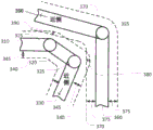
FIG. 3 is a simplified diagram of portions of two repositionable arms having virtual boundaries with multiple overlaps, according to some embodiments. As shown in fig. 3, two repositionable arms have multiple overlaps between their respective virtual boundaries. In some examples, the two repositionable arms are coincident with repositionable arm 120 and/or end effector 125 of device 110.
In more detail, FIG. 3 shows a portion of a first repositionable arm having links 310, 320, and 330 coupled by joints 315 and 325, respectively. The first repositionable arm also has a virtual boundary 340 that extends beyond the outer surfaces of the links 310, 320, and 330 and joints 315 and 325 by a predetermined distance 345. FIG. 3 also shows a portion of a second repositionable arm having links 350 and 360 coupled by a joint 355. The second repositionable arm also has a virtual boundary 370 that extends beyond the outer surfaces of the links 350 and 360 and the joint 355 by a predetermined distance 375. Just as the repositionable arms and virtual boundaries of fig. 2A and 2B, the repositionable arms and virtual boundaries of fig. 3 extend into three-dimensional space, and the virtual boundaries 340 and 370 change shape as the joints 315 and 325 and joint 355 are manipulated accordingly.
As further shown in fig. 3, as the first and second repositionable arms move closer to each other, multiple overlaps between virtual boundary 340 and virtual boundary 370 may occur, such as depicted at overlaps 380 and 390. The collision engine 152 and physics engine 154 initially process each of the overlaps 380 and 390 separately in much the same way that they process the overlap 270. Thus, for each of the overlaps 380 and 390, a respective virtual overlap force and a respective feedback to reduce and/or eliminate the respective overlap are independently determined, and it is possible that the respective feedback may affect different joints in both the first repositionable arm and the second repositionable arm based on the orientation of the overlaps 380 and 390. Once the respective feedback is determined separately, the total composite feedback is determined using superposition. The efficacy of this superposition approach is shown in fig. 3. For example, under the assumption that the proximal ends of the first and second repositionable arms are positioned as indicated by the proximal arrows in FIG. 3, feedback provided to separately reduce the overlap 380 (e.g., feedback to push apart portions of the first and second repositionable arms in the predominantly horizontal direction of FIG. 3, such as feedback to cause counterclockwise rotation of the joint (not shown) below the joint 315 and counterclockwise rotation of the joint 355) would not be as effective for reducing or eliminating the overlap 390, and feedback provided to separately reduce overlap 390 (e.g., feedback to push apart portions of the first and second repositionable arms in the primary vertical direction of fig. 3, such as feedback to cause counterclockwise rotation of joint 325 and counterclockwise rotation of a joint (not shown) to the left of joint 355) will not be as effective for reducing or eliminating overlap 380. However, by superimposing, feedback having a primary horizontal component to reduce the overlap 380 and a primary vertical component to reduce the overlap 390 more effectively reduces and/or eliminates both the overlap 380 and the overlap 390. This method of superimposition also generalizes to three or more points of overlap, and may also be used to additionally provide feedback that occurs as a result of the overlap between the first and/or second repositionable arms and the third repositionable arm (not shown).
FIG. 4 is a simplified diagram of a method of generating a virtual model of a repositionable arm, according to some embodiments. One or more of the processes 410-430 of the method 400 may be implemented at least in part in the form of executable code stored on a non-transitory, tangible, machine-readable medium, which when executed by one or more processors (e.g., the processor 142 in the control unit 130) may cause the one or more processors to perform one or more of the processes 410-430. In some embodiments, method 400 may be used to generate one or more data structures and/or executable programs to implement a corresponding model of a repositionable arm, such as any of repositionable arm 120 and/or end effector 125. In some embodiments, the virtual model may be one of the virtual models 150. In some embodiments, the method 400 may be used to create one or more virtual models of each of the repositionable arms, the end effectors, and/or the instruments used by the computer-assisted medical devices.
At process 410, a CAD and/or kinematic model of the repositionable arm is received. The CAD and/or kinematic model should contain sufficient (e.g., high fidelity) detail so that the exterior surface detail can be modeled with at least as good an accuracy as the repositionable arm can be controlled to. In some examples, the high fidelity precision is a precision having a precision of 6mm to 12mm or less. Thus, the CAD and/or kinematic model contains details regarding the type, number, shape, and/or configuration of links and joints in the repositionable arm. In some examples, the CAD and/or kinematic model may further contain information regarding how each joint in the repositionable arm may be manipulated and/or repositionable during operation of the repositionable arm. In some examples, the CAD and/or kinematic model may be generated from a CAD or similar tool.
At process 420, a convex hull is determined. Using the CAD and/or kinematic model received during process 410, the repositionable arm is divided into sections. The segments are selected such that the outer surface of each of the respective segments can be approximated within a desired accuracy by using a convex hull. In some examples, CAD tools may optionally be used to extract convex hulls from CAD and/or kinematic models. In some examples, the CAD and/or kinematic model may optionally contain a mesh of vertices and/or control points that approximate the outer surface of each of the respective segments. In some examples, the number of vertices and/or control points used in the mesh or as part of the convex hull model may optionally be selected based on a desired precision of the convex hull. In some examples, the desired accuracy is 6mm to 12mm or less. In some examples, the desired accuracy of each segment may optionally change (e.g., such that a closer segment of the repositionable arm is modeled with greater accuracy than a more distant segment of the repositionable arm). In some examples, the determined convex hull of the respective segment may optionally represent a simplified model of the outer surface of the respective segment by eliminating and/or smoothing outer surface features that have a finer variation in size than a desired precision.
At process 430, the convex hull is expanded. To generate a virtual boundary for each segment, and to relocate the arm as a whole, each convex hull determined during process 420 is expanded in size based on a predetermined distance. In this manner, the virtual boundary provides a virtual buffer zone around the links and joints of the repositionable arm. In some examples, the predetermined distance is selected to be at least as accurate as a kinematic calibration to which a motion control module (such as motion control module 156) can position and orient the repositionable arm. In some examples, the predetermined distance may optionally vary for different sections of the repositionable arm. In some examples, segments located closer on the repositionable arm may optionally have a smaller predetermined distance than segments located farther on the repositionable arm.
In some embodiments, the virtual model may optionally be parameterized to account for changes in position and/or articulation in the joints of the repositionable arm as the repositionable arm is operated and/or manipulated. Thus, an application or module using the virtual model is able to provide the current joint position and/or orientation to the virtual model, and generate and make available a corresponding virtual boundary that accounts for the current joint position and/or orientation. In some examples, the joint position and/or orientation is provided to the virtual model by using an API and/or similar calling interface.
In some embodiments, the virtual model may optionally be parameterized to specify locations along the repositionable arm at which the virtual boundaries terminate. In some examples, the sections of the repositionable arm that are positioned away from the location are not used to generate the virtual boundary, such that the virtual boundary generated by the virtual model does not contain boundary sections that are further away from the location. This allows a user of the virtual model to suppress virtual boundaries further away from the location such that no overlap and/or virtual collision is detected at the further away location. In some examples, this allows a virtual collision to be cut off if an actual collision between a repositionable arm and/or its end effector and another virtual arm and/or end effector is warranted. In some examples, the position is selected to correspond to a position in which the repositionable arm and/or its end effector is inserted through the body wall of the patient. In some examples, the location may optionally correspond to a remote center of motion of the repositionable arm. In some examples, the virtual boundary may optionally be implemented by using a zero predetermined distance and/or a negative predetermined distance such that a collision is warranted, but where at least some feedback is desired to limit the severity and/or extent of the collision.
In some embodiments, method 400 is repeated to produce a virtual model of each repositionable arm for which collision avoidance is desired. In the example of fig. 1, method 400 would be repeated for each repositionable arm 120 to produce a corresponding one of virtual models 150.
Fig. 5 is a simplified diagram of a method of avoiding collisions by using virtual boundaries, according to some embodiments. One or more of processes 510-560 of method 500 may be implemented, at least in part, in executable code stored on a non-transitory, tangible, machine-readable medium, which when executed by one or more processors (e.g., processor 142 in control unit 130) may cause the one or more processors to perform one or more of processes 510-560. In some embodiments, the method 500 may optionally be performed by one or more modules or applications, such as the virtual model 150, the collision engine 152, the physics engine 154, the motion control module 156, and/or the haptic feedback module 158. In some embodiments, method 500 may be used to determine one or more virtual collisions between virtual boundaries of two or more repositionable arms, and use those virtual boundaries to provide feedback to the repositionable arms to help reduce and/or eliminate actual collisions between the repositionable arms. In some embodiments, method 500 may be used to provide haptic feedback to an operator of a repositionable arm to prevent the operator's attempt to manipulate the repositionable arm into a configuration in which an actual collision between the repositionable arms occurs. In some embodiments, method 500 may be used to reduce the likelihood of collisions between repositionable arms 120 and/or end effectors 125 when they are operated remotely by using input controls 195. In some embodiments, method 500 may be used to reduce the likelihood of collisions between the repositionable arms, the end effector, and/or the instruments of the computer-assisted medical device when the computer-assisted medical device is used to perform one or more procedures.
At process 510, the position of the repositionable arm is determined. Collision avoidance between the repositionable arms and/or their end effectors begins by determining the current position of each of the repositionable arms and/or their end effectors for which collision avoidance is desired. In some embodiments, data is received from one or more sensors associated with the joints of each repositionable arm. The sensor data contains information about the orientation of the joints in the repositionable arm so that the current position of the repositionable arm is determined. In some examples, one or more kinematic models and/or virtual models (such as the virtual model generated using method 400) are used to convert joint orientation information into a position of the repositionable arm. In some examples, the orientation of the joint is provided as a parameter to one or more kinematic and/or virtual models. In some embodiments, one or more registration markers, fiducial markers, or the like mounted on the repositionable arm may instead be tracked using one or more tracking sensors (such as an imaging device) to supplement and/or replace sensor data to determine the orientation of the joints in the repositionable arm.
At process 520, a virtual boundary of the repositionable arm is determined. Once the position of the repositionable arms is determined during process 510, the position of the repositionable arms may be used to generate the current position of the virtual boundary of each repositionable arm using one or more virtual models. In some examples, the one or more virtual models correspond to virtual model 150 and/or a virtual model generated using method 400.
At process 530, one or more overlaps between virtual boundaries are determined. The virtual boundaries determined by each repositionable arm during process 520 are compared using a collision engine, such as collision engine 152, to determine whether there is any overlap between the virtual boundaries of the different repositionable arms. In some examples, because each virtual boundary may optionally be bounded by using one or more convex bodies (such as the convex hull determined during process 430), each convex body from each virtual boundary is compared to convex bodies from each of the other virtual boundaries in order to find each place in which an overlap occurs in the virtual boundary. In some examples, the comparison may optionally involve an iterative comparison strategy in which a rough approximation of the convex body is used to quickly determine the potential overlap, and the actual model of the convex body and virtual boundary is used to detect the actual overlap. In some examples, whenever one virtual boundary intrudes into or intersects other virtual boundaries, an overlap between two virtual boundaries is detected. In some examples, the detection of each overlap includes determining an amount and an orientation of a maximum overlap between two virtual boundaries and a direction of the maximum overlap and/or other virtual overlap properties from which the direction and magnitude of the virtual overlap may be determined. In some examples, the maximum overlap is determined by: a point is found on a first one of the virtual boundaries that extends furthest into an area bounded by a second one of the virtual boundaries, and a distance between the first virtual boundary and the second virtual boundary is recorded along a direction of a surface normal of the first virtual boundary at the maximum overlap. In some examples, the direction of the surface normal is used to determine a direction associated with the overlap, the direction indicating a direction in which a feedback force should be applied to reduce and/or eliminate the overlap.
At process 540, each overlap detected during process 530 is further processed such that the effect of each overlap and its corresponding virtual collision is used to provide feedback to reduce and/or eliminate the virtual collision. As each overlap is processed, the overlap becomes the current overlap.
At process 542, a virtual overlap force for the current overlap is determined. The current overlap detected during process 530 is processed by a physics engine (such as physics engine 154) to determine a virtual overlap force for the current virtual collision. In some examples, the magnitude of the virtual overlap force is based on the amount of overlap, and the direction of the virtual overlap force is based on the direction of maximum overlap between the virtual boundaries and/or based on the surface normal of the virtual boundaries at the overlap. In some examples, a virtual spring model with a linear constant, or alternatively a non-linear constant, is used to determine the magnitude of the virtual overlap force. In some examples, a deformable material model (such as a gas or fluid dynamic model) for the region within the virtual boundary such that the volume of overlap in combination with the elastic coefficient of the virtual material in the region within the virtual boundary provides a moving force from which the virtual overlap force is derived. An example of a model that generates Virtual feedback force is described in more detail in International patent publication No. WO 2015/120008, entitled "System and Method for Dynamic Virtual interaction Objects," which is incorporated herein by reference in its entirety.
At process 544, a virtual torque on the proximal joint is determined. Using the virtual overlap force determined during process 542, a corresponding virtual torque in each joint proximate to the overlap in the two repositionable arms associated with the current virtual collision is determined. In some examples, a respective jacobian transpose between the point of overlap and the proximal joint is used to map the virtual overlap force to the virtual torque. In this embodiment, the calculation of the virtual torque is limited to those joints that are close to the overlap, since the overlap can be satisfactorily reduced and/or eliminated by using joints that are only close to the point of the virtual collision; in other embodiments, the calculation of the virtual torque for the other joints is also determined. In some examples, the kinematics of the repositionable arm may sometimes result in not calculating a virtual torque for one or more of the joints proximate to the overlap, indicating that manipulation of those joints is not contributing to the reduction or elimination of the overlap. The virtual torque of each repositionable arm associated with a current virtual collision is determined separately because the current virtual collision may occur at different locations on the two repositionable arms, and the two repositionable arms may have different kinematic models. In some examples, the determination of the virtual torque on the proximal joint may optionally be performed by a physics engine and/or a motion control module.
At process 546, a virtual tip force is determined. Using the virtual torque determined during process 544, a corresponding virtual tip force for each repositionable arm associated with the current virtual impact is determined. Each corresponding virtual tip force represents an effective force that may be applied to a distal-most end of a corresponding repositionable arm to move the repositionable arm away from the current overlap. In some examples, the virtual torque of each repositionable arm is mapped to a corresponding virtual tip force by using an inverse of a corresponding jacobian transpose between a distal-most end of the corresponding repositionable arm and a joint of the corresponding repositionable arm.
At process 548, the effect of the current overlay is superimposed with the previously processed overlay effect. In some examples, the virtual tip force of each repositionable arm determined during process 546 overlaps (e.g., adds to) any previous virtual tip force determined by the corresponding repositionable arm. Accordingly, at process 548, the virtual tip force is adjusted by each current overlap and the corresponding current virtual collision experienced by the corresponding repositionable arm to produce a total virtual tip force for each repositionable arm. In some examples, the superposition of overlapping effects may optionally be performed by a physics engine and/or a motion control module.
Processes 542 through 548 are then repeated for each overlap detected during process 530.
At process 550, a feedback force is applied. The total virtual tip force generated during process 548 is applied to each repositionable arm as a feedback force. In some examples, the total virtual tip force of each repositionable arm is provided to a motion control application, such as a motion control application including a motion control module (e.g., motion control module 156) of the corresponding repositionable arm. The motion control application applies the total virtual tip force as feedback to the motion control of the corresponding repositionable arm so that the corresponding repositionable arm opposes the virtual collision detected by the corresponding repositionable arm. In this manner, the motion control module is able to exert a resistive effect that helps prevent the corresponding repositionable arm from being remotely operated closer to an actual collision, but does not oppose the motion that moves the corresponding repositionable arm from an impending collision. In some examples, feedback of the corresponding virtual tip force is superimposed on the motion specified by the teleoperational command for the corresponding repositionable arm.
At process 560, a haptic feedback force is applied. The total tip force generated during process 548 is applied as haptic feedback to a corresponding input control (such as input control 195) that is used to remotely operate a corresponding repositionable arm. In some examples, each total tip force is scaled to reflect a difference in relative force for manipulating the corresponding repositionable arm and force for manipulating the corresponding input control. In some examples, the inverse of the jacobian transpose for the corresponding input control is used to map the total tip force to the respective joint torque in the input-controlled repositionable arm to apply the haptic feedback to the corresponding input control. In some embodiments, the difference between the actual position of the corresponding repositionable arm and the commanded position of the corresponding repositionable arm is optionally used to determine haptic feedback on the corresponding input control. In some embodiments, the difference between the current command for the corresponding repositionable arm as adjusted by the feedback force applied during process 550 and the commanded position of the corresponding repositionable arm from the corresponding input control is optionally used to determine haptic feedback on the corresponding input control.
The processes 510-560 are then repeated at suitable intervals (such as during a control loop for a device having a repositionable arm) to provide continuous monitoring of overlap between virtual boundaries indicating a virtual collision, and to provide feedback to the repositionable arm and haptic feedback to the input control.
As discussed above and further emphasized here, fig. 5 is merely an example, which should not unduly limit the scope of the claims. Those skilled in the art should recognize many variations, substitutions, and modifications. In some embodiments, when no overlap is detected during process 530, processes 540-560 are skipped and no feedback force and/or haptic feedback force is applied. In some embodiments, the effects in each overlap may optionally be superimposed in a different manner. In some examples, the virtual torques determined during process 544 may be superimposed on a joint-by-joint basis to determine a total virtual torque for each joint in the repositionable arm due to the overlap and corresponding virtual impact detected during process 530. The total virtual torque is then provided to the motion control application, where it is superimposed on the joint torque due to other control inputs, such as remote operation commands from the input controls.
In some embodiments, effects due to redundant degrees of freedom in the repositionable arms may optionally be accounted for when applying the feedback force and/or the haptic feedback force. Because a repositionable arm having redundant degrees of freedom in its motion may contain repositionable elements and/or joint motions that do not affect the pose of the tip of the repositionable arm, the motion of the repositionable arm is divided into two orthogonal sets of motions: those that cause a change in the pose of the tip, and those that do not cause a change in the pose of the tip and are sometimes referred to as null-space motions. To address this issue, the feedback force applied to the repositionable element and/or joint of the repositionable arm that is in zero-space motion may optionally be omitted because the feedback force does not cause motion of the tip and therefore does not produce haptic feedback motion.
In some embodiments, it may be desirable to slowly step-wise implement the feedback effect of (phase) method 500. In some examples, a transition in the operating mode of the computer-assisted medical device from a mode in which method 500 is not used to a mode in which method 500 is used may result in an undesirable risk of end effector and/or repositionable arm movement. In some examples, when there is an existing overlap between the two repositionable arms when the transition between the modes occurs, the feedback force during process 550 and/or the tactile feedback force during process 560 are applied quickly when such force was not previously applied, which may result in undesirable and/or undesired motion in the end effector and/or repositionable arms. In some examples, this may optionally be addressed by implementing the feedback force and the haptic feedback force in steps after an initial transition into a mode in which method 500 is performed. In some examples, the feedback force and/or the tactile feedback force may optionally be implemented stepwise using a ramp, a series of steps, or the like. In some examples, the feedback force and/or the haptic force may optionally be implemented gradually over a predetermined period of time, such as approximately one second.
Some examples of a control unit (such as control unit 130) may include a non-transitory, tangible, machine-readable medium containing executable code that, when executed by one or more processors (e.g., processor 142), may cause the one or more processors to perform the processes of methods 400 and/or 500. Some common forms of machine-readable media that may include the processes of methods 400 and/or 500 are, for example, a floppy disk, a flexible disk, hard disk, magnetic tape, any other magnetic medium, a CD-ROM, any other optical medium, punch cards, paper tape, any other physical medium with patterns of holes, a RAM, a PROM, an EPROM, a FLASH-EPROM, any other memory chip or cartridge, and/or any other medium from which a processor or computer is adapted to read.
While illustrative embodiments have been shown and described, a wide range of modifications, changes, and substitutions is contemplated in the foregoing disclosure and, in some instances, some features of the embodiments may be employed without a corresponding use of other features. Those skilled in the art should recognize many variations, substitutions, and modifications. For example, similar techniques may be applied to determine one or more other virtual boundaries around other objects than a repositionable arm, end effector, or arm-and-end effector assembly. Such other objects may include another portion of the device 110, a portion of the operator workstation 170, other equipment (e.g., an operating table, a cart, an appliance, a wall, a person, etc.). The process for detecting and responding to a virtual collision of a repositionable arm, end effector, or arm-and-end effector assembly with such other virtual boundaries may be the same as described herein for such a virtually collided arm, end effector, or arm-and-end effector assembly.
Accordingly, the scope of the invention should be limited only by the attached claims, and it is appropriate that the claims be construed broadly and in a manner consistent with the scope of the embodiments disclosed herein.