EP0309201B1 - Übertragungsverfahren und -System für kontaktlose I.S.-Karten - Google Patents
Übertragungsverfahren und -System für kontaktlose I.S.-Karten Download PDFInfo
- Publication number
- EP0309201B1 EP0309201B1 EP88308709A EP88308709A EP0309201B1 EP 0309201 B1 EP0309201 B1 EP 0309201B1 EP 88308709 A EP88308709 A EP 88308709A EP 88308709 A EP88308709 A EP 88308709A EP 0309201 B1 EP0309201 B1 EP 0309201B1
- Authority
- EP
- European Patent Office
- Prior art keywords
- communicating unit
- circuit
- voltage
- data
- signal
- Prior art date
- Legal status (The legal status is an assumption and is not a legal conclusion. Google has not performed a legal analysis and makes no representation as to the accuracy of the status listed.)
- Expired - Lifetime
Links
- 238000004891 communication Methods 0.000 title claims description 37
- 238000000034 method Methods 0.000 title claims description 6
- 230000010355 oscillation Effects 0.000 claims description 35
- 230000005540 biological transmission Effects 0.000 claims description 22
- 238000001514 detection method Methods 0.000 claims description 21
- 230000002463 transducing effect Effects 0.000 claims description 17
- 230000008878 coupling Effects 0.000 claims description 15
- 238000010168 coupling process Methods 0.000 claims description 15
- 238000005859 coupling reaction Methods 0.000 claims description 15
- 230000007274 generation of a signal involved in cell-cell signaling Effects 0.000 claims description 5
- 230000004044 response Effects 0.000 claims description 3
- 230000004048 modification Effects 0.000 claims description 2
- 238000012986 modification Methods 0.000 claims description 2
- 230000003019 stabilising effect Effects 0.000 claims 3
- 230000004913 activation Effects 0.000 claims 1
- 230000001276 controlling effect Effects 0.000 claims 1
- 230000002596 correlated effect Effects 0.000 claims 1
- 230000008859 change Effects 0.000 description 9
- 238000009499 grossing Methods 0.000 description 9
- 238000010586 diagram Methods 0.000 description 6
- 239000003381 stabilizer Substances 0.000 description 4
- 238000006243 chemical reaction Methods 0.000 description 3
- 230000003247 decreasing effect Effects 0.000 description 3
- 230000005672 electromagnetic field Effects 0.000 description 3
- 230000033228 biological regulation Effects 0.000 description 2
- 239000003990 capacitor Substances 0.000 description 2
- 230000004907 flux Effects 0.000 description 2
- 230000001105 regulatory effect Effects 0.000 description 2
- 230000000630 rising effect Effects 0.000 description 2
- 230000008054 signal transmission Effects 0.000 description 2
- 230000002457 bidirectional effect Effects 0.000 description 1
- 238000001914 filtration Methods 0.000 description 1
- 230000006870 function Effects 0.000 description 1
- 230000017525 heat dissipation Effects 0.000 description 1
- 230000002093 peripheral effect Effects 0.000 description 1
- 238000007493 shaping process Methods 0.000 description 1
- 230000006641 stabilisation Effects 0.000 description 1
- 238000011105 stabilization Methods 0.000 description 1
- 230000001131 transforming effect Effects 0.000 description 1
Images


Classifications
-
- G—PHYSICS
- G06—COMPUTING; CALCULATING OR COUNTING
- G06K—GRAPHICAL DATA READING; PRESENTATION OF DATA; RECORD CARRIERS; HANDLING RECORD CARRIERS
- G06K19/00—Record carriers for use with machines and with at least a part designed to carry digital markings
- G06K19/06—Record carriers for use with machines and with at least a part designed to carry digital markings characterised by the kind of the digital marking, e.g. shape, nature, code
- G06K19/067—Record carriers with conductive marks, printed circuits or semiconductor circuit elements, e.g. credit or identity cards also with resonating or responding marks without active components
- G06K19/07—Record carriers with conductive marks, printed circuits or semiconductor circuit elements, e.g. credit or identity cards also with resonating or responding marks without active components with integrated circuit chips
- G06K19/0701—Record carriers with conductive marks, printed circuits or semiconductor circuit elements, e.g. credit or identity cards also with resonating or responding marks without active components with integrated circuit chips at least one of the integrated circuit chips comprising an arrangement for power management
-
- G—PHYSICS
- G06—COMPUTING; CALCULATING OR COUNTING
- G06K—GRAPHICAL DATA READING; PRESENTATION OF DATA; RECORD CARRIERS; HANDLING RECORD CARRIERS
- G06K7/00—Methods or arrangements for sensing record carriers, e.g. for reading patterns
- G06K7/0008—General problems related to the reading of electronic memory record carriers, independent of its reading method, e.g. power transfer
-
- G—PHYSICS
- G06—COMPUTING; CALCULATING OR COUNTING
- G06K—GRAPHICAL DATA READING; PRESENTATION OF DATA; RECORD CARRIERS; HANDLING RECORD CARRIERS
- G06K7/00—Methods or arrangements for sensing record carriers, e.g. for reading patterns
- G06K7/10—Methods or arrangements for sensing record carriers, e.g. for reading patterns by electromagnetic radiation, e.g. optical sensing; by corpuscular radiation
- G06K7/10009—Methods or arrangements for sensing record carriers, e.g. for reading patterns by electromagnetic radiation, e.g. optical sensing; by corpuscular radiation sensing by radiation using wavelengths larger than 0.1 mm, e.g. radio-waves or microwaves
- G06K7/10316—Methods or arrangements for sensing record carriers, e.g. for reading patterns by electromagnetic radiation, e.g. optical sensing; by corpuscular radiation sensing by radiation using wavelengths larger than 0.1 mm, e.g. radio-waves or microwaves using at least one antenna particularly designed for interrogating the wireless record carriers
- G06K7/10336—Methods or arrangements for sensing record carriers, e.g. for reading patterns by electromagnetic radiation, e.g. optical sensing; by corpuscular radiation sensing by radiation using wavelengths larger than 0.1 mm, e.g. radio-waves or microwaves using at least one antenna particularly designed for interrogating the wireless record carriers the antenna being of the near field type, inductive coil
Definitions
- This invention relates to a non-contact, magnetically-coupled communication technique, and particularly to an improved method and system of communication for a non-contact IC card.
- An object of this invention is to provide a data communication system which links a data reader/writer to a recording medium such as an IC card on the basis of non-contact, electromagnetic coupling, with the intention of eliminating the need for an oscillation source on the part of the recording medium and simplifying the circuit.
- the invention provides for the functional recording medium to have its power voltage, which is supplied through electromagnetic coupling from the external equipment, stabilised easily on the part of the external equipment.
- US-A-4 546 241 discloses a system in accordance with the prior art portion of claim 1. This prior system is incapable of transmitting a data carrying signal from the first communication unit to the second communication unit, the only transmission in that direction being of a fixed frequency signal which also serves to power the second communication means, this fixed frequency being amplitude modulated by the second communication unit for transmission of data signals from the second communication unit to the first communication unit.
- the present invention is capable of transmitting data in both directions, in each case through a single bidirectional coil in the respective communication units, with the fixed frequency signal of the first communication unit providing information as a tone burst signal with the fixed frequency signal then being returned from the second communication unit to the first by frequency modulating in a digital manner the fixed carrier frequency by varying the impedance of the transceiver coil of the second communication unit.
- the second communication unit or transceiver is an IC card, in which are included a power source circuit which provides power by transforming a field of electromagnetic energy into a d.c. power voltage or owes the power source to a battery, a coil which is placed in the electromagnetic field produced by an oscillation circuit of the reader/writer, a circuit which detects and rectifies the energy captured by the coil to produce a signal, a circuit which connects or disconnects (ON/OFF) the coil so that the resonant frequency of the space is varied, and a circuit which implements data processing, so that the whole IC card circuit operates on the power provided by the power source circuit, and the above-mentioned first transceiver is an IC card reader/writer, with the provision of a reader/writer or host computer, in which are included an oscillation circuit which produces a carrier modulated by a signal to be sent to the IC card, and a frequency comparison circuit which demodulates a change in
- the carrier generating circuit and frequency comparison circuit are placed on the part of the reader/writer, while the circuit for detecting energy on the coil and rectifying it into data and the circuit for connecting or disconnecting the coil are placed on the part of the IC card.
- the oscillation circuit In transmitting data from the reader/writer to the IC card, the oscillation circuit is operated, energy is received on the coil, and the oscillation circuit is connected or disconnected.
- the oscillation circuit In transmitting data from the IC card to the reader/writer, the oscillation circuit is kept operating and the coil is disconnected (e.g., grounded) in compliance with the transmitted data, so that a change in the oscillation frequency caused by the impedance variation is entered to the frequency comparison circuit and it releases reception data on the basis of the oscillation frequency variation.
- the second transceiver varies the impedance of the electromagnetic transducer of the first transceiver to vary the resonant frequency of the carrier generator, whereby the second transceiver can have data transmission to the first transceiver without the need of having an oscillation circuit. Consequently, the second transceiver has its transmission circuit simplified with less number of component parts, resulting in an improved reliability, and it is especially suitable when applied to IC cards.
- Fig. 1 is a block diagram showing the communication for a non-contact IC card to which the inventive non-contact, electromagnetically coupled communication system is applied.
- IC card reader/writer which accepts a non-contact IC card (will be termed simply "IC card” hereinafter) 2.
- the IC card 2 is supplied with its operating power from an oscillation circuit 4 of the reader/writer 1 on its receiving coil 13 which is in non-contact, electromagnetic coupling with a sending coil 12 of the reader/writer 1.
- the oscillation circuit 4 supplies a signal of around 200 kHz, for example, to the sending coil 12 and it is received by the receiving coil 13 in the form of the electromagnetic field, and thus power is transferred.
- the power received on the receiving coil 13 is transformed into a d.c. voltage by a rectifying circuit 8 and distributed to the whole circuit in the IC card 2.
- Indicated by 3 is a power circuit provided in the reader/writer 1 and it supplies power to its whole circuit.
- the reader/writer 1 transmits data to the IC card 2 from a data processor 6 including a microprocessor or the like by way of an associated oscillation circuit 5 and transceiving coil 14.
- the oscillation circuit 5 generates a carrier of around 10 MHz, for example, which is turned on and off for output by the transmission data provided by the data processor 6. Namely, data transmission is based on "tone burst" mode.
- the tone-burst data transmitted in the form of electrometnetic field from the transceiving coil 14 is received by a transceiving coil 15 of the IC card 2 which is in non-contact, electromagnetic coupling with the coil 14, and, after it is demodulated into a digital signal by a detecting rectifier 9, sent to the data processor 11 incorporating a microprocessor or the like.
- Data transmission from the IC card 2 to the reader/writer 1 takes place while the oscillation circuit 5 of the reader/writer 1 is kept operating.
- a switching circuit 10 located at the node of the transceiving coil 15 and detecting rectifier 9 of the IC card 2 is operated so that the coil 15 is connected or disconnected in accordance with data to be transmitted.
- the on-off control of the switching circuit 10 is such that when it is "on", a bias voltage or power voltage is applied to the terminal of the coil 15 in connection to the detecting rectifier 9 so that a d.c. current flows, while the terminal is grounded when it is “off”.
- the "on” state causes the transceiving coil 15 to produce a d.c. magnetic flux, and it vanishes when the coil is in "off” state.
- the on-off control varies the impedance of the magnetic circuit of the transceiving coil 14, thereby causing the oscillation circuit 5 to vary the output frequency.
- the transceiving coil 15 is disconnected at its one terminal from the detecting rectifier 9 so that the coil 15 is open for the "off" state, and the terminals of the coil is connected directly or through a resistor for the "on” state.
- the transceiving coil 15 is not a magnetic flux generating circuit as opposed to the previous case, but it merely functions as a magnetic coupling circuit for varying the impedance of magnetic circuit by being coupled electromagnetically with the transceiving coil 14.
- the on-off control of the switching circuit 10 varies the output frequency of the oscillation circuit 5, which is detected by a frequency comparison circuit 7, and the transmitted data is demodulated.
- a change in the load impedance of the transceiving coil 15 is transferred as a signal to the transceiving coil 14, and it modulates the output signal of the oscillation circuit 5.
- a signal with a varying frequency is produced on the terminal of the oscillation circuit 5 in connection with the transceiving coil 14.
- the varying frequency is compared by the frequency comparison circuit 7 with a reference carrier frequency provided by the oscillation circuit 5, so that the transmitted data from the IC card 2 is detected, and the carrier signal is modulated in accordance with the detected data to retrieve the transmitted data.
- the reference carrier frequency signal is produced by the resonator or the peripheral circuit in the oscillation circuit 5 or by a separate clock oscillator or the like.
- the detected data is delivered to the data processor 6 in the reader/writer 1, and the data transmitted from the IC card 2 is processed.
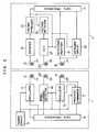
- Fig. 2 is a block diagram showing the inventive non-contact, magnetically coupled communication system applied to a non-contact IC card of a different power supply system.
- indicated by 1 is a reader/writer which accepts an IC card 2.
- the IC card 2 is supplied with its operating power from an oscillation circuit 4 of the reader/writer 1 on its receiving coil 13 which is in non-contact electromagnetic coupling with a sending coil 12 of the reader/writer 1.
- the oscillation circuit 4 supplies a signal of around 200 kHz, for example, to the sending coil 12 and it is received in the form of the magnetic field by the receiving coil 13, and thus power is transferred.
- the power received on the receiving coil 13 is transformed into a d.c.
- a rectifying-smoothing circuit 8 which is a power circuit in the IC card 2, and it is distributed to the whole circuit in the IC card 2.
- Indicated by 3 is a power circuit provided in the reader/writer 1, and it supplies power to its whole circuit.
- Indicated by 18 is a voltage detection circuit which monitors the output voltage of the rectifying-smoothing circuit 8 and produces a control voltage, by which the oscillation frequency of a voltage-controlled oscillator (VCO) 17 is controlled.
- VCO 17 delivers its output signal with the controlled frequency to a sending coil 20. Consequently, the signal produced by the VCO 17 is transmitted to a receiving coil 19 of the reader/writer 1 in magnetic coupling with the sending coil 20, and the signal received on the coil 19 is detected by a frequency change detection circuit 16, which generates data in compliance with the frequency variation of the received signal, and it is delivered to the data processor 6 incorporating a microprocessor or the like.
- the data processor 6 issues a control signal to the oscillation circuit 4 so that its output voltage level is stabilized.
- the power voltage control in the IC card 2 will be described. If the IC card 2 and reader/writer 1 have a decreased gap therebetween, or the IC card has a decreased power consumption, the output voltage of the rectifying-smoothing circuit 8 will rise. Upon detecting a rising voltage, the voltage detection circuit 18 issues a corresponding control signal to the VCO 17, which in turn oscillates at a frequency higher than the reference oscillation frequency.
- the high-frequency signal is received by the frequency change detection circuit 16 by way of the sending coil 20 and receiving coil 19.
- the frequency change detection circuit 16 incorporates a frequency comparison circuit and an oscillator turned to the reference frequency of the VCO 17.
- the circuit 16 compares the frequency received on the receiving coil 19 with the reference frequency of the VCO 17, and produces a digital signal which represents an up-offset value from the reference frequency and sends it to the data processor 6.
- the data processor 6 is informed of a rising power voltage of the IC card 2 by receiving the data, and issues a control signal to the oscillation circuit 4 so that its output level is lowered.
- the output voltage of the rectifying-smoothing circuit 8 will fall.
- the voltage detection circuit 18 issues a corresponding control signal to the VCO 17, which in turn oscillates at a frequency lower than the reference frequency.
- the low frequency signal is received by the frequency change detection circuit 16 by way of the sending coil 20 and receiving coil 19 in the same manner as above.
- the frequency change detection circuit 16 produces a digital signal which represents a down-offset from the reference frequency and sends it to the data processor 6.
- the data processor 6 is informed of the falling power voltage of the IC card 2 by receiving the data, and issues a control signal to the oscillation circuit 4 so that it raises the output level.
- the oscillation circuit 4 and sending coil 12 are a specific example of the electromagnetic transducer, and the receiving coil 13 is a specific example of electromagnetic transducers which convert electromagnetic energy into electrical energy.
- the VCO 17 is a specific example of control signal generation circuits, and the sending coil 20 is a specific example of control signal transmission circuits.
- the receiving coil 19 and frequency change detection circuit 16 are a specific example of control signal receiving circuits of this invention, and the data processor 6 is a specific example of control circuits.
- the voltage detection circuit 18 is specifically a voltage comparison circuit or a voltage level conversion circuit, and generally it can be formed of operational amplifiers or transistor circuits without including capacitors and therefore can be formed as an integrated circuit.
- the voltage detection circuit of the voltage level conversion mode will be a circuit which converts the output voltage of the rectifying-smoothing circuit 8 into the voltage control level of the VCO 17. If the VCO 17 can be controlled directly by the output of the rectifying-smoothing circuit 8, the voltage detection circuit 18 may be omitted.
- VCO voltage-to-Velator
- the supplied electromagnetic energy is controlled so that the voltage variation is offset
- an alternative scheme is to set the power circuit to produce a higher voltage thereby to supply a larger energy from the reader/writer and to stabilize the voltage, as in a voltage stabilization based on a zener diode, in the voltage detection circuit. This allows one-way control and simplifies the circuit arrangement.
- a voltage comparison circuit when used for the voltage detection circuit, it is set to a higher voltage level and designed to produce a control signal for a certain lower voltage level, and in this case the voltage comparison circuit needs only one threshold level.
- the circuit in case of using a level conversion circuit, the circuit is merely required to control the frequency to the higher or lower with respect to the reference value. For the frequency generation as a signal of regulating the voltage, it is of course possible to generate a lower value for a high voltage, or conversely a higher value for a low voltage.
- the signal for adjusting the energy is sent as an oscillation frequency of VCO to the reader/writer, it may be data which simply corresponds to the current voltage value.
- a circuit may be provided to convert a detected voltage value or its deviation from the reference voltage value into a digital value so that a precise digitized power supply adjustment signal is sent to the reader/writer.
- this embodiment is a communication system for an IC card through a reader/writer
- this invention is applicable to general recording media including memory cards
- the partner equipment can be general external facilities such as a host computer.
- the power circuit for the IC card 2 is formed of an electromagnetic transducing circuit, it may use solar cells or supersonic energy, or may be of a built-in battery type.
- a comparison circuit is used to detect the variation of frequency
- an alternative scheme is that transmitted data is detected by extracting a specific frequency through the filtering or the like and the data is demodulated through the waveform shaping, any circuit capable of detecting a frequency variation may be used.
- the IC card has been described mainly, it can of course be applied to various information recording media such as memory cards incorporating a microprocessor or the like and memory cartridges. Furthermore, the invention is also applicable to non-contact, electromagnetically coupled communication systems intended for the communication between facilities in general based on the non-contact, electromagnetic coupling.
- Fig. 4 shows a variation of the embodiment shown in Fig. 2, and the following describes the differences of the system from the embodiment. Both systems have the same power supply system.
- the data processor 6 sends the data through a data transmission circuit 37 and sending coil 14 to the IC card 2.
- the data transmission circuit 37 generates a carrier with a frequency of around 10 MHz for example.
- the carrier is modulated in on/off mode by the data transmitted from the data processor 6. In this case, data transmission is of so-called tone-burst mode.
- the tone-burst data transmitted in the form of electromagnetic field through the sending coil 14 is received by the receiving coil 15 of IC card 2 in non-contact magnetic coupling with the coil 14, and, after it is demodulated into a digital signal by a data receiving circuit 39, delivered to the data processor 11 incorporating a microprocessor or the like.
- Data transmission from the IC card 2 to the reader/writer 1 is carried out by a data transmission circuit 40 by way of a sending coil 46.
- Digital data sent out of the data processor 11 is received by the data transmission circuit 40, which supplies a tone-burst signal to the sending coil 46 in the same manner as of the above-mentioned data transmission circuit 37.
- the signal is received by a receiving coil 42 of reader/writer 1 in electromagnetic coupling with the coil 46, demodulated by a data reception circuit 38, and, after it is transformed into digital, delivered to the data processor 6.
- Fig. 5 shows a modification of the system shown in Fig. 4. Similar to the power supply circuit of Fig. 3, a voltage stabilizer 21 is added between the rectifying-smoothing circuit 8 and the voltage detection circuit 18.
Landscapes
- Engineering & Computer Science (AREA)
- Physics & Mathematics (AREA)
- General Physics & Mathematics (AREA)
- Theoretical Computer Science (AREA)
- Artificial Intelligence (AREA)
- Microelectronics & Electronic Packaging (AREA)
- Computer Hardware Design (AREA)
- Computer Vision & Pattern Recognition (AREA)
- Health & Medical Sciences (AREA)
- Toxicology (AREA)
- Computer Networks & Wireless Communication (AREA)
- Electromagnetism (AREA)
- General Health & Medical Sciences (AREA)
- Near-Field Transmission Systems (AREA)
- Credit Cards Or The Like (AREA)
Claims (11)
- Kontaktloses, elektromagnetisch gekoppeltes Übertragungssystem mit einer ersten Übertragungseinheit (1) und einer zweiten Übertragungseinheit (2), die miteinander kontaktlos elektromagnetisch koppelbar sind, um Signale untereinander zu übertragen, wobei die erste Übertragungseinheit erste elektromagnetische Wandlermittel (14) mit einer Sender/Empfängerspule (14) zur Herstellung von elektromagnetischer Kopplung mit der zweiten Übertragungseinheit und Trägerwellenerzeugungsmittel (5), die mit dem ersten elektromagnetischen Wandlermittel verbunden sind, um eine Trägerwelle konstanter Frequenz für die Übertragung zu der zweiten Übertragungseinheit zu erzeugen, umfaßt, und die zweite Übertragungseinheit (2) zweite elektromagnetische Wandlermittel (15) mit einer Sender/Empfängerspule zum Herstellen von elektromagnetischer Kopplung mit den ersten elektromagnetischen Wandlermitteln zum Empfang des Trägerwellensignals und zum Übertragen eines Datensignals umfaßt, und wobei die erste Übertragungseinheit (1) darüber hinaus Erfassungsmittel (5, 7) zum Erfassen des Empfangs des Datensignals durch die Modulation der Trägerwelle beinhaltet,
dadurch gekennzeichnet,
daß beide Sender/Empfängerspulen (14, 15) bidirektional sind, für Signalübertragung von der ersten Übertragungseinheit (1) zur zweiten Übertragungseinheit (2) als auch von der zweiten Übertragungseinheit (2) zur ersten Übertragungseinheit (1), daß das Trägerwellenerzeugungsmittel (5) geeignet ist, ein hochfrequentes Schwingungsimpulssignal zu erzeugen, das das Trägerwellensignal beinhaltet, für die Datenübertragung zur zweiten Übertragungseinheit (2), wobei die zweite Übertragungseinheit (2) mit den zweiten elektromagnetischen Wandlermitteln (15) verbundene Schaltmittel (10) zum Verändern der Impedanz der zweiten elektromagnetischen Wandlermittel (15), wenn sie entsprechend der Übertragung eines Datensignals zur ersten Übertragungseinheit (1) von der zweiten Übertragungseinheit (2) aktiviert werden, beinhaltet, wobei die zweiten elektromagnetischen Wandlermittel (15), wenn die Impedanz verändert wird, die Frequenz des vorher konstanten Trägerwellensignals modulieren, um das Datensignal zu übertragen, und wobei die erste Übertragungseinheit (1) auf die Betätigung der Schaltmittel (10) reagiert, um den Empfang des Datensignals durch Erfassen der Modulation der Frequenz der vorher konstantfrequenten Trägerwelle, die durch die Veränderung der Impedanz der zweiten elektromagnetischen Wandlermittel verursacht ist, zu erfassen. - System nach Anspruch 1, bei dem die erste Übertragungseinheit (1) eine Datenschreib/leseeinheit und die zweite Übertragungseinheit (2) eine I.S.-Karte umfaßt, wobei die Schaltmittel (10) der zweiten Übertragungseinheit (2) Mittel zur Erzeugung einer Veränderung einer Lastimpedanz der Spule (15) der zweiten elektromagnetischen Übertragermittel (2) entsprechend der Übertragung eines Datensignals durch Erden oder Öffnen der Verbindung der Sender/Empfängerspule (15) der zweiten elektromagnetischen Wandlermittel mit dem Rest der zweiten Wandlermittel beinhalten.
- System nach Anspruch 1 oder 2, bei dem das Erfassungsmittel der ersten Übertragungseinheit (1) Vergleichsmittel (7) zum Vergleich der Trägerwellenfrequenz des durch die ersten elektromagnetischen Wandlermittel (1) von den zweiten elektromagnetischen Wandlermitteln empfangenen Signals mit einer Trägerwellenreferenzfrequenz, die gleich der konstanten Trägerwellenfrequenz des Trägererzeugungsmittels (5) ist, um eine den Empfang eines Datensignals anzeigende Modulation der Trägerfrequenz zu erfassen, umfaßt.
- System nach Anspruch 1 oder 2, bei dem die erste Übertragungseinheit zusätzlich Datenverarbeitungsmittel (6), die mit dem Trägerwellenerzeugungsmittel (5) und dem Erfassungsmittel (7) verbunden sind, umfaßt, um die durch das Hochfrequenzimpulssignal zu übertragenden Daten zu verarbeiten, und um das durch die Erfassungsmittel erfaßte Datensignal zu empfangen.
- System nach Anspruch 4, bei dem die zweite Übertragungseinheit zusätzlich Datenverarbeitungsmittel (11) umfaßt, die mit den Schaltmitteln (10) und den zweiten elektromagnetischen Wandlermitteln (15) verbunden sind, um das zur ersten Übertragungseinheit (1) in Verbindung mit der Impedanzänderung zu übertragende Datensignal zu verarbeiten und um das Hochfrequenzimpulssignal als zu der zweiten Übertragungseinheit (2) über die zweiten elektromagnetischen Wandlermittel (15) übertragene Daten zu empfangen.
- System nach einem der vorhergehenden Ansprüche, bei dem die erste Übertragungseinheit (1) Leistungsversorgungsmittel (3, 4, 12) zur Erzeugung und Versorgung der zweiten Übertragungseinheit (2) mit Leistung in Form von elektromagnetischer Energie, Steuersignalempfangsmittel (19, 16) zum Empfang eines Leistungssteuerungssignals, das die von der zweiten Übertragungseinheit (2) empfangene Menge von elektromagnetischer Energie anzeigt, und Steuermittel (16, 6, 4) zur Steuerung der Menge von durch die Leistungsversorgungsmittel (4, 12) erzeugter und bereitgestellter elektromagnetischer Energie in Abhängigkeit vom Leistungssteuerungssignal von den Empfangsmitteln (19, 16) umfaßt, und wobei die zweite Übertragungseinheit (2) Wandlermittel (13) zum Umwandeln von von den Leistungsversorgungsmitteln empfangener elektromagnetischer Energie in elektrische Energie, Leistungsmittel (8) zur Erzeugung einer Gleichstromleistungsspannung aus der von den Wandlermitteln (13) empfangenen elektrischen Energie, Leistungssteuerungssignalerzeugungsmittel (18, 17) zum Erzeugen des Leistungssteuerungssignals bei einer mit der Gleichstromleistungsspannung der Leistungsmittel korrelierten Frequenz, und Steuerungssignalausgabemittel (20), die mit den Steuerungssignalempfangsmitteln (19) elektromagnetisch verbunden sind, zur Ausgabe des Leistungssteuerungssignals, umfaßt.
- System nach Anspruch 6, das zusätzlich eine Spannungsstabilisierungsschaltung (21) umfaßt, die eine konstante Ausgangsspannung der Leistungsschaltung (13, 8) aufrechterhält, und die zwischen der Leistungsschaltung (13, 8) und der Steuersignalerzeugungsschaltung (17) der zweiten Übertragungseinheit vorgesehen ist.
- System nach Anspruch 7, bei dem die Spannungsstabilisierungsschaltung (21) die ganze Schaltung der zweiten Übertragungseinheit (2) mit Leistung versorgt.
- System nach Anspruch 6, 7 oder 8, bei dem das Leistungssteuerungserzeugungsmittel eine Spannungserfassungsschaltung (18) zur Erfassung einer Spannung der Leistungsmittel beinhaltet und das Steuerungssignal in Abhängigkeit von der durch die Spannungserfassungsschaltung erfaßten Spannung erzeugt.
- System nach Anspruch 9, bei dem das Leistungsversorgungsmittel eine Schwingschaltung (4) und eine Spule (12) umfaßt, bei dem das Leistungssteuerungs-Signalausgabemittel eine Spule (20) umfaßt und bei dem das Leistungssteuerungs-Signalerzeugungsmittel eine spannungsgesteuerte Schwingschaltung (17) und eine Spannungserfassungsschaltung (18) zur Erfassung einer Spannung der Spannungsstabilisierungsschaltung umfaßt, wobei die Spannungserfassungsschaltung (18) eine Steuerspannung für die spannungsgesteuerte Schwingschaltung (17) erzeugt.
- Verfahren zur Datenübertragung für ein Übertragungssystem, in dem eine erste Übertragungseinheit und eine zweite Übertragungseinheit elektromagnetisch kontaktlos für den Signalaustausch gekoppelt sind, wobei das Verfahren die Schritte umfaßt: Erzeugen eines Trägerwellensignals mit konstanter Frequenz zum Übertragen zur zweiten Übertragungseinheit, Versorgen einer Sender/Empfängerspule der zweiten Übertragungseinheit mit dem Trägerwellensignal mittels einer Sender/Empfängerspule der ersten Übertragungseinheit, Versorgen der elektromagnetischen Sender/Empfängerspule der zweiten Übertragungseinheit mit dem Trägerwellensignal nach Modifikation durch die zweite Übertragungseinheit und Erfassen der Modulation der durch die Sender/Empfängerspule der ersten Übertragungseinheit von der Sender/Empfängerspule der zweiten Übertragungseinheit empfangenen Trägerwelle, um so den Empfang von übertragenen Daten bei der ersten Übertragungseinheit zu erfassen,
dadurch gekennzeichnet,
daß in der ersten Übertragungseinheit ein Hochfrequenzimpulssignal mit der konstanten Frequenz für die Datenübertragung zur zweiten Übertragungseinheit erzeugt wird, daß die Impedanz der Sender/Empfängerspule der zweiten Übertragungseinheit durch Aktivierung eines Schalters entsprechend als Datensignal an die erste Übertragungseinheit zu übertragenden Daten verändert wird, und daß die übertragenen Daten bei der ersten Übertragungseinheit als eine Änderung der Trägerwellenfrequenz erfaßt werden, die auf die Impedanzänderung der Sender/Empfängerspule der zweiten Übertragungseinheit reagiert.
Applications Claiming Priority (6)
| Application Number | Priority Date | Filing Date | Title |
|---|---|---|---|
| JP238212/87 | 1987-09-22 | ||
| JP62238212A JP2631664B2 (ja) | 1987-09-22 | 1987-09-22 | 非接触形磁気結合送受信方式 |
| JP260425/87 | 1987-10-15 | ||
| JP62260425A JPH01102693A (ja) | 1987-10-15 | 1987-10-15 | 電磁結合形記録媒体の電力供給方式 |
| JP62282202A JPH01124084A (ja) | 1987-11-10 | 1987-11-10 | 電磁結合形記録媒体の電力供給方式 |
| JP282202/87 | 1987-11-10 |
Publications (3)
| Publication Number | Publication Date |
|---|---|
| EP0309201A2 EP0309201A2 (de) | 1989-03-29 |
| EP0309201A3 EP0309201A3 (en) | 1989-09-06 |
| EP0309201B1 true EP0309201B1 (de) | 1993-05-26 |
Family
ID=27332545
Family Applications (1)
| Application Number | Title | Priority Date | Filing Date |
|---|---|---|---|
| EP88308709A Expired - Lifetime EP0309201B1 (de) | 1987-09-22 | 1988-09-20 | Übertragungsverfahren und -System für kontaktlose I.S.-Karten |
Country Status (2)
| Country | Link |
|---|---|
| US (1) | US5113184A (de) |
| EP (1) | EP0309201B1 (de) |
Cited By (1)
| Publication number | Priority date | Publication date | Assignee | Title |
|---|---|---|---|---|
| US6970089B2 (en) | 2002-07-03 | 2005-11-29 | Battelle Memorial Institute K1-53 | Full-spectrum passive communication system and method |
Families Citing this family (101)
| Publication number | Priority date | Publication date | Assignee | Title |
|---|---|---|---|---|
| WO1993011509A1 (en) † | 1991-12-04 | 1993-06-10 | Citizen Watch Co., Ltd. | Data carrier |
| DK174975B1 (da) * | 1988-05-06 | 2004-04-05 | Toppan Printing Co Ltd | Integreret kredsløbskort |
| FR2640830B1 (fr) * | 1988-12-16 | 1994-08-26 | Levionnais Philippe | Dispositif pour l'echange d'informations a distance entre un objet portatif et une station |
| EP0460885B1 (de) * | 1990-06-05 | 1997-04-16 | Hitachi Maxell Ltd. | Berührungsloser IC-Aufzeichnungsträger |
| DE59010221D1 (de) * | 1990-07-16 | 1996-04-25 | Siemens Ag | Einrichtung zur berührungslosen Daten- und Energieübertragung sowie Verwendung einer solchen |
| NL9001930A (nl) * | 1990-09-03 | 1992-04-01 | Philips Nv | Stelsel voor informatie-uitwisseling, met een informatiedrager en een lees- en schrijfeenheid. |
| US5495241A (en) * | 1991-01-25 | 1996-02-27 | Siemens Aktiengesellschaft | Method for reducing power loss in devices for contactless data and energy transfer, and apparatus for performing the method |
| DE59108330D1 (de) * | 1991-01-25 | 1996-12-12 | Siemens Ag | Verfahren zur Reduzierung der Verlustleistung bei Einrichtungen zur berührungslosen Daten- und Energieübertragung sowie Anordnung zur Durchführung des Verfahrens |
| EP0509125B1 (de) * | 1991-04-19 | 1995-01-25 | Siemens Aktiengesellschaft | Einrichtung zur berührungslosen Daten- und Energieübertragung sowie Verfahren zum Betrieb einer solchen |
| DK0510220T3 (de) * | 1991-04-23 | 1997-02-17 | Siemens Ag | |
| DE4115065A1 (de) * | 1991-05-08 | 1992-11-12 | Angewandte Digital Elektronik | Stromfluss kontroll-schaltung |
| FR2679670B1 (fr) * | 1991-07-23 | 1993-10-29 | Dan Serbanescu | Systeme de communication bilaterale sans contacts pour les cartes de credit a microprocesseur. |
| US5418353A (en) * | 1991-07-23 | 1995-05-23 | Hitachi Maxell, Ltd. | Non-contact, electromagnetically coupled transmission and receiving system for IC cards |
| JPH0528330A (ja) * | 1991-07-24 | 1993-02-05 | Mitsubishi Electric Corp | 非接触型可搬担体及びその初期化方法 |
| CA2074702C (en) * | 1991-07-29 | 1996-11-19 | Donald J. Urbas | Programmable transponder |
| NL9101608A (nl) * | 1991-09-24 | 1993-04-16 | Nedap Nv | Chipkaart met identificatiemogelijkheid op afstand. |
| DE4215955C1 (de) * | 1992-05-14 | 1993-12-09 | Siemens Ag | Informationsübertragungssystem, bestehend aus einer Schreib/Leseeinheit und einer tragbaren Datenträgeranordnung |
| DE4215957C2 (de) * | 1992-05-14 | 1994-05-19 | Siemens Ag | Einrichtung zur Informationsübertragung mit einem stationären Teil und einer tragbaren Datenträgeranordnung |
| DE4215956C2 (de) * | 1992-05-14 | 1994-04-28 | Siemens Ag | Informationsübertragungssystem, bestehend aus einer Schreib/Leseeinheit und einer tragbaren Datenträgeranordnung |
| US5311003A (en) * | 1992-06-05 | 1994-05-10 | American Magnetics Corporation | Hand-operated magnetic stripe card reader |
| DE4227551A1 (de) * | 1992-08-20 | 1994-02-24 | Eurosil Electronic Gmbh | Chip-Karte mit Feldstärkedetektor |
| US6058497A (en) | 1992-11-20 | 2000-05-02 | Micron Technology, Inc. | Testing and burn-in of IC chips using radio frequency transmission |
| US5983363A (en) * | 1992-11-20 | 1999-11-09 | Micron Communications, Inc. | In-sheet transceiver testing |
| DE4240238C2 (de) * | 1992-11-30 | 1995-01-05 | Angewandte Digital Elektronik | Einrichtung zur berührungslosen Energie- und Datenübertragung für Einspulen- und Zweispulensysteme |
| DE4243108A1 (de) * | 1992-12-18 | 1994-06-23 | Eurosil Electronic Gmbh | IC-Karte |
| US5850416A (en) * | 1993-06-30 | 1998-12-15 | Lucent Technologies, Inc. | Wireless transmitter-receiver information device |
| DE4327334C1 (de) * | 1993-08-15 | 1995-01-12 | Angewandte Digital Elektronik | Chipkarte |
| JP3600266B2 (ja) * | 1994-04-08 | 2004-12-15 | 株式会社ルネサステクノロジ | 非接触icカードインタフェース装置及びそれを用いた通信システム |
| JPH07296125A (ja) * | 1994-04-28 | 1995-11-10 | Mitsubishi Denki Semiconductor Software Kk | リーダライタ及び非接触icカードシステム |
| US5451763A (en) * | 1994-07-05 | 1995-09-19 | Alto Corporation | Personal medical IC card and read/write unit |
| US5523746A (en) * | 1994-09-01 | 1996-06-04 | Gallagher; Robert R. | Identification system with a passive activator |
| JPH08138018A (ja) * | 1994-11-10 | 1996-05-31 | Rikagaku Kenkyusho | データ・キャリア・システム |
| JP2698766B2 (ja) * | 1995-01-11 | 1998-01-19 | ソニーケミカル株式会社 | 非接触式icカードシステム用送受信装置 |
| JPH08241383A (ja) * | 1995-03-03 | 1996-09-17 | Mitsubishi Electric Corp | 非接触icカードおよびこれを含む非接触icカードシステムおよびそのデータ伝送方法 |
| CA2219229A1 (en) * | 1995-04-27 | 1996-10-31 | Jos Scheelen | Interrogator for electronic identification system |
| CN1107922C (zh) * | 1995-06-16 | 2003-05-07 | 罗姆股份有限公司 | 半导体器件,使用同样器件的ic卡和通信系统 |
| FR2738370B1 (fr) * | 1995-09-06 | 1997-11-07 | France Telecom | Installation pour l'echange d'informations a distance entre un objet portatif passif et une station, objet et station correspondants |
| JPH0981701A (ja) * | 1995-09-19 | 1997-03-28 | Toshiba Corp | 非接触式情報記録媒体および非接触式情報伝送方法 |
| US6097292A (en) * | 1997-04-01 | 2000-08-01 | Cubic Corporation | Contactless proximity automated data collection system and method |
| SG54559A1 (en) | 1996-09-13 | 1998-11-16 | Hitachi Ltd | Power transmission system ic card and information communication system using ic card |
| JPH1090405A (ja) * | 1996-09-19 | 1998-04-10 | Toshiba Corp | 情報処理装置 |
| US5815020A (en) * | 1996-09-24 | 1998-09-29 | Motorola, Inc. | Balance differential receiver |
| US5812942A (en) * | 1996-09-24 | 1998-09-22 | Motorola, Inc. | Balanced differential radio receiver and method of operation |
| US7054271B2 (en) | 1996-12-06 | 2006-05-30 | Ipco, Llc | Wireless network system and method for providing same |
| US8982856B2 (en) | 1996-12-06 | 2015-03-17 | Ipco, Llc | Systems and methods for facilitating wireless network communication, satellite-based wireless network systems, and aircraft-based wireless network systems, and related methods |
| US6233327B1 (en) * | 1997-02-14 | 2001-05-15 | Statsignal Systems, Inc. | Multi-function general purpose transceiver |
| US7137550B1 (en) | 1997-02-14 | 2006-11-21 | Statsignal Ipc, Llc | Transmitter for accessing automated financial transaction machines |
| US7079810B2 (en) * | 1997-02-14 | 2006-07-18 | Statsignal Ipc, Llc | System and method for communicating with a remote communication unit via the public switched telephone network (PSTN) |
| US5926531A (en) * | 1997-02-14 | 1999-07-20 | Statsignal Systems, Inc. | Transmitter for accessing pay-type telephones |
| US6628764B1 (en) | 1997-02-14 | 2003-09-30 | Statsignal Systems, Inc. | System for requesting service of a vending machine |
| US5930304A (en) * | 1997-03-20 | 1999-07-27 | Motorola, Inc. | Wireless powered communication device with adaptive data detection and method |
| IL120675A0 (en) * | 1997-04-15 | 1997-08-14 | Zuta Marc | Smart card device and method |
| US6164532A (en) * | 1997-05-15 | 2000-12-26 | Hitachi, Ltd. | Power transmission system, power transmission/communication system and reader and/or writer |
| US6747548B1 (en) * | 1997-06-18 | 2004-06-08 | Mitsubishi Denki Kabushiki Kaisha | Non-contact IC card system and non-contact IC card |
| US6079619A (en) * | 1997-08-05 | 2000-06-27 | Denso Corporation | Identification tag for wireless communication with remote controller |
| US6037879A (en) | 1997-10-02 | 2000-03-14 | Micron Technology, Inc. | Wireless identification device, RFID device, and method of manufacturing wireless identification device |
| US7012504B2 (en) * | 2002-04-01 | 2006-03-14 | Micron Technology, Inc. | Wireless identification device, RFID device with push-on/push off switch, and method of manufacturing wireless identification device |
| US6768415B1 (en) | 1997-10-03 | 2004-07-27 | Micron Technology, Inc. | Wireless identification device, RFID device with push-on/push-off switch, method of manufacturing wireless identification device |
| US5982297A (en) * | 1997-10-08 | 1999-11-09 | The Aerospace Corporation | Ultrasonic data communication system |
| JP3792913B2 (ja) * | 1997-11-17 | 2006-07-05 | 株式会社東芝 | 保守点検支援装置 |
| US6119255A (en) | 1998-01-21 | 2000-09-12 | Micron Technology, Inc. | Testing system for evaluating integrated circuits, a burn-in testing system, and a method for testing an integrated circuit |
| JP3972224B2 (ja) | 1998-02-10 | 2007-09-05 | ソニー株式会社 | Icカード、icカード処理装置及びicカードシステム |
| JPH11282976A (ja) * | 1998-03-26 | 1999-10-15 | Toshiba Corp | カードリーダライタ |
| US6914533B2 (en) * | 1998-06-22 | 2005-07-05 | Statsignal Ipc Llc | System and method for accessing residential monitoring devices |
| US6891838B1 (en) | 1998-06-22 | 2005-05-10 | Statsignal Ipc, Llc | System and method for monitoring and controlling residential devices |
| US6914893B2 (en) | 1998-06-22 | 2005-07-05 | Statsignal Ipc, Llc | System and method for monitoring and controlling remote devices |
| US6437692B1 (en) | 1998-06-22 | 2002-08-20 | Statsignal Systems, Inc. | System and method for monitoring and controlling remote devices |
| US8410931B2 (en) | 1998-06-22 | 2013-04-02 | Sipco, Llc | Mobile inventory unit monitoring systems and methods |
| DE19832628C2 (de) * | 1998-07-21 | 2000-10-12 | Daimler Chrysler Ag | Transponderanordnung |
| JP3916328B2 (ja) * | 1998-07-27 | 2007-05-16 | ローム株式会社 | 非接触通信システム |
| JP2000099653A (ja) * | 1998-09-17 | 2000-04-07 | Sony Corp | 記憶装置および方法、情報処理装置および方法、並びに提供媒体 |
| US7103511B2 (en) * | 1998-10-14 | 2006-09-05 | Statsignal Ipc, Llc | Wireless communication networks for providing remote monitoring of devices |
| US7263073B2 (en) | 1999-03-18 | 2007-08-28 | Statsignal Ipc, Llc | Systems and methods for enabling a mobile user to notify an automated monitoring system of an emergency situation |
| US7650425B2 (en) | 1999-03-18 | 2010-01-19 | Sipco, Llc | System and method for controlling communication between a host computer and communication devices associated with remote devices in an automated monitoring system |
| US6955300B1 (en) | 1999-06-29 | 2005-10-18 | Renesas Technology Corp. | Dual interface IC card |
| KR100691592B1 (ko) * | 1999-06-29 | 2007-03-09 | 가부시키가이샤 히타치세이사쿠쇼 | Ic 칩 및 이를 실장한 ic 카드 |
| WO2001001340A1 (fr) * | 1999-06-29 | 2001-01-04 | Hitachi, Ltd. | Carte a circuit integre composite |
| JP3824451B2 (ja) * | 1999-07-29 | 2006-09-20 | 富士通株式会社 | 非接触icカードの有無検出回路 |
| US6714121B1 (en) * | 1999-08-09 | 2004-03-30 | Micron Technology, Inc. | RFID material tracking method and apparatus |
| CA2308820A1 (en) | 2000-05-15 | 2001-11-15 | The Governors Of The University Of Alberta | Wireless radio frequency technique design and method for testing of integrated circuits and wafers |
| JP2003536302A (ja) * | 2000-06-06 | 2003-12-02 | バッテル メモリアル インスティテュート | 遠隔通信のシステムおよび方法 |
| FR2812962B1 (fr) * | 2000-08-08 | 2004-09-24 | Schneider Electric Ind Sa | Appareil electrique comportant un dispositif de controle, support et dispositif de surveillance pour un tel appareil, et installation electrique les comportant |
| US20030169169A1 (en) * | 2000-08-17 | 2003-09-11 | Luc Wuidart | Antenna generating an electromagnetic field for transponder |
| DE10045695C1 (de) * | 2000-09-15 | 2002-05-02 | Infineon Technologies Ag | Kontaktloser Datenträger |
| WO2002037413A1 (en) * | 2000-10-31 | 2002-05-10 | Koninklijke Philips Electronics N.V. | Data carrier having means for communicating the value of its d.c. supply voltage to a communication station |
| GB0102882D0 (en) * | 2001-02-06 | 2001-03-21 | Koninkl Philips Electronics Nv | Signalling system and a transport for use in the system |
| US7480501B2 (en) * | 2001-10-24 | 2009-01-20 | Statsignal Ipc, Llc | System and method for transmitting an emergency message over an integrated wireless network |
| US8489063B2 (en) | 2001-10-24 | 2013-07-16 | Sipco, Llc | Systems and methods for providing emergency messages to a mobile device |
| US7424527B2 (en) | 2001-10-30 | 2008-09-09 | Sipco, Llc | System and method for transmitting pollution information over an integrated wireless network |
| US7003167B2 (en) * | 2001-11-01 | 2006-02-21 | Hewlett-Packard Development Company, L.P. | Single-pass guaranteed-fit data compression using rate feedback |
| EP1538557B1 (de) * | 2003-12-05 | 2013-02-13 | STMicroelectronics S.A. | Widerstands- und Kapazitätsmodulation in einem elektromagnetischen Transponder |
| US20050224313A1 (en) * | 2004-01-26 | 2005-10-13 | Cubic Corporation | Robust noncontact media processor |
| US8031650B2 (en) | 2004-03-03 | 2011-10-04 | Sipco, Llc | System and method for monitoring remote devices with a dual-mode wireless communication protocol |
| US7756086B2 (en) | 2004-03-03 | 2010-07-13 | Sipco, Llc | Method for communicating in dual-modes |
| JP2006031512A (ja) * | 2004-07-20 | 2006-02-02 | Sony Corp | メモリカード、メモリカードの通信制御方法、電子機器並びに無線通信システム |
| US9439126B2 (en) * | 2005-01-25 | 2016-09-06 | Sipco, Llc | Wireless network protocol system and methods |
| WO2007136022A1 (en) | 2006-05-22 | 2007-11-29 | Semiconductor Energy Laboratory Co., Ltd. | Semiconductor device and position detection system using semiconductor device |
| US20080136635A1 (en) * | 2006-12-08 | 2008-06-12 | Symbol Technologies, Inc. | Low power rfid reader that gives visibility to passive tags as active tags using low power 802.11 |
| US20090128300A1 (en) * | 2007-11-19 | 2009-05-21 | Keystone Technology Solutions, Llc | Wireless device with an rfid interrogator |
| US9934902B2 (en) * | 2012-12-05 | 2018-04-03 | Samsung Electronics Co., Ltd. | Apparatus and method for transceiving wireless power |
| WO2018111421A1 (en) * | 2016-12-15 | 2018-06-21 | General Electric Company | Charging pads and methods for charging receiver devices having different frequency standards |
Family Cites Families (10)
| Publication number | Priority date | Publication date | Assignee | Title |
|---|---|---|---|---|
| US4353064A (en) * | 1981-01-14 | 1982-10-05 | Honeywell Inc. | Battery operated access control card |
| US4546241A (en) * | 1982-12-10 | 1985-10-08 | Walton Charles A | Electronic proximity identification system |
| FR2554936B1 (fr) * | 1983-11-10 | 1986-08-29 | Saulnier Dominique | Systeme d'echange d'informations a etiquettes electroniques |
| DE3427581A1 (de) * | 1984-07-26 | 1986-02-06 | Robert Bosch Gmbh, 7000 Stuttgart | Einrichtung zum uebertragen von binaeren daten zwischen einem mobilen datentraeger und einer feststation |
| US4605844A (en) * | 1985-02-11 | 1986-08-12 | At&T Technologies, Inc. | Computerized transaction card with inductive data transfer |
| GB2176327B (en) * | 1985-06-05 | 1988-06-29 | John Jones | Identification system |
| JP2567219B2 (ja) * | 1985-07-03 | 1996-12-25 | 日本エルエスアイカード 株式会社 | 非接触方式による記憶基板とリ−ド・ライト装置間の書込み・読取り方法 |
| US4752776A (en) * | 1986-03-14 | 1988-06-21 | Enguvu Ag/Sa/Ltd. | Identification system |
| FR2607264B1 (fr) * | 1986-11-25 | 1989-05-05 | Jacques Lewiner | Perfectionnements aux dispositifs d'identification par proximite |
| JPH01118789A (ja) * | 1987-10-30 | 1989-05-11 | Aisan Ind Co Ltd | 情報信号伝送装置 |
-
1988
- 1988-09-20 EP EP88308709A patent/EP0309201B1/de not_active Expired - Lifetime
-
1991
- 1991-05-20 US US07/704,841 patent/US5113184A/en not_active Expired - Lifetime
Cited By (1)
| Publication number | Priority date | Publication date | Assignee | Title |
|---|---|---|---|---|
| US6970089B2 (en) | 2002-07-03 | 2005-11-29 | Battelle Memorial Institute K1-53 | Full-spectrum passive communication system and method |
Also Published As
| Publication number | Publication date |
|---|---|
| US5113184A (en) | 1992-05-12 |
| EP0309201A2 (de) | 1989-03-29 |
| EP0309201A3 (en) | 1989-09-06 |
Similar Documents
| Publication | Publication Date | Title |
|---|---|---|
| EP0309201B1 (de) | Übertragungsverfahren und -System für kontaktlose I.S.-Karten | |
| JP3621560B2 (ja) | 電磁誘導型データキャリアシステム | |
| US5847447A (en) | Capcitively coupled bi-directional data and power transmission system | |
| KR100295473B1 (ko) | 비접촉식정보기록매체 | |
| US10461812B2 (en) | Near-field communication (NFC) tags optimized for high performance NFC and wireless power reception with small antennas | |
| US10153809B2 (en) | Near-field communication (NFC) reader optimized for high performance NFC and wireless power transfer with small antennas | |
| WO2000041334A1 (en) | Wireless electrostatic charging and communicating system | |
| JP2006319991A (ja) | 端末と遠隔電力供給型携帯式物体の間の非接触型通信によるデータ交換のためのシステム | |
| JPH08191258A (ja) | 非接触式icカードシステム用送受信装置 | |
| EP1141879B1 (de) | Datenträger mit lastabhängigem modulationsmittel und mit verbesserter stromversorgungseinrichtung im lastabhängigem modulationsprozess | |
| JPH03209589A (ja) | 送受信方式 | |
| JPH01124084A (ja) | 電磁結合形記録媒体の電力供給方式 | |
| US10863467B2 (en) | Communication device and method for operating an antenna resonant circuit | |
| JPH01102693A (ja) | 電磁結合形記録媒体の電力供給方式 | |
| JP2631664B2 (ja) | 非接触形磁気結合送受信方式 | |
| US8330578B2 (en) | Transponder device and method for providing a supply voltage | |
| JPH1032526A (ja) | 識別システム | |
| JPH01181179A (ja) | 非接触形電磁結合送受信方式 | |
| JP3376085B2 (ja) | 半導体記憶媒体への非接触電源供給方法および供給装置 | |
| JP3558170B2 (ja) | 半導体記憶媒体を用いた非接触通信方法および通信システム | |
| JP3873350B2 (ja) | 非接触icカード | |
| US20030090366A1 (en) | Signal transceiver | |
| JPH04262483A (ja) | Icカードシステム | |
| JPH08316889A (ja) | 非接触通信装置及びこれに用いられるデータキャリア | |
| GB2333665A (en) | Transaction system |
Legal Events
| Date | Code | Title | Description |
|---|---|---|---|
| PUAI | Public reference made under article 153(3) epc to a published international application that has entered the european phase |
Free format text: ORIGINAL CODE: 0009012 |
|
| AK | Designated contracting states |
Kind code of ref document: A2 Designated state(s): FR GB |
|
| PUAL | Search report despatched |
Free format text: ORIGINAL CODE: 0009013 |
|
| AK | Designated contracting states |
Kind code of ref document: A3 Designated state(s): FR GB |
|
| 17P | Request for examination filed |
Effective date: 19900122 |
|
| 17Q | First examination report despatched |
Effective date: 19911216 |
|
| GRAA | (expected) grant |
Free format text: ORIGINAL CODE: 0009210 |
|
| AK | Designated contracting states |
Kind code of ref document: B1 Designated state(s): FR GB |
|
| ET | Fr: translation filed | ||
| PLBE | No opposition filed within time limit |
Free format text: ORIGINAL CODE: 0009261 |
|
| STAA | Information on the status of an ep patent application or granted ep patent |
Free format text: STATUS: NO OPPOSITION FILED WITHIN TIME LIMIT |
|
| 26N | No opposition filed | ||
| REG | Reference to a national code |
Ref country code: GB Ref legal event code: IF02 |
|
| PGFP | Annual fee paid to national office [announced via postgrant information from national office to epo] |
Ref country code: GB Payment date: 20040915 Year of fee payment: 17 |
|
| PGFP | Annual fee paid to national office [announced via postgrant information from national office to epo] |
Ref country code: FR Payment date: 20040928 Year of fee payment: 17 |
|
| PG25 | Lapsed in a contracting state [announced via postgrant information from national office to epo] |
Ref country code: GB Free format text: LAPSE BECAUSE OF NON-PAYMENT OF DUE FEES Effective date: 20050920 |
|
| GBPC | Gb: european patent ceased through non-payment of renewal fee |
Effective date: 20050920 |
|
| PG25 | Lapsed in a contracting state [announced via postgrant information from national office to epo] |
Ref country code: FR Free format text: LAPSE BECAUSE OF NON-PAYMENT OF DUE FEES Effective date: 20060531 |
|
| REG | Reference to a national code |
Ref country code: FR Ref legal event code: ST Effective date: 20060531 |