[go: up one dir, main page]

CN111030440B - Single-phase two-tube five-level rectifier based on hybrid H-bridge - Google Patents

Single-phase two-tube five-level rectifier based on hybrid H-bridge Download PDF

Info

Publication number
CN111030440B
CN111030440B CN201911283810.1A CN201911283810A CN111030440B CN 111030440 B CN111030440 B CN 111030440B CN 201911283810 A CN201911283810 A CN 201911283810A CN 111030440 B CN111030440 B CN 111030440B
Authority
CN
China
Prior art keywords
diode
switch tube
voltage
tube
anode
Prior art date
Legal status (The legal status is an assumption and is not a legal conclusion. Google has not performed a legal analysis and makes no representation as to the accuracy of the status listed.)
Active
Application number
CN201911283810.1A
Other languages
Chinese (zh)
Other versions
CN111030440A (en
Inventor
马辉
鲁海鹏
郑凯通
韩笑
Current Assignee (The listed assignees may be inaccurate. Google has not performed a legal analysis and makes no representation or warranty as to the accuracy of the list.)
China Three Gorges University CTGU
Original Assignee
China Three Gorges University CTGU
Priority date (The priority date is an assumption and is not a legal conclusion. Google has not performed a legal analysis and makes no representation as to the accuracy of the date listed.)
Filing date
Publication date
Application filed by China Three Gorges University CTGU filed Critical China Three Gorges University CTGU
Priority to CN201911283810.1A priority Critical patent/CN111030440B/en
Publication of CN111030440A publication Critical patent/CN111030440A/en
Application granted granted Critical
Publication of CN111030440B publication Critical patent/CN111030440B/en
Active legal-status Critical Current
Anticipated expiration legal-status Critical

Links

Images

Classifications

    • HELECTRICITY
    • H02GENERATION; CONVERSION OR DISTRIBUTION OF ELECTRIC POWER
    • H02MAPPARATUS FOR CONVERSION BETWEEN AC AND AC, BETWEEN AC AND DC, OR BETWEEN DC AND DC, AND FOR USE WITH MAINS OR SIMILAR POWER SUPPLY SYSTEMS; CONVERSION OF DC OR AC INPUT POWER INTO SURGE OUTPUT POWER; CONTROL OR REGULATION THEREOF
    • H02M7/00Conversion of AC power input into DC power output; Conversion of DC power input into AC power output
    • H02M7/02Conversion of AC power input into DC power output without possibility of reversal
    • H02M7/04Conversion of AC power input into DC power output without possibility of reversal by static converters
    • H02M7/06Conversion of AC power input into DC power output without possibility of reversal by static converters using discharge tubes without control electrode or semiconductor devices without control electrode
    • H02M7/066Conversion of AC power input into DC power output without possibility of reversal by static converters using discharge tubes without control electrode or semiconductor devices without control electrode particular circuits having a special characteristic
    • HELECTRICITY
    • H02GENERATION; CONVERSION OR DISTRIBUTION OF ELECTRIC POWER
    • H02MAPPARATUS FOR CONVERSION BETWEEN AC AND AC, BETWEEN AC AND DC, OR BETWEEN DC AND DC, AND FOR USE WITH MAINS OR SIMILAR POWER SUPPLY SYSTEMS; CONVERSION OF DC OR AC INPUT POWER INTO SURGE OUTPUT POWER; CONTROL OR REGULATION THEREOF
    • H02M1/00Details of apparatus for conversion
    • H02M1/42Circuits or arrangements for compensating for or adjusting power factor in converters or inverters
    • H02M1/4208Arrangements for improving power factor of AC input
    • H02M1/4225Arrangements for improving power factor of AC input using a non-isolated boost converter
    • HELECTRICITY
    • H02GENERATION; CONVERSION OR DISTRIBUTION OF ELECTRIC POWER
    • H02MAPPARATUS FOR CONVERSION BETWEEN AC AND AC, BETWEEN AC AND DC, OR BETWEEN DC AND DC, AND FOR USE WITH MAINS OR SIMILAR POWER SUPPLY SYSTEMS; CONVERSION OF DC OR AC INPUT POWER INTO SURGE OUTPUT POWER; CONTROL OR REGULATION THEREOF
    • H02M1/00Details of apparatus for conversion
    • H02M1/42Circuits or arrangements for compensating for or adjusting power factor in converters or inverters
    • H02M1/4208Arrangements for improving power factor of AC input
    • H02M1/4233Arrangements for improving power factor of AC input using a bridge converter comprising active switches
    • HELECTRICITY
    • H02GENERATION; CONVERSION OR DISTRIBUTION OF ELECTRIC POWER
    • H02MAPPARATUS FOR CONVERSION BETWEEN AC AND AC, BETWEEN AC AND DC, OR BETWEEN DC AND DC, AND FOR USE WITH MAINS OR SIMILAR POWER SUPPLY SYSTEMS; CONVERSION OF DC OR AC INPUT POWER INTO SURGE OUTPUT POWER; CONTROL OR REGULATION THEREOF
    • H02M7/00Conversion of AC power input into DC power output; Conversion of DC power input into AC power output
    • H02M7/02Conversion of AC power input into DC power output without possibility of reversal
    • H02M7/04Conversion of AC power input into DC power output without possibility of reversal by static converters
    • H02M7/12Conversion of AC power input into DC power output without possibility of reversal by static converters using discharge tubes with control electrode or semiconductor devices with control electrode
    • H02M7/145Conversion of AC power input into DC power output without possibility of reversal by static converters using discharge tubes with control electrode or semiconductor devices with control electrode using devices of a thyratron or thyristor type requiring extinguishing means
    • H02M7/155Conversion of AC power input into DC power output without possibility of reversal by static converters using discharge tubes with control electrode or semiconductor devices with control electrode using devices of a thyratron or thyristor type requiring extinguishing means using semiconductor devices only
    • H02M7/162Conversion of AC power input into DC power output without possibility of reversal by static converters using discharge tubes with control electrode or semiconductor devices with control electrode using devices of a thyratron or thyristor type requiring extinguishing means using semiconductor devices only in a bridge configuration
    • HELECTRICITY
    • H02GENERATION; CONVERSION OR DISTRIBUTION OF ELECTRIC POWER
    • H02MAPPARATUS FOR CONVERSION BETWEEN AC AND AC, BETWEEN AC AND DC, OR BETWEEN DC AND DC, AND FOR USE WITH MAINS OR SIMILAR POWER SUPPLY SYSTEMS; CONVERSION OF DC OR AC INPUT POWER INTO SURGE OUTPUT POWER; CONTROL OR REGULATION THEREOF
    • H02M7/00Conversion of AC power input into DC power output; Conversion of DC power input into AC power output
    • H02M7/02Conversion of AC power input into DC power output without possibility of reversal
    • H02M7/04Conversion of AC power input into DC power output without possibility of reversal by static converters
    • H02M7/12Conversion of AC power input into DC power output without possibility of reversal by static converters using discharge tubes with control electrode or semiconductor devices with control electrode
    • H02M7/21Conversion of AC power input into DC power output without possibility of reversal by static converters using discharge tubes with control electrode or semiconductor devices with control electrode using devices of a triode or transistor type requiring continuous application of a control signal
    • H02M7/217Conversion of AC power input into DC power output without possibility of reversal by static converters using discharge tubes with control electrode or semiconductor devices with control electrode using devices of a triode or transistor type requiring continuous application of a control signal using semiconductor devices only
    • H02M7/219Conversion of AC power input into DC power output without possibility of reversal by static converters using discharge tubes with control electrode or semiconductor devices with control electrode using devices of a triode or transistor type requiring continuous application of a control signal using semiconductor devices only in a bridge configuration
    • YGENERAL TAGGING OF NEW TECHNOLOGICAL DEVELOPMENTS; GENERAL TAGGING OF CROSS-SECTIONAL TECHNOLOGIES SPANNING OVER SEVERAL SECTIONS OF THE IPC; TECHNICAL SUBJECTS COVERED BY FORMER USPC CROSS-REFERENCE ART COLLECTIONS [XRACs] AND DIGESTS
    • Y02TECHNOLOGIES OR APPLICATIONS FOR MITIGATION OR ADAPTATION AGAINST CLIMATE CHANGE
    • Y02BCLIMATE CHANGE MITIGATION TECHNOLOGIES RELATED TO BUILDINGS, e.g. HOUSING, HOUSE APPLIANCES OR RELATED END-USER APPLICATIONS
    • Y02B70/00Technologies for an efficient end-user side electric power management and consumption
    • Y02B70/10Technologies improving the efficiency by using switched-mode power supplies [SMPS], i.e. efficient power electronics conversion e.g. power factor correction or reduction of losses in power supplies or efficient standby modes

Landscapes

  • Engineering & Computer Science (AREA)
  • Power Engineering (AREA)
  • Rectifiers (AREA)

Abstract

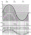
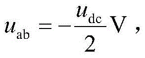
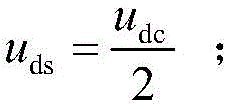
基于混合H桥的单相两管五电平整流器,包括开关管Q1、开关管Q2,交流电源Vs一侧分别连接二极管D1阳极、二极管D2阴极,该连接节点构成端点b;电感L另一端与二极管D3、D4、D5、D6的连接节点构成端点a;开关管Q1漏极与二极管D1、D3、D7的连接节点构成端点c;开关管Q1源极与二极管D2、D4、D8的连接节点构成端点d;二极管D8阳极连接电容C2负极构成端点m;二极管D11阳极、二极管D12阴极、电容C2正极均连接电容C1负极构成端点n;二极管D7阴极连接电容C1正极构成端点p。端点a、端点c、端点d、端点n构成混合H桥四端口。本发明整流器具有输出直流电压较高,谐波含量较小,开关管应力较低,控制较为简单等优点。

Figure 201911283810

A single-phase, two-tube, five-level rectifier based on a hybrid H-bridge includes a switch tube Q 1 and a switch tube Q 2 . One side of the AC power supply Vs is connected to the anode of the diode D 1 and the cathode of the diode D 2 respectively, and the connection node constitutes the terminal b; the inductance The other end of L and the connection node of the diodes D 3 , D 4 , D 5 , D 6 form the terminal a; the drain of the switch Q1 and the connection node of the diodes D 1 , D 3 , D 7 form the terminal c ; the switch Q 1 The connection node between the source and the diodes D 2 , D 4 and D 8 forms the terminal d; the anode of the diode D 8 is connected to the negative electrode of the capacitor C 2 to form the terminal m; the anode of the diode D 11 , the cathode of the diode D 12 and the positive electrode of the capacitor C 2 are all connected to the capacitor C 1 The negative electrode forms the terminal n; the cathode of the diode D 7 is connected to the positive electrode of the capacitor C 1 to form the terminal p. The endpoint a, the endpoint c, the endpoint d, and the endpoint n constitute the four ports of the hybrid H-bridge. The rectifier of the invention has the advantages of higher output DC voltage, lower harmonic content, lower switching tube stress, simpler control and the like.

Figure 201911283810

Description

Single-phase two-tube five-level rectifier based on hybrid H bridge
Technical Field
The invention relates to a five-level rectifier, in particular to a single-phase two-tube five-level rectifier based on a hybrid H bridge.
Background
With the development of power electronic technology, research and application of multi-level power factor correction circuits are receiving wide attention, wherein a five-level high power factor boost converter is one of the most popular research aspects at present. By adopting the multilevel converter, on one hand, the voltage stress of the switching tube can be reduced, so that the harmonic content is reduced, and on the other hand, the working voltage of the system can be improved. In a high-power electronic converter, a diode-clamped multilevel converter is widely applied, and the diode-clamped multilevel converter mainly keeps the advantages of a two-level converter, reduces the voltage at two ends of a switch tube, further reduces the harmonic content and improves the rectification voltage.
At present, aiming at the existing circuit structure, the three-level topological structure has lower output voltage level and higher harmonic content; and the five-level topology has the problems of more switching tubes, more complex control, higher loss and the like. In the traditional topological structure, the boosting is carried out after uncontrolled rectification to realize power factor correction, the mode has the problems of larger loss and more required switching tubes, the length of a current circulation path is reduced as far as possible for reducing the rectification loss, the power density is improved, the most effective mode is to change the topological structure to reduce the number of devices, and meanwhile, the improved topological structure has higher voltage level, smaller harmonic content and simpler control mode.
Disclosure of Invention
In order to overcome the defects in the conventional topological structure, the invention provides the single-phase two-tube five-level rectifier based on the hybrid H bridge, and the topological structure of the rectifier adopts a multi-level mode, so that the converter has the advantages of higher output direct-current voltage, lower harmonic content, lower stress of a switching tube, simpler control and the like.
The technical scheme adopted by the invention is as follows:
a single-phase two-tube five-level rectifier based on a hybrid H bridge comprises an inductor L and a switching tube Q1And a switching tube Q2Diode D1~D12Capacitor C1Capacitor C2
One side of the AC power supply Vs is respectively connected with a diode D1Anode, diode D2A cathode, the connection node constituting a terminal b;
the other side of the AC power supply Vs is connected with one end of an inductor L, and the other end of the inductor L is respectively connected with a diode D3Anode, diode D4Cathode, diode D5Anode, diode D6A cathode; the other end of the inductor L and the diode D3、D4、D5、D6The connection nodes of (a) form an endpoint a;
switch tube Q1The drain electrodes are respectively connected with a diode D1Cathode, diode D3Cathode, diode D7An anode; switch tube Q1Drain and diode D1、D3、D7Connecting jointThe points constitute an endpoint c;
switch tube Q1The source electrodes are respectively connected with a diode D2Anode, diode D4Anode, diode D8A cathode; switch tube Q1Source and diode D2、D4、D8The connecting nodes of (a) form an endpoint d;
switch tube Q2The drain electrodes are respectively connected with a diode D5Cathode, diode D11A cathode;
switch tube Q2The source electrodes are respectively connected with a diode D6Anode, diode D12An anode;
switch tube Q1Anti-parallel diode D9Switching tube Q2Anti-parallel diode D10
Diode D8Anode connected capacitor C2A negative electrode, the connection node of which forms an end point m;
diode D11Anode, diode D12Cathode and capacitor C2The positive electrodes are all connected with a capacitor C1A negative electrode, the connection node of which constitutes an end point n;
diode D7Cathode connection capacitor C1A positive electrode, the connection node of which constitutes an end point p;
load RLThe two ends are respectively connected between the end point p and the end point m.
And the endpoint a, the endpoint c, the endpoint d and the endpoint n form four ports of the hybrid H-bridge network.
The switch tube Q1And a switching tube Q2Is an insulated gate bipolar transistor IGBT, an integrated gate commutated thyristor IGCT, or a power field effect transistor MOSFET.
The capacitor C1Capacitor C2The split capacitors are connected in series with a direct current bus.
The invention discloses a single-phase two-tube five-level rectifier based on a hybrid H bridge, which has the following technical effects:
1: the five-level topology, the power combining diode and the full control device have a hybrid H-bridge four-end network structure with high reliability, and the invention is applied to a bidirectional switch unit, wherein a bidirectional switch is switched on by a switchClosing tube Q2Diode D5、D6、D11、D12Composition, the main function of which lies in the selection
Figure BDA0002317472540000021
Voltage flow path using diode D7、D8The unidirectional power circulation of the direct current bus is realized. The topology of the invention has the characteristics of boosting, rectifying and five-level power factor correction.
2: the novel topology is a hybrid H-bridge four-port network structure, and can be used as a five-level modular power unit based on a hybrid H-bridge circuit module.
3: a mixed H-bridge five-level topology is integrated into a unit power factor correction circuit topology structure; a boosting process is introduced into a topological structure of the rectifier, and a fusion technology of a fully-controlled device and an uncontrolled device is applied, so that the structure of the rectifier is modularized, and the cascade connection of a module circuit is facilitated. In addition, the topological structure adopts an uncontrollable diode rectifier bridge structure, so that the power output of the later stage can still be realized under the condition that the pulse signal of the switching tube is lost, the fault loss is reduced to a certain degree, and the working reliability of the single-phase five-level power factor correction circuit is improved.
4: the invention provides a hybrid H-bridge four-terminal structure with a diode and a full-control device fused, which has the advantages of low cost, high reliability, simple control system design and the like, so that the circuit volume is reduced to a certain extent, the switching loss is reduced, and the power density is improved.
5: the topology of the invention adopts fewer switching tubes and diodes to realize multi-level, only adopts two switching tubes and ten diodes to realize multi-level, reduces the cost and the circuit volume compared with the traditional multi-level, and simultaneously improves the power density of the topology structure.
6: the converter provided by the invention has six working modes in an alternating current input period, and the topological structure divides vab=±udcTime switch tube Q1、Q2In the off state, only one of the other four modes is in the on state, and because the topological structure adopts a mixed H-bridge type,reliable power output can be realized under the fault state, and the reliability of the topology is improved to a certain extent.
Drawings
The invention is further illustrated by the following examples in conjunction with the accompanying drawings:
fig. 1 is a circuit topology of the present invention.
Fig. 2 is a flow chart of the switching mode of the present invention.
Fig. 3 is a switch mode flow diagram of the present invention.
Fig. 4 is a switch mode three-flow diagram of the present invention.
Fig. 5 is a switch mode four-flow diagram of the present invention.
Fig. 6 is a five-flow diagram of the switching mode of the present invention.
Fig. 7 is a switch mode six-flow diagram of the present invention.
FIG. 8 is a diagram of the pulse distribution of the present invention.
FIG. 9(1) shows a steady-state AC input U according to the present inventionNA voltage waveform diagram.
FIG. 9(2) is a steady-state AC input I of the present inventionNA current waveform diagram.
FIG. 9(3) shows a steady state U of the present inventionabA voltage waveform diagram.
FIG. 9(4) shows the steady-state output voltage U of the present inventiondcAnd (4) waveform diagrams.
FIG. 10(1) is a diagram of a power increase/decrease 50% AC input U of the present inventionNA voltage waveform diagram.
FIG. 10(2) is a diagram of a power increase/decrease 50% AC input I of the present inventionNA current waveform diagram.
FIG. 10(3) shows the power increase or decrease of 50% U according to the present inventionabA voltage waveform diagram.
FIG. 10(4) shows the power increase/decrease 50% output voltage U of the present inventiondcAnd (4) waveform diagrams.
FIG. 11(1) shows the uncontrolled rectification to the controlled rectification AC input U of the present inventionNA voltage waveform diagram.
FIG. 11(2) shows the uncontrolled to controllably rectified AC input I of the present inventionNA current waveform diagram.
FIG. 11(3) For the uncontrolled to controlled rectification U of the inventionabA voltage waveform diagram.
FIG. 11(4) shows the uncontrolled rectification to the controlled rectified output voltage U according to the present inventiondcAnd (4) waveform diagrams.
Detailed Description
As shown in FIG. 1, the single-phase two-transistor five-level rectifier based on the hybrid H-bridge comprises an inductor L and a switching transistor Q1And a switching tube Q2Diode D1~D12Capacitor C1Capacitor C2. One side of the AC power supply Vs is respectively connected with a diode D1Anode, diode D2A cathode, the connection node constituting a terminal b;
the other side of the AC power supply Vs is connected with one end of an inductor L, and the other end of the inductor L is respectively connected with a diode D3Anode, diode D4Cathode, diode D5Anode, diode D6A cathode; the other end of the inductor L and the diode D3、D4、D5、D6The connection nodes of (a) form an endpoint a;
switch tube Q1The drain electrodes are respectively connected with a diode D1Cathode, diode D3Cathode, diode D7An anode; switch tube Q1Drain and diode D1、D3、D7The connection nodes of (a) form an endpoint c;
switch tube Q1The source electrodes are respectively connected with a diode D2Anode, diode D4Anode, diode D8A cathode; switch tube Q1Source and diode D2、D4、D8The connecting nodes of (a) form an endpoint d;
switch tube Q2The drain electrodes are respectively connected with a diode D5Cathode, diode D11A cathode;
switch tube Q2The source electrodes are respectively connected with a diode D6Anode, diode D12An anode;
switch tube Q1Anti-parallel diode D9Switching tube Q2Anti-parallel diode D10
Diode D8Anode is connected withA capacitor C2A negative electrode, the connection node of which forms an end point m;
diode D11Anode, diode D12Cathode and capacitor C2The positive electrodes are all connected with a capacitor C1A negative electrode, the connection node of which constitutes an end point n;
diode D7Cathode connection capacitor C1A positive electrode, the connection node of which constitutes an end point p;
load RLThe two ends are respectively connected between the end point p and the end point m.
And the endpoint a, the endpoint c, the endpoint d and the endpoint n form four ports of the hybrid H-bridge network.
The switch tube Q1And a switching tube Q2Is an insulated gate bipolar transistor IGBT, an integrated gate commutated thyristor IGCT, or a power field effect transistor MOSFET.
The capacitor C1Capacitor C2The split capacitors are connected in series with a direct current bus. The split capacitor is formed by connecting two capacitors with the same capacitance in series, and the capacitors with the same capacitance in series are divided by voltage, and the series voltage of the capacitors with the same capacitance in series is half of the series voltage, so that the direct-current side voltage is mainly divided to form a midpoint of half of the bus voltage, and the function of the split capacitor is to finish the purpose of dividing the direct-current side voltage
Figure BDA0002317472540000051
A change in level.
Single-phase two-transistor five-level rectifier based on hybrid H bridge includes the following switching pattern:
a first switching mode: as shown in fig. 2, the circuit operates in the positive half cycle of the network voltage, and the switching tube Q1Conducting, diode D2、D3On, the capacitance C1、C2To a load RLSupply of current i1=i2=-idcDecreasing, inductor L current isThe linear rise is equivalent to the conduction stage of a switching tube of a Boost circuit, the inductor L stores energy, and the voltage uab0V, switching tube Q2Drain-source voltage
Figure BDA0002317472540000052
And a second switching mode: as shown in fig. 3, the circuit operates in the positive half cycle of the network voltage, and the switching tube Q2Conducting, diode D2、D5、D8、D12When the inductor L is conducted, the energy released by the inductor L is applied to the capacitor C2Charging, current is=i2Elevation, C1Discharge, current-i1=idcDecrease of voltage uc2Rising, uc1Falling, switching tube Q1Drain-source voltage
Figure BDA0002317472540000053
And (3) switching mode III: as shown in fig. 4, the circuit operates in the positive half cycle of the mains voltage, diode D2、D3、D7、D8On, the capacitance C1、C2Charging, current is=i1+idcVoltage uc1、uc2Rising, switching tube Q1Drain-source voltage uds=udc,uab=udcV, inductor current drops in this mode;
and a fourth switching mode: as shown in fig. 5, the circuit operates in the negative half-cycle of the grid voltage, and the switching tube Q1Conducting, diode D1、D4On, the capacitance C1、C2To a load RLSupply of current i1=i2=-idcDecreasing, inductor L current isThe linear rising is equivalent to the conduction stage of a switching tube of a Boost circuit, and an inductor L stores energy and uab=0V;
A switching mode five: as shown in fig. 6, the circuit operates in the negative half-cycle of the grid voltage, and the switching tube Q2Conducting, diode D1、D4、D6、D7、D8、D11When the inductor L is conducted, the energy released by the inductor L is applied to the capacitor C1Charging, -is=i1+idcVoltage uc1The temperature of the molten steel rises and rises,
Figure BDA0002317472540000054
switch tube Q1Drain-source voltage
Figure BDA0002317472540000055
A switching mode six: as shown in fig. 7, the circuit operates in the negative half cycle of the mains voltage, diode D1、D4、D7、D8On, the capacitance C1、C2Charging, current i1=i2,-is=i1+idcVoltage uc1、uc2Rising, switching tube Q1Drain-source voltage uds=udc,uab=-udcV。
Single-phase two-tube five-level rectifier based on hybrid H bridge and using diode D7、D8The following circuit protection is performed:
one, two diodes D are adopted7、D8Ensuring one-way power circulation to make the capacitor C1、C2Will only flow to the load RLFlow without flowing backward;
secondly, when the circuit is in failure, the capacitor C is connected1、C2The protection can be well realized;
thirdly, in the process of mode switching, the diode is used as a boosting clamping diode;
and fourthly, when the voltage is lower than the voltage of the direct current bus in the energy storage process of the inductor L in the first switching mode and the fourth switching mode, the voltage clamping effect is achieved.
Experimental parameters:
the peak value of the alternating current power supply is 220V, and the output direct current voltage Vdc400V, 40 omega of resistance load, 2.5mH of filter inductance and a split capacitor C1=C21000 muf, switching frequency 10 kHz.
Fig. 8, fig. 9(1), fig. 9(2), fig. 9(3), fig. 9(4), fig. 10(1), fig. 10(2), fig. 10(3), fig. 10(4), fig. 11(1), fig. 11(2), fig. 11(3), fig. 11(4) are experimental waveform diagrams when the middle load is 40 ohms according to the present invention.
FIG. 8 is a switch tubeImpulse signal and five-level waveform diagram. From the graph shown in FIG. 8, the voltage UabFive levels appear in one ac input period, i.e. this figure illustrates that the topology proposed by this patent has the function of realizing five levels.
FIG. 9(1), FIG. 9(2), FIG. 9(3), FIG. 9(4) show the voltage and current waveforms in the steady state process of the topology structure,
FIG. 9(1) shows the input voltage U during steady state of the circuitNMaintaining a sinusoidal variation.
FIG. 9(2) shows the input voltage I during steady state of the circuitNFollowing AC input voltage UN
FIG. 9(3) shows the voltage U during steady state of the circuitabFive level changes are implemented.
FIG. 9(4) shows the rectifier output voltage U during circuit steady statedcThe bus voltage is kept stable.
Fig. 10(1), fig. 10(2), fig. 10(3), and fig. 10(4) are graphs of voltage and current waveforms when the load increases or decreases by 50%.
FIG. 10(1) is a diagram of a power increase/decrease 50% AC input U of the present inventionNAs can be seen from fig. 10(1), the ac input voltage waveform maintains a sinusoidal variation.
FIG. 10(2) is a diagram of a power increase/decrease 50% AC input I of the present inventionNAnd in the current waveform diagram, the AC input current waveform keeps sinusoidal change and follows the AC input voltage in the process of load reduction and increase at 0.1s and 0.2 s.
Fig. 10(3) is a voltage waveform diagram of power increase and decrease 50% Uab according to the present invention, and fig. 10(3) shows that the voltage Uab keeps five levels of change during the load change.
FIG. 10(4) shows the power increase/decrease 50% output voltage U of the present inventiondcThe waveform diagram, which can be obtained from fig. 10(4), shows that the dc side voltage Udc is kept stable and unchanged during the load variation process, which indicates that the circuit structure can realize the stabilization of the dc side voltage.
Fig. 11(1), fig. 11(2), fig. 11(3), and fig. 11(4) are voltage-current waveform diagrams of the topology uncontrolled rectifying process of the present invention.
FIG. 11(1) shows the present inventionUncontrolled to controlled rectified AC input UNThe voltage waveform diagram, as shown in fig. 11(1), during the state switching process, the ac input voltage keeps changing sinusoidally because the power grid is a voltage source.
FIG. 11(2) shows the uncontrolled to controllably rectified AC input I of the present inventionNAs can be seen from fig. 11(2), in the ac uncontrolled rectification process, the waveform distortion of the ac input current is severe, the harmonic content is high, and after the ac input current enters the controlled rectification process for 0.1s, the current is sinusoidal and keeps consistent with the ac input voltage wave, and it is verified that the circuit structure can realize power factor correction.
Fig. 11(3) is a voltage waveform diagram of the uncontrollable rectification to the controllable rectification Uab according to the present invention, which can be obtained from fig. 11(3), and when the ac input is in the uncontrolled rectification process, the Uab voltage waveform has a large distortion and does not form a five-level voltage change, and when the ac input enters the controllable rectification process in 0.1s, the Uab realizes the five-level change.
Fig. 11(4) is a waveform diagram of the uncontrollable rectified to controllable rectified output voltage Udc according to the present invention, which can be obtained from fig. 11(4), and after the uncontrollable rectification is controllable, the output voltage waveform of the dc side is well stabilized, so as to verify that the circuit structure has the characteristic of well stabilizing the output voltage.
In conclusion, the waveform and the analysis process of the experiment can be obtained, the circuit structure provided by the invention has better stability, can realize higher power factor, and provides a novel circuit structure for the single-phase rectifier converter.

Claims (6)

1.基于混合H桥的单相两管五电平整流器,包括电感L、开关管Q1、开关管Q2、二极管D1~D12,电容C1、电容C2,其特征在于:1. A single-phase, two-tube, five-level rectifier based on a hybrid H-bridge, comprising an inductor L, a switch tube Q 1 , a switch tube Q 2 , diodes D 1 to D 12 , a capacitor C 1 , and a capacitor C 2 , and is characterized in that: 交流电源Vs一侧分别连接二极管D1阳极、二极管D2阴极,该连接节点构成端点b; One side of the AC power supply Vs is respectively connected to the anode of the diode D1 and the cathode of the diode D2, and the connection node constitutes the terminal b ; 交流电源Vs另一侧连接电感L一端,电感L另一端分别连接二极管D3阳极、二极管D4阴极、二极管D5阳极、二极管D6阴极;电感L另一端与二极管D3、D4、D5、D6的连接节点构成端点a;The other side of the AC power supply Vs is connected to one end of the inductor L, and the other end of the inductor L is connected to the anode of the diode D3 , the cathode of the diode D4 , the anode of the diode D5 , and the cathode of the diode D6 respectively ; the other end of the inductor L is connected to the diodes D3 , D4 , D 5. The connection node of D6 constitutes the endpoint a ; 开关管Q1漏极分别连接二极管D1阴极、二极管D3阴极、二极管D7阳极;开关管Q1漏极与二极管D1、D3、D7的连接节点构成端点c; The drain of the switch tube Q1 is respectively connected to the cathode of the diode D1, the cathode of the diode D3 , and the anode of the diode D7 ; the connection node of the drain of the switch tube Q1 and the diodes D1, D3 , D7 constitutes the terminal c; 开关管Q1源极分别连接二极管D2阳极、二极管D4阳极、二极管D8阴极;开关管Q1源极与二极管D2、D4、D8的连接节点构成端点d; The source of the switch tube Q1 is respectively connected to the anode of the diode D2, the anode of the diode D4, and the cathode of the diode D8 ; the connection node of the source of the switch tube Q1 and the diodes D2, D4 , D8 constitutes the terminal d ; 开关管Q2漏极分别连接二极管D5阴极、二极管D11阴极; The drain of the switching tube Q2 is respectively connected to the cathode of the diode D5 and the cathode of the diode D11 ; 开关管Q2源极分别连接二极管D6阳极、二极管D12阳极;The source of the switch tube Q2 is respectively connected to the anode of the diode D6 and the anode of the diode D12 ; 开关管Q1反并联二极管D9,开关管Q2反并联二极管D10The switch tube Q1 has an anti-parallel diode D 9 , and the switch tube Q 2 has an anti-parallel diode D 10 ; 二极管D8阳极连接电容C2负极,其连接节点构成端点m; The anode of the diode D8 is connected to the cathode of the capacitor C2 , and its connection node constitutes the terminal m; 二极管D11阳极、二极管D12阴极、电容C2正极均连接电容C1负极,其连接节点构成端点n;The anode of the diode D11, the cathode of the diode D12 , and the anode of the capacitor C2 are all connected to the cathode of the capacitor C1 , and the connection nodes form the terminal n; 二极管D7阴极连接电容C1正极,其连接节点构成端点p; The cathode of the diode D7 is connected to the anode of the capacitor C1 , and its connection node constitutes the terminal p; 负载RL两端分别连接于端点p、端点m之间。Both ends of the load RL are respectively connected between the end point p and the end point m. 2.根据权利要求1所述基于混合H桥的单相两管五电平整流器,其特征在于:所述端点a、端点c、端点d、端点n构成混合H桥网络四端口。2. The single-phase, two-tube, five-level rectifier based on a hybrid H-bridge according to claim 1, wherein the terminal a, the terminal c, the terminal d, and the terminal n constitute four ports of a hybrid H-bridge network. 3.根据权利要求1所述基于混合H桥的单相两管五电平整流器,其特征在于:所述开关管Q1、开关管Q2为绝缘栅型双极晶体管IGBT、集成门极换流晶闸管IGCT、或者电力场效应晶体管MOSFET。3. The single-phase two-tube five-level rectifier based on the hybrid H-bridge according to claim 1, wherein the switch tube Q 1 and the switch tube Q 2 are insulated gate type bipolar transistors IGBT, integrated gate switch Flow thyristor IGCT, or power field effect transistor MOSFET. 4.根据权利要求1所述基于混合H桥的单相两管五电平整流器,其特征在于:所述电容C1、电容C2为串联直流母线分裂电容。4 . The hybrid H-bridge-based single-phase two-tube five-level rectifier according to claim 1 , wherein the capacitors C 1 and C 2 are series-connected DC bus split capacitors. 5 . 5.如权利要求1-4所述任意一种基于混合H桥的单相两管五电平整流器,其特征在于,包括以下开关模式:5. any kind of single-phase two-tube five-level rectifier based on hybrid H bridge as described in claim 1-4, is characterized in that, comprises following switch mode: 开关模式一:电路工作在电网电压正半周期,开关管Q1导通,二极管D2、D3导通,电容C1、C2向负载RL供电,电流i1=i2=-idc下降,电感L电流is线性上升,此过程相当于升压电路开关管导通阶段,电感L储能,电压uab=0V,开关管Q2漏极-源极电压
Figure FDA0002317472530000021
Switching mode 1: The circuit works in the positive half cycle of the grid voltage, the switch tube Q1 is turned on , the diodes D2 and D3 are turned on , the capacitors C1 and C2 supply power to the load RL , and the current i1 = i2 =-i When dc drops, the inductor L current i s rises linearly. This process is equivalent to the conduction stage of the switch tube of the boost circuit, the inductor L stores energy, the voltage u ab = 0V, and the drain-source voltage of the switch tube Q 2
Figure FDA0002317472530000021
开关模式二:电路工作在电网电压正半周期,开关管Q2导通,二极管D2、D5、D8、D12导通,电感L释放能量对电容C2充电,电流is=i2上升,C1放电,电流-i1=idc减小,电压uc2上升、uc1下降,开关管Q1漏极-源极电压
Figure FDA0002317472530000022
Switching mode 2: The circuit works in the positive half cycle of the grid voltage, the switch tube Q 2 is turned on, the diodes D 2 , D 5 , D 8 , and D 12 are turned on, the inductor L releases energy to charge the capacitor C 2 , the current is = i 2 rises, C 1 discharges, current -i 1 =id dc decreases, voltage u c2 rises, u c1 falls, switch tube Q 1 drain-source voltage
Figure FDA0002317472530000022
开关模式三:电路工作在电网电压正半周期,二极管D2、D3、D7、D8导通,电容C1、C2充电,电流is=i1+idc,电压uc1、uc2上升,开关管Q1漏极-源极电压uds=udc,uab=udcV,在此模态中电感电流下降;Switching mode 3: The circuit works in the positive half cycle of the grid voltage, the diodes D 2 , D 3 , D 7 , and D 8 are turned on, the capacitors C 1 and C 2 are charged, the current is = i 1 + i dc , the voltages u c1 , When u c2 rises, the drain-source voltage of switch Q1 is uds = u dc , u ab = u dc V, and the inductor current decreases in this mode; 开关模式四:电路工作在电网电压负半周期,开关管Q1导通,二极管D1、D4导通,电容C1、C2向负载RL供电,电流i1=i2=-idc下降,电感L电流is线性上升,此过程相当于升压电路开关管导通阶段,电感L储能,uab=0V;Switching mode 4: The circuit works in the negative half cycle of the grid voltage, the switch tube Q1 is turned on , the diodes D1 and D4 are turned on , the capacitors C1 and C2 supply power to the load RL , and the current i1 = i2 = -i When dc drops, the inductor L current i s rises linearly. This process is equivalent to the conduction stage of the switch tube of the boost circuit, and the inductor L stores energy, u ab = 0V; 开关模式五:电路工作在电网电压负半周期,开关管Q2导通,二极管D1、D4、D6、D7、D8、D11导通,电感L释放能量对电容C1充电,-is=i1+idc,电压uc1上升,
Figure FDA0002317472530000023
开关管Q1漏极-源极电压
Figure FDA0002317472530000024
Switching mode 5: The circuit works in the negative half cycle of the grid voltage, the switch tube Q2 is turned on , the diodes D1, D4, D6 , D7 , D8 , D11 are turned on , and the inductor L releases energy to charge the capacitor C1 , -i s =i 1 +i dc , the voltage u c1 rises,
Figure FDA0002317472530000023
Switch tube Q 1 drain-source voltage
Figure FDA0002317472530000024
开关模式六:电路工作在电网电压负半周期,二极管D1、D4、D7、D8导通,电容C1、C2充电,电流i1=i2,-is=i1+idc,电压uc1、uc2上升,开关管Q1漏极-源极电压uds=udc,uab=-udcV。Switching mode 6: The circuit works in the negative half cycle of the grid voltage, the diodes D 1 , D 4 , D 7 , and D 8 are turned on, the capacitors C 1 and C 2 are charged, and the current i 1 = i 2 , -is =i 1 + i dc , the voltages u c1 and u c2 rise, and the drain-source voltages of the switch tube Q 1 uds = u dc , u ab = -u dc V .
6.根据权利要求5所述基于混合H桥的单相两管五电平整流器,其特征在于,使用二极管D7、D8进行如下电路保护:6. the single-phase two-tube five-level rectifier based on the hybrid H bridge according to claim 5, is characterized in that, uses diode D7 , D8 to carry out following circuit protection: 其一,采用两个二极管D7、D8,保证功率的单向流通,使电容C1、C2的电流只会向负载RL流动,而不会使其倒灌回流;First, two diodes D 7 and D 8 are used to ensure the unidirectional flow of power, so that the currents of the capacitors C 1 and C 2 can only flow to the load RL , and will not flow backward; 其二,电路故障时,对电容C1、C2可以起到很好的保护;Second, when the circuit fails, it can protect the capacitors C 1 and C 2 very well; 其三,模态切换过程中,作为升压钳位二极管;Third, in the process of mode switching, it acts as a boost clamp diode; 其四,在开关模式一、开关模式四时,电感L储能过程中电压低于直流母线电压时,起到电压钳位作用。Fourth, in switching mode 1 and switching mode 4, when the voltage of the inductor L is lower than the DC bus voltage during the energy storage process, it acts as a voltage clamp.
CN201911283810.1A 2019-12-13 2019-12-13 Single-phase two-tube five-level rectifier based on hybrid H-bridge Active CN111030440B (en)

Priority Applications (1)

Application Number Priority Date Filing Date Title
CN201911283810.1A CN111030440B (en) 2019-12-13 2019-12-13 Single-phase two-tube five-level rectifier based on hybrid H-bridge

Applications Claiming Priority (1)

Application Number Priority Date Filing Date Title
CN201911283810.1A CN111030440B (en) 2019-12-13 2019-12-13 Single-phase two-tube five-level rectifier based on hybrid H-bridge

Publications (2)

Publication Number Publication Date
CN111030440A CN111030440A (en) 2020-04-17
CN111030440B true CN111030440B (en) 2021-05-04

Family

ID=70209065

Family Applications (1)

Application Number Title Priority Date Filing Date
CN201911283810.1A Active CN111030440B (en) 2019-12-13 2019-12-13 Single-phase two-tube five-level rectifier based on hybrid H-bridge

Country Status (1)

Country Link
CN (1) CN111030440B (en)

Families Citing this family (12)

* Cited by examiner, † Cited by third party
Publication number Priority date Publication date Assignee Title
CN111416534B (en) * 2020-04-24 2023-07-14 三峡大学 A single-phase five-level rectifier with current path reconstruction
CN111416535B (en) * 2020-04-24 2023-06-16 三峡大学 Three-mode mixed single-phase five-level rectifier
CN111416533B (en) * 2020-04-24 2023-07-14 三峡大学 Single-phase five-level rectifier based on four-port plug-in
CN111416536B (en) * 2020-04-24 2023-07-14 三峡大学 Single-phase dual-boost bridgeless five-level rectifier based on bidirectional transistor plug-in
CN111756257B (en) * 2020-06-16 2023-12-19 三峡大学 Dual-boost three-level rectifier based on three switching tubes
CN112187071B (en) * 2020-09-09 2021-09-28 三峡大学 DC side capacitor cascade single-phase seven-level rectifier
CN112187087B (en) * 2020-09-09 2021-10-08 三峡大学 Scalable Multilevel Rectifier
CN114553039B (en) * 2020-11-25 2025-10-31 华为数字能源技术有限公司 Neutral point clamped inverter and photovoltaic power supply system
CN112865567B (en) * 2021-01-28 2022-05-20 三峡大学 Heterogeneous diode clamping type three-level rectifier
CN112910244B (en) * 2021-01-28 2022-05-20 三峡大学 A hybrid bridge arm single-phase three-level power factor correction circuit
CN113193763B (en) * 2021-04-02 2022-04-22 三峡大学 Hybrid multilevel AC-DC converter based on T-type selection unit
CN113258797B (en) * 2021-04-21 2022-06-14 三峡大学 A back-to-back three-level rectifier with heterogeneous switch bridge arms

Family Cites Families (13)

* Cited by examiner, † Cited by third party
Publication number Priority date Publication date Assignee Title
US9413268B2 (en) * 2012-05-10 2016-08-09 Futurewei Technologies, Inc. Multilevel inverter device and method
CN103219907B (en) * 2013-03-20 2015-04-22 上海交通大学 Five-level inverter
CN103684019A (en) * 2013-12-16 2014-03-26 上海交通大学无锡研究院 Five-level inverter and control method thereof
US9520800B2 (en) * 2014-01-09 2016-12-13 Rockwell Automation Technologies, Inc. Multilevel converter systems and methods with reduced common mode voltage
CN105720852A (en) * 2016-02-05 2016-06-29 浙江大学 Single-phase five-level inverter with battery energy balance function and control strategy thereof
WO2017157338A1 (en) * 2016-03-17 2017-09-21 汪洪亮 Single-phase five-level active clamping converter unit and converter
CN107612304B (en) * 2017-09-06 2019-07-16 湖北工业大学 Single-phase five-level boost power factor correction converter
CN107896069B (en) * 2017-12-25 2020-02-14 三峡大学 Novel single-phase mixed three-level rectifier
CN208424231U (en) * 2018-05-03 2019-01-22 易事特集团股份有限公司 Five-level topology unit and five-level AC-DC converter
CN109067226A (en) * 2018-10-17 2018-12-21 广东电网有限责任公司 Five lever boosting type inverters of one kind and its control method
CN109167525B (en) * 2018-11-02 2020-09-01 湖南大学 A Novel Non-isolated Five-Level Inverter
CN109831113A (en) * 2019-03-04 2019-05-31 易事特集团股份有限公司 Converter topology unit and converter device
CN110086360A (en) * 2019-04-22 2019-08-02 浙江大学 A kind of five level high efficiency rectifiers

Also Published As

Publication number Publication date
CN111030440A (en) 2020-04-17

Similar Documents

Publication Publication Date Title
CN111030440B (en) Single-phase two-tube five-level rectifier based on hybrid H-bridge
CN110880864B (en) Single-phase five-level power factor correction circuit based on hybrid H-bridge
CN111416534B (en) A single-phase five-level rectifier with current path reconstruction
CN111416535B (en) Three-mode mixed single-phase five-level rectifier
CN111030441B (en) Single-phase power factor correction circuit based on three-tube five-level topology
CN112910244B (en) A hybrid bridge arm single-phase three-level power factor correction circuit
CN112865560B (en) Multi-diode series back-to-back bridgeless three-level rectifier
CN111082680B (en) Single-phase five-level rectifier based on T-type structure
WO2012041020A1 (en) Single-phase five-level power converter
CN112865587B (en) A single-phase three-level rectifier with two-tube T-bridge
CN112865562B (en) Single-phase three-switch tube pseudo-totem-pole type three-level rectifier
CN112865567B (en) Heterogeneous diode clamping type three-level rectifier
CN110649829A (en) Single-phase three-level power factor correction rectifier based on asymmetric four-port
CN113193768B (en) Back-to-back three-level rectifier with four switches in series
CN112910243B (en) A single-phase three-level pseudo-totem pole power factor correction circuit
CN112865563B (en) Three-port clamping type back-to-back bridgeless three-level rectifier
CN112865561B (en) A diode-clamped back-to-back bridgeless three-level rectifier
CN113437884B (en) Three-level rectifier based on parallel diode clamped bidirectional switch
CN112701905B (en) Single-phase three-level power factor correction circuit based on pseudo totem-pole structure
CN113258797B (en) A back-to-back three-level rectifier with heterogeneous switch bridge arms
CN213461565U (en) Novel five-level inverter
CN113206605A (en) Three-level rectification charger with single-phase T-shaped staggered parallel structure
CN113206602B (en) DC charger based on single-phase grid three-level pseudo-totem pole
CN112187087A (en) Expandable multi-level rectifier
CN113206600B (en) Single-phase three-level pseudo-totem pole DC charger

Legal Events

Date Code Title Description
PB01 Publication
PB01 Publication
SE01 Entry into force of request for substantive examination
GR01 Patent grant
GR01 Patent grant
EE01 Entry into force of recordation of patent licensing contract

Application publication date: 20200417

Assignee: Hubei Zhikan Technology Co.,Ltd.

Assignor: CHINA THREE GORGES University

Contract record no.: X2023980043945

Denomination of invention: Single phase two transistor five level rectifier based on hybrid H-bridge

Granted publication date: 20210504

License type: Common License

Record date: 20231024

OL01 Intention to license declared