WO2005098821A2 - Multi-channel encoder - Google Patents
Multi-channel encoder Download PDFInfo
- Publication number
- WO2005098821A2 WO2005098821A2 PCT/IB2005/051037 IB2005051037W WO2005098821A2 WO 2005098821 A2 WO2005098821 A2 WO 2005098821A2 IB 2005051037 W IB2005051037 W IB 2005051037W WO 2005098821 A2 WO2005098821 A2 WO 2005098821A2
- Authority
- WO
- WIPO (PCT)
- Prior art keywords
- channels
- signals
- channel
- input signals
- data
- Prior art date
- Legal status (The legal status is an assumption and is not a legal conclusion. Google has not performed a legal analysis and makes no representation as to the accuracy of the status listed.)
- Ceased
Links
Classifications
-
- G—PHYSICS
- G10—MUSICAL INSTRUMENTS; ACOUSTICS
- G10L—SPEECH ANALYSIS TECHNIQUES OR SPEECH SYNTHESIS; SPEECH RECOGNITION; SPEECH OR VOICE PROCESSING TECHNIQUES; SPEECH OR AUDIO CODING OR DECODING
- G10L19/00—Speech or audio signals analysis-synthesis techniques for redundancy reduction, e.g. in vocoders; Coding or decoding of speech or audio signals, using source filter models or psychoacoustic analysis
- G10L19/008—Multichannel audio signal coding or decoding using interchannel correlation to reduce redundancy, e.g. joint-stereo, intensity-coding or matrixing
-
- G—PHYSICS
- G10—MUSICAL INSTRUMENTS; ACOUSTICS
- G10L—SPEECH ANALYSIS TECHNIQUES OR SPEECH SYNTHESIS; SPEECH RECOGNITION; SPEECH OR VOICE PROCESSING TECHNIQUES; SPEECH OR AUDIO CODING OR DECODING
- G10L19/00—Speech or audio signals analysis-synthesis techniques for redundancy reduction, e.g. in vocoders; Coding or decoding of speech or audio signals, using source filter models or psychoacoustic analysis
- G10L19/02—Speech or audio signals analysis-synthesis techniques for redundancy reduction, e.g. in vocoders; Coding or decoding of speech or audio signals, using source filter models or psychoacoustic analysis using spectral analysis, e.g. transform vocoders or subband vocoders
-
- H—ELECTRICITY
- H04—ELECTRIC COMMUNICATION TECHNIQUE
- H04S—STEREOPHONIC SYSTEMS
- H04S3/00—Systems employing more than two channels, e.g. quadraphonic
Definitions
- the present invention relates to multi-channel encoders, for example multichannel audio encoders utilizing parametric descriptions of spatial audio. Moreover, the invention also relates to methods of processing signals, for example spatial audio signals, in such multi-channel encoders. Furthermore, the invention relates to decoders operable to decode signals generated by such multi-channel encoders.
- An object of the present invention is to provide for a multi-channel encoder which is operable to provide more efficient encoding of multi-channel data content, for example multi-channel audio data content.
- output encoded data is capable of conveying information corresponding to, for example, five- channel audio program content, whilst using a bit rate conventionally required to convey two- channel audio program content, namely stereo.
- a multi-channel encoder arranged to process input signals conveyed in N input channels to generate corresponding output signals conveyed in M output channels together with parametric data such that M and N are integers and N is greater than M, the encoder including:
- a down-mixer for down-mixing the input signals to generate corresponding output signals
- an analyzer for processing the input signals either during down-mixing or as a separate process, said analyzer being operable to generate said parametric data complementary to the output signals, said parametric data describing mutual differences between the N channels of input signal so as to allow substantially for regenerating during decoding of one or more of the N channels of input signal from the M channels of output signal, said output signals being in a form compatible for reproduction in decoders providing for N or for fewer than N output channels to enable backwards compatibility.
- the invention is of advantage in that the multi-channel encoder is capable of more efficiently encoding multi-channel input signals into an output stream which, for example, can be rendered to be compatible with two-channel stereo playback apparatus.
- Such backwards compatibility of the encoder with earlier types of corresponding decoder is provided in three ways:
- the analyzer includes processing means for converting the input signals by way of transformation from a temporal domain to a frequency domain and for processing these transformed input signals to generate the parametric data. Processing of the input signals in a frequency domain is of benefit in providing efficient encoding within the encoder.
- the encoder includes a coder for processing the input signals to generate M intermediate audio data channels for inclusion in the M output signals, the analyzer being arranged to output information in the parametric data relating to at least one of:
- phase differences in (d) are average phase differences.
- PCA principal component analysis
- inter-channel phase alignment to generate the output signals.
- at least one of the input signals conveyed in the N channels corresponds to an effects channel.
- the encoder is adapted to generate the output signals in a form suitable for playback using conventional playback systems.
- the method is adapted to encode input signals corresponding to 5- channels and generate the output signals and parametric data in a form compatible with one or more of corresponding 2-channel stereo decoders, 3 channel decoders and 4-channel decoders.
- the processing includes converting the input signals by way of transformation from a temporal domain to a frequency domain.
- at least one of the input signals is processed as a sequence of time-frequency tiles to generate the output signals.
- the tiles correspond to mutually overlapping analysis windows.
- the method includes a step of using a coder for processing the input signals to generate M intermediate audio data channels for inclusion in the output signals, the coder being arranged to output information in the parametric data relating to at least one of: (a) inter-channel input signal power ratios or logarithmic level differences;
- phase differences in (d) are average phase differences.
- calculation of at least one of the level differences, the coherence data and the power ratio is followed by principal component analysis and/or phase alignment to generate the output signals.
- at least one of the input signals conveyed in the N channels corresponds to an effects channel.
- a decoder operable to decode encoded output data as generated by an encoder according to the first aspect of the invention, said encoded output data comprising M channels and associated parametric data generated from input signals of N channels such that M ⁇ N where M and N are integers, the decoder including a processor: (a) for receiving the encoded output data and converting it from a time domain to a frequency domain;
- the processor is operable to apply an all-pass decorrelation filter to obtain decorrelated versions of signals for use in regenerating said one or more input signals of N channels at the decoder.
- the processor is operable to apply inverse encoder rotation to split signals of the M channels and decorrelated versions thereof into their constituent components for regenerating said one or more input signals of N channels at the decoder.
- Figure 1 is a schematic diagram of a first multi-channel encoder according to the invention
- Figure 2 is a schematic diagram of a second multi-channel encoder according to the invention including provision for effects, for example low- frequency effects
- Figure 3 is a schematic diagram of a multi-channel decoder according to the invention, the decoder being complementary to the encoders of Figures 1 and 2 and capable of decoding output data provided from such encoders.
- the encoder is beneficially operable: (a) to down- mix the input data of the N channels into M channels such that M ⁇ N;
- the five-channel encoder is operable to generate associated parametric overhead data to combine with data of the two channels to generate the output data stream, the parametric data being sufficient to enable the decoder to reconstruct a representation of the five input channels.
- an encoder is operable to process N input data channels.
- the N input channels preferably correspond to a center audio data channel, a left- front audio data channel, a left-rear audio data channel, a right-front audio data channel and a right rear audio data channel; such five channels are capable of creating an apparent 3 -dimensional distribution of sound appropriate for domestic cinema-type programme content reproduction.
- the N input data channels are down-mixed into two intermediate audio data channels, for example encoded using a contemporary stereo audio coder.
- the coder beneficially employs principal component analysis and/or phase alignment of the left-front and the left-rear data channels.
- the encoder is also arranged to employ a separate principal component analysis and/or phase alignment on the right-front and the right-rear input channels.
- the encoder is operable to generate parametric overhead data including information relating to the following:
- inter-channel coherence data relating to the right-front and right-rear data channels; and (e) a power ratio between the center data channel and a sum of powers of the left- front, left-rear, right-front and right rear data channels.
- the two intermediate data channels and the parametric overhead data are combined to generate encoded output data from the encoder.
- data relating to inter-channel phase differences and preferably overall phase differences between the left- front and left-rear data channels on the one hand, and right-front and right-rear data channels on the other hand are included in the encoded output data from the encoder.
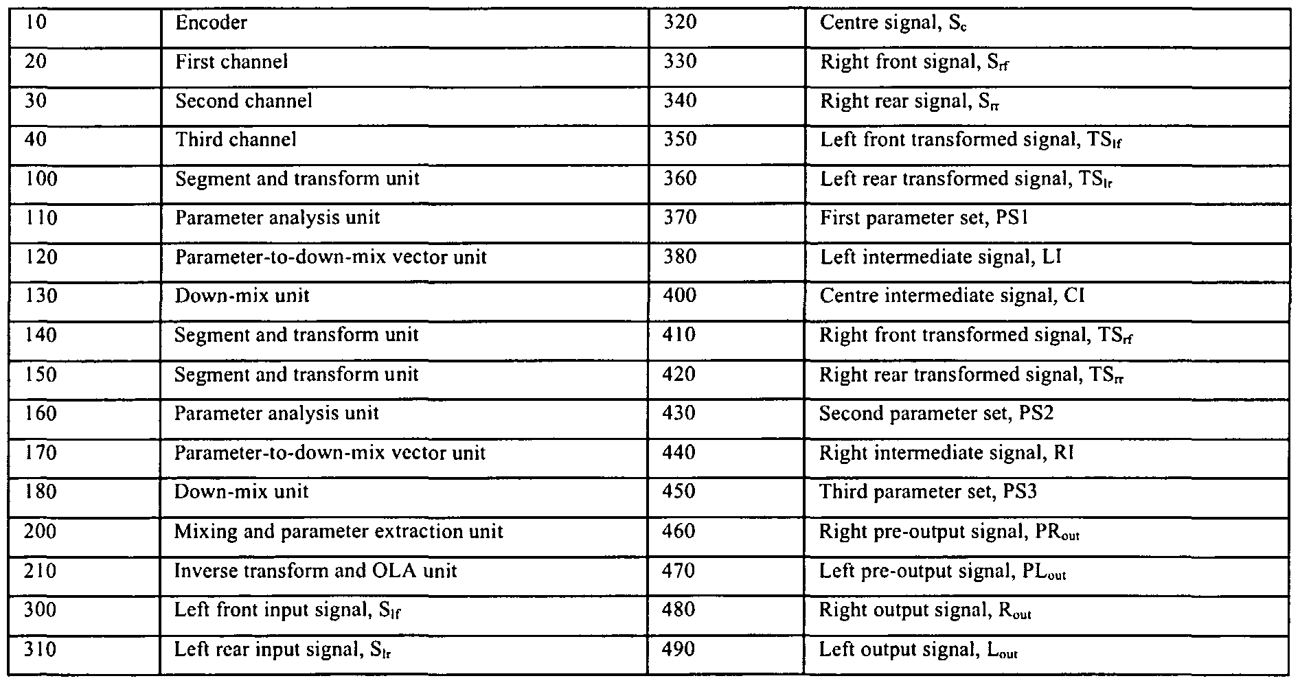
- Parametric analysis performed in (a) to (e) with regard to this example embodiment of the invention preferably involves temporal and frequency analysis; more preferably, the analysis is performed by way of time-frequency tiles as will be further elucidated later. Operation of the encoder in the preferred embodiment of the invention will now be described in greater detail in terms of its associated mathematical functions with reference to Figure 1 whose parts and signals are defined as provided in Table 1. Table 1:
- the encoder 10 comprises first, second and third input channels 20, 30, 40 respectively.
- Output signals 380, 400, 440, namely LI, CI, RI, from these three channels 20, 30, 40 respectively are coupled to a mixing and parameter extraction unit 200.
- the extraction unit 200 comprises associated right and left pre-output signals 460, 470, namely PRout, PL 0U t, which are connected to an inverse transform and OLA unit 210 for generating encoded right and left output signals 480, 490, namely R o ut, L out respectively.
- the first channel 20 includes a segment and transform unit 100 for receiving left front and left rear input signals 300, 310 respectively, namely Sif, S ⁇ r .
- the third channel 40 includes a segment and transform unit 150 for receiving right front and right rear input signals 330, 340 respectively, namely S r r, S ⁇ .
- Corresponding right front and right rear transformed signals 410, 420, namely TSr f , TSrr, are coupled to a down-mix unit 180 of the channel 40, and also to parameter analysis unit 160 of the channel 40.
- a second parameter set signal 430, namely PS2 is coupled to an input of the parameter- to-down-mix vector conversion unit 170 whose corresponding output is coupled to the down- mix unit 180.
- the Parameter extraction unit 200 is arranged to receive signal 380, 400, 440 from the channels 20, 30, 40 to generate the third parameter set output 450, namely PS3, as well as the pre-output signals 470, 460, namely PRout, PL ou t for the OLA unit 210.
- the encoder 10 is susceptible to being implemented in dedicated hardware. Alternatively, the encoder 10 can be based on computer hardware arranged to execute software for implementing processing functions of the encoder 10. As a further alternative, the encoder 10 can be implemented by a combination of dedicated hardware coupled to computer hardware operating under software control. Operation of the encoder 10 will now be described with reference to Figure 1.
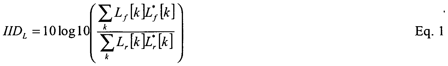
- Such signal processing results in segmented sub-band representations of the input signals in frequency domain denoted by L f [k], L r [k], R f ⁇ k], R r [k], C[k] wherein a parameter k denotes a frequency index, L denotes left, R denotes right, f denotes front, r denotes rear and C denotes center.
- data processing is executed in a first step to estimate relevant parameters between left-front and left-rear signals.
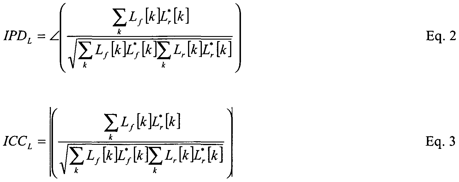
- These parameters include a level difference IID L , phase difference IPDL and a coherence ICCL.
- the phase difference IPD L corresponds to an average phase difference.
- these parameters IIDL, IPDL and ICCL are calculated as provided in Equations 1 to 3 (Eq. 1 to 3):
- Equations 1 to 3 are also repeated for right-front and right-rear signals, such processing resulting in corresponding parameters IID R , IPD R and ICC R relating to level difference, phase difference and coherence respectively.
- data processing is executed in a second step to compute complex weights for the down-mix of the two signals left-front L f and left-rear L r .
- the down-mix vector sent to the down-mix unit 130 is arranged to maximize the energy of the down-mix signal Y[k] by applying a rotation ⁇ of the input signal space and/or complex phase alignment.
- the down-mix is applied as follows.
- Equation 4 cos sin a L f [k ⁇ e ⁇ p(j(- OPD L )) Eq. 4 Q[k] - sin ⁇ cos ⁇ L r [k] ⁇ PU(- OPD L + IPD L ))
- an angle OPD L denotes an overall phase rotation angle
- the phase difference IPD L is calculated to ensure a maximum phase-alignment of the two signals Lf, L r .
- the rotation angle ⁇ is calculable from the extracted parameters using Equations 5 and 6 (Eq. 5 and 6):
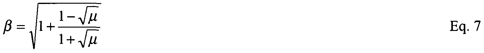
- the signal Q[k] from Equation 4 is subsequently discarded in the parameter extraction unit 200, the signal Y[k] is scaled by a scalar ⁇ to obtain the signal L[k] in such a way that the signal L[k] has a similar power to that of the signal Q[k] plus the power of the signal Y[k]; in other words, the signal Q[k] is discarded whilst a corresponding loss in signal power arising is compensated by scaling the signal Y[k].
- the scalar ⁇ is calculable using Equations 7 and 8 (Eq. 7 and 8):
- the foregoing process comprising the aforementioned first, second and third steps is repeated in the encoder 10 for each time/frequency tile.
- the signals PL 0Ut [k] and PR o M are subsequently transformed in the encoder to a temporal domain and combined with previous segments using an overlap-add type of summation to generate the aforesaid output signals 490, 480 respectively, namely L ou t, Rout- Output data from the encoder 10 is susceptible to being communicated by way of a communication network, for example via the Internet or other similar broadcast network.
- the output data is capable of being conveyed by way of a data carrier, for example a DVD optical data disk or other similar type of data carrying medium.
- the output data from the encoder 10 is capable of being decoded in decoders compatible with the encoder 10, for example in a decoder indicated generally by 800 in Figure 3.
- the decoder 800 includes a data processing unit 810 for subjecting output signals 480, 490 and associated parameter data 370, 430, 450, 690 received from the encoders 10, 600 to various mathematical operations to generate corresponding decoded output signals (DOP).
- DOP decoded output signals
- such decoders can be at least one of stereo, 3-channel and 5-channel apparatus.
- the stereo-type decoder compatible with the encoder 10, namely where decoder 800 includes only two decoded outputs for DOP, the stereo-type decoder having two playback channels, the signals ?Rout, L ou t provided from the encoder 10 are reproduced in the stereo-type decoder over two playback channels without further processing being performed.
- the decoder having three playback channels namely where the decoder 800 includes three decoded outputs for DOP
- the two signals Ro Ut , L ou t for example read from a data carrier such as a DVD optical disk, are segmented and then transformed to the aforementioned frequency domain.
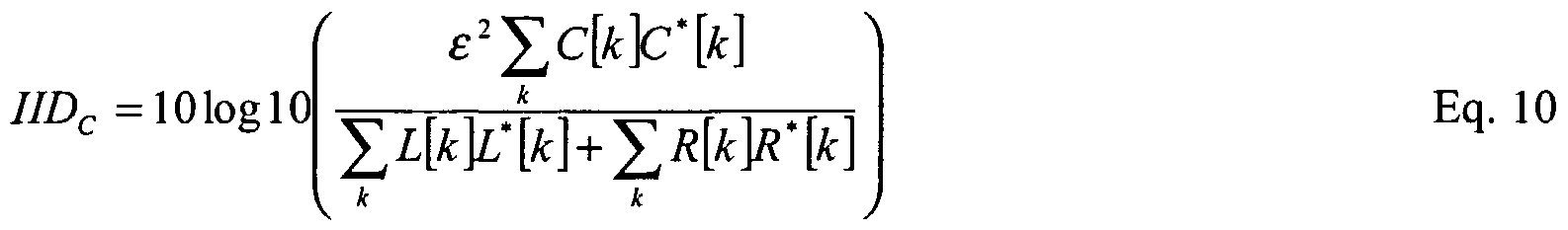
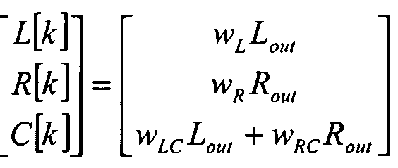
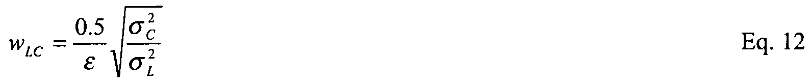
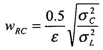
- Corresponding recreated signals L[k], R[k] and C[k] are then derived using Equations 11 to 16 (Eq. 11 to 16):
- Three-channel audio signals for user-appreciation are then derived from the signals L[k], R[k] and C[k] in a manner similar to that described in the foregoing.
- a five-channel decoder compatible with the encoder 10 namely the decoder 800 providing five decoded outputs
- a three-channel playback reconstruction as described in the foregoing is employed resulting in regeneration of the signals L[k], R[k] and C[k] at the decoder.
- a further step is executed which involves splitting the signal L[k] in its constituent components, namely a front left component L f j?k] and a rear left component L r [k]; similarly, the signal R[k] is also split into its constituent components, namely a front right component R f [k] and a rear right component R r [k].
- Such signal splitting utilizes an inverse encoder rotation operation complementary to the rotation performed in the encoder 10 as described in the foregoing.
- the dominant signal Y[k] and the residual signal Q[k] required for the inverse rotation are derived in the five-way decoder using Equations 17 and l8 (Eq. 17, 18):
- Equation 17 H[k] denotes an all-pass decorrelation filter to obtain a decorrelated version of the signal L[k].
- the signals L f ⁇ k] and L r [k] are generated using an inverse encoder rotation function as described by Equation 19 (Eq. 19): cos ⁇ - sm ⁇ ' e ⁇ p(jOPD L ) Eq. 19 sin or cos ⁇ 0 exp(jOPD L - IPD L
- the four-channel decoder is operable to firstly decode five channels in a manner akin to that employed in the aforementioned five-channel decoder to generate five audio signals S
- a coefficient q 0.707.
- the coefficient q ensures for the four-channel decoder that the total power of the center signal components is substantially constant, irrespective of playback through a single center loudspeaker or as a phantom apparent source of sound for the user created by left front and right front loudspeakers coupled to the four-channel decoder.
- LFE effects channel
- Such a LFE channel is of benefit, for example, for conveying sound effects information such as thunder-sound information or explosion sound information which beneficially accompanies visual information simultaneously presented to users in, for example, a home movie system.
- sound effects information such as thunder-sound information or explosion sound information which beneficially accompanies visual information simultaneously presented to users in, for example, a home movie system.
- the inventors have appreciated in an embodiment of the present invention that it is beneficial to modify the encoder 10 to enhance its second channel 30 and thereby generate an encoder as depicted in Figure 2 and indicated therein generally by 600.
- the LFE channel has a relatively restricted frequency bandwidth of substantially 120 Hz although selective relatively greater bandwidths are also capable of being accommodated.
- the encoder 600 is generally similar to the encoder 10 except that the second channel 30 of the encoder 600 is furnished with a parameter analysis unit 630, a parameter to down-mix vector unit 640 and a down-mix unit 650 connected in a similar manner to corresponding components of the first and third channels 20, 40 respectively; the channel 30 of the encoder 600 is operable to output a fourth parameter set 690, namely PS4. Moreover, the second channel 30 of the encoder 600 includes a low frequency effects (lfe) input 610 for receiving a low frequency effects signal Sif e , and also an input 620 for receiving the aforementioned center signal Sc.
- lfe low frequency effects
- processing of the signal Sif e is limited to a frequency bandwidth of 120 Hz from sub- audio frequencies upwards and therefore potentially suitable for driving contemporary sub-woofer type loudspeakers.
- embodiments of the invention are susceptible to being implemented with the second channel 30 having a much greater bandwidth than 120 Hz, for example to provide high frequency signal information corresponding to impulse-like sounds.
- Inclusion of low frequency effect information in output from the encoder 600 requires use of additional parameters in comparison to the encoder 10.
- a signal presented to the input 610 is analyzed in the encoder 600 to determine corresponding representative parameters which are analyzed on a time/frequency tile basis in a similar manner to other aforementioned audio signals processed through the encoder 10.
Landscapes
- Engineering & Computer Science (AREA)
- Physics & Mathematics (AREA)
- Acoustics & Sound (AREA)
- Signal Processing (AREA)
- Multimedia (AREA)
- Health & Medical Sciences (AREA)
- Audiology, Speech & Language Pathology (AREA)
- Human Computer Interaction (AREA)
- Computational Linguistics (AREA)
- Mathematical Physics (AREA)
- Spectroscopy & Molecular Physics (AREA)
- Stereophonic System (AREA)
- Compression, Expansion, Code Conversion, And Decoders (AREA)
- Analogue/Digital Conversion (AREA)
- Time-Division Multiplex Systems (AREA)
- Error Detection And Correction (AREA)
- Control Of Motors That Do Not Use Commutators (AREA)
- Signal Processing For Digital Recording And Reproducing (AREA)
Abstract
Description


Claims
Priority Applications (8)
| Application Number | Priority Date | Filing Date | Title |
|---|---|---|---|
| DE602005006777T DE602005006777D1 (en) | 2004-04-05 | 2005-03-25 | MULTI-CHANNEL CODER |
| PL05718568T PL1735774T3 (en) | 2004-04-05 | 2005-03-25 | Multi-channel encoder |
| KR1020067020276A KR101158698B1 (en) | 2004-04-05 | 2005-03-25 | A multi-channel encoder, a method of encoding input signals, storage medium, and a decoder operable to decode encoded output data |
| BRPI0509113A BRPI0509113B8 (en) | 2004-04-05 | 2005-03-25 | multichannel encoder, method for encoding input signals, encoded data content, data bearer, and operable decoder for decoding encoded output data |
| JP2007506877A JP5032977B2 (en) | 2004-04-05 | 2005-03-25 | Multi-channel encoder |
| MXPA06011361A MXPA06011361A (en) | 2004-04-05 | 2005-03-25 | Multi-channel encoder. |
| US10/599,559 US7602922B2 (en) | 2004-04-05 | 2005-03-25 | Multi-channel encoder |
| EP05718568A EP1735774B1 (en) | 2004-04-05 | 2005-03-25 | Multi-channel encoder |
Applications Claiming Priority (4)
| Application Number | Priority Date | Filing Date | Title |
|---|---|---|---|
| EP04101405 | 2004-04-05 | ||
| EP04101405.1 | 2004-04-05 | ||
| EP04102863 | 2004-06-22 | ||
| EP04102863.0 | 2004-06-22 |
Publications (2)
| Publication Number | Publication Date |
|---|---|
| WO2005098821A2 true WO2005098821A2 (en) | 2005-10-20 |
| WO2005098821A3 WO2005098821A3 (en) | 2006-03-16 |
Family
ID=34962299
Family Applications (1)
| Application Number | Title | Priority Date | Filing Date |
|---|---|---|---|
| PCT/IB2005/051037 Ceased WO2005098821A2 (en) | 2004-04-05 | 2005-03-25 | Multi-channel encoder |
Country Status (14)
| Country | Link |
|---|---|
| US (1) | US7602922B2 (en) |
| EP (1) | EP1735774B1 (en) |
| JP (2) | JP5032977B2 (en) |
| KR (1) | KR101158698B1 (en) |
| CN (1) | CN102122509B (en) |
| AT (1) | ATE395686T1 (en) |
| BR (1) | BRPI0509113B8 (en) |
| DE (1) | DE602005006777D1 (en) |
| ES (1) | ES2307160T3 (en) |
| MX (1) | MXPA06011361A (en) |
| PL (1) | PL1735774T3 (en) |
| RU (1) | RU2390857C2 (en) |
| TW (1) | TWI393119B (en) |
| WO (1) | WO2005098821A2 (en) |
Cited By (10)
| Publication number | Priority date | Publication date | Assignee | Title |
|---|---|---|---|---|
| US20070121954A1 (en) | 2005-11-21 | 2007-05-31 | Samsung Electronics Co., Ltd. | System, medium, and method of encoding/decoding multi-channel audio signals |
| CN101297594A (en) * | 2005-10-24 | 2008-10-29 | Lg电子株式会社 | Eliminate time delays in the signal path |
| JP2009524100A (en) * | 2006-01-18 | 2009-06-25 | エルジー エレクトロニクス インコーポレイティド | Encoding / decoding apparatus and method |
| EP1987594A4 (en) * | 2006-02-23 | 2010-03-31 | Lg Electronics Inc | METHOD AND APPARATUS FOR PROCESSING AUDIO SIGNAL |
| US7831434B2 (en) * | 2006-01-20 | 2010-11-09 | Microsoft Corporation | Complex-transform channel coding with extended-band frequency coding |
| US7953604B2 (en) | 2006-01-20 | 2011-05-31 | Microsoft Corporation | Shape and scale parameters for extended-band frequency coding |
| US8706508B2 (en) | 2009-03-05 | 2014-04-22 | Fujitsu Limited | Audio decoding apparatus and audio decoding method performing weighted addition on signals |
| US9741354B2 (en) | 2007-06-29 | 2017-08-22 | Microsoft Technology Licensing, Llc | Bitstream syntax for multi-process audio decoding |
| RU2643644C2 (en) * | 2012-07-09 | 2018-02-02 | Конинклейке Филипс Н.В. | Coding and decoding of audio signals |
| US9992599B2 (en) | 2004-04-05 | 2018-06-05 | Koninklijke Philips N.V. | Method, device, encoder apparatus, decoder apparatus and audio system |
Families Citing this family (36)
| Publication number | Priority date | Publication date | Assignee | Title |
|---|---|---|---|---|
| US6934677B2 (en) | 2001-12-14 | 2005-08-23 | Microsoft Corporation | Quantization matrices based on critical band pattern information for digital audio wherein quantization bands differ from critical bands |
| US7240001B2 (en) | 2001-12-14 | 2007-07-03 | Microsoft Corporation | Quality improvement techniques in an audio encoder |
| US7502743B2 (en) | 2002-09-04 | 2009-03-10 | Microsoft Corporation | Multi-channel audio encoding and decoding with multi-channel transform selection |
| US7460990B2 (en) | 2004-01-23 | 2008-12-02 | Microsoft Corporation | Efficient coding of digital media spectral data using wide-sense perceptual similarity |
| EP1769491B1 (en) * | 2004-07-14 | 2009-09-30 | Koninklijke Philips Electronics N.V. | Audio channel conversion |
| CN101147191B (en) * | 2005-03-25 | 2011-07-13 | 松下电器产业株式会社 | Speech coding device and speech coding method |
| US8190425B2 (en) * | 2006-01-20 | 2012-05-29 | Microsoft Corporation | Complex cross-correlation parameters for multi-channel audio |
| US8554550B2 (en) | 2008-01-28 | 2013-10-08 | Qualcomm Incorporated | Systems, methods, and apparatus for context processing using multi resolution analysis |
| EP2293292B1 (en) * | 2008-06-19 | 2013-06-05 | Panasonic Corporation | Quantizing apparatus, quantizing method and encoding apparatus |
| KR101428487B1 (en) * | 2008-07-11 | 2014-08-08 | 삼성전자주식회사 | Multi-channel encoding and decoding method and apparatus |
| EP2169664A3 (en) | 2008-09-25 | 2010-04-07 | LG Electronics Inc. | A method and an apparatus for processing a signal |
| EP2169665B1 (en) * | 2008-09-25 | 2018-05-02 | LG Electronics Inc. | A method and an apparatus for processing a signal |
| WO2010036059A2 (en) | 2008-09-25 | 2010-04-01 | Lg Electronics Inc. | A method and an apparatus for processing a signal |
| KR101108060B1 (en) * | 2008-09-25 | 2012-01-25 | 엘지전자 주식회사 | Signal processing method and apparatus thereof |
| JP5608660B2 (en) * | 2008-10-10 | 2014-10-15 | テレフオンアクチーボラゲット エル エム エリクソン(パブル) | Energy-conserving multi-channel audio coding |
| US8000485B2 (en) * | 2009-06-01 | 2011-08-16 | Dts, Inc. | Virtual audio processing for loudspeaker or headphone playback |
| KR101710113B1 (en) * | 2009-10-23 | 2017-02-27 | 삼성전자주식회사 | Apparatus and method for encoding/decoding using phase information and residual signal |
| EP2323130A1 (en) | 2009-11-12 | 2011-05-18 | Koninklijke Philips Electronics N.V. | Parametric encoding and decoding |
| US8942989B2 (en) | 2009-12-28 | 2015-01-27 | Panasonic Intellectual Property Corporation Of America | Speech coding of principal-component channels for deleting redundant inter-channel parameters |
| EP2369861B1 (en) * | 2010-03-25 | 2016-07-27 | Nxp B.V. | Multi-channel audio signal processing |
| JP5604933B2 (en) * | 2010-03-30 | 2014-10-15 | 富士通株式会社 | Downmix apparatus and downmix method |
| PL3144932T3 (en) | 2010-08-25 | 2019-04-30 | Fraunhofer Ges Forschung | An apparatus for encoding an audio signal having a plurality of channels |
| EP2612321B1 (en) | 2010-09-28 | 2016-01-06 | Huawei Technologies Co., Ltd. | Device and method for postprocessing decoded multi-channel audio signal or decoded stereo signal |
| KR20120132342A (en) * | 2011-05-25 | 2012-12-05 | 삼성전자주식회사 | Apparatus and method for removing vocal signal |
| US9288603B2 (en) * | 2012-07-15 | 2016-03-15 | Qualcomm Incorporated | Systems, methods, apparatus, and computer-readable media for backward-compatible audio coding |
| US9473870B2 (en) | 2012-07-16 | 2016-10-18 | Qualcomm Incorporated | Loudspeaker position compensation with 3D-audio hierarchical coding |
| KR20140016780A (en) * | 2012-07-31 | 2014-02-10 | 인텔렉추얼디스커버리 주식회사 | A method for processing an audio signal and an apparatus for processing an audio signal |
| EP2830333A1 (en) * | 2013-07-22 | 2015-01-28 | Fraunhofer-Gesellschaft zur Förderung der angewandten Forschung e.V. | Multi-channel decorrelator, multi-channel audio decoder, multi-channel audio encoder, methods and computer program using a premix of decorrelator input signals |
| MY195412A (en) | 2013-07-22 | 2023-01-19 | Fraunhofer Ges Forschung | Multi-Channel Audio Decoder, Multi-Channel Audio Encoder, Methods, Computer Program and Encoded Audio Representation Using a Decorrelation of Rendered Audio Signals |
| EP2866227A1 (en) * | 2013-10-22 | 2015-04-29 | Fraunhofer-Gesellschaft zur Förderung der angewandten Forschung e.V. | Method for decoding and encoding a downmix matrix, method for presenting audio content, encoder and decoder for a downmix matrix, audio encoder and audio decoder |
| KR102063790B1 (en) * | 2014-09-24 | 2020-01-09 | 한국전자통신연구원 | Data transmission device and method for reducing the number of wires |
| CN105897738B (en) * | 2016-05-20 | 2017-02-22 | 电子科技大学 | Real-time stream coding method for multi-channel environment |
| PT3539127T (en) * | 2016-11-08 | 2020-12-04 | Fraunhofer Ges Forschung | Downmixer and method for downmixing at least two channels and multichannel encoder and multichannel decoder |
| CN110892478A (en) | 2017-04-28 | 2020-03-17 | Dts公司 | Audio codec window and transform implementation |
| CN108009347B (en) * | 2017-11-30 | 2021-06-22 | 南京理工大学 | A Time-Frequency Analysis Method Based on Synchronous Compression Jointly Improved Generalized S-Transform |
| WO2020216459A1 (en) | 2019-04-23 | 2020-10-29 | Fraunhofer-Gesellschaft zur Förderung der angewandten Forschung e.V. | Apparatus, method or computer program for generating an output downmix representation |
Family Cites Families (24)
| Publication number | Priority date | Publication date | Assignee | Title |
|---|---|---|---|---|
| ES2087522T3 (en) * | 1991-01-08 | 1996-07-16 | Dolby Lab Licensing Corp | DECODING / CODING FOR MULTIDIMENSIONAL SOUND FIELDS. |
| DE4236989C2 (en) * | 1992-11-02 | 1994-11-17 | Fraunhofer Ges Forschung | Method for transmitting and / or storing digital signals of multiple channels |
| EP0688113A2 (en) * | 1994-06-13 | 1995-12-20 | Sony Corporation | Method and apparatus for encoding and decoding digital audio signals and apparatus for recording digital audio |
| US5982903A (en) * | 1995-09-26 | 1999-11-09 | Nippon Telegraph And Telephone Corporation | Method for construction of transfer function table for virtual sound localization, memory with the transfer function table recorded therein, and acoustic signal editing scheme using the transfer function table |
| US5857026A (en) * | 1996-03-26 | 1999-01-05 | Scheiber; Peter | Space-mapping sound system |
| US5870480A (en) * | 1996-07-19 | 1999-02-09 | Lexicon | Multichannel active matrix encoder and decoder with maximum lateral separation |
| US5890125A (en) * | 1997-07-16 | 1999-03-30 | Dolby Laboratories Licensing Corporation | Method and apparatus for encoding and decoding multiple audio channels at low bit rates using adaptive selection of encoding method |
| EA003444B1 (en) * | 1999-01-07 | 2003-06-26 | Конинклейке Филипс Электроникс Н.В. | Efficient coding of side information in a lossless encoder |
| US6539357B1 (en) * | 1999-04-29 | 2003-03-25 | Agere Systems Inc. | Technique for parametric coding of a signal containing information |
| US6480984B1 (en) * | 1999-06-23 | 2002-11-12 | Agere Systems Inc. | Rate (M/N) code encoder, detector, and decoder for control data |
| US6208699B1 (en) * | 1999-09-01 | 2001-03-27 | Qualcomm Incorporated | Method and apparatus for detecting zero rate frames in a communications system |
| US6970567B1 (en) * | 1999-12-03 | 2005-11-29 | Dolby Laboratories Licensing Corporation | Method and apparatus for deriving at least one audio signal from two or more input audio signals |
| US6584438B1 (en) * | 2000-04-24 | 2003-06-24 | Qualcomm Incorporated | Frame erasure compensation method in a variable rate speech coder |
| JP2002175097A (en) * | 2000-12-06 | 2002-06-21 | Yamaha Corp | Encoding and compressing device, and decoding and expanding device for voice signal |
| TW511340B (en) * | 2000-12-12 | 2002-11-21 | Elan Microelectronics Corp | Method and system for data loss detection and recovery in wireless communication |
| US20030014579A1 (en) * | 2001-07-11 | 2003-01-16 | Motorola, Inc | Communication controller and method of transforming information |
| AU2002318813B2 (en) * | 2001-07-13 | 2004-04-29 | Matsushita Electric Industrial Co., Ltd. | Audio signal decoding device and audio signal encoding device |
| KR100978018B1 (en) * | 2002-04-22 | 2010-08-25 | 코닌클리케 필립스 일렉트로닉스 엔.브이. | Parametric Representation of Spatial Audio |
| ATE377339T1 (en) * | 2002-07-12 | 2007-11-15 | Koninkl Philips Electronics Nv | AUDIO ENCODING |
| JP3778358B2 (en) * | 2003-05-01 | 2006-05-24 | 日本電信電話株式会社 | Sound source separation method, apparatus and program thereof |
| US7447317B2 (en) * | 2003-10-02 | 2008-11-04 | Fraunhofer-Gesellschaft Zur Foerderung Der Angewandten Forschung E.V | Compatible multi-channel coding/decoding by weighting the downmix channel |
| US7394903B2 (en) * | 2004-01-20 | 2008-07-01 | Fraunhofer-Gesellschaft Zur Forderung Der Angewandten Forschung E.V. | Apparatus and method for constructing a multi-channel output signal or for generating a downmix signal |
| US7805313B2 (en) * | 2004-03-04 | 2010-09-28 | Agere Systems Inc. | Frequency-based coding of channels in parametric multi-channel coding systems |
| KR101315077B1 (en) * | 2005-03-30 | 2013-10-08 | 코닌클리케 필립스 일렉트로닉스 엔.브이. | Scalable multi-channel audio coding |
-
2005
- 2005-03-25 KR KR1020067020276A patent/KR101158698B1/en not_active Expired - Lifetime
- 2005-03-25 DE DE602005006777T patent/DE602005006777D1/en not_active Expired - Lifetime
- 2005-03-25 BR BRPI0509113A patent/BRPI0509113B8/en active IP Right Grant
- 2005-03-25 RU RU2006139048/09A patent/RU2390857C2/en active
- 2005-03-25 JP JP2007506877A patent/JP5032977B2/en not_active Expired - Lifetime
- 2005-03-25 EP EP05718568A patent/EP1735774B1/en not_active Expired - Lifetime
- 2005-03-25 CN CN201110035024.7A patent/CN102122509B/en not_active Expired - Lifetime
- 2005-03-25 ES ES05718568T patent/ES2307160T3/en not_active Expired - Lifetime
- 2005-03-25 WO PCT/IB2005/051037 patent/WO2005098821A2/en not_active Ceased
- 2005-03-25 MX MXPA06011361A patent/MXPA06011361A/en active IP Right Grant
- 2005-03-25 US US10/599,559 patent/US7602922B2/en active Active
- 2005-03-25 PL PL05718568T patent/PL1735774T3/en unknown
- 2005-03-25 AT AT05718568T patent/ATE395686T1/en not_active IP Right Cessation
- 2005-04-01 TW TW094110564A patent/TWI393119B/en not_active IP Right Cessation
-
2012
- 2012-04-17 JP JP2012093538A patent/JP5311597B2/en not_active Expired - Lifetime
Cited By (23)
| Publication number | Priority date | Publication date | Assignee | Title |
|---|---|---|---|---|
| US9992599B2 (en) | 2004-04-05 | 2018-06-05 | Koninklijke Philips N.V. | Method, device, encoder apparatus, decoder apparatus and audio system |
| CN101297594A (en) * | 2005-10-24 | 2008-10-29 | Lg电子株式会社 | Eliminate time delays in the signal path |
| CN101297594B (en) * | 2005-10-24 | 2014-07-02 | Lg电子株式会社 | Removing time delays in signal paths |
| US8280538B2 (en) | 2005-11-21 | 2012-10-02 | Samsung Electronics Co., Ltd. | System, medium, and method of encoding/decoding multi-channel audio signals |
| JP2009516861A (en) * | 2005-11-21 | 2009-04-23 | サムスン エレクトロニクス カンパニー リミテッド | Multi-channel audio signal encoding / decoding system, recording medium and method |
| US20070121954A1 (en) | 2005-11-21 | 2007-05-31 | Samsung Electronics Co., Ltd. | System, medium, and method of encoding/decoding multi-channel audio signals |
| US9667270B2 (en) | 2005-11-21 | 2017-05-30 | Samsung Electronics Co., Ltd. | System, medium, and method of encoding/decoding multi-channel audio signals |
| US9100039B2 (en) | 2005-11-21 | 2015-08-04 | Samsung Electronics Co., Ltd. | System, medium, and method of encoding/decoding multi-channel audio signals |
| US8812141B2 (en) | 2005-11-21 | 2014-08-19 | Samsung Electronics Co., Ltd. | System, medium and method of encoding/decoding multi-channel audio signals |
| JP2014089467A (en) * | 2005-11-21 | 2014-05-15 | Samsung Electronics Co Ltd | Encoding/decoding system for multi-channel audio signal, recording medium and method |
| JP2012063782A (en) * | 2005-11-21 | 2012-03-29 | Samsung Electronics Co Ltd | System, medium, and method of encoding/decoding multi-channel audio signals |
| JP2009524100A (en) * | 2006-01-18 | 2009-06-25 | エルジー エレクトロニクス インコーポレイティド | Encoding / decoding apparatus and method |
| US7831434B2 (en) * | 2006-01-20 | 2010-11-09 | Microsoft Corporation | Complex-transform channel coding with extended-band frequency coding |
| AU2010249173B2 (en) * | 2006-01-20 | 2012-08-23 | Microsoft Technology Licensing, Llc | Complex-transform channel coding with extended-band frequency coding |
| US7953604B2 (en) | 2006-01-20 | 2011-05-31 | Microsoft Corporation | Shape and scale parameters for extended-band frequency coding |
| US7991494B2 (en) | 2006-02-23 | 2011-08-02 | Lg Electronics Inc. | Method and apparatus for processing an audio signal |
| US7991495B2 (en) | 2006-02-23 | 2011-08-02 | Lg Electronics Inc. | Method and apparatus for processing an audio signal |
| US7974287B2 (en) | 2006-02-23 | 2011-07-05 | Lg Electronics Inc. | Method and apparatus for processing an audio signal |
| US7881817B2 (en) | 2006-02-23 | 2011-02-01 | Lg Electronics Inc. | Method and apparatus for processing an audio signal |
| EP1987594A4 (en) * | 2006-02-23 | 2010-03-31 | Lg Electronics Inc | METHOD AND APPARATUS FOR PROCESSING AUDIO SIGNAL |
| US9741354B2 (en) | 2007-06-29 | 2017-08-22 | Microsoft Technology Licensing, Llc | Bitstream syntax for multi-process audio decoding |
| US8706508B2 (en) | 2009-03-05 | 2014-04-22 | Fujitsu Limited | Audio decoding apparatus and audio decoding method performing weighted addition on signals |
| RU2643644C2 (en) * | 2012-07-09 | 2018-02-02 | Конинклейке Филипс Н.В. | Coding and decoding of audio signals |
Also Published As
| Publication number | Publication date |
|---|---|
| CN102122509B (en) | 2016-03-23 |
| JP5032977B2 (en) | 2012-09-26 |
| JP5311597B2 (en) | 2013-10-09 |
| JP2007531913A (en) | 2007-11-08 |
| RU2390857C2 (en) | 2010-05-27 |
| MXPA06011361A (en) | 2007-01-16 |
| KR101158698B1 (en) | 2012-06-22 |
| JP2012191625A (en) | 2012-10-04 |
| ATE395686T1 (en) | 2008-05-15 |
| ES2307160T3 (en) | 2008-11-16 |
| EP1735774A2 (en) | 2006-12-27 |
| BRPI0509113B1 (en) | 2018-08-14 |
| TW200614150A (en) | 2006-05-01 |
| PL1735774T3 (en) | 2008-11-28 |
| RU2006139048A (en) | 2008-05-20 |
| US20070194952A1 (en) | 2007-08-23 |
| DE602005006777D1 (en) | 2008-06-26 |
| KR20070001208A (en) | 2007-01-03 |
| EP1735774B1 (en) | 2008-05-14 |
| BRPI0509113B8 (en) | 2018-10-30 |
| CN102122509A (en) | 2011-07-13 |
| BRPI0509113A (en) | 2007-08-28 |
| WO2005098821A3 (en) | 2006-03-16 |
| TWI393119B (en) | 2013-04-11 |
| US7602922B2 (en) | 2009-10-13 |
Similar Documents
| Publication | Publication Date | Title |
|---|---|---|
| US7602922B2 (en) | Multi-channel encoder | |
| US8065136B2 (en) | Multi-channel encoder | |
| EP1866911B1 (en) | Scalable multi-channel audio coding | |
| US8433583B2 (en) | Audio decoding | |
| EP3561810A1 (en) | Method of coding data | |
| RU2396608C2 (en) | Method, device, coding device, decoding device and audio system | |
| WO2005122639A1 (en) | Acoustic signal encoding device and acoustic signal decoding device | |
| WO2005112002A1 (en) | Audio signal encoder and audio signal decoder | |
| CN1942929A (en) | Multi-channel encoder |
Legal Events
| Date | Code | Title | Description |
|---|---|---|---|
| AK | Designated states |
Kind code of ref document: A2 Designated state(s): AE AG AL AM AT AU AZ BA BB BG BR BW BY BZ CA CH CN CO CR CU CZ DE DK DM DZ EC EE EG ES FI GB GD GE GH GM HR HU ID IL IN IS JP KE KG KP KR KZ LC LK LR LS LT LU LV MA MD MG MK MN MW MX MZ NA NI NO NZ OM PG PH PL PT RO RU SC SD SE SG SK SL SM SY TJ TM TN TR TT TZ UA UG US UZ VC VN YU ZA ZM ZW |
|
| AL | Designated countries for regional patents |
Kind code of ref document: A2 Designated state(s): GM KE LS MW MZ NA SD SL SZ TZ UG ZM ZW AM AZ BY KG KZ MD RU TJ TM AT BE BG CH CY CZ DE DK EE ES FI FR GB GR HU IE IS IT LT LU MC NL PL PT RO SE SI SK TR BF BJ CF CG CI CM GA GN GQ GW ML MR NE SN TD TG |
|
| 121 | Ep: the epo has been informed by wipo that ep was designated in this application | ||
| WWE | Wipo information: entry into national phase |
Ref document number: 2005718568 Country of ref document: EP |
|
| WWE | Wipo information: entry into national phase |
Ref document number: 1020067020276 Country of ref document: KR |
|
| WWE | Wipo information: entry into national phase |
Ref document number: 10599559 Country of ref document: US Ref document number: 2007194952 Country of ref document: US Ref document number: PA/a/2006/011361 Country of ref document: MX |
|
| WWE | Wipo information: entry into national phase |
Ref document number: 2007506877 Country of ref document: JP |
|
| NENP | Non-entry into the national phase |
Ref country code: DE |
|
| WWW | Wipo information: withdrawn in national office |
Ref document number: DE |
|
| WWE | Wipo information: entry into national phase |
Ref document number: 200580012104.3 Country of ref document: CN |
|
| WWE | Wipo information: entry into national phase |
Ref document number: 4042/CHENP/2006 Country of ref document: IN |
|
| WWE | Wipo information: entry into national phase |
Ref document number: 2006139048 Country of ref document: RU |
|
| WWP | Wipo information: published in national office |
Ref document number: 2005718568 Country of ref document: EP |
|
| WWP | Wipo information: published in national office |
Ref document number: 1020067020276 Country of ref document: KR |
|
| WWP | Wipo information: published in national office |
Ref document number: 10599559 Country of ref document: US |
|
| ENP | Entry into the national phase |
Ref document number: PI0509113 Country of ref document: BR |
|
| WWG | Wipo information: grant in national office |
Ref document number: 2005718568 Country of ref document: EP |