JP5608660B2 - Energy-conserving multi-channel audio coding - Google Patents
Energy-conserving multi-channel audio coding Download PDFInfo
- Publication number
- JP5608660B2 JP5608660B2 JP2011530989A JP2011530989A JP5608660B2 JP 5608660 B2 JP5608660 B2 JP 5608660B2 JP 2011530989 A JP2011530989 A JP 2011530989A JP 2011530989 A JP2011530989 A JP 2011530989A JP 5608660 B2 JP5608660 B2 JP 5608660B2
- Authority
- JP
- Japan
- Prior art keywords
- energy
- channel
- representation
- audio
- encoding
- Prior art date
- Legal status (The legal status is an assumption and is not a legal conclusion. Google has not performed a legal analysis and makes no representation as to the accuracy of the status listed.)
- Expired - Fee Related
Links
- 238000000034 method Methods 0.000 claims description 215
- 230000008569 process Effects 0.000 claims description 139
- 230000015572 biosynthetic process Effects 0.000 claims description 48
- 238000003786 synthesis reaction Methods 0.000 claims description 48
- 230000005236 sound signal Effects 0.000 claims description 40
- 238000013139 quantization Methods 0.000 claims description 7
- 238000009795 derivation Methods 0.000 claims description 6
- 230000008878 coupling Effects 0.000 claims description 4
- 238000010168 coupling process Methods 0.000 claims description 4
- 238000005859 coupling reaction Methods 0.000 claims description 4
- 238000012545 processing Methods 0.000 description 17
- 238000010586 diagram Methods 0.000 description 15
- 230000005540 biological transmission Effects 0.000 description 12
- 238000012937 correction Methods 0.000 description 12
- 230000014509 gene expression Effects 0.000 description 9
- 230000003595 spectral effect Effects 0.000 description 9
- 230000008901 benefit Effects 0.000 description 8
- 230000003044 adaptive effect Effects 0.000 description 7
- 238000005259 measurement Methods 0.000 description 7
- 238000004422 calculation algorithm Methods 0.000 description 6
- 239000002131 composite material Substances 0.000 description 6
- 230000000694 effects Effects 0.000 description 6
- 230000000670 limiting effect Effects 0.000 description 6
- 230000002829 reductive effect Effects 0.000 description 6
- 238000001228 spectrum Methods 0.000 description 6
- 238000013459 approach Methods 0.000 description 5
- 230000009286 beneficial effect Effects 0.000 description 5
- 230000006835 compression Effects 0.000 description 5
- 238000007906 compression Methods 0.000 description 5
- 230000001419 dependent effect Effects 0.000 description 5
- 238000005516 engineering process Methods 0.000 description 5
- 230000006872 improvement Effects 0.000 description 5
- 238000005070 sampling Methods 0.000 description 5
- 230000006978 adaptation Effects 0.000 description 4
- 238000011160 research Methods 0.000 description 4
- 238000006243 chemical reaction Methods 0.000 description 3
- 238000004891 communication Methods 0.000 description 3
- 230000007423 decrease Effects 0.000 description 3
- 230000008447 perception Effects 0.000 description 3
- 238000012360 testing method Methods 0.000 description 3
- 238000012546 transfer Methods 0.000 description 3
- VBRBNWWNRIMAII-WYMLVPIESA-N 3-[(e)-5-(4-ethylphenoxy)-3-methylpent-3-enyl]-2,2-dimethyloxirane Chemical compound C1=CC(CC)=CC=C1OC\C=C(/C)CCC1C(C)(C)O1 VBRBNWWNRIMAII-WYMLVPIESA-N 0.000 description 2
- 230000032683 aging Effects 0.000 description 2
- 230000008859 change Effects 0.000 description 2
- 238000013461 design Methods 0.000 description 2
- 238000004134 energy conservation Methods 0.000 description 2
- 238000011156 evaluation Methods 0.000 description 2
- 230000006870 function Effects 0.000 description 2
- 238000010606 normalization Methods 0.000 description 2
- 238000004091 panning Methods 0.000 description 2
- 230000009467 reduction Effects 0.000 description 2
- 230000002194 synthesizing effect Effects 0.000 description 2
- 101000591286 Homo sapiens Myocardin-related transcription factor A Proteins 0.000 description 1
- 102100034099 Myocardin-related transcription factor A Human genes 0.000 description 1
- 230000002411 adverse Effects 0.000 description 1
- 238000004458 analytical method Methods 0.000 description 1
- 230000002238 attenuated effect Effects 0.000 description 1
- 238000004364 calculation method Methods 0.000 description 1
- 238000011965 cell line development Methods 0.000 description 1
- 238000011161 development Methods 0.000 description 1
- 230000018109 developmental process Effects 0.000 description 1
- 238000009792 diffusion process Methods 0.000 description 1
- 230000005284 excitation Effects 0.000 description 1
- 239000000284 extract Substances 0.000 description 1
- 238000010348 incorporation Methods 0.000 description 1
- 230000002452 interceptive effect Effects 0.000 description 1
- 238000013507 mapping Methods 0.000 description 1
- 230000000873 masking effect Effects 0.000 description 1
- 230000007246 mechanism Effects 0.000 description 1
- 239000000203 mixture Substances 0.000 description 1
- 238000010295 mobile communication Methods 0.000 description 1
- 238000012986 modification Methods 0.000 description 1
- 230000004048 modification Effects 0.000 description 1
- 230000006855 networking Effects 0.000 description 1
- 238000005381 potential energy Methods 0.000 description 1
- 230000000750 progressive effect Effects 0.000 description 1
- 230000004044 response Effects 0.000 description 1
- 230000000717 retained effect Effects 0.000 description 1
- 230000002441 reversible effect Effects 0.000 description 1
- 230000035945 sensitivity Effects 0.000 description 1
- 238000010561 standard procedure Methods 0.000 description 1
- 230000008685 targeting Effects 0.000 description 1
- 230000002123 temporal effect Effects 0.000 description 1
- 230000001052 transient effect Effects 0.000 description 1
Images


Classifications
-
- G—PHYSICS
- G10—MUSICAL INSTRUMENTS; ACOUSTICS
- G10L—SPEECH ANALYSIS TECHNIQUES OR SPEECH SYNTHESIS; SPEECH RECOGNITION; SPEECH OR VOICE PROCESSING TECHNIQUES; SPEECH OR AUDIO CODING OR DECODING
- G10L19/00—Speech or audio signals analysis-synthesis techniques for redundancy reduction, e.g. in vocoders; Coding or decoding of speech or audio signals, using source filter models or psychoacoustic analysis
- G10L19/008—Multichannel audio signal coding or decoding using interchannel correlation to reduce redundancy, e.g. joint-stereo, intensity-coding or matrixing
Landscapes
- Engineering & Computer Science (AREA)
- Physics & Mathematics (AREA)
- Mathematical Physics (AREA)
- Computational Linguistics (AREA)
- Signal Processing (AREA)
- Health & Medical Sciences (AREA)
- Audiology, Speech & Language Pathology (AREA)
- Human Computer Interaction (AREA)
- Acoustics & Sound (AREA)
- Multimedia (AREA)
- Compression, Expansion, Code Conversion, And Decoders (AREA)
Description
本発明は、オーディオ符号化方法及び対応するオーディオ復号化方法、並びに、オーディオエンコーダ及び対応するオーディオデコーダに関する。 The present invention relates to an audio encoding method and a corresponding audio decoding method, and an audio encoder and a corresponding audio decoder.
パケット交換網を介して電気通信サービスを提供する必要性が急激に増加しており、今日ではかつてないほど高まっている。それと同時に、異なる帯域幅やモノラル音声及びステレオ音声、音声信号及び音楽信号を含む送信されるメディアコンテンツの多様性も増大している。ユーザへの混合コンンテンツの配信に対して柔軟で効率的なソリューションを定義するために種々の標準化団体において多大な努力がなされている。注目すべきは、2つの大きな課題が未だ解決されていないことである。第一に、導入されたネットワーク化技術及びユーザデバイスの多様性によって、異なるユーザに提供されるサービスが同一であっても、転送ネットワークの特性が異なるために、ユーザに知覚される品質が異なる可能性がある、ということである。このため、サービスを実際の転送特性に適応するために品質メカニズムの改善が必要となる。第二に、通信サービスは広範なメディアコンテンツを含まなければならない。現在、音声及び音楽の送信は未だに異なるパラダイムに属しており、あらゆる種類のオーディオ信号に高い品質を提供できるサービスを提供する段階には至っていない。 The need to provide telecommunications services over packet-switched networks is increasing rapidly and is now more than ever. At the same time, the diversity of transmitted media content including different bandwidths, monaural and stereo audio, audio signals and music signals is also increasing. A great deal of effort has been made by various standards bodies to define flexible and efficient solutions for the delivery of mixed content to users. It should be noted that two major issues have not yet been solved. First, the perceived quality may vary due to the different characteristics of the transport network, even if the services provided to different users are the same due to the variety of networking technologies and user devices introduced It means that there is sex. For this reason, it is necessary to improve the quality mechanism in order to adapt the service to the actual transfer characteristics. Second, communication services must include a wide range of media content. Currently, voice and music transmissions still belong to different paradigms, and have not yet reached the stage of providing a service that can provide high quality to all kinds of audio signals.
今日、スケーラブル・オーディオビジュアル・コーデックと一般にメディアコンテンツ・コーデックとが利用可能であり、実際、MPEGの初期の設計ガイドラインの1つには当初からスケーラビリティがあった。しかし、これらのコーデックはその機能性ゆえに魅力的であるものの、低ビットレートで動作させるには効率が悪いため、現在市場に大量に出回っている無線デバイスに対応していないのが実情である。無線通信が広く浸透するのに伴い、より高機能なスケーラブルコーデックが必要とされている。このことは既に認識されており、新しいコーデックが近い将来出現することが期待されている。 Today, scalable audiovisual codecs and generally media content codecs are available, and in fact, one of the early design guidelines for MPEG was scalable from the start. However, although these codecs are attractive because of their functionality, they are not efficient for operating at low bit rates, and are not compatible with wireless devices that are currently on the market in large numbers. As wireless communication becomes more widespread, more sophisticated scalable codecs are needed. This has already been recognized, and new codecs are expected to appear in the near future.
適応サービスやスケーラブルコーデックに多大な努力がなされているが、転送の問題により多くの配慮が払われない限り、スケーラブルサービスが発生することはないだろう。そのため、効率的なコーデックだけでなく、適切なネットワークアーキテクチャや転送フレームワークが、サービス配信においてスケーラビリティをフルに利用することが可能な技術であるとみなされなければならない。基本的に3つの例が考えられる。 Although much effort has been put into adaptive services and scalable codecs, unless much attention is paid to forwarding issues, scalable services will not occur. Therefore, not only an efficient codec but also an appropriate network architecture and transport framework must be regarded as a technology that can make full use of scalability in service delivery. There are basically three examples.
・エンドポイントでの適応。すなわち、より低い伝送速度を選択しなければならない場合、送信側に通知されてスケーリングを行うか又はコーデックを変更する。 ・ Adaptation at the endpoint. That is, when a lower transmission rate has to be selected, the transmission side is notified and scaling is performed or the codec is changed.
・中間ゲートウェイでの適応。ネットワークの一部が輻輳していたり、異なるサービス能力を有する場合、図1に例示するような専用ネットワークエンティティがサービスのトランスコーディングを行う。スケーラブルコーデックを使用すれば、これはメディアフレームを削減するか又は切り捨てるだけの単純なものになる。 -Adaptation at intermediate gateways. When a part of the network is congested or has different service capabilities, a dedicated network entity as illustrated in FIG. 1 transcodes the service. With a scalable codec, this can be as simple as reducing or truncating media frames.
・ネットワーク内での適応。ルータや無線インタフェースが輻輳すると、パケットを削減するか又は切り捨てることにより正確に問題箇所で適応が行われる。これは、サービストラフィックのバーストの取り扱いや無線リンクのチャネル品質の変動等の過渡的な問題に対する解決策としては望ましい。 • Adaptation within the network. When a router or radio interface is congested, adaptation is performed exactly at the problem location by reducing or truncating packets. This is desirable as a solution to transient problems such as handling of service traffic bursts and fluctuations in channel quality of the radio link.
以下に、従来技術による音声及びオーディオのスケーラブルコーデックの概要を示す。ステレオ符号化の概念に関する一般的な背景も示す。 The outline of the conventional audio and audio scalable codec will be described below. A general background on the concept of stereo coding is also presented.
スケーラブルオーディオ符号化
(非会話型ストリーミング/ダウンロード)
一般に、現在のオーディオ研究の傾向は低ビットレートでの圧縮効率を向上することである(32kbps未満のビットレートで十分に高いステレオ品質を提供することである)。最近の低ビットレートオーディオの改良点は、MPEGにおけるパラメトリックステレオ(PS)ツール開発の完成と、3GPPにおけるMixed CELP及び変換コーデックExtended AMR-WB(別名AMR-WB+)の標準化である。Spatial Audio Coding(サラウンド/5.1コンテンツ)の周辺でも進行中のMPEG標準化活動があり、第一の参照モデル(RM0)が選択されている(非特許文献4)。
Scalable audio coding (non-conversational streaming / downloading)
In general, the trend in current audio research is to improve compression efficiency at low bit rates (providing sufficiently high stereo quality at bit rates below 32 kbps). Recent improvements in low bit rate audio include the completion of parametric stereo (PS) tool development in MPEG and the standardization of Mixed CELP and conversion codec Extended AMR-WB (aka AMR-WB +) in 3GPP. There is ongoing MPEG standardization activity around Spatial Audio Coding (Surround / 5.1 content), and the first reference model (RM0) is selected (Non-Patent Document 4).
スケーラブルオーディオ符号化に対し、MPEGにおける最近の標準化活動の結果、スケーラブルロスレス拡張ツールMPEG4−SLSが得られた。MPEG4−SLSは、0.4kbpsに低下した粒度ステップ (granularity step) で可逆になるまでコアAAC/BSACへの進歩的な拡張性を提供する。SLSのオーディオオブジェクトタイプ(AOT)はまだ定義されていない。更にMPEG内では、コールフォーインフォメーション(CfI)がスケーラブル音声及びオーディオ符号化の分野を対象にして2005年1月に発行された(非特許文献1)。CfIで取り扱った主要問題は、スケーラビリティ、複数のコンテンツ種類(例えば、音声及び音楽)を通じて一貫した性能及び低ビットレート(<24kbps)での符号化品質である。その後、スケーラブルな部分は切り捨てられ、現在はエンベデッド・スケーラビリティ無しで種々のビットレートで動作するコーデックを対象に研究が行われている。 As a result of recent standardization activities in MPEG for scalable audio coding, the scalable lossless extension tool MPEG4-SLS was obtained. MPEG4-SLS provides progressive scalability to the core AAC / BSAC until it becomes reversible with a granularity step reduced to 0.4 kbps. The SLS audio object type (AOT) is not yet defined. Furthermore, within MPEG, call for information (CfI) was issued in January 2005 targeting the fields of scalable speech and audio coding (Non-Patent Document 1). The main issues addressed in CfI are scalability, consistent performance across multiple content types (eg, voice and music) and coding quality at low bit rates (<24 kbps). Since then, the scalable part has been discarded, and research is currently being conducted on codecs that operate at various bit rates without embedded scalability.
<音声符号化(会話型モノラル)>
(概要)
一般の音声圧縮における最新の標準化活動は、8.55kbpsの最大レートでの動作もサポートするような3GPP2/VMR−WBコーデックの拡張である。ITU−TではマルチレートG.722.1オーディオ/ビデオ会議コーデックが、24、32、48kbpsで動作する超広帯域(14kHzオーディオ帯域幅、32kHzサンプリング)での能力を提供する2つの新しいモードで以前、更新されている。更なる標準化活動は、帯域幅を48kHzのフルバンド符号化に拡張する付加モードを追加することを目的としていた。最終結果は新しいスタンドアロン・コーデックG.719であり、これは16kbpsのステップで32〜128kbpsの低演算量のフルバンド符号化を提供する。
<Voice coding (conversational monaural)>
(Overview)
The latest standardization activity in general voice compression is an extension of the 3GPP2 / VMR-WB codec that also supports operation at a maximum rate of 8.55 kbps. In ITU-T, multirate G.P. The 722.1 audio / video conferencing codec has been previously updated with two new modes that provide capabilities in the ultra-wideband (14 kHz audio bandwidth, 32 kHz sampling) operating at 24, 32, and 48 kbps. Further standardization activities were aimed at adding additional modes that extend the bandwidth to 48 kHz full-band coding. The end result is a new standalone codec 719, which provides a low-complexity full-band coding of 32 to 128 kbps in steps of 16 kbps.
スケーラブル会話型音声符号化に対してITU−Tでは主要な標準化活動が行われている(作業部会3、研究委員会16)。ここで、G.729のスケーラブル拡張は2006年5月に標準化され、G.729.1と呼ばれている。この拡張は、12kbpsから2kbpsの粒度ステップで8〜32kbpsまでスケーラブルである。G.729.1の主な対象適用は共有/帯域幅制限xDSLリンクに対する会話型音声であり、すなわちスケーリングはVoIPパケットを特定の制御音声チャネル(Vc)を介して通過するデジタル住居用ゲートウェイで行われる可能性がある。また、ITU−Tは全く新しいスケーラブル会話型コーデックG.718の勧告を最近(2008年9月)承認した。このコーデックは、12.0、16.0及び24.0kbpsのスケーリングステップで8.0kbpsのコアレートと32kbpsの最大レートとを有する。G.718のコアはVMR−WBから継承したWB音声コーデックであるが、コアサンプルレートへのアップサンプリングによりNB入力信号も取り扱う。更に、超広帯域とステレオ能力(32kHzサンプリング/2チャネル)とをもたらすG.718とG.729.1との合同拡張はITU−Tにおいて現在標準化中である(作業部会3、研究委員会16、課題23)。この認定期間は2008年6月に終了した。
ITU-T has been conducting major standardization activities for scalable conversational speech coding (Working
(SNRスケーラビリティ)
SNRスケーラビリティの原理は、ビットやレイヤの数が増すほどSNRが向上するというものである。上述の2つの音声コーデックG.729.1及びG.718はこの特徴を有する。一般に、これは先行するレイヤからの符号化残差を段階的に再符号化することで達成される。上位階層を単に破棄するだけでより低いビットレートを復号化できるため、エンベデッド階層化構造は魅力的である。しかし、より高いビットレートを考えるとエンベデッド階層化は最適ではなく、ビットレートが同じであれば階層コーデックは通常、固定ビットレートコーデックより劣る。ここで言及可能な他のコーデックとしてはSNRスケーラブルMPEG4−CELP及びG.727(エンベデッドADPCM)がある。
(SNR scalability)
The principle of SNR scalability is that the SNR improves as the number of bits and layers increases. The two audio codecs G. 729.1 and G.A. 718 has this feature. In general, this is achieved by stepwise re-encoding the encoding residual from the preceding layer. The embedded layered structure is attractive because lower bit rates can be decoded by simply discarding the upper layer. However, considering higher bit rates, embedded layering is not optimal, and layer codecs are usually inferior to fixed bit rate codecs for the same bit rate. Other codecs that can be mentioned here include SNR scalable MPEG4-CELP and G.264. 727 (embedded ADPCM).
(帯域幅スケーラビリティ)
G.722(サブバンドADPCM)やG.729.1及びG.718等のビット量の増加に伴い帯域幅を増加できるコーデックもある。G.729.1は8及び12kpbsのビットレートでカスケード型CELPコーデックと共に動作するが、4kHz〜7kHzの範囲をカバーするために帯域幅拡張を使用して14kbpsでWB信号を提供する。帯域幅拡張では一般に、スペクトル折り返し又は他のマッピングでより低い帯域から励起信号を作成し、それは更にゲイン調整され、スペクトル包路で整形され、より高品質の周波数スペクトルをシミュレートする。このソリューションは良さそうに思われるが、拡張スペクトルはMSEの意味では入力信号と通常一致しない。SNRスケーラブルなコーデックについては、より低いレートで使用された帯域幅拡張はより高いレイヤの符号化コンンテンツと通常置換される。これは、スペクトルがサブバンドベースで符号化コンンテンツと徐々に置換されるG.729.1の場合である。G.718は同じ特徴を示し、8、12及び16kbpsのレートで6.4kHz〜7.0kHzの帯域幅拡張を使用する。24及び32kbpsのレートについては、帯域幅拡張は無効になり符号化スペクトルと置換される。SNR−スケーラブルであることに加え、MPEG4−CELPは8及び16kHzのサンプリング済み入力信号に対する帯域幅スケーラブル符号化システムを特定する。
(Bandwidth scalability)
G. 722 (subband ADPCM) and G. 729.1 and G.A. Some codecs can increase the bandwidth as the amount of bits, such as 718, increases. G. 729.1 operates with cascaded CELP codecs at bit rates of 8 and 12 kbps, but provides WB signals at 14 kbps using bandwidth extension to cover the range of 4 kHz to 7 kHz. Bandwidth expansion generally creates an excitation signal from a lower band with spectral folding or other mapping, which is further gain adjusted and shaped with a spectral envelope to simulate a higher quality frequency spectrum. While this solution seems good, the extended spectrum usually does not match the input signal in the MSE sense. For SNR scalable codecs, the bandwidth extension used at the lower rate is usually replaced with higher layer coding content. This is because the spectrum is gradually replaced with coded content on a subband basis. This is the case of 729.1. G. 718 exhibits the same characteristics and uses a bandwidth extension of 6.4 kHz to 7.0 kHz at rates of 8, 12, and 16 kbps. For rates of 24 and 32 kbps, bandwidth extension is disabled and replaced with the encoded spectrum. In addition to being SNR-scalable, MPEG4-CELP specifies a bandwidth scalable coding system for 8 and 16 kHz sampled input signals.
(オーディオスケーラビリティ)
基本的にオーディオスケーラビリティは以下のように達成できる。
・信号の量子化の変更、すなわちSNRライクなスケーラビリティ。
・信号の帯域幅の拡張又は縮小。
・オーディオチャネルの削減(例えば、1チャネルのモノラル、2チャネルのステレオ、5チャネルのサラウンド)−(空間スケーラビリティ)。
(Audio scalability)
Basically, audio scalability can be achieved as follows.
Change in signal quantization, that is, SNR-like scalability.
• Expansion or reduction of signal bandwidth.
Audio channel reduction (
現在利用可能な細粒度スケーラブルオーディオコーデックはAAC−BSAC(アドバンストオーディオ符号化−ビットスライス算術符号化)である。これはオーディオ符号化及び音声符号化の双方に使用可能であり、インクリメントが小さい場合でもビットレートスケーラビリティを可能にする。 A fine-grain scalable audio codec currently available is AAC-BSAC (Advanced Audio Coding-Bitslice Arithmetic Coding). This can be used for both audio coding and speech coding, and enables bit rate scalability even when the increment is small.
それはビットストリームを生成し、ストリームのある部分が失われても復号化できる。ストリームの復号化を可能にするのに利用可能なデータ量に関して最低限の要求がある。これは基本レイヤと呼ばれる。残りのビット組は品質拡張に対応するため、拡張レイヤと呼ばれる。AAC−BSACは、オーディオ信号に対して1チャネル当たり約1kbit/s以下の拡張レイヤをサポートする。 It generates a bitstream and can be decoded even if some part of the stream is lost. There is a minimum requirement on the amount of data available to enable the decoding of the stream. This is called the base layer. Since the remaining bit sets correspond to quality enhancement, they are called enhancement layers. AAC-BSAC supports an enhancement layer of about 1 kbit / s or less per channel for audio signals.
「そのような細粒度のスケーラビリティを得るために、ビットスライス方式が量子化スペクトルデータに適用される。まず、量子化スペクトル値が周波数帯域にグループ化され、これらのグループの各々は2進表現の量子化スペクトル値を含む。その後、グループのビットは有意性及びスペクトルコンンテンツに応じてスライス状に処理される。これにより、グループ内の量子化値の最初の全ての最上位ビット(MSB)が処理され、これらのビットはあるスライス内で低い周波数から高い周波数に向かって処理される。これらのビットスライスは2進演算符号化方式を使用して符号化され、最小冗長度でエントロピー符号化が得られる。」(非特許文献1) “To obtain such fine-grained scalability, a bit-slicing scheme is applied to the quantized spectral data. First, the quantized spectral values are grouped into frequency bands, and each of these groups is represented in binary representation. Contains the quantized spectral values, after which the bits of the group are processed in slices according to significance and spectral content, so that all the most significant bits (MSBs) of the first quantized value in the group are These bits are processed from low to high frequency within a slice, and these bit slices are encoded using a binary arithmetic coding scheme and are entropy encoded with minimal redundancy. (Non-Patent Document 1)
「デコーダが利用する拡張レイヤ数の増加に伴いより多くの最下位ビット(LSB)情報を提供することで量子化スペクトルデータを精緻化する。同時に、より高い周波数帯域のスペクトルデータのビットスライスを提供することでオーディオ帯域幅を拡張する。このようにして準連続スケーラビリティが達成できる。」(非特許文献1) “The refined quantized spectral data is provided by providing more least significant bits (LSB) information as the number of enhancement layers used by the decoder increases. At the same time, bit slices of spectral data in higher frequency bands are provided. In this way, quasi-continuous scalability can be achieved ”(Non-Patent Document 1).
換言すれば、スケーラビリティは二次元空間で達成できる。ある信号帯域に対応する品質はより多くのLSBを送信することで拡張でき、又は信号の帯域幅はより多くのビットスライスを受信器に提供することで拡張できる。更に、スケーラビリティの第3の次元は復号化に利用可能なチャネル数を適応することで利用可能になる。例えば、サラウンドオーディオ(5チャネル)はステレオ(2チャネル)に縮小でき、他方、例えば転送条件が必要とすればモノラル(1チャネル)に縮小できる。 In other words, scalability can be achieved in a two-dimensional space. The quality corresponding to a certain signal band can be expanded by transmitting more LSBs, or the signal bandwidth can be expanded by providing more bit slices to the receiver. Furthermore, the third dimension of scalability is made available by adapting the number of channels available for decoding. For example, surround audio (5 channels) can be reduced to stereo (2 channels), while, for example, it can be reduced to monaural (1 channel) if transfer conditions are required.
ステレオ符号化又はマルチチャネル符号化
マルチチャネル(すなわち、少なくとも2つの入力チャネル)符号化及び復号化を使用するオーディオ送信システムの一般例を図2に概略的に示す。システム全体は送信側のマルチチャネルオーディオエンコーダ100及び送信モジュール10と、受信側の受信モジュール20及びマルチチャネルオーディオデコーダ200とを基本的に具備する。
A general example of an audio transmission system using stereo coding or multi-channel coding multi-channel (ie, at least two input channels) coding and decoding is shown schematically in FIG. The entire system basically includes a
オーディオ信号のステレオ又はマルチチャネル符号化の最も単純な方法は、図3に示すように異なるチャネルの信号を個別の独立した信号に別々に符号化することである。しかし、これは複数のチャネル間の冗長性が除去されず、ビットレート要求がチャネル数に比例することを意味する。 The simplest method of stereo or multi-channel encoding of an audio signal is to separately encode different channel signals into separate independent signals as shown in FIG. However, this means that redundancy between multiple channels is not removed and the bit rate requirement is proportional to the number of channels.
ステレオFM無線伝送で使用され従来のモノラル無線受信機との互換性を保証する他の基本方法は、2つの関連チャネルの和信号(モノラル)と差信号(サイド)とを送信することである。 Another basic method used in stereo FM radio transmission to ensure compatibility with conventional mono radio receivers is to transmit the sum signal (monaural) and difference signal (side) of two related channels.
MPEG−1/2レイヤIIIやMPEG−2/4AAC等の最先端のオーディオコーデックは、いわゆるジョイントステレオ符号化を利用する。この技術によれば、異なるチャネルの信号が別々に処理されるのではなく、一緒に処理される。最も広く使用されているジョイントステレオ符号化技術は、「Mid/Side」(M/S)ステレオ符号化、及び、インテンシティステレオ符号化として知られている2つの符号化であり、これらは通常、符号化されるステレオ信号又はマルチチャネル信号のサブバンドに適用される。 State-of-the-art audio codecs such as MPEG-1 / 2 layer III and MPEG-2 / 4 AAC use so-called joint stereo coding. According to this technique, the signals of the different channels are not processed separately, but are processed together. The most widely used joint stereo coding techniques are two encodings known as “Mid / Side” (M / S) stereo coding and intensity stereo coding, which are usually It applies to the subbands of the stereo signal or multichannel signal to be encoded.
M/Sステレオ符号化は、チャネルのサブバンドの和と差の信号を符号化して送信し、それによりチャネルのサブバンド間の冗長性を利用する点において、前述のステレオFMラジオの手順と類似している。M/Sステレオ符号化に基づくコーダの構成と動作については、例えば特許文献1に記載されている。
M / S stereo coding is similar to the stereo FM radio procedure described above in that it encodes and transmits the signal of the sum and difference of the channel subbands, thereby exploiting the redundancy between the channel subbands. doing. The configuration and operation of a coder based on M / S stereo coding is described in
他方、インテンシティステレオは、ステレオの無関係さを使用することができる。インテンシティステレオでは、(異なるサブバンドの)チャネルの連結強度(joint intensity)を、チャネル間に信号の強度がどのように分布しているかを示す位置情報と共に送信する。インテンシティステレオでは、チャネルのスペクトル振幅情報だけを出力し、位相情報は伝達しない。このため及び、チャネル間時間情報(より具体的にはチャネル間時間差)は特に低周波数においては心理音響関連性が大きいことから、インテンシティステレオは、例えば2kHzを超える高い周波数でのみの使用とすることができる。インテンシティステレオ符号化方法は、例えば特許文献2に記載されている。
On the other hand, intensity stereo can use stereo independence. Intensity stereo transmits the joint intensity of channels (of different subbands) along with position information indicating how the signal strength is distributed between the channels. Intensity stereo outputs only the spectral amplitude information of the channel and does not transmit phase information. For this reason, since the interchannel time information (more specifically, the interchannel time difference) has a large psychoacoustic relevance particularly at low frequencies, intensity stereo is used only at high frequencies exceeding 2 kHz, for example. be able to. The intensity stereo encoding method is described in
バイノーラルキュー符号化(BCC)と呼ばれる最近開発されたステレオ符号化方法が、Faller等による、「Binaural cue coding applied to stereo and multi-channel audio compression」(112th AES convention, 2002年5月, Munich, Germany)(非特許文献6)に記載されている。この方法はパラメトリック・マルチチャネル音声符号化方法である。そのようなパラメトリック技術の基本原理は、符号化側でN個のチャネルc1、c2、...、cNからの入力信号を結合して1つのモノラル信号mにすることである。モノラル信号は、何らかの従来のモノラルオーディオコーデックを使用してオーディオ符号化される。同時に、パラメータがマルチチャネル画像を記述するチャネル信号から導出される。パラメータは符号化され、オーディオビットストリームと共にデコーダに送信される。デコーダはまずモノラル信号m’を復号化し、マルチチャネル画像のパラメトリック記述に基づきチャネル信号c1’、c2’、...、cN’を再生成する。 A recently developed stereo coding method called binaural cue coding (BCC) is “Binaural cue coding applied to stereo and multi-channel audio compression” by Faller et al. (112th AES convention, May 2002, Munich, Germany) (Non-Patent Document 6). This method is a parametric multi-channel speech coding method. The basic principle of such a parametric technique is that N channels c1, c2,. . . , CN to combine the input signals into one monaural signal m. The monaural signal is audio encoded using any conventional mono audio codec. At the same time, parameters are derived from the channel signal that describes the multi-channel image. The parameters are encoded and sent to the decoder along with the audio bitstream. The decoder first decodes the monaural signal m 'and based on the parametric description of the multichannel image, the channel signals c1', c2 ',. . . , CN '.
バイノーラルキュー符号化法(BCC)(非特許文献2)の原理は、符号化モノラル信号及びいわゆるBCCパラメータとを送信することである。BCCパラメータには、原マルチチャネル入力信号のサブバンドに関する符号化されたチャネル間レベル差及び符号化されたチャネル間時間差が含まれる。デコーダは、BCCパラメータに基づき、モノラル信号のサブバンドに関するレベルと位相調整とを適用することで異なるチャネル信号を再生する。例えばM/Sステレオやインテンシティステレオよりも有利な点は、チャネル間時間情報を含むステレオ情報がより低いビットレートで送信されることである。 The principle of the binaural cue coding method (BCC) (Non-Patent Document 2) is to transmit an encoded monaural signal and so-called BCC parameters. The BCC parameters include the encoded inter-channel level difference and the encoded inter-channel time difference for the subbands of the original multi-channel input signal. The decoder reproduces different channel signals by applying the level and phase adjustment for the subband of the monaural signal based on the BCC parameters. For example, an advantage over M / S stereo or intensity stereo is that stereo information including inter-channel time information is transmitted at a lower bit rate.
特許文献3に記載される別の技術は、モノラル信号及びサイド情報を符号化する同じ原理を使用する。この場合、サイド情報は予測フィルタとオプションとして残差信号とからなる。モノラル信号への適用時にLMSアルゴリズムで推定された予測フィルタによりマルチチャネルオーディオ信号の予測が可能になる。この技術によりマルチチャネル音源の非常に低いビットレートでの符号化を達成できるが、品質低下という犠牲を伴う。 Another technique described in U.S. Pat. No. 6,057,097 uses the same principle of encoding monaural signals and side information. In this case, the side information consists of a prediction filter and optionally a residual signal. The prediction filter estimated by the LMS algorithm when applied to a monaural signal enables prediction of a multi-channel audio signal. This technique can achieve the encoding of multi-channel sound sources at very low bit rates, but at the cost of reduced quality.
パラメトリック・ステレオ符号化の基本原理を図4に示す。図4は、ダウンミキシングモジュール120、コア・モノラルコーデック130、230、ビットストリーム・マルチプレクサ/デマルチプレクサ150、250、パラメトリック・ステレオサイド情報エンコーダ/デコーダ140、240を備えるステレオコーデックの構成を示している。ダウンミキシングにより、マルチチャネル(この場合、ステレオ)信号がモノラル信号に変換される。パラメトリック・ステレオコーデックの目的は、再構成モノラル信号と追加ステレオパラメータとを与えられたデコーダでステレオ信号を再生することである。
The basic principle of parametric stereo coding is shown in FIG. FIG. 4 shows a configuration of a stereo codec including a
特許文献4には、マルチチャネル符号化のための適応ビット割り当て技術が記載されている。ここでは少なくとも2つのエンコーダを使用し、第2のエンコーダはマルチステージエンコーダである。マルチチャネルオーディオ信号特性に基づいて、第2のマルチステージエンコーダの各ステージに符号化ビットが適応的に割り当てられる。
MPEGパラメトリックステレオで採用されたダウンミキシング技術が非特許文献3で説明されている。ここでは、ダウンミキシング手順でのチャネルキャンセルによるポテンシャルエネルギ損失が、スケーリング係数で補償される。
MPEGサラウンド(非特許文献4、5)では、オーディオ符号化が2つに分割される。すなわち、ドライ成分と呼ばれる予測/パラメトリック部と、ウェット成分と呼ばれる非予測/拡散部である。ドライ成分は別々に符号化及び復号化されたダウンミックス信号からのチャネル予測を使用して得られる。ウェット成分は以下の3つの内のいずれかである。すなわち、予測及び無相関フィルタから生成された合成拡散音声信号、予測部のゲイン調整バージョン又は単に符号化予測残差によるものである。
In MPEG surround (
オーディオコーデックの分野では多数の進展が見られるが、オーディオコーデック技術の改良に対する一般的な需要が未だにある。 Although many advances have been made in the audio codec field, there is still a general demand for improvements in audio codec technology.
一般的な目的は、改良されたオーディオ符号化及び/又は復号化技術を提供することである。 A general purpose is to provide improved audio encoding and / or decoding techniques.
特定の目的は、改良されたオーディオ符号化方法を提供することである。 A particular object is to provide an improved audio encoding method.
また、特定の目的は、改良されたオーディオ復号化方法を提供することである。 A particular object is also to provide an improved audio decoding method.
他の特定の目的は、改良されたオーディオ符号化装置を提供することである。 Another particular object is to provide an improved audio encoding device.
更に他の特定の目的は、改良されたオーディオ復号化装置を提供することである。 Yet another specific object is to provide an improved audio decoding device.
上記目的及びその他の目的は、添付の請求の範囲で定義されるように本発明によって達成される。 These and other objects are achieved by the present invention as defined in the appended claims.
第一の態様において、少なくとも2つのチャネルを有するマルチチャネルオーディオ信号のオーディオ入力チャネル群の信号表現に作用する符号化手順全体に基づくオーディオ符号化方法が提供される。本オーディオ符号化方法によれば、前記オーディオ入力チャネル群のダウンミックス信号を含む第1の信号表現を符号化するための第1の符号化処理が行われる。前記第1の符号化処理に関連して局所合成が行われ、第1の符号化処理の符号化誤差の表現を含む局所復号化ダウンミックス信号を生成する。少なくとも前記局所復号化ダウンミックス信号を入力として使用し、前記オーディオ入力チャネル群の第2の表現を符号化するための第2の符号化処理が行われる。前記オーディオ入力チャネル群の入力チャネルエネルギが推定され、前記オーディオ入力チャネル群の少なくとも1つのエネルギ表現が前記オーディオ入力チャネル群の推定入力チャネルエネルギに基づき生成される。その後、1つ又は複数のエネルギ表現が符号化される。少なくとも前記第2の符号化処理を含む前記複数の符号化処理の少なくとも1つから残差誤差信号が生成され、第3の符号化処理において前記残差誤差信号の残差符号化が行われる。 In a first aspect, an audio encoding method is provided that is based on an entire encoding procedure that affects the signal representation of an audio input channel group of a multi-channel audio signal having at least two channels. According to this audio encoding method, the first encoding process for encoding the first signal representation including the downmix signal of the audio input channel group is performed. Local synthesis is performed in association with the first encoding process to generate a local decoded downmix signal that includes a representation of the encoding error of the first encoding process. A second encoding process for encoding a second representation of the audio input channel group is performed using at least the locally decoded downmix signal as an input. An input channel energy of the audio input channel group is estimated, and at least one energy representation of the audio input channel group is generated based on the estimated input channel energy of the audio input channel group. Thereafter, one or more energy representations are encoded. A residual error signal is generated from at least one of the plurality of encoding processes including at least the second encoding process, and residual encoding of the residual error signal is performed in a third encoding process.
このように出力チャネルがエネルギ及び/又は品質の点で入力チャネルと整合可能になることに加え、オーディオ入力を全体に効果的に符号化可能とする。 Thus, in addition to being able to match the output channel with the input channel in terms of energy and / or quality, the audio input can be effectively encoded throughout.
また、少なくとも2つのチャネルを有するマルチチャネルオーディオ信号のオーディオ入力チャネル群の信号表現に作用する対応オーディオ符号化装置が提供される。基本的に本オーディオ符号化装置は、第1の符号化処理において前記オーディオ入力チャネル群のダウンミックス信号を含む第1の表現を符号化する第1のエンコーダと、前記第1の符号化処理に関連して局所合成を行い、前記第1の符号化処理の符号化誤差の表現を含む局所復号化ダウンミックス信号を生成する局所合成器と、少なくとも前記局所復号化ダウンミックス信号を入力として使用し、第2の符号化処理において前記オーディオ入力チャネル群の第2の表現を符号化する第2のエンコーダとを備える。更に本オーディオ符号化装置は、前記オーディオ入力チャネル群の入力チャネルエネルギを推定するエネルギ推定器と、前記オーディオ入力チャネル群の推定入力チャネルエネルギに基づき前記オーディオ入力チャネル群の少なくとも1つのエネルギ表現を生成するエネルギ表現生成器と、1つ又は複数のエネルギ表現を符号化するエネルギ表現エンコーダとを備える。また本オーディオ符号化装置は、少なくとも前記第2の符号化処理を含む前記複数の符号化処理の少なくとも1つから残差誤差信号を生成する残差生成器と、第3の符号化処理において前記残差誤差信号の残差符号化を行う残差エンコーダとを備える。 There is also provided a corresponding audio encoding device that operates on the signal representation of an audio input channel group of a multi-channel audio signal having at least two channels. Basically, the audio encoding apparatus includes a first encoder that encodes a first expression including a downmix signal of the audio input channel group in the first encoding process, and the first encoding process. A local synthesizer that performs local synthesis in association and generates a local decoded downmix signal including a representation of the coding error of the first encoding process, and at least the local decoded downmix signal is used as an input And a second encoder for encoding a second representation of the audio input channel group in a second encoding process. The audio encoding apparatus further generates an energy estimator for estimating an input channel energy of the audio input channel group, and generates at least one energy representation of the audio input channel group based on the estimated input channel energy of the audio input channel group. And an energy representation encoder that encodes one or more energy representations. In addition, the audio encoding device includes a residual generator that generates a residual error signal from at least one of the plurality of encoding processes including at least the second encoding process, and a third encoding process that includes the residual generator. A residual encoder that performs residual encoding of the residual error signal.
第二の態様において、少なくとも2つのチャネルを有するマルチチャネルオーディオ信号を再構成する受信ビットストリームに作用する復号化手順全体に基づくオーディオ復号化方法が提供される。本オーディオ復号化方法によると、前記受信ビットストリームの第1の部分に基づき復号化ダウンミックス信号を含む少なくとも1つの第1の復号化チャネル表現を生成する第1の復号化処理が行われる。前記復号化ダウンミックス信号の推定エネルギとオーディオ入力チャネルの少なくとも1つのエネルギ表現を代表する前記受信ビットストリームの第2の部分とに基づき少なくとも1つの第2の復号化チャネル表現を生成する第2の復号化処理が行われる。前記復号化ダウンミックス信号の推定エネルギとオーディオ入力チャネルの少なくとも1つのエネルギ表現を代表する前記受信ビットストリームの前記第2の部分とに基づきオーディオ入力チャネルの入力チャネルエネルギが推定される。残差誤差信号情報を代表する前記受信ビットストリームの第3の部分に基づき第3の復号化処理で残差復号化が行われ、残差誤差信号を生成する。前記残差誤差信号と少なくとも前記第2の復号化処理を含む前記第1の復号化処理及び前記第2の復号化処理の少なくとも1つからの復号化チャネル表現とが結合され、前記マルチチャネルオーディオ信号を生成するための推定入力チャネルエネルギに少なくとも部分的に基づきチャネルエネルギ補償が行われる。 In a second aspect, an audio decoding method is provided that is based on an entire decoding procedure that operates on a received bitstream that reconstructs a multi-channel audio signal having at least two channels. According to the present audio decoding method, a first decoding process for generating at least one first decoding channel representation including a decoded downmix signal based on a first portion of the received bitstream is performed. Generating at least one second decoded channel representation based on an estimated energy of the decoded downmix signal and a second portion of the received bitstream representative of at least one energy representation of an audio input channel; Decryption processing is performed. An input channel energy of the audio input channel is estimated based on the estimated energy of the decoded downmix signal and the second portion of the received bitstream that is representative of at least one energy representation of the audio input channel. Residual decoding is performed in a third decoding process based on the third portion of the received bit stream representing the residual error signal information to generate a residual error signal. The residual error signal is combined with the decoded channel representation from at least one of the first decoding process and the second decoding process including at least the second decoding process, and the multi-channel audio Channel energy compensation is performed based at least in part on the estimated input channel energy for generating the signal.
このように出力チャネルがエネルギ及び/又は品質の点で入力チャネルに近づくようにマルチチャネルオーディオ信号を効果的に再構成できる。 In this way, the multi-channel audio signal can be effectively reconstructed so that the output channel approaches the input channel in terms of energy and / or quality.
また、少なくとも2つのチャネルを有するマルチチャネルオーディオ信号を再構成するための受信ビットストリームに作用するオーディオ復号化装置が提供される。基本的に本オーディオ復号化装置は、前記受信ビットストリームの第1部分に基づき復号化ダウンミックス信号を含む少なくとも1つの第1の復号化チャネル表現を生成する第1のデコーダと、前記復号化ダウンミックス信号の推定エネルギとオーディオ入力チャネルの少なくとも1つのエネルギ表現を代表する前記受信ビットストリームの第2の部分とに基づき少なくとも1つの第2の復号化チャネル表現を生成する第2のデコーダとを備える。更に本オーディオ復号化装置は、前記復号化ダウンミックス信号の推定エネルギとオーディオ入力チャネルの少なくとも1つのエネルギ表現を代表する前記受信ビットストリームの前記第2の部分とに基づきオーディオ入力チャネルの入力チャネルエネルギを推定する推定器を備える。また本オーディオ復号化装置は、残差誤差信号情報を代表する前記受信ビットストリームの第3の部分に基づき第3の復号化処理で残差復号化を行い、残差誤差信号を生成する残差デコーダを備える。また本オーディオ復号化装置は、前記残差誤差信号と少なくとも前記第2の復号化処理を含む前記第1の復号化処理及び前記第2の復号化処理の少なくとも1つからの復号化チャネル表現とを結合し、前記マルチチャネルオーディオ信号を生成するために推定入力チャネルエネルギに少なくとも部分的に基づきチャネルエネルギ補償を行う手段とを含む。 Also provided is an audio decoding device that operates on a received bitstream for reconstructing a multi-channel audio signal having at least two channels. Basically, the audio decoding device comprises a first decoder that generates at least one first decoded channel representation including a decoded downmix signal based on a first part of the received bitstream, and the decoded down A second decoder for generating at least one second decoded channel representation based on the estimated energy of the mix signal and a second portion of the received bitstream representative of at least one energy representation of the audio input channel. . The audio decoding apparatus further comprises: an input channel energy of the audio input channel based on the estimated energy of the decoded downmix signal and the second portion of the received bitstream representative of at least one energy representation of the audio input channel. Is provided. In addition, the audio decoding apparatus performs residual decoding in a third decoding process based on a third portion of the received bit stream representing the residual error signal information to generate a residual error signal. A decoder is provided. The audio decoding apparatus further includes: a decoding channel representation from at least one of the first decoding process and the second decoding process including the residual error signal and at least the second decoding process; And means for performing channel energy compensation based at least in part on the estimated input channel energy to produce the multi-channel audio signal.
本発明が提供する他の利点は、本発明の実施形態の下記の説明を読むことにより理解されるであろう。 Other advantages provided by the present invention will be understood by reading the following description of embodiments of the invention.
添付の図面を参照して、以下の本発明の例示的な実施形態の詳細な説明を読めば、本発明は、その更なる目的及び利点とともに、よく理解されるであろう。 The invention, together with further objects and advantages thereof, will be better understood when the following detailed description of exemplary embodiments of the invention is read with reference to the accompanying drawings, in which:
本発明は、一般にオーディオアプリケーションにおけるマルチチャネル(すなわち、少なくとも2つのチャネル)符号化/復号化技術に関し、特にオーディオ送信システム及び/又はオーディオ記憶のためのステレオ符号化/復号化に関する。実施可能なオーディオアプリケーション例としては、電話会議システム、移動体通信システムにおけるステレオオーディオ送信、オーディオサービスを供給する種々のシステム、及びマルチチャネルホームシネマシステムがある。 The present invention relates generally to multi-channel (ie, at least two channels) encoding / decoding techniques in audio applications, and more particularly to audio transmission systems and / or stereo encoding / decoding for audio storage. Examples of audio applications that can be implemented include teleconference systems, stereo audio transmission in mobile communication systems, various systems that provide audio services, and multi-channel home cinema systems.
本発明は、例えばG.729.1及びG.718のITU−T WP3/SG16/Q23 SWB/ステレオ拡張等の将来の規格に特に適用可能であるが、これらの規格に限定されないのは言うまでもない。 The present invention relates to, for example, G. 729.1 and G.A. Although it is particularly applicable to future standards such as 718 ITU-T WP3 / SG16 / Q23 SWB / stereo extension, it goes without saying that it is not limited to these standards.
マルチチャネル及びステレオコーデック技術のいくつかの概念の説明から始めるのが有益であろう。 It would be beneficial to start with an explanation of some concepts of multi-channel and stereo codec technology.
例えばステレオコーデックにおいては、ステレオ符号化及び復号化は通常、マルチステージで行われる。この処理の概要を図5に示す。まず、左右チャネルL及びRから、ダウンミックスのモノラル信号Mが形成される。モノラル信号はモノラルエンコーダに送られ、そこで局所合成^Mが抽出される。信号M、^M及び[L R]Tを用いて、パラメトリックステレオエンコーダは、入力チャネルへの第1の近似[^L ^R]Tを生成する。最終段では予測残差を算出して符号化し、更なる拡張を提供する。 For example, in a stereo codec, stereo encoding and decoding are usually performed in multiple stages. An outline of this processing is shown in FIG. First, a downmix monaural signal M is formed from the left and right channels L and R. The monaural signal is sent to a monaural encoder where a local synthesis ^ M is extracted. Using the signals M, ^ M and [LR] T , the parametric stereo encoder generates a first approximation [^ L ^ R] T to the input channel. The final stage computes and encodes the prediction residual to provide further enhancement.
チャネルダウンミックス
ダウンミキシングの標準的な方法は以下のように信号を単純に加算することである。
The standard method of channel downmix downmixing is to simply add the signals as follows.
この種のダウンミキシングはnでインデクスされた時間領域信号に直接適用できる。一般にダウンミックスとは、入力チャネル数pをより少ないダウンミックスチャネル数qに低減する処理のことである。ダウンミックスは、時間領域又は周波数領域で行われる入力チャネルの線形又は非線形組み合わせとすることができる。ダウンミックスは信号特性に適応できる。 This type of downmixing can be applied directly to time domain signals indexed by n. In general, downmixing is processing for reducing the number of input channels p to a smaller number of downmix channels q. Downmixing can be a linear or non-linear combination of input channels performed in the time domain or frequency domain. Downmix can be adapted to signal characteristics.
他の種類のダウンミキシングでは左右チャネルの任意の組み合わせを使用し、この組み合わせは周波数依存でもよい。 Other types of downmixing use any combination of left and right channels, which may be frequency dependent.
本発明の例示的な実施形態では、ステレオ符号化及び復号化は周波数帯域又は変換係数群で行われると仮定している。ここでは、チャネルの処理は周波数帯域で行われると仮定する。周波数依存係数の任意のダウンミックスは以下のように表現できる。 In the exemplary embodiment of the present invention, it is assumed that stereo encoding and decoding are performed in a frequency band or a group of transform coefficients. Here, it is assumed that the channel processing is performed in the frequency band. An arbitrary downmix of frequency dependent coefficients can be expressed as:
![]()
![]()
モノラルチャネルが生成されると、下層のモノラルコーデックに送られる。ステレオエンコーダは局所復号化モノラル信号を使用してステレオ信号を生成する。 When the mono channel is generated, it is sent to the lower mono codec. The stereo encoder uses a locally decoded monaural signal to generate a stereo signal.
チャネル予測
ステレオ信号の2つのチャネルは非常に似ていることが多く、ステレオ符号化で予測技術を適用することは有用である。復号化モノラルチャネル^Mはデコーダでも利用可能なため、予測の目的は送信された量子化ステレオパラメータ^Ψと共にこの信号から左右チャネル対を再構成することである。
The two channels of a channel-predicted stereo signal are often very similar, and it is useful to apply prediction techniques in stereo coding. Since the decoded monaural channel ^ M is also available in the decoder, the purpose of prediction is to reconstruct the left and right channel pairs from this signal along with the transmitted quantized stereo parameter ^ Ψ.
この予測をエンコーダの原入力信号から減算することにより誤差信号対が以下のように生成される。 By subtracting this prediction from the original input signal of the encoder, an error signal pair is generated as follows.
MMSEの観点では、最適予測は誤差ベクトル[εL εR]Tを最小にすることで得られる。これは時変FIRフィルタを使用して時間領域で以下のように解ける。 From the MMSE perspective, optimal prediction can be obtained by minimizing the error vector [ε L ε R ] T. This can be solved in the time domain using a time-varying FIR filter as follows:
周波数領域での同等の動作は以下のように表現できる。 The equivalent operation in the frequency domain can be expressed as follows.
周波数領域処理の利点として、ステレオ知覚(非特許文献2)に関連する位相に対して明示的な制御を与えることがある。より低い周波数領域では位相情報は高い関連があるが、高周波数では破棄できる。これは、知覚的に関連する周波数分解能を与えるサブバンド分割を含むこともできる。周波数領域処理の欠点は、複雑性及び時間/周波数変換に対する遅延要求があることである。これらのパラメータが致命的な場合、時間領域でのアプローチが望ましい。 An advantage of frequency domain processing is that explicit control is given to the phase associated with stereo perception (Non-Patent Document 2). Phase information is highly relevant in lower frequency regions, but can be discarded at higher frequencies. This can also include subband splitting that provides perceptually relevant frequency resolution. The disadvantage of frequency domain processing is the complexity and delay requirements for time / frequency conversion. If these parameters are fatal, a time domain approach is desirable.
本発明の例示的な実施形態による対象コーデックについて、コーデックの最上層はMDCT領域のSNR拡張レイヤである。MDCTに対する遅延要求は下層で既に説明されており、処理の一部が再利用できる。このため、MDCT領域はステレオ処理のために選択される。それは変換符号化に十分適合されているが、明示的な位相制御を与えないため、ステレオ信号処理ではいくつかの欠点がある。更に、隣接フレームは本質的に依存しているため、MDCTの時間エイリアシング特性は予期せぬ結果をもたらすかもしれない。一方、それは周波数依存ビット割当てには高い柔軟性を与える。正確な位相表現のためにMDCTとMDSTとの組み合わせを使用できる。しかし、追加的なMDST信号表現は総コーデックビットレートと処理負荷とを増大させる。MDSTは多重フレームからのMDCTスペクトルを使用してMDCTから近似できることもある。 For the target codec according to an exemplary embodiment of the present invention, the top layer of the codec is the SNR enhancement layer of the MDCT region. The delay request for MDCT has already been described in the lower layer, and a part of the processing can be reused. For this reason, the MDCT region is selected for stereo processing. Although it is well adapted to transform coding, it does not give explicit phase control and therefore has some drawbacks in stereo signal processing. Furthermore, the temporal aliasing characteristics of MDCT may lead to unexpected results because adjacent frames are inherently dependent. On the other hand, it provides high flexibility for frequency dependent bit allocation. A combination of MDCT and MDST can be used for accurate phase representation. However, the additional MDST signal representation increases the total codec bit rate and processing load. MDST may be approximated from MDCT using MDCT spectra from multiple frames.
ステレオ処理のために周波数スペクトルは処理帯域に分割するのが好ましい。AACパラメトリックステレオでは、人間の聴覚の臨界帯域幅に一致するように処理帯域を選択する。利用可能なビットレートが低いので、選択された帯域はより少なく、より広くなるが、帯域幅は依然として臨界帯域に比例する。帯域をbで表すと、予測は以下のように表現できる。 The frequency spectrum is preferably divided into processing bands for stereo processing. In AAC parametric stereo, the processing band is selected to match the critical bandwidth of human hearing. Because the available bit rate is low, the selected band is less and wider, but the bandwidth is still proportional to the critical band. When the band is represented by b, the prediction can be expressed as follows.
平均二乗誤差の[Lb Rb]Tに近いwb(m)の解は以下の通りである。 The solution of w b (m) close to [L b R b ] T of the mean square error is as follows.
予測パラメータの導出において符号化モノラル信号^Mを使用することは、この計算で符号化誤差を含む。MMSEの観点から明らかであるが、これは知覚的に気になるステレオ画像の不安定性を引き起こす。このため、予測パラメータは未処理のモノラル信号に基づき、予測からモノラル誤差を排除する。 Using the encoded monaural signal ^ M in the derivation of the prediction parameters involves encoding errors in this calculation. Clearly from the MMSE perspective, this causes perceptually worrisome stereo image instability. For this reason, the prediction parameter is based on an unprocessed monaural signal and eliminates monaural errors from prediction.
ダウンミックス計算式M=(L+R)/2を使用することにより、ここでは左チャネルに対してこの表現を以下のように拡張できる。 By using the downmix formula M = (L + R) / 2, this representation can now be extended for the left channel as follows:
信号L、R、MはMDCT領域にあるため実数値であり、複素共役(*)を省略できる。 The signals L, R, and M are real values because they are in the MDCT region, and the complex conjugate (*) can be omitted.
同様に、右チャネル予測係数を以下のように表現できる。 Similarly, the right channel prediction coefficient can be expressed as follows.
これらの表現E[Lb(m)Lb(m)]及びE[Rb(m)Rb(m)]はそれぞれ左右チャネルのエネルギに対応し、E[Lb(m)Rb(m)]は帯域bの相互相関を表す。更に、予測係数の合計は以下のように導出できる。 These expressions E [L b (m) L b (m)] and E [R b (m) R b (m)] correspond to the energy of the left and right channels, respectively, and E [L b (m) R b ( m)] represents the cross-correlation of band b. Furthermore, the sum of the prediction coefficients can be derived as follows.
チャネル予測係数の典型的な範囲は[0,2]であるが、強い負の相互相関に対してこれらの値はこれらの範囲を超えてもよい。式(14)の関係式によると、MMSEチャネル予測同士は関連があり、サブバンドコンテンツを左又は右チャネルにパンする単一のパラメータと見なせる。このため、チャネル予測はサブバンドパニングアルゴリズムと呼ぶこともできる。 A typical range of channel prediction coefficients is [0,2], but for strong negative cross-correlations these values may exceed these ranges. According to equation (14), MMSE channel predictions are related and can be viewed as a single parameter that pans the subband content to the left or right channel. For this reason, channel prediction can also be called a subband panning algorithm.
ステレオ又はマルチチャネルオーディオ信号の空間オーディオ特性は時間と共に変化する可能性があるので、空間パラメータは可変ビットレート方式で符号化するのが好ましい。固定条件として、パラメータビットは最小値に低下し、保存ビットはSNR拡張等のコーデックの一部で使用できる。 Since the spatial audio characteristics of a stereo or multi-channel audio signal can change over time, the spatial parameters are preferably encoded using a variable bit rate scheme. As a fixed condition, the parameter bits are reduced to the minimum value, and the storage bits can be used in some codecs such as SNR extension.
残差符号化度合が変動する一方で合成チャネルエネルギを安定させ続けるようにチャネル予測係数及び入力チャネルエネルギを表現するのが望ましい。詳細は例示的な実施形態で更に説明する。 It is desirable to represent the channel prediction coefficients and the input channel energy so that the combined channel energy remains stable while the residual coding degree varies. Details are further described in the exemplary embodiments.
残差信号符号化
予測ステレオチャネルと入力チャネルとの間の差は、予測残差を形成する。
The difference between the residual signal encoded prediction stereo channel and the input channel forms the prediction residual.
残差信号は、モノラルダウンミックスチャネルと相関がなく予測によるモデル化ができない入力チャネルの部分を含む。更に、予測分解能が低いほど誤差が大きくなる可能性があるため、予測残差は予測関数の精度に依存する。最後に、予測は符号化モノラルダウンミックス信号に基づくため、モノラルエンコーダの不完全さもが残差誤差に加算される。残差誤差信号の成分は相関を示し、本願に組み込まれる国際特許出願第SE2008/000272号に記載されているように、誤差を符号化する際にこの相関を利用するのが有益である。 The residual signal includes the portion of the input channel that is uncorrelated with the mono downmix channel and cannot be modeled by prediction. Furthermore, since the error may increase as the prediction resolution decreases, the prediction residual depends on the accuracy of the prediction function. Finally, since the prediction is based on the encoded mono downmix signal, the imperfections of the mono encoder are also added to the residual error. The components of the residual error signal exhibit a correlation, and it is beneficial to use this correlation when encoding the error, as described in International Patent Application No. SE2008 / 000272 incorporated herein.
残差符号化の他の手段も適用できる。予測残差は、予測不能な拡散音場を表すことが多い。知覚の観点から、チャネル間相関(ICC)(非特許文献2、非特許文献3、非特許文献4)が重要である。この特性は、無相関フィルタのシステムと共に復号化ダウンミックス信号又は予測/アップミックス信号を使用してシミュレートできる。本発明の原理は予測残差のいかなる表現にも適用可能である。
Other means of residual coding can also be applied. The prediction residual often represents an unpredictable diffuse sound field. From the viewpoint of perception, inter-channel correlation (ICC) (
実施形態の問題解析及び非限定例
本発明はオーディオコーデックの最新技術を綿密に分析し、そのようなコーデックの機能と性能とに関していくつかの有益な洞察を得た。マルチチャネルマルチステージエンコーダにおいて、信号は符号化ステージに対応する異なる成分から通常構成される。制限されたビットレート、変化する空間特性、更に送信条件によって、復号化成分の品質は時間と共に変動する可能性がある。資源が不足して信号を表現できなくなると、エネルギ損失を観察することになり、ステレオ画像が時間と共に変動すると不安定になる。
Problem analysis and non-limiting examples of embodiments The present invention closely analyzed the state of the art of audio codecs and gained some useful insights regarding the function and performance of such codecs. In a multi-channel multi-stage encoder, the signal is usually composed of different components corresponding to the encoding stage. Depending on the limited bit rate, changing spatial characteristics, and transmission conditions, the quality of the decoded components may vary over time. If the signal cannot be expressed due to lack of resources, energy loss will be observed, and it will become unstable if the stereo image fluctuates with time.
例えばMPEG PS(非特許文献3)で使用されるダウンミックス手順は、チャネルキャンセルによるダウンミックスでのエネルギ損失を補償するが、合成チャネルエネルギや予測係数に対する明示的な制御を提供しない。 For example, the downmix procedure used in MPEG PS (Non-Patent Document 3) compensates for energy loss in the downmix due to channel cancellation, but does not provide explicit control over the combined channel energy and prediction coefficients.
MPEGサラウンド(非特許文献4、非特許文献5)の方法では、例えばパラメトリック部(ドライ成分)と組み合わせて予測残差(ウェット成分)の存在を取り扱う。ウェット成分は、1)ゲイン調整パラメトリック部、2)符号化予測残差、又は3)無相関フィルタを通過したパラメトリック部のいずれかでもよい。3)のソリューションは予測残差のパラメトリック表現とみなすことができる。しかし、このシステムでは変動比率でこれら3つが共存することはできず、従ってこの状況では合成チャネルエネルギの組込み制御を提供しない。
In the method of MPEG Surround (
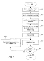
本発明を更に理解するために、図18及び図19の例示的なフローチャートを参照してオーディオ符号化/復号化技術の新しい分野の概念を導入するのは有益である。 In order to better understand the present invention, it is beneficial to introduce the concept of a new field of audio encoding / decoding techniques with reference to the exemplary flowcharts of FIGS.
図18は、オーディオ符号化方法の一例を示す概略フローチャートである。例示的なオーディオ符号化方法は、少なくとも2つのチャネルを有するマルチチャネルオーディオ信号のオーディオ入力チャネル群の信号表現に作用する符号化手順全体に基づく。ステップS1において、前記オーディオ入力チャネル群のダウンミックス信号を含む第1の信号表現を符号化するために第1の符号化処理が行われる。ステップS2において、第1の符号化処理に関連して局所合成が行われ、第1の符号化処理の符号化誤差の表現を含む局所復号化ダウンミックス信号を生成する。ステップS3において、少なくとも局所復号化ダウンミックス信号を入力として使用し、前記オーディオ入力チャネル群の第2の信号表現を符号化するために第2の符号化処理が行われる。ステップS4において、オーディオ入力チャネルの入力チャネルエネルギが推定される。ステップS5において、オーディオ入力チャネルの少なくとも1つのエネルギ表現が、前記オーディオ入力チャネルの推定入力チャネルエネルギに基づき生成される。ステップS6において、生成された1つ又は複数のエネルギ表現が符号化される。ステップS7において、少なくとも第2の符号化処理を含む前記複数の符号化処理の少なくとも1つから残差誤差信号が生成される。ステップS8において、残差誤差信号の残差符号化が第3の符号化処理において行われる。 FIG. 18 is a schematic flowchart illustrating an example of an audio encoding method. An exemplary audio encoding method is based on an entire encoding procedure that operates on the signal representation of the audio input channels of a multi-channel audio signal having at least two channels. In step S1, a first encoding process is performed to encode a first signal representation including a downmix signal of the audio input channel group. In step S2, local synthesis is performed in association with the first encoding process, and a local decoded downmix signal including a representation of the encoding error of the first encoding process is generated. In step S3, a second encoding process is performed to encode a second signal representation of the audio input channel group using at least a locally decoded downmix signal as input. In step S4, the input channel energy of the audio input channel is estimated. In step S5, at least one energy representation of the audio input channel is generated based on the estimated input channel energy of the audio input channel. In step S6, the generated one or more energy representations are encoded. In step S7, a residual error signal is generated from at least one of the plurality of encoding processes including at least the second encoding process. In step S8, residual encoding of the residual error signal is performed in the third encoding process.
このようにしてオーディオ入力チャネルの効果的な符号化全体が得られる。オーディオ入力チャネルのエネルギ表現により、復号化側の出力チャネルのエネルギが推定入力チャネルエネルギと一致可能になる。出力チャネルはエネルギ及び品質の双方の点で入力チャネルと一致するのが好ましい。 In this way an overall effective encoding of the audio input channel is obtained. The energy representation of the audio input channel allows the decoding output channel energy to match the estimated input channel energy. The output channel preferably matches the input channel in both energy and quality.
例示的な実施形態では、後からより詳細に例示するように、少なくとも1つのエネルギ表現を生成してエネルギ表現を符号化するステップは第2の符号化処理で行われる。 In an exemplary embodiment, as illustrated in more detail later, the step of generating at least one energy representation and encoding the energy representation is performed in a second encoding process.
通常、符号化手順全体は比較的多数のオーディオフレームの各々に対して実行される。しかし、オーディオ入力チャネルエネルギの推定及び(好ましいエネルギ表現を介した)符号化等の符号化手順全体の各部は、1つ以上の選択可能な周波数帯域においてフレームの選択可能な部分集合に対して行われてもよい。実際には、例えば少なくとも1つのエネルギ表現を生成してエネルギ表現を符号化するステップは少なくとも1つの周波数帯域の多数のフレームの各々に対して行われてもよいことを意味する。 Usually, the entire encoding procedure is performed for each of a relatively large number of audio frames. However, each part of the overall encoding procedure, such as estimation of audio input channel energy and encoding (via preferred energy representation) is performed on a selectable subset of frames in one or more selectable frequency bands. It may be broken. In practice, for example, the step of generating at least one energy representation and encoding the energy representation may mean that it may be performed for each of a number of frames in at least one frequency band.
特定の例において第1の符号化処理はダウンミックス符号化処理であり、第2の符号化処理は1つ以上の予測チャネルを生成するチャネル予測に基づき、このため残差誤差信号は残差予測誤差信号を含む。この例示的な状況では、第2の予測ベースの符号化処理において推定入力チャネルエネルギとチャネル予測の予測パラメータとを一緒に表現して符号化することは特に有利であることが分かる。 In a particular example, the first encoding process is a downmix encoding process, and the second encoding process is based on channel prediction that generates one or more prediction channels, so that the residual error signal is a residual prediction. Contains error signal. In this exemplary situation, it can be seen that it is particularly advantageous to represent and code the estimated input channel energy and the prediction parameters of the channel prediction together in the second prediction-based encoding process.
更に、予測ベースの符号化と残差符号化とに組み合わされたダウンミックス符号化の例示的な状況では、各々特別な利点を有するエネルギ表現及びエネルギ符号化に対する多数の異なる実現例がある。以下、3つの異なる例示的な実現例を下記の表に簡単にまとめ、より詳細に後述する。 Furthermore, in the exemplary situation of downmix coding combined with prediction-based coding and residual coding, there are many different implementations for energy representation and energy coding, each with particular advantages. In the following, three different exemplary implementations are briefly summarized in the table below and described in more detail below.
例A
エネルギ表現:
・チャネルエネルギレベル差を決定し、
・チャネルエネルギレベル和を決定し、
・第1の符号化処理に関連してチャネルエネルギレベル和と局所合成からの局所復号化ダウンミックス信号のエネルギとに基づきデルタエネルギ測度を決定する。
エネルギ符号化:
・チャネルエネルギレベル差を量子化し、
・デルタエネルギ測度を量子化する。
チャネル予測:
・非量子化チャネル予測パラメータに基づく。
Example A
Energy expression:
Determine the channel energy level difference,
・ Determine the sum of channel energy levels,
Determining a delta energy measure based on the sum of the channel energy levels and the energy of the locally decoded downmix signal from the local synthesis in connection with the first encoding process;
Energy encoding:
・ Quantize channel energy level difference,
Quantize the delta energy measure.
Channel prediction:
• Based on unquantized channel prediction parameters.
例B
エネルギ表現:
・チャネルエネルギレベル差を決定し、
・チャネルエネルギレベル和を決定し、
・第1の符号化処理に関連してチャネルエネルギレベル和と局所合成からの局所復号化ダウンミックス信号のエネルギとに基づきデルタエネルギ測度を決定し、
・デルタエネルギ測度と局所復号化ダウンミックス信号のエネルギにより正規化された予測チャネルのエネルギとに基づき正規化エネルギ補償パラメータを決定する。
エネルギ符号化:
・チャネルエネルギレベル差を量子化し、
・正規化エネルギ補償パラメータを量子化する。
チャネル予測:
・量子化チャネルエネルギレベル差から導出された量子化チャネル予測パラメータに基づく。
Example B
Energy expression:
Determine the channel energy level difference,
・ Determine the sum of channel energy levels,
Determining a delta energy measure based on the sum of the channel energy levels and the energy of the local decoded downmix signal from the local synthesis in connection with the first encoding process;
Determine a normalized energy compensation parameter based on the delta energy measure and the energy of the prediction channel normalized by the energy of the locally decoded downmix signal.
Energy encoding:
・ Quantize channel energy level difference,
Quantize the normalized energy compensation parameter.
Channel prediction:
Based on quantized channel prediction parameters derived from quantized channel energy level differences.
例C
エネルギ表現:
・チャネルエネルギレベル差を決定し、
・エネルギ正規化入力チャネル相互相関パラメータを決定する。
エネルギ符号化:
・チャネルエネルギレベル差を量子化し、
・エネルギ正規化入力チャネル相互相関パラメータを量子化する。
チャネル予測:
・量子化チャネルエネルギレベル差から導出された量子化チャネル予測パラメータと量子化エネルギ正規化入力チャネル相互相関パラメータとに基づく。
Example C
Energy expression:
Determine the channel energy level difference,
Determine energy normalized input channel cross-correlation parameters.
Energy encoding:
・ Quantize channel energy level difference,
Quantize energy normalized input channel cross-correlation parameters.
Channel prediction:
Based on quantized channel prediction parameters derived from quantized channel energy level differences and quantized energy normalized input channel cross-correlation parameters.
図19は、オーディオ復号化方法の一例を示す概略フローチャートである。例示的なオーディオ復号化方法は、少なくとも2つのチャネルを有するマルチチャネルオーディオ信号を再構成する受信ビットストリームに作用する復号化手順全体に基づく。ステップS11において、第1の復号化処理が行われ、前記受信ビットストリームの第1の部分に基づき復号化ダウンミックス信号を含む少なくとも1つの第1の復号化チャネル表現を生成する。ステップS12において、第2の復号化処理が行われ、復号化ダウンミックス信号の推定エネルギとオーディオ入力チャネルの少なくとも1つのエネルギ表現を代表する受信ビットストリームの第2の部分とに基づき少なくとも1つの第2の復号化チャネル表現を生成する。ステップS13において、オーディオ入力チャネルの入力チャネルエネルギが、復号化ダウンミックス信号の推定エネルギとオーディオ入力チャネルの少なくとも1つのエネルギ表現を代表する受信ビットストリームの第2の部分とに基づき推定される。ステップS14において、残差復号化が残差誤差信号情報を代表する受信ビットストリームの第3の部分に基づき第3の復号化処理で行われ、残差誤差信号を生成する。ステップS15において、残差誤差信号と少なくとも第2の復号化処理を含む第1の復号化処理及び第2の復号化処理の少なくとも1つからの復号化チャネル表現とが結合され、マルチチャネルオーディオ信号を生成するための推定入力チャネルエネルギに少なくとも部分的に基づきチャネルエネルギ補償が行われる。 FIG. 19 is a schematic flowchart showing an example of an audio decoding method. An exemplary audio decoding method is based on an entire decoding procedure that operates on a received bitstream that reconstructs a multi-channel audio signal having at least two channels. In step S11, a first decoding process is performed to generate at least one first decoded channel representation including a decoded downmix signal based on the first portion of the received bitstream. In step S12, a second decoding process is performed and based on the estimated energy of the decoded downmix signal and a second portion of the received bitstream representative of at least one energy representation of the audio input channel. Generate two decoded channel representations. In step S13, the input channel energy of the audio input channel is estimated based on the estimated energy of the decoded downmix signal and a second portion of the received bitstream that is representative of at least one energy representation of the audio input channel. In step S14, residual decoding is performed in a third decoding process based on a third portion of the received bitstream representing residual error signal information to generate a residual error signal. In step S15, the residual error signal and the decoded channel representation from at least one of the first decoding process and the second decoding process including at least the second decoding process are combined to produce a multi-channel audio signal. Channel energy compensation is performed based at least in part on the estimated input channel energy for generating.
これは、出力チャネルがエネルギ及び/又は品質の点で入力チャネルに近づくようにマルチチャネルオーディオ信号を効果的に再構成できることを意味する。特にチャネルエネルギ補償は、マルチチャネルオーディオ信号の出力チャネルのエネルギが推定入力チャネルエネルギと一致するように行われてもよい。しかし、マルチチャネルオーディオ信号の出力チャネルがエネルギ及び品質の双方の点で符号化側の対応する入力チャネルと一致し、より高品質な信号がより低品質な信号よりも高い割合で表現されて出力チャネルの品質全体を向上するのが好ましい。 This means that the multi-channel audio signal can be effectively reconfigured so that the output channel approaches the input channel in terms of energy and / or quality. In particular, the channel energy compensation may be performed so that the energy of the output channel of the multi-channel audio signal matches the estimated input channel energy. However, the output channel of the multi-channel audio signal matches the corresponding input channel on the encoding side in both energy and quality, and the higher quality signal is represented and output at a higher rate than the lower quality signal It is preferable to improve the overall quality of the channel.
例示的な実施形態において、1つ以上の第2の復号化チャネル表現を生成する場合にチャネルエネルギ補償は第2の復号化処理に統合される。この状況では、復号化ダウンミックス信号のエネルギと残差誤差信号のエネルギとを推定し、復号化ダウンミックス信号のエネルギと残差誤差信号のエネルギとに基づき第2の復号化処理を行うことは有益である。 In the exemplary embodiment, channel energy compensation is integrated into the second decoding process when generating one or more second decoded channel representations. In this situation, it is possible to estimate the energy of the decoded downmix signal and the energy of the residual error signal and perform the second decoding process based on the energy of the decoded downmix signal and the energy of the residual error signal. It is beneficial.
別の例示的な実施形態において、残差誤差信号と復号化チャネル表現とを結合した後にチャネルエネルギ補償が行われる。この状況では、残差誤差信号と第1の復号化処理及び第2の復号化処理の少なくとも1つからの復号化チャネル表現とが結合されてマルチチャネル合成になり、結合マルチチャネル合成のエネルギが推定される。次に、チャネルエネルギ補償が結合マルチチャネル合成の推定エネルギと推定入力チャネルエネルギとに基づき行われる。 In another exemplary embodiment, channel energy compensation is performed after combining the residual error signal and the decoded channel representation. In this situation, the residual error signal and the decoded channel representation from at least one of the first decoding process and the second decoding process are combined into multi-channel combining, and the energy of the combined multi-channel combining is Presumed. Channel energy compensation is then performed based on the combined multi-channel combined estimated energy and the estimated input channel energy.
特定の例において、少なくとも1つの第2の復号化チャネル表現を生成する第2の復号化処理は予測チャネルを合成することを含み、残差復号化は残差予測誤差信号を生成することを含む。この例示的な状況では、少なくとも1つの第2の復号化チャネル表現を生成する第2の復号化処理は、オーディオ入力チャネルの1つ以上のエネルギ表現を受信ビットストリームの第2の部分から導出し、エネルギ表現に少なくとも部分的に基づきチャネル予測パラメータを推定し、復号化ダウンミックス信号と推定チャネル予測パラメータとに基づき予測チャネルを合成することを含む。 In a particular example, the second decoding process that generates at least one second decoding channel representation includes synthesizing the prediction channel, and residual decoding includes generating a residual prediction error signal. . In this exemplary situation, the second decoding process that generates at least one second decoded channel representation derives one or more energy representations of the audio input channel from the second portion of the received bitstream. Estimating channel prediction parameters based at least in part on the energy representation and combining the prediction channel based on the decoded downmix signal and the estimated channel prediction parameters.
以下、3つの異なる例示的な実現例を下記の表に簡単にまとめ、より詳細に後述する。下記の復号化例A〜Cは一般に上述の符号化例A〜Cに対応する。 In the following, three different exemplary implementations are briefly summarized in the table below and described in more detail below. The following decoding examples A to C generally correspond to the above encoding examples A to C.
例A
エネルギ表現の導出:
・チャネルエネルギレベル差とデルタエネルギ測度とを受信ビットストリームの第2の部分から導出する。
入力チャネルエネルギの推定:
・復号化ダウンミックス信号の推定エネルギとチャネルエネルギレベル差とデルタエネルギ測度とに基づく。
チャネル予測パラメータの推定:
・推定入力チャネルエネルギと復号化ダウンミックス信号の推定エネルギと残差誤差信号の推定エネルギとに基づく。
Example A
Derivation of energy expression:
Deriving the channel energy level difference and the delta energy measure from the second part of the received bitstream.
Input channel energy estimation:
Based on the estimated energy of the decoded downmix signal, the channel energy level difference and the delta energy measure.
Estimating channel prediction parameters:
Based on the estimated input channel energy, the estimated energy of the decoded downmix signal, and the estimated energy of the residual error signal.
例B
エネルギ表現の導出:
・チャネルエネルギレベル差と正規化エネルギ補償パラメータとを受信ビットストリームの第2の部分から導出する。
入力チャネルエネルギの推定:
・復号化ダウンミックス信号の推定エネルギとチャネルエネルギレベル差と正規化エネルギ補償パラメータとに基づく。
チャネル予測パラメータの推定:
・チャネルエネルギレベル差に基づく。
予測チャネルの合成:
・復号化ダウンミックス信号と推定チャネル予測パラメータとに基づく。
結合:
・残差誤差信号と合成予測チャネルとを結合して結合マルチチャネル合成にする。
チャネルエネルギ補償(結合後):
・結合マルチチャネル合成のエネルギを推定し、
・推定入力チャネルエネルギと結合マルチチャネル合成の推定エネルギとに基づきエネルギ補正係数を決定し、
・エネルギ補正係数を結合マルチチャネル合成に適用してマルチチャネルオーディオ信号を生成する。
Example B
Derivation of energy expression:
Deriving the channel energy level difference and the normalized energy compensation parameter from the second part of the received bitstream.
Input channel energy estimation:
Based on the estimated energy of the decoded downmix signal, the channel energy level difference and the normalized energy compensation parameter.
Estimating channel prediction parameters:
• Based on channel energy level difference.
Prediction channel synthesis:
Based on the decoded downmix signal and estimated channel prediction parameters.
Join:
Combine the residual error signal with the combined prediction channel to make a combined multi-channel combination.
Channel energy compensation (after coupling):
Estimate the energy of combined multi-channel synthesis,
Determine an energy correction factor based on the estimated input channel energy and the estimated energy of the combined multi-channel synthesis;
Apply the energy correction factor to combined multi-channel synthesis to generate a multi-channel audio signal.
例C
エネルギ表現の導出:
・チャネルエネルギレベル差とエネルギ正規化入力チャネル相互相関パラメータとを受信ビットストリームの第2の部分から導出する。
入力チャネルエネルギの推定:
・復号化ダウンミックス信号の推定エネルギとチャネルエネルギレベル差とエネルギ正規化入力チャネル相互相関パラメータとに基づく。
チャネル予測パラメータの推定:
・チャネルエネルギレベル差とエネルギ正規化入力チャネル相互相関パラメータとに基づく。
予測チャネルの合成:
・復号化ダウンミックス信号と推定チャネル予測パラメータとに基づく。
結合:
・残差誤差信号と合成予測チャネルとを結合して結合マルチチャネル合成にする。
チャネルエネルギ補償(結合後):
・結合マルチチャネル合成のエネルギを推定し、
・推定入力チャネルエネルギと結合マルチチャネル合成の推定エネルギとに基づきエネルギ補正係数を決定し、
・エネルギ補正係数を結合マルチチャネル合成に適用してマルチチャネルオーディオ信号を生成する。
Example C
Derivation of energy expression:
Deriving the channel energy level difference and the energy normalized input channel cross-correlation parameter from the second part of the received bitstream.
Input channel energy estimation:
Based on the estimated energy of the decoded downmix signal, the channel energy level difference and the energy normalized input channel cross-correlation parameter.
Estimating channel prediction parameters:
• Based on channel energy level difference and energy normalized input channel cross-correlation parameters.
Prediction channel synthesis:
Based on the decoded downmix signal and estimated channel prediction parameters.
Join:
Combine the residual error signal with the combined prediction channel to make a combined multi-channel combination.
Channel energy compensation (after coupling):
Estimate the energy of combined multi-channel synthesis,
Determine an energy correction factor based on the estimated input channel energy and the estimated energy of the combined multi-channel synthesis;
Apply the energy correction factor to combined multi-channel synthesis to generate a multi-channel audio signal.
構造上の観点から、図20及び図21の例示的なブロック図を参照して例示するように、本発明はオーディオ符号化装置及び対応するオーディオ復号化装置に関する。 From a structural point of view, the present invention relates to an audio encoding device and a corresponding audio decoding device, as illustrated with reference to the exemplary block diagrams of FIGS.
図20は、オーディオ符号化装置の一例を示す概略ブロック図である。オーディオ符号化装置100は、少なくとも2つのチャネルを有するマルチチャネルオーディオ信号のオーディオ入力チャネル群の信号表現に作用するように構成される。
FIG. 20 is a schematic block diagram illustrating an example of an audio encoding device. The
基本的な符号化装置100は、第1のエンコーダ130と、第2のエンコーダ140と、エネルギ推定器142と、エネルギ表現生成器144と、エネルギ表現エンコーダ146と、残差生成器155と、残差エンコーダ160とを含む。最終符号化パラメータは、復号化側に転送するためにマルチプレクサ150により通常収集される。
The
第1のエンコーダ130は、第1の符号化処理においてオーディオ入力チャネルのダウンミックス信号を含む第1の表現を受信して符号化するように構成される。ダウンミックス部120は、好適な入力チャネル群をダウンミックス信号にダウンミキシングするために使用されてもよい。ダウンミックス部120は基本的な符号化装置100の一体部分とみなしてもよいし、「外部の」サポート部とみなしてもよい。
The
更に局所合成器132は、第1の符号化処理に関連して局所合成を行い、第1の符号化処理の符号化誤差の表現を含む局所復号化ダウンミックス信号を生成するように配置される。局所合成器132は第1のエンコーダと一体化されるのが好ましいが、第1のエンコーダに関連して符号化側で実現される別箇のデコーダとして提供されてもよい。
Further, the
第2のエンコーダ140は、少なくとも局所復号化ダウンミックス信号を入力として使用し、第2の符号化処理において前記オーディオ入力チャネルの第2の表現を受信して符号化するように構成される。
The
エネルギ推定器142は、前記オーディオ入力チャネルの入力チャネルエネルギを推定するように構成され、エネルギ表現生成器144は、オーディオ入力チャネルの推定入力チャネルエネルギに基づきオーディオ入力チャネルの少なくとも1つのエネルギ表現を生成するように構成される。エネルギ表現エンコーダ146は、エネルギ表現を符号化するように構成される。このように入力チャネルエネルギが符号化側で推定され符号化されてもよい。
An
エネルギ推定器142は第2のエンコーダ140の一体部分として実現されてもよいし、第2のエンコーダの外部で専用器として配置されてもよい。例示的な実施形態において、後からより詳細に例示するように、エネルギ表現生成器144とエネルギ表現エンコーダ146とは第2のエンコーダ140内で実現されると都合がよい。別の実施形態において、エネルギ表現処理は第2のエンコーダの外部で提供されてもよい。
The
残差生成器155は、少なくとも第2の符号化処理を含む複数の符号化処理の少なくとも1つから残差誤差信号を生成するように構成され、残差エンコーダ160は、第3の符号化処理において残差誤差信号の残差符号化を行うように構成される。
The
エネルギ表現生成器144で生成され符号化されたエネルギ表現により、復号化側の出力チャネルのエネルギが推定入力チャネルエネルギと一致可能になる。あるいはエネルギ表現により、出力チャネルがエネルギ及び品質の双方の点で入力チャネルに一致可能になる。 The energy representation generated and encoded by the energy representation generator 144 allows the decoding side output channel energy to match the estimated input channel energy. Alternatively, the energy representation allows the output channel to match the input channel in both energy and quality.
エネルギ表現生成器144とエネルギ表現エンコーダ146とは、少なくとも1つの周波数帯域の多数のフレームの各々に対してエネルギ表現を生成して符号化するように構成されるのが好ましい。エネルギ推定器142は入力チャネルエネルギを連続して推定するように構成されてもよく、あるいはエネルギ表現生成器144とエンコーダ146との動作に適応された選択されたフレーム及び/又は周波数帯域群のみに対して構成されてもよい。
The energy representation generator 144 and the
特定の例において、第1のエンコーダ130はダウンミックスエンコーダであり、第2のエンコーダ140は1つ以上の予測チャネルを生成するチャネル予測に基づき動作するように構成されたパラメトリックエンコーダであり、残差生成器155は残差予測誤差信号を生成するように構成される。この例示的な状況では、第2のエンコーダ140はチャネル予測パラメータと共に推定入力チャネルエネルギを一緒に表現して符号化するように構成されるのが好ましい。
In a particular example, the
予測ベースの符号化と残差符号化とに結合されたダウンミックス符号化の例示的な状況に対して3つの異なる例示的な実現例を下記にまとめる。更なる詳細は後述する。 Three different exemplary implementations are summarized below for exemplary situations of downmix coding combined with prediction-based coding and residual coding. Further details will be described later.
例A
本例においてエネルギ表現生成器144は、チャネルエネルギレベル差を決定する決定部と、チャネルエネルギレベル和を決定する決定部と、第1の符号化処理に関連してチャネルエネルギレベル和と局所合成からの局所復号化ダウンミックス信号のエネルギとに基づき所謂デルタエネルギ測度を決定する決定部とを含む。エネルギ表現エンコーダ146は、チャネルエネルギレベル差を量子化する量子化器と、デルタエネルギ測度を量子化する量子化器とを含む。
Example A
In this example, the energy representation generator 144 includes a determining unit that determines a channel energy level difference, a determining unit that determines a channel energy level sum, and a channel energy level sum and local combination in connection with the first encoding process. And a determination unit for determining a so-called delta energy measure based on the energy of the local decoded downmix signal. The
例えば、第2のエンコーダ140が非量子化チャネル予測パラメータに基づきチャネル予測を行うことも有益である。
For example, it may be beneficial for the
例B
本例においてエネルギ表現生成器144は、チャネルエネルギレベル差を決定する決定部と、チャネルエネルギレベル和を決定する決定部と、第1の符号化処理に関連してチャネルエネルギレベル和と局所合成からの局所復号化ダウンミックス信号のエネルギとに基づきデルタエネルギ測度を決定する決定部と、デルタエネルギ測度と局所復号化ダウンミックス信号のエネルギにより正規化された予測チャネルのエネルギとに基づき所謂正規化エネルギ補償パラメータを決定する決定部とを含む。エネルギ表現エンコーダ146は、チャネルエネルギレベル差を量子化する量子化器と、正規化エネルギ補償パラメータを量子化する量子化器とを含む。
Example B
In this example, the energy representation generator 144 includes a determining unit that determines a channel energy level difference, a determining unit that determines a channel energy level sum, and a channel energy level sum and local combination in connection with the first encoding process. A determining unit for determining a delta energy measure based on the energy of the local decoded downmix signal, and a so-called normalized energy based on the energy of the prediction channel normalized by the delta energy measure and the energy of the local decoded downmix signal. A determination unit for determining a compensation parameter. The
例えば第2のエンコーダ140は、量子化チャネルエネルギレベル差から導出された量子化チャネル予測パラメータに基づきチャネル予測を行うように構成されてもよい。
For example, the
例C
本例においてエネルギ表現生成器144は、チャネルエネルギレベル差を決定する決定部と、エネルギ正規化入力チャネル相互相関パラメータを決定する決定部とを含む。エネルギ表現エンコーダ146は、チャネルエネルギレベル差を量子化する量子化器と、エネルギ正規化入力チャネル相互相関パラメータを量子化する量子化器とを含む。
Example C
In this example, the energy representation generator 144 includes a determining unit that determines a channel energy level difference and a determining unit that determines an energy normalized input channel cross-correlation parameter. The
例えば第2のエンコーダ140は、量子化チャネルエネルギレベル差から導出された量子化チャネル予測パラメータと量子化エネルギ正規化入力チャネル相互相関パラメータとに基づきチャネル予測を行うように構成されてもよい。
For example, the
図21は、オーディオ復号化装置の一例を示す概略ブロック図である。オーディオ復号化装置200は、少なくとも2つのチャネルを有するマルチチャネルオーディオ信号を再構成するための受信ビットストリームに作用するように構成される。受信ビットストリームは符号化側からビットストリームデマルチプレクサ250により通常受信され、ビットストリームデマルチプレクサ250は受信ビットストリームを受信ビットストリーム全体の関連部分集合又は部分に分割する。
FIG. 21 is a schematic block diagram illustrating an example of an audio decoding device.
基本的なオーディオ復号化装置200は、第1のデコーダ230と、第2のデコーダ240と、入力チャネルエネルギ推定器242と、残差デコーダ260と、結合/チャネルエネルギ補償手段270とを含む。
The basic
第1のデコーダ230は、受信ビットストリームの第1部分に基づき復号化ダウンミックス信号を含む1つ以上の復号化チャネル表現を生成するように構成される。
The
第2のデコーダ240は、復号化ダウンミックス信号の推定エネルギとオーディオ入力チャネルの少なくとも1つのエネルギ表現を代表する受信ビットストリームの第2の部分とに基づき1つ以上の第2の復号化チャネル表現を生成するように構成される。
The
入力チャネルエネルギ推定器242は、復号化ダウンミックス信号の推定エネルギとオーディオ入力チャネルの少なくとも1つのエネルギ表現を代表する受信ビットストリームの第2の部分とに基づきオーディオ入力チャネルの入力チャネルエネルギを推定するように構成される。
Input
残差デコーダ260は、残差誤差信号情報を代表する受信ビットストリームの第3の部分に基づき第3の復号化処理で残差復号化を行い、残差誤差信号を生成するように構成される。
結合/チャネルエネルギ補償手段270は、残差誤差信号と少なくとも第2のデコーダ/復号化処理を含む第1のデコーダ/復号化処理及び第2のデコーダ/復号化処理の少なくとも1つからの復号化チャネル表現とを結合し、マルチチャネルオーディオ信号を生成するために推定入力チャネルエネルギに少なくとも部分的に基づきチャネルエネルギ補償を行うように構成される。 The combination / channel energy compensation means 270 decodes from at least one of the first decoder / decoding process and the second decoder / decoding process including a residual error signal and at least a second decoder / decoding process. The channel representation is combined and configured to provide channel energy compensation based at least in part on the estimated input channel energy to produce a multi-channel audio signal.
例えば、結合及びチャネルエネルギ補償を行う手段270は、マルチチャネルオーディオ信号の出力チャネルのエネルギを推定入力チャネルエネルギに一致させるように構成されてもよい。しかし、結合及びチャネルエネルギ補償を行う手段270は、出力チャネルをエネルギ及び品質の双方の点で符号化側の対応する入力チャネルに一致させるように構成し、より高品質な信号がより低品質な信号よりも高い割合で表現されて出力チャネルの品質全体を向上するのが好ましい。
For example, the
後述の例示的な実施形態から理解されるように、結合/チャネルエネルギ補償の全体構造はいくつかの異なるやり方で実現できる。 As will be appreciated from the exemplary embodiments described below, the overall structure of coupling / channel energy compensation can be implemented in several different ways.
例えば、チャネルエネルギ補償は第2のデコーダに統合されてもよい。本例において、第2のデコーダ240は復号化ダウンミックス信号のエネルギと残差誤差信号のエネルギとに基づき動作するように構成されるのが好ましく、これはオーディオ復号化装置200が復号化ダウンミックス信号のエネルギと残差誤差信号のエネルギとを推定する手段も具備することを意味する。
For example, channel energy compensation may be integrated into the second decoder. In this example, the
あるいは復号化装置は、残差誤差信号と関連復号化チャネル表現とを結合して結合マルチチャネル合成にする結合器と、チャネルエネルギ補償を結合マルチチャネル合成に適用してマルチチャネルオーディオ信号を生成するチャネルエネルギ補償器とを含む。本例において、オーディオ復号化装置は結合マルチチャネル合成のエネルギを推定する推定器を含むのが好ましく、チャネルエネルギ補償器は結合マルチチャネル合成の推定エネルギと推定入力チャネルエネルギとに基づきチャネルエネルギ補償を適用するように構成される。 Alternatively, the decoding device generates a multi-channel audio signal by combining the residual error signal and the associated decoded channel representation into combined multi-channel combining and applying channel energy compensation to the combined multi-channel combining. A channel energy compensator. In this example, the audio decoding device preferably includes an estimator for estimating the energy of the combined multi-channel combination, and the channel energy compensator performs channel energy compensation based on the estimated energy of the combined multi-channel combination and the estimated input channel energy. Configured to apply.
特定の例において、第1のデコーダ230はダウンミックスデコーダであり、第2のデコーダ240は予測チャネルを合成するように構成されたパラメトリックデコーダであり、残差デコーダ260は残差予測誤差信号を生成するように構成される。この例示的な状況では第2のデコーダ240は、オーディオ入力チャネルのエネルギ表現を受信ビットストリームの第2の部分から導出する(又はそのように構成された)導出器241と、エネルギ表現に少なくとも部分的に基づきチャネル予測パラメータを推定する推定器と、復号化ダウンミックス信号と推定チャネル予測パラメータとに基づき予測チャネルを合成する合成器とを含んでもよい。
In a particular example, the
予測ベースの復号化及び残差復号化と組み合わされたダウンミックス復号化の例示的な状況に対して3つの異なる例示的な実現例を以下にまとめる。更なる詳細は後述する。 Three different exemplary implementations are summarized below for an exemplary situation of downmix decoding combined with prediction-based decoding and residual decoding. Further details will be described later.
例A
本例において導出器241は、チャネルエネルギレベル差とデルタエネルギ測度とを受信ビットストリームの第2の部分から導出するように構成される。入力チャネルエネルギを推定する推定器242は、復号化ダウンミックス信号の推定エネルギと、チャネルエネルギレベル差と、デルタエネルギ測度とに基づき入力チャネルエネルギを推定するように構成される。チャネル予測パラメータを推定する推定器は、推定入力チャネルエネルギと、復号化ダウンミックス信号の推定エネルギと、残差誤差信号の推定エネルギとに基づきチャネル予測パラメータを推定するように構成されるのが好ましい。
Example A
In this example, the
例B
本例において導出器241は、チャネルエネルギレベル差と正規化エネルギ補償パラメータとを前記受信ビットストリームの第2の部分から導出するように構成される。入力チャネルエネルギを推定する推定器242は、復号化ダウンミックス信号の推定エネルギと、チャネルエネルギレベル差と、正規化エネルギ補償パラメータとに基づき入力チャネルエネルギを推定するように構成される。チャネル予測パラメータを推定する推定器は、チャネルエネルギレベル差に基づきチャネル予測パラメータを推定するように構成され、予測チャネルを合成する合成器は、復号化ダウンミックス信号と推定チャネル予測パラメータとに基づき予測チャネルを合成するように構成される。本例において、結合及びチャネルエネルギ補償を行う手段270は、残差誤差信号と合成予測チャネルとを結合して結合マルチチャネル合成にする結合器と、チャネルエネルギ補償器とを含む。チャネルエネルギ補償器は、結合マルチチャネル合成のエネルギを推定する推定器と、推定入力チャネルエネルギと結合マルチチャネル合成の推定エネルギとに基づきエネルギ補正係数を決定する決定器と、エネルギ補正係数を結合マルチチャネル合成に適用してマルチチャネルオーディオ信号を生成するエネルギ補正器とを含む。
Example B
In this example, the
例C
本例において導出器241は、チャネルエネルギレベル差とエネルギ正規化入力チャネル相互相関パラメータとを受信ビットストリームの第2の部分から導出するように構成される。入力チャネルエネルギを推定する推定器242は、復号化ダウンミックス信号の推定エネルギと、チャネルエネルギレベル差と、エネルギ正規化入力チャネル相互相関パラメータとに基づき入力チャネルエネルギを推定するように構成される。チャネル予測パラメータを推定する推定器は、チャネルエネルギレベル差とエネルギ正規化入力チャネル相互相関パラメータとに基づきチャネル予測パラメータを推定するように構成されるのが好ましい。予測チャネルを合成する合成器は、復号化ダウンミックス信号と推定チャネル予測パラメータとに基づき予測チャネルを合成するように構成される。本例において、結合及びチャネルエネルギ補償を行う手段270は、残差誤差信号と合成予測チャネルとを結合して結合マルチチャネル合成にする結合器と、チャネルエネルギ補償器とを含む。本例においてチャネルエネルギ補償器は、結合マルチチャネル合成のエネルギを推定する推定器と、推定入力チャネルエネルギと結合マルチチャネル合成の推定エネルギとに基づきエネルギ補正係数を決定する決定器と、エネルギ補正係数を結合マルチチャネル合成に適用してマルチチャネルオーディオ信号を生成するエネルギ補正器とを含む。
Example C
In this example, the
特定の例において、本発明は以下の2つの問題の内少なくとも1つ、好ましくは2つを解決することを目的とする。すなわち、最適なチャネル予測を得ること及び出力チャネルエネルギに対して明示的な制御を維持することである。信号成分を単純に加算するとエネルギ及び品質全体の点から不安定な印象になってしまうように、信号成分はエネルギ及び品質において個別の経時変動を示すかもしれない。エネルギ及び品質の変動には種々の理由があるが、この内いくつかを下記に示す。 In a particular example, the present invention aims to solve at least one, preferably two of the following two problems. That is, to obtain optimal channel prediction and to maintain explicit control over the output channel energy. The signal components may show individual aging in energy and quality so that simply adding the signal components will result in an unstable impression in terms of overall energy and quality. There are various reasons for variations in energy and quality, some of which are listed below.
・送信条件により信号成分が失われるか又は劣化する。
・損失エネルギはデコーダで回復されることが既知であるため、信号成分がエンコーダで故意に減衰される。そのような減衰は、例えば知覚重要性に基づいてもよい。
・信号の一部を表現するエンコーダ全体に対する制限があるため、信号の一部が失われる可能性がある。例えばビットレートやモデル化能力の制限のため、信号の一部がエンコーダ全体の範囲外になるかもしれない。一般的な観点から見ると、個別のエンコーダ及び関連したデコーダの処理の各々は、真の入力信号が投影される部分空間を表現している。最終残差又は符号化誤差は、エンコーダ及びデコーダ全体を表現する部分空間の合体に直交している。最終残差はこれらの部分空間では表現できないが、入力エネルギと受信部分空間成分のエネルギとが分かるか又は少なくとも推定できればそのエネルギは推定し補償できる。
-Signal components are lost or deteriorated depending on transmission conditions.
Since the loss energy is known to be recovered at the decoder, the signal component is deliberately attenuated at the encoder. Such attenuation may be based on perceptual importance, for example.
-Since there is a restriction on the entire encoder that represents a part of the signal, part of the signal may be lost. For example, some of the signal may be outside the range of the entire encoder due to limitations in bit rate and modeling capabilities. From a general point of view, each individual encoder and associated decoder process represents a subspace into which the true input signal is projected. The final residual or coding error is orthogonal to the union of subspaces that represent the entire encoder and decoder. Although the final residual cannot be represented in these subspaces, the energy can be estimated and compensated if the input energy and the energy of the received subspace components are known or at least estimated.
これらの問題や他の問題に対する効率的な解決策は、例えば上述のように異なる成分の起こり得るエネルギ及び品質変動に対してロバスト性を有するようにエネルギと予測パラメータとの双方を一緒に表現して符号化することにより実現してもよい。 An efficient solution to these and other problems is to express both energy and prediction parameters together so that they are robust to possible energy and quality variations of different components, as described above. It may be realized by encoding.
本発明は、一般に符号化手順全体と関連した復号化手順とに関する。符号化手順は、オーディオ入力チャネル群の信号表現に作用する少なくとも2つの信号符号化処理を含む。それは入力チャネルのエネルギを推定する専用プロセスも含む。本発明の基本概念は、第1の符号化処理に関連して局所合成を使用し、第1の符号化処理の符号化誤差の表現を含む局所復号化信号を生成し、この局所復号化信号を入力として第2の符号化処理に適用することである。符号化処理の流れは、符号化処理全体の改良ステップ又は信号の異なる特性の取り込みとみなすことができる。 The present invention relates generally to the entire encoding procedure and the associated decoding procedure. The encoding procedure includes at least two signal encoding processes that affect the signal representation of the audio input channels. It also includes a dedicated process that estimates the energy of the input channel. The basic concept of the present invention uses local synthesis in connection with the first encoding process, generates a local decoded signal including a representation of the encoding error of the first encoding process, and this local decoded signal Is applied to the second encoding process. The flow of the encoding process can be viewed as an improvement step in the overall encoding process or the incorporation of different characteristics of the signal.
例えば、第1の符号化処理はモノラル符号化処理又はより一般的にはダウンミックスエンコーダ等の主符号化処理であり、第2の符号化処理はステレオ符号化処理又は一般的なパラメトリック符号化処理等の補助符号化処理である。符号化手順全体は少なくとも2つ(多重)のオーディオ入力チャネルで動作し、より複雑なマルチチャネル符号化に加えてステレオ符号化を含む。 For example, the first encoding process is a monaural encoding process or more generally a main encoding process such as a downmix encoder, and the second encoding process is a stereo encoding process or a general parametric encoding process. Or the like. The entire encoding procedure operates on at least two (multiplex) audio input channels and includes stereo encoding in addition to more complex multi-channel encoding.
各符号化処理は復号化処理に関連付けられる。復号化手順全体において、出力チャネルがエネルギ及び品質の双方の点で入力チャネルに近づくように各符号化処理からの復号化信号を結合するのが好ましい。通常、エネルギ及び品質がデコーダにある信号で最適化されるように結合ステップは部分的に又は全体的に1つ以上の信号表現の起こり得る損失にも適合する。結合ステップにおいて、より高品質な信号がより低品質な信号よりも高い割合で表現されて出力チャネルの品質全体を向上するように信号成分の品質を考慮してもよい。 Each encoding process is associated with a decoding process. In the entire decoding procedure, it is preferable to combine the decoded signals from each encoding process so that the output channel approaches the input channel in both energy and quality. Usually, the combining step is also partly or totally adapted to the possible loss of one or more signal representations so that energy and quality are optimized with the signals present in the decoder. In the combining step, the quality of the signal components may be taken into account such that higher quality signals are represented at a higher rate than lower quality signals to improve the overall quality of the output channel.
構造又は実現性の観点から、本発明はエンコーダ及び関連したデコーダに関する。エンコーダ全体は、入力チャネルの異なる表現を符号化するための少なくとも2つのエンコーダを基本的に具備する。第1のエンコーダに関連した局所合成は局所復号化信号を生成し、この局所復号化信号は入力として第2のエンコーダに適用される。エンコーダ全体は、入力チャネルのエネルギ表現も生成する。デコーダ全体は、エンコーダでの各符号化手順に関連した符号化手順を含む。更にデコーダは、復号化成分を安定したエネルギ及び品質と結合する結合ステップを含み、1つ以上の復号化信号の起こり得る部分又は総損失に直面する。 In terms of structure or feasibility, the present invention relates to an encoder and an associated decoder. The entire encoder basically comprises at least two encoders for encoding different representations of the input channel. The local synthesis associated with the first encoder produces a local decoded signal that is applied as input to the second encoder. The entire encoder also generates an energy representation of the input channel. The entire decoder includes an encoding procedure associated with each encoding procedure at the encoder. In addition, the decoder includes a combining step that combines the decoded components with stable energy and quality and encounters a possible portion or total loss of one or more decoded signals.
・本発明は以下の2つの問題の内少なくとも1つ、好ましくは2つを解決することを目的とする。すなわち、最適なチャネル予測を得ること及び出力チャネルエネルギに対して明示的な制御を維持することである。信号成分を単純に加算するとエネルギ及び品質全体の点から不安定な印象になってしまうように、信号の成分はエネルギ及び品質において個別の経時変動を示すかもしれない。 The present invention aims to solve at least one of the following two problems, preferably two. That is, to obtain optimal channel prediction and to maintain explicit control over the output channel energy. The components of the signal may show individual aging in energy and quality so that simply adding the signal components will result in an unstable impression in terms of overall energy and quality.
これらの問題や他の問題に対する解決策は、例えば異なる成分の起こり得るエネルギ及び品質変動に対してロバスト性を有するようにエネルギと予測パラメータとの双方を一緒に表現して符号化することにより実現してもよい。 Solutions to these and other problems can be realized, for example, by representing and encoding both energy and prediction parameters together to be robust against possible energy and quality variations of different components May be.
以下、エネルギ保存を得る異なる方法の非限定例、すなわち実施形態A、B及びCを示す。これらの実施形態は単なる例であることを理解すべきである。例えば、これらの実施形態ではステレオアプリケーションに主に焦点を当てているが、3つ以上のオーディオチャネルを含むアプリケーションに対して一般化してもよい。これらの実施形態の共通点は、残差符号化において変動分解能で合成エネルギを保存することである。例示的な実施形態のいくつかの差異は更に後述する。 In the following, non-limiting examples of different ways of obtaining energy conservation, namely embodiments A, B and C, are shown. It should be understood that these embodiments are merely examples. For example, although these embodiments primarily focus on stereo applications, they may be generalized for applications that include more than two audio channels. The common feature of these embodiments is to preserve the composite energy with variable resolution in residual coding. Some differences in the exemplary embodiments are further described below.
例示的なステレオの場合の概要を図7に示す。第1のステップS21において、エンコーダは入力信号に対してダウンミックスを行い、それをモノラルエンコーダに送り、ステップS22において局所復号化ダウンミックス信号を抽出する。ステップS23において、エンコーダは入力チャネルエネルギを推定して復号化する。次にステップS24において、チャネル予測パラメータが導出される。ステップS25において、予測/パラメトリックステレオの局所合成が作成され、入力信号から減算され、ステップS26において好適な方法で符号化される予測/パラメトリック残差を形成する。ステップS27において更なる符号化ステージが可能ならば、更に繰返し改良ステップを採用してもよい。これは、局所合成を行い、符号化予測残差を前回の繰返しからの予測残差から減算し、現在の繰返しの新しい残差を符号化することによりステップS28で実行される。図7に示す例示的なエンコーダ処理は、全ての実施形態A、B及びCで有効な概要を構成する。しかし、更に説明するように、図7に概要を示したステップの根底にある詳細は各実施形態で異なる。 An overview of an exemplary stereo case is shown in FIG. In the first step S21, the encoder downmixes the input signal, sends it to the monaural encoder, and extracts the locally decoded downmix signal in step S22. In step S23, the encoder estimates and decodes the input channel energy. Next, in step S24, channel prediction parameters are derived. In step S25, a local combination of prediction / parametric stereo is created and subtracted from the input signal to form a prediction / parametric residual that is encoded in a suitable manner in step S26. If further encoding stages are possible in step S27, further iterative refinement steps may be employed. This is performed in step S28 by performing local synthesis, subtracting the encoded prediction residual from the prediction residual from the previous iteration, and encoding the new residual for the current iteration. The exemplary encoder process shown in FIG. 7 constitutes a valid overview for all embodiments A, B and C. However, as will be further described, the details underlying the steps outlined in FIG. 7 differ in each embodiment.
例示的なデコーダは、エンコーダでの局所復号化ダウンミックス信号と同一の復号化ダウンミックス信号を再構成する。入力チャネルエネルギは、符号化エネルギ表現と共に復号化ダウンミックス信号を使用して推定される。チャネル予測パラメータが導出される。デコーダは更に合成信号のエネルギを分析し、これらのエネルギを推定入力チャネルエネルギに調節する。実施形態Aで説明するように、このステップはチャネル予測ステップに含まれてもよい。更に、より低品質の成分がより高品質の成分に対して抑制されるようにエネルギ調整処理は信号成分の品質を考慮してもよい。 The exemplary decoder reconstructs a decoded downmix signal that is identical to the local decoded downmix signal at the encoder. The input channel energy is estimated using the decoded downmix signal along with the encoded energy representation. Channel prediction parameters are derived. The decoder further analyzes the energy of the composite signal and adjusts these energies to the estimated input channel energy. As described in embodiment A, this step may be included in the channel prediction step. Furthermore, the energy adjustment process may take into account the quality of the signal components so that lower quality components are suppressed relative to higher quality components.
非特許文献5に関して記したように、本発明を1チャネル当りの多重成分を可能にする予測ベースのアップミックスとみなしてもよく、更にエネルギベースアップミックスのエネルギ保存特性を有する。
As described with respect to
用語「アップミックス」はMPEGサラウンドの文脈で一般に使用されるが、表現「チャネル予測」及び「パラメトリックマルチチャネル合成」と同義で以下に使用される。 The term “upmix” is commonly used in the context of MPEG surround, but is used below in the same meaning as the expressions “channel prediction” and “parametric multichannel synthesis”.
符号化/復号化はフレーム単位で行わることが多いが、種々の大きさのフレームに対してビット割当てと符号化/復号化とを行うことができ、信号適応的最適化フレーム処理を可能にする。 Encoding / decoding is often performed in units of frames, but bit allocation and encoding / decoding can be performed on frames of various sizes, enabling signal adaptive optimized frame processing. To do.
以下の実施形態は単に例として挙げるのであり、本発明がこれらに限定されるものではないことを理解すべきである。 It should be understood that the following embodiments are merely examples, and the present invention is not limited thereto.
実施形態A
本非限定例において、エンコーダ及びデコーダはステレオ入力及び出力信号でそれぞれ動作する。本実施形態の概要を図9Aに示す。図9Aのエンコーダは、ステレオ入力信号からモノラル信号を作成するダウンミキサと、ダウンミックス信号を符号化して局所復号化ダウンミックス合成を生成するモノラルエンコーダとを基本的に含む。更にエンコーダは、局所復号化ダウンミックス信号を使用して入力ステレオチャネルの第1の表現を作成し、また入力チャネルエネルギを推定し、エネルギ表現を作成し、デコーダで使用されるこの表現を符号化するパラメトリックステレオエンコーダを含む。エンコーダは、残差エンコーダで符号化されるステレオ予測残差も作成する。図9Aのデコーダは、エンコーダの局所復号化ダウンミックス信号に対応する復号化ダウンミックス信号を作成するモノラルデコーダを含む。デコーダは、符号化ステレオ予測残差を復号化する残差デコーダも含む。最後に、デコーダはエネルギ測定部とパラメトリックステレオデコーダとを含む。
Embodiment A
In this non-limiting example, the encoder and decoder operate on stereo input and output signals, respectively. An overview of this embodiment is shown in FIG. 9A. The encoder of FIG. 9A basically includes a downmixer that creates a monaural signal from a stereo input signal, and a monaural encoder that encodes the downmix signal to generate a locally decoded downmix composite. In addition, the encoder uses the locally decoded downmix signal to create a first representation of the input stereo channel, also estimates the input channel energy, creates an energy representation, and encodes this representation used by the decoder Including a parametric stereo encoder. The encoder also creates a stereo prediction residual that is encoded by the residual encoder. The decoder of FIG. 9A includes a monaural decoder that creates a decoded downmix signal corresponding to the local decoded downmix signal of the encoder. The decoder also includes a residual decoder that decodes the encoded stereo prediction residual. Finally, the decoder includes an energy measurement unit and a parametric stereo decoder.
図8は、フローチャート形式でデコーダの動作を説明する。第1のステップS31においてモノラル復号化を行い、ステップS32において残差復号化を行う。ステップS33は残差信号エネルギのエネルギ測定を含む。ステップS34において統合エネルギ補償と共にパラメトリックステレオ合成を行い、ステップS35において復号化残差とパラメトリックステレオ合成との連結を行う。実施形態Aのエネルギ符号化及び復号化とチャネル予測とを更に詳細に説明する。 FIG. 8 illustrates the operation of the decoder in flowchart form. Monaural decoding is performed in the first step S31, and residual decoding is performed in step S32. Step S33 includes energy measurement of residual signal energy. In step S34, the parametric stereo synthesis is performed together with the integrated energy compensation. In step S35, the decoding residual and the parametric stereo synthesis are connected. The energy encoding and decoding and channel prediction of Embodiment A will be described in further detail.
(エネルギ符号化及び復号化 − 実施形態A)
エネルギ符号化のために、まず入力チャネルエネルギを定義する。
(Energy encoding and decoding-embodiment A)
For energy coding, the input channel energy is first defined.
ここでは、フレームインデクスmの周波数帯域bに対する入力チャネルのサンプル当りのエネルギを、
![]()
![]()
エネルギ測定の実際の実現例では、帯域幅正規化は1つの帯域における全てのエネルギパラメータで等しいため省略できる。 In practical implementations of energy measurement, bandwidth normalization can be omitted because it is equal for all energy parameters in one band.
左右チャネルのエネルギ差は知覚的に重要である(非特許文献2)。エネルギバランスに対する明示的な制御を得るために、チャネルレベル差(CLD)及びチャネルレベル和(CLS)を形成する。 The energy difference between the left and right channels is perceptually important (Non-Patent Document 2). To obtain explicit control over the energy balance, a channel level difference (CLD) and a channel level sum (CLS) are formed.
![]()
![]()
チャネルエネルギ[σb,L(m) σb,R(m)]Tは、変数Db(m)、ΔSb(m)及び
![]()
![]()
デコーダでは量子化パラメータ^Db(m)及びΔ^Sb(m)を使用して推定チャネルエネルギ^σb 2を以下のように導出する。 The decoder uses the quantization parameters ^ D b (m) and Δ ^ S b (m) to derive the estimated channel energy ^ σ b 2 as follows.
(チャネル予測 − 実施形態A)
エンコーダで使用されるチャネル予測パラメータw'b(m)は量子化せず、これにより予測残差が最小であることを保証する。予測パラメータの量子化からの誤差は予測残差に転送されない。
(Channel prediction-embodiment A)
The channel prediction parameter w ′ b (m) used in the encoder is not quantized, thereby ensuring that the prediction residual is minimal. Errors from the quantization of the prediction parameters are not transferred to the prediction residual.
エネルギが符号化され、符号化ダウンミックス信号と共にデコーダに転送されたとすると、チャネル予測パラメータはエネルギから推定できる。完全ステレオ合成は以下のように表現できる。 If energy is encoded and transferred to the decoder along with the encoded downmix signal, the channel prediction parameters can be estimated from the energy. Full stereo synthesis can be expressed as:
![]()
![]()
高レート仮定の下で予測誤差εは以下のように予測信号と無相関になる。 Under the high rate assumption, the prediction error ε is uncorrelated with the prediction signal as follows:
なお、平方根の符号はエンコーダでは不明であり符号化される必要がある。しかし、典型的な入力に対して予測パラメータは範囲[0,2]内にあり、正符号はほとんどの信号に対して問題なく動作すると仮定する。この切捨ては、予測係数の1つを[0,2]に限定し、式(14)を使用して他の係数を得ることで達成できる。符号を符号化したい場合、負符号を有するチャネルはせいぜい1つであるという事実を単純な可変長コードを使用して利用する。 Note that the square root code is unknown to the encoder and needs to be encoded. However, for typical inputs, the prediction parameters are in the range [0,2], and it is assumed that the positive sign works without problems for most signals. This truncation can be achieved by limiting one of the prediction coefficients to [0, 2] and obtaining other coefficients using equation (14). If one wants to encode the code, it takes advantage of the fact that there is at most one channel with a negative sign using a simple variable length code.
本実施形態を利用し、出力チャネルエネルギはチャネル予測係数を使用して補正される。復号化残差信号が真の残差に近ければ、チャネル予測係数はエンコーダで使用される最適予測係数に近くなる。例えば、低ビットレート符号化のために残差符号化エネルギが真の残差エネルギより低ければ、パラメトリックステレオからの寄与率を増加しエネルギ損失を補償する。残差符号化がゼロならば、アルゴリズムは本質的にデフォルトのインテンシティステレオ符号化になる。 Using this embodiment, the output channel energy is corrected using channel prediction coefficients. If the decoded residual signal is close to the true residual, the channel prediction coefficient is close to the optimal prediction coefficient used at the encoder. For example, if the residual coding energy is lower than the true residual energy due to low bit rate coding, the contribution from parametric stereo is increased to compensate for energy loss. If the residual encoding is zero, the algorithm is essentially the default intensity stereo encoding.
実施形態B
第2の非限定例において、エンコーダ及びデコーダはステレオ信号で動作する。本実施形態の概要を図9Bに示し、ここで図9Bのエンコーダは、ステレオ入力信号からモノラル信号を作成するダウンミキサと、ダウンミックス信号を符号化して局所復号化ダウンミックス合成を生成するモノラルエンコーダとを基本的に含む。更にエンコーダは、局所復号化ダウンミックス信号を使用して入力ステレオチャネルの第1の表現を作成し、また入力チャネルエネルギを推定し、エネルギ表現を作成し、デコーダで使用されるこの表現を符号化するパラメトリックステレオエンコーダを含む。エンコーダは、残差エンコーダで符号化されるステレオ予測残差も作成する。図9Bのデコーダは、エンコーダの局所復号化ダウンミックス信号に対応する復号化ダウンミックス信号を作成するモノラルデコーダを含む。デコーダは、符号化ステレオ予測残差を復号化する残差デコーダも含む。更にデコーダは、パラメトリックステレオデコーダと、結合信号合成で動作するエネルギ測定部と、結合ステレオ合成を修正して最終ステレオ合成を作成するエネルギ補正部とを含む。図10のフローチャートはデコーダ動作のステップを記述する。ステップS41においてモノラル復号化を行い、その後ステップS42においてパラメトリックステレオ合成を行い、ステップS43においてステレオ残差復号化を行う。ステップS44において残差及びパラメトリックステレオ合成を連結し、ステップS45において結合合成エネルギを測定する。最後に、ステップS46は結合合成のエネルギ調整を含む。実施形態Bのエネルギ符号化及び復号化とチャネル予測とを更に詳細に説明する。
Embodiment B
In a second non-limiting example, the encoder and decoder operate on a stereo signal. The outline of this embodiment is shown in FIG. 9B, where the encoder of FIG. 9B is a downmixer that creates a monaural signal from a stereo input signal, and a monaural encoder that encodes the downmix signal to generate a locally decoded downmix combination And basically. In addition, the encoder uses the locally decoded downmix signal to create a first representation of the input stereo channel, also estimates the input channel energy, creates an energy representation, and encodes this representation used by the decoder Including a parametric stereo encoder. The encoder also creates a stereo prediction residual that is encoded by the residual encoder. The decoder of FIG. 9B includes a monaural decoder that creates a decoded downmix signal corresponding to the local decoded downmix signal of the encoder. The decoder also includes a residual decoder that decodes the encoded stereo prediction residual. The decoder further includes a parametric stereo decoder, an energy measurement unit that operates with combined signal synthesis, and an energy correction unit that modifies the combined stereo synthesis to create a final stereo synthesis. The flowchart of FIG. 10 describes the steps of the decoder operation. In step S41, monaural decoding is performed, then in step S42, parametric stereo synthesis is performed, and in step S43, stereo residual decoding is performed. Residual and parametric stereo synthesis are concatenated in step S44, and the combined composite energy is measured in step S45. Finally, step S46 includes bond synthesis energy adjustment. The energy encoding and decoding and channel prediction of Embodiment B will be described in further detail.
(エネルギ符号化及び復号化 − 実施形態B)
エネルギを符号化するオプションの戦略が導出できる。CLDのDb(m)は上述のように導出する。次に、CLDはチャネル予測係数の関係を与える残差符号化せずに予測ステレオ寄与率に保存すべきであると仮定する。
(Energy encoding and decoding-embodiment B)
An optional strategy for encoding energy can be derived. CLD of D b (m) is derived as described above. Next, it is assumed that the CLD should be stored in the predicted stereo contribution rate without residual coding giving the relationship of channel prediction coefficients.
式(14)を使用して、チャネル予測係数をCLDから以下のように計算できる。 Using equation (14), the channel prediction coefficients can be calculated from the CLD as follows:
合成ステレオ信号の共通スケーリング係数Cb(m)はCDLに影響しない。残差符号化がないと再度仮定すれば、このスケーリング係数を合成に加えることで合成信号エネルギを一致させる。 The common scaling coefficient C b (m) of the synthesized stereo signal does not affect the CDL. Assuming again that there is no residual coding, this scaling factor is added to the synthesis to match the synthesized signal energy.
左又は右チャネルのいずれかを使用してCb(m)について式(26)は以下のように解ける。 Equation (26) can be solved for C b (m) using either the left or right channel as follows:
これら2つの式からは同一のCb(m)が得られる。より高い数値精度を与えるより高いエネルギチャネルの使用を選択する。 From these two equations, the same C b (m) is obtained. Choose to use a higher energy channel that gives higher numerical accuracy.
式(26)及び式(19)は入力チャネルエネルギに対して2つの表現を提供する。等式の右辺をとり、それらを等しく設定すると以下が得られる。 Equations (26) and (19) provide two representations for the input channel energy. Taking the right hand side of the equations and setting them equal, we get:
上記式より以下を同定する。 The following is identified from the above formula.
![]()
![]()
デコーダは、近似チャネルエネルギ
![]()
![]()
(チャネル予測 − 実施形態B)
別の方式ではエンコーダで使用されるチャネル予測係数は量子化CLDから以下のように導出される。
(Channel prediction-embodiment B)
In another scheme, the channel prediction coefficients used in the encoder are derived from the quantized CLD as follows:
この場合、同一のチャネル予測係数がエンコーダとデコーダとで使用される。これにより予測チャネルと残差符号化との間の正しい一致が保証される。 In this case, the same channel prediction coefficient is used in the encoder and the decoder. This ensures a correct match between the prediction channel and the residual coding.
(デコーダエネルギ補償 − 実施形態B)
残差符号化がないと仮定して
Assuming no residual coding
![]()
![]()
![]()
![]()
残差符号化がゼロならば、エネルギ補正係数は1と評価される。この方法では、利用可能なビットレートが限定されている場合に高速仮定が保持されておらず且つ残差符号化が予測チャネルとの相関を示すという事実も補償する。 If the residual encoding is zero, the energy correction factor is evaluated as 1. This method also compensates for the fact that fast assumptions are not retained when the available bit rate is limited and the residual coding shows correlation with the prediction channel.
実施形態C
第3の非限定例もステレオエンコーダ及びデコーダの実施形態である。本実施形態の概要を図9Cに示し、ここで図9Cのエンコーダは、ステレオ入力信号からモノラル信号を作成するダウンミキサと、ダウンミックス信号を符号化して局所復号化ダウンミックス合成を生成するモノラルエンコーダとを基本的に含む。更にエンコーダは、局所復号化ダウンミックス信号を使用して入力ステレオチャネルの第1の表現を作成し、また入力チャネルエネルギを推定し、エネルギ表現を作成し、デコーダで使用されるこの表現を符号化するパラメトリックステレオエンコーダを含む。エンコーダは、残差エンコーダで符号化されるステレオ予測残差も作成する。図9Cのデコーダは、エンコーダの局所復号化ダウンミックス信号に対応する復号化ダウンミックス信号を作成するモノラルデコーダを含む。デコーダは、符号化ステレオ予測残差を復号化する残差デコーダも含む。更にデコーダは、パラメトリックステレオデコーダと、結合ステレオ合成で動作するエネルギ測定部と、結合ステレオ合成を修正して最終ステレオ合成を作成するエネルギ補正部とを含む。概要の観点から実施形態Cのデコーダ動作は実施形態Bのデコーダと同様であり、図10は2つの例のデコーダのステップを正確に記述する。実施形態Cのエネルギ符号化及び復号化とチャネル予測とを更に詳細に説明する。
Embodiment C
The third non-limiting example is also an embodiment of a stereo encoder and decoder. The outline of this embodiment is shown in FIG. 9C, where the encoder of FIG. 9C is a downmixer that creates a monaural signal from a stereo input signal, and a monaural encoder that encodes the downmix signal to generate a locally decoded downmix combination And basically. In addition, the encoder uses the locally decoded downmix signal to create a first representation of the input stereo channel, also estimates the input channel energy, creates an energy representation, and encodes this representation used by the decoder Including a parametric stereo encoder. The encoder also creates a stereo prediction residual that is encoded by the residual encoder. The decoder of FIG. 9C includes a monaural decoder that creates a decoded downmix signal corresponding to the local decoded downmix signal of the encoder. The decoder also includes a residual decoder that decodes the encoded stereo prediction residual. The decoder further includes a parametric stereo decoder, an energy measurement unit that operates in combined stereo synthesis, and an energy correction unit that modifies the combined stereo synthesis to create a final stereo synthesis. From an overview point of view, the decoder operation of embodiment C is similar to the decoder of embodiment B, and FIG. 10 accurately describes the steps of the two example decoders. The energy encoding and decoding and channel prediction of Embodiment C will be described in further detail.
(エネルギ符号化及び復号化 − 実施形態C)
式(12)及び式(13)よりチャネル予測係数は正規化相互相関という1つの項を共有するが、これはエネルギ正規化入力チャネル相互相関とも呼ばれ、以下のようにρと定義される。
(Energy encoding and decoding-embodiment C)
From equation (12) and equation (13), the channel prediction coefficient shares one term called normalized cross-correlation, which is also called energy normalized input channel cross-correlation and is defined as ρ as follows.
式(17)からのDb(m)の定義を使用して、代替チャネルエネルギ表現が以下のように形成できる。 Using the definition of D b (m) from equation (17), an alternative channel energy representation can be formed as follows:
これは直線式に書き換えることができ、ρの増加に比例してエネルギが減少することを示す。 This can be rewritten as a linear equation, indicating that the energy decreases in proportion to an increase in ρ.
モノラル符号化でエネルギが保存される、すなわち、
![]()
![]()
この方法により量子化CLD ^Db(m)は保存されることが保証されるが、^ρb(m)中の量子化雑音及び符号化モノラル^Mb(m,k)のためにエネルギが多少不安定になる。エネルギの急増はエネルギ損失よりも知覚的に不快であることが経験的に知られている。デコーダでエネルギを過大に推定しないようエンコーダでρの量子化を制約することによりこれに対処できる。 This method guarantees that the quantized CLD ^ D b (m) is preserved, but the energy due to the quantization noise in ^ ρ b (m) and the encoded monaural ^ M b (m, k). Is somewhat unstable. It has been empirically known that sudden increases in energy are more perceptually unpleasant than energy losses. This can be addressed by constraining the quantization of ρ at the encoder so that the decoder does not overestimate the energy.
![]()
![]()
![]()
![]()
![]()
![]()
(チャネル予測 − 実施形態C)
ρとDとを使用して、MMSE最適チャネル予測係数は以下のように表現できる。
(Channel prediction-embodiment C)
Using ρ and D, the MMSE optimal channel prediction coefficient can be expressed as:
同一の入力チャネルチャネルエネルギD=1の場合、チャネル予測係数はρとは無関係になる。図11において、チャネル予測パラメータは増加するρに対して中間に移動する。この結果、ρがわずかに増加してもチャネル漏洩はわずかに増加するのみでCLDは依然として保存されるという予測が得られるため、式(37)で概略が示された方法はチャネル予測パラメータに対して安全である。 For the same input channel channel energy D = 1, the channel prediction coefficient is independent of ρ. In FIG. 11, the channel prediction parameter moves in the middle for increasing ρ. This results in a prediction that even with a slight increase in ρ, the channel leakage only increases slightly and the CLD is still preserved, so the method outlined in equation (37) And safe.
更に非常に大きい負のρの場合、チャネル予測係数はDの影響を受けない。最小ビットレートでの歪みを小さくするためにこれらの変数間の依存性を利用できる。 Furthermore, for very large negative ρ, the channel prediction coefficient is not affected by D. Dependencies between these variables can be used to reduce distortion at the minimum bit rate.
符号化された^Db(m)と^ρb(m)とを仮定すると、エンコーダチャネル予測係数は以下のように導出される。 Assuming encoded ^ D b (m) and ^ ρ b (m), the encoder channel prediction coefficients are derived as follows:
実施形態Bのように同一のチャネル予測係数がエンコーダとデコーダの双方で使用される。実施形態Bとの違いは量子化MMSE最適チャネル予測係数を使用したことである。更に実施形態Bのように復号化残差と予測チャネルとの間のエネルギ関係が保存される。 As in Embodiment B, the same channel prediction coefficient is used in both the encoder and the decoder. The difference from Embodiment B is that a quantized MMSE optimal channel prediction coefficient is used. Further, as in embodiment B, the energy relationship between the decoding residual and the prediction channel is preserved.
(デコーダエネルギ補償 − 実施形態C)
実施形態Bのように予測符号化成分と残差符号化成分とを連結した後、出力チャネルエネルギが補正される。異なるパラメータがチャネル予測とエネルギ推定とで使用されるという点を除き、図10のデコーダフローチャートの記述全体は実施形態Cにも有効である。実施形態Cでは上述のように図9Cのブロック図を参照する。
(Decoder Energy Compensation-Embodiment C)
After concatenating the predictive coding component and the residual coding component as in Embodiment B, the output channel energy is corrected. The entire description of the decoder flowchart of FIG. 10 is also valid for embodiment C, except that different parameters are used for channel prediction and energy estimation. Embodiment C refers to the block diagram of FIG. 9C as described above.
実施形態A〜Cの相違点
上述の例示的な実施形態A、B、Cでは、合成ステレオ音声でCLDを表現する際に同一の正確さを付与していた。また残差符号化がない場合、これらの実施形態では同等の挙動となり、この場合デフォルトのインテンシティ・ステレオアルゴリズムになる。主な相違はチャネル予測パラメータがエンコーダで使用され、これらがデコーダでどのように導出されるかである。好適な実施形態は、種々のパラメータ、例えば利用可能なビットレートや符号化及び空間情報に対する入力信号の複雑さ等に応じて異なる。
Differences between Embodiments A to C In the above-described exemplary embodiments A, B, and C, the same accuracy is given when CLD is expressed by synthetic stereophonic sound. Also, in the absence of residual coding, these embodiments have equivalent behavior, in this case the default intensity stereo algorithm. The main difference is how channel prediction parameters are used at the encoder and how they are derived at the decoder. The preferred embodiment depends on various parameters, such as the available bit rate and coding and complexity of the input signal for spatial information.
実施形態Aにおいては、最適非量子化チャネル予測係数がエンコーダで使用される。ビットレートが高く、残差符号化が完全再構成に近づくならば、デコーダで使用されるチャネル予測係数は同一である。中間ビットレートではステレオの予測部分のみが拡大されることで残差のエネルギ損失を補償する。低ビットレート残差符号化等のために残差符号化が予測ステレオ成分より雑音が多ければ、高い比率で予測ステレオを使用することが望ましい。 In embodiment A, optimal unquantized channel prediction coefficients are used at the encoder. If the bit rate is high and the residual coding approaches perfect reconstruction, the channel prediction coefficients used at the decoder are the same. At the intermediate bit rate, only the stereo prediction portion is expanded to compensate for residual energy loss. If the residual encoding is more noisy than the predicted stereo component due to low bit rate residual encoding or the like, it is desirable to use the predicted stereo at a high ratio.
実施形態Bにおいては、量子化チャネル予測係数がエンコーダで使用される。この予測はMMSEの意味では最適ではないが、予測信号及び符号化残差信号の拡張が一致することを保証する。モノラル信号の符号化誤差が支配的であり、残差が主にこの誤差を補正する場合、このことは重要である。 In embodiment B, quantized channel prediction coefficients are used at the encoder. This prediction is not optimal in the MMSE sense, but ensures that the prediction signal and the encoded residual signal extensions match. This is important if the coding error of the monaural signal is dominant and the residual mainly corrects this error.
実施形態Cの利点は、チャネルエネルギ及びチャネル予測係数の双方のコンパクトな表現を付与することである。パラメータは符号化に利用可能な依存性を示す。モノラル符号化がモノラル信号のエネルギを保存するものでないならば、エネルギ増加に対する追加的な予防策を追加でき、パラメトリックステレオ予測性能への影響は予測可能である。 The advantage of embodiment C is that it provides a compact representation of both channel energy and channel prediction coefficients. The parameter indicates the dependence available for encoding. If mono coding does not preserve the energy of the monaural signal, additional precautions against energy increase can be added and the impact on parametric stereo prediction performance can be predicted.
これらの戦略の内で最も有益なものは、利用可能なビットレート及び典型的な入力信号の観点から状況に応じる。しかし、G.718へのSWB/ステレオ拡張については実施形態Bが好適な結果をもたらしているが見出された。異なる周波数帯域に異なるアルゴリズムを使用することでこれらの方法は組み合わせることもできる。そのような組み合わせは適応的に行われ、この場合選択された戦略をデコーダに伝達する必要がある。既にデコーダに送信されたパラメータを使用して戦略が選択されるならば、追加的な伝達をせずに行うこともできる。 The most useful of these strategies depends on the situation in terms of available bit rates and typical input signals. However, G. For SWB / stereo extension to 718, it was found that embodiment B gave good results. These methods can also be combined by using different algorithms for different frequency bands. Such a combination is done adaptively, in which case the selected strategy needs to be communicated to the decoder. If a strategy is selected using parameters already sent to the decoder, it can be done without additional communication.
他の符号化方式も上述の方法と組み合わせ可能である。 Other encoding schemes can be combined with the method described above.
本発明は、ステレオ画像知覚に対して重要なチャネルエネルギレベルを維持しながらスケーラビリティを達成する。残差符号化がない場合、システムはデフォルトのインテンシティ・ステレオアルゴリズムになる。残差符号化が増大するほど、チャネルエネルギとステレオ画像安定性を維持しながら合成出力は完全再構成へ拡張する。 The present invention achieves scalability while maintaining an important channel energy level for stereo image perception. In the absence of residual coding, the system becomes the default intensity stereo algorithm. As residual coding increases, the combined output extends to full reconstruction while maintaining channel energy and stereo image stability.
ABリスニングテスト評価
一例として、例示的な方法Bをテストした。比較の基準としては、2.2kHz〜7.0kHzの範囲でCLDベースのチャネル予測(インテンシティステレオ)を使用した。2.2kHz未満に適用される方法についてはテストした候補に対しては同一であった。図12は票決のヒストグラムを示し、本発明に対する好みを表している。
As an example of the AB listening test evaluation , exemplary method B was tested. As a reference for comparison, CLD-based channel prediction (intensity stereo) was used in the range of 2.2 kHz to 7.0 kHz. The method applied below 2.2 kHz was the same for the tested candidates. FIG. 12 shows a voting histogram showing preferences for the present invention.
オーディオ試料は、AMR−WB+選択テスト試料から抽出された7つのオーディオクリップである。 The audio samples are seven audio clips extracted from the AMR-WB + selected test sample.
上述のように、本発明の原理は入力チャネル及び出力チャネルが3つ以上あるマルチチャネルシナリオにも適用可能である。 As described above, the principles of the present invention are also applicable to multi-channel scenarios with more than two input channels and output channels.
以下、p個の入力チャネルで動作する例示的なマルチチャネル実施形態の概要を最後に示す。 The following is a summary of an exemplary multi-channel embodiment that operates with p input channels.
入力信号は、pチャネルを有する多重チャネル信号
![]()
![]()
![]()
![]()
![]()
![]()
![]()
![]()
例示的な実施形態において、デコーダ全体はエンコーダでの局所復号化ダウンミックス信号に対応するダウンミックス信号を復号化する。1つ又は複数の符号化残差は復号化される。送信済み予測及びエネルギパラメータを使用して、第1ステージのマルチチャネル予測又はアップミックスが行われる。マルチチャネル予測はエンコーダのマルチチャネル予測と異なっていてもよい。デコーダは、復号化ダウンミックス信号、予測マルチチャネル信号及び1つ又は複数の残差信号等の受信復号化信号のエネルギを測定する。入力チャネルエネルギのエネルギ推定値が計算され、復号化信号成分を結合してマルチチャネル出力信号とするのに使用される。図14及び図15に例示するように予測ステージの前にエネルギを測定してもよく、出力エネルギを予測と一緒に制御できる。図16及び図17に例示するように信号成分を連結した後にエネルギを測定し、最終ステージにおいて連結成分上で調整してもよい。 In the exemplary embodiment, the entire decoder decodes the downmix signal corresponding to the locally decoded downmix signal at the encoder. One or more encoded residuals are decoded. A first stage multi-channel prediction or upmix is performed using the transmitted prediction and energy parameters. Multi-channel prediction may be different from encoder multi-channel prediction. The decoder measures the energy of the received decoded signal, such as a decoded downmix signal, a predicted multi-channel signal, and one or more residual signals. An energy estimate of the input channel energy is calculated and used to combine the decoded signal components into a multichannel output signal. As illustrated in FIGS. 14 and 15, energy may be measured before the prediction stage, and the output energy can be controlled along with the prediction. The energy may be measured after concatenating signal components as illustrated in FIGS. 16 and 17 and adjusted on the connected components in the final stage.
上述の実施形態は例示にすぎないものであり、本発明を限定するものではないことを理解すべきである。ここに開示され請求の範囲に記載された根底にある基本原理を保持する更なる変形、変更及び改良も、本発明の範囲に含まれるものである。 It should be understood that the above-described embodiments are merely illustrative and do not limit the invention. Further variations, modifications and improvements that retain the underlying basic principles disclosed herein and set forth in the claims are also within the scope of the present invention.
(略語)
AAC (Advanced Audio Coding):アドバンストオーディオ符号化
AAC-BSAC (Advanced Audio Coding - Bit-Sliced Arithmetic Coding):アドバンストオーディオ符号化−ビットスライス算術符号化
AMR (Adaptive Multi-Rate):適応マルチレート
AMR-WB (Adaptive Multi-Rate Wide Band):適応マルチレート広帯域
AOT (Audio Object Type):オーディオ・オブジェクトタイプ
BCC (Binaural cue coding):バイノーラルキュー符号化(非特許文献2)
BMLD (Binaural masking level difference):両耳マスキングレベル差
CELP (Code Excited Linear Prediction):符号励振線形予測
CfI (Call for Information):コールフォーインフォメーション
CLD (Channel level difference):チャネルレベル差
CLS (Channel level sum):チャネルレベル和
EV (Embedded VBR (Variable Bit Rate)):エンベデッドVBR(可変ビットレート)
ICC (Inter-channel correlation):チャネル間相関
ICP (Inter-channel prediction):チャネル間予測
ITU (International Telecommunication Union):国際電気通信連合
LSB (Least Significant Bit):最下位ビット
MDCT (Modified discrete cosine transform):変形離散コサイン変換
MDST (Modified discrete sinusoid transform):変形離散サイン変換
MMSE (Minimum mean squared error):最小平均二乗誤差
MPEG (Moving Picture Experts Group):動画像圧縮方式の標準化作業グループ
MPEG-SLS (MPEG-Scalable to Lossless):MPEG−スケーラブルロスレス
MSB (Most Significant Bit):最上位ビット
MSE (Mean Squared Error):平均二乗誤差
NB (Narrow Band (8 kHz samplerate)):狭帯域(8kHzサンプリングレート)
SNR (Signal-to-noise ratio):信号対雑音比
SWB (Super Wide Band (32 kHz samplerate)):超広帯域(32kHzサンプリングレート)
PS (Parametric Stereo):パラメトリックステレオ
VMR-WB (Variable Multi Rate-Wide Band):可変マルチレート広帯域
VoIP (Voice over Internet Protocol):ボイスオーバーインターネットプロトコル
WB (Wide Band (16 kHz samplerate)):広帯域(16kHzサンプリングレート)
xDSL (x Digital Subscriber Line):xデジタル加入者回線
(Abbreviation)
AAC (Advanced Audio Coding): Advanced Audio Coding
AAC-BSAC (Advanced Audio Coding-Bit-Sliced Arithmetic Coding): Advanced Audio Coding-Bit Slice Arithmetic Coding
AMR (Adaptive Multi-Rate): adaptive multi-rate
AMR-WB (Adaptive Multi-Rate Wide Band)
AOT (Audio Object Type): Audio object type
BCC (Binaural cue coding): Binaural cue coding (Non-Patent Document 2)
BMLD (Binaural masking level difference)
CELP (Code Excited Linear Prediction): Code-Excited Linear Prediction
CfI (Call for Information): Call for Information
CLD (Channel level difference): Channel level difference
CLS (Channel level sum): Channel level sum
EV (Embedded VBR (Variable Bit Rate)): Embedded VBR (Variable Bit Rate)
ICC (Inter-channel correlation)
ICP (Inter-channel prediction)
ITU (International Telecommunication Union)
LSB (Least Significant Bit): Least Significant Bit
MDCT (Modified discrete cosine transform)
MDST (Modified discrete sinusoid transform)
MMSE (Minimum mean squared error): Minimum mean square error
MPEG (Moving Picture Experts Group): Standardization work group for video compression
MPEG-SLS (MPEG-Scalable to Lossless)
MSB (Most Significant Bit): Most significant bit
MSE (Mean Squared Error): Mean square error
NB (Narrow Band (8 kHz samplerate)): Narrow Band (8 kHz sampling rate)
SNR (Signal-to-noise ratio)
SWB (Super Wide Band (32 kHz sample rate)): Super Wide Band (32 kHz sampling rate)
PS (Parametric Stereo): Parametric stereo
VMR-WB (Variable Multi Rate-Wide Band): Variable multi-rate wideband
VoIP (Voice over Internet Protocol): Voice over Internet Protocol
WB (Wide Band (16 kHz samplerate)): Wideband (16 kHz sampling rate)
xDSL (x Digital Subscriber Line): x Digital Subscriber Line
Claims (28)
前記オーディオ入力チャネル群のダウンミックス信号を含む第1の信号表現を符号化するための第1の符号化処理を行うステップ(S1)と、
前記第1の符号化処理に関連して局所合成が行われ、前記第1の符号化処理の符号化誤差の表現を含む局所復号化ダウンミックス信号を生成するステップ(S2)と、
少なくとも前記局所復号化ダウンミックス信号を入力として使用し、前記オーディオ入力チャネル群の第2の表現を符号化するための第2の符号化処理を行うステップ(S3)と、
前記オーディオ入力チャネル群の入力チャネルエネルギを推定するステップ(S4)と、
前記オーディオ入力チャネル群の推定入力チャネルエネルギに基づいて、前記オーディオ入力チャネル群の少なくとも1つのエネルギ表現を生成するステップ(S5)と、
前記少なくとも1つのエネルギ表現を符号化するステップ(S6)と、
少なくとも前記第2の符号化処理を含む前記複数の符号化処理の少なくとも1つから残差誤差信号を生成するステップ(S7)と、
第3の符号化処理において前記残差誤差信号の残差符号化を行うステップ(S8)と、
を有し、
前記少なくとも1つのエネルギ表現を生成するステップ(S5)は、復号化側の出力チャネルのエネルギと前記推定入力チャネルエネルギとの整合が可能となるように、前記少なくとも1つのエネルギ表現を生成し、
前記第1の符号化処理は、ダウンミックス符号化処理であり、
前記第2の符号化処理は、少なくとも1つの予測チャネルを生成するチャネル予測に基づくものであり、
前記残差誤差信号を生成するステップ(S7)は、残差予測誤差信号を生成するステップを含み、
前記少なくとも1つのエネルギ表現を生成するステップ(S5)は、
チャネルエネルギレベル差を決定するステップと、
チャネルエネルギレベル和を決定するステップと、
前記第1の符号化処理に関連して前記チャネルエネルギレベル和と前記局所合成からの前記局所復号化ダウンミックス信号のエネルギとに基づきデルタエネルギ測度を決定するステップと、
を含み、
前記少なくとも1つのエネルギ表現を符号化するステップ(S6)は、
前記チャネルエネルギレベル差を量子化するステップと、
前記デルタエネルギ測度を量子化するステップと、
を含むことを特徴とするオーディオ符号化方法。 An audio encoding method based on an entire encoding procedure that operates on the signal representation of an audio input channel group of a multi-channel audio signal having at least two channels, comprising:
Performing a first encoding process (S1) for encoding a first signal representation including a downmix signal of the audio input channel group;
Generating a locally decoded downmix signal that includes local synthesis associated with the first encoding process and includes a representation of the encoding error of the first encoding process (S2);
Performing at least a second encoding process for encoding a second representation of the audio input channel group using at least the locally decoded downmix signal as input;
Estimating an input channel energy of the audio input channel group (S4);
Generating at least one energy representation of the audio input channel group based on the estimated input channel energy of the audio input channel group (S5);
Encoding the at least one energy representation (S6);
Generating a residual error signal from at least one of the plurality of encoding processes including at least the second encoding process (S7);
Performing a residual encoding of the residual error signal in a third encoding process (S8);
Have
Generating the at least one energy representation (S5) generates the at least one energy representation so that the energy of the output channel on the decoding side and the estimated input channel energy can be matched;
The first encoding process is a downmix encoding process,
The second encoding process is based on channel prediction generating at least one prediction channel;
Generating the residual error signal (S7) includes generating a residual prediction error signal;
Generating (S5) the at least one energy representation comprises:
Determining a channel energy level difference;
Determining a channel energy level sum;
Determining a delta energy measure based on the sum of channel energy levels and energy of the locally decoded downmix signal from the local synthesis in connection with the first encoding process;
Including
Encoding the at least one energy representation (S6) comprises:
Quantizing the channel energy level difference;
Quantizing the delta energy measure;
An audio encoding method comprising:
前記オーディオ入力チャネル群のダウンミックス信号を含む第1の信号表現を符号化するための第1の符号化処理を行うステップ(S1)と、
前記第1の符号化処理に関連して局所合成が行われ、前記第1の符号化処理の符号化誤差の表現を含む局所復号化ダウンミックス信号を生成するステップ(S2)と、
少なくとも前記局所復号化ダウンミックス信号を入力として使用し、前記オーディオ入力チャネル群の第2の表現を符号化するための第2の符号化処理を行うステップ(S3)と、
前記オーディオ入力チャネル群の入力チャネルエネルギを推定するステップ(S4)と、
前記オーディオ入力チャネル群の推定入力チャネルエネルギに基づいて、前記オーディオ入力チャネル群の少なくとも1つのエネルギ表現を生成するステップ(S5)と、
前記少なくとも1つのエネルギ表現を符号化するステップ(S6)と、
少なくとも前記第2の符号化処理を含む前記複数の符号化処理の少なくとも1つから残差誤差信号を生成するステップ(S7)と、
第3の符号化処理において前記残差誤差信号の残差符号化を行うステップ(S8)と、
を有し、
前記少なくとも1つのエネルギ表現を生成するステップ(S5)は、復号化側の出力チャネルのエネルギと前記推定入力チャネルエネルギとの整合が可能となるように、前記少なくとも1つのエネルギ表現を生成し、
前記第1の符号化処理は、ダウンミックス符号化処理であり、
前記第2の符号化処理は、少なくとも1つの予測チャネルを生成するチャネル予測に基づくものであり、
前記残差誤差信号を生成するステップ(S7)は、残差予測誤差信号を生成するステップを含み、
前記少なくとも1つのエネルギ表現を生成するステップ(S5)は、
チャネルエネルギレベル差を決定するステップと、
チャネルエネルギレベル和を決定するステップと、
前記第1の符号化処理に関連して前記チャネルエネルギレベル和と前記局所合成からの前記局所復号化ダウンミックス信号のエネルギとに基づきデルタエネルギ測度を決定するステップと、
前記デルタエネルギ測度と前記局所復号化ダウンミックス信号のエネルギにより正規化された前記予測チャネルのエネルギとに基づき正規化エネルギ補償パラメータを決定するステップと、
を含み、
前記少なくとも1つのエネルギ表現を符号化するステップ(S6)は、
前記チャネルエネルギレベル差を量子化するステップと、
前記正規化エネルギ補償パラメータを量子化するステップと、
を含むことを特徴とするオーディオ符号化方法。 An audio encoding method based on an entire encoding procedure that operates on the signal representation of an audio input channel group of a multi-channel audio signal having at least two channels, comprising:
Performing a first encoding process (S1) for encoding a first signal representation including a downmix signal of the audio input channel group;
Generating a locally decoded downmix signal that includes local synthesis associated with the first encoding process and includes a representation of the encoding error of the first encoding process (S2);
Performing at least a second encoding process for encoding a second representation of the audio input channel group using at least the locally decoded downmix signal as input;
Estimating an input channel energy of the audio input channel group (S4);
Generating at least one energy representation of the audio input channel group based on the estimated input channel energy of the audio input channel group (S5);
Encoding the at least one energy representation (S6);
Generating a residual error signal from at least one of the plurality of encoding processes including at least the second encoding process (S7);
Performing a residual encoding of the residual error signal in a third encoding process (S8);
Have
Generating the at least one energy representation (S5) generates the at least one energy representation so that the energy of the output channel on the decoding side and the estimated input channel energy can be matched;
The first encoding process is a downmix encoding process,
The second encoding process is based on channel prediction generating at least one prediction channel;
Generating the residual error signal (S7) includes generating a residual prediction error signal;
Generating (S5) the at least one energy representation comprises:
Determining a channel energy level difference;
Determining a channel energy level sum;
Determining a delta energy measure based on the sum of channel energy levels and energy of the locally decoded downmix signal from the local synthesis in connection with the first encoding process;
Determining a normalized energy compensation parameter based on the delta energy measure and the energy of the prediction channel normalized by the energy of the locally decoded downmix signal;
Including
Encoding the at least one energy representation (S6) comprises:
Quantizing the channel energy level difference;
Quantizing the normalized energy compensation parameter;
Features and to Luo Dio encoding method comprises a.
第1の符号化処理において前記オーディオ入力チャネル群のダウンミックス信号を含む第1の表現を符号化する第1のエンコーダ(130)と、
前記第1の符号化処理に関連して局所合成を行い、前記第1の符号化処理の符号化誤差の表現を含む局所復号化ダウンミックス信号を生成する局所合成器(132)と、
少なくとも前記局所復号化ダウンミックス信号を入力として使用し、第2の符号化処理において前記オーディオ入力チャネル群の第2の表現を符号化する第2のエンコーダ(140)と、
前記オーディオ入力チャネル群の入力チャネルエネルギを推定するエネルギ推定器(142)と、
前記オーディオ入力チャネル群の推定入力チャネルエネルギに基づいて、前記オーディオ入力チャネル群の少なくとも1つのエネルギ表現を生成するエネルギ表現生成器(144)と、
前記少なくとも1つのエネルギ表現を符号化するエネルギ表現エンコーダ(146)と、
少なくとも前記第2の符号化処理を含む前記複数の符号化処理の少なくとも1つから残差誤差信号を生成する残差生成器(155)と、
第3の符号化処理において前記残差誤差信号の残差符号化を行う残差エンコーダ(160)と、
を有し、
前記エネルギ表現生成器(144)は、復号化側の出力チャネルのエネルギと推定入力チャネルエネルギとの整合が可能となるように、少なくとも1つのエネルギ表現を生成し、
前記第1のエンコーダ(130)は、ダウンミックスエンコーダであり、
前記第2のエンコーダ(140)は、少なくとも1つの予測チャネルを生成するチャネル予測に基づいて動作するパラメトリックエンコーダであり、
前記残差生成器(155)は、残差予測誤差信号を生成するように構成され、
前記エネルギ表現生成器(144)は、
チャネルエネルギレベル差を決定する決定器と、
チャネルエネルギレベル和を決定する決定器と、
前記第1の符号化処理に関連して前記チャネルエネルギレベル和と前記局所合成からの前記局所復号化ダウンミックス信号のエネルギとに基づきデルタエネルギ測度を決定する決定器と、
を含み、
前記エネルギ表現エンコーダ(146)は、
前記チャネルエネルギレベル差を量子化する量子化器と、
前記デルタエネルギ測度を量子化する量子化器と、
を含むことを特徴とするオーディオ符号化装置。 An audio encoding device (100) operating on a signal representation of an audio input channel group of a multi-channel audio signal having at least two channels, comprising:
A first encoder (130) for encoding a first representation including a downmix signal of the audio input channel group in a first encoding process;
A local synthesizer (132) that performs local synthesis in connection with the first encoding process and generates a locally decoded downmix signal that includes a representation of the encoding error of the first encoding process;
A second encoder (140) that uses at least the locally decoded downmix signal as input and encodes a second representation of the audio input channel group in a second encoding process;
An energy estimator (142) for estimating an input channel energy of the audio input channel group;
An energy representation generator (144) for generating at least one energy representation of the audio input channel group based on an estimated input channel energy of the audio input channel group;
An energy representation encoder (146) for encoding the at least one energy representation;
A residual generator (155) for generating a residual error signal from at least one of the plurality of encoding processes including at least the second encoding process;
A residual encoder (160) for performing residual encoding of the residual error signal in a third encoding process;
Have
The energy representation generator (144) generates at least one energy representation so that the energy of the output channel on the decoding side and the estimated input channel energy can be matched;
The first encoder (130) is a downmix encoder;
The second encoder (140) is a parametric encoder that operates based on channel prediction to generate at least one prediction channel;
The residual generator (155) is configured to generate a residual prediction error signal;
The energy representation generator (144) is
A determinator for determining the channel energy level difference;
A determiner for determining a sum of channel energy levels;
A determiner that determines a delta energy measure based on the sum of the channel energy levels in relation to the first encoding process and the energy of the locally decoded downmix signal from the local synthesis;
Including
The energy representation encoder (146) is
A quantizer for quantizing the channel energy level difference;
A quantizer for quantizing the delta energy measure;
An audio encoding device comprising:
第1の符号化処理において前記オーディオ入力チャネル群のダウンミックス信号を含む第1の表現を符号化する第1のエンコーダ(130)と、
前記第1の符号化処理に関連して局所合成を行い、前記第1の符号化処理の符号化誤差の表現を含む局所復号化ダウンミックス信号を生成する局所合成器(132)と、
少なくとも前記局所復号化ダウンミックス信号を入力として使用し、第2の符号化処理において前記オーディオ入力チャネル群の第2の表現を符号化する第2のエンコーダ(140)と、
前記オーディオ入力チャネル群の入力チャネルエネルギを推定するエネルギ推定器(142)と、
前記オーディオ入力チャネル群の推定入力チャネルエネルギに基づいて、前記オーディオ入力チャネル群の少なくとも1つのエネルギ表現を生成するエネルギ表現生成器(144)と、
前記少なくとも1つのエネルギ表現を符号化するエネルギ表現エンコーダ(146)と、
少なくとも前記第2の符号化処理を含む前記複数の符号化処理の少なくとも1つから残差誤差信号を生成する残差生成器(155)と、
第3の符号化処理において前記残差誤差信号の残差符号化を行う残差エンコーダ(160)と、
を有し、
前記エネルギ表現生成器(144)は、復号化側の出力チャネルのエネルギと推定入力チャネルエネルギとの整合が可能となるように、少なくとも1つのエネルギ表現を生成し、
前記第1のエンコーダ(130)は、ダウンミックスエンコーダであり、
前記第2のエンコーダ(140)は、少なくとも1つの予測チャネルを生成するチャネル予測に基づいて動作するパラメトリックエンコーダであり、
前記残差生成器(155)は、残差予測誤差信号を生成するように構成され、
前記エネルギ表現生成器(144)は、
チャネルエネルギレベル差を決定する決定器と、
チャネルエネルギレベル和を決定する決定器と、
前記第1の符号化処理に関連して前記チャネルエネルギレベル和と前記局所合成からの前記局所復号化ダウンミックス信号のエネルギとに基づきデルタエネルギ測度を決定する決定器と、
前記デルタエネルギ測度と前記局所復号化ダウンミックス信号のエネルギにより正規化された前記予測チャネルのエネルギとに基づき正規化エネルギ補償パラメータを決定する決定器と、
を含み、
前記エネルギ表現エンコーダ(146)は、
前記チャネルエネルギレベル差を量子化する量子化器と、
前記正規化エネルギ補償パラメータを量子化する量子化器と、
を含むことを特徴とするオーディオ符号化装置。 An audio encoding device (100) operating on a signal representation of an audio input channel group of a multi-channel audio signal having at least two channels, comprising:
A first encoder (130) for encoding a first representation including a downmix signal of the audio input channel group in a first encoding process;
A local synthesizer (132) that performs local synthesis in connection with the first encoding process and generates a locally decoded downmix signal that includes a representation of the encoding error of the first encoding process;
A second encoder (140) that uses at least the locally decoded downmix signal as input and encodes a second representation of the audio input channel group in a second encoding process;
An energy estimator (142) for estimating an input channel energy of the audio input channel group;
An energy representation generator (144) for generating at least one energy representation of the audio input channel group based on an estimated input channel energy of the audio input channel group;
An energy representation encoder (146) for encoding the at least one energy representation;
A residual generator (155) for generating a residual error signal from at least one of the plurality of encoding processes including at least the second encoding process;
A residual encoder (160) for performing residual encoding of the residual error signal in a third encoding process;
Have
The energy representation generator (144) generates at least one energy representation so that the energy of the output channel on the decoding side and the estimated input channel energy can be matched;
The first encoder (130) is a downmix encoder;
The second encoder (140) is a parametric encoder that operates based on channel prediction to generate at least one prediction channel;
The residual generator (155) is configured to generate a residual prediction error signal;
The energy representation generator (144) is
A determinator for determining the channel energy level difference;
A determiner for determining a sum of channel energy levels;
A determiner that determines a delta energy measure based on the sum of the channel energy levels in relation to the first encoding process and the energy of the locally decoded downmix signal from the local synthesis;
A determinator that determines a normalized energy compensation parameter based on the delta energy measure and the energy of the prediction channel normalized by the energy of the locally decoded downmix signal;
Including
The energy representation encoder (146) is
A quantizer for quantizing the channel energy level difference;
A quantizer for quantizing the normalized energy compensation parameter;
Features and to Luo Dio encoding apparatus comprises a.
前記受信ビットストリームの第1の部分に基づき復号化ダウンミックス信号を含む少なくとも1つの第1の復号化チャネル表現を生成する第1の復号化処理を行うステップ(S11)と、
前記復号化ダウンミックス信号の推定エネルギとオーディオ入力チャネルの少なくとも1つのエネルギ表現を代表する前記受信ビットストリームの第2の部分とに基づき少なくとも1つの第2の復号化チャネル表現を生成する第2の復号化処理を行うステップ(S12)と、
前記復号化ダウンミックス信号の推定エネルギとオーディオ入力チャネルの少なくとも1つのエネルギ表現を代表する前記受信ビットストリームの前記第2の部分とに基づきオーディオ入力チャネルの入力チャネルエネルギを推定するステップ(S13)と、
残差誤差信号情報を代表する前記受信ビットストリームの第3の部分に基づき第3の復号化処理で残差復号化を行い、残差誤差信号を生成するステップ(S14)と、
前記残差誤差信号と少なくとも前記第2の復号化処理を含む前記第1の復号化処理及び前記第2の復号化処理の少なくとも1つからの復号化チャネル表現とを結合し、前記マルチチャネルオーディオ信号を生成するための推定入力チャネルエネルギに少なくとも部分的に基づきチャネルエネルギ補償を行うステップ(S15)と、
を有し、
前記チャネルエネルギ補償は、前記マルチチャネルオーディオ信号の出力チャネルのエネルギと前記推定入力チャネルエネルギとが整合するように行われ、
前記少なくとも1つの第2の復号化チャネル表現を生成する第2の復号化処理を行うステップ(S12)は、
前記オーディオ入力チャネルの少なくとも1つのエネルギ表現を前記受信ビットストリームの前記第2の部分から導出するステップと、
前記少なくとも1つのエネルギ表現に少なくとも部分的に基づきチャネル予測パラメータを推定するステップと、
復号化ダウンミックス信号と推定チャネル予測パラメータとに基づき予測チャネルを合成するステップと、
を含み、
前記残差復号化を行うステップ(S14)は、残差予測誤差信号を生成するステップを含み、
前記少なくとも1つのエネルギ表現を導出するステップは、チャネルエネルギレベル差とデルタエネルギ測度とを前記受信ビットストリームの前記第2の部分から導出するステップを含み、
前記入力チャネルエネルギを推定するステップは、前記復号化ダウンミックス信号の推定エネルギと前記チャネルエネルギレベル差とデルタエネルギ測度とに基づいて行われ、
前記チャネル予測パラメータを推定するステップは、前記推定入力チャネルエネルギと前記復号化ダウンミックス信号の推定エネルギと前記残差誤差信号の推定エネルギとに基づき行われる
ことを特徴とするオーディオ復号化方法。 An audio decoding method based on a whole decoding procedure operating on a received bitstream reconstructing a multi-channel audio signal having at least two channels, comprising:
Performing a first decoding process (S11) for generating at least one first decoded channel representation including a decoded downmix signal based on a first portion of the received bitstream;
Generating at least one second decoded channel representation based on an estimated energy of the decoded downmix signal and a second portion of the received bitstream representative of at least one energy representation of an audio input channel; Performing a decryption process (S12);
Estimating an input channel energy of the audio input channel based on the estimated energy of the decoded downmix signal and the second portion of the received bitstream representative of at least one energy representation of the audio input channel (S13); ,
Performing residual decoding in a third decoding process based on a third portion of the received bitstream representing residual error signal information to generate a residual error signal (S14);
Combining the residual error signal with a decoded channel representation from at least one of the first decoding process and the second decoding process including at least the second decoding process; Performing channel energy compensation (S15) based at least in part on the estimated input channel energy for generating the signal;
Have
The channel energy compensation is performed such that the energy of the output channel of the multi-channel audio signal matches the estimated input channel energy;
Performing a second decoding process to generate the at least one second decoded channel representation (S12),
Deriving at least one energy representation of the audio input channel from the second portion of the received bitstream;
Estimating a channel prediction parameter based at least in part on the at least one energy representation;
Combining a prediction channel based on the decoded downmix signal and the estimated channel prediction parameter;
Including
Performing the residual decoding (S14) includes generating a residual prediction error signal;
Deriving the at least one energy representation comprises deriving a channel energy level difference and a delta energy measure from the second portion of the received bitstream;
Estimating the input channel energy is performed based on an estimated energy of the decoded downmix signal, the channel energy level difference, and a delta energy measure;
The method for estimating the channel prediction parameter is performed based on the estimated input channel energy, the estimated energy of the decoded downmix signal, and the estimated energy of the residual error signal.
The residual error signal and the decoded channel representation from at least one of the first decoding process and the second decoding process are combined into multi-channel combining, and the energy of the multi-channel combining is estimated. is, the channel energy compensation is an audio decoding method of claim 2 1, characterized in that it is performed based on the estimated energy and the estimated input channel energies of the multichannel synthesis.
前記受信ビットストリームの第1部分に基づき復号化ダウンミックス信号を含む少なくとも1つの第1の復号化チャネル表現を生成する第1のデコーダ(230)と、
前記復号化ダウンミックス信号の推定エネルギとオーディオ入力チャネルの少なくとも1つのエネルギ表現を代表する前記受信ビットストリームの第2の部分とに基づき少なくとも1つの第2の復号化チャネル表現を生成する第2のデコーダ(240)と、
前記復号化ダウンミックス信号の推定エネルギとオーディオ入力チャネルの少なくとも1つのエネルギ表現を代表する前記受信ビットストリームの前記第2の部分とに基づきオーディオ入力チャネルの入力チャネルエネルギを推定する推定器(242)と、
残差誤差信号情報を代表する前記受信ビットストリームの第3の部分に基づき第3の復号化処理で残差復号化を行い、残差誤差信号を生成する残差デコーダ(260)と、
前記残差誤差信号と少なくとも前記第2の復号化チャネル表現を含む前記第1のデコーダ及び前記第2のデコーダの少なくとも1つからの復号化チャネル表現とを結合し、前記マルチチャネルオーディオ信号を生成するために推定入力チャネルエネルギに少なくとも部分的に基づきチャネルエネルギ補償を行う手段(270)と、
を有し、
前記結合及びチャネルエネルギ補償を行う手段(270)は、前記マルチチャネルオーディオ信号の出力チャネルのエネルギと前記推定入力チャネルエネルギとを整合させ、
前記第1のデコーダ(230)は、ダウンミックスデコーダであり、
前記第2のデコーダ(240)は、予測チャネルを合成するパラメトリックデコーダであり、
前記残差デコーダ(260)は、残差予測誤差信号を生成し、
前記第2のデコーダ(240)は、
前記オーディオ入力チャネルの前記少なくとも1つのエネルギ表現を前記受信ビットストリームの前記第2の部分から導出する導出器(241)と、
前記少なくとも1つのエネルギ表現に少なくとも部分的に基づきチャネル予測パラメータを推定する推定器と、
復号化ダウンミックス信号と推定チャネル予測パラメータとに基づき予測チャネルを合成する合成器と
を含み、
前記導出器は、チャネルエネルギレベル差とデルタエネルギ測度とを、前記受信ビットストリームの前記第2の部分から導出し、
前記入力チャネルエネルギを推定する前記推定器(242)は、前記復号化ダウンミックス信号の推定エネルギと前記チャネルエネルギレベル差とデルタエネルギ測度とに基づき入力チャネルエネルギを推定し、
前記チャネル予測パラメータを推定する前記推定器は、推定入力チャネルエネルギと前記復号化ダウンミックス信号の推定エネルギと前記残差誤差信号の推定エネルギとに基づきチャネル予測パラメータを推定する
ことを特徴とするオーディオ復号化装置。 An audio decoding device (200) operating on a received bitstream for reconstructing a multi-channel audio signal having at least two channels, comprising:
A first decoder (230) that generates at least one first decoded channel representation comprising a decoded downmix signal based on a first portion of the received bitstream;
Generating at least one second decoded channel representation based on an estimated energy of the decoded downmix signal and a second portion of the received bitstream representative of at least one energy representation of an audio input channel; A decoder (240);
An estimator (242) for estimating the input channel energy of the audio input channel based on the estimated energy of the decoded downmix signal and the second portion of the received bitstream representative of at least one energy representation of the audio input channel When,
A residual decoder (260) for generating a residual error signal by performing residual decoding in a third decoding process based on a third portion of the received bit stream representing the residual error signal information;
Combining at least from one of the decoding channel representation of the first decoder and said second decoder including at least the second decoding channel representation and said residual error signal, generating the multi-channel audio signal Means (270) for performing channel energy compensation based at least in part on the estimated input channel energy to:
Have
The means for performing coupling and channel energy compensation (270) matches the output channel energy of the multi-channel audio signal with the estimated input channel energy;
The first decoder (230) is a downmix decoder;
The second decoder (240) is a parametric decoder that synthesizes a prediction channel;
The residual decoder (260) generates a residual prediction error signal;
The second decoder (240)
A deriver (241) for deriving the at least one energy representation of the audio input channel from the second portion of the received bitstream;
An estimator for estimating a channel prediction parameter based at least in part on the at least one energy representation;
Combining a prediction channel based on the decoded downmix signal and the estimated channel prediction parameter,
The derivation unit derives a channel energy level difference and a delta energy measure from the second portion of the received bitstream;
The estimator (242) for estimating the input channel energy estimates an input channel energy based on an estimated energy of the decoded downmix signal, the channel energy level difference and a delta energy measure;
The estimator for estimating the channel prediction parameter estimates a channel prediction parameter based on an estimated input channel energy, an estimated energy of the decoded downmix signal, and an estimated energy of the residual error signal. Decryption device.
前記第2のデコーダ(240)は、前記復号化ダウンミックス信号のエネルギと前記残差誤差信号のエネルギとに基づいて動作する
ことを特徴とする請求項25に記載のオーディオ復号化装置。 The audio decoding device (200) includes means for estimating energy of the decoded downmix signal and energy of the residual error signal;
26. The audio decoding device according to claim 25 , wherein the second decoder (240) operates based on the energy of the decoded downmix signal and the energy of the residual error signal.
前記チャネルエネルギ補償器は、結合マルチチャネル合成の推定エネルギと推定入力チャネルエネルギとに基づき前記チャネルエネルギ補償を適用する
ことを特徴とする請求項27に記載のオーディオ復号化装置。 The audio decoding device (200) includes an estimator for estimating energy of combined multi-channel synthesis;
The audio decoding apparatus according to claim 27 , wherein the channel energy compensator applies the channel energy compensation based on an estimated energy of combined multi-channel synthesis and an estimated input channel energy.
Applications Claiming Priority (3)
| Application Number | Priority Date | Filing Date | Title |
|---|---|---|---|
| US10440408P | 2008-10-10 | 2008-10-10 | |
| US61/104,404 | 2008-10-10 | ||
| PCT/SE2009/051071 WO2010042024A1 (en) | 2008-10-10 | 2009-09-25 | Energy conservative multi-channel audio coding |
Publications (2)
| Publication Number | Publication Date |
|---|---|
| JP2012505429A JP2012505429A (en) | 2012-03-01 |
| JP5608660B2 true JP5608660B2 (en) | 2014-10-15 |
Family
ID=42100797
Family Applications (1)
| Application Number | Title | Priority Date | Filing Date |
|---|---|---|---|
| JP2011530989A Expired - Fee Related JP5608660B2 (en) | 2008-10-10 | 2009-09-25 | Energy-conserving multi-channel audio coding |
Country Status (5)
| Country | Link |
|---|---|
| US (1) | US9330671B2 (en) |
| EP (1) | EP2345027B1 (en) |
| JP (1) | JP5608660B2 (en) |
| CN (1) | CN102177542B (en) |
| WO (1) | WO2010042024A1 (en) |
Families Citing this family (51)
| Publication number | Priority date | Publication date | Assignee | Title |
|---|---|---|---|---|
| JP5608660B2 (en) * | 2008-10-10 | 2014-10-15 | テレフオンアクチーボラゲット エル エム エリクソン(パブル) | Energy-conserving multi-channel audio coding |
| EP2395504B1 (en) * | 2009-02-13 | 2013-09-18 | Huawei Technologies Co., Ltd. | Stereo encoding method and apparatus |
| AU2010225051B2 (en) * | 2009-03-17 | 2013-06-13 | Dolby International Ab | Advanced stereo coding based on a combination of adaptively selectable left/right or mid/side stereo coding and of parametric stereo coding |
| US20100324915A1 (en) * | 2009-06-23 | 2010-12-23 | Electronic And Telecommunications Research Institute | Encoding and decoding apparatuses for high quality multi-channel audio codec |
| US9838784B2 (en) | 2009-12-02 | 2017-12-05 | Knowles Electronics, Llc | Directional audio capture |
| CN102157151B (en) * | 2010-02-11 | 2012-10-03 | 华为技术有限公司 | A multi-channel signal encoding method, decoding method, device and system |
| CA2796292C (en) * | 2010-04-13 | 2016-06-07 | Fraunhofer-Gesellschaft Zur Foerderung Der Angewandten Forschung E.V. | Audio or video encoder, audio or video decoder and related methods for processing multi-channel audio or video signals using a variable prediction direction |
| US8798290B1 (en) | 2010-04-21 | 2014-08-05 | Audience, Inc. | Systems and methods for adaptive signal equalization |
| US9558755B1 (en) | 2010-05-20 | 2017-01-31 | Knowles Electronics, Llc | Noise suppression assisted automatic speech recognition |
| CN102280107B (en) | 2010-06-10 | 2013-01-23 | 华为技术有限公司 | Sideband residual signal generating method and device |
| WO2012009851A1 (en) | 2010-07-20 | 2012-01-26 | Huawei Technologies Co., Ltd. | Audio signal synthesizer |
| US9767822B2 (en) * | 2011-02-07 | 2017-09-19 | Qualcomm Incorporated | Devices for encoding and decoding a watermarked signal |
| EP2673771B1 (en) * | 2011-02-09 | 2016-06-01 | Telefonaktiebolaget LM Ericsson (publ) | Efficient encoding/decoding of audio signals |
| PT2681734T (en) | 2011-03-04 | 2017-07-31 | ERICSSON TELEFON AB L M (publ) | POST GAIN CORRECTION QUANTIFICATION IN AUDIO CODING |
| NO2669468T3 (en) * | 2011-05-11 | 2018-06-02 | ||
| WO2013188562A2 (en) * | 2012-06-12 | 2013-12-19 | Audience, Inc. | Bandwidth extension via constrained synthesis |
| CA2881065C (en) | 2012-08-10 | 2020-03-10 | Thorsten Kastner | Encoder, decoder, system and method employing a residual concept for parametric audio object coding |
| JP6065452B2 (en) | 2012-08-14 | 2017-01-25 | 富士通株式会社 | Data embedding device and method, data extraction device and method, and program |
| EP2898506B1 (en) * | 2012-09-21 | 2018-01-17 | Dolby Laboratories Licensing Corporation | Layered approach to spatial audio coding |
| EP2757559A1 (en) * | 2013-01-22 | 2014-07-23 | Fraunhofer-Gesellschaft zur Förderung der angewandten Forschung e.V. | Apparatus and method for spatial audio object coding employing hidden objects for signal mixture manipulation |
| US9336791B2 (en) * | 2013-01-24 | 2016-05-10 | Google Inc. | Rearrangement and rate allocation for compressing multichannel audio |
| JP6146069B2 (en) * | 2013-03-18 | 2017-06-14 | 富士通株式会社 | Data embedding device and method, data extraction device and method, and program |
| BR112015025092B1 (en) | 2013-04-05 | 2022-01-11 | Dolby International Ab | AUDIO PROCESSING SYSTEM AND METHOD FOR PROCESSING AN AUDIO BITS FLOW |
| WO2014210284A1 (en) | 2013-06-27 | 2014-12-31 | Dolby Laboratories Licensing Corporation | Bitstream syntax for spatial voice coding |
| CN108198564B (en) * | 2013-07-01 | 2021-02-26 | 华为技术有限公司 | Signal encoding and decoding method and device |
| EP2830051A3 (en) | 2013-07-22 | 2015-03-04 | Fraunhofer-Gesellschaft zur Förderung der angewandten Forschung e.V. | Audio encoder, audio decoder, methods and computer program using jointly encoded residual signals |
| EP2838086A1 (en) * | 2013-07-22 | 2015-02-18 | Fraunhofer-Gesellschaft zur Förderung der angewandten Forschung e.V. | In an reduction of comb filter artifacts in multi-channel downmix with adaptive phase alignment |
| CN110648674B (en) | 2013-09-12 | 2023-09-22 | 杜比国际公司 | Encoding of multi-channel audio content |
| EP2996269A1 (en) | 2014-09-09 | 2016-03-16 | Fraunhofer-Gesellschaft zur Förderung der angewandten Forschung e.V. | Audio splicing concept |
| DE112015004185T5 (en) | 2014-09-12 | 2017-06-01 | Knowles Electronics, Llc | Systems and methods for recovering speech components |
| US9955276B2 (en) | 2014-10-31 | 2018-04-24 | Dolby International Ab | Parametric encoding and decoding of multichannel audio signals |
| WO2016123560A1 (en) | 2015-01-30 | 2016-08-04 | Knowles Electronics, Llc | Contextual switching of microphones |
| CN107430862B (en) * | 2015-02-27 | 2022-10-04 | 奥罗技术公司 | Encoding and decoding of digital data sets |
| EP3067887A1 (en) | 2015-03-09 | 2016-09-14 | Fraunhofer-Gesellschaft zur Förderung der angewandten Forschung e.V. | Audio encoder for encoding a multichannel signal and audio decoder for decoding an encoded audio signal |
| US12125492B2 (en) * | 2015-09-25 | 2024-10-22 | Voiceage Coproration | Method and system for decoding left and right channels of a stereo sound signal |
| EP3208800A1 (en) | 2016-02-17 | 2017-08-23 | Fraunhofer-Gesellschaft zur Förderung der angewandten Forschung e.V. | Apparatus and method for stereo filing in multichannel coding |
| CN106023999B (en) * | 2016-07-11 | 2019-06-11 | 武汉大学 | Codec method and system for improving compression ratio of three-dimensional audio spatial parameters |
| US10553224B2 (en) | 2017-10-03 | 2020-02-04 | Dolby Laboratories Licensing Corporation | Method and system for inter-channel coding |
| EP4586247A3 (en) | 2018-04-05 | 2025-11-12 | Telefonaktiebolaget LM Ericsson (publ) | Truncateable predictive coding |
| WO2020216459A1 (en) * | 2019-04-23 | 2020-10-29 | Fraunhofer-Gesellschaft zur Förderung der angewandten Forschung e.V. | Apparatus, method or computer program for generating an output downmix representation |
| FR3101741A1 (en) * | 2019-10-02 | 2021-04-09 | Orange | Determination of corrections to be applied to a multichannel audio signal, associated encoding and decoding |
| KR20220125225A (en) * | 2020-01-10 | 2022-09-14 | 소니그룹주식회사 | Encoding apparatus and method, decoding apparatus and method, and program |
| CN111402906B (en) * | 2020-03-06 | 2024-05-14 | 深圳前海微众银行股份有限公司 | Speech decoding method, device, engine and storage medium |
| WO2022009505A1 (en) * | 2020-07-07 | 2022-01-13 | パナソニック インテレクチュアル プロパティ コーポレーション オブ アメリカ | Coding apparatus, decoding apparatus, coding method, decoding method, and hybrid coding system |
| JP7641355B2 (en) * | 2020-07-07 | 2025-03-06 | フラウンホーファー-ゲゼルシャフト・ツール・フェルデルング・デル・アンゲヴァンテン・フォルシュング・アインゲトラーゲネル・フェライン | AUDIO QUANTIZER, AUDIO DEQUANTIZER, AND RELATED METHODS - Patent application |
| JP7517458B2 (en) * | 2020-11-05 | 2024-07-17 | 日本電信電話株式会社 | Audio signal high-frequency compensation method, audio signal post-processing method, audio signal decoding method, their devices, programs, and recording media |
| US12424227B2 (en) * | 2020-11-05 | 2025-09-23 | Nippon Telegraph And Telephone Corporation | Sound signal refinement method, sound signal decode method, apparatus thereof, program, and storage medium |
| JP7537512B2 (en) * | 2020-11-05 | 2024-08-21 | 日本電信電話株式会社 | Sound signal refining method, sound signal decoding method, their devices, programs and recording media |
| WO2022097237A1 (en) * | 2020-11-05 | 2022-05-12 | 日本電信電話株式会社 | Sound signal refinement method and sound signal decoding method, and device, program and recording medium for same |
| US12406678B2 (en) * | 2020-11-05 | 2025-09-02 | Nippon Telegraph And Telephone Corporation | Sound signal purification using decoded monaural signals |
| CN120112994A (en) * | 2023-07-14 | 2025-06-06 | 北京小米移动软件有限公司 | Signal processing method and device |
Family Cites Families (29)
| Publication number | Priority date | Publication date | Assignee | Title |
|---|---|---|---|---|
| US5434948A (en) | 1989-06-15 | 1995-07-18 | British Telecommunications Public Limited Company | Polyphonic coding |
| NL9100173A (en) | 1991-02-01 | 1992-09-01 | Philips Nv | SUBBAND CODING DEVICE, AND A TRANSMITTER EQUIPPED WITH THE CODING DEVICE. |
| US5285498A (en) | 1992-03-02 | 1994-02-08 | At&T Bell Laboratories | Method and apparatus for coding audio signals based on perceptual model |
| DE19742655C2 (en) | 1997-09-26 | 1999-08-05 | Fraunhofer Ges Forschung | Method and device for coding a discrete-time stereo signal |
| JP3571890B2 (en) | 1997-10-23 | 2004-09-29 | 古河電気工業株式会社 | Optical fiber core observation device |
| JP3609623B2 (en) | 1998-07-14 | 2005-01-12 | 古河電気工業株式会社 | Connection loss estimation method of different diameter core fiber connection and connection method of different diameter core fiber |
| SE0202159D0 (en) * | 2001-07-10 | 2002-07-09 | Coding Technologies Sweden Ab | Efficientand scalable parametric stereo coding for low bitrate applications |
| SE0200569L (en) | 2002-02-26 | 2003-10-23 | Ericsson Telefon Ab L M | Alignment of PM fibers |
| ES2403178T3 (en) | 2002-04-10 | 2013-05-16 | Koninklijke Philips Electronics N.V. | Stereo signal coding |
| DE602004002390T2 (en) | 2003-02-11 | 2007-09-06 | Koninklijke Philips Electronics N.V. | AUDIO CODING |
| US7447317B2 (en) * | 2003-10-02 | 2008-11-04 | Fraunhofer-Gesellschaft Zur Foerderung Der Angewandten Forschung E.V | Compatible multi-channel coding/decoding by weighting the downmix channel |
| SE527713C2 (en) | 2003-12-19 | 2006-05-23 | Ericsson Telefon Ab L M | Coding of polyphonic signals with conditional filters |
| EP3561810B1 (en) * | 2004-04-05 | 2023-03-29 | Koninklijke Philips N.V. | Method of encoding left and right audio input signals, corresponding encoder, decoder and computer program product |
| KR101158698B1 (en) * | 2004-04-05 | 2012-06-22 | 코닌클리케 필립스 일렉트로닉스 엔.브이. | A multi-channel encoder, a method of encoding input signals, storage medium, and a decoder operable to decode encoded output data |
| SE0400998D0 (en) * | 2004-04-16 | 2004-04-16 | Cooding Technologies Sweden Ab | Method for representing multi-channel audio signals |
| SE0402652D0 (en) * | 2004-11-02 | 2004-11-02 | Coding Tech Ab | Methods for improved performance of prediction based multi-channel reconstruction |
| BRPI0516376A (en) | 2004-12-27 | 2008-09-02 | Matsushita Electric Industrial Co Ltd | sound coding device and sound coding method |
| US7573912B2 (en) * | 2005-02-22 | 2009-08-11 | Fraunhofer-Gesellschaft Zur Foerderung Der Angewandten Forschunng E.V. | Near-transparent or transparent multi-channel encoder/decoder scheme |
| EP1851866B1 (en) * | 2005-02-23 | 2011-08-17 | Telefonaktiebolaget LM Ericsson (publ) | Adaptive bit allocation for multi-channel audio encoding |
| US7751572B2 (en) | 2005-04-15 | 2010-07-06 | Dolby International Ab | Adaptive residual audio coding |
| CA2613731C (en) * | 2005-06-30 | 2012-09-18 | Lg Electronics Inc. | Apparatus for encoding and decoding audio signal and method thereof |
| ES2391117T3 (en) * | 2006-02-23 | 2012-11-21 | Lg Electronics Inc. | Method and apparatus for processing an audio signal |
| US8027479B2 (en) | 2006-06-02 | 2011-09-27 | Coding Technologies Ab | Binaural multi-channel decoder in the context of non-energy conserving upmix rules |
| MX2008012315A (en) * | 2006-09-29 | 2008-10-10 | Lg Electronics Inc | Methods and apparatuses for encoding and decoding object-based audio signals. |
| EP2201566B1 (en) * | 2007-09-19 | 2015-11-11 | Telefonaktiebolaget LM Ericsson (publ) | Joint multi-channel audio encoding/decoding |
| CA2701457C (en) * | 2007-10-17 | 2016-05-17 | Oliver Hellmuth | Audio coding using upmix |
| EP2144230A1 (en) * | 2008-07-11 | 2010-01-13 | Fraunhofer-Gesellschaft zur Förderung der angewandten Forschung e.V. | Low bitrate audio encoding/decoding scheme having cascaded switches |
| KR101428487B1 (en) * | 2008-07-11 | 2014-08-08 | 삼성전자주식회사 | Multi-channel encoding and decoding method and apparatus |
| JP5608660B2 (en) * | 2008-10-10 | 2014-10-15 | テレフオンアクチーボラゲット エル エム エリクソン(パブル) | Energy-conserving multi-channel audio coding |
-
2009
- 2009-09-25 JP JP2011530989A patent/JP5608660B2/en not_active Expired - Fee Related
- 2009-09-25 EP EP09819478.0A patent/EP2345027B1/en not_active Not-in-force
- 2009-09-25 CN CN2009801401393A patent/CN102177542B/en not_active Expired - Fee Related
- 2009-09-25 US US13/122,880 patent/US9330671B2/en not_active Expired - Fee Related
- 2009-09-25 WO PCT/SE2009/051071 patent/WO2010042024A1/en not_active Ceased
Also Published As
| Publication number | Publication date |
|---|---|
| EP2345027B1 (en) | 2018-04-18 |
| US9330671B2 (en) | 2016-05-03 |
| JP2012505429A (en) | 2012-03-01 |
| CN102177542B (en) | 2013-01-09 |
| EP2345027A4 (en) | 2016-10-12 |
| EP2345027A1 (en) | 2011-07-20 |
| US20110224994A1 (en) | 2011-09-15 |
| CN102177542A (en) | 2011-09-07 |
| WO2010042024A1 (en) | 2010-04-15 |
Similar Documents
| Publication | Publication Date | Title |
|---|---|---|
| JP5608660B2 (en) | Energy-conserving multi-channel audio coding | |
| JP7244609B2 (en) | Method and system for encoding left and right channels of a stereo audio signal that selects between a two-subframe model and a four-subframe model depending on bit budget | |
| JP5363488B2 (en) | Multi-channel audio joint reinforcement | |
| JP7280306B2 (en) | Apparatus and method for MDCT M/S stereo with comprehensive ILD with improved mid/side determination | |
| US12125492B2 (en) | Method and system for decoding left and right channels of a stereo sound signal | |
| HK1257684B (en) | Method and system for time domain down mixing a stereo sound signal into primary and secondary channels using detecting an out-of-phase condition of the left and right channels | |
| HK1259477B (en) | Method and system for encoding left and right channels of a stereo sound signal selecting between two and four sub-frames models depending on the bit budget |
Legal Events
| Date | Code | Title | Description |
|---|---|---|---|
| A621 | Written request for application examination |
Free format text: JAPANESE INTERMEDIATE CODE: A621 Effective date: 20120824 |
|
| A131 | Notification of reasons for refusal |
Free format text: JAPANESE INTERMEDIATE CODE: A131 Effective date: 20130215 |
|
| A601 | Written request for extension of time |
Free format text: JAPANESE INTERMEDIATE CODE: A601 Effective date: 20130416 |
|
| A602 | Written permission of extension of time |
Free format text: JAPANESE INTERMEDIATE CODE: A602 Effective date: 20130423 |
|
| A521 | Request for written amendment filed |
Free format text: JAPANESE INTERMEDIATE CODE: A523 Effective date: 20130729 |
|
| A02 | Decision of refusal |
Free format text: JAPANESE INTERMEDIATE CODE: A02 Effective date: 20131025 |
|
| A521 | Request for written amendment filed |
Free format text: JAPANESE INTERMEDIATE CODE: A523 Effective date: 20140221 |
|
| A911 | Transfer to examiner for re-examination before appeal (zenchi) |
Free format text: JAPANESE INTERMEDIATE CODE: A911 Effective date: 20140304 |
|
| A131 | Notification of reasons for refusal |
Free format text: JAPANESE INTERMEDIATE CODE: A131 Effective date: 20140602 |
|
| A521 | Request for written amendment filed |
Free format text: JAPANESE INTERMEDIATE CODE: A523 Effective date: 20140710 |
|
| TRDD | Decision of grant or rejection written | ||
| A01 | Written decision to grant a patent or to grant a registration (utility model) |
Free format text: JAPANESE INTERMEDIATE CODE: A01 Effective date: 20140808 |
|
| A61 | First payment of annual fees (during grant procedure) |
Free format text: JAPANESE INTERMEDIATE CODE: A61 Effective date: 20140901 |
|
| R150 | Certificate of patent or registration of utility model |
Ref document number: 5608660 Country of ref document: JP Free format text: JAPANESE INTERMEDIATE CODE: R150 |
|
| R250 | Receipt of annual fees |
Free format text: JAPANESE INTERMEDIATE CODE: R250 |
|
| R250 | Receipt of annual fees |
Free format text: JAPANESE INTERMEDIATE CODE: R250 |
|
| R250 | Receipt of annual fees |
Free format text: JAPANESE INTERMEDIATE CODE: R250 |
|
| LAPS | Cancellation because of no payment of annual fees |