EP2201566B1 - Joint multi-channel audio encoding/decoding - Google Patents
Joint multi-channel audio encoding/decoding Download PDFInfo
- Publication number
- EP2201566B1 EP2201566B1 EP08753930.0A EP08753930A EP2201566B1 EP 2201566 B1 EP2201566 B1 EP 2201566B1 EP 08753930 A EP08753930 A EP 08753930A EP 2201566 B1 EP2201566 B1 EP 2201566B1
- Authority
- EP
- European Patent Office
- Prior art keywords
- residual
- encoding
- signal
- channel
- error
- Prior art date
- Legal status (The legal status is an assumption and is not a legal conclusion. Google has not performed a legal analysis and makes no representation as to the accuracy of the status listed.)
- Not-in-force
Links
- 238000000034 method Methods 0.000 claims description 122
- 230000008569 process Effects 0.000 claims description 72
- 150000001875 compounds Chemical class 0.000 claims description 41
- 230000002596 correlated effect Effects 0.000 claims description 22
- 230000005236 sound signal Effects 0.000 claims description 18
- 230000009466 transformation Effects 0.000 claims description 13
- 230000005540 biological transmission Effects 0.000 claims description 12
- 238000004091 panning Methods 0.000 claims description 12
- 238000013139 quantization Methods 0.000 claims description 12
- 238000004458 analytical method Methods 0.000 claims description 11
- 230000000875 corresponding effect Effects 0.000 claims description 10
- 230000000295 complement effect Effects 0.000 claims description 6
- 238000006467 substitution reaction Methods 0.000 claims description 5
- 238000003786 synthesis reaction Methods 0.000 claims description 5
- 230000015572 biosynthetic process Effects 0.000 claims description 4
- 238000010586 diagram Methods 0.000 description 18
- 239000010410 layer Substances 0.000 description 16
- 230000003044 adaptive effect Effects 0.000 description 13
- 238000012545 processing Methods 0.000 description 12
- 230000006978 adaptation Effects 0.000 description 9
- 238000002156 mixing Methods 0.000 description 8
- 230000003595 spectral effect Effects 0.000 description 7
- 230000008901 benefit Effects 0.000 description 6
- 238000005516 engineering process Methods 0.000 description 6
- 230000008447 perception Effects 0.000 description 6
- 230000006835 compression Effects 0.000 description 4
- 238000007906 compression Methods 0.000 description 4
- 230000001419 dependent effect Effects 0.000 description 4
- 238000005070 sampling Methods 0.000 description 4
- 230000002123 temporal effect Effects 0.000 description 4
- 239000013598 vector Substances 0.000 description 4
- 238000012935 Averaging Methods 0.000 description 3
- 230000009286 beneficial effect Effects 0.000 description 3
- 238000013461 design Methods 0.000 description 3
- 238000009826 distribution Methods 0.000 description 3
- 238000001914 filtration Methods 0.000 description 3
- 230000000873 masking effect Effects 0.000 description 3
- 239000011159 matrix material Substances 0.000 description 3
- 238000005457 optimization Methods 0.000 description 3
- 230000004044 response Effects 0.000 description 3
- 239000003638 chemical reducing agent Substances 0.000 description 2
- 238000004891 communication Methods 0.000 description 2
- 238000009795 derivation Methods 0.000 description 2
- 230000002708 enhancing effect Effects 0.000 description 2
- 238000010295 mobile communication Methods 0.000 description 2
- 238000007670 refining Methods 0.000 description 2
- 238000009877 rendering Methods 0.000 description 2
- 238000003860 storage Methods 0.000 description 2
- 238000012546 transfer Methods 0.000 description 2
- VBRBNWWNRIMAII-WYMLVPIESA-N 3-[(e)-5-(4-ethylphenoxy)-3-methylpent-3-enyl]-2,2-dimethyloxirane Chemical compound C1=CC(CC)=CC=C1OC\C=C(/C)CCC1C(C)(C)O1 VBRBNWWNRIMAII-WYMLVPIESA-N 0.000 description 1
- 101000591286 Homo sapiens Myocardin-related transcription factor A Proteins 0.000 description 1
- 102100034099 Myocardin-related transcription factor A Human genes 0.000 description 1
- 238000013459 approach Methods 0.000 description 1
- 238000004422 calculation algorithm Methods 0.000 description 1
- 238000004364 calculation method Methods 0.000 description 1
- 230000001413 cellular effect Effects 0.000 description 1
- 230000008859 change Effects 0.000 description 1
- 239000012792 core layer Substances 0.000 description 1
- 238000011161 development Methods 0.000 description 1
- 230000000694 effects Effects 0.000 description 1
- VJYFKVYYMZPMAB-UHFFFAOYSA-N ethoprophos Chemical compound CCCSP(=O)(OCC)SCCC VJYFKVYYMZPMAB-UHFFFAOYSA-N 0.000 description 1
- 238000002474 experimental method Methods 0.000 description 1
- 230000006872 improvement Effects 0.000 description 1
- 230000007246 mechanism Effects 0.000 description 1
- 230000006855 networking Effects 0.000 description 1
- 230000035515 penetration Effects 0.000 description 1
- 230000000750 progressive effect Effects 0.000 description 1
- 238000012797 qualification Methods 0.000 description 1
- 238000011084 recovery Methods 0.000 description 1
- 230000009467 reduction Effects 0.000 description 1
- 238000011160 research Methods 0.000 description 1
- 238000000926 separation method Methods 0.000 description 1
- 238000000638 solvent extraction Methods 0.000 description 1
- 238000001228 spectrum Methods 0.000 description 1
- 230000008685 targeting Effects 0.000 description 1
- 238000012360 testing method Methods 0.000 description 1
- 238000000844 transformation Methods 0.000 description 1
- 230000001052 transient effect Effects 0.000 description 1
- 230000007704 transition Effects 0.000 description 1
Images


Classifications
-
- G—PHYSICS
- G10—MUSICAL INSTRUMENTS; ACOUSTICS
- G10L—SPEECH ANALYSIS TECHNIQUES OR SPEECH SYNTHESIS; SPEECH RECOGNITION; SPEECH OR VOICE PROCESSING TECHNIQUES; SPEECH OR AUDIO CODING OR DECODING
- G10L19/00—Speech or audio signals analysis-synthesis techniques for redundancy reduction, e.g. in vocoders; Coding or decoding of speech or audio signals, using source filter models or psychoacoustic analysis
- G10L19/04—Speech or audio signals analysis-synthesis techniques for redundancy reduction, e.g. in vocoders; Coding or decoding of speech or audio signals, using source filter models or psychoacoustic analysis using predictive techniques
- G10L19/16—Vocoder architecture
- G10L19/18—Vocoders using multiple modes
- G10L19/24—Variable rate codecs, e.g. for generating different qualities using a scalable representation such as hierarchical encoding or layered encoding
-
- G—PHYSICS
- G10—MUSICAL INSTRUMENTS; ACOUSTICS
- G10L—SPEECH ANALYSIS TECHNIQUES OR SPEECH SYNTHESIS; SPEECH RECOGNITION; SPEECH OR VOICE PROCESSING TECHNIQUES; SPEECH OR AUDIO CODING OR DECODING
- G10L19/00—Speech or audio signals analysis-synthesis techniques for redundancy reduction, e.g. in vocoders; Coding or decoding of speech or audio signals, using source filter models or psychoacoustic analysis
- G10L19/008—Multichannel audio signal coding or decoding using interchannel correlation to reduce redundancy, e.g. joint-stereo, intensity-coding or matrixing
Definitions
- the present invention generally relates to audio encoding and decoding techniques, and more particularly to multi-channel audio encoding such as stereo coding.
- MPEG4-SLS provides progressive enhancements to the core AAC/BSAC all the way up to lossless with granularity step down to 0.4 kbps.
- AOT Audio Object Type
- An Audio Object Type (AOT) for SLS is yet to be defined.
- CfI Call for Information
- the latest standardization efforts is an extension of the 3GPP2/VMR-WB codec to also support operation at a maximum rate of 8.55 kbps.
- the Multirate G.722.1 audio/video conferencing codec has previously been updated with two new modes providing super wideband (14 kHz audio bandwidth, 32 kHz sampling) capability operating at 24, 32 and 48 kbps.
- An additional mode is currently under standardization that will extend the bandwidth to 48 kHz full-band coding.
- G.729 With respect to scalable conversational speech coding the main standardization effort is taking place in ITU-T, (Working Party 3, Study Group 16). There the requirements for a scalable extension of G.729 have been defined recently (Nov. 2004), and the qualification process was ended in July 2005. This new G.729 extension will be scalable from 8 to 32 kbps with at least 2 kbps granularity steps from 12 kbps.
- the main target application for the G.729 scalable extension is conversational speech over shared and bandwidth limited xDSL-links, i.e. the scaling is likely to take place in a Digital Residential Gateway that passes the VoIP packets through specific controlled Voice channels (Vc's).
- ITU-T is also in the process of defining the requirements for a completely new scalable conversational codec in SG16/WP3/Question 9.
- the requirements for the Q.9/Embedded Variable rate (EV) codec were finalized in July 2006; currently the Q.9/EV requirements state a core rate of 8.0 kbps and a maximum rate of 32 kbps.
- a specific requirement for Q.9/EV fine grain scalability is not yet introduced instead certain operation points are likely to be evaluated, but fine grain scalability is still an objective.
- the Q.9/EV core is not restricted to narrowband (8 kHz sampling) like the G.729 extension will be, i.e. Q.9/EV may provide wideband (16 kHz sampling) from the core layer and onwards. Further the requirements for an extension of the forthcoming Q.9/EV codec that will give it super wideband and stereo capabilities (32 kHz sampling/2 channels) was defined in November 2006.
- codecs that can increase bandwidth with increasing amount of bits. Examples include G722 (Sub band ADPCM), the TI candidate to the 3GPP WB speech codec competition [3] and the academic AMR-BWS [2] codec. For these codecs addition of a specific bandwidth layer increases the audio bandwidth of the synthesized signal from ⁇ 4 kHz to ⁇ 7 kHz.
- Another example of a bandwidth scalable coder is the 16 kbps bandwidth scalable audio coder based on G.729 described by Koishida in [4].
- SNR-scalable MPEG4-CELP specifies a SNR scalable coding system for 8 and 16 kHz sampled input signals [9].
- audio scalability can be achieved by:
- AAC-BSAC Advanced Audio Coding - Bit-Sliced Arithmetic Coding
- the AAC-BSAC supports enhancement layers of around 1 Kbit/s/channel or smaller for audio signals.
- bit-slicing scheme is applied to the quantized spectral data.
- the quantized spectral values are grouped into frequency bands, each of these groups containing the quantized spectral values in their binary representation.
- the bits of the group are processed in slices according to their significance and spectral content.
- MSB most significant bits
- scalability can be achieved in a two-dimensional space. Quality, corresponding to a certain signal bandwidth, can be enhanced by transmitting more LSBs, or the bandwidth of the signal can be extended by providing more bit-slices to the receiver. Moreover, a third dimension of scalability is available by adapting the number of channels available for decoding. For example, a surround audio (5 channels) could be scaled down to stereo (2 channels) which, on the other hand, can be scaled to mono (1 channels) if, e.g., transport conditions make it necessary.
- perceptual models in audio coding can be implemented in different ways.
- One method is to perform the bit allocation of the coding parameters in a way that corresponds to perceptual importance.
- a transform domain codec such as e.g. MPEG-1/2 Layer III
- this is implemented by allocating bits in the frequency domain to different sub bands according to their perceptual importance.
- Another method is to perform a perceptual weighting, or filtering, in order to emphasize the perceptually important frequencies of the signal. The emphasis guarantees more resources will be allocated in a standard MMSE encoding technique.
- Yet another way is to perform perceptual weighting on the residual error signal after the coding. By minimizing the perceptually weighted error, the perceptual quality is maximized with respect to the model. This method is commonly used in e.g. CELP speech codecs.
- FIG. 2 A general example of an audio transmission system using multi-channel (i.e. at least two input channels) coding and decoding is schematically illustrated in Fig. 2 .
- the overall system basically comprises a multi-channel audio encoder 100 and a transmission module 10 on the transmitting side, and a receiving module 20 and a multi-channel audio decoder 200 on the receiving side.
- the simplest way of stereophonic or multi-channel coding of audio signals is to encode the signals of the different channels separately as individual and independent signals, as illustrated in Fig. 3 .
- Another basic way used in stereo FM radio transmission and which ensures compatibility with legacy mono radio receivers is to transmit a sum signal (mono) and a difference signal (side) of the two involved channels.
- M/S stereo coding is similar to the described procedure in stereo FM radio, in a sense that it encodes and transmits the sum and difference signals of the channel sub-bands and thereby exploits redundancy between the channel sub-bands.
- the structure and operation of a coder based on M/S stereo coding is described, e.g., in U.S patent No. 5285498 by J. D. Johnston .
- Intensity stereo on the other hand is able to make use of stereo irrelevancy. It transmits the joint intensity of the channels (of the different sub-bands) along with some location information indicating how the intensity is distributed among the channels. Intensity stereo does only provide spectral magnitude information of the channels, while phase information is not conveyed. For this reason and since temporal inter-channel information (more specifically the inter-channel time difference) is of major psycho-acoustical relevancy particularly at lower frequencies, intensity stereo can only be used at high frequencies above e.g. 2 kHz.
- An intensity stereo coding method is described, e.g., in European Patent 0497413 by R. Veldhuis et al.
- a recently developed stereo coding method is described, e.g., in a conference paper with title 'Binaural cue coding applied to stereo and multi-channel audio compression', 112th AES convention, May 2002, Kunststoff (Germany) by C. Faller et al.
- This method is a parametric multi-channel audio coding method.
- the basic principle of such parametric techniques is that at the encoding side the input signals from the N channels c 1 , c 2 , ... c N are combined to one mono signal m.
- the mono signal is audio encoded using any conventional monophonic audio codec.
- parameters are derived from the channel signals, which describe the multi-channel image.
- the parameters are encoded and transmitted to the decoder, along with the audio bit stream.
- the decoder first decodes the mono signal m' and then regenerates the channel signals c 1 ', c 2 ', ... c N ', based on the parametric description of the multi-channel image.
- the principle of the binaural cue coding (BCC[14]) method is that it transmits the encoded mono signal and so-called BCC parameters.
- the BCC parameters comprise coded inter-channel level differences and inter-channel time differences for sub-bands of the original multi-channel input signal.
- the decoder regenerates the different channel signals by applying sub-band-wise level and phase adjustments of the mono signal based on the BCC parameters.
- the advantage over e.g. M/S or intensity stereo is that stereo information comprising temporal inter-channel information is transmitted at much lower bit rates.
- side information consists of predictor filters and optionally a residual signal.
- the predictor filters estimated by the LMS algorithm, when applied to the mono signal allow the prediction of the multi-channel audio signals. With this technique one is able to reach very low bit rate encoding of multi-channel audio sources, however at the expense of a quality drop.
- Fig. 4 displays a layout of a stereo codec, comprising a down-mixing module 120, a core mono codec 130, 230 and a parametric stereo side information encoder/decoder 140, 240.
- the down-mixing transforms the multi-channel (in this case stereo) signal into a mono signal.
- the objective of the parametric stereo codec is to reproduce a stereo signal at the decoder given the reconstructed mono signal and additional stereo parameters.
- This technique synthesizes the right and left channel signals by filtering sound source signals with so-called head-related filters.
- this technique requires the different sound source signals to be separated and can thus not generally be applied for stereo or multi-channel coding.
- US 2006/0190247 A1 relates to a multi-channel encoder/decoder scheme.
- An analysis-by-synthesis based encoder includes a main encoding down-mixer device, an auxiliary encoding parameter provider, and a residual encoder.
- the down-mixer device includes a down-mixer followed by a data rate reducer.
- the parameter provider includes a parameter calculator followed by a data rate reducer.
- the residual encoder includes a parametric multichannel reconstructor, an error calculator and a residual processor.
- the parametric multichannel reconstructor is only associated with an auxiliary parametric encoding process, and the error calculator compares the reconstructed parametric channels with the original channels to form a set of error signals.
- the error calculator merely provides error signals for the residual processor, which in turn performs the actual residual encoding.
- US 6,629,078 B1 relates to an apparatus and method of coding a mono signal and stereo information in a mono encoding process and an auxiliary stereo encoding process. There is also provided a further complementary stage of residual encoding, which performs a switched decision per frequency band, where each decision is based on the energy of the error components.
- Subband Coding of Stereophonic Digital Audio Signals by R. G. van der Waal et al. relates to subband coding. Instead of down-mixing the left (L) and right (R) channels into sum and difference signals, there is presented a method to reduce left-right correlation in sub-bands in a way that can be seen as a rotation of left and right axes to so-called intensity and error axes.
- the present invention overcomes these and other drawbacks of the prior art arrangements.
- the invention generally relates to an overall encoding procedure and associated decoding procedure according to independent claims 1 and 9, respectively.
- the invention relates to an encoder and an associated decoder according to independent claims 5 and 12, respectively.
- the invention relates to an audio transmission system according to claim 15 based on the proposed audio encoder and decoder.
- the invention relates to multi-channel (i.e. at least two channels) encoding/decoding techniques in audio applications, and particularly to stereo encoding/decoding in audio transmission systems and/or for audio storage.
- audio applications include phone conference systems, stereophonic audio transmission in mobile communication systems, various systems for supplying audio services, and multi-channel home cinema systems.
- the invention preferably relies on the principle of encoding a first signal representation of a set of input channels in a first signal encoding process (S1), and encoding at least one additional signal representation of at least part of the input channels in a second signal encoding process (S4).
- a basic idea is to generate a so-called locally decoded signal through local synthesis (S2) in connection with the first encoding process.
- the locally decoded signal includes a representation of the encoding error of the first encoding process.
- the locally decoded signal is applied as input (S3) to the second encoding process.
- the overall encoding procedure generates at least two residual encoding error signals (S5) from one or both of the first and second encoding processes, primarily from the second encoding process, but optionally from the first and second encoding processes taken together.
- the residual error signals are then processed in a compound residual encoding process (S6) including compound error analysis based on correlation between the residual error signals.
- the first encoding process may be a main encoding process such as a mono encoding process and the second encoding process may be an auxiliary encoding process such as a stereo encoding process.
- the overall encoding procedure generally operates on at least two (multiple) input channels, including stereophonic encoding as well as more complex multi-channel encoding.
- the compound residual encoding process may include decorrelation of the correlated residual error signals by means of a suitable transform to produce corresponding uncorrelated error components, quantization of at least one of the uncorrelated error components, and quantization of a representation of the transform, as will be exemplified and explained in more detail later on.
- the quantization of the error component(s) may for example involve bit allocation among the uncorrelated error components based on the corresponding energy levels of the error components.
- the corresponding decoding process preferably involves at least two decoding processes, including a first decoding process (S11) and a second decoding process (S12) operating on incoming bit streams for the reconstruction of a multi-channel audio signal.
- Compound residual decoding is performed in a further decoding process (S13) based on an incoming residual bit stream representative of uncorrelated residual error signal information to generate correlated residual error signals.
- the correlated residual error signals are then added (S14) to decoded channel representations from at least one of the first and second decoding processes, including at least the second decoding process, to generate the multi-channel audio signal.
- the compound residual decoding may include residual dequantization based on the incoming residual bit stream, and orthogonal signal substitution and inverse transformation based on an incoming transform bit stream to generate the correlated residual error signals.
- the inventors have recognized that the multi-channel or stereo signal properties are likely to change with time. In some parts of the signal the channel correlation is high, meaning that the stereo image is narrow (mono-like) or can be represented with a simple panning left or right. This situation is common in for example teleconferencing applications since there is likely only one person speaking at a time. For such cases less resource is needed to render the stereo image and excess bits are better spent on improving the quality of the mono signal.
- Fig. 5 is a schematic block diagram of a stereo coder according to an exemplary embodiment of the invention.
- the invention is based on the idea of implicitly refining both the down-mix quality as well as the stereo spatial quality in a consistent and unified way.
- the embodiment of the invention illustrated in Fig. 5 is intended to be part of a scalable speech codec as a stereo enhancement layer.
- the exemplary stereo coder 100-A of Fig. 5 basically includes a down-mixer 101-A, a main encoder 102-A, a channel predictor 105-A, a compound residual encoder 106-A and an index multiplexing unit 107-A.
- the main encoder 102-A includes an encoder unit 103-A and a local synthesizer 104-A.
- the main encoder 102-A implements a first encoding process
- the channel predictor 105-A implements a second encoding process.
- the compound residual encoder 106-A implements a further complementary encoding process.
- the down-mix is a process of reducing the number of input channels p to a smaller number of down-mix channels q .
- the down-mix can be any linear or non-linear combination of the input channels, performed in temporal domain or in frequency domain.
- the down-mix can be adapted to the signal properties.
- the stereo encoding and decoding is assumed to be done on a frequency band or a group of transform coefficients. This assumes that the processing of the channels is done in frequency bands.
- index m indexes the samples of the frequency bands.
- more elaborate down-mixing schemes may be used with adaptive and time variant weighting coefficients ⁇ b and ⁇ b .
- the main encoder 102-A encodes the input signal M to produce a quantized bit stream ( Q 0 ) in the encoder unit 103-A, and also produces a locally decoded mono signal M ⁇ in the local synthesizer 104-A.
- the stereo encoder then uses the locally decoded mono signal to produce a stereo signal.
- perceptual weighting Before the following processing stages, it is beneficial to employ perceptual weighting. This way, perceptually important parts of the signal will automatically be encoded with higher resolution.
- the weighting will be reversed in the decoding stage.
- the main encoder is assumed to have a perceptual weighting filter which is extracted and reused for the locally decoded mono signal and well as the stereo input channels L and R . Since the perceptual model parameters are transmitted with the main encoder bitstream, no additional bits are needed for the perceptual weighting. It is also possible to use a different model, e.g. one that takes binaural audio perception into account. In general, different weighting can be applied for each coding stage if it is beneficial for the encoding method of that stage.
- the stereo encoding scheme/encoder preferably includes two stages.
- a first stage here referred to as the channel predictor 105-A, handles the correlated components of the stereo signal by estimating correlation and providing a prediction of the left and right channels L ⁇ and R ⁇ , while using the locally decoded mono signal M ⁇ as input.
- the channel predictor 105-A produces a quantized bit stream ( Q 1 ).
- a stereo prediction error ⁇ L and ⁇ R for each channel is calculated by subtracting the prediction L and R from the original input signals L and R . Since the prediction is based on the locally decoded mono signal M ⁇ , the prediction residual will contain both the stereo prediction error and the coding error from the mono codec.
- the compound error signal is further analyzed and quantized ( Q 2 ), allowing the encoder to exploit correlation between the stereo prediction error and the mono coding error, as well as sharing resources between the two entities.
- the quantized bit streams ( Q 0 , Q 1 , Q 2 ) are collected by the index multiplexing unit 107-A for transmission to the decoding side.
- the optimal prediction is obtained by minimizing the error vector [ ⁇ L ⁇ R ] T .
- L ⁇ b n R ⁇ b n H L b k ⁇ M ⁇ b k H R b k ⁇ M ⁇ b k
- H L ( b , k ) and H R ( b , k ) are the frequency responses of the filters h L and h R for coefficient k of the frequency band b
- L ⁇ b ( k ), R ⁇ b ( k ) and M ⁇ b ( k ) are the transformed counterparts of the time signals l ⁇ ( n ), r ⁇ ( n ) and m ⁇ ( n ).
- frequency domain processing gives explicit control over the phase, which is relevant to stereo perception [14].
- phase information is highly relevant but can be discarded in the high frequencies. It can also accommodate a sub-band partitioning that gives a frequency resolution which is perceptually relevant.
- the drawbacks of frequency domain processing are the complexity and delay requirements for the time/frequency transformations. In cases where these parameters are critical, a time domain approach is desirable.
- the top layers of the codec are SNR enhancement layers in MDCT domain.
- the delay requirements for the MDCT are already accounted for in the lower layers and the part of the processing can be reused. For this reason, the MDCT domain is selected for the stereo processing.
- the time aliasing property of MDCT may give unexpected results since adjacent frames are inherently dependent. On the other hand, it still gives good flexibility for frequency dependent bit allocation.
- the frequency spectrum is preferably divided into processing bands.
- the processing bands are selected to match the critical bandwidths of human auditory perception. Since the available bitrate is low the selected bands are fewer and wider, but the bandwidths are still proportional to the critical bands.
- k denotes the index of the MDCT coefficient in the band b and m denotes the time domain frame index.
- E[.] denotes the averaging operator and is defined as an example for an arbitrary time frequency variable as an averaging over a predefined time frequency region.
- the averaging may also extend beyond the frequency band b .
- the use of the coded mono signal in the derivation of the prediction parameters includes the coding error in the calculation. Although sensible from an MMSE perspective, this causes instability in the stereo image that is perceptually annoying. For this reason, the prediction parameters are based on the unprocessed mono signal, excluding the mono error from the prediction.
- Fig. 6 is a schematic block diagram of a stereo coder according to another exemplary embodiment of the invention.
- the exemplary stereo coder 100-B of Fig. 6 basically includes a down-mixer 101-B, a main encoder 102-B, a so-called side predictor 105-B, a compound residual encoder 106-B and an index multiplexing unit 107-B.
- the main encoder 102-B includes an encoder unit 103-B and a local synthesizer 104-B.
- the main encoder 102-B implements a first encoding process
- the side predictor 105-B implements a second encoding process.
- the compound residual encoder 106-B implements a further complementary encoding process.
- channels are usually represented by the left and the right signals l(n), r(n).
- ICP inter-channel prediction
- the ICP filter derived at the encoder may for example be estimated by minimizing the mean squared error (MSE), or a related performance measure, for instance psycho-acoustically weighted mean square error, of the side signal prediction error.
- L is the frame size
- N is the length/order/dimension of the ICP filter.
- the mono signal m(n) is encoded and quantized ( Q 0 ) by the encoder 103-B of the main encoder 102-B for transfer to the decoding side as usual.
- the ICP module of the side predictor 105-B for side signal prediction provides a FIR filter representation H(z) which is quantized ( Q 1 ) for transfer to the decoding side. Additional quality can be gained by encoding and/or quantizing ( Q 2 ) the side signal prediction error ⁇ s . It should be noted that when the residual error is quantized, the coding can no longer be referred to as purely parametric, and therefore the side encoder is referred to as a hybrid encoder.
- a so-called mono signal encoding error ⁇ m is generated and analyzed together with the side signal prediction error ⁇ s in the compound residual encoder 106-B.
- This encoder model is more or less equivalent to that described in connection with Fig. 5 .
- an analysis is conducted on the compound error signal, aiming to extract inter-channel correlation or other signal dependencies.
- the result of the analysis is preferably used to derive a transform performing a decorrelation/orthogonalization of the channels of the compound error.
- the transformed error components when the error components have been orthogonalized, can be quantized individually.
- the energy levels of the transformed error "channels" are preferably used in performing a bit allocation among the channels.
- the bit allocation may also take in account perceptual importance or other weighting factors.
- the stereo prediction is subtracted from the original input signals, producing a prediction residual [ ⁇ L ⁇ R ] T .
- This residual contains both the stereo prediction error and the mono coding error.
- the stereo prediction error L b - w b , L ⁇ M R b - w b , R ⁇ M which among other things contains the diffuse sound field components, i.e. components which have no correlation with the mono signal.
- the second component is related to the mono coding error and is proportional to the coding noise on the mono signal: - w b , L ⁇ ⁇ M w b , R ⁇ ⁇ M
- the correlation matrix of the two errors can be derived as: E L b ⁇ L b * - E L b ⁇ M ⁇ b * 2 E M ⁇ b ⁇ M ⁇ b * E L b ⁇ R b * - E L b ⁇ M ⁇ b * ⁇ E R b ⁇ M ⁇ b * E M ⁇ b ⁇ M ⁇ b * E R b ⁇ L b * - E M ⁇ b ⁇ L b * ⁇ E M ⁇ b ⁇ M ⁇ b * E R b ⁇ L b * ⁇ E M ⁇ b ⁇ L b * E M ⁇ b ⁇ M ⁇ b * E R b ⁇ R b * E M ⁇ b ⁇ M ⁇ b * E R b ⁇ R b * E M ⁇ b ⁇ M ⁇ b * E R b ⁇ R b * - E R b ⁇ M ⁇ b *
- PCA Principal Components Analysis
- PCA is a technique used to reduce multidimensional data sets to lower dimensions for analysis. Depending on the field of application, it is also named the discrete Karhunen-Loeve Transform (or KLT).
- KLT is mathematically defined as an orthogonal linear transformation that transforms the data to a new coordinate system such that the greatest variance by any projection of the data comes to lie on the first coordinate (called the first principal component), the second greatest variance on the second coordinate, and so on.
- the KLT can be used for dimensionality reduction in a data set by retaining those characteristics of the data set that contribute most to its variance, by keeping lower-order principal components and ignoring higher-order ones. Such low-order components often contain the "most important" aspects of the data. But this is not necessarily the case, depending on the application.
- the residual errors can be decorrelated/orthogonalized by using a 2x2 Karhunen Loève Transform (KLT).
- KLT Karhunen Loève Transform
- This representation provides implicitly a way to perform bit allocation for encoding the two components. Bits are preferably allocated to the uncorrelated components which has the largest variance. The second component can optionally be ignored if its energy is negligible or very low. This means that it is actually possible to quantize only a single one of the uncorrelated error components.
- the largest component z b 1 k m is quantized and encoded, by using for instance a scalar quantizer or a lattice quantizer. While the lowest component is ignored, i.e. zero bit quantization of the second component z k 2 except for its energy which will be needed in the decoder in order to artificially simulate this component.
- the encoder is here configured for selecting a first error component and an indication of the energy of a second error component for quantization.
- This embodiment is useful when the total bit budget does not allow an adequate quantization of both KLT components.
- the z b 1 k m component is decoded, while the z b 2 k m components are simulated by using noise filling at the appropriate energy, the energy is set by using a gain computation module which adjusts the level to the one which is received.
- the gain can also be directly quantized and may use any prior art methods for gain quantization.
- the noise filling generates a noise component with the constraint of being decorrelated from z b 1 k m (which is available at the decoder in quantized form) and having the same energy as z b 2 k m . .
- the decorrelation constraint is important in order to preserve the energy distribution of the two residuals. In fact, any amount of correlation between the noise replacement and z b 1 k m will lead to a mismatch in correlation and will disturb the perceived balance on the two decoded channels and affects the stereo width.
- the so-called residual bit stream thus includes a first quantized uncorrelated component and an indication of energy of a second uncorrelated component
- the so-called transform bit stream includes a representation of the KLT transform
- the first quantized uncorrelated component is decoded and the second uncorrelated component is simulated by noise filling at the indicated energy.
- the inverse KLT transformation is then based on the first decoded uncorrelated component and the simulated second uncorrelated component and the KLT transform representation to produce the correlated residual error signals.
- both encoding of z b 1 k m , z b 2 k m is performed on the low frequency bands, while for the high frequency bands z b 2 k m is dropped and orthogonal noise filling is used only for the high frequency bands at the decoder.
- Figs. 9A-H are example scatter plots in L/R signal planes for a particular frame using eight bands.
- the error is dominated by the side signal component. This indicates that the mono codec and stereo prediction has made a good stereo rendering.
- the higher bands show a dominating mono error.
- the oval circle shows the estimated sample distribution using the correlation values.
- the KLT matrix i.e. KLT rotation angle in the case of two channels
- the KLT angle is correlated with the previously defined panning angle ⁇ b ( m ). This is beneficial when encoding the KLT angle ⁇ b ( m ) to design a differential quantization, i.e. to quantize the difference ⁇ b ( m ) - ⁇ b ( m ).
- the parameters that preferably are transmitted to the decoder are the two rotation angles: the panning angle ⁇ b and the KLT angle ⁇ b .
- One pair of angles is typically used for each subband, producing vector of panning angles ⁇ b and a vector of KLT angles ⁇ b .
- the elements of these vectors are individually quantized using a uniform scalar quantizer.
- a prediction scheme can then be applied to the quantizer indices. This scheme preferably has two modes which are evaluated and selected closed loop:
- Mode 1 yields a good prediction when the frame-to-frame conditions are stable. In case of transitions or onsets, mode 2 may give a better prediction.
- the selected scheme is transmitted to the decoder using one bit. Based on the prediction, a set of delta-indices are computed.
- the delta-indices are further encoded using a type of entropy code, a unitary code. It assigns shorter code words for smaller values, so that stable stereo conditions will produce a lower parameter bitrate.
- Table 1 Example code words for delta indices Value Codeword Length -3 11101 5 -2 1101 4 -1 101 3 0 0 1 1 100 3 2 1100 4 3 11100 5
- the delta index uses the bounds of the quantizer, so that the wrap-around step may be considered, as illustrated in Fig. 8 .
- Fig. 10 is a schematic diagram illustrating an overview of a stereo decoder corresponding to the stereo encoder of Fig. 5 .
- the stereo decoder of Fig. 10 basically includes an index demultiplexing unit 201-A, a mono decoder 202-A, a prediction unit 203-A, and a residual error decoding unit 204-A operating based on dequantization (deQ), noise filling, orthogonalization, optional gain computation and inverse KLT transformation (KLT -1 ), and a residual addition unit 205-A. Examples of the operation of the residual error decoding unit 204-A has been described above.
- the mono decoder 202-A implements a first decoding process
- the prediction unit 203-A implements a second decoding process.
- the residual error decoding unit 204-A implements a third decoding process that together with the residual addition unit 205-A finally reconstructs the left and right stereo channels.
- the invention is not only applicable to stereophonic (two-channel) encoding and decoding, but is generally applicable to multiple (i.e. at least two) channels.
- Examples with more than two channels include but are not limited to encoding/decoding 5.1 (front left, front centre, front right, rear left and rear right and subwoofer) or 2.1 (left, right and center subwoofer) multi-channel sound.
- Fig. 11 is a schematic diagram illustrating the invention in a general multi-channel context, although relating to an exemplary embodiment.
- the overall multi-channel encoder 100-C of Fig. 11 basically includes a down-mixer 101-C, a main encoder 102-C, a parametric encoder 105-C, a residual computation unit 108-C, a compound residual encoder 106-C, and a quantized bit stream collector 107-C.
- the main encoder 102-C typically includes an encoder unit 103-C and a local synthesizer 104-C.
- the main encoder 102-C implements a first encoding process
- the parametric encoder 105-C (together with the residual computation unit 108-C) implement a second encoding process.
- the compound residual encoder 106-C implements a third complementary encoding process.
- the invention is based on the idea of implicitly refining both the down-mix quality as well as the multi-channel spatial quality in a consistent and unified way.
- the invention provides a method and system to encode a multi-channel signal based on down-mixing of the channels into a reduced number of channels.
- the down-mix in the down-mixer 101-C is generally a process of reducing the number of input channels p to a smaller number of down-mix channels q .
- the down-mix can be any linear or non-linear combination of the input channels, performed in temporal domain or in frequency domain.
- the down-mix can be adapted to the signal properties.
- the down-mixed channels are encoded by a main encoder 102-C, and more particularly the encoder unit 103-C thereof, and the resulting quantized bit stream is normally referred to as the main bitstream (Q 0 ).
- the locally decoded down-mixed channels from the local synthesizer module 104-C are fed to the parametric encoder 105-C.
- the parametric multi-channel encoder 105-C is typically configured to perform an analysis of the correlation between the down-mixed channels and the original multi-channel signal, and results in a prediction of the original multi-channel signals.
- the resulting quantized bit stream is normally referred to as the predictor bit stream (Q 1 ). Residual computation by module 108-C results in a set of residual error signals.
- a further encoding stage here referred to as the compound residual encoder 106-C, handles the compound residual encoding of the compound error between the predicted multi-channel signals and the original multi-channel signals. Because the predicted multi-channel signals are based on the locally decoded down-mixed channels, the compound prediction residual will contain both the spatial prediction error and the coding noise from the main encoder.
- the compound error signal is analyzed, transformed and quantized (Q 2 ), allowing the invention to exploit correlation between the multi-channel prediction error and the coding error of the locally decoded down-mix signals, as well as implicitly sharing the available resources to uniformly refine both the decoded down-mixed channels as well as the spatial perception of the multi-channel output.
- the compound error encoder 106-C basically provides a so-called quantized transform bit stream (Q 2-A ) and a quantized residual bit stream (Q 2-B ).
- the main bit stream of the main encoder 102-C, the predictor bit stream of the parametric encoder 105-C, and the transform bit stream and residual bit stream of the residual error encoder 106-C are transferred to the collector or multiplexor 107-C to provide a total bit stream (Q) for transmission to the decoding side.
- the benefit of the suggested encoding scheme is that it may adapt to the signal properties and redirect resources to where they are most needed. It may also provide a low subjective distortion relative to the necessary quantized information, and represents a solution that consumes very little additional compression delay.
- the invention also relates to a multi-channel decoder involving a multiple stage decoding procedure that can use the information extracted in the encoder to reconstruct a multi-channel output signal that is similar to the multi-channel input signal.
- the overall decoder 200-B includes a receiver unit 201-B for receiving a total bit stream from the encoding side, and a main decoder 202-B that, in response to a main bit stream, produces a decoded down-mix signal (having q channels) which is identical to the locally decoded down-mix signal in the corresponding encoder.
- the decoded down-mix signal is input to a parametric multi-channel decoder 203-B, together with the parameters (from the predictor bit stream) that was derived and used in the multi-channel encoder.
- the parametric multi-channel decoder 203-B performs a prediction to reconstruct a set of p predicted channels which are identical to the predicted channels in the encoder.
- the final stage, in the form of the residual error decoder 204-B, of the decoder handles decoding of the encoded residual signal from the encoder, here provided in the form of a transform bit stream and a quantized residual bit stream. It also takes into consideration that the encoder might have reduced the number of channels in the residual due to bit rate constraints or that some signals were deemed less important and that these n channels were not encoded, only their energies were transmitted in an encoded form via the bitstream. To maintain the energy consistency and inter-channel correlation of the multi-channel input signals, an orthogonal signal substitution may be performed.
- the residual error decoder 204-B is configured to operate based on residual dequantization, orthogonal substitution and inverse transformation to reconstruct correlated residual error components.
- the decoded multi-channel output signal of the overall decoder is produced by letting the residual addition unit 205-B add the correlated residual error components to the decoded channels from the parametric multi-channel decoder 203-B.
Landscapes
- Engineering & Computer Science (AREA)
- Physics & Mathematics (AREA)
- Computational Linguistics (AREA)
- Signal Processing (AREA)
- Health & Medical Sciences (AREA)
- Audiology, Speech & Language Pathology (AREA)
- Human Computer Interaction (AREA)
- Acoustics & Sound (AREA)
- Multimedia (AREA)
- Quality & Reliability (AREA)
- Mathematical Physics (AREA)
- Compression, Expansion, Code Conversion, And Decoders (AREA)
Description
- The present invention generally relates to audio encoding and decoding techniques, and more particularly to multi-channel audio encoding such as stereo coding.
- The need for offering telecommunication services over packet switched networks has been dramatically increasing and is today stronger than ever. In parallel there is a growing diversity in the media content to be transmitted, including different bandwidths, mono and stereo sound and both speech and music signals. A lot of efforts at diverse standardization bodies are being mobilized to define flexible and efficient solutions for the delivery of mixed content to the users. Noticeably, two major challenges still await solutions. First, the diversity of deployed networking technologies and user-devices imply that the same service offered for different users may have different user-perceived quality due to the different properties of the transport networks. Hence, improving quality mechanisms is necessary to adapt services to the actual transport characteristics. Second, the communication service must accommodate a wide range of media content. Currently, speech and music transmission still belong to different paradigms and there is a gap to be filled for a service that can provide good quality for all types of audio signals.
- Today, scalable audiovisual and in general media content codecs are available, in fact one of the early design guidelines of MPEG was scalability from the beginning. However, although these codecs are attractive due to their functionality, they lack the efficiency to operate at low bitrates, which do not really map to the current mass market wireless devices. With the high penetration of wireless communications more sophisticated scalable-codecs are needed. This fact has been already realized and new codecs are to be expected to appear in the near future.
- Despite the tremendous efforts being put on adaptive services and scalable codecs, scalable services will not happen unless more attention is given to the transport issues. Therefore, besides efficient codecs an appropriate network architecture and transport framework must be considered as an enabling technology to fully utilize scalability in service delivery. Basically, three scenarios can be considered:
- Adaptation at the end-points. That is, if a lower transmission rate must be chosen the sending side is informed and it performs scaling or codec changes.
- Adaptation at intermediate gateways. If a part of the network becomes congested, or has a different service capability, a dedicated network entity as illustrated in
Fig. 1 , performs the transcoding of the service. With scalable codec this could be as simple as dropping or truncating media frames. - Adaptation inside the network. If a router or wireless interface becomes congested adaptation is performed right at the place of the problem by dropping or truncating packets. This is a desirable solution for transient problems like handling of severe traffic bursts or the channel quality variations of wireless links.
- In general the current audio research trend is to improve the compression efficiency at low rates (provide good enough stereo quality at bit rates below 32 kbps). Recent low rate audio improvements are the finalization of the Parametric Stereo (PS) tool development in MPEG, the standardization of a mixed CELP/and transform codec Extended AMR-WB (a.k.a. AMR-WB+) in 3GPP. There is also an ongoing MPEG standardization activity around Spatial Audio Coding (Surround/5.1 content), where a first reference model (RM0) has been selected.
- With respect to scalable audio coding, recent standardization efforts in MPEG have resulted in a scalable to lossless extension tool, MPEG4-SLS. MPEG4-SLS provides progressive enhancements to the core AAC/BSAC all the way up to lossless with granularity step down to 0.4 kbps. An Audio Object Type (AOT) for SLS is yet to be defined. Further within MPEG a Call for Information (CfI) has been issued in January 2005 [1] targeting the area of scalable speech and audio coding, in the CfI the key issues addressed are scalability, consistent performance across content types (e.g. speech and music) and encoding quality at low bit rates (< 24kbps).
- In general speech compression the latest standardization efforts is an extension of the 3GPP2/VMR-WB codec to also support operation at a maximum rate of 8.55 kbps. In ITU-T the Multirate G.722.1 audio/video conferencing codec has previously been updated with two new modes providing super wideband (14 kHz audio bandwidth, 32 kHz sampling) capability operating at 24, 32 and 48 kbps. An additional mode is currently under standardization that will extend the bandwidth to 48 kHz full-band coding.
- With respect to scalable conversational speech coding the main standardization effort is taking place in ITU-T, (Working
Party 3, Study Group 16). There the requirements for a scalable extension of G.729 have been defined recently (Nov. 2004), and the qualification process was ended in July 2005. This new G.729 extension will be scalable from 8 to 32 kbps with at least 2 kbps granularity steps from 12 kbps. The main target application for the G.729 scalable extension is conversational speech over shared and bandwidth limited xDSL-links, i.e. the scaling is likely to take place in a Digital Residential Gateway that passes the VoIP packets through specific controlled Voice channels (Vc's). ITU-T is also in the process of defining the requirements for a completely new scalable conversational codec in SG16/WP3/Question 9. The requirements for the Q.9/Embedded Variable rate (EV) codec were finalized in July 2006; currently the Q.9/EV requirements state a core rate of 8.0 kbps and a maximum rate of 32 kbps. A specific requirement for Q.9/EV fine grain scalability is not yet introduced instead certain operation points are likely to be evaluated, but fine grain scalability is still an objective. The Q.9/EV core is not restricted to narrowband (8 kHz sampling) like the G.729 extension will be, i.e. Q.9/EV may provide wideband (16 kHz sampling) from the core layer and onwards. Further the requirements for an extension of the forthcoming Q.9/EV codec that will give it super wideband and stereo capabilities (32 kHz sampling/2 channels) was defined in November 2006. - There are a number of scalable conversational codec that can increase SNR with increasing amounts of bits/ layers. E.g. MPEG4-CELP [8], G.727 (Embedded ADPCM) are SNR-scalable, each additional layer increases the fidelity of the reconstructed signal. Recently Kövesi et al has proposed a flexible SNR and bandwidth scalable codec [9], that achieves fine grain scalability from a certain core rate, enabling a fine granular optimization of the transport bandwidth, applicable for speech/audio conferencing servers or open loop network congestion control.
- There are also codecs that can increase bandwidth with increasing amount of bits. Examples include G722 (Sub band ADPCM), the TI candidate to the 3GPP WB speech codec competition [3] and the academic AMR-BWS [2] codec. For these codecs addition of a specific bandwidth layer increases the audio bandwidth of the synthesized signal from ~4 kHz to ~7 kHz. Another example of a bandwidth scalable coder is the 16 kbps bandwidth scalable audio coder based on G.729 described by Koishida in [4]. Also In addition to being SNR-scalable MPEG4-CELP specifies a SNR scalable coding system for 8 and 16 kHz sampled input signals [9].
- With regards to improving channel robustness of conversational codecs, this has been done in various ways for existing standards and codecs. For example:
- EVRC (1995), Transmits a delta Delay parameter, which is a partial redundant coded parameter, making it possible to reconstruct the Adaptive Codebook State after a channel erasure, and thus enhancing error recovery. A detailed overview of EVRC is found in [11].
- In AMR-NB [12], a speech service specified for GSM networks operates on a maximum source rate adaptation principle. The trade off between channel coding and source coding for a given gross bit rate is continuously monitored and adjusted by the GSM-system and the encoder source rate is adapted to provide the best quality possible. The source rate may be varied from 4.75 kbps to 12.2 kbps. And the channel gross rate is either 22.8 kbps or 11.4 kbps.
- In addition to the maximum source rate adaptation capabilities described in the bullet above. The AMR RTP payload format [5] allows for the retransmission of whole past frames, significantly increasing the robustness to random frame errors. In [10] a multimode adaptive AMR system using the full and partial redundancy concepts adaptively is described. Further the RTP payload allows for interleaving of packets, thus enhancing the robustness for non-conversational applications.
- Multiple Descriptive Coding in combination with AMR-WB is described in [6], further an adaptive codec mode selection scheme is proposed where AMR-WB is used for low error conditions and the described channel robust MD-AMR (WB) coder is used during severe error conditions.
- A channel robustness technology variation to the transmitting redundant data technique is to adjust the encoder analysis to reduce the dependency of states; this is done in the AMR 4.75 encoding mode. The application of a similar encoder side analysis technique for AMR-WB was described by Lefebvre et al in [7].
- In [13] Chen et al describes a multimedia application that uses multi rate audio capabilities to adapt the total rate and also the actually used compressing schemes based on information from a slow (1 sec) feedback channel. In addition Chen et al extends the audio application with a very low rate base layer that uses text, as a redundant parameter, to be able to provide speech synthesis for really severe error conditions.
- Basically, audio scalability can be achieved by:
- Changing the quantization of the signal, i.e. SNR-like scalability.
- Extending or tightening the bandwidth of the signal.
- Dropping audio channels (e.g., mono consist of 1 channel,
stereo 2 channels,surround 5 channels) - (spatial scalability). - Currently available, fine-grained scalable audio codec is the AAC-BSAC (Advanced Audio Coding - Bit-Sliced Arithmetic Coding). It can be used for both audio and speech coding, it also allows for bit-rate scalability in small increments.
- It produces a bit-stream, which can even be decoded if certain parts of the stream are missing. There is a minimum requirement on the amount of data that must be available to permit decoding of the stream. This is referred to as base-layer. The remaining set of bits corresponds to quality enhancements, hence their reference as enhancement-layers. The AAC-BSAC supports enhancement layers of around 1 Kbit/s/channel or smaller for audio signals.
- "To obtain such fine grain scalability, a bit-slicing scheme is applied to the quantized spectral data. First the quantized spectral values are grouped into frequency bands, each of these groups containing the quantized spectral values in their binary representation. Then the bits of the group are processed in slices according to their significance and spectral content. Thus, first all most significant bits (MSB) of the quantized values in the group are processed and the bits are processed from lower to higher frequencies within a given slice. These bit-slices are then encoded using a binary arithmetic coding scheme to obtain entropy coding with minimal redundancy." [1]
- "With an increasing number of enhancement layers utilized by the decoder, providing more LSB information refines quantized spectral data. At the same time, providing bit-slices of spectral data in higher frequency bands increases the audio bandwidth. In this way, quasi-continuous scalability is achievable." [1]
- In other words, scalability can be achieved in a two-dimensional space. Quality, corresponding to a certain signal bandwidth, can be enhanced by transmitting more LSBs, or the bandwidth of the signal can be extended by providing more bit-slices to the receiver. Moreover, a third dimension of scalability is available by adapting the number of channels available for decoding. For example, a surround audio (5 channels) could be scaled down to stereo (2 channels) which, on the other hand, can be scaled to mono (1 channels) if, e.g., transport conditions make it necessary.
- To achieve the best perceived quality at a given bitrate for an audio coding system, one must consider the properties of the human auditory system. The purpose is to focus the resources to the parts of the sound which will be scrutinized, while saving resources where auditory perception is dull. The properties of the human auditory system have been documented in various listening tests, whose results have been used in the derivation of perceptual models.
- The application of perceptual models in audio coding can be implemented in different ways. One method is to perform the bit allocation of the coding parameters in a way that corresponds to perceptual importance. In a transform domain codec, such as e.g. MPEG-1/2 Layer III, this is implemented by allocating bits in the frequency domain to different sub bands according to their perceptual importance. Another method is to perform a perceptual weighting, or filtering, in order to emphasize the perceptually important frequencies of the signal. The emphasis guarantees more resources will be allocated in a standard MMSE encoding technique. Yet another way is to perform perceptual weighting on the residual error signal after the coding. By minimizing the perceptually weighted error, the perceptual quality is maximized with respect to the model. This method is commonly used in e.g. CELP speech codecs.
- A general example of an audio transmission system using multi-channel (i.e. at least two input channels) coding and decoding is schematically illustrated in
Fig. 2 . The overall system basically comprises amulti-channel audio encoder 100 and atransmission module 10 on the transmitting side, and a receivingmodule 20 and amulti-channel audio decoder 200 on the receiving side. - The simplest way of stereophonic or multi-channel coding of audio signals is to encode the signals of the different channels separately as individual and independent signals, as illustrated in
Fig. 3 . However, this means that the redundancy among the plurality of channels is not removed, and that the bit-rate requirement will be proportional to the number of channels. - Another basic way used in stereo FM radio transmission and which ensures compatibility with legacy mono radio receivers is to transmit a sum signal (mono) and a difference signal (side) of the two involved channels.
- State-of-the art audio codecs such as MPEG-1/2 Layer III and MPEG-2/4 AAC make use of so-called joint stereo coding. According to this technique, the signals of the different channels are processed jointly rather than separately and individually. The two most commonly used joint stereo coding techniques are known as 'Mid/Side' (M/S) Stereo and intensity stereo coding which usually are applied on sub-bands of the stereo or multi-channel signals to be encoded.
- M/S stereo coding is similar to the described procedure in stereo FM radio, in a sense that it encodes and transmits the sum and difference signals of the channel sub-bands and thereby exploits redundancy between the channel sub-bands. The structure and operation of a coder based on M/S stereo coding is described, e.g., in
U.S patent No. 5285498 by J. D. Johnston . - Intensity stereo on the other hand is able to make use of stereo irrelevancy. It transmits the joint intensity of the channels (of the different sub-bands) along with some location information indicating how the intensity is distributed among the channels. Intensity stereo does only provide spectral magnitude information of the channels, while phase information is not conveyed. For this reason and since temporal inter-channel information (more specifically the inter-channel time difference) is of major psycho-acoustical relevancy particularly at lower frequencies, intensity stereo can only be used at high frequencies above e.g. 2 kHz. An intensity stereo coding method is described, e.g., in European Patent
0497413 by R. Veldhuis et al. - A recently developed stereo coding method is described, e.g., in a conference paper with title 'Binaural cue coding applied to stereo and multi-channel audio compression', 112th AES convention, May 2002, Munich (Germany) by C. Faller et al. This method is a parametric multi-channel audio coding method. The basic principle of such parametric techniques is that at the encoding side the input signals from the N channels c1, c2, ... cN are combined to one mono signal m. The mono signal is audio encoded using any conventional monophonic audio codec. In parallel, parameters are derived from the channel signals, which describe the multi-channel image. The parameters are encoded and transmitted to the decoder, along with the audio bit stream. The decoder first decodes the mono signal m' and then regenerates the channel signals c1', c2', ... cN', based on the parametric description of the multi-channel image.
- The principle of the binaural cue coding (BCC[14]) method is that it transmits the encoded mono signal and so-called BCC parameters. The BCC parameters comprise coded inter-channel level differences and inter-channel time differences for sub-bands of the original multi-channel input signal. The decoder regenerates the different channel signals by applying sub-band-wise level and phase adjustments of the mono signal based on the BCC parameters. The advantage over e.g. M/S or intensity stereo is that stereo information comprising temporal inter-channel information is transmitted at much lower bit rates.
- Another technique, described in
US patent no 5434948 by C.E. Holt et al. uses the same principle of encoding of the mono signal and side information. In this case, side information consists of predictor filters and optionally a residual signal. The predictor filters, estimated by the LMS algorithm, when applied to the mono signal allow the prediction of the multi-channel audio signals. With this technique one is able to reach very low bit rate encoding of multi-channel audio sources, however at the expense of a quality drop. - The basic principles of parametric stereo coding are illustrated in
Fig. 4 , which displays a layout of a stereo codec, comprising a down-mixingmodule 120, acore mono codec decoder - In International Patent Application, published as
WO 2006/091139 , a technique for adaptive bit allocation for multi-channel encoding is described. It utilises at least two encoders, where the second encoder is a multistage encoder. Encoding bits are adaptively allocated among the different stages of the second multi-stage encoder based on multi-channel audio signal characteristics. - Finally, for completeness, a technique is to be mentioned that is used in 3D audio. This technique synthesizes the right and left channel signals by filtering sound source signals with so-called head-related filters. However, this technique requires the different sound source signals to be separated and can thus not generally be applied for stereo or multi-channel coding.
- Traditional parametric multi-channel or stereo encoding solutions aim to reconstruct a stereo or multi-channel signal from a mono down-mix signal using a parametric representation of the channel relations. If the quality of the coded down-mix signal is low this will also be reflected in the end result, regardless of the amount of resources spent on the stereo signal parameters.
-
US 2006/0190247 A1 relates to a multi-channel encoder/decoder scheme. An analysis-by-synthesis based encoder includes a main encoding down-mixer device, an auxiliary encoding parameter provider, and a residual encoder. The down-mixer device includes a down-mixer followed by a data rate reducer. The parameter provider includes a parameter calculator followed by a data rate reducer. The residual encoder includes a parametric multichannel reconstructor, an error calculator and a residual processor. The parametric multichannel reconstructor is only associated with an auxiliary parametric encoding process, and the error calculator compares the reconstructed parametric channels with the original channels to form a set of error signals. The error calculator merely provides error signals for the residual processor, which in turn performs the actual residual encoding. -
US 6,629,078 B1 relates to an apparatus and method of coding a mono signal and stereo information in a mono encoding process and an auxiliary stereo encoding process. There is also provided a further complementary stage of residual encoding, which performs a switched decision per frequency band, where each decision is based on the energy of the error components. - The article "Subband Coding of Stereophonic Digital Audio Signals" by R. G. van der Waal et al. relates to subband coding. Instead of down-mixing the left (L) and right (R) channels into sum and difference signals, there is presented a method to reduce left-right correlation in sub-bands in a way that can be seen as a rotation of left and right axes to so-called intensity and error axes.
- The present invention overcomes these and other drawbacks of the prior art arrangements.
- The invention generally relates to an overall encoding procedure and associated decoding procedure according to
independent claims - From a hardware perspective, the invention relates to an encoder and an associated decoder according to
independent claims - In yet another aspect, the invention relates to an audio transmission system according to claim 15 based on the proposed audio encoder and decoder.
- Other advantages offered by the invention will be appreciated when reading the below description of embodiments of the invention.
- The invention, together with further objects and advantages thereof, will be best understood by reference to the following description taken together with the accompanying drawings, in which:
-
Fig. 1 illustrates an example of a dedicated network entity for media adaptation. -
Fig. 2 is a schematic block diagram illustrating a general example of an audio transmission system using multi-channel coding and decoding. -
Fig. 3 is a schematic diagram illustrating how signals of different channels are encoded separately as individual and independent signals. -
Fig. 4 is a schematic block diagram illustrating the basic principles of parametric stereo coding. -
Fig. 5 is a schematic block diagram of a stereo coder according to an exemplary embodiment of the invention. -
Fig. 6 is a schematic block diagram of a stereo coder according to another exemplary embodiment of the invention. -
Figs. 7A-B are schematic diagrams illustrating how stereo panning can be represented as an angle in the L/R plane. -
Fig. 8 is a schematic diagram illustrating how the bounds of a quantizer can be used so that a potentially shorter wrap-around step can be taken. -
Figs. 9A-H are example scatter plots in L/R signal planes for a particular frame using eight bands. -
Fig. 10 is a schematic diagram illustrating an overview of a stereo decoder corresponding to the stereo encoder ofFig. 5 . -
Fig. 11 is a schematic block diagram of a multi-channel audio encoder according to an exemplary embodiment of the invention. -
Fig. 12 is a schematic block diagram of a multi-channel audio decoder according to an exemplary embodiment of the invention. -
Fig. 13 is a schematic flow diagram of an audio encoding method according to an exemplary embodiment of the invention. -
Fig. 14 is a schematic flow diagram of an audio decoding method according to an exemplary embodiment of the invention. - Throughout the drawings, the same reference characters will be used for corresponding or similar elements.
- The invention relates to multi-channel (i.e. at least two channels) encoding/decoding techniques in audio applications, and particularly to stereo encoding/decoding in audio transmission systems and/or for audio storage. Examples of possible audio applications include phone conference systems, stereophonic audio transmission in mobile communication systems, various systems for supplying audio services, and multi-channel home cinema systems.
- With reference to the schematic exemplary flow diagram of
Fig. 13 , it can be seen that the invention preferably relies on the principle of encoding a first signal representation of a set of input channels in a first signal encoding process (S1), and encoding at least one additional signal representation of at least part of the input channels in a second signal encoding process (S4). Briefly, a basic idea is to generate a so-called locally decoded signal through local synthesis (S2) in connection with the first encoding process. The locally decoded signal includes a representation of the encoding error of the first encoding process. The locally decoded signal is applied as input (S3) to the second encoding process. The overall encoding procedure generates at least two residual encoding error signals (S5) from one or both of the first and second encoding processes, primarily from the second encoding process, but optionally from the first and second encoding processes taken together. The residual error signals are then processed in a compound residual encoding process (S6) including compound error analysis based on correlation between the residual error signals. - For example, the first encoding process may be a main encoding process such as a mono encoding process and the second encoding process may be an auxiliary encoding process such as a stereo encoding process. The overall encoding procedure generally operates on at least two (multiple) input channels, including stereophonic encoding as well as more complex multi-channel encoding.
- In a preferred exemplary embodiment of the invention, the compound residual encoding process may include decorrelation of the correlated residual error signals by means of a suitable transform to produce corresponding uncorrelated error components, quantization of at least one of the uncorrelated error components, and quantization of a representation of the transform, as will be exemplified and explained in more detail later on. As will be seen later on, the quantization of the error component(s) may for example involve bit allocation among the uncorrelated error components based on the corresponding energy levels of the error components.
- With reference to the schematic exemplary flow diagram of
Fig. 14 , the corresponding decoding process preferably involves at least two decoding processes, including a first decoding process (S11) and a second decoding process (S12) operating on incoming bit streams for the reconstruction of a multi-channel audio signal. Compound residual decoding is performed in a further decoding process (S13) based on an incoming residual bit stream representative of uncorrelated residual error signal information to generate correlated residual error signals. The correlated residual error signals are then added (S14) to decoded channel representations from at least one of the first and second decoding processes, including at least the second decoding process, to generate the multi-channel audio signal. - In a preferred exemplary embodiment of the invention, the compound residual decoding may include residual dequantization based on the incoming residual bit stream, and orthogonal signal substitution and inverse transformation based on an incoming transform bit stream to generate the correlated residual error signals.
- The inventors have recognized that the multi-channel or stereo signal properties are likely to change with time. In some parts of the signal the channel correlation is high, meaning that the stereo image is narrow (mono-like) or can be represented with a simple panning left or right. This situation is common in for example teleconferencing applications since there is likely only one person speaking at a time. For such cases less resource is needed to render the stereo image and excess bits are better spent on improving the quality of the mono signal.
- For a better understanding of the invention, it may be useful to begin by describing examples of the invention in relation to stereo encoding and decoding, and later on continue with a more general multi-channel description.
-
Fig. 5 is a schematic block diagram of a stereo coder according to an exemplary embodiment of the invention. - The invention is based on the idea of implicitly refining both the down-mix quality as well as the stereo spatial quality in a consistent and unified way. The embodiment of the invention illustrated in
Fig. 5 is intended to be part of a scalable speech codec as a stereo enhancement layer. The exemplary stereo coder 100-A ofFig. 5 basically includes a down-mixer 101-A, a main encoder 102-A, a channel predictor 105-A, a compound residual encoder 106-A and an index multiplexing unit 107-A. The main encoder 102-A includes an encoder unit 103-A and a local synthesizer 104-A. The main encoder 102-A implements a first encoding process, and the channel predictor 105-A implements a second encoding process. The compound residual encoder 106-A implements a further complementary encoding process. The underlying codec layers process mono signals which means the input stereo channels must be down-mixed to a single channel. A standard way of down-mixing is to simply add the signals together:
- This type of down-mixing is applied directly on the time domain signal indexed by n. In general, the down-mix is a process of reducing the number of input channels p to a smaller number of down-mix channels q. The down-mix can be any linear or non-linear combination of the input channels, performed in temporal domain or in frequency domain. The down-mix can be adapted to the signal properties.
- Other types of down-mixing use an arbitrary combination of the Left and Right channels and this combination may also be frequency dependent.
- In exemplary embodiments of the invention the stereo encoding and decoding is assumed to be done on a frequency band or a group of transform coefficients. This assumes that the processing of the channels is done in frequency bands. An arbitrary down-mix with frequency dependent coefficients can be written as:

- Here the index m indexes the samples of the frequency bands. Without departing from the spirit of the invention, more elaborate down-mixing schemes may be used with adaptive and time variant weighting coefficients α b and β b.
- Hereafter, when referring to the signals L, R and M without indices n, m or b, we typically describe general concepts which can be implemented using either time domain or frequency domain representations of the signals. However, when referring to time domain signals it is common to use lower case letters. In the following text, we will mainly use lower case l(n), r(n) and m(n) when explicitly referring to exemplary time domain signals at sample index n.
- Once the mono channel has been produced it is fed to the lower layer mono codec, generally referred to as the main encoder 102-A. The main encoder 102-A encodes the input signal M to produce a quantized bit stream (Q0 ) in the encoder unit 103-A, and also produces a locally decoded mono signal M̂ in the local synthesizer 104-A. The stereo encoder then uses the locally decoded mono signal to produce a stereo signal.
- Before the following processing stages, it is beneficial to employ perceptual weighting. This way, perceptually important parts of the signal will automatically be encoded with higher resolution. The weighting will be reversed in the decoding stage. In this exemplary embodiment, the main encoder is assumed to have a perceptual weighting filter which is extracted and reused for the locally decoded mono signal and well as the stereo input channels L and R. Since the perceptual model parameters are transmitted with the main encoder bitstream, no additional bits are needed for the perceptual weighting. It is also possible to use a different model, e.g. one that takes binaural audio perception into account. In general, different weighting can be applied for each coding stage if it is beneficial for the encoding method of that stage.
- The stereo encoding scheme/encoder preferably includes two stages. A first stage, here referred to as the channel predictor 105-A, handles the correlated components of the stereo signal by estimating correlation and providing a prediction of the left and right channels L̂ and R̂, while using the locally decoded mono signal M̂ as input. In the process, the channel predictor 105-A produces a quantized bit stream (Q1 ). A stereo prediction error ε L and ε R for each channel is calculated by subtracting the prediction L and R from the original input signals L and R. Since the prediction is based on the locally decoded mono signal M̂, the prediction residual will contain both the stereo prediction error and the coding error from the mono codec. In a further stage, here referred to as the compound residual encoder 106-A, the compound error signal is further analyzed and quantized (Q2 ), allowing the encoder to exploit correlation between the stereo prediction error and the mono coding error, as well as sharing resources between the two entities.
- The quantized bit streams (Q0 , Q1 , Q2 ) are collected by the index multiplexing unit 107-A for transmission to the decoding side.
- The two channels of a stereo signal are often very alike, making it useful to apply prediction techniques in stereo coding. Since the decoded mono channel M̂ will be available at the decoder, the objective of the prediction is to reconstruct the left and right channel pair from this signal.
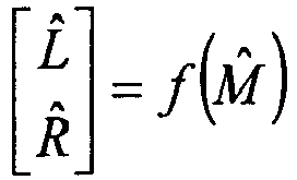
- Subtracting the prediction from the original input signal at the encoder will form an error signal pair:
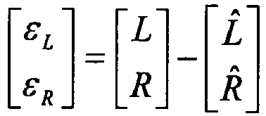
- For an MMSE perspective, the optimal prediction is obtained by minimizing the error vector [ε L ε R ]T. This can be solved in time domain by using a time varying FIR-filter:

- The equivalent operation in frequency domain can be written:
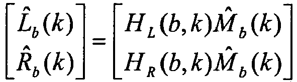
where HL (b,k) and HR (b,k) are the frequency responses of the filters h L and h R for coefficient k of the frequency band b, and L̂b (k), R̂b (k) and M̂b (k) are the transformed counterparts of the time signals l̂(n), r̂(n) and m̂(n). - Among the advantages of frequency domain processing is that it gives explicit control over the phase, which is relevant to stereo perception [14]. In lower frequency regions, phase information is highly relevant but can be discarded in the high frequencies. It can also accommodate a sub-band partitioning that gives a frequency resolution which is perceptually relevant. The drawbacks of frequency domain processing are the complexity and delay requirements for the time/frequency transformations. In cases where these parameters are critical, a time domain approach is desirable.
- For the targeted codec according to this exemplary embodiment of the invention, the top layers of the codec are SNR enhancement layers in MDCT domain. The delay requirements for the MDCT are already accounted for in the lower layers and the part of the processing can be reused. For this reason, the MDCT domain is selected for the stereo processing. Although well suited for transform coding, it has some drawbacks in stereo signal processing since it does not give explicit phase control. Further, the time aliasing property of MDCT may give unexpected results since adjacent frames are inherently dependent. On the other hand, it still gives good flexibility for frequency dependent bit allocation.
- For the stereo processing, the frequency spectrum is preferably divided into processing bands. In AAC parametric stereo, the processing bands are selected to match the critical bandwidths of human auditory perception. Since the available bitrate is low the selected bands are fewer and wider, but the bandwidths are still proportional to the critical bands. Denoting the band b, the prediction can be written:
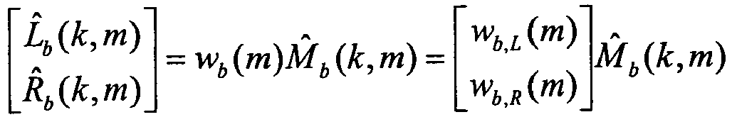
- Here, k denotes the index of the MDCT coefficient in the band b and m denotes the time domain frame index.
- The solution for wb (m) which is close to [Lb Rb ]T in the mean square error sense is:
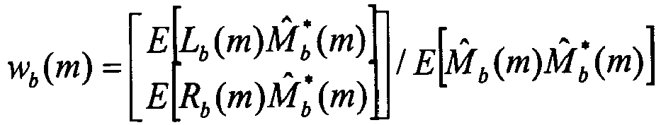
- Here E[.] denotes the averaging operator and is defined as an example for an arbitrary time frequency variable as an averaging over a predefined time frequency region. For example:

- The averaging may also extend beyond the frequency band b.
- The use of the coded mono signal in the derivation of the prediction parameters includes the coding error in the calculation. Although sensible from an MMSE perspective, this causes instability in the stereo image that is perceptually annoying. For this reason, the prediction parameters are based on the unprocessed mono signal, excluding the mono error from the prediction.
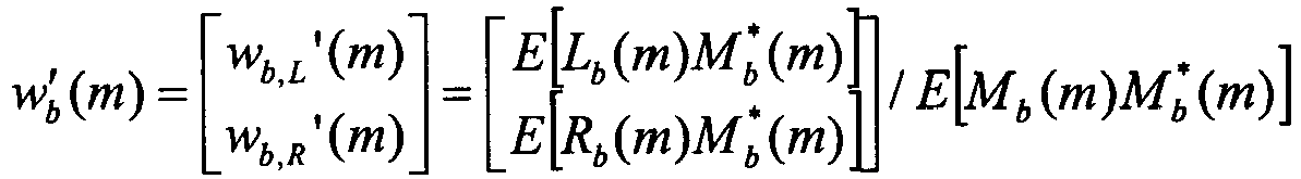
- To facilitate low bitrate encoding of the prediction parameters, further simplification is made. Since the encoding is performed in MDCT domain, the signals will be real valued, and hence so will the predictors

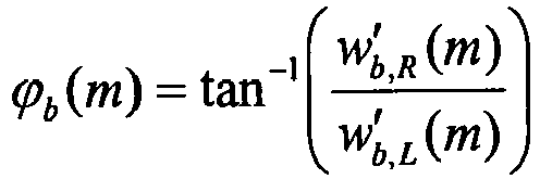
- This angle has an interpretation in the L/R signal space, as illustrated in
Figs. 7A-B . The angle is limited to the range [0, π / 2]. An angle in the range [π / 2, π] would mean the channels are anti-correlated, which is an unlikely situation for most stereo recordings. Stereo panning can thus be represented as an angle in the L/R plane.Fig. 7B is a scatter-plot where each dot represents a stereo sample at a given time instant n(L(n),R(n)). The scatter-plot shows the samples spread along a thick line with a certain angle. If the channels would have been equal L=R, the dots would be spread over a single line on the angle ϕ = πl 4. Now, since the sound is panned slightly to the left, the point distribution is leaning towards smaller values of ϕ. -
Fig. 6 is a schematic block diagram of a stereo coder according to another exemplary embodiment of the invention. The exemplary stereo coder 100-B ofFig. 6 basically includes a down-mixer 101-B, a main encoder 102-B, a so-called side predictor 105-B, a compound residual encoder 106-B and an index multiplexing unit 107-B. The main encoder 102-B includes an encoder unit 103-B and a local synthesizer 104-B. The main encoder 102-B implements a first encoding process, and the side predictor 105-B implements a second encoding process. The compound residual encoder 106-B implements a further complementary encoding process. In stereo coding, channels are usually represented by the left and the right signals l(n), r(n). However, an equivalent representation is the mono signal m(n) (a special case of the main signal) and the side signal s(n). Both representations are equivalent and are normally related by the traditional matrix operation: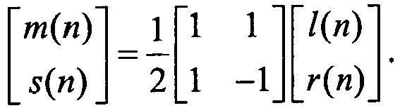
- In the particular example illustrated in
Fig. 6 , so-called inter-channel prediction (ICP) is employed in the side predictor 105-B to represent the side signal s(n) by an estimate ŝ(n), which may be obtained by filtering the mono signal m(n) through a time-varying FIR filter H(z) having N filter coefficients ht (i):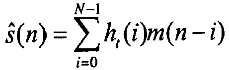
- The ICP filter derived at the encoder may for example be estimated by minimizing the mean squared error (MSE), or a related performance measure, for instance psycho-acoustically weighted mean square error, of the side signal prediction error. The MSE is typically given by:

where L is the frame size and N is the length/order/dimension of the ICP filter. Simply speaking, the performance of the ICP filter, thus the magnitude of the MSE, is the main factor determining the final stereo separation. Since the side signal describes the differences between the left and right channels, accurate side signal reconstruction is essential to ensure a wide enough stereo image. - The mono signal m(n) is encoded and quantized (Q0 ) by the encoder 103-B of the main encoder 102-B for transfer to the decoding side as usual. The ICP module of the side predictor 105-B for side signal prediction provides a FIR filter representation H(z) which is quantized (Q1 ) for transfer to the decoding side. Additional quality can be gained by encoding and/or quantizing (Q2 ) the side signal prediction error εs. It should be noted that when the residual error is quantized, the coding can no longer be referred to as purely parametric, and therefore the side encoder is referred to as a hybrid encoder. In addition, a so-called mono signal encoding error εm is generated and analyzed together with the side signal prediction error εs in the compound residual encoder 106-B. This encoder model is more or less equivalent to that described in connection with
Fig. 5 . - In an exemplary embodiment of the invention, an analysis is conducted on the compound error signal, aiming to extract inter-channel correlation or other signal dependencies. The result of the analysis is preferably used to derive a transform performing a decorrelation/orthogonalization of the channels of the compound error.
- In an exemplary embodiment, when the error components have been orthogonalized, the transformed error components can be quantized individually. The energy levels of the transformed error "channels" are preferably used in performing a bit allocation among the channels. The bit allocation may also take in account perceptual importance or other weighting factors.
- The stereo prediction is subtracted from the original input signals, producing a prediction residual [ε L ε R ]T. This residual contains both the stereo prediction error and the mono coding error. Assume the mono signal can be written as a sum of the original signal and the coding noise:

- The prediction error for band b can then be written as (omitting the frame index m and the band coefficient k):

- Here two error components can be identified. First, the stereo prediction error:
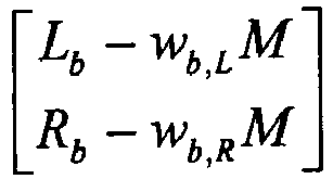
which among other things contains the diffuse sound field components, i.e. components which have no correlation with the mono signal. - The second component is related to the mono coding error and is proportional to the coding noise on the mono signal:

- Note that the mono coding error is distributed to the different channels using the panning factors.
- These two sources of errors although seemingly independent and uncorrelated will make the two errors on the left and the right channels

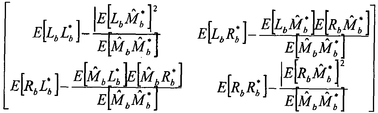
- This shows that ultimately the errors on the left and right channels are correlated. It is recognized that a separate encoding of the two errors is not optimal unless the two signals are uncorrelated. A good idea is therefore to employ correlation-based compound error encoding.
- In a preferred exemplary embodiment, techniques like Principal Components Analysis (PCA) or similar transformation techniques can be used in this process
- PCA is a technique used to reduce multidimensional data sets to lower dimensions for analysis. Depending on the field of application, it is also named the discrete Karhunen-Loeve Transform (or KLT).
- KLT is mathematically defined as an orthogonal linear transformation that transforms the data to a new coordinate system such that the greatest variance by any projection of the data comes to lie on the first coordinate (called the first principal component), the second greatest variance on the second coordinate, and so on.
- The KLT can be used for dimensionality reduction in a data set by retaining those characteristics of the data set that contribute most to its variance, by keeping lower-order principal components and ignoring higher-order ones. Such low-order components often contain the "most important" aspects of the data. But this is not necessarily the case, depending on the application.
- In the above stereo encoding example, the residual errors can be decorrelated/orthogonalized by using a 2x2 Karhunen Loève Transform (KLT). This is a simple operation in this two dimensional case. The errors can therefore be decomposed as:
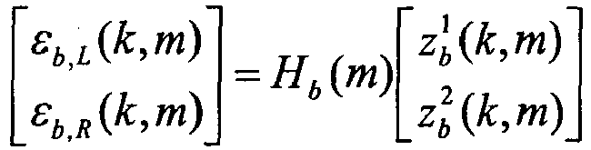
where


- With this representation, we have implicitly transformed the correlated residual errors into two uncorrelated sources of errors, one of which has an energy which is larger than the other component.
- This representation provides implicitly a way to perform bit allocation for encoding the two components. Bits are preferably allocated to the uncorrelated components which has the largest variance. The second component can optionally be ignored if its energy is negligible or very low. This means that it is actually possible to quantize only a single one of the uncorrelated error components.
- Different schemes of how to encode the two components,


- In an exemplary embodiment, the largest component

component 
- This embodiment is useful when the total bit budget does not allow an adequate quantization of both KLT components.
- At the decoder, the


- In this particular example, the so-called residual bit stream thus includes a first quantized uncorrelated component and an indication of energy of a second uncorrelated component, and the so-called transform bit stream includes a representation of the KLT transform, and the first quantized uncorrelated component is decoded and the second uncorrelated component is simulated by noise filling at the indicated energy. The inverse KLT transformation is then based on the first decoded uncorrelated component and the simulated second uncorrelated component and the KLT transform representation to produce the correlated residual error signals.
- In another embodiment, both encoding of


-
Figs. 9A-H are example scatter plots in L/R signal planes for a particular frame using eight bands. In the lower bands, the error is dominated by the side signal component. This indicates that the mono codec and stereo prediction has made a good stereo rendering. The higher bands show a dominating mono error. The oval circle shows the estimated sample distribution using the correlation values. - Besides encoding


- The creation of a compound or joint error space allows for further adaptation and optimization:
- By allowing an independent transform such as KLT for each frequency band, the scheme can apply different strategy for different frequencies. If the main (mono) codec shows poor performance for a certain frequency range, resources can be redirected to fix that range, while focusing on stereo rendering where the main (mono) codec has good performance (
Figs. 9A-H ). - By introducing a frequency weighting which depends on the binaural masking level difference (BMLD [14]). This frequency weighting may further emphasize one KLT component with respect to the other in order to take advantage of the masking properties of the human auditory system.
- In an exemplary embodiment of the invention, the parameters that preferably are transmitted to the decoder are the two rotation angles: the panning angle ϕ b and the KLT angle θ b . One pair of angles is typically used for each subband, producing vector of panning angles ϕ b and a vector of KLT angles θ b . For example, the elements of these vectors are individually quantized using a uniform scalar quantizer. A prediction scheme can then be applied to the quantizer indices. This scheme preferably has two modes which are evaluated and selected closed loop:
- 1. Time prediction: the predictor for each band is the index from the previous frame.
- 2. Frequency prediction: each index is quantized relative to the median index.
-
Mode 1 yields a good prediction when the frame-to-frame conditions are stable. In case of transitions or onsets,mode 2 may give a better prediction. The selected scheme is transmitted to the decoder using one bit. Based on the prediction, a set of delta-indices are computed. - The delta-indices are further encoded using a type of entropy code, a unitary code. It assigns shorter code words for smaller values, so that stable stereo conditions will produce a lower parameter bitrate.
Table 1: Example code words for delta indices Value Codeword Length -3 11101 5 -2 1101 4 -1 101 3 0 0 1 1 100 3 2 1100 4 3 11100 5 - The delta index uses the bounds of the quantizer, so that the wrap-around step may be considered, as illustrated in
Fig. 8 . -
Fig. 10 is a schematic diagram illustrating an overview of a stereo decoder corresponding to the stereo encoder ofFig. 5 . The stereo decoder ofFig. 10 basically includes an index demultiplexing unit 201-A, a mono decoder 202-A, a prediction unit 203-A, and a residual error decoding unit 204-A operating based on dequantization (deQ), noise filling, orthogonalization, optional gain computation and inverse KLT transformation (KLT-1), and a residual addition unit 205-A. Examples of the operation of the residual error decoding unit 204-A has been described above. The mono decoder 202-A implements a first decoding process, and the prediction unit 203-A implements a second decoding process. The residual error decoding unit 204-A implements a third decoding process that together with the residual addition unit 205-A finally reconstructs the left and right stereo channels. - As already indicated, the invention is not only applicable to stereophonic (two-channel) encoding and decoding, but is generally applicable to multiple (i.e. at least two) channels. Examples with more than two channels include but are not limited to encoding/decoding 5.1 (front left, front centre, front right, rear left and rear right and subwoofer) or 2.1 (left, right and center subwoofer) multi-channel sound.
- Reference will now be made to
Fig. 11 , which is a schematic diagram illustrating the invention in a general multi-channel context, although relating to an exemplary embodiment. The overall multi-channel encoder 100-C ofFig. 11 basically includes a down-mixer 101-C, a main encoder 102-C, a parametric encoder 105-C, a residual computation unit 108-C, a compound residual encoder 106-C, and a quantized bit stream collector 107-C. The main encoder 102-C typically includes an encoder unit 103-C and a local synthesizer 104-C. The main encoder 102-C implements a first encoding process, and the parametric encoder 105-C (together with the residual computation unit 108-C) implement a second encoding process. The compound residual encoder 106-C implements a third complementary encoding process. - The invention is based on the idea of implicitly refining both the down-mix quality as well as the multi-channel spatial quality in a consistent and unified way.
- The invention provides a method and system to encode a multi-channel signal based on down-mixing of the channels into a reduced number of channels. The down-mix in the down-mixer 101-C is generally a process of reducing the number of input channels p to a smaller number of down-mix channels q. The down-mix can be any linear or non-linear combination of the input channels, performed in temporal domain or in frequency domain. The down-mix can be adapted to the signal properties.
- The down-mixed channels are encoded by a main encoder 102-C, and more particularly the encoder unit 103-C thereof, and the resulting quantized bit stream is normally referred to as the main bitstream (Q0). The locally decoded down-mixed channels from the local synthesizer module 104-C are fed to the parametric encoder 105-C. The parametric multi-channel encoder 105-C is typically configured to perform an analysis of the correlation between the down-mixed channels and the original multi-channel signal, and results in a prediction of the original multi-channel signals. The resulting quantized bit stream is normally referred to as the predictor bit stream (Q1). Residual computation by module 108-C results in a set of residual error signals.
- A further encoding stage, here referred to as the compound residual encoder 106-C, handles the compound residual encoding of the compound error between the predicted multi-channel signals and the original multi-channel signals. Because the predicted multi-channel signals are based on the locally decoded down-mixed channels, the compound prediction residual will contain both the spatial prediction error and the coding noise from the main encoder. In the further encoding stage 106-C, the compound error signal is analyzed, transformed and quantized (Q2), allowing the invention to exploit correlation between the multi-channel prediction error and the coding error of the locally decoded down-mix signals, as well as implicitly sharing the available resources to uniformly refine both the decoded down-mixed channels as well as the spatial perception of the multi-channel output. The compound error encoder 106-C basically provides a so-called quantized transform bit stream (Q2-A) and a quantized residual bit stream (Q2-B).
- The main bit stream of the main encoder 102-C, the predictor bit stream of the parametric encoder 105-C, and the transform bit stream and residual bit stream of the residual error encoder 106-C are transferred to the collector or multiplexor 107-C to provide a total bit stream (Q) for transmission to the decoding side.
- The benefit of the suggested encoding scheme is that it may adapt to the signal properties and redirect resources to where they are most needed. It may also provide a low subjective distortion relative to the necessary quantized information, and represents a solution that consumes very little additional compression delay.
- The invention also relates to a multi-channel decoder involving a multiple stage decoding procedure that can use the information extracted in the encoder to reconstruct a multi-channel output signal that is similar to the multi-channel input signal.
- As illustrated in the example of
Fig. 12 , the overall decoder 200-B includes a receiver unit 201-B for receiving a total bit stream from the encoding side, and a main decoder 202-B that, in response to a main bit stream, produces a decoded down-mix signal (having q channels) which is identical to the locally decoded down-mix signal in the corresponding encoder. The decoded down-mix signal is input to a parametric multi-channel decoder 203-B, together with the parameters (from the predictor bit stream) that was derived and used in the multi-channel encoder. The parametric multi-channel decoder 203-B performs a prediction to reconstruct a set of p predicted channels which are identical to the predicted channels in the encoder. - The final stage, in the form of the residual error decoder 204-B, of the decoder handles decoding of the encoded residual signal from the encoder, here provided in the form of a transform bit stream and a quantized residual bit stream. It also takes into consideration that the encoder might have reduced the number of channels in the residual due to bit rate constraints or that some signals were deemed less important and that these n channels were not encoded, only their energies were transmitted in an encoded form via the bitstream. To maintain the energy consistency and inter-channel correlation of the multi-channel input signals, an orthogonal signal substitution may be performed. The residual error decoder 204-B is configured to operate based on residual dequantization, orthogonal substitution and inverse transformation to reconstruct correlated residual error components. The decoded multi-channel output signal of the overall decoder is produced by letting the residual addition unit 205-B add the correlated residual error components to the decoded channels from the parametric multi-channel decoder 203-B.
- Although encoding/decoding is often performed on a frame-by-frame basis, it is possible to perform bit allocation and encoding/decoding on variable sized frames, allowing signal adaptive optimized frame processing.
- The embodiments described above are merely given as examples, and it should be understood that the present invention is not limited thereto but according to the scope defined by the appended claims.
-
- AAC
- Advanced Audio Coding
- AAC-BSAC
- Advanced Audio Coding - Bit-Sliced Arithmetic Coding
- ADPCM
- Adaptive Differential Pulse Code Modulation
- AMR
- Adaptive Multi Rate
- AMR-NB
- AMR NarrowBand
- AMR-WB
- AMR WideBand
- AMR-BWS
- AMR-BandWidth Scalable
- AOT
- Audio Object Type
- BCC
- Binaural Cue Coding
- BMLD
- Binaural Masking Level Difference
- CELP
- Code Excited Linear Prediction
- EV
- Embedded VBR (Variable Bit Rate)
- EVRC
- Enhanced Variable Rate Coder
- FIR
- Finite Impulse Response
- GSM
- Groupe Spécial Mobile; Global System for Mobile communications
- ICP
- Inter Channel Prediction
- KLT
- Karhunen-Loève Transform
- LSB
- Least Significant Bit
- MD-AMR
- Multi Description AMR
- MDCT
- Modified Discrete Cosine Transform
- MPEG
- Moving Picture Experts Group
- MPEG-SLS
- MPEG-Scalable to Lossless
- MSB
- Most Significant Bit
- MSE
- Mean Squared Error
- MMSE
- Minimum MSE
- PCA
- Principal Components Analysis
- PS
- Parametric Stereo
- RTP
- Real-Time Protocol
- SNR
- Signal-to-Noise Ratio
- VMR
- Variable Multi Rate
- VoIP
- Voice over Internet Protocol
- xDSL
- x Digital Subscriber Line
-
- [1] ISO/.
- [2] Hui Dong Gibson, JD Kokes, MG, "SNR and bandwidth scalable speech coding", Circuits and Systems, 2002. ISCAS 2002
- [3] McCree et al, "AN EMBEDDED ADAPTIVE MULTI-RATE WIDEBAND SPEECH CODER", ICASSP 2001
- [4] Koishida et al, "A 16-KBIT/S BANDWIDTH SCALABLE AUDIO CODER BASED ON THE G.729 STANDARD" ,ICASSP 2000
- [5] Sjöberg et al, "Real-Time Transport Protocol (RTP) Payload Format and File Storage Format for the Adaptive Multi-Rate (AMR) and Adaptive Multi-Rate Wideband (AMR-WB) Audio Codecs", RFC 3267, IETF, June 2002
- [6] H. Dong et al, "Multiple description speech coder based on AMR-WB for Mobile ad-hoc networks", ICASSP 2004
- [7] Chibani, M.; Gournay, P.; Lefebvre, R, "Increasing the Robustness of CELP-Based Coders By Constrained Optimization", ICASSP 2005
- [8] Herre, "OVERVIEW OF MPEG-4 AUDIO AND ITS APPLICATIONS IN MOBILE COMMUNICATIONS", ICCT 2000
- [9] Kovesi,"A SCALABLE SPEECH AND AUDIO CODING SCHEME WITH CONTINUOUS BITRATE FLEXIBILITY", ICASSP2004
- [10] Johansson et al, "Bandwidth Efficient AMR Operation for VoIP", IEEE WS on SPC, 2002
- [11] Recchione, "The Enhanced Variable Rate Coder Toll Quality Speech For CDMA", Journal of Speech Technology, 1999
- [12] Uvliden et al, "Adaptive Multi-Rate - A speech service adapted to Cellular Radio Network Quality", Asilomar, 1998
- [13] Chen et al, "Experiments on QoS Adaptation for Improving End User Speech Perception Over Multi-hop Wireless Networks", ICC, 1999
- [14] C. Faller and F. Baumgarte, "Binaural cue coding - Part I: Psychoacoustic fundamentals and design principles", IEEE Trans. Speech Audio Processing, vol. 11, pp. 509-519, Nov. 2003.
Claims (15)
- A multi-channel audio encoding method based on an overall encoding procedure involving at least two signal encoding processes, including a first, main encoding process (S1) and a second, auxiliary encoding process (S4), operating on signal representations of a set of audio input channels of a multi-channel audio signal, wherein said method includes:- encoding (S1) a first signal representation of said set of audio input channels of said multi-channel audio signal in said first, main encoding process in a first, main encoder (102);- performing (S2) local synthesis in connection with said first, main encoding process to generate a locally decoded signal including a representation of the encoding error of the first, main encoding process;- applying (S3) at least said locally decoded signal as input to said second, auxiliary encoding process;- encoding (S4) at least one additional signal representation of at least part of said audio input channels of said multi-channel audio signal in said second, auxiliary encoding process in a second, parametric multi-channel encoder (105), while using said locally decoded signal as input to said second, auxiliary encoding process;- generating (S5) at least two residual encoding error signals defining a compound residual that includes representations of the encoding errors of both the first and second encoding processes;- performing (S6) compound residual encoding of said residual error signals in a further complementary encoding process including compound error analysis based on correlation between said residual error signals, wherein said compound residual encoding includes decorrelation of the correlated residual error signals by means of a transform to produce corresponding uncorrelated error components, quantization of at least one of said uncorrelated error components, and quantization of a representation of said transform.
- The multi-channel audio encoding method of claim 1, wherein said step of quantizing at least one of said uncorrelated error components comprises the step of performing bit allocation among the uncorrelated error components based on the energy levels of the error components.
- The multi-channel audio encoding method of claim 2, wherein said transform is a Karhunen-Loève Transform (KLT), and said representation of said transform includes a representation of a KLT rotation angle, and said second encoding process generates prediction parameters that are joined into a panning angle, and said panning angle and said KLT rotation angle are quantized.
- The multi-channel audio encoding method of claim 1, wherein said compound residual includes both a stereo prediction error and a mono coding error.
- A multi-channel audio encoder device (100) configured for operating on signal representations of a set of audio input channels of a multi-channel audio signal, wherein said multi-channel audio encoder device includes:- a first, main encoder (102) configured for encoding a first signal representation of said set of audio input channels of said multi-channel audio signal in a first, main encoding process;- means (104) for local synthesis in connection with said first encoder to generate a locally decoded signal including a representation of the encoding error of said first encoder;- a second, parametric multi-channel encoder (105) configured for encoding at least one additional signal representation of at least part of said audio input channels of said multi-channel audio signal in a second, auxiliary encoding process, while using the locally decoded signal as input to said second, auxiliary encoding process;- means for applying at least said locally decoded signal as input to said second, auxiliary encoder (105);- means for generating at least two residual encoding error signals defining a compound residual that includes representations of the encoding errors of both the first and second encoding processes;- a compound residual encoder (106) for compound residual encoding of said residual error signals in a further complementary encoding process including compound error analysis based on correlation between said residual error signals, wherein said residual encoder (106) is configured for decorrelating the correlated residual error signals by means of a transform to produce corresponding uncorrelated error components, and for quantizing at least one of said uncorrelated error components, and for quantizing a representation of said transform.
- The multi-channel audio encoder device of claim 5, wherein said means for quantizing at least one of said uncorrelated error components is configured for performing bit allocation among the uncorrelated error components based on the energy levels of the error components.
- The multi-channel audio encoder device of claim 6, wherein said transform is a Karhunen-Loève Transform (KLT), and said representation of said transform includes a representation of a KLT rotation angle, and said second encoder is configured for generating prediction parameters that are joined into a panning angle, and said encoder device is configured for jointly quantizing said panning angle and said KLT rotation angle by differential quantization.
- The multi-channel audio encoder device of claim 5, wherein said compound residual encoder (106) is configured to operate based on the correlation between a stereo prediction error and a mono coding error.
- A multi-channel audio decoding method based on an overall decoding procedure involving at least two decoding processes, including a first, main decoding process (S11) and a second, auxiliary decoding process (S12), operating on incoming bit streams for reconstruction of a multi-channel audio signal, wherein said method includes:- performing (S11) said first, main decoding process in a main decoder (202) for producing a decoded down-mix signal representing a number of channels based on an incoming main bit stream;- performing (S12) said second, auxiliary decoding process in a parametric multi-channel decoder (203) for reconstructing a set of predicted channels based on the decoded down-mix signal and an incoming predictor bit stream;- performing (S 13) compound residual decoding in a further decoding process based on an incoming residual bit stream representative of uncorrelated residual error signal information to generate correlated residual error signals;- adding (S14) said correlated residual error signals to decoded channel representations from said second, auxiliary decoding process, or from said first, main decoding process and said second, auxiliary decoding process, to generate the multi-channel audio signal.
- The multi-channel audio decoding method of claim 9, wherein said step of performing compound residual decoding in a further decoding process comprises the steps of performing residual dequantization based on said incoming residual bit stream, and performing orthogonal signal substitution and inverse transformation based on an incoming transform bit stream to generate said correlated residual error signals.
- The multi-channel audio decoding method of claim 10, wherein said inverse transformation is an inverse of a Karhunen-Loève Transform (KLT), and said incoming residual bit stream includes a first quantized uncorrelated component and an indication of energy of a second uncorrelated component, and said transform bit stream includes a representation of said KLT transform, and said first quantized uncorrelated component is decoded and said second uncorrelated component is simulated by noise filling at the indicated energy, and said inverse KLT transformation is based on said first decoded uncorrelated component and said simulated second uncorrelated component and said KLT transform representation to produce said correlated residual error signals.
- A multi-channel audio decoder device (200) configured for operating on incoming bit streams for reconstruction of a multi-channel audio signal, wherein said multi-channel audio decoder device (200) includes:- a first, main decoder (202) for producing a decoded down-mix signal representing a number of channels based on an incoming main bit stream;- a second, parametric multi-channel decoder (203) for reconstructing a set of predicted channels based on the decoded down-mix signal and an incoming predictor bit stream;- a compound residual decoder (204) configured for performing compound residual decoding based on an incoming residual bit stream representative of uncorrelated residual error signal information to generate correlated residual error signals;- an adder module (205) configured to add said correlated residual error signals to decoded channel representations from said second, parametric multi-channel decoder (203), or from said first, main decoder (202) and said second, parametric multi-channel decoder (203), to generate the multi-channel audio signal.
- The multi-channel audio decoder device of claim 12, wherein said compound residual decoder (204) comprises:- means for residual dequantization based on said incoming residual bit stream; and- means for orthogonal signal substitution and inverse transformation based on an incoming transform bit stream to generate said correlated residual error signals.
- The multi-channel audio decoder device of claim 13, wherein said inverse transformation is an inverse of a Karhunen-Loève Transform (KLT), and said incoming residual bit stream includes a first quantized uncorrelated component and an indication of energy of a second uncorrelated component, and said transform bit stream includes a representation of said KLT transform, and said compound residual decoder is configured for decoding said first quantized uncorrelated component and for simulating said second uncorrelated component by noise filling at the indicated energy, and said inverse KLT transformation is based on said first decoded uncorrelated component and said simulated second uncorrelated component and said KLT transform representation to produce said correlated residual error signals.
- An audio transmission system comprising an audio encoder device (100) of any of the claims 5-8 and an audio decoder device (200) of any of the claims 12-14.
Priority Applications (1)
| Application Number | Priority Date | Filing Date | Title |
|---|---|---|---|
| PL08753930T PL2201566T3 (en) | 2007-09-19 | 2008-04-17 | Joint multi-channel audio encoding/decoding |
Applications Claiming Priority (2)
| Application Number | Priority Date | Filing Date | Title |
|---|---|---|---|
| US96017507P | 2007-09-19 | 2007-09-19 | |
| PCT/SE2008/000272 WO2009038512A1 (en) | 2007-09-19 | 2008-04-17 | Joint enhancement of multi-channel audio |
Publications (3)
| Publication Number | Publication Date |
|---|---|
| EP2201566A1 EP2201566A1 (en) | 2010-06-30 |
| EP2201566A4 EP2201566A4 (en) | 2011-09-28 |
| EP2201566B1 true EP2201566B1 (en) | 2015-11-11 |
Family
ID=40468142
Family Applications (1)
| Application Number | Title | Priority Date | Filing Date |
|---|---|---|---|
| EP08753930.0A Not-in-force EP2201566B1 (en) | 2007-09-19 | 2008-04-17 | Joint multi-channel audio encoding/decoding |
Country Status (7)
| Country | Link |
|---|---|
| US (1) | US8218775B2 (en) |
| EP (1) | EP2201566B1 (en) |
| JP (1) | JP5363488B2 (en) |
| KR (1) | KR101450940B1 (en) |
| CN (1) | CN101802907B (en) |
| PL (1) | PL2201566T3 (en) |
| WO (1) | WO2009038512A1 (en) |
Families Citing this family (55)
| Publication number | Priority date | Publication date | Assignee | Title |
|---|---|---|---|---|
| EP2287836B1 (en) * | 2008-05-30 | 2014-10-15 | Panasonic Intellectual Property Corporation of America | Encoder and encoding method |
| EP2293292B1 (en) * | 2008-06-19 | 2013-06-05 | Panasonic Corporation | Quantizing apparatus, quantizing method and encoding apparatus |
| RU2491656C2 (en) | 2008-06-27 | 2013-08-27 | Панасоник Корпорэйшн | Audio signal decoder and method of controlling audio signal decoder balance |
| KR101428487B1 (en) * | 2008-07-11 | 2014-08-08 | 삼성전자주식회사 | Multi-channel encoding and decoding method and apparatus |
| KR101756834B1 (en) * | 2008-07-14 | 2017-07-12 | 삼성전자주식회사 | Method and apparatus for encoding and decoding of speech and audio signal |
| JP5608660B2 (en) * | 2008-10-10 | 2014-10-15 | テレフオンアクチーボラゲット エル エム エリクソン(パブル) | Energy-conserving multi-channel audio coding |
| EP2395504B1 (en) * | 2009-02-13 | 2013-09-18 | Huawei Technologies Co., Ltd. | Stereo encoding method and apparatus |
| EP2224425B1 (en) * | 2009-02-26 | 2012-02-08 | Honda Research Institute Europe GmbH | An audio signal processing system and autonomous robot having such system |
| US20100223061A1 (en) * | 2009-02-27 | 2010-09-02 | Nokia Corporation | Method and Apparatus for Audio Coding |
| AU2010225051B2 (en) * | 2009-03-17 | 2013-06-13 | Dolby International Ab | Advanced stereo coding based on a combination of adaptively selectable left/right or mid/side stereo coding and of parametric stereo coding |
| GB2470059A (en) | 2009-05-08 | 2010-11-10 | Nokia Corp | Multi-channel audio processing using an inter-channel prediction model to form an inter-channel parameter |
| CN101556799B (en) * | 2009-05-14 | 2013-08-28 | 华为技术有限公司 | Audio decoding method and audio decoder |
| WO2010140306A1 (en) * | 2009-06-01 | 2010-12-09 | 三菱電機株式会社 | Signal processing device |
| WO2010140350A1 (en) * | 2009-06-02 | 2010-12-09 | パナソニック株式会社 | Down-mixing device, encoder, and method therefor |
| KR101641684B1 (en) * | 2009-08-18 | 2016-07-21 | 삼성전자주식회사 | Apparatus and method for transmitting digital multimedia broadcasting, and method and apparatus for receiving digital multimedia broadcasting |
| KR101613975B1 (en) * | 2009-08-18 | 2016-05-02 | 삼성전자주식회사 | Method and apparatus for encoding multi-channel audio signal, and method and apparatus for decoding multi-channel audio signal |
| EP2492911B1 (en) * | 2009-10-21 | 2017-08-16 | Panasonic Intellectual Property Management Co., Ltd. | Audio encoding apparatus, decoding apparatus, method, circuit and program |
| US8942989B2 (en) * | 2009-12-28 | 2015-01-27 | Panasonic Intellectual Property Corporation Of America | Speech coding of principal-component channels for deleting redundant inter-channel parameters |
| JP5299327B2 (en) * | 2010-03-17 | 2013-09-25 | ソニー株式会社 | Audio processing apparatus, audio processing method, and program |
| KR101698439B1 (en) | 2010-04-09 | 2017-01-20 | 돌비 인터네셔널 에이비 | Mdct-based complex prediction stereo coding |
| WO2011145987A1 (en) * | 2010-05-18 | 2011-11-24 | Telefonaktiebolaget Lm Ericsson (Publ) | Encoder adaption in teleconferencing system |
| CN102280107B (en) | 2010-06-10 | 2013-01-23 | 华为技术有限公司 | Sideband residual signal generating method and device |
| JP5581449B2 (en) * | 2010-08-24 | 2014-08-27 | ドルビー・インターナショナル・アーベー | Concealment of intermittent mono reception of FM stereo radio receiver |
| KR101468458B1 (en) * | 2010-11-12 | 2014-12-03 | 폴리콤 인코포레이티드 | Scalable audio in a multipoint environment |
| JP5582027B2 (en) * | 2010-12-28 | 2014-09-03 | 富士通株式会社 | Encoder, encoding method, and encoding program |
| US9978379B2 (en) * | 2011-01-05 | 2018-05-22 | Nokia Technologies Oy | Multi-channel encoding and/or decoding using non-negative tensor factorization |
| EP2898506B1 (en) * | 2012-09-21 | 2018-01-17 | Dolby Laboratories Licensing Corporation | Layered approach to spatial audio coding |
| CN105976824B (en) | 2012-12-06 | 2021-06-08 | 华为技术有限公司 | Method and device for signal decoding |
| US20150025894A1 (en) * | 2013-07-16 | 2015-01-22 | Electronics And Telecommunications Research Institute | Method for encoding and decoding of multi channel audio signal, encoder and decoder |
| EP2830051A3 (en) | 2013-07-22 | 2015-03-04 | Fraunhofer-Gesellschaft zur Förderung der angewandten Forschung e.V. | Audio encoder, audio decoder, methods and computer program using jointly encoded residual signals |
| TWI634547B (en) | 2013-09-12 | 2018-09-01 | 瑞典商杜比國際公司 | Decoding method, decoding device, encoding method and encoding device in a multi-channel audio system including at least four audio channels, and computer program products including computer readable media |
| US9088447B1 (en) * | 2014-03-21 | 2015-07-21 | Mitsubishi Electric Research Laboratories, Inc. | Non-coherent transmission and equalization in doubly-selective MIMO channels |
| KR101641645B1 (en) * | 2014-06-11 | 2016-07-22 | 전자부품연구원 | Audio Source Seperation Method and Audio System using the same |
| EP3067885A1 (en) | 2015-03-09 | 2016-09-14 | Fraunhofer-Gesellschaft zur Förderung der angewandten Forschung e.V. | Apparatus and method for encoding or decoding a multi-channel signal |
| ES2904275T3 (en) * | 2015-09-25 | 2022-04-04 | Voiceage Corp | Method and system for decoding the left and right channels of a stereo sound signal |
| US10499229B2 (en) * | 2016-01-24 | 2019-12-03 | Qualcomm Incorporated | Enhanced fallback to in-band mode for emergency calling |
| EP3208800A1 (en) * | 2016-02-17 | 2017-08-23 | Fraunhofer-Gesellschaft zur Förderung der angewandten Forschung e.V. | Apparatus and method for stereo filing in multichannel coding |
| FR3048808A1 (en) * | 2016-03-10 | 2017-09-15 | Orange | OPTIMIZED ENCODING AND DECODING OF SPATIALIZATION INFORMATION FOR PARAMETRIC CODING AND DECODING OF A MULTICANAL AUDIO SIGNAL |
| US10057681B2 (en) | 2016-08-01 | 2018-08-21 | Bose Corporation | Entertainment audio processing |
| US10217468B2 (en) * | 2017-01-19 | 2019-02-26 | Qualcomm Incorporated | Coding of multiple audio signals |
| US10362332B2 (en) * | 2017-03-14 | 2019-07-23 | Google Llc | Multi-level compound prediction |
| ES2911515T3 (en) * | 2017-04-10 | 2022-05-19 | Nokia Technologies Oy | audio encoding |
| CN107483194A (en) * | 2017-08-29 | 2017-12-15 | 中国民航大学 | G.729 Speech Information Hiding Algorithm Based on Non-Zero Pulse Position and Amplitude Information |
| CN114420139A (en) * | 2018-05-31 | 2022-04-29 | 华为技术有限公司 | Method and device for calculating downmix signal |
| MX2021001970A (en) | 2018-08-21 | 2021-05-31 | Dolby Int Ab | Methods, apparatus and systems for generation, transportation and processing of immediate playout frames (ipfs). |
| KR102501233B1 (en) * | 2018-10-22 | 2023-02-20 | 삼성에스디에스 주식회사 | Method for service video conference and apparatus for executing the method |
| EP3891737B1 (en) * | 2019-01-11 | 2024-07-03 | Boomcloud 360, Inc. | Soundstage-conserving audio channel summation |
| JP7092050B2 (en) * | 2019-01-17 | 2022-06-28 | 日本電信電話株式会社 | Multipoint control methods, devices and programs |
| EP3706119A1 (en) * | 2019-03-05 | 2020-09-09 | Orange | Spatialised audio encoding with interpolation and quantifying of rotations |
| EP3719799A1 (en) * | 2019-04-04 | 2020-10-07 | FRAUNHOFER-GESELLSCHAFT zur Förderung der angewandten Forschung e.V. | A multi-channel audio encoder, decoder, methods and computer program for switching between a parametric multi-channel operation and an individual channel operation |
| GB2586461A (en) * | 2019-08-16 | 2021-02-24 | Nokia Technologies Oy | Quantization of spatial audio direction parameters |
| CN110718211B (en) * | 2019-09-26 | 2021-12-21 | 东南大学 | Keyword recognition system based on hybrid compressed convolutional neural network |
| WO2022009505A1 (en) * | 2020-07-07 | 2022-01-13 | パナソニック インテレクチュアル プロパティ コーポレーション オブ アメリカ | Coding apparatus, decoding apparatus, coding method, decoding method, and hybrid coding system |
| GB2598773A (en) * | 2020-09-14 | 2022-03-16 | Nokia Technologies Oy | Quantizing spatial audio parameters |
| US20230230604A1 (en) * | 2022-01-20 | 2023-07-20 | Electronics And Telecommunications Research Institute | Method of encoding audio signal and encoder, method of decoding audio signal and decoder |
Family Cites Families (16)
| Publication number | Priority date | Publication date | Assignee | Title |
|---|---|---|---|---|
| US5434948A (en) | 1989-06-15 | 1995-07-18 | British Telecommunications Public Limited Company | Polyphonic coding |
| NL9100173A (en) | 1991-02-01 | 1992-09-01 | Philips Nv | SUBBAND CODING DEVICE, AND A TRANSMITTER EQUIPPED WITH THE CODING DEVICE. |
| US5285498A (en) | 1992-03-02 | 1994-02-08 | At&T Bell Laboratories | Method and apparatus for coding audio signals based on perceptual model |
| DE19742655C2 (en) | 1997-09-26 | 1999-08-05 | Fraunhofer Ges Forschung | Method and device for coding a discrete-time stereo signal |
| US6125348A (en) * | 1998-03-12 | 2000-09-26 | Liquid Audio Inc. | Lossless data compression with low complexity |
| US7231054B1 (en) * | 1999-09-24 | 2007-06-12 | Creative Technology Ltd | Method and apparatus for three-dimensional audio display |
| SE519985C2 (en) * | 2000-09-15 | 2003-05-06 | Ericsson Telefon Ab L M | Coding and decoding of signals from multiple channels |
| SE519981C2 (en) | 2000-09-15 | 2003-05-06 | Ericsson Telefon Ab L M | Coding and decoding of signals from multiple channels |
| ES2403178T3 (en) * | 2002-04-10 | 2013-05-16 | Koninklijke Philips Electronics N.V. | Stereo signal coding |
| KR100978018B1 (en) * | 2002-04-22 | 2010-08-25 | 코닌클리케 필립스 일렉트로닉스 엔.브이. | Parametric Representation of Spatial Audio |
| DE602004002390T2 (en) | 2003-02-11 | 2007-09-06 | Koninklijke Philips Electronics N.V. | AUDIO CODING |
| BRPI0516376A (en) * | 2004-12-27 | 2008-09-02 | Matsushita Electric Industrial Co Ltd | sound coding device and sound coding method |
| US7573912B2 (en) * | 2005-02-22 | 2009-08-11 | Fraunhofer-Gesellschaft Zur Foerderung Der Angewandten Forschunng E.V. | Near-transparent or transparent multi-channel encoder/decoder scheme |
| EP1851866B1 (en) | 2005-02-23 | 2011-08-17 | Telefonaktiebolaget LM Ericsson (publ) | Adaptive bit allocation for multi-channel audio encoding |
| US9626973B2 (en) | 2005-02-23 | 2017-04-18 | Telefonaktiebolaget L M Ericsson (Publ) | Adaptive bit allocation for multi-channel audio encoding |
| WO2006109113A2 (en) | 2005-04-12 | 2006-10-19 | Acol Technologies Sa | Primary optic for a light emitting diode |
-
2008
- 2008-04-17 EP EP08753930.0A patent/EP2201566B1/en not_active Not-in-force
- 2008-04-17 JP JP2010525778A patent/JP5363488B2/en not_active Expired - Fee Related
- 2008-04-17 CN CN2008801083540A patent/CN101802907B/en not_active Expired - Fee Related
- 2008-04-17 WO PCT/SE2008/000272 patent/WO2009038512A1/en not_active Ceased
- 2008-04-17 KR KR1020107006915A patent/KR101450940B1/en not_active Expired - Fee Related
- 2008-04-17 PL PL08753930T patent/PL2201566T3/en unknown
- 2008-04-17 US US12/677,383 patent/US8218775B2/en not_active Expired - Fee Related
Also Published As
| Publication number | Publication date |
|---|---|
| KR101450940B1 (en) | 2014-10-15 |
| EP2201566A4 (en) | 2011-09-28 |
| WO2009038512A1 (en) | 2009-03-26 |
| KR20100063099A (en) | 2010-06-10 |
| US8218775B2 (en) | 2012-07-10 |
| JP2010540985A (en) | 2010-12-24 |
| CN101802907B (en) | 2013-11-13 |
| US20100322429A1 (en) | 2010-12-23 |
| CN101802907A (en) | 2010-08-11 |
| JP5363488B2 (en) | 2013-12-11 |
| PL2201566T3 (en) | 2016-04-29 |
| EP2201566A1 (en) | 2010-06-30 |
Similar Documents
| Publication | Publication Date | Title |
|---|---|---|
| EP2201566B1 (en) | Joint multi-channel audio encoding/decoding | |
| US9330671B2 (en) | Energy conservative multi-channel audio coding | |
| US11056121B2 (en) | Method and system for encoding left and right channels of a stereo sound signal selecting between two and four sub-frames models depending on the bit budget | |
| CN101611442B (en) | Encoding device, decoding device and method thereof | |
| CN101124740B (en) | Multi-channel audio encoding and decoding method and device, audio transmission system | |
| JP5654632B2 (en) | Mixing the input data stream and generating the output data stream from it | |
| JP5383676B2 (en) | Encoding device, decoding device and methods thereof | |
| US9530422B2 (en) | Bitstream syntax for spatial voice coding | |
| KR20090007396A (en) | Method and apparatus for lossless encoding of source signal using lossy encoded data stream and lossless extended data stream | |
| JPWO2007026763A1 (en) | Stereo encoding apparatus, stereo decoding apparatus, and stereo encoding method | |
| JPWO2009057327A1 (en) | Encoding device and decoding device | |
| WO2006041055A1 (en) | Scalable encoder, scalable decoder, and scalable encoding method | |
| EP1801783B1 (en) | Scalable encoding device, scalable decoding device, and method thereof | |
| JPWO2008132826A1 (en) | Stereo speech coding apparatus and stereo speech coding method | |
| Geiger et al. | ISO/IEC MPEG-4 high-definition scalable advanced audio coding | |
| US12125492B2 (en) | Method and system for decoding left and right channels of a stereo sound signal | |
| JPWO2008090970A1 (en) | Stereo encoding apparatus, stereo decoding apparatus, and methods thereof | |
| Li et al. | Efficient stereo bitrate allocation for fully scalable audio codec |
Legal Events
| Date | Code | Title | Description |
|---|---|---|---|
| PUAI | Public reference made under article 153(3) epc to a published international application that has entered the european phase |
Free format text: ORIGINAL CODE: 0009012 |
|
| 17P | Request for examination filed |
Effective date: 20100419 |
|
| AK | Designated contracting states |
Kind code of ref document: A1 Designated state(s): AT BE BG CH CY CZ DE DK EE ES FI FR GB GR HR HU IE IS IT LI LT LU LV MC MT NL NO PL PT RO SE SI SK TR |
|
| AX | Request for extension of the european patent |
Extension state: AL BA MK RS |
|
| DAX | Request for extension of the european patent (deleted) | ||
| A4 | Supplementary search report drawn up and despatched |
Effective date: 20110826 |
|
| RIC1 | Information provided on ipc code assigned before grant |
Ipc: G10L 19/14 20060101ALI20110822BHEP Ipc: G10L 19/00 20060101AFI20110822BHEP |
|
| 17Q | First examination report despatched |
Effective date: 20130425 |
|
| REG | Reference to a national code |
Ref country code: DE Ref legal event code: R079 Ref document number: 602008041134 Country of ref document: DE Free format text: PREVIOUS MAIN CLASS: G10L0019000000 Ipc: G10L0019008000 |
|
| RIC1 | Information provided on ipc code assigned before grant |
Ipc: G10L 19/008 20130101AFI20150420BHEP Ipc: G10L 19/24 20130101ALI20150420BHEP |
|
| GRAP | Despatch of communication of intention to grant a patent |
Free format text: ORIGINAL CODE: EPIDOSNIGR1 |
|
| INTG | Intention to grant announced |
Effective date: 20150616 |
|
| GRAS | Grant fee paid |
Free format text: ORIGINAL CODE: EPIDOSNIGR3 |
|
| GRAA | (expected) grant |
Free format text: ORIGINAL CODE: 0009210 |
|
| AK | Designated contracting states |
Kind code of ref document: B1 Designated state(s): AT BE BG CH CY CZ DE DK EE ES FI FR GB GR HR HU IE IS IT LI LT LU LV MC MT NL NO PL PT RO SE SI SK TR |
|
| REG | Reference to a national code |
Ref country code: GB Ref legal event code: FG4D |
|
| REG | Reference to a national code |
Ref country code: CH Ref legal event code: EP |
|
| REG | Reference to a national code |
Ref country code: IE Ref legal event code: FG4D |
|
| REG | Reference to a national code |
Ref country code: AT Ref legal event code: REF Ref document number: 760802 Country of ref document: AT Kind code of ref document: T Effective date: 20151215 |
|
| REG | Reference to a national code |
Ref country code: DE Ref legal event code: R096 Ref document number: 602008041134 Country of ref document: DE |
|
| REG | Reference to a national code |
Ref country code: LT Ref legal event code: MG4D |
|
| REG | Reference to a national code |
Ref country code: NL Ref legal event code: FP |
|
| REG | Reference to a national code |
Ref country code: AT Ref legal event code: MK05 Ref document number: 760802 Country of ref document: AT Kind code of ref document: T Effective date: 20151111 |
|
| PG25 | Lapsed in a contracting state [announced via postgrant information from national office to epo] |
Ref country code: LT Free format text: LAPSE BECAUSE OF FAILURE TO SUBMIT A TRANSLATION OF THE DESCRIPTION OR TO PAY THE FEE WITHIN THE PRESCRIBED TIME-LIMIT Effective date: 20151111 Ref country code: IT Free format text: LAPSE BECAUSE OF FAILURE TO SUBMIT A TRANSLATION OF THE DESCRIPTION OR TO PAY THE FEE WITHIN THE PRESCRIBED TIME-LIMIT Effective date: 20151111 Ref country code: ES Free format text: LAPSE BECAUSE OF FAILURE TO SUBMIT A TRANSLATION OF THE DESCRIPTION OR TO PAY THE FEE WITHIN THE PRESCRIBED TIME-LIMIT Effective date: 20151111 Ref country code: NO Free format text: LAPSE BECAUSE OF FAILURE TO SUBMIT A TRANSLATION OF THE DESCRIPTION OR TO PAY THE FEE WITHIN THE PRESCRIBED TIME-LIMIT Effective date: 20160211 Ref country code: HR Free format text: LAPSE BECAUSE OF FAILURE TO SUBMIT A TRANSLATION OF THE DESCRIPTION OR TO PAY THE FEE WITHIN THE PRESCRIBED TIME-LIMIT Effective date: 20151111 Ref country code: IS Free format text: LAPSE BECAUSE OF FAILURE TO SUBMIT A TRANSLATION OF THE DESCRIPTION OR TO PAY THE FEE WITHIN THE PRESCRIBED TIME-LIMIT Effective date: 20160311 |
|
| PG25 | Lapsed in a contracting state [announced via postgrant information from national office to epo] |
Ref country code: AT Free format text: LAPSE BECAUSE OF FAILURE TO SUBMIT A TRANSLATION OF THE DESCRIPTION OR TO PAY THE FEE WITHIN THE PRESCRIBED TIME-LIMIT Effective date: 20151111 Ref country code: LV Free format text: LAPSE BECAUSE OF FAILURE TO SUBMIT A TRANSLATION OF THE DESCRIPTION OR TO PAY THE FEE WITHIN THE PRESCRIBED TIME-LIMIT Effective date: 20151111 Ref country code: GR Free format text: LAPSE BECAUSE OF FAILURE TO SUBMIT A TRANSLATION OF THE DESCRIPTION OR TO PAY THE FEE WITHIN THE PRESCRIBED TIME-LIMIT Effective date: 20160212 Ref country code: SE Free format text: LAPSE BECAUSE OF FAILURE TO SUBMIT A TRANSLATION OF THE DESCRIPTION OR TO PAY THE FEE WITHIN THE PRESCRIBED TIME-LIMIT Effective date: 20151111 Ref country code: FI Free format text: LAPSE BECAUSE OF FAILURE TO SUBMIT A TRANSLATION OF THE DESCRIPTION OR TO PAY THE FEE WITHIN THE PRESCRIBED TIME-LIMIT Effective date: 20151111 Ref country code: PT Free format text: LAPSE BECAUSE OF FAILURE TO SUBMIT A TRANSLATION OF THE DESCRIPTION OR TO PAY THE FEE WITHIN THE PRESCRIBED TIME-LIMIT Effective date: 20160311 |
|
| PG25 | Lapsed in a contracting state [announced via postgrant information from national office to epo] |
Ref country code: CZ Free format text: LAPSE BECAUSE OF FAILURE TO SUBMIT A TRANSLATION OF THE DESCRIPTION OR TO PAY THE FEE WITHIN THE PRESCRIBED TIME-LIMIT Effective date: 20151111 |
|
| REG | Reference to a national code |
Ref country code: DE Ref legal event code: R097 Ref document number: 602008041134 Country of ref document: DE |
|
| PG25 | Lapsed in a contracting state [announced via postgrant information from national office to epo] |
Ref country code: DK Free format text: LAPSE BECAUSE OF FAILURE TO SUBMIT A TRANSLATION OF THE DESCRIPTION OR TO PAY THE FEE WITHIN THE PRESCRIBED TIME-LIMIT Effective date: 20151111 Ref country code: SK Free format text: LAPSE BECAUSE OF FAILURE TO SUBMIT A TRANSLATION OF THE DESCRIPTION OR TO PAY THE FEE WITHIN THE PRESCRIBED TIME-LIMIT Effective date: 20151111 Ref country code: BE Free format text: LAPSE BECAUSE OF NON-PAYMENT OF DUE FEES Effective date: 20160430 Ref country code: EE Free format text: LAPSE BECAUSE OF FAILURE TO SUBMIT A TRANSLATION OF THE DESCRIPTION OR TO PAY THE FEE WITHIN THE PRESCRIBED TIME-LIMIT Effective date: 20151111 Ref country code: RO Free format text: LAPSE BECAUSE OF FAILURE TO SUBMIT A TRANSLATION OF THE DESCRIPTION OR TO PAY THE FEE WITHIN THE PRESCRIBED TIME-LIMIT Effective date: 20151111 |
|
| PLBE | No opposition filed within time limit |
Free format text: ORIGINAL CODE: 0009261 |
|
| STAA | Information on the status of an ep patent application or granted ep patent |
Free format text: STATUS: NO OPPOSITION FILED WITHIN TIME LIMIT |
|
| 26N | No opposition filed |
Effective date: 20160812 |
|
| PG25 | Lapsed in a contracting state [announced via postgrant information from national office to epo] |
Ref country code: SI Free format text: LAPSE BECAUSE OF FAILURE TO SUBMIT A TRANSLATION OF THE DESCRIPTION OR TO PAY THE FEE WITHIN THE PRESCRIBED TIME-LIMIT Effective date: 20151111 |
|
| REG | Reference to a national code |
Ref country code: CH Ref legal event code: PL |
|
| PG25 | Lapsed in a contracting state [announced via postgrant information from national office to epo] |
Ref country code: BE Free format text: LAPSE BECAUSE OF FAILURE TO SUBMIT A TRANSLATION OF THE DESCRIPTION OR TO PAY THE FEE WITHIN THE PRESCRIBED TIME-LIMIT Effective date: 20151111 Ref country code: LU Free format text: LAPSE BECAUSE OF FAILURE TO SUBMIT A TRANSLATION OF THE DESCRIPTION OR TO PAY THE FEE WITHIN THE PRESCRIBED TIME-LIMIT Effective date: 20160417 |
|
| REG | Reference to a national code |
Ref country code: IE Ref legal event code: MM4A |
|
| REG | Reference to a national code |
Ref country code: FR Ref legal event code: ST Effective date: 20161230 |
|
| PG25 | Lapsed in a contracting state [announced via postgrant information from national office to epo] |
Ref country code: FR Free format text: LAPSE BECAUSE OF NON-PAYMENT OF DUE FEES Effective date: 20160502 Ref country code: LI Free format text: LAPSE BECAUSE OF NON-PAYMENT OF DUE FEES Effective date: 20160430 Ref country code: CH Free format text: LAPSE BECAUSE OF NON-PAYMENT OF DUE FEES Effective date: 20160430 |
|
| PG25 | Lapsed in a contracting state [announced via postgrant information from national office to epo] |
Ref country code: IE Free format text: LAPSE BECAUSE OF NON-PAYMENT OF DUE FEES Effective date: 20160417 |
|
| PG25 | Lapsed in a contracting state [announced via postgrant information from national office to epo] |
Ref country code: HU Free format text: LAPSE BECAUSE OF FAILURE TO SUBMIT A TRANSLATION OF THE DESCRIPTION OR TO PAY THE FEE WITHIN THE PRESCRIBED TIME-LIMIT; INVALID AB INITIO Effective date: 20080417 Ref country code: CY Free format text: LAPSE BECAUSE OF FAILURE TO SUBMIT A TRANSLATION OF THE DESCRIPTION OR TO PAY THE FEE WITHIN THE PRESCRIBED TIME-LIMIT Effective date: 20151111 |
|
| PG25 | Lapsed in a contracting state [announced via postgrant information from national office to epo] |
Ref country code: MT Free format text: LAPSE BECAUSE OF NON-PAYMENT OF DUE FEES Effective date: 20160430 Ref country code: MC Free format text: LAPSE BECAUSE OF FAILURE TO SUBMIT A TRANSLATION OF THE DESCRIPTION OR TO PAY THE FEE WITHIN THE PRESCRIBED TIME-LIMIT Effective date: 20151111 |
|
| PG25 | Lapsed in a contracting state [announced via postgrant information from national office to epo] |
Ref country code: BG Free format text: LAPSE BECAUSE OF FAILURE TO SUBMIT A TRANSLATION OF THE DESCRIPTION OR TO PAY THE FEE WITHIN THE PRESCRIBED TIME-LIMIT Effective date: 20151111 |
|
| PGFP | Annual fee paid to national office [announced via postgrant information from national office to epo] |
Ref country code: PL Payment date: 20200331 Year of fee payment: 13 |
|
| PGFP | Annual fee paid to national office [announced via postgrant information from national office to epo] |
Ref country code: TR Payment date: 20200331 Year of fee payment: 13 |
|
| PGFP | Annual fee paid to national office [announced via postgrant information from national office to epo] |
Ref country code: DE Payment date: 20210428 Year of fee payment: 14 |
|
| PGFP | Annual fee paid to national office [announced via postgrant information from national office to epo] |
Ref country code: GB Payment date: 20210427 Year of fee payment: 14 |
|
| PGFP | Annual fee paid to national office [announced via postgrant information from national office to epo] |
Ref country code: NL Payment date: 20210426 Year of fee payment: 14 |
|
| REG | Reference to a national code |
Ref country code: DE Ref legal event code: R119 Ref document number: 602008041134 Country of ref document: DE |
|
| REG | Reference to a national code |
Ref country code: NL Ref legal event code: MM Effective date: 20220501 |
|
| GBPC | Gb: european patent ceased through non-payment of renewal fee |
Effective date: 20220417 |
|
| PG25 | Lapsed in a contracting state [announced via postgrant information from national office to epo] |
Ref country code: NL Free format text: LAPSE BECAUSE OF NON-PAYMENT OF DUE FEES Effective date: 20220501 Ref country code: GB Free format text: LAPSE BECAUSE OF NON-PAYMENT OF DUE FEES Effective date: 20220417 Ref country code: DE Free format text: LAPSE BECAUSE OF NON-PAYMENT OF DUE FEES Effective date: 20221103 |
|
| PG25 | Lapsed in a contracting state [announced via postgrant information from national office to epo] |
Ref country code: PL Free format text: LAPSE BECAUSE OF NON-PAYMENT OF DUE FEES Effective date: 20210417 |
|
| PG25 | Lapsed in a contracting state [announced via postgrant information from national office to epo] |
Ref country code: TR Free format text: LAPSE BECAUSE OF NON-PAYMENT OF DUE FEES Effective date: 20210417 |