US9956399B2 - Medical device for removing an implanted object - Google Patents
Medical device for removing an implanted object Download PDFInfo
- Publication number
- US9956399B2 US9956399B2 US15/406,033 US201715406033A US9956399B2 US 9956399 B2 US9956399 B2 US 9956399B2 US 201715406033 A US201715406033 A US 201715406033A US 9956399 B2 US9956399 B2 US 9956399B2
- Authority
- US
- United States
- Prior art keywords
- barrel cam
- trigger
- cam cylinder
- cutting tip
- assembly
- Prior art date
- Legal status (The legal status is an assumption and is not a legal conclusion. Google has not performed a legal analysis and makes no representation as to the accuracy of the status listed.)
- Active
Links
- 238000005520 cutting process Methods 0.000 claims abstract description 414
- 230000007246 mechanism Effects 0.000 abstract description 65
- 238000000034 method Methods 0.000 abstract description 27
- 210000005166 vasculature Anatomy 0.000 abstract description 11
- 230000002401 inhibitory effect Effects 0.000 description 93
- 230000033001 locomotion Effects 0.000 description 50
- 210000001519 tissue Anatomy 0.000 description 46
- 230000005291 magnetic effect Effects 0.000 description 42
- 230000009471 action Effects 0.000 description 15
- 210000002216 heart Anatomy 0.000 description 14
- 230000000977 initiatory effect Effects 0.000 description 14
- 239000000463 material Substances 0.000 description 12
- 238000006073 displacement reaction Methods 0.000 description 9
- 230000000670 limiting effect Effects 0.000 description 9
- 230000008569 process Effects 0.000 description 8
- 102100024522 Bladder cancer-associated protein Human genes 0.000 description 7
- 101150110835 Blcap gene Proteins 0.000 description 7
- 101100493740 Oryza sativa subsp. japonica BC10 gene Proteins 0.000 description 7
- 238000013459 approach Methods 0.000 description 7
- 230000003993 interaction Effects 0.000 description 7
- 229910052751 metal Inorganic materials 0.000 description 7
- 239000002184 metal Substances 0.000 description 7
- 239000000853 adhesive Substances 0.000 description 6
- 230000001070 adhesive effect Effects 0.000 description 6
- 230000008878 coupling Effects 0.000 description 6
- 238000010168 coupling process Methods 0.000 description 6
- 238000005859 coupling reaction Methods 0.000 description 6
- 231100000241 scar Toxicity 0.000 description 6
- 239000010935 stainless steel Substances 0.000 description 6
- 229910001220 stainless steel Inorganic materials 0.000 description 6
- 230000002792 vascular Effects 0.000 description 6
- 210000003462 vein Anatomy 0.000 description 6
- 210000004369 blood Anatomy 0.000 description 5
- 239000008280 blood Substances 0.000 description 5
- 239000007943 implant Substances 0.000 description 5
- -1 polytetrafluoroethylene Polymers 0.000 description 5
- 229910000906 Bronze Inorganic materials 0.000 description 4
- 230000008901 benefit Effects 0.000 description 4
- 210000003129 brachiocephalic vein Anatomy 0.000 description 4
- 239000010974 bronze Substances 0.000 description 4
- KUNSUQLRTQLHQQ-UHFFFAOYSA-N copper tin Chemical compound [Cu].[Sn] KUNSUQLRTQLHQQ-UHFFFAOYSA-N 0.000 description 4
- 238000000605 extraction Methods 0.000 description 4
- 238000001125 extrusion Methods 0.000 description 4
- 238000003780 insertion Methods 0.000 description 4
- 230000037431 insertion Effects 0.000 description 4
- 230000036961 partial effect Effects 0.000 description 4
- 229920000642 polymer Polymers 0.000 description 4
- 238000012545 processing Methods 0.000 description 4
- 230000002441 reversible effect Effects 0.000 description 4
- 230000033764 rhythmic process Effects 0.000 description 4
- 238000012546 transfer Methods 0.000 description 4
- 229910001369 Brass Inorganic materials 0.000 description 3
- 239000004698 Polyethylene Substances 0.000 description 3
- 229910000831 Steel Inorganic materials 0.000 description 3
- 210000004204 blood vessel Anatomy 0.000 description 3
- 239000010951 brass Substances 0.000 description 3
- 210000005242 cardiac chamber Anatomy 0.000 description 3
- 230000006870 function Effects 0.000 description 3
- 230000014509 gene expression Effects 0.000 description 3
- 238000012986 modification Methods 0.000 description 3
- 230000004048 modification Effects 0.000 description 3
- 229920000573 polyethylene Polymers 0.000 description 3
- 210000005241 right ventricle Anatomy 0.000 description 3
- 239000010959 steel Substances 0.000 description 3
- 229910000881 Cu alloy Inorganic materials 0.000 description 2
- 101001057156 Homo sapiens Melanoma-associated antigen C2 Proteins 0.000 description 2
- 102100027252 Melanoma-associated antigen C2 Human genes 0.000 description 2
- NPXOKRUENSOPAO-UHFFFAOYSA-N Raney nickel Chemical compound [Al].[Ni] NPXOKRUENSOPAO-UHFFFAOYSA-N 0.000 description 2
- RTAQQCXQSZGOHL-UHFFFAOYSA-N Titanium Chemical compound [Ti] RTAQQCXQSZGOHL-UHFFFAOYSA-N 0.000 description 2
- 229910052782 aluminium Inorganic materials 0.000 description 2
- XAGFODPZIPBFFR-UHFFFAOYSA-N aluminium Chemical compound [Al] XAGFODPZIPBFFR-UHFFFAOYSA-N 0.000 description 2
- 239000000560 biocompatible material Substances 0.000 description 2
- 230000000747 cardiac effect Effects 0.000 description 2
- 239000004020 conductor Substances 0.000 description 2
- 230000007423 decrease Effects 0.000 description 2
- 230000000994 depressogenic effect Effects 0.000 description 2
- 239000003302 ferromagnetic material Substances 0.000 description 2
- 229920005570 flexible polymer Polymers 0.000 description 2
- 230000035876 healing Effects 0.000 description 2
- 229920001343 polytetrafluoroethylene Polymers 0.000 description 2
- 239000004810 polytetrafluoroethylene Substances 0.000 description 2
- 238000002360 preparation method Methods 0.000 description 2
- 210000005245 right atrium Anatomy 0.000 description 2
- 229920002725 thermoplastic elastomer Polymers 0.000 description 2
- 229920006342 thermoplastic vulcanizate Polymers 0.000 description 2
- 239000010936 titanium Substances 0.000 description 2
- 229910052719 titanium Inorganic materials 0.000 description 2
- 230000007704 transition Effects 0.000 description 2
- 238000013519 translation Methods 0.000 description 2
- 230000002861 ventricular Effects 0.000 description 2
- 229920004943 Delrin® Polymers 0.000 description 1
- 206010019280 Heart failures Diseases 0.000 description 1
- 239000004677 Nylon Substances 0.000 description 1
- 239000004642 Polyimide Substances 0.000 description 1
- 239000004809 Teflon Substances 0.000 description 1
- 229920006362 Teflon® Polymers 0.000 description 1
- 229910009445 Y1-Ym Inorganic materials 0.000 description 1
- 210000001367 artery Anatomy 0.000 description 1
- 230000000712 assembly Effects 0.000 description 1
- 238000000429 assembly Methods 0.000 description 1
- 230000000975 bioactive effect Effects 0.000 description 1
- 210000001736 capillary Anatomy 0.000 description 1
- 230000001413 cellular effect Effects 0.000 description 1
- 238000010276 construction Methods 0.000 description 1
- 230000001419 dependent effect Effects 0.000 description 1
- 230000000916 dilatatory effect Effects 0.000 description 1
- 238000012377 drug delivery Methods 0.000 description 1
- 230000000694 effects Effects 0.000 description 1
- 238000005516 engineering process Methods 0.000 description 1
- 230000002600 fibrillogenic effect Effects 0.000 description 1
- 230000010247 heart contraction Effects 0.000 description 1
- 208000019622 heart disease Diseases 0.000 description 1
- 210000005003 heart tissue Anatomy 0.000 description 1
- 208000015181 infectious disease Diseases 0.000 description 1
- 239000001995 intermetallic alloy Substances 0.000 description 1
- 238000003698 laser cutting Methods 0.000 description 1
- 238000003754 machining Methods 0.000 description 1
- 230000007257 malfunction Effects 0.000 description 1
- 238000004519 manufacturing process Methods 0.000 description 1
- 150000002739 metals Chemical class 0.000 description 1
- 210000004165 myocardium Anatomy 0.000 description 1
- 229920001778 nylon Polymers 0.000 description 1
- 239000011368 organic material Substances 0.000 description 1
- 230000002093 peripheral effect Effects 0.000 description 1
- 239000006187 pill Substances 0.000 description 1
- 229920001721 polyimide Polymers 0.000 description 1
- 229920002635 polyurethane Polymers 0.000 description 1
- 239000004814 polyurethane Substances 0.000 description 1
- 238000005096 rolling process Methods 0.000 description 1
- 230000035939 shock Effects 0.000 description 1
- 238000003860 storage Methods 0.000 description 1
- 238000007920 subcutaneous administration Methods 0.000 description 1
- 238000001356 surgical procedure Methods 0.000 description 1
- 210000000779 thoracic wall Anatomy 0.000 description 1
- 230000008467 tissue growth Effects 0.000 description 1
- 210000002620 vena cava superior Anatomy 0.000 description 1
- 208000003663 ventricular fibrillation Diseases 0.000 description 1
- 206010047302 ventricular tachycardia Diseases 0.000 description 1
Images


Classifications
-
- A—HUMAN NECESSITIES
- A61—MEDICAL OR VETERINARY SCIENCE; HYGIENE
- A61B—DIAGNOSIS; SURGERY; IDENTIFICATION
- A61B17/00—Surgical instruments, devices or methods
- A61B17/34—Trocars; Puncturing needles
- A61B17/3468—Trocars; Puncturing needles for implanting or removing devices, e.g. prostheses, implants, seeds, wires
-
- A—HUMAN NECESSITIES
- A61—MEDICAL OR VETERINARY SCIENCE; HYGIENE
- A61B—DIAGNOSIS; SURGERY; IDENTIFICATION
- A61B17/00—Surgical instruments, devices or methods
- A61B17/32—Surgical cutting instruments
-
- A—HUMAN NECESSITIES
- A61—MEDICAL OR VETERINARY SCIENCE; HYGIENE
- A61B—DIAGNOSIS; SURGERY; IDENTIFICATION
- A61B17/00—Surgical instruments, devices or methods
- A61B17/32—Surgical cutting instruments
- A61B17/320016—Endoscopic cutting instruments, e.g. arthroscopes, resectoscopes
-
- A—HUMAN NECESSITIES
- A61—MEDICAL OR VETERINARY SCIENCE; HYGIENE
- A61B—DIAGNOSIS; SURGERY; IDENTIFICATION
- A61B17/00—Surgical instruments, devices or methods
- A61B17/32—Surgical cutting instruments
- A61B17/320016—Endoscopic cutting instruments, e.g. arthroscopes, resectoscopes
- A61B17/32002—Endoscopic cutting instruments, e.g. arthroscopes, resectoscopes with continuously rotating, oscillating or reciprocating cutting instruments
-
- A—HUMAN NECESSITIES
- A61—MEDICAL OR VETERINARY SCIENCE; HYGIENE
- A61B—DIAGNOSIS; SURGERY; IDENTIFICATION
- A61B17/00—Surgical instruments, devices or methods
- A61B17/32—Surgical cutting instruments
- A61B17/3205—Excision instruments
-
- A—HUMAN NECESSITIES
- A61—MEDICAL OR VETERINARY SCIENCE; HYGIENE
- A61B—DIAGNOSIS; SURGERY; IDENTIFICATION
- A61B17/00—Surgical instruments, devices or methods
- A61B17/32—Surgical cutting instruments
- A61B17/3205—Excision instruments
- A61B17/32053—Punch like cutting instruments, e.g. using a cylindrical or oval knife
-
- A—HUMAN NECESSITIES
- A61—MEDICAL OR VETERINARY SCIENCE; HYGIENE
- A61B—DIAGNOSIS; SURGERY; IDENTIFICATION
- A61B17/00—Surgical instruments, devices or methods
- A61B17/32—Surgical cutting instruments
- A61B17/3205—Excision instruments
- A61B17/3207—Atherectomy devices working by cutting or abrading; Similar devices specially adapted for non-vascular obstructions
- A61B17/320758—Atherectomy devices working by cutting or abrading; Similar devices specially adapted for non-vascular obstructions with a rotating cutting instrument, e.g. motor driven
-
- A—HUMAN NECESSITIES
- A61—MEDICAL OR VETERINARY SCIENCE; HYGIENE
- A61B—DIAGNOSIS; SURGERY; IDENTIFICATION
- A61B17/00—Surgical instruments, devices or methods
- A61B17/50—Instruments, other than pincettes or toothpicks, for removing foreign bodies from the human body
-
- A—HUMAN NECESSITIES
- A61—MEDICAL OR VETERINARY SCIENCE; HYGIENE
- A61N—ELECTROTHERAPY; MAGNETOTHERAPY; RADIATION THERAPY; ULTRASOUND THERAPY
- A61N1/00—Electrotherapy; Circuits therefor
- A61N1/02—Details
- A61N1/04—Electrodes
- A61N1/05—Electrodes for implantation or insertion into the body, e.g. heart electrode
- A61N1/056—Transvascular endocardial electrode systems
- A61N1/057—Anchoring means; Means for fixing the head inside the heart
- A61N1/0573—Anchoring means; Means for fixing the head inside the heart chacterised by means penetrating the heart tissue, e.g. helix needle or hook
-
- A—HUMAN NECESSITIES
- A61—MEDICAL OR VETERINARY SCIENCE; HYGIENE
- A61B—DIAGNOSIS; SURGERY; IDENTIFICATION
- A61B17/00—Surgical instruments, devices or methods
- A61B2017/00982—General structural features
- A61B2017/00986—Malecots, e.g. slotted tubes, of which the distal end is pulled to deflect side struts
-
- A—HUMAN NECESSITIES
- A61—MEDICAL OR VETERINARY SCIENCE; HYGIENE
- A61B—DIAGNOSIS; SURGERY; IDENTIFICATION
- A61B17/00—Surgical instruments, devices or methods
- A61B17/32—Surgical cutting instruments
- A61B17/320016—Endoscopic cutting instruments, e.g. arthroscopes, resectoscopes
- A61B17/32002—Endoscopic cutting instruments, e.g. arthroscopes, resectoscopes with continuously rotating, oscillating or reciprocating cutting instruments
- A61B2017/320032—Details of the rotating or oscillating shaft, e.g. using a flexible shaft
-
- A—HUMAN NECESSITIES
- A61—MEDICAL OR VETERINARY SCIENCE; HYGIENE
- A61B—DIAGNOSIS; SURGERY; IDENTIFICATION
- A61B90/00—Instruments, implements or accessories specially adapted for surgery or diagnosis and not covered by any of the groups A61B1/00 - A61B50/00, e.g. for luxation treatment or for protecting wound edges
- A61B90/08—Accessories or related features not otherwise provided for
- A61B2090/0801—Prevention of accidental cutting or pricking
- A61B2090/08021—Prevention of accidental cutting or pricking of the patient or his organs
-
- A—HUMAN NECESSITIES
- A61—MEDICAL OR VETERINARY SCIENCE; HYGIENE
- A61N—ELECTROTHERAPY; MAGNETOTHERAPY; RADIATION THERAPY; ULTRASOUND THERAPY
- A61N1/00—Electrotherapy; Circuits therefor
- A61N1/02—Details
- A61N1/04—Electrodes
- A61N1/05—Electrodes for implantation or insertion into the body, e.g. heart electrode
- A61N1/056—Transvascular endocardial electrode systems
- A61N1/057—Anchoring means; Means for fixing the head inside the heart
- A61N2001/0578—Anchoring means; Means for fixing the head inside the heart having means for removal or extraction
Definitions
- No. 14/627,950 also claims the benefit of and priority to, under 35 U.S.C. ⁇ 119(e), U.S. Provisional Application Ser. No. 61/947,377, filed Mar. 3, 2014, entitled MEDICAL DEVICE FOR REMOVING AN IMPLANTED OBJECT, U.S. Provisional Application Ser. No. 62/058,790, filed Oct. 2, 2014, entitled MEDICAL DEVICE FOR REMOVING AN IMPLANTED OBJECT, and U.S. Provisional Application Ser. No. 62/113,865, filed Feb. 9, 2015, entitled MEDICAL DEVICE FOR REMOVING AN IMPLANTED OBJECT.
- the above applications are hereby incorporated by reference in their entireties for all that they teach and for all purposes.
- the present disclosure relates generally to devices, methods and systems for separating tissue in a patient's vascular system, and more specifically, to devices for separating tissue attached to implanted objects, such as leads, in a patient's vascular system and removing such objects.
- Surgically implanted cardiac pacing systems such as pacemakers and defibrillators, play an important role in the treatment of heart disease.
- technology has improved dramatically, and these systems have saved or improved the quality of countless lives.
- Pacemakers treat slow heart rhythms by increasing the heart rate or by coordinating the heart's contraction for some heart failure patients.
- Implantable cardioverter-defibrillators stop dangerous rapid heart rhythms by delivering an electric shock.
- Cardiac pacing systems typically include a timing device and a lead, which are placed inside the body of a patient.
- One part of the system is the pulse generator containing electric circuits and a battery, usually placed under the skin on the chest wall beneath the collarbone. To replace the battery, the pulse generator must be changed by a simple surgical procedure every 5 to 10 years.
- Another part of the system includes the wires, or leads, which run between the pulse generator and the heart. In a pacemaker, these leads allow the device to increase the heart rate by delivering small timed bursts of electric energy to make the heart beat faster.
- the lead In a defibrillator, the lead has special coils to allow the device to deliver a high-energy shock and convert potentially dangerous rapid rhythms (ventricular tachycardia or fibrillation) back to a normal rhythm. Additionally, the leads may transmit information about the heart's electrical activity to the pacemaker.
- leads For both of these functions, leads must be in contact with heart tissue. Most leads pass through a vein under the collarbone that connects to the right side of the heart (right atrium and right ventricle). In some cases, a lead is inserted through a vein and guided into a heart chamber where it is attached with the heart. In other instances, a lead is attached to the outside of the heart. To remain attached to the heart muscle, most leads have a fixation mechanism, such as a small screw and/or hooks at the end.
- leads usually last longer than device batteries, so leads are simply reconnected to each new pulse generator (battery) at the time of replacement.
- pulse generator battery
- leads are designed to be implanted permanently in the body, occasionally these leads must be removed, or extracted. Leads may be removed from patients for numerous reasons, including but not limited to, infections, lead age, and lead malfunction.
- the body's natural healing process forms scar tissue over and along the lead, and possibly at its tip, thereby encasing at least a portion of the lead and fastening it even more securely in the patient's body.
- the lead and/or tissue may become attached to the vasculature wall. Both results may, therefore, increase the difficulty of removing the leads from the patient's vasculature.
- a mechanical device to extract leads may include one or more a flexible tubes called a sheath that passes over the lead and/or the surrounding tissue.
- One of the sheaths may include a tip having a dilator, a separator and/or a cutting blade, such that upon advancement, the tip (and possibly the sheath cooperate to) dilates, separates and/or cuts to separate the scar tissue from other scar tissue including the scar tissue surrounding the lead. In some cases, the tip (and sheath) may also separate the tissue itself from the lead.
- the lead may be inserted into a hollow lumen of the sheath for removal and/or be removed from the patient's vasculature using some other mechanical devices, such as the mechanical traction device previously described in United States Patent Publication No. 2008/0154293 to Taylor, which is hereby incorporated herein by reference in its entirety for all that it teaches and for all purposes.
- Some lead extraction devices include mechanical sheaths that have trigger mechanisms for extending the blade from the distal end of the sheath.
- An example of such devices and method used to extract leads is described and illustrated in U.S. Pat. No. 5,651,781 to Grace, which is hereby incorporated herein by reference in its entirety for all that it teaches and for all purposes.
- Another example of these device that has a trigger mechanism for extending the blade from the distal end of the sheath is described and illustrated in United States Patent Publication No. 2014/0277037 having application Ser. No. 13/834,405 filed Mar. 14, 2013, which is hereby incorporated herein by reference in its entirety for all that it teaches and for all purposes.
- Controlling the amount of extension and retraction of the blade within a patient's vasculature may be critical, particularly when the sheath and blade negotiate tortuous paths that exist in certain vascular or physiological environments and/or when the blade is attempting to cut and/or separate tough surrounding tissue.
- using such mechanical devices for lead removal may require more meticulous control, such as when the leads are located in, and/or attached to a structurally-weak portion of the vasculature.
- typical leads in a human may pass through the innominate vein, past the superior vena cava (“SVC”), and into the right atrium of the heart. Tissue growth occurring along the SVC and other locations along the innominate vein may increase the risk and difficulty in extracting the leads from such locations, particularly when the vein(s)′ walls are thin and the surrounding tissue is notably fibrous.
- a device, method and/or system such as a surgical device that has the capability to precisely control the extension, retraction and rotation of a blade from within an outer sheath.
- the present disclosure discusses a surgical device that has a barrel cam cylinder in the handle assembly that imparts rotation of the blade and a separate cam mechanism in the tip of outer sheath assembly that imparts and controls the extension and retraction of the blade.
- the barrel cam cylinder and cam mechanism cooperate to cause the blade to rotate in one direction as it initially extends from and retracts in the outer sheath and to rotate in a second direction as it extends and retracts a second time.
- the blade rotates in one direction as it initially extends from and retracts into outer sheath and subsequently rotates in a second direction as it extends and retracts a second time. Alternating the direction of rotation in conjunction with the extension and retraction of the blade during rotation creates a slicing action in one direction for each extension and retraction of the blade, thereby minimizing the potential for the blade to become jammed in the surrounding tissue.
- a device in accordance with this disclosure for removing an implanted object from a body vessel may comprise a sheath assembly comprising an outer sheath assembly and an inner sheath assembly, and a pin, the outer sheath assembly comprising an outer sheath and an outer band, the outer band coupled to the pin, the inner sheath assembly comprising an inner sheath and a tip, wherein the tip has a cutting surface, the inner sheath comprising a proximal end and a distal end, wherein the distal end of the inner sheath is coupled to the tip, the tip comprising a cam slot for receipt of and cooperation with the pin, and a handle assembly comprising a trigger and a barrel cam cylinder, the trigger comprising a trigger pin, the barrel cam cylinder comprising a barrel cam cylinder slot for receipt and cooperation with the trigger pin, wherein the proximal end of the inner sheath is coupled to the barrel cam cylinder such that upon the trigger pin moving proximally in a longitudinal direction, the barrel cam cylinder
- a device in accordance with this disclosure for removing an implanted object from a body vessel may alternatively comprise a sheath assembly comprising an outer sheath assembly and an inner sheath assembly, and a pin, wherein the outer sheath assembly and the inner sheath assembly each comprise a proximal end and a distal end, wherein the distal end of the outer sheath assembly is coupled to the distal end of the inner sheath assembly by the pin, the inner sheath assembly comprising an inner sheath and a tip at its distal end, wherein the tip has a cutting surface, the tip comprising a slot for receipt of and cooperation with the pin, and a handle assembly comprising a trigger and a barrel cam cylinder, the trigger comprising a trigger pin, the barrel cam cylinder comprising a barrel cam cylinder slot for receipt and cooperation with the trigger pin, wherein the proximal end of the inner sheath is coupled to the barrel cam cylinder by the trigger pin such that upon the trigger pin moving proximally in a longitudinal
- a device, method and/or system such as a surgical device that has the capability to precisely control the extension, retraction and rotation of a blade from within an outer sheath. For example, it may be desirable for the blade to rotate in one direction as the blade initially extends from and retracts within the outer sheath, then rotate in an opposite direction upon subsequent extension and retraction during the same actuation of the surgical device.
- the present disclosure discusses a surgical device that has a barrel cam cylinder in the handle assembly that imparts rotation of the blade and a separate cam mechanism in the tip of outer sheath assembly that imparts and controls the extension and retraction of the blade.
- the barrel cam cylinder and cam mechanism cooperate such that (1) upon a first actuation of the device, the barrel cam cylinder rotates in a first direction, thereby causing the blade to rotate in the first direction while the blade extends and retracts, and (2) upon a second actuation of the device, the barrel cam cylinder rotates in a second direction, thereby causing the blade to rotate in the second direction while the blade extends and retracts. Alternating the direction of rotation in conjunction with the extension and retraction of the blade during rotation creates a slicing action that minimizes the potential for the blade to become jammed in the surrounding tissue.
- a device in accordance with this disclosure for removing an implanted object from a body vessel may comprise a sheath assembly comprising an outer sheath assembly and an inner sheath assembly, and a pin, the outer sheath assembly comprising an outer sheath and an outer band, the outer band coupled to the pin, the inner sheath assembly comprising an inner sheath and a tip, wherein the tip has a cutting surface, the inner sheath comprising a proximal end and a distal end, wherein the distal end of the inner sheath is coupled to the tip, the tip comprising a cam slot for receipt of and cooperation with the pin, and a handle assembly comprising a trigger and a barrel cam cylinder, the trigger comprising a trigger pin, the barrel cam cylinder comprising a barrel cam cylinder slot for receipt and cooperation with the trigger pin, wherein the proximal end of the inner sheath is coupled to the barrel cam cylinder such that (1) upon a first actuation of the trigger to proximally move the trigger pin
- a device in accordance with this disclosure for removing an implanted object from a body vessel may comprise a sheath comprising a proximal end and a distal end, a tip coupled to the distal end of the sheath, wherein the tip has a cutting surface, a handle assembly rotatably carrying the sheath, the handle assembly comprising a trigger comprising a trigger pin; and a barrel cam assembly comprising a barrel cam cylinder comprising a barrel cam cylinder slot for receipt and cooperation with the trigger pin, the barrel cam cylinder slot comprising a first slot portion and a second slot portion; a follower guide rotatably carried by the barrel cam cylinder; wherein upon a first actuation of the trigger to proximally move the trigger pin in a longitudinal direction, the follower guide urges the trigger pin to traverse the first slot portion, thereby causing the barrel cam cylinder and the tip to rotate in the first direction; and wherein upon a second actuation of the trigger to proximally move the trigger pin in
- each of the expressions “at least one of A, B and C”, “at least one of A, B, or C”, “one or more of A, B, and C”, “one or more of A, B, or C” and “A, B, and/or C” means A alone, B alone, C alone, A and B together, A and C together, B and C together, or A, B and C together.
- each one of A, B, and C in the above expressions refers to an element, such as X, Y, and Z, or class of elements, such as X 1 -X n , Y 1 -Y m , and Z 1 -Z 0
- the phrase is intended to refer to a single element selected from X, Y, and Z, a combination of elements selected from the same class (e.g., X 1 and X 2 ) as well as a combination of elements selected from two or more classes (e.g., Y 1 and Z 0 ).
- a barrel cam cylinder is generally used to convert rotational motion to linear motion parallel to the rotational axis of the cylinder or to convert linear motion, parallel to the axis of the cylinder, to rotational motion.
- the barrel cam cylinder may refer to the cylinder and the follower.
- a “lead” is a conductive structure, typically an electrically insulated coiled wire.
- the electrically conductive material may be any conductive material, with metals and intermetallic alloys common.
- the outer sheath of insulated material is biocompatible and bio stable (e.g., non-dissolving in the body) and generally includes organic materials such as polyurethane and polyimide.
- Lead types include, by way of non-limiting example, epicardial and endocardial leads. Leads are commonly implanted into a body percutaneously or surgically.
- a “serration” or “serrated edge” or “serrated blade” or other variations, as used herein, shall mean the configuration of a cutting surface having a notched edge or saw-like teeth.
- the notched edges create a plurality of smaller points that contact (and therefore less contact area with) the material being cut in comparison to an un-notched blade. Additionally, the pressure applied by each serrated point of contact is relatively greater and the points of contact are at a sharper angle to the material being cut.
- One example of a serrated blade may include one notch adjacent to and abutting another notch such that there is very little, if any, blade between such notches, thereby creating points of contact. There are multiple variations and/or features of serrations.
- a serrated blade or other variation, in the shape of a “crown,” shall mean a blade comprising a plurality of notches and adjacent un-notched areas such that the combination of notched and un-notched areas resembles a crown for a royal member (e.g., king, queen, etc.), particularly when the blade is circular.
- a royal member e.g., king, queen, etc.
- a further type of “crown” includes a “hook crown.”
- a serrated blade, or other variation, in the shape of a “hook crown,” shall mean a blade comprising of a plurality of notches and adjacent un-notched areas, wherein the length of the un-notched areas ascend to the next adjacent point at an angle to increase the slicing action in one rotary direction and the notches are created at an angle to create a hook feature at the points to promote engagement with the tissue at the hook-shaped point.
- a “surgical implant” or “implanted object” is a medical device manufactured to replace a missing biological structure, support, stimulate, or treat a damaged biological structure, or enhance, stimulate, or treat an existing biological structure.
- Medical implants are man-made devices, in contrast to a transplant, which is a transplanted biomedical tissue. In some cases implants contain electronics, including, without limitation, artificial pacemaker, defibrillator, electrodes, and cochlear implants. Some implants are bioactive, including, without limitation, subcutaneous drug delivery devices in the form of implantable pills or drug-eluting stents.
- Vasculature or “vascular system” is any part of the circulatory system, which includes the heart, blood, and blood vessels such as arteries, veins and capillaries.
- FIG. 1 is a perspective view of a human having a pacemaker lead located in the venous system and a terminating electrode anchored to the ventricular heart chamber, with an embodiment of a surgical device being shown inserted into the body and partly advanced over the lead;
- FIG. 2 is an elevation view of an embodiment of a surgical device
- FIG. 3 is a cross-sectional view of a sheath assembly within a blood vessel with an extendable and rotatable blade for removing a lead according to an embodiment of the disclosure
- FIG. 4A is an internal view of an embodiment of a handle assembly of the surgical device illustrated in FIG. 2 ;
- FIG. 4B is a perspective view of an embodiment of a trigger for the handle assembly illustrated in FIG. 4A ;
- FIG. 4C is an elevation view of an embodiment of the barrel cam cylinder for the handle assembly illustrated in FIG. 4A ;
- FIG. 4D is a cross-sectional view of an embodiment of the barrel cam cylinder illustrated in FIG. 4C ;
- FIG. 4E is an end view of an embodiment of the barrel cam cylinder illustrated in FIG. 4C ;
- FIG. 4F is an enlarged perspective view of an embodiment of a spool for the handle assembly illustrated in FIG. 4A ;
- FIG. 5A is an elevation view of the barrel cam cylinder illustrated in FIG. 4C in its home position
- FIG. 5B is an elevation view of the barrel cam cylinder illustrated in FIG. 4C upon being rotated to about 136.5 degrees in clockwise direction and/or counter-clockwise direction;
- FIG. 5C is an elevation view of the barrel cam cylinder illustrated in FIG. 4C upon being rotated to about 273.1 degrees in clockwise direction;
- FIG. 5D is an elevation view of the barrel cam cylinder illustrated in FIG. 4C upon being rotated to 307.6 degrees in a counter-clockwise direction and toward its home position;
- FIG. 5E is an end view of the barrel cam cylinder illustrated in FIG. 4E including an indication of the amount of angular rotation for the cam cutter at each of the barrel cam cylinder positions illustrated in FIGS. 5A, 5B, 5C and 5D ;
- FIG. 6 is an elevation view of an embodiment of the sheath assembly
- FIG. 6A is a break-away, elevation view of an embodiment of the distal end of the sheath assembly illustrated in FIG. 6 ;
- FIG. 6B is a break-away, elevation view of an embodiment of the proximal end of the sheath assembly illustrated in FIG. 6 ;
- FIG. 7A is an elevation view of an embodiment of the outer sheath assembly
- FIG. 7B is an elevation view of an embodiment of the inner sheath assembly
- FIG. 8 is a cross-sectional view of an embodiment of the sheath assembly illustrated in FIG. 6 ;
- FIG. 8A is an enlarged cross-sectional view of the distal end of the inner sheath assembly located within the outer sheath assembly illustrated in FIG. 8 , wherein the blade is retracted and located within the outer sheath assembly;
- FIG. 8A ′ is an enlarged cross-sectional view of the distal end of the inner sheath assembly located within the outer sheath assembly illustrated in FIG. 8 , wherein the blade is extended and located outside the outer sheath assembly;
- FIG. 8B is a distal end view of the inner sheath assembly located within the outer sheath assembly illustrated in FIG. 8 ;
- FIG. 8C is an enlarged cross-sectional view of the inner key of the inner sheath assembly located within the outer key of the outer sheath assembly illustrated in FIG. 8 ;
- FIG. 9A is a perspective view of an outer band member according to an embodiment of the disclosure.
- FIG. 9B is an end view of the outer band member illustrated in FIG. 9A ;
- FIG. 9C is cross-sectional view of the outer band member illustrated in FIG. 9A taken along line 9 C- 9 C of FIG. 9B ;
- FIG. 10A is a perspective view of a cutting tip according to an embodiment of the disclosure.
- FIG. 10B is side view of the cutting tip illustrated in FIG. 10A ;
- FIG. 10C is end view of the cutting tip member illustrated in FIG. 10A ;
- FIG. 10D is cross-sectional view of the cutting tip illustrated in FIG. 10A taken along line 10 D- 10 D in FIG. 10C ;
- FIG. 11 is an illustration of the cam slot profile of the cutting tip and the cam slot of the barrel cam cylinder depicting the longitudinal position of the cutting tip in combination with the longitudinal position of the trigger for a particular amount of angular rotation by both the cutting tip and the barrel cam cylinder;
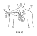
- FIG. 12 is a perspective view of a human having a pacemaker lead located in the venous system and a terminating electrode anchored to the ventricular heart chamber, with an embodiment of a surgical device being shown inserted into the body and partly advanced over the lead;
- FIG. 13 is an elevation view of an embodiment of a surgical device
- FIG. 14 is a cross-sectional view of a sheath assembly within a blood vessel with an extendable and rotatable blade for removing a lead according to an embodiment of the disclosure
- FIG. 15A is an internal view of an embodiment of a handle assembly of the surgical device illustrated in FIG. 13 ;
- FIG. 15B is a perspective view of an embodiment of a trigger for the handle assembly illustrated in FIG. 15A ;
- FIG. 15C is an elevation view of an embodiment of the barrel cam assembly for the handle assembly illustrated in FIG. 15A ;
- FIG. 15D is an elevation view of a barrel cam cylinder of the barrel cam assembly illustrated in FIG. 15C ;
- FIG. 15E is an illustration of the cam slot profile of the cam slot of the barrel cam cylinder illustrated in FIG. 15D ;
- FIG. 15F is a longitudinal-sectional view of the barrel cam cylinder illustrated in FIG. 15D ;
- FIG. 15G is a cross-sectional view of the barrel cam cylinder illustrated in FIG. 15D ;
- FIG. 15H is an elevation view of a follower guide of the barrel cam assembly illustrated in FIG. 15C
- FIG. 15I is an illustration of the aperture profile of the follower guide illustrated in FIG. 15H ;
- FIG. 15J is an end view of the barrel cam assembly of FIG. 15C illustrating a relative rotation-inhibiting mechanism in a first relative rotation-inhibiting position
- FIG. 15K is an end view of the barrel cam assembly of FIG. 15C illustrating the relative rotation-inhibiting mechanism in a second relative rotation-inhibiting position
- FIG. 15L is an enlarged perspective view of an embodiment of a spring assembly for the handle assembly illustrated in FIG. 15A ;
- FIG. 16 is an elevation view of an embodiment of the sheath assembly
- FIG. 16A is a break-away, elevation view of an embodiment of the distal end of the sheath assembly illustrated in FIG. 16 ;
- FIG. 16B is a break-away, elevation view of an embodiment of the proximal end of the sheath assembly illustrated in FIG. 16 ;
- FIG. 17A is an elevation view of an embodiment of the outer sheath assembly
- FIG. 17B is an elevation view of an embodiment of the inner sheath assembly
- FIG. 18 is a cross-sectional view of an embodiment of the sheath assembly illustrated in FIG. 16 ;
- FIG. 18A is an enlarged cross-sectional view of the distal end of the inner sheath assembly located within the outer sheath assembly illustrated in FIG. 18 , wherein the blade is retracted and located within the outer sheath assembly;
- FIG. 18A ′ is an enlarged cross-sectional view of the distal end of the inner sheath assembly located within the outer sheath assembly illustrated in FIG. 18 , wherein the blade is extended and located outside the outer sheath assembly;
- FIG. 18B is a distal end view of the inner sheath assembly located within the outer sheath assembly illustrated in FIG. 18 ;
- FIG. 18C is an enlarged cross-sectional view of the inner key of the inner sheath assembly located within the outer key of the outer sheath assembly illustrated in FIG. 18 ;
- FIG. 19A is a perspective view of an outer band member according to an embodiment of the disclosure.
- FIG. 19B is an end view of the outer band member illustrated in FIG. 19A ;
- FIG. 19C is cross-sectional view of the outer band member illustrated in FIG. 19A taken along line 19 C- 19 C of FIG. 19B ;
- FIG. 20A is a perspective view of a cutting tip according to an embodiment of the disclosure.
- FIG. 20B is side view of the cutting tip illustrated in FIG. 20A ;
- FIG. 20C is end view of the cutting tip member illustrated in FIG. 20A ;
- FIG. 20D is cross-sectional view of the cutting tip illustrated in FIG. 20A taken along line 20 D- 20 D in FIG. 20C ;
- FIG. 21 depicts two-dimensional illustrations of a profile of a cam slot of an embodiment of a cutting tip, a profile of a cam slot of an embodiment of a barrel cam cylinder, and a profile of an aperture of an embodiment of a follower guide;
- FIG. 22A is an illustration of the cam slot profile of the cutting tip, the cam slot of the barrel cam cylinder, and the profile of the aperture of the follower guide depicting the longitudinal position of the cutting tip in combination with the longitudinal position of the trigger for a particular amount of angular rotation by both the cutting tip and the barrel cam cylinder; the follower guide is illustrated in a first relative rotation-inhibiting position compared to the barrel cam cylinder;
- FIG. 22B is another illustration of the cam slot profile of the cutting tip, the cam slot of the barrel cam cylinder, and the profile of the aperture of the follower guide depicting the longitudinal position of the cutting tip in combination with the longitudinal position of the trigger for a particular amount of angular rotation by both the cutting tip and the barrel cam cylinder; the follower guide is illustrated in a second relative rotation-inhibiting position compared to the barrel cam cylinder;
- FIG. 22C is another illustration of the cam slot profile of the cutting tip, the cam slot of the barrel cam cylinder, and the profile of the aperture of the follower guide depicting the longitudinal position of the cutting tip in combination with the longitudinal position of the trigger for a particular amount of angular rotation by both the cutting tip and the barrel cam cylinder; the follower guide is again illustrated in the first relative rotation-inhibiting position compared to the barrel cam cylinder;
- FIG. 23A is an elevation view of the barrel cam assembly illustrated in FIG. 15C in its first home position
- FIG. 23B is an elevation view of the barrel cam assembly illustrated in FIG. 15C upon being rotated away from its first home position;
- FIG. 23C is an elevation view of the barrel cam assembly illustrated in FIG. 15C upon being rotated further away from its first home position;
- FIG. 23D is an elevation view of the barrel cam assembly illustrated in FIG. 15C in its second home position
- FIG. 23E is an elevation view of the barrel cam assembly illustrated in FIG. 15C upon being rotated away from its second home position;
- FIG. 23F is an elevation view of the barrel cam assembly illustrated in FIG. 15C upon being rotated further away from its second home position;
- FIG. 24 is a perspective view of an embodiment of the barrel cam assembly for a surgical device
- FIG. 25 is an exploded perspective view of the barrel cam assembly of FIG. 24 ;
- FIG. 26 is a side view of a barrel cam cylinder of the barrel cam assembly of FIG. 24 ;
- FIG. 27 is a side view of a follower guide of the barrel cam assembly of FIG. 24 ;
- FIG. 28 is another side view of the follower guide of FIG. 24 ;
- FIG. 29 is a partial perspective view of an embodiment of the barrel cam assembly for a surgical device.
- FIG. 30 is another partial perspective view of the barrel cam assembly of FIG. 29 ;
- FIG. 31 is a perspective view of an embodiment of the barrel cam assembly for a surgical device; a follower guide of the barrel cam assembly is translucent for illustrative purposes;
- FIG. 32 is a perspective view of an embodiment of the barrel cam assembly for a surgical device; a follower guide of the barrel cam assembly is translucent for illustrative purposes;
- FIG. 33 is a perspective view of an embodiment of the barrel cam assembly for a surgical device; hidden features are shown in light gray lines;
- FIG. 34 is another perspective view of the barrel cam assembly of FIG. 33 ;
- FIG. 35 depicts two-dimensional illustrations of a profile of a cam slot of an embodiment of a cutting tip, a profile of a cam slot of an embodiment of a barrel cam cylinder, and a profile of an aperture of an embodiment of a follower guide;
- FIG. 36A is an illustration of the cam slot profile of the cutting tip, the cam slot of the barrel cam cylinder, and the profile of the aperture of the follower guide depicting the longitudinal position of the cutting tip in combination with the longitudinal position of the trigger for a particular amount of angular rotation by both the cutting tip and the barrel cam cylinder; the follower guide is illustrated in a first relative rotation-inhibiting position compared to the barrel cam cylinder;
- FIG. 36B is another illustration of the cam slot profile of the cutting tip, the cam slot of the barrel cam cylinder, and the profile of the aperture of the follower guide depicting the longitudinal position of the cutting tip in combination with the longitudinal position of the trigger for a particular amount of angular rotation by both the cutting tip and the barrel cam cylinder; the follower guide is illustrated in a second relative rotation-inhibiting position compared to the barrel cam cylinder;
- FIG. 36C is another illustration of the cam slot profile of the cutting tip, the cam slot of the barrel cam cylinder, and the profile of the aperture of the follower guide depicting the longitudinal position of the cutting tip in combination with the longitudinal position of the trigger for a particular amount of angular rotation by both the cutting tip and the barrel cam cylinder; the follower guide is again illustrated in the first relative rotation-inhibiting position compared to the barrel cam cylinder; and
- FIG. 37 depicts a two-dimensional illustration of a profile of a cam slot of an embodiment of a barrel cam cylinder.
- Embodiments according to this disclosure provide a surgical device that includes a sheath assembly, which can be deployed safely within a vascular system of a patient and separate implanted objects, such as leads, from a patient's vasculature system.
- FIG. 1 depicts a surgical device 106 having a sheath assembly 112 inserted within an exemplary patient 104 .
- the sheath assembly 112 surrounds an implanted lead (not shown) running along the left innominate vein past the SVC and connected into, or about, the right ventricle of the heart.
- the user of the surgical device 106 may actuate the handle assembly 108 , thereby rotating and extending a cutting blade (not shown) beyond the distal end of the sheath assembly 112 to dilate, separate and/or cut the tissue surrounding the lead within the patient's SVC.
- the cutting blade may extend from and retract into the sheath multiple times upon actuation of the handle assembly according to the profile of the cam slot in the cutting tip disclosed below.
- the cutting blade may also rotate in both a clockwise and counter-clockwise direction per the profile of the cam slot in the barrel cam cylinder discussed below.
- the proximal portion of the implanted lead and/or surrounding tissue enters further into a hollow passageway within the sheath assembly 112 . This process is again repeated until the implanted lead and/or surrounding tissue is completely or substantially dilated, separated, and/or cut from the tissue attached to the SVC. At that time, the implanted lead may safely be removed from the patient's SVC.
- the surgical device 106 includes a handle assembly 108 and a flexible sheath assembly 112 .
- the flexible sheath assembly 112 which is discussed in more detail below, generally includes a flexible inner sheath assembly (not shown) located within a flexible outer sheath assembly. It may be preferable for the outer sheath to remain stationary while the inner sheath is capable of moving (e.g., rotating and extending) with respect to the outer sheath.
- the inner sheath and outer sheath can both be flexible, rigid or a combination thereof.
- the handle assembly 108 may include some or all of the following components: a handle frame 404 , a trigger 408 , a spring assembly 412 , a strain relief component 416 , a barrel cam cylinder 420 , a bushing 424 and an end cap 427 .
- the handle frame 404 may be constructed of a singular component or multiple component, such as two halves as illustrated in FIG. 4A .
- the trigger 408 depicted in FIG. 4A includes one opening 430 into which a clinician can insert his/her fingers.
- a trigger may have more than one opening.
- a trigger may also be comprised of a straight or non-linear member without any openings.
- a trigger may be in the shape of a button capable of being depressed. As long as the trigger, either alone or in conjunction with the handle frame, is ergonomically correct and comfortable for the clinician, the trigger may have a variety of sizes and shapes.
- the trigger 408 illustrated in FIG. 4B includes a trigger pin 428 that extends vertically from the top of the trigger 408 .
- the trigger pin 428 may be formed of a metal, such as a copper alloy (for example, brass or bronze, particularly C 630 nickel aluminum bronze), and may include a frusto-conically shaped end to facilitate insertion into the handle frame 404 .
- the trigger pin 428 which cooperates with the groove in the barrel cam cylinder 420 , acts as a follower for the barrel cam.
- the trigger 408 also includes a pair of sliders 432 protruding laterally from the proximal end of the trigger 408 and a pair of sliders 436 protruding laterally from the distal end of the trigger 408 .
- the trigger 408 When the trigger 408 is located within the handle assembly 108 , the sliders 432 , 436 sit and slide in corresponding grooves within the handle frame 404 .
- the trigger 408 also includes a post 440 extending vertically from the top of trigger 408 , and preferably from the distal end of the top of the trigger 408 .
- the post 440 connects to spring assembly 412 .
- the handle assembly 108 including the trigger 408 and barrel cam cylinder 420 discussed above is an example of a mechanical actuation means to rotate the inner sheath assembly.
- the actuation means may comprise electromechanical components.
- the actuation means may comprise an electric motor (not shown) having a driven shaft that is directly or indirectly coupled to the inner sheath, the barrel cam cylinder, the trigger pin, and/or any combination thereof.
- the motor's shaft may be indirectly coupled to the inner sheath by one or more gears discussed hereinbefore.
- the motor may be controlled by a switch, thereby causing the inner sheath to rotate in a clockwise and/or a counter-clockwise direction upon actuating a switch that may also act as the trigger.
- the electric motor may be either a direct current (DC) motor or an alternating current (AC) motor. Accordingly, the motor may be powered by a DC source, such as a battery, or an AC source, such as a conventional power cord. Additionally, those skilled in the art will appreciate that there are numerous other ways in which a surgical device comprising a rotatable sheath may be actuated and driven.
- the handle assembly 108 may include a strain relief component 416 .
- the strain relief component 416 as illustrated in FIG. 4A , is attached to the distal end of the handle frame 404 and tapers from its proximal end toward its distal end.
- the strain relief component 416 also has a lumen passing through it, thereby allowing the sheath assembly 112 to extend there through and into the handle assembly 108 .
- the strain relief component 416 may be constructed of a flexible material such as, SantopreneTM thermoplastic vulcanizate produced by ExxonMobil.
- the material from which the strain relief component is made and the shape of the strain relief component provide a flexural modulus to protect the flexible shaft as it extends the rigid handle.
- the lumen of the strain relief may also contain a counter bore that enables ancillary outer sheaths to be docked during device preparations.
- the barrel cam cylinder 420 has an exterior surface comprising a cam slot (or channel) 444 that cooperates with the trigger pin 428 to create the barrel cam.
- the cam slot 444 may create a two dimensional linear and/or non-linear cam profile, which is discussed in further detail below.
- the barrel cam cylinder 420 has a proximal end 448 and a distal end 452 through which a lumen 456 extends.
- FIG. 4E illustrates the end view of the distal end 452 of the barrel cam cylinder 420 .
- the distal end 452 of the lumen 456 of the barrel cam cylinder 420 is designed to mate with exterior of the proximal end of the inner key 612 , which is discussed in further detail below.
- the cross section of the distal end 452 of the lumen 456 of the barrel cam cylinder 420 is preferably non-circular.
- one embodiment of a non-circular lumen includes two chamfered sides 464 , wherein one chamfered side 464 is not offset, and the other chamfered side 464 is offset (e.g., about 8 degrees).
- the cross section of the exterior of proximal end of the inner key 612 will have a complimentary profile of the lumen 456 .
- the cross sectional shape of the non-circular lumen is described as having two chamfered sides 464 , the disclosure shall not be limited to such shape and may include alternative non-circular shapes, such as a square, rectangle, D-shape, triangle, rhombus, trapezoid, pentagon, hexagon, octagon, parallelogram, ellipse, etc.
- the inner key could couple to the outside of the barrel cam cylinder.
- the proximal end of the barrel cam cylinder 420 mates with the bushing 424 .
- the exterior, distal end of the bushing 424 is located within the proximal end of the lumen 456 .
- Both the exterior, distal end of the bushing 424 and the proximal end of the lumen 456 are circularly shaped, thereby allowing the bushing 424 and the barrel cam cylinder 420 to rotate with respect to one another.
- the proximal end of the exterior of the bushing 424 is located within a groove within the handle frame 404 , thereby preventing the bushing 424 and the barrel cam cylinder 420 from moving longitudinally within the handle assembly 108 .
- the spring assembly 412 includes a constant force spring 472 and a spool 474 .
- One end of the constant force spring 472 is connected to the spool 474
- the other end of the constant force spring 472 is connected to the post 440 extending from the trigger 408 .
- the sliders 432 , 436 travel and slide in the grooves within the handle frame 404 , thereby preventing the trigger 408 from moving vertically within the handle assembly 108 and only allowing the trigger 408 to move along the longitudinal axis of the surgical device 106 from its distal end toward its proximal end and/or vice versa.
- the constant force spring 472 uncoils, thereby creating tension and a distally directed force. Accordingly, when the trigger 408 is released by the clinician, the constant force spring 472 recoils and pulls the trigger 408 back towards its original and most distal position.
- FIG. 6 there is depicted an elevation view of an embodiment of an assembled sheath assembly 112 of the present disclosure.
- the sheath assembly 112 includes an inner sheath assembly and an outer sheath assembly.
- FIG. 6A which illustrates an exploded view of the distal end of the sheath assembly 112 , and referring to FIG.
- the sheath assembly 112 may include may include some or all of the following components: an outer band 636 ; a guide pin 640 ; a cutting tip 632 ; a flexible inner sheath 620 ; a flexible outer sheath 624 ; an outer jacket 628 ; an inner key 612 ; an outer key 608 ; and a rigid inner tube 616 .
- the outer sheath assembly 602 includes an outer band 636 located at and attached to the distal end of an elongated flexible outer sheath 624 , and an outer key 608 located at and attached to the proximal end of the flexible outer sheath 624 .
- the outer band 636 may be attached to the distal end of a flexible outer sheath 624 via a weld, an adhesive, a press-fitting technique, an interlock such as a barbed joint or other known means of attachment. All such attachment techniques within the knowledge of one skilled in the art are considered within the scope of this disclosure.
- the outer key 608 may be attached to the proximal end of the flexible outer sheath 624 via a weld, an adhesive, a press-fitting technique, interlock such as a barbed joint, or other known means of attachment.
- the outer sheath assembly may also include a flexible outer jacket 628 that covers the outer sheath 624 and abuts the outer band 636 , thereby providing the outer sheath assembly with a relatively smooth, continuous and uninterrupted exterior profile.
- the flexible jacket also contains the egress of blood from the system.
- the inner sheath assembly 604 includes a cutting tip 632 , a flexible inner sheath 620 , an inner key 612 , and a rigid inner tube 616 .
- the proximal end of the cutting tip 632 is attached to the distal end of a flexible inner sheath 620 ; the distal end of an inner tube 616 is attached to the proximal end of the flexible inner sheath 620 ; and an inner key 612 is attached to the proximal end of the inner tube 616 .
- the means of attaching these components may include a weld, an adhesive, a press-fitting technique, or other known means of attachment.
- the guide pin 640 couples the outer band 636 with the cutting tip 632 , and the guide pin 640 may be includes with either the inner sheath assembly 604 or the outer sheath assembly 602 .
- a portion of either the inner sheath 620 and/or the outer sheath 624 may be rigid and a portion of the outer sheath to be flexible.
- Both the rigid portion and the flexible portion may be constructed of materials suitable for insertion into the human body.
- the rigid portion may be constructed of stainless steel
- the flexible portion may be constructed of a flexible polymer such as polytetrafluoroethylene or thermoplastic elastomers. Assuming that both a rigid portion and a flexible portion are used, they will form a unitary inner sheath and/or outer sheath. As depicted in FIG.
- the rigid inner tube 616 is not only attached to the inner key 612 , the rigid tube 616 also is inserted through the inner key 612 and extends from both the proximal end and distal end of the inner key 612 .
- the attachment and extension of the rigid tube 616 to the inner key 612 allows for an increased amount of torque that can be transferred from the barrel cam to the rigid tube 616 via the inner key 612 and eventually to the cutting tip 632 via the inner sheath assembly 604 .
- the extension of the rigid tube through the handle provides an access point for introduction of other medical devices.
- the extension also provides a means of controlling blood egress after the lead has been extracted.
- the outer sheath 624 and the inner sheath 620 be generally flexible in order to accept, accommodate and navigate the patient's vasculature system.
- the inner sheath 620 may also have a high degree of stiffness in order to receive the torque transferred from the barrel cam cylinder/inner key and transfer sufficient torque to the cutting tip 632 discussed in more detail below.
- the inner sheath 620 (and/or the outer sheath 624 ) may be formed of a polymer extrusion, braided reinforced polymer extrusion, coils, bi-coils, tri-coils, laser cut metal tubing and any combination of the above.
- the inner sheath (and/or the outer sheath 624 ) may be a unitary structure comprised of multiple portions.
- FIG. 8 there is depicted a cross-sectional view of an embodiment of the sheath assembly 112 comprising the inner sheath assembly 604 located within the outer sheath assembly 602 .
- FIG. 8C there is depicted an enlarged view of the inner key 612 of the inner sheath assembly 604 located within the outer key 608 of the outer sheath assembly 602 .
- the exterior of the inner key 612 is designed to mate with lumen 456 of the distal end of the barrel cam cylinder 420 . Accordingly, the cross section of the exterior of proximal end of the inner key 612 will have a profile complimentary to the distal end of the lumen 456 within the barrel cam cylinder 420 .
- the exterior of the proximal end of the inner key 612 will also have a non-circular profile with two chamfered sides, wherein one chamfered side is not offset, and the other chamfered side is offset (e.g., about 8 degrees).
- the inner key 612 and outer key 608 provide means for rotationally coupling.
- the inner key 612 is a means for rotationally coupling the inner sheath assembly 604 to the barrel cam
- the outer key is a means for rotationally coupling the outer shaft assembly to the handle.
- the inner key 612 and outer key 608 provide journal bearing for the other key.
- the inner key 612 is able to rotate freely within the outer key 608 due, at least in part, to the distal end of the exterior of the inner key 612 having a circular cross section that mates with a circular cross section of the proximal end of a lumen within the outer key 608 . Additionally, because the inner key 612 and outer key 608 are loosely coupled, the inner key 612 and outer key 608 are able to move longitudinally with respect to one another. For instance, supposing the outer key 608 is fixed such that it neither rotates nor moves longitudinally, the inner key 612 is able to both rotate and travel longitudinally within the outer key 608 .
- the inner key 612 will rotate within the outer key 608
- the inner sheath assembly 604 will rotate within the outer sheath assembly 602 , including the rotation of the cutting tip 632 within the outer band 636 .
- the cam slot profile in the cutting tip 632 controls the longitudinal movement of the inner sheath assembly 604 within the outer sheath assembly 602 , including the longitudinal movement of the inner key 612 relative to the outer key 608 and the longitudinal movement of the cutting tip 632 relative to the outer band 636 .
- the lumen within the outer key 608 is larger toward its proximal end and smaller toward its distal end because there is a step down or an abutment in the lumen as it progresses from the proximal end to the distal end. Due to the transition from a larger lumen to a smaller lumen within the outer key 608 , there is depicted an adjustable gap 610 between the distal end of the inner key 612 and the abutment within the distal end of the larger lumen in the outer key 608 . This gap increases, decreases and/or remains the same according to the cam slot profile of the cutting tip 632 .
- the abutment in the outer key 608 insures that the inner key 612 will only travel a limited longitudinal distance within the outer key 608 , thereby limiting the inner sheath assembly 604 potential longitudinal movement within the outer sheath assembly 602 , including limiting the longitudinal movement of the cutting tip 632 relative to the outer band 636 in the distal direction.
- FIG. 8A there is depicted an enlarged cross-sectional view of the distal end of the sheath assembly 112 with the inner sheath assembly 604 coupled with the outer sheath assembly 602 via guide pin 640 , wherein the blade 822 of the cutting tip 632 is in a retracted position and located within the outer sheath assembly 602 .
- the distal end of the outer sheath assembly 602 includes an outer band 636 , which may be constructed of a biocompatible metal, such as stainless steel, and polished so that it is generally smooth and evenly rounded at its most distal point, thereby allowing it to act as a dilator when pressed and forced against tissue.
- the distal end 822 of cutting tip 632 includes a cutting surface capable of cutting tissue.
- the inner sheath assembly 604 is coupled to the outer sheath assembly 602 through the cutting tip 632 and the outer band 636 , respectively, via guide pin 640 .
- One end of the guide pin 640 is fixed within the outer band 636 , and the other end of the guide pin 640 is located within the cam slot 814 of the cutting tip 632 .
- the cutting tip 632 also rotates because the inner sheath 620 is fixedly attached to the cutting tip 632 .
- the cutting tip 632 may also extend distally in the direction of the arrow ( ⁇ ) according to the profile of the cam slot 814 as depicted in FIG. 8A ′.
- the guide pin 640 and the outer sheath assembly 602 remain stationary.
- the cutting surface at the distal end 822 of the cutting tip 632 is able to perform a slicing action against the tissue and cut it.
- FIG. 8A depicts the cutting tip 632 within a retracted (and potentially un-actuated) position because the cutting tip 632 is in a proximal position.
- the distal end 822 of the cutting tip 632 of FIG. 8A is located within the interior of the outer sheath assembly 602 , particularly the outer band 636 , and does not extend beyond the distal end of the outer band 636 .
- the cutting tip 632 is depicted in an extended (and actuated) position because the cutting tip 632 is extending beyond the distal end of the outer sheath assembly 602 and the outer band 636 .
- FIG. 3 depicts the distal portion of the flexible outer sheath and flexible inner sheath of FIG. 8A surrounding a lead 330 within a patient's vein 334 with the cutting tip 632 in its extended position.
- the circumferential nature of the cutting surface (e.g., notched blade) at the distal end of the cutting tip 632 causes the surgical device to act as a coring device, thereby cutting tissue 338 either partially (i.e., less than 360 degrees) or completely (i.e., 360 degrees) around the lead or implanted object being extracted.
- the amount of tissue that the cutting surface cuts depends upon the size, shape and configuration of the lead, as well as the diameter and thickness of the circular cutting blade.
- the cutting surface will cut and core more tissue in comparison to a cutting surface having a smaller diameter.
- the operator releases trigger and the cutting tip 632 (including the cutting surface) returns to a retracted position.
- the distal tip of the outer band 636 (and/or other portions of the outer sheath assembly) safely acts as a dilating device, thereby stretching tissue as the outer sheath assembly move over the lead or implanted object to be extracted.
- the cutting tip (and inner sheath) With each full squeeze of the trigger, the cutting tip (and inner sheath) will rotate clockwise and counterclockwise while extending and retracting. The cutting tip (and inner sheath) retracts into the tip of the outer sheath when the trigger is fully compressed and/or remains retracted at the release of the trigger after a full squeeze of the trigger. If the trigger is partially squeezed, it will not reset and the cutting tip (and inner sheath) will reverse its motion upon release of the trigger, returning the blade to the retracted position. The return to the fully returned trigger position results in a rotation of about 35 degrees that due to the profile at the distal cam, which retains the cutting in the sheathed position.
- the inner sheath and outer sheath are coupled to one another via the cutting tip, the outer band, and the guide pin
- the inner sheath assembly and outer sheath assembly may be coupled to one another in other ways.
- those of skill in the art will understand how to make and use the disclosed aspects, embodiments, and/or configurations after understanding the present disclosure to couple the sheaths in a manner to allow a cutting surface to extend and rotate beyond the distal end of the outer sheath. All such configurations within the knowledge of one skilled in the art are considered within the scope of this disclosure.
- the outer band 636 may be a sleeve in the general shape of a hollow cylinder. Although the exterior of the outer band 636 is non-uniform, it may be uniform. The interior of the outer band 636 is non-uniform. For example, the interior of the outer band 636 includes an abutment 916 to prevent the cutting tip (not shown in FIGS. 9A, 9B and 9C ) from traveling further from the proximal end 912 to the distal end 908 within the outer band 636 .
- the outer band 636 also includes a hole 904 for receipt and possible attachment of a guide pin (not shown in FIGS.
- the guide pin engages the cam slot of the cutting tip.
- the size, shape and configuration of the outer band 636 may differ depending upon how it is attached to the flexible outer sheath. As discussed above, the outer sheath may be stationary. If so, the outer band 636 and the guide pin remain stationary as the cutting tip moves (e.g., rotates and travel longitudinally) relative thereto.
- the outer band may also contain a journal bearing surface to align the cutting blade during actuation and provide a surface to disengage the tissue at the retraction of the cutting blade within the device.
- the cutting tip 632 has a generally hollow cylindrical shape.
- the cutting tip 632 comprises a proximal portion 1024 , an intermediate portion 1028 , and a distal portion 1032 .
- the outside diameter of the proximal portion 1024 is sized to allow it to be inserted to and/or engage (or otherwise attached to) the interior diameter of the inner flexible sheath (not shown in FIGS. 10A, 10B, 10C and 10D ).
- the distal end of cutting tip 632 comprises a cutting surface 1012 having a serrated, sharp blade profile.
- the intermediate portion 1028 comprises a channel (or cam slot) 1016 cut within its exterior surface.
- the outer sheath and pin may remain stationary. If so, the inner sheath (not shown), which is connected to cutting tip 632 , forces the cutting tip 632 to rotate.
- the cam slot 1016 engages the guide pin, and the shape and profile of the cam slot 1016 controls the rate and distance with which the cutting tip 632 travels longitudinally. That is, the configuration of the cam slot 1016 controls the cutting tip's direction and amount of longitudinal travel, such as moving distally toward an extended position and/or proximally toward a retracted position, while the cutting tip 632 rotates in either a clockwise or counter-clockwise direction.
- the cutting tip 632 may also comprise a step up 1020 such that the diameter of the intermediate portion 1028 is greater than the distal portion 1032 .
- the step up 1020 of the cutting tip 632 contacts the abutment of the outer band, thereby limiting the distance that the cutting tip 632 may travel and/or may prevent the cutting tip 632 from exiting or extending beyond the distal tip of the outer sheath assembly, particularly the outer band, in the event that the pin is sheared.
- the profile of the cam slot in the cutting tip may have various configurations, such as those disclosed in U.S. patent application Ser. No. 13/834,405 filed Mar. 15, 2013 and entitled Retractable Blade For Lead Removal Device, which is hereby incorporated herein by reference in its entirety for all that it teaches and for all purposes.
- the cam slot may have a substantially linear profile, a substantially sinusoidal profile, or a combination of individual and/or multiple linear and non-linear profiles.
- the cam slot may have an open and continuous configuration, thereby allowing the cutting tip to continuously rotate, or the cam slot may have a closed and discontinuous configuration such that when the cutting tip reaches its fully extended position, the trigger assembly must be released or reversed so that the cutting tip returns to initially retracted position before being re-actuated.
- the cam slot 1016 in FIG. 10A is discontinuous because the cam slot does not travel around the entire circumference of the exterior of the cutting tip 632 .
- cams such as a partial lobe cam (which includes a cam slot surrounding less than 360 degrees of the circumference of the exterior surface of the cutting tip), a single lobe cam (which includes a cam slot surrounding 360 degrees of the circumference of the exterior surface of the cutting tip), double lobe cams (which includes a cam slot surrounding 720 degrees of the circumference of the exterior surface of the cutting tip) and/or other multiple lobe cams.
- the distal end of cutting tip 632 may comprise a cutting surface 1012 having different blade profiles, such as those disclosed in U.S. patent application Ser. No. 13/834,405 filed Mar. 15, 2013 and entitled Retractable Blade For Lead Removal Device, which is hereby incorporated herein by reference in its entirety for all that it teaches and for all purposes.
- the plane of the cutting surface 1012 of the distal end of the cutting tip depicted in the figures of this disclosure is parallel to the plane of the proximal end of the cutting tip.
- the plane of the cutting surface may be offset (0 degrees to 90 degrees) from the plane of the proximal end of the cutting tip.
- the profile of the cutting surface 1012 need not be serrated and may comprise other configurations, such as a constant and/or smooth sharp profile.
- the profile of the cutting surface 1012 in FIGS. 10A-10D has a plurality of six (6) serrations. However, it may be preferable to have less than or more than six (6) serrations. It may also be preferable to have between five (5) and seven (7) serrations, or between four (4) and eight (8) serrations, or between six (6) and ten (10) serrations.
- FIGS. 10A-10D are not intended to represent the only number and type of serrations that may be included in a serrated cutting surface.
- the size of the surgical device, including the sheaths, and cutting tip those of skill in the art will understand how to make and use the disclosed aspects, embodiments, and/or configurations after understanding the present disclosure to adjust the number, size and configurations of the serrations. All such configurations within the knowledge of one skilled in the art are considered within the scope of this disclosure.
- the serrations may comprise a myriad of different shapes and configurations, including but not limited to any variation of a square, rectangle, rhombus, parallelogram, trapezoid, triangle, circle, ellipse, kite, etc.
- FIGS. 10A, 10B and 10D depict the intermediate portion 1028 of the cutting tip 632 having a cam slot (or channel) 1016 cut within its exterior surface
- FIGS. 4C and 4D depict the barrel cam cylinder 420 having a channel (or cam slot) 444 on its exterior surface that creates a non-linear cam profile.
- FIG. 11 there is depicted a two-dimensional illustration of the profile of the cam slot 1016 for the cutting tip 632 at the top of the figure and a two-dimensional illustration of the profile of the cam slot 444 for the barrel cam cylinder 420 at the bottom of the figure.
- the horizontal axis which is the same for the top illustration and the bottom illustration, is the degree(s) of rotation of the cutting tip 632 and the barrel cam cylinder 420 .
- the cutting tip 632 will rotate less than 360 degrees. It may be preferable for the cutting tip 632 to rotate between 5 and 355 degrees, 180 degrees and 355 degrees, 210 degrees and 325 degrees, 240 degrees and 295 degrees, or 270 degrees and 275 degrees.
- the cutting tip 632 may also be preferable for the cutting tip 632 rotate about 180, 185, 190, 200, 205, 210, 215, 220, 225, 230, 235, 240, 245, 250, 255, 260, 265, 270, 275, 280, 285, 290, 300, 305, 310, 315, 320, 325, 330, 335, 340, 345, 350 or 355 degrees.
- the first half of a trigger pull results in about a 273° rotation in one direction—clockwise when looking from the handle to the tip—thereby returning the cam blade to the sheathed position.
- the second half of the trigger pull results in about a 273° in the opposite direction—counter-clockwise when looking from the handle to the tip—thereby, returning the cutting blade to the sheathed position again.
- the blade remains in the sheathed position for the full return of the trigger to the forward position.
- the vertical axis for the top illustration is the amount of longitudinal movement, if any, of the cutting tip 632 including its cutting surface.
- the vertical axis for the bottom illustration is the amount of longitudinal displacement (in inches) of the trigger assembly (and trigger pin).
- the positions CT 1 -CT 6 of the guide pin 640 within the cam slot of the cutting tip 632 correspond with positions BC 1 -BC 6 of the trigger pin 428 within the cam slot of the barrel cam cylinder 420 .
- the trigger pin 428 when the trigger assembly 106 , particularly the trigger 408 , is at its initial, distal position, the trigger pin 428 is at its home position (BC 1 ).
- the guide pin 640 in the sheath assembly 112 is at its initial position (CT 1 ), and the cutting tip 632 is at a retracted (or recessed) position within the outer sheath assembly 602 .
- both the barrel cam cylinder 420 and the cutting tip 632 rotate in a clockwise direction (from the proximal perspective of barrel cam cylinder).
- the profile of the cam slot in the cutting tip 632 causes the cutting tip 632 to move longitudinally in a distal direction from a retracted position to an extended position.
- the trigger pin 428 continues to move proximally, and the barrel cam cylinder 420 and the cutting tip 632 continue to rotate in a clockwise direction.
- the cutting tip 632 rotates adjacent the guide pin 640 , and the profile of the cam slot in cutting tip 632 causes the cutting tip 632 to move longitudinally from position CT 2 , which is an extended position, to CT 3 , which is a recessed position.
- the cam slot in the cutting tip 632 extends beyond position CT 3 .
- the inner sheath assembly and outer sheath assembly may both be flexible.
- the cam slot 1016 in the cutting tip 632 extends beyond position CT 3 .
- the home position of the guide pin 640 is slightly to the right of position CT 1 , rather than exactly at position CT 1 , then the extended length of the cam slot allows the guide pin 640 to travel to the right of position CT 3 , thereby allowing the cutting tip to rotate its total amount of allowable rotation in the clockwise direction without obstruction.
- the trigger pin 428 moves from position BC 1 to BC 3 in the barrel cam cylinder 420 , and the barrel cam cylinder 420 rotates in a clockwise direction, the trigger pin 428 rides along the inside edge of the cam slot 444 in the barrel cam cylinder 420 .
- the barrel cam cylinder 420 rotates in a counter-clockwise direction, and the trigger pin 428 rides along the outside edge of the cam slot 444 in the barrel cam cylinder 420 .
- the trigger assembly 106 When the guide pin 640 reaches position CT 3 in the cutting tip 632 and the trigger pin 428 reaches position BC 3 in the barrel cam cylinder 420 , the trigger assembly 106 , particularly the trigger 408 , has only travelled about half of its predetermined allowable distance in the longitudinal direction. As the user continues to pull the trigger assembly 106 , the trigger 408 and trigger pin 428 continue to move proximally. As this occurs, the barrel cam cylinder 420 and the cutting tip 632 switch from rotating in a clockwise direction to rotating in a counter-clockwise direction.
- the cutting tip 632 switches from rotating in a clockwise direction to a counter-clockwise direction as the cutting tip 632 moves past position CT 3 to CT 4 adjacent the guide pin 640 , the cutting tip 632 moves from a retracted position within the outer sheath assembly 602 (including the outer band 636 ) to an extended position or partially extended position outside the outer sheath assembly 602 (including the outer band 636 ).
- the trigger pin 428 is at position BC 4
- the barrel cam cylinder 420 and the cutting tip 632 have rotated counter-clockwise for slightly less than half (or half) of its predetermined allowable distance
- the guide pin 640 is at position CT 4
- the cutting tip 632 is at its most extended position.
- the trigger pin 428 continues to move proximally from position BC 4 to position BC 5 in the barrel cam cylinder 420 , thereby causing the barrel cam cylinder 420 and cutting tip 632 to continue rotating in a counter-clockwise direction.
- the cutting tip 632 rotates adjacent the guide pin 640 from position CC 4 toward CC 6 , and the profile of the cam slot in the cutting tip 632 causes the cutting tip 632 to move from an extended position to a retracted position.
- the trigger pin 428 is located at position BC 5 in cam slot of the barrel cam cylinder 420 , the trigger 408 has reached the end of its longitudinal movement in the proximal direction.
- the constant force spring causes the trigger 408 and trigger pin 428 to reverse direction and travel toward its distal position.
- the cutting tip 432 rotates less than 360 degrees in either the clockwise or counter-clockwise direction. Assuming that the predetermined amount of allowable rotation is about 275 degrees, the amount of angular rotation by the barrel cam cylinder 420 in the clockwise direction from BC 1 to BC 3 and by the cutting tip 632 from CT 1 to CT 3 is about 275 degrees. The amount of angular rotation by the barrel cam cylinder 420 in the counter-clockwise direction from BC 3 to BC 5 and the cutting tip 632 from CT 3 to CT 3 is greater than 275 degrees by about nine degrees.
- This additional rotation (or over rotation) by the barrel cam cylinder 420 and the cutting tip 632 in the counter-clockwise direction ensures that the cutting tip 632 , including its cutting surface, is covered by the outer sheath assembly 602 , particularly the outer band 636 .
- the barrel cam cylinder 420 and cutting tip 632 continue to move in a counter-clockwise direction to position BC 6 and position CT 6 , respectively.
- barrel cam cylinder 420 rotates counter-clockwise form position BC 5 to BC 6 about 17 degrees, thereby causing the cutting tip 632 to rotate counter-clockwise the same amount from position CT 5 (not shown) to position CT 6 , which is the cutting tip's most recessed position.
- the cutting tip 632 (and barrel cam cylinder 420 ) have rotated a net 273.1 degrees in the clockwise direction in a retracted(home)-extended-retracted sequence of positions and 273.1 degrees in the counter-clockwise direction a retracted-extended-retracted(home) sequence of positions, even though the cutting tip 632 (and barrel cam cylinder 420 ) rotated in both a counter-clockwise direction and a clockwise direction in a retracted-extended-retracted (home) sequence of positions.
- the user may then repeat the process, if so desired.
- Embodiments according to this disclosure provide a surgical device that includes a sheath assembly, which can be deployed safely within a vascular system of a patient and separate implanted objects, such as leads, from a patient's vasculature system.
- FIG. 12 depicts a surgical device 1206 having a sheath assembly 1212 inserted within an exemplary patient 1204 .
- the sheath assembly 1212 surrounds an implanted lead (not shown) running along the left innominate vein past the SVC and connected into, or about, the right ventricle of the heart.
- the user of the surgical device 1206 may actuate the handle assembly 1208 , thereby rotating and extending a cutting blade (not shown) beyond the distal end of the sheath assembly 1212 to dilate, separate and/or cut the tissue surrounding the lead within the patient's SVC.
- the cutting blade may extend from and retract into the sheath upon actuation of the handle assembly according to the profile of the cam slot in the cutting tip disclosed below.
- the cutting blade may rotate in a first, or clockwise, direction upon an initial, or first, actuation of the handle assembly per the profile of the cam slot in the barrel cam cylinder discussed below.
- the clinician releases the handle assembly the cutting blade is ensured to remain or return within the sheath assembly 1212 , thereby allowing the clinician to force and advance the distal portion of the sheath assembly against additional uncut tissue.
- the cutting blade may rotate in a second, or counter-clockwise, direction upon a subsequent, or second, actuation of the handle assembly per the profile of the cam slot in the barrel cam cylinder discussed below.
- the proximal portion of the implanted lead and/or surrounding tissue enters further into a hollow passageway within the sheath assembly 1212 . This process is again repeated until the implanted lead and/or surrounding tissue is completely or substantially dilated, separated, and/or cut from the tissue attached to the SVC. At that time, the implanted lead may safely be removed from the patient's SVC.
- the surgical device 1206 includes a handle assembly 1208 and a flexible sheath assembly 1212 .
- the flexible sheath assembly 1212 which is discussed in more detail below, generally includes a flexible inner sheath assembly (not shown) located within a flexible outer sheath assembly. It may be preferable for the outer sheath to remain stationary while the inner sheath is capable of moving (e.g., rotating and extending) with respect to the outer sheath.
- the inner sheath and outer sheath can both be flexible, rigid or a combination thereof.
- the handle assembly 1208 may include some or all of the following components: a handle frame 1504 , a trigger 1508 , a spring assembly 1512 , a strain relief component 1516 , a barrel cam assembly 1519 , a bushing 1524 and an end cap 1527 .
- the handle frame 1504 may be constructed of a singular component or multiple component, such as two halves as illustrated in FIG. 15A .
- the trigger 1508 depicted in FIG. 15B includes one opening 1530 into which a clinician can insert his/her fingers.
- a trigger may have more than one opening.
- a trigger may also be comprised of a straight or non-linear member without any openings.
- a trigger may be in the shape of a button capable of being depressed. As long as the trigger, either alone or in conjunction with the handle frame, is ergonomically correct and comfortable for the clinician, the trigger may have a variety of sizes and shapes.
- the trigger 1508 illustrated in FIG. 15B includes a trigger pin 1528 that extends vertically from the top of the trigger 1508 .
- the trigger pin 1528 may be formed of a metal, such as a copper alloy (for example, brass or bronze, particularly C 630 nickel aluminum bronze), and may include a frusto-conically shaped end to facilitate insertion into the handle frame 1504 .
- the trigger pin 1528 which cooperates with a groove in a barrel cam cylinder of the barrel cam assembly 1519 , acts as a follower for the barrel cam cylinder.
- the trigger 1508 also includes a pair of sliders 1532 protruding laterally from the proximal end of the trigger 1508 and a pair of sliders 1536 protruding laterally from the distal end of the trigger 1508 .
- the sliders 1532 , 1536 sit and slide in corresponding grooves within the handle frame 1504 .
- the trigger 1508 also includes a post 1540 extending vertically from the top of trigger 1508 , and preferably from the distal end of the top of the trigger 1508 .
- the post 1540 connects to the spring assembly 1512 .
- the handle assembly 1208 may include a strain relief component 1516 .
- the strain relief component 1516 as illustrated in FIG. 15A , is attached to the distal end of the handle frame 1504 and tapers from its proximal end toward its distal end.
- the strain relief component 1516 also has a lumen passing through it, thereby allowing the sheath assembly 1212 to extend there through and into the handle assembly 1208 .
- the strain relief component 1516 may be constructed of a flexible material such as, SantopreneTM thermoplastic vulcanizate produced by ExxonMobil.
- the material from which the strain relief component is made and the shape of the strain relief component provide a flexural modulus to protect the flexible shaft as it extends the rigid handle.
- the lumen of the strain relief may also contain a counter bore that enables ancillary outer sheaths to be docked during device preparations.
- the barrel cam assembly 1519 includes a barrel cam cylinder 1520 that rotatably carries a follower guide 1521 . As described in further detail below, the barrel cam cylinder 1520 and the follower guide 1521 cooperate with the trigger pin 1528 to create the barrel cam.
- the barrel cam cylinder 1520 may be formed from one or more biocompatible materials, such as polyethylene-filled Delrin®, stainless steel, anodized aluminum, brass, titanium, or the like. As illustrated in FIG. 15D , the barrel cam cylinder 1520 has an exterior surface comprising a cam groove (or slot or channel) 1544 that translatably receives the trigger pin 1528 .
- FIG. 15E depicts a two-dimensional illustration of the profile of the cam slot 1544 for the barrel cam cylinder 1520 .
- the cam slot 1544 defines a generally “hourglass”-like or “figure eight”-like path for the follower (that is, the trigger pin 1528 ).
- the trigger pin 1528 traverses about half of the cam slot 1544 when an initial, or first, actuation is applied to the trigger 1508 , and the trigger pin 1528 traverses the remainder of the cam slot 1544 (that is, about half of the cam slot 1544 ) when a subsequent, or second, actuation is applied to the trigger 1508 .
- the follower guide 1521 causes the trigger pin 1528 to travel straight through the intersection (or crossing portion) 1545 of the cam slot 1544 during each actuation of the trigger 1508 .
- the follower guide 1521 causes the trigger pin 1528 to travel from a first leg 1547 of the cam slot 1544 to a second parallel leg 1549 of the cam slot 1544 , and then from a third leg 1551 of the cam slot 1544 to a fourth parallel leg 1553 of the cam slot 1544 .
- FIGS. 15F and 15G illustrate a longitudinal-sectional view and a cross-sectional view, respectively, of the barrel cam cylinder 1520 .
- the barrel cam cylinder 1520 has a proximal end 1548 and a distal end 1552 through which a lumen 1556 extends.
- the distal end 1552 of the lumen 1556 of the barrel cam cylinder 1520 is designed to mate with exterior of the proximal end of the inner key 1612 , which is discussed in further detail below.
- the cross section of the distal end 1552 of the lumen 1556 of the barrel cam cylinder 1520 is preferably non-circular.
- one embodiment of a non-circular lumen includes two chamfered sides 1564 , wherein one chamfered side 1564 is not offset, and the other chamfered side 1564 is offset (e.g., about 8 degrees). Because the distal end of the barrel cam cylinder 1520 is designed to mate with exterior of the proximal end of the inner key 1612 and transfer torque from the barrel cam cylinder 1520 to the inner sheath assembly via the inner key 1612 , the cross section of the exterior of proximal end of the inner key 1612 will have a complimentary profile of the lumen 1556 .
- the cross sectional shape of the non-circular lumen is described as having two chamfered sides 1564 , the disclosure shall not be limited to such shape and may include alternative non-circular shapes, such as a square, rectangle, D-shape, triangle, rhombus, trapezoid, pentagon, hexagon, octagon, parallelogram, ellipse, etc.
- the inner key could couple to the outside of the barrel cam cylinder.
- the proximal end of the barrel cam cylinder 1520 mates with the bushing 1524 .
- the exterior, distal end of the bushing 1524 is located within the proximal end of the lumen 1556 .
- Both the exterior, distal end of the bushing 1524 and the proximal end of the lumen 1556 are circularly shaped, thereby allowing the bushing 1524 and the barrel cam cylinder 1520 to rotate with respect to one another.
- the proximal end of the exterior of the bushing 1524 is located within a groove within the handle frame 1504 , thereby preventing the bushing 1524 and the barrel cam cylinder 1520 from moving longitudinally within the handle assembly 1208 .
- the follower guide 1521 may be formed from one or more biocompatible materials, such as stainless steel, anodized aluminum, titanium, or the like. In some embodiments, the follower guide 1521 and the barrel cam cylinder 1520 have a relatively high coefficient of friction therebetween.
- the follower guide 1521 is rotatably carried by the barrel cam cylinder 1520 ; as such, it may be preferable for the follower guide 1521 to be a dissimilar material from the barrel cam cylinder 1520 to inhibit galling.
- the inner surface of the follower guide 1521 may have a slightly different cross-sectional shape than that of the outer surface of the barrel cam cylinder 1520 to inhibit unintentional rotation of the follower guide 1521 relative to the barrel cam cylinder 1520 .
- the outer surface of the barrel cam cylinder 1520 may have a circular cross-sectional shape, and the inner surface of the follower guide 1520 may have a slightly non-circular cross-sectional shape.
- the follower guide 1521 is a generally cylindrical component that includes an aperture 1565 .
- the trigger pin 1528 extends through the aperture 1565 to enter the cam slot 1544 of the barrel cam cylinder 1520 .
- first and second diagonally extending walls 1567 and 1569 of the aperture 1565 engage the trigger pin 1528 to cause the trigger pin 1528 to travel straight through the intersection 1545 of the cam slot 1544 .
- the follower guide 1521 rotates relative to the barrel cam cylinder 1520 to appropriately position the first and second diagonally extending walls 1567 and 1569 during first and second actuations of the trigger 1508 .
- the aperture 1565 includes first and second longitudinally extending walls 1571 and 1573 (that is, walls extending parallel to the longitudinal axis of the barrel cam assembly 1519 ) that engage the trigger pin 1528 to facilitate rotation of the follower guide 1521 relative to the barrel cam cylinder 1520 .
- the first and second diagonally extending walls 1567 and 1569 , the first and second longitudinally extending walls 1571 and 1573 , and the other walls that define the aperture 1565 extend from an inner surface to an outer surface of the follower guide 1521 . In some embodiments, these walls extend in a radial direction between the inner surface and the outer surface. In some embodiments, these walls extend diagonally between the inner surface and the outer surface (that is, these walls form a chamfer between the inner surface and the outer surface).
- the barrel cam assembly 1519 further includes a relative rotation-inhibiting mechanism 1575 that, as the name implies, inhibits some rotation of the follower guide 1521 relative to the barrel cam cylinder 1520 .
- the relative rotation-inhibiting mechanism 1575 permits the follower guide 1521 to occupy a first relative rotation-inhibiting position and a second relative rotation-inhibiting position. In the first relative rotation-inhibiting position, the mechanism 1575 permits the follower guide 1521 to rotate in a first direction relative to the barrel cam cylinder 1520 (that is, toward the second relative rotation-inhibiting position) and inhibits rotation of the follower guide 1521 relative to the barrel cam cylinder 1520 in a second direction.
- the mechanism 1575 permits the follower guide 1521 to rotate in the second direction relative to the barrel cam cylinder 1520 (that is, toward the first relative rotation-inhibiting position) and inhibits rotation of the follower guide 1521 relative to the barrel cam cylinder 1520 in the first direction.
- the relative rotation-inhibiting mechanism 1575 may include a longitudinally extending tab (or arm) 1577 (see also FIGS. 15C and 15H ) carried by the follower guide 1521 and a semi-annular flange 1579 (see also FIGS. 15C and D) carried by the barrel cam cylinder 1520 .
- FIG. 15J illustrates such an embodiment of the relative rotation-inhibiting mechanism 1575 in the first relative rotation-inhibiting position (the arm 1577 engages a first side of the semi-annular flange 1579 )
- FIG. 15K illustrates such an embodiment of the relative rotation-inhibiting mechanism 1575 in the second relative rotation-inhibiting position (the arm 1577 engages a second side of the semi-annular flange 1579 ).
- the relative rotation-inhibiting mechanism 1575 may take other forms.
- the mechanism 1575 may include one or more magnets that hold the follower guide 1521 in the first and second relative rotation-inhibiting positions.
- the spring assembly 1512 includes a constant force spring 1572 and a spool 1574 .
- One end of the constant force spring 1572 is connected to the spool 1574
- the other end of the constant force spring 1572 is connected to the post 1540 extending from the trigger 1508 .
- the sliders 1532 , 1536 travel and slide in the grooves within the handle frame 1504 , thereby preventing the trigger 1508 from moving vertically within the handle assembly 1208 and only allowing the trigger 1508 to move along the longitudinal axis of the surgical device 1206 from its distal end toward its proximal end and/or vice versa.
- the constant force spring 1572 uncoils, thereby creating tension and a distally directed force. Accordingly, when the trigger 1508 is released by the clinician, the constant force spring 1572 recoils and pulls the trigger 1508 back towards its original and most distal position.
- FIG. 16 there is depicted an elevation view of an embodiment of an assembled sheath assembly 1212 of the present disclosure.
- the sheath assembly 1212 includes an inner sheath assembly and an outer sheath assembly.
- FIG. 16A which illustrates an exploded view of the distal end of the sheath assembly 1212 , and referring to FIG.
- the sheath assembly 1212 may include may include some or all of the following components: an outer band 1636 ; a guide pin 1640 ; a cutting tip 1632 ; a flexible inner sheath 1620 ; a flexible outer sheath 1624 ; an outer jacket 1628 ; an inner key 1612 ; an outer key 1608 ; and a rigid inner tube 1616 .
- the outer sheath assembly 1602 includes an outer band 1636 located at and attached to the distal end of an elongated flexible outer sheath 1624 , and an outer key 1608 located at and attached to the proximal end of the flexible outer sheath 1624 .
- the outer band 1636 may be attached to the distal end of a flexible outer sheath 1624 via a weld, an adhesive, a press-fitting technique, an interlock such as a barbed joint or other known means of attachment. All such attachment techniques within the knowledge of one skilled in the art are considered within the scope of this disclosure.
- the outer key 1608 may be attached to the proximal end of the flexible outer sheath 1624 via a weld, an adhesive, a press-fitting technique, interlock such as a barbed joint, or other known means of attachment.
- the outer sheath assembly 1602 may also include a flexible outer jacket 1628 (see FIG. 16A ) that covers the outer sheath 1624 and abuts the outer band 1636 , thereby providing the outer sheath assembly 1602 with a relatively smooth, continuous and uninterrupted exterior profile.
- the flexible jacket also contains the egress of blood from the system.
- the inner sheath assembly 1604 includes a cutting tip 1632 , a flexible inner sheath 1620 , an inner key 1612 , and a rigid inner tube 1616 .
- the proximal end of the cutting tip 1632 is attached to the distal end of a flexible inner sheath 1620 ; the distal end of an inner tube 1616 is attached to the proximal end of the flexible inner sheath 1620 ; and an inner key 1612 is attached to the proximal end of the inner tube 1616 .
- the means of attaching these components may include a weld, an adhesive, a press-fitting technique, or other known means of attachment.
- the guide pin 1640 couples the outer band 1636 with the cutting tip 1632 , and the guide pin 1640 may be includes with either the inner sheath assembly 1604 or the outer sheath assembly 1602 .
- a portion of either the inner sheath 1620 and/or the outer sheath 1624 may be rigid and a portion of the outer sheath to be flexible.
- Both the rigid portion and the flexible portion may be constructed of materials suitable for insertion into the human body.
- the rigid portion may be constructed of stainless steel
- the flexible portion may be constructed of a flexible polymer such as polytetrafluoroethylene or thermoplastic elastomers. Assuming that both a rigid portion and a flexible portion are used, they will form a unitary inner sheath and/or outer sheath. As depicted in FIG.
- the rigid inner tube 1616 is not only attached to the inner key 1612 , the rigid tube 1616 also is inserted through the inner key 1612 and extends from both the proximal end and distal end of the inner key 1612 .
- the attachment and extension of the rigid tube 1616 to the inner key 1612 allows for an increased amount of torque that can be transferred from the barrel cam to the rigid tube 1616 via the inner key 1612 and eventually to the cutting tip 1632 via the inner sheath assembly 1604 .
- the extension of the rigid tube through the handle provides an access point for introduction of other medical devices.
- the extension also provides a means of controlling blood egress after the lead has been extracted.
- the outer sheath 1624 and the inner sheath 1620 be generally flexible in order to accept, accommodate and navigate the patient's vasculature system.
- the inner sheath 1620 may also have a high degree of stiffness in order to receive the torque transferred from the barrel cam cylinder/inner key and transfer sufficient torque to the cutting tip 1632 discussed in more detail below.
- the inner sheath 1620 (and/or the outer sheath 1624 ) may be formed of a polymer extrusion, braided reinforced polymer extrusion, coils, bi-coils, tri-coils, laser cut metal tubing and any combination of the above.
- the inner sheath (and/or the outer sheath 1624 ) may be a unitary structure comprised of multiple portions.
- FIG. 18 there is depicted a cross-sectional view of an embodiment of the sheath assembly 1212 comprising the inner sheath assembly 1604 located within the outer sheath assembly 1602 .
- FIG. 18C there is depicted an enlarged view of the inner key 1612 of the inner sheath assembly 1604 located within the outer key 1608 of the outer sheath assembly 1602 .
- the exterior of the inner key 1612 is designed to mate with lumen 1556 of the distal end of the barrel cam cylinder 1520 . Accordingly, the cross section of the exterior of proximal end of the inner key 1612 will have a profile complimentary to the distal end of the lumen 1556 within the barrel cam cylinder 1520 .
- the exterior of the proximal end of the inner key 1612 will also have a non-circular profile with two chamfered sides, wherein one chamfered side is not offset, and the other chamfered side is offset (e.g., about 8 degrees).
- the inner key 1612 and outer key 1608 provide means for rotationally coupling.
- the inner key 1612 is a means for rotationally coupling the inner sheath assembly 1604 to the barrel cam
- the outer key is a means for rotationally coupling the outer shaft assembly to the handle.
- the inner key 1612 and outer key 1608 provide journal bearing for the other key.
- the inner key 1612 is able to rotate freely within the outer key 1608 due, at least in part, to the distal end of the exterior of the inner key 1612 having a circular cross section that mates with a circular cross section of the proximal end of a lumen within the outer key 1608 . Additionally, because the inner key 1612 and outer key 1608 are loosely coupled, the inner key 1612 and outer key 1608 are able to move longitudinally with respect to one another. For instance, supposing the outer key 1608 is fixed such that it neither rotates nor moves longitudinally, the inner key 1612 is able to both rotate and travel longitudinally within the outer key 1608 .
- the inner key 1612 will rotate within the outer key 1608
- the inner sheath assembly 1604 will rotate within the outer sheath assembly 1602 , including the rotation of the cutting tip 1632 within the outer band 1636 .
- the cam slot profile in the cutting tip 1632 controls the longitudinal movement of the inner sheath assembly 1604 within the outer sheath assembly 1602 , including the longitudinal movement of the inner key 1612 relative to the outer key 1608 and the longitudinal movement of the cutting tip 1632 relative to the outer band 1636 .
- the lumen within the outer key 1608 is larger toward its proximal end and smaller toward its distal end because there is a step down or an abutment in the lumen as it progresses from the proximal end to the distal end. Due to the transition from a larger lumen to a smaller lumen within the outer key 1608 , there is depicted an adjustable gap 1610 between the distal end of the inner key 1612 and the abutment within the distal end of the larger lumen in the outer key 1608 . This gap increases, decreases and/or remains the same according to the cam slot profile of the cutting tip 1632 .
- the abutment in the outer key 1608 insures that the inner key 1612 will only travel a limited longitudinal distance within the outer key 1608 , thereby limiting the inner sheath assembly 1604 potential longitudinal movement within the outer sheath assembly 1602 , including limiting the longitudinal movement of the cutting tip 1632 relative to the outer band 1636 in the distal direction.
- FIG. 18A there is depicted an enlarged cross-sectional view of the distal end of the sheath assembly 1212 with the inner sheath assembly 1604 coupled with the outer sheath assembly 1602 via guide pin 1640 , wherein the blade 1822 of the cutting tip 1632 is in a retracted position and located within the outer sheath assembly 1602 .
- the distal end of the outer sheath assembly 1602 includes an outer band 1636 , which may be constructed of a biocompatible metal, such as stainless steel, and polished so that it is generally smooth and evenly rounded at its most distal point, thereby allowing it to act as a dilator when pressed and forced against tissue.
- the distal end 1822 of cutting tip 1632 includes a cutting surface capable of cutting tissue.
- the inner sheath assembly 1604 is coupled to the outer sheath assembly 1602 through the cutting tip 1632 and the outer band 1636 , respectively, via guide pin 1640 .
- One end of the guide pin 1640 is fixed within the outer band 1636 , and the other end of the guide pin 1640 is located within the cam slot 1814 of the cutting tip 1632 .
- the cutting tip 1632 As the inner sheath 1620 rotates, upon actuation of the trigger assembly discussed above, the cutting tip 1632 also rotates because the inner sheath 1620 is fixedly attached to the cutting tip 1632 .
- the cutting tip 1632 may also extend distally in the direction of the arrow ( ⁇ ) according to the profile of the cam slot 1814 as depicted in FIG. 18A ′.
- the guide pin 1640 and the outer sheath assembly 1602 particularly the outer band 1636 , remain stationary.
- the cutting surface at the distal end 1822 of the cutting tip 1632 is able to perform a slicing action against the tissue and cut it.
- FIG. 18A depicts the cutting tip 1632 within a retracted (and potentially un-actuated) position because the cutting tip 1632 is in a proximal position.
- the distal end 1822 of the cutting tip 1632 of FIG. 18A is located within the interior of the outer sheath assembly 1602 , particularly the outer band 1636 , and does not extend beyond the distal end of the outer band 1636 .
- the cutting tip 1632 is depicted in an extended (and actuated) position because the cutting tip 1632 is extending beyond the distal end of the outer sheath assembly 1602 and the outer band 1636 .
- FIG. 14 depicts the distal portion of the flexible outer sheath and flexible inner sheath surrounding a lead 330 within a patient's vein 334 with the cutting tip 1632 in its extended position.
- the circumferential nature of the cutting surface (e.g., notched blade) at the distal end of the cutting tip 1632 causes the surgical device to act as a coring device, thereby cutting tissue 338 either partially (i.e., less than 360 degrees) or completely (i.e., 360 degrees) around the lead or implanted object being extracted.
- the amount of tissue that the cutting surface cuts depends upon the size, shape and configuration of the lead, as well as the diameter and thickness of the circular cutting blade. For example, if the diameter of the circular cutting surface is substantially greater than the diameter of the lead, then the cutting surface will cut and core more tissue in comparison to a cutting surface having a smaller diameter.
- the inner sheath and outer sheath are coupled to one another via the cutting tip, the outer band, and the guide pin
- the inner sheath assembly and outer sheath assembly may be coupled to one another in other ways.
- those of skill in the art will understand how to make and use the disclosed aspects, embodiments, and/or configurations after understanding the present disclosure to couple the sheaths in a manner to allow a cutting surface to extend and rotate beyond the distal end of the outer sheath. All such configurations within the knowledge of one skilled in the art are considered within the scope of this disclosure.
- the outer band 1636 may be a sleeve in the general shape of a hollow cylinder. Although the exterior of the outer band 1636 is non-uniform, it may be uniform. The interior of the outer band 1636 is non-uniform. For example, the interior of the outer band 1636 includes an abutment 1916 to prevent the cutting tip (not shown in FIGS. 19A, 19B and 19C ) from traveling further from the proximal end 1912 to the distal end 1908 within the outer band 1636 .
- the outer band 1636 also includes a hole 1904 for receipt and possible attachment of a guide pin (not shown in FIGS.
- the guide pin engages the cam slot of the cutting tip.
- the size, shape and configuration of the outer band 1636 may differ depending upon how it is attached to the flexible outer sheath. As discussed above, the outer sheath may be stationary. If so, the outer band 1636 and the guide pin remain stationary as the cutting tip moves (e.g., rotates and travel longitudinally) relative thereto.
- the outer band may also contain a journal bearing surface to align the cutting blade during actuation and provide a surface to disengage the tissue at the retraction of the cutting blade within the device.
- the cutting tip 1632 has a generally hollow cylindrical shape.
- the cutting tip 1632 comprises a proximal portion 2024 , an intermediate portion 2028 , and a distal portion 2032 .
- the outside diameter of the proximal portion 2024 is sized to allow it to be inserted to and/or engage (or otherwise attached to) the interior diameter of the inner flexible sheath (not shown).
- the distal end of cutting tip 1632 comprises a cutting surface 2012 having a serrated, sharp blade profile.
- the intermediate portion 2028 comprises a channel (or cam slot) 2016 cut within its exterior surface.
- the outer sheath and pin may remain stationary. If so, the inner sheath (not shown), which is connected to cutting tip 1632 , forces the cutting tip 1632 to rotate.
- the cam slot 2016 engages the guide pin, and the shape and profile of the cam slot 2016 controls the rate and distance with which the cutting tip 1632 travels longitudinally. That is, the configuration of the cam slot 2016 controls the cutting tip's direction and amount of longitudinal travel, such as moving distally toward an extended position and/or proximally toward a retracted position, while the cutting tip rotates in either a clockwise or counter-clockwise direction.
- the cutting tip 1632 may also comprise a step up 2020 such that the diameter of the intermediate portion 2028 is greater than the distal portion 2032 .
- the step up 2020 of the cutting tip 1632 contacts the abutment of the outer band, thereby limiting the distance that the cutting tip 1632 may travel and/or may prevent the cutting tip 1632 from exiting or extending beyond the distal tip of the outer sheath assembly, particularly the outer band, in the event that the pin is sheared.
- the profile of the cam slot in the cutting tip may have various configurations, such as those disclosed in U.S. patent application Ser. No. 13/834,405 filed Mar. 15, 2013 and entitled Retractable Blade For Lead Removal Device, which is hereby incorporated herein by reference in its entirety for all that it teaches and for all purposes.
- the cam slot may have a substantially linear profile, a substantially sinusoidal profile, or a combination of individual and/or multiple linear and non-linear profiles.
- the cam slot may have an open and continuous configuration, thereby allowing the cutting tip to continuously rotate, or the cam slot may have a closed and discontinuous configuration such that when the cutting tip reaches its fully extended position, the trigger assembly must be released or reversed so that the cutting tip returns to initially retracted position before being re-actuated.
- the cam slot 2016 in FIG. 20A is discontinuous because the cam slot does not travel around the entire circumference of the exterior of the cutting tip 1632 .
- the cam slot 2016 may be symmetric over a longitudinally-extending plane.
- cams such as a partial lobe cam (which includes a cam slot surrounding less than 360 degrees of the circumference of the exterior surface of the cutting tip), a single lobe cam (which includes a cam slot surrounding 360 degrees of the circumference of the exterior surface of the cutting tip), double lobe cams (which includes a cam slot surrounding 720 degrees of the circumference of the exterior surface of the cutting tip) and/or other multiple lobe cams.
- the distal end of cutting tip 1632 may comprise a cutting surface 2012 having different blade profiles, such as those disclosed in U.S. patent application Ser. No. 13/834,405 filed Mar. 15, 2013 and entitled Retractable Blade For Lead Removal Device, which is hereby incorporated herein by reference in its entirety for all that it teaches and for all purposes.
- the plane of the cutting surface 2012 of the distal end of the cutting tip depicted in the figures of this disclosure is parallel to the plane of the proximal end of the cutting tip.
- the plane of the cutting surface may be offset (0 degrees to 90 degrees) from the plane of the proximal end of the cutting tip.
- the profile of the cutting surface 2012 in FIGS. 10A-10D has a plurality of serrations.
- the profile of the cutting surface 2012 need not be serrated and may comprise other configurations, such as a constant and/or smooth sharp profile.
- the profile of the cutting surface 2012 in FIGS. 20A-20D has a plurality of six (6) serrations. However, it may be preferable to have less than or more than six (6) serrations. It may also be preferable to have between five (5) and seven (7) serrations, or between four (4) and eight (8) serrations, or between six (6) and ten (10) serrations.
- FIGS. 20A-20D are not intended to represent the only number and type of serrations that may be included in a serrated cutting surface.
- the size of the surgical device, including the sheaths, and cutting tip those of skill in the art will understand how to make and use the disclosed aspects, embodiments, and/or configurations after understanding the present disclosure to adjust the number, size and configurations of the serrations. All such configurations within the knowledge of one skilled in the art are considered within the scope of this disclosure.
- the serrations may comprise a myriad of different shapes and configurations, including but not limited to any variation of a square, rectangle, rhombus, parallelogram, trapezoid, triangle, circle, ellipse, kite, etc.
- FIG. 21 depicts two-dimensional illustrations of the profile of the cam slot 2016 for the cutting tip 1632 , the profile of the cam slot 1544 for the barrel cam cylinder 1520 , and the profile of the aperture 1565 of the follower guide 1521 .
- a horizontal axis for the profiles of the slots 2016 and 1544 is the degree(s) of rotation of the cutting tip 1632 and the barrel cam cylinder 1520 .
- the cutting tip 1632 will rotate less than 360 degrees. It may be preferable for the cutting tip 1632 to rotate between 5 and 355 degrees, 180 degrees and 355 degrees, 210 degrees and 325 degrees, 240 degrees and 295 degrees, or 270 degrees and 275 degrees.
- the cutting tip 1632 may also be preferable for the cutting tip 1632 rotate about 180, 185, 190, 200, 205, 210, 215, 220, 225, 230, 235, 240, 245, 250, 255, 260, 265, 270, 275, 280, 285, 290, 300, 305, 310, 315, 320, 325, 330, 335, 340, 345, 350 or 355 degrees.
- a vertical axis for the profile of the cam slot 2016 for the cutting tip 1632 is the amount of longitudinal displacement, if any, of the cutting tip 1632 .
- the vertical axis for the profile of the cam slot 1544 for the barrel cam cylinder 1520 is the amount of longitudinal displacement of the trigger assembly (and trigger pin 1528 ).
- the aperture 1565 of the follower guide 1521 is shown as a dashed line and is overlaid on the profile of the cam slot 1544 for the barrel cam cylinder 1520 to illustrate the rotational position of the aperture 1565 relative to the cam slot 1544 .
- the rotational position of the aperture 1565 changes relative to the cam slot 1544 during actuation of the trigger 1508 .
- an initial, or first, actuation of the trigger 1508 results in about a 254 degree rotational displacement of the cutting tip 1632 and the barrel cam cylinder 1520 in one direction—clockwise when looking from the handle to the tip.
- the first actuation also extends the cutting tip 1632 from the outer band 1636 and then returns the cutting tip 1632 to the sheathed position as the cutting tip 1632 rotates.
- a subsequent, or second, actuation of the trigger 1508 results in about a 254 degree rotational displacement of the cutting tip 1632 and the barrel cam cylinder 1520 in the opposite direction—counter-clockwise when looking from the handle to the tip.
- the second actuation also extends the cutting tip 1632 from the outer band 1636 and then returns the cutting tip 1632 to the sheathed position as the cutting tip 1632 rotates. Additional “odd” actuations (that is, a third actuation, a fifth actuation, and so on) cause the same device motions as the first actuation of the trigger 1508 , and additional “even” actuations (that is, a fourth actuation, a sixth actuation, and so on) cause the same device motions as the second actuation of the trigger 1508 .
- the positions BC 1 ′-BC 3 ′ of the trigger pin 1528 within the cam slot 1544 of the barrel cam cylinder 1520 correspond to positions CT 1 ′-CT 3 ′ of the guide pin 1640 within the cam slot of the cutting tip 1632 .
- the trigger pin 1528 moves from its first home position BC 1 ′ and into the intersection 1545 of the cam slot 1544 of the barrel cam cylinder 1520 (position BC 2 ′). This action causes the barrel cam cylinder 1520 and the cutting tip 1632 to rotate in a clockwise direction by about 127 degrees. In position BC 2 ′, the trigger pin 1528 engages the first diagonally-extending wall 1567 of the aperture 1565 of the follower guide 1521 to ensure that the trigger pin 1528 travels straight through the intersection 1545 of the cam slot 1544 of the barrel cam cylinder 1520 .
- the trigger pin 1528 travels from the first leg 1547 of the cam slot 1544 to the second leg 1549 of the cam slot 1544 .
- the follower guide 1521 ensures that that trigger pin 1528 traverses a first slot portion defined by the first leg 1547 and the second leg 1549 . This ensures that the barrel cam cylinder 1520 continues to rotate in a clockwise direction. Engagement of the trigger pin 1528 against the wall of the aperture 1565 of the follower guide 1521 tends to rotate the follower guide 1521 in a clockwise direction relative to the barrel cam cylinder 1520 . However, such motion is inhibited by the relative rotation-inhibiting mechanism 1575 in the first relative rotation-inhibiting position.
- the trigger 1508 pin moves from position BC 2 ′ to position BC 3 ′.
- This action causes the barrel cam cylinder 1520 and the cutting tip 1632 to rotate in the clockwise direction by about 50 degrees.
- the trigger pin 1528 engages the first longitudinally-extending wall 1571 of the aperture 1565 of the follower guide 1521 .
- movement of the trigger pin 1528 past position BC 3 ′ rotates the follower guide 1521 in a counter-clockwise direction relative to the barrel cam cylinder 1520 .
- the positions BC 4 ′-BC 6 ′ of the trigger pin 1528 within the cam slot of the barrel cam cylinder 1520 correspond to positions CT 4 ′-CT 6 ′ of the guide pin 1640 within the cam slot of the cutting tip 1632 .
- the trigger pin 1528 moves from position BC 3 ′ ( FIG. 22A ) to position BC 4 ′.
- This action causes the barrel cam cylinder 1520 and the cutting tip 1632 to rotate in the clockwise direction by about 110 degrees.
- This action also causes the trigger pin 1528 to rotate the follower guide 1521 in a counter-clockwise direction by about 110 degrees relative to the barrel cam cylinder 1520 . That is, the follower guide 1521 rotates from the first relative rotation-inhibiting position to the second relative rotation-inhibiting position. In the second relative rotation-inhibiting position, the follower guide 1521 is positioned to ensure that the trigger pin 1528 subsequently crosses its previous path and travels straight through the intersection 1545 of the cam slot 1544 of the barrel cam cylinder 1520 .
- the trigger 1508 is moved in a distal direction (for example, by releasing the trigger 1508 ). This action causes the trigger pin 1528 to move from position BC 4 ′ to position BC 5 ′ and then position BC 6 ′.
- the barrel cam cylinder 1520 and the cutting tip 1632 rotate in the counter-clockwise direction by about 33 degrees. As such, the barrel cam cylinder 1520 and the cutting tip 1632 are rotationally displaced by about 254 degrees in the clockwise direction as the trigger pin 1528 moves from position BC 1 ′ to position BC 6 ′.
- the trigger pin 1528 remains at position BC 6 ′, the second home position thereof, until the clinician begins a second actuation of the trigger 1508 .
- the positions BC 7 ′-BC 8 ′ of the trigger pin 1528 within the cam slot of the barrel cam cylinder 1520 correspond to positions CT 7 ′-CT 8 ′ of the guide pin 1640 within the cam slot of the cutting tip 1632 .
- the trigger pin 1528 moves from its second home position BC 6 ′ and into the intersection 1545 of the cam slot 1544 of the barrel cam cylinder 1520 (position BC 7 ′). This action causes the barrel cam cylinder 1520 and the cutting tip 1632 to rotate in a counter-clockwise direction by 127 degrees. In position BC 7 ′, the trigger pin 1528 engages the second diagonally-extending wall 1569 of the aperture 1565 of the follower guide 1521 to ensure that the trigger pin 1528 travels straight through the intersection 1545 of the cam slot 1544 of the barrel cam cylinder 1520 .
- the trigger pin 1528 travels from the third leg 1551 of the cam slot 1544 to the fourth leg 1553 of the cam slot 1544 .
- the follower guide 1521 ensures that that trigger pin 1528 traverses a second slot portion defined by the third leg 1551 and the fourth leg 1553 . This ensures that the barrel cam cylinder 1520 continues to rotate in a counter-clockwise direction. Engagement of the trigger pin 1528 against the wall of the aperture 1565 of the follower guide 1521 tends to rotate the follower guide 1521 in a counter-clockwise direction relative to the barrel cam cylinder 1520 . However, such motion is inhibited by the relative rotation-inhibiting mechanism 1575 in the second relative rotation-inhibiting position.
- the trigger 1508 pin moves from position BC 7 ′ to position BC 8 ′.
- This action causes the barrel cam cylinder 1520 and the cutting tip 1632 to further rotate in the counter-clockwise direction by 50 degrees.
- the trigger pin 1528 engages the second longitudinally-extending wall 1573 of the aperture 1565 of the follower guide 1521 .
- movement of the trigger pin 1528 past position BC 8 ′ rotates the follower guide 1521 in a clockwise direction relative to the barrel cam cylinder 1520 .
- the positions BC 9 ′-BC 10 ′ of the trigger pin 1528 within the cam slot of the barrel cam cylinder 1520 correspond to positions CT 9 ′-CT 10 ′ of the guide pin 1640 within the cam slot of the cutting tip 1632 .
- the trigger pin 1528 moves from position BC 8 ′ ( FIG. 22B ) to position BC 9 ′.
- This action causes the barrel cam cylinder 1520 and the cutting tip 1632 to further rotate in the counter-clockwise direction by 110 degrees.
- This action also causes the trigger pin 1528 to rotate the follower guide 1521 in a clockwise direction relative to the barrel cam cylinder 1520 by 100 degrees. That is, the follower guide 1521 rotates from the second relative rotation-inhibiting position back to the first relative rotation-inhibiting position. In the first relative rotation-inhibiting position, the follower guide 1521 is again positioned to ensure that the trigger pin 1528 subsequently crosses its previous path and travels straight through the intersection 1545 of the cam slot 1544 of the barrel cam cylinder 1520 .
- the trigger 1508 is moved in a distal direction (for example, by releasing the trigger 1508 ). This action causes the trigger pin 1528 to move from position BC 9 ′ to position BC 10 ′ and then position BC 1 ′.
- the barrel cam cylinder 1520 and the cutting tip 1632 rotate in the clockwise direction by about 33 degrees. As such, the barrel cam cylinder 1520 and the cutting tip 1632 are rotationally displaced by about 254 degrees in the counter-clockwise direction as the trigger pin 1528 moves from position BC 6 ′ to position BC 1 ′.
- the trigger pin 1528 remains at position BC 1 ′, the first home position thereof, until the clinician begins a third actuation of the trigger 1508 .
- additional “odd” actuations that is, a third actuation, a fifth actuation, and so on
- additional “even” actuations that is, a fourth actuation, a sixth actuation, and so on
- the trigger 1508 cause the same device motions as the second actuation of the trigger 1508 .
- the barrel cam assembly 2419 may be used with a surgical device, such as the surgical device 1206 described above, in place of the barrel cam assembly 1519 .
- the barrel cam assembly 2419 includes a barrel cam cylinder 2420 that rotatably carries a follower guide 2421 .
- the barrel cam cylinder 2420 and the follower guide 2421 may have the same features as any of the barrel cam cylinders and the follower guides, respectively, described herein (for example, the cam groove 1544 and the follower aperture 1565 , respectively), with the exception of the relative rotation-inhibiting mechanism.
- the barrel cam assembly 2419 includes a relative rotation-inhibiting mechanism 2475 that inhibits some rotation of the follower guide 2421 relative to the barrel cam cylinder 2420 .
- the relative rotation-inhibiting mechanism 2475 permits the follower guide 2421 to move from a first relative rotation-inhibiting position (referred to as the “first locked position” for simplicity) to a second relative rotation-inhibiting position (referred to as the “first locked position” for simplicity) and vice versa.
- the mechanism 2475 initially inhibits the follower guide 2421 from rotating in a first direction relative to the barrel cam cylinder 2420 (that is, toward the second locked position) and inhibits rotation of the follower guide 2421 in a second direction relative to the barrel cam cylinder 2420 .
- the mechanism 2475 initially inhibits the follower guide 2421 from rotating in the second direction relative to the barrel cam cylinder 2420 (that is, toward the first locked position) and inhibits rotation of the follower guide 2421 in the first direction relative to the barrel cam cylinder 2420 .
- the relative rotation-inhibiting mechanism 2475 includes a radially-outwardly projecting protrusion 2402 formed near the proximal end of the barrel cam cylinder 2420 .
- the protrusion 2402 may be formed on the barrel cam cylinder 2420 in a machining process.
- the protrusion 2402 includes a proximally-facing curved recess 2404 .
- the protrusion 2402 also includes a first transversely-facing engagement surface 2406 and a second transversely-facing engagement surface 2408 .
- the relative rotation-inhibiting mechanism 2475 also includes a first spring prong 2410 , a second spring prong 2412 (see FIG. 25 ), a first transversely-facing engagement surface 2413 , and a second transversely-facing engagement surface 2414 (see FIG. 25 ) formed near the proximal end of the follower guide 2421 .
- the spring prongs 2410 , 2412 and the engagement surfaces 2413 , 2414 may be formed on the follower guide 2421 in a laser cutting process.
- the first spring prong 2410 is cantilevered from the remainder of the follower guide 2421 and extends partially about the circumference of the follower guide 2421 .
- the first spring prong 2410 includes a curved tip 2418 that selectively engages the curved recess 2404 of the protrusion 2402 to inhibit rotation of the follower guide 2421 relative to the barrel cam cylinder 2420 . This aspect is described in further detail below.
- the curved tip 2418 has a radius of about 0.040 inches and 0.015 inches of interference with the curved recess 2404 of the protrusion 2402 . Such dimensions facilitate both securement and slidable detachment of the first spring prong 2410 relative to the protrusion 2402 .
- the second spring prong 2412 is cantilevered from the remainder of the follower guide 2421 .
- the second spring prong 2412 extends partially about the circumference of the follower guide 2421 and faces in the opposite circumferential direction as the first spring prong 2410 .
- the second spring prong 2412 includes a curved tip 2422 that selectively engages the curved recess 2404 of the protrusion 2402 to inhibit rotation of the follower guide 2421 relative to the barrel cam cylinder 2420 . This aspect is described in further detail below.
- the curved tip 2422 has a radius of about 0.040 inches and 0.015 inches of interference with the curved recess 2404 of the protrusion 2402 . Such dimensions facilitate both securement and slidable detachment of the second spring prong 2412 relative to the protrusion 2402 .
- the trigger pin initially moves from position BC 1 ′ to BC 3 ′.
- the follower guide 2421 rotates together with the barrel cam cylinder 2420 because the curved tip 2418 of the first spring prong 2410 is engaged with the curved recess 2404 of the protrusion 2402 .
- the first spring prong 2410 engages the protrusion 2402 to initially hold the follower guide 2421 in the first locked position relative to the barrel cam cylinder 2420 .
- the trigger pin moves from position BC 3 ′ to BC 4 ′.
- position BC 3 ′ the trigger pin engages the wall of the follower guide aperture.
- the trigger pin applies a force to the follower guide 2421 that causes the curved tip 2418 of the first spring prong 2410 to slip over and disengage the curved recess 2404 of the protrusion 2402 .
- the follower guide 2421 is “unlocked” and rotates relative to the barrel cam cylinder 2420 as the trigger pin moves from position BC 3 ′ to BC 4 ′.
- the curved tip 2422 of the second spring prong 2412 slips over and engages the curved recess 2404 of the protrusion 2402 .
- the follower guide 2421 thereby enters the second locked position relative to the barrel cam cylinder 2420 .
- the trigger pin moves from position BC 4 ′ to BC 6 ′.
- the follower guide 2421 rotates together with the barrel cam cylinder 2420 because the curved tip 2422 of the second spring prong 2412 is engaged with the curved recess 2404 of the protrusion 2402 .
- the second spring prong 2412 engages the protrusion 2402 to hold the follower guide 2421 in the second locked position relative to the barrel cam cylinder 2420 after the first actuation of the trigger assembly.
- the trigger pin initially moves from position BC 6 ′ to BC 8 ′.
- the follower guide 2421 rotates together with the barrel cam cylinder 2420 because the curved tip 2422 of the second spring prong 2412 is engaged with the curved recess 2404 of the protrusion 2402 .
- the second spring prong 2412 engages the protrusion 2402 to initially hold the follower guide 2421 in the second locked position relative to the barrel cam cylinder 2420 .
- the trigger pin moves from position BC 8 ′ to BC 9 ′.
- position BC 8 ′ the trigger pin engages the wall of the follower guide aperture.
- the trigger pin applies a force to the follower guide 2421 that causes the curved tip 2422 of the second spring prong 2412 to slip over and disengage the curved recess 2404 of the protrusion 2402 .
- the follower guide 2421 is “unlocked” and rotates relative to the barrel cam cylinder 2420 as the trigger pin moves from position BC 8 ′ to BC 9 ′.
- the curved tip 2418 of the first spring prong 2410 slips over and engages the curved recess 2404 of the protrusion 2402 .
- the follower guide 2421 thereby returns to the first locked position relative to the barrel cam cylinder 2420 .
- the trigger pin moves from position BC 9 ′ to BC 1 ′.
- the follower guide 2421 rotates together with the barrel cam cylinder 2420 because the curved tip 2418 of the first spring prong 2410 is engaged with the curved recess 2404 of the protrusion 2402 .
- the first spring prong 2410 engages the protrusion 2402 to hold the follower guide 2421 in the first locked position relative to the barrel cam cylinder 2420 after the second actuation of the trigger assembly.
- first engagement surface 2413 of the follower guide 2421 engages the first engagement surface 2406 of the protrusion 2402 in the first locked position to inhibit the follower guide 2421 from rotating in a direction away from the second locked position.
- the second engagement surface 2414 of the follower guide 2421 engages the second engagement surface 2408 of the protrusion 2402 in the second locked position to inhibit the follower guide 2421 from rotating in a direction away from the first locked position.
- the barrel cam assembly 2919 may be used with a surgical device, such as the surgical device 1206 described above, in place of the barrel cam assembly 1519 .
- the barrel cam assembly 2919 includes a barrel cam cylinder 2920 that rotatably carries a follower guide 2921 .
- the barrel cam cylinder 2920 and the follower guide 2921 may have the same features as any of the barrel cam cylinders and the follower guides, respectively, described herein (for example, the cam groove 1544 and the follower aperture 1565 , respectively), with the exception of the relative rotation-inhibiting mechanism.
- the barrel cam assembly 2919 includes a relative rotation-inhibiting mechanism 2975 that inhibits some rotation of the follower guide 2921 relative to the barrel cam cylinder 2920 .
- the relative rotation-inhibiting mechanism 2975 permits the follower guide 2921 to move from a first relative rotation-inhibiting position (referred to as the “first locked position” for simplicity) to a second relative rotation-inhibiting position (referred to as the “first locked position” for simplicity) and vice versa.
- the mechanism 2975 initially inhibits the follower guide 2921 from rotating in a first direction relative to the barrel cam cylinder 2920 (that is, toward the second locked position) and inhibits rotation of the follower guide 2921 in a second direction relative to the barrel cam cylinder 2920 .
- the mechanism 2975 initially inhibits the follower guide 2921 from rotating in the second direction relative to the barrel cam cylinder 2920 (that is, toward the first locked position) and inhibits rotation of the follower guide 2921 in the first direction relative to the barrel cam cylinder 2920 .
- the relative rotation-inhibiting mechanism 2975 includes a radially-outwardly projecting pin 2902 carried near the proximal end of the barrel cam cylinder 2920 .
- the pin 2902 may be coupled to the barrel cam cylinder 2920 in various manners.
- the pin 2902 may be press fitted or adhered in a hole formed on the barrel cam cylinder 2920 .
- the relative rotation-inhibiting mechanism 2975 also includes a radially outwardly-facing curved recess 2904 formed near the proximal end of the barrel cam cylinder 2920 .
- the curved recess 2904 may be angularly offset from the pin 2902 about the longitudinal axis of the barrel cam cylinder 2920 .
- the relative rotation-inhibiting mechanism 2975 also includes a spring arm 2908 , a first transversely-facing engagement surface 2913 , and a second transversely-facing engagement surface 2914 formed near the proximal end of the follower guide 2921 .
- the spring arm 2908 is cantilever from the remainder of the follower guide 2921 at a first end. At an opposite end, the spring arm 2908 includes a radially inwardly-facing curved finger 2910 .
- the finger 2910 selectively engages the curved recess 2904 of the barrel cam cylinder 2920 to inhibit rotation of the follower guide 2921 relative to the barrel cam cylinder 2920 . This aspect is described in further detail below.
- FIGS. 22A-22C Interaction of the spring arm 2908 with the barrel cam cylinder 2920 , and the resulting motion of the follower guide 2921 relative to the barrel cam cylinder 2920 , are described with reference to the cam slot and aperture profiles illustrated in FIGS. 22A-22C .
- the trigger pin initially moves from position BC 1 ′ to BC 3 ′.
- the follower guide 2921 rotates together with the barrel cam cylinder 2920 because the finger 2910 is engaged with the curved recess 2904 of the barrel cam cylinder 2920 .
- the finger 2910 engages the curved recess 2904 to initially hold the follower guide 2921 in the first locked position relative to the barrel cam cylinder 2920 .
- the trigger pin moves from position BC 3 ′ to BC 4 ′.
- position BC 3 ′ the trigger pin engages the wall of the follower guide aperture.
- the trigger pin applies a force to the follower guide 2921 that causes the finger 2910 to slip over and disengage the curved recess 2904 of the barrel cam cylinder 2920 .
- the follower guide 2921 is “unlocked” and rotates relative to the barrel cam cylinder 2920 as the trigger pin moves from position BC 3 ′ to BC 4 ′.
- the finger 2910 slips over and engages the outer surface of the barrel cam cylinder 2920 as the follower guide 2921 rotates relative to the barrel cam cylinder 2920 .
- the finger 2910 remains engaged with the curved recess 2904 of the barrel cam cylinder 2920 .
- the follower guide 2921 thereby enters the second locked position relative to the barrel cam cylinder 2920 .
- the trigger pin moves from position BC 4 ′ to BC 6 ′.
- the follower guide 2921 rotates together with the barrel cam cylinder 2920 because the finger 2910 is engaged with the outer surface of the barrel cam cylinder 2920 .
- the finger 2910 remains engaged with the outer surface of the barrel cam cylinder 2920 to hold the follower guide 2921 in the second locked position relative to the barrel cam cylinder 2920 after the first actuation of the trigger assembly.
- the trigger pin initially moves from position BC 6 ′ to BC 8 ′.
- the follower guide 2921 rotates together with the barrel cam cylinder 2920 due to frictional forces between the finger 2910 and the outer surface of the barrel cam cylinder 2920 .
- the finger 2910 engages the outer surface of the barrel cam cylinder 2920 to initially hold the follower guide 2921 in the second locked position relative to the barrel cam cylinder 2920 .
- the trigger pin moves from position BC 8 ′ to BC 9 ′.
- position BC 8 ′ the trigger pin engages the wall of the follower guide aperture.
- the trigger pin applies a force to the follower guide 2921 that overcomes the frictional forces between the finger 2910 and the outer surface of the barrel cam cylinder 2920 .
- the finger 2910 slips over the outer surface of the barrel cam cylinder 2920 , and the follower guide 2921 is “unlocked” and rotates relative to the barrel cam cylinder 2920 as the trigger pin moves from position BC 8 ′ to BC 9 ′.
- the finger 2910 slips over and engages the curved recess 2904 of barrel cam cylinder 2920 .
- the follower guide 2921 thereby returns to the first locked position relative to the barrel cam cylinder 2920 .
- the trigger pin moves from position BC 9 ′ to BC 1 ′.
- the follower guide 2921 rotates together with the barrel cam cylinder 2920 because the finger 2910 is engaged with the curved recess 2904 of the barrel cam cylinder 2920 .
- the finger 2910 engages the protrusion 2902 to hold the follower guide 2921 in the first locked position relative to the barrel cam cylinder 2920 after the second actuation of the trigger assembly.
- the first engagement surface 2913 of the follower guide 2921 engages the pin 2902 of the barrel cam cylinder 2920 in the first locked position to inhibit the follower guide 2921 from rotating in a direction away from the second locked position.
- the second engagement surface 2914 of the follower guide 2921 engages the pin 2902 in the second locked position to inhibit the follower guide 2921 from rotating in a direction away from the first locked position.
- the barrel cam cylinder 2920 includes a second radially outwardly-facing curved recess (not shown) that receives the finger 2910 in the second locked position of the follower guide 2921 .
- the barrel cam cylinder 2920 lacks any radially outwardly-facing curved recesses. Instead, the finger 2910 remains in engagement with the outer surface of the barrel cam cylinder 2920 in the first locked position, the second locked position, and the unlocked position.
- the barrel cam assembly 3119 may be used with a surgical device, such as the surgical device 1206 described above, in place of the barrel cam assembly 1519 .
- the barrel cam assembly 3119 includes a barrel cam cylinder 3120 that rotatably carries a follower guide 3121 .
- the barrel cam cylinder 3120 and the follower guide 3121 may have the same features as any of the barrel cam cylinders and the follower guides, respectively, described herein (for example, the cam groove 1544 and the follower aperture 1565 , respectively), with the exception of the relative rotation-inhibiting mechanism.
- the barrel cam assembly 3119 includes a relative rotation-inhibiting mechanism 3175 that inhibits some rotation of the follower guide 3121 relative to the barrel cam cylinder 3120 .
- the relative rotation-inhibiting mechanism 3175 permits the follower guide 3121 to move from a first relative rotation-inhibiting position (referred to as the “first locked position” for simplicity) to a second relative rotation-inhibiting position (referred to as the “first locked position” for simplicity) and vice versa.
- the mechanism 3175 initially inhibits the follower guide 3121 from rotating in a first direction relative to the barrel cam cylinder 3120 (that is, toward the second locked position) and inhibits rotation of the follower guide 3121 in a second direction relative to the barrel cam cylinder 3120 .
- the mechanism 3175 initially inhibits the follower guide 3121 from rotating in the second direction relative to the barrel cam cylinder 3120 (that is, toward the first locked position) and inhibits rotation of the follower guide 3121 in the first direction relative to the barrel cam cylinder 3120 .
- the relative rotation-inhibiting mechanism 3175 includes a radially-outwardly projecting pin 3102 carried near the proximal end of the barrel cam cylinder 3120 .
- the pin 3102 may be coupled to the barrel cam cylinder 3120 in various manners.
- the pin 3102 may be press fitted or adhered in a hole formed on the barrel cam cylinder 3120 .
- the relative rotation-inhibiting mechanism 3175 also includes first and second spherical elements 3108 and 3110 .
- the first and second spherical elements 3108 and 3110 are fixedly received in cylindrical blind holes formed in the outer surface of the barrel cam cylinder 3120 .
- the first and second spherical elements 3108 and 3110 protrude from the holes to engage the inner surface of the follower guide 3121 .
- the first and second spherical elements 3108 and 3110 facilitate frictional engagement between the barrel cam cylinder 3120 and the follower guide 3121 .
- the first and second spherical elements 3108 and 3110 are press fitted into the holes on the barrel cam cylinder 3120 .
- the first and second spherical elements 3108 and 3110 may be disposed near the proximal end and the distal end, respectively, of the barrel cam cylinder 3120 .
- the first and second spherical elements 3108 and 3110 are formed of steel, polyethylene, or the like.
- the first and second spherical elements 3108 and 3110 are similar to the rolling elements, or balls, of a ball bearing.
- the relative rotation-inhibiting mechanism 3175 further includes a first transversely-facing engagement surface 3113 and a second transversely-facing engagement surface 3114 formed near the proximal end of the follower guide 3121 .
- the relative rotation-inhibiting mechanism 3175 further includes a through hole 3112 formed on the follower guide 3121 .
- the through hole 3112 has a diameter that is smaller than the diameter of the first spherical element 3108 .
- the through hole 3112 receives the first spherical element 3108 in the first locked position of the follower guide 3121 . Entry of the first spherical element 3108 in the through hole 3112 provides tactile feedback to the device user.
- FIGS. 22A-22C Interaction of the first and second spherical elements 3108 and 3110 with the follower guide 3121 , and the resulting motion of the follower guide 3121 relative to the barrel cam cylinder 3120 , are described with reference to the cam slot and aperture profiles illustrated in FIGS. 22A-22C .
- the trigger pin initially moves from position BC 1 ′ to BC 3 ′.
- the follower guide 3121 rotates together with the barrel cam cylinder 3120 due to the frictional forces between the first and second spherical elements 3108 and 3110 and the follower guide 3121 .
- the first and second spherical elements 3108 and 3110 initially hold the follower guide 3121 in the first locked position relative to the barrel cam cylinder 3120 .
- the trigger pin moves from position BC 3 ′ to BC 4 ′.
- position BC 3 ′ the trigger pin engages the wall of the follower guide aperture.
- the trigger pin applies a force to the follower guide 3121 that overcomes the frictional forces between the first and second spherical elements 3108 and 3110 and the follower guide 3121 .
- the first and second spherical elements 3108 and 3110 slip against the follower guide 3121 , and the follower guide 3121 is “unlocked” and rotates relative to the barrel cam cylinder 3120 as the trigger pin moves from position BC 3 ′ to BC 4 ′.
- the trigger pin no longer applies the force to the follower guide 3121 .
- the trigger pin moves from position BC 4 ′ to BC 6 ′.
- the follower guide 3121 rotates together with the barrel cam cylinder 3120 due to the frictional forces between the first and second spherical elements 3108 and 3110 and the follower guide 3121 .
- the first and second spherical elements 3108 and 3110 hold the follower guide 3121 in the second locked position relative to the barrel cam cylinder 3120 after the first actuation of the trigger assembly.
- the trigger pin initially moves from position BC 6 ′ to BC 8 ′.
- the follower guide 3121 rotates together with the barrel cam cylinder 3120 due to the frictional forces between the first and second spherical elements 3108 and 3110 and the follower guide 3121 .
- the first and second spherical elements 3108 and 3110 initially hold the follower guide 3121 in the second locked position relative to the barrel cam cylinder 3120 .
- the trigger pin moves from position BC 8 ′ to BC 9 ′.
- position BC 8 ′ the trigger pin engages the wall of the follower guide aperture.
- the trigger pin applies a force to the follower guide 3121 that overcomes the frictional forces between the first and second spherical elements 3108 and 3110 and the follower guide 3121 .
- the first and second spherical elements 3108 and 3110 slip against the follower guide 3121 , and the follower guide 3121 is “unlocked” and rotates relative to the barrel cam cylinder 3120 as the trigger pin moves from position BC 8 ′ to BC 9 ′.
- the trigger pin no longer applies the force to the follower guide 3121 .
- the trigger pin moves from position BC 9 ′ to BC 1 ′.
- the follower guide 3121 rotates together with the barrel cam cylinder 3120 due to the frictional forces between the first and second spherical elements 3108 and 3110 and the follower guide 3121 .
- the first and second spherical elements 3108 and 3110 hold the follower guide 3121 in the first locked position relative to the barrel cam cylinder 3120 after the second actuation of the trigger assembly.
- the first engagement surface 3113 of the follower guide 3121 engages the pin 3102 of the barrel cam cylinder 3120 in the first locked position to inhibit the follower guide 3121 from rotating in a direction away from the second locked position.
- the second engagement surface 3114 of the follower guide 3121 engages the pin 3102 in the second locked position to inhibit the follower guide 3121 from rotating in a direction away from the first locked position.
- the barrel cam assembly 3119 includes one spherical element, or three or more spherical elements. In some embodiments, one or more of the spherical elements 3108 and/or 3110 are received in through holes formed on the follower guide 3121 in the first and/or second locked positions. Entry of the spherical elements in the through holes provides tactile feedback to the device user.
- the barrel cam assembly 3219 may be used with a surgical device, such as the surgical device 1206 described above, in place of the barrel cam assembly 1519 .
- the barrel cam assembly 3219 includes a barrel cam cylinder 3220 that rotatably carries a follower guide 3221 .
- the barrel cam cylinder 3220 and the follower guide 3221 may have the same features as any of the barrel cam cylinders and the follower guides, respectively, described herein (for example, the cam groove 1544 and the follower aperture 1565 , respectively), with the exception of the relative rotation-inhibiting mechanism.
- the barrel cam assembly 3219 includes a relative rotation-inhibiting mechanism 3275 that inhibits some rotation of the follower guide 3221 relative to the barrel cam cylinder 3220 .
- the relative rotation-inhibiting mechanism 3275 permits the follower guide 3221 to move from a first relative rotation-inhibiting position (referred to as the “first locked position” for simplicity) to a second relative rotation-inhibiting position (referred to as the “first locked position” for simplicity) and vice versa.
- the mechanism 3275 initially inhibits the follower guide 3221 from rotating in a first direction relative to the barrel cam cylinder 3220 (that is, toward the second locked position) and inhibits rotation of the follower guide 3221 in a second direction relative to the barrel cam cylinder 3220 .
- the mechanism 3275 initially inhibits the follower guide 3221 from rotating in the second direction relative to the barrel cam cylinder 3220 (that is, toward the first locked position) and inhibits rotation of the follower guide 3221 in the first direction relative to the barrel cam cylinder 3220 .
- the relative rotation-inhibiting mechanism 3275 includes a longitudinally extending tab 3277 formed near the proximal end of the follower guide 3221 .
- the tab 3277 engages a semi-annular flange 3279 formed near the proximal end of the barrel cam cylinder 3220 . As shown in FIG. 31 , the tab 3277 engages one side of the flange 3279 in the first locked position to inhibit the follower guide 3221 from rotating in a direction away from the second locked position.
- the tab 3277 engages the other side of the flange 3279 in the second locked position to inhibit the follower guide 3221 from rotating in a direction away from the first locked position.
- the relative rotation-inhibiting mechanism 3275 also includes a friction element 3208 that is fixedly carried by the barrel cam cylinder 3220 .
- the friction element 3208 engages the follower guide 3221 to provide frictional engagement between the barrel cam cylinder 3220 and the follower guide 3221 .
- the friction element 3208 is formed by Teflon, polyethylene, nylon, or the like.
- the friction element 3208 has a disk shape, a spring washer shape, or a wave washer shape.
- the friction element 3208 is adhered to the barrel cam cylinder 3220 .
- FIGS. 22A-22C Interaction of the friction element 3208 with the follower guide 3221 , and the resulting motion of the follower guide 3221 relative to the barrel cam cylinder 3220 , are described with reference to the cam slot and aperture profiles illustrated in FIGS. 22A-22C .
- the trigger pin initially moves from position BC 1 ′ to BC 3 ′.
- the follower guide 3221 rotates together with the barrel cam cylinder 3220 due to the frictional forces between the friction element 3208 and the follower guide 3221 .
- the friction element 3208 initially holds the follower guide 3221 in the first locked position relative to the barrel cam cylinder 3220 .
- the trigger pin moves from position BC 3 ′ to BC 4 ′.
- position BC 3 ′ the trigger pin engages the wall of the follower guide aperture.
- the trigger pin applies a force to the follower guide 3221 that overcomes the frictional forces between the friction element 3208 and the follower guide 3221 .
- the friction element 3208 slips against the follower guide 3221 , and the follower guide 3221 is “unlocked” and rotates relative to the barrel cam cylinder 3220 as the trigger pin moves from position BC 3 ′ to BC 4 ′.
- the trigger pin no longer applies the force to the follower guide 3221 .
- the trigger pin moves from position BC 4 ′ to BC 6 ′.
- the follower guide 3221 rotates together with the barrel cam cylinder 3220 due to the frictional forces between the friction element 3208 and the follower guide 3221 .
- the friction element 3208 holds the follower guide 3221 in the second locked position relative to the barrel cam cylinder 3220 after the first actuation of the trigger assembly.
- the trigger pin initially moves from position BC 6 ′ to BC 8 ′.
- the follower guide 3221 rotates together with the barrel cam cylinder 3220 due to the frictional forces between the friction element 3208 and the follower guide 3221 .
- the friction element 3208 initially holds the follower guide 3221 in the second locked position relative to the barrel cam cylinder 3220 .
- the trigger pin moves from position BC 8 ′ to BC 9 ′.
- position BC 8 ′ the trigger pin engages the wall of the follower guide aperture.
- the trigger pin applies a force to the follower guide 3221 that overcomes the frictional forces between the friction element 3208 and the follower guide 3221 .
- the friction element 3208 slips against the follower guide 3221 , and the follower guide 3221 is “unlocked” and rotates relative to the barrel cam cylinder 3220 as the trigger pin moves from position BC 8 ′ to BC 9 ′.
- the trigger pin no longer applies the force to the follower guide 3221 .
- the trigger pin moves from position BC 9 ′ to BC 1 ′.
- the follower guide 3221 rotates together with the barrel cam cylinder 3220 due to the frictional forces between the friction element 3208 and the follower guide 3221 .
- the friction element 3208 holds the follower guide 3221 in the first locked position relative to the barrel cam cylinder 3220 after the second actuation of the trigger assembly.
- the barrel cam cylinder 3220 fixedly carries multiple friction elements. In some embodiments, the follower guide 3221 fixedly carries one or more friction elements that engage the outer surface of the barrel cam cylinder 3220 .
- the barrel cam assembly 3319 may be used with a surgical device, such as the surgical device 1206 described above, in place of the barrel cam assembly 1519 .
- the barrel cam assembly 3319 includes a barrel cam cylinder 3320 that rotatably carries a follower guide 3321 .
- the barrel cam cylinder 3320 and the follower guide 3321 may have the same features as any of the barrel cam cylinders and the follower guides, respectively, described herein (for example, the cam groove 1544 and the follower aperture 1565 , respectively), with the exception of the relative rotation-inhibiting mechanism.
- the barrel cam assembly 3319 includes a relative rotation-inhibiting mechanism 3375 that inhibits some rotation of the follower guide 3321 relative to the barrel cam cylinder 3320 .
- the relative rotation-inhibiting mechanism 3375 permits the follower guide 3321 to move from a first relative rotation-inhibiting position (referred to as the “first locked position” for simplicity) to a second relative rotation-inhibiting position (referred to as the “first locked position” for simplicity) and vice versa.
- the mechanism 3375 initially inhibits the follower guide 3321 from rotating in a first direction relative to the barrel cam cylinder 3320 (that is, toward the second locked position) and inhibits rotation of the follower guide 3321 in a second direction relative to the barrel cam cylinder 3320 .
- the mechanism 3375 initially inhibits the follower guide 3321 from rotating in the second direction relative to the barrel cam cylinder 3320 (that is, toward the first locked position) and inhibits rotation of the follower guide 3321 in the first direction relative to the barrel cam cylinder 3320 .
- the relative rotation-inhibiting mechanism 3375 includes a longitudinally extending tab 3377 formed near the proximal end of the follower guide 3321 .
- the tab 3377 engages a semi-annular flange 3379 formed near the proximal end of the barrel cam cylinder 3320 .
- the tab 3377 engages one side of the flange 3379 in the first locked position to inhibit the follower guide 3321 from rotating in a direction away from the second locked position.
- the tab 3377 engages the other side of the flange 3379 in the second locked position to inhibit the follower guide 3321 from rotating in a direction away from the first locked position.
- the relative rotation-inhibiting mechanism 3375 also includes a first magnetic element 3308 that is fixedly carried by the barrel cam cylinder 3320 .
- the first magnetic element 3308 may be a magnet or may be formed from one or more ferromagnetic materials that are attracted to magnets (for example, steel).
- the relative rotation-inhibiting mechanism 3375 further includes second and third magnetic elements 3310 and 3312 that are fixedly carried by the follower guide 3321 .
- the second and third magnetic elements 3310 and 3312 may be magnets or may be formed from one or more ferromagnetic materials that are attracted to magnets (for example, steel) if the first magnet element 3308 is a magnet.
- the trigger pin initially moves from position BC 1 ′ to BC 3 ′.
- the follower guide 3321 rotates together with the barrel cam cylinder 3320 due to the magnetic attraction forces between the first magnetic element 3308 and the second magnetic element 3310 .
- the first magnetic element 3308 and the second magnetic element 3310 initially hold the follower guide 3321 in the first locked position relative to the barrel cam cylinder 3320 .
- the trigger pin moves from position BC 3 ′ to BC 4 ′.
- position BC 3 ′ the trigger pin engages the wall of the follower guide aperture.
- the trigger pin applies a force to the follower guide 3321 that overcomes the magnetic attraction forces between the first magnetic element 3308 and the second magnetic element 3310 .
- the first magnetic element 3308 and the second magnetic element 3310 move apart, and the follower guide 3321 is “unlocked” and rotates relative to the barrel cam cylinder 3320 as the trigger pin moves from position BC 3 ′ to BC 4 ′.
- the first magnetic element 3308 and the third magnetic element 3312 are magnetically attracted to each other.
- the follower guide 3321 thereby enters the second locked position relative to the barrel cam cylinder 3320 .
- the trigger pin moves from position BC 4 ′ to BC 6 ′.
- the follower guide 3321 rotates together with the barrel cam cylinder 3320 due to the magnetic attraction forces between the first magnetic element 3308 and the third magnetic element 3312 .
- the first magnetic element 3308 and the third magnetic element 3312 hold the follower guide 3321 in the second locked position relative to the barrel cam cylinder 3320 after the first actuation of the trigger assembly.
- the trigger pin initially moves from position BC 6 ′ to BC 8 ′.
- the follower guide 3321 rotates together with the barrel cam cylinder 3320 due to the magnetic attraction forces between the first magnetic element 3308 and the third magnetic element 3312 .
- the first magnetic element 3308 and the third magnetic element 3312 initially hold the follower guide 3321 in the second locked position relative to the barrel cam cylinder 3320 .
- the trigger pin moves from position BC 8 ′ to BC 9 ′.
- position BC 8 ′ the trigger pin engages the wall of the follower guide aperture.
- the trigger pin applies a force to the follower guide 3321 that overcomes the magnetic attraction forces between the first magnetic element 3308 and the third magnetic element 3312 .
- the first magnetic element 3308 and the third magnetic element 3312 move apart, and the follower guide 3321 is “unlocked” and rotates relative to the barrel cam cylinder 3320 as the trigger pin moves from position BC 8 ′ to BC 9 ′.
- the first magnetic element 3308 and the second magnetic element 3310 are magnetically attracted to each other.
- the follower guide 3321 thereby returns to the first locked position relative to the barrel cam cylinder 3320 .
- the trigger pin moves from position BC 9 ′ to BC 1 ′.
- the follower guide 3321 rotates together with the barrel cam cylinder 3320 due to the magnetic attraction forces between the first magnetic element 3308 and the second magnetic element 3310 .
- the first magnetic element 3308 and the second magnetic element 3310 hold the follower guide 3321 in the first locked position relative to the barrel cam cylinder 3320 after the second actuation of the trigger assembly.
- the follower guide 3321 carries one magnetic element, and the barrel cam cylinder 3320 carries two magnetic elements.
- FIG. 35 depicts two-dimensional illustrations of the profile of a cutting tip slot 3516 , the profile of a barrel cam slot 3544 , and the profile of a follower guide aperture 3565 that may be formed on any of the cutting tips, barrel cam cylinders, and follower guides, respectively, described herein.
- FIGS. 36A-36C depict the how actuation of a trigger (which may be any of the triggers described herein), and the resulting movement of the trigger pin 3528 (which may be any of the trigger pins described herein), results in rotational movement of the barrel cam cylinder, the follower guide, and the cutting tip, and translation movement of the cutting tip.
- a horizontal axis for the profiles of the slots 3516 and 3544 is the degree(s) of rotation of the cutting tip and the barrel cam cylinder.
- a vertical axis for the profile of the cam slot 3516 for the cutting tip is the amount of longitudinal displacement, if any, of the cutting tip.
- the vertical axis for the profile of the cam slot 3544 for the barrel cam cylinder is the amount of longitudinal displacement of the trigger assembly (and trigger pin).
- the aperture 3565 of the follower guide is shown as a dashed line and is overlaid on the profile of the cam slot 3544 for the barrel cam cylinder to illustrate the rotational position of the aperture 3565 relative to the cam slot 3544 .
- the rotational position of the aperture 3565 changes relative to the cam slot 3544 during actuation of the trigger.
- an initial, or first, actuation of the trigger results in a net rotational displacement of the cutting tip and the barrel cam cylinder about 254 degrees in one direction—clockwise when looking from the handle to the tip.
- the first actuation also extends the cutting tip from the outer band and then returns the cutting tip to the sheathed position as the cutting tip rotates.
- a subsequent, or second, actuation of the trigger results in a net rotational displacement of the cutting tip and the barrel cam cylinder about 254 degrees in the opposite direction—counter-clockwise when looking from the handle to the tip.
- the second actuation also extends the cutting tip from the outer band and then returns the cutting tip to the sheathed position as the cutting tip rotates. Additional “odd” actuations (that is, a third actuation, a fifth actuation, and so on) cause the same device motions as the first actuation of the trigger. Additional “even” actuations (that is, a fourth actuation, a sixth actuation, and so on) cause the same device motions as the second actuation of the trigger.
- the trigger pin prior to the first actuation of the trigger, the trigger pin is at a first home position (BC 1 ′′) within the barrel cam cylinder, the guide pin is at its initial position (CT 1 ′′), and the cutting tip is at a recessed position within the outer sheath.
- the follower guide is at its first relative rotation-inhibiting position (GS 1 ′′) with respect to the barrel cam cylinder.
- the trigger pin When the trigger pin is at position BC 2 ′′, the trigger pin is in the intersection 3545 of the barrel cam slot 3544 . Additionally, when the trigger pin is at position BC 2 ′′ (i) the barrel cam cylinder and cutting tip have rotated about 127 degrees in a clockwise direction since initiating the first actuation of the trigger, (ii) the guide pin is at position CT 2 ′′, and (iii) the cutting tip is at a partially extended position.
- the trigger pin when the trigger pin is at position BC 2 ′′, the trigger pin abuts a first curved wall 3567 of the follower guide aperture 3565 . Because the first curved wall 3567 of the follower guide aperture 3565 is aligned with one path of the intersection 3545 of the barrel cam slot 3544 , the follower guide prevents the trigger pin from traveling in the alternative path and guides the trigger pin straight through the intersection 3545 of the barrel cam slot 3544 as the trigger pin passes position BC 2 ′′.
- the apex between the first curved wall 3567 and the second curved wall 3569 is offset from the wall of the barrel cam slot 3544 in a longitudinal direction (for example, by about 0.025 inches) to inhibit the trigger pin from engaging the apex. This facilitates guiding the trigger pin straight through the intersection 3545 of the barrel cam slot 3544 .
- the first curved wall 3567 extends beyond the wall of the barrel cam slot 3544 (for example, the perpendicular distance between the barrel cam slot 3544 and the furthest point on the first curved wall 3567 may be about 0.010 inches) to facilitate smooth motion of the trigger pin as the trigger pin passes through the intersection 3545 and to permit a relatively small amount of misalignment between the barrel cam and the follower guide.
- the barrel cam cylinder, the cutting tip, and the follower guide continue to rotate in a clockwise direction from position BC 2 ′′ to position BC 3 ′′.
- the trigger pin is at position BC 3 ′′, (i) the barrel cam cylinder and cutting tip have rotated about 140 degrees in a clockwise direction since initiating the first actuation of the trigger, (ii) the guide pin is at position CT 3 ′′, and (iii) the cutting tip is at a fully extended position.
- the trigger pin moves from position BC 3 ′′ to position BC 4 ′′.
- the barrel cam cylinder and cutting tip have rotated about 177 degrees in a clockwise direction since initiating the first actuation of the trigger,
- the guide pin is at position CT 4 ′′, and
- the cutting tip is at a partially extended position.
- the trigger pin When the trigger pin is at position BC 4 ′′, the trigger pin abuts a wall 3571 of the follower guide aperture 3565 .
- the follower guide and barrel cam cylinder As the trigger pin has moved from the first home position (BC 1 ′′) to position BC 4 ′′, the follower guide and barrel cam cylinder have rotated in unison with one another due to the presence of one of the relative rotation-inhibiting mechanisms described above.
- the barrel cam cylinder and the follower guide include the relative rotation-inhibiting mechanism 2475 (see FIGS. 24-28 ).
- the first spring prong 2410 on the follower guide has been engaged with the curved recess 2404 of the protrusion 2402 of the barrel cam cylinder, thereby preventing the follower guide and barrel cam cylinder from rotationally moving relative to one another.
- the trigger pin engages the wall 3571 of the follower guide, thereby rotating the follower guide in a counter-clockwise direction relative to the barrel cam cylinder and forcing the follower guide from its first relative rotation-inhibiting position (GS 1 ′′) to a movable position. That is, as the trigger pin moves from position BC 4 ′′ to position BC 5 ′′, the follower guide is in a movable position relative to the barrel cam cylinder. Once the trigger pin reaches position BC 5 ′′, the follower guide and barrel cam cylinder are in a second relative rotation-inhibiting position (GS 2 ′′).
- the second spring prong 2412 on the follower guide engages the curved recess 2404 of the protrusion 2402 of the barrel cam cylinder, and a first engagement surface 2413 on the follower guide engages the protrusion 2402 to prevent the follower guide from further rotating in the counter-clockwise direction relative to the barrel cam cylinder.
- the barrel cam cylinder and the cutting tip continue to rotate in a clockwise direction relative to the trigger pin.
- the follower guide does not continue to rotate relative to the trigger pin and thereby rotates relative to the barrel cam cylinder. Specifically, the follower guide rotates about 110 degrees in a counter-clockwise direction to a second relative rotation-inhibiting position (GS 2 ′′) relative to the barrel cam cylinder.
- the barrel cam cylinder has rotated about 287 degrees in a clockwise direction since initiating the first actuation of the trigger
- the guide pin is at position CT 5 ′′
- the cutting tip is at its most recessed position.
- the cutting tip has rotated a total of about 284 degrees in a clockwise direction since initiating the first actuation of the trigger. The cutting tip rotates less than the barrel cam cylinder because the guide pin engages the wall of the cutting tip slot 3516 (that is, the guide pin reaches position CT 5 ′′) before the trigger pin reaches position BC 5 ′′.
- the barrel cam cylinder rotates about 3 degrees in the clockwise direction after the guide pin engages the wall of the cutting tip slot 3516 . As a result, the barrel cam cylinder rotates about 3 degrees relative to the cutting tip when the trigger pin approaches position BC 5 ′′. The relative rotation between the barrel cam cylinder and the cutting tip is accounted for by rotational deflection of the flexible inner sheath.
- the user can release the trigger.
- the trigger and trigger pin reverse direction and travel toward their distal position due to the constant force spring attached to the trigger.
- the barrel cam cylinder and cutting tip are rotationally stationary relative to the trigger pin. Accordingly, upon the user releasing the trigger, the trigger pin moves from position BC 5 ′′ toward position BC 6 ′′.
- the barrel cam cylinder has rotated about 287 degrees in a clockwise direction since initiating the first actuation of the trigger
- the guide pin is still at position CT 5 ′′
- the cutting tip is still at its most recessed position.
- the trigger pin is still not at its most distal position.
- the barrel cam cylinder rotates about 33 degrees in a counter-clockwise direction.
- the trigger pin engages a radiused corner of the wall of the barrel cam slot 3544 and/or the wall of the follower guide aperture 3565 (for example, a 0.050 inch radius) when moving from position BC 6 ′′ to position BC 7 ′′.
- Such a structure may facilitate reliably sliding the trigger pin to position BC 7 ′′.
- the trigger pin is at position BC 7 ′′, the trigger pin is at a second home position within the barrel cam cylinder.
- the follower guide is at its second relative rotation-inhibiting position (GS 2 ′′).
- the follower guide and the barrel cam cylinder remain stationary with respect to one another, and the barrel cam cylinder, the cutting tip, and the follower guide rotate in a counter-clockwise direction.
- the barrel cam cylinder, the cutting tip, and the follower guide continue to rotate in a counter-clockwise direction relative to the trigger pin.
- the trigger pin is at position BC 9 ′′
- the barrel cam cylinder and cutting tip have rotated about 127 degrees in a counter-clockwise direction since initiating the second actuation of the trigger
- the guide pin is at position CT 9 ′′
- the cutting tip is at a partially extended position
- the trigger pin is at the intersection 3545 of the barrel cam slot 3544 .
- the trigger pin When the trigger pin is at position BC 9 ′′, the trigger pin abuts a second curved wall 3569 of the follower guide aperture 3565 . Because the second curved wall 3569 of the follower guide aperture 3565 is aligned with one path of the intersection 3545 of the barrel cam slot 3544 , the follower guide prevents the trigger pin from traveling in the alternative path and guides the trigger pin straight through the intersection 3545 of the barrel cam slot 3544 as the trigger pin passes position BC 9 ′′.
- the barrel cam cylinder, the cutting tip, and the follower guide continue to rotate in a counter-clockwise direction.
- the trigger pin is at position BC 10 ′′, (i) the barrel cam cylinder and cutting tip have rotated about 177 degrees in a clockwise direction since initiating the second actuation of the trigger, (ii) the guide pin is at position CT 10 ′′, (iii) the cutting tip is at a partially extended position, and (iv) the trigger pin abuts a wall 3573 of the follower guide aperture 3565 .
- the follower guide and barrel cam cylinder have rotated in unison with one another due to the presence of the relative rotation-inhibiting mechanism.
- the second spring prong 2412 on the follower guide has been engaged with the curved recess 2404 of the protrusion 2402 of the barrel cam cylinder, thereby preventing the follower guide and barrel cam cylinder from rotationally moving relative to one another.
- the trigger pin engages the wall 3573 of the follower guide, thereby rotating the follower guide in the clockwise direction relative to the barrel cam cylinder and forcing the follower guide from its second relative rotation-inhibiting position (GS 2 ′′) to a movable position. That is, as the trigger pin moves from position BC 10 ′′ to position BC 11 ′′, the follower guide is in a movable position relative to the barrel cam cylinder. Once the trigger pin reaches position BC 11 ′′, the follower guide and barrel cam cylinder have returned to the first relative rotation-inhibiting position (GS 1 ′′).
- the first spring prong 2410 on the follower guide engages the curved recess 2404 of the protrusion 2402 of the barrel cam cylinder, and a second engagement surface 2414 on the follower guide (see FIG. 25 ) engages the protrusion 2402 to prevent the follower guide from further rotating in the clockwise direction relative to the barrel cam cylinder.
- the barrel cam cylinder and the cutting tip continue to rotate in a counter-clockwise direction.
- the follower guide does not continue to rotate relative to the trigger pin, and the trigger pin rotates only relative to the barrel cam cylinder. Specifically, the follower guide rotates about 110 degrees in a clockwise direction to the first relative rotation-inhibiting position (GS 1 ′′) relative to the barrel cam cylinder.
- the trigger pin When the trigger pin is at position BC 11 ′′ (i) the trigger has reached the end of its proximal travel, (ii) the barrel cam cylinder and the cutting tip have rotated about 287 degrees in a counter-clockwise direction since initiating the second actuation of the trigger, (iii) the guide pin is at position CT 11 ′′, and (iv) the cutting tip is at its most recessed position.
- the user can release the trigger.
- the trigger and trigger pin reverse direction and travel toward their distal position due to the constant force spring attached to the trigger.
- the barrel cam cylinder and cutting tip are rotationally stationary relative to the trigger pin. Accordingly, upon the user releasing the trigger, the trigger pin moves from position BC 11 ′′ toward position BC 12 ′′.
- the trigger pin engages a radiused corner of the wall of the barrel cam slot 3544 and/or the wall of the follower guide aperture 3565 (for example, a 0.050 inch radius) when moving from position BC 12 ′′ to position BC 1 ′′.
- a radiused corner of the wall of the barrel cam slot 3544 and/or the wall of the follower guide aperture 3565 for example, a 0.050 inch radius
- Such a structure may facilitate reliably sliding the trigger pin to position BC 1 ′′.
- the guide pin returns to its initial position (CT 1 ′′), and the cutting tip remains at a recessed position within the outer sheath. The user may then repeat the process, if so desired.
- FIG. 37 depicts a two-dimensional illustration of the profile of a barrel cam slot 3744 that may be formed on any of the barrel cam cylinders described herein.
- the cam slot 3744 defines a generally “hourglass”-like or “figure eight”-like path for the follower (for example, the trigger pin 1528 ).
- the trigger pin traverses about half of the cam slot 3744 when an initial, or first, actuation is applied to the trigger, and the trigger pin traverses the remainder of the cam slot 3744 (that is, about half of the cam slot 3744 ) when a subsequent, or second, actuation is applied to the trigger.
- the follower guide (for example, the follower guide 1521 ) causes the trigger pin to travel straight through the intersection (or crossing portion) 3745 of the cam slot 3744 during each actuation of the trigger. Stated another way, the follower guide causes the trigger pin to travel from a first leg 3747 of the cam slot 3744 to a second leg 3749 of the cam slot 3744 , and then from a third leg 3751 of the cam slot 3744 to a fourth leg 3753 of the cam slot 3744 .
- Each of the legs 3747 , 3749 , 3751 , and 3753 is shaped to inhibit the trigger pin from engaging the walls of the legs 3747 , 3749 , 3751 , and 3753 when travelling through the intersection 3745 and potentially binding up with the barrel cam assembly.
- each of the legs 3747 , 3749 , 3751 , and 3753 has a width that taperingly increases proceeding toward the intersection 3745 .
- the first leg 3747 includes a first angled wall 3760 that is adjacent to the intersection 3745 and disposed on a distal side of the first leg 3747 .
- the first angled wall 3760 is angled away from the first trigger pin path 3762 (that is, the path traversed by the trigger pin during the first actuation of the trigger) proceeding toward the intersection 3745 .
- the first angled wall 3760 may have a length in the range of about 0.25 to 0.40 inches, and more specifically about 0.33 inches, and may be angled away from the first trigger pin path 3762 by an angle in the range of about 1 to 7 degrees, and more specifically about 4 degrees.
- the second leg 3749 includes a second angled wall 3764 that is adjacent to the intersection 3745 and disposed on a distal side of the second leg 3749 .
- the second angled wall 3764 is angled away from the first trigger pin path 3762 proceeding toward the intersection 3745 .
- the second angled wall 3764 may have a length in the range of about 0.18 to 0.32 inches, and more specifically about 0.25 inches, and may be angled away from the first trigger pin path 3762 by an angle in the range of about 4 to 10 degrees, and more specifically about 7 degrees.
- the third leg 3751 includes a third angled wall 3766 that is adjacent to the intersection 3745 and disposed on a distal side of the third leg 3751 .
- the third angled wall 3766 is angled away from the second trigger pin path 3768 (that is, the path traversed by the trigger pin during the second actuation of the trigger) proceeding toward the intersection 3745 .
- the third angled wall 3766 may have a length in the range of about 0.25 to 0.40 inches, and more specifically about 0.33 inches, and may be angled away from the second trigger pin path 3768 by an angle in the range of about 1 to 7 degrees, and more specifically about 4 degrees.
- the fourth leg 3753 includes a fourth angled wall 3770 that is adjacent to the intersection 3745 and disposed on a distal side of the fourth leg 3753 .
- the fourth angled wall 3770 is angled away from the second trigger pin path 3768 proceeding toward the intersection 3745 .
- the fourth angled wall 3770 may have a length in the range of about 0.18 to 0.32 inches, and more specifically about 0.25 inches, and may be angled away from the second trigger pin path 3768 by an angle in the range of about 4 to 10 degrees, and more specifically about 7 degrees.
- barrel cam cylinders and follower guides according to the disclosure may be used with other types of devices (for example, non-medical devices) to convert a translational input to a rotational output. That is, barrel cam cylinders and follower guides according to the disclosure may be used such that a first translational input (for example, a first actuation of a translatable trigger) causes a first rotational output (for example, rotation of a shaft in a first direction) and a second translational input (for example, a second actuation of the translatable trigger) causes a second rotational output (for example, rotation of the shaft in a second direction).
- a first translational input for example, a first actuation of a translatable trigger
- first rotational output for example, rotation of a shaft in a first direction
- a second translational input for example, a second actuation of the translatable trigger
- the discussion above discusses that the inner sheath, including the cutting tip, travel at certain rates (e.g., constant and/or variable). However, the rates are also dependent upon the speed at which the inner sheath rotates and travels longitudinally (i.e., extends and/or retracts), and in turn, upon the speed of the actuation of the trigger assembly, including the longitudinal movement of the trigger and the rotational movement of the barrel cam cylinder. Accordingly, the discussion and/or comparison of the rates at which the blade travels assumes that the means for actuating extends the inner sheath at a relatively constant speed. Regardless of whether this assumption is correct, the greater the amount of blade extension per predetermined amount of rotation, the blade will extend at a greater rate and speed, thereby providing the surgical device with the ability to cut more tissue per rotation.
- rates e.g., constant and/or variable.
- the rates are also dependent upon the speed at which the inner sheath rotates and travels longitudinally (i.e., extends and/or retracts), and in
- the systems and methods of this disclosure may be implemented in conjunction with a special purpose computer, a programmed microprocessor or microcontroller and peripheral integrated circuit element(s), an ASIC or other integrated circuit, a digital signal processor, a hard-wired electronic or logic circuit such as discrete element circuit, a programmable logic device or gate array such as PLD, PLA, FPGA, PAL, special purpose computer, any comparable means, or the like.
- a special purpose computer a programmed microprocessor or microcontroller and peripheral integrated circuit element(s), an ASIC or other integrated circuit, a digital signal processor, a hard-wired electronic or logic circuit such as discrete element circuit, a programmable logic device or gate array such as PLD, PLA, FPGA, PAL, special purpose computer, any comparable means, or the like.
- any device(s) or means capable of implementing the methodology illustrated herein may be used to implement the various aspects of this disclosure.
- Exemplary hardware that may be used for the disclosed embodiments, configurations and aspects includes computers, handheld devices, telephones (e.g., cellular, Internet enabled, digital, analog, hybrids, and others), and other hardware known in the art. Some of these devices include processors (e.g., a single or multiple microprocessors), memory, nonvolatile storage, input devices, and output devices.
- processors e.g., a single or multiple microprocessors
- memory e.g., a single or multiple microprocessors
- nonvolatile storage e.g., a single or multiple microprocessors
- input devices e.g., input devices
- output devices e.g., input devices, and output devices.
- alternative software implementations including, but not limited to, distributed processing or component/object distributed processing, parallel processing, or virtual machine processing may also be constructed to implement the methods described herein.
- the present disclosure in various aspects, embodiments, and/or configurations, includes components, methods, processes, systems and/or apparatus substantially as depicted and described herein, including various aspects, embodiments, configurations embodiments, sub combinations, and/or subsets thereof.
- the present disclosure in various aspects, embodiments, and/or configurations, includes providing devices and processes in the absence of items not depicted and/or described herein or in various aspects, embodiments, and/or configurations hereof, including in the absence of such items as may have been used in previous devices or processes, e.g., for improving performance, achieving ease and/or reducing cost of implementation.
- a captured ring cam configuration may include a ring that is attached to at least one of the inner sheath (or inner member attached to the inner sheath) or the outer sheath (or outer member attached to the outer sheath) and that is captured by two angled lobes on the other sheath (or member).
- the ring may be captured by one lobe, it may be preferred for the ring to be captured by two lobes—one on each side of the ring—such that cutting surface may be forced in both a proximal direction (toward a retraction position) and distal direction (toward an extended direction).
- the benefit of being able to force the cutting surface in both directions with the aid of the captured cam configuration potentially negates the need for a spring or other retraction mechanism to force the inner sheath (or inner member) and cutting surface back within the outer sheath (or outer member.
- Another example of an alternate embodiment may include replacing the cutting tip with a dilator top or separator tip.
- a further example of an alternate embodiment may include varying the degrees of rotation of the inner sheath assembly or the barrel cam cylinder in the clockwise and/or counter-clockwise direction.
- An even further example of an alternate embodiment may include the barrel cam cylinder and the inner sheath assembly first rotating in a counter-clockwise direction followed by rotating in a clockwise direction.
Landscapes
- Health & Medical Sciences (AREA)
- Life Sciences & Earth Sciences (AREA)
- Surgery (AREA)
- Heart & Thoracic Surgery (AREA)
- Public Health (AREA)
- General Health & Medical Sciences (AREA)
- Biomedical Technology (AREA)
- Nuclear Medicine, Radiotherapy & Molecular Imaging (AREA)
- Engineering & Computer Science (AREA)
- Veterinary Medicine (AREA)
- Animal Behavior & Ethology (AREA)
- Medical Informatics (AREA)
- Molecular Biology (AREA)
- Cardiology (AREA)
- Vascular Medicine (AREA)
- Orthopedic Medicine & Surgery (AREA)
- Radiology & Medical Imaging (AREA)
- Pathology (AREA)
- Surgical Instruments (AREA)
Abstract
Description
-
- CT1—the
guide pin 640 is at its home position within thecam slot 1016 of thecutting tip 632, and thecutting tip 632 is in a retracted position within the outer sheath assembly 602 (including the outer band 636); - CT2—the
cutting tip 632 has rotated in a clockwise direction over theguide pin 640 within thecam slot 1016 for about half of its predetermined rotation, and thecutting tip 632 is in its most extended position outside theouter sheath assembly 602; - CT3—the
cutting tip 632 has completed its rotation in a clockwise direction over theguide pin 640 within thecam slot 1016, and thecutting tip 632 is in a retracted position within theouter sheath assembly 602; - CT4—the
cutting tip 632 has rotated in a counter-clockwise direction over theguide pin 640 within thecam slot 1016 for about half of its predetermined rotation, and thecutting tip 632 is in its most extended position outside theouter sheath assembly 602; - CT5—(not shown) the
cutting tip 632 has completed its rotation in a counter-clockwise direction over theguide pin 640 within thecam slot 1016, and thecutting tip 632 is in a retracted position within theouter sheath assembly 602; and - CT6—the
cutting tip 632 has completed its rotation in a counter-clockwise direction over theguide pin 640 within thecam slot 1016, and thecutting tip 632 is in its most retracted position within theouter sheath assembly 602.
- CT1—the
-
- BC1—the trigger pin 428 (along with the
trigger 408 of the trigger assembly 106) is at its home position within thecam slot 444 of thebarrel cam cylinder 420; - BC2—the
trigger pin 428 has moved longitudinally in a proximal direction, thereby causing thebarrel cam cylinder 420 to rotate in a clockwise direction; at this point, the barrel cam cylinder has rotated clockwise about half of its predetermined amount; - BC3—the
trigger pin 428 has moved about half of its longitudinal movement is continuing to move longitudinally in a proximal direction and thebarrel cam cylinder 420 has completed its rotation in a clockwise direction; - BC4—the
trigger pin 428 is moving longitudinally in a proximal direction, thereby causing thebarrel cam cylinder 420 to rotate in a counter-clockwise direction; at this point, the barrel cam cylinder has rotated counter-clockwise about half of its predetermined amount; - BC5—the
trigger pin 428 has moved about its entire longitudinal movement in a proximal direction and thebarrel cam cylinder 420 has completed its rotation in a counter-clockwise direction; and - BC6—the
trigger pin 428 has moved longitudinally in a distal direction, thereby causing thebarrel cam cylinder 420 to rotate any remaining amount in a counter-clockwise direction.
- BC1—the trigger pin 428 (along with the
-
- BC1′—The
trigger pin 1528 is at a first home position within the cam slot of thebarrel cam cylinder 1520. Thetrigger 1508 of the trigger assembly is also at its home position. - BC2′—The
trigger pin 1528 has moved longitudinally in a proximal direction, thereby causing thebarrel cam cylinder 1520 to rotate in a clockwise direction. Thetrigger pin 1528 engages the first diagonally-extendingwall 1567 of theaperture 1565 of thefollower guide 1521. - BC3′—The
trigger pin 1528 has moved longitudinally further in the proximal direction, thereby causing thebarrel cam cylinder 1520 to rotate further in the clockwise direction. Thetrigger pin 1528 engages the first longitudinally-extendingwall 1571 of theaperture 1565 of thefollower guide 1521.
- BC1′—The
-
- CT1′—The
guide pin 1640 is at a first home position within thecam slot 2016 of thecutting tip 1632, and thecutting tip 1632 is in a retracted position within the outer sheath assembly 1602 (including the outer band 1636). - CT2′—The
cutting tip 1632 has rotated in a clockwise direction over theguide pin 1640 within thecam slot 2016 for about half of its predetermined rotation. Thecutting tip 1632 may be in its most extended position outside theouter sheath assembly 1602. - CT3′—The
cutting tip 1632 has rotated further in the clockwise direction over theguide pin 1640 within thecam slot 2016. Thecutting tip 1632 may be in an intermediate position between the extended position and the retracted position within theouter sheath assembly 1602, or thecutting tip 1632 may be in the retracted position within theouter sheath assembly 1602.
- CT1′—The
-
- BC4′—The
trigger pin 1528 has moved about its entire longitudinal movement in a proximal direction and thebarrel cam cylinder 1520 has completed its rotation in a clockwise direction. Thetrigger pin 1528 has rotated thefollower guide 1521 to the second relative rotation-inhibiting position. - BC5′—The
trigger pin 1528 has moved longitudinally in a distal direction. Thebarrel cam cylinder 1520 has remained stationary. - BC6′—The
trigger pin 1528 has moved longitudinally further in the distal direction. Thetrigger pin 1528 is at a second home position within the cam slot of thebarrel cam cylinder 1520. Thetrigger 1508 of the trigger assembly is also at its home position.
- BC4′—The
-
- CT4′—The
cutting tip 1632 has completed its rotation in a clockwise direction over theguide pin 1640 within thecam slot 2016. Thecutting tip 1632 is in its most retracted position within theouter sheath assembly 1602. - CT5′—(Not shown) the
cutting tip 1632 has not moved relative to position CT4′. - CT6′—The
guide pin 1640 is at a second home position within thecam slot 2016 of thecutting tip 1632, and thecutting tip 1632 is in a retracted position within the outer sheath assembly 1602 (including the outer band 1636).
- CT4′—The
-
- BC7′—The
trigger pin 1528 has moved longitudinally in a proximal direction, thereby causing thebarrel cam cylinder 1520 to rotate in a counter-clockwise direction. Thetrigger pin 1528 engages the second diagonally-extendingwall 1569 of theaperture 1565 of thefollower guide 1521. - BC8′—The
trigger pin 1528 has moved longitudinally further in the proximal direction, thereby causing thebarrel cam cylinder 1520 to rotate further in the counter-clockwise direction. Thetrigger pin 1528 engages the second longitudinally-extendingwall 1573 of theaperture 1565 of thefollower guide 1521.
- BC7′—The
-
- CT7′—The
cutting tip 1632 has rotated in a counter-clockwise direction over theguide pin 1640 within thecam slot 2016 for about half of its predetermined rotation. Thecutting tip 1632 may be in its most extended position outside theouter sheath assembly 1602. - CT8′—The
cutting tip 1632 has rotated further in the counter-clockwise direction over theguide pin 1640 within thecam slot 2016. Thecutting tip 1632 may be in an intermediate position between the extended position and the retracted position within theouter sheath assembly 1602, or thecutting tip 1632 may be in the retracted position within theouter sheath assembly 1602.
- CT7′—The
-
- BC9′—The
trigger pin 1528 has moved about its entire longitudinal movement in a proximal direction and thebarrel cam cylinder 1520 has completed its rotation in a counter-clockwise direction. Thetrigger pin 1528 has rotated thefollower guide 1521 back to the first relative rotation-inhibiting position. - BC10′—The
trigger pin 1528 has moved longitudinally in a distal direction. Thebarrel cam cylinder 1520 has remained stationary.
- BC9′—The
-
- CT9′—The
cutting tip 1632 has completed its rotation in a counter-clockwise direction over theguide pin 1640 within thecam slot 2016. Thecutting tip 1632 is in its most retracted position within theouter sheath assembly 1602. - CT10′—(Not shown) the
cutting tip 1632 has not moved relative to position CT9′.
- CT9′—The
Claims (11)
Priority Applications (1)
| Application Number | Priority Date | Filing Date | Title |
|---|---|---|---|
| US15/406,033 US9956399B2 (en) | 2013-03-15 | 2017-01-13 | Medical device for removing an implanted object |
Applications Claiming Priority (7)
| Application Number | Priority Date | Filing Date | Title |
|---|---|---|---|
| US201361793597P | 2013-03-15 | 2013-03-15 | |
| US201461947377P | 2014-03-03 | 2014-03-03 | |
| PCT/US2014/026496 WO2014151814A1 (en) | 2013-03-15 | 2014-03-13 | Surgical instrument for removing an implanted object |
| US201462058790P | 2014-10-02 | 2014-10-02 | |
| US201562113865P | 2015-02-09 | 2015-02-09 | |
| US14/627,950 US9918737B2 (en) | 2013-03-15 | 2015-02-20 | Medical device for removing an implanted object |
| US15/406,033 US9956399B2 (en) | 2013-03-15 | 2017-01-13 | Medical device for removing an implanted object |
Related Parent Applications (1)
| Application Number | Title | Priority Date | Filing Date |
|---|---|---|---|
| US14/627,950 Continuation US9918737B2 (en) | 2013-03-15 | 2015-02-20 | Medical device for removing an implanted object |
Publications (2)
| Publication Number | Publication Date |
|---|---|
| US20170157392A1 US20170157392A1 (en) | 2017-06-08 |
| US9956399B2 true US9956399B2 (en) | 2018-05-01 |
Family
ID=54067834
Family Applications (6)
| Application Number | Title | Priority Date | Filing Date |
|---|---|---|---|
| US14/627,950 Active US9918737B2 (en) | 2013-03-15 | 2015-02-20 | Medical device for removing an implanted object |
| US14/627,851 Active 2034-06-15 US9603618B2 (en) | 2013-03-15 | 2015-02-20 | Medical device for removing an implanted object |
| US15/406,033 Active US9956399B2 (en) | 2013-03-15 | 2017-01-13 | Medical device for removing an implanted object |
| US15/462,357 Active US10052129B2 (en) | 2013-03-15 | 2017-03-17 | Medical device for removing an implanted object |
| US15/894,602 Active US10314615B2 (en) | 2013-03-15 | 2018-02-12 | Medical device for removing an implanted object |
| US17/470,033 Pending US20220015792A1 (en) | 2013-03-15 | 2021-09-09 | Medical device for removing an omplanted object using laser cut hypotubes |
Family Applications Before (2)
| Application Number | Title | Priority Date | Filing Date |
|---|---|---|---|
| US14/627,950 Active US9918737B2 (en) | 2013-03-15 | 2015-02-20 | Medical device for removing an implanted object |
| US14/627,851 Active 2034-06-15 US9603618B2 (en) | 2013-03-15 | 2015-02-20 | Medical device for removing an implanted object |
Family Applications After (3)
| Application Number | Title | Priority Date | Filing Date |
|---|---|---|---|
| US15/462,357 Active US10052129B2 (en) | 2013-03-15 | 2017-03-17 | Medical device for removing an implanted object |
| US15/894,602 Active US10314615B2 (en) | 2013-03-15 | 2018-02-12 | Medical device for removing an implanted object |
| US17/470,033 Pending US20220015792A1 (en) | 2013-03-15 | 2021-09-09 | Medical device for removing an omplanted object using laser cut hypotubes |
Country Status (1)
| Country | Link |
|---|---|
| US (6) | US9918737B2 (en) |
Cited By (1)
| Publication number | Priority date | Publication date | Assignee | Title |
|---|---|---|---|---|
| US10314615B2 (en) * | 2013-03-15 | 2019-06-11 | The Spectranetics Corporation | Medical device for removing an implanted object |
Families Citing this family (34)
| Publication number | Priority date | Publication date | Assignee | Title |
|---|---|---|---|---|
| AU2012221758B2 (en) | 2011-02-24 | 2017-05-04 | Eximo Medical Ltd. | Hybrid catheter for tissue resection |
| US9283040B2 (en) | 2013-03-13 | 2016-03-15 | The Spectranetics Corporation | Device and method of ablative cutting with helical tip |
| US9456872B2 (en) | 2013-03-13 | 2016-10-04 | The Spectranetics Corporation | Laser ablation catheter |
| US10383691B2 (en) | 2013-03-13 | 2019-08-20 | The Spectranetics Corporation | Last catheter with helical internal lumen |
| US9668765B2 (en) | 2013-03-15 | 2017-06-06 | The Spectranetics Corporation | Retractable blade for lead removal device |
| US10842532B2 (en) | 2013-03-15 | 2020-11-24 | Spectranetics Llc | Medical device for removing an implanted object |
| WO2014151814A1 (en) | 2013-03-15 | 2014-09-25 | The Spectranetics Corporation | Surgical instrument for removing an implanted object |
| US10448999B2 (en) | 2013-03-15 | 2019-10-22 | The Spectranetics Corporation | Surgical instrument for removing an implanted object |
| EP3341071B1 (en) | 2013-03-15 | 2020-01-29 | The Spectranetics Corporation | Medical device for removing an implanted object using laser cut hypotubes |
| US12053203B2 (en) | 2014-03-03 | 2024-08-06 | Spectranetics, Llc | Multiple configuration surgical cutting device |
| WO2015134383A1 (en) | 2014-03-03 | 2015-09-11 | The Spectranetics Corporation | Multiple configuration surgical cutting device |
| CN106794043B (en) | 2014-05-18 | 2020-03-13 | 爱克斯莫医疗有限公司 | System for tissue ablation using pulsed laser |
| US10405924B2 (en) | 2014-05-30 | 2019-09-10 | The Spectranetics Corporation | System and method of ablative cutting and vacuum aspiration through primary orifice and auxiliary side port |
| USD765243S1 (en) * | 2015-02-20 | 2016-08-30 | The Spectranetics Corporation | Medical device handle |
| USD770616S1 (en) * | 2015-02-20 | 2016-11-01 | The Spectranetics Corporation | Medical device handle |
| US10905458B2 (en) * | 2015-06-08 | 2021-02-02 | Covidien Lp | Tissue-removing catheter, tissue-removing element, and method of making same |
| CN108348747B (en) | 2015-08-28 | 2021-10-26 | 斯佩克特尼克斯公司 | Medical device for removing implanted objects using laser cut hypotubes |
| US20170105762A1 (en) * | 2015-10-15 | 2017-04-20 | Medtronic Advanced Energy Llc | Lead extraction |
| JP6692920B2 (en) * | 2016-03-31 | 2020-05-13 | カーディアック ペースメイカーズ, インコーポレイテッド | Implantable medical device configured for deployment within a patient's heart chamber and implantable medical device configured for deployment within a patient's body |
| EP3445284B1 (en) * | 2016-04-21 | 2023-05-24 | Zenflow, Inc. | Systems for implants and deployment devices |
| CN109414292A (en) | 2016-05-05 | 2019-03-01 | 爱克斯莫医疗有限公司 | Device and method for cutting off and/or melting unwanted tissue |
| JP7091335B2 (en) | 2016-12-09 | 2022-06-27 | ゼンフロー, インコーポレイテッド | Systems, devices, and methods for the accurate deployment of implants within the urethral prostate |
| WO2018199936A1 (en) * | 2017-04-25 | 2018-11-01 | Advanced Bionics Ag | Cochlear implants having impact resistant mri-compatible magnet apparatus |
| US10933247B2 (en) * | 2017-08-21 | 2021-03-02 | MRM MedTech, LLC | Lead with integrated features to facilitate extraction and associated methods of extraction |
| US11865334B2 (en) * | 2017-08-21 | 2024-01-09 | MRM MedTech, LLC | Lead with integrated feature including a low friction component to facilitate extraction and associated methods of extraction |
| EP3456379B1 (en) * | 2017-09-15 | 2020-03-11 | Sorin CRM SAS | Explantation assembly for retrieving intracorporeal autonomous capsules |
| EP3700439B1 (en) * | 2017-10-23 | 2024-05-15 | Globus Medical, Inc. | Rotary oscillating and linearly reciprocating surgical tool |
| US10932812B2 (en) | 2018-03-30 | 2021-03-02 | Spectranetics Llc | Calibrated power-driven surgical cutting device |
| CN109481110B (en) * | 2018-12-29 | 2024-02-02 | 上海拓脉医疗科技有限公司 | Delivery system for medical implants |
| EP3914169A1 (en) * | 2019-01-21 | 2021-12-01 | Koninklijke Philips N.V. | Vascular treatment systems and devices including intravascular imaging capabilities |
| US11678908B2 (en) | 2019-09-06 | 2023-06-20 | Koninklijke Philips N.V. | Traction applying devices for lead removal systems |
| EP4124309A1 (en) * | 2021-07-29 | 2023-02-01 | Cook Medical Technologies LLC | Medical devices that include a trigger assembly for a rotatable catheter and methods of use |
| US12038322B2 (en) | 2022-06-21 | 2024-07-16 | Eximo Medical Ltd. | Devices and methods for testing ablation systems |
| WO2024046804A1 (en) | 2022-08-29 | 2024-03-07 | Koninklijke Philips N.V. | Reciprocating catheter motion using only portion of cam profile |
Citations (464)
| Publication number | Priority date | Publication date | Assignee | Title |
|---|---|---|---|---|
| US1663761A (en) | 1927-02-07 | 1928-03-27 | George A Johnson | Surgical instrument |
| US2708437A (en) | 1952-03-31 | 1955-05-17 | Elizabeth Painter Hutchins | Surgical instrument |
| US3400708A (en) | 1965-11-24 | 1968-09-10 | Robert A. Scheidt | Cytologic endocrine evaluation device |
| US3614953A (en) | 1968-01-30 | 1971-10-26 | Nat Res Dev | Drills for clearing obstructions in arteries |
| US3756242A (en) | 1972-01-04 | 1973-09-04 | Micro Motors Inc | Mechanical scarifier |
| US4051596A (en) | 1975-09-10 | 1977-10-04 | U.S. Philips Corporation | Wire cutter, particularly for cutting electrical connection wires |
| US4203444A (en) | 1977-11-07 | 1980-05-20 | Dyonics, Inc. | Surgical instrument suitable for closed surgery such as of the knee |
| US4246902A (en) | 1978-03-10 | 1981-01-27 | Miguel Martinez | Surgical cutting instrument |
| US4274414A (en) | 1979-02-21 | 1981-06-23 | Dyonics, Inc. | Surgical instrument |
| USD267145S (en) | 1979-09-28 | 1982-12-07 | Hogara Kaneko | Strap tightener and cutter |
| US4471777A (en) | 1983-03-30 | 1984-09-18 | Mccorkle Jr Charles E | Endocardial lead extraction apparatus and method |
| US4517977A (en) | 1981-07-24 | 1985-05-21 | Unisearch Limited | Co-axial tube surgical infusion/suction cutter tip |
| US4582056A (en) | 1983-03-30 | 1986-04-15 | Mccorkle Jr Charles E | Endocardial lead extraction apparatus and method |
| US4598710A (en) | 1984-01-20 | 1986-07-08 | Urban Engineering Company, Inc. | Surgical instrument and method of making same |
| US4601290A (en) | 1983-10-11 | 1986-07-22 | Cabot Medical Corporation | Surgical instrument for cutting body tissue from a body area having a restricted space |
| US4646738A (en) | 1985-12-05 | 1987-03-03 | Concept, Inc. | Rotary surgical tool |
| US4662869A (en) | 1984-11-19 | 1987-05-05 | Wright Kenneth W | Precision intraocular apparatus |
| US4674502A (en) | 1985-09-27 | 1987-06-23 | Coopervision, Inc. | Intraocular surgical instrument |
| US4729763A (en) | 1986-06-06 | 1988-03-08 | Henrie Rodney A | Catheter for removing occlusive material |
| US4754755A (en) | 1984-05-14 | 1988-07-05 | Husted Royce Hill | Catheter with a rotary blade |
| US4767403A (en) | 1987-02-09 | 1988-08-30 | The Boc Group, Inc. | Positive pulse device and system |
| US4785826A (en) | 1987-03-02 | 1988-11-22 | Ward John L | Biopsy instrument |
| USD309350S (en) | 1987-06-01 | 1990-07-17 | Pfizer Hospital Products Group, Inc. | Surgical sternotomy band tightening instrument |
| US4943289A (en) | 1989-05-03 | 1990-07-24 | Cook Pacemaker Corporation | Apparatus for removing an elongated structure implanted in biological tissue |
| US4950277A (en) | 1989-01-23 | 1990-08-21 | Interventional Technologies, Inc. | Atherectomy cutting device with eccentric wire and method |
| US4988347A (en) | 1988-11-09 | 1991-01-29 | Cook Pacemaker Corporation | Method and apparatus for separating a coiled structure from biological tissue |
| US5011482A (en) | 1989-01-17 | 1991-04-30 | Cook Pacemaker Corporation | Apparatus for removing an elongated structure implanted in biological tissue |
| US5013310A (en) | 1988-11-09 | 1991-05-07 | Cook Pacemaker Corporation | Method and apparatus for removing an implanted pacemaker lead |
| US5031634A (en) | 1990-01-19 | 1991-07-16 | Beth Israel Hospital Assoc., Inc. | Adjustable biopsy needle-guide device |
| WO1991017711A1 (en) | 1990-05-21 | 1991-11-28 | Cardiovascular Imaging Systems, Inc. | Intravascular catheter having combined imaging abrasion head |
| US5152744A (en) | 1990-02-07 | 1992-10-06 | Smith & Nephew Dyonics | Surgical instrument |
| US5201316A (en) | 1991-03-18 | 1993-04-13 | Cardiovascular Imaging Systems, Inc. | Guide wire receptacle for catheters having rigid housings |
| US5207683A (en) | 1988-11-09 | 1993-05-04 | Cook Pacemaker Corporation | Apparatus for removing an elongated structure implanted in biological tissue |
| US5217454A (en) | 1991-08-01 | 1993-06-08 | Angiolaz, Incorporated | Laser delivery catheter |
| US5261877A (en) | 1991-07-22 | 1993-11-16 | Dow Corning Wright | Method of performing a thrombectomy procedure |
| US5263928A (en) | 1991-06-14 | 1993-11-23 | Baxter International Inc. | Catheter and endoscope assembly and method of use |
| US5275609A (en) | 1990-06-22 | 1994-01-04 | Vance Products Incorporated | Surgical cutting instrument |
| US5281220A (en) | 1992-01-13 | 1994-01-25 | Blake Joseph W Iii | Endoscopic instrument |
| US5290303A (en) | 1990-06-22 | 1994-03-01 | Vance Products Incorporated D/B/A Cook Urological Incorporated | Surgical cutting instrument |
| US5290275A (en) | 1985-03-22 | 1994-03-01 | Massachusetts Institute Of Technology | Catheter for laser angiosurgery |
| US5383199A (en) | 1992-07-02 | 1995-01-17 | Advanced Interventional Systems, Inc. | Apparatus and method for optically controlling the output energy of a pulsed laser source |
| US5395328A (en) | 1994-01-19 | 1995-03-07 | Daig Corporation | Steerable catheter tip having an X-shaped lumen |
| US5411513A (en) | 1994-02-24 | 1995-05-02 | Danek Medical, Inc. | Transmission mechanism for a surgical cutting instrument |
| US5423806A (en) | 1993-10-01 | 1995-06-13 | Medtronic, Inc. | Laser extractor for an implanted object |
| US5423330A (en) | 1993-03-10 | 1995-06-13 | The University Of Miami | Capsule suction punch instrument and method of use |
| US5456680A (en) | 1993-09-14 | 1995-10-10 | Spectranetics Corp | Fiber optic catheter with shortened guide wire lumen |
| WO1995033513A1 (en) | 1994-06-08 | 1995-12-14 | Cook Pacemaker Corporation | Locally flexible dilator sheath |
| US5484433A (en) | 1993-12-30 | 1996-01-16 | The Spectranetics Corporation | Tissue ablating device having a deflectable ablation area and method of using same |
| US5562694A (en) | 1994-10-11 | 1996-10-08 | Lasersurge, Inc. | Morcellator |
| US5569284A (en) | 1994-09-23 | 1996-10-29 | United States Surgical Corporation | Morcellator |
| US5575797A (en) | 1993-09-24 | 1996-11-19 | Siemens Elema Ab | Device for explanting a medical electrode device |
| US5595186A (en) | 1992-04-06 | 1997-01-21 | Alan I. Rubinstein | Bone marrow biopsy needle |
| US5620451A (en) | 1995-04-25 | 1997-04-15 | Intermedics, Inc. | Lead extraction system for transvenous defibrillation leads and for endocardial pacing leads |
| US5651781A (en) | 1995-04-20 | 1997-07-29 | Grace-Wells Technology Partners No. 1, L.P. | Surgical cutting instrument |
| US5697936A (en) | 1988-11-10 | 1997-12-16 | Cook Pacemaker Corporation | Device for removing an elongated structure implanted in biological tissue |
| US5718237A (en) | 1993-11-15 | 1998-02-17 | Haaga; John R. | Biopsy needle |
| US5725523A (en) | 1996-03-29 | 1998-03-10 | Mueller; Richard L. | Lateral-and posterior-aspect method and apparatus for laser-assisted transmyocardial revascularization and other surgical applications |
| US5766164A (en) | 1996-07-03 | 1998-06-16 | Eclipse Surgical Technologies, Inc. | Contiguous, branched transmyocardial revascularization (TMR) channel, method and device |
| US5782823A (en) | 1996-04-05 | 1998-07-21 | Eclipse Surgical Technologies, Inc. | Laser device for transmyocardial revascularization procedures including means for enabling a formation of a pilot hole in the epicardium |
| US5792151A (en) | 1996-01-24 | 1998-08-11 | The Ohio State University | Method and apparatus for ligating a blood vessel, tissue or other bodily duct |
| US5807399A (en) | 1996-10-23 | 1998-09-15 | Medtronic, Inc. | Method for removal of chronically implanted leads and leads optimized for use therewith |
| US5814044A (en) | 1995-02-10 | 1998-09-29 | Enable Medical Corporation | Apparatus and method for morselating and removing tissue from a patient |
| US5823971A (en) | 1993-10-29 | 1998-10-20 | Boston Scientific Corporation | Multiple biopsy sampling coring device |
| US5824026A (en) | 1996-06-12 | 1998-10-20 | The Spectranetics Corporation | Catheter for delivery of electric energy and a process for manufacturing same |
| US5863294A (en) | 1996-01-26 | 1999-01-26 | Femrx, Inc. | Folded-end surgical tubular cutter and method for fabrication |
| WO1999007295A1 (en) | 1997-08-05 | 1999-02-18 | Femrx, Inc. | Disposable laparoscopic morcellator |
| US5873886A (en) | 1995-04-04 | 1999-02-23 | United States Surgical Corporation | Surgical cutting apparatus |
| US5879365A (en) | 1995-04-04 | 1999-03-09 | United States Surgical Corporation | Surgical cutting apparatus |
| US5893862A (en) | 1997-04-10 | 1999-04-13 | Pratt; Arthur William | Surgical apparatus |
| US5899915A (en) | 1996-12-02 | 1999-05-04 | Angiotrax, Inc. | Apparatus and method for intraoperatively performing surgery |
| US5910150A (en) | 1996-12-02 | 1999-06-08 | Angiotrax, Inc. | Apparatus for performing surgery |
| US5916210A (en) | 1990-01-26 | 1999-06-29 | Intraluminal Therapeutics, Inc. | Catheter for laser treatment of atherosclerotic plaque and other tissue abnormalities |
| WO1999049937A1 (en) | 1998-03-27 | 1999-10-07 | The General Hospital Corporation | Method and apparatus for the selective targeting of lipid-rich tissues |
| US5972012A (en) | 1997-10-17 | 1999-10-26 | Angiotrax, Inc. | Cutting apparatus having articulable tip |
| US5980545A (en) | 1996-05-13 | 1999-11-09 | United States Surgical Corporation | Coring device and method |
| US5980515A (en) | 1997-12-19 | 1999-11-09 | Irvine Biomedical, Inc. | Devices and methods for lead extraction |
| WO1999058066A1 (en) | 1998-05-12 | 1999-11-18 | Med-En Ltd. | Device and method for evacuating refuse from tissues of the body |
| US6010476A (en) | 1996-12-02 | 2000-01-04 | Angiotrax, Inc. | Apparatus for performing transmyocardial revascularization |
| US6019756A (en) | 1996-04-05 | 2000-02-01 | Eclipse Surgical Technologies, Inc. | Laser device for transmyocardial revascularization procedures |
| US6022336A (en) | 1996-05-20 | 2000-02-08 | Percusurge, Inc. | Catheter system for emboli containment |
| US6027497A (en) | 1996-03-29 | 2000-02-22 | Eclipse Surgical Technologies, Inc. | TMR energy delivery system |
| US6033402A (en) | 1998-09-28 | 2000-03-07 | Irvine Biomedical, Inc. | Ablation device for lead extraction and methods thereof |
| US6051008A (en) | 1996-12-02 | 2000-04-18 | Angiotrax, Inc. | Apparatus having stabilization members for percutaneously performing surgery and methods of use |
| US6063037A (en) | 1998-08-21 | 2000-05-16 | Manan Medical Products, Inc. | Bone marrow biopsy needle |
| US6080175A (en) | 1998-07-29 | 2000-06-27 | Corvascular, Inc. | Surgical cutting instrument and method of use |
| US6083237A (en) | 1998-10-23 | 2000-07-04 | Ethico Endo-Surgery, Inc. | Biopsy instrument with tissue penetrating spiral |
| US6099537A (en) | 1996-02-26 | 2000-08-08 | Olympus Optical Co., Ltd. | Medical treatment instrument |
| US6102926A (en) | 1996-12-02 | 2000-08-15 | Angiotrax, Inc. | Apparatus for percutaneously performing myocardial revascularization having means for sensing tissue parameters and methods of use |
| USD430781S (en) | 1999-11-01 | 2000-09-12 | Panduit Corp. | Cable tie application tool |
| US6117149A (en) | 1992-11-30 | 2000-09-12 | Optex Ophthalmologics, Inc. | Rotary device and method for removing ophthalmic lens |
| US6120520A (en) | 1997-05-27 | 2000-09-19 | Angiotrax, Inc. | Apparatus and methods for stimulating revascularization and/or tissue growth |
| US6126654A (en) | 1997-04-04 | 2000-10-03 | Eclipse Surgical Technologies, Inc. | Method of forming revascularization channels in myocardium using a steerable catheter |
| US6136005A (en) | 1988-11-09 | 2000-10-24 | Cook Pacemaker Corporation | Apparatus for removing a coiled structure implanted in biological tissue, having expandable means including a laterally deflectable member |
| US6139543A (en) | 1998-07-22 | 2000-10-31 | Endovasix, Inc. | Flow apparatus for the disruption of occlusions |
| US6152909A (en) | 1996-05-20 | 2000-11-28 | Percusurge, Inc. | Aspiration system and method |
| US6152918A (en) | 1996-04-05 | 2000-11-28 | Eclipse Surgical Technologies, Inc. | Laser device with auto-piercing tip for myocardial revascularization procedures |
| US6156049A (en) | 1997-04-11 | 2000-12-05 | Coherent Inc. | Method and apparatus for transurethral resection of the prostate |
| US6159225A (en) | 1995-10-13 | 2000-12-12 | Transvascular, Inc. | Device for interstitial transvascular intervention and revascularization |
| US6159203A (en) | 1985-07-31 | 2000-12-12 | Cardiofocus, Inc. | Infrared laser catheter system |
| US6162214A (en) | 1997-10-30 | 2000-12-19 | Eclipse Surgical Technologies, Inc. | Corning device for myocardial revascularization |
| US6165188A (en) | 1996-12-02 | 2000-12-26 | Angiotrax, Inc. | Apparatus for percutaneously performing myocardial revascularization having controlled cutting depth and methods of use |
| US6167315A (en) | 1999-04-05 | 2000-12-26 | Spectranetics Corporation | Lead locking device and method |
| US6174307B1 (en) | 1996-03-29 | 2001-01-16 | Eclipse Surgical Technologies, Inc. | Viewing surgical scope for minimally invasive procedures |
| US6190352B1 (en) | 1997-10-01 | 2001-02-20 | Boston Scientific Corporation | Guidewire compatible port and method for inserting same |
| US6190353B1 (en) | 1995-10-13 | 2001-02-20 | Transvascular, Inc. | Methods and apparatus for bypassing arterial obstructions and/or performing other transvascular procedures |
| US6203537B1 (en) | 1999-02-04 | 2001-03-20 | Sorin Adrian | Laser-driven acoustic ablation catheter |
| US6210400B1 (en) | 1998-07-22 | 2001-04-03 | Endovasix, Inc. | Flexible flow apparatus and method for the disruption of occlusions |
| US6228076B1 (en) | 1999-01-09 | 2001-05-08 | Intraluminal Therapeutics, Inc. | System and method for controlling tissue ablation |
| US6235044B1 (en) | 1999-08-04 | 2001-05-22 | Scimed Life Systems, Inc. | Percutaneous catheter and guidewire for filtering during ablation of mycardial or vascular tissue |
| US6241692B1 (en) | 1998-10-06 | 2001-06-05 | Irvine Biomedical, Inc. | Ultrasonic ablation device and methods for lead extraction |
| US6245011B1 (en) | 1997-11-04 | 2001-06-12 | Karl Storz Gmbh & Co. Kg | Endoscopic instrument with cutting tool |
| US6290668B1 (en) | 1998-04-30 | 2001-09-18 | Kenton W. Gregory | Light delivery catheter and methods for the use thereof |
| WO2001076680A1 (en) | 2000-04-05 | 2001-10-18 | Stx Medical, Inc. | Intralumenal material removal systems and methods |
| US20010031981A1 (en) | 2000-03-31 | 2001-10-18 | Evans Michael A. | Method and device for locating guidewire and treating chronic total occlusions |
| US20010039427A1 (en) | 1999-09-24 | 2001-11-08 | Dinger Fred B. | Suction rasp and handpiece adapter assembly and powered surgical handpiece assembly including a suction rasp |
| US6315774B1 (en) | 1996-03-29 | 2001-11-13 | Eclipse Surgical Technologies, Inc. | Minimally invasive apparatus for forming revascularization channels |
| US20010041899A1 (en) | 1998-03-27 | 2001-11-15 | James B. Hunt | Minimally-invasive medical retrieval device |
| US20010044568A1 (en) | 2000-01-31 | 2001-11-22 | Langberg Jonathan J. | Endoluminal ventricular retention |
| US20020002372A1 (en) | 2000-04-27 | 2002-01-03 | Medtronic, Inc. | Suction stabilized epicardial ablation devices |
| US20020007204A1 (en) | 2000-05-17 | 2002-01-17 | Cook Vascular Incorporated | Apparatus for removing an elongated structure implanted in biological tissue |
| US20020045811A1 (en) | 1985-03-22 | 2002-04-18 | Carter Kittrell | Laser ablation process and apparatus |
| US6379351B1 (en) | 1997-08-27 | 2002-04-30 | Arthrocare Corporation | Electrosurgical method for the removal of pacemaker leads |
| US6395002B1 (en) | 2000-01-18 | 2002-05-28 | Alan G. Ellman | Electrosurgical instrument for ear surgery |
| US20020065543A1 (en) | 2000-11-29 | 2002-05-30 | Pacesetter, Inc. | Double threaded stylet for extraction of leads with a threaded electrode |
| US20020068954A1 (en) | 1999-03-26 | 2002-06-06 | Cook Urological Inc. | Minimally-invasive medical retrieval device |
| US6402771B1 (en) | 1999-12-23 | 2002-06-11 | Guidant Endovascular Solutions | Snare |
| WO2002049690A2 (en) | 2000-12-20 | 2002-06-27 | Fox Hollow Technologies, Inc. | Debulking catheter |
| US20020087046A1 (en) | 1997-04-23 | 2002-07-04 | St. Jude Medical Cardiovascular Group, Inc. | Medical grafting methods and apparatus |
| US20020087151A1 (en) | 2000-12-29 | 2002-07-04 | Afx, Inc. | Tissue ablation apparatus with a sliding ablation instrument and method |
| US6419674B1 (en) | 1996-11-27 | 2002-07-16 | Cook Vascular Incorporated | Radio frequency dilator sheath |
| US6419684B1 (en) | 2000-05-16 | 2002-07-16 | Linvatec Corporation | End-cutting shaver blade for axial resection |
| US6423051B1 (en) | 1999-09-16 | 2002-07-23 | Aaron V. Kaplan | Methods and apparatus for pericardial access |
| US20020103532A1 (en) | 2001-01-30 | 2002-08-01 | Langberg Jonathan J. | Transluminal mitral annuloplasty |
| US20020103477A1 (en) | 1999-02-19 | 2002-08-01 | Michael Grasso | Laser lithotripsy device with suction |
| US20020103459A1 (en) | 2000-12-05 | 2002-08-01 | Sparks Kurt D. | Catheter system for vascular re-entry from a sub-intimal space |
| US6428556B1 (en) | 1999-08-25 | 2002-08-06 | Origin Medsystems, Inc. | Longitudinal dilator and method |
| US6428539B1 (en) | 2000-03-09 | 2002-08-06 | Origin Medsystems, Inc. | Apparatus and method for minimally invasive surgery using rotational cutting tool |
| US6432119B1 (en) | 1999-03-17 | 2002-08-13 | Angiotrax, Inc. | Apparatus and methods for performing percutaneous myocardial revascularization and stimulating angiogenesis using autologous materials |
| US6436054B1 (en) | 1998-11-25 | 2002-08-20 | United States Surgical Corporation | Biopsy system |
| US6436114B1 (en) | 1998-02-18 | 2002-08-20 | Storz Endoskop Gmbh | Apparatus for treating body tissue with ultrasound |
| US20020123785A1 (en) | 2001-03-02 | 2002-09-05 | Cardiac Pacemakers, Inc. | Cardiac lead permitting easy extraction |
| US6454758B1 (en) | 1996-12-19 | 2002-09-24 | Ep Technologies, Inc. | Loop structures for supporting multiple electrode elements |
| US6454741B1 (en) | 1997-03-06 | 2002-09-24 | Medtronic Percusurge, Inc. | Aspiration method |
| US6461349B1 (en) | 1997-10-24 | 2002-10-08 | Carl Zeiss Meditec Ag | Medical handpiece with a light guide which can be displaced in an axial direction |
| US20020151918A1 (en) | 2001-04-17 | 2002-10-17 | Scimed Life Systems, Inc. | In-stent ablative tool |
| US20020151961A1 (en) | 2000-01-31 | 2002-10-17 | Lashinski Randall T. | Medical system and method for remodeling an extravascular tissue structure |
| US20020165425A1 (en) | 2000-06-22 | 2002-11-07 | Yoon Gul Joong | Implantable left ventricular assist device with cylindrical cam |
| US6478777B1 (en) | 2000-05-25 | 2002-11-12 | Medtronic, Inc. | Introducer system for medical electrical lead |
| US6488636B2 (en) | 1997-09-19 | 2002-12-03 | United States Surgical Corporation | Biopsy apparatus |
| US20020183735A1 (en) | 2000-04-25 | 2002-12-05 | Edwards Stuart D. | Ablation of rectal and other internal body structures |
| US20020188278A1 (en) | 2001-06-07 | 2002-12-12 | Bruce Tockman | Method and apparatus for an adjustable shape guide catheter |
| US6512959B1 (en) | 2000-11-28 | 2003-01-28 | Pacesetter, Inc. | Double threaded stylet for extraction of leads with a threaded electrode |
| US20030036788A1 (en) | 2000-12-04 | 2003-02-20 | The Spectranetics Corporation | Lead locking device and method |
| US6527752B1 (en) | 1999-09-24 | 2003-03-04 | Cook Urological, Inc. | Embryo transfer catheter |
| US6540865B1 (en) | 1996-09-27 | 2003-04-01 | Avery Dennison Corporation | Prelaminate pressure-sensitive adhesive constructions |
| US20030073985A1 (en) | 1996-06-13 | 2003-04-17 | Mueller Richard L. | Intraoperative myocardial device and stimulation procedure |
| US20030078562A1 (en) | 2001-01-17 | 2003-04-24 | Transvascular, Inc. | Methods and apparatus for acute or chronic delivery of substances or apparatus to extravascular treatment sites |
| US6554779B2 (en) | 1998-02-20 | 2003-04-29 | United States Surgical Corporation | Biopsy instrument driver apparatus |
| US6565588B1 (en) | 2000-04-05 | 2003-05-20 | Pathway Medical Technologies, Inc. | Intralumenal material removal using an expandable cutting device |
| US6569082B1 (en) | 1999-08-10 | 2003-05-27 | Origin Medsystems, Inc. | Apparatus and methods for cardiac restraint |
| US20030105451A1 (en) | 2001-12-04 | 2003-06-05 | Cardiac Pacemakers, Inc. | Adjustable length catheter assembly |
| US6575997B1 (en) | 1999-12-23 | 2003-06-10 | Endovascular Technologies, Inc. | Embolic basket |
| US20030125709A1 (en) | 2001-12-28 | 2003-07-03 | Eidenschink Tracee E.J. | Hypotube with improved strain relief |
| US20030125619A1 (en) | 2001-12-31 | 2003-07-03 | Cardiac Pacemakers, Inc. | Telescoping guide catheter with peel-away outer sheath |
| US6595982B2 (en) | 1996-06-03 | 2003-07-22 | Terumo Kabushiki Kaisha | Tubular medical device |
| US6599296B1 (en) | 2001-07-27 | 2003-07-29 | Advanced Cardiovascular Systems, Inc. | Ratcheting handle for intraluminal catheter systems |
| US6610046B1 (en) | 1999-04-30 | 2003-08-26 | Usaminanotechnology Inc. | Catheter and guide wire |
| US6620180B1 (en) | 1998-09-09 | 2003-09-16 | Medtronic Xomed, Inc. | Powered laryngeal cutting blade |
| US6620160B2 (en) | 1996-09-26 | 2003-09-16 | Nanoptics, Inc. | Method and device for electro microsurgery in a physiological liquid environment |
| US20030187460A1 (en) | 1999-08-10 | 2003-10-02 | Chin Albert K. | Methods and apparatus for endoscopic cardiac surgery |
| US20030187461A1 (en) | 1999-08-10 | 2003-10-02 | Chin Albert K. | Releasable guide and method for endoscopic cardiac lead placement |
| US20030199916A1 (en) | 1997-11-14 | 2003-10-23 | Yee Carl E. | Multi-sheath delivery catheter |
| US20030208209A1 (en) | 2000-03-03 | 2003-11-06 | Gambale Richard A. | Endoscopic tissue apposition device with multiple suction ports |
| US6652480B1 (en) | 1997-03-06 | 2003-11-25 | Medtronic Ave., Inc. | Methods for reducing distal embolization |
| US6660021B1 (en) | 1999-12-23 | 2003-12-09 | Advanced Cardiovascular Systems, Inc. | Intravascular device and system |
| US20030229353A1 (en) | 2000-02-16 | 2003-12-11 | Cragg Andrew H. | Method and apparatus for providing posterior or anterior trans-sacral access to spinal vertebrae |
| US6663626B2 (en) | 1998-07-13 | 2003-12-16 | Novacept | Apparatuses and methods for interstitial tissue removal |
| US6669685B1 (en) | 1997-11-06 | 2003-12-30 | Biolase Technology, Inc. | Tissue remover and method |
| US20040006358A1 (en) | 2000-04-05 | 2004-01-08 | Pathway Medical Technologies, Inc. | Intralumenal material removal using a cutting device for differential cutting |
| US20040010248A1 (en) | 2002-07-10 | 2004-01-15 | Appling William M. | Endovascular treatment device having a fiber tip spacer |
| US20040015193A1 (en) | 2002-04-11 | 2004-01-22 | Transvascular, Inc. | Devices and methods for transluminal or transthoracic interstitial electrode placement |
| US20040019359A1 (en) | 2002-07-24 | 2004-01-29 | Worley Seth J. | Telescopic introducer with a compound curvature for inducing alignment and method of using the same |
| US20040049208A1 (en) | 2002-04-03 | 2004-03-11 | Thomas Fogarty, M.D. | Methods and systems for vein harvesting and fistula creation |
| US6706052B1 (en) | 1999-08-10 | 2004-03-16 | Origin Medsystems, Inc. | Longitudinal dilator and method |
| US20040054388A1 (en) | 2002-07-19 | 2004-03-18 | Osypka Thomas P. | Device and method for delivering cardiac leads |
| US20040059348A1 (en) | 2002-09-23 | 2004-03-25 | Geske Jeff B. | Non-sheath based medical device delivery system |
| US6712773B1 (en) | 2000-09-11 | 2004-03-30 | Tyco Healthcare Group Lp | Biopsy system |
| US20040064024A1 (en) | 2002-09-30 | 2004-04-01 | Sommer John L. | Cardiac vein lead and guide catheter |
| US20040102804A1 (en) | 1999-08-10 | 2004-05-27 | Chin Albert K. | Apparatus and methods for endoscopic surgical procedures |
| US20040111101A1 (en) | 1999-08-10 | 2004-06-10 | Chin Albert K. | Endoscopic subxiphoid surgical procedures |
| WO2004049956A2 (en) | 2002-11-27 | 2004-06-17 | The Anspach Effort | Powered kerrison-like rongeur system |
| US20040133220A1 (en) | 2000-01-31 | 2004-07-08 | Randall Lashinski | Adjustable transluminal annuloplasty system |
| US20040138562A1 (en) | 2002-01-17 | 2004-07-15 | Joshua Makower | Devices, systems and methods for acute or chronic delivery of substances or apparatus to extravascular treatment sites |
| US20040143284A1 (en) | 2003-01-17 | 2004-07-22 | Chin Albert K. | Subxiphoid procedures and apparatus for placement of cardiac defibrillator and pacer |
| US20040147913A1 (en) | 1999-08-25 | 2004-07-29 | Cardiofocus, Inc. | Surgical ablation instruments with irrigation features |
| US20040153096A1 (en) | 2003-02-05 | 2004-08-05 | Goode Louis B. | Device for removing an elongated structure implanted in biological tissue |
| US20040153098A1 (en) | 1999-08-10 | 2004-08-05 | Chin Albert K. | Apparatus and method for endoscopic cardiac mapping and lead placement |
| US20040172116A1 (en) | 2003-01-31 | 2004-09-02 | Medtronic, Inc. | Arrangement for implanting a miniaturized cardiac lead having a fixation helix |
| WO2004080507A2 (en) | 2003-03-10 | 2004-09-23 | Pathway Medical Technologies, Inc. | Interventional catheters assemblies and control systems |
| US6802838B2 (en) | 2002-04-22 | 2004-10-12 | Trimedyne, Inc. | Devices and methods for directed, interstitial ablation of tissue |
| US20040216748A1 (en) | 1999-08-10 | 2004-11-04 | Chin Albert K. | Apparatus and method for endoscopic encirclement of pulmonary veins for epicardial ablation |
| US20040230212A1 (en) | 2000-04-05 | 2004-11-18 | Pathway Medical Technologies, Inc. | Medical sealed tubular structures |
| US20040230213A1 (en) | 2000-04-05 | 2004-11-18 | Pathway Medical Technologies, Inc. | Liquid seal assembly for a rotating torque tube |
| US20040236397A1 (en) | 1999-04-05 | 2004-11-25 | The Spectranetics Corporation | Lead locking device and method |
| US20040243162A1 (en) | 2000-04-05 | 2004-12-02 | Pathway Medical Technologies, Inc. | Interventional catheter assemblies and control systems |
| US20040254534A1 (en) | 2003-06-11 | 2004-12-16 | Bjorkman Bradford A. | Sliding connection assembly to facilitate lead stabilization |
| US20040260322A1 (en) | 2003-06-20 | 2004-12-23 | Rudko Robert I. | Endovascular tissue removal device |
| US20040267304A1 (en) | 2003-06-30 | 2004-12-30 | Zannis Anthony D. | Instrument for delivery of implant |
| US20040267276A1 (en) | 2003-06-30 | 2004-12-30 | Camino Thomas S. | Slide and kit for delivering implants |
| US20050004644A1 (en) | 2003-05-06 | 2005-01-06 | Enpath Medical, Inc. | Rotatable lead introducer |
| US20050025798A1 (en) | 2003-07-29 | 2005-02-03 | Harry Moulis | Medical liquid delivery device |
| US20050027337A1 (en) | 2003-07-28 | 2005-02-03 | Rudko Robert I. | Endovascular tissue removal device |
| US20050038419A9 (en) | 1994-09-09 | 2005-02-17 | Cardiofocus, Inc. | Coaxial catheter instruments for ablation with radiant energy |
| US6860860B2 (en) | 2000-11-27 | 2005-03-01 | Tyco Healthcare Group, Lp | Tissue sampling and removal apparatus and method |
| US20050054948A1 (en) | 2003-07-29 | 2005-03-10 | Goldenberg Alec S. | Biopsy needles |
| US20050060030A1 (en) | 2000-01-31 | 2005-03-17 | Lashinski Randall T. | Remotely activated mitral annuloplasty system and methods |
| US6884240B1 (en) | 2001-12-07 | 2005-04-26 | Ronald Dykes | Protection system for surgical instruments |
| US20050096740A1 (en) | 2001-01-30 | 2005-05-05 | Edwards Lifesciences Ag | Transluminal mitral annuloplasty |
| US20050119615A1 (en) | 2000-04-06 | 2005-06-02 | Norborn Medical, Inc. | Guidewire for crossing occlusions or stenoses |
| US20050131399A1 (en) | 2002-04-22 | 2005-06-16 | Loeb Marvin P. | Devices and methods for directed, interstitial ablation of tissue |
| US20050149104A1 (en) | 2003-10-03 | 2005-07-07 | Leeflang Stephen A. | Expandable guide sheath and apparatus and methods for making them |
| US20050197623A1 (en) | 2004-02-17 | 2005-09-08 | Leeflang Stephen A. | Variable steerable catheters and methods for using them |
| US20050228452A1 (en) | 2004-02-11 | 2005-10-13 | Mourlas Nicholas J | Steerable catheters and methods for using them |
| US20050228402A1 (en) | 2002-01-24 | 2005-10-13 | Lawrence Hofmann | Methods and devices for percutaneous and surgical interventions |
| US6962585B2 (en) | 2002-11-22 | 2005-11-08 | Poleo Jr Louis A | Catherization system and method |
| US20050251116A1 (en) | 2004-05-05 | 2005-11-10 | Minnow Medical, Llc | Imaging and eccentric atherosclerotic material laser remodeling and/or ablation catheter |
| US20050259942A1 (en) | 2004-04-08 | 2005-11-24 | Burak Temelkuran | Photonic crystal fibers and medical systems including photonic crystal fibers |
| US20050267557A1 (en) | 1998-07-22 | 2005-12-01 | Cardiac Pacemakers, Inc. | Extendable and retractable lead having a snap-fit terminal connector |
| US20050273090A1 (en) | 2004-06-07 | 2005-12-08 | Tim Nieman | Methods and devices for directionally ablating tissue |
| US6979290B2 (en) | 2002-05-30 | 2005-12-27 | The Board Of Trustees Of The Leland Stanford Junior University | Apparatus and methods for coronary sinus access |
| US20050288596A1 (en) | 2002-09-26 | 2005-12-29 | Eigler Neal L | Implantable pressure transducer system optimized for reduced thrombosis effect |
| US20060004346A1 (en) | 2004-06-17 | 2006-01-05 | Begg John D | Bend relief |
| WO2006007410A2 (en) | 2004-06-16 | 2006-01-19 | Medtronic, Inc. | Minimally invasive coring vein harvester |
| US6999809B2 (en) | 2002-07-16 | 2006-02-14 | Edwards Lifesciences Corporation | Central venous catheter having a soft tip and fiber optics |
| US20060052660A1 (en) | 1999-08-10 | 2006-03-09 | Chin Albert K | Apparatus and methods for cardiac restraint |
| US7014614B2 (en) | 2000-07-20 | 2006-03-21 | H.S. Hospital Service S.P.A. | Device for transcutaneous biopsy |
| US7033324B2 (en) | 2000-12-28 | 2006-04-25 | H.S. Hospital Service S.P.A. | Apparatus for transcutaneous biopsy of rigid tissues in particular osteomedullary tissue |
| US20060100687A1 (en) | 2004-11-10 | 2006-05-11 | Creganna Technologies Limited | Elongate tubular member for use in medical device shafts |
| US7063693B2 (en) | 2003-01-15 | 2006-06-20 | Medtronic, Inc. | Methods and tools for accessing an anatomic space |
| US7077856B2 (en) | 1999-06-02 | 2006-07-18 | Power Medical Interventions, Inc. | Electromechanical driver and remote surgical instrument attachment having computer assisted control capabilities |
| US20060167417A1 (en) | 2005-01-26 | 2006-07-27 | Thomas Medical Products, Inc. | Catheter sheath slitter and method of use |
| US20060173440A1 (en) | 2001-01-17 | 2006-08-03 | Medtronic Vascular, Inc. | Microcatheter Devices and Methods for Targeted Substance Delivery |
| US20060217755A1 (en) | 2004-10-04 | 2006-09-28 | Eversull Christian S | Expandable guide sheath with steerable backbone and methods for making and using them |
| US7114642B2 (en) | 1999-07-12 | 2006-10-03 | Power Medical Interventions, Inc. | Expanding parallel jaw device for use with an electromechanical driver device |
| US20060235431A1 (en) | 2005-04-15 | 2006-10-19 | Cook Vascular Incorporated | Lead extraction device |
| US20060247751A1 (en) | 2005-04-28 | 2006-11-02 | Seifert Kevin R | Guide catheters for accessing cardiac sites |
| US20060265042A1 (en) | 2005-05-20 | 2006-11-23 | Exploramed Nc2, Inc. | Devices, systems and methods for retracting, lifting, compressing, supporting or repositioning tissues or anatomical structures |
| US20060276871A1 (en) | 2005-05-20 | 2006-12-07 | Exploramed Nc2, Inc. | Devices, systems and methods for treating benign prostatic hyperplasia and other conditions |
| US7149587B2 (en) | 2002-09-26 | 2006-12-12 | Pacesetter, Inc. | Cardiovascular anchoring device and method of deploying same |
| US20060287574A1 (en) | 1999-08-25 | 2006-12-21 | Chin Albert K | Longitudinal dilator |
| US20070016130A1 (en) | 2005-05-06 | 2007-01-18 | Leeflang Stephen A | Complex Shaped Steerable Catheters and Methods for Making and Using Them |
| US20070049929A1 (en) | 2005-05-20 | 2007-03-01 | Catanese Joseph Iii | Apparatus and method for manipulating or retracting tissue and anatomical structure |
| US20070050003A1 (en) | 2005-08-30 | 2007-03-01 | Cardiac Pacemakers, Inc. | Device on lead to prevent perforation and/or fixate lead |
| US20070083217A1 (en) | 2002-05-30 | 2007-04-12 | Eversull Christian S | Apparatus and Methods for Placing Leads Using Direct Visualization |
| US20070123892A1 (en) | 2005-10-26 | 2007-05-31 | Joimax Gmbh | Facet joint reamer |
| US7226459B2 (en) | 2001-10-26 | 2007-06-05 | Smith & Nephew, Inc. | Reciprocating rotary arthroscopic surgical instrument |
| US20070142846A1 (en) | 2005-05-20 | 2007-06-21 | Neotract, Inc. | Integrated handle assembly for anchor delivery system |
| US7238180B2 (en) | 2003-10-30 | 2007-07-03 | Medicalcv Inc. | Guided ablation with end-fire fiber |
| US7238179B2 (en) | 2003-10-30 | 2007-07-03 | Medical Cv, Inc. | Apparatus and method for guided ablation treatment |
| US7252641B2 (en) | 2003-02-25 | 2007-08-07 | Ethicon Endo-Surgery, Inc. | Method of operating a biopsy device |
| US20070198020A1 (en) | 1998-04-06 | 2007-08-23 | Kyphon Inc. | Apparatus and method for creating cavities in interior body regions |
| US7276052B2 (en) | 2002-07-23 | 2007-10-02 | Nipro Corporation | Medical aspirator |
| US20070232981A1 (en) | 2005-11-10 | 2007-10-04 | Phase One Medical Llc | Catheter device |
| US20070276419A1 (en) | 2006-05-26 | 2007-11-29 | Fox Hollow Technologies, Inc. | Methods and devices for rotating an active element and an energy emitter on a catheter |
| US20080004644A1 (en) | 2006-06-30 | 2008-01-03 | Atheromed, Inc. | Atherectomy devices and methods |
| US20080004646A1 (en) | 2006-06-30 | 2008-01-03 | Atheromed, Inc. | Atherectomy devices and methods |
| US20080004647A1 (en) | 2006-06-30 | 2008-01-03 | Atheromed, Inc. | Atherectomy devices and methods |
| WO2008005888A2 (en) | 2006-06-30 | 2008-01-10 | Atheromed, Inc. | Atherectomy devices and methods |
| US20080015625A1 (en) | 2004-10-04 | 2008-01-17 | Acumen Medical, Inc. | Shapeable for steerable guide sheaths and methods for making and using them |
| US7328071B1 (en) | 2005-10-12 | 2008-02-05 | Pacesetter, Inc. | Lead placement device |
| US20080033458A1 (en) | 2005-05-20 | 2008-02-07 | Neotract, Inc. | Multi-actuating trigger anchor delivery system |
| US20080039883A1 (en) | 2006-08-10 | 2008-02-14 | Nohilly Martin J | Anti-coring device for a surgical morcellator |
| US20080039893A1 (en) | 2005-05-20 | 2008-02-14 | Neotract, Inc. | Multi-actuating trigger anchor delivery system |
| US20080039884A1 (en) | 2006-08-10 | 2008-02-14 | Nohilly Martin J | Morcellator with detachable handle |
| US20080045986A1 (en) | 2006-06-30 | 2008-02-21 | Atheromed, Inc. | Atherectomy devices and methods |
| US20080071341A1 (en) | 2005-04-15 | 2008-03-20 | Cook Vascular Incorporated | Tip for lead extraction device |
| US20080077085A1 (en) | 2006-09-27 | 2008-03-27 | Boston Scientific Scimed, Inc. | Catheter shaft designs |
| WO2008042987A2 (en) | 2006-10-04 | 2008-04-10 | Pathway Medical Technologies, Inc. | Interventional catheters |
| US20080097398A1 (en) | 2006-07-31 | 2008-04-24 | Vladimir Mitelberg | Interventional medical device component having an interrupted spiral section and method of making the same |
| US7369901B1 (en) | 2004-02-11 | 2008-05-06 | Pacesetter, Inc. | Myocardial lead and lead system |
| US20080125748A1 (en) | 2006-09-25 | 2008-05-29 | Medtronic Vascular, Inc. | High Torque, Low Profile Catheters and Methods for Transluminal Interventions |
| US20080147061A1 (en) | 2006-12-15 | 2008-06-19 | Cook Vascular Incorporated | Device for extracting an elongated structure implanted in biological tissue |
| US20080154293A1 (en) | 2006-12-22 | 2008-06-26 | The Spectranetics Corporation | Retractable Separating Systems and Methods |
| US20080154296A1 (en) | 2006-12-22 | 2008-06-26 | The Spectranetics Corporation | Tissue Separating Systems and Methods |
| US7396354B2 (en) | 2002-08-05 | 2008-07-08 | Rychnovsky Steven J | Light delivery catheter |
| US20080183163A1 (en) | 2007-01-30 | 2008-07-31 | Lampropoulos Fred P | Introducer sheath and hub assembly |
| US20080208105A1 (en) | 2006-12-12 | 2008-08-28 | Zelickson Brian D | Laser energy device for soft tissue removal |
| US20080221560A1 (en) | 2003-05-01 | 2008-09-11 | Keio University | Intravascular Diagnostic or Therapeutic Apparatus Using High-Intensity Pulsed Light |
| US20080234698A1 (en) | 2007-03-19 | 2008-09-25 | Oostman Clifford A | Harvesting tools for biological units |
| US20080234716A1 (en) | 2005-10-12 | 2008-09-25 | Kiester Douglas P | Apparatus And Method For A High Speed Rotation-To-Rotation Oscillation Converter For Surgical Use |
| US20080249516A1 (en) | 2007-03-05 | 2008-10-09 | Amj Bv | Device for creating openings in pressurized vessels with deformable walls |
| US7449010B1 (en) | 2002-07-15 | 2008-11-11 | Motoya Hayase | Material removal catheter and method |
| US20080277445A1 (en) | 2007-05-07 | 2008-11-13 | Zergiebel Earl M | Single fire tacker instrument |
| US20080281308A1 (en) | 2007-05-07 | 2008-11-13 | Ceramoptec Industries, Inc. | Device and method for improved vascular laser treatment |
| US20080287888A1 (en) | 2005-11-10 | 2008-11-20 | Ravenscroft Adrian C | Catheter device |
| US20090012510A1 (en) | 2001-12-04 | 2009-01-08 | Endoscopic Technologies, Inc. | Cardiac ablation devices and methods |
| WO2009005779A1 (en) | 2007-06-29 | 2009-01-08 | Atheromed, Inc. | Atherectomy devices, systems, and methods |
| US20090018553A1 (en) | 2007-07-09 | 2009-01-15 | Neotract, Inc. | Multi-actuating trigger anchor delivery system |
| US7494484B2 (en) | 1999-12-10 | 2009-02-24 | Beck Robert C | Method of removing particulate debris with an interventional device |
| US20090054918A1 (en) | 2007-08-06 | 2009-02-26 | Henson Michael R | Thrombectomy System and Method |
| US20090071012A1 (en) | 2007-09-18 | 2009-03-19 | Ela Medical S.A.S., 98, Rue Maurice-Arnoux, F-9212 | Slitter tool for cutting a tubular sheath of a guide catheter |
| US20090076522A1 (en) | 2007-09-18 | 2009-03-19 | Ela Medical S.A.S. | Toolkit for implanting an intracorporeal lead such as for cardiac pacing or sensing |
| WO2009054968A1 (en) | 2007-10-22 | 2009-04-30 | Atheromed, Inc. | Atherectomy devices and methods |
| WO2009065082A1 (en) | 2007-11-14 | 2009-05-22 | Pathway Medical Technologies, Inc. | Methods and systems for biological sample collection and analysis |
| US7540865B2 (en) | 2003-03-27 | 2009-06-02 | Boston Scientific Scimed, Inc. | Medical device |
| US20090149847A1 (en) | 2007-10-05 | 2009-06-11 | Cardiodex Ltd. | Systems and methods for puncture closure |
| USD594983S1 (en) | 2007-10-05 | 2009-06-23 | Ethicon Endo-Surgery, Inc. | Handle assembly for surgical instrument |
| US20090221994A1 (en) | 2006-05-11 | 2009-09-03 | Wolfgang Neuberger | Device and Method for Improved Vascular Laser Treatment |
| US20090227999A1 (en) | 2007-05-11 | 2009-09-10 | Voyage Medical, Inc. | Visual electrode ablation systems |
| US20090234378A1 (en) | 2007-10-22 | 2009-09-17 | Atheromed, Inc. | Atherectomy devices and methods |
| USD600792S1 (en) | 2009-02-12 | 2009-09-22 | Pathway Medical Technologies, Inc. | Tubing cassette |
| US7591790B2 (en) | 2001-03-23 | 2009-09-22 | Stryker Puerto Rico Limited | Micro-invasive device |
| WO2009126309A2 (en) | 2008-04-10 | 2009-10-15 | Atheromed, Inc. | Atherectomy devices and methods |
| US20090270898A1 (en) | 2007-04-06 | 2009-10-29 | Interlace Medical, Inc. | Tissue removal device with high reciprocation rate |
| US20090270862A1 (en) | 2008-04-25 | 2009-10-29 | Greg Arcenio | Medical device with one-way rotary drive mechanism |
| US7611474B2 (en) | 2004-12-29 | 2009-11-03 | Ethicon Endo-Surgery, Inc. | Core sampling biopsy device with short coupled MRI-compatible driver |
| US7637904B2 (en) | 2003-12-19 | 2009-12-29 | Vance Products Incorporated | Catheter with snap on feature |
| US20100004606A1 (en) | 2008-07-02 | 2010-01-07 | William Cook Europe Aps | Deployment assembly and introducer |
| US7648466B2 (en) | 2000-10-13 | 2010-01-19 | Ethicon Endo-Surgery, Inc. | Manually rotatable piercer |
| US7651503B1 (en) | 2005-10-26 | 2010-01-26 | The Spectranetics Corporation | Endocardial lead cutting apparatus |
| US20100030262A1 (en) | 2005-05-20 | 2010-02-04 | Neotract, Inc. | Anchor delivery system with replaceable cartridge |
| US20100030263A1 (en) | 2005-05-20 | 2010-02-04 | Neotracrt, Inc. | Slotted anchor device |
| US20100030154A1 (en) | 2008-07-30 | 2010-02-04 | Niall Duffy | Medical instrument inserter |
| US20100030248A1 (en) | 2008-08-01 | 2010-02-04 | Palmer Matthew A | Medical Ultrasonic Cauterization and Cutting Device and Method |
| US20100030161A1 (en) | 2008-07-30 | 2010-02-04 | Niall Duffy | Integrated slitter for medical instrument inserter |
| USD610259S1 (en) | 2008-10-23 | 2010-02-16 | Vertos Medical, Inc. | Tissue modification device |
| US20100049225A1 (en) | 2007-10-22 | 2010-02-25 | Atheromed, Inc. | Atherectomy devices and methods |
| USD611146S1 (en) | 2008-10-23 | 2010-03-02 | Vertos Medical, Inc. | Tissue modification device |
| US20100063488A1 (en) | 2008-09-09 | 2010-03-11 | Fischer Jr Frank J | Wire guided thrombectomy device |
| US7695485B2 (en) | 2001-11-30 | 2010-04-13 | Power Medical Interventions, Llc | Surgical device |
| US20100125253A1 (en) | 2008-11-17 | 2010-05-20 | Avinger | Dual-tip Catheter System for Boring through Blocked Vascular Passages |
| US7722549B2 (en) | 2004-11-29 | 2010-05-25 | Granit Medical Innovations, Llc | Rotating fine needle for core tissue sampling |
| US20100137873A1 (en) | 2004-11-03 | 2010-06-03 | Grady Jr Mark P | Aiming Arm for Bone Plates |
| US7740626B2 (en) | 2003-11-21 | 2010-06-22 | Terumo Kabushiki Kaisha | Laser induced liquid jet generating apparatus |
| US7743960B2 (en) | 2002-06-14 | 2010-06-29 | Power Medical Interventions, Llc | Surgical device |
| USD619252S1 (en) | 2008-10-23 | 2010-07-06 | Vertos Medical, Inc. | Tissue modification device |
| USD619253S1 (en) | 2008-10-23 | 2010-07-06 | Vertos Medical, Inc. | Tissue modification device |
| US20100191165A1 (en) | 2009-01-29 | 2010-07-29 | Angiodynamics, Inc. | Multilumen Catheters and Method of Manufacturing |
| US20100198229A1 (en) | 2009-01-13 | 2010-08-05 | Leadex Cardiac Ltd. | Lead extraction methods and apparatus |
| USD621939S1 (en) | 2008-10-23 | 2010-08-17 | Vertos Medical, Inc. | Tissue modification device |
| US20100217277A1 (en) | 2009-02-25 | 2010-08-26 | Pacesetter, Inc. | Device and method for the implantation of active fixation medical leads |
| US20100217081A1 (en) | 2004-05-12 | 2010-08-26 | Linvatec Corporation | Endoscope and related system |
| US20100222787A1 (en) | 2009-03-02 | 2010-09-02 | Cook Vascular Incorporated | Tension control device |
| US20100222737A1 (en) | 2007-04-24 | 2010-09-02 | Arizant Healthcare Inc. | High flow rate infusion unit and heat exchanger |
| US7794411B2 (en) | 1994-03-24 | 2010-09-14 | Devicor Medical Products, Inc. | Methods and devices for automated biopsy and collection of soft tissue |
| US7798813B1 (en) | 2007-11-20 | 2010-09-21 | Harrel Stephen K | Rotary tissue removing instrument |
| US20100240951A1 (en) | 2005-05-20 | 2010-09-23 | Neotract, Inc. | Integrated Handle Assembly for Anchor Delivery System |
| US7803151B2 (en) | 2001-12-04 | 2010-09-28 | Power Medical Interventions, Llc | System and method for calibrating a surgical instrument |
| US7806835B2 (en) | 2007-11-20 | 2010-10-05 | Devicor Medical Products, Inc. | Biopsy device with sharps reduction feature |
| US20100256616A1 (en) | 2007-09-26 | 2010-10-07 | Retrovascular, Inc. | Recanalizing occluded vessels using radiofrequency energy |
| US7811281B1 (en) | 2000-01-04 | 2010-10-12 | Peter Rentrop | Excimer laser catheter |
| US20100280496A1 (en) | 2009-05-01 | 2010-11-04 | Shippert Ronald D | Tissue transfer cannula |
| US20100305594A1 (en) | 2004-05-13 | 2010-12-02 | Scottsdale Medical Devices, Inc. | Percutaneous vein harvester with shielded blade |
| US20100324472A1 (en) | 2007-11-14 | 2010-12-23 | Pathway Medical Technologies, Inc. | Delivery and administration of compositions using interventional catheters |
| US7858038B2 (en) | 2007-11-20 | 2010-12-28 | Devicor Medical Products, Inc. | Biopsy device with illuminated tissue holder |
| US20100331793A1 (en) | 2008-02-21 | 2010-12-30 | Amj B.V. | Laser catheter for bypass surgery and assembly comprising said catheter |
| WO2011003113A1 (en) | 2009-07-03 | 2011-01-06 | Tactus Technology | User interface enhancement system |
| USD631155S1 (en) | 2010-02-23 | 2011-01-18 | Cambridge Endoscopic Devices, Inc. | Medical instrument |
| US20110022057A1 (en) | 2006-02-03 | 2011-01-27 | Pacesetter, Inc. | Apparatus and methods for transferring an implanted elongate body to a remote site |
| US20110028959A1 (en) | 2009-07-30 | 2011-02-03 | Paul Chasan | Surgical Apparatus and Method for Performing Minimally Invasive Surgery |
| US20110040326A1 (en) | 2005-05-20 | 2011-02-17 | Neotract, Inc. | Coiled anchor device |
| US20110040312A1 (en) | 2005-05-20 | 2011-02-17 | Neotract, Inc. | Deforming anchor device |
| US20110040238A1 (en) | 2009-08-12 | 2011-02-17 | Pathway Medical Technologies, Inc. | Interventional catheter assemblies incorporating guide wire brake and management systems |
| US20110046648A1 (en) | 2005-05-20 | 2011-02-24 | Neotract, Inc. | Latching anchor device |
| US7896879B2 (en) | 2004-07-29 | 2011-03-01 | Vertos Medical, Inc. | Spinal ligament modification |
| US20110054493A1 (en) | 2005-05-20 | 2011-03-03 | Neotract, Inc. | Multi-Actuating Trigger Anchor Delivery System |
| US20110060349A1 (en) | 2005-05-20 | 2011-03-10 | Neotract, Inc. | Anchor delivery system |
| US7914464B2 (en) | 1999-12-17 | 2011-03-29 | Devicor Medical Products, Inc. | Surgical biopsy system with control unit for selecting an operational mode |
| US7918230B2 (en) | 2007-09-21 | 2011-04-05 | Tyco Healthcare Group Lp | Surgical device having a rotatable jaw portion |
| USD635671S1 (en) | 2008-10-23 | 2011-04-05 | Vertos Medical, Inc. | Tissue modification device |
| US20110106099A1 (en) | 2009-10-29 | 2011-05-05 | Medtronic, Inc. | Lead extraction device |
| US20110105947A1 (en) | 2009-10-30 | 2011-05-05 | Wilson-Cook Medical Inc. | System and method for performing a full thickness tissue biopsy |
| US20110106004A1 (en) | 2009-08-12 | 2011-05-05 | Pathway Medical Technologies, Inc. | Systems and methods for operating interventional catheters using a common operating console and adaptive interface components |
| US7938786B2 (en) | 2006-12-13 | 2011-05-10 | Devicor Medical Products, Inc. | Vacuum timing algorithm for biopsy device |
| US20110112564A1 (en) | 2008-05-21 | 2011-05-12 | Wolf Yehuda G | Device And Method For Crossing Occlusions |
| US20110112563A1 (en) | 2006-06-30 | 2011-05-12 | Atheromed, Inc. | Atherectomy devices and methods |
| US20110112548A1 (en) | 2009-11-06 | 2011-05-12 | Daniel Fifer | Methods and systems for removal of implantable intravascular devices |
| US7942830B2 (en) | 2006-05-09 | 2011-05-17 | Vertos Medical, Inc. | Ipsilateral approach to minimally invasive ligament decompression procedure |
| US20110118660A1 (en) | 2006-10-04 | 2011-05-19 | Pathway Medical Technologies, Inc. | Interventional catheters incorporating an active aspiration system |
| USD638935S1 (en) | 2010-06-25 | 2011-05-31 | Abbott Cardiovascular Systems Inc. | Medical device handle |
| US7951071B2 (en) | 1999-06-02 | 2011-05-31 | Tyco Healthcare Group Lp | Moisture-detecting shaft for use with an electro-mechanical surgical device |
| US20110144423A1 (en) | 2005-05-20 | 2011-06-16 | Neotract, Inc. | Median Lobe Retraction Apparatus and Method |
| US7963433B2 (en) | 2007-09-21 | 2011-06-21 | Tyco Healthcare Group Lp | Surgical device having multiple drivers |
| US20110152906A1 (en) | 2006-06-30 | 2011-06-23 | Atheromed, Inc. | Devices, systems, and methods for debulking restenosis of a blood vessel |
| US20110160747A1 (en) | 2005-05-20 | 2011-06-30 | Neotract, Inc. | Continuous Indentation Lateral Lobe Apparatus and Method |
| US20110160748A1 (en) | 2005-05-20 | 2011-06-30 | Neotract, Inc. | Median Lobe Band Implant Apparatus and Method |
| US20110166564A1 (en) | 2005-05-20 | 2011-07-07 | Neotract, Inc. | Median Lobe Destruction Apparatus and Method |
| WO2011084863A2 (en) | 2010-01-07 | 2011-07-14 | Cheetah Omni, Llc | Fiber lasers and mid-infrared light sources in methods and systems for selective biological tissue processing and spectroscopy |
| US7981049B2 (en) | 2006-12-13 | 2011-07-19 | Devicor Medical Products, Inc. | Engagement interface for biopsy system vacuum module |
| US20110178543A1 (en) | 2010-01-20 | 2011-07-21 | Pavilion Medical Innovations | Systems and methods for removal of intravascular leads |
| US7993359B1 (en) | 2005-07-27 | 2011-08-09 | The Spectrametics Corporation | Endocardial lead removing apparatus |
| US20110196355A1 (en) | 2008-11-18 | 2011-08-11 | Precise Light Surgical, Inc. | Flash vaporization surgical systems |
| US20110196298A1 (en) | 2008-10-31 | 2011-08-11 | Cathrx Ltd | Catheter Assembly |
| US20110208207A1 (en) | 2005-07-27 | 2011-08-25 | Bowe Wade A | Endocardial lead removing apparatus |
| US8007434B2 (en) | 2006-03-06 | 2011-08-30 | Boston Scientific Scimed, Inc. | Variable stiffness medical device shaft |
| US20110218528A1 (en) | 2010-03-05 | 2011-09-08 | Retro Vascular, Inc. | Anatomical structure access and penetration |
| US8016855B2 (en) | 2002-01-08 | 2011-09-13 | Tyco Healthcare Group Lp | Surgical device |
| US8016844B2 (en) | 1998-10-23 | 2011-09-13 | Devicor Medical Products, Inc. | Surgical device for the collection of soft tissue |
| US8025199B2 (en) | 2004-02-23 | 2011-09-27 | Tyco Healthcare Group Lp | Surgical cutting and stapling device |
| US20110238078A1 (en) | 2010-03-29 | 2011-09-29 | Cook Medical Technologies Llc | Device and method for positioning an implanted structure to facilitate removal |
| US20110238102A1 (en) | 2007-06-14 | 2011-09-29 | Pacesetter, Inc. | Transseptal delivery instrument |
| US20110270170A1 (en) | 2010-04-30 | 2011-11-03 | Medtronic, Inc. | Steerable Medical Device Having Means For Imparting Multiple Curves in the Device |
| US20110270169A1 (en) | 2010-04-30 | 2011-11-03 | Medtronic, Inc. | Steerable Stylet with Guidewire Tip |
| US8052616B2 (en) | 2007-11-20 | 2011-11-08 | Devicor Medical Products, Inc. | Biopsy device with fine pitch drive train |
| USD650074S1 (en) | 2010-10-01 | 2011-12-06 | Ethicon Endo-Surgery, Inc. | Surgical instrument |
| US20110300010A1 (en) | 2009-08-12 | 2011-12-08 | Pathway Medical Technologies, Inc. | Peristaltic pump assemblies, tubing cassettes, and systems incorporating such pump assemblies |
| WO2011162595A1 (en) | 2010-06-24 | 2011-12-29 | Vascular Connect B.V. | Laser catheter for bypass surgery |
| WO2012009697A1 (en) | 2010-07-16 | 2012-01-19 | Pathway Medical Technologies, Inc. | Peristaltic pump assemblies and systems incorporating such pump assemblies |
| US20120029278A1 (en) | 2009-11-09 | 2012-02-02 | Olympus Medical Systems Corp. | Implant placement device, coupling support, and endoscopic treatment tool |
| US20120035590A1 (en) | 2006-02-03 | 2012-02-09 | Pacesetter, Inc. | System and method for manipulating insertion pathways for accessing target sites |
| US8128636B2 (en) | 2006-02-13 | 2012-03-06 | Cook Medical Technologies Llc | Device and method for removing lumenless leads |
| US20120065659A1 (en) | 2009-02-09 | 2012-03-15 | To John T | Helical groove dilating device and related methods |
| WO2012040239A1 (en) | 2010-09-20 | 2012-03-29 | Spine View, Inc. | Cannulotome |
| US20120083826A1 (en) | 2009-04-03 | 2012-04-05 | The Board Of Trustees Of The Leland Stanford Junior University | Surgical device and methods |
| US20120095447A1 (en) | 2010-10-19 | 2012-04-19 | Occam Scientific, Llc | Apparatus for rotating medical devices, systems including the apparatus, and associated methods |
| US20120097174A1 (en) | 2009-07-07 | 2012-04-26 | The Trustees Of Columbia University In The City Of | Coronary Sinus Cannula With Left Ventricle Lead And Pressure Tent |
| US20120123411A1 (en) | 2010-11-12 | 2012-05-17 | Estech, Inc. (Endoscopic Technologies, Inc.) | Stabilized ablation systems and methods |
| US8187204B2 (en) | 2007-10-01 | 2012-05-29 | Suros Surgical Systems, Inc. | Surgical device and method for using same |
| US20120165827A1 (en) | 2010-12-13 | 2012-06-28 | Alexander Khairkhahan | Pacemaker Retrieval Systems and Methods |
| US20120165861A1 (en) | 1999-12-23 | 2012-06-28 | Abbott Laboratories | Snare |
| WO2012098335A1 (en) | 2011-01-20 | 2012-07-26 | A Raymond Et Cie | Device for introducing elements into a body |
| US20120191015A1 (en) | 2004-10-29 | 2012-07-26 | Depuy Products, Inc. | Coordinate instrument set |
| US20120215305A1 (en) | 2007-08-10 | 2012-08-23 | Micardia Corporation | Adjustable annuloplasty ring and activation system |
| US8251916B2 (en) | 2006-12-13 | 2012-08-28 | Devicor Medical Products, Inc. | Revolving tissue sample holder for biopsy device |
| WO2012114333A1 (en) | 2011-02-24 | 2012-08-30 | Ilan Ben Oren | Hybrid catheter for vascular intervention |
| US20120239008A1 (en) | 2010-10-19 | 2012-09-20 | Distal Access, Llc | Apparatus for rotating medical devices, systems including the apparatus, and associated methods |
| US20120253229A1 (en) | 2011-04-01 | 2012-10-04 | Cook Medical Technologies Llc | Tissue Sampling Device And Method |
| US20120265183A1 (en) | 2009-09-11 | 2012-10-18 | Amj Bv | Catheter system for bypass surgery and a method for preparing a catheter system for bypass surgery |
| US8303570B2 (en) | 2005-09-02 | 2012-11-06 | Boston Scientific Scimed, Inc. | Adjustable stiffness catheter |
| US8326437B2 (en) | 2009-03-04 | 2012-12-04 | W. L. Gore & Associates, Inc. | Atraumatic lead removal sheath |
| US20120323252A1 (en) | 2011-06-16 | 2012-12-20 | Cook Medical Technologies Llc | Tip for lead extraction device |
| US20120323253A1 (en) | 2010-09-28 | 2012-12-20 | Ellis Garai | Device and method for positioning an electrode in tissue |
| US20120330292A1 (en) | 2011-06-24 | 2012-12-27 | Arqos Surgical, Inc. | Tissue extraction devices and methods |
| WO2012177117A1 (en) | 2011-06-21 | 2012-12-27 | Amj B.V. | Laser catheter for bypass surgery, as well as assembly comprising such a catheter |
| US20130006167A1 (en) | 2011-06-30 | 2013-01-03 | Alvarez Jeffery B | Reentry Catheter and Method Thereof |
| US20130006228A1 (en) | 2000-07-25 | 2013-01-03 | Johnson Theododre C | Methods and apparatuses for tissue treatment |
| US8353899B1 (en) | 2007-03-18 | 2013-01-15 | Lockheed Martin Corporation | Multiple-mode device for high-power short-pulse laser ablation and CW cauterization of bodily tissues |
| US8364280B2 (en) | 2004-05-28 | 2013-01-29 | Boston Scientific Neuromodulation Corporation | Engagement tool for implantable medical devices |
| US8372098B2 (en) | 2006-02-08 | 2013-02-12 | Merit Medical Systems, Inc. | Fluid line removal device for removing a fluid line from a body and related methods |
| US20130066345A1 (en) | 2011-06-29 | 2013-03-14 | Matthew Wilkinson | System and method for dilating and adjusting flexibility in a guiding device |
| WO2013036588A1 (en) | 2011-09-07 | 2013-03-14 | Circulite, Inc. | Cannula tips, tissue attachment rings, and methods of delivering and using the same |
| USD679010S1 (en) | 2011-10-31 | 2013-03-26 | Olympus Medical Systems Corp. | Handle of surgical instrument |
| US8424535B2 (en) | 2008-11-06 | 2013-04-23 | Covidien Lp | Circular surgical stapler with mating anvil and shell assembly |
| US20130103047A1 (en) | 2011-10-24 | 2013-04-25 | Medtronic, Inc. | Delivery system assemblies and associated methods for implantable medical devices |
| US20130131548A1 (en) | 2010-07-30 | 2013-05-23 | Cook Medical Technologies Llc | Coaxial incisional full-core biopsy needle |
| USD687549S1 (en) | 2011-10-24 | 2013-08-06 | Ethicon Endo-Surgery, Inc. | Surgical instrument |
| US8622275B2 (en) | 2009-11-19 | 2014-01-07 | Ethicon Endo-Surgery, Inc. | Circular stapler introducer with rigid distal end portion |
| USD697618S1 (en) | 2010-06-04 | 2014-01-14 | Entrigue Surgical, Inc. | Insertion device |
| USD706928S1 (en) | 2013-03-05 | 2014-06-10 | Anchor Orthopedics Xt Inc. | Handle for suturing instrument |
| USD708742S1 (en) | 2012-06-12 | 2014-07-08 | Karl Storz Gmbh & Co. Kg | Handle for medical device |
| US20140277037A1 (en) | 2013-03-15 | 2014-09-18 | The Spectranetics Corporation | Retractable blade for lead removal device |
| WO2014151814A1 (en) | 2013-03-15 | 2014-09-25 | The Spectranetics Corporation | Surgical instrument for removing an implanted object |
| US20150164530A1 (en) | 2013-03-15 | 2015-06-18 | The Spectranetics Corporation | Multiple configuration surgical cutting device |
| US20150196297A1 (en) | 2007-06-18 | 2015-07-16 | Covidien Lp | Interlocking buttress material retention system |
| US20150258333A1 (en) * | 2013-03-15 | 2015-09-17 | The Spectranetics Corporation | Medical device for removing an implanted object |
| US20150305744A1 (en) | 2008-02-14 | 2015-10-29 | Ethicon Endo-Surgery, Inc. | Detachable motor powered surgical instrument |
| US20150342680A1 (en) | 2013-03-15 | 2015-12-03 | The Spectranetics Corporation | Surgical instrument for removing an implanted object |
| US9232945B2 (en) | 2010-09-09 | 2016-01-12 | Ethicon Endo-Surgery, Inc. | Surgical stapling head assembly with firing lockout for a surgical stapler |
| US9283040B2 (en) | 2013-03-13 | 2016-03-15 | The Spectranetics Corporation | Device and method of ablative cutting with helical tip |
| USD765243S1 (en) | 2015-02-20 | 2016-08-30 | The Spectranetics Corporation | Medical device handle |
| USD770616S1 (en) | 2015-02-20 | 2016-11-01 | The Spectranetics Corporation | Medical device handle |
| US9622762B2 (en) | 2013-09-18 | 2017-04-18 | Xablecath Inc. | Catheter devices for crossing and treating an occlusion |
| USD786430S1 (en) | 2015-07-23 | 2017-05-09 | Baylis Medical Company Inc. | Medical device handle |
| US20170172622A1 (en) | 2013-03-15 | 2017-06-22 | The Spectranetics Corporation | Medical device for removing an implanted object |
Family Cites Families (3)
| Publication number | Priority date | Publication date | Assignee | Title |
|---|---|---|---|---|
| US3703767A (en) | 1971-07-02 | 1972-11-28 | Micro Mega Sa | Dental instrument for root canal work |
| US6666874B2 (en) * | 1998-04-10 | 2003-12-23 | Endicor Medical, Inc. | Rotational atherectomy system with serrated cutting tip |
| US7727227B2 (en) | 2003-09-18 | 2010-06-01 | Boston Scientific Scimed, Inc. | Medical retrieval devices with laser and retrieval assembly |
-
2015
- 2015-02-20 US US14/627,950 patent/US9918737B2/en active Active
- 2015-02-20 US US14/627,851 patent/US9603618B2/en active Active
-
2017
- 2017-01-13 US US15/406,033 patent/US9956399B2/en active Active
- 2017-03-17 US US15/462,357 patent/US10052129B2/en active Active
-
2018
- 2018-02-12 US US15/894,602 patent/US10314615B2/en active Active
-
2021
- 2021-09-09 US US17/470,033 patent/US20220015792A1/en active Pending
Patent Citations (765)
| Publication number | Priority date | Publication date | Assignee | Title |
|---|---|---|---|---|
| US1663761A (en) | 1927-02-07 | 1928-03-27 | George A Johnson | Surgical instrument |
| US2708437A (en) | 1952-03-31 | 1955-05-17 | Elizabeth Painter Hutchins | Surgical instrument |
| US3400708A (en) | 1965-11-24 | 1968-09-10 | Robert A. Scheidt | Cytologic endocrine evaluation device |
| US3614953A (en) | 1968-01-30 | 1971-10-26 | Nat Res Dev | Drills for clearing obstructions in arteries |
| US3756242A (en) | 1972-01-04 | 1973-09-04 | Micro Motors Inc | Mechanical scarifier |
| US4051596A (en) | 1975-09-10 | 1977-10-04 | U.S. Philips Corporation | Wire cutter, particularly for cutting electrical connection wires |
| US4203444A (en) | 1977-11-07 | 1980-05-20 | Dyonics, Inc. | Surgical instrument suitable for closed surgery such as of the knee |
| US4203444B1 (en) | 1977-11-07 | 1987-07-21 | ||
| US4246902A (en) | 1978-03-10 | 1981-01-27 | Miguel Martinez | Surgical cutting instrument |
| US4274414A (en) | 1979-02-21 | 1981-06-23 | Dyonics, Inc. | Surgical instrument |
| USD267145S (en) | 1979-09-28 | 1982-12-07 | Hogara Kaneko | Strap tightener and cutter |
| US4517977A (en) | 1981-07-24 | 1985-05-21 | Unisearch Limited | Co-axial tube surgical infusion/suction cutter tip |
| US4471777A (en) | 1983-03-30 | 1984-09-18 | Mccorkle Jr Charles E | Endocardial lead extraction apparatus and method |
| US4582056A (en) | 1983-03-30 | 1986-04-15 | Mccorkle Jr Charles E | Endocardial lead extraction apparatus and method |
| US4601290A (en) | 1983-10-11 | 1986-07-22 | Cabot Medical Corporation | Surgical instrument for cutting body tissue from a body area having a restricted space |
| US4598710A (en) | 1984-01-20 | 1986-07-08 | Urban Engineering Company, Inc. | Surgical instrument and method of making same |
| US4754755A (en) | 1984-05-14 | 1988-07-05 | Husted Royce Hill | Catheter with a rotary blade |
| US4662869A (en) | 1984-11-19 | 1987-05-05 | Wright Kenneth W | Precision intraocular apparatus |
| US5290275A (en) | 1985-03-22 | 1994-03-01 | Massachusetts Institute Of Technology | Catheter for laser angiosurgery |
| US20020045811A1 (en) | 1985-03-22 | 2002-04-18 | Carter Kittrell | Laser ablation process and apparatus |
| US6159203A (en) | 1985-07-31 | 2000-12-12 | Cardiofocus, Inc. | Infrared laser catheter system |
| US4674502A (en) | 1985-09-27 | 1987-06-23 | Coopervision, Inc. | Intraocular surgical instrument |
| US4646738A (en) | 1985-12-05 | 1987-03-03 | Concept, Inc. | Rotary surgical tool |
| US4729763A (en) | 1986-06-06 | 1988-03-08 | Henrie Rodney A | Catheter for removing occlusive material |
| US4767403A (en) | 1987-02-09 | 1988-08-30 | The Boc Group, Inc. | Positive pulse device and system |
| US4785826A (en) | 1987-03-02 | 1988-11-22 | Ward John L | Biopsy instrument |
| USD309350S (en) | 1987-06-01 | 1990-07-17 | Pfizer Hospital Products Group, Inc. | Surgical sternotomy band tightening instrument |
| US6136005A (en) | 1988-11-09 | 2000-10-24 | Cook Pacemaker Corporation | Apparatus for removing a coiled structure implanted in biological tissue, having expandable means including a laterally deflectable member |
| US4988347A (en) | 1988-11-09 | 1991-01-29 | Cook Pacemaker Corporation | Method and apparatus for separating a coiled structure from biological tissue |
| US5013310A (en) | 1988-11-09 | 1991-05-07 | Cook Pacemaker Corporation | Method and apparatus for removing an implanted pacemaker lead |
| US5632749A (en) | 1988-11-09 | 1997-05-27 | Cook Pacemaker Corporation | Apparatus for removing an elongated structure implanted in biological tissue |
| US5507751A (en) | 1988-11-09 | 1996-04-16 | Cook Pacemaker Corporation | Locally flexible dilator sheath |
| US5207683A (en) | 1988-11-09 | 1993-05-04 | Cook Pacemaker Corporation | Apparatus for removing an elongated structure implanted in biological tissue |
| US5697936A (en) | 1988-11-10 | 1997-12-16 | Cook Pacemaker Corporation | Device for removing an elongated structure implanted in biological tissue |
| US5011482A (en) | 1989-01-17 | 1991-04-30 | Cook Pacemaker Corporation | Apparatus for removing an elongated structure implanted in biological tissue |
| US4950277A (en) | 1989-01-23 | 1990-08-21 | Interventional Technologies, Inc. | Atherectomy cutting device with eccentric wire and method |
| US4943289A (en) | 1989-05-03 | 1990-07-24 | Cook Pacemaker Corporation | Apparatus for removing an elongated structure implanted in biological tissue |
| US5031634A (en) | 1990-01-19 | 1991-07-16 | Beth Israel Hospital Assoc., Inc. | Adjustable biopsy needle-guide device |
| US5916210A (en) | 1990-01-26 | 1999-06-29 | Intraluminal Therapeutics, Inc. | Catheter for laser treatment of atherosclerotic plaque and other tissue abnormalities |
| US5152744A (en) | 1990-02-07 | 1992-10-06 | Smith & Nephew Dyonics | Surgical instrument |
| WO1991017711A1 (en) | 1990-05-21 | 1991-11-28 | Cardiovascular Imaging Systems, Inc. | Intravascular catheter having combined imaging abrasion head |
| JPH05506382A (en) | 1990-05-21 | 1993-09-22 | ボストン・サイエンティフィック・リミテッド | Intravascular catheter with combined contrast imaging and scraping head |
| US5290303A (en) | 1990-06-22 | 1994-03-01 | Vance Products Incorporated D/B/A Cook Urological Incorporated | Surgical cutting instrument |
| US5275609A (en) | 1990-06-22 | 1994-01-04 | Vance Products Incorporated | Surgical cutting instrument |
| US5201316A (en) | 1991-03-18 | 1993-04-13 | Cardiovascular Imaging Systems, Inc. | Guide wire receptacle for catheters having rigid housings |
| US5263928A (en) | 1991-06-14 | 1993-11-23 | Baxter International Inc. | Catheter and endoscope assembly and method of use |
| US5261877A (en) | 1991-07-22 | 1993-11-16 | Dow Corning Wright | Method of performing a thrombectomy procedure |
| US5217454A (en) | 1991-08-01 | 1993-06-08 | Angiolaz, Incorporated | Laser delivery catheter |
| US5281220A (en) | 1992-01-13 | 1994-01-25 | Blake Joseph W Iii | Endoscopic instrument |
| US5595186A (en) | 1992-04-06 | 1997-01-21 | Alan I. Rubinstein | Bone marrow biopsy needle |
| US5383199A (en) | 1992-07-02 | 1995-01-17 | Advanced Interventional Systems, Inc. | Apparatus and method for optically controlling the output energy of a pulsed laser source |
| US6117149A (en) | 1992-11-30 | 2000-09-12 | Optex Ophthalmologics, Inc. | Rotary device and method for removing ophthalmic lens |
| US5423330A (en) | 1993-03-10 | 1995-06-13 | The University Of Miami | Capsule suction punch instrument and method of use |
| US5456680A (en) | 1993-09-14 | 1995-10-10 | Spectranetics Corp | Fiber optic catheter with shortened guide wire lumen |
| US5575797A (en) | 1993-09-24 | 1996-11-19 | Siemens Elema Ab | Device for explanting a medical electrode device |
| US5423806A (en) | 1993-10-01 | 1995-06-13 | Medtronic, Inc. | Laser extractor for an implanted object |
| US5823971A (en) | 1993-10-29 | 1998-10-20 | Boston Scientific Corporation | Multiple biopsy sampling coring device |
| US5718237A (en) | 1993-11-15 | 1998-02-17 | Haaga; John R. | Biopsy needle |
| US5484433A (en) | 1993-12-30 | 1996-01-16 | The Spectranetics Corporation | Tissue ablating device having a deflectable ablation area and method of using same |
| US5395328A (en) | 1994-01-19 | 1995-03-07 | Daig Corporation | Steerable catheter tip having an X-shaped lumen |
| US5411513A (en) | 1994-02-24 | 1995-05-02 | Danek Medical, Inc. | Transmission mechanism for a surgical cutting instrument |
| US7981050B2 (en) | 1994-03-24 | 2011-07-19 | Devicor Medical Products, Inc. | Methods and devices for automated biopsy and collection of soft tissue |
| US7794411B2 (en) | 1994-03-24 | 2010-09-14 | Devicor Medical Products, Inc. | Methods and devices for automated biopsy and collection of soft tissue |
| US7918803B2 (en) | 1994-03-24 | 2011-04-05 | Devicor Medical Products, Inc. | Methods and devices for automated biopsy and collection of soft tissue |
| WO1995033513A1 (en) | 1994-06-08 | 1995-12-14 | Cook Pacemaker Corporation | Locally flexible dilator sheath |
| US8241272B2 (en) | 1994-09-09 | 2012-08-14 | Cardiofocus, Inc. | Methods for ablation with radiant energy |
| US20050038419A9 (en) | 1994-09-09 | 2005-02-17 | Cardiofocus, Inc. | Coaxial catheter instruments for ablation with radiant energy |
| US5569284A (en) | 1994-09-23 | 1996-10-29 | United States Surgical Corporation | Morcellator |
| US5562694A (en) | 1994-10-11 | 1996-10-08 | Lasersurge, Inc. | Morcellator |
| US5814044A (en) | 1995-02-10 | 1998-09-29 | Enable Medical Corporation | Apparatus and method for morselating and removing tissue from a patient |
| US6007512A (en) | 1995-02-10 | 1999-12-28 | Enable Medical Corporation | Apparatus and method for morselating and removing tissue from a patient |
| US5873886A (en) | 1995-04-04 | 1999-02-23 | United States Surgical Corporation | Surgical cutting apparatus |
| US5879365A (en) | 1995-04-04 | 1999-03-09 | United States Surgical Corporation | Surgical cutting apparatus |
| US5651781A (en) | 1995-04-20 | 1997-07-29 | Grace-Wells Technology Partners No. 1, L.P. | Surgical cutting instrument |
| US5620451A (en) | 1995-04-25 | 1997-04-15 | Intermedics, Inc. | Lead extraction system for transvenous defibrillation leads and for endocardial pacing leads |
| US20050283143A1 (en) | 1995-08-31 | 2005-12-22 | Rizoiu Ioana M | Tissue remover and method |
| US6190353B1 (en) | 1995-10-13 | 2001-02-20 | Transvascular, Inc. | Methods and apparatus for bypassing arterial obstructions and/or performing other transvascular procedures |
| US6159225A (en) | 1995-10-13 | 2000-12-12 | Transvascular, Inc. | Device for interstitial transvascular intervention and revascularization |
| US5792151A (en) | 1996-01-24 | 1998-08-11 | The Ohio State University | Method and apparatus for ligating a blood vessel, tissue or other bodily duct |
| US5863294A (en) | 1996-01-26 | 1999-01-26 | Femrx, Inc. | Folded-end surgical tubular cutter and method for fabrication |
| US6099537A (en) | 1996-02-26 | 2000-08-08 | Olympus Optical Co., Ltd. | Medical treatment instrument |
| US6315774B1 (en) | 1996-03-29 | 2001-11-13 | Eclipse Surgical Technologies, Inc. | Minimally invasive apparatus for forming revascularization channels |
| US5725523A (en) | 1996-03-29 | 1998-03-10 | Mueller; Richard L. | Lateral-and posterior-aspect method and apparatus for laser-assisted transmyocardial revascularization and other surgical applications |
| US6258083B1 (en) | 1996-03-29 | 2001-07-10 | Eclipse Surgical Technologies, Inc. | Viewing surgical scope for minimally invasive procedures |
| US20010025174A1 (en) | 1996-03-29 | 2001-09-27 | Daniel Steven A. | Viewing surgical scope for minimally invasive procedures |
| US6027497A (en) | 1996-03-29 | 2000-02-22 | Eclipse Surgical Technologies, Inc. | TMR energy delivery system |
| US6036685A (en) | 1996-03-29 | 2000-03-14 | Eclipse Surgical Technologies. Inc. | Lateral- and posterior-aspect method for laser-assisted transmyocardial revascularization and other surgical applications |
| US6174307B1 (en) | 1996-03-29 | 2001-01-16 | Eclipse Surgical Technologies, Inc. | Viewing surgical scope for minimally invasive procedures |
| US5782823A (en) | 1996-04-05 | 1998-07-21 | Eclipse Surgical Technologies, Inc. | Laser device for transmyocardial revascularization procedures including means for enabling a formation of a pilot hole in the epicardium |
| US6019756A (en) | 1996-04-05 | 2000-02-01 | Eclipse Surgical Technologies, Inc. | Laser device for transmyocardial revascularization procedures |
| US6152918A (en) | 1996-04-05 | 2000-11-28 | Eclipse Surgical Technologies, Inc. | Laser device with auto-piercing tip for myocardial revascularization procedures |
| US5980545A (en) | 1996-05-13 | 1999-11-09 | United States Surgical Corporation | Coring device and method |
| US6022336A (en) | 1996-05-20 | 2000-02-08 | Percusurge, Inc. | Catheter system for emboli containment |
| US6398773B1 (en) | 1996-05-20 | 2002-06-04 | Medtronic Percusurge, Inc | Aspiration system and method |
| US6152909A (en) | 1996-05-20 | 2000-11-28 | Percusurge, Inc. | Aspiration system and method |
| US6595982B2 (en) | 1996-06-03 | 2003-07-22 | Terumo Kabushiki Kaisha | Tubular medical device |
| US5824026A (en) | 1996-06-12 | 1998-10-20 | The Spectranetics Corporation | Catheter for delivery of electric energy and a process for manufacturing same |
| US20030073985A1 (en) | 1996-06-13 | 2003-04-17 | Mueller Richard L. | Intraoperative myocardial device and stimulation procedure |
| US6620153B2 (en) | 1996-06-13 | 2003-09-16 | Richard L. Mueller | Intraoperative myocardial device and stimulation procedure |
| US6066131A (en) | 1996-07-03 | 2000-05-23 | Eclipse Surgical Technologies, Inc. | Contiguous, branched transmyocardial revascularization (TMR) channel, method and device |
| US5766164A (en) | 1996-07-03 | 1998-06-16 | Eclipse Surgical Technologies, Inc. | Contiguous, branched transmyocardial revascularization (TMR) channel, method and device |
| US6620160B2 (en) | 1996-09-26 | 2003-09-16 | Nanoptics, Inc. | Method and device for electro microsurgery in a physiological liquid environment |
| US6540865B1 (en) | 1996-09-27 | 2003-04-01 | Avery Dennison Corporation | Prelaminate pressure-sensitive adhesive constructions |
| US5807399A (en) | 1996-10-23 | 1998-09-15 | Medtronic, Inc. | Method for removal of chronically implanted leads and leads optimized for use therewith |
| US6419674B1 (en) | 1996-11-27 | 2002-07-16 | Cook Vascular Incorporated | Radio frequency dilator sheath |
| US6251121B1 (en) | 1996-12-02 | 2001-06-26 | Angiotrax, Inc. | Apparatus and methods for intraoperatively performing surgery |
| US6102926A (en) | 1996-12-02 | 2000-08-15 | Angiotrax, Inc. | Apparatus for percutaneously performing myocardial revascularization having means for sensing tissue parameters and methods of use |
| US5951581A (en) | 1996-12-02 | 1999-09-14 | Angiotrax, Inc. | Cutting apparatus having disposable handpiece |
| US5899915A (en) | 1996-12-02 | 1999-05-04 | Angiotrax, Inc. | Apparatus and method for intraoperatively performing surgery |
| US6010476A (en) | 1996-12-02 | 2000-01-04 | Angiotrax, Inc. | Apparatus for performing transmyocardial revascularization |
| USRE42959E1 (en) | 1996-12-02 | 2011-11-22 | Abbott Cardiovascular Systems Inc. | Apparatus and methods for stimulating revascularization and/or tissue growth |
| US6165188A (en) | 1996-12-02 | 2000-12-26 | Angiotrax, Inc. | Apparatus for percutaneously performing myocardial revascularization having controlled cutting depth and methods of use |
| US5910150A (en) | 1996-12-02 | 1999-06-08 | Angiotrax, Inc. | Apparatus for performing surgery |
| US5931848A (en) | 1996-12-02 | 1999-08-03 | Angiotrax, Inc. | Methods for transluminally performing surgery |
| USRE43300E1 (en) | 1996-12-02 | 2012-04-03 | Abbott Cardiovascular Systems Inc. | Apparatus having stabilization members for percutaneously performing surgery and methods of use |
| US5941893A (en) | 1996-12-02 | 1999-08-24 | Angiotrax, Inc. | Apparatus for transluminally performing surgery |
| US6051008A (en) | 1996-12-02 | 2000-04-18 | Angiotrax, Inc. | Apparatus having stabilization members for percutaneously performing surgery and methods of use |
| US6454758B1 (en) | 1996-12-19 | 2002-09-24 | Ep Technologies, Inc. | Loop structures for supporting multiple electrode elements |
| US20030009146A1 (en) | 1997-03-06 | 2003-01-09 | Muni Ketan P. | Aspiration method |
| US6454741B1 (en) | 1997-03-06 | 2002-09-24 | Medtronic Percusurge, Inc. | Aspiration method |
| US6805692B2 (en) | 1997-03-06 | 2004-10-19 | Medtronic Ave, Inc. | Aspiration method |
| US6652480B1 (en) | 1997-03-06 | 2003-11-25 | Medtronic Ave., Inc. | Methods for reducing distal embolization |
| US7033344B2 (en) | 1997-03-06 | 2006-04-25 | Medtronic Vascular, Inc. | Methods for reducing distal embolization |
| US6126654A (en) | 1997-04-04 | 2000-10-03 | Eclipse Surgical Technologies, Inc. | Method of forming revascularization channels in myocardium using a steerable catheter |
| US5893862A (en) | 1997-04-10 | 1999-04-13 | Pratt; Arthur William | Surgical apparatus |
| US6156049A (en) | 1997-04-11 | 2000-12-05 | Coherent Inc. | Method and apparatus for transurethral resection of the prostate |
| US20020087046A1 (en) | 1997-04-23 | 2002-07-04 | St. Jude Medical Cardiovascular Group, Inc. | Medical grafting methods and apparatus |
| US6120520A (en) | 1997-05-27 | 2000-09-19 | Angiotrax, Inc. | Apparatus and methods for stimulating revascularization and/or tissue growth |
| US6039748A (en) | 1997-08-05 | 2000-03-21 | Femrx, Inc. | Disposable laparoscopic morcellator |
| WO1999007295A1 (en) | 1997-08-05 | 1999-02-18 | Femrx, Inc. | Disposable laparoscopic morcellator |
| US6379351B1 (en) | 1997-08-27 | 2002-04-30 | Arthrocare Corporation | Electrosurgical method for the removal of pacemaker leads |
| US6488636B2 (en) | 1997-09-19 | 2002-12-03 | United States Surgical Corporation | Biopsy apparatus |
| US20030229323A1 (en) | 1997-10-01 | 2003-12-11 | Boston Scientific Corporation | Guidewire compatible port and method for inserting same |
| US7513892B1 (en) | 1997-10-01 | 2009-04-07 | Navilyst Medical, Inc. | Guidewire compatible port and method for inserting same |
| US6190352B1 (en) | 1997-10-01 | 2001-02-20 | Boston Scientific Corporation | Guidewire compatible port and method for inserting same |
| US20010016717A1 (en) | 1997-10-01 | 2001-08-23 | Boston Scientific Corporation | Guidewire compatible port and method for inserting same |
| US20090157045A1 (en) | 1997-10-01 | 2009-06-18 | Brett Haarala | Guidewire Compatible Port and Method for Inserting the Same |
| US6613013B2 (en) | 1997-10-01 | 2003-09-02 | Boston Scientific Corporation | Guidewire compatible port and method for inserting same |
| US7033335B2 (en) | 1997-10-01 | 2006-04-25 | Boston Scientific Corporation | Guidewire compatible port and method for inserting same |
| US5972012A (en) | 1997-10-17 | 1999-10-26 | Angiotrax, Inc. | Cutting apparatus having articulable tip |
| US6461349B1 (en) | 1997-10-24 | 2002-10-08 | Carl Zeiss Meditec Ag | Medical handpiece with a light guide which can be displaced in an axial direction |
| US6162214A (en) | 1997-10-30 | 2000-12-19 | Eclipse Surgical Technologies, Inc. | Corning device for myocardial revascularization |
| US6245011B1 (en) | 1997-11-04 | 2001-06-12 | Karl Storz Gmbh & Co. Kg | Endoscopic instrument with cutting tool |
| US20040068256A1 (en) | 1997-11-06 | 2004-04-08 | Biolase Technology, Inc. | Tissue remover and method |
| US6669685B1 (en) | 1997-11-06 | 2003-12-30 | Biolase Technology, Inc. | Tissue remover and method |
| US20030199916A1 (en) | 1997-11-14 | 2003-10-23 | Yee Carl E. | Multi-sheath delivery catheter |
| US7022133B2 (en) | 1997-11-14 | 2006-04-04 | Scimed Life Systems, Inc. | Multi-sheath delivery catheter |
| US5980515A (en) | 1997-12-19 | 1999-11-09 | Irvine Biomedical, Inc. | Devices and methods for lead extraction |
| US6436114B1 (en) | 1998-02-18 | 2002-08-20 | Storz Endoskop Gmbh | Apparatus for treating body tissue with ultrasound |
| US6554779B2 (en) | 1998-02-20 | 2003-04-29 | United States Surgical Corporation | Biopsy instrument driver apparatus |
| US6500182B2 (en) | 1998-03-27 | 2002-12-31 | Cook Urological, Incorporated | Minimally-invasive medical retrieval device |
| US20010041899A1 (en) | 1998-03-27 | 2001-11-15 | James B. Hunt | Minimally-invasive medical retrieval device |
| WO1999049937A1 (en) | 1998-03-27 | 1999-10-07 | The General Hospital Corporation | Method and apparatus for the selective targeting of lipid-rich tissues |
| US7060061B2 (en) | 1998-03-27 | 2006-06-13 | Palomar Medical Technologies, Inc. | Method and apparatus for the selective targeting of lipid-rich tissues |
| US20070198020A1 (en) | 1998-04-06 | 2007-08-23 | Kyphon Inc. | Apparatus and method for creating cavities in interior body regions |
| US20070197861A1 (en) | 1998-04-06 | 2007-08-23 | Kyphon Inc. | Systems and methods for creating cavities in interior body regions |
| US6290668B1 (en) | 1998-04-30 | 2001-09-18 | Kenton W. Gregory | Light delivery catheter and methods for the use thereof |
| WO1999058066A1 (en) | 1998-05-12 | 1999-11-18 | Med-En Ltd. | Device and method for evacuating refuse from tissues of the body |
| US20040054368A1 (en) | 1998-07-13 | 2004-03-18 | Novacept | Apparatuses and methods for interstitial tissue removal |
| US7192430B2 (en) | 1998-07-13 | 2007-03-20 | Cytyc Corporation | Apparatuses and methods for interstitial tissue removal |
| US20070293853A1 (en) | 1998-07-13 | 2007-12-20 | Cytyc Corporation | Apparatuses and Methods for Interstitial Tissue Removal |
| US6663626B2 (en) | 1998-07-13 | 2003-12-16 | Novacept | Apparatuses and methods for interstitial tissue removal |
| US6210400B1 (en) | 1998-07-22 | 2001-04-03 | Endovasix, Inc. | Flexible flow apparatus and method for the disruption of occlusions |
| US20050267557A1 (en) | 1998-07-22 | 2005-12-01 | Cardiac Pacemakers, Inc. | Extendable and retractable lead having a snap-fit terminal connector |
| US6139543A (en) | 1998-07-22 | 2000-10-31 | Endovasix, Inc. | Flow apparatus for the disruption of occlusions |
| US6080175A (en) | 1998-07-29 | 2000-06-27 | Corvascular, Inc. | Surgical cutting instrument and method of use |
| US6063037A (en) | 1998-08-21 | 2000-05-16 | Manan Medical Products, Inc. | Bone marrow biopsy needle |
| US6620180B1 (en) | 1998-09-09 | 2003-09-16 | Medtronic Xomed, Inc. | Powered laryngeal cutting blade |
| US6033402A (en) | 1998-09-28 | 2000-03-07 | Irvine Biomedical, Inc. | Ablation device for lead extraction and methods thereof |
| US6241692B1 (en) | 1998-10-06 | 2001-06-05 | Irvine Biomedical, Inc. | Ultrasonic ablation device and methods for lead extraction |
| US6083237A (en) | 1998-10-23 | 2000-07-04 | Ethico Endo-Surgery, Inc. | Biopsy instrument with tissue penetrating spiral |
| US8206409B2 (en) | 1998-10-23 | 2012-06-26 | Devicor Medical Products, Inc. | Surgical device for the collection of soft tissue |
| US8016844B2 (en) | 1998-10-23 | 2011-09-13 | Devicor Medical Products, Inc. | Surgical device for the collection of soft tissue |
| US6436054B1 (en) | 1998-11-25 | 2002-08-20 | United States Surgical Corporation | Biopsy system |
| US6228076B1 (en) | 1999-01-09 | 2001-05-08 | Intraluminal Therapeutics, Inc. | System and method for controlling tissue ablation |
| US6203537B1 (en) | 1999-02-04 | 2001-03-20 | Sorin Adrian | Laser-driven acoustic ablation catheter |
| US20020103477A1 (en) | 1999-02-19 | 2002-08-01 | Michael Grasso | Laser lithotripsy device with suction |
| US7104983B2 (en) | 1999-02-19 | 2006-09-12 | Boston Scientific Scimed, Inc. | Laser lithotripsy device with suction |
| US20040243123A1 (en) | 1999-02-19 | 2004-12-02 | Scimed Life Systems, Inc. | Laser lithotripsy device with suction |
| US6432119B1 (en) | 1999-03-17 | 2002-08-13 | Angiotrax, Inc. | Apparatus and methods for performing percutaneous myocardial revascularization and stimulating angiogenesis using autologous materials |
| US6893450B2 (en) | 1999-03-26 | 2005-05-17 | Cook Urological Incorporated | Minimally-invasive medical retrieval device |
| US20020068954A1 (en) | 1999-03-26 | 2002-06-06 | Cook Urological Inc. | Minimally-invasive medical retrieval device |
| US6324434B2 (en) | 1999-04-05 | 2001-11-27 | Spectranetics Corporation | Lead locking device and method |
| US20040236397A1 (en) | 1999-04-05 | 2004-11-25 | The Spectranetics Corporation | Lead locking device and method |
| US6167315A (en) | 1999-04-05 | 2000-12-26 | Spectranetics Corporation | Lead locking device and method |
| US6610046B1 (en) | 1999-04-30 | 2003-08-26 | Usaminanotechnology Inc. | Catheter and guide wire |
| US8016858B2 (en) | 1999-06-02 | 2011-09-13 | Tyco Healthcare Group Ip | Electromechanical driver and remote surgical instrument attachment having computer assisted control capabilities |
| US7077856B2 (en) | 1999-06-02 | 2006-07-18 | Power Medical Interventions, Inc. | Electromechanical driver and remote surgical instrument attachment having computer assisted control capabilities |
| US7758613B2 (en) | 1999-06-02 | 2010-07-20 | Power Medical Interventions, Llc | Electromechanical driver and remote surgical instrument attachment having computer assisted control capabilities |
| US7951071B2 (en) | 1999-06-02 | 2011-05-31 | Tyco Healthcare Group Lp | Moisture-detecting shaft for use with an electro-mechanical surgical device |
| US7845538B2 (en) | 1999-07-12 | 2010-12-07 | Power Medical Interventions, Llc | Expanding parallel jaw device for use with an electromechanical driver device |
| US8118208B2 (en) | 1999-07-12 | 2012-02-21 | Tyco Healthcare Group Lp | Expanding parallel jaw device for use with an electromechanical driver device |
| US7114642B2 (en) | 1999-07-12 | 2006-10-03 | Power Medical Interventions, Inc. | Expanding parallel jaw device for use with an electromechanical driver device |
| US8186559B1 (en) | 1999-07-12 | 2012-05-29 | Tyco Healthcare Group Lp | Expanding parallel jaw device for use with an electromechanical driver device |
| US7537602B2 (en) | 1999-07-12 | 2009-05-26 | Power Medical Interventions, Inc. | Expanding parallel jaw device for use with an electromechanical driver device |
| US8056791B2 (en) | 1999-07-12 | 2011-11-15 | Tyco Healthcare Group Lp | Expanding parallel jaw device for use with an electromechanical driver device |
| US20010005789A1 (en) | 1999-08-04 | 2001-06-28 | Embol-X, Inc. | Percutaneous catheter and guidewire for filtering during ablation of myocardial or vascular tissue |
| US20080097426A1 (en) | 1999-08-04 | 2008-04-24 | Boston Scientific Scimed, Inc. | Percutaneous catheter and guidewire for filtering during ablation of myocardial or vascular tissue |
| US6673090B2 (en) | 1999-08-04 | 2004-01-06 | Scimed Life Systems, Inc. | Percutaneous catheter and guidewire for filtering during ablation of myocardial or vascular tissue |
| US20040093016A1 (en) | 1999-08-04 | 2004-05-13 | Scimed Life Systems, Inc. | Percutaneous catheter and guidewire for filtering during ablation of myocardial or vascular tissue |
| US7326226B2 (en) | 1999-08-04 | 2008-02-05 | Boston Scientific Scimed, Inc. | Percutaneous catheter and guidewire for filtering during ablation of myocardial or vascular tissue |
| US6235044B1 (en) | 1999-08-04 | 2001-05-22 | Scimed Life Systems, Inc. | Percutaneous catheter and guidewire for filtering during ablation of mycardial or vascular tissue |
| US20060229490A1 (en) | 1999-08-10 | 2006-10-12 | Chin Albert K | Method for cardiac restaint |
| US7526342B2 (en) | 1999-08-10 | 2009-04-28 | Maquet Cardiovascular Llc | Apparatus for endoscopic cardiac mapping and lead placement |
| US20040102804A1 (en) | 1999-08-10 | 2004-05-27 | Chin Albert K. | Apparatus and methods for endoscopic surgical procedures |
| US20040111101A1 (en) | 1999-08-10 | 2004-06-10 | Chin Albert K. | Endoscopic subxiphoid surgical procedures |
| US6706052B1 (en) | 1999-08-10 | 2004-03-16 | Origin Medsystems, Inc. | Longitudinal dilator and method |
| US20030187460A1 (en) | 1999-08-10 | 2003-10-02 | Chin Albert K. | Methods and apparatus for endoscopic cardiac surgery |
| US20030187461A1 (en) | 1999-08-10 | 2003-10-02 | Chin Albert K. | Releasable guide and method for endoscopic cardiac lead placement |
| US6569082B1 (en) | 1999-08-10 | 2003-05-27 | Origin Medsystems, Inc. | Apparatus and methods for cardiac restraint |
| US20060052660A1 (en) | 1999-08-10 | 2006-03-09 | Chin Albert K | Apparatus and methods for cardiac restraint |
| US20040216748A1 (en) | 1999-08-10 | 2004-11-04 | Chin Albert K. | Apparatus and method for endoscopic encirclement of pulmonary veins for epicardial ablation |
| US7398781B1 (en) | 1999-08-10 | 2008-07-15 | Maquet Cardiovascular, Llc | Method for subxiphoid endoscopic access |
| US20080306333A1 (en) | 1999-08-10 | 2008-12-11 | Chin Albert K | Apparatus and Method for Endoscopic Surgical Procedures |
| US20090131907A1 (en) | 1999-08-10 | 2009-05-21 | Maquet Cardiovascular Llc | Endoscopic Cardiac Surgery |
| US20040153098A1 (en) | 1999-08-10 | 2004-08-05 | Chin Albert K. | Apparatus and method for endoscopic cardiac mapping and lead placement |
| US7264587B2 (en) | 1999-08-10 | 2007-09-04 | Origin Medsystems, Inc. | Endoscopic subxiphoid surgical procedures |
| US7214180B2 (en) | 1999-08-10 | 2007-05-08 | Origin Medsystems, Inc. | Method for cardiac restraint |
| US7597698B2 (en) | 1999-08-10 | 2009-10-06 | Maquet Cardiovascular Llc | Apparatus and method for endoscopic encirclement of pulmonary veins for epicardial ablation |
| US20040147913A1 (en) | 1999-08-25 | 2004-07-29 | Cardiofocus, Inc. | Surgical ablation instruments with irrigation features |
| US20060287574A1 (en) | 1999-08-25 | 2006-12-21 | Chin Albert K | Longitudinal dilator |
| US20040147911A1 (en) | 1999-08-25 | 2004-07-29 | Cardiofocus, Inc. | Surgical ablation instruments for forming an encircling lesion |
| US6607547B1 (en) | 1999-08-25 | 2003-08-19 | Origin Medsystems, Inc. | Longitudinal dilator and method |
| US20040147912A1 (en) | 1999-08-25 | 2004-07-29 | Cardiofocus, Inc. | Surgical ablation system with sliding ablation device |
| US6428556B1 (en) | 1999-08-25 | 2002-08-06 | Origin Medsystems, Inc. | Longitudinal dilator and method |
| US6423051B1 (en) | 1999-09-16 | 2002-07-23 | Aaron V. Kaplan | Methods and apparatus for pericardial access |
| US20010039427A1 (en) | 1999-09-24 | 2001-11-08 | Dinger Fred B. | Suction rasp and handpiece adapter assembly and powered surgical handpiece assembly including a suction rasp |
| US6527752B1 (en) | 1999-09-24 | 2003-03-04 | Cook Urological, Inc. | Embryo transfer catheter |
| USD430781S (en) | 1999-11-01 | 2000-09-12 | Panduit Corp. | Cable tie application tool |
| US7494484B2 (en) | 1999-12-10 | 2009-02-24 | Beck Robert C | Method of removing particulate debris with an interventional device |
| US7914464B2 (en) | 1999-12-17 | 2011-03-29 | Devicor Medical Products, Inc. | Surgical biopsy system with control unit for selecting an operational mode |
| US6913612B2 (en) | 1999-12-23 | 2005-07-05 | Endovascular Technologies, Inc. | Snare |
| US7780694B2 (en) | 1999-12-23 | 2010-08-24 | Advanced Cardiovascular Systems, Inc. | Intravascular device and system |
| US6402771B1 (en) | 1999-12-23 | 2002-06-11 | Guidant Endovascular Solutions | Snare |
| US7004956B2 (en) | 1999-12-23 | 2006-02-28 | Endovascular Technologies, Inc. | Embolic basket |
| US20120165861A1 (en) | 1999-12-23 | 2012-06-28 | Abbott Laboratories | Snare |
| US20060100663A1 (en) | 1999-12-23 | 2006-05-11 | Olin Palmer | Embolic basket |
| US6660021B1 (en) | 1999-12-23 | 2003-12-09 | Advanced Cardiovascular Systems, Inc. | Intravascular device and system |
| US6641590B1 (en) | 1999-12-23 | 2003-11-04 | Endovascular Technologies, Inc. | Snare |
| US20030204202A1 (en) | 1999-12-23 | 2003-10-30 | Olin Palmer | Embolic basket |
| US20040068288A1 (en) | 1999-12-23 | 2004-04-08 | Olin Palmer | Intravascular device and system |
| US20030199921A1 (en) | 1999-12-23 | 2003-10-23 | Olin Palmer | Snare |
| US6575997B1 (en) | 1999-12-23 | 2003-06-10 | Endovascular Technologies, Inc. | Embolic basket |
| US20050222607A1 (en) | 1999-12-23 | 2005-10-06 | Olin Palmer | Snare |
| US20110004238A1 (en) | 1999-12-23 | 2011-01-06 | Abbott Laboratories | Intravascular device and system |
| US20080275498A1 (en) | 1999-12-23 | 2008-11-06 | Endosvascular Technologies, Inc. | Embolic basket |
| US8137377B2 (en) | 1999-12-23 | 2012-03-20 | Abbott Laboratories | Embolic basket |
| US20080275497A1 (en) | 1999-12-23 | 2008-11-06 | Endosvascular Technologies, Inc. | Snare |
| US6592607B1 (en) | 1999-12-23 | 2003-07-15 | Endovascular Technologies, Inc. | Snare |
| US8142442B2 (en) | 1999-12-23 | 2012-03-27 | Abbott Laboratories | Snare |
| US7811281B1 (en) | 2000-01-04 | 2010-10-12 | Peter Rentrop | Excimer laser catheter |
| US6395002B1 (en) | 2000-01-18 | 2002-05-28 | Alan G. Ellman | Electrosurgical instrument for ear surgery |
| US6709456B2 (en) | 2000-01-31 | 2004-03-23 | Ev3 Santa Rosa, Inc. | Percutaneous mitral annuloplasty with hemodynamic monitoring |
| US6706065B2 (en) | 2000-01-31 | 2004-03-16 | Ev3 Santa Rosa, Inc. | Endoluminal ventricular retention |
| US7695512B2 (en) | 2000-01-31 | 2010-04-13 | Edwards Lifesciences Ag | Remotely activated mitral annuloplasty system and methods |
| US7296577B2 (en) | 2000-01-31 | 2007-11-20 | Edwards Lifescience Ag | Transluminal mitral annuloplasty with active anchoring |
| US20040138744A1 (en) | 2000-01-31 | 2004-07-15 | Randall Lashinski | Transluminal mitral annuloplasty with active anchoring |
| US20040133220A1 (en) | 2000-01-31 | 2004-07-08 | Randall Lashinski | Adjustable transluminal annuloplasty system |
| US7011682B2 (en) | 2000-01-31 | 2006-03-14 | Edwards Lifesciences Ag | Methods and apparatus for remodeling an extravascular tissue structure |
| US20040176840A1 (en) | 2000-01-31 | 2004-09-09 | Langberg Jonathan J. | Percutaneous mitral annuloplasty with hemodynamic monitoring |
| US20020016628A1 (en) | 2000-01-31 | 2002-02-07 | Langberg Jonathan J. | Percutaneous mitral annuloplasty with hemodynamic monitoring |
| US6402781B1 (en) | 2000-01-31 | 2002-06-11 | Mitralife | Percutaneous mitral annuloplasty and cardiac reinforcement |
| US20110009957A1 (en) | 2000-01-31 | 2011-01-13 | Edwards Lifesciences Ag | Percutaneous mitral annulplasty with cardiac rhythm management |
| US7507252B2 (en) | 2000-01-31 | 2009-03-24 | Edwards Lifesciences Ag | Adjustable transluminal annuloplasty system |
| US20040102841A1 (en) | 2000-01-31 | 2004-05-27 | Langberg Jonathan J. | Percutaneous mitral annuloplasty with cardiac rhythm management |
| US7988726B2 (en) | 2000-01-31 | 2011-08-02 | Edward Lifesciences Llc | Percutaneous mitral annuloplasty with cardiac rhythm management |
| US20020151961A1 (en) | 2000-01-31 | 2002-10-17 | Lashinski Randall T. | Medical system and method for remodeling an extravascular tissue structure |
| US20060116757A1 (en) | 2000-01-31 | 2006-06-01 | Randall Lashinski | Methods and apparatus for remodeling an extravascular tissue structure |
| US6989028B2 (en) | 2000-01-31 | 2006-01-24 | Edwards Lifesciences Ag | Medical system and method for remodeling an extravascular tissue structure |
| US20010044568A1 (en) | 2000-01-31 | 2001-11-22 | Langberg Jonathan J. | Endoluminal ventricular retention |
| US7935146B2 (en) | 2000-01-31 | 2011-05-03 | Edwards Lifesciences Ag | Percutaneous mitral annuloplasty with hemodynamic monitoring |
| US20020103533A1 (en) | 2000-01-31 | 2002-08-01 | Langberg Jonathan J. | Percutaneous mitral annuloplasty and cardiac reinforcement |
| US20050060030A1 (en) | 2000-01-31 | 2005-03-17 | Lashinski Randall T. | Remotely activated mitral annuloplasty system and methods |
| US6537314B2 (en) | 2000-01-31 | 2003-03-25 | Ev3 Santa Rosa, Inc. | Percutaneous mitral annuloplasty and cardiac reinforcement |
| US20030229353A1 (en) | 2000-02-16 | 2003-12-11 | Cragg Andrew H. | Method and apparatus for providing posterior or anterior trans-sacral access to spinal vertebrae |
| US20080262516A1 (en) | 2000-03-03 | 2008-10-23 | C.R. Bard, Inc. | Endoscopic tissue apposition device with multiple suction ports |
| US20030208209A1 (en) | 2000-03-03 | 2003-11-06 | Gambale Richard A. | Endoscopic tissue apposition device with multiple suction ports |
| US8100920B2 (en) | 2000-03-03 | 2012-01-24 | C.R. Bard, Inc. | Endoscopic tissue apposition device with multiple suction ports |
| US6428539B1 (en) | 2000-03-09 | 2002-08-06 | Origin Medsystems, Inc. | Apparatus and method for minimally invasive surgery using rotational cutting tool |
| US6702813B1 (en) | 2000-03-09 | 2004-03-09 | Origin Medsystems, Inc. | Apparatus and method for minimally invasive surgery using rotational cutting tool |
| US7033357B2 (en) | 2000-03-09 | 2006-04-25 | Origin Medsystems, Inc. | Apparatus and method for minimally invasive surgery using rotational cutting tool |
| US6652548B2 (en) | 2000-03-31 | 2003-11-25 | Bacchus Vascular Inc. | Expansible shearing catheters for thrombus removal |
| US20020010487A1 (en) | 2000-03-31 | 2002-01-24 | Evans Michael A. | Expansible shearing catheters for thrombus removal |
| US20030055444A1 (en) | 2000-03-31 | 2003-03-20 | Bacchus Vascular, Inc. | Expansible shearing catheters for thrombus and occlusive material removal |
| US20030055445A1 (en) | 2000-03-31 | 2003-03-20 | Bacchus Vascular, Inc. | Expansible shearing catheters for thrombus and occlusive material removal |
| US20010031981A1 (en) | 2000-03-31 | 2001-10-18 | Evans Michael A. | Method and device for locating guidewire and treating chronic total occlusions |
| US7344546B2 (en) | 2000-04-05 | 2008-03-18 | Pathway Medical Technologies | Intralumenal material removal using a cutting device for differential cutting |
| US20040243162A1 (en) | 2000-04-05 | 2004-12-02 | Pathway Medical Technologies, Inc. | Interventional catheter assemblies and control systems |
| US20040230212A1 (en) | 2000-04-05 | 2004-11-18 | Pathway Medical Technologies, Inc. | Medical sealed tubular structures |
| WO2001076680A1 (en) | 2000-04-05 | 2001-10-18 | Stx Medical, Inc. | Intralumenal material removal systems and methods |
| US6818001B2 (en) | 2000-04-05 | 2004-11-16 | Pathway Medical Technologies, Inc. | Intralumenal material removal systems and methods |
| US6565588B1 (en) | 2000-04-05 | 2003-05-20 | Pathway Medical Technologies, Inc. | Intralumenal material removal using an expandable cutting device |
| US20040006358A1 (en) | 2000-04-05 | 2004-01-08 | Pathway Medical Technologies, Inc. | Intralumenal material removal using a cutting device for differential cutting |
| US20040230213A1 (en) | 2000-04-05 | 2004-11-18 | Pathway Medical Technologies, Inc. | Liquid seal assembly for a rotating torque tube |
| US20050119615A1 (en) | 2000-04-06 | 2005-06-02 | Norborn Medical, Inc. | Guidewire for crossing occlusions or stenoses |
| US20020183735A1 (en) | 2000-04-25 | 2002-12-05 | Edwards Stuart D. | Ablation of rectal and other internal body structures |
| US20020002372A1 (en) | 2000-04-27 | 2002-01-03 | Medtronic, Inc. | Suction stabilized epicardial ablation devices |
| US6887238B2 (en) | 2000-04-27 | 2005-05-03 | Medtronic, Inc. | Suction stabilized epicardial ablation devices |
| US20030167056A1 (en) | 2000-04-27 | 2003-09-04 | Jahns Scott E. | Suction stabilized epicardial ablation devices |
| US6558382B2 (en) | 2000-04-27 | 2003-05-06 | Medtronic, Inc. | Suction stabilized epicardial ablation devices |
| US6419684B1 (en) | 2000-05-16 | 2002-07-16 | Linvatec Corporation | End-cutting shaver blade for axial resection |
| US20040116939A1 (en) | 2000-05-17 | 2004-06-17 | Cook Vascular Incorporated | Apparatus for removing an elongated structure implanted in biological tissue |
| US7359756B2 (en) | 2000-05-17 | 2008-04-15 | Cook Vascular Incorporated | Method of removing an elongated structure implanted in biological tissue |
| US20020007204A1 (en) | 2000-05-17 | 2002-01-17 | Cook Vascular Incorporated | Apparatus for removing an elongated structure implanted in biological tissue |
| US6687548B2 (en) | 2000-05-17 | 2004-02-03 | Cook Vascular Incorporated | Apparatus for removing an elongated structure implanted in biological tissue |
| US6712826B2 (en) | 2000-05-17 | 2004-03-30 | Cook Vascular Incorporated | Apparatus for removing an elongated structure implanted in biological tissue |
| US20020010475A1 (en) | 2000-05-17 | 2002-01-24 | Cook Vascular Incorporated | Apparatus for removing an elongated structure implanted in biological tissue |
| US6478777B1 (en) | 2000-05-25 | 2002-11-12 | Medtronic, Inc. | Introducer system for medical electrical lead |
| US20020165425A1 (en) | 2000-06-22 | 2002-11-07 | Yoon Gul Joong | Implantable left ventricular assist device with cylindrical cam |
| US7014614B2 (en) | 2000-07-20 | 2006-03-21 | H.S. Hospital Service S.P.A. | Device for transcutaneous biopsy |
| US20130006228A1 (en) | 2000-07-25 | 2013-01-03 | Johnson Theododre C | Methods and apparatuses for tissue treatment |
| US8128577B2 (en) | 2000-09-11 | 2012-03-06 | Tyco Healthcare Group Lp | Biopsy system |
| US6712773B1 (en) | 2000-09-11 | 2004-03-30 | Tyco Healthcare Group Lp | Biopsy system |
| US7189207B2 (en) | 2000-09-11 | 2007-03-13 | Tyco Healthcare Group Lp | Biopsy system having a single use loading unit operable with a trocar driver, a knife driver and firing module |
| US7648466B2 (en) | 2000-10-13 | 2010-01-19 | Ethicon Endo-Surgery, Inc. | Manually rotatable piercer |
| US6860860B2 (en) | 2000-11-27 | 2005-03-01 | Tyco Healthcare Group, Lp | Tissue sampling and removal apparatus and method |
| US7513877B2 (en) | 2000-11-27 | 2009-04-07 | Tyco Healthcare Group Lp | Tissue sampling and removal apparatus and method |
| US6512959B1 (en) | 2000-11-28 | 2003-01-28 | Pacesetter, Inc. | Double threaded stylet for extraction of leads with a threaded electrode |
| US20020065543A1 (en) | 2000-11-29 | 2002-05-30 | Pacesetter, Inc. | Double threaded stylet for extraction of leads with a threaded electrode |
| US20030036788A1 (en) | 2000-12-04 | 2003-02-20 | The Spectranetics Corporation | Lead locking device and method |
| US6772014B2 (en) | 2000-12-04 | 2004-08-03 | The Spectranetics Corporation | Lead locking device and method |
| US20020103459A1 (en) | 2000-12-05 | 2002-08-01 | Sparks Kurt D. | Catheter system for vascular re-entry from a sub-intimal space |
| JP2004516073A (en) | 2000-12-20 | 2004-06-03 | フォックス ハロウ テクノロジーズ,インコーポレイティド | Reduced volume catheter |
| WO2002049690A2 (en) | 2000-12-20 | 2002-06-27 | Fox Hollow Technologies, Inc. | Debulking catheter |
| US7033324B2 (en) | 2000-12-28 | 2006-04-25 | H.S. Hospital Service S.P.A. | Apparatus for transcutaneous biopsy of rigid tissues in particular osteomedullary tissue |
| US20030050631A1 (en) | 2000-12-29 | 2003-03-13 | Afx, Inc. | Tissue ablation apparatus with a sliding ablation instrument and method |
| US20030069575A1 (en) | 2000-12-29 | 2003-04-10 | Afx, Inc. | Tissue ablation system with a sliding ablating device and method |
| US20030050630A1 (en) | 2000-12-29 | 2003-03-13 | Afx, Inc. | Tissue ablation apparatus with a sliding ablation instrument and method |
| US20020087151A1 (en) | 2000-12-29 | 2002-07-04 | Afx, Inc. | Tissue ablation apparatus with a sliding ablation instrument and method |
| US6602241B2 (en) | 2001-01-17 | 2003-08-05 | Transvascular, Inc. | Methods and apparatus for acute or chronic delivery of substances or apparatus to extravascular treatment sites |
| US20030078562A1 (en) | 2001-01-17 | 2003-04-24 | Transvascular, Inc. | Methods and apparatus for acute or chronic delivery of substances or apparatus to extravascular treatment sites |
| US20050090748A1 (en) | 2001-01-17 | 2005-04-28 | Transvascular, Inc. | Methods and apparatus for acute or chronic delivery of substances or apparatus to extravascular treatment sites |
| US8090430B2 (en) | 2001-01-17 | 2012-01-03 | Medtronic Vascular, Inc. | Methods and apparatus for acute or chronic delivery or substances or apparatus to extravascular treatment sites |
| US20060173440A1 (en) | 2001-01-17 | 2006-08-03 | Medtronic Vascular, Inc. | Microcatheter Devices and Methods for Targeted Substance Delivery |
| US7606615B2 (en) | 2001-01-17 | 2009-10-20 | Medtronic Vascular, Inc. | Methods and apparatus for acute or chronic delivery of substances or apparatus to extravascular treatment sites |
| US7510576B2 (en) | 2001-01-30 | 2009-03-31 | Edwards Lifesciences Ag | Transluminal mitral annuloplasty |
| US20020103532A1 (en) | 2001-01-30 | 2002-08-01 | Langberg Jonathan J. | Transluminal mitral annuloplasty |
| US20050096740A1 (en) | 2001-01-30 | 2005-05-05 | Edwards Lifesciences Ag | Transluminal mitral annuloplasty |
| US6810882B2 (en) | 2001-01-30 | 2004-11-02 | Ev3 Santa Rosa, Inc. | Transluminal mitral annuloplasty |
| US20020123785A1 (en) | 2001-03-02 | 2002-09-05 | Cardiac Pacemakers, Inc. | Cardiac lead permitting easy extraction |
| US7591790B2 (en) | 2001-03-23 | 2009-09-22 | Stryker Puerto Rico Limited | Micro-invasive device |
| US20020151918A1 (en) | 2001-04-17 | 2002-10-17 | Scimed Life Systems, Inc. | In-stent ablative tool |
| US7875018B2 (en) | 2001-06-07 | 2011-01-25 | Cardiac Pacemakers, Inc. | Method for manipulating an adjustable shape guide catheter |
| US20020188278A1 (en) | 2001-06-07 | 2002-12-12 | Bruce Tockman | Method and apparatus for an adjustable shape guide catheter |
| US6599296B1 (en) | 2001-07-27 | 2003-07-29 | Advanced Cardiovascular Systems, Inc. | Ratcheting handle for intraluminal catheter systems |
| US7226459B2 (en) | 2001-10-26 | 2007-06-05 | Smith & Nephew, Inc. | Reciprocating rotary arthroscopic surgical instrument |
| US8021373B2 (en) | 2001-11-30 | 2011-09-20 | Tyco Healthcare Group Lp | Surgical device |
| US7695485B2 (en) | 2001-11-30 | 2010-04-13 | Power Medical Interventions, Llc | Surgical device |
| US20030105451A1 (en) | 2001-12-04 | 2003-06-05 | Cardiac Pacemakers, Inc. | Adjustable length catheter assembly |
| US20090012510A1 (en) | 2001-12-04 | 2009-01-08 | Endoscopic Technologies, Inc. | Cardiac ablation devices and methods |
| US6706018B2 (en) | 2001-12-04 | 2004-03-16 | Cardiac Pacemakers, Inc. | Adjustable length catheter assembly |
| US7803151B2 (en) | 2001-12-04 | 2010-09-28 | Power Medical Interventions, Llc | System and method for calibrating a surgical instrument |
| US6884240B1 (en) | 2001-12-07 | 2005-04-26 | Ronald Dykes | Protection system for surgical instruments |
| US20030125709A1 (en) | 2001-12-28 | 2003-07-03 | Eidenschink Tracee E.J. | Hypotube with improved strain relief |
| US20030125619A1 (en) | 2001-12-31 | 2003-07-03 | Cardiac Pacemakers, Inc. | Telescoping guide catheter with peel-away outer sheath |
| US20070021812A1 (en) | 2001-12-31 | 2007-01-25 | Cardiac Pacemakers, Inc. | Telescoping guide catheter with peel-away outer sheath |
| US20050065561A1 (en) | 2001-12-31 | 2005-03-24 | Cardiac Pacemakers, Inc. | Methods of using a telescoping guide catheter with peel-away outer sheath |
| US7117039B2 (en) | 2001-12-31 | 2006-10-03 | Cardiac Pacemakers, Inc. | Methods of using a telescoping guide catheter with peel-away outer sheath |
| US20100198194A1 (en) | 2001-12-31 | 2010-08-05 | Manning Frank E | Telescoping Guide Catheter with Peel-Away Outer Sheath |
| US7697996B2 (en) | 2001-12-31 | 2010-04-13 | Cardiac Pacemakers, Inc. | Telescoping guide catheter with peel-away outer sheath |
| US8126570B2 (en) | 2001-12-31 | 2012-02-28 | Cardiac Pacemakers, Inc. | Telescoping guide catheter with peel-away outer sheath |
| US6979319B2 (en) | 2001-12-31 | 2005-12-27 | Cardiac Pacemakers, Inc. | Telescoping guide catheter with peel-away outer sheath |
| US8016855B2 (en) | 2002-01-08 | 2011-09-13 | Tyco Healthcare Group Lp | Surgical device |
| US20080051756A1 (en) | 2002-01-17 | 2008-02-28 | Medtronic Vascular, Inc. | Devices, Systems and Methods for Acute or Chronic Delivery of Substances or Apparatus to Extravascular Treatment Sites |
| US20080058759A1 (en) | 2002-01-17 | 2008-03-06 | Medtronic Vascular, Inc. | Devices, Systems and Methods for Acute or Chronic Delivery of Substances or Apparatus to Extravascular Treatment Sites |
| US7357794B2 (en) | 2002-01-17 | 2008-04-15 | Medtronic Vascular, Inc. | Devices, systems and methods for acute or chronic delivery of substances or apparatus to extravascular treatment sites |
| US20040138562A1 (en) | 2002-01-17 | 2004-07-15 | Joshua Makower | Devices, systems and methods for acute or chronic delivery of substances or apparatus to extravascular treatment sites |
| US20110245751A1 (en) | 2002-01-24 | 2011-10-06 | The John Hopkins University | Methods and devices for percutaneous and surgical interventions |
| US20050228402A1 (en) | 2002-01-24 | 2005-10-13 | Lawrence Hofmann | Methods and devices for percutaneous and surgical interventions |
| US20040049208A1 (en) | 2002-04-03 | 2004-03-11 | Thomas Fogarty, M.D. | Methods and systems for vein harvesting and fistula creation |
| US20040015193A1 (en) | 2002-04-11 | 2004-01-22 | Transvascular, Inc. | Devices and methods for transluminal or transthoracic interstitial electrode placement |
| US20070100410A1 (en) | 2002-04-11 | 2007-05-03 | Medtronic Vascular, Inc. | Devices and methods for transluminal or transthoracic interstitial electrode placement |
| US8295947B2 (en) | 2002-04-11 | 2012-10-23 | Medtronic Vascular, Inc. | Devices and methods for transluminal or transthoracic interstitial electrode placement |
| US7191015B2 (en) | 2002-04-11 | 2007-03-13 | Medtronic Vascular, Inc. | Devices and methods for transluminal or transthoracic interstitial electrode placement |
| US7306588B2 (en) | 2002-04-22 | 2007-12-11 | Trimedyne, Inc. | Devices and methods for directed, interstitial ablation of tissue |
| US20050131399A1 (en) | 2002-04-22 | 2005-06-16 | Loeb Marvin P. | Devices and methods for directed, interstitial ablation of tissue |
| US6802838B2 (en) | 2002-04-22 | 2004-10-12 | Trimedyne, Inc. | Devices and methods for directed, interstitial ablation of tissue |
| US8016748B2 (en) | 2002-05-30 | 2011-09-13 | The Board Of Trustees Of The Leland Stanford Jr. University | Apparatus and methods for coronary sinus access |
| US20070015964A1 (en) | 2002-05-30 | 2007-01-18 | Eversull Christian S | Apparatus and Methods for Coronary Sinus Access |
| US20110034790A1 (en) | 2002-05-30 | 2011-02-10 | The Board Of Trustees Of The Leland Stanford Jr. University | Apparatus and methods for coronary sinus access |
| US20110301417A1 (en) | 2002-05-30 | 2011-12-08 | The Board Of Trustees Of The Leland Stanford Jr. University | Apparatus and methods for coronary sinus access |
| US6979290B2 (en) | 2002-05-30 | 2005-12-27 | The Board Of Trustees Of The Leland Stanford Junior University | Apparatus and methods for coronary sinus access |
| US20070083217A1 (en) | 2002-05-30 | 2007-04-12 | Eversull Christian S | Apparatus and Methods for Placing Leads Using Direct Visualization |
| US20060084839A1 (en) | 2002-05-30 | 2006-04-20 | Mourlas Nicholas J | Apparatus and methods for coronary sinus access |
| US7743960B2 (en) | 2002-06-14 | 2010-06-29 | Power Medical Interventions, Llc | Surgical device |
| US8056786B2 (en) | 2002-06-14 | 2011-11-15 | Tyco Healthcare Group Lp | Surgical device |
| US20040010248A1 (en) | 2002-07-10 | 2004-01-15 | Appling William M. | Endovascular treatment device having a fiber tip spacer |
| US7273478B2 (en) | 2002-07-10 | 2007-09-25 | Angiodynamics, Inc. | Endovascular treatment device having a fiber tip spacer |
| US7449010B1 (en) | 2002-07-15 | 2008-11-11 | Motoya Hayase | Material removal catheter and method |
| US20090036871A1 (en) | 2002-07-15 | 2009-02-05 | Motoya Hayase | Material removal catheter and method |
| US8133214B2 (en) | 2002-07-15 | 2012-03-13 | Motoya Hayase | Material removal catheter and method |
| US20120209173A1 (en) | 2002-07-15 | 2012-08-16 | Motoya Hayase | Material removal catheter and method |
| US6999809B2 (en) | 2002-07-16 | 2006-02-14 | Edwards Lifesciences Corporation | Central venous catheter having a soft tip and fiber optics |
| US20040054388A1 (en) | 2002-07-19 | 2004-03-18 | Osypka Thomas P. | Device and method for delivering cardiac leads |
| US7151965B2 (en) | 2002-07-19 | 2006-12-19 | Oscor Inc. | Device and method for delivering cardiac leads |
| US7276052B2 (en) | 2002-07-23 | 2007-10-02 | Nipro Corporation | Medical aspirator |
| US7993351B2 (en) | 2002-07-24 | 2011-08-09 | Pressure Products Medical Supplies, Inc. | Telescopic introducer with a compound curvature for inducing alignment and method of using the same |
| US20040019359A1 (en) | 2002-07-24 | 2004-01-29 | Worley Seth J. | Telescopic introducer with a compound curvature for inducing alignment and method of using the same |
| US7396354B2 (en) | 2002-08-05 | 2008-07-08 | Rychnovsky Steven J | Light delivery catheter |
| US7092765B2 (en) | 2002-09-23 | 2006-08-15 | Medtronic, Inc. | Non-sheath based medical device delivery system |
| US20040059348A1 (en) | 2002-09-23 | 2004-03-25 | Geske Jeff B. | Non-sheath based medical device delivery system |
| US7890186B2 (en) | 2002-09-26 | 2011-02-15 | Pacesetter, Inc. | Retrieval devices for anchored cardiovascular sensors |
| US7509169B2 (en) | 2002-09-26 | 2009-03-24 | Pacesetter, Inc. | Implantable pressure transducer system optimized for anchoring and positioning |
| US8303511B2 (en) | 2002-09-26 | 2012-11-06 | Pacesetter, Inc. | Implantable pressure transducer system optimized for reduced thrombosis effect |
| US7149587B2 (en) | 2002-09-26 | 2006-12-12 | Pacesetter, Inc. | Cardiovascular anchoring device and method of deploying same |
| US20070106328A1 (en) | 2002-09-26 | 2007-05-10 | Wardle John L | Retrieval devices for anchored cardiovascular sensors |
| US20050288604A1 (en) | 2002-09-26 | 2005-12-29 | Eigler Neal L | Implantable pressure transducer system optimized to correct environmental factors |
| US20050288596A1 (en) | 2002-09-26 | 2005-12-29 | Eigler Neal L | Implantable pressure transducer system optimized for reduced thrombosis effect |
| US6871085B2 (en) | 2002-09-30 | 2005-03-22 | Medtronic, Inc. | Cardiac vein lead and guide catheter |
| US20040064024A1 (en) | 2002-09-30 | 2004-04-01 | Sommer John L. | Cardiac vein lead and guide catheter |
| US6962585B2 (en) | 2002-11-22 | 2005-11-08 | Poleo Jr Louis A | Catherization system and method |
| US20060041250A1 (en) | 2002-11-22 | 2006-02-23 | Poleo Louis A | Catherization system and method |
| WO2004049956A2 (en) | 2002-11-27 | 2004-06-17 | The Anspach Effort | Powered kerrison-like rongeur system |
| US7063693B2 (en) | 2003-01-15 | 2006-06-20 | Medtronic, Inc. | Methods and tools for accessing an anatomic space |
| US7288096B2 (en) | 2003-01-17 | 2007-10-30 | Origin Medsystems, Inc. | Apparatus for placement of cardiac defibrillator and pacer |
| US20060116746A1 (en) | 2003-01-17 | 2006-06-01 | Chin Albert K | Cardiac electrode attachment procedure |
| US20040143284A1 (en) | 2003-01-17 | 2004-07-22 | Chin Albert K. | Subxiphoid procedures and apparatus for placement of cardiac defibrillator and pacer |
| US20040172116A1 (en) | 2003-01-31 | 2004-09-02 | Medtronic, Inc. | Arrangement for implanting a miniaturized cardiac lead having a fixation helix |
| US7651504B2 (en) | 2003-02-05 | 2010-01-26 | Cook Vascular Incorporated | Device for removing an elongated structure implanted in biological tissue |
| US20040153096A1 (en) | 2003-02-05 | 2004-08-05 | Goode Louis B. | Device for removing an elongated structure implanted in biological tissue |
| US7252641B2 (en) | 2003-02-25 | 2007-08-07 | Ethicon Endo-Surgery, Inc. | Method of operating a biopsy device |
| US7713231B2 (en) | 2003-03-10 | 2010-05-11 | Pathway Medical Technologies, Inc. | Interventional catheter assemblies and control systems |
| US7485127B2 (en) | 2003-03-10 | 2009-02-03 | Pathway Medical Technologies, Inc. | Tubular torque transmitting system for medical device |
| WO2004080345A2 (en) | 2003-03-10 | 2004-09-23 | Pathway Medical Technologies Inc. | Interventional catheters having differential cutting surfaces |
| US7674272B2 (en) | 2003-03-10 | 2010-03-09 | Pathway Medical Technologies, Inc. | Bearing system to support a rotatable operating head in an intracorporeal device |
| US20040235611A1 (en) | 2003-03-10 | 2004-11-25 | Pathway Medical Technologies, Inc. | Tubular torque transmitting system for medical device |
| US20040236312A1 (en) | 2003-03-10 | 2004-11-25 | Pathway Medical Technologies, Inc. | Seal for a connector of a movable catheter system |
| WO2004080507A2 (en) | 2003-03-10 | 2004-09-23 | Pathway Medical Technologies, Inc. | Interventional catheters assemblies and control systems |
| US20040181249A1 (en) | 2003-03-10 | 2004-09-16 | Pathway Medical Technologies, Inc. | Bearing system to support a rotatable operating head in an intracorporeal device |
| US20080228208A1 (en) | 2003-03-10 | 2008-09-18 | Pathway Medical Technologies, Inc. | Intralumenal material removal using a cutting device for differential cutting |
| US20110112562A1 (en) | 2003-03-10 | 2011-05-12 | Pathway Medical Technologies, Inc. | Interventional catheter assemblies and control systems |
| US8323240B2 (en) | 2003-03-10 | 2012-12-04 | Medrad, Inc. | Interventional catheter assemblies and control systems |
| US20040220519A1 (en) | 2003-03-10 | 2004-11-04 | Pathway Medical Technologies, Inc. | Interventional catheter assemblies and control systems |
| US7540865B2 (en) | 2003-03-27 | 2009-06-02 | Boston Scientific Scimed, Inc. | Medical device |
| US20080221560A1 (en) | 2003-05-01 | 2008-09-11 | Keio University | Intravascular Diagnostic or Therapeutic Apparatus Using High-Intensity Pulsed Light |
| US7544197B2 (en) | 2003-05-06 | 2009-06-09 | Greatbatch Ltd. | Rotatable lead introducer |
| US7890192B1 (en) | 2003-05-06 | 2011-02-15 | Greatbatch Ltd. | Method for inserting a lead electrode into body tissue using a rotatable lead introducer |
| US7930040B1 (en) | 2003-05-06 | 2011-04-19 | Greatbatch Ltd. | Rotatable lead introducer |
| US20050004644A1 (en) | 2003-05-06 | 2005-01-06 | Enpath Medical, Inc. | Rotatable lead introducer |
| US20040254534A1 (en) | 2003-06-11 | 2004-12-16 | Bjorkman Bradford A. | Sliding connection assembly to facilitate lead stabilization |
| US20040260322A1 (en) | 2003-06-20 | 2004-12-23 | Rudko Robert I. | Endovascular tissue removal device |
| US20040267276A1 (en) | 2003-06-30 | 2004-12-30 | Camino Thomas S. | Slide and kit for delivering implants |
| US7559941B2 (en) | 2003-06-30 | 2009-07-14 | Depuy Products, Inc. | Instrument for delivery of implant |
| US20040267304A1 (en) | 2003-06-30 | 2004-12-30 | Zannis Anthony D. | Instrument for delivery of implant |
| US20070129710A1 (en) | 2003-07-28 | 2007-06-07 | Rudko Robert I | Endovascular tissue removal device |
| US20050027337A1 (en) | 2003-07-28 | 2005-02-03 | Rudko Robert I. | Endovascular tissue removal device |
| US20050054948A1 (en) | 2003-07-29 | 2005-03-10 | Goldenberg Alec S. | Biopsy needles |
| US7204824B2 (en) | 2003-07-29 | 2007-04-17 | Harry Moulis | Medical liquid delivery device |
| US20050025798A1 (en) | 2003-07-29 | 2005-02-03 | Harry Moulis | Medical liquid delivery device |
| US8252015B2 (en) | 2003-10-03 | 2012-08-28 | Medtronic, Inc. | Expandable guide sheath and apparatus and methods for making them |
| US7713281B2 (en) | 2003-10-03 | 2010-05-11 | Medtronic, Inc. | Expandable guide sheath and apparatus and methods for making them |
| US20050149105A1 (en) | 2003-10-03 | 2005-07-07 | Leeflang Stephen A. | Expandable guide sheath and apparatus and methods for making them |
| US20100160952A1 (en) | 2003-10-03 | 2010-06-24 | Medtronic, Inc. | Expandable Guide Sheath and Apparatus and Methods for Making Them |
| US20050149104A1 (en) | 2003-10-03 | 2005-07-07 | Leeflang Stephen A. | Expandable guide sheath and apparatus and methods for making them |
| US7238179B2 (en) | 2003-10-30 | 2007-07-03 | Medical Cv, Inc. | Apparatus and method for guided ablation treatment |
| US7238180B2 (en) | 2003-10-30 | 2007-07-03 | Medicalcv Inc. | Guided ablation with end-fire fiber |
| US7740626B2 (en) | 2003-11-21 | 2010-06-22 | Terumo Kabushiki Kaisha | Laser induced liquid jet generating apparatus |
| US7637904B2 (en) | 2003-12-19 | 2009-12-29 | Vance Products Incorporated | Catheter with snap on feature |
| US20050228452A1 (en) | 2004-02-11 | 2005-10-13 | Mourlas Nicholas J | Steerable catheters and methods for using them |
| US7369901B1 (en) | 2004-02-11 | 2008-05-06 | Pacesetter, Inc. | Myocardial lead and lead system |
| US20050197623A1 (en) | 2004-02-17 | 2005-09-08 | Leeflang Stephen A. | Variable steerable catheters and methods for using them |
| US8025199B2 (en) | 2004-02-23 | 2011-09-27 | Tyco Healthcare Group Lp | Surgical cutting and stapling device |
| US20050259942A1 (en) | 2004-04-08 | 2005-11-24 | Burak Temelkuran | Photonic crystal fibers and medical systems including photonic crystal fibers |
| US20090034927A1 (en) | 2004-04-08 | 2009-02-05 | Burak Temelkuran | Photonic crystal fibers and medical systems including photonic crystal fibers |
| US7991258B2 (en) | 2004-04-08 | 2011-08-02 | Omniguide, Inc. | Photonic crystal fibers and medical systems including photonic crystal fibers |
| US20050251116A1 (en) | 2004-05-05 | 2005-11-10 | Minnow Medical, Llc | Imaging and eccentric atherosclerotic material laser remodeling and/or ablation catheter |
| US20100217081A1 (en) | 2004-05-12 | 2010-08-26 | Linvatec Corporation | Endoscope and related system |
| US20100305594A1 (en) | 2004-05-13 | 2010-12-02 | Scottsdale Medical Devices, Inc. | Percutaneous vein harvester with shielded blade |
| US8364280B2 (en) | 2004-05-28 | 2013-01-29 | Boston Scientific Neuromodulation Corporation | Engagement tool for implantable medical devices |
| US20050288654A1 (en) | 2004-06-07 | 2005-12-29 | Tim Nieman | Methods and devices for delivering ablative energy |
| US20050273090A1 (en) | 2004-06-07 | 2005-12-08 | Tim Nieman | Methods and devices for directionally ablating tissue |
| WO2006007410A2 (en) | 2004-06-16 | 2006-01-19 | Medtronic, Inc. | Minimally invasive coring vein harvester |
| US20060004346A1 (en) | 2004-06-17 | 2006-01-05 | Begg John D | Bend relief |
| US7896879B2 (en) | 2004-07-29 | 2011-03-01 | Vertos Medical, Inc. | Spinal ligament modification |
| US7993350B2 (en) | 2004-10-04 | 2011-08-09 | Medtronic, Inc. | Shapeable or steerable guide sheaths and methods for making and using them |
| US20080015625A1 (en) | 2004-10-04 | 2008-01-17 | Acumen Medical, Inc. | Shapeable for steerable guide sheaths and methods for making and using them |
| US20110257592A1 (en) | 2004-10-04 | 2011-10-20 | Medtronic, Inc. | Shapeable or Steerable Guide Sheaths and Methods for Making and Using Them |
| US20060217755A1 (en) | 2004-10-04 | 2006-09-28 | Eversull Christian S | Expandable guide sheath with steerable backbone and methods for making and using them |
| US7875049B2 (en) | 2004-10-04 | 2011-01-25 | Medtronic, Inc. | Expandable guide sheath with steerable backbone and methods for making and using them |
| US20120191015A1 (en) | 2004-10-29 | 2012-07-26 | Depuy Products, Inc. | Coordinate instrument set |
| US20100137873A1 (en) | 2004-11-03 | 2010-06-03 | Grady Jr Mark P | Aiming Arm for Bone Plates |
| US20060100687A1 (en) | 2004-11-10 | 2006-05-11 | Creganna Technologies Limited | Elongate tubular member for use in medical device shafts |
| US7722549B2 (en) | 2004-11-29 | 2010-05-25 | Granit Medical Innovations, Llc | Rotating fine needle for core tissue sampling |
| US7611474B2 (en) | 2004-12-29 | 2009-11-03 | Ethicon Endo-Surgery, Inc. | Core sampling biopsy device with short coupled MRI-compatible driver |
| US20060167417A1 (en) | 2005-01-26 | 2006-07-27 | Thomas Medical Products, Inc. | Catheter sheath slitter and method of use |
| US7462167B2 (en) | 2005-01-26 | 2008-12-09 | Thomas Medical Products, Inc. | Catheter sheath slitter and method of use |
| US20060253179A1 (en) | 2005-04-15 | 2006-11-09 | Cook Vascular Incorporated | Tip for lead extraction device |
| US20080071342A1 (en) | 2005-04-15 | 2008-03-20 | Cook Vascular Incorporated | Vessel entry device |
| US20060235431A1 (en) | 2005-04-15 | 2006-10-19 | Cook Vascular Incorporated | Lead extraction device |
| US20080071341A1 (en) | 2005-04-15 | 2008-03-20 | Cook Vascular Incorporated | Tip for lead extraction device |
| US7974710B2 (en) | 2005-04-28 | 2011-07-05 | Medtronic, Inc. | Guide catheters for accessing cardiac sites |
| US20060247751A1 (en) | 2005-04-28 | 2006-11-02 | Seifert Kevin R | Guide catheters for accessing cardiac sites |
| US20070016130A1 (en) | 2005-05-06 | 2007-01-18 | Leeflang Stephen A | Complex Shaped Steerable Catheters and Methods for Making and Using Them |
| US20100030262A1 (en) | 2005-05-20 | 2010-02-04 | Neotract, Inc. | Anchor delivery system with replaceable cartridge |
| US7780682B2 (en) | 2005-05-20 | 2010-08-24 | Neotract, Inc. | Apparatus and method for manipulating or retracting tissue and anatomical structure |
| US8043309B2 (en) | 2005-05-20 | 2011-10-25 | Neotract, Inc. | Devices, systems and methods for retracting, lifting, compressing, supporting or repositioning tissues or anatomical structures |
| US20080039833A1 (en) | 2005-05-20 | 2008-02-14 | Neotract, Inc. | Apparatus and method for maniuplating or retracting tissue and anatomical structure |
| US20110040312A1 (en) | 2005-05-20 | 2011-02-17 | Neotract, Inc. | Deforming anchor device |
| US20100030263A1 (en) | 2005-05-20 | 2010-02-04 | Neotracrt, Inc. | Slotted anchor device |
| US20080033456A1 (en) | 2005-05-20 | 2008-02-07 | Neotract, Inc. | Integrated handle assembly for anchor delivery system |
| US20080033488A1 (en) | 2005-05-20 | 2008-02-07 | Neotract, Inc. | Devices, systems and methods for retracting, lifting, compressing, supporting or repositioning tissues or anatomical structures |
| US20080033458A1 (en) | 2005-05-20 | 2008-02-07 | Neotract, Inc. | Multi-actuating trigger anchor delivery system |
| US8007503B2 (en) | 2005-05-20 | 2011-08-30 | Neotract, Inc. | Apparatus and method for manipulating or retracting tissue and anatomical structure |
| US20110046648A1 (en) | 2005-05-20 | 2011-02-24 | Neotract, Inc. | Latching anchor device |
| US20080033232A1 (en) | 2005-05-20 | 2008-02-07 | Neotract, Inc. | Devices, systems and methods for retracting, lifting, compressing, supporting or repositioning tissues or anatomical structures |
| US20110040326A1 (en) | 2005-05-20 | 2011-02-17 | Neotract, Inc. | Coiled anchor device |
| US20080039893A1 (en) | 2005-05-20 | 2008-02-14 | Neotract, Inc. | Multi-actuating trigger anchor delivery system |
| US20090222025A1 (en) | 2005-05-20 | 2009-09-03 | Neotract, Inc. | Devices, systems and methods for retracting, lifting, compressing, supporting or repositioning tissues or anatomical structures |
| US20080039876A1 (en) | 2005-05-20 | 2008-02-14 | Neotract, Inc. | Apparatus and method for manipulating or retracting tissue and anatomical structure |
| US20090204128A1 (en) | 2005-05-20 | 2009-08-13 | Neotract, Inc. | Devices, systems and methods for treating benign prostatic hyperplasia and other conditions |
| US20090192439A1 (en) | 2005-05-20 | 2009-07-30 | Neotract, Inc. | Devices, systems and methods for treating benign prostatic hyperplasia and other conditions |
| US20070142846A1 (en) | 2005-05-20 | 2007-06-21 | Neotract, Inc. | Integrated handle assembly for anchor delivery system |
| US20080039894A1 (en) | 2005-05-20 | 2008-02-14 | Neotract, Inc. | Devices, systems and methods for retracting, lifting, compressing, supporting or repositioning tissues or anatomical structures |
| US20110190758A1 (en) | 2005-05-20 | 2011-08-04 | Neotract, Inc. | Devices, systems and methods for treating benign prostatic hyperplasia and other conditions |
| US7896891B2 (en) | 2005-05-20 | 2011-03-01 | Neotract, Inc. | Apparatus and method for manipulating or retracting tissue and anatomical structure |
| US20080021484A1 (en) | 2005-05-20 | 2008-01-24 | Neotract, Inc. | Apparatus and method for manipulating or retracting tissue and anatomical structure |
| US20080021485A1 (en) | 2005-05-20 | 2008-01-24 | Neotract, Inc. | Apparatus and method for manipulating or retracting tissue and anatomical structure |
| US8157815B2 (en) | 2005-05-20 | 2012-04-17 | Neotract, Inc. | Integrated handle assembly for anchor delivery system |
| US8425535B2 (en) | 2005-05-20 | 2013-04-23 | Neotract, Inc. | Multi-actuating trigger anchor delivery system |
| US8211118B2 (en) | 2005-05-20 | 2012-07-03 | Neotract, Inc. | Apparatus and method for manipulating or retracting tissue and anatomical structure |
| US8216254B2 (en) | 2005-05-20 | 2012-07-10 | Neotract, Inc. | Anchor delivery system with replaceable cartridge |
| US7758594B2 (en) | 2005-05-20 | 2010-07-20 | Neotract, Inc. | Devices, systems and methods for treating benign prostatic hyperplasia and other conditions |
| US20110054493A1 (en) | 2005-05-20 | 2011-03-03 | Neotract, Inc. | Multi-Actuating Trigger Anchor Delivery System |
| US20110166564A1 (en) | 2005-05-20 | 2011-07-07 | Neotract, Inc. | Median Lobe Destruction Apparatus and Method |
| US7766923B2 (en) | 2005-05-20 | 2010-08-03 | Neotract, Inc. | Integrated handle assembly for anchor delivery system |
| US20090060977A1 (en) | 2005-05-20 | 2009-03-05 | Neotract, Inc. | Devices, systems and methods for treating benign prostatic hyperplasia and other conditions |
| US20110160748A1 (en) | 2005-05-20 | 2011-06-30 | Neotract, Inc. | Median Lobe Band Implant Apparatus and Method |
| US20110160747A1 (en) | 2005-05-20 | 2011-06-30 | Neotract, Inc. | Continuous Indentation Lateral Lobe Apparatus and Method |
| US7645286B2 (en) | 2005-05-20 | 2010-01-12 | Neotract, Inc. | Devices, systems and methods for retracting, lifting, compressing, supporting or repositioning tissues or anatomical structures |
| US20080039875A1 (en) | 2005-05-20 | 2008-02-14 | Neotract, Inc. | Apparatus and method for manipulating or retracting tissue and anatomical structure |
| US20110152607A1 (en) | 2005-05-20 | 2011-06-23 | Neotract, Inc. | Apparatus and Method for Manipulating or Retracting Tissue and Anatomical Structure |
| US20060265042A1 (en) | 2005-05-20 | 2006-11-23 | Exploramed Nc2, Inc. | Devices, systems and methods for retracting, lifting, compressing, supporting or repositioning tissues or anatomical structures |
| US20110144423A1 (en) | 2005-05-20 | 2011-06-16 | Neotract, Inc. | Median Lobe Retraction Apparatus and Method |
| US20110144425A1 (en) | 2005-05-20 | 2011-06-16 | Neotract, Inc. | Apparatus and Method for Manipulating or Retracting Tissue and Anatomical Structure |
| US20120245600A1 (en) | 2005-05-20 | 2012-09-27 | Neotract, Inc. | Anchor delivery system with replaceable cartridge |
| US20090018523A1 (en) | 2005-05-20 | 2009-01-15 | Neotract, Inc. | Devices, systems and methods for treating benign prostatic hyperplasia and other conditions |
| US20100240951A1 (en) | 2005-05-20 | 2010-09-23 | Neotract, Inc. | Integrated Handle Assembly for Anchor Delivery System |
| US20130096582A1 (en) | 2005-05-20 | 2013-04-18 | Neotract, Inc. | Anchor delivery system |
| US7951158B2 (en) | 2005-05-20 | 2011-05-31 | Neotract, Inc. | Devices, systems and methods for retracting, lifting, compressing, supporting or repositioning tissues or anatomical structures |
| US20080039872A1 (en) | 2005-05-20 | 2008-02-14 | Neotract, Inc. | Apparatus and method for manipulating or retracting tissue and anatomical structure |
| US20060276871A1 (en) | 2005-05-20 | 2006-12-07 | Exploramed Nc2, Inc. | Devices, systems and methods for treating benign prostatic hyperplasia and other conditions |
| US7815655B2 (en) | 2005-05-20 | 2010-10-19 | Neotract, Inc. | Devices, systems and methods for retracting, lifting, compressing, supporting or repositioning tissues or anatomical structures |
| US20080039889A1 (en) | 2005-05-20 | 2008-02-14 | Neotract, Inc. | Devices, systems and methods for treating benign prostatic hyperplasia and other conditions |
| US20070276412A1 (en) | 2005-05-20 | 2007-11-29 | Neotract, Inc. | Integrated handle assembly for anchor delivery system |
| US8333776B2 (en) | 2005-05-20 | 2012-12-18 | Neotract, Inc. | Anchor delivery system |
| US20080039874A1 (en) | 2005-05-20 | 2008-02-14 | Neotract, Inc. | Devices, systems and methods for retracting, lifting, compressing, supporting or repositioning tissues or anatomical structures |
| US8343187B2 (en) | 2005-05-20 | 2013-01-01 | Neotract, Inc. | Devices, systems and methods for treating benign prostatic hyperplasia and other conditions |
| US7914542B2 (en) | 2005-05-20 | 2011-03-29 | Neotract, Inc. | Devices, systems and methods for treating benign prostatic hyperplasia and other conditions |
| US7909836B2 (en) | 2005-05-20 | 2011-03-22 | Neotract, Inc. | Multi-actuating trigger anchor delivery system |
| US7905889B2 (en) | 2005-05-20 | 2011-03-15 | Neotract, Inc. | Integrated handle assembly for anchor delivery system |
| US20070049929A1 (en) | 2005-05-20 | 2007-03-01 | Catanese Joseph Iii | Apparatus and method for manipulating or retracting tissue and anatomical structure |
| US8394110B2 (en) | 2005-05-20 | 2013-03-12 | Neotract, Inc. | Apparatus and method for manipulating or retracting tissue and anatomical structure |
| US20110060349A1 (en) | 2005-05-20 | 2011-03-10 | Neotract, Inc. | Anchor delivery system |
| US8394113B2 (en) | 2005-05-20 | 2013-03-12 | Neotract, Inc. | Coiled anchor device |
| US20120095479A1 (en) | 2005-07-27 | 2012-04-19 | Bowe Wade A | Endocardial Lead Removing Apparatus |
| US7993359B1 (en) | 2005-07-27 | 2011-08-09 | The Spectrametics Corporation | Endocardial lead removing apparatus |
| US8097012B2 (en) | 2005-07-27 | 2012-01-17 | The Spectranetics Corporation | Endocardial lead removing apparatus |
| US20110208207A1 (en) | 2005-07-27 | 2011-08-25 | Bowe Wade A | Endocardial lead removing apparatus |
| US8239039B2 (en) | 2005-08-30 | 2012-08-07 | Cardiac Pacemakers, Inc. | Device on lead to prevent perforation and/or fixate lead |
| US20070050003A1 (en) | 2005-08-30 | 2007-03-01 | Cardiac Pacemakers, Inc. | Device on lead to prevent perforation and/or fixate lead |
| US8303570B2 (en) | 2005-09-02 | 2012-11-06 | Boston Scientific Scimed, Inc. | Adjustable stiffness catheter |
| US20080234716A1 (en) | 2005-10-12 | 2008-09-25 | Kiester Douglas P | Apparatus And Method For A High Speed Rotation-To-Rotation Oscillation Converter For Surgical Use |
| US7328071B1 (en) | 2005-10-12 | 2008-02-05 | Pacesetter, Inc. | Lead placement device |
| US20070123892A1 (en) | 2005-10-26 | 2007-05-31 | Joimax Gmbh | Facet joint reamer |
| US7651503B1 (en) | 2005-10-26 | 2010-01-26 | The Spectranetics Corporation | Endocardial lead cutting apparatus |
| US20080287888A1 (en) | 2005-11-10 | 2008-11-20 | Ravenscroft Adrian C | Catheter device |
| US8052659B2 (en) | 2005-11-10 | 2011-11-08 | Phase One Medical Llc | Catheter device |
| US8007488B2 (en) | 2005-11-10 | 2011-08-30 | Phase One Medical Llc | Catheter device |
| US20120053564A1 (en) | 2005-11-10 | 2012-03-01 | Ravenscroft Adrian C | Catheter device |
| US20070232981A1 (en) | 2005-11-10 | 2007-10-04 | Phase One Medical Llc | Catheter device |
| US20110022057A1 (en) | 2006-02-03 | 2011-01-27 | Pacesetter, Inc. | Apparatus and methods for transferring an implanted elongate body to a remote site |
| US20120035590A1 (en) | 2006-02-03 | 2012-02-09 | Pacesetter, Inc. | System and method for manipulating insertion pathways for accessing target sites |
| US20120041422A1 (en) | 2006-02-03 | 2012-02-16 | Pacesetter, Inc. | System and method for manipulating insertion pathways for accessing target sites |
| US8235916B2 (en) | 2006-02-03 | 2012-08-07 | Pacesetter, Inc. | System and method for manipulating insertion pathways for accessing target sites |
| US8372098B2 (en) | 2006-02-08 | 2013-02-12 | Merit Medical Systems, Inc. | Fluid line removal device for removing a fluid line from a body and related methods |
| US8128636B2 (en) | 2006-02-13 | 2012-03-06 | Cook Medical Technologies Llc | Device and method for removing lumenless leads |
| US8007434B2 (en) | 2006-03-06 | 2011-08-30 | Boston Scientific Scimed, Inc. | Variable stiffness medical device shaft |
| US7942830B2 (en) | 2006-05-09 | 2011-05-17 | Vertos Medical, Inc. | Ipsilateral approach to minimally invasive ligament decompression procedure |
| US20090221994A1 (en) | 2006-05-11 | 2009-09-03 | Wolfgang Neuberger | Device and Method for Improved Vascular Laser Treatment |
| US20070276419A1 (en) | 2006-05-26 | 2007-11-29 | Fox Hollow Technologies, Inc. | Methods and devices for rotating an active element and an energy emitter on a catheter |
| US20110152906A1 (en) | 2006-06-30 | 2011-06-23 | Atheromed, Inc. | Devices, systems, and methods for debulking restenosis of a blood vessel |
| US20080045986A1 (en) | 2006-06-30 | 2008-02-21 | Atheromed, Inc. | Atherectomy devices and methods |
| US20110040315A1 (en) | 2006-06-30 | 2011-02-17 | Atheromed, Inc. | Devices, systems, and methods for cutting and removing occlusive material from a body lumen |
| US20080004643A1 (en) | 2006-06-30 | 2008-01-03 | Atheromed, Inc. | Atherectomy devices and methods |
| US7981128B2 (en) | 2006-06-30 | 2011-07-19 | Atheromed, Inc. | Atherectomy devices and methods |
| US20080004644A1 (en) | 2006-06-30 | 2008-01-03 | Atheromed, Inc. | Atherectomy devices and methods |
| US20110112563A1 (en) | 2006-06-30 | 2011-05-12 | Atheromed, Inc. | Atherectomy devices and methods |
| US20080004646A1 (en) | 2006-06-30 | 2008-01-03 | Atheromed, Inc. | Atherectomy devices and methods |
| US20080004647A1 (en) | 2006-06-30 | 2008-01-03 | Atheromed, Inc. | Atherectomy devices and methods |
| US8361094B2 (en) | 2006-06-30 | 2013-01-29 | Atheromed, Inc. | Atherectomy devices and methods |
| US20080004645A1 (en) | 2006-06-30 | 2008-01-03 | Atheromed, Inc. | Atherectomy devices and methods |
| US20110270289A1 (en) | 2006-06-30 | 2011-11-03 | Atheromed, Inc. | Atherectomy devices and methods |
| WO2008005888A2 (en) | 2006-06-30 | 2008-01-10 | Atheromed, Inc. | Atherectomy devices and methods |
| US8007506B2 (en) | 2006-06-30 | 2011-08-30 | Atheromed, Inc. | Atherectomy devices and methods |
| WO2008005891A2 (en) | 2006-06-30 | 2008-01-10 | Atheromed, Inc. | Atherectomy devices and methods |
| US20110301626A1 (en) | 2006-06-30 | 2011-12-08 | Atheromed, Inc. | Atherectomy devices and methods |
| US20110152907A1 (en) | 2006-06-30 | 2011-06-23 | Atheromed, Inc. | Devices, systems, and methods for performing atherectomy including delivery of a bioactive material |
| US20080097398A1 (en) | 2006-07-31 | 2008-04-24 | Vladimir Mitelberg | Interventional medical device component having an interrupted spiral section and method of making the same |
| US20080039884A1 (en) | 2006-08-10 | 2008-02-14 | Nohilly Martin J | Morcellator with detachable handle |
| US20080039883A1 (en) | 2006-08-10 | 2008-02-14 | Nohilly Martin J | Anti-coring device for a surgical morcellator |
| US20080125748A1 (en) | 2006-09-25 | 2008-05-29 | Medtronic Vascular, Inc. | High Torque, Low Profile Catheters and Methods for Transluminal Interventions |
| US20080077085A1 (en) | 2006-09-27 | 2008-03-27 | Boston Scientific Scimed, Inc. | Catheter shaft designs |
| US20080103446A1 (en) | 2006-10-04 | 2008-05-01 | Pathway Medical Technologies, Inc. | Interventional catheters incorporating aspiration and/or infusion systems |
| US7713235B2 (en) | 2006-10-04 | 2010-05-11 | Pathway Medical Technologies, Inc. | Interventional catheters incorporating an active aspiration system |
| US20110118660A1 (en) | 2006-10-04 | 2011-05-19 | Pathway Medical Technologies, Inc. | Interventional catheters incorporating an active aspiration system |
| US20080103439A1 (en) | 2006-10-04 | 2008-05-01 | Pathway Medical Technologies, Inc. | Interventional catheters incorporating an active aspiration system |
| WO2008042987A2 (en) | 2006-10-04 | 2008-04-10 | Pathway Medical Technologies, Inc. | Interventional catheters |
| US7842009B2 (en) | 2006-10-04 | 2010-11-30 | Pathway Medical Technologies, Inc. | Interventional catheters incorporating aspiration and/or infusion systems |
| US20110071440A1 (en) | 2006-10-04 | 2011-03-24 | Pathway Medical Technologies, Inc. | Interventional catheters incorporating aspiration and/or infusion systems |
| US20080103516A1 (en) | 2006-10-04 | 2008-05-01 | Pathway Medical Technologies, Inc. | Interventional catheters having cutter assemblies and differential cutting surfaces for use in such assemblies |
| US20080208105A1 (en) | 2006-12-12 | 2008-08-28 | Zelickson Brian D | Laser energy device for soft tissue removal |
| US7938786B2 (en) | 2006-12-13 | 2011-05-10 | Devicor Medical Products, Inc. | Vacuum timing algorithm for biopsy device |
| US8251916B2 (en) | 2006-12-13 | 2012-08-28 | Devicor Medical Products, Inc. | Revolving tissue sample holder for biopsy device |
| US7981049B2 (en) | 2006-12-13 | 2011-07-19 | Devicor Medical Products, Inc. | Engagement interface for biopsy system vacuum module |
| US8192430B2 (en) | 2006-12-15 | 2012-06-05 | Cook Medical Technologies Llc | Device for extracting an elongated structure implanted in biological tissue |
| US20080147061A1 (en) | 2006-12-15 | 2008-06-19 | Cook Vascular Incorporated | Device for extracting an elongated structure implanted in biological tissue |
| US20080154296A1 (en) | 2006-12-22 | 2008-06-26 | The Spectranetics Corporation | Tissue Separating Systems and Methods |
| US8961551B2 (en) | 2006-12-22 | 2015-02-24 | The Spectranetics Corporation | Retractable separating systems and methods |
| US20160120562A1 (en) | 2006-12-22 | 2016-05-05 | The Spectranetics Corporation | Retractable separating systems and methods |
| US9289226B2 (en) | 2006-12-22 | 2016-03-22 | The Spectranetics Corporation | Retractable separating systems and methods |
| US20080154293A1 (en) | 2006-12-22 | 2008-06-26 | The Spectranetics Corporation | Retractable Separating Systems and Methods |
| US9028520B2 (en) | 2006-12-22 | 2015-05-12 | The Spectranetics Corporation | Tissue separating systems and methods |
| US20080183163A1 (en) | 2007-01-30 | 2008-07-31 | Lampropoulos Fred P | Introducer sheath and hub assembly |
| US8273078B2 (en) | 2007-03-05 | 2012-09-25 | Amj Bv | Device for creating openings in pressurized vessels with deformable walls |
| US20080249516A1 (en) | 2007-03-05 | 2008-10-09 | Amj Bv | Device for creating openings in pressurized vessels with deformable walls |
| US8353899B1 (en) | 2007-03-18 | 2013-01-15 | Lockheed Martin Corporation | Multiple-mode device for high-power short-pulse laser ablation and CW cauterization of bodily tissues |
| US20080234602A1 (en) | 2007-03-19 | 2008-09-25 | Oostman Clifford A | Biological unit removal tools with retention mechanism |
| US20080234698A1 (en) | 2007-03-19 | 2008-09-25 | Oostman Clifford A | Harvesting tools for biological units |
| US20090270898A1 (en) | 2007-04-06 | 2009-10-29 | Interlace Medical, Inc. | Tissue removal device with high reciprocation rate |
| US20100222737A1 (en) | 2007-04-24 | 2010-09-02 | Arizant Healthcare Inc. | High flow rate infusion unit and heat exchanger |
| US20080281308A1 (en) | 2007-05-07 | 2008-11-13 | Ceramoptec Industries, Inc. | Device and method for improved vascular laser treatment |
| US20080277445A1 (en) | 2007-05-07 | 2008-11-13 | Zergiebel Earl M | Single fire tacker instrument |
| US20090227999A1 (en) | 2007-05-11 | 2009-09-10 | Voyage Medical, Inc. | Visual electrode ablation systems |
| US20110238102A1 (en) | 2007-06-14 | 2011-09-29 | Pacesetter, Inc. | Transseptal delivery instrument |
| US20150196297A1 (en) | 2007-06-18 | 2015-07-16 | Covidien Lp | Interlocking buttress material retention system |
| WO2009005779A1 (en) | 2007-06-29 | 2009-01-08 | Atheromed, Inc. | Atherectomy devices, systems, and methods |
| US20090018553A1 (en) | 2007-07-09 | 2009-01-15 | Neotract, Inc. | Multi-actuating trigger anchor delivery system |
| US8343167B2 (en) | 2007-08-06 | 2013-01-01 | Reverse Medical Corporation | Thrombectomy system and method |
| US20090054918A1 (en) | 2007-08-06 | 2009-02-26 | Henson Michael R | Thrombectomy System and Method |
| US20120215305A1 (en) | 2007-08-10 | 2012-08-23 | Micardia Corporation | Adjustable annuloplasty ring and activation system |
| US20090076522A1 (en) | 2007-09-18 | 2009-03-19 | Ela Medical S.A.S. | Toolkit for implanting an intracorporeal lead such as for cardiac pacing or sensing |
| US8142446B2 (en) | 2007-09-18 | 2012-03-27 | Sorin Crm S.A.S. | Toolkit for implanting an intracorporeal lead such as for cardiac pacing or sensing |
| US7963040B2 (en) | 2007-09-18 | 2011-06-21 | Ela Medical S.A.S. | Slitter tool for cutting a tubular sheath of a guide catheter |
| US20090071012A1 (en) | 2007-09-18 | 2009-03-19 | Ela Medical S.A.S., 98, Rue Maurice-Arnoux, F-9212 | Slitter tool for cutting a tubular sheath of a guide catheter |
| US7992758B2 (en) | 2007-09-21 | 2011-08-09 | Tyco Healthcare Group Lp | Surgical device having a rotatable jaw portion |
| US7918230B2 (en) | 2007-09-21 | 2011-04-05 | Tyco Healthcare Group Lp | Surgical device having a rotatable jaw portion |
| US8272554B2 (en) | 2007-09-21 | 2012-09-25 | Tyco Healthcare Group Lp | Surgical device having multiple drivers |
| US7963433B2 (en) | 2007-09-21 | 2011-06-21 | Tyco Healthcare Group Lp | Surgical device having multiple drivers |
| US20100256616A1 (en) | 2007-09-26 | 2010-10-07 | Retrovascular, Inc. | Recanalizing occluded vessels using radiofrequency energy |
| US8202229B2 (en) | 2007-10-01 | 2012-06-19 | Suros Surgical Systems, Inc. | Surgical device |
| US8187204B2 (en) | 2007-10-01 | 2012-05-29 | Suros Surgical Systems, Inc. | Surgical device and method for using same |
| USD594983S1 (en) | 2007-10-05 | 2009-06-23 | Ethicon Endo-Surgery, Inc. | Handle assembly for surgical instrument |
| USD631965S1 (en) | 2007-10-05 | 2011-02-01 | Ethicon Endo-Surgery, Inc. | Handle assembly for surgical instrument |
| US20090149847A1 (en) | 2007-10-05 | 2009-06-11 | Cardiodex Ltd. | Systems and methods for puncture closure |
| US8236016B2 (en) | 2007-10-22 | 2012-08-07 | Atheromed, Inc. | Atherectomy devices and methods |
| US20100049225A1 (en) | 2007-10-22 | 2010-02-25 | Atheromed, Inc. | Atherectomy devices and methods |
| US20120083810A1 (en) | 2007-10-22 | 2012-04-05 | Atheromed, Inc. | Atherectomy devices and methods |
| US20090234378A1 (en) | 2007-10-22 | 2009-09-17 | Atheromed, Inc. | Atherectomy devices and methods |
| WO2009054968A1 (en) | 2007-10-22 | 2009-04-30 | Atheromed, Inc. | Atherectomy devices and methods |
| US8337516B2 (en) | 2007-10-22 | 2012-12-25 | Atheromed, Inc. | Atherectomy devices and methods |
| US8070762B2 (en) | 2007-10-22 | 2011-12-06 | Atheromed Inc. | Atherectomy devices and methods |
| WO2009065082A1 (en) | 2007-11-14 | 2009-05-22 | Pathway Medical Technologies, Inc. | Methods and systems for biological sample collection and analysis |
| US20110151463A1 (en) | 2007-11-14 | 2011-06-23 | Pathway Medical Technologies, Inc. | Methods and systems for biological sample collection and analysis |
| US20100324472A1 (en) | 2007-11-14 | 2010-12-23 | Pathway Medical Technologies, Inc. | Delivery and administration of compositions using interventional catheters |
| US7798813B1 (en) | 2007-11-20 | 2010-09-21 | Harrel Stephen K | Rotary tissue removing instrument |
| US7806835B2 (en) | 2007-11-20 | 2010-10-05 | Devicor Medical Products, Inc. | Biopsy device with sharps reduction feature |
| US8052616B2 (en) | 2007-11-20 | 2011-11-08 | Devicor Medical Products, Inc. | Biopsy device with fine pitch drive train |
| US7858038B2 (en) | 2007-11-20 | 2010-12-28 | Devicor Medical Products, Inc. | Biopsy device with illuminated tissue holder |
| US20150305744A1 (en) | 2008-02-14 | 2015-10-29 | Ethicon Endo-Surgery, Inc. | Detachable motor powered surgical instrument |
| US20100331793A1 (en) | 2008-02-21 | 2010-12-30 | Amj B.V. | Laser catheter for bypass surgery and assembly comprising said catheter |
| WO2009126309A2 (en) | 2008-04-10 | 2009-10-15 | Atheromed, Inc. | Atherectomy devices and methods |
| US20090270862A1 (en) | 2008-04-25 | 2009-10-29 | Greg Arcenio | Medical device with one-way rotary drive mechanism |
| US20110112564A1 (en) | 2008-05-21 | 2011-05-12 | Wolf Yehuda G | Device And Method For Crossing Occlusions |
| US20100004606A1 (en) | 2008-07-02 | 2010-01-07 | William Cook Europe Aps | Deployment assembly and introducer |
| US20100030161A1 (en) | 2008-07-30 | 2010-02-04 | Niall Duffy | Integrated slitter for medical instrument inserter |
| US8007469B2 (en) | 2008-07-30 | 2011-08-30 | Medtronic, Inc. | Medical instrument inserter |
| US8257312B2 (en) | 2008-07-30 | 2012-09-04 | Medtronic, Inc. | Integrated slitter for medical instrument inserter |
| US20100030154A1 (en) | 2008-07-30 | 2010-02-04 | Niall Duffy | Medical instrument inserter |
| US20100030248A1 (en) | 2008-08-01 | 2010-02-04 | Palmer Matthew A | Medical Ultrasonic Cauterization and Cutting Device and Method |
| US20100063488A1 (en) | 2008-09-09 | 2010-03-11 | Fischer Jr Frank J | Wire guided thrombectomy device |
| USD619253S1 (en) | 2008-10-23 | 2010-07-06 | Vertos Medical, Inc. | Tissue modification device |
| USD621939S1 (en) | 2008-10-23 | 2010-08-17 | Vertos Medical, Inc. | Tissue modification device |
| USD635671S1 (en) | 2008-10-23 | 2011-04-05 | Vertos Medical, Inc. | Tissue modification device |
| USD611146S1 (en) | 2008-10-23 | 2010-03-02 | Vertos Medical, Inc. | Tissue modification device |
| USD619252S1 (en) | 2008-10-23 | 2010-07-06 | Vertos Medical, Inc. | Tissue modification device |
| USD610259S1 (en) | 2008-10-23 | 2010-02-16 | Vertos Medical, Inc. | Tissue modification device |
| US20110196298A1 (en) | 2008-10-31 | 2011-08-11 | Cathrx Ltd | Catheter Assembly |
| US8424535B2 (en) | 2008-11-06 | 2013-04-23 | Covidien Lp | Circular surgical stapler with mating anvil and shell assembly |
| US20100125253A1 (en) | 2008-11-17 | 2010-05-20 | Avinger | Dual-tip Catheter System for Boring through Blocked Vascular Passages |
| US20110196355A1 (en) | 2008-11-18 | 2011-08-11 | Precise Light Surgical, Inc. | Flash vaporization surgical systems |
| US20100198229A1 (en) | 2009-01-13 | 2010-08-05 | Leadex Cardiac Ltd. | Lead extraction methods and apparatus |
| US20100191165A1 (en) | 2009-01-29 | 2010-07-29 | Angiodynamics, Inc. | Multilumen Catheters and Method of Manufacturing |
| US20120136341A1 (en) | 2009-01-29 | 2012-05-31 | Appling William M | Multilumen Catheters and Method of Manufacturing |
| US20120065659A1 (en) | 2009-02-09 | 2012-03-15 | To John T | Helical groove dilating device and related methods |
| USD600792S1 (en) | 2009-02-12 | 2009-09-22 | Pathway Medical Technologies, Inc. | Tubing cassette |
| US20100217277A1 (en) | 2009-02-25 | 2010-08-26 | Pacesetter, Inc. | Device and method for the implantation of active fixation medical leads |
| US20100222787A1 (en) | 2009-03-02 | 2010-09-02 | Cook Vascular Incorporated | Tension control device |
| US8326437B2 (en) | 2009-03-04 | 2012-12-04 | W. L. Gore & Associates, Inc. | Atraumatic lead removal sheath |
| US20120083826A1 (en) | 2009-04-03 | 2012-04-05 | The Board Of Trustees Of The Leland Stanford Junior University | Surgical device and methods |
| US20100280496A1 (en) | 2009-05-01 | 2010-11-04 | Shippert Ronald D | Tissue transfer cannula |
| US8333740B2 (en) | 2009-05-01 | 2012-12-18 | Shippert Ronald D | Tissue transfer cannula |
| WO2011003113A1 (en) | 2009-07-03 | 2011-01-06 | Tactus Technology | User interface enhancement system |
| US20120097174A1 (en) | 2009-07-07 | 2012-04-26 | The Trustees Of Columbia University In The City Of | Coronary Sinus Cannula With Left Ventricle Lead And Pressure Tent |
| US20110028959A1 (en) | 2009-07-30 | 2011-02-03 | Paul Chasan | Surgical Apparatus and Method for Performing Minimally Invasive Surgery |
| US20110300010A1 (en) | 2009-08-12 | 2011-12-08 | Pathway Medical Technologies, Inc. | Peristaltic pump assemblies, tubing cassettes, and systems incorporating such pump assemblies |
| US20110040238A1 (en) | 2009-08-12 | 2011-02-17 | Pathway Medical Technologies, Inc. | Interventional catheter assemblies incorporating guide wire brake and management systems |
| US20110106004A1 (en) | 2009-08-12 | 2011-05-05 | Pathway Medical Technologies, Inc. | Systems and methods for operating interventional catheters using a common operating console and adaptive interface components |
| US20120265183A1 (en) | 2009-09-11 | 2012-10-18 | Amj Bv | Catheter system for bypass surgery and a method for preparing a catheter system for bypass surgery |
| US20110106099A1 (en) | 2009-10-29 | 2011-05-05 | Medtronic, Inc. | Lead extraction device |
| US20110105947A1 (en) | 2009-10-30 | 2011-05-05 | Wilson-Cook Medical Inc. | System and method for performing a full thickness tissue biopsy |
| US20110112548A1 (en) | 2009-11-06 | 2011-05-12 | Daniel Fifer | Methods and systems for removal of implantable intravascular devices |
| US20120029278A1 (en) | 2009-11-09 | 2012-02-02 | Olympus Medical Systems Corp. | Implant placement device, coupling support, and endoscopic treatment tool |
| US8622275B2 (en) | 2009-11-19 | 2014-01-07 | Ethicon Endo-Surgery, Inc. | Circular stapler introducer with rigid distal end portion |
| WO2011084863A2 (en) | 2010-01-07 | 2011-07-14 | Cheetah Omni, Llc | Fiber lasers and mid-infrared light sources in methods and systems for selective biological tissue processing and spectroscopy |
| US20110213398A1 (en) | 2010-01-20 | 2011-09-01 | Pavilion Medical Innovations | Systems and Methods for Removal of Intravascular Leads |
| US20110178543A1 (en) | 2010-01-20 | 2011-07-21 | Pavilion Medical Innovations | Systems and methods for removal of intravascular leads |
| USD631155S1 (en) | 2010-02-23 | 2011-01-18 | Cambridge Endoscopic Devices, Inc. | Medical instrument |
| US20110218528A1 (en) | 2010-03-05 | 2011-09-08 | Retro Vascular, Inc. | Anatomical structure access and penetration |
| US20110238078A1 (en) | 2010-03-29 | 2011-09-29 | Cook Medical Technologies Llc | Device and method for positioning an implanted structure to facilitate removal |
| US20130035676A1 (en) | 2010-04-22 | 2013-02-07 | Precise Light Surgical, Inc. | Flash vaporization surgical systems |
| WO2011133941A2 (en) | 2010-04-22 | 2011-10-27 | Precise Light Surgical, Inc. | Flash vaporization surgical systems |
| US20110270170A1 (en) | 2010-04-30 | 2011-11-03 | Medtronic, Inc. | Steerable Medical Device Having Means For Imparting Multiple Curves in the Device |
| US20110270169A1 (en) | 2010-04-30 | 2011-11-03 | Medtronic, Inc. | Steerable Stylet with Guidewire Tip |
| USD697618S1 (en) | 2010-06-04 | 2014-01-14 | Entrigue Surgical, Inc. | Insertion device |
| WO2011162595A1 (en) | 2010-06-24 | 2011-12-29 | Vascular Connect B.V. | Laser catheter for bypass surgery |
| USD638935S1 (en) | 2010-06-25 | 2011-05-31 | Abbott Cardiovascular Systems Inc. | Medical device handle |
| WO2012009697A1 (en) | 2010-07-16 | 2012-01-19 | Pathway Medical Technologies, Inc. | Peristaltic pump assemblies and systems incorporating such pump assemblies |
| US20130131548A1 (en) | 2010-07-30 | 2013-05-23 | Cook Medical Technologies Llc | Coaxial incisional full-core biopsy needle |
| US9232945B2 (en) | 2010-09-09 | 2016-01-12 | Ethicon Endo-Surgery, Inc. | Surgical stapling head assembly with firing lockout for a surgical stapler |
| WO2012040239A1 (en) | 2010-09-20 | 2012-03-29 | Spine View, Inc. | Cannulotome |
| US20120323253A1 (en) | 2010-09-28 | 2012-12-20 | Ellis Garai | Device and method for positioning an electrode in tissue |
| USD650074S1 (en) | 2010-10-01 | 2011-12-06 | Ethicon Endo-Surgery, Inc. | Surgical instrument |
| US20120239008A1 (en) | 2010-10-19 | 2012-09-20 | Distal Access, Llc | Apparatus for rotating medical devices, systems including the apparatus, and associated methods |
| US20120095447A1 (en) | 2010-10-19 | 2012-04-19 | Occam Scientific, Llc | Apparatus for rotating medical devices, systems including the apparatus, and associated methods |
| US20120123411A1 (en) | 2010-11-12 | 2012-05-17 | Estech, Inc. (Endoscopic Technologies, Inc.) | Stabilized ablation systems and methods |
| US20120165827A1 (en) | 2010-12-13 | 2012-06-28 | Alexander Khairkhahan | Pacemaker Retrieval Systems and Methods |
| WO2012098335A1 (en) | 2011-01-20 | 2012-07-26 | A Raymond Et Cie | Device for introducing elements into a body |
| WO2012114333A1 (en) | 2011-02-24 | 2012-08-30 | Ilan Ben Oren | Hybrid catheter for vascular intervention |
| US20120253229A1 (en) | 2011-04-01 | 2012-10-04 | Cook Medical Technologies Llc | Tissue Sampling Device And Method |
| US20120323252A1 (en) | 2011-06-16 | 2012-12-20 | Cook Medical Technologies Llc | Tip for lead extraction device |
| WO2012177117A1 (en) | 2011-06-21 | 2012-12-27 | Amj B.V. | Laser catheter for bypass surgery, as well as assembly comprising such a catheter |
| US20120330292A1 (en) | 2011-06-24 | 2012-12-27 | Arqos Surgical, Inc. | Tissue extraction devices and methods |
| US20130066345A1 (en) | 2011-06-29 | 2013-03-14 | Matthew Wilkinson | System and method for dilating and adjusting flexibility in a guiding device |
| US20130006167A1 (en) | 2011-06-30 | 2013-01-03 | Alvarez Jeffery B | Reentry Catheter and Method Thereof |
| WO2013036588A1 (en) | 2011-09-07 | 2013-03-14 | Circulite, Inc. | Cannula tips, tissue attachment rings, and methods of delivering and using the same |
| US20130103047A1 (en) | 2011-10-24 | 2013-04-25 | Medtronic, Inc. | Delivery system assemblies and associated methods for implantable medical devices |
| USD687549S1 (en) | 2011-10-24 | 2013-08-06 | Ethicon Endo-Surgery, Inc. | Surgical instrument |
| USD679010S1 (en) | 2011-10-31 | 2013-03-26 | Olympus Medical Systems Corp. | Handle of surgical instrument |
| USD708742S1 (en) | 2012-06-12 | 2014-07-08 | Karl Storz Gmbh & Co. Kg | Handle for medical device |
| USD706928S1 (en) | 2013-03-05 | 2014-06-10 | Anchor Orthopedics Xt Inc. | Handle for suturing instrument |
| US9283040B2 (en) | 2013-03-13 | 2016-03-15 | The Spectranetics Corporation | Device and method of ablative cutting with helical tip |
| US20150342680A1 (en) | 2013-03-15 | 2015-12-03 | The Spectranetics Corporation | Surgical instrument for removing an implanted object |
| US20150258333A1 (en) * | 2013-03-15 | 2015-09-17 | The Spectranetics Corporation | Medical device for removing an implanted object |
| US20150105796A1 (en) | 2013-03-15 | 2015-04-16 | The Spectranetics Corporation | Surgical instrument including an inwardly deflecting cutting tip for removing an implanted object |
| US20150258334A1 (en) * | 2013-03-15 | 2015-09-17 | The Spectranetics Corporation | Medical device for removing an implanted object |
| US20160015963A1 (en) | 2013-03-15 | 2016-01-21 | The Spectranetics Corporation | Surgical instrument for removing an implanted object |
| US20140277037A1 (en) | 2013-03-15 | 2014-09-18 | The Spectranetics Corporation | Retractable blade for lead removal device |
| US20150164530A1 (en) | 2013-03-15 | 2015-06-18 | The Spectranetics Corporation | Multiple configuration surgical cutting device |
| WO2014151814A1 (en) | 2013-03-15 | 2014-09-25 | The Spectranetics Corporation | Surgical instrument for removing an implanted object |
| US20170172622A1 (en) | 2013-03-15 | 2017-06-22 | The Spectranetics Corporation | Medical device for removing an implanted object |
| US9622762B2 (en) | 2013-09-18 | 2017-04-18 | Xablecath Inc. | Catheter devices for crossing and treating an occlusion |
| WO2015134383A1 (en) | 2014-03-03 | 2015-09-11 | The Spectranetics Corporation | Multiple configuration surgical cutting device |
| USD770616S1 (en) | 2015-02-20 | 2016-11-01 | The Spectranetics Corporation | Medical device handle |
| USD765243S1 (en) | 2015-02-20 | 2016-08-30 | The Spectranetics Corporation | Medical device handle |
| USD786430S1 (en) | 2015-07-23 | 2017-05-09 | Baylis Medical Company Inc. | Medical device handle |
Non-Patent Citations (62)
| Title |
|---|
| Decision to Grant for European Patent Application No. 07255018.9, dated Aug. 8, 2013, 2 pages. |
| Department of Health and Ageing in Australian Government, "Horizon Scanning Technology Prioritising: Laser Extraction Systems." 2010. 15 pages. |
| EP extended Search Report dated Oct. 21, 2009; Application No. 07255019.7, 8 pages. |
| European Search Report issued in EP Application No. 15757928.5, dated Sep. 14, 2017, 6 pages. |
| Extended European Search Repor] issued in Application No. 14770355.7, dated Sep. 15, 2016, 7 pages. |
| Extended European Search Report for European Application No. 07255018.9, dated Nov. 12, 2010, 7 pages. |
| Extended European Search Report issued in EP Application No. 14770860.6, dated Jan. 10, 2017, 14 pages. |
| Extended European Search Report issued in EP Application No. 15757744.6, dated Sep. 14, 2017, 5 pages. |
| Final Action for U.S. Appl. No. 11/615,005, dated Nov. 21, 2013, 20 pages. |
| Final Action for U.S. Appl. No. 11/615,005, dated Nov. 9, 2009, 10 pages. |
| Intent to Grant for European Patent Application No. 07255018.9, dated Nov. 29, 2012, 7 pages. |
| International Preliminary Report on Patentability issued in PCT/US2015/016899, dated Sep. 15, 2016, 7 pages. |
| International Search Report and Written Opinion for International Patent Application No. PCT/US2013/059434, dated Dec. 13, 2013, 14 pages. |
| International Search Report and Written Opinion issued in PCT/US2014/021167 dated Jun. 26, 2014, 19 pages. |
| International Search Report and Written Opinion issued in PCT/US2014/026496 dated Jul. 30, 2014, 16 pages. |
| International Search Report and Written Opinion issued in PCT/US2015/016899, dated May 1, 2015, 14 pages. |
| International Search Report and Written Opinion issued in PCT/US2015/018305, dated May 28, 2015, 14 pages. |
| International Search Report and Written Opinion issued in PCT/US2015/058227, dated Feb. 3, 2016, 18 pages. |
| International Search Report and Written Opinion issued in PCT/US2016/049108, dated Dec. 5, 2016, 9 pages. |
| Notice of Allowance for European Patent Application No. 07255018.9, dated Jul. 26, 2012, 47 pages. |
| Notice of Allowance for Japan Patent Application No. 2007-333273, dated Jan. 16, 2014, 3 pages. |
| Official Action for European Patent Application No. 07255018.9, dated Jul. 19, 2011, 3 pages. |
| Official Action for U.S. Appl. No. 11/615,005, dated Apr. 16, 2009, 13 pages. |
| Official Action for U.S. Appl. No. 11/615,005, dated Feb. 11, 2011, 12 pages. |
| Official Action for U.S. Appl. No. 11/615,005, dated Jul. 21, 2010, 10 pages. |
| Official Action for U.S. Appl. No. 11/615,005, dated Mar. 14, 2013, 16 pages. |
| Official Action for U.S. Appl. No. 13/800,728, dated Jan. 16, 2014, 14 pages. |
| Official Action with English translation for Japan Patent Application No. 2007-333173, dated Apr. 30, 2013, 5 pages. |
| Official Action with English translation for Japan Patent Application No. 2007-333173, dated Aug. 13, 2012, 7 pages. |
| Official Action with English translation for Japan Patent Application No. 2007-333273, dated Jul. 30, 2012, 7 pages. |
| Official Action with English translation for Japan Patent Application No. 2007-333273, dated Jun. 6, 2013, 10 pages. |
| PCT Application No. PCT/US2015/016899 entitled Medical Device for Removing an Implanted Object filed Feb. 20, 2015. |
| PCT Application No. PCT/US2015/018305 entitled Multiple Configuration Surgical Cutting Device filed Mar. 2, 2015. |
| Supplemental European Search Report issued in EP Application 14770355 dated Sep. 15, 2016, 7 pages. |
| Supplemental Partial European Search Report issued in EP Application No. EP14770860 dated Sep. 15, 2016, 7 pages. |
| U.S. Appl. No. 13/800,651 entitled System and Method of Ablative Cutting and Pulsed Vacuum Aspiration, filed Mar. 13, 2013. |
| U.S. Appl. No. 13/800,675 entitled Laser Catheter With Helical Internal Lumen, filed Mar. 13, 2013. |
| U.S. Appl. No. 13/800,700 entitled Device and Method of Ablative Cutting With Helical Tip, filed Mar. 13, 2013. |
| U.S. Appl. No. 13/800,728 entitled Laser Ablation Catheter, filed Mar. 13, 2013. |
| U.S. Appl. No. 13/828,231 entitled Tissue Slitting Methods and Systems, filed Mar. 14, 2013. |
| U.S. Appl. No. 13/828,310 entitled Tissue Slitting Methods and Systems, filed Mar. 14, 2013. |
| U.S. Appl. No. 13/828,383 entitled Tissue Slitting Methods and Systems, filed Mar. 14, 2013. |
| U.S. Appl. No. 13/828,441 entitled Tissue Slitting Methods and Systems, filed Mar. 14, 2013. |
| U.S. Appl. No. 13/828,536 entitled Expandable Lead Jacket, filed Mar. 14, 2013. |
| U.S. Appl. No. 13/828,638 entitled Lead Removal Sleeve, filed Mar. 14, 2013. |
| U.S. Appl. No. 13/834,405 entitled Retractable Blade for Lead Removal Device, filed Mar. 15, 2013. |
| U.S. Appl. No. 14/577,976 entitled Surgical Instrument Including an Inwardly Deflecting Cutting Tip for Removing an Implanted Object filed Dec. 19, 2014. |
| U.S. Appl. No. 14/589,688 entitled Retractable Separating Systems and Methods filed Jan. 5, 2015. |
| U.S. Appl. No. 14/627,851 entitled Medical Device for Removing an Implanted Object filed Feb. 20, 2015. |
| U.S. Appl. No. 14/627,950 entitled Medical Device for Removing an Implanted Object filed Feb. 20, 2015. |
| U.S. Appl. No. 14/635,742 entitled Multiple Configuration Surgical Cutting Device filed Mar. 2, 2015. |
| U.S. Appl. No. 14/725,781 entitled Surgical Instrument for Removing an Implanted Object, filed May 29, 2015. |
| U.S. Appl. No. 15/462,357 entitled Medical Device for Removing an Implanted Object, filed Mar. 17, 2017. |
| U.S. Appl. No. 29/519,239 entitled Medical Device Handle, filed Mar. 3, 2015. |
| U.S. Appl. No. 29/575,820 entitled Medical Device Handle, filed Aug. 29, 2016. |
| U.S. Appl. No. 29/580,392 entitled Medical Device Handle, filed Oct. 7, 2016. |
| U.S. Appl. No. 61/793,597 entitled Surgical Instrument for Removing an Implanted Object filed Mar. 15, 2013. |
| U.S. Appl. No. 61/987,993 entitled Dual Mode Mechanical Catheter Cutting System filed May 2, 2014. |
| U.S. Appl. No. 62/005,315 entitled Surgical Instrument for Removing an Implanted Object filed May 30, 2014. |
| U.S. Appl. No. 62/058,790 entitled Medical Device for Removing an Implanted Object filed Oct. 2, 2014. |
| U.S. Appl. No. 62/094,808 entitled Multiple Configuration Surgical Cutting Device filed Dec. 19, 2014. |
| U.S. Appl. No. 62/113,865 entitled Medical Device for Removing an Implanted Object filed Feb. 9, 2015. |
Cited By (1)
| Publication number | Priority date | Publication date | Assignee | Title |
|---|---|---|---|---|
| US10314615B2 (en) * | 2013-03-15 | 2019-06-11 | The Spectranetics Corporation | Medical device for removing an implanted object |
Also Published As
| Publication number | Publication date |
|---|---|
| US10052129B2 (en) | 2018-08-21 |
| US9918737B2 (en) | 2018-03-20 |
| US9603618B2 (en) | 2017-03-28 |
| US20170189064A1 (en) | 2017-07-06 |
| US20150258333A1 (en) | 2015-09-17 |
| US20220015792A1 (en) | 2022-01-20 |
| US10314615B2 (en) | 2019-06-11 |
| US20180161055A1 (en) | 2018-06-14 |
| US20150258334A1 (en) | 2015-09-17 |
| US20170157392A1 (en) | 2017-06-08 |
Similar Documents
| Publication | Publication Date | Title |
|---|---|---|
| US10314615B2 (en) | Medical device for removing an implanted object | |
| US9980743B2 (en) | Medical device for removing an implanted object using laser cut hypotubes | |
| US20210038885A1 (en) | Medical device for removing an implanted object using laser cut hypotubes | |
| US11160579B2 (en) | Multiple configuration surgical cutting device | |
| US11925334B2 (en) | Surgical instrument for removing an implanted object | |
| US10842532B2 (en) | Medical device for removing an implanted object | |
| US10219819B2 (en) | Retractable blade for lead removal device | |
| JP7066025B2 (en) | Medical device for removing implants using laser cutting hypotubes | |
| EP3113836B1 (en) | Medical device for removing an implanted object | |
| US12053203B2 (en) | Multiple configuration surgical cutting device |
Legal Events
| Date | Code | Title | Description |
|---|---|---|---|
| AS | Assignment |
Owner name: THE SPECTRANETICS CORPORATION, COLORADO Free format text: ASSIGNMENT OF ASSIGNORS INTEREST;ASSIGNOR:BRIDGE DESIGN, INC.;REEL/FRAME:041856/0612 Effective date: 20150610 Owner name: BRIDGE DESIGN, INC., CALIFORNIA Free format text: ASSIGNMENT OF ASSIGNORS INTEREST;ASSIGNORS:GLEASON, PETER WILBUR;HALBERT, PHILLIP CHARLES;SIGNING DATES FROM 20150623 TO 20150625;REEL/FRAME:041856/0609 Owner name: THE SPECTRANETICS CORPORATION, COLORADO Free format text: ASSIGNMENT OF ASSIGNORS INTEREST;ASSIGNORS:CARVER, ROBERT;LEE, WESTON H.;KAGARISE, BRIAN E.;AND OTHERS;SIGNING DATES FROM 20150608 TO 20150615;REEL/FRAME:041859/0131 |
|
| AS | Assignment |
Owner name: MIDCAP FINANCIAL TRUST, AS AGENT, MARYLAND Free format text: SECURITY INTEREST (TERM);ASSIGNOR:THE SPECTRANETICS CORPORATION;REEL/FRAME:042782/0958 Effective date: 20151207 Owner name: MIDCAP FINANCIAL TRUST, AS AGENT, MARYLAND Free format text: SECURITY INTEREST (REVOLVER);ASSIGNOR:THE SPECTRANETICS CORPORATION;REEL/FRAME:042787/0001 Effective date: 20151207 |
|
| AS | Assignment |
Owner name: ANGIOSCORE INC., CALIFORNIA Free format text: RELEASE BY SECURED PARTY;ASSIGNOR:MIDCAP FINANCIAL TRUST;REEL/FRAME:043518/0066 Effective date: 20170809 Owner name: ANGIOSCORE INC., CALIFORNIA Free format text: RELEASE BY SECURED PARTY;ASSIGNOR:MIDCAP FINANCIAL TRUST;REEL/FRAME:043518/0142 Effective date: 20170809 Owner name: THE SPECTRANETICS CORPORATION, COLORADO Free format text: RELEASE BY SECURED PARTY;ASSIGNOR:MIDCAP FINANCIAL TRUST;REEL/FRAME:043518/0142 Effective date: 20170809 Owner name: THE SPECTRANETICS CORPORATION, COLORADO Free format text: RELEASE BY SECURED PARTY;ASSIGNOR:MIDCAP FINANCIAL TRUST;REEL/FRAME:043518/0066 Effective date: 20170809 |
|
| STCF | Information on status: patent grant |
Free format text: PATENTED CASE |
|
| MAFP | Maintenance fee payment |
Free format text: PAYMENT OF MAINTENANCE FEE, 4TH YEAR, LARGE ENTITY (ORIGINAL EVENT CODE: M1551); ENTITY STATUS OF PATENT OWNER: LARGE ENTITY Year of fee payment: 4 |