US6620180B1 - Powered laryngeal cutting blade - Google Patents
Powered laryngeal cutting blade Download PDFInfo
- Publication number
- US6620180B1 US6620180B1 US09/692,232 US69223200A US6620180B1 US 6620180 B1 US6620180 B1 US 6620180B1 US 69223200 A US69223200 A US 69223200A US 6620180 B1 US6620180 B1 US 6620180B1
- Authority
- US
- United States
- Prior art keywords
- cutting
- window
- blade assembly
- opening
- blade
- Prior art date
- Legal status (The legal status is an assumption and is not a legal conclusion. Google has not performed a legal analysis and makes no representation as to the accuracy of the status listed.)
- Expired - Lifetime, expires
Links
- 230000036346 tooth eruption Effects 0.000 claims description 29
- 230000003902 lesion Effects 0.000 abstract description 18
- 210000001260 vocal cord Anatomy 0.000 abstract description 13
- 238000012986 modification Methods 0.000 description 10
- 230000004048 modification Effects 0.000 description 10
- 238000000034 method Methods 0.000 description 9
- 210000001519 tissue Anatomy 0.000 description 8
- 208000003154 papilloma Diseases 0.000 description 5
- 230000008878 coupling Effects 0.000 description 4
- 238000010168 coupling process Methods 0.000 description 4
- 238000005859 coupling reaction Methods 0.000 description 4
- 206010028980 Neoplasm Diseases 0.000 description 3
- 206010030113 Oedema Diseases 0.000 description 3
- 208000014674 injury Diseases 0.000 description 3
- 230000008733 trauma Effects 0.000 description 3
- 208000004550 Postoperative Pain Diseases 0.000 description 2
- 210000003484 anatomy Anatomy 0.000 description 2
- 230000001419 dependent effect Effects 0.000 description 2
- 239000012530 fluid Substances 0.000 description 2
- 230000002262 irrigation Effects 0.000 description 2
- 238000003973 irrigation Methods 0.000 description 2
- 210000004877 mucosa Anatomy 0.000 description 2
- 230000007170 pathology Effects 0.000 description 2
- 230000002093 peripheral effect Effects 0.000 description 2
- 238000002627 tracheal intubation Methods 0.000 description 2
- 238000012800 visualization Methods 0.000 description 2
- 206010002091 Anaesthesia Diseases 0.000 description 1
- 206010063560 Excessive granulation tissue Diseases 0.000 description 1
- 208000031481 Pathologic Constriction Diseases 0.000 description 1
- 229910000831 Steel Inorganic materials 0.000 description 1
- 230000037005 anaesthesia Effects 0.000 description 1
- 238000001949 anaesthesia Methods 0.000 description 1
- 238000011987 exercise tolerance test Methods 0.000 description 1
- 239000000835 fiber Substances 0.000 description 1
- 210000001126 granulation tissue Anatomy 0.000 description 1
- 238000003384 imaging method Methods 0.000 description 1
- 210000000867 larynx Anatomy 0.000 description 1
- 239000000463 material Substances 0.000 description 1
- 206010061289 metastatic neoplasm Diseases 0.000 description 1
- 230000010355 oscillation Effects 0.000 description 1
- 238000011084 recovery Methods 0.000 description 1
- 229910001220 stainless steel Inorganic materials 0.000 description 1
- 239000010935 stainless steel Substances 0.000 description 1
- 238000011272 standard treatment Methods 0.000 description 1
- 239000010959 steel Substances 0.000 description 1
- 230000036262 stenosis Effects 0.000 description 1
- 208000037804 stenosis Diseases 0.000 description 1
- 230000002966 stenotic effect Effects 0.000 description 1
- 210000005177 subglottis Anatomy 0.000 description 1
- 238000001356 surgical procedure Methods 0.000 description 1
- 208000037816 tissue injury Diseases 0.000 description 1
- 230000008016 vaporization Effects 0.000 description 1
- 238000009834 vaporization Methods 0.000 description 1
- 238000009423 ventilation Methods 0.000 description 1
Images


Classifications
-
- A—HUMAN NECESSITIES
- A61—MEDICAL OR VETERINARY SCIENCE; HYGIENE
- A61B—DIAGNOSIS; SURGERY; IDENTIFICATION
- A61B17/00—Surgical instruments, devices or methods
- A61B17/32—Surgical cutting instruments
- A61B17/320016—Endoscopic cutting instruments, e.g. arthroscopes, resectoscopes
- A61B17/32002—Endoscopic cutting instruments, e.g. arthroscopes, resectoscopes with continuously rotating, oscillating or reciprocating cutting instruments
-
- A—HUMAN NECESSITIES
- A61—MEDICAL OR VETERINARY SCIENCE; HYGIENE
- A61B—DIAGNOSIS; SURGERY; IDENTIFICATION
- A61B17/00—Surgical instruments, devices or methods
- A61B17/24—Surgical instruments, devices or methods for use in the oral cavity, larynx, bronchial passages or nose; Tongue scrapers
-
- A—HUMAN NECESSITIES
- A61—MEDICAL OR VETERINARY SCIENCE; HYGIENE
- A61B—DIAGNOSIS; SURGERY; IDENTIFICATION
- A61B17/00—Surgical instruments, devices or methods
- A61B17/32—Surgical cutting instruments
- A61B17/320016—Endoscopic cutting instruments, e.g. arthroscopes, resectoscopes
- A61B17/32002—Endoscopic cutting instruments, e.g. arthroscopes, resectoscopes with continuously rotating, oscillating or reciprocating cutting instruments
- A61B2017/320032—Details of the rotating or oscillating shaft, e.g. using a flexible shaft
-
- A—HUMAN NECESSITIES
- A61—MEDICAL OR VETERINARY SCIENCE; HYGIENE
- A61B—DIAGNOSIS; SURGERY; IDENTIFICATION
- A61B17/00—Surgical instruments, devices or methods
- A61B17/32—Surgical cutting instruments
- A61B2017/320044—Blunt dissectors
Definitions
- the present invention relates generally to instruments and methods for removing laryngeal lesions and, more particularly, to a surgical cutting instrument in the form of a powered shaver having a blade with an elongate inner member rotatably disposed within an elongate outer member having a cutting window at a distal end configured to permit laryngeal use including debulking of large, firm lesions and delicate shaving of superficial lesions directly on the vocal folds within the larynx.
- Treatment for the removal of laryngeal lesions has progressed from cold steel techniques to the use of the CO 2 laser and KTP fiber directed laser. While the laser has become the standard treatment, there remain concerns such as airway fire and laser plume. Additionally, the use of lasers in removing laryngeal lesions can result in laser burn and post procedure edema.
- Yet another object of the present invention is to reduce post operative pain and to speed recovery of the voice following removal of laryngeal lesions.
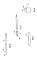
- FIG. 1 is a side view, broken longitudinally, of a laryngeal blade according to the present invention.
- FIG. 2 is a fragmentary rear view of the laryngeal blade shown in FIG. 1
- FIG. 3 is a side view, straightened and broken longitudinally, of the laryngeal blade shown in FIG. 1 .
- FIG. 4 is an enlarged fragmentary view of the distal end of the outer blade member.
- FIG. 5 is a front view of the outer blade member.
- FIG. 6 is a fragmentary top view of the distal end of the outer blade member.
- FIGS. 7-10 are sectional views taken through lines 7 — 7 , 8 — 8 , 9 — 9 and 10 — 10 , respectively, in FIG. 4 .
- FIG. 11 is a side view, broken longitudinally, of a modification of an outer blade member according to the present invention.
- FIG. 12 is a fragmentary top view of the modified outer blade member shown in FIG. 11 .
- FIG. 13 is a bottom view of the modified outer blade member shown in FIG. 11 .
- FIG. 14 is an enlarged fragmentary view of the distal end of the modified outer blade member shown in FIG. 11 .
- FIG. 15 is a front view of the modified outer blade member shown in FIG. 11 .
- FIG. 16 is a side view, broken longitudinally, of another modification of an outer blade member according to the present invention.
- FIG. 17 is a fragmentary top view of the modified outer blade member shown in FIG. 16 .
- FIG. 18 is a bottom view, broken longitudinally, of the modified outer blade member shown in FIG. 16 .
- FIG. 19 is a side view, broken longitudinally, of an inner blade member or assembly for the laryngeal blade according to the present invention.
- FIG. 20 is a side view, broken longitudinally, of a cutting tip at the distal end of the inner blade member.
- FIG. 21 is a top view of the cutting tip shown in FIG. 20 .
- FIG. 22 is an enlarged fragmentary side view of the cutting tip shown in FIG. 20 .
- FIG. 23 is a front view of the cutting tip shown in FIG. 22 .
- FIG. 24 is a sectional view taken through line 24 — 24 in FIG. 22 .
- FIG. 25 is a side view, broken longitudinally, of a modification of a cutting tip or cutter for use with the laryngeal blade according to the present invention.
- FIG. 26 is a top view of the modified cutter shown in FIG. 25 .
- FIG. 27 is an enlarged fragmentary side view of the cutter shown in FIG. 25 .
- FIG. 28 is a front view of the cutter shown in FIG. 27 .
- FIG. 29 is a side view, broken longitudinally, of yet another modification of a cutter for use with the laryngeal blade according to the present invention.
- FIG. 30 is a top view of the modified cutter shown in FIG. 29 .
- FIG. 31 is an enlarged fragmentary side view of the cutter shown in FIG. 29 .
- FIG. 32 is a front view of the cutter shown in FIG. 31 .
- FIG. 33 is a modified laryngeal blade according to the present invention.
- FIG. 34 is a side view, broken longitudinally, of the outer blade member shown in FIG. 33 .
- FIG. 35 is a bottom view, broken longitudinally, of the outer blade member shown in FIG. 34 .
- FIG. 36 is a fragmentary top view of the outer blade member shown in FIG. 34 .
- FIG. 37 is an enlarged fragmentary view of the distal end of the outer blade member shown in FIG. 34 .
- FIG. 38 is a front view of the outer blade member shown in FIG. 37 .
- FIG. 39 is an enlarged fragmentary side view of the distal end of the outer blade member.
- FIG. 40 is a side view, broken longitudinally, of an inner blade member for use with the laryngeal blade illustrated in FIG. 33 .
- FIG. 41 is a side view of a cutting tip or cutter for use with the laryngeal blade according to the present invention.
- FIG. 42 is a front view of the cutter shown in FIG. 41 .
- FIG. 43 is a top view of the cutter shown in FIG. 41 .
- FIG. 44 is a sectional view taken through line 44 — 44 in FIG. 41 .
- FIG. 45 is a perspective view of a modified cutter for use with the laryngeal blade according to the present invention.
- FIG. 46 is a side view of the modified cutter shown in FIG. 45 .
- FIG. 47 is a front view of the cutter shown in FIG. 46 .
- FIG. 48 is a top view of the cutter shown in FIG. 46 .
- FIG. 49 is another view of the cutter shown in FIG. 46 .
- FIGS. 50 and 51 illustrate use of the laryngeal blade according to the present invention for removal of papilloma from the vocal fold.
- FIG. 52 illustrates use of the laryngeal blade according to the present invention for removal of papilloma from the anterior commissure.
- FIGS. 53 and 54 illustrate use of the laryngeal blade according to the present invention for removal of lesions located on the undersurface of the vocal fold.
- FIGS. 55 and 56 illustrate use of the laryngeal blade according to the present invention for removal of vocal fold polyps.
- FIG. 57 illustrates use of the laryngeal blade according to the present invention for delicate sculpting of edges after removal of an airway tumor using an aggressive toothed blade.
- a powered laryngeal cutting blade 10 according to the present invention is illustrated in FIGS. 1-3 and can be driven by any suitable handpiece such as the STRAIGHTSHOT marketed by Xomed Surgical Products, Inc. and shown in U.S. Pat. No. 5,916,231 to Bays, the disclosure of which is incorporated herein by reference.
- the blade 10 includes an outer blade member or assembly 12 and a hollow inner blade member assembly 14 rotatably received within the outer blade member.
- Outer blade member 12 includes a hub 16 with an irrigation port or coupling 17 extending angularly therefrom and an outer tubular member or sleeve 18 having a proximal portion 20 of straight configuration extending distally from the hub to a proximal bend 22 connecting the proximal portion with a distal portion 24 oriented at an angle ⁇ of about 45° relative to the longitudinal axis 26 of the proximal portion.
- the proximal bend 22 is closer to the proximal portion 20 than to the distal end 28 to provide desired spacing of the distal end from the proximal portion.
- Angled straight distal portion 24 of the outer tubular member extends downwardly from bend 22 , looking at FIG.
- a distance greater than the distance between bend 22 and the proximal portion and portion 24 extends to a rounded distal end 28 having an opening facing upwardly, away from the center of curvature of the bend, to define a cutting port or window 30 .
- the window 30 can face in any desired direction (i.e. also downwardly or sidewards) and the outer blade member 12 can have multiple curves or bends, such as 22 , along the length thereof.
- cutting port or window 30 is beveled and includes a plurality of teeth 32 along longitudinal sides thereof with an outer surface or edge 34 of the window being dull or blunt and an inner surface or edge 36 of the window being sharp.
- teeth 32 are shown on each side, however, any number of teeth can be used.
- FIGS. 11-15 illustrate a modification of the outer assembly 12 to provide a smooth profile (as compared with the above described toothed laryngeal blade) wherein the outer. tubular member includes a necked distal portion 38 extending to a distal end having and a beveled circular cutting port or window 30 similar to that described above in that the inner surface or edge 36 is sharp but without any teeth.
- the necked distal portion which is joined to the proximal portion, as an outer or external cross-sectional diameter smaller than the outer or external cross-sectional diameter of the proximal portion.
- FIGS. 16-18 illustrate another modification of the outer assembly 12 similar to that shown in FIGS. 11-15 but without a necked portion at a distal end.
- FIGS. 19-24 illustrate an inner assembly 14 for the laryngeal blade according to the present invention, the inner assembly including a hub 40 , a drive shaft 42 extending distally from the hub to a flexible coupling 44 , and a cutting tip or cutter 46 extending distally from the flexible coupling.
- Cutting tip 46 includes a distal opening 48 defined by a peripheral edge with teeth 50 having a blunt inner surface or edge 52 and a sharp outer surface or edge 54 .
- the distal opening communicates with a lumen defined by the inner assembly to permit tissue evacuation when the blade is connected with a source of suction.
- the inner assembly 14 has a size to rotate within the outer blade member 14 with sufficient annular space for irrigating fluid to pass between the inner and outer members from port 17 to the cutting tip via a flat 49 adjacent and aligned with opening 48 in order to prevent clogging of cut tissue in the lumen of the inner blade.
- the cut tissue is aspirated from the surgical site in a straight path through hub 40 to also prevent clogging and can be drawn through a STRAIGHTSHOT handpiece in a straight path.
- FIGS. 25-28 illustrate a modification of a cutting tip 46 similar to that described above but with a necked distal portion 56 and a beveled circular distal opening or cutting tip 48 without any teeth.
- the necked distal portion 56 is joined to a proximal portion of the cutting tip and has an outer or external cross-sectional diameter smaller than the outer or external cross-sectional diameter of the proximal portion of the cutting tip.
- the cutting tip 46 includes an intermediate portion joining the distal and proximal portions of the cutting tip, and the intermediate portion has an outer or external cross-sectional diameter smaller than the outer diameter of the proximal portion of the cutting tip and larger than the outer diameter of the distal portion of the cutting tip.
- FIGS. 29-32 illustrate another modification of a cutting tip 46 similar to that shown in FIGS. 25-28 but with an enlarged distal portion 56 of larger diameter than the proximal portion of the cutting tip.
- FIG. 33 A modification of a laryngeal blade according to the present invention is shown in FIG. 33 at 10 .
- the modified blade 10 is similar to that shown in FIG. 1 but with a distal bend 23 forming an angled distal portion 58 of relatively short length (e.g., about 0.425 inch) oriented at an angle of about 15° relative to distal portion 24 such that bend 23 is opposite the direction of bend 22 and the distal portion extends in the upward direction looking at FIG. 33 or any other desired direction as noted above dependent on anatomy.
- the angular orientation allows the surgeon the best view of the working tip plus enhanced access to lateral structures, the anterior commissure, the posterior commissure or the undersurface of the vocal folds.
- FIGS. 34-39 illustrate further details of the outer assembly 12 of laryngeal blade 10 shown in FIG. 33 .
- window 30 of the blade shown in FIG. 33 is sharp along an inner surface or edge 36 and blunt or dull along an outer surface or edge 34 .
- the window can be formed with teeth 32 as shown in FIGS. 34-39, or without teeth (e.g., in the ways described above for the blade shown in FIG. 1 ).
- FIG. 37 illustrates the cutting teeth extending upwardly at an angle of 13° from a distal end to a proximal end of the cutting window.
- FIG. 37 also illustrates the cutting teeth as having rearward surfaces angularly joined to forward surfaces thereof, with each of the rearward surfaces being angularly joined to a proximally adjacent forward surface at an angle of 90°.
- FIG. 39 illustrates the forward surfaces disposed at an angle of 136° to a central longitudinal axis of the outer tubular member
- FIGS. 41-49 illustrate exemplary cutting tips 46 which can be used with the inner assembly 14 .
- FIG. 41 illustrates the cutting teeth as having proximal surfaces angularly joined to distal surfaces thereof, with each of the proximal surfaces being angularly joined to a proximally adjacent distal surface at an angle of 90°.
- FIG. 44 illustrates the blunt inner edge 52 joined to the sharp outer edge 54 by a surface disposed at an angle of 46°.
- ETT endotracheal tube
- tracheotomy if indicated.
- Size of the endotracheal tube will vary depending on airway conditions (presence of stenosis) and intubation technique. In adults, a small, cuffed 5.0 mm or 5.5 mm ETT is adequate for ventilation and allows access for surgical instrumentation. With stenotic lesions, smaller cuffless ETTs may be required. In this situation, the laryngoscope may accommodate powered instrumentation, a rigid telescope, and the ETT, allowing for uninterrupted surgery.
- the laryngoscope is positioned to allow access to the anatomy to be excised with the powered shaver 10 . Access to the anterior commissure and subglottic region may be accomplished using an anterior commissure laryngoscope. Visualization can be enhanced using 0° or 30° rigid telescopes and conventional video imaging systems. Console settings for the powered handpiece should preferably be set on “oscillate” mode with a maximum speed set at about 1000 rpms for superficial lesions or those located near or on the vocal folds. Use of “variable” mode of foot switch operation is preferred as it allows for more controlled excision with slow, single revolutions when needed. The laryngeal blade is then securely attached to the powered handpiece.
- Irrigation e.g., a 1000 cc or 3000 cc bag at 6 foot elevation
- Wall suction levels may be adjusted to provide enough vacuum to allow the blade to remove tissue at an efficient rate (e.g., 150 mm to 180 mm Hg).
- Use of an in-line tissue trap is desirable to capture specimens for pathology.
- the laryngeal shaver blade 10 can be utilized for a number of procedures.
- FIGS. 50 and 51 the laryngeal blade 10 is shown in use, along with a laryngoscope or endoscope 11 , for delicate removal of papilloma from the vocal fold.
- Oscillation speeds of between about 60 and about 1000 rpm are believed to offer the most precise result and, for the most precise excisions, tissue can be pulled into the opening and with light pressure on the variable foot switch amputated with single blade revolutions.
- discrete lesions can be accurately removed with trauma limited to the superficial mucosa.
- endoscopic visualization with a 30° endoscope is recommended as shown in FIG. 52 .
- the angled-tip design of the laryngeal blade 10 shown in FIG. 33 allows excellent access for removal of lesions located on the under surface of the vocal fold as shown in FIGS. 53 and 54. With an oblique endoscope and/or aid of suction to elevate the vocal fold, delicate excision of pathology can be achieved.
- Vocal fold polyps can be quickly and precisely removed without tearing or trauma to peripheral tissues as shown in FIGS. 55 and 56. After debulking airway tumors using the aggressive toothed laryngeal blades shown in FIGS. 1-10, 19 - 24 and 33 - 44 , edges can be more delicately sculpted with the smooth laryngeal blades shown in FIGS. 11-18, 25 - 32 and 45 - 49 .
- the toothed laryngeal blades according to the present invention are particularly effective for debulking of large, firm lesions, such as exophytic or fibrous lesions, airway tumors, granulation tissue, tracheal lesions and metastatic tumors.
- the smooth laryngeal blades according to the present invention are particularly effective for delicate shaving of superficial lesions off the vocal folds, such as papilloma, without tearing or trauma and after removal of bulk mass by the toothed laryngeal blades, for sculpting edges.
- the tubular portions of the blade can be formed of any suitable materials and can have any suitable dimensions.
- the tubular portions can be made of stainless steel with the outer tube being about 0.156 in diameter and about 11.0 inches long, the inner tube or drive shaft being rotatable within the outer tube with sufficient space for irrigating fluid to pass therebetween.
Landscapes
- Health & Medical Sciences (AREA)
- Surgery (AREA)
- Life Sciences & Earth Sciences (AREA)
- Medical Informatics (AREA)
- Nuclear Medicine, Radiotherapy & Molecular Imaging (AREA)
- Engineering & Computer Science (AREA)
- Biomedical Technology (AREA)
- Heart & Thoracic Surgery (AREA)
- Orthopedic Medicine & Surgery (AREA)
- Molecular Biology (AREA)
- Animal Behavior & Ethology (AREA)
- General Health & Medical Sciences (AREA)
- Public Health (AREA)
- Veterinary Medicine (AREA)
- Surgical Instruments (AREA)
- Endoscopes (AREA)
Abstract
A laryngeal cutting blade has an outer blade assembly including a tubular member having a bend closer to a proximal portion than a distal end, a hollow inner blade assembly rotatably received in the outer blade assembly for mounting to a powered handpiece and having a flexible portion disposed adjacent the bend and a suction passage extending through the inner blade assembly to permit aspiration of cut tissue, the angled configuration of the laryngeal cutting blade and toothed and smooth profile cutting ends therefore are particularly effective for debulking large, firm lesions and for delicate shaving of superficial lesions of the vocal cords after removal of bulk mass.
Description
This application is a continuation application of prior U.S. patent application Ser. No. 09/392,797, filed Sep. 9, 1999 now abandoned, which claims priority to U.S. provisional application Ser. No. 60/099,563, filed Sep. 9, 1998, the entire disclosures of which are incorporated herein by reference.
The present invention relates generally to instruments and methods for removing laryngeal lesions and, more particularly, to a surgical cutting instrument in the form of a powered shaver having a blade with an elongate inner member rotatably disposed within an elongate outer member having a cutting window at a distal end configured to permit laryngeal use including debulking of large, firm lesions and delicate shaving of superficial lesions directly on the vocal folds within the larynx.
Treatment for the removal of laryngeal lesions has progressed from cold steel techniques to the use of the CO2 laser and KTP fiber directed laser. While the laser has become the standard treatment, there remain concerns such as airway fire and laser plume. Additionally, the use of lasers in removing laryngeal lesions can result in laser burn and post procedure edema.
Accordingly, it is an object of the present invention to provide an alternative treatment for the removal of laryngeal lesions that is safer, more accurate, and faster than laser tissue vaporization.
It is another object of the present invention to minimize post procedure edema by confining tissue injury to the superficial mucosa only.
Yet another object of the present invention is to reduce post operative pain and to speed recovery of the voice following removal of laryngeal lesions.
It is still another object of the present invention to address the fixed operating radius of the laryngoscope in laryngeal procedures by forming the distal tip of a powered shaver blade driven by a handpiece with an angle such that the radius of surgical access is increased to provide surgeons with the best view of the working tip plus enhanced access to lateral structures, the anterior commissure or the undersurface of the vocal folds.
Some of the advantages of the present invention over the prior art are that concerns such as laser burn, airway fire and laser plume are eliminated, post procedure edema is minimized, and post operative pain is reduced. In addition, equipment costs, set up and surgical time for the shaver are dramatically reduced versus the laser.
These and other objects and advantages can be accomplished individually or in combination by use of a powered shaver having a blade assembly in accordance with the present invention.
Other objects and advantages of the present invention will become apparent from the following description of the preferred embodiments taken in conjunction with the accompanying drawings, wherein like parts in each of the several figures are identified by the same reference numerals or by reference numerals having the same last two digits.
FIG. 1 is a side view, broken longitudinally, of a laryngeal blade according to the present invention.
FIG. 2 is a fragmentary rear view of the laryngeal blade shown in FIG. 1
FIG. 3 is a side view, straightened and broken longitudinally, of the laryngeal blade shown in FIG. 1.
FIG. 4 is an enlarged fragmentary view of the distal end of the outer blade member.
FIG. 5 is a front view of the outer blade member.
FIG. 6 is a fragmentary top view of the distal end of the outer blade member.
FIGS. 7-10 are sectional views taken through lines 7—7, 8—8, 9—9 and 10—10, respectively, in FIG. 4.
FIG. 11 is a side view, broken longitudinally, of a modification of an outer blade member according to the present invention.
FIG. 12 is a fragmentary top view of the modified outer blade member shown in FIG. 11.
FIG. 13 is a bottom view of the modified outer blade member shown in FIG. 11.
FIG. 14 is an enlarged fragmentary view of the distal end of the modified outer blade member shown in FIG. 11.
FIG. 15 is a front view of the modified outer blade member shown in FIG. 11.
FIG. 16 is a side view, broken longitudinally, of another modification of an outer blade member according to the present invention.
FIG. 17 is a fragmentary top view of the modified outer blade member shown in FIG. 16.
FIG. 18 is a bottom view, broken longitudinally, of the modified outer blade member shown in FIG. 16.
FIG. 19 is a side view, broken longitudinally, of an inner blade member or assembly for the laryngeal blade according to the present invention.
FIG. 20 is a side view, broken longitudinally, of a cutting tip at the distal end of the inner blade member.
FIG. 21 is a top view of the cutting tip shown in FIG. 20.
FIG. 22 is an enlarged fragmentary side view of the cutting tip shown in FIG. 20.
FIG. 23 is a front view of the cutting tip shown in FIG. 22.
FIG. 24 is a sectional view taken through line 24—24 in FIG. 22.
FIG. 25 is a side view, broken longitudinally, of a modification of a cutting tip or cutter for use with the laryngeal blade according to the present invention.
FIG. 26 is a top view of the modified cutter shown in FIG. 25.
FIG. 27 is an enlarged fragmentary side view of the cutter shown in FIG. 25.
FIG. 28 is a front view of the cutter shown in FIG. 27.
FIG. 29 is a side view, broken longitudinally, of yet another modification of a cutter for use with the laryngeal blade according to the present invention.
FIG. 30 is a top view of the modified cutter shown in FIG. 29.
FIG. 31 is an enlarged fragmentary side view of the cutter shown in FIG. 29.
FIG. 32 is a front view of the cutter shown in FIG. 31.
FIG. 33 is a modified laryngeal blade according to the present invention.
FIG. 34 is a side view, broken longitudinally, of the outer blade member shown in FIG. 33.
FIG. 35 is a bottom view, broken longitudinally, of the outer blade member shown in FIG. 34.
FIG. 36 is a fragmentary top view of the outer blade member shown in FIG. 34.
FIG. 37 is an enlarged fragmentary view of the distal end of the outer blade member shown in FIG. 34.
FIG. 38 is a front view of the outer blade member shown in FIG. 37.
FIG. 39 is an enlarged fragmentary side view of the distal end of the outer blade member.
FIG. 40 is a side view, broken longitudinally, of an inner blade member for use with the laryngeal blade illustrated in FIG. 33.
FIG. 41 is a side view of a cutting tip or cutter for use with the laryngeal blade according to the present invention.
FIG. 42 is a front view of the cutter shown in FIG. 41.
FIG. 43 is a top view of the cutter shown in FIG. 41.
FIG. 44 is a sectional view taken through line 44—44 in FIG. 41.
FIG. 45 is a perspective view of a modified cutter for use with the laryngeal blade according to the present invention.
FIG. 46 is a side view of the modified cutter shown in FIG. 45.
FIG. 47 is a front view of the cutter shown in FIG. 46.
FIG. 48 is a top view of the cutter shown in FIG. 46.
FIG. 49 is another view of the cutter shown in FIG. 46.
FIGS. 50 and 51 illustrate use of the laryngeal blade according to the present invention for removal of papilloma from the vocal fold.
FIG. 52 illustrates use of the laryngeal blade according to the present invention for removal of papilloma from the anterior commissure.
FIGS. 53 and 54 illustrate use of the laryngeal blade according to the present invention for removal of lesions located on the undersurface of the vocal fold.
FIGS. 55 and 56 illustrate use of the laryngeal blade according to the present invention for removal of vocal fold polyps.
FIG. 57 illustrates use of the laryngeal blade according to the present invention for delicate sculpting of edges after removal of an airway tumor using an aggressive toothed blade.
A powered laryngeal cutting blade 10 according to the present invention is illustrated in FIGS. 1-3 and can be driven by any suitable handpiece such as the STRAIGHTSHOT marketed by Xomed Surgical Products, Inc. and shown in U.S. Pat. No. 5,916,231 to Bays, the disclosure of which is incorporated herein by reference. The blade 10 includes an outer blade member or assembly 12 and a hollow inner blade member assembly 14 rotatably received within the outer blade member. Outer blade member 12 includes a hub 16 with an irrigation port or coupling 17 extending angularly therefrom and an outer tubular member or sleeve 18 having a proximal portion 20 of straight configuration extending distally from the hub to a proximal bend 22 connecting the proximal portion with a distal portion 24 oriented at an angle θ of about 45° relative to the longitudinal axis 26 of the proximal portion. The proximal bend 22 is closer to the proximal portion 20 than to the distal end 28 to provide desired spacing of the distal end from the proximal portion. Angled straight distal portion 24 of the outer tubular member extends downwardly from bend 22, looking at FIG. 1, a distance greater than the distance between bend 22 and the proximal portion and portion 24 extends to a rounded distal end 28 having an opening facing upwardly, away from the center of curvature of the bend, to define a cutting port or window 30. Dependent upon the anatomical situation and requirements, the window 30 can face in any desired direction (i.e. also downwardly or sidewards) and the outer blade member 12 can have multiple curves or bends, such as 22, along the length thereof.
As best seen in FIGS. 4-10, cutting port or window 30 is beveled and includes a plurality of teeth 32 along longitudinal sides thereof with an outer surface or edge 34 of the window being dull or blunt and an inner surface or edge 36 of the window being sharp. Four teeth 32 are shown on each side, however, any number of teeth can be used.
FIGS. 11-15 illustrate a modification of the outer assembly 12 to provide a smooth profile (as compared with the above described toothed laryngeal blade) wherein the outer. tubular member includes a necked distal portion 38 extending to a distal end having and a beveled circular cutting port or window 30 similar to that described above in that the inner surface or edge 36 is sharp but without any teeth. The necked distal portion, which is joined to the proximal portion, as an outer or external cross-sectional diameter smaller than the outer or external cross-sectional diameter of the proximal portion.
FIGS. 16-18 illustrate another modification of the outer assembly 12 similar to that shown in FIGS. 11-15 but without a necked portion at a distal end.
FIGS. 19-24 illustrate an inner assembly 14 for the laryngeal blade according to the present invention, the inner assembly including a hub 40, a drive shaft 42 extending distally from the hub to a flexible coupling 44, and a cutting tip or cutter 46 extending distally from the flexible coupling. Cutting tip 46 includes a distal opening 48 defined by a peripheral edge with teeth 50 having a blunt inner surface or edge 52 and a sharp outer surface or edge 54. The distal opening communicates with a lumen defined by the inner assembly to permit tissue evacuation when the blade is connected with a source of suction. The inner assembly 14 has a size to rotate within the outer blade member 14 with sufficient annular space for irrigating fluid to pass between the inner and outer members from port 17 to the cutting tip via a flat 49 adjacent and aligned with opening 48 in order to prevent clogging of cut tissue in the lumen of the inner blade. The cut tissue is aspirated from the surgical site in a straight path through hub 40 to also prevent clogging and can be drawn through a STRAIGHTSHOT handpiece in a straight path.
FIGS. 25-28 illustrate a modification of a cutting tip 46 similar to that described above but with a necked distal portion 56 and a beveled circular distal opening or cutting tip 48 without any teeth. As shown in FIGS. 25 and 26, the necked distal portion 56 is joined to a proximal portion of the cutting tip and has an outer or external cross-sectional diameter smaller than the outer or external cross-sectional diameter of the proximal portion of the cutting tip. As also shown in FIGS. 25 and 26, the cutting tip 46 includes an intermediate portion joining the distal and proximal portions of the cutting tip, and the intermediate portion has an outer or external cross-sectional diameter smaller than the outer diameter of the proximal portion of the cutting tip and larger than the outer diameter of the distal portion of the cutting tip.
FIGS. 29-32 illustrate another modification of a cutting tip 46 similar to that shown in FIGS. 25-28 but with an enlarged distal portion 56 of larger diameter than the proximal portion of the cutting tip.
A modification of a laryngeal blade according to the present invention is shown in FIG. 33 at 10. The modified blade 10 is similar to that shown in FIG. 1 but with a distal bend 23 forming an angled distal portion 58 of relatively short length (e.g., about 0.425 inch) oriented at an angle of about 15° relative to distal portion 24 such that bend 23 is opposite the direction of bend 22 and the distal portion extends in the upward direction looking at FIG. 33 or any other desired direction as noted above dependent on anatomy. The angular orientation allows the surgeon the best view of the working tip plus enhanced access to lateral structures, the anterior commissure, the posterior commissure or the undersurface of the vocal folds.
FIGS. 34-39 illustrate further details of the outer assembly 12 of laryngeal blade 10 shown in FIG. 33. Like the blade 10 shown in FIG. 1, window 30 of the blade shown in FIG. 33 is sharp along an inner surface or edge 36 and blunt or dull along an outer surface or edge 34. The window can be formed with teeth 32 as shown in FIGS. 34-39, or without teeth (e.g., in the ways described above for the blade shown in FIG. 1). FIG. 37 illustrates the cutting teeth extending upwardly at an angle of 13° from a distal end to a proximal end of the cutting window. FIG. 37 also illustrates the cutting teeth as having rearward surfaces angularly joined to forward surfaces thereof, with each of the rearward surfaces being angularly joined to a proximally adjacent forward surface at an angle of 90°. FIG. 39 illustrates the forward surfaces disposed at an angle of 136° to a central longitudinal axis of the outer tubular member
In use, general anaesthesia is typically induced and the airway secured by endotracheal tube (ETT) intubation or tracheotomy, if indicated. Size of the endotracheal tube will vary depending on airway conditions (presence of stenosis) and intubation technique. In adults, a small, cuffed 5.0 mm or 5.5 mm ETT is adequate for ventilation and allows access for surgical instrumentation. With stenotic lesions, smaller cuffless ETTs may be required. In this situation, the laryngoscope may accommodate powered instrumentation, a rigid telescope, and the ETT, allowing for uninterrupted surgery.
The laryngoscope is positioned to allow access to the anatomy to be excised with the powered shaver 10. Access to the anterior commissure and subglottic region may be accomplished using an anterior commissure laryngoscope. Visualization can be enhanced using 0° or 30° rigid telescopes and conventional video imaging systems. Console settings for the powered handpiece should preferably be set on “oscillate” mode with a maximum speed set at about 1000 rpms for superficial lesions or those located near or on the vocal folds. Use of “variable” mode of foot switch operation is preferred as it allows for more controlled excision with slow, single revolutions when needed. The laryngeal blade is then securely attached to the powered handpiece. Irrigation (e.g., a 1000 cc or 3000 cc bag at 6 foot elevation) is preferably used with the blade and allowed to flow continuously throughout the procedure to prevent clogging. Wall suction levels may be adjusted to provide enough vacuum to allow the blade to remove tissue at an efficient rate (e.g., 150 mm to 180 mm Hg). Use of an in-line tissue trap is desirable to capture specimens for pathology.
The laryngeal shaver blade 10 can be utilized for a number of procedures. In FIGS. 50 and 51, the laryngeal blade 10 is shown in use, along with a laryngoscope or endoscope 11, for delicate removal of papilloma from the vocal fold. Oscillation speeds of between about 60 and about 1000 rpm are believed to offer the most precise result and, for the most precise excisions, tissue can be pulled into the opening and with light pressure on the variable foot switch amputated with single blade revolutions. With the window configuration of the present invention, discrete lesions can be accurately removed with trauma limited to the superficial mucosa. For greatest precision when removing papilloma from the anterior commissure, endoscopic visualization with a 30° endoscope is recommended as shown in FIG. 52.
The angled-tip design of the laryngeal blade 10 shown in FIG. 33 allows excellent access for removal of lesions located on the under surface of the vocal fold as shown in FIGS. 53 and 54. With an oblique endoscope and/or aid of suction to elevate the vocal fold, delicate excision of pathology can be achieved.
Vocal fold polyps can be quickly and precisely removed without tearing or trauma to peripheral tissues as shown in FIGS. 55 and 56. After debulking airway tumors using the aggressive toothed laryngeal blades shown in FIGS. 1-10, 19-24 and 33-44, edges can be more delicately sculpted with the smooth laryngeal blades shown in FIGS. 11-18, 25-32 and 45-49.
The toothed laryngeal blades according to the present invention are particularly effective for debulking of large, firm lesions, such as exophytic or fibrous lesions, airway tumors, granulation tissue, tracheal lesions and metastatic tumors. The smooth laryngeal blades according to the present invention are particularly effective for delicate shaving of superficial lesions off the vocal folds, such as papilloma, without tearing or trauma and after removal of bulk mass by the toothed laryngeal blades, for sculpting edges.
The tubular portions of the blade can be formed of any suitable materials and can have any suitable dimensions. For example, the tubular portions can be made of stainless steel with the outer tube being about 0.156 in diameter and about 11.0 inches long, the inner tube or drive shaft being rotatable within the outer tube with sufficient space for irrigating fluid to pass therebetween.
Inasmuch as the present invention is subject to many variations, modifications, and changes in detail, it is intended that all subject matter discussed above or shown in the accompanying drawings be interpreted as illustrative only and not be taken in a limiting sense.
Claims (13)
1. A laryngeal cutting blade comprising:
an outer blade assembly including an outer tubular member having a proximal portion for mounting to a powered handpiece and a distal portion extending distally to a rounded distal end having a cutting window therein, said cutting window being configured with a plurality of cutting teeth extending along longitudinal sides of said cutting window, said cutting teeth having a blunt outer edge and a sharp inner edge, said distal portion of said outer tubular member being cylindrical, said proximal portion of said outer tubular member being cylindrical, and said distal portion of said outer tubular member having an external diameter smaller than an external diameter of said proximal portion of said outer tubular member;
a hollow inner blade assembly rotatably received in said outer blade assembly and having a drive shaft for mounting to the powered handpiece and a cutting tip coupled to said drive shaft, said cutting tip including a cutting opening disposed adjacent said cutting window of said outer blade assembly, said cutting opening being configured with a plurality of cutting teeth extending along longitudinal sides of said cutting opening, said cutting teeth of said cutting opening having a blunt inner edge and a sharp outer edge; and
a suction passage extending through said inner blade assembly to permit aspiration of cut tissue through said cutting blade.
2. A laryngeal cutting blade as recited in claim 1 wherein said cutting tip includes a proximal portion coupled to said drive shaft and a distal portion having said cutting opening therein joined to said proximal portion of said cutting tip, said proximal portion of said cutting tip is cylindrical, said distal portion of said cutting tip is cylindrical, and said distal portion of said cutting tip has an external diameter smaller than an external diameter of said proximal portion of said cutting tip.
3. A laryngeal cutting blade as recited in claim 2 wherein said cutting tip includes an intermediate portion joining said distal portion of said cutting tip to said proximal portion of said cutting tip, said intermediate portion having an external diameter smaller than said external diameter of said proximal portion of said cutting tip and larger than said external diameter of said distal portion of said cutting tip.
4. A laryngeal cutting blade as recited in claim 2 wherein said cutting opening is beveled and said cutting opening and said cutting window are circular.
5. A laryngeal cutting blade comprising
an outer blade assembly including an outer tubular member having a proximal portion for mounting to a powered handpiece and a distal portion extending distally to a rounded distal end having a beveled cutting window therein, said cutting window being circular and having a blunt outer edge and a sharp inner edge, said beveled cutting window being disposed at an angle of 32° to a central longitudinal axis of said outer tubular member;
a hollow inner blade assembly rotatably received in said outer blade assembly and having a drive shaft for mounting to the powered handpiece and a cutting tip coupled to said drive shaft, said cutting tip including a beveled cutting opening disposed adjacent said cutting window of said outer blade assembly, said cutting opening being circular and having a blunt inner edge and a sharp outer edge; and
a suction passage extending through said inner blade assembly to permit aspiration of cut tissue through said cutting blade.
6. A laryngeal cutting blade comprising:
an outer blade assembly including an outer tubular member having a proximal portion for mounting to a powered handpiece and a distal portion extending distally to a rounded distal end having a beveled cutting window therein, said cutting window having a blunt outer edge and a sharp inner edge, said cutting window being configured with a plurality of cutting teeth extending along longitudinal sides of said cutting window, said cutting teeth of said cutting window extending upwardly at an angle of 13° from a distal end to a proximal end of said cutting window;
a hollow inner blade assembly rotatably received in said outer blade assembly and having a drive shaft for mounting to the powered handpiece and a cutting tip coupled to said drive shaft, said cutting tip including a cutting opening disposed adjacent said cutting window of said outer blade assembly and having a blunt inner edge and a sharp outer edge, said cutting opening being configured with a plurality of cutting teeth extending along longitudinal sides of said cutting opening; and
a suction passage extending through said inner blade assembly to permit aspiration of cut tissue through said cutting blade.
7. A laryngeal cutting blade as recited in claim 6 wherein said cutting teeth of said cutting opening extend upwardly at an angle from a distal end to a proximal end of said cutting opening.
8. A laryngeal cutting blade as recited in claim 6 wherein each of said cutting teeth of said cutting window has a forward surface and a rearward surface angularly joined to said forward surface, each of said rearward surfaces being angularly joined to a proximally adjacent one of said forward surfaces at an angle of 90°, said forward surfaces being disposed at an angle of 136° to a central longitudinal axis of said outer tubular member.
9. A laryngeal cutting blade as recited in claim 6 wherein each of said cutting teeth of said cutting opening has a distal surface and a proximal surface angularly joined to said distal surface, each of said proximal surfaces being angularly joined to a proximally adjacent one of said distal surfaces at an angle of 90°, said blunt inner edge of said cutting opening being joined to said sharp outer edge of said cutting opening by a surface disposed at an angle of 46°.
10. A laryngeal cutting blade comprising:
an outer blade assembly including an outer tubular member having a proximal portion for mounting to a powered handpiece and a distal portion extending distally to a rounded distal end having a cutting window therein, said cutting window being configured with a plurality of cutting teeth extending along longitudinal sides of said cutting window, said cutting teeth having a blunt outer edge and a sharp inner edge, each of said cutting teeth of said cutting window having a forward surface and a rearward surface angularly joined to said forward surface, each of said rearward surfaces being angularly joined to a proximally adjacent one of said forward surfaces at an angle of 90°, said forward surfaces being disposed at an angle of 136° to a central longitudinal axis of said outer tubular member;
a hollow inner blade assembly rotatably received in outer blade assembly and having a drive shaft for mounting to the powered handpiece and a cutting tip coupled to said, drive shaft, said cutting tip including a cutting opening disposed adjacent said cutting window of said outer blade assembly, said cutting opening being configured with a plurality of cutting teeth extending along longitudinal sides of said cutting opening, said cutting teeth of said cutting opening having a blunt inner edge and a sharp outer edge; and
a suction passage extending through said inner blade assembly to permit aspiration of cut tissue through said cutting blade.
11. A laryngeal cutting blade as recited in claim 10 wherein each of said cutting teeth of said cutting opening has a distal surface and a proximal surface angularly joined to said distal surface, each of said proximal surfaces being angularly joined to a proximally adjacent one of said distal surfaces at an angle of 90°, said blunt inner edge of said cutting teeth of said cutting opening being joined to said sharp outer edge of said cutting teeth of said cutting opening by a surface disposed at an angle of 46°.
12. A laryngeal cutting blade as recited in claim 11 wherein said cutting teeth of said cutting window extend upwardly at an angle of 13° from a distal end to a proximal end of said cutting window and said cutting teeth of said cutting opening extend upwardly at an angle from a distal end to a proximal end of said cutting opening.
13. A laryngeal cutting blade comprising:
an outer blade assembly including an outer tubular member having a proximal portion for mounting to a powered handpiece and a distal portion extending distally to a rounded distal end having a cutting window therein, said cutting window being configured with a plurality of cutting teeth extending along longitudinal sis of said cutting window, said cutting teeth having a blunt outer edge and a sharp inner edge, said cutting teeth of said cutting window extending upwardly at an angle from a distal end to a proximal end of said cutting window to be disposed non-parallel to a central longitudinal axis of said outer tubular member;
a hollow inner blade assembly rotatably received in said outer blade assembly and having a drive shaft for mounting to the powered handpiece and a cutting tip coupled to said drive shaft, said cutting tip including a cutting opening disposed adjacent said cutting window of said outer blade assembly, said cutting opening being configured with a plurality of cutting teeth extending along longitudinal sides of said cutting opening, said cutting teeth of said cutting opening having a blunt inner edge and a sharp outer edge, said cutting teeth of said cutting opening extending upwardly at an angle from a distal end to a proximal end of said cutting opening to be disposed non-parallel to a central longitudinal axis of said drive shaft; and
a suction passage extending through said inner blade assembly to permit aspiration of cut tissue through said cutting blade.
Priority Applications (1)
| Application Number | Priority Date | Filing Date | Title |
|---|---|---|---|
| US09/692,232 US6620180B1 (en) | 1998-09-09 | 2000-10-20 | Powered laryngeal cutting blade |
Applications Claiming Priority (3)
| Application Number | Priority Date | Filing Date | Title |
|---|---|---|---|
| US9956398P | 1998-09-09 | 1998-09-09 | |
| US39279799A | 1999-09-09 | 1999-09-09 | |
| US09/692,232 US6620180B1 (en) | 1998-09-09 | 2000-10-20 | Powered laryngeal cutting blade |
Related Parent Applications (1)
| Application Number | Title | Priority Date | Filing Date |
|---|---|---|---|
| US39279799A Continuation | 1998-09-09 | 1999-09-09 |
Publications (1)
| Publication Number | Publication Date |
|---|---|
| US6620180B1 true US6620180B1 (en) | 2003-09-16 |
Family
ID=27807251
Family Applications (1)
| Application Number | Title | Priority Date | Filing Date |
|---|---|---|---|
| US09/692,232 Expired - Lifetime US6620180B1 (en) | 1998-09-09 | 2000-10-20 | Powered laryngeal cutting blade |
Country Status (1)
| Country | Link |
|---|---|
| US (1) | US6620180B1 (en) |
Cited By (89)
| Publication number | Priority date | Publication date | Assignee | Title |
|---|---|---|---|---|
| US20030191488A1 (en) * | 2002-04-09 | 2003-10-09 | Braden Robison | Surgical instrument |
| US20060025793A1 (en) * | 2004-08-02 | 2006-02-02 | Karl Storz Endovision | Surgical instrument attachment system |
| US20060224160A1 (en) * | 2005-04-01 | 2006-10-05 | Trieu Hai H | Instruments and methods for aggressive yet continuous tissue removal |
| US20070282361A1 (en) * | 2004-07-22 | 2007-12-06 | Orlando Da Rold | Surgical Cutting Instrument |
| US20080071303A1 (en) * | 2006-07-11 | 2008-03-20 | Randall Lee Hacker | Rotary shaver with improved connection between flexible and rigid rotatable tubes |
| US20080200941A1 (en) * | 2007-02-16 | 2008-08-21 | Miro Mitusina | Rotary surgical instruments having curved cutting teeth |
| US20080216826A1 (en) * | 2007-08-07 | 2008-09-11 | Searete Llc, A Limited Liability Corporation Of The State Of Delaware | Airway imaging system |
| US20080216840A1 (en) * | 2007-03-06 | 2008-09-11 | Searete Llc, A Limited Liability Corporation Of The State Of Delaware | Imaging via the airway |
| US20090024018A1 (en) * | 2007-08-07 | 2009-01-22 | Searete Llc, A Limited Liability Corporation Of The State Of Delaware | Anatomical imaging system |
| US20090228030A1 (en) * | 2008-03-07 | 2009-09-10 | Medtronic Xomed, Inc. | Systems and methods for surgical removal of tissue |
| US20100256662A1 (en) * | 2008-10-23 | 2010-10-07 | Racenet Danyel J | Vacuum assisted surgical dissection tools |
| US20100286674A1 (en) * | 2008-01-22 | 2010-11-11 | Board Of Regents, The University Of Texas System | Systems, devices and methods for imaging and surgery |
| US20100298855A1 (en) * | 2009-05-19 | 2010-11-25 | Dierck Ryon J | Surgical tool arrangement and surgical cutting accessory for use therewith |
| US20110166576A1 (en) * | 2005-11-29 | 2011-07-07 | Medtronic Xomed, Inc. | Method and apparatus for removing material from an intervertebral disc space, such as in performing a nucleotomy |
| WO2011091283A1 (en) * | 2010-01-22 | 2011-07-28 | Board Of Regents, The University Of Texas System | Systems, devices and methods for imaging and surgery |
| WO2012003383A1 (en) * | 2010-06-30 | 2012-01-05 | Laurimed, Llc | Devices and methods for cutting and evacuating tissue |
| US8192452B2 (en) | 2009-05-14 | 2012-06-05 | Tyco Healthcare Group Lp | Easily cleaned atherectomy catheters and methods of use |
| US20120172877A1 (en) * | 2011-01-04 | 2012-07-05 | Gyrus Ent, L.L.C. | Surgical tool coupling |
| US20120172907A1 (en) * | 2010-12-30 | 2012-07-05 | Kimberly-Clark, Inc. | Tissue Removal Apparatus |
| US8226674B2 (en) | 2000-12-20 | 2012-07-24 | Tyco Healthcare Group Lp | Debulking catheters and methods |
| US8246640B2 (en) | 2003-04-22 | 2012-08-21 | Tyco Healthcare Group Lp | Methods and devices for cutting tissue at a vascular location |
| US8277437B2 (en) | 2008-04-02 | 2012-10-02 | Laurimed, Llc | Method of accessing two lateral recesses |
| US8328829B2 (en) | 1999-08-19 | 2012-12-11 | Covidien Lp | High capacity debulking catheter with razor edge cutting window |
| US8414587B2 (en) | 2007-01-26 | 2013-04-09 | Laurimed, Llc | Styli used to position device for carrying out selective discetomy |
| US8414604B2 (en) | 2008-10-13 | 2013-04-09 | Covidien Lp | Devices and methods for manipulating a catheter shaft |
| US8469979B2 (en) | 2000-12-20 | 2013-06-25 | Covidien Lp | High capacity debulking catheter with distal driven cutting wheel |
| US8496677B2 (en) | 2009-12-02 | 2013-07-30 | Covidien Lp | Methods and devices for cutting tissue |
| US8597315B2 (en) | 1999-08-19 | 2013-12-03 | Covidien Lp | Atherectomy catheter with first and second imaging devices |
| US8657842B2 (en) | 2010-06-30 | 2014-02-25 | Laurimed, Llc | Devices and methods for cutting tissue |
| US20140092925A1 (en) * | 2006-01-20 | 2014-04-03 | John Redvers Clowes | Optical pulse apparatus and method |
| US8784440B2 (en) | 2008-02-25 | 2014-07-22 | Covidien Lp | Methods and devices for cutting tissue |
| US8801738B2 (en) | 2012-01-31 | 2014-08-12 | Globus Medical, Inc. | Surgical disc removal tool |
| US8808186B2 (en) | 2010-11-11 | 2014-08-19 | Covidien Lp | Flexible debulking catheters with imaging and methods of use and manufacture |
| US8815099B1 (en) | 2014-01-21 | 2014-08-26 | Laurimed, Llc | Devices and methods for filtering and/or collecting tissue |
| US8920450B2 (en) | 2010-10-28 | 2014-12-30 | Covidien Lp | Material removal device and method of use |
| US8961551B2 (en) | 2006-12-22 | 2015-02-24 | The Spectranetics Corporation | Retractable separating systems and methods |
| US20150080896A1 (en) | 2013-07-19 | 2015-03-19 | Ouroboros Medical, Inc. | Anti-clogging device for a vacuum-assisted, tissue removal system |
| US8992717B2 (en) | 2011-09-01 | 2015-03-31 | Covidien Lp | Catheter with helical drive shaft and methods of manufacture |
| US8998937B2 (en) | 1999-08-19 | 2015-04-07 | Covidien Lp | Methods and devices for cutting tissue |
| US9028520B2 (en) * | 2006-12-22 | 2015-05-12 | The Spectranetics Corporation | Tissue separating systems and methods |
| US9028512B2 (en) | 2009-12-11 | 2015-05-12 | Covidien Lp | Material removal device having improved material capture efficiency and methods of use |
| US9119662B2 (en) | 2010-06-14 | 2015-09-01 | Covidien Lp | Material removal device and method of use |
| US9198685B2 (en) | 2011-08-24 | 2015-12-01 | Gyrus Ent, L.L.C. | Surgical instrument with malleable tubing |
| US20160066946A1 (en) * | 2011-12-03 | 2016-03-10 | Ouroboros Medical, Inc. | Discectomy kits with an obturator, guard cannula |
| US9283040B2 (en) | 2013-03-13 | 2016-03-15 | The Spectranetics Corporation | Device and method of ablative cutting with helical tip |
| US9291663B2 (en) | 2013-03-13 | 2016-03-22 | The Spectranetics Corporation | Alarm for lead insulation abnormality |
| US9413896B2 (en) | 2012-09-14 | 2016-08-09 | The Spectranetics Corporation | Tissue slitting methods and systems |
| USD765243S1 (en) | 2015-02-20 | 2016-08-30 | The Spectranetics Corporation | Medical device handle |
| US9456872B2 (en) | 2013-03-13 | 2016-10-04 | The Spectranetics Corporation | Laser ablation catheter |
| USD770616S1 (en) | 2015-02-20 | 2016-11-01 | The Spectranetics Corporation | Medical device handle |
| US9532844B2 (en) | 2012-09-13 | 2017-01-03 | Covidien Lp | Cleaning device for medical instrument and method of use |
| US9603610B2 (en) | 2013-03-15 | 2017-03-28 | DePuy Synthes Products, Inc. | Tools and methods for tissue removal |
| US9603618B2 (en) | 2013-03-15 | 2017-03-28 | The Spectranetics Corporation | Medical device for removing an implanted object |
| US9636132B2 (en) | 2014-09-08 | 2017-05-02 | Medtronic Xomed, Inc. | Tumor debulker |
| US9636131B2 (en) | 2013-03-15 | 2017-05-02 | Stryker Corporation | Surgical tool arrangement and surgical cutting accessory for use therewith |
| US9668765B2 (en) | 2013-03-15 | 2017-06-06 | The Spectranetics Corporation | Retractable blade for lead removal device |
| US9687266B2 (en) | 2009-04-29 | 2017-06-27 | Covidien Lp | Methods and devices for cutting and abrading tissue |
| US9737322B2 (en) | 2014-09-08 | 2017-08-22 | Medtronic Xomed, Inc. | Method for resection of tumors and tissues |
| US9763731B2 (en) | 2012-02-10 | 2017-09-19 | Myromed, Llc | Vacuum powered rotary devices and methods |
| US9801647B2 (en) | 2006-05-26 | 2017-10-31 | Covidien Lp | Catheter including cutting element and energy emitting element |
| US9827004B2 (en) | 2012-01-31 | 2017-11-28 | Globus Medical, Inc. | Surgical disc removal tool |
| US9839441B2 (en) | 2013-03-14 | 2017-12-12 | Stryker Corporation | Surgical tool arrangement and surgical cutting accessory for use therewith |
| US9883885B2 (en) | 2013-03-13 | 2018-02-06 | The Spectranetics Corporation | System and method of ablative cutting and pulsed vacuum aspiration |
| US9925366B2 (en) | 2013-03-15 | 2018-03-27 | The Spectranetics Corporation | Surgical instrument for removing an implanted object |
| US9943329B2 (en) | 2012-11-08 | 2018-04-17 | Covidien Lp | Tissue-removing catheter with rotatable cutter |
| US9980743B2 (en) | 2013-03-15 | 2018-05-29 | The Spectranetics Corporation | Medical device for removing an implanted object using laser cut hypotubes |
| CN108158633A (en) * | 2018-02-12 | 2018-06-15 | 李勇 | A kind of polyp of vocal cord cutter |
| US10022144B2 (en) | 2015-04-17 | 2018-07-17 | Medtronic Xomed, Inc. | Surgical cutting instrument |
| CN108354654A (en) * | 2018-03-27 | 2018-08-03 | 中国人民解放军陆军总医院 | Annular groove periosteum elevator |
| US10136913B2 (en) | 2013-03-15 | 2018-11-27 | The Spectranetics Corporation | Multiple configuration surgical cutting device |
| US10166013B2 (en) * | 2015-10-30 | 2019-01-01 | Medtronic Xomed, Inc. | Flexible member for angled system |
| US10213224B2 (en) | 2014-06-27 | 2019-02-26 | Covidien Lp | Cleaning device for catheter and catheter including the same |
| US10292721B2 (en) | 2015-07-20 | 2019-05-21 | Covidien Lp | Tissue-removing catheter including movable distal tip |
| US10314667B2 (en) | 2015-03-25 | 2019-06-11 | Covidien Lp | Cleaning device for cleaning medical instrument |
| US10314664B2 (en) | 2015-10-07 | 2019-06-11 | Covidien Lp | Tissue-removing catheter and tissue-removing element with depth stop |
| US10383691B2 (en) | 2013-03-13 | 2019-08-20 | The Spectranetics Corporation | Last catheter with helical internal lumen |
| CN110179522A (en) * | 2019-06-26 | 2019-08-30 | 北京市隆福医院 | A kind of lateral cannula is bored and operating method |
| US10405924B2 (en) | 2014-05-30 | 2019-09-10 | The Spectranetics Corporation | System and method of ablative cutting and vacuum aspiration through primary orifice and auxiliary side port |
| US10448999B2 (en) | 2013-03-15 | 2019-10-22 | The Spectranetics Corporation | Surgical instrument for removing an implanted object |
| US10470786B2 (en) | 2014-10-16 | 2019-11-12 | Stryker Corporation | Surgical tool arrangement and surgical cutting accessory for use therewith |
| US10835279B2 (en) | 2013-03-14 | 2020-11-17 | Spectranetics Llc | Distal end supported tissue slitting apparatus |
| US10842532B2 (en) | 2013-03-15 | 2020-11-24 | Spectranetics Llc | Medical device for removing an implanted object |
| US20210100542A1 (en) * | 2019-10-04 | 2021-04-08 | Gyrus Acmi, Inc. D/B/A Olympus Surgical Technologies America | Curved blade flex wrap with seal lining |
| US11000305B2 (en) | 2017-08-02 | 2021-05-11 | Stryker Corporation | Surgical tool systems, and methods of use thereof |
| US11020139B2 (en) | 2016-07-14 | 2021-06-01 | Stryker European Holdings I, Llc | Cutting assembly for surgical instrument with clog reducing tip |
| WO2022155049A1 (en) * | 2021-01-12 | 2022-07-21 | Arthrex, Inc. | Surgical cutting tool |
| US11413051B2 (en) | 2017-07-25 | 2022-08-16 | Stryker European Holdings I Llc | Irrigation sleeves for use with surgical systems |
| US11793536B2 (en) | 2014-04-17 | 2023-10-24 | Stryker Corporation | Surgical tool having cables for selectively steering and locking a shaft in a bend |
| US12053203B2 (en) | 2014-03-03 | 2024-08-06 | Spectranetics, Llc | Multiple configuration surgical cutting device |
Citations (22)
| Publication number | Priority date | Publication date | Assignee | Title |
|---|---|---|---|---|
| US4203444A (en) | 1977-11-07 | 1980-05-20 | Dyonics, Inc. | Surgical instrument suitable for closed surgery such as of the knee |
| US4646738A (en) | 1985-12-05 | 1987-03-03 | Concept, Inc. | Rotary surgical tool |
| DE3828478A1 (en) | 1987-10-30 | 1989-05-18 | Olympus Optical Co | Surgical resection instrument |
| US5152744A (en) | 1990-02-07 | 1992-10-06 | Smith & Nephew Dyonics | Surgical instrument |
| US5217479A (en) | 1991-02-14 | 1993-06-08 | Linvatec Corporation | Surgical cutting instrument |
| US5285795A (en) | 1991-09-12 | 1994-02-15 | Surgical Dynamics, Inc. | Percutaneous discectomy system having a bendable discectomy probe and a steerable cannula |
| US5320635A (en) | 1990-10-19 | 1994-06-14 | Smith & Nephew Dyonics, Inc. | Surgical device with surgical element removably connected to drive element |
| US5411514A (en) | 1992-09-30 | 1995-05-02 | Linvatec Corporation | Bendable variable angle rotating shaver |
| US5437630A (en) * | 1993-10-27 | 1995-08-01 | Stryker Corporation | Arthroscopic cutter having curved rotatable drive |
| US5514151A (en) | 1992-12-02 | 1996-05-07 | Fogarty; Thomas J. | Valvulotome with a laterally offset curved cutting edge |
| US5529580A (en) | 1987-10-30 | 1996-06-25 | Olympus Optical Co., Ltd. | Surgical resecting tool |
| US5540708A (en) | 1993-05-06 | 1996-07-30 | Linvatec Corporation | Polymeric rotatable shaver blade with interlocking cutting tip |
| US5593416A (en) | 1993-01-26 | 1997-01-14 | Donahue; John R. | Method of using flexible surgical instrument |
| US5620447A (en) | 1993-01-29 | 1997-04-15 | Smith & Nephew Dyonics Inc. | Surgical instrument |
| US5690660A (en) | 1993-10-27 | 1997-11-25 | Stryker Corporation | Arthroscopic cutter having curved rotatable drive |
| US5709698A (en) * | 1996-02-26 | 1998-01-20 | Linvatec Corporation | Irrigating/aspirating shaver blade assembly |
| US5741287A (en) * | 1996-11-01 | 1998-04-21 | Femrx, Inc. | Surgical tubular cutter having a tapering cutting chamber |
| US5833702A (en) * | 1996-04-10 | 1998-11-10 | Linvatec Corporation | Process for shaping and sharpening a rotatable surgical shaver blade |
| US5851212A (en) | 1997-06-11 | 1998-12-22 | Endius Incorporated | Surgical instrument |
| US5916231A (en) | 1996-09-24 | 1999-06-29 | Xomed Surgical Products, Inc. | Powered handpiece and surgical blades and methods therefor |
| US5922003A (en) | 1997-05-09 | 1999-07-13 | Xomed Surgical Products, Inc. | Angled rotary tissue cutting instrument and method of fabricating the same |
| US6183433B1 (en) | 1995-06-30 | 2001-02-06 | Xomed Surgical Products, Inc. | Surgical suction cutting instrument with internal irrigation |
-
2000
- 2000-10-20 US US09/692,232 patent/US6620180B1/en not_active Expired - Lifetime
Patent Citations (23)
| Publication number | Priority date | Publication date | Assignee | Title |
|---|---|---|---|---|
| US4203444A (en) | 1977-11-07 | 1980-05-20 | Dyonics, Inc. | Surgical instrument suitable for closed surgery such as of the knee |
| US4203444B1 (en) | 1977-11-07 | 1987-07-21 | ||
| US4646738A (en) | 1985-12-05 | 1987-03-03 | Concept, Inc. | Rotary surgical tool |
| DE3828478A1 (en) | 1987-10-30 | 1989-05-18 | Olympus Optical Co | Surgical resection instrument |
| US5529580A (en) | 1987-10-30 | 1996-06-25 | Olympus Optical Co., Ltd. | Surgical resecting tool |
| US5152744A (en) | 1990-02-07 | 1992-10-06 | Smith & Nephew Dyonics | Surgical instrument |
| US5320635A (en) | 1990-10-19 | 1994-06-14 | Smith & Nephew Dyonics, Inc. | Surgical device with surgical element removably connected to drive element |
| US5217479A (en) | 1991-02-14 | 1993-06-08 | Linvatec Corporation | Surgical cutting instrument |
| US5285795A (en) | 1991-09-12 | 1994-02-15 | Surgical Dynamics, Inc. | Percutaneous discectomy system having a bendable discectomy probe and a steerable cannula |
| US5411514A (en) | 1992-09-30 | 1995-05-02 | Linvatec Corporation | Bendable variable angle rotating shaver |
| US5514151A (en) | 1992-12-02 | 1996-05-07 | Fogarty; Thomas J. | Valvulotome with a laterally offset curved cutting edge |
| US5593416A (en) | 1993-01-26 | 1997-01-14 | Donahue; John R. | Method of using flexible surgical instrument |
| US5620447A (en) | 1993-01-29 | 1997-04-15 | Smith & Nephew Dyonics Inc. | Surgical instrument |
| US5540708A (en) | 1993-05-06 | 1996-07-30 | Linvatec Corporation | Polymeric rotatable shaver blade with interlocking cutting tip |
| US5437630A (en) * | 1993-10-27 | 1995-08-01 | Stryker Corporation | Arthroscopic cutter having curved rotatable drive |
| US5690660A (en) | 1993-10-27 | 1997-11-25 | Stryker Corporation | Arthroscopic cutter having curved rotatable drive |
| US6183433B1 (en) | 1995-06-30 | 2001-02-06 | Xomed Surgical Products, Inc. | Surgical suction cutting instrument with internal irrigation |
| US5709698A (en) * | 1996-02-26 | 1998-01-20 | Linvatec Corporation | Irrigating/aspirating shaver blade assembly |
| US5833702A (en) * | 1996-04-10 | 1998-11-10 | Linvatec Corporation | Process for shaping and sharpening a rotatable surgical shaver blade |
| US5916231A (en) | 1996-09-24 | 1999-06-29 | Xomed Surgical Products, Inc. | Powered handpiece and surgical blades and methods therefor |
| US5741287A (en) * | 1996-11-01 | 1998-04-21 | Femrx, Inc. | Surgical tubular cutter having a tapering cutting chamber |
| US5922003A (en) | 1997-05-09 | 1999-07-13 | Xomed Surgical Products, Inc. | Angled rotary tissue cutting instrument and method of fabricating the same |
| US5851212A (en) | 1997-06-11 | 1998-12-22 | Endius Incorporated | Surgical instrument |
Cited By (197)
| Publication number | Priority date | Publication date | Assignee | Title |
|---|---|---|---|---|
| US9532799B2 (en) | 1999-08-19 | 2017-01-03 | Covidien Lp | Method and devices for cutting tissue |
| US10022145B2 (en) | 1999-08-19 | 2018-07-17 | Covidien Lp | Methods and devices for cutting tissue |
| US9486237B2 (en) | 1999-08-19 | 2016-11-08 | Covidien Lp | Methods and devices for cutting tissue |
| US9615850B2 (en) | 1999-08-19 | 2017-04-11 | Covidien Lp | Atherectomy catheter with aligned imager |
| US8998937B2 (en) | 1999-08-19 | 2015-04-07 | Covidien Lp | Methods and devices for cutting tissue |
| US8597315B2 (en) | 1999-08-19 | 2013-12-03 | Covidien Lp | Atherectomy catheter with first and second imaging devices |
| US8328829B2 (en) | 1999-08-19 | 2012-12-11 | Covidien Lp | High capacity debulking catheter with razor edge cutting window |
| US9788854B2 (en) | 1999-08-19 | 2017-10-17 | Covidien Lp | Debulking catheters and methods |
| US8911459B2 (en) | 1999-08-19 | 2014-12-16 | Covidien Lp | Debulking catheters and methods |
| US8226674B2 (en) | 2000-12-20 | 2012-07-24 | Tyco Healthcare Group Lp | Debulking catheters and methods |
| US8469979B2 (en) | 2000-12-20 | 2013-06-25 | Covidien Lp | High capacity debulking catheter with distal driven cutting wheel |
| US9241733B2 (en) | 2000-12-20 | 2016-01-26 | Covidien Lp | Debulking catheter |
| US20030191488A1 (en) * | 2002-04-09 | 2003-10-09 | Braden Robison | Surgical instrument |
| US7244263B2 (en) * | 2002-04-09 | 2007-07-17 | Stryker Corporation | Surgical instrument |
| US8961546B2 (en) | 2003-04-22 | 2015-02-24 | Covidien Lp | Methods and devices for cutting tissue at a vascular location |
| US8246640B2 (en) | 2003-04-22 | 2012-08-21 | Tyco Healthcare Group Lp | Methods and devices for cutting tissue at a vascular location |
| US9999438B2 (en) | 2003-04-22 | 2018-06-19 | Covidien Lp | Methods and devices for cutting tissue at a vascular location |
| US20070282361A1 (en) * | 2004-07-22 | 2007-12-06 | Orlando Da Rold | Surgical Cutting Instrument |
| EP1773215B2 (en) † | 2004-07-22 | 2019-07-24 | Da Rold Engineering AG | Surgical cutting instrument |
| US7591829B2 (en) * | 2004-08-02 | 2009-09-22 | Karl Storz Endovision, Inc. | Surgical instrument attachment system |
| US20060025793A1 (en) * | 2004-08-02 | 2006-02-02 | Karl Storz Endovision | Surgical instrument attachment system |
| US20060224160A1 (en) * | 2005-04-01 | 2006-10-05 | Trieu Hai H | Instruments and methods for aggressive yet continuous tissue removal |
| US20110166576A1 (en) * | 2005-11-29 | 2011-07-07 | Medtronic Xomed, Inc. | Method and apparatus for removing material from an intervertebral disc space, such as in performing a nucleotomy |
| US20140092925A1 (en) * | 2006-01-20 | 2014-04-03 | John Redvers Clowes | Optical pulse apparatus and method |
| US8767287B2 (en) * | 2006-01-20 | 2014-07-01 | Fianium Ltd. | Optical pulse apparatus and method |
| US9801647B2 (en) | 2006-05-26 | 2017-10-31 | Covidien Lp | Catheter including cutting element and energy emitting element |
| US11666355B2 (en) | 2006-05-26 | 2023-06-06 | Covidien Lp | Catheter including cutting element and energy emitting element |
| US10588653B2 (en) | 2006-05-26 | 2020-03-17 | Covidien Lp | Catheter including cutting element and energy emitting element |
| US7993360B2 (en) * | 2006-07-11 | 2011-08-09 | Arthrex, Inc. | Rotary shaver with improved connection between flexible and rigid rotatable tubes |
| US20080071303A1 (en) * | 2006-07-11 | 2008-03-20 | Randall Lee Hacker | Rotary shaver with improved connection between flexible and rigid rotatable tubes |
| US8961551B2 (en) | 2006-12-22 | 2015-02-24 | The Spectranetics Corporation | Retractable separating systems and methods |
| US10537354B2 (en) | 2006-12-22 | 2020-01-21 | The Spectranetics Corporation | Retractable separating systems and methods |
| US20180008301A1 (en) * | 2006-12-22 | 2018-01-11 | The Spectranetics Corporation | Tissue separating systems and methods |
| US9028520B2 (en) * | 2006-12-22 | 2015-05-12 | The Spectranetics Corporation | Tissue separating systems and methods |
| US9801650B2 (en) | 2006-12-22 | 2017-10-31 | The Spectranetics Corporation | Tissue separating systems and methods |
| US9289226B2 (en) | 2006-12-22 | 2016-03-22 | The Spectranetics Corporation | Retractable separating systems and methods |
| US10869687B2 (en) * | 2006-12-22 | 2020-12-22 | Spectranetics Llc | Tissue separating systems and methods |
| US9808275B2 (en) | 2006-12-22 | 2017-11-07 | The Spectranetics Corporation | Retractable separating systems and methods |
| US8414587B2 (en) | 2007-01-26 | 2013-04-09 | Laurimed, Llc | Styli used to position device for carrying out selective discetomy |
| US7803170B2 (en) | 2007-02-16 | 2010-09-28 | B&M Precision, Inc. | Rotary surgical instruments having curved cutting teeth |
| US20080200941A1 (en) * | 2007-02-16 | 2008-08-21 | Miro Mitusina | Rotary surgical instruments having curved cutting teeth |
| US20080216840A1 (en) * | 2007-03-06 | 2008-09-11 | Searete Llc, A Limited Liability Corporation Of The State Of Delaware | Imaging via the airway |
| US20080216826A1 (en) * | 2007-08-07 | 2008-09-11 | Searete Llc, A Limited Liability Corporation Of The State Of Delaware | Airway imaging system |
| US20090024018A1 (en) * | 2007-08-07 | 2009-01-22 | Searete Llc, A Limited Liability Corporation Of The State Of Delaware | Anatomical imaging system |
| US20100286674A1 (en) * | 2008-01-22 | 2010-11-11 | Board Of Regents, The University Of Texas System | Systems, devices and methods for imaging and surgery |
| US8894637B2 (en) | 2008-01-22 | 2014-11-25 | Board Of Regents, The University Of Texas System | Systems, devices and methods for imaging and surgery |
| US9445834B2 (en) | 2008-02-25 | 2016-09-20 | Covidien Lp | Methods and devices for cutting tissue |
| US8784440B2 (en) | 2008-02-25 | 2014-07-22 | Covidien Lp | Methods and devices for cutting tissue |
| US10219824B2 (en) | 2008-02-25 | 2019-03-05 | Covidien Lp | Methods and devices for cutting tissue |
| US20090228030A1 (en) * | 2008-03-07 | 2009-09-10 | Medtronic Xomed, Inc. | Systems and methods for surgical removal of tissue |
| US8109956B2 (en) * | 2008-03-07 | 2012-02-07 | Medtronic Xomed, Inc. | Systems and methods for surgical removal of tissue |
| AU2009223387B2 (en) * | 2008-03-07 | 2014-02-27 | Medtronic Xomed, Inc. | Systems for surgical removal of tissue |
| US8277437B2 (en) | 2008-04-02 | 2012-10-02 | Laurimed, Llc | Method of accessing two lateral recesses |
| US8414604B2 (en) | 2008-10-13 | 2013-04-09 | Covidien Lp | Devices and methods for manipulating a catheter shaft |
| US10507037B2 (en) | 2008-10-13 | 2019-12-17 | Covidien Lp | Method for manipulating catheter shaft |
| US9192406B2 (en) | 2008-10-13 | 2015-11-24 | Covidien Lp | Method for manipulating catheter shaft |
| US20100256662A1 (en) * | 2008-10-23 | 2010-10-07 | Racenet Danyel J | Vacuum assisted surgical dissection tools |
| US10420578B2 (en) | 2008-10-23 | 2019-09-24 | Covidien Lp | Vacuum assisted surgical dissection tools |
| US9622765B2 (en) * | 2008-10-23 | 2017-04-18 | Covidien Lp | Vacuum assisted surgical dissection tools |
| US9687266B2 (en) | 2009-04-29 | 2017-06-27 | Covidien Lp | Methods and devices for cutting and abrading tissue |
| US10555753B2 (en) | 2009-04-29 | 2020-02-11 | Covidien Lp | Methods and devices for cutting and abrading tissue |
| US9220530B2 (en) | 2009-05-14 | 2015-12-29 | Covidien Lp | Easily cleaned atherectomy catheters and methods of use |
| US8574249B2 (en) | 2009-05-14 | 2013-11-05 | Covidien Lp | Easily cleaned atherectomy catheters and methods of use |
| US8192452B2 (en) | 2009-05-14 | 2012-06-05 | Tyco Healthcare Group Lp | Easily cleaned atherectomy catheters and methods of use |
| US8435259B2 (en) | 2009-05-19 | 2013-05-07 | Stryker Corporation | Surgical tool arrangement and surgical cutting accessory for use therewith with the tool arrangement including a toothed cutting edge and a generally straight cutting edge |
| US20100298855A1 (en) * | 2009-05-19 | 2010-11-25 | Dierck Ryon J | Surgical tool arrangement and surgical cutting accessory for use therewith |
| US10499947B2 (en) | 2009-12-02 | 2019-12-10 | Covidien Lp | Device for cutting tissue |
| US9687267B2 (en) | 2009-12-02 | 2017-06-27 | Covidien Lp | Device for cutting tissue |
| US8496677B2 (en) | 2009-12-02 | 2013-07-30 | Covidien Lp | Methods and devices for cutting tissue |
| US9913659B2 (en) | 2009-12-11 | 2018-03-13 | Covidien Lp | Material removal device having improved material capture efficiency and methods of use |
| US9028512B2 (en) | 2009-12-11 | 2015-05-12 | Covidien Lp | Material removal device having improved material capture efficiency and methods of use |
| US10751082B2 (en) | 2009-12-11 | 2020-08-25 | Covidien Lp | Material removal device having improved material capture efficiency and methods of use |
| US9333036B2 (en) | 2010-01-22 | 2016-05-10 | Board Of Regents, The University Of Texas System | Systems, devices and methods for imaging and surgery |
| WO2011091283A1 (en) * | 2010-01-22 | 2011-07-28 | Board Of Regents, The University Of Texas System | Systems, devices and methods for imaging and surgery |
| US9855072B2 (en) | 2010-06-14 | 2018-01-02 | Covidien Lp | Material removal device and method of use |
| US9119662B2 (en) | 2010-06-14 | 2015-09-01 | Covidien Lp | Material removal device and method of use |
| US8882793B2 (en) | 2010-06-30 | 2014-11-11 | Laurimed, Llc | Devices and methods for cutting tissue |
| US8292909B1 (en) | 2010-06-30 | 2012-10-23 | Laurimed, Llc | Devices and methods for cutting tissue |
| CN103068327A (en) * | 2010-06-30 | 2013-04-24 | 劳瑞弥徳有限责任公司 | Devices and methods for cutting and evacuating tissue |
| US8840632B2 (en) | 2010-06-30 | 2014-09-23 | Laurimed, Llc | Devices and methods for cutting tissue |
| CN103068327B (en) * | 2010-06-30 | 2015-08-05 | 劳瑞弥徳有限责任公司 | For excising and withdraw from the apparatus and method of tissue |
| US9532796B2 (en) | 2010-06-30 | 2017-01-03 | Myromed, Llc | Devices and methods for cutting tissue |
| US8298254B2 (en) | 2010-06-30 | 2012-10-30 | Laurimed, Llc | Devices and methods for cutting and evacuating tissue |
| US8657842B2 (en) | 2010-06-30 | 2014-02-25 | Laurimed, Llc | Devices and methods for cutting tissue |
| WO2012003383A1 (en) * | 2010-06-30 | 2012-01-05 | Laurimed, Llc | Devices and methods for cutting and evacuating tissue |
| US8685052B2 (en) | 2010-06-30 | 2014-04-01 | Laurimed, Llc | Devices and methods for cutting tissue |
| US8920450B2 (en) | 2010-10-28 | 2014-12-30 | Covidien Lp | Material removal device and method of use |
| US10952762B2 (en) | 2010-10-28 | 2021-03-23 | Covidien Lp | Material removal device and method of use |
| US9717520B2 (en) | 2010-10-28 | 2017-08-01 | Covidien Lp | Material removal device and method of use |
| US8808186B2 (en) | 2010-11-11 | 2014-08-19 | Covidien Lp | Flexible debulking catheters with imaging and methods of use and manufacture |
| US9326789B2 (en) | 2010-11-11 | 2016-05-03 | Covidien Lp | Flexible debulking catheters with imaging and methods of use and manufacture |
| US20120172907A1 (en) * | 2010-12-30 | 2012-07-05 | Kimberly-Clark, Inc. | Tissue Removal Apparatus |
| US20120172877A1 (en) * | 2011-01-04 | 2012-07-05 | Gyrus Ent, L.L.C. | Surgical tool coupling |
| US9198685B2 (en) | 2011-08-24 | 2015-12-01 | Gyrus Ent, L.L.C. | Surgical instrument with malleable tubing |
| US9381032B2 (en) | 2011-08-24 | 2016-07-05 | Gyrus Ent, L.L.C. | Surgical instrument with malleable tubing |
| US10335188B2 (en) | 2011-09-01 | 2019-07-02 | Covidien Lp | Methods of manufacture of catheter with helical drive shaft |
| US8992717B2 (en) | 2011-09-01 | 2015-03-31 | Covidien Lp | Catheter with helical drive shaft and methods of manufacture |
| US9770259B2 (en) | 2011-09-01 | 2017-09-26 | Covidien Lp | Catheter with helical drive shaft and methods of manufacture |
| US20160066946A1 (en) * | 2011-12-03 | 2016-03-10 | Ouroboros Medical, Inc. | Discectomy kits with an obturator, guard cannula |
| US10448967B2 (en) * | 2011-12-03 | 2019-10-22 | DePuy Synthes Products, Inc. | Discectomy kits with an obturator, guard cannula |
| US8801738B2 (en) | 2012-01-31 | 2014-08-12 | Globus Medical, Inc. | Surgical disc removal tool |
| US10675049B2 (en) | 2012-01-31 | 2020-06-09 | Globus Medical Inc. | Surgical disc removal tool |
| US9265517B2 (en) | 2012-01-31 | 2016-02-23 | Globus Medical, Inc. | Surgical disc removal tool |
| US9028517B2 (en) | 2012-01-31 | 2015-05-12 | Globus Medical, Inc. | Surgical disc removal tool |
| US9827004B2 (en) | 2012-01-31 | 2017-11-28 | Globus Medical, Inc. | Surgical disc removal tool |
| US11751895B2 (en) | 2012-01-31 | 2023-09-12 | Globus Medical, Inc. | Surgical disc removal tool |
| US9763731B2 (en) | 2012-02-10 | 2017-09-19 | Myromed, Llc | Vacuum powered rotary devices and methods |
| US9770289B2 (en) | 2012-02-10 | 2017-09-26 | Myromed, Llc | Vacuum powered rotary devices and methods |
| US9579157B2 (en) | 2012-09-13 | 2017-02-28 | Covidien Lp | Cleaning device for medical instrument and method of use |
| US10406316B2 (en) | 2012-09-13 | 2019-09-10 | Covidien Lp | Cleaning device for medical instrument and method of use |
| US10434281B2 (en) | 2012-09-13 | 2019-10-08 | Covidien Lp | Cleaning device for medical instrument and method of use |
| US9532844B2 (en) | 2012-09-13 | 2017-01-03 | Covidien Lp | Cleaning device for medical instrument and method of use |
| US10368900B2 (en) | 2012-09-14 | 2019-08-06 | The Spectranetics Corporation | Tissue slitting methods and systems |
| US9763692B2 (en) | 2012-09-14 | 2017-09-19 | The Spectranetics Corporation | Tissue slitting methods and systems |
| US11596435B2 (en) | 2012-09-14 | 2023-03-07 | Specrtranetics Llc | Tissue slitting methods and systems |
| US9949753B2 (en) | 2012-09-14 | 2018-04-24 | The Spectranetics Corporation | Tissue slitting methods and systems |
| US10531891B2 (en) | 2012-09-14 | 2020-01-14 | The Spectranetics Corporation | Tissue slitting methods and systems |
| US9724122B2 (en) | 2012-09-14 | 2017-08-08 | The Spectranetics Corporation | Expandable lead jacket |
| US9413896B2 (en) | 2012-09-14 | 2016-08-09 | The Spectranetics Corporation | Tissue slitting methods and systems |
| US9943329B2 (en) | 2012-11-08 | 2018-04-17 | Covidien Lp | Tissue-removing catheter with rotatable cutter |
| US10932811B2 (en) | 2012-11-08 | 2021-03-02 | Covidien Lp | Tissue-removing catheter with rotatable cutter |
| US9925371B2 (en) | 2013-03-13 | 2018-03-27 | The Spectranetics Corporation | Alarm for lead insulation abnormality |
| US10799293B2 (en) | 2013-03-13 | 2020-10-13 | The Spectranetics Corporation | Laser ablation catheter |
| US9456872B2 (en) | 2013-03-13 | 2016-10-04 | The Spectranetics Corporation | Laser ablation catheter |
| US9291663B2 (en) | 2013-03-13 | 2016-03-22 | The Spectranetics Corporation | Alarm for lead insulation abnormality |
| US9283040B2 (en) | 2013-03-13 | 2016-03-15 | The Spectranetics Corporation | Device and method of ablative cutting with helical tip |
| US9937005B2 (en) | 2013-03-13 | 2018-04-10 | The Spectranetics Corporation | Device and method of ablative cutting with helical tip |
| US10485613B2 (en) | 2013-03-13 | 2019-11-26 | The Spectranetics Corporation | Device and method of ablative cutting with helical tip |
| US9883885B2 (en) | 2013-03-13 | 2018-02-06 | The Spectranetics Corporation | System and method of ablative cutting and pulsed vacuum aspiration |
| US10265520B2 (en) | 2013-03-13 | 2019-04-23 | The Spetranetics Corporation | Alarm for lead insulation abnormality |
| US10383691B2 (en) | 2013-03-13 | 2019-08-20 | The Spectranetics Corporation | Last catheter with helical internal lumen |
| US10835279B2 (en) | 2013-03-14 | 2020-11-17 | Spectranetics Llc | Distal end supported tissue slitting apparatus |
| US11925380B2 (en) | 2013-03-14 | 2024-03-12 | Spectranetics Llc | Distal end supported tissue slitting apparatus |
| US9839441B2 (en) | 2013-03-14 | 2017-12-12 | Stryker Corporation | Surgical tool arrangement and surgical cutting accessory for use therewith |
| US10219819B2 (en) | 2013-03-15 | 2019-03-05 | The Spectranetics Corporation | Retractable blade for lead removal device |
| US9603618B2 (en) | 2013-03-15 | 2017-03-28 | The Spectranetics Corporation | Medical device for removing an implanted object |
| US9668765B2 (en) | 2013-03-15 | 2017-06-06 | The Spectranetics Corporation | Retractable blade for lead removal device |
| US10849603B2 (en) | 2013-03-15 | 2020-12-01 | Spectranetics Llc | Surgical instrument for removing an implanted object |
| US9980743B2 (en) | 2013-03-15 | 2018-05-29 | The Spectranetics Corporation | Medical device for removing an implanted object using laser cut hypotubes |
| US9636131B2 (en) | 2013-03-15 | 2017-05-02 | Stryker Corporation | Surgical tool arrangement and surgical cutting accessory for use therewith |
| US10314615B2 (en) | 2013-03-15 | 2019-06-11 | The Spectranetics Corporation | Medical device for removing an implanted object |
| US9918737B2 (en) | 2013-03-15 | 2018-03-20 | The Spectranetics Corporation | Medical device for removing an implanted object |
| US11925334B2 (en) | 2013-03-15 | 2024-03-12 | Spectranetics Llc | Surgical instrument for removing an implanted object |
| US10582943B2 (en) | 2013-03-15 | 2020-03-10 | Depuy Synthes Products Llc | Tools and methods for tissue removal |
| US9956399B2 (en) | 2013-03-15 | 2018-05-01 | The Spectranetics Corporation | Medical device for removing an implanted object |
| US10052129B2 (en) | 2013-03-15 | 2018-08-21 | The Spectranetics Corporation | Medical device for removing an implanted object |
| US10136913B2 (en) | 2013-03-15 | 2018-11-27 | The Spectranetics Corporation | Multiple configuration surgical cutting device |
| US10842532B2 (en) | 2013-03-15 | 2020-11-24 | Spectranetics Llc | Medical device for removing an implanted object |
| US10448999B2 (en) | 2013-03-15 | 2019-10-22 | The Spectranetics Corporation | Surgical instrument for removing an implanted object |
| US9925366B2 (en) | 2013-03-15 | 2018-03-27 | The Spectranetics Corporation | Surgical instrument for removing an implanted object |
| US11534194B2 (en) | 2013-03-15 | 2022-12-27 | DePuy Synthes Products, Inc. | Tools and methods for tissue removal |
| US9603610B2 (en) | 2013-03-15 | 2017-03-28 | DePuy Synthes Products, Inc. | Tools and methods for tissue removal |
| US11160579B2 (en) | 2013-03-15 | 2021-11-02 | Spectranetics Llc | Multiple configuration surgical cutting device |
| US10524817B2 (en) | 2013-03-15 | 2020-01-07 | The Spectranetics Corporation | Surgical instrument including an inwardly deflecting cutting tip for removing an implanted object |
| US20150080896A1 (en) | 2013-07-19 | 2015-03-19 | Ouroboros Medical, Inc. | Anti-clogging device for a vacuum-assisted, tissue removal system |
| US10342563B2 (en) | 2013-07-19 | 2019-07-09 | DePuy Synthes Products, Inc. | Anti-clogging device for a vacuum-assisted, tissue removal system |
| US8815099B1 (en) | 2014-01-21 | 2014-08-26 | Laurimed, Llc | Devices and methods for filtering and/or collecting tissue |
| US12053203B2 (en) | 2014-03-03 | 2024-08-06 | Spectranetics, Llc | Multiple configuration surgical cutting device |
| US11793536B2 (en) | 2014-04-17 | 2023-10-24 | Stryker Corporation | Surgical tool having cables for selectively steering and locking a shaft in a bend |
| US10405924B2 (en) | 2014-05-30 | 2019-09-10 | The Spectranetics Corporation | System and method of ablative cutting and vacuum aspiration through primary orifice and auxiliary side port |
| US10213224B2 (en) | 2014-06-27 | 2019-02-26 | Covidien Lp | Cleaning device for catheter and catheter including the same |
| US12048453B2 (en) | 2014-06-27 | 2024-07-30 | Covidien Lp | Cleaning device for catheter and catheter including the same |
| US9737322B2 (en) | 2014-09-08 | 2017-08-22 | Medtronic Xomed, Inc. | Method for resection of tumors and tissues |
| US9636132B2 (en) | 2014-09-08 | 2017-05-02 | Medtronic Xomed, Inc. | Tumor debulker |
| EP3689278A1 (en) * | 2014-09-08 | 2020-08-05 | Medtronic Xomed, Inc. | Tumor debulker |
| US10470786B2 (en) | 2014-10-16 | 2019-11-12 | Stryker Corporation | Surgical tool arrangement and surgical cutting accessory for use therewith |
| US11612407B2 (en) | 2014-10-16 | 2023-03-28 | Stryker Corporation | Surgical tool arrangement and surgical cutting accessory for use therewith |
| USD765243S1 (en) | 2015-02-20 | 2016-08-30 | The Spectranetics Corporation | Medical device handle |
| USD819204S1 (en) | 2015-02-20 | 2018-05-29 | The Spectranetics Corporation | Medical device handle |
| USD770616S1 (en) | 2015-02-20 | 2016-11-01 | The Spectranetics Corporation | Medical device handle |
| USD854682S1 (en) | 2015-02-20 | 2019-07-23 | The Spectranetics Corporation | Medical device handle |
| USD806245S1 (en) | 2015-02-20 | 2017-12-26 | The Spectranetics Corporation | Medical device handle |
| US10314667B2 (en) | 2015-03-25 | 2019-06-11 | Covidien Lp | Cleaning device for cleaning medical instrument |
| US10881427B2 (en) | 2015-04-17 | 2021-01-05 | Medtronic Xomed, Inc. | Surgical cutting instrument |
| US11717316B2 (en) | 2015-04-17 | 2023-08-08 | Medtronic Xomed, Inc. | Surgical cutting instrument |
| US10022144B2 (en) | 2015-04-17 | 2018-07-17 | Medtronic Xomed, Inc. | Surgical cutting instrument |
| US10292721B2 (en) | 2015-07-20 | 2019-05-21 | Covidien Lp | Tissue-removing catheter including movable distal tip |
| US10314664B2 (en) | 2015-10-07 | 2019-06-11 | Covidien Lp | Tissue-removing catheter and tissue-removing element with depth stop |
| US11819201B2 (en) | 2015-10-30 | 2023-11-21 | Medtronic Xomed, Inc. | Flexible member for angled system |
| US10166013B2 (en) * | 2015-10-30 | 2019-01-01 | Medtronic Xomed, Inc. | Flexible member for angled system |
| US11071532B2 (en) | 2015-10-30 | 2021-07-27 | Medtronic Xomed, Inc. | Flexible member for angled system |
| US11020139B2 (en) | 2016-07-14 | 2021-06-01 | Stryker European Holdings I, Llc | Cutting assembly for surgical instrument with clog reducing tip |
| US11766274B2 (en) | 2016-07-14 | 2023-09-26 | Stryker European Operations Holdings Llc | Cutting assembly for surgical instrument with clog-reducing hub |
| US11413051B2 (en) | 2017-07-25 | 2022-08-16 | Stryker European Holdings I Llc | Irrigation sleeves for use with surgical systems |
| US12121242B2 (en) | 2017-07-25 | 2024-10-22 | Stryker European Operations Holdings Llc | Surgical instrument system and irrigation sleeve |
| US11000305B2 (en) | 2017-08-02 | 2021-05-11 | Stryker Corporation | Surgical tool systems, and methods of use thereof |
| US12127758B2 (en) | 2017-08-02 | 2024-10-29 | Stryker Corporation | Surgical tool systems, and methods of use thereof |
| CN108158633B (en) * | 2018-02-12 | 2023-09-26 | 李勇 | Vocal cord polyp cutter |
| CN108158633A (en) * | 2018-02-12 | 2018-06-15 | 李勇 | A kind of polyp of vocal cord cutter |
| CN108354654A (en) * | 2018-03-27 | 2018-08-03 | 中国人民解放军陆军总医院 | Annular groove periosteum elevator |
| CN108354654B (en) * | 2018-03-27 | 2020-06-30 | 中国人民解放军陆军总医院 | Ring-shaped groove periosteum detacher |
| CN110179522A (en) * | 2019-06-26 | 2019-08-30 | 北京市隆福医院 | A kind of lateral cannula is bored and operating method |
| CN110179522B (en) * | 2019-06-26 | 2020-10-20 | 北京市隆福医院 | Lateral casing drill and operation method |
| US12178449B2 (en) | 2019-06-26 | 2024-12-31 | Beijing Longfu Hospital | Lateral sleeve pipe drill and operating method |
| US20210100542A1 (en) * | 2019-10-04 | 2021-04-08 | Gyrus Acmi, Inc. D/B/A Olympus Surgical Technologies America | Curved blade flex wrap with seal lining |
| US11723638B2 (en) * | 2019-10-04 | 2023-08-15 | Gyrus Acmi, Inc. | Curved blade flex wrap with seal lining |
| WO2022155049A1 (en) * | 2021-01-12 | 2022-07-21 | Arthrex, Inc. | Surgical cutting tool |
Similar Documents
| Publication | Publication Date | Title |
|---|---|---|
| US6620180B1 (en) | Powered laryngeal cutting blade | |
| US20050154255A1 (en) | Surgical device | |
| US20220110671A1 (en) | Electrosurgical device for cutting and removing tissue | |
| US6183433B1 (en) | Surgical suction cutting instrument with internal irrigation | |
| US5527330A (en) | Fluid cutting instrument | |
| US8377086B2 (en) | Surgical cutting instrument with distal suction passage forming member | |
| US5498258A (en) | Laser resectoscope with laser induced mechanical cutting means | |
| EP1322240B1 (en) | Endoscopic shaver | |
| US5741287A (en) | Surgical tubular cutter having a tapering cutting chamber | |
| CA1281964C (en) | Arthroscopic surgical instrument | |
| US6375635B1 (en) | Fluid jet surgical instruments | |
| US6312438B1 (en) | Rotary bur instruments having bur tips with aspiration passages | |
| JP2001507590A (en) | Surgical instruments | |
| US20080097346A1 (en) | Trocar cannula | |
| CN117618077A (en) | Minimally invasive instrument with stable interface bushing | |
| US11737777B2 (en) | Tissue resecting instruments | |
| CN114126469A (en) | Endoscopic resection cap with built-in swing stripper | |
| JPH065770Y2 (en) | Surgical cutting instrument | |
| JPH01119241A (en) | Surgical incision instrument | |
| CN117618078A (en) | Minimally invasive instrument with improved cutting and reduced occlusion | |
| Basista et al. | Endoscopic Adenoidectomy with Microdebrider | |
| Dyce et al. | Powered instrumentation in laryngeal surgery | |
| Shapshay et al. | Lasers in otolaryngology | |
| JPS59192360A (en) | Surgical incision instrument | |
| JPS61199848A (en) | Surgical incision instrument |
Legal Events
| Date | Code | Title | Description |
|---|---|---|---|
| AS | Assignment |
Owner name: MEDTRONIC XOMED, INC., FLORIDA Free format text: CHANGE OF NAME;ASSIGNOR:MEDTRONIC XOMED SURGICAL PRODUCTS, INC.;REEL/FRAME:012304/0156 Effective date: 20001229 |
|
| STCF | Information on status: patent grant |
Free format text: PATENTED CASE |
|
| FPAY | Fee payment |
Year of fee payment: 4 |
|
| FPAY | Fee payment |
Year of fee payment: 8 |
|
| FPAY | Fee payment |
Year of fee payment: 12 |