US11702600B2 - Assemblies and methods for enhancing fluid catalytic cracking (FCC) processes during the FCC process using spectroscopic analyzers - Google Patents
Assemblies and methods for enhancing fluid catalytic cracking (FCC) processes during the FCC process using spectroscopic analyzers Download PDFInfo
- Publication number
- US11702600B2 US11702600B2 US18/052,780 US202218052780A US11702600B2 US 11702600 B2 US11702600 B2 US 11702600B2 US 202218052780 A US202218052780 A US 202218052780A US 11702600 B2 US11702600 B2 US 11702600B2
- Authority
- US
- United States
- Prior art keywords
- fcc
- sample
- properties
- hydrocarbon feedstock
- processing units
- Prior art date
- Legal status (The legal status is an assumption and is not a legal conclusion. Google has not performed a legal analysis and makes no representation as to the accuracy of the status listed.)
- Active
Links
Images


Classifications
-
- C—CHEMISTRY; METALLURGY
- C10—PETROLEUM, GAS OR COKE INDUSTRIES; TECHNICAL GASES CONTAINING CARBON MONOXIDE; FUELS; LUBRICANTS; PEAT
- C10G—CRACKING HYDROCARBON OILS; PRODUCTION OF LIQUID HYDROCARBON MIXTURES, e.g. BY DESTRUCTIVE HYDROGENATION, OLIGOMERISATION, POLYMERISATION; RECOVERY OF HYDROCARBON OILS FROM OIL-SHALE, OIL-SAND, OR GASES; REFINING MIXTURES MAINLY CONSISTING OF HYDROCARBONS; REFORMING OF NAPHTHA; MINERAL WAXES
- C10G11/00—Catalytic cracking, in the absence of hydrogen, of hydrocarbon oils
-
- G—PHYSICS
- G01—MEASURING; TESTING
- G01N—INVESTIGATING OR ANALYSING MATERIALS BY DETERMINING THEIR CHEMICAL OR PHYSICAL PROPERTIES
- G01N21/00—Investigating or analysing materials by the use of optical means, i.e. using sub-millimetre waves, infrared, visible or ultraviolet light
- G01N21/17—Systems in which incident light is modified in accordance with the properties of the material investigated
- G01N21/25—Colour; Spectral properties, i.e. comparison of effect of material on the light at two or more different wavelengths or wavelength bands
- G01N21/31—Investigating relative effect of material at wavelengths characteristic of specific elements or molecules, e.g. atomic absorption spectrometry
-
- G—PHYSICS
- G01—MEASURING; TESTING
- G01N—INVESTIGATING OR ANALYSING MATERIALS BY DETERMINING THEIR CHEMICAL OR PHYSICAL PROPERTIES
- G01N33/00—Investigating or analysing materials by specific methods not covered by groups G01N1/00 - G01N31/00
- G01N33/26—Oils; Viscous liquids; Paints; Inks
- G01N33/28—Oils, i.e. hydrocarbon liquids
-
- G—PHYSICS
- G06—COMPUTING OR CALCULATING; COUNTING
- G06F—ELECTRIC DIGITAL DATA PROCESSING
- G06F30/00—Computer-aided design [CAD]
- G06F30/20—Design optimisation, verification or simulation
- G06F30/28—Design optimisation, verification or simulation using fluid dynamics, e.g. using Navier-Stokes equations or computational fluid dynamics [CFD]
-
- C—CHEMISTRY; METALLURGY
- C10—PETROLEUM, GAS OR COKE INDUSTRIES; TECHNICAL GASES CONTAINING CARBON MONOXIDE; FUELS; LUBRICANTS; PEAT
- C10G—CRACKING HYDROCARBON OILS; PRODUCTION OF LIQUID HYDROCARBON MIXTURES, e.g. BY DESTRUCTIVE HYDROGENATION, OLIGOMERISATION, POLYMERISATION; RECOVERY OF HYDROCARBON OILS FROM OIL-SHALE, OIL-SAND, OR GASES; REFINING MIXTURES MAINLY CONSISTING OF HYDROCARBONS; REFORMING OF NAPHTHA; MINERAL WAXES
- C10G2300/00—Aspects relating to hydrocarbon processing covered by groups C10G1/00 - C10G99/00
- C10G2300/40—Characteristics of the process deviating from typical ways of processing
- C10G2300/4006—Temperature
-
- C—CHEMISTRY; METALLURGY
- C10—PETROLEUM, GAS OR COKE INDUSTRIES; TECHNICAL GASES CONTAINING CARBON MONOXIDE; FUELS; LUBRICANTS; PEAT
- C10G—CRACKING HYDROCARBON OILS; PRODUCTION OF LIQUID HYDROCARBON MIXTURES, e.g. BY DESTRUCTIVE HYDROGENATION, OLIGOMERISATION, POLYMERISATION; RECOVERY OF HYDROCARBON OILS FROM OIL-SHALE, OIL-SAND, OR GASES; REFINING MIXTURES MAINLY CONSISTING OF HYDROCARBONS; REFORMING OF NAPHTHA; MINERAL WAXES
- C10G2300/00—Aspects relating to hydrocarbon processing covered by groups C10G1/00 - C10G99/00
- C10G2300/40—Characteristics of the process deviating from typical ways of processing
- C10G2300/4012—Pressure
Definitions
- the present disclosure relates to assemblies and methods to enhance fluid catalytic cracking (FCC) processes and, more particularly, to assemblies and methods to enhance FCC processes, during the FCC processes, using one or more spectroscopic analyzers.
- FCC fluid catalytic cracking
- Fluid catalytic cracking (FCC) processes may be used to produce desired petroleum-based intermediate and final products from hydrocarbon feeds.
- FCC processes are inherently complex because they involve a large number of variables and processing parameters associated with the hydrocarbon feeds and operation of FCC processing units and downstream processing units.
- Optimization, design, and control of fluid catalytic cracking (FCC) processing units may benefit from analytical models that describe conversion of hydrocarbon feeds to products. Analytical models, however, may only be useful if provided with timely and accurate information. If the information lacks sufficient accuracy, the analytical model may provide inaccurate outputs, for example, relating to hydrocarbon feedstock monitoring and control, and/or control of FCC and related processing units, and resulting products may lack desired properties.
- FCC processes may include devices and processes for monitoring and controlling the FCC process
- Applicant has recognized that such devices and processes may suffer from delayed acquisition of useful information and/or inaccuracies due to the nature of the devices or processes.
- Applicant has recognized that there may be a desire to provide assemblies and methods for more accurately monitoring, controlling, and/or optimizing FCC processes and/or for more responsively determining properties and/or characteristics of hydrocarbon feeds, processing unit product materials, intermediate materials, FCC effluent, and/or upstream materials or downstream materials related to the FCC processes.
- Such assemblies and methods may result in enhanced control or optimization of FCC processes for more efficiently producing FCC products and/or downstream products.
- the present disclosure may address one or more of the above-referenced considerations, as well as other possible considerations.
- At least some embodiments of the present disclosure may advantageously provide assemblies and/or methods for monitoring, controlling, and/or optimizing FCC processes, such that the resulting FCC-related products have desired characteristics or properties that may be achieved more efficiently.
- the assemblies and/or methods disclosed herein may result in acquisition of useful information and/or provide more accurate information for monitoring, controlling, and/or optimizing FCC processes while the FCC processes are occurring.
- At least some of the acquired information may be used to monitor and prescriptively control FCC processes, during the FCC processes, resulting in producing FCC-related products having desired characteristics or properties in a more economically efficient manner.
- prescriptively controlling the FCC process assembly and/or the FCC process, during the FCC processes may result in causing the FCC process to produce intermediate materials, the unit materials, and/or the downstream materials having properties within selected ranges of target properties, thereby to cause the FCC process to achieve material outputs that more accurately and responsively converge on one or more of the target properties.
- a method to enhance a fluid catalytic cracking (FCC) process associated with a refining operation may include supplying a hydrocarbon feedstock to one or more first processing units associated with the refining operation.
- the hydrocarbon feedstock may have one or more hydrocarbon feedstock parameters, and the one or more first processing units may include an FCC processing unit.
- the method also may include operating the one or more first processing units to produce one or more corresponding unit materials.
- the one or more corresponding unit materials may include one or more of intermediate materials or unit product materials including FCC effluent.
- the method further may include conditioning a hydrocarbon feedstock sample to one or more of filter the hydrocarbon feedstock sample, change a temperature of the hydrocarbon feedstock sample, dilute the hydrocarbon feedstock sample in solvent, or degas the hydrocarbon feedstock sample.
- the method also may include analyzing the hydrocarbon feedstock sample via a first spectroscopic analyzer to provide hydrocarbon feedstock sample spectra.
- the method further may include conditioning a unit material sample to one or more of filter the unit material sample, change a temperature of the unit material sample, dilute the unit material sample in solvent, or degas the unit material sample.
- the method also may include analyzing the unit material sample via one or more of the first spectroscopic analyzer or a second spectroscopic analyzer to provide unit material sample spectra.
- the one or more of the first spectroscopic analyzer or the second spectroscopic analyzer may be calibrated to generate standardized spectral responses.
- the method still further may include predicting one or more hydrocarbon feedstock sample properties associated with the hydrocarbon feedstock sample based at least in part on the hydrocarbon feedstock sample spectra, and predicting one or more unit material sample properties associated with the unit material sample based at least in part on the unit material sample spectra.
- the method also may include prescriptively controlling, during the FCC process, via one or more FCC process controllers based at least in part on the one or more hydrocarbon feedstock parameters, the one or more hydrocarbon feedstock sample properties, and the one or more unit material sample properties, one or more of: (i) the one or more hydrocarbon feedstock parameters associated with the hydrocarbon feedstock supplied to the one or more first processing units; (ii) one or more intermediates properties associated with the intermediate materials produced by one or more of the first processing units; (iii) operation of the one or more first processing units; (iv) one or more unit materials properties associated with the one or more unit materials; or (v) operation of one or more second processing units positioned downstream relative to the one or more first processing units, so that the prescriptively controlling during the FCC process causes the FCC process to produce one or more of: (a) one or more intermediate materials each having one or more properties within a selected range of one or more target properties of the one or more intermediate materials; (b) one or more unit materials each having one or more properties within
- a fluid catalytic cracking (FCC) control assembly to enhance a fluid catalytic cracking (FCC) process associated with a refining operation may include a first spectroscopic analyzer positioned to receive a hydrocarbon feedstock sample of a hydrocarbon feedstock positioned to be supplied to one or more first processing units associated with the refining operation.
- the hydrocarbon feedstock may have one or more hydrocarbon feedstock parameters, and the one or more first processing units may include an FCC processing unit.
- the first spectroscopic analyzer also may be positioned to analyze the hydrocarbon feedstock sample to provide hydrocarbon feedstock sample spectra.
- the FCC control assembly further may include a second spectroscopic analyzer positioned to receive a unit material sample of one more unit materials produced by the one or more first processing units.
- the one or more unit materials may include one or more of intermediate materials or unit product materials comprising FCC effluent.
- the first spectroscopic analyzer and the second spectroscopic analyzer may be calibrated to generate standardized spectral responses.
- the second spectroscopic analyzer may be positioned to analyze the unit material sample to provide unit material sample spectra.
- the FCC control assembly further may include a sample conditioning assembly positioned to one or more of (i) condition the hydrocarbon feedstock sample, prior to being supplied to the first spectroscopic analyzer, to one or more of filter the hydrocarbon feedstock sample, change a temperature of the hydrocarbon feedstock sample, dilute the hydrocarbon feedstock sample in solvent, or degas the hydrocarbon feedstock sample; or (ii) condition the unit material sample, prior to being supplied to the second spectroscopic analyzer, to one or more of filter the unit material sample, change a temperature of the unit material sample, dilute the unit material sample in solvent, or degas the unit material sample.
- the FCC control assembly also may include an FCC process controller in communication with the first spectroscopic analyzer and the second spectroscopic analyzer.
- the FCC process controller may be configured to predict one or more hydrocarbon feedstock sample properties associated with the hydrocarbon feedstock sample based at least in part on the hydrocarbon feedstock sample spectra and predict one or more unit material sample properties associated with the unit material sample based at least in part on the unit material sample spectra.
- the FCC process controller further may be configured to prescriptively control, during the FCC process, based at least in part on the one or more hydrocarbon feedstock parameters, the one or more hydrocarbon feedstock sample properties, and the one or more unit material sample properties, one or more of: (i) the one or more hydrocarbon feedstock parameters associated with the hydrocarbon feedstock supplied to the one or more first processing units; (ii) one or more intermediates properties associated with the intermediate materials produced by one or more of the first processing units; (iii) operation of the one or more first processing units; (iv) one or more unit materials properties associated with the one or more unit materials; or (v) operation of one or more second processing units positioned downstream relative to the one or more first processing units, so that the prescriptively controlling during the FCC process causes the FCC process to produce one or more of: (a) one or more intermediate materials each having one or more properties within a selected range of one or more target properties of the one or more intermediate materials; (b) one or more unit materials each having one or more properties within a selected range
- a fluid catalytic cracking (FCC) process controller to enhance an FCC process associated with a refining operation, the FCC process controller being in communication with one or more spectroscopic analyzers and one or more first processing units, may be configured to predict one or more hydrocarbon feedstock sample properties associated with a hydrocarbon feedstock sample based at least in part on hydrocarbon feedstock sample spectra generated by the one or more spectroscopic analyzers.
- the FCC process controller further maybe configured to predict one or more unit material sample properties associated with a unit material sample based at least in part on unit material sample spectra generated by the one or more spectroscopic analyzers.
- the FCC process controller also may be configured to prescriptively control, during the FCC process, based at least in part on one or more hydrocarbon feedstock parameters, the one or more hydrocarbon feedstock sample properties, and the one or more unit material sample properties, one or more of: (i) the one or more hydrocarbon feedstock parameters associated with hydrocarbon feedstock supplied to the one or more first processing units; (ii) one or more intermediates properties associated with intermediate materials produced by one or more of the first processing units; (iii) operation of the one or more first processing units; (iv) one or more unit materials properties associated with the one or more unit materials; or (v) operation of one or more second processing units positioned downstream relative to the one or more first processing units, so that the prescriptively controlling during the FCC process causes the FCC process to produce one or more of: (a) one or more intermediate materials each having one or more properties within a selected range of one or more target properties of the one or more intermediate materials; (b) one or more unit materials each having one or more properties within a selected range of one or
- a fluid catalytic cracking (FCC) processing assembly for performing an FCC process associated with a refining operation may include one or more first FCC processing units associated with the refining operation including one or more of an FCC reactor or an FCC regenerator.
- the FCC processing assembly also may include a first spectroscopic analyzer positioned to receive, during the FCC process, a hydrocarbon feedstock sample of a hydrocarbon feedstock.
- the hydrocarbon feedstock may have one or more hydrocarbon feedstock parameters and may be supplied to the one or more first FCC processing units.
- the first spectroscopic analyzer further may be positioned to analyze during the FCC process the hydrocarbon feedstock sample to provide hydrocarbon feedstock sample spectra.
- the FCC processing assembly also may include a second spectroscopic analyzer positioned to receive during the FCC process a unit material sample of one more unit materials produced by the one or more first FCC processing units.
- the one or more unit materials may include one or more of intermediate materials or unit product materials including FCC effluent.
- the first spectroscopic analyzer and the second spectroscopic analyzer may be calibrated to generate standardized spectral responses.
- the second spectroscopic analyzer also may be positioned to analyze during the FCC process the unit material sample to provide unit material sample spectra.
- the FCC processing assembly further may include a sample conditioning assembly positioned to one or more of (i) condition the hydrocarbon feedstock sample, prior to being supplied to the first spectroscopic analyzer, to one or more of filter the hydrocarbon feedstock sample, change a temperature of the hydrocarbon feedstock sample, dilute the hydrocarbon feedstock sample in solvent, or degas the hydrocarbon feedstock sample; or (ii) condition the unit material sample, prior to being supplied to the second spectroscopic analyzer, to one or more of filter the unit material sample, change a temperature of the unit material sample, dilute the unit material sample in solvent, or degas the unit material sample.
- a sample conditioning assembly positioned to one or more of (i) condition the hydrocarbon feedstock sample, prior to being supplied to the first spectroscopic analyzer, to one or more of filter the hydrocarbon feedstock sample, change a temperature of the hydrocarbon feedstock sample, dilute the hydrocarbon feedstock sample in solvent, or degas the hydrocarbon feedstock sample.
- the FCC processing assembly also may include an FCC process controller in communication with the first spectroscopic analyzer and the second spectroscopic analyzer during the FCC process.
- the FCC process controller may be configured to predict during the FCC process one or more hydrocarbon feedstock sample properties associated with the hydrocarbon feedstock sample based at least in part on the hydrocarbon feedstock sample spectra.
- the FCC process controller also may be configured to predict during the FCC process one or more unit material sample properties associated with the unit material sample based at least in part on the unit material sample spectra.
- the FCC process controller further may be configured to prescriptively control, during the FCC process, based at least in part on the one or more hydrocarbon feedstock parameters, the one or more hydrocarbon feedstock sample properties, and the one or more unit material sample properties, one or more of: (i) the one or more hydrocarbon feedstock parameters associated with the hydrocarbon feedstock supplied to the one or more first FCC processing units; (ii) one or more intermediates properties associated with the intermediate materials produced by one or more of the first FCC processing units; (iii) operation of the one or more first FCC processing units; (iv) one or more unit materials properties associated with the one or more unit materials; or (v) operation of one or more second processing units positioned downstream relative to the one or more first FCC processing units, so that the prescriptively controlling during the FCC process causes the FCC process to produce one or more of: (a) one or more intermediate materials each having one or more properties within a selected range of one or more target properties of the one or more intermediate materials; (b) one or more unit materials each having one
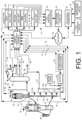
- FIG. 1 is a schematic block diagram illustrating an example FCC processing assembly including an example FCC reactor, an example catalyst regenerator, and an example FCC control assembly, according to embodiments of the disclosure.
- FIG. 2 is a schematic block diagram illustrating an example FCC processing assembly including an example FCC control assembly and an example sample conditioning assembly, according to embodiments of the disclosure.
- FIG. 3 is a schematic block diagram illustrating an example sample conditioning assembly, according to embodiments of the disclosure.
- FIG. 4 A is a block diagram of a spectroscopic analyzer assembly including a first standardized spectroscopic analyzer and a first analyzer controller configured to standardize a plurality of spectroscopic analyzers and showing example inputs and example outputs in relation to an example timeline, according to embodiments of the disclosure.
- FIG. 4 B is a continuation of the block diagram shown in FIG. 4 A showing the plurality of example standardized spectroscopic analyzers outputting respective analyzer portfolio sample-based corrections based at least in part on respective variances, and analyzing conditioned materials for outputting respective corrected material spectra, according to embodiments of the disclosure.
- FIG. 4 C is a continuation of the block diagrams shown in FIGS. 4 A and 4 B showing respective corrected material spectra output by the plurality of standardized spectroscopic analyzers used to output predicted (or determined) material data for the materials for use in an example FCC process, according to embodiments of the disclosure.
- FIG. 5 A is a block diagram of an example method to enhance a fluid catalytic cracking (FCC) process associated with a refining operation, during the FCC process, according to embodiments of the disclosure.
- FCC fluid catalytic cracking
- FIG. 5 B is a continuation of the block diagram shown in FIG. 5 A , according to embodiments of the disclosure.
- FIG. 5 C is a continuation of the block diagram shown in FIG. 5 A and FIG. 5 B , according to embodiments of the disclosure.
- FIG. 5 D is a continuation of the block diagram shown in FIG. 5 A , FIG. 5 B , and FIG. 5 C , according to embodiments of the disclosure.
- FIG. 5 E is a continuation of the block diagram shown in FIG. 5 A , FIG. 5 B , FIG. 5 C , and FIG. 5 D , according to embodiments of the disclosure.
- FIG. 6 A is a table illustrating spectroscopic analysis data associated with an example FCC process including samples of hydrotreater charges and products, and FCC feeds used to control relative amounts of each hydrocarbon class shown in weight percent, according to embodiments of the disclosure.
- FIG. 6 B is a table illustrating minimum and maximum amounts for a calibration set shown in weight percent for example hydrocarbon classes related to the data shown in FIG. 6 A , according to embodiments of the disclosure.
- FIG. 7 illustrates example near-infrared (NIR) absorption spectra for example FCC feed samples, according to embodiments of the disclosure.
- NIR near-infrared
- FIG. 8 illustrates example NIR absorption second derivative spectra derived from the example NIR absorption spectra shown in FIG. 7 , according to embodiments of the disclosure.
- FIG. 9 A is a table showing NIR regression statistics for each of a plurality of example properties, according to embodiments of the disclosure.
- FIG. 9 B is a table showing NIR regression statistics for each of a plurality of example properties, according to embodiments of the disclosure.
- FIG. 10 is a correlation plot showing predicted sulfur content of an example hydrocarbon feed based on analysis by an on-line NIR spectroscopic analyzer versus results obtained from a laboratory analysis, according to embodiments of the disclosure.
- FIG. 11 is a correlation plot showing predicted API gravity of an example hydrocarbon feed based on analysis by an on-line NIR spectroscopic analyzer versus results obtained from a laboratory analysis, according to embodiments of the disclosure.
- FIG. 12 is a correlation plot showing predicted percent coker gas oil of an example hydrocarbon feed based on analysis by an on-line NIR spectroscopic analyzer versus results obtained from a laboratory analysis, according to embodiments of the disclosure.
- FIG. 13 A is a graph showing example hydrocarbon feed sulfur content determined off-line over time, according to embodiments of the disclosure.
- FIG. 13 B is a graph showing example hydrocarbon feed API gravity determined off-line over time, according to embodiments of the disclosure.
- FIG. 13 C is a graph showing example hydrocarbon feed Conradson carbon determined off-line over time, according to embodiments of the disclosure.
- FIG. 14 A is a graph showing example gasoline conversions determined off-line over time, according to embodiments of the disclosure.
- FIG. 14 B is a graph showing example gasoline yields determined off-line over time, according to embodiments of the disclosure.
- FIG. 14 C is a graph showing example light cycle oil (LCO) yields determined off-line over time, according to embodiments of the disclosure.
- LCO light cycle oil
- FIG. 14 D is a graph showing example slurry yields determined off-line over time, according to embodiments of the disclosure.
- FIG. 15 is a schematic diagram of an example fluid catalytic cracking (FCC) process controller configured to at least partially control an FCC processing assembly, according to embodiments of the disclosure.
- FCC fluid catalytic cracking
- a multi-component sample may refer to a single (one) sample including a plurality of components, such as two or more components.
- the terms “comprising,” “including,” “carrying,” “having,” “containing,” and “involving,” whether in the written description or the claims and the like, are open-ended terms, in particular, to mean “including but not limited to,” unless otherwise stated. Thus, the use of such terms is meant to encompass the items listed thereafter, and equivalents thereof, as well as additional items.
- the transitional phrases “consisting of” and “consisting essentially of,” are closed or semi-closed transitional phrases, respectively, with respect to any claims.
- the “sampling circuit” may refer to an assembly for facilitating separation of a sample of a material, a sample of a composition of material, and/or a sample of an FCC product, for example, for processing and/or analysis of the sample.
- sample conditioner may refer to an assembly for facilitating preparation of a sample for analysis, for example, to improve the accuracy of analysis of the sample and/or to provide consistency and/or repeatability of the analysis of the sample or more than one sample.
- the term “spectroscopic analyzer” may refer an analyzer that may be used to measure or predict one or more properties of a sample of, for example, a material, a composition of materials, and/or an FCC product. In some embodiments, the spectroscopic analyzers may be used online or in a laboratory setting. “Spectroscopic analyzer” may refer in some instances to a spectroscopic analyzer assembly, which may include a spectroscopic analyzer and an analyzer controller in communication with one or more spectroscopic analyzers. The analyzer controller may be configured for use with a corresponding spectroscopic analyzer for pre-processing and/or post-processing steps or procedures related to a spectroscopic analysis, as will be understood by those skilled in the art.
- the analyzer controller may be physically connected to the spectroscopic analyzer.
- the spectroscopic analyzer may include a housing, and at least a portion of the analyzer controller may be contained in the housing.
- the analyzer controller may be in communication with the spectroscopic analyzer via a hard-wired communications link and/or wireless communications link.
- the analyzer controller may be physically separated from the spectroscopic analyzer and may be in communication with the spectroscopic analyzer via a hard-wired communications link and/or a wireless communications link.
- physical separation may include being spaced from one another, but within the same building, within the same facility (e.g., located at a common manufacturing facility, such as a refinery), or being spaced from one another geographically (e.g., anywhere in the world).
- both the spectroscopic analyzer and the analyzer controller may be linked to a common communications network, such as a hard-wired communications network and/or a wireless communications network.
- Such communications links may operate according to any known hard-wired communications protocols and/or wireless communications protocols, as will be understood by those skilled in the art.
- sample introducer may refer to a component or assembly that may be used to facilitate the provision of a conditioned sample (portion or stream) to one or more spectroscopic analyzers for analysis.
- sample stream may refer to a portion of a sample stream supplied to one or more spectroscopic analyzers for spectroscopic analysis by the one or more spectroscopic analyzers.
- the term “predicting” may refer to measuring, estimating, determining, and/or calculating one or more properties of a material, a composition of materials, and/or an FCC product based on, for example, a mathematical relationship, a correlation, an analytical model, and/or a statistical model.
- sample probe may refer to a component or an interface used to facilitate collection of a sample for analysis by, for example, one or more spectroscopic analyzers.
- the term “analyzer probe” may refer to a component of one or more spectroscopic analyzers that facilitates direction of electromagnetic radiation (e.g., light energy) from a source through a sample stream (e.g., a conditioned sample stream) to detect and/or measure one or more of absorbance, transmittance, transflectance, reflectance, or scattering intensity associated with the sample stream.
- electromagnetic radiation e.g., light energy
- sample cell may refer to a receptacle or cell for receipt of samples for analysis or measurement, for example, by a spectroscopic analyzer.
- an on-line spectroscopic analyzer may receive one or more sample streams directly from a processing assembly or process and analyze the one or more sample streams in real-time or near real-time to provide results that may, in some embodiments, be used to at least partially control operation of one or more processing assemblies and/or one or more processes in real-time or near real-time.
- the on-line spectroscopic analyzer or analyzers may be physically located in a laboratory setting. This may be either extractive (e.g., a sample stream is drawn off of a processing unit and supplied to a spectroscopic analyzer and/or to one or more sensors) or in situ (e.g., a probe of a spectroscopic analyzer or one or more sensors is present in a conduit associated with the processing assembly).
- extractive e.g., a sample stream is drawn off of a processing unit and supplied to a spectroscopic analyzer and/or to one or more sensors
- in situ e.g., a probe of a spectroscopic analyzer or one or more sensors is present in a conduit associated with the processing assembly.
- the term “at-line” may refer to equipment and/or processes that are physically located at or adjacent to processing assemblies during operation, but which, for at least some embodiments, are not capable of providing real-time and/or near real-time analysis and/or are not capable providing data capable of real-time and/or near real-time analysis.
- a “field analyzer” located physically at or adjacent a processing assembly may be used to analyze a sample withdrawn from the processing assembly or process and manually taken to the field analyzer for analysis.
- the at-line spectroscopic analyzer or analyzers may be physically located in a laboratory setting.
- an at-line spectroscopic analyzer would not receive a sample stream directly from processing assemblies, but instead, would manually receive a sample manually withdrawn from a processing unit by an operator and manually taken or delivered by the operator to the at-line spectroscopic analyzer.
- FIG. 1 is a schematic block diagram illustrating an example fluid catalytic cracking (FCC) processing assembly 10 including an example FCC reactor 12 , an example catalyst regenerator 14 , and an example FCC control assembly 16 , according to embodiments of the disclosure.
- FCC fluid catalytic cracking
- the example FCC processing assembly 10 may be used in association with a refinery.
- catalytic cracking may be used to convert hydrocarbon feedstock or feed/charge 18 , for example, heavy feeds including hydrocarbons having boiling points ranging from about 600 degrees Fahrenheit (F) to about 1,050 degrees, such as, for example, atmospheric gas oil, vacuum gas oil, coker gas oil, lube extracts, and/or slop streams, into lighter products, such as, for example, light gases, olefins, gasoline, distillate, and/or coke, by catalytically cracking large molecules into smaller molecules.
- heavy feeds including hydrocarbons having boiling points ranging from about 600 degrees Fahrenheit (F) to about 1,050 degrees, such as, for example, atmospheric gas oil, vacuum gas oil, coker gas oil, lube extracts, and/or slop streams
- lighter products such as, for example, light gases, olefins, gasoline, distillate, and/or coke
- catalytic cracking may be performed at relatively low pressures (e.g., pressures ranging from about 15 pounds per square inch (psig) to about 30 psig), for example, in the absence of externally supplied hydrogen (H 2 ), or in some embodiments (e.g., including hydrocracking), in which hydrogen is added during one or more cracking steps.
- pressures e.g., pressures ranging from about 15 pounds per square inch (psig) to about 30 psig
- H 2 externally supplied hydrogen
- hydrocracking hydrocracking
- the hydrocarbon feed/charge 18 may include FCC feedstocks including a fraction of crude oil having boiling points ranging from about 650 degrees F. to about 1,000 degrees F., which, in some embodiments, may be relatively free of coke precursors and/or heavy metal contamination, such as, for example, feedstock sometimes referred to as “vacuum gas oil” (VGO), which, in some instances, may be generally obtained from crude oil by distilling off the fractions of the feedstock having boiling points below 650 degrees F. at atmospheric pressure and thereafter separating by further vacuum distillation from the heavier fractions a cut having boiling points ranging from about 650 degrees F. to about 900 degrees to 1,025 degrees F., for example, as will be understood by those skilled in the art.
- VGO vacuum gas oil
- Fractions of the feedstock having boiling points ranging from above about 900 degrees F. to about 1,025 degrees F. may be used for other purposes, such as, for example, asphalt, residual fuel oil, #6 fuel oil, and/or marine Bunker C fuel oil.
- some of the cuts having higher boiling points may be used, for example, as feedstock in association with FCC processes that use carbo-metallic oils formed by reduced crude conversion (RCC), for example, using a progressive flow-type reactor having an elongated reaction chamber.
- RCC reduced crude conversion
- the hydrocarbon feed/charge 18 may be selected to increase or optimize production of propylene by an FCC processing assembly, such as, for example, the hydrocarbon feedstock/charge 18 may be selected to contain feedstocks having a particular aromatics content, a particular hydrogen content, and/or other particular feedstock characteristics known to those skilled in the art to increase, enhance, or optimize propylene production by an FCC processing assembly.
- one or more analytical models may be used to predict (or determine) process yields as a function of, for example, feedstock quality (e.g., feedstock content and/or properties), catalyst conditions, and/or processing conditions or parameters.
- feedstock quality e.g., feedstock content and/or properties
- catalyst conditions e.g., catalyst conditions, and/or processing conditions or parameters.
- an optimizer algorithm may be incorporated into or used with the one or more analytical models to determine an improved or optimum combination of, for example, feedstock rate, processing conditions or parameters, and/or catalyst properties for performing the FCC process.
- spectroscopic analyzers for example, as described herein to provide accurate information related to hydrocarbon feedstock properties and/or parameters, accurate unit material property information (e.g., intermediates and/or product yields), and/or other related analytical data may facilitate determining the improved or optimum combination(s) of, for example, feedstock rate, processing conditions or parameters, and/or catalyst properties for performing the FCC process.
- the one or more spectroscopic analyzers may facilitate improvement or optimization during the FCC process (e.g., in real-time), which may reduce or eliminate inefficient operation of the FCC process that may result from delaying changes to properties and/or parameters associated with the materials and processing units due to delays with receiving test results from, for example, off-line laboratory testing.
- one or more spectroscopic analyzers may be used on-line to facilitate control, improvement, and/or optimization of the FCC process during the FCC process.
- the spectroscopic analyzer(s) may be used to relatively precisely predict or determine process properties and/or parameters associated with materials involved with the FCC process, including the hydrocarbon feedstock, intermediate materials produced by the one or more FCC processing units, and/or products produced by the FCC processing units and/or downstream processing units.
- properties and parameters may include, for example, feed quality, feed rate, FCC operating conditions, and/or FCC product properties. Other properties and parameters are contemplated, such as those described herein, as well as others.
- measurement for example, during the FCC process, of properties and processing parameters (e.g., processing conditions) may be used to manipulate or control the FCC process.
- advanced process control-related (APC-related) techniques may be used to improve, optimize, and/or maximize the FCC process against processing constraints, such as, for example, processing unit capabilities.
- Control during the FCC process for example, leveraging APC-related techniques, may facilitate control of the FCC process to balance intermediates and/or products yield(s), recovery, capacity, and/or efficiency, for example, selected from multiple process variables and equipment capabilities, which may include material properties and/or parameters associated with the feedstock, catalyst, intermediates, and/or products, as well as operational parameters associated with the one or more FCC processing units.
- a spectroscopic analyzer may be used to collect spectra of samples of the hydrocarbon feedstock for the FCC process.
- the collected spectral data may be indicative of one or more properties and/or parameters associated with the hydrocarbon feedstock, and may be correlated to traditional laboratory tests (e.g., performed via one or more primary test methods), including, for example, HPLC Heavy Distillate Analyzer (HDA) results for aromatic core type (e.g., 1-ring core, 2-ring core, 3-ring core, 4-ring core, and/or polars), ASTM D2887 high temperature simulated distillation, basic nitrogen, total nitrogen, API gravity, total sulfur, mean cell residence time (MCRT), and percent of coker gas oil in vacuum gas oil (VGO).
- HDA HPLC Heavy Distillate Analyzer
- MCRT mean cell residence time
- VGO percent of coker gas oil in vacuum gas oil
- the spectroscopic analyzer(s) may be used to monitor the hydrocarbon feedstock more responsively, more accurately, and/or more efficiently, as
- certain wavelengths, wavenumbers, and/or frequencies may be useful for controlling, improving, and/or optimizing the FCC process, for example, by controlling operation of one or more FCC processing units.
- a process may be used for controlling on-line hydrocarbon feedstock, intermediates, and unit materials (e.g., FCC products) exhibiting absorption in the near infrared region.
- a method for controlling on-line an FCC process may include measuring absorbances of the hydrocarbon feed using a spectroscopic analyzer at wavelengths ranging from about 780 nanometers (nm) to about 2,500 nm), and outputting one or more signals indicative of the absorbances.
- the method may further include subjecting the one or more signals to mathematical treatment or manipulation, such as, for example, taking one or more derivatives, smoothing, and/or performing baseline correction of the one or more signals.
- the method further may include using an analytical model to determine one or more chemical and/or physical properties of the hydrocarbon feed, intermediates, and/or unit materials (e.g., products) based at least in part on the treated and/or manipulated one or more signals, and outputting a processed signal.
- the method further may include controlling on-line, based at least in part on the processed signal, at least one property and/or parameter associated with the hydrocarbon feed, the intermediates, and/or the unit materials, and/or one or more processing unit parameters.
- the FCC process may be at least partially controlled by selecting a hydrocarbon feedstock having certain properties and/or parameters based at least in part on one or more characteristics associated with one or more of the FCC processing units, for example, as well as controlling one or more processing parameters associated with the one or more FCC processing units.
- one or more FCC processing parameters and/or conditions may be varied to effect products resulting for the FCC process. For example, operating under relatively more severe cracking conditions, for example, by increasing the processing temperatures, may result in providing a gasoline product having a relatively higher octane rating, while increasing conversion may result in providing relatively more olefins for alkylate production, as well as relatively more gasoline and potential alkylate.
- Catalytic cracking may also be affected by inhibitors, which may be naturally present in the hydrocarbon feed and/or or may be added. Generally, as the boiling range of the hydrocarbon feed increases, the concentration of inhibitors naturally therein may also increase. The effects of inhibitors may be temporary or lasting, depending on, for example, the type of inhibitor present.
- Nitrogen inhibitors may generally provide temporary effects, while heavy metals, such as nickel, vanadium, iron, copper, etc., which may quantitatively transfer from the hydrocarbon feed to the catalyst may provide a more lasting effect.
- Metals poisoning may result in relatively higher dry gas yields, relatively higher hydrogen factors, relatively higher coke yields as a percent of conversion, and/or relatively lower gasoline yields.
- Coke precursors such as asphaltenes may tend to break down into coke during cracking, which may be deposited on the catalyst, reducing its activity.
- an inventory of particulate catalyst may be generally continuously cycled between the FCC reactor and the catalyst regenerator.
- hydrocarbon feedstock may contact catalyst in the FCC reactor, for example, at a temperature ranging from about 425 degrees C. to about 600 degrees C., (e.g., from about 460 degrees C. to about 560 degrees C.).
- As the hydrocarbons crack carbonaceous hydrocarbons and/or coke may be deposited on the catalyst.
- the cracked products may be separated from the coked catalyst.
- the coked catalyst may be stripped of volatiles, for example, with steam, and thereafter may be regenerated.
- the coke may be burned from the catalyst using oxygen-containing gas, such as air.
- the coke burns off, restoring catalyst activity and heating the catalyst to, for example, as temperature ranging from about 500 degrees C. to about 900 degrees C. (e.g., from about 600 degrees C. to about 750 degrees C.).
- flue gas formed by burning coke in the catalyst regenerator may thereafter be discharged into the atmosphere.
- the one or more FCC processing units may use zeolite-containing catalyst having relatively high activity and/or selectivity.
- Such catalysts may be relatively more effective when the amount of coke on the catalyst after regeneration is relatively low, such as, for example, less than about 0.1 wt % (e.g., less than about 0.05 wt %).
- CO carbon monoxide
- CO 2 carbon dioxide
- FCC processing units may be operated in a complete CO combustion mode, for example, such that the mole ratio of CO 2 -to-CO is at least 10.
- the CO may be burned within the catalyst regenerator to conserve heat and/or minimize undesirable emissions.
- CO may be burned in the catalyst regenerator by adding platinum catalyst.
- a desired product slate may be determined based at least in part on spectroscopic analysis of one or more of the unit materials (e.g., the FCC products), which may be used for monitoring and/or controlling one or more aspects of the FCC process, such as one or more processing parameters for operation of one or more of the FCC processing units.
- the unit materials e.g., the FCC products
- one or more spectroscopic analyzers may be used to determine one or more properties and/or one or more parameters associated with the hydrocarbon feedstock.
- the one or more properties and/or parameters may be used to monitor and/or control operation of one or more of the FCC processing units.
- the hydrocarbon feed properties and/or parameters may variables used for controlling the FCC process and may include, for example, but are not limited to, weight percent (wt. %) or volume percent (vol. %) of mono-aromatics, di-aromatics, tri-aromatics, benzothiophenes, di-benzothiophenes, paraffins, naphthenes, aromatics, and/or nitrogen content.
- Unit material properties and/or unit material parameters may include, for example, but are not limited to, amount of butane (C4) free gasoline (volume), amount of total C4 (volume), amount of dry gas (wt), amount of coke (wt), an amount of propylene (e.g., propylene yield), gasoline octane, amount of light fuel oil (LFO), amount of heavy fuel oil (HFO), amount of hydrogen sulfide (H 2 S), amount of sulfur in the LFO, and/or the aniline point of the LFO.
- C4 butane
- C4 butane
- wt dry gas
- wt amount of coke
- propylene e.g., propylene yield
- gasoline octane amount of light fuel oil (LFO), amount of heavy fuel oil (HFO), amount of hydrogen sulfide (H 2 S), amount of sulfur in the LFO, and/or the aniline point of the LFO.
- the example fluid catalytic cracking (FCC) assembly 10 includes the example FCC reactor 12 and the example catalyst regenerator 14 , and the example FCC control assembly 16 may be used to at least partially (e.g., semi-autonomously, autonomously, and/or fully) control an FCC process performed by the FCC processing assembly 10 .
- FCC fluid catalytic cracking
- the FCC control assembly 16 may include one or more spectroscopic analyzers 20 (e.g., 20 A through 20 N as shown), which may be used to receive (e.g., on-line), analyze, and generate one or more spectra indicative of properties and/or parameters of samples of the feed/charge 18 (e.g., the hydrocarbon feedstock) and/or indicative of properties of samples of one or more unit materials produced by one or more FCC processing units 22 .
- one or more of the spectroscopic analyzers 20 may be configured to receive more than a single stream of material for analysis.
- a multiplexer may be associated with the one or more spectroscopic analyzers 20 to facilitate analysis of two or streams of material by a single spectroscopic analyzer.
- one or more of the spectroscopic analyzers 20 A though 20 N may be used and/or located online and/or in a laboratory setting.
- the one or more unit materials may include one or more of intermediate materials or unit product materials, for example, including FCC effluent and/or other associated materials taken from any point or any stage of the FCC process.
- two or more of the spectroscopic analyzers 20 A through 20 N may be calibrated to generate standardized spectral responses, for example, as described herein.
- a first spectroscopic analyzer 20 A and additional spectroscopic analyzers 20 B through 20 N may be calibrated to generate standardized spectral responses, for example, such that each of the first spectroscopic analyzer 20 A and the additional spectroscopic analyzers 20 B through 20 N output a respective corrected material spectrum, including a plurality of signals indicative of a plurality of material properties of an analyzed material based at least in part on the corrected material spectrum, such that the plurality of material properties or parameters of the analyzed material outputted by the first spectroscopic analyzer 20 A are substantially consistent with a plurality of material properties of the analyzed material outputted by the additional spectroscopic analyzers 20 B through 20 N.
- one of more of the spectroscopic analyzers 20 A through 20 N may be located in a laboratory setting, for example, as schematically depicted in FIG. 1 with respect to the first spectroscopic analyzer 20 A.
- the one or more hydrocarbon feed/charge 18 sample properties and/or the one or more unit material sample properties may include a content ratio indicative of relative amounts of one or more hydrocarbon classes present in one or more of the hydrocarbon feed/charge 18 sample and/or the unit material samples.
- Other hydrocarbon feed/charge 18 sample properties and/or unit material sample properties are contemplated. Although many embodiments described herein use more than one spectroscopic analyzer, it is contemplated that a single spectroscopic analyzer may be used for at least some embodiments of the FCC processes described herein.
- One or more of the spectroscopic analyzers 20 A through 20 N may include one or more near-infrared (NIR) spectroscopic analyzers, one or more mid-infrared (mid-IR) spectroscopic analyzers, one or more combined NIR and mid-IR spectroscopic analyzers, and/or one or more Raman spectroscopic analyzers.
- one or more of the spectroscopic analyzer(s) 20 A through 20 N may include a Fourier Transform near infrared (FTNIR) spectroscopic analyzer, a Fourier Transform infrared (FTIR) spectroscopic analyzer, or an infrared (IR) type spectroscopic analyzer.
- FNIR Fourier Transform near infrared
- FTIR Fourier Transform infrared
- IR infrared
- one or more of the spectroscopic analyzers 20 A through 20 N may be ruggedized for use in an on-line analyzing process and/or in a laboratory setting, and in some embodiments, one or more of the spectroscopic analyzers 20 A through 20 N may be at least partially housed in a temperature-controlled and/or explosion-resistant cabinet.
- some embodiments of the one or more spectroscopic analyzers 20 A through 20 N may be configured to withstand operating conditions, such as, for example, temperature, pressure, chemical compatibility, vibrations, etc., that may be present in an on-line environment and/or in a laboratory setting.
- the one or more spectroscopic analyzers 20 A through 20 N may be designed to be operated in a particular environment of use and/or an environment that meets area classifications, such as, for example, a Class 1 , Division 2 location.
- area classifications such as, for example, a Class 1 , Division 2 location.
- a photometer with present optical filters moving successively into position may be used as a type of spectroscopic analyzer.
- the FCC processing assembly 10 also may include one or more FCC process controllers 24 in communication with one or more of the spectroscopic analyzers 20 A through 20 N and that control one or more aspects of the FCC process.
- the FCC process controller(s) 24 may be configured to predict (or determine) one or more hydrocarbon feedstock sample properties and/or parameters associated with samples of the hydrocarbon feed/charge 18 , for example, based at least in part on hydrocarbon feedstock sample spectra generated by the one or more spectroscopic analyzers 20 A through 20 N (e.g., first spectroscopic analyzer 20 A, as shown in FIG. 1 ).
- the FCC process controller(s) 24 may be configured to predict (or determine) one or more unit material sample properties and/or parameters associated with the unit material samples based at least in part on the unit material sample spectra generated by the one or more spectroscopic analyzers 20 A through 20 N.
- each of the one or more spectroscopic analyzer(s) 20 A through 20 N may output a signal communicated to the one or more FCC process controller(s) 24 , which may mathematically manipulate the signal (e.g., take a first or higher order derivative of the signal) received from the spectroscopic analyzer, and subject the manipulated signal to a defined model to generate material properties and/or parameters of interest, for example, as described herein.
- such models may be derived from signals obtained from spectroscopic analyzer measurement of the one or more unit materials (e.g., the intermediates and/or the cracking products).
- an analyzer controller in communication with a corresponding one or more of the spectroscopic analyzer(s) 20 A through 20 N may be configured to receive the signal output by the one or more corresponding spectroscopic analyzers and mathematically manipulate the signal, for example, prior to the one or more FCC process controller(s) 24 receiving the signal.
- the FCC process controller(s) 24 may be configured to prescriptively control, during the FCC process, via one or more FCC process controllers 24 , based at least in part on the one or more hydrocarbon feedstock parameters, the one or more hydrocarbon feedstock sample properties, and/or the one or more unit material sample properties, (i) the one or more hydrocarbon feedstock parameters associated with the hydrocarbon feedstock 18 supplied to the one or more FCC processing units 22 ; (ii) one or more intermediates properties associated with the intermediate materials produced by one or more of the FCC processing units 22 ; (iii) operation of the one or more FCC processing units 22 ; (iv) one or more unit materials properties associated with the one or more unit materials; and/or (v) operation of one or more processing units positioned downstream relative to the one or more FCC processing units 22 such as, for example, a fractionator 26 configured to separate various hydrocarbon products of FCC effluent received from the FCC reactor 12 .
- a fractionator 26 configured to separate various hydrocarbon products of FCC eff
- the prescriptive control may result in causing the FCC process to produce one or more of: (a) one or more intermediate materials each having one or more properties within a selected range of one or more target properties of the one or more intermediate materials; (b) one or more unit materials each having one or more properties within a selected range of one or more target properties of the one or more unit materials; or (c) one or more downstream materials each having one or more properties within a selected range of one or more target properties of the one or more downstream materials. In some embodiments, this may result causing the FCC process to achieve material outputs that more accurately and responsively converge on one or more of the target properties.
- the prescriptive control may result in optimizing one or more target properties of the one or more intermediate materials, one or more target properties of the one or more unit materials, and/or one or more target properties of one or more downstream materials produced by the one or more second processing units, for example, thereby to optimize the FCC process to achieve material outputs that more accurately and responsively converge on one or more of the target properties.
- the FCC processing assembly 10 further may include a sample conditioning assembly 28 configured to condition the hydrocarbon feed/charge 18 , for example, prior to being supplied to the one or more spectroscopic analyzer(s) 20 A through 20 N.
- the sample conditioning assembly 28 may be configured to filter samples of the hydrocarbon feed/charge 18 , change (e.g., control) the temperature of the samples of the hydrocarbon feed/charge 18 , dilute the samples of the hydrocarbon feed/charge 18 in solvent (e.g., on-line and/or in a laboratory setting), and/or degas the samples of the hydrocarbon feed/charge 18 .
- one or more sample conditioning procedures may be performed without using the sample conditioning assembly 28 , for example, in a laboratory setting.
- the sample conditioning assembly 28 also may be configured to condition samples of the unit materials, for example, prior to being supplied to the one or more spectroscopic analyzer(s) 20 A through 20 N, to filter the samples of the unit materials, to change (e.g., control) the temperature of the samples of the unit materials, dilute the samples of the unit materials in solvent, and/or degas the samples of the unit materials.
- this may include diluting samples of the hydrocarbon feed/charge 18 and/or the unit materials, such dilution may be used for analysis in a laboratory setting, and in some embodiments, the dilution may be performed in a laboratory setting.
- sample conditioning by the sample conditioning assembly 28 may result in more accurate, more repeatable, and/or more consistent analysis of the hydrocarbon feed/charge 18 and/or the one or more unit materials, which may in turn result in improved and/or more efficient control and/or more accurate control of the FCC process.
- Example embodiments of a sample conditioning assembly 28 are described herein, for example, with respect to FIG. 3 .
- the one or more FCC process controller(s) 24 may be configured to control at least some aspects of operation of the sample conditioning assembly 28 , for example, as described herein.
- the one or more FCC process controller(s) 24 may be configured to prescriptively control one or more process parameters associated with operation of one or more of the FCC processing units 22 .
- the FCC process controller(s) 24 may be configured to generate one or more processing unit control signal(s) 30 indicative of parameters associated with operation of the FCC processing units 22 , such as, for example, the rate of supply of the hydrocarbon feed/charge 18 the one or more FCC processing units 22 ; the pressure of the hydrocarbon feed/charge 18 supplied to the one or more FCC processing units 22 ; a preheating temperature of the hydrocarbon feed/charge 18 supplied to the one or more FCC processing units 22 ; the temperature in the FCC reactor 12 or one or more other FCC processing units 22 ; or a reactor pressure associated with a reaction mixture in the FCC reactor 12 , wherein the reaction mixture may include the hydrocarbon feed/charge 18 and catalyst to promote catalytic cracking of the hydrocarbon feed/charge 18 .
- the reaction mixture may include the hydrocarbon feed/charge 18 and catalyst to promote cata
- the one or more process parameters may include, for example, residence time in the reactor, reaction temperature, catalyst-to-oil ratio, hydrocarbon partial pressure, and/or other process parameters associated with the production of propylene by an FCC processing assembly known to those skill in the art. Control of other parameters associated with operation of the FCC processing units 22 are contemplated. In some embodiments, controlling the one or more operating parameters of the one or more FCC processing units 22 may include controlling the one or more operating parameters against operating constraints associated with the one or more FCC processing units 22 .
- a feedstock parameter associated with the hydrocarbon feed/charge 18 supplied to the one or more FCC processing units may include content, temperature, pressure, flow rate, API gravity, UOP K factor, distillation points, coker gas oil content, carbon residue content, nitrogen content, sulfur content, catalyst oil ratio, saturates content, thiophene content, single-ring aromatics content, dual-ring aromatics content, triple-ring aromatics content, and/or quad-ring aromatics content.
- one or more of the FCC process controller(s) 24 may be configured to prescriptively control at least a portion of the FCC process by, for example, operating an analytical cracking model, which may be executed by one or more computer processors.
- the analytical cracking model may be configured to improve the accuracy of: predicting (or determining) one or more properties and/or one or more parameters associated with the hydrocarbon feed/charge 18 supplied to the one or more FCC processing units 22 ; predicting (or determining) one or more properties and/or one or more parameters associated with intermediate materials produced by the one or more FCC processing units 22 ; controlling the one or more properties and/or one or more parameters associated with the hydrocarbon feed/charge 18 supplied to the one or more FCC processing units 22 ; controlling the one or more properties and/or one or more parameters associated with the intermediate materials produced by the one or more FCC processing units 22 ; controlling one or more properties and/or one or more parameters associated with the FCC effluent produced by the one or more FCC processing units 22 ; the
- the analytical cracking model may include or be a machine-learning-trained model.
- the FCC process controller(s) 24 may be configured to: (a) provide, to the analytical cracking model, catalytic cracking processing data related to: (i) material data including one or more of: feedstock data indicative of one or more parameters and/or properties associated with the hydrocarbon feed/charge 18 ; unit material data indicative of one or more unit material properties associated with the one or more unit materials; and/or downstream material data indicative of one or more downstream material properties associated with one or more downstream materials produced by the one or more downstream processing units 36 ; and/or (ii) processing assembly data including: first processing unit data indicative of one or more operating parameters 32 associated with operation of the one or more processing units 34 , such as, for example, the one or more FCC processing units 22 ; second processing unit data indicative of one or more operating parameters associated with operation of the one or more of the processing units 34 (collectively), such as, for example, the one or more downstream processing units 36 ; and
- the unit material properties and/or unit material parameters may include, for example, but are not limited to, amount of butane (C4) free gasoline (volume), amount of total C4 (volume), amount of dry gas (wt), amount of coke (wt), gasoline octane, amount of light fuel oil (LFO), amount of heavy fuel oil (HFO), amount of hydrogen sulfide (H 2 S), amount of sulfur in the LFO, and/or the aniline point of the LFO.
- C4 butane
- C4 butane
- wt dry gas
- wt amount of coke
- gasoline octane gasoline octane
- amount of light fuel oil (LFO) amount of heavy fuel oil (HFO)
- H 2 S amount of hydrogen sulfide
- the analytical cracking model may include one or more cracking algorithms.
- the cracking algorithms may be configured to determine, based at least in part on the catalytic cracking data, target material properties for one or more of the hydrocarbon feed/charge 18 , the unit materials, or the downstream materials.
- the cracking algorithms further may be configured to prescriptively control operation of one or more of the FCC processing units 22 and/or the one or more downstream processing units 36 , for example, to produce one or more of unit materials having unit material properties within a first predetermined range of target unit material properties for the unit materials, or one or more of downstream materials having downstream material properties within a second predetermined range of target material properties for the downstream materials.
- Within range may include within a range above (but not below) the target unit material properties or the target material properties of the downstream materials, within a range below (but not above) the target unit material properties or the target material properties of the downstream materials, or within a range surrounding (on either or both sides of) the target unit material properties or the target material properties of the downstream materials.
- the cracking algorithms also may be configured to determine one or more of actual unit material properties for the unit materials produced by the one or more FCC processing units 24 or one or more of actual downstream material properties for the downstream materials produced by the one or more downstream processing units 36 .
- the cracking algorithms further may be configured to determine one or more of unit material differences between the actual unit material properties and the target unit material properties or downstream material differences between the actual downstream material properties and the target downstream material properties. In some embodiments, the cracking algorithms further still may be configured to change, based at least in part on one or more of the unit material differences or the downstream material differences, the one or more cracking algorithms to reduce the one or more of the unit material differences or the downstream material differences. In some embodiments, the cracking algorithms may result in more responsively controlling the FCC processing assembly 10 , the FCC processing unit(s) 22 , and/or the downstream processing unit(s) 36 to achieve material outputs that more accurately and responsively converge on the target properties.
- the one or more FCC process controller(s) 24 may be configured to prescriptively control by one or more of (i) generating, based at least in part on the target unit material properties, one or more first processing unit control signals configured to control at least one first processing parameter associated with operation of the one or more FCC processing unit(s) 22 to produce one or more unit materials having unit material properties within the first preselected range of the target unit material properties; or (ii) generating, based at least in part on the target downstream material properties, a second processing unit control signal configured to control at least one second processing parameter associated with operation of the one or more downstream processing unit(s) 36 to produce one or more downstream materials having downstream material properties within the second preselected range of the target downstream material properties.
- the FCC process controller(s) 24 still further may be configured to prescriptively control operation of the sample conditioning assembly 28 , for example, by generating, based at least in part on the catalytic cracking data, a conditioning control signal configured to control at least one conditioning parameter related to operation of the sample conditioning assembly 28 .
- the FCC process controller(s) 24 may be configured to predict the one or more hydrocarbon feed/charge 18 sample properties, for example, by mathematically manipulating a feedstock spectra signal indicative of the hydrocarbon feedstock sample spectra to provide a manipulated feedstock signal, and communicating the manipulated feedstock signal to an analytical property model configured to predict, based at least in part on the manipulated feedstock signal, the one or more hydrocarbon feedstock sample properties.
- the FCC process controller(s) 24 may be configured to predict the one or more unit material sample properties by mathematically manipulating a unit material spectra signal indicative of the unit material sample spectra to provide a manipulated unit material signal, and communicating the manipulated unit material signal to an analytical property model configured to predict, based at least in part on the manipulated unit material signal, the one or more unit material sample properties.
- the mathematical manipulation may be performed, for example, for an individual wavelength and/or a plurality of wavelengths over a range of wavelengths, and the mathematical manipulation may be based on, for example, a mathematical relationship, which may include one or more of a ratio, a correlation, an addition, a subtraction, a multiplication, a division, taking one or more derivatives, an equation, or a combination thereof, and/or other mathematically-derived relationships.
- the one or more FCC process controller(s) 24 may be configured to prescriptively control one or more aspects of the FCC process by, for example, generating, based at least in part on one or more of the hydrocarbon feed/charge 18 sample properties or one or more of the unit material sample properties, the one or more processing unit control signal(s) 30 to control on-line, during the FCC process, one or more of the processing parameter(s) 32 related to operation of one or more of the FCC processing unit(s) 22 and/or one or more of the downstream processing unit(s) 36 .
- the one or more unit sample properties may include reaction effluent yield, and the prescriptive control may include controlling a riser outlet temperature based at least in part on the reaction effluent yield and/or riser lift velocity based at least in part on the reaction effluent yield.
- the one or more unit material sample properties may include FCC product yield, and the prescriptive control may include, for example, controlling riser lift steam rate based at least in part on the FCC product yield.
- the one or more unit material sample properties may include riser stripper effluent, and the prescriptive control may include, for example, controlling FCC catalyst stripping based at least in part on the riser stripper effluent.
- the one or more unit material sample properties may include one or more reaction effluent properties
- the FCC process controller(s) 24 may further be configured to on-line model, based at least in part on the one or more reaction effluent properties, operation of the one or more FCC processing unit(s) 22 .
- the one or more FCC process controller(s) 24 may be configured to prescriptively control, real-time for improvement or optimization of the FCC process.
- the FCC process controller(s) 24 may be configured, in at least some embodiments, to provide the one or more hydrocarbon feed/charge 18 sample properties and/or the one or more unit material sample properties to fluid catalytic cracking (FCC) simulation software, for example, to model FCC processing unit material yields and/or FCC unit material characteristics.
- FCC fluid catalytic cracking
- the one or more FCC process controller(s) 24 may be configured to determine, via the FCC simulation software, based at least in part on the one or more hydrocarbon feed/charge 18 sample properties and/or the one or more unit material sample properties, one or more processing unit control parameters to achieve the FCC processing unit material yields and/or the FCC unit material characteristics.
- the FCC reactor 12 may be configured to receive the hydrocarbon feed/charge 18 and a catalyst to promote catalytic cracking of the hydrocarbon feed/charge 18 into the FCC effluent 38 , with the hydrocarbon feed/charge 18 and the catalyst providing a reaction mixture.
- the FCC control assembly 16 may include the one or more spectroscopic analyzers 20 A through 20 N, which may be configured to analyze reaction mixture samples taken from one or more locations of the FCC reactor 12 to obtain unit material samples of, for example, catalyst stripper vapor, reactor dilute vapor, riser vapor, and/or reactor effluent, for example, to determine respective catalyst stripper vapor yield, reactor dilute vapor yield, riser vapor yield, and/or reactor effluent yield.
- the unit sample properties may include one or more properties associated with reactor dilute vapors
- the FCC process controller(s) 24 may be configured to prescriptively control riser outlet conditions based at least in part on the reactor dilute vapors, and/or vapor quench based at least in part on the reactor dilute vapors.
- the one or more unit material properties may include one more unit material yields, and, in some embodiments, the FCC process controller(s) 24 may be configured to tune, based at least in part on the one or more unit material yields, a fluid catalytic cracking (FCC) simulation model, and/or benchmark, based at least in part on the one or more unit material yields, refinery linear program predicted yields.
- FCC fluid catalytic cracking
- some embodiments of the FCC processing assembly 10 may include the FCC reactor 12 , the catalyst regenerator 14 , and the FCC control assembly 16 configured to enhance control of operation of at least some aspects of the FCC processing assembly 10 and related processes, such as the FCC process, as described herein.
- the hydrocarbon feed/charge 18 may be supplied via a feed conduit 40 , and a heater 42 may be provided and configured to preheat the feed/charge 18 prior to being supplied to the FCC reactor 12 .
- the heater 42 may be any temperature control unit capable of heating the feed-charge 18 to a predetermined preheating temperature, such as, for example, a fossil-fuel-fired heater (e.g., a gas burner) and/or an electrically-powered heater.
- a fossil-fuel-fired heater e.g., a gas burner
- an electrically-powered heater e.g., a gas burner
- the heat flux supplied to the hydrocarbon feed/charge 18 may be controlled by, for example, the FCC process controller(s) 24 , which may control a flow of fuel (e.g., via a control valve) and/or electrical power supplied to the heater 42 . As shown in FIG.
- a sample of the hydrocarbon feed/charge 18 may be extracted upstream (before) the hydrocarbon feed/charge 18 is preheated, and the sample of the hydrocarbon feed/charge 18 may be supplied to the sample conditioning assembly 28 via a feed/charge sample conduit 44 for conditioning prior to be supplied to the one or more spectroscopic analyzer(s) 20 A through 20 N for analysis, for example, as described herein.
- a fiber optic probe in communication with the one or more spectroscopic analyzer(s) 20 A through 20 N may be inserted directly into the feed conduit 40 to facilitate analysis of the hydrocarbon feed/charge 18 by one or more of the spectroscopic analyzer(s) 20 A through 20 N, which may prevent a need to extract the sample of the hydrocarbon feed/charge 18 for analysis via the feed/charge sample conduit 44 .
- water/steam 46 may be added to the preheated hydrocarbon feed/charge 18 via a water/steam conduit 48 , for example, as shown in FIG. 1 .
- some embodiments of the FCC processing assembly 10 may include a riser 50 for conveying the preheated hydrocarbon feed/charge 18 to the FCC reactor 12 and for combining catalyst 52 , which may be received from the catalyst regenerator 14 , with the hydrocarbon feed/charge 18 forming a reaction mixture 54 , for example, to promote catalytic cracking of the hydrocarbon feed/charge 18 into the FCC effluent 38 in the FCC reactor 12 .
- the catalyst 52 may be supplied to a lower portion of the riser 50 , for example, via a catalyst return line 56 , as shown in FIG. 1 .
- the catalyst regenerator 14 may be configured to receive spent catalyst from the FCC reactor 12 via a catalyst stripper line 80 and at least partially recondition the spent catalyst, for example, by facilitating contact between the spent catalyst and air to burn-off carbon and produce flue gas that may exit the catalyst regenerator 14 via a regenerator cyclone 57 and a flue gas line 58 .
- the reaction mixture 54 may be in the form of vaporized products, which ascend the riser 50 and may be recovered, for example, via a reactor cyclone 59 in the form of the FCC effluent 38 .
- the FCC processing unit(s) 22 may include a catalyst cooler 60 , and the FCC process controller(s) 24 may be configured to control operation of the catalyst cooler 60 .
- the FCC effluent 38 may be supplied to one or more downstream processing units 36 , which may include, for example, the fractionator 26 and/or other associated downstream processing units 36 .
- the fractionator 26 may be configured to separate various hydrocarbon products of the FCC effluent 38 received from the FCC reactor 12 , such as, for example, hydrocarbon gases 60 (e.g., propane, butane, methane, and/or ethane), gasoline 62 , light gas oil 64 , and/or heavy gas oil 66 .
- the heavy gas oil 66 e.g., naphtha
- the FCC reactor 12 and/or the catalyst regenerator 14 may operate according to known FCC reactor and catalyst regenerator processes, except as described herein.
- the one or more spectroscopic analyzers 20 A through 20 B may be configured to receive material samples from one or more locations associated with the FCC processes and/or downstream processes.
- the material samples prior to being received by the one or more spectroscopic analyzers 20 A through 20 N for analysis, may be conditioned, for example, via the sample conditioning assembly 28 , as described herein.
- the one or more spectroscopic analyzers 20 A through 20 N may be configured to receive (e.g., on-line and/or in a laboratory) a sample of the hydrocarbon feed/charge 18 to be supplied to the one or more FCC processing units 22 associated with the refining operation via the feed/charge sample conduit 44 .
- the one or more spectroscopic analyzers 20 A through 20 N may be configured to analyze the sample of the hydrocarbon feed/charge 18 to provide hydrocarbon feedstock sample spectra.
- the one or more spectroscopic analyzers 20 A through 20 N may be configured to receive on-line a sample of the one or more unit materials produced by the one or more FCC processing units 22 .
- the one or more unit materials may include intermediate materials and/or unit product materials.
- the one or more spectroscopic analyzers 20 A through 20 N may be configured to analyze the samples of the unit materials to provide unit material sample spectra.
- one or more of the spectroscopic analyzers 20 A through 20 N may be configured to receive on-line a sample of the FCC effluent 38 from the outlet of the FCC reactor 12 , for example, via an effluent conduit 68 , and the one or more spectroscopic analyzers 20 A through 20 N may be configured to analyze the FCC effluent 38 to generate one or more effluent sample spectra.
- the one or more of the spectroscopic analyzers 20 A through 20 N may be configured to receive on-line a sample of the reaction mixture 54 , for example, taken from one or more locations of the FCC reactor 12 and/or the riser 50 via a reaction mixture conduit 70 , and analyze the reaction mixture 54 to generate one or more reaction mixture spectra.
- samples of the reaction mixture 54 may be taken from two or more locations of the FCC reactor 12 and/or riser 50 , and respective samples of the reaction mixture 54 may be analyzed to generate two or more sets of reaction mixture spectra.
- one or more of the spectroscopic analyzers 20 A through 20 N may be configured to receive on-line two or more samples of the reaction mixture 54 taken from two or more respective different points along the height of the riser 50 via two or more riser sample conduits 72 (e.g., 72 A, 72 B, 72 C, 72 D, etc., as shown in FIG. 1 ), and respective samples of the reaction mixture 54 may be analyzed to generate two or more sets of reaction mixture spectra.
- riser sample conduits 72 e.g., 72 A, 72 B, 72 C, 72 D, etc.
- the one or more of the spectroscopic analyzers 20 A through 20 N may be configured to receive on-line a sample of the reaction mixture 54 , for example, taken at the outlet of the riser 50 via a riser outlet conduit 74 , and the sample of the reaction mixture 54 taken from the outlet of the riser 50 may be analyzed to generate reaction mixture outlet spectra.
- one or more of the spectroscopic analyzers 20 A through 20 N may be configured to analyze sample of the reaction mixture 54 taken at the outlet of the riser 50 , and another one of the spectroscopic analyzers 20 A through 20 N may be configured to analyze the FCC effluent 38 taken at the outlet of the FCC reactor 12 , the sample of the reaction mixture 54 and the sample of the FCC effluent 38 may be analyzed substantially concurrently.
- one or more of the spectroscopic analyzers 20 A through 20 N may be configured to receive on-line two or more reaction mixture samples 54 taken from two or more respective different locations of the cross section of the riser 50 (e.g., form two or more respective different locations of the diameter), and the two or more samples of the reaction mixture 54 may be analyzed to generate two or more respective sets of reaction mixture spectra.
- one or more of the spectroscopic analyzers 20 A through 20 N may be configured to receive on-line a sample of the reaction mixture 54 taken from the inlet of the riser 50 via a riser inlet conduit 76 , and the sample taken from the inlet of the riser 50 may be analyzed to generate one or more riser inlet sample spectra.
- one or more of the spectroscopic analyzers 20 A through 20 N may be configured to receive on-line samples of the one or more downstream unit materials produced by one or more of the downstream processing units 36 , such as the fractionator 26 , and generate one or more downstream unit material sample spectra.
- one or more of the spectroscopic analyzers 20 A through 20 N may be configured to receive on-line samples of one or more of a sample of the hydrocarbon gases 60 via a gas sample conduit 84 , a sample of the gasoline 62 via a gasoline sample conduit 86 , a sample of the light gas oil 64 via a light gas oil sample conduit 88 , or a sample of the heavy gas oil 66 via a heavy gas oil sample conduit 90 .
- the one or more spectroscopic analyzers 20 A through 20 N may be configured to analyze one or more of the downstream unit materials and generate one or more downstream material spectra indicative of one or more properties of the downstream unit materials, which may be used to predict (or determine) the one or more properties of the downstream unit materials.
- the analysis of the one or more spectroscopic analyzers 20 A through 20 N may be communicated to the one or more FCC process controller(s) 24 .
- the one or more FCC process controller(s) 24 may be configured to receive one or more signals indicative of the spectra associated with the feed/charge 18 , the spectra associated with the reaction mixture 54 , the spectra associated with the FCC effluent 38 , and/or the spectra associated with unit materials produced by the one or more downstream processing units 36 , compare one or more respective material properties associated therewith (e.g., hydrocarbon group type) against an optimum materials slate desired for improved or optimum efficiency.
- such as comparison may be used to control supply of the hydrocarbon feed/charge 18 (e.g., flow rate, temperature, pressure, and/or content), and/or operation of one or more of the FCC processing units 22 , operation of the sample conditioning assembly 28 , and/or or operation of one or more of the downstream processing units (e.g., the fractionator 26 ).
- the hydrocarbon feed/charge 18 e.g., flow rate, temperature, pressure, and/or content
- the downstream processing units e.g., the fractionator 26
- the FCC process controller(s) 24 may be configured to generate one or more processing unit control signal(s) 30 , which may be communicated to one or more actuators (e.g., flow control valves and/or pumps), to one or more of the FCC processing units 22 , and/or to one or more of the downstream processing units 36 , to control one or more processing parameters 32 associated with the FCC process and/or associated processes.
- the one or more processing control signal(s) 30 may be used to control the content, pressure, and/or temperature of the hydrocarbon feed/charge 18 , and/or to control operation of the sample conditioning assembly 28 , for example, as described herein.
- the FCC processing assembly 10 may include a network 92 providing communication between components of the FCC processing assembly 10 .
- the network 92 may be any type of communications network, such as, for example, a hard-wired communications network and/or a wireless communications network. Such communications links may operate according to any known hard-wired communications protocols and/or wireless communications protocols, as will be understood by those skilled in the art.
- the FCC process controller(s) 24 may be configured to supply one or more hydrocarbon feedstock sample properties and/or one or more unit material sample properties to fluid catalytic cracking (FCC) simulation software to model FCC processing unit material yields and/or FCC unit material characteristics.
- FCC simulation software may be configured to determine, based at least in part on the one or more hydrocarbon feedstock sample properties and/or the one or more unit material sample properties, one or more processing unit control parameters to achieve the FCC processing unit material yields and/or the FCC unit material characteristics.
- the FCC simulation software may be configured to determine one or more properties of the one or more downstream materials based at least in part on the one or more hydrocarbon feedstock properties and/or the one or more processing unit control parameters.
- the FCC simulation software may be configured to compare the one or more hydrocarbon feedstock properties to model hydrocarbon feedstock properties, and determine feedstock differences between the one or more hydrocarbon feedstock properties and the model hydrocarbon feedstock properties. Based at least in part on the feedstock differences, the FCC simulation software may be configured to determine the one or more processing unit control parameters to increase the efficiency of, improve, and/or optimize the FCC process.
- FIG. 2 is a schematic block diagram illustrating an example FCC processing assembly 10 including an example FCC control assembly 16 and an example sample conditioning assembly 28 , according to embodiments of the disclosure.
- the example FCC control assembly 16 may be used to at least partially (e.g., fully) control an FCC process performed by the FCC processing assembly 10 .
- FIG. 2 shows that the example FCC control assembly 16 may be used to at least partially (e.g., fully) control an FCC process performed by the FCC processing assembly 10 .
- the FCC control assembly 16 may include a sample conditioning assembly 28 and one or more spectroscopic analyzers, such as, for example, a feed/charge spectroscopic analyzer 94 configured to receive (e.g., on-line and/or in a laboratory) via a feed sample conduit 96 a sample of the hydrocarbon feed/charge 18 , an FCC spectroscopic analyzer 98 configured to receive on-line via an FCC sample conduit 100 a sample of one or more unit product materials 102 (e.g., samples of reaction mixture, and/or FCC effluent), an intermediates spectroscopic analyzer 104 configured to receive on-line via an intermediates sample conduit 105 a sample of one or more intermediate materials 106 (e.g., materials taken from points anywhere in the process between the hydrocarbon feed/charge 18 and downstream materials 108 produced by one or more downstream processing units 36 ), a unit products spectroscopic analyzer 110 configured to receive on-line via a unit products sample conduit 112 a sample of
- one or more of the spectroscopic analyzers shown in FIG. 2 may substantially correspond to one or more of the spectroscopic analyzers 20 A through 20 N shown FIG. 1 .
- one or more of the spectroscopic analyzers shown in FIG. 2 may be configured to receive (e.g., on-line), analyze, and generate one or more spectra indicative of properties of the received samples.
- the FCC processing assembly 10 also may include one or more FCC process controller(s) 24 in communication with one or more of the spectroscopic analyzers and control one or more aspects of the FCC process.
- the FCC process controller(s) 24 may be configured to predict one or more hydrocarbon feedstock sample properties associated with samples of the hydrocarbon feed/charge 18 , for example, based at least in part on hydrocarbon feedstock sample spectra generated by the feed/charge spectroscopic analyzer 94 .
- the FCC process controller(s) 24 may be configured to predict (or determine) one or more unit material sample properties associated with the unit material samples based at least in part on the unit material sample spectra generated by the unit products spectroscopic analyzer 110 .
- each of the one or more spectroscopic analyzer(s) shown in FIG. 2 may output a signal communicated to the one or more FCC process controller(s) 24 , which may mathematically manipulate the signal (e.g., take a first or higher order derivative of the signal) received from the spectroscopic analyzer, and subject the manipulated signal to a defined model to generate material properties of interest, for example, as described herein.
- such models may be derived from signals obtained from spectroscopic analyzer measurement of the one or more unit materials (e.g., the cracking products).
- an analyzer controller in communication with a corresponding one or more of the spectroscopic analyzer(s) may be configured to receive the signal output by the one or more corresponding spectroscopic analyzers and mathematically manipulate the signal, for example, prior to the one or more FCC process controller(s) 24 receiving the signal.
- the FCC process controller(s) 24 may be configured to prescriptively control, based at least in part on the one or more hydrocarbon feedstock sample properties and the one or more unit material sample properties: (i) one or more feedstock parameters and/or properties associated with the hydrocarbon feed/charge 18 supplied to the one or more FCC processing units 22 ; (ii) content of the intermediate materials 106 produced by one or more of the FCC processing units 22 ; operation of the one or more FCC processing units 22 ; (iii) content of the one or more unit product materials 102 ; and/or operation of one or more downstream processing units 36 positioned downstream relative to the one or more FCC processing units 22 , such as, for example, a fractionator 26 (see FIG.
- the prescriptive control may result in enhancing accuracy of target content of one or more of the intermediate materials 106 , the unit product materials 102 , or downstream materials 108 produced by the one or more downstream processing units 36 downstream from the one or more FCC processing units, thereby to more responsively control the FCC processing assembly 10 and/or the downstream processing unit(s) 36 to achieve material outputs that more accurately and responsively converge on target properties.
- the FCC processing assembly 10 further may include a sample conditioning assembly 28 configured to condition the hydrocarbon feed/charge 18 , for example, prior to being supplied to the one or more spectroscopic analyzer(s).
- the sample, conditioning assembly 28 may be configured to filter samples of the hydrocarbon feed/charge 18 , change (e.g., control) the temperature of the samples of the hydrocarbon feed/charge 18 , dilute the samples of the hydrocarbon feed/charge 18 in solvent (e.g., on-line and/or in a laboratory setting), and/or degas the samples of the hydrocarbon feed/charge 18 .
- the sample conditioning assembly 28 also may be configured to condition samples of one or more of the intermediate materials 106 , the unit product materials 102 , and/or the downstream materials 108 , for example, prior to being supplied to the one or more spectroscopic analyzer(s), to filter the samples, to change (e.g., control) the temperature of the samples, dilute the samples in solvent, and/or to degas the samples.
- the sample conditioning assembly 28 may result in more accurate, more repeatable, and/or more consistent analysis of the hydrocarbon feed/charge 18 and/or the one or more materials, which may in turn result in improved and/or more efficient control and/or more accurate control of the FCC process. and/or downstream processes.
- Example embodiments of a sample conditioning assembly 28 are described herein, for example, with respect to FIG. 3 .
- the one or more FCC process controller(s) 24 may be configured to control at least some aspects of operation of the sample conditioning assembly 28 , for example, as described herein.
- the one or more FCC process controller(s) 24 may be configured to prescriptively control one or more process parameters associated with operation of one or more of the FCC processing units 22 .
- the FCC process controller(s) 24 may be configured to generate one or more processing unit control signal(s) 30 indicative of parameters associated with operation of the FCC processing units 22 , such as, for example, content of the hydrocarbon feed/charge 18 , the rate of supply of the hydrocarbon feed/charge 18 the one or more FCC processing unit(s) 22 ; the pressure of the hydrocarbon feed/charge 18 supplied to the one or more FCC processing unit(s) 22 ; a preheating temperature of the hydrocarbon feed/charge 18 supplied to the one or more FCC processing unit(s) 22 ; the temperature in the FCC reactor 12 or one or more other FCC processing unit(s) 22 ; or a reactor pressure associated with a reaction mixture in the FCC reactor 12 , wherein the reaction mixture may include the hydrocarbon feed/charge 18 and catalyst to
- a feedstock parameter associated with the hydrocarbon feed/charge 18 supplied to the one or more FCC processing units may include content, temperature, pressure, flow rate, API gravity, UOP K factor, distillation points, coker gas oil content, carbon residue content, nitrogen content, sulfur content, catalyst oil ratio, saturates content, thiophene content, single-ring aromatics content, dual-ring aromatics content, triple-ring aromatics content, and/or quad-ring aromatics content.
- one or more of the FCC process controllers 24 may be configured to prescriptively control at least a portion of the FCC process by, for example, operating an analytical cracking model, which may be executed by one or more computer processors.
- the analytical cracking model may be configured to improve the accuracy of: predicting one or more parameters and/or properties associated with the hydrocarbon feed/charge 18 supplied to the one or more FCC processing unit(s) 22 ; predicting one or more parameters and/or properties associated with intermediate materials produced by the one or more FCC processing unit(s) 22 ; controlling one or more parameters and/or properties associated with the hydrocarbon feed/charge 18 supplied to the one or more FCC processing unit(s) 22 ; controlling one or more parameters and/or properties associated with the intermediate materials produced by the one or more FCC processing unit(s) 22 ; controlling one or more parameters and/or properties associated with the FCC effluent produced by the one or more FCC processing unit(s) 22 ; the target content of the unit product materials produced by the one or more FCC
- the FCC processing assembly 10 may include a network 92 providing communication between components of the FCC processing assembly 10 .
- the network 92 may be any type of communications network, such as, for example, a hard-wired communications network and/or a wireless communications network. Such communications links may operate according to any known hard-wired and/or wireless communications protocols, as will be understood by those skilled in the art.
- FIG. 3 is a schematic block diagram illustrating an example sample conditioning assembly 28 , according to embodiments of the disclosure.
- the sample conditioning assembly 28 may be configured to condition a sample (e.g., an at least partially continuous sample stream) of one or more materials associated with an FCC process and/or one more processes upstream and/or downstream relative to the FCC process, for example, to enhance analysis of the sample by one or more spectroscopic analyzer(s) 20 (e.g., one or more of the spectroscopic analyzer(s) 20 A through 20 N shown in FIG. 1 ) associated with the process or processes.
- a sample e.g., an at least partially continuous sample stream
- spectroscopic analyzer(s) 20 e.g., one or more of the spectroscopic analyzer(s) 20 A through 20 N shown in FIG. 1 .
- operation of one or more components of the sample conditioning assembly 28 may be at least partially controlled (e.g., prescriptively controlled) via the one or more FCC process controller(s) 24 , which may further enhance the analysis of the sample(s) by one or more spectroscopic analyzer(s) 20 .
- the sample conditioning assembly 28 may include a sampling circuit 120 positioned to direct samples (e.g., an on-line sample stream) from any point taken along the FCC process, an upstream process, and/or a downstream process, to provide the samples for analysis.
- the sampling circuit 120 may include a sampler 122 including one or more of a sample probe, a sample supply pump, or a pressure adjuster to control a supply of the sample from a header 124 configured to provide a flow of the sample.
- the sample conditioning assembly 28 further may include a sample conditioner 126 in fluid association with the sampling circuit 120 and positioned to receive the sample via the sampling circuit 120 .
- the sample conditioner 126 may be configured to condition the sample for analysis by the one or more spectroscopic analyzer(s) 20 .
- the sample conditioner 126 may include a first stage 128 and a second stage 130 .
- the first stage 128 of the sample conditioner 126 may include a first set of one or more filters 132 including filter media positioned to remove one or more of water, particulates, or other contaminants from the sample to provide a filtered sample (e.g., a filtered sample stream).
- the second stage 130 may include, for example, a first temperature control unit 134 in fluid communication with the first set of the one or more filters 132 and configured to receive the filtered sample and to change (e.g., control) the temperature of the filtered sample of the to provide a temperature-adjusted sample (e.g., a temperature-adjusted sample stream), such that the temperature of the temperature-adjusted sample is within a first preselected temperature range.
- the first temperature control unit 134 may include a cooler or heat exchanger configured to reduce the temperature of the filtered sample.
- the first preselected temperature range may be from about 45 degrees F. to about 50 degrees F., although other temperature ranges are contemplated.
- the second stage 130 also may include a degassing unit 136 configured to degas the temperature-adjusted sample to provide a degassed sample (e.g., a degassed sample stream).
- some embodiments may include a second set of one or more filters 138 (e.g., one or more coalescing filters) in fluid communication with the first temperature control unit 134 and configured to remove one or more of water, particulates, or other contaminants from the degassed sample.
- the second stage 130 further may include a third set of one or more filters 140 (e.g., one or more hydrophobic and/or liquid-to-liquid filters) configured to further filter the sample.
- the second stage 130 further may include a second temperature control unit 142 in fluid communication with one or more of the degassing unit 136 or the second set of the one or more filters 138 and configured to change (e.g., control) the temperature of the degassed sample to provide a temperature-adjusted degassed sample (e.g., a temperature-adjusted degassed sample stream), such that the temperature-adjusted degassed sample has a temperature within a second preselected temperature range to feed to the one or more spectroscopic analyzers for more accurate, more consistent, and/or more repeatable analysis (e.g., for more accurate property measurements).
- a second temperature control unit 142 in fluid communication with one or more of the degassing unit 136 or the second set of the one or more filters 138 and configured to change (e.g., control) the temperature of the degassed sample to provide a temperature-adjusted degassed sample (e.g., a temperature-adjusted
- the second temperature control unit 142 may include a heater or heat exchanger configured to increase the temperature of the degassed sample.
- the second preselected temperature range may be from about 70 degrees F. to about 75 degrees F., although other temperature ranges are contemplated.
- some embodiments of the sample conditioning assembly 28 may include an auxiliary filter 144 in fluid communication with the sampling circuit 120 and connected in parallel relative to the first set of the one or more filters 132 .
- the auxiliary filter 144 may be configured to receive the sample and remove one or more of water, particulates, or other contaminants from the sample, for example, to output a filtered sample when the first set of the one or more filters 132 are not in use, for example, during maintenance or service.
- the sample conditioning assembly 28 may include a bypass conduit 146 configured to facilitate passage of one or more of water, particulates, or contaminates removed from the sample to one or more of, for example, a process, a sample recovery assembly, or a pump, for example, as depicted in FIG. 3 as a reclamation process 148 .
- the sample conditioning assembly 28 may include one or more temperature sensors 150 associated with the sample conditioning assembly 28 and configured to generate one or more temperature signals indicative of the temperature of one or more of the filtered sample, the temperature-adjusted sample, the degassed sample, or the temperature-adjusted degassed sample.
- the sample conditioning assembly 28 further may include a sample conditioning controller 152 in communication with the one or more temperature sensors 150 and configured to receive the one or more temperature signals and communicate the one or more temperature signals to the FCC process controller(s) 24 , which may use the one or more temperature signals to control an aspect of the FCC process and/or operation of the first temperature control unit 134 and/or the second temperature control unit 142 .
- some embodiments may include an insulated sample line 154 in flow communication with, for example, the second temperature control unit 142 .
- Some such embodiments further may include a sample introducer 156 in flow communication with the second temperature control unit 142 via the insulated sample line 154 , and the sample introducer 156 may be configured to provide fluid flow from the second temperature control unit 142 to the one or more spectroscopic analyzer(s) 20 to supply the temperature-adjusted degassed sample to the one or more spectroscopic analyzer(s) 20 , for example, after at least partially conditioning the sample.
- Some embodiments further may include an optical fiber cable connected to the second temperature control unit 142 and the sample introducer 156 , and the optical fiber cable may be configured to substantially maintain the temperature of the temperature-adjusted degassed sample within the second preselected temperature range, for example, until the sample reaches the one or more spectroscopic analyzer(s) 20 .
- some embodiments of the sample conditioning assembly 28 may include a nitrogen source 158 in selective fluid communication via a nitrogen conduit 160 with the first stage 128 of the sample conditioning assembly 28 .
- the nitrogen source 158 may be used to flush portions of the sample conditioning assembly 28 , for example, between receipt of different samples, to improve the accuracy of analysis of the sample by the one or more spectroscopic analyzer(s) 20 .
- the nitrogen source 158 may be used to flush particulates, fluid, and/or contaminates from the sample conditioning assembly 28 .
- the sample conditioning assembly 28 may include one or more flow control devices 162 , such as valves configured to control the flow of samples to, within, and/or at exit of the sample conditioning assembly 28 .
- the flow control devices 162 may include one or more pumps, one or more flow regulators, etc., configured to control the flow of samples to, within, and/or at exit of the sample conditioning assembly 28 .
- one or more actuators may be connected to one or more of the flow control devices 162 , and operation of the one or more actuators may be controlled via the sample conditioning controller 152 and/or one or more of the FCC process controller(s) 24 to control flow of the samples to, within, and/or at exit of the sample conditioning assembly 28 .
- FIG. 4 B , and FIG. 4 C are a block diagram of a spectroscopic analyzer assembly 170 including a first standardized spectroscopic analyzer 172 A and a first analyzer controller 174 A configured to standardize a plurality of spectroscopic analyzers and showing example inputs and example outputs in relation to an example timeline, according to embodiments of the disclosure.
- FIG. 170 including a first standardized spectroscopic analyzer 172 A and a first analyzer controller 174 A configured to standardize a plurality of spectroscopic analyzers and showing example inputs and example outputs in relation to an example timeline, according to embodiments of the disclosure.
- FIG. 170 including a first standardized spectroscopic analyzer 172 A and a first analyzer controller 174 A configured to standardize a plurality of spectroscopic analyzers and showing example inputs and example outputs in relation to an example timeline, according to embodiments of the disclosure.
- FIG. 170 including a first standardized
- FIGS. 4 A through 4 C shows the plurality of example standardized spectroscopic analyzers 172 A through 172 N (collectively 172 ) and/or the analyzer controllers 174 A through 174 N (collectively 174 ) analyzing conditioned materials to output predicted (or determined) material data for the materials for use in example processes, such as the FCC process and related processes described herein, according to embodiments of the disclosure.
- the spectroscopic analyzers 172 A through 172 N and the analyzer controllers 174 A through 174 N shown in FIGS. 4 A through 4 C may substantially correspond the spectroscopic analyzer(s) 20 A through 20 N shown in FIG. 1 and/or the spectroscopic analyzers(s) shown in FIG. 2 .
- the spectroscopic analyzers 172 and/or the analyzer controllers 174 may analyze unconditioned material samples, semi-conditioned material samples, and/or conditioned material samples to output predicted (or determined) material data for the material samples for use in example processes, such as the processes described herein.
- FIG. 4 B is a continuation of the block diagram shown in FIG. 4 A showing the plurality of example standardized spectroscopic analyzers 172 outputting respective analyzer portfolio sample-based corrections based at least in part on respective variances, and analyzing conditioned materials for outputting respective corrected material spectra, according to embodiments of the disclosure.
- FIG. 4 C is a continuation of the block diagrams shown in FIGS. 4 A and 4 B showing respective corrected material spectra output by the plurality of standardized spectroscopic analyzers 172 used to output predicted (or determined) material data for the materials for use in an example FCC process, according to embodiments of the disclosure.
- Spectroscopic analyzers may be used to non-destructively predict (or determine) properties associated with materials. For example, a sample of material may be fed to a spectroscopic analyzer for analysis, and a beam of electromagnetic radiation may be transmitted into the material sample, resulting in the spectroscopic analyzer measuring a spectral response representative of the chemical composition of the sample material, which may be used to predict (or determine) properties of the sample material via the use of modeling.
- the spectral response may include a spectrum related to the absorbance, transmission, transflectance, reflectance, or scattering intensity caused by the material sample over a range of wavelengths, wavenumbers, or frequencies of the electromagnetic radiation.
- Applicant has recognized that over time the results of analysis using a spectroscopic analyzer may change, for example, due to changes or degradation of the components of the spectroscopic analyzer, such as its lamp, laser, detector, or grating. Changing or servicing components of the spectroscopic analyzer may alter its spectral responses relative to the spectral responses outputted prior to the changes, necessitating recalibration.
- more than one spectroscopic analyzer may be used in association with analysis of materials at, for example, a production facility (e.g., a refinery), and it may be desirable for two or more of the spectroscopic analyzers to generate results that are reproducible and consistent with one another to enhance control of the production process, such as an FCC process and/or related upstream processes and/or downstream processes. Due to the complex nature, sensitivity, and principle of operation of spectroscopic analyzers, however, two spectroscopic analyzers may not be likely to provide equivalent results within the variability of the primary test method with which calibration models were made without additional activity (e.g., extensive testing), even when analyzing the same sample of material.
- methods and assemblies described herein may be used for determining and using standardized spectral responses for calibration (or recalibration) of spectroscopic analyzers.
- the methods and assemblies may be used to calibrate or recalibrate a spectroscopic analyzer when the spectroscopic analyzer changes from a first state to a second state, for example, the second state being defined as a period of time after a change to the spectroscopic analyzer causing a need to calibrate the spectroscopic analyzer.
- the recalibration may result in the spectroscopic analyzer outputting a standardized spectrum, for example, such that the spectroscopic analyzer outputs a corrected material spectrum for an analyzed material, including one or more of an absorption-corrected spectrum, a transmittance-corrected spectrum, a transflectance-corrected spectrum, a reflectance-corrected spectrum, or an intensity-corrected spectrum and defining the standardized spectrum.
- the corrected material spectrum, output when the calibrated or recalibrated spectroscopic analyzer is in the second state may include a plurality of signals indicative of a plurality of material properties of an analyzed material (e.g., a sample of the material) based at least in part on the corrected material spectrum, the plurality of material properties of the material being substantially consistent with a plurality of material properties of the material outputted by the spectroscopic analyzer in the first state. This may enhance the accuracy, reproducibility, and/or consistency of results outputted by the second-state recalibrated spectroscopic analyzer prior to recalibration relative to results outputted by the first-state spectroscopic analyzer.
- using calibration of a first spectroscopic analyzer to calibrate one or more additional spectroscopic analyzers may include using standardized analyzer spectra for calibration of a spectroscopic analyzer, for example, such that each of the one or more spectroscopic analyzers outputs a corrected material spectrum, including a plurality of signals indicative of a plurality of material properties of an analyzed material based at least in part on the corrected material spectrum, such that the plurality of material properties of the material are substantially consistent with a plurality of material properties of the material outputted by the first spectroscopic analyzer.
- this may result in achieving desired levels of accuracy, reproducibility, and/or consistent results from a plurality of spectroscopic analyzers, potentially rendering comparisons between the results outputted by two or more of the spectroscopic analyzers more valuable, for example, when incorporated into a complex process including a plurality of different material altering processes, such as, for example, an FCC process and/or related upstream processes and/or downstream processes.
- a method for determining and using standardized analyzer spectral responses to enhance a process for calibration of a plurality of spectroscopic analyzers may include transferring one or more spectral models to each of the plurality of spectroscopic analyzers.
- Each of the one or more spectral models may be indicative of relationships between a spectrum or spectra and one or more of the plurality of material properties of one or more materials.
- the method also may include analyzing, via the first spectroscopic analyzer when in a first state, a selected one or more first-state portfolio samples to output a standardized analyzer spectra portfolio for the selected one or more first-state portfolio samples.
- the standardized analyzer spectra portfolio may include a first-state portfolio sample spectrum for each of the first-state portfolio samples.
- the method further may include analyzing, via each of a remainder of the plurality of spectroscopic analyzers when in a second state a selected one or more second-state portfolio samples to output second-state portfolio sample spectra for the selected one or more second-state portfolio samples.
- Each of the second-state portfolio sample spectra may be associated with a corresponding second-state portfolio sample.
- the analysis of the selected one or more second-state portfolio samples may occur during a second-state time period.
- the multi-component samples may include a significantly greater number of samples than a number of samples included in the second-state portfolio samples, and the second-state time period for analyzing the second-state portfolio samples may be significantly less than the first-state time period.
- the method also may include comparing one or more of the second-state portfolio sample spectra for the selected plurality of portfolio samples to the first-state sample spectra of a selected plurality of corresponding first-state multi-component samples.
- the method still further may include determining, based at least in part on the comparison, for the one or more of the selected plurality of portfolio samples of the second-state portfolio sample spectra, a variance at one or more of a plurality of wavelengths or over a range of wavelengths between the second-state portfolio sample spectra output by each of the remainder of the plurality of spectroscopic analyzers when in the second state and the first-state sample spectra corresponding to the selected one or more first-state multi-component material samples output by the first spectroscopic analyzer in the first state.
- the method still further may include analyzing, via one or more of the remainder of the plurality of spectroscopic analyzers when in the second state, a material received from a material source to output a material spectrum.
- the method also may include transforming, based at least in part on the standardized analyzer spectra portfolio, the material spectrum to output a corrected material spectrum for the material when in the second state, the corrected material spectrum including one or more of an absorption-corrected spectrum, transmittance-corrected spectrum, a transflectance-corrected spectrum, a reflectance-corrected spectrum, or an intensity-corrected spectrum and defining a standardized spectrum, for example, and/or a mathematical treatment of the material spectrum, such as, for example, a second derivative of the material spectrum.
- the spectroscopic analyzer assembly 170 may include a first spectroscopic analyzer 172 A and a first analyzer controller 174 A configured to determine and use standardized analyzer spectral responses to standardize spectral responses of one or more (e.g., each) of the plurality of spectroscopic analyzers (e.g., a second spectroscopic analyzer 172 B, a third spectroscopic analyzer 172 C, and a fourth spectroscopic analyzer 172 D through an N th spectroscopic analyzer 172 N), such that for a given material one or more of the plurality of spectroscopic analyzers outputs a plurality of signals indicative of a plurality of material properties of the material, the plurality of material properties of the material output by each of the plurality of spectroscopic analyzers being substantially consistent with one another.
- a first spectroscopic analyzer 172 A and a first analyzer controller 174 A configured to determine and use standardized analyzer spectral responses to standardize spect
- the spectroscopic analyzer assembly 170 may further include a plurality of analyzer controllers (e.g., a second analyzer controller 174 B, a third analyzer controller 174 C, and a fourth analyzer controller 174 D through an N th analyzer controller 174 N), each associated with a corresponding spectroscopic analyzer.
- analyzer controllers e.g., a second analyzer controller 174 B, a third analyzer controller 174 C, and a fourth analyzer controller 174 D through an N th analyzer controller 174 N
- each of the analyzer controllers 174 may be in communication with a respective one of the spectroscopic analyzers 172 .
- the analyzer controllers 174 may each be physically connected to the respective spectroscopic analyzer 172 .
- the spectroscopic analyzers 172 may each include a housing and at least a portion of the respective analyzer controller 174 may be contained in the housing.
- the respective analyzer controllers 174 may be in communication with the respective spectroscopic analyzers 172 via a hard-wired and/or wireless communications link.
- the respective analyzer controllers 174 may be physically separated from the respective spectroscopic analyzers 172 and may be in communication with the respective spectroscopic analyzers 172 via a hard-wired communications link and/or a wireless communications link.
- physical separation may include being spaced from one another, but within the same building, within the same facility (e.g., located at a common manufacturing facility, such as a refinery), or being spaced from one another geographically (e.g., anywhere in the world).
- both the spectroscopic analyzer 172 and/or the respective analyzer controller 174 may be linked to a common communications network, such as a hard-wired communications network and/or a wireless communications network.
- FIG. 4 A schematically depicts each of the analyzer controllers 174 A through 174 N being separate analyzer controllers, in some embodiments, one or more of the analyzer controllers 174 A through 174 N may be part of a common analyzer controller configured to control one or more the spectroscopic analyzers 172 A through 172 N.
- using the standardized analyzer spectra may include transferring one or more spectral models of the first spectroscopic analyzer 172 A when in the first state to one or more of the second through N th spectroscopic analyzers 172 b through 172 N with respective analyzer controllers 174 B through 174 N after a change to the second through N th spectroscopic analyzers 172 B through 172 N, such that, when in the second state, analysis by the second through N th spectroscopic analyzers 172 B through 172 N of multi-component materials results in generation of second through N th material spectra 208 B through 208 N ( FIGS.
- the first spectroscopic analyzer 172 A and one or more of the second through N th spectroscopic analyzers 172 B through 172 N will be capable of generating the substantially same spectrum after an event causing the need to calibrate (or recalibrate) one or more of the second through N th spectroscopic analyzers 172 B through 172 N (e.g., a change to one or more of the second through N th spectroscopic analyzers 172 B through 172 N, such as maintenance and/or component replacement).
- this may improve one or more of the accuracy, reproducibility, or consistency of results outputted by the one or more of the second through N th spectroscopic analyzers 172 B through 172 N after a change in state from the first state to the second state.
- one or more of the second through N th spectroscopic analyzers 172 B through 172 N with one or more of the respective second through N th analyzer controllers 174 B through 174 N may be configured to analyze a multi-component material and output plurality of signals indicative of a plurality of material properties of the material based at least in part on a corrected material spectrum, such that the plurality of material properties of the material predicted (or determined) by one or more of the second through N th spectroscopic analyzers 172 B through 172 N and/or one or more of the second through N th analyzer controllers 174 B through 174 N are substantially consistent with (e.g., substantially the same as) a plurality of material properties outputted by the first spectroscopic analyzer 172 A with first analyzer controller 174 A in the first state.
- the first analyzer controller 174 A may be configured to determine standardized analyzer spectra for calibration of the plurality of spectroscopic analyzer 172 B through 172 N when one or more of the spectroscopic analyzers 172 B through 172 N changes from a first state to a second state.
- the first analyzer controller 174 A while in the first state and during a first-state time period T 1 , may be configured to analyze a plurality of different multi-component samples 176 and, based at least in part on the multi-component samples 176 , output first-state sample spectra 178 of the different multi-component samples 176 .
- each of the first-state sample spectra 178 may be collected and stored, for example, in a database. In some embodiments, each of the first-state sample spectra 178 may be associated with a corresponding different multi-component sample 176 and may be indicative of a plurality of different multi-component sample properties. In some embodiments, the first-state sample spectra 178 , in combination with material data 179 associated with each of the multi-component samples 176 , may be used to output (e.g., develop) one or more spectral model(s) 180 , which, in turn, may be used to calibrate the first spectroscopic analyzer 172 A with the first analyzer controller 174 A, resulting in an analyzer calibration 182 .
- output e.g., develop
- the material data 179 may include any data related to one or more properties associated with one or more of the respective multi-component samples 176 .
- the one or more spectral model(s) 180 may be indicative of relationships (e.g., correlations) between a spectrum or spectra of the first-state sample spectra 178 and one or more properties associated with one or more of respective multi-component samples 176 , and the relationships may be used to provide the analyzer calibration 182 .
- the one or more spectral model(s) 180 may represent a univariate or multivariate regression (e.g., a least-squares regression, a multiple linear regression (MLR), a partial least squares regression (PLS), a principal component regression (PCR)), such as a regression of material data (e.g., one or more properties of the multi-component sample) against a corresponding spectrum of the first-state sample spectra 178 .
- a univariate or multivariate regression e.g., a least-squares regression, a multiple linear regression (MLR), a partial least squares regression (PLS), a principal component regression (PCR)
- material data e.g., one or more properties of the multi-component sample
- the one or more spectral model(s) 180 may represent topological modeling by use of nearest neighbor positioning to calculate properties, based on the material data (e.g., one or more properties of the multi-component sample) against a corresponding spectrum of the first-state sample spectra 178 , as also will be understood by those skilled in the art. This may facilitate prediction of one or more properties of a material analyzed by the spectroscopic analyzers 172 A through 172 N, once calibrated, based at least in part on a spectrum associated with the material.
- the plurality of different multi-component samples 176 may include a relatively large number of samples.
- the first spectroscopic analyzer 172 A in order to calibrate the first spectroscopic analyzer 172 A with the first analyzer controller 174 A to a desired level of accuracy and/or reproducibility, it may be necessary to analyze hundreds or thousands of multi-component samples 176 that have corresponding material data 179 . Due to the relatively large number of multi-component samples 176 used for calibration, the first-state time period T 1 , which may generally correspond to the time period during which the multi-component samples 176 are analyzed, may take a significant amount of time to complete.
- the first-state time period T 1 may take dozens of hours or longer to complete.
- the spectral responses of the first spectroscopic analyzer 172 A with the first analyzer controller 174 A may be standardized, for example, by analyzing one or more first-state portfolio sample(s) 183 to output a standardized analyzer spectra portfolio 184 including one or more first-state portfolio sample spectra 185 .
- the first spectroscopic analyzer 172 A with the first analyzer controller 174 A when in the first state, may be used to analyze one or more first-state portfolio sample(s) 183 to output a first-state portfolio spectrum 185 for each of the one or more first-state portfolio sample(s) 183 .
- the respective first-state portfolio sample spectrum 185 associated with a respective first-state portfolio sample 183 may be stored to develop the standardized analyzer spectra portfolio 184 , which may be used to reduce a variance between a second-state portfolio sample spectrum (outputted during a second state) and a corresponding first-state portfolio sample spectrum 185 of the standardized analyzer spectra portfolio 184 .
- the first spectroscopic analyzer 172 A with the first analyzer controller 174 A may be used to analyze multi-component materials to predict properties of the multi-component materials analyzed.
- the first spectroscopic analyzer 172 A with the first analyzer controller 174 A may be used as part of a manufacturing process, for example, as described herein with respect to FIGS. 1 , 2 , and 3 .
- the first spectroscopic analyzer 172 A with the first analyzer controller 174 A may be used to analyze multi-component materials, and the corresponding material properties predicted (or determined) from the analyses may be used to assist with at least partial control of the manufacturing process or processes.
- a manufacturing process may result in generating conditioned materials for analysis 186 A (e.g., fluids, such as gases and/or liquids) during the manufacturing process, and multi-component materials associated with the manufacturing process may be diverted for analysis by the first spectroscopic analyzer 172 A with the first analyzer controller 174 A.
- the multi-component material may be conditioned via a sample conditioning assembly to output conditioned material for analysis 186 A by the first spectroscopic analyzer 172 A with the first analyzer controller 174 a , for example, as described previously herein with respect to FIG. 3 .
- the material conditioning may include one or more of filtering particulates and/or fluid contaminants from the multi-component material, controlling the temperature of the multi-component material (e.g., reducing or increasing the temperature to be within a desired range of temperatures), or controlling the pressure of the multi-component material (e.g., reducing or increasing the pressure to be within a desired range of pressures).
- the spectroscopic analyzers 172 and/or the analyzer controllers 174 may analyze unconditioned materials and/or semi-conditioned materials to output predicted (or determined) material data for the materials for use in example processes.
- the first spectroscopic analyzer 172 A with the first analyzer controller 174 A may output a plurality of material spectra 188 A and, based at least in part on the material spectra 188 A, predict a plurality of material properties associated with the multi-component materials.
- the material spectra 188 A and the associated predicted or determined material properties may be stored in a database as predicted (or determined) material data 190 A. It is contemplated that additional material data associated with the multi-component materials analyzed may also be included in the database to supplement the predicted or determined material properties.
- the database may define a library including material data including correlations between the plurality of material spectra and the plurality of different material properties of the corresponding material.
- the analysis of the multi-component materials may occur during a first material time period T 1 , as shown in FIG. 4 A .
- the first analyzer controller 174 A (and/or one or more of the plurality of analyzer controllers 174 B through 174 N, as explained herein) may also be configured to output one or more output signals 192 A indicative of the multi-component material properties.
- the output signal(s) 192 A may be used to at least partially control a manufacturing process, for example, as described with respect to FIGS. 1 , 2 , and 3 (e.g., output signals 192 A through 192 N).
- the output signals 192 A through 192 N are shown as individually being communicated to the FCC process controller(s) 24 ( FIG. 4 C ) independently of one another, in some examples, two or more of the output signals 192 A through 192 N may be combined prior to being communicated to the FCC process controller(s) 24 . For example, two or more (e.g., all) of the output signals 192 A through 192 N may be received at a single receiver, which in turn, communicates the two or more of the combined signals to the FCC process controller(s) 24 . In some examples, at least some of the output signal(s) 192 A through 192 N may be communicated to one or more output device(s) 214 ( FIG.
- the output device(s) 214 may include display devices, such as, for example, a computer monitor and/or portable output devices, such as a laptop computer, a smartphone, a tablet computing device, etc., as will be understood by those skilled in the art.
- Such communication may be enabled by a communications link, such as a hard-wired and/or wireless communications link, for example, via one or more communications networks (e.g., the network 92 described herein).
- the first analyzer controller 174 A may be configured to use the first-state-portfolio sample spectra 185 of the standardized analyzer spectra portfolio 184 to calibrate or recalibrate one or more of the plurality of spectroscopic analyzers 172 A through 172 N with the respective analyzer controllers 174 A through 174 N. For example, as shown in FIG.
- such change(s) 194 to the plurality of spectroscopic analyzers 172 B through 172 N that might necessitate recalibration may include, but are not limited to, for example, maintenance performed on the plurality of spectroscopic analyzers 172 B through 172 N, replacement of one or more components of the plurality of spectroscopic analyzers 172 B through 172 N, cleaning of one or more components of the plurality of spectroscopic analyzers 172 B through 172 N, re-orienting one or more components of the plurality of spectroscopic analyzers 172 B through 172 N, a change in path length (e.g., relative to the path length for prior calibration), or preparing the plurality of spectroscopic analyzers 172 B through 172 N for use, for example, prior to a first use and/or calibration (or recalibration) of the plurality of spectroscopic analyzers 172 B through 172 N specific to the materials to which they are intended to analyze.
- using respective portfolio sample-based correction(s) 200 B through 200 N (see FIG. 4 B ) based at least in part on the standardized analyzer spectra portfolio 184 to calibrate or recalibrate the plurality of spectroscopic analyzers 172 B through 172 N may result in the plurality of spectroscopic analyzers 172 B through 172 N with the respective analyzer controllers 174 B through 174 N outputting analyzed material spectra and/or predicting corresponding material properties in a manner substantially consistent with a plurality of material properties of the material outputted by the first spectroscopic analyzer 172 A with the first analyzer controller 174 A in the first state, for example, in a state prior to the change(s) 194 to the plurality of spectroscopic analyzers 172 B through 172 N.
- the plurality of analyzer controllers 174 B through 174 N may be configured to analyze, via the respective spectroscopic analyzers 172 B through 172 N, when in the second state, a selected plurality of portfolio sample(s) 183 to output second-state portfolio sample spectra 198 for the selected plurality of different second-state portfolio sample(s) 196 .
- the portfolio sample(s) 183 may be the first-state portfolio sample(s) 183 and/or the second-state portfolio sample(s) 196 .
- each of the second-state portfolio sample spectra 196 A through 196 N may be associated with a corresponding different portfolio sample 183 . As shown in FIG.
- the portfolio sample(s) 183 may include a number of samples significantly lower than the number of samples of the plurality of multi-component samples 176 .
- the plurality of spectroscopic analyzers 172 B through 172 N with the respective analyzer controllers 174 B through 174 N after the change(s) 194 to achieve a desired level of accuracy and/or reproducibility for example, an accuracy and/or reproducibility substantially equal to or better than the level of accuracy and/or reproducibility of the first spectroscopic analyzer 172 A with the first analyzer controller 174 A
- it may only be necessary to analyze as few as ten or fewer of the portfolio sample(s) 183 as explained in more detail herein.
- a second-state time period T 2 during which the portfolio sample(s) 183 or the portfolio sample(s) 196 are analyzed may be significantly less than the first-state time period T 1 during which the multi-component samples 176 are analyzed for the output (e.g., the development) of spectral model(s) 180 and analyzer calibration 182 .
- the first-state time period T 1 may exceed 100 hours, as compared with the second-state time period T 2 , which may be less than 20 hours (e.g., less than 16 hours, less than 10 hours, less than 8 hours, less than 4 hours, or less than 2 hours) for each of the plurality of spectroscopic analyzers 172 B through 172 N.
- the plurality of spectroscopic analyzers 172 B through 172 N with the respective analyzer controllers 174 B through 174 N may be configured to be calibrated or recalibrated to achieve substantially the same accuracy and/or reproducibility of analysis as the first spectroscopic analyzer 172 A with first analyzer controller 174 A, while using significantly fewer samples to calibrate or recalibrate each of the plurality of spectroscopic analyzers 172 B through 172 N with the respective analyzer controllers 174 B through 174 N, as compared to the number of multi-component samples 176 used to calibrate or recalibrate the first spectroscopic analyzer 172 A with the first analyzer controller 174 A for the development of spectral model(s) 180 and analyzer calibration 182 , thus requiring significantly less time for calibration or recalibration.
- the calibrated or recalibrated plurality of spectroscopic analyzers 172 B through 172 N and/or the plurality of analyzer controllers 174 B through 174 N, calibrated or recalibrated in such a manner may be capable of generating substantially the same spectra following calibration or recalibration as outputted by the first spectroscopic analyzer 172 A with the first analyzer controller 174 A, which may result in improved accuracy and/or reproducibility by the first spectroscopic analyzer 172 A and each of the plurality of spectroscopic analyzers 172 B through 172 N.
- Such accuracy and/or reproducibility may provide the ability to compare analysis results outputted by either the first spectroscopic analyzer 172 A or the plurality of spectroscopic analyzers 172 B through 172 N, which may result in the first spectroscopic analyzer 172 A and the plurality of spectroscopic analyzers 172 B through 172 N being relatively more useful, for example, when incorporated into a manufacturing process involving the processing of multi-component materials received from material sources, such as shown in FIGS. 1 and 2 , for example, a petroleum refining-related process, such as an FCC process, a pharmaceutical manufacturing process, or other processes involving the processing of materials.
- a petroleum refining-related process such as an FCC process, a pharmaceutical manufacturing process, or other processes involving the processing of materials.
- each of the plurality of analyzer controllers 174 B through 174 N also may be configured to compare one or more of the respective second-state portfolio sample spectra 198 A through 198 B from the portfolio samples to the first-state portfolio sample spectra 185 .
- the plurality of analyzer controllers 174 B through 174 N further may be configured to determine for one or more of the respective second-state portfolio sample spectra 198 A through 198 N, a variance 212 (e.g., respective variances 212 B through 212 N) over a range of wavelengths, wavenumbers, and/or frequencies between the respective second-state portfolio sample spectra 189 A through 198 N outputted by each of the respective spectroscopic analyzers 172 B through 172 N and the first-state portfolio sample spectra 185 of the standardized analyzer spectra portfolio 184 outputted by the first spectroscopic analyzer 172 A.
- a variance 212 e.g., respective variances 212 B through 212 N
- the plurality of analyzer controllers 174 B through 174 N may be configured to determine a difference in magnitude between each of the second-state portfolio sample spectra 198 and the first-state portfolio sample spectra 185 for each of a plurality of wavelengths, wavenumbers, and/or frequencies over one or more ranges of wavelengths, wavenumbers, and/or frequencies, respectively.
- each of the plurality of analyzer controllers 174 B through 174 N may be configured to determine respective variances 212 B through 212 N by determining a mean average variance, one or more ratios of variances at respective individual wavelengths, or a combination thereof, for a plurality of wavelengths, wavenumbers, and/or frequencies over a range of wavelengths, wavenumbers, and/or frequencies, respectively.
- each of the plurality of analyzer controllers 174 B through 174 N may be configured to determine a relationship for a plurality of wavelengths, wavenumbers, and/or frequencies over the range of wavelengths, wavenumbers, and/or frequencies, respectively, between the respective second-state portfolio sample spectra 198 B through 198 N and the first-state portfolio sample spectra 185 , and the relationship may include one or more of a ratio, an addition, a subtraction, a multiplication, a division, one or more derivatives, or an equation.
- each of the plurality of analyzer controllers 174 B through 174 N still further may be configured to reduce the respective variance 212 B through 212 N ( FIG. 4 B ) between the respective second-state portfolio sample spectra 198 B through 198 N and the first-state portfolio sample spectra 185 .
- each of the plurality of analyzer controllers 174 B through 174 N may be configured to use respective analyzer portfolio sample-based correction(s) 200 B through 200 N based at least in part on the previously outputted standardized analyzer spectra portfolio 184 to reduce the respective variances 212 B through 212 N between the respective second-state portfolio sample spectra 198 B through 198 N and the first-state portfolio sample spectra 185 , so that each of the respective ones of the plurality of spectroscopic analyzers 172 B through 172 N and/or the respective ones of the plurality of analyzer controllers 174 B through 174 N is able to output, when in the second state following the change(s) 194 (e.g., during initial set-up or after maintenance), a plurality of signals indicative of a plurality of material properties of an analyzed multi-component material, such that the plurality of material properties of the multi-component material are substantially consistent with a plurality of material properties of the multi-component material that were, or would be, output
- the plurality of spectroscopic analyzers 172 B through 172 N with the respective analyzer controllers 174 B through 174 N may be configured to output respective portfolio sample-based correction(s) 200 B through 200 N, which reduce or substantially eliminate the respective variance 212 B through 212 N between the second-state portfolio sample spectra 198 B through 198 N and the respective first-state portfolio sample spectra 185 ( FIG. 4 A ), which, in turn, may reduce or substantially eliminate the respective variance between second-state multi-component material spectra 202 and first-state multicomponent spectra 178 , for example, should the same sample be analyzed in both the first and second states.
- the plurality of spectroscopic analyzers 172 B through 172 N may be used to analyze a plurality of multi-component materials. For example, as shown in FIG.
- a manufacturing process may include a plurality of material sources for respective multi-component materials (e.g., fluids, such as gases and/or liquids) of the manufacturing process (e.g., an FCC process and/or a related upstream process and/or downstream process), and multi-component materials associated with the manufacturing process may be diverted for analysis by one or more of the plurality of spectroscopic analyzers 172 B through 172 N with the respective analyzer controllers 174 B through 174 N.
- multi-component materials e.g., fluids, such as gases and/or liquids
- the manufacturing process e.g., an FCC process and/or a related upstream process and/or downstream process
- multi-component materials associated with the manufacturing process may be diverted for analysis by one or more of the plurality of spectroscopic analyzers 172 B through 172 N with the respective analyzer controllers 174 B through 174 N.
- the multi-component materials may be conditioned via material conditioning (e.g., as described herein) to output conditioned materials for analysis 204 B through 204 N by the respective spectroscopic analyzers 172 B through 172 N with the respective analyzer controllers 174 B through 174 N.
- material conditioning may include one or more of filtering particulates and/or fluid contaminants from the multi-component material, controlling the temperature of the multi-component material (e.g., reducing or increasing the temperature to be within a desired range of temperatures), or controlling the pressure of the multi-component material (e.g., reducing or increasing the pressure to be within a desired range of pressures).
- the manufacturing processes, the material sources, the material conditioning, and/or the conditioned materials for analysis 204 B through 204 N may substantially correspond to the previously-discussed FCC process, material source(s), material conditioning, and/or the conditioned material for analysis (see, e.g., FIGS. 1 - 3 ).
- each of the plurality of spectroscopic analyzers 172 B through 172 N with each of the respective analyzer controllers 174 B through 174 N may be configured to analyze, when in the second state, the multi-component materials received from the respective material sources and output a material spectrum corresponding to the respective multi-component materials, for example, as described previously herein with respect to FIGS. 1 and 2 . As shown in FIG.
- the plurality of spectroscopic analyzers 172 B through 172 N with the respective analyzer controllers 174 B through 174 N also may be configured to use the second through N th material spectrum 202 B through 202 N to output respective corrected material spectra 206 B through 206 N, based at least in part on the standardized analyzer spectra portfolio 184 , the respective portfolio sample-based correction(s) 200 B′ through 200 N′, for each of the respective multi-component materials.
- each of the corrected material spectra 206 B through 206 N may include one or more of an absorption-corrected spectrum, a transmittance-corrected spectrum, a transflectance-corrected spectrum, a reflectance-corrected spectrum, or an intensity-corrected spectrum, for example, and/or a mathematical treatment of the material spectrum, such as, for example, a second derivative of the material spectrum.
- the respective analyzer controllers 174 B through 174 N may be configured to output a plurality of signals indicative of a plurality of material properties of the respective multi-component materials, and the plurality of material properties may be substantially consistent with (e.g., substantially the same as) a plurality of material properties of the multi-component materials that would be outputted by the first spectroscopic analyzer 172 A with the first analyzer controller 174 A.
- the respective corrected material spectra 206 B through 206 N may result in standardized spectra, such that the corrected material spectra 208 B through 208 N have been standardized based at least in part on the standardized analyzer spectra portfolio 184 , so that the respective corrected material spectra 208 B through 208 N are the substantially the same material spectra that would be outputted by the first spectroscopic analyzer 172 A with the first analyzer controller 174 A.
- this may render it possible to directly compare the results of analysis by the plurality of spectroscopic analyzers 172 B through 172 N with the respective analyzer controllers 174 B through 174 N with results of analysis by the first spectroscopic analyzer 172 A with the first analyzer controller 174 A. In some embodiments, this may render it possible to directly compare the results of analysis by each of the plurality of spectroscopic analyzers 172 B through 172 N with each of the respective analyzer controllers 174 B through 174 N with one another.
- using the portfolio sample-based correction(s) 200 B through 200 N to calibrate or recalibrate of the plurality of spectroscopic analyzers 172 B through 172 N with the respective analyzer controllers 174 B through 174 N to achieve the standardization may require the analysis of significantly fewer samples (e.g., the second-state portfolio samples 198 ) as compared to the original calibration of the first spectroscopic analyzer 172 A with first analyzer controller 174 A during the first state. This may also significantly reduce the time required to calibrate or recalibrate each of the plurality of spectroscopic analyzers 172 B through 172 N with each of the respective analyzer controllers 174 B through 174 N.
- the plurality of spectroscopic analyzers 172 B through 172 N with the respective analyzer controllers 174 B through 174 N may establish a plurality of corrected material spectra 208 B through 208 N and, based at least in part on the corrected material spectra 208 B through 208 N, predict a plurality of material properties associated with the multi-component materials.
- the corrected material spectra 208 B through 208 N and the associated predicted or determined material properties may be stored in a database as respective predicted (or determined) material data 210 B through 210 N.
- the database may define a library including material data and/or including correlations between the plurality of material spectra and the plurality of different material properties of the corresponding materials.
- the plurality of analyzer controllers 174 B through 174 N may also be configured to output one or more output signals 192 B through 192 N indicative of the respective multi-component material properties.
- the output signal(s) 192 B through 192 N may be used to at least partially control a manufacturing process.
- the output signal(s) 192 B through 192 N may be communicated to one or more FCC process controllers 24 (see also FIG. 1 ) configured, based at least in part on the output signal(s) 192 B through 192 N, to output one or more processing unit control signals 30 (see also FIG.
- the FCC process controller(s) 24 also may be configured to receive one or more processing parameter(s) 32 and based at least partially on the output signal(s) 192 A through 192 N and/or the processing parameter(s) 32 , output the one or more processing unit control signal(s) 30 to at least partially control operation of the one or more material processing unit(s) 34 , for example, as described herein with respect to FIGS. 1 and 2 .
- At least some of the output signal(s) 192 A through 192 N may be communicated to one or more output devices 214 , such as, for example, printers, display devices, such as a computer monitor and/or portable output devices, such as a laptop computer, a smartphone, a tablet computing device, a printer, etc., as will be understood by those skilled in the art.
- output devices 214 such as, for example, printers, display devices, such as a computer monitor and/or portable output devices, such as a laptop computer, a smartphone, a tablet computing device, a printer, etc.
- Such communication may be enabled by one or more communications links, such as a hard-wired and/or wireless communications link, for example, via one or more communication networks.
- using the portfolio sample-based correction(s) 200 B through 200 N to calibrate or recalibrate the plurality of spectroscopic analyzers 172 B through 172 N may result in the plurality of spectroscopic analyzers 172 B through 172 N with the respective analyzer controllers 174 B through 174 N generating analyzed material spectra and/or predicting corresponding material properties in a manner substantially consistent with a plurality of material properties outputted by the first spectroscopic analyzer 172 A with the first analyzer controller 174 A.
- the plurality of analyzer controllers 174 B through 174 N may be configured to output one or more gain signals for controlling one or more analyzer sources, analyzer detectors, and/or detector responses, such that the plurality of spectroscopic analyzers 172 B through 172 N with the respective analyzer controllers 174 B through 174 N, when analyzing a multi-component material, output a corrected material spectrum or spectra that are standardized according to the standardized analyzer spectra portfolio 184 .
- the plurality of spectroscopic analyzers 172 B through 172 N with the respective analyzer controllers 174 B through 174 N may be configured to output a respective corrected material spectrum 206 B through 206 N by adjusting the detector gain, for example, without prior generation of a material spectrum, which is thereafter corrected.
- the plurality of spectroscopic analyzers 172 B through 172 N with the plurality of analyzer controllers 174 B through 174 N may be configured to adjust the gain associated with the respective analyzer sources, detectors, and/or detector responses, so that the plurality of spectroscopic analyzers 172 B through 172 N with the respective analyzer controllers 174 B through 174 N output corrected material spectra 208 B through 208 N that reduces or substantially eliminates the respective variance(s) 212 B through 212 N.
- FIG. 5 A , FIG. 5 B , FIG. 5 C , FIG. 5 D , and FIG. 5 E are a block diagram of an example method 500 to enhance or optimize a fluid catalytic cracking (FCC) process associated with a refining operation, during the FCC process, according to embodiments of the disclosure.
- the example method 500 is illustrated as a collection of blocks in a logical flow graph, which represent a sequence of operations.
- the blocks represent computer-executable instructions stored on one or more computer-readable storage media that, when executed by one or more processors, perform the recited operations.
- computer-executable instructions include routines, programs, objects, components, data structures, and the like that perform particular functions or implement particular data types.
- the order in which the operations are described is not intended to be construed as a limitation, and any number of the described blocks may be combined in any order and/or in parallel to implement the method.
- FIG. 5 A through FIG. 5 E are a block diagram of the example method 500 to enhance or optimize a fluid catalytic cracking (FCC) process associated with a refining operation, during the FCC process, according to embodiments of the disclosure.
- the example method 500 may include supplying hydrocarbon feedstock to an FCC processing assembly for FCC processing to produce an FCC effluent, for example, as described herein.
- the example process 500 may include determining whether the hydrocarbon feedstock is within a target temperature range, a target pressure range, and/or a target flow rate, for example, as described herein.
- the example method 500 may include adjusting the temperature, the pressure, and/or the flow rate of the hydrocarbon feedstock to be within the target ranges and returning to 504 to repeat the determination.
- the example method 500 may include conditioning, via a sample conditioning assembly, a sample of the hydrocarbon feedstock for analysis by a spectroscopic analyzer, for example, as described herein.
- the example method 500 may include determining whether the conditioned hydrocarbon feedstock sample is within target parameters for analysis. This may include determining whether water, particulates, and/or other contaminates have been removed from the conditioned hydrocarbon feedstock sample, and/or whether the conditioned sample is within a desired predetermined temperature range for improving the accuracy of the analysis by the spectroscopic analyzer(s).
- the example method 500 may include adjusting one or more parameters associated with operation of the sample conditioning assembly, such that the conditioned hydrocarbon feedstock sample is within the target parameters and returning to 510 to repeat the determination.
- the example method 500 may include supplying the conditioned hydrocarbon feedstock sample to the spectroscopic analyzer(s) for analysis, for example, as described herein.
- the example method 500 may include analyzing, via the spectroscopic analyzer(s), the conditioned hydrocarbon feedstock sample to predict (or determine) hydrocarbon feedstock properties (and/or parameters), for example, as described herein.
- the example method 500 may include determining whether the hydrocarbon feedstock properties are within desired ranges of property targets for the hydrocarbon feedstock.
- the example method 500 may include altering the hydrocarbon feedstock toward the target properties to be within the desired ranges of property targets for the hydrocarbon feedstock and returning to 518 to repeat the determination.
- the example method 500 may include supplying the hydrocarbon feedstock to a riser of the FCC processing assembly, for example, as described herein.
- the example method 500 may include determining whether the riser is operating within a desired range of a predetermined target riser temperature.
- the example method 500 may include altering the riser temperature toward the target riser temperature and returning to 524 to repeat the determination.
- the example method 500 may include supplying catalyst to the riser to provide a reaction mixture including the hydrocarbon feedstock and catalyst, for example, as described herein.
- the example method 500 may include determining whether the FCC reactor is operating within desired ranges of predetermined target FCC reactor parameters.
- the example method 500 may include altering the FCC reactor operating parameters toward the predetermined target FCC reactor parameters and returning to 530 to repeat the determination.
- the example method 500 may include supplying the reaction mixture to an FCC reactor to produce FCC effluent, for example, as described herein.
- the example method 500 may include conditioning, via a sample conditioning assembly, a reaction mixture sample and/or an FCC effluent sample for analysis by one or more spectroscopic analyzers.
- the one or more spectroscopic analyzers may be calibrated to generate standardized spectral responses, for example, as described herein.
- the example method 500 may include determining whether the conditioned reaction mixture sample and/or the FCC effluent sample is/are within desired ranges of target parameters for analysis. This may include determining whether water, particulates, and other contaminates have been removed from the conditioned reaction mixture sample and/or the FCC effluent sample, and/or whether the conditioned sample is within a predetermined temperature range for improving the accuracy of the analysis by the spectroscopic analyzer.
- the example method 500 may include adjusting one or more parameters associated with operation of the sample conditioning assembly such that the conditioned reaction mixture sample and/or the FCC effluent sample is/are within the target parameters and returning to 538 to repeat the determination.
- the example method 500 may include supplying the conditioned reaction mixture sample and/or the FCC effluent sample to the one or more spectroscopic analyzers for analysis, for example, as described herein.
- the example method 500 may include analyzing, via the one or more spectroscopic analyzers, the conditioned reaction mixture sample and/or the conditioned FCC effluent sample to predict (or determine) the reaction mixture properties (and/or parameters) and/or the FCC effluent properties (and/or parameters), for example, as described herein.
- the one or more spectroscopic analyzers may be calibrated to generate standardized spectral responses, for example, as described herein.
- the example method may include determining whether the reaction mixture properties and/or the FCC effluent properties is/are within desired ranges of respective property targets.
- the example method 500 may include altering one or more of the hydrocarbon feedstock, the riser operating parameters, or the FCC reactor operating parameters according to differences between the reaction mixture properties and/or the FCC effluent properties and the property targets, and returning to 546 to repeat the determination.
- the example method 500 may include supplying the FCC effluent to one or more downstream processing units to separate the FCC effluent into downstream products, for example, as described herein.
- the example method 500 may include conditioning, via a sample conditioning assembly, one or more downstream product samples for analysis by one or more spectroscopic analyzers, for example, as described herein.
- the example method 500 may include determining whether the conditioned one or more downstream product samples is/are within desired ranges of target parameters for analysis. This may include determining whether water, particulates, and other contaminates have been removed from the conditioned one or more downstream product samples, and/or whether the conditioned samples is/are within a desired predetermined temperature range for improving the accuracy of the analysis by the spectroscopic analyzer.
- the example method 500 may include adjusting one or more parameters associated with operation of the sample conditioning assembly such that the conditioned one or more downstream product samples is/are within the desired ranges of the target parameters, and returning to 554 to repeat the determination.
- the example method 500 may include supplying the conditioned one or more downstream product samples to the one or more spectroscopic analyzers for analysis, for example, as described herein.
- the example method 500 may include analyzing, via the one or more spectroscopic analyzers, the conditioned one or more downstream product samples to predict the properties (and/or parameters) of the one or more downstream products, for example, as described herein.
- the one or more spectroscopic analyzers may be calibrated to generate standardized spectral responses, for example, as described herein.
- the example method 500 may include determining whether the properties of the one or more downstream products are within desired ranges of property targets.
- the example method 500 may include altering one or more of the hydrocarbon feedstock, the riser operating parameters, the FCC reactor operating parameters, or the downstream processing units operating parameters according to differences between the properties of the one or more downstream products and the property targets, for example, as described herein. Thereafter, at 566 , the example method may include returning to 502 and continuing to alter the hydrocarbon feedstock and/or operating parameters to drive the FCC process toward target properties.
- the example method 500 may include returning to 502 and continuing to monitor and/or control the FCC process according to the method 500 .
- the example method 500 may result in causing the FCC process to produce one or more of: intermediate materials having one or more properties within a selected range of one or more target properties of the intermediate materials, unit materials having one or more properties within a selected range of one or more target properties of the unit materials, or downstream materials having one or more properties within a selected range of one or more target properties of the downstream materials. In some embodiments, this may cause the FCC process to achieve material outputs that more accurately and responsively converge on one or more of the target properties.
- the example method may result in optimizing one or more of: (a) one or more target properties of the one or more intermediate materials, (b) one or more target properties of the one or more unit materials, (c) or one or more target properties of one or more downstream materials produced by the one or more second processing units, thereby to optimize the FCC process to achieve material outputs that more accurately and responsively converge on one or more of the target properties.
- Typical process parameters or process variables for an FCC process may include feed rate, reactor temperature, feed preheat, and/or pressure. Process responses from each of the process parameters or variables may be non-linear. The optimum set of conditions to increase process and/or economic efficiency in view of unit constraints may depending on, for example, feed quality.
- Table 1 below provides example feed properties, process conditions, equipment constraints, and product yields, that may be adjusted to increase or optimize process and/or economic efficiency, for four test conditions: normal FCC process operation, new feed with multivariable optimization, new feed with only feed rate varied, and new feed with only real-time optimization.
- the results in Table 1 show that the application of real-time optimization using spectroscopic analyzers may facilitate the FCC process to automatically adjust processing conditions, for example, to maximize processing as feedstock quality changes. Without determining feedstock quality using spectroscopic analyzers and real-time optimization, the FCC process may operate at a non-optimum condition until a model optimizer is run and the results implemented.
- advanced process control and on-line material analysis by spectroscopic analyzers may be used to manipulate multiple FCC processing variables (e.g., one or more of the variables shown in Table 1 and/or any variables and/or parameters described herein) to push the FCC processing unit against unit operational constraints, for example, to improve or maximize economic and/or processing efficiency associated with the FCC process.
- on-line real-time optimization may be used to choose a set of operating conditions to improve or maximize economic and/or processing efficiency.
- FIG. 6 A is a table illustrating spectroscopic analysis data associated with an example FCC process including samples of hydrotreater charges and products, and FCC feeds used to control relative amounts of each hydrocarbon class shown in weight percent, according to embodiments of the disclosure.
- FIG. 6 B is a table illustrating minimum and maximum amounts for a calibration set shown in weight percent for example hydrocarbon classes related to the data shown in FIG. 6 A , according to embodiments of the disclosure. Two hundred-fifty samples, including hydrotreater charges and products, and FCC feeds were used to create a PLS model for predicting weight percent for each hydrocarbon class. The samples were analyzed using an on-line spectroscopic analyzer for example, as described herein, according to some embodiments.
- wavelengths for near-infrared (NIR) analysis may range from about 780 nanometers to about 2500 nanometers, and/or one or more wavelength bands within the range may be analyzed; wavenumbers for Raman analysis may range from about 200 wavenumbers (cm ⁇ 1 ) to about 3700 wavenumbers (cm ⁇ 1 ), and/or one or more wavenumber bands within the range may be analyzed; wavenumbers for mid-infrared (MIR) analysis may range from about 200 wavenumbers (cm ⁇ 1 ) to about 4000 wavenumbers (cm ⁇ 1 ), and/or one or more wavenumber bands within the range may be analyzed; and wavelengths for combination NIR analysis and MIR analysis may range from about 780 nanometers (about 12820 wavenum
- Example 3 is illustrated in FIG. 7 and FIG. 8 .
- FIG. 7 shows example near-infrared (NIR) absorption spectra for example FCC hydrocarbon feed samples, according to embodiments of the disclosure.
- the spectra may be collected on-line, for example, during the FCC process, and the resulting spectra may be used to predict or determine one or more hydrocarbon feed properties and/or one or more hydrocarbon feed parameters, which may be used to monitor and/or at least partially control the FCC process during the FCC process (e.g., in real-time), for example, as described herein.
- FIG. 8 illustrates example NIR absorption second derivative spectra derived from the example NIR absorption spectra shown in FIG.
- the second derivative spectra may be used to predict or determine one or more hydrocarbon feed properties and/or one or more hydrocarbon feed parameters, which may be used to monitor and/or at least partially control the FCC process during the FCC process (e.g., in real-time), for example, as described herein.
- First derivative spectra and/or higher order derivative spectra may provide potential advantages when predicting or determining properties and/or parameters, as compared to spectra, such as the example spectra shown in FIG. 7 .
- Example 4 is illustrated in FIG. 9 A and FIG. 9 B .
- FIG. 9 A is a table showing NIR regression statistics for each of a plurality of example material properties and/or material parameters, according to embodiments of the disclosure.
- FIG. 9 B is a table showing NIR regression statistics for each of a plurality of example properties, including hydrocarbon group types, according to embodiments of the disclosure.
- Example 5 is illustrated in FIG. 10 , FIG. 11 , and FIG. 12 .
- FIG. 10 is a correlation plot showing predicted or determined sulfur content of an example hydrocarbon feed based on analysis by an on-line NIR spectroscopic analyzer versus results obtained from a laboratory analysis using traditional laboratory analysis methods, according to embodiments of the disclosure.
- the laboratory analysis may include one or more of the laboratory analysis techniques described herein, as well as others, including primary test methods.
- FIG. 11 is a correlation plot showing predicted or determined API gravity of an example hydrocarbon feed based on analysis by an on-line NIR spectroscopic analyzer versus results obtained from a laboratory analysis, according to embodiments of the disclosure.
- FIG. 10 is a correlation plot showing predicted or determined sulfur content of an example hydrocarbon feed based on analysis by an on-line NIR spectroscopic analyzer versus results obtained from a laboratory analysis using traditional laboratory analysis methods, according to embodiments of the disclosure.
- the laboratory analysis may include one or more of the laboratory analysis techniques described herein, as well as others
- FIGS. 10 - 12 is a correlation plot showing predicted or determined percent coker gas oil of an example hydrocarbon feed based on analysis by an on-line NIR spectroscopic analyzer versus results obtained from a laboratory analysis, according to embodiments of the disclosure.
- FIGS. 10 - 12 show strong respective correlations between the predicted or determined results based on spectroscopic analyzer analysis and processing and the laboratory analysis for the example three material properties and/or material parameters associated with the hydrocarbon feed samples shown in FIGS. 10 - 12 .
- FIGS. 10 - 12 show that hydrocarbon feed properties and/or parameters may be predicted or determined by hydrocarbon group types, which may affect FCC processes and/or products.
- the properties and/or parameters may be related to the weighting of certain components in the composition of the hydrocarbon feed, such as, for example, mono-aromatics, di-aromatics, tri-aromatics, benzothiophenes, and/or di-benzothiophenes.
- One or more of the hydrocarbon group types may be determined by the techniques illustrated by the Tables shown in FIG. 6 A and FIG. 6 B , and/or from changes in specific spectroscopic analyzer wavelength ranges, wavenumber ranges, and/or frequency ranges, such as, for example, in specific infrared absorption bands.
- the content of these components in the hydrocarbon feed may be correlated to FCC product properties according to the methods described herein, and this may be used for monitoring, controlling, and/or optimizing operation of one or more of the FCC processing units and/or related FCC processes.
- Example 6 is illustrated by FIG. 13 A , FIG. 13 B , FIG. 13 C , FIG. 14 A , FIG. 14 B , FIG. 14 C , and FIG. 14 .
- FIG. 13 A is a graph showing example hydrocarbon feed sulfur content determined off-line over time.
- FIG. 13 B is a graph showing example hydrocarbon feed API gravity determined off-line over time.
- FIG. 13 C is a graph showing example hydrocarbon feed Conradson carbon determined off-line over time.
- FIG. 14 A is a graph showing example gasoline conversions determined off-line over time.
- FIG. 14 B is a graph showing example gasoline yields determined off-line over time.
- FIG. 14 C is a graph showing example light cycle oil (LCO) yields determined off-line over time.
- FIG. 14 D is a graph showing example slurry yields determined off-line over time.
- LCO light cycle oil
- FIG. 13 A through FIG. 13 C , and FIG. 14 A through FIG. 14 D are graphs of FCC processing unit monitoring plots that track hydrocarbon feedstock quality and FCC product yields.
- the graphs, as shown, are not based on information obtained during the FCC process, and thus, the information may not be used to control the FCC process and/or the FCC processing units while the FCC process is proceeding. Rather, the graphs merely show weekly or monthly trends, and thus, they do not facilitate monitor, control, and/or optimization of operation of one or more of the FCC processing units and/or related FCC processes.
- the use of one or more spectroscopic analyzers as described herein may facilitate collection of such data on-line, for example, during an associated FCC process to provide real-time data, which may be used as described herein to monitor, control, and/or optimize operation of one or more of the FCC processing units and/or related FCC processes, for example, without waiting for laboratory analysis, which may delay appropriate process and/or processing unit operation changes.
- FIG. 15 is a schematic diagram of an example FCC process controller 24 configured to at least partially control an FCC processing assembly 10 , according to embodiments of the disclosure, for example, as described herein.
- the FCC process controller 24 may include one or more processor(s) 1500 configured to execute certain operational aspects associated with implementing certain systems and methods described herein.
- the processor(s) 1500 may communicate with a memory 1502 .
- the processor(s) 1500 may be implemented and operated using appropriate hardware, software, firmware, or combinations thereof.
- Software or firmware implementations may include computer-executable or machine-executable instructions written in any suitable programming language to perform the various functions described. In some examples, instructions associated with a function block language may be stored in the memory 1502 and executed by the processor(s) 1500 .
- the memory 1502 may be used to store program instructions that are loadable and executable by the processor(s) 1500 , as well as to store data generated during the execution of these programs.
- the memory 1502 may be volatile (such as random access memory (RAM)) and/or non-volatile (such as read-only memory (ROM), flash memory, etc.).
- the memory devices may include additional removable storage 1504 and/or non-removable storage 1506 including, but not limited to, magnetic storage, optical disks, and/or tape storage.
- the disk drives and their associated computer-readable media may provide non-volatile storage of computer-readable instructions, data structures, program modules, and other data for the devices.
- the memory 1502 may include multiple different types of memory, such as static random access memory (SRAM), dynamic random access memory (DRAM), or ROM.
- SRAM static random access memory
- DRAM dynamic random access memory
- ROM read-only memory
- the memory 1502 , the removable storage 1504 , and the non-removable storage 1506 are all examples of computer-readable storage media.
- computer-readable storage media may include volatile and non-volatile, removable and non-removable media implemented in any method or technology for storage of information such as computer-readable instructions, data structures, program modules or other data.
- Additional types of computer storage media may include, but are not limited to, programmable random access memory (PRAM), SRAM, DRAM, RAM, ROM, electrically erasable programmable read-only memory (EEPROM), flash memory or other memory technology, compact disc read-only memory (CD-ROM), digital versatile discs (DVD) or other optical storage, magnetic cassettes, magnetic tapes, magnetic disk storage or other magnetic storage devices, or any other medium which may be used to store the desired information and which may be accessed by the devices. Combinations of any of the above should also be included within the scope of computer-readable media.
- the FCC process controller 24 may also include one or more communication connection(s) 1508 that may facilitate a control device (not shown) to communicate with devices or equipment capable of communicating with the FCC process controller 24 .
- the FCC process controller 24 may also include a computer system (not shown). Connections may also be established via various data communication channels or ports, such as USB or COM ports to receive cables connecting the FCC process controller 24 to various other devices on a network.
- the FCC process controller 24 may include Ethernet drivers that enable the FCC process controller 24 to communicate with other devices on the network.
- communication connections 1508 may be established via a wired and/or wireless connection on the network.
- the FCC process controller 24 may also include one or more input devices 1510 , such as a keyboard, mouse, pen, voice input device, gesture input device, and/or touch input device. It may further include one or more output devices 1512 , such as a display, printer, and/or speakers.
- input devices 1510 such as a keyboard, mouse, pen, voice input device, gesture input device, and/or touch input device. It may further include one or more output devices 1512 , such as a display, printer, and/or speakers.
- computer-readable communication media may include computer-readable instructions, program modules, or other data transmitted within a data signal, such as a carrier wave or other transmission. As used herein, however, computer-readable storage media may not include computer-readable communication media.
- the memory 1502 may include, but is not limited to, an operating system (OS) 1514 and one or more application programs or services for implementing the features and embodiments disclosed herein.
- applications or services may include remote terminal units 1516 for executing certain systems and methods for controlling operation of the FCC processing assembly 10 (e.g., semi- or fully-autonomously controlling operation of the FCC processing assembly 10 ), for example, upon receipt of one or more control signals generated by the FCC process controller 24 .
- one or more remote terminal unit(s) 1516 may be located in the vicinity of the FCC processing assembly 10 .
- the remote terminal unit(s) 1516 may reside in the memory 1502 or may be independent of the FCC process controller 24 .
- the remote terminal unit(s) 1516 may be implemented by software that may be provided in configurable control block language and may be stored in non-volatile memory. When executed by the processor(s) 1500 , the remote terminal unit(s) 1516 may implement the various functionalities and features associated with the FCC process controller 24 described herein.
- embodiments of the disclosure may include an FCC process controller 24 with more or fewer components than are illustrated in FIG. 15 . Additionally, certain components of the example FCC process controller 24 shown in FIG. 15 may be combined in various embodiments of the disclosure.
- the FCC process controller 24 of FIG. 15 is provided by way of example only.
- references are made to block diagrams of systems, methods, apparatuses, and computer program products according to example embodiments. It will be understood that at least some of the blocks of the block diagrams, and combinations of blocks in the block diagrams, may be implemented at least partially by computer program instructions. These computer program instructions may be loaded onto a general purpose computer, special purpose computer, special purpose hardware-based computer, or other programmable data processing apparatus to produce a machine, such that the instructions which execute on the computer or other programmable data processing apparatus create means for implementing the functionality of at least some of the blocks of the block diagrams, or combinations of blocks in the block diagrams discussed.
- These computer program instructions may also be stored in a non-transitory computer-readable memory that can direct a computer or other programmable data processing apparatus to function in a particular manner, such that the instructions stored in the computer-readable memory produce an article of manufacture including instruction means that implement the function specified in the block or blocks.
- the computer program instructions may also be loaded onto a computer or other programmable data processing apparatus to cause a series of operational steps to be performed on the computer or other programmable apparatus to produce a computer implemented process such that the instructions that execute on the computer or other programmable apparatus provide task, acts, actions, or operations for implementing the functions specified in the block or blocks.
- One or more components of the systems and one or more elements of the methods described herein may be implemented through an application program running on an operating system of a computer. They may also be practiced with other computer system configurations, including hand-held devices, multiprocessor systems, microprocessor-based or programmable consumer electronics, mini-computers, mainframe computers, and the like.
- Application programs that are components of the systems and methods described herein may include routines, programs, components, data structures, etc. that may implement certain abstract data types and perform certain tasks or actions.
- the application program in whole or in part
- the application program may be located in local memory or in other storage.
- the application program in whole or in part
Landscapes
- Chemical & Material Sciences (AREA)
- Engineering & Computer Science (AREA)
- Physics & Mathematics (AREA)
- Oil, Petroleum & Natural Gas (AREA)
- General Physics & Mathematics (AREA)
- Health & Medical Sciences (AREA)
- Life Sciences & Earth Sciences (AREA)
- Chemical Kinetics & Catalysis (AREA)
- General Chemical & Material Sciences (AREA)
- General Health & Medical Sciences (AREA)
- Analytical Chemistry (AREA)
- Biochemistry (AREA)
- Immunology (AREA)
- Pathology (AREA)
- Theoretical Computer Science (AREA)
- Spectroscopy & Molecular Physics (AREA)
- Food Science & Technology (AREA)
- Medicinal Chemistry (AREA)
- Organic Chemistry (AREA)
- Computer Hardware Design (AREA)
- Mathematical Optimization (AREA)
- Mathematical Physics (AREA)
- Pure & Applied Mathematics (AREA)
- Computing Systems (AREA)
- Evolutionary Computation (AREA)
- Geometry (AREA)
- General Engineering & Computer Science (AREA)
- Algebra (AREA)
- Mathematical Analysis (AREA)
- Fluid Mechanics (AREA)
- Production Of Liquid Hydrocarbon Mixture For Refining Petroleum (AREA)
Abstract
Assemblies and methods to enhance a fluid catalytic cracking (FCC) process associated with a refining operation, during the FCC process, may include supplying a hydrocarbon feedstock to first processing units associated with the refining operation. The assemblies and methods also may include conditioning a hydrocarbon feedstock and unit material samples, and analyzing the samples via one or more spectroscopic analyzers. The assemblies and methods further may include prescriptively controlling, via one or more FCC process controllers, based at least in part on the hydrocarbon feedstock properties and the unit material properties, the FCC processing assembly, so that the prescriptively controlling results in causing the FCC process to produce intermediate materials, the unit materials, and/or the downstream materials having properties within selected ranges of target properties, thereby to cause the FCC process to achieve material outputs that more accurately and responsively converge on one or more of the target properties.
Description
This U.S. Non-Provisional patent application is a continuation-in-part of U.S. Non-Provisional application Ser. No. 17/652,431, filed Feb. 24, 2022, titled “METHODS AND ASSEMBLIES FOR DETERMINING AND USING STANDARDIZED SPECTRAL RESPONSES FOR CALIBRATION OF SPECTROSCOPIC ANALYZERS,” which claims priority to and the benefit of U.S. Provisional Application No. 63/153,452, filed Feb. 25, 2021, titled “METHODS AND ASSEMBLIES FOR DETERMINING AND USING STANDARDIZED SPECTRAL RESPONSES FOR CALIBRATION OF SPECTROSCOPIC ANALYZERS,” and U.S. Provisional Application No. 63/268,456, filed Feb. 24, 2022, titled “ASSEMBLIES AND METHODS FOR ENHANCING CONTROL OF FLUID CATALYTIC CRACKING (FCC) PROCESSES USING SPECTROSCOPIC ANALYZERS,” the disclosures of which are incorporated herein by reference in their entireties; and further claims priority to and the benefit of U.S. Provisional Application No. 63/268,456, filed Feb. 24, 2022, titled “ASSEMBLIES AND METHODS FOR ENHANCING CONTROL OF FLUID CATALYTIC CRACKING (FCC) PROCESSES USING SPECTROSCOPIC ANALYZERS”; U.S. Provisional Application No. 63/268,827, filed Mar. 3, 2022, titled “ASSEMBLIES AND METHODS FOR OPTIMIZING FLUID CATALYTIC CRACKING (FCC) PROCESSES DURING THE FCC PROCESS USING SPECTROSCOPIC ANALYZERS”; and U.S. Provisional Application No. 63/268,875, filed Mar. 4, 2022, titled “ASSEMBLIES AND METHODS FOR ENHANCING CONTROL OF HYDROTREATING AND FLUID CATALYTIC CRACKING (FCC) PROCESSES USING SPECTROSCOPIC ANALYZERS,” the disclosures of all three of which are incorporated herein by reference in their entireties.
The present disclosure relates to assemblies and methods to enhance fluid catalytic cracking (FCC) processes and, more particularly, to assemblies and methods to enhance FCC processes, during the FCC processes, using one or more spectroscopic analyzers.
Fluid catalytic cracking (FCC) processes may be used to produce desired petroleum-based intermediate and final products from hydrocarbon feeds. FCC processes are inherently complex because they involve a large number of variables and processing parameters associated with the hydrocarbon feeds and operation of FCC processing units and downstream processing units. Optimization, design, and control of fluid catalytic cracking (FCC) processing units may benefit from analytical models that describe conversion of hydrocarbon feeds to products. Analytical models, however, may only be useful if provided with timely and accurate information. If the information lacks sufficient accuracy, the analytical model may provide inaccurate outputs, for example, relating to hydrocarbon feedstock monitoring and control, and/or control of FCC and related processing units, and resulting products may lack desired properties. If the information is not provided to the analytical model in a sufficiently responsive manner, desired changes based on the information and model outputs may be delayed, resulting in extending the time during which the FCC processes are performed below optimum efficiency. Conventional laboratory analysis of the hydrocarbon feeds and related materials or processes may suffer from insufficiently responsive results to provide effective monitoring and control of the FCC process and related materials. For example, off-line laboratory analysis and related modeling studies may involve response times of hours, days, or even weeks, during which processing parameters are not optimized. As a result, the value of such monitoring and control may be reduced when used to monitor and control FCC processes in during operation.
Although some FCC processes may include devices and processes for monitoring and controlling the FCC process, Applicant has recognized that such devices and processes may suffer from delayed acquisition of useful information and/or inaccuracies due to the nature of the devices or processes. As a result, Applicant has recognized that there may be a desire to provide assemblies and methods for more accurately monitoring, controlling, and/or optimizing FCC processes and/or for more responsively determining properties and/or characteristics of hydrocarbon feeds, processing unit product materials, intermediate materials, FCC effluent, and/or upstream materials or downstream materials related to the FCC processes. Such assemblies and methods may result in enhanced control or optimization of FCC processes for more efficiently producing FCC products and/or downstream products.
The present disclosure may address one or more of the above-referenced considerations, as well as other possible considerations.
Monitoring and control of FCC processes may be important for producing FCC-related products having certain characteristics or properties to meet industry and/or marketing standards. Using current systems and processes, it may be difficult to achieve desired standards because the systems and methods may suffer from delayed acquisition of useful information and/or inaccuracies due to the nature of the devices or processes. At least some embodiments of the present disclosure may advantageously provide assemblies and/or methods for monitoring, controlling, and/or optimizing FCC processes, such that the resulting FCC-related products have desired characteristics or properties that may be achieved more efficiently. In some embodiments, the assemblies and/or methods disclosed herein may result in acquisition of useful information and/or provide more accurate information for monitoring, controlling, and/or optimizing FCC processes while the FCC processes are occurring. This, in turn, may result in producing FCC-related products having desired characteristics or properties in a more efficient manner. For example, in at least some embodiments, at least some of the acquired information may be used to monitor and prescriptively control FCC processes, during the FCC processes, resulting in producing FCC-related products having desired characteristics or properties in a more economically efficient manner. For example, prescriptively controlling the FCC process assembly and/or the FCC process, during the FCC processes, according to some embodiments, may result in causing the FCC process to produce intermediate materials, the unit materials, and/or the downstream materials having properties within selected ranges of target properties, thereby to cause the FCC process to achieve material outputs that more accurately and responsively converge on one or more of the target properties.
According to some embodiments, a method to enhance a fluid catalytic cracking (FCC) process associated with a refining operation, during the FCC process, may include supplying a hydrocarbon feedstock to one or more first processing units associated with the refining operation. The hydrocarbon feedstock may have one or more hydrocarbon feedstock parameters, and the one or more first processing units may include an FCC processing unit. The method also may include operating the one or more first processing units to produce one or more corresponding unit materials. The one or more corresponding unit materials may include one or more of intermediate materials or unit product materials including FCC effluent. The method further may include conditioning a hydrocarbon feedstock sample to one or more of filter the hydrocarbon feedstock sample, change a temperature of the hydrocarbon feedstock sample, dilute the hydrocarbon feedstock sample in solvent, or degas the hydrocarbon feedstock sample. The method also may include analyzing the hydrocarbon feedstock sample via a first spectroscopic analyzer to provide hydrocarbon feedstock sample spectra. The method further may include conditioning a unit material sample to one or more of filter the unit material sample, change a temperature of the unit material sample, dilute the unit material sample in solvent, or degas the unit material sample. The method also may include analyzing the unit material sample via one or more of the first spectroscopic analyzer or a second spectroscopic analyzer to provide unit material sample spectra. The one or more of the first spectroscopic analyzer or the second spectroscopic analyzer may be calibrated to generate standardized spectral responses. The method still further may include predicting one or more hydrocarbon feedstock sample properties associated with the hydrocarbon feedstock sample based at least in part on the hydrocarbon feedstock sample spectra, and predicting one or more unit material sample properties associated with the unit material sample based at least in part on the unit material sample spectra. The method also may include prescriptively controlling, during the FCC process, via one or more FCC process controllers based at least in part on the one or more hydrocarbon feedstock parameters, the one or more hydrocarbon feedstock sample properties, and the one or more unit material sample properties, one or more of: (i) the one or more hydrocarbon feedstock parameters associated with the hydrocarbon feedstock supplied to the one or more first processing units; (ii) one or more intermediates properties associated with the intermediate materials produced by one or more of the first processing units; (iii) operation of the one or more first processing units; (iv) one or more unit materials properties associated with the one or more unit materials; or (v) operation of one or more second processing units positioned downstream relative to the one or more first processing units, so that the prescriptively controlling during the FCC process causes the FCC process to produce one or more of: (a) one or more intermediate materials each having one or more properties within a selected range of one or more target properties of the one or more intermediate materials; (b) one or more unit materials each having one or more properties within a selected range of one or more target properties of the one or more unit materials; or (c) one or more downstream materials each having one or more properties within a selected range of one or more target properties of the one or more downstream materials, thereby to cause the FCC process to achieve material outputs that more accurately and responsively converge on one or more of the target properties.
According to some embodiments, a fluid catalytic cracking (FCC) control assembly to enhance a fluid catalytic cracking (FCC) process associated with a refining operation, during the FCC process, may include a first spectroscopic analyzer positioned to receive a hydrocarbon feedstock sample of a hydrocarbon feedstock positioned to be supplied to one or more first processing units associated with the refining operation. The hydrocarbon feedstock may have one or more hydrocarbon feedstock parameters, and the one or more first processing units may include an FCC processing unit. The first spectroscopic analyzer also may be positioned to analyze the hydrocarbon feedstock sample to provide hydrocarbon feedstock sample spectra. The FCC control assembly further may include a second spectroscopic analyzer positioned to receive a unit material sample of one more unit materials produced by the one or more first processing units. The one or more unit materials may include one or more of intermediate materials or unit product materials comprising FCC effluent. The first spectroscopic analyzer and the second spectroscopic analyzer may be calibrated to generate standardized spectral responses. The second spectroscopic analyzer may be positioned to analyze the unit material sample to provide unit material sample spectra. The FCC control assembly further may include a sample conditioning assembly positioned to one or more of (i) condition the hydrocarbon feedstock sample, prior to being supplied to the first spectroscopic analyzer, to one or more of filter the hydrocarbon feedstock sample, change a temperature of the hydrocarbon feedstock sample, dilute the hydrocarbon feedstock sample in solvent, or degas the hydrocarbon feedstock sample; or (ii) condition the unit material sample, prior to being supplied to the second spectroscopic analyzer, to one or more of filter the unit material sample, change a temperature of the unit material sample, dilute the unit material sample in solvent, or degas the unit material sample. The FCC control assembly also may include an FCC process controller in communication with the first spectroscopic analyzer and the second spectroscopic analyzer. The FCC process controller may be configured to predict one or more hydrocarbon feedstock sample properties associated with the hydrocarbon feedstock sample based at least in part on the hydrocarbon feedstock sample spectra and predict one or more unit material sample properties associated with the unit material sample based at least in part on the unit material sample spectra. The FCC process controller further may be configured to prescriptively control, during the FCC process, based at least in part on the one or more hydrocarbon feedstock parameters, the one or more hydrocarbon feedstock sample properties, and the one or more unit material sample properties, one or more of: (i) the one or more hydrocarbon feedstock parameters associated with the hydrocarbon feedstock supplied to the one or more first processing units; (ii) one or more intermediates properties associated with the intermediate materials produced by one or more of the first processing units; (iii) operation of the one or more first processing units; (iv) one or more unit materials properties associated with the one or more unit materials; or (v) operation of one or more second processing units positioned downstream relative to the one or more first processing units, so that the prescriptively controlling during the FCC process causes the FCC process to produce one or more of: (a) one or more intermediate materials each having one or more properties within a selected range of one or more target properties of the one or more intermediate materials; (b) one or more unit materials each having one or more properties within a selected range of one or more target properties of the one or more unit materials; or (c) one or more downstream materials each having one or more properties within a selected range of one or more target properties of the one or more downstream materials, thereby to cause the FCC process to achieve material outputs that more accurately and responsively converge on one or more of the target properties.
According to some embodiments, a fluid catalytic cracking (FCC) process controller to enhance an FCC process associated with a refining operation, the FCC process controller being in communication with one or more spectroscopic analyzers and one or more first processing units, may be configured to predict one or more hydrocarbon feedstock sample properties associated with a hydrocarbon feedstock sample based at least in part on hydrocarbon feedstock sample spectra generated by the one or more spectroscopic analyzers. The FCC process controller further maybe configured to predict one or more unit material sample properties associated with a unit material sample based at least in part on unit material sample spectra generated by the one or more spectroscopic analyzers. The FCC process controller also may be configured to prescriptively control, during the FCC process, based at least in part on one or more hydrocarbon feedstock parameters, the one or more hydrocarbon feedstock sample properties, and the one or more unit material sample properties, one or more of: (i) the one or more hydrocarbon feedstock parameters associated with hydrocarbon feedstock supplied to the one or more first processing units; (ii) one or more intermediates properties associated with intermediate materials produced by one or more of the first processing units; (iii) operation of the one or more first processing units; (iv) one or more unit materials properties associated with the one or more unit materials; or (v) operation of one or more second processing units positioned downstream relative to the one or more first processing units, so that the prescriptively controlling during the FCC process causes the FCC process to produce one or more of: (a) one or more intermediate materials each having one or more properties within a selected range of one or more target properties of the one or more intermediate materials; (b) one or more unit materials each having one or more properties within a selected range of one or more target properties of the one or more unit materials; or (c) one or more downstream materials each having one or more properties within a selected range of one or more target properties of the one or more downstream materials, thereby to cause the FCC process to achieve material outputs that more accurately and responsively converge on one or more of the target properties.
According to some embodiments, a fluid catalytic cracking (FCC) processing assembly for performing an FCC process associated with a refining operation may include one or more first FCC processing units associated with the refining operation including one or more of an FCC reactor or an FCC regenerator. The FCC processing assembly also may include a first spectroscopic analyzer positioned to receive, during the FCC process, a hydrocarbon feedstock sample of a hydrocarbon feedstock. The hydrocarbon feedstock may have one or more hydrocarbon feedstock parameters and may be supplied to the one or more first FCC processing units. The first spectroscopic analyzer further may be positioned to analyze during the FCC process the hydrocarbon feedstock sample to provide hydrocarbon feedstock sample spectra. The FCC processing assembly also may include a second spectroscopic analyzer positioned to receive during the FCC process a unit material sample of one more unit materials produced by the one or more first FCC processing units. The one or more unit materials may include one or more of intermediate materials or unit product materials including FCC effluent. The first spectroscopic analyzer and the second spectroscopic analyzer may be calibrated to generate standardized spectral responses. The second spectroscopic analyzer also may be positioned to analyze during the FCC process the unit material sample to provide unit material sample spectra. The FCC processing assembly further may include a sample conditioning assembly positioned to one or more of (i) condition the hydrocarbon feedstock sample, prior to being supplied to the first spectroscopic analyzer, to one or more of filter the hydrocarbon feedstock sample, change a temperature of the hydrocarbon feedstock sample, dilute the hydrocarbon feedstock sample in solvent, or degas the hydrocarbon feedstock sample; or (ii) condition the unit material sample, prior to being supplied to the second spectroscopic analyzer, to one or more of filter the unit material sample, change a temperature of the unit material sample, dilute the unit material sample in solvent, or degas the unit material sample. The FCC processing assembly also may include an FCC process controller in communication with the first spectroscopic analyzer and the second spectroscopic analyzer during the FCC process. The FCC process controller may be configured to predict during the FCC process one or more hydrocarbon feedstock sample properties associated with the hydrocarbon feedstock sample based at least in part on the hydrocarbon feedstock sample spectra. The FCC process controller also may be configured to predict during the FCC process one or more unit material sample properties associated with the unit material sample based at least in part on the unit material sample spectra. The FCC process controller further may be configured to prescriptively control, during the FCC process, based at least in part on the one or more hydrocarbon feedstock parameters, the one or more hydrocarbon feedstock sample properties, and the one or more unit material sample properties, one or more of: (i) the one or more hydrocarbon feedstock parameters associated with the hydrocarbon feedstock supplied to the one or more first FCC processing units; (ii) one or more intermediates properties associated with the intermediate materials produced by one or more of the first FCC processing units; (iii) operation of the one or more first FCC processing units; (iv) one or more unit materials properties associated with the one or more unit materials; or (v) operation of one or more second processing units positioned downstream relative to the one or more first FCC processing units, so that the prescriptively controlling during the FCC process causes the FCC process to produce one or more of: (a) one or more intermediate materials each having one or more properties within a selected range of one or more target properties of the one or more intermediate materials; (b) one or more unit materials each having one or more properties within a selected range of one or more target properties of the one or more unit materials; or (c) one or more downstream materials each having one or more properties within a selected range of one or more target properties of the one or more downstream materials, thereby to cause the FCC process to achieve material outputs that more accurately and responsively converge on one or more of the target properties.
Still other aspects, examples, and advantages of these exemplary aspects and embodiments are discussed in more detail below. It is to be understood that both the foregoing information and the following detailed description are merely illustrative examples of various aspects and embodiments, and are intended to provide an overview or framework for understanding the nature and character of the claimed aspects and embodiments. Accordingly, these and other objects, along with advantages and features of the present disclosure herein disclosed, may become apparent through reference to the following description and the accompanying drawings. Furthermore, it is to be understood that the features of the various embodiments described herein are not mutually exclusive and may exist in various combinations and permutations.
The accompanying drawings, which are included to provide a further understanding of the embodiments of the present disclosure, are incorporated in and constitute a part of this specification, illustrate embodiments of the present disclosure, and together with the detailed description, serve to explain principles of the embodiments discussed herein. No attempt is made to show structural details of this disclosure in more detail than may be necessary for a fundamental understanding of the exemplary embodiments discussed herein and the various ways in which they may be practiced. According to common practice, the various features of the drawings discussed below are not necessarily drawn to scale. Dimensions of various features and elements in the drawings may be expanded or reduced to more clearly illustrate the embodiments of the disclosure.
Referring now to the drawings in which like numerals indicate like parts throughout the several views, the following description is provided as an enabling teaching of exemplary embodiments, and those skilled in the relevant art will recognize that many changes may be made to the embodiments described. It also will be apparent that some of the desired benefits of the embodiments described may be obtained by selecting some of the features of the embodiments without utilizing other features. Accordingly, those skilled in the art will recognize that many modifications and adaptations to the embodiments described are possible and may even be desirable in certain circumstances. Thus, the following description is provided as illustrative of principles of the embodiments and not in limitation thereof.
The phraseology and terminology used herein is for the purpose of description and should not be regarded as limiting. Any examples of operating parameters and/or environmental conditions are not exclusive of other parameters/conditions of the disclosed embodiments. Additionally, it should be understood that references to “one embodiment,” “an embodiment,” “certain embodiments,” or “other embodiments” of the present disclosure are not intended to be interpreted as excluding the existence of additional embodiments that also incorporate the recited features. When introducing elements of various embodiments of the present disclosure, the articles “a,” “an,” “the,” and “said” are intended to mean that there are one or more of the elements. As used herein, the term “plurality” refers to two or more items or components. A multi-component sample may refer to a single (one) sample including a plurality of components, such as two or more components. The terms “comprising,” “including,” “carrying,” “having,” “containing,” and “involving,” whether in the written description or the claims and the like, are open-ended terms, in particular, to mean “including but not limited to,” unless otherwise stated. Thus, the use of such terms is meant to encompass the items listed thereafter, and equivalents thereof, as well as additional items. The transitional phrases “consisting of” and “consisting essentially of,” are closed or semi-closed transitional phrases, respectively, with respect to any claims. Use of ordinal terms such as “first,” “second,” “third,” and the like in the claims to modify a claim element does not necessarily, by itself, connote any priority, precedence, or order of one claim element over another or the temporal order in which acts of a method are performed, but are used merely as labels to distinguish one claim element having a certain name from another element having a same name (but for use of the ordinal term) to distinguish claim elements.
Certain terminology used herein may have definitions provided for the purpose of illustration and not limitation. For example, as used herein, the “sampling circuit” may refer to an assembly for facilitating separation of a sample of a material, a sample of a composition of material, and/or a sample of an FCC product, for example, for processing and/or analysis of the sample.
As used herein, the term “sample conditioner” may refer to an assembly for facilitating preparation of a sample for analysis, for example, to improve the accuracy of analysis of the sample and/or to provide consistency and/or repeatability of the analysis of the sample or more than one sample.
As used herein, the term “spectroscopic analyzer” may refer an analyzer that may be used to measure or predict one or more properties of a sample of, for example, a material, a composition of materials, and/or an FCC product. In some embodiments, the spectroscopic analyzers may be used online or in a laboratory setting. “Spectroscopic analyzer” may refer in some instances to a spectroscopic analyzer assembly, which may include a spectroscopic analyzer and an analyzer controller in communication with one or more spectroscopic analyzers. The analyzer controller may be configured for use with a corresponding spectroscopic analyzer for pre-processing and/or post-processing steps or procedures related to a spectroscopic analysis, as will be understood by those skilled in the art. In some embodiments, the analyzer controller may be physically connected to the spectroscopic analyzer. In some such embodiments, the spectroscopic analyzer may include a housing, and at least a portion of the analyzer controller may be contained in the housing. In some embodiments, the analyzer controller may be in communication with the spectroscopic analyzer via a hard-wired communications link and/or wireless communications link. In some embodiments, the analyzer controller may be physically separated from the spectroscopic analyzer and may be in communication with the spectroscopic analyzer via a hard-wired communications link and/or a wireless communications link. In some embodiments, physical separation may include being spaced from one another, but within the same building, within the same facility (e.g., located at a common manufacturing facility, such as a refinery), or being spaced from one another geographically (e.g., anywhere in the world). In some physically separated embodiments, both the spectroscopic analyzer and the analyzer controller may be linked to a common communications network, such as a hard-wired communications network and/or a wireless communications network. Such communications links may operate according to any known hard-wired communications protocols and/or wireless communications protocols, as will be understood by those skilled in the art.
As used herein, the term “sample introducer” may refer to a component or assembly that may be used to facilitate the provision of a conditioned sample (portion or stream) to one or more spectroscopic analyzers for analysis.
As used herein, the term “sample stream” may refer to a portion of a sample stream supplied to one or more spectroscopic analyzers for spectroscopic analysis by the one or more spectroscopic analyzers.
As used herein, the term “predicting” may refer to measuring, estimating, determining, and/or calculating one or more properties of a material, a composition of materials, and/or an FCC product based on, for example, a mathematical relationship, a correlation, an analytical model, and/or a statistical model.
As used herein, the term “sample probe” may refer to a component or an interface used to facilitate collection of a sample for analysis by, for example, one or more spectroscopic analyzers.
As used herein, the term “analyzer probe” may refer to a component of one or more spectroscopic analyzers that facilitates direction of electromagnetic radiation (e.g., light energy) from a source through a sample stream (e.g., a conditioned sample stream) to detect and/or measure one or more of absorbance, transmittance, transflectance, reflectance, or scattering intensity associated with the sample stream.
As used herein, the term “sample cell” may refer to a receptacle or cell for receipt of samples for analysis or measurement, for example, by a spectroscopic analyzer.
As used herein, the term “on-line” may refer to equipment and/or processes that are physically located at or adjacent to processing assemblies during operation and, for at least some embodiments, may be capable of providing real-time and/or near real-time analysis and/or data capable of real-time and/or near real-time analysis. For example, in some embodiments, an on-line spectroscopic analyzer may receive one or more sample streams directly from a processing assembly or process and analyze the one or more sample streams in real-time or near real-time to provide results that may, in some embodiments, be used to at least partially control operation of one or more processing assemblies and/or one or more processes in real-time or near real-time. In some embodiments, the on-line spectroscopic analyzer or analyzers may be physically located in a laboratory setting. This may be either extractive (e.g., a sample stream is drawn off of a processing unit and supplied to a spectroscopic analyzer and/or to one or more sensors) or in situ (e.g., a probe of a spectroscopic analyzer or one or more sensors is present in a conduit associated with the processing assembly).
As used herein, the term “at-line” may refer to equipment and/or processes that are physically located at or adjacent to processing assemblies during operation, but which, for at least some embodiments, are not capable of providing real-time and/or near real-time analysis and/or are not capable providing data capable of real-time and/or near real-time analysis. For example, in an “at-line” process, a “field analyzer” located physically at or adjacent a processing assembly may be used to analyze a sample withdrawn from the processing assembly or process and manually taken to the field analyzer for analysis. In some embodiments, the at-line spectroscopic analyzer or analyzers may be physically located in a laboratory setting. For example, in some embodiments, an at-line spectroscopic analyzer would not receive a sample stream directly from processing assemblies, but instead, would manually receive a sample manually withdrawn from a processing unit by an operator and manually taken or delivered by the operator to the at-line spectroscopic analyzer.
In some embodiments, the hydrocarbon feed/charge 18 may include FCC feedstocks including a fraction of crude oil having boiling points ranging from about 650 degrees F. to about 1,000 degrees F., which, in some embodiments, may be relatively free of coke precursors and/or heavy metal contamination, such as, for example, feedstock sometimes referred to as “vacuum gas oil” (VGO), which, in some instances, may be generally obtained from crude oil by distilling off the fractions of the feedstock having boiling points below 650 degrees F. at atmospheric pressure and thereafter separating by further vacuum distillation from the heavier fractions a cut having boiling points ranging from about 650 degrees F. to about 900 degrees to 1,025 degrees F., for example, as will be understood by those skilled in the art. Fractions of the feedstock having boiling points ranging from above about 900 degrees F. to about 1,025 degrees F. may be used for other purposes, such as, for example, asphalt, residual fuel oil, #6 fuel oil, and/or marine Bunker C fuel oil. In some embodiments, some of the cuts having higher boiling points may be used, for example, as feedstock in association with FCC processes that use carbo-metallic oils formed by reduced crude conversion (RCC), for example, using a progressive flow-type reactor having an elongated reaction chamber. In some embodiments, the hydrocarbon feed/charge 18 may be selected to increase or optimize production of propylene by an FCC processing assembly, such as, for example, the hydrocarbon feedstock/charge 18 may be selected to contain feedstocks having a particular aromatics content, a particular hydrogen content, and/or other particular feedstock characteristics known to those skilled in the art to increase, enhance, or optimize propylene production by an FCC processing assembly.
In some embodiments, one or more analytical models (e.g., one or more kinetic models) may be used to predict (or determine) process yields as a function of, for example, feedstock quality (e.g., feedstock content and/or properties), catalyst conditions, and/or processing conditions or parameters. In some embodiments, an optimizer algorithm may be incorporated into or used with the one or more analytical models to determine an improved or optimum combination of, for example, feedstock rate, processing conditions or parameters, and/or catalyst properties for performing the FCC process. The use of one or more spectroscopic analyzers, for example, as described herein to provide accurate information related to hydrocarbon feedstock properties and/or parameters, accurate unit material property information (e.g., intermediates and/or product yields), and/or other related analytical data may facilitate determining the improved or optimum combination(s) of, for example, feedstock rate, processing conditions or parameters, and/or catalyst properties for performing the FCC process. Moreover, in some embodiments, the one or more spectroscopic analyzers, alone or in combination with other sources of operational information, may facilitate improvement or optimization during the FCC process (e.g., in real-time), which may reduce or eliminate inefficient operation of the FCC process that may result from delaying changes to properties and/or parameters associated with the materials and processing units due to delays with receiving test results from, for example, off-line laboratory testing.
In some embodiments of the assemblies and processes described herein, one or more spectroscopic analyzers may be used on-line to facilitate control, improvement, and/or optimization of the FCC process during the FCC process. In some embodiments, the spectroscopic analyzer(s) may be used to relatively precisely predict or determine process properties and/or parameters associated with materials involved with the FCC process, including the hydrocarbon feedstock, intermediate materials produced by the one or more FCC processing units, and/or products produced by the FCC processing units and/or downstream processing units. Such properties and parameters may include, for example, feed quality, feed rate, FCC operating conditions, and/or FCC product properties. Other properties and parameters are contemplated, such as those described herein, as well as others.
In some embodiments, measurement, for example, during the FCC process, of properties and processing parameters (e.g., processing conditions) may be used to manipulate or control the FCC process. In some embodiments, advanced process control-related (APC-related) techniques may be used to improve, optimize, and/or maximize the FCC process against processing constraints, such as, for example, processing unit capabilities. Control during the FCC process, for example, leveraging APC-related techniques, may facilitate control of the FCC process to balance intermediates and/or products yield(s), recovery, capacity, and/or efficiency, for example, selected from multiple process variables and equipment capabilities, which may include material properties and/or parameters associated with the feedstock, catalyst, intermediates, and/or products, as well as operational parameters associated with the one or more FCC processing units.
For example, in some embodiments, a spectroscopic analyzer may be used to collect spectra of samples of the hydrocarbon feedstock for the FCC process. The collected spectral data may be indicative of one or more properties and/or parameters associated with the hydrocarbon feedstock, and may be correlated to traditional laboratory tests (e.g., performed via one or more primary test methods), including, for example, HPLC Heavy Distillate Analyzer (HDA) results for aromatic core type (e.g., 1-ring core, 2-ring core, 3-ring core, 4-ring core, and/or polars), ASTM D2887 high temperature simulated distillation, basic nitrogen, total nitrogen, API gravity, total sulfur, mean cell residence time (MCRT), and percent of coker gas oil in vacuum gas oil (VGO). The spectroscopic analyzer(s) may be used to monitor the hydrocarbon feedstock more responsively, more accurately, and/or more efficiently, as compared to performing laboratory tests.
In some embodiments, certain wavelengths, wavenumbers, and/or frequencies (or ranges thereof) may be useful for controlling, improving, and/or optimizing the FCC process, for example, by controlling operation of one or more FCC processing units. For example, in some embodiments, a process may be used for controlling on-line hydrocarbon feedstock, intermediates, and unit materials (e.g., FCC products) exhibiting absorption in the near infrared region. (Other regions are contemplated.) For example, a method for controlling on-line an FCC process (e.g., during the FCC process) may include measuring absorbances of the hydrocarbon feed using a spectroscopic analyzer at wavelengths ranging from about 780 nanometers (nm) to about 2,500 nm), and outputting one or more signals indicative of the absorbances. The method may further include subjecting the one or more signals to mathematical treatment or manipulation, such as, for example, taking one or more derivatives, smoothing, and/or performing baseline correction of the one or more signals. The method further may include using an analytical model to determine one or more chemical and/or physical properties of the hydrocarbon feed, intermediates, and/or unit materials (e.g., products) based at least in part on the treated and/or manipulated one or more signals, and outputting a processed signal. The method further may include controlling on-line, based at least in part on the processed signal, at least one property and/or parameter associated with the hydrocarbon feed, the intermediates, and/or the unit materials, and/or one or more processing unit parameters.
In some embodiments, the FCC process may be at least partially controlled by selecting a hydrocarbon feedstock having certain properties and/or parameters based at least in part on one or more characteristics associated with one or more of the FCC processing units, for example, as well as controlling one or more processing parameters associated with the one or more FCC processing units.
In some embodiments, one or more FCC processing parameters and/or conditions may be varied to effect products resulting for the FCC process. For example, operating under relatively more severe cracking conditions, for example, by increasing the processing temperatures, may result in providing a gasoline product having a relatively higher octane rating, while increasing conversion may result in providing relatively more olefins for alkylate production, as well as relatively more gasoline and potential alkylate. Catalytic cracking may also be affected by inhibitors, which may be naturally present in the hydrocarbon feed and/or or may be added. Generally, as the boiling range of the hydrocarbon feed increases, the concentration of inhibitors naturally therein may also increase. The effects of inhibitors may be temporary or lasting, depending on, for example, the type of inhibitor present. Nitrogen inhibitors may generally provide temporary effects, while heavy metals, such as nickel, vanadium, iron, copper, etc., which may quantitatively transfer from the hydrocarbon feed to the catalyst may provide a more lasting effect. Metals poisoning may result in relatively higher dry gas yields, relatively higher hydrogen factors, relatively higher coke yields as a percent of conversion, and/or relatively lower gasoline yields. Coke precursors such as asphaltenes may tend to break down into coke during cracking, which may be deposited on the catalyst, reducing its activity.
In some embodiments, an inventory of particulate catalyst may be generally continuously cycled between the FCC reactor and the catalyst regenerator. In some FCC processes, hydrocarbon feedstock may contact catalyst in the FCC reactor, for example, at a temperature ranging from about 425 degrees C. to about 600 degrees C., (e.g., from about 460 degrees C. to about 560 degrees C.). As the hydrocarbons crack, carbonaceous hydrocarbons and/or coke may be deposited on the catalyst. The cracked products may be separated from the coked catalyst. The coked catalyst may be stripped of volatiles, for example, with steam, and thereafter may be regenerated. For example, in the catalyst regenerator, the coke may be burned from the catalyst using oxygen-containing gas, such as air. The coke burns off, restoring catalyst activity and heating the catalyst to, for example, as temperature ranging from about 500 degrees C. to about 900 degrees C. (e.g., from about 600 degrees C. to about 750 degrees C.). As described herein, flue gas formed by burning coke in the catalyst regenerator may thereafter be discharged into the atmosphere.
In some embodiments, the one or more FCC processing units may use zeolite-containing catalyst having relatively high activity and/or selectivity. Such catalysts may be relatively more effective when the amount of coke on the catalyst after regeneration is relatively low, such as, for example, less than about 0.1 wt % (e.g., less than about 0.05 wt %). To regenerate catalysts to such relatively low residual carbon levels, and to burn carbon monoxide (CO) relatively completely to form carbon dioxide (CO2) within the catalyst regenerator (e.g., to conserve heat and/or minimize air pollution), high-efficiency regenerators and/or CO combustion promoters may be used. In some embodiments, FCC processing units may be operated in a complete CO combustion mode, for example, such that the mole ratio of CO2-to-CO is at least 10. In some embodiments, the CO may be burned within the catalyst regenerator to conserve heat and/or minimize undesirable emissions. In some embodiments, CO may be burned in the catalyst regenerator by adding platinum catalyst.
In some embodiments, a desired product slate may be determined based at least in part on spectroscopic analysis of one or more of the unit materials (e.g., the FCC products), which may be used for monitoring and/or controlling one or more aspects of the FCC process, such as one or more processing parameters for operation of one or more of the FCC processing units.
In some embodiments, one or more spectroscopic analyzers may be used to determine one or more properties and/or one or more parameters associated with the hydrocarbon feedstock. The one or more properties and/or parameters may be used to monitor and/or control operation of one or more of the FCC processing units. The hydrocarbon feed properties and/or parameters may variables used for controlling the FCC process and may include, for example, but are not limited to, weight percent (wt. %) or volume percent (vol. %) of mono-aromatics, di-aromatics, tri-aromatics, benzothiophenes, di-benzothiophenes, paraffins, naphthenes, aromatics, and/or nitrogen content. Unit material properties and/or unit material parameters (e.g., intermediates and/or products of the FCC process and/or downstream processes) may include, for example, but are not limited to, amount of butane (C4) free gasoline (volume), amount of total C4 (volume), amount of dry gas (wt), amount of coke (wt), an amount of propylene (e.g., propylene yield), gasoline octane, amount of light fuel oil (LFO), amount of heavy fuel oil (HFO), amount of hydrogen sulfide (H2S), amount of sulfur in the LFO, and/or the aniline point of the LFO.
As schematically shown in FIG. 1 , the example fluid catalytic cracking (FCC) assembly 10 includes the example FCC reactor 12 and the example catalyst regenerator 14, and the example FCC control assembly 16 may be used to at least partially (e.g., semi-autonomously, autonomously, and/or fully) control an FCC process performed by the FCC processing assembly 10. As shown in FIG. 1 , in some embodiments, the FCC control assembly 16 may include one or more spectroscopic analyzers 20 (e.g., 20A through 20N as shown), which may be used to receive (e.g., on-line), analyze, and generate one or more spectra indicative of properties and/or parameters of samples of the feed/charge 18 (e.g., the hydrocarbon feedstock) and/or indicative of properties of samples of one or more unit materials produced by one or more FCC processing units 22. In some embodiments, one or more of the spectroscopic analyzers 20 may be configured to receive more than a single stream of material for analysis. In some such embodiments, a multiplexer may be associated with the one or more spectroscopic analyzers 20 to facilitate analysis of two or streams of material by a single spectroscopic analyzer. In some embodiments, one or more of the spectroscopic analyzers 20A though 20N may be used and/or located online and/or in a laboratory setting. In some embodiments, the one or more unit materials may include one or more of intermediate materials or unit product materials, for example, including FCC effluent and/or other associated materials taken from any point or any stage of the FCC process. In some embodiments, two or more of the spectroscopic analyzers 20A through 20N may be calibrated to generate standardized spectral responses, for example, as described herein. For example, a first spectroscopic analyzer 20A and additional spectroscopic analyzers 20B through 20N may be calibrated to generate standardized spectral responses, for example, such that each of the first spectroscopic analyzer 20A and the additional spectroscopic analyzers 20B through 20N output a respective corrected material spectrum, including a plurality of signals indicative of a plurality of material properties of an analyzed material based at least in part on the corrected material spectrum, such that the plurality of material properties or parameters of the analyzed material outputted by the first spectroscopic analyzer 20A are substantially consistent with a plurality of material properties of the analyzed material outputted by the additional spectroscopic analyzers 20B through 20N. In some embodiments, one of more of the spectroscopic analyzers 20A through 20N may be located in a laboratory setting, for example, as schematically depicted in FIG. 1 with respect to the first spectroscopic analyzer 20A.
In some embodiments, the one or more hydrocarbon feed/charge 18 sample properties and/or the one or more unit material sample properties may include a content ratio indicative of relative amounts of one or more hydrocarbon classes present in one or more of the hydrocarbon feed/charge 18 sample and/or the unit material samples. Other hydrocarbon feed/charge 18 sample properties and/or unit material sample properties are contemplated. Although many embodiments described herein use more than one spectroscopic analyzer, it is contemplated that a single spectroscopic analyzer may be used for at least some embodiments of the FCC processes described herein. One or more of the spectroscopic analyzers 20A through 20N may include one or more near-infrared (NIR) spectroscopic analyzers, one or more mid-infrared (mid-IR) spectroscopic analyzers, one or more combined NIR and mid-IR spectroscopic analyzers, and/or one or more Raman spectroscopic analyzers. In some embodiments, one or more of the spectroscopic analyzer(s) 20A through 20N may include a Fourier Transform near infrared (FTNIR) spectroscopic analyzer, a Fourier Transform infrared (FTIR) spectroscopic analyzer, or an infrared (IR) type spectroscopic analyzer. In some embodiments, one or more of the spectroscopic analyzers 20A through 20N may be ruggedized for use in an on-line analyzing process and/or in a laboratory setting, and in some embodiments, one or more of the spectroscopic analyzers 20A through 20N may be at least partially housed in a temperature-controlled and/or explosion-resistant cabinet. For example, some embodiments of the one or more spectroscopic analyzers 20A through 20N may be configured to withstand operating conditions, such as, for example, temperature, pressure, chemical compatibility, vibrations, etc., that may be present in an on-line environment and/or in a laboratory setting. For example, the one or more spectroscopic analyzers 20A through 20N may be designed to be operated in a particular environment of use and/or an environment that meets area classifications, such as, for example, a Class 1, Division 2 location. In some embodiments, a photometer with present optical filters moving successively into position, may be used as a type of spectroscopic analyzer.
As shown in FIG. 1 , in some embodiments, the FCC processing assembly 10 also may include one or more FCC process controllers 24 in communication with one or more of the spectroscopic analyzers 20A through 20N and that control one or more aspects of the FCC process. For example, in some embodiments, the FCC process controller(s) 24 may be configured to predict (or determine) one or more hydrocarbon feedstock sample properties and/or parameters associated with samples of the hydrocarbon feed/charge 18, for example, based at least in part on hydrocarbon feedstock sample spectra generated by the one or more spectroscopic analyzers 20A through 20N (e.g., first spectroscopic analyzer 20A, as shown in FIG. 1 ). In some embodiments, the FCC process controller(s) 24 may be configured to predict (or determine) one or more unit material sample properties and/or parameters associated with the unit material samples based at least in part on the unit material sample spectra generated by the one or more spectroscopic analyzers 20A through 20N. For example, as described herein, each of the one or more spectroscopic analyzer(s) 20A through 20N may output a signal communicated to the one or more FCC process controller(s) 24, which may mathematically manipulate the signal (e.g., take a first or higher order derivative of the signal) received from the spectroscopic analyzer, and subject the manipulated signal to a defined model to generate material properties and/or parameters of interest, for example, as described herein. In some embodiments, such models may be derived from signals obtained from spectroscopic analyzer measurement of the one or more unit materials (e.g., the intermediates and/or the cracking products). In some examples, an analyzer controller in communication with a corresponding one or more of the spectroscopic analyzer(s) 20A through 20N may be configured to receive the signal output by the one or more corresponding spectroscopic analyzers and mathematically manipulate the signal, for example, prior to the one or more FCC process controller(s) 24 receiving the signal.
In some embodiments, the FCC process controller(s) 24 may be configured to prescriptively control, during the FCC process, via one or more FCC process controllers 24, based at least in part on the one or more hydrocarbon feedstock parameters, the one or more hydrocarbon feedstock sample properties, and/or the one or more unit material sample properties, (i) the one or more hydrocarbon feedstock parameters associated with the hydrocarbon feedstock 18 supplied to the one or more FCC processing units 22; (ii) one or more intermediates properties associated with the intermediate materials produced by one or more of the FCC processing units 22; (iii) operation of the one or more FCC processing units 22; (iv) one or more unit materials properties associated with the one or more unit materials; and/or (v) operation of one or more processing units positioned downstream relative to the one or more FCC processing units 22 such as, for example, a fractionator 26 configured to separate various hydrocarbon products of FCC effluent received from the FCC reactor 12. In some embodiments, the prescriptive control may result in causing the FCC process to produce one or more of: (a) one or more intermediate materials each having one or more properties within a selected range of one or more target properties of the one or more intermediate materials; (b) one or more unit materials each having one or more properties within a selected range of one or more target properties of the one or more unit materials; or (c) one or more downstream materials each having one or more properties within a selected range of one or more target properties of the one or more downstream materials. In some embodiments, this may result causing the FCC process to achieve material outputs that more accurately and responsively converge on one or more of the target properties. In some embodiments, the prescriptive control may result in optimizing one or more target properties of the one or more intermediate materials, one or more target properties of the one or more unit materials, and/or one or more target properties of one or more downstream materials produced by the one or more second processing units, for example, thereby to optimize the FCC process to achieve material outputs that more accurately and responsively converge on one or more of the target properties.
In some embodiments, the FCC processing assembly 10 further may include a sample conditioning assembly 28 configured to condition the hydrocarbon feed/charge 18, for example, prior to being supplied to the one or more spectroscopic analyzer(s) 20A through 20N. In some embodiments, the sample conditioning assembly 28 may be configured to filter samples of the hydrocarbon feed/charge 18, change (e.g., control) the temperature of the samples of the hydrocarbon feed/charge 18, dilute the samples of the hydrocarbon feed/charge 18 in solvent (e.g., on-line and/or in a laboratory setting), and/or degas the samples of the hydrocarbon feed/charge 18. In some embodiments, one or more sample conditioning procedures may be performed without using the sample conditioning assembly 28, for example, in a laboratory setting. In some embodiments, the sample conditioning assembly 28 also may be configured to condition samples of the unit materials, for example, prior to being supplied to the one or more spectroscopic analyzer(s) 20A through 20N, to filter the samples of the unit materials, to change (e.g., control) the temperature of the samples of the unit materials, dilute the samples of the unit materials in solvent, and/or degas the samples of the unit materials. With respect to diluting samples, for example, in some embodiments, this may include diluting samples of the hydrocarbon feed/charge 18 and/or the unit materials, such dilution may be used for analysis in a laboratory setting, and in some embodiments, the dilution may be performed in a laboratory setting. In some such embodiments, the resulting spectra of the diluted sample may be manipulated, for example, to back out account for the infrared absorption or the Raman scattering due to the presence of the solvent used. In some embodiments, sample conditioning by the sample conditioning assembly 28 may result in more accurate, more repeatable, and/or more consistent analysis of the hydrocarbon feed/charge 18 and/or the one or more unit materials, which may in turn result in improved and/or more efficient control and/or more accurate control of the FCC process. Example embodiments of a sample conditioning assembly 28 are described herein, for example, with respect to FIG. 3 . In some embodiments, the one or more FCC process controller(s) 24 may be configured to control at least some aspects of operation of the sample conditioning assembly 28, for example, as described herein.
As shown in FIG. 1 , in some embodiments, the one or more FCC process controller(s) 24 may be configured to prescriptively control one or more process parameters associated with operation of one or more of the FCC processing units 22. For example, the FCC process controller(s) 24 may be configured to generate one or more processing unit control signal(s) 30 indicative of parameters associated with operation of the FCC processing units 22, such as, for example, the rate of supply of the hydrocarbon feed/charge 18 the one or more FCC processing units 22; the pressure of the hydrocarbon feed/charge 18 supplied to the one or more FCC processing units 22; a preheating temperature of the hydrocarbon feed/charge 18 supplied to the one or more FCC processing units 22; the temperature in the FCC reactor 12 or one or more other FCC processing units 22; or a reactor pressure associated with a reaction mixture in the FCC reactor 12, wherein the reaction mixture may include the hydrocarbon feed/charge 18 and catalyst to promote catalytic cracking of the hydrocarbon feed/charge 18. For example, according to some embodiments, the assemblies and processes described herein may be used to produce propylene.
In some such embodiments, the one or more process parameters may include, for example, residence time in the reactor, reaction temperature, catalyst-to-oil ratio, hydrocarbon partial pressure, and/or other process parameters associated with the production of propylene by an FCC processing assembly known to those skill in the art. Control of other parameters associated with operation of the FCC processing units 22 are contemplated. In some embodiments, controlling the one or more operating parameters of the one or more FCC processing units 22 may include controlling the one or more operating parameters against operating constraints associated with the one or more FCC processing units 22.
In some embodiments, a feedstock parameter associated with the hydrocarbon feed/charge 18 supplied to the one or more FCC processing units may include content, temperature, pressure, flow rate, API gravity, UOP K factor, distillation points, coker gas oil content, carbon residue content, nitrogen content, sulfur content, catalyst oil ratio, saturates content, thiophene content, single-ring aromatics content, dual-ring aromatics content, triple-ring aromatics content, and/or quad-ring aromatics content.
In some embodiments, one or more of the FCC process controller(s) 24 may be configured to prescriptively control at least a portion of the FCC process by, for example, operating an analytical cracking model, which may be executed by one or more computer processors. In some embodiments, the analytical cracking model may be configured to improve the accuracy of: predicting (or determining) one or more properties and/or one or more parameters associated with the hydrocarbon feed/charge 18 supplied to the one or more FCC processing units 22; predicting (or determining) one or more properties and/or one or more parameters associated with intermediate materials produced by the one or more FCC processing units 22; controlling the one or more properties and/or one or more parameters associated with the hydrocarbon feed/charge 18 supplied to the one or more FCC processing units 22; controlling the one or more properties and/or one or more parameters associated with the intermediate materials produced by the one or more FCC processing units 22; controlling one or more properties and/or one or more parameters associated with the FCC effluent produced by the one or more FCC processing units 22; the target properties of the unit product materials produced by the one or more FCC processing units 22; and/or the target properties of downstream materials produced by one or more of the downstream processing units, such as, for example, the fractionator 26 and/or processing units associated with operation of the fractionator 26.
In some embodiments, the analytical cracking model may include or be a machine-learning-trained model. In at least some such embodiments, the FCC process controller(s) 24 may be configured to: (a) provide, to the analytical cracking model, catalytic cracking processing data related to: (i) material data including one or more of: feedstock data indicative of one or more parameters and/or properties associated with the hydrocarbon feed/charge 18; unit material data indicative of one or more unit material properties associated with the one or more unit materials; and/or downstream material data indicative of one or more downstream material properties associated with one or more downstream materials produced by the one or more downstream processing units 36; and/or (ii) processing assembly data including: first processing unit data indicative of one or more operating parameters 32 associated with operation of the one or more processing units 34, such as, for example, the one or more FCC processing units 22; second processing unit data indicative of one or more operating parameters associated with operation of the one or more of the processing units 34 (collectively), such as, for example, the one or more downstream processing units 36; and/or conditioning assembly data indicative of operation of a sample conditioning assembly 28 configured to one or more of control a sample temperature of a material sample, remove particulates from the material sample, dilute the material sample in solvent, or degas the material sample; and/or (b) prescriptively controlling, based at least in part on the catalytic cracking processing data: one or more hydrocarbon feedstock parameters and/or properties associated with the hydrocarbon feed/charge 18; one or more first operating parameters associated with operation of the one or more FCC processing units 22; one or more properties associated with the one or more unit materials; content of the one or more unit materials; one or more second operating parameters associated with operation of the one or more downstream processing units 36 positioned downstream relative to the one or more FCC processing units 22; one or more properties associated with the one or more downstream materials produced by the one or more downstream processing units 36; content of the one or more downstream materials; and/or one or more sample conditioning assembly operating parameters associated with operation of the sample conditioning assembly 28. In some embodiments, the unit material properties and/or unit material parameters (e.g., intermediates and/or products of the FCC process and/or downstream processes) may include, for example, but are not limited to, amount of butane (C4) free gasoline (volume), amount of total C4 (volume), amount of dry gas (wt), amount of coke (wt), gasoline octane, amount of light fuel oil (LFO), amount of heavy fuel oil (HFO), amount of hydrogen sulfide (H2S), amount of sulfur in the LFO, and/or the aniline point of the LFO. Other unit material properties and/or parameters are contemplated.
In some embodiments, the analytical cracking model may include one or more cracking algorithms. The cracking algorithms may be configured to determine, based at least in part on the catalytic cracking data, target material properties for one or more of the hydrocarbon feed/charge 18, the unit materials, or the downstream materials. In some embodiments, the cracking algorithms further may be configured to prescriptively control operation of one or more of the FCC processing units 22 and/or the one or more downstream processing units 36, for example, to produce one or more of unit materials having unit material properties within a first predetermined range of target unit material properties for the unit materials, or one or more of downstream materials having downstream material properties within a second predetermined range of target material properties for the downstream materials. Within range may include within a range above (but not below) the target unit material properties or the target material properties of the downstream materials, within a range below (but not above) the target unit material properties or the target material properties of the downstream materials, or within a range surrounding (on either or both sides of) the target unit material properties or the target material properties of the downstream materials. The cracking algorithms also may be configured to determine one or more of actual unit material properties for the unit materials produced by the one or more FCC processing units 24 or one or more of actual downstream material properties for the downstream materials produced by the one or more downstream processing units 36. The cracking algorithms, in some embodiments, further may be configured to determine one or more of unit material differences between the actual unit material properties and the target unit material properties or downstream material differences between the actual downstream material properties and the target downstream material properties. In some embodiments, the cracking algorithms further still may be configured to change, based at least in part on one or more of the unit material differences or the downstream material differences, the one or more cracking algorithms to reduce the one or more of the unit material differences or the downstream material differences. In some embodiments, the cracking algorithms may result in more responsively controlling the FCC processing assembly 10, the FCC processing unit(s) 22, and/or the downstream processing unit(s) 36 to achieve material outputs that more accurately and responsively converge on the target properties.
In some embodiments, the one or more FCC process controller(s) 24 may be configured to prescriptively control by one or more of (i) generating, based at least in part on the target unit material properties, one or more first processing unit control signals configured to control at least one first processing parameter associated with operation of the one or more FCC processing unit(s) 22 to produce one or more unit materials having unit material properties within the first preselected range of the target unit material properties; or (ii) generating, based at least in part on the target downstream material properties, a second processing unit control signal configured to control at least one second processing parameter associated with operation of the one or more downstream processing unit(s) 36 to produce one or more downstream materials having downstream material properties within the second preselected range of the target downstream material properties. In some embodiments, the FCC process controller(s) 24 still further may be configured to prescriptively control operation of the sample conditioning assembly 28, for example, by generating, based at least in part on the catalytic cracking data, a conditioning control signal configured to control at least one conditioning parameter related to operation of the sample conditioning assembly 28.
In some embodiments, the FCC process controller(s) 24 may be configured to predict the one or more hydrocarbon feed/charge 18 sample properties, for example, by mathematically manipulating a feedstock spectra signal indicative of the hydrocarbon feedstock sample spectra to provide a manipulated feedstock signal, and communicating the manipulated feedstock signal to an analytical property model configured to predict, based at least in part on the manipulated feedstock signal, the one or more hydrocarbon feedstock sample properties. In some examples, the FCC process controller(s) 24 may be configured to predict the one or more unit material sample properties by mathematically manipulating a unit material spectra signal indicative of the unit material sample spectra to provide a manipulated unit material signal, and communicating the manipulated unit material signal to an analytical property model configured to predict, based at least in part on the manipulated unit material signal, the one or more unit material sample properties. In some embodiments, the mathematical manipulation may be performed, for example, for an individual wavelength and/or a plurality of wavelengths over a range of wavelengths, and the mathematical manipulation may be based on, for example, a mathematical relationship, which may include one or more of a ratio, a correlation, an addition, a subtraction, a multiplication, a division, taking one or more derivatives, an equation, or a combination thereof, and/or other mathematically-derived relationships.
In some embodiments, the one or more FCC process controller(s) 24 may be configured to prescriptively control one or more aspects of the FCC process by, for example, generating, based at least in part on one or more of the hydrocarbon feed/charge 18 sample properties or one or more of the unit material sample properties, the one or more processing unit control signal(s) 30 to control on-line, during the FCC process, one or more of the processing parameter(s) 32 related to operation of one or more of the FCC processing unit(s) 22 and/or one or more of the downstream processing unit(s) 36. For example, in some embodiments, the one or more unit sample properties may include reaction effluent yield, and the prescriptive control may include controlling a riser outlet temperature based at least in part on the reaction effluent yield and/or riser lift velocity based at least in part on the reaction effluent yield. In some embodiments, the one or more unit material sample properties may include FCC product yield, and the prescriptive control may include, for example, controlling riser lift steam rate based at least in part on the FCC product yield. In some embodiments, the one or more unit material sample properties may include riser stripper effluent, and the prescriptive control may include, for example, controlling FCC catalyst stripping based at least in part on the riser stripper effluent.
In some embodiments, the one or more unit material sample properties may include one or more reaction effluent properties, and the FCC process controller(s) 24 may further be configured to on-line model, based at least in part on the one or more reaction effluent properties, operation of the one or more FCC processing unit(s) 22. In some embodiments, the one or more FCC process controller(s) 24 may be configured to prescriptively control, real-time for improvement or optimization of the FCC process. The FCC process controller(s) 24 may be configured, in at least some embodiments, to provide the one or more hydrocarbon feed/charge 18 sample properties and/or the one or more unit material sample properties to fluid catalytic cracking (FCC) simulation software, for example, to model FCC processing unit material yields and/or FCC unit material characteristics. For example, the one or more FCC process controller(s) 24 may be configured to determine, via the FCC simulation software, based at least in part on the one or more hydrocarbon feed/charge 18 sample properties and/or the one or more unit material sample properties, one or more processing unit control parameters to achieve the FCC processing unit material yields and/or the FCC unit material characteristics.
As shown in FIG. 1 , the FCC reactor 12 may be configured to receive the hydrocarbon feed/charge 18 and a catalyst to promote catalytic cracking of the hydrocarbon feed/charge 18 into the FCC effluent 38, with the hydrocarbon feed/charge 18 and the catalyst providing a reaction mixture. In some such embodiments, the FCC control assembly 16 may include the one or more spectroscopic analyzers 20A through 20N, which may be configured to analyze reaction mixture samples taken from one or more locations of the FCC reactor 12 to obtain unit material samples of, for example, catalyst stripper vapor, reactor dilute vapor, riser vapor, and/or reactor effluent, for example, to determine respective catalyst stripper vapor yield, reactor dilute vapor yield, riser vapor yield, and/or reactor effluent yield.
In some embodiments, the unit sample properties may include one or more properties associated with reactor dilute vapors, and the FCC process controller(s) 24 may be configured to prescriptively control riser outlet conditions based at least in part on the reactor dilute vapors, and/or vapor quench based at least in part on the reactor dilute vapors. The one or more unit material properties may include one more unit material yields, and, in some embodiments, the FCC process controller(s) 24 may be configured to tune, based at least in part on the one or more unit material yields, a fluid catalytic cracking (FCC) simulation model, and/or benchmark, based at least in part on the one or more unit material yields, refinery linear program predicted yields.
As shown in FIG. 1 , some embodiments of the FCC processing assembly 10 may include the FCC reactor 12, the catalyst regenerator 14, and the FCC control assembly 16 configured to enhance control of operation of at least some aspects of the FCC processing assembly 10 and related processes, such as the FCC process, as described herein. As shown in FIG. 1 , the hydrocarbon feed/charge 18 may be supplied via a feed conduit 40, and a heater 42 may be provided and configured to preheat the feed/charge 18 prior to being supplied to the FCC reactor 12. The heater 42 may be any temperature control unit capable of heating the feed-charge 18 to a predetermined preheating temperature, such as, for example, a fossil-fuel-fired heater (e.g., a gas burner) and/or an electrically-powered heater. The heat flux supplied to the hydrocarbon feed/charge 18 may be controlled by, for example, the FCC process controller(s) 24, which may control a flow of fuel (e.g., via a control valve) and/or electrical power supplied to the heater 42. As shown in FIG. 1 , in some embodiments, a sample of the hydrocarbon feed/charge 18 may be extracted upstream (before) the hydrocarbon feed/charge 18 is preheated, and the sample of the hydrocarbon feed/charge 18 may be supplied to the sample conditioning assembly 28 via a feed/charge sample conduit 44 for conditioning prior to be supplied to the one or more spectroscopic analyzer(s) 20A through 20N for analysis, for example, as described herein. In some embodiments, a fiber optic probe in communication with the one or more spectroscopic analyzer(s) 20A through 20N may be inserted directly into the feed conduit 40 to facilitate analysis of the hydrocarbon feed/charge 18 by one or more of the spectroscopic analyzer(s) 20A through 20N, which may prevent a need to extract the sample of the hydrocarbon feed/charge 18 for analysis via the feed/charge sample conduit 44. In some embodiments, water/steam 46 may be added to the preheated hydrocarbon feed/charge 18 via a water/steam conduit 48, for example, as shown in FIG. 1 .
As shown in FIG. 1 , some embodiments of the FCC processing assembly 10 may include a riser 50 for conveying the preheated hydrocarbon feed/charge 18 to the FCC reactor 12 and for combining catalyst 52, which may be received from the catalyst regenerator 14, with the hydrocarbon feed/charge 18 forming a reaction mixture 54, for example, to promote catalytic cracking of the hydrocarbon feed/charge 18 into the FCC effluent 38 in the FCC reactor 12. For example, the catalyst 52 may be supplied to a lower portion of the riser 50, for example, via a catalyst return line 56, as shown in FIG. 1 . In some embodiments, the catalyst regenerator 14 may be configured to receive spent catalyst from the FCC reactor 12 via a catalyst stripper line 80 and at least partially recondition the spent catalyst, for example, by facilitating contact between the spent catalyst and air to burn-off carbon and produce flue gas that may exit the catalyst regenerator 14 via a regenerator cyclone 57 and a flue gas line 58. The reaction mixture 54 may be in the form of vaporized products, which ascend the riser 50 and may be recovered, for example, via a reactor cyclone 59 in the form of the FCC effluent 38. In some embodiments, the FCC processing unit(s) 22 may include a catalyst cooler 60, and the FCC process controller(s) 24 may be configured to control operation of the catalyst cooler 60.
As shown in FIG. 1 , the FCC effluent 38 may be supplied to one or more downstream processing units 36, which may include, for example, the fractionator 26 and/or other associated downstream processing units 36. The fractionator 26 may be configured to separate various hydrocarbon products of the FCC effluent 38 received from the FCC reactor 12, such as, for example, hydrocarbon gases 60 (e.g., propane, butane, methane, and/or ethane), gasoline 62, light gas oil 64, and/or heavy gas oil 66. In some embodiments, at least a portion of the heavy gas oil 66 (e.g., naphtha) may be recycled and added to the hydrocarbon feed/charge 18 via a recycle line 67. In some embodiments, the FCC reactor 12 and/or the catalyst regenerator 14 may operate according to known FCC reactor and catalyst regenerator processes, except as described herein.
As shown in FIG. 1 , the one or more spectroscopic analyzers 20A through 20B may be configured to receive material samples from one or more locations associated with the FCC processes and/or downstream processes. In some embodiments, the material samples, prior to being received by the one or more spectroscopic analyzers 20A through 20N for analysis, may be conditioned, for example, via the sample conditioning assembly 28, as described herein.
For example, the one or more spectroscopic analyzers 20A through 20N may be configured to receive (e.g., on-line and/or in a laboratory) a sample of the hydrocarbon feed/charge 18 to be supplied to the one or more FCC processing units 22 associated with the refining operation via the feed/charge sample conduit 44. The one or more spectroscopic analyzers 20A through 20N may be configured to analyze the sample of the hydrocarbon feed/charge 18 to provide hydrocarbon feedstock sample spectra.
In some embodiments, for example, as shown FIG. 1 , the one or more spectroscopic analyzers 20A through 20N may be configured to receive on-line a sample of the one or more unit materials produced by the one or more FCC processing units 22. The one or more unit materials may include intermediate materials and/or unit product materials. The one or more spectroscopic analyzers 20A through 20N may be configured to analyze the samples of the unit materials to provide unit material sample spectra.
For example, as shown in FIG. 1 , one or more of the spectroscopic analyzers 20A through 20N may be configured to receive on-line a sample of the FCC effluent 38 from the outlet of the FCC reactor 12, for example, via an effluent conduit 68, and the one or more spectroscopic analyzers 20A through 20N may be configured to analyze the FCC effluent 38 to generate one or more effluent sample spectra. In some embodiments, the one or more of the spectroscopic analyzers 20A through 20N may be configured to receive on-line a sample of the reaction mixture 54, for example, taken from one or more locations of the FCC reactor 12 and/or the riser 50 via a reaction mixture conduit 70, and analyze the reaction mixture 54 to generate one or more reaction mixture spectra. In some such embodiments, samples of the reaction mixture 54 may be taken from two or more locations of the FCC reactor 12 and/or riser 50, and respective samples of the reaction mixture 54 may be analyzed to generate two or more sets of reaction mixture spectra.
As shown in FIG. 1 , one or more of the spectroscopic analyzers 20A through 20N may be configured to receive on-line two or more samples of the reaction mixture 54 taken from two or more respective different points along the height of the riser 50 via two or more riser sample conduits 72 (e.g., 72A, 72B, 72C, 72D, etc., as shown in FIG. 1 ), and respective samples of the reaction mixture 54 may be analyzed to generate two or more sets of reaction mixture spectra. In some embodiments, the one or more of the spectroscopic analyzers 20A through 20N may be configured to receive on-line a sample of the reaction mixture 54, for example, taken at the outlet of the riser 50 via a riser outlet conduit 74, and the sample of the reaction mixture 54 taken from the outlet of the riser 50 may be analyzed to generate reaction mixture outlet spectra.
In some embodiments, one or more of the spectroscopic analyzers 20A through 20N may be configured to analyze sample of the reaction mixture 54 taken at the outlet of the riser 50, and another one of the spectroscopic analyzers 20A through 20N may be configured to analyze the FCC effluent 38 taken at the outlet of the FCC reactor 12, the sample of the reaction mixture 54 and the sample of the FCC effluent 38 may be analyzed substantially concurrently. In some embodiments, one or more of the spectroscopic analyzers 20A through 20N may be configured to receive on-line two or more reaction mixture samples 54 taken from two or more respective different locations of the cross section of the riser 50 (e.g., form two or more respective different locations of the diameter), and the two or more samples of the reaction mixture 54 may be analyzed to generate two or more respective sets of reaction mixture spectra. In some embodiments, one or more of the spectroscopic analyzers 20A through 20N may be configured to receive on-line a sample of the reaction mixture 54 taken from the inlet of the riser 50 via a riser inlet conduit 76, and the sample taken from the inlet of the riser 50 may be analyzed to generate one or more riser inlet sample spectra.
As shown in FIG. 1 , one or more of the spectroscopic analyzers 20A through 20N may be configured to receive on-line samples of the one or more downstream unit materials produced by one or more of the downstream processing units 36, such as the fractionator 26, and generate one or more downstream unit material sample spectra. For example, one or more of the spectroscopic analyzers 20A through 20N may be configured to receive on-line samples of one or more of a sample of the hydrocarbon gases 60 via a gas sample conduit 84, a sample of the gasoline 62 via a gasoline sample conduit 86, a sample of the light gas oil 64 via a light gas oil sample conduit 88, or a sample of the heavy gas oil 66 via a heavy gas oil sample conduit 90. The one or more spectroscopic analyzers 20A through 20N may be configured to analyze one or more of the downstream unit materials and generate one or more downstream material spectra indicative of one or more properties of the downstream unit materials, which may be used to predict (or determine) the one or more properties of the downstream unit materials.
As shown in FIG. 1 , the analysis of the one or more spectroscopic analyzers 20A through 20N may be communicated to the one or more FCC process controller(s) 24. In some embodiments, the one or more FCC process controller(s) 24 may be configured to receive one or more signals indicative of the spectra associated with the feed/charge 18, the spectra associated with the reaction mixture 54, the spectra associated with the FCC effluent 38, and/or the spectra associated with unit materials produced by the one or more downstream processing units 36, compare one or more respective material properties associated therewith (e.g., hydrocarbon group type) against an optimum materials slate desired for improved or optimum efficiency. In some embodiments, such as comparison may be used to control supply of the hydrocarbon feed/charge 18 (e.g., flow rate, temperature, pressure, and/or content), and/or operation of one or more of the FCC processing units 22, operation of the sample conditioning assembly 28, and/or or operation of one or more of the downstream processing units (e.g., the fractionator 26). The FCC process controller(s) 24 may be configured to generate one or more processing unit control signal(s) 30, which may be communicated to one or more actuators (e.g., flow control valves and/or pumps), to one or more of the FCC processing units 22, and/or to one or more of the downstream processing units 36, to control one or more processing parameters 32 associated with the FCC process and/or associated processes. In some embodiments, the one or more processing control signal(s) 30 may be used to control the content, pressure, and/or temperature of the hydrocarbon feed/charge 18, and/or to control operation of the sample conditioning assembly 28, for example, as described herein.
As shown in FIG. 1 , in some embodiments, the FCC processing assembly 10 may include a network 92 providing communication between components of the FCC processing assembly 10. The network 92 may be any type of communications network, such as, for example, a hard-wired communications network and/or a wireless communications network. Such communications links may operate according to any known hard-wired communications protocols and/or wireless communications protocols, as will be understood by those skilled in the art.
In some embodiments, the FCC process controller(s) 24 may be configured to supply one or more hydrocarbon feedstock sample properties and/or one or more unit material sample properties to fluid catalytic cracking (FCC) simulation software to model FCC processing unit material yields and/or FCC unit material characteristics. In some examples, the FCC simulation software may be configured to determine, based at least in part on the one or more hydrocarbon feedstock sample properties and/or the one or more unit material sample properties, one or more processing unit control parameters to achieve the FCC processing unit material yields and/or the FCC unit material characteristics. In some embodiments, the FCC simulation software may be configured to determine one or more properties of the one or more downstream materials based at least in part on the one or more hydrocarbon feedstock properties and/or the one or more processing unit control parameters.
In some embodiments, the FCC simulation software may be configured to compare the one or more hydrocarbon feedstock properties to model hydrocarbon feedstock properties, and determine feedstock differences between the one or more hydrocarbon feedstock properties and the model hydrocarbon feedstock properties. Based at least in part on the feedstock differences, the FCC simulation software may be configured to determine the one or more processing unit control parameters to increase the efficiency of, improve, and/or optimize the FCC process.
As shown in FIG. 2 , in some embodiments, the FCC processing assembly 10 also may include one or more FCC process controller(s) 24 in communication with one or more of the spectroscopic analyzers and control one or more aspects of the FCC process. For example, in some embodiments, the FCC process controller(s) 24 may be configured to predict one or more hydrocarbon feedstock sample properties associated with samples of the hydrocarbon feed/charge 18, for example, based at least in part on hydrocarbon feedstock sample spectra generated by the feed/charge spectroscopic analyzer 94. In some embodiments, the FCC process controller(s) 24 may be configured to predict (or determine) one or more unit material sample properties associated with the unit material samples based at least in part on the unit material sample spectra generated by the unit products spectroscopic analyzer 110. For example, as described herein, each of the one or more spectroscopic analyzer(s) shown in FIG. 2 may output a signal communicated to the one or more FCC process controller(s) 24, which may mathematically manipulate the signal (e.g., take a first or higher order derivative of the signal) received from the spectroscopic analyzer, and subject the manipulated signal to a defined model to generate material properties of interest, for example, as described herein. In some embodiments, such models may be derived from signals obtained from spectroscopic analyzer measurement of the one or more unit materials (e.g., the cracking products). In some examples, an analyzer controller in communication with a corresponding one or more of the spectroscopic analyzer(s) may be configured to receive the signal output by the one or more corresponding spectroscopic analyzers and mathematically manipulate the signal, for example, prior to the one or more FCC process controller(s) 24 receiving the signal.
In some embodiments, the FCC process controller(s) 24 may be configured to prescriptively control, based at least in part on the one or more hydrocarbon feedstock sample properties and the one or more unit material sample properties: (i) one or more feedstock parameters and/or properties associated with the hydrocarbon feed/charge 18 supplied to the one or more FCC processing units 22; (ii) content of the intermediate materials 106 produced by one or more of the FCC processing units 22; operation of the one or more FCC processing units 22; (iii) content of the one or more unit product materials 102; and/or operation of one or more downstream processing units 36 positioned downstream relative to the one or more FCC processing units 22, such as, for example, a fractionator 26 (see FIG. 1 ) configured to separate various hydrocarbon products of FCC effluent 38 received from the FCC reactor 12. In some embodiments, the prescriptive control may result in enhancing accuracy of target content of one or more of the intermediate materials 106, the unit product materials 102, or downstream materials 108 produced by the one or more downstream processing units 36 downstream from the one or more FCC processing units, thereby to more responsively control the FCC processing assembly 10 and/or the downstream processing unit(s) 36 to achieve material outputs that more accurately and responsively converge on target properties.
A shown in FIG. 2 , the FCC processing assembly 10 further may include a sample conditioning assembly 28 configured to condition the hydrocarbon feed/charge 18, for example, prior to being supplied to the one or more spectroscopic analyzer(s). In some embodiments, the sample, conditioning assembly 28 may be configured to filter samples of the hydrocarbon feed/charge 18, change (e.g., control) the temperature of the samples of the hydrocarbon feed/charge 18, dilute the samples of the hydrocarbon feed/charge 18 in solvent (e.g., on-line and/or in a laboratory setting), and/or degas the samples of the hydrocarbon feed/charge 18. In some embodiments, the sample conditioning assembly 28 also may be configured to condition samples of one or more of the intermediate materials 106, the unit product materials 102, and/or the downstream materials 108, for example, prior to being supplied to the one or more spectroscopic analyzer(s), to filter the samples, to change (e.g., control) the temperature of the samples, dilute the samples in solvent, and/or to degas the samples. In some embodiments, the sample conditioning assembly 28 may result in more accurate, more repeatable, and/or more consistent analysis of the hydrocarbon feed/charge 18 and/or the one or more materials, which may in turn result in improved and/or more efficient control and/or more accurate control of the FCC process. and/or downstream processes. Example embodiments of a sample conditioning assembly 28 are described herein, for example, with respect to FIG. 3 . In some embodiments, the one or more FCC process controller(s) 24 may be configured to control at least some aspects of operation of the sample conditioning assembly 28, for example, as described herein.
As shown in FIG. 2 , in some embodiments, the one or more FCC process controller(s) 24 may be configured to prescriptively control one or more process parameters associated with operation of one or more of the FCC processing units 22. For example, the FCC process controller(s) 24 may be configured to generate one or more processing unit control signal(s) 30 indicative of parameters associated with operation of the FCC processing units 22, such as, for example, content of the hydrocarbon feed/charge 18, the rate of supply of the hydrocarbon feed/charge 18 the one or more FCC processing unit(s) 22; the pressure of the hydrocarbon feed/charge 18 supplied to the one or more FCC processing unit(s) 22; a preheating temperature of the hydrocarbon feed/charge 18 supplied to the one or more FCC processing unit(s) 22; the temperature in the FCC reactor 12 or one or more other FCC processing unit(s) 22; or a reactor pressure associated with a reaction mixture in the FCC reactor 12, wherein the reaction mixture may include the hydrocarbon feed/charge 18 and catalyst to promote catalytic cracking of the hydrocarbon feed/charge 18. Control of other parameters associated with operation of the FCC processing units 22 are contemplated.
In some embodiments, a feedstock parameter associated with the hydrocarbon feed/charge 18 supplied to the one or more FCC processing units may include content, temperature, pressure, flow rate, API gravity, UOP K factor, distillation points, coker gas oil content, carbon residue content, nitrogen content, sulfur content, catalyst oil ratio, saturates content, thiophene content, single-ring aromatics content, dual-ring aromatics content, triple-ring aromatics content, and/or quad-ring aromatics content.
In some embodiments, one or more of the FCC process controllers 24 may be configured to prescriptively control at least a portion of the FCC process by, for example, operating an analytical cracking model, which may be executed by one or more computer processors. In some embodiments, the analytical cracking model may be configured to improve the accuracy of: predicting one or more parameters and/or properties associated with the hydrocarbon feed/charge 18 supplied to the one or more FCC processing unit(s) 22; predicting one or more parameters and/or properties associated with intermediate materials produced by the one or more FCC processing unit(s) 22; controlling one or more parameters and/or properties associated with the hydrocarbon feed/charge 18 supplied to the one or more FCC processing unit(s) 22; controlling one or more parameters and/or properties associated with the intermediate materials produced by the one or more FCC processing unit(s) 22; controlling one or more parameters and/or properties associated with the FCC effluent produced by the one or more FCC processing unit(s) 22; the target content of the unit product materials produced by the one or more FCC processing unit(s) 22; and/or the target content of downstream materials produced by one or more of the downstream processing unit(s) 36, such as, for example, the fractionator 26 and/or processing units associated with operation of the fractionator 26.
As shown in FIG. 2 , in some embodiments, the FCC processing assembly 10 may include a network 92 providing communication between components of the FCC processing assembly 10. The network 92 may be any type of communications network, such as, for example, a hard-wired communications network and/or a wireless communications network. Such communications links may operate according to any known hard-wired and/or wireless communications protocols, as will be understood by those skilled in the art.
As shown in FIG. 3 , in some embodiments, the sample conditioning assembly 28 may include a sampling circuit 120 positioned to direct samples (e.g., an on-line sample stream) from any point taken along the FCC process, an upstream process, and/or a downstream process, to provide the samples for analysis. In some embodiments, the sampling circuit 120 may include a sampler 122 including one or more of a sample probe, a sample supply pump, or a pressure adjuster to control a supply of the sample from a header 124 configured to provide a flow of the sample. The sample conditioning assembly 28 further may include a sample conditioner 126 in fluid association with the sampling circuit 120 and positioned to receive the sample via the sampling circuit 120. The sample conditioner 126 may be configured to condition the sample for analysis by the one or more spectroscopic analyzer(s) 20.
As shown in FIG. 3 , in some embodiments, the sample conditioner 126 may include a first stage 128 and a second stage 130. For example, the first stage 128 of the sample conditioner 126 may include a first set of one or more filters 132 including filter media positioned to remove one or more of water, particulates, or other contaminants from the sample to provide a filtered sample (e.g., a filtered sample stream). In some embodiments including the second stage 130, the second stage 130 may include, for example, a first temperature control unit 134 in fluid communication with the first set of the one or more filters 132 and configured to receive the filtered sample and to change (e.g., control) the temperature of the filtered sample of the to provide a temperature-adjusted sample (e.g., a temperature-adjusted sample stream), such that the temperature of the temperature-adjusted sample is within a first preselected temperature range. For example, the first temperature control unit 134 may include a cooler or heat exchanger configured to reduce the temperature of the filtered sample. In some embodiments, the first preselected temperature range may be from about 45 degrees F. to about 50 degrees F., although other temperature ranges are contemplated.
In some embodiments, as shown in FIG. 3 , the second stage 130 also may include a degassing unit 136 configured to degas the temperature-adjusted sample to provide a degassed sample (e.g., a degassed sample stream). As shown in FIG. 3 , some embodiments may include a second set of one or more filters 138 (e.g., one or more coalescing filters) in fluid communication with the first temperature control unit 134 and configured to remove one or more of water, particulates, or other contaminants from the degassed sample. In some embodiments, the second stage 130 further may include a third set of one or more filters 140 (e.g., one or more hydrophobic and/or liquid-to-liquid filters) configured to further filter the sample. The second stage 130 further may include a second temperature control unit 142 in fluid communication with one or more of the degassing unit 136 or the second set of the one or more filters 138 and configured to change (e.g., control) the temperature of the degassed sample to provide a temperature-adjusted degassed sample (e.g., a temperature-adjusted degassed sample stream), such that the temperature-adjusted degassed sample has a temperature within a second preselected temperature range to feed to the one or more spectroscopic analyzers for more accurate, more consistent, and/or more repeatable analysis (e.g., for more accurate property measurements). In some embodiments, the second temperature control unit 142 may include a heater or heat exchanger configured to increase the temperature of the degassed sample. In some embodiments, the second preselected temperature range may be from about 70 degrees F. to about 75 degrees F., although other temperature ranges are contemplated.
As shown in FIG. 3 , some embodiments of the sample conditioning assembly 28 may include an auxiliary filter 144 in fluid communication with the sampling circuit 120 and connected in parallel relative to the first set of the one or more filters 132. The auxiliary filter 144 may be configured to receive the sample and remove one or more of water, particulates, or other contaminants from the sample, for example, to output a filtered sample when the first set of the one or more filters 132 are not in use, for example, during maintenance or service. In some embodiments, the sample conditioning assembly 28 may include a bypass conduit 146 configured to facilitate passage of one or more of water, particulates, or contaminates removed from the sample to one or more of, for example, a process, a sample recovery assembly, or a pump, for example, as depicted in FIG. 3 as a reclamation process 148.
As shown in FIG. 3 , the sample conditioning assembly 28 may include one or more temperature sensors 150 associated with the sample conditioning assembly 28 and configured to generate one or more temperature signals indicative of the temperature of one or more of the filtered sample, the temperature-adjusted sample, the degassed sample, or the temperature-adjusted degassed sample. The sample conditioning assembly 28 further may include a sample conditioning controller 152 in communication with the one or more temperature sensors 150 and configured to receive the one or more temperature signals and communicate the one or more temperature signals to the FCC process controller(s) 24, which may use the one or more temperature signals to control an aspect of the FCC process and/or operation of the first temperature control unit 134 and/or the second temperature control unit 142.
As shown in FIG. 3 , some embodiments may include an insulated sample line 154 in flow communication with, for example, the second temperature control unit 142. Some such embodiments further may include a sample introducer 156 in flow communication with the second temperature control unit 142 via the insulated sample line 154, and the sample introducer 156 may be configured to provide fluid flow from the second temperature control unit 142 to the one or more spectroscopic analyzer(s) 20 to supply the temperature-adjusted degassed sample to the one or more spectroscopic analyzer(s) 20, for example, after at least partially conditioning the sample. Some embodiments further may include an optical fiber cable connected to the second temperature control unit 142 and the sample introducer 156, and the optical fiber cable may be configured to substantially maintain the temperature of the temperature-adjusted degassed sample within the second preselected temperature range, for example, until the sample reaches the one or more spectroscopic analyzer(s) 20.
As shown in FIG. 3 , some embodiments of the sample conditioning assembly 28 may include a nitrogen source 158 in selective fluid communication via a nitrogen conduit 160 with the first stage 128 of the sample conditioning assembly 28. The nitrogen source 158 may be used to flush portions of the sample conditioning assembly 28, for example, between receipt of different samples, to improve the accuracy of analysis of the sample by the one or more spectroscopic analyzer(s) 20. In some embodiments, the nitrogen source 158 may be used to flush particulates, fluid, and/or contaminates from the sample conditioning assembly 28.
As shown in FIG. 3 , the sample conditioning assembly 28 may include one or more flow control devices 162, such as valves configured to control the flow of samples to, within, and/or at exit of the sample conditioning assembly 28. In some embodiments, the flow control devices 162 may include one or more pumps, one or more flow regulators, etc., configured to control the flow of samples to, within, and/or at exit of the sample conditioning assembly 28. In some embodiments, one or more actuators (e.g., electrical, hydraulic, and/or pneumatic actuators) may be connected to one or more of the flow control devices 162, and operation of the one or more actuators may be controlled via the sample conditioning controller 152 and/or one or more of the FCC process controller(s) 24 to control flow of the samples to, within, and/or at exit of the sample conditioning assembly 28.
Spectroscopic analyzers may be used to non-destructively predict (or determine) properties associated with materials. For example, a sample of material may be fed to a spectroscopic analyzer for analysis, and a beam of electromagnetic radiation may be transmitted into the material sample, resulting in the spectroscopic analyzer measuring a spectral response representative of the chemical composition of the sample material, which may be used to predict (or determine) properties of the sample material via the use of modeling. The spectral response may include a spectrum related to the absorbance, transmission, transflectance, reflectance, or scattering intensity caused by the material sample over a range of wavelengths, wavenumbers, or frequencies of the electromagnetic radiation.
Applicant has recognized that over time the results of analysis using a spectroscopic analyzer may change, for example, due to changes or degradation of the components of the spectroscopic analyzer, such as its lamp, laser, detector, or grating. Changing or servicing components of the spectroscopic analyzer may alter its spectral responses relative to the spectral responses outputted prior to the changes, necessitating recalibration. Further, for some applications (e.g., as described herein), more than one spectroscopic analyzer may be used in association with analysis of materials at, for example, a production facility (e.g., a refinery), and it may be desirable for two or more of the spectroscopic analyzers to generate results that are reproducible and consistent with one another to enhance control of the production process, such as an FCC process and/or related upstream processes and/or downstream processes. Due to the complex nature, sensitivity, and principle of operation of spectroscopic analyzers, however, two spectroscopic analyzers may not be likely to provide equivalent results within the variability of the primary test method with which calibration models were made without additional activity (e.g., extensive testing), even when analyzing the same sample of material. This may result in a lack of reproducibility or consistency of results across different spectroscopic analyzers, potentially rendering comparisons between the results outputted by two or more spectroscopic analyzers of little value, unless the spectroscopic analyzers have been calibrated to achieve the same spectral responses.
In some embodiments, methods and assemblies described herein may be used for determining and using standardized spectral responses for calibration (or recalibration) of spectroscopic analyzers. For example, in some embodiments, the methods and assemblies may be used to calibrate or recalibrate a spectroscopic analyzer when the spectroscopic analyzer changes from a first state to a second state, for example, the second state being defined as a period of time after a change to the spectroscopic analyzer causing a need to calibrate the spectroscopic analyzer. In some embodiments, the recalibration may result in the spectroscopic analyzer outputting a standardized spectrum, for example, such that the spectroscopic analyzer outputs a corrected material spectrum for an analyzed material, including one or more of an absorption-corrected spectrum, a transmittance-corrected spectrum, a transflectance-corrected spectrum, a reflectance-corrected spectrum, or an intensity-corrected spectrum and defining the standardized spectrum. In some embodiments, the corrected material spectrum, output when the calibrated or recalibrated spectroscopic analyzer is in the second state, may include a plurality of signals indicative of a plurality of material properties of an analyzed material (e.g., a sample of the material) based at least in part on the corrected material spectrum, the plurality of material properties of the material being substantially consistent with a plurality of material properties of the material outputted by the spectroscopic analyzer in the first state. This may enhance the accuracy, reproducibility, and/or consistency of results outputted by the second-state recalibrated spectroscopic analyzer prior to recalibration relative to results outputted by the first-state spectroscopic analyzer.
In some embodiments, using calibration of a first spectroscopic analyzer to calibrate one or more additional spectroscopic analyzers may include using standardized analyzer spectra for calibration of a spectroscopic analyzer, for example, such that each of the one or more spectroscopic analyzers outputs a corrected material spectrum, including a plurality of signals indicative of a plurality of material properties of an analyzed material based at least in part on the corrected material spectrum, such that the plurality of material properties of the material are substantially consistent with a plurality of material properties of the material outputted by the first spectroscopic analyzer. In some embodiments, this may result in achieving desired levels of accuracy, reproducibility, and/or consistent results from a plurality of spectroscopic analyzers, potentially rendering comparisons between the results outputted by two or more of the spectroscopic analyzers more valuable, for example, when incorporated into a complex process including a plurality of different material altering processes, such as, for example, an FCC process and/or related upstream processes and/or downstream processes.
According to some embodiments, a method for determining and using standardized analyzer spectral responses to enhance a process for calibration of a plurality of spectroscopic analyzers, such that for a given material each of the plurality of spectroscopic analyzers outputs a plurality of signals indicative of a plurality of material properties of the material, the plurality of material properties of the material output by each of the plurality of spectroscopic analyzers being substantially consistent with one another, may include transferring one or more spectral models to each of the plurality of spectroscopic analyzers. Each of the one or more spectral models may be indicative of relationships between a spectrum or spectra and one or more of the plurality of material properties of one or more materials. The method also may include analyzing, via the first spectroscopic analyzer when in a first state, a selected one or more first-state portfolio samples to output a standardized analyzer spectra portfolio for the selected one or more first-state portfolio samples. The standardized analyzer spectra portfolio may include a first-state portfolio sample spectrum for each of the first-state portfolio samples. The method further may include analyzing, via each of a remainder of the plurality of spectroscopic analyzers when in a second state a selected one or more second-state portfolio samples to output second-state portfolio sample spectra for the selected one or more second-state portfolio samples. Each of the second-state portfolio sample spectra may be associated with a corresponding second-state portfolio sample. The analysis of the selected one or more second-state portfolio samples may occur during a second-state time period. The multi-component samples may include a significantly greater number of samples than a number of samples included in the second-state portfolio samples, and the second-state time period for analyzing the second-state portfolio samples may be significantly less than the first-state time period. The method also may include comparing one or more of the second-state portfolio sample spectra for the selected plurality of portfolio samples to the first-state sample spectra of a selected plurality of corresponding first-state multi-component samples. The method still further may include determining, based at least in part on the comparison, for the one or more of the selected plurality of portfolio samples of the second-state portfolio sample spectra, a variance at one or more of a plurality of wavelengths or over a range of wavelengths between the second-state portfolio sample spectra output by each of the remainder of the plurality of spectroscopic analyzers when in the second state and the first-state sample spectra corresponding to the selected one or more first-state multi-component material samples output by the first spectroscopic analyzer in the first state.
In some embodiments, the method still further may include analyzing, via one or more of the remainder of the plurality of spectroscopic analyzers when in the second state, a material received from a material source to output a material spectrum. The method also may include transforming, based at least in part on the standardized analyzer spectra portfolio, the material spectrum to output a corrected material spectrum for the material when in the second state, the corrected material spectrum including one or more of an absorption-corrected spectrum, transmittance-corrected spectrum, a transflectance-corrected spectrum, a reflectance-corrected spectrum, or an intensity-corrected spectrum and defining a standardized spectrum, for example, and/or a mathematical treatment of the material spectrum, such as, for example, a second derivative of the material spectrum.
In the example embodiments shown in FIGS. 4A, 4B, and 4C , the spectroscopic analyzer assembly 170 may include a first spectroscopic analyzer 172A and a first analyzer controller 174A configured to determine and use standardized analyzer spectral responses to standardize spectral responses of one or more (e.g., each) of the plurality of spectroscopic analyzers (e.g., a second spectroscopic analyzer 172B, a third spectroscopic analyzer 172C, and a fourth spectroscopic analyzer 172D through an Nth spectroscopic analyzer 172N), such that for a given material one or more of the plurality of spectroscopic analyzers outputs a plurality of signals indicative of a plurality of material properties of the material, the plurality of material properties of the material output by each of the plurality of spectroscopic analyzers being substantially consistent with one another. In some embodiments, the spectroscopic analyzer assembly 170 may further include a plurality of analyzer controllers (e.g., a second analyzer controller 174B, a third analyzer controller 174C, and a fourth analyzer controller 174D through an Nth analyzer controller 174N), each associated with a corresponding spectroscopic analyzer.
In some embodiments, each of the analyzer controllers 174 may be in communication with a respective one of the spectroscopic analyzers 172. For example, the analyzer controllers 174 may each be physically connected to the respective spectroscopic analyzer 172. In some such embodiments, the spectroscopic analyzers 172 may each include a housing and at least a portion of the respective analyzer controller 174 may be contained in the housing. In some embodiments, the respective analyzer controllers 174 may be in communication with the respective spectroscopic analyzers 172 via a hard-wired and/or wireless communications link. In some embodiments, the respective analyzer controllers 174 may be physically separated from the respective spectroscopic analyzers 172 and may be in communication with the respective spectroscopic analyzers 172 via a hard-wired communications link and/or a wireless communications link. In some embodiments, physical separation may include being spaced from one another, but within the same building, within the same facility (e.g., located at a common manufacturing facility, such as a refinery), or being spaced from one another geographically (e.g., anywhere in the world). In some physically separated embodiments, both the spectroscopic analyzer 172 and/or the respective analyzer controller 174 may be linked to a common communications network, such as a hard-wired communications network and/or a wireless communications network. Such communications links may operate according to any known hard-wired and/or wireless communications protocols as will be understood by those skilled in the art. Although FIG. 4A schematically depicts each of the analyzer controllers 174A through 174N being separate analyzer controllers, in some embodiments, one or more of the analyzer controllers 174A through 174N may be part of a common analyzer controller configured to control one or more the spectroscopic analyzers 172A through 172N.
In some embodiments, using the standardized analyzer spectra may include transferring one or more spectral models of the first spectroscopic analyzer 172A when in the first state to one or more of the second through Nth spectroscopic analyzers 172 b through 172N with respective analyzer controllers 174B through 174N after a change to the second through Nth spectroscopic analyzers 172B through 172N, such that, when in the second state, analysis by the second through Nth spectroscopic analyzers 172B through 172N of multi-component materials results in generation of second through Nth material spectra 208B through 208N (FIGS. 4B and 4C ) that are consistent with a first-state material spectrum outputted by the first spectroscopic analyzer 172A, when in the first state, resulting from analysis of the first multi-component material 32A. Thus, in some embodiments, the first spectroscopic analyzer 172A and one or more of the second through Nth spectroscopic analyzers 172B through 172N will be capable of generating the substantially same spectrum after an event causing the need to calibrate (or recalibrate) one or more of the second through Nth spectroscopic analyzers 172B through 172N (e.g., a change to one or more of the second through Nth spectroscopic analyzers 172B through 172N, such as maintenance and/or component replacement). In some embodiments, this may improve one or more of the accuracy, reproducibility, or consistency of results outputted by the one or more of the second through Nth spectroscopic analyzers 172B through 172 N after a change in state from the first state to the second state. For example, one or more of the second through Nth spectroscopic analyzers 172B through 172N with one or more of the respective second through Nth analyzer controllers 174B through 174N may be configured to analyze a multi-component material and output plurality of signals indicative of a plurality of material properties of the material based at least in part on a corrected material spectrum, such that the plurality of material properties of the material predicted (or determined) by one or more of the second through Nth spectroscopic analyzers 172B through 172N and/or one or more of the second through Nth analyzer controllers 174B through 174N are substantially consistent with (e.g., substantially the same as) a plurality of material properties outputted by the first spectroscopic analyzer 172A with first analyzer controller 174A in the first state. This may result in standardizing the one or more second through Nth spectroscopic analyzers 172B through 172N with the corresponding one or more of the second through Nth analyzer controllers 174B through 174N based at least in part on the first spectroscopic analyzer 172A with the first analyzer controller 174A.
As shown in FIG. 4A , in some embodiments, the first analyzer controller 174A may be configured to determine standardized analyzer spectra for calibration of the plurality of spectroscopic analyzer 172B through 172N when one or more of the spectroscopic analyzers 172B through 172N changes from a first state to a second state. For example, the first analyzer controller 174A, while in the first state and during a first-state time period T1, may be configured to analyze a plurality of different multi-component samples 176 and, based at least in part on the multi-component samples 176, output first-state sample spectra 178 of the different multi-component samples 176. In some embodiments, each of the first-state sample spectra 178 may be collected and stored, for example, in a database. In some embodiments, each of the first-state sample spectra 178 may be associated with a corresponding different multi-component sample 176 and may be indicative of a plurality of different multi-component sample properties. In some embodiments, the first-state sample spectra 178, in combination with material data 179 associated with each of the multi-component samples 176, may be used to output (e.g., develop) one or more spectral model(s) 180, which, in turn, may be used to calibrate the first spectroscopic analyzer 172A with the first analyzer controller 174A, resulting in an analyzer calibration 182. The material data 179 may include any data related to one or more properties associated with one or more of the respective multi-component samples 176. The one or more spectral model(s) 180 may be indicative of relationships (e.g., correlations) between a spectrum or spectra of the first-state sample spectra 178 and one or more properties associated with one or more of respective multi-component samples 176, and the relationships may be used to provide the analyzer calibration 182.
In some embodiments, the one or more spectral model(s) 180 may represent a univariate or multivariate regression (e.g., a least-squares regression, a multiple linear regression (MLR), a partial least squares regression (PLS), a principal component regression (PCR)), such as a regression of material data (e.g., one or more properties of the multi-component sample) against a corresponding spectrum of the first-state sample spectra 178. In some embodiments, the one or more spectral model(s) 180 may represent topological modeling by use of nearest neighbor positioning to calculate properties, based on the material data (e.g., one or more properties of the multi-component sample) against a corresponding spectrum of the first-state sample spectra 178, as also will be understood by those skilled in the art. This may facilitate prediction of one or more properties of a material analyzed by the spectroscopic analyzers 172A through 172N, once calibrated, based at least in part on a spectrum associated with the material.
In some embodiments, the plurality of different multi-component samples 176 may include a relatively large number of samples. For example, in some embodiments, in order to calibrate the first spectroscopic analyzer 172A with the first analyzer controller 174A to a desired level of accuracy and/or reproducibility, it may be necessary to analyze hundreds or thousands of multi-component samples 176 that have corresponding material data 179. Due to the relatively large number of multi-component samples 176 used for calibration, the first-state time period T1, which may generally correspond to the time period during which the multi-component samples 176 are analyzed, may take a significant amount of time to complete. For example, in some embodiments, in order to calibrate the first spectroscopic analyzer 172A with the first analyzer controller 174A to a desired level of accuracy and/or reproducibility, due to the relatively large number of samples analyzed, the first-state time period T1 may take dozens of hours or longer to complete.
Following calibration of the first spectroscopic analyzer 172A with the first analyzer controller 174A, the spectral responses of the first spectroscopic analyzer 172A with the first analyzer controller 174A may be standardized, for example, by analyzing one or more first-state portfolio sample(s) 183 to output a standardized analyzer spectra portfolio 184 including one or more first-state portfolio sample spectra 185. For example, the first spectroscopic analyzer 172A with the first analyzer controller 174A, when in the first state, may be used to analyze one or more first-state portfolio sample(s) 183 to output a first-state portfolio spectrum 185 for each of the one or more first-state portfolio sample(s) 183. In some embodiments, the respective first-state portfolio sample spectrum 185 associated with a respective first-state portfolio sample 183 may be stored to develop the standardized analyzer spectra portfolio 184, which may be used to reduce a variance between a second-state portfolio sample spectrum (outputted during a second state) and a corresponding first-state portfolio sample spectrum 185 of the standardized analyzer spectra portfolio 184.
As shown in FIG. 4A , following calibration and/or standardization of the first spectroscopic analyzer 172A with the first analyzer controller 174A, the first spectroscopic analyzer 172A with the first analyzer controller 174A may be used to analyze multi-component materials to predict properties of the multi-component materials analyzed. For example, in some embodiments, the first spectroscopic analyzer 172A with the first analyzer controller 174A may be used as part of a manufacturing process, for example, as described herein with respect to FIGS. 1, 2, and 3 . For example, the first spectroscopic analyzer 172A with the first analyzer controller 174A may be used to analyze multi-component materials, and the corresponding material properties predicted (or determined) from the analyses may be used to assist with at least partial control of the manufacturing process or processes.
For example, as shown in FIG. 4A , a manufacturing process may result in generating conditioned materials for analysis 186A (e.g., fluids, such as gases and/or liquids) during the manufacturing process, and multi-component materials associated with the manufacturing process may be diverted for analysis by the first spectroscopic analyzer 172A with the first analyzer controller 174A. In some embodiments, for example, as shown in FIG. 4A , the multi-component material may be conditioned via a sample conditioning assembly to output conditioned material for analysis 186A by the first spectroscopic analyzer 172A with the first analyzer controller 174 a, for example, as described previously herein with respect to FIG. 3 . In some embodiments, the material conditioning may include one or more of filtering particulates and/or fluid contaminants from the multi-component material, controlling the temperature of the multi-component material (e.g., reducing or increasing the temperature to be within a desired range of temperatures), or controlling the pressure of the multi-component material (e.g., reducing or increasing the pressure to be within a desired range of pressures). In some embodiments, the spectroscopic analyzers 172 and/or the analyzer controllers 174 may analyze unconditioned materials and/or semi-conditioned materials to output predicted (or determined) material data for the materials for use in example processes.
Upon analysis of the multi-component materials, which may be a feed to a processing unit and/or an output from a processing unit, the first spectroscopic analyzer 172A with the first analyzer controller 174A, using the analyzer calibration 182, may output a plurality of material spectra 188A and, based at least in part on the material spectra 188A, predict a plurality of material properties associated with the multi-component materials. In some embodiments, the material spectra 188A and the associated predicted or determined material properties may be stored in a database as predicted (or determined) material data 190A. It is contemplated that additional material data associated with the multi-component materials analyzed may also be included in the database to supplement the predicted or determined material properties. For example, the database may define a library including material data including correlations between the plurality of material spectra and the plurality of different material properties of the corresponding material.
In some embodiments, the analysis of the multi-component materials may occur during a first material time period T1, as shown in FIG. 4A . As shown in FIG. 42A , in some embodiments, the first analyzer controller 174A (and/or one or more of the plurality of analyzer controllers 174B through 174N, as explained herein) may also be configured to output one or more output signals 192A indicative of the multi-component material properties. The output signal(s) 192A may be used to at least partially control a manufacturing process, for example, as described with respect to FIGS. 1, 2, and 3 (e.g., output signals 192A through 192N). Although the output signals 192A through 192N are shown as individually being communicated to the FCC process controller(s) 24 (FIG. 4C ) independently of one another, in some examples, two or more of the output signals 192A through 192N may be combined prior to being communicated to the FCC process controller(s) 24. For example, two or more (e.g., all) of the output signals 192A through 192N may be received at a single receiver, which in turn, communicates the two or more of the combined signals to the FCC process controller(s) 24. In some examples, at least some of the output signal(s) 192A through 192N may be communicated to one or more output device(s) 214 (FIG. 4C ), either independently of communication to the FCC process controller(s) 24 or via the FCC process controller(s) 24, for example, following receipt of the output signals 192A through 192N by the FCC process controller(s) 24. The output device(s) 214 may include display devices, such as, for example, a computer monitor and/or portable output devices, such as a laptop computer, a smartphone, a tablet computing device, etc., as will be understood by those skilled in the art. Such communication may be enabled by a communications link, such as a hard-wired and/or wireless communications link, for example, via one or more communications networks (e.g., the network 92 described herein).
As referenced above, in some embodiments, the first analyzer controller 174A may be configured to use the first-state-portfolio sample spectra 185 of the standardized analyzer spectra portfolio 184 to calibrate or recalibrate one or more of the plurality of spectroscopic analyzers 172A through 172N with the respective analyzer controllers 174A through 174N. For example, as shown in FIG. 4A , such change(s) 194 to the plurality of spectroscopic analyzers 172B through 172N that might necessitate recalibration may include, but are not limited to, for example, maintenance performed on the plurality of spectroscopic analyzers 172B through 172N, replacement of one or more components of the plurality of spectroscopic analyzers 172B through 172N, cleaning of one or more components of the plurality of spectroscopic analyzers 172B through 172N, re-orienting one or more components of the plurality of spectroscopic analyzers 172B through 172N, a change in path length (e.g., relative to the path length for prior calibration), or preparing the plurality of spectroscopic analyzers 172B through 172N for use, for example, prior to a first use and/or calibration (or recalibration) of the plurality of spectroscopic analyzers 172B through 172N specific to the materials to which they are intended to analyze.
In some embodiments, using respective portfolio sample-based correction(s) 200B through 200N (see FIG. 4B ) based at least in part on the standardized analyzer spectra portfolio 184 to calibrate or recalibrate the plurality of spectroscopic analyzers 172B through 172N may result in the plurality of spectroscopic analyzers 172B through 172N with the respective analyzer controllers 174B through 174N outputting analyzed material spectra and/or predicting corresponding material properties in a manner substantially consistent with a plurality of material properties of the material outputted by the first spectroscopic analyzer 172A with the first analyzer controller 174A in the first state, for example, in a state prior to the change(s) 194 to the plurality of spectroscopic analyzers 172B through 172N.
For example, as shown in FIG. 4A , in some embodiments, the plurality of analyzer controllers 174B through 174N may be configured to analyze, via the respective spectroscopic analyzers 172B through 172N, when in the second state, a selected plurality of portfolio sample(s) 183 to output second-state portfolio sample spectra 198 for the selected plurality of different second-state portfolio sample(s) 196. In some embodiments, the portfolio sample(s) 183 may be the first-state portfolio sample(s) 183 and/or the second-state portfolio sample(s) 196. In some embodiments, each of the second-state portfolio sample spectra 196A through 196N may be associated with a corresponding different portfolio sample 183. As shown in FIG. 4A , in some embodiments, the portfolio sample(s) 183 may include a number of samples significantly lower than the number of samples of the plurality of multi-component samples 176. For example, in some embodiments, in order to calibrate or recalibrate the plurality of spectroscopic analyzers 172B through 172N with the respective analyzer controllers 174B through 174N after the change(s) 194 to achieve a desired level of accuracy and/or reproducibility, for example, an accuracy and/or reproducibility substantially equal to or better than the level of accuracy and/or reproducibility of the first spectroscopic analyzer 172A with the first analyzer controller 174A, in some embodiments, it may only be necessary to analyze as few as ten or fewer of the portfolio sample(s) 183, as explained in more detail herein.
As shown in FIG. 4A , in some embodiments, because it may be necessary to only analyze substantially fewer portfolio sample(s) 183 to achieve results substantially consistent with the results achieved prior to the change(s) 194, a second-state time period T2 during which the portfolio sample(s) 183 or the portfolio sample(s) 196 are analyzed may be significantly less than the first-state time period T1 during which the multi-component samples 176 are analyzed for the output (e.g., the development) of spectral model(s) 180 and analyzer calibration 182. For example, as noted above, in some embodiments, the first-state time period T1 may exceed 100 hours, as compared with the second-state time period T2, which may be less than 20 hours (e.g., less than 16 hours, less than 10 hours, less than 8 hours, less than 4 hours, or less than 2 hours) for each of the plurality of spectroscopic analyzers 172B through 172N.
Thus, in some embodiments, the plurality of spectroscopic analyzers 172B through 172N with the respective analyzer controllers 174B through 174N may be configured to be calibrated or recalibrated to achieve substantially the same accuracy and/or reproducibility of analysis as the first spectroscopic analyzer 172A with first analyzer controller 174A, while using significantly fewer samples to calibrate or recalibrate each of the plurality of spectroscopic analyzers 172B through 172N with the respective analyzer controllers 174B through 174N, as compared to the number of multi-component samples 176 used to calibrate or recalibrate the first spectroscopic analyzer 172A with the first analyzer controller 174A for the development of spectral model(s) 180 and analyzer calibration 182, thus requiring significantly less time for calibration or recalibration. In some embodiments, the calibrated or recalibrated plurality of spectroscopic analyzers 172B through 172N and/or the plurality of analyzer controllers 174B through 174N, calibrated or recalibrated in such a manner, may be capable of generating substantially the same spectra following calibration or recalibration as outputted by the first spectroscopic analyzer 172A with the first analyzer controller 174A, which may result in improved accuracy and/or reproducibility by the first spectroscopic analyzer 172A and each of the plurality of spectroscopic analyzers 172B through 172N. Such accuracy and/or reproducibility may provide the ability to compare analysis results outputted by either the first spectroscopic analyzer 172A or the plurality of spectroscopic analyzers 172B through 172N, which may result in the first spectroscopic analyzer 172A and the plurality of spectroscopic analyzers 172B through 172N being relatively more useful, for example, when incorporated into a manufacturing process involving the processing of multi-component materials received from material sources, such as shown in FIGS. 1 and 2 , for example, a petroleum refining-related process, such as an FCC process, a pharmaceutical manufacturing process, or other processes involving the processing of materials.
As shown in FIG. 4A , in some embodiments, each of the plurality of analyzer controllers 174B through 174N also may be configured to compare one or more of the respective second-state portfolio sample spectra 198A through 198B from the portfolio samples to the first-state portfolio sample spectra 185. Based at least in part on the comparison, the plurality of analyzer controllers 174B through 174N further may be configured to determine for one or more of the respective second-state portfolio sample spectra 198A through 198N, a variance 212 (e.g., respective variances 212B through 212N) over a range of wavelengths, wavenumbers, and/or frequencies between the respective second-state portfolio sample spectra 189A through 198N outputted by each of the respective spectroscopic analyzers 172B through 172N and the first-state portfolio sample spectra 185 of the standardized analyzer spectra portfolio 184 outputted by the first spectroscopic analyzer 172A. For example, in some embodiments, the plurality of analyzer controllers 174B through 174N may be configured to determine a difference in magnitude between each of the second-state portfolio sample spectra 198 and the first-state portfolio sample spectra 185 for each of a plurality of wavelengths, wavenumbers, and/or frequencies over one or more ranges of wavelengths, wavenumbers, and/or frequencies, respectively.
In some embodiments, each of the plurality of analyzer controllers 174B through 174N may be configured to determine respective variances 212B through 212N by determining a mean average variance, one or more ratios of variances at respective individual wavelengths, or a combination thereof, for a plurality of wavelengths, wavenumbers, and/or frequencies over a range of wavelengths, wavenumbers, and/or frequencies, respectively. In some embodiments, each of the plurality of analyzer controllers 174B through 174N may be configured to determine a relationship for a plurality of wavelengths, wavenumbers, and/or frequencies over the range of wavelengths, wavenumbers, and/or frequencies, respectively, between the respective second-state portfolio sample spectra 198B through 198N and the first-state portfolio sample spectra 185, and the relationship may include one or more of a ratio, an addition, a subtraction, a multiplication, a division, one or more derivatives, or an equation.
As shown in FIGS. 4A and 4B , in some embodiments, each of the plurality of analyzer controllers 174B through 174N still further may be configured to reduce the respective variance 212B through 212N (FIG. 4B ) between the respective second-state portfolio sample spectra 198B through 198N and the first-state portfolio sample spectra 185. For example, each of the plurality of analyzer controllers 174B through 174N may be configured to use respective analyzer portfolio sample-based correction(s) 200B through 200N based at least in part on the previously outputted standardized analyzer spectra portfolio 184 to reduce the respective variances 212B through 212N between the respective second-state portfolio sample spectra 198B through 198N and the first-state portfolio sample spectra 185, so that each of the respective ones of the plurality of spectroscopic analyzers 172B through 172N and/or the respective ones of the plurality of analyzer controllers 174B through 174N is able to output, when in the second state following the change(s) 194 (e.g., during initial set-up or after maintenance), a plurality of signals indicative of a plurality of material properties of an analyzed multi-component material, such that the plurality of material properties of the multi-component material are substantially consistent with a plurality of material properties of the multi-component material that were, or would be, outputted by the first spectroscopic analyzer 172A with the first analyzer controller 174A in the first state. For example, as shown in FIG. 4B , the plurality of spectroscopic analyzers 172B through 172N with the respective analyzer controllers 174B through 174N may be configured to output respective portfolio sample-based correction(s) 200B through 200N, which reduce or substantially eliminate the respective variance 212B through 212N between the second-state portfolio sample spectra 198B through 198N and the respective first-state portfolio sample spectra 185 (FIG. 4A ), which, in turn, may reduce or substantially eliminate the respective variance between second-state multi-component material spectra 202 and first-state multicomponent spectra 178, for example, should the same sample be analyzed in both the first and second states.
As shown in FIG. 4B , in some embodiments, following the change(s) 194 to the plurality of spectroscopic analyzers 172B through 172N and/or the plurality of analyzer controllers 174B through 174N and the calibration or recalibration in the second state, the plurality of spectroscopic analyzers 172B through 172N may be used to analyze a plurality of multi-component materials. For example, as shown in FIG. 4B , a manufacturing process may include a plurality of material sources for respective multi-component materials (e.g., fluids, such as gases and/or liquids) of the manufacturing process (e.g., an FCC process and/or a related upstream process and/or downstream process), and multi-component materials associated with the manufacturing process may be diverted for analysis by one or more of the plurality of spectroscopic analyzers 172B through 172N with the respective analyzer controllers 174B through 174N. In some embodiments, for example, as shown in FIG. 4B , the multi-component materials may be conditioned via material conditioning (e.g., as described herein) to output conditioned materials for analysis 204B through 204N by the respective spectroscopic analyzers 172B through 172N with the respective analyzer controllers 174B through 174N. In some embodiments, material conditioning may include one or more of filtering particulates and/or fluid contaminants from the multi-component material, controlling the temperature of the multi-component material (e.g., reducing or increasing the temperature to be within a desired range of temperatures), or controlling the pressure of the multi-component material (e.g., reducing or increasing the pressure to be within a desired range of pressures). In some embodiments, the manufacturing processes, the material sources, the material conditioning, and/or the conditioned materials for analysis 204B through 204N, may substantially correspond to the previously-discussed FCC process, material source(s), material conditioning, and/or the conditioned material for analysis (see, e.g., FIGS. 1-3 ).
In some embodiments, each of the plurality of spectroscopic analyzers 172B through 172N with each of the respective analyzer controllers 174B through 174N may be configured to analyze, when in the second state, the multi-component materials received from the respective material sources and output a material spectrum corresponding to the respective multi-component materials, for example, as described previously herein with respect to FIGS. 1 and 2 . As shown in FIG. 4B , the plurality of spectroscopic analyzers 172B through 172N with the respective analyzer controllers 174B through 174N also may be configured to use the second through Nth material spectrum 202B through 202N to output respective corrected material spectra 206B through 206N, based at least in part on the standardized analyzer spectra portfolio 184, the respective portfolio sample-based correction(s) 200B′ through 200N′, for each of the respective multi-component materials. In some embodiments, each of the corrected material spectra 206B through 206N may include one or more of an absorption-corrected spectrum, a transmittance-corrected spectrum, a transflectance-corrected spectrum, a reflectance-corrected spectrum, or an intensity-corrected spectrum, for example, and/or a mathematical treatment of the material spectrum, such as, for example, a second derivative of the material spectrum. For example, based at least in part on the respective corrected material spectra 206B through 206N, the respective analyzer controllers 174B through 174N may be configured to output a plurality of signals indicative of a plurality of material properties of the respective multi-component materials, and the plurality of material properties may be substantially consistent with (e.g., substantially the same as) a plurality of material properties of the multi-component materials that would be outputted by the first spectroscopic analyzer 172A with the first analyzer controller 174A. Thus, in some such embodiments, the respective corrected material spectra 206B through 206N may result in standardized spectra, such that the corrected material spectra 208B through 208N have been standardized based at least in part on the standardized analyzer spectra portfolio 184, so that the respective corrected material spectra 208B through 208N are the substantially the same material spectra that would be outputted by the first spectroscopic analyzer 172A with the first analyzer controller 174A.
In some embodiments, this may render it possible to directly compare the results of analysis by the plurality of spectroscopic analyzers 172B through 172N with the respective analyzer controllers 174B through 174N with results of analysis by the first spectroscopic analyzer 172A with the first analyzer controller 174A. In some embodiments, this may render it possible to directly compare the results of analysis by each of the plurality of spectroscopic analyzers 172B through 172N with each of the respective analyzer controllers 174B through 174N with one another. In addition, as noted above, in some embodiments, using the portfolio sample-based correction(s) 200B through 200N to calibrate or recalibrate of the plurality of spectroscopic analyzers 172B through 172N with the respective analyzer controllers 174B through 174N to achieve the standardization may require the analysis of significantly fewer samples (e.g., the second-state portfolio samples 198) as compared to the original calibration of the first spectroscopic analyzer 172A with first analyzer controller 174A during the first state. This may also significantly reduce the time required to calibrate or recalibrate each of the plurality of spectroscopic analyzers 172B through 172N with each of the respective analyzer controllers 174B through 174N.
Upon analysis of the multi-component materials from the material source(s), which may be feed(s) to one or more processing units and/or an output(s) from one or more processing units, the plurality of spectroscopic analyzers 172B through 172N with the respective analyzer controllers 174B through 174N may establish a plurality of corrected material spectra 208B through 208N and, based at least in part on the corrected material spectra 208B through 208N, predict a plurality of material properties associated with the multi-component materials. In some embodiments, the corrected material spectra 208B through 208N and the associated predicted or determined material properties may be stored in a database as respective predicted (or determined) material data 210B through 210N. It is contemplated that additional material data associated with the multi-component materials analyzed may also be included in the database to supplement the predicted or determined material properties. For example, the database may define a library including material data and/or including correlations between the plurality of material spectra and the plurality of different material properties of the corresponding materials.
As shown in FIG. 4C , in some embodiments, the plurality of analyzer controllers 174B through 174N may also be configured to output one or more output signals 192B through 192N indicative of the respective multi-component material properties. The output signal(s) 192B through 192N may be used to at least partially control a manufacturing process. For example, as shown in FIG. 4C , the output signal(s) 192B through 192N may be communicated to one or more FCC process controllers 24 (see also FIG. 1 ) configured, based at least in part on the output signal(s) 192B through 192N, to output one or more processing unit control signals 30 (see also FIG. 1 ) for at least partially controlling operation of one or more material processing unit(s) 34 configured to process a multi-component material. In some embodiments, the FCC process controller(s) 24 also may be configured to receive one or more processing parameter(s) 32 and based at least partially on the output signal(s) 192A through 192N and/or the processing parameter(s) 32, output the one or more processing unit control signal(s) 30 to at least partially control operation of the one or more material processing unit(s) 34, for example, as described herein with respect to FIGS. 1 and 2 . In some examples, at least some of the output signal(s) 192A through 192N may be communicated to one or more output devices 214, such as, for example, printers, display devices, such as a computer monitor and/or portable output devices, such as a laptop computer, a smartphone, a tablet computing device, a printer, etc., as will be understood by those skilled in the art. Such communication may be enabled by one or more communications links, such as a hard-wired and/or wireless communications link, for example, via one or more communication networks.
In some embodiments, as explained herein, using the portfolio sample-based correction(s) 200B through 200N to calibrate or recalibrate the plurality of spectroscopic analyzers 172B through 172N may result in the plurality of spectroscopic analyzers 172B through 172N with the respective analyzer controllers 174B through 174N generating analyzed material spectra and/or predicting corresponding material properties in a manner substantially consistent with a plurality of material properties outputted by the first spectroscopic analyzer 172A with the first analyzer controller 174A.
Although not shown in FIGS. 4A and 4B , in some embodiments, the plurality of analyzer controllers 174B through 174N, based at least in part on the respective portfolio sample-based correction(s) 200B through 200N, may be configured to output one or more gain signals for controlling one or more analyzer sources, analyzer detectors, and/or detector responses, such that the plurality of spectroscopic analyzers 172B through 172N with the respective analyzer controllers 174B through 174N, when analyzing a multi-component material, output a corrected material spectrum or spectra that are standardized according to the standardized analyzer spectra portfolio 184. Thus, in some embodiments, rather than generating a material spectrum when analyzing a multi-component material, and thereafter correcting the material spectrum based at least in part on the variance and the portfolio sample-based correction(s) 200 developed to reduce the variance to output a corrected material spectrum, the plurality of spectroscopic analyzers 172B through 172N with the respective analyzer controllers 174B through 174N may be configured to output a respective corrected material spectrum 206B through 206N by adjusting the detector gain, for example, without prior generation of a material spectrum, which is thereafter corrected. Rather, in some embodiments, based at least in part on the respective variance(s) 212B through 212N, the plurality of spectroscopic analyzers 172B through 172N with the plurality of analyzer controllers 174B through 174N may be configured to adjust the gain associated with the respective analyzer sources, detectors, and/or detector responses, so that the plurality of spectroscopic analyzers 172B through 172N with the respective analyzer controllers 174B through 174N output corrected material spectra 208B through 208N that reduces or substantially eliminates the respective variance(s) 212B through 212N.
At 504, the example process 500 may include determining whether the hydrocarbon feedstock is within a target temperature range, a target pressure range, and/or a target flow rate, for example, as described herein.
If, at 504, it is determined that the temperature, pressure, or target flow rate is not within one or more of the target ranges, at 506, the example method 500 may include adjusting the temperature, the pressure, and/or the flow rate of the hydrocarbon feedstock to be within the target ranges and returning to 504 to repeat the determination.
If, at 504, it is determined that the temperature, pressure, or target flow rate are within the target ranges, at 508, the example method 500 may include conditioning, via a sample conditioning assembly, a sample of the hydrocarbon feedstock for analysis by a spectroscopic analyzer, for example, as described herein.
At 510, the example method 500 may include determining whether the conditioned hydrocarbon feedstock sample is within target parameters for analysis. This may include determining whether water, particulates, and/or other contaminates have been removed from the conditioned hydrocarbon feedstock sample, and/or whether the conditioned sample is within a desired predetermined temperature range for improving the accuracy of the analysis by the spectroscopic analyzer(s).
If, at 510, it is determined that the conditioned hydrocarbon feedstock sample is not within target parameters for analysis, the example method 500, at 512, may include adjusting one or more parameters associated with operation of the sample conditioning assembly, such that the conditioned hydrocarbon feedstock sample is within the target parameters and returning to 510 to repeat the determination.
If, at 510, it is determined that the conditioned hydrocarbon feedstock sample is within target parameters for analysis, the example method 500, at 514, may include supplying the conditioned hydrocarbon feedstock sample to the spectroscopic analyzer(s) for analysis, for example, as described herein.
The example method 500, at 516, may include analyzing, via the spectroscopic analyzer(s), the conditioned hydrocarbon feedstock sample to predict (or determine) hydrocarbon feedstock properties (and/or parameters), for example, as described herein.
At 518 (FIG. 5B ), the example method 500 may include determining whether the hydrocarbon feedstock properties are within desired ranges of property targets for the hydrocarbon feedstock.
If, at 518, it is determined that the hydrocarbon feedstock properties are not within the desired ranges of the property targets for the hydrocarbon feedstock, the example method 500, at 520, may include altering the hydrocarbon feedstock toward the target properties to be within the desired ranges of property targets for the hydrocarbon feedstock and returning to 518 to repeat the determination.
If, at 518, it is determined that the hydrocarbon feedstock properties are within the desired ranges of the property targets for the hydrocarbon feedstock, the example method 500, at 522, may include supplying the hydrocarbon feedstock to a riser of the FCC processing assembly, for example, as described herein.
At 524, the example method 500 may include determining whether the riser is operating within a desired range of a predetermined target riser temperature.
If, at 524, it is determined that the riser is not operating within the desired range of the predetermined target riser temperature, the example method 500, at 526, may include altering the riser temperature toward the target riser temperature and returning to 524 to repeat the determination.
If, at 524, it is determined that the riser is operating within the desired range of the predetermined target riser temperature, the example method 500, at 528, may include supplying catalyst to the riser to provide a reaction mixture including the hydrocarbon feedstock and catalyst, for example, as described herein.
At 530 (FIG. 5C ), the example method 500 may include determining whether the FCC reactor is operating within desired ranges of predetermined target FCC reactor parameters.
If, at 530, it is determined that the FCC reactor is not operating within the desired ranges of the predetermined target FCC reactor parameters, the example method 500, at 532, may include altering the FCC reactor operating parameters toward the predetermined target FCC reactor parameters and returning to 530 to repeat the determination.
If, at 530, it is determined that the FCC reactor is operating within the desired ranges of the predetermined target FCC reactor parameters, the example method 500, at 534, may include supplying the reaction mixture to an FCC reactor to produce FCC effluent, for example, as described herein.
At 536, the example method 500 may include conditioning, via a sample conditioning assembly, a reaction mixture sample and/or an FCC effluent sample for analysis by one or more spectroscopic analyzers. In some embodiments, the one or more spectroscopic analyzers may be calibrated to generate standardized spectral responses, for example, as described herein.
At 538, the example method 500 may include determining whether the conditioned reaction mixture sample and/or the FCC effluent sample is/are within desired ranges of target parameters for analysis. This may include determining whether water, particulates, and other contaminates have been removed from the conditioned reaction mixture sample and/or the FCC effluent sample, and/or whether the conditioned sample is within a predetermined temperature range for improving the accuracy of the analysis by the spectroscopic analyzer.
If, at 538, it is determined that the conditioned reaction mixture sample and/or the FCC effluent sample is/are not within the desired ranges of the target parameters for analysis, the example method 500, at 540, may include adjusting one or more parameters associated with operation of the sample conditioning assembly such that the conditioned reaction mixture sample and/or the FCC effluent sample is/are within the target parameters and returning to 538 to repeat the determination.
If, at 538, it is determined that the conditioned reaction mixture sample and/or the FCC effluent sample is/are within the desired ranges of the target parameters for analysis, the example method 500, at 542, may include supplying the conditioned reaction mixture sample and/or the FCC effluent sample to the one or more spectroscopic analyzers for analysis, for example, as described herein.
At 544 (FIG. 5D ), the example method 500 may include analyzing, via the one or more spectroscopic analyzers, the conditioned reaction mixture sample and/or the conditioned FCC effluent sample to predict (or determine) the reaction mixture properties (and/or parameters) and/or the FCC effluent properties (and/or parameters), for example, as described herein. In some embodiments, the one or more spectroscopic analyzers may be calibrated to generate standardized spectral responses, for example, as described herein.
At 546, the example method may include determining whether the reaction mixture properties and/or the FCC effluent properties is/are within desired ranges of respective property targets.
If, at 546, it is determined that the reaction mixture properties and/or the FCC effluent properties is/are not within the desired ranges of the respective property targets, the example method 500, at 548, may include altering one or more of the hydrocarbon feedstock, the riser operating parameters, or the FCC reactor operating parameters according to differences between the reaction mixture properties and/or the FCC effluent properties and the property targets, and returning to 546 to repeat the determination.
If, at 546, it is determined that the reaction mixture properties and/or the FCC effluent properties is/are within the desired ranges of the respective property targets, the example method 500, at 550, may include supplying the FCC effluent to one or more downstream processing units to separate the FCC effluent into downstream products, for example, as described herein.
At 552, the example method 500 may include conditioning, via a sample conditioning assembly, one or more downstream product samples for analysis by one or more spectroscopic analyzers, for example, as described herein.
At 554 (FIG. 5E ), the example method 500 may include determining whether the conditioned one or more downstream product samples is/are within desired ranges of target parameters for analysis. This may include determining whether water, particulates, and other contaminates have been removed from the conditioned one or more downstream product samples, and/or whether the conditioned samples is/are within a desired predetermined temperature range for improving the accuracy of the analysis by the spectroscopic analyzer.
If, at 554, it is determined that the conditioned one or more downstream product samples is/are not within the desired ranges of the target parameters for analysis, the example method 500, at 556, may include adjusting one or more parameters associated with operation of the sample conditioning assembly such that the conditioned one or more downstream product samples is/are within the desired ranges of the target parameters, and returning to 554 to repeat the determination.
If, at 554, it is determined that the conditioned one or more downstream product samples is/are within the desired ranges of the target parameters for analysis, the example method 500, at 558, may include supplying the conditioned one or more downstream product samples to the one or more spectroscopic analyzers for analysis, for example, as described herein.
At 560, the example method 500 may include analyzing, via the one or more spectroscopic analyzers, the conditioned one or more downstream product samples to predict the properties (and/or parameters) of the one or more downstream products, for example, as described herein. In some embodiments, the one or more spectroscopic analyzers may be calibrated to generate standardized spectral responses, for example, as described herein.
At 562, the example method 500 may include determining whether the properties of the one or more downstream products are within desired ranges of property targets.
If, at 562, it is determined that the properties of the one or more downstream products are not within the desired ranges of the property targets, the example method 500, at 564, may include altering one or more of the hydrocarbon feedstock, the riser operating parameters, the FCC reactor operating parameters, or the downstream processing units operating parameters according to differences between the properties of the one or more downstream products and the property targets, for example, as described herein. Thereafter, at 566, the example method may include returning to 502 and continuing to alter the hydrocarbon feedstock and/or operating parameters to drive the FCC process toward target properties.
If, at 562, it is determined that the properties of the one or more downstream products are within the desired ranges of the property targets, the example method 500, at 566, may include returning to 502 and continuing to monitor and/or control the FCC process according to the method 500.
In some embodiments, the example method 500 may result in causing the FCC process to produce one or more of: intermediate materials having one or more properties within a selected range of one or more target properties of the intermediate materials, unit materials having one or more properties within a selected range of one or more target properties of the unit materials, or downstream materials having one or more properties within a selected range of one or more target properties of the downstream materials. In some embodiments, this may cause the FCC process to achieve material outputs that more accurately and responsively converge on one or more of the target properties. In some embodiments, the example method may result in optimizing one or more of: (a) one or more target properties of the one or more intermediate materials, (b) one or more target properties of the one or more unit materials, (c) or one or more target properties of one or more downstream materials produced by the one or more second processing units, thereby to optimize the FCC process to achieve material outputs that more accurately and responsively converge on one or more of the target properties.
Different hydrocarbon feedstocks will result in different yields from an FCC process. If an FCC processing unit is operating against a constraint or constraints, the FCC process may need to adjust to avoid exceeding equipment limitations. Typical process parameters or process variables for an FCC process may include feed rate, reactor temperature, feed preheat, and/or pressure. Process responses from each of the process parameters or variables may be non-linear. The optimum set of conditions to increase process and/or economic efficiency in view of unit constraints may depending on, for example, feed quality. Table 1 below provides example feed properties, process conditions, equipment constraints, and product yields, that may be adjusted to increase or optimize process and/or economic efficiency, for four test conditions: normal FCC process operation, new feed with multivariable optimization, new feed with only feed rate varied, and new feed with only real-time optimization.
| TABLE 1 | |||||
| New Feed w/ | New Feed w/ | New Feed w/ | |||
| Normal | Multivariable | Only Rate | Only RTO | ||
| Operation | Optimization | Varied | Varied | ||
| Feed Properties/Params. | ||||
| API | 24.6 | 21.8 | 21.8 | 21.8 |
| UOP K | 11.69 | 11.77 | 11.77 | 11.77 |
| Concarbon (%) | 0.15 | 0.59 | 0.59 | 0.59 |
| Nitrogen (ppm) | 1150 | 162 | 162 | 162 |
| Sulfur (%) | 0.34 | 0.55 | 0.55 | 0.55 |
| 1-Ring Aromatics (%) | 35 | 29 | 29 | 29 |
| 2-Ring Aromatics (%) | 34 | 26 | 26 | 26 |
| 3-Ring Aromatics (%) | 17 | 25 | 25 | 25 |
| 4-Ring Aromatics (%) | 14 | 20 | 20 | 20 |
| Process Parameters | ||||
| Feed Rate (% capacity) | 100 | 95.3 | 83.8 | 100 |
| Reactor Temp. (F.) | 1010 | 992 | 1006 | 986 |
| Reactor Pressure (psig) | 34.7 | 33.6 | 32.3 | 34.2 |
| Equipment Constraints | ||||
| Wet Gas Compressor (%) | 100 | 100 | 100 | 100 |
| Main Air Blower (%) | 100 | 90 | 84 | 94 |
| Yields | ||||
| Conversion (lv %) | 77.55 | 74.33 | 76.83 | 73.59 |
The results in Table 1 show that the application of real-time optimization using spectroscopic analyzers may facilitate the FCC process to automatically adjust processing conditions, for example, to maximize processing as feedstock quality changes. Without determining feedstock quality using spectroscopic analyzers and real-time optimization, the FCC process may operate at a non-optimum condition until a model optimizer is run and the results implemented. In some embodiments, advanced process control and on-line material analysis by spectroscopic analyzers may be used to manipulate multiple FCC processing variables (e.g., one or more of the variables shown in Table 1 and/or any variables and/or parameters described herein) to push the FCC processing unit against unit operational constraints, for example, to improve or maximize economic and/or processing efficiency associated with the FCC process. In some embodiments, on-line real-time optimization may be used to choose a set of operating conditions to improve or maximize economic and/or processing efficiency.
Example 3 is illustrated in FIG. 7 and FIG. 8 . FIG. 7 shows example near-infrared (NIR) absorption spectra for example FCC hydrocarbon feed samples, according to embodiments of the disclosure. As described herein, in some embodiments, the spectra may be collected on-line, for example, during the FCC process, and the resulting spectra may be used to predict or determine one or more hydrocarbon feed properties and/or one or more hydrocarbon feed parameters, which may be used to monitor and/or at least partially control the FCC process during the FCC process (e.g., in real-time), for example, as described herein. FIG. 8 illustrates example NIR absorption second derivative spectra derived from the example NIR absorption spectra shown in FIG. 7 , according to embodiments of the disclosure. In some embodiments, the second derivative spectra may be used to predict or determine one or more hydrocarbon feed properties and/or one or more hydrocarbon feed parameters, which may be used to monitor and/or at least partially control the FCC process during the FCC process (e.g., in real-time), for example, as described herein. First derivative spectra and/or higher order derivative spectra may provide potential advantages when predicting or determining properties and/or parameters, as compared to spectra, such as the example spectra shown in FIG. 7 .
Example 4 is illustrated in FIG. 9A and FIG. 9B . FIG. 9A is a table showing NIR regression statistics for each of a plurality of example material properties and/or material parameters, according to embodiments of the disclosure. FIG. 9B is a table showing NIR regression statistics for each of a plurality of example properties, including hydrocarbon group types, according to embodiments of the disclosure.
Example 5 is illustrated in FIG. 10 , FIG. 11 , and FIG. 12 . FIG. 10 is a correlation plot showing predicted or determined sulfur content of an example hydrocarbon feed based on analysis by an on-line NIR spectroscopic analyzer versus results obtained from a laboratory analysis using traditional laboratory analysis methods, according to embodiments of the disclosure. The laboratory analysis may include one or more of the laboratory analysis techniques described herein, as well as others, including primary test methods. FIG. 11 is a correlation plot showing predicted or determined API gravity of an example hydrocarbon feed based on analysis by an on-line NIR spectroscopic analyzer versus results obtained from a laboratory analysis, according to embodiments of the disclosure. FIG. 12 is a correlation plot showing predicted or determined percent coker gas oil of an example hydrocarbon feed based on analysis by an on-line NIR spectroscopic analyzer versus results obtained from a laboratory analysis, according to embodiments of the disclosure. FIGS. 10-12 show strong respective correlations between the predicted or determined results based on spectroscopic analyzer analysis and processing and the laboratory analysis for the example three material properties and/or material parameters associated with the hydrocarbon feed samples shown in FIGS. 10-12 .
Example 6 is illustrated by FIG. 13A , FIG. 13B , FIG. 13C , FIG. 14A , FIG. 14B , FIG. 14C , and FIG. 14 . FIG. 13A is a graph showing example hydrocarbon feed sulfur content determined off-line over time. FIG. 13B is a graph showing example hydrocarbon feed API gravity determined off-line over time. FIG. 13C is a graph showing example hydrocarbon feed Conradson carbon determined off-line over time. FIG. 14A is a graph showing example gasoline conversions determined off-line over time. FIG. 14B is a graph showing example gasoline yields determined off-line over time. FIG. 14C is a graph showing example light cycle oil (LCO) yields determined off-line over time. FIG. 14D is a graph showing example slurry yields determined off-line over time.
In some embodiments, the use of one or more spectroscopic analyzers as described herein may facilitate collection of such data on-line, for example, during an associated FCC process to provide real-time data, which may be used as described herein to monitor, control, and/or optimize operation of one or more of the FCC processing units and/or related FCC processes, for example, without waiting for laboratory analysis, which may delay appropriate process and/or processing unit operation changes.
It should be appreciated that at least some subject matter presented herein may be implemented as a computer process, a computer-controlled apparatus, a computing system, or an article of manufacture, such as a computer-readable storage medium. While the subject matter described herein is presented in the general context of program modules that execute on one or more computing devices, those skilled in the art will recognize that other implementations may be performed in combination with other types of program modules. Generally, program modules include routines, programs, components, data structures, and other types of structures that perform particular tasks or implement particular abstract data types.
Those skilled in the art will also appreciate that aspects of the subject matter described herein may be practiced on or in conjunction with other computer system configurations beyond those described herein, including multiprocessor systems, microprocessor-based or programmable consumer electronics, minicomputers, mainframe computers, handheld computers, mobile telephone devices, tablet computing devices, special-purposed hardware devices, network appliances, and the like.
The memory 1502 may be used to store program instructions that are loadable and executable by the processor(s) 1500, as well as to store data generated during the execution of these programs. Depending on the configuration and type of the FCC process controller 24, the memory 1502 may be volatile (such as random access memory (RAM)) and/or non-volatile (such as read-only memory (ROM), flash memory, etc.). In some examples, the memory devices may include additional removable storage 1504 and/or non-removable storage 1506 including, but not limited to, magnetic storage, optical disks, and/or tape storage. The disk drives and their associated computer-readable media may provide non-volatile storage of computer-readable instructions, data structures, program modules, and other data for the devices. In some implementations, the memory 1502 may include multiple different types of memory, such as static random access memory (SRAM), dynamic random access memory (DRAM), or ROM.
The memory 1502, the removable storage 1504, and the non-removable storage 1506 are all examples of computer-readable storage media. For example, computer-readable storage media may include volatile and non-volatile, removable and non-removable media implemented in any method or technology for storage of information such as computer-readable instructions, data structures, program modules or other data. Additional types of computer storage media that may be present may include, but are not limited to, programmable random access memory (PRAM), SRAM, DRAM, RAM, ROM, electrically erasable programmable read-only memory (EEPROM), flash memory or other memory technology, compact disc read-only memory (CD-ROM), digital versatile discs (DVD) or other optical storage, magnetic cassettes, magnetic tapes, magnetic disk storage or other magnetic storage devices, or any other medium which may be used to store the desired information and which may be accessed by the devices. Combinations of any of the above should also be included within the scope of computer-readable media.
The FCC process controller 24 may also include one or more communication connection(s) 1508 that may facilitate a control device (not shown) to communicate with devices or equipment capable of communicating with the FCC process controller 24. The FCC process controller 24 may also include a computer system (not shown). Connections may also be established via various data communication channels or ports, such as USB or COM ports to receive cables connecting the FCC process controller 24 to various other devices on a network. In some examples, the FCC process controller 24 may include Ethernet drivers that enable the FCC process controller 24 to communicate with other devices on the network. According to various examples, communication connections 1508 may be established via a wired and/or wireless connection on the network.
The FCC process controller 24 may also include one or more input devices 1510, such as a keyboard, mouse, pen, voice input device, gesture input device, and/or touch input device. It may further include one or more output devices 1512, such as a display, printer, and/or speakers. In some examples, computer-readable communication media may include computer-readable instructions, program modules, or other data transmitted within a data signal, such as a carrier wave or other transmission. As used herein, however, computer-readable storage media may not include computer-readable communication media.
Turning to the contents of the memory 1502, the memory 1502 may include, but is not limited to, an operating system (OS) 1514 and one or more application programs or services for implementing the features and embodiments disclosed herein. Such applications or services may include remote terminal units 1516 for executing certain systems and methods for controlling operation of the FCC processing assembly 10 (e.g., semi- or fully-autonomously controlling operation of the FCC processing assembly 10), for example, upon receipt of one or more control signals generated by the FCC process controller 24. In some embodiments, one or more remote terminal unit(s) 1516 may be located in the vicinity of the FCC processing assembly 10. The remote terminal unit(s) 1516 may reside in the memory 1502 or may be independent of the FCC process controller 24. In some examples, the remote terminal unit(s) 1516 may be implemented by software that may be provided in configurable control block language and may be stored in non-volatile memory. When executed by the processor(s) 1500, the remote terminal unit(s) 1516 may implement the various functionalities and features associated with the FCC process controller 24 described herein.
As desired, embodiments of the disclosure may include an FCC process controller 24 with more or fewer components than are illustrated in FIG. 15 . Additionally, certain components of the example FCC process controller 24 shown in FIG. 15 may be combined in various embodiments of the disclosure. The FCC process controller 24 of FIG. 15 is provided by way of example only.
References are made to block diagrams of systems, methods, apparatuses, and computer program products according to example embodiments. It will be understood that at least some of the blocks of the block diagrams, and combinations of blocks in the block diagrams, may be implemented at least partially by computer program instructions. These computer program instructions may be loaded onto a general purpose computer, special purpose computer, special purpose hardware-based computer, or other programmable data processing apparatus to produce a machine, such that the instructions which execute on the computer or other programmable data processing apparatus create means for implementing the functionality of at least some of the blocks of the block diagrams, or combinations of blocks in the block diagrams discussed.
These computer program instructions may also be stored in a non-transitory computer-readable memory that can direct a computer or other programmable data processing apparatus to function in a particular manner, such that the instructions stored in the computer-readable memory produce an article of manufacture including instruction means that implement the function specified in the block or blocks. The computer program instructions may also be loaded onto a computer or other programmable data processing apparatus to cause a series of operational steps to be performed on the computer or other programmable apparatus to produce a computer implemented process such that the instructions that execute on the computer or other programmable apparatus provide task, acts, actions, or operations for implementing the functions specified in the block or blocks.
One or more components of the systems and one or more elements of the methods described herein may be implemented through an application program running on an operating system of a computer. They may also be practiced with other computer system configurations, including hand-held devices, multiprocessor systems, microprocessor-based or programmable consumer electronics, mini-computers, mainframe computers, and the like.
Application programs that are components of the systems and methods described herein may include routines, programs, components, data structures, etc. that may implement certain abstract data types and perform certain tasks or actions. In a distributed computing environment, the application program (in whole or in part) may be located in local memory or in other storage. In addition, or alternatively, the application program (in whole or in part) may be located in remote memory or in storage to allow for circumstances where tasks can be performed by remote processing devices linked through a communications network.
This U.S. Non-Provisional patent application is a continuation-in-part of U.S. Non-Provisional application Ser. No. 17/652,431, filed Feb. 24, 2022, titled “METHODS AND ASSEMBLIES FOR DETERMINING AND USING STANDARDIZED SPECTRAL RESPONSES FOR CALIBRATION OF SPECTROSCOPIC ANALYZERS,” which claims priority to and the benefit of U.S. Provisional Application No. 63/153,452, filed Feb. 25, 2021, titled “METHODS AND ASSEMBLIES FOR DETERMINING AND USING STANDARDIZED SPECTRAL RESPONSES FOR CALIBRATION OF SPECTROSCOPIC ANALYZERS,” and U.S. Provisional Application No. 63/268,456, filed Feb. 24, 2022, titled “ASSEMBLIES AND METHODS FOR ENHANCING CONTROL OF FLUID CATALYTIC CRACKING (FCC) PROCESSES USING SPECTROSCOPIC ANALYZERS,” the disclosures of which are incorporated herein by reference in their entireties; and further claims priority to and the benefit of U.S. Provisional Application No. 63/268,456, filed Feb. 24, 2022, titled “ASSEMBLIES AND METHODS FOR ENHANCING CONTROL OF FLUID CATALYTIC CRACKING (FCC) PROCESSES USING SPECTROSCOPIC ANALYZERS”; U.S. Provisional Application No. 63/268,827, filed Mar. 3, 2022, titled “ASSEMBLIES AND METHODS FOR OPTIMIZING FLUID CATALYTIC CRACKING (FCC) PROCESSES DURING THE FCC PROCESS USING SPECTROSCOPIC ANALYZERS”; and U.S. Provisional Application No. 63/268,875, filed Mar. 4, 2022, titled “ASSEMBLIES AND METHODS FOR ENHANCING CONTROL OF HYDROTREATING AND FLUID CATALYTIC CRACKING (FCC) PROCESSES USING SPECTROSCOPIC ANALYZERS,” the disclosures of all three of which are incorporated herein by reference in their entireties.
Having now described some illustrative embodiments of the disclosure, it should be apparent to those skilled in the art that the foregoing is merely illustrative and not limiting, having been presented by way of example only. Numerous modifications and other embodiments are within the scope of one of ordinary skill in the art and are contemplated as falling within the scope of the disclosure. In particular, although many of the examples presented herein involve specific combinations of method acts or system elements, it should be understood that those acts and those elements may be combined in other ways to accomplish the same objectives. Those skilled in the art should appreciate that the parameters and configurations described herein are exemplary and that actual parameters and/or configurations will depend on the specific application in which the systems, methods, and/or aspects or techniques of the disclosure are used. Those skilled in the art should also recognize or be able to ascertain, using no more than routine experimentation, equivalents to the specific embodiments of the disclosure. It is, therefore, to be understood that the embodiments described herein are presented by way of example only and that, within the scope of any appended claims and equivalents thereto, the disclosure may be practiced other than as specifically described.
Furthermore, the scope of the present disclosure shall be construed to cover various modifications, combinations, additions, alterations, etc., above and to the above-described embodiments, which shall be considered to be within the scope of this disclosure. Accordingly, various features and characteristics as discussed herein may be selectively interchanged and applied to other illustrated and non-illustrated embodiment, and numerous variations, modifications, and additions further may be made thereto without departing from the spirit and scope of the present disclosure as set forth in the appended claims.
Claims (30)
1. A method to enhance a fluid catalytic cracking (FCC) process associated with a refining operation, during the FCC process, the method comprising:
supplying a hydrocarbon feedstock to one or more FCC processing units associated with the refining operation, the hydrocarbon feedstock having one or more hydrocarbon feedstock parameters;
operating the one or more first FCC processing units, thereby to produce one or more corresponding unit materials, the one or more corresponding unit materials comprising one or more of intermediate materials or unit product materials comprising FCC effluent;
conditioning a hydrocarbon feedstock sample to one or more of filter the hydrocarbon feedstock sample, change a temperature of the hydrocarbon feedstock sample, dilute the hydrocarbon feedstock sample in solvent, or degas the hydrocarbon feedstock sample;
analyzing the hydrocarbon feedstock sample via a first spectroscopic analyzer, thereby to provide hydrocarbon feedstock sample spectra;
conditioning a unit material sample to one or more of filter the unit material sample, change a temperature of the unit material sample, dilute the unit material sample in solvent, or degas the unit material sample;
analyzing the unit material sample via one or more of the first spectroscopic analyzer or a second spectroscopic analyzer, thereby to provide unit material sample spectra, the one or more of the first spectroscopic analyzer or the second spectroscopic analyzer being calibrated to generate standardized spectral responses;
predicting one or more hydrocarbon feedstock sample properties associated with the hydrocarbon feedstock sample based at least in part on the hydrocarbon feedstock sample spectra;
predicting one or more unit material sample properties associated with the unit material sample based at least in part on the unit material sample spectra; and
prescriptively controlling, during the FCC process, via one or more FCC process controllers based at least in part on the one or more hydrocarbon feedstock parameters, the one or more hydrocarbon feedstock sample properties, and the one or more unit material sample properties, one or more of:
(i) the one or more hydrocarbon feedstock parameters associated with the hydrocarbon feedstock supplied to the one or more FCC processing units,
(ii) one or more intermediates properties associated with the intermediate materials produced by one or more of the FCC processing units,
(iii) operation of the one or more FCC processing units,
(iv) one or more unit materials properties associated with the one or more unit materials, or
(v) operation of one or more downstream processing units positioned downstream relative to the one or more first FCC processing units,
so that the prescriptively controlling during the FCC process causes the FCC process to produce one or more of:
(a) one or more intermediate materials each having one or more properties within a selected range of one or more target properties of the one or more intermediate materials,
(b) one or more unit materials each having one or more properties within a selected range of one or more target properties of the one or more unit materials, or
(c) one or more downstream materials each having one or more properties within a selected range of one or more target properties of the one or more downstream materials,
thereby to cause the FCC process to achieve material outputs that more accurately and responsively converge on one or more of the target properties.
2. The method of claim 1 , wherein one or more of:
(i) conditioning the hydrocarbon feedstock sample comprises one or more of:
controlling a sample temperature of the hydrocarbon feedstock sample to maintain a hydrocarbon feedstock sample temperature within a first preselected temperature range,
removing particulates from the hydrocarbon feedstock sample,
diluting the hydrocarbon feedstock sample in solvent, or
degassing the hydrocarbon feedstock sample, or
(ii) conditioning the unit material sample comprises one or more of:
controlling a unit material sample temperature of the unit material sample to maintain a unit material sample temperature within a second preselected temperature range,
removing particulates from the unit sample material,
diluting the unit material sample in solvent, or
degassing the unit material sample.
3. The method of claim 1 , wherein:
analyzing the unit material sample via one or more of the first spectroscopic analyzer or the second spectroscopic analyzer comprises analyzing the unit material sample via the second spectroscopic analyzer,
the second spectroscopic analyzer generates spectral responses standardized with respect to the first spectroscopic analyzer, and
wherein the first spectroscopic analyzer and the second spectroscopic analyzer generate standardized spectral responses such that each of the first spectroscopic analyzer and the second spectroscopic analyzer output a respective corrected material spectrum, including a plurality of signals indicative of a plurality of material properties of an analyzed material based at least in part on the corrected material spectrum, and such that the plurality of material properties of the analyzed material outputted by the first spectroscopic analyzer are substantially consistent with a plurality of material properties of the analyzed material outputted by the second spectroscopic analyzer.
4. The method of claim 1 , wherein:
the one or more FCC processing units comprise a reactor positioned to receive the hydrocarbon feedstock and a catalyst, thereby to promote catalytic cracking of the hydrocarbon feedstock into the FCC effluent, and
the method comprises analyzing, via one or more of the first spectroscopic analyzer or the second spectroscopic analyzer, the FCC effluent at an outlet of the reactor.
5. The method of claim 1 , wherein prescriptively controlling operation of the one or more FCC processing units comprises controlling one or more operating parameters of the one or more FCC processing units, and
wherein controlling the one or more operating parameters of the one or more FCC processing units comprises controlling the one or more operating parameters against operating constraints associated with the one or more FCC processing units.
6. The method of claim 1 , wherein:
the one or more FCC processing units comprises a reactor positioned to receive the hydrocarbon feedstock and a catalyst to promote catalytic cracking of the hydrocarbon feedstock into the FCC effluent, the hydrocarbon feedstock and the catalyst providing a reaction mixture, and
the method further comprising: (a) analyzing, via one or more spectroscopic analyzers, a reaction mixture sample taken from one or more locations of the reactor, the one or more spectroscopic analyzers calibrated so as to generate standardized spectral responses; and
(b) one or more of:
(i) wherein analyzing the reaction mixture sample taken from the one or more locations of the reactor comprises analyzing the reaction mixture sample taken from the one or more locations of the reactor via respective spectroscopic analyzers, the respective spectroscopic analyzers calibrated so as to generate standardized spectral responses, and
(ii) wherein the one or more FCC processing units comprises a riser associated with the reactor, and the method further comprises analyzing, via one of more spectroscopic analyzers, two or more reaction mixture samples taken from two or more different points along a height of the riser, the one or more spectroscopic analyzers being calibrated to generate standardized spectral responses, or
(iii) wherein the one or more FCC processing units comprises a riser associated with the reactor, and the method further comprises analyzing, via the second spectroscopic analyzer, a reaction mixture sample at an outlet of the riser.
7. The method of claim 1 , wherein:
the one or more FCC processing units comprises:
a reactor positioned to receive the hydrocarbon feedstock and a catalyst, thereby to promote catalytic cracking of the hydrocarbon feedstock into the FCC effluent, the hydrocarbon feedstock and the catalyst providing a reaction mixture, and
a riser associated with the reactor; and
the method further comprises:
analyzing, via a spectroscopic analyzer, a reaction mixture sample at an outlet of the riser; and
analyzing, via the second spectroscopic analyzer, the FCC effluent at an outlet of the reactor, wherein the analyzing the reaction mixture sample at the outlet of the riser and the analyzing the FCC effluent at the outlet of the reactor occurr substantially during a concurent time period, and
wherein the analyzing the reaction mixture comprises analyzing the reaction mixture via a third spectroscopic analyzer, the first spectroscopic analyzer, the second spectroscopic analyzer, and the third spectroscopic analyzer calibrated so as to generate standardized spectral responses.
8. The method of claim 1 , wherein:
the one or more FCC processing units comprises a reactor positioned to receive the hydrocarbon feedstock and a catalyst, thereby to promote catalytic cracking of the hydrocarbon feedstock into the FCC effluent, the hydrocarbon feedstock and the catalyst providing a reaction mixture, and
the method further comprises analyzing, via one or more spectroscopic analyzers, two or more reaction mixture samples taken from two or more different locations of a cross section of the riser, the one or more spectroscopic analyzers calibrated so as to generate standardized spectral responses.
9. The method of claim 1 , wherein:
the one or more FCC processing units comprises:
a reactor positioned to receive the hydrocarbon feedstock and a catalyst, thereby to promote catalytic cracking of the hydrocarbon feedstock into the FCC effluent, the hydrocarbon feedstock and the catalyst providing a reaction mixture, and
a riser associated with the reactor, and
the method further comprises analyzing, via one of the second spectroscopic analyzer or a third spectroscopic analyzer, a reaction mixture sample taken from an inlet of the riser.
10. The method of claim 1 , wherein:
the one or more FCC processing units comprises:
a reactor positioned to receive the hydrocarbon feedstock and a catalyst to promote catalytic cracking of the hydrocarbon feedstock into the FCC effluent, the hydrocarbon feedstock and the catalyst providing a reaction mixture, and
a catalyst stripper bed associated with the reactor and positioned to receive at least a portion of the catalyst after the catalytic cracking.
11. The method of claim 1 , wherein the prescriptively controlling comprises controlling one or more process parameters, the one or more process parameters comprising one or more of:
(i) the one or more hydrocarbon feedstock parameters associated with the hydrocarbon feedstock,
(ii) a rate of supply of the hydrocarbon feedstock to the one or more FCC processing units,
(iii) a pressure of the hydrocarbon feedstock supplied to the one or more FCC processing units,
(iv) a preheating temperature of the hydrocarbon feedstock supplied to the one or more FCC processing units,
(v) a reactor temperature in a reactor of the one or more FCC processing units,
(vi) a reactor pressure associated with a reaction mixture in the reactor, the reaction mixture comprising the hydrocarbon feedstock and a catalyst to promote catalytic cracking the hydrocarbon feedstock,
(vii) the one or more unit materials properties associated with the one or more unit materials produced by the one or more FCC processing units, or
(viii) one or more downstream properties associated with the one or more downstream materials produced by the one or more downstream processing units.
12. The method of claim 1 , wherein the one or more feedstock parameters associated with the hydrocarbon feedstock supplied to the one or more FCC processing units comprises one or more of API gravity, UOP K factor, distillation points, coker gas oil content, carbon residue content, nitrogen content, sulfur content, catalyst oil ratio, saturates content, thiophene content, single-ring aromatics content, dual-ring aromatics content, triple-ring aromatics content, or quad-ring aromatics content.
13. The method of claim 1 , wherein the one or more hydrocarbon feedstock sample properties and the one or more unit material sample properties comprise a content ratio indicative of relative amounts of one or more hydrocarbon classes present in one or more of the hydrocarbon feedstock sample or the unit material sample.
14. The method of claim 1 , wherein the one or more unit materials properties associated with the one or more unit materials comprises one or more of an amount of butane free gasoline, an amount of total butane, an amount of dry gas, an amount of coke, an amount of propylene, an amount of gasoline, octane rating, an amount of light fuel oil, an amount of heavy fuel oil, an amount of hydrogen sulfide, an amount of sulfur in light fuel oil, or an aniline point of light fuel oil.
15. The method of claim 1 , wherein the analyzing the unit material sample comprises analyzing the unit material sample via a second spectroscopic analyzer, and wherein one or more of the first spectroscopic analyzer or the second spectroscopic analyzer comprises: one or more of one or more near-infrared (NIR) spectroscopic analyzers, one or more mid-infrared (mid-IR) spectroscopic analyzers, one or more combined NIR and mid-IR spectroscopic analyzers, or one or more Raman spectroscopic analyzers.
16. The method of claim 1 , wherein the prescriptively controlling comprises operating an analytical cracking model configured to improve an accuracy of one or more of:
(i) predicting the one or more hydrocarbon feedstock parameters,
(ii) predicting the one or more intermediates properties associated with the intermediate materials produced by the one or more FCC processing units,
(iii) controlling the one or more hydrocarbon feedstock parameters of the hydrocarbon feedstock supplied to the one or more FCC processing units,
(iv) controlling the one or more properties associated with the intermediate materials produced by the one or more FCC processing units,
(v) controlling the one or more effluent properties associated with FCC effluent produced by the one or more FCC processing units,
(vi) the one or more target properties of the unit materials produced by one or more of the FCC processing units, or
(vii) the one or more target properties of the downstream materials produced by one or more of the downstream processing units,
wherein the analytical cracking model comprises a machine-learning-trained model, and the method further comprises:
(i) supplying, to the analytical cracking model, catalytic cracking processing data related to one or more of:
(a) material data comprising one or more of:
feedstock data indicative of one or more hydrocarbon feedstock properties associated with the hydrocarbon feedstock,
unit material data indicative of one or more unit material properties associated with the one or more unit materials, or
downstream material data indicative of one or more downstream material properties associated with one or more downstream materials produced by the one or more downstream processing units, or
(b) processing assembly data comprising one or more of:
first processing unit data indicative of one or more operating parameters associated with operation of the one or more FCC processing units,
second processing unit data indicative of one or more operating parameters associated with operation of the one or more downstream processing units, or
conditioning assembly data indicative of operation of a sample conditioning assembly configured to one or more of control a sample temperature of a material sample, remove particulates from the material sample, dilute the material sample in solvent, or degas the material sample; and
(ii) prescriptively controlling, based at least in part on the catalytic cracking processing data, one or more of:
(a) one or more hydrocarbon feedstock parameters associated with the hydrocarbon feedstock,
(b) one or more first operating parameters associated with operation of the one or more FCC processing units,
(c) the one or more unit material properties associated with the one or more unit materials,
(d) the one or more intermediates properties associated with the one or more intermediate materials,
(e) one or more second operating parameters associated with operation of the one or more downstream processing units positioned downstream relative to the one or more FCC processing units,
(f) one or more downstream properties associated with the one or more downstream materials produced by the one or more downstream processing units, or
(g) one or more sample conditioning assembly operating parameters associated with operation of the sample conditioning assembly.
17. The method of claim 16 , further comprising updating the analytical cracking model based at least in part on catalytic cracking processing data, wherein the analytical cracking model comprises one or more cracking algorithms configured to:
determine, based at least in part on the catalytic cracking data, one or more target properties of the hydrocarbon feedstock, the one or more target properties of the one or more unit materials, or the one or more target properties of the one or more downstream materials,
prescriptively control operation of one or more of the FCC processing units or the one or more downstream processing units, thereby to produce one or more of unit materials having unit material properties within a first predetermined range of target unit material properties for the unit materials or one or more of downstream materials having downstream material properties within a second predetermined range of target material properties for the downstream materials,
determine one or more of actual unit material properties for the unit materials produced by the one or more FCC processing units or one or more of actual downstream material properties for the downstream materials produced by the one or more downstream processing units,
determine one or more of unit material differences between the actual unit material properties and the target unit material properties or downstream material differences between the actual downstream material properties and the target downstream material properties, and
change, based at least in part on one or more of the unit material differences or the downstream material differences, the one or more cracking algorithms, thereby to reduce the one or more of the unit material differences or the downstream material differences.
18. The method of claim 1 , wherein one or more of:
(a) predicting the one or more hydrocarbon feedstock sample properties comprises mathematically manipulating a feedstock spectra signal indicative of the hydrocarbon feedstock sample spectra, thereby to provide a manipulated feedstock signal and communicating the manipulated feedstock signal an analytical property model configured to predict, based at least in part on the manipulated feedstock signal, the one or more hydrocarbon feedstock sample properties, or
(b)predicting the one or more unit material sample properties comprises mathematically manipulating a unit material spectra signal indicative of the unit material sample spectra, thereby to provide a manipulated unit material signal and communicating the manipulated unit material signal to an analytical property model configured to predict, based at least in part on the manipulated unit material signal, the one or more unit material sample properties,
wherein the prescriptively controlling comprises generating, based at least in part on one or more of the one or more hydrocarbon feedstock sample properties or the one or more unit material sample properties, one or more processing unit control signals configured to control on-line one or more processing parameters related to operation of one or more of the one or more FCC processing units or the one or more of the downstream processing units; and
wherein one or more of:
(i) the one or more unit sample properties comprises reaction effluent yield, and the prescriptively controlling comprises controlling one or more of riser outlet temperature based at least in part on the reaction effluent yield or riser lift velocity based at least in part on the reaction effluent yield,
(ii) the one or more unit material sample properties comprises FCC product yield, and the prescriptively controlling comprises controlling riser lift steam rate based at least in part on the FCC product yield,
(iii) the one or more unit material sample properties comprises riser stripper effluent, and the prescriptively controlling comprises controlling FCC catalyst stripping based at least in part on the riser stripper effluent,
(iv) the one or more unit material sample properties comprises one or more reaction effluent properties, and the method further comprising on-line modeling, based at least in part on the one or more reaction effluent properties, of operation of the one or more FCC processing units, or
(v) the prescriptively controlling comprises real-time prescriptively controlling for improvement of operation of the FCC processing assembly.
19. The method of claim 1 , further comprising:
supplying the one or more of the one or more hydrocarbon feedstock sample properties or the one or more unit material sample properties to fluid catalytic cracking (FCC) simulation software, thereby to model one or more of FCC processing unit material yields or FCC unit material characteristics;
determining, via the FCC simulation software, based at least in part on the one or more of the one or more hydrocarbon feedstock sample properties or the one or more unit material sample properties, one or more processing unit control parameters to achieve one or more of the FCC processing unit material yields or the FCC unit material characteristics; and
one or more of:
(i) determining one or more properties of the one or more downstream materials, based at least in part on the one or more hydrocarbon feedstock properties and the one or more processing unit control parameters,
(ii) comparing the one or more hydrocarbon feedstock properties to model hydrocarbon feedstock properties,
(iii) determining feedstock differences between the one or more hydrocarbon feedstock properties and the model hydrocarbon feedstock properties, or
(iv) determining, based at least in part on the feedstock differences, the one or more processing unit control parameters to improve the FCC process.
20. The method of claim 1 , wherein:
the one or more FCC processing units comprise a reactor positioned to receive the hydrocarbon feedstock and a catalyst to promote catalytic cracking of the hydrocarbon feedstock into the FCC effluent, the hydrocarbon feedstock and the catalyst providing a reaction mixture, and
the method further comprises analyzing, via one or more spectroscopic analyzers, reaction mixture samples taken from one or more locations of the reactor, thereby to obtain unit material samples of one or more of catalyst stripper vapor, reactor dilute vapor, riser vapor, or reactor effluent to determine one or more of respective catalyst stripper vapor yield, reactor dilute vapor yield, riser vapor yield, or reactor effluent yield.
21. A fluid catalytic cracking (FCC) control assembly to enhance a fluid catalytic cracking (FCC) process associated with a refining operation, during the FCC process, the FCC control assembly comprising:
(i) a first spectroscopic analyzer positioned to:
receive a hydrocarbon feedstock sample of a hydrocarbon feedstock positioned to be supplied to one or more FCC processing units associated with the refining operation, the hydrocarbon feedstock having one or more hydrocarbon feedstock parameters, and
analyze the hydrocarbon feedstock sample, thereby to provide hydrocarbon feedstock sample spectra;
(ii) a second spectroscopic analyzer positioned to:
receive a unit material sample of one more unit materials produced by the one or more FCC processing units, the one or more unit materials comprising one or more of intermediate materials or unit product materials comprising FCC effluent, the first spectroscopic analyzer and the second spectroscopic analyzer calibrated so as to generate standardized spectral responses, and
analyze the unit material sample to provide unit material sample spectra;
(iii) a sample conditioning assembly positioned to one or more of:
condition the hydrocarbon feedstock sample, prior to being supplied to the first spectroscopic analyzer, to one or more of filter the hydrocarbon feedstock sample, change a temperature of the hydrocarbon feedstock sample, dilute the hydrocarbon feedstock sample in solvent, or degas the hydrocarbon feedstock sample; or
condition the unit material sample, prior to being supplied to the second spectroscopic analyzer, to one or more of (w) filter the unit material sample, (x) change a temperature of the unit material sample, (y) dilute the unit material sample in solvent, or(z) degas the unit material sample, and
(iv) an FCC process controller in communication with the first spectroscopic analyzer and the second spectroscopic analyzer, the FCC process controller configured to:
predict one or more hydrocarbon feedstock sample properties associated with the hydrocarbon feedstock sample based at least in part on the hydrocarbon feedstock sample spectra,
predict one or more unit material sample properties associated with the unit material sample based at least in part on the unit material sample spectra, and
prescriptively control, during the FCC process, based at least in part on the one or more hydrocarbon feedstock parameters, the one or more hydrocarbon feedstock sample properties, and the one or more unit material sample properties, one or more of:
(a) the one or more hydrocarbon feedstock parameters associated with the hydrocarbon feedstock supplied to the one or more FCC processing units,
(b) one or more intermediates properties associated with the intermediate materials produced by one or more of the FCC processing units,
(c) operation of the one or more FCC processing units,
(d) one or more unit materials properties associated with the one or more unit materials, or
(e) operation of one or more downstream processing units positioned downstream relative to the one or more FCC processing units,
(f) so that the prescriptively controlling during the FCC process causes the FCC process to produce one or more of:
(aa) one or more intermediate materials each having one or more properties within a selected range of one or more target properties of the one or more intermediate materials,
(bb) one or more unit materials each having one or more properties within a selected range of one or more target properties of the one or more unit materials, or
(cc) one or more downstream materials each having one or more properties within a selected range of one or more target properties of the one or more downstream materials,
thereby to cause the FCC process to achieve material outputs that more accurately and responsively converge on one or more of the target properties.
22. The FCC control assembly of claim 21 , wherein the first spectroscopic analyzer and the second spectroscopic analyzer generate standardized spectral responses such that each of the first spectroscopic analyzer and the second spectroscopic analyzer output a respective corrected material spectrum, including a plurality of signals indicative of a plurality of material properties of an analyzed material based at least in part on the corrected material spectrum, and such that the plurality of material properties of the analyzed material outputted by the first spectroscopic analyzer are substantially consistent with a plurality of material properties of the analyzed material outputted by the second spectroscopic analyzer.
23. The FCC control assembly of claim 21 , wherein one or more of:
(i) the one or more FCC processing units comprises a reactor positioned to receive the hydrocarbon feedstock and a catalyst, thereby to promote catalytic cracking of the hydrocarbon feedstock into the FCC effluent, and the second spectroscopic analyzer is configured to analyze the FCC effluent at an outlet of the reactor,
(ii) the FCC process controller is configured to prescriptively control during the FCC process control one or more operating parameters of the one or more FCC processing units, wherein the FCC process controller is configured to prescriptively control during the FCC process one or more operating parameters of the one or more FCC processing units against operating constraints associated with the one or more FCC processing units, or
(iii) the one or more FCC processing units comprise a reactor positioned to receive the hydrocarbon feedstock and a catalyst to promote catalytic cracking of the hydrocarbon feedstock into the FCC effluent, the hydrocarbon feedstock and the catalyst providing a reaction mixture,
wherein one or more of the second spectroscopic analyzer or one or more additional spectroscopic analyzers is configured to analyze a reaction mixture sample taken from one or more locations of the reactor, the control assembly further comprising additional spectroscopic analyzers configured to analyze two or more respective reaction mixture samples taken from two or more different points along a height of the riser, the additional spectroscopic analyzers being calibrated to generate standardized spectral responses, and
wherein the one or more FCC processing units comprise a riser associated with the reactor, and the second spectroscopic analyzer is configured to analyze the reaction mixture sample at an outlet of the riser.
24. The FCC control assembly of claim 21 , wherein:
the one or more FCC processing units comprises:
a reactor positioned to receive the hydrocarbon feedstock and a catalyst, thereby to promote catalytic cracking of the hydrocarbon feedstock into the FCC effluent, the hydrocarbon feedstock and the catalyst providing a reaction mixture, and
a riser associated with the reactor,
wherein the FCC control assembly comprises a spectroscopic analyzer configured to analyze a reaction mixture sample at an outlet of the riser, and
wherein the second spectroscopic analyzer is configured to analyze the FCC effluent at an outlet of the reactor, the reaction mixture sample at the outlet of the riser and the FCC effluent at the outlet of the reactor analyzed substantially during current periods of time.
25. The FCC control assembly of claim 21 , wherein the prescriptively controlling comprises controlling one or more process parameters, the one or more process parameters comprising one or more of:
(i) the one or more hydrocarbon feedstock parameters, wherein the one or more hydrocarbon feedstock parameters comprises one or more of API gravity, UOP K factor, distillation pints, coker gas oil content, carbon residue content, nitrogen content, sulfur content, catalyst oil ratio, saturates content, thiophene content, single-ring aromatics content, dual-ring aromatics content, triple-ring aromatics content, or quad-ring aromatics content,
(ii) a rate of supply of the hydrocarbon feedstock to the one or more FCC processing units,
(iii) a pressure of the hydrocarbon feedstock supplied to the one or more FCC processing units,
(iv) a preheating temperature of the hydrocarbon feedstock supplied to the one or more FCC processing units,
(v) a reactor temperature in a reactor of the one or more FCC processing units,
(vi) a reactor pressure associated with a reaction mixture in the reactor, the reaction mixture comprising the hydrocarbon feedstock and a catalyst to promote catalytic cracking of the hydrocarbon feedstock,
(vii) the one or more unit materials properties associated with the one or more unit materials produced by the one or more FCC processing units, or
(viii) one or more downstream properties associated with the one or more downstream materials produced by the one or more downstream processing units.
26. A fluid catalytic cracking (FCC) process controller to enhance an FCC process associated with a refining operation, the FCC process controller being in communication with one or more spectroscopic analyzers and one or more FCC processing units, the FCC process controller being configured to:
predict one or more hydrocarbon feedstock sample properties associated with a hydrocarbon feedstock sample based at least in part on hydrocarbon feedstock sample spectra generated by the one or more spectroscopic analyzers;
predict one or more unit material sample properties associated with a unit material sample based at least in part on unit material sample spectra generated by the one or more spectroscopic analyzers; and
prescriptively control, during the FCC process, based at least in part on one or more hydrocarbon feedstock parameters, the one or more hydrocarbon feedstock sample properties, and the one or more unit material sample properties, one or more of:
(i) the one or more hydrocarbon feedstock parameters associated with hydrocarbon feedstock supplied to the one or more FCC processing units,
(ii) one or more intermediates properties associated with intermediate materials produced by one or more of the FCC processing units,
(iii) operation of the one or more FCC processing units,
(iv) one or more unit materials properties associated with the one or more unit materials, or
(v) operation of one or more second downstream processing units positioned downstream relative to the one or more FCC processing units,
so that the prescriptively controlling during the FCC process causes the FCC process to produce one or more of:
(a) one or more intermediate materials each having one or more properties within a selected range of one or more target properties of the one or more intermediate materials,
(b) one or more unit materials each having one or more properties within a selected range of one or more target properties of the one or more unit materials, or
(c) one or more downstream materials each having one or more properties within a selected range of one or more target properties of the one or more downstream materials,
thereby to cause the FCC process to achieve material outputs that more accurately and responsively converge on one or more of the target properties.
27. The FCC process controller of claim 26 , wherein the FCC process controller is configured to prescriptively control during the FCC process control one or more operating parameters of the one or more FCC processing units against operating constraints associated with the one or more FCC processing units.
28. The FCC controller of claim 26 , wherein the prescriptively controlling comprises controlling one or more process parameters, the one or more process parameters comprising one or more of:
(i) the one or more hydrocarbon feedstock parameters,
(ii) a rate of supply of the hydrocarbon feedstock to the one or more FCC processing units,
(iii) a pressure of the hydrocarbon feedstock supplied to the one or more FCC processing units,
(iv) a preheating temperature of the hydrocarbon feedstock supplied to the one or more FCC processing units,
(v) a reactor temperature in a reactor of the one or more FCC processing units,
(vi) a reactor pressure associated with a reaction mixture in the reactor, the reaction mixture comprising the hydrocarbon feedstock and a catalyst to promote catalytic cracking of the hydrocarbon feedstock,
(vii) the one or more unit materials properties associated with the one or more unit materials produced by the one or more FCC processing units, or
(viii) one or more downstream properties associated with the one or more downstream materials produced by the one or more downstream processing units.
29. The FCC controller of claim 26 , wherein one or more of:
the feedstock parameter associated with the hydrocarbon feedstock supplied to the one or more FCC processing units comprises one or more of API gravity, UOP K factor, distillation pints, coker gas oil content, carbon residue content, nitrogen content, sulfur content, catalyst oil ratio, saturates content, thiophene content, single-ring aromatics content, dual-ring aromatics content, triple-ring aromatics content, or quad-ring aromatics content, or
the one or more hydrocarbon feedstock sample properties and the one or more unit material sample properties comprise a content ratio indicative of relative amounts of one or more hydrocarbon classes present in one or more of the hydrocarbon feedstock sample or the unit material sample.
30. The FCC controller of claim 26 , wherein the one or more unit materials properties associated with the one or more unit materials comprises one or more of an amount of butane free gasoline, an amount of total butane, an amount of dry gas, an amount of coke, an amount of propylene, an amount of gasoline, octane rating, an amount of light fuel oil, an amount of heavy fuel oil, an amount of hydrogen sulfide, an amount of sulfur in light fuel oil, or an aniline point of light fuel oil.
Priority Applications (3)
| Application Number | Priority Date | Filing Date | Title |
|---|---|---|---|
| US18/052,780 US11702600B2 (en) | 2021-02-25 | 2022-11-04 | Assemblies and methods for enhancing fluid catalytic cracking (FCC) processes during the FCC process using spectroscopic analyzers |
| CA3190483A CA3190483A1 (en) | 2022-02-24 | 2023-02-21 | Assemblies and methods for enhancing fluid catalytic cracking (fcc) processes during the fcc process using spectroscopic analyzers |
| US18/213,233 US12031094B2 (en) | 2021-02-25 | 2023-06-22 | Assemblies and methods for enhancing fluid catalytic cracking (FCC) processes during the FCC process using spectroscopic analyzers |
Applications Claiming Priority (6)
| Application Number | Priority Date | Filing Date | Title |
|---|---|---|---|
| US202163153452P | 2021-02-25 | 2021-02-25 | |
| US202263268456P | 2022-02-24 | 2022-02-24 | |
| US17/652,431 US12461022B2 (en) | 2021-02-25 | 2022-02-24 | Methods and assemblies for determining and using standardized spectral responses for calibration of spectroscopic analyzers |
| US202263268827P | 2022-03-03 | 2022-03-03 | |
| US202263268875P | 2022-03-04 | 2022-03-04 | |
| US18/052,780 US11702600B2 (en) | 2021-02-25 | 2022-11-04 | Assemblies and methods for enhancing fluid catalytic cracking (FCC) processes during the FCC process using spectroscopic analyzers |
Related Parent Applications (1)
| Application Number | Title | Priority Date | Filing Date |
|---|---|---|---|
| US17/652,431 Continuation-In-Part US12461022B2 (en) | 2021-02-25 | 2022-02-24 | Methods and assemblies for determining and using standardized spectral responses for calibration of spectroscopic analyzers |
Related Child Applications (1)
| Application Number | Title | Priority Date | Filing Date |
|---|---|---|---|
| US18/213,233 Continuation US12031094B2 (en) | 2021-02-25 | 2023-06-22 | Assemblies and methods for enhancing fluid catalytic cracking (FCC) processes during the FCC process using spectroscopic analyzers |
Publications (2)
| Publication Number | Publication Date |
|---|---|
| US20230093452A1 US20230093452A1 (en) | 2023-03-23 |
| US11702600B2 true US11702600B2 (en) | 2023-07-18 |
Family
ID=85572804
Family Applications (2)
| Application Number | Title | Priority Date | Filing Date |
|---|---|---|---|
| US18/052,780 Active US11702600B2 (en) | 2021-02-25 | 2022-11-04 | Assemblies and methods for enhancing fluid catalytic cracking (FCC) processes during the FCC process using spectroscopic analyzers |
| US18/213,233 Active US12031094B2 (en) | 2021-02-25 | 2023-06-22 | Assemblies and methods for enhancing fluid catalytic cracking (FCC) processes during the FCC process using spectroscopic analyzers |
Family Applications After (1)
| Application Number | Title | Priority Date | Filing Date |
|---|---|---|---|
| US18/213,233 Active US12031094B2 (en) | 2021-02-25 | 2023-06-22 | Assemblies and methods for enhancing fluid catalytic cracking (FCC) processes during the FCC process using spectroscopic analyzers |
Country Status (1)
| Country | Link |
|---|---|
| US (2) | US11702600B2 (en) |
Cited By (20)
| Publication number | Priority date | Publication date | Assignee | Title |
|---|---|---|---|---|
| US11802257B2 (en) | 2022-01-31 | 2023-10-31 | Marathon Petroleum Company Lp | Systems and methods for reducing rendered fats pour point |
| US11835450B2 (en) | 2021-02-25 | 2023-12-05 | Marathon Petroleum Company Lp | Methods and assemblies for determining and using standardized spectral responses for calibration of spectroscopic analyzers |
| US11891581B2 (en) | 2017-09-29 | 2024-02-06 | Marathon Petroleum Company Lp | Tower bottoms coke catching device |
| US11898109B2 (en) | 2021-02-25 | 2024-02-13 | Marathon Petroleum Company Lp | Assemblies and methods for enhancing control of hydrotreating and fluid catalytic cracking (FCC) processes using spectroscopic analyzers |
| US11905479B2 (en) | 2020-02-19 | 2024-02-20 | Marathon Petroleum Company Lp | Low sulfur fuel oil blends for stability enhancement and associated methods |
| US11905468B2 (en) | 2021-02-25 | 2024-02-20 | Marathon Petroleum Company Lp | Assemblies and methods for enhancing control of fluid catalytic cracking (FCC) processes using spectroscopic analyzers |
| US11970664B2 (en) | 2021-10-10 | 2024-04-30 | Marathon Petroleum Company Lp | Methods and systems for enhancing processing of hydrocarbons in a fluid catalytic cracking unit using a renewable additive |
| US11975316B2 (en) | 2019-05-09 | 2024-05-07 | Marathon Petroleum Company Lp | Methods and reforming systems for re-dispersing platinum on reforming catalyst |
| US12000720B2 (en) | 2018-09-10 | 2024-06-04 | Marathon Petroleum Company Lp | Product inventory monitoring |
| US12018216B2 (en) | 2021-10-10 | 2024-06-25 | Marathon Petroleum Company Lp | Methods and systems for enhancing processing of hydrocarbons in a fluid catalytic cracking unit using plastic |
| US12031094B2 (en) | 2021-02-25 | 2024-07-09 | Marathon Petroleum Company Lp | Assemblies and methods for enhancing fluid catalytic cracking (FCC) processes during the FCC process using spectroscopic analyzers |
| US12031676B2 (en) | 2019-03-25 | 2024-07-09 | Marathon Petroleum Company Lp | Insulation securement system and associated methods |
| US12037548B2 (en) | 2021-10-10 | 2024-07-16 | Marathon Petroleum Company Lp | Methods and systems for enhancing processing of hydrocarbons in a fluid catalytic cracking unit using a renewable additive |
| US12306076B2 (en) | 2023-05-12 | 2025-05-20 | Marathon Petroleum Company Lp | Systems, apparatuses, and methods for sample cylinder inspection, pressurization, and sample disposal |
| US12311305B2 (en) | 2022-12-08 | 2025-05-27 | Marathon Petroleum Company Lp | Removable flue gas strainer and associated methods |
| US12345416B2 (en) | 2019-05-30 | 2025-07-01 | Marathon Petroleum Company Lp | Methods and systems for minimizing NOx and CO emissions in natural draft heaters |
| US12415962B2 (en) | 2023-11-10 | 2025-09-16 | Marathon Petroleum Company Lp | Systems and methods for producing aviation fuel |
| US12473500B2 (en) | 2021-02-25 | 2025-11-18 | Marathon Petroleum Company Lp | Assemblies and methods for enhancing control of fluid catalytic cracking (FCC) processes using spectroscopic analyzers |
| US12517106B2 (en) | 2021-02-25 | 2026-01-06 | Marathon Petroleum Company Lp | Methods and assemblies for enhancing control of refining processes using spectroscopic analyzers |
| US12533615B2 (en) | 2023-06-02 | 2026-01-27 | Marathon Petroleum Company Lp | Methods and systems for reducing contaminants in a feed stream |
Families Citing this family (1)
| Publication number | Priority date | Publication date | Assignee | Title |
|---|---|---|---|---|
| US20250044245A1 (en) * | 2023-07-31 | 2025-02-06 | Fei Company | Energy dispersive x-ray spectroscopy phase spectrum synthesis |
Citations (94)
| Publication number | Priority date | Publication date | Assignee | Title |
|---|---|---|---|---|
| US2909482A (en) | 1957-11-14 | 1959-10-20 | Exxon Research Engineering Co | Determination of asphaltic components of petroleum |
| GB1207719A (en) | 1968-03-06 | 1970-10-07 | Mobil Oil Corp | Method of controlling interaction between pretreating and hydrocracking stages |
| US4149756A (en) | 1977-05-23 | 1979-04-17 | Marathon Oil Company | Method for maximizing the efficiency of a hydrocarbon slurry by controlling the overhead cut |
| US4299687A (en) | 1979-11-14 | 1981-11-10 | Ashland Oil, Inc. | Carbo-metallic oil conversion with controlled CO:CO2 ratio in regeneration |
| US4434044A (en) | 1981-09-01 | 1984-02-28 | Ashland Oil, Inc. | Method for recovering sulfur oxides from CO-rich flue gas |
| US4495063A (en) | 1981-05-13 | 1985-01-22 | Ashland Oil, Inc. | Carbometallic oil conversion with ballistic separation |
| US4554313A (en) | 1982-06-10 | 1985-11-19 | Societe Anonyme Dite: Elf France | Process for preparing bitumen-polymer compositions, application of these compositions of the obtention of coverings and mother solution of polymer usable for the obtention of the said compositions |
| US4601303A (en) | 1984-12-21 | 1986-07-22 | Mobil Oil Corporation | Electro-optical fuel blending process |
| US4621062A (en) | 1984-04-27 | 1986-11-04 | Phillips Petroleum Company | Control of an isomerization process |
| US4771176A (en) | 1985-12-09 | 1988-09-13 | Avl Gesellschaft Fur Verbrennungskraftmaschinen Und Messtechnik M.B.H. | Method for quantitative analysis of hydrocarbon |
| US4816137A (en) | 1983-05-27 | 1989-03-28 | Total Engineering And Research Company | Method for cracking residual oils |
| US4963745A (en) | 1989-09-01 | 1990-10-16 | Ashland Oil, Inc. | Octane measuring process and device |
| US5013537A (en) | 1986-12-16 | 1991-05-07 | Institut Francais Du Petrole | Process for the synthesis of zeolites of the ferrisilicate type, products so obtained |
| US5082985A (en) | 1988-05-30 | 1992-01-21 | Crouzet Pierre G | Process for controlling hydrocarbon steam cracking system using a spectrophotometer |
| US5145785A (en) | 1990-12-11 | 1992-09-08 | Ashland Oil, Inc. | Determination of aromatics in hydrocarbons by near infrared spectroscopy and calibration therefor |
| US5223714A (en) | 1991-11-26 | 1993-06-29 | Ashland Oil, Inc. | Process for predicting properties of multi-component fluid blends |
| US5225679A (en) | 1992-01-24 | 1993-07-06 | Boston Advanced Technologies, Inc. | Methods and apparatus for determining hydrocarbon fuel properties |
| US5243546A (en) | 1991-01-10 | 1993-09-07 | Ashland Oil, Inc. | Spectroscopic instrument calibration |
| US5262645A (en) | 1991-09-03 | 1993-11-16 | General Motors Corporation | Sensor for measuring alcohol content of alcohol gasoline fuel mixtures |
| US5404015A (en) | 1993-09-21 | 1995-04-04 | Exxon Research & Engineering Co. | Method and system for controlling and optimizing isomerization processes |
| US5452232A (en) | 1987-08-18 | 1995-09-19 | Bp Oil International Limited | Method and apparatus for determining a property or yield of a hydrocarbon product based on NIRA of the feedstock |
| USRE35046E (en) | 1990-02-09 | 1995-10-03 | Hettinger, Jr.; William P. | Addition of magnetically active moieties for magnetic beneficiation of particulates in fluid bed hydrocarbon processing |
| US5459677A (en) | 1990-10-09 | 1995-10-17 | Board Of Regents Of The University Of Washington | Calibration transfer for analytical instruments |
| US5475612A (en) | 1987-08-18 | 1995-12-12 | Bp Oil International Limited | Method for the direct determination of physical properties of hydrocarbon products |
| US5490085A (en) | 1987-02-27 | 1996-02-06 | Bp Oil International Limited | Method for optimizing control of a production unit |
| US5532487A (en) | 1994-11-23 | 1996-07-02 | E. I. Du Pont De Nemours And Company | Near-infrared measurement and control of polyamide processes |
| US5549814A (en) | 1992-12-02 | 1996-08-27 | Uop | FCC stripper with spoke arrangement for bi-directional catalyst stripping |
| US5569808A (en) | 1992-12-30 | 1996-10-29 | Institut Francais Du Petrole | Method for regulating a process for the separation of isomers of aromatic hydrocarbons having from 8 to 10 carbon atoms |
| EP0801299A1 (en) | 1996-04-09 | 1997-10-15 | Bp Chemicals S.N.C. | Process control |
| US5684580A (en) | 1995-05-01 | 1997-11-04 | Ashland Inc. | Hydrocarbon analysis and control by raman spectroscopy |
| TW320682B (en) | 1994-06-30 | 1997-11-21 | Inst Francais Du Petrole | Method and apparatus for regulating a process for the separation of isomers of aromatic hydrocarbons having from 8 to 10 carbon atoms by a monochromatic light signal |
| US5712481A (en) | 1990-04-09 | 1998-01-27 | Ashland Inc | Process and apparatus for analysis of hydrocarbon species by near infrared spectroscopy |
| US5712797A (en) | 1994-10-07 | 1998-01-27 | Bp Chemicals Limited | Property determination |
| US5717209A (en) * | 1996-04-29 | 1998-02-10 | Petrometrix Ltd. | System for remote transmission of spectral information through communication optical fibers for real-time on-line hydrocarbons process analysis by near infra red spectroscopy |
| US5817517A (en) | 1995-02-08 | 1998-10-06 | Exxon Research And Engineering Company | Method of characterizing feeds to catalytic cracking process units |
| US5856869A (en) | 1995-05-01 | 1999-01-05 | Ashland Inc | Distributed bragg reflector diode laser for Raman excitation and method for use |
| US5862060A (en) | 1996-11-22 | 1999-01-19 | Uop Llc | Maintenance of process control by statistical analysis of product optical spectrum |
| US5895506A (en) | 1998-03-20 | 1999-04-20 | Cook; Bruce Randall | Use of infrared spectroscopy to produce high lubricity, high stability, Fischer-Tropsch diesel fuels and blend stocks |
| WO1999041591A1 (en) | 1998-02-10 | 1999-08-19 | Bp Oil International Limited | Controlling water content of a catalytic reforming process for producing gasoline blending components using near infrared spectroscopy |
| US6025305A (en) | 1998-08-04 | 2000-02-15 | Exxon Research And Engineering Co. | Process for producing a lubricant base oil having improved oxidative stability |
| US6070128A (en) | 1995-06-06 | 2000-05-30 | Eutech Engineering Solutions Limited | Method for determining properties using near infra-red (NIR) spectroscopy |
| US6072576A (en) | 1996-12-31 | 2000-06-06 | Exxon Chemical Patents Inc. | On-line control of a chemical process plant |
| US6087662A (en) | 1998-05-22 | 2000-07-11 | Marathon Ashland Petroleum Llc | Process for analysis of asphaltene content in hydrocarbon mixtures by middle infrared spectroscopy |
| US6107631A (en) | 1998-03-13 | 2000-08-22 | Alliedsignal Inc. | Self-calibration approach for tunable laser spectral absorption sensors |
| US6162644A (en) | 1998-03-24 | 2000-12-19 | Sk Corporation | Method for controlling and optimizing xylene isomer separation and isomerization process using near infrared analyzer system and apparatus for carrying out same |
| WO2001051588A1 (en) | 2000-01-14 | 2001-07-19 | Foxboro Nmr Ltd. | Petroleum distillation method and system |
| JP2003129067A (en) | 2001-10-24 | 2003-05-08 | Jgc Corp | Device and method for gasoline production |
| US20040010170A1 (en) | 2002-01-09 | 2004-01-15 | Vickers George H. | Para-xylene and ethylbenzene separation from mixed C8 aromatics |
| US20050088653A1 (en) | 2003-08-14 | 2005-04-28 | Microspectral Sensing, Llc | System and method for integrated sensing and control of industrial processes |
| US6897071B2 (en) | 2002-08-13 | 2005-05-24 | Saudi Arabian Oil Company | Topological near infrared analysis modeling of petroleum refinery products |
| WO2006126978A1 (en) | 2003-08-14 | 2006-11-30 | Saudi Arabian Oil Company | Topological near infrared analysis modeling of petroleum refinery products |
| US7213413B2 (en) | 2004-06-16 | 2007-05-08 | Conocophillips Company | Noninvasive measurement and control system for use in hydrocarbon processing |
| US20070212790A1 (en) | 2006-03-13 | 2007-09-13 | Marathon Petroleum Company Llc | Method for monitoring feeds to catalytic cracking units by near-infrared spectroscopy |
| US20080078694A1 (en) | 2006-09-29 | 2008-04-03 | Marathon Petroleum Company Llc | Method and apparatus for controlling FCC effluent with near-infrared spectroscopy |
| US20080078693A1 (en) | 2006-09-29 | 2008-04-03 | Marathon Petroleum Company Llc | Method and apparatus for controlling FCC hydrotreating by near-infrared spectroscopy |
| US20080078695A1 (en) | 2006-09-29 | 2008-04-03 | Marathon Petroleum Company, Llc | Method and apparatus for controlling catalytic cracking by near-infrared spectroscopy |
| US20080149486A1 (en) * | 2006-12-20 | 2008-06-26 | Exxonmobil Research And Engineering Company | Focused beam reflectance measurement to optimize desalter performance and reduce downstream fouling |
| US20080211505A1 (en) * | 2006-10-03 | 2008-09-04 | Trygstad W Marcus | Sample analyzer and sampling system |
| US20100131247A1 (en) | 2008-11-25 | 2010-05-27 | Carpenter David W | Preparation and optimization of oxygenated gasolines |
| US20100127217A1 (en) | 2007-06-15 | 2010-05-27 | David Lightowlers | Method for the online analysis of a vapour phase process stream |
| US7857964B2 (en) | 2001-02-20 | 2010-12-28 | Jgc Corporation | Method of refining heavy oil and refining apparatus |
| US7895011B2 (en) | 2008-12-17 | 2011-02-22 | Bausch & Lomb Incorporated | Method and apparatus for performing remote calibration verification |
| US7939335B1 (en) | 2004-09-16 | 2011-05-10 | Marathon Ashland Petroleum Llc | Detection and classification of heavy hydrocarbon contamination in refinery process streams via spectrofluorometry |
| US20110299076A1 (en) | 2010-10-21 | 2011-12-08 | Alfred Feitisch | Spectrometer with validation cell |
| US8080426B1 (en) | 2007-11-15 | 2011-12-20 | Marathon Petroleum Company Lp | Method and apparatus for controlling hydroprocessing on-line |
| US8360118B2 (en) | 2007-09-19 | 2013-01-29 | Siemens Aktiengesellschaft | Fuel system for a floating unit, and method for the operation thereof |
| US8370082B2 (en) | 2007-05-02 | 2013-02-05 | Shell Oil Company | Method for predicting a physical property of a residue obtainable from a crude oil |
| US20130125619A1 (en) * | 2011-11-17 | 2013-05-23 | Exxonmobil Research And Engiineering Company | Measurement of carbon to hydrogen ratio in hydrocarbons |
| US8591814B2 (en) | 2006-01-30 | 2013-11-26 | Bp Oil International Limited | Sample plate for fluid analysis in a refinery process |
| US20130342203A1 (en) * | 2006-10-03 | 2013-12-26 | Invensys Systems, Inc. | Spectroscopic sample analyzer and sample handling system |
| US20140019052A1 (en) | 2012-07-13 | 2014-01-16 | Baker Hughes Incorporated | Device and method for predictive calibration |
| US8781757B2 (en) | 2007-10-12 | 2014-07-15 | Real-Time Analyzers, Inc. | Method and apparatus for determining properties of fuels |
| US20140229010A1 (en) | 2010-04-09 | 2014-08-14 | Real-Time Analysers, Inc. | Method of monitoring and controlling activity involving a fuel composition |
| US8986402B2 (en) | 2012-09-17 | 2015-03-24 | Exxonmobil Research And Engineering Company | Method for controlling and optimizing the manufacture of gasoline blendstocks for blending with an alcohol as an oxygenate |
| US8999012B2 (en) | 2011-05-05 | 2015-04-07 | Exxonmobil Research And Engineering Company | Quality certification of oxygenated gasoline |
| US9011674B2 (en) * | 2010-12-10 | 2015-04-21 | Shell Oil Company | Process for treating a hydrocarbon-containing feed |
| EP2903955A2 (en) | 2012-10-01 | 2015-08-12 | Basf Se | Method for separating a mixture of hydrocarbons by extractive distillation |
| CN106407648A (en) | 2016-08-26 | 2017-02-15 | 南京富岛信息工程有限公司 | Rapid batch forecast method for key property of gasoline |
| US9665693B2 (en) | 2012-05-30 | 2017-05-30 | Exxonmobil Research And Engineering Company | System and method to generate molecular formula distributions beyond a predetermined threshold for a petroleum stream |
| US9709545B2 (en) | 2015-07-23 | 2017-07-18 | Tesoro Refining & Marketing Company LLC | Methods and apparatuses for spectral qualification of fuel properties |
| US20180017469A1 (en) * | 2016-07-14 | 2018-01-18 | Bp Corporation North America Inc. | Sample Conditioning |
| US9891198B2 (en) | 2012-04-02 | 2018-02-13 | I-Vigilant Technologies Limited | Method of analysing gas chromatography data |
| US20180246142A1 (en) | 2017-02-24 | 2018-08-30 | West Energy Support & Technology, Inc. | Systems and methods for recalibrating a measurement instrument |
| US10228708B2 (en) | 2014-06-13 | 2019-03-12 | Topnir Systems Sas | Method for optimising a mixture of components by means of spectral analysis |
| EP3569988A1 (en) | 2017-01-10 | 2019-11-20 | Beijing Const Instrument Technology Inc. | Instrument calibration device and calibration method using same |
| US10495570B2 (en) | 2016-10-03 | 2019-12-03 | Abb Schweiz Ag | Measurement of hydrocarbon fuel gas composition and properties from tunable diode laser absorption spectrometry |
| US20200049675A1 (en) | 2018-08-07 | 2020-02-13 | Beckman Coulter, Inc. | Automatic calibration of laboratory instruments |
| CN110987862A (en) | 2019-11-06 | 2020-04-10 | 汉谷云智(武汉)科技有限公司 | Diesel oil on-line blending method |
| US20200291316A1 (en) | 2019-03-12 | 2020-09-17 | Texon Lp | Controlled blending of transmix fractions into defined hydrocarbon streams |
| US20200332198A1 (en) | 2019-04-18 | 2020-10-22 | Xiaoli Yang | Monitoring of residual metals in paraffinic froth treatment operations and process control |
| US20210003502A1 (en) | 2018-03-20 | 2021-01-07 | Hte Gmbh The High Throughput Experimentation Company | Method for analysing process streams |
| US20210115344A1 (en) | 2019-10-21 | 2021-04-22 | Exxonmobil Research And Engineering Company | Monitoring of hydroprocessed fluids by optical spectroscopy |
| US20210396660A1 (en) * | 2018-09-15 | 2021-12-23 | Sohrab Zarrabian | Apparatus and method for detecting phase changes in a fluid using spectral recognition |
| US20220268694A1 (en) | 2021-02-25 | 2022-08-25 | Marathon Petroleum Company Lp | Methods and assemblies for determining and using standardized spectral responses for calibration of spectroscopic analyzers |
Family Cites Families (755)
| Publication number | Priority date | Publication date | Assignee | Title |
|---|---|---|---|---|
| DE10179C (en) | E. AMOUROUX in Paris | Apparatus for examining the condition of the air in mines, wells and drains | ||
| US981434A (en) | 1910-06-14 | 1911-01-10 | Freeman L Lander | Float-gage. |
| US1572922A (en) | 1919-05-22 | 1926-02-16 | Francis X Govers | Balanced packing for shafts |
| US1526301A (en) | 1923-02-16 | 1925-02-10 | Lattimer Stevens Company | Meter seal |
| US1867143A (en) | 1928-02-17 | 1932-07-12 | Ruthsaccumulator Aktiebolag | Method and apparatus for controlling steam generation |
| US2401570A (en) | 1945-05-14 | 1946-06-04 | Koehler Egon | Hydraulic surge damper |
| US2498442A (en) | 1946-12-14 | 1950-02-21 | Glen H Morey | Electrical heater and method of manufacturing it |
| US2516097A (en) | 1948-05-11 | 1950-07-18 | Socony Vacuum Oil Co Inc | Catalyst sampler |
| US2691773A (en) | 1951-07-23 | 1954-10-12 | Harold V Lichtenberger | Valve leak detector |
| US2691621A (en) | 1951-12-17 | 1954-10-12 | Phillips Petroleum Co | Improved asphalt compositions and method of producing same |
| US2686728A (en) | 1952-06-19 | 1954-08-17 | Whitehead Bros Co | Binders for baked sand cores and dry sand molds for use in casting metals |
| US2740616A (en) | 1952-11-03 | 1956-04-03 | Willie W Walden | Mixer |
| US2731282A (en) | 1953-02-04 | 1956-01-17 | Walworth Co | Shaft seal |
| FR1103578A (en) | 1953-04-30 | 1955-11-04 | Bataafsche Petroleum | Method and device for the distillation of mixtures of liquids |
| US2888239A (en) | 1954-03-15 | 1959-05-26 | Chrysler Corp | Turbine wheel construction |
| US2792908A (en) | 1954-12-07 | 1957-05-21 | Clarence J Glanzer | Filtering means |
| US2925144A (en) | 1955-02-09 | 1960-02-16 | Kloeckner Humboldt Deutz Ag | Apparatus for separating dust from gas, particularly hot gas |
| US2867913A (en) | 1956-05-24 | 1959-01-13 | Andrew J Faucher | Apparatus for drying and humidifying materials |
| US3063681A (en) | 1956-07-23 | 1962-11-13 | Shell Oil Co | Transfer of heat from superheated vapor in a condensing heat exchanger |
| US2804165A (en) | 1956-09-28 | 1957-08-27 | Roland A Blomgren | Arrangement for replacing filters |
| US2963423A (en) | 1958-12-31 | 1960-12-06 | Exxon Research Engineering Co | Preparation of catalytic cracking feed stocks |
| US3070990A (en) | 1960-02-11 | 1963-01-01 | Pittsburgh Plate Glass Co | Sampling device and method for analysis of furnace gases |
| US3109481A (en) | 1960-02-19 | 1963-11-05 | Standard Oil Co | Burner igniter system |
| US3188184A (en) | 1960-04-15 | 1965-06-08 | Pullman Inc | Fluid catalytic cracking unit |
| GB944705A (en) | 1960-07-26 | 1963-12-18 | Unilever Ltd | Homogenising device and method |
| GB933618A (en) | 1961-05-27 | 1963-08-08 | Rolls Royce | A sealing device |
| DE1157175B (en) | 1961-10-24 | 1963-11-14 | Deutsche Erdoel Ag | Safety head piece for lifting collars and drill rods |
| US3279441A (en) | 1962-09-14 | 1966-10-18 | Babcock & Wilcox Ltd | Apparatus for and a method of cooling superheated steam |
| CH432129A (en) | 1962-10-17 | 1967-03-15 | Licentia Gmbh | Power plant with the combustion of liquid or solid fuel and process for operating this power plant |
| US3199876A (en) | 1963-06-10 | 1965-08-10 | Crane Co | Stuffing box construction |
| US3307574A (en) | 1964-02-07 | 1967-03-07 | Acf Ind Inc | Drain structure for venting leaked fluid from valve stem packing |
| DE1551028A1 (en) | 1966-04-20 | 1970-01-15 | Licentia Gmbh | Saturated steam generator for steam-cooled nuclear reactor |
| US3364134A (en) | 1966-11-30 | 1968-01-16 | Universal Oil Prod Co | Black oil conversion and desulfurization process |
| US3400049A (en) | 1967-01-11 | 1968-09-03 | Gen Electric | Steam cooled nuclear reactor power system |
| US3660057A (en) | 1969-03-17 | 1972-05-02 | Exxon Research Engineering Co | Increasing low temperature flowability of middle distillate fuel |
| US3720601A (en) | 1969-07-09 | 1973-03-13 | Mobil Oil Corp | Hydrocracking process |
| US3839484A (en) | 1970-07-17 | 1974-10-01 | Marathon Oil Co | Pyrolyzing hydrocracked naphthas to produce unsaturated hydrocarbons |
| US3840209A (en) | 1970-07-29 | 1974-10-08 | Anglo Amer Corp South Africa | Flow controlling devices |
| US3771638A (en) | 1970-12-03 | 1973-11-13 | Texaco Ag | Method and apparatus for preventing coke obstructions in pyrolysis plants |
| US3719027A (en) | 1971-02-01 | 1973-03-06 | Chevron Res | Hydrocarbon stripping process |
| US3775294A (en) | 1971-06-28 | 1973-11-27 | Marathon Oil Co | Producing coke from hydrotreated crude oil |
| BE792224A (en) | 1971-12-01 | 1973-03-30 | Penny Robert N | LONG COMPOSITE ELEMENT WITH A PREDETERMINED EFFECTIVE LINEAR EXPANSION COEFFICIENT |
| JPS4897972A (en) | 1972-03-27 | 1973-12-13 | ||
| US3937660A (en) | 1972-04-28 | 1976-02-10 | Exxon Research & Engineering Company | Regeneration procedure for iridium-containing catalyst |
| JPS5314770B2 (en) | 1972-07-03 | 1978-05-19 | ||
| US3795607A (en) | 1972-08-23 | 1974-03-05 | Universal Oil Prod Co | Metal,sulfur and nitrogen removed from hydrocarbons utilizing moving bed reactors |
| US3841144A (en) | 1972-10-12 | 1974-10-15 | Mobil Oil Corp | Sand detection probe |
| US3906780A (en) | 1972-10-12 | 1975-09-23 | Mobil Oil Corp | Particulate material detection means |
| US3838036A (en) | 1972-11-29 | 1974-09-24 | Universal Oil Prod Co | Fluid catalytic cracking process employing a catalyst heating zone |
| US3912307A (en) | 1973-05-21 | 1975-10-14 | Brown Edward L | Flanged joint sealing nut |
| US3928172A (en) | 1973-07-02 | 1975-12-23 | Mobil Oil Corp | Catalytic cracking of FCC gasoline and virgin naphtha |
| US4017214A (en) | 1974-11-25 | 1977-04-12 | Smith Leonard G | Packing gland leak retriever device |
| US4006075A (en) | 1975-01-06 | 1977-02-01 | Exxon Research And Engineering Company | Method of regenerating a cracking catalyst with substantially complete combustion of carbon monoxide |
| US4340204A (en) | 1976-02-06 | 1982-07-20 | Smith International, Inc. | High pressure gate valve with preloaded, stacked, solid lubricated stem seals |
| US4151003A (en) | 1976-03-01 | 1979-04-24 | Otisca Industries, Ltd. | Viscosity modification of bituminous materials |
| FR2357630A1 (en) | 1976-07-05 | 1978-02-03 | Erap | Catalytic cracking in presence of rubber pyrolysis oil - from waste tyre material, giving improved yield of gasoline |
| DE2634885C2 (en) | 1976-08-03 | 1985-10-31 | Leybold-Heraeus GmbH, 5000 Köln | Pendulum slide |
| US4066425A (en) | 1976-08-30 | 1978-01-03 | Nett Louis A | Ventilating apparatus including exhaust filter exchanger |
| US4167492A (en) | 1976-10-12 | 1979-09-11 | Uop Inc. | Spent-catalyst combustion regeneration process with recycle of hot regenerated catalyst and spent catalyst |
| US4085078A (en) | 1976-12-27 | 1978-04-18 | Mcdonald Charles H | Low viscosity asphalt-rubber paving material |
| US4144759A (en) | 1977-11-16 | 1979-03-20 | Slowik Alfred A | Automatic pulverized coal sampler |
| US4217116A (en) | 1978-05-30 | 1980-08-12 | John Seever | Method and apparatus for the cleaning of the surface of filter panels in a fluid passageway |
| JPS55500773A (en) | 1978-10-13 | 1980-10-16 | ||
| US4260068A (en) | 1980-01-10 | 1981-04-07 | Texaco Inc. | Storage tank and floating roof with a gauge well having a floating seal therein |
| US4308968A (en) | 1980-06-03 | 1982-01-05 | H.M.T., Inc. | Secondary seal for tank having floating roof |
| US4302324A (en) | 1980-06-27 | 1981-11-24 | Chen Nai Y | Delayed coking process |
| US4357603A (en) | 1980-11-24 | 1982-11-02 | The United States Of America As Represented By The Depart Of Energy | Method and apparatus for acoustically monitoring the flow of suspended solid particulate matter |
| US4392870A (en) | 1981-05-11 | 1983-07-12 | Sun Oil Company Of Pennsylvania | Vapor recovery unit performance test analyzer and method |
| US4332671A (en) | 1981-06-08 | 1982-06-01 | Conoco Inc. | Processing of heavy high-sulfur crude oil |
| US4353812A (en) | 1981-06-15 | 1982-10-12 | Uop Inc. | Fluid catalyst regeneration process |
| US4439533A (en) | 1981-06-15 | 1984-03-27 | Uop Inc. | Fluid particle backmixed cooling process |
| US4422925A (en) | 1981-12-28 | 1983-12-27 | Texaco Inc. | Catalytic cracking |
| US4404095A (en) | 1982-07-22 | 1983-09-13 | Mobil Oil Corporation | Method and means for separating gaseous materials from finely divided catalyst particles |
| US4468975A (en) | 1982-08-09 | 1984-09-04 | Chevron Research Company | Gauge well float for floating roof storage tanks |
| US4482451A (en) | 1982-09-16 | 1984-11-13 | Uop Inc. | Process for the separation of particulate solids from vapors using a discharge having a helical twist |
| SE450690B (en) | 1983-03-18 | 1987-07-20 | Bergvik Kemi Ab | DISPERSIBLE FOR SOLID PARTICLES IN THE WATER AND APPLICATION OF THE DISPERSIBLE FOR DISPERSING COPPER PARTICLES |
| JPS59174647A (en) | 1983-03-24 | 1984-10-03 | Nikka Chem Ind Co Ltd | Pitch composition |
| US4764347A (en) | 1983-04-05 | 1988-08-16 | Milligan John D | Grid plate assembly for ebullated bed reactor |
| JPS59220609A (en) | 1983-05-30 | 1984-12-12 | Nissan Motor Co Ltd | Clearance measuring method during turbine operation |
| GB8317605D0 (en) | 1983-06-29 | 1983-08-03 | Imi Marston Ltd | Container |
| ES8606023A1 (en) | 1983-11-10 | 1986-04-16 | Exxon Research Engineering Co | A PROCEDURE FOR REACTIVATING A TYPE L ZEOLITE CATALYST CONTAINING COKE |
| US5236765A (en) | 1984-04-06 | 1993-08-17 | Nv Raychem Sa | Heat-recoverable article |
| US4622210A (en) | 1984-08-13 | 1986-11-11 | Standard Oil Company (Indiana) | Sulfur oxide and particulate removal system |
| US4554799A (en) | 1984-10-29 | 1985-11-26 | Vilter Manufacturing Corporation | Multi-stage gas compressor system and desuperheater means therefor |
| US4741819A (en) | 1984-10-31 | 1988-05-03 | Chevron Research Company | Sulfur removal system for protection of reforming catalyst |
| DE3510422A1 (en) | 1985-03-22 | 1986-09-25 | Krupp Koppers GmbH, 4300 Essen | GASKET SEALING |
| US4661241A (en) | 1985-04-01 | 1987-04-28 | Mobil Oil Corporation | Delayed coking process |
| US4570942A (en) | 1985-04-22 | 1986-02-18 | Joy Manufacturing Company | Dual diameter valve stem packing |
| US4615792A (en) | 1985-04-25 | 1986-10-07 | Uop Inc. | Hydrogen circulation for moving bed catalyst transfer systems |
| US4849182A (en) | 1985-06-06 | 1989-07-18 | Marathon Oil Company | Apparatus and method for the continuous production of aqueous polymer solutions |
| US4686027A (en) | 1985-07-02 | 1987-08-11 | Foster Wheeler Usa Corporation | Asphalt coking method |
| US4684759A (en) | 1985-08-23 | 1987-08-04 | C. F. Braun & Co. | Process for recovering energy from an ethane-rich recycle stream |
| US4673490A (en) | 1985-08-23 | 1987-06-16 | Fluor Corporation | Process for separating crude oil components |
| US4624771A (en) | 1985-09-18 | 1986-11-25 | Texaco Inc. | Fluid catalytic cracking of vacuum residuum oil |
| US4647313A (en) | 1985-10-17 | 1987-03-03 | Exxon Research And Engineering Company | Paving asphalt |
| US4654748A (en) | 1985-11-04 | 1987-03-31 | Coats & Clark, Inc. | Conductive wrist band |
| US5149261A (en) | 1985-11-15 | 1992-09-22 | Nippon Sanso Kabushiki Kaisha | Oxygen heater and oxygen lance using oxygen heater |
| US4820404A (en) | 1985-12-30 | 1989-04-11 | Mobil Oil Corporation | Cooling of stripped catalyst prior to regeneration in cracking process |
| US4674337A (en) | 1986-07-07 | 1987-06-23 | Otakar Jonas | Particle detector |
| JPH0765933B2 (en) | 1986-08-01 | 1995-07-19 | 株式会社日立製作所 | Spectrofluorometer |
| US4728348A (en) | 1986-08-18 | 1988-03-01 | Exxon Research And Engineering Company | Low stress cyclone gas collection systems |
| US4733888A (en) | 1986-12-10 | 1988-03-29 | Toelke Lester W | Protector for threaded connections |
| DE3716867A1 (en) | 1987-05-20 | 1988-12-15 | Wolfgang Von Dipl In Meyerinck | FUELING SYSTEM, ESPECIALLY FOR THE FUELING OF AIRCRAFT WITH HIGH-ENDING WINGS |
| DE3721725A1 (en) | 1987-07-01 | 1989-01-12 | Wilhelm Doerenkaemper | Facility for cleaning flue gases in heating systems |
| FR2619631B1 (en) | 1987-08-18 | 1993-12-03 | Bp France | METHOD AND DEVICE FOR MEASURING THE FLOCCULATION THRESHOLD OF AN OIL PRODUCT |
| US5174345A (en) | 1987-10-13 | 1992-12-29 | Dover Corporation | Drop tubes and overfill valves therefor |
| CA1332204C (en) | 1987-10-26 | 1994-10-04 | Kenneth W. Busch | Infrared emission detection |
| US4824016A (en) | 1987-12-10 | 1989-04-25 | Exxon Research And Engineering Company | Acoustic monitoring of two phase feed nozzles |
| US4877513A (en) | 1987-12-11 | 1989-10-31 | Hydrocarbon Sciences, Inc. | Oil characteristic improvement process and device therefor |
| US5097677A (en) | 1988-01-13 | 1992-03-24 | Texas A&M University System | Method and apparatus for vapor compression refrigeration and air conditioning using liquid recycle |
| US5061467A (en) | 1988-03-08 | 1991-10-29 | Rom Industries Corporation | Economic recovery and utilization of boiler flue gas pollutants |
| US4854855A (en) | 1988-03-18 | 1989-08-08 | Rajewski Robert C | Flare igniter assembly |
| US4875994A (en) | 1988-06-10 | 1989-10-24 | Haddad James H | Process and apparatus for catalytic cracking of residual oils |
| US4844927A (en) | 1988-06-20 | 1989-07-04 | National By-Products, Inc. | Storage tank assembly for bulk fat and method for using same |
| US5002459A (en) | 1988-07-28 | 1991-03-26 | Rotoflow Corporation | Surge control system |
| US4916938A (en) | 1988-08-25 | 1990-04-17 | Atomic Energy Of Canada Limited | Valve leakage inspection, testing and maintenance process |
| CA1306214C (en) | 1988-10-04 | 1992-08-11 | William H. Dawson | Process for reducing the viscosity of heavy hydrocarbon oils |
| US5050603A (en) | 1988-10-24 | 1991-09-24 | Public Service Marine, Inc. | Mobile vapor recovery and vapor scavenging unit |
| US4960503A (en) | 1988-11-21 | 1990-10-02 | Uop | Heating FCC feed in a backmix cooler |
| US4914249A (en) | 1988-12-29 | 1990-04-03 | Uop | Dehydrogenation of dehydrogenatable hydrocarbons |
| US5022266A (en) | 1989-03-02 | 1991-06-11 | Exxon Research And Engineering Company | Passive acoustics process to monitor fluidized bed flow |
| US4917790A (en) | 1989-04-10 | 1990-04-17 | Mobil Oil Corporation | Heavy oil catalytic cracking process and apparatus |
| US4923834A (en) | 1989-03-17 | 1990-05-08 | Uop | Side mounted coolers with improved backmix cooling in FCC regeneration |
| US5540893A (en) | 1989-03-23 | 1996-07-30 | Chevron U.S.A. Inc. | Upper feed injector for fluidized catalytic cracking unit |
| US5000841A (en) | 1989-04-10 | 1991-03-19 | Mobil Oil Corporation | Heavy oil catalytic cracking process and apparatus |
| US5128109A (en) | 1989-04-10 | 1992-07-07 | Mobil Oil Corporation | Heavy oil catalytic cracking apparatus |
| US5032154A (en) | 1989-04-14 | 1991-07-16 | Wilhelm Environmental Technologies, Inc. | Flue gas conditioning system |
| US4901751A (en) | 1989-06-15 | 1990-02-20 | Systems Chemistry, Inc. | Fluid control valve and system with leak detection and containment |
| NO167879C (en) | 1989-07-07 | 1991-12-18 | Norsk Hydro As | SAND DETECTOR. |
| US5258117A (en) | 1989-07-18 | 1993-11-02 | Amoco Corporation | Means for and methods of removing heavy bottoms from an effluent of a high temperature flash drum |
| US5492617A (en) | 1989-07-19 | 1996-02-20 | Trimble; Harold J. | Apparatus and method for quenching in hydroprocessing of a hydrocarbon feed stream |
| US4972867A (en) | 1989-11-03 | 1990-11-27 | Ruesch J O | Valve stem seal leak protection and detection apparatus |
| US5009768A (en) | 1989-12-19 | 1991-04-23 | Intevep, S.A. | Hydrocracking high residual contained in vacuum gas oil |
| US5008653A (en) | 1989-12-22 | 1991-04-16 | Emhart Industries, Inc. | Fluid detector with overfill probe |
| US5138891A (en) | 1990-02-20 | 1992-08-18 | Johnson Ronald G | Gauge well system |
| US5170911A (en) | 1990-02-23 | 1992-12-15 | S.A. Incoplas N.V. | Packaging for liquid or pulverulent products |
| US5115686A (en) | 1990-03-02 | 1992-05-26 | Conoco Inc. | Vapor free multi-liquid sampler |
| FR2660322B1 (en) | 1990-03-29 | 1992-06-19 | Inst Francais Du Petrole | PROCESS FOR HYDROTREATING AN OIL RESIDUE OR HEAVY OIL WITH A VIEW TO REFINING THEM AND CONVERTING THEM INTO LIGHTER FRACTIONS. |
| US5349188A (en) | 1990-04-09 | 1994-09-20 | Ashland Oil, Inc. | Near infrared analysis of piano constituents and octane number of hydrocarbons |
| US5059305A (en) | 1990-04-16 | 1991-10-22 | Mobil Oil Corporation | Multistage FCC catalyst stripping |
| US5160426A (en) | 1990-04-27 | 1992-11-03 | Mobil Oil Corporation | Process and apparatus for indirect heating of catalyst stripper above a bubbling bed catalyst regenerator |
| US5139649A (en) | 1990-04-27 | 1992-08-18 | Mobil Oil Corporation | Process for multi-stage fast fluidized bed regeneration of catalyst |
| US5034115A (en) | 1990-04-27 | 1991-07-23 | Mobil Oil Corporation | Process and apparatus for fast fluidized bed regeneration of catalyst in a bubbling bed catalyst regenerator |
| NZ238058A (en) | 1990-05-07 | 1993-05-26 | Emoleum Australia Ltd | Modification of cationic bitumen emulsions by adding agent to initiate coalescence |
| US5056758A (en) | 1990-05-11 | 1991-10-15 | Bramblet John W | Valve stem packing structure |
| US5114562A (en) | 1990-08-03 | 1992-05-19 | Uop | Two-stage hydrodesulfurization and hydrogenation process for distillate hydrocarbons |
| US5045177A (en) | 1990-08-15 | 1991-09-03 | Texaco Inc. | Desulfurizing in a delayed coking process |
| US5154558A (en) | 1990-09-04 | 1992-10-13 | Mccallion James P | Blind anchor for use with unthreaded rod |
| US5372352A (en) | 1990-09-28 | 1994-12-13 | Johnston Pump/General Valve, Inc. | Apparatus for sealing a fluid carrying device |
| US5076910A (en) | 1990-09-28 | 1991-12-31 | Phillips Petroleum Company | Removal of particulate solids from a hot hydrocarbon slurry oil |
| US5112357A (en) | 1990-10-05 | 1992-05-12 | Universal Beverage Equipment, Inc. | Deoxygenation system and method |
| US5230498A (en) | 1990-10-09 | 1993-07-27 | Fisher Controls International, Inc. | Live load packing system |
| US5121337A (en) | 1990-10-15 | 1992-06-09 | Exxon Research And Engineering Company | Method for correcting spectral data for data due to the spectral measurement process itself and estimating unknown property and/or composition data of a sample using such method |
| MY107650A (en) | 1990-10-12 | 1996-05-30 | Exxon Res & Engineering Company | Method of estimating property and / or composition data of a test sample |
| BR9107030A (en) | 1990-10-22 | 1993-08-17 | Marine Shale Processors Inc | CONTINUOUS EMISSION MONITORING SYSTEM BASED ON A MASS SPECTROMETER FOR HAZARDOUS CHAMINE RESIDUAL GAS MEDICATIONS |
| US5053371A (en) | 1990-11-02 | 1991-10-01 | Uop | Catalyst regeneration method with three-zone combustion gas addition |
| US5128292A (en) | 1990-11-05 | 1992-07-07 | Uop | Side mounted coolers with improved backmix cooling in FCC regeneration |
| US5066049A (en) | 1990-11-13 | 1991-11-19 | Parker Hannifin Corporation | Lockout device for hose fitting |
| US5129624A (en) | 1990-11-15 | 1992-07-14 | M&Fc Holding Company, Inc. | Valve stem sealing means for prevention of fugitive emissions |
| US5178363A (en) | 1990-11-15 | 1993-01-12 | M&Fc Holding Company, Inc. | Valve stem sealing means for prevention of fugitive emissions |
| US5201850A (en) | 1991-02-15 | 1993-04-13 | General Electric Company | Rotor tip shroud damper including damper wires |
| US5510265A (en) | 1991-03-15 | 1996-04-23 | Energy Biosystems Corporation | Multistage process for deep desulfurization of a fossil fuel |
| US5248408A (en) | 1991-03-25 | 1993-09-28 | Mobil Oil Corporation | Catalytic cracking process and apparatus with refluxed spent catalyst stripper |
| WO1992019700A2 (en) | 1991-05-01 | 1992-11-12 | Energy Biosystems Corporation | Continuous process for biocatalytic desulfurization of sulfur-bearing heterocyclic molecules |
| US5302294A (en) | 1991-05-02 | 1994-04-12 | Conoco Specialty Products, Inc. | Separation system employing degassing separators and hydroglyclones |
| US5111882A (en) | 1991-06-06 | 1992-05-12 | Exxon Production Research Company | Use of tracers to monitor in situ miscibility of solvent in oil reservoirs during EOR |
| GB9116907D0 (en) | 1991-08-06 | 1991-09-18 | Ici Plc | Sulphur removal process |
| US5834539A (en) | 1991-10-15 | 1998-11-10 | Krivohlavek; Dennis | Multiple phase emulsions in burner fuel, combustion, emulsion and explosives applications |
| CH684965A5 (en) | 1991-10-18 | 1995-02-15 | Linde Ag | Method and apparatus for increasing the efficiency of compression devices. |
| CN2128346Y (en) | 1991-10-19 | 1993-03-17 | 大庆石油管理局第四采油厂 | Telescopic ignitor for gas boiler |
| US5258115A (en) | 1991-10-21 | 1993-11-02 | Mobil Oil Corporation | Delayed coking with refinery caustic |
| US5257530A (en) | 1991-11-05 | 1993-11-02 | Atlantic Richfield Company | Acoustic sand detector for fluid flowstreams |
| US5301560A (en) | 1991-11-22 | 1994-04-12 | Texas Sampling, Inc. | Closed loop liquid sampler and sampling system |
| US5431067A (en) | 1991-11-22 | 1995-07-11 | Texas Sampling, Inc. | Closed loop liquid sampler and sampling system |
| US5235999A (en) | 1991-11-26 | 1993-08-17 | Guillotine, Inc. | Drop tube assembly with shut-off valve and method for assembling the same |
| US5203370A (en) | 1991-11-26 | 1993-04-20 | Block Gary C | Mounting apparatus with fugitive emission collection means for directly coupling a rotary valve to an actuator having rotary drive means |
| US6395228B1 (en) | 1991-11-27 | 2002-05-28 | Marathon Ashland Petroleum Llc | Sampling and analysis system |
| US5221463A (en) | 1991-12-09 | 1993-06-22 | Exxon Research & Engineering Company | Fixed-bed/moving-bed two stage catalytic reforming with recycle of hydrogen-rich stream to both stages |
| WO1993012202A1 (en) | 1991-12-09 | 1993-06-24 | Exxon Research And Engineering Company | Reforming with two fixed-bed units, each having a moving-bed tail reactor sharing a common regenerator |
| US5354451A (en) | 1991-12-09 | 1994-10-11 | Exxon Research And Engineering Company | Fixed-bed/moving-bed two stage catalytic reforming |
| US5196110A (en) | 1991-12-09 | 1993-03-23 | Exxon Research And Engineering Company | Hydrogen recycle between stages of two stage fixed-bed/moving-bed unit |
| US5211838A (en) | 1991-12-09 | 1993-05-18 | Exxon Research & Engineering Company | Fixed-bed/moving-bed two stage catalytic reforming with interstage aromatics removal |
| US5212129A (en) | 1991-12-17 | 1993-05-18 | Uop | Inverted backmix coolers for FCC units |
| US5174250A (en) | 1991-12-27 | 1992-12-29 | Caterpillar Inc. | Dual seal pump |
| US6130095A (en) | 1992-01-23 | 2000-10-10 | Sievers Instruments, Inc. | Method for the measurement of sulfur compounds |
| US5246860A (en) | 1992-01-31 | 1993-09-21 | Union Oil Company Of California | Tracer chemicals for use in monitoring subterranean fluids |
| US6169218B1 (en) | 1992-02-10 | 2001-01-02 | Catalytic Distillation Technologies | Selective hydrogenation of highly unsaturated compounds in hydrocarbon streams |
| US5263682A (en) | 1992-03-17 | 1993-11-23 | Whitey Co. | Valve stem packing system |
| US5389232A (en) | 1992-05-04 | 1995-02-14 | Mobil Oil Corporation | Riser cracking for maximum C3 and C4 olefin yields |
| AU3665393A (en) | 1992-05-27 | 1993-12-30 | Ashland Oil, Inc. | An improved indirect method for determining oxygenate content using near-infrared absorption spectra |
| JP3411280B2 (en) | 1992-09-21 | 2003-05-26 | 協和醗酵工業株式会社 | Antithrombotic agent |
| WO1994008225A1 (en) | 1992-10-07 | 1994-04-14 | Ashland Oil, Inc. | Spectroscopic instrument calibration |
| US5328591A (en) | 1992-10-13 | 1994-07-12 | Mobil Oil Corporation | Mechanical shattering of asphaltenes in FCC riser |
| US5320671A (en) | 1992-10-15 | 1994-06-14 | Westvaco Corporation | Cationic aqueous bituminous aggregate slurries for hot climates |
| US5328505A (en) | 1992-10-16 | 1994-07-12 | Westvaco Corporation | Cationic aqueous bituminous aggregate slurries for hot climates |
| US5338439A (en) | 1992-10-20 | 1994-08-16 | Mobil Oil Corporation | Process and apparatus for regeneration of FCC catalyst with reduced NOx and or dust emissions |
| US5326074A (en) | 1992-11-06 | 1994-07-05 | Xomox Corporation | Enhanced sealing arrangement for a rotary valve shaft |
| US5304800A (en) | 1992-11-10 | 1994-04-19 | Nalco Chemical Company | Leak detection and responsive treatment in industrial water processes |
| US5381002A (en) | 1992-11-27 | 1995-01-10 | Texaco Inc. | Fluorescence method of quantifying hydrocarbons, including crude oil, dispersed in water |
| US5370146A (en) | 1993-03-18 | 1994-12-06 | Hoechst Celanese Corporation | Sample valve |
| US5354453A (en) | 1993-04-13 | 1994-10-11 | Exxon Chemical Patents Inc. | Removal of H2 S hydrocarbon liquid |
| US5423446A (en) | 1993-04-20 | 1995-06-13 | Johnson; Ronald G. | Vapor seal for floating roof of liquid storage tank |
| US5372270A (en) | 1993-05-04 | 1994-12-13 | Allentech, Inc. | Shoe seal for floating roof |
| US5332492A (en) | 1993-06-10 | 1994-07-26 | Uop | PSA process for improving the purity of hydrogen gas and recovery of liquefiable hydrocarbons from hydrocarbonaceous effluent streams |
| US5433120A (en) | 1993-07-30 | 1995-07-18 | Texas Sampling, Inc. | Sampling system for septum closed container |
| US5361643A (en) | 1993-07-30 | 1994-11-08 | Texas Sampling Co. | LPG sampling system |
| US5549137A (en) | 1993-08-25 | 1996-08-27 | Rosemount Inc. | Valve positioner with pressure feedback, dynamic correction and diagnostics |
| EP0665280B1 (en) | 1993-12-30 | 2000-05-10 | Cosmo Oil Company, Ltd | Process for producing a hydrodesulfurization catalyst |
| US5388805A (en) | 1994-01-03 | 1995-02-14 | C.E.B. Enterprises, Inc. | Dual seal for shut-off valve |
| US5435436A (en) | 1994-01-21 | 1995-07-25 | Manley; David B. | Thermomechanically integrated distillation of close-boiling light hydrocarbons |
| US5560509A (en) | 1994-03-21 | 1996-10-01 | Chicago Bridge & Iron Technical Services Company | Guide pole fitting seal for floating roof storage tanks |
| US5507326A (en) | 1994-08-05 | 1996-04-16 | Scully Signal Company | Fluid overfill protection and product identification system |
| US5443716A (en) | 1994-09-28 | 1995-08-22 | Amoco Corporation | Process for converting oligomer-containing waste streams to fuels |
| EP0706050A1 (en) | 1994-10-07 | 1996-04-10 | Bp Chemicals S.N.C. | Lubricant property determination |
| EP0706049A1 (en) | 1994-10-07 | 1996-04-10 | Bp Chemicals S.N.C. | Cracking property determination |
| EP0706041A1 (en) | 1994-10-07 | 1996-04-10 | Bp Chemicals S.N.C. | Chemicals property determination |
| US5476117A (en) | 1994-11-16 | 1995-12-19 | Pakula; Barry S. | Retrofit second packing chamber for quarter-turn valves |
| US5559295A (en) | 1994-12-01 | 1996-09-24 | Sheryll; Richard P. | Underwater sampling method and apparatus |
| US5935415A (en) | 1994-12-22 | 1999-08-10 | Uop Llc | Continuous catalytic reforming process with dual zones |
| US5584985A (en) | 1994-12-27 | 1996-12-17 | Uop | FCC separation method and apparatus with improved stripping |
| US5817595A (en) | 1994-12-30 | 1998-10-06 | Intevep, S.A. | Catalyst for the hydroisomerization of contaminated hydrocarbon feedstock |
| US5494079A (en) | 1995-01-17 | 1996-02-27 | Tiedemann; Henry | Stop-gate apparatus and methods of use thereof |
| US5516969A (en) | 1995-01-23 | 1996-05-14 | Ontario Hydro | Waste oil decontamination process |
| FR2729735B1 (en) | 1995-01-25 | 1997-03-21 | Levivier Yves | FLANGE FOR TUBE OR COMPENSATOR SLEEVE |
| CA2167424C (en) | 1995-02-02 | 2002-02-19 | David C. Orlowski | Emission seal |
| US5556222A (en) | 1995-02-08 | 1996-09-17 | Chen; Chun-Hsung | Quick release mechanism |
| US5647961A (en) | 1995-03-17 | 1997-07-15 | Tom Nicol | Refrigerant decontamination and separation system |
| US5758514A (en) | 1995-05-02 | 1998-06-02 | Envirotherm Heating & Cooling Systems, Inc. | Geothermal heat pump system |
| US5596196A (en) | 1995-05-24 | 1997-01-21 | Ashland Inc. | Oxygenate analysis and control by Raman spectroscopy |
| EP0831971A4 (en) | 1995-06-07 | 1998-12-16 | Ada Technologies Inc | Method for removing undesired particles from gas |
| US5800697A (en) | 1995-06-19 | 1998-09-01 | Uop Llc | FCC process with dual function catalyst cooling |
| US5699270A (en) | 1995-06-23 | 1997-12-16 | Exxon Research And Engineering Company | Method for preparing lubrication oils (LAW232) |
| US5600134A (en) | 1995-06-23 | 1997-02-04 | Exxon Research And Engineering Company | Method for preparing blend products |
| US5699269A (en) | 1995-06-23 | 1997-12-16 | Exxon Research And Engineering Company | Method for predicting chemical or physical properties of crude oils |
| US5746906A (en) | 1995-08-10 | 1998-05-05 | Koppers Industries, Inc. | Coal tar pitch blend having low polycyclic aromatic hydrocarbon content and method of making thereof |
| US5744024A (en) | 1995-10-12 | 1998-04-28 | Nalco/Exxon Energy Chemicals, L.P. | Method of treating sour gas and liquid hydrocarbon |
| US6034018A (en) | 1995-10-20 | 2000-03-07 | Uop Llc | Method for reducing chloride emissions from a moving bed catalyst regeneration process |
| US5713401A (en) | 1995-12-22 | 1998-02-03 | Emco Wheaton Retail Corporation | Fuel dispensing and vapor recovery nozzle |
| US5675071A (en) | 1995-12-22 | 1997-10-07 | Exxon Research & Engineering Company | Passive acoustics process to monitor transfer lines of a reactor |
| US5652145A (en) | 1995-12-22 | 1997-07-29 | Exxon Research And Engineering Company | Passive acoustics process to monitor feed injection lines of a catalytic cracker (law077) |
| WO1997033678A1 (en) | 1996-03-11 | 1997-09-18 | Fls Miljø A/S | A method for removing nitrogen oxides, sulfur oxides, and other acid gases from a gas stream |
| US5687974A (en) | 1996-03-15 | 1997-11-18 | Calconn, Inc. | Packing material having expanded graphite dispersed throughout |
| DE19619722A1 (en) | 1996-05-15 | 1997-11-20 | Siemens Ag | Steam turbine sealing device |
| US5858210A (en) | 1996-05-20 | 1999-01-12 | Uop Llc | Method for regulating particle transfer rates |
| DE19620694C2 (en) | 1996-05-22 | 2001-02-15 | Xomox Int Gmbh | Valve arrangement |
| US5858212A (en) | 1996-07-03 | 1999-01-12 | Interglobal Desulfuruzations Systems, Inc. | Desulfurization and hydrocarbon quality enhancement process |
| WO1998003249A1 (en) | 1996-07-22 | 1998-01-29 | Fls Miljø A/S | Flue gas cleaning device with catalytic ceramic filter |
| US5883363A (en) | 1996-08-12 | 1999-03-16 | Nichias Corporation | Heating mantle and method for fabricating the same |
| US5744702A (en) | 1996-09-12 | 1998-04-28 | Exxon Research And Engineering Company | Method for analyzing total reactive sulfur |
| US5940176A (en) | 1996-09-16 | 1999-08-17 | Knapp; Julius Z. | Accurate manual illumination inspection |
| US5892228A (en) | 1996-09-30 | 1999-04-06 | Ashland Inc. | Process and apparatus for octane numbers and reid vapor pressure by Raman spectroscopy |
| US5837130A (en) | 1996-10-22 | 1998-11-17 | Catalytic Distillation Technologies | Catalytic distillation refining |
| US6047602A (en) | 1996-10-29 | 2000-04-11 | Panametrics, Inc. | Ultrasonic buffer/waveguide |
| US6420181B1 (en) | 1996-12-11 | 2002-07-16 | The United States Of America As Represented By The Secretary Of The Army | Field microspot test method for on-site chemical testing |
| US5822058A (en) | 1997-01-21 | 1998-10-13 | Spectral Sciences, Inc. | Systems and methods for optically measuring properties of hydrocarbon fuel gases |
| US5972171A (en) | 1997-04-08 | 1999-10-26 | Mobil Oil Corporation | De-entrainment tray and method of operation |
| US5853455A (en) | 1997-04-14 | 1998-12-29 | Jordan Technologies, Inc. | Vapor recovery system with continuous inlet monitoring |
| US5919354A (en) | 1997-05-13 | 1999-07-06 | Marathon Oil Company | Removal of sulfur from a hydrocarbon stream by low severity adsorption |
| US7291257B2 (en) | 1997-06-24 | 2007-11-06 | Process Dynamics, Inc. | Two phase hydroprocessing |
| EP1017762B1 (en) | 1997-09-01 | 2002-04-10 | Institut Francais Du Petrole | Separating and stripping device and its use in catalytic cracking on fluidised bed |
| US6026841A (en) | 1997-09-08 | 2000-02-22 | Kozik; Meir | Pressurized fluid apparatus |
| DE59710621D1 (en) | 1997-09-19 | 2003-09-25 | Alstom Switzerland Ltd | Gap sealing device |
| US6015440A (en) | 1997-10-31 | 2000-01-18 | Board Of Regents Of The University Of Nebraska | Process for producing biodiesel fuel with reduced viscosity and a cloud point below thirty-two (32) degrees fahrenheit |
| US6174501B1 (en) | 1997-10-31 | 2001-01-16 | The Board Of Regents Of The University Of Nebraska | System and process for producing biodiesel fuel with reduced viscosity and a cloud point below thirty-two (32) degrees fahrenheit |
| US5885439A (en) | 1997-11-04 | 1999-03-23 | Uop Llc | Catalytic reforming process with multiple zones |
| US6056005A (en) | 1997-11-13 | 2000-05-02 | The Protectoseal Company | Vent valve with liquid seal |
| US6160193A (en) | 1997-11-20 | 2000-12-12 | Gore; Walter | Method of desulfurization of hydrocarbons |
| US5858207A (en) | 1997-12-05 | 1999-01-12 | Uop Llc | FCC process with combined regenerator stripper and catalyst blending |
| US6140647A (en) | 1997-12-19 | 2000-10-31 | Marathon Ashland Petroleum | Gasoline RFG analysis by a spectrometer |
| FR2773219B1 (en) | 1997-12-30 | 2000-02-18 | Elf Exploration Prod | METHOD FOR DETECTION AND CHARACTERIZATION OF FORMING HYDROCARBONS |
| EP1047756A2 (en) | 1998-01-12 | 2000-11-02 | Deborah Wenzel | An additive composition also used as a fuel composition comprising water soluble alcohols |
| EP0936253B1 (en) | 1998-02-13 | 2003-02-12 | Dahlia Ireland Limited | Production of pigments |
| US6324895B1 (en) | 1998-02-13 | 2001-12-04 | Mobil Oil Corporation | Process for determining the amount of erosive material entering a power recovery turbine |
| US6051538A (en) | 1999-01-26 | 2000-04-18 | The Procter & Gamble Company | Pour point depression of heavy cut methyl esters via alkyl methacrylate copolymer |
| IT1299034B1 (en) | 1998-04-07 | 2000-02-07 | Agip Petroli | PROCEDURE FOR DETERMINING THE NITROGEN CONTENT OF THE PRE-TREATMENT REACTOR EFFLUENT IN A CATALYTIC CRACKING PLANT |
| US6063263A (en) | 1998-04-24 | 2000-05-16 | Uop Llc | Process for feed contacting with immediate catalyst separation |
| JP2891993B1 (en) | 1998-04-27 | 1999-05-17 | 日本ピラー工業株式会社 | Shaft sealing device |
| US6093867A (en) | 1998-05-05 | 2000-07-25 | Exxon Research And Engineering Company | Process for selectively producing C3 olefins in a fluid catalytic cracking process |
| DE19821365C2 (en) | 1998-05-13 | 2001-09-13 | Man Turbomasch Ag Ghh Borsig | Cooling a honeycomb seal in the part of a gas turbine charged with hot gas |
| US6165350A (en) | 1998-05-22 | 2000-12-26 | Membrane Technology And Research, Inc. | Selective purge for catalytic reformer recycle loop |
| US6105441A (en) | 1999-01-28 | 2000-08-22 | Eastman Chemical Company | Product sampler system and method |
| US6099607A (en) | 1998-07-22 | 2000-08-08 | Haslebacher; William J. | Rollably positioned, adjustably directable clean air delivery supply assembly, for use in weather protected environments to provide localized clean air, where activities require clean air quality per strict specifications |
| US6099616A (en) | 1998-08-31 | 2000-08-08 | Owens Corning Fiberglas Technology, Inc. | Method for recovering vapors during the dispensing of a bituminous product |
| US6117812A (en) | 1998-10-06 | 2000-09-12 | China Petro-Chemical Corporation | Dual functional catalyst of packing type and the catalytic distillation equipment |
| US6328348B1 (en) | 1998-10-09 | 2001-12-11 | Emco Wheaton Fleet Fueling, Corp. | Hose coupling |
| US5997723A (en) | 1998-11-25 | 1999-12-07 | Exxon Research And Engineering Company | Process for blending petroleum oils to avoid being nearly incompatible |
| US6824673B1 (en) | 1998-12-08 | 2004-11-30 | Exxonmobil Research And Engineering Company | Production of low sulfur/low aromatics distillates |
| US6331436B1 (en) | 1999-01-07 | 2001-12-18 | Texaco, Inc. | Tracers for heavy oil |
| US6062274A (en) | 1999-03-15 | 2000-05-16 | Universal Valve Co., Inc. | Vapor reduction in filling fuel storage tanks |
| US6503460B1 (en) | 1999-03-17 | 2003-01-07 | Kellogg Brown & Root, Inc. | Staged catalyst regeneration in a baffled fluidized bed |
| US6350371B1 (en) | 1999-03-19 | 2002-02-26 | Membrane Technology And Research, Inc. | Refinery process including membrane separation |
| US6155294A (en) | 1999-04-02 | 2000-12-05 | Emco Wheaton Fleet Fueling, Corp. | Dry disconnect coupling with improved poppet seal |
| US6368495B1 (en) | 1999-06-07 | 2002-04-09 | Uop Llc | Removal of sulfur-containing compounds from liquid hydrocarbon streams |
| US6290734B1 (en) | 1999-07-28 | 2001-09-18 | Chevron U.S.A. Inc. | Blending of summer gasoline containing ethanol |
| US6258987B1 (en) | 1999-08-09 | 2001-07-10 | Bp Amoco Corporation | Preparation of alcohol-containing gasoline |
| US6190535B1 (en) | 1999-08-20 | 2001-02-20 | Uop Llc | Hydrocracking process |
| US6869521B2 (en) | 2002-04-18 | 2005-03-22 | Uop Llc | Process and apparatus for upgrading FCC product with additional reactor with thorough mixing |
| US6284128B1 (en) | 1999-09-02 | 2001-09-04 | Uop Llc | Reforming with selective reformate olefin saturation |
| US6399800B1 (en) | 1999-09-22 | 2002-06-04 | The United States Of America As Represented By The Secretary Of Agriculture | Process for the production of fatty acid alkyl esters |
| US6312586B1 (en) | 1999-09-27 | 2001-11-06 | Uop Llc | Multireactor parallel flow hydrocracking process |
| US6446729B1 (en) | 1999-10-18 | 2002-09-10 | Schlumberger Technology Corporation | Sand control method and apparatus |
| US6589323B1 (en) | 1999-11-19 | 2003-07-08 | Amos Korin | System for cleaning air and method for using same |
| FR2801604B1 (en) | 1999-11-30 | 2002-04-26 | Inst Francais Du Petrole | PROCESS FOR THE PRODUCTION OF MOBILE BED AROMATICS INCLUDING A CATALYST REDUCTION |
| US6585784B1 (en) | 1999-12-13 | 2003-07-01 | Exxonmobil Chemical Patents Inc. | Method for utilizing gas reserves with low methane concentrations for fueling gas turbines |
| US6298652B1 (en) | 1999-12-13 | 2001-10-09 | Exxon Mobil Chemical Patents Inc. | Method for utilizing gas reserves with low methane concentrations and high inert gas concentrations for fueling gas turbines |
| US6315815B1 (en) | 1999-12-16 | 2001-11-13 | United Technologies Corporation | Membrane based fuel deoxygenator |
| US6454935B1 (en) | 1999-12-22 | 2002-09-24 | Utc Fuel Cells, Llc | Method for desulfurizing gasoline or diesel fuel for use in a fuel cell power plant |
| US6467303B2 (en) | 1999-12-23 | 2002-10-22 | James Ross | Hot discharge gas desuperheater |
| JP4274666B2 (en) | 2000-03-07 | 2009-06-10 | 三菱重工業株式会社 | gas turbine |
| US6398518B1 (en) | 2000-03-29 | 2002-06-04 | Watson Cogeneration Company | Method and apparatus for increasing the efficiency of a multi-stage compressor |
| US6558531B2 (en) | 2000-04-04 | 2003-05-06 | Exxonmobil Chemical Patents Inc. | Method for maintaining heat balance in a fluidized bed catalytic cracking unit |
| US6435279B1 (en) | 2000-04-10 | 2002-08-20 | Halliburton Energy Services, Inc. | Method and apparatus for sampling fluids from a wellbore |
| US6390673B1 (en) | 2000-04-10 | 2002-05-21 | Watson Cogeneration Company | Method and apparatus for extending the life of a hot gas duct thermowell tube |
| US6609888B1 (en) | 2000-04-24 | 2003-08-26 | Watson Cogeneration Company | Method and apparatus for reducing contamination in an axial compressor |
| US6379535B1 (en) | 2000-04-25 | 2002-04-30 | Uop Llc | Hydrocracking process |
| US6342445B1 (en) | 2000-05-15 | 2002-01-29 | Micron Technology, Inc. | Method for fabricating an SrRuO3 film |
| US6482762B1 (en) | 2000-08-14 | 2002-11-19 | Atlantic Richfield Company | NOx conversion catalyst rejuvenation process |
| US6422035B1 (en) | 2000-09-08 | 2002-07-23 | Gary M. Phillippe | Heat exchanged system efficiency enhancing device |
| WO2002038295A1 (en) | 2000-11-10 | 2002-05-16 | Gary Taylor | An installation for recovering gases which damage the environment |
| GB0031710D0 (en) | 2000-12-27 | 2001-02-07 | Dyno Oil Field Chemicals | Process for the reduction or elimination of hydrogen sulphide |
| US6736961B2 (en) | 2001-01-30 | 2004-05-18 | Marathon Oil Company | Removal of sulfur from a hydrocarbon through a selective membrane |
| US6451197B1 (en) | 2001-02-13 | 2002-09-17 | Uop Llc | Process for hydrocracking a hydrocarbonaceous feedstock |
| US20040139858A1 (en) | 2001-03-01 | 2004-07-22 | Phillips Plastics Corporation | Filtration media of porous inorganic particles |
| CA2381610C (en) | 2001-04-16 | 2010-07-06 | Electric Power Research Institute, Inc. | Method and apparatus for removing vapor phase contaminants from a flue gas stream |
| US6528047B2 (en) | 2001-04-18 | 2003-03-04 | Goldschmidt Chemical Corporation | Odor absorption and deodorization |
| US7445936B2 (en) | 2001-06-05 | 2008-11-04 | Albemarle Netherlands B.V. | Process for small-scale testing of FCC catalysts |
| US6672858B1 (en) | 2001-07-18 | 2004-01-06 | Charles E. Benson | Method and apparatus for heating a furnace |
| US7194369B2 (en) | 2001-07-23 | 2007-03-20 | Cognis Corporation | On-site analysis system with central processor and method of analyzing |
| US6733232B2 (en) | 2001-08-01 | 2004-05-11 | Watson Cogeneration Company | Extended tip turbine blade for heavy duty industrial gas turbine |
| US6687620B1 (en) | 2001-08-01 | 2004-02-03 | Sandia Corporation | Augmented classical least squares multivariate spectral analysis |
| ATE537240T1 (en) | 2001-08-08 | 2011-12-15 | Shell Int Research | METHOD FOR PRODUCING A HYDROCARBON PRODUCT WITH A SULFUR CONTENT BELOW 0.05 Wt. |
| US6814941B1 (en) | 2001-08-09 | 2004-11-09 | Uop Llc | Separation process and apparatus |
| US6841133B2 (en) | 2001-08-09 | 2005-01-11 | Uop Llc | Separation process and apparatus |
| US7004985B2 (en) | 2001-09-05 | 2006-02-28 | Texaco, Inc. | Recycle of hydrogen from hydroprocessing purge gas |
| US6446446B1 (en) | 2001-09-07 | 2002-09-10 | Advanced Thermal Sciences Corp. | Efficient cooling system and method |
| CA2457139A1 (en) | 2001-09-12 | 2003-03-27 | Cosmo Oil Co., Ltd. | Method for desulfurization and reforming of hydrocarbon |
| US6854346B2 (en) | 2001-09-17 | 2005-02-15 | Pgi International, Ltd. | Purging system for use with a gas sampling system |
| CA2412072C (en) | 2001-11-19 | 2012-06-19 | Packers Plus Energy Services Inc. | Method and apparatus for wellbore fluid treatment |
| US20040040201A1 (en) | 2001-12-12 | 2004-03-04 | Roos Joseph W | Ultra-low sulfur fuel compositions containing organometallic additives |
| US20030113598A1 (en) | 2001-12-19 | 2003-06-19 | Ballard Power Systems Inc. | Method and apparatus for removing sulfur from a hydrocarbon fuel |
| US6622490B2 (en) | 2002-01-11 | 2003-09-23 | Watson Cogeneration Company | Turbine power plant having an axially loaded floating brush seal |
| US6740226B2 (en) | 2002-01-16 | 2004-05-25 | Saudi Arabian Oil Company | Process for increasing hydrogen partial pressure in hydroprocessing processes |
| US6835223B2 (en) | 2002-02-06 | 2004-12-28 | Vapor Systems Technologies, Inc. | Fuel storage and dispensing system |
| US7419583B2 (en) | 2002-03-20 | 2008-09-02 | Shell Oil Company | Process for catalytically reforming a hydrocarbonaceous feedstock |
| US6733237B2 (en) | 2002-04-02 | 2004-05-11 | Watson Cogeneration Company | Method and apparatus for mounting stator blades in axial flow compressors |
| DE50304325D1 (en) | 2002-04-16 | 2006-09-07 | Alstom Technology Ltd | Blade for a turbomachine |
| US6866771B2 (en) | 2002-04-18 | 2005-03-15 | Uop Llc | Process and apparatus for upgrading FCC product with additional reactor with catalyst recycle |
| US7540887B1 (en) | 2002-07-23 | 2009-06-02 | Gregory Turocy | Methods and systems for producing fuel compositions |
| US7260499B2 (en) | 2002-08-20 | 2007-08-21 | Fe Petro Inc. | Fuel delivery system with enhanced functionality and diagnostic capability |
| US7159620B2 (en) | 2002-09-04 | 2007-01-09 | Knauf Insulation Gmbh | Pipe blanket to fit a variety of pipe diameters |
| EP1413712A1 (en) | 2002-10-21 | 2004-04-28 | Siemens Aktiengesellschaft | Shrouded turbine blade with tip sealing |
| US6946013B2 (en) | 2002-10-28 | 2005-09-20 | Geo2 Technologies, Inc. | Ceramic exhaust filter |
| US20040129605A1 (en) | 2002-10-29 | 2004-07-08 | Goldstein Stuart S. | Method for revamping fixed-bed catalytic reformers |
| US7074321B1 (en) | 2002-11-12 | 2006-07-11 | Uop Llc | Combination hydrocracking process for the production of low sulfur motor fuels |
| US7172686B1 (en) | 2002-11-14 | 2007-02-06 | The Board Of Regents Of The University Of Oklahoma | Method of increasing distillates yield in crude oil distillation |
| US6936112B2 (en) | 2002-11-26 | 2005-08-30 | Refined Technologies, Inc. | Heat exchanger cleaning process |
| US7618822B2 (en) | 2002-12-19 | 2009-11-17 | Bp Corporation North America Inc. | Predictive crude oil compatibility model |
| US7087153B1 (en) | 2003-02-04 | 2006-08-08 | Uop Llc | Combination hydrocracking process for the production of ultra low sulfur diesel |
| US20040154610A1 (en) | 2003-02-05 | 2004-08-12 | Raymond Hopp | Flue guard and method of use |
| GB2398582A (en) | 2003-02-20 | 2004-08-25 | Schlumberger Holdings | System and method for maintaining zonal isolation in a wellbore |
| JP2004263117A (en) | 2003-03-04 | 2004-09-24 | Idemitsu Kosan Co Ltd | Crude oil catalytic hydrotreating method |
| US7252755B2 (en) | 2003-04-07 | 2007-08-07 | Marathon Ashland Petroleum Co. | Viscosity modification of heavy hydrocarbons |
| US6827841B2 (en) | 2003-04-07 | 2004-12-07 | Marathon Ashland Petroleum Llc | Low viscosity, high carbon yield pitch product |
| US7013718B2 (en) | 2003-04-28 | 2006-03-21 | Watson Cogeneration Company | Method for monitoring the performance of a turbine |
| US6772741B1 (en) | 2003-05-28 | 2004-08-10 | Daimlerchrysler Corporation | High vacuum purge arrangement for vapor canisters |
| US7048254B2 (en) | 2003-06-19 | 2006-05-23 | Giant Industries | Low-leakage valve apparatus |
| US20050123466A1 (en) | 2003-12-08 | 2005-06-09 | Sullivan Douglas W. | Continuous, non-fluidized, petroleum coking process |
| WO2005061854A1 (en) | 2003-12-17 | 2005-07-07 | Watson Cogeneration Company | Gas turbine tip shroud rails |
| ES2378443T3 (en) | 2003-12-23 | 2012-04-12 | Bp Corporation North America Inc. | Procedure for mixing gasoline in a terminal |
| US7776208B2 (en) | 2004-01-12 | 2010-08-17 | L'air Liquide - Societe Anonyme A Directoire Et Conseil De Surveillance Pour L'etude Et L'exploitation Des Procedes Georges Claude | Integration of gasification, hydrocarbon synthesis unit, and refining processes |
| US7332132B2 (en) | 2004-03-19 | 2008-02-19 | Uop Llc | Stripping apparatus and process |
| AU2005234067A1 (en) | 2004-04-14 | 2005-10-27 | Catalyst Design, Inc. | Smart combinatorial operando spectroscopy catalytic system |
| US20050229777A1 (en) | 2004-04-16 | 2005-10-20 | Brown Jeffrey A | Method and apparatus for filtering particulate matter from an air-flow |
| US7035767B2 (en) | 2004-06-14 | 2006-04-25 | Varec, Inc. | Method and system for reporting and diagnosing components of a bulk fuel distribution facility |
| US7637970B1 (en) | 2004-07-14 | 2009-12-29 | Marathon Ashland Petroleum Llc | Method and apparatus for recovery and recycling of hydrogen |
| US6932123B1 (en) | 2004-07-19 | 2005-08-23 | Marathon Ashland Petroluem Llc | Drop tube assembly |
| US7458998B2 (en) | 2004-08-23 | 2008-12-02 | Flint Hills Resources, L.P. | Blending biodiesel with diesel fuel in cold locations |
| US7340939B2 (en) | 2004-08-25 | 2008-03-11 | Jansen's Aircraft Systems Controls, Inc. | Emissions sampling valve |
| US7228250B2 (en) | 2004-09-02 | 2007-06-05 | Marathon Petroleum Co. | Method for transporting and testing ultra low sulfur diesel |
| GB0419686D0 (en) | 2004-09-06 | 2004-10-06 | Buchanan Andrea E | An appliance for the removal of sediments & debris from fluids |
| US8192614B2 (en) | 2004-09-09 | 2012-06-05 | Kellogg Brown & Root Llc | Self-stripping FCC riser cyclone |
| US7399419B2 (en) | 2004-10-29 | 2008-07-15 | Filtersure, Inc. | Modular filtration system |
| US7459081B2 (en) | 2004-11-30 | 2008-12-02 | Phyre Technologies, Inc. | Contacting systems and methods and uses thereof |
| US7682501B2 (en) | 2004-12-23 | 2010-03-23 | Abb Lummus Global, Inc. | Processing of different feeds in a fluid catalytic cracking unit |
| US7881892B2 (en) | 2005-01-21 | 2011-02-01 | University Of Massachusetts | Standardization methods for correcting spectral differences across multiple spectroscopic instruments |
| BRPI0614026A2 (en) | 2005-01-25 | 2012-12-25 | Bp Corp North America Inc | petrol composition and rvp reduction methods of a hydrogen peroxide and rvp construction over in gasoline mixture stock in the production of peroxide having a predetermined maximum limit of rvp |
| US7121156B2 (en) | 2005-01-31 | 2006-10-17 | Proptester, Inc. | Proppant sampling |
| US7174715B2 (en) | 2005-02-02 | 2007-02-13 | Siemens Power Generation, Inc. | Hot to cold steam transformer for turbine systems |
| ATE462487T1 (en) | 2005-02-14 | 2010-04-15 | Evonik Energy Services Gmbh | ARRANGEMENT FOR SEPARATING COARSE ASH FROM A FLUE GAS STREAM |
| US7485801B1 (en) | 2005-03-11 | 2009-02-03 | Marathon Petroleum Co. | Heat trace or control cable support with insulating jackets |
| US7404411B2 (en) | 2005-03-23 | 2008-07-29 | Marathon Ashland Petroleum Llc | Method and apparatus for analysis of relative levels of biodiesel in fuels by near-infrared spectroscopy |
| US7156123B2 (en) | 2005-03-30 | 2007-01-02 | Welker Engineering Company | Pressure reduction system for quick-connects |
| CA2502823A1 (en) | 2005-03-30 | 2006-09-30 | Brian Erickson | Steamout effluent catchment blind for tanks and pressure tanks |
| DE102005020943A1 (en) | 2005-05-04 | 2006-11-09 | Linde Ag | Process and reactor for carrying out endothermic catalytic reactions |
| CN101189349B (en) | 2005-05-13 | 2010-09-22 | 技术资源有限公司 | Cold start method for direct smelting process |
| BRPI0502266B1 (en) | 2005-06-09 | 2018-06-12 | Petroleo Brasileiro S.A. - Petrobras | RETRACTABLE IGNITOR AND USE |
| US7634937B2 (en) | 2005-07-01 | 2009-12-22 | Symyx Solutions, Inc. | Systems and methods for monitoring solids using mechanical resonator |
| US9057718B2 (en) | 2005-10-06 | 2015-06-16 | Jp3 Measurement, Llc | Optical determination and reporting of hydrocarbon properties |
| US7487955B1 (en) | 2005-12-02 | 2009-02-10 | Marathon Petroleum Llc | Passive desuperheater |
| US20070138062A1 (en) | 2005-12-15 | 2007-06-21 | The U. S. A. As Represented By The Administrator Of The U.S. Environ. Protection Agency | Sorbent compositions and desulfurization method using same |
| WO2007075426A2 (en) | 2005-12-16 | 2007-07-05 | Chemimage Corporation | Method and apparatus for automated spectral calibration |
| US7547427B2 (en) | 2005-12-22 | 2009-06-16 | Uop Llc | Multiple stage separator vessel |
| US7686280B2 (en) | 2005-12-28 | 2010-03-30 | Circor Instrumentation Technologies, Inc. | Removable valve seat member for diaphragm valve |
| US7932424B2 (en) | 2006-01-26 | 2011-04-26 | Kitakyushu Foundation For The Advancement Of Industry, Science And Technology | Method for catalytically cracking waste plastics and apparatus for catalytically cracking waste plastics |
| US20070212271A1 (en) | 2006-02-17 | 2007-09-13 | Kennedy Paul E | Process air desulfurization for syngas production |
| US7655135B2 (en) | 2006-03-14 | 2010-02-02 | Syntroleum Corporation | Process for removing solid particles from a hydroprocessing feed |
| US20070283812A1 (en) | 2006-06-09 | 2007-12-13 | General Electric Company | System and method for removing sulfur from fuel gas streams |
| DE102006029058A1 (en) | 2006-06-24 | 2008-01-03 | Rippert Besitzgesellschaft Mbh & Co. Kg | Filter arrangement for dry separation |
| WO2008105798A2 (en) | 2006-06-30 | 2008-09-04 | University Of North Dakota | Method for cold stable biojet fuel |
| US8377403B2 (en) | 2006-08-09 | 2013-02-19 | Fluor Technologies Corporation | Configurations and methods for removal of mercaptans from feed gases |
| US7722690B2 (en) | 2006-09-29 | 2010-05-25 | Kellogg Brown & Root Llc | Methods for producing synthesis gas |
| US20080109107A1 (en) | 2006-11-03 | 2008-05-08 | Stefani Arthur N | Method of performing a decoking cycle |
| US7611622B2 (en) | 2006-12-29 | 2009-11-03 | Kellogg Brown & Root Llc | FCC process for converting C3/C4 feeds to olefins and aromatics |
| SG144761A1 (en) | 2007-01-18 | 2008-08-28 | Inst Of Environmental Science | Method |
| US7977524B2 (en) | 2007-02-22 | 2011-07-12 | Exxonmobil Chemical Patents Inc. | Process for decoking a furnace for cracking a hydrocarbon feed |
| BRPI0701518A2 (en) | 2007-03-26 | 2008-11-11 | Petroleo Brasileiro Sa | retractable pilot light for fuel burners |
| US7851663B2 (en) | 2007-04-16 | 2010-12-14 | Syntroleum Corporation | Process for producing synthetic petroleum jelly |
| EP2179271B1 (en) | 2007-07-27 | 2014-09-10 | SpectraSensors, Inc. | Energy meter for mixed streams of combustible compounds |
| DE102007038760B3 (en) | 2007-08-16 | 2009-01-02 | Dge Dr.-Ing. Günther Engineering Gmbh | Process and plant for the production of synthesis gas from biogas |
| BRPI0705179B1 (en) | 2007-10-10 | 2016-10-11 | Petróleo Brasileiro S A Petrobras | additive to maximize fcc light olefins and process for preparation thereof |
| US8328889B2 (en) | 2007-12-12 | 2012-12-11 | Kellogg Brown & Root Llc | Efficiency of gasification processes |
| US8127845B2 (en) | 2007-12-19 | 2012-03-06 | Schlumberger Technology Corporation | Methods and systems for completing multi-zone openhole formations |
| US8322200B2 (en) | 2007-12-21 | 2012-12-04 | Exxonmobil Research And Engineering Company | Method for certifying composition and property variables of manufactured petroleum products |
| US7866346B1 (en) | 2008-01-07 | 2011-01-11 | Walters Jimmy A | Mud pump receiving flange and plug retainer |
| AU2009209514A1 (en) | 2008-01-28 | 2009-08-06 | Milux Holding Sa | An implantable drainage device |
| US7993514B2 (en) | 2008-01-28 | 2011-08-09 | Uop Llc | Removal of peroxide impurities from naphtha stream |
| CA2765209C (en) | 2008-06-13 | 2012-09-04 | Sigan Peng | Ship flue gas desulphurization method and equipment |
| US9757686B2 (en) | 2008-06-13 | 2017-09-12 | Sigan Peng | Ship flue gas scrubbing apparatus and method |
| CN201264907Y (en) | 2008-07-08 | 2009-07-01 | 黄涛 | Ammonia gas purification production line units |
| WO2010027353A1 (en) | 2008-09-02 | 2010-03-11 | General Electric Company | Process for removing hydrogen sulfide in crude oil |
| US8764970B1 (en) | 2008-09-10 | 2014-07-01 | Marathon Petroleum Company Lp | Hydroprocessing |
| JP5070170B2 (en) | 2008-09-18 | 2012-11-07 | Jx日鉱日石エネルギー株式会社 | Method for producing hydrocarbon oil |
| IL194614A (en) | 2008-10-07 | 2012-01-31 | Aharon Eyal | Process for minimizing the emission of particulate matter from a gas emission stream |
| US8017910B2 (en) | 2008-10-20 | 2011-09-13 | Nalco Company | Method for predicting hydrocarbon process stream stability using near infrared spectra |
| US8066867B2 (en) | 2008-11-10 | 2011-11-29 | Uop Llc | Combination of mild hydrotreating and hydrocracking for making low sulfur diesel and high octane naphtha |
| CN201306736Y (en) | 2008-12-05 | 2009-09-09 | 武汉钢铁(集团)公司 | Handheld pull rod type igniter |
| US8685232B2 (en) | 2008-12-10 | 2014-04-01 | Reliance Industries Limited | Fluid catalytic cracking (FCC) process for manufacturing propylene and ethylene in increased yield |
| US8037938B2 (en) | 2008-12-18 | 2011-10-18 | Smith International, Inc. | Selective completion system for downhole control and data acquisition |
| ES2594439T3 (en) | 2008-12-31 | 2016-12-20 | American Sterilizer Company | Circulation and evacuation device for sterilization chambers and multifunctional cleaning chambers |
| US8192510B2 (en) | 2009-01-13 | 2012-06-05 | Sunoco Partners Butane Blending Llc | Method for modifying the volatility of petroleum prior to ethanol addition |
| US10239034B2 (en) | 2009-02-06 | 2019-03-26 | Marathon Petroleum Company Lp | FCC cyclone using acoustic detectors |
| US8007662B2 (en) | 2009-03-27 | 2011-08-30 | Uop Llc | Direct feed/effluent heat exchange in fluid catalytic cracking |
| US8087459B2 (en) | 2009-03-31 | 2012-01-03 | Weatherford/Lamb, Inc. | Packer providing multiple seals and having swellable element isolatable from the wellbore |
| AT11772U1 (en) | 2009-05-11 | 2011-04-15 | Univ Wien Tech | DEVICE FOR IDENTIFYING CELLS |
| US20100301044A1 (en) | 2009-05-26 | 2010-12-02 | Terrell Sprecher | Perforating gun lock |
| US20100314290A1 (en) | 2009-06-10 | 2010-12-16 | Co2 Solutions Llc | Fluid catalytic cracking process including flue gas conversion process |
| US8286673B1 (en) | 2009-07-06 | 2012-10-16 | Marathon Petroleum Company Llc | Opacity filtering system |
| US8579139B1 (en) | 2009-10-16 | 2013-11-12 | Marathon Petroleum Company Lp | Gauge well mixer |
| US9097423B2 (en) | 2009-11-16 | 2015-08-04 | Honeywell International, Inc. | Portable gas torch suitable for igniting a flame in combustion equipment |
| WO2011068665A1 (en) | 2009-12-04 | 2011-06-09 | Exxonmobil Research And Engineering Company | Rapid cycle reforming process |
| US8193401B2 (en) | 2009-12-11 | 2012-06-05 | Uop Llc | Composition of hydrocarbon fuel |
| US8753502B1 (en) | 2009-12-22 | 2014-06-17 | Marathon Petroleum Company Lp | Using low carbon fuel with a catalyst charge heater |
| US8354065B1 (en) | 2010-01-20 | 2013-01-15 | Marathon Petroleum Company Lp | Catalyst charge heater |
| US8695697B2 (en) | 2010-02-01 | 2014-04-15 | Weatherford/Lamb, Inc. | Downhole tool having setting valve for packing element |
| JP3160405U (en) | 2010-04-09 | 2010-06-24 | 富士貿易株式会社 | Marine fuel supply system |
| US8735820B2 (en) | 2010-04-09 | 2014-05-27 | Tesoro Refining And Marketing Company | Direct match spectrographic determination of fuel properties |
| US8481942B2 (en) | 2010-04-09 | 2013-07-09 | Tesoro Refining And Marketing Company | Direct match spectrographic determination of fuel properties |
| US8602116B2 (en) | 2010-04-12 | 2013-12-10 | Halliburton Energy Services, Inc. | Sequenced packing element system |
| CA2798714A1 (en) | 2010-05-14 | 2011-11-17 | Exxonmobil Research And Engineering Company | Hydroprocessing of pyrolysis oil and its use as a fuel |
| DE102010017563A1 (en) | 2010-06-24 | 2011-12-29 | Hellmich Gmbh & Co. Kg | Method for cleaning flue gas stream during combustion of e.g. heavy oil, in flue gas cleaning system for ship, involves transferring stream from one reactor unit to another reactor unit in which residual cleaning is performed |
| US8388830B2 (en) | 2010-06-25 | 2013-03-05 | Uop Llc | Process for upgrading sweetened or oxygen-contaminated kerosene or jet fuel, to minimize or eliminate its tendency to polymerize or foul when heated |
| US8397803B2 (en) | 2010-07-06 | 2013-03-19 | Halliburton Energy Services, Inc. | Packing element system with profiled surface |
| US20120012342A1 (en) | 2010-07-13 | 2012-01-19 | Wilkin James F | Downhole Packer Having Tandem Packer Elements for Isolating Frac Zones |
| IL207208A (en) | 2010-07-25 | 2015-08-31 | Clean Marine As | Flue gas scrubbing apparatus and methods thereof |
| GB201013202D0 (en) | 2010-08-05 | 2010-09-22 | Icon Scient Ltd | A method and apparatus for mixing additives into a fuel |
| JP5787500B2 (en) | 2010-08-24 | 2015-09-30 | 三菱重工業株式会社 | Engine exhaust gas purification device and ship |
| US8670945B2 (en) | 2010-09-30 | 2014-03-11 | Honeywell International Inc. | Apparatus and method for product movement planning to support safety monitoring in inventory management systems |
| FR2966836B1 (en) | 2010-10-28 | 2014-01-10 | IFP Energies Nouvelles | PROCESS FOR REFORMING HYDROCARBON CUTTINGS |
| DE202011111050U1 (en) | 2010-10-29 | 2018-11-20 | Thermo Fisher Scientific Oy | Automated system for sample preparation and analysis |
| BR112013011287A2 (en) | 2010-11-12 | 2016-11-01 | Shell Int Research | process for the preparation of a biofuel and / or biochemical from a pyrolysis oil |
| US8658019B2 (en) | 2010-11-23 | 2014-02-25 | Equistar Chemicals, Lp | Process for cracking heavy hydrocarbon feed |
| US8945496B2 (en) | 2010-11-30 | 2015-02-03 | General Electric Company | Carbon capture systems and methods with selective sulfur removal |
| US8829258B2 (en) | 2010-12-27 | 2014-09-09 | Phillips 66 Company | Integrated FCC biomass pyrolysis/upgrading |
| EP2658632A1 (en) | 2010-12-31 | 2013-11-06 | Shell Internationale Research Maatschappij B.V. | Process for removing sulphur-containing contaminants from a gas stream |
| KR101029879B1 (en) | 2011-02-09 | 2011-04-15 | 주식회사 덕분 | Manufacturing method of eco-friendly low sulfur containing bio bunker C oil using palm oil by-product |
| CN201940168U (en) | 2011-02-17 | 2011-08-24 | 大连海事大学 | Marine desulfurization system using magnesium-based seawater method |
| CN102120138B (en) | 2011-02-17 | 2012-12-05 | 大连海事大学 | Magnesium base-seawater method desulfurization system for ship |
| US8918953B2 (en) | 2011-02-22 | 2014-12-30 | Aktiebolaget Elctrolux | Filter unit for vacuum cleaner |
| US8790444B2 (en) | 2011-03-01 | 2014-07-29 | Rsr Technologies, Inc. | Wet electrostatic precipitator and related methods |
| WO2012128721A2 (en) | 2011-03-22 | 2012-09-27 | Keppel Offshore & Marine Technology Centre Pte Ltd | Systems and methods for exhaust gas cleaning and/or ballast water treatment |
| US9109176B2 (en) | 2011-03-28 | 2015-08-18 | Exxonmobil Research And Engineering Company | Method for making marine bunker fuels |
| US8991233B2 (en) | 2011-04-28 | 2015-03-31 | Sgs North America Inc. | Analysis of pressurized reservoir fluids |
| US8679202B2 (en) | 2011-05-27 | 2014-03-25 | Seachange Group Llc | Glycerol containing fuel mixture for direct injection engines |
| US20130014431A1 (en) | 2011-07-11 | 2013-01-17 | Phillips 66 Company | Advanced, biomass-derived, low-sulfur bunker fuels |
| US20130109895A1 (en) | 2011-09-23 | 2013-05-02 | Exxonmobil Research And Engineering Company | Low temperature adsorbent for removing sulfur from fuel |
| WO2013059586A1 (en) | 2011-10-20 | 2013-04-25 | Icr Turbine Engine Corporation | Multi-fuel service station |
| FR2981659B1 (en) | 2011-10-20 | 2013-11-01 | Ifp Energies Now | PROCESS FOR CONVERTING PETROLEUM LOADS COMPRISING A BOILING BED HYDROCONVERSION STEP AND A FIXED BED HYDROTREATMENT STEP FOR THE PRODUCTION OF LOW SULFUR CONTENT |
| US8434800B1 (en) | 2011-10-28 | 2013-05-07 | Adam LeBlanc | Flange lifter device |
| US9377340B2 (en) | 2011-11-11 | 2016-06-28 | Rosemount Tank Radar Ab | Monitoring of floating roof tank |
| US8778823B1 (en) | 2011-11-21 | 2014-07-15 | Marathon Petroleum Company Lp | Feed additives for CCR reforming |
| FR2983866B1 (en) | 2011-12-07 | 2015-01-16 | Ifp Energies Now | PROCESS FOR HYDROCONVERSION OF PETROLEUM LOADS IN BEDS FOR THE PRODUCTION OF LOW SULFUR CONTENT FIELDS |
| US9109177B2 (en) | 2011-12-12 | 2015-08-18 | Ensyn Renewables, Inc. | Systems and methods for renewable fuel |
| US8916041B2 (en) | 2011-12-23 | 2014-12-23 | Shell Oil Company | Blending hydrocarbon streams to prevent fouling |
| US20150337207A1 (en) | 2012-01-06 | 2015-11-26 | Shell Oil Company | Process for making a distillate product and/or c2-c4 olefins |
| US9873080B2 (en) | 2012-01-09 | 2018-01-23 | ScioTech LLC | Processes and methods using chlorine dioxide to remove NOx and SOx from marine exhaust |
| US9783741B2 (en) | 2012-01-17 | 2017-10-10 | Shell Oil Company | Process for vacuum distillation of a crude hydrocarbon stream |
| US9101855B2 (en) | 2012-01-20 | 2015-08-11 | Fluor Technologies Corporation | Optimum net wash oil flow rate in crude vacuum distillation units |
| EP2807481B1 (en) | 2012-01-27 | 2016-06-01 | SGS North America Inc. | Composite sampling of fluids |
| US9371493B1 (en) | 2012-02-17 | 2016-06-21 | Marathon Petroleum Company Lp | Low coke reforming |
| FR2987368B1 (en) | 2012-02-27 | 2015-01-16 | Axens | PROCESS FOR REMOVING MERCURY FROM HYDROCARBON LOAD WITH HYDROGEN RECYCLE |
| US8932458B1 (en) | 2012-03-27 | 2015-01-13 | Marathon Petroleum Company Lp | Using a H2S scavenger during venting of the coke drum |
| ITFI20120071A1 (en) | 2012-04-04 | 2013-10-05 | Tea Sistemi S P A | SEPARATOR SYSTEM FOR GAS-WATER-OIL MIXTURES, AND RELATIVE SEPARATION PROCESS |
| KR101287300B1 (en) | 2012-04-17 | 2013-07-17 | 에스케이에너지 주식회사 | Method for preparing stabilized hydrocarbon oil blends |
| US9354183B2 (en) | 2012-05-03 | 2016-05-31 | Exxonmobil Research And Engineering Company | Method to optimize run lengths and product quality in coking processes and system for performing the same |
| DE102013104837B4 (en) | 2012-05-11 | 2025-06-12 | Fisher-Rosemount Systems, Inc. | Method and apparatus for controlling combustion process systems |
| WO2013192174A2 (en) | 2012-06-19 | 2013-12-27 | Winter George R | A system to improve distillate quality and recovery in a distillation column |
| US8647415B1 (en) | 2012-07-20 | 2014-02-11 | Lummus Technology Inc. | Coke catcher |
| CN103573430B (en) | 2012-07-27 | 2016-08-03 | 广船国际有限公司 | A kind of fuel oil switched system |
| US9663729B2 (en) | 2012-07-31 | 2017-05-30 | Uop Llc | Methods and fuel processing apparatuses for upgrading a pyrolysis oil stream and a hydrocarbon stream |
| CN103627433B (en) | 2012-08-23 | 2015-05-20 | 中国石油化工股份有限公司 | Hydrogenation method for producing lubricant basic oil with low pour point and high viscosity index |
| ES2663915T5 (en) | 2012-09-25 | 2021-07-07 | Alfa Laval Corp Ab | Combined cleaning system and method of reducing SOx and NOx in exhaust gases from a combustion engine |
| CN103773496B (en) | 2012-10-25 | 2017-03-22 | 中国石油大学(北京) | Method for catalytic cracking pyrolytic oil |
| US8609048B1 (en) | 2012-11-02 | 2013-12-17 | Uop Llc | Process for reducing corrosion, fouling, solvent degradation, or zeolite degradation in a process unit |
| US9371494B2 (en) | 2012-11-20 | 2016-06-21 | Marathon Petroleum Company Lp | Mixed additives low coke reforming |
| US9315403B1 (en) | 2012-12-04 | 2016-04-19 | Eldorado Biofuels, LLC | System for algae-based treatment of water |
| FR2999596B1 (en) | 2012-12-19 | 2015-11-13 | IFP Energies Nouvelles | METHOD FOR CONVERTING CHARGES FROM RENEWABLE SOURCES TO MARINE FUEL BASES |
| FR3000097B1 (en) | 2012-12-20 | 2014-12-26 | Ifp Energies Now | INTEGRATED PROCESS FOR THE TREATMENT OF PETROLEUM LOADS FOR THE PRODUCTION OF LOW SULFUR CONTENT FIELDS |
| FR3000098B1 (en) | 2012-12-20 | 2014-12-26 | IFP Energies Nouvelles | PROCESS WITH SEPARATING TREATMENT OF PETROLEUM LOADS FOR THE PRODUCTION OF LOW SULFUR CONTENT FIELDS |
| CN104736225B (en) | 2013-01-29 | 2018-05-04 | 富士电机株式会社 | The seawater amount control device of Drechsel system, the seawater amount control method of Drechsel system, alkali number control device and alkali number control method |
| JP5971355B2 (en) | 2013-01-30 | 2016-08-17 | 富士電機株式会社 | Marine diesel engine exhaust gas treatment system |
| US9273867B2 (en) | 2013-02-04 | 2016-03-01 | Air Products And Chemicals, Inc. | Retractable ignition system |
| US9428695B2 (en) | 2013-02-12 | 2016-08-30 | Saudi Basic Industries Corporation | Conversion of plastics to olefin and aromatic products with product recycle |
| CN104995285B (en) | 2013-02-13 | 2018-05-18 | 吉坤日矿日石能源株式会社 | Method for producing lubricating base oil |
| US10702816B2 (en) | 2013-03-07 | 2020-07-07 | M-I L.L.C. | Demister for capturing moist fine particulates |
| US9279748B1 (en) | 2013-03-15 | 2016-03-08 | The United States Of America As Represented By The Secretary Of The Army | Disseminated vapor capture device |
| US9333497B2 (en) | 2013-03-29 | 2016-05-10 | Exxonmobil Research And Engineering Company | Mitigation of plugging in hydroprocessing reactors |
| US9067183B2 (en) | 2013-04-03 | 2015-06-30 | Westfall Manufacturing Company | Static mixer |
| US9944859B2 (en) | 2013-04-19 | 2018-04-17 | Phillips 66 Company Albermarle Corporation | Deep deoxygenation of biocrudes utilizing fluidized catalytic cracking co-processing with hydrocarbon feedstocks |
| FR3004722B1 (en) | 2013-04-23 | 2016-03-11 | IFP Energies Nouvelles | PROCESS FOR THE CONVERSION OF FUEL BASED RENEWABLE ORIGINAL LOADS COMPRISING A BOILING BED HYDROTREATMENT STEP AND A FIXED BED HYDROISOMERIZATION STEP |
| JP6319794B2 (en) | 2013-04-26 | 2018-05-09 | 臼井国際産業株式会社 | Exhaust gas purification device for marine diesel engines using low quality fuel such as heavy oil containing sulfur component at high concentration |
| KR20160003203A (en) | 2013-05-02 | 2016-01-08 | 쉘 인터내셔날 리써취 마트샤피지 비.브이. | Process for preparing a heavy base oil |
| WO2014191004A2 (en) | 2013-05-30 | 2014-12-04 | Insatech A/S | A method and system for producing a low sulfur fuel |
| ES2527359B1 (en) | 2013-06-21 | 2015-11-02 | Consejo Superior De Investigaciones Científicas (Csic) | ADSORBENT COMPOSITE MATERIAL THAT INCLUDES NOBLE METALS AND A TENSIOACTIVE POLYMER, SYNTHESIS PROCEDURE AND ITS USE FOR THE DESULFURATION OF FLUIDS |
| US9677006B2 (en) | 2013-06-24 | 2017-06-13 | Fluor Technologies Corporation | Multiple preflash and exchanger (MPEX) network system for crude and vacuum units |
| TWI645026B (en) | 2013-06-26 | 2018-12-21 | 安信再生公司 | Systems and methods for renewable fuel |
| CN103331093B (en) | 2013-06-26 | 2015-04-08 | 哈尔滨工程大学 | Device for washing and desulfurating waste gas of marine diesel engine |
| EP2835806A1 (en) | 2013-08-05 | 2015-02-11 | ABB Technology AG | High voltage interrupter unit with improved mechanical endurance |
| CN203453713U (en) | 2013-08-10 | 2014-02-26 | 淄博北岳设备防护工程有限公司 | Hoop for large-sized chrome molybdenum steel reactor composite heat-preservation structure |
| US20150057477A1 (en) | 2013-08-23 | 2015-02-26 | Uop Llc | Systems and methods for producing fuel from a renewable feedstock |
| US9453169B2 (en) | 2013-09-13 | 2016-09-27 | Uop Llc | Process for converting fischer-tropsch liquids and waxes into lubricant base stock and/or transportation fuels |
| TW201516138A (en) | 2013-09-20 | 2015-05-01 | IFP Energies Nouvelles | Process for producing marine fuels with low sulphur content from a hydrocarbon-containing cut originating from catalytic cracking of the HCO or slurry type, and employing a hydrotreating stage |
| US20210213382A1 (en) | 2013-10-07 | 2021-07-15 | Jpl Investments, Llc | Modified air filter and method and system for indicating air filter status |
| US10376827B2 (en) | 2013-10-07 | 2019-08-13 | Jpl Investments, Llc | Method and system for replacing an air filter |
| US9546324B2 (en) | 2013-11-01 | 2017-01-17 | Council Of Scientific And Industrial Research | Method for increasing gas oil yield and energy efficiency in crude oil distillation |
| EP2873924A1 (en) | 2013-11-15 | 2015-05-20 | Siemens Aktiengesellschaft | Intelligent control method with predictive emissions monitoring ability for a gas turbine combustor |
| US9890907B1 (en) | 2013-12-02 | 2018-02-13 | Marathon Petroleum Company Lp | FCC catalyst cyclone sampling method and apparatus |
| KR101801501B1 (en) | 2013-12-17 | 2017-12-20 | 우수이 고쿠사이 산교 가부시키가이샤 | Exhaust gas purification device for marine diesel engine that uses low-quality fuel such as heavy oil containing high concentration of sulfur component |
| US20150166426A1 (en) | 2013-12-17 | 2015-06-18 | Uop Llc | Process for oligomerizing to maximize nonenes for cracking to propylene |
| FR3014897B1 (en) | 2013-12-17 | 2017-04-07 | Ifp Energies Now | NEW INTEGRATED PROCESS FOR THE TREATMENT OF PETROLEUM LOADS FOR THE PRODUCTION OF LOW SULFUR AND SEDIMENT FIELDS |
| CN203629938U (en) | 2014-01-01 | 2014-06-04 | 阿拉山口出入境检验检疫局综合技术服务中心 | Liquefied petroleum gas inspection sampling device |
| SG11201605068PA (en) | 2014-01-17 | 2016-08-30 | Marine Exhaust Solutions Inc | Marine exhaust gas cleaning system |
| US9878300B2 (en) | 2014-01-31 | 2018-01-30 | Triton Emission Solutions Inc. | Removal of contaminants from bunker oil fuel |
| US10235481B2 (en) * | 2014-02-05 | 2019-03-19 | Yokogawa Corporation Of America | System and method for online measurement of vapor pressure in hydrocarbon process streams |
| CA2879783C (en) | 2014-02-13 | 2019-01-22 | Marathon Petroleum Company Lp | A method for replacing a packing chamber in an existing valve |
| US9057035B1 (en) | 2014-02-17 | 2015-06-16 | Shell Oil Company | Fuel compositions |
| US20150240167A1 (en) | 2014-02-25 | 2015-08-27 | Uop Llc | Green fluid catalytic cracking process |
| US9393520B2 (en) | 2014-03-25 | 2016-07-19 | Luis Gomez | System and method for creating and maintaining liquid bunker and reducing sulfur contaminants |
| JP6207020B2 (en) | 2014-04-07 | 2017-10-04 | 臼井国際産業株式会社 | Exhaust gas purification system for marine diesel engines using low quality fuel containing sulfur component at high concentration |
| US9895649B2 (en) | 2014-04-08 | 2018-02-20 | Premier Magnesia, Llc | High solids magnesium hydroxide sea water slurries |
| JP6238823B2 (en) | 2014-04-08 | 2017-11-29 | 臼井国際産業株式会社 | Exhaust gas treatment equipment for marine diesel engines using low quality fuel containing sulfur component at high concentration |
| CN103933845B (en) | 2014-04-12 | 2016-01-27 | 哈尔滨工程大学 | A kind of system for the treatment of boats and ships discharging waste gas |
| US9138738B1 (en) | 2014-04-14 | 2015-09-22 | Uop Llc | Processes for the continuous regeneration of a catalyst |
| CN203816490U (en) | 2014-05-13 | 2014-09-10 | 湖南利能科技股份有限公司 | Offshore desulfuration and dust removal system by using fresh water and sea water |
| EP2947135A1 (en) | 2014-05-22 | 2015-11-25 | Shell Internationale Research Maatschappij B.V. | Fuel compositions |
| US20150353851A1 (en) | 2014-06-05 | 2015-12-10 | Sunoco Partners Marketing & Terminals L.P. | Low sulfur marine fuel |
| DE102014009231B4 (en) | 2014-06-21 | 2016-01-07 | Festo Ag & Co. Kg | Shut-off filter apparatus |
| EP3169753B1 (en) | 2014-07-17 | 2020-06-10 | SABIC Global Technologies B.V. | Upgrading hydrogen deficient streams using hydrogen donor streams in a hydropyrolysis process |
| KR101740678B1 (en) | 2014-07-18 | 2017-05-26 | 후지 덴키 가부시키가이샤 | Seawater amount control apparatus for scrubber, seawater amount control method for scrubber and alkali amount control apparatus |
| HRP20200842T1 (en) | 2014-08-07 | 2020-08-21 | Clariant International Ltd | SHIP DIESEL ACCESSORIES WITH REDUCED SULFUR CONTENT |
| US9339817B2 (en) | 2014-08-15 | 2016-05-17 | Counsyl, Inc. | High-throughput sample processing systems and methods of use |
| US9657241B2 (en) | 2014-09-16 | 2017-05-23 | Marathon Petroleum Company Lp | Method and apparatus for reducing phosphorus in crude refining |
| US20160090539A1 (en) | 2014-09-30 | 2016-03-31 | Uop Llc | Fcc units, apparatuses and methods for processing pyrolysis oil and hydrocarbon streams |
| US10087397B2 (en) | 2014-10-03 | 2018-10-02 | Flint Hills Resources, Lp | System and methods for making bioproducts |
| CN104353357A (en) | 2014-10-22 | 2015-02-18 | 哈尔滨工程大学 | Integrated exhaust gas scrubbing desulfuration equipment for ship power device and control method |
| CN204170623U (en) | 2014-10-22 | 2015-02-25 | 哈尔滨工程大学 | Ship Power Equipment integrated form waste gas washing desulphurization equipment |
| FR3027909A1 (en) | 2014-11-04 | 2016-05-06 | Ifp Energies Now | INTEGRATED PROCESS FOR THE PRODUCTION OF HEAVY FUEL TYPE FUELS FROM A HEAVY HYDROCARBONNE LOAD WITHOUT INTERMEDIATE SEPARATION BETWEEN THE HYDROTREATING STEP AND THE HYDROCRACKING STEP |
| CN204253221U (en) | 2014-11-04 | 2015-04-08 | 哈尔滨工程大学 | Boat diesel engine NOx and SOx combines emission reduction device |
| FR3027912B1 (en) | 2014-11-04 | 2018-04-27 | IFP Energies Nouvelles | PROCESS FOR PRODUCING HEAVY FUEL TYPE FUELS FROM A HEAVY HYDROCARBON LOAD USING A SEPARATION BETWEEN THE HYDROTREATING STEP AND THE HYDROCRACKING STEP |
| FR3027911B1 (en) | 2014-11-04 | 2018-04-27 | IFP Energies Nouvelles | METHOD FOR CONVERTING PETROLEUM LOADS COMPRISING A BOILING BED HYDROCRACKING STEP, MATURATION STEP AND SEDIMENT SEPARATION STEP FOR THE PRODUCTION OF LOW SEDIMENT FOLDS |
| CN104358627B (en) | 2014-11-04 | 2016-11-30 | 哈尔滨工程大学 | Boat diesel engine NOx and SOx associating emission reduction device and control method |
| FR3027913A1 (en) | 2014-11-04 | 2016-05-06 | Ifp Energies Now | METHOD FOR CONVERTING PETROLEUM LOADS COMPRISING A VISCOREDUCTION STEP, A MATURATION STEP AND A SEDIMENT SEPARATION STEP FOR THE PRODUCTION OF LOW SEDIMENT FOLDS |
| FR3027910B1 (en) | 2014-11-04 | 2016-12-09 | Ifp Energies Now | (EN) METHOD FOR CONVERTING PETROLEUM LOADS COMPRISING A FIXED BED HYDROTREATMENT STEP, A BOILING BED HYDROCRACKING STEP, A MATURATION STEP AND A SEDIMENT SEPARATION STEP FOR PRODUCING LOW SEDIMENT FOLDS. |
| CN104326604B (en) | 2014-11-28 | 2016-11-30 | 中国船舶重工集团公司第七一一研究所 | Marine exhaust desulfurization based on sodium alkali washing water treatment technology and processing system thereof |
| CN204265565U (en) | 2014-11-28 | 2015-04-15 | 中国船舶重工集团公司第七一一研究所 | Based on the marine exhaust desulfurization washing water treatment system of sodium alkali |
| CN107001959B (en) | 2014-12-04 | 2019-05-03 | 埃克森美孚研究工程公司 | Low-sulfur marine fuel and preparation method thereof |
| US20160168481A1 (en) | 2014-12-15 | 2016-06-16 | Uop Llc | Methods and apparatuses for co-processing pyrolysis oil |
| US9982788B1 (en) | 2014-12-23 | 2018-05-29 | Marathon Petroleum Company Lp | Method and apparatus for blinding non-energy sources |
| CN107208514B (en) | 2014-12-26 | 2020-01-17 | 臼井国际产业株式会社 | Scrubbers for exhaust gas purification devices of marine diesel engines |
| US20160244677A1 (en) | 2015-02-24 | 2016-08-25 | Uop Llc | Apparatuses and methods for fluid catalytic cracking with feedstock temperature control |
| US10618622B2 (en) | 2015-03-04 | 2020-04-14 | Samsung Heavy Industries Co., Ltd. | Pollutant reduction device and method |
| US9925486B1 (en) | 2015-03-06 | 2018-03-27 | Rick Botti | Filter changer system and related methods |
| CN107430157B (en) | 2015-03-19 | 2020-05-19 | Abb瑞士股份有限公司 | Assembly of gas impermeable chamber and optical voltage sensor |
| SE538815C2 (en) | 2015-04-14 | 2016-12-13 | Lkw Teknik Ab | Ways to clean exhaust gas from diesel engines from soot, sulfur and nitrogen oxides |
| US20160312127A1 (en) | 2015-04-22 | 2016-10-27 | Uop Llc | Processes for minimizing catalyst fines in a regenerator flue gas stream |
| FR3036705B1 (en) | 2015-06-01 | 2017-06-02 | Ifp Energies Now | METHOD FOR CONVERTING LOADS COMPRISING A HYDROTREATING STEP, A HYDROCRACKING STEP, A PRECIPITATION STEP AND A SEDIMENT SEPARATION STEP FOR FIELD PRODUCTION |
| FR3036703B1 (en) | 2015-06-01 | 2017-05-26 | Ifp Energies Now | METHOD FOR CONVERTING LOADS COMPRISING A HYDROCRACKING STEP, A PRECIPITATION STEP AND A SEDIMENT SEPARATION STEP FOR FIELD PRODUCTION |
| SG11201708632SA (en) | 2015-06-30 | 2018-01-30 | Exxonmobil Res & Eng Co | Fuel production from catalytic slurry oil |
| JP2017014437A (en) | 2015-07-03 | 2017-01-19 | 三菱重工業株式会社 | Purification device and purification method of raw material gas |
| CN204824775U (en) | 2015-07-13 | 2015-12-02 | 毛志明 | Low carbon gaseous fuel's preparation system |
| WO2017010957A1 (en) | 2015-07-14 | 2017-01-19 | Adeba Muhendislik Danismanlik Halkla Iliskiler Insaat Sanayi Ve Ticaret Anonim Sirketi | Exhaust air dust filters with telescopic cleaning system applying internal bi-directional air flow principle |
| US9803152B2 (en) | 2015-08-13 | 2017-10-31 | Exxonmobil Research And Engineering Company | Modification of fuel oils for compatibility |
| CA2904903C (en) | 2015-09-17 | 2020-08-11 | Marathon Petroleum Company Lp | Method and apparatus for reducing phosphorus in crude refining |
| CN105289241A (en) | 2015-09-24 | 2016-02-03 | 哈尔滨工程大学 | Combined desulphurization and denitration device and method of marine diesel engine |
| CN105148728A (en) | 2015-10-18 | 2015-12-16 | 北京化工大学 | Tail-gas desulfurization system and technique for seawater and fresh water dual-purpose ship |
| CN105289246A (en) | 2015-10-18 | 2016-02-03 | 彭斯干 | Method and device for washing and purifying ocean engineering power tail gas only through seawater |
| US9846109B2 (en) | 2015-10-27 | 2017-12-19 | Sgs North America Inc. | Fluid sampling |
| US10253269B2 (en) | 2015-11-05 | 2019-04-09 | Marathon Petroleum Company Lp | Method to migrate fouling of a vacuum wash bed |
| WO2017103021A1 (en) | 2015-12-18 | 2017-06-22 | Solvay Sa | Process for continuously converting mixed waste plastic into waxes and liquid fuels by cracking |
| US10647925B2 (en) | 2015-12-28 | 2020-05-12 | Exxonmobil Research And Engineering Company | Fuel components from hydroprocessed deasphalted oils |
| US10408448B2 (en) | 2016-01-07 | 2019-09-10 | Ashutosh Garg | Damper system for heater stack |
| CN105536486B (en) | 2016-01-08 | 2019-06-11 | 张拿慧 | Ship tail gas denitrating technique and system, desulfurization and denitrification integral process and system |
| KR101751923B1 (en) | 2016-01-22 | 2017-07-06 | 한국화학연구원 | Hydrodesulfurization catalyst and preparing method thereof |
| RU2703724C1 (en) | 2016-02-05 | 2019-10-22 | Юоп Ллк | Method of producing diesel fuel from a hydrocarbon stream |
| CN108633286B (en) | 2016-02-05 | 2021-09-14 | 安耐罗技术股份有限公司 | Chemical and fuel blend preparation by catalytic fast pyrolysis process |
| CN105778987B (en) | 2016-02-23 | 2017-08-29 | 新疆恒晟能源科技有限公司 | A kind of production method of biodiesel and bunker fuel oil |
| US9662597B1 (en) | 2016-03-09 | 2017-05-30 | NANA WorleyParsons LLC | Methods and systems for handling raw oil and structures related thereto |
| US10435636B2 (en) | 2016-04-13 | 2019-10-08 | Marathon Petroleum Company Lp | Apparatus and method for reducing fouling in crude refining by reduction of phosphorus |
| US10323190B2 (en) | 2016-04-26 | 2019-06-18 | Insultherm, Inc. | Insulated coke drum, insulation system therefore, and method of installing same |
| CN107313842A (en) | 2016-04-26 | 2017-11-03 | 彭斯干 | Zero energy consumption ocean engineering motor exhaust seawer washing purification method and device |
| US10494579B2 (en) | 2016-04-26 | 2019-12-03 | Exxonmobil Research And Engineering Company | Naphthene-containing distillate stream compositions and uses thereof |
| FR3050735B1 (en) | 2016-04-27 | 2020-11-06 | Ifp Energies Now | CONVERSION PROCESS INCLUDING PERMUTABLE HYDRODEMETALLATION GUARD BEDS, A FIXED BED HYDRO-TREATMENT STAGE AND A PERMUTABLE REACTOR HYDRO-CRACKING STAGE |
| CN205655095U (en) | 2016-04-29 | 2016-10-19 | 四川空分设备(集团)有限责任公司 | High vacuum insulation cryrogenic pressure vessel's adiabatic structure |
| CN105804900A (en) | 2016-05-06 | 2016-07-27 | 哈尔滨工程大学 | Dual-fuel oil supply system for marine diesel engine |
| CN205779365U (en) | 2016-05-06 | 2016-12-07 | 哈尔滨工程大学 | A kind of boat diesel engine double fuel oil supply system |
| GB2551118A (en) | 2016-05-31 | 2017-12-13 | Univ Oxford Innovation Ltd | Process |
| US10443000B2 (en) | 2016-06-03 | 2019-10-15 | Marathon Petroleum Company Lp | Higher containment VSS with multi zone stripping |
| FR3052458B1 (en) | 2016-06-09 | 2019-12-27 | IFP Energies Nouvelles | CONVERSION PROCESS COMPRISING AT LEAST ONE FIXED-BED HYDROTREATMENT STEP AND A HYDROCRACKING STEP IN BYPASSABLE REACTORS |
| JP6943881B2 (en) | 2016-06-16 | 2021-10-06 | ハルドール・トプサー・アクチエゼルスカベット | Pyrolytic fragmentation of sugar |
| US10302253B2 (en) | 2016-06-28 | 2019-05-28 | Insultherm, Inc. | Insulated sphere, insulation system therefore, and method of installing same |
| MY200507A (en) | 2016-07-20 | 2023-12-29 | Ensyn Renewables Inc | Systems and methods for preparing and co-processing biocrude oil |
| CN106237802A (en) | 2016-08-09 | 2016-12-21 | 上海亨远船舶设备有限公司 | A kind of post-processing approach of ship tail gas |
| BR112019003267B1 (en) | 2016-08-18 | 2022-09-06 | Pacific Green Technologies Inc | METHOD AND SYSTEM TO REMOVE CONTAMINANTS FROM A GAS Stream; AND USE OF THE SYSTEM TO REMOVE CONTAMINANTS |
| PL3301362T3 (en) | 2016-09-30 | 2020-08-24 | Siemens Aktiengesellschaft | Method of controlling turbulent flows |
| KR102243789B1 (en) | 2016-10-18 | 2021-04-22 | 모에탈 엘엘씨 | A process to make a turbine fuel |
| MX2018014995A (en) | 2016-10-18 | 2019-05-13 | Mawetal Llc | Environment-friendly marine fuel. |
| KR102243790B1 (en) | 2016-10-18 | 2021-04-22 | 모에탈 엘엘씨 | Fuel composition from hard tight oil and high sulfur fuel oil |
| FR3057876B1 (en) | 2016-10-20 | 2020-06-26 | IFP Energies Nouvelles | CONVERSION PROCESS COMPRISING FIXED-BED HYDROTREATMENT, SEPARATION OF A HYDROTREATED RESIDUE FRACTION, A CATALYTIC CRACKING STEP FOR THE PRODUCTION OF MARINE FUELS |
| US10808184B1 (en) | 2016-11-03 | 2020-10-20 | Marathon Petroleum Company Lp | Catalytic stripping process |
| US10526547B2 (en) | 2016-12-06 | 2020-01-07 | Marathon Petroleum Company Lp | FCC yield selectivity improvements in high containment riser termination systems |
| HUE071842T2 (en) | 2016-12-22 | 2025-09-28 | Lummus Technology Inc | Multistage resid hydrocracking |
| WO2018122274A1 (en) | 2016-12-28 | 2018-07-05 | Shell Internationale Research Maatschappij B.V. | Process for producing middle distillates |
| US10968403B2 (en) | 2017-01-12 | 2021-04-06 | Marathon Petroleum Company Lp | Hydrocracker activity management |
| EP3355056A1 (en) | 2017-01-31 | 2018-08-01 | Auramarine Oy | System and method for measuring sulphur content in petrochemical products |
| US20190233741A1 (en) | 2017-02-12 | 2019-08-01 | Magēmā Technology, LLC | Multi-Stage Process and Device for Reducing Environmental Contaminates in Heavy Marine Fuel Oil |
| US10604709B2 (en) | 2017-02-12 | 2020-03-31 | Magēmā Technology LLC | Multi-stage device and process for production of a low sulfur heavy marine fuel oil from distressed heavy fuel oil materials |
| WO2018148829A1 (en) | 2017-02-14 | 2018-08-23 | Validere Technologies Inc. | Liquid testing system and method |
| KR102674449B1 (en) | 2017-02-17 | 2024-06-13 | 한화오션 주식회사 | Fuel Oil Change-Over System and Method |
| US10435339B2 (en) | 2017-05-12 | 2019-10-08 | Marathon Petroleum Company Lp | FCC feed additive for propylene/butylene maximization |
| KR101823897B1 (en) | 2017-05-25 | 2018-03-14 | 겟에스씨알 주식회사 | Exhaust gas purification system |
| FR3067036A1 (en) | 2017-06-02 | 2018-12-07 | IFP Energies Nouvelles | CONVERSION PROCESS COMPRISING A FIXED BED HYDROTREATMENT, A VACUUM DISTILLATE SEPARATION, A VACUUM DISTILLATE HYDROTREATMENT STEP |
| FR3067037A1 (en) | 2017-06-02 | 2018-12-07 | IFP Energies Nouvelles | CONVERSION PROCESS COMPRISING FIXED BED HYDROTREATMENT, VACUUM DISTILLATE SEPARATION, VACUUM DISTILLATE HYDROCRACKING STEP |
| KR102329238B1 (en) | 2017-06-12 | 2021-11-19 | 쓰리나인 에이비 | Method and equipment for reduction of sulfur oxides in exhaust gas of marine diesel engine |
| US11491441B2 (en) | 2017-06-16 | 2022-11-08 | Chevron U.S.A. Inc. | Methods and systems for removing contaminants from flue gas on a ship or offshore floating vessel using a rotating packed bed device |
| CN207179722U (en) | 2017-06-20 | 2018-04-03 | 马玉宁 | A kind of petroleum heating furnace, torch electronic ignition device |
| EP3645673B1 (en) | 2017-06-27 | 2024-06-19 | ExxonMobil Technology and Engineering Company | Fuel components from hydroprocessed deasphalted oils |
| DK3421572T3 (en) | 2017-06-29 | 2020-11-09 | Neste Oyj | Process for increasing gasoline and middle distillate selectivity by catalytic cracking |
| JP6734818B2 (en) | 2017-07-03 | 2020-08-05 | 株式会社新来島どっく | SOx regulation compliant ship and fuel oil mixing method |
| KR102418124B1 (en) | 2017-07-04 | 2022-07-08 | 대우조선해양 주식회사 | Integrated inert gas system having desulfurization function, method for removing sulfur oxides, and vessel having the same |
| KR102418123B1 (en) | 2017-07-04 | 2022-07-08 | 대우조선해양 주식회사 | System and method for removing sulfur oxides according to sea area of low salinity, and vessel having the system |
| WO2019014008A1 (en) | 2017-07-14 | 2019-01-17 | Exxonmobil Research And Engineering Company | Multi-stage upgrading pyrolysis tar products |
| AR112622A1 (en) | 2017-08-08 | 2019-11-20 | Haldor Topsoe As | A PROCESS FOR THE REMOVAL OF AEROSOL DROPS AND A PROCESS PLANT FOR THE PRODUCTION OF SULFURIC ACID |
| PT110250B (en) | 2017-08-10 | 2022-03-25 | Manuel Gomes Antunes Jorge | PROCESS FOR REDUCING THE SULFUR CONTENT OF FUELS. |
| EP3668585B1 (en) | 2017-08-15 | 2024-02-28 | Fluid Management Systems, Inc. | Vacuum liquid extraction and purification systems and methods |
| CN109423345A (en) | 2017-08-24 | 2019-03-05 | 深圳华联世纪生物工程股份有限公司 | A kind of clean fuel oil preparation method peculiar to vessel |
| FI20175815A1 (en) | 2017-09-14 | 2019-03-15 | Neste Oyj | Low sulfur fuel oil bunker composition and process for producing the same |
| CA3194449A1 (en) | 2017-09-22 | 2019-03-22 | Marathon Petroleum Company Lp | Higher containment vss with multi zone stripping |
| CA2980055C (en) | 2017-09-22 | 2021-12-28 | Marathon Petroleum Company Lp | Apparatus and method for reducing fouling in crude refining by reduction of phosphorous |
| US10696906B2 (en) | 2017-09-29 | 2020-06-30 | Marathon Petroleum Company Lp | Tower bottoms coke catching device |
| US20190099706A1 (en) | 2017-10-02 | 2019-04-04 | Chevron U.S.A. Inc. | Integrated system for seawater scrubbing of marine exhaust gas |
| CN207395575U (en) | 2017-10-19 | 2018-05-22 | 王月龙 | A kind of safe igniter |
| FR3072684A1 (en) | 2017-10-25 | 2019-04-26 | IFP Energies Nouvelles | METHOD FOR HYDROPROCESSING HYDROCARBONATED LOAD |
| CN109722303B (en) | 2017-10-27 | 2020-11-10 | 中国石油化工股份有限公司 | Method for producing low-sulfur marine fuel oil blending component from high-sulfur heavy oil |
| SG11202002272XA (en) | 2017-11-02 | 2020-05-28 | Exxonmobil Res & Eng Co | Cetane improver in fuel oil |
| EP3714024A1 (en) | 2017-11-21 | 2020-09-30 | Chevron U.S.A. Inc. | Process and system for upgrading hydrocracker unconverted heavy oil |
| EP3728523B1 (en) | 2017-12-19 | 2021-12-15 | ExxonMobil Research and Engineering Company | Low sulfur marine fuel compositions |
| FR3075808A1 (en) | 2017-12-21 | 2019-06-28 | IFP Energies Nouvelles | PROCESS FOR TREATING A HEAVY HYDROCARBON HEAVY |
| SG11202006256TA (en) | 2017-12-29 | 2020-07-29 | Lummus Technology Inc | Conversion of heavy fuel oil to chemicals |
| CN108179022A (en) | 2017-12-29 | 2018-06-19 | 浙江美润科技有限公司 | A kind of admiralty fuel oil compounding desulfurization filtering agent and its preparation method and application |
| EP4530333A3 (en) | 2018-01-17 | 2025-06-04 | REG Synthetic Fuels, LLC | Method for blended fuel compositions with improved emissions profiles |
| GB2570922B (en) | 2018-02-12 | 2021-07-14 | A Taylor John | Purification of hydrocarbons |
| CA3094409A1 (en) | 2018-03-23 | 2019-09-26 | International Ultrasonic Technologies Inc. | Ultrasonic oxidative desulfurization of heavy fuel oils |
| CN108704478A (en) | 2018-05-25 | 2018-10-26 | 哈尔滨工程大学 | Sodium alkali ship tail gas denitration integrated device and method |
| RU2673558C1 (en) | 2018-08-15 | 2018-11-28 | Федеральное автономное учреждение "25 Государственный научно-исследовательский институт химмотологии Министерства обороны Российской Федерации" | Method of obtaining multigrade standardized diesel fuel |
| US10479943B1 (en) | 2018-08-17 | 2019-11-19 | Chevron U.S.A. Inc. | Fluid catalytic cracking process employing a lipid-containing feedstock |
| US10962259B2 (en) | 2018-08-31 | 2021-03-30 | Uop Llc | Segregated fired heater |
| US12000720B2 (en) | 2018-09-10 | 2024-06-04 | Marathon Petroleum Company Lp | Product inventory monitoring |
| CN109126458A (en) | 2018-09-19 | 2019-01-04 | 青岛双瑞海洋环境工程股份有限公司 | Ship fume desulphurization method and device |
| US10443006B1 (en) | 2018-11-27 | 2019-10-15 | Exxonmobil Research And Engineering Company | Low sulfur marine fuel compositions |
| RU2700705C1 (en) | 2018-12-12 | 2019-09-19 | Общество с ограниченной ответственностью "Русбункер" | Ship residual fuel |
| CN109499365B (en) | 2018-12-12 | 2021-12-24 | 大连海事大学 | Marine diesel engine tail gas comprehensive treatment system and method based on activated carbon oxidation and wet desulfurization and denitrification |
| WO2020141255A1 (en) | 2018-12-31 | 2020-07-09 | Neste Oyj | Process for integrated production of renewable fuels and chemicals |
| US11753596B2 (en) | 2019-01-02 | 2023-09-12 | King Fahd University Of Petroleum And Minerals | Co-gasification of vacuum gas oil (VGO) and biomass to produce syngas/hydrogen |
| CN209451617U (en) | 2019-01-14 | 2019-10-01 | 苏州万鸿环保科技有限公司 | Marine diesel exhaust gas desulfurization I type desulfurizing tower |
| US11164406B2 (en) | 2019-01-25 | 2021-11-02 | Ford Global Technologies, Llc | Real-time emissions estimation and monitoring |
| US11225618B1 (en) | 2019-01-28 | 2022-01-18 | Susteon Inc. | Continuous desulfurization process based on metal oxide-based regenerable sorbents |
| CN110129103A (en) | 2019-01-31 | 2019-08-16 | 中实投石化科技有限公司 | A kind of low-sulfur ordinary diesel oil |
| CN109705939B (en) | 2019-01-31 | 2020-11-03 | 中实投石化科技有限公司 | Low-sulfur marine residual fuel oil emulsifier |
| JP7194036B2 (en) | 2019-02-08 | 2022-12-21 | 株式会社日立製作所 | Transfer device, sample processing system, and transportation method |
| CA3077045A1 (en) | 2019-03-25 | 2020-09-25 | Marathon Petroleum Company Lp | Insulation securement system and associated methods |
| US12031676B2 (en) | 2019-03-25 | 2024-07-09 | Marathon Petroleum Company Lp | Insulation securement system and associated methods |
| CN111795435A (en) | 2019-04-08 | 2020-10-20 | 开利公司 | Fan coil and air purification system |
| US11975316B2 (en) | 2019-05-09 | 2024-05-07 | Marathon Petroleum Company Lp | Methods and reforming systems for re-dispersing platinum on reforming catalyst |
| US20200378600A1 (en) | 2019-05-30 | 2020-12-03 | Marathon Petroleum Company Lp | Methods and systems for minimizing NOx and CO emissions in natural draft heaters |
| US11236281B2 (en) | 2019-06-10 | 2022-02-01 | Chevron U.S.A. Inc. | Production of stable fuel oils |
| CN110229686B (en) | 2019-07-01 | 2021-05-14 | 中科合成油技术有限公司 | Low-sulfur marine fractional fuel oil and preparation method thereof |
| US20190338205A1 (en) | 2019-07-15 | 2019-11-07 | Duke Technologies, Llc | Heavy Fuel Oil Product |
| US11493523B2 (en) | 2019-07-31 | 2022-11-08 | Elemental Scientific, Inc. | Automated system for safe sample collection, transfer, and analysis |
| FR3101082B1 (en) | 2019-09-24 | 2021-10-08 | Ifp Energies Now | Integrated fixed bed hydrocracking and bubbling bed hydroconversion process with improved gas / liquid separation |
| WO2021081754A1 (en) | 2019-10-29 | 2021-05-06 | Agilent Technologies, Inc. | Gas sample selector |
| US11319262B2 (en) | 2019-10-31 | 2022-05-03 | Eastman Chemical Company | Processes and systems for making recycle content hydrocarbons |
| US11720526B2 (en) | 2019-11-12 | 2023-08-08 | ClearTrace Technologies, Inc. | Sustainable energy tracking system utilizing blockchain technology and Merkle tree hashing structure |
| CA3109606C (en) | 2020-02-19 | 2022-12-06 | Marathon Petroleum Company Lp | Low sulfur fuel oil blends for paraffinic resid stability and associated methods |
| US11214741B2 (en) | 2020-02-25 | 2022-01-04 | Uop Llc | Fluid catalytic cracking process for cracking multiple feedstocks |
| EP3878926A1 (en) | 2020-03-09 | 2021-09-15 | Michiel Cramwinckel | Suspension of a waste plastic and a vacuum gas oil, its preparation and use in fcc |
| CN111336612A (en) | 2020-03-17 | 2020-06-26 | 深圳市桦信科技有限公司 | Air purification and sterilization device applied to tail end of air flow channel |
| US11566182B2 (en) | 2020-03-30 | 2023-01-31 | Chevron U.S.A. Inc. | Circular economy for plastic waste to polyethylene via refinery FCC feed pretreater and FCC units |
| US11306253B2 (en) | 2020-03-30 | 2022-04-19 | Chevron U.S.A. Inc. | Circular economy for plastic waste to polyethylene via refinery FCC or FCC/alkylation units |
| US20230259088A1 (en) | 2020-06-30 | 2023-08-17 | Everfuel Europe A/S | A hydrogen supervisory control and data acquisition system |
| US11270393B2 (en) | 2020-08-04 | 2022-03-08 | Marathon Petroleum Company Lp | Systems and methods for holistic low carbon intensity fuel production |
| US20220040629A1 (en) | 2020-08-04 | 2022-02-10 | Honeywell International Inc. | Pitch destruction processes using thermal oxidation system |
| JP7289879B2 (en) | 2020-08-05 | 2023-06-12 | インディアン オイル コーポレイション リミテッド | Co-conversion process of waste plastics and hydrocarbon raw materials |
| CN213824075U (en) | 2020-09-27 | 2021-07-30 | 合肥费舍罗热工装备有限公司 | Device for effectively discharging waste gas of boat pushing furnace |
| RU2760879C1 (en) | 2020-10-14 | 2021-12-01 | Общество с ограниченной ответственностью "ЭКОТЕХПРОМ" | Complex for production and supply of hydrogen-containing fuel to fueling stations for vehicles |
| CA3202686A1 (en) | 2020-12-18 | 2022-06-23 | Kenneth Wade KELLY | Methods for inspecting pharmaceutical containers for particles and defects |
| FI20206383A1 (en) | 2020-12-30 | 2022-07-01 | Neste Oyj | CO-PROCESSING ROUTE FOR HYDROGEN TREATMENT OF POLYMER WASTE BASED MATERIAL |
| WO2022149501A1 (en) | 2021-01-06 | 2022-07-14 | 株式会社デンソー | Information management method and information provision method |
| CA3206764C (en) | 2021-01-29 | 2024-02-27 | Troy Martin | Sustainable energy physical delivery tracking and verification of actual environmental impact |
| US11702600B2 (en) | 2021-02-25 | 2023-07-18 | Marathon Petroleum Company Lp | Assemblies and methods for enhancing fluid catalytic cracking (FCC) processes during the FCC process using spectroscopic analyzers |
| US11898109B2 (en) | 2021-02-25 | 2024-02-13 | Marathon Petroleum Company Lp | Assemblies and methods for enhancing control of hydrotreating and fluid catalytic cracking (FCC) processes using spectroscopic analyzers |
| US12473500B2 (en) | 2021-02-25 | 2025-11-18 | Marathon Petroleum Company Lp | Assemblies and methods for enhancing control of fluid catalytic cracking (FCC) processes using spectroscopic analyzers |
| US11905468B2 (en) | 2021-02-25 | 2024-02-20 | Marathon Petroleum Company Lp | Assemblies and methods for enhancing control of fluid catalytic cracking (FCC) processes using spectroscopic analyzers |
| US11578638B2 (en) | 2021-03-16 | 2023-02-14 | Marathon Petroleum Company Lp | Scalable greenhouse gas capture systems and methods |
| TWI817379B (en) | 2021-03-22 | 2023-10-01 | 美商曼瑟森三汽油公司 | Getter cartridge for toxic gases inside valves |
| EP4323473A1 (en) | 2021-04-14 | 2024-02-21 | ExxonMobil Chemical Patents Inc. | Chloride removal for plastic waste conversion |
| FI129568B (en) | 2021-04-15 | 2022-04-29 | Neste Oyj | 2-butanone and ethanol as gasoline components |
| CA3216958A1 (en) | 2021-04-27 | 2022-11-03 | Patrick Gruber | Systems and methods for automatic carbon intensity calculation and tracking |
| CN215288592U (en) | 2021-06-17 | 2021-12-24 | 浙江科茂环境科技有限公司 | Fluidized bed device for waste plastic treatment |
| CN215263512U (en) | 2021-07-15 | 2021-12-21 | 爱利丝科技(扬州)有限公司 | Oxidation stability tester |
| US12203762B2 (en) | 2021-07-19 | 2025-01-21 | Ford Global Technologies, Llc | Real-time carbon footprint estimation |
| CA3230474A1 (en) | 2021-08-31 | 2023-03-09 | Eleanor Elizabeth Campbell | Systems and methods for ecosystem credit recommendations |
| CN113886752B (en) | 2021-09-10 | 2025-10-14 | 远景智能国际私人投资有限公司 | Method, device, terminal and storage medium for calculating carbon emission intensity |
| CN114001278B (en) | 2021-09-16 | 2023-03-24 | 北京市燃气集团有限责任公司 | Hydrogen-mixing gas mixing method and system for urban gas burning valve station |
| US11467172B1 (en) | 2021-09-23 | 2022-10-11 | Marathon Petroleum Company Lp | Dispensing assembly to facilitate dispensing of fluid from a sample cylinder and related methods |
| US12037548B2 (en) | 2021-10-10 | 2024-07-16 | Marathon Petroleum Company Lp | Methods and systems for enhancing processing of hydrocarbons in a fluid catalytic cracking unit using a renewable additive |
| US12018216B2 (en) | 2021-10-10 | 2024-06-25 | Marathon Petroleum Company Lp | Methods and systems for enhancing processing of hydrocarbons in a fluid catalytic cracking unit using plastic |
| US11692141B2 (en) | 2021-10-10 | 2023-07-04 | Marathon Petroleum Company Lp | Methods and systems for enhancing processing of hydrocarbons in a fluid catalytic cracking unit using a renewable additive |
| CN113963818B (en) | 2021-10-22 | 2025-01-14 | 中国原子能科学研究院 | Non-metallic insulation structure for fast reactor container |
| US20250354077A1 (en) | 2022-01-11 | 2025-11-20 | Mighty Pipeline, Inc. | Ammonia-hydrocarbon fuel compositions, method of use, and systems thereof |
| US20230241548A1 (en) | 2022-01-31 | 2023-08-03 | Marathon Petroleum Company Lp | Systems and methods for preventing the formation of carbonyl sulfide |
| CA3188122A1 (en) | 2022-01-31 | 2023-07-31 | Marathon Petroleum Company Lp | Systems and methods for reducing rendered fats pour point |
| WO2023164683A1 (en) | 2022-02-25 | 2023-08-31 | Earn Re, Inc. | Minting and transacting tokenized differentiated energy attributes using blockchain |
| CN217431673U (en) | 2022-04-25 | 2022-09-16 | 浙江科赛新材料科技有限公司 | PTFE reaction vessel with inspection window |
| WO2023242308A1 (en) | 2022-06-17 | 2023-12-21 | Unibio A/S | Oxidation stabilised biomass material and process |
| US20240115996A1 (en) | 2022-10-07 | 2024-04-11 | Marathon Petroleum Company Lp | METHODS AND SYSTEMS FOR REDUCING NITROGEN OXIDES (NOx) IN A HEAT GENERATION UNIT USING SOUR WATER STRIPPER VAPOR |
| CN218565442U (en) | 2022-11-16 | 2023-03-03 | 南京沪友冶金机械制造有限公司 | Hand-held type coke oven crude gas diffuses burning torch |
-
2022
- 2022-11-04 US US18/052,780 patent/US11702600B2/en active Active
-
2023
- 2023-06-22 US US18/213,233 patent/US12031094B2/en active Active
Patent Citations (99)
| Publication number | Priority date | Publication date | Assignee | Title |
|---|---|---|---|---|
| US2909482A (en) | 1957-11-14 | 1959-10-20 | Exxon Research Engineering Co | Determination of asphaltic components of petroleum |
| GB1207719A (en) | 1968-03-06 | 1970-10-07 | Mobil Oil Corp | Method of controlling interaction between pretreating and hydrocracking stages |
| US4149756A (en) | 1977-05-23 | 1979-04-17 | Marathon Oil Company | Method for maximizing the efficiency of a hydrocarbon slurry by controlling the overhead cut |
| US4299687A (en) | 1979-11-14 | 1981-11-10 | Ashland Oil, Inc. | Carbo-metallic oil conversion with controlled CO:CO2 ratio in regeneration |
| US4495063A (en) | 1981-05-13 | 1985-01-22 | Ashland Oil, Inc. | Carbometallic oil conversion with ballistic separation |
| US4434044A (en) | 1981-09-01 | 1984-02-28 | Ashland Oil, Inc. | Method for recovering sulfur oxides from CO-rich flue gas |
| US4554313A (en) | 1982-06-10 | 1985-11-19 | Societe Anonyme Dite: Elf France | Process for preparing bitumen-polymer compositions, application of these compositions of the obtention of coverings and mother solution of polymer usable for the obtention of the said compositions |
| US4816137A (en) | 1983-05-27 | 1989-03-28 | Total Engineering And Research Company | Method for cracking residual oils |
| US4621062A (en) | 1984-04-27 | 1986-11-04 | Phillips Petroleum Company | Control of an isomerization process |
| US4601303A (en) | 1984-12-21 | 1986-07-22 | Mobil Oil Corporation | Electro-optical fuel blending process |
| US4771176A (en) | 1985-12-09 | 1988-09-13 | Avl Gesellschaft Fur Verbrennungskraftmaschinen Und Messtechnik M.B.H. | Method for quantitative analysis of hydrocarbon |
| US5013537A (en) | 1986-12-16 | 1991-05-07 | Institut Francais Du Petrole | Process for the synthesis of zeolites of the ferrisilicate type, products so obtained |
| US5490085A (en) | 1987-02-27 | 1996-02-06 | Bp Oil International Limited | Method for optimizing control of a production unit |
| US5475612A (en) | 1987-08-18 | 1995-12-12 | Bp Oil International Limited | Method for the direct determination of physical properties of hydrocarbon products |
| US5452232A (en) | 1987-08-18 | 1995-09-19 | Bp Oil International Limited | Method and apparatus for determining a property or yield of a hydrocarbon product based on NIRA of the feedstock |
| US5082985A (en) | 1988-05-30 | 1992-01-21 | Crouzet Pierre G | Process for controlling hydrocarbon steam cracking system using a spectrophotometer |
| US4963745A (en) | 1989-09-01 | 1990-10-16 | Ashland Oil, Inc. | Octane measuring process and device |
| USRE35046E (en) | 1990-02-09 | 1995-10-03 | Hettinger, Jr.; William P. | Addition of magnetically active moieties for magnetic beneficiation of particulates in fluid bed hydrocarbon processing |
| US5712481A (en) | 1990-04-09 | 1998-01-27 | Ashland Inc | Process and apparatus for analysis of hydrocarbon species by near infrared spectroscopy |
| US5459677A (en) | 1990-10-09 | 1995-10-17 | Board Of Regents Of The University Of Washington | Calibration transfer for analytical instruments |
| US5145785A (en) | 1990-12-11 | 1992-09-08 | Ashland Oil, Inc. | Determination of aromatics in hydrocarbons by near infrared spectroscopy and calibration therefor |
| US5370790A (en) | 1990-12-11 | 1994-12-06 | Ashland Oil, Inc. | Determination of aromatics in hydrocarbons by near infrared spectroscopy |
| US5243546A (en) | 1991-01-10 | 1993-09-07 | Ashland Oil, Inc. | Spectroscopic instrument calibration |
| US5262645A (en) | 1991-09-03 | 1993-11-16 | General Motors Corporation | Sensor for measuring alcohol content of alcohol gasoline fuel mixtures |
| US5223714A (en) | 1991-11-26 | 1993-06-29 | Ashland Oil, Inc. | Process for predicting properties of multi-component fluid blends |
| US5225679A (en) | 1992-01-24 | 1993-07-06 | Boston Advanced Technologies, Inc. | Methods and apparatus for determining hydrocarbon fuel properties |
| US5549814A (en) | 1992-12-02 | 1996-08-27 | Uop | FCC stripper with spoke arrangement for bi-directional catalyst stripping |
| US5569808A (en) | 1992-12-30 | 1996-10-29 | Institut Francais Du Petrole | Method for regulating a process for the separation of isomers of aromatic hydrocarbons having from 8 to 10 carbon atoms |
| US5404015A (en) | 1993-09-21 | 1995-04-04 | Exxon Research & Engineering Co. | Method and system for controlling and optimizing isomerization processes |
| TW320682B (en) | 1994-06-30 | 1997-11-21 | Inst Francais Du Petrole | Method and apparatus for regulating a process for the separation of isomers of aromatic hydrocarbons having from 8 to 10 carbon atoms by a monochromatic light signal |
| US5712797A (en) | 1994-10-07 | 1998-01-27 | Bp Chemicals Limited | Property determination |
| US5532487A (en) | 1994-11-23 | 1996-07-02 | E. I. Du Pont De Nemours And Company | Near-infrared measurement and control of polyamide processes |
| US5817517A (en) | 1995-02-08 | 1998-10-06 | Exxon Research And Engineering Company | Method of characterizing feeds to catalytic cracking process units |
| US5684580A (en) | 1995-05-01 | 1997-11-04 | Ashland Inc. | Hydrocarbon analysis and control by raman spectroscopy |
| US5856869A (en) | 1995-05-01 | 1999-01-05 | Ashland Inc | Distributed bragg reflector diode laser for Raman excitation and method for use |
| US6070128A (en) | 1995-06-06 | 2000-05-30 | Eutech Engineering Solutions Limited | Method for determining properties using near infra-red (NIR) spectroscopy |
| EP0801299A1 (en) | 1996-04-09 | 1997-10-15 | Bp Chemicals S.N.C. | Process control |
| US5717209A (en) * | 1996-04-29 | 1998-02-10 | Petrometrix Ltd. | System for remote transmission of spectral information through communication optical fibers for real-time on-line hydrocarbons process analysis by near infra red spectroscopy |
| US5862060A (en) | 1996-11-22 | 1999-01-19 | Uop Llc | Maintenance of process control by statistical analysis of product optical spectrum |
| US6072576A (en) | 1996-12-31 | 2000-06-06 | Exxon Chemical Patents Inc. | On-line control of a chemical process plant |
| WO1999041591A1 (en) | 1998-02-10 | 1999-08-19 | Bp Oil International Limited | Controlling water content of a catalytic reforming process for producing gasoline blending components using near infrared spectroscopy |
| US6107631A (en) | 1998-03-13 | 2000-08-22 | Alliedsignal Inc. | Self-calibration approach for tunable laser spectral absorption sensors |
| US5895506A (en) | 1998-03-20 | 1999-04-20 | Cook; Bruce Randall | Use of infrared spectroscopy to produce high lubricity, high stability, Fischer-Tropsch diesel fuels and blend stocks |
| US6162644A (en) | 1998-03-24 | 2000-12-19 | Sk Corporation | Method for controlling and optimizing xylene isomer separation and isomerization process using near infrared analyzer system and apparatus for carrying out same |
| US6087662A (en) | 1998-05-22 | 2000-07-11 | Marathon Ashland Petroleum Llc | Process for analysis of asphaltene content in hydrocarbon mixtures by middle infrared spectroscopy |
| US6025305A (en) | 1998-08-04 | 2000-02-15 | Exxon Research And Engineering Co. | Process for producing a lubricant base oil having improved oxidative stability |
| WO2001051588A1 (en) | 2000-01-14 | 2001-07-19 | Foxboro Nmr Ltd. | Petroleum distillation method and system |
| US7857964B2 (en) | 2001-02-20 | 2010-12-28 | Jgc Corporation | Method of refining heavy oil and refining apparatus |
| JP2003129067A (en) | 2001-10-24 | 2003-05-08 | Jgc Corp | Device and method for gasoline production |
| US20040010170A1 (en) | 2002-01-09 | 2004-01-15 | Vickers George H. | Para-xylene and ethylbenzene separation from mixed C8 aromatics |
| US6897071B2 (en) | 2002-08-13 | 2005-05-24 | Saudi Arabian Oil Company | Topological near infrared analysis modeling of petroleum refinery products |
| US20050088653A1 (en) | 2003-08-14 | 2005-04-28 | Microspectral Sensing, Llc | System and method for integrated sensing and control of industrial processes |
| WO2006126978A1 (en) | 2003-08-14 | 2006-11-30 | Saudi Arabian Oil Company | Topological near infrared analysis modeling of petroleum refinery products |
| US7213413B2 (en) | 2004-06-16 | 2007-05-08 | Conocophillips Company | Noninvasive measurement and control system for use in hydrocarbon processing |
| US7939335B1 (en) | 2004-09-16 | 2011-05-10 | Marathon Ashland Petroleum Llc | Detection and classification of heavy hydrocarbon contamination in refinery process streams via spectrofluorometry |
| US8591814B2 (en) | 2006-01-30 | 2013-11-26 | Bp Oil International Limited | Sample plate for fluid analysis in a refinery process |
| US20070212790A1 (en) | 2006-03-13 | 2007-09-13 | Marathon Petroleum Company Llc | Method for monitoring feeds to catalytic cracking units by near-infrared spectroscopy |
| US20080078694A1 (en) | 2006-09-29 | 2008-04-03 | Marathon Petroleum Company Llc | Method and apparatus for controlling FCC effluent with near-infrared spectroscopy |
| US20080078695A1 (en) | 2006-09-29 | 2008-04-03 | Marathon Petroleum Company, Llc | Method and apparatus for controlling catalytic cracking by near-infrared spectroscopy |
| US20080078693A1 (en) | 2006-09-29 | 2008-04-03 | Marathon Petroleum Company Llc | Method and apparatus for controlling FCC hydrotreating by near-infrared spectroscopy |
| US20080211505A1 (en) * | 2006-10-03 | 2008-09-04 | Trygstad W Marcus | Sample analyzer and sampling system |
| US20130342203A1 (en) * | 2006-10-03 | 2013-12-26 | Invensys Systems, Inc. | Spectroscopic sample analyzer and sample handling system |
| US20080149486A1 (en) * | 2006-12-20 | 2008-06-26 | Exxonmobil Research And Engineering Company | Focused beam reflectance measurement to optimize desalter performance and reduce downstream fouling |
| US8370082B2 (en) | 2007-05-02 | 2013-02-05 | Shell Oil Company | Method for predicting a physical property of a residue obtainable from a crude oil |
| US20100127217A1 (en) | 2007-06-15 | 2010-05-27 | David Lightowlers | Method for the online analysis of a vapour phase process stream |
| US8360118B2 (en) | 2007-09-19 | 2013-01-29 | Siemens Aktiengesellschaft | Fuel system for a floating unit, and method for the operation thereof |
| US8781757B2 (en) | 2007-10-12 | 2014-07-15 | Real-Time Analyzers, Inc. | Method and apparatus for determining properties of fuels |
| US8080426B1 (en) | 2007-11-15 | 2011-12-20 | Marathon Petroleum Company Lp | Method and apparatus for controlling hydroprocessing on-line |
| US8569068B2 (en) | 2008-11-25 | 2013-10-29 | Phillips 66 Company | Preparation and optimization of oxygenated gasolines |
| US8389285B2 (en) | 2008-11-25 | 2013-03-05 | Philips 66 Company | Preparation and optimization of oxygenated gasolines |
| US8236566B2 (en) | 2008-11-25 | 2012-08-07 | Phillips 66 Company | Preparation and optimization of oxygenated gasolines |
| US20100131247A1 (en) | 2008-11-25 | 2010-05-27 | Carpenter David W | Preparation and optimization of oxygenated gasolines |
| US7895011B2 (en) | 2008-12-17 | 2011-02-22 | Bausch & Lomb Incorporated | Method and apparatus for performing remote calibration verification |
| US20140229010A1 (en) | 2010-04-09 | 2014-08-14 | Real-Time Analysers, Inc. | Method of monitoring and controlling activity involving a fuel composition |
| US20110299076A1 (en) | 2010-10-21 | 2011-12-08 | Alfred Feitisch | Spectrometer with validation cell |
| US9011674B2 (en) * | 2010-12-10 | 2015-04-21 | Shell Oil Company | Process for treating a hydrocarbon-containing feed |
| US8999012B2 (en) | 2011-05-05 | 2015-04-07 | Exxonmobil Research And Engineering Company | Quality certification of oxygenated gasoline |
| US20130125619A1 (en) * | 2011-11-17 | 2013-05-23 | Exxonmobil Research And Engiineering Company | Measurement of carbon to hydrogen ratio in hydrocarbons |
| US9891198B2 (en) | 2012-04-02 | 2018-02-13 | I-Vigilant Technologies Limited | Method of analysing gas chromatography data |
| US9665693B2 (en) | 2012-05-30 | 2017-05-30 | Exxonmobil Research And Engineering Company | System and method to generate molecular formula distributions beyond a predetermined threshold for a petroleum stream |
| US20140019052A1 (en) | 2012-07-13 | 2014-01-16 | Baker Hughes Incorporated | Device and method for predictive calibration |
| US8986402B2 (en) | 2012-09-17 | 2015-03-24 | Exxonmobil Research And Engineering Company | Method for controlling and optimizing the manufacture of gasoline blendstocks for blending with an alcohol as an oxygenate |
| EP2903955A2 (en) | 2012-10-01 | 2015-08-12 | Basf Se | Method for separating a mixture of hydrocarbons by extractive distillation |
| US10228708B2 (en) | 2014-06-13 | 2019-03-12 | Topnir Systems Sas | Method for optimising a mixture of components by means of spectral analysis |
| US9709545B2 (en) | 2015-07-23 | 2017-07-18 | Tesoro Refining & Marketing Company LLC | Methods and apparatuses for spectral qualification of fuel properties |
| US10295521B2 (en) | 2015-07-23 | 2019-05-21 | Tesoro Refining & Marketing Llc | Methods and apparatuses for spectral qualification of fuel properties |
| US20180017469A1 (en) * | 2016-07-14 | 2018-01-18 | Bp Corporation North America Inc. | Sample Conditioning |
| CN106407648A (en) | 2016-08-26 | 2017-02-15 | 南京富岛信息工程有限公司 | Rapid batch forecast method for key property of gasoline |
| US10495570B2 (en) | 2016-10-03 | 2019-12-03 | Abb Schweiz Ag | Measurement of hydrocarbon fuel gas composition and properties from tunable diode laser absorption spectrometry |
| EP3569988A1 (en) | 2017-01-10 | 2019-11-20 | Beijing Const Instrument Technology Inc. | Instrument calibration device and calibration method using same |
| US20180246142A1 (en) | 2017-02-24 | 2018-08-30 | West Energy Support & Technology, Inc. | Systems and methods for recalibrating a measurement instrument |
| US20210003502A1 (en) | 2018-03-20 | 2021-01-07 | Hte Gmbh The High Throughput Experimentation Company | Method for analysing process streams |
| US20200049675A1 (en) | 2018-08-07 | 2020-02-13 | Beckman Coulter, Inc. | Automatic calibration of laboratory instruments |
| US20210396660A1 (en) * | 2018-09-15 | 2021-12-23 | Sohrab Zarrabian | Apparatus and method for detecting phase changes in a fluid using spectral recognition |
| US20200291316A1 (en) | 2019-03-12 | 2020-09-17 | Texon Lp | Controlled blending of transmix fractions into defined hydrocarbon streams |
| US20200332198A1 (en) | 2019-04-18 | 2020-10-22 | Xiaoli Yang | Monitoring of residual metals in paraffinic froth treatment operations and process control |
| US20210115344A1 (en) | 2019-10-21 | 2021-04-22 | Exxonmobil Research And Engineering Company | Monitoring of hydroprocessed fluids by optical spectroscopy |
| CN110987862A (en) | 2019-11-06 | 2020-04-10 | 汉谷云智(武汉)科技有限公司 | Diesel oil on-line blending method |
| US20220268694A1 (en) | 2021-02-25 | 2022-08-25 | Marathon Petroleum Company Lp | Methods and assemblies for determining and using standardized spectral responses for calibration of spectroscopic analyzers |
Non-Patent Citations (9)
| Title |
|---|
| "Optimizing Refinery Catalytic Reforming Units with the Use of Simple Robust On-Line Analyzer Technology", ABB Measurement & Analytics—Analytical Measurement Products, Nov. 27, 2017, found at: https://www.azom.com/article.aspx?ArticleID=14840. |
| ABB Measurement & Analytics, Crude distillation unit (CDU) optimization, 2017. |
| ABB Measurement & Analytics, Using FT-NIR as a Multi-Stream Method for CDU Optimization, Nov. 8, 2018. |
| Alves, J.C.L. et al., "Dielsel Oil Quality Parameter Determinations Using Support Vector Regression and Near Infrared Spectroscopy for Hydrotreating Feedstock Monitoring", Journal of Near Infrared Spectroscopy, 20, 419-425 (2012), Jul. 23, 2012. |
| Bueno, Alexis et al., "Characterization of Catalytic Reforming Streams by NIR Spectroscopy", Energy & Fuels 2009, 23, 3172-3177, Apr. 29, 2009. |
| Caricato, Enrico et al., "Catalytic Naphtha Reforming—a Novel Control System for the Bench-Scale Evaluation of Commercial Continuous Catalytic Regeneration Catalysts", Industrial & Engineering Chemistry Research, ACS Publications, May 18, 2017. |
| Cooper et al., Calibration transfer of near-IR partial least squares property models of fuels using virtual standards, Wiley Online Library, Jul. 19, 2011. |
| Guided Wave Inc., The Role of NIR Process Analyzers in Refineries to Process Crude Oil into Useable Petrochemical Products, 2021. |
| Modcon Systems LTD., On-Line NIR Analysis of Crude Distillation Unit, Jun. 2008. |
Cited By (32)
| Publication number | Priority date | Publication date | Assignee | Title |
|---|---|---|---|---|
| US11891581B2 (en) | 2017-09-29 | 2024-02-06 | Marathon Petroleum Company Lp | Tower bottoms coke catching device |
| US12000720B2 (en) | 2018-09-10 | 2024-06-04 | Marathon Petroleum Company Lp | Product inventory monitoring |
| US12031676B2 (en) | 2019-03-25 | 2024-07-09 | Marathon Petroleum Company Lp | Insulation securement system and associated methods |
| US11975316B2 (en) | 2019-05-09 | 2024-05-07 | Marathon Petroleum Company Lp | Methods and reforming systems for re-dispersing platinum on reforming catalyst |
| US12345416B2 (en) | 2019-05-30 | 2025-07-01 | Marathon Petroleum Company Lp | Methods and systems for minimizing NOx and CO emissions in natural draft heaters |
| US11920096B2 (en) | 2020-02-19 | 2024-03-05 | Marathon Petroleum Company Lp | Low sulfur fuel oil blends for paraffinic resid stability and associated methods |
| US11905479B2 (en) | 2020-02-19 | 2024-02-20 | Marathon Petroleum Company Lp | Low sulfur fuel oil blends for stability enhancement and associated methods |
| US12448578B2 (en) | 2020-02-19 | 2025-10-21 | Marathon Petroleum Company Lp | Low sulfur fuel oil blends for paraffinic resid stability and associated methods |
| US12421467B2 (en) | 2020-02-19 | 2025-09-23 | Marathon Petroleum Company Lp | Low sulfur fuel oil blends for stability enhancement and associated methods |
| US11860069B2 (en) | 2021-02-25 | 2024-01-02 | Marathon Petroleum Company Lp | Methods and assemblies for determining and using standardized spectral responses for calibration of spectroscopic analyzers |
| US11921035B2 (en) | 2021-02-25 | 2024-03-05 | Marathon Petroleum Company Lp | Methods and assemblies for determining and using standardized spectral responses for calibration of spectroscopic analyzers |
| US12517106B2 (en) | 2021-02-25 | 2026-01-06 | Marathon Petroleum Company Lp | Methods and assemblies for enhancing control of refining processes using spectroscopic analyzers |
| US11885739B2 (en) | 2021-02-25 | 2024-01-30 | Marathon Petroleum Company Lp | Methods and assemblies for determining and using standardized spectral responses for calibration of spectroscopic analyzers |
| US11906423B2 (en) | 2021-02-25 | 2024-02-20 | Marathon Petroleum Company Lp | Methods, assemblies, and controllers for determining and using standardized spectral responses for calibration of spectroscopic analyzers |
| US12473500B2 (en) | 2021-02-25 | 2025-11-18 | Marathon Petroleum Company Lp | Assemblies and methods for enhancing control of fluid catalytic cracking (FCC) processes using spectroscopic analyzers |
| US12031094B2 (en) | 2021-02-25 | 2024-07-09 | Marathon Petroleum Company Lp | Assemblies and methods for enhancing fluid catalytic cracking (FCC) processes during the FCC process using spectroscopic analyzers |
| US11835450B2 (en) | 2021-02-25 | 2023-12-05 | Marathon Petroleum Company Lp | Methods and assemblies for determining and using standardized spectral responses for calibration of spectroscopic analyzers |
| US11898109B2 (en) | 2021-02-25 | 2024-02-13 | Marathon Petroleum Company Lp | Assemblies and methods for enhancing control of hydrotreating and fluid catalytic cracking (FCC) processes using spectroscopic analyzers |
| US12163878B2 (en) | 2021-02-25 | 2024-12-10 | Marathon Petroleum Company Lp | Methods and assemblies for determining and using standardized spectral responses for calibration of spectroscopic analyzers |
| US12221583B2 (en) | 2021-02-25 | 2025-02-11 | Marathon Petroleum Company Lp | Assemblies and methods for enhancing control of hydrotreating and fluid catalytic cracking (FCC) processes using spectroscopic analyzers |
| US12461022B2 (en) | 2021-02-25 | 2025-11-04 | Marathon Petroleum Company Lp | Methods and assemblies for determining and using standardized spectral responses for calibration of spectroscopic analyzers |
| US11905468B2 (en) | 2021-02-25 | 2024-02-20 | Marathon Petroleum Company Lp | Assemblies and methods for enhancing control of fluid catalytic cracking (FCC) processes using spectroscopic analyzers |
| US12037548B2 (en) | 2021-10-10 | 2024-07-16 | Marathon Petroleum Company Lp | Methods and systems for enhancing processing of hydrocarbons in a fluid catalytic cracking unit using a renewable additive |
| US12338396B2 (en) | 2021-10-10 | 2025-06-24 | Marathon Petroleum Company Lp | Methods and systems for enhancing processing of hydrocarbons in a fluid catalytic cracking unit using a renewable additive |
| US12018216B2 (en) | 2021-10-10 | 2024-06-25 | Marathon Petroleum Company Lp | Methods and systems for enhancing processing of hydrocarbons in a fluid catalytic cracking unit using plastic |
| US11970664B2 (en) | 2021-10-10 | 2024-04-30 | Marathon Petroleum Company Lp | Methods and systems for enhancing processing of hydrocarbons in a fluid catalytic cracking unit using a renewable additive |
| US11802257B2 (en) | 2022-01-31 | 2023-10-31 | Marathon Petroleum Company Lp | Systems and methods for reducing rendered fats pour point |
| US12297403B2 (en) | 2022-01-31 | 2025-05-13 | Marathon Petroleum Company Lp | Systems and methods for reducing rendered fats pour point |
| US12311305B2 (en) | 2022-12-08 | 2025-05-27 | Marathon Petroleum Company Lp | Removable flue gas strainer and associated methods |
| US12306076B2 (en) | 2023-05-12 | 2025-05-20 | Marathon Petroleum Company Lp | Systems, apparatuses, and methods for sample cylinder inspection, pressurization, and sample disposal |
| US12533615B2 (en) | 2023-06-02 | 2026-01-27 | Marathon Petroleum Company Lp | Methods and systems for reducing contaminants in a feed stream |
| US12415962B2 (en) | 2023-11-10 | 2025-09-16 | Marathon Petroleum Company Lp | Systems and methods for producing aviation fuel |
Also Published As
| Publication number | Publication date |
|---|---|
| US12031094B2 (en) | 2024-07-09 |
| US20230357649A1 (en) | 2023-11-09 |
| US20230093452A1 (en) | 2023-03-23 |
Similar Documents
| Publication | Publication Date | Title |
|---|---|---|
| US11702600B2 (en) | Assemblies and methods for enhancing fluid catalytic cracking (FCC) processes during the FCC process using spectroscopic analyzers | |
| US12221583B2 (en) | Assemblies and methods for enhancing control of hydrotreating and fluid catalytic cracking (FCC) processes using spectroscopic analyzers | |
| US11905468B2 (en) | Assemblies and methods for enhancing control of fluid catalytic cracking (FCC) processes using spectroscopic analyzers | |
| US12473500B2 (en) | Assemblies and methods for enhancing control of fluid catalytic cracking (FCC) processes using spectroscopic analyzers | |
| US20070212790A1 (en) | Method for monitoring feeds to catalytic cracking units by near-infrared spectroscopy | |
| WO2008042286A2 (en) | Method and apparatus for controlling fcc hydrotreating by near-infrared spectroscopy | |
| WO2008042275A1 (en) | Method and apparatus for controlling catalytic cracking by near-infrared spectroscopy | |
| AU701755B2 (en) | A method for characterizing feeds to catalytic cracking process units | |
| US6897071B2 (en) | Topological near infrared analysis modeling of petroleum refinery products | |
| EP0742901B1 (en) | Cracking property determination | |
| EP2350615B1 (en) | Method for predicting hydrocarbon process stream stability using near infrared spectra | |
| EP1463937B1 (en) | Method for analyzing an unknown material as a blend of known materials calculated so as to match certain analytical data and predicting properties of the unknown based on the calculated blend | |
| WO2008042276A2 (en) | Method and apparatus for controlling fcc effluent with near-infrared spectroscopy | |
| CA3190483A1 (en) | Assemblies and methods for enhancing fluid catalytic cracking (fcc) processes during the fcc process using spectroscopic analyzers | |
| WO2006126978A1 (en) | Topological near infrared analysis modeling of petroleum refinery products | |
| Garcia et al. | Diesel cetane number estimation from NIR spectra of hydrocracking total effluent | |
| Abrahamsson et al. | Comprehensive two-dimensional gas chromatography in combination with pixel-based analysis for fouling tendency prediction | |
| CA3190467A1 (en) | Assemblies and methods for enhancing control of hydrotreating and fluid catalytic cracking (fcc) processes using spectroscopic analyzers | |
| CA3190475A1 (en) | Assemblies and methods for enhancing control of fluid catalytic cracking (fcc) processes using spectroscopic analyzers | |
| US12517106B2 (en) | Methods and assemblies for enhancing control of refining processes using spectroscopic analyzers | |
| US20260015546A1 (en) | Assemblies, systems, apparatuses, and processes for enhancing fractionation and distillation processes associated with refining operations | |
| EP0801298B1 (en) | Control of process | |
| US20260015300A1 (en) | Assemblies, systems, apparatuses, and processes for enhancing alkylation processes | |
| WO2025255051A1 (en) | Systems, analyzers, controllers, and associated methods to enhance fluid production of refining operations | |
| Simpson | Naphtha Steam Cracking (NSC) unit optimization |
Legal Events
| Date | Code | Title | Description |
|---|---|---|---|
| FEPP | Fee payment procedure |
Free format text: ENTITY STATUS SET TO UNDISCOUNTED (ORIGINAL EVENT CODE: BIG.); ENTITY STATUS OF PATENT OWNER: LARGE ENTITY |
|
| STCF | Information on status: patent grant |
Free format text: PATENTED CASE |
|
| STCF | Information on status: patent grant |
Free format text: PATENTED CASE |