RU2524887C1 - Smokeless aroma inhalator - Google Patents
Smokeless aroma inhalator Download PDFInfo
- Publication number
- RU2524887C1 RU2524887C1 RU2013108758/12A RU2013108758A RU2524887C1 RU 2524887 C1 RU2524887 C1 RU 2524887C1 RU 2013108758/12 A RU2013108758/12 A RU 2013108758/12A RU 2013108758 A RU2013108758 A RU 2013108758A RU 2524887 C1 RU2524887 C1 RU 2524887C1
- Authority
- RU
- Russia
- Prior art keywords
- heat source
- aroma
- air
- carbon heat
- tobacco material
- Prior art date
Links
- OKTJSMMVPCPJKN-UHFFFAOYSA-N Carbon Chemical compound [C] OKTJSMMVPCPJKN-UHFFFAOYSA-N 0.000 claims abstract description 119
- 229910052799 carbon Inorganic materials 0.000 claims abstract description 117
- 238000001816 cooling Methods 0.000 claims abstract description 69
- 125000003118 aryl group Chemical group 0.000 claims abstract description 33
- 238000010438 heat treatment Methods 0.000 claims abstract description 32
- 239000000443 aerosol Substances 0.000 claims abstract description 17
- 230000015572 biosynthetic process Effects 0.000 claims abstract description 9
- 239000000126 substance Substances 0.000 claims abstract description 7
- 239000000796 flavoring agent Substances 0.000 claims description 18
- 235000019634 flavors Nutrition 0.000 claims description 15
- 239000003795 chemical substances by application Substances 0.000 claims description 11
- 230000035699 permeability Effects 0.000 claims description 3
- 241000208125 Nicotiana Species 0.000 abstract description 132
- 235000002637 Nicotiana tabacum Nutrition 0.000 abstract description 132
- 230000000694 effects Effects 0.000 abstract description 4
- 238000004321 preservation Methods 0.000 abstract description 4
- 239000000463 material Substances 0.000 description 128
- 238000012360 testing method Methods 0.000 description 33
- 230000000391 smoking effect Effects 0.000 description 27
- 239000007789 gas Substances 0.000 description 24
- 239000000123 paper Substances 0.000 description 19
- 230000004048 modification Effects 0.000 description 18
- 238000012986 modification Methods 0.000 description 18
- 238000002485 combustion reaction Methods 0.000 description 14
- 239000000779 smoke Substances 0.000 description 13
- 239000011230 binding agent Substances 0.000 description 11
- 229910052751 metal Inorganic materials 0.000 description 11
- 239000002184 metal Substances 0.000 description 11
- 235000019504 cigarettes Nutrition 0.000 description 10
- 239000002245 particle Substances 0.000 description 10
- XLYOFNOQVPJJNP-UHFFFAOYSA-N water Substances O XLYOFNOQVPJJNP-UHFFFAOYSA-N 0.000 description 10
- 239000011810 insulating material Substances 0.000 description 9
- VTYYLEPIZMXCLO-UHFFFAOYSA-L Calcium carbonate Chemical compound [Ca+2].[O-]C([O-])=O VTYYLEPIZMXCLO-UHFFFAOYSA-L 0.000 description 8
- 239000000654 additive Substances 0.000 description 8
- 238000012546 transfer Methods 0.000 description 8
- 210000000214 mouth Anatomy 0.000 description 7
- 239000007788 liquid Substances 0.000 description 6
- VYPSYNLAJGMNEJ-UHFFFAOYSA-N Silicium dioxide Chemical compound O=[Si]=O VYPSYNLAJGMNEJ-UHFFFAOYSA-N 0.000 description 5
- 230000000996 additive effect Effects 0.000 description 5
- 229910010272 inorganic material Inorganic materials 0.000 description 5
- 239000011147 inorganic material Substances 0.000 description 5
- 238000000034 method Methods 0.000 description 5
- 239000000203 mixture Substances 0.000 description 5
- 229920002134 Carboxymethyl cellulose Polymers 0.000 description 4
- 229910000019 calcium carbonate Inorganic materials 0.000 description 4
- BWHMMNNQKKPAPP-UHFFFAOYSA-L potassium carbonate Chemical compound [K+].[K+].[O-]C([O-])=O BWHMMNNQKKPAPP-UHFFFAOYSA-L 0.000 description 4
- 230000008569 process Effects 0.000 description 4
- 239000000047 product Substances 0.000 description 4
- 239000002671 adjuvant Substances 0.000 description 3
- 238000003763 carbonization Methods 0.000 description 3
- 239000003245 coal Substances 0.000 description 3
- 235000013355 food flavoring agent Nutrition 0.000 description 3
- 239000000446 fuel Substances 0.000 description 3
- 230000001965 increasing effect Effects 0.000 description 3
- 238000000926 separation method Methods 0.000 description 3
- 239000007787 solid Substances 0.000 description 3
- 229910000838 Al alloy Inorganic materials 0.000 description 2
- ODINCKMPIJJUCX-UHFFFAOYSA-N Calcium oxide Chemical compound [Ca]=O ODINCKMPIJJUCX-UHFFFAOYSA-N 0.000 description 2
- UQSXHKLRYXJYBZ-UHFFFAOYSA-N Iron oxide Chemical compound [Fe]=O UQSXHKLRYXJYBZ-UHFFFAOYSA-N 0.000 description 2
- 239000004372 Polyvinyl alcohol Substances 0.000 description 2
- 239000004113 Sepiolite Substances 0.000 description 2
- GWEVSGVZZGPLCZ-UHFFFAOYSA-N Titan oxide Chemical compound O=[Ti]=O GWEVSGVZZGPLCZ-UHFFFAOYSA-N 0.000 description 2
- 229920006221 acetate fiber Polymers 0.000 description 2
- PNEYBMLMFCGWSK-UHFFFAOYSA-N aluminium oxide Inorganic materials [O-2].[O-2].[O-2].[Al+3].[Al+3] PNEYBMLMFCGWSK-UHFFFAOYSA-N 0.000 description 2
- 150000004649 carbonic acid derivatives Chemical class 0.000 description 2
- 239000001768 carboxy methyl cellulose Substances 0.000 description 2
- 235000010948 carboxy methyl cellulose Nutrition 0.000 description 2
- 239000008112 carboxymethyl-cellulose Substances 0.000 description 2
- 239000003054 catalyst Substances 0.000 description 2
- 229910010293 ceramic material Inorganic materials 0.000 description 2
- 238000006243 chemical reaction Methods 0.000 description 2
- 239000004927 clay Substances 0.000 description 2
- 239000011248 coating agent Substances 0.000 description 2
- 238000000576 coating method Methods 0.000 description 2
- 239000002131 composite material Substances 0.000 description 2
- 239000005038 ethylene vinyl acetate Substances 0.000 description 2
- 238000010304 firing Methods 0.000 description 2
- 230000006870 function Effects 0.000 description 2
- 239000011521 glass Substances 0.000 description 2
- 239000012784 inorganic fiber Substances 0.000 description 2
- 239000002648 laminated material Substances 0.000 description 2
- 230000007774 longterm Effects 0.000 description 2
- 229910044991 metal oxide Inorganic materials 0.000 description 2
- 150000004706 metal oxides Chemical class 0.000 description 2
- 150000002739 metals Chemical class 0.000 description 2
- 238000012856 packing Methods 0.000 description 2
- 229920001200 poly(ethylene-vinyl acetate) Polymers 0.000 description 2
- 229920002689 polyvinyl acetate Polymers 0.000 description 2
- 229920002451 polyvinyl alcohol Polymers 0.000 description 2
- 229910000027 potassium carbonate Inorganic materials 0.000 description 2
- 235000019355 sepiolite Nutrition 0.000 description 2
- 229910052624 sepiolite Inorganic materials 0.000 description 2
- 239000000377 silicon dioxide Substances 0.000 description 2
- 229920003002 synthetic resin Polymers 0.000 description 2
- 239000000057 synthetic resin Substances 0.000 description 2
- 238000012795 verification Methods 0.000 description 2
- SNICXCGAKADSCV-JTQLQIEISA-N (-)-Nicotine Chemical compound CN1CCC[C@H]1C1=CC=CN=C1 SNICXCGAKADSCV-JTQLQIEISA-N 0.000 description 1
- QTBSBXVTEAMEQO-UHFFFAOYSA-M Acetate Chemical compound CC([O-])=O QTBSBXVTEAMEQO-UHFFFAOYSA-M 0.000 description 1
- BVKZGUZCCUSVTD-UHFFFAOYSA-M Bicarbonate Chemical class OC([O-])=O BVKZGUZCCUSVTD-UHFFFAOYSA-M 0.000 description 1
- OYPRJOBELJOOCE-UHFFFAOYSA-N Calcium Chemical compound [Ca] OYPRJOBELJOOCE-UHFFFAOYSA-N 0.000 description 1
- DGAQECJNVWCQMB-PUAWFVPOSA-M Ilexoside XXIX Chemical compound C[C@@H]1CC[C@@]2(CC[C@@]3(C(=CC[C@H]4[C@]3(CC[C@@H]5[C@@]4(CC[C@@H](C5(C)C)OS(=O)(=O)[O-])C)C)[C@@H]2[C@]1(C)O)C)C(=O)O[C@H]6[C@@H]([C@H]([C@@H]([C@H](O6)CO)O)O)O.[Na+] DGAQECJNVWCQMB-PUAWFVPOSA-M 0.000 description 1
- 125000002066 L-histidyl group Chemical group [H]N1C([H])=NC(C([H])([H])[C@](C(=O)[*])([H])N([H])[H])=C1[H] 0.000 description 1
- FYYHWMGAXLPEAU-UHFFFAOYSA-N Magnesium Chemical compound [Mg] FYYHWMGAXLPEAU-UHFFFAOYSA-N 0.000 description 1
- ZLMJMSJWJFRBEC-UHFFFAOYSA-N Potassium Chemical compound [K] ZLMJMSJWJFRBEC-UHFFFAOYSA-N 0.000 description 1
- XUIMIQQOPSSXEZ-UHFFFAOYSA-N Silicon Chemical compound [Si] XUIMIQQOPSSXEZ-UHFFFAOYSA-N 0.000 description 1
- 229910021536 Zeolite Inorganic materials 0.000 description 1
- 230000009471 action Effects 0.000 description 1
- 235000010443 alginic acid Nutrition 0.000 description 1
- 229920000615 alginic acid Polymers 0.000 description 1
- 229910052783 alkali metal Inorganic materials 0.000 description 1
- 150000001340 alkali metals Chemical class 0.000 description 1
- 229910052784 alkaline earth metal Inorganic materials 0.000 description 1
- 150000001342 alkaline earth metals Chemical class 0.000 description 1
- 239000000728 ammonium alginate Substances 0.000 description 1
- 235000010407 ammonium alginate Nutrition 0.000 description 1
- KPGABFJTMYCRHJ-YZOKENDUSA-N ammonium alginate Chemical group [NH4+].[NH4+].O1[C@@H](C([O-])=O)[C@@H](OC)[C@H](O)[C@H](O)[C@@H]1O[C@@H]1[C@@H](C([O-])=O)O[C@@H](O)[C@@H](O)[C@H]1O KPGABFJTMYCRHJ-YZOKENDUSA-N 0.000 description 1
- 235000019568 aromas Nutrition 0.000 description 1
- 239000002585 base Substances 0.000 description 1
- 239000000440 bentonite Substances 0.000 description 1
- 229910000278 bentonite Inorganic materials 0.000 description 1
- SVPXDRXYRYOSEX-UHFFFAOYSA-N bentoquatam Chemical compound O.O=[Si]=O.O=[Al]O[Al]=O SVPXDRXYRYOSEX-UHFFFAOYSA-N 0.000 description 1
- 239000001273 butane Substances 0.000 description 1
- 238000001354 calcination Methods 0.000 description 1
- 229910052791 calcium Inorganic materials 0.000 description 1
- 239000011575 calcium Substances 0.000 description 1
- 235000001465 calcium Nutrition 0.000 description 1
- 235000011116 calcium hydroxide Nutrition 0.000 description 1
- 239000000292 calcium oxide Substances 0.000 description 1
- 235000012255 calcium oxide Nutrition 0.000 description 1
- 239000000378 calcium silicate Substances 0.000 description 1
- 229910052918 calcium silicate Inorganic materials 0.000 description 1
- 235000012241 calcium silicate Nutrition 0.000 description 1
- OYACROKNLOSFPA-UHFFFAOYSA-N calcium;dioxido(oxo)silane Chemical compound [Ca+2].[O-][Si]([O-])=O OYACROKNLOSFPA-UHFFFAOYSA-N 0.000 description 1
- 239000001913 cellulose Substances 0.000 description 1
- 229920002678 cellulose Polymers 0.000 description 1
- 230000001055 chewing effect Effects 0.000 description 1
- 235000019506 cigar Nutrition 0.000 description 1
- 229940075614 colloidal silicon dioxide Drugs 0.000 description 1
- 238000010276 construction Methods 0.000 description 1
- 239000000356 contaminant Substances 0.000 description 1
- 230000006866 deterioration Effects 0.000 description 1
- HNPSIPDUKPIQMN-UHFFFAOYSA-N dioxosilane;oxo(oxoalumanyloxy)alumane Chemical compound O=[Si]=O.O=[Al]O[Al]=O HNPSIPDUKPIQMN-UHFFFAOYSA-N 0.000 description 1
- 238000005516 engineering process Methods 0.000 description 1
- 230000002708 enhancing effect Effects 0.000 description 1
- 239000000284 extract Substances 0.000 description 1
- 238000001125 extrusion Methods 0.000 description 1
- 239000002657 fibrous material Substances 0.000 description 1
- 239000000945 filler Substances 0.000 description 1
- 239000003063 flame retardant Substances 0.000 description 1
- 239000006260 foam Substances 0.000 description 1
- 239000003205 fragrance Substances 0.000 description 1
- 239000008187 granular material Substances 0.000 description 1
- 150000004677 hydrates Chemical class 0.000 description 1
- 150000004679 hydroxides Chemical class 0.000 description 1
- 239000011261 inert gas Substances 0.000 description 1
- 230000004941 influx Effects 0.000 description 1
- 229910052500 inorganic mineral Inorganic materials 0.000 description 1
- 239000012212 insulator Substances 0.000 description 1
- -1 iron oxide Chemical class 0.000 description 1
- 229910052749 magnesium Inorganic materials 0.000 description 1
- 239000011777 magnesium Substances 0.000 description 1
- 238000005259 measurement Methods 0.000 description 1
- 239000012528 membrane Substances 0.000 description 1
- 239000011707 mineral Substances 0.000 description 1
- 235000010755 mineral Nutrition 0.000 description 1
- 238000000465 moulding Methods 0.000 description 1
- IJDNQMDRQITEOD-UHFFFAOYSA-N n-butane Chemical compound CCCC IJDNQMDRQITEOD-UHFFFAOYSA-N 0.000 description 1
- OFBQJSOFQDEBGM-UHFFFAOYSA-N n-pentane Natural products CCCCC OFBQJSOFQDEBGM-UHFFFAOYSA-N 0.000 description 1
- 229960002715 nicotine Drugs 0.000 description 1
- SNICXCGAKADSCV-UHFFFAOYSA-N nicotine Natural products CN1CCCC1C1=CC=CN=C1 SNICXCGAKADSCV-UHFFFAOYSA-N 0.000 description 1
- 238000007254 oxidation reaction Methods 0.000 description 1
- RVTZCBVAJQQJTK-UHFFFAOYSA-N oxygen(2-);zirconium(4+) Chemical compound [O-2].[O-2].[Zr+4] RVTZCBVAJQQJTK-UHFFFAOYSA-N 0.000 description 1
- 239000012466 permeate Substances 0.000 description 1
- 229920000642 polymer Polymers 0.000 description 1
- 239000011118 polyvinyl acetate Substances 0.000 description 1
- 229910052700 potassium Inorganic materials 0.000 description 1
- 239000011591 potassium Substances 0.000 description 1
- 235000019353 potassium silicate Nutrition 0.000 description 1
- 238000003825 pressing Methods 0.000 description 1
- 230000005855 radiation Effects 0.000 description 1
- 230000029058 respiratory gaseous exchange Effects 0.000 description 1
- 230000014860 sensory perception of taste Effects 0.000 description 1
- 238000007493 shaping process Methods 0.000 description 1
- 239000010703 silicon Substances 0.000 description 1
- 229910052710 silicon Inorganic materials 0.000 description 1
- 235000012239 silicon dioxide Nutrition 0.000 description 1
- 229910052708 sodium Inorganic materials 0.000 description 1
- 239000011734 sodium Substances 0.000 description 1
- NTHWMYGWWRZVTN-UHFFFAOYSA-N sodium silicate Chemical compound [Na+].[Na+].[O-][Si]([O-])=O NTHWMYGWWRZVTN-UHFFFAOYSA-N 0.000 description 1
- 230000007480 spreading Effects 0.000 description 1
- 230000000087 stabilizing effect Effects 0.000 description 1
- 235000000346 sugar Nutrition 0.000 description 1
- 150000008163 sugars Chemical class 0.000 description 1
- 239000003826 tablet Substances 0.000 description 1
- 239000004408 titanium dioxide Substances 0.000 description 1
- 238000013024 troubleshooting Methods 0.000 description 1
- 238000011144 upstream manufacturing Methods 0.000 description 1
- 239000010457 zeolite Substances 0.000 description 1
- 229910001928 zirconium oxide Inorganic materials 0.000 description 1
Images


Classifications
-
- A—HUMAN NECESSITIES
- A24—TOBACCO; CIGARS; CIGARETTES; SIMULATED SMOKING DEVICES; SMOKERS' REQUISITES
- A24D—CIGARS; CIGARETTES; TOBACCO SMOKE FILTERS; MOUTHPIECES FOR CIGARS OR CIGARETTES; MANUFACTURE OF TOBACCO SMOKE FILTERS OR MOUTHPIECES
- A24D1/00—Cigars; Cigarettes
- A24D1/22—Cigarettes with integrated combustible heat sources, e.g. with carbonaceous heat sources
Landscapes
- Cigarettes, Filters, And Manufacturing Of Filters (AREA)
- Manufacture Of Tobacco Products (AREA)
Abstract
Description
ОБЛАСТЬ ТЕХНИКИFIELD OF TECHNOLOGY
[0001] Настоящее изобретение относится к бездымным ингаляторам аромата, способным выделять аромат без образования аэрозоля, чтобы позволить пользователю вдыхать высвобожденные ароматы и пользоваться ими.[0001] The present invention relates to smokeless aroma inhalers capable of releasing aroma without aerosol formation to allow a user to inhale and use released aromas.
УРОВЕНЬ ТЕХНИКИBACKGROUND
[0002] Курительные изделия, такие как сигареты и сигары, представляют собой типичные изделия, выделяющие аромат, с использованием, в качестве среды, дыма (аэрозоля), образуемого при горении табачных листьев, чтобы позволить пользователю получать удовольствие от аромата табака в процессе восприятия вкуса и аромата.[0002] Smoking articles, such as cigarettes and cigars, are typical aroma-emitting products using, as a medium, smoke (aerosol) generated by the burning of tobacco leaves to allow a user to enjoy tobacco aroma in a taste perception process and flavor.
[0003] Между тем в недавние годы стали известными многообразные заменители курительных изделий, которые позволяют пользователю получать удовольствие от аромата табака. Заменители курительных изделий могут быть приблизительно классифицированы на два типа, безнагревательного типа и нагревательного типа. В обоих типах нет горения листьев табака, и тем самым можно предотвратить воздействие распространяющегося дыма или запаха горящих табачных листьев на людей вокруг пользователя.[0003] Meanwhile, in recent years, various substitutes for smoking articles have become known that allow the user to enjoy the aroma of tobacco. Smoking substitutes can be roughly classified into two types, non-heating type and heating type. In both types, there is no burning of tobacco leaves, and thus, the effects of the spreading smoke or smell of burning tobacco leaves on people around the user can be prevented.
[0004] Например, заменитель курительного изделия безнагревательного типа, представленный в нижеуказанном Патентном Документе 1, включает обойму, оснащенную входным отверстием для воздуха и мундштуком, и в обойме размещен воздухопроницаемый резервуар. Воздухопроницаемый резервуар заполнен табачным материалом, пропитанным ароматическими компонентами табака.[0004] For example, a non-heating type smoking article substitute presented in Patent Document 1 below includes a clip equipped with an air inlet and a mouthpiece, and a breathable reservoir is placed in the clip. The breathable tank is filled with tobacco material impregnated with the aromatic components of tobacco.
[0005] С заменителем курительного изделия согласно Патентному Документу 1 пользователь только должен вдыхать через мундштук воздух, который был пропущен через табачный материал, без поджигания табачного материала, чтобы получать удовольствие от аромата табака, содержащегося в воздухе.[0005] With a substitute for a smoking article according to Patent Document 1, the user only needs to inhale through the mouthpiece the air that was passed through the tobacco material without igniting the tobacco material in order to enjoy the aroma of the tobacco contained in the air.
[0006] С другой стороны, заменители курительных изделий нагревательного типа могут быть классифицированы более подробно согласно типу источника тепла и способу теплопередачи от источника тепла на табачный материал или средство выделения аромата.[0006] On the other hand, substitutes for heating type smoking articles can be classified in more detail according to the type of heat source and the method of heat transfer from the heat source to the tobacco material or flavoring means.
[0007] Более конкретно, в заменителях курительных изделий, раскрытых в Патентных Документах 2-6, используют углеродный источник тепла. Углеродный источник тепла нагревает воздух с использованием теплоты от его сгорания, чтобы образовать поток высокотемпературного газа для нагревания табачного материала или средства выделения аромата. В заменителях курительных изделий нагревательного типа ароматические компоненты табака испаряются и высвобождаются всегда в результате нагревания табачного материала или средства выделения аромата.[0007] More specifically, the substitutes for smoking articles disclosed in Patent Documents 2-6 use a carbon heat source. A carbon heat source heats the air using the heat from its combustion to form a high-temperature gas stream to heat the tobacco material or flavoring agent. In substitutes for smoking products of a heating type, the aromatic components of tobacco evaporate and are always released as a result of heating of the tobacco material or flavor release agent.
[0008] В заменителях курительных изделий, раскрытых в Патентных Документах 7 и 8, также используют углеродный источник тепла. В этих заменителях теплота, генерированная сгоранием углеродного источника тепла, передается табачному материалу или генератору аромата для их нагревания.[0008] The substitutes for smoking articles disclosed in Patent Documents 7 and 8 also use a carbon heat source. In these substitutes, the heat generated by the combustion of a carbon heat source is transferred to the tobacco material or flavor generator to heat them.
[0009] В заменителях курительных изделий, представленных в Патентных Документах 9-13, в качестве источника тепла применяют жидкое или газообразное топливо.[0009] In the substitutes for smoking articles disclosed in Patent Documents 9-13, liquid or gaseous fuels are used as a heat source.
[0010] Более конкретно, в заменителе курительного изделия, представленном в Патентном Документе 9, жидкое топливо сжигают с помощью катализатора, и табачный материал или средство выделения аромата нагревают потоком высокотемпературного газа, созданного теплотой сгорания жидкого топлива.[0010] More specifically, in the substitute for a smoking article disclosed in Patent Document 9, liquid fuel is burned using a catalyst, and the tobacco material or flavoring means is heated by a stream of high temperature gas created by the calorific value of the liquid fuel.
[0011] Заменитель курительного изделия согласно Патентному Документу 10 оснащают газовой микрогорелкой в качестве дополнительного блока, которую используют для нагревания сигареты.[0011] The smoking article substitute according to
[0012] В заменителях курительных изделий согласно Патентным Документам 10-12 сжигают газообразный бутан с помощью катализатора, и теплота, генерированная сгоранием газа, передается табачному материалу или генератору аромата для их нагревания.[0012] In substitutes for smoking articles according to Patent Documents 10-12, gaseous butane is burned with a catalyst, and the heat generated by combustion of the gas is transferred to the tobacco material or flavor generator to heat them.
[0013] Заменитель курительного изделия согласно Патентному Документу 13 оснащен радиатором, который запасает в себе теплоту, будучи нагретым пламенем газовой зажигалки (внешним источником тепла). Теплота, запасенная радиатором, переносится по тепловой трубе на летучий компонент (средство выделения аромата) для его нагревания.[0013] The smoking article substitute according to Patent Document 13 is equipped with a radiator that stores heat in itself while being heated by the flame of a gas lighter (external heat source). The heat stored by the radiator is transferred through the heat pipe to the volatile component (a means of flavor release) to heat it.
[0014] Заменители курительных изделий, представленные в Патентных Документах 14-17, оснащены источником тепла, в котором используют теплоту химической реакции. Более конкретно, в заменителях курительных изделий согласно Патентным Документам 14 и 15 источник тепла генерирует теплоту с использованием экзотермической реакции между двумя химическими веществами (например, негашеной известью и водой) для нагревания табачного материала или средства выделения аромата. В заменителях курительных изделий согласно Патентным Документам 16 и 17 источник тепла генерирует теплоту для нагревания табачного материала или средства выделения аромата с использованием теплоты реакции окисления металла.[0014] The substitutes for smoking articles disclosed in Patent Documents 14-17 are equipped with a heat source that uses the heat of a chemical reaction. More specifically, in substitutes for smoking articles according to
[0015] Все заменители курительных изделий, раскрытые в Патентных Документах 18-21, оснащены источником тепла, в котором используют электрическую энергию. А именно, источник тепла преобразует электрическую энергию в тепловую энергию, которая применяется для нагревания табачного материала или средства выделения аромата.[0015] All substitutes for smoking articles disclosed in Patent Documents 18-21 are equipped with a heat source that uses electrical energy. Namely, a heat source converts electrical energy into thermal energy, which is used to heat tobacco material or a flavor release means.
[0016] Что касается заменителя курительного изделия, представленного в Патентном Документе 22, то в табачный материал вносят добавки, и условия нагревания для нагревания добавок определяются с учетом усиления эффекта высвобождения ароматических компонентов.[0016] As for the substitute for the smoking article described in Patent Document 22, additives are added to the tobacco material, and the heating conditions for heating the additives are determined taking into account the enhanced effect of the release of aromatic components.
ПРОТОТИПНАЯ ЛИТЕРАТУРАPROTOTYPE LITERATURE
[0017] Патентный Документ 1: JP H02-2331 A1[0017] Patent Document 1: JP H02-2331 A1
Патентный Документ 2: JP S63-35468 A1Patent Document 2: JP S63-35468 A1
Патентный Документ 3: JP H06-46818 A1Patent Document 3: JP H06-46818 A1
Патентный Документ 4: JP H03-45658 B1Patent Document 4: JP H03-45658 B1
Патентный Документ 5: JP 3012253 B1Patent Document 5: JP 3012253 B1
Патентный Документ 6: JP H02-84164 A1Patent Document 6: JP H02-84164 A1
Патентный Документ 7: JP 3013914 B1Patent Document 7: JP 3013914 B1
Патентный Документ 8: WO 2009/22232Patent Document 8: WO 2009/22232
Патентный Документ 9: WO 2008/113420Patent Document 9: WO 2008/113420
Патентный Документ 10: JP 2006-504065 A1Patent Document 10: JP 2006-504065 A1
Патентный Документ 11: WO 2007/12007Patent Document 11: WO 2007/12007
Патентный Документ 12: WO 2009/79641Patent Document 12: WO 2009/79641
Патентный Документ 13: JP 2008-35742 A1Patent Document 13: JP 2008-35742 A1
Патентный Документ 14: US 4892109 B1Patent Document 14: US 4,892,109 B1
Патентный Документ 15: JP H02-190171 A1Patent Document 15: JP H02-190171 A1
Патентный Документ 16: JP H06-114105 A1Patent Document 16: JP H06-114105 A1
Патентный Документ 17: WO 2009/92862Patent Document 17: WO 2009/92862
Патентный Документ 18: US 5144962 B1Patent Document 18: US 5144962 B1
Патентный Документ 19: US 5060671 B1Patent Document 19: US 5060671 B1
Патентный Документ 20: WO 2004/80216Patent Document 20: WO 2004/80216
Патентный Документ 21: JP 2006-525798 A1Patent Document 21: JP 2006-525798 A1
Патентный Документ 22: JP S62-501050 A1Patent Document 22: JP S62-501050 A1
СУЩНОСТЬ ИЗОБРЕТЕНИЯSUMMARY OF THE INVENTION
[0018] В случае заменителя курительного изделия согласно Патентному Документу 1 из табачного материала не образуется никакого дыма, но количество ароматических компонентов, выделяющихся из табачного материала, мало, так что пользователь не будет полностью удовлетворен ароматическими веществами, образованными из табачного материала.[0018] In the case of a substitute for a smoking article according to Patent Document 1, no smoke is generated from the tobacco material, but the amount of aromatic components released from the tobacco material is small, so that the user will not be completely satisfied with aromatic substances formed from the tobacco material.
[0019] В этой связи в заменителях курительных изделий согласно Патентным Документам 2-21 нагревают табачный материал или средство выделения аромата, тем самым обеспечивая выделение большого количества ароматических компонентов из табачного материала или из средства выделения аромата, по сравнению с заменителем курительного изделия согласно Патентному Документу 1. Поэтому представляется, что пользователь будет в состоянии получить удовольствие от аромата в степени, которая эквивалентна тому, что пользователь ощущает, когда курит традиционную сигарету с фильтром. Однако поскольку нагревание табачного материала или средства выделения аромата сопровождается образованием аэрозоля, заменители курительных изделий согласно Патентным Документам 2-21 не является совершенно бездымными.[0019] In this regard, in the substitutes for smoking articles according to Patent Documents 2-21, the tobacco material or flavoring means is heated, thereby allowing the release of a large amount of aromatic components from the tobacco material or from the flavoring means, compared to a substitute for a smoking article according to Patent Document 1. Therefore, it appears that the user will be able to enjoy the aroma to a degree that is equivalent to what the user feels when smoking traditional filter cigarette. However, since the heating of the tobacco material or flavor release means is accompanied by the formation of an aerosol, substitutes for smoking articles according to Patent Documents 2-21 are not completely smokeless.
[0020] С другой стороны, заменитель курительного изделия согласно Патентному Документу 22 является бездымным и в то же время способен выделять увеличенное количество ароматических компонентов. Однако в случае заменителя курительного изделия согласно Патентному Документу 22 необходимо, чтобы в табачном материале должно содержаться большое количество воды. Более конкретно, влагосодержание должно составлять от 0,25 до 7 г, предпочтительно от 1 до 5 г на грамм табачного материала.[0020] On the other hand, the substitute for a smoking article according to Patent Document 22 is smokeless and at the same time is capable of releasing an increased amount of aromatic components. However, in the case of a substitute for a smoking article according to Patent Document 22, it is necessary that the tobacco material must contain a large amount of water. More specifically, the moisture content should be from 0.25 to 7 g, preferably from 1 to 5 g per gram of tobacco material.
[0021] В случае традиционных сигарет с фильтром влагосодержание на грамм табачного материала составляет от 0,1 до 0,15 г, и даже в нюхательном табаке, имеющем относительно высокое содержание воды, таком как снюс, верхний предел содержания воды на грамм табачного материала составляет 0,5 г или около того, по соображениям сохранения качества. Ввиду этого заменитель курительного изделия согласно Патентному Документу 22 непригоден для коммерческой реализации с точки зрения долговременного сохранения качества табачного материала.[0021] In the case of traditional filter cigarettes, the moisture content per gram of tobacco material is from 0.1 to 0.15 g, and even in snuff tobacco having a relatively high water content such as snus, the upper limit of water content per gram of tobacco material is 0.5 g or so, for reasons of quality preservation. In view of this, the substitute for a smoking article according to Patent Document 22 is unsuitable for commercial sale in terms of long-term preservation of the quality of the tobacco material.
[0022] Помимо долговременного сохранения качества, влагосодержание табачного материала снижается вследствие нагревания табачного материала. Таким образом, когда пользователь делает повторяющиеся вдыхания, количество ароматических компонентов, высвобождающихся из табачного материала, варьирует, что создает у пользователя ощущение странности.[0022] In addition to long-term quality preservation, the moisture content of the tobacco material is reduced due to heating of the tobacco material. Thus, when the user makes repeated inhalations, the amount of aromatic components released from the tobacco material varies, which makes the user feel weird.
[0023] Цель настоящего изобретения состоит в создании бездымного ингалятора аромата, обеспечивающего сочетаемость бездымности и усиления вкуса и аромата и также способного стабилизировать количество ароматических компонентов, высвобождающихся каждый раз, когда пользователь вдыхает через ингалятор аромата.[0023] An object of the present invention is to provide a smokeless aroma inhaler that provides smokeless compatibility and enhances taste and aroma and is also capable of stabilizing the amount of aromatic components released each time a user inhales through an aroma inhaler.
СРЕДСТВА РАЗРЕШЕНИЯ ПРОБЛЕМTROUBLESHOOTING MEANS
[0024] Для достижения вышеуказанной цели настоящее изобретение представляет бездымный ингалятор аромата, включающий: оболочку, имеющую мундштук, причем оболочка конфигурирована для создания потока воздуха, направляемого через нее к мундштуку, когда пользователь затягивается через мундштук; средство выделения аромата, расположенное внутри оболочки и способное высвобождать ароматический компонент в поток воздуха; и нагреватель для поддержания средства выделения аромата в нагретом состоянии при температуре нагревания от 50 до 200°С, чтобы обеспечить высвобождение ароматического компонента, в то же время предотвращая образование аэрозоля из средства выделения аромата, причем нагреватель включает углеродный источник тепла, имеющий воздухопроницаемость и прикрепленный к дистальному концу оболочки для нагревания воздуха, и негорючий охлаждающий элемент, имеющий воздухопроницаемость и размещенный внутри оболочки и между углеродным источником тепла и средством выделения аромата для охлаждения воздуха, нагретого углеродным источником тепла.[0024] In order to achieve the above object, the present invention provides a smokeless aroma inhaler, comprising: a shell having a mouthpiece, the shell being configured to create a stream of air directed through it to the mouthpiece when the user is drawn through the mouthpiece; odor releasing agent located inside the shell and capable of releasing the aromatic component into the air stream; and a heater for maintaining the odor releasing agent in a heated state at a heating temperature of from 50 to 200 ° C. to provide release of the aromatic component while preventing the formation of an aerosol from the odor releasing agent, the heater including a carbon heat source having air permeability and attached to the distal end of the shell for heating air, and a non-combustible cooling element having breathability and placed inside the shell and between the carbon source is warm and fragrance emission means for cooling the air heated by the carbon heat source.
[0025] В вышеуказанном бездымном ингаляторе аромата нагреватель поддерживает температуру нагревания средства выделения аромата, при температуре от 50 до 200°С. Соответственно этому, когда пользователь вдыхает через ингалятор аромата, средство выделения аромата высвобождает ароматический компонент в поток воздуха, направляемый к мундштуку, без образования любого аэрозоля (дыма). Поэтому ингалятор аромата не только является бездымным, но и способен поставлять ароматический компонент в рот пользователя.[0025] In the above smokeless aroma inhaler, the heater maintains the heating temperature of the aroma releasing agent at a temperature of from 50 to 200 ° C. Accordingly, when the user inhales through the aroma inhaler, the aroma releasing agent releases the aromatic component into the air stream directed to the mouthpiece without generating any aerosol (smoke). Therefore, the aroma inhaler is not only smokeless, but also able to deliver the aromatic component to the user's mouth.
[0026] Охлаждающий элемент предпочтительно содержит множество сквозных отверстий, образованных через него, так что сквозные отверстия обеспечивают в охлаждающем элементе площадь теплообменной поверхности 500 мм2 или более. Присутствие охлаждающего элемента служит для сокращения расстояния, необходимого между углеродным источником тепла и средством выделения аромата, позволяя уменьшить длину ингалятора аромата.[0026] The cooling element preferably comprises a plurality of through holes formed therethrough so that the through holes provide a heat exchange surface of 500 mm 2 or more in the cooling element. The presence of a cooling element serves to shorten the distance required between the carbon heat source and the aroma evolution means, thereby reducing the length of the aroma inhaler.
[0027] Более подробные и предпочтительные конструкции согласно настоящему изобретению станут очевидными из последующего описания вариантов выполнения и модификаций, со ссылкой на сопровождающие чертежи.[0027] More detailed and preferred constructions according to the present invention will become apparent from the following description of embodiments and modifications, with reference to the accompanying drawings.
ТЕХНИЧЕСКИЙ РЕЗУЛЬТАТ ИЗОБРЕТЕНИЯBACKGROUND OF THE INVENTION
[0028] Бездымный ингалятор аромата согласно настоящему изобретению обеспечивает эффективное высвобождение ароматических компонентов из средства выделения аромата, без генерирования аэрозоля из средства выделения аромата, сообразно чему ароматические компоненты из средства выделения аромата могут быть надлежащим образом доставлены в рот пользователя.[0028] The smokeless aroma inhaler according to the present invention provides an effective release of aromatic components from the aroma separation means, without generating an aerosol from the aroma separation means, according to which aromatic components from the aroma separation means can be properly delivered to the user's mouth.
КРАТКОЕ ОПИСАНИЕ ЧЕРТЕЖЕЙBRIEF DESCRIPTION OF THE DRAWINGS
[0029] Фиг. 1 - вид в продольном разрезе бездымного ингалятора аромата согласно первому варианту выполнения.[0029] FIG. 1 is a longitudinal sectional view of a smokeless aroma inhaler according to a first embodiment.
Фиг. 2 - пример торцевой поверхности углеродного источника тепла.FIG. 2 is an example of an end surface of a carbon heat source.
Фиг. 3 - пример еще одной торцевой поверхности углеродного источника тепла.FIG. 3 is an example of another end surface of a carbon heat source.
Фиг. 4 - дополнительный пример еще одной торцевой поверхности углеродного источника тепла.FIG. 4 is a further example of another end surface of a carbon heat source.
Фиг. 5 - вид в продольном разрезе держателя источника тепла согласно модификации 1(1) первого варианта выполнения.FIG. 5 is a longitudinal sectional view of a heat source holder according to modification 1 (1) of the first embodiment.
Фиг. 6 - вид в продольном разрезе ингалятора аромата согласно модификации 1(2) первого варианта выполнения.FIG. 6 is a longitudinal sectional view of an aroma inhaler according to modification 1 (2) of the first embodiment.
Фиг. 7 - вид в продольном разрезе бездымного ингалятора аромата согласно второму варианту выполнения.FIG. 7 is a longitudinal sectional view of a smokeless aroma inhaler according to a second embodiment.
Фиг. 8 - вид в продольном разрезе бездымного ингалятора аромата согласно третьему варианту выполнения.FIG. 8 is a longitudinal sectional view of a smokeless aroma inhaler according to a third embodiment.
Фиг. 9 - вид в продольном разрезе ингалятора аромата согласно модификации 3(1) третьего варианта выполнения.FIG. 9 is a longitudinal sectional view of an aroma inhaler according to modification 3 (1) of the third embodiment.
Фиг. 10 - вид в продольном разрезе ингалятора аромата согласно модификации 3(2) третьего варианта выполнения.FIG. 10 is a longitudinal sectional view of an aroma inhaler according to modification 3 (2) of the third embodiment.
Фиг. 11 - вид в продольном разрезе бездымного ингалятора аромата согласно четвертому варианту выполнения.FIG. 11 is a longitudinal sectional view of a smokeless aroma inhaler according to a fourth embodiment.
Фиг. 12 - схематичный вид первого тестируемого устройства.FIG. 12 is a schematic view of a first device under test.
Фиг. 13 - схематичный вид второго тестируемого устройства.FIG. 13 is a schematic view of a second device under test.
Фиг. 14 - схематичный вид третьего тестируемого устройства.FIG. 14 is a schematic view of a third device under test.
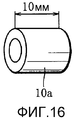
Фиг. 15 - вид с торца углеродного источника тепла, используемого в третьем тестируемом устройстве.FIG. 15 is an end view of a carbon heat source used in a third test device.
Фиг. 16 - вид в перспективе углеродного источника тепла из Фиг. 15.FIG. 16 is a perspective view of the carbon heat source of FIG. fifteen.
Фиг. 17 - график, показывающий результаты испытания, полученные с использованием третьего тестируемого устройства.FIG. 17 is a graph showing test results obtained using a third test device.
Фиг. 18 - схематичный вид четвертого тестируемого устройства.FIG. 18 is a schematic view of a fourth device under test.
Фиг. 19 - вид с торца охлаждающего элемента, используемого в четвертом тестируемом устройстве.FIG. 19 is an end view of a cooling element used in a fourth test device.
Фиг. 20 - вид с торца еще одного охлаждающего элемента, используемого в четвертом тестируемом устройстве.FIG. 20 is an end view of yet another cooling element used in a fourth test device.
Фиг. 21 - график, показывающий результаты испытания, полученные с использованием четвертого тестируемого устройства.FIG. 21 is a graph showing test results obtained using the fourth test device.
Фиг. 22 - график, показывающий взаимосвязи между величинами площади теплообменной поверхности и температурами на выходе охлаждающего элемента.FIG. 22 is a graph showing the relationship between the values of the heat exchange surface area and the temperatures at the outlet of the cooling element.
ПРЕДПОЧТИТЕЛЬНЫЙ ВАРИАНТ ВЫПОЛНЕНИЯ ИЗОБРЕТЕНИЯBEST MODE FOR CARRYING OUT THE INVENTION
[0030] Бездымный ингалятор аромата согласно первому варианту выполнения, показанный на Фиг. 1, квалифицирован как тип «Горение углерода + Нагревание высокотемпературным газом + Охлаждение» и в целом образован в виде стержня.[0030] The smokeless aroma inhaler according to the first embodiment shown in FIG. 1, qualified as the type “Carbon Combustion + Heating with High-Temperature Gas + Cooling” and is generally formed in the form of a rod.
[0031] Углеродный источник тепла:[0031] Carbon heat source:
Ингалятор по Фиг. 1 на своем дистальном конце имеет углеродный источник 10 тепла. Углеродный источник 10 тепла ниже будет описан более подробно.The inhaler of FIG. 1 at its distal end has a
[0032] Углеродный источник 10 тепла является цилиндрическим по форме и получается формованием смеси частиц высокочистого углерода, негорючей добавки, органического или неорганического связующего и воды с приданием формы. Более конкретно, углеродный источник 10 тепла имеет углеродный коэффициент от 10 до 99 вес.% или содержание углерода от 1 до 120 мг/мм.[0032] The
[0033] Частицы высокочистого углерода получают, например, нагреванием угля при высокой температуре 750°С или более в течение 5 минут или более в атмосфере инертного газа. Это процесс нагревания удаляет летучие компоненты, которые представляют собой загрязняющие примеси, содержащиеся в угле. В результате уменьшается запах, исходящий от угольных частиц.[0033] Particles of high-purity carbon are obtained, for example, by heating coal at a high temperature of 750 ° C or more for 5 minutes or more in an inert gas atmosphere. This heating process removes volatile components that are contaminants in coal. As a result, the odor emanating from the coal particles is reduced.
[0034] Для негорючей добавки могут быть использованы карбонаты или оксиды натрия, калия, кальция, магния и кремния. На долю негорючей добавки приходятся от 40 до 89 вес.% углеродного источника 10 тепла. В качестве негорючей добавки предпочтительно применяют карбонат кальция. Негорючая добавка является необязательной и может быть исключена.[0034] Carbonates or oxides of sodium, potassium, calcium, magnesium, and silicon may be used for the non-combustible additive. Non-combustible additives account for 40 to 89% by weight of the
[0035] Органическое связующее представляет собой одно, или смесь двух или более, из альгинатов, CMC (карбоксиметилцеллюлозы), EVA (этилен-винилацетатного сополимера), PVA (поливинилового спирта), PVAC (поливинилацетата) и сахаров и составляет от 1 до 10 вес.% углеродного источника 10 тепла. Предпочтительным органическим связующим является альгинат аммония.[0035] An organic binder is one, or a mixture of two or more, of alginates, CMC (carboxymethyl cellulose), EVA (ethylene-vinyl acetate copolymer), PVA (polyvinyl alcohol), PVAC (polyvinyl acetate) and sugars and ranges from 1 to 10 weight .
[0036] С другой стороны, для неорганического связующего могут быть применены связующие на минеральной основе, такие как очищенный бентонит, или связующие на основе кремнезема, такие как коллоидальный диоксид кремния, жидкое стекло и силикат кальция. На неорганическое связующее приходятся от 5 до 20 вес.% углеродного источника 10 тепла.[0036] Alternatively, mineral based binders such as purified bentonite or silica binders such as colloidal silicon dioxide, water glass and calcium silicate can be used for the inorganic binder. An inorganic binder accounts for 5 to 20% by weight of the
[0037] Неорганическое связующее является лучшим по сравнению с органическим связующим в том отношении, что первое не выделяет дыма, когда углеродный источник 10 тепла сгорает. Когда используют органическое связующее, то углеродный источник 10 тепла предпочтительно получают способом обугливания и обжига. В процессе обугливания и обжига органическое связующее удаляется из углеродного источника 10 тепла, и поэтому углеродный источник 10 тепла не испускает запаха при сгорании. Процесс обугливания и обжига подробно описан, например, в Патентном Документе JP 3024703 В1.[0037] The inorganic binder is better than the organic binder in that the former does not emit smoke when the
[0038] Углеродный источник 10 тепла имеет по меньшей мере одно сквозное отверстие 12, протяженное по его осевому направлению. Каждая из Фиг. 2-4 иллюстрирует примерную конкретную форму торцевой поверхности углеродного источника 10 тепла. Как ясно показано на Фиг. 2-4, смежные проемы сквозных отверстий 12 отделены друг от друга разделительной стенкой. В этом случае разделительная стенка имеет толщину от 0,1 до 0,5 мм.[0038] The
[0039] Держатель источника тепла:[0039] Heat source holder:
Углеродный источник 10 тепла прикреплен к дистальному концу держателя 14 источника тепла. Далее будет подробно описан держатель 14 источника тепла.A
[0040] Держатель 14 источника тепла является термостойким и имеет трубчатую форму. Держатель 14 источника тепла предпочтительно удерживает углеродный источник 10 тепла таким образом, что углеродный источник 10 тепла выступает из дистального конца держателя 14 источника тепла на заданную длину.[0040] The
[0041] Держатель 14 источника тепла имеет окружную стенку, например, с многослойной структурой. Более конкретно, окружная стенка составлена одиночным слоистым материалом, включающим соединенные друг с другом слой металла и слой бумаги, или многочисленными такими слоистыми материалами, наложенными один поверх другого в радиальном направлении держателя 14 источника тепла. Внутренняя поверхность окружной стенки должна быть составлена слоем металла. Слой металла выполнен, например, из алюминиевого сплава, и общая толщина слоев металла, входящих в состав окружной стенки, предпочтительно является большей или равной 30 микрометров. Слой бумаги может быть получен из бумажной обертки, применяемой для сигарет, ободковой бумаги, используемой для сигарет с фильтром, или другого бумажного материала, такого как обычная бумага, негорючая бумага и огнестойкая бумага.[0041] The
[0042] Слой металла имеет превосходную теплопроводность. Соответственно этому, когда углеродный источник 10 тепла сгорает, и тем самым слой бумаги нагревается теплотой от углеродного источника 10 тепла, слой металла поддерживает температуру нагревания слоя бумаги на более низком уровне, нежели температура воспламенения слоя бумаги. Поэтому может быть подавлено распространение запаха вследствие выгорания слоя бумаги.[0042] The metal layer has excellent thermal conductivity. Accordingly, when the
[0043] Вместо окружной стенки с указанной многослойной структурой держатель 14 источника тепла может иметь окружную стенку, выполненную из негорючего материала, или композитную окружную стенку, включающую участок стенки, составленный указанной окружной стенкой с многослойной структурой, и участок стенки, выполненный из негорючего материала. Для негорючего материала может быть использован один из неорганических материалов, включающих керамические материалы, сепиолит, стекло и металлы, или смесь двух или более неорганических материалов.[0043] Instead of a circumferential wall with the specified multilayer structure, the
[0044] Секция охлаждения:[0044] Cooling section:
Держатель 14 источника тепла заключает в себе охлаждающий элемент 16. Охлаждающий элемент 16 является воздухопроницаемым и термостойким и размещен рядом с углеродным источником 10 тепла. Далее будет подробно описан охлаждающий элемент 16.The
[0045] Охлаждающий элемент 16 выполнен из неорганического материала, такого как керамические материалы, сепиолит, стекло, металлы и карбонат кальция, гидраты, или водопоглощающие полимеры. Более конкретно, охлаждающий элемент 16 имеет сотовую структуру, вспененную структуру или структуру набивки, причем структура набивки получается размещением таблеток или гранулированного или волокнистого материала в форму. Более конкретно, охлаждающий элемент 16 включает внутренние протоки. Эти внутренние протоки имеют совокупную внутреннюю поверхность, или площадь теплообменной поверхности, 500 мм2 или более. Охлаждающий элемент 16 предпочтительно содержит неорганический материал в количестве от 90 до 95 вес.%.[0045] The
[0046] Охлаждающий элемент 16 альтернативно может иметь композитную структуру, включающую две или более различных структуры, выбранных из вышеуказанных структур, и различные структуры могут быть наложены друг на друга так, чтобы быть плотно прижатыми друг к другу, или же с промежутком между ними в осевом направлении держателя 14 источника тепла. Охлаждающий элемент 16 может содержать воду, ароматизатор, жидкий экстракт из табачных компонентов, и тому подобные.[0046] The
[0047] Держатель материала:[0047] Material holder:
Держатель 18 материала соединен с ближним концом держателя 14 источника тепла. Держатель 18 материала является термостойким и имеет трубчатую форму. Держатель 18 материала выполнен из бумаги, металла или синтетической смолы, или образован с использованием многослойной структуры указанных слоистых материалов.The
[0048] Табачный материал:[0048] Tobacco material:
Табачный материал 20, в качестве средства выделения аромата, содержится в держателе 18 материала. Табачный материал 20 может представлять собой обычный резаный табак, используемый для сигарет, гранулированный табак, применяемый для жевательного табака, свернутый (рулонный) табак или отформованный табак. Рулонный табак получают свертыванием листа восстановленного табака в рулон, и имеются каналы в нем. Отформованный табак получают прессованием гранулированного табака с приданием ему определенной формы.
[0049] Табачный материал 20 может быть смешан со вспомогательной добавкой для интенсификации вкуса и аромата. Вспомогательная добавка для интенсификации вкуса и аромата содержит по меньшей мере одно вещество из карбонатов, гидрокарбонатов, оксидов и гидроксидов щелочных металлов и/или щелочноземельных металлов. Предпочтительной вспомогательной добавкой для интенсификации вкуса и аромата является карбонат калия. Табачный материал 20 может дополнительно содержать желательный ароматизатор или ароматизаторы.[0049]
[0050] Более конкретно, табачный материал 20 имеет длину от 5 до 30 мм и создает сопротивление затяжке от 10 до 120 мм водяного столба (mmAq) (прибл. 0,1-1,2 КПа). Здесь следует отметить, что табачный материал 20 имеет влагосодержание, эквивалентное содержанию воды в резаном табаке, применяемом в традиционных сигаретах, то есть влагосодержание от 10 до 20 вес.%.[0050] More specifically, the
[0051] В этом варианте выполнения табачный материал 20 содержится между передней и задней заглушками 22f и 22r, чтобы удерживаться внутри держателя 18 материала. Каждая из заглушек 22f и 22r имеет дискообразную форму и является воздухопроницаемой. Более конкретно, заглушки 22f и 22r вставлены в соответствующие противоположные концы держателя 18 материала, и каждая из них выполнена из фильтрового материала, такого как ацетат или бумага, или мембранного материала, такого как нетканый материал, или сформована с использованием неорганической фасонной детали, имеющей воздухопроницаемость.[0051] In this embodiment,
[0052] Мундштук:[0052] Mouthpiece:
Мундштук 24 соединен с задним концом держателя 18 материала. Мундштук 24 включает трубчатый держатель 26 фильтра. Держатель 26 фильтра выполнен из бумаги или синтетической смолы и имеет задний конец, образующий мундштук.The
[0053] Фильтр 28 размещен в держателе 26 фильтра. Фильтр 28 выполнен в форме сплошного цилиндра и сделан из ацетатных волокон, бумаги или тому подобного. Ацетатные волокна и бумага имеют свойство с трудом адсорбировать ароматические компоненты табачного материала 20. Фильтр 28 может иметь по меньшей мере одно сквозное отверстие, протяженное по его продольной оси. Кроме того, фильтр 28 может представлять собой комбинацию различных сортов фильтровых материалов, типа двойных фильтров и тому подобных для сигарет.[0053] The
[0054] Для применения ингалятора аромата согласно первому варианту выполнения пользователь сначала поджигает углеродный источник 10 тепла ингалятора аромата и затем вдыхает, держа мундштук 24 в его/ее рту. Вдыхание создает поток воздуха снаружи от ингалятора аромата в ротовую полость пользователя через сквозные отверстия 12 углеродного источника 10 тепла, охлаждающий элемент 16 в держателе 14 источника тепла, переднюю заглушку 22f, табачный материал 20, заднюю заглушку 22r, фильтр 28 и мундштук 24.[0054] To use the aroma inhaler according to the first embodiment, the user first sets fire to the
[0055] Проходя через сквозные отверстия 12 в углеродном источнике 10 тепла, поток воздуха нагревается теплотой сгорания углеродного источника 10 тепла. Соответственно этому поток воздуха сразу по выходе из углеродного источника 10 тепла образует поток высокотемпературного газа.[0055] Passing through the through
[0056] Поток высокотемпературного газа до некоторой степени охлаждается, проходя через охлаждающий элемент 16, тем самым превращаясь в поток нагретого газа. Поток нагретого газа нагревает табачный материал 20, когда проходит через табачный материал 20, но нагревание табачного материала 20 потоком нагретого газа не ведет к возгоранию табачного материала 20 или образованию аэрозоля (дыма) из табачного материала 20.[0056] The high-temperature gas stream is cooled to some extent by passing through the
[0057] Более конкретно, температура нагревания табачного материала 20 поддерживается в пределах температурного диапазона от 50 до 200°С. Этот температурный диапазон является более высоким, чем температура окружающей среды (более конкретно, от 5 до 35°С), при которой используют ингалятор аромата, но является значительно более низким, чем температура нагревания углеродного источника 10 тепла. А именно, назначение охлаждающего элемента 16 состоит в сокращении количества теплоты, переносимой от углеродного источника 10 тепла на табачный материал 20.[0057] More specifically, the heating temperature of the
[0058] Когда температура нагревания табачного материала 20 удерживается в пределах вышеуказанного температурного диапазона, жидкость, содержащаяся в табачном материале 20, такая как вода, не превращается в аэрозоль, и ароматические компоненты табачного материала 20 удовлетворительно высвобождаются в поток нагретого газа, проходящий через табачный материал 20. Более того, указанная вспомогательная добавка для интенсификации вкуса и аромата стимулирует высвобождение ароматических компонентов из табачного материала 20 в поток нагретого газа; с другой стороны, количество ароматических компонентов, адсорбированных фильтром 28 мундштука 24, является малым.[0058] When the heating temperature of the
[0059] Поэтому ингалятор аромата обеспечивает доставку большого количества ароматических компонентов табачного материала 20 в ротовую полость пользователя без формирования аэрозоля, так что пользователь может сполна получить удовольствие от вкуса и аромата табачного материала 20.[0059] Therefore, the aroma inhaler delivers a large number of aromatic components of the
[0060] Когда углеродный источник 10 тепла загорается, образование дыма от углеродного источника 10 тепла сводится к минимуму, как указано выше, и поэтому углеродный источник 10 тепла также не становится источником аэрозоля (дыма).[0060] When the
[0061] Используемый здесь термин «бездымный» означает, что аэрозоль, образуемый из ингалятора аромата во время применения, имеет концентрацию 1,0×10⁵ частиц/см3 или менее. Аэрозоль с такой концентрацией по существу невидим, и его концентрацию в сущности нельзя измерить вследствие влияния фонового загрязнения окружающего воздуха.[0061] As used herein, the term "smokeless" means that the aerosol generated from the aroma inhaler during use has a concentration of 1.0 × 10 5 particles / cm 3 or less. An aerosol with such a concentration is essentially invisible, and its concentration in essence cannot be measured due to the influence of background pollution of the surrounding air.
[0062] Влагосодержание табачного материала 20 эквивалентно содержанию воды в резаном табаке традиционных сигарет. Соответственно этому, хотя влагосодержание табачного материала 20 варьирует при его нагревании до температуры, не выходящей за пределы указанного температурного диапазона, количество ароматических компонентов в потоке нагретого воздуха, вдыхаемое за одну затяжку пользователем, является почти постоянным. В результате пользователь получает удовольствие от аромата табачного материала 20 надежно и стабильно, даже при множестве затяжек.[0062] The moisture content of the
[0063] Когда в табачном материале 20 содержатся ароматизатор или ароматизаторы, отличающиеся от специфических для табака ароматических компонентов, пользователь, конечно, может в то же время получать удовольствие от ароматизатора или ароматизаторов.[0063] When flavoring material or flavorings other than tobacco-specific flavoring components are contained in the
[0064] В вышеописанном первом варианте выполнения держатель 14 источника тепла, держатель 18 материала и держатель 26 фильтра составляют оболочку ингалятора аромата. Из этих держателей 14, 18 и 26, соединенных между собой, по меньшей мере два из держателей могут быть образованы в виде единой цельной детали, или смежные детали из держателей могут быть заблаговременно соединены друг с другом ободковой бумагой или тому подобным. Кроме того, держатели могут быть соединены между собой разъемно.[0064] In the above-described first embodiment, the
[0065] Настоящее изобретение не ограничивается указанным первым вариантом выполнения и может быть модифицировано разнообразными путями.[0065] The present invention is not limited to the first embodiment, and may be modified in a variety of ways.
[0066] Далее будут по порядку описаны разнообразные модификации и другие варианты выполнения. В нижеследующем описании идентичные кодовые номера позиций использованы для обозначения деталей или секций, имеющих функции, идентичные назначению деталей или секций, уже разъясненных выше, и описание таких деталей и секций опущено ради краткости. Нижеследующее описание сосредоточено на различиях.[0066] Next, various modifications and other embodiments will be described in order. In the following description, identical code numbers are used to indicate parts or sections having functions identical to the purpose of the parts or sections already explained above, and the description of such parts and sections is omitted for the sake of brevity. The following description focuses on differences.
[0067] На Фиг. 5 показана модификация 1(1) ингалятора аромата первого варианта выполнения.[0067] FIG. 5 shows a modification 1 (1) of the aroma inhaler of the first embodiment.
В модификации 1(1), как ясно из Фиг. 5, между углеродным источником 10 тепла и держателем 14 источника тепла размещен теплоизолирующий материал 30. Теплоизолирующий материал 30 является трубчатым по форме и выполнен из неорганического материала, такого как неорганические волокна, или, например, сформован с использованием неорганической фасонной детали.In modification 1 (1), as is clear from FIG. 5, a heat-insulating
[0068] Теплоизолирующий материал 30 уменьшает перенос теплоты от углеродного источника 10 тепла на держатель 14 источника тепла и предотвращает образование дыма вследствие выгорания держателя 14 источника тепла. Кроме того, теплоизолирующий материал 30 может быть размещен так, что он окружает всю наружную периферию углеродного источника 10 тепла. В этом случае дым, если образуется в малом количестве вследствие горения углеродного источника 10 тепла, рассеивается внутри теплоизолирующего материала 30 и не становится видимым.[0068] The
[0069] На Фиг. 6 показана модификация 1(2) бездымного ингалятора аромата первого варианта выполнения.[0069] In FIG. 6 shows a modification 1 (2) of a smokeless aroma inhaler of a first embodiment.
В модификации 1(2) ингалятор аромата имеет многочисленные входные отверстия 32 для воздуха, образованные по меньшей мере на одном из держателя 14 источника тепла, держателя 18 материала и держателя 26 фильтра. Входные отверстия 32 для воздуха размещены ниже по потоку относительно углеродного источника 10 тепла и расположены с интервалами в окружном направлении соответствующего держателя. Более конкретно, в модификации 1(2), показанной на Фиг. 6, входные отверстия 32 для воздуха образованы в каждом из держателя 14 источника тепла, держателя 18 материала и держателя 26 фильтра.In Modification 1 (2), the aroma inhaler has
[0070] Когда пользователь вдыхает через мундштук 24 ингалятора аромата согласно Фиг. 6, наружный воздух поступает в соответствующий держатель через входные отверстия 32 для воздуха. Этот приток воздуха сокращает скорость течения указанного потока высокотемпературного газа или потока нагретого газа, и тем самым введенный воздух смешивается с потоком высокотемпературного газа или потоком нагретого газа, снижая температуру потока высокотемпературного газа или потока нагретого газа. То есть воздух, введенный через входные отверстия 32 для воздуха, усиливает охлаждающее действие охлаждающего элемента 16 и является очень эффективным для поддержания температуры нагревания табачного материала 20 в пределах указанного температурного диапазона.[0070] When the user inhales through the
[0071] Фиг. 7 иллюстрирует бездымный ингалятор аромата согласно второму варианту выполнения.[0071] FIG. 7 illustrates a smokeless aroma inhaler according to a second embodiment.
Более конкретно, ингалятор аромата согласно Фиг. 7 квалифицирован как тип «Горение углерода + Нагревание высокотемпературным газом/путем теплопроводности + Охлаждение».More specifically, the aroma inhaler according to FIG. 7 is qualified as type “Carbon combustion + Heating with high-temperature gas / by thermal conductivity + Cooling”.
[0072] Ингалятор аромата во втором варианте выполнения оснащен теплопроводным держателем 50. Теплопроводный держатель 50 не только служит и как держатель 14 источника тепла, и как держатель 18 материала, но предназначен для переноса теплоты углеродного источника 10 тепла на табачный материал 20. Соответственно этому теплопроводный держатель 50 выполнен из материала с высокой теплопроводностью.[0072] The aroma inhaler in the second embodiment is equipped with a heat-conducting
[0073] Во втором варианте выполнения, даже когда подача потока нагретого газа от углеродного источника 10 тепла на табачный материал 20 прекращается между одной затяжкой пользователя и еще одной, теплопроводный держатель 50 позволяет обеспечивать передачу теплоты от углеродного источника 10 тепла на табачный материал 20. Таким образом, даже во время периода между одной затяжкой пользователя и еще одной, табачный материал 20 непрерывно нагревается для выделения ароматических компонентов, имеющих богатый вкус и аромат.[0073] In the second embodiment, even when the flow of heated gas from the
[0074] Фиг. 8 иллюстрирует бездымный ингалятор аромата согласно третьему варианту выполнения. Этот ингалятор аромата квалифицирован как тип «Горение углерода + Нагревание путем теплопроводности».[0074] FIG. 8 illustrates a smokeless aroma inhaler according to a third embodiment. This aroma inhaler is qualified as Carbon Combustion + Heating by Thermal Conductivity.
[0075] Ингалятор аромата в третьем варианте выполнения также оснащен теплопроводным держателем 50, но в нем вместо охлаждающего элемента 16 и передней заглушки 22f используют негорючий элемент 52.[0075] The aroma inhaler in the third embodiment is also equipped with a heat-conducting
[0076] Негорючий элемент 52 является воздухонепроницаемым и термостойким. Более конкретно, негорючий элемент 52 составлен наполнителем из неорганических волокон или неорганической фасонной деталью и, как ясно показано на Фиг. 8, размещен между углеродным источником 10 тепла и табачным материалом 20 внутри теплопроводного держателя 50.[0076] The
[0077] Поскольку негорючий элемент 52 является непроницаемым для воздуха, теплопроводный держатель 50 имеет многочисленные входные отверстия 32 для воздуха, образованные по его наружному периметру.[0077] Since the
[0078] В ингаляторе аромата третьего варианта выполнения теплота, генерированная сгоранием углеродного источника 10 тепла, передается на табачный материал 20 только через теплопроводный держатель 50, и табачный материал 20 нагревается до температуры в пределах указанного температурного диапазона только передаваемой таким образом теплотой. То есть теплопроводный держатель 50 выполняет функцию, подобную действию указанного охлаждающего элемента 16. В этом случае маловероятно, что пользователь будет вдыхать газообразные продукты горения, образованные при сгорании углеродного источника 10 тепла.[0078] In the aroma inhaler of the third embodiment, the heat generated by the combustion of the
[0079] В третьем варианте выполнения углеродный источник 10 тепла не должен быть воздухопроницаемым. Когда используемый углеродный источник тепла является непроницаемым для воздуха, негорючий элемент 52 может иметь воздухопроницаемость. Таким образом, в случае третьего варианта выполнения непроницаемым для воздуха является только либо углеродный источник 10 тепла, либо негорючий элемент 52, чтобы предотвратить попадание газообразных продуктов горения в табачный материал 20.[0079] In the third embodiment, the
[0080] Дополнительно, когда воздухопроницаемым делают углеродный источник 10 тепла, углеродный источник 10 тепла предпочтительно имеет круглое поперечное сечение, как показано на Фиг. 2 или 3. Углеродный источник 10 тепла, показанный на Фиг. 2 или 3, имеет большую площадь эффективной теплопередачи в отношении внутренней окружной поверхности теплопроводного держателя 50, по сравнению с углеродным источником 10 тепла, показанным на Фиг. 4.[0080] Further, when the
[0081] На Фиг. 9 показана модификация 3(1) ингалятора аромата третьего варианта выполнения.[0081] In FIG. 9 shows a modification 3 (1) of a flavor inhaler of a third embodiment.
В модификации 3(1) ингалятор аромата оснащен теплопроводным стержнем 54, вместо теплопроводного держателя 50. Теплопроводный стержень 54 проходит через углеродный источник 10 тепла, негорючий элемент 52 и табачный материал 20 по их центру и имеет наружный конец, выступающий из углеродного источника 10 тепла, и внутренний конец, размещенный в контакте с задней заглушкой 22r. Поэтому в случае модификации 3(1) каждая секция из углеродного источника 10 тепла, негорючего элемента 52 и табачного материала 20 является трубчатой или кольцеобразной по форме.In modification 3 (1), the aroma inhaler is equipped with a heat-conducting
[0082] Теплопроводный стержень 54 выполнен из металла, имеющего высокую теплопроводность, например из алюминиевого сплава, и представляет собой сплошную деталь или пустотелую деталь по меньшей мере с одним заглушенным концом. По сравнению со сплошным теплопроводным стержнем пустотелый теплопроводный стержень 54 имеет малую теплоемкость и тем самым способен удовлетворительно и быстро проводит теплоту от углеродного источника 10 тепла к табачному материалу 10. В этом случае теплопроводный стержень 54 имеет наружный диаметр от 1 до 5 мм, и длина секции 20 табачного материала может составлять от 5 до 50 мм.[0082] The heat-conducting
[0083] На Фиг. 10 показана модификация 3(2) ингалятора аромата третьего варианта выполнения.[0083] FIG. 10 shows a modification 3 (2) of a flavor inhaler of a third embodiment.
В модификации 3(2) внутри пустотелого углеродного источника 10 тепла соосно с ним размещена теплопроводная трубка 56. Теплопроводная трубка 56 служит и в качестве держателя 18 материала, и в качестве теплопроводного стержня 54.In modification 3 (2), a heat-conducting tube 56 is placed coaxially with the inside of the hollow
[0084] Более конкретно, теплопроводная трубка 56 имеет входное отверстие для воздуха, размещенное на дистальной торцевой поверхности углеродного источника 10 тепла, и передняя заглушка 22f вставлена в дистальную концевую часть теплопроводной трубки 56. Между передней заглушкой 22f и входным отверстием для воздуха обеспечен зазор величиной 5 мм или более. Зазор служит для надежного предотвращения возгорания табачного материала 20, когда поджигают углеродный источник 10 тепла.[0084] More specifically, the heat transfer tube 56 has an air inlet located on the distal end surface of the
[0085] Углеродный источник 10 тепла окружен наружным теплоизолирующим материалом 58. Наружный теплоизолирующий материал 58 выполнен в форме тонкой трубки и является воздухопроницаемым, то есть способным «дышать». Наружный теплоизолирующий материал 58 служит для сокращения излучения теплоты от углеродного источника 10 тепла, тем самым позволяя сохранять количество теплоты, необходимое для поддержания горения углеродного источника 10 тепла, и тем самым является очень эффективным в обеспечении поддержания горения углеродного источника 10 тепла.[0085] The
[0086] В случаях когда теплопроводная трубка 56 имеет такую высокую теплопроводность, что табачный материал 20 может быть с высокой вероятностью нагрет до температуры выше указанного температурного диапазона, между углеродным источником 10 тепла и теплопроводной трубкой 56 и/или между теплопроводной трубкой 56 и табачным материалом 20 размещают изолятор в форме тонкой трубки (не показан). Теплопроводная трубка 56 имеет наружный диаметр от 3 до 8 мм и внутренний диаметр от 2 до 7 мм.[0086] In cases where the heat-conducting pipe 56 has such a high thermal conductivity that the
[0087] На Фиг. 11 показан бездымный ингалятор аромата согласно четвертому варианту выполнения. Этот ингалятор аромата квалифицирован как тип «Горение углерода + Нагревание воздухом».[0087] In FIG. 11 shows a smokeless aroma inhaler according to a fourth embodiment. This aroma inhaler is qualified as Carbon Burn + Air Heater.
В четвертом варианте выполнения углеродный источник 10 тепла имеет входное отверстие для воздуха 60, образованное в его центре. Входное отверстие для воздуха 60 пронизывает углеродный источник 10 тепла по его оси.In a fourth embodiment, the
[0088] Дополнительно, углеродный источник 10 тепла имеет термостойкое покрытие 62, покрывающее внутреннюю поверхность входного отверстия 60 для воздуха. Термостойкое покрытие 62 может быть выполнено из глины, или оксида металла, такого как оксид железа, оксид алюминия, диоксид титана, диоксид кремния, оксид кремния-оксид алюминия, оксид циркония и цеолит, или смеси глины и двух или более из упомянутых оксидов металлов.[0088] Additionally, the
[0089] Дополнительно, негорючий элемент 52 имеет сквозное отверстие 64, образованное в его центре и соединенное с входным отверстием 60 для воздуха. Как очевидно из Фиг. 11, негорючий элемент 52 имеет выступающую часть, окружающую задний концевой участок углеродного источника 10 тепла. В этом случае негорючий элемент 52 служит также в качестве держателя 14 источника тепла. В Фиг. 11 кодовый номер L1 позиции представляет длину участка углеродного источника 10 тепла, выступающего наружу из негорючего элемента 52, и кодовый номер L2 позиции представляет длину участка перекрывания (длину выступающей части) негорючего элемента 52 и охваченного им углеродного источника 10 тепла.[0089] Additionally, the
[0090] С ингалятором аромата в четвертом варианте выполнения, когда пользователь вдыхает через мундштук 24 после поджигания углеродного источника 10 тепла, воздух поступает в табачный материал 20 через входное отверстие для воздуха 60 углеродного источника 10 тепла и через отверстие 64 негорючего элемента 52, и воздух нагревается до температуры в пределах указанного температурного диапазона в процессе прохождения через углеродный источник 10 тепла. Таким образом, ингалятор аромата в этом варианте выполнения также обеспечивает надлежащую доставку ароматических компонентов табачного материала 20 в ротовую полость пользователя без образования аэрозоля.[0090] With the aroma inhaler in the fourth embodiment, when the user inhales through the
[0091] Как будет ясно из вышеизложенного, бездымный ингалятор аромата согласно настоящему изобретению требует, чтобы табачный материал 20 был нагрет до температуры от 50°С до 200°С, когда ингалятор находится в режиме применения. С целью проверки было приготовлено первое тестируемое устройство, показанное на Фиг. 12.[0091] As will be clear from the foregoing, the smokeless aroma inhaler according to the present invention requires that the
[0092] Первое тестируемое устройство оснащено термостойкой трубкой 100, заключающей в себе табачный материал 20, и нагревателем 102, окружающим трубку 100 и способным нагревать трубку 100, а именно табачный материал 20, до температуры 22°С или 50°С. Подвергаемый испытанию табачный материал 20 содержал 230 мг частиц табака, приготовленных из листьев табака Берли, и 14 мг карбоната калия. Частицы табака имели диаметр частиц от 0,5 до 1,18 мм.[0092] The first device under test is equipped with a heat-
[0093] Первое тестируемое устройство дополнительно оснащено всасывающим устройством 104, которое соединено с трубкой 100 через импинджер 106. Всасывающее устройство 104 предназначено для втягивания воздуха или газа из трубки 100 через импинджер 106 с величиной расхода потока 55 мл/2 сек (соответственно одной затяжке).[0093] The first test device is additionally equipped with a
[0094] В случае табачного материала 20, нагретого до температуры 22°С, всасываемый газ втягивался во всасывающее устройство 104 так, чтобы ароматический компонент (никотин) табачного материала, содержащийся во всасываемом газе, мог бы быть собран в импинджере 106. В результате было найдено, что количество собранного ароматического компонента составляло 0,7 микрограммов/затяжку.[0094] In the case of
[0095] Дополнительно, в случае табачного материала 20, нагретого до температуры 50°С, ароматический компонент был собран в импинджере 106 таким же образом, и было найдено, что количество собранного ароматического компонента составляло 9,0 микрограммов/затяжку.[0095] Further, in the case of the
[0096] Два вышеуказанных результата испытания показывают, что, когда табачный материал 20 нагревают до температуры 50°С, количество высвобожденного ароматического компонента более чем на порядок превышает количество, получаемое, когда табачный материал 20 нагревают до температуры 20°С. Это подтверждает, что табачный материал 20 должен нагреваться до температуры 50°С или выше, чтобы доставлять надлежащее количество ароматического компонента в ротовую полость пользователя.[0096] The two above test results show that when
[0097] На Фиг. 13 показано второе тестируемое устройство.[0097] In FIG. 13 shows a second test device.
Второе тестируемое устройство оснащено термостойкой трубкой 108, заключающей в себе табачный материал 20. Подвергаемый испытанию табачный материал 20 содержал 35 мг частиц табака, приготовленных из листьев табака Берли, и частицы табака имели диаметр частиц от 0,5 до 1,18 мм.The second test device is equipped with a heat-
[0098] Трубка 108 через прозрачную камеру 110 и регулятор 112 расхода соединена со всасывающим насосом 114, который способен втягивать воздух из трубки 108 с величиной расхода потока 1650 мл/мин.[0098] The
[0099] Засасывание воздуха с помощью всасывающего насоса 114 при упомянутой величине расхода потока повторяли, в то же время постепенно повышая температуру воздуха, притекающего в трубку 108, и в результате было подтверждено, что внутри прозрачной камеры 110 аэрозоль (дым) не образуется до тех пор, пока температура воздуха, то есть температура табачного материала 20, составляла 200°С или менее. Этим обеспечивается то, что из табачного материала 20 не образуется никакой дым, пока температуру нагревания табачного материала поддерживают при 200°С или ниже.[0099] The suction of air using the
[0100] Дополнительно, как указано выше, в бездымном ингаляторе аромата согласно настоящему изобретению охлаждающий элемент 16 должен иметь площадь теплообменной поверхности 500 мм2. С целью проверки приготовили третье тестируемое устройство, показанное на Фиг. 14.[0100] Additionally, as indicated above, in the smokeless aroma inhaler according to the present invention, the
[0101] Третье тестируемое устройство оснащено трубкой 116, выполненной из термостойкой бумаги. Трубка 116 имеет пустотелый цилиндрический углеродный источник 10а тепла, прикрепленный к дистальному концу ее. Подвергаемый испытанию углеродный источник 10а тепла был получен экструзионным формованием и содержал 80 вес.% активированного угля, 15 вес.% карбоната кальция и 5 вес.% карбоксиметилцеллюлозы (CMC). Более конкретно, как показано на Фиг. 15 и 16, углеродный источник 10а тепла имел внутренний диаметр 3 мм, наружный диаметр 6,8 мм и длину 10 мм.[0101] The third test device is equipped with a
[0102] Ближний конец трубки 116 соединен со всасывающим устройством (не показано), и всасывающее устройство предназначено для втягивания воздуха из трубки 116 с величиной расхода потока 55 мл/2 сек (соответственно одной затяжке) с интервалами в 30 секунд. Дополнительно, трубка 116 имеет пять присоединенных к ней температурных датчиков (не показаны). Температурные датчики размещены на расстояниях 5 мм, 10 мм, 15 мм, 20 мм и 50 мм от углеродного источника 10а тепла соответственно, и каждый из них способен измерять температуру в трубке 116.[0102] The near end of the
[0103] Когда засасывание воздуха с помощью всасывающего устройства повторяли с поджиганием углеродного источника 10 тепла, температуры в трубке 116 измеряли соответственными температурными датчиками. Результаты измерений показаны на Фиг. 17.[0103] When the air suction using the suction device was repeated with ignition of the
[0104] Как очевидно из Фиг. 17, температура в трубке 116 проявляет тенденцию к снижению с увеличением расстояния от углеродного источника 10а тепла, и, для того чтобы температура в трубке 116 снизилась до 200°С или менее, требуется расстояние в 50 мм или более от углеродного источника 10а тепла.[0104] As is apparent from FIG. 17, the temperature in the
[0105] Иначе говоря, в случае третьего тестируемого устройства, не включающего охлаждающий элемент 16, должно быть обеспечено расстояние в 50 мм или более между углеродным источником 10а тепла и табачным материалом 20, чтобы ограничить температуру нагревания табачного материала 20 до температуры, не превышающей 200°С, и ниже которой можно избежать образования дыма (аэрозоля) из табачного материала 20.[0105] In other words, in the case of a third test device that does not include a
[0106] Таким образом, когда бездымный ингалятор аромата не включает охлаждающий элемент 16, должно быть обеспечено расстояние в 50 мм или более между углеродным источником 10а тепла и табачным материалом 20. Однако такой ингалятор аромата является чрезмерно длинным и непрактичным.[0106] Thus, when the smokeless aroma inhaler does not include a
[0107] Фиг. 18 иллюстрирует четвертое тестируемое устройство, приготовленное для проверки функционирования охлаждающего элемента 16.[0107] FIG. 18 illustrates a fourth test device prepared to test the functioning of the
По сравнению с третьим тестируемым устройством четвертое тестируемое устройство включает охлаждающий элемент 16, имеющий воздухопроницаемость, а также термостойкость и размещенный внутри трубки 116 в положении, смежном с углеродным источником 10а тепла. Температурный датчик размещают только на выходном конце (конце ниже по потоку) охлаждающего элемента 16 для измерения температуры в трубке 116 на выходе из охлаждающего элемента 16.Compared to the third test device, the fourth test device includes a
[0108] Для применения с четвертым тестируемым устройством были приготовлены многочисленные образцы цилиндрических охлаждающих элементов 16а и 16b, показанные на Фиг. 19 и 20 соответственно. Каждый из охлаждающих элементов 16а и 16b был получен экструзионным формованием и содержал 95 вес.% карбоната кальция и 5 вес.% карбоксиметилцеллюлозы (CMC).[0108] For use with the fourth test device, numerous samples of cylindrical cooling elements 16a and 16b, shown in FIG. 19 and 20, respectively. Each of the cooling elements 16a and 16b was extruded and contained 95% by weight calcium carbonate and 5% by weight carboxymethyl cellulose (CMC).
[0109] Охлаждающие элементы 16а и 16b идентичны по наружному диаметру (6,5 мм), но различаются по площади отверстий своих внутренних протоков. Более конкретно, охлаждающий элемент 16а имел площадь отверстий 17,2 мм2, полученную, например, в 52 сквозных проемах, каждый с квадратным поперечным сечением (0,57 мм×0,57 мм). В этом случае общая длина внутренних периметров всех сквозных отверстий составляет 120 мм.[0109] The cooling elements 16a and 16b are identical in outer diameter (6.5 mm), but differ in the area of the openings of their internal ducts. More specifically, the cooling element 16a had a hole area of 17.2 mm 2 obtained, for example, in 52 through openings, each with a square cross section (0.57 mm × 0.57 mm). In this case, the total length of the internal perimeters of all through holes is 120 mm.
[0110] С другой стороны, охлаждающий элемент 16b имел площадь отверстий 24,1 мм2, полученную, например, 21 сквозным проемом, каждый с квадратным поперечным сечением (1,23 мм×1,23 мм). В этом случае общая длина внутренних периметров всех сквозных отверстий составляет 90,9 мм.[0110] On the other hand, the cooling element 16b had an aperture area of 24.1 mm 2 obtained, for example, through 21 openings, each with a square cross section (1.23 mm × 1.23 mm). In this case, the total length of the inner perimeters of all through holes is 90.9 mm.
[0111] Поскольку площади теплообменной поверхности каждого из охлаждающих элементов 16а и 16b задаются длиной Х внутреннего периметра, были приготовлены охлаждающие элементы 16а и 16b с различными длинами.[0111] Since the heat exchange surface areas of each of the cooling elements 16a and 16b are defined by the length X of the inner perimeter, cooling elements 16a and 16b with different lengths were prepared.
[0112] В случае охлаждающего элемента 16а, размещенного в четвертом тестируемом устройстве, испытание на всасывание проводили таким же образом, как испытание, выполненное с использованием третьего тестируемого устройства, и испытание на всасывание повторяли в отношении всех охлаждающих элементов 16а с различными длинами. Подобным образом испытанию на всасывание подвергли каждый из охлаждающих элементов 16b с различными длинами.[0112] In the case of the cooling element 16a housed in the fourth test device, the suction test was performed in the same manner as the test using the third test device, and the suction test was repeated for all cooling elements 16a with different lengths. Similarly, each of the cooling elements 16b with different lengths was tested for suction.
[0113] Фиг. 21 и 22 показывают результаты испытаний. Как ясно из Фиг. 21, чем больше длина, тем ниже становится температура на выходе охлаждающего элемента 16, независимо от того, является ли испытуемый охлаждающий элемент охлаждающим элементом 16а или охлаждающим элементом 16b.[0113] FIG. 21 and 22 show test results. As is clear from FIG. 21, the longer the length, the lower the outlet temperature of the
[0114] В отношении площадей теплообменной поверхности охлаждающих элементов 16а и 16b результаты испытаний показывают, что необходима площадь теплообменной поверхности 500 мм2, чтобы поддерживать температуру на выходе охлаждающего элемента 16, то есть температуру нагревания табачного материала 20, при 200°С или ниже. В случае охлаждающего элемента 16а площадь теплообменной поверхности 500,4 мм2 (=120 мм×4,17 мм) или более может быть обеспечена, если охлаждающий элемент 16а имеет длину 4,17 мм или более. С другой стороны, в случае охлаждающего элемента 16b площадь теплообменной поверхности 500,5 мм2 (=91 мм×5,5 мм) или более может быть обеспечена, если охлаждающий элемент 16b имеет длину 5,5 мм или более.[0114] With respect to the heat exchange surface areas of the cooling elements 16a and 16b, the test results show that a heat exchange surface area of 500 mm 2 is necessary to maintain the temperature at the outlet of the
[0115] Таким образом, включением охлаждающего элемента 16а или 16b в бездымный ингалятор аромата можно значительно сократить расстояние (длину охлаждающего элемента 16а или 16b), необходимое между углеродным источником 10 тепла и табачным материалом 20, чтобы общая длина бездымного ингалятора аромата могла быть сокращена до практически приемлемого уровня.[0115] Thus, by incorporating the cooling element 16a or 16b into the smokeless aroma inhaler, the distance (length of the cooling element 16a or 16b) required between the
[0116] Охлаждающий элемент 16а или 16b, размещенный между углеродным источником 10 тепла и табачным материалом 20, не должен находиться в непосредственном контакте с углеродным источником 10 тепла или табачным материалом 20. Заданный промежуток может быть создан между углеродным источником 10 тепла и охлаждающим элементом 16а или 16b, или между охлаждающим элементом 16а или 16b и табачным материалом 20.[0116] A cooling element 16a or 16b located between the
[0117] Присутствие охлаждающего элемента 16а или 16b делает ненужным введение наружного воздуха на стороне выше по потоку относительно табачного материала 20, то есть в область между углеродным источником 10 тепла и табачным материалом 20, чтобы поддерживать температуру нагревания табачного материала 20 при температуре не выше 200°С, и к тому же предотвращает ухудшение характеристик воспламенения углеродного источника 10 тепла вследствие притока наружного воздуха. Более конкретно, введение наружного воздуха ведет к сокращению количества наружного воздуха, проходящего через углеродный источник 10 тепла, когда углеродный источник 10 тепла поджигают, чем ухудшает характеристики воспламенения углеродного источника 10 тепла.[0117] The presence of a cooling element 16a or 16b makes it unnecessary to introduce outside air upstream of the
[0118] Настоящее изобретение не ограничивается описанными выше вариантами выполнения и модификациями и может быть модифицировано разнообразными другими путями.[0118] The present invention is not limited to the embodiments and modifications described above, and may be modified in various other ways.
[0119] Например, средство выделения аромата не ограничивается указанным табачным материалом и может представлять собой жидкое или твердое ароматическое вещество, иное, нежели ароматические компоненты табачного материала, нанесенное на базовый материал из целлюлозы или тому подобный носитель. Кроме того, ингалятор аромата согласно настоящему изобретению может быть реализован на практике сочетанием по выбору элементов в указанных вариантах выполнения и модификациях с общеизвестными средствами без выхода за пределы цели изобретения.[0119] For example, the aroma highlighting agent is not limited to said tobacco material, and may be a liquid or solid aromatic substance other than the aromatic components of the tobacco material applied to the base material from cellulose or the like. In addition, the aroma inhaler according to the present invention can be implemented in practice by a combination of optional elements in these embodiments and modifications with well-known means without going beyond the scope of the invention.
СПИСОК ПОЗИЦИЙ НА ЧЕРТЕЖАХLIST OF POSITIONS ON THE DRAWINGS
[0120][0120]
10 углеродный источник тепла10 carbon heat source
12 сквозное отверстие (проток)12 through hole (duct)
14 держатель источника тепла (оболочка)14 heat source holder (shell)
16 охлаждающий элемент16 cooling element
18 держатель материала18 material holder
20 табачный материал (средство выделения аромата)20 tobacco material (flavor release agent)
24 мундштук24 mouthpiece
28 фильтр28 filter
30 теплоизолирующий материал30 heat insulating material
32 входное отверстие для воздуха (проток)32 air inlet (duct)
50 теплопроводный держатель (оболочка)50 heat-conducting holder (shell)
52 негорючий элемент52 non-combustible element
54 теплопроводный стержень54 heat transfer rod
56 теплопроводная трубка56 heat conduit
60 входное отверстие для воздуха (проток)60 air inlet (duct)
Claims (5)
оболочку, имеющую мундштук, причем указанная оболочка выполнена для создания потока воздуха, направляемого через нее к мундштуку, когда пользователь вдыхает через мундштук;
средство выделения аромата, расположенное внутри указанной оболочки и способное высвобождать ароматический компонент в поток воздуха; и
нагреватель для поддержания указанного средства выделения аромата нагретым при температуре нагревания от 50 до 200°С, чтобы обеспечить высвобождение ароматического компонента, при этом предотвращая образование аэрозоля из указанного средства выделения аромата,
причем указанный нагреватель включает:
углеродный источник тепла, имеющий воздухопроницаемость и прикрепленный к дистальному концу указанной оболочки для нагревания воздуха, и
негорючий охлаждающий элемент, имеющий воздухопроницаемость и размещенный внутри указанной оболочки и между углеродным источником тепла и указанным средством выделения аромата для охлаждения воздуха, нагретого углеродным источником тепла.1. Smokeless aroma inhaler, including:
a shell having a mouthpiece, and the specified shell is made to create a stream of air directed through it to the mouthpiece when the user inhales through the mouthpiece;
aroma highlighting means located within said shell and capable of releasing the aromatic component into the air stream; and
a heater for keeping said odor releasing agent heated at a heating temperature of from 50 to 200 ° C. to provide release of the aromatic component while preventing the formation of an aerosol from said odor releasing agent,
wherein said heater includes:
a carbon heat source having breathability and attached to the distal end of the specified shell for heating air, and
non-combustible cooling element having air permeability and placed inside the specified shell and between the carbon heat source and the specified means of flavor release to cool the air heated by the carbon heat source.
Applications Claiming Priority (3)
| Application Number | Priority Date | Filing Date | Title |
|---|---|---|---|
| JP2010-172338 | 2010-07-30 | ||
| JP2010172338 | 2010-07-30 | ||
| PCT/JP2011/004299 WO2012014490A1 (en) | 2010-07-30 | 2011-07-28 | Smokeless flavor inhalator |
Publications (1)
| Publication Number | Publication Date |
|---|---|
| RU2524887C1 true RU2524887C1 (en) | 2014-08-10 |
Family
ID=45529717
Family Applications (1)
| Application Number | Title | Priority Date | Filing Date |
|---|---|---|---|
| RU2013108758/12A RU2524887C1 (en) | 2010-07-30 | 2011-07-28 | Smokeless aroma inhalator |
Country Status (7)
| Country | Link |
|---|---|
| US (2) | US20130133675A1 (en) |
| EP (2) | EP3831220B1 (en) |
| JP (1) | JP5459813B2 (en) |
| CN (1) | CN103037718B (en) |
| RU (1) | RU2524887C1 (en) |
| TW (1) | TWI507220B (en) |
| WO (1) | WO2012014490A1 (en) |
Cited By (4)
| Publication number | Priority date | Publication date | Assignee | Title |
|---|---|---|---|---|
| RU2725275C1 (en) * | 2016-11-29 | 2020-06-30 | Филип Моррис Продактс С.А. | Aerosol-generating system with pump controlled flow rate |
| RU2774956C1 (en) * | 2018-12-06 | 2022-06-24 | Филип Моррис Продактс С.А. | Aerosol-generating article with a layered wrapper |
| US11800891B2 (en) | 2017-09-07 | 2023-10-31 | Philip Morris Products S.A. | Aerosol-generating article with improved outermost wrapper |
| US12239158B2 (en) | 2018-12-06 | 2025-03-04 | Philip Morris Products S.A. | Aerosol-generating article with laminated wrapper |
Families Citing this family (167)
| Publication number | Priority date | Publication date | Assignee | Title |
|---|---|---|---|---|
| US10244793B2 (en) | 2005-07-19 | 2019-04-02 | Juul Labs, Inc. | Devices for vaporization of a substance |
| AT509046B1 (en) | 2010-03-10 | 2011-06-15 | Helmut Dr Buchberger | FLAT EVAPORATOR |
| KR102060691B1 (en) | 2011-09-06 | 2020-02-11 | 브리티시 아메리칸 토바코 (인베스트먼츠) 리미티드 | Heating smokeable material |
| PL2753203T5 (en) | 2011-09-06 | 2023-05-08 | Nicoventures Trading Limited | Heating smokable material |
| BR112014012956B1 (en) | 2011-12-30 | 2021-01-12 | Philip Morris Products S.A. | smoking article, process of using a smoking article and system |
| BR112014013198B1 (en) | 2011-12-30 | 2020-11-10 | Philip Morris Products S.A | smoking article |
| EP2625975A1 (en) * | 2012-02-13 | 2013-08-14 | Philip Morris Products S.A. | Aerosol-generating article having an aerosol-cooling element |
| AR089602A1 (en) | 2011-12-30 | 2014-09-03 | Philip Morris Products Sa | AEROSOL GENERATOR ARTICLE FOR USE WITH AN AEROSOL GENERATOR DEVICE |
| TWI639391B (en) * | 2012-02-13 | 2018-11-01 | 菲利浦莫里斯製品股份有限公司 | Smoking article comprising an isolated combustible heat source |
| TWI590769B (en) * | 2012-02-13 | 2017-07-11 | 菲利浦莫里斯製品股份有限公司 | Smoking article comprising a dual heat conducting element and method for adjusting the amount of aerosol delivered by the smoking article |
| TW201340892A (en) | 2012-02-13 | 2013-10-16 | Philip Morris Prod | Smoking article comprising an isolated combustible heat source |
| WO2013131763A1 (en) * | 2012-03-05 | 2013-09-12 | British American Tobacco (Investments) Limited | Heating smokable material |
| RU2577727C1 (en) * | 2012-03-30 | 2016-03-20 | Джапан Тобакко Инк. | Heat coal source and aroma inhaler |
| GB201207039D0 (en) | 2012-04-23 | 2012-06-06 | British American Tobacco Co | Heating smokeable material |
| AR091211A1 (en) | 2012-05-31 | 2015-01-21 | Philip Morris Products Sa | FLAVORED CYLINDERS FOR USE IN AEROSOL GENERATING ITEMS |
| TW201402027A (en) * | 2012-06-08 | 2014-01-16 | Japan Tobacco Inc | Flavor inhaler |
| AR091509A1 (en) * | 2012-06-21 | 2015-02-11 | Philip Morris Products Sa | ARTICLE TO SMOKE TO BE USED WITH AN INTERNAL HEATING ELEMENT |
| GB201216621D0 (en) * | 2012-09-18 | 2012-10-31 | British American Tobacco Co | Heading smokeable material |
| GB201217067D0 (en) | 2012-09-25 | 2012-11-07 | British American Tobacco Co | Heating smokable material |
| CN102885398B (en) * | 2012-09-26 | 2014-02-26 | 广东中烟工业有限责任公司 | Cigarette with adjustable cigarette temperature during burning and smoking |
| TWI629007B (en) * | 2012-12-21 | 2018-07-11 | Philip Morris Products S. A. | Smoking article comprising an airflow directing element |
| EP2974606B1 (en) * | 2013-03-11 | 2020-11-11 | Japan Tobacco Inc. | Burning type heat source and flavour inhaler |
| CN103230097B (en) * | 2013-04-24 | 2014-04-16 | 湖北中烟工业有限责任公司 | Method for utilizing acids to prepare piece-shaped carbonaceous heat source material for cigarettes |
| CN112315043B (en) * | 2013-08-13 | 2025-02-25 | 菲利普莫里斯生产公司 | Smoking article with dual heat-conducting elements and improved airflow |
| US9788571B2 (en) | 2013-09-25 | 2017-10-17 | R.J. Reynolds Tobacco Company | Heat generation apparatus for an aerosol-generation system of a smoking article, and associated smoking article |
| EA030672B1 (en) * | 2013-09-30 | 2018-09-28 | Джапан Тобакко Инк. | Flavor inhalator |
| TWI645789B (en) * | 2013-10-14 | 2019-01-01 | 菲利浦莫里斯製品股份有限公司 | Heated aerosol generating article comprising improved rod and use of the rod |
| KR102444219B1 (en) * | 2013-10-29 | 2022-09-15 | 니코벤처스 트레이딩 리미티드 | Apparatus for heating smokable material |
| CN103549657A (en) * | 2013-11-12 | 2014-02-05 | 黄争鸣 | Heating type low-temperature cigarette and manufacturing method thereof |
| CN103584288B (en) * | 2013-11-26 | 2016-08-17 | 湖南中烟工业有限责任公司 | A kind of non-combustion type low-temperature cigarette |
| UA118858C2 (en) * | 2013-12-05 | 2019-03-25 | Філіп Морріс Продактс С.А. | Aerosol Generating Product with a Rigid Empty Tip |
| UA118457C2 (en) * | 2013-12-05 | 2019-01-25 | Філіп Морріс Продактс С.А. | Heated aerosol generating article with air-flow barrier |
| UA119333C2 (en) * | 2013-12-05 | 2019-06-10 | Філіп Морріс Продактс С.А. | HEATING PRODUCT GENERATED BY AEROSOL WITH HEAT DISTRIBUTION WRAP |
| GB2558805B8 (en) | 2013-12-23 | 2018-12-19 | Juul Labs Uk Holdco Ltd | Vaporization device systems and methods |
| US10058129B2 (en) | 2013-12-23 | 2018-08-28 | Juul Labs, Inc. | Vaporization device systems and methods |
| WO2015098447A1 (en) * | 2013-12-25 | 2015-07-02 | 日本たばこ産業株式会社 | Method for manufacturing tobacco compact |
| WO2015098445A1 (en) * | 2013-12-25 | 2015-07-02 | 日本たばこ産業株式会社 | Tobacco compact and flavor plunger |
| TWI828016B (en) | 2014-02-06 | 2024-01-01 | 美商尤爾實驗室有限公司 | An electronic device for generating an inhalable vapor, a system, and a kit comprising the electronic device |
| US12279646B2 (en) | 2014-02-06 | 2025-04-22 | Juul Labs, Inc. | Cartridge of vaporization device systems having unequal transverse cartridge dimensions |
| US10094562B2 (en) | 2014-02-11 | 2018-10-09 | R.J. Reynolds Tobacco Company | Igniter apparatus for a smoking article, and associated method |
| US9833019B2 (en) | 2014-02-13 | 2017-12-05 | Rai Strategic Holdings, Inc. | Method for assembling a cartridge for a smoking article |
| US20150242883A1 (en) | 2014-02-24 | 2015-08-27 | R.J. Reynolds Tobacco Company | Electronic coupon system |
| US11080739B2 (en) | 2014-04-25 | 2021-08-03 | R.J. Reynolds Tobacco Company | Data translator |
| GB201407642D0 (en) * | 2014-04-30 | 2014-06-11 | British American Tobacco Co | Aerosol-cooling element and arrangements for apparatus for heating a smokable material |
| US20150335070A1 (en) * | 2014-05-20 | 2015-11-26 | R.J. Reynolds Tobacco Company | Electrically-powered aerosol delivery system |
| US9955726B2 (en) | 2014-05-23 | 2018-05-01 | Rai Strategic Holdings, Inc. | Sealed cartridge for an aerosol delivery device and related assembly method |
| GB201500582D0 (en) | 2015-01-14 | 2015-02-25 | British American Tobacco Co | Apparatus for heating or cooling a material contained therein |
| CN106998791A (en) * | 2014-09-19 | 2017-08-01 | 菲利普莫里斯生产公司 | For manufacturing the method and apparatus that aerosol generates semi-finished product |
| EP3000339B1 (en) * | 2014-09-23 | 2017-03-01 | Fontem Holdings 1 B.V. | Electronic smoking device |
| GB201418817D0 (en) | 2014-10-22 | 2014-12-03 | British American Tobacco Co | Apparatus and method for generating an inhalable medium, and a cartridge for use therewith |
| JP6495315B2 (en) | 2014-10-24 | 2019-04-03 | 日本たばこ産業株式会社 | Flavor source manufacturing method and package |
| KR102755161B1 (en) | 2014-12-05 | 2025-01-15 | 쥴 랩스, 인크. | Calibrated dose control |
| TR201903115T4 (en) * | 2014-12-15 | 2019-03-21 | Philip Morris Products Sa | Continuous mode heater assembly for aerosol-generating system. |
| CN104585884B (en) * | 2015-01-20 | 2018-04-17 | 四川中烟工业有限责任公司 | A kind of charcoal heats the aspirator of not burning tobacco |
| GB201503411D0 (en) | 2015-02-27 | 2015-04-15 | British American Tobacco Co | Apparatus and method for generating an inhalable medium, and a cartridge for use therewith |
| WO2016135331A1 (en) | 2015-02-27 | 2016-09-01 | British American Tobacco (Investments) Limited | Cartridge, components and methods for generating an inhalable medium |
| TWI703936B (en) * | 2015-03-27 | 2020-09-11 | 瑞士商菲利浦莫里斯製品股份有限公司 | A paper wrapper for an electrically heated aerosol-generating article |
| RU2704893C2 (en) | 2015-03-31 | 2019-10-31 | Филип Моррис Продактс С.А. | Smoking article comprising wrapper with plurality of projections provided on inner surface thereof |
| GB201511349D0 (en) | 2015-06-29 | 2015-08-12 | Nicoventures Holdings Ltd | Electronic aerosol provision systems |
| GB201511361D0 (en) | 2015-06-29 | 2015-08-12 | Nicoventures Holdings Ltd | Electronic vapour provision system |
| US10154689B2 (en) | 2015-06-30 | 2018-12-18 | R.J. Reynolds Tobacco Company | Heat generation segment for an aerosol-generation system of a smoking article |
| WO2017013741A1 (en) * | 2015-07-21 | 2017-01-26 | 日本たばこ産業株式会社 | Package for rod-shaped tobacco articles |
| US20170055581A1 (en) * | 2015-08-31 | 2017-03-02 | British American Tobacco (Investments) Limited | Article for use with apparatus for heating smokable material |
| US20170055584A1 (en) | 2015-08-31 | 2017-03-02 | British American Tobacco (Investments) Limited | Article for use with apparatus for heating smokable material |
| US11924930B2 (en) | 2015-08-31 | 2024-03-05 | Nicoventures Trading Limited | Article for use with apparatus for heating smokable material |
| US20170055575A1 (en) | 2015-08-31 | 2017-03-02 | British American Tobacco (Investments) Limited | Material for use with apparatus for heating smokable material |
| US20170055576A1 (en) | 2015-08-31 | 2017-03-02 | R. J. Reynolds Tobacco Company | Smoking article |
| US20170055574A1 (en) | 2015-08-31 | 2017-03-02 | British American Tobacco (Investments) Limited | Cartridge for use with apparatus for heating smokable material |
| WO2017041920A1 (en) * | 2015-09-08 | 2017-03-16 | Philip Morris Products S.A. | Method of producing high tensile strength homogenized tobacco material |
| GB201517471D0 (en) | 2015-10-02 | 2015-11-18 | British American Tobacco Co | Apparatus for generating an inhalable medium |
| US20180317554A1 (en) | 2015-10-30 | 2018-11-08 | British American Tobacco (Investments) Limited | Article for use with apparatus for heating smokable material |
| US20170119047A1 (en) | 2015-10-30 | 2017-05-04 | British American Tobacco (Investments) Limited | Article for Use with Apparatus for Heating Smokable Material |
| US20170119049A1 (en) | 2015-10-30 | 2017-05-04 | British American Tobacco (Investments) Limited | Article for Use with Apparatus for Heating Smokable Material |
| US20170119051A1 (en) * | 2015-10-30 | 2017-05-04 | British American Tobacco (Investments) Limited | Article for Use with Apparatus for Heating Smokable Material |
| US20170119050A1 (en) | 2015-10-30 | 2017-05-04 | British American Tobacco (Investments) Limited | Article for Use with Apparatus for Heating Smokable Material |
| US20170119046A1 (en) | 2015-10-30 | 2017-05-04 | British American Tobacco (Investments) Limited | Apparatus for Heating Smokable Material |
| CN105433440B (en) * | 2015-12-03 | 2018-12-11 | 安徽中烟工业有限责任公司 | A kind of carbon heat source that easily ignites |
| US10314334B2 (en) | 2015-12-10 | 2019-06-11 | R.J. Reynolds Tobacco Company | Smoking article |
| US11744296B2 (en) | 2015-12-10 | 2023-09-05 | R. J. Reynolds Tobacco Company | Smoking article |
| US20170215478A1 (en) | 2016-01-28 | 2017-08-03 | Stratos Product Development Llc | Vapor delivery systems and methods |
| WO2017139595A1 (en) | 2016-02-11 | 2017-08-17 | Pax Labs, Inc. | Fillable vaporizer cartridge and method of filling |
| SG11201806801VA (en) | 2016-02-11 | 2018-09-27 | Juul Labs Inc | Securely attaching cartridges for vaporizer devices |
| US11717018B2 (en) | 2016-02-24 | 2023-08-08 | R.J. Reynolds Tobacco Company | Smoking article comprising aerogel |
| WO2017147560A1 (en) | 2016-02-25 | 2017-08-31 | Pax Labs, Inc. | Vaporization device control systems and methods |
| WO2017187556A1 (en) | 2016-04-27 | 2017-11-02 | 日本たばこ産業株式会社 | Flavor inhaler |
| WO2017187555A1 (en) | 2016-04-27 | 2017-11-02 | 日本たばこ産業株式会社 | Flavor inhaler |
| CN105707986A (en) * | 2016-05-05 | 2016-06-29 | 张志雄 | Electronic smoke atomizer based on hot airflow non-contact heating |
| GB201608928D0 (en) | 2016-05-20 | 2016-07-06 | British American Tobacco Co | Article for use in apparatus for heating smokable material |
| GB201608931D0 (en) | 2016-05-20 | 2016-07-06 | British American Tobacco Co | Article for use in apparatus for heating smokeable material |
| US10194691B2 (en) | 2016-05-25 | 2019-02-05 | R.J. Reynolds Tobacco Company | Non-combusting smoking article with thermochromatic label |
| TW201801618A (en) | 2016-05-31 | 2018-01-16 | 菲利浦莫里斯製品股份有限公司 | Aerosol-generating article with an insulated heat source |
| RU2730708C2 (en) * | 2016-05-31 | 2020-08-25 | Филип Моррис Продактс С.А. | Aerosol-generating article with insulated heat source |
| USD849996S1 (en) | 2016-06-16 | 2019-05-28 | Pax Labs, Inc. | Vaporizer cartridge |
| MY189668A (en) | 2016-06-29 | 2022-02-24 | Nicoventures Trading Ltd | Apparatus for heating smokable material |
| US12478096B2 (en) | 2016-06-29 | 2025-11-25 | Nicoventures Trading Limited | Apparatus for heating smokable material |
| JP6933323B2 (en) | 2016-06-29 | 2021-09-08 | ニコベンチャーズ トレーディング リミテッド | Device for heating smoking material |
| PL3515219T3 (en) | 2016-09-20 | 2023-03-13 | Nicoventures Trading Limited | A method of manufacturing an aerosol provision apparatus and an aerosol provision apparatus |
| CN206165813U (en) * | 2016-10-10 | 2017-05-17 | 韩力 | Heat pipe type liquid cigarette |
| GB201618481D0 (en) | 2016-11-02 | 2016-12-14 | British American Tobacco Investments Ltd | Aerosol provision article |
| CN106820260B (en) * | 2016-11-25 | 2023-10-31 | 上海烟草集团有限责任公司 | Carbon heated smoking article and method of making the same |
| GB201707436D0 (en) * | 2017-05-09 | 2017-06-21 | British American Tobacco Investments Ltd | Aerosol provision device and apparatus for a vessel |
| GB2562764A (en) * | 2017-05-24 | 2018-11-28 | Robert Hopps Jason | Tobacco-containing consumable for aerosol generating devices |
| USD887632S1 (en) | 2017-09-14 | 2020-06-16 | Pax Labs, Inc. | Vaporizer cartridge |
| CA3075657C (en) | 2017-09-15 | 2023-10-10 | British American Tobacco (Investments) Limited | Apparatus for heating smokable material |
| US10512286B2 (en) | 2017-10-19 | 2019-12-24 | Rai Strategic Holdings, Inc. | Colorimetric aerosol and gas detection for aerosol delivery device |
| GB201719523D0 (en) * | 2017-11-24 | 2018-01-10 | British American Tobacco Investments Ltd | Smoking article |
| CN108065456B (en) * | 2017-12-22 | 2020-07-24 | 安徽中烟工业有限责任公司 | A heat-not-burn tobacco product comprising tobacco particles and preparation method |
| CN109998171A (en) * | 2018-01-05 | 2019-07-12 | 深圳御烟实业有限公司 | A kind of aerosol generates product and system |
| US12439973B2 (en) | 2018-02-14 | 2025-10-14 | Zenigata Inc. | Vaporization system with integrated heaters |
| KR102909447B1 (en) * | 2018-02-15 | 2026-01-09 | 필립모리스 프로덕츠 에스.에이. | Aerosol-generating articles containing an aerosol cooling element |
| US20190254335A1 (en) | 2018-02-22 | 2019-08-22 | R.J. Reynolds Tobacco Company | System for debossing a heat generation member, a smoking article including the debossed heat generation member, and a related method |
| JP6909921B2 (en) * | 2018-03-26 | 2021-07-28 | 日本たばこ産業株式会社 | Aerosol generator and control method and program |
| CN108593487B (en) * | 2018-04-02 | 2020-09-15 | 云南中烟工业有限责任公司 | A Thermogravimetric Analysis Method for Identifying the Safety Temperature Window of Low-Temperature Cigarettes |
| KR102369446B1 (en) * | 2018-04-12 | 2022-03-02 | 주식회사 케이티앤지 | Aerosol-generating device |
| KR102329088B1 (en) * | 2018-05-17 | 2021-11-18 | 주식회사 케이티앤지 | Article and apparatus for for generating generating aerosols |
| KR102652799B1 (en) * | 2018-05-21 | 2024-03-28 | 차이나 토바코 후난 인더스트리얼 코포레이션 리미티드 | Cooling filter rod, application and cigarette |
| CN110506989A (en) * | 2018-05-21 | 2019-11-29 | 湖南中烟工业有限责任公司 | A cooling filter stick, application and cigarette |
| CN108669663B (en) * | 2018-05-31 | 2024-03-29 | 乐美星辰(深圳)生物科技有限公司 | Heating non-burning cigarette |
| US11723399B2 (en) | 2018-07-13 | 2023-08-15 | R.J. Reynolds Tobacco Company | Smoking article with detachable cartridge |
| KR102369449B1 (en) * | 2018-07-17 | 2022-03-02 | 주식회사 케이티앤지 | Articles for genarating aerosol |
| GB201812373D0 (en) | 2018-07-30 | 2018-09-12 | Nicoventures Trading Ltd | Generation of an inhalable medium |
| CN108652087A (en) * | 2018-08-02 | 2018-10-16 | 湖北中烟工业有限责任公司 | A kind of temperature self adjusting component and the carbon including the component heat tobacco suction unit |
| KR102881212B1 (en) * | 2018-10-12 | 2025-11-04 | 제이티 인터내셔널 소시에떼 아노님 | Aerosol generating device and heating chamber for aerosol generating device |
| GB201817548D0 (en) * | 2018-10-29 | 2018-12-12 | Nerudia Ltd | Smoking substitute consumable |
| US12478112B2 (en) | 2018-10-30 | 2025-11-25 | R.J. Reynolds Tobacco Company | Smoking article cartridge |
| JP7197604B2 (en) * | 2018-11-14 | 2022-12-27 | 日本たばこ産業株式会社 | COOLING SEGMENT AND METHOD OF MANUFACTURE THEREOF, NO-COMBUSTION HEAT SMOKING ARTICLE, AND NO-COMBUSTION HEAT SMOKING SYSTEM |
| CN109430943A (en) * | 2018-12-27 | 2019-03-08 | 云南巴菰生物科技有限公司 | It is a kind of to heat the cigarette temperature descending section and preparation method thereof that do not burn |
| WO2020157813A1 (en) * | 2019-01-29 | 2020-08-06 | 日本たばこ産業株式会社 | Flavor inhaler |
| CN109674098A (en) * | 2019-02-18 | 2019-04-26 | 上海黎邦电子科技有限公司 | A kind of electronic cigarette cartridge |
| CN111728265A (en) * | 2019-03-21 | 2020-10-02 | 云南恩典科技产业发展有限公司 | Novel heating non-combustion suction product prepared from biological matrix and preparation method and application thereof |
| US12075819B2 (en) | 2019-07-18 | 2024-09-03 | R.J. Reynolds Tobacco Company | Aerosol delivery device with consumable cartridge |
| US12022859B2 (en) * | 2019-07-18 | 2024-07-02 | R.J. Reynolds Tobacco Company | Thermal energy absorbers for tobacco heating products |
| US12232542B2 (en) | 2019-07-19 | 2025-02-25 | R.J. Reynolds Tobacco Company | Aerosol delivery device with sliding sleeve |
| US11395510B2 (en) | 2019-07-19 | 2022-07-26 | R.J. Reynolds Tobacco Company | Aerosol delivery device with rotatable enclosure for cartridge |
| US12082607B2 (en) | 2019-07-19 | 2024-09-10 | R.J. Reynolds Tobacco Company | Aerosol delivery device with clamshell holder for cartridge |
| US11330838B2 (en) | 2019-07-19 | 2022-05-17 | R. J. Reynolds Tobacco Company | Holder for aerosol delivery device with detachable cartridge |
| EP4042888B1 (en) * | 2019-10-10 | 2025-02-19 | Japan Tobacco Inc. | Non-combustion heating type flavor inhaler |
| GB2588212B (en) * | 2019-10-16 | 2024-05-29 | Essentra Filter Products Dev Co Pte Ltd | A cooling element |
| EP3858174A1 (en) * | 2020-01-30 | 2021-08-04 | Nerudia Limited | Aerosol delivery system |
| US12484610B2 (en) * | 2020-04-16 | 2025-12-02 | R.J. Reynolds Tobacco Company | Aerosol delivery device including a segregated substrate |
| US11439185B2 (en) | 2020-04-29 | 2022-09-13 | R. J. Reynolds Tobacco Company | Aerosol delivery device with sliding and transversely rotating locking mechanism |
| US11589616B2 (en) | 2020-04-29 | 2023-02-28 | R.J. Reynolds Tobacco Company | Aerosol delivery device with sliding and axially rotating locking mechanism |
| EP4185136A1 (en) * | 2020-07-21 | 2023-05-31 | JT International SA | Aerosol generating device |
| TWI878582B (en) * | 2020-08-17 | 2025-04-01 | 瑞士商Jt國際公司 | Aerosol generating article, aerosol generating system using the aerosol generating article, and method for providing the aerosol generating article |
| KR102481437B1 (en) * | 2020-08-27 | 2022-12-27 | 주식회사 케이티앤지 | Aerosol generating article comprising porous tobacco solid material and method of manufacturing porous tobacco solid material |
| JPWO2022123649A1 (en) * | 2020-12-08 | 2022-06-16 | ||
| EP4291050A1 (en) * | 2021-02-10 | 2023-12-20 | Philip Morris Products S.A. | Aerosol-generating article comprising a tubular element |
| US11825872B2 (en) | 2021-04-02 | 2023-11-28 | R.J. Reynolds Tobacco Company | Aerosol delivery device with protective sleeve |
| US12433340B2 (en) | 2021-04-02 | 2025-10-07 | R. J. Reynolds Tobacco Company | Aerosol delivery device consumable unit |
| US12250969B2 (en) | 2021-04-02 | 2025-03-18 | R. J. Reynolds Tobacco Company | Aerosol delivery device with modular lighter |
| US12426633B2 (en) | 2021-04-02 | 2025-09-30 | R. J. Reynolds Tobacco Company | Aerosol delivery device with integrated inductive heater |
| US12426634B2 (en) | 2021-04-02 | 2025-09-30 | R. J. Reynolds Tobacco Company | Aerosol delivery device with integrated lighter |
| KR102639729B1 (en) | 2021-04-30 | 2024-02-23 | 주식회사 케이티앤지 | Aerosol generating article and aerosol generating system |
| JP7738059B2 (en) * | 2021-05-13 | 2025-09-11 | 日本たばこ産業株式会社 | Non-combustion heated flavor inhalation article and non-combustion heated flavor inhalation system |
| KR102713416B1 (en) * | 2021-05-14 | 2024-10-02 | 주식회사 케이티앤지 | Aerosol generating article and aerosol generating device having the same |
| KR102731286B1 (en) * | 2021-05-14 | 2024-11-18 | 주식회사 케이티앤지 | Aerosol generating article and aerosol generating device having the same |
| KR102715275B1 (en) * | 2021-05-14 | 2024-10-11 | 주식회사 케이티앤지 | Aerosol generating article and aerosol generating device having the same |
| KR102715274B1 (en) * | 2021-05-14 | 2024-10-11 | 주식회사 케이티앤지 | Aerosol generating article and aerosol generating device having the same |
| WO2022263466A1 (en) | 2021-06-14 | 2022-12-22 | Jt International S.A. | Aerosol generating article comprising a tubular support |
| KR102734099B1 (en) * | 2021-06-21 | 2024-11-25 | 주식회사 케이티앤지 | Tobacco rod, aerosol-generating article including the same and aerosol-generating apparatus used with the same |
| US12426637B2 (en) | 2021-08-17 | 2025-09-30 | Rai Strategic Holdings, Inc. | Inductively heated aerosol delivery device consumable |
| CA3231994A1 (en) * | 2021-09-17 | 2023-03-23 | Nikhil Aggarwal | A smoking substitute device |
| CN118973417A (en) * | 2022-04-11 | 2024-11-15 | 日本烟草国际股份公司 | Aerosol Generating Consumables |
| US12329199B2 (en) | 2022-08-30 | 2025-06-17 | R.J. Reynolds Tobaco Company | Aerosol delivery device with improved mouthpieces |
| US12357024B2 (en) | 2022-08-30 | 2025-07-15 | R. J. Reynolds Tobacco Company | Aerosol delivery device with static ignitor contacts |
| US12471639B2 (en) | 2022-12-14 | 2025-11-18 | R.J. Reynolds Tobacco Company | Aerosol delivery device with improved cartridge loading |
| TWI838055B (en) * | 2022-12-29 | 2024-04-01 | 大量科技股份有限公司 | Pcb in-hole circuit manufacturing method |
Citations (4)
| Publication number | Priority date | Publication date | Assignee | Title |
|---|---|---|---|---|
| US20060191546A1 (en) * | 2003-04-01 | 2006-08-31 | Shusei Takano | Nicotine suction pipe and nicotine holder |
| RU2297781C2 (en) * | 2001-10-24 | 2007-04-27 | Бритиш Америкэн Тобэкко (Инвестментс) Лимитед | Artificial smoking article (versions) and heat-releasing member for the same |
| RU2302806C2 (en) * | 2001-10-24 | 2007-07-20 | Бритиш Америкэн Тобэкко (Инвестментс) Лимитед | Holder for artificial smoking article |
| US20090272379A1 (en) * | 2008-04-30 | 2009-11-05 | Philip Morris Usa Inc. | Electrically heated smoking system having a liquid storage portion |
Family Cites Families (40)
| Publication number | Priority date | Publication date | Assignee | Title |
|---|---|---|---|---|
| JPS5496539A (en) | 1978-01-17 | 1979-07-31 | Nichiban Kk | Pressure sensitive adhesive composition having weak tack and strong selffadhesivity |
| JPS5821546A (en) * | 1981-07-31 | 1983-02-08 | Dainippon Printing Co Ltd | Automatic inspecting device for surface |
| JPS6064537A (en) | 1983-09-19 | 1985-04-13 | Nissan Motor Co Ltd | On-vehicle radio transmitter using induced electromagnetic field as medium |
| US4854331A (en) * | 1984-09-14 | 1989-08-08 | R. J. Reynolds Tobacco Company | Smoking article |
| US4793365A (en) | 1984-09-14 | 1988-12-27 | R. J. Reynolds Tobacco Company | Smoking article |
| IE80788B1 (en) * | 1984-09-14 | 1999-04-24 | Reynolds Tobacco Co R | Smoking article |
| SE8405479D0 (en) | 1984-11-01 | 1984-11-01 | Nilsson Sven Erik | WANT TO ADMINISTER VOCABULARY, PHYSIOLOGY, ACTIVE SUBJECTS AND DEVICE FOR THIS |
| US4827950A (en) * | 1986-07-28 | 1989-05-09 | R. J. Reynolds Tobacco Company | Method for modifying a substrate material for use with smoking articles and product produced thereby |
| US4924883A (en) * | 1987-03-06 | 1990-05-15 | R. J. Reynolds Tobacco Company | Smoking article |
| JPH022331A (en) | 1988-03-30 | 1990-01-08 | Kowa Display:Kk | Smokeless tobacco |
| US4981522A (en) * | 1988-07-22 | 1991-01-01 | Philip Morris Incorporated | Thermally releasable flavor source for smoking articles |
| US5076296A (en) | 1988-07-22 | 1991-12-31 | Philip Morris Incorporated | Carbon heat source |
| US4966171A (en) * | 1988-07-22 | 1990-10-30 | Philip Morris Incorporated | Smoking article |
| US4991606A (en) | 1988-07-22 | 1991-02-12 | Philip Morris Incorporated | Smoking article |
| US4955399A (en) | 1988-11-30 | 1990-09-11 | R. J. Reynolds Tobacco Company | Smoking article |
| US4892109A (en) * | 1989-03-08 | 1990-01-09 | Brown & Williamson Tobacco Corporation | Simulated smoking article |
| US5144962A (en) | 1989-12-01 | 1992-09-08 | Philip Morris Incorporated | Flavor-delivery article |
| US5060671A (en) | 1989-12-01 | 1991-10-29 | Philip Morris Incorporated | Flavor generating article |
| US5027837A (en) * | 1990-02-27 | 1991-07-02 | R. J. Reynolds Tobacco Company | Cigarette |
| US5099861A (en) * | 1990-02-27 | 1992-03-31 | R. J. Reynolds Tobacco Company | Aerosol delivery article |
| US5396911A (en) | 1990-08-15 | 1995-03-14 | R. J. Reynolds Tobacco Company | Substrate material for smoking articles |
| EP0532194A1 (en) * | 1991-09-10 | 1993-03-17 | Philip Morris Products Inc. | Thermally-regulated flavor generator |
| US5469871A (en) * | 1992-09-17 | 1995-11-28 | R. J. Reynolds Tobacco Company | Cigarette and method of making same |
| US5345955A (en) * | 1992-09-17 | 1994-09-13 | R. J. Reynolds Tobacco Company | Composite fuel element for smoking articles |
| JPH06114105A (en) | 1992-10-02 | 1994-04-26 | Masanobu Iguchi | Smokeless suction and intake implement and method for cigarette or chemical component |
| US5327915A (en) | 1992-11-13 | 1994-07-12 | Brown & Williamson Tobacco Corp. | Smoking article |
| US5845649A (en) * | 1994-01-26 | 1998-12-08 | Japan Tobacco Inc. | Flavor-tasting article |
| CN1113621C (en) * | 1996-06-17 | 2003-07-09 | 日本烟业产业株式会社 | Flavor generating product and flavor generating tool |
| JP3974898B2 (en) * | 2001-12-28 | 2007-09-12 | 日本たばこ産業株式会社 | Smoking article |
| US6827573B2 (en) | 2002-10-25 | 2004-12-07 | Brown & Williamson Tobacco Corporation | Gas micro burner |
| CN100381082C (en) | 2003-03-14 | 2008-04-16 | 韩力 | Non-combustible electronic atomized cigarette |
| DE10321379A1 (en) | 2003-05-12 | 2004-12-30 | Nicstic Ag | Smokeless Cigarette |
| US9675109B2 (en) | 2005-07-19 | 2017-06-13 | J. T. International Sa | Method and system for vaporization of a substance |
| US9220301B2 (en) * | 2006-03-16 | 2015-12-29 | R.J. Reynolds Tobacco Company | Smoking article |
| JP2008035742A (en) | 2006-08-03 | 2008-02-21 | British American Tobacco Pacific Corporation | Evaporating apparatus |
| EP1972215A1 (en) | 2007-03-20 | 2008-09-24 | Wedegree GmbH | Smoke-free cigarette substitute |
| BRPI0814773B1 (en) * | 2007-08-10 | 2019-11-12 | Philip Morris Products Sa | distillation-based smoking article |
| US8991402B2 (en) | 2007-12-18 | 2015-03-31 | Pax Labs, Inc. | Aerosol devices and methods for inhaling a substance and uses thereof |
| FI121361B (en) | 2008-01-22 | 2010-10-29 | Stagemode Oy | Tobacco product and process for its manufacture |
| WO2009131009A1 (en) * | 2008-04-25 | 2009-10-29 | 日本たばこ産業株式会社 | Method of drying non-combustion type molded smoking article and apparatus therefor |
-
2011
- 2011-07-28 EP EP21154270.9A patent/EP3831220B1/en active Active
- 2011-07-28 JP JP2013502317A patent/JP5459813B2/en not_active Expired - Fee Related
- 2011-07-28 WO PCT/JP2011/004299 patent/WO2012014490A1/en not_active Ceased
- 2011-07-28 RU RU2013108758/12A patent/RU2524887C1/en active
- 2011-07-28 CN CN201180037410.8A patent/CN103037718B/en not_active Expired - Fee Related
- 2011-07-28 EP EP11812088.0A patent/EP2597976B1/en not_active Not-in-force
- 2011-07-29 TW TW100126955A patent/TWI507220B/en not_active IP Right Cessation
-
2012
- 2012-12-19 US US13/720,081 patent/US20130133675A1/en not_active Abandoned
-
2018
- 2018-07-18 US US16/038,877 patent/US11160304B2/en not_active Expired - Fee Related
Patent Citations (4)
| Publication number | Priority date | Publication date | Assignee | Title |
|---|---|---|---|---|
| RU2297781C2 (en) * | 2001-10-24 | 2007-04-27 | Бритиш Америкэн Тобэкко (Инвестментс) Лимитед | Artificial smoking article (versions) and heat-releasing member for the same |
| RU2302806C2 (en) * | 2001-10-24 | 2007-07-20 | Бритиш Америкэн Тобэкко (Инвестментс) Лимитед | Holder for artificial smoking article |
| US20060191546A1 (en) * | 2003-04-01 | 2006-08-31 | Shusei Takano | Nicotine suction pipe and nicotine holder |
| US20090272379A1 (en) * | 2008-04-30 | 2009-11-05 | Philip Morris Usa Inc. | Electrically heated smoking system having a liquid storage portion |
Cited By (6)
| Publication number | Priority date | Publication date | Assignee | Title |
|---|---|---|---|---|
| RU2725275C1 (en) * | 2016-11-29 | 2020-06-30 | Филип Моррис Продактс С.А. | Aerosol-generating system with pump controlled flow rate |
| US11800891B2 (en) | 2017-09-07 | 2023-10-31 | Philip Morris Products S.A. | Aerosol-generating article with improved outermost wrapper |
| RU2807049C2 (en) * | 2017-09-07 | 2023-11-09 | Филип Моррис Продактс С.А. | Aerosol generator with improved centre wrap (variants) |
| RU2774956C1 (en) * | 2018-12-06 | 2022-06-24 | Филип Моррис Продактс С.А. | Aerosol-generating article with a layered wrapper |
| RU2794322C2 (en) * | 2018-12-06 | 2023-04-17 | Филип Моррис Продактс С.А. | Aerosol generating product with layered cover |
| US12239158B2 (en) | 2018-12-06 | 2025-03-04 | Philip Morris Products S.A. | Aerosol-generating article with laminated wrapper |
Also Published As
| Publication number | Publication date |
|---|---|
| CN103037718B (en) | 2014-05-21 |
| EP2597976A1 (en) | 2013-06-05 |
| JP2013532953A (en) | 2013-08-22 |
| TW201208725A (en) | 2012-03-01 |
| EP2597976A4 (en) | 2017-02-22 |
| US20130133675A1 (en) | 2013-05-30 |
| US11160304B2 (en) | 2021-11-02 |
| TWI507220B (en) | 2015-11-11 |
| US20180317560A1 (en) | 2018-11-08 |
| EP2597976B1 (en) | 2021-03-10 |
| EP3831220B1 (en) | 2022-09-07 |
| JP5459813B2 (en) | 2014-04-02 |
| EP3831220A1 (en) | 2021-06-09 |
| CN103037718A (en) | 2013-04-10 |
| WO2012014490A1 (en) | 2012-02-02 |
Similar Documents
| Publication | Publication Date | Title |
|---|---|---|
| RU2524887C1 (en) | Smokeless aroma inhalator | |
| JP6435021B2 (en) | Smoking article comprising two heat conducting elements | |
| TWI654940B (en) | Smoke with dual thermal elements and improved airflow | |
| KR102392890B1 (en) | Smoking article comprising an isolated combustible heat source | |
| JP6506690B2 (en) | Adiabatic heat source | |
| TWI226821B (en) | Smoke article | |
| TWI654943B (en) | Smoke product with a single radial separation of thermally conductive elements | |
| TW201442651A (en) | Smoking article with an airflow directing element comprising an aerosol-modifying agent | |
| JP2019521658A (en) | Heated aerosol generating article comprising a liquid aerosol forming substrate and a combustible heat generating element | |
| JP2019505202A (en) | Holder for aerosol generating articles | |
| CN101778578A (en) | Distillation-based smoking articles | |
| CN101282660A (en) | Method and system for atomizing substances | |
| CN105792691A (en) | Smoking article with valve | |
| JPH04262772A (en) | Cigarette | |
| JPH04229166A (en) | Smoking article | |
| CN114845574A (en) | Combustible heat source comprising an ignition aid and a binding agent | |
| KR102555646B1 (en) | Combustible heat sources including ignition aids and binders | |
| RU2827723C1 (en) | Combustible heat source comprising igniter and binder | |
| EA038767B1 (en) | Flavor inhaler and combustion-type heat source |