KR20150009536A - Apparatus for optical see-through head mounted dispaly with mutual occlusion and opaqueness control capability - Google Patents
Apparatus for optical see-through head mounted dispaly with mutual occlusion and opaqueness control capability Download PDFInfo
- Publication number
- KR20150009536A KR20150009536A KR1020147031031A KR20147031031A KR20150009536A KR 20150009536 A KR20150009536 A KR 20150009536A KR 1020147031031 A KR1020147031031 A KR 1020147031031A KR 20147031031 A KR20147031031 A KR 20147031031A KR 20150009536 A KR20150009536 A KR 20150009536A
- Authority
- KR
- South Korea
- Prior art keywords
- view
- perspective
- path
- light
- beam splitter
- Prior art date
- Legal status (The legal status is an assumption and is not a legal conclusion. Google has not performed a legal analysis and makes no representation as to the accuracy of the status listed.)
- Granted
Links
Images


Classifications
-
- G—PHYSICS
- G02—OPTICS
- G02B—OPTICAL ELEMENTS, SYSTEMS OR APPARATUS
- G02B27/00—Optical systems or apparatus not provided for by any of the groups G02B1/00 - G02B26/00, G02B30/00
- G02B27/01—Head-up displays
- G02B27/0101—Head-up displays characterised by optical features
-
- G—PHYSICS
- G02—OPTICS
- G02B—OPTICAL ELEMENTS, SYSTEMS OR APPARATUS
- G02B26/00—Optical devices or arrangements for the control of light using movable or deformable optical elements
-
- G—PHYSICS
- G02—OPTICS
- G02B—OPTICAL ELEMENTS, SYSTEMS OR APPARATUS
- G02B13/00—Optical objectives specially designed for the purposes specified below
- G02B13/06—Panoramic objectives; So-called "sky lenses" including panoramic objectives having reflecting surfaces
-
- G—PHYSICS
- G02—OPTICS
- G02B—OPTICAL ELEMENTS, SYSTEMS OR APPARATUS
- G02B25/00—Eyepieces; Magnifying glasses
- G02B25/001—Eyepieces
-
- G—PHYSICS
- G02—OPTICS
- G02B—OPTICAL ELEMENTS, SYSTEMS OR APPARATUS
- G02B27/00—Optical systems or apparatus not provided for by any of the groups G02B1/00 - G02B26/00, G02B30/00
- G02B27/01—Head-up displays
- G02B27/017—Head mounted
-
- G—PHYSICS
- G02—OPTICS
- G02B—OPTICAL ELEMENTS, SYSTEMS OR APPARATUS
- G02B27/00—Optical systems or apparatus not provided for by any of the groups G02B1/00 - G02B26/00, G02B30/00
- G02B27/01—Head-up displays
- G02B27/017—Head mounted
- G02B27/0172—Head mounted characterised by optical features
-
- G—PHYSICS
- G02—OPTICS
- G02B—OPTICAL ELEMENTS, SYSTEMS OR APPARATUS
- G02B27/00—Optical systems or apparatus not provided for by any of the groups G02B1/00 - G02B26/00, G02B30/00
- G02B27/10—Beam splitting or combining systems
- G02B27/1066—Beam splitting or combining systems for enhancing image performance, like resolution, pixel numbers, dual magnifications or dynamic range, by tiling, slicing or overlapping fields of view
-
- G—PHYSICS
- G02—OPTICS
- G02B—OPTICAL ELEMENTS, SYSTEMS OR APPARATUS
- G02B27/00—Optical systems or apparatus not provided for by any of the groups G02B1/00 - G02B26/00, G02B30/00
- G02B27/10—Beam splitting or combining systems
- G02B27/14—Beam splitting or combining systems operating by reflection only
- G02B27/144—Beam splitting or combining systems operating by reflection only using partially transparent surfaces without spectral selectivity
-
- G—PHYSICS
- G02—OPTICS
- G02B—OPTICAL ELEMENTS, SYSTEMS OR APPARATUS
- G02B27/00—Optical systems or apparatus not provided for by any of the groups G02B1/00 - G02B26/00, G02B30/00
- G02B27/28—Optical systems or apparatus not provided for by any of the groups G02B1/00 - G02B26/00, G02B30/00 for polarising
- G02B27/283—Optical systems or apparatus not provided for by any of the groups G02B1/00 - G02B26/00, G02B30/00 for polarising used for beam splitting or combining
-
- G—PHYSICS
- G02—OPTICS
- G02B—OPTICAL ELEMENTS, SYSTEMS OR APPARATUS
- G02B5/00—Optical elements other than lenses
- G02B5/04—Prisms
-
- G—PHYSICS
- G03—PHOTOGRAPHY; CINEMATOGRAPHY; ANALOGOUS TECHNIQUES USING WAVES OTHER THAN OPTICAL WAVES; ELECTROGRAPHY; HOLOGRAPHY
- G03B—APPARATUS OR ARRANGEMENTS FOR TAKING PHOTOGRAPHS OR FOR PROJECTING OR VIEWING THEM; APPARATUS OR ARRANGEMENTS EMPLOYING ANALOGOUS TECHNIQUES USING WAVES OTHER THAN OPTICAL WAVES; ACCESSORIES THEREFOR
- G03B37/00—Panoramic or wide-screen photography; Photographing extended surfaces, e.g. for surveying; Photographing internal surfaces, e.g. of pipe
- G03B37/02—Panoramic or wide-screen photography; Photographing extended surfaces, e.g. for surveying; Photographing internal surfaces, e.g. of pipe with scanning movement of lens or cameras
-
- H—ELECTRICITY
- H04—ELECTRIC COMMUNICATION TECHNIQUE
- H04N—PICTORIAL COMMUNICATION, e.g. TELEVISION
- H04N23/00—Cameras or camera modules comprising electronic image sensors; Control thereof
- H04N23/45—Cameras or camera modules comprising electronic image sensors; Control thereof for generating image signals from two or more image sensors being of different type or operating in different modes, e.g. with a CMOS sensor for moving images in combination with a charge-coupled device [CCD] for still images
-
- H—ELECTRICITY
- H04—ELECTRIC COMMUNICATION TECHNIQUE
- H04N—PICTORIAL COMMUNICATION, e.g. TELEVISION
- H04N23/00—Cameras or camera modules comprising electronic image sensors; Control thereof
- H04N23/60—Control of cameras or camera modules
- H04N23/698—Control of cameras or camera modules for achieving an enlarged field of view, e.g. panoramic image capture
-
- G—PHYSICS
- G02—OPTICS
- G02B—OPTICAL ELEMENTS, SYSTEMS OR APPARATUS
- G02B27/00—Optical systems or apparatus not provided for by any of the groups G02B1/00 - G02B26/00, G02B30/00
- G02B27/01—Head-up displays
- G02B27/0101—Head-up displays characterised by optical features
- G02B2027/0118—Head-up displays characterised by optical features comprising devices for improving the contrast of the display / brillance control visibility
-
- G—PHYSICS
- G02—OPTICS
- G02B—OPTICAL ELEMENTS, SYSTEMS OR APPARATUS
- G02B27/00—Optical systems or apparatus not provided for by any of the groups G02B1/00 - G02B26/00, G02B30/00
- G02B27/01—Head-up displays
- G02B27/0101—Head-up displays characterised by optical features
- G02B2027/0145—Head-up displays characterised by optical features creating an intermediate image
-
- G—PHYSICS
- G02—OPTICS
- G02B—OPTICAL ELEMENTS, SYSTEMS OR APPARATUS
- G02B27/00—Optical systems or apparatus not provided for by any of the groups G02B1/00 - G02B26/00, G02B30/00
- G02B27/01—Head-up displays
- G02B27/0149—Head-up displays characterised by mechanical features
- G02B2027/015—Head-up displays characterised by mechanical features involving arrangement aiming to get less bulky devices
-
- G—PHYSICS
- G06—COMPUTING OR CALCULATING; COUNTING
- G06T—IMAGE DATA PROCESSING OR GENERATION, IN GENERAL
- G06T19/00—Manipulating 3D models or images for computer graphics
- G06T19/006—Mixed reality
Landscapes
- Physics & Mathematics (AREA)
- General Physics & Mathematics (AREA)
- Optics & Photonics (AREA)
- Engineering & Computer Science (AREA)
- Multimedia (AREA)
- Signal Processing (AREA)
- Spectroscopy & Molecular Physics (AREA)
- Human Computer Interaction (AREA)
- Theoretical Computer Science (AREA)
- General Engineering & Computer Science (AREA)
- Software Systems (AREA)
- Computer Graphics (AREA)
- Computer Hardware Design (AREA)
- Lenses (AREA)
- Studio Devices (AREA)
- Stereoscopic And Panoramic Photography (AREA)
- Control Of Indicators Other Than Cathode Ray Tubes (AREA)
- Eyeglasses (AREA)
- Instrument Panels (AREA)
- Camera Bodies And Camera Details Or Accessories (AREA)
- Optical Elements Other Than Lenses (AREA)
- Liquid Crystal Display Device Control (AREA)
- Telescopes (AREA)
- Cameras In General (AREA)
- Closed-Circuit Television Systems (AREA)
Abstract
본 발명은 투시 이미지 경로의 불투명도가 변조될 수 있고 가상 이미지가 투시 이미지의 일부를 가리고 또한 상기 투시 뷰가 상기 가상 뷰의 일부를 가릴 수도 있도록, 투시 이미지 경로를 가상 이미지 경로와 결합할 수 있는 컴팩트한 광학적 투시 헤드-장착형 디스플레이(compact optical see-through head-mounted display)를 포함한다.The present invention provides a compact, compact, and robust solution that can combine the perspective image path with the virtual image path so that the opacity of the perspective image path can be modulated and the virtual image covers a portion of the perspective image, And a compact optical see-through head-mounted display.
Description
[0001] 본원은 2012년 4월 5일에 출원된 미국 가출원 번호 제61/620,574호 및 2012년 4월 5일에 출원된 미국 가출원 번호 제61/620,581호에 대한 우선권을 주장하며, 이 문헌들의 개시내용은 그 전체가 본 명세서에 참조로서 포함된다.[0001] This application claims priority to U.S. Provisional Application No. 61 / 620,574, filed April 5, 2012, and U.S. Provisional Application No. 61 / 620,581, filed April 5, 2012, The disclosure of which is incorporated herein by reference in its entirety.
[0002] 본 발명은 미국 육군에 의해 수여된 SBIR 계약 번호 W91CRB-12-C-0002 하에서 부분적으로 이루어졌다. 미국 정부는 본 발명에 대한 소정의 권리들을 갖는다.[0002] The present invention was made in part under the SBIR contract number W91CRB-12-C-0002 granted by the United States Army. The US government has certain rights to the invention.
[0003] 본 발명은 일반적으로 헤드-장착형 디스플레이들에 관한 것이며, 보다 구체적으로 그러나 배타적인 것은 아닌, 실제의 객체들이 전방에 위치한 컴퓨터에 의해 구현되는 가상 객체들에 의해서 가려질 수 있거나 이와 반대로 될 수 있는, 불투명도 제어 및 상호 가림 능력을 갖는 광학적 투시 헤드-장착형 디스플레이들에 관한 것이다.[0003] The present invention relates generally to head-mounted displays and, more specifically but not exclusively, that actual objects may be obscured by virtual objects implemented by computers located in front of them, or vice versa Mountable displays with opacity control and mutual occlusion capabilities.
[0004] 수십년 동안에, 증강 현실(AR) 기술은 의료 및 군사 트레이닝, 엔지니어링 설계 및 프로토타이핑, 원격조작(tele-manipulation)과 텔레프레즌스(tele-presence), 및 개인용 엔터테인먼트 시스템들과 같은 수많은 응용들에 적용되어왔다. 투시 헤드-장착형 디스플레이(See-through Head-Mounted DISPLAY: ST-HMD)들은 가상 뷰(virtual view)들을 물리적 장면(physical scene)과 합치기 위한 증강된 현실 시스템 기술을 가능하게 하는 것들 중 하나이다. 2개의 타입의 ST-HMD들, 즉 광학적 타입과 비디오 타입이 존재한다(J. Rolland and H. Fuchs, "Optical versus video See-through head mounted Displays," In Fundamentals of Wearable Computers and Augmented Reality, pp.113-157, 2001.). 비디오 투시 방식의 주된 단점들로는 투시 뷰의 이미지 품질의 저하, 입력 비디오 스트림의 프로세싱으로 인한 이미지 래그(image lag), 하드웨어/소프트웨어 오동작으로 인한 투시 뷰의 잠재적 손실을 포함할 수 있다. 이와는 대조적으로, 광학적 투시 HMD(OST-HMT)는 빔스플리터를 통하여 현실 세계의 직접적인 뷰를 제공함으로써 현실 세계의 뷰에 최소한의 영향을 준다. 이는 라이브 환경에 대한 사용자 인식이 중요한 응용들의 요구에 있어서 매우 바람직하다.[0004] Over the decades, augmented reality (AR) technology has been used in numerous applications such as medical and military training, engineering design and prototyping, tele-manipulation and tele-presence, and personal entertainment systems . See-through Head-Mounted Displays (ST-HMDs) are one of the things that enable enhanced real-world system technology to combine virtual views with physical scenes. There are two types of ST-HMDs, namely optical type and video type (J. Rolland and H. Fuchs, "Optical versus video See-through head mounted displays," In Fundamentals of Wearable Computers and Augmented Reality, pp. 113-157, 2001.). The main disadvantages of the video perspective approach may include degradation of the image quality of the perspective view, image lag due to processing of the input video stream, and potential loss of the perspective view due to hardware / software malfunctions. In contrast, an optically-transparent HMD (OST-HMT) provides a direct view of the real world through a beam splitter, thus minimally affecting the view of the real world. This is highly desirable for the needs of applications where user awareness of the live environment is important.
[0005] 그러나, 광학적 투시 HMD들 개발하는 것은 복잡한 기술적 과제들에 직면하게 된다. 이러한 중요한 문제들 중 하나는 OST-HMD에서 가상 뷰들이 가림 능력(occlusion capability) 부족으로 인해 현실 세계에서는 떠있는 "고스트처럼(ghost-like)" 보인다는 것이다. 도 1은 통상적인 OST-HMD을 통해 보여지는 증강된 뷰(도 1a)와 가림 가능한 OST-HMD(OCOST-HMD)를 통해 보여지는 증강된 뷰(도 1b)의 비교 예시를 도시한 것이다. 이 도면에서는, 가상의 자동차 모델이 실제의 객체를 나타내는 솔리드 플랫폼(solid platform) 상에 중첩된다. 도 1a에 도시된 바와 같이 적절한 가림 관리가 없다면, 통상적인 AR 뷰에서, 자동차는 플랫폼과 믹싱되며(mixed) 자동차와 플랫폼의 깊이 관계를 구별하기 어렵다. 이와는 대조적으로, 도 1b에 도시된 바와 같이, 적절한 가림 관리에 의해서, 자동차는 플랫폼의 일부를 블로킹하고 자동차가 플랫폼의 상단에 안착된 것이 명확하게 식별될 수 있다. AR 디스플레이에 가림 능력을 부가하는 것은 가상 객체들을 실제 환경에 현실감 있게 합치는 것을 가능하게 한다. 이러한 가림에 의해서 가능해지는 능력은 AR 디스플레이 기술에 혁신적인 영향을 줄 수 있으며 수많은 증강 현실 기반 응용들에서 매우 가치가 있다. [0005] However, the development of optically transparent HMDs faces complex technical challenges. One of these important problems is that virtual views in the OST-HMD seem to be floating "ghost-like" in the real world due to lack of occlusion capability. FIG. 1 shows a comparative example of an augmented view (FIG. 1 a) seen through a conventional OST-HMD and an augmented view (FIG. 1 b) seen through a blindable OST-HMD (OCOST-HMD). In this figure, a virtual car model is superimposed on a solid platform representing an actual object. Without proper occlusion management, as shown in FIG. 1A, in a typical AR view, the car is mixed with the platform and it is difficult to distinguish the depth relationship between the vehicle and the platform. In contrast, as shown in FIG. 1B, with proper closure management, the vehicle can be clearly identified as blocking a portion of the platform and the car being seated at the top of the platform. Adding blocking capabilities to the AR display makes it possible to realistically incorporate virtual objects into the real world. The capability enabled by this occlusion can have an innovative impact on AR display technology and is of great value in many augmented reality based applications.
[0006] OCOST-HMD 시스템은 통상적으로 2개의 주요한 하위-시스템들을 포함한다. 제 1 하위-시스템은 마이크로디스플레이 상에 디스플레이된 확대된 이미지를 사용자가 볼 수 있게 하는 접안렌즈 광학체(eyepiece optics)이며, 제 2 하위-시스템은 현실 세계의 외부 장면으로부터의 광을 수집하고 변조하는 릴레이 광학체(relay optics)로서 이것은 뷰어들에 제공할 때에 외부 장면에 대한 불투명도 및 가림 제어를 가능하게 하는 것이다. 진정으로 휴대가능하고 경량인 OCOST-HMD 시스템을 만드는데 있어서의 핵심 과제들은 3개의 주요한 이슈들, 즉 (1) 시스템에 상당한 중량과 체적을 부가하지 않으면서 2개의 하위시스템들들의 통합을 가능하게는 광학적 설계(optical scheme), (2) 외부 장면의 좌표 시스템의 패리티(parity)를 유지하는 적합한 광학적 방법, (3) HMD 개발자들에게 언제나 꿈이 되어 왔던 엘레겐트한(elegant) 폭 팩터(form factor)로 이러한 광학적 하위시스템들의 설계를 가능하게 하는 광학적 설계 방법을 처리하는 것에 있다. 몇몇 가림 가능한 광학적 ST-HMD 개념들이 개발되었다(미국 특허, 7,639,208 Bl, Kiyokawa, K., Kurata, Y., and Ohno, H., "An Optical See-through Display for Mutual Occlusion with a Real-time Stereo Vision System," Elsevier Computer & Graphics, Special Issue on "Mixed Realities - Beyond Conventions," Vol.25, No.5, pp.2765-779, 2001. K. Kiyokawa, M. Billinghurst, b. Campbell, e. Woods, "An Occlusion-Capable Optical See-through Head Mount Display for Supporting Co-located Collaboration." ISMAR 2003, pp. 133-141). 예를 들어, Kiyokawa 등은 통상적인 렌즈들, 프리즘들 및 미러들을 사용하는 ELMO 시리즈 가림 디스플레이(occlusion dispaly)들을 개발하였다. 사용되는 요소들의 수로 인해서 뿐만 아니라, 보다 중요하게는 광학적 시스템들의 회전적으로 대칭성인 성질로 인해서, 기존의 가림-가능한 OST-HMD들은 헬멧형의 부피가 나가는 폭 팩터를 갖는다. 이들은 무거운 중량 및 복잡한 설계로 인하여 오직 실험실 환경에서만 사용되어 왔다. 이러한 크고 무거운 헬멧형의 폼 팩터는 수많은 수요가 있는 현재 출현하고 있는 응용들을 위한 기술을 받아들이지 못하게 하고 있다. [0006] OCOST-HMD systems typically include two major sub-systems. The first sub-system is an eyepiece optics that allows a user to view an enlarged image displayed on a microdisplay, and the second sub-system is used to acquire light from an outside scene of the real world, Which allows for opacity and occlusion control of the external scene when presented to the viewers. The key challenges in making truly portable and lightweight OCOST-HMD systems are three key issues: (1) enabling the integration of two subsystems without adding significant weight and volume to the system (2) an appropriate optical method of maintaining the parity of the coordinate system of the external scene, (3) an elegant form factor that has always been a dream for HMD developers, ) To process optical design methods that enable the design of these optical subsystems. Several occlusive optical ST-HMD concepts have been developed (US Pat. No. 7,639,208 B1, Kiyokawa, K., Kurata, Y., and Ohno, H., "An Optical See-through Display for Mutual Occlusion with a Real-time Stereo K. Kiyokawa, M. Billinghurst, and B. Campbell, e. G., "Vision System," Elsevier Computer & Graphics, Special Issue on "Mixed Realities - Beyond Conventions," Vol.25, No.5, pp. 2765-779, Woods, " An Occlusion-Capable Optical See-through Head Mount Display for Supporting Co-located Collaboration. "ISMAR 2003, pp. 133-141). For example, Kiyokawa et al. Developed ELMO series occlusion dispaly using conventional lenses, prisms, and mirrors. Owing to the rotationally symmetrical nature of optical systems as well as more importantly due to the number of elements used, conventional occlusion-capable OST-HMDs have a volumetric width factor of helmet type. They have been used only in laboratory environments due to their heavy weight and complex design. These large and heavy helmet-type form factors have made it impossible to accept technologies for emerging applications that are in high demand.
[0007] 본 발명은 불투명 제어 및 상호 가림 능력을 가진 광학적 투시 헤드-장착형 디스플레이(OST-HMD) 디바이스에 관한 것이다. 이 디스플레이 시스템은 통상적으로 디스플레이된 가상 이미지를 보여주기 위한 가상 뷰 경로(virtual view path) 및 현실 세계의 외부 장면을 보여주기 위한 투시 경로(see-through path)를 포함한다. 본 발명에서, 가상 뷰 경로는 가상 이미지 컨텐츠를 제공하기 위한 미니아처(miniature) 이미지 디스플레이 유닛 및 사용자가 확대된 가상 이미지를 볼 수 있게 하는 접안렌즈를 포함한다. 투시 경로는 외부 장면으로부터 광을 직접 캡처하여 적어도 하나의 중간 이미지를 형성하는 대물렌즈 광학체, 투시 경로 내의 중간 이미지 플레인에 또는 그 근처에 배치되어서 그 투시 경로의 불투명도를 제어 및 변조하는 공간적 광 변조기(SLM), 및 변조된 투시 뷰를 뷰어가 볼 수 있게 하는 접안렌즈 광학체를 포함한다. 투시 경로 내에서, 대물렌즈 광학체 및 접안렌즈는 함께 현실 세계로부터의 광을 뷰어의 눈에 전달하기 위한 릴레이 광학체로서 기능한다. 컴팩트한 폼 팩터를 달성하고 뷰포인트 오프셋을 줄이기 위해서, 투시 경로는 몇 개의 반사성 표면들을 통해서 2개의 층들, 즉 외부 장면으로부터 입사 광을 수용하는 전방 층(front layer) 및 전방 층에 의해서 캡처된 광을 뷰어의 눈으로 커플링하는 후방 층(back layer)으로 폴딩(folding)된다. 빔스플리터에 의해서 투시 경로가 가상 이미지 경로와 합쳐지며, 이에 따라 디스플레이된 가상 컨텐츠 및 변조된 투시 이미지를 뷰잉하기 위해서 동일한 접안렌즈가 두 경로들에 의해서 공유된다. 마이크로디스플레이 및 SLM은 빔스플리터를 통해 서로 광학적으로 컨주게이션되며(optically conjugate), 이것은 픽셀 레벨 가림 조작을 가능하게 한다. 본 발명에서, 접안렌즈, 대물렌즈 광학체, 또는 이 둘은 회전적으로 대칭인 렌즈들 또는 비-회전적으로(non-rotationally) 대칭인 프리폼(freeform) 광학체일 수 있다. 그것의 중요한 측면들 중 하나에서, 본 발명은 컴팩트하고 경량인 OCOST-HMD 설계를 달성하기 위해서 접안렌즈 광학체, 대물렌즈 광학체, 또는 이 둘에서 프리폼 광학적 기술을 활용할 수 있다.The present invention relates to an optical perspective head-mounted display (OST-HMD) device having opacity control and mutual blocking capabilities. The display system typically includes a virtual view path for displaying the displayed virtual image and a see-through path for displaying the outside world of the real world. In the present invention, the virtual view path includes a miniature image display unit for providing virtual image content and an eyepiece for allowing the user to view the enlarged virtual image. The perspective path includes an objective optics that captures light directly from an external scene to form at least one intermediate image, a spatial light modulator that is disposed at or near the intermediate image plane in the perspective path to control and modulate the opacity of the perspective path (SLM), and eyepiece optics that allow the viewer to view the modulated perspective view. In the perspective path, the objective lens optics and the eyepiece lens together function as relay optics for transmitting light from the real world to the viewer's eyes. To achieve a compact form factor and reduce viewpoint offsets, the perspective path includes two layers through several reflective surfaces: a front layer that receives incident light from an external scene and a light that is captured by the front layer To a back layer that couples the viewer's eyes to the viewer's eyes. The beam splitter combines the perspective path with the virtual image path, so that the same eyepiece is shared by the two paths in order to view the displayed virtual content and the modulated perspective image. The microdisplay and the SLM are optically conjugated to each other via a beam splitter, which enables a pixel level clipping operation. In the present invention, the eyepiece, the objective lens optics, or both can be rotationally symmetric lenses or non-rotationally symmetric freeform optics. In one of its important aspects, the present invention can utilize preform optical technology in eyepiece optics, objective lens optics, or both to achieve a compact and lightweight OCOST-HMD design.
[0008] 광학적 경로들을 폴딩하기 위한 반사성 표면들은 평면형 미러들, 광학적 능력을 가진 구형의, 비구형의 또는 프리폼의 표면들일 수 있다. 본 발명의 다른 중요한 측면에서, 반사성 표면들 중 일부는 프리폼 광학 기술을 이용할 수 있다. 반사성 표면들 중 일부는 또한 접안렌즈 또는 대물렌즈 광학체의 일체형 부분이 되도록 전략적으로 설계될 수 있으며, 여기서 반사성 표면들은 컴팩트한 디스플레이 설계를 달성하기 위한 광학적 경로의 폴딩을 용이하게 할 뿐만 아니라 광학적 능력에 기여하며 광학적 수차를 보정하기도 한다. 예시적인 구성에서, 본 발명은 접안렌즈 또는 대물렌즈 광학체로서 1회-반사 또는 다회 반사 프리폼 프리즘을 사용할 수 있으며, 여기서 이 프리즘은 반사성 표면들 및 광학적 경로를 폴딩하고 수차들을 보정하기 위한 하나 이상의 반사성 표면들을 포함하는 단일의 광학적 요소이다.[0008] The reflective surfaces for folding optical paths may be planar mirrors, spherical, non-spherical or preformed surfaces with optical capabilities. In another important aspect of the present invention, some of the reflective surfaces may utilize preform optical technology. Some of the reflective surfaces can also be strategically designed to be an integral part of an eyepiece or an objective lens wherein the reflective surfaces not only facilitate folding of the optical path to achieve a compact display design, And corrects optical aberrations. In an exemplary configuration, the present invention may use a one-reflection or multi-reflection preform prism as an eyepiece or objective lens optics, wherein the prism is configured to fold reflective surfaces and optical paths, Lt; RTI ID = 0.0 > reflective < / RTI > surfaces.
[0009] 본 발명의 다른 중요한 측면에서, 투시 경로 내의 대물렌즈 광학체는 적어도 하나의 액세스 가능한 중간 이미지를 형성하며, 이 이미지 근처에서 SLM이 배치되어서 불투명도 제어 및 투시 뷰 변조를 제공한다. 본 발명에서는, 반사-타입(reflection-type) SLM 또는 투과-타입(transmission-type) SLM이 가림 제어를 위해 투시 뷰를 변조하도록 사용될 수 있다. 대물렌즈 광학체에 있어서의 보다 긴 백 초점 거리(back focal distance)는, 투과-타입 SLM보다는 반사-타입 SLM에서 요구된다. 반사-타입 SLM은 투과-타입 SLM보다 높은 광 효율의 이점을 가질 수 있다.[0009] In another important aspect of the invention, the objective lens optics in the viewing path form at least one accessible intermediate image, wherein the SLM is positioned near the image to provide opacity control and perspective view modulation. In the present invention, a reflection-type SLM or a transmission-type SLM can be used to modulate the perspective view for occlusion control. The longer back focal distance in the objective lens optics is required in the reflection-type SLM rather than the transmission-type SLM. Reflective-type SLMs can have the advantage of higher light efficiency than transmission-type SLMs.
[0010] 본 발명의 다른 중요한 측면에서, 투시 경로는 홀수 또는 짝수 개의 중간 이미지들을 형성할 수 있다. 홀수 개의 중간 이미지들의 경우에, 투시 경로에서 투시 뷰를 반전(invert) 및/또는 복구(revert)시키는 광학적 방법이 제공된다. 예를 들어, 투시 경로에 관여하는 반사 수에 따라, 가능한 방법들의 예들로는 추가의 반사 또는 반사들을 삽입하는 것, 루프 미러 표면을 사용하는 것, 또는 직립 프리즘(erection prism) 또는 렌즈를 삽입하는 것을 포함하며, 이에 한정되지 않는다. 짝수 개의 중간 이미지들의 경우에는, 투시 뷰 내에 어떠한 패리티 변화도 없으면, 어떠한 이미지 직립 요소도 필요하지 않다. 예를 들어, 다회 반사 프리폼 프리즘 구조체(통상적으로 2 회보다 많이 반사)가 접안렌즈 또는 대물렌즈 광학체 또는 이 둘로서 사용될 수 있으며, 이것은 대물렌즈 및/또는 접안렌즈 프리즘 내측에서 투시 경로를 다수 회 폴딩하는 것을 가능하게 하여서 이 프리즘 내측에 중간 이미지(들)를 형성하며, 이는 직립 루프 반사성 표면을 사용할 필요성을 제거한다. 직립 프리즘을 제거하는 것의 잠재적 이점은, 이러한 접근방식은 보다 컴팩트한 설계로 이어질 수 있다는 것이다.[0010] In another important aspect of the present invention, the perspective path can form odd or even intermediate images. In the case of an odd number of intermediate images, an optical method is provided to invert and / or revert the perspective view in the perspective path. For example, depending on the number of reflections involved in the perspective path, examples of possible methods include inserting additional reflections or reflections, using a loop mirror surface, or inserting an erection prism or lens But is not limited thereto. In the case of an even number of intermediate images, no image upright element is required if there are no parity changes in the perspective view. For example, a multi-reflex reflective preform prism structure (typically more than two reflections) may be used as an eyepiece lens or an objective lens, or both, which may cause the viewing path to pass through the objective lens and / Thereby forming an intermediate image (s) inside this prism, which eliminates the need to use an upright loop reflective surface. A potential advantage of removing the upright prism is that this approach can lead to a more compact design.
[0011] 전술한 발명의 내용 및 본 발명의 예시적인 실시예들에 대한 다음의 상세한 설명은 첨부 도면들과 함께 독해될 때에 더 이해될 수 있다.
[0012] 도 1은 가림 능력이 없는 광학적 투시 HMD(도 1a) 및 가림 능력을 갖는 광학적 투시 HMD(도 1b)를 통해 보여진 AR 뷰들을 개략적으로 도시한 것이다.
[0013] 도 2는 모노큘러 광학적 모듈(monocular optical module)로서 나타낸 본 발명에 따른 예시적인 광학적 레이아웃을 개략적으로 도시한 것이다.
[0014] 도 3은 프리폼 광학적 기술을 기반으로 하는 본 발명에 따른 바람직한 실시예를 개략적으로 도시한 것이다. 이 실시예는 1회-반사 접안렌즈 프리즘, 1회-반사 대물렌즈 프리즘, 반사-타입 SLM 및 루프 반사성 표면을 포함한다.
[0015] 도 4는 프리폼 광학적 기술을 기반으로 하는 본 발명에 따른 다른 바람직한 실시예를 개략적으로 도시한 것이다. 이 실시예는 2회-반사 접안렌즈 프리즘, 2회-반사 대물렌즈 프리즘, 4회-반사 대물렌즈 프리즘 및 반사-타입 SLM을 포함한다.
[0016] 도 5는 프리폼 광학적 기술을 기반으로 하는 본 발명에 따른 다른 바람직한 실시예를 개략적으로 도시한 것이다. 이 실시예는 2회-반사 접안렌즈 프리즘, 1회-반사 대물렌즈 프리즘, 반사-타입 SLM 및 루프 반사성 표면을 포함한다.
[0017] 도 6은 프리폼 광학적 기술을 기반으로 하는 본 발명에 따른 다른 바람직한 실시예를 개략적으로 도시한 것이다. 이 실시예는 2회-반사 접안렌즈 프리즘, 3회-반사 대물렌즈 프리즘, 및 투과-타입 SLM을 포함한다.
[0018] 도 7은 프리폼 광학적 기술을 기반으로 하는 본 발명에 따른 다른 바람직한 실시예를 개략적으로 도시한 것이다. 이 실시예는 2회-반사 접안렌즈 프리즘, 2회-반사 대물렌즈 프리즘, 반사-타입 SLM 및 릴레이 렌즈를 포함한다.
[0019] 도 8은 도 3에서의 예시적인 레이아웃에 기초하는 본 발명에 따른 OCOST-HMD 시스템의 예시적인 설계를 개략적으로 도시한 것이다.
[0020] 도 9는 3mm 동공(pupil) 직경을 사용하여서 평가된 컷오프 주파수 40lps/mm(밀리미터당 라인 쌍들)에서 도 8에서의 설계의 가상 디스플레이 경로의 다색 변조 전달 함수(polychromatic modulation transfer function)들의 필드 맵 플롯을 도시한 것이다.
[0021] 도 10은 동일한 프리폼 구조를 가진 접안렌즈 광학체 및 대물렌즈 광학체를 갖는 도 3에서의 예시적인 레이아웃에 기초한 본 발명에 따른 OCOST-HMD 시스템의 예시적인 설계를 개략적으로 도시한 것이다.
[0022] 도 11은 3mm 동공 직경을 사용하여서 평가된 컷오프 주파수 40lps/mm에서 도 10에서의 설계의 가상 디스플레이 경로의 다색 변조 전달 함수들의 필드 맵 플롯을 도시한 것이다.
[0023] 도 12는 본 발명의 실시예에 따른 이미지 처리 파이프라인의 일 예의 블록도를 도시한 것이다.
[0024] 도 13은 표 1: 접안렌즈 프리즘의 표면 1의 광학적 표면 규정(optical surface prescription)을 도시한 것이다.
[0025] 도 14는 표 2: 접안렌즈 프리즘의 표면 2의 광학적 표면 규정을 도시한 것이다.
[0026] 도 15는 표 3: 접안렌즈 프리즘의 표면 3의 광학적 표면 규정을 도시한 것이다.
[0027] 도 16은 표 4: 접안렌즈 프리즘의 위치 및 배향 파라미터들을 도시한 것이다.
[0028] 도 17은 표 5: 대물렌즈 프리즘의 표면 4의 광학적 표면 규정을 도시한 것이다.
[0029] 도 18은 표 6: 대물렌즈 프리즘의 표면 5의 광학적 표면 규정을 도시한 것이다.
[0030] 도 19는 표 7: 대물렌즈 프리즘의 표면 6의 광학적 표면 규정을 도시한 것이다.
[0031] 도 20은 표 8: 대물렌즈 프리즘의 위치 및 배향 파라미터들을 도시한 것이다.
[0032] 도 21은 표 9: DOE 플레이트들(882 및 884)에 대한 표면 파라미터들을 예시한 것이다.
[0033] 도 22는 표 10: 프리폼 프리즘의 표면 1의 광학적 표면 규정을 도시한 것이다.
[0034] 도 23은 표 11: 프리폼 프리즘의 표면 2의 광학적 표면 규정을 도시한 것이다.
[0035] 도 24는 표 12: 프리폼 프리즘의 표면 3의 광학적 표면 규정을 도시한 것이다.
[0036] 도 25는 표 13: 접안렌즈로서의 프리폼 프리즘의 위치 및 배향 파라미터들을 도시한 것이다.BRIEF DESCRIPTION OF THE DRAWINGS [0011] The following detailed description of the foregoing invention and exemplary embodiments of the invention may be better understood when read in conjunction with the appended drawings.
[0012] FIG. 1 schematically illustrates AR views shown through an optically transparent HMD (FIG. 1A) and an optically transparent HMD (FIG. 1B) with no blocking capability.
[0013] FIG. 2 schematically illustrates an exemplary optical layout according to the present invention shown as a monocular optical module.
[0014] FIG. 3 schematically illustrates a preferred embodiment according to the present invention based on preform optical technology. This embodiment includes a once-reflective eyepiece lens prism, a once-reflective objective lens prism, a reflective-type SLM, and a loop reflective surface.
[0015] FIG. 4 schematically illustrates another preferred embodiment according to the present invention, which is based on preform optical technology. This embodiment includes a double-reflective eyepiece lens prism, a double-reflective objective lens prism, a four-reflective objective lens prism, and a reflective-type SLM.
[0016] FIG. 5 schematically illustrates another preferred embodiment according to the present invention based on preform optical technology. This embodiment includes a double-reflective eyepiece lens prism, a single-reflective objective lens prism, a reflective-type SLM, and a loop reflective surface.
[0017] FIG. 6 schematically illustrates another preferred embodiment according to the present invention based on preform optical technology. This embodiment includes a double-reflective eyepiece lens prism, a three-reflective objective lens prism, and a transmissive-type SLM.
[0018] FIG. 7 schematically illustrates another preferred embodiment according to the present invention, which is based on a preform optical technique. This embodiment includes a double-reflective eyepiece lens prism, a double-reflective objective lens prism, a reflective-type SLM, and a relay lens.
[0019] FIG. 8 schematically illustrates an exemplary design of an OCOST-HMD system in accordance with the present invention, based on the exemplary layout in FIG.
[0020] FIG. 9 is a plot of the polychromatic modulation transfer functions of the virtual display path of the design in FIG. 8 at a cutoff frequency of 40 lps / mm (line pairs per millimeter) evaluated using a 3 mm pupil diameter Field map plot.
[0021] FIG. 10 schematically illustrates an exemplary design of an OCOST-HMD system according to the present invention based on an exemplary layout in FIG. 3 with an eyepiece optics and an objective lens optics having the same preform structure.
[0022] FIG. 11 shows a field map plot of the multicolor modulation transfer functions of the virtual display path of the design in FIG. 10 at a cutoff frequency of 40 lps / mm evaluated using a 3 mm pupil diameter.
[0023] FIG. 12 shows a block diagram of an example of an image processing pipeline according to an embodiment of the present invention.
[0024] FIG. 13 illustrates optical surface prescription of
[0025] FIG. 14 illustrates the optical surface definition of
[0026] FIG. 15 illustrates the optical surface specification of
[0027] Figure 16 shows the position and orientation parameters of Table 4: eyepiece prism.
[0028] FIG. 17 shows the optical surface specification of the
[0029] FIG. 18 shows the optical surface specification of the
[0030] FIG. 19 shows the optical surface specification of the
[0031] FIG. 20 shows the position and orientation parameters of the objective lens prism in Table 8.
[0032] FIG. 21 illustrates Table 9: surface parameters for
[0033] FIG. 22 shows the optical surface specification of
[0034] Figure 23 shows the optical surface definition of the
[0035] Figure 24 shows the optical surface definition of the
[0036] Figure 25 shows Table 13: position and orientation parameters of the preform prism as an eyepiece.
[0037] 본 발명에 따른 실시예들이 첨부된 도면들을 참조하여 완전하게 기술될 것이다. 다음의 설명은 본 발명의 이해를 제공하기 위해서 제시된다. 그러나, 본 발명은 이러한 세부사항들 없이도 실시될 수 있음이 명백할 것이다. 또한, 본 발명은 다양한 형태들로 구현될 수 있다. 그러나, 이하에서 기술되는 본 발명의 실시예들은 본 명세서에서 제시된 실시예들로만 한정되는 것으로 해석되어서는 안된다. 이보다는, 이러한 실시예들, 도면들 및 실례들은 예시적인 것이며 본 발명을 모호하게 하지 않는 것으로 의도된다.[0037] Embodiments according to the present invention will now be described fully with reference to the accompanying drawings. The following description is presented to provide an understanding of the present invention. However, it will be apparent that the present invention may be practiced without these details. Further, the present invention can be implemented in various forms. However, the embodiments of the present invention described below should not be construed as being limited only to the embodiments disclosed herein. Rather, these embodiments, figures and examples are illustrative and are not intended to obscure the present invention.
[0038] 가림가능한(occlusion capable) 광학적 투시 헤드-장착형 디스플레이(optical see-through head-mounted display: OCOST-HMD) 시스템은 통상적으로 디스플레이된 가상 이미지를 보여주기 위한 가상 뷰 경로 및 현실 세계의 외부 장면을 보여주기 위한 투시 경로를 포함한다. 이하에서는, 가상 뷰 경로를 통해서 관찰된 가상 이미지를 가상 뷰로 지칭하고, 투시 경로를 통해서 관찰된 외부 장면을 투시 뷰로 지칭한다. 본 발명의 일부 실시예들에서, 가상 뷰 경로는 가상 이미지 컨텐츠를 공급하기 위한 마이크로디스플레이 유닛(microdisplay unit) 및 그를 통해서 사용자가 확대된 가상 이미지를 보게 하는 접안렌즈(eyepiece)를 포함한다. 투시 경로는, 외부 장면으로부터의 광을 캡처하여 적어도 하나의 중간 이미지를 형성하는 대물렌즈 광학체(objective optics), 투시 뷰의 불투명도를 제어 및 변조하도록 투시 경로 내의 중간 이미지 플레인에 또는 그 근처에 배치된 공간적 광 변조기(spatial light modular: SLM), 및 그를 통해서 상기 변조된 투시 뷰가 관찰자에 의해서 보여지게 되는 접안렌즈를 포함한다. 투시 경로에서, 대물렌즈 광학체 및 접안렌즈는 함께 현실 세계로부터의 광을 관찰자의 눈으로 전달하기 위한 릴레이 광학체 역할을 한다. 투시 경로 내의 중간 이미지는 투시 이미지로 지칭되며, SLM에 의해서 변조된 중간 이미지는 변조된 투시 이미지로 지칭된다. OCOST-HMD는 가상 뷰 및 투시 뷰의 결합된 뷰(combined view)를 생성하며, 여기서 가상 뷰는 투시 뷰의 일 부분들을 가리게 된다.An occlusion capable optical see-through head-mounted display (OCOST-HMD) system typically includes a virtual view path for displaying the displayed virtual image and an external view of the real world As shown in FIG. Hereinafter, the virtual image observed through the virtual view path is referred to as a virtual view, and the external scene observed through the perspective path is referred to as a perspective view. In some embodiments of the present invention, the virtual view path includes a microdisplay unit for supplying virtual image content and an eyepiece through which a user views the enlarged virtual image. The perspective path includes objective optics for capturing light from an external scene to form at least one intermediate image, a plurality of objective optics arranged at or near the intermediate image plane in the perspective path to control and modulate the opacity of the perspective view A spatial light modulator (SLM), and an eyepiece through which the modulated perspective view is viewed by an observer. In the perspective path, the objective lens optics and the eyepiece lens together serve as relay optics for transmitting light from the real world to the observer's eye. The intermediate image in the perspective path is referred to as the perspective image and the intermediate image modulated by the SLM is referred to as the modulated perspective image. The OCOST-HMD generates a combined view of the virtual and perspective views, where the virtual views cover portions of the perspective view.
[0039] 몇몇 실시예들에서, 본 발명은 투시 경로(207)를 가상 뷰 경로(205)와 결합함으로써 투시 경로의 불투명도가 변조될 수 있고 가상 뷰가 투시 뷰의 일부를 가리고 그 반대의 경우도 가능하도록 할 수 있는, 컴팩트한 광학적 투시 헤드-장착형 디스플레이(200)를 포함하며, 이 디스플레이는,[0039] In some embodiments, the present invention combines the
a. 사용자에 의해서 보여질 이미지를 생성하기 위한 마이크로디스플레이(250)로서, 이와 연관된 가상 뷰 경로(205)를 갖는 마이크로디스플레이(250);a. A microdisplay (250) for generating an image to be viewed by a user, the microdisplay (250) having a virtual view path (205) associated therewith;
b. 가려질 투시 뷰의 부분들을 블로킹(blocking)하도록 현실 세계의 외부 장면으로부터의 광을 수정하기 위한 공간적 광 변조기(240)로서, 이와 연관된 투시 경로(207)를 갖는 공간적 광 변조기(240);b. A spatial light modulator (240) for modifying light from an external scene in the real world to block portions of the perspective view to be masked, the spatial light modulator (240) having a perspective path (207) associated therewith;
c. 외부 장면으로부터 입사되는 광을 수용하고 이 광을 공간적 광 변조기(240)에 포커싱(focusing)하도록 구성된 대물렌즈 광학체(220);c. An
d. 마이크로디스플레이(250)로부터의 가상 이미지와 공간적 광 변조기로부터 전달되는 외부 장면의 변조된 투시 이미지를 서로 합쳐서(merge) 결합된 이미지를 생성하도록 구성된 빔스플리터(230); d. A
e. 결합된 이미지를 확대하도록 구성된 접안렌즈(210); e. An
f. 접안렌즈와 대면하도록 구성되며, 가상 뷰가 투시 뷰의 일부를 가리는, 가상 뷰와 투시 뷰의 결합된 뷰를 사용자가 관찰하게 하는 출사 동공(exit pupil)(202);f. An exit pupil (202) configured to face the eyepiece and allowing a user to observe a combined view of the virtual view and the perspective view, wherein the virtual view obscures a portion of the perspective view;
g. 가상 뷰 경로(205) 및 투시 경로들(207)을 2개의 층들로 폴딩(folding)하도록 구성된 복수의 반사성 표면들을 포함한다.g. And includes a plurality of reflective surfaces configured to fold the virtual view path 205 and
[0040] 일부 실시예들에서, 적어도 3개의 반사성 표면들이 가상 경로 및 투시 경로를 2개의 층들로 폴딩하는데 사용된다. 제 1 반사성 표면(M1)은 외부 장면으로부터 광을 반사하도록 배향된 디스플레이의 전방 층 상에 배치된다. 대물렌즈 광학체(220)는 디스플레이의 전방 층 상에 배치된다. 제 2 반사성 표면(M2)은 공간적 광 변조기 내로 광을 반사시키도록 배향된 디스플레이의 전방 층 상에 배치된다. 공간적 광 변조기(240)는 투시 경로(207)의 중간 이미지 플레인에 또는 그 근처에 배치되며, 투시 경로(207)를 따라서 빔스플리터(230)를 통해 대물렌즈 광학체(220) 및 접안렌즈(210)와 광학적으로 연통한다. 마이크로디스플레이(250)는 접안렌즈(210)의 초점 플레인(focal plane)에 배치되며, 가상 뷰 경로(205)를 따라서 빔스플리터(230)를 통해 접안렌즈(210)와 광학적으로 연통한다. 빔스플리터(230)는, 투시 경로(207)가 가상 뷰 경로(205)와 합쳐지고 투시 경로 및 가상 뷰 경로 양쪽 모두로부터의 광이 접안렌즈(210)를 향하도록, 배향된다. 접안렌즈(210)는 디스플레이의 후방 층 상에 배치된다. 제 3 반사성 표면(M3)은 디스플레이의 후방 층 상에 배치되며, 접안렌즈로부터의 광을 출사 동공(202)으로 반사하도록 배향된다.[0040] In some embodiments, at least three reflective surfaces are used to fold the virtual path and the perspective path into two layers. The first reflective surface M1 is disposed on the front layer of the display oriented to reflect light from the external scene. The
[0041] 일부 실시예들에서, 대물렌즈 광학체(220)는 외부 장면의 광을 수용하고, 그 외부 장면의 광을 포커싱하여서 공간적 광 변조기(240) 상에 투시 이미지를 형성한다. 공간적 광 변조기(240)는 가려질 투시 이미지의 부분을 제거하도록 투시 이미지를 수정한다. 마이크로디스플레이(250)는 빔스플리터(230)로 가상 이미지를 투사한다. 공간적 광 변조기(240)는 변조된 투시 이미지를 빔스플리터(230)로 투과하며, 빔스플리터(230)는 2개의 이미지들을 결합하여, 가상 이미지가 투시 이미지의 일부를 가리는 결합된 이미지를 생성한다. 이어서, 빔스플리터(230)는 결합된 이미지를 접안렌즈(210)에 투사하며, 접안렌즈는 이 이미지를 출사 동공(202)에 투사한다.[0041] In some embodiments, the
[0042] 일부 실시예들에서, 본 발명은 현실 세계의 외부 장면을 가상 뷰와 결합할 수 있고, 여기서 외부 장면의 불투명도가 변조되고, 디지털적으로 생성된 가상 뷰가 외부 장면의 일부를 가리며 그 반대의 경우도 가능한, 광학적 투시 헤드-장착형 디스플레이(200)를 포함한다. 본 발명은 이미지를 투과시키는 마이크로디스플레이(250), 외부 장면으로부터의 광을 수정하기 위한 공간적 광 변조기(240), 외부 장면을 캡처하는 대물렌즈 광학체(220), 마이크로디스플레이(250)로부터 디지털적으로 생성된 가상 이미지를 공간적 광 변조기로부터의 변조된 외부 장면과 결합하도록 구성된 빔스플리터(230), 가상 이미지 및 변조된 외부 장면을 확대하는 접안렌즈(210) 및 사용자가 가상 이미지 및 수정된 외부 장면의 결합된 뷰를 관찰하게 하는 출사 동공(202)을 포함한다.[0042] In some embodiments, the present invention can combine the outer world of a real world with a virtual view, where the opacity of the outer scene is modulated, the digitally generated virtual view covers a portion of the outer scene And vice versa, including the optically transmissive head-mounted
[0043] 일부 실시예들에서는, 적어도 3개의 반사성 표면들이 사용되어 가상 뷰 경로(205) 및 투시 경로(207)를 2개의 층으로 폴딩한다. 대물렌즈 광학체(220)는 디스플레이의 전방 층 상에 배치되고, 접안렌즈(210)는 디스플레이의 후방 층 상에 배치된다. 일련의 미러들이 사용되어서 광을 공간적 광 변조기, 빔스플리터 및 접안렌즈를 거치는 광학적 경로를 따라서 가이드할 수도 있다. 공간적 광 변조기(240)는 투시 경로 내의 중간 이미지 플레인에 또는 그 근처에서 배치된다. 마이크로디스플레이(250)는 마이크로디스플레이로부터의 광이 빔스플리터(230)로 투과되도록 빔스플리터(230)에 대면한다. 빔스플리터(230)는 마이크로디스플레이 및 공간적 광 변조기로부터의 광들을 결합시키며, 빔스플리터로부터의 광 투과의 방향이 접안렌즈(210)와 대면하도록 배향된다. 접안렌즈(210)는 빔스플리터로부터의 광이 접안렌즈를 거쳐 출사 동공으로 투과되도록 배치된다.[0043] In some embodiments, at least three reflective surfaces are used to fold the virtual view path 205 and the
[0044] 일부 실시예들에서, 대물렌즈 광학체(220)는 외부 장면의 이미지를 수용하여서 이 이미지를 공간적 광 변조기(240)에 반사 또는 굴절시킨다. 공간적 광 변조기(240)는 가려질 이미지의 부분을 제거하도록 외부 장면으로부터의 광을 수정하고 광을 빔스플리터로 투과 또는 반사시킨다. 마이크로디스플레이(250)는 빔스플리터(230)로 가상 이미지를 투과하며, 빔스플리터(230)는 2개의 이미지들을 결합하여, 가상 이미지(205)가 외부 장면의 이미지의 일부를 가리는 결합된 이미지를 생성한다. 이어서, 빔스플리터(230)는 결합된 이미지를 접안렌즈(210)에 투사하며, 접안렌즈는 이 이미지를 출사 동공(208)에 전달한다. 이로써, 사용자는 결합된 이미지를 관찰하게 되며, 이 결합된 이미지에서는 가상 이미지가 외부 장면의 일부를 가리도록 나타난다.[0044] In some embodiments, the
[0045] 도 2는 컴팩트한 OCOST-HMD 시스템을 달성하기 위한 본 발명에 따른 개략적 레이아웃(200)을 도시한 것이다. 이 예시적인 레이아웃(200)에서, 가상 뷰 경로(205)(파선으로 도시됨)는 가상 뷰의 광 전파 경로를 나타내며, 디스플레이 컨텐츠를 공급하기 위한 마스크로디스플레이(250) 및 디스플레이된 컨텐츠의 확대된 이미지를 사용자가 볼 수 있게 하는 접안렌즈(210)를 포함하며, 투시 경로(207)(실선으로 도시됨)는 투시 뷰의 광 전파 경로를 나타내며, 현실 세계의 외부 장면으로부터의 광을 뷰어의 눈에 전달하기 위한 릴레이 광학체로서 기능하는 대물렌즈 광학체(220) 및 접안렌즈(210) 양쪽 모두를 포함한다. 컴팩트한 폼 팩터를 달성하고 뷰포인트 오프셋을 줄이기 위해서, 투시 경로(207)는 몇 개의 반사성 표면들(M1 내지 M3)을 통해 뷰어의 눈 전방에서 2개의 층들로 폴딩된다. 외부 장면으로부터 입사되는 광을 수용하는 전방 층(215)은 주로 대물렌즈 광학체(220) 및 필수 반사성 표면들(M1 및 M2)을 포함한다. 전방 층에 의해서 캡처된 광을 뷰어의 눈으로 커플링하는 후방 층(217)은 주로 접안렌즈(210) 및 다른 필수 광학적 컴포넌트들, 예를 들어 추가의 폴딩 미러(additional folding mirror)(M3)를 포함한다. 전방 층(215)에서, 반사성 표면(M1)은 외부 장면으로부터 입사된 광을 대물렌즈 광학체(220)로 향하게 하며, 대물렌즈 광학체(220)를 통과한 후에, 광은 반사성 표면(M2)을 거쳐 후방 층(217)을 향해서 폴딩된다. 투시 경로(207) 내의 대물렌즈 광학체(220)는 적어도 하나의 액세스 가능한 중간 이미지를 형성한다. 공간적 광 변조기(SLM)(240)는 통상적으로 대물렌즈 광학체의 백 초점 플레인(back focual plane)에 있는 액세스 가능한 중간 이미지의 위치에 또는 그 근처에 배치되어서 투시 뷰의 불투명도 제어 및 투시 뷰 변조를 제공한다. 본 발명에서, SLM은 그를 통과하거나 이에 의해서 반사된 광 빔의 강도를 변조할 수 있는 광 제어 디바이스이다. SLM은 반사-타입 SLM, 예를 들어, LCoS(liquid crystal on silicon) 디스플레이 패널 또는 디지털 미러 디바이스(DMD)이거나 투과-타입 SLM, 예를 들어, 액정 디스플레이(LCD) 패널일 수 있다. 이 두 타입의 SLM 모두는 투시 경로(207) 내의 가림 제어를 위해서 투시 뷰를 변조하도록 사용될 수 있다. 도 2a는 반사-타입 SLM을 사용하는 예시적인 구성을 도시한 것이고, 도 2b는 투과-타입 SLM을 사용하는 예시적인 구성을 도시한 것이다. 대물렌즈 광학체(220)의 초점 플레인 위치에 따라서, SLM(240)은 도 2a의 반사-타입 SLM에서 SLM2의 위치에서 배치되거나, 도 2b의 투과-타입 SLM에서 SLM1의 위치에서 배치될 수 있다. 빔스플리터(230)는 투시 경로(207)를 폴딩하여 이를 가상 뷰 경로(205)와 합치며, 이에 따라 동일한 접안렌즈(210)가 디스플레이된 가상 컨텐츠 및 변조된 투시 뷰를 뷰잉하는데 공유되도록 한다. 반사성 표면(M3)은 가상 뷰 경로(205) 및 투시 경로(207)가 출사 동공(202)을 향하게 하며, 여기서 뷰어의 눈은 믹싱된(mixed) 가상 및 실제 뷰를 관찰하게 된다. 반사성 표면들(M1 내지 M3)은 단독형 요소(미러)이거나 접안렌즈(210) 또는 대물렌즈 광학체(220)의 일체형 부분이 되도록 전략적으로 설계될 수 있다. 마이크로디스플레이(250) 및 SLM(204) 모두는 대물렌즈 광학체(220)의 초점 플레인에 배치되어, 빔스플리터(230)를 통해 서로 광학적으로 컨쥬게이션되며, 이로 인해 투시 뷰에 대한 픽셀 레벨 불투명도 제어가 가능하게 된다. SLM(240), 마이크로디스플레이(250) 및 빔스플리터(230)를 어셈블리한 유닛이, 예시적인 도면들에서 도시된 바와 같이 후방 층 내에 포함되어 있지만, 접안렌즈의 백 초점 거리가 대물렌즈 광학체의 백 초점 거리보다 커서 이 결합 유닛을 대물렌즈 광학체에 보다 가깝게 배치하는 것이 바람직할 경우에는, 이 유닛을 전방 층 내에 포함시킬 수도 있다. 위에서 기술된 방식은 컴팩트한 OCOST-HDM 및 최소의 뷰 축 시프트(view axis shift)를 달성하는 것을 가능하게 한다.[0045] Figure 2 shows a
[0046] 그의 이점들 중 하나로서, 광학적 레이아웃(200)은 회전적으로 대칭인 광학체 및 비회전적으로 대칭인 프리폼 광학체를 포함하는 수많은 타입의 HMD 광학체들로의 적용가능성을 가지게 되며, 이에 한정되지 않는다. 광학적 경로들을 폴딩하기 위한 반사성 표면들(M1 내지 M3)은 평면형 미러들, 광학적 능력을 가진 구형의, 비구형의, 또는 프리폼의 표면들일 수 있다. 반사성 표면들 중 일부는 프리폼 광학 기술을 사용할 수도 있다. 반사성 표면들 중 일부는 또한 접안렌즈(210) 또는 대물렌즈 광학체(220)의 일체형 부분이 되도록 전략적으로 설계될 수도 있으며, 여기서 반사성 표면들은 컴팩트한 디스플레이 설계을 달성하기 위한 광학적 경로의 폴딩을 용이하게 할 뿐만 아니라 광학적 능력에 기여하며 광학적 수차를 보정하기도 한다. 도 3에 도시된 예시적인 구성에서, 본 발명은 접안렌즈 또는 대물렌즈 광학체로서 1회-반사 프리폼 프리즘의 사용을 입증하였으며, 이 프리즘은 2개의 반사성 표면들 및 광학적 경로를 폴딩하고 수차들을 보정하기 위한 하나 이상의 반사성 표면들을 포함하는 단일의 광학적 요소이다. 구성들의 다른 예들에서, 다중-반사 프리폼 프리즘들이 입증되었다.[0046] As one of its advantages, the
[0047] 본 발명의 다른 중요한 측면에서, SLM(240)으로 액세스 가능한 중간 이미지 이외에, 투시 경로(207)는 대물렌즈 광학체(220) 또는 접안렌즈(210) 또는 이 둘에 의해서 추가의 중간 이미지들을 형성할 수도 있다. 예를 들어, 다회 반사 프리폼 프리즘 구조(통상적으로 3 회 이상 반사)가 대물렌즈 광학체 또는 접안렌즈 또는 이 둘로서 사용될 수 있으며, 이는 대물렌즈 및/또는 접안렌즈 프리즘 내측에서 투시 경로를 다수 회로 폴딩하는 것을 가능하게 하며 이 프리즘 내측에서 중간 이미지(들)를 형성할 수 있다. 이로써, 투시 경로(207)는 짝수 개의 또는 홀수 개의 중간 이미지들을 산출할 수 있다. 하나 이상의 중간 이미지 생성의 잠재적 이점은 확장된 광학적 경로 길이, 긴 백 초점 거리 및 실제-뷰 직립 요소(real-view erection element)의 제거의 이점이다.In another important aspect of the present invention, in addition to the intermediate image that is accessible to the SLM 240, the
[0048] 투시 경로(207)에서 생성된 중간 이미지의 총 개수 및 사용된 반사성 표면들의 총 개수에 따라서, 투시 뷰의 좌표 시스템의 패리티를 유지하도록 투시 경로의 투시 뷰를 반전 및/또는 복구시키고, 뷰어가 반전되거나 복구된 뷰를 보는 것을 방지하기 위해서, 투시 뷰 직립 방법이 필요할 수 있다. 구체적으로 투시 뷰 직립 방법에 대해서, 본 발명은 2개의 상이한 이미지 직립 전략들을 고려한다. 총 짝수 회의 반사들이 투시 경로(207)에 관여하고 이것이 투시 뷰의 좌표 시스템의 패리티에 변화를 주지 않는 경우에는, 접안렌즈(210) 및 대물렌즈 광학체(220)의 형태는 짝수 개의 중간 이미지들이 투시 경로(207)에서 생성되도록 설계될 수 있다. 홀수 회의 반사들이 투시 경로(207)에서 관여하고 이것이 투시 뷰의 좌표 시스템의 패리티에 변화를 주는 경우에는, 반사성 표면들(M1 내지 M3) 중 하나가 투시 뷰 직립을 위해서 루프 미러 표면으로 대체될 수 있다. 루프 반사를 사용하여 뷰 직립하는 바람직한 실시예들에 대하여, 도 3 및 도 5를 참조하여 이하에서 설명하도록 한다. 중간 이미지를 사용하여서 뷰 직립하는 바람직한 실시예들에 대하여 도 4, 도 6 및 도 7를 참조하여 이하에서 설명하도록 한다.[0048] Depending on the total number of intermediate images generated in the
[0049] 그의 중요한 측면들 중 하나에서, 본 발명은 컴팩트하고 경량인 OCOST-HMD를 달성하기 위해서 접안렌즈 또는 대물렌즈 광학체 또는 이 둘에서 프리폼 광학 기술을 사용할 수 있다. 도 3은 프리폼 광학적 기술을 기반으로 하는 본 발명에 따른 컴팩트한 OCOST-HMD에 대한 예시적인 방식의 블록도(300)를 도시한 것이다. 후방 층(317) 내의 접안렌즈(310)는 3개의 광학적 프리폼 표면들, 즉 반사성 표면 S1, 반사성 표면 S2 및 반사성 표면 S3으로 구성되는 1회-반사 프리폼 프리즘이다. 가상 뷰 경로(305)에서, 마이크로디스플레이(350)로부터 방사된 광선은 반사성 표면 S3를 통해 접안렌즈(310)로 들어가며, 이어서 반사성 표면 S2에 의해서 반사되고, 반사성 표면 S1를 통해 접안렌즈(310)를 나가고 출사 동공(302)에 도달하며, 여기서 뷰어의 눈은 마이크로디스플레이(350)의 확대된 가상 이미지를 보도록 정렬된다. 전방 층(315) 내의 대물렌즈 광학체(320)도 또한 3개의 광학적 프리폼 표면들, 즉 반사성 표면 S4, 반사성 표면 S5 및 반사성 표면 S6으로 구성되는 1회-반사 프리폼 프리즘이다. 투시 경로(307)에서, 대물렌즈 광학체(320)는 접안렌즈(310)와 함께 동작하여 투시 뷰용의 릴레이 광학체 역할을 한다. 미러(325)에 의해 반사된, 외부 장면으로부터 입사된 광은 반사성 표면 S4를 통해서 대물렌즈 광학체(320)로 들어가고 이어서 반사성 표면 S5에 의해서 반사되고, 반사성 표면 S6를 통해 대물렌즈 광학체(320)를 나가며, 광 변조를 위해서 SLM(340) 상에서 그의 초점 플레인에서 중간 이미지를 형성한다. 빔스플리터(330)는 투시 경로(307)에서 변조된 광을 가상 뷰 경로(305)의 광과 합치고, 뷰잉을 위해서 접안렌즈(310)를 향해 폴딩한다. 빔스플리터(330)는 와이어 그리드 타입(wire-grid type) 빔스플리터, 편광 큐브(polarized cube) 빔스플리터 또는 다른 유사한 타입의 빔스플리터들일 수 있다. 이 방식에서는, SLM(340)이 반사-타입 SLM이고, 개략적 레이아웃(200)의 SLM2 위치에 배치하며, 빔스플리터(330)를 통해 마이크로디스플레이(350)와 광학적으로 컨쥬게이션된다. [0049] In one of its important aspects, the present invention can use preform optics techniques in eyepiece or objective optics, or both, to achieve a compact and lightweight OCOST-HMD. Figure 3 illustrates a block diagram 300 of an exemplary scheme for a compact OCOST-HMD in accordance with the present invention based on preform optical technology. The
[0050] 이 예시적인 레이아웃(300)에서는, 개략적 레이아웃(200)의 반사성 표면 M2가 프리폼 반사성 표면 S5로서 대물렌즈 프리즘(320)의 일체형 부분이 되도록 전략적으로 설계되며, 개략적 레이아웃(200)의 반사성 표면 M3는 프리폼 반사성 표면 S2로서 접안렌즈 프리즘(310)의 일체형 부분이 되도록 전략적으로 설계되고, 개략적 레이아웃(200)의 반사성 표면 M1은 투시 경로(307)에서의 총 반사 회수들이 5(홀수)이면 루프 타입 미러(325)로서 설계된다.In this
[0051] 이 예시적인 레이아웃(300)에서, 접안렌즈(310) 및 대물렌즈 광학체(320)는 동일한 프리폼 프리즘 구조를 가질 수 있다. 접안렌즈 및 대물렌즈 광학체에 대해서 이러한 동일한 구조를 사용하는 것의 이점은 단일 프리즘의 광학적 설계 전략이 다른 것에도 용이하게 적용될 수 있어서, 광학적 설계를 단순화하는 것을 돕는다는 것이다. 접안렌즈 및 대물렌즈 광학체의 대칭적 구조도 또한 코마(coma), 디스토션(distrotion) 및 래터럴 컬러(lateral color)와 같은 홀수 차수 수차(odd oder abberation)를 보정하는 것을 지원할 수 있다.[0051] In this
[0052] 도 4는 프리폼 광학적 기술을 기반으로 하는 본 발명에 따른 컴팩트한 OCOST-HMD에 대한 다른 예시적인 방식의 블록도(400)를 도시한 것이다. 일 예시적인 구현예에서, 접안렌즈(410)는 2회-반사 프리즘이며 대물렌즈 광학체(420)는 4회-반사 프리즘이다. 대물렌즈 광학체(420) 내측에는, 중간 이미지(460)가 투시 뷰를 직립하도록 형성되며 이는 직립 루프 반사성 표면을 사용할 필요를 제거한다. 직립 프리즘(erection prism)을 제거하는 것의 잠재적 이점은 이 시스템 구조가 대물렌즈 프리즘 내측에서 수회 광학적 경로를 폴딩함으로써 보다 컴팩트한 설계로 이어질 수 있다는 것이다. 후방 층(417) 내의 접안렌즈(410)는 4개의 광학적 프리폼 표면들, 즉 반사성 표면 S1, 반사성 표면 S2, 반사성 표면 S1' 및 반사성 표면 S3로 구성된다. 가상 뷰 경로(405)에서는, 마이크로디스플레이(450)로부터 방사된 광선이 반사성 표면 S3를 통해 접안렌즈(410)로 들어가며, 이어서 반사성 표면들 S1' 및 S2에 의해 연속적으로 반사되고, 반사성 표면 S1을 통해 접안렌즈(410)를 나가서 출사 동공(402)에 도달하며, 여기서 뷰어의 눈은 마이크로디스플레이(450)의 확대된 가상 이미지를 보도록 정렬된다. 반사성 표면 S1 및 반사성 표면 S1'은 동일한 물리적 표면들일 수 있으며 동일한 세트의 표면 규정들을 가질 수 있다. 전방 층(415) 내의 대물렌즈 광학체(420)는 6개의 광학적 프리폼 표면들, 즉 반사성 표면 S4, 반사성 표면들 S5, S4', S5', 및 S6 및 반사성 표면 S7로 구성된다. 투시 경로(407)에서는, 대물렌즈 광학체(420)가 접안렌즈(410)와 함께 동작하여 투시 뷰용의 릴레이 광학체 역할을 한다. 현실 세계의 외부 장면으로부터 입사되는 광은 반사성 표면 S4를 통해 대물렌즈 광학체(420)로 들어가며 이어서 반사성 표면들 S5, S4', S5' 및 S6에 의해서 연속적으로 반사되고, 반사성 표면 S7을 통해 대물렌즈 광학체(420)를 나가서 광 변조를 위해 SLM(440) 상의 초점 플레인에서 중간 이미지를 형성한다. 반사성 표면 S4 및 반사성 표면 S4'는 동일한 물리적 표면들일 수 있으며 동일한 세트의 표면 규정들을 가질 수 있다. 반사성 표면 S5 및 반사성 표면 S5'는 동일한 물리적 표면들일 수 있으며 동일한 세트의 표면 규정들을 가질 수 있다. 빔스플리터(430)는 투시 경로(407)에서 변조된 광을 가상 뷰 경로(405)의 광과 합치고 뷰잉을 위해서 이를 접안렌즈(410)를 향해 폴딩한다. 빔스플리터(430)는 와이어 그리드 타입 빔스플리터, 편광 큐브 빔스플리터 또는 다른 유사한 타입 빔스플리터들일 수 있다. 이 방식에서, SLM(440)는 반사-타입 SLM이고, 개략적 레이아웃(200)의 SLM2 위치에 배치되며, 빔스플리터(430)를 통해 마이크로디스플레이(450)와 광학적으로 컨쥬게이션된다. [0052] FIG. 4 illustrates a block diagram 400 of another exemplary scheme for a compact OCOST-HMD in accordance with the present invention based on preform optical technology. In one exemplary embodiment, the eyepiece 410 is a two-reflection prism and the
[0053] 이 예시적인 레이아웃(400)에서는, 개략적 레이아웃(200)의 반사성 표면 M2이 반사성 표면 S6로서 대물렌즈 광학체(420)의 일체형 부분이 되도록 전략적으로 설계되고, 개략적 레이아웃(200)의 반사성 표면 M3는 반사성 표면 S2로서 접안렌즈(410)의 일체형 부분이 되도록 전략적으로 설계되며, 개략적 레이아웃(200)의 반사성 표면 M1은 반사성 표면 S5로서 대물렌즈 광학체(420)의 일체형 부분이 되도록 설계된다. 투시 경로(407)에서의 총 반사 회수들이 8(짝수)이면, 루프 타입 미러는 어떠한 반사성 표면상에서도 요구되지 않는다.In this
[0054] 도 5는 프리폼 광학적 기술을 기반으로 하는 본 발명에 따른 컴팩트한 OCOST-HMD에 대한 다른 예시적인 방식의 블록도(500)를 도시한 것이다. 이 방식은 투과-타입 SLM의 사용을 용이하게 한다. 접안렌즈(510)는 2회-반사 프리즘이며 대물렌즈 광학체(520)는 1회-반사 프리즘이다. 루프 미러(527)가 대물렌즈 광학체(520)의 상단에 배치되어 투시 뷰를 반전하고, 투시 경로(507)를 후방 층(520)을 향해 폴딩한다. 후방 층(517) 내의 접안렌즈(510)는 4개의 광학적 프리폼 표면들, 즉 굴절성 표면(refractive surface) S1, 반사성 표면 S2, 굴절성 표면 S1' 및 굴절성 표면 S3으로 구성된다. 가상 뷰 경로(505)에서는, 마이크로디스플레이(550)로부터 방사된 광선이 굴절성 표면 S3를 통해 접안렌즈(510)로 들어가며, 이어서 반사성 표면들 S1' 및 S2에 의해 연속적으로 반사되고, 굴절성 표면 S1을 통해 접안렌즈(510)를 나가서 출사 동공(502)에 도달하며, 여기서 뷰어의 눈은 마이크로디스플레이(550)의 확대된 가상 이미지를 보도록 정렬된다. 굴절성 표면 S1 및 굴절성 표면 S1'은 동일한 물리적 표면들일 수 있으며 동일한 세트의 표면 규정들을 가질 수 있다. 전방 층(515) 내의 대물렌즈 광학체(520)는 3개의 광학적 프리폼 표면들, 즉 굴절성 표면 S4, 반사성 표면 S5 및 굴절성 표면 S6로 구성된다. 투시 경로(507)에서는, 대물렌즈 광학체(520)가 접안렌즈(510)와 함께 동작하여 투시 뷰용의 릴레이 광학체 역할을 한다. 현실 세계의 외부 장면으로부터 입사되는 광은 굴절성 표면 S4를 통해 대물렌즈 광학체(520)로 들어가며 이어서 반사성 표면 S5에 의해 반사되고, 굴절성 표면 S6를 통해 대물렌즈 광학체(520)를 나가고, 후방 층(517)을 향해 미러(527)에 의해서 폴딩되어서 광 변조를 위해 SLM(540)의 초점 플레인에서 중간 이미지를 형성한다. 빔스플리터(530)는 투시 경로(507)에서 변조된 광을 가상 뷰 경로(505)의 광과 합치고 뷰잉을 위해서 이를 접안렌즈(510)를 향해 폴딩한다. 빔스플리터(530)는 와이어 그리드 타입 빔스플리터, 편광 큐브 빔스플리터 또는 다른 유사한 타입 빔스플리터들일 수 있다. 이 방식에서, SLM(540)은 투과-타입 SLM이고, 개략적 레이아웃(200)의 SLM1 위치에 배치되며, 빔스플리터(530)를 통해 마이크로디스플레이(550)와 광학적으로 컨쥬게이션된다. [0054] FIG. 5 illustrates a block diagram 500 of another exemplary scheme for a compact OCOST-HMD in accordance with the present invention based on preform optical technology. This approach facilitates the use of a transmission-type SLM. The
[0055] 이 예시적인 레이아웃(500)에서는, 개략적 레이아웃(200)의 반사성 표면 M1이 반사성 표면 S5로서 대물렌즈 광학체(520)의 일체형 부분이 되도록 전략적으로 설계되고, 개략적 레이아웃(200)의 반사성 표면 M3은 반사성 표면 S2로서 접안렌즈(510)의 일체형 부분이 되도록 전략적으로 설계되고, 개략적 레이아웃(200)의 반사성 표면 M2는, 투시 경로(507)에서의 총 반사 회수들이 5(홀수)인 경우, 뷰 직립을 위해서 루프 타입 미러(527)로서 설계된다.In this
[0056] 도 6은 프리폼 광학적 기술을 기반으로 하는 본 발명에 따른 컴팩트한 OCOST-HMD에 대한 다른 예시적인 방식의 블록도(600)를 도시한 것이다. 이 방식은 투과-타입 SLM의 사용을 용이하게 한다. 일 예시적인 구현예에서, 접안렌즈(610)는 2회-반사 프리폼 프리즘이며, 대물렌즈 광학체(620)는 3회-반사 프리폼 프리즘이다. 대물렌즈 광학체(620) 내측에서는, 중간 이미지(660)가 투시 뷰를 직립하도록 형성된다. 후방 층(617) 내의 접안렌즈(510)는 4개의 광학적 프리폼 표면들, 즉 굴절성 표면 S1, 반사성 표면 S2, 반사성 표면 S1' 및 굴절성 표면 S3로 구성된다. 가상 뷰 경로(605)에서는, 마이크로디스플레이(650)로부터 방사된 광선이 굴절성 표면 S3를 통해 접안렌즈(610)로 들어가며, 이어서 반사성 표면들 S1' 및 S2에 의해 연속적으로 반사되고, 굴절성 표면 S1을 통해 접안렌즈(610)를 나가서 출사 동공(602)에 도달하며, 여기서 뷰어의 눈은 마이크로디스플레이(650)의 확대된 가상 이미지를 보도록 정렬된다. 굴절성 표면 S1 및 반사성 표면 S1'은 동일한 물리적 표면들일 수 있으며 동일한 세트의 표면 규정들을 가질 수 있다. 전방 층(615) 내의 대물렌즈 광학체(620)는 5개의 광학적 프리폼 표면들, 즉 굴절성 표면 S4, 반사성 표면들 S5, S4' 및 S6 및 굴절성 표면 S7을 포함한다. 투시 경로(607)에서는, 대물렌즈 광학체(620)가 접안렌즈(610)와 함께 동작하여 투시 뷰용의 릴레이 광학체 역할을 한다. 현실 세계의 외부 장면으로부터 입사되는 광은 굴절성 표면 S4를 통해 대물렌즈 광학체(620)로 들어가며, 이어서 반사성 표면들 S5, S4' 및 S6에 의해 연속적으로 반사되고 굴절성 표면 S7을 통해 대물렌즈 광학체(620)를 나가서 광 변조를 위해 SLM(640)의 초점 플레인에서 중간 이미지를 형성한다. 굴절성 표면 S4 및 반사성 표면 S4'은 동일한 물리적 표면들일 수 있으며 동일한 세트의 표면 규정들을 가질 수 있다. 빔스플리터(630)는 투시 경로(607)에서 변조된 광을 가상 뷰 경로(605)의 광과 합치고 뷰잉을 위해 이를 접안렌즈(610)를 향해서 폴딩한다. 빔스플리터(630)는 와이어 그리드 타입 빔스플리터, 편광 큐브 빔스플리터 또는 다른 유사한 타입 빔스플리터들일 수 있다. 이 방식에서는, SLM(640)이 투과-타입 SLM이고, 개략적 레이아웃(200)의 SLM1 위치에 배치되며, 빔스플리터(630)를 통해 마이크로디스플레이(650)와 광학적으로 컨쥬게이션된다. [0056] Figure 6 illustrates a block diagram 600 of another exemplary scheme for a compact OCOST-HMD in accordance with the present invention based on preform optical technology. This approach facilitates the use of a transmission-type SLM. In one exemplary embodiment, the
[0057] 이 예시적인 레이아웃(600)에서는, 개략적 레이아웃(200)의 반사성 표면 M1이 반사성 표면 S5로서 대물렌즈 광학체(620)의 일체형 부분이 되도록 전략적으로 설계되고, 개략적 레이아웃(200)의 반사성 표면 M2은 반사성 표면 S6로서 대물렌즈 광학체(620)의 일체형 부분이 되도록 전략적으로 설계되며, 개략적 레이아웃(200)의 반사성 표면 M3는 반사성 표면 S2로서 접안렌즈(610)의 일체형 부분이 되도록 설계된다. 투시 경로(607)에서의 총 반사 회수들이 6(짝수)인 경우, 어떠한 루프 미러도 임의의 반사성 표면 상에서 요구되지 않는다. In this
[0058] 도 7은 프리폼 광학적 기술을 기반으로 하는 본 발명에 따른 컴팩트한 OCOST-HMD에 대한 다른 예시적인 방식의 블록도(700)를 도시한 것이다. 일 예시적인 구현예에서, 접안렌즈와 대물렌즈 광학체 모두 2회-반사 프리폼 프리즘이며 거의 동일한 구조를 갖는다. 접안렌즈 및 대물렌즈 광학체에 대해서 이러한 동일한 구조를 사용하는 것의 이점은 단일 프리즘의 광학적 설계 전략이 다른 것에도 용이하게 적용될 수 있어서, 광학적 설계를 단순화하는 것을 돕는다는 것이다. 접안렌즈 및 대물렌즈 광학체의 대칭적 구조도 또한 코마, 디스토션 및 래터럴 컬러와 같은 홀수 차수 수차를 보정하는 것을 지원할 수 있다. 후방 층(717) 내의 접안렌즈(510)는 4개의 광학적 프리폼 표면들, 즉 굴절성 표면 S1, 반사성 표면 S2, 반사성 표면 S1' 및 굴절성 표면 S3로 구성된다. 가상 뷰 경로(705)에서는, 마이크로디스플레이(750)로부터 방사된 광선이 굴절성 표면 S3를 통해 접안렌즈(710)로 들어가며, 이어서 반사성 표면들 S1' 및 S2에 의해 연속적으로 반사되고, 굴절성 표면 S1을 통해 접안렌즈(710)를 나가서 출사 동공(702)에 도달하며, 여기서 뷰어의 눈은 마이크로디스플레이(750)의 확대된 가상 이미지를 보도록 정렬된다. 굴절성 표면 S1 및 반사성 표면 S1'은 동일한 물리적 표면들일 수 있으며 동일한 세트의 표면 규정을 가질 수 있다. 전방 층(715) 내의 대물렌즈 광학체(620)는 4개의 광학적 프리폼 표면들, 즉 굴절성 표면 S4, 반사성 표면들 S5, S4' 및 굴절성 표면 S6로 구성된다. 투시 경로(707)에서는, 대물렌즈 광학체(720)가 접안렌즈(710)와 함께 동작하여 투시 뷰용의 릴레이 광학체 역할을 한다. 현실 세계의 외부 장면으로부터 입사되는 광은 굴절성 표면 S4를 통해 대물렌즈 광학체(720)로 들어가며, 이어서 반사성 표면들 S5, S4'에 의해 연속적으로 반사되고, 굴절성 표면 S6를 통해 대물렌즈 광학체(720)를 나가서 광 변조를 위해 그것의 초점 플레인에서 중간 이미지(760)를 형성한다. 빔스플리터(780)는 대물렌즈 광학체(720)의 초점 플레인에 위치한 미러(790)를 향해서, 후방 층(715)으로부터 투시 경로(707)가 멀어지게 폴딩한다. 투시 경로(707)는 후방 층(715)을 향해서 미러(790)에 의해서 반사된다. 릴레이 렌즈(707)는, 뷰 변조를 위해서 개략적 레이아웃(200)의 SLM2 위치에 중간 이미지(760)의 이미지를 생성하도록 사용된다. 빔스플리터(730)는 투시 경로(707)에서 변조된 광을 가상 뷰 경로(705)의 광과 합치고 뷰잉을 위해 이를 접안렌즈(710)를 향해서 폴딩한다. 이 방식에서는, SLM(740)이 반사-타입 SLM이고, 빔스플리터(730)를 통해 마이크로디스플레이(750)와 광학적으로 컨쥬게이션된다. 중간 이미지(760)가 SLM(740)과 광학적으로 컨쥬게이션된다는 사실로 인하여, SLM(740)과 미러(790)의 위치는 상호교환가능하다.[0058] FIG. 7 illustrates a block diagram 700 of another exemplary scheme for a compact OCOST-HMD in accordance with the present invention based on preform optical technology. In one exemplary embodiment, both the eyepiece and objective lens optics are two-reflex preform prisms and have approximately the same structure. The advantage of using this same structure for the eyepiece and objective lens optics is that the optical design strategy of a single prism can be readily applied to other, thus helping to simplify the optical design. The symmetrical structure of the eyepiece and objective lens optics may also support correction of odd order aberrations such as coma, distortion and lateral color. The
[0059] 이 예시적인 레이아웃(700)에서는, 개략적 레이아웃(200)의 반사성 표면 M1이 반사성 표면 S5로서 대물렌즈 광학체(720)의 일체형 부분이 되도록 전략적으로 설계되고, 개략적 레이아웃(200)의 반사성 표면 M3는 반사성 표면 S2로서 접안렌즈(710)의 일체형 부분이 되도록 전략적으로 설계되며, 개략적 레이아웃(200)의 반사성 표면 M2는 미러(760)로서 대물렌즈 광학체(710)의 초점 플레인에 위치되어 투시 경로(707)를 가상 뷰 경로(705)를 향해서 폴딩한다. 중간 이미지(760)는 실제-뷰 직립을 위해서 대물렌즈 광학체(720)의 초점 플레인에 형성된다. 투시 경로(707)에서의 총 반사 회수들이 8(짝수)인 경우에는, 어떠한 루프 미러도 임의의 반사성 표면 상에서 요구되지 않는다. In this
[0060] 도 8은 도 3에 도시된 예시적인 방식에 기초한 예시적인 설계(800)를 개략적으로 도시한 것이다. 이 설계는 40 도(degree)의 사선 FOV를 달성하며, 이 FOV는 수평 방향(X 축 방향)에서 31.7 도이고, 수직 방향(Y 축 방향)에서 25.6 도이며, 이 설계는 또한 8mm의 출사 동공 직경(exit pupil diameter)(EPD)(비네트되지 않음:non-vignetted), 및 18mm의 아이 클리어런스(eye clearance)를 달성하였다. 이 설계는 5:4 종횡비 및 1280x1024 픽셀 해상도를 갖는 0.8" 마이크로디스플레이에 기초한 것이다. 마이크로디스플레이는 15.36mm 및 12.29mm의 유효 면적 및 화소 크기 12㎛를 갖는다. 이 설계는 마이크로디스플레이와 동일한 크기 및 해상도의 SLM을 사용하였다. 편광 큐브(polarized cube) 빔스플리터를 사용하여 가상 뷰 경로와 투시 경로를 결합하였다. DOE 플레이트들(882 및 884)을 사용하여 색수차(chromatic aberration)를 보정하였다. 이 시스템은 43mm(X)x23mm(Y)x 44.5mm(Z)로 측정되었다. 입사 동공(886)과 출사 동공(802) 간의 뷰포인트 시프트는 각기 Y 방향에서 0.6mm이고 z 방향에서 67mm이었다.[0060] FIG. 8 schematically illustrates an
[0061] 접안렌즈(810)의 예시적인 광학적 규정에 대하여 표 1 내지 표 4에서 열거되어 있다. 접안렌즈(810)에서의 3개의 모든 광학적 표면들은 애너모픽 비구면(anamorphic aspheric surface: AAS)이다. AAS 표면들의 새그(sag)는 다음과 같이 정의된다:
[0061] Exemplary optical specifications of eyepiece 810 are listed in Tables 1 to 4. All three optical surfaces in the eyepiece 810 are anamorphic aspheric surfaces (AAS). The sag of the AAS surfaces is defined as follows:
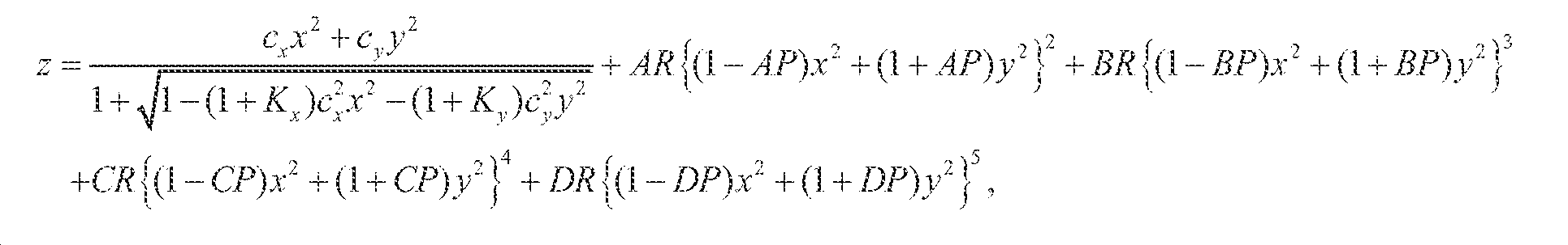
여기서, z는 로컬 x, y, z 좌표 시스템의 z 축을 따라서 측정된 프리폼 표면의 새그이고, cx 및 cy는 각기 x 축 및 y 축에서 꼭지점 곡률(vertex curvature)이며, Kx 및 Ky는 각기 x 축 및 y 축에서의 코닉 상수(conic constant)이고, AR, BR, CR 및 DR은 각기 코닉으로부터의 4차, 6차, 8차 및 10차 변형의 회전적으로 대칭인 부분이며, AP, BP, CP 및 DP은 각기 코닉으로부터의 4차, 6차, 8차 및 10차 변형의 비회전적으로 대칭인 부분이다.Where z is the sag of the preform surface measured along the z axis of the local x, y, z coordinate system, c x and c y are the vertex curvatures in the x and y axes, respectively, and K x and K y AR, BR, CR, and DR are rotationally symmetric parts of the fourth, sixth, eighth, and tenth transforms from the conic, respectively, and AP , BP, CP, and DP are non-recursively symmetric portions of the fourth, sixth, eighth, and tenth transforms from the conic, respectively.
표 1: 접안렌즈 프리즘의 표면 1의 광학적 표면 규정, 도 13 참조Table 1: Optical surface specification of
표 2: 접안렌즈 프리즘의 표면 2의 광학적 표면 규정, 도 14 참조Table 2: Optical surface specification of
표 3: 접안렌즈 프리즘의 표면 3의 광학적 표면 규정, 도 15 참조Table 3: Optical surface specification of
표 4: 접안렌즈 프리즘의 위치 및 배향 파라미터들, 도 16 참조Table 4: Position and orientation parameters of the eyepiece prism, see Figure 16
[0062] 대물렌즈 광학체(820)의 예시적인 광학적 규정에 대하여 표 5 내지 표 8에서 열거되어 있다. 대물렌즈 광학체(820)에서의 모든 3개의 광학적 표면들은 애너모픽 비구면(AAS)이다. Table 5 to Table 8 list the exemplary optical specifications of the objective lens
표 5: 대물렌즈 프리즘의 표면 4의 광학적 표면 규정, 도 17 참조Table 5: Optical surface specification of
표 6: 대물렌즈 프리즘의 표면 5의 광학적 표면 규정, 도 18 참조Table 6: Optical surface specification of
표 7: 대물렌즈 프리즘의 표면 6의 광학적 표면 규정, 도 19 참조Table 7: Optical surface specification of
표 8: 대물렌즈 프리즘의 위치 및 배향 파라미터들, 도 20 참조Table 8: Position and orientation parameters of the objective prism, see Figure 20
[0063] DOE 플레이트(882 및 884)의 예시적인 광학적 규정에 대하여 표 9에 열거되어 있다.[0063] Exemplary optical specifications of
표 9: DOE 플레이트들(882 및 884)에 대한 표면 파라미터들, 도 21 참조Table 9: Surface parameters for
[0064] 도 9는 3mm 동공 직경을 사용하여 평가된 컷오프 주파수 40lps/mm(밀리미터당 라인 쌍들)에서의 가상 디스플레이 경로의 다색 변조 전달 함수들의 필드 맵 플롯을 도시한 것이다. 이 플롯은 본 설계가 15 퍼센트보다 약간 작은 컷오프 주파수에의 MTF 값들을 갖는 2개의 상부 디스플레이 코너들을 제외하고, 대부분의 필드들에 있어서 매우 우수한 성능을 가짐을 보인다. 전체 FOV에 걸쳐서, 가상 디스플레이 경로의 디스토션은 2.9%보다 작은 한편, 투시 경로의 디스토션은 0.5%보다 작다. 광학체에 대한 총 추정된 중량은 단독으로 눈당(per eye) 33 그램이다.[0064] FIG. 9 shows a field map plot of the multicolor modulation transfer functions of the virtual display path at a cutoff frequency of 40 lps / mm (line pairs per millimeter) evaluated using a 3 mm pupil diameter. This plot shows that the design has very good performance in most fields, except for two top display corners with MTF values at cutoff frequencies slightly less than 15 percent. Over the entire FOV, the distortion of the virtual display path is less than 2.9%, while the distortion of the perspective path is less than 0.5%. The total estimated weight for the optical body is 33 grams per eye alone.
[0065] 도 10은 도 3에서 도시된 예시적인 방식에 기초한 예시적인 설계(1000)를 개략적으로 도시한 것이다. 이 설계는 40 도의 사선 FOV를 달성하며, 이 FOV는 수평 방향(X 축 방향)에서 35.2 도이고, 수직 방향(Y 축 방향)에서 20.2 도이며, 이 설계는 또한 8mm의 출사 동공 직경(EPD)(비네트되지 않음: non-vignetted), 및 18mm의 아이 클리어런스를 달성하였다. 이 설계는 16:9 종횡비 및 1280x720 픽셀 해상도를 갖는 0.7" 마이크로디스플레이에 기초한 것이다. 이 설계는 마이크로디스플레이와 동일한 크기 및 해상도의 SLM을 사용하였다. 와이어-그리드 빔스플리터를 사용하여 가상 뷰 경로와 투시 경로를 결합하였다. 동일한 프리폼 프리즘이 접안렌즈 및 대물렌즈 광학체로서 사용되었다.[0065] FIG. 10 schematically illustrates an
[0066] 프리폼 프리즘의 예시적인 광학적 규정에 대하여 표 10 내지 표 15에 열거되어 있다. 프리즘의 2개의 표면들은 애너모픽 비구면(AAS)이며, 한 개의 표면은 비구면(aspheric surface: ASP)이다. ASP 표면의 새그는 다음과 같이 정의된다:[0066] Exemplary optical specifications of the preform prism are listed in Tables 10 to 15. The two surfaces of the prism are anamorphic aspherical surfaces (AAS), and one surface is an aspheric surface (ASP). The ASP of the ASP surface is defined as follows:

여기서, z는 로컬 x, y, z 좌표 시스템의 z 축을 따라서 측정된 표면의 새그이고, c는 꼭지점 곡률이고, K는 코닉 상수이고, A 내지 J는 각기 4차, 6차, 8차 및 10차, 12차, 14차, 16차, 18차 및 20차 변형 계수들이다. Where z is the sag of the surface measured along the z-axis of the local x, y, z coordinate system, c is the vertex curvature, K is the conic constant, AJ is the fourth, sixth, , 12th, 14th, 16th, 18th and 20th order deformation coefficients.
표 10: 프리폼 프리즘의 표면 1의 광학적 표면 규정, 도 22 참조Table 10: Optical surface designation of
표 11: 프리폼 프리즘의 표면 2의 광학적 표면 규정, 도 23 참조Table 11: Optical surface designation of
표 12: 프리폼 프리즘의 표면 3의 광학적 표면 규정, 도 24 참조Table 12: Optical surface specification of
표 13: 접안렌즈로서의 프리폼 프리즘의 위치 및 배향 파라미터들, 도 25 참조Table 13: Position and orientation parameters of the preform prism as eyepiece, see Figure 25
[0068] 도 11은 3mm 동공 직경을 사용하여 평가된 컷오프 주파수 40lps/mm(밀리미터당 라인 쌍들)에서의 가상 디스플레이 경로의 다색 변조 전달 함수들의 필드 맵 플롯을 도시한 것이다. 이 플롯은 본 설계가 대부분의 필드들에 대해서 매우 우수한 성능을 가짐을 보인다.[0068] FIG. 11 shows a field map plot of the multicolor modulation transfer functions of the virtual display path at a cutoff frequency of 40 lps / mm (line pairs per millimeter) evaluated using a 3 mm pupil diameter. This plot shows that this design has very good performance for most fields.
[0069] 도 12는 본 발명에 필요한 이미지 처리 파이프라인의 일 예의 블록도를 도시한 것이다. 먼저, 적합한 깊이 감지 수단을 사용하여 외부 장면의 깊이 맵(depth map)이 추출된다. 이어서, 가상 객체를 깊이 맵과 비교함으로써, 가림(occlusion)이 발생하는 영역들을 결정한다. 마스크 생성 알고리즘이 사전 결정된 가림 영역들에 따라서 이진 마스크 이미지(binary mask image)를 생성한다. 이어서, 마스크 이미지가 공간적 광 변조기 상에 디스플레이되어서, 외부 장면의 중간 이미지 내의 가려진 영역으로부터 광을 블로킹한다. 가상 객체의 가상 이미지가 렌더링되고 마이크로디스플레이 상에 디스플레이된다. 본 발명의 디스플레이 디바이스를 통해 가상 이미지와 외부 장면의 변조된 투시 이미지가 결합된 이미지를, 뷰어가 관찰한다.[0069] Figure 12 shows a block diagram of an example of an image processing pipeline for the present invention. First, a depth map of an external scene is extracted using an appropriate depth sensing means. Then, the virtual object is compared with the depth map to determine areas where occlusion occurs. A mask generation algorithm generates a binary mask image according to predetermined masking areas. The mask image is then displayed on the spatial light modulator to block light from the obscured region in the intermediate image of the outer scene. A virtual image of the virtual object is rendered and displayed on the microdisplay. Through the display device of the present invention, a viewer observes an image in which a virtual image and a modulated perspective image of an external scene are combined.
[0070] 종래 기술과 비교할 때, 본 발명은 컴팩트한 형태로 압축되며, 헤드-장착형 디스플레이로서 보다 용이하게 착용될 수 있게 하는, 폴딩된(folded) 이미지 경로를 특징으로 한다. 종래 기술(미국 특허 7,639,208 B1)에서는, 이 광학적 경로가 회전적으로 대칭인 렌즈들을 사용하여 선형으로 배열된다. 그 결과, 종래 기술의 가림 타입 디스플레이는 긴 텔레스코프와 유사한 형상을 가지며, 헤드에 착용하도록 다루는 것이 쉽지 않다. 본 발명은 반사성 표면들을 사용하여 이미지 경로를 2개의 층들로 폴딩함으로써, 공간적 광 변조기, 마이크로디스플레이 및 빔스플리터가 눈의 전방에서 선형적으로 보다는 헤드의 상단에 장착된다.Compared to the prior art, the present invention features a folded image path that is compressed in a compact form and allows it to be worn more easily as a head-mounted display. In the prior art (US Pat. No. 7,639,208 B1), this optical path is linearly arranged using lenses that are rotationally symmetric. As a result, prior art blind-type displays have a shape similar to a long telescope and are not easy to handle to wear on the head. The present invention uses reflective surfaces to fold the image path into two layers so that a spatial light modulator, microdisplay, and beam splitter are mounted at the top of the head rather than linearly in front of the eye.
[0071] 종래 기술은 오직 반사-타입 공간적 광 변조기에 의존하는 반면에, 본 발명은 반사-타입 또는 투과-타입 공간적 광 변조기를 사용할 수 있다. 또한, 종래 기술은 외부 장면을 변조하기 위해서 편광 빔스플리터를 요구하지만, 본 발명은 편광을 필요로 하지 않는다.[0071] While the prior art relies solely on a reflection-type spatial light modulator, the present invention can use a reflection-type or transmission-type spatial light modulator. Further, while the prior art requires a polarization beam splitter to modulate the external scene, the present invention does not require polarization.
[0072] 본 발명은 층들로 배열되기 때문에, 접안렌즈 및 대물렌즈 광학체가 동일선상에 있을 필요가 없지만, 종래 기술에서는 동일선상에 있어야 한다. 또한, 대물렌즈 광학체는 반드시 텔레-센트릭(tele-centric)할 필요가 없다.[0072] Since the present invention is arranged in layers, the eyepiece and objective lens optics need not be collinear, but must be collinear in the prior art. Also, the objective lens optic does not necessarily have to be tele-centric.
[0073] 종래 기술에서는, 시스템의 대물렌즈 광학체로 인하여, 현실 세계의 뷰가 투시 뷰의 미러 반사이다. 본 발명은 사용자의 뷰와 외부 장면 간의 패리티를 유지하도록 루프 미러가 삽입되게 할 수 있는 폴딩된 이미지 경로를 가지고 있다. 이로 인해, 본 발명은 사용자의 관점에서 보다 기능적게 된다.[0073] In the prior art, due to the objective lens optics of the system, the view of the real world is the mirror reflection of the perspective view. The present invention has a folded image path that allows a loop mirror to be inserted to maintain parity between a user's view and an external scene. As a result, the present invention becomes more functional in terms of the user.
[0074] 종래 기술과 비교할 때, 본 발명은 시스템이 훨씬 컴팩트하게 될 수 있는 프리폼 광학적 기술을 사용한다. 프리폼 광학적 표면들은 내부에서 광을 다수회 반사하도록 설계될 수 있으며, 이로써 광 경로를 폴딩하는데 미러들이 사용될 필요가 없다.[0074] Compared to the prior art, the present invention uses preform optical technology, which makes the system much more compact. The preform optical surfaces can be designed to reflect light many times internally, thereby eliminating the need for mirrors to fold the optical path.
[0075] 본 발명에서, 광학적 경로들을 폴딩하기 위한 반사성 표면들은 광학적 능력을 갖는 평면형 미러들, 구형의, 비구형의, 또는 프리폼 표면들일 수 있다. 본 발명의 중요한 측면은 반사성 표면들 일부가 프리폼 광학적 기술을 사용하여 광학적 성능 및 컴팩트성을 증진시키는 것을 돕는다는 것에 있다. 본 발명에서는, 반사성 표면들 일부가 접안렌즈 또는 대물렌즈 광학체의 일체형 부분이 되게 전략적으로 설계되며, 반사성 표면들은 컴팩트한 디스플레이 설계을 달성하기 위한 광학적 경로의 폴딩을 용이하게 할 뿐만 아니라 광학적 능력에 기여하며 광학적 수차를 보정할 수 있다. 예를 들어, 도 2에서, 반사성 표면들(M1 내지 M3)은 접안렌즈 및 대물렌즈 광학체와는 별도의 일반적 미러들로서 도시되어 있다. 도 3에서는, 미러들(M1 내지 M3) 중 2 개가 프리폼 접안렌즈 프리즘 및 대물렌즈 프리즘 내에 S2 및 S5로서 포함된 프리폼 표면들이다. 도 4에서는, 4개의 반사성 프리폼 표면들이 프리폼 대물렌즈 프리즘 내에 포함되어 있으며 2개의 반사성 프리폼 표면들이 프리폼 접안렌즈 프리즘 내에 포함되어 있다. 도 5에서는, 1개의 반사성 표면이 대물렌즈 프리즘 내에 포함되어 있고, 2개의 프리폼 표면들이 접안렌즈 내에 포함되어 있으며, 루프 프리즘이 추가되어 있다. 도 6에서는, 3개의 프리폼 표면들이 대물렌즈 광학체 내에 있고, 2개의 프리폼 표면들이 접안렌즈 내에 있다. 도 7에서는, 2개의 반사성 프리폼 미러들이 대물렌즈 광학체 내에 있고, 2개의 프리폼 미러들이 접안렌즈 내에 있으며, 미러(790) 및 빔스플리터(780)가 추가되어 있다. [0075] In the present invention, the reflective surfaces for folding optical paths may be planar mirrors having optical capabilities, spherical, non-spherical, or preform surfaces. An important aspect of the present invention is that some of the reflective surfaces help to improve optical performance and compactness using preform optical techniques. In the present invention, some of the reflective surfaces are strategically designed to be an integral part of the eyepiece or objective optics, and the reflective surfaces facilitate folding of the optical path to achieve a compact display design, And the optical aberration can be corrected. For example, in FIG. 2, the reflective surfaces M1 to M3 are shown as general mirrors separate from the eyepiece lens and the objective lens optics. In Fig. 3, two of the mirrors M1 to M3 are the preform eyepiece lens prisms and the preform surfaces included as S2 and S5 in the objective prism. In Figure 4, four reflective preform surfaces are included in the preform objective prism and two reflective preform surfaces are included in the preform eyepiece lens prism. In Fig. 5, one reflective surface is included in the objective lens prism, two preform surfaces are included in the eyepiece lens, and a loop prism is added. In Fig. 6, the three preform surfaces are in the objective lens body, and the two preform surfaces are in the eyepiece. In Figure 7, two reflective preform mirrors are in the objective lens optics, two preform mirrors are in the eyepiece, and a mirror 790 and
[0076] 본 발명은 시스템을 통해 보여지는 투시 뷰가 정확하게 직립되도록(반전 또는 복구되지 않도록) 보장한다. 이를 달성하기 위한 본 실시예들에서는, 투시 경로에 형성된 중간 이미지들의 개수 및 투시 경로에 관여하는 반사 회수에 따라서 2개의 상이한 광학적 방법들이 이용되었다. 홀수 개수의 중간 이미지들의 경우에, 광학적 방법은 투시 경로에서 투시 뷰를 반전 및/또는 복구시키도록 제공된다. 예를 들어, 투시 경로에서 관여한 반사 회수에 따라, 가능한 방법들의 예들은 추가의 반사 또는 반사들을 삽입하는 것, 루프 미러 표면을 사용하는 것, 또는 직립 렌즈를 삽입하는 것을 포함하며, 이에 한정되지 않는다. 짝수 개수의 중간 이미지들의 경우에는, 패리티 변화가 필요하지 않다면, 어떠한 이미지 직립 요소도 필요하지 않다. 예를 들어, 다회 반사 프리폼 프리즘 구조체(통상적으로 2 회보다 많이 반사)가 접안렌즈 또는 대물렌즈 광학체 또는 이 둘로서 사용될 수 있으며, 이것은 대물렌즈 및/또는 접안렌즈 프리즘 내측에서 투시 광학적 경로를 다수 회 폴딩하는 것을 가능하게 하며, 이에 따라 투시 뷰를 직립시킬 수 있고 직립 루프 반사성 표면을 사용할 필요성을 제거한다. [0076] The present invention ensures that the perspective view seen through the system is correctly erected (not inverted or restored). In order to achieve this, two different optical methods have been used, depending on the number of intermediate images formed in the perspective path and the number of reflections involved in the perspective path. In the case of an odd number of intermediate images, the optical method is provided to invert and / or restore the perspective view in the perspective path. For example, depending on the number of reflections involved in the perspective path, examples of possible methods include, but are not limited to, inserting additional reflections or reflections, using a loop mirror surface, or inserting an upright lens Do not. In the case of an even number of intermediate images, no image upright element is required unless a parity change is required. For example, a multi-reflex reflective preform prism structure (typically more than two reflections) may be used as an eyepiece lens or an objective lens, or both, which may include a plurality of perspective optical paths inside the objective lens and / or eyepiece prism Fold folding, thereby allowing the perspective view to be erected and eliminating the need to use an upright loop reflective surface.
[0077] 도 3에서는, 오직 1개의 중간 이미지가 투시 경로에 생성된다. 이 구조는 루프 프리즘(325)을 사용하여 직립된 투시 뷰를 적절하게 생성한다.[0077] In FIG. 3, only one intermediate image is generated in the perspective path. This structure appropriately creates an upright perspective view using a
[0078] 도 4에서는, 4회 반사 프리폼 프리즘이 대물렌즈 광학체로서 사용되며, 이것은 2개의 중간 이미지들(이 프리즘 내측에서 하나(460), SLM에 대해서 하나(440))을 생성한다. 또한, 투시 경로 내에서는 총 8 회의 반사가 관여하게 되며, 이것은 패리티 무변화로 이어진다. 따라서, 직립된 뷰가 생성된다. 대물렌즈 광학체 및 접안렌즈의 구조는 동일한 결과들을 위해서 서로 바뀔 수도 있음에 유의한다.In FIG. 4, a four-fold reflective preform prism is used as the objective lens optics, which produces two intermediate images (one on the inside of the prism (460), one for the SLM (440)). Also, a total of 8 reflections are involved in the perspective path, leading to parity non-change. Thus, an upright view is created. Note that the structures of the objective lens optics and the eyepiece may be interchanged for the same results.
[0079] 도 5에서는, 1개의 중간 이미지가 SLM을 위하여 투시 경로에 생성된다. 이 설계는 루프 프리즘(527)을 사용하여 직립된 투시 뷰를 생성한다.[0079] In FIG. 5, one intermediate image is generated in the perspective path for the SLM. This design uses the
[0080] 도 6에서는, 3회 반사 프리폼 프리즘이 대물렌즈 광학체로서 사용되며, 이것은 2개의 중간 이미지들(이 프리즘 내측에서 하나(660), SLM에 대해서 하나(640))을 생성한다. 또한, 투시 경로 내에서는 총 6 회의 반사가 관여하게 되며, 이것은 패리티 무변화로 이어진다. 따라서, 직립된 뷰가 생성된다. 대물렌즈 광학체 및 접안렌즈의 구조는 동일한 결과들을 위해서 서로 바뀔 수도 있음에 유의한다.[0080] In FIG. 6, a triple-reflective preform prism is used as the objective lens optics, which produces two intermediate images (one on the inside of the
[0081] 도 7에서는, 대물렌즈 광학체(720)가 오직 2회 반사만을 사용하며, 빔스플리터(780)와 미러(790)의 조합이 투시 경로에서 2개의 중간 이미지들(SLM에 대해서 하나(740) 및 추가된 하나(760))을 생성하는 것을 가능하게 한다. 또한, 투시 경로 내에서는 총 8회의 반사가 관여하게 된다. 따라서, 직립된 투시 뷰가 생성된다.In FIG. 7, the objective lens
[0082] 투시 헤드-장착형 디스플레이가 외부 장면의 패리티를 유지하여서, HMD 없이도 사용자에게 그들의 일반적인 뷰들로서 실감나는 경험을 제공하는 것은 매우 중요하다.[0082] It is very important that the perspective head-mounted display maintain the parity of the external scene, thus providing the user with a realistic experience as their general views without the HMD.
[0083] 본 발명의 바람직한 실시예들이 도시 및 기술되었지만, 수정사항들이 첨부된 청구항들의 범위를 벗어나지 않으면서 이러한 실시예들에 대해 가능하다는 것은 본 기술 분야의 당업자에게 용이하게 명백해질 것이다. 청구항들에서 인용된 참조 번호들은 예시적인 것이고, 특허청이 검토하기 용이하게 제공된 것이며, 어떤 경우에도 한정적이지 않다. 일부 실시예들에서, 본 특허출원에서 제공된 도면들은 각도들, 치수 비들 등을 포함하여 크기대로 도시되지 않았다. 일부 실시예들에서, 도면들은 오직 대표적인 것이며 청구항들은 이 도면들의 치수들로 한정되지 않는다.While the preferred embodiments of the present invention have been shown and described, it will be readily apparent to those skilled in the art that modifications may be made to these embodiments without departing from the scope of the appended claims. Reference numerals recited in the claims are illustrative and are provided for ease of review by the Patent Office and are in no way limiting. In some embodiments, the drawings provided in this patent application are not drawn to scale, including angles, dimensional ratios, and the like. In some embodiments, the drawings are exemplary only and the claims are not limited to the dimensions of these figures.
[0084] 아래의 청구항들에서 인용된 참조 부호들은 본 특허출원의 심사의 편의를 위해서만 존재하고, 예시적인 것이며, 어떠한 방식으로도 청구항들의 범위를 도면들에서의 대응하는 참조 번호들을 갖는 특정 특징부들로 한정하는 것으로 의도되지 않는다.The references cited in the claims below are only for convenience of examination of the present patent application and are exemplary and in no way should the scope of the claims be construed to limit the scope of the claims to specific features But is not intended to be limited to.
Claims (46)
a. 사용자에 의해서 뷰잉(viewing)될 이미지를 생성하기 위한 마이크로디스플레이(250) ―상기 마이크로디스플레이는, 자신과 연관된 가상 뷰 경로(205)를 가짐―;
b. 가려질 투시 뷰의 일부들을 블로킹(blocking)하도록 현실 세계의 외부 장면으로부터의 광을 수정하기 위한 공간적 광 변조기(spatial light modulator)(240) ―상기 공간적 광 변조기는, 자신과 연관된 투시 경로(207)를 가짐―;
c. 상기 외부 장면으로부터 입사되는 광을 수용하고 상기 광을 상기 공간적 광 변조기(204) 상으로 포커싱(focusing)하도록 구성된 대물렌즈 광학체(objective optics)(220);
d. 마이크로디스플레이(250)로부터의 가상 이미지와 공간적 광 변조기로부터 전달되는 외부 장면의 변조된 투시 이미지를 합쳐(merge), 결합된 이미지(combined image)를 생성하도록 구성된 빔스플리터(230);
e. 상기 결합된 이미지를 확대하도록 구성된 접안렌즈(eyepiece)(210);
f. 상기 접안렌즈를 대면하도록 구성된 출사 동공(exip pupil)(202) ―상기 출사 동공으로 인해, 사용자는, 상기 가상 뷰가 상기 투시 뷰의 일부들을 가리는 상기 가상 뷰 및 투시 뷰의 결합된 뷰를 관찰함―; 및
g. 상기 가상 뷰 경로(205) 및 상기 투시 뷰(207)를 2개의 층들로 폴딩(folding)하도록 구성된 복수의 반사성 표면들을 포함하며,
제 1 반사성 표면(M1)은 상기 디스플레이의 전방 층(front layer) 상에 배치되어 상기 외부 장면으로부터의 광을 반사하도록 배향되고, 상기 대물렌즈 광학체(220)는 상기 디스플레이의 전방 층 상에 배치되고, 제 2 반사성 표면(M2)은 상기 디스플레이의 전방 층 상에 배치되어 상기 공간적 광 변조기로 광을 반사하도록 배향되고, 상기 공간적 광 변조기(240)는 상기 투시 경로(207)를 따라서 상기 빔스플리터(230)를 통해 상기 대물렌즈 광학체(202) 및 상기 접안렌즈(210)와 광학적으로 연통하게, 상기 투시 경로(207)의 중간 이미지 플레인에 또는 그 근처에 배치되고, 상기 마이크로디스플레이(250)는 상기 빔스플리터(230)를 통해 상기 접안렌즈(210)와 광학적으로 연통하게, 상기 가상 뷰 경로(205)를 따라서 상기 접안렌즈(210)의 초점 플레인(focal plane)에 배치되고, 상기 빔스플리터(230)는 상기 투시 경로(207)가 상기 가상 뷰 경로(205)와 합쳐지고 상기 투시 경로 및 상기 가상 뷰 경로 양쪽 모두로부터의 광이 상기 접안렌즈(210)를 향하도록 배치되고, 상기 접안렌즈(210)는 상기 디스플레이의 후방 층(back layer) 상에 배치되고, 제 3 반사성 표면(M3)이 상기 디스플레이의 후방 층 상에 배치되어 상기 접안렌즈로부터의 광을 상기 출사 동공(202)으로 반사하도록 배향되며,
상기 대물렌즈 광학체(220)는 상기 외부 장면의 광을 수용하고, 상기 대물렌즈 광학체(220)는 상기 외부 장면의 광을 포커싱하고 투시 이미지를 상기 공간적 광 변조기(240) 상에 형성하며, 상기 공간적 광 변조기(240)는 가려질 투시 이미지의 일부들을 제거하도록 상기 투시 이미지를 수정하고, 상기 마이크로디스플레이(250)는 상기 빔스플리터(230)로 가상 이미지를 투사하고, 상기 공간적 광 변조기(240)는 상기 변조된 투시 이미지를 상기 빔스플리터(230)에 투과하고, 상기 빔스플리터(230)는 2개의 이미지들을 결합하여, 상기 가상 이미지가 상기 투시 이미지의 일부들을 가리는 결합된 이미지를 생성하며,
상기 빔스플리터(230)는 상기 결합된 이미지를 상기 접안렌즈(2310)에 투사하며, 상기 접안렌즈는 상기 결합된 이미지를 상기 출사 동공(202)에 투사하고, 사용자는 상기 결합된 이미지를 관찰하며, 상기 결합된 이미지에서 상기 가상 이미지는 상기 외부 장면의 일부들을 가리는, 컴팩트한 광학적 투시 헤드-장착형 디스플레이.So that the opacity of the see-through path 207 can be modulated and the virtual view can obscure portions of the perspective view and the perspective view can obscure portions of the virtual view, A compact optical see-through head-mounted display 200 that is capable of coupling a display 207 with a virtual view path 205,
a. A microdisplay (250) for generating an image to be viewed by a user, the microdisplay having a virtual view path (205) associated therewith;
b. A spatial light modulator 240 for modifying light from an external scene in the real world to block portions of the perspective view to be masked, the spatial light modulator having a perspective path 207 associated therewith, -;
c. Objective optics (220) configured to receive light incident from the outer scene and to focus the light onto the spatial light modulator (204);
d. A beam splitter 230 configured to merge a virtual image from the microdisplay 250 with a modulated perspective image of an external scene delivered from the spatial light modulator, and to generate a combined image;
e. An eyepiece 210 configured to magnify the combined image;
f. An exip pupil (202) configured to face the eyepiece - Due to the exit pupil, the user observes a combined view of the virtual and perspective views over which the virtual view obscures portions of the perspective view -; And
g. And a plurality of reflective surfaces configured to fold the virtual view path (205) and the perspective view (207) into two layers,
A first reflective surface (M1) is disposed on the front layer of the display and is oriented to reflect light from the outer scene, and the objective lens optics (220) are disposed on the front layer And a second reflective surface (M2) is disposed on the front layer of the display and is oriented to reflect light to the spatial light modulator, the spatial light modulator (240) Is disposed at or near an intermediate image plane of the viewing path (207) so as to be in optical communication with the objective lens optics (202) and the eyepiece lens (210) Is disposed in a focal plane of the eyepiece 210 along the virtual view path 205 so as to be in optical communication with the eyepiece 210 through the beam splitter 230, The splitter 230 is arranged so that the sight path 207 is merged with the virtual view path 205 and the light from both the sight path and the virtual view path is directed to the eyepiece 210, A lens 210 is disposed on a back layer of the display and a third reflective surface M3 is disposed on a rear layer of the display to direct light from the eyepiece to the exit pupil 202 Is oriented to reflect,
The objective lens optics 220 receive the light of the external scene and the objective lens optics 220 focus the light of the external scene and form a perspective image on the spatial light modulator 240, The spatial light modulator 240 modifies the perspective image to remove portions of the perspective image to be masked and the microdisplay 250 projects a virtual image to the beam splitter 230 and the spatial light modulator 240 ) Transmits the modulated perspective image to the beam splitter 230 and the beam splitter 230 combines the two images to produce a combined image wherein the virtual image obscures portions of the perspective image,
The beam splitter 230 projects the combined image to the eyepiece lens 2310, which projects the combined image to the exit pupil 202, and the user views the combined image And wherein the virtual image in the combined image covers portions of the external scene.
상기 공간적 광 변조기는 투과-타입(transmission-type) 공간적 광 변조기이고, 상기 공간적 광 변조기는 상기 빔스플리터의 전방에 배치되며, 상기 대물렌즈 광학체들로부터의 광은 상기 빔스플리터에 도달하기 이전에 상기 공간적 광 변조기를 통해서 전달되고, 상기 공간적 광 변조기의 불투명도는 상기 외부 장면의 일부들로부터의 광을 블로킹하도록 제어되는, 컴팩트한 광학적 투시 헤드-장착형 디스플레이.The method according to claim 1,
Wherein the spatial light modulator is a transmission-type spatial light modulator, the spatial light modulator is disposed in front of the beam splitter, and the light from the objective lens optics, before reaching the beam splitter Wherein the spatial light modulator is transmitted through the spatial light modulator and the opacity of the spatial light modulator is controlled to block light from portions of the outer scene.
상기 공간적 광 변조기는 반사-타입(reflection-type) 공간적 광 변조기이고, 상기 공간적 광 변조기는 상기 빔스플리터의 후방에 배치되며, 상기 대물렌즈 광학체들로부터의 광은 상기 빔스플리터를 통과하여 상기 공간적 광 변조기로부터 상기 빔스플리터로 역반사되며, 상기 공간적 광 변조기의 반사도는 가려지지 않을 상기 외부 장면의 일부들로부터의 광만을 반사하도록 제어되는, 컴팩트한 광학적 투시 헤드-장착형 디스플레이.The method according to claim 1,
Wherein the spatial light modulator is a reflection-type spatial light modulator, the spatial light modulator is disposed behind the beam splitter, and light from the objective lens optics passes through the beam splitter, Wherein the reflectivity of the spatial light modulator is controlled to reflect only light from portions of the outer scene that are not to be masked, wherein the reflectivity of the spatial light modulator is reflected back from the light modulator to the beam splitter.
중간 이미지가 상기 투시 경로 내의 하나 이상의 지점들에서 형성되며, 상기 공간적 광 변조기는 중간 이미지 플레인들 중 하나에 또는 그 근처에 배치되는, 컴팩트한 광학적 투시 헤드-장착형 디스플레이.The method according to claim 1,
Wherein an intermediate image is formed at one or more points within the viewing path, and wherein the spatial light modulator is disposed at or near one of the intermediate image planes.
상기 반사성 표면들(M1 내지 M3) 중 하나 이상은 상기 광학적 경로들을 폴딩하고 광을 포커싱할 수 있는 광학적 능력(optical power)을 갖는 독립형 표면들인, 컴팩트한 광학적 투시 헤드-장착형 디스플레이.The method according to claim 1,
Wherein at least one of the reflective surfaces (M1-M3) is a stand-alone surface having optical power to fold the optical paths and to focus the light.
상기 반사성 표면들(M1 내지 M3) 중 하나 이상은 프리폼(freeform) 표면들인, 컴팩트한 광학적 투시 헤드-장착형 디스플레이.The method according to claim 1,
Wherein at least one of the reflective surfaces (M1-M3) is a freeform surface.
상기 전방 층에 있는 상기 제 1 반사성 표면 및/또는 상기 제 2 반사성 표면은 상기 대물렌즈 광학체 내에 포함되는, 컴팩트한 광학적 투시 헤드-장착형 디스플레이.The method according to claim 1,
Wherein the first reflective surface and / or the second reflective surface in the front layer are contained within the objective lens optic. ≪ Desc / Clms Page number 19 >
상기 후방 층에 있는 상기 제 3 반사성 표면(M3)은 상기 접안렌즈 내에 포함되는, 컴팩트한 광학적 투시 헤드-장착형 디스플레이.The method according to claim 1,
Wherein the third reflective surface (M3) in the rear layer is contained within the eyepiece lens.
상기 대물렌즈 광학체는 상기 외부 장면을 상기 공간적 광 변조기 내로 이미징(imaging)하도록 복수의 반사성 표면들 및 굴절성 표면들에 의해서 형성되는 프리폼 프리즘인, 컴팩트한 광학적 투시 헤드-장착형 디스플레이.The method according to claim 1,
Wherein the objective lens optics is a preform prism formed by a plurality of reflective surfaces and refractive surfaces for imaging the outer scene into the spatial light modulator.
상기 접안렌즈는 상기 가상 이미지 및 상기 변조된 투시 이미지를 확대하도록 복수의 반사성 표면들 및 굴절성 표면들에 의해서 형성되는 프리폼 프리즘인, 컴팩트한 광학적 투시 헤드-장착형 디스플레이.The method according to claim 1,
Wherein the eyepiece is a preform prism formed by a plurality of reflective surfaces and refractive surfaces to magnify the virtual image and the modulated perspective image.
상기 전방 층에 있는 상기 제 1 반사성 표면(M1) 및/또는 상기 제 2 반사성 표면(M2)은 상기 대물렌즈 광학체 내에 포함되는, 컴팩트한 광학적 투시 헤드-장착형 디스플레이.10. The method of claim 9,
Wherein the first reflective surface (M1) and / or the second reflective surface (M2) in the front layer are contained within the objective lens optic.
상기 후방 층에 있는 상기 제 3 반사성 표면(M3)은 상기 접안렌즈 내에 포함되는, 컴팩트한 광학적 투시 헤드-장착형 디스플레이.11. The method of claim 10,
Wherein the third reflective surface (M3) in the rear layer is contained within the eyepiece lens.
짝수 개의 중간 이미지들이 상기 투시 경로를 따라 형성되어, 뷰어(viewer)에게 제공되는 투시 뷰와 상기 외부 장면 간의 패리티(parity)를 유지하도록 상기 투시 뷰를 반전시키는(invert), 컴팩트한 광학적 투시 헤드-장착형 디스플레이.The method according to claim 1,
An even number of intermediate images are formed along the viewing path to invert the perspective view to maintain a parity between the perspective view provided to the viewer and the external scene, Mountable display.
뷰어에게 제공되는 투시 뷰와 상기 외부 장면 간의 패리티를 유지하도록 상기 투시 뷰를 복구(revert)하기 위해, 상기 반사성 표면들 중 하나가 루프 미러(roof mirror)로 대체되는, 컴팩트한 광학적 투시 헤드-장착형 디스플레이.The method according to claim 1,
In which one of the reflective surfaces is replaced by a roof mirror to revert the perspective view to maintain parity between the perspective view provided to the viewer and the exterior scene, display.
상기 접안렌즈와 상기 대물렌즈 광학체 양쪽 모두는 동일한 광학적 구조를 갖는, 컴팩트한 광학적 투시 헤드-장착형 디스플레이.The method according to claim 1,
Wherein the eyepiece lens and the objective lens optics both have the same optical structure.
상기 접안렌즈와 상기 대물렌즈 광학체 양쪽 모두는 동일한 형상을 갖는 프리폼 프리즘들인, 컴팩트한 광학적 투시 헤드-장착형 디스플레이.16. The method of claim 15,
Wherein the eyepiece lens and the objective lens optical body are preform prisms having the same shape.
상기 빔스플리터는 상기 전방 층 상에 배치되는, 컴팩트한 광학적 투시 헤드-장착형 디스플레이.The method according to claim 1,
Wherein the beam splitter is disposed on the front layer.
하나 이상의 DOE(diffractive optical element) 플레이트들이 광학적 경로 내에 배치되어 색수차(chromatic aberration)를 보정하는, 컴팩트한 광학적 투시 헤드-장착형 디스플레이.The method according to claim 1,
A compact optically transparent head-mounted display in which one or more diffractive optical element (DOE) plates are disposed in the optical path to compensate for chromatic aberration.
상기 대물렌즈 광학체는, 굴절성 표면(S4), 반사성 표면(S5) 및 굴절성 표면(S6)의 3개의 광학적 표면들 포함하는 1회-반사 프리즘(one-reflection prism)이고,
상기 접안렌즈는, 굴절성 표면(S1), 반사성 표면(S2) 및 굴절성 표면(S3)의 3개의 광학적 표면들을 포함하는 1회-반사 프리즘이고,
상기 제 2 반사성 표면(M2)은 상기 대물렌즈 광학체 내에 포함되고, 상기 제 3 반사성 표면(M3)은 상기 접안렌즈 내에 포함되며,
루프 미러가 상기 제 1 반사성 표면(M1)를 대체하여 상기 투시 뷰를 반전시키고,
반사-타입 공간적 광 변조기는 상기 외부 장면으로부터의 광을 변조하는데 사용되는, 컴팩트한 광학적 투시 헤드-장착형 디스플레이.The method according to any one of claims 1, 3, 6 to 12 or 14,
The objective lens optic is a one-reflection prism comprising three optical surfaces: a refractive surface (S4), a reflective surface (S5) and a refractive surface (S6)
The eyepiece is a once-reflecting prism comprising three optical surfaces, a refractive surface (S1), a reflective surface (S2) and a refractive surface (S3)
Wherein said second reflective surface (M2) is contained within said objective lens optic, said third reflective surface (M3) is contained within said eyepiece lens,
A loop mirror replaces the first reflective surface (M1) to invert the perspective view,
A reflective-type spatial light modulator is used to modulate light from the external scene.
상기 미러(325)에 의해서 반사된 외부 장면으로부터의 입사 광은 상기 굴절성 표면(S4)을 통해 상기 대물렌즈 광학체(320)로 들어가고, 이후 상기 반사성 표면(S5)에 의해 반사되고, 상기 굴절성 표면(S6)을 통해 상기 대물렌즈 광학체(320)를 나와서 상기 공간적 광 변조기(340) 상의 그의 초점 플레인에서 중간 이미지를 형성하고,
상기 공간적 광 변조기(340)는 가려질 광을 블로킹하도록 상기 투시 경로 내의 광을 변조하고, 상기 공간적 광 변조기는 변조된 광을 상기 빔스플리터(330)로 반사하고, 상기 마이크로디스플레이(350)로부터의 광은 상기 빔스플리터(330)로 들어가고, 상기 빔스플리터(330)는 상기 투시 경로(307)에서의 변조된 광을 상기 가상 뷰 경로(305)의 광과 합쳐서 뷰잉(veiwing)을 위해 상기 접안렌즈(310)를 향해서 폴딩하고, 상기 빔스플리터(330)로부터의 광은 상기 굴절성 표면(S3)을 통해서 상기 접안렌즈(310)로 들어가고, 이후 상기 반사성 표면(S2)에 의해 반사되고, 상기 굴절성 표면(S1)을 통해 상기 접안렌즈(310)를 나가서 상기 출사 동공(302)에 도달하며, 뷰어의 눈은 가상 뷰와 변조된 투시 뷰의 결합된 뷰를 보도록 정렬되는, 컴팩트한 광학적 투시 헤드-장착형 디스플레이.20. The method of claim 19,
The incident light from the external scene reflected by the mirror 325 enters the objective lens optics 320 through the refractive surface S4 and is then reflected by the reflective surface S5, Exits the objective lens optics 320 through the sagittal surface S6 to form an intermediate image at its focus plane on the spatial light modulator 340,
The spatial light modulator 340 modulates the light in the vision path to block the light to be masked, the spatial light modulator reflects the modulated light to the beam splitter 330, Light enters the beam splitter 330 and the beam splitter 330 combines the modulated light in the viewing path 307 with the light in the virtual view path 305 to create a beam of light, Wherein the light from the beam splitter 330 enters the eyepiece 310 through the refractive surface S3 and is then reflected by the reflective surface S2, The eye of the viewer is aligned to view a combined view of the virtual view and the modulated perspective view through the eyepiece lens 310 through the focal surface S1 to reach the exit pupil 302, - Mountable display .
상기 대물렌즈 광학체는, 굴절성 표면(S4), 반사성 표면들(S5, S4', S5', S6) 및 굴절성 표면(S7)의 6개의 광학적 프리폼 표면들을 포함하는 4회-반사 프리즘이고,
상기 접안렌즈는, 굴절성 표면(S1), 반사성 표면(S2), 반사성 표면(S1') 및 굴절성 표면(S3)의 4개의 광학적 표면들을 포함하는 2회-반사 프리즘이고,
상기 제 1 반사성 표면(M1) 및 제 2 반사성 표면(M2)은 상기 대물렌즈 광학체 내에 포함되고, 상기 제 3 반사성 표면(M3)은 상기 접안렌즈 내에 포함되며,
상기 대물렌즈 광학체는 상기 대물렌즈 광학체 내에 중간 이미지(460)를 형성하고,
짝수 개수의 중간 이미지들은 상기 투시 뷰를 반전시키도록 상기 투시 경로를 따라 형성되며,
반사-타입 공간적 광 변조기는 외부 장면으로부터의 광을 변조하는데 사용되는, 컴팩트한 광학적 투시 헤드-장착형 디스플레이.The method according to any one of claims 1, 3, 6 to 13,
The objective lens optic is a four-reflection prism comprising six optical preform surfaces: refractive surface S4, reflective surfaces S5, S4 ', S5', S6 and refractive surface S7 ,
The eyepiece is a double-reflecting prism comprising four optical surfaces of a refractive surface S1, a reflective surface S2, a reflective surface S1 'and a refractive surface S3,
Wherein the first reflective surface (M1) and the second reflective surface (M2) are contained within the objective lens optic, the third reflective surface (M3) is contained within the eyepiece lens,
The objective lens optical body forms an intermediate image (460) in the objective lens optical body,
An even number of intermediate images are formed along the viewing path to invert the perspective view,
A reflective-type spatial light modulator is used to modulate light from an external scene.
외부 장면으로부터의 입사 광은 상기 굴절성 표면(S4)을 통해 상기 대물렌즈 광학체(420)로 들어가고, 이후 상기 반사성 표면들(S5, S4', S5', S6)에 의해 연속하여 반사되고, 상기 굴절성 표면(S7)을 통해 상기 대물렌즈 광학체(420)를 나오며, 상기 입사 광은 상기 공간적 광 변조기(440) 상의 그의 초점 플레인에서 중간 이미지를 형성하며,
상기 공간적 광 변조기(440)는 가려질 광을 블로킹하도록 상기 투시 경로 내의 광을 변조하고, 상기 공간적 광 변조기는 변조된 광을 상기 빔스플리터(430)로 반사하고, 상기 마이크로디스플레이(450)로부터의 광은 상기 빔스플리터(430)로 들어가고, 상기 빔스플리터(430)는 상기 투시 경로(407)에서의 변조된 광을 상기 가상 뷰 경로(405)의 광과 합쳐서 뷰잉을 위해 상기 접안렌즈(410)를 향해서 폴딩하고, 상기 빔스플리터로부터의 광은 상기 굴절성 표면(S3)을 통해 상기 접안렌즈(410)로 들어가고, 이후 상기 반사성 표면들(S1' 및 S2)에 의해 연속하여 반사되고, 상기 굴절성 표면(S1)을 통해 상기 접안렌즈(410)를 나가서 상기 출사 동공(402)에 도달하며, 뷰어의 눈은 가상 뷰와 변조된 투시 뷰의 결합된 뷰를 보도록 정렬되는, 컴팩트한 광학적 투시 헤드-장착형 디스플레이.22. The method of claim 21,
Incident light from an external scene enters the objective lens optics 420 through the refractive surface S4 and is subsequently reflected by the reflective surfaces S5, S4 ', S5', S6, Exits the objective lens optics 420 through the refractive surface S7 and the incident light forms an intermediate image at its focus plane on the spatial light modulator 440,
The spatial light modulator 440 modulates the light in the vision path to block the light to be masked, the spatial light modulator reflects the modulated light to the beam splitter 430, Light enters the beam splitter 430 and the beam splitter 430 combines the modulated light in the viewing path 407 with the light in the virtual view path 405 to form the eyepiece 410 for viewing, And the light from the beam splitter enters the eyepiece lens 410 through the refractive surface S3 and is subsequently reflected by the reflective surfaces S1 'and S2, The eye of the viewer is aligned to view a combined view of the virtual view and the modulated perspective view through the eyepiece lens 410 through the focal surface S1 to reach the exit pupil 402, - Mounting type disk Ray.
상기 굴절성 표면(S4) 및 상기 반사성 표면(S4')은 동일한 물리적 표면들이며, 동일한 세트의 표면 규정(surface prescription)들을 갖는, 컴팩트한 광학적 투시 헤드-장착형 디스플레이.22. The method of claim 21,
The refracting surface (S4) and the reflective surface (S4 ') are the same physical surfaces and have the same set of surface prescriptions.
상기 대물렌즈 광학체는, 굴절성 표면(S4), 반사성 표면(S5) 및 굴절성 표면(S6)의 3개의 광학적 표면들을 포함하는 1회-반사 프리즘이고,
상기 접안렌즈는, 굴절성 표면(S1), 반사성 표면(S2), 반사성 표면(S1') 및 굴절성 표면(S3)의 4개의 광학적 표면들을 포함하는 2회-반사 프리즘이고,
상기 제 1 반사성 표면(M1)은 상기 대물렌즈 광학체 내에 포함되고, 상기 제 3 반사성 표면(M3)은 상기 접안렌즈 내에 포함되며,
루프 미러(527)가 상기 제 2 반사성 표면(M2)을 대체하여 투시 뷰를 반전시키며,
투과-타입 공간적 광 변조기는 외부 장면으로부터의 광을 변조하는데 사용되는, 컴팩트한 광학적 투시 헤드-장착형 디스플레이.The method according to any one of claims 1, 3, 6 to 12, or 14,
The objective lens optic is a once-reflecting prism comprising three optical surfaces, a refractive surface (S4), a reflective surface (S5) and a refractive surface (S6)
The eyepiece is a double-reflecting prism comprising four optical surfaces of a refractive surface S1, a reflective surface S2, a reflective surface S1 'and a refractive surface S3,
Wherein said first reflective surface (M1) is contained within said objective lens optic, said third reflective surface (M3) is contained within said eyepiece lens,
The loop mirror 527 replaces the second reflective surface M2 to invert the perspective view,
A transmissive-type spatial light modulator is used to modulate light from an external scene.
외부 장면으로부터의 입사 광은 상기 굴절성 표면(S4)을 통해 상기 대물렌즈 광학체(520)로 들어가고, 이후 상기 반사성 표면(S5)에 의해 반사되고, 상기 굴절성 표면(S6)을 통해 상기 대물렌즈 광학체(520)를 나오고, 상기 미러(527)에 의해 상기 후방 층(517)을 향해서 폴딩되고 상기 공간적 광 변조기(540) 상의 그의 초점 플레인에서 중간 이미지를 형성하며,
상기 공간적 광 변조기(540)는 가려질 광을 블로킹하도록 상기 투시 경로 내의 광을 변조하고, 상기 공간적 광 변조기는 변조된 광을 상기 빔스플리터(530)로 반사하고, 상기 마이크로디스플레이(550)로부터의 광이 상기 빔스플리터(530)로 들어가고, 상기 빔스플리터(530)는 상기 투시 경로(507)에서의 변조된 광을 상기 가상 뷰 경로(505)의 광과 합쳐서 뷰잉을 위해 상기 접안렌즈(510)를 향해서 폴딩하고, 상기 빔스플리터로부터의 광은 상기 굴절성 표면(S3)을 통해 상기 접안렌즈(510)로 들어가고, 이후 상기 반사성 표면들(S1', S2)에 의해 연속적으로 반사되고, 상기 굴절성 표면(S1)을 통해 상기 접안렌즈(510)를 나가서 상기 출사 동공(502)에 도달하며, 뷰어의 눈은 가상 뷰와 변조된 투시 뷰의 결합된 뷰를 보도록 정렬되는, 컴팩트한 광학적 투시 헤드-장착형 디스플레이.25. The method of claim 24,
Incident light from an external scene enters the objective lens optics 520 through the refractive surface S4 and is then reflected by the reflective surface S5 and is reflected by the reflective surface S6 through the refractive surface S6, Exits the lens optics 520 and is folded toward the rear layer 517 by the mirror 527 and forms an intermediate image at its focus plane on the spatial light modulator 540,
The spatial light modulator 540 modulates the light in the vision path to block the light to be masked, the spatial light modulator reflects the modulated light to the beam splitter 530, Light enters the beam splitter 530 and the beam splitter 530 combines the modulated light in the viewing path 507 with the light in the virtual view path 505 to form the eyepiece 510 for viewing, And the light from the beam splitter enters the eyepiece 510 through the refracting surface S3 and is subsequently reflected by the reflective surfaces S1 ', S2, The eye of the viewer is aligned to view a combined view of the virtual view and the modulated perspective view through the eyepiece lens 510 through the focal surface S1 to reach the exit pupil 502, - Mounting type disk Ray.
상기 표면(S1) 및 상기 반사성 표면(S1')은 동일한 물리적 표면들이며, 동일한 세트의 표면 규정들을 갖는, 컴팩트한 광학적 투시 헤드-장착형 디스플레이.25. The method of claim 24,
Wherein the surface (S1) and the reflective surface (S1 ') are the same physical surfaces and have the same set of surface definitions.
상기 대물렌즈 광학체는, 굴절성 표면(S4), 반사성 표면들(S5, S4',S6) 및 굴절성 표면(S7)의 5개의 광학적 프리폼 표면들을 포함하는 3회-반사 프리즘이고,
상기 접안렌즈는, 굴절성 표면(S1), 반사성 표면(S2), 반사성 표면(S1') 및 굴절성 표면(S3)의 4개의 광학적 표면들을 포함하는 2회-반사 프리즘이고,
상기 제 1 반사성 표면(M1) 및 상기 제 2 반사성 표면(M2)은 상기 대물렌즈 광학체 내에 포함되고, 상기 제 3 반사성 표면(M3)은 상기 접안렌즈 내에 포함되며,
상기 대물렌즈 광학체는 상기 대물렌즈 광학체 내에 중간 이미지(660)를 형성하고,
짝수 개수의 중간 이미지들은 상기 투시 뷰를 반전시키도록 상기 투시 경로를 따라 형성되고,
투과-타입 공간적 광 변조기는 외부 장면으로부터의 광을 변조하는데 사용되는, 컴팩트한 광학적 투시 헤드-장착형 디스플레이.The method according to any one of claims 1, 2 and 6 to 13,
The objective lens optic is a three-reflection prism comprising five optical preform surfaces: a refractive surface (S4), reflective surfaces (S5, S4 ', S6) and a refractive surface (S7)
The eyepiece is a double-reflecting prism comprising four optical surfaces of a refractive surface S1, a reflective surface S2, a reflective surface S1 'and a refractive surface S3,
Wherein the first reflective surface (M1) and the second reflective surface (M2) are contained within the objective lens optic, the third reflective surface (M3) is contained within the eyepiece lens,
The objective lens optical body forms an intermediate image 660 in the objective lens optical body,
An even number of intermediate images are formed along the viewing path to invert the perspective view,
A transmissive-type spatial light modulator is used to modulate light from an external scene.
외부 장면으로부터의 입사 광은 상기 굴절성 표면(S4)을 통해 상기 대물렌즈 광학체(620)로 들어가고, 이후 상기 반사성 표면들(S5,S4',S6)에 의해 연속적으로 반사되고, 상기 굴절성 표면(S7)을 통해 상기 대물렌즈 광학체(620)를 나오고, 상기 입사 광은 상기 공간적 광 변조기(640) 상의 그의 초점 플레인에서 중간 이미지를 형성하며,
상기 공간적 광 변조기는 가려질 광을 블로킹하도록 상기 투시 경로 내의 광을 변조하고, 상기 공간적 광 변조기는 변조된 광을 상기 빔스플리터(630)로 반사하고, 상기 마이크로디스플레이(650)로부터의 광은 상기 빔스플리터(630)로 들어가고, 상기 빔스플리터는 상기 투시 경로(607)에서의 변조된 광을 상기 가상 뷰 경로(605)의 광과 합쳐서 뷰잉을 위해 상기 접안렌즈(610)를 향해서 폴딩하고, 상기 빔스플리터로부터의 광은 상기 굴절성 표면(S3)을 통해 상기 접안렌즈(610)로 들어가고, 이후 상기 반사성 표면들(S1', S2)에 의해 연속적으로 반사되고, 상기 굴절성 표면(S1)을 통해 상기 접안렌즈(610)를 나가서 상기 출사 동공(602)에 도달하며, 뷰어의 눈은 가상 뷰와 변조된 투시 뷰의 결합된 뷰를 보도록 정렬되는, 컴팩트한 광학적 투시 헤드-장착형 디스플레이.28. The method of claim 27,
Incident light from an external scene enters the objective lens optics 620 through the refractive surface S4 and is subsequently reflected by the reflective surfaces S5, S4 ', S6, Exits the objective lens optics 620 through surface S7 and the incident light forms an intermediate image at its focus plane on the spatial light modulator 640,
The spatial light modulator modulates light in the vision path to block the light to be masked, the spatial light modulator reflects the modulated light to the beam splitter 630, Enters a beam splitter 630 which combines the modulated light in the viewing path 607 with the light in the virtual view path 605 and folds towards the eyepiece 610 for viewing, Light from the beam splitter enters the eyepiece 610 through the refractive surface S3 and is subsequently reflected by the reflective surfaces S1 'and S2, and the refractive surface S1 Through the eyepiece (610) to reach the exit pupil (602), and the viewer's eye is aligned to view a combined view of the virtual view and the modulated perspective view.
상기 굴절성 표면(S1) 및 상기 반사성 표면(S1')은 동일한 물리적 표면들일 수 있으며, 동일한 세트의 표면 규정들을 갖는, 컴팩트한 광학적 투시 헤드-장착형 디스플레이.28. The method of claim 27,
The refracting surface (S1) and the reflective surface (S1 ') can be the same physical surfaces and have the same set of surface qualifications.
상기 굴절성 표면(S4) 및 상기 반사성 표면(S4')은 동일한 물리적 표면들이며, 동일한 세트의 표면 규정들을 갖는, 컴팩트한 광학적 투시 헤드-장착형 디스플레이.28. The method of claim 27,
The refracting surface (S4) and the reflective surface (S4 ') are the same physical surfaces and have the same set of surface qualities.
상기 대물렌즈 광학체는, 굴절성 표면(S4), 반사성 표면(S5), 반사성 표면(S4') 및 굴절성 표면(S6)의 5개의 광학적 프리폼 표면들을 포함하는 2회-반사 프리즘이고,
상기 접안렌즈는, 굴절성 표면(S1), 반사성 표면(S2), 반사성 표면(S1') 및 굴절성 표면(S3)의 4개의 광학적 표면들을 포함하는 2회-반사 프리즘이고,
상기 제 1 반사성 표면(M1)은 상기 대물렌즈 광학체 내에 포함되고, 상기 제 3 반사성 표면(M3)은 상기 접안렌즈 내에 포함되며,
상기 제 2 반사성 표면(M2)은 제 1 빔스플리터(780) 및 릴레이 렌즈(770)와 함께 미러(790)로서 구성되어 상기 투시 경로를 폴딩하고 제 2 중간 이미지를 형성하며,
짝수 개수의 중간 이미지들은 상기 투시 뷰를 반전시키도록 상기 투시 경로를 따라 형성되고,
반사-타입 공간적 광 변조기는 외부 장면으로부터의 광을 변조하는데 사용되는, 컴팩트한 광학적 투시 헤드-장착형 디스플레이.The method according to any one of claims 1, 3, and 6 to 13,
The objective lens optics is a two-reflection prism comprising five optical preform surfaces, a refractive surface (S4), a reflective surface (S5), a reflective surface (S4 ') and a refractive surface (S6)
The eyepiece is a double-reflecting prism comprising four optical surfaces of a refractive surface S1, a reflective surface S2, a reflective surface S1 'and a refractive surface S3,
Wherein said first reflective surface (M1) is contained within said objective lens optic, said third reflective surface (M3) is contained within said eyepiece lens,
The second reflective surface M2 is configured as a mirror 790 with a first beam splitter 780 and a relay lens 770 to fold the viewing path and form a second intermediate image,
An even number of intermediate images are formed along the viewing path to invert the perspective view,
A reflective-type spatial light modulator is used to modulate light from an external scene.
외부 장면으로부터의 입사 광은 상기 굴절성 표면(S4)을 통해 상기 대물렌즈 광학체(720)로 들어가고, 상기 반사성 표면들(S5,S4')에 의해 연속적으로 반사되고, 상기 굴절성 표면(S6)을 통해 상기 대물렌즈 광학체(720)를 나오고, 상기 입사 광은 상기 제 1 빔스플리터(780)에 의해 상기 미러(790) 상으로 반사되고, 상기 입사 광은 중간 이미지를 형성하고, 상기 미러(790)는 상기 광을 상기 전방 층으로부터 상기 릴레이 렌즈(770)로 반사하고, 상기 릴레이 렌즈(770)는 상기 공간적 광 변조기(740) 상에 다른 중간 이미지를 형성하고,
상기 공간적 광 변조기는 가려질 광을 블로킹하도록 상기 투시 경로 내의 광을 변조하고, 상기 공간적 광 변조기는 변조된 광을 제 2 빔스플리터(730)로 반사하고, 상기 마이크로디스플레이(750)로부터의 광이 상기 제 2 빔스플리터(730)로 들어가고, 상기 제 2 빔스플리터(730)는 상기 투시 경로(707)에서의 변조된 광을 상기 가상 뷰 경로(705)의 광과 합쳐서 뷰잉을 위해 상기 접안렌즈(710)를 향해 폴딩하고, 상기 제 2 빔스플리터로부터의 광은 상기 굴절성 표면(S3)을 통해 상기 접안렌즈(710)로 들어가고, 이후 상기 반사성 표면들(S1', S2)에 의해 연속적으로 반사되고, 상기 굴절성 표면(S1)을 통해 상기 접안렌즈(710)를 나가서 상기 출사 동공(702)에 도달하며, 뷰어의 눈은 가상 뷰와 변조된 투시 뷰의 결합된 뷰를 보도록 정렬되는, 컴팩트한 광학적 투시 헤드-장착형 디스플레이.32. The method of claim 31,
The incident light from the external scene enters the objective lens optics 720 through the refractive surface S4 and is successively reflected by the reflective surfaces S5 and S4 ' And the incident light is reflected by the first beam splitter 780 onto the mirror 790. The incident light forms an intermediate image and the mirror 790 reflects the incident light to form an intermediate image, (790) reflects the light from the front layer to the relay lens (770), and the relay lens (770) forms another intermediate image on the spatial light modulator (740)
The spatial light modulator modulates the light in the viewing path to block the light to be masked, the spatial light modulator reflects the modulated light to the second beam splitter 730, and the light from the microdisplay 750 Enters the second beam splitter 730 and the second beam splitter 730 combines the modulated light in the viewing path 707 with the light in the virtual view path 705 to form the eyepiece 710 and the light from the second beam splitter enters the eyepiece lens 710 through the refracting surface S3 and is then successively reflected by the reflective surfaces S1 ' And the eye of the viewer is aligned to see a combined view of the virtual view and the modulated perspective view through the eyepiece lens 710 through the refractive surface S1 to reach the exit pupil 702, One optically transparent head - mounted Display.
상기 미러(790) 및 상기 공간적 광 변조기(740)의 위치들은 상호교환가능한, 컴팩트한 광학적 투시 헤드-장착형 디스플레이.32. The method of claim 31,
The positions of the mirror (790) and the spatial light modulator (740) are interchangeable, compact optically transmissive head-mounted displays.
상기 대물렌즈 광학체의 광학적 표면들 중 1개 이상은 회전적 대칭을 갖거나 또는 갖지 않는 비구면 표면인, 컴팩트한 광학적 투시 헤드-장착형 디스플레이.33. The method according to any one of claims 19 to 32,
Wherein at least one of the optical surfaces of the objective lens optics is an aspherical surface with or without rotational symmetry.
접안렌즈 프리즘의 광학적 표면들 중 1개 이상은 회전적 대칭을 갖거나 또는 갖지 않는 비구면 표면(aspherical surface)인, 컴팩트한 광학적 투시 헤드-장착형 디스플레이.33. The method according to any one of claims 19 to 32,
A compact optical perspective head-mounted display wherein at least one of the optical surfaces of the eyepiece prism is an aspherical surface with or without rotational symmetry.
상기 빔스플리터(130)는 큐브 또는 플레이트 형태이며 비편광 빔스플리터 또는 편광 빔스플리터일 수 있는, 컴팩트한 광학적 투시 헤드-장착형 디스플레이.The method according to claim 1,
The beam splitter 130 is in the form of a cube or a plate and can be a non-polarizing beam splitter or a polarizing beam splitter.
상기 컴팩트한 광학적 투시 헤드-장착형 디스플레이는 모노큘러(monocular) 및 바이노큘러(binocular) 중 하나인, 컴팩트한 광학적 투시 헤드-장착형 디스플레이.37. The method according to any one of claims 1 to 36,
Wherein the compact optical perspective head-mounted display is one of a monocular and a binocular.
a. 사용자에 의해서 뷰잉될 이미지를 생성하기 위한 마이크로디스플레이(350) ―상기 마이크로디스플레이는 자신과 연관된 가상 뷰 경로(305)를 가짐―;
b. 가려질 투시 뷰의 일부들을 블로킹하도록 현실 세계의 외부 장면으로부터의 광을 수정하기 위한 반사-타입 공간적 광 변조기(340) ―상기 공간적 광 변조기는 자신과 연관된 투시 경로(307)를 가짐―;
c. 상기 외부 장면으로부터 입사되는 광을 수용하고 상기 광을 상기 공간적 광 변조기(340) 상으로 포커싱하도록 구성된 대물렌즈 광학체(320) ―상기 대물렌즈 광학체는, 굴절성 표면(S4), 반사성 표면(S5) 및 굴절성 표면(S6)의 3개의 광학적 프리폼 표면들을 포함하는 1회-반사 프리폼 프리즘임―;
d. 마이크로디스플레이(350)로부터 디지털방식으로 발생된 가상 이미지와 공간적 광 변조기로부터 전달되는 외부 장면의 변조된 투시 이미지를 합쳐, 결합된 이미지를 생성하도록 구성된 빔스플리터(330);
e. 상기 결합된 이미지를 확대하도록 구성된 접안렌즈(310) ―상기 접안렌즈는, 굴절성 표면(S1), 반사성 표면(S2) 및 굴절성 표면(S3)의 3개의 광학적 프리폼 표면들을 포함하는 1회-반사 프리폼 프리즘임―;
f. 상기 접안렌즈와 대면하도록 구성된 출사 동공(302) ―상기 출사 동공으로 인해, 사용자는 상기 가상 뷰가 상기 투시 뷰의 일부들을 가리는 상기 가상 뷰와 투시 뷰의 결합된 뷰를 관찰함―; 및
g. 상기 외부 장면으로부터의 광을 상기 대물렌즈 광학체로 반사하도록 구성된 루프 미러(325) ―상기 루프 미러는, 뷰어에게 제공되는 투시 뷰와 상기 외부 장면 간의 패리티를 유지하도록, 상기 투시 이미지를 복구시키기 위해서 추가의 반사를 추가로 행함(add)―를 포함하며,
상기 루프 미러(325)는 상기 디스플레이의 전방 층(315) 상에 배치되고, 상기 대물렌즈 광학체(320)는 상기 디스플레이의 전방 층(315) 상에 배치되고, 상기 공간적 광 변조기(340)는 상기 디스플레이의 후방 층(317) 상에, 상기 투시 경로의 중간 이미지 플레인에 또는 그 근처에서, 상기 빔스플리터(330)의 일측과 대면하도록 배치되고,
상기 마이크로디스플레이(350)는 상기 디스플레이의 후방 층(317) 상에서 상기 빔스플리터(330)의 다른 측과 대면하도록 배치되고, 상기 빔스플리터(330)는 상기 투시 경로(307)가 상기 가상 뷰 경로(505)와 합쳐지고 합쳐진 경로로부터의 광이 상기 접안렌즈(310)를 향하도록 배치되고, 상기 접안렌즈(210)는 상기 디스플레이의 후방 층(317) 상에 배치되며,
상기 미러(325)에 의해 반사된 외부 장면으로부터의 입사 광은 상기 굴절성 표면(S4)을 통해 상기 대물렌즈 광학체(320)로 들어가고, 이후 상기 반사성 표면(S5)에 의해 반사되고, 상기 굴절성 표면(S6)을 통해 상기 대물렌즈 광학체(320)를 나와서 상기 공간적 광 변조기(340) 상의 그의 초점 플레인에서 중간 이미지를 형성하며,
상기 공간적 광 변조기(340)는 투시 뷰의 일부들을 가리기 위해 상기 투시 경로 내의 광을 변조하고, 상기 공간적 광 변조기는 변조된 광을 상기 빔스플리터(330)로 반사하고, 상기 마이크로디스플레이(350)로부터의 광이 상기 빔스플리터(330)로 들어가고, 상기 빔스플리터(330)는 상기 투시 경로(307)에서의 변조된 광을 상기 가상 뷰 경로(305)의 광과 합쳐서 뷰잉을 위해 상기 접안렌즈(310)를 향해서 폴딩하고, 상기 빔스플리터로부터의 광은 상기 굴절성 표면(S3)을 통해 상기 접안렌즈(310)로 들어가고, 이후 상기 반사성 표면(S2)에 의해서 반사되고, 상기 굴절성 표면(S1)을 통해 상기 접안렌즈(310)를 나가서 상기 출사 동공(302)에 도달하며, 뷰어의 눈은 가상 뷰와 변조된 투시 뷰의 결합된 뷰를 보도록 정렬되는, 컴팩트한 광학적 투시 헤드-장착형 디스플레이.The perspective path 307 may be moved to a virtual view path 305 (e.g., a viewpoint) so that the opacity of the perspective path 307 may be modulated and the virtual view may obscure portions of the perspective view and the perspective view may obscure portions of the virtual view. , Which can be coupled to a display (300)
a. A microdisplay (350) for generating an image to be viewed by a user, the microdisplay having a virtual view path (305) associated therewith;
b. A reflective-type spatial light modulator (340) for modifying light from an external scene in the real world to block portions of the perspective view to be masked, the spatial light modulator having a perspective path (307) associated therewith;
c. An objective lens optics 320 configured to receive light incident from the external scene and to focus the light onto the spatial light modulator 340, the objective lens optic comprising a refractive surface S4, a reflective surface Reflective preform prism comprising three optical preform surfaces, a refractive surface (S5) and a refractive surface (S6);
d. A beam splitter 330 configured to combine the digitally generated virtual image from the microdisplay 350 with the modulated perspective image of the external scene delivered from the spatial light modulator and generate a combined image;
e. An eyepiece lens configured to magnify the combined image, wherein the eyepiece comprises a single-lens reflex surface including three optical preform surfaces, a refractive surface (S1), a reflective surface (S2), and a refractive surface (S3) A reflective freeform prism;
f. An exit pupil (302) configured to face the eyepiece lens - due to the exit pupil, the user observes a combined view of the virtual view and the perspective view, wherein the virtual view obscures portions of the perspective view; And
g. A loop mirror (325) configured to reflect light from the external scene to the objective lens optics, the loop mirror further comprising: (Add) the reflection of the light,
The loop mirror 325 is disposed on the front layer 315 of the display and the objective lens optics 320 is disposed on the front layer 315 of the display and the spatial light modulator 340 Is disposed on the rear layer (317) of the display to face one side of the beam splitter (330) at or near the mid-image plane of the viewing path,
The microdisplay 350 is arranged to face the other side of the beam splitter 330 on the rear layer 317 of the display and the beam splitter 330 is positioned such that the viewing path 307 is located on the virtual view path 505 and the light from the combined path is directed toward the eyepiece lens 310 and the eyepiece lens 210 is disposed on the rear layer 317 of the display,
The incident light from the external scene reflected by the mirror 325 enters the objective lens optics 320 through the refractive surface S4 and is then reflected by the reflective surface S5, Exits the objective lens optics 320 through the sagittal surface S6 to form an intermediate image at its focus plane on the spatial light modulator 340,
The spatial light modulator 340 modulates the light in the viewing path to cover a portion of the perspective view and the spatial light modulator reflects the modulated light to the beam splitter 330 and from the microdisplay 350 And the beam splitter 330 combines the modulated light in the viewing path 307 with the light in the virtual view path 305 and transmits the modulated light in the viewing path 307 to the eyepiece 310 And the light from the beam splitter enters the eyepiece lens 310 through the refracting surface S3 and is then reflected by the reflective surface S2 and is reflected by the refracting surface S1, Wherein the eye of the viewer is aligned to view a combined view of the virtual view and the modulated perspective view by exiting the eyepiece lens (310) through the exit pupil (310) and reaching the exit pupil (302).
a. 사용자에 의해 뷰잉될 이미지를 생성하기 위한 마이크로디스플레이(450) ―상기 마이크로디스플레이는, 자신과 연관된 가상 뷰 경로(405)를 가짐―;
b. 가려질 투시 뷰의 일부들을 블로킹하도록 외부 장면으로부터의 광을 수정하기 위한 반사-타입 공간적 광 변조기(440) ―상기 공간적 광 변조기는, 자신과 연관된 투시 경로(407)를 가짐―;
c. 외부 장면을 대면하며, 상기 외부 장면으로부터 입사되는 광을 수용하고 상기 광을 상기 공간적 광 변조기(440) 상으로 포커싱하도록 구성된 대물렌즈 광학체(420) ―상기 대물렌즈 광학체는, 굴절성 표면(S4), 반사성 표면들(S5, S4', S5', S6) 및 굴절성 표면(S7)의 6개의 광학적 프리폼 표면들을 포함하는 4회-반사 프리폼 프리즘임―;
d. 마이크로디스플레이(450)로부터 디지털방식으로 생성된 가상 이미지와 공간적 광 변조기(440)로부터 전달되는 외부 장면의 변조된 투시 이미지를 합쳐서, 결합된 이미지를 형성하도록 구성된 빔스플리터(430);
e. 상기 결합된 이미지를 확대하도록 구성된 접안렌즈(410) ―상기 접안렌즈는, 굴절성 표면(S1), 반사성 표면(S2), 반사성 표면(S1') 및 굴절성 표면(S3)인 4개의 광학적 프리폼 표면들을 포함하는 2회-반사 프리폼 프리즘임―; 및
f. 상기 접안렌즈와 대면하도록 구성된 출사 동공(402) ―상기 출사 동공으로 인해, 사용자는 상기 가상 뷰가 상기 투시 뷰의 일부들을 가리는 상기 가상 뷰와 투시 뷰의 결합된 뷰를 관찰함―을 포함하며,
상기 대물렌즈 광학체(420)는 상기 디스플레이의 전방 층(415) 상에 배치되고, 상기 공간적 광 변조기(440)는 상기 디스플레이의 후방 층(417) 상에, 상기 투시 경로의 중간 이미지 플레인에 또는 그 근처에서, 상기 빔스플리터(430)의 일측과 대면하도록 배치되고, 상기 마이크로디스플레이(450)는 상기 디스플레이의 후방 층(417) 상에서 상기 빔스플리터(430)의 다른 측과 대면하도록 배치되고, 상기 빔스플리터(430)는 상기 투시 경로(407)가 상기 가상 뷰 경로(405)와 합쳐지고 합쳐진 경로로부터의 광이 상기 접안렌즈(410)를 향하도록 배치되고, 상기 접안렌즈(410)는 상기 디스플레이의 후방 층(417) 상에 배치되며,
상기 외부 장면으로부터의 입사 광은 상기 굴절성 표면(S4)을 통해 상기 대물렌즈 광학체(420)로 들어가고, 이후 상기 반사성 표면들(S5,S4',S5',S6)에 의해 연속하여 반사되고, 상기 굴절성 표면(S7)을 통해 상기 대물렌즈 광학체(420)를 나오고, 상기 입사 광은 상기 공간적 광 변조기(440) 상의 그의 초점 플레인에서 중간 이미지를 형성하며,
상기 공간적 광 변조기는 투시 뷰의 일부들을 가리도록 상기 투시 경로 내의 광을 변조하고, 상기 공간적 광 변조기는 변조된 광을 상기 빔스플리터(430)로 반사하고, 상기 마이크로디스플레이(450)로부터의 광이 상기 빔스플리터(430)로 들어가고, 상기 빔스플리터(430)는 상기 투시 경로(407)에서의 변조된 광을 상기 가상 뷰 경로(405)의 광과 합쳐서 뷰잉을 위해 상기 접안렌즈(410)를 향해서 폴딩하고, 상기 빔스플리터로부터의 광은 상기 굴절성 표면(S3)을 통해 상기 접안렌즈(410)로 들어가고, 이후 상기 반사성 표면들(S1' 및 S2)에 의해 연속하여 반사되고, 상기 굴절성 표면(S1)을 통해 상기 접안렌즈(410)를 나와서 상기 출사 동공(402)에 도달하며, 뷰어의 눈은 가상 뷰와 변조된 투시 뷰의 결합된 뷰를 보도록 정렬되는, 컴팩트한 광학적 투시 헤드-장착형 디스플레이.The perspective path 407 may be moved to the virtual view path 405 so that the opacity of the perspective path 407 may be modulated and the virtual view may obscure portions of the perspective view and the perspective view may obscure portions of the virtual view. Mounted display (400) that can be coupled to a display
a. A microdisplay (450) for generating an image to be viewed by a user, the microdisplay having a virtual view path (405) associated therewith;
b. A reflective-type spatial light modulator (440) for modifying light from an external scene to block portions of the perspective view to be masked, the spatial light modulator having a perspective path (407) associated therewith;
c. An objective lens optics (420) configured to confront an external scene and to receive light incident from the external scene and to focus the light onto the spatial light modulator (440), the objective lens optic comprising a refractive surface Reflective preform prism comprising six optical preform surfaces of reflective surfaces S6, S4, reflective surfaces S5, S4 ', S5', S6 and refractive surface S7;
d. A beam splitter 430 configured to combine the digitally generated virtual image from the microdisplay 450 with the modulated perspective image of the external scene delivered from the spatial light modulator 440 to form a combined image;
e. An eyepiece lens configured to magnify the combined image, wherein the eyepiece comprises four optical preforms: a refractive surface (S1), a reflective surface (S2), a reflective surface (S1 ') and a refractive surface (S3) A two-reflection preform prism comprising surfaces; And
f. An exit pupil (402) configured to face the eyepiece, said exit pupil causing a user to view a combined view of said virtual view and a perspective view said virtual view obscuring portions of said perspective view,
The objective lens optics 420 is disposed on the front layer 415 of the display and the spatial light modulator 440 is disposed on the rear layer 417 of the display at an intermediate image plane of the viewing path The microdisplay 450 is arranged to face one side of the beam splitter 430 and the microdisplay 450 is arranged to face the other side of the beam splitter 430 on the rear layer 417 of the display, The beam splitter 430 is arranged such that the sight path 407 is merged with the virtual view path 405 and light from the combined path is directed to the eyepiece 410, Is disposed on the rear layer (417)
The incident light from the external scene enters the objective lens optics 420 through the refractive surface S4 and is subsequently reflected by the reflective surfaces S5, S4 ', S5', S6 Exits the objective lens optics 420 through the refractive surface S7 and the incident light forms an intermediate image at its focus plane on the spatial light modulator 440,
The spatial light modulator modulates light in the viewing path to cover portions of the perspective view, the spatial light modulator reflects the modulated light to the beam splitter 430, and the light from the microdisplay 450 Enters the beam splitter 430 and the beam splitter 430 combines the modulated light in the viewing path 407 with the light in the virtual view path 405 and directs it towards the eyepiece 410 for viewing And the light from the beam splitter enters the eyepiece lens 410 through the refractive surface S3 and is subsequently reflected by the reflective surfaces S1 'and S2, (Not shown) through the eyepiece lens 410 to reach the exit pupil 402 and the eye of the viewer is aligned to see a combined view of the virtual view and the modulated perspective view, disrespect Ray.
상기 굴절성 표면(S4) 및 상기 반사성 표면(S4')은 동일한 물리적 표면들이며, 동일한 세트의 표면 규정들을 갖는, 컴팩트한 광학적 투시 헤드-장착형 디스플레이.40. The method of claim 39,
The refracting surface (S4) and the reflective surface (S4 ') are the same physical surfaces and have the same set of surface qualities.
a. 사용자에 의해 뷰잉될 이미지를 생성하기 위한 마이크로디스플레이(550) ―상기 마이크로디스플레이는, 자신과 연관된 가상 뷰 경로(505)를 가짐―;
b. 가려질 투시 뷰의 일부들을 블로킹하도록 외부 장면으로부터의 광을 수정하기 위한 투과-타입 공간적 광 변조기(540) ―상기 공간적 광 변조기는, 자신과 연관된 투시 경로(507)를 가짐―;
c. 외부 장면을 대면하고, 상기 외부 장면으로부터 입사되는 광을 수용하고 상기 광을 상기 공간적 광 변조기(540) 상으로 포커싱하도록 구성된 대물렌즈 광학체(520) ―상기 대물렌즈 광학체는, 굴절성 표면(S4), 반사성 표면(S5) 및 굴절성 표면(S6)의 3개의 광학적 프리폼 표면들을 포함하는 1회-반사 프리폼 프리즘임―;
d. 마이크로디스플레이(550)로부터 디지털방식으로 생성된 가상 이미지와 상기 공간적 광 변조기로부터 전달되는 외부 장면의 변조된 투시 이미지를 합쳐서, 결합된 이미지를 형성하도록 구성된 빔스플리터(530);
e. 상기 결합된 이미지를 확대하도록 구성된 접안렌즈(510) ―상기 접안렌즈는, 굴절성 표면(S1), 반사성 표면(S2), 반사성 표면(S1') 및 굴절성 표면(S3)의 3개의 광학적 프리폼 표면들을 포함하는 2회-반사 프리폼 프리즘임―; 및
f. 상기 접안렌즈와 대면하도록 구성된 출사 동공(502) ―상기 출사 동공으로 인해, 사용자는 상기 가상 뷰가 상기 투시 뷰의 일부들을 가리는 상기 가상 뷰와 투시 뷰의 결합된 뷰를 관찰함―; 및
g. 상기 대물렌즈 광학체로부터 광을 상기 공간적 광 변조기로 반사하도록 구성된 루프 미러(527) ―상기 루프 미러는 뷰어에게 제공되는 투시 뷰와 상기 외부 장면 간의 패리티를 유지하도록, 상기 투시 뷰를 복구시키기 위해서 추가의 반사를 추가로 행함(add)―을 포함하며,
상기 대물렌즈 광학체(520)는 상기 디스플레이의 전방 층(515) 상에 배치되고, 상기 미러(527)는 상기 디스플레이의 전방 층(515) 상에 배치되고, 상기 공간적 광 변조기(540)는 상기 디스플레이의 후방 층(517) 상에, 상기 투시 경로의 중간 이미지 플레인에 또는 그 근처에서, 상기 빔스플리터(530)와 상기 미러(527) 사이에 배치되고, 상기 마이크로디스플레이(550)는 상기 디스플레이의 후방 층(517) 상에서 상기 빔스플리터(530)의 다른 측과 대면하도록 배치되고, 상기 빔스플리터(530)는 상기 투시 경로(507)가 상기 가상 뷰 경로(505)와 합쳐지고 합쳐진 경로로부터의 광이 상기 접안렌즈(510)를 향하도록 배치되고, 상기 접안렌즈(510)는 상기 디스플레이의 후방 층 상에 배치되고,
상기 외부 장면으로부터의 입사 광은 상기 굴절성 표면(S4)을 통해 상기 대물렌즈 광학체(520)로 들어가고, 이후 상기 반사성 표면(S5)에 의해 반사되고, 상기 굴절성 표면(S6)을 통해 상기 대물렌즈 광학체(520)를 나오고, 상기 미러(527)에 의해 상기 후방 층(517)을 향해서 폴딩되고, 상기 공간적 광 변조기(540) 상의 그의 초점 플레인에서 중간 이미지를 형성하며,
상기 공간적 광 변조기(540)는 투시 뷰의 일부들을 가리기 위해 상기 투시 경로 내의 광을 변조하고, 상기 공간적 광 변조기는 변조된 광을 상기 스플리터(530)로 투과시키고, 상기 마이크로디스플레이(550)로부터의 광이 상기 빔스플리터(530)로 들어가고, 상기 빔스플리터(530)는 상기 투시 경로(507)에서의 변조된 광을 상기 가상 뷰 경로(505)의 광과 합쳐서 뷰잉을 위해 상기 접안렌즈(310)를 향해서 폴딩하고, 상기 빔스플리터로부터의 광은 상기 굴절성 표면(S3)을 통해 상기 접안렌즈(510)로 들어가고, 이후 상기 반사성 표면들(S1', S2)에 의해 연속적으로 반사되고, 상기 굴절성 표면(S1)을 통해 상기 접안렌즈(510)를 나와서 상기 출사 동공(502)에 도달하며, 뷰어의 눈은 가상 뷰와 변조된 투시 뷰의 결합된 뷰를 보도록 정렬되는, 컴팩트한 광학적 투시 헤드-장착형 디스플레이.The perspective path 507 may be moved to the virtual view path 505 so that the opacity of the perspective path 507 may be modulated and the virtual view may obscure portions of the perspective view and the perspective view may obscure portions of the virtual view. , ≪ / RTI > which can be coupled to a display (500)
a. A microdisplay (550) for generating an image to be viewed by a user, the microdisplay having a virtual view path (505) associated therewith;
b. A transmissive-type spatial light modulator (540) for modifying light from an external scene to block portions of the perspective view to be masked, the spatial light modulator having a perspective path (507) associated therewith;
c. An objective lens optics (520) configured to confront an external scene and to receive light incident from the external scene and to focus the light onto the spatial light modulator (540), the objective lens optic comprising a refractive surface Reflective preform prism comprising three optical preform surfaces, a reflective surface (S5), a refractive surface (S4), a reflective surface (S5) and a refractive surface (S6);
d. A beam splitter 530 configured to combine the digitally generated virtual image from the microdisplay 550 with the modulated perspective image of the external scene delivered from the spatial light modulator to form a combined image;
e. (510) configured to magnify the combined image, wherein the eyepiece comprises three optical preforms: a refractive surface (S1), a reflective surface (S2), a reflective surface (S1 ') and a refractive surface A two-reflection preform prism comprising surfaces; And
f. An exit pupil (502) configured to face the eyepiece lens - due to the exit pupil, the user observes a combined view of the virtual view and the perspective view, wherein the virtual view obscures portions of the perspective view; And
g. A loop mirror (527) configured to reflect light from the objective lens optics to the spatial light modulator, the loop mirror further comprising: means for adding to the perspective view to restore the perspective view to maintain parity between the perspective view provided to the viewer and the external scene (Add) the reflection of the light,
Wherein the objective lens optics 520 is disposed on a front layer 515 of the display and the mirror 527 is disposed on a front layer 515 of the display and the spatial light modulator 540 Is disposed between the beam splitter (530) and the mirror (527) on a rear layer (517) of the display, at or near an intermediate image plane of the viewing path, the microdisplay (550) The beam splitter 530 is arranged to face the other side of the beam splitter 530 on the rear layer 517 and the beam splitter 530 is positioned such that the viewing path 507 is aligned with the virtual view path 505, Is disposed to face the eyepiece (510), the eyepiece (510) is disposed on the rear layer of the display,
The incident light from the external scene enters the objective lens optics 520 through the refractive surface S4 and is then reflected by the reflective surface S5 and reflected by the reflective surface S6 through the refractive surface S6. Exit from the objective lens optics 520 and are folded toward the rear layer 517 by the mirror 527 to form an intermediate image at its focus plane on the spatial light modulator 540,
The spatial light modulator 540 modulates the light in the viewing path to mask portions of the perspective view and the spatial light modulator transmits the modulated light to the splitter 530, Light enters the beam splitter 530 and the beam splitter 530 combines the modulated light in the viewing path 507 with the light in the virtual view path 505 to form the eyepiece 310 for viewing, And the light from the beam splitter enters the eyepiece 510 through the refracting surface S3 and is subsequently reflected by the reflective surfaces S1 ', S2, And the eye of the viewer is aligned to see a combined view of the virtual view and the modulated perspective view. ≪ RTI ID = 0.0 > - Mounting type display.
상기 굴절성 표면(S1) 및 상기 반사성 표면(S1')은 동일한 물리적 표면들이며, 동일한 세트의 표면 규정들을 갖는, 컴팩트한 광학적 투시 헤드-장착형 디스플레이.42. The method of claim 41,
Wherein the refractive surface (S1) and the reflective surface (S1 ') are the same physical surfaces and have the same set of surface definitions.
a. 사용자에 의해서 뷰잉될 이미지를 생성하기 위한 마이크로디스플레이(650) ―상기 마이크로디스플레이는, 자신과 연관된 가상 뷰 경로(605)를 갖는, 상기 마이크로디스플레이(650)―;
b. 가려질 투시 뷰의 일부들을 블로킹하도록 외부 장면으로부터의 광을 수정하기 위한 투과-타입 공간적 광 변조기(640) ―상기 공간적 광 변조기는 자신과 연관된 투시 경로(607)를 가짐―;
c. 외부 장면과 대면하며, 상기 외부 장면으로부터 입사되는 광을 수용하고 상기 광을 상기 공간적 광 변조기(640) 상으로 포커싱하도록 구성된 대물렌즈 광학체(620) ―상기 대물렌즈 광학체(620)는, 굴절성 표면(S4), 반사성 표면들(S5, S4', S6) 및 굴절성 표면(S7)의 5개의 광학적 프리폼 표면들을 포함하는 3회-반사 프리폼 프리즘이고, 상기 대물렌즈 광학체는 상기 대물렌즈 광학체 내에서 중간 이미지를 형성하도록 구성됨―;
d. 마이크로디스플레이(650)로부터 디지털방식으로 생성된 가상 이미지와 상기 공간적 광 변조기(640)로부터 전달되는 외부 장면의 변조된 투시 이미지를 합쳐서, 결합된 이미지를 형성하도록 구성된 빔스플리터(630);
e. 상기 결합된 이미지를 확대하도록 구성된 접안렌즈(610) ―상기 접안렌즈(610)는, 굴절성 표면(S1), 반사성 표면(S2), 반사성 표면(S1') 및 굴절성 표면(S3)의 4개의 광학적 프리폼 표면들을 포함하는 2회-반사 프리폼 프리즘임―; 및
f. 상기 접안렌즈와 대면하도록 구성된 출사 동공(602) ―상기 출사 동공으로 인해, 사용자는 상기 가상 뷰가 상기 투시 뷰의 일부들을 가리는 상기 가상 뷰와 투시 뷰의 결합된 뷰를 관찰함―을 포함하며,
상기 대물렌즈 광학체(620)는 상기 디스플레이의 전방 층(615) 상에 배치되고, 상기 공간적 광 변조기(640)는 상기 디스플레이의 후방 층(617) 상에, 상기 투시 경로의 중간 이미지 플레인에 또는 그 근처에서, 상기 빔스플리터(630)의 일측과 대면하도록 배치되고, 상기 마이크로디스플레이(650)는 상기 디스플레이의 후방 층(617) 상에서 상기 빔스플리터(630)의 다른 측과 대면하도록 배치되고, 상기 빔스플리터(630)는 상기 투시 경로(607)가 상기 가상 뷰 경로(605)와 합쳐지고 합쳐진 경로로부터의 광이 상기 접안렌즈(610)를 향하도록 배치되고, 상기 접안렌즈(610)는 상기 디스플레이의 후방 층(617) 상에 배치되고,
상기 외부 장면으로부터의 입사 광은 상기 굴절성 표면(S4)을 통해 상기 대물렌즈 광학체(620)로 들어가고, 상기 반사성 표면들(S5,S4',S6)에 의해 연속적으로 반사되고, 상기 굴절성 표면(S7)을 통해 상기 대물렌즈 광학체(620)를 나오고, 상기 입사 광은 상기 공간적 광 변조기(640) 상의 그의 초점 플레인에서 중간 이미지를 형성하며,
상기 공간적 광 변조기는 투시 뷰의 일부들을 가리도록 상기 투시 경로 내의 광을 변조하고, 상기 공간적 광 변조기는 변조된 광을 상기 빔스플리터(630)로 투과시키고, 상기 마이크로디스플레이(650)로부터의 광이 상기 빔스플리터(630)로 들어가고, 상기 빔스플리터(630)는 상기 투시 경로(607)에서의 변조된 광을 상기 가상 뷰 경로(605)의 광과 합쳐서 뷰잉을 위해 상기 접안렌즈(610)를 향해서 폴딩하고, 상기 빔스플리터로부터의 광은 상기 굴절성 표면(S3)을 통해 상기 접안렌즈(610)로 들어가고, 이후 상기 반사성 표면들(S1', S2)에 의해 연속적으로 반사되고, 상기 굴절성 표면(S1)을 통해 상기 접안렌즈(610)를 나와서 상기 출사 동공(602)에 도달하며, 뷰어의 눈은 가상 뷰와 변조된 투시 뷰의 결합된 뷰를 보도록 정렬되는, 컴팩트한 광학적 투시 헤드-장착형 디스플레이.The perspective path 607 may be moved to the virtual view path 605 so that the opacity of the perspective path 607 may be modulated and the virtual view may obscure portions of the perspective view and the perspective view may obscure portions of the virtual view. ), Which can be coupled to a display (600)
a. A microdisplay (650) for generating an image to be viewed by a user, said microdisplay having a virtual view path (605) associated with it;
b. A transmissive-type spatial light modulator (640) for modifying light from an external scene to block portions of the perspective view to be masked, the spatial light modulator having a perspective path (607) associated therewith;
c. An objective lens optics (620) facing the outer scene and configured to receive light incident from the outer scene and to focus the light onto the spatial light modulator (640), the objective lens optics (620) Reflective preform prism comprising five optical preform surfaces, a first surface (S4), a reflective surface (S5, S4 ', S6) and a refractive surface (S7) Configured to form an intermediate image within an optical body;
d. A beam splitter 630 configured to combine the digitally generated virtual image from the microdisplay 650 with the modulated perspective image of the external scene delivered from the spatial light modulator 640 to form a combined image;
e. An eyepiece 610 configured to magnify the combined image, wherein the eyepiece 610 is configured to magnify the combined image of the refracting surface S1, the reflective surface S2, the reflective surface S1 ' A two-reflection preform prism comprising two optical preform surfaces; And
f. An exit pupil (602) configured to face the eyepiece, the user observing a combined view of the virtual view and the perspective view, wherein the virtual view obscures portions of the perspective view,
The objective lens optics 620 is disposed on the front layer 615 of the display and the spatial light modulator 640 is disposed on the rear layer 617 of the display at an intermediate image plane of the viewing path And the microdisplay 650 is arranged to face the other side of the beam splitter 630 on the rear layer 617 of the display, Beam splitter 630 is arranged so that the sight path 607 is merged with the virtual view path 605 and the light from the combined path is directed to the eyepiece 610, Is disposed on the rear layer (617)
The incident light from the external scene enters the objective lens optics 620 through the refractive surface S4 and is continuously reflected by the reflective surfaces S5, S4 ', S6, Exits the objective lens optics 620 through surface S7 and the incident light forms an intermediate image at its focus plane on the spatial light modulator 640,
The spatial light modulator modulates the light in the viewing path to cover portions of the perspective view and the spatial light modulator transmits the modulated light to the beam splitter 630 and the light from the microdisplay 650 Enters the beam splitter 630 and the beam splitter 630 combines the modulated light in the viewing path 607 with the light in the virtual view path 605 and directs it towards the eyepiece 610 for viewing And the light from the beam splitter enters the eyepiece lens 610 through the refractive surface S3 and is subsequently reflected by the reflective surfaces S1 'and S2, (Not shown) through the eyepiece lens 610 to reach the exit pupil 602 through the eyepiece slit S1 and the viewer's eye is aligned to see a combined view of the virtual view and the modulated perspective view, D Play.
상기 굴절성 표면(S1) 및 상기 반사성 표면(S1')은 동일한 물리적 표면들일 수 있으며, 동일한 세트의 표면 규정들을 갖는, 컴팩트한 광학적 투시 헤드-장착형 디스플레이.44. The method of claim 43,
The refracting surface (S1) and the reflective surface (S1 ') can be the same physical surfaces and have the same set of surface qualifications.
상기 굴절성 표면(S4) 및 상기 반사성 표면(S4')은 동일한 물리적 표면들이며, 동일한 세트의 표면 규정들을 갖는, 컴팩트한 광학적 투시 헤드-장착형 디스플레이.44. The method of claim 43,
The refracting surface (S4) and the reflective surface (S4 ') are the same physical surfaces and have the same set of surface qualities.
a. 사용자에 의해서 뷰잉될 이미지를 생성하기 위한 마이크로디스플레이(750) ―상기 마이크로디스플레이는, 자신과 연관된 가상 뷰 경로(705)를 가짐―;
b. 가려질 투시 뷰의 일부들을 블로킹하도록 외부 장면으로부터의 광을 수정하기 위한 반사-타입 공간적 광 변조기(740) ―상기 공간적 광 변조기는, 자신과 연관된 투시 경로(707)를 가짐―;
c. 외부 장면을 대면하며, 상기 외부 장면으로부터 입사되는 광을 수용하고 상기 광을 상기 공간적 광 변조기(740) 상으로 포커싱하도록 구성된 대물렌즈 광학체(720) ―상기 대물렌즈 광학체(720)는, 굴절성 표면(S4), 반사성 표면들(S5, S4') 및 굴절성 표면(S6)의 4개의 광학적 프리폼 표면들을 포함하는 2회-반사 프리폼 프리즘임―;
d. 미러(790) 상에 상기 투시 경로를 반사하도록 구성된 제 1 빔스플리터(780);
e. 상기 공간적 광 변조기(740) 상에 다른 중간 이미지를 생성하도록 구성된 릴레이 렌즈(770);
f. 마이크로디스플레이(750)로부터의 가상 이미지와 상기 공간적 광 변조기(740)로부터 전달되는 외부 장면의 변조된 투시 이미지를 합쳐서, 결합된 이미지를 형성하도록 구성된 제 2 빔스플리터(730);
g. 상기 결합된 이미지를 확대하도록 구성된 접안렌즈(710) ―상기 접안렌즈(710)는, 굴절성 표면(S1), 반사성 표면(S2), 반사성 표면(S1') 및 굴절성 표면(S3)인 4개의 광학적 프리폼 표면들인 포함하는 2회-반사 프리폼 프리즘임―;
h. 상기 접안렌즈와 대면하도록 구성된 출사 동공(702) ―상기 출사 동공으로 인해, 사용자는 상기 가상 뷰가 상기 투시 뷰의 일부들을 가리는 상기 가상 뷰와 투시 뷰의 결합된 뷰를 관찰함―;
i. 상기 투시 경로를 폴딩하는 미러(790)를 포함하며,
상기 대물렌즈 광학체(720)는 상기 디스플레이의 전방 층(715) 상에 배치되고, 상기 제 1 빔 스플리터(780)는 상기 디스플레이의 전방 층 상에 배치되고, 상기 미러(790)는 상기 디스플레이의 전방 층 상에서, 상기 대물렌즈 광학체(720)의 초점 플레인에서 상기 공간적 광 변조기와 대면하게 배치되고, 공간적 광 변조기(740)는 상기 디스플레이의 후방 층(717) 상에, 상기 제 2 빔스플리터(730)와 대면하게 배치되며, 상기 릴레이는 상기 제 1 빔스플리터와 상기 제 2 빔스플리터 사이에 배치되고, 상기 마이크로디스플레이(750)는 상기 디스플레이의 후방 층 상에서 상기 제 2 빔스플리터(730)와 대면하도록 배치되고, 상기 제 2 빔스플리터(730)는 상기 빔스플리터로부터의 광 투과 방향이 상기 접안렌즈(710)를 대면하게 배치되며, 상기 접안렌즈(710)는 상기 디스플레이의 후방 층 상에 배치되며,
상기 외부 장면으로부터의 입사 광은 상기 굴절성 표면(S4)을 통해 상기 대물렌즈 광학체(720)로 들어가고, 상기 반사성 표면들(S5,S4')에 의해 연속적으로 반사되고, 상기 굴절성 표면(S6)을 통해 상기 대물렌즈 광학체(720)를 나오고, 상기 입사 광은 상기 제 1 빔스플리터(780)에 의해 상기 미러(790) 상으로 반사되고, 상기 입사 광은 중간 이미지를 형성하고, 상기 미러는 상기 광을 상기 전방 층으로부터 상기 릴레이 렌즈(770)로 반사하고, 상기 릴레이 렌즈(770)는 상기 공간적 광 변조기(740) 상에 다른 중간 이미지를 형성하고,
상기 공간적 광 변조기는 가려질 광을 제거하기 위해 상기 투시 경로 내의 광을 변조하고, 상기 공간적 광 변조기는 변조된 광을 제 2 빔스플리터(730)로 반사하고, 상기 마이크로디스플레이(750)로부터의 광이 상기 제 2 빔스플리터(730)로 들어가고, 상기 제 2 빔스플리터(730)는 상기 투시 경로(707)에서의 변조된 광을 상기 가상 뷰 경로(705)의 광과 합쳐서 뷰잉을 위해 상기 접안렌즈(710)를 향해서 폴딩하고, 상기 제 2 빔스플리터로부터의 광은 상기 굴절성 표면(S3)을 통해 상기 접안렌즈(710)로 들어가고, 이후 상기 반사성 표면들(S1', S2)에 의해 연속적으로 반사되고, 상기 굴절성 표면(S1)을 통해 상기 접안렌즈(710)를 나와서 상기 출사 동공(702)에 도달하며, 뷰어의 눈은 가상 뷰와 변조된 투시 뷰의 결합된 뷰를 보도록 정렬되는, 컴팩트한 광학적 투시 헤드-장착형 디스플레이.The perspective path 707 may be moved to the virtual view path 705 so that the opacity of the perspective path 707 may be modulated and the virtual view may obscure portions of the perspective view and the perspective view may obscure portions of the virtual view. , Which can be coupled to a display (700)
a. A microdisplay (750) for generating an image to be viewed by a user, the microdisplay having a virtual view path (705) associated therewith;
b. A reflective-type spatial light modulator (740) for modifying light from an external scene to block portions of the perspective view to be masked, the spatial light modulator having a perspective path (707) associated therewith;
c. An objective lens optics (720) facing the outer scene and configured to receive light incident from the outer scene and to focus the light onto the spatial light modulator (740), the objective lens optic (720) Reflective preform prism comprising four optical preform surfaces: a sagittal surface (S4), reflective surfaces (S5, S4 ') and a refractive surface (S6);
d. A first beam splitter (780) configured to reflect the sight path on a mirror (790);
e. A relay lens 770 configured to generate another intermediate image on the spatial light modulator 740;
f. A second beam splitter 730 configured to combine the virtual image from the microdisplay 750 and the modulated perspective image of the external scene delivered from the spatial light modulator 740 to form a combined image;
g. An eyepiece 710 configured to magnify the combined image, wherein the eyepiece 710 includes a refractive surface S 1, a reflective surface S 2, a reflective surface S 1 ', and a refractive surface S 3, Reflective preform prism that includes two optical preform surfaces;
h. An exit pupil (702) configured to face the eyepiece lens - due to the exit pupil, the user observes a combined view of the virtual view and the perspective view, wherein the virtual view obscures portions of the perspective view;
i. And a mirror (790) for folding the viewing path,
The objective lens optics 720 is disposed on a front layer 715 of the display and the first beam splitter 780 is disposed on a front layer of the display, And a spatial light modulator (740) is arranged on the rear layer (717) of the display, on the front layer, on the focal plane of the objective lens optic body (720) 730), the relay being disposed between the first beam splitter and the second beam splitter, and the microdisplay (750) being arranged on the rear layer of the display with the second beam splitter (730) And the second beam splitter 730 is arranged such that a light transmission direction from the beam splitter is arranged to face the eyepiece lens 710, It is disposed on the chamber floor,
The incident light from the external scene enters the objective lens optics 720 through the refractive surface S4 and is successively reflected by the reflective surfaces S5 and S4 ' S6 exit the objective lens optical body 720 and the incident light is reflected by the first beam splitter 780 onto the mirror 790 and the incident light forms an intermediate image, The mirror reflects the light from the front layer to the relay lens 770 and the relay lens 770 forms another intermediate image on the spatial light modulator 740,
The spatial light modulator modulates light in the viewing path to remove occluded light, the spatial light modulator reflects the modulated light to a second beam splitter 730, and the light from the microdisplay 750 Enters the second beam splitter 730 and the second beam splitter 730 combines the modulated light in the viewing path 707 with the light in the virtual view path 705, And the light from the second beam splitter enters the eyepiece lens 710 through the refractive surface S3 and is then successively reflected by the reflective surfaces S1 ' Is reflected and exits the ocular lens 710 through the refractive surface S1 to reach the exit pupil 702 and the eye of the viewer is aligned to see a combined view of the virtual view and the modulated perspective view, Compact optical sight head - sheet Type display.
Priority Applications (1)
| Application Number | Priority Date | Filing Date | Title |
|---|---|---|---|
| KR1020207034778A KR102345444B1 (en) | 2012-04-05 | 2013-04-05 | Apparatus for optical see-through head mounted dispaly with mutual occlusion and opaqueness control capability |
Applications Claiming Priority (5)
| Application Number | Priority Date | Filing Date | Title |
|---|---|---|---|
| US201261620581P | 2012-04-05 | 2012-04-05 | |
| US201261620574P | 2012-04-05 | 2012-04-05 | |
| US61/620,581 | 2012-04-05 | ||
| US61/620,574 | 2012-04-05 | ||
| PCT/US2013/035486 WO2014011266A2 (en) | 2012-04-05 | 2013-04-05 | Apparatus for optical see-through head mounted display with mutual occlusion and opaqueness control capability |
Related Child Applications (4)
| Application Number | Title | Priority Date | Filing Date |
|---|---|---|---|
| KR1020187009715A Division KR102124350B1 (en) | 2012-04-05 | 2013-04-05 | Apparatus for optical see-through head mounted dispaly with mutual occlusion and opaqueness control capability |
| KR1020187009709A Division KR102099156B1 (en) | 2012-04-05 | 2013-04-05 | Apparatus for optical see-through head mounted dispaly with mutual occlusion and opaqueness control capability |
| KR1020207034778A Division KR102345444B1 (en) | 2012-04-05 | 2013-04-05 | Apparatus for optical see-through head mounted dispaly with mutual occlusion and opaqueness control capability |
| KR1020187009706A Division KR102129330B1 (en) | 2012-04-05 | 2013-04-05 | Apparatus for optical see-through head mounted dispaly with mutual occlusion and opaqueness control capability |
Publications (2)
| Publication Number | Publication Date |
|---|---|
| KR20150009536A true KR20150009536A (en) | 2015-01-26 |
| KR102188748B1 KR102188748B1 (en) | 2020-12-08 |
Family
ID=49301051
Family Applications (11)
| Application Number | Title | Priority Date | Filing Date |
|---|---|---|---|
| KR1020147031167A Active KR102022719B1 (en) | 2012-04-05 | 2013-04-04 | Wide-field of view (fov) imaging devices with active foveation capability |
| KR1020217005871A Active KR102306729B1 (en) | 2012-04-05 | 2013-04-04 | Wide-field of view (fov) imaging devices with active foveation capability |
| KR1020187009611A Active KR102028732B1 (en) | 2012-04-05 | 2013-04-04 | Wide-field of view (fov) imaging devices with active foveation capability |
| KR1020207008629A Active KR102223290B1 (en) | 2012-04-05 | 2013-04-04 | Wide-field of view (fov) imaging devices with active foveation capability |
| KR1020217030170A Active KR102404537B1 (en) | 2012-04-05 | 2013-04-04 | Wide-field of view (fov) imaging devices with active foveation capability |
| KR1020197028502A Active KR102095330B1 (en) | 2012-04-05 | 2013-04-04 | Wide-field of view (fov) imaging devices with active foveation capability |
| KR1020187009715A Active KR102124350B1 (en) | 2012-04-05 | 2013-04-05 | Apparatus for optical see-through head mounted dispaly with mutual occlusion and opaqueness control capability |
| KR1020187009709A Active KR102099156B1 (en) | 2012-04-05 | 2013-04-05 | Apparatus for optical see-through head mounted dispaly with mutual occlusion and opaqueness control capability |
| KR1020187009706A Active KR102129330B1 (en) | 2012-04-05 | 2013-04-05 | Apparatus for optical see-through head mounted dispaly with mutual occlusion and opaqueness control capability |
| KR1020147031031A Active KR102188748B1 (en) | 2012-04-05 | 2013-04-05 | Apparatus for optical see-through head mounted dispaly with mutual occlusion and opaqueness control capability |
| KR1020207034778A Active KR102345444B1 (en) | 2012-04-05 | 2013-04-05 | Apparatus for optical see-through head mounted dispaly with mutual occlusion and opaqueness control capability |
Family Applications Before (9)
| Application Number | Title | Priority Date | Filing Date |
|---|---|---|---|
| KR1020147031167A Active KR102022719B1 (en) | 2012-04-05 | 2013-04-04 | Wide-field of view (fov) imaging devices with active foveation capability |
| KR1020217005871A Active KR102306729B1 (en) | 2012-04-05 | 2013-04-04 | Wide-field of view (fov) imaging devices with active foveation capability |
| KR1020187009611A Active KR102028732B1 (en) | 2012-04-05 | 2013-04-04 | Wide-field of view (fov) imaging devices with active foveation capability |
| KR1020207008629A Active KR102223290B1 (en) | 2012-04-05 | 2013-04-04 | Wide-field of view (fov) imaging devices with active foveation capability |
| KR1020217030170A Active KR102404537B1 (en) | 2012-04-05 | 2013-04-04 | Wide-field of view (fov) imaging devices with active foveation capability |
| KR1020197028502A Active KR102095330B1 (en) | 2012-04-05 | 2013-04-04 | Wide-field of view (fov) imaging devices with active foveation capability |
| KR1020187009715A Active KR102124350B1 (en) | 2012-04-05 | 2013-04-05 | Apparatus for optical see-through head mounted dispaly with mutual occlusion and opaqueness control capability |
| KR1020187009709A Active KR102099156B1 (en) | 2012-04-05 | 2013-04-05 | Apparatus for optical see-through head mounted dispaly with mutual occlusion and opaqueness control capability |
| KR1020187009706A Active KR102129330B1 (en) | 2012-04-05 | 2013-04-05 | Apparatus for optical see-through head mounted dispaly with mutual occlusion and opaqueness control capability |
Family Applications After (1)
| Application Number | Title | Priority Date | Filing Date |
|---|---|---|---|
| KR1020207034778A Active KR102345444B1 (en) | 2012-04-05 | 2013-04-05 | Apparatus for optical see-through head mounted dispaly with mutual occlusion and opaqueness control capability |
Country Status (12)
| Country | Link |
|---|---|
| US (14) | US9851563B2 (en) |
| EP (5) | EP3608717B1 (en) |
| JP (9) | JP6176747B2 (en) |
| KR (11) | KR102022719B1 (en) |
| CN (5) | CN108391033B (en) |
| AU (4) | AU2013243380B2 (en) |
| BR (2) | BR112014024941A2 (en) |
| CA (4) | CA3111134A1 (en) |
| IL (6) | IL300033B2 (en) |
| NZ (6) | NZ725322A (en) |
| RU (2) | RU2015156050A (en) |
| WO (2) | WO2013152205A1 (en) |
Cited By (1)
| Publication number | Priority date | Publication date | Assignee | Title |
|---|---|---|---|---|
| KR20170107750A (en) * | 2016-03-16 | 2017-09-26 | 삼성전자주식회사 | See-through type display apparatus |
Families Citing this family (526)
| Publication number | Priority date | Publication date | Assignee | Title |
|---|---|---|---|---|
| GB0522968D0 (en) | 2005-11-11 | 2005-12-21 | Popovich Milan M | Holographic illumination device |
| GB0718706D0 (en) | 2007-09-25 | 2007-11-07 | Creative Physics Ltd | Method and apparatus for reducing laser speckle |
| US9158116B1 (en) | 2014-04-25 | 2015-10-13 | Osterhout Group, Inc. | Temple and ear horn assembly for headworn computer |
| US9952664B2 (en) | 2014-01-21 | 2018-04-24 | Osterhout Group, Inc. | Eye imaging in head worn computing |
| US9229233B2 (en) | 2014-02-11 | 2016-01-05 | Osterhout Group, Inc. | Micro Doppler presentations in head worn computing |
| US9400390B2 (en) | 2014-01-24 | 2016-07-26 | Osterhout Group, Inc. | Peripheral lighting for head worn computing |
| US20150277120A1 (en) | 2014-01-21 | 2015-10-01 | Osterhout Group, Inc. | Optical configurations for head worn computing |
| US9366867B2 (en) | 2014-07-08 | 2016-06-14 | Osterhout Group, Inc. | Optical systems for see-through displays |
| US20150205111A1 (en) | 2014-01-21 | 2015-07-23 | Osterhout Group, Inc. | Optical configurations for head worn computing |
| US9298007B2 (en) | 2014-01-21 | 2016-03-29 | Osterhout Group, Inc. | Eye imaging in head worn computing |
| US9715112B2 (en) | 2014-01-21 | 2017-07-25 | Osterhout Group, Inc. | Suppression of stray light in head worn computing |
| US9965681B2 (en) | 2008-12-16 | 2018-05-08 | Osterhout Group, Inc. | Eye imaging in head worn computing |
| US9335604B2 (en) | 2013-12-11 | 2016-05-10 | Milan Momcilo Popovich | Holographic waveguide display |
| US11726332B2 (en) | 2009-04-27 | 2023-08-15 | Digilens Inc. | Diffractive projection apparatus |
| US9274349B2 (en) | 2011-04-07 | 2016-03-01 | Digilens Inc. | Laser despeckler based on angular diversity |
| US10670876B2 (en) | 2011-08-24 | 2020-06-02 | Digilens Inc. | Waveguide laser illuminator incorporating a despeckler |
| WO2013027004A1 (en) | 2011-08-24 | 2013-02-28 | Milan Momcilo Popovich | Wearable data display |
| WO2016020630A2 (en) | 2014-08-08 | 2016-02-11 | Milan Momcilo Popovich | Waveguide laser illuminator incorporating a despeckler |
| WO2013102759A2 (en) | 2012-01-06 | 2013-07-11 | Milan Momcilo Popovich | Contact image sensor using switchable bragg gratings |
| CA3111134A1 (en) * | 2012-04-05 | 2013-10-10 | Magic Leap, Inc. | Wide-field of view (fov) imaging devices with active foveation capability |
| JP6238965B2 (en) | 2012-04-25 | 2017-11-29 | ロックウェル・コリンズ・インコーポレーテッド | Holographic wide-angle display |
| WO2013167864A1 (en) | 2012-05-11 | 2013-11-14 | Milan Momcilo Popovich | Apparatus for eye tracking |
| US9933684B2 (en) | 2012-11-16 | 2018-04-03 | Rockwell Collins, Inc. | Transparent waveguide display providing upper and lower fields of view having a specific light output aperture configuration |
| WO2014113455A1 (en) | 2013-01-15 | 2014-07-24 | The University Of North Carolina At Chapel Hill | Methods, systems, and computer readable media for generating an augmented scene display |
| WO2014188149A1 (en) | 2013-05-20 | 2014-11-27 | Milan Momcilo Popovich | Holographic waveguide eye tracker |
| US10228561B2 (en) * | 2013-06-25 | 2019-03-12 | Microsoft Technology Licensing, Llc | Eye-tracking system using a freeform prism and gaze-detection light |
| US9625723B2 (en) * | 2013-06-25 | 2017-04-18 | Microsoft Technology Licensing, Llc | Eye-tracking system using a freeform prism |
| US9727772B2 (en) | 2013-07-31 | 2017-08-08 | Digilens, Inc. | Method and apparatus for contact image sensing |
| US10274731B2 (en) | 2013-12-19 | 2019-04-30 | The University Of North Carolina At Chapel Hill | Optical see-through near-eye display using point light source backlight |
| US9841599B2 (en) | 2014-06-05 | 2017-12-12 | Osterhout Group, Inc. | Optical configurations for head-worn see-through displays |
| US20150228119A1 (en) | 2014-02-11 | 2015-08-13 | Osterhout Group, Inc. | Spatial location presentation in head worn computing |
| US11103122B2 (en) | 2014-07-15 | 2021-08-31 | Mentor Acquisition One, Llc | Content presentation in head worn computing |
| US11227294B2 (en) | 2014-04-03 | 2022-01-18 | Mentor Acquisition One, Llc | Sight information collection in head worn computing |
| US9529195B2 (en) | 2014-01-21 | 2016-12-27 | Osterhout Group, Inc. | See-through computer display systems |
| US9575321B2 (en) | 2014-06-09 | 2017-02-21 | Osterhout Group, Inc. | Content presentation in head worn computing |
| US20150277118A1 (en) | 2014-03-28 | 2015-10-01 | Osterhout Group, Inc. | Sensor dependent content position in head worn computing |
| US9594246B2 (en) | 2014-01-21 | 2017-03-14 | Osterhout Group, Inc. | See-through computer display systems |
| US9810906B2 (en) | 2014-06-17 | 2017-11-07 | Osterhout Group, Inc. | External user interface for head worn computing |
| US9746686B2 (en) | 2014-05-19 | 2017-08-29 | Osterhout Group, Inc. | Content position calibration in head worn computing |
| US10254856B2 (en) | 2014-01-17 | 2019-04-09 | Osterhout Group, Inc. | External user interface for head worn computing |
| US9299194B2 (en) | 2014-02-14 | 2016-03-29 | Osterhout Group, Inc. | Secure sharing in head worn computing |
| US9939934B2 (en) | 2014-01-17 | 2018-04-10 | Osterhout Group, Inc. | External user interface for head worn computing |
| US10191279B2 (en) | 2014-03-17 | 2019-01-29 | Osterhout Group, Inc. | Eye imaging in head worn computing |
| US9829707B2 (en) | 2014-08-12 | 2017-11-28 | Osterhout Group, Inc. | Measuring content brightness in head worn computing |
| US9671613B2 (en) | 2014-09-26 | 2017-06-06 | Osterhout Group, Inc. | See-through computer display systems |
| US9366868B2 (en) | 2014-09-26 | 2016-06-14 | Osterhout Group, Inc. | See-through computer display systems |
| US20160019715A1 (en) | 2014-07-15 | 2016-01-21 | Osterhout Group, Inc. | Content presentation in head worn computing |
| US10684687B2 (en) | 2014-12-03 | 2020-06-16 | Mentor Acquisition One, Llc | See-through computer display systems |
| US10649220B2 (en) | 2014-06-09 | 2020-05-12 | Mentor Acquisition One, Llc | Content presentation in head worn computing |
| US9448409B2 (en) | 2014-11-26 | 2016-09-20 | Osterhout Group, Inc. | See-through computer display systems |
| US12093453B2 (en) | 2014-01-21 | 2024-09-17 | Mentor Acquisition One, Llc | Eye glint imaging in see-through computer display systems |
| US11487110B2 (en) | 2014-01-21 | 2022-11-01 | Mentor Acquisition One, Llc | Eye imaging in head worn computing |
| US12105281B2 (en) | 2014-01-21 | 2024-10-01 | Mentor Acquisition One, Llc | See-through computer display systems |
| US11737666B2 (en) | 2014-01-21 | 2023-08-29 | Mentor Acquisition One, Llc | Eye imaging in head worn computing |
| US9532714B2 (en) | 2014-01-21 | 2017-01-03 | Osterhout Group, Inc. | Eye imaging in head worn computing |
| US9529199B2 (en) | 2014-01-21 | 2016-12-27 | Osterhout Group, Inc. | See-through computer display systems |
| US9651784B2 (en) | 2014-01-21 | 2017-05-16 | Osterhout Group, Inc. | See-through computer display systems |
| US9836122B2 (en) | 2014-01-21 | 2017-12-05 | Osterhout Group, Inc. | Eye glint imaging in see-through computer display systems |
| US11892644B2 (en) | 2014-01-21 | 2024-02-06 | Mentor Acquisition One, Llc | See-through computer display systems |
| US20150205135A1 (en) | 2014-01-21 | 2015-07-23 | Osterhout Group, Inc. | See-through computer display systems |
| US9310610B2 (en) | 2014-01-21 | 2016-04-12 | Osterhout Group, Inc. | See-through computer display systems |
| US9753288B2 (en) | 2014-01-21 | 2017-09-05 | Osterhout Group, Inc. | See-through computer display systems |
| US9766463B2 (en) | 2014-01-21 | 2017-09-19 | Osterhout Group, Inc. | See-through computer display systems |
| US9811159B2 (en) | 2014-01-21 | 2017-11-07 | Osterhout Group, Inc. | Eye imaging in head worn computing |
| US9494800B2 (en) | 2014-01-21 | 2016-11-15 | Osterhout Group, Inc. | See-through computer display systems |
| US11669163B2 (en) | 2014-01-21 | 2023-06-06 | Mentor Acquisition One, Llc | Eye glint imaging in see-through computer display systems |
| US9846308B2 (en) | 2014-01-24 | 2017-12-19 | Osterhout Group, Inc. | Haptic systems for head-worn computers |
| US9852545B2 (en) | 2014-02-11 | 2017-12-26 | Osterhout Group, Inc. | Spatial location presentation in head worn computing |
| US9401540B2 (en) | 2014-02-11 | 2016-07-26 | Osterhout Group, Inc. | Spatial location presentation in head worn computing |
| US20150241964A1 (en) | 2014-02-11 | 2015-08-27 | Osterhout Group, Inc. | Eye imaging in head worn computing |
| US12112089B2 (en) | 2014-02-11 | 2024-10-08 | Mentor Acquisition One, Llc | Spatial location presentation in head worn computing |
| US11138793B2 (en) | 2014-03-14 | 2021-10-05 | Magic Leap, Inc. | Multi-depth plane display system with reduced switching between depth planes |
| US10430985B2 (en) | 2014-03-14 | 2019-10-01 | Magic Leap, Inc. | Augmented reality systems and methods utilizing reflections |
| CN103901615B (en) * | 2014-03-14 | 2016-05-25 | 北京理工大学 | Little recessed imaging optical system |
| US20160187651A1 (en) | 2014-03-28 | 2016-06-30 | Osterhout Group, Inc. | Safety for a vehicle operator with an hmd |
| US10529359B2 (en) | 2014-04-17 | 2020-01-07 | Microsoft Technology Licensing, Llc | Conversation detection |
| US9922667B2 (en) | 2014-04-17 | 2018-03-20 | Microsoft Technology Licensing, Llc | Conversation, presence and context detection for hologram suppression |
| US10853589B2 (en) | 2014-04-25 | 2020-12-01 | Mentor Acquisition One, Llc | Language translation with head-worn computing |
| US20150309534A1 (en) | 2014-04-25 | 2015-10-29 | Osterhout Group, Inc. | Ear horn assembly for headworn computer |
| US9672210B2 (en) | 2014-04-25 | 2017-06-06 | Osterhout Group, Inc. | Language translation with head-worn computing |
| US9651787B2 (en) | 2014-04-25 | 2017-05-16 | Osterhout Group, Inc. | Speaker assembly for headworn computer |
| US9423842B2 (en) | 2014-09-18 | 2016-08-23 | Osterhout Group, Inc. | Thermal management for head-worn computer |
| US20160137312A1 (en) | 2014-05-06 | 2016-05-19 | Osterhout Group, Inc. | Unmanned aerial vehicle launch system |
| CN104102018B (en) * | 2014-05-08 | 2016-10-05 | 北京理工大学 | Double small recessed local high resolution imaging system |
| CN104007559B (en) * | 2014-05-08 | 2017-05-17 | 北京理工大学 | Foveated imaging system with partial super-resolution scanning function |
| US10663740B2 (en) | 2014-06-09 | 2020-05-26 | Mentor Acquisition One, Llc | Content presentation in head worn computing |
| WO2016020632A1 (en) | 2014-08-08 | 2016-02-11 | Milan Momcilo Popovich | Method for holographic mastering and replication |
| US10241330B2 (en) | 2014-09-19 | 2019-03-26 | Digilens, Inc. | Method and apparatus for generating input images for holographic waveguide displays |
| WO2016046514A1 (en) | 2014-09-26 | 2016-03-31 | LOKOVIC, Kimberly, Sun | Holographic waveguide opticaltracker |
| US9459201B2 (en) | 2014-09-29 | 2016-10-04 | Zyomed Corp. | Systems and methods for noninvasive blood glucose and other analyte detection and measurement using collision computing |
| AU2015323940B2 (en) | 2014-09-29 | 2021-05-20 | Magic Leap, Inc. | Architectures and methods for outputting different wavelength light out of waveguides |
| US9684172B2 (en) | 2014-12-03 | 2017-06-20 | Osterhout Group, Inc. | Head worn computer display systems |
| USD743963S1 (en) | 2014-12-22 | 2015-11-24 | Osterhout Group, Inc. | Air mouse |
| USD751552S1 (en) | 2014-12-31 | 2016-03-15 | Osterhout Group, Inc. | Computer glasses |
| USD753114S1 (en) | 2015-01-05 | 2016-04-05 | Osterhout Group, Inc. | Air mouse |
| KR102329295B1 (en) | 2015-01-09 | 2021-11-19 | 삼성디스플레이 주식회사 | Head mounted display device |
| CN111323867A (en) | 2015-01-12 | 2020-06-23 | 迪吉伦斯公司 | Environmentally isolated waveguide display |
| EP3245551B1 (en) | 2015-01-12 | 2019-09-18 | DigiLens Inc. | Waveguide light field displays |
| US10105049B2 (en) | 2015-01-16 | 2018-10-23 | Massachusetts Institute Of Technology | Methods and apparatus for anterior segment ocular imaging |
| JP6867947B2 (en) | 2015-01-20 | 2021-05-12 | ディジレンズ インコーポレイテッド | Holographic waveguide rider |
| US9632226B2 (en) | 2015-02-12 | 2017-04-25 | Digilens Inc. | Waveguide grating device |
| CN105988763B (en) * | 2015-02-15 | 2019-10-29 | 联想(北京)有限公司 | A kind of information processing method and device |
| US10878775B2 (en) | 2015-02-17 | 2020-12-29 | Mentor Acquisition One, Llc | See-through computer display systems |
| US20160239985A1 (en) | 2015-02-17 | 2016-08-18 | Osterhout Group, Inc. | See-through computer display systems |
| KR102630754B1 (en) | 2015-03-16 | 2024-01-26 | 매직 립, 인코포레이티드 | Augmented Reality Pulse Oximetry |
| US10459145B2 (en) | 2015-03-16 | 2019-10-29 | Digilens Inc. | Waveguide device incorporating a light pipe |
| GB2536650A (en) | 2015-03-24 | 2016-09-28 | Augmedics Ltd | Method and system for combining video-based and optic-based augmented reality in a near eye display |
| JP2016180955A (en) * | 2015-03-25 | 2016-10-13 | 株式会社ソニー・インタラクティブエンタテインメント | Head mounted display, display control method and position control method |
| CN106154640B (en) * | 2015-03-31 | 2020-02-21 | 联想(北京)有限公司 | Display module and electronic device |
| WO2016156776A1 (en) | 2015-03-31 | 2016-10-06 | Milan Momcilo Popovich | Method and apparatus for contact image sensing |
| US10274728B2 (en) * | 2015-05-18 | 2019-04-30 | Facebook Technologies, Llc | Stacked display panels for image enhancement |
| KR102449800B1 (en) | 2015-06-15 | 2022-09-29 | 매직 립, 인코포레이티드 | Virtual and augmented reality systems and methods |
| US9977493B2 (en) | 2015-06-17 | 2018-05-22 | Microsoft Technology Licensing, Llc | Hybrid display system |
| US10222619B2 (en) | 2015-07-12 | 2019-03-05 | Steven Sounyoung Yu | Head-worn image display apparatus for stereoscopic microsurgery |
| US10139966B2 (en) | 2015-07-22 | 2018-11-27 | Osterhout Group, Inc. | External user interface for head worn computing |
| CN109409251B (en) | 2015-08-18 | 2023-05-16 | 奇跃公司 | Virtual and augmented reality systems and methods |
| IL283014B (en) | 2015-08-21 | 2022-07-01 | Magic Leap Inc | Assessment of eyelid shape |
| CN112836664A (en) | 2015-08-21 | 2021-05-25 | 奇跃公司 | Eyelid shape estimation using eye pose measurements |
| KR102014003B1 (en) | 2015-09-03 | 2019-10-21 | 쓰리엠 이노베이티브 프로퍼티즈 컴파니 | Optical system |
| KR102351060B1 (en) | 2015-09-16 | 2022-01-12 | 매직 립, 인코포레이티드 | Mixing Head Pose of Audio Files |
| CN118584664A (en) | 2015-09-23 | 2024-09-03 | 奇跃公司 | Eye imaging using off-axis imagers |
| WO2017053874A1 (en) | 2015-09-23 | 2017-03-30 | Datalogic ADC, Inc. | Imaging systems and methods for tracking objects |
| JP6598269B2 (en) | 2015-10-05 | 2019-10-30 | ディジレンズ インコーポレイテッド | Waveguide display |
| CN114140867A (en) | 2015-10-16 | 2022-03-04 | 奇跃公司 | Eye pose recognition using eye features |
| AU2016341196B2 (en) | 2015-10-20 | 2021-09-16 | Magic Leap, Inc. | Selecting virtual objects in a three-dimensional space |
| AU2016349891B9 (en) | 2015-11-04 | 2021-05-06 | Magic Leap, Inc. | Dynamic display calibration based on eye-tracking |
| US11231544B2 (en) | 2015-11-06 | 2022-01-25 | Magic Leap, Inc. | Metasurfaces for redirecting light and methods for fabricating |
| CN105404005A (en) * | 2015-12-10 | 2016-03-16 | 合肥虔视光电科技有限公司 | Head-mounted display for augmented reality |
| KR102439768B1 (en) | 2016-01-07 | 2022-09-01 | 매직 립, 인코포레이티드 | Virtual and augmented reality systems and methods with an unequal number of component color images distributed across depth planes |
| JP6952713B2 (en) | 2016-01-19 | 2021-10-20 | マジック リープ, インコーポレイテッドMagic Leap,Inc. | Augmented reality systems and methods that utilize reflection |
| EP3405829A4 (en) | 2016-01-19 | 2019-09-18 | Magic Leap, Inc. | COLLECTION, SELECTION AND COMBINATION OF EYE IMAGES |
| KR20180104056A (en) | 2016-01-22 | 2018-09-19 | 코닝 인코포레이티드 | Wide Field Private Display |
| EP3971874A1 (en) | 2016-01-29 | 2022-03-23 | Magic Leap, Inc. | Display for three-dimensional image |
| US10459230B2 (en) | 2016-02-02 | 2019-10-29 | Disney Enterprises, Inc. | Compact augmented reality / virtual reality display |
| WO2017134412A1 (en) | 2016-02-04 | 2017-08-10 | Milan Momcilo Popovich | Holographic waveguide optical tracker |
| KR102503155B1 (en) | 2016-02-11 | 2023-02-22 | 매직 립, 인코포레이티드 | Multi-depth flat display system with reduced switching between depth planes |
| US10591728B2 (en) | 2016-03-02 | 2020-03-17 | Mentor Acquisition One, Llc | Optical systems for head-worn computers |
| US10850116B2 (en) | 2016-12-30 | 2020-12-01 | Mentor Acquisition One, Llc | Head-worn therapy device |
| JP6991981B2 (en) | 2016-02-24 | 2022-01-13 | マジック リープ, インコーポレイテッド | Thin interconnect for light emitters |
| CN114137729A (en) | 2016-02-24 | 2022-03-04 | 奇跃公司 | Polarizing beam splitter with low light leakage |
| KR102799675B1 (en) | 2016-02-26 | 2025-04-22 | 매직 립, 인코포레이티드 | Display system having multiple light pipes for multiple emitters |
| EP4246039A3 (en) | 2016-02-26 | 2023-11-15 | Magic Leap, Inc. | Optical system |
| US10667981B2 (en) | 2016-02-29 | 2020-06-02 | Mentor Acquisition One, Llc | Reading assistance system for visually impaired |
| AU2017228307B2 (en) | 2016-02-29 | 2021-11-04 | Magic Leap, Inc. | Virtual and augmented reality systems and methods |
| JP6978423B2 (en) | 2016-03-01 | 2021-12-08 | マジック リープ, インコーポレイテッドMagic Leap, Inc. | Reflection switching device for inputting different wavelengths of light into a waveguide |
| US9880441B1 (en) | 2016-09-08 | 2018-01-30 | Osterhout Group, Inc. | Electrochromic systems for head-worn computer systems |
| US9826299B1 (en) | 2016-08-22 | 2017-11-21 | Osterhout Group, Inc. | Speaker systems for head-worn computer systems |
| NZ745738A (en) | 2016-03-04 | 2020-01-31 | Magic Leap Inc | Current drain reduction in ar/vr display systems |
| JP6920329B2 (en) | 2016-03-07 | 2021-08-18 | マジック リープ, インコーポレイテッドMagic Leap,Inc. | Blue light regulation for biometric security |
| EP3779740B1 (en) | 2016-03-22 | 2021-12-08 | Magic Leap, Inc. | Head mounted display system configured to exchange biometric information |
| CN105744132B (en) * | 2016-03-23 | 2020-01-03 | 捷开通讯(深圳)有限公司 | Optical lens accessory for panoramic image shooting |
| JP6895451B2 (en) | 2016-03-24 | 2021-06-30 | ディジレンズ インコーポレイテッド | Methods and Devices for Providing Polarized Selective Holography Waveguide Devices |
| KR20180122726A (en) | 2016-03-25 | 2018-11-13 | 매직 립, 인코포레이티드 | Virtual and augmented reality systems and methods |
| US9554738B1 (en) | 2016-03-30 | 2017-01-31 | Zyomed Corp. | Spectroscopic tomography systems and methods for noninvasive detection and measurement of analytes using collision computing |
| KR102551198B1 (en) | 2016-03-31 | 2023-07-03 | 매직 립, 인코포레이티드 | Interactions with 3d virtual objects using poses and multiple-dof controllers |
| US10539763B2 (en) * | 2016-03-31 | 2020-01-21 | Sony Corporation | Optical system, electronic device, camera, method and computer program |
| US10466491B2 (en) | 2016-06-01 | 2019-11-05 | Mentor Acquisition One, Llc | Modular systems for head-worn computers |
| US10824253B2 (en) | 2016-05-09 | 2020-11-03 | Mentor Acquisition One, Llc | User interface systems for head-worn computers |
| US9910284B1 (en) | 2016-09-08 | 2018-03-06 | Osterhout Group, Inc. | Optical systems for head-worn computers |
| US10684478B2 (en) | 2016-05-09 | 2020-06-16 | Mentor Acquisition One, Llc | User interface systems for head-worn computers |
| WO2017176898A1 (en) | 2016-04-08 | 2017-10-12 | Magic Leap, Inc. | Augmented reality systems and methods with variable focus lens elements |
| US10890707B2 (en) | 2016-04-11 | 2021-01-12 | Digilens Inc. | Holographic waveguide apparatus for structured light projection |
| US10001648B2 (en) | 2016-04-14 | 2018-06-19 | Disney Enterprises, Inc. | Occlusion-capable augmented reality display using cloaking optics |
| CN114296552A (en) | 2016-04-21 | 2022-04-08 | 奇跃公司 | Visual halo around the field of vision |
| US9726896B2 (en) | 2016-04-21 | 2017-08-08 | Maximilian Ralph Peter von und zu Liechtenstein | Virtual monitor display technique for augmented reality environments |
| KR102384882B1 (en) | 2016-04-26 | 2022-04-07 | 매직 립, 인코포레이티드 | Electromagnetic Tracking Using Augmented Reality Systems |
| CN113484944A (en) | 2016-05-06 | 2021-10-08 | 奇跃公司 | Supersurface with asymmetric grating for redirecting light and method of making same |
| IL289757B2 (en) | 2016-05-09 | 2024-12-01 | Magic Leap Inc | Augmented reality systems and methods for analyzing user health |
| US9922464B2 (en) * | 2016-05-10 | 2018-03-20 | Disney Enterprises, Inc. | Occluded virtual image display |
| WO2017196999A1 (en) | 2016-05-12 | 2017-11-16 | Magic Leap, Inc. | Wavelength multiplexing in waveguides |
| CN115185366A (en) | 2016-05-20 | 2022-10-14 | 奇跃公司 | Context awareness for user interface menus |
| US9959678B2 (en) * | 2016-06-03 | 2018-05-01 | Oculus Vr, Llc | Face and eye tracking using facial sensors within a head-mounted display |
| US10430988B2 (en) | 2016-06-03 | 2019-10-01 | Facebook Technologies, Llc | Facial animation using facial sensors within a head-mounted display |
| AU2017273737B2 (en) | 2016-06-03 | 2022-05-05 | Magic Leap, Inc. | Augmented reality identity verification |
| KR102448938B1 (en) | 2016-06-10 | 2022-09-28 | 매직 립, 인코포레이티드 | Integral point light source for texture projection bulbs |
| EP3472828B1 (en) | 2016-06-20 | 2022-08-10 | Magic Leap, Inc. | Augmented reality display system for evaluation and modification of neurological conditions, including visual processing and perception conditions |
| CN116777994A (en) | 2016-06-30 | 2023-09-19 | 奇跃公司 | Estimating pose in 3D space |
| US9996984B2 (en) | 2016-07-05 | 2018-06-12 | Disney Enterprises, Inc. | Focus control for virtual objects in augmented reality (AR) and virtual reality (VR) displays |
| US10296792B2 (en) | 2016-07-14 | 2019-05-21 | Magic Leap, Inc. | Iris boundary estimation using cornea curvature |
| US10922393B2 (en) | 2016-07-14 | 2021-02-16 | Magic Leap, Inc. | Deep neural network for iris identification |
| CN119644594A (en) | 2016-07-25 | 2025-03-18 | 奇跃公司 | Image modification, display and visualization using augmented and virtual reality glasses |
| CN109788901B (en) | 2016-07-25 | 2024-01-02 | 奇跃公司 | Light field processor system |
| EP3491480B1 (en) | 2016-07-29 | 2022-10-19 | Magic Leap, Inc. | Secure exchange of cryptographically signed records |
| US10627625B2 (en) | 2016-08-11 | 2020-04-21 | Magic Leap, Inc. | Automatic placement of a virtual object in a three-dimensional space |
| KR102892155B1 (en) | 2016-08-12 | 2025-12-01 | 매직 립, 인코포레이티드 | Word flow annotation |
| IL247360B (en) * | 2016-08-18 | 2021-09-30 | Veeride Ltd | Augmented reality apparatus and method |
| US10402649B2 (en) | 2016-08-22 | 2019-09-03 | Magic Leap, Inc. | Augmented reality display device with deep learning sensors |
| US10108013B2 (en) | 2016-08-22 | 2018-10-23 | Microsoft Technology Licensing, Llc | Indirect-view augmented reality display system |
| KR102450386B1 (en) | 2016-08-22 | 2022-09-30 | 매직 립, 인코포레이티드 | Dithering methods and apparatus for wearable display device |
| US10690936B2 (en) | 2016-08-29 | 2020-06-23 | Mentor Acquisition One, Llc | Adjustable nose bridge assembly for headworn computer |
| CN113467089A (en) | 2016-09-13 | 2021-10-01 | 奇跃公司 | Sensing glasses |
| JP6978493B2 (en) | 2016-09-21 | 2021-12-08 | マジック リープ, インコーポレイテッドMagic Leap, Inc. | Systems and methods for optical systems with exit pupil expanders |
| US10330935B2 (en) | 2016-09-22 | 2019-06-25 | Apple Inc. | Predictive, foveated virtual reality system |
| IL307292A (en) | 2016-09-22 | 2023-11-01 | Magic Leap Inc | Augmented reality spectroscopy |
| AU2017330454B2 (en) | 2016-09-26 | 2022-08-18 | Magic Leap, Inc. | Calibration of magnetic and optical sensors in a virtual reality or augmented reality display system |
| IL265520B2 (en) | 2016-09-28 | 2023-09-01 | Magic Leap Inc | Face model capture by a wearable device |
| RU2016138608A (en) | 2016-09-29 | 2018-03-30 | Мэджик Лип, Инк. | NEURAL NETWORK FOR SEGMENTING THE EYE IMAGE AND ASSESSING THE QUALITY OF THE IMAGE |
| WO2018064502A1 (en) * | 2016-09-30 | 2018-04-05 | Visbit Inc. | View-optimized light field image and video streaming |
| KR102216019B1 (en) | 2016-10-04 | 2021-02-15 | 매직 립, 인코포레이티드 | Efficient data layouts for convolutional neural networks |
| KR102657100B1 (en) | 2016-10-05 | 2024-04-12 | 매직 립, 인코포레이티드 | Periocular test for mixed reality calibration |
| USD840395S1 (en) | 2016-10-17 | 2019-02-12 | Osterhout Group, Inc. | Head-worn computer |
| WO2018075968A1 (en) | 2016-10-21 | 2018-04-26 | Magic Leap, Inc. | System and method for presenting image content on multiple depth planes by providing multiple intra-pupil parallax views |
| US10565790B2 (en) | 2016-11-11 | 2020-02-18 | Magic Leap, Inc. | Periocular and audio synthesis of a full face image |
| CN115097937B (en) | 2016-11-15 | 2025-04-29 | 奇跃公司 | Deep learning system for cuboid detection |
| IL294413B2 (en) | 2016-11-16 | 2024-07-01 | Magic Leap Inc | Thermal management systems for wearable components |
| US11067860B2 (en) | 2016-11-18 | 2021-07-20 | Magic Leap, Inc. | Liquid crystal diffractive devices with nano-scale pattern and methods of manufacturing the same |
| EP3542215B1 (en) | 2016-11-18 | 2022-11-02 | Magic Leap, Inc. | Spatially variable liquid crystal diffraction gratings |
| WO2018094093A1 (en) | 2016-11-18 | 2018-05-24 | Magic Leap, Inc. | Waveguide light multiplexer using crossed gratings |
| US10908423B2 (en) | 2016-11-18 | 2021-02-02 | Magic Leap, Inc. | Multilayer liquid crystal diffractive gratings for redirecting light of wide incident angle ranges |
| EP3548939A4 (en) | 2016-12-02 | 2020-11-25 | DigiLens Inc. | WAVE GUIDE DEVICE WITH UNIFORM OUTPUT LIGHTING |
| US10531220B2 (en) | 2016-12-05 | 2020-01-07 | Magic Leap, Inc. | Distributed audio capturing techniques for virtual reality (VR), augmented reality (AR), and mixed reality (MR) systems |
| CN116883628A (en) | 2016-12-05 | 2023-10-13 | 奇跃公司 | Wearable system and method for providing virtual remote control in mixed reality environment |
| KR102656425B1 (en) * | 2016-12-07 | 2024-04-12 | 삼성전자주식회사 | Electronic apparatus and method for displaying an image |
| EP4002000B1 (en) | 2016-12-08 | 2025-02-19 | Magic Leap, Inc. | Diffractive devices based on cholesteric liquid crystal |
| US10664049B2 (en) | 2016-12-09 | 2020-05-26 | Nvidia Corporation | Systems and methods for gaze tracking |
| CA3046399A1 (en) | 2016-12-13 | 2018-06-21 | Magic Leap, Inc. | 3d object rendering using detected features |
| WO2018111449A2 (en) | 2016-12-13 | 2018-06-21 | Magic Leap. Inc. | Augmented and virtual reality eyewear, systems, and methods for delivering polarized light and determing glucose levels |
| KR102550742B1 (en) | 2016-12-14 | 2023-06-30 | 매직 립, 인코포레이티드 | Patterning of liquid crystals using soft-imprint replication of surface alignment patterns |
| US10088686B2 (en) | 2016-12-16 | 2018-10-02 | Microsoft Technology Licensing, Llc | MEMS laser scanner having enlarged FOV |
| US10371896B2 (en) * | 2016-12-22 | 2019-08-06 | Magic Leap, Inc. | Color separation in planar waveguides using dichroic filters |
| CN114675420A (en) | 2016-12-22 | 2022-06-28 | 奇跃公司 | System and method for manipulating light from an ambient light source |
| US10746999B2 (en) | 2016-12-28 | 2020-08-18 | Magic Leap, Inc. | Dual depth exit pupil expander |
| WO2018125428A1 (en) | 2016-12-29 | 2018-07-05 | Magic Leap, Inc. | Automatic control of wearable display device based on external conditions |
| CN106773054A (en) * | 2016-12-29 | 2017-05-31 | 北京乐动卓越科技有限公司 | A kind of device and method for realizing that augmented reality is interactive |
| WO2018125712A1 (en) * | 2016-12-30 | 2018-07-05 | Datalogic Usa, Inc. | Self-checkout with three dimensional scanning |
| USD864959S1 (en) | 2017-01-04 | 2019-10-29 | Mentor Acquisition One, Llc | Computer glasses |
| US10442727B2 (en) | 2017-01-05 | 2019-10-15 | Magic Leap, Inc. | Patterning of high refractive index glasses by plasma etching |
| US10545346B2 (en) | 2017-01-05 | 2020-01-28 | Digilens Inc. | Wearable heads up displays |
| CN116230153A (en) | 2017-01-11 | 2023-06-06 | 奇跃公司 | Medical assistant |
| CN110462460B (en) | 2017-01-23 | 2022-10-14 | 奇跃公司 | Eyepiece for virtual, augmented or mixed reality systems |
| KR20240066186A (en) | 2017-01-27 | 2024-05-14 | 매직 립, 인코포레이티드 | Antireflection coatings for metasurfaces |
| IL295913B2 (en) | 2017-01-27 | 2024-03-01 | Magic Leap Inc | Diffraction gratings produced using a surface cell with differently oriented nano-rays |
| US10504397B2 (en) | 2017-01-31 | 2019-12-10 | Microsoft Technology Licensing, Llc | Curved narrowband illuminant display for head mounted display |
| US11187909B2 (en) | 2017-01-31 | 2021-11-30 | Microsoft Technology Licensing, Llc | Text rendering by microshifting the display in a head mounted display |
| US10354140B2 (en) | 2017-01-31 | 2019-07-16 | Microsoft Technology Licensing, Llc | Video noise reduction for video augmented reality system |
| US10298840B2 (en) | 2017-01-31 | 2019-05-21 | Microsoft Technology Licensing, Llc | Foveated camera for video augmented reality and head mounted display |
| US9983412B1 (en) | 2017-02-02 | 2018-05-29 | The University Of North Carolina At Chapel Hill | Wide field of view augmented reality see through head mountable display with distance accommodation |
| US11287292B2 (en) | 2017-02-13 | 2022-03-29 | Lockheed Martin Corporation | Sensor system |
| US11347054B2 (en) | 2017-02-16 | 2022-05-31 | Magic Leap, Inc. | Systems and methods for augmented reality |
| KR102574219B1 (en) | 2017-02-23 | 2023-09-01 | 매직 립, 인코포레이티드 | Variable-focus virtual image devices based on polarization conversion |
| EP3596387B1 (en) | 2017-03-14 | 2023-05-10 | Magic Leap, Inc. | Waveguides with light absorbing films and processes for forming the same |
| CN110419049B (en) | 2017-03-17 | 2024-01-23 | 奇跃公司 | Room layout estimation methods and techniques |
| AU2018240181A1 (en) | 2017-03-21 | 2019-09-26 | Magic Leap, Inc. | Stacked waveguides having different diffraction gratings for combined field of view |
| KR20240069826A (en) | 2017-03-21 | 2024-05-20 | 매직 립, 인코포레이티드 | Low-profile beam splitter |
| EP4489393A3 (en) | 2017-03-21 | 2025-03-26 | Magic Leap, Inc. | Depth sensing techniques for virtual, augmented, and mixed reality systems |
| EP3602156B1 (en) | 2017-03-21 | 2025-04-23 | Magic Leap, Inc. | Display system with spatial light modulator illumination for divided pupils |
| KR102579249B1 (en) | 2017-03-21 | 2023-09-15 | 매직 립, 인코포레이티드 | Methods, devices, and systems for illuminating spatial light modulators |
| AU2018239264B2 (en) | 2017-03-21 | 2023-05-18 | Magic Leap, Inc. | Eye-imaging apparatus using diffractive optical elements |
| KR102653388B1 (en) | 2017-03-22 | 2024-04-01 | 매직 립, 인코포레이티드 | Depth based foveated rendering for display systems |
| US10891488B2 (en) | 2017-03-30 | 2021-01-12 | Hrl Laboratories, Llc | System and method for neuromorphic visual activity classification based on foveated detection and contextual filtering |
| US10417975B2 (en) | 2017-04-03 | 2019-09-17 | Microsoft Technology Licensing, Llc | Wide field of view scanning display |
| US10921593B2 (en) | 2017-04-06 | 2021-02-16 | Disney Enterprises, Inc. | Compact perspectively correct occlusion capable augmented reality displays |
| US10499021B2 (en) | 2017-04-11 | 2019-12-03 | Microsoft Technology Licensing, Llc | Foveated MEMS scanning display |
| IL269908B (en) | 2017-04-18 | 2022-07-01 | Magic Leap Inc | Waveguides having reflective layers formed by reflective flowable materials |
| IL270002B2 (en) | 2017-04-19 | 2023-11-01 | Magic Leap Inc | Multimodal task execution and text editing for a wearable system |
| AU2018258679B2 (en) | 2017-04-27 | 2022-03-31 | Magic Leap, Inc. | Light-emitting user input device |
| EP3625658B1 (en) | 2017-05-19 | 2024-10-09 | Magic Leap, Inc. | Keyboards for virtual, augmented, and mixed reality display systems |
| CA3059789A1 (en) | 2017-05-22 | 2018-11-29 | Magic Leap, Inc. | Pairing with companion device |
| CA3059984C (en) | 2017-05-30 | 2024-01-30 | Magic Leap, Inc. | Power supply assembly with fan assembly for electronic device |
| KR102799682B1 (en) | 2017-05-31 | 2025-04-23 | 매직 립, 인코포레이티드 | Eye tracking calibration techniques |
| AU2018284089B2 (en) | 2017-06-12 | 2022-12-15 | Magic Leap, Inc. | Augmented reality display having multi-element adaptive lens for changing depth planes |
| US10810773B2 (en) * | 2017-06-14 | 2020-10-20 | Dell Products, L.P. | Headset display control based upon a user's pupil state |
| CN107065196B (en) | 2017-06-16 | 2019-03-15 | 京东方科技集团股份有限公司 | A kind of augmented reality display device and augmented reality display methods |
| KR102314789B1 (en) | 2017-06-29 | 2021-10-20 | 에스케이텔레콤 주식회사 | Apparatus for displaying augmented reality contents |
| US10338400B2 (en) | 2017-07-03 | 2019-07-02 | Holovisions LLC | Augmented reality eyewear with VAPE or wear technology |
| US10859834B2 (en) | 2017-07-03 | 2020-12-08 | Holovisions | Space-efficient optical structures for wide field-of-view augmented reality (AR) eyewear |
| US10908680B1 (en) | 2017-07-12 | 2021-02-02 | Magic Leap, Inc. | Pose estimation using electromagnetic tracking |
| CN107167921B (en) * | 2017-07-18 | 2020-01-21 | 京东方科技集团股份有限公司 | Display device |
| US11409105B2 (en) | 2017-07-24 | 2022-08-09 | Mentor Acquisition One, Llc | See-through computer display systems |
| US10422995B2 (en) | 2017-07-24 | 2019-09-24 | Mentor Acquisition One, Llc | See-through computer display systems with stray light management |
| US10578869B2 (en) | 2017-07-24 | 2020-03-03 | Mentor Acquisition One, Llc | See-through computer display systems with adjustable zoom cameras |
| WO2019022849A1 (en) | 2017-07-26 | 2019-01-31 | Magic Leap, Inc. | Training a neural network with representations of user interface devices |
| KR102595846B1 (en) | 2017-07-28 | 2023-10-30 | 매직 립, 인코포레이티드 | Fan assembly for displaying images |
| US10969584B2 (en) | 2017-08-04 | 2021-04-06 | Mentor Acquisition One, Llc | Image expansion optic for head-worn computer |
| US10976551B2 (en) | 2017-08-30 | 2021-04-13 | Corning Incorporated | Wide field personal display device |
| US10521661B2 (en) | 2017-09-01 | 2019-12-31 | Magic Leap, Inc. | Detailed eye shape model for robust biometric applications |
| AU2018337653A1 (en) | 2017-09-20 | 2020-01-16 | Magic Leap, Inc. | Personalized neural network for eye tracking |
| IL273397B2 (en) | 2017-09-21 | 2024-09-01 | Magic Leap Inc | Augmented reality display with waveguide configured to capture images of eye and/or environment |
| CN111133368B (en) | 2017-09-27 | 2024-12-13 | 奇跃公司 | Near-eye 3D display with separated phase and amplitude modulators |
| US10867368B1 (en) | 2017-09-29 | 2020-12-15 | Apple Inc. | Foveated image capture for power efficient video see-through |
| CA3077455A1 (en) | 2017-10-11 | 2019-04-18 | Magic Leap, Inc. | Augmented reality display comprising eyepiece having a transparent emissive display |
| EP3698214A4 (en) | 2017-10-16 | 2021-10-27 | Digilens Inc. | SYSTEMS AND METHODS FOR MULTIPLE IMAGE RESOLUTION OF A PIXELED DISPLAY |
| JP7181928B2 (en) | 2017-10-26 | 2022-12-01 | マジック リープ, インコーポレイテッド | A Gradient Normalization System and Method for Adaptive Loss Balancing in Deep Multitasking Networks |
| KR102698364B1 (en) | 2017-10-26 | 2024-08-23 | 매직 립, 인코포레이티드 | Wideband adaptive lens assembly for augmented reality displays |
| EP4246213A3 (en) | 2017-10-26 | 2023-12-20 | Magic Leap, Inc. | Augmented reality display having liquid crystal variable focus element and roll-to-roll method and apparatus for forming the same |
| KR102668725B1 (en) | 2017-10-27 | 2024-05-29 | 매직 립, 인코포레이티드 | Virtual reticle for augmented reality systems |
| CN111328400B (en) | 2017-11-14 | 2025-08-19 | 奇跃公司 | Meta learning for multitasking learning of neural networks |
| US12458411B2 (en) | 2017-12-07 | 2025-11-04 | Augmedics Ltd. | Spinous process clamp |
| US12521201B2 (en) | 2017-12-07 | 2026-01-13 | Augmedics Ltd. | Spinous process clamp |
| AU2018383595B2 (en) | 2017-12-11 | 2024-06-13 | Magic Leap, Inc. | Waveguide illuminator |
| US12372793B2 (en) | 2017-12-11 | 2025-07-29 | Magic Leap, Inc. | Illumination layout for compact projection system |
| EP3724855B1 (en) | 2017-12-14 | 2025-09-24 | Magic Leap, Inc. | Contextual-based rendering of virtual avatars |
| US10943120B2 (en) | 2017-12-15 | 2021-03-09 | Magic Leap, Inc. | Enhanced pose determination for display device |
| AU2018386296B2 (en) | 2017-12-15 | 2023-11-23 | Magic Leap, Inc. | Eyepieces for augmented reality display system |
| CN108072978A (en) * | 2017-12-21 | 2018-05-25 | 成都理想境界科技有限公司 | A kind of augmented reality wears display device |
| CN108267856A (en) * | 2017-12-21 | 2018-07-10 | 成都理想境界科技有限公司 | A kind of augmented reality wears display equipment |
| TWI647485B (en) * | 2018-01-03 | 2019-01-11 | 國立交通大學 | Head-mounted virtual object imaging device |
| US11656466B2 (en) * | 2018-01-03 | 2023-05-23 | Sajjad A. Khan | Spatio-temporal multiplexed single panel based mutual occlusion capable head mounted display system and method |
| US10916060B2 (en) | 2018-01-04 | 2021-02-09 | Magic Leap, Inc. | Optical elements based on polymeric structures incorporating inorganic materials |
| WO2019136476A1 (en) | 2018-01-08 | 2019-07-11 | Digilens, Inc. | Waveguide architectures and related methods of manufacturing |
| KR20250089565A (en) | 2018-01-08 | 2025-06-18 | 디지렌즈 인코포레이티드. | Systems and methods for manufacturing waveguide cells |
| KR20250027583A (en) | 2018-01-08 | 2025-02-26 | 디지렌즈 인코포레이티드. | Systems and methods for high-throughput recording of holographic gratings in waveguide cells |
| US20190212699A1 (en) | 2018-01-08 | 2019-07-11 | Digilens, Inc. | Methods for Fabricating Optical Waveguides |
| EP3740847B1 (en) | 2018-01-17 | 2024-03-13 | Magic Leap, Inc. | Display systems and methods for determining registration between a display and a user's eyes |
| AU2019209930B2 (en) | 2018-01-17 | 2023-08-03 | Magic Leap, Inc. | Eye center of rotation determination, depth plane selection, and render camera positioning in display systems |
| CN115052139B (en) | 2018-01-19 | 2023-09-08 | 交互数字Vc控股公司 | Method for displaying video and display device |
| US10540941B2 (en) | 2018-01-30 | 2020-01-21 | Magic Leap, Inc. | Eclipse cursor for mixed reality displays |
| US11567627B2 (en) | 2018-01-30 | 2023-01-31 | Magic Leap, Inc. | Eclipse cursor for virtual content in mixed reality displays |
| WO2019152177A2 (en) * | 2018-01-30 | 2019-08-08 | Hrl Laboratories, Llc | System and method for neuromorphic visual activity classification based on foveated detection and contextual filtering |
| US20190250407A1 (en) * | 2018-02-15 | 2019-08-15 | Microsoft Technology Licensing, Llc | See-through relay for a virtual reality and a mixed environment display device |
| US10735649B2 (en) | 2018-02-22 | 2020-08-04 | Magic Leap, Inc. | Virtual and augmented reality systems and methods using display system control information embedded in image data |
| AU2019227506A1 (en) | 2018-02-27 | 2020-08-06 | Magic Leap, Inc. | Matching meshes for virtual avatars |
| CA3089645A1 (en) | 2018-02-28 | 2019-09-06 | Magic Leap, Inc. | Head scan alignment using ocular registration |
| JP7081473B2 (en) * | 2018-03-02 | 2022-06-07 | 株式会社リコー | Imaging optical system, imaging system and imaging device |
| EP3762765B1 (en) * | 2018-03-05 | 2025-12-17 | Magic Leap, Inc. | Display system with low-latency pupil tracker |
| AU2019232746A1 (en) | 2018-03-07 | 2020-08-20 | Magic Leap, Inc. | Adaptive lens assemblies including polarization-selective lens stacks for augmented reality display |
| WO2019173524A1 (en) | 2018-03-07 | 2019-09-12 | Magic Leap, Inc. | Visual tracking of peripheral devices |
| AU2019236460B2 (en) | 2018-03-12 | 2024-10-03 | Magic Leap, Inc. | Tilting array based display |
| US10878620B2 (en) | 2018-03-14 | 2020-12-29 | Magic Leap, Inc. | Display systems and methods for clipping content to increase viewing comfort |
| US11430169B2 (en) | 2018-03-15 | 2022-08-30 | Magic Leap, Inc. | Animating virtual avatar facial movements |
| US11238836B2 (en) | 2018-03-16 | 2022-02-01 | Magic Leap, Inc. | Depth based foveated rendering for display systems |
| EP3766004A4 (en) | 2018-03-16 | 2021-12-15 | Magic Leap, Inc. | FACIAL EXPRESSIONS FROM EYE TRACKING CAMERAS |
| CN119471906A (en) | 2018-03-16 | 2025-02-18 | 迪吉伦斯公司 | Holographic waveguides incorporating birefringence control and methods for their fabrication |
| WO2019183399A1 (en) | 2018-03-21 | 2019-09-26 | Magic Leap, Inc. | Augmented reality system and method for spectroscopic analysis |
| MX2020009791A (en) | 2018-03-23 | 2020-11-11 | Pcms Holdings Inc | Multifocal plane based method to produce stereoscopic viewpoints in a dibr system (mfp-dibr). |
| EP4550031A3 (en) | 2018-04-02 | 2025-07-16 | Magic Leap, Inc. | Waveguides with integrated optical elements |
| CN112041716A (en) | 2018-04-02 | 2020-12-04 | 奇跃公司 | Hybrid polymer waveguides and methods for making hybrid polymer waveguides |
| US11886000B2 (en) | 2018-04-02 | 2024-01-30 | Magic Leap, Inc. | Waveguides having integrated spacers, waveguides having edge absorbers, and methods for making the same |
| US11276219B2 (en) | 2018-04-16 | 2022-03-15 | Magic Leap, Inc. | Systems and methods for cross-application authoring, transfer, and evaluation of rigging control systems for virtual characters |
| WO2019204765A1 (en) | 2018-04-19 | 2019-10-24 | Magic Leap, Inc. | Systems and methods for operating a display system based on user perceptibility |
| WO2019209431A1 (en) | 2018-04-23 | 2019-10-31 | Magic Leap, Inc. | Avatar facial expression representation in multidimensional space |
| WO2019212698A1 (en) | 2018-05-01 | 2019-11-07 | Magic Leap, Inc. | Avatar animation using markov decision process policies |
| US11980507B2 (en) | 2018-05-02 | 2024-05-14 | Augmedics Ltd. | Registration of a fiducial marker for an augmented reality system |
| WO2019213220A1 (en) | 2018-05-03 | 2019-11-07 | Magic Leap, Inc. | Using 3d scans of a physical subject to determine positions and orientations of joints for a virtual character |
| JP7328993B2 (en) | 2018-05-17 | 2023-08-17 | マジック リープ, インコーポレイテッド | Gradient Adversarial Training of Neural Networks |
| WO2019226494A1 (en) | 2018-05-21 | 2019-11-28 | Magic Leap, Inc. | Generating textured polygon strip hair from strand-based hair for a virtual character |
| WO2019226549A1 (en) | 2018-05-22 | 2019-11-28 | Magic Leap, Inc. | Computer generated hair groom transfer tool |
| EP3797345A4 (en) | 2018-05-22 | 2022-03-09 | Magic Leap, Inc. | TRANSMODAL INPUT FUSION FOR PORTABLE SYSTEM |
| WO2019226554A1 (en) | 2018-05-22 | 2019-11-28 | Magic Leap, Inc. | Skeletal systems for animating virtual avatars |
| WO2019226865A1 (en) | 2018-05-25 | 2019-11-28 | Magic Leap, Inc. | Compression of dynamic unstructured point clouds |
| US12087022B2 (en) | 2018-06-01 | 2024-09-10 | Magic Leap, Inc. | Compression of dynamic unstructured point clouds |
| US11157159B2 (en) | 2018-06-07 | 2021-10-26 | Magic Leap, Inc. | Augmented reality scrollbar |
| US11531244B2 (en) | 2018-06-15 | 2022-12-20 | Magic Leap, Inc. | Wide field-of-view polarization switches with liquid crystal optical elements with pretilt |
| EP3807711A4 (en) | 2018-06-15 | 2022-02-23 | Magic Leap, Inc. | WIDE FIELD OF VIEW POLARIZATION SWITCHES AND METHOD OF MANUFACTURING LIQUID CRYSTAL OPTICAL ELEMENTS WITH FORWARD TILT |
| EP3807710B1 (en) | 2018-06-18 | 2024-01-17 | Magic Leap, Inc. | Augmented reality display with frame modulation functionality |
| US11694435B2 (en) | 2018-06-18 | 2023-07-04 | Magic Leap, Inc. | Systems and methods for temporarily disabling user control interfaces during attachment of an electronic device |
| EP3807868A4 (en) * | 2018-06-18 | 2021-09-22 | Magic Leap, Inc. | CENTRALIZED RENDERING |
| WO2019246044A1 (en) | 2018-06-18 | 2019-12-26 | Magic Leap, Inc. | Head-mounted display systems with power saving functionality |
| US11151793B2 (en) | 2018-06-26 | 2021-10-19 | Magic Leap, Inc. | Waypoint creation in map detection |
| US12154295B2 (en) | 2018-07-02 | 2024-11-26 | Magic Leap, Inc. | Methods and systems for interpolation of disparate inputs |
| EP3818530A4 (en) | 2018-07-02 | 2022-03-30 | Magic Leap, Inc. | DISPARATE INPUT INTERPOLATION METHODS AND SYSTEMS |
| WO2020010271A1 (en) | 2018-07-05 | 2020-01-09 | Magic Leap, Inc. | Waveguide-based illumination for head mounted display system |
| EP4440104A3 (en) | 2018-07-05 | 2024-10-23 | InterDigital VC Holdings, Inc. | Method and system for near-eye focal plane overlays for 3d perception of content on 2d displays |
| WO2020018938A1 (en) | 2018-07-19 | 2020-01-23 | Magic Leap, Inc. | Content interaction driven by eye metrics |
| US11627587B2 (en) | 2018-07-23 | 2023-04-11 | Magic Leap, Inc. | Coexistence interference avoidance between two different radios operating in the same band |
| WO2020023399A1 (en) | 2018-07-23 | 2020-01-30 | Magic Leap, Inc. | Deep predictor recurrent neural network for head pose prediction |
| WO2020023491A1 (en) | 2018-07-24 | 2020-01-30 | Magic Leap, Inc. | Thermal management system for electronic device |
| USD918176S1 (en) | 2018-07-24 | 2021-05-04 | Magic Leap, Inc. | Totem controller having an illumination region |
| USD924204S1 (en) | 2018-07-24 | 2021-07-06 | Magic Leap, Inc. | Totem controller having an illumination region |
| JP7418400B2 (en) | 2018-07-24 | 2024-01-19 | マジック リープ, インコーポレイテッド | Diffractive optical elements and related systems and methods with mitigation of rebounce-induced light loss |
| US11422620B2 (en) | 2018-07-24 | 2022-08-23 | Magic Leap, Inc. | Display systems and methods for determining vertical alignment between left and right displays and a user's eyes |
| WO2020023404A1 (en) | 2018-07-24 | 2020-01-30 | Magic Leap, Inc. | Flicker mitigation when toggling eyepiece display illumination in augmented reality systems |
| USD930614S1 (en) | 2018-07-24 | 2021-09-14 | Magic Leap, Inc. | Totem controller having an illumination region |
| WO2020023542A1 (en) | 2018-07-24 | 2020-01-30 | Magic Leap, Inc. | Display systems and methods for determining registration between a display and eyes of a user |
| US11402801B2 (en) | 2018-07-25 | 2022-08-02 | Digilens Inc. | Systems and methods for fabricating a multilayer optical structure |
| US10950024B2 (en) | 2018-07-27 | 2021-03-16 | Magic Leap, Inc. | Pose space dimensionality reduction for pose space deformation of a virtual character |
| EP3830674A4 (en) | 2018-08-03 | 2022-04-20 | Magic Leap, Inc. | SELECTION OF DEPTH LEVELS FOR MULTI-LEVEL SCREEN DISPLAY SYSTEMS BY A USER CLASSIFICATION |
| US11002971B1 (en) * | 2018-08-24 | 2021-05-11 | Apple Inc. | Display device with mechanically adjustable optical combiner |
| US11103763B2 (en) | 2018-09-11 | 2021-08-31 | Real Shot Inc. | Basketball shooting game using smart glasses |
| US11141645B2 (en) | 2018-09-11 | 2021-10-12 | Real Shot Inc. | Athletic ball game using smart glasses |
| USD934872S1 (en) | 2018-09-18 | 2021-11-02 | Magic Leap, Inc. | Mobile computing support system having an illumination region |
| USD934873S1 (en) | 2018-09-18 | 2021-11-02 | Magic Leap, Inc. | Mobile computing support system having an illumination region |
| USD955396S1 (en) | 2018-09-18 | 2022-06-21 | Magic Leap, Inc. | Mobile computing support system having an illumination region |
| USD950567S1 (en) | 2018-09-18 | 2022-05-03 | Magic Leap, Inc. | Mobile computing support system having an illumination region |
| TWI857974B (en) | 2018-09-25 | 2024-10-11 | 美商蘋果公司 | Camera, computing device, and lens system |
| US11733523B2 (en) | 2018-09-26 | 2023-08-22 | Magic Leap, Inc. | Diffractive optical elements with optical power |
| US10861240B1 (en) * | 2018-09-26 | 2020-12-08 | Facebook Technologies, Llc | Virtual pupil camera in head mounted display |
| EP3857289B1 (en) | 2018-09-26 | 2025-04-23 | Magic Leap, Inc. | Eyewear with pinhole and slit cameras |
| EP3871034B1 (en) | 2018-10-26 | 2025-08-27 | Magic Leap, Inc. | Ambient electromagnetic distortion correction for electromagnetic tracking |
| JP7389116B2 (en) | 2018-11-15 | 2023-11-29 | マジック リープ, インコーポレイテッド | Deep neural network pose estimation system |
| WO2020106824A1 (en) | 2018-11-20 | 2020-05-28 | Magic Leap, Inc. | Eyepieces for augmented reality display system |
| US10939977B2 (en) | 2018-11-26 | 2021-03-09 | Augmedics Ltd. | Positioning marker |
| US11766296B2 (en) | 2018-11-26 | 2023-09-26 | Augmedics Ltd. | Tracking system for image-guided surgery |
| WO2020112561A1 (en) | 2018-11-30 | 2020-06-04 | Magic Leap, Inc. | Multi-modal hand location and orientation for avatar movement |
| CN113508580A (en) | 2018-12-28 | 2021-10-15 | 奇跃公司 | Augmented and virtual reality display system with left and right eye shared display |
| JP7457714B2 (en) | 2018-12-28 | 2024-03-28 | マジック リープ, インコーポレイテッド | Variable pixel density display system with mechanically actuated image projector |
| WO2020149956A1 (en) | 2019-01-14 | 2020-07-23 | Digilens Inc. | Holographic waveguide display with light control layer |
| CN113614783A (en) | 2019-01-25 | 2021-11-05 | 奇跃公司 | Eye tracking using images with different exposure times |
| JP7268372B2 (en) * | 2019-01-31 | 2023-05-08 | 株式会社リコー | Imaging device |
| EP4439152A3 (en) | 2019-02-01 | 2024-11-27 | Magic Leap, Inc. | Display system having 1-dimensional pixel array with scanning mirror |
| US12105289B2 (en) | 2019-02-01 | 2024-10-01 | Magic Leap, Inc. | Inline in-coupling optical elements |
| US20200247017A1 (en) | 2019-02-05 | 2020-08-06 | Digilens Inc. | Methods for Compensating for Optical Surface Nonuniformity |
| US20220283377A1 (en) | 2019-02-15 | 2022-09-08 | Digilens Inc. | Wide Angle Waveguide Display |
| CN113692544B (en) | 2019-02-15 | 2025-04-22 | 迪吉伦斯公司 | Method and apparatus for providing holographic waveguide displays using integrated gratings |
| EP3931625B1 (en) | 2019-02-28 | 2024-09-18 | Magic Leap, Inc. | Display system and method for providing variable accommodation cues using multiple intra-pupil parallax views formed by light emitter arrays |
| JP2022525165A (en) | 2019-03-12 | 2022-05-11 | ディジレンズ インコーポレイテッド | Holographic Waveguide Backlights and Related Manufacturing Methods |
| JP7498191B2 (en) | 2019-03-12 | 2024-06-11 | マジック リープ, インコーポレイテッド | Waveguide with high refractive index material and method for fabricating same |
| EP3938818B1 (en) | 2019-03-12 | 2024-10-09 | Magic Leap, Inc. | Method of fabricating display device having patterned lithium-based transition metal oxide |
| US11435584B2 (en) * | 2019-03-13 | 2022-09-06 | Hong Kong Applied Science And Technology Research Institute Co., Ltd. | Large field of view see through head mounted display having magnified curved intermediate image |
| CN113841005A (en) | 2019-03-20 | 2021-12-24 | 奇跃公司 | system for collecting light |
| WO2020191170A1 (en) | 2019-03-20 | 2020-09-24 | Magic Leap, Inc. | System for providing illumination of the eye |
| US10466489B1 (en) | 2019-03-29 | 2019-11-05 | Razmik Ghazaryan | Methods and apparatus for a variable-resolution screen |
| US11284053B2 (en) | 2019-03-29 | 2022-03-22 | Razmik Ghazaryan | Head-mounted display and projection screen |
| US10554940B1 (en) | 2019-03-29 | 2020-02-04 | Razmik Ghazaryan | Method and apparatus for a variable-resolution screen |
| WO2020214272A1 (en) | 2019-04-15 | 2020-10-22 | Magic Leap, Inc. | Sensor fusion for electromagnetic tracking |
| US11800205B2 (en) * | 2019-04-18 | 2023-10-24 | University Of Florida Research Foundation, Incorporated | Fast foveation camera and controlling algorithms |
| EP3955562B1 (en) | 2019-05-05 | 2024-06-12 | Huawei Technologies Co., Ltd. | Camera module, terminal device, imaging method and imaging apparatus |
| CN110913096A (en) * | 2019-05-05 | 2020-03-24 | 华为技术有限公司 | A camera module and electronic equipment |
| WO2020236827A1 (en) | 2019-05-20 | 2020-11-26 | Magic Leap, Inc. | Systems and techniques for estimating eye pose |
| TWI707193B (en) * | 2019-05-22 | 2020-10-11 | 財團法人國家實驗研究院 | Focal plane assembly of remote sensing satellite and image processing method thereof |
| CN116249918A (en) | 2019-05-24 | 2023-06-09 | 奇跃公司 | variable focus component |
| JP7357081B2 (en) | 2019-05-28 | 2023-10-05 | マジック リープ, インコーポレイテッド | Thermal management system for portable electronic devices |
| USD962981S1 (en) | 2019-05-29 | 2022-09-06 | Magic Leap, Inc. | Display screen or portion thereof with animated scrollbar graphical user interface |
| JP7765292B2 (en) | 2019-06-07 | 2025-11-06 | ディジレンズ インコーポレイテッド | Waveguides incorporating transmission and reflection gratings and related methods of manufacture |
| CN114286962A (en) | 2019-06-20 | 2022-04-05 | 奇跃公司 | Eyepiece for augmented reality display system |
| WO2020256973A1 (en) | 2019-06-21 | 2020-12-24 | Magic Leap, Inc. | Secure authorization via modal window |
| WO2020263866A1 (en) | 2019-06-24 | 2020-12-30 | Magic Leap, Inc. | Waveguides having integral spacers and related systems and methods |
| US12535685B2 (en) | 2019-06-24 | 2026-01-27 | Magic Leap, Inc. | Waveguides having integral spacers and related systems and methods |
| JP7542563B2 (en) | 2019-07-05 | 2024-08-30 | マジック リープ, インコーポレイテッド | Eye tracking latency improvement |
| US11029805B2 (en) | 2019-07-10 | 2021-06-08 | Magic Leap, Inc. | Real-time preview of connectable objects in a physically-modeled virtual space |
| EP3999940A4 (en) | 2019-07-16 | 2023-07-26 | Magic Leap, Inc. | Eye center of rotation determination with one or more eye tracking cameras |
| CN114502991A (en) | 2019-07-19 | 2022-05-13 | 奇跃公司 | Display device with diffraction grating having reduced polarization sensitivity |
| CN114514443A (en) | 2019-07-19 | 2022-05-17 | 奇跃公司 | Method for manufacturing diffraction grating |
| US11740458B2 (en) | 2019-07-26 | 2023-08-29 | Microsoft Technology Licensing, Llc | Projection device and projection method for head mounted display based on rotary MEMS fast scanner |
| JP2022543571A (en) | 2019-07-29 | 2022-10-13 | ディジレンズ インコーポレイテッド | Method and Apparatus for Multiplying Image Resolution and Field of View for Pixelated Displays |
| US12178666B2 (en) | 2019-07-29 | 2024-12-31 | Augmedics Ltd. | Fiducial marker |
| US11980506B2 (en) | 2019-07-29 | 2024-05-14 | Augmedics Ltd. | Fiducial marker |
| WO2021021957A1 (en) | 2019-07-30 | 2021-02-04 | Magic Leap, Inc. | Angularly segmented hot mirror for eye tracking |
| JP7599475B2 (en) | 2019-07-31 | 2024-12-13 | マジック リープ, インコーポレイテッド | User Data Management for Augmented Reality Using Distributed Ledgers |
| CN114174791B (en) * | 2019-08-07 | 2024-12-20 | 安捷伦科技有限公司 | Optical imaging performance testing system and method |
| CN114450608A (en) | 2019-08-29 | 2022-05-06 | 迪吉伦斯公司 | Vacuum Bragg grating and method of manufacture |
| WO2021050924A1 (en) | 2019-09-11 | 2021-03-18 | Magic Leap, Inc. | Display device with diffraction grating having reduced polarization sensitivity |
| WO2021051068A1 (en) * | 2019-09-13 | 2021-03-18 | Arizona Board Of Regents On Behalf Of The University Of Arizona | Pupil matched occlusion-capable optical see-through head-mounted display |
| US11610290B2 (en) | 2019-09-24 | 2023-03-21 | Rockwell Collins, Inc. | Point source detection |
| US11933949B2 (en) * | 2019-09-27 | 2024-03-19 | Apple Inc. | Freeform folded optical system |
| WO2021061821A1 (en) | 2019-09-27 | 2021-04-01 | Magic Leap, Inc. | Individual viewing in a shared space |
| US11176757B2 (en) | 2019-10-02 | 2021-11-16 | Magic Leap, Inc. | Mission driven virtual character for user interaction |
| US11276246B2 (en) | 2019-10-02 | 2022-03-15 | Magic Leap, Inc. | Color space mapping for intuitive surface normal visualization |
| WO2021070970A1 (en) * | 2019-10-12 | 2021-04-15 | 国立大学法人奈良先端科学技術大学院大学 | See-through display device |
| USD982593S1 (en) | 2019-11-08 | 2023-04-04 | Magic Leap, Inc. | Portion of a display screen with animated ray |
| CN114641713A (en) | 2019-11-08 | 2022-06-17 | 奇跃公司 | Metasurfaces with light redirecting structures comprising multiple materials and methods of making |
| US11493989B2 (en) | 2019-11-08 | 2022-11-08 | Magic Leap, Inc. | Modes of user interaction |
| EP4062380A4 (en) | 2019-11-18 | 2023-11-29 | Magic Leap, Inc. | Mapping and localization of a passable world |
| CN114730111A (en) | 2019-11-22 | 2022-07-08 | 奇跃公司 | Method and system for patterning liquid crystal layer |
| US12094139B2 (en) | 2019-11-22 | 2024-09-17 | Magic Leap, Inc. | Systems and methods for enhanced depth determination using projection spots |
| KR102244445B1 (en) * | 2019-11-22 | 2021-04-26 | 인하대학교 산학협력단 | Apparatus and method for occlusion capable near-eye display for augmented reality using single dmd |
| CN114761859A (en) | 2019-11-26 | 2022-07-15 | 奇跃公司 | Augmented eye tracking for augmented or virtual reality display systems |
| WO2021113322A1 (en) | 2019-12-06 | 2021-06-10 | Magic Leap, Inc. | Dynamic browser stage |
| CN114788251A (en) | 2019-12-06 | 2022-07-22 | 奇跃公司 | Encoding stereoscopic splash screens in still images |
| USD941353S1 (en) | 2019-12-09 | 2022-01-18 | Magic Leap, Inc. | Portion of a display screen with transitional graphical user interface for guiding graphics |
| USD941307S1 (en) | 2019-12-09 | 2022-01-18 | Magic Leap, Inc. | Portion of a display screen with graphical user interface for guiding graphics |
| USD940189S1 (en) | 2019-12-09 | 2022-01-04 | Magic Leap, Inc. | Portion of a display screen with transitional graphical user interface for guiding graphics |
| USD952673S1 (en) | 2019-12-09 | 2022-05-24 | Magic Leap, Inc. | Portion of a display screen with transitional graphical user interface for guiding graphics |
| USD940748S1 (en) | 2019-12-09 | 2022-01-11 | Magic Leap, Inc. | Portion of a display screen with transitional graphical user interface for guiding graphics |
| USD940749S1 (en) | 2019-12-09 | 2022-01-11 | Magic Leap, Inc. | Portion of a display screen with transitional graphical user interface for guiding graphics |
| US11288876B2 (en) | 2019-12-13 | 2022-03-29 | Magic Leap, Inc. | Enhanced techniques for volumetric stage mapping based on calibration object |
| US11382712B2 (en) | 2019-12-22 | 2022-07-12 | Augmedics Ltd. | Mirroring in image guided surgery |
| CN111077679A (en) * | 2020-01-23 | 2020-04-28 | 福州贝园网络科技有限公司 | Intelligent glasses display and imaging method thereof |
| CN115380236B (en) | 2020-01-24 | 2025-05-06 | 奇跃公司 | Content movement and interaction using a single controller |
| US11340695B2 (en) | 2020-01-24 | 2022-05-24 | Magic Leap, Inc. | Converting a 2D positional input into a 3D point in space |
| USD949200S1 (en) | 2020-01-27 | 2022-04-19 | Magic Leap, Inc. | Portion of a display screen with a set of avatars |
| US11574424B2 (en) | 2020-01-27 | 2023-02-07 | Magic Leap, Inc. | Augmented reality map curation |
| USD948562S1 (en) | 2020-01-27 | 2022-04-12 | Magic Leap, Inc. | Portion of a display screen with avatar |
| WO2021154437A1 (en) | 2020-01-27 | 2021-08-05 | Magic Leap, Inc. | Gaze timer based augmentation of functionality of a user input device |
| EP4097685A4 (en) | 2020-01-27 | 2024-02-21 | Magic Leap, Inc. | Neutral avatars |
| EP4097684B1 (en) | 2020-01-27 | 2025-12-31 | Magic Leap, Inc. | IMPROVED CONDITION CONTROL FOR ANCHOR-BASED CROSS-REALITY APPLICATIONS |
| USD936704S1 (en) | 2020-01-27 | 2021-11-23 | Magic Leap, Inc. | Portion of a display screen with avatar |
| USD948574S1 (en) | 2020-01-27 | 2022-04-12 | Magic Leap, Inc. | Portion of a display screen with a set of avatars |
| CN115039012A (en) | 2020-01-31 | 2022-09-09 | 奇跃公司 | Augmented and virtual reality display system for eye assessment |
| US11276248B2 (en) | 2020-02-10 | 2022-03-15 | Magic Leap, Inc. | Body-centric content positioning relative to three-dimensional container in a mixed reality environment |
| US11709363B1 (en) | 2020-02-10 | 2023-07-25 | Avegant Corp. | Waveguide illumination of a spatial light modulator |
| CN115398894A (en) | 2020-02-14 | 2022-11-25 | 奇跃公司 | Virtual object motion velocity profiles for virtual and augmented reality display systems |
| CN115151784A (en) | 2020-02-26 | 2022-10-04 | 奇跃公司 | procedural electron beam lithography |
| CN115190837A (en) | 2020-02-28 | 2022-10-14 | 奇跃公司 | Method of manufacturing a mold for forming an eyepiece with an integral spacer |
| US11262588B2 (en) | 2020-03-10 | 2022-03-01 | Magic Leap, Inc. | Spectator view of virtual and physical objects |
| WO2021188926A1 (en) | 2020-03-20 | 2021-09-23 | Magic Leap, Inc. | Systems and methods for retinal imaging and tracking |
| CN115698782A (en) | 2020-03-25 | 2023-02-03 | 奇跃公司 | Optical device with a single-way mirror |
| JP7578711B2 (en) | 2020-04-03 | 2024-11-06 | マジック リープ, インコーポレイテッド | Avatar customization for optimal gaze discrimination |
| JP7775214B2 (en) | 2020-04-03 | 2025-11-25 | マジック リープ, インコーポレイテッド | Wearable display system with nanowire LED microdisplay |
| US11994687B2 (en) | 2020-05-13 | 2024-05-28 | President And Fellows Of Harvard College | Meta-optics for virtual reality and augmented reality systems |
| WO2021237115A1 (en) | 2020-05-22 | 2021-11-25 | Magic Leap, Inc. | Augmented and virtual reality display systems with correlated in-coupling and out-coupling optical regions |
| JP7635264B2 (en) | 2020-06-05 | 2025-02-25 | マジック リープ, インコーポレイテッド | Improved eye tracking techniques based on neural network analysis of images. |
| US11389252B2 (en) | 2020-06-15 | 2022-07-19 | Augmedics Ltd. | Rotating marker for image guided surgery |
| CN111580280B (en) * | 2020-06-16 | 2022-10-28 | 京东方科技集团股份有限公司 | See-through head mounted display |
| CN116033864A (en) | 2020-07-15 | 2023-04-28 | 奇跃公司 | Eye tracking using a non-spherical cornea model |
| JP2023537486A (en) | 2020-08-07 | 2023-09-01 | マジック リープ, インコーポレイテッド | Adjustable cylindrical lens and head mounted display containing same |
| US12239385B2 (en) | 2020-09-09 | 2025-03-04 | Augmedics Ltd. | Universal tool adapter |
| US12502163B2 (en) | 2020-09-09 | 2025-12-23 | Augmedics Ltd. | Universal tool adapter for image-guided surgery |
| US12529830B2 (en) | 2020-09-16 | 2026-01-20 | Magic Leap, Inc. | Eyepieces for augmented reality display system |
| JP2023545653A (en) | 2020-09-29 | 2023-10-31 | エイヴギャント コーポレイション | Architecture for illuminating display panels |
| EP4252048A4 (en) | 2020-12-21 | 2024-10-16 | Digilens Inc. | EYEGLOW SUPPRESSION IN WAVEGUIDE-BASED DISPLAYS |
| WO2022150841A1 (en) | 2021-01-07 | 2022-07-14 | Digilens Inc. | Grating structures for color waveguides |
| US12158612B2 (en) | 2021-03-05 | 2024-12-03 | Digilens Inc. | Evacuated periodic structures and methods of manufacturing |
| WO2022197603A1 (en) | 2021-03-15 | 2022-09-22 | Magic Leap, Inc. | Optical devices and head-mounted displays employing tunable cylindrical lenses |
| JP7711404B2 (en) * | 2021-03-18 | 2025-07-23 | 株式会社Jvcケンウッド | Display device, display method, and program |
| JP7721293B2 (en) * | 2021-03-19 | 2025-08-12 | キヤノン株式会社 | Optical system and image display device |
| TWI775392B (en) * | 2021-04-20 | 2022-08-21 | 宏碁股份有限公司 | Augmented reality glasses |
| US11936975B2 (en) | 2021-05-12 | 2024-03-19 | Nio Technology (Anhui) Co., Ltd. | Combined computer vision and human vision camera system |
| US20240236496A1 (en) * | 2021-06-25 | 2024-07-11 | Nikon Corporation | Imaging device and light receiving device |
| US11896445B2 (en) | 2021-07-07 | 2024-02-13 | Augmedics Ltd. | Iliac pin and adapter |
| US12150821B2 (en) | 2021-07-29 | 2024-11-26 | Augmedics Ltd. | Rotating marker and adapter for image-guided surgery |
| US12164110B2 (en) * | 2021-08-17 | 2024-12-10 | Texas Instruments Incorporated | Compact near eye display engine |
| US12242056B2 (en) * | 2021-08-17 | 2025-03-04 | Texas Instruments Incorporated | Compact near eye display engine |
| EP4387517A4 (en) * | 2021-08-18 | 2025-06-18 | Advanced Neuromodulation Systems, Inc. | DIGITAL HEALTH SERVICE DELIVERY SYSTEMS AND METHODS |
| WO2023021451A1 (en) | 2021-08-18 | 2023-02-23 | Augmedics Ltd. | Augmented reality assistance for osteotomy and discectomy |
| WO2023021467A1 (en) * | 2021-08-20 | 2023-02-23 | Immervision Inc. | Dual field of view optical system |
| US11417069B1 (en) * | 2021-10-05 | 2022-08-16 | Awe Company Limited | Object and camera localization system and localization method for mapping of the real world |
| TW202403392A (en) * | 2021-12-04 | 2024-01-16 | 兆輝光電股份有限公司 | Device for near-eye light-field augmented-reality display |
| US20250093654A1 (en) * | 2022-01-07 | 2025-03-20 | Arizona Board Of Regents On Behalf Of The University Of Arizona | Occlusion-capable optical viewing device and associated method |
| EP4511809A1 (en) | 2022-04-21 | 2025-02-26 | Augmedics Ltd. | Systems and methods for medical image visualization |
| US12306422B2 (en) * | 2022-07-01 | 2025-05-20 | Brelyon Inc. | Full lightfield with monocular and stereoscopic depth control via monocular-to-binocular hybridization |
| US11662591B1 (en) * | 2022-07-01 | 2023-05-30 | Brelyon Inc. | Display systems and imaging systems with dynamically controllable optical path lengths |
| US12468154B2 (en) | 2022-07-01 | 2025-11-11 | Brelyon Inc. | Wearable device with 1D-1D optical surfaces for stereoscopic and monocular depth programming |
| US12466256B2 (en) | 2022-07-01 | 2025-11-11 | Brelyon Inc. | In-vehicle display with stereoscopic and monocular depth programming |
| US12298511B2 (en) | 2022-07-01 | 2025-05-13 | Brelyon Inc. | Display and imaging systems with 1D-1D optical surfaces for stereoscopic and monocular depth programming |
| CN115220238B (en) * | 2022-07-12 | 2024-06-28 | 李宪亭 | Myopia prevention and control structure and myopia prevention and control equipment |
| TWI847212B (en) | 2022-08-09 | 2024-07-01 | 大立光電股份有限公司 | Folded optical system, image capturing unit and electronic device |
| WO2024057210A1 (en) | 2022-09-13 | 2024-03-21 | Augmedics Ltd. | Augmented reality eyewear for image-guided medical intervention |
| CN115524842B (en) * | 2022-11-02 | 2025-09-30 | 华侨大学 | A monocular narrow-band multi-band confocal imaging system |
| US11776206B1 (en) | 2022-12-23 | 2023-10-03 | Awe Company Limited | Extended reality system and extended reality method with two-way digital interactive digital twins |
| US12196957B2 (en) | 2023-03-02 | 2025-01-14 | United States Of America, As Represented By The Secretary Of The Army | Dual-function optic for near-to-eye display and camera |
| WO2025015151A1 (en) * | 2023-07-13 | 2025-01-16 | Arizona Board Of Regents On Behalf Of The University Of Arizona | Perceptual-driven foveated optical see-through head-mounted displays |
| IL305075A (en) | 2023-08-08 | 2025-03-01 | Elbit Systems Ltd | Head-mounted image display system |
| US12477205B1 (en) * | 2023-09-06 | 2025-11-18 | Waymo Llc | Foveated imager for automotive applications |
| US12487686B2 (en) | 2023-09-29 | 2025-12-02 | Apple Inc. | Systems, methods, and devices including optical occlusion detection |
| PL448398A1 (en) * | 2024-04-24 | 2025-10-27 | Politechnika Rzeszowska im. Ignacego Łukasiewicza | Method of prototyping an omnidirectional mirror with vertical observation characteristics |
Citations (1)
| Publication number | Priority date | Publication date | Assignee | Title |
|---|---|---|---|---|
| JPH0792426A (en) * | 1993-09-24 | 1995-04-07 | Sony Corp | Visual device |
Family Cites Families (105)
| Publication number | Priority date | Publication date | Assignee | Title |
|---|---|---|---|---|
| US3909121A (en) * | 1974-06-25 | 1975-09-30 | Mesquita Cardoso Edgar Antonio | Panoramic photographic methods |
| US4026641A (en) * | 1975-12-30 | 1977-05-31 | The United States Of America As Represented By The Secretary Of The Army | Toric reflector display |
| JPS54128217A (en) * | 1978-03-29 | 1979-10-04 | Olympus Optical Co Ltd | Pickup device |
| JPS57171314A (en) * | 1981-04-15 | 1982-10-21 | Mitsubishi Electric Corp | Optical branching and coupling circuit |
| KR940010879B1 (en) * | 1989-07-28 | 1994-11-19 | 캐논 가부시끼가이샤 | Image forming apparatus |
| US5136183A (en) | 1990-06-27 | 1992-08-04 | Advanced Micro Devices, Inc. | Integrated comparator circuit |
| US5307203A (en) * | 1990-12-06 | 1994-04-26 | Tandem Scanning Corporation | Confocal tandem scanning reflected light microscope |
| US5135183A (en) * | 1991-09-23 | 1992-08-04 | Hughes Aircraft Company | Dual-image optoelectronic imaging apparatus including birefringent prism arrangement |
| CA2084111A1 (en) * | 1991-12-17 | 1993-06-18 | William E. Nelson | Virtual display device and method of use |
| US5406415A (en) | 1992-09-22 | 1995-04-11 | Kelly; Shawn L. | Imaging system for a head-mounted display |
| US5386313A (en) | 1993-03-11 | 1995-01-31 | Szegedi; Nicholas J. | Reflective magneto-optic spatial light modulator assembly |
| JP3320252B2 (en) * | 1995-04-24 | 2002-09-03 | キヤノン株式会社 | Reflection type optical system and imaging apparatus using the same |
| US6347744B1 (en) * | 1995-10-10 | 2002-02-19 | Symbol Technologies, Inc. | Retroreflective scan module for electro-optical readers |
| JPH09166759A (en) * | 1995-12-18 | 1997-06-24 | Olympus Optical Co Ltd | Picture display device |
| JP3222052B2 (en) * | 1996-01-11 | 2001-10-22 | 株式会社東芝 | Optical scanning device |
| JPH1068899A (en) * | 1996-08-26 | 1998-03-10 | Asahi Optical Co Ltd | Cascade scanning optical system |
| US6204974B1 (en) | 1996-10-08 | 2001-03-20 | The Microoptical Corporation | Compact image display system for eyeglasses or other head-borne frames |
| JP3924348B2 (en) * | 1996-11-05 | 2007-06-06 | オリンパス株式会社 | Image display device |
| JPH10197796A (en) * | 1996-12-27 | 1998-07-31 | Olympus Optical Co Ltd | Finder optical system |
| US6377229B1 (en) * | 1998-04-20 | 2002-04-23 | Dimensional Media Associates, Inc. | Multi-planar volumetric display system and method of operation using three-dimensional anti-aliasing |
| US6466185B2 (en) | 1998-04-20 | 2002-10-15 | Alan Sullivan | Multi-planar volumetric display system and method of operation using psychological vision cues |
| US6215532B1 (en) | 1998-07-27 | 2001-04-10 | Mixed Reality Systems Laboratory Inc. | Image observing apparatus for observing outside information superposed with a display image |
| JP2000105348A (en) * | 1998-07-27 | 2000-04-11 | Mr System Kenkyusho:Kk | Image observation device |
| JP2000267038A (en) | 1999-03-12 | 2000-09-29 | Mr System Kenkyusho:Kk | Image observation device |
| JP4100531B2 (en) * | 1998-08-11 | 2008-06-11 | 株式会社東京大学Tlo | Information presentation method and apparatus |
| JP2000171750A (en) * | 1998-12-03 | 2000-06-23 | Sony Corp | Head-mounted display, display method, and provided medium |
| JP2000227554A (en) * | 1999-02-05 | 2000-08-15 | Olympus Optical Co Ltd | Image-formation optical system |
| JP2000330025A (en) * | 1999-05-19 | 2000-11-30 | Olympus Optical Co Ltd | Image formation optical system using louver |
| EP1259850A1 (en) * | 2000-02-11 | 2002-11-27 | Primex Ltd. | Optical beam-splitter unit and binocular display device containing such a unit |
| WO2001068540A2 (en) * | 2000-03-16 | 2001-09-20 | Lee Scott Friend | Imaging apparatus |
| WO2001095027A2 (en) * | 2000-06-05 | 2001-12-13 | Lumus Ltd. | Substrate-guided optical beam expander |
| US20020000951A1 (en) * | 2000-06-26 | 2002-01-03 | Richards Angus Duncan | Display device enhancements |
| AU2001210228A1 (en) * | 2000-10-07 | 2002-04-22 | Physoptics Opto-Electronic Gmbh | Information system |
| US6457834B1 (en) | 2001-01-24 | 2002-10-01 | Scram Technologies, Inc. | Optical system for display panel |
| EP1231780A3 (en) * | 2001-02-07 | 2004-01-14 | Sony Corporation | Image pickup apparatus |
| JP2002244074A (en) * | 2001-02-15 | 2002-08-28 | Mixed Reality Systems Laboratory Inc | Picture display device |
| FR2826221B1 (en) | 2001-05-11 | 2003-12-05 | Immervision Internat Pte Ltd | METHOD FOR OBTAINING AND DISPLAYING A VARIABLE RESOLUTION DIGITAL PANORAMIC IMAGE |
| US7009773B2 (en) | 2001-05-23 | 2006-03-07 | Research Foundation Of The University Of Central Florida, Inc. | Compact microlenslet arrays imager |
| CN1316286C (en) * | 2001-06-21 | 2007-05-16 | 皇家菲利浦电子有限公司 | Display device |
| US6593561B2 (en) * | 2001-06-22 | 2003-07-15 | Litton Systems, Inc. | Method and system for gathering image data using multiple sensors |
| US7940299B2 (en) | 2001-08-09 | 2011-05-10 | Technest Holdings, Inc. | Method and apparatus for an omni-directional video surveillance system |
| US6473241B1 (en) * | 2001-11-27 | 2002-10-29 | The United States Of America As Represented By The Secretary Of The Air Force | Wide field-of-view imaging system using a reflective spatial light modulator |
| US7084904B2 (en) * | 2002-09-30 | 2006-08-01 | Microsoft Corporation | Foveated wide-angle imaging system and method for capturing and viewing wide-angle images in real time |
| US7427996B2 (en) * | 2002-10-16 | 2008-09-23 | Canon Kabushiki Kaisha | Image processing apparatus and image processing method |
| JP2004170386A (en) * | 2002-10-28 | 2004-06-17 | Seiko Epson Corp | Inspection device and inspection method, droplet discharge device and droplet discharge method, device and electronic apparatus |
| JP2004153605A (en) * | 2002-10-31 | 2004-05-27 | Victor Co Of Japan Ltd | Image pickup device and system for transmitting pick-up image |
| GB0228089D0 (en) * | 2002-12-02 | 2003-01-08 | Seos Ltd | Dynamic range enhancement of image display apparatus |
| JP4288939B2 (en) * | 2002-12-05 | 2009-07-01 | ソニー株式会社 | Imaging device |
| JP4304973B2 (en) * | 2002-12-10 | 2009-07-29 | ソニー株式会社 | Imaging device |
| US6870653B2 (en) * | 2003-01-31 | 2005-03-22 | Eastman Kodak Company | Decoupled alignment axis for fold mirror adjustment |
| US7542090B1 (en) * | 2003-03-21 | 2009-06-02 | Aerodyne Research, Inc. | System and method for high-resolution with a small-format focal-plane array using spatial modulation |
| US20050117015A1 (en) * | 2003-06-26 | 2005-06-02 | Microsoft Corp. | Foveated panoramic camera system |
| US7336299B2 (en) * | 2003-07-03 | 2008-02-26 | Physical Optics Corporation | Panoramic video system with real-time distortion-free imaging |
| JP2005094417A (en) * | 2003-09-18 | 2005-04-07 | Sony Corp | Imaging device |
| CN100437200C (en) * | 2003-12-12 | 2008-11-26 | 海德佩(巴巴多斯)公司 | Optical device for head-mounted display |
| DE10359691A1 (en) * | 2003-12-18 | 2005-07-14 | Carl Zeiss | Observation system and procedure |
| DE602005007403D1 (en) * | 2004-03-25 | 2008-07-24 | Olympus Corp | Scanning confocal microscope |
| KR100491271B1 (en) | 2004-04-30 | 2005-05-25 | 주식회사 나노포토닉스 | Panoramic mirror and imaging system using the same |
| US20070182812A1 (en) * | 2004-05-19 | 2007-08-09 | Ritchey Kurtis J | Panoramic image-based virtual reality/telepresence audio-visual system and method |
| US7639208B1 (en) | 2004-05-21 | 2009-12-29 | University Of Central Florida Research Foundation, Inc. | Compact optical see-through head-mounted display with occlusion support |
| JP4143571B2 (en) | 2004-06-15 | 2008-09-03 | Nec液晶テクノロジー株式会社 | Liquid crystal display |
| AU2005269256B2 (en) * | 2004-08-03 | 2008-08-07 | Silverbrook Research Pty Ltd | Head mounted display with wave front modulator |
| US20060055811A1 (en) * | 2004-09-14 | 2006-03-16 | Frtiz Bernard S | Imaging system having modules with adaptive optical elements |
| US7532771B2 (en) * | 2004-11-12 | 2009-05-12 | Microsoft Corporation | Image processing system for digital collage |
| JP4689266B2 (en) * | 2004-12-28 | 2011-05-25 | キヤノン株式会社 | Image display device |
| US7884947B2 (en) | 2005-01-20 | 2011-02-08 | Zygo Corporation | Interferometry for determining characteristics of an object surface, with spatially coherent illumination |
| US20070002131A1 (en) * | 2005-02-15 | 2007-01-04 | Ritchey Kurtis J | Dynamic interactive region-of-interest panoramic/three-dimensional immersive communication system and method |
| DE102005012763A1 (en) * | 2005-03-19 | 2006-09-21 | Diehl Bgt Defence Gmbh & Co. Kg | Wide-angle lens |
| US7023628B1 (en) * | 2005-04-05 | 2006-04-04 | Alex Ning | Compact fisheye objective lens |
| JP5286638B2 (en) | 2005-05-30 | 2013-09-11 | コニカミノルタ株式会社 | Video display device and head mounted display |
| EP1798587B1 (en) * | 2005-12-15 | 2012-06-13 | Saab Ab | Head-up display |
| ATE434200T1 (en) * | 2005-12-29 | 2009-07-15 | Fiat Ricerche | OPTICAL SYSTEM FOR IMAGE TRANSMISSION, ESPECIALLY FOR HEAD-MOUNTED PROJECTION DEVICES |
| CN101021669A (en) * | 2006-02-13 | 2007-08-22 | 耿忠 | Whole-view field imaging and displaying method and system |
| US20100045773A1 (en) * | 2007-11-06 | 2010-02-25 | Ritchey Kurtis J | Panoramic adapter system and method with spherical field-of-view coverage |
| CN100526936C (en) * | 2006-03-09 | 2009-08-12 | 比亚迪股份有限公司 | Optical imaging system for helmet display |
| JP2007248545A (en) * | 2006-03-14 | 2007-09-27 | Konica Minolta Holdings Inc | Video display device and video display system |
| US20080097347A1 (en) | 2006-09-22 | 2008-04-24 | Babak Arvanaghi | Bendable needle assembly |
| US8072482B2 (en) * | 2006-11-09 | 2011-12-06 | Innovative Signal Anlysis | Imaging system having a rotatable image-directing device |
| CN101029968A (en) * | 2007-04-06 | 2007-09-05 | 北京理工大学 | Optical perspective helmet display device of addressing light-ray shielding mechanism |
| US8643948B2 (en) * | 2007-04-22 | 2014-02-04 | Lumus Ltd. | Collimating optical device and system |
| US7589901B2 (en) * | 2007-07-10 | 2009-09-15 | Microvision, Inc. | Substrate-guided relays for use with scanned beam light sources |
| KR100882011B1 (en) * | 2007-07-29 | 2009-02-04 | 주식회사 나노포토닉스 | Method and apparatus for obtaining omnidirectional image using rotationally symmetrical wide angle lens |
| US7973834B2 (en) * | 2007-09-24 | 2011-07-05 | Jianwen Yang | Electro-optical foveated imaging and tracking system |
| JP2009122379A (en) * | 2007-11-14 | 2009-06-04 | Canon Inc | Optical device and control method thereof, imaging device, and program |
| JP5201957B2 (en) | 2007-11-21 | 2013-06-05 | キヤノン株式会社 | Imaging device |
| JP5153351B2 (en) * | 2008-01-18 | 2013-02-27 | キヤノン株式会社 | Zoom lens and optical apparatus having the same |
| EP2138886A3 (en) | 2008-06-25 | 2011-10-05 | Samsung Electronics Co., Ltd. | Compact virtual display |
| US7952783B2 (en) | 2008-09-22 | 2011-05-31 | Microvision, Inc. | Scanning mirror control |
| WO2010053979A2 (en) | 2008-11-04 | 2010-05-14 | William Marsh Rice University | Image mapping spectrometers |
| US20110164108A1 (en) * | 2009-12-30 | 2011-07-07 | Fivefocal Llc | System With Selective Narrow FOV and 360 Degree FOV, And Associated Methods |
| US20110213664A1 (en) | 2010-02-28 | 2011-09-01 | Osterhout Group, Inc. | Local advertising content on an interactive head-mounted eyepiece |
| WO2011106797A1 (en) * | 2010-02-28 | 2011-09-01 | Osterhout Group, Inc. | Projection triggering through an external marker in an augmented reality eyepiece |
| US8743199B2 (en) * | 2010-03-09 | 2014-06-03 | Physical Optics Corporation | Omnidirectional imaging optics with 360°-seamless telescopic resolution |
| WO2012037290A2 (en) | 2010-09-14 | 2012-03-22 | Osterhout Group, Inc. | Eyepiece with uniformly illuminated reflective display |
| US8941559B2 (en) | 2010-09-21 | 2015-01-27 | Microsoft Corporation | Opacity filter for display device |
| JP2012252091A (en) | 2011-06-01 | 2012-12-20 | Sony Corp | Display apparatus |
| EP2732330A4 (en) * | 2011-07-17 | 2015-07-08 | Ziva Corp | Optical imaging with foveation |
| AU2011204946C1 (en) * | 2011-07-22 | 2012-07-26 | Microsoft Technology Licensing, Llc | Automatic text scrolling on a head-mounted display |
| US9256117B2 (en) * | 2011-10-07 | 2016-02-09 | L-3 Communications Cincinnati Electronics Corporation | Panoramic imaging systems comprising rotatable mirrors for image stabilization |
| CA3111134A1 (en) * | 2012-04-05 | 2013-10-10 | Magic Leap, Inc. | Wide-field of view (fov) imaging devices with active foveation capability |
| KR20140118770A (en) | 2013-03-27 | 2014-10-08 | 가부시키가이샤 한도오따이 에네루기 켄큐쇼 | Display device |
| US9494792B2 (en) | 2013-07-30 | 2016-11-15 | Global Oled Technology Llc | Local seal for encapsulation of electro-optical element on a flexible substrate |
| US20160077345A1 (en) | 2014-09-17 | 2016-03-17 | Michael Bohan | Eliminating Binocular Rivalry in Monocular Displays |
| EP3163379B1 (en) * | 2015-10-28 | 2019-10-16 | Samsung Electronics Co., Ltd. | See-through holographic display apparatus |
| WO2020045338A1 (en) | 2018-08-30 | 2020-03-05 | 三井化学東セロ株式会社 | Release film |
-
2013
- 2013-04-04 CA CA3111134A patent/CA3111134A1/en not_active Abandoned
- 2013-04-04 BR BR112014024941A patent/BR112014024941A2/en not_active IP Right Cessation
- 2013-04-04 CA CA2869781A patent/CA2869781C/en active Active
- 2013-04-04 NZ NZ725322A patent/NZ725322A/en unknown
- 2013-04-04 AU AU2013243380A patent/AU2013243380B2/en active Active
- 2013-04-04 WO PCT/US2013/035293 patent/WO2013152205A1/en not_active Ceased
- 2013-04-04 RU RU2015156050A patent/RU2015156050A/en not_active Application Discontinuation
- 2013-04-04 US US13/856,847 patent/US9851563B2/en active Active
- 2013-04-04 EP EP19193685.5A patent/EP3608717B1/en active Active
- 2013-04-04 KR KR1020147031167A patent/KR102022719B1/en active Active
- 2013-04-04 CN CN201810181619.5A patent/CN108391033B/en active Active
- 2013-04-04 KR KR1020217005871A patent/KR102306729B1/en active Active
- 2013-04-04 KR KR1020187009611A patent/KR102028732B1/en active Active
- 2013-04-04 KR KR1020207008629A patent/KR102223290B1/en active Active
- 2013-04-04 KR KR1020217030170A patent/KR102404537B1/en active Active
- 2013-04-04 EP EP13772991.9A patent/EP2841991B1/en active Active
- 2013-04-04 JP JP2015504728A patent/JP6176747B2/en active Active
- 2013-04-04 NZ NZ700887A patent/NZ700887A/en unknown
- 2013-04-04 KR KR1020197028502A patent/KR102095330B1/en active Active
- 2013-04-04 CN CN201380029492.0A patent/CN104541201B/en active Active
- 2013-04-05 CA CA2874576A patent/CA2874576C/en active Active
- 2013-04-05 CN CN201380029550.XA patent/CN104937475B/en active Active
- 2013-04-05 US US13/857,656 patent/US9547174B2/en active Active
- 2013-04-05 CN CN201711317271.XA patent/CN107976818B/en active Active
- 2013-04-05 KR KR1020187009715A patent/KR102124350B1/en active Active
- 2013-04-05 CA CA3138549A patent/CA3138549A1/en active Pending
- 2013-04-05 JP JP2015504750A patent/JP6126682B2/en active Active
- 2013-04-05 EP EP24154095.4A patent/EP4339690A3/en active Pending
- 2013-04-05 CN CN201711317230.0A patent/CN107843988B/en active Active
- 2013-04-05 NZ NZ724344A patent/NZ724344A/en unknown
- 2013-04-05 NZ NZ725339A patent/NZ725339A/en unknown
- 2013-04-05 KR KR1020187009709A patent/KR102099156B1/en active Active
- 2013-04-05 BR BR112014024945-8A patent/BR112014024945A2/en not_active IP Right Cessation
- 2013-04-05 IL IL300033A patent/IL300033B2/en unknown
- 2013-04-05 NZ NZ740631A patent/NZ740631A/en unknown
- 2013-04-05 EP EP20206176.8A patent/EP3796071B1/en active Active
- 2013-04-05 KR KR1020187009706A patent/KR102129330B1/en active Active
- 2013-04-05 NZ NZ700898A patent/NZ700898A/en unknown
- 2013-04-05 IL IL308962A patent/IL308962A/en unknown
- 2013-04-05 AU AU2013289157A patent/AU2013289157B2/en active Active
- 2013-04-05 EP EP13817261.4A patent/EP2834699B1/en active Active
- 2013-04-05 KR KR1020147031031A patent/KR102188748B1/en active Active
- 2013-04-05 WO PCT/US2013/035486 patent/WO2014011266A2/en not_active Ceased
- 2013-04-05 KR KR1020207034778A patent/KR102345444B1/en active Active
-
2015
- 2015-12-22 RU RU2015154980A patent/RU2015154980A/en not_active Application Discontinuation
-
2016
- 2016-09-27 US US15/277,887 patent/US9726893B2/en active Active
-
2017
- 2017-03-10 AU AU2017201669A patent/AU2017201669B2/en active Active
- 2017-04-07 JP JP2017076771A patent/JP6434076B2/en active Active
- 2017-05-15 AU AU2017203227A patent/AU2017203227B2/en active Active
- 2017-05-26 US US15/607,335 patent/US9874752B2/en active Active
- 2017-06-20 JP JP2017120476A patent/JP6322753B2/en active Active
- 2017-11-13 US US15/811,543 patent/US10061130B2/en active Active
- 2017-12-06 US US15/833,945 patent/US10048501B2/en active Active
-
2018
- 2018-04-09 JP JP2018074580A patent/JP2018139421A/en not_active Withdrawn
- 2018-05-11 US US15/977,593 patent/US10175491B2/en active Active
- 2018-06-12 US US16/006,717 patent/US10162184B2/en active Active
- 2018-08-15 IL IL261165A patent/IL261165B/en active IP Right Grant
- 2018-09-25 US US16/141,730 patent/US20190018249A1/en not_active Abandoned
- 2018-11-07 JP JP2018209499A patent/JP6768046B2/en active Active
- 2018-11-20 US US16/196,886 patent/US10451883B2/en active Active
-
2019
- 2019-09-02 US US16/558,241 patent/US10901221B2/en active Active
-
2020
- 2020-06-25 IL IL275662A patent/IL275662B/en unknown
- 2020-09-18 JP JP2020157204A patent/JP6944578B2/en active Active
- 2020-12-18 US US17/127,316 patent/US11656452B2/en active Active
-
2021
- 2021-06-20 IL IL284204A patent/IL284204B/en unknown
- 2021-09-10 JP JP2021147476A patent/JP7216165B2/en active Active
-
2022
- 2022-04-06 IL IL292007A patent/IL292007B2/en unknown
-
2023
- 2023-01-19 JP JP2023006331A patent/JP7527415B2/en active Active
- 2023-04-04 US US18/295,685 patent/US12147026B2/en active Active
-
2024
- 2024-10-07 US US18/908,422 patent/US20250028166A1/en active Pending
Patent Citations (1)
| Publication number | Priority date | Publication date | Assignee | Title |
|---|---|---|---|---|
| JPH0792426A (en) * | 1993-09-24 | 1995-04-07 | Sony Corp | Visual device |
Cited By (1)
| Publication number | Priority date | Publication date | Assignee | Title |
|---|---|---|---|---|
| KR20170107750A (en) * | 2016-03-16 | 2017-09-26 | 삼성전자주식회사 | See-through type display apparatus |
Also Published As
Similar Documents
| Publication | Publication Date | Title |
|---|---|---|
| JP7527415B2 (en) | Apparatus for an optical see-through head mounted display with mutual occlusion and opacity control capabilities - Patents.com |
Legal Events
| Date | Code | Title | Description |
|---|---|---|---|
| PA0105 | International application |
St.27 status event code: A-0-1-A10-A15-nap-PA0105 |
|
| P11-X000 | Amendment of application requested |
St.27 status event code: A-2-2-P10-P11-nap-X000 |
|
| P13-X000 | Application amended |
St.27 status event code: A-2-2-P10-P13-nap-X000 |
|
| P11-X000 | Amendment of application requested |
St.27 status event code: A-2-2-P10-P11-nap-X000 |
|
| P13-X000 | Application amended |
St.27 status event code: A-2-2-P10-P13-nap-X000 |
|
| PG1501 | Laying open of application |
St.27 status event code: A-1-1-Q10-Q12-nap-PG1501 |
|
| R18-X000 | Changes to party contact information recorded |
St.27 status event code: A-3-3-R10-R18-oth-X000 |
|
| A107 | Divisional application of patent | ||
| A201 | Request for examination | ||
| E13-X000 | Pre-grant limitation requested |
St.27 status event code: A-2-3-E10-E13-lim-X000 |
|
| P11-X000 | Amendment of application requested |
St.27 status event code: A-2-2-P10-P11-nap-X000 |
|
| P13-X000 | Application amended |
St.27 status event code: A-2-2-P10-P13-nap-X000 |
|
| PA0104 | Divisional application for international application |
St.27 status event code: A-0-1-A10-A18-div-PA0104 St.27 status event code: A-0-1-A10-A16-div-PA0104 |
|
| PA0201 | Request for examination |
St.27 status event code: A-1-2-D10-D11-exm-PA0201 |
|
| D13-X000 | Search requested |
St.27 status event code: A-1-2-D10-D13-srh-X000 |
|
| D14-X000 | Search report completed |
St.27 status event code: A-1-2-D10-D14-srh-X000 |
|
| E902 | Notification of reason for refusal | ||
| PE0902 | Notice of grounds for rejection |
St.27 status event code: A-1-2-D10-D21-exm-PE0902 |
|
| E13-X000 | Pre-grant limitation requested |
St.27 status event code: A-2-3-E10-E13-lim-X000 |
|
| P11-X000 | Amendment of application requested |
St.27 status event code: A-2-2-P10-P11-nap-X000 |
|
| P13-X000 | Application amended |
St.27 status event code: A-2-2-P10-P13-nap-X000 |
|
| E902 | Notification of reason for refusal | ||
| PE0902 | Notice of grounds for rejection |
St.27 status event code: A-1-2-D10-D21-exm-PE0902 |
|
| P11-X000 | Amendment of application requested |
St.27 status event code: A-2-2-P10-P11-nap-X000 |
|
| P13-X000 | Application amended |
St.27 status event code: A-2-2-P10-P13-nap-X000 |
|
| E701 | Decision to grant or registration of patent right | ||
| PE0701 | Decision of registration |
St.27 status event code: A-1-2-D10-D22-exm-PE0701 |
|
| A107 | Divisional application of patent | ||
| GRNT | Written decision to grant | ||
| PA0104 | Divisional application for international application |
St.27 status event code: A-0-1-A10-A18-div-PA0104 St.27 status event code: A-0-1-A10-A16-div-PA0104 |
|
| PR0701 | Registration of establishment |
St.27 status event code: A-2-4-F10-F11-exm-PR0701 |
|
| PR1002 | Payment of registration fee |
St.27 status event code: A-2-2-U10-U12-oth-PR1002 Fee payment year number: 1 |
|
| PG1601 | Publication of registration |
St.27 status event code: A-4-4-Q10-Q13-nap-PG1601 |
|
| PR1001 | Payment of annual fee |
St.27 status event code: A-4-4-U10-U11-oth-PR1001 Fee payment year number: 4 |
|
| PR1001 | Payment of annual fee |
St.27 status event code: A-4-4-U10-U11-oth-PR1001 Fee payment year number: 5 |
|
| PR1001 | Payment of annual fee |
St.27 status event code: A-4-4-U10-U11-oth-PR1001 Fee payment year number: 6 |
|
| U11 | Full renewal or maintenance fee paid |
Free format text: ST27 STATUS EVENT CODE: A-4-4-U10-U11-OTH-PR1001 (AS PROVIDED BY THE NATIONAL OFFICE) Year of fee payment: 6 |
|
| R17 | Change to representative recorded |
Free format text: ST27 STATUS EVENT CODE: A-5-5-R10-R17-OTH-X000 (AS PROVIDED BY THE NATIONAL OFFICE) |
|
| R17-X000 | Change to representative recorded |
St.27 status event code: A-5-5-R10-R17-oth-X000 |