JP7119788B2 - Inspection equipment for magnetic materials - Google Patents
Inspection equipment for magnetic materials Download PDFInfo
- Publication number
- JP7119788B2 JP7119788B2 JP2018163476A JP2018163476A JP7119788B2 JP 7119788 B2 JP7119788 B2 JP 7119788B2 JP 2018163476 A JP2018163476 A JP 2018163476A JP 2018163476 A JP2018163476 A JP 2018163476A JP 7119788 B2 JP7119788 B2 JP 7119788B2
- Authority
- JP
- Japan
- Prior art keywords
- magnetic field
- magnetic
- steel wire
- wire rope
- coil
- Prior art date
- Legal status (The legal status is an assumption and is not a legal conclusion. Google has not performed a legal analysis and makes no representation as to the accuracy of the status listed.)
- Active
Links
Images


Landscapes
- Measuring Magnetic Variables (AREA)
- Investigating Or Analyzing Materials By The Use Of Magnetic Means (AREA)
Description
本発明は、磁性体の検査装置に関し、特に、磁性体の磁界の変化に基づいて検知信号を取得する検知部を備える磁性体の検査装置に関する。 TECHNICAL FIELD The present invention relates to a magnetic material inspection apparatus, and more particularly to a magnetic material inspection apparatus having a detection unit that acquires a detection signal based on a change in the magnetic field of the magnetic material.
従来、磁性体の磁界に基づいて検知信号を取得する検知部を備える磁性体の検査装置が知られている(たとえば、特許文献1参照)。
2. Description of the Related Art Conventionally, there has been known a magnetic material inspection apparatus including a detection unit that acquires a detection signal based on a magnetic field of a magnetic material (see
上記特許文献1には、予め磁界を印加されたコンクリート内の鉄筋(磁性体)の長手方向に沿って移動して鉄筋の磁界を検知する磁気検知部を備え、鉄筋の異常(傷等の有無)を検査する非破壊検査装置(磁性体の検査装置)が開示されている。上記特許文献1の磁性体の検査装置では、鉄筋を予め磁化するために、N極とS極とが鉄筋の長手方向に沿うように配置された永久磁石が用いられている。また、上記特許文献1の磁性体の検査装置では、磁気検知部として、非晶質(アモルファス)磁性ワイヤの磁気インピーダンス(MI:MAGNETO IMPEDANCE)効果を利用した磁気センサであるMIセンサ、または、高透磁率材料の磁化飽和性を利用した磁気センサであるフラックスゲート型磁気センサが用いられている。
The above-mentioned
しかしながら、MIセンサおよびフラックスゲート型磁気センサは、外部磁界を比較的精度良く検出することができるものの、センサを構成する素子や電子回路が比較的複雑になる。このため、上記特許文献1に記載の磁性体の検査装置では、磁気検知部として、MIセンサおよびフラックスゲート型磁気センサが用いられているため、検査装置の装置構成が比較的複雑になるという問題点が考えられる。
However, although MI sensors and fluxgate magnetic sensors can detect external magnetic fields with relatively high accuracy, the elements and electronic circuits that make up the sensors are relatively complicated. Therefore, in the inspection apparatus for magnetic materials described in
この発明は、上記のような課題を解決するためになされたものであり、この発明の1つの目的は、磁性体の状態(傷等の有無)を簡素な構成により検査することが可能な磁性体の検査装置を提供することである。 The present invention has been made to solve the above-mentioned problems, and one object of the present invention is to provide a magnetometer capable of inspecting the state of a magnetic material (presence or absence of scratches, etc.) with a simple configuration. It is to provide a body inspection device.
上記目的を達成するために、この発明の一の局面における磁性体の検査装置は、検査対象である磁性体に対して予め磁界を印加し磁性体の磁化の方向を整える磁界印加部と、磁界印加部により磁界が印加された後に、磁性体の磁界の変化に基づいて検知信号を取得する検知部と、を備え、磁界印加部は、磁界印加部のN極とS極とが磁性体の長手方向に沿うように配置されており、検知部は、差動コイルを含み、差動コイルに含まれる2つのコイル部分により発生する各々の検知信号の大きさの差を取得するように構成されており、差動コイルの2つのコイル部分の磁性体の長手方向における中心間距離は、検知部を磁性体の長手方向に相対的に移動させることにより磁性体の磁界の変化を検知する場合の差動コイルの測定周期の間に差動コイルが移動する移動量と略同等以上、かつ、移動量に近い値に設定されている。 In order to achieve the above object, an inspection apparatus for a magnetic material according to one aspect of the present invention includes a magnetic field applying section that applies a magnetic field in advance to a magnetic material to be inspected to adjust the magnetization direction of the magnetic material, and a detection unit that acquires a detection signal based on a change in the magnetic field of the magnetic material after the magnetic field is applied by the application unit; The detector is arranged along the longitudinal direction, and the detector includes a differential coil and is configured to obtain a difference in magnitude of each detected signal generated by two coil portions included in the differential coil. The distance between the centers of the two coil portions of the differential coil in the longitudinal direction of the magnetic body is the same as when detecting a change in the magnetic field of the magnetic body by relatively moving the detection unit in the longitudinal direction of the magnetic body. It is set to a value substantially equal to or greater than the amount of movement of the differential coil during the measurement period of the differential coil and close to the amount of movement .
この発明の一の局面による磁性体の検査装置は、上記のように、検知部は、差動コイルに含まれる2つのコイル部分に発生する各々の検知信号の大きさの差を取得する。これにより、磁性体の磁界の変化に基づいて異なる電圧(検知信号)が2つのコイル部分に発生するので、2つの検知信号の大きさの差を取得することにより、磁性体の局所的な磁界の変化を容易に検知することができる。その結果、差動コイルに含まれる比較的単純な構造である2つのコイル部分を用いて、局所的な磁界の変化を発生させるような磁性体の状態(傷等の有無)を簡素な構成により検査することができる。また、磁界印加部により予め磁性体の磁化の方向が整えられることにより、検知信号に表われるノイズを少なくした状態で磁性体の状態(傷等の有無)を検査することができる。その結果、磁性体の磁化の方向が整えられていない場合と比較して、磁性体の傷等の有無を容易に判定することができるので、磁性体の状態(傷等の有無)を精度よく検査することができる。 In the magnetic material inspection device according to one aspect of the present invention, as described above, the detection unit acquires the difference in magnitude of each detection signal generated in the two coil portions included in the differential coil. As a result, different voltages (detection signals) are generated in the two coil portions based on changes in the magnetic field of the magnetic body. changes can be easily detected. As a result, by using two coil parts, which are relatively simple structures included in the differential coil, the state of the magnetic material (presence or absence of scratches, etc.) that generates a local change in the magnetic field can be controlled by a simple configuration. can be inspected. In addition, since the direction of magnetization of the magnetic material is adjusted in advance by the magnetic field applying section, the state of the magnetic material (whether there is a scratch or the like) can be inspected with reduced noise appearing in the detection signal. As a result, compared to the case where the magnetization direction of the magnetic material is not aligned, it is possible to easily determine the presence or absence of scratches on the magnetic material. can be inspected.
この場合、好ましくは、磁性体の長手方向の第1位置における差動コイルにより取得された検知信号の大きさの差と、差動コイルの2つのコイル部分の磁性体の長手方向における中心間距離に基づいて磁性体の長手方向の第1位置に対して所定の距離だけ離れた第2位置における差動コイルにより取得された検知信号の大きさの差と、を差分した差分値を算出する差分信号処理を行う信号処理部をさらに備える。このように構成すれば、磁性体の長手方向の位置を横軸、差動コイルにより取得された検知信号の大きさの差(信号強度)を縦軸として計測波形を示した場合、当該計測波形において、磁性体の長手方向の位置の変化に対して信号強度が大きく変化する部分を大きな差分値として抽出することができる。これにより、磁性体に傷等が存在する場合に計測波形に表われる信号強度の負側に凸の部分と正側に凸の部分とが隣り合うような部分を容易に抽出することができる。その結果、たとえば、磁性体の磁化の方向が十分に整っていないことに起因して計測波形が整っていない(ノイズが含まれる)場合でも、磁性体の状態(傷等の有無)の局所的な変化を容易に検知することができる。 In this case, preferably, the difference in the magnitude of the sensed signal obtained by the differential coil at the first position in the longitudinal direction of the magnetic body and the distance between the centers of the two coil portions of the differential coil in the longitudinal direction of the magnetic body A difference for calculating a difference value obtained by subtracting the difference in the magnitude of the detection signal obtained by the differential coil at a second position separated by a predetermined distance from the first position in the longitudinal direction of the magnetic body based on A signal processing unit that performs signal processing is further provided. With this configuration, when the measured waveform is shown with the position of the magnetic material in the longitudinal direction on the horizontal axis and the difference in magnitude of the detection signal (signal strength) obtained by the differential coil on the vertical axis, the measured waveform , a portion where the signal intensity changes greatly with respect to the position change in the longitudinal direction of the magnetic body can be extracted as a large difference value. As a result, when there is a flaw or the like on the magnetic material, it is possible to easily extract a portion in which the convex portion on the negative side and the convex portion on the positive side of the signal strength appearing in the measured waveform are adjacent to each other. As a result, for example, even if the measured waveform is not aligned (including noise) due to the magnetization direction of the magnetic material not being sufficiently aligned, the state of the magnetic material (whether there is a scratch or the like) can be detected locally. changes can be easily detected.
上記信号処理部を備える構成において、好ましくは、信号処理部は、上記差分値のうち、負の値をゼロとする信号処理を行うように構成されている。このように構成すれば、計測波形において、磁性体の長手方向の位置の変化に対して信号強度が増加する部分のみを上記差分値として抽出することができる。これにより、たとえば、計測波形において信号強度の正側に凸の部分がある側から負側に凸の部分がある側への差分を取る場合、信号強度の負側に凸の部分と正側に凸の部分とが隣り合う部分のうち、信号強度の負側に凸の部分の頂部から正側に凸の部分の頂部に向かって信号強度が特に大きく変化する部分を抽出することができる。その結果、磁性体の磁化の方向が十分に整っていないことに起因して計測波形が整っていない場合でも、磁性体の状態(傷等の有無)の局所的な変化をより容易に検知することができる。 In the configuration provided with the signal processing section, preferably, the signal processing section is configured to perform signal processing for zeroing a negative value of the difference value. With this configuration, it is possible to extract, as the difference value, only a portion of the measured waveform in which the signal intensity increases with respect to the change in the position of the magnetic body in the longitudinal direction. As a result, for example, when taking the difference from the positive side of the signal strength to the negative side of the measured waveform, the negative side of the signal strength and the positive side of the signal strength Among the portions adjacent to the convex portion, it is possible to extract a portion in which the signal intensity changes particularly greatly from the top of the convex portion on the negative side toward the top of the convex portion on the positive side. As a result, local changes in the state of the magnetic material (presence or absence of scratches, etc.) can be more easily detected even when the measured waveform is not aligned due to the magnetization direction of the magnetic material not being sufficiently aligned. be able to.
上記信号処理部を備える構成において、好ましくは、信号処理部は、ノイズ低減処理が行われた検知信号の大きさの差に対して、上記差分信号処理を行うように構成されている。このように構成すれば、電子回路の雑音(ノイズ)に起因する計測波形の乱れの影響をノイズ低減処理によって低減した上で、上記差分信号処理を行うことができる。その結果、差動コイルの2つのコイル部分の磁性体の長手方向における中心間距離を小さくしたこと等により電子回路の雑音を検知してしまった場合でも、電子回路の雑音の影響を低減した状態で、計測波形において、磁性体の長手方向の位置の変化に対して信号強度が大きく変化する部分を上記差分値として抽出することができる。 In the configuration including the signal processing section, the signal processing section is preferably configured to perform the difference signal processing on the difference in magnitude of the detection signal subjected to the noise reduction processing. With this configuration, the difference signal processing can be performed after reducing the influence of the disturbance of the measured waveform caused by the noise of the electronic circuit by the noise reduction processing. As a result, even if the noise of the electronic circuit is detected by reducing the distance between the centers of the magnetic bodies in the longitudinal direction of the two coil parts of the differential coil, the effect of the noise of the electronic circuit is reduced. Then, in the measured waveform, a portion where the signal intensity changes greatly with respect to the change in the position of the magnetic body in the longitudinal direction can be extracted as the difference value.
上記一の局面による磁性体の検査装置において、好ましくは、磁性体は、長尺材からなり、差動コイルに含まれる2つのコイル部分は、長尺材の長手方向に沿って互いに並ぶように配置されている。このように構成すれば、2つのコイル部分が長尺材の長手方向に沿って互いに並ぶように配置されているので、長尺材(磁性体)の状態(傷等の有無)の局所的な変化を、長尺材(磁性体)の長手方向に沿って検知することができる。その結果、長尺材(磁性体)の状態(傷等の有無)を、長尺材の長手方向に沿って検査することができるので、検知部を長尺材の長手方向に沿って相対移動させることにより、ワイヤロープ等の長尺材(磁性体)全体を容易に検査することができる。 In the magnetic material inspection apparatus according to the above aspect, the magnetic material is preferably made of a long material, and the two coil portions included in the differential coil are arranged along the longitudinal direction of the long material. are placed. With this configuration, since the two coil portions are arranged side by side along the longitudinal direction of the elongated material, the state of the elongated material (magnetic body) (presence or absence of scratches, etc.) can be localized. Changes can be detected along the length of the elongated material (magnetic material). As a result, the state of the long material (magnetic material) (presence or absence of scratches, etc.) can be inspected along the longitudinal direction of the long material. By doing so, the entire elongated material (magnetic material) such as a wire rope can be easily inspected.
上記一の局面による磁性体の検査装置において、好ましくは、磁界印加部は、出力される磁界が検知部での検知に影響しないように、検知部から磁性体の長手方向に離間した位置に設けられている。このように構成すれば、磁界印加部により出力される磁界に起因するノイズが検知部により検知されるのを抑制することができる。 In the apparatus for inspecting a magnetic material according to the above aspect, the magnetic field applying section is preferably provided at a position separated from the detecting section in the longitudinal direction of the magnetic material so that the output magnetic field does not affect detection by the detecting section. It is With this configuration, it is possible to suppress detection of noise caused by the magnetic field output by the magnetic field applying section by the detection section.
上記一の局面による磁性体の検査装置において、好ましくは、磁界印加部は、検知部に対して、磁性体の長手方向の一方側に配置される第1磁界印加部と、磁性体の長手方向の他方側に配置される第2磁界印加部と、を含む。このように構成すれば、磁性体の長手方向の一方側および他方側にそれぞれ第1磁界印加部および第2磁界印加部が配置されるので、磁性体の検査を磁性体の長手方向の一方側および他方側のいずれの側から行う場合でも、予め磁性体に磁界を印加して磁化の方向を整えることができる。 In the magnetic material inspection apparatus according to the above aspect, preferably, the magnetic field applying section includes a first magnetic field applying section arranged on one side in the longitudinal direction of the magnetic body with respect to the detecting section, and and a second magnetic field applying section arranged on the other side of the. With this configuration, the first magnetic field applying section and the second magnetic field applying section are arranged on one side and the other side in the longitudinal direction of the magnetic body, respectively. and the other side, a magnetic field can be applied in advance to the magnetic body to adjust the direction of magnetization.
上記一の局面による磁性体の検査装置において、好ましくは、磁界印加部は、磁性体を挟んで対向するように、磁性体に対して、磁性体の短手方向の一方側および他方側に配置されている。このように構成すれば、磁性体の長手方向に直交する短手方向の一方側および他方側にそれぞれ磁界印加部が磁性体を挟んで対向するように配置されるので、磁性体の短手方向の一方側のみに磁界印加部が配置される場合と比較して、磁性体に対して印加する磁界を容易に大きくすることができるので、磁性体の磁化の方向を効率よく整えることができる。 In the apparatus for inspecting a magnetic material according to the above aspect, the magnetic field applying units are preferably arranged on one side and the other side in the short direction of the magnetic material so as to face each other with the magnetic material interposed therebetween. It is With this configuration, the magnetic field applying sections are arranged on one side and the other side in the short direction orthogonal to the longitudinal direction of the magnetic body so as to face each other with the magnetic body interposed therebetween. Since the magnetic field applied to the magnetic body can be easily increased compared to the case where the magnetic field applying section is arranged only on one side of the magnetic body, the direction of magnetization of the magnetic body can be efficiently adjusted.
この場合、好ましくは、磁性体を挟んで対向するように、磁性体の短手方向の一方側に配置された磁界印加部と、磁性体の短手方向の他方側に配置された磁界印加部とは、磁界印加部のN極とS極とが磁性体の長手方向の同じ側となるように配置されている。このように構成すれば、磁性体を挟んで対向するように磁性体の短手方向の一方側および他方側に配置された磁界印加部の同極同士が磁性体の長手方向の同じ側に配置されるので、磁性体の短手方向の一方側に配置された磁界印加部により磁性体に対して印加される磁界の方向と、磁性体の短手方向の他方側に配置された磁界印加部により磁性体に対して印加される磁界の方向とを揃えることができる。その結果、磁性体に対して印加する磁界をより容易に大きくすることができるので、磁性体の磁化の方向をより効率よく整えることができる。 In this case, preferably, the magnetic field applying section arranged on one side in the short direction of the magnetic body and the magnetic field applying section arranged on the other side in the short direction of the magnetic body are arranged so as to face each other across the magnetic body. is arranged such that the N pole and the S pole of the magnetic field applying portion are on the same side in the longitudinal direction of the magnetic body. With this configuration, the same poles of the magnetic field applying sections arranged on one side and the other side in the short direction of the magnetic body are arranged on the same side in the longitudinal direction of the magnetic body so as to face each other with the magnetic body interposed therebetween. Therefore, the direction of the magnetic field applied to the magnetic body by the magnetic field applying section arranged on one side in the short direction of the magnetic body and the direction of the magnetic field applying section arranged on the other side in the short direction of the magnetic body can be aligned with the direction of the magnetic field applied to the magnetic material. As a result, the magnetic field applied to the magnetic body can be increased more easily, so that the magnetization direction of the magnetic body can be arranged more efficiently.
上記一の局面による磁性体の検査装置において、好ましくは、検知部は、磁性体の磁化の状態を励振するための励振コイルをさらに含み、差動コイルは、励振コイルにより流れる励振電流により発生した磁界により磁化の状態が励振された磁性体の磁界の変化に基づいて検知信号を取得するように構成されている。このように構成すれば、励振コイルにより磁性体の磁化の状態が励振され、磁性体の磁界を時間変化させることができるので、磁性体と検知部とを相対移動させることなく、磁性体の磁界の変化を検知することができる。 In the magnetic material inspection apparatus according to the above aspect, preferably, the detection unit further includes an excitation coil for exciting the state of magnetization of the magnetic material, and the differential coil is generated by an excitation current flowing through the excitation coil. It is configured to acquire a detection signal based on a change in the magnetic field of the magnetic body whose magnetization state is excited by the magnetic field. With this configuration, the magnetization state of the magnetic material is excited by the excitation coil, and the magnetic field of the magnetic material can be changed over time. change can be detected.
本発明によれば、上記のように、磁性体の状態(傷等の有無)を簡素な構成により検査することができる。 According to the present invention, as described above, it is possible to inspect the state of a magnetic material (whether there is a scratch or the like) with a simple configuration.
以下、本発明を具体化した実施形態を図面に基づいて説明する。 Embodiments embodying the present invention will be described below with reference to the drawings.
[第1実施形態]
まず、図1~図9を参照して、本発明の第1実施形態による検査装置100の構成について説明する。第1実施形態では、移動型X線撮影装置(回診車)900に内蔵されているスチールワイヤロープWを検査するために検査装置100が用いられる例について説明する。なお、検査装置100は、特許請求の範囲の「磁性体の検査装置」の一例である。
[First embodiment]
First, the configuration of an
(移動型X線撮影装置の構成)
図1に示すように、移動型X線撮影装置900は、柱Pに対して上下方向(X方向)に移動可能に構成されているX線照射部E1と、可搬型のX線検出部E2とを備え、車輪により移動可能に構成されている。X線照射部E1は、被検体にX線を照射する。また、X線検出部E2は、被検体を透過したX線を検出し、X線画像を受像する。また、X線照射部E1とX線検出部E2とは、たとえば、それぞれX管とFPD(フラットパネルディテクター)により構成されている。また、柱P内には、X線照射部E1を牽引し支えるスチールワイヤロープWと、スチールワイヤロープWの延びる上下方向(X方向)に対して移動可能に構成されている検査装置100が内蔵されている。なお、スチールワイヤロープWは、特許請求の範囲の「磁性体」および「長尺材」の一例である。
(Configuration of mobile X-ray imaging apparatus)
As shown in FIG. 1, a mobile
スチールワイヤロープWは、磁性を有する素線材料が編みこまれる(たとえば、ストランド編みされる)ことにより形成され、X方向に延びる長尺材からなる磁性体である。また、図示は省略したが、スチールワイヤロープWは、X線照射部E1を移動させる際に滑車等の機構を通過し、滑車等による応力が加えられる。このため、スチールワイヤロープWに劣化による切断が起こりX線照射部E1が落下するのを防ぐために、普段からスチールワイヤロープWの状態(傷等の有無)を監視し、劣化が進行したスチールワイヤロープWを早い段階で交換することが必要である。 The steel wire rope W is a magnetic body that is formed by weaving (for example, strand weaving) a magnetic wire material, and is a long material that extends in the X direction. Although not shown, the steel wire rope W passes through a mechanism such as a pulley when moving the X-ray irradiation unit E1, and stress is applied by the pulley or the like. Therefore, in order to prevent the steel wire rope W from being cut due to deterioration and the X-ray irradiation unit E1 falling, the state of the steel wire rope W (presence or absence of scratches, etc.) is routinely monitored, and the steel wire that has progressed in deterioration is It is necessary to replace the rope W at an early stage.
(検査装置の構成)
図2に示すように、検査装置100は、磁界印加部1と、検知部2と、電子回路部3と、を備えている。磁界印加部1、検知部2および電子回路部3は、検査ユニットUとして、フレームFに対して固定され、駆動部(図示しない)によりスチールワイヤロープWの長手方向(X方向)に対して移動可能に構成されている。なお、スチールワイヤロープWの長手方向(X方向)に直交する面内で互いに直交する方向を、Y方向およびZ方向とする。
(Configuration of inspection device)
As shown in FIG. 2 , the
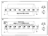
図3に示すように、第1実施形態では、磁界印加部1は、検査対象であるスチールワイヤロープWに対して予め磁界を印加しスチールワイヤロープWの磁化の方向を整えるように構成されている。詳細には、磁界印加部1は、永久磁石により構成されており、磁界印加部1のN極とS極とがスチールワイヤロープWの長手方向(X方向)に沿うように配置されている。すなわち、磁界印加部1は、スチールワイヤロープWに対して略X方向に磁界を印加するように構成されている。なお、図面では、磁界印加部1のN極およびS極を、それぞれ、斜線ありおよび斜線なしで示している。
As shown in FIG. 3, in the first embodiment, the magnetic
また、第1実施形態では、磁界印加部1は、出力される磁界が検知部2での検知に影響しないように、スチールワイヤロープWの長手方向(X方向)において検知部2から離間した位置に設けられている。具体的には、磁界印加部1と検知部2との距離が近過ぎると、磁界印加部1による磁界が検知部2で検知されてしまう場合がある。そのため、磁界印加部1は、検知部2に与える影響が問題とならない程度に離間した位置に設けられている。
Further, in the first embodiment, the magnetic
また、第1実施形態では、磁界印加部1は、スチールワイヤロープWの長手方向(X方向)の一方側(X1側)に配置された磁界印加部11と、スチールワイヤロープWの長手方向(X方向)の他方側(X2側)に配置された磁界印加部12と、を含む。したがって、検査ユニットUをX1方向に移動させることにより、検査ユニットUに設けられた磁界印加部1および検知部2とスチールワイヤロープWとを相対移動させる場合、磁界印加部11によって検知部2により検査される部分に予め磁界が印加され、磁化の方向が整えられる。また、検査ユニットUをX2方向に移動させることにより、検査ユニットUに設けられた磁界印加部1および検知部2とスチールワイヤロープWとを相対移動させる場合、磁界印加部12によって検知部2により検査される部分に予め磁界が印加され、磁化の方向が整えられる。なお、磁界印加部11および磁界印加部12は、それぞれ、特許請求の範囲の「第1磁界印加部」および「第2磁界印加部」の一例である。
Further, in the first embodiment, the magnetic
磁界印加部11は、N極およびS極が、それぞれ、X1側およびX2側に配置され、スチールワイヤロープWに対して略X2方向の磁界を印加するように構成されている。また、磁界印加部12は、N極およびS極が、それぞれ、X2側およびX1側に配置され、スチールワイヤロープWに対して略X1方向の磁界を印加するように構成されている。したがって、検査の前後において、磁界印加部1によりスチールワイヤロープWが磁化される方向が逆になるので、検査後のスチールワイヤロープWに磁化が残存しにくい。
The magnetic
また、第1実施形態では、磁界印加部1は、スチールワイヤロープWを挟んで対向するように、スチールワイヤロープWに対して、スチールワイヤロープWの短手方向(Y方向)の一方側(Y1側)および他方側(Y2側)に配置されている。具体的には、磁界印加部11は、スチールワイヤロープWの短手方向(Y方向)の一方側(Y1側)に配置された磁界印加部11aと、スチールワイヤロープWの短手方向(Y方向)の他方側(Y2側)に配置された磁界印加部11bと、を含む。磁界印加部11aおよび磁界印加部11bは、互いにスチールワイヤロープWを挟んで対向するように配置されている。また、磁界印加部12は、スチールワイヤロープWの短手方向(Y方向)の一方側(Y1側)に配置された磁界印加部12aと、スチールワイヤロープWの短手方向(Y方向)の他方側(Y2側)に配置された磁界印加部12bと、を含む。磁界印加部12aおよび磁界印加部12bは、互いにスチールワイヤロープWを挟んで対向するように配置されている。
In addition, in the first embodiment, the magnetic
また、第1実施形態では、スチールワイヤロープWを挟んで対向するように、スチールワイヤロープWの短手方向(Y方向)の一方側(Y方向)に配置された磁界印加部11a(12a)と、スチールワイヤロープWの短手方向の他方側(Y2方向)に配置された磁界印加部11b(12b)とは、磁界印加部11のN極とS極とがスチールワイヤロープWの長手方向(X方向)の同じ側になるように配置されている。具体的には、磁界印加部11aおよび磁界印加部11bは、スチールワイヤロープWの長手方向の一方側(X1側)および他方側(X2側)が、それぞれ、N極およびS極となるように配置されている。また、磁界印加部12aおよび磁界印加部12bは、スチールワイヤロープWの長手方向(X方向)の一方側および他方側が、それぞれ、S極およびN極となるように配置されている。
Further, in the first embodiment, the magnetic
検知部2は、図4に示すように、励振コイル21と、差動コイル22と、を含む。励振コイル21および差動コイル22は、長尺材からなる磁性体であるスチールワイヤロープWの延びる方向を中心軸として、長手方向に沿うように複数回巻き回され、スチールワイヤロープWの延びるX方向(長手方向)に沿って円筒形となるように形成される導線部分を含むコイルである。すなわち、円筒形のコイル(差動コイル22および励振コイル21)がスチールワイヤロープWを取り囲むように設けられている。
The
励振コイル21は、スチールワイヤロープWの磁化の状態を励振するように構成されている。具体的には、励振コイル21に励振電流が流されることにより、励振コイル21の内部において、励振電流に基づいて発生する磁界がX方向に沿って印加されるように構成されている。これにより、励振コイル21は、スチールワイヤロープWの磁化の状態を励振する。具体的には、図5(A)のように、磁界印加部1により予め磁化の方向が整えられているので、励振コイル21による磁界の印加がない場合には、傷等のない部分において、スチールワイヤロープWの磁化の方向は略揃っている。ここで、図5(B)に示すように、励振コイル21に一定の大きさかつ一定の周波数を有する交流電流(励振電流)が外部から流されることにより、スチールワイヤロープWの延びるX方向に振動するように磁界が印加される。また、励振コイル21に流れる時間変化する励振電流の向き(実線または点線)に伴って、励振コイル21により印加される磁界(実線または点線)の方向も変化する。したがって、時間変化する磁界によりスチールワイヤロープWの磁化の方向が励振され、スチールワイヤロープWから発せられる磁界も時間変化する。その結果、スチールワイヤロープWと差動コイル22との相対位置を変化させることなく、スチールワイヤロープWの同じ部分による磁界が時間変化するため、磁界の変化を検知する差動コイル22(後述)により、スチールワイヤロープWの状態を検査することができる。
The
図4に示すように、第1実施形態では、検知部2は、磁界印加部1により磁界が印加された後に、スチールワイヤロープWの磁界の変化に基づいて検知信号を取得するように構成されている。詳細には、検知部2は、差動コイル22に含まれる2つの検知コイル22aおよび22bにより発生する各々の検知信号の大きさの差を取得するように構成されている。また、差動コイル22に含まれる2つの検知コイル22aおよび22bは、スチールワイヤロープWの長手方向(X方向)に沿って互いに並ぶように配置されている。なお、検知コイル22aおよび22bは、特許請求の範囲の「コイル部分」の一例である。
As shown in FIG. 4, in the first embodiment, the
具体的には、検知コイル22aおよび22bは、それぞれ、X方向に長さL2を有するとともに、X方向に並ぶように、かつ、離間せずに配置されている。そして、検知コイル22aおよび22bは、それぞれ、X方向の磁界の変化を検知して電圧(検知信号)を発生するように構成されている。そして、検知部2は、検知コイル22aにより発生した検知信号の大きさと、検知コイル22bにより発生した検知信号の大きさとの差を、差動信号H(図9参照)として取得するように構成されている。なお、検査装置100では、検知コイル22aと検知コイル22bとのX方向における中心間距離L3は、長さL2と略等しい長さを有する。
Specifically, the detector coils 22a and 22b each have a length L2 in the X direction, and are arranged side by side in the X direction without being separated from each other. Each of the detection coils 22a and 22b is configured to detect a change in the magnetic field in the X direction and generate a voltage (detection signal). The
図6は、傷等のあるスチールワイヤロープWの例である。図6において、素線の編まれ方は、簡略化して示されている。図6(A)のスチールワイヤロープWは、表面部分の素線が断線している。そのため、素線断線の生じた部分から磁界が漏れ出ている。また、図6(B)のスチールワイヤロープWは、スレもしくは打痕により表面部に凹みが生じている。また、図6(C)のスチールワイヤロープWは、内部に素線断線が生じている。これら傷等のある位置の断面積S1、S2およびS3は、傷等のない部分の断面積S0と比較して、それぞれ小さくなっているため、スチールワイヤロープWの全磁束(磁界に透磁率と面積とを掛けた値)は傷等のある部分で小さくなる。以上のように、磁界の漏れや、全磁束の減少が生じるため、傷等のある部分では検知される磁界に変化が生じる。 FIG. 6 shows an example of a steel wire rope W with scratches or the like. In FIG. 6, the way the strands are woven is shown in a simplified manner. The steel wire rope W shown in FIG. 6(A) has broken wires on the surface. Therefore, the magnetic field leaks out from the portion where the wire disconnection occurs. Further, the steel wire rope W in FIG. 6(B) has dents on the surface due to scratches or dents. In addition, the steel wire rope W of FIG. 6(C) has an internal wire breakage. Since the cross-sectional areas S1, S2, and S3 of the positions with these flaws are smaller than the cross-sectional area S0 of the portion without flaws, the total magnetic flux of the steel wire rope W (magnetic field plus magnetic permeability The value obtained by multiplying the surface area by the surface area) becomes smaller in areas with scratches or the like. As described above, the leakage of the magnetic field and the reduction of the total magnetic flux occur, so that the detected magnetic field changes in a portion with a flaw or the like.
その結果、たとえば、傷等のある場所に位置する検知コイル22aの検知電圧(検知信号)の値が検知コイル22bと比較して減少するため、検知コイル22aの検知電圧と検知コイル22bの検知電圧の差(差動信号H(図9参照))の値が大きくなる。すなわち、傷等のない部分での検知信号は略ゼロとなり、傷等のある部分では検知信号がゼロより大きい値を持つので、差動コイルにおいて、傷等の存在をあらわす明確な信号(S/N比の良い信号)が差動信号H(図9参照)として検知される。これにより、電子回路部3(後述)は、検知信号の差(差動信号H(図9参照))の値に基づいてスチールワイヤロープWの傷等の存在を検出することができる。また、傷等の大きさ(断面積の減少量の大きさ)が大きいほど、検知信号の値が大きくなり差動信号H(図9参照)の値も大きくなるため、傷等の大きさを判定(評価)する際に、ある程度以上に大きな傷等があれば、差動信号H(図9参照)が所定の第1閾値Th1または第2閾値Th2(後述)を超えたことを自動で判定することが可能となる。なお、傷等には錆等による透磁率の変化も含まれ、同様に検知信号として表われる。
As a result, for example, the value of the detection voltage (detection signal) of the
図7に示すように、電子回路部3は、差動コイル22からの信号に基づいて長尺材からなるスチールワイヤロープWの状態を判定するように構成されている、また、電子回路部3は、交流電源31と、増幅器32と、AD変換器33と、CPU34と、デジタル出力インターフェース35とを含む。交流電源31は、励振コイル21に交流電流を流す(出力する)。増幅器32は、差動コイル22から出力される差動信号H(図9参照)を増幅し、AD変換器33に出力する。AD変換器33は、増幅器32により増幅されたアナログの差動信号Hを、デジタルの差動信号H(図9参照)に変換する。CPU34は、AD変換器33から出力される差動信号H(図9参照)から交流成分を取り除く処理を行い、差動信号H(図9参照)の絶対値の変化に対応した信号(DCレベル信号)に変換する同期検波整流処理を行うとともに、差動信号Hが後述する所定の閾値を超えた場合に、警報信号を出力する。また、CPU34は、交流電源31により出力される電流の強さを制御する。また、傷等の大きさを判定する機能をCPU34に持たせている。デジタル出力インターフェースは、外部の図示しないPCなどに接続され、処理がされた差動信号H(図9参照)や警報信号のデジタルデータを出力する。また、外部のPCは、入力された信号の大きさをメモリに保存や、信号の大きさの時間経過に伴うグラフの表示とともに、CPU34を介して、検知部2(一体構成されたフレーム)のスチールワイヤロープWに対する移動速度の制御等を行う。
As shown in FIG. 7, the
また、電子回路部3は、差動コイル22(検知部2)により出力された差動信号H(図9参照)が第1閾値Th1を超えた場合に、差動信号H(図9参照)が第1閾値Th1を超えたことを示す第1閾値信号を外部に出力するとともに、検知部2により出力された差動信号H(図9参照)が第2閾値Th2を超えた場合に、差動信号H(図9参照)が第2閾値Th2を超えたことを示す第2閾値信号を外部に出力するように構成されている。これにより、スチールワイヤロープWの状態(傷等の有無)が不均一となる部分を、閾値信号に基づいて容易に判定することができる。また、比較的小さな第1閾値Th1を超えた第1閾値信号により、経過観察等注意を要する程度の小さな傷等を有するスチールワイヤロープWの状態を判定するとともに、比較的大きな第2閾値Th2を超えた第2閾値信号により、早急に交換等を行う必要がある比較的大きな傷等を有するスチールワイヤロープWの状態を判定することができる。
Further, when the differential signal H (see FIG. 9) output by the differential coil 22 (detection unit 2) exceeds the first threshold value Th1, the
なお、第1実施形態では、差動コイル22は、励振コイル21により流れる励振電流により発生した磁界により磁化の状態が励振されたスチールワイヤロープWの磁界の変化に基づいて検知信号を取得するように構成されている。ここで、検査装置100では、差動コイル22は、励振コイル21によって発生する磁界の略全てが検知可能に(入力される様に)配置されている。具体的には、励振コイル21は、X方向において、長さL2の略2倍の長さL1を有する。また、励振コイル21のX1側の端部およびX2側の端部は、それぞれ、検知コイル22aのX1側の端部および検知コイル22bと、X方向において略等しい位置に配置されている。
In the first embodiment, the
(比較例)
ここで、磁界印加部1が設けられていないことを除いて同様に構成されている比較例による磁性体の検査装置101(図示省略)と比較しながら、検査装置100の磁界印加部1による磁化について説明する。
(Comparative example)
Here, magnetization by the magnetic
磁界印加部1が設けられていない比較例による磁性体の検査装置101(図示省略)では、励振コイル21により、X方向に磁場が印加される。このとき、傷等の無い均一な部分で検知される差動信号H(図9参照)が等しくなるように、励振コイル21によりX方向に印加する磁界を大きくする必要がある。また、予め磁化の方向を整えて(揃えて)いないので、励振コイル21によりX方向に印加される磁界は、磁化の方向を略X方向に揃える程度に大きくする必要がある。
In the magnetic material inspection apparatus 101 (not shown) according to the comparative example in which the magnetic
ここで、図8に示すように、磁界を印加する前において、磁性体であるスチールワイヤロープW内は、製造時点で、内部の構造ごとに磁化の方向がバラついている。また、滑車等の機構を通過し、応力等の外力が加えられることによっても、これらの磁化の方向は変化していく。したがって、傷等の無い均質な部分であっても、励振コイル21により磁化の方向をX方向に励振しても磁化の方向のバラツキが消しきれないため、スチールワイヤロープWの場所ごとの磁化の大きさおよび方向のバラツキにより差動信号H(図9参照)にノイズが生じる原因となる。
Here, as shown in FIG. 8, before the magnetic field is applied, the direction of magnetization within the steel wire rope W, which is a magnetic material, varies depending on the internal structure at the time of manufacture. In addition, the direction of these magnetizations changes when they pass through a mechanism such as a pulley and are subjected to an external force such as stress. Therefore, even if the portion is uniform without flaws, even if the
一方で、予め磁界を印加することにより磁化の大きさおよび方向を整えて(揃えて)おく場合は、スチールワイヤロープWの傷等のない部分の磁界は概ね一定の大きさとなって検知されるため、傷からの信号と区別が容易となる。 On the other hand, when the magnitude and direction of magnetization are adjusted (aligned) by applying a magnetic field in advance, the magnetic field of a portion of the steel wire rope W free from flaws or the like is detected with a substantially constant magnitude. Therefore, it becomes easy to distinguish from signals from scratches.
図9のグラフは、比較例および第1実施形態における、スチールワイヤロープWの磁界の変化を示した計測波形である。計測波形の縦軸は、差動信号H(図9参照)の大きさに対応し、計測波形の横軸は、検知位置X(スチールワイヤロープWの検知される場所)に対応している。CPU34により同期検波整流処理がされているため、励振コイル21により印加される磁界の時間変化の影響は取り除かれている。
The graph of FIG. 9 is a measured waveform showing changes in the magnetic field of the steel wire rope W in the comparative example and the first embodiment. The vertical axis of the measured waveform corresponds to the magnitude of the differential signal H (see FIG. 9), and the horizontal axis of the measured waveform corresponds to the detection position X (where the steel wire rope W is detected). Since the synchronous detection and rectification processing is performed by the
磁界印加部1を設けない比較例による磁性体の検査装置101において、図9の整磁前の計測波形に示すように、傷等の無い部分であっても、磁化の大きさおよび方向のバラツキによるノイズが検知されている。そのため、このような比較例による磁性体の検査装置101では、経験や知識(たとえば、特徴的な検知信号のあらわれのパターン方など)のない非専門化が傷等の有無を判断することは難しい。特に、閾値等を設けて信号の大きさのみに基づいて判定する場合、誤判定の原因となる。
In the magnetic material inspection apparatus 101 according to the comparative example in which the magnetic
一方で、磁界印加部1が設けられた第1実施形態による検査装置100において、図9の整磁後の計測波形に示すように、電子回路の雑音(ノイズ)はほとんど検知されない。具体的には、ノイズの大きさが相対的に小さく、S/N比の良好な計測波形となり、差動信号Hが明確にあらわれている。したがって、磁界印加部1により、非専門家や閾値による判定であっても、誤判定が生じない程度にノイズを低減することができる。なお、図9の整磁後の計測波形において、スチールワイヤロープWの傷等のある部分の位置が差動コイルの一方側(検知コイル22a)から他方側(検知コイル22b)に移ったことによる差動信号H(図9参照)の正負の逆転が明瞭に表われていることがわかる。
On the other hand, in the
(第1実施形態の効果)
第1実施形態では、以下のような効果を得ることができる。
(Effect of the first embodiment)
The following effects can be obtained in the first embodiment.
第1実施形態では、上記のように、検知部2を、差動コイル22に含まれる2つの検知コイル22aおよび22bに発生する各々の検知信号の大きさの差(差動信号H)を取得するように構成する。これにより、スチールワイヤロープWの磁界の変化に基づいて異なる電圧(検知信号)が2つの検知コイル22aおよび22bに発生するので、2つの検知信号の大きさの差(差動信号H)を取得することにより、スチールワイヤロープWの局所的な磁界の変化を容易に検知することができる。その結果、差動コイル22に含まれる比較的単純な構造である2つの検知コイル22aおよび22bを用いて、局所的な磁界の変化を発生させるようなスチールワイヤロープWの状態(傷等の有無)を簡素な構成により検査することができる。また、磁界印加部1により予めスチールワイヤロープWの磁化の方向が整えられることにより、検知信号に表われるノイズを少なくした状態でスチールワイヤロープWの状態(傷等の有無)を検査することができる。その結果、スチールワイヤロープWの磁化の方向が整えられていない場合と比較して、スチールワイヤロープWの傷等の有無を容易に判定することができるので、スチールワイヤロープWの状態(傷等の有無)を精度よく検査することができる。
In the first embodiment, as described above, the
また、第1実施形態では、上記のように、スチールワイヤロープWは、長尺材からなり、差動コイル22に含まれる2つの検知コイル22aおよび22bを、長尺材の長手方向(X方向)に沿って互いに並ぶように配置する。これにより、2つの検知コイル22aおよび22bがスチールワイヤロープWの長手方向に沿って互いに並ぶように配置されているので、スチールワイヤロープWの状態(傷等の有無)の局所的な変化を、スチールワイヤロープWの長手方向に沿って検知することができる。その結果、スチールワイヤロープWの状態(傷等の有無)を、スチールワイヤロープWの長手方向に沿って検査することができるので、検知部2をスチールワイヤロープWの長手方向に沿って相対移動させることにより、スチールワイヤロープW全体を容易に検査することができる。
Further, in the first embodiment, as described above, the steel wire rope W is made of a long material, and the two
また、第1実施形態では、上記のように、磁界印加部1を、出力される磁界が検知部2での検知に影響しないように、検知部2からスチールワイヤロープWの長手方向(X方向)に離間した位置に設ける。これにより、磁界印加部1により出力される磁界に起因するノイズが検知部2により検知されるのを抑制することができる。
Further, in the first embodiment, as described above, the magnetic
また、第1実施形態では、上記のように、磁界印加部1は、検知部2に対して、スチールワイヤロープWの長手方向(X方向)の一方側(X1側)に配置される磁界印加部11と、スチールワイヤロープWの長手方向の他方側(X2側)に配置される磁界印加部12と、を含む。これにより、スチールワイヤロープWの長手方向の一方側および他方側にそれぞれ磁界印加部11および磁界印加部12が配置されるので、スチールワイヤロープWの検査をスチールワイヤロープWの長手方向の一方側および他方側のいずれの側から行う場合でも、予めスチールワイヤロープWに磁界を印加して磁化の方向を整えることができる。
Further, in the first embodiment, as described above, the magnetic
また、第1実施形態では、上記のように、磁界印加部1を、スチールワイヤロープWを挟んで対向するように、スチールワイヤロープWに対して、スチールワイヤロープWの短手方向(Y方向)の一方側および他方側に配置する。これにより、スチールワイヤロープWの長手方向に直交する短手方向の一方側および他方側にそれぞれ磁界印加部1がスチールワイヤロープWを挟んで対向するように配置されるので、スチールワイヤロープWの短手方向の一方側のみに磁界印加部1が配置される場合と比較して、スチールワイヤロープWに対して印加する磁界を容易に大きくすることができるので、スチールワイヤロープWの磁化の方向を効率よく整えることができる。
Further, in the first embodiment, as described above, the magnetic
また、第1実施形態では、上記のように、スチールワイヤロープWを挟んで対向するように、スチールワイヤロープWの短手方向(Y方向)の一方側(Y1側)に配置された磁界印加部11aおよび12aと、スチールワイヤロープWの短手方向の他方側(Y2側)に配置された磁界印加部11bおよび12bとを、磁界印加部11のN極とS極とがスチールワイヤロープWの長手方向(X方向)の同じ側となるように配置させる。これにより、スチールワイヤロープWを挟んで対向するようにスチールワイヤロープWの短手方向の一方側および他方側に配置された磁界印加部1の同極同士がスチールワイヤロープWの長手方向の同じ側に配置されるので、スチールワイヤロープWの短手方向の一方側に配置された磁界印加部11aおよび12aによりスチールワイヤロープWに対して印加される磁界の方向と、スチールワイヤロープWの短手方向の他方側に配置された磁界印加部11bおよび12bによりスチールワイヤロープWに対して印加される磁界の方向とを揃えることができる。その結果、スチールワイヤロープWに対して印加する磁界をより容易に大きくすることができるので、スチールワイヤロープWの磁化の方向をより効率よく整えることができる。
In addition, in the first embodiment, as described above, the magnetic field applying magnetic field applicators arranged on one side (Y1 side) in the lateral direction (Y direction) of the steel wire rope W so as to face each other with the steel wire rope W therebetween.
また、第1実施形態では、上記のように、検知部2は、スチールワイヤロープWの磁化の状態を励振するための励振コイル21を含み、差動コイル22を、励振コイル21により流れる励振電流により発生した磁界により磁化の状態が励振されたスチールワイヤロープWの磁界の変化に基づいて検知信号を取得するように構成する。これにより、励振コイルによりスチールワイヤロープWの磁化の状態が励振され、スチールワイヤロープWの磁界を時間変化させることができるので、スチールワイヤロープWと検知部2とを相対移動させることなく、スチールワイヤロープWの磁界の変化を検知することができる。
Further, in the first embodiment, as described above, the
[第2実施形態]
次に、図3、7、10および11を参照して、第2実施形態による検査装置200の構成について説明する。第2実施形態による検査装置200は、第1実施形態の検査装置100と比較して、差動コイルに含まれる2つの検知コイルのX方向における中心間距離が小さくなるように構成されている。なお、検査装置200は、特許請求の範囲の「磁性体の検査装置」の一例である。
[Second embodiment]
Next, with reference to FIGS. 3, 7, 10 and 11, the configuration of
図3に示すように、検査装置200は、検知部202と、電子回路部203と、を備えている。
As shown in FIG. 3 , the
図10に示すように、第2実施形態では、検知部202は、第1実施形態の検査装置100の検知部2と同様に、差動コイル222に含まれる2つの検知コイル222aおよび222bにより発生する各々の検知信号の大きさの差(差動信号H(図11参照))を取得するように構成されている。なお、検知コイル222aおよび222bは、特許請求の範囲の「コイル部分」の一例である。
As shown in FIG. 10, in the second embodiment, the
検知コイル222aおよび222bは、それぞれ、X方向に長さL202を有するとともに、X方向に長さL4だけ離間して並ぶように配置されている。また、差動コイル222の2つの検知コイル222aおよび222bは、スチールワイヤロープWの長手方向(X方向)に中心間距離L203の長さを有する。中心間距離L203は、第1実施形態の差動コイル22の中心間距離L3よりも小さくなるように設定されている。なお、差動コイル22(222)では、中心間距離L3(L203)が小さくなるにしたがって、スチールワイヤロープWの状態(傷等の有無)のより局所的な変化を検知することが可能である。
The detector coils 222a and 222b each have a length L202 in the X direction and are arranged side by side with a length L4 in the X direction. Also, the two
ここで、第2実施形態では、中心間距離L203は、検知部202をスチールワイヤロープWの長手方向(X方向)に相対的に移動させることによりスチールワイヤロープWの磁界の変化を検知する場合の差動コイル222の測定周期の間に差動コイル222が移動する移動量に基づいて設定されている。
Here, in the second embodiment, the center-to-center distance L203 is set when detecting a change in the magnetic field of the steel wire rope W by relatively moving the
具体的には、検査装置200では、差動コイル222の測定周期が、数ms程度の小さな値となるように構成されている。また、検知部202をスチールワイヤロープWの長手方向に相対的に移動させる移動速度を、数m/s程度の値となるように構成されている。すなわち、差動コイル222の測定周期の間に差動コイル222が移動する移動量は小さな値となる。そして、検査装置200では、中心間距離L203は、差動コイル222の測定周期の間に差動コイル222が移動する移動量に基づいて、比較的小さな値となるように設定される。
Specifically, the
なお、中心間距離L203が、差動コイル222の測定周期の間に差動コイル222が移動する移動量よりも小さい場合には、スチールワイヤロープWにおいて検知されない部分が生じる。したがって、検査装置200では、中心間距離L203は、差動コイル222の測定周期の間に差動コイル222がX方向に移動する移動量(移動距離)と略同等以上、かつ、比較的小さい値に設定される。
If the center-to-center distance L203 is smaller than the amount of movement of the
たとえば、差動コイル222の測定周期を1msとし、差動コイル222がスチールワイヤロープWに対して相対的にX方向に移動する移動速度を1m/sとした場合、差動コイル222の測定周期の間に差動コイル222がX方向に移動する移動量(移動距離)は、1mmとなる。この場合、中心間距離L203は、略1mmよりも大きく、かつ、比較的小さい(1mmに近い)値に設定される。
For example, when the measurement period of the
図7に示すように、電子回路部203は、CPU234を含む。なお、CPU234は、特許請求の範囲の「信号処理部」の一例である。
As shown in FIG. 7, the
ここで、中心間距離L203が小さくなるにしたがって、検知コイル222aおよび222bの巻き数は少なくなる。この場合、検知コイル222aおよび222bにより検知される検知信号も比較的小さくなるので、差動信号Hは比較的小さくなる。このため、差動コイル222では、図11(A)に示す計測波形のように、電子回路の雑音(ノイズ)の大きさが図9の整磁後の計測波形と比較して相対的に大きく、S/N比が良好でない計測波形が取得される。したがって、スチールワイヤロープWの素線断線箇所が比較的判別しにくく、誤判定の原因となる。
Here, the number of turns of the
そこで、第2実施形態では、CPU234は、スチールワイヤロープWの長手方向(X方向)の位置P1における差動コイル222により取得された差動信号Haと、スチールワイヤロープWの長手方向の位置P2における差動コイル222により取得された差動信号Haと、を差分した差動信号Hbを算出する差分信号処理を行うように構成されている。位置P2は、中心間距離L203に基づいてスチールワイヤロープWの長手方向の位置P1に対して所定の距離dLだけ離れた位置に設定される。また、CPU234は、ノイズ低減処理が行われた検知信号の大きさの差(差動信号H)に対して、差分信号処理を行うように構成されている。なお、位置P1および位置P2は、それぞれ、特許請求の範囲の「第1位置」および「第2位置」の一例である。また、差動信号Hbは、特許請求の範囲の「差分値」の一例である。
Therefore, in the second embodiment, the
具体的には、CPU234は、検知信号の大きさの差(差動信号H)に対して、スチールワイヤロープWの長手方向(X方向)のそれぞれの位置においてスチールワイヤロープWの長手方向に沿って所定の区間dx毎に移動平均処理(ローパスフィルタ処理)を行う。これにより、図11(B)に示した計測波形のように、ノイズが低減された計測波形が取得される。そして、CPU234は、図11(B)に示す計測波形において、検知位置Xが位置P1の差動信号Haを、検知位置Xが位置P2の差動信号Haと差分した差分値を算出する。そして、CPU234は、算出された差分値を、検知位置Xにおける差動信号Hbとする。位置P2は、検知位置Xが位置P1から所定の距離dLだけ離れた位置である。所定の距離dLは、たとえば、中心間距離L203の数倍程度に設定される。なお、図11(B)では、位置P1(および位置P2)を1箇所のみ示しているが、差分信号処理は、計測波形の全体に渡って行われる(すなわち、位置P1は、計測波形の横軸のそれぞれの位置となる)。すなわち、差分信号処理により、図11(B)に示した計測波形において、差動信号Haが大きく変化する部分が、大きな差動信号Hbとして抽出される。
Specifically, the
また、第2実施形態では、CPU234は、差分信号処理において、算出された差動信号Hbのうち、負の値をゼロとする信号処理をさらに行うように構成されている。すなわち、差動信号Hbのうち負の値をゼロとする信号処理により、差動信号Haが増加する部分のみが差動信号Hbとして抽出される。これにより、図11(B)に示した計測波形において、差動信号Haの負側に凸の部分と正側に凸の部分とが隣り合う部分のうち、差動信号Haの負側に凸の部分の頂部から正側に凸の部分の頂部に向かって差動信号Haが大きく変化する部分(部分A)が、図11(C)に示した計測波形において、大きな差動信号Hbとして抽出される。
Further, in the second embodiment, the
第2実施形態のその他の構成については、第1実施形態と同様である。 Other configurations of the second embodiment are the same as those of the first embodiment.
(第2実施形態の効果)
第2実施形態では、上記のように、検知部202を、差動コイル222に含まれる2つの検知コイル222aおよび222bに発生する各々の検知信号の大きさの差(差動信号H)を取得するように構成する。これにより、スチールワイヤロープWの磁界の変化に基づいて異なる電圧(検知信号)が2つの検知コイル222aおよび222bに発生するので、2つの検知信号の大きさの差(差動信号H)を取得することにより、スチールワイヤロープWの局所的な磁界の変化を容易に検知することができる。その結果、上記第1実施形態と同様に、差動コイル222に含まれる比較的単純な構造である2つの検知コイル222aおよび222bを用いて、局所的な磁界の変化を発生させるようなスチールワイヤロープWの状態(傷等の有無)を簡素な構成により検査することができる。
(Effect of Second Embodiment)
In the second embodiment, as described above, the
第2実施形態では、上記のように、差動コイル222の2つの検知コイル222aおよび222bのスチールワイヤロープWの長手方向(X方向)における中心間距離L203を、検知部202をスチールワイヤロープWの長手方向に相対的に移動させることによりスチールワイヤロープWの磁界の変化を検知する場合の差動コイル222の測定周期の間に差動コイル222が移動する移動量に基づいて設定する。これにより、差動コイル222の測定周期を、数ms程度の小さな値とした場合、差動コイル222の測定周期の間に差動コイル222が移動する移動量も小さな値となり、差動コイル222の2つの検知コイル222aおよび222bのスチールワイヤロープWの長手方向における中心間距離L203が小さくなるので、スチールワイヤロープWの状態(傷等の有無)の局所的な変化を確実に検知することができる。
In the second embodiment, as described above, the distance L203 between the centers of the two
また、第2実施形態では、上記のように、検査装置100は、スチールワイヤロープWの長手方向(X方向)の位置P1における差動コイル222により取得された検知信号の大きさの差(差動信号H)と、スチールワイヤロープWの長手方向の位置P2における差動コイル222により取得された検知信号の大きさの差(差動信号H)と、を差分した差動信号Hbを算出する差分信号処理を行うCPU234を備える。位置P2は、差動コイル222の2つの検知コイル222aおよび222bのスチールワイヤロープWの長手方向における中心間距離L203に基づいてスチールワイヤロープWの長手方向の位置P1に対して所定の距離dLだけ離れた位置である。これにより、スチールワイヤロープWの長手方向の位置を横軸、差動コイル222により取得された検知信号の大きさの差(差動信号H)を縦軸として示した計測波形において、スチールワイヤロープWの長手方向の位置の変化に対して差動信号Hが大きく変化する部分を大きな差動信号Hbとして抽出することができる。これにより、スチールワイヤロープWに傷等が存在する場合に計測波形に表われる差動信号Hの負側に凸の部分と正側に凸の部分とが隣り合うような部分を容易に抽出することができる。その結果、スチールワイヤロープWの磁化の方向が十分に整っていないことに起因して計測波形が整っていない(ノイズが含まれる)場合でも、スチールワイヤロープWの状態(傷等の有無)の局所的な変化を容易に検知することができる。
In addition, in the second embodiment, as described above, the
また、第2実施形態では、上記のように、CPU234を、差動信号Hbのうち、負の値をゼロとする信号処理を行うように構成する。これにより、計測波形において差動信号Hの正側に凸の部分がある側から負側に凸の部分がある側への差分を取る場合、差動信号Hの負側に凸の部分と正側に凸の部分とが隣り合う部分のうち、差動信号Hの負側に凸の部分の頂部から正側に凸の部分の頂部に向かって差動信号Hが特に大きく変化する部分(部分A)を抽出することができる。その結果、スチールワイヤロープWの磁化の方向が十分に整っていないことに起因して計測波形が整っていない場合でも、スチールワイヤロープWの状態(傷等の有無)の局所的な変化をより容易に検知することができる。
Further, in the second embodiment, as described above, the
また、第2実施形態では、上記のように、CPU234を、ノイズ低減処理が行われた検知信号の大きさの差(差動信号H)に対して、差分信号処理を行うように構成する。これにより、電子回路の雑音(ノイズ)に起因する計測波形の乱れの影響を低減した上で、差分信号処理を行うことができる。その結果、差動コイル222の2つの検知コイル222aおよび222bのスチールワイヤロープWの長手方向における中心間距離L203を小さくしたこと等により電子回路の雑音を検知してしまった場合でも、電子回路の雑音の影響を低減した状態で、計測波形において、スチールワイヤロープWの長手方向の位置の変化に対して差動信号Hが大きく変化する部分を差動信号Hbとして抽出することができる。
In the second embodiment, as described above, the
第2実施形態のその他の効果については、第1実施形態と同様である。 Other effects of the second embodiment are similar to those of the first embodiment.
[変形例]
なお、今回開示された実施形態は、すべての点で例示であって制限的なものではないと考えられるべきである。本発明の範囲は、上記した実施形態の説明ではなく特許請求の範囲によって示され、さらに特許請求の範囲と均等の意味および範囲内でのすべての変更(変形例)が含まれる。
[Modification]
It should be noted that the embodiments disclosed this time should be considered as examples and not restrictive in all respects. The scope of the present invention is indicated by the scope of the claims rather than the description of the above-described embodiments, and includes all modifications (modifications) within the meaning and scope equivalent to the scope of the claims.
たとえば、上記第1および第2実施形態では、磁性体を長尺材とする例を示したが、本発明はこれに限られない。本発明では、磁性体は、たとえば、長尺材以外の薄板、鉄球(ベアリング)等でもよい。その他、均一な構造をもつ磁性体全般の検査に本発明を用いることができる。また、磁性体が薄板等である場合、薄板等の面の延びる方向の磁界の変化を検知するように構成してもよい。 For example, in the above-described first and second embodiments, an example in which a long material is used as a magnetic material has been described, but the present invention is not limited to this. In the present invention, the magnetic body may be, for example, a thin plate, an iron ball (bearing), or the like other than the long material. In addition, the present invention can be used for inspection of magnetic materials in general having a uniform structure. Moreover, when the magnetic body is a thin plate or the like, it may be configured to detect a change in the magnetic field in the direction in which the surface of the thin plate or the like extends.
また、上記第1および第2実施形態では、長尺材からなる磁性体をスチールワイヤロープWとする例を示したが、本発明はこれに限られない。本発明では、たとえば、長尺材からなる磁性体は、薄板、角材、円筒状のパイプ、針金、チェーン等でもよい。 Further, in the above-described first and second embodiments, an example in which the steel wire rope W is used as the magnetic body made of a long material has been shown, but the present invention is not limited to this. In the present invention, for example, the long magnetic body may be a thin plate, a square bar, a cylindrical pipe, a wire, a chain, or the like.
また、上記第1および第2実施形態では、磁界印加部1を、検査ユニットUとして、検知部2とともにフレームFに対して固定させるように構成した例を示したが、本発明はこれに限られない。本発明では、磁界印加部1と検知部2との相対位置を変更可能に構成してもよい。具体的には、スチールワイヤロープWの磁化の方向を磁界印加部1により整えた後、磁界印加部1のみをスチールワイヤロープWから離した位置に移動させてもよい。これにより、検知部2によるスチールワイヤロープWの磁界の変化の検知時に、磁界印加部1の磁界が検知部2に影響しないように容易に離間させることができる。
In addition, in the first and second embodiments, an example is shown in which the magnetic
また、上記第1および第2実施形態では、磁界印加部1を、永久磁石により構成する例を示したが、本発明はこれに限られない。本発明では、磁界印加部を電磁石(コイル)により構成してもよい。
Further, in the above-described first and second embodiments, an example in which the magnetic
また、上記第1および第2実施形態では、スチールワイヤロープWに予め磁界を印加する場合に、磁界印加部1の構成を、図12に示すような構成としてもよい。具体的には、図12(A)に示す磁界印加部1Aのように、磁界印加部11と磁界印加部12Aとを、同極が、X方向の同じ側となるように配置してもよい。また、図12(B)に示す磁界印加部1Bおよび図12(D)に示す磁界印加部1Dのように、磁界印加部を、スチールワイヤロープWの長手方向において検知部2の一方側のみに設けるように構成してもよい。また、図12(C)に示す磁界印加部1Cおよび図12(D)に示す磁界印加部1Dのように、磁界印加部を、スチールワイヤロープWの短手方向の一方側のみに設けるように構成してもよい。また、図12(E)に示す磁界印加部1E(11E、12E)および図12(F)に示す磁界印加部1F(11F、12F)のように、磁界印加部を、スチールワイヤロープWの短手方向の一方側におよび他方側に、N極とS極とがX方向の逆側となるように配置してもよい。なお、磁界印加部11Eおよび11Fは、特許請求の範囲の「第1磁界印加部」の一例である。また、磁界印加部12A、12Eおよび12Fは、特許請求の範囲の「第2磁界印加部」の一例である。
Further, in the first and second embodiments, when a magnetic field is applied to the steel wire rope W in advance, the configuration of the magnetic
また、上記第1および第2実施形態では、磁界印加部1により磁界が印加された状態のスチールワイヤロープWの磁界の変化に基づいて検知信号を取得する検知部2の構成を、図13に示すような構成としてもよい。具体的には、また、図13(A)に示す検知部2Aのように、2つの検知コイル22Aaおよび22AbがX方向に互いに離間するとともに、検知コイル22Aaの一方側(X1側)の端部および検知コイル22Abの他方側(X2側)の端部が、それぞれ、励振コイル21の一方側(X1側)の端部と他方側(X2側)の端部と、X方向において略等しい位置となるように構成されていてもよい。また、図13(B)に示す検知部2Bのように、2つの検知コイル22Baおよび22BbがX方向に互いに離間せずに、検知コイル22Baの一方側(X1側)の端部および検知コイル22Bbの他方側(X2側)の端部が、それぞれ、励振コイル21の一方側(X1側)の端部よりもX2側および他方側(X2側)の端部よりもX1側となるように構成してもよい。また、図13(C)に示す検知部2Cのように、差動コイル22Cの2つの検知コイル22Caおよび22Cbの間に励振コイル21Cを配置するように構成してもよい。また、図13(D)に示す検知部2Dおよび図13(E)に示す検知部2Eのように、励振コイルを含まないように構成してもよい。なお、検知コイル22Aa、22Ab、22Ba、22Bb、22Caおよび22Cbは、特許請求の範囲の「コイル部分」の一例である。
In addition, in the first and second embodiments, FIG. 13 shows the configuration of the
また、上記第1および第2実施形態では、円筒形のコイル(差動コイル22(222)および励振コイル21)がスチールワイヤロープWを取り囲むように設けられている例を示したが、本発明はこれに限らない。本発明では、図14に示すように、検知コイル322および励振コイルを角筒形としてもよい。また、図15に示すように、検知コイル422および励振コイルを、スチールワイヤロープWを取り囲まず、スチールワイヤロープWに沿う方向の磁界の変化を検知するようスチールワイヤロープWから離間した位置に配置してもよい。
Further, in the first and second embodiments, an example was shown in which the cylindrical coils (the differential coil 22 (222) and the excitation coil 21) were provided so as to surround the steel wire rope W, but the present invention is not limited to this. In the present invention, as shown in FIG. 14, the
また、上記第1および第2実施形態では、検査装置100(200)がスチールワイヤロープWに沿って移動可能に構成されている例を示したが、本発明はこれに限られない。本発明では、検査装置は移動しないように構成されていてもよい。この場合、検査装置は、定位置において内部または付近を通過するスチールワイヤロープWの磁界の変化を検知する。 Moreover, although the inspection apparatus 100 (200) is configured to be movable along the steel wire rope W in the first and second embodiments, the present invention is not limited to this. In the present invention, the inspection device may be configured not to move. In this case, the inspection device detects changes in the magnetic field of the steel wire rope W passing in or near it in place.
また、上記第1および第2実施形態では、また、電子回路部3(203)を、差動コイル(検知部)により出力された差動信号Hが所定の閾値(第1閾値Th1および第2閾値Th2)を超えた場合、外部に信号を出力するように構成されている例を示したが、本発明はこれに限られない。本発明では、電子回路部を、差動信号Hが閾値Thを超えた回数Nをカウントするとともに、カウントされた回数Nが所定の回数Mを超えた場合に、カウントされた回数Nが所定の回数Mを超えたことを示す信号を外部に出力するように構成してもよい。これにより、電子回路部は、閾値Thを超えた回数Nをカウントし、傷等の多さに基づいてスチールワイヤロープWの劣化の状態を判定することができる。また、前回測定時において閾値Thを超えた回数Nと今回測定時に閾値Thを超えた回数Nとを比較することにより、スチールワイヤロープWの傷等の有無の状態の継時的な変化(たとえば、劣化の進行速度)を判定するように構成してもよい。また、所定の閾値の数は、1つや、2つ以外の複数(たとえば、3つ)としてもよい。 In addition, in the first and second embodiments, the electronic circuit unit 3 (203) is configured so that the differential signal H output by the differential coil (detection unit) is set to a predetermined threshold value (first threshold value Th1 and second threshold value Th1). Although an example is shown in which a signal is output to the outside when the threshold value Th2) is exceeded, the present invention is not limited to this. In the present invention, the electronic circuit unit counts the number of times N that the differential signal H exceeds the threshold value Th, and when the counted number of times N exceeds a predetermined number of times M, the counted number of times N exceeds a predetermined number of times M. A signal indicating that the number of times M has been exceeded may be output to the outside. As a result, the electronic circuit section can count the number of times N that the threshold value Th is exceeded, and determine the state of deterioration of the steel wire rope W based on the number of scratches or the like. In addition, by comparing the number N of times the threshold Th was exceeded during the previous measurement and the number N of times the threshold Th was exceeded during the current measurement, changes over time in the state of the presence or absence of scratches on the steel wire rope W (for example, , deterioration progress rate) may be determined. Also, the number of predetermined thresholds may be one or a plurality other than two (for example, three).
また、上記第1および第2実施形態では、励振コイル21に、時間変化する励振電流(交流電流)が流れるように構成した例を示したが、本発明はこれに限られない。本発明では、励振コイル21に、時間変化しない電流(直流電流)が流れるように構成してもよい。この場合、検知部2(202)を、スチールワイヤロープWに対して、X方向に略一定となる定速度で相対移動させることにより、検知部2の検知位置におけるスチールワイヤロープWのX方向の磁界の変化を検知することが可能である。
Further, in the first and second embodiments, an example is shown in which an excitation current (alternating current) that changes with time flows through the
また、上記第2実施形態では、CPU234を、ノイズ低減処理が行われた検知信号の大きさの差(差動信号H)に対して、差分信号処理を行うように構成した例を示したが、本発明はこれに限られない。本発明では、CPUを、ノイズ低減処理を行わずに、検知部により取得した検知信号の大きさの差(差動信号H)そのものに対して、差分信号処理を行うように構成してもよい。
Further, in the above-described second embodiment, an example is shown in which the
また、上記第2実施形態では、検知信号の大きさの差(差動信号H)に対するノイズ低減処理として、スチールワイヤロープWの長手方向に沿って移動平均処理を行うように構成した例を示したが、本発明はこれに限られない。本発明では、検知信号の大きさの差(差動信号H)に対して、移動平均処理以外の手法によりノイズ低減処理を行うように構成してもよい。 Further, in the above-described second embodiment, an example is shown in which moving average processing is performed along the longitudinal direction of the steel wire rope W as noise reduction processing for the difference in magnitude of the detection signal (differential signal H). However, the present invention is not limited to this. The present invention may be configured to perform noise reduction processing on the difference in magnitude of the detection signal (differential signal H) using a method other than the moving average processing.
また、上記第2実施形態では、また、CPU234を、差分信号処理において、算出された差動信号Hbのうち、負の値をゼロとする信号処理をさらに行うように構成した例を示したが、本発明はこれに限られない。本発明では、CPUを、差分信号処理において、算出された差動信号Hbのうち、負の値をゼロとする信号処理を行わないように構成してもよい。
In addition, in the above-described second embodiment, an example is shown in which the
また、上記第2実施形態では、CPU234を、スチールワイヤロープWの長手方向(X方向)の位置P1における差動コイル222により取得された差動信号Hと、スチールワイヤロープWの長手方向の位置P2における差動コイル222により取得された差動信号Hと、を差分した差動信号Hbを算出する差分信号処理を行うように構成した例を示したが、本発明はこれに限られない。本発明では、CPUを、差分信号処理を行わないように構成してもよい。この場合、第1実施形態と同様に、検知部により取得した検知信号の大きさの差(差動信号H)そのものに基づいて、スチールワイヤロープWの状態(傷等の有無)を検査する。
In the second embodiment, the
また、上記第1および第2実施形態では、検査装置100(200)を、移動型X線撮影装置(回診車)に用いる例を示したが、本発明はこれに限られない。本発明では、検査装置100(200)を、図16(A)に示す据え置き型のX線照射装置(X線撮影装置)901、図16(B)に示すスタンド型のX線照射装置(X線撮影装置)902、および、図16(C)に示すスタンド型のX線検出装置(X線撮影装置)903に用いてもよい。さらに、ワイヤを利用した装置やインフラ、例えば、エレベータ、ロープウエイなどの移動用装置や、つり橋・橋脚等のワイヤ部分についても適用可能である。さらに、ワイヤのみならず、電柱、上下水道配管、ガス管、パイプライン等、磁性体の損傷を測定するあらゆる用途に適用可能である。なお、図16(A)のX線照射部E11および図16(B)のX線照射部E12は、ともにX線管等を含みX線を照射する部分であり、図16(C)のX線検出部E23は、FPD(フラットパネルディテクター)等を含むX線を検出する部分である。また、X線照射部E11、X線照射部E12およびX線検出部E23は、それぞれスチールワイヤロープWに牽引され支えられている。また、図16(A)~(C)において、検査装置100(200)は、スチールワイヤロープWに沿って移動可能に構成されている。
Further, in the above-described first and second embodiments, an example in which the inspection apparatus 100 (200) is used as a mobile X-ray imaging apparatus (carrying car) has been described, but the present invention is not limited to this. In the present invention, the inspection apparatus 100 (200) includes a stationary X-ray irradiation apparatus (X-ray imaging apparatus) 901 shown in FIG. 16A and a stand-type X-ray irradiation apparatus (
また、上記第1および第2実施形態では、磁性体(スチールワイヤロープW)の「傷等」として主に磁性体(スチールワイヤロープW)の表面の傷を検出対象として説明したが、断線(完全ではなくワイヤロープであれば素線の断線)、太さの変化、腐食(錆)、亀裂、透磁率の不均一も検出対象に含まれる。また、検出対象は、磁性体(スチールワイヤロープW)の表面に限らず、内部でもよい。その他、磁性体(スチールワイヤロープW)の磁界または磁界の不均一性を生じさせる状態であれば、「磁性体の状態」として検出可能である。 In addition, in the first and second embodiments described above, as "flaws, etc." of the magnetic body (steel wire rope W), mainly scratches on the surface of the magnetic body (steel wire rope W) are detected. If it is a wire rope that is not perfect, it may be a broken wire), change in thickness, corrosion (rust), cracks, and non-uniformity in magnetic permeability are also included in the detection targets. Further, the object to be detected is not limited to the surface of the magnetic material (steel wire rope W), and may be the inside. In addition, any state that causes the magnetic field of the magnetic body (steel wire rope W) or non-uniformity of the magnetic field can be detected as the "state of the magnetic body".
また、特許請求の範囲の「磁性体の磁界の変化」には、外部から磁界を印加した場合の、磁界が印加された磁性体の近傍で観測される磁界の変化の他、外部から磁界を印加しない場合の、磁性体そのものから生ずる磁界の変化をも含む。 In addition, the "change in the magnetic field of a magnetic body" in the scope of claims includes changes in the magnetic field observed near the magnetic body to which the magnetic field is applied from the outside, as well as changes in the magnetic field from the outside. It also includes changes in the magnetic field caused by the magnetic material itself when no application is applied.
1、1A、1B、1C、1D、1E、1F 磁界印加部
11(11a、11b)、11E、11F 磁界印加部(第1磁界印加部)
12(12a、12b)、12A、12E、12F 磁界印加部(第2磁界印加部)
2、203、2A、2B、2C、2D、2E 検知部
21、21C 励振コイル
22、222、22A、22B、22C、22D、22E、322、422 差動コイル
22a、22b、222a、222b、22Aa、22Ab、22Ba、22Bb、22Ca、22Cb 検知コイル(コイル部分)
303 電子回路部
234 CPU(信号処理部)
100、200 検査装置(磁性体の検査装置)
H 差動信号(検知信号の大きさの差)
Hb 差動信号(差分値)
L203 (2つのコイル部分の磁性体の長手方向における)中心間距離
P1 位置(第1位置)
P2 位置(第2位置)
W スチールワイヤロープ(磁性体、長尺材)
dL 所定の距離
1, 1A, 1B, 1C, 1D, 1E, 1F magnetic field applying section 11 (11a, 11b), 11E, 11F magnetic field applying section (first magnetic field applying section)
12 (12a, 12b), 12A, 12E, 12F magnetic field applying section (second magnetic field applying section)
2, 203, 2A, 2B, 2C, 2D,
303
100, 200 inspection equipment (inspection equipment for magnetic materials)
H Differential signal (difference in magnitude of detection signal)
Hb differential signal (differential value)
L203 Center-to-center distance (in the longitudinal direction of the magnetic material of the two coil parts) P1 position (first position)
P2 position (second position)
W Steel wire rope (magnetic material, long material)
dL Predetermined distance
Claims (10)
前記磁界印加部により磁界が印加された後に、前記磁性体の磁界の変化に基づいて検知信号を取得する検知部と、を備え、
前記磁界印加部は、前記磁界印加部のN極とS極とが前記磁性体の長手方向に沿うように配置されており、
前記検知部は、差動コイルを含み、前記差動コイルに含まれる2つのコイル部分により発生する各々の前記検知信号の大きさの差を取得するように構成されており、
前記差動コイルの前記2つのコイル部分の前記磁性体の長手方向における中心間距離は、前記検知部を前記磁性体の長手方向に相対的に移動させることにより前記磁性体の磁界の変化を検知する場合の前記差動コイルの測定周期の間に前記差動コイルが移動する移動量と略同等以上、かつ、前記移動量に近い値に設定されている、磁性体の検査装置。 a magnetic field applying unit that applies a magnetic field in advance to a magnetic material to be inspected and adjusts the direction of magnetization of the magnetic material;
A detection unit that acquires a detection signal based on a change in the magnetic field of the magnetic material after the magnetic field is applied by the magnetic field application unit,
The magnetic field applying section is arranged such that the N pole and the S pole of the magnetic field applying section are along the longitudinal direction of the magnetic body,
The detection unit includes a differential coil and is configured to acquire a difference in magnitude of each of the detection signals generated by two coil portions included in the differential coil,
The distance between the centers of the two coil portions of the differential coil in the longitudinal direction of the magnetic body detects changes in the magnetic field of the magnetic body by relatively moving the detection unit in the longitudinal direction of the magnetic body. The apparatus for inspecting a magnetic material is set to a value that is substantially equal to or greater than and close to the amount of movement of the differential coil during the measurement period of the differential coil when the differential coil is measured .
前記差動コイルに含まれる前記2つのコイル部分は、前記長尺材の長手方向に沿って互いに並ぶように配置されている、請求項1~4のいずれか1項に記載の磁性体の検査装置。 The magnetic body is made of a long material,
5. The inspection of the magnetic material according to claim 1 , wherein the two coil portions included in the differential coil are arranged side by side along the longitudinal direction of the elongated member. Device.
前記差動コイルは、前記励振コイルにより流れる励振電流により発生した磁界により磁化の状態が励振された前記磁性体の磁界の変化に基づいて前記検知信号を取得するように構成されている、請求項1~9のいずれか1項に記載の磁性体の検査装置。 The detection unit further includes an excitation coil for exciting the magnetization state of the magnetic material,
The differential coil is configured to acquire the detection signal based on a change in the magnetic field of the magnetic material whose state of magnetization is excited by a magnetic field generated by an excitation current flowing by the excitation coil. 10. A magnetic body inspection device according to any one of 1 to 9 .
Priority Applications (1)
| Application Number | Priority Date | Filing Date | Title |
|---|---|---|---|
| JP2018163476A JP7119788B2 (en) | 2018-08-31 | 2018-08-31 | Inspection equipment for magnetic materials |
Applications Claiming Priority (1)
| Application Number | Priority Date | Filing Date | Title |
|---|---|---|---|
| JP2018163476A JP7119788B2 (en) | 2018-08-31 | 2018-08-31 | Inspection equipment for magnetic materials |
Publications (2)
| Publication Number | Publication Date |
|---|---|
| JP2020034509A JP2020034509A (en) | 2020-03-05 |
| JP7119788B2 true JP7119788B2 (en) | 2022-08-17 |
Family
ID=69667875
Family Applications (1)
| Application Number | Title | Priority Date | Filing Date |
|---|---|---|---|
| JP2018163476A Active JP7119788B2 (en) | 2018-08-31 | 2018-08-31 | Inspection equipment for magnetic materials |
Country Status (1)
| Country | Link |
|---|---|
| JP (1) | JP7119788B2 (en) |
Families Citing this family (6)
| Publication number | Priority date | Publication date | Assignee | Title |
|---|---|---|---|---|
| CN111307932B (en) * | 2020-03-30 | 2023-09-22 | 福建省特种设备检验研究院 | Detection device for long-distance amusement equipment load-bearing ropes and its use method |
| CN114160431A (en) * | 2020-09-10 | 2022-03-11 | 宁波科宁达工业有限公司 | Magnetization direction detection device |
| JP7405046B2 (en) * | 2020-09-10 | 2023-12-26 | 株式会社島津製作所 | Magnetic material inspection equipment and magnetic material magnetization equipment |
| KR102275062B1 (en) * | 2020-10-20 | 2021-07-08 | 한국건설기술연구원 | Apparatus for Monitoring Status of Tendon, System and Method for Detecting Damage of Tendon using such Apparatus |
| WO2022239440A1 (en) * | 2021-05-14 | 2022-11-17 | 株式会社島津製作所 | Wire rope inspection device, wire rope inspection system, and wire rope inspection method |
| JP7582132B2 (en) * | 2021-09-03 | 2024-11-13 | 株式会社島津製作所 | Wire rope inspection method, wire rope inspection system, and wire rope inspection device |
Citations (5)
| Publication number | Priority date | Publication date | Assignee | Title |
|---|---|---|---|---|
| JP2000019160A (en) | 1998-06-30 | 2000-01-21 | Nkk Corp | Paint film damaged position detecting method for buried steel pipe |
| JP2004028740A (en) | 2002-06-25 | 2004-01-29 | Kura Gijutsu Kenkyusho:Kk | Inspection device for detecting defect or presence/absence of magnetic body or conductor |
| US20090051350A1 (en) | 2007-08-21 | 2009-02-26 | Prueftechnik Dieter Busch Ag | Device and process for detecting particles in a flowing liquid |
| JP2011080950A (en) | 2009-10-09 | 2011-04-21 | Hitachi-Ge Nuclear Energy Ltd | Eddy current flaw detector and signal processing method therefor |
| WO2018138850A1 (en) | 2017-01-26 | 2018-08-02 | 株式会社島津製作所 | Magnetic body inspection device and magnetic body inspection method |
-
2018
- 2018-08-31 JP JP2018163476A patent/JP7119788B2/en active Active
Patent Citations (5)
| Publication number | Priority date | Publication date | Assignee | Title |
|---|---|---|---|---|
| JP2000019160A (en) | 1998-06-30 | 2000-01-21 | Nkk Corp | Paint film damaged position detecting method for buried steel pipe |
| JP2004028740A (en) | 2002-06-25 | 2004-01-29 | Kura Gijutsu Kenkyusho:Kk | Inspection device for detecting defect or presence/absence of magnetic body or conductor |
| US20090051350A1 (en) | 2007-08-21 | 2009-02-26 | Prueftechnik Dieter Busch Ag | Device and process for detecting particles in a flowing liquid |
| JP2011080950A (en) | 2009-10-09 | 2011-04-21 | Hitachi-Ge Nuclear Energy Ltd | Eddy current flaw detector and signal processing method therefor |
| WO2018138850A1 (en) | 2017-01-26 | 2018-08-02 | 株式会社島津製作所 | Magnetic body inspection device and magnetic body inspection method |
Also Published As
| Publication number | Publication date |
|---|---|
| JP2020034509A (en) | 2020-03-05 |
Similar Documents
| Publication | Publication Date | Title |
|---|---|---|
| JP7119788B2 (en) | Inspection equipment for magnetic materials | |
| JP6791270B2 (en) | Magnetic material inspection equipment and magnetic material inspection method | |
| JP6863518B2 (en) | Magnetic material inspection device | |
| US11358836B2 (en) | Wire rope inspection device, wire rope inspection system, and wire rope inspection method | |
| CN112119301B (en) | Magnetic substance inspection device and magnetic substance inspection method | |
| JP7187855B2 (en) | Magnetic material inspection system, magnetic material inspection apparatus, and magnetic material inspection method | |
| JP5946638B2 (en) | Nondestructive inspection method | |
| JP2006177747A (en) | Nondestructive inspection method | |
| JP7095808B2 (en) | Wire rope inspection system and wire rope inspection method | |
| JP2019138703A (en) | Magnetic body inspection device | |
| JP7405046B2 (en) | Magnetic material inspection equipment and magnetic material magnetization equipment | |
| CN107576720A (en) | Ferromagnetic slender member shallow damage magnetic transmitting detection method and magnetic emission detection system | |
| RU2584729C1 (en) | Method of monitoring technical state of underground pipelines from residual magnetic field | |
| JP7323380B2 (en) | Net-like structure maintenance method and net-like structure maintenance device | |
| JP4674416B2 (en) | Self-comparing eddy current flaw detector |
Legal Events
| Date | Code | Title | Description |
|---|---|---|---|
| A621 | Written request for application examination |
Free format text: JAPANESE INTERMEDIATE CODE: A621 Effective date: 20210205 |
|
| A977 | Report on retrieval |
Free format text: JAPANESE INTERMEDIATE CODE: A971007 Effective date: 20211228 |
|
| A131 | Notification of reasons for refusal |
Free format text: JAPANESE INTERMEDIATE CODE: A131 Effective date: 20220111 |
|
| A521 | Request for written amendment filed |
Free format text: JAPANESE INTERMEDIATE CODE: A523 Effective date: 20220311 |
|
| TRDD | Decision of grant or rejection written | ||
| A01 | Written decision to grant a patent or to grant a registration (utility model) |
Free format text: JAPANESE INTERMEDIATE CODE: A01 Effective date: 20220705 |
|
| A61 | First payment of annual fees (during grant procedure) |
Free format text: JAPANESE INTERMEDIATE CODE: A61 Effective date: 20220718 |
|
| R151 | Written notification of patent or utility model registration |
Ref document number: 7119788 Country of ref document: JP Free format text: JAPANESE INTERMEDIATE CODE: R151 |