WO2018138850A1 - Magnetic body inspection device and magnetic body inspection method - Google Patents
Magnetic body inspection device and magnetic body inspection method Download PDFInfo
- Publication number
- WO2018138850A1 WO2018138850A1 PCT/JP2017/002830 JP2017002830W WO2018138850A1 WO 2018138850 A1 WO2018138850 A1 WO 2018138850A1 JP 2017002830 W JP2017002830 W JP 2017002830W WO 2018138850 A1 WO2018138850 A1 WO 2018138850A1
- Authority
- WO
- WIPO (PCT)
- Prior art keywords
- magnetic field
- magnetic
- detection
- unit
- magnetic body
- Prior art date
Links
Images


Classifications
-
- G—PHYSICS
- G01—MEASURING; TESTING
- G01N—INVESTIGATING OR ANALYSING MATERIALS BY DETERMINING THEIR CHEMICAL OR PHYSICAL PROPERTIES
- G01N27/00—Investigating or analysing materials by the use of electric, electrochemical, or magnetic means
- G01N27/72—Investigating or analysing materials by the use of electric, electrochemical, or magnetic means by investigating magnetic variables
- G01N27/82—Investigating or analysing materials by the use of electric, electrochemical, or magnetic means by investigating magnetic variables for investigating the presence of flaws
- G01N27/83—Investigating or analysing materials by the use of electric, electrochemical, or magnetic means by investigating magnetic variables for investigating the presence of flaws by investigating stray magnetic fields
-
- G—PHYSICS
- G01—MEASURING; TESTING
- G01R—MEASURING ELECTRIC VARIABLES; MEASURING MAGNETIC VARIABLES
- G01R33/00—Arrangements or instruments for measuring magnetic variables
- G01R33/02—Measuring direction or magnitude of magnetic fields or magnetic flux
-
- G—PHYSICS
- G01—MEASURING; TESTING
- G01R—MEASURING ELECTRIC VARIABLES; MEASURING MAGNETIC VARIABLES
- G01R33/00—Arrangements or instruments for measuring magnetic variables
- G01R33/20—Arrangements or instruments for measuring magnetic variables involving magnetic resonance
- G01R33/24—Arrangements or instruments for measuring magnetic variables involving magnetic resonance for measuring direction or magnitude of magnetic fields or magnetic flux
Definitions
- the present invention relates to a magnetic substance inspection apparatus and a magnetic substance inspection method, and more particularly, to a magnetic substance inspection apparatus and a magnetic substance inspection method including a detection unit that detects a magnetic field of a magnetic substance.
- a magnetic substance inspection apparatus including a detection unit that detects a magnetic field of a magnetic substance is known.
- Such a magnetic substance inspection apparatus is disclosed in, for example, Japanese Patent Application Laid-Open No. 2003-302379).
- Japanese Patent Application Laid-Open No. 2003-302379 discloses a coil holder provided on the outer periphery of a steel wire rope (magnetic body) extending in the longitudinal direction so as to be relatively movable with respect to the steel wire rope, and steel around each steel wire rope.
- a wire rope breakage detection device magnetotic material inspection device
- the exciting coil is configured to apply a magnetic field in the longitudinal direction of the steel wire rope to the steel wire rope.
- the detection coil (detection unit) is configured to detect (detect) the leakage magnetization in the longitudinal direction of the steel wire rope generated from the steel wire rope and output a detection signal.
- this wire rope breakage detection device detects the leakage of the magnetic field generated at the position where the steel wire rope is broken by relatively moving the sensor holder and the steel wire rope in the longitudinal direction, and detects the breakage of the steel wire rope. Configured to alarm.
- the wire rope breakage detection device (magnetic material inspection device) disclosed in Japanese Patent Application Laid-Open No. 2003-302379 detects noise due to the magnetization variation of the steel wire rope (magnetic material).
- the direction of magnetization inside a magnetic body such as a steel wire rope may not be aligned in a certain direction during manufacturing (after manufacturing).
- the detection coil detects a signal based on noise (detection) due to variations in the magnetization direction of the steel wire rope even in a uniform part where the steel wire rope is not broken. May end up. In that case, there is a problem that it is not possible to easily determine the state of the magnetic material (whether there is a scratch or the like).
- the present invention has been made to solve the above-described problems, and one object of the present invention is to provide a magnetic material that can easily determine the state of the magnetic material (whether there is a scratch or the like). It is providing the inspection apparatus of this, and the inspection method of a magnetic body.
- a magnetic body inspection apparatus for a curved surface includes a magnetic field application unit that preliminarily applies a magnetic field to a magnetic body to be inspected to adjust the magnetization direction of the magnetic body, and a magnetic field A detection unit that outputs a detection signal based on the magnetic field of the magnetic body or a change in the magnetic field after the magnetic field is applied by the application unit, and a determination that determines the state of the magnetic body based on the detection signal output by the detection unit And a portion.
- the detection signal based on the magnetic field of the magnetic body or a change in the magnetic field is applied to the magnetic body after the magnetic field is applied in advance by the magnetic field applying unit.
- a determination unit that determines the state of the magnetic body based on the detection signal output by the detection unit.
- a magnetic field is applied to the magnetic material in advance, so that the magnetization of the uniform portion of the magnetic material (portion without scratches or the like) is substantially adjusted.
- the magnetic field of a portion where the magnetic material is scratched is not arranged.
- the detection signal output from the detection unit is different between a part having a scratch and the like and a part having no scratch, so that the determination unit can easily determine the state of the magnetic body (whether there is a scratch or the like).
- the term “scratches etc.” of a magnetic material refers to the detection direction caused by threading, local wear, wire breakage, dents, corrosion, cracks, breakage, etc. (Including those caused by voids when it occurs) Changes in cross-sectional area, magnetic body rust, weld burn, impurity contamination, changes in magnetic permeability caused by composition changes, and other parts where the magnetic body is non-uniform It is a broad concept.
- the change in the magnetic field is due to a temporal change in the strength of the magnetic field detected by the detection unit by relatively moving the magnetic body and the detection unit, and a time change in the magnetic field applied to the magnetic body. This is a broad concept including temporal changes in the strength of the magnetic field detected by the detector.
- “intersection” includes not only orthogonal but also intersecting in an oblique direction.
- the magnetic field application unit applies a magnetic field in the first direction to the magnetic material to be inspected in advance to adjust the magnetization direction of the magnetic material, and the detection unit. Detects at least one of a magnetic field in the second direction intersecting the first direction or a change in the magnetic field in the second direction with respect to the magnetic material after the magnetic field is applied in the first direction by the magnetic field application unit. And a detection signal based on the detected magnetic field in the second direction or the change in the magnetic field in the second direction is output, and the determination unit is configured to determine the state of the magnetic material based on the detection signal output by the detection unit. It is configured to make a determination.
- the magnetic field is applied in advance to the magnetic body in the first direction that intersects the second direction, which is the direction in which the magnetic field or the change in the magnetic field is detected.
- the magnetization of the non-equal part is arranged in the substantially first direction.
- the magnetic field in the second direction is smaller than when no magnetic field is applied in the first direction in advance. That is, variations in the magnitude and direction of magnetization are reduced, and the direction of the magnetization intersects the detection direction, so that generation of noise due to this variation can be suppressed. As a result, it is possible to easily determine the state of the magnetic body (whether there is a scratch or the like).
- the magnetic body is made of a long material
- the magnetic field applying unit applies a magnetic field in a direction crossing the longitudinal direction of the long material
- the detection unit is a first magnetic material made of a long material. It is configured to detect a change in the magnetic field in the second direction or the magnetic field in the second direction that intersects the one direction.
- the magnetic field applying unit is spaced apart from the detection unit in the second direction in which the long material extends so that the output magnetic field does not affect detection by the detection unit. It is provided at the position.
- the relative position of the detection unit and the magnetic field application unit changes, it causes noise in the magnetic field detected by the detection unit. Moreover, this noise becomes larger as the distance between the detection unit and the magnetic field application unit is shorter. For this reason, the accuracy of the S / N ratio of the detection signal is increased by arranging the magnetic field application unit so as to be separated to such an extent that the detection of the magnetic field in the detection unit is not affected. As a result, it is possible to suppress the occurrence of noise due to the change of the relative position between the detection unit and the magnetic field application unit.
- the magnetic field application unit includes a first magnetic field application unit that applies a magnetic field in a first direction to a magnetic body made of a long material, and a first magnetic field application unit of the detection unit in the second direction. And a second magnetic field application unit configured to apply a magnetic field along a direction parallel to a plane intersecting the second direction with respect to the magnetic body made of a long material. .
- the magnetic field application unit sets the first magnetization direction of the magnetic body before the magnetic field is detected by the detection unit. It can be arranged in the direction.
- the detection unit is provided so as to surround the magnetic material around the magnetic material made of a long material and wind along the extending direction of the magnetic material
- the detection unit includes a detection coil that detects a change in the magnetic field in the second direction of the magnetic body and generates a detection signal
- the determination unit is configured to determine the state of the magnetic body made of a long material based on the detection signal. ing. If comprised in this way, since a detection coil generate
- the detection coil includes a differential coil
- the determination unit is based on a difference in magnitude between detection signals generated by the two coil portions included in the differential coil due to the magnetic field in the second direction.
- the state of the magnetic body made of a long material is determined.
- the state of the magnetic material (whether there is a scratch or the like) is detected by detecting a difference in detection signal caused by a scratch or the like of the magnetic material generated by one coil portion and the other coil portion of the differential coil. ) Can be detected more easily.
- the determination unit includes one or more detection signals when the detection signal output by the detection unit exceeds one or more predetermined thresholds.
- One or a plurality of threshold signals indicating that the predetermined threshold is exceeded are output to the outside. If comprised in this way, the part from which the state (the presence or absence of a damage
- the magnetization direction of the magnetic material is adjusted to the first direction, noise is hardly generated in the detection of the magnetic field in the second direction, and the S / N ratio is improved. For this reason, even if it is the determination by a threshold value, it can be made difficult to make an incorrect determination.
- the predetermined threshold value includes a first threshold value and a second threshold value that is larger than the first threshold value
- the determination unit detects that the detection signal output by the detection unit exceeds the first threshold value.
- the first threshold signal indicating that the detection signal exceeds the first threshold value is output to the outside, and the detection signal is set to the second threshold value when the detection signal output by the detection unit exceeds the second threshold value.
- the second threshold signal indicating that the value exceeds the threshold value is output to the outside.
- the determination unit counts the number of times that the detection signal output by the detection unit exceeds one or a plurality of predetermined thresholds, and is counted. When the number of times exceeds a predetermined number, a signal indicating that the counted number exceeds the predetermined number is output to the outside. If comprised in this way, states, such as deterioration of a magnetic body, can be determined based on the number of flaws.
- the detection unit further includes an excitation coil for exciting the magnetization state of the magnetic body, and is magnetized by a magnetic field generated by an excitation current flowing through the excitation coil.
- the magnetic field excited in the second state is configured to detect a magnetic field in the second direction or a change in the magnetic field in the second direction.
- the excitation coil excites the magnetization state of the magnetic material such as a flaw, so that the second direction magnetic field or the change in the second direction magnetic field from the magnetic material flaw or the like can be reduced. It can be easily detected.
- the magnetic field applied to the magnetic body by the magnetic field applying unit is preferably configured to be larger than the magnetic field generated by the excitation coil to excite the magnetization state of the magnetic body.
- the magnetization direction of the magnetic body is adjusted in the first direction by a large magnetic field applied in advance by the magnetic field application unit, in order to excite the magnetization state in the second direction in the determination of the state of the magnetic body. Even if the magnetic field required for the detection is smaller than the magnetization applied in the first direction, it is sufficiently large for detection. That is, the magnitude of the magnetic field required to excite the magnetization state can be reduced as compared with the case where the magnetization direction is not adjusted in the first direction.
- the detection unit moves the magnetic body relative to the detection unit in the second direction to move the second magnetic body at the detection position of the detection unit. It is configured to detect a change in the magnetic field in the direction or the magnetic field in the second direction. If configured in this way, the portion where the magnetic field is detected by the magnetic detection unit changes with relative movement, so it is possible to easily detect a scratch or the like by comparing the portion with and without the scratch. Can do.
- the detection unit is configured to include at least one magnetic sensor element that detects a magnetic field of the magnetic body or a change in the magnetic field. If comprised in this way, unlike the case where a coil is provided so that a magnetic body may be passed through the inside of the detection unit, the restriction on the size of the magnetic body or the installation situation is relaxed, and the application range is expanded.
- the magnetic body is provided in the X-ray imaging apparatus so as to be movable relative to the subject, and the subject is irradiated with X-rays. It includes a wire for moving at least one of the X-ray irradiation unit or the X-ray detection unit that detects X-rays transmitted through the subject, and the detection unit is configured to detect a magnetic field in the second direction of the wire. Has been. If comprised in this way, the state (the presence or absence of a damage
- a method for inspecting a magnetic material includes a step of applying a magnetic field in advance in a first direction to a magnetic material to be inspected to adjust the magnetization direction of the magnetic material Then, after applying the magnetic field in the first direction, the magnetic body detects the magnetic field in the second direction crossing the first direction or the change in the magnetic field in the second direction and detects the magnetic field or magnetic field of the detected magnetic body. It is comprised so that the step which outputs the detection signal based on the change of and the step which determines the state of a magnetic body may be provided.
- the magnetic material in the second direction intersecting the first direction is applied to the magnetic material.
- a detection unit that detects at least one of the magnetic field and the change in the magnetic field in the second direction and outputs a detection signal based on the detected magnetic field in the second direction or the magnetic field in the second direction of the detected magnetic body is provided. Accordingly, since the magnetic field is applied in advance to the magnetic body in the first direction that intersects the second direction that is the detection direction of the magnetic field or the change in the magnetic field, the magnetic body or the change in the magnetic field is detected with respect to the magnetic body.
- the magnetization of the uniform part of the magnetic material (the part without scratches or the like) is adjusted in the substantially first direction.
- the magnetic field in the second direction is smaller than when no magnetic field is applied in the first direction in advance. That is, variations in the magnitude and direction of magnetization are reduced, and the direction of the magnetization intersects the detection direction, so that generation of noise due to this variation can be suppressed. As a result, it is possible to easily determine the state of the magnetic body (whether there is a scratch or the like).
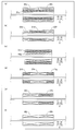
- FIG. 1 is a diagram showing an overall configuration of a mobile X-ray fluoroscopic apparatus including a magnetic substance inspection apparatus according to first to third embodiments of the present invention.
- FIG. 1 is a block diagram showing an overall configuration of a magnetic substance inspection apparatus according to first to third embodiments of the present invention.
- FIG. It is a figure for demonstrating the application direction of the magnetic field of the magnetic field application part by 1st Embodiment of this invention. It is a figure for demonstrating the excitation coil and detection coil by 1st Embodiment of this invention. It is a figure for demonstrating the excitation of the magnetization of the excitation coil by 1st Embodiment of this invention. It is a figure which shows the case where there are a crack etc. in a steel wire rope.
- FIG. 1 It is the block diagram which showed the electronic circuit part by 1st Embodiment of this invention. It is a figure for demonstrating the direction of magnetization of the steel wire rope by a comparative example. It is a graph of the value of the detection signal of the magnetic body by 1st Embodiment of this invention and a comparative example. It is the block diagram which showed the electronic circuit part by 2nd Embodiment of this invention. It is a figure for demonstrating the excitation coil and magnetic sensor element by 3rd Embodiment of this invention. It is the block diagram which showed the electronic circuit part by 3rd Embodiment of this invention. It is a figure for demonstrating the magnetic field application part by 4th Embodiment of this invention.
- FIG. 1st Embodiment of this invention It is a figure for demonstrating the direction of magnetization of the steel wire rope by a comparative example. It is a graph of the value of the detection signal of the magnetic body by 1st Embodiment of this invention and a comparative example
- FIG. 10 is a diagram for explaining a magnetic field application unit according to a modification of the first to third embodiments of the present invention. It is a figure for demonstrating the magnetic field application part by the modification of 4th Embodiment of this invention. It is a figure for demonstrating the excitation coil and detection coil by the modification of 1st and 2nd embodiment of this invention.
- FIG. 10 is a diagram for explaining an excitation coil and a detection coil according to modifications of the first to third embodiments of the present invention.
- FIG. 10 is a view for explaining a detection coil according to a modification of the first to fourth embodiments of the present invention.
- FIG. 10 is a diagram for explaining an excitation coil and a detection coil according to modifications of the first to fourth embodiments of the present invention.
- FIG. 6 is a diagram for explaining an X-ray imaging apparatus according to a modification of the first to fourth embodiments of the present invention.
- a mobile X-ray imaging apparatus 900 includes an X-ray irradiation unit E1 configured to be movable up and down (X direction) with respect to a column P, and a portable X-ray detection unit E2. It is configured to be movable by wheels.
- the X-ray irradiation unit E1 irradiates the subject with X-rays.
- the X-ray detection unit E2 detects X-rays that have passed through the subject and receives an X-ray image.
- the X-ray irradiation part E1 and the X-ray detection part E2 are each comprised by the X tube and FPD (flat panel detector), for example.
- a steel wire rope W that pulls and supports the X-ray irradiation unit E1 and an inspection apparatus 100 configured to be movable in the vertical direction (X direction) in which the steel wire rope W extends is built in the column P.
- the steel wire rope W is an example of “magnetic material”, “long material”, and “wire” in the claims.
- the steel wire rope W is a magnetic body made of a long material that is formed by knitting (for example, strand knitting) a magnetic wire material and extending in the X direction. Although not shown, the steel wire rope W passes through a mechanism such as a pulley when the X-ray irradiation unit E1 is moved, and stress due to the pulley is applied. In order to prevent the steel wire rope W from being cut due to deterioration and dropping the X-ray irradiation part E1, the state of the steel wire rope W (whether there are scratches, etc.) is monitored from the usual, and the steel wire rope W that has deteriorated is removed. It is necessary to replace it at an early stage.
- the inspection apparatus 100 is configured to detect a change in the magnetic field (magnetic flux) of the steel wire rope W.
- the inspection apparatus 100 can move the inspection unit U (see FIG. 2) including the magnetic field application unit 1, the detection unit 2, and the electronic circuit unit 3 provided on the frame F, and the steel wire rope W.
- the Y direction and the Z direction are two directions orthogonal to each other in a plane perpendicular to the direction in which the steel wire rope W extends.
- the electronic circuit unit 3 is an example of the “determination unit” in the claims.
- the magnetic field application unit 1 is configured to apply a magnetic field in the Y direction in advance to the steel wire rope W to be inspected to adjust the magnetization direction of the magnetic material.
- the magnetic field application unit 1 includes first magnetic field application units 11a and 11b that apply a magnetic field in the Y2 direction to the steel wire rope W made of a long material, and a first magnetic field application unit 11a that is a detection unit in the X direction. And a second magnetic field applied to the steel wire rope W made of a long material parallel to the plane intersecting the X direction and along the Y1 direction opposite to the Y2 direction.
- Magnetic field application units 12a and 12b are configured to apply a magnetic field in the Y direction in advance to the steel wire rope W to be inspected to adjust the magnetization direction of the magnetic material.
- the magnetic field application unit 1 includes first magnetic field application units 11a and 11b that apply a magnetic field in the Y2 direction to the steel wire rope W made of a long material, and a first magnetic field application unit 11a that
- the magnetic field application unit 1 is configured to apply a magnetic field in a direction substantially orthogonal to the X direction, which is the longitudinal direction of the long material.
- the Y direction (Y1 direction and Y2 direction) is an example of the “first direction” in the claims.
- the X direction (X1 direction and X2 direction) is an example of the “second direction” in the claims.
- the magnetic field application unit 1 (the first magnetic field application units 11a and 11b and the second magnetic field application units 12a and 12b) is fixed to the frame F (see FIG. 2).
- the magnetic field application part 1 is comprised with the permanent magnet, for example.
- the magnitude of the magnetic field applied by the magnetic field applying unit 1 is such that a relatively strong magnetic field is applied in order to adjust the direction of magnetization of the steel wire rope W substantially uniformly in the Y direction (in a portion without scratches or the like). Is configured to be possible.
- the first magnetic field application units 11a and 11b include an N pole (with diagonal lines) directed in the Y2 direction of the first magnetic field application unit 11a and an S pole (diagonal lines) directed in the Y1 direction of the first magnetic field application unit 11b. No) is provided so as to face each other across the steel wire rope W. As a result, the steel wire rope W that has passed between the first magnetic field application units 11a and 11b is applied with a magnetic field by the first magnetic field application units 11a and 11b as shown in FIG. The direction of magnetization is adjusted in the Y2 direction orthogonal to the direction in which the film extends.
- the second magnetic field application units 12a and 12b include an S pole (no hatching) directed in the Y2 direction of the second magnetic field application unit 12a and an N pole (hatched line) directed in the Y1 direction of the second magnetic field application unit 12b.
- S pole no hatching
- N pole hatching line
- Y1 direction of the second magnetic field application unit 12b are provided so as to face each other across the steel wire rope W.
- the steel wire rope W that has passed between the second magnetic field application units 12a and 12b is magnetized in the Y1 direction perpendicular to the direction in which the steel wire rope W extends because the magnetic field is applied by the second magnetic field application units 12a and 12b. (The illustration of the magnetization direction is omitted).
- the inspection unit U is moved in the X1 direction to move the magnetic field application unit 1 and the detection unit 2 provided in the inspection unit U and the steel wire rope W relative to each other, the first magnetic field application units 11a and 11b.
- a magnetic field is applied in advance to the portion to be inspected by the detection unit 2, and the direction of magnetization is adjusted.
- the second magnetic field application units 12a and 12b A magnetic field is applied in advance to the portion to be inspected by the detection unit 2, and the direction of magnetization is adjusted. Therefore, in the case of relative movement in any direction, the magnetic field application unit 1 can apply a magnetic field to the steel wire rope W in advance to adjust the direction of magnetization.
- the first magnetic field application units 11a and 11b and the second magnetic field application units 12a and 12b are in opposite directions, in which the direction in which the magnetic field is applied is the Y2 direction and the Y1 direction. Therefore, before and after the inspection, the direction in which the steel wire rope W is magnetized by the magnetic field applying unit 1 is reversed, so that the magnetization hardly remains in the steel wire rope W after the inspection.
- the magnetic field application unit 1 is provided at a position separated from the detection unit 2 in the X direction in which the steel wire rope W which is a long material extends so that the output magnetic field does not affect the detection by the detection unit 2. Yes. Specifically, the relationship between the relative positions of the magnetic field application unit 1 and the detection unit 2 with respect to the steel wire rope W due to the deflection of the steel wire rope W or the backlash of the frame F that the magnetic field application unit 1 and the detection unit 2 are fixed to. If this changes, it will cause noise in the detection signal. For this reason, the magnetic field application unit 1 is provided at a position separated to such an extent that the influence on the detection unit 2 does not matter.
- the magnetic field applied to the magnetic body by the magnetic field applying unit 1 is configured to be larger than the magnetic field generated by the excitation coil 21 (described later) to excite the magnetization state of the steel wire rope W.
- the magnetic field applied by the magnetic field applying unit 1 needs to be relatively large in order to adjust (align) the magnetization direction of the steel wire rope W in the substantially Y2 direction.
- a relatively small magnetic field is sufficient for exciting the magnetization of the steel wire rope W by the excitation coil 21. Details will be described later.
- the detection unit 2 includes an excitation coil 21 and a detection coil 22 as shown in FIG. Further, as shown in FIG. 3A and FIG. 4, the excitation coil 21 and the detection coil 22 extend along the longitudinal direction with the extending direction of the steel wire rope W, which is a magnetic material made of a long material, as the central axis. Is a coil including a conductor portion formed so as to have a cylindrical shape along the X direction (longitudinal direction) in which the steel wire rope W extends. Therefore, the surface formed by the wound conductive wire is substantially orthogonal to the longitudinal direction, and the steel wire rope W passes through the inside of the coil.
- the detection coil 22 is provided inside the excitation coil 21.
- a magnetic field generated based on the excitation current is applied along the X direction inside the excitation coil 21 when an excitation current is passed through the excitation coil 21.
- the excitation coil 21 excites the magnetization state of the steel wire rope W.
- the direction of magnetization is adjusted in advance by the magnetic field application unit 1, and therefore, when there is no application of the magnetic field by the excitation coil 21,
- the direction of magnetization of the steel wire rope W is substantially aligned with the Y2 direction.
- an alternating current (excitation current) having a constant magnitude and a constant frequency is caused to flow from the outside to the excitation coil 21, so that the steel wire rope W extends in the X direction.
- a magnetic field is applied so as to vibrate (a magnetic field in the X1 direction and a magnetic field in the X2 direction appear periodically).
- the direction of the magnetic field (solid line or dotted line) applied by the excitation coil 21 also changes with the direction (solid line or dotted line) of the exciting current flowing through the excitation coil 21 over time.
- the magnetization direction of the steel wire rope W is excited by the time-varying magnetic field, and the magnetic field emitted from the steel wire rope W also changes with time.
- the magnetic field due to the same portion of the steel wire rope W changes over time without changing the relative position between the steel wire rope W and the detection coil 22, so that the detection coil 22 (described later) that detects the change in the magnetic field
- the state of the steel wire rope W can be determined.
- the detection coil 22 is configured to generate a voltage by detecting a change in the magnetic field in the X direction of the magnetic material.
- the detection coil 22 detects a change in the magnetic field in the X direction intersecting the Y2 direction with respect to the steel wire rope W to which the magnetic field is applied in the Y2 direction by the magnetic field applying unit 1, and detects the detected steel wire rope W.
- the voltage based on the change of the magnetic field in the X direction is output.
- the detection coil 22 is arranged so that substantially all of the magnetic field generated by the excitation coil 21 can be detected (input).
- the detection coil 22 is a differential coil composed of two detection coil portions 22a and 22b.
- the detection coil 22 detects a change in the magnetic field in the X direction of the steel wire rope W whose magnetization state is excited by the magnetic field generated by the excitation current flowing in the excitation coil 21.
- FIG. 6 is an example of a steel wire rope W with scratches and the like.
- FIG. 6 how the strands are knitted is shown in a simplified manner.
- the steel wire rope W of Fig.6 (a) the strand of the surface part has disconnected. For this reason, the magnetic field leaks from the portion where the wire breakage occurs.
- the steel wire rope W of FIG.6 (b) has the dent in the surface part by thread or a dent.
- the wire breakage has arisen inside the steel wire rope W of FIG.6 (c).
- the total magnetic flux of the steel wire rope W (the magnetic The value obtained by multiplying by the area becomes smaller at the part with scratches. As described above, the leakage of the magnetic field and the decrease of the total magnetic flux occur, so that the detected magnetic field changes in a part having a scratch or the like.
- the value of the difference in detection voltage (the entire detection coil 22) ( Detection signal) increases. That is, the detection signal in a portion without a scratch is substantially zero, and the detection signal has a value greater than zero in a portion with a scratch or the like, so that a clear signal (S / Signal with a good N ratio) is detected.
- the electronic circuit unit 3 (described later) can detect the presence of a scratch or the like of the steel wire rope W based on the difference value of the detection signals.
- the detection signal increases as the size of the scratches (the amount of decrease in the cross-sectional area) increases, the scratches that are larger than a certain degree when determining (evaluating) the size of the scratches, etc. If there is, it is possible to automatically determine that the detection signal has exceeded a predetermined first threshold value Th1 or second threshold value Th2 (described later). Note that a flaw or the like includes a change in magnetic permeability due to rust or the like, and similarly appears as a detection signal.
- the electronic circuit unit 3 is configured to determine the state of the steel wire rope W made of a long material based on a signal from the detection coil.
- An AC power supply 31, an amplifier 32, an AD converter 33, a CPU 34, and a digital output interface 35 are included.
- the AC power supply 31 causes an AC current to flow (output) through the excitation coil 21.
- the amplifier 32 amplifies the detection signal (current based on the strength of the magnetic field in the X direction of the steel wire rope W) output from the detection coil 22 and outputs the amplified signal to the AD converter 33.
- the AD converter 33 converts the analog detection signal amplified by the amplifier 32 into a digital detection signal.
- the CPU 34 performs a process of removing an AC component from the detection signal output from the AD converter 33, performs a synchronous detection rectification process for converting the signal into a signal (DC level signal) corresponding to a change in the absolute value of the detection signal, and detects the detection signal. When the signal exceeds a predetermined threshold described later, an alarm signal is output. Further, the CPU 34 controls the intensity of the current output from the AC power supply 31. In addition, the CPU 34 has a function of determining the size of a scratch or the like.
- the digital output interface is connected to an external PC (not shown) and outputs digital data of processed detection signals and alarm signals.
- the external PC stores the magnitude of the input signal in a memory, displays a graph of the signal magnitude over time, and displays the graph of the detection unit 2 (integrated frame) via the CPU 34. The moving speed of the steel wire rope W is controlled.
- the electronic circuit unit 3 has a first threshold signal indicating that the detection signal exceeds the first threshold Th1 when the detection signal output by the detection coil 22 (detection unit 2) exceeds the first threshold Th1. And when the detection signal output by the detection unit 2 exceeds the second threshold Th2, a second threshold signal indicating that the detection signal exceeds the second threshold Th2 is output to the outside. It is configured.
- a magnetic field is applied in the X direction by the excitation coil 21.
- the excitation coil 21 causes the detection signal (magnitude of magnetic field including time change of magnetic field accompanying movement or excitation) to be equal in the X direction by the excitation coil 21 so as to be equalized in a uniform part without scratches. It is necessary to increase the applied magnetic field. Further, since the magnetization directions are not adjusted (aligned) in advance, the magnetic field applied in the X direction by the excitation coil 21 needs to be increased to the extent that the magnetization directions are substantially aligned in the X direction.
- the direction of magnetization varies depending on the internal structure in the steel wire rope W, which is a magnetic body, at the time of manufacture. Further, the direction of the magnetization is changed by passing an external force such as a stress through a mechanism such as a pulley. Accordingly, even in a homogeneous portion without scratches or the like, even if the magnetization direction is excited in the X direction by the excitation coil 21, the variation in the magnetization direction cannot be completely eliminated. Variations in size and direction cause noise in the detection signal.
- the magnitude and direction of magnetization are adjusted (aligned) by applying a magnetic field in advance, the magnetic field in a portion free from scratches or the like of the magnetic material is detected as a substantially constant magnitude. It becomes easy to distinguish from signals from scratches.
- the steel wire rope W (generally a magnetic material) when magnetized in the short direction (Y direction) as compared with the case of magnetizing in the longitudinal direction (X direction). ) Is reduced to a few tenths to a few thousandths according to the thickness of the steel wire rope W, and the direction of magnetization is adjusted in the short direction (Y direction). The problem of residual magnetization is alleviated.
- the graph of FIG. 9 is a graph of the change in the magnetic field of the steel wire rope W in the comparative example and the first embodiment.
- the vertical axis of the graph corresponds to the magnitude of the detection signal
- the horizontal axis of the graph corresponds to the detection position (where the steel wire rope W is detected). Since the synchronous detection and rectification processing is performed by the CPU 34, the influence of the time change of the magnetic field applied by the excitation coil 21 is removed.
- noise is hardly detected as shown in the graph after magnetizing in FIG. Specifically, the noise level is relatively small and the S / N ratio is good, and the detection signal is clearly shown. Therefore, noise can be reduced by the magnetic field application unit 1 to such an extent that erroneous determination does not occur even when determination is made by a non-expert or a threshold.
- the positive / negative reversal of the detection signal due to the position of the damaged portion of the steel wire rope W moving from one side of the differential coil to the other side is clearly shown. I understand that.
- the detection signal based on the change of the magnetic field of the steel wire rope W is output with respect to the steel wire rope W after a magnetic field is previously applied by the magnetic field application part 1 as mentioned above.
- a detection unit 2 and an electronic circuit unit 3 that determines the state of the steel wire rope W based on the detection signal output by the detection unit 2 are provided.
- a magnetic field is applied to the steel wire rope W in advance, so that the magnetization of the steel wire rope W that is uniform (portion without scratches or the like) is substantially adjusted.
- the magnetic field of the part where the steel wire rope W is scratched is not arranged.
- the detection signal output from the detection unit 2 is different between a part having a scratch and the like and a part having no scratch, so that the electronic circuit unit 3 can easily determine the state of the steel wire rope W (whether there is a scratch or the like). be able to.
- a change in the magnetic field in the X direction substantially perpendicular to the Y direction is detected with respect to the steel wire rope W after the magnetic field applying unit 1 applies the magnetic field in the Y2 direction.
- a detection unit 2 and an electronic circuit unit 3 that output a detection signal based on the detected change in the magnetic field in the X direction of the steel wire rope W are provided.
- a magnetic field is applied in advance to the steel wire rope W in the Y direction that is substantially orthogonal to the X direction, which is the direction in which the change in the magnetic field is detected.
- the magnetization of the (part) is arranged in a substantially Y direction.
- the magnetic field in the X direction is smaller (substantially zero) than when no magnetic field is previously applied in the Y direction. That is, variations in the magnitude and direction of magnetization are reduced and the direction is perpendicular to the detection direction, so that the generation of noise due to this variation can be suppressed. As a result, it is possible to easily determine the state of the steel wire rope W (whether there is a scratch or the like).
- the steel wire rope W consists of a long material, and the magnetic field application part 1 is substantially orthogonal to the longitudinal direction (X direction) of the steel wire rope W which is a long material.
- the magnetic field is applied in the direction (Y direction) to be detected, and the detection unit 2 and the electronic circuit unit 3 are configured to detect a change in the magnetic field in the X direction of the steel wire rope W.
- the magnetization of the magnetic material is smaller than in the case of magnetization in the longitudinal direction, and the direction is substantially perpendicular to the detection direction of the detection unit. Thereby, since noise is further reduced, it is possible to more easily determine the state of the magnetic body (whether there is a scratch or the like).
- the magnetic field application unit 1 is separated from the detection unit 2 in the X direction in which the long material extends so that the output magnetic field does not affect detection by the detection unit 2. In the position. This increases the accuracy of the S / N ratio of the detection signal. As a result, it is possible to suppress noise caused by a change in the relative position between the detection unit 2 and the magnetic field application unit 1.
- the magnetic field application unit 1 includes the first magnetic field application units 11a and 11b that apply a magnetic field in the Y2 direction to the steel wire rope W made of a long material, and the X direction.
- the magnetic field along the Y1 direction parallel to the plane intersecting the X direction with respect to the steel wire rope W made of a long material is provided on the side opposite to the first magnetic field application units 11a and 11b side of the detection unit 2. It includes so that 2nd magnetic field application parts 12a and 12b which apply may be included.
- the magnetic field application unit 1 and the steel wire rope W are moved relative to the X1 direction side which is one side of the X direction or the X2 direction side which is the other side of the X direction, thereby changing the magnetic field in the X direction.
- the direction of magnetization of the steel wire rope W by the magnetic field application unit 1 before the magnetic field is detected by the detection unit 2 regardless of the relative movement in either the X1 direction side or the X2 direction side.
- the detection coil 22 which generates a detection signal is provided, and the electronic circuit part 3 determines the state of the steel wire rope W which consists of elongate materials based on a detection signal. It is configured as follows. As a result, the detection coil 22 generates a dielectric voltage due to the total magnetic flux inside the closed curve formed by the conductive wire wound along the X direction in which the steel wire rope W of the detection coil 22 extends. A change in the magnetic field in the X direction of the wire rope W can be detected.
- the detection coil 22 constitutes a differential coil
- the electronic circuit unit 3 is a voltage generated by two coil portions included in the differential coil by a magnetic field in the X direction.
- the state of the steel wire rope W made of a long material is determined based on the difference in size. Thereby, a local change in the state of the steel wire rope W (whether there is a scratch or the like) is detected by detecting a difference in voltage (detection signal) generated by one coil portion of the differential coil and another coil portion. It can be detected more easily.
- the steel wire rope W passing through the inside of the excitation coil 21 and the detection coil 22 is slightly displaced from the central axis of the detection coils 22a and 22b due to deflection (for example, the distance r1 in the case of FIG. 4). > Distance r2). Since the detection coils 22a and 22b are configured to have a symmetric shape (cylindrical symmetry) with the steel wire rope W as a central axis, noise due to deviation from the central axis of the steel wire rope W is suppressed.
- the two detection coils 22a and 22b are provided in the detection coil 22 so as to be a differential coil, the deviation from the central axis of the steel wire rope W in each coil portion becomes substantially equal. This also suppresses noise caused by the deviation of the steel wire rope W from the central axis.
- the electronic circuit unit 3 when the detection signal output from the detection unit 2 exceeds the two predetermined thresholds Th1 and Th2, the electronic circuit unit 3 has two predetermined detection signals. Two threshold signals (first threshold signal and second threshold signal) indicating that the threshold values Th1 and Th2 have been exceeded are output to the outside. Thereby, it is possible to easily determine a portion where the state of the steel wire rope W (whether there is a scratch or the like) is not uniform based on the threshold signal.
- the first embodiment since the direction of magnetization of the steel wire rope W is adjusted in the Y direction, noise hardly occurs in the detection of the magnetic field in the X direction, and the S / N ratio becomes good. For this reason, even if the determination is based on the threshold Th, it is possible to make it difficult for an erroneous determination to be made.
- the predetermined threshold value Th includes the first threshold value Th1 and the second threshold value Th2 that is larger than the first threshold value Th1
- the electronic circuit unit 3 includes the detection unit. 2 and when the detection signal output by the electronic circuit unit 3 exceeds the first threshold Th1, the first threshold signal indicating that the detection signal exceeds the first threshold Th1 is output to the outside, and the detection unit When the output detection signal exceeds the second threshold Th2, the second threshold signal indicating that the detection signal exceeds the second threshold is output to the outside. Accordingly, the state of the steel wire rope W having a small scratch or the like that requires attention such as follow-up observation is determined based on the first threshold signal exceeding the relatively small first threshold Th1, and the relatively large second threshold Th2. Based on the second threshold signal exceeding the value, it is possible to determine the state of the steel wire rope W having a relatively large scratch or the like that needs to be replaced quickly.
- the excitation coil 21 excites the magnetization state of the steel wire rope W such as a flaw, so that it is possible to easily detect a change in the magnetic field in the X direction from the steel wire rope W such as a flaw. it can.
- an alternating current or the like is passed through the excitation coil 21 to give excitation that changes with time to the magnetization state of the steel wire rope W, the magnetic field of the steel wire rope W also changes with time. Therefore, the magnetic field detected by the detection unit 2 can be changed and detected without relatively moving the steel wire rope W and the detection unit 2.
- the magnetic field applied to the steel wire rope W by the magnetic field applying unit 1 is more than the magnetic field generated by the excitation coil 21 to excite the magnetization state of the steel wire rope W. Is configured to be larger.
- the direction of magnetization of the steel wire rope W is adjusted in the Y direction by a large magnetic field applied by the magnetic field applying unit 1 in advance, the state of magnetization in the X direction is excited in the determination of the state of the steel wire rope W. Even if the magnetic field required for this is smaller than the magnetization applied in the Y direction, it is sufficiently large for detection. That is, the magnitude of the magnetic field required to excite the magnetization state in the X direction can be reduced as compared with the case where the magnetization direction is not adjusted in the Y direction.
- the magnetic field applied by the excitation coil 21 is The detection coil 22 can sufficiently detect even a slight swing in the X1 or X2 direction. Therefore, the magnetic field generated by the excitation coil 21 can be made sufficiently smaller than the magnetic field applied by the magnetic field applying unit 1. Thereby, the magnitude
- the steel wire rope W is provided in the mobile X-ray imaging apparatus 900 so as to be relatively movable with respect to the subject, and the detection unit 2 is configured to It is comprised so that the magnetic field of the X direction of the steel wire rope W for moving the line irradiation part E1 may be detected. Thereby, the state (presence / absence of a flaw etc.) of the wire used for the mobile X-ray imaging apparatus 900 can be easily determined.
- the inspection apparatus 200 according to the second embodiment is a direct current in which the excitation current supplied to the excitation coil does not change over time.
- the inspection apparatus 200 includes an electronic circuit unit 302 provided in the inspection unit U. Moreover, the electronic circuit unit 302 includes a DC power supply 312 as shown in FIG.
- the direct current power source passes a direct current that does not change over time (becomes a constant value) through the excitation coil 21. Thereby, a static magnetic field having a constant magnitude in the X direction is generated in the excitation coil 21.
- the detection unit 202 moves the steel wire rope W relative to the detection unit 2 at a constant speed that is substantially constant in the X direction, thereby detecting the detection position of the detection unit 2.
- the steel wire rope W is configured to detect a change in the magnetic field in the X direction.
- the magnetic field detected by the detection coil 22 also changes with time.
- the detection coil 22 passes through a portion of the steel wire rope W that is not scratched, the magnitude of the magnetic field in the detection coil 22 in the X direction is substantially constant, so that the detection signal also has a constant value.
- the detection coil 22 is located at a part of the steel wire rope W with a scratch or the like, the magnitude of the magnetic field at the detection position changes with time, so that the detection signal changes. Thereby, the state (presence / absence of scratches) of the steel wire rope W can be determined.
- the detection unit 202 moves the steel wire rope W relative to the detection unit 2 at a constant speed that is substantially constant in the X direction, thereby moving the steel at the detection position of the detection unit 202.
- the wire rope W is configured to detect a change in the magnetic field in the X direction.
- a crack etc. can be easily detected by comparing with a part with a crack etc. and a part without a crack. it can.
- the detection signal becomes substantially constant at a position where there is no scratch or the like, and a different detection signal is output at a position where there is a scratch or the like. Becomes easy.
- the inspection apparatus 300 according to the third embodiment is provided with a magnetic sensor element 23 that detects the magnetic field of the steel wire rope W.
- the inspection apparatus 300 includes a detection unit 203 and an electronic circuit unit 303 provided in the inspection unit.
- a plurality of detection units 203 (12 symmetrically about the steel wire rope W as an axis) are arranged on the surface orthogonal to the longitudinal direction of the steel wire rope W so as to surround the steel wire rope W in a circumferential shape.
- the magnetic sensor element 23 is configured by, for example, any one or a combination of a coil, a coil with an excitation coil, a differential coil with an excitation coil, a Hall element, a magnetic impedance element, a magnetoresistive element, and the like. ing.
- a static magnetic field cannot be detected, so it is necessary to perform measurement while moving the magnetic body.
- the excitation coil is used together, the magnetic body to be measured is stationary. Measurement can be performed even in the state.
- Hall elements, magneto-impedance elements, and magneto-resistive elements since these elements themselves can measure a static magnetic field, measurement is performed even when the magnetic material to be measured is stationary. It becomes possible.
- a plurality of magnetic sensor elements 23 may be arranged at a plurality of positions so that the magnetic sensor elements 23 detect two or three directions. Further, the magnetic sensor element 23 can be configured to detect not only the magnitude of the change in the magnetic field but also the magnitude of the magnetic field.
- the electronic circuit unit 303 is configured to electrically control the magnetic sensor element 23, process an electrical signal from the detection unit 203, and output it as a detection signal.
- the detection unit 2 is configured such that at least one magnetic sensor element 23 that detects the magnetic field of the steel wire rope W is disposed outside the steel wire rope W. Yes.
- the detection unit 2 is free from restrictions on the size (for example, thickness) of the steel wire rope W. The application range is expanded.
- the inspection apparatus 400 includes an amplification unit 324 that receives and amplifies a detection signal output from the detection coil 224, an AD converter 334, a CPU 344, a switchable AC power supply 314, and a DC power supply 364.
- An electronic circuit 304 is provided.
- the inspection apparatus 400 includes a coil unit 44 connected to one of the switchable AC power source 314 and DC power source 364 and a yoke unit 14y around which the coil unit 44 is wound.
- the inspection apparatus 400 connects a DC power source 316 to the coil portion 44 when a magnetic field is applied to the steel wire rope W in advance.
- a magnetic circuit is formed in the steel wire rope W and the yoke part 14y, and a magnetic field is applied to the steel wire rope W in advance. That is, the steel wire rope W is magnetized in advance in a direction substantially parallel to the longitudinal direction (X direction).
- the yoke portion 14y functions as a “magnetic field applying portion” in the claims.
- the AC power source 314 is connected to the coil section 44 during measurement.
- the point of performing the measurement after magnetizing the measurement target region of the steel wire rope W in the longitudinal direction (X direction) in advance remains the same.
- the current flowing through the coil unit 44 can be changed between an alternating current and a direct current by switching between the alternating current power supply 314 and the direct current power supply 364 as described above. Further, the switching (selection) of the current source and the increase / decrease in the amount of current between when the magnetic field is applied in advance and when the measurement is performed are changed by the CPU 344.
- the state of the steel wire rope W is determined with respect to the steel wire rope W after the magnetic field is applied in advance. Thereby, it is possible to easily determine the state of the steel wire rope W (whether there is a scratch or the like).
- the measurement is performed by applying an alternating magnetic field by the excitation coil included in the detection unit, it is preferable to magnetize in the direction perpendicular to the longitudinal direction of the steel wire rope W as in the first embodiment. It becomes possible to detect the scratches on the rope W with higher accuracy.
- the magnetic body may be, for example, a thin plate other than a long material, an iron ball (bearing), or the like.
- the present invention can be used for general inspection of magnetic materials having a uniform structure.
- the magnetic body is a thin plate or the like, it is configured to apply magnetization in a direction perpendicular to the surface of the thin plate (thickness direction) and detect a magnetic field in the direction in which the surface of the thin plate extends or a change in the magnetic field. May be.
- the magnetic body made of a long material is a steel wire rope
- the present invention is not limited to this.
- the magnetic body made of a long material may be a thin plate, a square member, a cylindrical pipe, a wire, a chain, or the like.
- the relative position between the magnetic field application unit and the detection unit may be configured to be changeable. Specifically, after the direction of magnetization of the steel wire rope is adjusted to a direction orthogonal to the longitudinal direction by the magnetic field application unit, only the magnetic field application unit may be moved to a position away from the steel wire rope W. Thereby, when the magnetic field of the steel wire rope or the change of the magnetic field is detected by the detection unit, it can be separated so that the magnetic field of the magnetic field application unit does not affect the detection unit.
- the configuration of the magnetic field application unit 1 is shown in FIG. It is good also as such a structure.
- the magnetic field application directions of the first magnetic field application units 11e and 11f and the second magnetic field application units 12e and 12f may be the same.
- the magnetic field application directions of the first magnetic field application units 11g and 11h and the second magnetic field application units 12g and 12h do not have to be parallel (respectively in the Y direction).
- the direction is inclined by an angle ⁇ with respect to the Y direction).
- a magnetic field is applied in the same direction as a single configuration (a configuration not provided to face each other) as in the first magnetic field application unit 11i and the second magnetic field application unit 12i. May be.
- the magnetic field application units 13a and 13b may be provided only on one side of the detection unit. Note that the directions of the magnetic poles of the first magnetic field application unit and the second magnetic field application unit may be the same direction (for example, the Y2 direction) or may be opposite directions (for example, the Y1 direction and the Y2 direction). .
- the direction of application of the magnetic field by the magnetic field application unit 1 is the direction intersecting with the steel wire rope W
- the direction is perpendicular to the longitudinal direction of the steel wire rope W.
- the application direction of a magnetic field may cross
- the magnetic field application unit is configured by a permanent magnet.
- the present invention is not limited to this.
- the configuration of the magnetic field application unit 14 may be configured as shown in FIG. Specifically, as shown in FIG. 15A, the magnetic field application directions of the first magnetic field application units 11j and 11k and the second magnetic field application units 12j and 12k are the same (that is, the same characteristics). May be. Further, as shown in FIG. 15B, the magnetic field application directions of the first magnetic field application units 11l and 11m and the second magnetic field application units 121 and 12m may not be parallel (respectively in the X direction and The direction is inclined by an angle ⁇ with respect to the Y direction). Further, as shown in FIG.
- a magnetic field is applied in the same direction as a single configuration (a configuration not provided to face each other) as in the first magnetic field application unit 11n and the second magnetic field application unit 12n. (With the same characteristics). Further, as shown in FIGS. 15D and 15E, the magnetic field application units 13d and 13e (or the magnetic field application unit 13f) may be provided only on one side of the detection unit. Note that the directions of the magnetic poles of the first magnetic field application unit and the second magnetic field application unit may be the same direction (for example, the X2 direction) or may be opposite directions (for example, the X1 direction and the X2 direction). . Note that, as in the fourth embodiment, a magnetic field may be applied in advance by a yoke portion, or a magnetic field may be applied in advance by a permanent magnet.
- the detection coils 22a and 22b serving as differential coils are arranged inside the excitation coil 21
- the present invention is not limited to this.
- position the detection coils 22c and 22d which consist of a differential coil in the outer side of the excitation coil 21c.
- the detection coils 22e and 22f made of differential coils may be arranged side by side on both sides in the X direction (longitudinal direction) of the excitation coil 21d so as to sandwich the excitation coil 21d.
- the detection coils 22e and 22f made of differential coils may be arranged side by side on both sides in the X direction (longitudinal direction) of the excitation coil 21d so as to sandwich the excitation coil 21d.
- FIG.17 (a) you may arrange
- the detection coils 22e and 22f made of differential coils may be arranged side by side on both sides in the X direction (longit
- a single detection coil 22g that is not a differential coil may be arranged inside (or outside) the excitation coil 21e. Further, as shown in FIG. 17D, the two excitation coils 21f and 21g may be arranged side by side on both sides in the X direction (longitudinal direction) of the detection coil 22h so as to sandwich the single detection coil 22h. . As shown in FIG. 17E, a single excitation coil 21h and a single detection coil 22i may be arranged side by side in the X direction (longitudinal direction). Also, as shown in FIG. 17 (f), a configuration may be adopted in which the detection coils 22j and 22k (or a single detection coil) serving as a differential coil are arranged and the excitation coil is omitted.
- the detection coil 220 (excitation coil 210) may be a rectangular tube.
- the detection coil 221 is not surrounded by the steel wire rope W and is detected from the steel wire rope W so as to detect a magnetic field in the direction along the steel wire rope W. You may arrange
- a cylindrical coil 20b in which two semicylindrical (horse-shoe-shaped) coil portions 20a (see FIG. 20A) are combined may be used.
- the semi-cylindrical (horse-shoe) coil can be easily attached and detached even in a state where a steel wire rope is installed (the end is closed).
- the excitation coil corresponds to a coil portion.
- the present invention is not limited to this.
- at least one magnetic sensor element may be arranged at a position where the magnetic field of the steel wire rope can be detected.
- the magnetic sensor element 23 may be provided with a plurality of magnetic sensor elements 23 so as to detect two directions or three directions.
- the magnetic material inspection apparatus (inspection unit) is configured to be movable along the steel wire rope.
- the present invention is not limited to this.
- the magnetic inspection apparatus (inspection unit) may be configured not to move.
- the magnetic body inspection device detects the magnetic field of the steel wire rope passing through or near the fixed position.
- the electronic circuit unit also has a case where the detection signal output by the detection coil (detection unit) exceeds a predetermined threshold (first threshold Th1 and second threshold Th2).
- a predetermined threshold first threshold Th1 and second threshold Th2
- the electronic circuit unit counts the number N of times that the detection signal has exceeded the threshold Th, and when the counted number N exceeds the predetermined number M, the counted number N becomes the predetermined number M. It may be configured to output to the outside a signal indicating that the above has been exceeded.
- the electronic circuit part can count the frequency
- the number of predetermined thresholds may be one or a plurality (for example, three) other than two.
- the inspection apparatus 100 (200, 300) includes a stationary X-ray irradiation apparatus (X-ray imaging apparatus) 901 shown in FIG. 20A and a stand-type X-ray irradiation apparatus shown in FIG. (X-ray imaging apparatus) 902 and a stand-type X-ray detection apparatus (X-ray imaging apparatus) 903 shown in FIG.
- the present invention can also be applied to devices and infrastructure using wires, for example, moving devices such as elevators and ropeways, and wire portions such as suspension bridges and piers.
- the X-ray irradiator E11 and the X-ray irradiator E12 both include X-ray tubes and the like and irradiate X-rays, and the X-ray detector E23 emits X-rays including FPD (flat panel detector) and the like. This is the part to detect.
- the X-ray irradiation unit E11, the X-ray irradiation unit E12, and the X-ray detection unit E23 are supported by being pulled by the steel wire rope W, respectively.
- the inspection apparatus 100 (200, 300) is configured to be movable along the steel wire rope W.
- scratches on the surface of the magnetic material are mainly detected as “scratches, etc.” of the magnetic material.
- the wire is broken (if the wire rope is not perfect, the wire is broken) Changes in thickness, corrosion (rust), cracks, and non-uniform magnetic permeability are also included in the detection target.
- the detection target is not limited to the surface of the magnetic material, but may be inside.
- any state that causes a magnetic field or magnetic field non-uniformity of the magnetic material can be detected as a “magnetic state”.
- Magnetic magnetic field or change in magnetic field in addition to applying a magnetic field from the outside, in addition to a magnetic field observed in the vicinity of the magnetic material to which the magnetic field is applied or a change in the magnetic field, In this case, the magnetic field generated by the magnetic material itself or a change in the magnetic field is included.
- Magnetic field application unit 2 203 Detection unit 3, 302, 303, 304 Electronic circuit unit (determination unit) 11a, 11b, 11e, 11f, 11g, 11h, 11i, 11j, 11k, 11l, 11m, 11n First magnetic field application unit 12a, 12b, 12e, 12f, 12g, 12h, 12i, 12j, 12k, 12l, 12m, 12n 2nd magnetic field application part 14y Yoke part (magnetic field application part) 21, 21a, 21b, 21c, 21d, 21e, 21f, 21g, 21h, 210 Excitation coil 22, 22a, 22b, 22c, 22d, 22e, 22f, 22g, 22h, 22i, 22j, 22k, 220, 221, 224 Detection coil 23 Magnetic sensor element 44 Coil part (magnetic field application part, excitation coil) 100, 200, 300 Inspection device (magnetic material inspection device) 900 Mobile
Landscapes
- Physics & Mathematics (AREA)
- Chemical & Material Sciences (AREA)
- General Physics & Mathematics (AREA)
- Electrochemistry (AREA)
- Health & Medical Sciences (AREA)
- Life Sciences & Earth Sciences (AREA)
- Analytical Chemistry (AREA)
- Biochemistry (AREA)
- General Health & Medical Sciences (AREA)
- Chemical Kinetics & Catalysis (AREA)
- Immunology (AREA)
- Pathology (AREA)
- Condensed Matter Physics & Semiconductors (AREA)
- Investigating Or Analyzing Materials By The Use Of Magnetic Means (AREA)
Abstract
Description
まず、図1~図9を参照して、第1実施形態による検査装置100の構成について説明する。第1実施形態では、移動型X線撮影装置(回診車)900に内蔵されているスチールワイヤロープWを検査するために検査装置100が用いられる例について説明する。 (First embodiment)
First, the configuration of the inspection apparatus 100 according to the first embodiment will be described with reference to FIGS. In the first embodiment, an example will be described in which the inspection apparatus 100 is used to inspect the steel wire rope W built in the mobile
ここで、磁界印加部1が設けられていないことを除いて同様に構成されている比較例による磁性体の検査装置101と比較しながら、検査装置100の磁界印加部1による磁化について説明する。 (Comparative example)
Here, magnetization by the magnetic
本発明の第1実施形態では、以下のような効果を得ることができる。 (Effect of 1st Embodiment)
In the first embodiment of the present invention, the following effects can be obtained.
次に、図10を参照して、第2実施形態による検査装置200の構成について説明する。第2実施形態による検査装置200は、第1実施形態とは異なり、励振コイルに供給される励振電流が時間変化しない直流電流である。 (Second Embodiment)
Next, the configuration of the inspection apparatus 200 according to the second embodiment will be described with reference to FIG. Unlike the first embodiment, the inspection apparatus 200 according to the second embodiment is a direct current in which the excitation current supplied to the excitation coil does not change over time.
第2実施形態では、上記のように、検知部202は、スチールワイヤロープWを検知部2に対してX方向に略一定となる定速度で相対移動させることにより検知部202の検知位置におけるスチールワイヤロープWのX方向の磁界の変化を検知するように構成されている。これにより、スチールワイヤロープWの検知部202に磁界を検知される部分が相対移動に伴って変化するので、傷等のある部分とない部分との比較により、容易に傷等を検知することができる。また、定速度で相対移動させることによって、傷等のない位置では検知信号が略一定となり、傷等のある位置では異なる検知信号が出力されるため、スチールワイヤロープWの傷等の状態の判定が容易となる。 (Effect of 2nd Embodiment)
In the second embodiment, as described above, the detection unit 202 moves the steel wire rope W relative to the
次に、図11および図12を参照して、第3実施形態による検査装置300の構成について説明する。第3実施形態による検査装置300は、第1実施形態とは異なり、スチールワイヤロープWの磁界を検知する磁気センサ素子23が設けられている。 (Third embodiment)
Next, the configuration of the inspection apparatus 300 according to the third embodiment will be described with reference to FIGS. 11 and 12. Unlike the first embodiment, the inspection apparatus 300 according to the third embodiment is provided with a
第3実施形態では、上記のように、磁界印加部1によりY2方向に磁界が印加された後のスチールワイヤロープWに対して、磁界または磁界の変化を検知するとともに、検知したスチールワイヤロープWの磁界に基づく検知信号を出力する検知部2を設ける。これによっても、磁化の大きさおよび方向のバラツキが低減した状態で検知が行われるため、スチールワイヤロープWの状態(傷等の有無)の判定を容易に行うことができる。 (Effect of the third embodiment)
In the third embodiment, as described above, a magnetic field or a change in the magnetic field is detected with respect to the steel wire rope W after the magnetic field is applied in the Y2 direction by the magnetic
次に、図13を参照して、第4実施形態による検査装置400の構成について説明する。 (Fourth embodiment)
Next, the configuration of the inspection apparatus 400 according to the fourth embodiment will be described with reference to FIG.
第4実施形態では、上記のように、予め磁界が印加された後のスチールワイヤロープWに対して、スチールワイヤロープWの状態の判定を行うように構成されている。これにより、スチールワイヤロープWの状態(傷等の有無)の判定を容易に行うことができる。 (Effect of 4th Embodiment)
In the fourth embodiment, as described above, the state of the steel wire rope W is determined with respect to the steel wire rope W after the magnetic field is applied in advance. Thereby, it is possible to easily determine the state of the steel wire rope W (whether there is a scratch or the like).
なお、今回開示された実施形態は、すべての点で例示であって制限的なものではないと考えられるべきである。本発明の範囲は、上記した実施形態の説明ではなく特許請求の範囲によって示され、さらに特許請求の範囲と均等の意味および範囲内でのすべての変更(変形例)が含まれる。 (Modification)
The embodiment disclosed this time should be considered as illustrative in all points and not restrictive. The scope of the present invention is shown not by the above description of the embodiment but by the scope of claims for patent, and further includes all modifications (modifications) within the meaning and scope equivalent to the scope of claims for patent.
2、203 検知部
3、302、303、304 電子回路部(判定部)
11a、11b、11e、11f、11g、11h、11i、11j、11k、11l、11m、11n 第1磁界印加部
12a、12b、12e、12f、12g、12h、12i、12j、12k、12l、12m、12n 第2磁界印加部
14y ヨーク部(磁界印加部)
21、21a、21b、21c、21d、21e、21f、21g、21h、210 励振コイル
22、22a、22b、22c、22d、22e、22f、22g、22h、22i、22j、22k、220、221、224 検知コイル
23 磁気センサ素子
44 コイル部(磁界印加部、励振コイル)
100、200、300 検査装置(磁性体の検査装置)
900 移動型X線撮影装置(X線撮影装置)
901 据え置き型X線照射装置(X線撮影装置)
902 スタンド型X線照射装置(X線撮影装置)
903 スタンド型X線検出装置(X線撮影装置)
E1、E11、E12 X線照射部
E2、E23 X線検出部
Th 所定の閾値
Th1 所定の第1閾値
Th2 所定の第2閾値
M 所定の回数
W スチールワイヤロープ(磁性体、長尺材、ワイヤ) 1, 13a, 13b, 13c, 13d, 13e, 13f Magnetic
11a, 11b, 11e, 11f, 11g, 11h, 11i, 11j, 11k, 11l, 11m, 11n First magnetic
21, 21a, 21b, 21c, 21d, 21e, 21f, 21g, 21h, 210
100, 200, 300 Inspection device (magnetic material inspection device)
900 Mobile X-ray equipment (X-ray equipment)
901 Stationary X-ray irradiation device (X-ray imaging device)
902 Stand type X-ray irradiation device (X-ray imaging device)
903 Stand type X-ray detection device (X-ray imaging device)
E1, E11, E12 X-ray irradiation unit E2, E23 X-ray detection unit Th Predetermined threshold Th1 Predetermined first threshold Th2 Predetermined second threshold M Predetermined number of times W Steel wire rope (magnetic material, long material, wire)
Claims (16)
- 検査対象である磁性体に対して予め磁界を印加し前記磁性体の磁化の方向を整える磁界印加部と、
前記磁界印加部により磁界が印加された後に、前記磁性体の磁界又は磁界の変化に基づく検知信号を出力する検知部と、
前記検知部により出力された前記検知信号に基づいて、前記磁性体の状態の判定を行う判定部とを備える、磁性体の検査装置。 A magnetic field application unit that preliminarily applies a magnetic field to the magnetic material to be inspected to adjust the magnetization direction of the magnetic material;
A detection unit that outputs a detection signal based on a magnetic field of the magnetic body or a change in the magnetic field after a magnetic field is applied by the magnetic field application unit;
A magnetic body inspection apparatus comprising: a determination unit configured to determine the state of the magnetic body based on the detection signal output by the detection unit. - 前記磁界印加部は、検査対象である磁性体に対して予め第1方向に磁界を印加し前記磁性体の磁化の方向を整え、
前記検知部は、前記磁界印加部により前記第1方向に磁界が印加された後の前記磁性体に対して、前記第1方向に交差する第2方向の磁界または前記第2方向の磁界の変化のうち少なくともいずれか一方を検知するとともに、検知した前記磁性体の前記第2方向の磁界または前記第2方向の磁界の変化に基づく検知信号を出力し、
前記判定部は、前記検知部により出力された前記検知信号に基づいて、前記磁性体の状態の判定を行うように構成されている、請求項1に記載の磁性体の検査装置。 The magnetic field application unit applies a magnetic field in a first direction to the magnetic body to be inspected in advance to adjust the magnetization direction of the magnetic body,
The detection unit changes the magnetic field in the second direction or the magnetic field in the second direction that intersects the first direction with respect to the magnetic body after the magnetic field is applied in the first direction by the magnetic field application unit. And detecting a detection signal based on a change in the magnetic field in the second direction or the magnetic field in the second direction of the detected magnetic body,
The magnetic body inspection apparatus according to claim 1, wherein the determination unit is configured to determine the state of the magnetic body based on the detection signal output from the detection unit. - 前記磁性体は、長尺材からなり、
前記磁界印加部は、前記長尺材の長手方向と交差する方向に磁界を印加し、
前記検知部は、前記長尺材からなる前記磁性体の前記第2方向の磁界または前記第2方向の磁界の変化を検知するように構成されている、請求項2に記載の磁性体の検査装置。 The magnetic body is made of a long material,
The magnetic field application unit applies a magnetic field in a direction crossing a longitudinal direction of the long material,
The magnetic body inspection according to claim 2, wherein the detection unit is configured to detect a magnetic field in the second direction or a change in the magnetic field in the second direction of the magnetic body made of the long material. apparatus. - 前記磁界印加部は、出力される磁界が前記検知部での検知に影響しないように、前記検知部から前記長尺材が延びる前記第2方向に離間した位置に設けられている、請求項3に記載の磁性体の検査装置。 The said magnetic field application part is provided in the position spaced apart in the said 2nd direction where the said elongate material extends from the said detection part so that the output magnetic field may not affect the detection in the said detection part. 2. Inspection apparatus for magnetic material according to 1.
- 前記磁界印加部は、前記長尺材からなる前記磁性体に対して前記第1方向に磁界を印加する第1磁界印加部と、前記第2方向において、前記検知部の前記第1磁界印加部の側とは反対側に設けられ、前記長尺材からなる前記磁性体に対し前記第2方向に交差する面に平行な方向に沿って磁界を印加する第2磁界印加部とを含む、請求項4に記載の磁性体の検査装置。 The magnetic field application unit includes a first magnetic field application unit that applies a magnetic field in the first direction to the magnetic body made of the long material, and the first magnetic field application unit of the detection unit in the second direction. And a second magnetic field applying unit that applies a magnetic field along a direction parallel to a plane intersecting the second direction to the magnetic body made of the long material, the second magnetic field applying unit being provided on the opposite side of the long material. Item 5. The magnetic material inspection apparatus according to Item 4.
- 前記検知部は、前記長尺材からなる前記磁性体を中心として前記磁性体を取り囲み前記磁性体の延びる方向に沿って巻回するように設けられ、前記磁性体の前記第2方向の磁界の変化を検知して前記検知信号を発生する検知コイルを含み、
前記判定部は、前記検知信号に基づいて前記長尺材からなる前記磁性体の状態を判定するように構成されている、請求項3に記載の磁性体の検査装置。 The detection unit is provided so as to surround the magnetic body around the magnetic body made of the long material and to be wound along a direction in which the magnetic body extends, and to detect a magnetic field in the second direction of the magnetic body. Including a detection coil for detecting the change and generating the detection signal;
The said determination part is a test | inspection apparatus of the magnetic body of Claim 3 comprised so that the state of the said magnetic body consisting of the said elongate material may be determined based on the said detection signal. - 前記検知コイルは、差動コイルを含み、
前記判定部は、前記第2方向の磁界により前記差動コイルに含まれる2つのコイル部分により発生する各々の前記検知信号の大きさの差に基づいて前記長尺材からなる前記磁性体の状態を判定する、請求項6に記載の磁性体の検査装置。 The sensing coil includes a differential coil;
The determination unit determines the state of the magnetic body made of the long material based on a difference in magnitude between the detection signals generated by two coil portions included in the differential coil due to the magnetic field in the second direction. The magnetic material inspection apparatus according to claim 6, wherein - 前記判定部は、前記検知部により出力された前記検知信号が1つまたは複数の所定の閾値を超えた場合に、前記検知信号が1つまたは複数の所定の閾値を超えたことを示す1つまたは複数の閾値信号を外部に出力するように構成されている、請求項1に記載の磁性体の検査装置。 The determination unit is one indicating that the detection signal exceeds one or more predetermined thresholds when the detection signal output by the detection unit exceeds one or more predetermined thresholds. The magnetic body inspection apparatus according to claim 1, wherein the inspection apparatus is configured to output a plurality of threshold signals to the outside.
- 前記所定の閾値は、第1閾値と前記第1閾値よりも大きい値となる第2閾値とを含み、
前記判定部は、前記検知部により出力された前記検知信号が前記第1閾値を超えた場合に、前記検知信号が前記第1閾値を超えたことを示す第1閾値信号を外部に出力するとともに、前記検知部により出力された前記検知信号が前記第2閾値を超えた場合に、前記検知信号が前記第2閾値を超えたことを示す第2閾値信号を外部に出力するように構成されている、請求項8に記載の磁性体の検査装置。 The predetermined threshold includes a first threshold and a second threshold that is larger than the first threshold;
The determination unit outputs a first threshold signal indicating that the detection signal has exceeded the first threshold to the outside when the detection signal output by the detection unit has exceeded the first threshold. When the detection signal output by the detection unit exceeds the second threshold, the second threshold signal indicating that the detection signal exceeds the second threshold is output to the outside. The magnetic body inspection apparatus according to claim 8. - 前記判定部は、前記検知部により出力された前記検知信号が1つまたは複数の所定の閾値を超えた回数を各々カウントするとともに、カウントされた回数が各々所定の回数を超えた場合に、カウントされた回数が前記所定の回数を超えたことを示す信号を外部に出力するように構成されている、請求項1に記載の磁性体の検査装置。 The determination unit counts the number of times that the detection signal output by the detection unit exceeds one or more predetermined thresholds, and counts when the counted number exceeds a predetermined number of times. The magnetic body inspection apparatus according to claim 1, wherein the magnetic body inspection apparatus is configured to output a signal indicating that the number of performed times exceeds the predetermined number of times.
- 前記検知部は、前記磁性体の磁化の状態を励振するための励振コイルをさらに含むとともに、前記励振コイルに流れる励振電流により発生した磁界により磁化の状態が励振された前記磁性体の前記第2方向の磁界または前記第2方向の磁界の変化を検知するように構成されている、請求項3に記載の磁性体の検査装置。 The detection unit further includes an excitation coil for exciting the magnetization state of the magnetic body, and the second state of the magnetic body is excited by a magnetic field generated by an excitation current flowing in the excitation coil. The magnetic body inspection apparatus according to claim 3, wherein the magnetic field inspection apparatus is configured to detect a change in a magnetic field in a direction or a magnetic field in the second direction.
- 前記磁界印加部によって前記磁性体に印加される磁界は、前記励振コイルが前記磁性体の磁化の状態を励振するために発生させる磁界よりも大きい、請求項11に記載の磁性体の検査装置。 12. The magnetic material inspection apparatus according to claim 11, wherein a magnetic field applied to the magnetic material by the magnetic field application unit is larger than a magnetic field generated by the excitation coil to excite the magnetization state of the magnetic material.
- 前記検知部は、前記磁性体を前記検知部に対して前記第2方向に相対移動させることにより前記検知部の検知位置における前記磁性体の前記第2方向の磁界または前記第2方向の磁界の変化を検知するように構成されている、請求項3に記載の磁性体の検査装置。 The detection unit moves the magnetic body relative to the detection unit in the second direction, thereby detecting the magnetic field in the second direction or the magnetic field in the second direction of the magnetic body at the detection position of the detection unit. The magnetic body inspection apparatus according to claim 3, wherein the magnetic body inspection apparatus is configured to detect a change.
- 前記検知部は、前記磁性体の磁界または磁界の変化を検知する少なくとも1つの磁気センサ素子を含む、請求項1に記載の磁性体の検査装置。 2. The magnetic substance inspection apparatus according to claim 1, wherein the detection unit includes at least one magnetic sensor element that detects a magnetic field of the magnetic substance or a change in the magnetic field.
- 前記磁性体は、被検体に対して相対的に移動可能となるようにX線撮影装置に設けられる、前記被検体にX線を照射するX線照射部または前記被検体を透過したX線を検出するX線検出部の少なくともいずれか一方を移動させるためのワイヤを含み、
前記検知部は、前記ワイヤの前記第2方向の磁界を検知するように構成されている、請求項2~14のいずれか1項に記載の磁性体の検査装置。 The magnetic body is provided in an X-ray imaging apparatus so as to be movable relative to the subject, and an X-ray irradiation unit that irradiates the subject with X-rays or X-rays transmitted through the subject. Including a wire for moving at least one of the X-ray detection units to be detected;
The magnetic body inspection apparatus according to any one of claims 2 to 14, wherein the detection unit is configured to detect a magnetic field in the second direction of the wire. - 検査対象である磁性体に対して磁界を印加し前記磁性体の磁化の方向を整えるステップと、
前記磁界を印加した後、前記磁性体の磁界または磁界の変化を検知するとともに、検知した前記磁性体の磁界または磁界の変化に基づく検知信号を出力するステップを備え、
出力された前記検知信号に基づいて、前記磁性体の状態を判定するステップとを備える、磁性体の検査方法。 Applying a magnetic field to the magnetic material to be inspected to adjust the magnetization direction of the magnetic material; and
After applying the magnetic field, detecting a magnetic field of the magnetic body or a change in the magnetic field, and outputting a detection signal based on the detected magnetic field of the magnetic body or a change in the magnetic field,
And a step of determining the state of the magnetic body based on the output detection signal.
Priority Applications (6)
| Application Number | Priority Date | Filing Date | Title |
|---|---|---|---|
| PCT/JP2017/002830 WO2018138850A1 (en) | 2017-01-26 | 2017-01-26 | Magnetic body inspection device and magnetic body inspection method |
| JP2018564029A JP6791270B2 (en) | 2017-01-26 | 2017-01-26 | Magnetic material inspection equipment and magnetic material inspection method |
| EP17894543.2A EP3575783A4 (en) | 2017-01-26 | 2017-01-26 | Magnetic body inspection device and magnetic body inspection method |
| US16/480,889 US11092570B2 (en) | 2017-01-26 | 2017-01-26 | Magnetic body inspection apparatus and magnetic body inspection method |
| KR1020197018329A KR102198678B1 (en) | 2017-01-26 | 2017-01-26 | Magnetic substance inspection device and magnetic substance inspection method |
| CN201780084860.XA CN110234988B (en) | 2017-01-26 | 2017-01-26 | Magnetic body inspection device and magnetic body inspection method |
Applications Claiming Priority (1)
| Application Number | Priority Date | Filing Date | Title |
|---|---|---|---|
| PCT/JP2017/002830 WO2018138850A1 (en) | 2017-01-26 | 2017-01-26 | Magnetic body inspection device and magnetic body inspection method |
Publications (1)
| Publication Number | Publication Date |
|---|---|
| WO2018138850A1 true WO2018138850A1 (en) | 2018-08-02 |
Family
ID=62977973
Family Applications (1)
| Application Number | Title | Priority Date | Filing Date |
|---|---|---|---|
| PCT/JP2017/002830 WO2018138850A1 (en) | 2017-01-26 | 2017-01-26 | Magnetic body inspection device and magnetic body inspection method |
Country Status (6)
| Country | Link |
|---|---|
| US (1) | US11092570B2 (en) |
| EP (1) | EP3575783A4 (en) |
| JP (1) | JP6791270B2 (en) |
| KR (1) | KR102198678B1 (en) |
| CN (1) | CN110234988B (en) |
| WO (1) | WO2018138850A1 (en) |
Cited By (9)
| Publication number | Priority date | Publication date | Assignee | Title |
|---|---|---|---|---|
| WO2019171667A1 (en) * | 2018-03-08 | 2019-09-12 | 株式会社島津製作所 | Magnetic body inspection device |
| WO2019220953A1 (en) * | 2018-05-15 | 2019-11-21 | 株式会社島津製作所 | Magnetic body inspection device and magnetic body inspection method |
| JP2020034509A (en) * | 2018-08-31 | 2020-03-05 | 株式会社島津製作所 | Inspection device for magnetic material |
| JP2020038072A (en) * | 2018-09-03 | 2020-03-12 | 株式会社島津製作所 | Magnetic body inspection system, magnetic body inspection device, and magnetic body inspection method |
| WO2020095354A1 (en) * | 2018-11-06 | 2020-05-14 | 株式会社島津製作所 | Magnetic-body inspection device and magnetic-body inspection system |
| JP2020076591A (en) * | 2018-11-06 | 2020-05-21 | 株式会社島津製作所 | Magnetic object inspection device and magnetic object inspection system |
| JP2020118620A (en) * | 2019-01-25 | 2020-08-06 | 株式会社島津製作所 | Magnetic body inspection device and magnetic body inspection method |
| WO2020246130A1 (en) | 2019-06-05 | 2020-12-10 | 株式会社島津製作所 | Wire rope examination system and wire rope examination method |
| EP4145121A1 (en) | 2021-09-03 | 2023-03-08 | Shimadzu Corporation | Wire rope inspection method and wire rope inspection system |
Families Citing this family (5)
| Publication number | Priority date | Publication date | Assignee | Title |
|---|---|---|---|---|
| US11493574B2 (en) * | 2020-08-17 | 2022-11-08 | Shimadzu Corporation | Magnetic material inspection device |
| US11506632B2 (en) * | 2020-10-20 | 2022-11-22 | Obshchestvo s ogranichennoi otvetstvennostiu “INTRON PLIUS” | Method for predicting a residual operating life of a steel rope |
| US11480546B2 (en) * | 2020-12-23 | 2022-10-25 | Shimadzu Corporation | Magnetic material inspection system, magnetic material inspection device, and magnetic material inspection method |
| CN113125549B (en) * | 2021-03-24 | 2022-12-13 | 广东电网能源发展有限公司 | Steel wire rope detection device and detection method |
| CN113640370B (en) * | 2021-08-09 | 2023-05-12 | 中国石油大学(北京) | Pipeline magnetic flux leakage detector capable of changing direction to excitation |
Citations (8)
| Publication number | Priority date | Publication date | Assignee | Title |
|---|---|---|---|---|
| JPS59147253A (en) * | 1983-02-12 | 1984-08-23 | Kawasaki Steel Corp | On-line hardness measurement of steel plate |
| JPS62108149A (en) * | 1985-11-06 | 1987-05-19 | Sumitomo Metal Ind Ltd | Grain size measurement method and device |
| JPH04240561A (en) * | 1991-01-25 | 1992-08-27 | Nkk Corp | Method and apparatus for magnetic flaw detection of wire rope |
| JP2003302379A (en) | 2002-04-09 | 2003-10-24 | Daiwa Steel Corp | Apparatus and method for eddy-current flaw detecting articulated long-sized material |
| JP2003322640A (en) * | 2002-05-07 | 2003-11-14 | Nippon Steel Corp | Steel surface flaw detection device |
| JP2005326152A (en) * | 2004-05-12 | 2005-11-24 | Utaro Fujioka | Reinforcing bar breakage detection method for concrete structures |
| JP2005338046A (en) * | 2004-05-24 | 2005-12-08 | Shige Ishikawa | Nondestructive inspection apparatus for metallic conduit |
| WO2015149165A1 (en) * | 2014-04-02 | 2015-10-08 | Her Majesty The Queen In Right Of Canada As Represented By The Minister Of Natural Resources Canada | Device for analysis of synthetic rope or cable, and method of use |
Family Cites Families (38)
| Publication number | Priority date | Publication date | Assignee | Title |
|---|---|---|---|---|
| US3359495A (en) * | 1964-08-13 | 1967-12-19 | Bell Inc F W | Magnetic reaction testing apparatus and method of testing utilizing semiconductor means for magnetic field sensing of an eddy-current-reaction magnetic field |
| JPS54104888A (en) | 1978-02-06 | 1979-08-17 | Hitachi Ltd | Magnetic flaw detector of steel rope |
| JPS55135976U (en) | 1979-03-22 | 1980-09-27 | ||
| JPS57166557A (en) | 1981-04-08 | 1982-10-14 | Mitsubishi Heavy Ind Ltd | Inspecting device for wire rope |
| JPS58115385A (en) | 1981-12-29 | 1983-07-09 | Shimadzu Corp | Metal detector |
| US4659991A (en) * | 1983-03-31 | 1987-04-21 | Ndt Technologies, Inc. | Method and apparatus for magnetically inspecting elongated objects for structural defects |
| JPS6135348A (en) * | 1984-07-27 | 1986-02-19 | Ishikawajima Harima Heavy Ind Co Ltd | Wire rope flaw detection device |
| JPS62223652A (en) * | 1986-03-26 | 1987-10-01 | Hitachi Ltd | Defect inspecting device |
| JPH02240560A (en) * | 1989-03-14 | 1990-09-25 | Nippon Glass Fiber Co Ltd | Defect inspecting device for glass fiber |
| JP2556957Y2 (en) * | 1993-04-13 | 1997-12-08 | 東京製綱株式会社 | Wire rope damage detector |
| US5414353A (en) * | 1993-05-14 | 1995-05-09 | Ndt Technologies, Inc. | Method and device for nondestructively inspecting elongated objects for structural defects using longitudinally arranged magnet means and sensor means disposed immediately downstream therefrom |
| JP3645634B2 (en) | 1995-12-28 | 2005-05-11 | 東京製綱株式会社 | Anti-vibration probe for wire rope electromagnetic flaw detector and wire rope anti-vibration flaw detection method using anti-vibration probe. |
| JPH10332542A (en) | 1997-05-28 | 1998-12-18 | Ishikawajima Harima Heavy Ind Co Ltd | Steel wire rope disconnection detector |
| JPH1130607A (en) * | 1997-07-09 | 1999-02-02 | Sumitomo Electric Ind Ltd | Conductor non-destructive inspection equipment |
| US6366085B1 (en) * | 1997-09-11 | 2002-04-02 | Bar-Ilan University | Probe device for measuring a magnetic field vector |
| JPH11230947A (en) * | 1998-02-10 | 1999-08-27 | Hitachi Building Systems Co Ltd | Magnetic flaw-detecting device of wire rope |
| DE69942172D1 (en) * | 1998-08-06 | 2010-05-06 | Mitsubishi Heavy Ind Ltd | SWITCHING CIRCUIT FOR DETECTING FAULTS |
| JP2000351575A (en) | 1999-06-08 | 2000-12-19 | Ishikawajima Harima Heavy Ind Co Ltd | Wire rope disconnection detector |
| JP2001153845A (en) | 1999-11-24 | 2001-06-08 | Kyosan Electric Mfg Co Ltd | Wire rope flaw detector |
| JP2002257789A (en) | 2001-02-28 | 2002-09-11 | Nkk Corp | Leakage flux detecting device |
| JP2003050230A (en) | 2001-08-06 | 2003-02-21 | Toshiba Elevator Co Ltd | Wire rope flaw detector |
| EP1429140A4 (en) * | 2001-09-21 | 2006-05-17 | Tok Engineering Co Ltd | Method for detecting metallic foreign matter and system for detecting metallic foreign matter |
| JP4432476B2 (en) * | 2003-12-02 | 2010-03-17 | 株式会社Ihi | Wire rope breakage detector |
| JP2005292111A (en) * | 2004-04-01 | 2005-10-20 | Shige Ishikawa | Non-destructive inspection system for steel frame material of reinforced concrete |
| EP2049961B1 (en) * | 2006-08-08 | 2011-07-06 | Siemens Industry, Inc. | Devices, systems, and methods regarding a plc system fault |
| CN101978261B (en) | 2008-04-14 | 2012-06-13 | 三菱电机株式会社 | Wire rope flaw detector |
| KR101419629B1 (en) | 2010-05-25 | 2014-07-15 | 미쓰비시덴키 가부시키가이샤 | Wire rope flaw detection device |
| US9075023B2 (en) | 2011-06-07 | 2015-07-07 | Mitsubishi Electric Corporation | Wire rope flaw detector |
| JP5201495B2 (en) * | 2011-08-18 | 2013-06-05 | 新日鐵住金株式会社 | Magnetic flaw detection method and magnetic flaw detection apparatus |
| CN102435666A (en) * | 2011-10-11 | 2012-05-02 | 南昌航空大学 | Method for evaluating stress concentration and fatigue damage based on feature permeability detection |
| US9103798B2 (en) * | 2011-12-07 | 2015-08-11 | Ndt Technologies, Inc. | Magnetic inspection device and method |
| CN102590328B (en) * | 2012-02-14 | 2015-01-21 | 厦门大学 | Permanent magnetic and alternating current direct current composite magnetic flux leakage detecting method |
| RU2561007C2 (en) * | 2012-02-23 | 2015-08-20 | Институт Др. Фёрстер Гмбх Унд Ко. Кг | Feed-through coil unit, long components test device complete with above unit and long components test method |
| US9581567B2 (en) * | 2012-11-12 | 2017-02-28 | Valerian Goroshevskiy | System and method for inspecting subsea vertical pipeline |
| US20150066391A1 (en) * | 2013-08-30 | 2015-03-05 | Transcanada Pipelines Limited | Methods for characterizing dents in pipelines |
| CN105758932A (en) * | 2014-12-15 | 2016-07-13 | 重庆迅升机车配件有限公司 | Magnetic powder flaw detection technology |
| WO2016143088A1 (en) * | 2015-03-11 | 2016-09-15 | 三菱電機株式会社 | Rope damage diagnostic examination device and rope damage diagnostic examination method |
| US9869729B1 (en) * | 2016-08-30 | 2018-01-16 | Infineon Technologies Ag | Magnetic field sensor circuit in package with means to add a signal from a coil |
-
2017
- 2017-01-26 CN CN201780084860.XA patent/CN110234988B/en active Active
- 2017-01-26 US US16/480,889 patent/US11092570B2/en active Active
- 2017-01-26 JP JP2018564029A patent/JP6791270B2/en active Active
- 2017-01-26 KR KR1020197018329A patent/KR102198678B1/en active IP Right Grant
- 2017-01-26 EP EP17894543.2A patent/EP3575783A4/en active Pending
- 2017-01-26 WO PCT/JP2017/002830 patent/WO2018138850A1/en active Application Filing
Patent Citations (8)
| Publication number | Priority date | Publication date | Assignee | Title |
|---|---|---|---|---|
| JPS59147253A (en) * | 1983-02-12 | 1984-08-23 | Kawasaki Steel Corp | On-line hardness measurement of steel plate |
| JPS62108149A (en) * | 1985-11-06 | 1987-05-19 | Sumitomo Metal Ind Ltd | Grain size measurement method and device |
| JPH04240561A (en) * | 1991-01-25 | 1992-08-27 | Nkk Corp | Method and apparatus for magnetic flaw detection of wire rope |
| JP2003302379A (en) | 2002-04-09 | 2003-10-24 | Daiwa Steel Corp | Apparatus and method for eddy-current flaw detecting articulated long-sized material |
| JP2003322640A (en) * | 2002-05-07 | 2003-11-14 | Nippon Steel Corp | Steel surface flaw detection device |
| JP2005326152A (en) * | 2004-05-12 | 2005-11-24 | Utaro Fujioka | Reinforcing bar breakage detection method for concrete structures |
| JP2005338046A (en) * | 2004-05-24 | 2005-12-08 | Shige Ishikawa | Nondestructive inspection apparatus for metallic conduit |
| WO2015149165A1 (en) * | 2014-04-02 | 2015-10-08 | Her Majesty The Queen In Right Of Canada As Represented By The Minister Of Natural Resources Canada | Device for analysis of synthetic rope or cable, and method of use |
Non-Patent Citations (1)
| Title |
|---|
| See also references of EP3575783A4 |
Cited By (23)
| Publication number | Priority date | Publication date | Assignee | Title |
|---|---|---|---|---|
| WO2019171667A1 (en) * | 2018-03-08 | 2019-09-12 | 株式会社島津製作所 | Magnetic body inspection device |
| JPWO2019171667A1 (en) * | 2018-03-08 | 2020-12-03 | 株式会社島津製作所 | Magnetic material inspection device |
| JPWO2019220953A1 (en) * | 2018-05-15 | 2021-04-22 | 株式会社島津製作所 | Magnetic material inspection equipment and magnetic material inspection method |
| WO2019220953A1 (en) * | 2018-05-15 | 2019-11-21 | 株式会社島津製作所 | Magnetic body inspection device and magnetic body inspection method |
| US11391697B2 (en) | 2018-05-15 | 2022-07-19 | Shimadzu Corporation | Magnetic body inspection device and magnetic body inspection method |
| JP2020034509A (en) * | 2018-08-31 | 2020-03-05 | 株式会社島津製作所 | Inspection device for magnetic material |
| JP7119788B2 (en) | 2018-08-31 | 2022-08-17 | 株式会社島津製作所 | Inspection equipment for magnetic materials |
| JP2020038072A (en) * | 2018-09-03 | 2020-03-12 | 株式会社島津製作所 | Magnetic body inspection system, magnetic body inspection device, and magnetic body inspection method |
| JP7143690B2 (en) | 2018-09-03 | 2022-09-29 | 株式会社島津製作所 | Magnetic material inspection system, magnetic material inspection apparatus, and magnetic material inspection method |
| JP2020076591A (en) * | 2018-11-06 | 2020-05-21 | 株式会社島津製作所 | Magnetic object inspection device and magnetic object inspection system |
| CN112997074B (en) * | 2018-11-06 | 2024-02-02 | 株式会社岛津制作所 | Magnetic material inspection device and magnetic material inspection system |
| JPWO2020095354A1 (en) * | 2018-11-06 | 2021-09-02 | 株式会社島津製作所 | Magnetic material inspection equipment and magnetic material inspection system |
| JP7081446B2 (en) | 2018-11-06 | 2022-06-07 | 株式会社島津製作所 | Magnetic material inspection device and magnetic material inspection system |
| CN112997074A (en) * | 2018-11-06 | 2021-06-18 | 株式会社岛津制作所 | Magnetic material inspection device and magnetic material inspection system |
| WO2020095354A1 (en) * | 2018-11-06 | 2020-05-14 | 株式会社島津製作所 | Magnetic-body inspection device and magnetic-body inspection system |
| US12209990B2 (en) | 2018-11-06 | 2025-01-28 | Shimadzu Corporation | Magnetic body inspection device and magnetic body inspection system |
| JP7243736B2 (en) | 2018-11-06 | 2023-03-22 | 株式会社島津製作所 | Magnetic material inspection device and magnetic material inspection system |
| JP2020118620A (en) * | 2019-01-25 | 2020-08-06 | 株式会社島津製作所 | Magnetic body inspection device and magnetic body inspection method |
| JP7200697B2 (en) | 2019-01-25 | 2023-01-10 | 株式会社島津製作所 | WIRE ROPE INSPECTION DEVICE AND WIRE ROPE INSPECTION METHOD |
| WO2020246130A1 (en) | 2019-06-05 | 2020-12-10 | 株式会社島津製作所 | Wire rope examination system and wire rope examination method |
| US11772935B2 (en) | 2019-06-05 | 2023-10-03 | Shimadzu Corporation | Wire rope inspection system and wire rope inspection method |
| US12135311B2 (en) | 2021-09-03 | 2024-11-05 | Shimadzu Corporation | Wire rope inspection method, wire rope inspection system, and wire rope inspection device |
| EP4145121A1 (en) | 2021-09-03 | 2023-03-08 | Shimadzu Corporation | Wire rope inspection method and wire rope inspection system |
Also Published As
| Publication number | Publication date |
|---|---|
| US11092570B2 (en) | 2021-08-17 |
| JPWO2018138850A1 (en) | 2019-11-07 |
| CN110234988B (en) | 2023-06-06 |
| US20190360965A1 (en) | 2019-11-28 |
| EP3575783A1 (en) | 2019-12-04 |
| KR20190088518A (en) | 2019-07-26 |
| EP3575783A4 (en) | 2020-09-09 |
| JP6791270B2 (en) | 2020-11-25 |
| KR102198678B1 (en) | 2021-01-05 |
| CN110234988A (en) | 2019-09-13 |
Similar Documents
| Publication | Publication Date | Title |
|---|---|---|
| WO2018138850A1 (en) | Magnetic body inspection device and magnetic body inspection method | |
| WO2019171667A1 (en) | Magnetic body inspection device | |
| US11358836B2 (en) | Wire rope inspection device, wire rope inspection system, and wire rope inspection method | |
| JP7119788B2 (en) | Inspection equipment for magnetic materials | |
| JP7434150B2 (en) | Magnetic substance inspection device and magnetic substance inspection method | |
| CN107850570B (en) | Defect measuring method, defect measuring device and inspection probe | |
| JP5006349B2 (en) | Wire rope flaw detector calibration equipment | |
| JP2006177747A (en) | Nondestructive inspection method | |
| JP7027927B2 (en) | Magnetic material inspection equipment | |
| JP7405046B2 (en) | Magnetic material inspection equipment and magnetic material magnetization equipment | |
| JP2014066654A (en) | Electromagnetic acoustic transducer and electromagnetic acoustic flaw detector | |
| Lee et al. | Measuring stress of strand using magnetic barkhausen noise measured by solenoid-type sensor | |
| JP2016197085A (en) | Magnetic flaw detection method | |
| CN103776898B (en) | Symmetrical balance type eddy current sensor | |
| JP2013185951A (en) | Magnetic flaw detection probe | |
| JP2020038072A (en) | Magnetic body inspection system, magnetic body inspection device, and magnetic body inspection method | |
| JP2012177647A (en) | Metal detector and metal detection method | |
| JP2016008846A (en) | Checkup method for rod-shaped magnetic bodies |
Legal Events
| Date | Code | Title | Description |
|---|---|---|---|
| 121 | Ep: the epo has been informed by wipo that ep was designated in this application |
Ref document number: 17894543 Country of ref document: EP Kind code of ref document: A1 |
|
| ENP | Entry into the national phase |
Ref document number: 20197018329 Country of ref document: KR Kind code of ref document: A |
|
| WWE | Wipo information: entry into national phase |
Ref document number: 2018564029 Country of ref document: JP |
|
| NENP | Non-entry into the national phase |
Ref country code: DE |
|
| ENP | Entry into the national phase |
Ref document number: 2017894543 Country of ref document: EP Effective date: 20190826 |