JP6861356B2 - Lighting device - Google Patents
Lighting device Download PDFInfo
- Publication number
- JP6861356B2 JP6861356B2 JP2017008719A JP2017008719A JP6861356B2 JP 6861356 B2 JP6861356 B2 JP 6861356B2 JP 2017008719 A JP2017008719 A JP 2017008719A JP 2017008719 A JP2017008719 A JP 2017008719A JP 6861356 B2 JP6861356 B2 JP 6861356B2
- Authority
- JP
- Japan
- Prior art keywords
- light emitting
- reflector
- lighting device
- light
- emitting unit
- Prior art date
- Legal status (The legal status is an assumption and is not a legal conclusion. Google has not performed a legal analysis and makes no representation as to the accuracy of the status listed.)
- Active
Links
- 238000003860 storage Methods 0.000 claims description 76
- 239000000463 material Substances 0.000 claims description 18
- 230000002093 peripheral effect Effects 0.000 claims description 16
- 229920005989 resin Polymers 0.000 claims description 16
- 239000011347 resin Substances 0.000 claims description 16
- 238000007689 inspection Methods 0.000 description 19
- 238000000034 method Methods 0.000 description 13
- 230000003287 optical effect Effects 0.000 description 13
- 238000012545 processing Methods 0.000 description 13
- 239000004035 construction material Substances 0.000 description 8
- 229910052782 aluminium Inorganic materials 0.000 description 7
- XAGFODPZIPBFFR-UHFFFAOYSA-N aluminium Chemical compound [Al] XAGFODPZIPBFFR-UHFFFAOYSA-N 0.000 description 7
- 238000010276 construction Methods 0.000 description 6
- 230000006870 function Effects 0.000 description 6
- 230000004397 blinking Effects 0.000 description 5
- 238000004891 communication Methods 0.000 description 5
- 238000004512 die casting Methods 0.000 description 5
- 238000012856 packing Methods 0.000 description 5
- 238000007599 discharging Methods 0.000 description 4
- 238000005286 illumination Methods 0.000 description 4
- 229910052751 metal Inorganic materials 0.000 description 4
- 239000002184 metal Substances 0.000 description 4
- RNFJDJUURJAICM-UHFFFAOYSA-N 2,2,4,4,6,6-hexaphenoxy-1,3,5-triaza-2$l^{5},4$l^{5},6$l^{5}-triphosphacyclohexa-1,3,5-triene Chemical compound N=1P(OC=2C=CC=CC=2)(OC=2C=CC=CC=2)=NP(OC=2C=CC=CC=2)(OC=2C=CC=CC=2)=NP=1(OC=1C=CC=CC=1)OC1=CC=CC=C1 RNFJDJUURJAICM-UHFFFAOYSA-N 0.000 description 3
- VYPSYNLAJGMNEJ-UHFFFAOYSA-N Silicium dioxide Chemical compound O=[Si]=O VYPSYNLAJGMNEJ-UHFFFAOYSA-N 0.000 description 3
- 239000004566 building material Substances 0.000 description 3
- 239000000470 constituent Substances 0.000 description 3
- 239000003063 flame retardant Substances 0.000 description 3
- 230000002265 prevention Effects 0.000 description 3
- VTYYLEPIZMXCLO-UHFFFAOYSA-L Calcium carbonate Chemical compound [Ca+2].[O-]C([O-])=O VTYYLEPIZMXCLO-UHFFFAOYSA-L 0.000 description 2
- 239000003086 colorant Substances 0.000 description 2
- 238000001514 detection method Methods 0.000 description 2
- 238000010586 diagram Methods 0.000 description 2
- 238000009826 distribution Methods 0.000 description 2
- 230000000694 effects Effects 0.000 description 2
- 238000005401 electroluminescence Methods 0.000 description 2
- 239000011521 glass Substances 0.000 description 2
- 150000002739 metals Chemical class 0.000 description 2
- 238000007639 printing Methods 0.000 description 2
- 229920002050 silicone resin Polymers 0.000 description 2
- 239000000758 substrate Substances 0.000 description 2
- 239000004925 Acrylic resin Substances 0.000 description 1
- 229920000178 Acrylic resin Polymers 0.000 description 1
- JOYRKODLDBILNP-UHFFFAOYSA-N Ethyl urethane Chemical compound CCOC(N)=O JOYRKODLDBILNP-UHFFFAOYSA-N 0.000 description 1
- DGAQECJNVWCQMB-PUAWFVPOSA-M Ilexoside XXIX Chemical compound C[C@@H]1CC[C@@]2(CC[C@@]3(C(=CC[C@H]4[C@]3(CC[C@@H]5[C@@]4(CC[C@@H](C5(C)C)OS(=O)(=O)[O-])C)C)[C@@H]2[C@]1(C)O)C)C(=O)O[C@H]6[C@@H]([C@H]([C@@H]([C@H](O6)CO)O)O)O.[Na+] DGAQECJNVWCQMB-PUAWFVPOSA-M 0.000 description 1
- HBBGRARXTFLTSG-UHFFFAOYSA-N Lithium ion Chemical compound [Li+] HBBGRARXTFLTSG-UHFFFAOYSA-N 0.000 description 1
- OAICVXFJPJFONN-UHFFFAOYSA-N Phosphorus Chemical compound [P] OAICVXFJPJFONN-UHFFFAOYSA-N 0.000 description 1
- GWEVSGVZZGPLCZ-UHFFFAOYSA-N Titan oxide Chemical compound O=[Ti]=O GWEVSGVZZGPLCZ-UHFFFAOYSA-N 0.000 description 1
- 230000002159 abnormal effect Effects 0.000 description 1
- 230000005856 abnormality Effects 0.000 description 1
- 238000000149 argon plasma sintering Methods 0.000 description 1
- 238000005452 bending Methods 0.000 description 1
- 229910000019 calcium carbonate Inorganic materials 0.000 description 1
- 230000007423 decrease Effects 0.000 description 1
- 238000004049 embossing Methods 0.000 description 1
- 239000010419 fine particle Substances 0.000 description 1
- 229910052736 halogen Inorganic materials 0.000 description 1
- 150000002367 halogens Chemical class 0.000 description 1
- WABPQHHGFIMREM-UHFFFAOYSA-N lead(0) Chemical compound [Pb] WABPQHHGFIMREM-UHFFFAOYSA-N 0.000 description 1
- 229910001416 lithium ion Inorganic materials 0.000 description 1
- 238000004519 manufacturing process Methods 0.000 description 1
- 229910001507 metal halide Inorganic materials 0.000 description 1
- 150000005309 metal halides Chemical class 0.000 description 1
- 229910052987 metal hydride Inorganic materials 0.000 description 1
- 238000012986 modification Methods 0.000 description 1
- 230000004048 modification Effects 0.000 description 1
- 229910052754 neon Inorganic materials 0.000 description 1
- GKAOGPIIYCISHV-UHFFFAOYSA-N neon atom Chemical compound [Ne] GKAOGPIIYCISHV-UHFFFAOYSA-N 0.000 description 1
- 230000000149 penetrating effect Effects 0.000 description 1
- 229920005668 polycarbonate resin Polymers 0.000 description 1
- 239000004431 polycarbonate resin Substances 0.000 description 1
- 238000007789 sealing Methods 0.000 description 1
- 239000004065 semiconductor Substances 0.000 description 1
- 239000000377 silicon dioxide Substances 0.000 description 1
- 238000009751 slip forming Methods 0.000 description 1
- 229910052708 sodium Inorganic materials 0.000 description 1
- 239000011734 sodium Substances 0.000 description 1
- OGIDPMRJRNCKJF-UHFFFAOYSA-N titanium oxide Inorganic materials [Ti]=O OGIDPMRJRNCKJF-UHFFFAOYSA-N 0.000 description 1
- XLYOFNOQVPJJNP-UHFFFAOYSA-N water Substances O XLYOFNOQVPJJNP-UHFFFAOYSA-N 0.000 description 1
- 229910052724 xenon Inorganic materials 0.000 description 1
- FHNFHKCVQCLJFQ-UHFFFAOYSA-N xenon atom Chemical compound [Xe] FHNFHKCVQCLJFQ-UHFFFAOYSA-N 0.000 description 1
Images


Landscapes
- Arrangement Of Elements, Cooling, Sealing, Or The Like Of Lighting Devices (AREA)
- Non-Portable Lighting Devices Or Systems Thereof (AREA)
Description
本発明は、照明装置に関する。 The present invention relates to a lighting device.
従来、通常時に光源を商用交流電源などの外部電源で点灯させ、停電が発生して商用交流電源から電力が供給されなくなった場合等の非常時に、バッテリ(蓄電池)の電源により光源を点灯させるようにした非常灯対応の非常用照明装置がある。また、非常用照明装置には、蓄電池が非常時に正常に動作するかどうかを確認するための、非常用照明装置の使用者(操作者)が操作するスイッチが備えられている。 Conventionally, the light source is normally turned on by an external power source such as a commercial AC power source, and in an emergency such as when a power failure occurs and the power is not supplied from the commercial AC power source, the light source is turned on by the power source of the battery (storage battery). There is an emergency lighting device that supports emergency lights. Further, the emergency lighting device is provided with a switch operated by a user (operator) of the emergency lighting device for confirming whether or not the storage battery operates normally in an emergency.
例えば特許文献1には、光源モジュールと、蓄電池と、蓄電池の状態を確認するためのスイッチと、モニタランプと、光源モジュール及びモニタランプの点灯を制御する点灯回路とを備える照明装置が開示されている。モニタランプは、操作者がスイッチの操作した場合に、蓄電池の点検結果を操作者に報知するものである。 For example, Patent Document 1 discloses a lighting device including a light source module, a storage battery, a switch for checking the state of the storage battery, a monitor lamp, and a lighting circuit for controlling the lighting of the light source module and the monitor lamp. There is. The monitor lamp notifies the operator of the inspection result of the storage battery when the operator operates the switch.
ところで、照明装置は人の手が届き難い比較的高所に設置される場合が多い。そのため、操作者は蓄電池等の照明装置が備える電子部品の状態を確認するが、照明装置が設置されているところから当該照明装置を取り外して電子部品の状態、又は、電子部品の状態を報知するためのモニタランプを確認することは困難である場合がある。 By the way, lighting devices are often installed in relatively high places that are difficult for humans to reach. Therefore, the operator confirms the state of the electronic component of the lighting device such as the storage battery, but removes the lighting device from the place where the lighting device is installed to notify the state of the electronic component or the state of the electronic component. It can be difficult to see the monitor lamp for.
本発明は、照明装置が備える電子部品の状態を容易に確認できる照明装置を提供する。 The present invention provides a lighting device that can easily confirm the state of electronic components included in the lighting device.
本発明の一態様に係る照明装置は、第一発光部と、前記第一発光部が載置される載置面を有し、前記第一発光部が発する光を反射する反射板と、前記照明装置が有する電子部品の状態に応じて点灯状態が変化する第二発光部とを備え、前記第一発光部は、平面視した場合に前記反射板の中央部に位置し、前記反射板は、前記第一発光部から離れるにつれて開口面積が広がる形状であり、前記反射板の周縁には、フランジ状の平坦部が設けられ、前記平坦部には、前記反射板を貫通する開口部が設けられ、前記第二発光部は、平面視した場合に前記開口部に位置し、前記第二発光部の光出射位置は、前記平坦部と略同一面、又は、前記載置面側に位置する。 The lighting device according to one aspect of the present invention has a first light emitting unit, a mounting surface on which the first light emitting unit is placed, and a reflector that reflects the light emitted by the first light emitting unit, and the above. It is provided with a second light emitting unit whose lighting state changes according to the state of an electronic component of the lighting device, the first light emitting unit is located at the center of the reflector when viewed in a plan view, and the reflector is The opening area expands as the distance from the first light emitting portion increases. A flange-shaped flat portion is provided on the peripheral edge of the reflector, and the flat portion is provided with an opening penetrating the reflector. The second light emitting portion is located at the opening when viewed in a plan view, and the light emitting position of the second light emitting portion is located on substantially the same surface as the flat portion or on the side of the above-mentioned mounting surface. ..
本発明によれば、照明装置が備える電子部品の状態を容易に確認できる照明装置が実現される。 According to the present invention, a lighting device capable of easily confirming the state of electronic components included in the lighting device is realized.
以下、実施の形態について、図面を参照しながら具体的に説明する。なお、以下で説明する実施の形態は、いずれも包括的又は具体的な例を示すものである。以下の実施の形態で示される数値、形状、材料、構成要素などは、一例であり、本発明を限定する主旨ではない。また、以下の実施の形態における構成要素のうち、最上位概念を示す独立請求項に記載されていない構成要素については、任意の構成要素として説明される。 Hereinafter, embodiments will be specifically described with reference to the drawings. It should be noted that all of the embodiments described below show comprehensive or specific examples. The numerical values, shapes, materials, components, and the like shown in the following embodiments are examples, and are not intended to limit the present invention. Further, among the components in the following embodiments, the components not described in the independent claims indicating the highest level concept are described as arbitrary components.
また、各図は、模式図であり、必ずしも厳密に図示されたものではない。なお、各図において、実質的に同一の構成に対しては同一の符号を付しており、重複する説明は省略又は簡略化される場合がある。 Further, each figure is a schematic view and is not necessarily exactly illustrated. In each figure, substantially the same configuration is designated by the same reference numerals, and duplicate description may be omitted or simplified.
以下の実施の形態の図面においては、Y軸方向は、例えば上下方向(鉛直方向)であり、Y軸負方向側は、上側又は天井側と記載される場合がある。また、Y軸正方向側は、下側と記載される場合がある。また、X軸方向及びZ軸方向は、Y軸に垂直な平面(水平面)上において、互いに直交する方向である。 In the drawings of the following embodiments, the Y-axis direction is, for example, the vertical direction (vertical direction), and the Y-axis negative direction side may be described as an upper side or a ceiling side. Further, the Y-axis positive direction side may be described as the lower side. Further, the X-axis direction and the Z-axis direction are directions orthogonal to each other on a plane (horizontal plane) perpendicular to the Y-axis.
また、本明細書において、「略」又は「約」とは、製造又は配置の際に生じる誤差を含むことを意味する。 Further, in the present specification, "abbreviation" or "about" means to include an error that occurs during manufacturing or arrangement.
(実施の形態)
[照明装置の構成]
実施の形態に係る照明装置の構成について詳細に説明する。
(Embodiment)
[Lighting device configuration]
The configuration of the lighting device according to the embodiment will be described in detail.
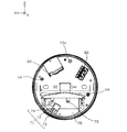
図1は、実施の形態に係る照明装置の下方から見た外観斜視図である。図2は、実施の形態に係る照明装置の下方から見た分解斜視図である。図3は、実施の形態に係る照明装置が備える反射板に取付けられる構成要素を反射板から取り外した図である。図4は、実施の形態に係る照明装置の透光カバーを取り外した場合の下面図である。図5は、図4の照明装置から反射板を取り外した場合の下面図である。具体的には、図5は、実施の形態に係る照明装置から透光カバーと、反射板と、反射板に取付けられる構成要素を取り外した図である。図6は、図4のVI−VI線に対応する位置で照明装置を切断した場合の断面図である。つまり、図6は、透光カバーを取付けた状態の照明装置を、図4に示すVI−VI線に対応する位置に沿って切断した断面を示す断面図である。 FIG. 1 is an external perspective view of the lighting device according to the embodiment as viewed from below. FIG. 2 is an exploded perspective view of the lighting device according to the embodiment as viewed from below. FIG. 3 is a diagram in which a component attached to a reflector included in the lighting device according to the embodiment is removed from the reflector. FIG. 4 is a bottom view of the lighting device according to the embodiment when the translucent cover is removed. FIG. 5 is a bottom view when the reflector is removed from the lighting device of FIG. Specifically, FIG. 5 is a diagram in which the translucent cover, the reflector, and the components attached to the reflector are removed from the lighting device according to the embodiment. FIG. 6 is a cross-sectional view when the illuminating device is cut at a position corresponding to the VI-VI line of FIG. That is, FIG. 6 is a cross-sectional view showing a cross section of the lighting device with the translucent cover attached along the position corresponding to the VI-VI line shown in FIG.
図1〜図6に示されるように、照明装置10は、器具本体11と、第一発光部30と、反射板40と、透光カバー50と、蓄電池60と、点灯制御装置70と、端子台80と、を備える。
As shown in FIGS. 1 to 6, the
照明装置10は、例えば、マンションの共用部などの半屋外空間で使用される、防災用(非常用)の照明装置である。照明装置10は、具体的には、シーリングライトとして天井やブラケットライトとして壁面などの施工面に取付けられる。本実施の形態においては、照明装置10の平面視形状は、円形である。なお、「平面視」とは、器具本体11に設けられた主面12a、又は、反射板40に設けられた載置面41を法線方向から見た場合を示す。
The
器具本体11は、天井又は壁面などの造営材の施工面に取付けられる部材であり、言い換えれば、取付け台である。器具本体11は、例えば、アルミダイカスト等によって形成されるが、その他の金属、又は樹脂によって形成されてもよい。器具本体11は、平面視形状が円形の平板状のベース部12と、ベース部12の周縁近傍に立設した側壁部13とを含む有底筒状である。
The instrument
ベース部12は、器具本体11を造営材に取付けるための取付け構造(開口)が設けられている。ベース部12は、平板状であり、後述する蓄電池60等の照明装置10の構成部材が載置される面(主面12a)とは反対側の面(取付け面12b)側が、造営材の施工面に取付けられる。なお、照明装置10が造営材に取り付けられた場合に、造営材の施工面と、上述した蓄電池60等の照明装置10の構成部材が載置される主面12aとは、略平行となる。また、以下の実施の形態では、器具本体11(照明装置10)は、天井に取付けられるものとして説明が行われる。
The
ベース部12には、2つの取付け部14が備えられている。
The
取付け部14は、主面12aに対して平行な方向の反射板40の動きを規制し、反射板40が着脱可能に取付けられる部材であり、造営材の施工面に対して垂直な方向に立設された状態でベース部12に設けられる。つまり、取付け部14は、反射板40を器具本体11に着脱可能に取付けるための部材である。2つの取付け部14は、ベース部12の周縁近傍に対向して配置される。
The
器具本体11のベース部12には、蓄電池60、点灯制御装置70及び端子台80が載置される。
A
蓄電池60は、第一発光部30に電力を供給する電源である。蓄電池60は、例えば、外部からの交流電力の供給が停止されたときに、非常用の電源として使用される。蓄電池60は、例えば、ニッケル水素電池である。蓄電池60は、充電及び放電が可能な電池であればよく、リチウムイオン電池又は鉛蓄電池等であってもよい。蓄電池60は、蓄電池カバー61によって下方から覆われる。蓄電池カバー61は、例えば、アルミダイカストによって形成されるが、樹脂によって形成されてもよい。
The
点灯制御装置70は、照明装置10の外部から供給される交流電力を直流電力に変換して第一発光部30に供給する電源回路を含む制御回路123(図9参照)を備える電源回路ユニットである。点灯制御装置70の詳細については、後述する。
The
端子台80は、外部交流電源と点灯制御装置70とを電気的に接続させるために電線が差し込まれる1又は複数の端子が配設された端子ユニットである。交流電力は、端子台80に差し込まれた電線を介して外部交流電源から点灯制御装置70へ供給される。
The
第一発光部30は、照明光を発する照明装置10の照明用光源として機能する。第一発光部30は、具体的には、基板上に実装されたLED(Light Emitting Diode)チップが、蛍光体を含有する透光性樹脂によって封止されたCOB(Chip On Board)型の発光モジュール31を備える。第一発光部30は、円形の発光領域を有する。本実施の形態においては、第一発光部30は、さらに、配光を制御するためのレンズを有し、第一発光部30を反射板40にネジ止めするためのホルダ32を備える。第一発光部30は、例えば、白色光を主とした照明光を下方に向けて発する。つまり、第一発光部30は、白色光を透光カバー50に向けて発する。なお、第一発光部30と載置面41との間には、放熱シート33などの放熱部材が配置されてもよい。
The first
また、第一発光部30は、透光カバー50が備える光透過部材51と反射板40との間に配置される。また、平面視した場合に、第一発光部30は反射板40下面の中央部に位置する載置面41に配置される。第一発光部30は、反射板40の載置面41に載置され、載置面41にねじ止めされる。なお、図示されないが、第一発光部30は、蓄電池60及び点灯制御装置70とリード線などによって電気的に接続される。
Further, the first
ところで、上述したように照明装置が備える光源の交換等のために、壁、天井等の造営材に固定される照明装置の本体と、照明装置が備える照明装置の構成部材とがねじ止め等によって着脱可能に取付けられる場合がある。実施の形態に係る照明装置10においては、照明装置10は蓄電池60を備える。一般的に、蓄電池が内蔵された例えば防災用(非常用)の照明装置は、定期的に蓄電池の状態を確認する必要がある。この際に、蓄電池に要求される能力を満たしていないことが確認された場合、蓄電池は交換される必要がある。そのために、照明装置10においては、器具本体11に取付けられている蓄電池60を交換しやすくするために、反射板40及び透光カバー50は器具本体11と着脱可能に取付けられている。
By the way, as described above, in order to replace the light source provided in the lighting device, the main body of the lighting device fixed to the building material such as a wall or the ceiling and the constituent members of the lighting device provided in the lighting device are screwed or the like. It may be attached detachably. In the
反射板40は、第一発光部30が配置される載置面41が設けられ、第一発光部30が発する光を反射する板体である。また、反射板40は、第一発光部30から発せられる光を、透光カバー50(具体的には、光透過部材51)側へ反射する。また、反射板40は、器具本体11に第一発光部30を着脱可能に取付けるための取付け部材である。具体的には、反射板40は、主面12aに対して平行な方向にスライドされることにより、器具本体11(具体的には、取付け部14)に着脱可能に取付けられる。また、反射板40は、ベース部12に載置された蓄電池60、点灯制御装置70及び端子台80を覆うように器具本体11に取付けられる。言い換えると、蓄電池60、点灯制御装置70及び端子台80は、反射板40に覆われて器具本体11に載置される。また、反射板40は、第一発光部30の光軸L方向(Y軸方向)において、器具本体11(具体的にはベース部12)と透光カバー50(具体的には透光カバー50が備える光透過部材51)との間に配置される。図6に示されるように、反射板40とベース部12との間、及び、反射板40と光透過部材51との間のそれぞれには、空隙(空気層)が配置される。つまり、反射板40は、器具本体11及び光透過部材51のいずれの部材とも直接接触しない。このように、第一発光部30が反射板40の載置面41に載置される構造によれば、第一発光部30がベース部12に載置される構造よりも、第一発光部30が発する熱がベース部12に伝わりにくい効果が得られる。
The
また、反射板40は、上方(ベース部12側)に向かうほど縮径する略漏斗状である。言い換えると、反射板40は、第一発光部30から離れるにつれて開口面積が広がる形状である。反射板40は、例えば、アルミニウムによって形成されるが、その他の金属又は樹脂によって形成されてもよい。
Further, the
図3に示されるように、反射板40は、載置面41、傾斜部42、平坦部43を有する。
As shown in FIG. 3, the
載置面41は、反射板40の略中央部に位置し、第一発光部30が載置される平面である。載置面41の平面視形状は、特に限定されるものではないが、本実施の形態においては円形である。第一発光部30は、載置面41に載置されることにより、光透過部材51と反射板40との間に位置する。
The mounting
また、反射板40のうち載置面41の反対側の面、つまり、載置面41と背向する面には、ヒートシンクが配置されてもよい。当該ヒートシンクによれば、第一発光部30が発光中に発する熱を当該ヒートシンクに逃がすことができる。当該ヒートシンクは、例えば、アルミダイカストによって形成されるが、その他の金属によって形成されてもよい。
Further, the heat sink may be arranged on the surface of the
また、反射板40には、第一発光部30が発する光を透光カバー50側に反射させる傾斜部42が含まれるとよい。傾斜部42は、載置面41の周囲を囲むように載置面41と連続的に形成された部分であり、第一発光部30が発する光の一部を光透過部材51に向けて反射する。傾斜部42は、反射板40の径方向において一部が湾曲したテーパ部分である。
Further, the
また、反射板40の周縁部には、傾斜部42に対して、さらに傾斜部42からベース部12側に傾斜して延在したフランジ状の平坦部43が設けられる。具体的には、反射板40の周縁部には、傾斜部42に対して傾斜し、載置面41に対して略平行な平坦部43が設けられる。言い換えると、反射板40の周縁近傍には、第一発光部30が発する光の光軸L方向に対して略垂直方向に屈曲して形成された平坦部43が設けられる。平坦部43には、開口部44及び取付け孔45が設けられる。
Further, on the peripheral edge of the
開口部44は、光軸L方向に貫通して形成された貫通孔である。開口部44には、第二発光部73が位置する。具体的には、開口部44は、第二発光部73を有するモニタユニット71が嵌合される。なお、開口部44は、反射板40を器具本体11に取付けやすくするために、反射板40の周縁に形成された切り欠き状の切り欠き部であるとよい。
The
反射板40の周縁部(平坦部43)には、一対の取付け孔45が対向して配置される。取付け孔45は、取付け部14に対応して位置し、光軸L方向に貫通して形成された貫通孔である。なお、反射板40の平坦部43に配置される取付け孔45の数は特に限定されるものではない。器具本体11に設けられる取付け部14に対応した数だけ設けられるとよい。
A pair of mounting
透光カバー50は、器具本体11とともに照明装置10の外郭筐体の一部を構成する、器具本体11と着脱可能なカバー部材である。透光カバー50は、光透過部材51と、枠体52とを備える。
The
光透過部材51は、下方に向かって突出した略円形ドーム状の光学部材(グローブ)である。光透過部材51は、例えば、白色又は乳白色であり、光拡散性(光散乱性)及び透光性を有する。
The
光透過部材51は、枠体52の下側の開口を塞ぐように枠体52に取付けられる。光透過部材51は、具体的には、外側に向かって鍔状にせり出した光透過部材51の縁が、支持枠100と枠体52の鍔状にせり出した部分との間に挟み込まれることによって、枠体52に取付けられる。
The
光透過部材51は、例えば、ガラスによって形成されるが、シリコーン樹脂、アクリル樹脂、又は、ポリカーボネート樹脂によって形成されてもよい。また、光透過部材51は、表面にシルク印刷が行われることによって光拡散性を有してもよい。また、光透過部材51は、シリカ又は炭酸カルシウムなどの光拡散材(微粒子)を含有することにより光拡散性を有してもよい。また、光透過部材51の表面(内面又は外面)に光拡散材等を含む乳白色の光拡散膜を形成することで、光透過部材51は光拡散性を有してもよい。また、光拡散材を用いるのではなくシボ加工処理等によって光透過部材51の表面に微小凹凸を形成したり、光透過部材51の表面にドットパターンを印刷したりすることで、光透過部材51は光拡散性を有してもよい。また、上述した光拡散性を持たせる材料、形状等を組み合わせることで、光透過部材51は光拡散性を有してもよい。
The
枠体52は、第一発光部30及び反射板40などを側方から囲む筒状筐体である。本実施の形態においては、枠体52は、円筒状である。枠体52は、器具本体11及び光透過部材51とともに、照明装置10の外郭筐体を構成する。枠体52は、外郭筐体の側壁部分に相当する。なお、枠体52は、取付け部14には接触しない。枠体52と取付け部14との間には空隙(空気層)が形成される。
The
枠体52は、上側の開口に器具本体11が配置された状態で回動されることにより、器具本体11に接続される。具体的には、枠体52の内壁には、器具本体11の側壁部13に形成された雄ねじと螺合する雌ねじが形成されている。器具本体11と枠体52とは、当該雄ねじと当該雌ねじとが回動されて螺合することにより接続される。枠体52は、例えば、アルミダイカストによって形成されるが、その他の金属、又は、樹脂によって形成されてもよい。
The
また、器具本体11に透光カバー50が取付けられた場合に、照明装置10は、第一発光部30が発する光の光軸L方向の長さに対して、光軸L方向に対して垂直な方向の長さの方が大きい扁平形状である。なお、本実施の形態においては、照明装置10は、平面視において円形であるが、楕円形状又は多角形などでもよく、平面視形状は特に限定されない。照明装置10の平面視形状が円形ではない場合は、照明装置10は、第一発光部30が発する光の光軸Lに平行な方向の長さ(高さ)に対して、照明装置10における最も長い垂直な方向の長さ(幅)の方が大きい扁平形状であるとよい。
Further, when the
なお、照明装置10が防災用の照明装置として採用される場合、照明装置10の外郭筐体を構成する器具本体11及び透光カバー50は、不燃性又は難燃性の材料で形成されるとよい。具体的には、上述したように、器具本体11及び枠体52はアルミダイカストによって形成され、光透過部材51はガラスによって形成されるとよい。こうすることにより、火災が発生した際などに、照明装置10が延焼によって発火することが抑制される。
When the
また、照明装置10は、取付けシート90及びパッキン110を備えてもよい。
Further, the
取付けシート90は、ベース部12の取付け面12b側に配置され、ベース部12と造営材とを密着させやすくするための緩衝部材である。取付けシート90には、ベース部12に形成された造営材に取付けるための取付け構造(開口)に対応した位置に、取付け構造(開口)が形成される。取付けシート90は、例えば、不燃性又は難燃性であり、水が不透過のウレタン等の樹脂材料によって形成される。
The mounting
パッキン110は、側壁部13の外周面13aと枠体52の内周面52aとの間に位置し、枠体52と側壁部13とを密着させやすくするための環状の気密封止部材である。パッキン110は、側壁部13の外周面13aに沿って形成される。言い換えると、パッキン110は側壁部13の外周面13aに、器具本体11の周方向に延在して形成される。パッキン110は、例えば、ゴム弾性を有する樹脂材料によって形成される。
The packing 110 is located between the outer
次に、作業者が反射板40を器具本体11に取付けられる際の、反射板40の動かし方について説明する。図7は、反射板40が器具本体11に取付けられる際の、反射板40の動きを示す説明図である。具体的には、図7の(a)は、反射板40が器具本体11に取付けられる前の状態を示し、図7の(b)は、反射板40が器具本体11に取付けられる途中の状態を示し、図7の(c)は、反射板40が器具本体11に取付けられた状態を示している。
Next, a method of moving the
図7の(a)に示されるように、反射板40は、主面12aに対して平行な方向にスライドされることにより、開口部(切り欠き部)44とモニタユニット71とが嵌合して器具本体11に取付けられる。反射板40は、器具本体11の側方からスライドされることで、取付け部14に取付けられる。具体的には、反射板40が器具本体11へスライドされる方向(取付けられる方向)は、造営材の施工面に対して平行な方向である。本実施の形態においては、造営材の施工面はXZ平面であるとある。図7の(a)においては、反射板40は一点鎖線で示される矢印の方向へスライドされることで、取付け部14に取付けられる。なお、取付け部14の構造は限定されるものではない。取付け部14は、例えば、ねじ26と、ねじ26を支持し、ベース部12に立設される支柱部27とから構成される。また、例えば、ベース部12に立設され、先端に突起形状を有する取付け部14aが設けられてもよい。反射板40が器具本体11の側方からスライドされることで、取付け部14aの先端の突起形状が、取付け孔45aに係合する。
As shown in FIG. 7A, the
また、図7に示されるように、反射板40は一対の取付け孔45を有する。また、器具本体11には、一対の取付け部14が設けられる。ここで、一対の取付け孔45と一対の取付け部14とはそれぞれが対応した位置に配置される。具体的には、取付け部14に反射板40がスライドされる際には、図7の(a)の一点鎖線の矢印の方向に反射板40がスライドされ、一方の取付け孔45が一方の取付け部14に配置され、他方の取付け孔45が他方の取付け部14に配置される。
Further, as shown in FIG. 7, the
図7の(b)に示されるように、器具本体11の側方から反射板40がスライドされることで、一対の取付け部14に一対の取付け孔45が係止される。また、器具本体11の側方から反射板40がスライドされることで、開口部(切り欠き部)44とモニタユニット71とが係合される。
As shown in FIG. 7B, the
図7の(c)に示されるように、反射板40が器具本体11の側方からスライドされることで、一対の取付け部14に一対の取付け孔45が係止され、取付け部14aは取付け孔45aに係合し、モニタユニット71は開口部44に嵌合する。一対の取付け部14に一対の取付け孔45に嵌合させた後、ねじ26によって反射板40は器具本体11に固定される。こうすることで、反射板40は、器具本体11に取付けられる。
As shown in FIG. 7 (c), the
なお、ベース部12に載置される蓄電池60、点灯制御装置70及び端子台80は、反射板40が器具本体11にスライドされる際に反射板40と接触しない位置に載置されるとよい。具体的には、上述したように反射板40は略漏斗状であるため、載置面41の上部ではなく、傾斜部42又は平坦部43の上部に蓄電池60及び端子台80が載置されるとよい。こうすることで、反射板40は、蓄電池60及び端子台80に接触することなく、取付け部14に取付けられる。
The
次に、図8〜図10を用いて点灯制御装置70の詳細について説明する。
Next, the details of the
図8は、実施の形態に係る照明装置10が備える点灯制御装置70の外観斜視図である。図9は、実施の形態に係る照明装置10が備える点灯制御装置70の分解斜視図である。図10は、図6の破線Xに囲まれた領域を示す点灯制御装置70の部分拡大図である。なお、図10において、説明のために、平坦部43が位置する部分を破線で図示している。
FIG. 8 is an external perspective view of the
点灯制御装置70は、照明装置10が備える第一発光部30などを制御する制御機構である。点灯制御装置70は、例えば、ベース部12の下面に載置された状態でベース部12にネジ止めされる。図8及び図9に示されるように、点灯制御装置70は、主基板77と、制御カバー76と、モニタユニット71とを備える。
The
主基板77は、複数の電子部品120が実装され、上述した電源回路含む制御回路123が形成された回路基板である。
The
制御回路123は、第一発光部30及びモニタランプ(第二発光部)73の点灯状態を制御する処理回路である。また、制御回路123は、点検スイッチ74が操作者から指示を取得した場合に、照明装置10が備える電子部品、例えば蓄電池60、又は、制御回路123を構成する電子部品120等が正常に機能しているかどうかの点検を行う。当該点検の結果に応じて、制御回路123は、モニタランプ73を所定の点灯状態で発光させる。制御回路123がモニタランプ73を所定の点灯状態で発光させる一例である、制御回路123が実行する蓄電池60の状態を確認する処理手順の詳細については、後述する。
The
制御回路123は、例えば、ゲートアレイ等を用いた専用の電子回路によってハードウェア的に実現される。なお、制御回路123は、制御プログラムが記憶されたメモリと、当該制御プログラムを実行するCPU(Central Processing Unit)等によって、つまりプロセッサがプログラムを実行することによってソフトウェア的に実現されてもよい。
The
また、主基板77は、上述したように、電源回路を含む。具体的には、制御回路123は、主基板77に回路部品となる複数の電子部品120が実装されることにより形成された電源回路を含む。電源回路は、整流回路及びインバータ回路などを含む。
Further, the
また、電源回路には、蓄電池60を充電する充電回路が含まれる。充電回路は、照明装置10の外部から供給される交流電力を蓄電池60の充電に適した直流電力に変換し、直流電力によって蓄電池60を充電する。本実施の形態では、照明装置10においては、停電時などの非常時においても照明装置10の使用が可能なように蓄電池60はトリクル充電される。
Further, the power supply circuit includes a charging circuit for charging the
また、電源回路には、外部からの交流電力の供給の停止(停電)を検出する検出回路、及び、蓄電池60を放電する放電回路も含まれる。検出回路によって停電が検出されると、放電回路は、蓄電池60を放電させる。この結果、蓄電池60は、第一発光部30に直流電力を供給する。これにより、照明装置10は、停電時も発光を継続することができる。
Further, the power supply circuit also includes a detection circuit for detecting the stoppage (power failure) of the supply of AC power from the outside and a discharge circuit for discharging the
制御カバー76は、主基板77を覆うカバー部材である。制御カバー76は、反射板40に設けられた傾斜部42の形状に沿って傾斜した形状を有する。制御カバー76は、例えば、アルミダイカスト又は不燃性若しくは難燃性の樹脂材料によって形成される。
The control cover 76 is a cover member that covers the
モニタユニット71は、モニタランプ73等が配置され、照明装置10が備える電子部品等の状態を、照明装置10の使用者(操作者)へ報知するためのユニットである。モニタユニット71には、モニタランプ73を収容し、モニタランプ73が発する光を反射する反射性を有した樹脂材料によって形成され、モニタランプ73の周囲を覆う筒状の孔である筒部79が設けられる。モニタユニット71は、モニタカバー72と、モニタランプ73と、点検スイッチ74とを備える。
The
モニタカバー72は、副基板78を覆うカバー部材である。また、モニタカバー72には、モニタランプ73が発する光を反射する(光反射性の)樹脂材料によって形成され、モニタランプ73の周囲を覆う筒状の孔である筒部79が設けられる。
The
筒部79は、モニタランプ73が発する光の配光を制御する機能を有する部分である。筒部79は、モニタランプ73から出射される光の一部を、光透過部材51に向けて反射する。具体的には、筒部79は、モニタランプ73が発する光の広がりを抑制するように機能する。筒部79は、例えば樹脂材料によってモニタランプ73の周囲を囲むように筒状に形成される。筒部79は、モニタカバー72と同一の樹脂材料で形成されてもよいし、モニタランプ73の周囲に位置するモニタカバー72の部分に光反射性の樹脂材料が塗布されることにより形成されてもよい。当該樹脂材料は、例えば酸化チタンなどの反射性(光反射性)の材料を添加したシリコーン樹脂などである。これにより、筒部79は、モニタランプ73が発する光を光透過部材51側へ反射するようにも機能する。なお、筒部79には、モニタランプ73が発する光の広がりを抑制するために、例えばレンズ等が設けられてもよい。
The
モニタランプ(第二発光部)73は、照明装置10が備える電子部品の状態に応じて点灯状態が切り替わる光源である。例えば、モニタランプ73は、照明装置10が備える電子部品の一例である蓄電池60の状態に応じて点灯状態が切り替わる光源である。具体的には、モニタランプ73は、点灯(連続点灯)又は点滅することにより蓄電池60が正常に機能しているかどうかを照明装置10の操作者へ提示(報知)するランプである。モニタランプ73は、例えば、砲弾型LEDにより構成される。また、上述したように、照明装置10は、モニタランプ73とは別に、照明装置10の照明用光源として機能する第一発光部30を備える。第一発光部30が点灯中においても、モニタランプ73が光を発しているかどうかを確認しやすくするために、第一発光部30及びモニタランプ73が発する光の色は異なるとよい。例えば、第一発光部30は白色光を発し、モニタランプ73は緑色光を発してもよい。モニタランプ73は、平坦部43に形成された貫通孔である開口部44に対応した位置に配置される。具体的には、モニタランプ73は、平面視において開口部44に配置される。
The monitor lamp (second light emitting unit) 73 is a light source whose lighting state is switched according to the state of electronic components included in the
ここで、図10に示されるように、モニタランプ73の光出射位置Pは、平坦部43より載置面41側に位置する。言い換えると、モニタランプ73の光出射位置Pは、平坦部43よりも透光カバー50側に位置する。なお、図10において、光出射位置Pは、モニタランプ73の先端部(図10の図示する黒点)の位置として定義する。これにより、モニタランプ73が発する光が、光透過部材51を通過して照明装置10の外側へ出射されやすくなる。なお、モニタランプ73の光出射位置Pは、平坦部43と略同一面にあればよい。つまり、モニタランプ73の光出射位置Pは、平坦部43と略同一面又は載置面41側に位置すればよい。ここで、平坦部43と略同一面とは、平坦部43の載置面41側の面を示す。
Here, as shown in FIG. 10, the light emitting position P of the
点検スイッチ74は、照明装置10を利用する操作者からの指示を取得するスイッチである。具体的には、点検スイッチ74が操作者からの指示を取得した場合に、制御回路123は蓄電池60の状態を確認する処理を実行する。点検スイッチ74は、例えば操作者が直接押圧するボタンでもよいが、PD(Photo Diode)等の光センサであるとよい。つまり、点検スイッチ74は、操作者が操作するリモートコントローラから発せられる赤外線などの信号を受信する光センサであるとよい。なお、点検スイッチ74の一例として、上述したボタン式のスイッチと、光センサとが照明装置10に備えられていてもよい。本実施の形態においては、点灯制御装置70は、点検スイッチ74と、上述した光センサとして、受光部75とを備える。
The
副基板78は、モニタランプ73及び点検スイッチ74が実装され、モニタランプ73及び点検スイッチ74に電力を供給するための回路が形成された回路基板である。
The sub-board 78 is a circuit board on which the
なお、モニタランプ73の点灯制御をするための制御回路123は、主基板77に形成されるとしたが、副基板78に形成されてもよく、限定されない。
Although the
次に、実施の形態に係る照明装置10が備える電子部品の一例である蓄電池60の状態を点検するための処理手順について説明する。
Next, a processing procedure for checking the state of the
図11は、実施の形態に係る照明装置10が備える蓄電池60の状態を点検する処理手順を示すフローチャートである。具体的には、図11は、点検スイッチ74又は受光部75が照明装置10の操作者から指示を取得した場合、制御回路123が蓄電池60の状態を点検し、当該点検の結果に応じてモニタランプ73を所定の態様で発光させる処理手順を示すフローチャートである。
FIG. 11 is a flowchart showing a processing procedure for checking the state of the
照明装置10は、まず、照明装置10を外部交流電源と電気的に接続させて第一発光部30及びモニタランプ(第二発光部)73を点灯させる(ステップS101)。
First, the
照明装置10を利用している操作者は、蓄電池60が正常に機能しているかどうかを点検する場合に、照明装置10へ指示を出す。例えば、操作者は、所定のリモートコントローラを操作して、蓄電池60を点検する指示を受光部75へ送信する。受光部75は、当該指示を取得する(ステップS102)。受光部75が操作者から指示を取得した場合に、制御回路123は、モニタランプ(第二発光部)73を消灯させる制御をする(ステップS103)。
The operator using the
次に、制御回路123は、蓄電池60の状態を点検する。まず、制御回路123は、蓄電池60と第一発光部30とが電気的に接続されているかを点検(判定)する(ステップS104)。具体的には、制御回路123は、外部から供給されていた電力を第一発光部30へ供給することを中断し、蓄電池60に蓄えられていた電力を第一発光部30へ供給することで、第一発光部30へ電力が供給できるかどうかを確認する。言い換えると、点検スイッチ74が操作者から指示を取得した場合に、制御回路123は、停電時と同様に、蓄電池60を放電させることにより第一発光部30を発光させる。
Next, the
次に、制御回路123が蓄電池60と第一発光部30とが電気的に接続されていないと判定した場合(ステップS104でNo)に、制御回路123は、モニタランプ73を点滅して発光させる制御をする(ステップS108)。
Next, when the
一方、制御回路123は、蓄電池60と第一発光部30とが電気的に接続されていると判定した場合(ステップS104でYes)に、蓄電池60が充電されているかどうかを点検する(ステップS105)。照明装置10が、例えば非常用の照明装置として使用され、非常用電源として蓄電池60が使用される場合には、いつ停電が発生しても対応できるように、常に満充電に保っておく必要がある。このような場合においては、ステップS105において、蓄電池60が満充電であるかどうかの確認を行う。
On the other hand, when the
次に、制御回路123は、蓄電池60が充電されていないと判定した場合(ステップS105でNo)に、モニタランプ73を点滅して発光させる制御をする(ステップS108)。
Next, when it is determined that the
一方、制御回路123は、蓄電池60が充電されていると判定した場合(ステップS105でYes)に、蓄電池60の放電によって第一発光部30を所定時間正常に点灯させ続けられるかどうかを点検する(ステップS106)。具体的には、制御回路123は、RTC(Real Time Clock)等の計時部(時計)を備え、当該計時部で蓄電池60の放電による第一発光部30の点灯時間を計測する。所定時間は特に限定されないが、例えば10分間でもよいし、30分間でもよいし、1時間でもよい。
On the other hand, when the
次に、制御回路123は、蓄電池60の放電によって第一発光部30を所定時間正常に点灯させ続けられなかった場合(ステップS106でNo)に、モニタランプ73を点滅して発光させる制御をする(ステップS108)。
Next, the
一方、制御回路123は、蓄電池60の放電によって第一発光部30を所定時間正常に点灯させ続けられた場合(ステップS106でYes)に、モニタランプ73を点灯させる制御をする(ステップS107)。ここで、点灯とは、モニタランプ73が連続的に発光されている状態を示す。
On the other hand, the
上述したように、モニタランプ73は、蓄電池60の状態に応じて点灯状態が変化する。具体的には、制御回路123は、蓄電池60の状態に応じてモニタランプ73の点灯状態を切り替える。これにより、照明装置10の操作者は、モニタランプ73の点灯状態を確認することで、蓄電池60が正常な状態であるか否かを確認できる。
As described above, the lighting state of the
なお、図11に示す処理手順はあくまで一例であり、処理手順の順序などは変更されてもよい。また、ステップS104、ステップS105及びステップS106において、制御回路123がNoと判定した場合に、ステップS108においてモニタランプ73を点滅させる制御をするが、各処理手順で同様の点滅状態とする必要はない。具体的には、ステップS104からステップS108へ移行した処理手順と、ステップS105からステップS108へ移行した処理手順と、ステップS106からステップS108へ移行した処理手順とで、モニタランプ73の点滅状態は異なってもよい。ここで、異なる点滅状態とは、例えば、モニタランプ73が点滅している状態における、点灯と消灯との周期、点灯時間の長さ、消灯時間の長さ等が異なる状態である。
The processing procedure shown in FIG. 11 is merely an example, and the order of the processing procedures may be changed. Further, in step S104, step S105, and step S106, when the
また、ステップS108において、制御回路123はモニタランプ73を点滅させる制御をするとしたが、操作者へ蓄電池60に異常がある旨を提示できればよい。例えば、モニタランプ73は複数の色の光を発することができてもよく、蓄電池60が正常だと判定された場合と異常だと判定された場合とで発光色を変更してもよい。
Further, in step S108, the
また、制御回路123は、操作者からの指示を点検スイッチ74(又は受光部75)が取得した場合に、蓄電池60の状態を点検するとしたが、当該点検を開始する条件は限定されない。例えば、制御回路123は計時部とメモリとを備え、当該メモリに定期的に図11に示すステップを実行させる制御プログラムを予め記憶させておき、当該制御プログラムが制御回路123によって定期的に実行されてもよい。
Further, the
[効果等]
以上説明したように、照明装置10は、第一発光部30と、第一発光部30が載置される載置面41を有し、第一発光部30が発する光を反射する反射板40と、照明装置10が有する電子部品の状態に応じて点灯状態が変化する第二発光部(モニタランプ)73とを備える。第一発光部30は、平面視した場合に反射板40の中央部に位置する。反射板40は、第一発光部30から離れるにつれて開口面積が広がる形状である。また、反射板40の周縁には、フランジ状の平坦部43が設けられる。平坦部43には、反射板40を貫通する開口部44が設けられる。モニタランプ73は、平面視した場合に開口部44に位置する。モニタランプ73の光出射位置Pは、平坦部43と略同一面、又は、載置面41側に位置する。
[Effects, etc.]
As described above, the
こうすることで、照明装置10が備える電子部品、例えば蓄電池60等の状態を報知するためのモニタランプ73は、開口部44に位置されているために、出射した光が反射板40に遮られることなく光透過部材51側に発せられる。これにより、照明装置10の使用者(操作者)は、モニタランプ73が発する光を確認しやすい。そのため、照明装置10によれば、照明装置10が備える電子部品、例えば蓄電池60等の状態を容易に確認できる。
By doing so, since the
また、例えば、開口部44は、反射板40の周縁に形成される切り欠き状の切り欠き部でもよい。
Further, for example, the
これにより、開口部(切り欠き部)44は、貫通孔を形成する場合と比較して、形成されやすい。 As a result, the opening (notch) 44 is more likely to be formed as compared with the case where the through hole is formed.
また、照明装置10は、さらに、モニタランプ73が発する光を反射する樹脂材料によって形成され、モニタランプ73の周囲を覆う筒状の孔である筒部79が設けられたモニタユニット71を備えてもよい。
Further, the
これにより、モニタランプ73から出射された光は、筒部79で反射され、光透過部材51側へ到達しやすくなる。そのため、照明装置10の使用者は、モニタランプ73が発する光を確認しやすい。
As a result, the light emitted from the
また、照明装置10は、さらに、モニタユニット71が配置され、平坦な主面12aを有する器具本体11を備えてもよい。反射板40は、主面12aに対して平行な方向にスライドされることにより、開口部44とモニタユニット71とが嵌合して器具本体11に取付けられてもよい。器具本体11は、反射板40の主面12aに対して平行な方向の動きを規制し、反射板40が着脱可能に取付けられる取付け部14を有してもよい。
Further, the
これにより、反射板40を取付け部14へ取付けた際に、開口部44とモニタユニット71とが嵌合することにより、反射板40は主面12aに平行な方向への動きが規制される。さらには、取付け部14もまた、主面12aに平行な方向への反射板40の動きを規制する。例えば、反射板40が取付け部14に取付けられる場合に、反射板40が有する取付け孔45は、取付け部14が有するねじ26に係止される。そのため、使用者は反射板40を適切に器具本体11に取付けやすくなる。
As a result, when the
また、照明装置10は、さらに、第一発光部30が発する光を透過する光透過部材51を有し、器具本体11に着脱可能に取付けられる透光カバー50を備えてもよい。
Further, the
これにより、照明装置10が内部に保持する電子部品等を外部から保護することができる。
As a result, the electronic components and the like held inside the
また、照明装置10は、反射板40に覆われて器具本体11に載置され、第一発光部30に電力を供給する蓄電池60をさらに備えてもよい。
Further, the
これにより、照明装置10は、停電などが発生した際においても、蓄電池60から第一発光部30へ電力が供給される。そのため、例えば災害などが発生した場合に外部交流電源から電力が供給されない場合においても、第一発光部30は光を発することができる。
As a result, the
(その他の実施の形態)
以上、実施の形態に係る照明装置について説明したが、本発明は、このような実施の形態に限定されるものではない。
(Other embodiments)
Although the lighting device according to the embodiment has been described above, the present invention is not limited to such an embodiment.
上記実施の形態で説明された照明装置の形状は、一例である。例えば、上記実施の形態では、照明装置の平面視形状は、円形であったが、照明装置の平面視形状は、矩形などの多角形であってもよい。 The shape of the lighting device described in the above embodiment is an example. For example, in the above embodiment, the plan view shape of the lighting device is circular, but the plan view shape of the lighting device may be a polygon such as a rectangle.
また、上記実施の形態では、第一発光部として、COB型の発光モジュールが用いられたが、第一発光部の態様は特に限定されるものではない。例えば、SMD型の発光モジュールが発光部として用いられてもよい。また、第一発光部には、LEDチップを用いた発光モジュールに代えて、蛍光灯、メタルハライドランプ、ナトリウムランプ、ハロゲンランプ、キセノンランプ、又は、ネオンランプ等が用いられてもよい。また、第一発光部には、無機エレクトロルミネッセンス、有機エレクトロルミネッセンス、ケミルミネッセンス(化学発光)、又は、半導体レーザー等が用いられてもよい。なお、第二発光部においても、その態様は特に限定されるものではない。第一発光部と同様に、上述した各種光源が用いられてよい。 Further, in the above embodiment, a COB type light emitting module is used as the first light emitting unit, but the mode of the first light emitting unit is not particularly limited. For example, an SMD type light emitting module may be used as a light emitting unit. Further, as the first light emitting unit, a fluorescent lamp, a metal halide lamp, a sodium lamp, a halogen lamp, a xenon lamp, a neon lamp or the like may be used instead of the light emitting module using the LED chip. Further, an inorganic electroluminescence, an organic electroluminescence, a chemiluminescence (chemiluminescence), a semiconductor laser or the like may be used for the first light emitting unit. The mode of the second light emitting unit is not particularly limited. Similar to the first light emitting unit, the various light sources described above may be used.
また、上記実施の形態では、点検スイッチとしてボタン又は光センサを例示したが、照明装置10の操作者からの指示を取得できればよい。例えば、点検スイッチは、無線通信装置でもよく、当該無線通信装置によって操作者からの指示を取得してもよい。照明装置10の操作者は、無線通信により、照明装置10へ指示を送信する。無線通信は、例えば、Bluetooth(登録商標)、Wi−Fi(登録商標)又はZigBee(登録商標)などの所定の無線通信規格に基づいて行われればよい。
Further, in the above embodiment, the button or the optical sensor is exemplified as the inspection switch, but it is sufficient if the instruction from the operator of the
以上、一つ又は複数の態様に係る照明装置について、実施の形態に基づいて説明したが、本発明は、この実施の形態に限定されるものではない。本発明の趣旨を逸脱しない限り、当業者が思いつく各種変形を本実施の形態に施したものや、異なる実施の形態における構成要素を組み合わせて構築される形態も、一つ又は複数の態様の範囲内に含まれてもよい。 Although the lighting device according to one or more aspects has been described above based on the embodiment, the present invention is not limited to this embodiment. As long as the gist of the present invention is not deviated, various modifications that can be conceived by those skilled in the art are applied to the present embodiment, and a form constructed by combining components in different embodiments is also within the scope of one or more embodiments. May be included within.
10 照明装置
11 器具本体
12 ベース部
12a 主面
14、14a 取付け部
30 第一発光部
40 反射板
41 載置面
43 平坦部
44 開口部(切り欠き部)
45、45a 取付け孔
50 透光カバー
51 光透過部材
60 蓄電池
70 点灯制御装置
71 モニタユニット
73 モニタランプ(第二発光部)
77 主基板
78 副基板
79 筒部
P 光出射位置
10
45,
77
Claims (4)
第一発光部と、
前記第一発光部が載置される載置面を有し、前記第一発光部が発する光を反射する反射板と、
前記照明装置が有する電子部品の状態に応じて点灯状態が変化する第二発光部とを備え、
前記第一発光部は、平面視した場合に前記反射板の中央部に位置し、
前記反射板は、前記第一発光部から離れるにつれて開口面積が広がる形状であり、
前記反射板の周縁には、フランジ状の平坦部が設けられ、
前記平坦部には、前記反射板を貫通する開口部が設けられ、
前記第二発光部は、平面視した場合に前記開口部に位置し、
前記第二発光部の光出射位置は、前記平坦部と略同一面、又は、前記載置面側に位置し、
前記照明装置は、さらに、前記第二発光部が発する光を反射する樹脂材料によって形成され、前記第二発光部の周囲を覆う筒状の孔である筒部が設けられたモニタユニットと、
前記反射板に設けられた傾斜部の形状に沿って傾斜した形状を有し、前記電子部品を覆い、且つ、前記モニタユニットが載置される制御カバーと、
前記モニタユニットが配置され、平坦な主面を有する器具本体と、を備え、
前記反射板は、前記主面に対して平行な方向にスライドされることにより、前記開口部と前記モニタユニットとが嵌合して前記器具本体に取付けられ、
前記器具本体は、前記反射板の前記主面に対して平行な方向の動きを規制し、前記反射板が着脱可能に取付けられる取付け部を有する
照明装置。 It ’s a lighting device,
The first light emitting part and
A reflector having a mounting surface on which the first light emitting unit is mounted and reflecting the light emitted by the first light emitting unit,
It is provided with a second light emitting unit whose lighting state changes according to the state of the electronic component of the lighting device.
The first light emitting portion is located at the center of the reflector when viewed in a plan view, and is located at the center of the reflector.
The reflector has a shape in which the opening area expands as the distance from the first light emitting portion increases.
A flange-shaped flat portion is provided on the peripheral edge of the reflector.
The flat portion is provided with an opening that penetrates the reflector.
The second light emitting portion is located at the opening when viewed in a plan view, and is located at the opening.
The light emitting position of the second light emitting portion is located on substantially the same surface as the flat portion or on the side of the above-mentioned mounting surface.
The lighting device further includes a monitor unit formed of a resin material that reflects light emitted by the second light emitting portion, and provided with a tubular portion that is a tubular hole that covers the periphery of the second light emitting portion.
A control cover having a shape inclined along the shape of the inclined portion provided on the reflector, covering the electronic component, and mounting the monitor unit.
A device body on which the monitor unit is arranged and having a flat main surface is provided.
By sliding the reflector in a direction parallel to the main surface, the opening and the monitor unit are fitted and attached to the instrument body.
The fixture body is a lighting device having a mounting portion that regulates the movement of the reflector in a direction parallel to the main surface and the reflector is detachably attached.
請求項1に記載の照明装置。 The lighting device according to claim 1, wherein the opening is a notch-shaped notch formed on the peripheral edge of the reflector.
請求項1又は2に記載の照明装置。 The lighting device according to claim 1 or 2 , further comprising a light transmitting member that transmits light emitted by the first light emitting unit and a translucent cover that is detachably attached to the instrument body.
前記第二発光部は、前記蓄電池の状態に応じて点灯状態が変化する
請求項1〜3のいずれか1項に記載の照明装置。 Further, a storage battery covered with the reflector and mounted on the main surface to supply electric power to the first light emitting unit is provided.
The lighting device according to any one of claims 1 to 3, wherein the second light emitting unit changes its lighting state according to the state of the storage battery.
Priority Applications (1)
| Application Number | Priority Date | Filing Date | Title |
|---|---|---|---|
| JP2017008719A JP6861356B2 (en) | 2017-01-20 | 2017-01-20 | Lighting device |
Applications Claiming Priority (1)
| Application Number | Priority Date | Filing Date | Title |
|---|---|---|---|
| JP2017008719A JP6861356B2 (en) | 2017-01-20 | 2017-01-20 | Lighting device |
Publications (2)
| Publication Number | Publication Date |
|---|---|
| JP2018116905A JP2018116905A (en) | 2018-07-26 |
| JP6861356B2 true JP6861356B2 (en) | 2021-04-21 |
Family
ID=62984305
Family Applications (1)
| Application Number | Title | Priority Date | Filing Date |
|---|---|---|---|
| JP2017008719A Active JP6861356B2 (en) | 2017-01-20 | 2017-01-20 | Lighting device |
Country Status (1)
| Country | Link |
|---|---|
| JP (1) | JP6861356B2 (en) |
Family Cites Families (2)
| Publication number | Priority date | Publication date | Assignee | Title |
|---|---|---|---|---|
| JP4561002B2 (en) * | 2001-06-15 | 2010-10-13 | 東芝ライテック株式会社 | Emergency lighting equipment |
| JP4245445B2 (en) * | 2003-09-17 | 2009-03-25 | 三洋電機株式会社 | Emergency light with charge monitor |
-
2017
- 2017-01-20 JP JP2017008719A patent/JP6861356B2/en active Active
Also Published As
| Publication number | Publication date |
|---|---|
| JP2018116905A (en) | 2018-07-26 |
Similar Documents
| Publication | Publication Date | Title |
|---|---|---|
| CN108506821A (en) | Luminaire | |
| TWM524426U (en) | Lighting fixture | |
| JP6631912B2 (en) | lighting equipment | |
| JP6846650B2 (en) | Lighting control device and lighting device | |
| TWI719279B (en) | Lighting equipment | |
| JP6861356B2 (en) | Lighting device | |
| JP6782465B2 (en) | Lighting device | |
| JP6775149B2 (en) | Lighting device | |
| JP6979587B2 (en) | lighting equipment | |
| JP6604572B2 (en) | lighting equipment | |
| JP5846383B2 (en) | lighting equipment | |
| JP6796795B2 (en) | Lighting device | |
| JP7406178B2 (en) | lighting equipment | |
| JP6861382B2 (en) | Lighting device | |
| JP2018077995A (en) | Lighting device | |
| JP2019145290A (en) | Lighting fixture | |
| JP2013229220A (en) | Lighting device | |
| JP2016028403A (en) | lighting equipment | |
| JP6685006B2 (en) | lighting equipment | |
| JP6778911B2 (en) | Downlights and lighting fixtures | |
| JP7162282B2 (en) | lighting equipment | |
| JP6817603B2 (en) | Lighting device | |
| JP2017112070A (en) | Lighting fixture | |
| JP2018120770A (en) | Lighting device | |
| JP2021022466A (en) | Lighting device |
Legal Events
| Date | Code | Title | Description |
|---|---|---|---|
| A621 | Written request for application examination |
Free format text: JAPANESE INTERMEDIATE CODE: A621 Effective date: 20191017 |
|
| A977 | Report on retrieval |
Free format text: JAPANESE INTERMEDIATE CODE: A971007 Effective date: 20200625 |
|
| A131 | Notification of reasons for refusal |
Free format text: JAPANESE INTERMEDIATE CODE: A131 Effective date: 20200630 |
|
| A521 | Written amendment |
Free format text: JAPANESE INTERMEDIATE CODE: A523 Effective date: 20200818 |
|
| A02 | Decision of refusal |
Free format text: JAPANESE INTERMEDIATE CODE: A02 Effective date: 20201208 |
|
| A521 | Written amendment |
Free format text: JAPANESE INTERMEDIATE CODE: A523 Effective date: 20210128 |
|
| C60 | Trial request (containing other claim documents, opposition documents) |
Free format text: JAPANESE INTERMEDIATE CODE: C60 Effective date: 20210128 |
|
| A911 | Transfer of reconsideration by examiner before appeal (zenchi) |
Free format text: JAPANESE INTERMEDIATE CODE: A911 Effective date: 20210208 |
|
| C21 | Notice of transfer of a case for reconsideration by examiners before appeal proceedings |
Free format text: JAPANESE INTERMEDIATE CODE: C21 Effective date: 20210209 |
|
| TRDD | Decision of grant or rejection written | ||
| A01 | Written decision to grant a patent or to grant a registration (utility model) |
Free format text: JAPANESE INTERMEDIATE CODE: A01 Effective date: 20210302 |
|
| A61 | First payment of annual fees (during grant procedure) |
Free format text: JAPANESE INTERMEDIATE CODE: A61 Effective date: 20210310 |
|
| R151 | Written notification of patent or utility model registration |
Ref document number: 6861356 Country of ref document: JP Free format text: JAPANESE INTERMEDIATE CODE: R151 |