JP6670173B2 - 乱流形成具及びそれを用いた熱交換器並びに給湯装置 - Google Patents
乱流形成具及びそれを用いた熱交換器並びに給湯装置 Download PDFInfo
- Publication number
- JP6670173B2 JP6670173B2 JP2016103215A JP2016103215A JP6670173B2 JP 6670173 B2 JP6670173 B2 JP 6670173B2 JP 2016103215 A JP2016103215 A JP 2016103215A JP 2016103215 A JP2016103215 A JP 2016103215A JP 6670173 B2 JP6670173 B2 JP 6670173B2
- Authority
- JP
- Japan
- Prior art keywords
- flat plate
- plate member
- piece
- heat transfer
- transfer tube
- Prior art date
- Legal status (The legal status is an assumption and is not a legal conclusion. Google has not performed a legal analysis and makes no representation as to the accuracy of the status listed.)
- Active
Links
- XLYOFNOQVPJJNP-UHFFFAOYSA-N water Substances O XLYOFNOQVPJJNP-UHFFFAOYSA-N 0.000 title claims description 15
- 239000012530 fluid Substances 0.000 claims description 33
- 230000002093 peripheral effect Effects 0.000 claims description 30
- 238000005452 bending Methods 0.000 claims description 5
- 239000007789 gas Substances 0.000 description 9
- 238000002485 combustion reaction Methods 0.000 description 7
- 230000015572 biosynthetic process Effects 0.000 description 6
- 238000005260 corrosion Methods 0.000 description 4
- 230000007797 corrosion Effects 0.000 description 4
- 239000000428 dust Substances 0.000 description 4
- 239000002737 fuel gas Substances 0.000 description 4
- 238000011084 recovery Methods 0.000 description 3
- 229910001220 stainless steel Inorganic materials 0.000 description 3
- 239000010935 stainless steel Substances 0.000 description 3
- 238000011144 upstream manufacturing Methods 0.000 description 3
- RYGMFSIKBFXOCR-UHFFFAOYSA-N Copper Chemical compound [Cu] RYGMFSIKBFXOCR-UHFFFAOYSA-N 0.000 description 2
- 238000009835 boiling Methods 0.000 description 2
- 229910052802 copper Inorganic materials 0.000 description 2
- 239000010949 copper Substances 0.000 description 2
- 238000010586 diagram Methods 0.000 description 2
- 238000006073 displacement reaction Methods 0.000 description 2
- 230000000694 effects Effects 0.000 description 2
- 238000010438 heat treatment Methods 0.000 description 2
- 238000010521 absorption reaction Methods 0.000 description 1
- 230000005540 biological transmission Effects 0.000 description 1
- 239000000446 fuel Substances 0.000 description 1
- 239000008236 heating water Substances 0.000 description 1
- 238000004519 manufacturing process Methods 0.000 description 1
- 238000000034 method Methods 0.000 description 1
- 239000000203 mixture Substances 0.000 description 1
- 230000002265 prevention Effects 0.000 description 1
- 230000001737 promoting effect Effects 0.000 description 1
- 238000010079 rubber tapping Methods 0.000 description 1
Images


Classifications
-
- F—MECHANICAL ENGINEERING; LIGHTING; HEATING; WEAPONS; BLASTING
- F28—HEAT EXCHANGE IN GENERAL
- F28F—DETAILS OF HEAT-EXCHANGE AND HEAT-TRANSFER APPARATUS, OF GENERAL APPLICATION
- F28F13/00—Arrangements for modifying heat-transfer, e.g. increasing, decreasing
- F28F13/06—Arrangements for modifying heat-transfer, e.g. increasing, decreasing by affecting the pattern of flow of the heat-exchange media
- F28F13/12—Arrangements for modifying heat-transfer, e.g. increasing, decreasing by affecting the pattern of flow of the heat-exchange media by creating turbulence, e.g. by stirring, by increasing the force of circulation
-
- B—PERFORMING OPERATIONS; TRANSPORTING
- B01—PHYSICAL OR CHEMICAL PROCESSES OR APPARATUS IN GENERAL
- B01F—MIXING, e.g. DISSOLVING, EMULSIFYING OR DISPERSING
- B01F25/00—Flow mixers; Mixers for falling materials, e.g. solid particles
- B01F25/40—Static mixers
- B01F25/42—Static mixers in which the mixing is affected by moving the components jointly in changing directions, e.g. in tubes provided with baffles or obstructions
- B01F25/43—Mixing tubes, e.g. wherein the material is moved in a radial or partly reversed direction
- B01F25/431—Straight mixing tubes with baffles or obstructions that do not cause substantial pressure drop; Baffles therefor
- B01F25/4314—Straight mixing tubes with baffles or obstructions that do not cause substantial pressure drop; Baffles therefor with helical baffles
-
- B—PERFORMING OPERATIONS; TRANSPORTING
- B01—PHYSICAL OR CHEMICAL PROCESSES OR APPARATUS IN GENERAL
- B01F—MIXING, e.g. DISSOLVING, EMULSIFYING OR DISPERSING
- B01F25/00—Flow mixers; Mixers for falling materials, e.g. solid particles
- B01F25/40—Static mixers
- B01F25/42—Static mixers in which the mixing is affected by moving the components jointly in changing directions, e.g. in tubes provided with baffles or obstructions
- B01F25/43—Mixing tubes, e.g. wherein the material is moved in a radial or partly reversed direction
- B01F25/431—Straight mixing tubes with baffles or obstructions that do not cause substantial pressure drop; Baffles therefor
- B01F25/4315—Straight mixing tubes with baffles or obstructions that do not cause substantial pressure drop; Baffles therefor the baffles being deformed flat pieces of material
- B01F25/43151—Straight mixing tubes with baffles or obstructions that do not cause substantial pressure drop; Baffles therefor the baffles being deformed flat pieces of material composed of consecutive sections of deformed flat pieces of material
-
- F—MECHANICAL ENGINEERING; LIGHTING; HEATING; WEAPONS; BLASTING
- F24—HEATING; RANGES; VENTILATING
- F24H—FLUID HEATERS, e.g. WATER OR AIR HEATERS, HAVING HEAT-GENERATING MEANS, e.g. HEAT PUMPS, IN GENERAL
- F24H9/00—Details
- F24H9/0005—Details for water heaters
- F24H9/001—Guiding means
- F24H9/0015—Guiding means in water channels
-
- F—MECHANICAL ENGINEERING; LIGHTING; HEATING; WEAPONS; BLASTING
- F24—HEATING; RANGES; VENTILATING
- F24H—FLUID HEATERS, e.g. WATER OR AIR HEATERS, HAVING HEAT-GENERATING MEANS, e.g. HEAT PUMPS, IN GENERAL
- F24H9/00—Details
- F24H9/0005—Details for water heaters
- F24H9/001—Guiding means
- F24H9/0026—Guiding means in combustion gas channels
-
- F—MECHANICAL ENGINEERING; LIGHTING; HEATING; WEAPONS; BLASTING
- F28—HEAT EXCHANGE IN GENERAL
- F28D—HEAT-EXCHANGE APPARATUS, NOT PROVIDED FOR IN ANOTHER SUBCLASS, IN WHICH THE HEAT-EXCHANGE MEDIA DO NOT COME INTO DIRECT CONTACT
- F28D1/00—Heat-exchange apparatus having stationary conduit assemblies for one heat-exchange medium only, the media being in contact with different sides of the conduit wall, in which the other heat-exchange medium is a large body of fluid, e.g. domestic or motor car radiators
- F28D1/02—Heat-exchange apparatus having stationary conduit assemblies for one heat-exchange medium only, the media being in contact with different sides of the conduit wall, in which the other heat-exchange medium is a large body of fluid, e.g. domestic or motor car radiators with heat-exchange conduits immersed in the body of fluid
- F28D1/04—Heat-exchange apparatus having stationary conduit assemblies for one heat-exchange medium only, the media being in contact with different sides of the conduit wall, in which the other heat-exchange medium is a large body of fluid, e.g. domestic or motor car radiators with heat-exchange conduits immersed in the body of fluid with tubular conduits
- F28D1/053—Heat-exchange apparatus having stationary conduit assemblies for one heat-exchange medium only, the media being in contact with different sides of the conduit wall, in which the other heat-exchange medium is a large body of fluid, e.g. domestic or motor car radiators with heat-exchange conduits immersed in the body of fluid with tubular conduits the conduits being straight
-
- F—MECHANICAL ENGINEERING; LIGHTING; HEATING; WEAPONS; BLASTING
- F28—HEAT EXCHANGE IN GENERAL
- F28D—HEAT-EXCHANGE APPARATUS, NOT PROVIDED FOR IN ANOTHER SUBCLASS, IN WHICH THE HEAT-EXCHANGE MEDIA DO NOT COME INTO DIRECT CONTACT
- F28D21/00—Heat-exchange apparatus not covered by any of the groups F28D1/00 - F28D20/00
- F28D21/0001—Recuperative heat exchangers
- F28D21/0003—Recuperative heat exchangers the heat being recuperated from exhaust gases
- F28D21/0005—Recuperative heat exchangers the heat being recuperated from exhaust gases for domestic or space-heating systems
- F28D21/0007—Water heaters
-
- B—PERFORMING OPERATIONS; TRANSPORTING
- B01—PHYSICAL OR CHEMICAL PROCESSES OR APPARATUS IN GENERAL
- B01F—MIXING, e.g. DISSOLVING, EMULSIFYING OR DISPERSING
- B01F25/00—Flow mixers; Mixers for falling materials, e.g. solid particles
- B01F25/40—Static mixers
- B01F25/42—Static mixers in which the mixing is affected by moving the components jointly in changing directions, e.g. in tubes provided with baffles or obstructions
- B01F25/43—Mixing tubes, e.g. wherein the material is moved in a radial or partly reversed direction
- B01F25/431—Straight mixing tubes with baffles or obstructions that do not cause substantial pressure drop; Baffles therefor
- B01F25/43197—Straight mixing tubes with baffles or obstructions that do not cause substantial pressure drop; Baffles therefor characterised by the mounting of the baffles or obstructions
- B01F25/431974—Support members, e.g. tubular collars, with projecting baffles fitted inside the mixing tube or adjacent to the inner wall
-
- F—MECHANICAL ENGINEERING; LIGHTING; HEATING; WEAPONS; BLASTING
- F24—HEATING; RANGES; VENTILATING
- F24H—FLUID HEATERS, e.g. WATER OR AIR HEATERS, HAVING HEAT-GENERATING MEANS, e.g. HEAT PUMPS, IN GENERAL
- F24H8/00—Fluid heaters characterised by means for extracting latent heat from flue gases by means of condensation
- F24H8/006—Means for removing condensate from the heater
-
- F—MECHANICAL ENGINEERING; LIGHTING; HEATING; WEAPONS; BLASTING
- F28—HEAT EXCHANGE IN GENERAL
- F28D—HEAT-EXCHANGE APPARATUS, NOT PROVIDED FOR IN ANOTHER SUBCLASS, IN WHICH THE HEAT-EXCHANGE MEDIA DO NOT COME INTO DIRECT CONTACT
- F28D21/00—Heat-exchange apparatus not covered by any of the groups F28D1/00 - F28D20/00
- F28D2021/0019—Other heat exchangers for particular applications; Heat exchange systems not otherwise provided for
- F28D2021/0024—Other heat exchangers for particular applications; Heat exchange systems not otherwise provided for for combustion apparatus, e.g. for boilers
-
- F—MECHANICAL ENGINEERING; LIGHTING; HEATING; WEAPONS; BLASTING
- F28—HEAT EXCHANGE IN GENERAL
- F28F—DETAILS OF HEAT-EXCHANGE AND HEAT-TRANSFER APPARATUS, OF GENERAL APPLICATION
- F28F2250/00—Arrangements for modifying the flow of the heat exchange media, e.g. flow guiding means; Particular flow patterns
- F28F2250/10—Particular pattern of flow of the heat exchange media
- F28F2250/102—Particular pattern of flow of the heat exchange media with change of flow direction
-
- Y—GENERAL TAGGING OF NEW TECHNOLOGICAL DEVELOPMENTS; GENERAL TAGGING OF CROSS-SECTIONAL TECHNOLOGIES SPANNING OVER SEVERAL SECTIONS OF THE IPC; TECHNICAL SUBJECTS COVERED BY FORMER USPC CROSS-REFERENCE ART COLLECTIONS [XRACs] AND DIGESTS
- Y02—TECHNOLOGIES OR APPLICATIONS FOR MITIGATION OR ADAPTATION AGAINST CLIMATE CHANGE
- Y02B—CLIMATE CHANGE MITIGATION TECHNOLOGIES RELATED TO BUILDINGS, e.g. HOUSING, HOUSE APPLIANCES OR RELATED END-USER APPLICATIONS
- Y02B30/00—Energy efficient heating, ventilation or air conditioning [HVAC]
Landscapes
- Engineering & Computer Science (AREA)
- Chemical & Material Sciences (AREA)
- Physics & Mathematics (AREA)
- Thermal Sciences (AREA)
- Mechanical Engineering (AREA)
- General Engineering & Computer Science (AREA)
- Dispersion Chemistry (AREA)
- Chemical Kinetics & Catalysis (AREA)
- Combustion & Propulsion (AREA)
- Heat-Exchange Devices With Radiators And Conduit Assemblies (AREA)
- Details Of Fluid Heaters (AREA)
Description
この種の乱流形成具を、断面楕円形の伝熱管(4)内の所定位置にセットした状態で不用意に回転することがないように、図9に示すように、平板部材(3)の流路方向に沿った両側辺を折り曲げて、この折り曲げ部(32)を伝熱管(4)の管壁内周面(40)に接触させることにより、乱流形成具の回転阻止手段として機能させている(特許文献2参照)。
この隙間(30)は極僅かであるため流路抵抗が大きく流体は流れ難く、隙間(30)内で流体の滞留が発生する上に、さらに、隙間(30)内に塵埃等の異物が流れ込んで堆積すると隙間(30)内で流体がより一層滞留してしまうので、伝熱管(4)が隙間(30)の部分から隙間腐食を発生させるおそれがある。
断面略楕円形状の伝熱管内に流路方向に挿入される平板部材からなり、前記平板部材の表裏両面に突出させた複数の突出片によって、前記伝熱管内を流れる流体を乱流させる乱流形成具であって、
前記平板部材の、前記流路方向に沿った両側辺のうち、少なくとも一方の側辺に、前記平板部材に対して所定の角度を有するように設けられ且つ先端が前記伝熱管の管壁内周面に接触して前記平板部材の伝熱管内での回転を阻止する回転阻止片が設けられ、
前記回転阻止片と前記管壁内周面との間に、流体が流通可能な空間が形成されており、
前記回転阻止片は、前記平板部材の前記側辺を折り曲げて形成される起立片とし、
前記起立片は、前記側辺の長手方向に沿って、表側に折り曲げてなる表起立片と、裏側に折り曲げてなる裏起立片とが交互に位置するように設けられていることである。
平板部材の少なくとも一方の側辺に設けられた回転阻止片の先端が、伝熱管の管壁内周面に接触するように平板部材を伝熱管内に挿入すると、前記平板部材は、回転阻止片によって、伝熱管内での回転が阻止された状態で伝熱管内の所定位置にセットされ、この状態は保持される。伝熱管内を流れる流体は、平板部材の表裏に突出する突出片によって乱流させられると共に、前記回転阻止片と前記管壁内周面との間に形成された空間内に入り込む。前記空間は、流体が流通するに十分な大きさに設定されているから、前記空間内にて流路抵抗は生じず、流体が滞留することはない。また、空間に異物が侵入しても流体で押し出され、空間内に滞留することはない。
第1起立片と管壁内周面との間には、第2起立片が介在された態様となり、前記空間は、第1起立片、第2起立片及び管壁内周面とで囲まれた範囲で構成されるので、前記空間をより広い流路として機能させることができる。
各側辺に設けられた前記表起立片と前記裏起立片との境界部は、一方の側辺と他方の側辺とで、前記平板部材の長手方向にて相互にずれた位置に設けられている。
起立片を、平板部材の両側辺に設けることで、管壁内周面との接点が増え、回転抑制効果を向上させることができる。また、前記表起立片と前記裏起立片との境界部を、平板部材の両側辺にて相互に対向する位置ではなく、長手方向にずれた位置に設けることにより、境界部を平板部材を介して同一線上に位置させない構成とした。これにより、平板部材の捩じり方向に対する強度を向上させることができる。
上記いずれかの乱流形成具を伝熱管に備えることで、安定した熱効率を備え、耐久性を向上させた熱交換器が得られる。
上記いずれかの乱流形成具が挿入された伝熱管を備えた熱交換器を用いることで、安定した熱効率を備え、耐久性を向上させた給湯装置が得られる。
前記空間内に塵埃等の異物が入り込んでも、流体によって下流側へ押し流すことができるので、空間内に異物が堆積することもない。よって、空間が異物で詰まることによる前記空間内における流体の滞留を確実に防止でき、前記空間部分にて伝熱管の隙間腐食を発生させる不都合を抑制することができる。
上記乱流形成具が挿入された伝熱管を備えた熱交換器、並びに、前記熱交換器を備えた給湯装置では、熱効率を安定させることができ、耐久性を向上させることができる。
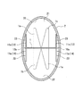
図1は、本発明の第1番目の実施の形態に係る乱流形成具を伝熱管(2)内に挿入した状態を示す斜視図であり、図2は図1のX−X断面図である。
第1番目の実施の形態の乱流形成具は、図1、図2に示すような、縦長断面楕円形状の伝熱管(2)内に装着させるもので、伝熱管(2)を構成する楕円の長径の中心線に沿って、セット可能な横幅を有し且つ伝熱管(2)の長さに略一致する長尺のステンレス製の平板部材(1)から構成されている。
この平板部材(1)の長手方向に沿って、多数の切起こし曲げ加工を施すことにより、切起こし孔からなる多数の貫通孔(1c)と、切起こし片からなる多数の突出片(1a)(1b)を、平板部材(1)の表裏両面に突出させている。
なお、伝熱管(2)の材質は、ステンレス製や銅製などが採用可能である。
一対の突出片(1a)(1b)の突出方向は、隣接する貫通孔(1c)で表裏逆方向とすることにより、平板部材(1)の表面側に突出する一対の突出片(1a)(1b)と、裏面側に突出する一対の突出片(1a)(1b)とが、平板部材(1)の長手方向に沿って交互に形成される態様となる。
上記構成の平板部材(1)を、図2に示すように、断面楕円形状の伝熱管(2)内に、長径の中心線上に位置するように装着させることにより、伝熱管(2)内の流路は、平板部材(1)の表面側の上部域(21)と、裏面側の下部域(22)に区画されることとなり、突出片(1a)(1b)は上部域側(21)及び下部域側(22)へそれぞれ均等に突出している。
具体的には、平板部材(1)の一方の側辺(10a)にて、図1にて、左側の一端と切込み(15a)との間を表側に切起こして表起立片(13)を形成し、切込み(15a)と切込み(15b)との間を、裏側へ切起こして裏起立片(14)を形成し、切込み(15b)と右側の他端との間を表側に切起こして表起立片(13)を形成している。
他方の側辺(10b)においては、前記一端から切込み(15c)との間を表側に切起こして表起立片(13)を形成し、切込み(15c)と切込み(15d)との間を、裏側へ切起こして裏起立片(14)を形成し、切込み(15d)と他端との間を表側に切起こして表起立片(13)を形成している。
第2起立片(12)の先端を伝熱管(2)の管壁内周面(20)に接触させた状態に、平板部材(1)を伝熱管(2)内に収容すると、平板部材(1)は伝熱管(2)内にて、回転やズレが防止された状態で、所定位置に設置され、その状態は保持される。
これら第1、第2起立片(11)(12)からなる表起立片(13)及び裏起立片(14)が、乱流形成具の回転阻止片として機能する。
空間(23)の広さを、流体が流通するに十分な大きさに設定しておくことにより、伝熱管(2)内を流れる流体は、上部域(21)と下部域(22)のほかに、空間(23)内にもスムーズに流れることとなり、流路抵抗が大きくなることがない。また、空間(23)に流れ込んだ塵や埃等の異物は、空間(23)を流れる流体によって押し出されるから、空間(23)内に堆積することがない。よって、空間(23)内に流体が滞留して、空間(23)を構成している表裏起立片(13)(14)や伝熱管(2)が腐食する不都合はない。
また、一つの表起立片(13)又は裏起立片(14)と伝熱管(2)の管壁内周面(20)との間に形成される空間(23)は、伝熱管(2)の流路方向に沿って短く分断されて形成されているから、流体は一つの空間(23)を容易に通過することができ、空間(23)が流路抵抗となったり、空間(23)内に異物が堆積したりする不都合を一層防止することを可能としている。
さらに、平板部材(1)の一方の側辺(10a)に形成された切込み(15a)(15b)と、他方の側辺(10b)に形成された切込み(15c)(15d)とは、平板部材(1)を介して相互に対向する位置になく、流路方向に相互にずれた位置に形成されている。
これにより、平板部材(1)に捩じり方向の力が加わっても、平板部材(1)が変形したり、割れたりする不都合はなく、平板部材(1)の強度を向上させることができる。
このものでは、平板部材(1)に対して直角方向に切起こした起立片(11a)のみで、表起立片(13)及び裏起立片(14)を構成するようにしたもので、起立片(11a)の先端が伝熱管(2)の管壁内周面(20)の所定個所に当接するまで延長させることにより、起立片(11a)と伝熱管(2)の管壁内周面(20)との間に、細長い空間(23)が形成されるようにしたものである。このものでは、平板部材(1)の両側辺(10a)(10b)を表裏に折り曲げるだけで良いから製造が簡単である。
また、上記各実施の形態のものでは、回転阻止手段として、表起立片(13)及び裏起立片(14)を、平板部材(1)の長手方向に沿った両側辺(10a)(10b)に設けたが、どちらか一方の側辺にのみに設ける構成としても良い。
同図に示す熱交換器は、ケース体(5)内に、吸熱用の銅板やステンレス板からなる板状フィン(50)が多数並列されていると共に、この板状フィン(50)を貫通するように、断面楕円形状の複数の直管からなる伝熱管(2)が、楕円の短径が水平に位置するように、ケース体(5)の両側壁間に架設されている。伝熱管(2)の両端は、前記側壁を貫通しており、伝熱管(2)の端縁を二つずつ囲むように、ケース体(5)の側壁に、カバー部(5a)が固定されている。これにより、伝熱管(2)に通水される流体は、カバー部(5a)を介して、蛇行しながら流れて行く。
乱流形成具の平板部材(1)は、伝熱管(2)内に、長手方向に沿って水平に位置するように挿入されている。
この給湯装置では、上部域に下向きの燃焼面(33a)を有するバーナ(33)を具備させた器体(53)と、これに連通し且つ空気と燃料ガスの混合気を器体(53)内のバーナ(33)に送り込むファン(34a)が収容されたファンケース(34)とが、ケーシング(55)内に設けられているもので、器体(53)内におけるバーナ(33)の下方には、バーナ(33)からの燃焼排気で加熱される給湯用の第1、第2熱交換器(51)(52)が設置され、ファンケース(34)の上流側には、空気と燃料ガスとを混合させる混合装置(35)が連設されている。混合装置(35)には、空気が送られてくる給気路(36)と燃料ガスが流れてくるガス供給路(37)が連通している。
なお、第2熱交換器(52)を通過した燃焼排気は、排気ダクト(54)を介してケーシング(55)の外部に排出されるとともに、第2熱交換器(52)で発生したドレンはドレン受け(322)に回収されて中和器(323)で処理された後、外部へ排出される。
また、伝熱管(2)内にて、平板部材(1)は不用意に回転しないように回転阻止片が設けられていると共に、回転阻止片と伝熱管(2)の管壁内周面との間には、流体が流通可能な空間が形成されるようにして、流体が滞留することによる隙間腐食は生じ難くしてあるから、第1熱交換器(51)、さらには、これを備えた給湯装置の耐久性は向上する。
(1a)(1b)・・・・・突出片
(10a)(10b)・・・・両側辺
(13)(14)・・・・・表裏起立片(回転阻止片)
(2) ・・・・・・・伝熱管
(20)・・・・・・・管壁内周面
(23)・・・・・・・空間
Claims (5)
- 断面略楕円形状の伝熱管内に流路方向に挿入される平板部材からなり、前記平板部材の表裏両面に突出させた複数の突出片によって、前記伝熱管内を流れる流体を乱流させる乱流形成具であって、
前記平板部材の、前記流路方向に沿った両側辺のうち、少なくとも一方の側辺に、前記平板部材に対して所定の角度を有するように設けられ且つ先端が前記伝熱管の管壁内周面に接触して前記平板部材の伝熱管内での回転を阻止する回転阻止片が設けられ、
前記回転阻止片と前記管壁内周面との間に、流体が流通可能な空間が形成されており、
前記回転阻止片は、前記平板部材の前記側辺を折り曲げて形成される起立片とし、
前記起立片は、前記側辺の長手方向に沿って、表側に折り曲げてなる表起立片と、裏側に折り曲げてなる裏起立片とが交互に位置するように設けられている乱流形成具。 - 請求項1に記載の乱流形成具において、
前記起立片は、前記平板部材から略直角方向に起立する第1起立片と、前記第1起立片の先端から、管壁内周面に向かう方向に延びる第2起立片とからなり、前記第2起立片の先端が管壁内周面に接触する長さに設定されている乱流形成具。 - 請求項1又は2に記載の乱流形成具において、
前記起立片は、前記平板部材の、前記流路方向に沿った両側辺に設けられ、
各側辺に設けられた前記表起立片と前記裏起立片との境界部は、一方の側辺と他方の側辺とで、前記平板部材の長手方向にて相互にずれた位置に設けられている乱流形成具。 - 請求項1から3のいずれかに記載の乱流形成具が挿入された伝熱管を備えた熱交換器。
- 請求項4に記載の熱交換器を備えた給湯装置。
Priority Applications (4)
| Application Number | Priority Date | Filing Date | Title |
|---|---|---|---|
| JP2016103215A JP6670173B2 (ja) | 2016-05-24 | 2016-05-24 | 乱流形成具及びそれを用いた熱交換器並びに給湯装置 |
| US15/599,625 US10458728B2 (en) | 2016-05-24 | 2017-05-19 | Turbulence member and heat exchanger using same, and water heater |
| CN201710373740.3A CN107421376B (zh) | 2016-05-24 | 2017-05-24 | 乱流形成用器具及使用其的热交换器和热水器 |
| KR1020170064208A KR102354854B1 (ko) | 2016-05-24 | 2017-05-24 | 난류 형성구 및 이것을 이용한 열교환기 및 급탕장치 |
Applications Claiming Priority (1)
| Application Number | Priority Date | Filing Date | Title |
|---|---|---|---|
| JP2016103215A JP6670173B2 (ja) | 2016-05-24 | 2016-05-24 | 乱流形成具及びそれを用いた熱交換器並びに給湯装置 |
Publications (2)
| Publication Number | Publication Date |
|---|---|
| JP2017211115A JP2017211115A (ja) | 2017-11-30 |
| JP6670173B2 true JP6670173B2 (ja) | 2020-03-18 |
Family
ID=60420406
Family Applications (1)
| Application Number | Title | Priority Date | Filing Date |
|---|---|---|---|
| JP2016103215A Active JP6670173B2 (ja) | 2016-05-24 | 2016-05-24 | 乱流形成具及びそれを用いた熱交換器並びに給湯装置 |
Country Status (4)
| Country | Link |
|---|---|
| US (1) | US10458728B2 (ja) |
| JP (1) | JP6670173B2 (ja) |
| KR (1) | KR102354854B1 (ja) |
| CN (1) | CN107421376B (ja) |
Families Citing this family (8)
| Publication number | Priority date | Publication date | Assignee | Title |
|---|---|---|---|---|
| CA2964399A1 (en) * | 2016-04-12 | 2017-10-12 | Ecodrain Inc. | Heat exchange conduit and heat exchanger |
| EP3511665B1 (en) * | 2016-09-09 | 2023-12-13 | Kyungdong Navien Co., Ltd. | Tube assembly for tubular heat exchanger, and tubular heat exchanger comprising same |
| JP7214210B2 (ja) * | 2019-03-06 | 2023-01-30 | 株式会社パロマ | 乱流板、熱交換器及び給湯器、熱交換器の製造方法 |
| CN111765535A (zh) * | 2019-04-02 | 2020-10-13 | 青岛海尔空调器有限总公司 | 流体管道、热交换设备及温度调节设备 |
| USD916257S1 (en) * | 2019-08-22 | 2021-04-13 | Noritz Corporation | Heat exchanger for water heater |
| USD904587S1 (en) * | 2019-08-22 | 2020-12-08 | Noritz Corporation | Heat exchanger for water heater |
| USD904589S1 (en) * | 2019-08-22 | 2020-12-08 | Noritz Corporation | Heat exchanger for water heater |
| USD904588S1 (en) * | 2019-08-22 | 2020-12-08 | Noritz Corporation | Heat exchanger for water heater |
Family Cites Families (31)
| Publication number | Priority date | Publication date | Assignee | Title |
|---|---|---|---|---|
| US662964A (en) * | 1900-03-30 | 1900-12-04 | Joseph Leon Marie Alphonse Reis | Means for facilitating production of steam. |
| US2359288A (en) * | 1942-07-20 | 1944-10-03 | Young Radiator Co | Turbulence strip for heat exchangers |
| US2691991A (en) * | 1950-08-30 | 1954-10-19 | Gen Motors Corp | Heat exchange device |
| US2688986A (en) * | 1950-09-02 | 1954-09-14 | Gen Motors Corp | Heat exchanger |
| US2852042A (en) * | 1951-04-07 | 1958-09-16 | Garrett Corp | Turbulator |
| US2677394A (en) * | 1951-09-12 | 1954-05-04 | Young Radiator Co | Turbulence strip for heat exchanger tubes |
| US3837396A (en) * | 1970-09-11 | 1974-09-24 | Borg Warner | Vertical surface vapor condensers |
| FR2123195B1 (ja) * | 1971-01-28 | 1973-12-07 | Chausson Usines Sa | |
| FR2320520A1 (fr) * | 1975-08-06 | 1977-03-04 | Ferodo Sa | Deflecteur pour tube d'echangeur de chaleur |
| HU173583B (hu) * | 1976-06-30 | 1979-06-28 | Energiagazdalkodasi Intezet | Ustrojstvo dlja uluchshenija teploperedachi v teploobmennykh trubakh |
| FR2397617A1 (fr) * | 1977-07-13 | 1979-02-09 | Ferodo Sa | Turbulateur pour tube d'echangeur de chaleur, notamment de radiateur de vehicule automobile |
| FR2457470A1 (fr) * | 1979-05-25 | 1980-12-19 | Ferodo Sa | Echangeur de chaleur tubulaire et agitateurs helicoidaux destines a de tels echangeurs |
| HU179455B (en) * | 1979-07-16 | 1982-10-28 | Energiagazdalkodasi Intezet | Ribbed device improving the heat transfer composed from sheet strips |
| JPS56173882U (ja) * | 1980-05-22 | 1981-12-22 | ||
| US4642149A (en) * | 1982-04-20 | 1987-02-10 | Jay Harper | Heat exchanger with radial baffles |
| US4577681A (en) * | 1984-10-18 | 1986-03-25 | A. O. Smith Corporation | Heat exchanger having a turbulator construction |
| JPS6213958A (ja) * | 1985-07-12 | 1987-01-22 | Hitachi Ltd | 温水熱交換器 |
| US4727907A (en) * | 1987-03-30 | 1988-03-01 | Dunham-Bush | Turbulator with integral flow deflector tabs |
| US4899812A (en) * | 1988-09-06 | 1990-02-13 | Westinghouse Electric Corp. | Self-securing turbulence promoter to enhance heat transfer |
| US5094224A (en) * | 1991-02-26 | 1992-03-10 | Inter-City Products Corporation (Usa) | Enhanced tubular heat exchanger |
| JPH0741270U (ja) * | 1993-12-17 | 1995-07-21 | オリオン機械株式会社 | 熱交換器 |
| JP3376501B2 (ja) * | 1994-03-31 | 2003-02-10 | 昭和電工株式会社 | インナーフィンを備えた熱交換管の製造方法 |
| JP3678262B2 (ja) * | 1997-10-06 | 2005-08-03 | 株式会社ノーリツ | フィンパイプの乱流形成装置 |
| US5983994A (en) * | 1997-10-30 | 1999-11-16 | Electric Power Research Institute, Inc. | Method and apparatus for on-line cleaning of and improvement of heat transfer in a heat exchanger tube |
| JP2000245628A (ja) * | 1999-03-03 | 2000-09-12 | Tokyo Gas Co Ltd | 熱交換器及びそれを使用した燃焼式厨房器 |
| US6286465B1 (en) * | 2000-04-28 | 2001-09-11 | Aos Holding Company | Water heater flue system |
| US7117686B2 (en) * | 2003-12-11 | 2006-10-10 | Utc Power, Llc | High-efficiency turbulators for high-stage generator of absorption chiller/heater |
| CN201867111U (zh) * | 2010-10-28 | 2011-06-15 | 湖北登峰换热器有限公司 | 内置强化扰流片式换热管 |
| US9242214B2 (en) * | 2011-10-31 | 2016-01-26 | Nordson Corporation | Reconfigurable mixing baffle for static mixer and method for making a static mixer |
| CN202836328U (zh) * | 2011-12-31 | 2013-03-27 | 南通江华热动力机械有限公司 | 一种扰流元件 |
| KR101438350B1 (ko) * | 2013-04-24 | 2014-09-04 | 주식회사 경동나비엔 | 열교환기 튜브에 삽입되는 개선된 난류 촉진 구조물 |
-
2016
- 2016-05-24 JP JP2016103215A patent/JP6670173B2/ja active Active
-
2017
- 2017-05-19 US US15/599,625 patent/US10458728B2/en active Active
- 2017-05-24 KR KR1020170064208A patent/KR102354854B1/ko active IP Right Grant
- 2017-05-24 CN CN201710373740.3A patent/CN107421376B/zh active Active
Also Published As
| Publication number | Publication date |
|---|---|
| CN107421376A (zh) | 2017-12-01 |
| JP2017211115A (ja) | 2017-11-30 |
| CN107421376B (zh) | 2020-07-07 |
| KR20170132691A (ko) | 2017-12-04 |
| US10458728B2 (en) | 2019-10-29 |
| US20170343304A1 (en) | 2017-11-30 |
| KR102354854B1 (ko) | 2022-01-21 |
Similar Documents
| Publication | Publication Date | Title |
|---|---|---|
| JP6670173B2 (ja) | 乱流形成具及びそれを用いた熱交換器並びに給湯装置 | |
| RU2603508C1 (ru) | Теплообменник с оребренными трубами | |
| JP6819263B2 (ja) | 熱交換器、温水装置および熱交換器の製造方法 | |
| JP6314106B2 (ja) | 熱交換器用の伝熱フィン、及びそれを備えた熱交換器 | |
| CN109959169B (zh) | 热交换装置以及热源机 | |
| JP6662696B2 (ja) | 乱流形成具 | |
| CN111380220B (zh) | 换热器及热水装置 | |
| CN107966046B (zh) | 翅片管式热交换器及具有该热交换器的燃烧装置 | |
| JP4079119B2 (ja) | 熱交換器 | |
| CN212362961U (zh) | 换热装置、换热组件及扰流结构 | |
| JP6848418B2 (ja) | 熱交換器および温水装置 | |
| JP7162875B2 (ja) | 熱交換器 | |
| JP4728056B2 (ja) | 温水機器 | |
| JP7161930B2 (ja) | 伝熱フィン | |
| JP6854004B2 (ja) | 熱交換器 | |
| JP6787574B2 (ja) | 熱交換器 | |
| CN103791661B (zh) | 翅片管热交换器 | |
| JP2011144979A (ja) | 熱交換器及びこれを用いる給湯機 | |
| JP2005156033A (ja) | 給湯器の熱交換器用フィン、及びこれを備える給湯器用熱交換器 | |
| CN111043892A (zh) | 传热翅片 | |
| JP6867676B2 (ja) | 熱交換器 | |
| JP2020143841A (ja) | 熱交換器及び給湯器 | |
| JP7298877B2 (ja) | 給湯器 | |
| JP2018044711A (ja) | 熱交換器 | |
| JP2022175131A (ja) | 燃焼熱源機 |
Legal Events
| Date | Code | Title | Description |
|---|---|---|---|
| A621 | Written request for application examination |
Free format text: JAPANESE INTERMEDIATE CODE: A621 Effective date: 20190121 |
|
| A131 | Notification of reasons for refusal |
Free format text: JAPANESE INTERMEDIATE CODE: A131 Effective date: 20191119 |
|
| A977 | Report on retrieval |
Free format text: JAPANESE INTERMEDIATE CODE: A971007 Effective date: 20191120 |
|
| A521 | Request for written amendment filed |
Free format text: JAPANESE INTERMEDIATE CODE: A523 Effective date: 20191219 |
|
| TRDD | Decision of grant or rejection written | ||
| A01 | Written decision to grant a patent or to grant a registration (utility model) |
Free format text: JAPANESE INTERMEDIATE CODE: A01 Effective date: 20200204 |
|
| A61 | First payment of annual fees (during grant procedure) |
Free format text: JAPANESE INTERMEDIATE CODE: A61 Effective date: 20200228 |
|
| R150 | Certificate of patent or registration of utility model |
Ref document number: 6670173 Country of ref document: JP Free format text: JAPANESE INTERMEDIATE CODE: R150 |
|
| R250 | Receipt of annual fees |
Free format text: JAPANESE INTERMEDIATE CODE: R250 |
|
| R250 | Receipt of annual fees |
Free format text: JAPANESE INTERMEDIATE CODE: R250 |
|
| R250 | Receipt of annual fees |
Free format text: JAPANESE INTERMEDIATE CODE: R250 |