JP6112795B2 - ワイヤ接続器 - Google Patents
ワイヤ接続器 Download PDFInfo
- Publication number
- JP6112795B2 JP6112795B2 JP2012157863A JP2012157863A JP6112795B2 JP 6112795 B2 JP6112795 B2 JP 6112795B2 JP 2012157863 A JP2012157863 A JP 2012157863A JP 2012157863 A JP2012157863 A JP 2012157863A JP 6112795 B2 JP6112795 B2 JP 6112795B2
- Authority
- JP
- Japan
- Prior art keywords
- wire
- holding
- main
- extension
- connector
- Prior art date
- Legal status (The legal status is an assumption and is not a legal conclusion. Google has not performed a legal analysis and makes no representation as to the accuracy of the status listed.)
- Active
Links
Images


Classifications
-
- H—ELECTRICITY
- H01—ELECTRIC ELEMENTS
- H01R—ELECTRICALLY-CONDUCTIVE CONNECTIONS; STRUCTURAL ASSOCIATIONS OF A PLURALITY OF MUTUALLY-INSULATED ELECTRICAL CONNECTING ELEMENTS; COUPLING DEVICES; CURRENT COLLECTORS
- H01R4/00—Electrically-conductive connections between two or more conductive members in direct contact, i.e. touching one another; Means for effecting or maintaining such contact; Electrically-conductive connections having two or more spaced connecting locations for conductors and using contact members penetrating insulation
- H01R4/24—Connections using contact members penetrating or cutting insulation or cable strands
- H01R4/2416—Connections using contact members penetrating or cutting insulation or cable strands the contact members having insulation-cutting edges, e.g. of tuning fork type
- H01R4/242—Connections using contact members penetrating or cutting insulation or cable strands the contact members having insulation-cutting edges, e.g. of tuning fork type the contact members being plates having a single slot
- H01R4/2425—Flat plates, e.g. multi-layered flat plates
- H01R4/2429—Flat plates, e.g. multi-layered flat plates mounted in an insulating base
- H01R4/2433—Flat plates, e.g. multi-layered flat plates mounted in an insulating base one part of the base being movable to push the cable into the slot
-
- H—ELECTRICITY
- H02—GENERATION; CONVERSION OR DISTRIBUTION OF ELECTRIC POWER
- H02G—INSTALLATION OF ELECTRIC CABLES OR LINES, OR OF COMBINED OPTICAL AND ELECTRIC CABLES OR LINES
- H02G1/00—Methods or apparatus specially adapted for installing, maintaining, repairing or dismantling electric cables or lines
- H02G1/14—Methods or apparatus specially adapted for installing, maintaining, repairing or dismantling electric cables or lines for joining or terminating cables
-
- H—ELECTRICITY
- H01—ELECTRIC ELEMENTS
- H01R—ELECTRICALLY-CONDUCTIVE CONNECTIONS; STRUCTURAL ASSOCIATIONS OF A PLURALITY OF MUTUALLY-INSULATED ELECTRICAL CONNECTING ELEMENTS; COUPLING DEVICES; CURRENT COLLECTORS
- H01R4/00—Electrically-conductive connections between two or more conductive members in direct contact, i.e. touching one another; Means for effecting or maintaining such contact; Electrically-conductive connections having two or more spaced connecting locations for conductors and using contact members penetrating insulation
- H01R4/24—Connections using contact members penetrating or cutting insulation or cable strands
- H01R4/2416—Connections using contact members penetrating or cutting insulation or cable strands the contact members having insulation-cutting edges, e.g. of tuning fork type
- H01R4/242—Connections using contact members penetrating or cutting insulation or cable strands the contact members having insulation-cutting edges, e.g. of tuning fork type the contact members being plates having a single slot
- H01R4/2425—Flat plates, e.g. multi-layered flat plates
- H01R4/2429—Flat plates, e.g. multi-layered flat plates mounted in an insulating base
-
- H—ELECTRICITY
- H01—ELECTRIC ELEMENTS
- H01R—ELECTRICALLY-CONDUCTIVE CONNECTIONS; STRUCTURAL ASSOCIATIONS OF A PLURALITY OF MUTUALLY-INSULATED ELECTRICAL CONNECTING ELEMENTS; COUPLING DEVICES; CURRENT COLLECTORS
- H01R13/00—Details of coupling devices of the kinds covered by groups H01R12/70 or H01R24/00 - H01R33/00
- H01R13/46—Bases; Cases
- H01R13/516—Means for holding or embracing insulating body, e.g. casing, hoods
- H01R13/518—Means for holding or embracing insulating body, e.g. casing, hoods for holding or embracing several coupling parts, e.g. frames
-
- H—ELECTRICITY
- H01—ELECTRIC ELEMENTS
- H01R—ELECTRICALLY-CONDUCTIVE CONNECTIONS; STRUCTURAL ASSOCIATIONS OF A PLURALITY OF MUTUALLY-INSULATED ELECTRICAL CONNECTING ELEMENTS; COUPLING DEVICES; CURRENT COLLECTORS
- H01R4/00—Electrically-conductive connections between two or more conductive members in direct contact, i.e. touching one another; Means for effecting or maintaining such contact; Electrically-conductive connections having two or more spaced connecting locations for conductors and using contact members penetrating insulation
- H01R4/24—Connections using contact members penetrating or cutting insulation or cable strands
- H01R4/2416—Connections using contact members penetrating or cutting insulation or cable strands the contact members having insulation-cutting edges, e.g. of tuning fork type
- H01R4/2445—Connections using contact members penetrating or cutting insulation or cable strands the contact members having insulation-cutting edges, e.g. of tuning fork type the contact members having additional means acting on the insulation or the wire, e.g. additional insulation penetrating means, strain relief means or wire cutting knives
- H01R4/245—Connections using contact members penetrating or cutting insulation or cable strands the contact members having insulation-cutting edges, e.g. of tuning fork type the contact members having additional means acting on the insulation or the wire, e.g. additional insulation penetrating means, strain relief means or wire cutting knives the additional means having two or more slotted flat portions
-
- H—ELECTRICITY
- H01—ELECTRIC ELEMENTS
- H01R—ELECTRICALLY-CONDUCTIVE CONNECTIONS; STRUCTURAL ASSOCIATIONS OF A PLURALITY OF MUTUALLY-INSULATED ELECTRICAL CONNECTING ELEMENTS; COUPLING DEVICES; CURRENT COLLECTORS
- H01R4/00—Electrically-conductive connections between two or more conductive members in direct contact, i.e. touching one another; Means for effecting or maintaining such contact; Electrically-conductive connections having two or more spaced connecting locations for conductors and using contact members penetrating insulation
- H01R4/70—Insulation of connections
-
- H—ELECTRICITY
- H01—ELECTRIC ELEMENTS
- H01R—ELECTRICALLY-CONDUCTIVE CONNECTIONS; STRUCTURAL ASSOCIATIONS OF A PLURALITY OF MUTUALLY-INSULATED ELECTRICAL CONNECTING ELEMENTS; COUPLING DEVICES; CURRENT COLLECTORS
- H01R11/00—Individual connecting elements providing two or more spaced connecting locations for conductive members which are, or may be, thereby interconnected, e.g. end pieces for wires or cables supported by the wire or cable and having means for facilitating electrical connection to some other wire, terminal, or conductive member, blocks of binding posts
- H01R11/03—Individual connecting elements providing two or more spaced connecting locations for conductive members which are, or may be, thereby interconnected, e.g. end pieces for wires or cables supported by the wire or cable and having means for facilitating electrical connection to some other wire, terminal, or conductive member, blocks of binding posts characterised by the relationship between the connecting locations
- H01R11/09—Individual connecting elements providing two or more spaced connecting locations for conductive members which are, or may be, thereby interconnected, e.g. end pieces for wires or cables supported by the wire or cable and having means for facilitating electrical connection to some other wire, terminal, or conductive member, blocks of binding posts characterised by the relationship between the connecting locations the connecting locations being identical
Landscapes
- Details Of Connecting Devices For Male And Female Coupling (AREA)
- Connections By Means Of Piercing Elements, Nuts, Or Screws (AREA)
- Processing Of Terminals (AREA)
Description
図14は、第2の実施形態に係るワイヤ接続器1Bを示す斜視図である。ワイヤ接続器1Bは、第1の実施形態に係るワイヤ接続器1の保護部23とは異なる構成を有する保護部41,42を備えている。その他の構成は、第1の実施形態のワイヤ接続器1と同様である。保護部41は、主ワイヤ2Aと延長ワイヤ3Aとの間に形成された突起部41aと、延長ワイヤ3Aを厚さ方向Hに沿って挟む突起部41bと、を含む円弧状の形状を有している。すなわち、厚さ方向Hに沿った延長ワイヤ3Aの中心を通る線L1(図6参照)よりも主ワイヤ2A側の周縁部に保護部41が形成されている。また、保護部42は、主ワイヤ2Bと延長ワイヤ3Bとの間に形成された突起部42aと、延長ワイヤ3Bを厚さ方向Hに沿って挟む突起部42bと、を含む円弧状の形状を有している。これら保護部41,42は、図6に示された領域S1〜S5上に形成された突起部41a,41b,42a,42bを含んでいるので、第1実施形態の保護部23と同様の効果を得ることができる。
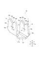
図15は、第3の実施形態に係るワイヤ接続器1Cを示す斜視図である。ワイヤ接続器1Cは、第1の実施形態に係るワイヤ接続器1の保護部23とは、異なる構成を有する保護部43,44を備えている。その他の構成は、第1の実施形態のワイヤ接続器1と同様である。保護部43は、主ワイヤ2Aと延長ワイヤ3Aとの間に形成された突起部である。この保護部43は、所定方向Lに突出すると共に、厚さ方向Hに沿って延在している。保護部43の上端43aは、主ワイヤ2A及び延長ワイヤ3Aよりも上側に形成されている。また、保護部43の下端43bは、主ワイヤ2A及び延長ワイヤ3Aよりも下側に形成されている。保護部44は、主ワイヤ2Bと延長ワイヤ3Bとの間に形成された突起部である。この保護部44は、所定方向Lに突出すると共に、厚さ方向Hに沿って延在している。保護部44の上端44aは、主ワイヤ2B及び延長ワイヤ3Bよりも上側に形成されている。また、保護部44の下端44bは、主ワイヤ2A及び延長ワイヤ3Aよりも下側に形成されている。これら保護部43,44も、図6に示された領域S1〜S5上に形成された突起部を含んでいるので、第1実施形態の保護部23と同様の効果を得ることができる。
本発明は、上述の実施形態に限定されるものではなく、本発明の趣旨を逸脱しない範囲で様々な変形が可能である。
Claims (4)
- 少なくとも第1のワイヤ及び第2のワイヤを保持するワイヤホルダと、
前記第1のワイヤと前記第2のワイヤとを電気的に接続するコンタクトと、
前記コンタクトが固定されると共に、前記ワイヤホルダを保持するボディと、を備えるワイヤ接続器であって、
前記ワイヤホルダは、
所定方向の一端側に形成された第1の端面と、
前記所定方向の他端側に形成された第2の端面と、
前記第1のワイヤ及び前記第2のワイヤが前記所定方向に延在すると共に、当該所定方向と直交する方向に互いに隣り合う状態で、前記第1のワイヤ及び前記第2のワイヤを保持するワイヤ保持部と、
を有し、
前記ワイヤ保持部は、
前記第1のワイヤを保持する第1の保持部と、
前記第1の保持部から前記所定方向と直交する方向に離間した位置に形成され、前記第2のワイヤを保持する第2の保持部と、を有し、
前記第1の保持部には、前記第1の端面及び前記第2の端面に、前記第1のワイヤを引き出し可能な開口部が形成され、
前記第2の保持部には、前記第1の端面に、前記第2のワイヤを引き出し可能な開口部が形成されると共に、前記第2の端面側に、前記第2のワイヤの端部を当接させる当接部が形成され、
前記第1の端面上における、前記第2の保持部の前記開口部の周縁部の少なくとも一部には、前記第1の端面から突出し、前記第2のワイヤを保護する保護部が設けられ、
前記第1の保持部は、前記第1の端面から突出した前記第1のワイヤの突出長さが、前記保護部が前記第1の端面から突出した長さよりも短くなる位置において、前記第1のワイヤを切断可能とする領域を形成する、ことを特徴とするワイヤ接続器。 - 前記保護部は、前記第2のワイヤを取り囲む筒形状をなし、前記第2の保持部と連通し前記第2のワイヤが挿通されるワイヤ貫通孔を有することを特徴とする請求項1に記載のワイヤ接続器。
- 前記ワイヤホルダは、前記ワイヤ保持部とは別のワイヤ保持部を更に有し、
前記ワイヤ保持部の前記第1の保持部と、前記別のワイヤ保持部の前記第1の保持部との間に、前記ワイヤ保持部の前記第2の保持部及び前記別のワイヤ保持部の前記第2の保持部が配置されている、ことを特徴とする請求項1又は2に記載のワイヤ接続器。 - 前記ボディは、前記第1の保持部の前記開口部を覆うカバーを有する、請求項1〜3の何れか一項に記載のワイヤ接続器。
Priority Applications (5)
| Application Number | Priority Date | Filing Date | Title |
|---|---|---|---|
| JP2012157863A JP6112795B2 (ja) | 2012-07-13 | 2012-07-13 | ワイヤ接続器 |
| PCT/US2013/029495 WO2014011219A1 (en) | 2012-07-13 | 2013-03-07 | Wire connector |
| CN201380037375.9A CN104428952A (zh) | 2012-07-13 | 2013-03-07 | 线材连接器 |
| MX2015000529A MX2015000529A (es) | 2012-07-13 | 2013-03-07 | Conector de cables. |
| US14/409,747 US9293840B2 (en) | 2012-07-13 | 2013-03-07 | Wire connector having a wire holder with an abutting portion and a protecting portion |
Applications Claiming Priority (1)
| Application Number | Priority Date | Filing Date | Title |
|---|---|---|---|
| JP2012157863A JP6112795B2 (ja) | 2012-07-13 | 2012-07-13 | ワイヤ接続器 |
Publications (2)
| Publication Number | Publication Date |
|---|---|
| JP2014022111A JP2014022111A (ja) | 2014-02-03 |
| JP6112795B2 true JP6112795B2 (ja) | 2017-04-12 |
Family
ID=49916456
Family Applications (1)
| Application Number | Title | Priority Date | Filing Date |
|---|---|---|---|
| JP2012157863A Active JP6112795B2 (ja) | 2012-07-13 | 2012-07-13 | ワイヤ接続器 |
Country Status (5)
| Country | Link |
|---|---|
| US (1) | US9293840B2 (ja) |
| JP (1) | JP6112795B2 (ja) |
| CN (1) | CN104428952A (ja) |
| MX (1) | MX2015000529A (ja) |
| WO (1) | WO2014011219A1 (ja) |
Cited By (9)
| Publication number | Priority date | Publication date | Assignee | Title |
|---|---|---|---|---|
| US9680416B2 (en) | 2004-06-23 | 2017-06-13 | Peregrine Semiconductor Corporation | Integrated RF front end with stacked transistor switch |
| US9831857B2 (en) | 2015-03-11 | 2017-11-28 | Peregrine Semiconductor Corporation | Power splitter with programmable output phase shift |
| US9948281B2 (en) | 2016-09-02 | 2018-04-17 | Peregrine Semiconductor Corporation | Positive logic digitally tunable capacitor |
| US10236872B1 (en) | 2018-03-28 | 2019-03-19 | Psemi Corporation | AC coupling modules for bias ladders |
| US10505530B2 (en) | 2018-03-28 | 2019-12-10 | Psemi Corporation | Positive logic switch with selectable DC blocking circuit |
| US10886911B2 (en) | 2018-03-28 | 2021-01-05 | Psemi Corporation | Stacked FET switch bias ladders |
| US10951210B2 (en) | 2007-04-26 | 2021-03-16 | Psemi Corporation | Tuning capacitance to enhance FET stack voltage withstand |
| USRE48965E1 (en) | 2005-07-11 | 2022-03-08 | Psemi Corporation | Method and apparatus improving gate oxide reliability by controlling accumulated charge |
| US11476849B2 (en) | 2020-01-06 | 2022-10-18 | Psemi Corporation | High power positive logic switch |
Families Citing this family (4)
| Publication number | Priority date | Publication date | Assignee | Title |
|---|---|---|---|---|
| DE102013012251A1 (de) * | 2013-07-24 | 2015-01-29 | Erni Production Gmbh & Co. Kg | Terminal zur Kontaktierung eines elektrischen Leiters |
| CN106329215A (zh) * | 2016-08-25 | 2017-01-11 | 铜陵华洋特种线材有限责任公司 | 线材保护器 |
| CN108598844B (zh) * | 2018-06-21 | 2023-12-12 | 宁波宏晟智能科技有限公司 | 一种全自动双压穿长套管机的穿管及头端铆端子机构 |
| JP7386231B2 (ja) * | 2019-03-28 | 2023-11-24 | パナソニックエナジー株式会社 | リード線の接続構造 |
Family Cites Families (17)
| Publication number | Priority date | Publication date | Assignee | Title |
|---|---|---|---|---|
| JPH0741638Y2 (ja) * | 1988-03-08 | 1995-09-27 | 太平洋精工株式会社 | 分岐電線用過電流保護器 |
| JP3380581B2 (ja) | 1993-02-18 | 2003-02-24 | ミネソタ マイニング アンド マニュファクチャリング カンパニー | 通信ケーブル用コネクタ |
| JP3636393B2 (ja) * | 1995-10-31 | 2005-04-06 | ミネソタ マイニング アンド マニュファクチャリング カンパニー | 分岐コネクタ装置 |
| JPH09320646A (ja) * | 1996-03-28 | 1997-12-12 | Tokai Rika Co Ltd | 分岐コネクタ |
| FR2750802B1 (fr) * | 1996-07-02 | 1998-09-18 | Pouyet Sa | Procede et dispositif d'interconnexion rapide de deux cables electriques |
| US6017241A (en) * | 1998-01-26 | 2000-01-25 | Tivoli Industries, Inc. | Aisle lighting lampholder |
| AUPQ819900A0 (en) * | 2000-06-16 | 2000-07-13 | Krone (Australia) Technique Pty Limited | Multi wire insulation displacement contact and a method of making multi wire erminations |
| JP2002151169A (ja) | 2000-11-09 | 2002-05-24 | Auto Network Gijutsu Kenkyusho:Kk | 分岐コネクタの接続構造 |
| US6552268B2 (en) * | 2001-06-25 | 2003-04-22 | Lucent Technologies Inc. | Insulation displacement connector with a wire ejection feature |
| US6827600B2 (en) * | 2002-03-20 | 2004-12-07 | Yazaki Corporation | Paired electrical cable connector |
| US20050227529A1 (en) | 2004-04-08 | 2005-10-13 | Gelcore Llc | Multi-conductor parallel splice connection |
| US7416434B2 (en) * | 2006-10-05 | 2008-08-26 | Lumination Llc | IDC splice connector |
| US7267571B1 (en) * | 2006-11-03 | 2007-09-11 | 3M Innovative Properties Company | Double wall connector |
| JP4916982B2 (ja) * | 2007-09-19 | 2012-04-18 | スタンレー電気株式会社 | 多芯フラットケーブル用コネクター |
| JP2010040251A (ja) * | 2008-08-01 | 2010-02-18 | Furukawa Electric Co Ltd:The | 圧接ジョイントコネクタ |
| US7867013B2 (en) * | 2008-08-04 | 2011-01-11 | 3M Innovative Properties Company | In-line splice connector |
| CN202259706U (zh) * | 2011-09-07 | 2012-05-30 | 德胜(苏州)洋楼有限公司 | 木屋布线电缆接线端用保护帽 |
-
2012
- 2012-07-13 JP JP2012157863A patent/JP6112795B2/ja active Active
-
2013
- 2013-03-07 WO PCT/US2013/029495 patent/WO2014011219A1/en active Application Filing
- 2013-03-07 US US14/409,747 patent/US9293840B2/en active Active
- 2013-03-07 CN CN201380037375.9A patent/CN104428952A/zh active Pending
- 2013-03-07 MX MX2015000529A patent/MX2015000529A/es not_active Application Discontinuation
Cited By (13)
| Publication number | Priority date | Publication date | Assignee | Title |
|---|---|---|---|---|
| US9680416B2 (en) | 2004-06-23 | 2017-06-13 | Peregrine Semiconductor Corporation | Integrated RF front end with stacked transistor switch |
| USRE48965E1 (en) | 2005-07-11 | 2022-03-08 | Psemi Corporation | Method and apparatus improving gate oxide reliability by controlling accumulated charge |
| US10951210B2 (en) | 2007-04-26 | 2021-03-16 | Psemi Corporation | Tuning capacitance to enhance FET stack voltage withstand |
| US9831857B2 (en) | 2015-03-11 | 2017-11-28 | Peregrine Semiconductor Corporation | Power splitter with programmable output phase shift |
| US9948281B2 (en) | 2016-09-02 | 2018-04-17 | Peregrine Semiconductor Corporation | Positive logic digitally tunable capacitor |
| US10236872B1 (en) | 2018-03-28 | 2019-03-19 | Psemi Corporation | AC coupling modules for bias ladders |
| US10886911B2 (en) | 2018-03-28 | 2021-01-05 | Psemi Corporation | Stacked FET switch bias ladders |
| US10862473B2 (en) | 2018-03-28 | 2020-12-08 | Psemi Corporation | Positive logic switch with selectable DC blocking circuit |
| US11018662B2 (en) | 2018-03-28 | 2021-05-25 | Psemi Corporation | AC coupling modules for bias ladders |
| US10505530B2 (en) | 2018-03-28 | 2019-12-10 | Psemi Corporation | Positive logic switch with selectable DC blocking circuit |
| US11418183B2 (en) | 2018-03-28 | 2022-08-16 | Psemi Corporation | AC coupling modules for bias ladders |
| US11870431B2 (en) | 2018-03-28 | 2024-01-09 | Psemi Corporation | AC coupling modules for bias ladders |
| US11476849B2 (en) | 2020-01-06 | 2022-10-18 | Psemi Corporation | High power positive logic switch |
Also Published As
| Publication number | Publication date |
|---|---|
| US20150194743A1 (en) | 2015-07-09 |
| JP2014022111A (ja) | 2014-02-03 |
| CN104428952A (zh) | 2015-03-18 |
| US9293840B2 (en) | 2016-03-22 |
| WO2014011219A1 (en) | 2014-01-16 |
| MX2015000529A (es) | 2015-05-11 |
Similar Documents
| Publication | Publication Date | Title |
|---|---|---|
| JP6112795B2 (ja) | ワイヤ接続器 | |
| JP4274381B2 (ja) | 極細同軸ケーブルの端末接続方法 | |
| WO2017090682A1 (ja) | シールドコネクタ、及びコネクタ付きシールドケーブル | |
| KR20120049219A (ko) | 동축 커넥터 및 그 조립방법 | |
| CN101569062A (zh) | 连接器 | |
| JPH0734373B2 (ja) | コネクタ | |
| JP2017126499A (ja) | シールドコネクタ、及びコネクタ付きシールドケーブル | |
| JP2000150030A (ja) | ケーブルコネクタ及びその結線方法 | |
| KR20080034396A (ko) | 와이어 정렬 기능을 가지며 크기를 감소시킬 수 있는 전기커넥터 | |
| KR101643218B1 (ko) | 커넥터용 터미널 및 이를 갖는 커넥터 | |
| KR101521386B1 (ko) | 케이블 접속 방법 | |
| CN100433460C (zh) | 多极同轴电缆连接器及连接器组装方法 | |
| JP7311309B2 (ja) | コネクタ | |
| JP3340325B2 (ja) | 複数段にケーブル列を配する電気コネクタ | |
| JP2020187895A (ja) | 圧接端子、端子付き電線、及び、コネクタ | |
| JP4864340B2 (ja) | 同軸ケーブルの電気コネクタ | |
| JP5765402B2 (ja) | 電気コネクタ | |
| CN109920593B (zh) | 一种线缆及处理线缆的装置和方法 | |
| KR102338051B1 (ko) | 동축 커넥터 및 동축 케이블을 구비한 동축 커넥터 | |
| US11133608B2 (en) | Contact member for an IDC terminal, contact member assembly, set of contact members and housing comprising a contact member | |
| JP7451046B2 (ja) | 電線圧接構造 | |
| CN220021799U (zh) | 线缆保持部件、线缆保持装置以及线缆连接器装置 | |
| JP2024118740A (ja) | マグネットワイヤ接続装置 | |
| JP7534717B2 (ja) | ケーブルコネクタ及びその組立て方法 | |
| JP2019030069A (ja) | ケーブルクランプおよびケーブルクランプ構造 |
Legal Events
| Date | Code | Title | Description |
|---|---|---|---|
| A621 | Written request for application examination |
Free format text: JAPANESE INTERMEDIATE CODE: A621 Effective date: 20150630 |
|
| A131 | Notification of reasons for refusal |
Free format text: JAPANESE INTERMEDIATE CODE: A131 Effective date: 20160308 |
|
| A601 | Written request for extension of time |
Free format text: JAPANESE INTERMEDIATE CODE: A601 Effective date: 20160606 |
|
| A521 | Request for written amendment filed |
Free format text: JAPANESE INTERMEDIATE CODE: A523 Effective date: 20160908 |
|
| TRDD | Decision of grant or rejection written | ||
| A01 | Written decision to grant a patent or to grant a registration (utility model) |
Free format text: JAPANESE INTERMEDIATE CODE: A01 Effective date: 20170214 |
|
| A61 | First payment of annual fees (during grant procedure) |
Free format text: JAPANESE INTERMEDIATE CODE: A61 Effective date: 20170314 |
|
| R150 | Certificate of patent or registration of utility model |
Ref document number: 6112795 Country of ref document: JP Free format text: JAPANESE INTERMEDIATE CODE: R150 |
|
| S111 | Request for change of ownership or part of ownership |
Free format text: JAPANESE INTERMEDIATE CODE: R313113 |
|
| R360 | Written notification for declining of transfer of rights |
Free format text: JAPANESE INTERMEDIATE CODE: R360 |
|
| R360 | Written notification for declining of transfer of rights |
Free format text: JAPANESE INTERMEDIATE CODE: R360 |
|
| R371 | Transfer withdrawn |
Free format text: JAPANESE INTERMEDIATE CODE: R371 |
|
| S111 | Request for change of ownership or part of ownership |
Free format text: JAPANESE INTERMEDIATE CODE: R313113 |
|
| R371 | Transfer withdrawn |
Free format text: JAPANESE INTERMEDIATE CODE: R371 |
|
| S111 | Request for change of ownership or part of ownership |
Free format text: JAPANESE INTERMEDIATE CODE: R313113 |
|
| R350 | Written notification of registration of transfer |
Free format text: JAPANESE INTERMEDIATE CODE: R350 |
|
| R250 | Receipt of annual fees |
Free format text: JAPANESE INTERMEDIATE CODE: R250 |
|
| R250 | Receipt of annual fees |
Free format text: JAPANESE INTERMEDIATE CODE: R250 |
|
| R250 | Receipt of annual fees |
Free format text: JAPANESE INTERMEDIATE CODE: R250 |
|
| R250 | Receipt of annual fees |
Free format text: JAPANESE INTERMEDIATE CODE: R250 |
|
| R250 | Receipt of annual fees |
Free format text: JAPANESE INTERMEDIATE CODE: R250 |