JP6112795B2 - Wire connector - Google Patents
Wire connector Download PDFInfo
- Publication number
- JP6112795B2 JP6112795B2 JP2012157863A JP2012157863A JP6112795B2 JP 6112795 B2 JP6112795 B2 JP 6112795B2 JP 2012157863 A JP2012157863 A JP 2012157863A JP 2012157863 A JP2012157863 A JP 2012157863A JP 6112795 B2 JP6112795 B2 JP 6112795B2
- Authority
- JP
- Japan
- Prior art keywords
- wire
- holding
- main
- extension
- connector
- Prior art date
- Legal status (The legal status is an assumption and is not a legal conclusion. Google has not performed a legal analysis and makes no representation as to the accuracy of the status listed.)
- Active
Links
- 230000001681 protective effect Effects 0.000 claims description 12
- 230000002093 peripheral effect Effects 0.000 claims description 6
- 238000012423 maintenance Methods 0.000 claims description 3
- 238000005520 cutting process Methods 0.000 description 11
- 239000004020 conductor Substances 0.000 description 10
- 238000000034 method Methods 0.000 description 8
- 238000004891 communication Methods 0.000 description 6
- 238000012986 modification Methods 0.000 description 6
- 230000004048 modification Effects 0.000 description 6
- 238000005452 bending Methods 0.000 description 4
- 230000000694 effects Effects 0.000 description 3
- XEEYBQQBJWHFJM-UHFFFAOYSA-N Iron Chemical compound [Fe] XEEYBQQBJWHFJM-UHFFFAOYSA-N 0.000 description 2
- 238000002788 crimping Methods 0.000 description 2
- 238000003780 insertion Methods 0.000 description 2
- 230000037431 insertion Effects 0.000 description 2
- 230000000717 retained effect Effects 0.000 description 2
- RYGMFSIKBFXOCR-UHFFFAOYSA-N Copper Chemical compound [Cu] RYGMFSIKBFXOCR-UHFFFAOYSA-N 0.000 description 1
- XAGFODPZIPBFFR-UHFFFAOYSA-N aluminium Chemical compound [Al] XAGFODPZIPBFFR-UHFFFAOYSA-N 0.000 description 1
- 229910052782 aluminium Inorganic materials 0.000 description 1
- 238000013459 approach Methods 0.000 description 1
- 229910052802 copper Inorganic materials 0.000 description 1
- 239000010949 copper Substances 0.000 description 1
- 230000007423 decrease Effects 0.000 description 1
- 238000010586 diagram Methods 0.000 description 1
- 239000011810 insulating material Substances 0.000 description 1
- 239000012212 insulator Substances 0.000 description 1
- 229910052742 iron Inorganic materials 0.000 description 1
- WABPQHHGFIMREM-UHFFFAOYSA-N lead(0) Chemical compound [Pb] WABPQHHGFIMREM-UHFFFAOYSA-N 0.000 description 1
- 239000000463 material Substances 0.000 description 1
- 230000013011 mating Effects 0.000 description 1
- 238000003825 pressing Methods 0.000 description 1
- 239000011347 resin Substances 0.000 description 1
- 229920005989 resin Polymers 0.000 description 1
Images


Classifications
-
- H—ELECTRICITY
- H01—ELECTRIC ELEMENTS
- H01R—ELECTRICALLY-CONDUCTIVE CONNECTIONS; STRUCTURAL ASSOCIATIONS OF A PLURALITY OF MUTUALLY-INSULATED ELECTRICAL CONNECTING ELEMENTS; COUPLING DEVICES; CURRENT COLLECTORS
- H01R4/00—Electrically-conductive connections between two or more conductive members in direct contact, i.e. touching one another; Means for effecting or maintaining such contact; Electrically-conductive connections having two or more spaced connecting locations for conductors and using contact members penetrating insulation
- H01R4/24—Connections using contact members penetrating or cutting insulation or cable strands
- H01R4/2416—Connections using contact members penetrating or cutting insulation or cable strands the contact members having insulation-cutting edges, e.g. of tuning fork type
- H01R4/242—Connections using contact members penetrating or cutting insulation or cable strands the contact members having insulation-cutting edges, e.g. of tuning fork type the contact members being plates having a single slot
- H01R4/2425—Flat plates, e.g. multi-layered flat plates
- H01R4/2429—Flat plates, e.g. multi-layered flat plates mounted in an insulating base
- H01R4/2433—Flat plates, e.g. multi-layered flat plates mounted in an insulating base one part of the base being movable to push the cable into the slot
-
- H—ELECTRICITY
- H02—GENERATION; CONVERSION OR DISTRIBUTION OF ELECTRIC POWER
- H02G—INSTALLATION OF ELECTRIC CABLES OR LINES, OR OF COMBINED OPTICAL AND ELECTRIC CABLES OR LINES
- H02G1/00—Methods or apparatus specially adapted for installing, maintaining, repairing or dismantling electric cables or lines
- H02G1/14—Methods or apparatus specially adapted for installing, maintaining, repairing or dismantling electric cables or lines for joining or terminating cables
-
- H—ELECTRICITY
- H01—ELECTRIC ELEMENTS
- H01R—ELECTRICALLY-CONDUCTIVE CONNECTIONS; STRUCTURAL ASSOCIATIONS OF A PLURALITY OF MUTUALLY-INSULATED ELECTRICAL CONNECTING ELEMENTS; COUPLING DEVICES; CURRENT COLLECTORS
- H01R4/00—Electrically-conductive connections between two or more conductive members in direct contact, i.e. touching one another; Means for effecting or maintaining such contact; Electrically-conductive connections having two or more spaced connecting locations for conductors and using contact members penetrating insulation
- H01R4/24—Connections using contact members penetrating or cutting insulation or cable strands
- H01R4/2416—Connections using contact members penetrating or cutting insulation or cable strands the contact members having insulation-cutting edges, e.g. of tuning fork type
- H01R4/242—Connections using contact members penetrating or cutting insulation or cable strands the contact members having insulation-cutting edges, e.g. of tuning fork type the contact members being plates having a single slot
- H01R4/2425—Flat plates, e.g. multi-layered flat plates
- H01R4/2429—Flat plates, e.g. multi-layered flat plates mounted in an insulating base
-
- H—ELECTRICITY
- H01—ELECTRIC ELEMENTS
- H01R—ELECTRICALLY-CONDUCTIVE CONNECTIONS; STRUCTURAL ASSOCIATIONS OF A PLURALITY OF MUTUALLY-INSULATED ELECTRICAL CONNECTING ELEMENTS; COUPLING DEVICES; CURRENT COLLECTORS
- H01R13/00—Details of coupling devices of the kinds covered by groups H01R12/70 or H01R24/00 - H01R33/00
- H01R13/46—Bases; Cases
- H01R13/516—Means for holding or embracing insulating body, e.g. casing, hoods
- H01R13/518—Means for holding or embracing insulating body, e.g. casing, hoods for holding or embracing several coupling parts, e.g. frames
-
- H—ELECTRICITY
- H01—ELECTRIC ELEMENTS
- H01R—ELECTRICALLY-CONDUCTIVE CONNECTIONS; STRUCTURAL ASSOCIATIONS OF A PLURALITY OF MUTUALLY-INSULATED ELECTRICAL CONNECTING ELEMENTS; COUPLING DEVICES; CURRENT COLLECTORS
- H01R4/00—Electrically-conductive connections between two or more conductive members in direct contact, i.e. touching one another; Means for effecting or maintaining such contact; Electrically-conductive connections having two or more spaced connecting locations for conductors and using contact members penetrating insulation
- H01R4/24—Connections using contact members penetrating or cutting insulation or cable strands
- H01R4/2416—Connections using contact members penetrating or cutting insulation or cable strands the contact members having insulation-cutting edges, e.g. of tuning fork type
- H01R4/2445—Connections using contact members penetrating or cutting insulation or cable strands the contact members having insulation-cutting edges, e.g. of tuning fork type the contact members having additional means acting on the insulation or the wire, e.g. additional insulation penetrating means, strain relief means or wire cutting knives
- H01R4/245—Connections using contact members penetrating or cutting insulation or cable strands the contact members having insulation-cutting edges, e.g. of tuning fork type the contact members having additional means acting on the insulation or the wire, e.g. additional insulation penetrating means, strain relief means or wire cutting knives the additional means having two or more slotted flat portions
-
- H—ELECTRICITY
- H01—ELECTRIC ELEMENTS
- H01R—ELECTRICALLY-CONDUCTIVE CONNECTIONS; STRUCTURAL ASSOCIATIONS OF A PLURALITY OF MUTUALLY-INSULATED ELECTRICAL CONNECTING ELEMENTS; COUPLING DEVICES; CURRENT COLLECTORS
- H01R4/00—Electrically-conductive connections between two or more conductive members in direct contact, i.e. touching one another; Means for effecting or maintaining such contact; Electrically-conductive connections having two or more spaced connecting locations for conductors and using contact members penetrating insulation
- H01R4/70—Insulation of connections
-
- H—ELECTRICITY
- H01—ELECTRIC ELEMENTS
- H01R—ELECTRICALLY-CONDUCTIVE CONNECTIONS; STRUCTURAL ASSOCIATIONS OF A PLURALITY OF MUTUALLY-INSULATED ELECTRICAL CONNECTING ELEMENTS; COUPLING DEVICES; CURRENT COLLECTORS
- H01R11/00—Individual connecting elements providing two or more spaced connecting locations for conductive members which are, or may be, thereby interconnected, e.g. end pieces for wires or cables supported by the wire or cable and having means for facilitating electrical connection to some other wire, terminal, or conductive member, blocks of binding posts
- H01R11/03—Individual connecting elements providing two or more spaced connecting locations for conductive members which are, or may be, thereby interconnected, e.g. end pieces for wires or cables supported by the wire or cable and having means for facilitating electrical connection to some other wire, terminal, or conductive member, blocks of binding posts characterised by the relationship between the connecting locations
- H01R11/09—Individual connecting elements providing two or more spaced connecting locations for conductive members which are, or may be, thereby interconnected, e.g. end pieces for wires or cables supported by the wire or cable and having means for facilitating electrical connection to some other wire, terminal, or conductive member, blocks of binding posts characterised by the relationship between the connecting locations the connecting locations being identical
Landscapes
- Details Of Connecting Devices For Male And Female Coupling (AREA)
- Processing Of Terminals (AREA)
- Connections By Means Of Piercing Elements, Nuts, Or Screws (AREA)
Description
本発明は、ワイヤ接続器に関する。 The present invention relates to a wire connector.
複数のワイヤ同士を接続する形態には、例えば、信号等を分岐させるために主ワイヤに分岐ワイヤを接続する形態や、ワイヤの長さを延長するためにワイヤから別のワイヤに接続する形態がある。 The form of connecting a plurality of wires includes, for example, a form of connecting a branch wire to the main wire in order to branch a signal or the like, and a form of connecting from one wire to another wire in order to extend the length of the wire. is there.
前者の例として、特許文献1に記載されたコネクタがある。分岐コネクタは、幹線用ツイストペア線及び支線用ツイストペア線を保持するコネクタ本体と、コネクタ本体に配置され幹線用ツイストペア線を支線用ツイストペア線に電気的に接続する一対の圧接端子と、コネクタ本体に固定される蓋体とを備えている。圧接端子の一端には、幹線用ツイストペア線の途中位置が接続される圧接刃が設けられ、圧接端子の他端には、支線用ツイストペア線の端部が接続される圧接刃が設けられている。このような構造によれば、幹線用ツイストペア線及び支線用ツイストペア線の被覆材を剥いで芯線を露出させることなく、幹線用ツイストペア線を支線用ツイストペアに分岐することができる。 As an example of the former, there is a connector described in Patent Document 1. The branch connector is fixed to the connector body, a connector body that holds the twisted pair wire for the main line and the twisted pair line for the branch line, a pair of press contact terminals that are arranged in the connector body and electrically connect the twisted pair wire for the main line to the twisted pair line for the branch line. And a lid. One end of the press contact terminal is provided with a press contact blade to which a midway position of the twisted pair wire for the main line is connected, and the other end of the press contact terminal is provided with a press contact blade to which the end of the twisted pair wire for the branch line is connected. . According to such a structure, the twisted pair wire for the main line can be branched into the twisted pair for the branch line without peeling off the covering material of the twisted pair line for the main line and the twisted pair line for the branch line to expose the core wire.
後者の例として、特許文献2に記載された通信ケーブル用コネクタがある。通信ケーブル用コネクタは、コネクタ本体と、コネクタ本体の内部に配置されて通信ケーブルを保持するカバーとを備えている。コネクタ本体は、通信ケーブルと電気的に接続される圧着素子と、圧着素子と結合されている雄コンタクト及び雌コンタクトと、を有している。このような構成によれば、第1のケーブルコネクタと、第2のケーブルコネクタとを突き合わせてかん合させることにより、第1のケーブルコネクタの雄コンタクトが第2のケーブルコネクタの雌コンタクトに接続される。従って、第1のケーブルコネクタに保持された通信ケーブルを、第2のケーブルコネクタに保持された通信ケーブルに接続して延長することができる。
An example of the latter is a communication cable connector described in
従来のコネクタは、ワイヤの分岐又はワイヤの延長のいずれか一方に対応するものである。このようなコネクタでは、ワイヤ同士の接続形態に応じた複数の種類のコネクタを準備する必要がある。さらに、ワイヤの分岐又はワイヤの延長のいずれにも対応可能なコネクタを用いた作業では、ワイヤ同士を電気的に接続した後にワイヤを切断する作業が発生することがある。 Conventional connectors correspond to either wire branching or wire extension. In such a connector, it is necessary to prepare a plurality of types of connectors according to the connection form between the wires. Furthermore, in an operation using a connector that can handle either the branching of the wire or the extension of the wire, an operation of cutting the wire after electrically connecting the wires may occur.
そこで、本発明は、ワイヤの分岐又はワイヤの延長の何れにも対応可能であり、ワイヤの切断作業においてワイヤが誤って切断されることを抑制できるワイヤ接続器を提供することを目的とする。 Therefore, an object of the present invention is to provide a wire connector that can cope with either the branching of the wire or the extension of the wire and can prevent the wire from being accidentally cut in the wire cutting operation.
本発明は、一の態様において、少なくとも第1のワイヤ及び第2のワイヤを保持するワイヤホルダと、第1のワイヤと第2のワイヤとを電気的に接続するコンタクトと、コンタクトが固定されると共に、ワイヤホルダを保持するボディと、を備えるワイヤ接続器であって、ワイヤホルダは、所定方向の一端側に形成された第1の端面と、所定方向の他端側に形成された第2の端面と、第1のワイヤ及び第2のワイヤが所定方向に延在すると共に、当該所定方向と直交する方向に互いに隣り合う状態で、第1のワイヤ及び第2のワイヤを保持するワイヤ保持部と、を有し、ワイヤ保持部は、第1のワイヤを保持する第1の保持部と、第1の保持部から所定方向と直交する方向に離間した位置に形成され、第2のワイヤを保持する第2の保持部と、を有し、第1の保持部には、第1の端面及び第2の端面に、第1のワイヤを引き出し可能な開口部が形成され、第2の保持部には、第1の端面に、第2のワイヤを引き出し可能な開口部が形成されると共に、第2の端面側に、第2のワイヤの端部を当接させる当接部が形成され、第1の端面上における、第2の保持部の開口部の周縁部の少なくとも一部には、第1の端面から突出し、第2のワイヤを保護する保護部が設けられているワイヤ接続器である。 In one aspect, the present invention provides a wire holder that holds at least the first wire and the second wire, a contact that electrically connects the first wire and the second wire, and the contact is fixed. A wire connector including a body for holding a wire holder, wherein the wire holder includes a first end surface formed on one end side in a predetermined direction, and a second end surface formed on the other end side in the predetermined direction. A wire holding portion for holding the first wire and the second wire in a state in which the first wire and the second wire extend in a predetermined direction and are adjacent to each other in a direction orthogonal to the predetermined direction; The wire holding part is formed at a position separated from the first holding part in a direction perpendicular to the predetermined direction from the first holding part for holding the first wire, and holds the second wire. A second holding part and The first holding portion is formed with an opening through which the first wire can be pulled out on the first end surface and the second end surface, and the second holding portion is formed on the first end surface. An opening through which the second wire can be drawn is formed, and an abutting portion for abutting the end of the second wire is formed on the second end surface side, and the first end surface is The wire connector is provided with a protective portion that protrudes from the first end face and protects the second wire at least at a part of the peripheral edge of the opening of the holding portion of the second holding portion.
このワイヤ接続器において、第1の保持部では第1及び第2の端面に形成された開口部から第1のワイヤが引き出されるので、第1の保持部は主ワイヤである第1のワイヤを保持することができる。第2の保持部では第2の端面側で第2のワイヤの一端が当接すると共に、第1の端面に形成された開口部から第2のワイヤが引き出されるので、第2の保持部は、主ワイヤを分岐するための分岐ワイヤ又は主ワイヤを延長するための延長ワイヤである第2のワイヤを保持することができる。この構成によれば、第1の保持部の開口部から引き出された第1のワイヤを切断しない場合には、第1のワイヤを第1のワイヤと第2のワイヤとに分岐することができる。これに対して、第1のワイヤを切断した場合には、第1のワイヤを第2のワイヤに接続して延長することができる。その上、第1のワイヤに隣り合う状態で配置されている第2のワイヤは、第1の端面上における第2の保持部の開口部の周縁部の少なくとも一部に設けられた保護部により保護されている。従って、第1のワイヤの切断作業において、第2のワイヤを誤って切断することを抑制できる。 In this wire connector, since the first wire is drawn out from the openings formed in the first and second end faces in the first holding portion, the first holding portion is configured to connect the first wire as the main wire. Can be held. In the second holding part, one end of the second wire abuts on the second end face side, and the second wire is pulled out from the opening formed in the first end face. A second wire that is a branch wire for branching the main wire or an extension wire for extending the main wire can be held. According to this configuration, when the first wire drawn from the opening of the first holding unit is not cut, the first wire can be branched into the first wire and the second wire. . On the other hand, when the first wire is cut, the first wire can be connected to the second wire and extended. In addition, the second wire disposed adjacent to the first wire is protected by at least a part of the peripheral edge of the opening of the second holding portion on the first end surface. Protected. Therefore, it is possible to prevent the second wire from being erroneously cut in the cutting operation of the first wire.
他の態様において、保護部は、第2のワイヤを取り囲む筒形状をなし、第2の保持部と連通し第2のワイヤが挿通されるワイヤ貫通孔を有する。これにより、第1の端面に形成された開口部から引き出された第2のワイヤの全周に保護部が形成される。従って、第1のワイヤの切断作業において、第2のワイヤを誤って切断することを更に抑制できる。 In another aspect, the protection part has a cylindrical shape surrounding the second wire, and has a wire through hole that communicates with the second holding part and through which the second wire is inserted. Thereby, a protection part is formed in the perimeter of the 2nd wire pulled out from the opening part formed in the 1st end surface. Therefore, it is possible to further suppress the erroneous cutting of the second wire in the cutting operation of the first wire.
他の態様において、ワイヤホルダは、ワイヤ保持部とは別のワイヤ保持部を更に有し、ワイヤ保持部の第1の保持部と、別のワイヤ保持部の第1の保持部との間に、ワイヤ保持部の第2の保持部及び別のワイヤ保持部の第2の保持部が配置されている。これにより、一のワイヤ接続器により、2対の第1及び第2ワイヤからなるワイヤ対を、分岐又は延長することができる。 In another aspect, the wire holder further includes a wire holding part different from the wire holding part, and between the first holding part of the wire holding part and the first holding part of the other wire holding part, A second holding part of the wire holding part and a second holding part of another wire holding part are arranged. Thereby, the wire pair which consists of two pairs of 1st and 2nd wires can be branched or extended by one wire connector.
他の態様において、ボディは、第1の保持部の開口部を覆うカバーを有する。これにより、切断した第1のワイヤの端面を保護することができる。 In another aspect, the body has a cover that covers the opening of the first holding portion. Thereby, the end surface of the cut | disconnected 1st wire can be protected.
本発明によれば、ワイヤの分岐又はワイヤの延長の何れにも対応可能であり、ワイヤの切断作業においてワイヤが誤って切断されることを抑制できる。 ADVANTAGE OF THE INVENTION According to this invention, it can respond to any of a branch of a wire or an extension of a wire, and can suppress that a wire is cut | disconnected accidentally in the cutting operation of a wire.
以下、添付図面を参照しながら本発明を実施するための形態を詳細に説明する。図面の説明において同一の要素には同一の符号を付し、重複する説明を省略する。なお、以下の実施形態では、主ワイヤを延長するために、主ワイヤに延長ワイヤを接続する場合を一例として説明する。ただし、図11に示されるように、本実施形態のワイヤ接続器は、主ワイヤを主ワイヤと延長ワイヤとに分岐するために用いてもよい。 DESCRIPTION OF EMBODIMENTS Hereinafter, embodiments for carrying out the present invention will be described in detail with reference to the accompanying drawings. In the description of the drawings, the same elements are denoted by the same reference numerals, and redundant description is omitted. In the following embodiments, a case where an extension wire is connected to the main wire in order to extend the main wire will be described as an example. However, as shown in FIG. 11, the wire connector of the present embodiment may be used to branch the main wire into the main wire and the extension wire.
図1は、本実施形態に係るワイヤ接続器1を示す斜視図であり、主ワイヤ(第1のワイヤ)2A,2Bを延長ワイヤ(第2のワイヤ)3A,3Bに接続した形態を示している。図1に示すように、ワイヤ接続器1は、主ワイヤ2Aを延長ワイヤ3Aに電気的に接続すると共に、主ワイヤ2Bを延長ワイヤ3Bに電気的に接続する。なお、本実施形態において「ワイヤ」という語は、絶縁体からなる部材により被覆された電線を意味するものとして用いる。これら主ワイヤ2A,2B及び延長ワイヤ3A,3Bは、例えば0.3mm〜0.9mmの直径を有する。ワイヤ接続器1は、略直方体箱型の形状を有している。このワイヤ接続器1は、短辺方向にワイヤ2A,2B,3A,3Bが延在すると共に、長辺方向にワイヤ2A,2B,3A,3Bが一列に並んだ状態にて、ワイヤ同士を接続している。なお、以下の説明においては、便宜上、ワイヤ接続器1の短辺方向を所定方向Lとし、ワイヤ接続器1の長辺方向を幅方向Wとし、短辺方向と長辺方向とのそれぞれに直交する方向を厚さ方向Hとする。従って、ワイヤ接続器1で接続された状態における主ワイヤ2A,2B及び延長ワイヤ3A,3Bは、所定方向Lへ延在し、主ワイヤ2A,2B及び延長ワイヤ3A,3Bは、幅方向Wに沿って並んだ状態となる。
FIG. 1 is a perspective view showing a wire connector 1 according to the present embodiment, showing a form in which main wires (first wires) 2A and 2B are connected to extension wires (second wires) 3A and 3B. Yes. As shown in FIG. 1, the wire connector 1 electrically connects the
ワイヤ接続器1は、ボディ4と、主ワイヤ2A,2B及び延長ワイヤ3A,3Bを保持するワイヤホルダ6と、を備えている。また、ワイヤ接続器1は、主ワイヤ2Aを延長ワイヤ3Aに電気的に接続するコンタクト7Aと、主ワイヤ2Bを延長ワイヤ3Bに電気的に接続するコンタクト7Bとを備えている(図7参照)。
The wire connector 1 includes a
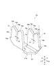
図2は、ボディ4を示す斜視図である。ボディ4は、直方体状の形状を有する箱状の部材である。ボディ4は、絶縁性を有する材料からなり、例えば樹脂製とされている。ボディ4は、所定方向Lの一端側に形成された前壁部8と、所定方向Lの他端側に形成された後壁部9とを有している。前壁部8と後壁部9とは、所定方向Lに互いに離間すると共に対向しており、所定方向Lに対して直交している。さらに、ボディ4は、前壁部8と後壁部9との間に延在する底部11及び側壁12,13を有している。ボディ4の前壁部8、後壁部9、底部11及び側壁12,13に囲まれた空間には、ワイヤホルダ6が配置される。
FIG. 2 is a perspective view showing the
前壁部8には、主ワイヤ2A,2B及び延長ワイヤ3A,3Bの幅方向Wにおいて位置決めを行うガイドとして機能する4つの溝8a〜8dが形成されている。側壁12側の溝8aは主ワイヤ2Aの幅方向Wにおいて位置決めを行うガイドとして機能する。溝8aに隣接する溝8bは延長ワイヤ3Aの幅方向Wにおいて位置決めを行うガイドとして機能する。溝8bに隣接する溝8cは延長ワイヤ3Bの幅方向Wにおいて位置決めを行う。溝8cに隣接する側壁13側の溝8dは主ワイヤ2Bの幅方向Wにおいて位置決めを行う。これら溝8a〜8dは、前壁部8の上端8tに開口し、上端8tから底部11へ向かう方向の途中まで延びた略U形状の溝である。溝8a〜8dの幅は主ワイヤ2A,2B又は延長ワイヤ3A,3Bの外被2j,3jの直径と略同一、または外被2j,3jの直径よりも大きくされている。また、溝8a〜8dの幅は上端8tから底部11へ近づくに従って徐々に小さくなっている。
The
後壁部9には、主ワイヤ2A,2Bの幅方向Wにおいて位置決めを行うガイドとして機能する2つの溝9a,9dが形成されている。溝9aは、前壁部8の溝8aに対向する位置に形成されている。また、溝9dは、前壁部8の溝8dに対向する位置に形成されている。従って、溝9aは主ワイヤ2Aの幅方向Wにおける位置決めを行うと共に、溝9dは主ワイヤ2Bの幅方向Wにおいて位置決めを行う。これら溝9a,9dは、溝8a等と同様の形状を有している。
The
側壁12,13の内側には、ワイヤホルダ6をボディ4に固定するための複数の突起部12a,13aが形成されている。突起部12a,13aは、側壁12,13からボディ4の内側に向かって突出し、前壁部8から後壁部9まで延びている。側壁12の突起部12aには、厚さ方向Hに延びた溝12bが形成されている。溝12bの端部は、底部11まで達している。また、側壁13の突起部13aには、厚さ方向Hに延びた溝13bが形成されている。溝13bの端部は、底部11まで達している。
A plurality of
底部11には、コンタクト7A,7Bを保持するための起立部14が形成されている。起立部14は、底部11から突出している。起立部14は、底部11の幅方向Wにおける中央位置に設けられている。また、起立部14は、側壁12と対向する側面及び側壁13と対向する側面を有するように所定方向Lに延びている。前壁部8と起立部14とは連結されておらず、前壁部8と起立部14との間には隙間が形成されている。後壁部9と起立部14とは連結されておらず、後壁部9と起立部14との間には隙間が形成されている。起立部14は、厚さ方向Hにおいて、前壁部8、後壁部9及び側壁12,13と同じ高さまで立ち上がっている。側壁12と対向する起立部14の側面には、コンタクト7Aを保持する溝14aが形成されている。また、側壁13と対向する起立部14の側面には、コンタクト7Bを保持する溝14bが形成されている。これら溝14a,14bは、起立部14の先端から底部11まで延びている。
The
底部11には、延長ワイヤ3A,3Bの幅方向Wにおいて位置決めを行うガイドとして機能する底部11から突出した起立部16A,16Bが形成されている。起立部16A,16Bは、起立部14と後壁部9との間であって、ボディ4の幅方向Wの中心線を挟んで両側に形成されている。起立部16A,16Bは、厚さ方向Hにおいて、前壁部8、後壁部9及び側壁12,13と同じ高さまで立ち上がっている。起立部16Aには延長ワイヤ3Aの幅方向Wにおいて位置決めを行うためのU字状の溝16bが形成され、起立部16Bには延長ワイヤ3Bの幅方向Wにおいて位置決めを行うためのU字状の溝16cが形成されている。溝16bは、前壁部8の溝8bに対向する位置に形成されている。溝16cは、前壁部8の溝8cに対向する位置に形成されている。従って、溝16bは延長ワイヤ3Aの幅方向Wにおいて位置決めを行うと共に、溝16cは延長ワイヤ3Bの幅方向Wにおいて位置決めを行う。これら溝16a,16dは、溝8a等と同様の形状を有する。
前壁部8と側壁12とのなす角部4aには、主ワイヤ2Aの端部を保護するためのカバー17Aが形成されている。また、前壁部8と側壁13とのなす角部4bには、主ワイヤ2Bの端部を保護するためのカバー17Bが形成されている。カバー17A,17Bは、主ワイヤ2A,2Bの端部を覆うカバー部17sと、カバー部17sとボディ4とを連結する連結部17cとを有している。カバー17A,17Bは連結部17cを折り曲げて前壁部8側へ移動させることができる。
A
図3は、コンタクト7Aを示す斜視図である。コンタクト7Aは、主ワイヤ2Aの外被2jに進入して導線2cに接触すると共に、延長ワイヤ3Aの外被3jに進入して導線3cに接触することにより、主ワイヤ2Aを延長ワイヤ3Aに電気的に接続する。また、コンタクト7Aは、導線2cを挟持することにより主ワイヤ2Aを機械的に保持すると共に、導線3cを挟持することにより延長ワイヤ3Aを機械的に保持する。なお、コンタクト7Bはコンタクト7Aと同様の構成を有するため、詳細な説明は省略する。
FIG. 3 is a perspective view showing the
図3に示すように、コンタクト7Aは、幅方向Wから見てU字状に屈曲された板状の部材であり、主ワイヤ2Aを幅方向Wに挟持する第1の挟持部18と、延長ワイヤ3Aを幅方向Wに挟持する第2の挟持部19と、第1の挟持部18と第2の挟持部19とを所定方向Lに互いに離間して連結する基部21とを有している。コンタクト7Aは、鉄、アルミニウム又は銅等の導電性を有する材料により構成されている。
As shown in FIG. 3, the contact 7 </ b> A is a plate-like member bent in a U shape when viewed in the width direction W, and includes a first holding
第1の挟持部18には、主ワイヤ2Aを幅方向Wに挟持する溝18aが形成されている。溝18aは、第1の挟持部18において幅方向Wの中心に形成され、端部18bから基部21に向かって延在している。この溝18aの幅A1の寸法は、主ワイヤ2Aの導線2cの直径と略同一又は僅かに小さいものとされている。このように溝18aの幅A1の寸法を設定することにより、第1の挟持部18を主ワイヤ2Aの導線2cと確実に接触させることができるため、確実に導通を確保することができる。
In the
第1の挟持部18の端部18bには、側面18cから溝18aに向かって斜め下方に延びる斜面18dが形成されている。これら斜面18dによれば、主ワイヤ2Aを容易に溝18aに挿入することができる。
A
第1の挟持部18には、突起部18eが形成されている。突起部18eは、第1の挟持部18の外側の側面18cにおいて基部21側に形成されている。この突起部18eは、ボディ4における側壁12の溝12bに案内されるものであり、この突起部18eと溝12bとによりコンタクト7Aをボディ4の内部に容易に位置決めして配置することができる。
The
第2の挟持部19には、延長ワイヤ3Aを幅方向Wに挟持する溝19aが形成されている。溝19aは、第2の挟持部19において幅方向Wの中心に形成され、端部19bから基部21に向かって延びている。この溝19aの幅A2の寸法は、延長ワイヤ3Aの導線3cの直径と略同一又は僅かに小さいものとされている。第2の挟持部19の端部19bには、側面19cから溝19aに向かって斜め下方に延びる斜面19dが形成されている。また、第2の挟持部19には、突起部19eが形成されている。突起部19eは、第2の挟持部19の側面19cにおいて基部21側に形成され、突起部18eとは反対方向に突出している。この突起部19eは、ボディ4における起立部14の溝14aに案内されるものであり、この突起部19eと溝14aとによりコンタクト7Aをボディ4の内部に容易に位置決めして配置することができる。
A
基部21は、第1の挟持部18と第2の挟持部19とを所定方向Lに離間して互いに連結している。つまり、第1の挟持部18と第2の挟持部19とは基部21を介して互いに導通されている。コンタクト7Aがボディ4に配置されたとき、この基部21の裏面21aがボディ4の底部11に当接する。
The
コンタクト7Aは、主ワイヤ2Aの導線2c及び延長ワイヤ3Aの導線3cと接触する為に外被2j,3jを切り裂くことが可能な厚さtを有している。例えば、厚さtは0.3mm〜0.7mm程度である。このような厚さtを有するコンタクト7Aは、主ワイヤ2Aの外被2j及び延長ワイヤ3Aの外被3jに容易に進入できるので、導線2c,3cの変形による断線を抑制できる。
The
なお、コンタクト7Aの厚さtは必ずしも一様である必要はない。例えば、第1の挟持部18において溝18aに近づくにつれて厚さtが薄くなるように、即ち、刃状に形成されてもよい。このような形状を有するコンタクト7Aは、溝18a近傍の第1の挟持部18の厚さtが薄いために主ワイヤ2Aの外被2jに容易に進入できる。そして、第1の挟持部18その他の部分の厚さtを厚くできるので剛性を確保することができる。
Note that the thickness t of the
図4は、ワイヤホルダ6を上側から見た斜視図である。図5は、ワイヤホルダ6を下側から見た斜視図である。このワイヤホルダ6は、所定方向Lにワイヤ2A,2B,3A,3Bが延在すると共に、幅方向Wにワイヤ2A,2B,3A,3Bが一列に並んだ状態にて、ワイヤ同士を保持する。より詳細には、各ワイヤは、幅方向Wに主ワイヤ2A、主ワイヤ2Aと接続される延長ワイヤ3A、主ワイヤ2Bと接続される延長ワイヤ3B、主ワイヤ2Bの順に並んでいる。すなわち、ワイヤホルダ6は、互いに隣り合うように配置された延長ワイヤ3A,3Bを主ワイヤ2A,2Bで挟むように各ワイヤを保持する。
FIG. 4 is a perspective view of the
ワイヤホルダ6は、直方体形状の本体部22と、本体部22に設けられた鞘状の保護部23とを有している。本体部22は、所定方向Lの一端側に形成された第1の端面24と、所定方向Lの他端側に形成された第2の端面26と、第1の端面24と第2の端面26との間に延在する側面27,28、上面29及び底部31とを有している。なお、第1の端面24は、平面でなくともよく、凹凸を有する面であってよい。第2の端面26も、平面でなくともよく、凹凸を有する面であってよい。また、本体部22は、主ワイヤ2Aを保持するための第1の保持部32と、延長ワイヤ3Aを保持するための第2の保持部34と、を含むワイヤ保持部25Aを有している。さらに、本体部22は、主ワイヤ2Bを保持するための第1の保持部33と、延長ワイヤ3Bを保持するための第2の保持部36と、を含む別のワイヤ保持部25Bを有している。
The
本体部22の側面27側には、主ワイヤ2Aを保持するための第1の保持部32が形成されている。第1の保持部32には、第1の端面24に形成された開口部32aと、第2の端面26に形成された開口部32bと、側面27に形成された開口部32cとにより画成される凹部32dが形成されている。開口部32a,32bは、主ワイヤ2Aの断面よりも大きく設定されている。そのため、主ワイヤ2Aの一端側を開口部32a又は開口部32bの一方からワイヤホルダ6の外部に取り出すことができ、主ワイヤ2Aの他端側を開口部32a又は開口部32bの他方からワイヤホルダ6の外部に取り出すことができるので、開口部32a,32bにより主ワイヤ2Aが引き出し可能とされている。
A first holding
また、第1の保持部32には、主ワイヤ2Aの脱落を防止するための掛止片32eが設けられている。掛止片32eは、側面27に形成された開口部32cを厚さ方向Hに横切るように形成されている。また、本体部22の側面27と底部31とのなす角部22aには、側面27から幅方向Wに突出した突起部32fが形成されている。この突起部32fは、ボディ4の側壁12に設けられた突起部12aとかみ合ってワイヤホルダ6をボディ4に固定する。
The first holding
また、側面27と対向する本体部22の側面28側には、主ワイヤ2Bを保持するための第1の保持部33が形成されている。この第1の保持部33は、側面27に形成された第1の保持部32と同様の構成を有している。
Further, a first holding
図5に示されるように、第1の保持部32と第1の保持部33との間には、第2の保持部34,36が形成されている。第2の保持部34,36には、第1の端面24に形成された2つの開口部34a,36aと、第2の端面26側に形成された2つの当接部34b,36bとが形成されている。これら開口部34a,36aは、第1の保持部32の開口部32aと同様に形成されているため、延長ワイヤ3A,3Bの一端側を開口部34a,36aからワイヤホルダ6の内部に挿入することができるので、開口部34a,36aにより延長ワイヤ3A,3Bが引き出し可能とされている。
As shown in FIG. 5,
また、第2の保持部34,36には、開口部34a,36aと当接部34b,36bとの間に画成され、本体部22の底部31に開口した2つの凹部34c,36cが形成されている。また、本体部22の底部31には、コンタクト7Aが挿入される溝37と、コンタクト7Bが挿入される溝38とが形成されている。溝37は、コンタクト7Aの厚さtよりも僅かに大きい幅を有し、底部31側から上面29側に向かって延在している。また、溝37,38の一部は、上面29に開口している(図4参照)。
The
次に、保護部23について説明する。図6は、延長ワイヤ3Aを保護する保護部23が形成される位置を説明するための図である。図6は、ワイヤホルダ6の第1の端面24を所定方向Lから見た図であり、第1の保持部32の開口部32aと、第2の保持部34の開口部34aを示している。ニッパー等の誤切断から延長ワイヤ3Aを保護するためには、第2の保持部34の開口部34aの周縁部において、開口部34aの厚さ方向Hの中心線L1と、第1の保持部32の厚さ方向Hに沿った第2の保持部34側の接線L2との間の領域S1に保護部23を構成する突起の一部が形成されていればよい。領域S1の幅は、開口部34aの厚さ方向Hの中心線L1と、第1の保持部32の厚さ方向Hに沿った第2の保持部34側の接線L2とにより規定される。領域S1の高さは、第1の端面24の上端24tと、下端24bにより規定される。
Next, the
また、保護部23は、領域S1において、導線3cの幅方向Wの接線L3と第1の端面24の上端24tとの間の領域S2及び導線3cの幅方向Wの接線L4と第1の端面24の下端24bとの間の領域S3の少なくとも一方に形成されていることが好ましい。これら領域S2,S3に形成された突起によれば、ニッパーの刃が導線3cに到達する前に、ニッパーの刃が突起に接触する。
In addition, in the region S1, the
さらに、保護部23は、領域S2における開口部34aの幅方向Wの接線L5と上端24tとの間の領域S4及び領域S3における開口部34aの幅方向Wの接線L6と下端24bとの間の領域S5の少なくとも何れか一方に形成されていることが更に好ましい。これら領域S4,S5に形成された突起によれば、ニッパーの刃が延長ワイヤ3A,3Bの外被3jに到達する前に、ニッパーの刃が突起に接触する。
Further, the
これら領域S1〜S5に形成された突起を含む保護部23によれば、主ワイヤ2A側からニッパー(不図示)が挿入されたとき、ニッパーの刃が保護部23に接触する。或いは、挿入時には保護部23に接触しなくても、挿入後にニッパーの刃を閉じたときに保護部23に刃が接触する。ニッパーの刃が保護部23に接触すると、主ワイヤ2Aのみを切断する時とは異なる抵抗を作業者が感じるため、延長ワイヤ3Aが切断される位置にニッパーがあることを認識することができる。
According to the
図4及び図5に示されるように、本実施形態のワイヤ接続器1では、本体部22の第1の端面24に保護部23が形成されている。保護部23は、主ワイヤ2A,2Bを切断するときに、主ワイヤ2A,2Bと共に延長ワイヤ3A,3Bを誤って切断することを防止するものである。保護部23は、第1の端面24における、第2の保持部34,36の開口部34a,36aの周縁部の一部である領域S1〜S5上に形成された部分を含む。保護部23は、延長ワイヤ3A,3Bを取り囲む筒形状をなし、第1の端面24から所定方向Lに突出している。保護部23の所定方向Lに沿った長さは、例えば少なくとも2mm以上であればよく、上限は特にないが10mm以下であってもよい。また、保護部23の所定方向Lに沿った長さは、好適には4mm以上5mm以下である。
As shown in FIGS. 4 and 5, in the wire connector 1 of the present embodiment, a
保護部23にはワイヤ貫通孔23aが形成されている。ワイヤ貫通孔23aは、保護部23の幅方向Wの中心よりも第1の保持部32側に形成されている。またワイヤ貫通孔23aは、所定方向Lに貫通し、延長ワイヤ3Aの直径と略同径又は僅かに大きい内径を有している。ワイヤ貫通孔23aは、第2の保持部34の開口部34aに対向する位置に形成されており、開口部34aの中心軸は、ワイヤ貫通孔23aの中心軸と重なり、ワイヤ貫通孔23aが第2の保持部34と連通している。貫通孔23dに挿入された延長ワイヤ3Aは、第2の保持部34に引き入れられる。従って、開口部34aから引き出された延長ワイヤ3Aでは、所定方向Lに沿って開口部34aから例えば4mm〜5mmの範囲における延長ワイヤ3Aの全周が保護部23に覆われている。
A wire through
また、本体部22にはワイヤ貫通孔23aとは別のワイヤ貫通孔23bが形成されている。ワイヤ貫通孔23bは、本体部22の幅方向Wの中心よりも第1の保持部33側に形成されている。このワイヤ貫通孔23bは、本体部22において形成される位置がワイヤ貫通孔23aと異なり、第2の保持部36と連通している他は、ワイヤ貫通孔23aと同様の構成を有しているため、詳細な説明は省略する。
In addition, a wire through
図7は、コンタクト7A,7Bが固定されたボディ4に、主ワイヤ2A,2B及び延長ワイヤ3A,3Bを保持したワイヤホルダ6を配置した状態を示す平面図である。ボディ4にワイヤホルダ6が配置されたとき、主ワイヤ2Aは、外被2jがボディ4の前壁部8の溝8a及び後壁部9の溝9aにより幅方向Wにおいて位置決めがなされ、導線2cがコンタクト7Aの第1の挟持部18に挟持されることにより機械的に保持されている。また、延長ワイヤ3Aは、外被3jが溝8b及び起立部16Aの溝16bにより幅方向Wにおいて位置決めがなされ、導線3cがコンタクト7Aの第2の挟持部19に挟持されることにより機械的に保持されている。第1の挟持部18と第2の挟持部19とは、基部21により連結されている。従って、主ワイヤ2Aの導線2cが延長ワイヤ3Aの導線3cに電気的に接続される。
FIG. 7 is a plan view showing a state in which the
さらに、延長ワイヤ3Bは、外被3jが溝8c及び起立部16Bの溝16cにより幅方向Wにおいて位置決めがなされ、導線3cがコンタクト7Bの第2の挟持部19に挟持されることにより機械的に保持されている。そして、主ワイヤ2Bは、外被2jがボディ4の溝8d及び溝9dにより幅方向Wにおいて位置決めがなされ、導線2cがコンタクト7Bの第1の挟持部18に挟持されることにより機械的に保持されている。第1の挟持部18と第2の挟持部19とは、基部21により連結されている。従って、主ワイヤ2Aの導線2cが延長ワイヤ3Aの導線3cに電気的に接続される。なお、溝8a〜8d、溝9a,9b及び溝16b,16cは、主ワイヤ2A,2B又は延長ワイヤ3A,3Bに曲げ力が作用した時に、主ワイヤ2A等と当接して曲げ変形を抑制する機能を有する。この構成により、コンタクト7A,7Bに作用する曲げ力を抑制して主ワイヤ2A等の破断を抑制することができる。
Further, the
次に、図8〜図13を参照して、上述のワイヤ接続器1を用いて主ワイヤ2A,2Bをそれぞれ延長ワイヤ3A,3Bに接続して延長する方法について説明する。
Next, a method for extending the
まず、図8に示すように、ボディ4の底部11にコンタクト7A,7Bを配置する。この時、コンタクト7Aの第1の挟持部18はボディ4の側壁12の内側に形成された溝12b(図7参照)に配置され、第2の挟持部19はボディ4の起立部14に形成された溝14aに配置される。また、コンタクト7Bの第1の挟持部18はボディ4の側壁13の内側に形成された溝13bに配置され、第2の挟持部19はボディ4の起立部14に形成された溝14bに配置される。
First, as shown in FIG. 8, contacts 7 </ b> A and 7 </ b> B are arranged on the bottom 11 of the
次に、図9に示すように、ワイヤホルダ6の第1の保持部32の開口部32cから主ワイヤ2Aを幅方向Wに押し込むことにより、第1の保持部32に主ワイヤ2Aを配置する。また、ワイヤホルダ6の第1の保持部33の開口部32cから主ワイヤ2Bを幅方向Wに沿って押し込むことにより、第1の保持部33に主ワイヤ2Bを配置する。この時、主ワイヤ2A,2Bは、予め所定の長さにするために切断しなくてもよい。次に、図10に示すように、延長ワイヤ3A,3Bを、保護部23の開口23c,23dからワイヤホルダ6の内部へ挿入する。このとき、延長ワイヤ3A,3Bの端部3dが当接部34b,36bに突き当たるまで延長ワイヤ3A,3Bをワイヤホルダ6の内部に挿入する(図7参照)。
Next, as shown in FIG. 9, the
次に、図11に示すように、ボディ4の底部11側にワイヤホルダ6を押圧して、ワイヤホルダ6をボディ4に押し込む。ワイヤホルダ6がボディ4に押し込まれることにより、コンタクト7A,7Bの第1の挟持部18が主ワイヤ2A,2Bの外被2jに進入して導線2cと電気的に接続され、第2の挟持部19が延長ワイヤ3A,3Bの外被3jに進入して導線3cと電気的に接続される。また、ワイヤホルダ6の突起部32fが、ボディ4の側壁12,13の内側に形成された突起部12a,13aとかみ合って、ワイヤホルダ6がボディ4から脱落することが防止される。
Next, as shown in FIG. 11, the
次に、図12に示すように、主ワイヤ2A,2Bを切断する。このとき、主ワイヤ2A,2Bの突出長さが、保護部23が第1の端面24から突出した長さよりも短くなる位置で切断する。この位置で主ワイヤ2A,2Bを切断することにより、主ワイヤ2A,2Bを切断するニッパー(図示せず)の刃が、延長ワイヤ3A,3Bの位置まで深く挿入するとき、ニッパーの刃が保護部23に当接するので、作業者はニッパーの刃の位置が、延長ワイヤ3A,3Bを切断する位置にあることを認識することができる。また、ニッパーを挿入するときにニッパーの刃が保護部23に当接しない場合であっても、ニッパーの刃を閉じていく過程において、ニッパーの刃が保護部23を挟むので、作業者は主ワイヤ2A,2Bのみを切断する場合よりも大きい抵抗を感じる。従って、作業者はニッパーの刃の位置が、延長ワイヤ3A,3Bを切断する位置にあることを認識することができる。
Next, as shown in FIG. 12, the
なお、主ワイヤ2A,2Bを切断しない場合には、主ワイヤ2A,2Bを、主ワイヤ2A,2Bと延長ワイヤ3A,3Bとに分岐する形態とすることができる。
When the
次に、図13に示すように、ボディ4に形成されたカバー17A,17Bを、主ワイヤ2A,2Bの端部2d(図12参照)に被せる。そして、所定の工具39を用いてワイヤホルダ6をボディ4に押し付ける方向D1に力を加える。以上によって、図1に示す状態となり、ワイヤ接続器1による主ワイヤ2A,2Bの延長作業が完了する。
Next, as shown in FIG. 13, covers 17A and 17B formed on the
次に、本実施形態に係るワイヤ接続器1の作用・効果について説明する。 Next, the operation and effect of the wire connector 1 according to this embodiment will be described.
このワイヤ接続器1によれば、第1の保持部32,33の開口部32aから引き出された主ワイヤ2A,2Bを切断しない場合には、主ワイヤ2A,2Bを、主ワイヤ2A,2Bと延長ワイヤ3A,3Bとに分岐することができる。これに対して、主ワイヤ2A,2Bを切断した場合には、主ワイヤ2A,2Bを延長ワイヤ3A,3Bに接続して延長することができる。従って、本実施形態のワイヤ接続器1は、ワイヤの分岐又はワイヤの延長の何れにも対応することが可能である。そして、このワイヤ接続器1によれば、ワイヤの接続作業前にワイヤの延長のみに対応する接続器及びワイヤの分岐のみに対応する接続器をそれぞれ準備する必要がなく、作業時に接続形態ごとに対応する接続器を選択する必要がない。従って、ワイヤの接続作業を効率的に行うことができる。
According to the wire connector 1, when the
また、延長ワイヤ3A,3Bは、保護部23により保護されている。これによれば、主ワイヤ2A,2Bを切断する場合と主ワイヤ2A,2B及び保護部23を同時に切断する場合とでは、作業者が感じる抵抗力が異なるので、ニッパーの刃が延長ワイヤ3A,3Bを切断する位置にあることを作業者が認識することができる。従って、主ワイヤ2A,2Bの切断作業において延長ワイヤ3A,3Bを誤って切断することを抑制できる。
Further, the
さらに、本実施形態のワイヤ接続器1では、切断しない延長ワイヤ3A,3Bを保護部23で覆うことにより、延長ワイヤ3A,3Bを切断しないように視覚的に作業者の注意を喚起することができる。
Furthermore, in the wire connector 1 of the present embodiment, the
本実施形態のワイヤ接続器1では、延長ワイヤ3A,3Bの全周に保護部23が形成される。従って、主ワイヤ2A,2Bの切断作業において延長ワイヤ3A,3Bを誤って切断することを更に抑制できる。
In the wire connector 1 of this embodiment, the
本実施形態のワイヤ接続器1は、主ワイヤ2Aを延長ワイヤ3Aに接続する構成と、主ワイヤ2Bを延長ワイヤ3Bに接続する構成と、を有しているので、1つのワイヤ接続器1で、主ワイヤ及び延長ワイヤの2つの組を分岐又は延長することができる。
The wire connector 1 of the present embodiment has a configuration in which the
本実施形態のワイヤ接続器1は、延長ワイヤ3A,3Bを保持する第2の保持部34,36が、主ワイヤ2A,2Bを保持する第1の保持部32,33に挟まれている。この構成によれば、主ワイヤ2A,2Bが延長ワイヤ3A,3Bよりも外側に配置される。このような配置によれば、主ワイヤ2Aから延長ワイヤ3Aに向かう方向、又は、主ワイヤ2Bから延長ワイヤ3Bに向かう方向にニッパーを入れることができるので、延長ワイヤ3A,3Bを挟むことなく、主ワイヤ2A,2Bのみを容易に挟むことができる。従って、主ワイヤ2A,2Bのみを容易にそれぞれ切断することができる。
In the wire connector 1 of the present embodiment, the
本実施形態のワイヤ接続器1では、ボディ4が、第1の保持部32,33の開口部32aを覆うカバー17A,17Bを有する。これにより、主ワイヤ2A,2Bの導線2cが露出した切断面を保護することができる。
In the wire connector 1 of the present embodiment, the
[第2の実施形態]
図14は、第2の実施形態に係るワイヤ接続器1Bを示す斜視図である。ワイヤ接続器1Bは、第1の実施形態に係るワイヤ接続器1の保護部23とは異なる構成を有する保護部41,42を備えている。その他の構成は、第1の実施形態のワイヤ接続器1と同様である。保護部41は、主ワイヤ2Aと延長ワイヤ3Aとの間に形成された突起部41aと、延長ワイヤ3Aを厚さ方向Hに沿って挟む突起部41bと、を含む円弧状の形状を有している。すなわち、厚さ方向Hに沿った延長ワイヤ3Aの中心を通る線L1(図6参照)よりも主ワイヤ2A側の周縁部に保護部41が形成されている。また、保護部42は、主ワイヤ2Bと延長ワイヤ3Bとの間に形成された突起部42aと、延長ワイヤ3Bを厚さ方向Hに沿って挟む突起部42bと、を含む円弧状の形状を有している。これら保護部41,42は、図6に示された領域S1〜S5上に形成された突起部41a,41b,42a,42bを含んでいるので、第1実施形態の保護部23と同様の効果を得ることができる。
[Second Embodiment]
FIG. 14 is a perspective view showing a
[第3の実施形態]
図15は、第3の実施形態に係るワイヤ接続器1Cを示す斜視図である。ワイヤ接続器1Cは、第1の実施形態に係るワイヤ接続器1の保護部23とは、異なる構成を有する保護部43,44を備えている。その他の構成は、第1の実施形態のワイヤ接続器1と同様である。保護部43は、主ワイヤ2Aと延長ワイヤ3Aとの間に形成された突起部である。この保護部43は、所定方向Lに突出すると共に、厚さ方向Hに沿って延在している。保護部43の上端43aは、主ワイヤ2A及び延長ワイヤ3Aよりも上側に形成されている。また、保護部43の下端43bは、主ワイヤ2A及び延長ワイヤ3Aよりも下側に形成されている。保護部44は、主ワイヤ2Bと延長ワイヤ3Bとの間に形成された突起部である。この保護部44は、所定方向Lに突出すると共に、厚さ方向Hに沿って延在している。保護部44の上端44aは、主ワイヤ2B及び延長ワイヤ3Bよりも上側に形成されている。また、保護部44の下端44bは、主ワイヤ2A及び延長ワイヤ3Aよりも下側に形成されている。これら保護部43,44も、図6に示された領域S1〜S5上に形成された突起部を含んでいるので、第1実施形態の保護部23と同様の効果を得ることができる。
[Third Embodiment]
FIG. 15 is a perspective view showing a
[変形例]
本発明は、上述の実施形態に限定されるものではなく、本発明の趣旨を逸脱しない範囲で様々な変形が可能である。
[Modification]
The present invention is not limited to the above-described embodiment, and various modifications can be made without departing from the spirit of the present invention.
ワイヤ接続器が有する保護部は、上記第1〜第3の実施形態に示された保護部23,41〜44に限定されるものではない。本発明の保護部は、第2の保持部34,36の開口部34a,36aの周縁部の少なくとも一部である領域S2(図6参照)に形成されていればよい。図16は、保護部の第1〜第3の変形例を示す図である。例えば、図16(a)に示される第1の変形例では、保護部46は、所定方向Lから見て延長ワイヤ3Aの上部のみに形成された、矩形状の突起部である。また、図16(b)に示される第2の変形例では、保護部47は、所定方向Lから見て延長ワイヤ3Aの上側及び下側に延長ワイヤ3Aを厚さ方向Hに沿って挟むように形成された矩形状の突起部である。さらに、図16(c)に示される第3の変形例では、保護部48は、所定方向Lから見て延長ワイヤ3Aを厚さ方向Hに沿って挟むように形成された円柱状の突起部である。
The protection unit included in the wire connector is not limited to the
また、第1〜第3の実施形態の実施形態では、ワイヤ接続器1,1B,1Cのワイヤホルダ6が2つのワイヤ保持部25A,25Bを有していた。しかし、ワイヤ接続器のワイヤホルダが有するワイヤ接続部は、1つであってもよい。
In the embodiments of the first to third embodiments, the
1,1B,1C…ワイヤ接続器、2A,2B…主ワイヤ(第1のワイヤ)、3A,3B…延長ワイヤ(第2のワイヤ)、4…ボディ、6…ワイヤホルダ、7A,7B…コンタクト、17…カバー、23…保護部、23a,23b…ワイヤ貫通孔、24…第1の端面、25…ワイヤ保持部、26…第2の端面、32,33…第1の保持部、34,36…第2の保持部、32a,33a,32b,33b,32c,33c,34a,36a…開口部、34b,36b…当接部、L…所定方向。
DESCRIPTION OF
Claims (4)
前記第1のワイヤと前記第2のワイヤとを電気的に接続するコンタクトと、
前記コンタクトが固定されると共に、前記ワイヤホルダを保持するボディと、を備えるワイヤ接続器であって、
前記ワイヤホルダは、
所定方向の一端側に形成された第1の端面と、
前記所定方向の他端側に形成された第2の端面と、
前記第1のワイヤ及び前記第2のワイヤが前記所定方向に延在すると共に、当該所定方向と直交する方向に互いに隣り合う状態で、前記第1のワイヤ及び前記第2のワイヤを保持するワイヤ保持部と、
を有し、
前記ワイヤ保持部は、
前記第1のワイヤを保持する第1の保持部と、
前記第1の保持部から前記所定方向と直交する方向に離間した位置に形成され、前記第2のワイヤを保持する第2の保持部と、を有し、
前記第1の保持部には、前記第1の端面及び前記第2の端面に、前記第1のワイヤを引き出し可能な開口部が形成され、
前記第2の保持部には、前記第1の端面に、前記第2のワイヤを引き出し可能な開口部が形成されると共に、前記第2の端面側に、前記第2のワイヤの端部を当接させる当接部が形成され、
前記第1の端面上における、前記第2の保持部の前記開口部の周縁部の少なくとも一部には、前記第1の端面から突出し、前記第2のワイヤを保護する保護部が設けられ、
前記第1の保持部は、前記第1の端面から突出した前記第1のワイヤの突出長さが、前記保護部が前記第1の端面から突出した長さよりも短くなる位置において、前記第1のワイヤを切断可能とする領域を形成する、ことを特徴とするワイヤ接続器。 A wire holder for holding at least a first wire and a second wire;
A contact for electrically connecting the first wire and the second wire;
A wire connector comprising: a body that holds the wire holder while the contact is fixed;
The wire holder is
A first end surface formed on one end side in a predetermined direction;
A second end face formed on the other end side in the predetermined direction;
The wire that holds the first wire and the second wire in a state where the first wire and the second wire extend in the predetermined direction and are adjacent to each other in a direction orthogonal to the predetermined direction. A holding part;
Have
The wire holding part is
A first holding part for holding the first wire;
A second holding part that is formed at a position spaced apart from the first holding part in a direction orthogonal to the predetermined direction, and holds the second wire,
The first holding portion is formed with an opening through which the first wire can be pulled out on the first end surface and the second end surface,
In the second holding portion, an opening through which the second wire can be drawn is formed on the first end surface, and an end portion of the second wire is formed on the second end surface side. An abutting part to be abutted is formed,
On the first end face, at least a part of the peripheral edge of the opening of the second holding part is provided with a protection part that protrudes from the first end face and protects the second wire,
The first holding portion is configured such that the protruding length of the first wire protruding from the first end surface is shorter than the length of the protective portion protruding from the first end surface. The wire connector is characterized in that it forms a region where the wire can be cut .
前記ワイヤ保持部の前記第1の保持部と、前記別のワイヤ保持部の前記第1の保持部との間に、前記ワイヤ保持部の前記第2の保持部及び前記別のワイヤ保持部の前記第2の保持部が配置されている、ことを特徴とする請求項1又は2に記載のワイヤ接続器。 The wire holder further has a wire holding part different from the wire holding part,
Between the first holding part of the wire holding part and the first holding part of the another wire holding part, the second holding part and the other wire holding part of the wire holding part The wire connector according to claim 1, wherein the second holding portion is disposed.
Priority Applications (5)
| Application Number | Priority Date | Filing Date | Title |
|---|---|---|---|
| JP2012157863A JP6112795B2 (en) | 2012-07-13 | 2012-07-13 | Wire connector |
| MX2015000529A MX2015000529A (en) | 2012-07-13 | 2013-03-07 | Wire connector. |
| CN201380037375.9A CN104428952A (en) | 2012-07-13 | 2013-03-07 | Wire connector |
| US14/409,747 US9293840B2 (en) | 2012-07-13 | 2013-03-07 | Wire connector having a wire holder with an abutting portion and a protecting portion |
| PCT/US2013/029495 WO2014011219A1 (en) | 2012-07-13 | 2013-03-07 | Wire connector |
Applications Claiming Priority (1)
| Application Number | Priority Date | Filing Date | Title |
|---|---|---|---|
| JP2012157863A JP6112795B2 (en) | 2012-07-13 | 2012-07-13 | Wire connector |
Publications (2)
| Publication Number | Publication Date |
|---|---|
| JP2014022111A JP2014022111A (en) | 2014-02-03 |
| JP6112795B2 true JP6112795B2 (en) | 2017-04-12 |
Family
ID=49916456
Family Applications (1)
| Application Number | Title | Priority Date | Filing Date |
|---|---|---|---|
| JP2012157863A Active JP6112795B2 (en) | 2012-07-13 | 2012-07-13 | Wire connector |
Country Status (5)
| Country | Link |
|---|---|
| US (1) | US9293840B2 (en) |
| JP (1) | JP6112795B2 (en) |
| CN (1) | CN104428952A (en) |
| MX (1) | MX2015000529A (en) |
| WO (1) | WO2014011219A1 (en) |
Cited By (9)
| Publication number | Priority date | Publication date | Assignee | Title |
|---|---|---|---|---|
| US9680416B2 (en) | 2004-06-23 | 2017-06-13 | Peregrine Semiconductor Corporation | Integrated RF front end with stacked transistor switch |
| US9831857B2 (en) | 2015-03-11 | 2017-11-28 | Peregrine Semiconductor Corporation | Power splitter with programmable output phase shift |
| US9948281B2 (en) | 2016-09-02 | 2018-04-17 | Peregrine Semiconductor Corporation | Positive logic digitally tunable capacitor |
| US10236872B1 (en) | 2018-03-28 | 2019-03-19 | Psemi Corporation | AC coupling modules for bias ladders |
| US10505530B2 (en) | 2018-03-28 | 2019-12-10 | Psemi Corporation | Positive logic switch with selectable DC blocking circuit |
| US10886911B2 (en) | 2018-03-28 | 2021-01-05 | Psemi Corporation | Stacked FET switch bias ladders |
| US10951210B2 (en) | 2007-04-26 | 2021-03-16 | Psemi Corporation | Tuning capacitance to enhance FET stack voltage withstand |
| USRE48965E1 (en) | 2005-07-11 | 2022-03-08 | Psemi Corporation | Method and apparatus improving gate oxide reliability by controlling accumulated charge |
| US11476849B2 (en) | 2020-01-06 | 2022-10-18 | Psemi Corporation | High power positive logic switch |
Families Citing this family (4)
| Publication number | Priority date | Publication date | Assignee | Title |
|---|---|---|---|---|
| DE102013012251A1 (en) * | 2013-07-24 | 2015-01-29 | Erni Production Gmbh & Co. Kg | Terminal for contacting an electrical conductor |
| CN106329215A (en) * | 2016-08-25 | 2017-01-11 | 铜陵华洋特种线材有限责任公司 | Wire protector |
| CN108598844B (en) * | 2018-06-21 | 2023-12-12 | 宁波宏晟智能科技有限公司 | Pipe penetrating and head end riveting terminal mechanism of full-automatic double-pressure long penetrating jacketing machine |
| WO2020196268A1 (en) * | 2019-03-28 | 2020-10-01 | 三洋電機株式会社 | Structure for connecting lead wire |
Family Cites Families (17)
| Publication number | Priority date | Publication date | Assignee | Title |
|---|---|---|---|---|
| JPH0741638Y2 (en) * | 1988-03-08 | 1995-09-27 | 太平洋精工株式会社 | Overcurrent protector for branch wires |
| JP3380581B2 (en) | 1993-02-18 | 2003-02-24 | ミネソタ マイニング アンド マニュファクチャリング カンパニー | Communication cable connector |
| JP3636393B2 (en) * | 1995-10-31 | 2005-04-06 | ミネソタ マイニング アンド マニュファクチャリング カンパニー | Branch connector device |
| JPH09320646A (en) * | 1996-03-28 | 1997-12-12 | Tokai Rika Co Ltd | Branch connector |
| FR2750802B1 (en) * | 1996-07-02 | 1998-09-18 | Pouyet Sa | METHOD AND DEVICE FOR QUICK INTERCONNECTION OF TWO ELECTRIC CABLES |
| US6017241A (en) * | 1998-01-26 | 2000-01-25 | Tivoli Industries, Inc. | Aisle lighting lampholder |
| AUPQ819900A0 (en) * | 2000-06-16 | 2000-07-13 | Krone (Australia) Technique Pty Limited | Multi wire insulation displacement contact and a method of making multi wire erminations |
| JP2002151169A (en) | 2000-11-09 | 2002-05-24 | Auto Network Gijutsu Kenkyusho:Kk | Branch connector connection structure |
| US6552268B2 (en) * | 2001-06-25 | 2003-04-22 | Lucent Technologies Inc. | Insulation displacement connector with a wire ejection feature |
| US6827600B2 (en) * | 2002-03-20 | 2004-12-07 | Yazaki Corporation | Paired electrical cable connector |
| US20050227529A1 (en) * | 2004-04-08 | 2005-10-13 | Gelcore Llc | Multi-conductor parallel splice connection |
| US7416434B2 (en) * | 2006-10-05 | 2008-08-26 | Lumination Llc | IDC splice connector |
| US7267571B1 (en) * | 2006-11-03 | 2007-09-11 | 3M Innovative Properties Company | Double wall connector |
| JP4916982B2 (en) | 2007-09-19 | 2012-04-18 | スタンレー電気株式会社 | Connector for multi-core flat cable |
| JP2010040251A (en) * | 2008-08-01 | 2010-02-18 | Furukawa Electric Co Ltd:The | Insulation displacement joint connector |
| US7867013B2 (en) * | 2008-08-04 | 2011-01-11 | 3M Innovative Properties Company | In-line splice connector |
| CN202259706U (en) * | 2011-09-07 | 2012-05-30 | 德胜(苏州)洋楼有限公司 | Protective cap for wiring terminal of log cabin wiring cable |
-
2012
- 2012-07-13 JP JP2012157863A patent/JP6112795B2/en active Active
-
2013
- 2013-03-07 MX MX2015000529A patent/MX2015000529A/en not_active Application Discontinuation
- 2013-03-07 CN CN201380037375.9A patent/CN104428952A/en active Pending
- 2013-03-07 US US14/409,747 patent/US9293840B2/en active Active
- 2013-03-07 WO PCT/US2013/029495 patent/WO2014011219A1/en active Application Filing
Cited By (13)
| Publication number | Priority date | Publication date | Assignee | Title |
|---|---|---|---|---|
| US9680416B2 (en) | 2004-06-23 | 2017-06-13 | Peregrine Semiconductor Corporation | Integrated RF front end with stacked transistor switch |
| USRE48965E1 (en) | 2005-07-11 | 2022-03-08 | Psemi Corporation | Method and apparatus improving gate oxide reliability by controlling accumulated charge |
| US10951210B2 (en) | 2007-04-26 | 2021-03-16 | Psemi Corporation | Tuning capacitance to enhance FET stack voltage withstand |
| US9831857B2 (en) | 2015-03-11 | 2017-11-28 | Peregrine Semiconductor Corporation | Power splitter with programmable output phase shift |
| US9948281B2 (en) | 2016-09-02 | 2018-04-17 | Peregrine Semiconductor Corporation | Positive logic digitally tunable capacitor |
| US10236872B1 (en) | 2018-03-28 | 2019-03-19 | Psemi Corporation | AC coupling modules for bias ladders |
| US10886911B2 (en) | 2018-03-28 | 2021-01-05 | Psemi Corporation | Stacked FET switch bias ladders |
| US10862473B2 (en) | 2018-03-28 | 2020-12-08 | Psemi Corporation | Positive logic switch with selectable DC blocking circuit |
| US11018662B2 (en) | 2018-03-28 | 2021-05-25 | Psemi Corporation | AC coupling modules for bias ladders |
| US10505530B2 (en) | 2018-03-28 | 2019-12-10 | Psemi Corporation | Positive logic switch with selectable DC blocking circuit |
| US11418183B2 (en) | 2018-03-28 | 2022-08-16 | Psemi Corporation | AC coupling modules for bias ladders |
| US11870431B2 (en) | 2018-03-28 | 2024-01-09 | Psemi Corporation | AC coupling modules for bias ladders |
| US11476849B2 (en) | 2020-01-06 | 2022-10-18 | Psemi Corporation | High power positive logic switch |
Also Published As
| Publication number | Publication date |
|---|---|
| WO2014011219A1 (en) | 2014-01-16 |
| MX2015000529A (en) | 2015-05-11 |
| US20150194743A1 (en) | 2015-07-09 |
| CN104428952A (en) | 2015-03-18 |
| JP2014022111A (en) | 2014-02-03 |
| US9293840B2 (en) | 2016-03-22 |
Similar Documents
| Publication | Publication Date | Title |
|---|---|---|
| JP6112795B2 (en) | Wire connector | |
| JP4274381B2 (en) | Terminal connection method for micro coaxial cable | |
| WO2017090682A1 (en) | Shield connector and shielded cable with connector | |
| KR20120049219A (en) | Coaxial connector and method for assembling the same | |
| CN101569062A (en) | Connector | |
| JPH0734373B2 (en) | connector | |
| JP2017126499A (en) | Shielded connector and shielded cable with connector | |
| JP2000150030A (en) | Cable connector and its connection method | |
| KR20080034396A (en) | Electrical connector with wire alignment and reduced size | |
| KR101643218B1 (en) | Terminal for connector and connector having the same | |
| KR101521386B1 (en) | Method of connecting a cable with a cable connector | |
| CN100433460C (en) | Multi-pole coaxial cable connector and connector assembling method | |
| JP7311309B2 (en) | connector | |
| JP3340325B2 (en) | Electrical connector with multiple rows of cables | |
| JP2020187895A (en) | Pressure welding terminal, terminal-equipped wire, and connector | |
| JP4864340B2 (en) | Coaxial cable electrical connector | |
| JP5765402B2 (en) | Electrical connector | |
| CN109920593B (en) | Cable and device and method for processing cable | |
| KR102338051B1 (en) | Coaxial Connectors and Coaxial Connectors with Coaxial Cables | |
| US11133608B2 (en) | Contact member for an IDC terminal, contact member assembly, set of contact members and housing comprising a contact member | |
| JP7451046B2 (en) | Wire pressure welding structure | |
| CN220021799U (en) | Cable holding member, cable holding device, and cable connector device | |
| JP2024118740A (en) | Magnet Wire Splicing Machine | |
| JP7534717B2 (en) | Cable connector and assembly method thereof | |
| JP2019030069A (en) | Cable clamp and cable clamp structure |
Legal Events
| Date | Code | Title | Description |
|---|---|---|---|
| A621 | Written request for application examination |
Free format text: JAPANESE INTERMEDIATE CODE: A621 Effective date: 20150630 |
|
| A131 | Notification of reasons for refusal |
Free format text: JAPANESE INTERMEDIATE CODE: A131 Effective date: 20160308 |
|
| A601 | Written request for extension of time |
Free format text: JAPANESE INTERMEDIATE CODE: A601 Effective date: 20160606 |
|
| A521 | Request for written amendment filed |
Free format text: JAPANESE INTERMEDIATE CODE: A523 Effective date: 20160908 |
|
| TRDD | Decision of grant or rejection written | ||
| A01 | Written decision to grant a patent or to grant a registration (utility model) |
Free format text: JAPANESE INTERMEDIATE CODE: A01 Effective date: 20170214 |
|
| A61 | First payment of annual fees (during grant procedure) |
Free format text: JAPANESE INTERMEDIATE CODE: A61 Effective date: 20170314 |
|
| R150 | Certificate of patent or registration of utility model |
Ref document number: 6112795 Country of ref document: JP Free format text: JAPANESE INTERMEDIATE CODE: R150 |
|
| S111 | Request for change of ownership or part of ownership |
Free format text: JAPANESE INTERMEDIATE CODE: R313113 |
|
| R360 | Written notification for declining of transfer of rights |
Free format text: JAPANESE INTERMEDIATE CODE: R360 |
|
| R360 | Written notification for declining of transfer of rights |
Free format text: JAPANESE INTERMEDIATE CODE: R360 |
|
| R371 | Transfer withdrawn |
Free format text: JAPANESE INTERMEDIATE CODE: R371 |
|
| S111 | Request for change of ownership or part of ownership |
Free format text: JAPANESE INTERMEDIATE CODE: R313113 |
|
| R371 | Transfer withdrawn |
Free format text: JAPANESE INTERMEDIATE CODE: R371 |
|
| S111 | Request for change of ownership or part of ownership |
Free format text: JAPANESE INTERMEDIATE CODE: R313113 |
|
| R350 | Written notification of registration of transfer |
Free format text: JAPANESE INTERMEDIATE CODE: R350 |
|
| R250 | Receipt of annual fees |
Free format text: JAPANESE INTERMEDIATE CODE: R250 |
|
| R250 | Receipt of annual fees |
Free format text: JAPANESE INTERMEDIATE CODE: R250 |
|
| R250 | Receipt of annual fees |
Free format text: JAPANESE INTERMEDIATE CODE: R250 |
|
| R250 | Receipt of annual fees |
Free format text: JAPANESE INTERMEDIATE CODE: R250 |
|
| R250 | Receipt of annual fees |
Free format text: JAPANESE INTERMEDIATE CODE: R250 |