JP5794470B2 - Image forming apparatus - Google Patents
Image forming apparatus Download PDFInfo
- Publication number
- JP5794470B2 JP5794470B2 JP2011178439A JP2011178439A JP5794470B2 JP 5794470 B2 JP5794470 B2 JP 5794470B2 JP 2011178439 A JP2011178439 A JP 2011178439A JP 2011178439 A JP2011178439 A JP 2011178439A JP 5794470 B2 JP5794470 B2 JP 5794470B2
- Authority
- JP
- Japan
- Prior art keywords
- recording medium
- feeding
- conveyance
- paper
- unit
- Prior art date
- Legal status (The legal status is an assumption and is not a legal conclusion. Google has not performed a legal analysis and makes no representation as to the accuracy of the status listed.)
- Expired - Fee Related
Links
Images


Classifications
-
- B—PERFORMING OPERATIONS; TRANSPORTING
- B65—CONVEYING; PACKING; STORING; HANDLING THIN OR FILAMENTARY MATERIAL
- B65H—HANDLING THIN OR FILAMENTARY MATERIAL, e.g. SHEETS, WEBS, CABLES
- B65H5/00—Feeding articles separated from piles; Feeding articles to machines
- B65H5/06—Feeding articles separated from piles; Feeding articles to machines by rollers or balls, e.g. between rollers
- B65H5/062—Feeding articles separated from piles; Feeding articles to machines by rollers or balls, e.g. between rollers between rollers or balls
-
- B—PERFORMING OPERATIONS; TRANSPORTING
- B65—CONVEYING; PACKING; STORING; HANDLING THIN OR FILAMENTARY MATERIAL
- B65H—HANDLING THIN OR FILAMENTARY MATERIAL, e.g. SHEETS, WEBS, CABLES
- B65H7/00—Controlling article feeding, separating, pile-advancing, or associated apparatus, to take account of incorrect feeding, absence of articles, or presence of faulty articles
- B65H7/02—Controlling article feeding, separating, pile-advancing, or associated apparatus, to take account of incorrect feeding, absence of articles, or presence of faulty articles by feelers or detectors
- B65H7/06—Controlling article feeding, separating, pile-advancing, or associated apparatus, to take account of incorrect feeding, absence of articles, or presence of faulty articles by feelers or detectors responsive to presence of faulty articles or incorrect separation or feed
-
- B—PERFORMING OPERATIONS; TRANSPORTING
- B65—CONVEYING; PACKING; STORING; HANDLING THIN OR FILAMENTARY MATERIAL
- B65H—HANDLING THIN OR FILAMENTARY MATERIAL, e.g. SHEETS, WEBS, CABLES
- B65H9/00—Registering, e.g. orientating, articles; Devices therefor
- B65H9/004—Deskewing sheet by abutting against a stop, i.e. producing a buckling of the sheet
- B65H9/006—Deskewing sheet by abutting against a stop, i.e. producing a buckling of the sheet the stop being formed by forwarding means in stand-by
-
- G—PHYSICS
- G03—PHOTOGRAPHY; CINEMATOGRAPHY; ANALOGOUS TECHNIQUES USING WAVES OTHER THAN OPTICAL WAVES; ELECTROGRAPHY; HOLOGRAPHY
- G03G—ELECTROGRAPHY; ELECTROPHOTOGRAPHY; MAGNETOGRAPHY
- G03G15/00—Apparatus for electrographic processes using a charge pattern
- G03G15/65—Apparatus which relate to the handling of copy material
- G03G15/6555—Handling of sheet copy material taking place in a specific part of the copy material feeding path
- G03G15/6558—Feeding path after the copy sheet preparation and up to the transfer point, e.g. registering; Deskewing; Correct timing of sheet feeding to the transfer point
- G03G15/6561—Feeding path after the copy sheet preparation and up to the transfer point, e.g. registering; Deskewing; Correct timing of sheet feeding to the transfer point for sheet registration
- G03G15/6564—Feeding path after the copy sheet preparation and up to the transfer point, e.g. registering; Deskewing; Correct timing of sheet feeding to the transfer point for sheet registration with correct timing of sheet feeding
-
- B—PERFORMING OPERATIONS; TRANSPORTING
- B65—CONVEYING; PACKING; STORING; HANDLING THIN OR FILAMENTARY MATERIAL
- B65H—HANDLING THIN OR FILAMENTARY MATERIAL, e.g. SHEETS, WEBS, CABLES
- B65H2511/00—Dimensions; Position; Numbers; Identification; Occurrences
- B65H2511/10—Size; Dimensions
- B65H2511/11—Length
-
- B—PERFORMING OPERATIONS; TRANSPORTING
- B65—CONVEYING; PACKING; STORING; HANDLING THIN OR FILAMENTARY MATERIAL
- B65H—HANDLING THIN OR FILAMENTARY MATERIAL, e.g. SHEETS, WEBS, CABLES
- B65H2511/00—Dimensions; Position; Numbers; Identification; Occurrences
- B65H2511/20—Location in space
- B65H2511/22—Distance
Landscapes
- Engineering & Computer Science (AREA)
- Mechanical Engineering (AREA)
- Physics & Mathematics (AREA)
- General Physics & Mathematics (AREA)
- Paper Feeding For Electrophotography (AREA)
- Sheets, Magazines, And Separation Thereof (AREA)
Description
本発明は、複写機、プリンタ、ファクシミリ、あるいはこれらの複合機等の画像形成装置に関する。 The present invention relates to an image forming apparatus such as a copying machine, a printer, a facsimile, or a complex machine of these.
複写機、プリンタ、ファクシミリ、あるいはこれらの複合機等の画像形成装置においては、スキャナ部又は外部のパーソナルコンピュータなどから入力された画像情報に基づき、画像形成部が用紙に画像を形成する。このとき、画像形成部には、給紙部から、通常、前記入力された画像情報に対応するサイズの用紙が給送される。 In an image forming apparatus such as a copying machine, a printer, a facsimile, or a complex machine of these, the image forming unit forms an image on a sheet based on image information input from a scanner unit or an external personal computer. At this time, a sheet having a size corresponding to the input image information is usually fed from the sheet feeding unit to the image forming unit.
しかしながら、誤って、給紙部に所望のサイズよりも用紙搬送方向長さの短い小サイズの用紙をセットしてしまった場合は、1枚分の給紙動作でその小サイズの用紙が2枚続けて給送されてしまうことがある。また、小サイズの用紙が2枚連続して給送されると、本来、大きいサイズの用紙に形成されるべき画像が、2枚の用紙に跨って形成されることになるため、2枚目の用紙の先端からトナー像が転写される場合がある。 However, if you accidentally set a small size paper with a paper transport direction shorter than the desired size in the paper feed unit, two small size papers will be fed in a single paper feed operation. You may continue to be fed. In addition, when two small-size sheets are fed continuously, an image that should originally be formed on a large-size sheet is formed across the two sheets. The toner image may be transferred from the leading edge of the paper.
一般に、トナー画像を定着ローラなどにより熱定着させる方式の画像形成装置においては、用紙の先端にはトナー画像を転写せずに余白を設け、その部分では定着ローラへのトナーの付着力が生じないようにすることで、定着ローラに対する用紙の分離性を確保している。しかし、この種の画像形成装置において、小サイズの用紙が2枚連続して給送された結果、上記のように2枚目の用紙の先端からトナー像が転写されると、2枚目の用紙が定着ローラから分離されずに巻き付いてしまう不具合が発生する。 In general, in an image forming apparatus of a type in which a toner image is thermally fixed by a fixing roller or the like, a margin is provided at the leading end of the paper without transferring the toner image, and no toner adheres to the fixing roller at that portion. By doing so, the separation of the paper with respect to the fixing roller is ensured. However, in this type of image forming apparatus, as a result of the continuous feeding of two small-sized sheets, when the toner image is transferred from the leading edge of the second sheet as described above, the second sheet There arises a problem that the paper is wound without being separated from the fixing roller.
このような問題に対して、例えば、特許文献1に記載の画像形成装置では、ユーザーにより設定された用紙搬送方向長さの半分まで用紙を給送した直後に、給紙ローラの駆動を一旦停止し、その後、再び給紙ローラを回転させて用紙を搬送するようにしている。このように給紙ローラの駆動を制御することで、仮に、セットされた用紙の搬送方向長さが、本来セットされるべき用紙の搬送方向長さの半分であったとしても、1枚目の用紙と2枚目の用紙との間に隙間を生じさせることができ、2枚の用紙が隙間をあけずに給送される連続給送を防止することができる。そして、この隙間をセンサで検知することで、小サイズの用紙が2枚続けて給送されたことを把握するようにしている。
To solve such a problem, for example, in the image forming apparatus described in
上記特許文献1に記載の方法によれば、誤セットされた用紙の搬送方向長さが、本来セットされるべき用紙の搬送方向長さに対して、半分、あるいは半分よりも短い場合は、1枚目の用紙と2枚目の用紙との間に隙間が形成することができる。しかしながら、誤セットされた用紙の搬送方向長さが、本来セットされるべき用紙の搬送方向長さの半分よりも長い場合は、1枚目の用紙と2枚目の用紙との間に隙間を形成することができないため、誤セット用紙の連続給送を検知できないといった問題がある。例えば、A3サイズの用紙を縦置きでセットすべきところ、誤ってB4サイズの用紙を縦置きでセットした場合は、B4サイズの縦はA3サイズの縦の半分よりも長いため、誤セットを検知できない。
According to the method described in
ただし、このような場合であっても、セットされた用紙の横幅を検知できるサイドフェンスなどが設けられていれば、A3サイズとB4サイズの横幅の違いから、誤セットを検知することが可能である。しかし、給紙部にサイドフェンスなどの検知手段を設けることは、コストアップや装置の大型化を招くため、特に、低価格化競争の激しいローエンドプリンタなどにおいては有効な手段ではない。 However, even in such a case, if a side fence or the like that can detect the width of the loaded paper is provided, it is possible to detect an erroneous set due to the difference in width between the A3 size and the B4 size. is there. However, the provision of a detection means such as a side fence in the paper feeding unit causes an increase in cost and an increase in the size of the apparatus, and thus is not an effective means particularly in a low-end printer that is highly competitive in price reduction.
また、特許文献1に記載の方法において、1枚目と2枚目の紙間を検知するために、小型プリンタなどで通常使用される接触式のフィラー(揺動レバー)を用いた場合、フィラーで紙間を検知するには、紙間の大きさは15〜20mm必要となる。しかし、紙間を15〜20mm確保すると、給送された用紙の斜行矯正のために用紙の先端側を撓ませるその撓み量を、通常の2〜4mmよりも大きくしなければならなくなる。その結果、用紙の撓んだ部分が周辺の搬送ガイドと干渉し、異音が生じたり、用紙にシワなどのダメージが発生したりするといった問題が生じる。また、厚紙などのコシの強い用紙を用いた場合は、用紙の撓み量を大きくするように給送動作制御しても、実際は、用紙のコシによって給紙ローラがスリップして撓み量は大きくならないといった問題もある。
Further, in the method described in
そこで、本発明は、斯かる事情に鑑み、実際に給送された用紙の搬送方向長さが、本来給送されるべき用紙の搬送方向長さの半分よりも長い場合であっても、その用紙が2枚連続して給送されるのを防止でき、かつ、低コスト化及び小型化を図り得る画像形成装置を提供しようとするものである。 Therefore, in view of such circumstances, the present invention is such that even when the conveyance direction length of the actually fed paper is longer than half of the conveyance direction length of the paper to be originally fed, An object of the present invention is to provide an image forming apparatus that can prevent two sheets of paper from being fed continuously and can be reduced in cost and size.
上記課題を解決するため、請求項1に係る画像形成装置は、シート状の記録媒体に画像を形成する画像形成部と、前記画像形成部に記録媒体を搬送する搬送手段と、前記搬送手段に対して記録媒体を給送する給送手段と、前記搬送手段及び前記給送手段の駆動を制御する制御手段と、前記給送手段と前記搬送手段との間の記録媒体搬送路で記録媒体を検知する検知手段と、前記画像形成部によって記録媒体に形成された画像を当該記録媒体上に定着する定着装置と、を備え、前記制御手段は、前記給送手段が記録媒体を給送すべく駆動を開始し、給送手段が設定可能な最小の記録媒体サイズの搬送方向長さ分を給送し終える前に、給送手段の駆動を停止させると共に、前記給送手段の給送開始時、あるいはその後の所定のタイミングから、入力された画像情報に対応する記録媒体サイズの搬送方向長さに基づいて予め設定された時間を過ぎる前に、前記検知手段によって記録媒体の後端が検知されなかった場合に、搬送異常と判定して、記録媒体の搬送を停止させるように制御し、前記給送手段の再駆動開始時点から前記搬送異常と判定されて搬送が停止されるまでにおける記録媒体搬送距離が、給送開始前の記録媒体先端位置から前記定着装置の画像定着位置までの記録媒体搬送距離よりも短くなるように、前記給送手段の再駆動開始のタイミングを設定した。 In order to solve the above problem, an image forming apparatus according to a first aspect includes an image forming unit that forms an image on a sheet-like recording medium, a conveying unit that conveys the recording medium to the image forming unit, and a conveying unit. The recording medium is fed by a feeding means for feeding the recording medium, a control means for controlling the conveying means and the driving of the feeding means, and a recording medium conveyance path between the feeding means and the conveying means. Detecting means for detecting, and a fixing device for fixing an image formed on the recording medium by the image forming unit on the recording medium , wherein the control means is for the feeding means to feed the recording medium. starts driving, before the feeding means finishes feeding the conveying direction length of the minimum recording medium possible size, to stop the driving of the feeding means, the feeding start of the feeding means Or after a predetermined timing If the trailing end of the recording medium is not detected by the detection means before the preset time based on the length in the conveyance direction of the recording medium size corresponding to the recorded image information, it is determined that the conveyance is abnormal. The conveyance of the recording medium is controlled so that the conveyance of the recording medium is stopped, and the recording medium conveyance distance from the start of re-driving of the feeding unit until the conveyance abnormality is determined and the conveyance is stopped is the recording before the feeding is started. The redrive start timing of the feeding unit was set so as to be shorter than the recording medium conveyance distance from the medium front end position to the image fixing position of the fixing device .
本発明によれば、給送手段が記録媒体を給送すべく駆動を開始し、給送手段が設定可能な最小の記録媒体サイズの搬送方向長さ分を給送し終える前に、給送手段の駆動を停止させることで、実際に給送された記録媒体が、入力された画像情報に対応する記録媒体サイズとは異なるサイズであったとしても、その記録媒体が2枚連続して給送されるのを防止することができる。 According to the present invention, the feeding unit starts driving to feed the recording medium, and before the feeding unit finishes feeding the minimum length of the recording medium size that can be set, the feeding unit feeds the recording medium. By stopping the driving of the means, even if the actually fed recording medium has a size different from the recording medium size corresponding to the input image information, the two recording media are continuously fed. It can be prevented from being sent.
しかも、本発明の場合、上記連続給送を防止できる記録媒体のサイズについて特に制限はないので、実際に給送された記録媒体の搬送方向長さが、入力された画像情報に対応する記録媒体サイズの搬送方向長さの半分よりも長い場合であっても、記録媒体の連続給送を防止することが可能である。 In addition, in the case of the present invention, there is no particular limitation on the size of the recording medium that can prevent the above-described continuous feeding. Therefore, the length of the actually fed recording medium in the transport direction corresponds to the input image information. Even when the size is longer than half of the length in the conveyance direction, it is possible to prevent continuous feeding of the recording medium.
これにより、本発明に係る画像形成装置では、サイドフェンスなどの記録媒体の幅を検知する検知手段が不要となるので、装置の小型化及び低コスト化を図れるようになる。また、給送手段の再駆動開始時点から搬送異常と判定されて搬送が停止されるまでにおける記録媒体搬送距離が、給送開始前の記録媒体先端位置から定着装置の画像定着位置までの記録媒体搬送距離よりも短くなるように、給送手段の再駆動開始のタイミングを設定することで、2枚目の記録媒体の先端が画像定着位置に到達する前に、搬送異常と判定されて搬送が停止されるので、2枚目の記録媒体が定着部材に巻き付くのを防止できるようになる。 As a result, the image forming apparatus according to the present invention does not require a detecting means for detecting the width of the recording medium such as a side fence, so that the apparatus can be reduced in size and cost. Further, the recording medium conveyance distance from the start of re-driving of the feeding unit until the conveyance is judged to be abnormal and the conveyance is stopped is the recording medium from the recording medium leading edge position before the feeding start to the image fixing position of the fixing device. By setting the re-drive start timing of the feeding means so as to be shorter than the transport distance, it is determined that the transport is abnormal and the transport is performed before the leading edge of the second recording medium reaches the image fixing position. Since the operation is stopped, the second recording medium can be prevented from being wound around the fixing member.
以下、添付の図面に基づき、本発明について説明する。なお、本発明を説明するための各図面において、同一の機能もしくは形状を有する部材や構成部品等の構成要素については、判別が可能な限り同一符号を付すことにより一度説明した後ではその説明を省略する。 Hereinafter, the present invention will be described with reference to the accompanying drawings. In the drawings for explaining the present invention, components such as members and components having the same function or shape are denoted by the same reference numerals as much as possible, and once described, the description will be given. Omitted.
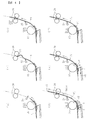
まず、図1を参照して、本発明の実施の一形態に係るカラーレーザープリンタの全体構成及び動作について説明する。
図1に示すプリンタは、シート状の記録媒体としての用紙に画像を形成する画像形成部200と、画像形成部200に用紙を供給する給紙部(記録媒体供給部)300と、画像形成部200によって用紙に形成された画像を当該用紙上に定着する定着部400と、定着部400によって画像が定着された用紙を装置外に排出する排紙部(記録媒体排出部)500等を備えている。
First, an overall configuration and operation of a color laser printer according to an embodiment of the present invention will be described with reference to FIG.
The printer shown in FIG. 1 includes an
画像形成部200には、画像形成ユニットとしての4つのプロセスユニット1Y,1M,1C,1Bkと、露光装置6と、転写装置7等が設けられている。4つのプロセスユニット1Y,1M,1C,1Bkは、それぞれ、プリンタの装置本体100に対して着脱可能に装着されている。各プロセスユニット1Y,1M,1C,1Bkは、カラー画像の色分解成分に対応するイエロー(Y)、マゼンタ(M)、シアン(C)、ブラック(Bk)の異なる色のトナーを収容している以外は同様の構成となっている。
The
具体的に、各プロセスユニット1Y,1M,1C,1Bkは、表面に静電潜像を担持する潜像担持体としてのドラム状の感光体2と、感光体2の表面を帯電させる帯電ローラ3等を備えた帯電装置と、感光体2上の静電潜像に現像剤としてのトナーを供給する現像装置4と、感光体2の表面をクリーニングするためのクリーニングブレード5等を備えたクリーニング装置を有する。なお、図1では、イエローのプロセスユニット1Yが備える感光体2、帯電ローラ3、現像装置4、クリーニングブレード5のみに符号を付しており、その他のプロセスユニット1M,1C,1Bkにおいては符号を省略している。
Specifically, each of the
図1において、各プロセスユニット1Y,1M,1C,1Bkの上方には露光装置6が配設されている。露光装置6は、光源、ポリゴンミラー、f−θレンズ、反射ミラー等を有し、画像データに基づいて各プロセスユニット1Y,1M,1C,1Bkが有する各感光体2の表面へレーザー光を照射するように構成されている。
In FIG. 1, an
また、各プロセスユニット1Y,1M,1C,1Bkの下方には、転写装置7が配設されている。転写装置7は、複数のローラによって張架された転写体としての中間転写ベルト8と、一次転写手段としての4つの一次転写ローラ11と、二次転写手段としての二次転写ローラ12等を有する。中間転写ベルト8は、無端状のベルトによって構成されている。ここでは、支持部材としての駆動ローラ9と従動ローラ10によって中間転写ベルト8が張架されている。この駆動ローラ9が図の反時計回りに回転することによって、中間転写ベルト8は図の矢印に示す方向に周回走行(回転)するようになっている。
A transfer device 7 is disposed below each
4つの一次転写ローラ11は、それぞれ、中間転写ベルト8を介して感光体2に対向した位置に配設されている。各一次転写ローラ11はそれぞれの位置で中間転写ベルト8の内周面を押圧しており、中間転写ベルト8の押圧された部分と各感光体2とが接触する箇所に一次転写ニップが形成されている。また、各一次転写ローラ11は、図示しない電源に接続されており、所定の直流電圧(DC)及び/又は交流電圧(AC)が一次転写ローラ11に印加されるようになっている。
The four
二次転写ローラ12は、中間転写ベルト8を介して駆動ローラ9に対向した位置に配設されている。この二次転写ローラ12は中間転写ベルト8の外周面を押圧しており、二次転写ローラ12と中間転写ベルト8とが接触する箇所に二次転写ニップが形成されている。また、二次転写ローラ12は、一次転写ローラ11と同様に、図示しない電源に接続されており、所定の直流電圧(DC)及び/又は交流電圧(AC)が二次転写ローラ12に印加されるようになっている。
The
また、中間転写ベルト8の図の右端側の外周面には、中間転写ベルト8の表面をクリーニングするベルトクリーニング装置13が配設されている。このベルトクリーニング装置13から伸びた図示しない廃トナー移送ホースは、転写装置7の下方に配設された廃トナー収容器14の入り口部に接続されている。
A
装置本体100の下部に配設された給紙部300には、用紙Pが収容される収容部としての給紙カセット15と、給紙カセット15から用紙を給送する給送手段としての給紙ローラ16と、給紙ローラ16によって給送される用紙を1枚ずつ分離する分離手段としてのフリクションパッド17等が設けられている。給紙カセット15には、用紙Pを載置する底板24が設けられており、底板24は、図示しない付勢手段により給紙ローラ16へ付勢されている。これにより、底板24上に積載されている用紙のうち、最上位の用紙は給紙ローラ16に接触した状態で保持される。
A
一方、装置本体100の上部に配設された排紙部500には、用紙を装置外へ排出するための排紙ローラ対18と、装置外に排出された用紙をストックするための排紙トレイ19とが設けられている。
On the other hand, a
また、装置本体100内には、用紙を給紙部300から上記二次転写ニップを通って排紙部500へ搬送するための搬送路(記録媒体搬送路)Rが配設されている。この搬送路Rにおいて、二次転写ローラ12の位置よりも用紙搬送方向上流側には、用紙を二次転写ニップへ搬送する搬送手段としてのレジストローラ対20が配設されている。さらに、レジストローラ対20と給紙ローラ16の間の搬送路Rには、用紙を検知する検知手段としてのレジストセンサ25が配設されている。レジストセンサ25としては、揺動可能に設けられたフィラー等から成る接触式のものでもよいし、透過型又は反射型の光学式センサを用いた非接触式のものであってもよい。
In the apparatus
また、搬送路Rにおいて、二次転写ローラ12の位置よりも用紙搬送方向下流側には、定着部400に設けてある定着装置21が配設されている。定着装置21は、用紙にトナー画像を定着する定着部材としての定着ローラ22と、定着ローラ22を加圧して定着ニップを形成する加圧部材としての加圧ローラ23とを有している。また、定着ローラ22内には、定着ローラ22を加熱する加熱手段としての図示しないヒータが設けられている。
In the conveyance path R, the fixing
図1に示す上記プリンタは以下のように動作する。
作像動作が開始されると、画像形成部200において、各プロセスユニット1Y,1M,1C,1Bkの感光体2が図1の時計回りに回転駆動され、帯電ローラ3によって各感光体2の表面が所定の極性に一様に帯電される。図示しない画像読取装置によって読み取られた原稿の画像情報に基づいて、露光装置6から各感光体2の帯電面にレーザー光が照射されて、各感光体2の表面に静電潜像が形成される。このとき、各感光体2に露光する画像情報は所望のフルカラー画像をイエロー、マゼンタ、シアン及びブラックの色情報に分解した単色の画像情報である。このように感光体2上に形成された静電潜像に、各現像装置4によってトナーが供給されることにより、静電潜像はトナー画像として顕像化(可視像化)される。
The printer shown in FIG. 1 operates as follows.
When the image forming operation is started, the photoconductors 2 of the
続いて、中間転写ベルト8を張架する駆動ローラ9が回転駆動し、中間転写ベルト8を図の矢印の方向に周回走行させる。また、各一次転写ローラ11に、トナーの帯電極性と逆極性の定電圧又は定電流制御された電圧が印加されることによって、各一次転写ローラ11と各感光体2との間の一次転写ニップにおいて転写電界が形成される。そして、各感光体2上の各色のトナー画像が、上記一次転写ニップにおいて形成された転写電界によって、中間転写ベルト8上に順次重ね合わせて一次転写される。かくして、中間転写ベルト8はその表面にフルカラーのトナー画像を担持する。また、中間転写ベルト8に転写しきれなかった各感光体2上のトナーは、クリーニングブレード5によって除去される。
Subsequently, the driving
一方、給紙部300では、給紙ローラ16が回転を開始し、給紙カセット15内に収容されている用紙Pが、回転する給紙ローラ16とそれに接触するフリクションパッド17との協働で1枚に分離されて搬送路Rへ送り出される。搬送路Rへ送り出された用紙Pは、レジストローラ対20に突き当たって斜行が矯正された後、レジストローラ対20が所定のタイミングで駆動を開始し、用紙Pを二次転写ローラ12と中間転写ベルト8との間の二次転写ニップに搬送する。
On the other hand, in the
このとき二次転写ローラ12には、中間転写ベルト8上のトナー画像のトナー帯電極性と逆極性の転写電圧が印加されており、これにより、二次転写ニップに転写電界が形成されている。そして、この二次転写ニップに形成された転写電界によって、上記中間転写ベルト8上のトナー画像が、二次転写ニップに搬送されてきた用紙P上に一括して二次転写される。また、転写後の中間転写ベルト8上に残留するトナーは、ベルトクリーニング装置13によって除去され、除去されたトナーは、廃トナー収容器14へ搬送され回収される。
At this time, a transfer voltage having a polarity opposite to the toner charging polarity of the toner image on the
上記のようにトナー画像が二次転写された用紙Pは、二次転写ニップを出た後、定着装置21に送られる。そして、用紙Pは、定着ローラ22と加圧ローラ23との間の定着ニップに送り込まれ、そこで用紙Pが加熱及び加圧されることにより、トナー画像が用紙Pに定着される。その後、用紙Pは、回転する定着ローラ22と加圧ローラ23によって送り出された後、排紙ローラ対18によって装置外に排出され、排紙トレイ19上にストックされる。
The sheet P onto which the toner image has been secondarily transferred as described above exits the secondary transfer nip and is then sent to the fixing
以上の説明は、記録媒体にフルカラー画像を形成するときの画像形成動作であるが、4つのプロセスユニット1Y,1M,1C,1Bkのいずれか1つを使用して単色画像を形成したり、2つ又は3つのプロセスユニットを使用して、2色又は3色の画像を形成したりすることも可能である。
The above description is an image forming operation when a full-color image is formed on a recording medium. A single color image is formed using any one of the four
次に、図2と図3を参照しつつ、通常の給紙動作について説明する。
図2は、通常の給紙動作における給紙の様子を示す図、図3は、通常の給紙動作における給紙ローラとレジストローラ対のそれぞれの駆動のタイミングチャートを示す図である。
Next, a normal paper feeding operation will be described with reference to FIGS.
FIG. 2 is a diagram showing a state of paper feeding in a normal paper feeding operation, and FIG. 3 is a diagram showing timing charts for driving the paper feeding roller and the registration roller pair in the normal paper feeding operation.
給紙指示があると、図2(a)に示すように、給紙ローラ16が回転駆動し、最上位の用紙P1が送り出される。そして、図2(b)に示すように、送り出された用紙P1の先端y1が、レジストセンサ25の検知位置を通過して、レジストローラ対20のニップ部に突き当たり、先端y1側で撓みが形成されると、給紙ローラ16の回転を一旦停止する。
When a paper feed instruction is issued, as shown in FIG. 2A, the
なお、実際は、用紙の先端がレジストローラ対に突き当たった後も、用紙の斜行を矯正するために、給紙ローラを僅かに駆動させている。しかし、図3においては、簡略化のため、用紙の先端がレジストローラ対に突き当たった時点で給紙ローラの駆動を停止させるように表示している(図3の給紙ローラOFF1回目)。また、後述の図6、図8、図10に示すタイミングチャートにおいても同様に簡略化している。 Actually, even after the leading edge of the sheet hits the pair of registration rollers, the sheet feeding roller is slightly driven in order to correct the skew of the sheet. However, in FIG. 3, for the sake of simplification, it is indicated that the driving of the paper feed roller is stopped when the leading edge of the paper hits the registration roller pair (the first time when the paper feed roller is turned OFF in FIG. 3). The timing charts shown in FIGS. 6, 8, and 10 described later are similarly simplified.
その後、図2(c)に示すように、レジストローラ対20を所定のタイミングで回転させ、同時に給紙ローラ16の回転も再開させて、用紙P1を下流側へ搬送する。そして、図2(d)に示すように、用紙P1の後端y4が給紙ローラ16を通過した時点で、給紙ローラ16の駆動が停止される。ここで、用紙P1の後端y4が給紙ローラ16を通過するタイミングは、スキャナ部又は外部のパーソナルコンピュータなどから入力された画像情報に基づき、それに対応する用紙サイズの搬送方向長さ分を、給紙ローラが給送し終えるタイミングとして設定している(以下、同様)。
Thereafter, as shown in FIG. 2C, the
その後、図2(e)に示すように、レジストセンサ25によって、用紙P1の後端y4が所定のタイミングを過ぎる前に検知されると、搬送動作が正常に行われていると判定され、レジストローラ対20による用紙搬送動作が継続される。その場合、用紙P1は、二次転写ニップ、定着装置へ順次搬送され、画像が転写及び定着された後、装置外に排出される。なお、レジストローラ対20の回転は、用紙の後端がレジストローラ対20のニップ部を通過した時点で停止される。
Thereafter, as shown in FIG. 2E, if the
一方、所定のタイミングを過ぎる前に、用紙後端が検知されなかった場合は、用紙ジャムなどの搬送異常が発生していると判定される。この場合、搬送異常が発生したことによる装置へのダメージを軽減するため、用紙の搬送が強制的に停止される。 On the other hand, if the trailing edge of the sheet is not detected before the predetermined timing, it is determined that a conveyance abnormality such as a sheet jam has occurred. In this case, the conveyance of the sheet is forcibly stopped in order to reduce damage to the apparatus due to the occurrence of the conveyance abnormality.
上記搬送異常か否かの判定基準となる所定のタイミングは、図2(e)に示すように、用紙P1の搬送方向長さL1に余裕分の長さLjを加えた長さ分が、レジストセンサ25の検知位置を通過するタイミングで設定されている。この余裕分の長さLjは、給送時に用紙がスリップした場合の遅れを考慮したものである。また、この判定基準となるタイミングに達したか否かについては、給紙開始時、あるいはその後の所定のタイミングから、予め設定された時間を計測することで把握される。図3に示すタイミングチャートでは、 レジストローラ対の駆動開始から予め設定された時間Tjを計測することで、判定基準となるタイミングを計っている。
As shown in FIG. 2E, the predetermined timing that is a criterion for determining whether or not there is a conveyance abnormality is a length obtained by adding a margin length Lj to the conveyance direction length L1 of the sheet P1. It is set at the timing of passing the detection position of the
また、上記搬送異常の判定及び給紙動作における、給紙ローラ、レジストローラ、レジストセンサなどの制御は、プリンタ本体に設けられている図示しない制御手段によって行われている。 Further, the control of the paper feed roller, the registration roller, the registration sensor, etc. in the determination of the conveyance abnormality and the paper feeding operation is performed by a control means (not shown) provided in the printer main body.
以上、通常の給紙動作について説明したが、この給紙動作を開始するにあたって、本来セットされるべき用紙のサイズとは異なる小サイズの用紙がセットされていた場合は、従来と同様に、1枚分の給紙動作で小サイズの用紙が2枚続けて給送されてしまう事態が発生する。 The normal paper feeding operation has been described above. When a paper having a small size different from the size of the paper to be originally set is set when starting this paper feeding operation, A situation occurs in which two small-sized sheets are continuously fed by the sheet feeding operation.
その場合でも、小サイズ用紙2枚分の用紙搬送方向長さが、上記搬送異常を判定するための基準となる搬送方向長さ(図2(e)に示す用紙サイズの搬送方向長さL1に余裕分の長さLjを加えた長さ)を超える場合は、搬送異常と判定され、用紙の搬送が停止される。しかし、小サイズ用紙2枚分の用紙搬送方向長さが、前記搬送異常判定の基準となる搬送方向長さ以下であった場合は、搬送異常と判定されず、小サイズの用紙が2枚連続して転写部(二次転写ニップ)へと搬送されてしまう。その結果、2枚目の用紙の先端からトナー画像が転写された場合は、2枚目の用紙が定着ローラに巻き付く虞がある。 Even in such a case, the length in the sheet conveyance direction for two small-size sheets is the conveyance direction length (reference length L1 for the sheet size shown in FIG. 2E) that serves as a reference for determining the conveyance abnormality. If the excess length Lj) is exceeded, it is determined that the conveyance is abnormal, and the conveyance of the sheet is stopped. However, if the paper conveyance direction length for two small size papers is equal to or less than the conveyance direction length that is the reference for the conveyance abnormality determination, it is not determined that the conveyance abnormality is present, and two small size sheets are consecutive. Then, it is conveyed to the transfer part (secondary transfer nip). As a result, when the toner image is transferred from the leading edge of the second sheet, the second sheet may be wound around the fixing roller.
そこで、本実施形態では、上記のような誤セット用紙の連続給送を防止するため、以下のように給紙動作を行うようにしている。 Therefore, in the present embodiment, in order to prevent continuous feeding of erroneously set sheets as described above, a sheet feeding operation is performed as follows.
図4は、誤セット用紙の連続給送を防止するための給紙動作において、正しいサイズの用紙がセットされている場合の給紙の様子を示す図、図5は、同給紙動作において、正しいサイズとは異なるサイズの用紙がセットされている場合の給紙の様子を示す図、図6は、同給紙動作における給紙ローラとレジストローラ対のそれぞれの回転駆動のタイミングチャートの一例を示す図である。 FIG. 4 is a diagram showing a state of paper feeding when a paper of a correct size is set in a paper feeding operation for preventing continuous feeding of erroneously set paper, and FIG. FIG. 6 is a diagram showing a state of paper feeding when a paper having a size different from the correct size is set. FIG. 6 is an example of a timing chart of rotation driving of each of the paper feeding roller and the registration roller pair in the paper feeding operation. FIG.
まず、図4と図6を参照しつつ、正しいサイズの用紙がセットされている場合の給紙動作について説明する。
給紙指示があると、図4(a)に示すように、給紙ローラ16が回転駆動し、最上位の用紙P1が送り出される。そして、図4(b)に示すように、送り出された用紙P1の先端y1が、レジストセンサ25の検知位置を通過して、レジストローラ対20のニップ部に突き当たり、先端y1側で撓みが形成されると、給紙ローラ16の回転を一旦停止する。その後、図4(c)に示すように、レジストローラ対20を所定のタイミングで回転させ、同時に給紙ローラ16の回転も再開させて、用紙P1を下流側へ搬送する。ここまでの給紙動作は、上記通常の給紙動作と同様である。
First, with reference to FIGS. 4 and 6, a paper feeding operation in a case where a correct size paper is set will be described.
When there is a paper feed instruction, as shown in FIG. 4A, the
そして、給紙ローラ16とレジストローラ対20によって用紙P1を搬送し、図4(d)に示すように、設定可能な最小の用紙サイズの搬送方向長さ分Lminが給紙ローラ16を通過するよりも前の時点で、給紙ローラ16の駆動を一旦停止させる。
Then, the paper P1 is transported by the
具体的に、図4(d)において、設定可能な最小の用紙サイズの後端に相当する部分をzとすると、その最小サイズの後端zよりも先端側へ余裕分xだけ移動した部分y2が給紙ローラ16に達した時点で、給紙ローラ16の駆動を停止させる。例えば、設定可能な最小の用紙サイズをA6サイズとした場合、その搬送方向長さLminである148mmに対し、上記余裕分xを10mmに設定する。この場合、給紙ローラ16が、用紙P1の先端からA6サイズの搬送方向長さ分(148mm)を搬送し終えるよりも、10mm手前の138mmの長さ分を搬送し終えた時点で、その駆動を停止させるように制御する。
Specifically, in FIG. 4D, if a portion corresponding to the rear end of the minimum settable paper size is z, a portion y2 moved by a margin x toward the front end side from the rear end z of the minimum size. When the paper reaches the
また、本実施形態では、上記給紙ローラ16の駆動を停止させるタイミング、すなわち、図6において、給紙ローラOFF2回目のタイミングを、レジストローラ対20の駆動開始をトリガに時間Txを設定することで管理している。この時間Txは、図6において、給紙ローラON1回目から給紙ローラOFF1回目のまでの時間をT2とすると、上記最小の用紙サイズの搬送方向長さ分Lminの給送時間から、上記余裕分xの給送時間と時間T2を減算して求められる(Tx=Lminの給送時間−裕分xの給送時間−T2)。なお、ここで、最小の用紙サイズの搬送方向長さ分Lminの給送時間には、用紙の先端がレジストローラ対20に突き当たって待機している時間は含めない。
In this embodiment, the timing for stopping the driving of the
上記のように、給紙ローラ16の駆動は、給紙ローラ16が最小の用紙サイズの搬送方向長さ分Lminを給送し終える前に一旦停止されるが、レジストローラ対20は回転駆動し続けるので、用紙P1はさらに下流側へと搬送される。このとき、給紙ローラ16は、駆動が停止されても、回転可能な状態となっているので、用紙P1の搬送に伴って従動回転する。
As described above, the driving of the
その後、図4(e)に示すように、搬送される用紙P1の後端y4が給紙ローラ16に近づいてくると、その後端y4が給紙ローラ16を通過するよりも前の時点で、給紙ローラ16の回転駆動を再開させる。すなわち、用紙P1の後端y4よりも先端側へ所定長さ分vだけ移動した部分y3が給紙ローラ16に達した時点で、給紙ローラ16を再駆動させる。そして、しばらくの間、駆動する給紙ローラ16とレジストローラ対20によって用紙P1は搬送される。その後、図4(f)に示すように、用紙P1の後端y4が給紙ローラ16を通過した時点、すなわち、給紙ローラ16が入力された画像情報に対応する用紙サイズの搬送方向長さ分を給送し終えた時点で、給紙ローラ16の駆動が停止される。
Thereafter, as shown in FIG. 4E, when the rear end y4 of the conveyed paper P1 approaches the
その後、図4では図示していないが、この場合も、上記通常の給紙動作と同様に、レジストセンサ25の用紙後端検知タイミングに基づいて搬送異常の判定が行われる(図2(e)参照)。 Thereafter, although not shown in FIG. 4, in this case as well, the conveyance abnormality is determined based on the sheet trailing edge detection timing of the registration sensor 25 (FIG. 2E). reference).
続いて、図5と図6を参照しつつ、正しいサイズとは異なるサイズの用紙がセットされている場合の給紙動作について説明する。
この場合、給紙ローラとレジストローラ対の駆動のON/OFFは、上記正しいサイズの用紙をセットした場合と同様に、図6に示すタイミングチャートで制御される。すなわち、誤セット用紙の連続給送を防止するための給紙動作では、セットされた用紙が正しいサイズであるか否かにかかわらず、給紙ローラとレジストローラ対のそれぞれの駆動制御は同様に行われる。
Next, with reference to FIGS. 5 and 6, a paper feeding operation when a paper having a size different from the correct size is set will be described.
In this case, ON / OFF of the driving of the paper feed roller and the registration roller pair is controlled by the timing chart shown in FIG. 6 in the same manner as when the correct size paper is set. In other words, in the paper feeding operation for preventing continuous feeding of erroneously set paper, the drive control of each of the paper feed roller and the registration roller pair is the same regardless of whether the set paper is the correct size or not. Done.
この場合も、給紙指示があると、図5(a)に示すように、給紙ローラ16が回転駆動し、誤セットされた用紙の最上位の用紙P1が送り出される。そして、図5(b)に示すように、送り出された用紙P1の先端y1が、レジストセンサ25の検知位置を通過して、レジストローラ対20のニップ部に突き当たり、先端y1側で撓みが形成されると、給紙ローラ16の回転を一旦停止する。その後、図5(c)に示すように、レジストローラ対20を所定のタイミングで回転させ、同時に給紙ローラ16の回転も再開させて、用紙P1を下流側へ搬送する。
Also in this case, when there is a paper feed instruction, as shown in FIG. 5A, the
そして、給紙ローラ16とレジストローラ対20によって用紙P1を搬送し、図5(d)に示すように、設定可能な最小の用紙サイズの搬送方向長さ分Lminが給紙ローラ16を通過するよりも前の時点で、給紙ローラ16の駆動を停止させる。このとき、給紙ローラ16の駆動を停止させる用紙P1上の位置は、上記正しいサイズの用紙をセットした場合の給紙動作と同様のy2で示す位置となる(図4(d)参照)。
Then, the paper P1 is transported by the
その後、用紙P1は、回転駆動するレジストローラ対20によってさらに下流側へ搬送される。このとき、給紙ローラ16は、上記と同様に、用紙P1の搬送動作に伴って従動回転する。
Thereafter, the sheet P1 is further conveyed downstream by the
しかし、図5(e)に示すように、用紙P1の後端y5が給紙ローラ16を通過すると、その時点で給紙ローラ16の従動回転が停止するので、1枚目の用紙P1の後端y5と2枚目の用紙P2の先端y6との間に紙間(隙間)が生じる。
However, as shown in FIG. 5 (e), when the trailing edge y5 of the paper P1 passes the
その後、図5(f)に示すように、給紙ローラ16を、上記と同様に、所定のタイミングで再駆動させる。すなわち、正しいサイズ(入力された画像情報に対応する用紙サイズ)の用紙の後端y4よりも先端側へ所定長さ分vだけ移動した部分y3が給紙ローラ16に達すると想定されるタイミングで、給紙ローラ16の駆動を再開させる。このときの給紙ローラ16の駆動再開によって、2枚目の用紙P2の給送が開始される。
Thereafter, as shown in FIG. 5F, the
その後、図5(g)に示すように、正しいサイズの用紙の後端y4が給紙ローラ16を通過したと想定されるタイミングで(給紙ローラ16が入力された画像情報に対応する用紙サイズの搬送方向長さ分を給送し終えた時点で)、給紙ローラ16の駆動は停止される。この給紙ローラ16の駆動停止によって、2枚目の用紙P2の給送も停止される。
Thereafter, as shown in FIG. 5G, the paper size corresponding to the image information input by the
上記説明したように、この場合は、1枚目の用紙P1の後端y5と2枚目の用紙P2の先端y6との間に紙間(隙間)を生じさせることができるので(図5(e)参照)、誤セットされた用紙の2枚連続給送を防止することができる。これにより、2枚目の用紙が定着装置へと搬送されて定着ローラに巻き付くなどの不具合が発生するのを回避できる。 As described above, in this case, a paper gap (gap) can be generated between the trailing edge y5 of the first sheet P1 and the leading edge y6 of the second sheet P2 (FIG. 5 ( e)), it is possible to prevent two sheets of mis-set sheets from being continuously fed. As a result, it is possible to avoid the occurrence of problems such as the second sheet being conveyed to the fixing device and being wound around the fixing roller.
また、1枚目の用紙P1の後端y5と2枚目の用紙P2の先端y6との間に紙間(隙間)を生じさせることで、レジストセンサ25によって、1枚目の用紙P1の後端を検知することが可能となる。これにより、その後端の検知タイミングに基づき、図示しない制御手段が、給送された用紙の搬送方向長さを算出することができる。その結果、給送された用紙のサイズが、本来セットされるべきサイズよりも短いと判定された場合は、用紙搬送を停止し、プリンタ本体に設けられている表示部にエラー表示を行うことで、用紙サイズが間違ったまま給紙されるのを防ぐことができる。
Further, by causing a paper gap (gap) between the trailing edge y5 of the first sheet P1 and the leading edge y6 of the second sheet P2, the
なお、図5では、誤セットされた用紙のサイズが最小サイズである場合を例として示しているが、誤セットされた用紙のサイズが、本来セットされるべき用紙サイズより短く、かつ、最小サイズよりも長い場合であっても、同様に、連続給送を防止することができる。ただし、その場合は、図5(d)に示す給紙ローラ16の駆動を一旦停止した時点で、給紙ローラ16よりも用紙給送方向上流側に残っている部分の用紙長さが長くなるため、図5(e)に示す1枚目の用紙P1と2枚目の用紙P2との紙間が短くなる。
FIG. 5 shows an example in which the size of the erroneously set paper is the minimum size, but the size of the erroneously set paper is shorter than the paper size to be originally set and the minimum size. Even if it is longer, continuous feeding can be similarly prevented. However, in that case, when the driving of the
また、図4(e)又は図5(f)において、給紙ローラ16を再駆動させているのは、ショックジターと称される線状の濃度ムラが画像に発生するのを防止するためである。
In FIG. 4E or FIG. 5F, the
ショックジターは、用紙に画像が印刷される際、その用紙の搬送速度が瞬間的に低下したときに発生する。仮に、図4(e)に示す状態で、給紙ローラの再駆動をさせない場合は、給紙ローラは搬送される用紙に連れられて従動回転することになる。このとき、用紙の後端が給紙カセットに積載されている用紙束の先端位置を通過すると、その用紙束の先端が底板に押されて給紙ローラに接触することにより、給紙ローラに回転負荷がかかり、用紙の搬送速度が瞬間的に低下する虞がある。 A shock jitter occurs when an image is printed on a sheet and the conveyance speed of the sheet is instantaneously reduced. If the paper feed roller is not re-driven in the state shown in FIG. 4E, the paper feed roller is driven to rotate with the conveyed paper. At this time, when the trailing edge of the paper passes the leading edge position of the paper bundle loaded in the paper feeding cassette, the leading edge of the paper bundle is pushed by the bottom plate and contacts the paper feeding roller to rotate to the paper feeding roller. There is a possibility that a load is applied, and the sheet conveyance speed is instantaneously decreased.
特に、最後の1枚の用紙後端が給紙ローラと底板との間を通過した場合は、底板が給紙ローラに直接接触することにより、給紙ローラに大きな負荷が生じる。また、一般的に、底板の上面には、最下位の用紙の重送を防止するために摩擦係数の高いパッド部材が設けられているため、このパッド部材が給紙ローラに直接接触すると、給紙ローラに大きな負荷が生じるため、ショックジターが発生する可能性が高い。 In particular, when the trailing edge of the last sheet passes between the paper feed roller and the bottom plate, the bottom plate comes into direct contact with the paper feed roller, causing a large load on the paper feed roller. In general, a pad member having a high friction coefficient is provided on the upper surface of the bottom plate to prevent double feeding of the lowest sheet. Since a large load is generated on the paper roller, there is a high possibility that shock jitter will occur.
上記のようなショックジターの発生を防止するためには、用紙の後端が給紙ローラと底板との間(ニップ部)を通過して給紙ローラに負荷がかかる前に、給紙ローラを再駆動させてやればよい。そこで、上記本発明の実施形態に係る給紙動作においては、図4(e)に示すように、用紙P1の後端y4が給紙ローラ16を通過する前に、給紙ローラ16の駆動を再開させるようにしている。これにより、給紙ローラの回転速度が瞬間的に低下するのを抑制することができるので、ショックジターの発生を防止することが可能となる。
In order to prevent the occurrence of shock jitter as described above, the paper feed roller must be turned on before the rear edge of the paper passes between the paper feed roller and the bottom plate (nip portion) and a load is applied to the paper feed roller. It only has to be re-driven. Therefore, in the paper feeding operation according to the embodiment of the present invention, the
また、別の問題として、図4(d)において、給紙ローラ16が用紙P1に連れられて従動回転していると、用紙に生じる搬送負荷が増えるため、その搬送負荷によって、用紙に形成される画像が用紙搬送方向に縮むなどの画像不良が発生することが挙げられる。
As another problem, in FIG. 4D, when the
このような画像不良の発生を抑制するには、給紙ローラを従動回転させる時間をなるべく短くする方がよい。具体的には、図4(e)に示す給紙ローラ16の再駆動させるタイミングを早めることで、従動回転時間を短くすることができる。
In order to suppress the occurrence of such image defects, it is preferable to shorten the time for which the paper feed roller is driven to rotate as much as possible. Specifically, the driven rotation time can be shortened by advancing the timing for re-driving the
しかし、図4(e)に示す給紙ローラ16の再駆動させるタイミングを早めると、図5(f)において、1枚目の用紙P1と2枚目の用紙P2との紙間が短くなる。その結果、紙間が無くなる、あるいは、紙間がレジストセンサ25で検知できる間隔よりも短くなってしまった場合は、エラーが表示されない。さらに、1枚目の用紙の先端から2枚目の用紙の後端までの搬送方向長さが、上記搬送異常判定の基準となる搬送方向長さ(図2(e)に示す用紙サイズの搬送方向長さL1に余裕分の長さLjを加えた長さ)以下であった場合は、搬送異常と判定されないため、用紙の搬送を停止することができない。この場合、2枚目の用紙が定着装置へと搬送されて定着ローラに巻き付く虞がある。
However, if the timing for re-driving the
そのため、図4(e)又は図5(f)に示す給紙ローラを再駆動させるタイミングは、1枚目の用紙と2枚目の用紙との紙間がレジストセンサ25によって検知されなくても、2枚目の用紙が定着装置の定着ニップ(画像定着位置)に到達する前に、搬送異常と判定されて、搬送が停止されるようなタイミングに設定しておく必要がある。
Therefore, the timing for re-driving the paper feed roller shown in FIG. 4E or FIG. 5F is the same even when the
具体的には、図7において、搬送異常として搬送が停止されるまでの2枚目の用紙P2の搬送距離をHとし、給送開始前の用紙先端位置Qから定着装置21の定着ニップN1までの用紙搬送距離をR1とすると、H<R1となるように、給紙ローラ16の再駆動のタイミングを設定する。このように設定することで、2枚目の用紙P2の先端が定着ニップN1に到達する前に、搬送異常と判定されて搬送が停止されるので、2枚目の用紙P2が定着ローラ22に巻き付くのを防止できるようになる。
Specifically, in FIG. 7, the conveyance distance of the second sheet P2 until conveyance is stopped due to conveyance abnormality is set to H, and from the sheet leading edge position Q before the start of feeding to the fixing nip N1 of the fixing
また、上記図7に示す搬送距離Hは、給紙ローラの再駆動開始時点から搬送異常と判定されて搬送が停止されるまでの用紙搬送距離であるので、これは、図6に示す給紙ローラON3回目のタイミングから搬送異常として搬送が停止されるまでの時間Thにおける搬送距離に相当する。ここで、給紙ローラON3回目から2枚目の用紙の先端が定着ニップに到達するまでの時間をT4とすると、Th<T4となるように、給紙ローラON3回目のタイミングを設定することで、2枚目の用紙の先端が定着ニップに到達する前に、搬送を停止させることができる。 Further, the transport distance H shown in FIG. 7 is a paper transport distance from the start of re-driving of the paper feed roller until it is determined that the transport is abnormal and the transport is stopped. This corresponds to the transport distance in the time Th from the third roller ON timing until the transport is stopped as a transport abnormality. Here, when the time from the third time the paper feed roller is turned on until the leading edge of the second sheet reaches the fixing nip is T4, the timing of the third time the paper feed roller is turned on is set so that Th <T4. The conveyance can be stopped before the leading edge of the second sheet reaches the fixing nip.
また、図6において、給紙ローラON3回目から給紙ローラOFF3回目までの時間をTy、搬送異常を判定するための予め設定された時間をTj、給紙ローラON1回目から給紙ローラOFF1回目のまでの時間をT2とすると、これらの値と、入力された画像情報に対応する用紙サイズの搬送方向長さL1を用いて、上記Thは下記式(1)のように表すことができる。 In FIG. 6, Ty is the time from the third feed roller ON to the third feed roller OFF, Tj is a preset time for determining the conveyance abnormality, and the first feed roller OFF to the first feed roller OFF time. When T2 is T2, the above Th can be expressed by the following equation (1) by using these values and the conveyance direction length L1 of the paper size corresponding to the input image information.
Th=Tj−(L1−T2)+Ty・・・式(1) Th = Tj− (L1−T2) + Ty (1)
さらに、この式(1)が上記Th<T4の関係を満たすようにすると、Tyは下記式(2)のように表される。 Furthermore, when this equation (1) satisfies the above relationship of Th <T4, Ty is expressed as the following equation (2).
Ty<T4−{Tj−(L1−T2)}・・・式(2) Ty <T4- {Tj- (L1-T2)} Expression (2)
すなわち、上記式(2)に示す関係を満たすようにTyを設定すれば、2枚目の用紙の先端が定着ニップに到達する前に、搬送異常と判定して、搬送を停止させることができる。 That is, if Ty is set so as to satisfy the relationship expressed by the above formula (2), it is determined that the conveyance is abnormal and the conveyance can be stopped before the leading edge of the second sheet reaches the fixing nip. .
図8は、図6とは異なるタイミングチャートを示す図である。
上記図6に示すタイミングチャートでは、給紙ローラON3回目のタイミングを、2枚目の用紙の先端が定着ニップに到達する前に搬送を停止できるように設定しているが、図8では、2枚目の用紙の先端が二次転写ニップに到達する前に搬送を停止できるように、給紙ローラON3枚目のタイミングを設定している。
FIG. 8 is a diagram showing a timing chart different from FIG.
In the timing chart shown in FIG. 6, the timing at which the paper feed roller is turned on is set so that the conveyance can be stopped before the leading edge of the second sheet reaches the fixing nip. The timing of the third sheet on the sheet feed roller is set so that the conveyance can be stopped before the leading edge of the sheet reaches the secondary transfer nip.
具体的には、図9に示すように、搬送異常で搬送が停止されるまでの2枚目の用紙P2の搬送距離をHとし、給送開始前の用紙先端位置Qから二次転写ニップN2までの用紙搬送距離をR2とすると、H<R2となるように、給紙ローラの再駆動のタイミングを設定する。 Specifically, as shown in FIG. 9, the conveyance distance of the second sheet P2 until conveyance is stopped due to conveyance abnormality is set to H, and the secondary transfer nip N2 from the sheet leading edge position Q before the start of feeding. If the paper transport distance up to R2 is R2, the timing for re-driving the paper feed roller is set so that H <R2.
このように給紙ローラの再駆動のタイミングを設定することで、2枚目の用紙の先端が二次転写ニップに到達する前に、搬送を停止させることができるので、2枚目の用紙が二次転写ニップに挟まれた状態で搬送が停止するのを回避することができる。この場合、ユーザー等が二次転写ニップに挟まれた用紙の除去作業を行わなくてもよくなるので、操作性が向上する。また、その作業中に、紙に転写された未定着トナーが手や服に着いて汚れる心配もない。 By setting the re-driving timing of the paper feed roller in this way, the conveyance can be stopped before the leading edge of the second sheet reaches the secondary transfer nip. It is possible to avoid the conveyance from being stopped while being sandwiched between the secondary transfer nips. In this case, it is not necessary for the user or the like to remove the paper sandwiched between the secondary transfer nips, so that the operability is improved. Further, there is no fear that the unfixed toner transferred to the paper gets on hands or clothes during the operation and gets dirty.
ただし、この場合は、図6に示すタイミングチャートに比べて、給紙ローラを再駆動させるタイミング(給紙ローラON3回目のタイミング)が遅くなるため、給紙ローラの従動回転時間が増え、用紙に形成される画像が用紙搬送方向に縮む量がやや増える。 However, in this case, the timing for re-driving the paper feed roller (the timing at which the paper feed roller is turned ON 3) is delayed compared to the timing chart shown in FIG. The amount by which the formed image shrinks in the paper transport direction is slightly increased.
また、この場合、図8に示す時間Tyを、下記式(3)を満たすように設定することで、2枚目の用紙の先端が二次転写ニップに到達する前に、搬送異常と判定することができる。 Further, in this case, the time Ty shown in FIG. 8 is set so as to satisfy the following expression (3), so that it is determined that the conveyance is abnormal before the leading edge of the second sheet reaches the secondary transfer nip. be able to.
Ty<T3−{Tj−(L1−T2)}・・・式(3) Ty <T3- {Tj- (L1-T2)} (3)
上記式(3)において、T3は、給紙ローラON3回目から2枚目の用紙の先端が二次転写ニップに到達するまでの時間である。また、式(3)中のそれ以外の文字は、上記式(2)中の文字と同じ内容を表すものであるので説明を省略する。 In the above equation (3), T3 is the time from when the paper feed roller is turned ON until the leading edge of the second sheet reaches the secondary transfer nip. The other characters in the formula (3) represent the same contents as the characters in the formula (2), and the description thereof will be omitted.
図10は、図6及び図8のいずれとも異なるタイミングチャートを示す図である。
この場合は、給紙ローラを再駆動させるタイミング(給紙ローラON3回目のタイミング)を、2枚目の用紙がレジストセンサの用紙検知位置に到達する前に、搬送異常と判定されて、搬送が停止されるようなタイミングに設定している。
FIG. 10 is a diagram showing a timing chart different from both of FIG. 6 and FIG.
In this case, the timing for re-driving the paper feed roller (the timing when the paper feed roller is turned on for the third time) is determined to be abnormal before the second paper reaches the paper detection position of the registration sensor. The timing is set to stop.
具体的には、図11に示すように、搬送異常として搬送が停止されるまでの2枚目の用紙P2の搬送距離をHとし、給送開始前の用紙先端位置Qからレジストセンサ25の用紙検知位置Uまでの用紙搬送距離をR3とすると、H<R3となるように、給紙ローラの再駆動のタイミングを設定する。
Specifically, as shown in FIG. 11, the conveyance distance of the second sheet P2 until conveyance is stopped due to conveyance abnormality is H, and the sheet of the
このように給紙ローラの再駆動のタイミングを設定することで、2枚目の用紙の先端がレジストセンサの用紙検知位置に到達する前に、搬送異常と判定されて、搬送を停止させることができる。これにより、搬送が停止した際に、2枚目の用紙がレジストセンサによって検知されないので、誤セットされた用紙サイズでも構わない場合は、それ以降の用紙の搬送を継続することができる。この場合、図5(g)に示すように、2枚目の用紙P2の先端が給紙ローラ16よりも下流側へ移動した状態で給送が開始されるが、その開始時点では、用紙P2の先端はレジストセンサ25によって検知されていない。このため、その後の給紙によって用紙P2の先端をレジストセンサ25によって検知でき、問題なく搬送することができる。
By setting the timing for re-driving the paper feed roller in this way, it is determined that the conveyance is abnormal and the conveyance is stopped before the leading edge of the second sheet reaches the sheet detection position of the registration sensor. it can. Thus, when the conveyance is stopped, the second sheet is not detected by the registration sensor. Therefore, if the wrongly set sheet size is acceptable, the subsequent sheet conveyance can be continued. In this case, as shown in FIG. 5G, the feeding is started in a state where the leading edge of the second sheet P2 has moved to the downstream side of the
ただし、この場合は、図8に示すタイミングチャートの場合よりも、さらに給紙ローラを再駆動させるタイミング(給紙ローラON3回目のタイミング)が遅くなるため、給紙ローラの従動回転時間が増え、用紙に形成される画像が用紙搬送方向に縮む量がやや増える。 However, in this case, the timing for re-driving the paper feed roller (the timing at which the paper feed roller is turned on for the third time) is further delayed than in the timing chart shown in FIG. The amount by which the image formed on the paper shrinks in the paper transport direction is slightly increased.
また、下記式(4)を満たすように、TyとT1の関係を設定することで、2枚目の用紙の先端がレジストセンサによって検知される前に、搬送異常と判定することが可能となる。 Further, by setting the relationship between Ty and T1 so as to satisfy the following expression (4), it is possible to determine that the conveyance abnormality has occurred before the leading edge of the second sheet is detected by the registration sensor. .
Ty<T1・・・式(4) Ty <T1 Formula (4)
ここで、上記式(4)中のTyは、上記と同様の給紙ローラON3回目から給紙ローラOFF3回目までの時間であり、T1は、給紙ローラON1回目から用紙の先端がレジストセンサに到達するまでの時間である。 Here, Ty in the above formula (4) is the same time from the third time when the paper feed roller is turned on to the third time when the paper feed roller is turned off, and T1 is the time from the first time when the paper feed roller is turned on to the registration sensor. It is the time to reach.
図12は、本発明の実施の一形態に係る給紙動作のフローチャートを示す図である。
通常、1つの給紙カセットにセットされる用紙は全て同じサイズであることから、給送された用紙のサイズが本来セットされるべきものであるか否かについては、1枚目の用紙のサイズを確認することでわかる。従って、1枚目の用紙のサイズが本来セットされるべきものと一致していると判定された場合、2枚目以降の用紙については、上記図6、図8又は図10に示すような誤セット連続給紙防止用の給紙動作を行う必要はない。また、図6、図8又は図10に示す給紙動作では、上記図3に示す通常の給紙動作とは異なり、給紙ローラが搬送される用紙に連れられて従動回転するため、必要のない時までこれらの給紙動作を行うのは、不要な搬送負荷が生じることから好ましくはない。そこで、図12に示すフローチャートでは、2枚目以降の用紙については、搬送負荷の生じにくい通常の給紙動作を行うようにしている。
FIG. 12 is a diagram illustrating a flowchart of the sheet feeding operation according to the embodiment of the present invention.
Normally, the sheets set in one paper cassette are all the same size, so whether or not the size of the fed paper should be set originally is the size of the first sheet You can tell by checking. Accordingly, if it is determined that the size of the first sheet is the same as that to be originally set, the second and subsequent sheets are erroneously displayed as shown in FIG. 6, FIG. 8, or FIG. There is no need to perform a sheet feeding operation for preventing continuous sheet feeding. Further, in the paper feeding operation shown in FIG. 6, FIG. 8, or FIG. 10, unlike the normal paper feeding operation shown in FIG. 3, the paper feeding roller is driven and rotated by the paper to be conveyed. It is not preferable to perform these sheet feeding operations until there is no time because an unnecessary transport load is generated. Therefore, in the flowchart shown in FIG. 12, the second and subsequent sheets are subjected to a normal sheet feeding operation that is less likely to cause a transport load.
以下、図12に示す給紙動作について詳しく説明する。
給紙動作の開始があると、まず、給紙される用紙が1枚目か否かを判断する(S1)。1枚目である場合は、上記図6、図8又は図10に示す誤セット連続給紙防止用の給紙動作を行う(S2)。一方、給紙される用紙が2枚目以降である場合は、上記の通り、図3に示す通常の給紙動作を行う(S3)。
Hereinafter, the paper feeding operation shown in FIG. 12 will be described in detail.
When the paper feeding operation is started, it is first determined whether or not the first paper is fed (S1). In the case of the first sheet, the sheet feeding operation for preventing erroneous set continuous sheet feeding shown in FIG. 6, FIG. 8, or FIG. 10 is performed (S2). On the other hand, when the second and subsequent sheets are fed, the normal sheet feeding operation shown in FIG. 3 is performed as described above (S3).
用紙が1枚目である場合は、その用紙の搬送方向長さが入力された画像情報に対応する用紙サイズの搬送方向長さよりも短いか否かが判定される(S4)。用紙の搬送方向長さは、レジストセンサが検知した用紙後端の検知タイミングに基づき、図示しない制御手段によって算出される。 If the sheet is the first sheet, it is determined whether the conveyance direction length of the sheet is shorter than the conveyance direction length of the sheet size corresponding to the input image information (S4). The length of the sheet in the conveyance direction is calculated by a control unit (not shown) based on the detection timing of the trailing edge of the sheet detected by the registration sensor.
その結果、検知した用紙の搬送方向長さが、入力された画像情報に対応する用紙サイズの搬送方向長さよりも短いと判定された場合は、本来セットされるべき用紙サイズよりも短いサイズの用紙がセットされているとして、用紙の搬送が強制的に停止される(S5)。一方、検知した用紙の搬送方向長さが短いと判定されなかった場合は、さらに、上記搬送異常判定の基準となるタイミングまでに用紙後端がレジストセンサによって検知されるか否かが確認される(S6)。 As a result, if it is determined that the detected conveyance direction length of the paper is shorter than the conveyance direction length of the paper size corresponding to the input image information, the paper having a size shorter than the paper size to be originally set Is set, the conveyance of the paper is forcibly stopped (S5). On the other hand, if it is not determined that the detected length in the transport direction of the sheet is short, it is further confirmed whether or not the trailing edge of the sheet is detected by the registration sensor by the timing that is the reference for the determination of transport abnormality. (S6).
その結果、搬送異常判定の基準となるタイミングまでに用紙後端が検知されなかった場合は、用紙ジャムなどの搬送異常が発生していると判定され(S7)、用紙の搬送が強制的に停止される(S8)。また、この用紙後端を検知することによる搬送異常判定は、2枚目以降の給紙の場合も同様に行われる。一方、搬送異常判定の基準となるタイミングまでに用紙後端が検知された場合は、搬送異常は生じていないと判定して給紙を続行する(S9)。 As a result, if the trailing edge of the sheet is not detected by the timing that is the standard for determining the conveyance abnormality, it is determined that a conveyance abnormality such as a paper jam has occurred (S7), and the conveyance of the sheet is forcibly stopped. (S8). Further, the conveyance abnormality determination by detecting the trailing edge of the sheet is performed in the same manner in the case of feeding the second and subsequent sheets. On the other hand, if the trailing edge of the sheet is detected by the timing that is the reference for the conveyance abnormality determination, it is determined that the conveyance abnormality has not occurred and the sheet feeding is continued (S9).
そして、給紙を続行した場合は、次の給紙があるか否かを確認し(S10)、次の給紙がある場合は、それ以降の給紙において上述の給紙フローを繰り返し行い、次の給紙がない場合は、給紙動作を終了する。 If the paper feeding is continued, it is confirmed whether or not there is a next paper feeding (S10). If there is a next paper feeding, the above paper feeding flow is repeated for the subsequent paper feeding, If there is no next paper feed, the paper feed operation is terminated.
上記のように、図12に示す給紙動作では、1枚目の給紙においてのみ、誤セット連続給紙防止用の給紙動作を行うようにしているので、2枚目以降の給紙において、給紙ローラの従動回転による搬送負荷の増大を防止できる。これにより、2枚目以降の用紙において、転写される画像が用紙搬送方向に縮むなどの画像不良の発生を防止することができる。 As described above, in the paper feeding operation shown in FIG. 12, the paper feeding operation for preventing the erroneous set continuous paper feeding is performed only for the first paper feeding. Further, it is possible to prevent an increase in the conveyance load due to the driven rotation of the paper feed roller. As a result, it is possible to prevent the occurrence of image defects such as shrinking of the transferred image in the paper transport direction on the second and subsequent sheets.
また、上記用紙が1枚目であるか否かの判断は、印刷指示ごとに毎回行ってもよい。しかし、印刷指示のたびに、用紙が交換又は補充されているわけではない(誤セットの虞があるわけではない)ので、例えば、給紙トレイに用紙をセットした後、プリンタの電源が投入された後、あるいは、ジャム処理が行われた後などにおいて行われる最初の印刷指示においてのみ、1枚目であるか否かの判断を行うようにしてもよい。これにより、誤セット連続給紙防止用の給紙動作を行う回数をさらに少なくすることができるため、上記のような画像不良が生じる回数をより少なくすることができる。 The determination as to whether or not the sheet is the first sheet may be made every time a print instruction is issued. However, the paper is not replaced or replenished every time a print instruction is issued (there is no risk of erroneous setting). For example, after the paper is set in the paper feed tray, the printer is turned on. It is also possible to determine whether or not it is the first sheet only in the first print instruction performed after the jam processing or after the jam processing. As a result, the number of times of performing the paper feeding operation for preventing erroneous set continuous paper feeding can be further reduced, so that the number of times that the above-described image defect occurs can be further reduced.
また、図13と図14に、図12とは異なる給紙動作のフローチャートを示す。
上記図12に示す給紙フローでは、検知した用紙の長さが、入力された画像情報に対応する用紙サイズよりも短いと判定された場合、用紙の搬送が停止されるが(S5)、図13に示す給紙フローでは、その場合でも搬送を停止させずに1枚目の用紙の排紙を行う。
13 and 14 show flowcharts of the paper feeding operation different from that in FIG.
In the paper feed flow shown in FIG. 12, when it is determined that the detected paper length is shorter than the paper size corresponding to the input image information, the paper transport is stopped (S5). In the paper feed flow shown in FIG. 13, even in that case, the first sheet is discharged without stopping the conveyance.
具体的には、図13において、検知した用紙の搬送方向長さが、入力された画像情報に対応する用紙サイズの搬送方向長さよりも短いと判定された場合、図14に示す給紙フローに移行する。そして、レジストセンサの検知情報から算出された1枚目の用紙の搬送方向長さに基づいて搬送制御を変更し、1枚目の用紙の搬送を続行する(S11)。ここでいう「搬送制御の変更」とは、例えば、搬送異常判定の基準となるタイミングを、入力された画像情報に対応する用紙サイズのタイミングから、検知された短い用紙サイズのタイミングに変更することなどである。一方、二枚目以降の給紙については待機状態にする(S12)。 Specifically, in FIG. 13, when it is determined that the detected sheet conveyance direction length is shorter than the sheet size conveyance direction length corresponding to the input image information, the sheet feeding flow shown in FIG. Transition. Then, the conveyance control is changed based on the conveyance direction length of the first sheet calculated from the detection information of the registration sensor, and the conveyance of the first sheet is continued (S11). Here, “change in transport control” refers to, for example, changing the timing that is the basis for determining transport abnormality from the paper size timing corresponding to the input image information to the detected short paper size timing. Etc. On the other hand, the second and subsequent sheets are placed in a standby state (S12).
上記、搬送が続行された1枚目の用紙は、二次転写ニップへと搬送されてトナー画像が転写される。その後、転写されたトナー画像が定着装置で定着された後、1枚目の用紙は装置外に排出される。 The first sheet that has been transported is transported to the secondary transfer nip to transfer the toner image. Thereafter, after the transferred toner image is fixed by the fixing device, the first sheet is discharged out of the device.
また、この場合、「用紙サイズが不一致である」ことをプリンタ本体に設けられている表示部に表示し(S13)、所望の用紙サイズ(入力された画像情報に対応する用紙サイズ)とは異なるサイズの用紙に画像が形成されたことを、ユーザー等に気づかせるようにする。 In this case, “paper size mismatch” is displayed on the display unit provided in the printer body (S13), and is different from the desired paper size (paper size corresponding to the input image information). The user is made aware that an image has been formed on the size paper.
また、上記のように短いサイズの用紙にトナー画像を転写すると、用紙に転写しきれなかったトナーが二次転写ローラ12(図1参照)に付着することが考えられる。このような状態で、次以降の用紙を印刷すると、二次転写ローラに付着しているトナーが装置内や次以降の用紙などに付着して、装置内が汚れたり、次以降の用紙に異常画像が発生したりする懸念がある。そのため、ここでは、1枚目の用紙にトナー画像を転写した後、二次転写ローラを図示しない転写クリーニング手段によってクリーニングする(S14)。これにより、装置内の汚れや、次以降の用紙の異常画像の発生を防止することができる。 In addition, when a toner image is transferred onto a short-sized sheet as described above, it is conceivable that toner that cannot be transferred onto the sheet adheres to the secondary transfer roller 12 (see FIG. 1). If the next or subsequent paper is printed in this state, the toner adhering to the secondary transfer roller will adhere to the inside of the device or the next or subsequent paper, etc. There is a concern that an image may be generated. Therefore, here, after the toner image is transferred to the first sheet, the secondary transfer roller is cleaned by a transfer cleaning means (not shown) (S14). As a result, it is possible to prevent the inside of the apparatus and the occurrence of abnormal images on the subsequent sheets.
その後、上記待機状態となっている2枚目以降の給紙を続行するか否かについて、ユーザー等がプリンタ本体に設けられているコントロールパネルなどで選択して決定する(S15)。ユーザー等が2枚目以降の給紙を続行しないと決定した場合は、給紙動作を終了する(S16)。一方、ユーザー等が2枚目以降の給紙を続行すると決定した場合は、1枚目と同様に、搬送制御を短い用紙サイズに基づいた制御に変更し、通常の給紙動作で、2枚目の給紙を開始する(S17)。 Thereafter, whether or not to continue feeding the second and subsequent sheets in the standby state is selected and determined by the user or the like on the control panel provided in the printer body (S15). If the user or the like decides not to continue feeding the second and subsequent sheets, the feeding operation is terminated (S16). On the other hand, when the user or the like decides to continue feeding the second and subsequent sheets, the transport control is changed to control based on a short sheet size as in the first sheet, and the normal sheet feeding operation changes to two sheets. The eye feed is started (S17).
そして、2枚目の給紙において、上記と同様の後端検知による搬送異常判定が行われ(S18)、搬送異常と判定された場合は(S19)、用紙の搬送が強制的に停止される(S20)。一方、搬送異常と判定されなかった場合は、給紙を続行し(S21)、2枚目の用紙にトナー画像の転写及び定着が行われた後、装置外に用紙を排出する。 Then, in the second sheet feeding, the conveyance abnormality determination by the rear end detection similar to the above is performed (S18), and when it is determined that the conveyance abnormality is present (S19), the sheet conveyance is forcibly stopped. (S20). On the other hand, if it is not determined that the conveyance is abnormal, the paper feeding is continued (S21), and after the toner image is transferred and fixed on the second sheet, the sheet is discharged out of the apparatus.
また、この場合も、2枚目の用紙に転写しきれなかったトナーが二次転写ローラに付着することがあるため、2枚目の用紙にトナー画像を転写した後、二次転写ローラを転写クリーニング手段によってクリーニングする(S22)。 In this case, too, the toner that could not be transferred onto the second sheet may adhere to the secondary transfer roller. Therefore, after the toner image is transferred onto the second sheet, the secondary transfer roller is transferred. Cleaning is performed by the cleaning means (S22).
そして、次の給紙があるか否かを確認し(S23)、次の給紙がある場合は、3枚目以降の用紙において上記2枚目の用紙と同様の給紙フローを行い、次の給紙がない場合は、給紙動作を終了する。 Then, it is checked whether or not there is a next paper feed (S23). If there is a next paper feed, the same paper feed flow as that for the second paper is performed on the third and subsequent sheets, and the next If there is no sheet feeding, the sheet feeding operation is terminated.
なお、図13と図14において、上記説明したフロー以外は、図12に示す給紙フローと同様であるので説明を省略する。 13 and 14 are the same as the paper feed flow shown in FIG. 12 except for the flow described above, and a description thereof will be omitted.
上記説明したように、図13と図14に示す給紙動作では、図12に示す給送動作とは異なり、1枚目の用紙が本来の用紙サイズよりも短いサイズであると判定された場合でも、用紙の搬送を強制的に停止させず、1枚目の用紙の搬送を続行して排紙するようにしている。これにより、用紙の搬送を強制的に停止させた場合のユーザー等による用紙の除去作業が不要となるので、操作性が向上する。 As described above, in the paper feeding operation shown in FIGS. 13 and 14, unlike the paper feeding operation shown in FIG. 12, the first paper is determined to be shorter than the original paper size. However, the conveyance of the first sheet is not stopped forcibly but the conveyance of the first sheet is continued and discharged. This eliminates the need for the user to remove the sheet when the conveyance of the sheet is forcibly stopped, thereby improving operability.
また、この場合も、上記図12に示す給紙動作と同様に、1枚目の給紙においてのみ、誤セット連続給紙防止用の給紙動作を行うようにしているので、2枚目以降の用紙において画像が用紙搬送方向に縮むなどの画像不良が発生するのを防止することができる。 Also in this case, similarly to the paper feeding operation shown in FIG. 12 above, the paper feeding operation for preventing the erroneous set continuous paper feeding is performed only for the first paper feeding. It is possible to prevent the occurrence of image defects such as the image shrinking in the paper transport direction on the other paper.
以上のように、本発明によれば、給紙ローラ16が用紙を給送すべく駆動を開始し、給紙ローラ16が設定可能な最小の用紙サイズの搬送方向長さ分Lminを給送し終える前に、給紙ローラ16の駆動を停止させることで、実際にセットされた用紙が、本来セットされるべき用紙サイズとは異なるサイズであったとしても、その誤セットされた用紙の連続給送を防止することができる。
As described above, according to the present invention, the
しかも、本発明の場合、連続給送を防止できる誤セット用紙のサイズについて特に制限はない。従って、誤セットされた用紙サイズの搬送方向長さが、本来セットされるべき用紙サイズの搬送方向長さの半分よりも長い場合であっても、誤セット用紙の連続給送を防止することが可能である。 In addition, in the case of the present invention, there is no particular limitation on the size of erroneously set sheets that can prevent continuous feeding. Therefore, even when the conveyance direction length of the erroneously set paper size is longer than half the conveyance direction length of the paper size to be originally set, continuous feeding of erroneously set paper can be prevented. Is possible.
例えば、画像形成装置に、用紙の横幅を検知可能なサイドフェンスなどの検知手段が設けられていない場合は、実際にセットされた用紙の搬送方向長さが、本来セットされるべき用紙サイズの半分よりも長くなる誤セットが生じやすい。特にこのような画像形成装置に本発明を適用することにより、誤セット用紙の連続給送防止効果の発揮を期待でき、信頼性を向上させることができる。言い換えれば、本発明を適用することで、サイドフェンスなどの用紙幅を検知する検知手段が不要となるので、装置の小型化及び低コスト化を図れるようになる。 For example, if the image forming apparatus is not provided with a detecting means such as a side fence that can detect the width of the paper, the length in the conveyance direction of the actually set paper is half of the paper size that should be originally set. It is easy to make a mistaken set that becomes longer. In particular, by applying the present invention to such an image forming apparatus, it is possible to expect the effect of preventing continuous feeding of erroneously set sheets, and the reliability can be improved. In other words, application of the present invention eliminates the need for detecting means for detecting the sheet width such as a side fence, thereby reducing the size and cost of the apparatus.
なお、本発明は上述の実施形態に限定されるものではなく、本発明の要旨を逸脱しない範囲で種々の変更を加え得ることは勿論である。上述の実施形態では、本発明の構成を適用する画像形成装置として、図1に示すカラーレーザープリンタを例に説明したが、これに限らず、モノクロプリンタや、その他のプリンタ、複写機、ファクシミリ、あるいはこれらの複合機等の画像形成装置にも本発明の構成を適用可能である。また、本発明の構成を適用可能な画像形成装置は、上記のような電子写真方式のものに限らず、記録ヘッドのノズルからインクの液滴を吐出して用紙に画像を形成する画像形成部を備えたインクジェット式の画像形成装置であってもよい。 In addition, this invention is not limited to the above-mentioned embodiment, Of course, a various change can be added in the range which does not deviate from the summary of this invention. In the above-described embodiment, the color laser printer shown in FIG. 1 is described as an example of the image forming apparatus to which the configuration of the present invention is applied. However, the present invention is not limited to this, and is not limited thereto. Alternatively, the configuration of the present invention can also be applied to an image forming apparatus such as a multifunction peripheral. The image forming apparatus to which the configuration of the present invention is applicable is not limited to the electrophotographic system as described above, and an image forming unit that forms an image on a sheet by ejecting ink droplets from nozzles of a recording head An ink jet type image forming apparatus including
16 給紙ローラ(給送手段)
20 レジストローラ対(搬送手段)
21 定着装置
25 レジストセンサ(検知手段)
200 画像形成部
H 搬送異常として搬送が停止されるまでの2枚目の用紙の搬送距離
L1 入力された画像情報に対応する用紙サイズの搬送方向長さ
Lmin 設定可能な最小の用紙サイズの搬送方向長さ
N1 定着ニップ(画像定着位置)
N2 二次転写ニップ(画像形成位置)
P 用紙(記録媒体)
Q 給送開始前の用紙先端位置
R1 給送開始前の用紙先端位置から定着ニップまでの用紙搬送距離
R2 給送開始前の用紙先端位置から二次転写ニップまでの用紙搬送距離
R3 給送開始前の用紙先端位置からレジストセンサの用紙検知位置までの用紙搬送距離
U 用紙検知位置
16 Paper feed roller (feeding means)
20 Registration roller pair (conveying means)
21
200 Image forming unit H Transport distance of second sheet until transport is stopped due to transport error L1 Transport direction length of paper size corresponding to input image information Lmin Transport direction of minimum settable paper size Length N1 Fixing nip (image fixing position)
N2 secondary transfer nip (image forming position)
P paper (recording medium)
Q Paper leading edge position before feeding start R1 Paper feeding distance from paper leading edge position before feeding start to fixing nip R2 Paper feeding distance from paper leading edge position before feeding start to secondary transfer nip R3 Before feeding start Paper transport distance from the leading edge position of the paper to the paper detection position of the registration sensor U Paper detection position
Claims (8)
前記画像形成部に記録媒体を搬送する搬送手段と、
前記搬送手段に対して記録媒体を給送する給送手段と、
前記搬送手段及び前記給送手段の駆動を制御する制御手段と、
前記給送手段と前記搬送手段との間の記録媒体搬送路で記録媒体を検知する検知手段と、
前記画像形成部によって記録媒体に形成された画像を当該記録媒体上に定着する定着装置と、を備え、
前記制御手段は、前記給送手段が記録媒体を給送すべく駆動を開始し、給送手段が設定可能な最小の記録媒体サイズの搬送方向長さ分を給送し終える前に、給送手段の駆動を停止させると共に、
前記給送手段の給送開始時、あるいはその後の所定のタイミングから、入力された画像情報に対応する記録媒体サイズの搬送方向長さに基づいて予め設定された時間を過ぎる前に、前記検知手段によって記録媒体の後端が検知されなかった場合に、搬送異常と判定して、記録媒体の搬送を停止させるように制御し、
前記給送手段の再駆動開始時点から前記搬送異常と判定されて搬送が停止されるまでにおける記録媒体搬送距離が、給送開始前の記録媒体先端位置から前記定着装置の画像定着位置までの記録媒体搬送距離よりも短くなるように、前記給送手段の再駆動開始のタイミングを設定したことを特徴とする画像形成装置。 An image forming unit for forming an image on a sheet-like recording medium;
Conveying means for conveying a recording medium to the image forming unit;
Feeding means for feeding a recording medium to the conveying means;
Control means for controlling driving of the conveying means and the feeding means ;
Detecting means for detecting a recording medium in a recording medium conveyance path between the feeding means and the conveying means;
A fixing device that fixes the image formed on the recording medium by the image forming unit on the recording medium ,
The control unit starts driving the feeding unit to feed the recording medium, and feeds the feed before the feeding unit finishes feeding the minimum length of the recording medium size that can be set by the feeding unit. Stop driving the means ,
The detection means at the start of feeding by the feeding means or from a predetermined timing thereafter before a preset time based on the conveyance direction length of the recording medium size corresponding to the input image information. When the trailing edge of the recording medium is not detected by the control, it is determined that the conveyance is abnormal, and control is performed to stop the conveyance of the recording medium,
The recording medium conveyance distance from the start of re-driving of the feeding unit until the conveyance abnormality is determined and the conveyance is stopped is a recording from the recording medium leading edge position before the feeding start to the image fixing position of the fixing device. An image forming apparatus , wherein a timing for starting re-driving of the feeding unit is set so as to be shorter than a medium conveyance distance .
前記画像形成部に記録媒体を搬送する搬送手段と、
前記搬送手段に対して記録媒体を給送する給送手段と、
前記搬送手段及び前記給送手段の駆動を制御する制御手段と、
前記給送手段と前記搬送手段との間の記録媒体搬送路で記録媒体を検知する検知手段と、を備え、
前記制御手段は、前記給送手段が記録媒体を給送すべく駆動を開始し、給送手段が設定可能な最小の記録媒体サイズの搬送方向長さ分を給送し終える前に、給送手段の駆動を停止させると共に、
前記給送手段の給送開始時、あるいはその後の所定のタイミングから、入力された画像情報に対応する記録媒体サイズの搬送方向長さに基づいて予め設定された時間を過ぎる前に、前記検知手段によって記録媒体の後端が検知されなかった場合に、搬送異常と判定して、記録媒体の搬送を停止させるように制御し、
前記給送手段の再駆動開始時点から前記搬送異常と判定されて搬送が停止されるまでにおける記録媒体搬送距離が、給送開始前の記録媒体先端位置から前記画像形成部の記録媒体への画像形成位置までの記録媒体搬送距離よりも短くなるように、前記給送手段の再駆動開始のタイミングを設定したことを特徴とする画像形成装置。 An image forming unit for forming an image on a sheet-like recording medium;
Conveying means for conveying a recording medium to the image forming unit;
Feeding means for feeding a recording medium to the conveying means;
Control means for controlling driving of the conveying means and the feeding means;
Detecting means for detecting a recording medium in a recording medium conveyance path between the feeding means and the conveying means,
The control unit starts driving the feeding unit to feed the recording medium, and feeds the feed before the feeding unit finishes feeding the minimum length of the recording medium size that can be set by the feeding unit. Stop driving the means,
The detection means at the start of feeding by the feeding means or from a predetermined timing thereafter before a preset time based on the conveyance direction length of the recording medium size corresponding to the input image information. When the trailing edge of the recording medium is not detected by the control, it is determined that the conveyance is abnormal, and control is performed to stop the conveyance of the recording medium,
The recording medium conveyance distance from the start of re-driving of the feeding means until the conveyance abnormality is determined and the conveyance is stopped is an image from the recording medium leading edge position before the feeding start to the recording medium of the image forming unit. An image forming apparatus , wherein a timing for starting re-driving of the feeding unit is set so as to be shorter than a recording medium conveyance distance to a formation position .
前記画像形成部に記録媒体を搬送する搬送手段と、
前記搬送手段に対して記録媒体を給送する給送手段と、
前記搬送手段及び前記給送手段の駆動を制御する制御手段と、
前記給送手段と前記搬送手段との間の記録媒体搬送路で記録媒体を検知する検知手段と、を備え、
前記制御手段は、前記給送手段が記録媒体を給送すべく駆動を開始し、給送手段が設定可能な最小の記録媒体サイズの搬送方向長さ分を給送し終える前に、給送手段の駆動を停止させると共に、
前記給送手段の給送開始時、あるいはその後の所定のタイミングから、入力された画像情報に対応する記録媒体サイズの搬送方向長さに基づいて予め設定された時間を過ぎる前に、前記検知手段によって記録媒体の後端が検知されなかった場合に、搬送異常と判定して、記録媒体の搬送を停止させるように制御し、
前記給送手段の再駆動開始時点から前記搬送異常と判定されて搬送が停止されるまでにおける記録媒体搬送距離が、給送開始前の記録媒体先端位置から前記検知手段の記録媒体検知位置までの記録媒体搬送距離よりも短くなるように、前記給送手段の再駆動開始のタイミングを設定したことを特徴とする画像形成装置。 An image forming unit for forming an image on a sheet-like recording medium;
Conveying means for conveying a recording medium to the image forming unit;
Feeding means for feeding a recording medium to the conveying means;
Control means for controlling driving of the conveying means and the feeding means;
Detecting means for detecting a recording medium in a recording medium conveyance path between the feeding means and the conveying means ,
The control unit starts driving the feeding unit to feed the recording medium, and feeds the feed before the feeding unit finishes feeding the minimum length of the recording medium size that can be set by the feeding unit. Stop driving the means,
The detection means at the start of feeding by the feeding means or from a predetermined timing thereafter before a preset time based on the conveyance direction length of the recording medium size corresponding to the input image information. When the trailing edge of the recording medium is not detected by the control , it is determined that the conveyance is abnormal, and control is performed to stop conveyance of the recording medium ,
The recording medium conveyance distance from the start of re-driving of the feeding unit until the conveyance abnormality is determined and the conveyance is stopped is from the recording medium leading end position before the feeding start to the recording medium detection position of the detection unit. An image forming apparatus , wherein a timing for starting re-driving of the feeding unit is set so as to be shorter than a recording medium conveyance distance .
前記画像形成部に記録媒体を搬送する搬送手段と、
前記搬送手段に対して記録媒体を給送する給送手段と、
前記搬送手段及び前記給送手段の駆動を制御する制御手段と、
前記給送手段と前記搬送手段との間の記録媒体搬送路で記録媒体を検知する検知手段と、を備え、
前記制御手段は、前記給送手段が記録媒体を給送すべく駆動を開始し、給送手段が設定可能な最小の記録媒体サイズの搬送方向長さ分を給送し終える前に、給送手段の駆動を停止させると共に、
前記検知手段による記録媒体の検知情報に基づいて、検知した記録媒体の搬送方向長さと、入力された画像情報に対応する記録媒体サイズの搬送方向長さとが、一致するか否かの判定を行い、検知した記録媒体の搬送方向長さが、入力された画像情報に対応する記録媒体サイズの搬送方向長さと一致すると判定した場合は、それ以降の記録媒体の給送において、前記給送手段と前記搬送手段が記録媒体を給送及び搬送すべく駆動を開始してから、給送手段が入力された画像情報に対応する記録媒体サイズの搬送方向長さ分を給送し終えるまで、給送手段の駆動を継続させるように制御することを特徴とする画像形成装置。 An image forming unit for forming an image on a sheet-like recording medium;
Conveying means for conveying a recording medium to the image forming unit;
Feeding means for feeding a recording medium to the conveying means;
Control means for controlling driving of the conveying means and the feeding means;
Detecting means for detecting a recording medium in a recording medium conveyance path between the feeding means and the conveying means,
The control unit starts driving the feeding unit to feed the recording medium, and feeds the feed before the feeding unit finishes feeding the minimum length of the recording medium size that can be set by the feeding unit. Stop driving the means,
Based on the detection information of the recording medium by the detection means, it is determined whether or not the detected conveyance direction length of the recording medium matches the conveyance direction length of the recording medium size corresponding to the input image information. If it is determined that the detected conveyance direction length of the recording medium matches the conveyance direction length of the recording medium size corresponding to the input image information, in the subsequent recording medium feeding, Feeding is performed until the feeding unit finishes feeding the recording medium size corresponding to the inputted image information after the feeding unit starts driving to feed and transport the recording medium. An image forming apparatus that controls to continue driving of the means .
前記制御手段が、前記検出した記録媒体の搬送方向長さに基づいて記録媒体の搬送制御を行った場合に、制御手段は、前記転写手段によって記録媒体に画像を転写した後、当該転写手段を前記転写クリーニング手段によってクリーニングするように制御する請求項7に記載の画像形成装置。 The image forming unit includes a transfer unit that transfers the formed image to a recording medium, and a transfer cleaning unit that cleans the transfer unit.
In a case where the control unit performs conveyance control of the recording medium based on the detected length of the recording medium in the conveyance direction, the control unit transfers the image to the recording medium by the transfer unit, and then transfers the transfer unit. The image forming apparatus according to claim 7 , wherein the image forming apparatus is controlled to be cleaned by the transfer cleaning unit .
Priority Applications (2)
| Application Number | Priority Date | Filing Date | Title |
|---|---|---|---|
| JP2011178439A JP5794470B2 (en) | 2011-08-17 | 2011-08-17 | Image forming apparatus |
| US13/571,825 US8827259B2 (en) | 2011-08-17 | 2012-08-10 | Image forming apparatus |
Applications Claiming Priority (1)
| Application Number | Priority Date | Filing Date | Title |
|---|---|---|---|
| JP2011178439A JP5794470B2 (en) | 2011-08-17 | 2011-08-17 | Image forming apparatus |
Publications (2)
| Publication Number | Publication Date |
|---|---|
| JP2013040021A JP2013040021A (en) | 2013-02-28 |
| JP5794470B2 true JP5794470B2 (en) | 2015-10-14 |
Family
ID=47712098
Family Applications (1)
| Application Number | Title | Priority Date | Filing Date |
|---|---|---|---|
| JP2011178439A Expired - Fee Related JP5794470B2 (en) | 2011-08-17 | 2011-08-17 | Image forming apparatus |
Country Status (2)
| Country | Link |
|---|---|
| US (1) | US8827259B2 (en) |
| JP (1) | JP5794470B2 (en) |
Families Citing this family (14)
| Publication number | Priority date | Publication date | Assignee | Title |
|---|---|---|---|---|
| JP6056258B2 (en) | 2012-08-17 | 2017-01-11 | 株式会社リコー | Sheet material conveying apparatus, image forming apparatus, and image reading apparatus |
| JP5825275B2 (en) * | 2013-02-01 | 2015-12-02 | コニカミノルタ株式会社 | Image forming apparatus, image forming system, and image forming control method |
| KR102090088B1 (en) * | 2013-10-17 | 2020-03-17 | 휴렛-팩커드 디벨롭먼트 컴퍼니, 엘.피. | Image forming apparatus and method of control the same |
| JP6440086B2 (en) | 2014-03-17 | 2018-12-19 | 株式会社リコー | Sheet feeding apparatus and image forming apparatus |
| JP6287470B2 (en) | 2014-03-28 | 2018-03-07 | 株式会社リコー | Sheet feeding apparatus, image forming apparatus, and image reading apparatus |
| WO2015178283A1 (en) * | 2014-05-22 | 2015-11-26 | 京セラドキュメントソリューションズ株式会社 | Image forming device |
| JP2016078983A (en) | 2014-10-16 | 2016-05-16 | 株式会社リコー | Sheet feeder and image formation device |
| US10035673B2 (en) * | 2015-06-19 | 2018-07-31 | Canon Kabushiki Kaisha | Image forming apparatus for forming image on conveyed sheet |
| JP6575749B2 (en) * | 2015-06-26 | 2019-09-18 | 株式会社リコー | Sheet feeding apparatus and image forming apparatus |
| JP2017105623A (en) * | 2015-12-11 | 2017-06-15 | キヤノン株式会社 | Sheet feeding device, image formation device and image formation system |
| JP6794136B2 (en) * | 2016-05-11 | 2020-12-02 | キヤノン株式会社 | Image forming device |
| JP7119790B2 (en) * | 2018-08-31 | 2022-08-17 | 株式会社リコー | image forming device |
| JP7190107B2 (en) | 2019-01-24 | 2022-12-15 | 株式会社リコー | Sheet handling device and image forming device |
| JP2021089323A (en) * | 2019-12-02 | 2021-06-10 | コニカミノルタ株式会社 | Image forming apparatus, control method in image forming apparatus, and conveyance program |
Family Cites Families (18)
| Publication number | Priority date | Publication date | Assignee | Title |
|---|---|---|---|---|
| JPH06161308A (en) * | 1992-11-24 | 1994-06-07 | Minolta Camera Co Ltd | Image forming device |
| US5423527A (en) * | 1993-11-05 | 1995-06-13 | Unisys Corporation | Document transport with gap adjust |
| US5580046A (en) * | 1995-01-31 | 1996-12-03 | Hewlett-Packard Company | Selective ejection of sensed paper jams in single sheet paper processing equipment |
| JPH0943916A (en) * | 1995-07-31 | 1997-02-14 | Ricoh Co Ltd | Paper feed control method for image forming device |
| JPH10194529A (en) * | 1996-12-30 | 1998-07-28 | Canon Inc | Image forming device and system |
| US6076821A (en) * | 1998-09-14 | 2000-06-20 | Lexmark International, Inc. | Method and apparatus for feeding sheets |
| JP3881822B2 (en) * | 2000-06-07 | 2007-02-14 | 株式会社リコー | Image forming apparatus |
| JP4183233B2 (en) | 2002-07-15 | 2008-11-19 | 株式会社リコー | Image forming apparatus |
| JP2004331357A (en) * | 2003-05-09 | 2004-11-25 | Ricoh Co Ltd | Sheet transporting device and image forming apparatus equipped with it |
| US7275740B2 (en) * | 2005-01-06 | 2007-10-02 | Lexmark International, Inc. | Method and apparatus for feeding sheets |
| JP2007121885A (en) * | 2005-10-31 | 2007-05-17 | Seiko Epson Corp | Image forming apparatus |
| JP4712626B2 (en) | 2006-07-07 | 2011-06-29 | 株式会社リコー | Image forming apparatus |
| JP4765878B2 (en) * | 2006-10-03 | 2011-09-07 | パナソニック株式会社 | Image forming apparatus and paper feeding method |
| JP2008107654A (en) * | 2006-10-26 | 2008-05-08 | Kyocera Mita Corp | Image forming apparatus |
| JP4618315B2 (en) * | 2008-04-08 | 2011-01-26 | ブラザー工業株式会社 | Sheet conveying apparatus and image recording apparatus |
| JP5195121B2 (en) * | 2008-07-28 | 2013-05-08 | 株式会社リコー | Recording medium conveying apparatus and image forming apparatus |
| JP5581811B2 (en) * | 2010-05-28 | 2014-09-03 | 株式会社リコー | Image forming apparatus |
| JP5358607B2 (en) * | 2011-03-30 | 2013-12-04 | 京セラドキュメントソリューションズ株式会社 | Image forming apparatus |
-
2011
- 2011-08-17 JP JP2011178439A patent/JP5794470B2/en not_active Expired - Fee Related
-
2012
- 2012-08-10 US US13/571,825 patent/US8827259B2/en not_active Expired - Fee Related
Also Published As
| Publication number | Publication date |
|---|---|
| US8827259B2 (en) | 2014-09-09 |
| JP2013040021A (en) | 2013-02-28 |
| US20130043647A1 (en) | 2013-02-21 |
Similar Documents
| Publication | Publication Date | Title |
|---|---|---|
| JP5794470B2 (en) | Image forming apparatus | |
| JP5195121B2 (en) | Recording medium conveying apparatus and image forming apparatus | |
| JP5696460B2 (en) | Sheet feeding apparatus and image forming apparatus | |
| JP5235475B2 (en) | Image forming apparatus | |
| JP6554775B2 (en) | Image forming apparatus | |
| JP4564769B2 (en) | Image forming apparatus | |
| JP2011128398A (en) | Image forming apparatus | |
| JP4445979B2 (en) | Image forming apparatus and method for restarting the same | |
| JP5939121B2 (en) | Image forming apparatus | |
| JP7293711B2 (en) | image forming device | |
| JP2013064961A (en) | Image forming apparatus | |
| JP4984977B2 (en) | Image forming apparatus | |
| JP2016130830A (en) | Image forming apparatus | |
| JP2014038144A (en) | Sheet material conveying device and image forming apparatus | |
| JP2009300864A (en) | Image forming apparatus | |
| JP6700090B2 (en) | Image forming device | |
| JP5820764B2 (en) | Image forming apparatus | |
| JP5409574B2 (en) | Image forming apparatus | |
| JP6659110B2 (en) | Image forming device | |
| JP2016130770A (en) | Fixing device and image forming apparatus using the same | |
| JP2016175718A (en) | Medium conveyance device and image formation apparatus | |
| JP5815103B2 (en) | Image forming apparatus | |
| JP5643254B2 (en) | Image forming apparatus | |
| JP2012086913A (en) | Image forming apparatus | |
| JP2015114347A (en) | Transfer device, image forming apparatus, and conveyance device for medium |
Legal Events
| Date | Code | Title | Description |
|---|---|---|---|
| A621 | Written request for application examination |
Free format text: JAPANESE INTERMEDIATE CODE: A621 Effective date: 20140711 |
|
| A977 | Report on retrieval |
Free format text: JAPANESE INTERMEDIATE CODE: A971007 Effective date: 20150528 |
|
| A131 | Notification of reasons for refusal |
Free format text: JAPANESE INTERMEDIATE CODE: A131 Effective date: 20150601 |
|
| A521 | Request for written amendment filed |
Free format text: JAPANESE INTERMEDIATE CODE: A523 Effective date: 20150702 |
|
| TRDD | Decision of grant or rejection written | ||
| A01 | Written decision to grant a patent or to grant a registration (utility model) |
Free format text: JAPANESE INTERMEDIATE CODE: A01 Effective date: 20150717 |
|
| A61 | First payment of annual fees (during grant procedure) |
Free format text: JAPANESE INTERMEDIATE CODE: A61 Effective date: 20150730 |
|
| R151 | Written notification of patent or utility model registration |
Ref document number: 5794470 Country of ref document: JP Free format text: JAPANESE INTERMEDIATE CODE: R151 |
|
| LAPS | Cancellation because of no payment of annual fees |