[go: up one dir, main page]

JP5363020B2 - Capsule type medical device and medical system - Google Patents

Capsule type medical device and medical system Download PDF

Info

Publication number
JP5363020B2
JP5363020B2 JP2008099481A JP2008099481A JP5363020B2 JP 5363020 B2 JP5363020 B2 JP 5363020B2 JP 2008099481 A JP2008099481 A JP 2008099481A JP 2008099481 A JP2008099481 A JP 2008099481A JP 5363020 B2 JP5363020 B2 JP 5363020B2
Authority
JP
Japan
Prior art keywords
unit
collection
biological tissue
medical device
tissue
Prior art date
Legal status (The legal status is an assumption and is not a legal conclusion. Google has not performed a legal analysis and makes no representation as to the accuracy of the status listed.)
Expired - Fee Related
Application number
JP2008099481A
Other languages
Japanese (ja)
Other versions
JP2009247616A (en
Inventor
勲 青木
美穂 片山
Current Assignee (The listed assignees may be inaccurate. Google has not performed a legal analysis and makes no representation or warranty as to the accuracy of the list.)
Olympus Medical Systems Corp
Original Assignee
Olympus Medical Systems Corp
Priority date (The priority date is an assumption and is not a legal conclusion. Google has not performed a legal analysis and makes no representation as to the accuracy of the date listed.)
Filing date
Publication date
Application filed by Olympus Medical Systems Corp filed Critical Olympus Medical Systems Corp
Priority to JP2008099481A priority Critical patent/JP5363020B2/en
Priority to US12/418,780 priority patent/US9232884B2/en
Publication of JP2009247616A publication Critical patent/JP2009247616A/en
Application granted granted Critical
Publication of JP5363020B2 publication Critical patent/JP5363020B2/en
Expired - Fee Related legal-status Critical Current
Anticipated expiration legal-status Critical

Links

Images

Classifications

    • AHUMAN NECESSITIES
    • A61MEDICAL OR VETERINARY SCIENCE; HYGIENE
    • A61BDIAGNOSIS; SURGERY; IDENTIFICATION
    • A61B1/00Instruments for performing medical examinations of the interior of cavities or tubes of the body by visual or photographical inspection, e.g. endoscopes; Illuminating arrangements therefor
    • A61B1/04Instruments for performing medical examinations of the interior of cavities or tubes of the body by visual or photographical inspection, e.g. endoscopes; Illuminating arrangements therefor combined with photographic or television appliances
    • A61B1/041Capsule endoscopes for imaging
    • AHUMAN NECESSITIES
    • A61MEDICAL OR VETERINARY SCIENCE; HYGIENE
    • A61BDIAGNOSIS; SURGERY; IDENTIFICATION
    • A61B1/00Instruments for performing medical examinations of the interior of cavities or tubes of the body by visual or photographical inspection, e.g. endoscopes; Illuminating arrangements therefor
    • A61B1/00002Operational features of endoscopes
    • A61B1/00011Operational features of endoscopes characterised by signal transmission
    • A61B1/00016Operational features of endoscopes characterised by signal transmission using wireless means
    • AHUMAN NECESSITIES
    • A61MEDICAL OR VETERINARY SCIENCE; HYGIENE
    • A61BDIAGNOSIS; SURGERY; IDENTIFICATION
    • A61B1/00Instruments for performing medical examinations of the interior of cavities or tubes of the body by visual or photographical inspection, e.g. endoscopes; Illuminating arrangements therefor
    • A61B1/00002Operational features of endoscopes
    • A61B1/00043Operational features of endoscopes provided with output arrangements
    • A61B1/00045Display arrangement
    • A61B1/0005Display arrangement combining images e.g. side-by-side, superimposed or tiled
    • AHUMAN NECESSITIES
    • A61MEDICAL OR VETERINARY SCIENCE; HYGIENE
    • A61BDIAGNOSIS; SURGERY; IDENTIFICATION
    • A61B1/00Instruments for performing medical examinations of the interior of cavities or tubes of the body by visual or photographical inspection, e.g. endoscopes; Illuminating arrangements therefor
    • A61B1/00147Holding or positioning arrangements
    • A61B1/00158Holding or positioning arrangements using magnetic field
    • AHUMAN NECESSITIES
    • A61MEDICAL OR VETERINARY SCIENCE; HYGIENE
    • A61BDIAGNOSIS; SURGERY; IDENTIFICATION
    • A61B10/00Instruments for taking body samples for diagnostic purposes; Other methods or instruments for diagnosis, e.g. for vaccination diagnosis, sex determination or ovulation-period determination; Throat striking implements
    • A61B10/02Instruments for taking cell samples or for biopsy
    • A61B10/0233Pointed or sharp biopsy instruments
    • A61B10/0283Pointed or sharp biopsy instruments with vacuum aspiration, e.g. caused by retractable plunger or by connected syringe
    • AHUMAN NECESSITIES
    • A61MEDICAL OR VETERINARY SCIENCE; HYGIENE
    • A61BDIAGNOSIS; SURGERY; IDENTIFICATION
    • A61B10/00Instruments for taking body samples for diagnostic purposes; Other methods or instruments for diagnosis, e.g. for vaccination diagnosis, sex determination or ovulation-period determination; Throat striking implements
    • A61B10/02Instruments for taking cell samples or for biopsy
    • A61B10/04Endoscopic instruments, e.g. catheter-type instruments
    • AHUMAN NECESSITIES
    • A61MEDICAL OR VETERINARY SCIENCE; HYGIENE
    • A61BDIAGNOSIS; SURGERY; IDENTIFICATION
    • A61B10/00Instruments for taking body samples for diagnostic purposes; Other methods or instruments for diagnosis, e.g. for vaccination diagnosis, sex determination or ovulation-period determination; Throat striking implements
    • A61B10/02Instruments for taking cell samples or for biopsy
    • A61B10/06Biopsy forceps, e.g. with cup-shaped jaws
    • AHUMAN NECESSITIES
    • A61MEDICAL OR VETERINARY SCIENCE; HYGIENE
    • A61BDIAGNOSIS; SURGERY; IDENTIFICATION
    • A61B34/00Computer-aided surgery; Manipulators or robots specially adapted for use in surgery
    • A61B34/70Manipulators specially adapted for use in surgery
    • A61B34/73Manipulators for magnetic surgery
    • A61B2034/731Arrangement of the coils or magnets
    • A61B2034/733Arrangement of the coils or magnets arranged only on one side of the patient, e.g. under a table
    • AHUMAN NECESSITIES
    • A61MEDICAL OR VETERINARY SCIENCE; HYGIENE
    • A61BDIAGNOSIS; SURGERY; IDENTIFICATION
    • A61B2562/00Details of sensors; Constructional details of sensor housings or probes; Accessories for sensors
    • A61B2562/02Details of sensors specially adapted for in-vivo measurements
    • A61B2562/0233Special features of optical sensors or probes classified in A61B5/00
    • A61B2562/0238Optical sensor arrangements for performing transmission measurements on body tissue
    • AHUMAN NECESSITIES
    • A61MEDICAL OR VETERINARY SCIENCE; HYGIENE
    • A61BDIAGNOSIS; SURGERY; IDENTIFICATION
    • A61B2562/00Details of sensors; Constructional details of sensor housings or probes; Accessories for sensors
    • A61B2562/16Details of sensor housings or probes; Details of structural supports for sensors
    • A61B2562/162Capsule shaped sensor housings, e.g. for swallowing or implantation
    • AHUMAN NECESSITIES
    • A61MEDICAL OR VETERINARY SCIENCE; HYGIENE
    • A61BDIAGNOSIS; SURGERY; IDENTIFICATION
    • A61B5/00Measuring for diagnostic purposes; Identification of persons
    • A61B5/07Endoradiosondes
    • A61B5/073Intestinal transmitters

Landscapes

  • Health & Medical Sciences (AREA)
  • Life Sciences & Earth Sciences (AREA)
  • Surgery (AREA)
  • Engineering & Computer Science (AREA)
  • Animal Behavior & Ethology (AREA)
  • Public Health (AREA)
  • Veterinary Medicine (AREA)
  • General Health & Medical Sciences (AREA)
  • Pathology (AREA)
  • Molecular Biology (AREA)
  • Medical Informatics (AREA)
  • Biomedical Technology (AREA)
  • Heart & Thoracic Surgery (AREA)
  • Radiology & Medical Imaging (AREA)
  • Nuclear Medicine, Radiotherapy & Molecular Imaging (AREA)
  • Physics & Mathematics (AREA)
  • Optics & Photonics (AREA)
  • Biophysics (AREA)
  • Computer Networks & Wireless Communication (AREA)
  • Endoscopes (AREA)
  • Measurement Of The Respiration, Hearing Ability, Form, And Blood Characteristics Of Living Organisms (AREA)

Abstract

A capsule medical apparatus includes a tissue obtaining unit that obtains a tissue from a body site of a subject; a detecting unit that detects a state of the tissue obtaining unit that varies depending on whether the tissue obtaining unit succeeds in obtaining a tissue; an output unit that outputs information representing whether the tissue obtaining unit succeeds in obtaining a tissue; and a control unit that determines whether the tissue obtaining unit succeeds in obtaining a tissue based on the state of the tissue obtaining unit, which is detected by the detecting unit, and causes the output unit to output the information representing whether the tissue obtaining unit succeeds in obtaining a tissue.

Description

本発明は、被検体内部に導入され、病理診断等の生体検査によって検査される体内部位(検査対象部位)の生体組織を採取するカプセル型医療装置および医療システムに関するものである。   The present invention relates to a capsule medical device and a medical system that are introduced into a subject and collect a biological tissue of a body part (examination target part) to be examined by a biological examination such as pathological diagnosis.

従来から、内視鏡の分野において、被検体の臓器内部に導入されて臓器内部の画像(以下、体内画像という場合がある)を撮像するカプセル型内視鏡が登場している。カプセル型内視鏡は、カプセル型筐体の内部に撮像機能と無線通信機能とを備え、患者等の被検体に経口摂取された後、蠕動運動等によって消化管内を移動しつつ被検体の体内画像を順次撮像し、その都度、被検体外部の受信装置に体内画像を順次無線送信する。なお、被検体内部に導入されたカプセル型内視鏡は、排泄物等とともに被検体外部に排出される。   2. Description of the Related Art Conventionally, in the field of endoscopes, capsule endoscopes that have been introduced into an organ of a subject to capture an image inside the organ (hereinafter also referred to as an in-vivo image) have appeared. A capsule endoscope has an imaging function and a wireless communication function inside a capsule housing, and after being orally ingested by a subject such as a patient, the capsule endoscope moves inside the digestive tract by peristalsis or the like while moving inside the subject's body. Images are sequentially captured, and each time the in-vivo images are sequentially wirelessly transmitted to a receiving device outside the subject. Note that the capsule endoscope introduced into the subject is discharged out of the subject together with excrement and the like.

このようなカプセル型内視鏡に例示されるカプセル型医療装置には、鉗子状のカップ部材またはブラシ等の生体組織採取手段を備え、被検体内部の検査対象部位において生体組織を採取するものがある(例えば、特許文献1参照)。この特許文献1に記載された従来のカプセル型医療装置は、被検体内部に導入された後、この被検体内部の検査対象部位に到達した場合に、外部から印加された回転磁界の作用によって生体組織採取手段を動作させて生体組織を採取する。   A capsule medical device exemplified by such a capsule endoscope includes a biological tissue collecting means such as a forceps-shaped cup member or a brush, and collects biological tissue at a site to be examined inside a subject. Yes (see, for example, Patent Document 1). The conventional capsule-type medical device described in Patent Document 1 is introduced into the subject and then living by the action of a rotating magnetic field applied from the outside when the examination target site inside the subject is reached. A biological tissue is collected by operating the tissue collection means.

なお、内視鏡の分野において、被検体内部の体内部位に対して生体組織の採取または切除等の医療処置を行う医療システムには、被検体内部の検査対象部位(目的部位)に穿刺針を刺し入れた状態を描出した超音波断層画像を画面表示して目的部位に穿刺針を穿刺できたことの確認を行えるようにしたもの(例えば、特許文献2参照)、病変部を切除した後の大腸等の組織を縫合する縫合部材に観察手段を設け、この観察手段によって組織の縫合状態等を観察できるもの(例えば、特許文献3参照)、被検体の組織内部に挿入されるチューブ状部材に超音波センサ等の画像化変換器を配置し、この画像化変換器からの情報をディスプレイ表示して患部が適正に切除されたか否かを確認できるもの(例えば、特許文献4参照)等がある。   In the field of endoscopes, a medical system that performs medical procedures such as collection or excision of a living tissue on a body part inside a subject includes a puncture needle at a site to be examined (target site) inside the subject. An ultrasonic tomographic image depicting the inserted state is displayed on the screen so that it can be confirmed that the puncture needle has been punctured at the target site (see, for example, Patent Document 2), after the lesion is excised An observation means is provided in a suture member for suturing a tissue such as the large intestine, and the suture state or the like of the tissue can be observed by this observation means (see, for example, Patent Document 3), and a tubular member inserted into the tissue of a subject. An imaging transducer such as an ultrasonic sensor is arranged, and information from this imaging transducer can be displayed on a display to confirm whether or not the affected area has been properly excised (for example, see Patent Document 4). .

特開2003−325438号公報JP 2003-325438 A 特開2005−40204号公報Japanese Patent Laid-Open No. 2005-40204 特開2003−111763号公報JP 2003-111863 A 特開2000−116657号公報JP 2000-116657 A

しかしながら、上述した従来技術では、被検体内部に導入したカプセル型医療装置によって体内部位の生体組織を採取できたか否かを確認するために、被検体の外部に排出されたカプセル型医療装置を回収し、この回収したカプセル型医療装置の内部に保管されている生体組織を実際に確認しなければならず、このため、生体組織を採取できたか否かを確認するまでに多大な時間を要するばかりでなく、カプセル型医療装置による生体組織採取の確実性が低下してしまう。   However, in the above-described prior art, in order to confirm whether or not the living body tissue of the internal body part can be collected by the capsule medical device introduced into the subject, the capsule medical device discharged outside the subject is collected. However, it is necessary to actually confirm the living tissue stored inside the collected capsule medical device. Therefore, it takes much time to confirm whether or not the living tissue can be collected. In addition, the certainty of collecting the biological tissue by the capsule medical device is lowered.

なお、被検体内部に導入したカプセル型医療装置によって体内部位の生体組織を採取する医療システムにおいては、生体組織の採取に要する時間の短縮および生体組織の採取の確実性向上等の観点から、被検体内部のカプセル型医療装置による生体組織の採取時、すなわちカプセル型医療装置が被検体内部の体内部位(検査対象部位)に位置する際に、この被検体内部のカプセル型医療装置によって体内部位の生体組織を採取できたか否かを確認できることが要望されている。   Note that in a medical system that collects a living tissue of a body part by a capsule medical device introduced into the subject, the subject is shortened from the viewpoint of shortening the time required for collecting the living tissue and improving the certainty of collecting the living tissue. When a biological tissue is collected by the capsule medical device inside the specimen, that is, when the capsule medical device is positioned at the internal body part (examination target part) inside the subject, It is desired to be able to confirm whether or not a biological tissue can be collected.

本発明は、上記の事情に鑑みてなされたものであって、被検体内部の体内部位の生体組織を採取できたか否かを生体組織採取時に確認できるカプセル型医療装置および医療システムを提供することを目的とする。   The present invention has been made in view of the above circumstances, and provides a capsule medical device and a medical system capable of confirming at the time of biological tissue collection whether or not the biological tissue in the body part inside the subject has been collected. With the goal.

上述した課題を解決し、目的を達成するために、本発明にかかるカプセル型医療装置は、被検体の体内部位の生体組織を採取する組織採取手段と、前記組織採取手段による生体組織採取の成否に応じて変化する前記組織採取手段の状態を検出する検出手段と、前記生体組織採取の成否を示す情報を前記被検体の外部に出力する出力手段と、前記検出手段によって検出された前記組織採取手段の状態をもとに前記生体組織採取の成否を判定し、この判定した前記生体組織採取の成否を示す情報を前記出力手段に出力させる制御手段と、を備えたことを特徴とする。   In order to solve the above-described problems and achieve the object, a capsule medical device according to the present invention includes a tissue collection unit that collects a biological tissue of a body part of a subject, and the success or failure of biological tissue collection by the tissue collection unit. Detection means for detecting the state of the tissue collection means that changes in response to the information, output means for outputting information indicating success or failure of the biological tissue collection to the outside of the subject, and the tissue collection detected by the detection means Control means for determining success or failure of the biological tissue collection based on the state of the means, and causing the output means to output information indicating the determined success or failure of the biological tissue collection.

また、本発明にかかるカプセル型医療装置は、上記の発明において、前記制御手段は、前記生体組織採取が成功である場合、前記生体組織採取の成功を示す情報を前記出力手段に出力させ、前記生体組織採取が不成功である場合、前記組織採取手段に生体組織採取動作を再度行わせることを特徴とする。   In the capsule medical device according to the present invention, in the above invention, when the biological tissue collection is successful, the control unit causes the output unit to output information indicating the success of the biological tissue collection, When the biological tissue collection is unsuccessful, the tissue collection means is made to perform the biological tissue collection operation again.

また、本発明にかかるカプセル型医療装置は、上記の発明において、前記組織採取手段の状態は、前記組織採取手段によって採取された生体組織の有無状態であり、前記検出手段は、前記組織採取手段によって採取された生体組織の有無状態を光学的に検出するフォトセンサであることを特徴とする。   In the capsule medical device according to the present invention as set forth in the invention described above, the state of the tissue collection means is the presence / absence state of a biological tissue collected by the tissue collection means, and the detection means is the tissue collection means. It is a photo sensor that optically detects the presence / absence state of a biological tissue collected by the above method.

また、本発明にかかるカプセル型医療装置は、上記の発明において、前記組織採取手段の状態は、前記組織採取手段の生体組織採取動作に伴って変化する前記組織採取手段の部品位置状態であり、前記検出手段は、前記組織採取手段の部品位置状態を検出する近接センサであることを特徴とする。   Further, in the capsule medical device according to the present invention, in the above invention, the state of the tissue collection means is a component position state of the tissue collection means that changes in accordance with a biological tissue collection operation of the tissue collection means, The detection means is a proximity sensor that detects a component position state of the tissue collection means.

また、本発明にかかるカプセル型医療装置は、上記の発明において、前記組織採取手段の状態は、前記組織採取手段の生体組織採取動作に伴って変化する前記組織採取手段の圧力状態であり、前記検出手段は、前記組織採取手段の圧力状態を検出する圧力センサであることを特徴とする。   Further, in the capsule medical device according to the present invention, in the above invention, the state of the tissue collection means is a pressure state of the tissue collection means that changes with a biological tissue collection operation of the tissue collection means, The detection means is a pressure sensor for detecting a pressure state of the tissue collection means.

また、本発明にかかるカプセル型医療装置は、上記の発明において、前記組織採取手段の状態は、前記組織採取手段によって採取された生体組織の有無に応じて変化する前記組織採取手段の電気抵抗状態であり、前記検出手段は、前記組織採取手段の電気抵抗状態を検出する電極センサであることを特徴とする。   Further, in the capsule medical device according to the present invention, in the above invention, the state of the tissue collecting means changes in accordance with the presence or absence of a biological tissue collected by the tissue collecting means. And the detection means is an electrode sensor for detecting an electrical resistance state of the tissue sampling means.

また、本発明にかかるカプセル型医療装置は、上記の発明において、前記組織採取手段は、前記体内部位の生体組織を吸引する吸引手段と、前記吸引手段によって吸引された生体組織を収容する収容手段と、前記吸引手段によって前記収容手段の内部に吸引された生体組織の押圧力によって動作して、この吸引された生体組織と前記収容手段の外部とを切り離す切断手段と、を備えたことを特徴とする。   In the capsule medical device according to the present invention as set forth in the invention described above, the tissue collection means includes a suction means for sucking the biological tissue in the body part, and a storage means for storing the biological tissue sucked by the suction means. And a cutting means that operates by the pressing force of the biological tissue sucked into the housing means by the suction means and separates the sucked biological tissue from the outside of the housing means. And

また、本発明にかかるカプセル型医療装置は、上記の発明において、前記出力手段は、前記被検体の外部に配置された受信手段に前記生体組織採取の成否を示す情報を送信する送信手段であることを特徴とする。   In the capsule medical device according to the present invention, in the above invention, the output unit is a transmission unit that transmits information indicating the success or failure of the collection of the biological tissue to a reception unit arranged outside the subject. It is characterized by that.

また、本発明にかかる医療システムは、被検体の内部に導入され、前記被検体の体内部位の生体組織を採取する一連の採取動作を行うとともに、生体組織採取の成否を示す成否情報を外部に送信するカプセル型医療装置と、前記カプセル型医療装置によって送信された成否情報を受信する受信手段と、前記成否情報を表示する表示手段と、前記一連の採取動作を制御するとともに、前記受信手段を介して前記成否情報を取得し、この取得した前記成否情報を前記表示手段に表示させる制御手段と、を備えたことを特徴とする。   In addition, the medical system according to the present invention is introduced into the subject, performs a series of collection operations for collecting the biological tissue of the body part of the subject, and sends success / failure information indicating success or failure of the biological tissue collection to the outside. A capsule medical device to transmit, a receiving means for receiving success / failure information transmitted by the capsule medical device, a display means for displaying the success / failure information, a series of sampling operations, and the receiving means And a control means for acquiring the success / failure information via the display means and displaying the acquired success / failure information on the display means.

また、本発明にかかる医療システムは、上記の発明において、前記カプセル型医療装置は、前記一連の採取動作の進行状態を示す動作状態情報を外部に送信し、前記受信手段は、前記カプセル型医療装置によって送信された動作状態情報を受信し、前記制御手段は、前記受信手段を介して前記動作状態情報を取得し、この取得した前記動作状態情報によって示される前記一連の採取動作の進行状態に応じた仮想画像を生成し、該仮想画像を前記表示手段に表示させることを特徴とする。   In the medical system according to the present invention as set forth in the invention described above, the capsule medical device transmits operation state information indicating a progress state of the series of collection operations to the outside, and the receiving unit includes the capsule medical device. The operation state information transmitted by the apparatus is received, and the control unit obtains the operation state information via the reception unit, and sets the progress state of the series of sampling operations indicated by the acquired operation state information. A corresponding virtual image is generated, and the display unit displays the virtual image.

また、本発明にかかる医療システムは、上記の発明において、前記表示手段の表示結果をもとに前記制御手段の制御を操作する操作手段を備えたことを特徴とする。   The medical system according to the present invention is characterized in that, in the above-described invention, the medical system includes an operation unit that operates the control of the control unit based on the display result of the display unit.

また、本発明にかかる医療システムは、上記の発明において、前記カプセル型医療装置は、前記一連の採取動作を行って前記被検体の体内部位の生体組織を採取する組織採取手段と、前記組織採取手段による前記一連の採取動作の進行状態を検出する複数の検出手段と、前記動作状態情報を前記受信手段に送信する送信手段と、前記複数の検出手段の検出結果をもとに前記一連の採取動作の進行状態を判定し、この判定した進行状態を示す前記動作状態情報を前記送信手段に送信させる制御手段と、を備えたことを特徴とする。   The medical system according to the present invention is the medical system according to the above invention, wherein the capsule medical device performs the series of collection operations to collect a biological tissue of a body part of the subject, and the tissue collection A plurality of detecting means for detecting a progress state of the series of sampling operations by the means, a transmitting means for transmitting the operation state information to the receiving means, and the series of sampling based on the detection results of the plurality of detecting means. Control means for determining the progress state of the operation and transmitting the operation state information indicating the determined progress state to the transmission means.

また、本発明にかかる医療システムは、上記の発明において、前記複数の検出手段は、前記組織採取手段の移動距離を検出する距離センサと、前記組織採取手段と前記生体組織との接触を検出する接触センサと、を含むことを特徴とする。   In the medical system according to the present invention as set forth in the invention described above, the plurality of detection means detect a distance sensor that detects a moving distance of the tissue collection means, and contact between the tissue collection means and the living tissue. And a contact sensor.

また、本発明にかかる医療システムは、上記の発明において、前記仮想画像は、前記カプセル型医療装置の外形を示す仮想外形画像と、前記組織採取手段を示す仮想処置部画像と、前記生体組織を示す仮想組織画像と、を含むことを特徴とする。   In the medical system according to the present invention, in the above invention, the virtual image includes a virtual outline image showing an outline of the capsule medical device, a virtual treatment section image showing the tissue collection means, and the living tissue. And a virtual tissue image to be displayed.

本発明によれば、組織採取手段が、被検体の体内部位の生体組織を採取する一連の採取動作を行い、検出手段が、この一連の採取動作による生体組織採取の成否に応じて変化する前記組織採取手段の状態を検出し、出力手段が、前記生体組織採取の成否を示す情報を前記被検体の外部に出力し、制御手段が、前記検出手段によって検出された前記組織採取手段の状態をもとに前記生体組織採取の成否を判定し、この判定した前記生体組織採取の成否を示す情報を前記出力手段に出力させるので、採取した生体組織が被検体外部に取り出される(回収される)前に、生体組織採取の成功を被検体外部に知らせることができ、この結果、被検体の体内部位から生体組織を採取できたか否かを生体組織の採取時に確認できるカプセル型医療装置および医療システムを実現できるという効果を奏する。   According to the present invention, the tissue collection means performs a series of collection operations for collecting the biological tissue of the body part of the subject, and the detection means changes according to the success or failure of the biological tissue collection by the series of collection operations. The state of the tissue collection means is detected, the output means outputs information indicating the success or failure of the biological tissue collection to the outside of the subject, and the control means indicates the state of the tissue collection means detected by the detection means. Based on the above, the success or failure of the biological tissue collection is determined, and information indicating the determined success or failure of the biological tissue collection is output to the output means, so that the collected biological tissue is taken out (collected) outside the subject. Before, it is possible to notify the outside of the subject of the success of collecting the biological tissue, and as a result, a capsule medical device and a capsule medical device that can confirm at the time of collecting the biological tissue whether or not the biological tissue has been collected from the internal part of the subject. An effect that can realize the medical system.

また、本発明によれば、カプセル型医療装置が、被検体の体内部位の生体組織を採取する一連の採取動作の進行状態を複数の検出手段によって検出し、この検出した一連の採取動作の進行状態を示す動作状態情報を外部に順次送信するようにし、被検体外部の制御手段が、このカプセル型医療装置から取得した動作状態情報をもとに、この一連の採取動作の進行状態を示す仮想画像を生成し、この生成した仮想画像を表示手段に順次表示させるようにしたので、生体組織採取の成否のみならず、直接目視することが困難な被検体内部における一連の採取動作の進行状態を仮想画像によって容易に表示でき、この結果、直接目視することが困難な一連の採取動作を操作する際の不安感を軽減でき、この一連の採取動作の操作性を向上できるという効果を奏する。   In addition, according to the present invention, the capsule medical device detects the progress of a series of collection operations for collecting the biological tissue of the body part of the subject by the plurality of detection means, and the progress of the detected series of collection operations The operation state information indicating the state is sequentially transmitted to the outside, and the control means outside the subject is the virtual state indicating the progress state of the series of collection operations based on the operation state information acquired from the capsule medical device. Since the images are generated and the generated virtual images are sequentially displayed on the display means, not only the success or failure of the biological tissue collection, but also the progress of a series of collection operations inside the subject that are difficult to see directly. It is easy to display with virtual images, and as a result, it is possible to reduce anxiety when operating a series of sampling operations that are difficult to see directly, and to improve the operability of this series of sampling operations. An effect.

以下、図面を参照して、本発明にかかるカプセル型医療装置および医療システムの好適な実施の形態を詳細に説明する。なお、この実施の形態によって本発明が限定されるものではない。   DESCRIPTION OF EXEMPLARY EMBODIMENTS Hereinafter, exemplary embodiments of a capsule medical device and a medical system according to the invention will be described in detail with reference to the drawings. Note that the present invention is not limited to the embodiments.

(実施の形態1)
図1は、本発明の実施の形態1にかかる医療システムの一構成例を模式的に示すブロック図である。この実施の形態1にかかる医療システム11は、被検体の内部にカプセル型医療装置を導入し、この被検体内部のカプセル型医療装置によって所望の体内部位から生体組織を採取するためのシステムである。具体的には、図1に示すように、医療システム11は、患者等の被検体1の内部に導入されて被検体1内部の生体組織を採取するカプセル型医療装置2と、被検体1の体表上に配置した複数のアンテナ3aを介して被検体1内部のカプセル型医療装置2と無線通信を行う通信部3と、カプセル型医療装置2によって撮像された被検体1の体内画像等の各種情報を表示する表示部4とを備える。また、医療システム11は、被検体1内部のカプセル型医療装置2を誘導するための磁界を発生する磁界発生部5と、磁界発生部5に電力を供給する電力供給部6と、磁界発生部5を移動させる移動部7とを備える。さらに、医療システム11は、各種情報を入力する入力部8と、被検体1の体内画像等の各種情報を記憶する記憶部9と、かかる医療システム11の各構成部を制御する制御部10とを備える。
(Embodiment 1)
FIG. 1 is a block diagram schematically illustrating a configuration example of the medical system according to the first embodiment of the present invention. The medical system 11 according to the first embodiment is a system for introducing a capsule medical device into a subject and collecting a biological tissue from a desired body part by the capsule medical device inside the subject. . Specifically, as shown in FIG. 1, the medical system 11 includes a capsule medical device 2 that is introduced into a subject 1 such as a patient and collects a living tissue inside the subject 1, and the subject 1. A communication unit 3 that wirelessly communicates with the capsule medical device 2 inside the subject 1 via a plurality of antennas 3 a arranged on the body surface, and an in-vivo image of the subject 1 captured by the capsule medical device 2 And a display unit 4 for displaying various information. The medical system 11 includes a magnetic field generator 5 that generates a magnetic field for guiding the capsule medical device 2 inside the subject 1, a power supply unit 6 that supplies power to the magnetic field generator 5, and a magnetic field generator. And a moving unit 7 for moving 5. Furthermore, the medical system 11 includes an input unit 8 for inputting various types of information, a storage unit 9 for storing various types of information such as an in-vivo image of the subject 1, and a control unit 10 for controlling each component of the medical system 11. Is provided.

カプセル型医療装置2は、被検体1の内部に導入可能な大きさに形成されたカプセル形状の医療装置であり、被検体1内部において体内部位の生体組織を採取する組織採取機能を有する。また、カプセル型医療装置2は、外部と無線通信を行うための無線通信機能を有する。具体的には、カプセル型医療装置2は、経口摂取等によって被検体1の内部に導入され、蠕動運動または外部磁界の作用等によって被検体1の消化管内部を移動する。カプセル型医療装置2は、被検体1内部における所望の体内部位(例えば病理診断等の生体検査によって生体組織が検査される検査対象の体内部位)に到達した場合、外部からの指示(具体的には外部の制御部10からの制御信号)に基づいて、この体内部位の生体組織を採取するための一連の採取動作を行うとともに、この一連の採取動作毎に生体組織採取の成否を示す成否情報を外部に無線送信する。かかるカプセル型医療装置2は、この体内部位の生体組織採取に成功した場合、一連の採取動作を完了するとともに、この採取した生体組織をカプセル型筐体内部に保管する。その後、カプセル型医療装置2は、蠕動運動または外部磁界の作用等によって被検体1の消化管内部を移動し、最終的に被検体1の外部に排出される。なお、かかるカプセル型医療装置2によって採取された生体組織は、カプセル型筐体内部から取り出され、病理診断等の生体検査のサンプルとして用いられる。   The capsule medical device 2 is a capsule-shaped medical device formed in a size that can be introduced into the subject 1, and has a tissue collection function for collecting a biological tissue in a body part inside the subject 1. The capsule medical device 2 has a wireless communication function for performing wireless communication with the outside. Specifically, the capsule medical device 2 is introduced into the subject 1 by oral ingestion or the like, and moves inside the digestive tract of the subject 1 by a peristaltic motion or an action of an external magnetic field. When the capsule medical device 2 reaches a desired in-vivo site within the subject 1 (for example, an in-vivo site to be inspected by a biopsy such as pathological diagnosis), an instruction from the outside (specifically, Is a success / failure information indicating the success or failure of the biological tissue collection for each of this series of collection operations, based on a control signal from the external control unit 10) To the outside wirelessly. When the capsule-type medical device 2 succeeds in collecting the biological tissue of the internal part, the capsule-type medical device 2 completes a series of collection operations and stores the collected biological tissue in the capsule-type housing. Thereafter, the capsule medical device 2 moves inside the digestive tract of the subject 1 by a peristaltic motion or the action of an external magnetic field, and is finally discharged to the outside of the subject 1. The living tissue collected by the capsule medical device 2 is taken out from the capsule housing and used as a sample for a biological examination such as pathological diagnosis.

また、カプセル型医療装置2は、被検体1の体内画像を撮像する撮像機能を有する。かかるカプセル型医療装置2は、蠕動運動または外部磁界の作用等によって被検体1の消化管内部を移動しつつ被検体1の体内画像を順次撮像し、その都度、得られた体内画像を含む画像信号を被検体1の外部に順次無線送信する。   The capsule medical device 2 has an imaging function for capturing an in-vivo image of the subject 1. The capsule medical device 2 sequentially captures in-vivo images of the subject 1 while moving inside the digestive tract of the subject 1 by peristaltic motion or the action of an external magnetic field, and each time an image including the obtained in-vivo image is obtained. Signals are sequentially wirelessly transmitted to the outside of the subject 1.

通信部3は、被検体1の体表面上に配置された複数のアンテナ3aと接続され、これら複数のアンテナ3aのいずれか一つを介して被検体1内部のカプセル型医療装置2と無線通信を行う。かかる通信部3は、複数のアンテナ3aを介してカプセル型医療装置2からの無線信号を受信し、この受信した無線信号に対して復調処理等を行って、この無線信号に含まれる画像信号または成否情報等を抽出する。通信部3は、この抽出した画像信号および成否情報等の各種情報を制御部10に送信する。一方、通信部3は、カプセル型医療装置2を制御するための制御信号を制御部10から取得し、この取得した制御信号に対して所定の変調処理等を行って、この制御信号を含む無線信号を生成する。通信部3は、この生成した無線信号をアンテナ3aを介して被検体1内部のカプセル型医療装置2に送信する。   The communication unit 3 is connected to a plurality of antennas 3a arranged on the body surface of the subject 1, and wirelessly communicates with the capsule medical device 2 inside the subject 1 via any one of the plurality of antennas 3a. I do. The communication unit 3 receives a radio signal from the capsule medical device 2 via the plurality of antennas 3a, performs a demodulation process on the received radio signal, and receives an image signal included in the radio signal or Extract success / failure information. The communication unit 3 transmits various information such as the extracted image signal and success / failure information to the control unit 10. On the other hand, the communication unit 3 acquires a control signal for controlling the capsule medical device 2 from the control unit 10, performs a predetermined modulation process on the acquired control signal, and wirelessly includes the control signal. Generate a signal. The communication unit 3 transmits the generated radio signal to the capsule medical device 2 inside the subject 1 via the antenna 3a.

なお、かかる通信部3によって抽出(復調)された画像信号は、上述したカプセル型内視鏡2が被検体1内部において撮像した体内画像を含む。また、かかる通信部3によって抽出された成否情報は、上述した被検体1内部のカプセル型医療装置2による生体組織採取の成否を示す情報である。   The image signal extracted (demodulated) by the communication unit 3 includes an in-vivo image captured by the capsule endoscope 2 described above inside the subject 1. The success / failure information extracted by the communication unit 3 is information indicating the success / failure of the collection of the living tissue by the capsule medical device 2 in the subject 1 described above.

複数のアンテナ3aは、被検体1の内部に導入されたカプセル型医療装置2と被検体1外部の通信部3との無線通信に用いられる送受信アンテナであり、カプセル型医療装置2を体内に導入する被検体1の体表面上に分散配置される。かかる複数のアンテナ3aのうちの少なくとも1つのアンテナは、被検体1の内部(例えば食道、胃、小腸、大腸等の消化管内部)に位置するカプセル型医療装置2からの無線信号を捕捉して通信部3に送信し、または通信部3からの無線信号を被検体1内部のカプセル型医療装置2に送信する。   The plurality of antennas 3a are transmission / reception antennas used for wireless communication between the capsule medical device 2 introduced into the subject 1 and the communication unit 3 outside the subject 1, and introduces the capsule medical device 2 into the body. Distributed on the body surface of the subject 1 to be tested. At least one of the plurality of antennas 3a captures a radio signal from the capsule medical device 2 located inside the subject 1 (for example, inside the digestive tract such as the esophagus, stomach, small intestine, and large intestine). The data is transmitted to the communication unit 3 or a radio signal from the communication unit 3 is transmitted to the capsule medical device 2 inside the subject 1.

表示部4は、CRTディスプレイまたは液晶ディスプレイ等の各種ディスプレイを用いて実現され、制御部10によって表示指示された各種情報を表示する。具体的には、表示部4は、カプセル型医療装置2が撮像した被検体1の体内画像群、入力部8によって入力された被検体1の患者情報および検査情報、被検体1の内部におけるカプセル型医療装置2の位置情報、カプセル型医療装置2による生体組織採取の成否情報等を表示する。   The display unit 4 is realized by using various displays such as a CRT display or a liquid crystal display, and displays various information instructed to be displayed by the control unit 10. Specifically, the display unit 4 includes an in-vivo image group of the subject 1 captured by the capsule medical device 2, patient information and examination information of the subject 1 input by the input unit 8, and a capsule inside the subject 1. The position information of the type medical device 2, the success / failure information on the collection of the biological tissue by the capsule type medical device 2, etc. are displayed.

磁界発生部5は、複数の電磁石を用いて実現され、電力供給部6から供給される電力によって回転磁界または勾配磁界等の3次元的な外部磁界を発生させる。かかる磁界発生部5は、ベッド12に載置された被検体1内部のカプセル型医療装置2に外部磁界を印加し、この外部磁界の作用によって、被検体1内部のカプセル型医療装置2を所望の体内部位に誘導し、または体内部位にカプセル型医療装置2を押し付ける。   The magnetic field generation unit 5 is realized by using a plurality of electromagnets, and generates a three-dimensional external magnetic field such as a rotating magnetic field or a gradient magnetic field by the electric power supplied from the power supply unit 6. The magnetic field generator 5 applies an external magnetic field to the capsule medical device 2 inside the subject 1 placed on the bed 12, and the capsule medical device 2 inside the subject 1 is desired by the action of the external magnetic field. The capsule medical device 2 is pressed against the body part.

電力供給部6は、被検体1内部のカプセル型医療装置2に印加する外部磁界を形成するための電力を磁界発生部5に供給する。具体的には、電力供給部6は、制御部10の制御に基づいて、磁界発生部5に電流を供給し、これによって、磁界発生部5に回転磁界または勾配磁界等の3次元的な外部磁界を形成させる。すなわち、上述した磁界発生部5による外部磁界は、かかる電力供給部6から供給される電流(電力供給部6からの通電量)によって制御される。例えば、回転磁界を発生させるためには、磁界発生部5の複数の電磁石に位相の異なる交流電流を供給すればよい。   The power supply unit 6 supplies the magnetic field generation unit 5 with power for forming an external magnetic field to be applied to the capsule medical device 2 inside the subject 1. Specifically, the power supply unit 6 supplies a current to the magnetic field generation unit 5 based on the control of the control unit 10, thereby providing the magnetic field generation unit 5 with a three-dimensional external such as a rotating magnetic field or a gradient magnetic field. Create a magnetic field. That is, the external magnetic field generated by the magnetic field generation unit 5 is controlled by the current supplied from the power supply unit 6 (the amount of current supplied from the power supply unit 6). For example, in order to generate a rotating magnetic field, alternating currents having different phases may be supplied to the plurality of electromagnets of the magnetic field generator 5.

移動部7は、被検体1内部のカプセル型医療装置2に磁界発生部5による外部磁界が印加されるように被検体1に対して相対的に磁界発生部5を移動するためのものである。具体的には、被検体1を載置するベッド12の載置面に対して略平行なXY平面が設定され、移動部7は、制御部10の制御に基づいて、このXY平面内の座標位置に磁界発生部5を移動する。この場合、移動部7は、磁界発生部5による外部磁界が形成される3次元空間内に被検体1内部のカプセル型医療装置2が位置するように磁界発生部5を移動する。なお、この実施の形態1では、移動部7が磁界発生部5を移動させているが、これに限らず、ベッド12に移動部を配設し、ベッド12を移動させることによって磁界発生部5と被検体1とを相対的に移動させてもよい。   The moving unit 7 is for moving the magnetic field generating unit 5 relative to the subject 1 so that an external magnetic field from the magnetic field generating unit 5 is applied to the capsule medical device 2 inside the subject 1. . More specifically, an XY plane that is substantially parallel to the placement surface of the bed 12 on which the subject 1 is placed is set, and the moving unit 7 coordinates in the XY plane based on the control of the control unit 10. The magnetic field generator 5 is moved to the position. In this case, the moving unit 7 moves the magnetic field generating unit 5 so that the capsule medical device 2 inside the subject 1 is located in a three-dimensional space where an external magnetic field is generated by the magnetic field generating unit 5. In the first embodiment, the moving unit 7 moves the magnetic field generating unit 5. However, the moving unit 7 is not limited to this, and the moving unit 7 is arranged on the bed 12, and the bed 12 is moved to move the magnetic field generating unit 5. And the subject 1 may be moved relatively.

入力部8は、キーボード、マウス、ジョイスティック等の入力デバイスを用いて実現され、医師または看護師等のユーザによる入力操作に応じて制御部10に各種情報を入力する。また、入力部8は、表示部4の表示結果(上述した体内画像または成否情報等)をもとに制御部10の制御を操作する操作手段としても機能する。かかる入力部8が制御部10に入力する各種情報は、例えば、制御部10に対して指示する指示情報、被検体の患者情報、被検体の検査情報等である。なお、被検体の患者情報は、被検体を特定する情報であり、例えば、被検体の患者名、患者ID、生年月日、性別、年齢等である。また、被検体の検査情報は、被検体内部に導入したカプセル型医療装置2によって体内部位から採取した生体組織を用いて実施される生体検査を特定する情報であり、例えば、検査ID、検査日等である。   The input unit 8 is realized by using an input device such as a keyboard, a mouse, and a joystick, and inputs various types of information to the control unit 10 according to an input operation by a user such as a doctor or a nurse. The input unit 8 also functions as an operation unit that operates the control of the control unit 10 based on the display result of the display unit 4 (in-vivo image or success / failure information described above). The various information that the input unit 8 inputs to the control unit 10 includes, for example, instruction information that is instructed to the control unit 10, patient information about the subject, examination information about the subject, and the like. The patient information of the subject is information for identifying the subject, and includes, for example, the patient name, patient ID, date of birth, sex, age, etc. of the subject. The examination information of the subject is information for specifying a biological examination performed using a biological tissue collected from a body part by the capsule medical device 2 introduced into the subject. For example, the examination ID, the examination date Etc.

記憶部9は、RAM、EEPROM、フラッシュメモリ、またはハードディスク等の書き換え可能に情報を保存する各種記憶メディアを用いて実現される。記憶部9は、制御部10が記憶指示した各種情報を記憶し、記憶した各種情報の中から制御部10が読み出し指示した情報を制御部10に送出する。かかる記憶部9は、制御部10の制御に基づいて、例えば、被検体1の体内画像群、被検体1の患者情報および検査情報、被検体1内部におけるカプセル型医療装置2の現在位置情報等を記憶する。   The storage unit 9 is realized using various storage media that store information in a rewritable manner such as a RAM, an EEPROM, a flash memory, or a hard disk. The storage unit 9 stores various types of information instructed to be stored by the control unit 10, and sends the information instructed to be read out by the control unit 10 from the stored various types of information to the control unit 10. The storage unit 9 is based on the control of the control unit 10, for example, an in-vivo image group of the subject 1, patient information and examination information of the subject 1, current position information of the capsule medical device 2 inside the subject 1, etc. Remember.

制御部10は、医療システム11の各構成部(カプセル型医療装置2、通信部3、表示部4、磁界発生部5、電力供給部6、移動部7、入力部8、および記憶部9)を制御し、且つ、かかる各構成部間における信号の入出力を制御する。具体的には、制御部10は、入力部8によって入力された指示情報に基づいて、上述した通信部3、表示部4、移動部7、および記憶部9の各動作を制御する。また、制御部10は、磁界発生部5に対する電力供給部6の通電量を制御し、この電力供給部6の通電量の制御を通して磁界発生部5の磁界方向および磁界強度を制御する。制御部10は、かかる磁界発生部5の制御によって被検体1内部のカプセル型医療装置2の磁気誘導を制御する。一方、制御部10は、入力部8によって入力された指示情報(具体的には、カプセル型医療装置2による一連の採取動作を指示する指示情報)に基づいて、体内部位の生体組織を採取するための一連の採取動作を被検体1内部のカプセル型医療装置2に指示する制御信号を生成する。制御部10は、かかる制御信号を被検体1内部のカプセル型医療装置2に送信するよう通信部3を制御し、かかる制御信号によって被検体1内部のカプセル型医療装置2を制御する。   The control unit 10 includes components of the medical system 11 (capsule type medical device 2, communication unit 3, display unit 4, magnetic field generation unit 5, power supply unit 6, moving unit 7, input unit 8, and storage unit 9). And the input / output of signals between these components. Specifically, the control unit 10 controls each operation of the communication unit 3, the display unit 4, the moving unit 7, and the storage unit 9 based on the instruction information input by the input unit 8. Further, the control unit 10 controls the energization amount of the power supply unit 6 to the magnetic field generation unit 5 and controls the magnetic field direction and the magnetic field strength of the magnetic field generation unit 5 through the control of the energization amount of the power supply unit 6. The control unit 10 controls the magnetic guidance of the capsule medical device 2 inside the subject 1 under the control of the magnetic field generation unit 5. On the other hand, the control unit 10 collects the biological tissue of the body part based on the instruction information input by the input unit 8 (specifically, instruction information for instructing a series of collection operations by the capsule medical device 2). A control signal for instructing the capsule medical device 2 inside the subject 1 to perform a series of sampling operations for the purpose is generated. The control unit 10 controls the communication unit 3 so as to transmit the control signal to the capsule medical device 2 inside the subject 1 and controls the capsule medical device 2 inside the subject 1 using the control signal.

また、制御部10は、被検体1の体内画像を生成する画像処理部10aと、被検体1内部におけるカプセル型医療装置2の位置を算出する位置算出部10bとを有する。画像処理部10aは、カプセル型医療装置2からの無線信号から復調された画像信号を通信部3から取得し、この取得した画像信号に対して所定の画像処理を行って、この画像信号に対応する画像情報すなわち被検体1の体内画像を生成(再構築)する。かかる画像処理部10aによって生成された体内画像群は、上述したように、表示部4に表示され、記憶部9に記憶される。   The control unit 10 also includes an image processing unit 10 a that generates an in-vivo image of the subject 1 and a position calculation unit 10 b that calculates the position of the capsule medical device 2 inside the subject 1. The image processing unit 10a acquires the image signal demodulated from the radio signal from the capsule medical device 2 from the communication unit 3, performs predetermined image processing on the acquired image signal, and handles this image signal. Image information to be generated, that is, an in-vivo image of the subject 1 is generated (reconstructed). The in-vivo image group generated by the image processing unit 10 a is displayed on the display unit 4 and stored in the storage unit 9 as described above.

位置算出部10bは、通信部3が複数のアンテナ3aを介してカプセル型医療装置2からの無線信号を順次受信した際の各アンテナの受信電界強度(例えば複数のアンテナ3aのうちの上位3つの受信電界強度)を通信部3から取得し、この取得した受信電界強度と複数のアンテナ3a内の各アンテナの位置情報とをもとに、三角法等に基づいて被検体1内部におけるカプセル型医療装置2の現在位置を算出する。制御部10は、かかる位置算出部10bによって算出された現在位置情報と、この現在位置に存在するカプセル型医療装置2が撮像した被検体1の体内画像とを対応付ける。かかる制御部10によって対応付けられた被検体1の体内画像およびカプセル型医療装置2の現在位置情報は、表示部4に表示され、記憶部9に記憶される。   The position calculation unit 10b receives the received electric field strength of each antenna when the communication unit 3 sequentially receives wireless signals from the capsule medical device 2 via the plurality of antennas 3a (for example, the top three of the plurality of antennas 3a). Received electric field intensity) from the communication unit 3, and based on the acquired received electric field intensity and the position information of each antenna in the plurality of antennas 3a, capsule medical treatment inside the subject 1 based on trigonometry or the like The current position of the device 2 is calculated. The control unit 10 associates the current position information calculated by the position calculation unit 10b with the in-vivo image of the subject 1 captured by the capsule medical device 2 existing at the current position. The in-vivo image of the subject 1 and the current position information of the capsule medical device 2 associated by the control unit 10 are displayed on the display unit 4 and stored in the storage unit 9.

つぎに、本発明の実施の形態1にかかるカプセル型医療装置2の構成について詳細に説明する。図2は、本発明の実施の形態1にかかるカプセル型医療装置の一構成例を示す模式図である。図3は、カプセル型医療装置に内蔵された組織採取手段の採取部を拡大した模式図である。図2,3に示すように、この実施の形態1にかかるカプセル型医療装置2は、筒状筐体20aとドーム形状筐体20bとによって形成されるカプセル型筐体20と、被検体1の体内画像を撮像する撮像ユニット21と、撮像ユニット21によって撮像された体内画像を含む画像信号を生成する信号処理部22と、体内部位の生体組織を採取する生検機構23と、生検機構23によって採取された生体組織の有無状態を検出するフォトセンサ24とを備える。また、カプセル型医療装置2は、外部の通信部3(図1参照)と無線通信を行う通信ユニット25と、かかるカプセル型医療装置2の各構成部を制御する制御部26と、電池等によって実現される電源ユニット27と、上述した磁界発生部5による外部磁界に追従して動作する磁石28とを備える。   Next, the configuration of the capsule medical device 2 according to the first embodiment of the present invention will be described in detail. FIG. 2 is a schematic diagram illustrating a configuration example of the capsule medical device according to the first embodiment of the present invention. FIG. 3 is an enlarged schematic view of the collection part of the tissue collection means built in the capsule medical device. As shown in FIGS. 2 and 3, the capsule medical device 2 according to the first embodiment includes a capsule housing 20 formed of a cylindrical housing 20 a and a dome-shaped housing 20 b, and a subject 1. An imaging unit 21 that captures an in-vivo image, a signal processing unit 22 that generates an image signal including the in-vivo image captured by the imaging unit 21, a biopsy mechanism 23 that collects a biological tissue of a body part, and a biopsy mechanism 23 And a photosensor 24 that detects the presence / absence state of the biological tissue collected by the above-described method. The capsule medical device 2 includes a communication unit 25 that performs wireless communication with an external communication unit 3 (see FIG. 1), a control unit 26 that controls each component of the capsule medical device 2, a battery, and the like. A power supply unit 27 to be realized and a magnet 28 that operates following the external magnetic field generated by the magnetic field generator 5 described above are provided.

カプセル型筐体20は、被検体1の内部に導入可能な大きさに形成されたカプセル型の筐体であり、一端がドーム形状をなす筒状筐体20aの他端(開口端)をドーム形状筐体20bによって塞いで形成される。ドーム形状筐体20bは、所定の波長帯域の光(例えば可視光)に対して透明な光学ドームである。一方、筒状筐体20aは略不透明な筐体であり、筒状筐体20aの一部分には、体内部位の生体組織を採取するための開口部20cが形成される。かかる筒状筐体20aとドーム形状筐体20bとによって形成されるカプセル型筐体20の内部には、撮像ユニット21、信号処理部22、生検機構23、フォトセンサ24、通信ユニット25、制御部26、電源ユニット27、および磁石28が収容される。この場合、生検機構23は、カプセル型筐体20の開口部20cの近傍に配置される。   The capsule-type housing 20 is a capsule-type housing formed in a size that can be introduced into the subject 1, and the other end (open end) of the cylindrical housing 20 a having one end in a dome shape. It is formed by being closed by the shape housing 20b. The dome-shaped housing 20b is an optical dome that is transparent to light of a predetermined wavelength band (for example, visible light). On the other hand, the cylindrical casing 20a is a substantially opaque casing, and an opening 20c is formed in a part of the cylindrical casing 20a for collecting a living tissue of a body part. Inside the capsule-type casing 20 formed by the cylindrical casing 20a and the dome-shaped casing 20b, an imaging unit 21, a signal processing unit 22, a biopsy mechanism 23, a photosensor 24, a communication unit 25, a control The unit 26, the power supply unit 27, and the magnet 28 are accommodated. In this case, the biopsy mechanism 23 is disposed in the vicinity of the opening 20c of the capsule housing 20.

撮像ユニット21は、被検体1の体内画像を撮像するためのものであり、LED等の照明部と集光レンズ等の光学系と固体撮像素子等の撮像部とを用いて実現される。撮像ユニット21は、ドーム形状筐体20b越しに被写体(具体的には被検体1の臓器内部)を照明し、この照明した被写体からの反射光を集光して、撮像部の受光面に被写体の光学像を結像する。そして、撮像ユニット21は、撮像部21cは、この結像した被写体の光学像、すなわち被検体1の体内画像を撮像する。信号処理部22は、かかる撮像ユニット21によって光電変換された信号を取得し、この取得した信号に対して所定の信号処理を行って、被検体1の体内画像を含む画像信号を生成する。   The imaging unit 21 is for capturing an in-vivo image of the subject 1, and is realized using an illumination unit such as an LED, an optical system such as a condenser lens, and an imaging unit such as a solid-state imaging device. The imaging unit 21 illuminates the subject (specifically, the inside of the organ of the subject 1) through the dome-shaped casing 20b, collects the reflected light from the illuminated subject, and places the subject on the light receiving surface of the imaging unit. An optical image is formed. In the imaging unit 21, the imaging unit 21 c captures an optical image of the imaged subject, that is, an in-vivo image of the subject 1. The signal processing unit 22 acquires a signal photoelectrically converted by the imaging unit 21, performs predetermined signal processing on the acquired signal, and generates an image signal including an in-vivo image of the subject 1.

生検機構23は、被検体1の体内部位の生体組織を採取する組織採取手段として機能し、制御部26の制御に基づく一連の採取動作を行って生体組織を採取する。かかる生検機構23は、被検体1の体内部位から生体組織を切断し、採取する鉗子状の採取部23aと、この採取部23aを動作させる駆動部23bと、採取部23aを収容する筒状の収容部23cとを備える。   The biopsy mechanism 23 functions as a tissue collection unit that collects a biological tissue of a body part of the subject 1 and performs a series of collection operations based on the control of the control unit 26 to collect the biological tissue. The biopsy mechanism 23 includes a forceps-like collection unit 23a that cuts and collects a living tissue from a body part of the subject 1, a drive unit 23b that operates the collection unit 23a, and a cylindrical shape that houses the collection unit 23a. Storage portion 23c.

採取部23aは、図2に示すように鉗子状のものであり、駆動部23bの作用によって、体内部位の生体組織を採取するための一連の採取動作を行う。具体的には、採取部23aは、カプセル型筐体20の内部において収容部23cの内部に収容され、駆動部23bの作用によって開口部20cからカプセル型筐体20の外部に突出する。かかる採取部23aは、所定の距離(例えば、被検体1の体内部位に接触するに充分な距離)だけ突出した後、駆動部23bの作用によって鉗子状先端部を開閉して、被検体1の体内部位から生体組織を切断し、この切断した生体組織を採取する。その後、採取部23aは、この生体組織を採取した状態(把持した状態)を維持しつつ、駆動部23bの作用によってカプセル型筐体20の内部に向けて移動し、最終的に収容部23cの内部に収容される。このようにして、採取部23aは、かかる一連の採取動作の1サイクルを終了する。なお、かかる採取部23aによって採取された生体組織は、この採取部23aの鉗子状先端部内に把持された状態でカプセル型筐体20の内部に保管される。   The collection unit 23a has a forceps shape as shown in FIG. 2, and performs a series of collection operations for collecting biological tissue in the body part by the action of the drive unit 23b. Specifically, the collection unit 23a is accommodated inside the accommodation unit 23c inside the capsule housing 20, and protrudes from the opening 20c to the outside of the capsule housing 20 by the action of the drive unit 23b. The sampling unit 23a protrudes by a predetermined distance (for example, a distance sufficient to contact the body part of the subject 1), and then opens and closes the forceps-like tip by the action of the driving unit 23b to A living tissue is cut from a body part, and the cut living tissue is collected. Thereafter, the collection unit 23a moves toward the inside of the capsule casing 20 by the action of the drive unit 23b while maintaining the state (gripping state) of this biological tissue, and finally the storage unit 23c. Housed inside. In this way, the collection unit 23a ends one cycle of the series of collection operations. Note that the biological tissue collected by the collection unit 23a is stored in the capsule housing 20 in a state of being grasped in the forceps-like tip of the collection unit 23a.

また、かかる採取部23aの鉗子状先端部には、図2,3に示すように、フォトセンサ24の発光部24aと受光部24bとによって送受光される光を通過させる一対の開口部23d,23eが形成される。一対の開口部23d,23eは、直線状に対向する態様で形成され、採取部23aが収容部23cの内部に収容された状態において、この採取部23aの鉗子状先端部内に生体組織が把持(採取)されていなければ、採取部23aの鉗子状先端部を介した発光部24aと受光部24bとの光の送受光を可能にする。   Further, as shown in FIGS. 2 and 3, a pair of opening portions 23d through which light transmitted and received by the light emitting portion 24a and the light receiving portion 24b of the photosensor 24 is passed through the forceps-like tip portion of the sampling portion 23a. 23e is formed. The pair of openings 23d and 23e are formed so as to face each other in a straight line, and in a state where the collection part 23a is accommodated inside the accommodation part 23c, the living tissue is grasped in the forceps-like tip of the collection part 23a ( If not collected, light can be transmitted and received by the light emitting part 24a and the light receiving part 24b via the forceps-like tip of the collecting part 23a.

駆動部23bは、アクチュエータ等を用いて実現され、制御部26の制御に基づいて採取部23aに一連の採取動作を行わせる。かかる駆動部23bは、制御部26からの制御信号を受信する都度、すなわち制御部26による1回の制御毎に、採取部23aに一連の採取動作を1サイクル行わせる。   The drive unit 23b is realized using an actuator or the like, and causes the sampling unit 23a to perform a series of sampling operations based on the control of the control unit 26. Each time the drive unit 23b receives a control signal from the control unit 26, that is, for each control by the control unit 26, the driving unit 23b causes the sampling unit 23a to perform a series of sampling operations for one cycle.

収容部23cは、上述した採取部23aを収容する筒状部材であり、カプセル型筐体20の開口部20cの近傍に配置される。かかる収容部23cは、この開口部20cを介してカプセル型筐体20の外部に連通するとともに、制御部26および電源ユニット27等の電子部品を収容するカプセル型筐体20の内部領域と採取部23aの収容領域とを隔離する。なお、かかる収容部23cの壁部には、フォトセンサ24の発光部24aおよび受光部24bが配置される。   The accommodating portion 23 c is a cylindrical member that accommodates the sampling portion 23 a described above, and is disposed in the vicinity of the opening portion 20 c of the capsule housing 20. The housing portion 23c communicates with the outside of the capsule housing 20 through the opening 20c, and also includes an internal region and a sampling portion of the capsule housing 20 for housing electronic components such as the control unit 26 and the power supply unit 27. 23a is isolated from the receiving area. In addition, the light emission part 24a and the light-receiving part 24b of the photosensor 24 are arrange | positioned at the wall part of this accommodating part 23c.

フォトセンサ24は、生検機構23による生体組織採取の成否に応じて変化する生検機構23の状態を検出する検出手段として機能する。具体的には、フォトセンサ24は、発光部24aおよび受光部24bによって構成され、発光部24aと受光部24bとの光の送受光によって、かかる生検機構23の状態、例えば、生検機構23の採取部23aによって採取された生体組織の有無状態を光学的に検出する。   The photosensor 24 functions as a detection unit that detects a state of the biopsy mechanism 23 that changes depending on whether the biopsy mechanism 23 succeeds in collecting the biological tissue. Specifically, the photosensor 24 includes a light emitting unit 24a and a light receiving unit 24b, and the state of the biopsy mechanism 23, for example, the biopsy mechanism 23, is transmitted and received by the light emitting unit 24a and the light receiving unit 24b. The presence / absence state of the biological tissue collected by the collection unit 23a is optically detected.

発光部24aおよび受光部24bは、直線状に対向する態様で収容部23cの側壁に配置され、図2,3に示すように採取部23aが収容部23cの内部に収容された状態において、この採取部23aの開口部23d,23eに各々対向する。発光部24aは、制御部26の制御に基づいて、受光部24bに向けて所定の光を発光する。かかる発光部24aによって出射された光は、この採取部23aの鉗子状先端部内に生体組織が把持されていない場合、この採取部23aの開口部23d,23eを順次通過後、受光部24bに受光され(図3に示す点線矢印参照)、この採取部23aの鉗子状先端部内に生体組織が把持されている場合、この採取部23aの開口部23dを通過後、この採取部23a内の生体組織によって遮断される。一方、受光部24bは、かかる発光部24aの発光タイミングにおいて、制御部26の制御に基づいて発光部24aからの光を受付可能な状態になる。受光部24bは、この採取部23aの鉗子状先端部内に生体組織が把持されていない場合、発光部24aからの光を受光し、この採取部23aの鉗子状先端部内に生体組織が把持されている場合、発光部24aからの光を受光しない。受光部24bは、発光部24aからの光を受光した場合、生検機構23の採取部23aによって採取された生体組織の有無状態の検出結果として、この受光した光に応じた電気信号(以下、検出信号という)を制御部26に送信する。   The light emitting part 24a and the light receiving part 24b are arranged on the side wall of the accommodating part 23c in a linearly opposed manner, and in a state where the sampling part 23a is accommodated inside the accommodating part 23c as shown in FIGS. The openings 23d and 23e of the collection unit 23a are opposed to each other. The light emitting unit 24 a emits predetermined light toward the light receiving unit 24 b based on the control of the control unit 26. When the living tissue is not grasped in the forceps-like tip of the sampling unit 23a, the light emitted by the light emitting unit 24a sequentially passes through the openings 23d and 23e of the sampling unit 23a and then received by the light receiving unit 24b. When the living tissue is grasped in the forceps-like tip of the collection unit 23a (see the dotted line arrow shown in FIG. 3), after passing through the opening 23d of the collection unit 23a, the biological tissue in the collection unit 23a Is blocked by. On the other hand, the light receiving unit 24b is in a state in which light from the light emitting unit 24a can be received based on the control of the control unit 26 at the light emission timing of the light emitting unit 24a. The light receiving unit 24b receives light from the light emitting unit 24a when the living tissue is not grasped in the forceps-like tip of the collection unit 23a, and the living tissue is grasped in the forceps-like tip of the collection unit 23a. If it is, the light from the light emitting unit 24a is not received. When the light receiving unit 24b receives the light from the light emitting unit 24a, as a detection result of the presence / absence state of the biological tissue collected by the collection unit 23a of the biopsy mechanism 23, an electrical signal (hereinafter, referred to as the received light) A detection signal) is transmitted to the control unit 26.

通信ユニット25は、コイル状のアンテナ25aを備え、このアンテナ25aを用いて被検体1外部の通信部3(図1参照)と無線通信を行う。具体的には、通信ユニット25は、制御部26の制御に基づいて、被検体1の体内画像を外部に無線送信する。この場合、通信ユニット25は、信号処理部22によって生成された画像信号を取得し、所定の変調処理等を行って、この画像信号を含む無線信号を生成し、この生成した無線信号を外部に送信する。また、通信ユニット25は、制御部26の制御に基づいて、生検機構23による生体組織採取の成否情報を外部に無線送信する。この場合、通信ユニット25は、制御部26から成否情報を取得し、所定の変調処理等を行って、この成否情報を含む無線信号を生成し、この生成した無線信号を外部に送信する。なお、かかる画像信号または成否情報を含む無線信号は、上述した複数のアンテナ3aを介して通信部3に受信される。   The communication unit 25 includes a coiled antenna 25a, and performs wireless communication with the communication unit 3 (see FIG. 1) outside the subject 1 using the antenna 25a. Specifically, the communication unit 25 wirelessly transmits the in-vivo image of the subject 1 to the outside based on the control of the control unit 26. In this case, the communication unit 25 acquires the image signal generated by the signal processing unit 22, performs a predetermined modulation process, etc., generates a radio signal including the image signal, and externally transmits the generated radio signal. Send. Further, the communication unit 25 wirelessly transmits to the outside the success / failure information of the biological tissue collection by the biopsy mechanism 23 based on the control of the control unit 26. In this case, the communication unit 25 acquires success / failure information from the control unit 26, performs a predetermined modulation process, etc., generates a radio signal including the success / failure information, and transmits the generated radio signal to the outside. Note that the radio signal including the image signal or the success / failure information is received by the communication unit 3 via the plurality of antennas 3a described above.

また、通信ユニット25は、制御部26の制御に基づき、アンテナ25aを介して通信部3からの無線信号を受信し、所定の復調処理等を行って、この無線信号に含まれる制御信号を抽出する。ここで、かかる通信ユニット25によって復調された制御信号は、上述したように、外部の制御部10によって生成された制御信号であって、体内部位の生体組織を採取するための一連の採取動作をカプセル型医療装置2に指示するための制御信号である。通信ユニット25は、かかる外部の制御部10からの制御信号を制御部26に送信する。   Further, the communication unit 25 receives a radio signal from the communication unit 3 via the antenna 25a based on the control of the control unit 26, performs a predetermined demodulation process, etc., and extracts a control signal included in the radio signal. To do. Here, as described above, the control signal demodulated by the communication unit 25 is a control signal generated by the external control unit 10, and performs a series of collection operations for collecting a biological tissue of a body part. It is a control signal for instructing the capsule medical device 2. The communication unit 25 transmits a control signal from the external control unit 10 to the control unit 26.

制御部26は、カプセル型医療装置2の各構成部(撮像ユニット21、信号処理部22、生検機構23、フォトセンサ24、通信ユニット25)を制御し、且つ、かかる各構成部間における信号の入出力を制御する。具体的には、制御部26は、照明光によって照明された被写体の画像(すなわち体内画像)を撮像するように撮像ユニット21を制御し、撮像ユニット21によって撮像された被検体1の体内画像を含む画像信号を外部に無線送信するように信号処理部22および通信ユニット25を制御する。また、制御部26は、通信ユニット25を介して外部の制御部10からの制御信号を取得し、この取得した制御信号に基づいて生検機構23による一連の採取動作を制御する。この場合、制御部26は、かかる制御信号に基づいて生検機構23の駆動部23bを制御し、この駆動部23bの制御を通して採取部23aの動作、すなわち一連の採取動作を制御する。   The control unit 26 controls each component (the imaging unit 21, the signal processing unit 22, the biopsy mechanism 23, the photosensor 24, the communication unit 25) of the capsule medical device 2, and signals between the components. Control the input and output of. Specifically, the control unit 26 controls the imaging unit 21 so as to capture an image of the subject illuminated by the illumination light (that is, an in-vivo image), and the in-vivo image of the subject 1 captured by the imaging unit 21. The signal processing unit 22 and the communication unit 25 are controlled so as to wirelessly transmit the included image signal to the outside. The control unit 26 acquires a control signal from the external control unit 10 via the communication unit 25, and controls a series of sampling operations by the biopsy mechanism 23 based on the acquired control signal. In this case, the control unit 26 controls the drive unit 23b of the biopsy mechanism 23 based on the control signal, and controls the operation of the collection unit 23a, that is, a series of collection operations through the control of the drive unit 23b.

また、制御部26は、生検機構23の採取部23aによる生体組織採取の成否を判定する成否判定部26aを有する。成否判定部26aは、フォトセンサ24によって検出された生検機構23の状態、すなわち、採取部23aによって採取された生体組織の有無状態の検出結果をもとに、採取部23aによる生体組織採取が成功したか否かを判定する。具体的には、成否判定部26aは、フォトセンサ24の発光部24aが光を発光させてから所定の時間内に、この発光部24aからの光を光電変換した検出信号を受光部24bから取得しなかった場合、採取部23aによる生体組織採取が成功したと判定し、かかる検出信号を受光部24bから取得した場合、採取部23aによる生体組織採取が未だ成功していない(不成功である)と判定する。成否判定部26aが生体組織採取を成功であると判定した場合、制御部26は、生体組織採取が成功した旨を示す成否情報を通信ユニット25に送信し、この成否情報を外部に無線送信するように通信ユニット25を制御する。一方、成否判定部26aが生体組織採取を不成功であると判定した場合、制御部26は、一連の採取動作を指示する制御信号を駆動部23bに送信して、採取部23aに一連の採取動作を再度行わせる。すなわち、制御部26は、生体組織採取が成功するまで、生検機構23に一連の採取動作を繰り返し行わせる。   In addition, the control unit 26 includes a success / failure determination unit 26a that determines success / failure of biological tissue collection by the collection unit 23a of the biopsy mechanism 23. The success / failure determination unit 26a performs the collection of the biological tissue by the collection unit 23a based on the detection result of the state of the biopsy mechanism 23 detected by the photosensor 24, that is, the presence / absence state of the biological tissue collected by the collection unit 23a. Determine if successful. Specifically, the success / failure determination unit 26a acquires, from the light receiving unit 24b, a detection signal obtained by photoelectrically converting light from the light emitting unit 24a within a predetermined time after the light emitting unit 24a of the photosensor 24 emits light. If not, it is determined that the biological tissue collection by the collection unit 23a is successful, and when such a detection signal is acquired from the light receiving unit 24b, the biological tissue collection by the collection unit 23a is not yet successful (unsuccessful). Is determined. When the success / failure determination unit 26a determines that the biological tissue collection is successful, the control unit 26 transmits success / failure information indicating that the biological tissue collection has been successful to the communication unit 25, and wirelessly transmits the success / failure information to the outside. The communication unit 25 is controlled as described above. On the other hand, when the success / failure determination unit 26a determines that the biological tissue collection is unsuccessful, the control unit 26 transmits a control signal instructing a series of collection operations to the drive unit 23b, and the collection unit 23a receives a series of collections. Let the action occur again. That is, the control unit 26 causes the biopsy mechanism 23 to repeat a series of collection operations until the biological tissue collection is successful.

電源ユニット27は、スイッチ回路およびボタン型の電池等を用いて実現され、スイッチ回路によってオン状態に切り替わった際に、上述した撮像ユニット21、信号処理部22、生検機構23、フォトセンサ24、通信ユニット25、および制御部26に対して電力を供給する。   The power supply unit 27 is realized using a switch circuit, a button-type battery, and the like. When the power supply unit 27 is turned on by the switch circuit, the above-described imaging unit 21, signal processing unit 22, biopsy mechanism 23, photosensor 24, Power is supplied to the communication unit 25 and the control unit 26.

磁石28は、永久磁石、電磁石、または磁性体によって実現され、例えばカプセル型筐体20の長手方向の中心軸CLに垂直な方向(すなわちカプセル型筐体20の径方向)に着磁する態様で筒状筐体20aの内部に固定配置される。磁石28は、上述した磁界発生部5(図1参照)によって形成された外部磁界に追従して動作する。かかる磁石28の作用によって、カプセル型医療装置2は、被検体1の内部における所望の体内部位に磁気誘導され、所望の姿勢をとり、または体内部位に押し付けられる。   The magnet 28 is realized by a permanent magnet, an electromagnet, or a magnetic material, and is magnetized in a direction perpendicular to the central axis CL in the longitudinal direction of the capsule casing 20 (that is, in the radial direction of the capsule casing 20). It is fixedly arranged inside the cylindrical housing 20a. The magnet 28 operates following the external magnetic field formed by the magnetic field generator 5 (see FIG. 1) described above. By the action of the magnet 28, the capsule medical device 2 is magnetically guided to a desired internal part inside the subject 1 and takes a desired posture or is pressed against the internal part.

以上のような構成を有するカプセル型医療装置2は、図1に示した医療システム11において、被検体1の内部に導入され、その後、蠕動運動または磁界発生部5による外部磁界等によって被検体1の消化管内部を移動しつつ被検体1の体内画像群を撮像し、撮像した被検体1の体内画像群を外部に無線送信する。一方、外部の表示部4は、このカプセル型医療装置2によって撮像された被検体1の体内画像と被検体1内部におけるカプセル型医療装置2の現在位置情報とを表示する。医師または看護師等のユーザは、かかる表示部4に表示された情報(体内画像、現在位置情報等)を参照しつつ入力部8を操作して、被検体1内部における所望の体内部位(検査対象の体内部位)にカプセル型医療装置2を誘導する。この場合、被検体1内部のカプセル型医療装置2は、磁界発生部5による外部磁界の作用によって誘導され、この結果、検査対象の体内部位に到達する。ユーザは、表示部4に表示された体内画像および現在位置情報を確認して、被検体1内部のカプセル型医療装置2が検査対象の体内部位に到達したか否かを判断する。   The capsule medical device 2 having the above-described configuration is introduced into the subject 1 in the medical system 11 illustrated in FIG. 1, and then the subject 1 is caused by a peristaltic motion or an external magnetic field generated by the magnetic field generation unit 5. The in-vivo image group of the subject 1 is imaged while moving in the digestive tract, and the imaged in-vivo image group of the subject 1 is wirelessly transmitted to the outside. On the other hand, the external display unit 4 displays the in-vivo image of the subject 1 imaged by the capsule medical device 2 and the current position information of the capsule medical device 2 inside the subject 1. A user such as a doctor or a nurse operates the input unit 8 while referring to the information (in-vivo image, current position information, etc.) displayed on the display unit 4, to thereby obtain a desired in-vivo region (examination). The capsule medical device 2 is guided to the body part of the subject. In this case, the capsule medical device 2 inside the subject 1 is guided by the action of an external magnetic field by the magnetic field generator 5, and as a result, reaches the body part to be examined. The user checks the in-vivo image displayed on the display unit 4 and the current position information, and determines whether or not the capsule medical device 2 inside the subject 1 has reached the body part to be examined.

被検体1内部のカプセル型医療装置2が検査対象部位に到達した場合、ユーザは、表示部4に表示された体内画像および現在位置情報を参照しつつ入力部8を操作して、被検体1内部のカプセル型医療装置2に生体組織を採取するよう指示する。この場合、外部の制御部10は、入力部8によって入力された指示情報に基づいてカプセル型医療装置2への制御信号(一連の採取動作を指示する制御信号)を生成し、通信部3は、アンテナ3aを介して被検体1内部のカプセル型医療装置2に、この制御部10からの制御信号を無線送信する。   When the capsule medical device 2 inside the subject 1 reaches the site to be examined, the user operates the input unit 8 while referring to the in-vivo image displayed on the display unit 4 and the current position information, so that the subject 1 The internal capsule medical device 2 is instructed to collect biological tissue. In this case, the external control unit 10 generates a control signal (control signal for instructing a series of collection operations) to the capsule medical device 2 based on the instruction information input by the input unit 8, and the communication unit 3 The control signal from the control unit 10 is wirelessly transmitted to the capsule medical device 2 inside the subject 1 via the antenna 3a.

被検体1内部のカプセル型医療装置2は、かかる制御部10からの制御信号に基づいて一連の採取動作を行い、この結果、検査対象の体内部位から生体組織を採取する。その後、被検体1内部のカプセル型医療装置2は、蠕動運動または外部磁界等によって消化管内部を移動し、最終的に被検体1の外部に排出される。かかるカプセル型医療装置2によって採取された生体組織は、医師または看護師等に回収され、病理診断等の生体検査に用いられる。   The capsule medical device 2 inside the subject 1 performs a series of collection operations based on the control signal from the control unit 10, and as a result, collects a biological tissue from a body part to be examined. Thereafter, the capsule medical device 2 inside the subject 1 moves inside the digestive tract by a peristaltic motion or an external magnetic field, and is finally discharged to the outside of the subject 1. The biological tissue collected by the capsule medical device 2 is collected by a doctor or a nurse and used for biological examinations such as pathological diagnosis.

つぎに、被検体1の体内部位の生体組織を採取する際のカプセル型医療装置2の動作について説明する。図4は、実施の形態1にかかるカプセル型医療装置2の採取部23aを体内部位に向けて突出させる状態を例示する模式図である。図5は、実施の形態1にかかるカプセル型医療装置2の採取部23aによって体内部位から生体組織を採取する状態を例示する模式図である。   Next, the operation of the capsule medical device 2 when collecting the biological tissue of the body part of the subject 1 will be described. FIG. 4 is a schematic view illustrating a state in which the collection unit 23a of the capsule medical device 2 according to the first embodiment protrudes toward the body part. FIG. 5 is a schematic view illustrating a state in which a biological tissue is collected from a body part by the collection unit 23a of the capsule medical device 2 according to the first embodiment.

被検体1内部のカプセル型医療装置2は、検査対象の体内部位(例えば胃、小腸、大腸等の消化管内の病変部等)に到達した際に外部の制御部10からの制御信号を取得し、この取得した制御信号に基づいて、この体内部位の生体組織を採取するための一連の採取動作を実行する。かかるカプセル型医療装置2は、図4に示すように、まず、カプセル型筐体20の開口部20cから採取部23aを突出させる。この場合、カプセル型医療装置2の制御部26は、外部の制御部10からの制御信号に基づいて駆動部23bの駆動を制御し、これによって、採取部23aに一連の採取動作を開始させる。かかる採取部23aは、カプセル型筐体20の開口部20cから体内部位に向けて突出し、その後、体内部位に接触するまで突出し続ける(状態A1)。   The capsule medical device 2 inside the subject 1 acquires a control signal from the external control unit 10 when it reaches a body part to be examined (for example, a lesion in the digestive tract such as the stomach, small intestine, and large intestine). Based on the acquired control signal, a series of collection operations for collecting the biological tissue of the body part is executed. As shown in FIG. 4, the capsule medical device 2 first causes the collection unit 23 a to protrude from the opening 20 c of the capsule housing 20. In this case, the control unit 26 of the capsule medical device 2 controls driving of the drive unit 23b based on a control signal from the external control unit 10, thereby causing the collection unit 23a to start a series of collection operations. The sampling part 23a protrudes from the opening 20c of the capsule housing 20 toward the internal part, and then continues to protrude until it contacts the internal part (state A1).

つぎに、カプセル型医療装置2は、このように突出させた採取部23aによって体内部位の一部分を捕捉する。この場合、駆動部23bは、制御部26の制御に基づいて、採取部23aを突出させつつ採取部23aの鉗子状先端部を開動作させる。採取部23aは、図4に示すように、開状態の鉗子状先端部によって体内部位の一部分を捕捉する(状態A2)。   Next, the capsule medical device 2 captures a part of the body part by the sampling part 23a thus projected. In this case, based on the control of the control unit 26, the drive unit 23b opens the forceps-like tip of the collection unit 23a while projecting the collection unit 23a. As shown in FIG. 4, the collection unit 23a captures a part of the body part with the open forceps-like tip (state A2).

続いて、カプセル型医療装置2は、体内部位の一部分を捕捉した状態の採取部23aによって、この体内部位の生体組織を採取する。この場合、駆動部23bは、制御部26の制御に基づいて、採取部23aの鉗子状先端部を閉動作させ、閉動作し終えた採取部23aをカプセル型筐体20に向けて移動させる。採取部23aは、鉗子状先端部によって捕捉した体内部位の一部分から塊状の生体組織15を切断し、この切断した生体組織15を採取する(状態A3)。この状態A3において、生体組織15は、かかる採取部23aの鉗子状先端部内に把持されている。   Subsequently, the capsule medical device 2 collects the biological tissue of the internal body part by the collection unit 23a in a state where a part of the internal body part is captured. In this case, based on the control of the control unit 26, the driving unit 23b closes the forceps-like tip of the sampling unit 23a and moves the sampling unit 23a that has completed the closing operation toward the capsule housing 20. The collection unit 23a cuts the massive biological tissue 15 from a part of the body part captured by the forceps-like tip, and collects the cut biological tissue 15 (state A3). In this state A3, the living tissue 15 is grasped in the forceps-like tip of the sampling part 23a.

その後、カプセル型医療装置2は、この生体組織15を採取した状態の採取部23aをカプセル型筐体20の内部に収容する。この場合、採取部23aは、生体組織15を採取(把持)した状態を維持しつつ収容部23cの内部に収容される(状態A4)。この時点において、かかるカプセル型医療装置2による一連の採取動作の1サイクルが終了する。生体組織15は、かかる採取部23aの鉗子状先端部内に保管される。   Thereafter, the capsule medical device 2 accommodates the collection unit 23 a in a state of collecting the living tissue 15 in the capsule housing 20. In this case, the collection unit 23a is accommodated inside the accommodation unit 23c while maintaining the state in which the biological tissue 15 is collected (gripped) (state A4). At this time, one cycle of a series of collection operations by the capsule medical device 2 is completed. The living tissue 15 is stored in the forceps-like tip of the collection unit 23a.

なお、上述した一連の採取動作の1サイクルが開始してから終了するまでの期間、外部の表示部4(図1参照)には、被検体1内部のカプセル型医療装置2が体内部位の生体組織を採取中である旨を示す動作状態情報を表示する。具体的には、外部の制御部10は、カプセル型医療装置2への制御信号を通信部3に無線送信させた後、かかる動作状態情報を表示部4に表示させる。表示部4は、制御部10の制御に基づいて、例えば「生体組織を採取中」等の動作状態情報を表示出力する。ユーザは、かかる表示部4によって表示された動作状態情報を視認することによって、被検体1内部のカプセル型医療装置2が体内部位の生体組織を採取中である(すなわち一連の採取動作を実行中である)旨を容易に把握できる。   Note that, during the period from the start to the end of one cycle of the above-described series of collection operations, the capsule medical device 2 inside the subject 1 is displayed on the external display unit 4 (see FIG. 1). Display operational status information indicating that the organization is being collected. Specifically, the external control unit 10 causes the communication unit 3 to wirelessly transmit a control signal to the capsule medical device 2 and then displays the operation state information on the display unit 4. Based on the control of the control unit 10, the display unit 4 displays and outputs operation state information such as “collecting biological tissue”, for example. The user visually recognizes the operation state information displayed on the display unit 4 so that the capsule medical device 2 inside the subject 1 is collecting the biological tissue of the body part (that is, performing a series of collection operations). Can be easily grasped.

一方、上述した一連の採取動作の1サイクルを実行し終えた被検体1内部のカプセル型医療装置2において、制御部26は、フォトセンサ24に生検機構23の状態(採取部23aによって採取された生体組織の有無状態)を検出させ、この検出結果をもとに生体組織採取の成否を判定する。この場合、成否判定部26aは、上述したように、受光部24bからの検出信号を取得すれば、採取部23aによる生体組織採取を不成功であると判定し、受光部24bからの検出信号を取得しなければ、採取部23aによる生体組織採取を成功であると判定する。   On the other hand, in the capsule medical device 2 in the subject 1 that has completed one cycle of the above-described series of collection operations, the control unit 26 collects the state of the biopsy mechanism 23 (collected by the collection unit 23a) in the photosensor 24. The presence / absence state of the living tissue is detected, and the success or failure of the collection of the living tissue is determined based on the detection result. In this case, as described above, if the success / failure determination unit 26a acquires the detection signal from the light receiving unit 24b, the success / failure determination unit 26a determines that the biological tissue collection by the collection unit 23a is unsuccessful, and the detection signal from the light receiving unit 24b is obtained. Otherwise, it is determined that the biological tissue collection by the collection unit 23a is successful.

ここで、図5に示すように採取部23aが体内部位の生体組織15を無事採取した場合、発光部24aによって発光された光は、採取部23a内の生体組織15によって遮られるため、受光部24bは、この発光部24aからの光を受光しない。この結果、受光部24bは、制御部26に検出信号を送信しない。これによって、採取部23a内の生体組織15の有状態が検出される。この場合、成否判定部26aは、受光部24bからの検出信号を取得せず、このことに基づいて、採取部23aによる生体組織採取を成功であると判定する。   Here, as shown in FIG. 5, when the collection unit 23a has successfully collected the biological tissue 15 in the body part, the light emitted by the light emitting unit 24a is blocked by the biological tissue 15 in the collection unit 23a. 24b does not receive the light from this light emission part 24a. As a result, the light receiving unit 24 b does not transmit a detection signal to the control unit 26. Thereby, the existence state of the biological tissue 15 in the collection part 23a is detected. In this case, the success / failure determination unit 26a does not acquire the detection signal from the light receiving unit 24b, and based on this, determines that the biological tissue collection by the collection unit 23a is successful.

採取部23aによる生体組織採取が成功した場合、制御部26は、かかる成否判定部26aの判定結果(生体組織採取の成功)に基づいて、採取部23aが生体組織15の採取に成功した旨を示す成否情報を外部に無線送信するように通信ユニット25を制御する。かかる成否情報は、外部の通信部3によって受信され、この通信部3を介して外部の制御部10に取得される。制御部10は、この取得した成否情報を表示部4に表示させる。この場合、表示部4は、上述した動作状態情報(生体組織を採取中である旨を示す情報)に代えて、この成否情報に基づくメッセージ情報、例えば「生体組織の採取が成功しました」等の生体組織採取の成功を示す情報を表示出力する。ユーザは、かかる表示部4によって表示された成否情報を視認することによって、被検体1内部からのカプセル型医療装置2の排出または回収を待つことなく、生体組織の採取時、すなわちカプセル型医療装置2が被検体1内部の体内部位(検査対象部位)に位置する際に、この被検体1内部のカプセル型医療装置2が体内部位の生体組織を採取できた旨を容易に把握できる。   When the biological tissue collection by the collection unit 23a is successful, the control unit 26 indicates that the collection unit 23a has successfully collected the biological tissue 15 based on the determination result (success of biological tissue collection) by the success / failure determination unit 26a. The communication unit 25 is controlled to wirelessly transmit the success / failure information shown to the outside. The success / failure information is received by the external communication unit 3 and acquired by the external control unit 10 via the communication unit 3. The control unit 10 causes the display unit 4 to display the acquired success / failure information. In this case, the display unit 4 replaces the above-described operation state information (information indicating that the biological tissue is being collected), message information based on the success / failure information, for example, “collecting the biological tissue was successful”, etc. The information indicating the success of the biological tissue collection is displayed and output. The user visually recognizes the success / failure information displayed on the display unit 4 so that the user does not wait for the capsule medical device 2 to be discharged or collected from the inside of the subject 1. When 2 is located in a body part (examination target part) inside the subject 1, it can be easily understood that the capsule medical device 2 inside the subject 1 has collected the biological tissue in the body part.

一方、一連の採取動作の1サイクルにおいて採取部23aが体内部位の生体組織を採取できなかった場合、発光部24aによって発光された光は、採取部23aの開口部23d,23eを順次通過し、受光部24bは、この発光部24aからの光を受光する。この場合、受光部24bは、この発光部24aからの光を光電変換した検出信号を制御部26に送信する。これによって、採取部23a内の生体組織の無状態が検出される。この場合、成否判定部26aは、受光部24bからの検出信号を取得し、この取得した検出信号に基づいて、採取部23aによる生体組織採取を不成功であると判定する。   On the other hand, when the collection unit 23a cannot collect the biological tissue of the body part in one cycle of a series of collection operations, the light emitted by the light emitting unit 24a sequentially passes through the openings 23d and 23e of the collection unit 23a, The light receiving unit 24b receives light from the light emitting unit 24a. In this case, the light receiving unit 24b transmits a detection signal obtained by photoelectrically converting the light from the light emitting unit 24a to the control unit 26. Thereby, the state of the living tissue in the collection unit 23a is detected. In this case, the success / failure determination unit 26a acquires the detection signal from the light receiving unit 24b, and determines that the biological tissue collection by the collection unit 23a is unsuccessful based on the acquired detection signal.

採取部23aによる生体組織採取が不成功である場合、制御部26は、かかる成否判定部26aの判定結果(生体組織採取の不成功)に基づいて、生検機構23に一連の採取動作を再度行わせる。この場合、駆動部23bは、かかる制御部26の制御に基づいて、上述した一連の採取動作を採取部23aに再度実行させる。採取部23aは、かかる駆動部23bの作用に基づいて、上述した一連の採取動作の1サイクル(図4,5に示す状態A1〜A4参照)を再度実行する。なお、制御部26は、採取部23aが生体組織の採取に成功するまで、上述した一連の採取動作を採取部23aに繰り返し行わせる。   When the biological tissue collection by the collection unit 23a is unsuccessful, the control unit 26 again performs a series of collection operations on the biopsy mechanism 23 based on the determination result of the success / failure determination unit 26a (unsuccessful biological tissue collection). Let it be done. In this case, the drive unit 23b causes the sampling unit 23a to execute the series of sampling operations described above again based on the control of the control unit 26. Based on the action of the drive unit 23b, the sampling unit 23a again executes one cycle of the series of sampling operations described above (see states A1 to A4 shown in FIGS. 4 and 5). Note that the control unit 26 causes the collection unit 23a to repeatedly perform the series of collection operations described above until the collection unit 23a succeeds in collecting the biological tissue.

以上、説明したように、本発明の実施の形態1では、カプセル型筐体から突没可能な鉗子状の採取部が、被検体の体内部位の生体組織を採取する一連の採取動作を行い、フォトセンサが、生体組織採取の成否に応じて変化する採取部の状態、すなわち採取部によって採取された生体組織の有無状態を検出し、制御部が、このフォトセンサの検出結果をもとに採取部による生体組織採取の成否を判定し、この成否判定結果を示す成否情報を被検体外部に向けて通信ユニットに送信させるように構成した。このため、被検体の体内部位から生体組織を採取した際に、生体組織採取が成功した旨を示す成否情報を被検体外部に送信でき、これによって、この採取した生体組織が被検体外部に取り出される(回収される)前に、生体組織採取の成功を被検体外部に知らせることができ、この結果、被検体の体内部位から生体組織を採取できたか否かを生体組織の採取時に確認できるカプセル型医療装置を実現できる。   As described above, in the first embodiment of the present invention, the forceps-like collection unit that can project and retract from the capsule-type housing performs a series of collection operations for collecting the biological tissue of the body part of the subject, The photo sensor detects the state of the collection unit that changes depending on the success or failure of the collection of the biological tissue, that is, the presence or absence of the biological tissue collected by the collection unit, and the control unit collects based on the detection result of the photo sensor. The success / failure information indicating the success / failure determination result is transmitted to the communication unit toward the outside of the subject. For this reason, when a biological tissue is collected from a body part of the subject, success / failure information indicating that the biological tissue has been successfully collected can be transmitted to the outside of the subject, whereby the collected biological tissue is taken out of the subject. Capsule that can notify the outside of the subject of the successful collection of the biological tissue before being collected (collected), and as a result, can confirm at the time of the collection of the biological tissue whether or not the biological tissue has been collected from the body part of the subject Type medical device can be realized.

また、この実施の形態1にかかるカプセル型医療装置を被検体内部に導入して体内部位の生体組織を採取し、外部の通信部が、この被検体内部のカプセル型医療装置によって送信された成否情報を受信し、外部の制御部が、この通信部を介してカプセル型医療装置からの成否情報を取得し、この取得した成否情報を外部の表示部に表示させるように構成した。このため、被検体内部からカプセル型医療装置が排出されるまで待つことなく、生体組織の採取時、すなわち、被検体内部のカプセル型医療装置が所望の体内部位に位置する際に、生体組織採取の成功を示す成否情報を外部の表示部に表示することができ、この結果、被検体内部のカプセル型医療装置が体内部位の生体組織を採取できたか否かを生体組織の採取時に容易に確認できる医療システムを実現できる。   In addition, the capsule medical device according to the first embodiment is introduced into the subject, the biological tissue of the body part is collected, and the success or failure of the external communication unit transmitted by the capsule medical device inside the subject is determined. The information is received, and the external control unit acquires the success / failure information from the capsule medical device via the communication unit, and displays the acquired success / failure information on the external display unit. Therefore, without waiting until the capsule medical device is discharged from the inside of the subject, when the biological tissue is collected, that is, when the capsule medical device inside the subject is located at a desired body part, Can be displayed on the external display unit, and as a result, whether the capsule medical device inside the subject has been able to collect the biological tissue of the internal part can be easily confirmed at the time of collecting the biological tissue A possible medical system can be realized.

さらに、上述した採取部による生体組織採取が不成功である場合、カプセル型医療装置の制御部が採取部に一連の採取動作を再度行わせるので、被検体内部のカプセル型医療装置は、再度の入力操作等に起因してユーザの手間を増大させることなく、体内部位の生体組織を採取できるまで一連の採取動作を繰り返し実行することができ、この結果、ユーザによる入力操作の煩雑化を軽減できるとともに、被検体内部のカプセル型医療装置によって体内部位の生体組織を確実に採取できる。   Further, when the above-described collection of the biological tissue by the collection unit is unsuccessful, the control unit of the capsule medical device causes the collection unit to perform a series of collection operations again. A series of collection operations can be repeatedly executed until the biological tissue of the internal body part can be collected without increasing the user's labor due to the input operation or the like. As a result, the complexity of the input operation by the user can be reduced. At the same time, the body tissue inside the body can be reliably collected by the capsule medical device inside the subject.

(実施の形態2)
つぎに、本発明の実施の形態2について説明する。上述した実施の形態1では、カプセル型筐体20から突没可能な鉗子状の採取部23aによって体内部位の生体組織を採取していたが、この実施の形態2では、カプセル型筐体内部に体内部位の一部分を吸引し、この吸引した体内部位の一部分から生体組織を切断し、採取するようにしている。
(Embodiment 2)
Next, a second embodiment of the present invention will be described. In the first embodiment described above, the biological tissue of the body part is collected by the forceps-like collection portion 23a that can project and retract from the capsule-type housing 20, but in this second embodiment, the internal tissue is collected inside the capsule-type housing. A part of the body part is aspirated, and the living tissue is cut from the part of the aspirated body part and collected.

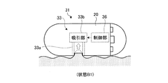
図6は、本発明の実施の形態2にかかるカプセル型医療装置の一構成例を示す模式図である。図7は、実施の形態2にかかるカプセル型医療装置の組織採取手段を拡大した模式図である。図6,7に示すように、この実施の形態2にかかるカプセル型医療装置31は、上述した実施の形態1にかかるカプセル型医療装置2の生検機構23に代えて生検機構33を備え、フォトセンサ24に代えて一対の近接センサ34a,34bを備え、制御部26に代えて制御部36を備える。また、この実施の形態2において、カプセル型筐体20の筒状筐体20aには、生検機構33が備える一対の切断部33c,33dを出し入れするための一対の開口部20d,20eが形成される。なお、この実施の形態2にかかる医療システムは、上述した実施の形態1にかかる医療システム11(図1参照)のカプセル型医療装置2に代えてカプセル型医療装置31を備える。その他の構成は実施の形態1と同じであり、同一構成部分には同一符号を付している。   FIG. 6 is a schematic diagram illustrating a configuration example of a capsule medical apparatus according to the second embodiment of the present invention. FIG. 7 is an enlarged schematic diagram of the tissue collection unit of the capsule medical device according to the second embodiment. As shown in FIGS. 6 and 7, the capsule medical device 31 according to the second embodiment includes a biopsy mechanism 33 instead of the biopsy mechanism 23 of the capsule medical device 2 according to the first embodiment described above. Instead of the photosensor 24, a pair of proximity sensors 34a and 34b are provided, and a control unit 36 is provided instead of the control unit 26. In the second embodiment, the cylindrical casing 20a of the capsule casing 20 is formed with a pair of openings 20d and 20e for inserting and removing the pair of cutting portions 33c and 33d included in the biopsy mechanism 33. Is done. The medical system according to the second embodiment includes a capsule medical device 31 instead of the capsule medical device 2 of the medical system 11 (see FIG. 1) according to the first embodiment. Other configurations are the same as those of the first embodiment, and the same reference numerals are given to the same components.

生検機構33は、被検体1の体内部位の生体組織を採取する組織採取手段として機能し、制御部36の制御に基づく一連の採取動作を行って生体組織を採取する。かかる生検機構33は、図7に示すように、生体組織を収容する筒状の収容部33aと、収容部33aの内部に体内部位の一部分を吸引する吸引部33bと、吸引部33bによって収容部33a内に吸引された体内部位の一部分から生体組織を切断する一対の切断部33c,33dとを備える。   The biopsy mechanism 33 functions as a tissue collection unit that collects the biological tissue of the body part of the subject 1 and performs a series of collection operations based on the control of the control unit 36 to collect the biological tissue. As shown in FIG. 7, the biopsy mechanism 33 is accommodated by a cylindrical accommodating portion 33a that accommodates a living tissue, a suction portion 33b that sucks a part of the body part inside the accommodating portion 33a, and a suction portion 33b. And a pair of cutting parts 33c and 33d for cutting the living tissue from a part of the body part sucked into the part 33a.

収容部33aは、吸引部33bおよび切断部33c,33dの作用によって切断採取された体内部位の生体組織を収容する筒状部材であり、カプセル型筐体20の開口部20cの近傍に配置される。かかる収容部33aは、この開口部20cを介してカプセル型筐体20の外部に連通するとともに、制御部36および電源ユニット27等の電子部品を収容するカプセル型筐体20の内部領域と生体組織の収容領域とを隔離する。   The accommodating portion 33a is a cylindrical member that accommodates a living tissue of a body part cut and collected by the action of the suction portion 33b and the cutting portions 33c and 33d, and is disposed in the vicinity of the opening portion 20c of the capsule housing 20. . The housing portion 33a communicates with the outside of the capsule housing 20 through the opening 20c, and the internal region of the capsule housing 20 for housing electronic components such as the control unit 36 and the power supply unit 27 and the living tissue. Isolate from the containment area.

吸引部33bは、制御部36の制御に基づいて動作する吸引ポンプ等を用いて実現され、図7に示す太線矢印の方向に作用する吸引力によって収容部33aの内部に被検体1の体内部位の一部分を吸引する。かかる吸引部33bの吸引圧力は、収容部33aの奥部(すなわち吸引部33bの近傍)まで体内部位の一部分を引き込むに充分な大きさである。   The aspiration unit 33b is realized by using an aspiration pump or the like that operates based on the control of the control unit 36, and the internal part of the subject 1 is placed inside the accommodation unit 33a by the aspiration force acting in the direction of the thick arrow shown in FIG. Aspirate a portion of. The suction pressure of the suction part 33b is large enough to draw a part of the body part up to the back part of the storage part 33a (that is, in the vicinity of the suction part 33b).

一対の切断部33c,33dは、直線状に対向する態様で収容部33aの側壁に回転自在に配置され、吸引部33bによって収容部33aの内部に吸引された体内部位の一部分の作用によって動作し、この体内部位の一部分から塊状の生体組織を切断する。かかる切断部33cは、体内部位から生体組織を切断するための刃部37cと、刃部37cを支持する支持部38cと、支持部38cを回転自在に支持する回転軸39cとによって構成される。同様に、かかる切断部33dは、体内部位から生体組織を切断するための刃部37dと、刃部37dを支持する支持部38dと、支持部38dを回転自在に支持する回転軸39dとによって構成される。   The pair of cutting portions 33c and 33d are rotatably arranged on the side wall of the housing portion 33a in a linearly opposed manner, and operate by the action of a part of the body part sucked into the housing portion 33a by the suction portion 33b. Then, a massive living tissue is cut from a part of the body part. The cutting portion 33c includes a blade portion 37c for cutting a living tissue from a body part, a support portion 38c that supports the blade portion 37c, and a rotating shaft 39c that rotatably supports the support portion 38c. Similarly, the cutting part 33d includes a blade part 37d for cutting a living tissue from a body part, a support part 38d that supports the blade part 37d, and a rotary shaft 39d that rotatably supports the support part 38d. Is done.

刃部37c,37dは、各支持部38c,38dの一端に固定配置され、生体組織採取前の初期状態においてカプセル型筐体20の内部に位置する。刃部37cは、回転軸39cを中心に回転する支持部38cの回転方向に移動しつつ開口部20dからカプセル型筐体20の外部に突出する。同様に、刃部37dは、回転軸39dを中心に回転する支持部38dの回転方向に移動しつつ開口部20eからカプセル型筐体20の外部に突出する。かかる刃部37c,37dは、体内部位から生体組織を切断するに充分な切断力を生成しつつカプセル型筐体20から突出し、最終的に、カプセル型筐体20の開口部20cを閉じる位置に移動する。この開口部20cを閉じる位置まで移動した刃部37c,37dは、収容部33aの蓋としての機能を有する。   The blade portions 37c and 37d are fixedly disposed at one end of each of the support portions 38c and 38d, and are located inside the capsule-type housing 20 in an initial state before collecting a biological tissue. The blade portion 37c protrudes from the opening 20d to the outside of the capsule housing 20 while moving in the rotation direction of the support portion 38c that rotates about the rotation shaft 39c. Similarly, the blade portion 37d protrudes from the opening 20e to the outside of the capsule housing 20 while moving in the rotation direction of the support portion 38d that rotates about the rotation shaft 39d. The blade portions 37c and 37d project from the capsule-type casing 20 while generating a cutting force sufficient to cut a living tissue from a body part, and finally close to the opening 20c of the capsule-type casing 20. Moving. The blade portions 37c and 37d that have moved to a position where the opening 20c is closed have a function as a lid of the accommodating portion 33a.

支持部38c,38dは、回転軸39c,39dによって回転自在に各々支持される。支持部38cは、一方の端部に刃部37cを支持し、他方の端部H1を収容部33aの内部に位置させる。かかる支持部38cの端部H1は、上述した吸引部33bが収容部33aの内部に吸引した体内部位の一部分によって押し動かされ、支持部38cは、この端部H1に連動して回転軸39cを中心に回転する。この場合、支持部38cは、図7に示すように、収容部33aに近接する方向に回転するとともに刃部37cをカプセル型筐体20の外部に突出させる。同様に、支持部38dは、一方の端部に刃部37dを支持し、他方の端部H2を収容部33aの内部に位置させる。かかる支持部38dの端部H2は、上述した吸引部33bが収容部33aの内部に吸引した体内部位の一部分によって押し動かされ、支持部38dは、この端部H2に連動して回転軸39dを中心に回転する。この場合、支持部38dは、図7に示すように、収容部33aに近接する方向に回転するとともに刃部37dをカプセル型筐体20の外部に突出させる。   The support portions 38c and 38d are rotatably supported by the rotation shafts 39c and 39d, respectively. The support portion 38c supports the blade portion 37c at one end portion, and positions the other end portion H1 inside the housing portion 33a. The end portion H1 of the support portion 38c is pushed and moved by a part of the body part sucked into the housing portion 33a by the suction portion 33b described above, and the support portion 38c moves the rotating shaft 39c in conjunction with the end portion H1. Rotate to center. In this case, as shown in FIG. 7, the support portion 38 c rotates in a direction close to the housing portion 33 a and causes the blade portion 37 c to protrude to the outside of the capsule housing 20. Similarly, the support portion 38d supports the blade portion 37d at one end portion, and positions the other end portion H2 inside the accommodating portion 33a. The end portion H2 of the support portion 38d is pushed and moved by a part of the body part sucked into the housing portion 33a by the suction portion 33b described above, and the support portion 38d moves the rotating shaft 39d in conjunction with the end portion H2. Rotate to center. In this case, as shown in FIG. 7, the support portion 38 d rotates in a direction close to the housing portion 33 a and causes the blade portion 37 d to protrude to the outside of the capsule housing 20.

回転軸39c,39dは、回転自在に支持部38c,38dを支持するものであり、直線状に対向する態様で収容部33aの側壁に配置される。詳細には、回転軸39cは、支持部38cのうちの刃部37c側を収容部33aの外部に位置させ且つ端部H1を収容部33aの内部に位置させる態様で支持部38cを回転自在に支持する。同様に、回転軸39dは、支持部38dのうちの刃部37d側を収容部33aの外部に位置させ且つ端部H2を収容部33aの内部に位置させる態様で支持部38dを回転自在に支持する。   The rotary shafts 39c and 39d support the support portions 38c and 38d in a freely rotatable manner, and are arranged on the side wall of the housing portion 33a in a linearly opposed manner. Specifically, the rotating shaft 39c allows the support portion 38c to rotate in such a manner that the blade portion 37c side of the support portion 38c is located outside the accommodation portion 33a and the end H1 is located inside the accommodation portion 33a. To support. Similarly, the rotating shaft 39d rotatably supports the support portion 38d in such a manner that the blade portion 37d side of the support portion 38d is located outside the accommodation portion 33a and the end H2 is located inside the accommodation portion 33a. To do.

一対の近接センサ34a,34bは、生検機構33による生体組織採取の成否に応じて変化する生検機構33の状態、例えば、生検機構33による一連の採取動作に伴って変化する生検機構33の部品位置状態を検出する検出手段として機能する。具体的には、近接センサ34aは、収容部33aの側壁であって切断部33cの支持部38cが回転によって最終的に近接する位置に固定配置される。かかる近接センサ34aは、制御部36の制御に基づいて動作し、支持部38cが近接センサ34aから所定の距離範囲内に近接した際に支持部38cの近接状態(上述した部品位置状態の一例)を検出する。同様に、近接センサ34bは、収容部33aの側壁であって切断部33dの支持部38dが回転によって最終的に近接する位置に固定配置される。かかる近接センサ34bは、制御部36の制御に基づいて動作し、支持部38dが近接センサ34bから所定の距離範囲内に近接した際に支持部38dの近接状態(上述した部品位置状態の一例)を検出する。かかる近接センサ34a,34bの各検出結果は、制御部36に送信される。   The pair of proximity sensors 34a and 34b is a state of the biopsy mechanism 33 that changes in accordance with the success or failure of collection of the biological tissue by the biopsy mechanism 33, for example, a biopsy mechanism that changes with a series of collection operations by the biopsy mechanism 33. It functions as a detecting means for detecting 33 component position states. Specifically, the proximity sensor 34a is fixedly disposed at a position that is a side wall of the housing portion 33a and the support portion 38c of the cutting portion 33c is finally close by rotation. The proximity sensor 34a operates based on the control of the control unit 36, and when the support unit 38c comes close to the proximity sensor 34a within a predetermined distance range, the proximity state of the support unit 38c (an example of the component position state described above). Is detected. Similarly, the proximity sensor 34b is fixedly disposed at a position that is the side wall of the housing portion 33a and the support portion 38d of the cutting portion 33d is finally close by rotation. The proximity sensor 34b operates based on the control of the control unit 36, and the proximity state of the support portion 38d when the support portion 38d approaches within a predetermined distance range from the proximity sensor 34b (an example of the component position state described above). Is detected. The detection results of the proximity sensors 34a and 34b are transmitted to the control unit 36.

ここで、生検機構33の部品位置状態は、体内部位の生体組織を採取する際に動作する切断部33c,33dの位置状態に例示されるように、生検機構33による一連の採取動作に伴って変化する。具体的には、切断部33c,33dは、生体組織を採取するための一連の採取動作を実行する前の段階において、カプセル型筐体20の内部に刃部37c,37dを位置させた状態、すなわち収容部33aと支持部38c,38dとを離間させた状態を維持する。その後、吸引部33bは、一連の採取動作の一つとして収容部33a内に体内部位の一部分を吸引する。切断部33c,33dは、かかる収容部33a内に吸引された体内部位の一部分の作用によって動作し、一対の刃部37c,37dによって、この体内部位の一部分から生体組織を切断採取する。この採取された生体組織は、吸引部33bによって収容部33a内に吸引され、これによって、生検機構33による一連の採取動作が完了する。このように生検機構33による一連の採取動作が無事完了した際に初めて、支持部38cは、近接センサ34aに対して所定の距離範囲内に近接し、支持部38dは、近接センサ34bに対して所定の距離範囲内に近接する。すなわち、近接センサ34a,34bは、上述した支持部38c,38dの近接状態を検出することによって、生検機構33が生体組織を無事採取した旨を間接的に検出できる。   Here, the component position state of the biopsy mechanism 33 is a series of collection operations by the biopsy mechanism 33, as exemplified by the position states of the cutting portions 33c and 33d that operate when the biological tissue of the body part is collected. It changes with it. Specifically, the cutting units 33c and 33d are in a state in which the blades 37c and 37d are positioned inside the capsule-type housing 20 in a stage before executing a series of collection operations for collecting a biological tissue. That is, the state where the accommodating portion 33a is separated from the support portions 38c and 38d is maintained. Thereafter, the suction part 33b sucks a part of the body part into the housing part 33a as one of a series of collection operations. The cutting parts 33c and 33d operate by the action of a part of the body part sucked into the housing part 33a, and the pair of blade parts 37c and 37d cut and extract the living tissue from a part of the body part. The collected biological tissue is aspirated into the accommodating portion 33a by the aspirating portion 33b, whereby a series of collecting operations by the biopsy mechanism 33 is completed. Only when the series of sampling operations by the biopsy mechanism 33 is successfully completed in this way, the support portion 38c comes close to the proximity sensor 34a within a predetermined distance range, and the support portion 38d becomes closer to the proximity sensor 34b. Close to each other within a predetermined distance range. That is, the proximity sensors 34a and 34b can indirectly detect that the biopsy mechanism 33 has successfully collected the biological tissue by detecting the proximity state of the support portions 38c and 38d described above.

制御部36は、上述した実施の形態1における生検機構23を制御する代わりに、生検機構33の吸引部33bの吸引動作を制御する。具体的には、制御部36は、外部の制御部10からの制御信号に基づいて吸引部33bに吸引動作を開始させ、生体組織採取が成功するまで吸引部33bに吸引動作を行わせる。制御部36は、かかる吸引部33bの吸引動作を制御することによって、生検機構33による一連の採取動作を制御する。また、制御部36は、上述した実施の形態1におけるフォトセンサ24を制御する代わりに、一対の近接センサ34a,34bを制御する。   The control unit 36 controls the suction operation of the suction unit 33b of the biopsy mechanism 33 instead of controlling the biopsy mechanism 23 in the first embodiment described above. Specifically, the control unit 36 causes the suction unit 33b to start a suction operation based on a control signal from the external control unit 10, and causes the suction unit 33b to perform a suction operation until the biological tissue collection is successful. The control unit 36 controls a series of sampling operations by the biopsy mechanism 33 by controlling the suction operation of the suction unit 33b. Moreover, the control part 36 controls a pair of proximity sensor 34a, 34b instead of controlling the photosensor 24 in Embodiment 1 mentioned above.

また、制御部36は、上述した実施の形態1にかかるカプセル型医療装置2の成否判定部26aに代えて成否判定部36aを有する。成否判定部36aは、近接センサ34a,34bによって検出された生検機構33の部品位置状態をもとに生体組織採取の成否を判定する。具体的には、成否判定部36aは、近接センサ34a,34bから支持部38c,38dの近接状態の検出結果を取得し、この取得した検出結果をもとに、生検機構33による生体組織採取が成功したと判定する。一方、成否判定部36aは、近接センサ34a,34bから支持部38c,38dの近接状態の検出結果を取得していなければ、生検機構33による生体組織採取が不成功であると判定する。なお、かかる制御部36が有する他の機能は、上述した実施の形態1にかかるカプセル型医療装置2の制御部26と同じである。   The control unit 36 includes a success / failure determination unit 36a instead of the success / failure determination unit 26a of the capsule medical device 2 according to the first embodiment. The success / failure determination unit 36a determines the success or failure of the collection of the biological tissue based on the component position state of the biopsy mechanism 33 detected by the proximity sensors 34a and 34b. Specifically, the success / failure determination unit 36a acquires the detection results of the proximity states of the support units 38c and 38d from the proximity sensors 34a and 34b, and collects the biological tissue by the biopsy mechanism 33 based on the acquired detection results. Is determined to be successful. On the other hand, the success / failure determination unit 36a determines that the biological tissue collection by the biopsy mechanism 33 is unsuccessful if the detection result of the proximity state of the support units 38c and 38d is not acquired from the proximity sensors 34a and 34b. The other functions of the control unit 36 are the same as those of the control unit 26 of the capsule medical device 2 according to the first embodiment.

つぎに、被検体1の体内部位の生体組織を採取する際のカプセル型医療装置31の動作について説明する。図8は、実施の形態2にかかるカプセル型医療装置31の生検機構33によって体内部位の一部分を吸引する状態を例示する模式図である。図9は、実施の形態2にかかるカプセル型医療装置31の生検機構33によって体内部位の生体組織を採取する状態を例示する模式図である。   Next, the operation of the capsule medical device 31 when collecting the biological tissue of the body part of the subject 1 will be described. FIG. 8 is a schematic view illustrating a state in which a part of the body part is aspirated by the biopsy mechanism 33 of the capsule medical device 31 according to the second embodiment. FIG. 9 is a schematic view illustrating a state in which a biological tissue of a body part is collected by the biopsy mechanism 33 of the capsule medical device 31 according to the second embodiment.

カプセル型医療装置31は、被検体1内部に導入された後、上述した実施の形態1の場合と同様に、被検体1内部の検査対象の体内部位に到達する。この被検体1内部における検査対象の体内部位に到達したカプセル型医療装置31は、外部の制御部10からの制御信号を取得し、この取得した制御信号に基づいて、この体内部位の生体組織を採取するための一連の採取動作を実行する。   After being introduced into the subject 1, the capsule medical device 31 reaches the body part to be examined inside the subject 1 as in the case of the first embodiment described above. The capsule medical device 31 that has reached the body part to be examined inside the subject 1 acquires a control signal from the external control unit 10, and based on the acquired control signal, converts the biological tissue of this body part. Execute a series of collection operations for collection.

かかるカプセル型医療装置31は、図8に示すように、まず、カプセル型筐体20の内部に体内部位の一部分を吸引する。この場合、カプセル型医療装置31の制御部36は、外部の制御部10からの制御信号に基づいて吸引部33bの駆動を制御し、これによって、生検機構33に一連の採取動作を開始させる。かかる吸引部33bは、収容部33aの内部に体内部位の一部分を吸引する(状態B1)。   As shown in FIG. 8, the capsule medical device 31 first sucks a part of the body part into the capsule housing 20. In this case, the control unit 36 of the capsule medical device 31 controls the driving of the suction unit 33b based on a control signal from the external control unit 10, thereby causing the biopsy mechanism 33 to start a series of collection operations. . The suction part 33b sucks a part of the body part into the housing part 33a (state B1).

このように吸引部33bによって体内部位の一部分を吸引し始めたカプセル型医療装置31において、生検機構33は、図9に示すように、この体内部位の一部分から生体組織を切断採取する。具体的には、吸引部33bは、収容部33a内に体内部位の一部分を吸引し続ける。かかる体内部位の一部分は、収容部33a内に引き込まれつつ、一対の切断部33c,33dの各端部H1,H2に接触する(状態B2)。   In the capsule medical device 31 that has started to suck a part of the body part by the suction part 33b as described above, the biopsy mechanism 33 cuts and collects the biological tissue from a part of the body part as shown in FIG. Specifically, the suction part 33b continues to suck a part of the body part into the housing part 33a. A part of the body part comes into contact with the end portions H1 and H2 of the pair of cutting portions 33c and 33d while being pulled into the accommodating portion 33a (state B2).

その後、かかる体内部位の一部分は、吸引部33bの吸引作用によって収容部33aの奥部に引き込まれるとともに、一対の切断部33c,33dの各端部H1,H2を押し動かす。一対の切断部33c,33dは、かかる体内部位の一部分の作用によって、一対の刃部37c,37dを体内部位に向けて移動させ、これら一対の刃部37c,37dによって体内部位の一部分から塊状の生体組織15を切断採取する(状態B3)。かかる切断部33c,33dによって切断採取された生体組織15は、吸引部33bによって収容部33a内に吸引され、その後、この収容部33a内に保管される。   Thereafter, a part of the body part is drawn into the inner part of the accommodating part 33a by the suction action of the suction part 33b and pushes and moves the end parts H1 and H2 of the pair of cutting parts 33c and 33d. The pair of cutting parts 33c and 33d move the pair of blade parts 37c and 37d toward the body part by the action of a part of the body part, and the pair of blade parts 37c and 37d are formed in a lump shape from a part of the body part. The living tissue 15 is cut and collected (state B3). The living tissue 15 cut and collected by the cutting portions 33c and 33d is sucked into the housing portion 33a by the suction portion 33b and then stored in the housing portion 33a.

かかる状態B3において、一対の刃部37c,37dは、収容部33aの開口部を閉じた状態になり、収容部33aの内部からカプセル型筐体20の外部へ生体組織15を零す事態を防止する。一方、かかる一対の刃部37c,37dの支持部38c,38dは、近接センサ34a,34bに各々近接した状態になる。   In this state B3, the pair of blade portions 37c and 37d are in a state in which the opening portion of the housing portion 33a is closed, and the situation where the living tissue 15 is zeroed from the inside of the housing portion 33a to the outside of the capsule housing 20 is prevented. To do. On the other hand, the support portions 38c and 38d of the pair of blade portions 37c and 37d are close to the proximity sensors 34a and 34b, respectively.

一方、上述した状態B1〜B3において、カプセル型医療装置31の制御部36は、近接センサ34a,34bに生検機構33の状態(一連の採取動作に伴って変化する生検機構33の部品位置状態)を検出させ、この検出結果をもとに生体組織採取の成否を判定する。具体的には、成否判定部36aは、上述したように、近接センサ34a,34bから支持部38c,38dの近接状態の検出結果を取得すれば、生検機構33による生体組織採取が成功であると判定し、かかる支持部38,38dの近接状態の検出結果を取得しなければ、生検機構33による生体組織採取が不成功であると判定する。   On the other hand, in the states B1 to B3 described above, the control unit 36 of the capsule medical device 31 sends the proximity sensors 34a and 34b to the state of the biopsy mechanism 33 (part positions of the biopsy mechanism 33 that change with a series of sampling operations). State) is detected, and success or failure of the collection of the biological tissue is determined based on the detection result. Specifically, as described above, if the success / failure determination unit 36a acquires the detection result of the proximity state of the support units 38c and 38d from the proximity sensors 34a and 34b, the biological tissue collection by the biopsy mechanism 33 is successful. If the detection result of the proximity state of the support portions 38 and 38d is not acquired, it is determined that the biological tissue collection by the biopsy mechanism 33 is unsuccessful.

ここで、図9に示すように生検機構33が体内部位の生体組織15を無事採取した場合、切断部33cの支持部38cは、近接センサ34aに近接し、近接センサ34aは、この支持部38cの近接状態を検出する。一方、切断部33dの支持部38dは、近接センサ34bに近接し、近接センサ34bは、この支持部38dの近接状態を検出する。かかる近接センサ34a,34bの検出結果は、制御部36に送信される。この場合、成否判定部36aは、かかる近接センサ34a,34bの検出結果を取得し、この取得した検出結果に基づいて、生検機構33による生体組織採取を成功であると判定する。この場合、制御部36は、吸引部33bの吸引動作を停止させて、生検機構33に一連の採取動作を終了させる。なお、かかる生検機構33による生体組織採取の成功を示す成否情報は、上述した実施の形態1の場合と同様に、外部の表示部4に表示される。   Here, as shown in FIG. 9, when the biopsy mechanism 33 has successfully collected the biological tissue 15 in the body part, the support part 38c of the cutting part 33c is close to the proximity sensor 34a, and the proximity sensor 34a is connected to the support part. The proximity state of 38c is detected. On the other hand, the support part 38d of the cutting part 33d is close to the proximity sensor 34b, and the proximity sensor 34b detects the proximity state of the support part 38d. The detection results of the proximity sensors 34a and 34b are transmitted to the control unit 36. In this case, the success / failure determination unit 36a acquires the detection results of the proximity sensors 34a and 34b, and determines that the biological tissue collection by the biopsy mechanism 33 is successful based on the acquired detection results. In this case, the control unit 36 stops the suction operation of the suction unit 33b and causes the biopsy mechanism 33 to end a series of collection operations. The success / failure information indicating the success of the biological tissue collection by the biopsy mechanism 33 is displayed on the external display unit 4 as in the case of the first embodiment.

一方、生検機構33が体内部位の生体組織を未だ採取できていない場合、切断部33cの支持部38cは、近接センサ34aから所定の距離以上離間した状態であり、同様に、切断部33dの支持部38dは、近接センサ34bから所定の距離以上離間した状態である。したがって、近接センサ34a,34bは、支持部38c,38dの近接状態を検出しない。この場合、成否判定部36aは、かかる近接センサ34a,34bの検出結果を取得せず、このことに基づいて、生検機構33による生体組織採取を不成功であると判定する。   On the other hand, when the biopsy mechanism 33 has not yet collected the biological tissue of the body part, the support part 38c of the cutting part 33c is in a state separated from the proximity sensor 34a by a predetermined distance or more, and similarly, the cutting part 33d The support portion 38d is in a state of being separated from the proximity sensor 34b by a predetermined distance or more. Therefore, the proximity sensors 34a and 34b do not detect the proximity state of the support portions 38c and 38d. In this case, the success / failure determination unit 36a does not acquire the detection results of the proximity sensors 34a and 34b, and based on this, determines that the biological tissue collection by the biopsy mechanism 33 is unsuccessful.

成否判定部36aが生検機構33による生体組織採取を不成功であると判定した場合、実際には、生検機構33の吸引部33bが吸引動作を行っている状態であり、制御部36は、かかる成否判定部36aの判定結果(生体組織採取の不成功)に基づいて、吸引部33bの吸引動作を継続させる。すなわち、制御部36は、生検機構33が生体組織の採取に成功するまで、上述した一連の採取動作を生検機構33に継続させる。   When the success / failure determination unit 36a determines that the biological tissue collection by the biopsy mechanism 33 is unsuccessful, the suction unit 33b of the biopsy mechanism 33 is actually performing a suction operation, and the control unit 36 Based on the determination result of the success / failure determination unit 36a (unsuccessful collection of biological tissue), the suction operation of the suction unit 33b is continued. That is, the control unit 36 causes the biopsy mechanism 33 to continue the series of collection operations described above until the biopsy mechanism 33 succeeds in collecting a biological tissue.

以上、説明したように、本発明の実施の形態2では、生検機構が、吸引部によって収容部内に吸引した体内部位の生体組織を切断採取する一連の採取動作を行い、近接センサが、生体組織採取の成否に応じて変化する生検機構の部品位置状態を検出し、制御部が、この近接センサの検出結果をもとに生検機構による生体組織採取の成否を判定し、この成否判定結果を示す成否情報を被検体外部に向けて通信ユニットに送信させるようにし、その他を上述した実施の形態1と同様に構成した。このため、実施の形態1の場合と同様に、生体組織採取の時に、生体組織採取が成功した旨を被検体外部に知らせることができ、この結果、実施の形態1と同様の作用効果を享受するカプセル型医療装置および医療システムを実現することができる。   As described above, in the second embodiment of the present invention, the biopsy mechanism performs a series of sampling operations for cutting and sampling the biological tissue of the internal body part sucked into the housing part by the suction part, and the proximity sensor The part position state of the biopsy mechanism that changes according to the success or failure of the tissue collection is detected, and the control unit determines the success or failure of the biological tissue collection by the biopsy mechanism based on the detection result of the proximity sensor. Success / failure information indicating the result is transmitted to the communication unit toward the outside of the subject, and the others are configured in the same manner as in the first embodiment. For this reason, as in the case of the first embodiment, it is possible to notify the outside of the subject that the biological tissue has been successfully collected at the time of collecting the biological tissue. As a result, the same effects as those of the first embodiment can be obtained. Capsule-type medical device and medical system can be realized.

また、生体組織を切断採取する生検機構の切断部が、吸引部によって収容部内に吸引された体内部位による押圧力(すなわち吸引部の吸引圧力)を駆動源にして動作し、この体内部位の生体組織を切断採取するので、この切断部の駆動電力を低減することができ、これによって、一連の採取動作を行う際のカプセル型医療装置の省電力化を実現することができる。   In addition, the cutting part of the biopsy mechanism that cuts and collects the living tissue operates using the pressing force (that is, the suction pressure of the suction part) by the body part sucked into the housing part by the suction part as a driving source. Since the living tissue is cut and collected, the driving power of the cutting unit can be reduced, and thereby, power saving of the capsule medical device when performing a series of collection operations can be realized.

(実施の形態2の変形例1)
つぎに、本発明の実施の形態2の変形例1について説明する。上述した実施の形態2では、生体組織を吸引して切断採取する一連の採取動作に伴って変化する生検機構33の部品位置状態、具体的には収容部33aに対する支持部38c,38dの近接状態を近接センサ34a,34bによって検出し、この近接センサ34a,34bの検出結果をもとに生体組織採取の成否を判定していたが、この実施の形態2の変形例1では、上述した一連の採取動作に伴って変化する吸引部33bの吸引圧力を圧力センサによって検出し、この圧力センサの検出結果をもとに生体組織採取の成否を判定するようにしている。
(Modification 1 of Embodiment 2)
Next, Modification 1 of Embodiment 2 of the present invention will be described. In the second embodiment described above, the component position state of the biopsy mechanism 33 that changes with a series of sampling operations for sucking and sampling the biological tissue, specifically, the proximity of the support portions 38c and 38d to the accommodating portion 33a. The state is detected by the proximity sensors 34a and 34b, and the success or failure of the biological tissue collection is determined based on the detection results of the proximity sensors 34a and 34b. In the first modification of the second embodiment, the series described above is performed. The suction pressure of the suction portion 33b that changes with the sampling operation is detected by a pressure sensor, and the success or failure of the collection of the biological tissue is determined based on the detection result of the pressure sensor.

図10は、本発明の実施の形態2の変形例1にかかるカプセル型医療装置の一構成例を示す模式図である。図10に示すように、この実施の形態2の変形例1にかかるカプセル型医療装置41は、上述した実施の形態2にかかるカプセル型医療装置31の近接センサ34a,34bに代えて圧力センサ44を備え、制御部36に代えて制御部46を備える。なお、この実施の形態2の変形例1にかかる医療システムは、上述した実施の形態2にかかる医療システムのカプセル型医療装置31に代えてカプセル型医療装置41を備える。その他の構成は実施の形態2と同じであり、同一構成部分には同一符号を付している。   FIG. 10 is a schematic diagram illustrating a configuration example of a capsule medical apparatus according to the first modification of the second embodiment of the present invention. As shown in FIG. 10, the capsule medical device 41 according to the first modification of the second embodiment is a pressure sensor 44 instead of the proximity sensors 34 a and 34 b of the capsule medical device 31 according to the second embodiment described above. And a control unit 46 instead of the control unit 36. The medical system according to the first modification of the second embodiment includes a capsule medical device 41 instead of the capsule medical device 31 of the medical system according to the second embodiment described above. Other configurations are the same as those of the second embodiment, and the same components are denoted by the same reference numerals.

圧力センサ44は、生検機構33による生体組織採取の成否に応じて変化する生検機構33の状態、例えば、生検機構33による一連の採取動作に伴って変化する吸引部33bの吸引圧力を検出する検出手段として機能する。具体的には、圧力センサ44は、吸引部33bが吸引動作を行っている期間、制御部46の制御に基づいて、この吸引部33bの吸引圧力を検出し、この吸引圧力の検出結果を制御部46に送信する。   The pressure sensor 44 changes the state of the biopsy mechanism 33 that changes in accordance with the success or failure of the collection of the biological tissue by the biopsy mechanism 33, for example, the suction pressure of the suction unit 33b that changes with a series of collection operations by the biopsy mechanism 33. It functions as detection means for detecting. Specifically, the pressure sensor 44 detects the suction pressure of the suction unit 33b and controls the detection result of the suction pressure based on the control of the control unit 46 while the suction unit 33b is performing the suction operation. To the unit 46.

制御部46は、上述した実施の形態2における近接センサ34a,34bを制御する代わりに、圧力センサ44を制御する。具体的には、制御部46は、吸引部33bに吸引動作を開始させたタイミングにおいて、この吸引部33bの吸引圧力の検出動作を圧力センサ44に開始させる。制御部46は、吸引部33bに吸引動作を行わせている期間、この吸引部33bの吸引圧力を継続的または断続的に検出するように圧力センサ44を制御し、この圧力センサ44による吸引圧力の検出結果を時系列に沿って順次取得する。   The control unit 46 controls the pressure sensor 44 instead of controlling the proximity sensors 34a and 34b in the second embodiment described above. Specifically, the control unit 46 causes the pressure sensor 44 to start the detection operation of the suction pressure of the suction unit 33b at the timing when the suction unit 33b starts the suction operation. The control unit 46 controls the pressure sensor 44 so as to detect the suction pressure of the suction unit 33b continuously or intermittently while the suction unit 33b performs the suction operation, and the suction pressure by the pressure sensor 44 is controlled. The detection results are sequentially acquired in time series.

また、制御部46は、上述した実施の形態2にかかるカプセル型医療装置31の成否判定部36aに代えて成否判定部46aを有する。成否判定部46aは、生検機構33による一連の採取動作に伴って変化する吸引部33bの吸引圧力をもとに生体組織採取の成否を判定する。具体的には、成否判定部46aは、圧力センサ44から吸引部33bの吸引圧力の検出結果を順次取得し、これによって、かかる吸引部33bの経時的な吸引圧力変化を取得する。成否判定部46aは、かかる吸引部33bの経時的な吸引圧力変化をもとに生体組織採取の成否を判定する。なお、かかる制御部46が有する他の機能は、上述した実施の形態2にかかるカプセル型医療装置31の制御部36と同じである。   The control unit 46 includes a success / failure determination unit 46a instead of the success / failure determination unit 36a of the capsule medical device 31 according to the second embodiment. The success / failure determination unit 46a determines the success or failure of the collection of the biological tissue based on the suction pressure of the suction unit 33b that changes with a series of collection operations by the biopsy mechanism 33. Specifically, the success / failure determination unit 46a sequentially acquires the detection result of the suction pressure of the suction unit 33b from the pressure sensor 44, and thereby acquires the suction pressure change with time of the suction unit 33b. The success / failure determination unit 46a determines the success or failure of the collection of the biological tissue based on the change in the suction pressure with time of the suction unit 33b. The other functions of the control unit 46 are the same as those of the control unit 36 of the capsule medical device 31 according to the second embodiment described above.

つぎに、上述した成否判定部46aによる生体組織採取の成否判定処理について詳細に説明する。図11は、圧力センサ44によって検出される吸引部33bの吸引圧力の経時変化を例示する模式図である。圧力センサ44は、例えば図11に示すように経時変化する吸引部33bの吸引圧力を順次検出する。成否判定部46aは、かかる圧力センサ44によって検出された吸引部33bの吸引圧力の経時変化をもとに生体組織採取の成否を判定する。   Next, the success / failure determination process of the biological tissue collection by the success / failure determination unit 46a described above will be described in detail. FIG. 11 is a schematic view illustrating the change with time of the suction pressure of the suction part 33b detected by the pressure sensor 44. As shown in FIG. For example, as shown in FIG. 11, the pressure sensor 44 sequentially detects the suction pressure of the suction unit 33b that changes with time. The success / failure determination unit 46a determines the success / failure of the collection of the living tissue based on the temporal change of the suction pressure of the suction unit 33b detected by the pressure sensor 44.

詳細には、図11に示すように、圧力センサ44は、吸引部33bが吸引動作を開始してから収容部33a内に体内部位の一部分を吸引し始めるまでの期間、吸引部33bの吸引圧力P1(最低値)を検出する。その後、かかる圧力センサ44によって検出される吸引部33bの吸引圧力は、収容部33a内に体内部位の一部分が吸引され始めるとともに上昇する。圧力センサ44は、収容部33a内に吸引された体内部位の一部分によってカプセル型筐体20の開口部20cが閉塞されたタイミング(時間T1)において吸引部33bの吸引圧力P2(最大値)を検出する。その後、かかる圧力センサ44によって検出される吸引部33bの吸引圧力は、収容部33a内に吸引された体内部位の一部分から生体組織が切断採取されるまでの期間、吸引圧力P2と略同値であり、この収容部33a内の体内部位の一部分から生体組織が切断採取されたタイミング(時間T2)において急激に低下する。圧力センサ44は、この時間T2において吸引部33bの吸引圧力P3を検出する。その後、かかる圧力センサ44によって検出される吸引部33bの吸引圧力は、この吸引圧力P3と略同値である。   Specifically, as shown in FIG. 11, the pressure sensor 44 is configured so that the suction pressure of the suction part 33 b is a period from when the suction part 33 b starts the suction operation to when a part of the body part starts to be sucked into the housing part 33 a. P1 (minimum value) is detected. Thereafter, the suction pressure of the suction part 33b detected by the pressure sensor 44 increases as a part of the body part starts to be sucked into the housing part 33a. The pressure sensor 44 detects the suction pressure P2 (maximum value) of the suction part 33b at the timing (time T1) when the opening 20c of the capsule-type housing 20 is closed by a part of the body part sucked into the housing part 33a. To do. Thereafter, the suction pressure of the suction part 33b detected by the pressure sensor 44 is substantially the same value as the suction pressure P2 until a living tissue is cut and collected from a part of the body part sucked into the storage part 33a. The temperature rapidly decreases at the timing (time T2) when the living tissue is cut and collected from a part of the body part in the accommodating portion 33a. The pressure sensor 44 detects the suction pressure P3 of the suction part 33b at this time T2. Thereafter, the suction pressure of the suction part 33b detected by the pressure sensor 44 is substantially equal to the suction pressure P3.

一方、成否判定部46aは、かかる圧力センサ44によって検出された吸引部33bの吸引圧力(例えば、図11に示す吸引圧力P1〜P3)を時系列に沿って順次取得し、この取得した吸引圧力の経時変化をもとに生体組織採取の成否を判定する。具体的には、成否判定部46aは、かかる圧力センサ44から取得した吸引圧力のうち、上述した吸引圧力P2(最大値)から急激に減少した後の吸引圧力P3と初期の吸引圧力P1とを選択し、この吸引圧力P3と吸引圧力P1との圧力差△Pを算出する。成否判定部46aは、この圧力差△Pと予め設定された閾値とを比較し、この比較結果をもとに生体組織採取の成否を判定する。   On the other hand, the success / failure determination unit 46a sequentially acquires the suction pressure (for example, suction pressures P1 to P3 shown in FIG. 11) of the suction unit 33b detected by the pressure sensor 44 in time series, and the acquired suction pressure. The success or failure of collecting the biological tissue is determined based on the change over time. Specifically, the success / failure determination unit 46a calculates the suction pressure P3 and the initial suction pressure P1 after abruptly decreasing from the suction pressure P2 (maximum value) described above, among the suction pressures acquired from the pressure sensor 44. The pressure difference ΔP between the suction pressure P3 and the suction pressure P1 is calculated. The success / failure determination unit 46a compares the pressure difference ΔP with a preset threshold value, and determines the success or failure of the biological tissue collection based on the comparison result.

ここで、生検機構33による生体組織採取が成功した場合、収容部33a内に切断採取された生体組織が保管されているため、上述した吸引圧力P3は、初期の吸引圧力P1に比して大きくなり、この吸引圧力P3と初期の吸引圧力P1との圧力差△Pは閾値以上になる。一方、生検機構33による生体組織採取が不成功である場合、収容部33a内に生体組織が吸引されていないため、上述した吸引圧力P3は、初期の吸引圧力P1と略同値になり、この吸引圧力P3と初期の吸引圧力P1との圧力差△Pは閾値未満(略零値)になる。以上のことに基づいて、成否判定部46aは、かかる圧力差△Pが閾値以上である場合、生検機構33による生体組織採取を成功であると判定し、かかる圧力差△Pが閾値未満である場合、生検機構33による生体組織採取を不成功であると判定する。   Here, when the biological tissue collection by the biopsy mechanism 33 is successful, since the biological tissue cut and collected is stored in the storage portion 33a, the above-described suction pressure P3 is higher than the initial suction pressure P1. The pressure difference ΔP between the suction pressure P3 and the initial suction pressure P1 becomes greater than the threshold value. On the other hand, when the biological tissue collection by the biopsy mechanism 33 is unsuccessful, since the biological tissue is not sucked into the housing portion 33a, the above-described suction pressure P3 is substantially equal to the initial suction pressure P1, The pressure difference ΔP between the suction pressure P3 and the initial suction pressure P1 is less than a threshold value (substantially zero value). Based on the above, the success / failure determination unit 46a determines that the biological tissue collection by the biopsy mechanism 33 is successful when the pressure difference ΔP is equal to or greater than the threshold, and the pressure difference ΔP is less than the threshold. In some cases, it is determined that the biological tissue collection by the biopsy mechanism 33 is unsuccessful.

以上、説明したように、本発明の実施の形態2の変形例1では、圧力センサが、生体組織採取の成否に応じて変化する生検機構の吸引圧力を検出し、制御部が、上述した近接センサの検出結果の代わりに、この圧力センサによって検出された吸引圧力の変化をもとに生検機構による生体組織採取の成否を判定するようにし、その他を上述した実施の形態2と同様に構成した。このため、実施の形態2の場合と同様に、生体組織採取の時に、生体組織採取が成功した旨を被検体外部に知らせることができ、実施の形態2と同様の作用効果を享受するカプセル型医療装置および医療システムを実現することができる。   As described above, in the first modification of the second embodiment of the present invention, the pressure sensor detects the suction pressure of the biopsy mechanism that changes according to the success or failure of the biological tissue collection, and the control unit described above. Instead of the detection result of the proximity sensor, the success or failure of the biological tissue collection by the biopsy mechanism is determined based on the change in the suction pressure detected by this pressure sensor, and the others are the same as in the second embodiment described above. Configured. For this reason, as in the case of the second embodiment, at the time of biological tissue collection, a capsule type can be notified to the outside of the subject that biological tissue collection has been successful, and can enjoy the same operational effects as in the second embodiment. Medical devices and medical systems can be realized.

(実施の形態2の変形例2)
つぎに、本発明の実施の形態2の変形例2について説明する。上述した実施の形態2では、生体組織を吸引して切断採取する一連の採取動作に伴って変化する生検機構33の部品位置状態、具体的には収容部33aに対する支持部38c,38dの近接状態を近接センサ34a,34bによって検出し、この近接センサ34a,34bの検出結果をもとに生体組織採取の成否を判定していたが、この実施の形態2の変形例2では、吸引部33bによって吸引された生体組織を収容する収容部33aの内壁に一対の電極を設け、この一対の電極間の電気抵抗値をもとに生体組織採取の成否を判定するようにしている。
(Modification 2 of Embodiment 2)
Next, a second modification of the second embodiment of the present invention will be described. In the second embodiment described above, the component position state of the biopsy mechanism 33 that changes with a series of sampling operations for sucking and sampling the biological tissue, specifically, the proximity of the support portions 38c and 38d to the accommodating portion 33a. The state is detected by the proximity sensors 34a and 34b, and the success or failure of the biological tissue collection is determined based on the detection results of the proximity sensors 34a and 34b. In the second modification of the second embodiment, the suction unit 33b A pair of electrodes is provided on the inner wall of the accommodating portion 33a that accommodates the living tissue sucked by the above, and the success or failure of collecting the living tissue is determined based on the electrical resistance value between the pair of electrodes.

図12は、本発明の実施の形態2の変形例2にかかるカプセル型医療装置の一構成例を示す模式図である。図12に示すように、この実施の形態2の変形例2にかかるカプセル型医療装置51は、絶縁性部材によって形成された筒状の収容部33aの内壁に一対の電極54a,54bを備える。また、カプセル型医療装置51は、上述した実施の形態2にかかるカプセル型医療装置31の近接センサ34a,34bの代わりに、一対の電極54a,54b間の電気抵抗値を検出する電極センサ54を備え、制御部36に代えて制御部56を備える。なお、この実施の形態2の変形例2にかかる医療システムは、上述した実施の形態2にかかる医療システムのカプセル型医療装置31に代えてカプセル型医療装置51を備える。その他の構成は実施の形態2と同じであり、同一構成部分には同一符号を付している。   FIG. 12 is a schematic diagram illustrating a configuration example of a capsule medical apparatus according to the second modification of the second embodiment of the present invention. As shown in FIG. 12, the capsule medical device 51 according to the second modification of the second embodiment includes a pair of electrodes 54a and 54b on the inner wall of a cylindrical housing portion 33a formed of an insulating member. The capsule medical device 51 includes an electrode sensor 54 that detects an electrical resistance value between the pair of electrodes 54a and 54b instead of the proximity sensors 34a and 34b of the capsule medical device 31 according to the second embodiment. And a control unit 56 is provided instead of the control unit 36. The medical system according to the second modification of the second embodiment includes a capsule medical device 51 instead of the capsule medical device 31 of the medical system according to the second embodiment. Other configurations are the same as those of the second embodiment, and the same components are denoted by the same reference numerals.

電極センサ54は、生検機構33による生体組織採取の成否に応じて変化する生検機構33の状態、例えば、生検機構33によって採取された生体組織の有無状態に応じて変化する電気抵抗値を検出する検出手段として機能する。具体的には、電極センサ54は、収容部33aの内壁に設けられた一対の電極54a,54bと電気的に接続され、制御部56の制御に基づいて、かかる一対の電極54a,54b間の電気抵抗値を検出し、この電気抵抗値の検出結果を制御部56に送信する。なお、かかる一対の電極54a,54bは、収容部33a内に生体組織が無い場合、電気的に絶縁状態であり、収容部33a内に生体組織が有る場合、すなわち生検機構33による生体組織採取が成功した場合、この収容部33a内の生体組織を介して電気的に導通可能な状態になる。   The electrode sensor 54 has an electrical resistance value that changes according to the state of the biopsy mechanism 33 that changes depending on whether the biopsy mechanism 33 succeeds in collecting the biological tissue, for example, the presence or absence of the biological tissue collected by the biopsy mechanism 33. Functions as a detecting means for detecting. Specifically, the electrode sensor 54 is electrically connected to a pair of electrodes 54 a and 54 b provided on the inner wall of the housing portion 33 a, and is controlled between the pair of electrodes 54 a and 54 b under the control of the control unit 56. The electrical resistance value is detected, and the detection result of the electrical resistance value is transmitted to the control unit 56. The pair of electrodes 54a and 54b is electrically insulated when there is no living tissue in the accommodating portion 33a, and when there is living tissue in the accommodating portion 33a, that is, when the living tissue is collected by the biopsy mechanism 33. Is successful, it becomes in a state where it can be electrically conducted through the living tissue in the accommodating portion 33a.

制御部56は、上述した実施の形態2における近接センサ34a,34bを制御する代わりに、電極センサ54を制御する。具体的には、制御部56は、生検機構33に一連の採取動作を開始させたタイミング(すなわち吸引部33bに吸引動作を開始させたタイミング)において、一対の電極54a,54b間の電気抵抗値の検出動作を電極センサ54に開始させる。制御部56は、生検機構33に一連の採取動作を行わせている期間、一対の電極54a,54b間の電気抵抗値を継続的または断続的に検出するように電極センサ54を制御し、この電極センサ54による電気抵抗値の検出結果を順次取得する。   The control unit 56 controls the electrode sensor 54 instead of controlling the proximity sensors 34a and 34b in the second embodiment described above. Specifically, the control unit 56 performs electrical resistance between the pair of electrodes 54a and 54b at the timing when the biopsy mechanism 33 starts a series of sampling operations (that is, the timing when the suction unit 33b starts the suction operation). The electrode sensor 54 starts the value detection operation. The control unit 56 controls the electrode sensor 54 so as to continuously or intermittently detect the electrical resistance value between the pair of electrodes 54a and 54b during a period in which the biopsy mechanism 33 performs a series of sampling operations. The detection result of the electrical resistance value by the electrode sensor 54 is sequentially acquired.

また、制御部56は、上述した実施の形態2にかかるカプセル型医療装置31の成否判定部36aに代えて成否判定部56aを有する。成否判定部56aは、生検機構33によって採取された生体組織の有無状態に応じて変化する電気抵抗値をもとに、生体組織採取の成否を判定する。具体的には、成否判定部56aは、電極センサ54から一対の電極54a,54b間の電気抵抗値の検出結果を順次取得し、この取得した電気抵抗値と予め設定された閾値とを比較処理する。成否判定部56aは、この比較処理の結果をもとに生体組織採取の成否を判定する。なお、かかる制御部56が有する他の機能は、上述した実施の形態2にかかるカプセル型医療装置31の制御部36と同じである。   The control unit 56 includes a success / failure determination unit 56a instead of the success / failure determination unit 36a of the capsule medical device 31 according to the second embodiment. The success / failure determination unit 56a determines the success or failure of the biological tissue collection based on the electrical resistance value that changes according to the presence / absence state of the biological tissue collected by the biopsy mechanism 33. Specifically, the success / failure determination unit 56a sequentially acquires the detection result of the electrical resistance value between the pair of electrodes 54a and 54b from the electrode sensor 54, and compares the acquired electrical resistance value with a preset threshold value. To do. The success / failure determination unit 56a determines the success or failure of the biological tissue collection based on the result of the comparison process. The other functions of the control unit 56 are the same as those of the control unit 36 of the capsule medical device 31 according to the second embodiment.

ここで、生検機構33による生体組織採取が成功した場合、切断部33c,33dによって切断採取された生体組織が収容部33a内に保管され、上述した一対の電極54a,54bは、この生体組織を介して電気的に導通可能な状態になる。この場合、かかる一対の電極54a,54b間の電気抵抗値は、急激に低下し、予め成否判定部56aに設定された閾値未満になる。一方、生検機構33による生体組織採取が不成功である場合、収容部33a内に生体組織が収容されていないため、上述した一対の電極54a,54bは互いに絶縁状態である。この場合、かかる一対の電極54a,54b間の電気抵抗値は、上述した成否判定部56aの閾値以上である。以上のことに基づいて、成否判定部56aは、かかる一対の電極54a,54b間の電気抵抗値が閾値未満である場合、生検機構33による生体組織採取を成功であると判定し、かかる一対の電極54a,54b間の電気抵抗値が閾値以上である場合、生検機構33による生体組織採取を不成功であると判定する。   Here, when the biological tissue collection by the biopsy mechanism 33 is successful, the biological tissue cut and collected by the cutting portions 33c and 33d is stored in the housing portion 33a, and the pair of electrodes 54a and 54b described above are stored in the biological tissue. It will be in the state which can be electrically conducted through. In this case, the electrical resistance value between the pair of electrodes 54a and 54b rapidly decreases and becomes less than the threshold set in advance in the success / failure determination unit 56a. On the other hand, when the biological tissue collection by the biopsy mechanism 33 is unsuccessful, the biological tissue is not stored in the storage portion 33a, and thus the pair of electrodes 54a and 54b described above are insulative from each other. In this case, the electrical resistance value between the pair of electrodes 54a and 54b is equal to or greater than the threshold value of the success / failure determination unit 56a. Based on the above, when the electrical resistance value between the pair of electrodes 54a and 54b is less than the threshold value, the success / failure determination unit 56a determines that the biological tissue collection by the biopsy mechanism 33 is successful, and the pair When the electrical resistance value between the electrodes 54a and 54b is equal to or greater than the threshold value, it is determined that the biological tissue collection by the biopsy mechanism 33 is unsuccessful.

以上、説明したように、本発明の実施の形態2の変形例2では、切断採取した生体組織を収容する収容部の内壁に一対の電極を設け、電極センサが、生体組織採取の成否に応じて変化する一対の電極間の電気抵抗値を検出し、制御部が、上述した近接センサの検出結果の代わりに、この電極センサによって検出された電気抵抗値をもとに生検機構による生体組織採取の成否を判定するようにし、その他を上述した実施の形態2と同様に構成した。このため、実施の形態2の場合と同様に、生体組織採取の時に、生体組織採取が成功した旨を被検体外部に知らせることができ、実施の形態2と同様の作用効果を享受するカプセル型医療装置および医療システムを実現することができる。   As described above, in the second modification of the second embodiment of the present invention, a pair of electrodes is provided on the inner wall of the accommodating portion that accommodates the cut and collected living tissue, and the electrode sensor responds to the success or failure of collecting the living tissue. The electrical resistance value between the pair of electrodes that changes in response to the detection result of the proximity sensor described above is detected by the control unit based on the electrical resistance value detected by the electrode sensor, and the living tissue by the biopsy mechanism The success or failure of the collection was determined, and the others were configured in the same manner as in the second embodiment. For this reason, as in the case of the second embodiment, at the time of biological tissue collection, a capsule type can be notified to the outside of the subject that biological tissue collection has been successful, and can enjoy the same operational effects as in the second embodiment. Medical devices and medical systems can be realized.

(実施の形態3)
つぎに、本発明の実施の形態3について説明する。上述した実施の形態1では、被検体1内部のカプセル型医療装置2が体内部位の生体組織を無事採取した場合に、この生体組織採取の成功を示す成否情報を外部の表示部4に表示していたが、この実施の形態3では、かかる成否情報を表示部4に表示する前に、被検体1内部のカプセル型医療装置による一連の採取動作の進行状態を示す動作状態情報を表示部4に表示するようにしている。
(Embodiment 3)
Next, a third embodiment of the present invention will be described. In the first embodiment described above, when the capsule medical device 2 inside the subject 1 has successfully collected the biological tissue of the body part, the success / failure information indicating the success of the biological tissue collection is displayed on the external display unit 4. However, in the third embodiment, before the success / failure information is displayed on the display unit 4, the operation state information indicating the progress of a series of collection operations by the capsule medical device in the subject 1 is displayed on the display unit 4. To be displayed.

図13は、本発明の実施の形態3にかかる医療システムの一構成例を模式的に示すブロック図である。図13に示すように、この実施の形態3にかかる医療システム61は、上述した実施の形態1にかかる医療システム11のカプセル型医療装置2に代えてカプセル型医療装置62を備え、制御部10に代えて制御部70を備える。その他の構成は実施の形態1と同じであり、同一構成部分には同一符号を付している。   FIG. 13 is a block diagram schematically illustrating one configuration example of the medical system according to the third embodiment of the present invention. As illustrated in FIG. 13, the medical system 61 according to the third embodiment includes a capsule medical device 62 instead of the capsule medical device 2 of the medical system 11 according to the first embodiment described above, and includes the control unit 10. Instead of this, a control unit 70 is provided. Other configurations are the same as those of the first embodiment, and the same reference numerals are given to the same components.

カプセル型医療装置62は、被検体1の体内部位の生体組織を採取するための一連の採取動作を実行している期間、この一連の採取動作の進行状態を検出し、その都度、この検出した進行状態を示す動作状態情報を被検体1外部の通信部3に無線送信する。かかるカプセル型医療装置62が有する他の機能は、上述した実施の形態1にかかるカプセル型医療装置2と同じである。なお、この実施の形態3にかかるカプセル型医療装置62の詳細については、後述する。   The capsule medical device 62 detects the progress of the series of collection operations during a period of time when the series of collection operations for collecting the biological tissue of the body part of the subject 1 is being performed. Operation state information indicating the progress state is wirelessly transmitted to the communication unit 3 outside the subject 1. Other functions of the capsule medical device 62 are the same as those of the capsule medical device 2 according to the first embodiment. Details of the capsule medical device 62 according to the third embodiment will be described later.

制御部70は、上述した実施の形態1にかかる医療システム11の制御部10と同様の機能を有し、さらに、被検体1内部のカプセル型医療装置62と被検体1内部の目標部位との距離を算出し、この算出した距離をもとにカプセル型医療装置62と目標部位との位置合わせを高精度に制御する位置制御機能と、カプセル型医療装置62が実行している一連の採取動作の進行状態を示す仮想画像を生成し、この生成した仮想画像を表示部4に表示させる表示制御機能とを有する。かかる制御部70は、上述した画像処理部10aおよび位置算出部10bを有し、さらに、距離算出部70cおよび仮想画像処理部70dを有する。   The control unit 70 has a function similar to that of the control unit 10 of the medical system 11 according to the first embodiment described above, and further includes a capsule medical device 62 inside the subject 1 and a target site inside the subject 1. A position control function for calculating the distance and controlling the alignment between the capsule medical device 62 and the target site with high accuracy based on the calculated distance, and a series of sampling operations performed by the capsule medical device 62 A display control function for generating a virtual image indicating the progress state of the image and displaying the generated virtual image on the display unit 4. The control unit 70 includes the image processing unit 10a and the position calculation unit 10b described above, and further includes a distance calculation unit 70c and a virtual image processing unit 70d.

距離算出部70cは、カプセル型医療装置62によって撮像された被検体1の体内画像と入力部8によって体内画像内に指定入力された位置情報とをもとに、被検体1内部の病変部等の目標部位とカプセル型医療装置62との距離を算出する。制御部70は、かかる距離算出部70cによって算出された距離をもとに磁界発生部5の磁力方向または移動部7の位置を制御し、この結果、入力部8によって入力された体内部位の位置(例えば病変部等の目標部位)とカプセル型医療装置62の位置とを高精度に合わせる。   The distance calculation unit 70c is based on the in-vivo image of the subject 1 imaged by the capsule medical device 62 and the position information designated and input in the in-vivo image by the input unit 8 and the like in the subject 1 The distance between the target site and the capsule medical device 62 is calculated. The control unit 70 controls the direction of the magnetic force of the magnetic field generating unit 5 or the position of the moving unit 7 based on the distance calculated by the distance calculating unit 70c. As a result, the position of the internal body part input by the input unit 8 is controlled. (For example, a target site such as a lesion) and the position of the capsule medical device 62 are matched with high accuracy.

仮想画像処理部70dは、通信部3を介して被検体1内部のカプセル型医療装置62から動作状態情報を取得し、この動作状態情報に対応する一連の採取動作の進行状態を示す仮想画像を生成する。制御部70は、入力部8によって入力された指示情報に基づいて、通常モードまたはバーチャルモードのいずれかに動作モードを設定し、通常モードの場合、被検体1の体内画像を表示部4に表示させ、バーチャルモードの場合、かかる仮想画像処理部70dによって生成された仮想画像を表示部4に表示させる。   The virtual image processing unit 70d acquires operation state information from the capsule medical device 62 inside the subject 1 via the communication unit 3, and displays a virtual image indicating a progress state of a series of collection operations corresponding to the operation state information. Generate. The control unit 70 sets the operation mode to either the normal mode or the virtual mode based on the instruction information input by the input unit 8, and displays the in-vivo image of the subject 1 on the display unit 4 in the normal mode. In the case of the virtual mode, the virtual image generated by the virtual image processing unit 70d is displayed on the display unit 4.

つぎに、本発明の実施の形態3にかかるカプセル型医療装置62の構成について詳細に説明する。図14は、本発明の実施の形態3にかかるカプセル型医療装置の一構成例を示す模式図である。図14に示すように、この実施の形態3にかかるカプセル型医療装置62は、生検機構23による一連の採取動作の進行状態を検出する複数の検出手段、具体的には、動作センサ64および接触センサ65を備え、上述した実施の形態1にかかるカプセル型医療装置2の制御部26に代えて制御部66を備える。その他の構成は実施の形態1と同じであり、同一構成部分には同一符号を付している。   Next, the configuration of the capsule medical device 62 according to the third embodiment of the present invention will be described in detail. FIG. 14 is a schematic diagram illustrating a configuration example of a capsule medical apparatus according to the third embodiment of the present invention. As shown in FIG. 14, the capsule medical device 62 according to the third embodiment includes a plurality of detection means for detecting the progress of a series of sampling operations by the biopsy mechanism 23, specifically, the motion sensor 64 and A contact sensor 65 is provided, and a control unit 66 is provided instead of the control unit 26 of the capsule medical device 2 according to the first embodiment. Other configurations are the same as those of the first embodiment, and the same reference numerals are given to the same components.

動作センサ64は、生検機構23による一連の採取動作の進行状態を検出する複数の検出手段の一つである。具体的には、動作センサ64は、制御部66の制御に基づいて、生検機構23の駆動部23bの動作状態を時系列に沿って順次検出し、これによって、一連の採取動作における採取部23aの動作の進行状態を検出する。かかる動作センサ64によって検出される採取部23aの動作の進行状態として、例えば、一連の採取動作時にカプセル型筐体20から突没する採取部23aの移動距離、採取部23aの鉗子状先端部の開閉状態等が挙げられる。すなわち、動作センサ64は、一連の採取動作における採取部23aの移動距離を検出する距離センサとしての機能を有する。動作センサ64は、かかる採取部23aの動作の進行状態検出結果を制御部66に送信する。   The motion sensor 64 is one of a plurality of detection means for detecting the progress of a series of sampling operations by the biopsy mechanism 23. Specifically, the motion sensor 64 sequentially detects the operation state of the drive unit 23b of the biopsy mechanism 23 in time series based on the control of the control unit 66, and thereby the sampling unit in a series of sampling operations. The progress state of the operation 23a is detected. Examples of the progress of the operation of the sampling unit 23a detected by the motion sensor 64 include, for example, the moving distance of the sampling unit 23a protruding and retracting from the capsule housing 20 during a series of sampling operations, and the forceps-like tip of the sampling unit 23a. Open / closed state and the like can be mentioned. That is, the motion sensor 64 has a function as a distance sensor that detects the moving distance of the sampling unit 23a in a series of sampling operations. The motion sensor 64 transmits the progress detection result of the operation of the sampling unit 23a to the control unit 66.

接触センサ65は、生検機構23による一連の採取動作の進行状態を検出する複数の検出手段の一つである。具体的には、接触センサ65は、例えば採取部23aの鉗子状先端部に配置され、採取部23aと駆動部23bと動作センサ64とを介して制御部66と接続される。かかる接触センサ65は、制御部66の制御に基づいて、この採取部23aと体内部位の生体組織との接触を検出し、動作センサ64等を介して制御部66に接触検出結果を送信する。   The contact sensor 65 is one of a plurality of detection means for detecting the progress of a series of sampling operations by the biopsy mechanism 23. Specifically, the contact sensor 65 is disposed, for example, at a forceps-like tip of the collection unit 23a, and is connected to the control unit 66 via the collection unit 23a, the drive unit 23b, and the operation sensor 64. Based on the control of the control unit 66, the contact sensor 65 detects contact between the collection unit 23a and the living tissue of the body part, and transmits a contact detection result to the control unit 66 via the motion sensor 64 and the like.

制御部66は、生検機構23に一連の採取動作を行わせている際に、上述した動作センサ64および接触センサ65を制御して、かかる動作センサ64および接触センサ65の各検出結果を取得する。具体的には、制御部66は、生検機構23に一連の採取動作を開始させたタイミングにおいて動作センサ64および接触センサ65に検出動作を開始させる。かかる制御部66は、時系列に沿って断続的または連続的に動作センサ64の検出結果を取得し、また、体内部位の生体組織と採取部23aとが接触した際に接触センサ65の検出結果を取得する。   The control unit 66 controls the operation sensor 64 and the contact sensor 65 described above when the biopsy mechanism 23 performs a series of sampling operations, and acquires the detection results of the operation sensor 64 and the contact sensor 65. To do. Specifically, the control unit 66 causes the motion sensor 64 and the contact sensor 65 to start a detection operation at the timing when the biopsy mechanism 23 starts a series of sampling operations. The control unit 66 acquires the detection result of the motion sensor 64 intermittently or continuously along a time series, and the detection result of the contact sensor 65 when the living tissue of the internal body part and the collection unit 23a come into contact with each other. To get.

また、制御部66は、生検機構23による一連の採取動作の進行状態を判定する動作判定部66bを有する。動作判定部66bは、上述した動作センサ64または接触センサ65の検出結果を取得し、この取得した検出結果(一連の採取動作における採取部23aの動作の進行状態、採取部23aと体内部位の生体組織との接触状態)をもとに、生検機構23の一連の採取動作の進行状態を判定する。具体的には、動作判定部66bは、動作センサ64によって検出された採取部23aの移動距離をもとに、一連の採取動作における採取部23aの移動状態を判定し、動作センサ64によって検出された開閉状態をもとに、採取部23aの鉗子状先端部が開状態または閉状態のいずれであるかを判定する。また、動作判定部66bは、接触センサ65の検出結果をもとに、カプセル型筐体20から突出した採取部23aが体内部位の生体組織と接触した状態であると判定する。このように動作判定部66bが生検機構23による一連の採取動作の進行状態を判定する都度、制御部66は、かかる動作判定部66bの判定結果を示す動作状態情報を通信ユニット25に送信し、この動作状態情報を外部に無線送信するように通信ユニット25を制御する。なお、かかる制御部66が有する他の機能は、上述した実施の形態1にかかるカプセル型医療装置2の制御部26と同様である。   In addition, the control unit 66 includes an operation determination unit 66b that determines the progress of a series of sampling operations performed by the biopsy mechanism 23. The motion determination unit 66b acquires the detection result of the motion sensor 64 or the contact sensor 65 described above, and the acquired detection result (the progress of the operation of the sampling unit 23a in a series of sampling operations, the sampling unit 23a and the living body in the body part) Based on the contact state with the tissue), the progress of a series of sampling operations of the biopsy mechanism 23 is determined. Specifically, the motion determination unit 66b determines the movement state of the sampling unit 23a in a series of sampling operations based on the movement distance of the sampling unit 23a detected by the motion sensor 64, and is detected by the motion sensor 64. Based on the opened / closed state, it is determined whether the forceps-like tip of the collection portion 23a is in an open state or a closed state. Further, the operation determination unit 66b determines that the collection unit 23a protruding from the capsule housing 20 is in contact with the living tissue of the body part based on the detection result of the contact sensor 65. Thus, each time the operation determination unit 66b determines the progress state of a series of sampling operations by the biopsy mechanism 23, the control unit 66 transmits operation state information indicating the determination result of the operation determination unit 66b to the communication unit 25. The communication unit 25 is controlled so as to wirelessly transmit this operation state information to the outside. The other functions of the control unit 66 are the same as those of the control unit 26 of the capsule medical device 2 according to the first embodiment.

以上のような構成を有するカプセル型医療装置62は、図13に示した医療システム61において、外部の制御部70からの制御信号に基づいて一連の採取動作を行い、上述した実施の形態1の場合と同様に被検体1内部の所望の体内部位の生体組織を採取する。また、カプセル型医療装置62は、かかる一連の採取動作を行うとともに、一連の採取動作の進行状態を示す動作状態情報を外部の通信部3に順次無線送信する。制御部70は、かかるカプセル型医療装置62からの動作状態情報を取得する都度、このカプセル型医療装置62による一連の採取動作の進行状態を示す仮想画像を表示部4に表示させる。ユーザは、かかる表示部4に表示された仮想画像を視認することによって、被検体1内部のカプセル型医療装置62が一連の採取動作を開始してから終了するまでのプロセスを容易に把握することができる。   The capsule medical device 62 having the above-described configuration performs a series of sampling operations based on the control signal from the external control unit 70 in the medical system 61 shown in FIG. Similarly to the case, a biological tissue of a desired internal part inside the subject 1 is collected. Further, the capsule medical device 62 performs such a series of collection operations and sequentially wirelessly transmits operation state information indicating a progress state of the series of collection operations to the external communication unit 3. The control unit 70 causes the display unit 4 to display a virtual image indicating the progress of a series of collection operations by the capsule medical device 62 every time the operation state information is acquired from the capsule medical device 62. By visually recognizing the virtual image displayed on the display unit 4, the user can easily grasp the process from when the capsule medical device 62 inside the subject 1 starts a series of collection operations to when it ends. Can do.

つぎに、上述した外部の制御部70の距離算出部70cによるカプセル型医療装置62と被検体1内部の目標部位との距離算出処理について説明する。図15は、被検体1内部のカプセル型医療装置62と目標部位との距離算出処理を説明するための模式図である。以下、この被検体1内部の目標部位として図15に示す体内部位の病変部17を例示して、距離算出部70cによる距離算出処理を説明する。   Next, the distance calculation processing between the capsule medical device 62 and the target site inside the subject 1 by the distance calculation unit 70c of the external control unit 70 described above will be described. FIG. 15 is a schematic diagram for explaining a distance calculation process between the capsule medical device 62 in the subject 1 and the target site. Hereinafter, the distance calculation processing by the distance calculation unit 70c will be described by exemplifying the lesion part 17 of the body part shown in FIG. 15 as the target part inside the subject 1.

距離算出部70cは、被検体1内部のカプセル型医療装置62によって撮像された体内画像の画素情報と、この体内画像の中から指定された病変部17の位置情報とを取得する。なお、この体内画像は、図15に示すような状態のカプセル型医療装置62によって撮像されたものであり、被検体1内部の病変部17を描出する態様で外部の表示部4に表示される。また、この病変部17の位置情報は、かかる表示部4に表示された体内画像に含まれる病変部17の画素位置に対応し、入力部8によって入力される。   The distance calculation unit 70c acquires the pixel information of the in-vivo image captured by the capsule medical device 62 inside the subject 1 and the position information of the lesioned part 17 specified from the in-vivo image. This in-vivo image is taken by the capsule medical device 62 in the state as shown in FIG. 15 and is displayed on the external display unit 4 in a manner to depict the lesioned part 17 inside the subject 1. . The position information of the lesioned part 17 corresponds to the pixel position of the lesioned part 17 included in the in-vivo image displayed on the display unit 4 and is input by the input unit 8.

ここで、距離算出部70cは、かかる体内画像の画素情報と病変部17の位置情報とをもとに、撮像ユニット21と病変部17との距離L1を算出する。距離算出部70cは、この算出した距離L1と、カプセル型医療装置62内部の撮像ユニット21と生検機構23の採取部23aとの距離L2とを加算処理し、この結果、病変部17と採取部23aとの距離L3を算出する。なお、かかる距離L2は、カプセル型医療装置62の内部において撮像ユニット21と生検機構23の採取部23aとの相対位置関係が固定されているため、一定であり、かかる距離算出部70cの演算パラメータとして予め設定される。   Here, the distance calculation unit 70c calculates the distance L1 between the imaging unit 21 and the lesioned part 17 based on the pixel information of the in-vivo image and the position information of the lesioned part 17. The distance calculation unit 70c adds the calculated distance L1 and the distance L2 between the imaging unit 21 in the capsule medical device 62 and the collection unit 23a of the biopsy mechanism 23. As a result, the lesion unit 17 and the collection unit are collected. The distance L3 with the part 23a is calculated. The distance L2 is constant because the relative positional relationship between the imaging unit 21 and the collection unit 23a of the biopsy mechanism 23 is fixed inside the capsule medical device 62, and is calculated by the distance calculation unit 70c. It is preset as a parameter.

上述した外部の制御部70は、かかる距離算出部70cによって算出された病変部17と採取部23aとの距離L3をもとに磁界発生部5の磁力方向または移動部7の位置を制御し、この結果、カプセル型医療装置62の生検機構23(具体的には採取部23a)のの位置と病変部17の位置とを高精度に合わせる。   The external control unit 70 described above controls the magnetic force direction of the magnetic field generating unit 5 or the position of the moving unit 7 based on the distance L3 between the lesioned part 17 and the sampling unit 23a calculated by the distance calculating unit 70c. As a result, the position of the biopsy mechanism 23 (specifically, the collection unit 23a) of the capsule medical device 62 and the position of the lesioned part 17 are matched with high accuracy.

つぎに、被検体1内部のカプセル型医療装置62による一連の採取動作の進行状態を示す仮想画像を表示部4に表示させる外部の制御部70の動作について説明する。図16は、外部の表示部4によって表示される仮想画像の一具体例を示す模式図である。図17〜20は、カプセル型医療装置62による一連の採取動作に応じて外部の表示部4に順次表示される仮想画像の一例を示すものである。すなわち、図17は、生体組織を採取する一連の採取動作が開始された際の仮想画像を示す模式図である。図18は、一連の採取動作においてカプセル型筐体20から採取部23aが突出した際の仮想画像を示す模式図である。図19は、一連の採取動作において採取部23aが体内部位の生体組織を捕捉する際の仮想画像を示す模式図である。図20は、一連の採取動作において採取部23aが生体組織を採取する際の仮想画像を示す模式図である。なお、図17〜20では、仮想画像の表示動作を説明し易くするために、一連の採取動作の進行状態に応じた仮想画像のみを図示している。   Next, the operation of the external control unit 70 that displays a virtual image indicating the progress of a series of collection operations by the capsule medical device 62 inside the subject 1 on the display unit 4 will be described. FIG. 16 is a schematic diagram illustrating a specific example of a virtual image displayed by the external display unit 4. 17 to 20 show examples of virtual images that are sequentially displayed on the external display unit 4 in accordance with a series of collection operations performed by the capsule medical device 62. That is, FIG. 17 is a schematic diagram illustrating a virtual image when a series of collection operations for collecting a biological tissue is started. FIG. 18 is a schematic diagram illustrating a virtual image when the collection unit 23a protrudes from the capsule housing 20 in a series of collection operations. FIG. 19 is a schematic diagram illustrating a virtual image when the collection unit 23a captures a biological tissue of a body part in a series of collection operations. FIG. 20 is a schematic diagram illustrating a virtual image when the collection unit 23a collects a biological tissue in a series of collection operations. In FIGS. 17 to 20, only the virtual image corresponding to the progress state of the series of collection operations is illustrated to facilitate the description of the virtual image display operation.

制御部70は、入力部8によって入力された指示情報に基づいて動作モードをバーチャルモードに設定した場合、図16に示すように、被検体1内部のカプセル型医療装置62による一連の採取動作の進行状態を示す仮想画像VPを表示部4に表示させる。この場合、仮想画像処理部70dは、カプセル型医療装置62の外形を示す仮想外形画像101と、生検機構23の採取部23aを示す仮想処置部画像102と、採取対象の生体組織を示す仮想組織画像103とを記憶部9から読み出し、これら仮想外形画像101と仮想処置部画像102と仮想組織画像103と、入力部8によって入力された目標部位の位置を示すターゲットマーク104とを含む仮想画像VPを生成する。制御部70は、かかる仮想画像VPを表示部4内の所定の表示領域に表示させる。   When the operation mode is set to the virtual mode based on the instruction information input by the input unit 8, the control unit 70 performs a series of collection operations by the capsule medical device 62 inside the subject 1 as illustrated in FIG. 16. A virtual image VP indicating the progress state is displayed on the display unit 4. In this case, the virtual image processing unit 70d includes a virtual outer shape image 101 that shows the outer shape of the capsule medical device 62, a virtual treatment unit image 102 that shows the collection unit 23a of the biopsy mechanism 23, and a virtual that shows the biological tissue to be collected. A tissue image 103 is read from the storage unit 9, and includes a virtual outline image 101, a virtual treatment unit image 102, a virtual tissue image 103, and a target mark 104 indicating the position of the target site input by the input unit 8. Create a VP. The control unit 70 displays the virtual image VP in a predetermined display area in the display unit 4.

なお、仮想画像処理部70dは、図16に示すように、実際の体内画像に仮想外形画像101と仮想処置部画像102と仮想組織画像103とを重畳して仮想画像VPを生成してもよいし、実際の体内画像を用いずに、かかる仮想外形画像101と仮想処置部画像102と仮想組織画像103との相対的な位置関係を示す仮想画像を生成してもよい。また、仮想画像処理部70dは、実際の体内画像の中から入力部8等によって指定された病変部等の目標部位の画像を仮想組織画像103として用いてもよいし、実際の体内画像に含まれる目標部位の外形および寸法を検出し、この検出した外形および寸法に合わせたバーチャル的な生体組織画像を仮想組織画像103として生成してもよい。一方、制御部70は、かかる仮想画像VPを表示部4に表示させる場合(すなわちバーチャルモードの場合)、図16に示すように実際の体内画像SPとともに仮想画像VPを表示部4に表示させてもよいし、仮想画像VPのみを表示部4に表示させてもよい。   Note that the virtual image processing unit 70d may generate the virtual image VP by superimposing the virtual outline image 101, the virtual treatment unit image 102, and the virtual tissue image 103 on the actual in-vivo image, as shown in FIG. However, a virtual image indicating the relative positional relationship among the virtual outline image 101, the virtual treatment section image 102, and the virtual tissue image 103 may be generated without using an actual in-vivo image. Further, the virtual image processing unit 70d may use, as the virtual tissue image 103, an image of a target site such as a lesion specified by the input unit 8 or the like from the actual in-vivo image, or is included in the actual in-vivo image. The outer shape and size of the target site to be detected may be detected, and a virtual biological tissue image matched with the detected outer shape and size may be generated as the virtual tissue image 103. On the other hand, when displaying the virtual image VP on the display unit 4 (that is, in the case of the virtual mode), the control unit 70 displays the virtual image VP together with the actual in-vivo image SP on the display unit 4 as shown in FIG. Alternatively, only the virtual image VP may be displayed on the display unit 4.

ここで、所望の生体組織(例えば病変部17)を採取する一連の採取動作を開始した被検体1内部のカプセル型医療装置62において、生検機構23の採取部23aは、上述したように、被検体1内部の病変部17に向けて移動を開始する。この場合、仮想画像処理部70dは、まず、採取部23aが移動を開始する前の初期状態を示す仮想画像VPを生成し、その後、カプセル型医療装置62から取得した動作状態情報をもとに、採取部23aが病変部17に向けて移動している旨を示す仮想画像VPを順次生成する。制御部70は、図17に示すように、まず、この初期状態を示す仮想画像VPを表示部4に表示させ(状態C1)、その後、実際の採取部23aの移動に合わせて仮想処置部画像102が変位する仮想画像VPを表示部4に順次表示させる(状態C2)。この状態C2において、かかる表示部4に表示された仮想画像VP内の仮想処置部画像102は、実際の採取部23aがカプセル型筐体20から突出する前であれば、仮想外形画像101の内側に表示され、この実際の採取部23aの移動距離に応じて、仮想組織画像103上のターゲットマーク104側に順次移動する。   Here, in the capsule medical device 62 inside the subject 1 that has started a series of collection operations for collecting a desired biological tissue (for example, the lesioned part 17), the collection unit 23a of the biopsy mechanism 23, as described above, The movement is started toward the lesioned part 17 inside the subject 1. In this case, the virtual image processing unit 70d first generates a virtual image VP indicating an initial state before the collection unit 23a starts moving, and then, based on the operation state information acquired from the capsule medical device 62. The virtual images VP indicating that the collection unit 23a is moving toward the lesioned part 17 are sequentially generated. As shown in FIG. 17, the control unit 70 first displays the virtual image VP indicating this initial state on the display unit 4 (state C1), and then the virtual treatment unit image in accordance with the actual movement of the collection unit 23a. The virtual image VP in which 102 is displaced is sequentially displayed on the display unit 4 (state C2). In this state C2, the virtual treatment unit image 102 in the virtual image VP displayed on the display unit 4 is the inside of the virtual outline image 101 before the actual collection unit 23a protrudes from the capsule-type housing 20. And sequentially moves to the target mark 104 side on the virtual tissue image 103 in accordance with the actual moving distance of the collection unit 23a.

続いて、生検機構23の採取部23aは、病変部17に向けて移動しつつカプセル型筐体20から突出し、その後、この病変部17に接触する。この場合、仮想画像処理部70dは、この採取部23aがカプセル型筐体20から突出した旨を示す仮想画像VPを生成し、その後、この採取部23aが病変部17に接触した旨を示す仮想画像VPを生成する。ここで、仮想画像処理部70dは、上述した接触センサ65の検出結果に対応する動作状態情報をカプセル型医療装置62から取得した場合、または、カプセル型医療装置62から取得した動作状態情報に示される採取部23aの移動距離が所定値以上である場合、この採取部23aと病変部17との接触状態を示す仮想画像VPを生成する。   Subsequently, the collection unit 23 a of the biopsy mechanism 23 protrudes from the capsule housing 20 while moving toward the lesioned part 17, and then contacts the lesioned part 17. In this case, the virtual image processing unit 70d generates a virtual image VP indicating that the sampling unit 23a protrudes from the capsule housing 20, and then indicates a virtual image indicating that the sampling unit 23a has contacted the lesioned part 17. An image VP is generated. Here, the virtual image processing unit 70d acquires the operation state information corresponding to the detection result of the contact sensor 65 described above from the capsule medical device 62, or is indicated in the operation state information acquired from the capsule medical device 62. When the moving distance of the collected part 23a is equal to or greater than a predetermined value, a virtual image VP indicating the contact state between the collected part 23a and the lesioned part 17 is generated.

制御部70は、図18に示すように、この採取部23aの突出状態を示す仮想画像VPを表示部4に表示させ(状態C3)、その後、この採取部23aと病変部17との接触状態を示す仮想画像VPを表示部4に表示させる(状態C4)。かかる制御部70は、仮想画像VP内において仮想処置部画像102がターゲットマーク104に到達していない場合であっても、上述した接触センサ65の検出結果に対応する動作状態情報をカプセル型医療装置62から取得した場合、または、カプセル型医療装置62から取得した動作状態情報に示される採取部23aの移動距離が所定値以上である場合、この状態C4の仮想画像VPを表示部4に表示させる。   As shown in FIG. 18, the control unit 70 causes the display unit 4 to display a virtual image VP indicating the protruding state of the collection unit 23a (state C3), and then the contact state between the collection unit 23a and the lesioned part 17 Is displayed on the display unit 4 (state C4). Even if the virtual treatment unit image 102 does not reach the target mark 104 in the virtual image VP, the control unit 70 displays the operation state information corresponding to the detection result of the contact sensor 65 described above in the capsule medical device. When acquired from 62, or when the moving distance of the collection unit 23a indicated by the operation state information acquired from the capsule medical device 62 is equal to or greater than a predetermined value, the virtual image VP in this state C4 is displayed on the display unit 4. .

ここで、状態C3において、かかる表示部4に表示された仮想画像VP内の仮想処置部画像102は、ターゲットマーク104に向かって順次移動しつつ、実際の採取部23aの突出に合わせて仮想外形画像101の外部に突出する。その後、かかる仮想処置部画像102は、この実際の採取部23aの移動距離に応じて変位を継続する。一方、状態C4において、かかる表示部4に表示された仮想画像VP内の仮想処置部画像102は、実際の採取部23aの移動距離に応じて変位しつつ、実際の病変部17を示すターゲットマーク104の位置に到達する。この場合、仮想組織画像103は、実際の採取部23aと病変部17とが接触した旨を示す表示態様によって表示部4に表示される。   Here, in the state C3, the virtual treatment unit image 102 in the virtual image VP displayed on the display unit 4 is moved sequentially toward the target mark 104, and the virtual outline is adjusted in accordance with the protrusion of the actual collection unit 23a. Projects outside the image 101. Thereafter, the virtual treatment unit image 102 continues to be displaced according to the actual movement distance of the collection unit 23a. On the other hand, in the state C4, the virtual treatment unit image 102 in the virtual image VP displayed on the display unit 4 is displaced according to the actual moving distance of the sampling unit 23a, and the target mark indicating the actual lesioned part 17 The position 104 is reached. In this case, the virtual tissue image 103 is displayed on the display unit 4 in a display mode indicating that the actual collection unit 23a and the lesioned part 17 are in contact with each other.

なお、かかる仮想組織画像103の表示態様は、実際の採取部23aが病変部17に接触した旨を示す前後において異なるものであればよく、例えば、この接触した旨を示す前後において異なる表示色であってもよいし、異なる輝度であってもよいし、異なる点滅パターンであってもよいし、これらを適宜組み合わせたものであってもよい。また、かかる仮想組織画像103の表示態様を変化させる代わりに、仮想画像VP全体の背景色を変化させてもよいし、仮想処置部画像102の表示態様(表示色、輝度、点滅パターン等)を変化させてもよい。あるいは、採取部23aと病変部17とが接触した旨のメッセージ情報を表示部4に表示させてもよい。   The display mode of the virtual tissue image 103 may be different before and after the fact that the actual collection unit 23a has touched the lesioned part 17, for example, in different display colors before and after the fact that the contact has been made. There may be different luminances, different blinking patterns, or a combination of these as appropriate. Further, instead of changing the display mode of the virtual tissue image 103, the background color of the entire virtual image VP may be changed, and the display mode (display color, brightness, blinking pattern, etc.) of the virtual treatment unit image 102 may be changed. It may be changed. Alternatively, message information indicating that the collection unit 23a and the lesioned part 17 are in contact may be displayed on the display unit 4.

一方、生検機構23の採取部23aは、病変部17に接触した状態において、鉗子状先端部の開閉動作を行って、この病変部17を捕捉(把持)する。この場合、仮想画像処理部70dは、この採取部23aが鉗子状先端部の開動作を行っている旨を示す仮想画像VPを生成し、その後、この採取部23aが鉗子状先端部の閉動作を行って病変部17を捕捉した旨を示す仮想画像VPを生成する。制御部70は、図19に示すように、この採取部23aの鉗子状先端部の開動作を示す仮想画像VPを表示部4に表示させ(状態C5)、その後、この採取部23aによる病変部17の捕捉状態を示す仮想画像VPを表示部4に表示させる(状態C6)。   On the other hand, the sampling part 23a of the biopsy mechanism 23 performs the opening / closing operation of the forceps-like tip part in a state of being in contact with the lesion part 17, and captures (holds) the lesion part 17. In this case, the virtual image processing unit 70d generates a virtual image VP indicating that the sampling unit 23a is opening the forceps-shaped tip, and then the sampling unit 23a closes the forceps-shaped tip. To generate a virtual image VP indicating that the lesioned part 17 has been captured. As shown in FIG. 19, the control unit 70 causes the display unit 4 to display a virtual image VP indicating the opening operation of the forceps-like tip of the collection unit 23a (state C5), and then the lesioned part by the collection unit 23a. A virtual image VP indicating 17 capture states is displayed on the display unit 4 (state C6).

ここで、状態C5において、かかる表示部4に表示された仮想画像VP内の仮想処置部画像102は、実際の採取部23aの移動停止に合わせて変位を停止し、且つ、この実際の採取部23aの鉗子状先端部の開動作に合わせて先端部を開状態に変化したものになる。一方、状態C6において、かかる表示部4に表示された仮想画像VP内の仮想処置部画像102は、実際の採取部23aの鉗子状先端部の閉動作に合わせて先端部を閉状態に変化させつつ、実際の病変部17を示す仮想組織画像105を捕捉した状態に変化する。この捕捉状態において、仮想組織画像103は、採取部23aと病変部17との接触状態を示す表示態様から元の表示態様に戻る。   Here, in the state C5, the virtual treatment unit image 102 in the virtual image VP displayed on the display unit 4 stops displacement in accordance with the movement stop of the actual collection unit 23a, and this actual collection unit The tip is changed to an open state in accordance with the opening operation of the forceps-like tip 23a. On the other hand, in the state C6, the virtual treatment part image 102 in the virtual image VP displayed on the display part 4 changes the tip part to the closed state in accordance with the closing operation of the forceps-like tip part of the actual collection part 23a. However, the virtual tissue image 105 showing the actual lesioned part 17 is changed to a captured state. In this captured state, the virtual tissue image 103 returns from the display mode indicating the contact state between the collection unit 23a and the lesioned part 17 to the original display mode.

その後、かかる病変部17を捕捉した状態の採取部23aは、被検体1の体内部位から病変部17を切断採取し、この採取した病変部17を把持した状態を維持しつつカプセル型筐体20の内部に収容される。この場合、仮想画像処理部70dは、この採取部23aが病変部17を切断採取した旨を示す仮想画像VPを生成し、その後、この病変部17を切断採取した採取部23aがカプセル型筐体20の内部に収容された旨を示す仮想画像VPを生成する。制御部70は、図20に示すように、この採取部23aが病変部17を切断採取した旨の仮想画像VPを表示部4に表示させ(状態C7)、その後、この採取後の採取部23aがカプセル型筐体20の内部に収容された旨の仮想画像VPを表示部4に表示させる(状態C8)。   Thereafter, the collection unit 23a that has captured the lesioned part 17 cuts and collects the lesioned part 17 from the body part of the subject 1 and maintains the state in which the collected lesioned part 17 is gripped, while the capsule-type casing 20 is maintained. Housed inside. In this case, the virtual image processing unit 70d generates a virtual image VP indicating that the collection unit 23a cuts and collects the lesioned part 17, and then the collection unit 23a that cuts and collects the lesioned part 17 includes the capsule housing. 20 generates a virtual image VP indicating that it has been accommodated in the interior of 20. As shown in FIG. 20, the control unit 70 causes the display unit 4 to display a virtual image VP indicating that the collection unit 23a cuts and collects the lesioned part 17 (state C7), and then the collection unit 23a after the collection. Is displayed on the display unit 4 (state C8).

ここで、状態C7において、かかる表示部4に表示された仮想画像VP内の仮想処置部画像102は、実際の採取部23aの切断採取動作に合わせて、病変部17を示す仮想組織画像105を把持した状態に変化し、その後、この実際の採取部23aの移動距離に応じて仮想外形画像101側に変位する。一方、状態C8において、かかる表示部4に表示された仮想画像VP内の仮想処置部画像102は、実際の採取部23aの移動距離に応じて仮想外形画像101側に変位しつつ、実際の病変部17を示す仮想組織画像105を把持した状態を維持して仮想外形画像101の内側に変位し、この実際の採取部23aの移動停止に合わせて変位を停止する。   Here, in the state C7, the virtual treatment unit image 102 in the virtual image VP displayed on the display unit 4 displays the virtual tissue image 105 indicating the lesioned part 17 in accordance with the cutting and sampling operation of the actual sampling unit 23a. It changes to the gripped state, and then it is displaced toward the virtual outer shape image 101 in accordance with the actual moving distance of the sampling unit 23a. On the other hand, in the state C8, the virtual treatment unit image 102 in the virtual image VP displayed on the display unit 4 is displaced toward the virtual outline image 101 according to the movement distance of the actual collection unit 23a, and the actual lesion is observed. The virtual tissue image 105 indicating the part 17 is maintained in a gripped state and displaced inside the virtual outline image 101, and the displacement is stopped in accordance with the actual movement stop of the sampling part 23a.

以上のように表示部4に順次表示される一連の仮想画像VPは、被検体1内部のカプセル型医療装置62が一連の採取動作を行っている際に、この一連の採取動作の進行状態をユーザに容易に把握させることができる。ユーザは、かかる表示部4の表示結果(上述した生体組織採取の成否情報、一連の仮想画像VP等)を視認することによって、生体組織採取の成否のみならず、この生体組織採取の際のカプセル型医療装置62による一連の採取動作の進行状態を容易に把握することができ、この結果、直接視認することが困難な被検体1内部のカプセル型医療装置62を操作する際の不安感を軽減できるとともに、かかる被検体1内部のカプセル型医療装置62を容易に操作することができる。   As described above, the series of virtual images VP sequentially displayed on the display unit 4 indicates the progress of the series of collection operations when the capsule medical device 62 inside the subject 1 is performing the series of collection operations. The user can easily grasp it. The user visually recognizes the display result of the display unit 4 (success / failure information about the biological tissue collection described above, a series of virtual images VP, etc.), so that not only the success / failure of the biological tissue collection but also the capsule at the time of this biological tissue collection As a result, it is possible to easily grasp the progress of a series of collection operations by the medical device 62, and to reduce anxiety when operating the capsule medical device 62 inside the subject 1 that is difficult to see directly. In addition, the capsule medical device 62 inside the subject 1 can be easily operated.

以上、説明したように、本発明の実施の形態3では、カプセル型医療装置が、被検体の体内部位の生体組織を採取する一連の採取動作の進行状態を複数の検出手段によって検出し、この検出した一連の採取動作の進行状態を示す動作状態情報を外部に順次送信するようにし、被検体外部の制御部が、このカプセル型医療装置から取得した動作状態情報をもとに、この一連の採取動作の進行状態を示す仮想画像を生成し、この生成した仮想画像を表示部に順次表示させるようにし、その他を上述した実施の形態1と同様に構成した。このため、生体組織採取の成否のみならず、直接目視することが困難な被検体内部のカプセル型医療装置の動作進行状態(例えば一連の採取動作の進行状態)を仮想画像によって容易に確認することができ、この結果、上述した実施の形態1の作用効果を享受するとともに、直接目視することが困難な一連の採取動作を操作する際の不安感を軽減でき、この一連の採取動作の操作性を向上できるカプセル型医療装置および医療システムを実現することができる。   As described above, in the third embodiment of the present invention, the capsule medical device detects a progress state of a series of collection operations for collecting a biological tissue of a body part of a subject by a plurality of detection means, The operation state information indicating the progress state of the detected series of collection operations is sequentially transmitted to the outside, and the control unit outside the subject is based on the operation state information acquired from the capsule medical device. A virtual image indicating the progress of the sampling operation is generated, and the generated virtual image is sequentially displayed on the display unit, and the others are configured in the same manner as in the first embodiment. For this reason, not only the success or failure of biological tissue collection, but also the operation progress state of the capsule medical device inside the subject that is difficult to see directly (for example, the progress state of a series of collection operations) can be easily confirmed by a virtual image. As a result, while enjoying the operational effects of the first embodiment described above, it is possible to reduce anxiety when operating a series of sampling operations that are difficult to observe directly, and the operability of this series of sampling operations A capsule medical device and a medical system can be realized.

なお、上述した実施の形態1〜3および変形例1,2では、カプセル型医療装置は、生体組織採取に成功した際に、この生体組織採取の成功を示す成否情報を外部に送信し、外部の表示部は、この成功した旨の成否情報を表示していたが、これに限らず、カプセル型医療装置は、生体組織採取が不成功(失敗)である場合、この不成功である旨を示す成否情報を外部に送信し、外部の表示部は、この不成功である旨の成否情報を表示してもよい。この場合、カプセル型医療装置は、不成功であることをトリガーにして一連の採取動作を再度繰り返してもよいし、一連の採取動作の1サイクルを終了後に外部からの制御信号を受付可能な状態で待機し、外部から取得した制御信号に基づいて一連の採取動作を再度繰り返してもよい。   In Embodiments 1 to 3 and Modifications 1 and 2 described above, the capsule medical device transmits success / failure information indicating the success of the biological tissue collection to the outside when the biological tissue collection is successful. The display unit displays the success / failure information indicating the success. However, the present invention is not limited to this, and the capsule medical device indicates that the tissue collection is unsuccessful (failure). The success / failure information shown may be transmitted to the outside, and the external display unit may display the success / failure information indicating that this is unsuccessful. In this case, the capsule medical device may repeat the series of collection operations triggered by unsuccessfulness, or can accept an external control signal after completing one cycle of the series of collection operations. And a series of sampling operations may be repeated again based on a control signal acquired from the outside.

また、上述した実施の形態1〜3および変形例1,2では、生体組織採取の成否情報を外部に無線送信していたが、これに限らず、生体組織採取が成功である場合、この成功を示す音情報を外部に出力してもよいし、生体組織採取が不成功である場合、この不成功を示す音情報を外部に出力してもよい。この場合、カプセル型医療装置は、各種パターン音または音声等の音情報を出力可能な音出力手段を内蔵し、この音出力手段は、カプセル型医療装置の制御部の制御に基づき、生体組織採取の成否に応じて成功または不成功を示す音情報を外部に出力すればよい。   Further, in the first to third embodiments and the first and second modifications, the success / failure information of the biological tissue collection is wirelessly transmitted to the outside. However, the present invention is not limited to this. May be output to the outside, and if biological tissue collection is unsuccessful, the sound information indicating this unsuccess may be output to the outside. In this case, the capsule medical device incorporates sound output means capable of outputting sound information such as various pattern sounds or sounds, and the sound output means is configured to collect biological tissue based on the control of the control unit of the capsule medical device. Sound information indicating success or failure may be output to the outside according to success or failure.

さらに、上述した実施の形態3では、表示部に表示される一連の仮想画像によって、被検体内部のカプセル型医療装置による一連の採取動作の進行状態を外部に知らせていたが、これに限らず、病変部等の採取対象の生体組織とカプセル型医療装置内の処置具(例えば生体組織を採取する採取部23a)との相対的な位置関係を示すランプ点灯表示であってもよいし、一連の採取動作の進行状態を示すメッセージまたはパターン音を出力してもよい。   Further, in Embodiment 3 described above, the progress of a series of collection operations performed by the capsule medical device inside the subject is informed to the outside by a series of virtual images displayed on the display unit. In addition, a lamp lighting display indicating a relative positional relationship between a biological tissue to be collected such as a lesioned part and a treatment tool in the capsule medical device (for example, the collecting unit 23a for collecting the biological tissue) may be used. A message or a pattern sound indicating the progress of the sampling operation may be output.

また、上述した実施の形態3では、カプセル型筐体から突没する鉗子状の採取部をバーチャル表示した仮想画像によって一連の採取動作の進行状態を表示していたが、これに限らず、上述した実施の形態2および変形例1,2に例示したように、収容部内に吸引した生体組織を切断採取する組織採取手段(上述した生検機構33)と生体組織との相対的な位置関係を示す仮想画像を生成し、この仮想画像によって一連の採取動作の進行状態を表示してもよい。   In the above-described third embodiment, the progress state of a series of collection operations is displayed by a virtual image in which a forceps-like collection unit projecting and retracting from a capsule-type housing is displayed. As illustrated in the second embodiment and the first and second modified examples 1 and 2, the relative positional relationship between the tissue collection means (the biopsy mechanism 33 described above) and the biological tissue that cuts and collects the biological tissue sucked into the accommodating portion. A virtual image may be generated, and the progress of a series of collection operations may be displayed using the virtual image.

さらに、上述した実施の形態1〜3および変形例1,2では、採取部23aまたは切断部33c,33dによって生体組織を切断採取していたが、さらに、この切断した生体組織の出血を止める止血処置を行うようにしてもよい。具体的には、実施の形態2または変形例1,2にかかるカプセル型医療装置では、例えば図21に示すように、切断部33c,33dの刃部37c,37dに発熱体を設け、かかる発熱体の作用によって生体組織の切断面を止血しつつ生体組織を切断採取してもよい。かかる刃部37c,37dの発熱体は、止血部として機能し、例えば電源ユニット27から供給された電力によって発熱して、生体組織の切断面を凝固させ、止血する。なお、かかる発熱体の電力源は、体外からの無線給電によって発熱体に電力を供給する受電コイル(図示せず)であってもよい。   Further, in Embodiments 1 to 3 and Modifications 1 and 2 described above, the biological tissue is cut and collected by the collection unit 23a or the cutting units 33c and 33d. Furthermore, hemostasis that stops bleeding of the cut biological tissue is performed. Treatment may be performed. Specifically, in the capsule medical device according to the second embodiment or the first and second modifications, for example, as shown in FIG. 21, heating elements are provided on the blade portions 37c and 37d of the cutting portions 33c and 33d, and the heat generation is performed. The biological tissue may be cut and collected while the cut surface of the biological tissue is stopped by the action of the body. The heating elements of the blade portions 37c and 37d function as a hemostatic portion, and generate heat by, for example, electric power supplied from the power supply unit 27 to coagulate the cut surface of the living tissue and stop hemostasis. Note that the power source of the heating element may be a power receiving coil (not shown) that supplies power to the heating element by wireless power feeding from outside the body.

一方、上述した実施の形態1,3にかかるカプセル型医療装置では、例えば図22,23に示すように、採取部23aの作用部(内側)に挟み込み型の止血部23f,23gと刃部23hとを設け、止血部23f,23gの間に生体組織を挟み込んで止血しつつ刃部23hによって生体組織を切断採取してもよい。詳細には、止血部23f,23gは、採取部23aの鉗子状先端部の周縁部に配置され、採取部23aが閉じた状態において、両側の止血部23f,23gの離間距離は、距離L4である。刃部23hは、止血部23gの内側に周状に形成され、採取部23aが閉じた状態において、刃部23hとその体腔面との離間距離は、この距離L4に比して若干大きい距離L5になる。かかる構成を有する採取部23aは、図24に示すように、止血部23f,23gの間に生体組織を挟み込み、この生体組織を圧迫しつつ刃部23hによって生体組織を切断する。その後、採取部23aは、一定時間、止血部23f,23gの間に生体組織を挟み込んで圧迫し続け、これによって、生体組織を止血する。   On the other hand, in the capsule medical devices according to the first and third embodiments described above, for example, as shown in FIGS. 22 and 23, the hemostatic parts 23f and 23g and the blade part 23h are sandwiched between the action parts (inner side) of the collection part 23a. May be provided, and the living tissue may be cut and collected by the blade portion 23h while the hemostasis is sandwiched between the hemostatic portions 23f and 23g and hemostasis is performed. Specifically, the hemostatic parts 23f and 23g are arranged at the peripheral edge of the forceps-like tip of the collection part 23a, and when the collection part 23a is closed, the separation distance between the hemostatic parts 23f and 23g on both sides is a distance L4. is there. The blade portion 23h is formed in a circumferential shape inside the hemostatic portion 23g, and in the state where the collection portion 23a is closed, the separation distance between the blade portion 23h and the body cavity surface is slightly larger than the distance L4. become. As shown in FIG. 24, the collection unit 23a having such a configuration sandwiches the living tissue between the hemostatic parts 23f and 23g, and cuts the living tissue with the blade 23h while pressing the living tissue. Thereafter, the collection unit 23a continues to press the biological tissue between the hemostatic units 23f and 23g for a certain period of time, thereby stopping the biological tissue.

なお、上述した止血部(切断部37c,37dの発熱体、採取部23aの止血部23f,23g)は、生体組織の熱処理(凝固)または圧迫処理による止血に限らず、さらに、生体組織の切断面に対してアルコール等の止血剤を散布できるように構成されていてもよい。   Note that the above-described hemostatic parts (the heating elements of the cutting parts 37c and 37d and the hemostatic parts 23f and 23g of the collection part 23a) are not limited to hemostasis by heat treatment (coagulation) or compression treatment of the biological tissue, and further, cutting of the biological tissue You may be comprised so that hemostatic agents, such as alcohol, can be sprayed with respect to a surface.

一方、上述した実施の形態1〜3および変形例1,2では、単一の生検機構を備えたカプセル型医療装置を例示したが、これに限らず、本発明にかかるカプセル型医療装置は、複数の生検機構を備えていてもよい。これによって、被検体内部において生体組織を複数回採取可能なカプセル型医療装置を実現できる。   On the other hand, in Embodiments 1 to 3 and Modifications 1 and 2 described above, the capsule medical device provided with a single biopsy mechanism is illustrated, but the present invention is not limited to this, and the capsule medical device according to the present invention is A plurality of biopsy mechanisms may be provided. Thereby, it is possible to realize a capsule medical device capable of collecting a biological tissue a plurality of times inside the subject.

かかるカプセル型医療装置に内蔵される複数の生検機構は、上述した実施の形態1〜3または変形例1,2における生検機構23,33であってもよいが、被検体外部から印加される外部磁界によって駆動する生検機構であってもよい。例えば図25に示すように、カプセル型筺体20の内部に配置される複数の生検機構83a〜83dは、外部磁界によって駆動するものであり、採取部84a〜84dと駆動部85a〜85dとを各々備える。採取部84a〜84dの各々は、上述した採取部23aと同様の構成を有し、駆動部83a〜83dの作用によって採取部23aと同様に各々動作する。駆動部85a〜85dは、互いに異なる共振周波数の圧電素子(PZT等)および受電コイル等を用いて実現される。かかる駆動部85a〜85dの各々は、自身の受電コイルが外部磁界を受けて駆動電流を発生して圧電素子が共振した場合に駆動する。すなわち、かかる採取部83a〜83dは、駆動部85a〜85dに印加する外部磁界の周波数を制御することによって、選択的に動作可能(生体組織を採取可能)である。   The plurality of biopsy mechanisms incorporated in the capsule medical device may be the biopsy mechanisms 23 and 33 in the first to third embodiments or the first and second modifications described above, but are applied from the outside of the subject. It may be a biopsy mechanism driven by an external magnetic field. For example, as shown in FIG. 25, the plurality of biopsy mechanisms 83a to 83d arranged inside the capsule housing 20 are driven by an external magnetic field, and the sampling units 84a to 84d and the drive units 85a to 85d are connected to each other. Provide each. Each of the collection units 84a to 84d has a configuration similar to that of the collection unit 23a described above, and operates similarly to the collection unit 23a by the action of the drive units 83a to 83d. The drive units 85a to 85d are realized using piezoelectric elements (PZT or the like) having different resonance frequencies, a power receiving coil, and the like. Each of the drive units 85a to 85d is driven when its power receiving coil receives an external magnetic field to generate a drive current and the piezoelectric element resonates. That is, the sampling units 83a to 83d can be selectively operated (biological tissue can be sampled) by controlling the frequency of the external magnetic field applied to the driving units 85a to 85d.

また、かかる外部磁界を印加して駆動する生検機構の駆動部は、2つの磁石を用いたものであってもよい。例えば図26に示すように、生検機構93は、外部磁界によって駆動する駆動部95と採取部23aとを備える。駆動部95は、一対の磁石95a,95bと、かかる磁石95a,95bの間に介在するスペーサ95cとを用いて実現される。磁石95aは、収容部23cの内側端部(開口部20cに対して反対側の端部)に配置される。磁石95bは、この磁石95aに比して開口部20c側に配置され、スペーサ95cは、かかる磁石95aと磁石95bとの間に配置される。かかる磁石95a,95bは、収容部23c内に採取部23aを収容した状態において、互いに異なる磁極(N極、S極)を対向させる態様で収容部23c内に位置する。この場合、かかる磁石95a,95bは、磁気引力によって、スペーサ95cを介して互いに引き合う。一方、被検体外部から駆動部95に印加された外部磁界の作用によって磁石95aおよび磁石95bが互いに同じ磁極を対向させた場合、磁石95a,95bは、スペーサ95を介して磁気斥力(反発力)を生成し、これによって、磁石95bは、開口部20c側に移動する。採取部23aは、かかる磁石95bとともに移動して開口部20cから突出し、上述した実施の形態1,3の場合と略同様に生体組織を採取する。その後、被検体外部から駆動部95に印加された外部磁界の作用によって磁石95aおよび磁石95bが互いに異なる磁極を対向させる。この場合、磁石95bは、磁気引力によって磁石95a側に移動し、スペーサ95cを介して磁石95aと引き合う。採取部23aは、かかる磁石95bとともに移動して収容部23c内に収容される。   Further, the drive unit of the biopsy mechanism that drives by applying the external magnetic field may be one using two magnets. For example, as shown in FIG. 26, the biopsy mechanism 93 includes a drive unit 95 and a sampling unit 23a that are driven by an external magnetic field. The drive unit 95 is realized by using a pair of magnets 95a and 95b and a spacer 95c interposed between the magnets 95a and 95b. The magnet 95a is arrange | positioned at the inner side edge part (edge part on the opposite side with respect to the opening part 20c) of the accommodating part 23c. The magnet 95b is disposed closer to the opening 20c than the magnet 95a, and the spacer 95c is disposed between the magnet 95a and the magnet 95b. The magnets 95a and 95b are positioned in the accommodating portion 23c in such a manner that different magnetic poles (N pole and S pole) face each other in a state where the sampling portion 23a is accommodated in the accommodating portion 23c. In this case, the magnets 95a and 95b are attracted to each other via the spacer 95c by magnetic attraction. On the other hand, when the magnet 95a and the magnet 95b oppose the same magnetic pole to each other by the action of an external magnetic field applied to the drive unit 95 from the outside of the subject, the magnets 95a and 95b have a magnetic repulsive force (repulsive force) via the spacer 95. Thus, the magnet 95b moves to the opening 20c side. The collection unit 23a moves with the magnet 95b and protrudes from the opening 20c, and collects a living tissue in substantially the same manner as in the first and third embodiments. Thereafter, the magnet 95a and the magnet 95b oppose different magnetic poles by the action of the external magnetic field applied to the driving unit 95 from the outside of the subject. In this case, the magnet 95b moves to the magnet 95a side by magnetic attraction, and is attracted to the magnet 95a via the spacer 95c. The collection part 23a moves together with the magnet 95b and is accommodated in the accommodation part 23c.

なお、かかる磁石95a,95bを有する生検機構93は、カプセル型医療装置の内部に複数配置されてもよい。例えば図27に示すように、本発明にかかるカプセル型医療装置は、カプセル型筺体20の内部に複数の生検機構93a〜93dを備えてもよい。これら複数の生検機構93a〜93dは、スペーサの厚さが互いに異なること以外、上述した生検機構93と同様の構成を有する。かかる生検機構93a〜93dは、スペーサを介した2つの磁石の磁気引力が異なる。このため、かかる生検機構93a〜93dの各採取部の作動順序は、生検機構93a〜93dに印加する外部磁界の磁界強度を弱から強に変化させることによって制御することができる。   A plurality of biopsy mechanisms 93 having such magnets 95a and 95b may be arranged inside the capsule medical device. For example, as shown in FIG. 27, the capsule medical device according to the present invention may include a plurality of biopsy mechanisms 93 a to 93 d inside the capsule housing 20. The plurality of biopsy mechanisms 93a to 93d have the same configuration as the biopsy mechanism 93 described above except that the spacers have different thicknesses. Such biopsy mechanisms 93a to 93d differ in the magnetic attraction of the two magnets via the spacer. For this reason, the operation order of each sampling part of the biopsy mechanisms 93a to 93d can be controlled by changing the magnetic field strength of the external magnetic field applied to the biopsy mechanisms 93a to 93d from weak to strong.

また、上述した生検機構93は、磁石95a,95bの間からスペーサ95cを取り除くように構成してもよい。例えば図28に示すように、生検機構93のスペーサ93cは、ばね96を介して収容部23cの外部と接続される。このばね96は、収容部23c内にスペーサ95cが収容された状態(すなわち磁石95a,95bの間にスペーサ95cが介在した状態)において、自然長に比して引っ張られた状態であり、収容部23cの外部にスペーサ95cを引き抜く力(収縮力)を維持している。一方、スペーサ95cは、磁石95a,95bの磁気引力の作用によって磁石95a,95bの間に固定配置される。かかるスペーサ95cは、外部磁界の作用によって磁石95bが開口部20c側に移動(磁石95aから離間する方向に移動)した場合、かかる磁石95a,95bの磁気引力の作用が弱まり、この結果、ばね96の収縮力によって磁石95a,95bの間から取り外される。その後、磁石95aおよび磁石95bは、被検体外部から印加された外部磁界の作用によって互いに異なる磁極を対向させる。この場合、磁石95bは、磁気引力によって磁石95a側に移動する。ここで、スペーサ95cは、上述したように、ばね96の作用によって収容部23cの外部に取り除かれている。このため、磁石95a,95bは、磁気引力によって直に接触し、上述したようにスペーサ95cを間に介在させていた場合に比して強い磁気引力によって密着する。かかる密着状態の磁石95a,95bは、外部磁界の作用では離間せず、この密着状態を維持する。かかる磁石95bに固定された採取部23aは、一度生体組織を採取した後、再度動作する(例えばカプセル型筺体の外部に突出する)ことがなくなり、これによって、生体組織間の汚染を防止することができる。   The biopsy mechanism 93 described above may be configured to remove the spacer 95c from between the magnets 95a and 95b. For example, as shown in FIG. 28, the spacer 93 c of the biopsy mechanism 93 is connected to the outside of the accommodating portion 23 c via a spring 96. The spring 96 is pulled in comparison with the natural length in a state in which the spacer 95c is accommodated in the accommodating portion 23c (that is, a state in which the spacer 95c is interposed between the magnets 95a and 95b). The force (shrinkage force) for pulling out the spacer 95c is maintained outside 23c. On the other hand, the spacer 95c is fixedly disposed between the magnets 95a and 95b by the action of the magnetic attraction of the magnets 95a and 95b. In the spacer 95c, when the magnet 95b moves to the opening 20c side (moves in a direction away from the magnet 95a) by the action of the external magnetic field, the action of the magnetic attraction of the magnets 95a and 95b is weakened. Is removed from between the magnets 95a and 95b. Thereafter, the magnet 95a and the magnet 95b oppose different magnetic poles by the action of an external magnetic field applied from the outside of the subject. In this case, the magnet 95b moves to the magnet 95a side by magnetic attraction. Here, as described above, the spacer 95c is removed from the accommodating portion 23c by the action of the spring 96. For this reason, the magnets 95a and 95b are in direct contact with each other by magnetic attraction, and are in close contact with each other with a strong magnetic attraction as compared with the case where the spacer 95c is interposed therebetween as described above. The magnets 95a and 95b in the close contact state are not separated by the action of the external magnetic field and maintain this close contact state. The collection unit 23a fixed to the magnet 95b does not operate again (for example, protrudes to the outside of the capsule housing) after collecting the biological tissue once, thereby preventing contamination between the biological tissues. Can do.

本発明の実施の形態1にかかる医療システムの一構成例を模式的に示すブロック図である。1 is a block diagram schematically showing a configuration example of a medical system according to a first embodiment of the present invention. 本発明の実施の形態1にかかるカプセル型医療装置の一構成例を示す模式図である。It is a schematic diagram which shows one structural example of the capsule type medical device concerning Embodiment 1 of this invention. カプセル型医療装置に内蔵された組織採取手段の採取部を拡大した模式図である。It is the schematic diagram which expanded the collection part of the structure | tissue collection means incorporated in the capsule type medical device. 実施の形態1にかかるカプセル型医療装置の採取部を体内部位に向けて突出させる状態を例示する模式図である。It is a schematic diagram which illustrates the state which makes the extraction | collection part of the capsule type medical device concerning Embodiment 1 protrude toward a body part. 実施の形態1にかかるカプセル型医療装置の採取部によって体内部位から生体組織を採取する状態を例示する模式図である。3 is a schematic view illustrating a state in which a biological tissue is collected from a body part by the collection unit of the capsule medical device according to the first embodiment. FIG. 本発明の実施の形態2にかかるカプセル型医療装置の一構成例を示す模式図である。It is a schematic diagram which shows one structural example of the capsule type medical device concerning Embodiment 2 of this invention. 実施の形態2にかかるカプセル型医療装置の組織採取手段を拡大した模式図である。FIG. 6 is an enlarged schematic diagram of a tissue collection unit of a capsule medical device according to a second embodiment. 実施の形態2にかかるカプセル型医療装置の生検機構によって体内部位の一部分を吸引する状態を例示する模式図である。FIG. 10 is a schematic view illustrating a state in which a part of the body part is sucked by the biopsy mechanism of the capsule medical device according to the second embodiment. 実施の形態2にかかるカプセル型医療装置の生検機構によって体内部位の生体組織を採取する状態を例示する模式図である。FIG. 6 is a schematic view illustrating a state where a biological tissue of a body part is collected by a biopsy mechanism of a capsule medical device according to a second embodiment. 本発明の実施の形態2の変形例1にかかるカプセル型医療装置の一構成例を示す模式図である。It is a schematic diagram which shows one structural example of the capsule type medical device concerning the modification 1 of Embodiment 2 of this invention. 圧力センサによって検出される吸引部の吸引圧力の経時変化を例示する模式図である。It is a schematic diagram which illustrates the time-dependent change of the suction pressure of the suction part detected by a pressure sensor. 本発明の実施の形態2の変形例2にかかるカプセル型医療装置の一構成例を示す模式図である。It is a schematic diagram which shows one structural example of the capsule type medical device concerning the modification 2 of Embodiment 2 of this invention. 本発明の実施の形態3にかかる医療システムの一構成例を模式的に示すブロック図である。It is a block diagram which shows typically one structural example of the medical system concerning Embodiment 3 of this invention. 本発明の実施の形態3にかかるカプセル型医療装置の一構成例を示す模式図である。It is a schematic diagram which shows one structural example of the capsule type medical device concerning Embodiment 3 of this invention. 被検体内部のカプセル型医療装置と目標部位との距離算出処理を説明するための模式図である。It is a schematic diagram for demonstrating the distance calculation process of the capsule medical device inside a subject, and a target site | part. 外部の表示部によって表示される仮想画像の一具体例を示す模式図である。It is a schematic diagram which shows a specific example of the virtual image displayed by an external display part. 生体組織を採取する一連の採取動作が開始された際の仮想画像を示す模式図である。It is a schematic diagram which shows a virtual image when a series of collection operation | movement which extract | collects a biological tissue is started. 一連の採取動作においてカプセル型筐体から採取部が突出した際の仮想画像を示す模式図である。It is a schematic diagram which shows a virtual image when a collection part protrudes from a capsule type housing | casing in a series of collection operation | movement. 一連の採取動作において採取部が体内部位の生体組織を捕捉する際の仮想画像を示す模式図である。It is a schematic diagram which shows a virtual image at the time of a collection part capture | acquiring the biological tissue of a body part in a series of collection operation | movement. 一連の採取動作において採取部が生体組織を採取する際の仮想画像を示す模式図である。It is a schematic diagram which shows the virtual image at the time of a collection | recovery part extract | collecting a biological tissue in a series of collection operation | movement. 本発明の実施の形態2にかかるカプセル型医療装置の生検機構によって体内部位の生体組織を止血しつつ採取する状態を例示する模式図である。It is a schematic diagram which illustrates the state which extract | collects the biological tissue of an internal-body site | part by hemostasis by the biopsy mechanism of the capsule type medical device concerning Embodiment 2 of this invention. 生検機構の採取部の一変形例を示す模式図である。It is a schematic diagram which shows the modification of the collection part of a biopsy mechanism. 図22に示す採取部のD−D線断面模式図である。It is the DD sectional view taken on the line of the collection part shown in FIG. 採取部が生体組織を止血しつつ切断採取する状態を例示する模式図である。It is a mimetic diagram which illustrates the state where a collection part cuts and collects a living tissue while haemostasis. 複数の生検機構を備えたカプセル型医療装置の一例を示す模式図である。It is a schematic diagram which shows an example of the capsule type medical device provided with the several biopsy mechanism. 外部磁界によって駆動する生検機構の一例を示す模式図である。It is a schematic diagram which shows an example of the biopsy mechanism driven by an external magnetic field. 複数の生検機構を備えたカプセル型医療装置の別の一例を示す模式図である。It is a schematic diagram which shows another example of the capsule type medical device provided with the several biopsy mechanism. 外部磁界によって駆動する生検機構の一変形例を示す模式図である。It is a schematic diagram which shows the modification of the biopsy mechanism driven by an external magnetic field.

符号の説明Explanation of symbols

1 被検体
2,31,41,51,62 カプセル型医療装置
3 通信部
3a アンテナ
4 表示部
5 磁界発生部
6 電力供給部
7 移動部
8 入力部
9 記憶部
10,70 制御部
10a 画像処理部
10b 位置算出部
11,61 医療システム
12 ベッド
15 生体組織
17 病変部
20 カプセル型筐体
20a 筒状筐体
20b ドーム形状筐体
20c,20d,20e,23d,23e 開口部
21 撮像ユニット
22 信号処理部
23,33,83a〜83d,93,93a〜93d 生検機構
23a,84a〜84d 採取部
23b,85a〜85d,95 駆動部
23c,33a 収容部
23f,23g 止血部
23h 刃部
24 フォトセンサ
24a 発光部
24b 受光部
25 通信ユニット
25a アンテナ
26,36,46,56,66 制御部
26a,36a,46a,56a 成否判定部
27 電源ユニット
28 磁石
33b 吸引部
33c,33d 切断部
34a,34b 近接センサ
37c,37d 刃部
38c,38d 支持部
39c,39d 回転軸
44 圧力センサ
54 電極センサ
54a,54b 電極
64 動作センサ
65 接触センサ
66b 動作判定部
70c 距離算出部
70d 仮想画像処理部
95a,95b 磁石
95c スペーサ
96 ばね
101 仮想外形画像
102 仮想処置部画像
103,105 仮想組織画像
104 ターゲットマーク
CL 中心軸
H1,H2 端部
SP 体内画像
VP 仮想画像
DESCRIPTION OF SYMBOLS 1 Subject 2, 31, 41, 51, 62 Capsule type medical device 3 Communication part 3a Antenna 4 Display part 5 Magnetic field generation part 6 Electric power supply part 7 Moving part 8 Input part 9 Storage part 10,70 Control part 10a Image processing part 10b position calculation unit 11, 61 medical system 12 bed 15 biological tissue 17 lesioned part 20 capsule-type casing 20a cylindrical casing 20b dome-shaped casing 20c, 20d, 20e, 23d, 23e opening 21 imaging unit 22 signal processing unit 23, 33, 83a to 83d, 93, 93a to 93d Biopsy mechanism 23a, 84a to 84d Collection part 23b, 85a to 85d, 95 Drive part 23c, 33a Storage part 23f, 23g Hemostasis part 23h Blade part 24 Photosensor 24a Light emission Unit 24b light receiving unit 25 communication unit 25a antenna 26, 36, 46, 56, 6 Control unit 26a, 36a, 46a, 56a Success / failure determination unit 27 Power supply unit 28 Magnet 33b Suction unit 33c, 33d Cutting unit 34a, 34b Proximity sensor 37c, 37d Blade unit 38c, 38d Support unit 39c, 39d Rotating shaft 44 Pressure sensor 54 Electrode Sensor 54a, 54b Electrode 64 Motion sensor 65 Contact sensor 66b Motion determination unit 70c Distance calculation unit 70d Virtual image processing unit 95a, 95b Magnet 95c Spacer 96 Spring 101 Virtual outline image 102 Virtual treatment unit image 103, 105 Virtual tissue image 104 Target mark CL center axis H1, H2 end SP in-vivo image VP virtual image

Claims (13)

カプセル型筐体と、
被検体の体内部位の生体組織を採取する組織採取手段と、
前記組織採取手段による生体組織採取の成否に応じて変化する前記組織採取手段の状態を検出する検出手段と、
前記生体組織採取の成否を示す情報を前記被検体の外部に出力する出力手段と、
前記カプセル型筐体内に配置され、前記検出手段によって検出された前記組織採取手段の状態をもとに前記生体組織採取の成否を判定し、この判定した前記生体組織採取の成否を示す情報を前記出力手段に出力させる制御手段と、
を有し、
前記制御手段は、前記生体組織採取が不成功である場合、前記組織採取手段に生体組織採取動作を再度行わせるとともに、生体組織採取が成功した場合には、成功を示す情報を前記出力手段に出力させ
前記組織採取手段は、
前記体内部位の生体組織を吸引する吸引手段と、
前記吸引手段によって吸引された生体組織を収容する収容手段と、
前記吸引手段によって前記収容手段の内部に吸引された生体組織の押圧力によって動作して、この吸引された生体組織と前記収容手段の外部とを切り離す切断手段と、
を備えることを特徴とするカプセル型医療装置。
A capsule housing;
A tissue collecting means for collecting a biological tissue of a body part of a subject;
Detecting means for detecting a state of the tissue collecting means that changes in accordance with success or failure of biological tissue collection by the tissue collecting means;
Output means for outputting information indicating success or failure of the collection of the biological tissue to the outside of the subject;
The success or failure of the biological tissue collection is determined based on the state of the tissue collection means that is disposed in the capsule casing and detected by the detection means, and information indicating the success or failure of the determined biological tissue collection is Control means for outputting to the output means;
Have
The control means causes the tissue collection means to perform the biological tissue collection operation again when the biological tissue collection is unsuccessful, and if the biological tissue collection is successful, information indicating success is sent to the output means. to output,
The tissue collection means includes
A suction means for sucking the living tissue of the body part;
Accommodating means for accommodating the biological tissue sucked by the suction means;
A cutting means that operates by the pressing force of the biological tissue sucked into the housing means by the suction means, and separates the sucked biological tissue from the outside of the housing means;
Capsule medical device according to claim Rukoto equipped with.
前記制御手段は、前記生体組織採取手段による生体組織の採取中であって生体採取の成功に至っていない場合には、生体組織を採取中であることを示す情報を前記出力手段に出力させることを特徴とする請求項1に記載のカプセル型医療装置。   The control means causes the output means to output information indicating that the biological tissue is being collected when the biological tissue is being collected by the biological tissue collecting means and has not been successfully collected. The capsule medical device according to claim 1, wherein the capsule medical device is a medical device. 前記組織採取手段の状態は、前記組織採取手段によって採取された生体組織の有無状態であり、
前記検出手段は、前記組織採取手段によって採取された生体組織の有無状態を光学的に検出するフォトセンサであることを特徴とする請求項1または2に記載のカプセル型医療装置。
The state of the tissue collection means is the presence / absence state of the biological tissue collected by the tissue collection means,
The capsule medical device according to claim 1, wherein the detection unit is a photosensor that optically detects the presence / absence state of a biological tissue collected by the tissue collection unit.
被検体の体内部位の生体組織を採取する組織採取手段と、
前記組織採取手段の生体組織採取動作に伴って変化する前記組織採取手段の部品位置状態を検出する近接センサである検出手段と、
前記生体組織採取の成否を示す情報を前記被検体の外部に出力する出力手段と、
前記検出手段によって検出された前記組織採取手段の状態をもとに前記生体組織採取の成否を判定し、この判定した前記生体組織採取の成否を示す情報を前記出力手段に出力させる制御手段と、
を備えたことを特徴とするカプセル型医療装置。
A tissue collecting means for collecting a biological tissue of a body part of a subject;
A detection means that is a proximity sensor that detects a component position state of the tissue collection means that changes in accordance with a biological tissue collection operation of the tissue collection means;
Output means for outputting information indicating success or failure of the collection of the biological tissue to the outside of the subject;
Control means for determining success or failure of the biological tissue collection based on the state of the tissue collection means detected by the detection means, and causing the output means to output information indicating the determined success or failure of the biological tissue collection;
A capsule-type medical device comprising:
被検体の体内部位の生体組織を採取する組織採取手段と、
前記組織採取手段の生体組織採取動作に伴って変化する前記組織採取手段の圧力状態を検出する圧力センサである検出手段と、
前記生体組織採取の成否を示す情報を前記被検体の外部に出力する出力手段と、
前記検出手段によって検出された前記組織採取手段の状態をもとに前記生体組織採取の成否を判定し、この判定した前記生体組織採取の成否を示す情報を前記出力手段に出力させる制御手段と、
を備えたことを特徴とするカプセル型医療装置。
A tissue collecting means for collecting a biological tissue of a body part of a subject;
Detection means that is a pressure sensor that detects a pressure state of the tissue collection means that changes in accordance with a biological tissue collection operation of the tissue collection means;
Output means for outputting information indicating success or failure of the collection of the biological tissue to the outside of the subject;
Control means for determining success or failure of the biological tissue collection based on the state of the tissue collection means detected by the detection means, and causing the output means to output information indicating the determined success or failure of the biological tissue collection;
A capsule-type medical device comprising:
被検体の体内部位の生体組織を採取する組織採取手段であって、前記体内部位の生体組織を吸引する吸引手段と、前記吸引手段によって吸引された生体組織を収容する収容手段と、前記吸引手段によって前記収容手段の内部に吸引された生体組織の押圧力によって動作して、この吸引された生体組織と前記収容手段の外部とを切り離す切断手段とを備えた組織採取手段と、
前記組織採取手段によって採取された生体組織の有無に応じて変化する前記組織採取手段の電気抵抗状態を検出する電極センサである検出手段と、
前記生体組織採取の成否を示す情報を前記被検体の外部に出力する出力手段と、
前記検出手段によって検出された前記組織採取手段の状態をもとに前記生体組織採取の成否を判定し、この判定した前記生体組織採取の成否を示す情報を前記出力手段に出力させる制御手段と、
を備えたことを特徴とするカプセル型医療装置。
Tissue collecting means for collecting a biological tissue of a body part of a subject, a suction means for sucking the biological tissue of the body part, a housing means for housing the biological tissue sucked by the suction means, and the suction means A tissue collecting means comprising a cutting means that operates by the pressing force of the biological tissue sucked into the storage means by the cutting means for separating the sucked biological tissue from the outside of the storage means;
Detection means that is an electrode sensor that detects an electrical resistance state of the tissue collection means that changes according to the presence or absence of a biological tissue collected by the tissue collection means;
Output means for outputting information indicating success or failure of the collection of the biological tissue to the outside of the subject;
Control means for determining success or failure of the biological tissue collection based on the state of the tissue collection means detected by the detection means, and causing the output means to output information indicating the determined success or failure of the biological tissue collection;
A capsule-type medical device comprising:
前記出力手段は、前記被検体の外部に配置された受信手段に前記生体組織採取の成否を示す情報を送信する送信手段であることを特徴とする請求項1〜のいずれか一つに記載のカプセル型医療装置。 The said output means is a transmission means which transmits the information which shows the success or failure of the said biological tissue collection to the receiving means arrange | positioned outside the said subject, The any one of Claims 1-6 characterized by the above-mentioned. Capsule medical device. 請求項1〜のいずれか一つに記載のカプセル型医療装置カプセル型医療装置と、
前記カプセル型医療装置によって送信された成否情報を受信する受信手段と、
前記成否情報を表示する表示手段と、
前記カプセル型医療装置による一連の採取動作を制御するとともに、前記受信手段を介して前記成否情報を取得し、この取得した前記成否情報を前記表示手段に表示させる制御手段と、
を備えたことを特徴とする医療システム。
Capsule type medical device according to any one of claims 1 to 7 ,
Receiving means for receiving success / failure information transmitted by the capsule medical device;
Display means for displaying the success / failure information;
A control unit that controls a series of collection operations by the capsule medical device , acquires the success / failure information via the receiving unit, and displays the acquired success / failure information on the display unit;
A medical system characterized by comprising:
前記カプセル型医療装置は、前記一連の採取動作の進行状態を示す動作状態情報を外部に送信し、
前記受信手段は、前記カプセル型医療装置によって送信された動作状態情報を受信し、
前記制御手段は、前記受信手段を介して前記動作状態情報を取得し、この取得した前記動作状態情報によって示される前記一連の採取動作の進行状態に応じた仮想画像を生成し、該仮想画像を前記表示手段に表示させることを特徴とする請求項に記載の医療システム。
The capsule medical device transmits operation state information indicating a progress state of the series of collection operations to the outside,
The receiving means receives the operating state information transmitted by the capsule medical device;
The control means acquires the operation state information via the reception means, generates a virtual image corresponding to the progress state of the series of sampling operations indicated by the acquired operation state information, and stores the virtual image The medical system according to claim 8 , wherein the display is performed on the display unit.
前記表示手段の表示結果をもとに前記制御手段の制御を操作する操作手段を備えたことを特徴とする請求項8または9に記載の医療システム。 The medical system according to claim 8 , further comprising an operation unit that operates the control of the control unit based on a display result of the display unit. 前記カプセル型医療装置は、
前記一連の採取動作を行って前記被検体の体内部位の生体組織を採取する組織採取手段と、
前記組織採取手段による前記一連の採取動作の進行状態を検出する複数の検出手段と、
前記動作状態情報を前記受信手段に送信する送信手段と、
前記複数の検出手段の検出結果をもとに前記一連の採取動作の進行状態を判定し、この判定した進行状態を示す前記動作状態情報を前記送信手段に送信させる制御手段と、
を備えたことを特徴とする請求項に記載の医療システム。
The capsule medical device is:
A tissue collection means for performing the series of collection operations to collect a biological tissue of a body part of the subject;
A plurality of detection means for detecting the progress of the series of collection operations by the tissue collection means;
Transmitting means for transmitting the operating state information to the receiving means;
Control means for determining a progress state of the series of sampling operations based on detection results of the plurality of detection means, and causing the transmission means to transmit the operation state information indicating the determined progress state;
The medical system according to claim 9 , comprising:
前記複数の検出手段は、
前記組織採取手段の移動距離を検出する距離センサと、
前記組織採取手段と前記生体組織との接触を検出する接触センサと、
を含むことを特徴とする請求項11に記載の医療システム。
The plurality of detection means include
A distance sensor for detecting a moving distance of the tissue sampling means;
A contact sensor for detecting contact between the tissue collection means and the living tissue;
The medical system according to claim 11 , comprising:
前記仮想画像は、
前記カプセル型医療装置の外形を示す仮想外形画像と、
前記組織採取手段を示す仮想処置部画像と、
前記生体組織を示す仮想組織画像と、
を含むことを特徴とする請求項11または12に記載の医療システム。
The virtual image is
A virtual outline image showing the outline of the capsule medical device;
A virtual treatment section image showing the tissue collection means;
A virtual tissue image showing the biological tissue;
The medical system according to claim 11 or 12 , characterized by comprising:
JP2008099481A 2008-04-07 2008-04-07 Capsule type medical device and medical system Expired - Fee Related JP5363020B2 (en)

Priority Applications (2)

Application Number Priority Date Filing Date Title
JP2008099481A JP5363020B2 (en) 2008-04-07 2008-04-07 Capsule type medical device and medical system
US12/418,780 US9232884B2 (en) 2008-04-07 2009-04-06 Capsule medical apparatus and medical system

Applications Claiming Priority (1)

Application Number Priority Date Filing Date Title
JP2008099481A JP5363020B2 (en) 2008-04-07 2008-04-07 Capsule type medical device and medical system

Publications (2)

Publication Number Publication Date
JP2009247616A JP2009247616A (en) 2009-10-29
JP5363020B2 true JP5363020B2 (en) 2013-12-11

Family

ID=41133894

Family Applications (1)

Application Number Title Priority Date Filing Date
JP2008099481A Expired - Fee Related JP5363020B2 (en) 2008-04-07 2008-04-07 Capsule type medical device and medical system

Country Status (2)

Country Link
US (1) US9232884B2 (en)
JP (1) JP5363020B2 (en)

Families Citing this family (39)

* Cited by examiner, † Cited by third party
Publication number Priority date Publication date Assignee Title
US8512241B2 (en) 2006-09-06 2013-08-20 Innurvation, Inc. Methods and systems for acoustic data transmission
US20120283563A1 (en) * 2011-05-03 2012-11-08 Moore Kyle P Biopsy device with manifold alignment feature and tissue sensor
US8617058B2 (en) 2008-07-09 2013-12-31 Innurvation, Inc. Displaying image data from a scanner capsule
US8647259B2 (en) * 2010-03-26 2014-02-11 Innurvation, Inc. Ultrasound scanning capsule endoscope (USCE)
JP5535725B2 (en) * 2010-03-31 2014-07-02 富士フイルム株式会社 Endoscope observation support system, endoscope observation support device, operation method thereof, and program
IT1400546B1 (en) * 2010-06-09 2013-06-11 Nemo Lab S R L DEVICE AND PROCEDURE FOR THE ACQUISITION AND PROCESSING OF IMAGES.
CN102379725B (en) * 2010-09-03 2013-10-09 宛新建 Sampler for pancreaticobiliary duct tissue
GB2493693A (en) * 2011-06-29 2013-02-20 Curar Animal Therapeutics Feedback device for use with a mammal treatment apparatus
EP2850992A4 (en) * 2012-05-14 2016-02-17 Olympus Corp Capsule therapy device and therapy system
US8491495B1 (en) * 2012-11-16 2013-07-23 L. Zane Shuck Human intestinal tract research and diagnostic system to evaluate patients and advance medical science and bioengineering and to determine processes in the gut and causes of diseases
US9955922B2 (en) * 2012-11-16 2018-05-01 Lowell Zane Shuck Capsule device and methodology for discovery of gut microbe roles in diseases with origin in gut
US9215997B2 (en) * 2012-11-16 2015-12-22 L. Zane Shuck In vivo technology system for human gut research, diagnostics and treatment
US8915863B2 (en) * 2012-11-16 2014-12-23 L. Zane Shuck In vivo device and method for researching GI tract processes, microbes, and variables associated with illnesses and diseases
US8926526B2 (en) * 2012-11-30 2015-01-06 L. Zane Shuck Patient in vivo gut diagnostic and treatment tool
WO2014100673A1 (en) * 2012-12-20 2014-06-26 The General Hospital Corporation Apparatus, system and method for providing image-guided in-vivo biopsy with at least one capsule
EP3184021A4 (en) * 2014-08-20 2018-03-28 Olympus Corporation Guidance device and capsule medical device guidance system
JPWO2016157596A1 (en) * 2015-03-31 2017-04-27 オリンパス株式会社 Capsule type endoscope guidance system and capsule type endoscope guidance device
CN105030285A (en) * 2015-06-23 2015-11-11 青岛大学附属医院 Multifunctional collector of digestive tract tumor cells
JP6654031B2 (en) * 2015-12-14 2020-02-26 セイコーインスツル株式会社 Small electronic equipment
TWI616180B (en) 2016-06-29 2018-03-01 國立成功大學 Upper gastrointestinal bleeding monitoring system
CN106137103A (en) * 2016-07-18 2016-11-23 王存金 Endoscope and endoscopic system
CN106137270B (en) * 2016-07-29 2019-09-03 上海交通大学 Magnetically controlled biopsy forceps for capsule endoscopy and method of use thereof
US11298010B2 (en) 2017-01-31 2022-04-12 University Of Kansas Imaging and collection device and related systems and methods
JP6844842B2 (en) * 2017-03-08 2021-03-17 学校法人 芝浦工業大学 Medical forceps and medical forceps system
IL270449B2 (en) 2017-05-17 2025-02-01 Massachusetts Inst Technology Self-righting systems, methods, and related components
US11541015B2 (en) 2017-05-17 2023-01-03 Massachusetts Institute Of Technology Self-righting systems, methods, and related components
WO2019008565A1 (en) * 2017-07-03 2019-01-10 Check-Cap Ltd. Bacteria sampling and dispersion capsule
EP3664708B1 (en) * 2017-08-07 2023-04-12 DePuy Synthes Products, Inc. Folded mri safe coil assembly
WO2019113259A1 (en) * 2017-12-06 2019-06-13 James Phillip Jones Sampling capsule system
CN108451488B (en) * 2018-05-04 2020-02-14 哈尔滨工业大学深圳研究生院 Intestinal micro-capsule robot with multi-direction in-vivo sampling function
CA3100710A1 (en) 2018-05-17 2019-11-21 Massachusetts Institute Of Technology Systems for electrical stimulation
CN109199466B (en) * 2018-08-22 2021-02-23 许文君 Gastroscope sampling device
CN109330634B (en) * 2018-11-12 2020-08-21 中南大学 A kind of sampling device in digestive tract
WO2020102997A1 (en) * 2018-11-20 2020-05-28 深圳华大智造科技有限公司 Sampling device and digestive tract sampling capsule
CN113993560B (en) 2019-02-01 2024-05-07 麻省理工学院 Systems and methods for fluid injection
KR20220048992A (en) 2019-06-28 2022-04-20 엔디아크스 인코포레이티드 Dosage-Type Device with Manipulation Capability
US11541216B2 (en) 2019-11-21 2023-01-03 Massachusetts Institute Of Technology Methods for manufacturing tissue interfacing components
CN111588335B (en) * 2020-04-08 2022-08-12 哈尔滨工业大学(深圳)(哈尔滨工业大学深圳科技创新研究院) A Magnetically Driven Capsule Endoscopy Robot with Radial Biopsy Sampling
CN111973237B (en) * 2020-08-31 2023-05-02 合肥工业大学 Cutting robot with tissue sample collection and recovery functions

Family Cites Families (12)

* Cited by examiner, † Cited by third party
Publication number Priority date Publication date Assignee Title
JP2003111763A (en) 1992-06-04 2003-04-15 Olympus Optical Co Ltd Surgical device for stapling and fastening body tissues
US6022362A (en) 1998-09-03 2000-02-08 Rubicor Medical, Inc. Excisional biopsy devices and methods
US8636648B2 (en) * 1999-03-01 2014-01-28 West View Research, Llc Endoscopic smart probe
US7039453B2 (en) * 2000-02-08 2006-05-02 Tarun Mullick Miniature ingestible capsule
JP4231657B2 (en) 2002-05-10 2009-03-04 オリンパス株式会社 Capsule medical device
US6936003B2 (en) * 2002-10-29 2005-08-30 Given Imaging Ltd In-vivo extendable element device and system, and method of use
AU2003288516A1 (en) 2002-12-26 2004-07-22 Given Imaging Ltd. Immobilizable in vivo sensing device
US20050154277A1 (en) * 2002-12-31 2005-07-14 Jing Tang Apparatus and methods of using built-in micro-spectroscopy micro-biosensors and specimen collection system for a wireless capsule in a biological body in vivo
JP2005040204A (en) 2003-07-23 2005-02-17 Olympus Corp Ultrasonic endoscope apparatus
US20080199065A1 (en) * 2004-05-17 2008-08-21 Christopher Paul Swain Method, System and Device for In-Vivo Biopsy
JP2008501466A (en) * 2004-06-07 2008-01-24 ギブン イメージング リミテッド Aspiration biopsy method, system and apparatus
JP2007303915A (en) * 2006-05-10 2007-11-22 Matsushita Electric Ind Co Ltd Sampling container

Also Published As

Publication number Publication date
US20090253999A1 (en) 2009-10-08
JP2009247616A (en) 2009-10-29
US9232884B2 (en) 2016-01-12

Similar Documents

Publication Publication Date Title
JP5363020B2 (en) Capsule type medical device and medical system
JP5100336B2 (en) Capsule medical device
JP4578740B2 (en) Capsule medical device
JP5314913B2 (en) Capsule medical system
JP4940135B2 (en) Method, system and device for in vivo biopsy
JP2004041709A (en) Capsule medical care device
JP4971209B2 (en) Medical equipment
CN102209487B (en) Capsule-type medical device
CN104244797B (en) Magnetic field generation device and encapsulated medical device guiding system
EP2371263B1 (en) Guiding system for capsule type medical device and method for guiding capsule type medical device
JP2008514363A (en) Multifunctional endoscope system for use in electrosurgical applications
JP3625894B2 (en) Medical treatment device
CN113288014A (en) Capsule endoscope system
JP5284846B2 (en) In vivo observation system and method of operating the in vivo observation system
JP5006591B2 (en) Ultrasound endoscope
JP2000287985A (en) Abscission instrument for surgery
JP4523293B2 (en) Capsule endoscope for follow-up observation of living body, capsule endoscope introduction device, and capsule endoscope introduction system
KR101092759B1 (en) Instrument of endoscopic surgical operation and control methode of the same
CN111110284A (en) Capsule endoscope pathological biopsy electromagnetic cabin
JPWO2016072156A1 (en) Capsule-type endoscope guidance device, capsule-type endoscope guidance system, and operation method of capsule-type endoscope guidance device
JP2007044074A (en) Ultrasonic diagnostic device
CN115227296A (en) Capsule endoscope robot capable of pathological biopsy
CN118924356A (en) A biopsy capsule device for the inner wall of the digestive tract
JPH0363024A (en) Endoscope apparatus
JP2019063389A (en) Diagnostic imaging system

Legal Events

Date Code Title Description
A621 Written request for application examination

Free format text: JAPANESE INTERMEDIATE CODE: A621

Effective date: 20110315

A977 Report on retrieval

Free format text: JAPANESE INTERMEDIATE CODE: A971007

Effective date: 20121213

A131 Notification of reasons for refusal

Free format text: JAPANESE INTERMEDIATE CODE: A131

Effective date: 20121218

A521 Request for written amendment filed

Free format text: JAPANESE INTERMEDIATE CODE: A523

Effective date: 20130130

A02 Decision of refusal

Free format text: JAPANESE INTERMEDIATE CODE: A02

Effective date: 20130514

A521 Request for written amendment filed

Free format text: JAPANESE INTERMEDIATE CODE: A523

Effective date: 20130716

A911 Transfer to examiner for re-examination before appeal (zenchi)

Free format text: JAPANESE INTERMEDIATE CODE: A911

Effective date: 20130724

TRDD Decision of grant or rejection written
A01 Written decision to grant a patent or to grant a registration (utility model)

Free format text: JAPANESE INTERMEDIATE CODE: A01

Effective date: 20130813

A61 First payment of annual fees (during grant procedure)

Free format text: JAPANESE INTERMEDIATE CODE: A61

Effective date: 20130905

R151 Written notification of patent or utility model registration

Ref document number: 5363020

Country of ref document: JP

Free format text: JAPANESE INTERMEDIATE CODE: R151

S111 Request for change of ownership or part of ownership

Free format text: JAPANESE INTERMEDIATE CODE: R313111

R350 Written notification of registration of transfer

Free format text: JAPANESE INTERMEDIATE CODE: R350

S531 Written request for registration of change of domicile

Free format text: JAPANESE INTERMEDIATE CODE: R313531

R350 Written notification of registration of transfer

Free format text: JAPANESE INTERMEDIATE CODE: R350

R250 Receipt of annual fees

Free format text: JAPANESE INTERMEDIATE CODE: R250

R250 Receipt of annual fees

Free format text: JAPANESE INTERMEDIATE CODE: R250

R250 Receipt of annual fees

Free format text: JAPANESE INTERMEDIATE CODE: R250

R250 Receipt of annual fees

Free format text: JAPANESE INTERMEDIATE CODE: R250

R250 Receipt of annual fees

Free format text: JAPANESE INTERMEDIATE CODE: R250

LAPS Cancellation because of no payment of annual fees