CN102209487B - Capsule-type medical device - Google Patents
Capsule-type medical device Download PDFInfo
- Publication number
- CN102209487B CN102209487B CN2009801450351A CN200980145035A CN102209487B CN 102209487 B CN102209487 B CN 102209487B CN 2009801450351 A CN2009801450351 A CN 2009801450351A CN 200980145035 A CN200980145035 A CN 200980145035A CN 102209487 B CN102209487 B CN 102209487B
- Authority
- CN
- China
- Prior art keywords
- mentioned
- tissue
- bio
- capsule medical
- living tissue
- Prior art date
- Legal status (The legal status is an assumption and is not a legal conclusion. Google has not performed a legal analysis and makes no representation as to the accuracy of the status listed.)
- Expired - Fee Related
Links
Images


Classifications
-
- A—HUMAN NECESSITIES
- A61—MEDICAL OR VETERINARY SCIENCE; HYGIENE
- A61B—DIAGNOSIS; SURGERY; IDENTIFICATION
- A61B1/00—Instruments for performing medical examinations of the interior of cavities or tubes of the body by visual or photographical inspection, e.g. endoscopes; Illuminating arrangements therefor
- A61B1/04—Instruments for performing medical examinations of the interior of cavities or tubes of the body by visual or photographical inspection, e.g. endoscopes; Illuminating arrangements therefor combined with photographic or television appliances
- A61B1/041—Capsule endoscopes for imaging
-
- A—HUMAN NECESSITIES
- A61—MEDICAL OR VETERINARY SCIENCE; HYGIENE
- A61B—DIAGNOSIS; SURGERY; IDENTIFICATION
- A61B1/00—Instruments for performing medical examinations of the interior of cavities or tubes of the body by visual or photographical inspection, e.g. endoscopes; Illuminating arrangements therefor
- A61B1/00064—Constructional details of the endoscope body
- A61B1/00071—Insertion part of the endoscope body
- A61B1/0008—Insertion part of the endoscope body characterised by distal tip features
- A61B1/00082—Balloons
-
- A—HUMAN NECESSITIES
- A61—MEDICAL OR VETERINARY SCIENCE; HYGIENE
- A61B—DIAGNOSIS; SURGERY; IDENTIFICATION
- A61B1/00—Instruments for performing medical examinations of the interior of cavities or tubes of the body by visual or photographical inspection, e.g. endoscopes; Illuminating arrangements therefor
- A61B1/00064—Constructional details of the endoscope body
- A61B1/00071—Insertion part of the endoscope body
- A61B1/0008—Insertion part of the endoscope body characterised by distal tip features
- A61B1/00087—Tools
-
- A—HUMAN NECESSITIES
- A61—MEDICAL OR VETERINARY SCIENCE; HYGIENE
- A61B—DIAGNOSIS; SURGERY; IDENTIFICATION
- A61B34/00—Computer-aided surgery; Manipulators or robots specially adapted for use in surgery
- A61B34/70—Manipulators specially adapted for use in surgery
- A61B34/73—Manipulators for magnetic surgery
-
- A—HUMAN NECESSITIES
- A61—MEDICAL OR VETERINARY SCIENCE; HYGIENE
- A61M—DEVICES FOR INTRODUCING MEDIA INTO, OR ONTO, THE BODY; DEVICES FOR TRANSDUCING BODY MEDIA OR FOR TAKING MEDIA FROM THE BODY; DEVICES FOR PRODUCING OR ENDING SLEEP OR STUPOR
- A61M31/00—Devices for introducing or retaining media, e.g. remedies, in cavities of the body
- A61M31/002—Devices for releasing a drug at a continuous and controlled rate for a prolonged period of time
-
- A—HUMAN NECESSITIES
- A61—MEDICAL OR VETERINARY SCIENCE; HYGIENE
- A61M—DEVICES FOR INTRODUCING MEDIA INTO, OR ONTO, THE BODY; DEVICES FOR TRANSDUCING BODY MEDIA OR FOR TAKING MEDIA FROM THE BODY; DEVICES FOR PRODUCING OR ENDING SLEEP OR STUPOR
- A61M5/00—Devices for bringing media into the body in a subcutaneous, intra-vascular or intramuscular way; Accessories therefor, e.g. filling or cleaning devices, arm-rests
- A61M5/14—Infusion devices, e.g. infusing by gravity; Blood infusion; Accessories therefor
- A61M5/142—Pressure infusion, e.g. using pumps
- A61M5/14244—Pressure infusion, e.g. using pumps adapted to be carried by the patient, e.g. portable on the body
- A61M5/14248—Pressure infusion, e.g. using pumps adapted to be carried by the patient, e.g. portable on the body of the skin patch type
- A61M2005/14252—Pressure infusion, e.g. using pumps adapted to be carried by the patient, e.g. portable on the body of the skin patch type with needle insertion means
-
- A—HUMAN NECESSITIES
- A61—MEDICAL OR VETERINARY SCIENCE; HYGIENE
- A61M—DEVICES FOR INTRODUCING MEDIA INTO, OR ONTO, THE BODY; DEVICES FOR TRANSDUCING BODY MEDIA OR FOR TAKING MEDIA FROM THE BODY; DEVICES FOR PRODUCING OR ENDING SLEEP OR STUPOR
- A61M5/00—Devices for bringing media into the body in a subcutaneous, intra-vascular or intramuscular way; Accessories therefor, e.g. filling or cleaning devices, arm-rests
- A61M5/14—Infusion devices, e.g. infusing by gravity; Blood infusion; Accessories therefor
- A61M5/142—Pressure infusion, e.g. using pumps
- A61M5/145—Pressure infusion, e.g. using pumps using pressurised reservoirs, e.g. pressurised by means of pistons
- A61M5/148—Pressure infusion, e.g. using pumps using pressurised reservoirs, e.g. pressurised by means of pistons flexible, e.g. independent bags
Landscapes
- Health & Medical Sciences (AREA)
- Life Sciences & Earth Sciences (AREA)
- Surgery (AREA)
- Engineering & Computer Science (AREA)
- Veterinary Medicine (AREA)
- Public Health (AREA)
- General Health & Medical Sciences (AREA)
- Animal Behavior & Ethology (AREA)
- Biomedical Technology (AREA)
- Heart & Thoracic Surgery (AREA)
- Nuclear Medicine, Radiotherapy & Molecular Imaging (AREA)
- Molecular Biology (AREA)
- Medical Informatics (AREA)
- Radiology & Medical Imaging (AREA)
- Pathology (AREA)
- Optics & Photonics (AREA)
- Biophysics (AREA)
- Physics & Mathematics (AREA)
- Anesthesiology (AREA)
- Hematology (AREA)
- Robotics (AREA)
- Vascular Medicine (AREA)
- Dermatology (AREA)
- Chemical & Material Sciences (AREA)
- Bioinformatics & Cheminformatics (AREA)
- Medicinal Chemistry (AREA)
- Endoscopes (AREA)
- Measurement Of The Respiration, Hearing Ability, Form, And Blood Characteristics Of Living Organisms (AREA)
- Infusion, Injection, And Reservoir Apparatuses (AREA)
- Medicinal Preparation (AREA)
Abstract
Description
技术领域 technical field
本发明涉及一种能够导入到被检体内在该被检体内对生物体组织注入药剂的胶囊型医疗装置。The present invention relates to a capsule-type medical device capable of being introduced into a subject and injecting a drug into living tissue in the subject.
背景技术 Background technique
近年来,在内窥镜领域中,提出了设置有摄像功能和无线通信功能的胶囊型的被检体内导入装置(例如胶囊型内窥镜),而开发有使用这种胶囊型内窥镜来获取被检体内的图像的被检体内导入系统。为了观察(检查)被检体内,胶囊型内窥镜例如从被检体的口被吞入,之后,在直到被自然排出的期间,在体腔内例如胃、小肠等脏器的内部伴随其蠕动运动而移动,并且以例如0.5秒的间隔拍摄被检体内的图像。In recent years, in the field of endoscopes, a capsule-type subject-introducing device (such as a capsule-type endoscope) equipped with an imaging function and a wireless communication function has been proposed. An in-subject introduction system for acquiring images inside a subject. In order to observe (inspect) the inside of the subject, the capsule endoscope is swallowed, for example, through the subject's mouth, and then moves around in the body cavity such as the stomach, the small intestine, and other organs until it is naturally excreted. moves while moving, and takes images inside the subject at intervals of, for example, 0.5 seconds.
在胶囊型内窥镜在被检体内移动的期间,外部的图像显示装置借助配置在被检体的体表面上的天线,接收由该胶囊型内窥镜拍摄的图像。该图像显示装置具有对胶囊型内窥镜的无线通信功能和图像的存储功能,并将从被检体内的胶囊型内窥镜接收的图像依次存储到存储器中。医生或者护士通过显示在显示器上的存储在该图像显示装置中的图像、即被检体的消化管内的图像,能够观察(检查)并诊断被检体内。While the capsule endoscope is moving within the subject, an external image display device receives images captured by the capsule endoscope via an antenna disposed on the body surface of the subject. The image display device has a wireless communication function with the capsule endoscope and an image storage function, and sequentially stores images received from the capsule endoscope in the subject in the memory. A doctor or a nurse can observe (examine) and diagnose the inside of the subject by displaying on the monitor the image stored in the image display device, that is, the image of the inside of the digestive canal of the subject.
在此,在专利文献1中记载了胶囊留置在生物体内的医疗用胶囊装置,其利用连通到体外的抽气管将生物体组织抽吸到胶囊内,穿刺用于留置的销而将胶囊留置在生物体内。Here,
专利文献1:日本特开昭55-136040号公报Patent Document 1: Japanese Patent Application Laid-Open No. 55-136040
发明内容Contents of the invention
发明要解决的问题The problem to be solved by the invention
但是,根据穿刺于生物体组织的注射针的穿刺状态,会存在如下问题:有时不能对生物体组织可靠地注入药剂。在此,在上述现有的胶囊型医疗装置中,未提及使用注射针注入药剂,而利用用于留置的销穿刺生物体组织,根据穿刺量等穿刺状态,即使能够留置在生物体组织内,也不能可靠地进行药剂的注入。However, depending on the puncture state of the injection needle that punctures the living tissue, there is a problem that the drug may not be reliably injected into the living tissue. Here, in the above-mentioned conventional capsule medical device, there is no mention of injecting the medicine with the injection needle, but the pin for indwelling is used to puncture the living tissue, depending on the puncture state such as the puncture amount, even if it can be indwelling in the living tissue , and the injection of the medicament cannot be performed reliably.
本发明是鉴于以上情况而完成的,其目的在于提供一种能够可靠地将药剂注入到目标生物体组织内的胶囊型医疗装置。The present invention has been made in view of the above circumstances, and an object of the present invention is to provide a capsule medical device capable of reliably injecting a drug into a target living tissue.
用于解决问题的方案solutions to problems
为了解决上述问题,达到上述目的,本发明提供一种胶囊型医疗装置,其导入到被检体内,将药剂注入到该被检体内的生物体组织内,其特征在于,上述胶囊型医疗装置包括:生物体组织拉入部,其在胶囊型医疗装置主体内形成有拉入生物体组织的空间;生物体组织移动部,其使上述生物体组织移动到上述生物体组织拉入部;注射针,其具有药剂的喷出口,并以使该喷出口位于上述生物体组织拉入部内的方式突出;以及注射针驱动部,其用于驱动上述注射针并使该注射针突出。In order to solve the above-mentioned problems and achieve the above-mentioned purpose, the present invention provides a capsule medical device, which is introduced into the body of the subject, and injects the medicine into the biological tissue in the body of the subject. It is characterized in that the above-mentioned capsule medical device includes : a living tissue drawing part, which forms a space for drawing living tissues in the main body of the capsule medical device; a living tissue moving part, which moves the living tissue to the living tissue drawing part; an injection needle, which There is a discharge port of the drug, which protrudes so that the discharge port is located in the living tissue drawing part, and an injection needle drive part, which drives the injection needle and protrudes the injection needle.
此外,本发明的胶囊型医疗装置根据上述的发明,其特征在于,上述注射针驱动部以使上述喷出口位于上述生物体组织拉入部的大致中心的方式使上述注射针突出。In addition, the capsule medical device of the present invention is according to the above invention, wherein the injection needle drive unit protrudes the injection needle so that the ejection port is positioned substantially at the center of the living tissue intake unit.
此外,本发明的胶囊型医疗装置根据上述的发明,其特征在于,上述喷出口配置在上述注射针的顶端部。In addition, the capsule medical device of the present invention is according to the above-mentioned invention, wherein the discharge port is arranged at the distal end of the injection needle.
此外,本发明的胶囊型医疗装置根据上述的发明,其特征在于,上述喷出口配置在上述注射针的侧面。In addition, the capsule medical device of the present invention is according to the above invention, wherein the discharge port is arranged on a side surface of the injection needle.
此外,本发明的胶囊型医疗装置根据上述的发明,其特征在于,由上述生物体组织拉入部形成的空间在上述生物体组织的拉入方向上的深度被规定为预定量,上述注射针驱动部使上述注射针从与上述拉入方向大致垂直的方向进行穿刺。In addition, the capsule medical device of the present invention is according to the above-mentioned invention, wherein the depth of the space formed by the living tissue drawing-in part in the drawing-in direction of the living tissue is specified as a predetermined amount, and the injection needle is driven The injection needle is pierced in a direction substantially perpendicular to the pull-in direction.
此外,本发明的胶囊型医疗装置根据上述的发明,其特征在于,由上述生物体组织拉入部形成的空间的与上述生物体组织的拉入方向垂直的宽度被规定为预定量,上述注射针驱动部使上述注射针从与上述拉入方向大致相同的方向进行穿刺。In addition, the capsule medical device of the present invention is according to the above invention, wherein the width of the space formed by the living tissue drawing part perpendicular to the drawing direction of the living tissue is defined as a predetermined amount, and the injection needle The drive unit punctures the injection needle from substantially the same direction as the drawing direction.
此外,本发明的胶囊型医疗装置根据上述的发明,其特征在于,利用相同的旋转动作进行上述生物体组织移动部作用下的生物体组织的移动和上述注射针驱动部作用下的注射针的突出。In addition, the capsule medical device of the present invention is based on the above invention, wherein the movement of the living tissue by the living tissue moving unit and the movement of the injection needle by the injection needle driving unit are performed by the same rotational motion. protrude.
此外,本发明的胶囊型医疗装置根据上述的发明,其特征在于,上述生物体组织移动部利用旋转机构向上述生物体组织拉入部拉入生物体组织。In addition, the capsule medical device of the present invention is according to the above invention, wherein the living tissue moving unit draws the living tissue into the living tissue drawing unit using a rotation mechanism.
此外,本发明的胶囊型医疗装置在上述的发明中的特征在于,上述生物体组织移动部利用抽吸机构向上述生物体组织拉入部拉入生物体组织。In addition, in the capsule medical device of the present invention, in the above invention, the living tissue moving unit draws the living tissue into the living tissue drawing unit using a suction mechanism.
此外,本发明的胶囊型医疗装置根据上述的发明,其特征在于,上述胶囊型医疗装置包括检测部,该检测部用于检测上述生物体组织的被拉入到上述生物体组织拉入部中的情况,上述注射针驱动部基于上述检测部的结果进行上述注射针的穿刺。In addition, the capsule medical device of the present invention is according to the above invention, wherein the capsule medical device includes a detection unit configured to detect the amount of the living tissue drawn into the living tissue drawing unit. In some cases, the injection needle drive unit punctures the injection needle based on the result of the detection unit.
此外,本发明的胶囊型医疗装置根据上述的发明,其特征在于,在上述胶囊型医疗装置内部设置有磁性体。Furthermore, the capsule medical device of the present invention is according to the above invention, wherein a magnetic body is provided inside the capsule medical device.
此外,本发明的胶囊型医疗装置根据上述的发明,其特征在于,上述胶囊型医疗装置包括摄像部及照明部。In addition, the capsule medical device of the present invention is according to the above invention, wherein the capsule medical device includes an imaging unit and an illuminating unit.
发明的效果The effect of the invention
根据本发明,生物体组织移动部使生物体组织移动到在胶囊型医疗装置主体内形成有拉入生物体组织的空间的生物体组织拉入部,注射针驱动部使药剂的喷出口以位于上述生物体组织拉入部内的方式突出而穿刺到该生物体组织,从而注入药剂,因此能够可靠地将药剂注入到被拉入的目标生物体组织内。According to the present invention, the living tissue moving part moves the living tissue to the living tissue drawing part in which a space for drawing the living tissue is formed in the main body of the capsule medical device, and the injection needle driving part makes the ejection port of the medicine to be located at the above-mentioned position. Since the form protruding into the living tissue drawing part pierces the living tissue and injects the drug, the drug can be reliably injected into the drawn target living tissue.
附图说明 Description of drawings
图1是表示本发明的实施方式1的胶囊型医疗装置的结构的示意图;1 is a schematic diagram showing the structure of a capsule medical device according to
图2是说明利用图1所示的胶囊型医疗装置进行的生物体组织的拉入动作及对生物体组织的穿刺动作的示意图;Fig. 2 is a schematic diagram illustrating the pulling-in operation of living tissue and the puncturing operation of living tissue performed by the capsule medical device shown in Fig. 1;
图3是表示辊的详细结构的示意图;Fig. 3 is a schematic view showing the detailed structure of the roller;
图4是表示本发明的实施方式1的变形例1的胶囊型医疗装置的结构及动作的示意图;4 is a schematic diagram showing the structure and operation of a capsule medical device according to
图5是表示本发明的实施方式2的胶囊型医疗装置的结构的示意图;5 is a schematic diagram showing the structure of a capsule medical device according to
图6是表示利用本发明的实施方式2的胶囊型医疗装置进行的生物体组织的拉入动作及对生物体组织的穿刺动作的示意图;FIG. 6 is a schematic diagram showing the pulling-in operation of living tissue and the puncturing operation of living tissue performed by the capsule medical device according to
图7是表示本发明的实施方式2的胶囊型医疗装置的结构的横截面示意图;7 is a schematic cross-sectional view showing the structure of a capsule medical device according to
图8是表示本发明的实施方式2的变形例1的胶囊型医疗装置的结构的纵剖面示意图;8 is a schematic longitudinal sectional view showing the structure of a capsule medical device according to
图9是表示本发明的实施方式3的胶囊型医疗装置的结构的示意图;9 is a schematic diagram showing the structure of a capsule medical device according to Embodiment 3 of the present invention;
图10是表示本发明的实施方式3的变形例1的胶囊型医疗装置的结构的示意图;10 is a schematic diagram showing the configuration of a capsule medical device according to
图11是表示本发明的实施方式3的变形例2的胶囊型医疗装置的结构的示意图;11 is a schematic diagram showing the configuration of a capsule medical device according to
图12是表示本发明的实施方式3的变形例3的胶囊型医疗装置的结构的示意图;12 is a schematic diagram showing the configuration of a capsule medical device according to Modification 3 of Embodiment 3 of the present invention;
图13是表示本发明的实施方式3的变形例4的胶囊型医疗装置的结构的示意图。13 is a schematic diagram showing the configuration of a capsule medical device according to Modification 4 of Embodiment 3 of the present invention.
具体实施方式 Detailed ways
下面,参照附图来详细说明本发明的胶囊型医疗装置的优选实施方式。另外,本发明不限于该实施方式。Next, preferred embodiments of the capsule medical device of the present invention will be described in detail with reference to the drawings. In addition, this invention is not limited to this embodiment.
(实施方式1)(Embodiment 1)
图1是表示本发明的实施方式1的胶囊型医疗装置的结构的示意图。如图1所示,该胶囊型医疗装置是形成为能够导入到被检体内的内部的大小的胶囊形状的医疗装置,其导入到被检体,将目标生物体组织拉入到胶囊型医疗装置内,将药剂注入到所拉入的生物体组织中,之后,解除对被注入了药剂的生物体组织的拉入。FIG. 1 is a schematic diagram showing the configuration of a capsule medical device according to
关于该胶囊型医疗装置,其筒状壳体的一端开口被透明的圆顶形状壳体1a堵塞,在维持为液密状态的胶囊型壳体1内内置各种功能。在圆顶形状壳体1a的附近,在胶囊型壳体1的轴线上具有摄像部3,该摄像部3利用摄像元件及聚光光学系统等来实现,并拍摄被检体内的体内图像。此外,在摄像部3的径向外侧方向上呈圆环状分别配置有照明部2,该照明部2利用LED等来实现。In this capsule medical device, one end opening of the cylindrical case is closed by a transparent dome-
在胶囊型壳体1的筒状壳体上具有生物体组织拉入部10,该生物体组织拉入部10形成有用于从侧部拉入目标生物体组织CE的空间。此外,在生物体组织拉入部10上具有一对辊11,该辊11是使生物体组织CE的生物体组织移动部。辊11能够向任意的方向转动,在其周缘具有爪,而将胶囊型壳体1外的生物体组织CE拉入到生物体组织拉入部10中。而且,在胶囊型壳体1内设置有注射针12,该注射针12用于穿刺被拉入到生物体组织拉入部10中的生物体组织CE。该注射针12具有顶端被倾斜地切削掉的喷出口12a。The cylindrical housing of the capsule-
该注射针12经由连结构件14与磁性体13连结。在与该磁性体13相对的位置上设置有螺线管16,若对螺线管16通电则会吸引磁性体13。因而,通过对螺线管16通电,能够使注射针12突出到生物体组织拉入部10侧,从而能够将喷出口12a配置于生物体组织拉入部10内的目标位置。此外,在连结构件14上连接有螺旋弹簧15,该螺旋弹簧15用作拉回连结构件14的压缩弹簧。在此,磁性体13、连结构件14、螺旋弹簧15、螺线管16作为驱动注射针12并使其突出的注射针驱动部而发挥功能。The
此外,在胶囊型壳体1内设置有用于容纳药剂18的球囊17,该球囊17经由阀19与注射针12连接,通过打开阀19,利用球囊17的收缩力将球囊17内的药剂18挤出到注射针12侧,能够从喷出口12a喷出药剂18。In addition, a balloon 17 for accommodating medicine 18 is provided in the
另外,在胶囊型壳体1内具有:作为磁性体的磁体7,其磁化方向沿径向配置,通过施加外部磁场而能够绕胶囊型医疗装置的轴线旋转、沿该轴线平行移动;无线电单元4,其将包含利用摄像部3拍摄的体内图像的各种信息无线发送到被检体外;控制部5,其进行包含对胶囊型壳体1内的各种构成部的处理的控制;以及电源6,其在控制部5的控制下,对胶囊型壳体1内的各种构成部供给电力。In addition, the
在此,参照图2及图3说明利用图1所示的胶囊型医疗装置进行的生物体组织的捕捉处理及药液的注入处理。首先,控制部5借助无线电单元4将由摄像部3依次拍摄的体内图像发送到被检体外。操作者在被检体外观看被发送过来的体内图像,来判断胶囊型医疗装置是否到达想要注入药剂的生物体组织的位置,在到达的情况下,从外部施加磁场,启动未图示的磁开关等而开始对生物体组织的药剂注入处理。另外,也可以强制地进行胶囊型医疗装置的移动。例如,从外部产生旋转磁场、倾斜磁场,从而能够使胶囊型医疗装置旋转、直线移动。另外,也可以通过在胶囊型医疗装置内设置接收部,从外部无线发送指示信号来实现对生物体组织的药剂注入处理的开始。而且,也可以通过在胶囊型医疗装置设置pH传感器等,或者分析所获取的体内图像,而自动地检测出大致已到达体内的目的地,从而开始对生物体组织的药剂注入处理。Here, the capturing process of living tissue and the injecting process of the medical solution performed by the capsule medical device shown in FIG. 1 will be described with reference to FIGS. 2 and 3 . First, the control unit 5 transmits the in-vivo images sequentially captured by the imaging unit 3 to the outside of the subject via the radio unit 4 . The operator watches the transmitted in-vivo images outside the subject to determine whether the capsule medical device has reached the position of the living tissue where the drug is intended to be injected. switch etc. to start the drug injection process into the living tissue. In addition, the capsule medical device may be moved forcibly. For example, the capsule medical device can be rotated and linearly moved by generating a rotating magnetic field or a gradient magnetic field from the outside. In addition, the start of the drug injection process into the living tissue may be realized by providing a receiving unit in the capsule medical device and wirelessly transmitting an instruction signal from the outside. Furthermore, by installing a pH sensor or the like in the capsule medical device or analyzing acquired in-vivo images, it is also possible to automatically detect that the drug has almost reached the destination in the body and start the drug injection process into the living tissue.
一旦被指示开始对生物体组织的药剂注入处理,如图2的(a)所示,控制部5就使辊11旋转,将生物体组织CE拉入到生物体组织拉入部10内。若结束向生物体组织拉入部10内拉入生物体组织CE,则控制部5使辊11的旋转停止,将被拉入的生物体组织CE保持在生物体组织拉入部10内。之后,如图2的(b)所示,控制部5对螺线管16通电,将磁性体13拉到近旁,从而使注射针12突出而穿刺生物体组织拉入部10内的生物体组织CE。在该情况下,注射针12的喷出口12a被控制成位于生物体组织拉入部10的宽度方向的大致中央。之后,控制部5打开阀19,将球囊17内的药剂18挤出到注射针12侧,从喷出口12a喷出药剂18而注入到体内组织CE中。一旦结束该药剂18的注入,控制部5就停止对螺线管16的通电,利用螺旋弹簧15的压缩力从生物体组织C E拔去注射针12并使其回到初始位置。之后,控制部5使辊11逆向旋转,而将被拉入到生物体组织拉入部10内并被注入了药液18的生物体组织CE送回到外部。Upon being instructed to start the drug injection process into the living tissue, the control unit 5 rotates the
另外,关于辊11,具体来说,如图3所示,在圆板状的固定板22的一个表面上沿圆周方向配置有多个爪23,该爪23从作为旋转中心的轴21朝向径向外侧方向突出和退避,爪23的径向外侧方向顶端尖锐成卷入生物体组织CE。各爪23的外周被线圈状的弹簧24覆盖,插入在弹簧24的线圈内部空间中。弹簧24的径向外侧方向端部固定在固定板22的周缘,径向内侧方向另一端与爪23的基端部23a结合。此外,在轴21上配置有凸轮20,利用作为压缩弹簧的弹簧24的按压力将各爪23的基端部23a以预定的距离L1按压在凸轮20的周缘上。一旦凸轮20的突起部分与爪23的基端部23a相接触,爪23的顶端部分就成为突出到固定板22的径向外侧的状态,在固定板22的以轴21为中心的旋转下,爪23的顶端部依次沿旋转方向突出,能够将体内组织CE捕捉并向固定板22的旋转方向卷入。另外,优选的是,将凸轮20的停止位置设定成在不进行拉入体内组织CE的情况下爪23不会从胶囊型壳体1的外周表面突出,以不妨碍胶囊型医疗装置的移动。In addition, regarding the
在该实施方式1中,由于将生物体组织CE拉入到生物体组织拉入部10内,使注射针12从生物体组织拉入部10的宽度方向突出,使注射针12的喷出口12a位于生物体组织拉入部10的大致中央地穿刺该被拉入的生物体组织CE,并注入药剂18,因此能够可靠地进行注射针12对生物体组织CE的穿刺及对生物体组织CE的药剂18注入。In this first embodiment, since the living tissue CE is drawn into the living
(实施方式1的变形例1)(
接着,说明本发明的实施方式1的变形例1。如图4的(a)所示,在该实施方式1的变形例1中,在生物体组织拉入部10的底部附近设置有作为检测生物体组织CE的拉入情况的检测单元的1对电极25,从而进一步可靠地进行利用注射针12对生物体组织CE的穿刺。Next,
如图4的(b)所示,一旦生物体组织CE被辊11的旋转拉入到生物体组织拉入部10内,1对电极25的附近就会能够利用体液等导通。可通过测量电极25之间的电阻值或导电性来检测出1对电极25的导电状态,当检测到导通状态时,可检测到处于生物体组织CE被拉入到生物体组织拉入部10内的状态。As shown in (b) of FIG. 4 , once the living tissue CE is pulled into the living
一旦该1对电极25检测到生物体组织CE的拉入状态,如图4的(c)所示,控制部5就使辊11的旋转停止,使注射针12从生物体组织拉入部10的宽度方向突出而穿刺生物体组织CE,并注入药剂18。Once the pair of
在该实施方式1的变形例1中,由于能够利用1对电极25来确认生物体组织CE是否位于被穿刺的位置,因此在利用辊11的旋转也不没能拉入生物体组织CE的情况下,去掉注射针12的无用的突出动作,能够可靠地进行利用注射针12对生物体组织CE的穿刺。In
另外,也可以替代1对电极25,利用如下传感器来检测体内组织CE是否位于穿刺位置:例如感压式的接触传感器、由发光部和光接收部构成并检测生物体组织CE引起的反射率变化或者透过率变化的光学传感器、测量当使注射针12突出了时承受来自生物体组织CE的反作用力的力觉传感器、检测供给到注射针12的药液等药剂18的液体压力的压力传感器等。In addition, instead of a pair of
(实施方式2)(Embodiment 2)
接着,说明本发明的实施方式2。如图5所示,在该实施方式2中,将对应于生物体组织拉入部10的生物体组织拉入部30在胶囊型壳体1的内部形成为一部分开口的圆柱形状。而且,在臂31的顶端部分上安装卷入部33,并且在臂32的顶端部分上安装注射针34,该臂31以圆柱的轴C1为中心旋转,该臂32以轴C1为中心旋转,并与臂31大致垂直,在旋转方向上比臂31延迟90度地旋转。此外,注射针34的穿刺方向朝向旋转方向的周向。即,注射针34朝向臂32顶端的旋转轨迹的切线方向。另外,注射针34的喷出口设置在其顶端。Next,
如图6的(a)、(b)所示,若臂31、32以轴C1为中心,使臂31、32以到达旋转方向目的地的方式旋转,则安装在臂31的顶端上的卷入部33从开口卷入生物体组织CE,将卷入组织CE1拉入到生物体组织拉入部30内。于是,如图6的(c)所示,注射针34滞后于卷入部33地旋转,穿刺到卷入组织CE1,臂31、32的旋转停止并且注入药剂。可通过臂31、32的逆向旋转,将卷入组织CE1释放到胶囊型壳体1外。另外,也可以根据生物体组织CE的卷入状态适当地改变臂31、32所形成的角度。As shown in (a) and (b) of FIG. The
因此,在该实施方式2中,利用臂31、32的旋转,可通过旋转这一个动作来进行拉入动作和穿刺动作。Therefore, in the second embodiment, the pull-in operation and the puncturing operation can be performed by one movement of the rotation by utilizing the rotation of the
此外,如图7所示,在该实施方式2中,注射针34的喷出口的圆轨迹34a是以在其与生物体组织拉入部30的内壁30a之间保持恒定的间隔D1的方式形成。因此,能够使对卷入组织CE1的穿刺位置成为恒定的深度位置。而且,由于从周向穿刺卷入组织CE1,因此能够使对应恒定的深度的穿刺位置可靠,并且也能够针对恒定的深度位置可靠地进行药剂的注入。In addition, as shown in FIG. 7 , in the second embodiment, the
(实施方式2的变形例1)(
另外,也可以对应于实施方式1的变形例1来检测生物体组织CE的拉入。例如,如图8所示,也可以在使臂31、32以轴C1为中心旋转的马达等驱动器35的轴C1上设置用于检测旋转的转矩的转矩传感器36,当转矩大于预定值时,判断为处于拉入了生物体组织CE的状态。In addition, it is also possible to detect the drawing-in of the living tissue CE corresponding to
(实施方式3)(Embodiment 3)
接着,说明本发明的实施方式3。在上述实施方式1、2中,都是利用旋转机构来进行生物体组织CE的拉入,在该实施方式3中,利用抽吸机构来进行生物体组织CE的拉入。Next, Embodiment 3 of the present invention will be described. In both of the first and second embodiments described above, the living tissue CE is pulled in by the rotation mechanism, but in this third embodiment, the living tissue CE is pulled in by the suction mechanism.
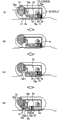
图9是表示该实施方式3的胶囊型医疗装置的概要结构的示意图。该胶囊型医疗装置具有对应于生物体组织拉入部10的生物体组织拉入部40,在胶囊型壳体1上形成有拉入生物体组织CE的粘膜抽吸口41。此外,在胶囊型壳体1内具有:减压装置43,其通过抽吸将生物体组织CE拉入到生物体组织拉入部40中;注射针驱动部50,其使注射针51突出到生物体组织拉入部40内的预定位置;凸轮装置44,其控制减压装置43和注射针驱动部50的动作时机;球囊42,其容纳药剂42a。FIG. 9 is a schematic diagram showing a schematic configuration of the capsule medical device according to the third embodiment. This capsule medical device has a living tissue suction part 40 corresponding to the living
关于该胶囊型医疗装置,首先,如图9的(a)、(b)所示,在拉入生物体组织CE的情况下,利用凸轮装置44的旋转,解除缸体固定爪44a对减压装置43内的隔板43b的限制。在减压装置43的减压用缸体43a内,利用隔板43b将设置在生物体组织拉入部40侧的伸长的弹簧43c维持在压缩状态。利用该隔板43b的解除,弹簧43c伸长,由连结管40a连结的生物体组织拉入部40内成为减压状态,将与胶囊型壳体1接触的生物体组织CE的粘膜抽吸口41附近的生物体组织CE作为卷入组织CE1拉入到生物体组织拉入部40内。With regard to this capsule medical device, first, as shown in (a) and (b) of FIG. The restriction of the partition 43b in the device 43. In the decompression cylinder 43a of the decompression device 43, the elongated spring 43c provided on the living tissue intake part 40 side is maintained in a compressed state by the partition plate 43b. When the partition plate 43b is released, the spring 43c is extended, and the inside of the living tissue drawing-in part 40 connected by the connecting tube 40a becomes a decompressed state, and the mucous membrane suction port 41 of the living tissue CE in contact with the
如图9的(b)、(c)所示,凸轮装置44比缸体固定爪44a的拉入滞后地进行拉入针固定爪44b的动作。关于注射针驱动部50,在缸体50a内插入有注射针51,注射针51的突出方向朝向生物体组织拉入部40侧。在缸体50a内,在注射针51的底部51a和缸体50a的底部之间,利用针固定爪44b将伸长的弹簧50b维持在压缩状态。若利用针固定爪44b的拉入释放注射针51的底部51a,则利用弹簧50b的伸长的按压力,使注射针51突出到生物体组织拉入部40内。As shown in (b) and (c) of FIG. 9 , the cam device 44 pulls in the needle fixing claw 44b later than the pulling in of the cylinder fixing claw 44a. In the injection needle drive unit 50 , an injection needle 51 is inserted into the cylinder 50 a, and the injection needle 51 protrudes toward the living tissue drawing-in unit 40 side. Inside the cylinder 50a, between the bottom 51a of the injection needle 51 and the bottom of the cylinder 50a, the elongated spring 50b is maintained in a compressed state by the needle fixing pawl 44b. When the bottom portion 51a of the injection needle 51 is released by pulling in the needle fixing claw 44b, the injection needle 51 is protruded into the living tissue drawing part 40 by the stretching pressing force of the spring 50b.
在此,注射针51在其顶端面的侧面上形成药液喷出口53,并且在其基端侧的侧面上形成药液导入口52,药液喷出口53和药液导入口52之间在细管状的注射针51的内部连通。另外,注射针51的顶端以被切削而形成为使穿刺动作变得容易,该顶端被堵塞而不会喷出药剂。在利用注射针驱动部50使注射针51突出到生物体组织拉入部40内的情况下,注射针51以如下方式突出:药液喷出口53位于生物体组织拉入部40的大致中央,药液导入口52位于能够与连结管42b的喷出口连结的位置,该连结管42b连结药液导入口52与球囊42之间。其结果,注射针51在完成突出动作即穿刺动作之后,如图9的(d)所示,利用球囊42的收缩力将药剂42a从药液喷出口53经由连结管42b、药液导入口52注入到卷入组织CE1。Here, the injection needle 51 has a liquid medicine discharge port 53 formed on the side surface of its distal end, and a liquid medicine inlet 52 formed on the side surface of the base end side, and the liquid medicine discharge port 53 and the liquid medicine introduction port 52 are separated. The inside of the thin tube-shaped injection needle 51 communicates. In addition, the tip of the injection needle 51 is cut to facilitate the puncturing operation, and the tip is blocked so that the drug cannot be ejected. When the injection needle driving part 50 is used to protrude the injection needle 51 into the living tissue drawing-in part 40, the injection needle 51 protrudes in such a manner that the liquid medicine ejection port 53 is located in the approximate center of the living tissue drawing-in part 40, and the medicine liquid The introduction port 52 is located at a position connectable to the discharge port of the connection tube 42 b connecting between the medical solution introduction port 52 and the balloon 42 . As a result, after the injection needle 51 completes the protruding action, that is, the puncturing action, as shown in (d) of FIG. 52 injected into the involved tissue CE1.
在该实施方式3中,由于利用抽吸机构拉入生物体组织CE,利用凸轮装置44进行生物体组织CE的拉入和注射针51的穿刺动作的时机调整,因此能够利用简单的装置自动地调整生物体组织CE的拉入动作和注射针51的穿刺动作的时机。In Embodiment 3, since the living tissue CE is pulled in by the suction mechanism, and the timing of pulling in the living tissue CE and the puncturing operation of the injection needle 51 is adjusted by the cam device 44, it is possible to use a simple device to automatically The timing of the drawing-in operation of the living tissue CE and the puncturing operation of the injection needle 51 is adjusted.
此外,由于在注射针51的侧部设置药液喷出口53,因此与在顶端的切割部设置喷出口的情况相比,能够使喷出口的直径较小,从而能够提高药液注入较薄的粘膜等的表层的位置精度。In addition, since the liquid medicine ejection port 53 is provided on the side of the injection needle 51, the diameter of the ejection port can be made smaller compared with the case where the ejection port is provided at the cutting portion of the tip, thereby improving the injection of the liquid drug into a thinner area. Positional accuracy of surface layers such as mucous membranes.
(实施方式3的变形例1)(
接着,说明本发明的实施方式3的变形例1。如图10所示,在该实施方式3的变形例1中,利用减压部盖61盖住对应于生物体组织拉入部40的生物体组织拉入部60的开口,从而封闭生物体组织拉入部60的空间。而且,删除了图9所示的减压装置43,预先使生物体组织拉入部60内处于减压状态。Next,
该减压部盖61例如可以由溶解于生物体内的体液等的材质形成而由此打开,也可以使用未图示的驱动器来机械地打开。该未图示的驱动器可以是利用外部磁场来打开的磁驱动器。The decompression unit cover 61 may be opened by being formed of a material such as body fluid dissolved in a living body, or may be opened mechanically using an unillustrated driver. The unillustrated drive may be a magnetic drive that opens using an external magnetic field.
另外,注射针65的穿刺是通过利用凸轮装置63解除固定爪64来进行。注射针65插入到与缸体50a相同的缸体内,压缩状态的弹簧67被维持着夹在注射针65的底部和设置在缸体底部的平衡锤66之间的状态。关于该状态,是利用凸轮装置63的固定爪64来夹持夹有弹簧67的注射针65的底部和平衡锤66,通过解除固定爪64使注射针65突出而穿刺生物体组织拉入部60内的生物体组织CE。在此,平衡锤66朝向注射针65的突出方向的相反侧移动,由此,胶囊型壳体1在注射针65突出时成为无反作用状态,胶囊型壳体1不会产生位置偏差,而能够稳定地进行注射针65的穿刺动作。之后,与上述实施方式3中药剂42a的情况相同,利用球囊62的收缩力并借助注射针65等将球囊62内的药剂62a注入到生物体组织拉入部60内的生物体组织CE。In addition, the puncture of the injection needle 65 is performed by releasing the fixing
在该实施方式3的变形例1中,能够通过简单的结构进行生物体组织CE的拉入动作,并且能够稳定地进行注射针65的穿刺动作。In
(实施方式3的变形例2)(
接着,说明本发明的实施方式3的变形例2。在上述实施方式3中,使用减压装置43对生物体组织拉入部40内部进行减压,从而拿进生物体组织CE,在该实施方式3的变形例2中,不使用减压装置43,而使注射针驱动部具有减压机构。Next,
即,如图11的(a)所示,注射针驱动部79在缸体内从底部起依次插入有伸长的弹簧78、隔板77、弹簧76、具有底部75a的注射针75。此外,借助连结管70a连通缸体内的底部附近的用于插入弹簧78的空间和生物体组织拉入部70。在此,如图11的(a)所示,凸轮装置73的固定爪74在初始状态下按压隔板77而将弹簧78保持为压缩状态。That is, as shown in FIG. 11( a ), the injection
之后,若凸轮装置73旋转,固定爪74被从缸体内拔出(参照图11的(b)),则如图11的(c)所示,隔板77被释放,弹簧78伸长。伴随该弹簧78的伸长,被隔板77划分形成的隔板77与缸体底部之间的空间成为减压状态,借助连结管70a使生物体组织拉入部70成为减压状态,其结果,借助粘膜抽吸口71从胶囊型壳体1外部的生物体组织CE将卷入组织CE1拉入生物体组织拉入部70内。Thereafter, when the
此时,虽然隔板77在弹簧78的伸展力下被向注射针75侧按压而移动,但是由于弹簧76暂时性地吸收隔板77的移动并被压缩,因此注射针75不会突出。之后,如图11的(d)所示,一旦弹簧78进一步伸长,隔板77、弹簧76、及注射针75就成为一体而向生物体组织拉入部70侧移动,注射针75穿刺到卷入组织CE1。在该穿刺之后,注射针75以如下方式停止:设置于注射针75的顶端侧的侧面的药液喷出口81位于生物体组织拉入部70内的大致中央,设置于注射针75的基部侧的药液导入口80位于连结药液导入口80与球囊72的连结管72b的喷出口。At this time, although the
在该停止位置中,由于药液导入口80与球囊72连通,因此利用球囊72的收缩力并借助药液导入口80挤出药剂72a,药剂72a从药液喷出口81注入到卷入组织CE1。In this stop position, since the
在该实施方式3的变形例2中,使用注射针驱动部79内的弹簧78进行生物体组织CE的抽吸动作及注射针75的穿刺动作,并且使用弹簧76进行从抽吸动作至穿刺动作的时机调整。In
另外,也可以不设置弹簧76及隔板77,而利用注射针75的底部保持弹簧78的压缩状态。该情况下的从吸引动作至穿刺动作的时机调整可通过调整注射针75的长度来进行。但是,优选的是设置弹簧76及隔板77,这样能够通过弹簧76来进行时机调整,从而能够实现紧凑的胶囊型医疗装置。In addition, the
(实施方式3的变形例3)(Modification 3 of Embodiment 3)
接着,说明本发明的实施方式3的变形例3。在该实施方式3的变形例3中,对应于实施方式1的变形例1而检测生物体组织CE的拉入。Next, Modification 3 of Embodiment 3 of the present invention will be described. In the modification 3 of the third embodiment, the drawing-in of the living tissue CE is detected corresponding to the
即,如图12所示,在连结管70a的中途设置具有减压泵和压力传感器的检测部90,在进行生物体组织CE的抽吸动作和注射针75的穿刺动作之前,利用减压泵进行抽吸,利用压力传感器获取该抽吸时的压力。其结果,在与减压动作之前相比压力减少的情况下,能够判断为粘膜抽吸口71被生物体组织CE堵塞,因此使凸轮装置73旋转,以使得进行利用注射针驱动部79的正式抽吸动作。另一方面,在与减压动作之前相比没有变化的情况下,考虑为在粘膜抽吸口71附近不存在生物体组织CE,不进行正式抽吸动作,而利用蠕动运动或者磁感应等感应动作来进行胶囊型医疗装置的移动。That is, as shown in FIG. 12 , a
另外,也可以替代检测部90,在粘膜抽吸口71的周围设置压力式、光学式等的各种接触传感器,判断粘膜抽吸口71是否被生物体组织CE覆盖,在判断为被覆盖的情况下,进行上述正式抽吸动作。In addition, instead of the
(实施方式3的变形例4)(Modification 4 of Embodiment 3)
此外,在该实施方式3的变形例4中,也可以如图13所示那样在注射针75的顶端部设置药液喷出口82。In addition, in Modification 4 of Embodiment 3, a drug
另外,在与上述实施方式对应的附图中,适当地省略了摄像部、照明部、无线电单元、控制部、电源、磁体等的功能。In addition, in the drawings corresponding to the above-mentioned embodiments, the functions of an imaging unit, an illumination unit, a radio unit, a control unit, a power supply, a magnet, and the like are appropriately omitted.
产业上的可利用性Industrial availability
如上所述,本发明的胶囊型医疗装置在对被检体内的生物体组织注入药剂的情况下有用,特别是适用于能够向目标生物体组织内可靠地注入药剂的胶囊型医疗装置。As described above, the capsule medical device of the present invention is useful for injecting a drug into a living tissue in a subject, and is particularly suitable for a capsule medical device capable of reliably injecting a drug into a target living tissue.
附图标记说明Explanation of reference signs
1胶囊型壳体;1a圆顶形状壳体;2照明部;3摄像部;4无线电单元;5控制部;6电源;7磁体;10、30、40、60、70生物体组织拉入部;11辊;12、34、51注射针;13磁性体;14连结构件;15螺旋弹簧;16螺线管;17、42、62、72球囊;18、42a、62a 药剂;19阀;20凸轮;21轴;22固定板;23爪;24弹簧;25电极;31、32臂;33卷入部;35驱动器;36转矩传感器;40a、42b 连结管;41粘膜抽吸口;43减压装置;50、79注射针驱动部;52、80药液导入口;53、82药液喷出口;61减压部盖;63、73凸轮装置;66平衡锤;90检测部;CE生物体组织;CE1卷入组织1 Capsule-shaped housing; 1a dome-shaped housing; 2 Illumination unit; 3 Camera unit; 4 Radio unit; 5 Control unit; 6 Power supply; 7 Magnet; 11 roller; 12, 34, 51 injection needle; 13 magnetic body; 14 connecting member; 15 coil spring; 16 solenoid; 17, 42, 62, 72 balloon; Cam; 21 shaft; 22 fixed plate; 23 claw; 24 spring; 25 electrode; 31, 32 arm; 33 involved part; 35 driver; 36 torque sensor; Pressure device; 50, 79 injection needle driving part; 52, 80 liquid medicine inlet; 53, 82 liquid medicine ejection port; 61 decompression part cover; organization; CE1 involved in the organization
Claims (9)
Applications Claiming Priority (3)
| Application Number | Priority Date | Filing Date | Title |
|---|---|---|---|
| JP2008-291444 | 2008-11-13 | ||
| JP2008291444 | 2008-11-13 | ||
| PCT/JP2009/068849 WO2010055796A1 (en) | 2008-11-13 | 2009-11-04 | Capsule-type medical device |
Publications (2)
| Publication Number | Publication Date |
|---|---|
| CN102209487A CN102209487A (en) | 2011-10-05 |
| CN102209487B true CN102209487B (en) | 2013-12-18 |
Family
ID=42169931
Family Applications (1)
| Application Number | Title | Priority Date | Filing Date |
|---|---|---|---|
| CN2009801450351A Expired - Fee Related CN102209487B (en) | 2008-11-13 | 2009-11-04 | Capsule-type medical device |
Country Status (5)
| Country | Link |
|---|---|
| US (1) | US8202247B2 (en) |
| EP (1) | EP2351511B1 (en) |
| JP (1) | JP4642934B2 (en) |
| CN (1) | CN102209487B (en) |
| WO (1) | WO2010055796A1 (en) |
Families Citing this family (38)
| Publication number | Priority date | Publication date | Assignee | Title |
|---|---|---|---|---|
| AU2010279575B2 (en) | 2009-08-03 | 2016-05-05 | Incube Labs, Llc | Swallowable capsule and method for stimulating incretin production within the intestinal tract |
| US8721620B2 (en) | 2009-12-24 | 2014-05-13 | Rani Therapeutics, Llc | Swallowable drug delivery device and methods of drug delivery |
| US9165703B2 (en) * | 2010-08-25 | 2015-10-20 | Brown University | Methods and systems for prolonged localization of drug delivery |
| US8776802B2 (en) * | 2010-08-25 | 2014-07-15 | Brown University | Methods and systems for prolonged localization of drug delivery |
| US8809269B2 (en) | 2010-12-23 | 2014-08-19 | Rani Therapeutics, Llc | Therapeutic agent preparations comprising insulin for delivery into a lumen of the intestinal tract using a swallowable drug delivery device |
| US9629799B2 (en) | 2010-12-23 | 2017-04-25 | Rani Therapeutics, Llc | Therapeutic agent preparations for delivery into a lumen of the intestinal tract using a swallowable drug delivery device |
| US9284367B2 (en) | 2010-12-23 | 2016-03-15 | Rani Therapeutics, Llc | Therapeutic agent preparations for delivery into a lumen of the intestinal tract using a swallowable drug delivery device |
| US9415004B2 (en) | 2010-12-23 | 2016-08-16 | Rani Therapeutics, Llc | Therapeutic agent preparations for delivery into a lumen of the intestinal tract using a swallowable drug delivery device |
| US8734429B2 (en) | 2010-12-23 | 2014-05-27 | Rani Therapeutics, Llc | Device, system and methods for the oral delivery of therapeutic compounds |
| US9283179B2 (en) | 2010-12-23 | 2016-03-15 | Rani Therapeutics, Llc | GnRH preparations for delivery into a lumen of the intestinal tract using a swallowable drug delivery device |
| US9402806B2 (en) | 2010-12-23 | 2016-08-02 | Rani Therapeutics, Llc | Therapeutic agent preparations for delivery into a lumen of the intestinal tract using a swallowable drug delivery device |
| US10639272B2 (en) | 2010-12-23 | 2020-05-05 | Rani Therapeutics, Llc | Methods for delivering etanercept preparations into a lumen of the intestinal tract using a swallowable drug delivery device |
| US8969293B2 (en) | 2010-12-23 | 2015-03-03 | Rani Therapeutics, Llc | Therapeutic agent preparations comprising exenatide for delivery into a lumen of the intestinal tract using a swallowable drug delivery device |
| US9259386B2 (en) | 2010-12-23 | 2016-02-16 | Rani Therapeutics, Llc | Therapeutic preparation comprising somatostatin or somatostatin analogoue for delivery into a lumen of the intestinal tract using a swallowable drug delivery device |
| US9861683B2 (en) | 2010-12-23 | 2018-01-09 | Rani Therapeutics, Llc | Therapeutic agent preparations for delivery into a lumen of the intestinal tract using a swallowable drug delivery device |
| US8980822B2 (en) | 2010-12-23 | 2015-03-17 | Rani Therapeutics, Llc | Therapeutic agent preparations comprising pramlintide for delivery into a lumen of the intestinal tract using a swallowable drug delivery device |
| US9402807B2 (en) | 2010-12-23 | 2016-08-02 | Rani Therapeutics, Llc | Therapeutic agent preparations for delivery into a lumen of the intestinal tract using a swallowable drug delivery device |
| JP5983736B2 (en) * | 2012-03-27 | 2016-09-06 | ソニー株式会社 | Capsule medical device |
| WO2014058605A1 (en) * | 2012-10-09 | 2014-04-17 | Medimetrics Personalized Drug Delivery | Drug delivery capsules with external intelligence |
| EP3318172B8 (en) * | 2016-11-04 | 2020-04-08 | Ovesco Endoscopy AG | Capsule endomicroscope for acquiring images of the surface of a hollow organ |
| IL270449B2 (en) | 2017-05-17 | 2025-02-01 | Massachusetts Inst Technology | Self-righting systems, methods, and related components |
| US11541015B2 (en) | 2017-05-17 | 2023-01-03 | Massachusetts Institute Of Technology | Self-righting systems, methods, and related components |
| CN108095806B (en) * | 2017-12-16 | 2023-04-28 | 重庆金山科技(集团)有限公司 | Adsorption puncture fixing device with self-locking function |
| CA3100710A1 (en) | 2018-05-17 | 2019-11-21 | Massachusetts Institute Of Technology | Systems for electrical stimulation |
| CN108742484B (en) * | 2018-05-30 | 2019-09-13 | 广州众健医疗科技有限公司 | A kind of Novel internal medicine gastroscope |
| CN113993560B (en) | 2019-02-01 | 2024-05-07 | 麻省理工学院 | Systems and methods for fluid injection |
| CN110151110B (en) * | 2019-06-05 | 2024-04-23 | 上海长海医院 | Fixed gastric bleeding monitoring capsule endoscope and gastric bleeding real-time monitoring system |
| US11541216B2 (en) | 2019-11-21 | 2023-01-03 | Massachusetts Institute Of Technology | Methods for manufacturing tissue interfacing components |
| WO2021186771A1 (en) * | 2020-03-19 | 2021-09-23 | 株式会社村田製作所 | Measuring device and measuring system |
| AU2021269780A1 (en) * | 2020-05-11 | 2022-11-17 | Biograil ApS | Drug delivery device |
| CN111888634B (en) * | 2020-07-30 | 2021-06-15 | 浙江大学 | An automatic drug delivery system and method |
| EP4284483A1 (en) * | 2021-01-29 | 2023-12-06 | Biograil APS | Drug delivery device with releasable attachment part |
| DK180991B1 (en) * | 2021-01-29 | 2022-09-06 | Biograil ApS | Drug delivery device with carrier and insert |
| BR112023015299A2 (en) * | 2021-01-29 | 2023-11-07 | Biograil ApS | DRUG DELIVERY DEVICE |
| FI130351B (en) * | 2021-04-21 | 2023-07-05 | Robomed Oy | Wireless capsule robot and system for operating a wireless capsule robot |
| CN113598690B (en) * | 2021-08-10 | 2023-07-28 | 安徽光阵光电科技有限公司 | An endoscopic pill for medical treatment inside the human body |
| DK181895B1 (en) * | 2022-10-28 | 2025-03-07 | Biograil ApS | Oral drug delivery device |
| KR102779373B1 (en) * | 2024-06-04 | 2025-03-12 | (주) 콘택코리아코퍼레이션 | needle assembly for skin treatment device and method for controlling the same |
Citations (6)
| Publication number | Priority date | Publication date | Assignee | Title |
|---|---|---|---|---|
| US4222380A (en) * | 1977-12-02 | 1980-09-16 | Olympus Optical Co., Ltd. | Celiac injector |
| WO1992015348A1 (en) * | 1991-03-01 | 1992-09-17 | Laparomed Corporation | Device and method for performing cholangiography |
| WO2002087657A2 (en) * | 2001-05-01 | 2002-11-07 | Intrapace, Inc. | Gastric device and suction assisted method for implanting a device on a stomach wall |
| US20040158125A1 (en) * | 2002-09-06 | 2004-08-12 | Aznoian Harold M. | Integrated endoscope and accessory treatment device |
| WO2005092433A1 (en) * | 2004-03-25 | 2005-10-06 | University College Cork - National University Of Ireland, Cork | Apparatus for prophylaxis or treatment of tissue |
| CN101184523A (en) * | 2005-05-27 | 2008-05-21 | 奥林巴斯株式会社 | Device introduced into the subject |
Family Cites Families (15)
| Publication number | Priority date | Publication date | Assignee | Title |
|---|---|---|---|---|
| JPS55136040A (en) | 1979-04-10 | 1980-10-23 | Olympus Optical Co | Capsule device for medical treatment |
| JPS55136041A (en) * | 1979-04-10 | 1980-10-23 | Olympus Optical Co | Capsule device for medical treatment |
| JPS55148540A (en) * | 1979-05-10 | 1980-11-19 | Olympus Optical Co | Capsule device for medical treatment |
| JPS55166142A (en) * | 1979-06-14 | 1980-12-25 | Olympus Optical Co | Capsule device for medical treatment |
| JPS5819232A (en) * | 1981-07-29 | 1983-02-04 | オリンパス光学工業株式会社 | Medical capsule |
| JPS5819233A (en) * | 1981-07-29 | 1983-02-04 | オリンパス光学工業株式会社 | Medical capsule |
| US5531692A (en) * | 1994-10-06 | 1996-07-02 | Rogers; William D. | Safety syringe |
| US6706000B2 (en) * | 1997-11-21 | 2004-03-16 | Amira Medical | Methods and apparatus for expressing body fluid from an incision |
| AU2003298538A1 (en) * | 2002-08-01 | 2004-05-04 | The Johns Hopkins University | Techniques for identifying molecular structures and treating cell types lining a body lumen using fluorescence |
| US8628547B2 (en) | 2004-03-09 | 2014-01-14 | Ethicon Endo-Surgery, Inc. | Devices and methods for placement of partitions within a hollow body organ |
| US9028511B2 (en) * | 2004-03-09 | 2015-05-12 | Ethicon Endo-Surgery, Inc. | Devices and methods for placement of partitions within a hollow body organ |
| US20080199065A1 (en) | 2004-05-17 | 2008-08-21 | Christopher Paul Swain | Method, System and Device for In-Vivo Biopsy |
| JP2008501466A (en) * | 2004-06-07 | 2008-01-24 | ギブン イメージング リミテッド | Aspiration biopsy method, system and apparatus |
| US7524284B2 (en) * | 2006-02-06 | 2009-04-28 | Olympus Medical Systems Corp. | Endoscopy system |
| JP5100336B2 (en) | 2007-11-29 | 2012-12-19 | オリンパスメディカルシステムズ株式会社 | Capsule medical device |
-
2009
- 2009-11-04 JP JP2010516099A patent/JP4642934B2/en not_active Expired - Fee Related
- 2009-11-04 EP EP09826046.6A patent/EP2351511B1/en not_active Not-in-force
- 2009-11-04 CN CN2009801450351A patent/CN102209487B/en not_active Expired - Fee Related
- 2009-11-04 WO PCT/JP2009/068849 patent/WO2010055796A1/en not_active Ceased
-
2010
- 2010-05-03 US US12/772,319 patent/US8202247B2/en active Active
Patent Citations (6)
| Publication number | Priority date | Publication date | Assignee | Title |
|---|---|---|---|---|
| US4222380A (en) * | 1977-12-02 | 1980-09-16 | Olympus Optical Co., Ltd. | Celiac injector |
| WO1992015348A1 (en) * | 1991-03-01 | 1992-09-17 | Laparomed Corporation | Device and method for performing cholangiography |
| WO2002087657A2 (en) * | 2001-05-01 | 2002-11-07 | Intrapace, Inc. | Gastric device and suction assisted method for implanting a device on a stomach wall |
| US20040158125A1 (en) * | 2002-09-06 | 2004-08-12 | Aznoian Harold M. | Integrated endoscope and accessory treatment device |
| WO2005092433A1 (en) * | 2004-03-25 | 2005-10-06 | University College Cork - National University Of Ireland, Cork | Apparatus for prophylaxis or treatment of tissue |
| CN101184523A (en) * | 2005-05-27 | 2008-05-21 | 奥林巴斯株式会社 | Device introduced into the subject |
Also Published As
| Publication number | Publication date |
|---|---|
| US8202247B2 (en) | 2012-06-19 |
| JPWO2010055796A1 (en) | 2012-04-12 |
| WO2010055796A1 (en) | 2010-05-20 |
| JP4642934B2 (en) | 2011-03-02 |
| CN102209487A (en) | 2011-10-05 |
| EP2351511A4 (en) | 2012-12-05 |
| US20100286668A1 (en) | 2010-11-11 |
| EP2351511A1 (en) | 2011-08-03 |
| EP2351511B1 (en) | 2014-04-02 |
Similar Documents
| Publication | Publication Date | Title |
|---|---|---|
| CN102209487B (en) | Capsule-type medical device | |
| JP4642941B2 (en) | Capsule medical device | |
| US9149172B2 (en) | System and apparatus for anchoring and operation of in-vivo medical devices | |
| US10064544B2 (en) | Endoscopic capsule and endoscopic system | |
| JP5100336B2 (en) | Capsule medical device | |
| JP4503979B2 (en) | Internal devices and medical devices | |
| JP5363020B2 (en) | Capsule type medical device and medical system | |
| CN101808567B (en) | Introduction-into-subject system | |
| KR101066820B1 (en) | Capsule medical device and capsule medical device retrieval system | |
| JP4520126B2 (en) | Capsule type medical device system | |
| JP4716922B2 (en) | Capsule type medical device and drug introduction system using the same | |
| JP2005103130A (en) | Capsule prescription system | |
| US20080242928A1 (en) | In vivo observation device | |
| JP4578740B2 (en) | Capsule medical device | |
| US20080234546A1 (en) | In vivo observation device | |
| JP2004041709A (en) | Capsule medical care device | |
| CN110151110B (en) | Fixed gastric bleeding monitoring capsule endoscope and gastric bleeding real-time monitoring system | |
| CA3167176A1 (en) | Ingestible apparatus and method for collecting samples in the gastrointestinal tract and/or delivering health-related substance thereto | |
| JP4811405B2 (en) | Capsule type medical device and diagnostic system | |
| HK1228235A1 (en) | Endoscopic capsule and endoscopic system |
Legal Events
| Date | Code | Title | Description |
|---|---|---|---|
| C06 | Publication | ||
| PB01 | Publication | ||
| C10 | Entry into substantive examination | ||
| SE01 | Entry into force of request for substantive examination | ||
| C14 | Grant of patent or utility model | ||
| GR01 | Patent grant | ||
| C41 | Transfer of patent application or patent right or utility model | ||
| TR01 | Transfer of patent right |
Effective date of registration: 20151126 Address after: Tokyo, Japan, Japan Patentee after: Olympus Corporation Address before: Tokyo, Japan, Japan Patentee before: Olympus Medical Systems Corp. |
|
| CF01 | Termination of patent right due to non-payment of annual fee | ||
| CF01 | Termination of patent right due to non-payment of annual fee |
Granted publication date: 20131218 Termination date: 20181104 |