KR20220048992A - Dosage-Type Device with Manipulation Capability - Google Patents
Dosage-Type Device with Manipulation Capability Download PDFInfo
- Publication number
- KR20220048992A KR20220048992A KR1020227003054A KR20227003054A KR20220048992A KR 20220048992 A KR20220048992 A KR 20220048992A KR 1020227003054 A KR1020227003054 A KR 1020227003054A KR 20227003054 A KR20227003054 A KR 20227003054A KR 20220048992 A KR20220048992 A KR 20220048992A
- Authority
- KR
- South Korea
- Prior art keywords
- capsule
- dosage form
- living body
- dosage
- interventional
- Prior art date
- Legal status (The legal status is an assumption and is not a legal conclusion. Google has not performed a legal analysis and makes no representation as to the accuracy of the status listed.)
- Ceased
Links
Images


Classifications
-
- A—HUMAN NECESSITIES
- A61—MEDICAL OR VETERINARY SCIENCE; HYGIENE
- A61B—DIAGNOSIS; SURGERY; IDENTIFICATION
- A61B10/00—Instruments for taking body samples for diagnostic purposes; Other methods or instruments for diagnosis, e.g. for vaccination diagnosis, sex determination or ovulation-period determination; Throat striking implements
- A61B10/02—Instruments for taking cell samples or for biopsy
- A61B10/04—Endoscopic instruments, e.g. catheter-type instruments
-
- A—HUMAN NECESSITIES
- A61—MEDICAL OR VETERINARY SCIENCE; HYGIENE
- A61B—DIAGNOSIS; SURGERY; IDENTIFICATION
- A61B1/00—Instruments for performing medical examinations of the interior of cavities or tubes of the body by visual or photographical inspection, e.g. endoscopes; Illuminating arrangements therefor
- A61B1/00002—Operational features of endoscopes
- A61B1/00004—Operational features of endoscopes characterised by electronic signal processing
- A61B1/00006—Operational features of endoscopes characterised by electronic signal processing of control signals
-
- A—HUMAN NECESSITIES
- A61—MEDICAL OR VETERINARY SCIENCE; HYGIENE
- A61B—DIAGNOSIS; SURGERY; IDENTIFICATION
- A61B1/00—Instruments for performing medical examinations of the interior of cavities or tubes of the body by visual or photographical inspection, e.g. endoscopes; Illuminating arrangements therefor
- A61B1/00002—Operational features of endoscopes
- A61B1/00004—Operational features of endoscopes characterised by electronic signal processing
- A61B1/00009—Operational features of endoscopes characterised by electronic signal processing of image signals during a use of endoscope
-
- A—HUMAN NECESSITIES
- A61—MEDICAL OR VETERINARY SCIENCE; HYGIENE
- A61B—DIAGNOSIS; SURGERY; IDENTIFICATION
- A61B1/00—Instruments for performing medical examinations of the interior of cavities or tubes of the body by visual or photographical inspection, e.g. endoscopes; Illuminating arrangements therefor
- A61B1/00002—Operational features of endoscopes
- A61B1/00011—Operational features of endoscopes characterised by signal transmission
- A61B1/00016—Operational features of endoscopes characterised by signal transmission using wireless means
-
- A—HUMAN NECESSITIES
- A61—MEDICAL OR VETERINARY SCIENCE; HYGIENE
- A61B—DIAGNOSIS; SURGERY; IDENTIFICATION
- A61B1/00—Instruments for performing medical examinations of the interior of cavities or tubes of the body by visual or photographical inspection, e.g. endoscopes; Illuminating arrangements therefor
- A61B1/00002—Operational features of endoscopes
- A61B1/0002—Operational features of endoscopes provided with data storages
-
- A—HUMAN NECESSITIES
- A61—MEDICAL OR VETERINARY SCIENCE; HYGIENE
- A61B—DIAGNOSIS; SURGERY; IDENTIFICATION
- A61B1/00—Instruments for performing medical examinations of the interior of cavities or tubes of the body by visual or photographical inspection, e.g. endoscopes; Illuminating arrangements therefor
- A61B1/00002—Operational features of endoscopes
- A61B1/00025—Operational features of endoscopes characterised by power management
- A61B1/00027—Operational features of endoscopes characterised by power management characterised by power supply
- A61B1/00032—Operational features of endoscopes characterised by power management characterised by power supply internally powered
-
- A—HUMAN NECESSITIES
- A61—MEDICAL OR VETERINARY SCIENCE; HYGIENE
- A61B—DIAGNOSIS; SURGERY; IDENTIFICATION
- A61B1/00—Instruments for performing medical examinations of the interior of cavities or tubes of the body by visual or photographical inspection, e.g. endoscopes; Illuminating arrangements therefor
- A61B1/00002—Operational features of endoscopes
- A61B1/00025—Operational features of endoscopes characterised by power management
- A61B1/00036—Means for power saving, e.g. sleeping mode
-
- A—HUMAN NECESSITIES
- A61—MEDICAL OR VETERINARY SCIENCE; HYGIENE
- A61B—DIAGNOSIS; SURGERY; IDENTIFICATION
- A61B1/00—Instruments for performing medical examinations of the interior of cavities or tubes of the body by visual or photographical inspection, e.g. endoscopes; Illuminating arrangements therefor
- A61B1/00064—Constructional details of the endoscope body
- A61B1/0011—Manufacturing of endoscope parts
-
- A—HUMAN NECESSITIES
- A61—MEDICAL OR VETERINARY SCIENCE; HYGIENE
- A61B—DIAGNOSIS; SURGERY; IDENTIFICATION
- A61B1/00—Instruments for performing medical examinations of the interior of cavities or tubes of the body by visual or photographical inspection, e.g. endoscopes; Illuminating arrangements therefor
- A61B1/00147—Holding or positioning arrangements
- A61B1/00156—Holding or positioning arrangements using self propulsion
-
- A—HUMAN NECESSITIES
- A61—MEDICAL OR VETERINARY SCIENCE; HYGIENE
- A61B—DIAGNOSIS; SURGERY; IDENTIFICATION
- A61B1/00—Instruments for performing medical examinations of the interior of cavities or tubes of the body by visual or photographical inspection, e.g. endoscopes; Illuminating arrangements therefor
- A61B1/00147—Holding or positioning arrangements
- A61B1/0016—Holding or positioning arrangements using motor drive units
-
- A—HUMAN NECESSITIES
- A61—MEDICAL OR VETERINARY SCIENCE; HYGIENE
- A61B—DIAGNOSIS; SURGERY; IDENTIFICATION
- A61B1/00—Instruments for performing medical examinations of the interior of cavities or tubes of the body by visual or photographical inspection, e.g. endoscopes; Illuminating arrangements therefor
- A61B1/04—Instruments for performing medical examinations of the interior of cavities or tubes of the body by visual or photographical inspection, e.g. endoscopes; Illuminating arrangements therefor combined with photographic or television appliances
- A61B1/041—Capsule endoscopes for imaging
-
- A—HUMAN NECESSITIES
- A61—MEDICAL OR VETERINARY SCIENCE; HYGIENE
- A61B—DIAGNOSIS; SURGERY; IDENTIFICATION
- A61B1/00—Instruments for performing medical examinations of the interior of cavities or tubes of the body by visual or photographical inspection, e.g. endoscopes; Illuminating arrangements therefor
- A61B1/04—Instruments for performing medical examinations of the interior of cavities or tubes of the body by visual or photographical inspection, e.g. endoscopes; Illuminating arrangements therefor combined with photographic or television appliances
- A61B1/045—Control thereof
-
- A—HUMAN NECESSITIES
- A61—MEDICAL OR VETERINARY SCIENCE; HYGIENE
- A61B—DIAGNOSIS; SURGERY; IDENTIFICATION
- A61B1/00—Instruments for performing medical examinations of the interior of cavities or tubes of the body by visual or photographical inspection, e.g. endoscopes; Illuminating arrangements therefor
- A61B1/06—Instruments for performing medical examinations of the interior of cavities or tubes of the body by visual or photographical inspection, e.g. endoscopes; Illuminating arrangements therefor with illuminating arrangements
- A61B1/0661—Endoscope light sources
-
- A—HUMAN NECESSITIES
- A61—MEDICAL OR VETERINARY SCIENCE; HYGIENE
- A61B—DIAGNOSIS; SURGERY; IDENTIFICATION
- A61B1/00—Instruments for performing medical examinations of the interior of cavities or tubes of the body by visual or photographical inspection, e.g. endoscopes; Illuminating arrangements therefor
- A61B1/31—Instruments for performing medical examinations of the interior of cavities or tubes of the body by visual or photographical inspection, e.g. endoscopes; Illuminating arrangements therefor for the rectum, e.g. proctoscopes, sigmoidoscopes, colonoscopes
-
- A—HUMAN NECESSITIES
- A61—MEDICAL OR VETERINARY SCIENCE; HYGIENE
- A61B—DIAGNOSIS; SURGERY; IDENTIFICATION
- A61B17/00—Surgical instruments, devices or methods
- A61B17/34—Trocars; Puncturing needles
- A61B17/3478—Endoscopic needles, e.g. for infusion
-
- A—HUMAN NECESSITIES
- A61—MEDICAL OR VETERINARY SCIENCE; HYGIENE
- A61B—DIAGNOSIS; SURGERY; IDENTIFICATION
- A61B17/00—Surgical instruments, devices or methods
- A61B17/34—Trocars; Puncturing needles
- A61B17/3494—Trocars; Puncturing needles with safety means for protection against accidental cutting or pricking, e.g. limiting insertion depth, pressure sensors
- A61B17/3496—Protecting sleeves or inner probes; Retractable tips
-
- H—ELECTRICITY
- H01—ELECTRIC ELEMENTS
- H01Q—ANTENNAS, i.e. RADIO AERIALS
- H01Q7/00—Loop antennas with a substantially uniform current distribution around the loop and having a directional radiation pattern in a plane perpendicular to the plane of the loop
-
- H—ELECTRICITY
- H01—ELECTRIC ELEMENTS
- H01Q—ANTENNAS, i.e. RADIO AERIALS
- H01Q9/00—Electrically-short antennas having dimensions not more than twice the operating wavelength and consisting of conductive active radiating elements
-
- H—ELECTRICITY
- H04—ELECTRIC COMMUNICATION TECHNIQUE
- H04B—TRANSMISSION
- H04B1/00—Details of transmission systems, not covered by a single one of groups H04B3/00 - H04B13/00; Details of transmission systems not characterised by the medium used for transmission
- H04B1/69—Spread spectrum techniques
- H04B1/713—Spread spectrum techniques using frequency hopping
-
- H—ELECTRICITY
- H04—ELECTRIC COMMUNICATION TECHNIQUE
- H04N—PICTORIAL COMMUNICATION, e.g. TELEVISION
- H04N17/00—Diagnosis, testing or measuring for television systems or their details
- H04N17/002—Diagnosis, testing or measuring for television systems or their details for television cameras
-
- H—ELECTRICITY
- H04—ELECTRIC COMMUNICATION TECHNIQUE
- H04N—PICTORIAL COMMUNICATION, e.g. TELEVISION
- H04N23/00—Cameras or camera modules comprising electronic image sensors; Control thereof
- H04N23/50—Constructional details
- H04N23/54—Mounting of pick-up tubes, electronic image sensors, deviation or focusing coils
-
- H—ELECTRICITY
- H04—ELECTRIC COMMUNICATION TECHNIQUE
- H04N—PICTORIAL COMMUNICATION, e.g. TELEVISION
- H04N23/00—Cameras or camera modules comprising electronic image sensors; Control thereof
- H04N23/56—Cameras or camera modules comprising electronic image sensors; Control thereof provided with illuminating means
-
- H—ELECTRICITY
- H04—ELECTRIC COMMUNICATION TECHNIQUE
- H04N—PICTORIAL COMMUNICATION, e.g. TELEVISION
- H04N23/00—Cameras or camera modules comprising electronic image sensors; Control thereof
- H04N23/60—Control of cameras or camera modules
- H04N23/66—Remote control of cameras or camera parts, e.g. by remote control devices
-
- H—ELECTRICITY
- H04—ELECTRIC COMMUNICATION TECHNIQUE
- H04N—PICTORIAL COMMUNICATION, e.g. TELEVISION
- H04N23/00—Cameras or camera modules comprising electronic image sensors; Control thereof
- H04N23/60—Control of cameras or camera modules
- H04N23/695—Control of camera direction for changing a field of view, e.g. pan, tilt or based on tracking of objects
-
- H04N5/23203—
-
- H—ELECTRICITY
- H04—ELECTRIC COMMUNICATION TECHNIQUE
- H04W—WIRELESS COMMUNICATION NETWORKS
- H04W76/00—Connection management
- H04W76/10—Connection setup
- H04W76/14—Direct-mode setup
-
- A—HUMAN NECESSITIES
- A61—MEDICAL OR VETERINARY SCIENCE; HYGIENE
- A61B—DIAGNOSIS; SURGERY; IDENTIFICATION
- A61B1/00—Instruments for performing medical examinations of the interior of cavities or tubes of the body by visual or photographical inspection, e.g. endoscopes; Illuminating arrangements therefor
- A61B1/06—Instruments for performing medical examinations of the interior of cavities or tubes of the body by visual or photographical inspection, e.g. endoscopes; Illuminating arrangements therefor with illuminating arrangements
-
- A—HUMAN NECESSITIES
- A61—MEDICAL OR VETERINARY SCIENCE; HYGIENE
- A61B—DIAGNOSIS; SURGERY; IDENTIFICATION
- A61B10/00—Instruments for taking body samples for diagnostic purposes; Other methods or instruments for diagnosis, e.g. for vaccination diagnosis, sex determination or ovulation-period determination; Throat striking implements
- A61B10/02—Instruments for taking cell samples or for biopsy
- A61B2010/0208—Biopsy devices with actuators, e.g. with triggered spring mechanisms
-
- A—HUMAN NECESSITIES
- A61—MEDICAL OR VETERINARY SCIENCE; HYGIENE
- A61B—DIAGNOSIS; SURGERY; IDENTIFICATION
- A61B10/00—Instruments for taking body samples for diagnostic purposes; Other methods or instruments for diagnosis, e.g. for vaccination diagnosis, sex determination or ovulation-period determination; Throat striking implements
- A61B10/02—Instruments for taking cell samples or for biopsy
- A61B10/04—Endoscopic instruments, e.g. catheter-type instruments
- A61B2010/045—Needles
-
- A—HUMAN NECESSITIES
- A61—MEDICAL OR VETERINARY SCIENCE; HYGIENE
- A61B—DIAGNOSIS; SURGERY; IDENTIFICATION
- A61B2562/00—Details of sensors; Constructional details of sensor housings or probes; Accessories for sensors
- A61B2562/16—Details of sensor housings or probes; Details of structural supports for sensors
- A61B2562/162—Capsule shaped sensor housings, e.g. for swallowing or implantation
-
- A—HUMAN NECESSITIES
- A61—MEDICAL OR VETERINARY SCIENCE; HYGIENE
- A61B—DIAGNOSIS; SURGERY; IDENTIFICATION
- A61B5/00—Measuring for diagnostic purposes; Identification of persons
- A61B5/07—Endoradiosondes
- A61B5/073—Intestinal transmitters
-
- H—ELECTRICITY
- H04—ELECTRIC COMMUNICATION TECHNIQUE
- H04N—PICTORIAL COMMUNICATION, e.g. TELEVISION
- H04N23/00—Cameras or camera modules comprising electronic image sensors; Control thereof
- H04N23/50—Constructional details
- H04N23/555—Constructional details for picking-up images in sites, inaccessible due to their dimensions or hazardous conditions, e.g. endoscopes or borescopes
-
- H—ELECTRICITY
- H04—ELECTRIC COMMUNICATION TECHNIQUE
- H04N—PICTORIAL COMMUNICATION, e.g. TELEVISION
- H04N23/00—Cameras or camera modules comprising electronic image sensors; Control thereof
- H04N23/60—Control of cameras or camera modules
- H04N23/65—Control of camera operation in relation to power supply
- H04N23/651—Control of camera operation in relation to power supply for reducing power consumption by affecting camera operations, e.g. sleep mode, hibernation mode or power off of selective parts of the camera
-
- H—ELECTRICITY
- H04—ELECTRIC COMMUNICATION TECHNIQUE
- H04N—PICTORIAL COMMUNICATION, e.g. TELEVISION
- H04N5/00—Details of television systems
- H04N5/38—Transmitter circuitry for the transmission of television signals according to analogue transmission standards
- H04N5/40—Modulation circuits
Landscapes
- Health & Medical Sciences (AREA)
- Life Sciences & Earth Sciences (AREA)
- Engineering & Computer Science (AREA)
- Surgery (AREA)
- General Health & Medical Sciences (AREA)
- Biomedical Technology (AREA)
- Public Health (AREA)
- Veterinary Medicine (AREA)
- Animal Behavior & Ethology (AREA)
- Pathology (AREA)
- Molecular Biology (AREA)
- Medical Informatics (AREA)
- Heart & Thoracic Surgery (AREA)
- Nuclear Medicine, Radiotherapy & Molecular Imaging (AREA)
- Radiology & Medical Imaging (AREA)
- Physics & Mathematics (AREA)
- Biophysics (AREA)
- Optics & Photonics (AREA)
- Signal Processing (AREA)
- Multimedia (AREA)
- Computer Networks & Wireless Communication (AREA)
- Manufacturing & Machinery (AREA)
- Endoscopes (AREA)
- Measurement Of The Respiration, Hearing Ability, Form, And Blood Characteristics Of Living Organisms (AREA)
- Surgical Instruments (AREA)
Abstract
캡슐과, 중재 툴과, 및 중재 툴을 제어 가능하게 사용하여 중재 툴이 생체 내의 구조들을 조작하게 하도록 구성된 프로세서를 구비할 수 있는 복용형 장치가 이 명세서에 소개된다. 복용형 장치는 복용형 장치가 생체를 통과함에 따라 다양한 생체내 환경의 이미지들을 생성하도록 구성된 카메라를 더 구비한다. 이 이미지들은 생체 외부에 위치한 전자기기로 무선 전송되어 중재 툴에 더 많은 제어를 가능하게 한다.Disclosed herein is a dosage form device that can include a capsule, an interventional tool, and a processor configured to controllably use the interventional tool to cause the interventional tool to manipulate structures in a living body. The dosage form further includes a camera configured to generate images of the various in vivo environments as the dosage device passes through the living body. These images are wirelessly transmitted to an electronic device located outside the living body, giving the intervention tool more control.
Description
관련 출원들과의 상호 참조CROSS-REFERENCE TO RELATED APPLICATIONS
본원은 2019년 6월 28일 출원된 "추진 및 이미징 능력을 갖는 복용형 장치(Ingestible Device with Propulsion and Imaging Capabilities)"라는 명칭의 미국특허가출원 제62/868,109호에 대한 우선권(효익)을 주장하는 바, 이는 그 전체로서 이 명세서에 참고로 포함된다.This application claims priority (benefit) to U.S. Provisional Patent Application No. 62/868,109, entitled "Ingestible Device with Propulsion and Imaging Capabilities," filed on June 28, 2019. which is incorporated herein by reference in its entirety.
기술분야technical field
여러 실시예들은 생체(living body) 내부에 위치하는 생체 구조(biological structure)의 이미지(image)들을 생성한 다음 이 이미지를 생체 외부에 위치한 전자장치로 전송하도록 설계된 장치에 관한 것이다.Various embodiments relate to a device designed to generate images of a biological structure located inside a living body and then transmit the images to an electronic device located outside the living body.
내시경 기법(endoscopy)은 생체 내부의 구조들이 유연한 튜브(flexible tube)의 단부에 고정된 카메라로 시각적 검사되는 의료 절차이다. 이와는 달리, 유연한 튜브의 단부 부근에서 노출된 광섬유(optical fiber)가 생체 내부의 구조들에 반사된 빛을 생체 외부에 위치한 카메라로 반송할 수 있다. 유연한 튜브는 카메라를 위치시키거나 광섬유를 원하는 위치에 위치시키는 데 사용된다. 의료 전문가(medical professional)는 카메라로 생성된 이미지들을 검사함으로써 생체에 영향을 미치는 조건들을 진단할 수 있게 된다. 예를 들어, 상부 내시경(upper endoscopy) 동안, 유연한 튜브는 입 또는 코를 통해 삽입되어 의료 전문가가 식도(esophagus), 위장(stomach), 또는 ("십이지장(duodenum)"으로도 지칭되는) 소장(small intestine)의 상부를 검사할 수 있게 된다. ("결장검사(colonoscopy)"로도 지칭되는) 하부 내시경은 직장(rectum)을 통해 삽입되어, 의료 전문가가 ("결장(colon)"으로도 지칭되는) 대장(large intestine)을 검사할 수 있게 된다.Endoscopy is a medical procedure in which internal structures of a living body are visually inspected with a camera fixed to an end of a flexible tube. Alternatively, an optical fiber exposed near the end of the flexible tube may return light reflected from structures inside the living body to a camera located outside the living body. The flexible tube is used to position the camera or position the optical fiber in the desired position. A medical professional can diagnose conditions affecting a living body by examining images generated by a camera. For example, during upper endoscopy, a flexible tube is inserted through the mouth or nose so that the healthcare professional can enter the esophagus, stomach, or small intestine (also referred to as "duodenum"). The upper part of the small intestine) can be examined. A lower endoscope (also referred to as “colonoscopy”) is inserted through the rectum, allowing medical professionals to examine the large intestine (also referred to as “colon”). .
내시경 기법의 품질과, 신뢰성, 및 안전성에 있어 진보들이 이뤄졌다. 예를 들어, 카메라 해상도의 향상은 의료 전문가가 더 많은 정보를 가진(more informed)(이에 따라 더 정확한) 의견을 제공할 수 있게 하였다. 그러나 내시경 기법은 침습적(invasive) 절차이므로 몇 가지 잠재적 합병증(complication)들이 있다. 환자들은 감염(infection), (사망을 포함하여) 진정제(sedation)에 대한 예기치 못한 반응, 예를 들어 조직검사(biopsy test)의 일부로 검사를 위한 조직의 제거에 기인하는) 출혈(bleeding) 또는 특히 화학요법(chemotherapy) 약물이 위장 기관(gastrointestinal(GI) tract)을 약화시킨 암 환자, 또는 해부학적 구조(anatomy)가 더 연약하거나 및/또는 물리적으로 더 작은 소아(pediatric) 환자에 있어서, 맥관(tortuosity)을 통해 유연한 관을 전진시키는 마찰에 기인하는 조직의 열상(tearing)을 겪을 수 있다.Advances have been made in the quality, reliability, and safety of endoscopic techniques. For example, improvements in camera resolution have enabled medical professionals to provide more informed (and thus more accurate) opinions. However, since the endoscopic technique is an invasive procedure, there are several potential complications. Patients may experience infection, unexpected reactions to sedation (including death), for example, bleeding due to removal of tissue for examination as part of a biopsy test, or in particular In cancer patients in which chemotherapy drugs have weakened the gastrointestinal (GI) tract, or in pediatric patients with more fragile and/or physically smaller anatomy, the vascular ( Tissue may experience tearing due to friction that advances the flexible tube through tortuosity.
뿐만 아니라, 내시경 기법은 값비싼 병원 자원들을 요구하는 시간 소모적 과정이 될 수 있다 예를 들어 환자는 집에서 내시경 준비를 교육받고, 의료기관(medical setting)으로 이동하여, 충분한 회복이 이뤄질 때까지 의료기관에 남을 수 있다. 내시경 자체는 15-30분밖에 걸리지 않음에도 이 과정은 8-12 시간을 소요할 수 있다. 병원 또는 의원 등의 의료기관에서 소요하는, 진정제 투여(sedation)에 연계된 회복 시간이 이 절차의 전체적 원가에 중요한 기여 인자(significant contributor)가 될 수 있다.In addition, endoscopic techniques can be a time-consuming process that requires expensive hospital resources. For example, the patient is trained in endoscopic preparation at home, then moved to a medical setting, where he/she may be admitted to a medical institution until adequate recovery is achieved. can remain Although the endoscope itself takes only 15-30 minutes, this process can take 8-12 hours. The recovery time associated with sedation, spent in a medical institution such as a hospital or clinic, can be a significant contributor to the overall cost of this procedure.
발명의 상세한 설명(Detailed Description)을 도면들에 연계하여 검토하면 이 기술(본 발명)의 여러 특징들이 당업계에 통상의 기술을 가진 자에게 더욱 명확해질 것이다. 이 기술의 실시예들은 한정이 아니라 예로서 도시된 것이며, 도면들에서 유사한 참조번호들은 유사한 부재들을 지시할 수 있다.
도 1은 인체 또는 동물 신체 등의 생체를 통해 그 자체의 동력으로 항행(travel)하면서 생체내(in vivo) 환경을 감시하도록 설계된 추진식 복용형 장치의 하나의 예의 단면도를 포함한다.
도 2a는 복용형 장치의 탑재부의 전부 사시도를 포함한다.
도 2b는 도 2a의 복용형 장치의 탑재부의 후부 사시도를 포함한다.
도 3은 복용형 장치의 동력부의 사시도를 포함한다.
도 4는 복용형 장치의 구동부의 사시도를 포함한다.
도 5a는 복용형 장치의 추진부의 사시도를 포함한다.
도 5b는 도 5a의 복용형 장치의 추진부의 투과(transparent) 사시도를 포함한다.
도 5c는 프로펄서들이 복용형 장치의 원격 부재 내의 고정자 블레이드들에 인접하여 배치되는 방식을 보이는 사시도를 도시한다.
도 5d는 도 5c의 원격 부재의 분리 배면도이다.
도 6a는 이를 관통하는 중심축을 갖는 둥근 구조체를 포함하는 복용형 장치의 사시도를 포함한다.
도 6b는 도 6a의 복용형 장치의 측면도를 포함한다.
도 6c는 도 6a의 복용형 장치의 배면도를 포함한다.
도 7a는 펀칭 또는 천공된 시트로 형성된 시일을 모터축의 직경에 비해 작게 함으로써 시일과 모터축 간에 단일한 접촉선의 생성을 가능하게 하는 방법을 보이는 복용형 장치의 단면도.
도 7b는 시일이 주 시일 몸체 내부에 매립될 때 형성된 포켓 내에 오리피스 디스크가 고정되는 방법을 도시한다.
도 8a는 전개 상태의 유연한 인쇄회로기판 조립체(PCBA)의 하나의 예를 도시한다.
도 8b는 도 8a의 유연한 PCBA의 절첩 상태를 도시한다.
도 9는 생체에 복용되도록 설계된 장치와 이를 통해 복용형 장치의 운동이 제어되는 컨트롤러 간의 통신을 보이는 개략도(high-level illustration)를 포함한다.
도 10은 생체에 복용되도록 설계된 장치를 사용하여 생체내 환경을 감시하는 프로세스의 흐름도를 도시한다.
도 11은 광학 센서를 갖는 추진식 복용형 장치가 생체를 통과하는 동안 제어하는 프로세스의 흐름도를 도시한다.
도 12는 주변 환경을 조작하는 중재 컴포넌트를 갖는 복용형 장치와 이를 통해 중재 컴포넌트가 제어될 수 있는 컨트롤러 간의 통신의 개략도를 포함한다.
도 13은 캡슐의 근접단에 위치한 복수의 중재 컴포넌트들을 구비하는 복용형 장치의 사시도이다.
도 14는 복용형 장치의 각 중재 컴포넌트가 캡슐 내부에 포함된 별도의 디스크 상에 장착될 수 있는 방식을 보인다.
도 15는 해당 중재 컴포넌트들에 요구되는 구동 기구(들)을 포함하는 베이들의 방사형 배치를 보이는 사시도 및 단부도를 포함한다.
도 16은 생체 내의 구조로부터 샘플을 채취한 다음 추가적인 분석을 위해 이 샘플을 저장할 수 있는 조직검사 기구를 구비하는 복용형 장치의 사시도를 포함한다.
도 17은 복용형 장치가, 그 안에 샘플들이 밀봉될 수 있는 하나 이상의 저장 베이들을 포함하는 방식을 보인다.
도 18a는 조직으로부터 돌출한 용종을 절제할 수 있는 중재 컴포넌트를 구비하는 복용형 장치의 사시도이다.
도 18b는 용종을 절제할 수 있는 중재 컴포넌트를 구비하는 다른 복용형 장치의 사시도이다.
도 19는 절단을 위한 하나 이상의 날카로운 날을 갖는 중재 컴포넌트를 구비하는 복용형 장치의 사시도이다.
도 20은 생체 내의 구조를 파지할 수 있는 중재 컴포넌트의 4개의 예들을 포함한다.
도 21은 그 근접단 둘레에 고정될 수 있는 하나 이상의 탄성 밴드들을 갖는 복용형 장치의 측면도들을 포함한다.
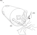
도 22는 일시적으로 순환혈액을 배출하도록 조직을 가압하는 데 사용되는 뭉툭한 형태를 갖는 중재 컴포넌트를 포함하는 복용형 장치의 사시도이다.
도 23은 안정화에 사용될 수 있는 복수의 정착 부재들을 포함하는 복용형 장치의 사시도, 측면도, 및 단부도를 포함한다.
도 24a는 거기에 저장된 물질을 갖는 일련의 중재 컴포넌트들을 포함하는 복용형 장치의 측면도 및 단부도를 포함한다.
도 24b는 거기에 저장된 물질을 갖는 중재 컴포넌트가 스프링으로 작동될 수 있는 방식을 보인다.
도 25는 수술용 스태플을 저장한 다음 설치할 수 있는 중재 컴포넌트를 포함하는 복용형 장치의 사시도를 포함한다.
도 26은 생체 내부의 조직을 소작할 수 있는 중재 컴포넌트를 포함하는 복용형 장치의 사시도를 포함한다.
도 27은 컨트롤러와 통신 접속된 추진식 복용형 장치를 포함하는 통신 환경의 하나의 예를 도시한다.
도 28은 이 명세서에 기재된 작동들의 적어도 일부가 구현될 수 있는 처리 시스템의 예를 보이는 블록도이다.Various features of this technology (invention) will become more apparent to those of ordinary skill in the art upon review of the Detailed Description in connection with the drawings. Embodiments of this technology are shown by way of example and not limitation, and like reference numerals in the drawings may indicate like elements.
1 includes a cross-sectional view of one example of a propelled dosage form device designed to monitor an in vivo environment while traveling on its own power through a living body, such as a human or animal body.
2A includes a front perspective view of a mount of a dosage form device;
FIG. 2B includes a rear perspective view of the mount of the dosage form device of FIG. 2A ;
3 includes a perspective view of a power unit of the dosage form device.
4 includes a perspective view of a drive portion of a dosage form device.
5A includes a perspective view of a propulsion portion of a dosage form device.
FIG. 5B includes a transparent perspective view of the propulsion portion of the dosage form device of FIG. 5A .
5C shows a perspective view showing how the propulsors are disposed adjacent to the stator blades in the remote member of the dosage device.
5D is an exploded rear view of the remote member of FIG. 5C;
6A includes a perspective view of a dosage form device comprising a round structure having a central axis therethrough.
6B includes a side view of the dosage device of FIG. 6A .
6C includes a rear view of the dosage form device of FIG. 6A .
7A is a cross-sectional view of a dosage form device showing a method of enabling the creation of a single line of contact between the seal and the motor shaft by making the seal formed from a punched or perforated sheet small relative to the diameter of the motor shaft.
7B shows how the orifice disk is secured within a pocket formed when the seal is embedded within the main seal body.
8A shows one example of a flexible printed circuit board assembly (PCBA) in a deployed state.
Figure 8b shows the folded state of the flexible PCBA of Figure 8a.
9 includes a high-level illustration showing communication between a device designed to be administered to a living body and a controller through which motion of the dosage device is controlled.
10 depicts a flow diagram of a process for monitoring an in vivo environment using a device designed to be administered to a living body.
11 depicts a flow diagram of a process for controlling a propelled dosage device having an optical sensor while passing through a living body.
12 includes a schematic diagram of communication between a dosage form device having an intervention component that manipulates the surrounding environment and a controller through which the intervention component can be controlled.
13 is a perspective view of a dosage form device having a plurality of interventional components positioned at a proximal end of a capsule;
14 shows how each interventional component of the dosage device can be mounted on a separate disk contained within the capsule.
15 includes perspective and end views showing the radial arrangement of the bays including the drive mechanism(s) required for the interventional components in question;
16 includes a perspective view of a dosage form device having a biopsy instrument capable of taking a sample from an in vivo structure and then storing the sample for further analysis.
17 shows the manner in which the dosage device includes one or more storage bays within which samples may be sealed.
18A is a perspective view of a dosage device having an interventional component capable of resecting a polyp protruding from tissue.
18B is a perspective view of another dosage device having an interventional component capable of resecting a polyp.
19 is a perspective view of a dosage form having an interventional component having one or more sharp edges for cutting.
20 includes four examples of an interventional component capable of gripping a structure in vivo.
21 includes side views of a dosage form device having one or more elastic bands that can be secured around its proximal end.
22 is a perspective view of a dosage form device comprising an interventional component having a blunt shape used to pressurize tissue to temporarily expel circulating blood.
23 includes a perspective view, a side view, and an end view of a dosage form device including a plurality of anchorage members that may be used for stabilization.
24A includes side and end views of a dosage form device including a series of interventional components having substances stored therein;
24B shows how an intervening component with material stored therein can be actuated with a spring.
25 includes a perspective view of a dosage device including an interventional component capable of storing and then installing surgical staples.
26 includes a perspective view of a dosage form device including an interventional component capable of cauterizing tissue within a living body.
27 depicts one example of a communications environment comprising a propelled dosage device communicatively coupled to a controller.
28 is a block diagram illustrating an example of a processing system in which at least some of the operations described herein may be implemented.
현대의 연구들은 어떻게 생체내 환경(in vivo environment)을 더 효율적인 방법으로 감시할지를 모색하기 시작했다. 예를 들어, 몇몇 기관들은 소화관(digestive tract)의 이미지들을 캡처할(capturing) 수 있는 카메라를 개발해왔다. 일반적으로 이 카메라는 환자가 삼킬 수 있는 알약 크기(vitamin-size)의 캡슐(capsule) 내에 위치된다. 이 카메라는 캡슐이 소화관을 이동(travel)함에 따라 수백 또는 수천 개의 이미지들을 생성할 수 있고, 이 이미지들은 환자가 반송(carry)하는 전자장치로 무선 전송될 수 있다. 이 과정은 "캡슐 내시경(capsule endoscopy)" 기법으로 지칭된다.Modern research is beginning to explore how to monitor the in vivo environment in a more efficient way. For example, several institutions have developed cameras that can capture images of the digestive tract. Typically, the camera is placed in a vitamin-size capsule that can be swallowed by a patient. The camera can generate hundreds or thousands of images as the capsule travels through the digestive tract, and these images can be wirelessly transmitted to the electronics that the patient carries. This procedure is referred to as a “capsule endoscopy” technique.
캡슐 내시경 기법은 종래의 내시경으로 쉽게 도달할 수 없는 소장(small intestine) 등의 생체내 환경을 의료 전문가(medical professional)가 관찰할 수 있게 해준다. 그러나 캡슐 내시경 기법은 여전히 비교적 흔치않은 과정이다. 그 하나의 이유는 캡슐의 섭취(ingestion)를 따르는 카메라에 대한 제어의 결여이다. 소화관을 통해 무동력으로(naturally) 이동하므로 캡슐의 방향 때문에 카메라가 관심 영역을 놓칠 수 있다. 다른 이유는 캡슐 내시경 기법에 사용되는 장치가 목표 구조(target anatomy)에 도달하는 데 수 시간이 걸리고, 이미지들(imagery)의 기록에 다시 수 시간이 더 걸린다는 것이다. 그러면 환자는 기록된 이미지들을 전달하기 위해 (예를 들어 병원 또는 의원 등의) 의료기관으로 돌아와야 할 수 있다.The capsule endoscopy technique allows a medical professional to observe an in vivo environment such as a small intestine that cannot be easily reached with a conventional endoscope. However, capsule endoscopy is still a relatively uncommon procedure. One reason is the lack of control over the camera following ingestion of the capsule. As it moves naturally through the digestive tract, the orientation of the capsule may cause the camera to miss the region of interest. Another reason is that the device used in the capsule endoscopy technique takes several hours to reach the target anatomy, and again several hours to record the images. The patient may then have to return to the medical institution (eg a hospital or clinic) to deliver the recorded images.
이에 따라, 이 명세서에는 ("외피(enclosure)"로도 지칭되는) 캡슐과, 카메라와, 안테나와, 및 하나 이상의 추진 컴포넌트들 및 추전 제어 부재들을 구비하는 ("알약(pill)" 또는 "알약로봇(pillbot)"으로도 지칭되는) 추진식 복용형 장치(propulsive ingestible device)가 소개된다. 복용형 장치가 생체를 통해 그 자체로 추진되도록 설계되므로, 이 복용형 장치는 "추진식 장치(propulsive device)"로도 지칭될 수 있다. Accordingly, this specification includes a capsule (also referred to as an “enclosure”), a camera, an antenna, and one or more propulsion components and propulsion control members (“pill” or “pill robot”) A propulsive ingestible device (also referred to as "a pillbot") is introduced. As the dosage form device is designed to propel itself through a living body, the dosage form device may also be referred to as a "propulsive device".
복용형 장치가 위장 기관(gastrointestinal tract)을 항행(traverse)함에 따라 카메라는 이미지들을 생성할 수 있다. 카메라는 예를 들어 2, 6, 또는 15 초당 프레임(frames per second; fps)의 프레임 속도(frame rate)로 이미지들을 캡처하도록 설계될 수 있다. 프레임 속도는 복용형 장치가 항행하는 속도에 기반하여 변화될 수 있다. 예를 들어, 복용형 장치는 속도가 상승함에 따라 프레임 속도를 증가시키도록 설계될 수 있다. 카메라로 생성된 이미지들은 안테나로 전달되어 생체 외부에 위치하는 전자장치로 전송된다. 더 구체적으로, 프로세서가 전자장치로 전송하기 위한 이미지들의 안테나로의 변조(modulating)를 담당하는 송수신기(transceiver)로 전송할 수 있다. 일부 실시예들에서, 이미지들은 전자장치에 실시간으로 전송되어 의료 전문가는 이 이미지들의 내용에 기반하여 적절한 행동(들)을 취할 수 있다. 예를 들어, 의료 전문가는 이미지들의 검토(reviewing)에 따라 추가적 검사(examination)를 요구하는 관심 영역(area of interest)을 탐색(discover)할 수 있다. 이러한 시나리오에서, 추진 컴포넌트(들)는 추진식 복용형 장치의 방향을 제어(orient)할 수 있어서 카메라가 관심 영역에 집중할 수 있다. 이러한 동작은 복용형 장치가 (예를 들어 이미지, 생체 측정치 등) 관심 영역에 관한 추가적 데이터를 수집하도록 할 수 있다.The camera may generate images as the dosage device traverses the gastrointestinal tract. The camera may be designed to capture images at a frame rate of, for example, 2, 6, or 15 frames per second (fps). The frame rate may be varied based on the speed at which the dosage device is navigating. For example, the dosage form device may be designed to increase the frame rate as the rate increases. The images generated by the camera are transmitted to an antenna and transmitted to an electronic device located outside the living body. More specifically, the processor may transmit to a transceiver responsible for modulating images to an antenna for transmission to the electronic device. In some embodiments, the images are transmitted to the electronic device in real time so that the medical professional can take appropriate action(s) based on the content of these images. For example, the medical professional may discover an area of interest that requires additional examination according to reviewing images. In such a scenario, the propulsion component(s) may orient the propulsive dosage device so that the camera can focus on the area of interest. Such actions may cause the dosage form device to collect additional data regarding the region of interest (eg, images, biometrics, etc.).
의료 전문가(medical professional)는 일반의(general practitioner), (예를 들어 외과의사, 위장병 전문의(gastroenterologist) 등의) 전문의(specialist). 간호사, 또는 복용형 장치가 생체를 통과할 때 이를 관리하는 기술전문가가 될 수 있다. 종래의 내시경과 달리, 의료 전문가가 검사를 받는 ("대상(subject)"으로도 지칭되는) 환자의 근방에 위치할 필요가 없다. 예를 들어, 환자가 가정이나 전장 들 다른 환경에 있는 동안, 의료 전문가는 원격의 병원에 위치한 전자장치 상의 카메라로 생성된 이미지들을 검사할 수 있다. 이와 같은 방식으로, 전통적인 위장 기관(GI) 과의 능력이 이 명세서에 기재된 기술을 사용하여 확장될 수 있다.A medical professional is a general practitioner, a specialist (eg, a surgeon, gastroenterologist, etc.). It could be a nurse, or a technical expert who manages the dosage device as it passes through the body. Unlike conventional endoscopes, there is no need for a medical professional to be located in the vicinity of the patient being examined (also referred to as a “subject”). For example, while a patient is in a home, battlefield, or other environment, a medical professional may examine images generated by a camera on an electronic device located in a remote hospital. In this way, capabilities with the traditional gastrointestinal (GI) tract can be extended using the techniques described herein.
일부 실시예들에서, 복용형 장치는 생체 내의 구조들을 조작(manipulate)하는 데 사용될 수 있는 ("중재 장치(intervention device)", "중재 기구(intervention mechanism)", "도구(implement)", 또는 "툴(tool)"로도 지칭되는) 적어도 하나의 중재 컴포넌트를 포함한다. 이 중재 컴포넌트(들)는 카메라로 생성되는 이미지들의 분석 이상의(beyond) 심화된(advanced) 진단 및 치료가 수행될 수 있게 한다. 후술할 바와 같이, 복용형 장치는 용액 및/또는 조직을 샘플링하고(sample), 약물(medication)을 전달(deliver)하며, 후속적인 재채취(reacquisition)를 위한 해부학적 부위(anatomical site)의 마킹(mark), 조직의 소작(cauterize), 및 다른 절차들에 사용될 수 있다. 대체적으로(at a high level), 중재 컴포넌트(들)의 구비는 복용형 장치가 전통적으로 종래의 내시경을 사용하여 의료 전문가만이 수행할 수 있던 진단 및/또는 중재를 수행할 수 있데 해준다.In some embodiments, the dosage form device can be used to manipulate structures in vivo (“intervention device”, “intervention mechanism”, “implement”, or at least one mediation component (also referred to as a “tool”). This intervention component(s) enables advanced diagnosis and treatment beyond the analysis of camera-generated images to be performed. As described below, the dosage form device samples solutions and/or tissues, delivers medication, and marks anatomical sites for subsequent reacquisition. It can be used for mark, cauterize tissue, and other procedures. At a high level, the provision of the interventional component(s) enables the dosage form device to perform diagnostics and/or interventions that could traditionally be performed only by medical professionals using conventional endoscopes.
실시예들은 특정한 캡슐 형태, 추진 컴포넌트, 센서, 네트워크 등을 참조하여 설명될 수 있다. 그러나 당업계에 통상의 기술을 가진 자라면 이 실시예들의 특징들이 다른 캡슐 형태, 추진 컴포넌트, 센서, 네트워크 등에도 마찬가지로 적용될 수 있음을 인식할 것이다. 예를 들어, 특징이 십자형(cross-type) 구조로 배치된 복수의 프로펠러(propeller)들을 갖는 복용형 센서의 맥락에서 설명될 수 있지만, 이 특징은 달리 배치된 다른 종류의 프로펄서(propulsor) 또는 프로펠러, 또는 그 변형들의 조합을 갖는 복용형 센서로도 구현될 수 있다.Embodiments may be described with reference to specific capsule forms, propulsion components, sensors, networks, and the like. However, one of ordinary skill in the art will recognize that features of these embodiments may be applied to other capsule forms, propulsion components, sensors, networks, and the like as well. For example, while a feature may be described in the context of a dosage sensor having a plurality of propellers arranged in a cross-type configuration, the feature may be a different type of propulsor or It can also be implemented as a dosage sensor with a propeller, or a combination of variations thereof.
복용형 장치 개관(Ingestible Device Overview)Ingestible Device Overview
도 1은 인체 또는 동물 신체 등의 생체(living body)를 통해 항행(travel)하면서 생체내(in vivo) 환경을 감시하도록 설계된 복용형 장치(ingestible device; 100)의 예의 단면도를 포함한다. 도 1 및 이 명세서의 다른 도면들은 축척대로 도시되지 않았으며 명확성의 향상을 위해 상당히 확대되어 도시된 것에 유의해야 한다. 복용형 장치(100)가 그 자체로 생체를 통해 추진되도록 설계될 수 있으므로, 이 복용형 장치(100)는 "추진식 장치(propulsive device)"로 지칭될 수 있다. 복용형 장치(100)는 원통체(104)와 유체역학적(hydrodynamic) 및 비손상적(atraumatically) 형태의 단부(end; 106a-b)를 갖는 캡슐(capsule; 102)을 포함한다. 유체역학적 및 비손상적 형태의 단부의 하나의 예는 도 1에 도시된 대략 반구형(roughly hemispherical)의 단부 등 접촉하는 생체 조직에 손상을 야기하지 않는 둥근 형태(rounded shape)이다. 이 기하학적 형상은 "캡슐형(스페로실린더; spherocylinder)"으로 지칭될 수 있다. 도 1에 도시된 복용형 장치(100)는 대략 반구형 단부를 갖지만, 다른 유체동역학적 형상의 단부들도 다른 실시예들에 포함될 수 있다. 예를 들어, 캡슐(102)의 적어도 하나의 단부는 이를 통해 빛이 광학 센서(optical sensor)로 안내될 수 있는 평탄부(flat portion)를 갖는 돔(dome)이 될 수 있다. 다른 예로, 캡슐(102)의 적어도 하나의 단부는 절두 원추(truncated cone)가 될 수 있다. 캡슐(102)의 적어도 하나의 단부는 또한 그 단부(들)을 따라 평탄 또는 최소 굴곡의(minimally curved) 표면에서 연장되는(leave) 돌출부(fillet)를 구비할(feature) 수 있다. 원통체(104)와 반구형 단부(106a-b)들은 집합적으로 캡슐(102)의 "구조적 컴포넌트들(structural components)"로 지칭될 수 있다. 원통체(104)와 반구형 단부(106a-b)들로 형성되는(define) 내부 캐비티(internal cavity)의 오염을 방지하기 위해 구조적 컴포넌트들은 서로 기밀로(hermetically) 밀봉될 수 있다.1 includes a cross-sectional view of an example of an
일부 실시예들에서, 이 구조적 컴포넌트들은 동일한 소재로 구성된다(comprise). 예를 들어, 구조적 컴포넌트들은 (예를 들어 폴리에틸렌(PE), 염화폴리비닐(PVC), 폴리에테르에테르케톤(PEEK), 아크릴로니트릴 부타디엔 스티렌(acrylonitrile butadiene styrene; ABS), 폴리카보네이트, 나일론 등의) 플라스틱, 스테인리스강, 티타늄 기반 합금, 또는 다른 생체적합(biocompatible) 소재로 구성될 수 있다. 이 명세서에 사용된 "생체적합(biocompatible)"이라는 용어는 생체조직에 유해하지 않은 것을 의미한다. 생체적합 폴리머는 복용형 장치(100)의 구조적 컴포넌트들 둘레에 3차원(3D) 인쇄, 가공(machined), 소결(sintered), 사출성형, 또는 달리 형성될 수 있다. 다른 실시예들에서, 이 구조적 컴포넌트들은 다른 소재들로 구성될 수 있다. 예를 들어, 그 안에 광학 센서(110)가 장착되는 반구형 단부(106a)는 투명 플라스틱으로 구성되는 반면, 다른 반구형 단부(106b)와 원통체(104)는 폴리머 또는 금속 합금으로 구성될 수 있다. 뿐만 아니라, 이 구조적 컴포넌트들은 생체내 환경에 대한 구조적 컴포넌트들 자체의 노출을 방지하는 피복(coating)을 포함할 수 있다. 예를 들어, 이 구조적 컴포넌트들은 복용형 장치(100)의 안전성, 내구성 및 작동 효율에 도움이 되는 실리콘 고무, 다이아몬드상(diamond-like) 탄소(박막), 테플론(Teflon), 또는 다른 생체적합, 소수성(hydrophobic), 또는 친수성(hydrophilic) 피복으로 피복될 수 있다. 추가적으로 또는 대체적으로, 이 구조적 컴포넌트들은 항생제 함입(antibiotic-loaded) 폴리메틸메타크릴레이트(polymethyl methacrylate; PMMA) 등의 항균성 소재로 피복될 수도 있다.In some embodiments, these structural components are constructed of the same material. For example, structural components (e.g., polyethylene (PE), polyvinyl chloride (PVC), polyether ether ketone (PEEK), acrylonitrile butadiene styrene (ABS)), polycarbonate, nylon, etc. ) plastics, stainless steel, titanium-based alloys, or other biocompatible materials. As used herein, the term "biocompatible" means not harmful to living tissue. The biocompatible polymer may be three-dimensionally (3D) printed, machined, sintered, injection molded, or otherwise formed around the structural components of the
도 1에 도시된 바와 같이, 적어도 하나의 반구형 단부(106a)는 이를 통해 광학 센서(110)의 시야(field of view)가 연장되는 개구(opening; 108)를 포함할 수 있다. 일부 실시예들에서, 개구(108)는 유리 또는 플라스틱 등의 투명 소재로 채워진다. 이와는 달리, 광학 센서(110)는 그 최외단 렌즈가 반구형 단부(106a)의 외면에 대략 정렬되거나, 그 렌즈의 초점거리(focal length)가 반구형 단부(106a)의 반경과 유사하여 복용형 장치(100)가 직접 접촉하는 어떤 해부학적 구조(anatomy)에 대한 초점이 보장될 수 있도록 광학 센서(110)가 위치할 수 있다. 도 1에 도시된 반구형 단부(106a)가 단일한 개구를 포함하는 반면, 반구형 단부(106a)의 다른 실시예들은 (예를 들어 복수의 광학 센서들, 생체측정(biometric) 센서들, 또는 그 조합들을 위한) 복수의 개구들을 포함할 수 있다. 일부 실시예들에서, 반구형 단부(106a)는 전체적으로 투명 소재로 구성될 수 있다. 이러한 실시예들에서, 광학 센서(110)가 투명 소재를 침투한 전자기 방사(electromagnetic radiation)를 사용하여 이미지를 생성할 수 있으므로 반구형 단부(106a)는 광학 센서(110)에 대한 전용(dedicated) 개구를 포함하지 않을 수 있다. 반구형 단부(106a)는 복용형 장치(100)에서 투사되는 조명을 확산 또는 유도시키는 표면 구성(feature)들을 포함할 수 있다. 뿐만 아니라, 반구형 단부(106a)의 일부는 거의 불투명하게 구성되어 광학 센서(110)에 간섭하는 내부 반사를 방지 또는 제거할 수 있다.As shown in FIG. 1 , the at least one
제조의 편의를 위해, 개구(108)는 대개 원형이 될 것이다. 그러나 개구(108)는 다른 형태를 가질 수 있다. 예를 들어, 일부 실시예들에서 개구(108)가 사각형인 반면, 개구(108)는 원형 단부점(endpont)들을 포함하는 사각형 부분을 가질 수 있다. 이 원형 단부점들은 반구형 단부(106a)의 양 반대측을 향하여 원형 단부점들 밑에 위치한 광학 센서들이 추진식 복용형 장치(100)의 양측을 따라 생체내 환경을 관찰할 수 있다.For ease of manufacture, the
여러 실시예들에서, 캡슐(102)은 표 I에 열거된 것들 중의 어느 것 등 다양하게 다른 크기들 중의 어느 것을 가질 수 있다.In various embodiments, the
표 I: 캡슐의 예시적 크기들.Table I: Example sizes of capsules.
도 1에 도시된 바와 같이, 복용형 장치(100)는 다른 담당들을 갖는 네 섹션(section)들: 탑재부(payload section; 200), 동력부(power section; 300), 구동부(drive section; 400), 및 추진부(propulsion section; 500)를 포함할 수 있다. 이 섹션들의 각각은 이하에 각각 도 2, 3, 4, 및 5를 참조하여 더 상세히 설명된다. 이 섹션들이 서로 구분되는 것으로 도시되었지만, 각 섹션에 연계된 컴포넌트(들)는 반드시 도 1에 도시된 해당 박스(box) 내에 위치하지는 않을 수 있다. 예를 들어, 동력부(300)는 탑재부(200), 구동부(400), 및/또는 추진부(500)로 연장되는 전력 분배 유닛(power distribution unit)을 포함할 수 있다.As shown in FIG. 1 , the
도 2a는 복용형 장치의 탑재부(200)의 전부 사시도를 포함하는 한편, 도 2b는 복용형 장치의 탑재부(200)의 후부 사시도를 포함한다. 탑재부(200)는 광학 센서(202)와, 전력 및 데이터 버스(power and data bus; 204)와, 제어 유닛(206)과, 조작기 제어기(manipulator controller; 208)와, 밀봉 시일(hermetic seal; 210)과, 및 조명 원(illumination source; 212)을 포함할 수 있다. 복용형 장치의 실시예들은 여기 도시되지 않은 다른 컴포넌트들과 함께 이 컴포넌트들의 일부 또는 전부를 포함할 수 있다. 예를 들어, 복용형 장치가 전적으로 이미징(imaging)만을 위해 설계되면, 조작이 수행되지 않을 것이므로 조작기 제어기(208)가 포함되지 않을 수 있다. 조작기 컨트롤러로 제어되는 중재 컴포넌트(들)를 갖는 복용형 장치의 실시예들은 도 13 내지 26을 참조하여 후술할 것이다.FIG. 2A includes a front perspective view of a
복용형 장치가 위장 기관((gastrointestinal tract)을 통과함에 따라, 광학 센서(202)는 위장 기관 내에 위치한 구조들로 반사되는 전자기 방사에 기반하여 이미지 데이터를 생성할 수 있다. 예를 들어, 광학 센서(202)가 카메라이면, 복용형 장치가 생체를 항행함에 따라 이미지 또는 비디오들이 캡처될 수 있다. 광학 센서(202)의 다른 예는 적외선 센서이다. 복용형 장치의 다른 실시예들은 광학 센서(202)을 대신하거나 이에 추가하여 초음파, 음파 등의 음향 센서(acoustic sensor)를 포함할 수 있다. 이와 같이, 복용형 장치는 신체 내의 구조들로 반사되는 에너지에 기반하여 이미지 데이터를 생성하도록 구성된 하나 이상의 센서들을 포함할 수 있다. 복용형 장치 내에 수납된 ("광원(light source)"으로도 지칭되는) 조명 원(212)은 전형적으로 전자기 방사의 생성을 담당한다. 조명 원(212)의 예는 발광다이오드(light-emitting diode; LED)이다. 여기서 조명 원(212)은 이를 통해 반사된 전자기 방사가 수신되는 캡슐의 동일한 개구(aperture)를 통해 배출되도록 배치된다. 다른 실시예에서는, 조명 원(212)이, 전자기 방사가 캡슐의 제1 개구를 통해 배출되는 반면, 반사된 전자기 방사는 캡슐의 제2 개구를 통해 수신되도록 배치된다.As the dosage form passes through the gastrointestinal tract, the
추진식 복용형 장치의 일부 실시예들은 복수의 광학 센서(202)들을 포함한다. 예를 들어, 복용형 장치는 가시 범위의 전자기 방사를 검출할 수 있는 전하결합장치(charge-coupled device; CCD) 또는 상보형 금속산화물 반도체(complementary metal-oxide-semiconductor; CMOS) 센서 조립체(assembly)와 적외선 범위의 전자기 방사를 검출할 수 있는 적외선 센서를 구비하는 카메라를 포함할 수 있다. 이 관학 센서들은 공간적 위치설정(positioning)의 보조와 함께 진단의 수행에 유용한 의미 있는 정보를 집합적으로(collectively) 제공하는 데이터의 구분되는 집합(distinct set)들을 생성할 수 있다. 여기서 예를 들어 적외선 센서는 카메라로 캡처된 칼라 이미지에 포함된 대상들로부터 배출되는 열을 측정할 수 있다.Some embodiments of the propelled dosage device include a plurality of
("버스(bus)" 또는 "버스 커넥터(bus connector)"로도 지칭되는) 전력 및 데이터 버스(204)는 데이터 및/또는 전력을 추진식 복용형 장치의 여러 컴포넌트들에 대한 분배를 담당할 수 있다. 예를 들어, 버스(204)는 광학 센서(202)로 생성된 이미지 데이터를 제어 유닛(206)으로 전송할 수 있고, 제어 유닛(206)은 이 이미지 데이터를, 생체 외부에 위치한 수신기(receiver)로의 전송을 위해 데이터를 안테나 상에 변조하도록 구성된 통신기(transceiver)로 전송할 수 있다. 후술할 바와 같이, 수신기는 운영자(individual)가 이미지 데이터에 대응하는 이미지들 관찰하고 복용 장치를 제어하는 등을 할 수 있는 전자기기의 일부가 될 수 있다. 버스(204)는 케이블, 커넥터, 무선 칩셋(wireless chipset), 프로세서들 등을 포함할 수 있다. 일부 실시예들에서, 버스(204)는 별도의 채널들 상에서 데이터와 전력을 관리한다. 예를 들어, 버스(204)는 제1 케이블 집합을 사용하여 데이터를 관리하고 제2 케이블 집합을 사용하여 전력을 관리한다. 다른 실시예들에서, 버스(204)는 (예를 들어 데이터와 전력을 동시에 전송할 수 있는 컴포넌트들을 구비하는) 단일한 채널 상에서 데이터와 전력을 관리한다.A power and data bus 204 (also referred to as a “bus” or “bus connector”) may be responsible for distributing data and/or power to the various components of the propulsive dosage unit. . For example, the
제어 유닛(206)은 추진식 복용형 장치의 다른 컴포넌트들의 제어를 담당할 수 있다. 예를 들어, 제어 유닛(206)은 안테나로 수신된 입력들을 분석(parsing)한 다음, 추진식 복용형 장치의 다른 컴포넌트들에 적절한 지령(instruction)들을 제공한다. 후술할 바와 같이, 의료 전문가는 신체 외부에 위치한 컨트롤러 장치(또는 간단히 '컨트롤러(controller)")를 사용하여 입력을 제공할 수 있다. 입력은 광학 센서(202)를 사용한 이미지 데이터 생성의 개시, 안테나를 사용한 이미지 데이터 전송의 개시, 광학 센서(202)를 사용한 이미지 데이터 생성의 중단, 안테나를 사용한 이미지 데이터 전송의 중단, 또는 추진식 복용형 장치의 원하는 위치로의 이동의 요청을 나타내는 것(representative)이 될 수 있다. 제어 유닛(206)은 중앙처리유닛(central processing unit; CPU), 그래픽처리유닛(graphics processing unit; GPU), 주문형 집적회로(application-specific integrated circuit; ASIC), 현장 프로그래밍 가능한 게이트어레이(field-programmable gate array; FPGA), 마이크로컨트롤러, 로직어셈블리(logic assembly), 또는 다른 유사한 처리 유닛들의 어떤 조합을 포함할 수 있다.The
일부 실시예들에서, 추진식 복용형 장치는 어떤 방식으로 생체내 환경을 조작하도록 설계된다. 이러한 실시예들에서, 탑재부(200)는 조직검사 부속기구(biopsy appendage), 바늘(needle), (예를 들어 CO2 레이저, 아르곤 레이저(argon laser), 네오디뮴 도핑된 이트륨 알루미늄 가넷(neodymium-doped yttrium aluminum garnet; Nd:YAG) 레이저, 회전 절단 부재, 가위(scissors), 포셉(forceps), 또는 해부기(dissector) 등의) 절단 기구(cutting mechanism), 미는 기구(pushing mechanism), (예를 들어 용종 절제 도구(polypectomy implement) 등의) 파지 기구(grasping mechanism), (예를 들어 저항 소작기(ohmic cauterizer) 또는 고주파 소작기(radio-frequency cauterizer) 등의) 소작 기구, (예를 들어 주사기, 약물(medication)로 함침된(impregnated) 소재, 또는 그 폐쇄 상태에서 약물을 수납하는(encasulate) 구조 등의) 투여 기구(delivery mechanism) 등의 중재(intervention) 컴포넌트들을 포함할 수 있을 것이다. 조작기 컨트롤러(208)는 이 중재 컴포넌트들을 제어할 수 있다. 예를 들어, 조작기 컨트롤러(208)는 제어 유닛(206)으로부터 수신된 명령들에 기반하여 캡슐을 통해 연신(extend)됨으로써 조직을 수집하는 조직검사 부속기구를 제어할 수 있다. 더 구체적으로, 조작기 컨트롤러(208)는 조직의 수집을 위해 캡슐의 구멍(aperture)을 통해 조직검사(biopsy) 부속기구(appendage)를 연신시킨 다음, 구멍을 통해 조직검사 부속기구를 캡슐 내로 축퇴(retract)시킬 수 있다.In some embodiments, the propelled dosage device is designed to manipulate the in vivo environment in some way. In such embodiments, the
유체가 캡슐에 진입하는 것을 방지하기 위해, 탑재부(200)와 동력부(300)는 서로 기밀로 밀봉될 수 있다. 이에 따라 밀봉 시일(210)은 탑재부(200)와 동력부(300) 간의 접촉면(interface)을 따라 고정될 수 있다. 밀봉 시일(210)은 에폭시 수지, 금속, 유리, 플라스틱(들), 고무(들), 세라믹(들), 접착제 또는 다른 밀봉 소재로 구성될 수 있다. 밀봉 시일(210)을 형성하는 데 사용된 소재(들)가 적절한지 여부를 판단하는 하나의 인자는 이 소재(들)의 표면 에너지(surface energy)가 밀봉 시일(210)이 구속되는 기판(substrate)으 표면 에너지와 유사한지의 여부이다. 이에 따라, 밀봉 시일(210)의 조성은 캡슐의 구조적 컴포넌트들의 조성에 좌우될 수 있다. 예를 들어, 캡슐의 구조적 컴포넌트들이 스테인리스강으로 구성되면, 밀봉 시일(210)은 (예를 들어 스테인리스 강 등의) 금속 입자들이 그 안에 분산된(suspended) 에폭시 수지로 구성될 수 있다. 이와는 달리, 밀봉 시일(210)이 유연한 개스킷(flexible gasket), 접착 필름, 용접, 시일(seal) 등을 사용하여 구성될 수 있다.In order to prevent the fluid from entering the capsule, the mounting
도 3은 복용형 장치의 동력부(300)의 사시도를 포함한다. 동력부(300)는 전력 컴포넌트(302)와, 전력 분배 유닛(304)과, 및 각 단부를 따라 고정된 밀봉 시일(306a-b)을 포함할 수 있다. 밀봉 시일(306a-b)은 도 2에 관련하여 설명한 바와 같은 탑재부(200)에 고정된 밀봉 시일(210)과 거의 유사할 수 있다. 뿐만 아니라, 탑재부(200)의 후단(lower end)에 고정된 밀봉 시일(210)은 동력부(300) 전단(upper end)에 고정된 밀봉 시일(306a)과 동일한 시일이 될 수 있다. 이와 같이, 단일한 시일이 탑재부(200)와 동력부(300)를 결합할 수 있다.3 includes a perspective view of a
("에너지 저장 컴포넌트(energy storage component"로도 지칭되는) 전력 컴포넌트(302)는 어떤 광학 센서(들), 생체측정 센서)들), 프로세서(들), (예를 들어 송신기(transmitter), 수신기, 통신기, 및 안테나 등의) 통신 컴포넌트들, 및 전력을 요구하는 다른 컴포넌트들 등 추진식 복용형 장치의 다른 컴포넌트들에 전력을 공급하도록 구성될 수 있다. 예를 들어, 전력 컴포넌트(302)는 (예를 들어 도 2의 광학 센서(202) 등의) 관학 센서가 이미지 데이터를 생성하는 데 필요한 전력의 제공을 담당할 수 있다. 다른 예로, 전력 컴포넌트(302)는 안테나가 생체 외부에 위치한 수신기로의 이미지 데이터의 무선 전송을 유발하도록 인가될 구동 에너지의 생성을 담당할 수 있다.Power component 302 (also referred to as “energy storage component”) includes any optical sensor(s), biometric sensors), processor(s), (eg a transmitter, a receiver, and communication components (such as a communicator and antenna), and other components that require power, to power other components of the propelled dosage device. For example, the
전력 컴포넌트(302)는 예를 들어 (예를 들어 액체 음극 셀(cell), 고체 음극 셀, 또는 고체 전해질(solid electrolyte) 셀을 구비하는) 산화은 배터리(silver-oxide battery), 니켈 카드뮴 배터리, 리튬 배터리, 캐패시터(capacitor), 연료배터리(fuel cell), 압전(piezoelectric) 컴포넌트, 또는 다른 에너지 캡처 및/또는 저장 장치가 될 수 있을 것이다. 일부 실시예들에서, 전력 컴포넌트(302)는 이를 통해 복용형 장치가 항행하는 유체(들)에 노출되는 하나 이상의 배터리 판들을 포함할 수 있다. 이러한 실시예들에서, 전력 컴포넌트(302)는 복용형 장치가 설계된 생체내 환경 내에서 용이하게 근접할 수 있는 (예를 들어 위산 등의 체액(bodily fluid) 같은) 유체로 작동(run on)하도록 설계될 수 있다. 일반적으로, 배터리는 양 또는 음으로 대전된 입자들을 갖는 전해질로 지칭되는 용액을 통해 양의 전하를 갖는 이온들을 한 장소에서 다른 장소로 운반(shuttling)함으로써 작동된다. 그러나 노출된 배터리 판들의 경우, 한 쌍의 금속 전극들이 복용형 장치의 외면에 고정될 수 있다. (예를 들어 아연으로 구성된) 한 금속 전극은 유체로 이온들을 배출할 수 있는데, 이 액체는 작은 전기 전류를 (예를 들어 구리로 구성된) 다른 금속 전극들로 운반함으로써 전해질로 작용한다.
일부 실시예들에서, 전력 컴포넌트(302)는 생체 외부에 위치한 전원(source)으로부터 무선으로 전력을 수신하도록 설계된다. 이러한 실시예들에서, 전원은 전력 컴포넌트(302)에 전력을 전송하는 시간에 따라 변동하는(time-varying) 전자기장(electromagnetic field)을 생성할 수 있다. 전력 컴포넌트(302)는 이 전자기장으로부터 전력을 추출한 다음, 복용형 장치의 다른 컴포넌트들에 필요에 따라 전력을 공급할 수 있다. 전력은 데이터 전송에 사용되는 동일한 안테나를 사용하거나, 다른 안테나, 유도 결합(inductively coupled) 코일, 또는 용량 결합(capacitively coupled) 구조를 사용하는 어느 하나로 수신될 수 있다. 이 전원은 복용형 장치를 제어하는 데 사용되는 컨트롤러, 이미지 데이터를 검토하는 데 사용되는 전자기기, 또는 (예를 들어 환자에게 속한 이동전화, 또는 무선 충전기 등의) 어떤 다른 전자기기가 될 수 있을 것이다. 이와는 달리, 무선 전원은 복용형 장치가 생체를 통과할 때 무선 전원이 이 근처에 위치하도록 착용될 수 있는 벨트 또는 밴드 등의 물품(article)이 될 수 있다. 이러한 착용 가능한(wearable) 물품은 물품 자체의 내부에 통합되거나 환자에게 부착되는 배터리 팩을 포함할 수 있다. 뿐만 아니라, 이러한 착용 가능한 물품은 데이터 전송을 위한 하나 이상의 안테나들을 포함할 수 있다.In some embodiments, the
전력 컴포넌트(302)는 복용형 장치의 특정한 부분(segment)에 맞도록 설계될 수 있다. 여기서 예를 들어 전력 컴포넌트(302)는 전력 컴포넌트(302)가 캡슐의 원통체 내부에 고정될 수 있게 하도록 버튼 셀(button cell) 형태를 가질 수 있다. 그러나 전력 컴포넌트(302)의 다른 실시예들은 캡슐의 반구형 단부 또는 캡슐의 다른 영역 내부에 맞도록 설계될 수 있다.The
전술한 바와 같이, 전력 분배 유닛(304)은 전력 컴포넌트(302) 내에 저장된 전력의 복용형 장치 내의 다른 컴포넌트들로의 분배를 담당할 수 있다. 이에 따라, 전력 분배 유닛(304)의 컴포넌트(들)는 탑재부(200), 구동부(400), 및/또는 추진부(500)로 연장될 수 있다. 예를 들어, 전력 분배 유닛(304)은 탑재부(200)에 위치할 수 있는 광학 센서, 버스 커넥터, 제어 유닛, 제어 센서들, 및/또는 조작기 컨트롤러에 연결되는 케이블들을 포함할 수 있다. 전력 분배 유닛(304)은 또한 분배될 전력을 조정, 안전화, 또는 수정하는 컴포넌트(들) 역시 포함할 수 있다. 이러한 컴포넌트들의 예는 전압 조정기, (예를 들어 DC-DC 변환기 등의) 변환기(converter), 금속산화물 전계효과 트랜지스터(metal-oxide-semiconductor field-effect transistor; MOSFET), 캐패시터, 변압기(transformer), 레지스터(resistor) 또는 인덕터(inductor)들을 포함할 수 있다.As noted above, the
도 4는 복용형 장치의 구동부(400)의 사시도를 포함한다. 구동부(400)는 에너지 운동 변환기(energy-to-movement converter; 402)(들)와, 열전달(heat transfer) 컴포넌트(404)(들)와, 및 각 단부를 따라 고정된 밀봉 시일(406a-b)을 포함할 수 있다. 밀봉 시일(406a-b)은 도 2에 관련하여 설명한 바와 같은 탑재부(200)에 고정된 밀봉 시일(210)과 동일 또는 거의 유사한 것이 될 수 있다. 뿐만 아니라, 동력부(300) 후단(lower end)에 고정된 밀봉 시일(306b)은 구동부(400) 전단(upper end)에 고정된 밀봉 시일(406a)과 동일한 시일이 될 수 있다. 이와 같이, 단일한 밀봉 시일이 동력부(300)와 구동부(400)를 결합할 수 있다.4 includes a perspective view of a
(예를 들어 도 3의 전력 분배 유닛(304) 등의) 전력 분배 유닛으로부터 전력을 수신하면, 기계력 변환기(mechanical power converter; 402)(들)는 복용형 장치의 다른 컴포넌트를 구동할 수 있다. 여기서 예를 들어, 구동부(400)는 복수의 모터들을 포함하고, 각 모터는 다른 프로펄서(propulsor)의 구동을 담당할 수 있다. 모터(402)(들)의 예는 DC 또는 AC 모터, 형상기억합금(shape-memory alloy)으로 구성된 드라이버(driver), 전자석, 축, 압전 컴포넌트 등을 포함한다. 프로펄서는 하나 이상의 축, 기어, 레버, 베어링들 등으로 모터에 연결될 수 있다.Upon receiving power from a power distribution unit (eg,
복용형 장치의 컴포넌트들은 생체 내부의 손상을 야기하지 않도록 소산(dissipate)되어야 할 열을 산출할 수 있다. 예를 들어, 프로펄서(들)가 장기간 구동되면 에너지 운동 변환기 및 모터 하우징이 열을 생성할 수 있다. 이에 따라, 이 컴포넌트들은 이 열의 소산을 촉진(assist)할 수 있는 열전달 컴포넌트(404)(들)를 포함하거나 이에 연결될 수 있다. 일부 실시예들에서, 열전달 컴포넌트(404)(들)는 복용형 장치를 둘러싸는 (예를 들어 물, 담즙(bile), 위산, 및 그 혼합물 등의) 유체에 이 열을 직접 배출한다. 예를 들어, 모터 하우징은 열의 소산을 촉진(promote)하기 위해 (예를 들어 스테인리스강 등) 적절한 열전도성을 갖는 소재로 구성될 수 있다. 다른 실시예들에서, 열전달 컴포넌트(404)(들)는 캡슐 내로 열을 배출할 수 있다. 열이 캡슐로 배출되면, 열은 전도와 복사를 통해 복용형 장치를 둘러싸는 유체로 자연적으로 전달될 수 있다.The components of the dosage form device can produce heat that must be dissipated so as not to cause damage to the living body. For example, if the propulsor(s) are driven for an extended period of time, the energy motion transducer and motor housing may generate heat. Accordingly, these components may include or be coupled to a heat transfer component 404(s) that may assist in dissipation of this heat. In some embodiments, the heat transfer component 404(s) dissipates this heat directly into the fluid (eg, water, bile, gastric acid, and mixtures thereof, etc.) surrounding the dosage device. For example, the motor housing may be constructed of a material having suitable thermal conductivity (eg, stainless steel, etc.) to promote heat dissipation. In other embodiments, the heat transfer component 404(s) may dissipate heat into the capsule. Once the heat is released into the capsule, the heat can be transferred naturally to the fluid surrounding the dosage form device through conduction and radiation.
도 5a는 복용형 장치의 추진부(500)의 사시도를 포함하는 반면, 도 5b는 복용형 장치의 추진부(500)의 투과(transparent) 사시도를 포함한다. 추진부(500)는 하나 이상의 프로펄서(propulsor; 502)들과, 하나 이상의 인입구(intake; 504)들, 및 그 전단(upper end)을 따라 고정된 밀봉 시일(508)을 포함할 수 있다. 밀봉 시일(508)은 도 2에 관련하여 설명한 탑재부(200)에 고정된 밀봉 시일(210)과 거의 유사할 수 있다. 뿐만 아니라, 밀봉 시일(508)은 구동부(400) 후단(lower end)에 고정된 밀봉 시일(406b)과 동일한 시일이 될 수 있다. 이와 같이 단일한 밀봉 시일이 구동부(400)와 추진부(500)를 결합할 수 있다.FIG. 5A includes a perspective view of the
전술한 바와 같이, 복용형 장치는 ("추진 시스템들(propulsion systems)" 또는 "추력 컴포넌트들(thrust components)"로도 지칭되는) 하나 이상의 추진 컴포넌트들을 포함할 수 있다. 각 추진 컴포넌트는 복용형 장치를 이동시키는 추진력을 생성하는 프로펄서와 이 프로펄서에 원동력(motive power)을 공급하도록 구성된 에너지 운동 변환기를 포함할 수 있다. 여기서 예를 들어, 추진부(500)는 구동부(400)에 위치한 4개의 모터들로 구동되는 4개의 로터(rotor; 502)들을 포함한다. 일부 실시예들에서, 각 프로펄서는 다른 기계력 변환기(mechanical power converter)로 구동된다. 다른 실시예들에서, 복수의 프로펄서들이 단일한 에너지 운동 변환기로 구동될 수 있다. 예를 들어, 각 프로펄서의 속도는 (예를 들어 클러치(clutch) 시스템 또는 기어 시스템 등의) 기계적 연결을 텅해 변화될 수 있더라도 단일한 모터가 복수의 프로펄서들에 대한 원동력의 공급을 담당할 수 있다.As noted above, a dosage form device may include one or more propulsion components (also referred to as “propulsion systems” or “thrust components”). Each propulsion component may include a propulsor that generates a propulsive force to move the dosage form device and an energy kinetic transducer configured to supply motive power to the propulsor. Here, for example, the
후술할 바와 같이, 복수의 프로펄서(502)들은 다른 축들을 따른 이동을 촉진하도록 배치될 수 있다. 예를 들어 도 5a-b에서, 4개의 프로펄서(502)들이 캡슐을 통해 규정되는 중심축(516) 둘레에 반경 방향의 십자형(cross-type) 구조의 방사형으로(radially) 배치된다. 더 구체적으로, 이 프로펄서(502)들은 중심축으로부터 방사형으로 편심(offset)된 위치들에 중심축 둘레의 다른 각 편심(angular offset)들로 위치된다. 이 프로펄서(502)들을 독립적으로 구동함으로써, 쿼드콥터(quadcopter; 4익 헬리콥터)와 유사한 방식으로 어느 방향(direction or orientation)으로건 이동이 이뤄질 수 있다. 이에 따라, 복용형 장치는 다른 속도로 전진 및 후진하도록 지령될 수 있다. 뿐만 아니라, 복용형 장치는 3개의 상호 직교하는 축들 둘레의 회전을 통해 그 방향을 변경하도록 지령될 수 있다. 방향 및 전진/후진 이동의 이 변경은 요우(yaw)(수직축; normal axis), 피치(pitch)(횡축; transverse axis) 및 롤(roll)(종축; longitudinal axis)의 변화로 나타날 수 있고, 이에 따라 어느 위치에서의 운동이 3차원 공간에 표현될 수 있다.As will be discussed below, a plurality of
도 5a-b에서, 프로펄서(502)들은 캡슐에 형성된 인입구(504)들을 통해 유체를 인입(draw)시킬 수 있는 로터들이다. 이 명세서에 사용된 "로터(rotor)"라는 용어는 회전하여 추진력을 생성할 수 있는 컴포넌트를 지칭한다. 로터의 예는 프로펠러이다. 그러나 다른 프로펄서가 로터 대신 또는 이에 추가하여 사용될 수도 있을 것이다. 추진 컴포넌트의 예는 나선(helicoid), 핀(fin), ("편모(flagellum)"로도 지칭되는) 채찍형(lash-like) 부속기구, 파상 기구(undulating mechanism) 등을 포함한다. 뿐만 아니라, 추진 컴포넌트는 캡슐의 반구형 단부를 대신하거나 이에 추가하여 캡슐의 원통체를 따라 배치될 수도 있을 것이다. 예를 들어, 복용형 장치는 캡슐의 원통체의 양 반대측을 따라 배치된 진동 핀(oscillating fin)들을 포함할 수 있다. 이 진동 핀들은 캡슐의 반구형 단부에 위치한 프로펠러(들), 나선(들), 또는 채찍형 부속기구와 연계하여 복용형 장치의 운동에 더 큰 제어를 제공할 수 있다.5a-b, the
도 5a-b에 도시된 바와 같이, 캡슐은 이를 통해 유체가 프로펄서(502)(들)로 인입될 수 있는 하나 이상의 채널(channel)들을 포함할 수 있다. 각 채널은 이를 통해 유체가 인입될 수 있는 유입구(inlet; 504)와 이를 통해 유체가 배출되는 유출구(outlet; 506)를 포함한다. 유입구(504)의 예는 덕트(duct), 내강(lumen), 베인(vane), 관(tube) 등을 포함한다. 도 5에 도시된 실시예는 동일한 수의 프로펄서(502) 및 유입구(504)를 포함하지만 항상 그럴 필요는 없다. 예를 들어, 캡슐의 반구형 단부에 장착된 프로펠러는 프로펄서(502)(들) 등의 이동 컴포넌트들이 생체 조직에 접촉하는 것을 방지하기 위해 하나 이상의 유입구들을 통해 유체를 인입할 수 있다. 도 5c-d에 관련하여 후술할 바와 같이 와류(swirl)를 제어하고, 속도를 상승시키며, 조종성을 향상시키기 위해 회전 가능한 프로펠러의 효율이 고정자(fixed stator) 베인(vane)들로 최적화될 수 있다. 일부 실시예들에서, 동축(coaxial) 이중반전 프로펠러(contra-rotating propeller)들이 고정자 베인들을 모두 배제(obviate)하도록 사용될 수 있다. 프로펠러와 베인 블레이드(vane blade) 수(count)와 구조(geometry)는 직경, 속도, 및 유체 특성들의 함수로서 기포와 장애물이 없게 최적화되도록 조정될 수 있다.5A-B , the capsule may include one or more channels through which fluid may be drawn into the propulsor 502(s). Each channel includes an
일부 실시예들에서, 캡슐을 통해 형성된 적어도 하나의 채널 내에 필터가 위치할 수 있다. 예를 들어, 필터는 캡슐을 통해 형성된 각 채널 내에 고정될 수 있다. 필터들은 특정한 크기를 초과하는 유입구(504)를 통해 인입된 유체에 분산된 물체들이 제거되도록 보장하는 데 필요하다. 예를 들어, 복용형 장치가 위장 기관 내부에서 사용되도록 설계된다면, 필터(들)는 음식 입자들 등의 고체 입자들의 프로펄서(502)(들)에의 접촉을 방지하도록 설계될 수 있다.In some embodiments, a filter may be located within at least one channel formed through the capsule. For example, a filter may be fixed within each channel formed through the capsule. Filters are needed to ensure that objects dispersed in the fluid drawn through the
다른 문제는 적절히 설계되지 않으면 프로펄서가 추력을 생성하는 대신 유체에 운동을 부과(즉 "교반(stir)")하는 경향이 있다는 것이다. 이 문제는 각 흐름 채널에 ("고정자 블레이드(stator blade)"로도 지칭되는) 하나 이상의 고정자 베인들을 추가함으로써 해결될 수 있다. "고정자 베인(stator vane)" 및 "고정자 블레이드(stator blade)"라는 용어는 이를 통해 유체가 프로펠러로 인입 및 배출되는 흐름 채널 내부에 위치하는 고정된 블레이드를 지칭한다. 도 5c는 프로펄서(502)(들)가 도 5a-b의 복용형 장치의 원격 부재(distal element; 512) 내의 고정자 베인(514)에 인접하여 배치되는 방식을 보인다. 이 고정자 베인(514)들은 유체 흐름을 바로잡고(straighten), 교반 효과(stirring effect)를 저감시키며, 추력 및 추력 밀도(thrust consistency)를 향상시키는 기능을 한다. 도 5c에 보인 바와 같이, 각 프로펄서(402)는 그 내부에 프로펄서의 구동을 담당하는 모터가 위치하는 별도의 모터 하우징(motor housing; 510)에 연결될 수 있다. 프로펄서(502)(및 이에 따른 모터 하우징(510))는 추진력을 더 잘 제어하도록 십자형 구성으로 배치될 수 있다.Another problem is that, if not properly designed, propulsors tend to impose motion (ie, “stir”) the fluid instead of generating thrust. This problem can be addressed by adding one or more stator vanes (also referred to as “stator blades”) to each flow channel. The terms “stator vane” and “stator blade” refer to a stationary blade positioned inside a flow channel through which fluid enters and exits the propeller. 5C shows the manner in which the propulsor 502(s) is disposed adjacent to the
도 5d는 도 5c에 보인 원격 부재(512)의 분리된(isolated) 배면도이다. 원격 부재(512)가 복수의 고정자 베인(514)들을 포함하는 실시예들에서, 고정자 베인(514)들은 원격 부재(512)의 기하학적 중심 둘레에 방사형으로 배치될 수 있다. 일반적으로, 고정자 베인(514)들은 도 5d에 도시된 바와 같이 기하학적 중심 둘레에 거의 균일하게(roughly evenly) 배치된다. 그러나 일부 실시예들에서, 고정자 베인(514)들은 기하학적 중심 둘레에 불균일한 방식으로 배치된다.FIG. 5D is an isolated rear view of the
도 6a-c는 이를 관통하는 중심축(612)을 포함하는 비손상(atraumatic) 구조체(structural body; 602)를 갖는 복용형 장치(600)의 사시도, 측면도, 및 배면도를 각각 포함한다. 도 6a-c에 도시된 구조체(602)는 반구형 세그먼트(segment)들 산을 원통형 세그먼트가 상호연결하는 캡슐형(스페로실린더; spherocylinder)이다. 다른 실시예에서, 구조체(602)는 난형(oval), 사각형, 눈물방울(teardrop) 등의 형태가 될 수 있다.6A-C include perspective, side, and rear views, respectively, of a
전술한 바와 같이, 복용형 장치(600)는 3개의 서로 직교하는 축들을 따라 이동을 제어하기 위해 하나 이상의 프로펄서들을 포함할 수 있다. 여기서 예를 들어, 복용형 장치(600)는 중심축(612)에 직교하는 구조체(602) 둘레에 방사형으로 배치된 4개의 로터(604a-d)들을 포함한다. 4개의 로터(604a-d)들은 중심축(612)에 대해 서로 방사상 반대측에(radially opposite) 배치된 제1 쌍의 로터(604a-b)와, 중심축(612)에 대해 서로 방사상 반대측에 배치된 제2 쌍의 로터(604c-d)들을 포함할 수 있다. 각 쌍의 로터들은 동일한 카이랄 대칭성(chirality)을 공유하도록 구성될 수 있는데: 예를 들어, 로터 604a-b들은 모두 중심축(612)에 대해 시계방향으로 회전할 때 전진 추력을 생성할 수 있다. 이와 동시에 로터 쌍들은 반대의 카이랄 대칭성을 갖도록 구성될 수 있는데; 예를 들어 4개의 모든 로터들이 중심축(612)에 대해 시계방향으로 회전할 때, 로터 604a-b들은 전진 추력을 생성하는 반면 로터 604c-d들은 후진 추력을 생성할 수 있다. 도 6c에 도시된 바와 같이, 제1 및 제2 쌍의 로터(604a-d)들은 십자형 구성으로 배치되어 반대 방향으로 회전하는 인접 로터들이 동일한 방향으로 추력을 생성하는 한편, 동일한 방향으로 회전하는 방사상 반대측의 로터들이 동일한 방향으로 추력을 생성하게 된다. 이러한 구성은 개별 로터들의 효과들의 조합을 통해 추력, 피치, 요우, 및 롤의 독립적인 제어를 가능하게 하고; 이에 따라 쿼드콥터와 유사한 방식으로 위치와 방향의 조정이 이뤄진다.As noted above, the
각 로터는 구조체(602)를 통해 형성된 다른 채널 내에 위치할 수 있고, 각 채널은 이를 통해 유체가 해당 로터에 의해 인입될 수 있는 유입구(606)와 이를 통해 유체가 해당 로터에 의해 배출될 수 있는 유출구(608)를 포함할 수 있다. 일반적으로, 채널들은 중심축에 거의 평행한 방향으로 구조체(602)를 통해 규정될 수 있다. 여기서 예를 들어, 각 채널의 유입구(606)는 구조체(602)의 원통형 부분(segment) 내에 위치하는 반면, 각 채널의 유출구(608)는 구조체(602)의 반구형 부분 내에 위치한다. 작동시, 로터(604a-d)들은 유입구(606)를 통해 유체를 인입시켜 복용형 장치를 특정한 방향으로 추진하는 흐름(610)을 생성할 수 있다. 일부 실시예들에서, 채널들은 테이퍼를 갖는다(tapered). 예를 들어, 각 채널의 유입구(606)가 유출구(608)보다 더 작은 직경을 갖거나 각 채널의 유입구(606)가 유출구(608)보다 더 큰 직경을 가질 수 있다.Each rotor may be located within a different channel formed through the
일부 실시예들에서, 각 로터는 주 방향(primary direction)과 부 방향(secondary direction)으로 회전하도록 설계된다. 예를 들어, 제1 쌍의 로터(604a-b)들은 중심축(612)에 대해 시계방향과 반시계방향으로 회전할 수 있도록 구성될 수 있다. 마찬가지로, 제2 쌍의 로터(604c-d)들은 중심축(612)에 대해 반시계방향과 시계방향으로 회전할 수 있도록 구성될 수 있다. 이에 따라, 흐름(610)이 복용형 장치(600)의 ("원격단(distal end)"으로도 지칭되는) 제1 단부(614)를 향해 흐르는 것으로 도시되어 있지만, 흐름(610)은 대신 복용형 장치(600)의 ("근접단(proximal end)"으로도 지칭되는) 제2 단부(616)를 향해 흐를 수 있다.In some embodiments, each rotor is designed to rotate in a primary direction and a secondary direction. For example, the first pair of
전술한 바와 같이, 이 명세서에 사용된 "로터(rotor)"라는 용어는 회전하여 추진력을 생성할 수 있는 컴포넌트를 지칭한다. 이 추진력은 둘러싸는 유체(들)에 운동을 산출할 모멘텀(momentum)을 부과한다. 구조체(602)는 복용형 장치(600)의 속도 및 조종(maneuvering) 요건에 따라 1개, 2개, 3개, 4개, 또는 더 많은 로터들을 구비할 수 있다. 도 6a-c에서, 4개의 로터들은 구조체(602)의 제1 단부(614) 내에 십자형 구성으로 배치되어 있다. 다른 실시예들에서, 로터들은 구조체(602)의 제1 단부(614) 내에 삼각형 구성으로 배치된다.As mentioned above, the term “rotor” as used herein refers to a component that can rotate to produce propulsive force. This propulsive force imposes a momentum on the surrounding fluid(s) that will produce motion.
각 로터는 다른 모터에 의해 독립적으로 구동될 수 있다. 도 6a-c에서 예를 들어, 복용형 장치(600)는 4개의 로터(604a-d)들에 원동력을 공급하도록 구성된 4개의 모터들을 포함한다. 다른 실시예들에서, 복수의 로터들이 단일한 기계력 변환기로 구동될 수 있다. 예를 들어, 이 로터들의 속도가 (예를 들어 클러치 시스템 또는 기어 시스템 등의) 기계적 연결을 통해 변화될 수 있더라도, 단일한 모터에 의해 제1 쌍의 로터(604a-b)들에 대한 원동력의 공급을 담당할 수 있다.Each rotor can be driven independently by a different motor. For example in FIGS. 6A-C ,
일부 실시예들에서, 각 로터는 고정 피치(fixed pitch)를 갖는다. 도 6a-c에서 예를 들어, 4개의 로터(604a-d)들은 중심축(612)에 직교하는 방사형 평면(radial plane)을 따라 고정 배치된다. 다른 실시예들에서, 적어도 하나의 로터가 가변 피치(variable pitch)를 갖는다. 이러한 실시예들에서, 로터(604a-d)들의 피치와 회전을 동시에 제어함으로써 복용형 장치(600)의 이동을 더 잘 제어할 수 있다.In some embodiments, each rotor has a fixed pitch. 6A-C , for example, four
로터들은 하나 이상의 생체적합(biocompatible) 소재들로 구성될 수 있다. 생체적합 소재의 예는 티타늄합금, 스테인리스강, 세라믹, 폴리머, (예를 들어 유리섬유 또는 탄소섬유 등의) 섬유보강 폴리머, (예를 들어 폴리카보네이트, 나일론, PEEK, 또는 ABS 등의) 플라스틱, 수지(resin), 복합소재(composite) 등을 포함한다. 뿐만 아니라, 각 로터는 거기에 도포된 항균성, 소수성 또는 친수성 피복(coating)을 가질 수 있다. 예를 들어, 각 로터는 항생제 함입(antibiotic-loaded) PMMA로 피복될 수 있다. 로터에 도포되는 피복(들)은 복용형 장치(600)가 설계되는 생체내 환경의 종류에 좌우될 수 있다.The rotors may be constructed from one or more biocompatible materials. Examples of biocompatible materials include titanium alloys, stainless steel, ceramics, polymers, fiber-reinforced polymers (such as glass fiber or carbon fiber), plastics (such as polycarbonate, nylon, PEEK, or ABS), resins, composite materials, and the like. In addition, each rotor may have an antimicrobial, hydrophobic or hydrophilic coating applied thereto. For example, each rotor can be coated with antibiotic-loaded PMMA. The coating(s) applied to the rotor may depend on the type of in vivo environment in which the
일반적으로, 로터를 제조하기 위해 복수의 블레이드들이 용접, 접착을 통해 허브(hub)에 고정되거나, 이와는 달리 전체 로터가 한 덩어리로 단조될 수 있다. 블레이드들의 수는 원하는 효율, 속도, 가속, 조종성(maneuverability) 등에 좌우될 수 있다. 예를 들어 3 블레이드 로터는 다른 종류의 로터들에 비해 우수한 가속을 나타내는 반면, 4블레이드 로터는 다른 종류의 로터들에 비해 우수한 조종성을 나타낸다. (예를 들어 5 또는 6개의 로터 블레이드들 등) 더 많은 블레이드 수를 갖는 로터는 높은 흐름 속도(high flow rate) 등 난류(turbulent)의 생체내 환경에서 우수한 유지력(holding power)을 나타낸다. 단일 블레이드 로터는 제작성(manufacturability)과 내구성에서 이점을 갖는다. 도 6a-c에 도시된 실시예에서, 각 로터는 스크류 효과(screw effect)를 가져 (예를 들어 물 또는 담즙 등의) 유체를 통해 회전하도록 함께 작용하는 3개의 나선 면들을 포함한다.In general, in order to manufacture the rotor, a plurality of blades may be fixed to a hub by welding or bonding, or otherwise, the entire rotor may be forged into one piece. The number of blades may depend on the desired efficiency, speed, acceleration, maneuverability, and the like. For example, a 3-blade rotor exhibits superior acceleration compared to other types of rotors, while a 4-blade rotor exhibits superior maneuverability compared to other types of rotors. A rotor with a higher number of blades (eg 5 or 6 rotor blades, etc.) exhibits superior holding power in a turbulent in vivo environment such as a high flow rate. Single blade rotors have advantages in manufacturability and durability. In the embodiment shown in Figures 6a-c, each rotor comprises three helical faces that act together to rotate through a fluid (eg water or bile, etc.) having a screw effect.
작은 규모로 추력을 산출하는 어려움들 중의 하나는 프로펠러 등의 로터 부근에 포집(get trapped)되어 로터가 유체와 적절히 맞물리지(engage) 못 하게 하는 잔류 기포(persistent bubble)이다. 이 문제는 기포의 제거를 촉진하도록 각 로터를 따른 블레이드들의 형태, 수, 및 배치를 주의 깊게 설계함으로써 해결될 수 있다. 블레이드의 피치, 내강(lumen)들의 형태, 모터 속도, 로터와 벽 사이의 간격, 로터와 고정자 베인 사이의 간격, 및 표면 소재 특성들의 주의 깊은 매칭(matching)이 기포의 생성과 제거에 영향을 미칠 것이다.One of the difficulties in calculating thrust on a small scale is residual bubbles that get trapped in the vicinity of the rotor, such as a propeller, preventing the rotor from properly engaging with the fluid. This problem can be addressed by carefully designing the shape, number, and arrangement of the blades along each rotor to facilitate the removal of air bubbles. Careful matching of blade pitch, shape of lumens, motor speed, rotor and wall spacing, rotor and stator vane spacing, and surface material properties can affect the formation and removal of air bubbles. will be.
로터는 간단한 절두(truncated) 아르키메데스 스크루(Archimedes screw) 형태(geometry)에 기반하여 형성될 수 있다. 이와는 달리, 전술한 바와 같이 전진 및 후진 방향의 추진에 최적화된 곡률을 가지는(featuring) 복수의 개별적 블레이드들을 구비(feature)할 수 있다. 마찬가지로, 고정자 블레이드가 이를 통해 로터가 유체를 인입 및 배출시키는 채널 내에 위치한다면, 이 고정자 블레이드들이 평탄한 또는 굴곡된 블레이드들로 구성(feature)될 수 있다.The rotor can be formed based on a simple truncated Archimedes screw geometry. Alternatively, as described above, it may feature a plurality of individual blades featuring a curvature optimized for propulsion in forward and backward directions. Likewise, the stator blades may feature flat or curved blades, provided that the stator blades are positioned within the channels through which the rotor draws in and discharges fluid.
특히 이동 모터 접속부(interface)를 포함하는 추진부 등 복용형 장치에 유체의 유입을 방지하는 것 역시 결정적이다. 이에 따라, 복용형 장치는 빡빡한 공차(tight tolerance), 소수성 및/또는 친수성 소재, 또는 기계적 시일(mechanical seal)로 구현될 수 있다. 시일은 미소 규모로 공차를 유지할 수 있으며, 이에 따라 복잡한 조립 공정들을 요구하지 않고도 안전성과 정합성(consistency)을 유지하는 데 유용하다. 도 7a-b는 평탄(low-profile)하고 저마찰(low-friction)인 시일이 복용형 장치(700)의 모터 하우징(들)로의 유체의 진입을 방지하는 방식을 도시한다.It is also critical to prevent the ingress of fluids into the dosage form, in particular a propulsion unit comprising a moving motor interface. Accordingly, the dosage form device may be implemented with a tight tolerance, hydrophobic and/or hydrophilic material, or a mechanical seal. The seal can maintain tolerances on a microscopic scale, which is useful for maintaining safety and consistency without requiring complex assembly processes. 7A-B illustrate how a low-profile, low-friction seal prevents ingress of fluid into the motor housing(s) of the
도 7a는 펀칭 또는 천공된 시트(sheet)로 형성되어 모터 축(702)의 직경에 비해 축소된(undersizing) 시일(704)이 시일(702)과 모터 축(702) 사이에 단일한 접촉선(706)을 생성할 수 있게 하는 방식을 보이는 복용형 장치(700)의 단면도를 포함한다. 밀봉 작용, 정적 마찰 및 동적 마찰은 크기 간섭(dimensional interference)과 결과적인 내재 인장력(embedded tension)의 조정에 의해 최적화될 수 있다. 펀칭 또는 천공되는 시트는 4불화에틸렌수지(polytetrafluoroethylene; PTFE) 또는 (예를 들어 초고분자량(ultra-high-molecular-weight; UHMW) 폴리에틸렌 등의) 유사한 소재로 구성될 수 있다. 이 설계는 비교적 적은 기계 가공(machining operation)들로 용이하게 제조될 수 있다. 이 접근 방식의 다른 이점은 단순한 천공 지그(jig)로 몇 개의 시일들이 한 번에 제조될 수 있는 것이다. 시트에 (예를 들어 0.7 mm 직경의 모터 축에 대해 0.5-0.6 mm의) 작은 구멍을 축소 천공한 다음 이를 모터 축 위에 확장(dilating)시킴으로써, (" 후프 응력(hoop stress)"으로도 지칭되는) 후프 인장력(hoop tension)이 산출된다. 후프 인장력은 확장된 구멍이 약간 돌출되어 모터 축(702)과 최소의 접촉선(706)을 형성하여 밀봉을 제공하는 동안 마찰을 감소시킨다.7A shows a
시일(704)은 피하 제관 펀치(hypodermic tubing punch)를 사용하여 산출될 수 있다. 복수의 시일들이 단순한 고정구(fixture)와 드릴 가이드(drill guide)를 사용하여 여전히 피하 관(hypodermic tube) 내에 있는 동안 선반(lathe) 상에서 동시에 천공될 수 있다. 이 조립 프로세스는 모터 축(702) 상에 시일(704)을 위치시킨 다음 (예를 들어 UV 경화성 접착제(curable adhesive) 등의) 경화성 접착제, 고주파(radio-frequency; RF) 용접, 가열 용접 등으로 제자리에 고정함으로써 완료될 수 있다. 시일(704)은 모터 축(702) 상에 확장된 다음, 경화성 접착제 또는 다른 밀봉 기법으로 주 시일 몸체(main seal body; 708) 내부에 매립될(potted) 수 있다.The
도 7a-b에 도시된 바와 같이, 주 시일 몸체(708)는 경화성 접착제 또는 다른 밀봉 기법으로 모터 하우징(710)에 연결될 수 있다. 축 마찰과 밀봉 신뢰도를 최적화하기 위해 단일한 모터 축 상에 하나 이상의 시일들이 구현될 수 있다. 다른 간격(clearance)들을 갖는 연속적인 립(lip) 시일들이 에너지 효율, 노후화(aging), 및 전체적 안전성과 성능의 최적화를 보조할 수 있다. 도 7b에 도시된 바와 같이, 시일(704)이 주 시일 몸체(708)의 내부에 매립되면 포켓(pocket; 712)이 형성될 수 있다. 모터 축(702)을 수납하도록 형성된 구멍을 갖는 유공 원반(orifice disc; 714)이 포켓 내에 위치하여 모터 하우징(710)으로의 누설을 추가적으로 방지할 수 있다. 유공 원반(714)은 플라스틱, 금속, 고무, 바이턴(Viton), 테플론(Teflon), UHMW 폴리에틸렌, 고밀도 폴리에틸렌, 또는 유사한 소재들로 구성될 수 있다.7A-B , the
이에 따라, 거의 원형 형태의 유연한 기판(flexible substrate)을 입수하여, 유연한 기판의 기하학적 중심에 (예를 들어 구멍을 펀칭 또는 천공함으로써) 구멍을 형성한 다음, 유연한 기판 내의 구멍을 구멍보다 더 큰 직경을 갖는 모터 축 둘레에 확장시킨다. 이러한 접근 방법은 유연한 기판과 모터 축 간에 탄성 끼워맞춤(interference fit)을 형성함으로써 밀봉을 형성한다. 이어서 제조자는 유연한 기판을 외주를 따라 고정하여 밀봉 시일을 형성할 수 있다. 예를 들어 전술한 바와 같이 유연한 기판은 경화성 접착제, RF 용접, 가영 용접 등으로 고정될 수 있을 것이다.Accordingly, a flexible substrate of a nearly circular shape is obtained, a hole is formed in the geometric center of the flexible substrate (for example by punching or drilling a hole), and then the hole in the flexible substrate is cut with a larger diameter than the hole. extends around the motor shaft with This approach creates a seal by forming an interference fit between the flexible substrate and the motor shaft. The manufacturer may then secure the flexible substrate along its perimeter to form a hermetic seal. For example, as described above, the flexible substrate may be secured with a curable adhesive, RF welding, false welding, or the like.
이 명세서에 복용형 장치 내에 포함되는 것으로 설명된 전자 컴포넌트들의 일부 또는 전부는 유연한(flexible) 인쇄회로기판 조립체들(printed circuit board assemblies; PCBAs) 상에 장착될 수 있다. 도 8a-b는 각각 전개 및 절첩 형태의 유연한 PCBA(800)의 예를 도시한다. 도 8a에 도시된 바와 같이, 유연한 PCBA는 거기에 장착되는 컴포넌트(804)들과 수반되는 납땜 이음에 지지를 제공하며, 이와 함께 PCBA(800)의 구조의 형성을 전체적으로 보조하도록 기능하는 적어도 2개의 강성 영역(rigid area; 802)들을 포함할 수 있다. 이 강성 영역(802)들은 PCBA(800)가 복용형 장치 내에 맞춰질 수 있도록 절첩(fold)될 수 있는 유연한 영역(806)들로 연결된다. PCBA(800)는 전자적 컴포넌트들 간의 전력 및/또는 데이터의 전송을 가능하게 하는 도전성 연결들을 포함할 수 있다. 더 구체적으로, PCBA(800)는 강성 영역(802)들에 장착된 전자 컴포넌트들 간의 연결로 기능하는 하나 이상의 도전층들을 포함할 수 있다. 도전층들의 각 쌍은 폴리이미드 등의 비 도전성 소재로 구성된 ("비 도전층(non-conductive layer)"으로도 지칭되는) 절연층으로 분리될 수 있다.Some or all of the electronic components described herein for inclusion in a dosage form device may be mounted on flexible printed circuit board assemblies (PCBAs). 8A-B show examples of
도 9는 생체가 복용하도록 설계된 장치(900)와 이를 통해 복용형 장치(900)가 제어되는 컨트롤러(950) 간의 통신의 개략도(high-level illustration)를 포함한다. 복용형 장치(900)로 생성된 이미지들이 컨트롤러(950)로 검토될 수 있으므로, 컨트롤러(950)는 "데이터 검토 국(data review station)" 또는 "데이터 검토 유닛(data review unit)"으로도 지칭될 수 있을 것이다. 처음에, 컨트롤러(950)는 복용형 장치(900) 내에 수납된 카메라를 작동시키라는 지령을 나타내는 제1 입력을 전송한다(단계 901). 이와는 달리, 복용형 장치(900)는 장치가 포장에서 분리됨으로써 처음 켜지거나 활성화될 때 자동으로 작동하도록 설계될 수도 있다.9 includes a high-level illustration of communication between a device 900 designed for ingestion by a living body and a controller 950 through which the dosage device 900 is controlled. Because images generated with the dosage device 900 can be reviewed with the controller 950 , the controller 950 is also referred to as a “data review station” or “data review unit”. it could be Initially, controller 950 sends a first input indicating a command to operate a camera housed within dosage device 900 (step 901 ). Alternatively, the dosage form device 900 may be designed to operate automatically when the device is first turned on or activated when it is removed from its packaging.
복용형 장치(900)는 제1 입력에 응답하여 카메라가 생체의 구조의 이미지를 생성하도록 시킬 수 있다(단계 902). 이 구조는 생물학적 구조 또는 ("이물질(foreign object)"로도 지칭되는) 비 생물학적 구조가 될 수 있다. 그러면 복용형 장치(900)는 이미지를 컨트롤러(950)에 검토를 위해 전송할 수 있다(단계 903). 더 구체적으로, 카메라로 생성된 이미지의 처리를 담당하는 프로세서가 이 이미지를 컨트롤러로의 무선 통신을 위한 안테나에 변조하도록 송신기(transmitter)로 전송할 수 있다. 일부 실시예들에서, 이 통신기는 컨트롤러(950)에 통신을 송신하고 이로부터 통신을 수신할 수 있는 통신기(transceiver)의 일부이다.The dosage form device 900 may cause the camera to generate an image of the structure of the living body in response to the first input (step 902 ). This structure can be a biological structure or a non-biological structure (also referred to as a “foreign object”). Dosage device 900 may then send the image to controller 950 for review (step 903 ). More specifically, the processor in charge of processing the image generated by the camera may transmit the image to a transmitter to be modulated by an antenna for wireless communication to the controller. In some embodiments, this communicator is part of a transceiver capable of sending communications to and receiving communications from the controller 950 .
컨트롤러(950)는 또한 복용형 장치(900)의 위치 및/또는 방향의 변경하라는 요청을 나타내는 제2 입력을 전송할 수 있다(단계 904). 이 제2 입력은 "조향 지령(steering instruction)" 또는"추진 지령(propulsion instruction)"으로도 지칭될 수 있다. 복용형 장치(900)는 제2 입력에 응답하여 적어도 하나의 프로펄서가 구동되도록 시킬 수 있다(단계 905). 복수의 프로펄서들이 제2 입력에 응답하여 구동되는 경우, 복용형 장치(900)는 복수의 프로펄서들을 구동시키는 복수의 신호들을 생성할 수 있다. 이 신호들은 서로 다를 수 있다. 예를 들어, 복수의 프로펄스들 중의 각 프로펄서는 다른 속도들로 회전될 수 있을 것이다. 다른 예로, 복용형 장치(900)의 다른 프로펄서들이 정지를 유지하는 동안 복용형 장치(900)의 일부 프로펄서들이 회전할 수 있다. The controller 950 may also send a second input indicating a request to change the position and/or orientation of the dosage device 900 (step 904). This second input may also be referred to as a “steering instruction” or a “propulsion instruction”. The dosage form device 900 may cause at least one propulsor to be actuated in response to the second input (step 905 ). When the plurality of propulsors are actuated in response to the second input, the dosage form device 900 may generate a plurality of signals that actuate the plurality of propulsors. These signals may be different. For example, each propulsor of the plurality of propulses may be rotated at different speeds. As another example, some propulsors of the dosage device 900 may rotate while other propulsors of the dosage device 900 remain stationary.
도 10은 생체에 복용되도록 설계된 장치를 사용하여 생체내 환경을 감시하는 프로세스(1000)의 흐름도를 도시한다. 먼저, 대상(subject)은 위장 기관을 관찰하는 캡슐 내시경 절차의 일부로서 복용형 장치를 복용한다(단계 1001). 복용형 장치 (및 그 제어 소프트웨어)는 몇 가지 다른 데이터 수집 모드들을 지원할 수 있다. 예를 들어, 복용형 장치는 개방 항행(open navigation)에 적합한 "일반 모드(general mode)" 및/또는 식도(esophagus)를 통한 편도여행(one-way trip)에 적합한 "삼킴 모드(swallow mode)"를 지원할 수 있다.10 depicts a flow diagram of a
그러면 복용형 장치가 생체를 통해 항행함에 따라 복용형 장치에 포함된 광학 센서가 이미지 데이터의 생성을 시작할 수 있다(단계 1002). 일부 실시예들에서, 복용형 장치는 그러라는 지령의 수신에 응답하여 광학 센서가 이미지 데이터의 생성을 시작하도록 시킬 수 있다. 이 지령은 복용형 장치와 통신 접속된 컨트롤러를 통해 운영자가 제출할 수 있다. 다른 실시예에서, 복용형 장치는 소정의 판단기준이 충족되었다는 판단에 응답하여 광학 센서가 자동으로 이미지 데이터를 생성하도록 시킬 수 있다. 예를 들어, 복용형 장치는 복용형 장치가 특정한 생체내 환경에 진입했다는 판단에 응답하여 광학 센서가 이미지 데이터의 생성을 시작하도록 시킬 수 있다. 복용형 장치는 생체측정(biometric) 센서로 생성된 생체측정 데이터를 검사하여 이러한 판단에 도달할 수 있다. 예를 들어, 복용형 장치는 pH 측정치를 나타내는 생체측정 데이터를 검사하여 현재 위장 내에 존재하는지 여부를 확증할 수 있을 것이다. 이미지들은 48x48 화소(pixels), 320x240 화소, 또는 640x480 화소 등의 다양한 해상도(resolution)들 중의 어느 것으로 캡처될 수 있다. 다른 실시예들에서, 이미지들은 더 높거나 더 낮은 해상도로 캡처될 수 있다. 이미지 데이터는 적어도 일시적으로 복용형 장치 내에 위치한 메모리에 저장될 수 있다(단계 1003).The optical sensor included in the dosage device may then begin generating image data as the dosage device navigates through the living body (step 1002). In some embodiments, the dosage form device may cause the optical sensor to begin generating image data in response to receiving a command to do so. The instructions may be submitted by the operator through a controller in communication connection with the dosage device. In another embodiment, the dosage form device may cause the optical sensor to automatically generate image data in response to determining that predetermined criteria have been met. For example, the dosage form device may cause the optical sensor to initiate generation of image data in response to determining that the dosage form device has entered a particular in vivo environment. The dosage form device may arrive at this determination by examining biometric data generated by a biometric sensor. For example, the dosage form device may examine biometric data representing a pH measurement to confirm whether it is currently present in the stomach. Images may be captured at any of a variety of resolutions, such as 48x48 pixels, 320x240 pixels, or 640x480 pixels. In other embodiments, images may be captured at a higher or lower resolution. The image data may be stored at least temporarily in a memory located within the dosage device (step 1003).
복용형 장치는 이어서 이미지 데이터의 적어도 일부의 생체 외부에 위치한 수신기로의 안테나를 통한 무선 전송을 시킬 수 있다(단계 1004). 일부 실시예들에서, 수신기는 대상에 연계된 전자기기 내에 수납될 수 있다. 예를 들어, 이미지 데이터는 대상에 연계된 휴대폰으로 전송될 수 있고, 휴대폰은 이 이미지 데이터를 복용형 장치의 제어를 담당하는 운영자가 검토하도록 다른 전자기기로 전송할 수 있다. 일부 실시예들에서, 이미지 데이터는 (예를 들어 3초, 5초, 30초, 60초 마다 등의) 주기적으로(on a periodic basis) 수신기에 전송될 수 있다. 다른 실시예들에서, 이미지 데이터는 실시간으로 수신기에 전송된다. 즉 복용형 장치는 이미지 데이터가 광학 센서로 생성됨에 따라 이미지 데이터를 수신기로 스트리밍할(stream) 수 있다.The dosage form device may then cause wireless transmission via the antenna to an ex vivo located receiver of at least a portion of the image data (step 1004). In some embodiments, the receiver may be housed within an electronic device associated with the subject. For example, the image data may be transmitted to a cell phone associated with the subject, which may transmit the image data to another electronic device for review by an operator responsible for controlling the dosage form device. In some embodiments, the image data may be transmitted to the receiver on a periodic basis (eg, every 3 seconds, 5 seconds, 30 seconds, 60 seconds, etc.). In other embodiments, the image data is transmitted to the receiver in real time. That is, the dosage form device may stream the image data to the receiver as the image data is generated with the optical sensor.
버스 또는 무선 링크를 통해 전송되어야 할 미가공 데이터(raw data)의 양을 감소시키기 위해 (식별 데이터(identifying data), 원격측정 데이터(telemetry data)와 함께) 이미지 데이터는 화질의 사용자 인식에 현저히 영향을 미치지 않으면서 (데이터의) 양을 감소시키는 방식으로 압축될 수 있다. 예를 들어, 색상(color/hue)을 광도(intensity)와 달리 감소시키거나 고주파 콘텐츠(content)를 저주파 콘텐츠와 달리 감소시키는 알고리즘이 채용될 수 있다. JPEG, H.264(MPEG), H.265 등의 표준화된 이미지 및/또는 비디오 압축 알고리즘이 데이터를 압축하는 데 채용될 수 있다. 데이터의 양을 더욱 감소시키기 위해, 압축 및 전송되기 전에 이미지 해상도가 저하될 수 있다. 예를 들어, 광학 센서는 640x480 화소 해상도를 갖는 이미지를 생성할 수 있지만, 이미지는 JPEG 압축에 앞서 320x240 화소 해상도롤 다운샘플링될(downsampled) 수 있다. 해상도는 화질(image quality)과 프레임 속도(frame rate) 간의 원하는 상보관계(tradeoff)를 달성하도록 작동 동안 조정될 수 있다(예를 들어 복용형 장치가 식도를 통해 이동하는 동안 프레임 속도의 증가를 위해 화질이 저하될 수 있다). 복용형 장치 자체에서 가능한 것보다 더 요구되는 압축을 실행하는 데 사용 가능한 연산 및 메모리 리소스(resource)들을 갖는 컨트롤러로 데이터가 전송되는 경우, 데이터가 무선 링크를 통해 전송된 이후 다른 압축 알고리즘들이 사용될 수도 있다. 이 추가적인 압축은 컨트롤러 또는 어떤 다른 전자기기 상에 저장되는 데이터의 크기를 축소시키는 데 사용될 수 있다. 환자식별 정보(patient identifying information; PII) 또는 의료적으로 민감한 정보에 대한 인가되지 않은 제3자의 액세스를 방지하기 위해 데이터는 복용형 장치, 컨트롤러, 또는 어떤 다른 전자기기 상에서 암호화될(encrypted) 수 있다.In order to reduce the amount of raw data that has to be transmitted over a bus or wireless link (along with identifying data, telemetry data), image data significantly affects user perception of image quality. It can be compressed in a way that reduces the amount (of the data) without going crazy. For example, an algorithm that reduces color/hue differently from intensity or reduces high-frequency content differently from low-frequency content may be employed. A standardized image and/or video compression algorithm such as JPEG, H.264 (MPEG), H.265, etc. may be employed to compress the data. To further reduce the amount of data, the image resolution can be degraded before it is compressed and transmitted. For example, an optical sensor may produce an image having a 640x480 pixel resolution, but the image may be downsampled to a 320x240 pixel resolution prior to JPEG compression. The resolution may be adjusted during operation to achieve a desired tradeoff between image quality and frame rate (eg, to increase frame rate while the dosage device moves through the esophagus) may be lowered). Other compression algorithms may be used after the data is transmitted over the wireless link when the data is sent to a controller that has computational and memory resources available to perform compression that is more demanding than is possible on the dosage device itself. there is. This additional compression can be used to reduce the size of data stored on a controller or some other electronic device. Data may be encrypted on the dosage device, controller, or any other electronic device to prevent unauthorized third parties from accessing patient identifying information (PII) or medically sensitive information .
도 11은 광학 센서를 갖는 복용형 장치가 생체를 통과함에 따라 이를 제어하는 프로세스(1100)의 흐름도를 도시한다. 처음, 복용형 장치가 생체에 삽입된다(단계 1101). 예를 들어, 복용형 장치가 소화기 계통을 감시하도록 설계되었다면, 복용형 장치는 대상에 의해 복용될 수 있다. 복용형 장치가 생체를 통과함에 따라, 복용형 장치는 생체 외부에 위치한 컨트롤러로부터 이미지 데이터의 기록을 시작하라는 지령을 나타내는 제1 입력을 수신할 수 있다(단계 1102).11 depicts a flow diagram of a
복용형 장치는 제1 입력에 응답하여 광학 센서가 이미지 데이터의 생성을 시작하도록 시킬 수 있다(단계 1103). 이와는 달리, 복용형 장치가 그 포장으로부터 분리된 다음 또는 복용형 장치 외면을 따라 접근 가능한 기계적 스위치가 활성화된 다음 광학 센서가 자동으로 이미지 데이터를 생성하기 시작하도록 구성될 수 있다. 일부 실시예들에서, 복용형 장치는 생체 외부에 위치한 신호원(source)에 의해 RF 신호, 자기 신호, 광학 신호 등을 통해 원격으로 활성화될 수 있다. 예를 들어, 복용형 장치가 (예를 들어 3분, 5분, 10분 등) 어떤 양의 시간 동안 포장 외부에 있었다는 판단에 응답하여 광학 센서가 이미지 데이터의 생성을 시작할 수 있다. 다른 예로, 복용형 장치가 특정한 생체내 환경에 진입했다는 판단에 응답하여 광학 센서가 이미지 데이터의 생성을 시작할 수 있다. The dosage form device may cause the optical sensor to begin generating image data in response to the first input (step 1103 ). Alternatively, the optical sensor may be configured to automatically begin generating image data after the dosage device is removed from its packaging or after a mechanical switch accessible along the exterior surface of the dosage device is activated. In some embodiments, the dosage form device may be activated remotely via an RF signal, magnetic signal, optical signal, or the like by a signal source located external to the body. For example, the optical sensor may initiate generation of image data in response to determining that the dosage form device has been out of the package for an amount of time (eg, 3 minutes, 5 minutes, 10 minutes, etc.). As another example, the optical sensor may initiate generation of image data in response to determining that the dosage form device has entered a particular in vivo environment.
이어서 복용형 장치는 이미지 데이터의 적어도 일부를 안테나를 사용하여 수신기로 전송할 수 있다(단계 1104). 예를 들어, 프로세서는 이미지 데이터를 수신기로의 전송을 위해 이미지 데이터의 안테나로의 변조를 담당하는 통신기로 전송할 수 있다. 일부 실시예들에서, 이미지 데이터는 그 원래의(즉 미가공) 형태로 전송된다. 다른 실시예들에서, 이미지 데이터는 처리된 형태로 전송된다. 예를 들어, 프로세서는 이미지 데이터로부터의 값들을 필터링하고 (예를 들어 위치, 시간, 또는 생체에 연계된 식별자(identifier) 등의) 메타데이터(metadata)를 추가할 수 있다. 전술한 바와 같이, 수신기는 컨트롤러 또는 어떤 다른 전자기기의 일부일 수 있다. 예를 들어, 의료 전문가는 복용형 장치에 무선으로 연결된 이동 워크스테이션(mobile workstation)을 사용하여 이미지 데이터를 관찰하고 복용형 장치를 제어할 수 있다. 다른 예로, 의료 전문가는 태블릿 컴퓨터 상에서 이미지 데이터를 관찰하고 비디오게임 콘솔(console)에 대한 컨트롤러와 유사한 전용 입력 장치를 사용하여 복용형 장치를 제어할 수 있다.The dosage form device may then transmit at least a portion of the image data to the receiver using the antenna (step 1104). For example, the processor may transmit the image data to a communicator responsible for modulation of the image data to an antenna for transmission to a receiver. In some embodiments, the image data is transmitted in its original (ie, raw) form. In other embodiments, the image data is transmitted in a processed form. For example, the processor may filter values from the image data and add metadata (eg, identifiers associated with location, time, or biometrics, etc.). As noted above, the receiver may be part of a controller or some other electronic device. For example, a healthcare professional may use a mobile workstation wirelessly connected to the dosage device to view image data and control the dosage device. As another example, a medical professional may view image data on a tablet computer and control the dosage device using a dedicated input device similar to a controller for a videogame console.
어떤 경우들에는, 의료 전문가가 생체 내의 특정한 구조를 관찰하기 원할 수 있다. 이에 따라, 복용형 장치는 광학 센서에 의해 이 구조가 관찰될 수 있게 이동하라는 지령을 나타내는 제2 입력을 수신할 수 있다(단계 1105). 바꿔 말해, 복용형 장치는 구조가 광학 센서의 시야(field of view; FoV)에 위치하도록 이동할 수 있다. 복용형 장치는 그 위치 및/또는 방향을 변경시킴으로써 이동할 수 있다. 복용형 장치는 원하는 위치 및/또는 점도, 흐름 속도(flow rate), 온도 등 생체내 환경의 특성들에 기반하여 각 추진 컴포넌트에 대한 적절한 구동 신호를 결정할 수 있다. 복용형 장치가 원하는 위치에 도달하고 나면, 복용형 장치는 소정 시간 간격이 경과하거나 새로운 위치로 이동하라는 지령이 컨트롤러로부터 수신될 때까지 자동으로 그 위치를 유지할 수 있다.In some cases, a medical professional may wish to observe a particular structure in vivo. Accordingly, the dosage form device may receive a second input indicating a command to move so that this structure can be observed by the optical sensor (step 1105). In other words, the dosage form device can be moved so that the structure is positioned in the field of view (FoV) of the optical sensor. The dosage form device may be moved by changing its position and/or orientation. The dosage form device may determine an appropriate actuation signal for each propulsion component based on a desired location and/or characteristics of the in vivo environment, such as viscosity, flow rate, temperature, and the like. Once the dosage device has reached the desired position, the dosage device may automatically maintain that position until a predetermined time interval has elapsed or a command to move to a new location is received from the controller.
이어서 복용형 장치는 제2 입력에 응답하여 적어도 하나의 프로펄서가 구동되도록 시킬 수 있다(단계 1106). 일부 실시예들에서, 프로펄서(들)는 전전으로 제2 입력에 기반하여 구동된다. 예를 들어, 제2 입력이 전방으로 이동하라는 지령을 나타내면, 프로펄스(들)는 전진 이동을 달성하도록 구동될 수 있다.The dosage form device may then cause the at least one propulsor to be actuated in response to the second input (step 1106). In some embodiments, the propulsor(s) are driven based on the second input in full swing. For example, if the second input indicates a command to move forward, the propulse(s) may be driven to achieve forward movement.
탑재(onboard) 배터리를 사용하여 동력을 받는 복용형 장치의 실시예들에 있어서, 일반적으로 작동 동안 사용 가능한 전력의 양을 최대화하기 위해 복용형 장치가 사용될 준비가 되기 전의 배터리 방전을 최소화하는 것이 바람직하다. 사용(deployment) 전의 운송(shipping) 및 저장 동안의 배터리 소모(battery drain)를 방지하기 위해, 복용형 장치는 배터리로부터 인출되는 전류가 최소화되거나 배터리가 (예를 들어 기계적 스위치, MOSFET 등의 트랜지스터, 또는 다른 어떤 수단 등의) 다른 컴포넌트들로부터 분리되는 저전력 비활성 상태에 진입할 수 있다.In embodiments of a dosage form that is powered using an onboard battery, it is generally desirable to minimize battery discharge before the dosage unit is ready for use in order to maximize the amount of power available during operation. Do. In order to prevent battery drain during shipping and storage prior to deployment, the dosage form device is designed such that the current drawn from the battery is minimized or that the battery (e.g. mechanical switches, transistors such as MOSFETs, or enter a low power inactive state that is separated from other components (such as by some other means).
복용형 장치의 일부 실시예들은 광이 검출되면 활성화가 촉발되는 광센서(photosensor)를 구비할 수 있다. 이 광센서는 현재 검출 가능한 가시광선, 적외선, 또는 자외선 광의 수준을 나타내는 판독치(reading)들을 생성하도록 구성될 수 있다. 이 실시예들에서, 복용형 장치는 광센서가 예기치 않거나 조급하게 활성화되는 것을 방지하기 위해 거의 불투명한 포장에 운송 및 저장될 수 있다. 포장이 개방되면, 광센서가 광에 노출되어 복용형 장치가 활성화될 수 있다. 복용형 장치의 다른 실시예들은 복용형 장치가 자계(magnetic field)에 노출되면 활성화되는 저출력 자기 센서를 채용할 수 있다. 이와는 달리, 복용형 장치는 복용형 장치가 자계에 노출되지 않으면 활성화되는 저출력 자기 센서를 채용할 수 있다. 예를 들어, 포장에 자석이 포함되어 복용형 장치가 운송 및 저장되는 모든 시간 동안 자계에 노출될 수 있다. 이 실시예는 몇 가지 이점들을 갖는다. 첫째, 사용이 임박할 때까지 포장이 복용형 장치에 수반될 가능성이 높으므로 너무 이른 활성화의 위험이 최소가 된다. 둘째, 복용형 장치의 사용(deploying)을 담당한 운영자(individual)가 자계 등의 활성화 신호를 도입할 필요가 없다. 복용형 장치의 다른 실시예들은 자계에 노출되었을 때 복용형 장치를 활성화시키는 기계적 전력 스위치로 리드 릴레이(reed relay)를 사용할 수 있다. 복용형 장치가 자계로의 노출로 활성화되는 실시예들에서, 단일 또는 다수 회 사용되는 자석 고정구가 자석을 복용형 장치에 대한 정확한 방향으로 고정(holding)함으로써 활성화를 촉진하는 데 사용될 수 있다. 복용형 장치의 다른 실시예들은 유체 진입을 방지하도록 밀봉되지만 접근 가능하도록 외피(enclosure)의 외면을 따라 위치하는 (예를 들어 스위치 또는 버튼 등의) 기계적 부재로 활성화될 수 있다.Some embodiments of the dosage form device may include a photosensor that triggers activation when light is detected. The photosensor may be configured to produce readings indicative of the level of currently detectable visible, infrared, or ultraviolet light. In these embodiments, the dosage form device may be shipped and stored in a substantially opaque package to prevent accidental or premature activation of the photosensor. When the package is opened, the photosensor may be exposed to light to activate the dosage form. Other embodiments of the dosage form may employ a low power magnetic sensor that is activated when the dosage form is exposed to a magnetic field. Alternatively, the dosage form device may employ a low power magnetic sensor that is activated when the dosage unit is not exposed to a magnetic field. For example, the packaging may contain magnets so that the dosage form device is exposed to magnetic fields all the time it is transported and stored. This embodiment has several advantages. First, the risk of premature activation is minimal as the packaging is likely to accompany the dosage device until imminent use. Second, there is no need for the individual responsible for deploying the dosage form device to introduce an activation signal such as a magnetic field. Other embodiments of the dosage form may use a reed relay as a mechanical power switch that activates the dosage form when exposed to a magnetic field. In embodiments where the dosage device is activated by exposure to a magnetic field, a single or multiple use magnetic fixture may be used to facilitate activation by holding the magnet in the correct orientation relative to the dosage device. Other embodiments of the dosage form device may be activated with a mechanical member (eg, a switch or button, etc.) located along the outer surface of the enclosure to be accessible but sealed to prevent fluid entry.
전술한 바와 같이, 복용형 장치는 자기 진단(self-diagnostic) 시험들을 수행하는 센서, 소프트웨어 등의 내장 구성(built-in feature)들을 가질 수 있다. 이 내장 구성들을 사용하면 복용형 장치의 상태(health)와 성능 기능들이 정기적으로 시험될 수 있다. 이 내장 구성들은 또한 새로운 작동 체제(operational regime)들을 디버깅(debugging)하고 개척하는 것을 보조할 수 있다. 자기 진단 시험의 예는 체크섬 오류(checksum error), 소프트웨어 버전확인(versioning), 배터리 전압, 모터 당 전력 인출(power draw per motor), 다른 주요 컴포넌트들의 시험 등을 포함한다. 대체적으로 또는 추가적으로, 카메라는 (예를 들어 컨트롤러 등의) 행선지로 전송될 (예를 들어 패키징(packaging) 등의) 시험 이미지를 생성하도록 명령될 수 있는데, 행선지에서 이 이미지는 기대 기준 이미지(expected reference image)와 비교될 수 있다. 시험 이미지의 성공적 전송은 복용형 장치가 적절히 기능할 것을 요구할 수 있다. 시험 이미지가 수신되지 않거나 정확하지 않으면, 이는 (예를 들어 복용형 장치, 통신 채널 등에서의) 결함을 의미할 수 있어, 이에 대해 그 복용형 장치를 사용해서는 안 된다는 경보가 생성될 수 있다.As noted above, the dosage form device may have built-in features such as sensors, software, etc. that perform self-diagnostic tests. The use of these built-in components allows the health and performance features of the dosage form to be tested on a regular basis. These built-in configurations can also assist in debugging and pioneering new operational regimes. Examples of self-diagnostic tests include checksum error, software versioning, battery voltage, power draw per motor, testing of other major components, and the like. Alternatively or additionally, the camera may be instructed to generate a trial image (eg packaging, etc.) to be transmitted to a destination (eg a controller, etc.), where the image is an expected reference image. reference image) can be compared. Successful transmission of the trial image may require the dosage device to function properly. If the test image is not received or is inaccurate, this may indicate a fault (eg in the dosage device, communication channel, etc.), for which an alert may be generated that the dosage device should not be used.
생체 내의 구조들의 조작(Manipulation of Structures in a Living Body)Manipulation of Structures in a Living Body
복용형 장치가 생체 내에 위치한 동안 주변 환경(surrounding environment)을 조작(manipulate)하는 능력은 유용할 수 있다. 예를 들어, 생체를 통해 항행하면서 복용형 장치는 추가적 시험이 필요한(merit) 이미지들을 생성할 수 있다. 구조는 조직(tissue)일 수 있지만 구조가 출처불명(unknown origin)의 이물질(foreign body)이 될 수도 있다. 이러한 상황에서, 복용형 장치의 운영자는 구조의 이미지들의 단순한 분석 이상의 심화(advanced) 진단을 수행하기를 원할 수 있다. 복용형 장치가 후술하는 바와 같이 ("중재 컴포넌트(intervention component)" 또는 "중재 기구(intervention mechanism)"로도 지칭되는) 하나 이상의 중재 툴(intervention tool)들을 포함한다면 이러한 진단이 수행될 수 있을 것이다.The ability to manipulate the surrounding environment while a dosage form device is placed in a living body can be useful. For example, while navigating through a living body, the dosage form device may generate images that merit further testing. A structure may be a tissue, but the structure may also be a foreign body of unknown origin. In such situations, the operator of the dosage device may wish to perform advanced diagnostics beyond simple analysis of images of the structure. Such diagnosis may be performed if the dosage device includes one or more intervention tools (also referred to as “intervention component” or “intervention mechanism”) as described below.
단순화를 위해, 복용형 장치는 단일한 중재 컴포넌트를 갖는 것으로 설명될 수 있다. 그러나 이 명세서에 설명되는 것과 같은 복용형 장치는 생체 내의 구조들을 다른 방식으로 조작할 수 있는 복수의 중재 컴포넌트들을 포함할 수 있다. 예를 들어 복용형 장치는 샘플들을 수집할 수 있는 생체측정 부속기구와 생체측정으로 결과되는 상처를 폐쇄할 수 있는 소작 기구(cauterization mechanism)를 포함할 수 있다. 이에 따라, 달리 규정되지 않는 한, 복용형 장치의 실시예들은 이 명세서에 기재된 중재 컴포넌트들의 어떤 조합을 포함할 수 있을 것이다.For simplicity, the dosage form may be described as having a single interventional component. However, a dosage form device as described herein may include a plurality of interventional components capable of otherwise manipulating structures within a living body. For example, the dosage form device may include a biometric appendage capable of collecting samples and a cauterization mechanism capable of occluding a biometrically-resulting wound. Accordingly, unless otherwise specified, embodiments of a dosage device may include any combination of interventional components described herein.
도 12는 주변 환경을 조작하기 위한 중재 컴포넌트를 갖는 복용형 장치(1200)와, 이를 통해 중재 컴포넌트가 제어되는 컨트롤러(1250) 간의 통신의 개략도이다. 단계 1201-1203들은 도 9의 단계 901-903들과 동일 또는 매우 유사할 수 있다. 그러나 이 시나리오에서, 컨트롤러(1250)는 구조를 조작하라는 요청을 나타내는 제2 입력을 복용형 장치(1200)에 전송한다(단계 1204).12 is a schematic diagram of communication between a dosage form device 1200 having an intervention component for manipulating the surrounding environment and a controller 1250 through which the intervention component is controlled. Steps 1201-1203 may be the same as or very similar to steps 901-903 of FIG. 9 . However, in this scenario, controller 1250 sends a second input to dosage device 1200 indicating a request to manipulate the structure (step 1204).
제2 입력을 수신하면, 복용형 장치(1200)는 구조를 조작하도록 중재 컴포넌트에 시킬 수 있다(단계 1205). 일부 실시예들에서, 중재 컴포넌트는 (예를 들어 캡슐의 인입부(depression) 등) 복용형 장치(1200)의 외면을 따라 배치되고, 이에 따라 구조를 향해 간단히 연신(extend)될 수 있다. 다른 실시예들에서, 중재 컴포넌트는 복용형 장치(1200) 내부의 캐비티(cavity)에 배치된다. 이런 실시예들에서, 중재 컴포넌트는 캡슐의 구멍(aperture)을 통해 구조를 향해 연신될 수 있다. 운영자는 컨트롤러(1250)를 통해 중재 컴포넌트를 제어할 수 있다. 이와 같이, 복용형 장치(1200)는 운영자가 제공한 입력에 기반하여 중재 컴포넌트를 컨트롤러(1250)를 통해 제어할 수 있다. 예를 들어, 운영자는 컨트롤러(1250)에 연결된 조이스틱(joystick) 등의 제어 기구를 통해 중재 컴포넌트를 제어하도록 허용될 수 있다.Upon receiving the second input, the dosage device 1200 may direct the intervention component to manipulate the structure (step 1205). In some embodiments, the interventional component (eg, a depression of a capsule, etc.) may be disposed along the exterior surface of the dosage form device 1200 and thus simply extend towards the structure. In other embodiments, the interventional component is disposed in a cavity within the dosage device 1200 . In such embodiments, the interventional component may extend towards the structure through an aperture in the capsule. An operator may control the mediation component via the controller 1250 . As such, the dosage device 1200 may control the intervention component via the controller 1250 based on input provided by the operator. For example, an operator may be allowed to control the intervention component via a control mechanism, such as a joystick, coupled to controller 1250 .
일부 실시예들에서, 복용형 장치(1200)는 중재 컴포넌트가 구조를 조작하는 동안 카메라가 구조의 제2 이미지를 생성하도록 시키고(단계 1206) 이어서 운영자가 검토하도록 이 제2 이미지를 컨트롤러(1250)로 전송한다(단계 1207). 운영자는 복용형 장치(1200)의 관리를 담당하는 일반의, 간호사, 또는 (예를 들어 외과의 또는 위장병 전문의 등의) 전문의 등의 의료 전문가가 될 수 있다. 제1 및 제2 이미지들을 비교함으로써 운영자는 구조가 성공적으로 조작되었는지 여부를 판단할 수 있다. 일부 실시예들에서, 제2 이미지는 중재 컴포넌트가 사용되는 동안 컨트롤러(12050)에 실시간(real time)으로 스트리밍되는(streamed) 일련의 이미지들 중의 일부일 수 있다. 예를 들어, 복용형 장치(1200)는 전체 절차 동안 일련의 이미지들을 컨트롤러(1250)에 스트리밍하여 운영자는 어떻게 중재 컴포넌트를 제어할지, 절차가 성공적인지, 복용형 장치(1200)가 재위치되어야(repositioned) 할지 여부 등을 판단할 수 있다.In some embodiments, the dosage device 1200 causes the camera to generate a second image of the structure while the intervention component manipulates the structure (step 1206) and then transmits the second image to the controller 1250 for review by the operator. to (step 1207). The operator may be a medical professional, such as a general practitioner, nurse, or specialist (eg, a surgeon or gastroenterologist) responsible for administering the dosage form device 1200 . By comparing the first and second images, the operator can determine whether the structure has been successfully manipulated. In some embodiments, the second image may be part of a series of images streamed in real time to the controller 12050 while the intervention component is being used. For example, the dosage device 1200 streams a series of images to the controller 1250 during the entire procedure so that the operator knows how to control the intervention component, whether the procedure is successful, and the dosage device 1200 must be repositioned ( repositioned) or not.
그 다음 컨트롤러(1250)는 중재 컴포넌트가 성공적으로 구조를 조작했다는 확인(acknowledgement)을 나타내는 제3 입력을 전송할 수 있다(단계 1208). 이 확인은 운영자에 의해 컨트롤러 또는 어떤 다른 전자기기를 통해 제출될 수 있다. 일부 실시예들에서, 이 확인은 명시적(explicit)이다. 예를 들어, 운영자는 컨트롤러(1250)가 통신 접속된 디스플레이 상에 보이는 디지털 요소와 상호작용하여 구조가 성공적으로 조작되었다고 명시(specify)할 수 있다. 다른 실시예들에서, 이 확인은 암시적(implicit)이다. 예를 들어 운영자는 중재 컴포넌트가 새로운 위치로 이동되도록 요청할 수 있는데, 이는 구조가 성공적으로 조작되었음을 나타낸다.The controller 1250 may then send a third input indicating an acknowledgment that the mediation component has successfully manipulated the structure (step 1208). This confirmation may be submitted by the operator through the controller or some other electronic device. In some embodiments, this confirmation is explicit. For example, the operator may specify that the structure has been successfully manipulated by the controller 1250 interacting with a digital element visible on a communicatively connected display. In other embodiments, this confirmation is implicit. For example, an operator may request that the intervention component be moved to a new location, indicating that the structure has been successfully manipulated.
이와는 달리, 이 확인이 중재 컴포넌트가 구조를 성공적으로 조작하였는지 여부를 감시하는 센서에 의해 생성될 수도 있다. 예를 들어, 복용형 장치(1200)는 후술하는 바와 같이 샘플을 수집하는 데 사용될 수 있는 조직검사 부속기구를 포함할 수 있다. 이러한 실시예에서, 복용형 장치(1200)는 반사되는 에너지에 기반하여 조직검사 부속기구가 샘플을 포함하는지 여부를 판단하는 (예를 들어 음향 센서 또는 광학 센서 등의) 센서를 포함할 수 있다. 다른 예로, 조직검사 부속기구가 샘플의 취득이 압력 센서에 인가되는 압력을 유발하도록 배치된 압력 센서를 포함할 수 있다.Alternatively, this confirmation may be generated by a sensor monitoring whether the intervention component has successfully manipulated the structure. For example, the dosage form device 1200 may include a biopsy accessory that may be used to collect a sample, as described below. In such embodiments, the dosage form device 1200 may include a sensor (eg, an acoustic sensor or an optical sensor) that determines whether the biopsy accessory contains a sample based on the reflected energy. As another example, the biopsy accessory may include a pressure sensor positioned such that acquisition of the sample causes pressure to be applied to the pressure sensor.
도 13은 캡슐(1302)의 근접단(proximal end)에 위치한 복수의 중재 컴포넌트들(1304a-d)을 구비하는 복용형 장치(1300)의 사시도이다. 도 13에서, 복용형 장치(1300)는 캡슐(1302) 둘레의 원주 상으로 이격된 4개의 중재 컴포넌트들을 포함한다. 그러나 다른 실시예들은 4개보다 많거나 적은 중재 컴포넌트들을 포함할 수 있다. 예를 들어, 복용형 장치는 캡슐(1302)의 양 반대측에 위치한 한 쌍의 중재 컴포넌트들을 포함할 수 있다.13 is a perspective view of a
복수의 중재 컴포넌트들(1304a-d)들은 서로 상보적인 툴들을 대표할 수 있다. 이에 따라, 복수의 중재 컴포넌트(1304a-d)들 중의 각 중재 컴포넌트는 복용형 장치(1300)를 둘러싸는 환경을 다른 방식들로 조작할 수 있다. 그러나 반드시 그럴 필요는 없다. 예를 들어, 복용형 장치는 파지(grasping)하도록 구성된 (예를 들어 캡슐(1302)의 양 반대측의) 한 쌍의 중재 컴포넌트들과, 샘플링, 절단, 소작 등을 하도록 구성된 다른 중재 컴포넌트를 포함할 수 있다.The plurality of
도 13에서, 복용형 장치(1300)는 조직검사 기구(biopsy mechanism; 1304a), 거기에 저장된 보유 물질(material)을 이송할 수 있는 이송 기구(delivery mechanism; 1304d)와, 및 한 쌍의 파지 기구(grasping mechanisms; 1304b-c)를 포함한다. ("조직검사 부속기구(biopsy appendages)" 또는"조직검사 도구(biopsy implements)"로도 지칭되는) 조직검사 기구는 질병의 존재, 원인, 또는 범위를 탐색하기 위해 생체로부터 샘플을 얻는 데 사용될 수 있다. ("이송 도구(delivery implements)"로도 지칭되는) 이송 기구는 품(medication), 소작제(cauterization agent), 방사 증강제(radiation enhancement agent), 및 잉크 등 거기에 저장된 물질을 가질 수 있다. 이 명세서에 사용된 "약물(medication)"이라는 용어는 그 형태에 무관하게 처리에 사용될 수 있는 어떤 물질을 지칭한다. 약물의 예는 치료 약품(therapeutic medicines), (고체)약품(drugs), 및 천연(natural) 및 생동일성(bioidentical) 호르몬을 포함한다. 한편 ("파지 도구(grasping implements)"로도 지칭되는) 파지 기구는 생체 내의 구조를 파지하는 데 사용될 수 있다. 도 13에서, 한 쌍의 파지 기구는 조작기 아암(manipulator arm; 1304b)과 용종 절제 도구(polypectomy implement; 1304c)를 포함한다.13 , a
복용형 장치(1300)는 중재 컴포넌트(1304a-d)들에 의한 조작의 이전, 동안, 이후에 주변 환경의 이미지들을 캡처할 수 있는 카메라(1306)를 포함할 수 있다. 도 13에 보인 바와 같이, 복수의 중재 컴포넌트(1304a-d)들은 카메라(1306) 둘레에 균일한 방식으로 방사상 이격(spaced radially)될 수 있다. 이와는 달리, 복수의 중재 컴포넌트(1304a-d)들은 카메라(1306) 둘레에 불균일한 방식으로 방사상 이격될 수 있다. 다. 예를 들어, 한 쌍의 중재 컴포넌트들이 캡슐(1302)의 일측을 따라 서로 근접하여 위치하는 한편, 다른 중재 컴포넌트는 캡슐(1302)의 타측을 따라 위치할 수 있다. 다른 예로, 제1쌍의 중재 컴포넌트들이 캡슐(1302)의 일측을 따라 서로 근접하여 위치하는 한편, 제2쌍의 중재 컴포넌트들은 캡슐(1302)의 타측을 따라 위치할 수 있다.
전술한 바와 같이, 복용형 장치(1300)는 주변 환경에 전자기 방사(electromagnetic radiation)를 방출하는 조명 원(들)을 포함할 수 있다. 이 조명 원(들)은 주변 환경에 일관된(consistent) 조명을 제공하도록 카메라(1306) 둘레에 배치될 수 있다. 도 13에서, 복수의 조명 원(1308a-d)들은 복수의 중재 컴포넌트(1304a-d)들과 편심(offset)되지만, 복수의 조명 원(1308a-d)들은 카메라 둘레에 균일한 방식으로 방사상 이격된다.As noted above, the
중재 컴포넌트들은 복용형 장치 내부에 몇 가지 다른 방식들로 설치될 수 있다. 도 14-15등은 캡슐 내부에 중재 컴포넌트를 설치하는 2가지 다른 접근법들을 도시한다.Intervention components may be installed within the dosage device in several different ways. 14-15 and the like illustrate two different approaches to installing an interventional component inside a capsule.
도 14는 복용형 장치(1400)의 각 중재 컴포넌트가 캡슐(1402) 내부에 포함된 분리된 디스크 상에 장착될 수 있는 방식을 도시한다. 각 디스크는 해당 중재 컴포넌트를 구동 또는 작동(actuate)시키는 데 필요한 기구(들)를 포함할 수 있다. 예를 들어, 각 디스크는 이로부터 작동 지령들이 수신되는 복용형 장치(1400)의 프로세서에 통신 접속된 전용 컨트롤러를 포함할 수 있다. 이에 추가하거나 대체하여, 각 디스크는 드라이버(들), 전기 모터(들) 등을 포함할 수 있다. 다른 실시예들에서, 이 디스크들은 해당 중재 컴포넌트를 작동시키는 미세전자기계 시스템(microelectromechanical systems; MEMS)을 포함하고, 이에 따라 "MEMS 디스크(MEMS disks)"로 지칭될 수 있다.14 illustrates how each interventional component of
전술한 바와 같이, 중재 컴포넌트는 축퇴 상태(retracted state)에 있는 동안 완전히 캡슐(1402) 내에 위치할 수 있다. 그러나 연신 상태(extended state)에서는 중재 컴포넌트는 적어도 부분적으로 캡슐(1402) 외부에 위치할 수 있다. 도 14는 모든 중재 컴포넌트(1404a-c)들이 연신 상태에 있는 복용형 장치(1400)의 단부도, 측면도, 및 사시도를 포함한다.As noted above, the interventional component may be positioned completely within the
일반적으로, 디스크(1406a-c)들은 캡슐(1402) 내부에 종방향으로 적층된(stacked) 구조로 고정된다. 각 디스크는 이를 통해 중재 컴포넌트가 이송될 수 있는 복용형 장치(1400)의 근접(proximal) 또는 원격단(distal end)의 어느 하나를 향해 연장되는 종방향 튜브(longitudinally oriented tube; 1408a-c)를 가질 수 있다. 이 튜브(1408a-c)들을 수용하기 위해, 디스크(1406a-c)들 중의 적어도 일부는 기저의(underlying) 디스크의 튜브가 경유될(routed) 수 있는 클리어런스 구성(clearance feature)(들)을 포함할 수 있다. 도 14에서, 좌단(lowermost)의 MEMS 디스크(1406a)는 클리어런스 구성이 없고(zero), 우단(uppermost의 MEMS 디스크(1406c)는 2개의 클리어런스 구성들을 가지며, 중간의 MEMS 디스크는 하나의 클리어런스 구성을 갖는다. 클리어런스 구성의 하나의 예는 디스크의 외주를 따른 노치(notch)이지만, 클리어런스 구성의 다른 예는 디스크의 구멍(aperture)이다. 클리어런스 구성은 디스크(1406a-c)들이 공간상(volumetrically) 효율적이고 모듈 구조로 적층될 수 있게 해준다. 이러한 접근법은 새로운 중재 컴포넌트들이 복용형 장치(1400)의 아키텍처를 완전히 재설계하지 않고도 쉽게 개발 및 통합될 수 있게 해준다.Generally, the
도 15는 해당 중재 컴포넌트(1504a-c) 에 필요한 구동 기구(들)을 포함하는 베이(bay; 1502-c)들의 방사형 배치(radial arrangement; 1500)의 사시도 및 단부도를 포함한다. 도 15에 보인 바와 같이, 각 중재 컴포넌트는 축퇴 상태와 연신 상태 간에 선형으로 전진될(linearly advanced) 수 있다. 베이(1502a-c)들의 방사형 배치(1500)는 캡슐 내부의 모든 360도 범위(sweep)를 점유할 수 있다. 이와는 달리, 이 베이들 간에 다른 컴포넌트들을 위한 중단부(interruption)가 존재할 수 있다. 예를 들어, 베이(1502a-c)들은 서로 결합되었을 때 (예를 들어 카메라 및 조명 원에 대한) 케이블들을 위한 채널이 방사형 배치(1500)의 기하학적 중심에 형성되도록 설계될 수 있다. 다른 예로, 베이(1502a-c)들은 서로 결합되었을 때 각 베이 쌍 사이에 케이블들을 위한 채널이 형성되도록 설계될 수 있다.FIG. 15 includes perspective and end views of a
일부 실시예들에서, 설계의 모듈성(modularity)을 보장하도록 사용 가능한 방사상 공간(radial space)이 대략 동일한 영역들로 분할된다. 이러한 실시예들에서, 중재 컴포넌트들은 이 베이들의 점유가 가능하도록 표준적인 방사상 폭(radial width)으로 설계될 수 있다. 도 14에 보인 접근법과 마찬가지로, 도 15에 보인 접근법도 새로운 중재 컴포넌트들이 복용형 장치의 아키텍처를 완전히 재설계하지 않고도 쉽게 개발 및 통합될 수 있게 해준다.In some embodiments, the usable radial space is divided into approximately equal regions to ensure modularity of the design. In such embodiments, the arbitration components may be designed with a standard radial width to allow occupancy of these bays. Like the approach shown in FIG. 14 , the approach shown in FIG. 15 allows new intervention components to be easily developed and integrated without a complete redesign of the architecture of the dosage device.
도 16은 생체 내의 구조로부터 샘플을 채취(remove)한 다음 추가적 분석을 위해 이 샘플을 저장할 수 있는 조직검사 기구(1602)를 구비하는 복용형 장치(1600)의 사시도를 포함한다. 예를 들어, 조직검사 기구(1602)는 복용형 장치(1600)가 생체 외부로 나온 후의 않은 후의 추가적 분석을 위해 채취된 샘플을 보유할 수 있다. 이 샘플은 해부학적 구조로부터 채취되거나 샘플이 이물질로부터 채취될 수 있다. 구조에 근접한 후, 복용형 장치(1600)는 조직검사 기구(1602)가 캡슐(1606)로부터 구조를 향해 연신되도록 시킬 수 있다. 예를 들어, 복용형 장치(1600)는 조직검사 기구(1602)가 도 16에 도시된 캡슐(1606)의 구멍(1604)을 통해 연신되도록 시킬 수 있다. 16 includes a perspective view of a
일부 실시예들에서, 조직검사 기구(1602)는 도시된 바와 같이 원격단에 테이퍼진 팁(tapered tip)을 갖는 중공 구조체(hollow structural body)를 구비한다. 이 중공 구조체는 스테인리스강, 티타늄 합금, 또는 다른 강성의 생체적합 소재로 구성될 수 있다. 중공 구조체의 테이퍼진 팁이 구조에 삽입되면, 구조의 일부가 횡방향 개구(lateral opening; 1608)를 통해 중공 구조체로 진입할 수 있다. 이 종류의 조직검사 기구는 "플런징 방식 부재(plunging-type element)"로 지칭될 수 있다. 이어서, 복용형 장치(1600)는 조직검사 부속기구(1602)가 성공적으로 샘플을 수집했다는 확인을 나타내는 입력을 수신할 수 있다. 일부 실시예들에서, 이 확인은 조직검사 부속기구가 샘플을 포함하는지 여부를 감시하도록 구성된 센서로 생성될 수 있지만, 다른 실시예들에서는, 이 확인을 복용형 장치(1600)가 제어되는 컨트롤러를 통해 운영자가 제출한다. 예를 들어, 운영자는 복용형 장치(1600)로 생성된 이미지들의 분석에 기반하여 조직검사 기구(1602)가 구조에 충분한 깊이로 진입했다고 판단하면 이 확인을 제공할 수 있다. 입력을 받으면, 복용형 장치(1600)는 조직검사 기구(1602)가 횡방향 개구(1608)에 샘플이 끼인(lodged) 채로 캡슐(1606)의 구멍(1604)를 통해 구조로부터 축퇴되도록 시킨다.In some embodiments,
다른 실시예들에서, 조직검사 기구(1602)는 원격단에 날카로운 팁(sharpened tip)을 갖는 중공 구조체를 구비하는 바늘(needle)을 포함할 수 있다. 이러한 실시예들에서, 복용형 장치(1600)는 날카로운 팁이 구조에 진입하도록 바늘을 구조를 향해 연신시킨 다음, 날카로운 팁이 구조로부터 후퇴(withdraw)하도록 바늘을 구조로부터 축퇴시킬 수 있다. 중공 구조체는 샘플 내의 고정을 촉진하도록 그 내면을 따라 하나 이상의 미늘(barb)들을 포함할 수 있다. 예를 들어, 미늘들의 고리형(annular) 배치는 중공 구조체의 내면 둘레에 원주 방향으로 이격된다. 이 미늘(들)은 수동형(passive) 구조 부재로, 각 미늘은 하나의 방향으로의 샘플의 이동이 금지 또는 제한되도록 하는 방식으로 방향을 갖는다. 예를 들어, 미늘(들)은 샘플이 중공 구조체에 쉽게 진입을 허용하지만 (예를 들어 바늘의 날카로운 팁이 샘플이 채취된 구조로부터 철수할 때) 중공 구조체로부터의 샘플의 이탈을 방지한다.In other embodiments,
복용형 장치(1600)는 캡슐(1606)의 구멍(1604)을 통한 진입(access)을 제한함으로써 조직검사 기구(1602)가 주변 환경으로 노출되는 것을 방지하는 장벽(barrier)을 포함할 수 있다. 달리 말하면, 장벽은 구멍(1604)을 막음(occluding)으로써 캡슐(1606)로의 유체의 진입을 방지할 수 있다.The
일부 실시예들에서, 장벽은 폴리머 또는 금속 등의 강성 소재로 구성된다. 그 원래의 위치에서, 장벽은 유체의 진입(및 조직검사 기구(1602)의 진출)을 방지하기 위해 구멍(1604)을 완전히 막을 수 있다. 전개 기구(deployment mechanism)는 조직검사 부속기구(1602)가 구멍(1604)을 통해 연신되기 전에 장벽을 이동시키도록 구성될 수 있다. 전개 기구는 솔레노이드 작용, (예를 들어 대응 기어들을 갖는 전기 모터에 의해 구동되는) 랙 및 피니언 작용, 스프링 장전(spring loading), 공압 장전, 유압 장전 등을 통해 이뤄질 수 있다. 일반적으로, 전개 기구는 구멍(1604)이 통행 가능하게 완전히 열리도록 장벽을 이동시키지만; 전개 기구가 구멍(1604)의 일부가 막힌 채 유지되도록 이동시킬 수도 있다.In some embodiments, the barrier is made of a rigid material such as a polymer or metal. In its original position, the barrier can completely block the
다른 실시예들에서, 장벽은 (예를 들어 이소프렌 고무 등의) 불포화 고무 또는 (예를 들어 실리콘 고무 등의) 포화 고무 같은 엘라스토머로 구성될 수 있다. 이런 실시예들에서, 전개 기구는 장벽을 이동시키지 않고 조직검사 기구(1602)를 이동시킴으로써 장벽이 조직검사 기구(1602)로 천공되도록 한다. 이와는 달리 전개 기구가 장벽의 손상 없이 조직검사 기구(1602)를 이동시킬 수 있도록 장벽이 (예를 들어 슬릿(slit) 등의) 개구를 포함할 수 있다. 유체에 대한 어느 정도의 밀봉을 여전히 유지하면서 조직검사 기구(1602)의 종방향 이동이 가능하므로 어떤 환경들에서는 엘라스토머 기반 장벽이 바람직할 수 있다.In other embodiments, the barrier may be composed of an elastomer such as an unsaturated rubber (eg, such as isoprene rubber) or a saturated rubber (eg, such as silicone rubber). In such embodiments, the deployment instrument causes the barrier to be punctured into the
후술할 바와 같이, 샘플의 수집을 촉진하기 위해 다른 중재 컴포넌트들이 존재할 수 있다. 예를 들어, 복용형 장치(1600)의 실시예들은 (예를 들어 샘플의 박리(peeling)를 위한) 큰(high) 경사각(rake angle)을 가진 드릴 비트(drill bit), 파지 기구(grasping mechanism), 또는 구조로부터의 샘플의 채취를 촉진하기 위한 날카로운 날(sharpened edge)을 구비한 절단 기구를 포함할 수 있다. 다른 예로, 복용형 장치는 구조의 표면을 긁어 샘플을 얻을 수 있는 (예를 들어 미세 미늘을 갖는) 강모(bristle)를 갖는 브러시를 포함할 수 있다. 예를 들어 브러시는 관심 있는 조직으로부터 세포를 긁기 위해 회전 또는 직선 운동을 받을 수 있다.As will be discussed below, other intervention components may be present to facilitate collection of the sample. For example, embodiments of the
도 17은 복용형 장치가, 그 안에 샘플들이 밀봉될 수 있는 하나 이상의 저장 베이(1702)들을 포함할 수 있는 방식을 도시한다. 전술한 바와 같이, 복용형 장치는 생체 내의 구조들로부터 샘플을 얻을 수 있는 중재 컴포넌트(1704)를 포함할 수 있다. 예를 들어, 복용형 장치가 샘플이 채취될 구조에 삽입될 수 있는 날카로운 팁을 가지는 바늘을 포함하거나, 또는 복용형 장치가 샘플이 채취될 구조에 플런징될(plunged) 수 있는 (예를 들어 잭스크루(jackscrew) 등의) 플런징 방식 부재를 포함할 수 있다. 도 17에서, 중재 컴포넌트(1704)는 도 16의 조직검사 기구와 유사한 플런징 방식 부재지만; 당업계에 통상의 기술을 갖는 자라면 다양한 종류의 중재 컴포넌트들이 샘플의 수집을 위해 복용형 장치에 채용될 수 있음을 인식할 수 있을 것이다. 그 형태에 무관하게, 중재 컴포넌트는 샘플을 가진 채 캡슐 내로 축퇴될 수 있다.17 illustrates how a dosage device may include one or
수집 기구(collection mechanism)는 저장 베이들 중의 하나에 저장하기 위해 중재 컴포넌트(1704)로부터 샘플을 분리하도록 구성될 수 있다. 예를 들어, 진공 부재(vacuum element)가 샘플을 저장 베이들 중의 하나로 끌어당기거나 기계적 부재가 샘플을 저장 베이들 중의 하나로 밀거나 위치시킬 수 있다. 이러한 접근법은 복수의 샘플들을 얻은 다음, 복용형 장치가 생체를 항행하는 동안 서로와 주변 환경 양자로부터 격리시킬(isolate) 수 있다.A collection mechanism may be configured to separate the sample from the
도 17에 도시된 바와 같이, 복용형 장치는 샘플들이 중재 컴포넌트로 수집됨에 따라 회전할 수 있는 저장 베이(1702)들의 방사형 배치를 포함할 수 있다. 예를 들어, 하나의 샘플이 중재 컴포넌트(1704)에서 분리되어 저장 베이(1702)들 중의 하나에 저장된 다음, 방사형 배치가 회전하여 중재 컴포넌트(1704)로 수집된 샘플이 다른 저장 베이에 저장될 수 있다. 복용형 장치는, 복용형 장치가 생체로부터 이탈된 다음 (예를 들어 전용 툴로) 캡슐이 개방되고 저장 베이(1702)들 내의 샘플들을 분리할 수 있는 방식으로 설계될 수 있다.As shown in FIG. 17 , the dosage device may include a radial arrangement of
복용형 장치의 다른 실시예들은 저장 베이들의 방사형 배치를 포함하는데, 여기서 각 저장 베이는 대응하는 중재 컴포넌트에 연계된다. 이러한 실시예들에서, 각 중재 컴포넌트로 수집된 샘플은 교차 오염(cross contamination)의 가능성을 최소화하도록 그 자체의 저장 베이에 저장될 수 있다. 전술한 바와 같이, 이 중재 컴포넌트들이 전용의 구동 기구들에 의해 별도로 제어되거나, 또는 이 중재 컴포넌트들은 샘플들이 수집되고 복용형 장치가 다음 샘플의 준비를 위해 순환(cycle)됨에 따라 단일한 구동 기구를 통해 회전할 수 있다.Other embodiments of the dosage device include a radial arrangement of storage bays, where each storage bay is associated with a corresponding intervening component. In such embodiments, the sample collected with each intervention component may be stored in its own storage bay to minimize the possibility of cross contamination. As noted above, these interventional components may be separately controlled by dedicated drive mechanisms, or they may operate a single drive mechanism as samples are collected and the dosage device cycled for preparation of the next sample. can be rotated through
도 18a는 조직으로부터 돌출하는 용종(polyp; 1804)을 절제(excising)할 수 있는 중재 컴포넌트(1802)를 구비하는 복용형 장치(1800)의 사시도이다. 이러한 중재 컴포넌트들은 "용종 절제 기구(polypectomy mechanisms)", "용종 절재 도구(polypectomy implements)", 또는 "용종 절제 툴(polypectomy tools)"로 지칭될 수 있다. 도 18a에 보인 바와 같이, 중재 컴포넌트(1802)는 올가미(lasso)와 유사하게 용종(1804) 둘레에 위치된 다음 당겨져 폐쇄됨으로써 용종(1804)을 그 바닥에서 조직으로부터 전단시키는(shearing) 와이어(wire)의 루프(loop)(1806)를 포함할 수 있다. 용종(1804)은 생체 밖으로 이송되도록 캡슐(1808) 내로 반입될 수 있다.18A is a perspective view of a
샘플들의 와이어 기반 절제는 다른 중재 컴포넌트들로 촉진될 수 있다. 예를 들어, 용종(1804)은 (예를 들어 RF파, 마이크로파 등으로 용종(1804)을 겨냥(target)하는 (고주파) 절제 부재(ablation element) 등의) 다른 중재 컴포넌트에 의해 에너지로 겨냥될 수 있다. 다른 예로, 용종(1804)은 ("절단 도구(cutting implement)"로도 지칭되는) 절단 기구에 의해 절단될(severed) 수 있다. 다른 예로, 복용형 장치(1800)는 용종(1804)을 조작 및/또는 탐사(explore)할 수 있는 (예를 들어 조작기 아암(manipulator arm) 등의) 파지 기구(grasping mechanism)를 포함할 수 있다. Wire-based ablation of samples may be facilitated with other interventional components. For example,
다른 실시예들은 주변 조직으로부터 현저히 돌출하지 않은 소재를 절제(shear away)하도록 설계된(intended) 회전 절제 구성(rotational excision features)을 포함할 수 있다. 회전 절제 구성의 하나의 예는 절단 플룻(cutting flute)을 갖는 축을 구비하는 회전 가능한 절단 부재(rotatable cutting element)이다. 회전 절제 구성은 절제되는 소재의 박리를 촉진하도록 높은 경사각을 갖는 절단면(들)을 구비할(feature) 수 있다. 절단면(들) 뒤의 여유각(relief angle)은 마찰을 저하시키고 절단 효율을 향상시키도록 기능할 수 있다. 절단된 소재는 생체 외부에서 추가적으로 연구될 수 있게 캡슐 내로 포착 또는 축퇴되거나, 또는 절단된 소재는 단순히 자연적인 연동 운동(peristalsis)을 통해 생체를 이탈하도록 할 수 있다.Other embodiments may include rotational excision features intended to shear away material that does not protrude significantly from surrounding tissue. One example of a rotational ablation configuration is a rotatable cutting element having a shaft with a cutting flute. The rotational ablation configuration may feature cutting surface(s) with a high angle of inclination to facilitate exfoliation of the material being ablated. A relief angle behind the cut surface(s) may serve to reduce friction and improve cutting efficiency. The cut material can be captured or degenerate into the capsule so that it can be further studied outside the living body, or the cut material can be simply allowed to leave the living body through natural peristalsis.
도 18b는 용종(1854)을 절제할 수 있는 중재 컴포넌트(1852)를 구비하는 다른 복용형 장치(1850)의 사시도이다. 도 18a의 중재 컴포넌트(1802)와 마찬가지로, 중재 컴포넌트(1852)는 중공 구조체(1858)로부터 전개되고 이로 당겨 들어갈 수 있는 와이어의 루프(1856)를 포함할 수 있다. 일부 실시예들에서, 중공 구조체(1858)는 용종(1854)이 절제되는 동안 캡슐(1860)을 통해 주변 환경으로 연신된 다음 고정된다. 다른 실시예들에서, 중공 구조체(1858)는 용종(1854)이 절제되는 동안 단일한 동작으로 캡슐(1860)을 통해 주변 환경으로 연신된 다음 캡슐(1860) 내로 축퇴된다. 양 접근법들은 복용형 장치(ingestible pill; 1850)가 생체를 통과하면서 (예를 들어 그 샘플 구조 또는 다른 구조들의) 복수의 샘플들을 얻을 수 있게 해준다. 중재 컴포넌트(1852)의 작동(actuation)은 MEMS 장치, 기계적 스프링, 전기 모터, 솔레노이드 등을 사용하여 이뤄질 수 있다.18B is a perspective view of another
도 18b에 보인 바와 같이, 와이어의 루프(1856)는 와이어의 루프(1856)가 폐쇄되도록 당겨져 채널을 형성함에 따른 전단 작용으로 용종(1854)의 적어도 일부를 절제하도록 전개될 수 있다. 와이어의 루프(1856)는 편조(braided) 스테인리스 강, 정단 부재 및/또는 전단 부재를 갖는 MEMS 장치의 체인 링크(chain link), 단섬유 모노머(monofilament polymer), 편조 폴리머, 또는 고(high) 인장강도를 갖는 다른 유연한 소재로 구성될 수 있다. 예를 들어, 축퇴에 높은 선형력(linear force)이 유용하다면 MEMS 장치의 체인 링크가 바람직할 것이다.As shown in FIG. 18B , the
도 19는 절단을 위한 하나 이상의 날카로운 날(sharpened edge)들을 갖는 중재 컴포넌트(1902)를 구비하는 복용형 장치(1900)의 사시도이다. 이러한 중재 컴포넌트들은 "절단 기구(cutting mechanisms)" 또는 "절단 도구(cutting implements)"로 지칭될 수 있다. 도 19에서, 중재 컴포넌트(1902)는 샘플들을 얻기 위한 절단 플룻(1906)들을 갖는 축(1904)을 구비하는 회전 가능한 절제 구성이다. 절단 플롯(1906)은 높은 방사상 여유각에 추가하여 높은 방사상 경사각을 가져 그 원래 위치로부터의 저밈(slicing) 및/또는 박리(peeling)를 촉진한다. 축(1904)의 회전을 담당하는 구동 기구(들)가 캡슐(1908) 내부에 위치할 수 있다.19 is a perspective view of a
샘플들은 아르키메데스 스크루(Archimedes screw)에 의해 캡슐(1908)로 반입될 수 있다. 이와는 달리, 복용형 장치(1900)는 절단 플룻(1906)에 의해 분리되고 난 샘플들을 포착(capture)하도록 구성된 다른 중재 컴포넌트를 포함할 수 있다. 예를 들어, 복용형 장치(1900)는 샘플을 파지할 수 있는 파지 기구(grasping mechanism) 또는 샘플을 압축(encapsulate)할 수 있는 기계적 조우(mechanical jaw)를 포함할 수 있다. 캡슐(1908) 내로 반입된 샘플들은 일부 실시예들에서 더 파쇄될(macerate) 수 있다. 예를 들어, 절단 플룻(1906) 내에 포착된 (조직 등의) 소재는 캡슐(1908) 내에 위치한 전단 부재로 제공될 수 있다.Samples may be brought into the
전술한 바와 같이, 중재 컴포넌트(1902)는 초기에는 강성 장벽에 의해 막힌 캡슐(1908)의 구멍을 통해 전진함으로써 주변 환경에 노출되거나, 또는 중재 컴포넌트(1902)가 거기에 형성된 개구를 갖는 유연한 장벽을 통해 전진함으로써 주변 환경에 노출될 수 있다. 이와는 달리, 중재 컴포넌트(1902)가 형상기억합금으로 구성되어 절단 작용이 완료되면 샘플을 밀봉(encapsulate)하도록 기능하는 반구형 하우징을 통해 전진함으로써 주변 환경에 노출될 수 있다. As described above, the
도 20은 생체 내의 구조들을 파지할 수 있는 중재 컴포넌트(2000, 2010, 2020, 2030)의 4가지 예들을 포함한다. 이러한 중재 컴포넌트들은 "파지 기구(grasping mechanisms)" 또는 "파지 도구(grasping implements)" 또는 "파지 툴(grasping tools)"로 지칭될 수 있다. 20 includes four examples of an
제1 중재 컴포넌트(2000)는 중공 구조체(2006) 내에서 피스톤 운동할 수 있는 구조체(2004)에 연결되는 한 쌍의 기계적 조우(2002)들을 포함한다. 한 쌍의 기계적 조우(2002)들이 중공 구조체(2006)의 개구로부터 멀리 연신되면, 한 쌍의 기계적 조우(2002)들이 자연히 개방된다. 그러나 한 쌍의 기계적 조우(2002)들이 중공 구조체(2006)의 개구로 당겨 들어가면, 한 쌍의 기계적 조우(2002)들이 (예를 들어 구조체(2006)의 모서리에 의해 인가되는 압력에 기인하여) 폐쇄될 수 있다.The first
제2 중재 컴포넌트(2010)는 구조체(2018)을 따라 지지 아암(supportive arm; 2016)들에 연결된 목 부품(throat piece; 2014)을 이동시킴으로써 작동될 수 있는 한 쌍의 기계적 조우(2012)들을 포함한다. 목 부품(2014)이 구조체(2018)를 따라 한 쌍의 기계적 조우(2012)들로부터 멀리 이동되면 지지 아암(2016)에 인장력(tension)이 인가되고, 이는 지지 아암(2016)이 한 쌍의 기계적 조우(2012)들을 개방 상태로 단기는 결과가 된다. 목 부품(2014)이 구조체(2018)를 따라 상방으로 이동되면, 지지 아암(2016)이 해방되어 인장력의 제거로 결과된다. 인장력의 제거는 한 쌍의 기계적 조우(2012)들이 폐쇄 상태로의 복귀를 야기한다.The second
일부 실시예들에서, 양 기계적 조우들 모두 작동 가능하다. 이에 따라, 각 기계적 조우는 ("개방 위치(open position)"로도 지칭되는 제1 위치와 ("폐쇄 위치(closed position)"로도 지칭되는) 제2 위치 간을 이동할 수 있다. 그러나 다른 실시예들에서는 기계적 조우들 중의 단 하나만이 작동 가능하다. 이러한 실시예들에서, 다른 기계적 조우가 개방 및 폐쇄 위치들 간을 이동하는 반면, 하나의 기계적 조우는 폐쇄 상태에 남아있을 것이다. 제3 중재 컴포넌트(2020)는 기계적 조우들 중의 하나만이 개방 및 폐쇄 위치들 간에 작동 가능하더라도 한 쌍의 기계적 조우(2022)들을 포함한다.In some embodiments, both mechanical jaws are operable. Accordingly, each mechanical jaw may move between a first position (also referred to as an “open position”) and a second position (also referred to as a “closed position”). However, other embodiments Only one of the mechanical jaws is operable in these embodiments, one mechanical jaw will remain closed while the other mechanical jaw moves between open and closed positions. 2020 includes a pair of
일부 파지 기구들은 단순히 생체 내의 구조들을 파지하도록 설계된다. 제4 중재 컴포넌트(2030)는 이러한 파지 기구의 하나의 예이다. 특히 제4 중재 컴포넌트(2030)는 "쥐 이빨 조우(rat tooth jaws)" 또는 "악어 조우(alligator jaws)"로 지칭될 수 있는 한 쌍의 기계적 조우(2032)들을 포함한다. 다른 파지 기구는 생체 내의 구조들을 절단하도록 설계된다. 예를 들어, 한 쌍의 기계적 조우들 중의 적어도 하나는 절단을 위한 날카로운 날을 가질 수 있다. ("절단 조우(cutting jaws)" 또는 "전단 조우(shearing jaws)"로도 지칭되는) 이 기계적 조우들은 구조를 전단하도록 그 둘레에 폐쇄되거나, 또는 충분한 소재가 구조로부터 분리될 때까지 이 기계적 조우들은 "물어뜯을(bites)" 수 있다. 소재의 단일한 "물어뜯음(bite)"이 생체 외부에서의 추가적 분석을 위해 복용형 장치로 반입(및 예를 들어 도 17을 참조하여 논의한 저장 베이에 저장)될 수 있다. 날카로운 날은 샘플이 채취될 구조에 현저한 토크(torque)의 인가 없이 샘플의 채취를 보장하는 데 유용하다.Some gripping mechanisms are simply designed to grip structures in vivo. The fourth
한 쌍의 기계적 조우들은 샘플들의 효율적인 파지 및 보유를 가능하게 하도록 서로 구조적으로 상보적(complementary)이 되도록 설계될 수 있다. 예를 들어 도 20에 보인 바와 같이 일부 기계적 조우들은 대략 선형의 프로파일(profile)을 갖는 반면, 다른 기계적 조우들은 톱니파(saw waves), 정현파(sinusoidal waves), 구형파(square waves) 등을 닮은 프로파일들을 가질 수 있다. 한 쌍의 기계적 조우들이 폐쇄 위치에 있을 때, 그 안에 샘플이 보유될 수 있는 캐비티가 형성될 수 있다. 이 캐비티는 한 쌍의 기계적 조우들로 부분적 또는 전체적으로 둘러싸일 수 있다. 예를 들어, 한 쌍의 기계적 조우들은 오염의 가능성을 최소화시키기 위해 샘플을 주변 유체로부터 격리시키도록 설계될 수 있다.A pair of mechanical jaws can be designed to be structurally complementary to each other to enable efficient gripping and retention of samples. For example, as shown in FIG. 20 , some mechanical encounters have an approximately linear profile, while others have profiles resembling sawtooth waves, sinusoidal waves, square waves, etc. can have When the pair of mechanical jaws are in the closed position, a cavity may be formed therein in which a sample may be retained. This cavity may be partially or wholly surrounded by a pair of mechanical jaws. For example, a pair of mechanical jaws can be designed to isolate the sample from the surrounding fluid to minimize the possibility of contamination.
도 21은 그 근접단 둘레에 하나 이상의 탄성 밴드(2102)(들)가 고정된 복용형 장치(2100)의 측면도를 포함한다. 이 탄성 밴드(2102)(들)는 종국적으로 분리(sloughing off)되도록 혈액순환을 감소 또는 차단하기 위해 (예를 들어 용종 등의) 구조 둘레에 전개될 수 있다. 탄성 밴드(2102)(들)는 처음에 캡슐(2104)의 테이퍼 부(tapered section; 2106) 둘레에 고정될 수 있다. 이 테이퍼 부(2106)는 이를 통해 빛이 카메라(2110)에 의한 이미징을 위해 수집될 수 있는 중공 코어(hollow core; 2108)를 가질 수 있다. 도 21에 보인 바와 같이, 한 쌍의 방출 아암(escapement arms; 2112)들이 탄성 밴드를 관심 있는 구조 둘레로 방출(release)하게 회전하고 다음 탄성 밴드를 방출을 위한 준비로 위치시키도록 구성될 수 있다. 탄성 밴드가 캡슐(2104)의 테이퍼 부(2106)로부터 방출됨에 따라, 나머지 탄성 밴드는 테이퍼 덕분에 전방으로 말릴(roll) 수 있다.21 includes a side view of a
도 22는 순환혈액을 일시적으로 배출하도록 조직을 가압(depress)하는 데 사용될 수 있는 뭉뚝한(blunt) 형태를 갖는 중재 컴포넌트(2202)를 포함하는 복용형 장치(2200)의 사시도이다. 도 22에서, 중재 컴포넌트(2202)는 캡슐(2204)의 근접단으로부터 돌출하는 연장 노즈 부(extended nose section)를 나타낸다. 중재 컴포넌트(2202)는 카메라 둘레에 부분적이거나 전체적으로 연신될 수 있다. 이에 따라 중재 컴포넌트(2202)는 카메라를 완전히 둘러싸는 고리형(annular form)이 될 수 있다. 중재 컴포넌트(2202)의 두께는 0.5 밀리미터(mm), 1 mm, 또는 2 mm 미만이 될 수 있다. 중재 컴포넌트(2202)는 폴리카보네이트, 또는 다른 강성의 생체적합 소재로 구성될 수 있다.22 is a perspective view of a
처음, 복용형 장치(2200)가 가압될 구조에 정렬될 수 있다. 이 구조는 예를 들어 ("상피(epithelium)"로도 지칭되는 위벽(stomach lining) 또는 장벽( intestine lining)이 될 수 있다. 이어서, 복용형 장치(2200)는 원격단에 위치한 프로펄서(2206)(들)를 사용(employ)하여 중재 컴포넌트(2202)를 구조로 밀어줄(thrust) 수 있다. 이와 같이 복용형 장치(2200)의 추진 시스템의 사용을 통해 뭉뚝한 (부분의) 가압이 이뤄질 수 있다. 이와는 달리, 캡슐(2204)에 대한 중재 컴포넌트(2202)의 기계적 전개를 통해 뭉뚝한 (부분의) 가압이 이뤄질 수도 있다. 예를 들어, 중재 컴포넌트(2202)는 축퇴 상태와 연신 상태 간에 기계적으로 작동되어 구조에 압력을 인가할 수 있다. 기계적 전개는 솔레노이드 작용, (예를 들어 전기 모터와 대응 기어들에 의해 구동되는) 랙 및 피니언 작용, 스프링 장전, 공압 장전, 유압 장전 등을 통해 이뤄질 수 있다.First, the
구조로부터 컴포넌트(2202)를 분리시킨 후 혈액이 대체되는 속도에 기반하여 혈관분포(vascularity) 및/또는 건강이 추론될 수 있다. 예를 들어, 발암 병소(cancerous lesion)는 높은 혈관분포 및 혈액 재충전 속도를 갖는 경향이 있다. 이에 따라 복용형 장치(2200)는 중재 컴포넌트(2202)가 분리된 직후부터 일련의 이미지들을 캡처한 다음 이 일련의 이미지들을 추가적 분석을 위해(예를 들어 컨트롤러 내의) 수신기로 전송하도록 시킬 수 있다.After separation of
도 23은 안정화(stabilizing)에 사용될 수 있는 복수의 정착 부재(anchoring member; 2302)들을 포함하는 복용형 장치(2300)의 사시도, 측면도, 및 단부도를 포함한다. 도 23에서, 복용형 장치(2300)는 캡슐(2304)의 원주상 둘레에 균일한 간격으로 이격된 4개의 정착 부재(2302)들을 포함한다. 복용형 장치(2300)의 다른 실시예들은 4개보다 더 많거나 적은 정착 부재(2302)들을 포함할 수도 있을 것이다. 정착 부재(2302)들이 캡슐(2304)의 근접단으로부터 캡슐(2304)의 원격단을 향해 연장되는 것으로 도시되어 있지만, 정착 부재(2302)들은 캡슐의 어떤 부분을 따라서도 정착될 수 있을 것이다.23 includes perspective, side, and end views of a
정착 부재(2302)들은 후프 또는 와이어의 형태가 될 수 있다. 정착 부재(2302)들이 와이어인 실시예들에서, 각 와이어의 단부는 뭉뚝하게 가공된다(rendered). 예를 들어, 레이저 용접기에 의해 각 와이어의 단부에 열이 연속적으로 인가되어 그 단면적이 와이어의 단면적보다 현저히 더 큰 구형 부재(spherical element)를 형성할 수 있다. 이러한 접근법은 정착 부재(2302)들이 비손상적인 방식으로 조직에 맞물리는 것을 보장한다.The anchoring
정착 부재(2302)들은 조직과 맞물려 복용형 장치(2300)를 제자리에 기계적으로 잠글 수 있다. 이러한 접근법은 중재 컴포넌트들 추진 시스템이 제공할 수 있는 것보다 더 큰 힘으로 목표 구조(target anatomy)에 대해 추진해야 하는 동격의(apposition) 힘을 제공하거나, 또는 제자리 정지(hover-in-place) 명령들에 연계된 전기 드레인(electrical drain)을 제거함으로써 상세 진단의 수행에 유용할 수 있다. 이와 같이 정착 부재(2302)는 복용형 장치(2300)의 추진 시스템을 대신하거나 이에 추가하여 (예를 들어 조직검사 기구로 샘플을 취득할 때) 힘(leverage)을 제공하는데 사용될 수 있다. 정착 부재(2302)는 형상기억합금, (예를 들어 전기 모터와 대응 기어들로 구동되는) 랙 및 피니언 방식 연장부(extension)들, 또는 보유(holing) 캐비티, 레일(rail) 등으로부터 연신될 때 다른 형태를 취하는 탄성적으로 장전된 부재들을 통해 작동될 수 있다. The
도 24a는 거기에 저장된 물질을 갖는 중재 컴포넌트(2402)들을 포함하는 복용형 장치(2400)의 측면도 및 단부도를 포함한다. 이 중재 컴포넌트(2402)들은 해당 소재를 목표 구조로 이송하는 데 사용될 수 있으며, 이에 따라 "이송 기구(delivery mechanisms)" 또는 "이송 도구(delivery implements)"로 지칭될 수 있다. 이송 기구의 하나의 예는 구조로 주사될 수 있는 소재가 충전된(loaded) 스프링 장전(spring-loaded) 주사기이다. 이송 기구의 다른 예는 복용형 장치(2400)를 둘러싸는 환경으로 방출될 수 있는 소재로 충전된 구획(compartment)이다. 24A includes side and end views of a
소재의 예는 약물, 소작제, 방사 증강제, 및 잉크를 포함한다. 예를 들어, 이송 기구는 치료 목적으로 방출될 수 있는 치료 (액체) 약물, (고체) 약물, 천연 호르몬, 또는 생동일성 호르몬을 포함할 수 있다. 다른 예로, 이송 기구는 생체 내부의 상처로부터의 출혈을 감소시키는 질화은 등의 소작제를 포함할 수 있다. 다른 예로, 이송 기구는 방사 기반 이미징 절차 동안 캡처되는 이미지들의 콘트라스트(contrast) 및/또는 화질을 향상시키도록 방출되는 방사 증강제를 포함할 수 있다. 다른 예로, 이송 기구는 생체 내부의 (예를 들어 후속 절차들에서 겨냥될 수 있는) 위치를 영구적 또는 일시적으로 마킹할(mark) 수 있는 잉크를 포함할 수 있다.Examples of the material include drugs, cauterizing agents, radiation enhancers, and inks. For example, the delivery device may include a therapeutic (liquid) drug, (solid) drug, natural hormone, or bioidentical hormone that may be released for therapeutic purposes. As another example, the transfer device may include a cauterizing agent such as silver nitride that reduces bleeding from a wound inside the living body. As another example, the transport mechanism may include a radiation enhancer that is released to enhance contrast and/or quality of images captured during a radiation-based imaging procedure. As another example, the delivery device may include ink capable of permanently or temporarily marking a location within a living body (eg, capable of being aimed in subsequent procedures).
이송 기구는 거기에 저장된 물질을 주입(inject)하기 위해 구조 내로 전진 가능할 수 있을 것이다. 도 24b는 거기에 저장된 물질(2406)을 갖는 중재 컴포넌트(2402)가 스프링(2408)으로 작동될 수 있는 방식을 보인다. 중재 컴포넌트(2402)의 다른 실시예들은 MEMS 장치, 유압 수단, 공압 수단, 또는 화학적 수단으로 작동될 수 있다. 일부 실시예들에서, 중재 컴포넌트(2402)는 캡슐(2404)을 통해 주변 환경에 노출되는 캐비티를 그 안에 갖는 중공 구조체 내부에서 피스톤 운동하도록 구성된다. 이러한 실시예들에서, 캡슐(2404)로의 유체의 흐름은 도 7a-b를 참조하여 전술한 프로세스에 따라 각 튜브를 밀봉함으로써 방지될 수 있다. 다른 실시예들에서, 중재 컴포넌트(2402)는 캡슐(2404)의 구멍을 통해 연신되도록 구성된다. 예를 들어, 각 중재 컴포넌트(2402)는 캡슐(2404)로의 유체의 흐름을 방지하는 유연한 장벽을 갖는 구멍을 통해 연신 가능할 수 있다.The delivery mechanism may be advanceable into the structure to inject a substance stored therein. 24B shows how an
도 25 수술용 스태플(surgical staples; 2504)(또는 간단히 "스태플(staple)")을 저장한 다음 전개시킬 수 있는 중재 컴포넌트(2502)를 포함하는 복용형 장치(2500)의 사시도를 포함한다. 스태플은 개방 출혈(open bleeding), 용종 절제, 조직검사로 결과된ㄴ 상처를 폐쇄하도록 전개된다. 스태플은 중재 컴포넌트(2502)에 포함된 MEMS 장치 등의 고 토크 저속 작동 기구(2508)로 폐쇄될 수 있다.25 includes a perspective view of a
일부 실시예들에서는 스태플이 금속 합금으로 구성되지만, 다른 실시예들에서는 스태플이 ("생체흡수성(bioresorbable)으로도 지칭되는) 생체흡수성(bioabsorbable) 소재로 구성될 수도 있다. 이 명세서에 사용된 "생체흡수성(bioabsorbable)" 또는 "생체흡수성(bioresorbable)이라는 용어는 생체 내부에 위치되고 나면 용해되기 시작하여 서서히 조직으로 대체되는 소재를 지칭한다. 생체흡수성 소재의 예는 인산삼칼슘(tricalcium phosphate)과 폴리젖산(polylactic-polyglycolic acid) 코폴리머(copolymer)를 포함한다. 상처가 시간의 경과에 따라 신속히 치유됨으로써 스태플을 불필요하게 한다면 생체흡수성 소재가 바람직할 것이다.While in some embodiments the staple is comprised of a metal alloy, in other embodiments the staple may be comprised of a bioabsorbable material (also referred to as "bioresorbable"). As used herein The term "bioabsorbable" or "bioresorbable" refers to a material that, once placed inside a living body, begins to dissolve and is gradually replaced by tissue. Examples of the bioabsorbable material include a copolymer of tricalcium phosphate and polylactic-polyglycolic acid. A bioabsorbable material would be desirable if the wound would heal quickly over time, thus eliminating the need for staples.
도 25에서, 중재 컴포넌트(2502)는 공급 로드((feeding rod) 등의 공급 기구(2520)를 통해 고 토크 저속 작동 기구(2508)로 공급될 수 있는 스태플들의 탄창(magazine; 2506)을 포함한다. 그러나 상처는 다른 방식으로 폐쇄될 수도 있다. 예를 들어, 복용형 장치(2500)의 실시예들은 (예를 들어 폴리에틸렌글리콜 기반(polyethylene glycol-based; PEG-based) 히드로겔(hydrogels) 등의) 생체흡수설 접착제 또는 biocompatible adhesives (예를 들어 폴리메틸 메타크릴레이트(polymethyl methacrylate; PMMA) 등의) 생체적합성 접착제를 도포(apply) 가능할 수 있다. 다른 예로, 복용형 장치(2500)의 실시예들은 생체흡수성 봉합선(suture) 또는 생체흡수성 스텐트(stent)를 시술(apply) 가능할 수 있다.In FIG. 25 ,
도 26은 생체 내부의 조직을 소작할 수 있는 중재 컴포넌트(2602)를 포함하는 복용형 장치(2600)의 사시도를 포함한다. 이러한 중재 컴포넌트(2602)들은 "소작 기구(cauterization mechanisms)" 또는 "소작 도구(cauterization implements)"로 지칭될 수 있다. 소작은 개방 출혈, 용종 절제, 조직검사 등으로 결과되는 상처를 폐쇄하도록 사용될 수 있다. 이와 같이, 소작 기구는 대개 조직검사 기구, 파지 기구 등이 수반될 수 있다. 도 26에서 예를 들어, 복용형 장치(2600)는 조직을 소작할 수 있는 제1 중재 컴포넌트(2602)와 조직(필요하다면 주변 구조까지)을 파지할 수 있는 제2 중재 컴포넌트(2604)를 포함한다.26 includes a perspective view of a
이루 실시예들에서, 중재 컴포넌트(2602)는 전도를 통해 조직에 열을 인가하는 저항성 가열 부재를 포함한다. 다른 실시예들에서, 중재 컴포넌트(2602)는 RF파, 마이크로파 등으로 조직을 직접 겨냥하여 열을 인가하는 (고주파) 절제 부재(ablation element)를 포함한다. 이에 따라, 전도, 대류, 또는 복사를 통해 열이 조직에 전달된다.In some embodiments,
복용형 장치는 도 13-26을 참조하여 설명한 것들에 추가하거나 이를 대신하는 다른 중재 컴포넌트들을 포함할 수 있다. 예를 들어, 복용형 장치는 (예를 들어 구형 또는 테이퍼진 부재의 표면을 따르는 등) 원격단을 따라 미늘을 갖는 축을 구비하는 파지 부재를 포함할 수 있다. 이러한 실시예들에서, 복용형 장치는 관심 있는 구조를 관통하도록 파지 부재를 연신시킬 수 있다. 이어서, 복용형 장치가 중재 컴포넌트를 부분적으로 축퇴시켜 구조의 적어도 일부를 샘플로서 분리할 수 있다.일부 실시예들에서, 중재 컴포넌트가 복용형 장치로 축퇴되어 샘플의 후속적 분석을 가능하게 하는 한편, 다른 실시예들에서는 샘플을 생체 내로 방출하도록 중재 컴포넌트가 복용형 장치로부터 분리(detach)될 수 있다.The dosage form may include other interventional components in addition to or in lieu of those described with reference to FIGS. 13-26 . For example, the dosage form device can include a gripping member having an axis with barbs along a distal end (eg, along a surface of a spherical or tapered member, etc.). In such embodiments, the dosage form device may elongate the gripping member to penetrate the structure of interest. The dosage device may then partially degenerate the interventional component to isolate at least a portion of the structure as a sample. In some embodiments, the interventional component may be degenerate into the dosage device to enable subsequent analysis of the sample while , in other embodiments, the intervention component may be detached from the dosage device to release the sample into the living body.
통신 환경(Communication Environment)Communication Environment
도 27은 컨트롤러(2704)에 통신 접속된 복용형 장치(2702)를 포함하는 통신 환경(2700)의 예를 도시한다. 운영자는 컨트롤러(2704)를 사용하여 복용형 장치(2702)를 제어할 있다. 뿐만 아니라, 복용형 장치(2702)는 하나 이상의 전자기기들에 (예를 들어 이미지 데이터 또는 생체측정 데이터 등의) 데이터를 전송하도록 구성될 수 있다. 전자기기의 예는 모니터(2706), 컴퓨터 서버(2708), 및 휴대폰(2710)을 포함한다. 복용형 장치(2702), 컨트롤러(2704). 및 전자기기(들)은 집합적으로 "네트워킹된 장치들(networked devices)"로 지칭될 수 있다.27 shows an example of a
일부 실시예들에서, 네트워킹된 장치들은 도 27에 도시된 바와 같이 지점간(point-to-point) 무선 연결들로 서로 연결된다. 예를 들어, 복용형 장치(2702)는 Bluetooth®, 근거리 통신(Near Field Communication; NFC), ("Wi-Fi P2P"로도 지칭되는) Wi-Fi® Direct, Zigbee®, 다른 상용(commercial) 지점간 프로토콜, 또는 전용(proprietary) 지점간 프로토콜을 통해 컨트롤러(2704)에 통신 접속될 수 있다. 다른 실시예들에서, 네크워킹된 장치들은 근거리 개인 통신망(personal area networks; PANs), 근거리 통신망(local area networks; LANs), 광역 통신망(wide area networks; WANs), 대도시 통신망(metropolitan area networks; MANs), 셀룰러 망(cellular networks), 또는 Internet을 통해 서로 연결될 수 있다. 예를 들어, 복용형 장치(2702)는 모니터(2706) 및 컴퓨터 서버(2708)에 별도의 LoRa® 통신 채널들을 통해 통신 접속될 수 있다.In some embodiments, the networked devices are connected to each other with point-to-point wireless connections as shown in FIG. 27 . For example, the
네트워킹된 장치들 간에 설정되는 연결들은 양방향 또는 단방향이 될 수 있다. 예를 들어, 컨트롤러(2704)는 복용형 장치(2702)가 컨트롤러(2704)에 데이터를 전송할 수 없더라도 복용형 장치(2702)에 데이터를 전송하도록 허용될 수 있다. 마찬가지로, 복용형 장치(2702)는 전자기기(들)가 복용형 장치(2702)에 데이터를 전송할 수 없더라도 전자기기(들)에 데이터를 전송하도록 허용될 수 있다.Connections established between networked devices may be bidirectional or unidirectional. For example,
통신 환경(2700)의 실시예들은 네트워킹된 장치들의 일부 또는 전부를 포함할 수 있다. 예를 들어, 통신 환경(2700)의 일부 실시예들은, 하나의 복용형 장치(2702)와 컨트롤러로 기능하는 (예를 들어 휴대폰, 태블릿 컴퓨터, 또는 휴대용 워크스테이션 등의) 단일한 기기와 그 위에서 이미지 데이터가 검토되는 전자기기를 포함한다. 다른 예로, 통신 환경(2700)의 일부 실시예들은 복용형 장치(2702)와 그 위에 이미지 데이터가 후속적 검토를 위해 저장되는 컴퓨터 서버(2708)를 포함한다. 이러한 실시예들에서, 이미지 데이터가 어떤 후속 시점에서 검토될 것이므로 통신 환경(2700)은 컨트롤러(2704)를 포함할 필요가 없다, 다른 예로, 통신 환경(2700)의 일부 실시예들은 컨트롤러(2704)로 기능하는 디스플레이 능력이 없는 전용 입력 장치와 그 위에서 이미지 데이터가 검토되는 태블릿 컴퓨터 또는 휴대폰 등의 전자기기를 포함한다. 이러한 실시예들에서, 전용 입력 장치는 복용형 장치 및/또는 전자기기에 통신 접속될 수 있다.Embodiments of the
복용형 장치(2702)가 유체에 근접한 생체내에서 작동할 수 있으므로, 조직 등이 안테나의 전자기 작동 특성에 영향을 미칠 수 있다. 이를 해결하기 위해, 안테나는 자유 공간(free space)과 현저히 다른 비유전율(relative dielectric constant)을 갖는 인접 소재들의 효과를 최소화시키도록 설계 및/또는 선택될 수 있다. 예를 들어, 하나의 실시예는 하나 이상의 턴(turn)을 갖는 작은 루프(loop) 안테나를 사용할 수 있을 것인데, 이는 주로 근접 장의 자계 컴포넌트와 상호작용하며, 이에 따라 고유전율 소재의 근접에 의해 덜 강하게 영향을 받는다. 이와는 달리, 안테나가 생체 내부의 유체(들)의 효과를 보상하도록 설계 및/또는 선택될 수 있다. 예를 들어, 하나의 실시예는, 직선, 절곡(bent), 굴곡, 또는 (예를 들어 단극 안테나(monopole antenna) 등의) 지그재그(meandered) 안테나가 사용될 수 있는데, 여기서 유효 전기 안테나 길이는 복용형 장치(2702)가 유체 또는 생체의 구조에 둘러싸여 있을 때 통신기 작동 파장의 1/8 내지 1/3이다. 예를 들어, 하나의 실시예는 자유 공간 1/4 파장보다 현저히 더 짧은 단극 또는 "휩(whip)"를 사용할 수 있을 것이다. 이 안테나는 공기 중에서는 최적으로 튜닝될(tuned) 수 없지만, 고유전율 유체(들)에 근접하면 현저히 더 긴 안테나로 거동하게 하여 관심 주파수에 적절히 튜닝될 수 있다. 이러한 접근 방법은 또한 건조 공기에서의 작동에 최적인 것보다 현저히 더 작은 안테나의 사용이 가능한 이점이 있다. 안테나의 기계적 구조는 복용형 장치(2702)의 외피(enclosure)에 부합되도록 설계될 수 있다.Because the
안테나 및 통신기 회로는 데이터의 송신과 수신 양자에 단일한 안테나가 사용되도록 설계될 수 있다. 이와는 달리, 복수의 안테나들이 사용될 수도 있다. 예를 들어, 어떤 방향들 또는 유체 조건들에서 다른 안테나들이 우월한 성능을 제공할 수 있는데, 특정 시점에서 최고 성능을 갖는 안테나를 선택하기 위해 각 안테나의 성능은 작동 동안 감시될 수 있다. 무선 전력 전송을 사용하는 실시예들에서, 복용형 장치(2702)는 추가적 안테나에 대한 필요를 제거하도록 전역 및 데이터 전송 양자에 대해 단일한 안테나를 사용하도록 구성될 수 있다. 이와는 달리, 다른 안테나 또는 전자기적으로 결합된 구조들이 전력과 데이터 전송에 사용되어, 그 개별적 과업에 최적화될 수 있게 할 수 있다.The antenna and communicator circuitry may be designed such that a single antenna is used for both transmission and reception of data. Alternatively, multiple antennas may be used. For example, in certain directions or fluid conditions different antennas may provide superior performance, the performance of each antenna may be monitored during operation to select the antenna with the best performance at a particular point in time. In embodiments using wireless power transfer, the
(예를 들어 복수의 환자들이 동일한 방 또는 건물 내에서 치료를 받는 등) 복수의 복용형 장치들이 근접하여 작동될 수 있도록 하기 위해, 전술한 통신 채널들은 페어링 구성(pairing features)을 사용하여 설정될 수 있다. 페어링 구성은 각 복용형 장치가 단일한 컨트롤러와 통신하는 것을 보장하도록 채용될 수 있다. 이를 달성하기 위해, 각 복용형 장치에는 제조 동안 고유의 식별 번호가 할당될 수 있다. 하나의 복용형 장치에 의해 통신 채널이 설정되면, 그 복용형 장치는 그 식별자(identifier)를 전송하여 적절한 컨트롤러와 통신 채널이 설정되었는지 여부를 입증한다. 추가적으로 또는 대체적으로, 복용형 장치는 식별자(또는 단축/개정 식별자)를 데이터 패킷들에 적절한 컨트롤러를 지정하는 라벨로 첨부한다. 이에 따라, 각 컨트롤러는 정확한 식별자가 없는 데이터 패킷들은 다른 컨트롤러에 수신되어야 할 것을 의미하고 이에 따라 무시할 수 있음을 추정할 수 있다. 이 프로세스의 일부로서, 복용형 장치 및 대응 컨트롤러는 다른 복용형 장치 및 컨트롤러 쌍들과 시간 및 밴드폭을 공유해야 하는 것을 방지하기 위해 다른 통신 채널 또는 주파수로 전환하도록 선택될 수 있다. 복용형 장치 및 대응 컨트롤러는 간섭하는 장치와의 경쟁을 방지하기 위해 작동 동안 필요에 따라 통신 주파수를 변경하도록 선택될 수 있는데, 이는 "주파수 도약(frequency hopping)"으로 알려진 전략이다.To enable a plurality of dosage devices to be operated in close proximity (eg multiple patients receiving treatment within the same room or building, etc.), the communication channels described above may be established using pairing features. can A pairing configuration may be employed to ensure that each dosage device communicates with a single controller. To achieve this, each dosage device may be assigned a unique identification number during manufacture. When a communication channel is established by a dosage device, the dosage device transmits its identifier to verify whether a communication channel has been established with the appropriate controller. Additionally or alternatively, the dosage device attaches an identifier (or abbreviated/modified identifier) to the data packets with a label designating the appropriate controller. Accordingly, each controller can assume that data packets without the correct identifier mean that they should be received by the other controller and can therefore be ignored. As part of this process, the dosage device and corresponding controller may be selected to switch to a different communication channel or frequency to avoid having to share time and bandwidth with other dosage device and controller pairs. The dosage form device and corresponding controller may be selected to change the communication frequency as needed during operation to avoid contention with interfering devices, a strategy known as “frequency hopping”.
처리 시스템(Processing System)Processing System
도 28은 이 명세서에 설명된 적어도 일부 작동들이 구현되는 처리 시스템(2800)의 예를 보이는 블록도이다 이 처리 시스템(2800)의 컴포넌트들은 (예를 들어 도 1의 복용형 장치(100) 등의) 복용형 장치 상에서 호스팅될(hosted) 수 있다.28 is a block diagram illustrating an example of a
처리 시스템(2800)은 중앙 처리 유닛(central processing unit)("프로세서(processor)")(2802), 주 메모리(main memory; 2806), 비휘발성 메모리(non-volatile memory; 2810), 무선 통신기(wireless transceiver; 2827), 입출력 장치(input/output device; 2818), 제어 장치(control device; 2820), 저장 매체(storage medium; 2824)를 포함하는 드라이브 유닛(drive unit; 2822), 및 버스(bus; 2816)에 통신 연결되는 신호 생성 장치(signal generation device; 2828)를 포함할 수 있다. 이 버스(2816)는 적절한 브리지(bridge), 어댑터(adapter), 또는 컨트롤러들로 연결되는 하나 이상의 물리적 버스들 및/또는 지점간 연결들을 나타내도록 추상적으로(as an abstraction) 도시되어 있다. 이에 따라 버스(2816)는 시스템 버스, 주변 컴포넌트 상호연결(Peripheral Component Interconnect; PCI) 버스, PCI-Express 버스, HyperTransport 버스, 기술 표준 구조(Industry Standard Architecture; ISA) 버스, 소형 컴퓨터 시스템 인터페이스(Small Computer System Interface; SCSI) 버스, 범용 시리얼 버스(Universal Serial Bus; USB), 집적회로간(Inter-Integrated Circuit; I2C) 버스, 또는 미국전기전자학회(Electrical and Electronics Engineers; IEEE) 표준(Standard) 2894를 준수하는 버스를 포함할 수 있다.The
처리 시스템(2800)은 데스크탑 컴퓨터, 태블릿 컴퓨터, 휴대폰, 비디오 게임 콘솔, (예를 들어 워치(watch) 또는 피트니스 트래커(fitness tracker) 등의) 웨어러블(wearable) 전자기기, (예를 들어 텔레비전 또는 홈 어시스턴트(home assistant device) 장치 등의) 네트워크 연결("스마트(smart)") 장치, (예를 들어 머리 장착 디스플레이(head-mounted display) 등의) 증강(augmented) 또는 가상현실 시스템(virtual reality system), 또는 처리 시스템(2800)이 수행할 동작(들)을 규정하는 (순차적 또는 다른) 지령들의 집합(set)을 실행할 수 있는 다른 전자기기들과 유사한 컴퓨터 프로세서 아키텍처를 공유할 수 있다.The
주 메모리(2806), 비휘발성 메모리(2810), 및 저장 매체(2824)는 단일한 매체로 도시되어 있지만, "저장 매체(storage medium)" 및 "기계 독출 가능한 매체(machine-readable medium)"라는 용어는 지령들의 하나 이상의 집합들을 저장하는 단일한 매체 또는 복수의 매체를 포함하는 것으로 이해되어야 한다. "저장 매체" 및 "기계 독출 가능한 매체"라는 용어는 또한 처리 시스템(2800)으로 실행될 지령들의 집합을 저장, 인코딩, 또는 반송(carry)할 수 있는 어떤 매체를 포함하는 것으로 이해되어야 한다.
일반적으로, 본 발명의 실시예들을 구현하도록 실행되는 루틴들은 운영체제 또는 특정한 응용프로그램, 컴포넌트, 프로그램, 객체, 모듈 또는 지령들의 시퀀스(집합적으로 "컴퓨터 프로그램(computer program)"으로 지칭)의 일부로 구현될 수 있다. 컴퓨터 프로그램들은 전형적으로 전자기기의 여러 메모리들과 저장장치들의 여러 시점들에 (예를 들어 지령 2804, 2808, 2826 등의) 지령 집합을 구비한다. 프로세서(2802)로 독출 및 실행되면, 지령들은 처리 시스템(2800)이 본 발명의 여러 국면(aspect)들을 실행하는 작동들을 수행하도록 시킨다.In general, the routines executed to implement the embodiments of the present invention are implemented as part of an operating system or particular application, component, program, object, module, or sequence of instructions (collectively referred to as a “computer program”). can be Computer programs typically have a set of instructions (eg instructions 2804, 2808, 2826, etc.) at various points in various memories and storage devices of the electronic device. When read and executed by the processor 2802, the instructions cause the
(이상에서) 실시예들은 독립적으로 작동하는(fully functioning) 전자기기의 맥락에서 설명되었지만, 당업계에 통상의 기술을 가진 자라면 여러 실시예들이 다양한 형식의 프로그램 제품으로 배포될 수 있음을 이해할 수 있을 것이다. 본 발명은 실제 배포에 사용되는 기계 또는 컴퓨터 독출 가능한 매체의 특정한 종류에 무관하게 적용된다. 기계 또는 컴퓨터 독출 가능한 매체의 추가적인 예는 휘발성 및 비휘발성 메모리(280), 분리 가능한 디스크(removable disks), 하드 디스크 드라이브, (예를 들어 콤팩트디스크 판독전용메모리(Compact Disk Read-Only Memory; CD-ROMS) 및 디지털 범용 디스크(Digital Versatile Disks) 등의) 광디스크, 클라우드 기반 저장장치(cloud-based storage) 등의 기록 가능한 방식(recordable-type)의 매체와, 디지털 및 아날로그 통신 링크 등의 전송 방식(transmission-type) 매체를 포함한다.Although the embodiments (above) have been described in the context of fully functioning electronic devices, those of ordinary skill in the art may understand that the various embodiments may be distributed as program products in various formats. There will be. The present invention is applied irrespective of the specific type of machine or computer readable medium used for actual distribution. Additional examples of machine or computer readable media include volatile and nonvolatile memory 280, removable disks, hard disk drives, (eg Compact Disk Read-Only Memory; CD- Recordable-type media such as optical disks, cloud-based storage (such as ROMS) and Digital Versatile Disks, and transmission methods such as digital and analog communication links ( transmission-type) media.
무선 통신기(2812)는 처리 시스템(2800)이 처리 시스템(2800) 외부의 주체(entity)와 처리 시스템(2800)과 외부 주체가 지원하는 어떤 무선 통신 프로토콜을 통해 네트워크(2814) 내에서 데이터를 중재(mediate)할 수 있게 한다. 무선 통신기(2812)는 예를 들어 (예를 들어 Bluetooth 또는 Wi-Fi 상에서 통신을 가능하게 하는) 집적회로, 네트워크 어댑터 카드, 또는 무선 네트워크 인터페이스 카드를 포함할 수 있다.The
이 명세서에 소개된 기법들은 소프트웨어, 펌웨어, 하드웨어, 또는 이런 형태들의 조합으로 구현될 수 있다. 예를 들어 본 발명의 국면(aspect)들은 주문형 집적회로(application-specific integrated circuits; ASICs), 프로그래밍 가능한 논리소자(programmable logic devices; PLDs), 현장 프로그래밍 가능한 게이트 어레이(field-programmable gate arrays; FPGAs) 등의 특정 목적(special-purpose)의 하드웨어 구현(hardwired)(즉 프로그래밍 가능하지 않은) 회로를 사용하여 구현될 수 있다.The techniques introduced herein may be implemented in software, firmware, hardware, or a combination of these forms. For example, aspects of the present invention include application-specific integrated circuits (ASICs), programmable logic devices (PLDs), field-programmable gate arrays (FPGAs) etc. may be implemented using special-purpose hardware-implemented (ie, non-programmable) circuitry.
주의(Remarks)Remarks
이상의 다양한 실시예들의 설명은 예시의 목적으로 제공되었다. 이는 완전하거나 청구된 주제를 개시된 정확한 형태들로 한정하고자 의도한 것이 아니다. 당업계에 통상의 기술을 가진 자에게는 많은 변경과 변형들이 자명할 것이다. 실시예들은 본 발명의 원리와 그 실제적 응용을 가장 잘 설명함으로써 관련 분야에 통상의 기술을 가진 자가 청구된 주제와, 여러 가지 실시예들과, 및 고려할 수 있는 특정한 용도에 적합한 변형들을 이해하도록 하기 위해 선택 및 설명되었다.The descriptions of the various embodiments above have been provided for purposes of illustration. It is not intended to be exhaustive or to limit the claimed subject matter to the precise forms disclosed. Many modifications and variations will be apparent to those skilled in the art. The embodiments are set forth to best explain the principles of the invention and its practical application so that those of ordinary skill in the relevant art will understand the claimed subject matter, the various embodiments, and modifications suitable for the particular use contemplated. selected and described for
상세한 설명이 여러 가지 실시예들을 설명하고 있지만, 본 발명은 상세한 설명에 얼마나 상세히 설명되었건 여러 가지 방식으로 구현될 수 있다. 실시예들은 여전히 이 명세서에 포괄되면서, 구현의 상세에 있어 상당히 변화될 수 있다. 여러 실시예들의 어떤 특징 또는 국면들을 설명할 때 사용된 특정한 용어는 이 용어가 연계된 본 발명의 어떤 구체적 특성, 특징 또는 들로 제한되도록 이 명세서에서 이 용어들이 재정의되는 것을 의미하는 것으로 이해되어서는 안 된다. 일반적으로, 다음 청구항들에 사용된 용어들은 이 용어들이 명시적으로 이 명세서에 정의되지 않는 한 이 명세서에 개시된 특정한 실시예들로 본 발명을 한정하는 것으로 해석되어서는 안 된다. 이에 따라, 본 발명의 실제 범위는 개시된 실시예들뿐 아니라, 이 실시예들을 실현 또는 구현하는 모든 등가의(equivalent) 방법들을 포함한다.Although the detailed description describes several embodiments, the invention may be implemented in many ways, no matter how detailed it is set forth in the detailed description. While embodiments are still encompassed by this specification, they may vary significantly in implementation details. A particular term used when describing any feature or aspect of the various embodiments is not to be construed as meaning that the term is redefined in this specification such that it is limited to any specific characteristic, feature, or aspects of the invention to which the term is associated. Can not be done. In general, terms used in the following claims should not be construed as limiting the invention to the specific embodiments disclosed herein unless these terms are explicitly defined herein. Accordingly, the actual scope of the present invention includes not only the disclosed embodiments, but also all equivalent methods of realizing or implementing these embodiments.
이 명세서에 사용된 문어들은 주로 가독성(readability)과 교육적 목적(instructional purpose)들로 선택되었다. 이는 (본 발명의) 주제를 묘사 또는 제한하도록 선택되지 않았을 수 있다. 이에 따라, 본 발명의 범위는 이 상세한 설명으로 한정되는 것이 아니라 이에 기반한 출원에 청구되는 어떤 청구항으로 한정될 것을 의도한 것이다. 이에 따라, 여러 실시예들의 개시는 예시를 의도한 것이며, 이하의 청구항들에 규정되는 본 발명의 범위를 한정하는 것이 아니다.The written words used in this specification have been mainly selected for readability and instructional purposes. It may not have been chosen to delineate or limit the subject matter (of the invention). Accordingly, it is intended that the scope of the present invention be limited not by this detailed description, but by any claims claimed in the application based thereon. Accordingly, the disclosure of various embodiments is intended to be illustrative and not limiting of the scope of the present invention as defined in the following claims.
Claims (31)
상기 캡슐로부터 연신되었을 때 상기 생체 내의 구조를 조작하도록 구성된 중재 툴;
상기 구조에 반사된 에너지에 기반하여 이미지 데이터를 생성하도록 구성된 센서;
안테나;
상기 안테나를 통해 상기 생체 외부에 위치한 수신기에 상기 데이터를 전송시키도록 구성된 프로세서; 및
상기 안테나에 의한 전송에 앞서 상기 데이터를 변조하도록 구성된 통신기;를
포함하는 장치.a capsule comprising a biocompatible material suitable for ingestion into a living body;
an interventional tool configured to manipulate structures in the living body when elongated from the capsule;
a sensor configured to generate image data based on energy reflected by the structure;
antenna;
a processor configured to transmit the data to a receiver located outside the living body through the antenna; and
a communicator configured to modulate the data prior to transmission by the antenna;
containing device.
상기 중재 툴이 상기 캡슐의 구멍을 통해 상기 구조를 향해 연신되는 장치.According to claim 1,
wherein the interventional tool extends through the aperture in the capsule towards the structure.
상기 중재 툴이 조직검사 기구, 바늘, 절단 기구, 미는 기구, 당기는 기구, 파지 기구, 소작 기구, 또는 이송 기구 중의 적어도 하나를 포함하는 장치.According to claim 1,
wherein the interventional tool comprises at least one of a biopsy instrument, a needle, a cutting instrument, a pushing instrument, a pulling instrument, a gripping instrument, a cauterizing instrument, or a transport instrument.
상기 중재 툴이 조직검사 기구를 포함하고,
상기 프로세서가:
상기 구조로부터 샘플을 수집하도록 상기 조직검사 기구를 사용하라는 지령을 나타내는 제1 입력을 수신하고,
상기 조직검사 기구가 상기 구조를 향해 연신되도록 시키며, 그리고
상기 조직검사 기구가 상기 구조로부터 상기캡슐의 상기 구멍을 통해 축퇴 시키도록 하는 장치.According to claim 1,
wherein the intervention tool comprises a biopsy instrument;
The processor is:
receive a first input indicating instructions to use the biopsy instrument to collect a sample from the structure;
causing the biopsy instrument to extend towards the structure, and
a device for causing the biopsy instrument to degenerate from the structure through the aperture of the capsule.
상기 조직검사 기구가 상기 샘플을 성공적으로 수집했다는 확인을 나타내는 제2 입력의 상기 프로세서의 수신에 응답하여 상기 조직검사 기구가 상기 구조로부터 축퇴되는 장치.5. The method of claim 4,
wherein the biopsy instrument is withdrawn from the structure in response to receiving the processor of a second input indicating confirmation that the biopsy instrument has successfully collected the sample.
상기 확인이 상기 조직검사 기구가 샘플을 포함했는지 여부를 감시하도록 구성된 별도의 센서에 의해 생성되는 장치.6. The method of claim 5,
wherein the confirmation is generated by a separate sensor configured to monitor whether the biopsy instrument contained a sample.
상기 확인이 운영자에 의해, 전자기기를 통해 제출되는 장치.6. The method of claim 5,
A device in which the confirmation is submitted by an operator, via an electronic device.
제1 위치에 있는 동안 상기 중재 툴의 상기 생체에의 노출을 방지하도록 구성되는 장벽 - 상기 구멍이 상기 장벽이 상기 제1 위치에 있는 동안 완전히 막힘 -; 및
상기 구멍을 통해 상기 중재 툴이 상기 캡슐로부터 연신되기에 앞서 상기 장벽을 제2 위치로 이동시키도록 구성되는 전개 기구 - 상기 장벽이 상기 제2 위치에 있는 동안 상기 구멍이 기껏해야 부분적으로 막힘 -;를
더 포함하는 장치.3. The method of claim 2,
a barrier configured to prevent exposure of the interventional tool to the living body while in the first position, wherein the aperture is completely blocked while the barrier is in the first position; and
a deployment mechanism configured to move the barrier through the aperture to a second position prior to drawing the interventional tool from the capsule, wherein the aperture is at most partially blocked while the barrier is in the second position; cast
more inclusive devices.
상기 중재 툴이 상기 캡슐의 상기 구멍을 통해 축퇴되었다는 상기 프로세서의 판단에 응답하여 상기 전개 기구가 상기 장벽을 상기 제1 위치로 이동시키도록 더 구성되는 장치.9. The method of claim 8,
and in response to the processor determining that the interventional tool has been retracted through the aperture of the capsule, the deployment instrument is configured to move the barrier to the first position.
상기 조직검사 기구가 원격단에 날카로운 팁을 포함하는 중공 구조체를 갖는 바늘을 포함하는 장치.5. The method of claim 4,
wherein the biopsy instrument comprises a needle having a hollow structure comprising a sharp tip at a distal end.
상기 바늘이 상기 중공 구조체의 내면을 따라 미늘을 포함하고, 상기 미늘이 상기 날카로운 팁이 상기 구조로부터 후퇴되었을 때 상기 샘플이 상기 중공 구조체로부터 분리되는 것을 방지하는 방식으로 방향을 갖는 장치.11. The method of claim 10,
wherein the needle comprises barbs along an inner surface of the hollow structure, wherein the barbs are oriented in such a way as to prevent separation of the sample from the hollow structure when the sharp tip is withdrawn from the structure.
상기 중재 툴이 완전히 상기 캡슐 내부에 있는 제1 위치에 상기 중재 툴이 있는 동안 상기 중재 툴의 상시 생체로의 노출을 방지하도록 구성된 장벽; 및
상기 중재 툴의 적어도 일부가 상기 캡슐 외부에 위치하는 제2 위치로 상기 중재 툴을 이동시키도록 구성된 전개 기구를 더 포함하고,
상기 중재 툴을 상기 제1 위치로부터 상기 제2 위치로 이동시키면 상기 장벽에 천공이 유발되는 장치.3. The method of claim 2,
a barrier configured to prevent exposure of the interventional tool to a living body at all times while the interventional tool is in a first position where the interventional tool is completely within the capsule; and
a deployment mechanism configured to move the interventional tool to a second position wherein at least a portion of the interventional tool is located outside the capsule;
wherein moving the interventional tool from the first position to the second position causes perforation in the intestinal wall.
상기 캡슐 내에 위치한 저장 베이; 및
상기 저장 베이에 저장되도록 상기 샘플을 상기 조직검사 기구로부터 분리하도록 구성된 수집 기구를
더 포함하는 장치.5. The method of claim 4,
a storage bay located within the capsule; and
a collection instrument configured to separate the sample from the biopsy instrument for storage in the storage bay;
more inclusive devices.
상기 중재 툴이 와이어의 루프를 구비하는 용종 절제 툴을 포함하고,
상기 프로세서가:
상기 용종 절제 툴이 상기 구조로부터 샘플을 수집하는 데 사용되도록 하는 명령을 나타내는 입력을 수신하고,
상기 와이어의 루프가 상기 구조의 일부의 둘레로 연신된 다음 축퇴되어 상기 구조로부터 상기 일부를 전단하게 시키고, 그리고
상기 구조의 일부를 상기 와이어의 루프에 고정한 채 상기 용종 절제 툴이 상기 구조로부터 축퇴 시키도록
더 구성되는 장치.According to claim 1,
wherein the intervention tool comprises a polyp resection tool having a loop of wire;
The processor is:
receive input representing instructions for causing the polyp resection tool to be used to collect a sample from the structure;
a loop of wire stretches around a portion of the structure and then degenerates to shear the portion from the structure, and
to retract the polyp resection tool from the structure while securing a portion of the structure to the loop of wire.
The device is further configured.
상기 중재 툴이 절단을 위한 날카로운 날을 갖는 작동 가능한 조우(jaw)를 포함하는 장치.According to claim 1,
wherein the intervention tool comprises an operable jaw having a sharp blade for cutting.
상기 중재 툴이 원격 팁을 따라 배치된 복수의 미늘들을 갖는 축을 포함하고,
상기 프로세서가:
상기 구조로부터 샘플을 수집하는 데 상기 중재 툴을 사용하라는 지령을 나타내는 입력을 수신하고,
상기 원격 팁이 상기 구조를 관통하도록 상기 중재 툴이 상기 구조를 향해 연신되게 시키며,
상기 구조의 적어도 일부가 샘플로 분리되도록 상기 중재 툴이 부분적으로 축퇴되게 시키고,
상기 샘플이 상기 생체로 방출되도록 상기 중재 툴이 상기 장치로부터 분리되게 시키도록
더 구성되는 장치.According to claim 1,
wherein the intervention tool comprises an axis having a plurality of barbs disposed along a remote tip;
The processor is:
receive an input indicating instructions to use the intervention tool to collect a sample from the structure;
causing the interventional tool to extend towards the structure such that the remote tip penetrates the structure;
causing the interventional tool to be partially retracted such that at least a portion of the structure is separated into the sample;
to disengage the interventional tool from the device such that the sample is released into the living body;
The device is further configured.
상기 중재 툴이, 제1 위치와 제2 위치 간을 독립적으로 조작 가능한 복수의 결합 부재들을 구비하는 파지 기구를 포함하고,
상기 각 결합 부재가 상기 제1 위치에 있을 때 상기 복수의 결합 부재들이 이격되고, 그리고
상기 각 결합 부재가 상기 제2 위치에 있을 때 상기 복수의 결합 부재들이 서로 근접하는 장치. According to claim 1,
wherein the intervention tool comprises a gripping mechanism having a plurality of engaging members independently operable between a first position and a second position;
the plurality of engagement members are spaced apart when each engagement member is in the first position, and
wherein the plurality of engagement members proximate each other when each engagement member is in the second position.
상기 중재 툴이 거기에 저장된 물질을 갖는 이송 기구를 포함하고,
상기 프로세서가:
상기 물질을 상기 생체에 방출하라는 지령을 나타내는 입력을 수신하고, 그리고
상기 이송 기구가 거기에 저장된 물질의 적어도 일부를 방출하게 시키도록
더 구성되는 장치.According to claim 1,
wherein the intervention tool comprises a transport mechanism having material stored therein;
The processor is:
receive an input indicative of a command to release the substance into the living body; and
cause the delivery mechanism to release at least a portion of the material stored therein;
The device is further configured.
상기 물질이 방사 증강제, 소작제, 잉크, 또는 약물인 장치.19. The method of claim 18,
wherein the substance is a radiation enhancer, a caustic agent, an ink, or a drug.
상기 이송 기구가 이를 통해 상기 물질이 배출되는, 날카로운 팁을 원격단에 갖는 바늘을 포함하고,
상기 프로세서가 상기 바늘이 상기 생체 내의 상기 구조로 연신되어 상기 물질의 적어도 일부를 상기 구조로 주입하게 시키도록 구성되는 장치.19. The method of claim 18,
wherein the conveying mechanism comprises a needle having a sharp tip distal end through which the material is ejected;
and the processor is configured to cause the needle to elongate into the structure in the living body to inject at least a portion of the material into the structure.
상기 중재 틀이 전도, 대류, 또는 복사를 통해 상기 구조에 열을 인가하도록 구성되는 소작 기구를 포함하는 장치.According to claim 1,
and a cauterizing mechanism wherein the interventional frame is configured to apply heat to the structure through conduction, convection, or radiation.
상기 프로세서에 의해, 상기 복용형 장치가 상기 생체 내에 위치하는 동안, 수신기로의 무선 전송을 위해 상기 이미지가 안테나로 변조되도록 통신기로 전송되게 시키는 단계;
상기 프로세서에 의해, 상기 생체 내의 상기 구조를 조작하라는 요청을 나타내는 입력을 수신하는 단계; 및
상기 프로세서에 의해, 상기 복용형 장치가 상기 생체 내에 위치하는 동안 상기 툴이 상기 구조를 향해 연신되도록 시키는 단계를
포함하는 방법.causing, by the processor, the camera of the dosage device to generate an image of the structure in the living body;
causing, by the processor, the image to be transmitted to a communicator to be modulated with an antenna for wireless transmission to a receiver while the dosage form device is positioned in the living body;
receiving, by the processor, an input indicating a request to manipulate the structure in the living body; and
causing, by the processor, the tool to extend toward the structure while the dosage form device is positioned in the living body;
How to include.
상기 프로세서에 의해, 상기 중재 툴이 상기 구조를 성공적으로 조작했다는 확인을 나타내는 제2 입력을 수신하는 단계; 및
상기 프로세서에 의해, 상기 중재 툴이 상기 복용형 장치 내의 캐비티로 축퇴되도록 시키는 단계를
더 포함하는 방법.23. The method of claim 22,
receiving, by the processor, a second input indicating confirmation that the intervention tool has successfully manipulated the structure; and
causing, by the processor, the intervention tool to be retracted into a cavity within the dosage device;
How to include more.
상기 프로세서에 의해, 상기 복용형 장치의 위치 및/또는 방향을 변경하라는 요청을 나타내는 제2 입력을 수신하는 단계;
상기 프로세서에 의해, 상기 생체의 특성의 측정치들을 나타내는 값들을 산출하도록 구성된 센서로 생성된 데이터를 시험하는 단계; 및
상기 프로세서에 의해, 상기 센서로 생성된 데이터에 기반하여 상기 복용형 장치의 추진 컴포넌트를 구동하는 신호를 생성하는 단계를
더 포함하는 방법.24. The method of claim 23,
receiving, by the processor, a second input indicative of a request to change a position and/or orientation of the dosage device;
examining, by the processor, data generated by a sensor configured to produce values indicative of measurements of the property of the living body; and
generating, by the processor, a signal to drive a propulsion component of the dosage form device based on the data generated with the sensor;
How to include more.
상기 센서로 생성된 데이터가 상기 복용형 장치를 둘러싸는 유체의 점도, 흐름 속도, 압력, 또는 온도의 이산적 측정치들을 나타내는 방법.25. The method of claim 24,
wherein the data generated by the sensor is indicative of discrete measurements of a viscosity, flow rate, pressure, or temperature of a fluid surrounding the dosage form device.
상기 중재 툴이 조직검사 기구, 바늘, 절단 기구, 미는 기구, 당기는 기구, 파지 기구, 소작 기구, 또는 이송 기구 중의 적어도 하나를 포함하는 방법.23. The method of claim 22,
wherein the interventional tool comprises at least one of a biopsy instrument, a needle, a cutting instrument, a pushing instrument, a pulling instrument, a gripping instrument, a cauterizing instrument, or a transport instrument.
상기 캡슐의 구멍을 통해 연신되었을 때 생체 내의 구조를 조작할 수 있는 중재 툴; 및
프로세서로:
상기 중재 툴을 사용하라는 지령을 나타내는 제1 입력을 수신하고,
상기 복용형 장치가 상기 생체 내에 위치하는 동안 상기 중재 툴이 상기 캡슐의 상기 구멍을 통해 구조로 연신되어 상기 구조를 조작하도록 시키며, 그리고
상기 중재 툴이 상기 캡슐의 상기 구멍을 통해 상기 구조로부터 축퇴되게 시키도록
구성된 상기 프로세서를
포함하는 장치.a capsule having an inner surface defining a cavity;
an interventional tool capable of manipulating structures in a living body when stretched through a hole in the capsule; and
As a processor:
receive a first input indicating an instruction to use the intervention tool;
causing the interventional tool to elongate the structure through the aperture of the capsule and manipulate the structure while the dosage form device is positioned in the living body; and
to cause the interventional tool to be withdrawn from the structure through the aperture of the capsule.
the configured processor
containing device.
상기 중재 툴이 상기 프로세서에 의해 독립적으로 제어 가능한 복수의 중재 툴 중의 하나인 장치.28. The method of claim 27,
wherein the intervention tool is one of a plurality of intervention tools independently controllable by the processor.
상기 복수의 중재 툴 중의 각 중재 툴이 상기 생체 내의 상기 구조를 다른 방식으로 조작하도록 구성되는 장치.29. The method of claim 28,
and each interventional tool of the plurality of interventional tools is configured to manipulate the structure in the living body in a different way.
상기 장치가 상기 생체 내부에 위치하는 동안 상기 장치의 운동을 3개의 상호 직교하는 축들 둘레로 제어하도록 구성된 복수의 프로펄서들을 더 포함하는 장치.28. The method of claim 27,
and a plurality of propulsors configured to control motion of the device about three mutually orthogonal axes while the device is positioned within the living body.
상기 프로세서가, 상기 중재 툴이 전개되는 동안 상기 복수의 프로펄서들 중의 적어도 하나를 구동시키도록 더 구성되는 장치.31. The method of claim 30,
The apparatus is further configured to cause the processor to run at least one of the plurality of propulsors while the intervention tool is deployed.
Applications Claiming Priority (3)
| Application Number | Priority Date | Filing Date | Title |
|---|---|---|---|
| US201962868109P | 2019-06-28 | 2019-06-28 | |
| US62/868,109 | 2019-06-28 | ||
| PCT/US2020/040192 WO2020264527A1 (en) | 2019-06-28 | 2020-06-29 | Ingestible device with manipulation capabilities |
Publications (1)
| Publication Number | Publication Date |
|---|---|
| KR20220048992A true KR20220048992A (en) | 2022-04-20 |
Family
ID=74043193
Family Applications (2)
| Application Number | Title | Priority Date | Filing Date |
|---|---|---|---|
| KR1020227003054A Ceased KR20220048992A (en) | 2019-06-28 | 2020-06-29 | Dosage-Type Device with Manipulation Capability |
| KR1020227003053A Active KR102890146B1 (en) | 2019-06-28 | 2020-06-29 | A dosage-type device with propulsion and imaging capabilities |
Family Applications After (1)
| Application Number | Title | Priority Date | Filing Date |
|---|---|---|---|
| KR1020227003053A Active KR102890146B1 (en) | 2019-06-28 | 2020-06-29 | A dosage-type device with propulsion and imaging capabilities |
Country Status (8)
| Country | Link |
|---|---|
| US (8) | US11045080B2 (en) |
| EP (2) | EP3989796A4 (en) |
| JP (5) | JP2022538345A (en) |
| KR (2) | KR20220048992A (en) |
| CN (2) | CN114554951A (en) |
| AU (2) | AU2020304682B2 (en) |
| CA (2) | CA3255577A1 (en) |
| WO (2) | WO2020264524A1 (en) |
Families Citing this family (6)
| Publication number | Priority date | Publication date | Assignee | Title |
|---|---|---|---|---|
| KR20220048992A (en) | 2019-06-28 | 2022-04-20 | 엔디아크스 인코포레이티드 | Dosage-Type Device with Manipulation Capability |
| KR20220160211A (en) * | 2021-05-27 | 2022-12-06 | 엘지이노텍 주식회사 | Camera actuator and camera device comprising the same |
| DE102021120971A1 (en) * | 2021-08-11 | 2023-02-16 | Endress+Hauser Flowtec Ag | Transmitter housing of a field device |
| CN114795305B (en) * | 2022-04-29 | 2025-06-17 | 上海理工大学 | Biopsy capsule that can be controlled back and forth in different directions by the same swing control mechanism |
| CA3257201A1 (en) * | 2022-05-19 | 2023-11-23 | Endiatx, Inc. | Ingestible device with propulsion capability including direct z-axis translational mobility |
| US20240008726A1 (en) * | 2022-07-08 | 2024-01-11 | Given Imaging Ltd. | Ingestible device with propulsion |
Family Cites Families (96)
| Publication number | Priority date | Publication date | Assignee | Title |
|---|---|---|---|---|
| US1748345A (en) | 1924-11-05 | 1930-02-25 | Carl A Hellmann | Rotary variable condenser |
| US2761710A (en) * | 1953-08-10 | 1956-09-04 | Us Gasket Company | Shaft seals |
| US3591109A (en) | 1966-06-29 | 1971-07-06 | Frank W Mclarty | Rotary wing aircraft |
| US3709187A (en) | 1970-07-22 | 1973-01-09 | A Marco | Propulsion and control system for motorboat |
| NL7200390A (en) | 1971-01-12 | 1972-07-14 | ||
| US3790105A (en) | 1971-03-08 | 1974-02-05 | K Eickman | Hydraulically controlled fluid stream driven vehicle |
| US5993378A (en) * | 1980-10-28 | 1999-11-30 | Lemelson; Jerome H. | Electro-optical instruments and methods for treating disease |
| US4936835A (en) | 1988-05-26 | 1990-06-26 | Haaga John R | Medical needle with bioabsorbable tip |
| US5313934A (en) | 1992-09-10 | 1994-05-24 | Deumed Group Inc. | Lens cleaning means for invasive viewing medical instruments |
| US5295643A (en) | 1992-12-28 | 1994-03-22 | Hughes Missile Systems Company | Unmanned vertical take-off and landing, horizontal cruise, air vehicle |
| US5393197A (en) | 1993-11-09 | 1995-02-28 | Lemont Aircraft Corporation | Propulsive thrust ring system |
| US5810289A (en) | 1997-09-19 | 1998-09-22 | Sager Innovations Inc. | High velocity propeller |
| US6240312B1 (en) | 1997-10-23 | 2001-05-29 | Robert R. Alfano | Remote-controllable, micro-scale device for use in in vivo medical diagnosis and/or treatment |
| US6110128A (en) | 1998-12-11 | 2000-08-29 | Andelin; John B. | Bone marrow biopsy needle and method for using the same |
| DE19960250A1 (en) * | 1999-12-14 | 2001-06-21 | Honsberg & Co Kg | Flexible i.e. foldable circuit board for equipping with electronic components, uses separate equipping boards which fold over one another via flexible hinge areas |
| US7039453B2 (en) * | 2000-02-08 | 2006-05-02 | Tarun Mullick | Miniature ingestible capsule |
| US6800056B2 (en) | 2000-04-03 | 2004-10-05 | Neoguide Systems, Inc. | Endoscope with guiding apparatus |
| AU2002311613A1 (en) | 2001-06-18 | 2003-01-02 | Given Imaging Ltd. | In vivo sensing device with a circuit board having rigid sections and flexible sections |
| US6939292B2 (en) | 2001-06-20 | 2005-09-06 | Olympus Corporation | Capsule type endoscope |
| US6692610B2 (en) | 2001-07-26 | 2004-02-17 | Osram Opto Semiconductors Gmbh | Oled packaging |
| US6939290B2 (en) | 2002-02-11 | 2005-09-06 | Given Imaging Ltd | Self propelled device having a magnetohydrodynamic propulsion system |
| IL154391A (en) | 2002-02-11 | 2009-05-04 | Given Imaging Ltd | Self propelled device |
| US6776165B2 (en) * | 2002-09-12 | 2004-08-17 | The Regents Of The University Of California | Magnetic navigation system for diagnosis, biopsy and drug delivery vehicles |
| US7833151B2 (en) * | 2002-12-26 | 2010-11-16 | Given Imaging Ltd. | In vivo imaging device with two imagers |
| US20050036059A1 (en) | 2003-08-13 | 2005-02-17 | Benad Goldwasser | Ingestible imaging system |
| JP4590171B2 (en) | 2003-08-29 | 2010-12-01 | オリンパス株式会社 | Capsule type medical device and medical device equipped with the capsule type medical device |
| US7153259B2 (en) | 2003-09-01 | 2006-12-26 | Olympus Corporation | Capsule type endoscope |
| US8306592B2 (en) * | 2003-12-19 | 2012-11-06 | Olympus Corporation | Capsule medical device |
| US7647090B1 (en) | 2003-12-30 | 2010-01-12 | Given Imaging, Ltd. | In-vivo sensing device and method for producing same |
| US7807251B1 (en) | 2004-04-02 | 2010-10-05 | Wallach Morton L | Smart coating system—aircraft deicing & periscope defouling |
| US7998060B2 (en) * | 2004-04-19 | 2011-08-16 | The Invention Science Fund I, Llc | Lumen-traveling delivery device |
| US7857767B2 (en) * | 2004-04-19 | 2010-12-28 | Invention Science Fund I, Llc | Lumen-traveling device |
| US8024036B2 (en) | 2007-03-19 | 2011-09-20 | The Invention Science Fund I, Llc | Lumen-traveling biological interface device and method of use |
| US7643865B2 (en) * | 2004-06-30 | 2010-01-05 | Given Imaging Ltd. | Autonomous in-vivo device |
| US20060078897A1 (en) * | 2004-10-13 | 2006-04-13 | Wedinger Robert S | Method of providing customized drug delivery correlating to a patient's metabolic profile |
| WO2006057443A1 (en) * | 2004-11-26 | 2006-06-01 | Olympus Corporation | Medical system |
| WO2007010997A1 (en) * | 2005-07-20 | 2007-01-25 | Olympus Medical Systems Corp. | Apparatus and system for detaining a device for introduction into body cavity |
| DE102006014885A1 (en) | 2006-03-30 | 2007-10-18 | Siemens Ag | Endoscopic device with biochip sensor |
| US7650185B2 (en) | 2006-04-25 | 2010-01-19 | Cardiac Pacemakers, Inc. | System and method for walking an implantable medical device from a sleep state |
| JP2007319442A (en) * | 2006-06-01 | 2007-12-13 | Fujifilm Corp | Capsule endoscope system and image processing apparatus |
| JP2008012035A (en) * | 2006-07-05 | 2008-01-24 | Olympus Medical Systems Corp | Capsule endoscope and intra-subject medical system using the same |
| WO2008012701A1 (en) * | 2006-07-24 | 2008-01-31 | Philips Intellectual Property And Standards Gmbh | Capsule camera with variable illumination of the surrounding tissue |
| US8512241B2 (en) | 2006-09-06 | 2013-08-20 | Innurvation, Inc. | Methods and systems for acoustic data transmission |
| US9155557B2 (en) | 2007-04-17 | 2015-10-13 | Surgiquest, Inc. | Endoluminal and transluminal surgical methods and devices |
| EP2116172B1 (en) * | 2007-03-01 | 2014-07-02 | Olympus Medical Systems Corp. | Device for checking for lumen passage and method of producing device for checking for lumen passage |
| FR2913728A1 (en) | 2007-03-14 | 2008-09-19 | Paul Guinard | DEVICE AND METHOD FOR CAPTURING KINETIC ENERGY FROM A NATURALLY MOVING FLUID |
| US20080300572A1 (en) | 2007-06-01 | 2008-12-04 | Medtronic Minimed, Inc. | Wireless monitor for a personal medical device system |
| CN101795614B (en) * | 2007-09-07 | 2012-05-02 | 奥林巴斯医疗株式会社 | In-vivo information acquiring device and power supply control method |
| JP5681861B2 (en) * | 2008-03-31 | 2015-03-11 | メディメトリクス ペルソナリズド ドルグ デリヴェリー ベー ヴェ | Method for making a swallowable capsule with a sensor |
| JP5363020B2 (en) | 2008-04-07 | 2013-12-11 | オリンパスメディカルシステムズ株式会社 | Capsule type medical device and medical system |
| US8847421B2 (en) | 2008-07-16 | 2014-09-30 | Anadarko Petroleum Corporation | Subsystems for a water current power generation system |
| US8232920B2 (en) * | 2008-08-07 | 2012-07-31 | International Business Machines Corporation | Integrated millimeter wave antenna and transceiver on a substrate |
| JP5096268B2 (en) * | 2008-09-02 | 2012-12-12 | オリンパスメディカルシステムズ株式会社 | Capsule guidance system |
| ITFI20080171A1 (en) * | 2008-09-05 | 2010-03-06 | Scuola Superiore Di Studi Universit Ari E Di Perfe | ENDOSCOPIC WIRELESS DEVICE WITH AUTONOMOUS PROPULSION FOR GASTRIC EXPLORATION |
| US20100074778A1 (en) | 2008-09-23 | 2010-03-25 | Essam Tawfik Marcus | Closed-circuit hydraulic propeller |
| US8945001B2 (en) * | 2008-10-31 | 2015-02-03 | Tarun Mullick | Miniature ingestible capsule |
| US20110282144A1 (en) | 2008-11-17 | 2011-11-17 | Mayo Foundation For Medical Education And Research | Diagnostic capsules, delivery/retrieval systems, kits and methods |
| KR100892239B1 (en) * | 2009-01-16 | 2009-04-09 | 아이쓰리시스템 주식회사 | Endoscope, endoscope system and endoscope control method provided with the same |
| WO2010093042A1 (en) * | 2009-02-16 | 2010-08-19 | オリンパスメディカルシステムズ株式会社 | Capsule medical device |
| CN101502410A (en) * | 2009-02-24 | 2009-08-12 | 重庆特奥科技有限公司 | Energy-saving type self-driving capsule |
| JP5191421B2 (en) * | 2009-03-10 | 2013-05-08 | オリンパスメディカルシステムズ株式会社 | Capsule medical device |
| WO2010109696A1 (en) | 2009-03-25 | 2010-09-30 | オリンパスメディカルシステムズ株式会社 | Medical device |
| KR200446281Y1 (en) | 2009-04-27 | 2009-10-14 | 주식회사 인트로메딕 | Capsule Endoscope with Flexible Electronic Circuit Board |
| US8414559B2 (en) | 2009-05-07 | 2013-04-09 | Rainbow Medical Ltd. | Gastroretentive duodenal pill |
| US8461713B2 (en) | 2009-06-22 | 2013-06-11 | Johann Quincy Sammy | Adaptive control ducted compound wind turbine |
| US8516691B2 (en) | 2009-06-24 | 2013-08-27 | Given Imaging Ltd. | Method of assembly of an in vivo imaging device with a flexible circuit board |
| JP5340089B2 (en) | 2009-09-08 | 2013-11-13 | 富士フイルム株式会社 | Endoscope |
| US8829706B1 (en) | 2010-06-21 | 2014-09-09 | Johann Quincy Sammy | Adaptive control ducted compound wind turbine |
| WO2012090197A1 (en) * | 2010-12-30 | 2012-07-05 | Given Imaging Ltd. | System and method for automatic navigation of a capsule based on image stream captured in-vivo |
| KR102292017B1 (en) | 2011-02-16 | 2021-08-20 | 더 제너럴 하스피탈 코포레이션 | Optical coupler for an endoscope |
| US8709034B2 (en) * | 2011-05-13 | 2014-04-29 | Broncus Medical Inc. | Methods and devices for diagnosing, monitoring, or treating medical conditions through an opening through an airway wall |
| KR101266518B1 (en) | 2011-07-15 | 2013-05-27 | 서울대학교산학협력단 | Capsule endoscope |
| US9795330B2 (en) * | 2011-12-15 | 2017-10-24 | Given Imaging Ltd. | Device, system and method for in-vivo detection of bleeding in the gastrointestinal tract |
| EP2848183A4 (en) | 2012-05-07 | 2016-05-25 | Olympus Corp | Guide device |
| JP2015517387A (en) | 2012-05-21 | 2015-06-22 | ザ ジェネラル ホスピタル コーポレイション | Apparatus, device and method for capsule microscopy |
| WO2014100673A1 (en) * | 2012-12-20 | 2014-06-26 | The General Hospital Corporation | Apparatus, system and method for providing image-guided in-vivo biopsy with at least one capsule |
| EP2953523B1 (en) * | 2013-02-08 | 2022-08-17 | Given Imaging Ltd. | Method and system for determining a device movement irrespective of movement of a reference frame |
| CN103340595B (en) * | 2013-07-03 | 2015-08-26 | 安翰光电技术(武汉)有限公司 | A kind of Wireless capsule endoscope and power control method thereof |
| FR3013555B1 (en) * | 2013-11-15 | 2015-12-11 | Zodiac Aero Electric | FLAT ELECTRONIC CIRCUIT AND CORRESPONDING THREE DIMENSIONAL ELECTRONIC CIRCUIT |
| US10315744B2 (en) | 2017-04-29 | 2019-06-11 | Martin Spencer Garthwaite | Fin-based diver propulsion vehicle |
| JP6324159B2 (en) | 2014-03-28 | 2018-05-16 | オリンパス株式会社 | Capsule endoscope |
| US9611744B2 (en) | 2014-04-04 | 2017-04-04 | Betty Jean Taylor | Intercooled compressor for a gas turbine engine |
| WO2016021248A1 (en) * | 2014-08-08 | 2016-02-11 | オリンパス株式会社 | Capsule medical device guidance system |
| CA2964900C (en) * | 2014-09-25 | 2023-02-21 | Progenity, Inc. | Electromechanical pill device with localization capabilities |
| KR20160057778A (en) * | 2014-11-14 | 2016-05-24 | 삼성전기주식회사 | Piezoelectric actuator and capsule endoscope including the same |
| US20170360283A1 (en) * | 2014-12-18 | 2017-12-21 | Piolax, Inc. | Capsule endoscope, capsule endoscopic inspection method, and capsule endoscopic inspection device |
| US20170119278A1 (en) * | 2015-10-29 | 2017-05-04 | Elwha Llc | Lumen traveling device |
| US20170316133A1 (en) | 2016-01-20 | 2017-11-02 | Soliton Holdings Corporation, Delaware Corporation | Generalized Jet-Effect |
| EP3319011B1 (en) | 2016-09-17 | 2019-10-02 | Shenzhen Goodix Technology Co., Ltd. | Fingerprint acquisition device and method, terminal apparatus and method for controlling screen to turn on and off |
| JP7051189B2 (en) * | 2017-05-29 | 2022-04-11 | マツクス-プランク-ゲゼルシヤフト ツール フエルデルング デル ヴイツセンシヤフテン エー フアウ | How to operate a magnetically actuated capsule endoscope, a magnetic field generator / detector, and a magnetically actuated capsule endoscope |
| US10647397B2 (en) | 2017-06-24 | 2020-05-12 | Fishboat Incorporated | Robotic jellyfish |
| JP6473266B1 (en) * | 2018-11-12 | 2019-02-20 | 弘幸 中西 | Capsule endoscope |
| JP6533860B1 (en) | 2018-12-04 | 2019-06-19 | 株式会社ショーワ | Propulsion shaft |
| US10405420B2 (en) * | 2018-12-12 | 2019-09-03 | Intel Corporation | Gullwing PCB structure to enable high frequency operation |
| US12016531B2 (en) * | 2019-05-07 | 2024-06-25 | The Regents Of The University Of Colorado, A Body Corporate | Robotic capsule endoscope |
| KR20220048992A (en) | 2019-06-28 | 2022-04-20 | 엔디아크스 인코포레이티드 | Dosage-Type Device with Manipulation Capability |
-
2020
- 2020-06-29 KR KR1020227003054A patent/KR20220048992A/en not_active Ceased
- 2020-06-29 US US16/915,787 patent/US11045080B2/en active Active
- 2020-06-29 WO PCT/US2020/040188 patent/WO2020264524A1/en not_active Ceased
- 2020-06-29 JP JP2021577905A patent/JP2022538345A/en not_active Withdrawn
- 2020-06-29 CN CN202080058109.4A patent/CN114554951A/en active Pending
- 2020-06-29 AU AU2020304682A patent/AU2020304682B2/en active Active
- 2020-06-29 US US16/915,735 patent/US11622754B2/en active Active
- 2020-06-29 WO PCT/US2020/040192 patent/WO2020264527A1/en not_active Ceased
- 2020-06-29 CN CN202080058128.7A patent/CN114554935A/en active Pending
- 2020-06-29 CA CA3255577A patent/CA3255577A1/en active Pending
- 2020-06-29 JP JP2021577984A patent/JP2022539206A/en not_active Withdrawn
- 2020-06-29 KR KR1020227003053A patent/KR102890146B1/en active Active
- 2020-06-29 EP EP20830557.3A patent/EP3989796A4/en active Pending
- 2020-06-29 US US16/915,922 patent/US12059134B2/en active Active
- 2020-06-29 EP EP20832747.8A patent/EP3989811A4/en active Pending
- 2020-06-29 CA CA3144435A patent/CA3144435A1/en active Pending
- 2020-06-29 AU AU2020302753A patent/AU2020302753B2/en active Active
-
2021
- 2021-06-28 US US17/360,797 patent/US11986173B2/en active Active
-
2023
- 2023-03-15 US US18/184,157 patent/US12201279B2/en active Active
- 2023-12-04 JP JP2023204633A patent/JP7805016B2/en active Active
-
2024
- 2024-01-09 JP JP2024001378A patent/JP2024026660A/en not_active Withdrawn
- 2024-04-16 US US18/637,231 patent/US20250114082A1/en active Pending
- 2024-06-26 US US18/754,647 patent/US20250107789A1/en active Pending
-
2025
- 2025-01-20 US US19/032,401 patent/US20250302456A1/en active Pending
- 2025-07-11 JP JP2025117310A patent/JP2025137624A/en active Pending
Also Published As
Similar Documents
| Publication | Publication Date | Title |
|---|---|---|
| JP7805016B2 (en) | Ingestible devices with manipulative capabilities | |
| WO2020005815A1 (en) | Miniaturized intra-body controllable medical device employing machine learning and artificial intelligence | |
| US20230371801A1 (en) | Ingestible device with propulsion capability including direct z-axis translational mobility | |
| HK40073833A (en) | Ingestible device with manipulation capabilities | |
| CA3144331C (en) | Ingestible device with propulsion and imaging capabilities | |
| HK40076617A (en) | Ingestible device with propulsion and imaging capabilities | |
| HK40117405A (en) | Ingestible device with propulsion capability including direct z-axis translational mobility | |
| Huynh | Development of a tagging mechanism for an ingestible capsule |
Legal Events
| Date | Code | Title | Description |
|---|---|---|---|
| PA0105 | International application |
St.27 status event code: A-0-1-A10-A15-nap-PA0105 |
|
| A201 | Request for examination | ||
| PA0201 | Request for examination |
St.27 status event code: A-1-2-D10-D11-exm-PA0201 |
|
| P11-X000 | Amendment of application requested |
St.27 status event code: A-2-2-P10-P11-nap-X000 |
|
| P13-X000 | Application amended |
St.27 status event code: A-2-2-P10-P13-nap-X000 |
|
| PG1501 | Laying open of application |
St.27 status event code: A-1-1-Q10-Q12-nap-PG1501 |
|
| P22-X000 | Classification modified |
St.27 status event code: A-2-2-P10-P22-nap-X000 |
|
| P22-X000 | Classification modified |
St.27 status event code: A-2-2-P10-P22-nap-X000 |
|
| E902 | Notification of reason for refusal | ||
| PE0902 | Notice of grounds for rejection |
St.27 status event code: A-1-2-D10-D21-exm-PE0902 |
|
| T11-X000 | Administrative time limit extension requested |
St.27 status event code: U-3-3-T10-T11-oth-X000 |
|
| E13-X000 | Pre-grant limitation requested |
St.27 status event code: A-2-3-E10-E13-lim-X000 |
|
| P11-X000 | Amendment of application requested |
St.27 status event code: A-2-2-P10-P11-nap-X000 |
|
| R18-X000 | Changes to party contact information recorded |
St.27 status event code: A-3-3-R10-R18-oth-X000 |
|
| B15 | Application refused following examination |
Free format text: ST27 STATUS EVENT CODE: N-2-6-B10-B15-EXM-PE0601 (AS PROVIDED BY THE NATIONAL OFFICE) |
|
| PE0601 | Decision on rejection of patent |
St.27 status event code: N-2-6-B10-B15-exm-PE0601 |
|
| E13 | Pre-grant limitation requested |
Free format text: ST27 STATUS EVENT CODE: A-2-3-E10-E13-LIM-X000 (AS PROVIDED BY THE NATIONAL OFFICE) |
|
| E13-X000 | Pre-grant limitation requested |
St.27 status event code: A-2-3-E10-E13-lim-X000 |
|
| P11 | Amendment of application requested |
Free format text: ST27 STATUS EVENT CODE: A-2-2-P10-P11-NAP-X000 (AS PROVIDED BY THE NATIONAL OFFICE) |
|
| P11-X000 | Amendment of application requested |
St.27 status event code: A-2-2-P10-P11-nap-X000 |