JP4899681B2 - Microchannel device - Google Patents
Microchannel device Download PDFInfo
- Publication number
- JP4899681B2 JP4899681B2 JP2006195904A JP2006195904A JP4899681B2 JP 4899681 B2 JP4899681 B2 JP 4899681B2 JP 2006195904 A JP2006195904 A JP 2006195904A JP 2006195904 A JP2006195904 A JP 2006195904A JP 4899681 B2 JP4899681 B2 JP 4899681B2
- Authority
- JP
- Japan
- Prior art keywords
- microchannel device
- cross
- flow
- shape
- microchannel
- Prior art date
- Legal status (The legal status is an assumption and is not a legal conclusion. Google has not performed a legal analysis and makes no representation as to the accuracy of the status listed.)
- Expired - Fee Related
Links
Images


Classifications
-
- B—PERFORMING OPERATIONS; TRANSPORTING
- B01—PHYSICAL OR CHEMICAL PROCESSES OR APPARATUS IN GENERAL
- B01J—CHEMICAL OR PHYSICAL PROCESSES, e.g. CATALYSIS OR COLLOID CHEMISTRY; THEIR RELEVANT APPARATUS
- B01J19/00—Chemical, physical or physico-chemical processes in general; Their relevant apparatus
- B01J19/0093—Microreactors, e.g. miniaturised or microfabricated reactors
-
- B—PERFORMING OPERATIONS; TRANSPORTING
- B01—PHYSICAL OR CHEMICAL PROCESSES OR APPARATUS IN GENERAL
- B01F—MIXING, e.g. DISSOLVING, EMULSIFYING OR DISPERSING
- B01F33/00—Other mixers; Mixing plants; Combinations of mixers
- B01F33/30—Micromixers
- B01F33/301—Micromixers using specific means for arranging the streams to be mixed, e.g. channel geometries or dispositions
- B01F33/3012—Interdigital streams, e.g. lamellae
- B01F33/30121—Interdigital streams, e.g. lamellae the interdigital streams being concentric lamellae
-
- C—CHEMISTRY; METALLURGY
- C09—DYES; PAINTS; POLISHES; NATURAL RESINS; ADHESIVES; COMPOSITIONS NOT OTHERWISE PROVIDED FOR; APPLICATIONS OF MATERIALS NOT OTHERWISE PROVIDED FOR
- C09B—ORGANIC DYES OR CLOSELY-RELATED COMPOUNDS FOR PRODUCING DYES, e.g. PIGMENTS; MORDANTS; LAKES
- C09B67/00—Influencing the physical, e.g. the dyeing or printing properties of dyestuffs without chemical reactions, e.g. by treating with solvents grinding or grinding assistants, coating of pigments or dyes; Process features in the making of dyestuff preparations; Dyestuff preparations of a special physical nature, e.g. tablets, films
- C09B67/0001—Post-treatment of organic pigments or dyes
- C09B67/0017—Influencing the physical properties by treatment with an acid, H2SO4
- C09B67/0019—Influencing the physical properties by treatment with an acid, H2SO4 of phthalocyanines
-
- B—PERFORMING OPERATIONS; TRANSPORTING
- B01—PHYSICAL OR CHEMICAL PROCESSES OR APPARATUS IN GENERAL
- B01J—CHEMICAL OR PHYSICAL PROCESSES, e.g. CATALYSIS OR COLLOID CHEMISTRY; THEIR RELEVANT APPARATUS
- B01J2219/00—Chemical, physical or physico-chemical processes in general; Their relevant apparatus
- B01J2219/00781—Aspects relating to microreactors
- B01J2219/00783—Laminate assemblies, i.e. the reactor comprising a stack of plates
-
- B—PERFORMING OPERATIONS; TRANSPORTING
- B01—PHYSICAL OR CHEMICAL PROCESSES OR APPARATUS IN GENERAL
- B01J—CHEMICAL OR PHYSICAL PROCESSES, e.g. CATALYSIS OR COLLOID CHEMISTRY; THEIR RELEVANT APPARATUS
- B01J2219/00—Chemical, physical or physico-chemical processes in general; Their relevant apparatus
- B01J2219/00781—Aspects relating to microreactors
- B01J2219/00788—Three-dimensional assemblies, i.e. the reactor comprising a form other than a stack of plates
-
- B—PERFORMING OPERATIONS; TRANSPORTING
- B01—PHYSICAL OR CHEMICAL PROCESSES OR APPARATUS IN GENERAL
- B01J—CHEMICAL OR PHYSICAL PROCESSES, e.g. CATALYSIS OR COLLOID CHEMISTRY; THEIR RELEVANT APPARATUS
- B01J2219/00—Chemical, physical or physico-chemical processes in general; Their relevant apparatus
- B01J2219/00781—Aspects relating to microreactors
- B01J2219/00819—Materials of construction
- B01J2219/00822—Metal
-
- B—PERFORMING OPERATIONS; TRANSPORTING
- B01—PHYSICAL OR CHEMICAL PROCESSES OR APPARATUS IN GENERAL
- B01J—CHEMICAL OR PHYSICAL PROCESSES, e.g. CATALYSIS OR COLLOID CHEMISTRY; THEIR RELEVANT APPARATUS
- B01J2219/00—Chemical, physical or physico-chemical processes in general; Their relevant apparatus
- B01J2219/00781—Aspects relating to microreactors
- B01J2219/00819—Materials of construction
- B01J2219/00831—Glass
-
- B—PERFORMING OPERATIONS; TRANSPORTING
- B01—PHYSICAL OR CHEMICAL PROCESSES OR APPARATUS IN GENERAL
- B01J—CHEMICAL OR PHYSICAL PROCESSES, e.g. CATALYSIS OR COLLOID CHEMISTRY; THEIR RELEVANT APPARATUS
- B01J2219/00—Chemical, physical or physico-chemical processes in general; Their relevant apparatus
- B01J2219/00781—Aspects relating to microreactors
- B01J2219/00819—Materials of construction
- B01J2219/00833—Plastic
-
- B—PERFORMING OPERATIONS; TRANSPORTING
- B01—PHYSICAL OR CHEMICAL PROCESSES OR APPARATUS IN GENERAL
- B01J—CHEMICAL OR PHYSICAL PROCESSES, e.g. CATALYSIS OR COLLOID CHEMISTRY; THEIR RELEVANT APPARATUS
- B01J2219/00—Chemical, physical or physico-chemical processes in general; Their relevant apparatus
- B01J2219/00781—Aspects relating to microreactors
- B01J2219/00851—Additional features
- B01J2219/00858—Aspects relating to the size of the reactor
- B01J2219/0086—Dimensions of the flow channels
-
- B—PERFORMING OPERATIONS; TRANSPORTING
- B01—PHYSICAL OR CHEMICAL PROCESSES OR APPARATUS IN GENERAL
- B01J—CHEMICAL OR PHYSICAL PROCESSES, e.g. CATALYSIS OR COLLOID CHEMISTRY; THEIR RELEVANT APPARATUS
- B01J2219/00—Chemical, physical or physico-chemical processes in general; Their relevant apparatus
- B01J2219/00781—Aspects relating to microreactors
- B01J2219/00889—Mixing
-
- Y—GENERAL TAGGING OF NEW TECHNOLOGICAL DEVELOPMENTS; GENERAL TAGGING OF CROSS-SECTIONAL TECHNOLOGIES SPANNING OVER SEVERAL SECTIONS OF THE IPC; TECHNICAL SUBJECTS COVERED BY FORMER USPC CROSS-REFERENCE ART COLLECTIONS [XRACs] AND DIGESTS
- Y10—TECHNICAL SUBJECTS COVERED BY FORMER USPC
- Y10T—TECHNICAL SUBJECTS COVERED BY FORMER US CLASSIFICATION
- Y10T137/00—Fluid handling
- Y10T137/0318—Processes
- Y10T137/0324—With control of flow by a condition or characteristic of a fluid
- Y10T137/0329—Mixing of plural fluids of diverse characteristics or conditions
-
- Y—GENERAL TAGGING OF NEW TECHNOLOGICAL DEVELOPMENTS; GENERAL TAGGING OF CROSS-SECTIONAL TECHNOLOGIES SPANNING OVER SEVERAL SECTIONS OF THE IPC; TECHNICAL SUBJECTS COVERED BY FORMER USPC CROSS-REFERENCE ART COLLECTIONS [XRACs] AND DIGESTS
- Y10—TECHNICAL SUBJECTS COVERED BY FORMER USPC
- Y10T—TECHNICAL SUBJECTS COVERED BY FORMER US CLASSIFICATION
- Y10T137/00—Fluid handling
- Y10T137/8593—Systems
- Y10T137/85938—Non-valved flow dividers
-
- Y—GENERAL TAGGING OF NEW TECHNOLOGICAL DEVELOPMENTS; GENERAL TAGGING OF CROSS-SECTIONAL TECHNOLOGIES SPANNING OVER SEVERAL SECTIONS OF THE IPC; TECHNICAL SUBJECTS COVERED BY FORMER USPC CROSS-REFERENCE ART COLLECTIONS [XRACs] AND DIGESTS
- Y10—TECHNICAL SUBJECTS COVERED BY FORMER USPC
- Y10T—TECHNICAL SUBJECTS COVERED BY FORMER US CLASSIFICATION
- Y10T137/00—Fluid handling
- Y10T137/8593—Systems
- Y10T137/87265—Dividing into parallel flow paths with recombining
- Y10T137/87281—System having plural inlets
-
- Y—GENERAL TAGGING OF NEW TECHNOLOGICAL DEVELOPMENTS; GENERAL TAGGING OF CROSS-SECTIONAL TECHNOLOGIES SPANNING OVER SEVERAL SECTIONS OF THE IPC; TECHNICAL SUBJECTS COVERED BY FORMER USPC CROSS-REFERENCE ART COLLECTIONS [XRACs] AND DIGESTS
- Y10—TECHNICAL SUBJECTS COVERED BY FORMER USPC
- Y10T—TECHNICAL SUBJECTS COVERED BY FORMER US CLASSIFICATION
- Y10T137/00—Fluid handling
- Y10T137/8593—Systems
- Y10T137/87571—Multiple inlet with single outlet
- Y10T137/87652—With means to promote mixing or combining of plural fluids
-
- Y—GENERAL TAGGING OF NEW TECHNOLOGICAL DEVELOPMENTS; GENERAL TAGGING OF CROSS-SECTIONAL TECHNOLOGIES SPANNING OVER SEVERAL SECTIONS OF THE IPC; TECHNICAL SUBJECTS COVERED BY FORMER USPC CROSS-REFERENCE ART COLLECTIONS [XRACs] AND DIGESTS
- Y10—TECHNICAL SUBJECTS COVERED BY FORMER USPC
- Y10T—TECHNICAL SUBJECTS COVERED BY FORMER US CLASSIFICATION
- Y10T137/00—Fluid handling
- Y10T137/8593—Systems
- Y10T137/877—With flow control means for branched passages
Landscapes
- Chemical & Material Sciences (AREA)
- Chemical Kinetics & Catalysis (AREA)
- Organic Chemistry (AREA)
- Physical Or Chemical Processes And Apparatus (AREA)
- Automatic Analysis And Handling Materials Therefor (AREA)
- Micromachines (AREA)
Description
本発明は、マイクロ流路デバイスに関する。 The present invention relates to a microchannel device.
一般的に「微細加工を利用して作られ、等価直径が500μm以下の微小な流路で反応を行う装置」と定義されているマイクロリアクタに代表される微小な素子や装置は、例えば、物質の分析、合成、抽出、分離を行う技術に応用した場合、少量多品種、高効率、低環境負荷などの多くの利点が得られるため、近年、様々な分野への応用が期待されている。
マイクロリアクタは流路が狭いため、一般に側壁の影響を受けやすく、流速の低下が起こりやすい。また、反応物の製造量を稼ぐ方法としては、反応装置の数を増やす、ナンバリングアップがあるが、ナンバリングアップでは故障の生じやすい細い流路の本数自身が増えるため、リアクターの故障が起こる確率が増加してしまう。
一方、細い流路での故障を防ぐために、反応生成物の流壁への付着を防止する方法としては、例えば、特許文献1に記載の方法が挙げられる。
In general, a microelement or device represented by a microreactor defined as “a device that uses microfabrication and performs a reaction in a microchannel having an equivalent diameter of 500 μm or less” When applied to techniques for analysis, synthesis, extraction, and separation, many advantages such as small quantity, variety, high efficiency, and low environmental impact are obtained, and in recent years, application to various fields is expected.
Since the microreactor has a narrow flow path, the microreactor is generally easily affected by side walls, and the flow velocity is likely to decrease. In addition, as a method of increasing the production amount of reactants, there is a numbering up that increases the number of reactors, but the number of thin channels that are prone to failure increases in the numbering up, so there is a probability that a reactor failure will occur. It will increase.
On the other hand, as a method for preventing the reaction product from adhering to the flow wall in order to prevent failure in the narrow flow path, for example, the method described in
本発明は、効率よく異なる2以上の流体を接触させる反応界面を効率よく形成することができるマイクロ流路デバイスを提供することである。 It is an object of the present invention to provide a microchannel device that can efficiently form a reaction interface that efficiently contacts two or more fluids.
本発明の上記課題は、手段<1>によって解決された。好ましい実施態様である<2>〜<6>と共に以下に示す。
<1> 異なる2以上の流体を多相流として形成する微小流路を有し、前記多相流の断面形状が、(1)複数の多角形が2次元状に配列されかつ前記多角形が相互に隣接した形状、(2)多角形が円若しくは楕円に内接するか若しくは多角形が円若しくは楕円に外接する形状、又は、(3)複数の円及び/若しくは楕円が2次元状に配列されかつ前記円及び/若しくは楕円が相互に隣接した形状、を少なくとも一部に有することを特徴とするマイクロ流路デバイス、
<2> 前記多角形が三角形、四角形、又は六角形である上記<1>に記載のマイクロ流路デバイス、
<3> 前記多角形が三角形であり、3種類又は6種類の流体を接触させる上記<2>に記載のマイクロ流路デバイス、
<4> 前記多角形が四角形であり、2種類又は4種類の流体を接触させる上記<2>に記載のマイクロ流路デバイス、
<5> 前記多角形が六角形であり、3種類の流体を接触させる上記<2>に記載のマイクロ流路デバイス、
<6> フラクタル構造により異なる2以上の流体を分岐する流路分岐構造を有する上記<1>〜<5>のいずれか1つに記載のマイクロ流路デバイス、
<7> 多相流と微小流路の内壁との間に少なくとも流速調整層を有する上記<1>〜<6>のいずれか1つに記載のマイクロ流路デバイス。
The above problem of the present invention has been solved by means <1>. It is shown below with <2>-<6> which are preferable embodiments.
<1> It has a micro flow path that forms two or more different fluids as a multiphase flow, and the cross-sectional shape of the multiphase flow is (1) a plurality of polygons are arranged two-dimensionally and the polygon is Mutually adjacent shapes, (2) polygons are inscribed in a circle or ellipse, or polygons are circumscribed in a circle or ellipse, or (3) a plurality of circles and / or ellipses are arranged two-dimensionally And a microchannel device characterized in that the circle and / or ellipse has a shape adjacent to each other at least in part,
<2> The microchannel device according to <1>, wherein the polygon is a triangle, a quadrangle, or a hexagon.
<3> The microchannel device according to <2>, wherein the polygon is a triangle, and 3 types or 6 types of fluid are brought into contact with each other.
<4> The microchannel device according to <2>, wherein the polygon is a quadrangle, and two kinds or four kinds of fluids are brought into contact with each other.
<5> The microchannel device according to <2>, wherein the polygon is a hexagon, and three types of fluid are brought into contact with each other.
<6> The microchannel device according to any one of the above <1> to <5>, which has a channel branching structure that branches two or more fluids different depending on a fractal structure,
<7> The microchannel device according to any one of the above <1> to <6>, which has at least a flow velocity adjusting layer between the multiphase flow and the inner wall of the microchannel.
本発明によれば、異なる2以上の流体を接触させる界面を効率よく形成することができるマイクロ流路デバイスを提供することができた。また、反応部を1本の円筒形状にすることで故障発生箇所を、流路の分岐・合流部分に集約する事で、故障しにくいナンバリングアップの手法を提供する。 ADVANTAGE OF THE INVENTION According to this invention, the microchannel device which can form efficiently the interface which makes two or more different fluids contact was able to be provided. In addition, by providing the reaction part in a single cylindrical shape, the failure occurrence points are concentrated at the branching / merging part of the flow path, thereby providing a numbering-up technique that is unlikely to cause failure.
以下、図面等を参照し、本発明を詳細に説明する。 Hereinafter, the present invention will be described in detail with reference to the drawings.
(マイクロ流路デバイス)
本発明のマイクロ流路デバイスは、異なる2以上の流体を多相流として形成する微小流路を有し、前記多相流の断面形状が、(1)複数の多角形が2次元状に配列されかつ前記多角形が相互に隣接した形状、(2)多角形が円若しくは楕円に内接するか若しくは多角形が円若しくは楕円に外接する形状、又は、(3)複数の円及び/若しくは楕円が2次元状に配列されかつ前記円及び/若しくは楕円が相互に隣接した形状、を少なくとも一部に有することを特徴とする。
本発明において、「多相流」とは、異なる2以上の流体が層流状態でありかつ互いに隣接している流れのことであり、「多層流」とも言う。また、多相流における流体は、流すことが可能であるものであれば特に制限はなく、例えば、異なる2以上の流体のその全てが液体であってもよく、一部の流体が気体であってもよく、液体中に気体や固体を含むものであってもよい。
前記多相流の断面形状とは、微小流路(「マイクロ流路」ともいう。)の流れ方向に対し垂直な面での断面形状である。また、前記多相流の断面形状は、多相流が形成された直後の断面形状であり、その後、異なる2以上の流体の混合や反応等により多相流を形成しなくなってもよいことは言うまでもない。
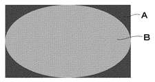
従来のマイクロ流路デバイスにより形成される多相流の断面形状としては、例えば、図1に示すような正四角形2つが1辺にて接する形状や、特開2004−344877号公報に記載の同心円等の形状が知られている。
一方、本発明のマイクロ流路デバイスは、形成する多相流の断面形状が、(1)複数の多角形が2次元状に配列されかつ前記多角形が相互に隣接した形状、(2)多角形が円若しくは楕円に内接するか若しくは多角形が円若しくは楕円に外接する形状、又は、(3)複数の円及び/若しくは楕円が2次元状に配列されかつ前記円及び/若しくは楕円が相互に隣接した形状、を少なくとも一部に有するため、効率よく異なる流体を接触させることができ、また、流体同士が接触するより多くの界面を、側壁の影響を受けない多相流内部に形成することができるため好ましい。
(Microchannel device)
The microchannel device of the present invention has a microchannel that forms two or more different fluids as a multiphase flow, and the cross-sectional shape of the multiphase flow is (1) a plurality of polygons arranged two-dimensionally. And the polygons are adjacent to each other, (2) the polygon is inscribed in a circle or ellipse, or the polygon is inscribed in a circle or ellipse, or (3) a plurality of circles and / or ellipses It is characterized in that it has a shape arranged two-dimensionally and the circles and / or ellipses are adjacent to each other at least in part.
In the present invention, “multiphase flow” refers to a flow in which two or more different fluids are in a laminar flow state and are adjacent to each other, and is also referred to as “multilayer flow”. The fluid in the multiphase flow is not particularly limited as long as it can be flowed. For example, all of two or more different fluids may be liquids, and some of the fluids are gases. Alternatively, the liquid may contain a gas or a solid.
The cross-sectional shape of the multiphase flow is a cross-sectional shape in a plane perpendicular to the flow direction of a micro flow channel (also referred to as “micro flow channel”). In addition, the cross-sectional shape of the multiphase flow is a cross-sectional shape immediately after the multiphase flow is formed, and thereafter, the multiphase flow may not be formed by mixing or reacting two or more different fluids. Needless to say.
As a cross-sectional shape of a multiphase flow formed by a conventional microchannel device, for example, a shape in which two regular squares contact each other as shown in FIG. 1 or a concentric circle described in Japanese Patent Application Laid-Open No. 2004-344877. Etc. are known.
On the other hand, in the microchannel device of the present invention, the cross-sectional shape of the multiphase flow to be formed is (1) a shape in which a plurality of polygons are arranged two-dimensionally and the polygons are adjacent to each other, and (2) many A shape in which a square is inscribed in a circle or an ellipse, or a polygon is inscribed in a circle or an ellipse, or (3) a plurality of circles and / or ellipses are arranged two-dimensionally and the circles and / or ellipses are mutually Because it has at least a part of the adjacent shape, different fluids can be contacted efficiently, and more interfaces where the fluids contact each other are formed inside the multiphase flow that is not affected by the side walls. Is preferable.
本発明における「複数の多角形が2次元状に配列されかつ前記多角形が相互に隣接した形状」とは、複数の多角形が2次元的に配列しており、前記多角形同士が一辺において隣接した形状を示し、具体的には、後出詳述する図2〜図10に示すような形状である。
なお、「複数の多角形が2次元状に配列されかつ前記多角形が相互に隣接した形状」を、以下単に「多角形配列形状」ともいう。
In the present invention, “a plurality of polygons are arranged two-dimensionally and the polygons are adjacent to each other” means that a plurality of polygons are arranged two-dimensionally and the polygons are on one side. The adjacent shapes are shown, and specifically, the shapes as shown in FIGS.
The “shape in which a plurality of polygons are arranged two-dimensionally and the polygons are adjacent to each other” is also simply referred to as “polygon array shape” hereinafter.
前記多角形配列形状における多角形は、三角形以上の多角形であればよく、混合する流体の種類の数や混合比等に応じて所望の多角形を選択すればよいが、構造の簡潔さや製造上の効率の観点から三角形、四角形又は六角形であることが好ましい。
また、前記断面形状における多角形は、多くの多角形を用いた多角形配列形状の形成が容易な点から、正多角形であることが好ましく、正三角形、正四角形又は正六角形であることがより好ましく、全ての多角形が正三角形、正四角形又は正六角形であることが特に好ましい。特に、混合する流体が2種類であるならば前記断面形状における多角形は四角形であることが望ましく、混合する流体が3種類であるならば前記断面形状における多角形は六角形であることが望ましい。
また、一つの多角形配列形状は、複数の形状の多角形により構成されていてもよく、単一の形状の多角形で構成されていてもよい。
前記断面形状における多角形の一辺の長さは、一つの多角形において全て同じであっても、異なっていてもよく、複数の多角形間において同じであっても、異なっていてもよい。さらに、2つの多角形の隣接した2辺の長さは同じであっても、異なっていてもよい。
The polygon in the polygon array shape may be a polygon that is equal to or greater than a triangle, and a desired polygon may be selected according to the number of types of fluids to be mixed, a mixing ratio, etc. From the viewpoint of the above efficiency, a triangle, a quadrangle, or a hexagon is preferable.
In addition, the polygon in the cross-sectional shape is preferably a regular polygon from the viewpoint of easy formation of a polygonal array shape using many polygons, and is preferably a regular triangle, a regular square, or a regular hexagon. More preferably, all the polygons are regular triangles, regular squares or regular hexagons. In particular, if there are two types of fluids to be mixed, the polygon in the cross-sectional shape is preferably a quadrangle, and if there are three types of fluids to be mixed, the polygon in the cross-sectional shape is preferably a hexagon. .
Moreover, one polygon arrangement shape may be comprised by the polygon of several shapes, and may be comprised by the polygon of a single shape.
The length of one side of the polygon in the cross-sectional shape may be the same or different in one polygon, and may be the same or different between a plurality of polygons. Furthermore, the lengths of two adjacent sides of the two polygons may be the same or different.
前記多角形配列形状が配列している多角形の数は、3個以上であることが好ましく、4個以上であることがより好ましく、10〜1,000個であることが更に好ましい。上記範囲であると、本発明の効果を十分に発揮できる。
また、前記多角形配列形状中に1つの多角形の外周全てが他の多角形により囲まれている形状を有すると、異種の流体が接触する界面を効率的に増加させることができるため好ましい。
また、前記多角形配列形状は、省スペースや異種の流体が接触する界面の増加等の観点から、多角形配列形状の外周の長さが最短となるように複数の多角形を配列した形状であることが好ましい。
The number of polygons arranged in the polygon arrangement shape is preferably 3 or more, more preferably 4 or more, and still more preferably 10 to 1,000. The effect of this invention can fully be exhibited as it is the said range.
In addition, it is preferable that the polygon array has a shape in which the outer periphery of one polygon is surrounded by other polygons, because the interface with which different kinds of fluids can be efficiently increased.
The polygon array shape is a shape in which a plurality of polygons are arrayed so that the length of the outer periphery of the polygon array shape is the shortest in terms of space saving and an increase in the interface with which different types of fluids contact. Preferably there is.
前記多角形配列形状として具体的には、図2〜図10に示すような形状が挙げられるが、これらに限定されるものではない。
図2は、本発明のマイクロ流路デバイスの一例を多相流が形成された部分で切断した断面概略図である。
図3〜図10はそれぞれ、本発明のマイクロ流路デバイスが形成する多相流の断面形状の一例を示す断面概略図である。
図2に示すマイクロ流路デバイス10は、断面形状が多角形配列形状12にある多相流がマイクロ流路の内壁14に接して形成されており、また、マイクロ流路は基材部16により形成されている。
また、図2に示すマイクロ流路デバイス10における多角形配列形状12は、断面形状が四角形を縦横に10×10個配列した形状であり、2つの異なる流体A及びBを流した場合を示すものである。このような多相流断面を形成するマイクロ流路デバイスであると、2つの異なる流体は均一に界面を形成することができる。
また、図3に示す多相流の断面形状は、四角形を縦横に5×5個配列した形状であり、2つの異なる流体A及びBを流した場合の一例を示すものであり、流体Aの流れる四角形は13個、流体Bの流れる四角形は12個である。このような多相流断面を形成するマイクロ流路デバイスのように、種類の異なる2以上の流体が、均等な割合で流れるものでなくともよく、流体の種類や混合比等に応じ、適宜選択すればよい。
前記多角形配列形状の多角形が、四角形、特に正四角形(正方形)である場合、種類の異なる2つの流体、又は、種類の異なる4つの流体を用いることが好ましい。上記条件であると、種類の異なる各流体が均一に界面を形成することが容易であるため好ましい。
Specific examples of the polygonal array shape include shapes shown in FIGS. 2 to 10, but are not limited thereto.
FIG. 2 is a schematic cross-sectional view of an example of the microchannel device of the present invention cut at a portion where a multiphase flow is formed.
3 to 10 are cross-sectional schematic views showing examples of the cross-sectional shape of the multiphase flow formed by the microchannel device of the present invention.
In the
Further, the polygonal array shape 12 in the
Further, the cross-sectional shape of the multiphase flow shown in FIG. 3 is a shape in which 5 × 5 squares are arranged vertically and horizontally, and shows an example of flowing two different fluids A and B. There are 13 flowing squares and 12 flowing fluid B. Like a microchannel device that forms such a multiphase flow cross section, two or more different types of fluids do not have to flow at an equal rate, and are appropriately selected according to the type of fluid, mixing ratio, etc. do it.
When the polygon of the polygon arrangement shape is a quadrangle, particularly a regular quadrangle (square), it is preferable to use two different types of fluids or four different types of fluids. The above conditions are preferable because it is easy for different types of fluids to form a uniform interface.
図4に示す多相流の断面形状は、六角形を縦横に17個配列した形状であり、3つの異なる流体A〜Cを流した場合の一例を示すものである。
前記多角形配列形状の多角形が、六角形、特に正六角形である場合、種類の異なる3つの流体を用いることが好ましい。上記条件であると、接触する3つの六角形により3つの流体が均等に接触する点を容易に形成することができるため好ましい。
The cross-sectional shape of the multiphase flow shown in FIG. 4 is a shape in which 17 hexagons are arranged vertically and horizontally, and shows an example when three different fluids A to C are flowed.
When the polygon of the polygon arrangement shape is a hexagon, particularly a regular hexagon, it is preferable to use three different types of fluids. The above conditions are preferable because the three hexagons that are in contact with each other can easily form points where the three fluids are in uniform contact.
図5に示す多相流の断面形状は、三角形を縦横に16個配列した形状であり、2つの異なる流体A及びBを流した場合の一例を示すものである。このような多相流断面を形成するマイクロ流路デバイスであると、2つの異なる流体は均一に界面を形成することができる。
図6に示す多相流の断面形状は、三角形を縦横に24個配列した形状であり、3つの異なる流体A〜Cを流した場合の一例を示すものである。このような多相流断面を形成するマイクロ流路デバイスであると、接触する6つの三角形により3つの流体が均等に接触する点を容易に形成することができるため好ましい。
図7に示す多相流の断面形状は、三角形を縦横に6個配列した形状であり、6つの異なる流体A〜Fを流した場合の一例を示すものである。このような多相流断面を形成するマイクロ流路デバイスであると、接触する6つの三角形により6つの流体が均等に接触する点を容易に形成することができるため好ましい。
前記多角形配列形状の多角形が、三角形、特に正三角形である場合、種類の異なる2つの流体、種類の異なる3つの流体、又は、種類の異なる6つの流体を用いることが好ましい。上記条件であると、種類の異なる各流体が均一に界面を形成することが容易であるため好ましい。
The cross-sectional shape of the multiphase flow shown in FIG. 5 is a shape in which 16 triangles are arranged vertically and horizontally, and shows an example when two different fluids A and B are flowed. In the microchannel device that forms such a multiphase flow section, two different fluids can form an interface uniformly.
The cross-sectional shape of the multiphase flow shown in FIG. 6 is a shape in which 24 triangles are arranged vertically and horizontally, and shows an example when three different fluids A to C are flowed. A microchannel device that forms such a multiphase flow cross section is preferable because the points where three fluids can be evenly contacted can be easily formed by the six triangles that are in contact with each other.
The cross-sectional shape of the multiphase flow shown in FIG. 7 is a shape in which six triangles are arranged vertically and horizontally, and shows an example when six different fluids A to F are flowed. A microchannel device that forms such a multiphase flow cross section is preferable because the points where the six fluids can be in uniform contact can be easily formed by the six triangles that are in contact.
When the polygon of the polygon arrangement shape is a triangle, particularly a regular triangle, it is preferable to use two different types of fluids, three different types of fluids, or six different types of fluids. The above conditions are preferable because it is easy for different types of fluids to form a uniform interface.
図8に示す多相流の断面形状は、十字型の十二角形を縦横に9個配列し、4つの十二角形で囲まれた四角形を4個有する形状であり、3つの異なる流体A〜Cを流した場合の一例を示すものである。
図9に示す多相流の断面形状は、八角形を縦横に13個配列し、3つ又は4つの八角形が少なくとも隣接した四角形を12個有する形状であり、3つの異なる流体A〜Cを流した場合の一例を示すものである。
図10に示す多相流の断面形状は、八角形を縦横に16個配列し、4つの八角形で囲まれた四角形を9個有する形状であり、3つの異なる流体A〜Cを流した場合の一例を示すものである。
このように、本発明における多相流の断面形状は、2種以上の多角形を2次元状に配列した形状であってもよい。
The cross-sectional shape of the multiphase flow shown in FIG. 8 is a shape having nine cross-shaped dodecagons arranged vertically and horizontally and having four quadrangles surrounded by four dodecagons, and three different fluids A to An example in the case of flowing C is shown.
The cross-sectional shape of the multiphase flow shown in FIG. 9 is a shape in which 13 octagons are arranged vertically and horizontally, and 3 or 4 octagons have at least 12 adjacent quadrangles. An example in the case of flowing is shown.
The cross-sectional shape of the multiphase flow shown in FIG. 10 is a shape in which 16 octagons are arranged vertically and horizontally and 9 quadrangles surrounded by 4 octagons are passed, and three different fluids A to C are flowed. An example is shown.
Thus, the cross-sectional shape of the multiphase flow in the present invention may be a shape in which two or more kinds of polygons are two-dimensionally arranged.
本発明における「多角形が円若しくは楕円に内接するか若しくは多角形が円若しくは楕円に外接する形状」とは、円若しくは楕円形の内部の多角形における全ての頂点が前記円若しくは楕円形に接している形状、又は、多角形の全ての辺に円若しくは楕円形が接している形状を示す。
なお、「多角形が円若しくは楕円に内接するか若しくは多角形が円若しくは楕円に外接する形状」を、以下単に「円内外接形状」ともいう。
In the present invention, “a shape in which a polygon is inscribed in a circle or an ellipse or a polygon is inscribed in a circle or an ellipse” means that all vertices in the polygon inside the circle or ellipse are in contact with the circle or ellipse. Or a shape in which a circle or an ellipse is in contact with all sides of the polygon.
Note that “a shape in which a polygon is inscribed in a circle or an ellipse or a polygon is inscribed in a circle or an ellipse” is also simply referred to as “inscribed in a circle”.
前記円内外接形状として具体的には、図11及び図12に示すような形状が挙げられるが、これらに限定されるものではない。
図11及び図12はそれぞれ、本発明のマイクロ流路デバイスが形成する多相流の断面形状の一例を示す断面概略図である。
図11に示す多相流の断面形状は、楕円形に四角形が内接した形状であり、2つの異なる流体A及びBを流した場合の一例を示すものである。また、多相流の断面形状が図11に示すような形状であると、内接四角形の各辺と円弧に囲まれた4つの部分に、それぞれ異なる4つの流体を流すことや、内接四角形の対向する二辺と円弧に囲まれた2つの部分の2組にそれぞれ異なる2つの流体を流すことも可能である。
図12に示す多相流の断面形状は、楕円形に四角形が外接した形状であり、2つの異なる流体A及びBを流した場合の一例を示すものである。また、多相流の断面形状が図12に示すような形状であると、外接四角形の各辺と円弧に囲まれた4つの部分に、それぞれ異なる4つの流体を流すことや、前記4つの部分のうち、一つの対角線上に存在する2つの部分の2組にそれぞれ異なる2つの流体を流すことも可能である。
前記円内外接形状における多角形は、三角形以上の多角形であればよく、混合する流体の種類の数や混合比等に応じて所望の多角形を選択すればよいが、構造の簡潔さや製造上の効率の観点から三角形、四角形又は六角形であることが好ましい。
Specific examples of the inscribed and circumscribed shape of the circle include shapes as shown in FIGS. 11 and 12, but are not limited thereto.
11 and 12 are cross-sectional schematic views showing examples of the cross-sectional shape of the multiphase flow formed by the microchannel device of the present invention.
The cross-sectional shape of the multiphase flow shown in FIG. 11 is an ellipse with a quadrilateral inscribed shape, and shows an example when two different fluids A and B are flowed. In addition, when the cross-sectional shape of the multiphase flow is as shown in FIG. 11, four different fluids are allowed to flow through each of the four sides surrounded by the sides and the arc of the inscribed rectangle, It is also possible to cause two different fluids to flow through two sets of two parts surrounded by two opposite sides and an arc.
The cross-sectional shape of the multiphase flow shown in FIG. 12 is an ellipse with a quadrilateral circumscribed shape, and shows an example when two different fluids A and B are flowed. Further, when the cross-sectional shape of the multiphase flow is as shown in FIG. 12, four different fluids are allowed to flow through the four parts surrounded by each side of the circumscribed square and the arc, or the four parts. Of these, two different fluids can flow through two sets of two portions existing on one diagonal line.
The polygon in the circumscribed circle may be a polygon that is equal to or greater than a triangle, and a desired polygon may be selected in accordance with the number of types of fluids to be mixed, a mixing ratio, and the like. From the viewpoint of the above efficiency, a triangle, a quadrangle, or a hexagon is preferable.
本発明における「複数の円及び/若しくは楕円が2次元状に配列されかつ前記円及び/若しくは楕円が相互に隣接した形状」とは、複数の円及び/若しくは楕円が2次元的に配列しており、前記円及び/若しくは楕円同士が円弧において隣接した形状を示し、具体的には、後出詳述する図13又は図14に示すような形状である。
なお、「複数の円及び/若しくは楕円が2次元状に配列されかつ前記円及び/若しくは楕円が相互に隣接した形状」を、以下単に「円配列形状」ともいう。
In the present invention, “a plurality of circles and / or ellipses are two-dimensionally arranged and the circles and / or ellipses are adjacent to each other” means that a plurality of circles and / or ellipses are two-dimensionally arranged. The circles and / or ellipses are adjacent to each other in an arc, and specifically, the shape is as shown in FIG. 13 or FIG.
The “shape in which a plurality of circles and / or ellipses are two-dimensionally arranged and the circles and / or ellipses are adjacent to each other” is also simply referred to as “circular array shape”.
前記円配列形状として具体的には、図13又は図14に示すような形状が挙げられるが、これらに限定されるものではない。
図13及び図14はそれぞれ、本発明のマイクロ流路デバイスが形成する多相流の断面形状の一例を示す断面概略図である。
図13に示す多相流の断面形状は、17個の円が縦横に隣接するように配列した形状であり、3つの異なる流体A〜Cを流した場合の一例を示すものであり、流体Aの流れる円は5個、流体Bの流れる円は7個、流体Cの流れる円は5個である。また、3つの円に囲まれる部分は基材部である。このような多相流断面を形成するマイクロ流路デバイスのように、種類の異なる3以上の流体が同時に接することなく、2種が接する界面により、均等に混合等を行うことができる。
図14に示す多相流の断面形状は、17個の円が縦横に隣接するように配列し、3つの円に囲まれた20個の部分を有する形状であり、4つの異なる流体A〜Dを流した場合の一例を示すものであり、流体Aの流れる円は5個、流体Bの流れる円は7個、流体Cの流れる円は5個、流体Dの流れる3つの円弧よりなる部分は20個である。このような多相流断面を形成するマイクロ流路デバイスのように、多くの界面を形成でき、かつ均等に混合等を行うことができる。
図13及び図14に示すように、複数の円及び/若しくは楕円が2次元状に配列されかつ前記円及び/若しくは楕円が相互に隣接した形状により生じる複数の円弧により囲まれる部分は、所望の用途に応じ、基材部としても、流路の一部としてもよい。
Specific examples of the circular arrangement shape include, but are not limited to, shapes shown in FIG. 13 or FIG.
13 and 14 are cross-sectional schematic views showing examples of the cross-sectional shape of the multiphase flow formed by the microchannel device of the present invention.
The cross-sectional shape of the multiphase flow shown in FIG. 13 is a shape in which 17 circles are arranged so as to be adjacent vertically and horizontally, and shows an example when three different fluids A to C are flowed. There are five circles through which fluid B flows, seven circles through which fluid B flows, and five circles through which fluid C flows. Moreover, the part enclosed by three circles is a base-material part. Like a microchannel device that forms such a multiphase flow cross section, three or more different types of fluids do not contact each other at the same time, and mixing and the like can be performed uniformly by the interface where the two types contact.
The cross-sectional shape of the multiphase flow shown in FIG. 14 is a shape having 20 portions surrounded by three circles arranged so that 17 circles are adjacent vertically and horizontally, and four different fluids A to D. The flow circle of fluid A is five, the circle of fluid B is seven, the circle of fluid C is five, and the part consisting of three arcs of fluid D is There are 20 pieces. Like a microchannel device that forms such a multiphase flow cross section, many interfaces can be formed, and mixing and the like can be performed evenly.
As shown in FIGS. 13 and 14, a plurality of circles and / or ellipses are two-dimensionally arranged and the circle and / or ellipse is surrounded by a plurality of arcs formed by adjacent shapes. Depending on the application, it may be a base material part or a part of a flow path.
また、図15に示すような、円及び/又は楕円と複数の種類の多角形とを互いに接触するように配列して使用した断面形状であってもよい。
図15は、本発明のマイクロ流路デバイスが形成する多相流の断面形状の一例を示す断面概略図である。
図15に示す多相流の断面形状は、9個の六角形、6個の長方形、及び、4個の楕円を配列した形状であり、楕円それぞれが4個の六角形及び2個の長方形によって形成された六角形に内接した形状であり、3つの異なる流体A〜Cを六角形、長方形及び楕円にそれぞれ流した場合の一例を示すものである。また、図15に示すような多相流の断面形状は、多角形配列形状、及び、円内外接形状の両方を満たす形状である。
Moreover, the cross-sectional shape which arranged and used so that a circle | round | yen and / or an ellipse and multiple types of polygons may mutually contact as shown in FIG. 15 may be sufficient.
FIG. 15 is a schematic cross-sectional view showing an example of the cross-sectional shape of the multiphase flow formed by the microchannel device of the present invention.
The cross-sectional shape of the multiphase flow shown in FIG. 15 is a shape in which nine hexagons, six rectangles, and four ellipses are arranged, each of which has four hexagons and two rectangles. It is a shape inscribed in the formed hexagon, and shows an example when three different fluids A to C are respectively flowed into a hexagon, a rectangle, and an ellipse. Moreover, the cross-sectional shape of the multiphase flow as shown in FIG. 15 is a shape that satisfies both the polygonal array shape and the circumscribed shape of the circle.
また、本発明のマイクロ流路デバイスは、多相流の断面形状中の一部分が(1)多角形配列形状、(2)円内外接形状、又は、(3)円配列形状であればよく、例えば、多相流の断面形状の中心部分のみが多角形配列形状である態様や、多相流全体の断面形状が多角形配列形状である態様、多相流の断面形状の中心部分のみが円内外接形状である態様、多相流全体の断面形状が円内外接形状である態様、多相流の断面形状の中心部分のみが円配列形状である態様や、多相流全体の断面形状が円配列形状である態様であってもよい。また、円又は楕円に内外接する多角形が、前記多角形配列形状であってもよく、前記円配列形状がさらに円、楕円又は多角形に内外接していてもよいことは言うまでもない。 In addition, the microchannel device of the present invention may be such that a part of the cross-sectional shape of the multiphase flow is (1) a polygonal array shape, (2) a circumscribed circle shape, or (3) a circular array shape, For example, an aspect in which only the central part of the cross-sectional shape of the multiphase flow is a polygonal array shape, an aspect in which the cross-sectional shape of the entire multiphase flow is a polygonal array shape, or only a central part of the cross-sectional shape of the multiphase flow is a circle An aspect that is inscribed and circumscribed, an aspect in which the cross-sectional shape of the entire multiphase flow is a circle inscribed and circumscribed shape, an aspect in which only the central portion of the cross-sectional shape of the multiphase flow is a circular array shape, and a cross-sectional shape of the entire multiphase flow is The aspect which is a circular arrangement | sequence shape may be sufficient. Needless to say, the polygon inscribed and circumscribed to the circle or ellipse may be the polygon array shape, and the circle array shape may be further inscribed and circumscribed to the circle, ellipse or polygon.
本発明のマイクロ流路デバイスが有する多相流を形成する構造(以下、「多相流形成構造」ともいう。)の一例としては、図16に示す構造が挙げられる。
図16は、本発明のマイクロ流路デバイスの一例における多相流形成構造を示す拡大概略図である。
図16に示すマイクロ流路デバイスが形成する多相流の断面形状は、四角形を縦横に2×2個配列した形状であり、2つの異なる流体A及びBを流した場合を示すものである。
図16における右側の図は、多相流形成構造部分の模式断面図であり、流体A及びBの流路を示す実線は紙面手前、波線は紙面奥を示す。
図16における左側の6図は、前記右側の図におけるa−a〜f−fでの流れ方向に垂直な面での各断面図を示す。
An example of a structure for forming a multiphase flow (hereinafter, also referred to as “multiphase flow forming structure”) included in the microchannel device of the present invention is the structure shown in FIG.
FIG. 16 is an enlarged schematic view showing a multiphase flow forming structure in an example of the microchannel device of the present invention.
The cross-sectional shape of the multiphase flow formed by the microchannel device shown in FIG. 16 is a shape in which 2 × 2 squares are arranged vertically and horizontally, and shows a case where two different fluids A and B are flowed.
The right side of FIG. 16 is a schematic cross-sectional view of the multiphase flow forming structure, where the solid lines indicating the flow paths of the fluids A and B are in front of the paper, and the wavy line is the back of the paper.
16 on the left side in FIG. 16 shows each cross-sectional view in a plane perpendicular to the flow direction at aa to f-f in the right side diagram.
図16におけるa−a断面図では、マイクロ流路基材部16により隔てられた2つの流路に流体A及び流体Bが流れている。以下、流体Aが流れる流路を流路Aともいい、流体Bが流れる流路を流路Bともいう。
a−a断面図とb−b断面図との間において、流路A及び流路Bの流路径が狭められ、断面が四角形の形状となり、流路Bはマイクロ流路デバイスの内部に、流路Aは流路Bよりも外側に移動し、図16におけるb−b断面図となる。
b−b断面図とc−c断面図との間において、流路Aは四角形の形状から、四角形型のドーナツ形状になり、流路Bはその内部に矩形状となり、図16におけるc−c断面図となる。
c−c断面図とd−d断面図との間において、流路A及び流路Bはそれぞれ2つの流路(流路A1、A2、B1及びB2)に分岐し、マイクロ流路デバイスの外形における四角形の対角線が通る2つの四角形の流路(流路A1及びA2)と他方の対角線が通る2つの四角形の流路(流路B1及びB2)を形成し、図16におけるd−d断面図となる。
d−d断面図とe−e断面図との間において、流路A1及びA2はマイクロ流路デバイスの内部に、流路B1及びB2はマイクロ流路デバイスの外部に移動し、また、各流路間のマイクロ流路基材の厚さが均等に調整され、図16におけるe−e断面図となる。
e−e断面図とf−f断面図との間において、流路A1、A2、B1及びB2の間における基材部16の厚さが薄くなり、多相流が形成可能な厚さ以下となる部分で各流路間の基材部16を無くし、図16におけるf−f断面図に示すような断面形状が四角形を縦横に2×2個配列した形状の多相流が形成される。このように、微小流路中の多相流の断面形状は、多相流形成構造部分における最下流側の形状(流体の出口側の形状、図16におけるf−f断面)と同一となる。
In the aa cross-sectional view in FIG. 16, fluid A and fluid B flow through two flow paths separated by the micro flow path base
Between the aa cross-sectional view and the bb cross-sectional view, the flow path diameters of the flow path A and the flow path B are narrowed, the cross section becomes a square shape, and the flow path B flows inside the micro flow path device. The path A moves to the outside of the flow path B, and becomes a bb cross-sectional view in FIG.
Between the bb cross-sectional view and the cc cross-sectional view, the flow path A changes from a quadrangular shape to a quadrilateral donut shape, and the flow path B becomes a rectangular shape inside thereof. It becomes a sectional view.
Between the cc cross-sectional view and the dd cross-sectional view, the flow path A and the flow path B are each branched into two flow paths (flow paths A1, A2, B1, and B2), and the outer shape of the micro flow path device. 16 is formed by forming two rectangular flow paths (flow paths A1 and A2) through which the square diagonal line of FIG. 16 passes and two square flow paths (flow paths B1 and B2) through which the other diagonal line passes. It becomes.
Between the dd sectional view and the ee sectional view, the channels A1 and A2 move to the inside of the microchannel device, the channels B1 and B2 move to the outside of the microchannel device, and each flow The thickness of the microchannel substrate between the channels is adjusted to be uniform, resulting in an ee cross-sectional view in FIG.
Between the ee cross-sectional view and the ff cross-sectional view, the thickness of the
前述した多相流が形成可能な厚さ、すなわち、多相流形成直前における各マイクロ流路を隔てる基材の厚さとしては、10〜1,000μmであることが好ましく、構造上、必要最低限の強度が保てれば、なるべく薄いことが好ましい。上記範囲であると、マイクロ流路デバイスにおける多相流形成構造である部分が十分な強度を有し、また、多相流形成時に流れの乱れなどが起こらないため好ましい。 The thickness at which the above-described multiphase flow can be formed, that is, the thickness of the base material that separates the microchannels immediately before the formation of the multiphase flow is preferably 10 to 1,000 μm. If the limit strength can be maintained, it is preferable that the thickness is as thin as possible. The above range is preferable because the portion of the microchannel device which is a multiphase flow forming structure has sufficient strength, and flow disturbance does not occur when the multiphase flow is formed.
本発明のマイクロ流路デバイスは、流路分岐部を有することも好ましい。
前記流路分岐部とは、1以上のマイクロ流路を分岐し流路数を増加させる部位であり、前述した図16に示すように、マイクロ流路デバイス中に多相流形成構造の一部分として流路分岐構造が設けられていてもよい。前記流路分岐構造の一例としては、図16におけるa−a断面図〜d−d断面図に相当する部分が挙げられる。
前記流路分岐構造は、その少なくとも一部がフラクタル構造であることが好ましい。
フラクタル構造とは、自己相似な幾何構造が繰り返される構造をいう。例えば、1つの流路Aを2つの流路A1及びA2に分岐し、2つの流路それぞれをさらに2つの流路に分岐した、すなわち、流路A1を2つの流路A11及びA12に分岐し、流路A2を2つの流路A21及びA22に分岐した場合に、流路Aを流路A1及びA2に分岐した構造と、流路A1を流路A11及びA12に分岐した構造と、流路A2を流路A21及びA22に分岐した構造とが相似の構造であると、フラクタル構造であると言える。
The microchannel device of the present invention preferably has a channel branching portion.
The flow path branching portion is a part that branches one or more micro flow paths to increase the number of flow paths, and as shown in FIG. 16 described above, as a part of the multiphase flow forming structure in the micro flow path device. A channel branching structure may be provided. As an example of the channel branching structure, a portion corresponding to the aa sectional view to the dd sectional view in FIG.
It is preferable that at least a part of the flow path branching structure has a fractal structure.
A fractal structure refers to a structure in which a self-similar geometric structure is repeated. For example, one flow path A is branched into two flow paths A1 and A2, and each of the two flow paths is further branched into two flow paths, that is, the flow path A1 is branched into two flow paths A11 and A12. When the channel A2 is branched into two channels A21 and A22, the channel A is branched into channels A1 and A2, the channel A1 is branched into channels A11 and A12, and the channel. If the structure in which A2 is branched into the flow paths A21 and A22 is similar, it can be said that it is a fractal structure.
本発明のマイクロ流路デバイスにおける多相流は、断面形状が前記多角形配列形状や前記楕円内外接形状である多相流とマイクロ流路の内壁との間に流速調整層を有することが好ましい。
図17は、本発明のマイクロ流路デバイスが形成する流速調整層を有する多相流の断面形状の一例を示す断面概略図である。
図18は、流速調整層のない多相流を形成した本発明のマイクロ流路デバイスの一例と、流速調整層を有する多相流を形成した本発明のマイクロ流路デバイスの一例とを比較した模式図である。
図18中、右側にはそれぞれのマイクロ流路における流速及び流路座標をそれぞれ縦軸及び横軸にとり、模式的にグラフ化したものである。
一般にマイクロ流路においては、内壁の影響を受け、内壁近傍の流速が低下してしまう。図17及び図18に示すように、この内壁近傍における流速の低下を、流速調整層18を形成することにより緩和し、所望の反応や混合等を行う多角形配列形状12や前記楕円内外接形状である多相流部分の流速の低下を防ぐことができるため好ましい。
The multiphase flow in the microchannel device of the present invention preferably has a flow rate adjusting layer between the multiphase flow whose cross-sectional shape is the polygonal array shape or the elliptical circumscribed shape and the inner wall of the microchannel. .
FIG. 17 is a schematic cross-sectional view showing an example of a cross-sectional shape of a multiphase flow having a flow rate adjusting layer formed by the microchannel device of the present invention.
FIG. 18 compares an example of the microchannel device of the present invention in which a multiphase flow without a flow rate adjusting layer was formed with an example of the microchannel device of the present invention in which a multiphase flow having a flow rate adjusting layer was formed. It is a schematic diagram.
In FIG. 18, on the right side, the flow velocity and channel coordinates in each microchannel are plotted on the vertical axis and the horizontal axis, respectively, and are schematically graphed.
In general, in the micro flow path, the flow velocity in the vicinity of the inner wall decreases due to the influence of the inner wall. As shown in FIGS. 17 and 18, the decrease in the flow velocity in the vicinity of the inner wall is mitigated by forming the flow
流速調整層の断面形状については、特に制限はなく、所望の形状であればよい。
流速調整層の厚さとしては、多角形配列形状12や前記円内外接形状、前記円配列形状である多相流部分の流路の幅と同等もしくはそれ以上であることが好適であり、マイクロ流路内壁から20〜500μmであることが好ましく、50〜200μmであることがより好ましい。この範囲内において、流速調整層の厚さを大きくすることで、マイクロ流路の内壁による流速の低下をより抑制することができる。
There is no restriction | limiting in particular about the cross-sectional shape of a flow-rate adjustment layer, What is necessary is just a desired shape.
The thickness of the flow rate adjusting layer is preferably equal to or greater than the width of the flow path of the multiphase flow portion having the
流速調整層に流す流体としては、使用する他の流体と反応しない流体であれば特に制限はなく、使用する他の流体と同じ程度の粘度が望ましい。例えば、水系の反応であればイオン交換水やエタノールが、生体系の反応であれば生理食塩水等が好ましく例示できる。 The fluid flowing through the flow rate adjusting layer is not particularly limited as long as it is a fluid that does not react with other fluids to be used, and desirably has the same viscosity as the other fluids to be used. For example, ion-exchanged water and ethanol are preferable for water-based reactions, and physiological saline is preferable for biological reactions.
本発明のマイクロ流路デバイスに流すことができる流体は、完全な液体でなくともよく、使用用途に応じ、固体や気体を含むものであってもよく、その組成や濃度等も必要に応じ選択することができる。 The fluid that can be flowed to the microchannel device of the present invention does not have to be a complete liquid, and may contain a solid or gas depending on the intended use, and its composition, concentration, etc. are selected as necessary. can do.
本発明のマイクロ流路デバイスの材質としては、金属、セラミック、ガラス、シリコーン、樹脂などの材料が例示でき、金属又は樹脂が好ましく挙げられ、金属ニッケルの表面に金メッキを施した部材が特に好ましく挙げられる。
前記樹脂としては、耐衝撃性、耐熱性、耐薬品性、透明性などが、行う反応や単位操作に適した樹脂が好ましく、具体的には、ポリエステル樹脂、ポリスチレン樹脂、ポリアクリル樹脂、スチレン・アクリル共重合体、ポリシリコーン樹脂、エポキシ樹脂、ジエン系樹脂、フェノール樹脂、テルペン樹脂、クマリン樹脂、ポリアミド樹脂、ポリアミドイミド樹脂、ポリイミド樹脂、ポリブチラール樹脂、ポリウレタン樹脂、エチレン・酢酸ビニル共重合体等が好ましく例示できるが、より好ましくは、ポリメチルメタクリレート樹脂などのポリアクリル樹脂、ポリスチレン樹脂である。また、前記樹脂としては、ガラス転移点を有する樹脂であることが好ましく、前記樹脂のガラス転移点は、90〜150℃の範囲であることが好ましく、100〜140℃の範囲であることがより好ましい。
Examples of the material of the microchannel device of the present invention include materials such as metal, ceramic, glass, silicone, and resin, preferably metal or resin, and particularly preferably a member having a metal nickel surface plated with gold. It is done.
As the resin, impact resistance, heat resistance, chemical resistance, transparency, and the like are preferable resins that are suitable for reactions to be performed and unit operations. Specifically, polyester resins, polystyrene resins, polyacryl resins, styrene Acrylic copolymer, Polysilicone resin, Epoxy resin, Diene resin, Phenol resin, Terpene resin, Coumarin resin, Polyamide resin, Polyamideimide resin, Polyimide resin, Polybutyral resin, Polyurethane resin, Ethylene / vinyl acetate copolymer, etc. Are preferable, but polyacrylic resin such as polymethylmethacrylate resin and polystyrene resin are more preferable. The resin is preferably a resin having a glass transition point, and the glass transition point of the resin is preferably in the range of 90 to 150 ° C, more preferably in the range of 100 to 140 ° C. preferable.
本発明のマイクロ流路デバイスにおけるマイクロ流路は、その一部において少なくともマイクロスケールの流路であればよい。すなわち、本発明のマイクロ流路デバイスにおいて最も流路の幅(流路径)が狭い部分の幅が、5,000μm以下であり、好ましくは10〜1,000μmの範囲であり、より好ましくは30〜500μmの範囲である。また、流路の深さは、10〜500μmの範囲であることが好ましい。
本発明のマイクロ流路デバイスにおいて、断面形状が(1)多角形配列形状、(2)円内外接形状、又は、(3)円配列形状を少なくとも一部に有する多相流が流れる部分のマイクロ流路の流路径としては、20〜500μmであることが好ましく、50〜200μmであることがより好ましい。
さらに、流路の長さは、形成される流路の形状にもより、また、可能であれば短いほど好ましいが、実用的な範囲では100〜1,000μmの範囲であることが好ましい。
また、マイクロ流路の形状については特に制限はなく、例えば、流れ方向に対し垂直な方向での断面形状が円形、楕円形、多角形など所望の形状とすることができる。
The microchannel in the microchannel device of the present invention may be at least a microscale channel in a part thereof. That is, in the microchannel device of the present invention, the width of the portion having the narrowest channel width (channel diameter) is 5,000 μm or less, preferably 10 to 1,000 μm, more preferably 30 to The range is 500 μm. Moreover, it is preferable that the depth of a flow path is the range of 10-500 micrometers.
In the microchannel device of the present invention, a micro of a portion where a cross-sectional shape is (1) a polygonal array shape, (2) a circumscribed shape of a circle, or (3) a multiphase flow having at least a part of the circular array shape flows. The channel diameter of the channel is preferably 20 to 500 μm, and more preferably 50 to 200 μm.
Further, the length of the flow path is preferably as short as possible depending on the shape of the formed flow path, but is preferably in the range of 100 to 1,000 μm in a practical range.
Moreover, there is no restriction | limiting in particular about the shape of a microchannel, For example, the cross-sectional shape in a direction perpendicular | vertical with respect to a flow direction can be made into desired shapes, such as circular, an ellipse, and a polygon.
マイクロ流路デバイスの大きさは、使用目的に応じ適宜設定することができるが、1〜100cm2の範囲が好ましく、10〜40cm2の範囲がより好ましい。またマイクロ流路デバイスの厚さは、2〜30mmの範囲が好ましく、3〜15mmの範囲がより好ましい。 The size of the microchannel device can be set appropriately according to the intended use, preferably in the range of 1 to 100 cm 2, the range of 10 to 40 cm 2 is more preferable. The thickness of the microchannel device is preferably in the range of 2 to 30 mm, more preferably in the range of 3 to 15 mm.
本発明のマイクロ流路デバイスは、その用途に応じて、上述した異なる2以上の流体を多相流として形成する微小流路以外にも、他の微小流路や、反応、混合、分離、精製、分析、洗浄等の機能を有する部位を有していてもよい。
また、本発明のマイクロ流路デバイスには、必要に応じて、例えば、マイクロ流路デバイスに流体を送液するための送液口や、マイクロ流路デバイスから流体を回収するための回収口などを設けてもよい。
The microchannel device of the present invention is not limited to the microchannel that forms two or more different fluids as a multiphase flow, depending on the application, but also other microchannels, reaction, mixing, separation, and purification. It may have a part having functions such as analysis and washing.
In addition, the microchannel device of the present invention includes, for example, a liquid feeding port for feeding a fluid to the microchannel device, a collection port for collecting the fluid from the microchannel device, if necessary. May be provided.
また、本発明のマイクロ流路デバイスは、その用途に応じて、複数を組み合わせたり、反応、混合、分離、精製、分析、洗浄等の機能を有する装置や、送液装置、回収装置、他のマイクロ流路デバイス等を組み合わせ、マイクロ化学システムを好適に構築することができる。 In addition, the microchannel device of the present invention can be used in combination with a plurality of devices or a device having functions such as reaction, mixing, separation, purification, analysis, washing, liquid feeding device, recovery device, A microchemical system can be suitably constructed by combining microchannel devices and the like.
本発明のマイクロ流路デバイスの製造方法は、特に制限されないが、特開平10−305488号公報や特開2000−238000号公報、特開2004−223637号公報等に記載の方法が好ましく挙げられる。具体的には、基板上に所定の2次元パターンを有する複数の薄膜を形成する第1の工程と、前記複数の薄膜を前記基板上から剥離し、ステージ上に前記複数の薄膜を積層して接合させて微小構造体を形成する第2の工程を含むことを特徴とする本発明のマイクロ流路デバイスの製造方法や、所定の2次元パターンを有する複数の薄膜が形成されたパターン基板と前記パターン基板に対向配置される対向基板との位置決め・圧接・離間を繰り返して前記対向基板上に前記複数の薄膜を積層して接合された微小構造体を製造する微小構造体の製造方法において、前記位置決めは、前記パターン基板と前記対向基板との相対的位置を検出し、前記相対的位置に基づいて行うことを特徴とする本発明のマイクロ流路デバイスの製造方法等が好ましく例示できる。 Although the manufacturing method of the microchannel device of the present invention is not particularly limited, the methods described in JP-A-10-305488, JP-A-2000-238000, JP-A-2004-223637, and the like are preferable. Specifically, a first step of forming a plurality of thin films having a predetermined two-dimensional pattern on a substrate, peeling the plurality of thin films from the substrate, and laminating the plurality of thin films on a stage A method of manufacturing a microchannel device of the present invention, comprising a second step of forming a microstructure by bonding, a pattern substrate on which a plurality of thin films having a predetermined two-dimensional pattern are formed; and In the method for manufacturing a microstructure, the positioning, press-contact, and separation with the counter substrate disposed to face the pattern substrate are repeated to manufacture the micro structure bonded by laminating the plurality of thin films on the counter substrate. Preferably, the positioning is performed based on the relative position by detecting the relative position between the pattern substrate and the counter substrate. It can be.
以下、本発明のマイクロ流路デバイスを使用した好ましい一実施態様として、顔料合成について説明する。なお、以下に記載の「部」は「重量部」を意味する。 Hereinafter, pigment synthesis will be described as a preferred embodiment using the microchannel device of the present invention. In the following description, “parts” means “parts by weight”.
<顔料合成(アシッドペースティング)>
図19は、本発明のマイクロ流路デバイスを用いたアシッドペースティング処理方法に好適に使用することができる処理装置の一例を示す概略構成図である。
<Pigment synthesis (acid pasting)>
FIG. 19 is a schematic configuration diagram showing an example of a processing apparatus that can be suitably used in the acid pasting processing method using the microchannel device of the present invention.
図19に示したアシッドペースティング処理装置は、水又はアルカリ性溶液を含む流体A(第1の流体)を通す第1の流路L1と、電荷発生材料用顔料及びその顔料を溶解する酸を含む流体B(第2の流体)を通す流路L2と、流路L1、L2それぞれの終端部に連結されており、流体Aと流体Bとを合流させて層流を生じさせるマイクロ流路デバイス10と、流路L3と、を備える。流路L1の上流側端部には流体Aが収容されたマイクロシリンジ20aが、流路L2の上流側端部には流体Bが収容されたマイクロシリンジ20bがそれぞれ連結されている。
流体Aは、前述の通り水又はアルカリ性溶液を含む溶液であり、好ましくは濃アルカリ性溶液を含む溶液である。流体A中に含まれる水としては、イオン交換水、純水、又は蒸留水等の精製した水が好ましい。また、アルカリ性溶液としては、アンモニア水、水酸化ナトリウム水溶液、水酸化カリウム水溶液等が挙げられ、これらの中でもアンモニア水が好ましい。
第1の流体Aには、有機溶剤を混合することもできる。有機溶剤を混合することによって、結晶型の制御や顔料の品質のコントロールがより容易となる。有機溶剤としては、公知のものが使用できる。
The acid pasting processing apparatus shown in FIG. 19 includes a first flow path L1 that passes a fluid A (first fluid) containing water or an alkaline solution, a charge generation material pigment, and an acid that dissolves the pigment. A
As described above, the fluid A is a solution containing water or an alkaline solution, and preferably a solution containing a concentrated alkaline solution. The water contained in the fluid A is preferably purified water such as ion exchange water, pure water, or distilled water. Examples of the alkaline solution include aqueous ammonia, aqueous sodium hydroxide solution, aqueous potassium hydroxide solution, etc. Among these, aqueous ammonia is preferable.
The first fluid A can be mixed with an organic solvent. By mixing the organic solvent, it becomes easier to control the crystal form and the quality of the pigment. Known organic solvents can be used.
また、第2の流体Bは電荷発生材料用顔料及び該顔料を溶解する酸を含む。
電荷発生材料用顔料としては、多環キノン顔料、ぺリレン系顔料、アゾ系顔料、インジゴ顔料、キナクリドン顔料、フタロシアニン顔料等の公知の有機系顔料が挙げられる。
フタロシアニン顔料としては、特に限定されないが、例えば、無金属フタロシアニン顔料、チタニルフタロシアニン顔料、銅フタロシアニン顔料、クロロガリウムフタロシアニン顔料、ヒドロキシガリウムフタロシアニン顔料、バナジルフタロシアニン顔料、クロロインジウムフタロシアニン顔料、ジクロロスズフタロシアニン顔料が挙げられる。
上記顔料の中でもフタロシアニン顔料は、レーザー・プリンターやフルカラー複写機等のデジタル記録用感光体の電荷発生材料として、感光波長領域が半導体レーザーの近赤外領域まで長波長化したものが既に実用化されている。
フタロシアニン顔料としては、特に限定されないが、例えば、無金属フタロシアニン顔料、チタニルフタロシアニン顔料、銅フタロシアニン顔料、クロロガリウムフタロシアニン顔料、ヒドロキシガリウムフタロシアニン顔料、バナジルフタロシアニン顔料、クロロインジウムフタロシアニン顔料、ジクロロスズフタロシアニン顔料が挙げられる。
上記フタロシアニン顔料のうち、ヒドロキシガリウムフタロシアニン顔料(粗結晶)は、例えば、o−フタロジニトリル又は1,3−ジイミノイソインドリンと、三塩化ガリウムとを所定の溶媒中で反応させる方法(I型クロロガリウムフタロシアニン法);o−フタロジニトリル、アルコキシガリウム及びエチレングリコールを所定の溶媒中で加熱し反応させてフタロシアニン二量体(フタロシアニン・ダイマー)を合成する方法(フタロシアニン・ダイマー法)により製造することができる。
The second fluid B contains a charge generating material pigment and an acid that dissolves the pigment.
Examples of the charge generation material pigment include known organic pigments such as polycyclic quinone pigments, perylene pigments, azo pigments, indigo pigments, quinacridone pigments, and phthalocyanine pigments.
The phthalocyanine pigment is not particularly limited, and examples thereof include a metal-free phthalocyanine pigment, a titanyl phthalocyanine pigment, a copper phthalocyanine pigment, a chlorogallium phthalocyanine pigment, a hydroxygallium phthalocyanine pigment, a vanadyl phthalocyanine pigment, a chloroindium phthalocyanine pigment, and a dichlorotin phthalocyanine pigment. It is done.
Among the above-mentioned pigments, phthalocyanine pigments have already been put into practical use as charge generation materials for digital recording photoreceptors such as laser printers and full-color copying machines, in which the photosensitive wavelength region has been extended to the near infrared region of semiconductor lasers. ing.
The phthalocyanine pigment is not particularly limited, and examples thereof include a metal-free phthalocyanine pigment, a titanyl phthalocyanine pigment, a copper phthalocyanine pigment, a chlorogallium phthalocyanine pigment, a hydroxygallium phthalocyanine pigment, a vanadyl phthalocyanine pigment, a chloroindium phthalocyanine pigment, and a dichlorotin phthalocyanine pigment. It is done.
Among the phthalocyanine pigments, hydroxygallium phthalocyanine pigment (crude crystal) is, for example, a method of reacting o-phthalodinitrile or 1,3-diiminoisoindoline with gallium trichloride in a predetermined solvent (type I). Chlorogallium phthalocyanine method); produced by a method (phthalocyanine dimer method) in which o-phthalodinitrile, alkoxygallium and ethylene glycol are heated and reacted in a predetermined solvent to synthesize a phthalocyanine dimer (phthalocyanine dimer) be able to.
上記の反応における溶媒としては、α−クロロナフタレン、β−クロロナフタレン、α−メチルナフタレン、メトキシナフタレン、ジメチルアミノエタノール、ジフェニルエタン、エチレングリコール、ジアルキルエーテル、キノリン、スルホラン、ジクロロベンゼン、ジメチルホルムアミド、ジメチルスルホキシド、ジメチルスルホアミド等の不活性且つ高沸点の溶媒を用いることが好ましい。
また、酸としては、硫酸、硝酸、塩酸、トリフルオロ酢酸等の公知の酸が挙げられるが、これらの中では、顔料を容易に溶解させることができる点で、硫酸が好ましく、95wt%以上の濃硫酸がより好ましい。
As the solvent in the above reaction, α-chloronaphthalene, β-chloronaphthalene, α-methylnaphthalene, methoxynaphthalene, dimethylaminoethanol, diphenylethane, ethylene glycol, dialkyl ether, quinoline, sulfolane, dichlorobenzene, dimethylformamide, dimethyl It is preferable to use an inert and high boiling point solvent such as sulfoxide or dimethylsulfamide.
Examples of the acid include known acids such as sulfuric acid, nitric acid, hydrochloric acid, and trifluoroacetic acid. Among these, sulfuric acid is preferable because the pigment can be easily dissolved. Concentrated sulfuric acid is more preferred.
第2の流体Bに含まれる顔料と酸との混合割合は、顔料1重量部に対して10〜1,000重量部が好ましく、15〜100重量部がより好ましい。顔料と酸との混合割合が上記範囲であると、顔料の溶解が充分であり、再結晶が容易である。また、顔料を酸に溶解する際の温度としては、100℃以下が好ましく、10〜80℃がより好ましい。また、第2の流体Bの液粘度は、250mPa・s以下であることが好ましい。 The mixing ratio of the pigment and the acid contained in the second fluid B is preferably 10 to 1,000 parts by weight and more preferably 15 to 100 parts by weight with respect to 1 part by weight of the pigment. When the mixing ratio of the pigment and the acid is within the above range, the pigment is sufficiently dissolved and recrystallization is easy. Moreover, as temperature at the time of melt | dissolving a pigment in an acid, 100 degrees C or less is preferable and 10-80 degreeC is more preferable. Moreover, it is preferable that the liquid viscosity of the 2nd fluid B is 250 mPa * s or less.
アシッドペースティング処理装置に好適に用いることができる図19に示した本発明のマイクロ流路デバイス10を形成するためには、特開2004−223637号公報に記載の技術を使うことが好ましい。この技術で必要な断面パターン(ドナー基板)作製方法としては、例えば、X線を用いたLIGA技術を用いる方法、フォトリソグラフィー法によりレジスト部を構造体として使用する方法、レジスト開口部をエッチング処理する方法、マイクロ放電加工法、レーザー加工法、ダイアモンドのような硬い材料で作られたマイクロ工具を用いる機械的マイクロ切削加工法がある。これらの技術は単独で用いてもよく、組み合わせて用いてもよい。
In order to form the
本発明のマイクロ流路デバイスの製造に使用するドナー基板の作製方法としては、図20に示すAu表面コートNi電鋳法による方法が好適に例示できる。
図20は、Au表面コートNi電鋳法によるパターン層のドナー基板上への製造工程の一例を示す断面図及び断面拡大図である。
まず、図20(A)に示すようにステンレス基板を準備し、洗浄する。次に、図20(B)に示すようにステンレス基板上に30μmのネガフィルムレジストを形成する。図20(C)に示すように前記レジストに対し、露光、現像を行い、ステンレス基板上に所望のパターン層形状の反転パターンを形成し、図20(D)に示すようにステンレスが露出している部分に2μmだけAuメッキを成長させ、さらに図20(E)に示すように22μmのNiメッキをAuメッキ上に成長させる。続いて、図20(F)に示すように前記レジストを表面から29μmアッシングにより除去し、図20(G)に示すようにNi及びAuメッキ表面に1μmだけさらにAuメッキを成長させる。最後に図20(H)に示すように残りのレジストを除去し、合計25μmの膜厚で、表面にはAuメッキがコートされているNi電鋳膜(パターン層)が得られる。なお、図20(I)は、図20(H)におけるNi電鋳膜の部分を拡大した図である。また、レジストを完全に除去せず、図20(G)の状態で用いてもよい。
このような図20に示す方法であると、Niパターンの全面にAuがコートされ、耐食性に優れた構造体を安価に得ることができるため好ましい。
As a method for producing a donor substrate used in the production of the microchannel device of the present invention, a method by Au surface-coated Ni electroforming shown in FIG. 20 can be suitably exemplified.
FIG. 20 is a cross-sectional view and an enlarged cross-sectional view showing an example of a manufacturing process of a pattern layer on a donor substrate by Au surface-coated Ni electroforming.
First, as shown in FIG. 20A, a stainless steel substrate is prepared and cleaned. Next, as shown in FIG. 20B, a 30 μm negative film resist is formed on the stainless steel substrate. As shown in FIG. 20C, the resist is exposed and developed to form a reversal pattern having a desired pattern layer shape on the stainless steel substrate, and the stainless steel is exposed as shown in FIG. An Au plating is grown by 2 μm on the existing portion, and a 22 μm Ni plating is further grown on the Au plating as shown in FIG. Subsequently, the resist is removed from the surface by 29 μm ashing as shown in FIG. 20F, and Au plating is further grown by 1 μm on the Ni and Au plating surfaces as shown in FIG. 20G. Finally, as shown in FIG. 20 (H), the remaining resist is removed, and a Ni electroformed film (pattern layer) having a total thickness of 25 μm and a surface coated with Au plating is obtained. FIG. 20I is an enlarged view of the Ni electroformed film portion in FIG. Alternatively, the resist may not be completely removed and used in the state of FIG.
The method shown in FIG. 20 is preferable because Au is coated on the entire surface of the Ni pattern and a structure having excellent corrosion resistance can be obtained at low cost.
前記の方法により例えば、図21に示すようなドナー基板を作製することができる。
図21は、パターン層を有するドナー基板の一例を示す概略図である。
図21に示すドナー基板200には、第1のパターン層204a〜第5のパターン層204eが形成され、接合の際に位置あわせに使用するアライメントマーク202が設けられている。
For example, a donor substrate as shown in FIG. 21 can be manufactured by the above method.
FIG. 21 is a schematic diagram illustrating an example of a donor substrate having a pattern layer.
In the
次に、ドナー基板、ターゲット基板及びステージ全体を真空槽中に設け、真空槽を10-5Paの真空にする。Ar中性ビームからなるFAB(Fast Atom Bombardment)をFAB源からドナー基板及びターゲット基板に照射し、表面を清浄化して活性化する。
図22は、パターン層の接合工程(転写工程)を示す模式図である。
図22の(A)に示すように、ターゲット基板306と第1のパターン層308aとを位置合わせしながら、ターゲット基板306を垂直方向に下降させ、第1のパターン層308aとターゲット基板306とを接触させ、さらに加重50kgf/cm2で5分間押し付けてターゲット基板306と第1のパターン層308aを接合する。このとき、接合強度は5〜10MPaである。
ターゲット基板306を垂直方向に上昇させると、図22(B)に示すように、ターゲット基板306上に第1のパターン層308aが転写される。このようにパターン層308aがドナー基板300からターゲット基板306側に転写できるのは、パターン層308aとドナー基板300間の接着力よりもパターン層308aとターゲット基板306間の接着力の方が大きいからである。次に、第1及び第2のパターン層308a、308bにFABを照射するため、平面ステージを移動させる。第1のパターン層308aの裏面(ドナー基板300に接触していた面)にFABを照射し、第2のパターン層308bの表面にFABを照射する。第1のパターン層308aと第2のパターン層308bとを接合する。
これら操作を、所望の回数繰り返して行い、転写が終了すると、マイクロ流路デバイスが得られる。
また、ターゲット基板を一旦対向ステージから剥離させ、これの上下を逆にして再び対向ステージに固定し、続いて、同様のパターン層の接合操作を行ってもよい。
また、既存の機械加工により得られた円形や矩形等のパイプを所望の長さに切断し、前記パターン層に接合し、マイクロ流路デバイスを形成してもよい。
Next, the donor substrate, the target substrate, and the entire stage are provided in a vacuum chamber, and the vacuum chamber is evacuated to 10 −5 Pa. The donor substrate and the target substrate are irradiated with FAB (Fast Atom Bombardment) made of an Ar neutral beam from the FAB source to clean and activate the surface.
FIG. 22 is a schematic diagram showing a pattern layer bonding step (transfer step).
As shown in FIG. 22A, while aligning the
When the
These operations are repeated a desired number of times, and when the transfer is completed, a microchannel device is obtained.
Alternatively, the target substrate may be once peeled off from the opposing stage, and turned upside down and fixed to the opposing stage again, and then the same pattern layer joining operation may be performed.
Alternatively, a circular or rectangular pipe obtained by existing machining may be cut to a desired length and joined to the pattern layer to form a microchannel device.
前記アシッドペースティング処理方法に好適に用いることができる本発明のマイクロ流路デバイスの一例としては、以下のものが挙げられる。
図23は、本発明のマイクロ流路デバイスの一例を示す概略斜視図である。
図23に示すマイクロ流路デバイス10の外形は、20mm×20mm×250mmの直方体であり、20mm×20mmの面の一方には2つの流路連結部34a及び34bが設けられており、20mm×20mmの面の他方には1つの流路連結部が設けられている(不図示)。
図23に示すマイクロ流路デバイス10の内部構造は、2つの流路連結部34a及び34bにつながる2つの流路が、それぞれ200の流路に交互になるよう分岐し、断面形状が正方形を20×20に配列した形状である多相流を形成する構造となっている。
また、図24〜29は、それぞれ図22に示すマイクロ流路デバイスにおけるa−a〜f〜f断面図である。
2つの流路連結部34a及び34bにつながる2つの流路が、それぞれ2つの流路に分岐し計4つの流路(図24:a−a断面図)となり、さらに計8つの流路(図25:b−b断面図)、計16の流路(図26:c−c断面図)へと分岐し、更にそれぞれ対をなしている2つの流路が図27に示すd−d断面図の形状を経由し、計400の流路となっている(図28:e−e断面図)。用いたマイクロ流路デバイス10では、層流形成近傍の流路の大きさを400μm×400μmの正方形とし、各流路間の間隔(基材部の幅)を50μmとした。20×20の計400の流路は1つの流路へと流出し、図29に示すf−f断面図以降の下流部分は、正方形を縦20個、横20個の400個配列した多相流を形成することができる1つの流路である(図29:f−f断面図)。
The following are mentioned as an example of the microchannel device of this invention which can be used suitably for the said acid pasting processing method.
FIG. 23 is a schematic perspective view showing an example of the microchannel device of the present invention.
The external shape of the
The internal structure of the
24 to 29 are cross-sectional views taken along lines aa to ff in the microchannel device shown in FIG. 22, respectively.
The two flow paths connected to the two flow
また、マイクロ流路デバイス10には、ヒーター22が設置されており、温度度制御装置24により、その温度は調節されている。また、ヒーター22としては、金属抵抗やポリシリコン等が用いられ、ヒーター22をマイクロリアクタ内に作りこんでもよい。また、温度制御のために、マイクロリアクタ全体を温度制御された容器中にいれてもよい。
Further, the
(I型ヒドロキシガリウムフタロシアニン顔料の粗結晶の作製)
3−ジイミノイソインドリン30部及び三塩化ガリウム9.1部をジメチルスルホキシド230部中にて、160℃で6時間撹拌しながら反応させ、赤紫色結晶を得た。次いで、ジメチルスルホキシドにより洗浄した後、イオン交換水で洗浄後乾燥して、I型クロロガリウムフタロシアニン顔料の粗結晶28部を得た。
(Preparation of crude crystals of type I hydroxygallium phthalocyanine pigment)
30 parts of 3-diiminoisoindoline and 9.1 parts of gallium trichloride were reacted in 230 parts of dimethyl sulfoxide with stirring at 160 ° C. for 6 hours to obtain reddish purple crystals. Next, after washing with dimethyl sulfoxide, washing with ion-exchanged water and drying, 28 parts of crude crystals of type I chlorogallium phthalocyanine pigment were obtained.
(アシッドペースティング処理)
25%アンモニア水600部、及び、イオン交換水200部を混合し、溶液Aを得た。
I型クロロガリウムフタロシアニン顔料粗結晶10部、及び、濃度97%の濃硫酸50部を混合し、溶液の温度50℃に保持して前記粗結晶を溶解し、溶液Bを得た。
(Acid pasting process)
A solution A was obtained by mixing 600 parts of 25% aqueous ammonia and 200 parts of ion-exchanged water.
10 parts of I-type chlorogallium phthalocyanine pigment crude crystals and 50 parts of concentrated sulfuric acid having a concentration of 97% were mixed and the solution was maintained at a temperature of 50 ° C. to dissolve the crude crystals to obtain a solution B.
図19に示す処理装置を使用して、得られた溶液A及び溶液Bを、ポンプP1、P2を備えたマイクロシリンジ20a、20bにそれぞれセットし、フィルターF1、F2を通して、一定流量でマイクロ流路デバイス10に送液した。温度制御装置24で10℃に設定されたマイクロ流路デバイス10において顔料のアシッドペースティング処理を行い、再結晶化し析出したI型ヒドロキシガリウムフタロシアニンを含む混合液28を回収した。なお、流量(送液速度)を、分岐前の流路一本辺り0.05cc/hr程度となるような流量とした。
得られた混合液28をろ過し、さらにN,N−ジメチルホルムアミド及びイオン交換水で洗浄後乾燥して、アシッドペースティング処理物であるI型ヒドロキシガリウムフタロシアニン8部を得た。
得られた顔料は、平均粒径の均一なものがえられることが、BET比表面積のばらつきを測定した結果から分かった。
また、この装置では従来のマイクロリアクタの400倍の収量を一度に得ることができ、ナンバリングアップによる故障発生箇所の増加も防ぐことができる。
Using the processing apparatus shown in FIG. 19, the obtained solution A and solution B are set in
The obtained
From the result of measuring the variation of the BET specific surface area, it was found that the obtained pigment had a uniform average particle diameter.
In addition, this apparatus can obtain a yield 400 times that of a conventional microreactor at a time, and can prevent an increase in the number of failure occurrence points due to numbering up.
次に、本発明のマイクロ流路デバイスを使用した好ましい他の一実施態様として、粒子の洗浄について説明する。 Next, as another preferred embodiment using the microchannel device of the present invention, cleaning of particles will be described.
<粒子の洗浄>
(樹脂粒子分散液の作製)
樹脂溶液を以下の配合で調製した。
−油相1の調製−
・ポリエステル樹脂(重量平均分子量:9,000) 120部
・酢酸エチル 60部
上記成分をホモミキサー(エースホモジナイザー、日本精機社製)に投入し、毎分15,000回転で2分間撹拌し、均一な溶液とし、油相1を調製した。
−水相1の調製−
・炭酸カルシウム(体積平均粒径:0.03μm) 60部
・純水 40部
上記成分を混合し、ボールミルで4日間撹拌し、水相1を調製した。
−水相2の調製−
・カルボキシメチルセルロース(粘度:500〜800パスカル秒) 2部
・純水 98部
上記成分を混合し、水相2を調製した。
<Washing particles>
(Preparation of resin particle dispersion)
A resin solution was prepared with the following formulation.
-Preparation of oil phase 1-
・ Polyester resin (weight average molecular weight: 9,000) 120 parts ・ Ethyl acetate 60 parts The above ingredients were put into a homomixer (Ace homogenizer, manufactured by Nippon Seiki Co., Ltd.) and stirred at 15,000 rpm for 2 minutes to be uniform. An
-Preparation of aqueous phase 1-
Calcium carbonate (volume average particle size: 0.03 μm) 60 parts Pure water 40 parts The above ingredients were mixed and stirred for 4 days in a ball mill to prepare an
-Preparation of aqueous phase 2-
Carboxymethylcellulose (viscosity: 500 to 800 Pascal second) 2 parts Pure water 98 parts The above ingredients were mixed to prepare aqueous phase 2.
−樹脂粒子分散液の作製−
以上のように作製した油相1、水相1、及び、水相2を以下の割合で混合・乳化し、樹脂粒子分散液を作製した。
・油相1 60部
・水相1 10部
・水相2 30部
-Preparation of resin particle dispersion-
The
・ 60 parts of
(マイクロ流路デバイスを用いた粒子の洗浄)
図30に示す処理装置を使用して、前記樹脂粒子分散液を純水を用いて固形分濃度を20vol%に調製した分散液及び洗浄用のイオン交換水を、ポンプP1、P2を備えたマイクロシリンジ20a、20bにそれぞれセットし、一定流量で連結した2つのマイクロ流路デバイス10に送液した。2つのマイクロ流路デバイス10は、前記アシッドペースティング処理方法に用いたものと同様のものであり、上流側のマイクロ流路デバイス10はは2つの流路から多相流を形成する方向、下流側のマイクロ流路デバイス10は多相流から2つの流路を形成する方向に設置した。また、流路L3は、多相流をそのまま維持する流路であり、長さは80mmとした。温度制御装置(不図示)で40℃に設定されたマイクロ流路デバイス10において粒子の洗浄を行い、回収洗浄液30及び回収樹脂粒子分散液32をそれぞれ分離して回収した。なお、流量(送液速度)を、それぞれ80cc/hrとした。また、必要に応じ、マイクロシリンジ20a、20bとマイクロ流路デバイス10との間に適当なフィルターを設けることも好ましい。
回収樹脂粒子分散液32より得られた樹脂粒子は、十分洗浄され、また、漏洩、損失も全くなかった。
(Washing particles using a microchannel device)
Using the processing apparatus shown in FIG. 30, the resin particle dispersion was prepared by using pure water to prepare a dispersion having a solid content concentration of 20 vol% and washing ion-exchanged water, which were equipped with pumps P1 and P2. Each of the
The resin particles obtained from the recovered
また、本発明のマイクロ流路デバイスを使用した好ましい他の一実施態様として、3液を混合する顔料合成について説明する。 In addition, as another preferred embodiment using the microchannel device of the present invention, pigment synthesis in which three liquids are mixed will be described.
使用する3液は、前記アシッドペースティング処理における溶液A及び溶液B、並びに、顔料を析出可能な溶媒であるイオン交換水(溶液C)を用いた。
前記溶液Cは、顔料を析出可能な溶媒であれば制限されないが、アルカリ希釈溶液、酸希釈溶液、水などが挙げられ、特に水が好ましく用いられる。水を用いた場合には、フタロシアニン顔料と含水塩を生成させることができる。また、アルカリとの中和反応よりマイルドな条件に中和反応を抑制することができる。
The three liquids used were Solution A and Solution B in the acid pasting treatment, and ion-exchanged water (Solution C), which is a solvent capable of precipitating the pigment.
The solution C is not limited as long as it is a solvent capable of precipitating a pigment, and examples thereof include an alkali diluted solution, an acid diluted solution, and water, and water is particularly preferably used. When water is used, a phthalocyanine pigment and a hydrated salt can be generated. Further, the neutralization reaction can be suppressed under milder conditions than the neutralization reaction with alkali.
図31に示す処理装置を使用して、得られた溶液A、溶液B及び溶液Cを、ポンプP1、P2、P3を備えたマイクロシリンジ20a、20b、20cにそれぞれセットし、フィルターF1、F2、F3を通して、一定流量でマイクロ流路デバイス10に送液した。温度制御装置24で10℃に設定されたマイクロ流路デバイス10において顔料のアシッドペースティング処理を行い、再結晶化し析出したI型ヒドロキシガリウムフタロシアニンを含む混合液28を回収した。なお、流量(送液速度)を、分岐前の流路一本辺り0.05cc/hr程度となるような流量とした。
得られた混合液28をろ過し、さらにN,N−ジメチルホルムアミド及びイオン交換水で洗浄後乾燥して、アシッドペースティング処理物であるI型ヒドロキシガリウムフタロシアニンを得た。
得られた顔料は、平均粒径の均一なものがえられることが、BET比表面積のばらつきを測定した結果から分かった。
Using the processing apparatus shown in FIG. 31, the obtained solution A, solution B, and solution C were set in
The obtained
From the result of measuring the variation of the BET specific surface area, it was found that the obtained pigment had a uniform average particle diameter.
なお、3液を混合する顔料合成に使用したマイクロ流路デバイス10は、3つの流路がそれぞれ64の流路に分岐し、図32に示す正六角形(一辺が300μm)が縦横に192個配列された多相流を形成することができるマイクロ流路デバイスであり、マイクロ流路デバイス10の外形は、20mm×20mm×100mmの直方体である。また、使用したマイクロ流路デバイス10は、前述と同様な方法にて作製した。
The
以上、本発明の好ましい実施態様を説明したが、本発明はこれに限定されるものでないことは言うまでもない。 As mentioned above, although the preferable embodiment of this invention was described, it cannot be overemphasized that this invention is not limited to this.
10・・・マイクロ流路デバイス
12・・・多角形配列形状部分
14・・・内壁
16・・・基材部
18・・・流速調整層
20a,20b,20c・・・マイクロシリンジ
22・・・ヒーター
24・・・温度制御装置
26・・・容器
28・・・混合液
30・・・回収洗浄液
32・・・回収樹脂粒子分散液
34a,34b・・・流路連結部
100・・・ステンレス基板
102・・・レジスト
104・・・Auメッキ
106・・・Niメッキ
200・・・ドナー基板
202・・・アライメントマーク
204a,204b,204c,204d,204e・・・パターン層
300・・・ドナー基板
302・・・ステージ
304・・・対向ステージ
306・・・ターゲット基板
308a・・・第1パターン層
308b・・・第2パターン層
308c・・・第3パターン層
P1,P2,P3・・・送液ポンプ
F1,F2,F3・・・フィルター
L1・・・流路1
L2・・・流路2
L3・・・流路3
L4・・・流路4
L5・・・流路5
A・・・流体A
B・・・流体B
C・・・流体C
D・・・流体D
E・・・流体E
F・・・流体F
DESCRIPTION OF
L2 ... Flow path 2
L3 ... Flow
L4 ... Flow path 4
L5 ... Flow path 5
A ... Fluid A
B ... Fluid B
C ... Fluid C
D ... Fluid D
E ... Fluid E
F ... Fluid F
Claims (9)
前記多相流の断面形状が、(1)複数の多角形が2次元状に配列されかつ前記多角形が相互に隣接した形状、(2)多角形が円若しくは楕円に内接するか若しくは多角形が円若しくは楕円に外接する形状、又は、(3)複数の円及び/若しくは楕円が2次元状に配列されかつ前記円及び/若しくは楕円が相互に隣接した形状、を少なくとも一部に有し、
前記微小流路が、前記流体をフラクタル構造に分岐する流路分岐部を有し、
前記多相流と前記微小流路の内壁との間に少なくとも流速調整層が形成され、
前記流速調整層の厚さが、前記多相流の断面形状の幅以上の厚さであることを特徴とする
マイクロ流路デバイス。 Having a microchannel that forms two or more different fluids as a multiphase flow;
The cross-sectional shape of the multiphase flow is (1) a shape in which a plurality of polygons are arranged two-dimensionally and the polygons are adjacent to each other, (2) the polygon is inscribed in a circle or an ellipse, or a polygon shape but which circumscribes a circle or an ellipse, or possess (3) a plurality of circular and / or elliptical is arranged two-dimensionally and shape the circular and / or elliptical are adjacent to each other, at least in part,
The micro flow path has a flow path branching section that branches the fluid into a fractal structure,
At least a flow rate adjusting layer is formed between the multiphase flow and the inner wall of the microchannel,
The microchannel device, wherein the flow rate adjusting layer has a thickness equal to or larger than a width of a cross-sectional shape of the multiphase flow .
前記マイクロ流路デバイスに異なる2以上の流体を送流し多相流を形成する工程を含む多相流の形成方法。 Preparing the microchannel device according to any one of claims 1 to 8 , and
A method for forming a multiphase flow, comprising a step of sending two or more different fluids to the microchannel device to form a multiphase flow.
Priority Applications (3)
| Application Number | Priority Date | Filing Date | Title |
|---|---|---|---|
| JP2006195904A JP4899681B2 (en) | 2006-07-18 | 2006-07-18 | Microchannel device |
| US11/783,394 US8418719B2 (en) | 2006-07-18 | 2007-04-09 | Microchannel device |
| EP20070007627 EP1880756A1 (en) | 2006-07-18 | 2007-04-13 | Microchannel device |
Applications Claiming Priority (1)
| Application Number | Priority Date | Filing Date | Title |
|---|---|---|---|
| JP2006195904A JP4899681B2 (en) | 2006-07-18 | 2006-07-18 | Microchannel device |
Publications (3)
| Publication Number | Publication Date |
|---|---|
| JP2008023418A JP2008023418A (en) | 2008-02-07 |
| JP2008023418A5 JP2008023418A5 (en) | 2009-08-06 |
| JP4899681B2 true JP4899681B2 (en) | 2012-03-21 |
Family
ID=38537741
Family Applications (1)
| Application Number | Title | Priority Date | Filing Date |
|---|---|---|---|
| JP2006195904A Expired - Fee Related JP4899681B2 (en) | 2006-07-18 | 2006-07-18 | Microchannel device |
Country Status (3)
| Country | Link |
|---|---|
| US (1) | US8418719B2 (en) |
| EP (1) | EP1880756A1 (en) |
| JP (1) | JP4899681B2 (en) |
Families Citing this family (8)
| Publication number | Priority date | Publication date | Assignee | Title |
|---|---|---|---|---|
| JP5262064B2 (en) * | 2007-10-30 | 2013-08-14 | 富士ゼロックス株式会社 | Reaction method using microreactor and microreactor |
| JP5553428B2 (en) * | 2008-08-27 | 2014-07-16 | Nsマテリアルズ株式会社 | Method for producing peptide polymer |
| FR2938778A1 (en) * | 2008-11-26 | 2010-05-28 | Centre Nat Rech Scient | Contactor for thermal transfer, mixing and chemical reaction operations between fluids, comprises two arborescent networks of pipes tangled together by interleaving respective pipes, where each networks comprise successive subdivisions |
| JP5765722B2 (en) * | 2009-03-31 | 2015-08-19 | マイクロ化学技研株式会社 | Microchannel chip and gas-liquid phase separation method using the same |
| JP4572303B1 (en) * | 2010-02-12 | 2010-11-04 | 株式会社ルス・コム | Method for manufacturing contact for electric current inspection jig, contact for electric current inspection jig manufactured thereby, and electric current inspection jig including the same |
| JP6983253B2 (en) * | 2016-12-20 | 2021-12-17 | スリーエム イノベイティブ プロパティズ カンパニー | Condensation control manifold and system |
| JP7391804B2 (en) * | 2020-09-15 | 2023-12-05 | 株式会社東芝 | Fluid controller and fluid mixer |
| CN115193496B (en) * | 2022-07-18 | 2024-02-27 | 南昌大学 | Micro-channel device, high-oil-carrying microcapsule prepared by device and method thereof |
Family Cites Families (69)
| Publication number | Priority date | Publication date | Assignee | Title |
|---|---|---|---|---|
| US3424437A (en) | 1967-08-28 | 1969-01-28 | Shell Oil Co | Apparatus for mixing viscous fluids |
| US3860217A (en) | 1973-04-26 | 1975-01-14 | Kenics Corp | Shear mixer |
| US4050676A (en) | 1974-04-19 | 1977-09-27 | Yasushi Morishima | Mixing device and element therefor |
| JPH0637291B2 (en) | 1989-03-31 | 1994-05-18 | 京都大学長 | Double-sided microporous alumina porous membrane and method for producing the same |
| JP3358850B2 (en) * | 1993-08-17 | 2002-12-24 | 住友化学工業株式会社 | Apparatus for producing long fiber reinforced thermoplastic resin composition, method for producing the same, and coating die for producing the same |
| CA2189783A1 (en) | 1994-05-09 | 1995-11-16 | Klaus Schubert | Method and device for performing chemical reactions with the aid of microstructure mixing |
| US5811062A (en) | 1994-07-29 | 1998-09-22 | Battelle Memorial Institute | Microcomponent chemical process sheet architecture |
| DE19540292C1 (en) | 1995-10-28 | 1997-01-30 | Karlsruhe Forschzent | Static micromixer |
| US5938333A (en) | 1996-10-04 | 1999-08-17 | Amalgamated Research, Inc. | Fractal cascade as an alternative to inter-fluid turbulence |
| JP3516146B2 (en) * | 1996-11-06 | 2004-04-05 | シークエノム・インコーポレーテツド | High-density immobilization of nucleic acids |
| JP3161362B2 (en) | 1997-05-01 | 2001-04-25 | 富士ゼロックス株式会社 | Microstructure, its manufacturing method, its manufacturing apparatus, substrate and molding die |
| EA002072B1 (en) | 1997-08-12 | 2001-12-24 | Унилевер Н.В. | Cleaning method for membranes |
| US6368871B1 (en) | 1997-08-13 | 2002-04-09 | Cepheid | Non-planar microstructures for manipulation of fluid samples |
| US5842787A (en) | 1997-10-09 | 1998-12-01 | Caliper Technologies Corporation | Microfluidic systems incorporating varied channel dimensions |
| ATE268214T1 (en) * | 1998-03-23 | 2004-06-15 | Amalgamated Res Inc | FRACTAL STRUCTURE FOR SCALE CONTROL AND DISTRIBUTION OF FLUID |
| AU763497B2 (en) * | 1998-10-13 | 2003-07-24 | Biomicro Systems, Inc. | Fluid circuit components based upon passive fluid dynamics |
| JP2000238000A (en) | 1999-02-22 | 2000-09-05 | Fuji Xerox Co Ltd | Manufacture and apparatus for micro-structure |
| DE10000196B4 (en) | 2000-01-05 | 2013-10-10 | Sartorius Stedim Biotech Gmbh | Improved crossflow filtration unit |
| US6361824B1 (en) * | 2000-07-31 | 2002-03-26 | Nanocrystal Imaging Corp. | Process for providing a highly reflective coating to the interior walls of microchannels |
| EP1334347A1 (en) * | 2000-09-15 | 2003-08-13 | California Institute Of Technology | Microfabricated crossflow devices and methods |
| JP4385541B2 (en) | 2001-04-02 | 2009-12-16 | 三菱化学株式会社 | Flow-through microreaction channel, reaction apparatus and reaction method |
| EP1384022A4 (en) | 2001-04-06 | 2004-08-04 | California Inst Of Techn | AMPLIFICATION OF NUCLEIC ACID USING MICROFLUIDIC DEVICES |
| US7449159B2 (en) | 2001-12-25 | 2008-11-11 | Wellness Co., Ltd | Liquid processing device and method of manufacturing processed liquid |
| JP2003194806A (en) | 2001-12-27 | 2003-07-09 | Minolta Co Ltd | Chip for separation of blood cell |
| JP2004154648A (en) | 2002-11-05 | 2004-06-03 | Toshiba Corp | Micro chemical reaction apparatus and micro reaction tank |
| JP4528488B2 (en) | 2003-01-21 | 2010-08-18 | 富士ゼロックス株式会社 | Manufacturing method of laminated structure and laminated structure |
| JP2004354180A (en) | 2003-05-28 | 2004-12-16 | Kyocera Corp | Microchemical chip |
| JP4804718B2 (en) * | 2003-04-28 | 2011-11-02 | 富士フイルム株式会社 | Fluid mixing device and fluid mixing system |
| JP2004330008A (en) | 2003-05-01 | 2004-11-25 | Rikogaku Shinkokai | Micro-channel apparatus |
| JP4407177B2 (en) | 2003-05-30 | 2010-02-03 | 富士フイルム株式会社 | Reaction method using microreactor |
| JP4575651B2 (en) | 2003-06-04 | 2010-11-04 | 富士ゼロックス株式会社 | Manufacturing method of laminated structure and laminated structure |
| JP2005028267A (en) | 2003-07-10 | 2005-02-03 | Bussan Nanotech Research Institute Inc | Device, reaction apparatus, separation apparatus, substrate member, and device manufacturing method |
| US20050207953A1 (en) | 2003-07-22 | 2005-09-22 | The Regents Of The University Of California | High aspect ratio chemical microreactor |
| JP4346370B2 (en) | 2003-08-22 | 2009-10-21 | 財団法人ファインセラミックスセンター | Elastic wave propagator |
| JP2005144634A (en) | 2003-11-19 | 2005-06-09 | Nippon Kayaku Co Ltd | Washing method for microchemical device and manufacturing method for optically-active epoxide using the same |
| JP2005152763A (en) | 2003-11-25 | 2005-06-16 | Koji Takahashi | Gas-liquid mixed solution containing ultrafine bubble for reactor, production method of the same, chemical reactor apparatus, and bioreactor apparatus |
| EP1547676A1 (en) | 2003-12-24 | 2005-06-29 | Corning Incorporated | Porous membrane microstructure devices and methods of manufacture |
| US7029647B2 (en) | 2004-01-27 | 2006-04-18 | Velocys, Inc. | Process for producing hydrogen peroxide using microchannel technology |
| CN100571860C (en) | 2004-02-18 | 2009-12-23 | 日立化成工业株式会社 | Micro fluid system support unit |
| JP4080440B2 (en) | 2004-03-05 | 2008-04-23 | 独立行政法人産業技術総合研究所 | Oxygen nanobubble water and method for producing the same |
| KR100583430B1 (en) | 2004-03-08 | 2006-05-24 | 양경숙 | Wheel variable scooter |
| JP4547606B2 (en) * | 2004-03-17 | 2010-09-22 | 富士フイルム株式会社 | Combined reaction method of microreactor and microreactor |
| JP4533685B2 (en) * | 2004-07-01 | 2010-09-01 | セイコーインスツル株式会社 | Microfluidic device |
| JP2006095515A (en) | 2004-08-30 | 2006-04-13 | Toray Ind Inc | Membrane device and using method for the same |
| JP2006061870A (en) | 2004-08-30 | 2006-03-09 | Toray Ind Inc | Membrane device |
| JP2006088077A (en) * | 2004-09-27 | 2006-04-06 | Kyocera Corp | Microchemical chip and its manufacturing method |
| CN101084061B (en) | 2004-10-01 | 2012-04-25 | 万罗赛斯公司 | Multiphase mixing process using microchannel process technology |
| JP5036162B2 (en) * | 2004-10-27 | 2012-09-26 | 京セラ株式会社 | Semiconductor ultrafine particle manufacturing apparatus and manufacturing method thereof |
| WO2006046202A1 (en) | 2004-10-29 | 2006-05-04 | Koninklijke Philips Electronics N.V. | Apparatus and methods for the production of ultrasound contrast agents |
| JP4654378B2 (en) | 2004-12-08 | 2011-03-16 | タマティーエルオー株式会社 | Flow control device for micro pump / mixer integrated device and flow control method for micro pump / mixer integrated device |
| JP4753572B2 (en) | 2004-12-16 | 2011-08-24 | 三洋電機株式会社 | Micro bubble generator |
| JP2006187685A (en) | 2004-12-28 | 2006-07-20 | Fuji Xerox Co Ltd | Microstructure, microreactor, heat exchanger and manufacturing method of microstructure |
| JP2006187684A (en) | 2004-12-28 | 2006-07-20 | Fuji Xerox Co Ltd | Microfluid device |
| GB0500838D0 (en) * | 2005-01-15 | 2005-02-23 | Accentus Plc | Catalytic reactor |
| EP1853818B1 (en) | 2005-02-21 | 2016-12-28 | Koninklijke Philips N.V. | Micro-fluidic systems based on actuator elements |
| JP2006272232A (en) | 2005-03-30 | 2006-10-12 | Hitachi Ltd | Method for forming superfine bubble, its device and sterilizing or disinfecting facility using it |
| JP4481859B2 (en) | 2005-03-30 | 2010-06-16 | 株式会社日立製作所 | Micro channel |
| JP4257795B2 (en) | 2005-04-28 | 2009-04-22 | 東レエンジニアリング株式会社 | Microreactor |
| JP4992201B2 (en) | 2005-06-07 | 2012-08-08 | 富士ゼロックス株式会社 | Microfluidic control method, microfluidic device and manufacturing method thereof |
| JP4684190B2 (en) | 2005-09-06 | 2011-05-18 | 富士フイルム株式会社 | Method for producing metal complex pigment fine particles and dispersion containing metal complex pigment fine particles obtained thereby |
| JP4792268B2 (en) | 2005-09-27 | 2011-10-12 | 富士フイルム株式会社 | Fluid device |
| JP2007105667A (en) | 2005-10-14 | 2007-04-26 | Toshiba Corp | Cleaning method and operation method of plant |
| US20070139451A1 (en) * | 2005-12-20 | 2007-06-21 | Somasiri Nanayakkara L | Microfluidic device having hydrophilic microchannels |
| JP2007252979A (en) * | 2006-03-20 | 2007-10-04 | National Institute Of Advanced Industrial & Technology | Method for producing compound by microreactor, microreactor, and shunt for microreactor |
| WO2007124409A2 (en) | 2006-04-20 | 2007-11-01 | Velocys, Inc. | Process for treating and/or forming a non-newtonian fluid using microchannel process technology |
| JP4970959B2 (en) | 2007-01-09 | 2012-07-11 | 株式会社神戸製鋼所 | Reaction apparatus and reaction method |
| US7837040B2 (en) | 2007-04-09 | 2010-11-23 | Los Alamos National Security, Llc | Acoustic concentration of particles in fluid flow |
| JP2007260678A (en) | 2007-06-18 | 2007-10-11 | Kyocera Corp | Microchemical chip |
| US8147121B2 (en) | 2008-07-09 | 2012-04-03 | General Electric Company | Pre-mixing apparatus for a turbine engine |
-
2006
- 2006-07-18 JP JP2006195904A patent/JP4899681B2/en not_active Expired - Fee Related
-
2007
- 2007-04-09 US US11/783,394 patent/US8418719B2/en not_active Expired - Fee Related
- 2007-04-13 EP EP20070007627 patent/EP1880756A1/en not_active Withdrawn
Also Published As
| Publication number | Publication date |
|---|---|
| US20080017246A1 (en) | 2008-01-24 |
| JP2008023418A (en) | 2008-02-07 |
| US8418719B2 (en) | 2013-04-16 |
| EP1880756A1 (en) | 2008-01-23 |
Similar Documents
| Publication | Publication Date | Title |
|---|---|---|
| JP4899681B2 (en) | Microchannel device | |
| JP5116114B2 (en) | Operation method of micro chemical equipment | |
| JP4501158B2 (en) | Operation method of micro chemical equipment | |
| JP4684190B2 (en) | Method for producing metal complex pigment fine particles and dispersion containing metal complex pigment fine particles obtained thereby | |
| EP1473077B1 (en) | Fluid mixing apparatus | |
| US8123398B2 (en) | Fluid-processing device | |
| JP4407177B2 (en) | Reaction method using microreactor | |
| JP4587757B2 (en) | Organic pigment fine particles and method for producing the same | |
| US20050007872A1 (en) | Microdevice | |
| JP2007039643A (en) | Method for producing liquid dispersion of organic pigment and organic pigment fine particle obtained therefrom | |
| JP2006341232A (en) | Fluid treatment apparatus and fluid treatment method | |
| JP2008183554A (en) | Method for producing dispersion liquid of organic fine particle, and organic fine particle obtained thereby | |
| US20090253841A1 (en) | Method for producing chemicals | |
| Besenhard et al. | Non-fouling flow reactors for nanomaterial synthesis | |
| JP2005224775A (en) | Method and apparatus for treating fine particle | |
| JP4667249B2 (en) | Method for producing pigment dispersion | |
| JP4896418B2 (en) | Method for producing organic fine particles and dispersion thereof, and organic fine particles obtained thereby and dispersion thereof | |
| JP4724619B2 (en) | Fluid processing apparatus and fluid processing method | |
| US20100163114A1 (en) | Micro mixer | |
| JP2005066382A (en) | Microreactor and use thereof | |
| JP2007196218A (en) | Fluid mixing unit, fluid mixing device and fluid mixing system integrating the same | |
| JP4606178B2 (en) | Method for producing organic pigment fine particles | |
| JP2009242570A (en) | Method and apparatus for producing fine particles | |
| JP2006193652A (en) | Organic pigment fine particle and method for producing the same | |
| JP2007270051A (en) | Manufacturing method of dispersion of organic pigment fine particles and organic pigment fine particles obtained by the same |
Legal Events
| Date | Code | Title | Description |
|---|---|---|---|
| A521 | Request for written amendment filed |
Free format text: JAPANESE INTERMEDIATE CODE: A523 Effective date: 20090623 |
|
| A621 | Written request for application examination |
Free format text: JAPANESE INTERMEDIATE CODE: A621 Effective date: 20090623 |
|
| A977 | Report on retrieval |
Free format text: JAPANESE INTERMEDIATE CODE: A971007 Effective date: 20101126 |
|
| A131 | Notification of reasons for refusal |
Free format text: JAPANESE INTERMEDIATE CODE: A131 Effective date: 20101130 |
|
| A521 | Request for written amendment filed |
Free format text: JAPANESE INTERMEDIATE CODE: A523 Effective date: 20110128 |
|
| TRDD | Decision of grant or rejection written | ||
| A01 | Written decision to grant a patent or to grant a registration (utility model) |
Free format text: JAPANESE INTERMEDIATE CODE: A01 Effective date: 20111206 |
|
| A01 | Written decision to grant a patent or to grant a registration (utility model) |
Free format text: JAPANESE INTERMEDIATE CODE: A01 |
|
| A61 | First payment of annual fees (during grant procedure) |
Free format text: JAPANESE INTERMEDIATE CODE: A61 Effective date: 20111219 |
|
| R150 | Certificate of patent or registration of utility model |
Free format text: JAPANESE INTERMEDIATE CODE: R150 |
|
| FPAY | Renewal fee payment (event date is renewal date of database) |
Free format text: PAYMENT UNTIL: 20150113 Year of fee payment: 3 |
|
| LAPS | Cancellation because of no payment of annual fees |