JP4543280B2 - seal - Google Patents
seal Download PDFInfo
- Publication number
- JP4543280B2 JP4543280B2 JP2004244459A JP2004244459A JP4543280B2 JP 4543280 B2 JP4543280 B2 JP 4543280B2 JP 2004244459 A JP2004244459 A JP 2004244459A JP 2004244459 A JP2004244459 A JP 2004244459A JP 4543280 B2 JP4543280 B2 JP 4543280B2
- Authority
- JP
- Japan
- Prior art keywords
- seal
- marking
- shaft
- dial
- stamp
- Prior art date
- Legal status (The legal status is an assumption and is not a legal conclusion. Google has not performed a legal analysis and makes no representation as to the accuracy of the status listed.)
- Expired - Lifetime
Links
- 230000000903 blocking effect Effects 0.000 claims description 25
- 230000002265 prevention Effects 0.000 description 13
- 210000000078 claw Anatomy 0.000 description 7
- 238000010586 diagram Methods 0.000 description 3
- 230000005764 inhibitory process Effects 0.000 description 3
- 238000007789 sealing Methods 0.000 description 2
- 230000008859 change Effects 0.000 description 1
- 239000003795 chemical substances by application Substances 0.000 description 1
- 230000007547 defect Effects 0.000 description 1
- 230000004069 differentiation Effects 0.000 description 1
- 230000000694 effects Effects 0.000 description 1
- WABPQHHGFIMREM-UHFFFAOYSA-N lead(0) Chemical compound [Pb] WABPQHHGFIMREM-UHFFFAOYSA-N 0.000 description 1
- 230000007246 mechanism Effects 0.000 description 1
- 230000004048 modification Effects 0.000 description 1
- 238000012986 modification Methods 0.000 description 1
- 238000000926 separation method Methods 0.000 description 1
- 239000000758 substrate Substances 0.000 description 1
- 230000000007 visual effect Effects 0.000 description 1
Images


Landscapes
- Closures For Containers (AREA)
- Lock And Its Accessories (AREA)
Description
本発明は、所有者等の特定の物のみが捺印できるよう、第三者による捺印を阻止できる装置を内蔵し、当該装置である錠前装置(以下、錠前装置という)の制御に基づき捺印阻止部材が印面上、或いは印面より突出することにより、他者の不正な捺印を阻止するとともに、捺印阻止部材を印面より内方に引き込み可能となす解錠操作によって捺印の阻止および解錠後捺印可能にすることにより、鍵の紛失や亡失に煩わされることなく従来の印鑑と同様に簡便に使用できる、錠前装置を内蔵する印鑑に関する。The present invention has a built- in device capable of blocking the marking by a third party so that only a specific item such as the owner can print, and a marking blocking member based on the control of the lock device (hereinafter referred to as the lock device). Protrusions on the marking surface or projecting from the marking surface prevent unauthorized printing by others, and can be prevented from being stamped and unlocked after unlocking by allowing the marking blocking member to be pulled inward from the marking surface. Thus, the present invention relates to a seal with a built-in lock device that can be used as easily as a conventional seal without being bothered by lost or lost keys.
従来より書類認証の技術手段として、所有者の印鑑による捺印認証が一般に行われてきた。 Conventionally, as a technical means of document authentication, stamp authentication by an owner's seal has been generally performed.
また、あるいは印鑑において、捺印者を限定できない課題を解消するべく印鑑および印面を分割し捺印時に接合する(登録実用新案第3078233号、登録実用新案第3093847号、特許公開2003−305931)発明、考案、印鑑を鍵付きケースに収納或いは係合し、別に有する鍵により解錠してケースから外に出して使用させる(特許公開平8−34153、登録実用新案第3063482号)などの発明、考案がある。 Alternatively, in order to solve the problem that the sealer cannot be limited in the seal, the seal and the seal face are divided and joined at the time of stamping (Registered Utility Model No. 3078233, Registered Utility Model No. 3093847, Patent Publication No. 2003-305931). The invention includes inventions or devices such as storing or engaging a seal in a case with a key, unlocking it with a separate key, and taking it out of the case for use (Patent Publication No. 8-34153, registered utility model No. 3063482). is there.
しかし、従来の例では、印鑑には捺印に関して使用者を規制する手段が無いため、印鑑を保有すれば所有者以外でも簡単に捺印でき、簡便である一方、所有者あるいは認証を求める者の意志に反し容易に不正使用され得るか偽造され得るなどの欠点がある。 However, in the conventional example, since there is no means to regulate the user regarding the seal, the seal can be easily stamped by anyone other than the owner if the seal is owned. On the other hand, there is a drawback that it can be easily tampered with or forged.
また、印鑑を分割して捺印時に組み合わせて使用する場合、予め分割した印鑑片を別々な場所に保管する必要があり、使用時に不便を来すのみならず、使用に備えてそれぞれの印鑑片を同所に保管しておいた場合、第三者によって容易に組み合わせ使用される可能性があり、また、その内の一片であっても捺印可能なために例えば独立した認め印として使用される恐れもあり、不正な使用を防止しきれないなどの欠点がある。 In addition, when dividing seals and using them in combination at the time of stamping, it is necessary to store the pre-divided seal stamps in separate places, not only causing inconvenience at the time of use, but also preparing each seal stamp for use. If stored in the same place, there is a possibility that it can be easily combined and used by a third party, and even one piece of it can be stamped, so it may be used as an independent recognition stamp, for example. There are disadvantages such as being unable to prevent unauthorized use.
さらに、特許公開平8−34153に示す発明を例として説明すると、印鑑の機能として常識的な印面の面積、外径が重視されることから、常に印鑑の外側にケースが付随すると印鑑の外径は印面の外径より太くなって嵩張り、体積が増すことにより携帯に不便となり、ケースの外径を細くすると印面は訂正専用印鑑のように小径となってしまう恐れがあり、ケースの外形が印面の外径を隠してしまうために、視認を妨げ正確な捺印を阻むなどの欠点がある。
また、分離して在る鍵を用いることから、鍵と印鑑ケースとは別々な場所に保管する必要があり、鍵を紛失あるいは忘失してしまった場合は所有者であっても捺印不能になってしまうなどの欠点がある。
さらに、鍵と印鑑を同所に所持保管した場合は第三者によって容易に捺印に使用される可能性があることから、従来の印鑑と同様、不正使用を防止することは出来ない。
また、前記発明の例によると、鍵は錠を回転するためのみに用いる構造となっており、この構造に依れば必ずしも鍵を必要とせず、ゼムクリップやマイナスドライバーなどの器具によって第三者も容易に捺印可能にすることが出来得る。Furthermore, when the invention shown in Japanese Patent Application Laid-Open No. 8-34153 is described as an example, since the area and outer diameter of a common stamp surface are emphasized as a function of the seal, the outer diameter of the seal is always attached to the case outside the seal. Is thicker and bulkier than the outer diameter of the marking surface, making it inconvenient to carry due to the increase in volume.If the outer diameter of the case is reduced, the marking surface may be as small as a correction-only seal. Since the outer diameter of the marking surface is concealed, there are drawbacks such as hindering visual recognition and preventing accurate marking.
In addition, since a separate key is used, it is necessary to store the key and the seal case in separate locations. If the key is lost or forgotten, it cannot be stamped even by the owner. There are disadvantages such as.
Further, if the key and the seal are held and stored at the same place, they may be easily used for a seal by a third party, so that the unauthorized use cannot be prevented as in the case of a conventional seal.
Further, according to the example of the invention, the key is used only for rotating the lock. According to this structure, the key is not necessarily required, and a third party can use a device such as a zem clip or a flat-blade screwdriver. It can be easily made stampable.
以上述べたように、錠前に対して分離した鍵を有する不正使用防止構造はドアの錠前に対する鍵か、またはスーツケースの錠前に対する鍵のように、一方が離れて定置しているか、すくなくとも自然な使用状態において錠前と鍵が同所に存在しにくいような場合にのみ有効であり、印鑑のようにバッグやポケットに収納されることが多い物品においては、同様にバッグやポケットに収納されやすい分離して存在する鍵を用いることは互いに同所に共在する恐れを招き、不正使用を完全に防止することが出来ないなどの欠点がある。 As described above, the structure for preventing unauthorized use having a key separated from the lock is natural, at least one of which is stationary, such as a key for a door lock or a key for a suitcase lock. Effective only when the lock and key are unlikely to be in the same location in use, and for items that are often stored in bags or pockets, such as seals, separation that is also easily stored in the bag or pocket In other words, the use of existing keys leads to the possibility of coexistence with each other, and there is a disadvantage that unauthorized use cannot be completely prevented.
本発明は、これらの課題を解決するためになされたものであり、印鑑が所有者の意図に反して捺印に使用されることを防止するとともに、前記捺印を阻止する手段および前記錠前装置を共に印鑑本体内部に構築することにより、従来の印鑑と同様な大きさと利便性、携帯性を保持し、
分離して存在する鍵などの解錠または施錠のための用具を用いる操作を必要とせず、したがって分離した鍵などの保管に煩わされることなく印鑑本体への操作のみで捺印阻止または解錠後に捺印を可能とする、前記印面である捺印阻止対象と前記捺印阻止部材を固止する前記係止手段と、前記解錠手段とを、共に前記印鑑本体内に収納することにより、
前記分離して存在する鍵などの解錠用具を必要としない、錠前装置内蔵の印鑑を提供することを目的とする。The present invention has been made to solve these problems, and prevents a seal stamp from being used for stamping contrary to the intention of the owner, and includes both means for blocking the stamp and the lock device. By building it inside the seal stamp body, it retains the same size, convenience and portability as conventional seal stamps.
There is no need to use a tool for unlocking or locking a key that exists separately, and therefore, the stamp is blocked or unlocked only by operating the seal body without being bothered by storage of the separated key. By storing both the locking prevention object, which is the marking surface, the locking means for fixing the sealing prevention member, and the unlocking means in the seal body,
It is an object of the present invention to provide a seal with a built-in lock device that does not require an unlocking tool such as a separate key.
それぞれの前記ダイヤルの内側には歯車状の歯が刻んであり、ダイヤルに内接して係合するシリンダーの一方には円周に沿って鍔形のフランジが設けられ、前記ダイヤルの歯に当たってシリンダーがダイヤルを通り抜け不能に係合するようになされている。
前記シリンダーのフランジには突起が設けてあり、当該突起は通常、前記ダイヤルの歯のいずれかに嵌合されており、故に前記ダイヤルを回動させるとシリンダーも共に回動する。シリンダーの内側、すなわち前記軸と接する穴には一本の通し溝が刻設してあり、軸表面のそれぞれのシリンダーに対応する近辺にはシリンダー毎に接合して前記通し溝を通る凸部が設けてある。Inside each of the dials, gear-shaped teeth are engraved, and one of the cylinders inscribed and engaged with the dials is provided with a hook-shaped flange along the circumference, and the cylinder hits the teeth of the dial. The dial is engaged so as not to pass through.
A protrusion is provided on the flange of the cylinder, and the protrusion is usually fitted to one of the teeth of the dial. Therefore, when the dial is rotated, the cylinder is also rotated. A through-groove is formed in the inside of the cylinder, that is, in the hole in contact with the shaft, and a convex portion passing through the through-groove is joined to each cylinder in the vicinity of the shaft surface corresponding to each cylinder. It is provided.
前記ダイヤルの表面にはそれぞれ数字や、アルファベットなどの記号が溝を隔てて記してあり、特定の数字および、または記号の符合(以下、記号の符合という)順序に従って回動させると前記シリンダーおよび前記通し溝も連動して回動し、前記軸の凸部と通し溝の位置が合致したときには凸部が通し溝を通ることが出来るようになり、軸はシリンダー内を前後に移動可能となる。
したがって、たとえば前記ダイヤルおよび前記シリンダーのセットが3組、列に枢着している場合、それぞれの前記通し溝が一直線に揃えば前記軸は3組全てのシリンダー内を移動可能となり、セット1組のみ揃わなくても前記凸部の対応する一つが阻止され、軸のシリンダー内における移動は不可能となる。On the surface of the dial, numerals and symbols such as alphabets are written with a groove therebetween, and when rotating according to a specific number and / or symbol order (hereinafter referred to as symbol order), the cylinder and the The through groove also rotates in conjunction with the shaft, and when the position of the convex portion of the shaft and the through groove coincides, the convex portion can pass through the through groove, and the shaft can move back and forth in the cylinder.
Thus, for example, if the dial and the set of cylinders are pivotally connected in a row, the shaft can be moved in all three sets of cylinders if the through-grooves are aligned in a straight line. Even if they are not aligned, the corresponding one of the projections is blocked, and the movement of the shaft in the cylinder becomes impossible.
また、前記通し溝が一直線に揃った場合は前記シリンダー列も前記軸に沿って前後に移動できることになり、前記シリンダー列の終辺に位置する前記リセットボタンを押してシリンダー列を移動し、前記ダイヤルと前記シリンダーのフランジ突起との嵌合を外すことにより、それぞれのダイヤルとシリンダーの連動が解除され、ダイヤルのみを回動し、新たな記号の符合を設定することが出来る。
次に操作部の位置を戻し、ダイヤルとシリンダーを再び係合状態に戻せば新たな記号の符合に従って前記阻止手段を固止することが可能となり、および解錠が可能となる。Further, when the through-grooves are aligned, the cylinder row can be moved back and forth along the axis, the cylinder row is moved by pressing the reset button located at the end of the cylinder row, and the dial By disengaging the cylinder and the flange protrusion of the cylinder, the interlocking between each dial and the cylinder is released, and only the dial can be rotated to set a new sign.
Next, when the position of the operation unit is returned and the dial and the cylinder are returned to the engaged state, the blocking means can be locked and unlocked according to the sign of the new symbol.
さらに、本発明の錠前装置内蔵の、印鑑は、前記捺印阻止部材を前記軸もしくは軸と同様な移動に関する機能を有し、解錠時に移動する機構に接合し、これらの移動に連動して、捺印阻止時に印面の一部分から印面と同一面か、あるいは更に外方に突出して捺印を阻止し、前記解錠時に印面以内に引き込み捺印可能にする、棒状部材を具える構造を特徴とする。 Furthermore, the seal with a built-in lock device of the present invention has a function related to the movement of the seal prevention member similar to the shaft or the shaft, and is joined to a mechanism that moves when unlocked, in conjunction with these movements, It is characterized by a structure including a rod-like member that prevents the marking by protruding outward from a part of the marking surface when it is blocked, or further protrudes outward, so that it can be pulled into the marking surface when unlocked.
および、本発明の錠前装置内蔵の、印鑑は、前記捺印阻止部材を、偏心する軸と、偏心する故に軸より長い方向と短い方向を具える回転体となし、前記印鑑本体の外周に設置し、前記回転体の長い方向を前記印面方向に向けて捺印を阻止した上で前記回動を係止し、さらに、前記解錠手段により前記回転体を回動可能にすることにより、捺印を可能とする。 And the seal stamp built in the lock device of the present invention has the seal-preventing member as an eccentric shaft and a rotating body having a direction longer and shorter than the shaft due to the eccentricity, and is installed on the outer periphery of the seal body. The rotation is stopped after the long direction of the rotating body is directed in the direction of the marking surface, and the rotation is locked, and further, the rotating body can be rotated by the unlocking means. And
さらに、本発明の錠前装置内蔵の、印鑑は、内蔵する錠前装置の構造の差異に拘わらず何れの形態であっても、その解錠状態において、前記解錠暗号手段である前記記号の符合を変更設定可能とする構造を具えることを特徴とする。 Further, the seal stamp built in the lock device according to the present invention can be used in any unlocked state regardless of the structure of the built-in lock device. It is characterized by having a structure that can be changed and set.
以下、図面に基づき、本発明にかかる錠前装置内臓の、印鑑の実施形態を詳細に説明する。
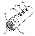
図1〜図3、図5は、印鑑における公知の前記捺印阻止部材を具える構成を示す外形図であり、図1は、印鑑1本体にダイヤル10を具え、捺印阻止部材である筒状部材2aが印鑑本体1の外周に係合し、印面1a方向に移動して捺印を阻止する状態を示す図。図2は、捺印阻止部材である蓋2bが、ダイヤル10を具える印鑑本体1の印面1aに対向し離れて配置され、前記蓋2bが係止し固止可能とする、突出する係止手段である固止部15を具える状態を示す図。図3は、捺印阻止部材である回動蓋2cが、ダイヤル10を具える、印鑑本体1の側面に回動可能に装着され、印面1aを覆って係止手段である固止部15によって係止して行く状態を示す図。
図4は、本発明にかかる印鑑における第1または第2実施形態の構成を示す図であり、前記内蔵装置の制御に基づき印面1aにおいて棒状部材2dがスライドして捺印を阻止する状態を示す図であり、または、偏心する軸からなり、その軸に対して長寸面と短寸面を対向して有し、前記偏心する軸を回動させる回転体である、軸移動レバーを具える図。
図5は、印鑑本体1に内蔵する錠前装置の電子制御装置に数字、記号等を入力するダイヤル10を具え、さらに、錠前装置を直進させ入力を実行する入力ボタン23a,入力のリセットおよび、またはクリアするリセットボタン17a、電池蓋10f、係止手段である固止部15を具え、捺印阻止部材である蓋2bを配置した状態を示す。前記公知の捺印阻止部材を具える構成は何れも印鑑本体1に内蔵する錠前装置によって制御が為される状態を示している。 Hereinafter, an embodiment of a seal stamp with a built-in lock device according to the present invention will be described in detail with reference to the drawings.
1 to 3 and FIG. 5 are external views showing a configuration including the known stamping prevention member in a seal, and FIG. 1 is a cylindrical member which is provided with a
FIG. 4 is a diagram showing a configuration of the first or second embodiment of the seal stamp according to the present invention, and shows a state in which the bar-like member 2d slides on the
5 includes a
図6〜図8は、本発明の印鑑における内蔵錠前装置の構成を示す図である。本実施形態の好適な構成例では、錠前装置3の構成として、ダイヤル10に内接して係合するシリンダー11を列状に配し、シリンダー11の列の中に軸12を、台面12bと台面12bに最も近いシリンダー11との間にスプリング13を間在して通し、軸12における台面12bと反対方向の端にリセットボタン17を近置して、記号の符号もしくは符号を外して係止手段の固止解除および符号の変更もしくは固止を可能にする構成となっている。6-8 is a figure which shows the structure of the built-in lock apparatus in the seal of this invention. In a preferred configuration example of the present embodiment, as a configuration of the
図6は、錠前装置3の分解状態を示す図である。
ダイヤル10は一個ずつ、それぞれ錠前筐体蓋18、錠前筐体19に穿設されたダイヤル溝19aに前後移動を阻止されて係合する。この状態ではダイヤル10の回転は可能になっている。また、ダイヤル10の外周にはクリック溝10bが刻まれ、錠前筐体19の側辺にダイヤル10に平行して設置されている板バネ16の折り出し部16aが押着して、ダイヤル10はクリック状に一時停止して記号などの符合が確実に出来得るようになる。FIG. 6 is a diagram illustrating an exploded state of the
One
ダイヤル10の内側の幅のおよそ半ば迄に歯10cが内向きに等設してあり、歯10cに隣接してフランジ嵌合部10dを穿設してある。また、シリンダー11の径は歯10cの構成する開口部より細くなっているが、フランジ11aの径はそれより大きく、フランジ嵌合部10dに内接する。フランジ11aにはフランジ突起11bが、歯10cに向けて突設し、何れかの歯10cの間に噛み合う。 The
シリンダー11の内側は軸12を通す穴が明いており、さらに通し溝11cとシリンダー端辺係合部11eが穿設される。一方、軸12には凸部12aを、それぞれのシリンダー11に対応し、シリンダーの位置に面して一つずつ配置し、前記捺印防止部材の固止状態では凸部係止部11g内に係止し、ダイヤル10を回転して全ての通し溝11cを同方向に揃えた場合に限り、軸12は前後に移動可能となる。なお、軸12は台面12bにより方向性を制限されており、左右に回動不能ゆえに凸部12aは常に同方向に向いて設定される。 The inside of the
軸12の台面12bとは反対方向の端にリセットボタン17が近在している。このリセットボタン17は、錠前筐体19のリセットガイド溝19dに、前後左右に可動状態に設置してある。 The
図7および図8は、印鑑本体1内に構成する錠前装置3の断面を示す。 FIG. 7 and FIG. 8 show a cross section of the
図8ではそれぞれのシリンダー11が回転し、通し溝11cが互いに一つの方向にそろった状態を示す。そのために凸12aは通し溝11c内を前後に移動可能となる。 FIG. 8 shows a state in which each
つぎに、図14に示す外形図および図15ないし図18に示す図によって、本発明の印鑑における第5実施形態の構成を説明する。
図14の印面1aから捺印阻止部材2に相当する棒状部材2dが突出して、捺印を阻止している。阻止の解除は、ダイヤル10の数字、および、または記号を符合した後、軸移動レバー21をダイヤル10方向に回動し、連動する棒状部材2dを印面1a以内に引き込むことにより行う。前記符合の変更は、阻止解除状態においてリセットボタン17を印面1a方向にスライドしながらダイヤル10を回転して行う。また、軸移動レバー21を印面1a方向に戻して棒状部材2dを突出させ、ダイヤル10の数字および、または記号の符合を乱すことにより、捺印阻止状態とする。Next, the configuration of the fifth embodiment of the seal stamp of the present invention will be described with reference to the external view shown in FIG. 14 and the diagrams shown in FIGS. 15 to 18.
A bar-shaped member 2d corresponding to the
図15は、棒状部材2dを作動する好適な例である。すでに第2実施形態の説明で述べたように、ダイヤル10とシリンダー11は係合し、シリンダー11の内周には凸部係止部11fおよび通し溝11cが穿設され、軸12の凸部12aが留まり、通し溝11cが揃うと凸部12aが移動でき、捺印の阻止、または阻止の解除が可能となる構造になっている。 FIG. 15 is a preferred example of operating the rod-shaped member 2d. As already described in the description of the second embodiment, the
この構造では、凸部12aはスプリング13およびリセットノブ17によって軸12および棒状部材2dは後退方向に移動し、凸部12aは常に通し溝11c内にあるので、捺印可能状態になっており、軸移動レバー21を倒し回動して、左右の回動を規制されている軸12を押し出し、ダイヤル10を回動して前記記号の符合を乱すことにより捺印阻止状態とする。 In this structure, the convex portion 12a is moved in the backward direction by the
軸12の印面1aに向く先端には台面12bが設けられ、台面の先にはさらに断面T字状のクランク保持部12cが突設している。当該クランク保持部にはクランク板2eが係合する。クランク板2eにはクランク保持部12cの頭部をくぐり抜けられる径の穴、同じくクランク保持部12の軸部を摺動可能な長穴がつながって明いており、一方の端には棒状部材2dが突出している。図15ではクランク板2eが2枚となっており、それぞれクランク保持部12の軸部に、左右の移動および回転自在に通されている。なお、棒状部材2dおよびクランク保持部12は必要に応じて何個装着してもよい。
このために、印面1aにどのような字を彫っても、適宜な明き部分に通し穴を明けることにより、自由に棒状部材2dを通して設定することが出来る。A
For this reason, no matter what character is engraved on the marking
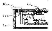
さらに、錠前筐体蓋18のレバー保持部18aに軸移動レバー21が回動自在に取り付けられており、軸移動レバー21から続く軸の下辺には軸に対し長手方向と短手方向に偏心して延在する軸移動部21aが台面12bに接し得るように配置される。
軸移動部21aの長手方向を印面1a方向に回動すると対向する短手方向が台面12bに向き、双方向の差により生ずるスペースを、スプリング13aによって軸12が押し出され移動し、連動する棒状部材2dも印面1a方向に移動して捺印阻止状態となる。Further, a
When the longitudinal direction of the shaft moving portion 21a is rotated in the direction of the marking
図16では、凸部12aがシリンダー11の凸部係止部11f内に係止しており、故に軸12および棒状部材2dが突出して後退不能の状態に留まり、捺印を阻止している。図17は、シリンダー11が回動し、通し溝11cが凸部12aを前後に通す位置に合っており、そのために軸移動レバー21を回動して軸移動部21aの長手方向を台面12bに向けることができ、結果、台面12bおよび棒状部材2dが後退して捺印可能となる状態を示す。 In FIG. 16, the convex portion 12a is locked in the convex portion locking portion 11f of the
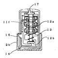
図18は、本発明の印鑑における第5実施形態の異なる構成を示す。本構成では、軸12の台面12bより台面爪12d、12eが延在しており、それぞれ錠前筐体蓋18および錠前筐体19の爪ガイド18d、19aを潜って前後摺動可能に係止している。
台面12bにはクランク保持部12cが設けられ、クランク2eおよび棒状部材2dが回動自在に係止し、印面1aの穴2fにスライド可能に嵌合している。
説明を容易にするために図では省略しているが、錠前筐体蓋18、錠前筐体19の外側に印鑑本体1が被さっており、印鑑本体1のさらに外側に突出する、台面爪12d、12e付近に軸移動リング22が嵌合している。
軸移動リング22の内側には、らせん溝22aが穿設してあり、当該溝のそれぞれに台面爪12d、12eが印鑑本体1を突き抜けて係合し、軸移動リング22を回転するに従い、台面爪12d、12eがらせん溝22a内を摺動し、棒状部材2dは前後に移動する。
凸部12aが凸部係止部11fに留まることにより棒状部材2dが突出して捺印を阻止し、軸移動リング22の回動は固止され、凸部12aが通し溝11c内を移動可能の状態では、当該軸移動リングを回動して棒状部材2dを移動し、捺印可能とすることが出来る。FIG. 18 shows a different configuration of the fifth embodiment of the seal stamp of the present invention. In this configuration, the base surface claws 12d and 12e extend from the
A crank holding portion 12c is provided on the
Although not shown in the figure for ease of explanation, a table claw 12d, which covers the
A spiral groove 22a is formed on the inner side of the
When the convex portion 12a stays at the convex portion locking portion 11f, the rod-like member 2d protrudes to prevent the marking, the rotation of the
図19および図20において、本発明の印鑑における第2の実施形態の構成を示す。すなわち、図19では軸移動レバー21の長寸面が印面1aより外方に突出しており、軸移動レバー21の回動が凸部12aの係止により固止され、捺印が阻止されている。図20では凸部21aが通し溝11c内を後退可能とすることにより、軸移動レバー21の長寸面を印面1aから遠い方向に回動して捺印の阻止を解除している。図21は、図19における軸移動レバー21の外形における状態を示している。In FIG. 19 and FIG. 20, the structure of 2nd Embodiment in the seal stamp of this invention is shown. That is, in FIG. 19, the long surface of the
本発明の実施形態における、ダイヤルを操作して、前記記号の符合により前記係止手段の固止または固止を解除する為の錠前装置は、上述の例に限定されるものではなく、様々な構造が考えられる。
外部より操作して数字および、または記号を符合する符合状態と、当該記号の符合状態に係合して連動し、正しく符合したときにのみ、他部品の移動を可能とする部品、さらに当該部品が他部品の移動を可能とする状態にあるときに、当該記号の符合状態と当該部品との係合の状態を変更することにより新たな前記記号の符合状態を選択できる、ダイヤル錠などの錠前装置に関しては、その基本概念は今までに知られており、前記錠前装置においては、実施する構造の差異や部品形状、レイアウト等の2次的な要素によって差別化がなされているに過ぎない。
本発明の実施形態の前記錠前装置に関しても、図6〜図8、および図15、図18に示すような、ダイヤル10とシリンダー11による係合構造にとどまらず、ダイヤル10が例えば円盤状を成しており、シリンダー11が例えば円盤体を成している部品であり、互いに係止して共に回動し、数字等の符合または符合を乱すことを可能に為し、当該部品の一部に溝または突起を具え、前記円盤状を成すダイヤルを当該部品と共に回動し、具える溝または突起を揃えた状態に置き、当該部品に当接する他部品が左右もしくは前後に移動可能に為し、前記係止手段の固止を解除するとともに、前記円盤状を成すダイヤルと当該部品の係合を一時的に外し、前記円盤状を成すダイヤルのみ回動することによって前記記号の符合の変更を可能にする構造にしてもよい。In the embodiment of the present invention, the lock device for operating the dial and releasing the locking or locking of the locking means according to the sign of the symbol is not limited to the above example, but various A structure is conceivable.
A part that allows the movement of other parts only when the sign state where the numbers and / or symbols are matched by operating from the outside, and the sign state of the symbol is engaged and interlocked and correctly matched A lock such as a dial lock that can select a new sign state of the symbol by changing the sign state of the symbol and the state of engagement with the component when the other component is in a state that allows movement of other parts. Regarding the device, the basic concept has been known so far, and in the lock device, differentiation is made only by secondary elements such as a difference in structure to be implemented, part shape, layout, and the like.
The lock device according to the embodiment of the present invention is not limited to the engagement structure by the
以上詳細に説明したとおり、本発明の錠前装置内蔵の、印鑑は、本来の所有者の意図に反してみだりに使用されることを防止する印鑑であり、捺印を阻止する手段と、錠前装置を共に内蔵する印鑑とすることにより、従来の印鑑と何等の変わりない収納性と携行性を具えるだけでなく、他に鍵などの分離所持しなければならない前記解錠用具を必要とせず、したがって、鍵などの紛失や忘失の心配にとらわれない、安全で簡便な印鑑を提供することにより、従来より印鑑の欠点とされた盗用の問題と、印鑑の利点とされる代理者に印証を託せる、携帯に便利である、模倣しにくいなどの長所を一挙に解決実現する。 As described above in detail, the seal stamp built in the lock device of the present invention is a seal that prevents it from being used unintentionally against the intention of the original owner. Both the means for blocking the seal and the lock device are used together. By having a built-in seal, not only does it have the same storage and portability as a conventional seal, but also does not require the unlocking tool that must be held separately, such as a key. By providing safe and simple seals that are not constrained by the loss or loss of keys etc., it is possible to entrust seals to the agents who are the advantages of seals and the problems of theft that have been regarded as defects of seals. It will solve all the advantages of being convenient to carry and difficult to imitate.
【図1】印鑑の構成に公知の捺印阻止部材を具える外形図である。
【図2】印鑑の構成に公知の捺印阻止部材を具える外形図である。
【図3】印鑑の構成に公知の捺印阻止部材を具える外形図である。
【図4】本発明の第1、第2の実施形態の構成を示す外形図である。
【図5】印鑑の構成に公知の捺印阻止部材を具える外形図である。
【図6】印鑑の構成に公知の捺印阻止部材を具える分解図である。
【図7】印鑑の構成に公知の捺印阻止部材を具える断面図である。
【図8】印鑑の構成に公知の捺印阻止部材を具える断面図である。
【図9】印鑑の構成に公知の捺印阻止部材を具える外形図である。
【図10】印鑑の構成に公知の捺印阻止部材を具える断面図である。
【図11】印鑑の構成に公知の捺印阻止部材を具える断面図である。
【図12】印鑑の構成に公知の捺印阻止部材を具える外形図である。
【図13】印鑑の構成に公知の捺印阻止部材を具える外形図である。
【図14】本発明の第1、第2の実施形態の構成を示す外形図である。
【図15】本発明の第1、第2の実施形態の構成を示す分解図である。
【図16】本発明の第1、第2の実施形態の構成を示す断面図である。
【図17】本発明の第1、第2の実施形態の構成を示す断面図である。
【図18】本発明の第1、第2の実施形態の構成の変形例を示す分解図である。
【図19】本発明の第1、第2の実施形態の構成と作動を示す断面図である。
【図20】本発明の第1、第2の実施形態の構成と作動を示す断面図である。
【図21】本発明の第1、第2の実施形態の構成を示す外形図である。
【図22】公知の捺印阻止部材を具える分解図である。
【図23】公知の捺印阻止部材を具える外形図である。
【図24】公知の捺印阻止部材を具える断面図である。
【図25】公知の捺印阻止部材を具える断面図である。
【図26】公知の捺印阻止部材を具える断面図である。FIG. 1 is an external view including a known stamp blocking member in the configuration of a seal.
FIG. 2 is an external view including a known stamp blocking member in the configuration of a seal.
FIG. 3 is an external view including a known stamp blocking member in the configuration of a seal.
FIG. 4 is an external view showing the configuration of the first and second embodiments of the present invention.
FIG. 5 is an external view including a known stamp blocking member in the configuration of a seal.
FIG. 6 is an exploded view in which a known stamp blocking member is provided in the configuration of the seal.
FIG. 7 is a cross-sectional view including a known stamp blocking member in the configuration of a seal.
FIG. 8 is a cross-sectional view including a known stamp blocking member in the configuration of a seal.
FIG. 9 is an external view including a known stamp blocking member in the configuration of a seal.
FIG. 10 is a cross-sectional view including a known stamp blocking member in the configuration of a seal.
FIG. 11 is a cross-sectional view including a known stamp blocking member in the configuration of a seal.
FIG. 12 is an external view including a known stamp blocking member in the configuration of a seal.
FIG. 13 is an external view including a known stamp blocking member in the configuration of the seal.
FIG. 14 is an external view showing the configuration of the first and second embodiments of the present invention.
FIG. 15 is an exploded view showing the configuration of the first and second embodiments of the present invention.
FIG. 16 is a cross-sectional view showing the configuration of the first and second embodiments of the present invention.
FIG. 17 is a cross-sectional view showing the configuration of the first and second embodiments of the present invention.
FIG. 18 is an exploded view showing a modification of the configuration of the first and second embodiments of the present invention.
FIG. 19 is a cross-sectional view showing the configuration and operation of the first and second embodiments of the present invention.
FIG. 20 is a cross-sectional view showing the configuration and operation of the first and second embodiments of the present invention.
FIG. 21 is an external view showing the configuration of the first and second embodiments of the present invention.
FIG. 22 is an exploded view including a known stamping prevention member.
FIG. 23 is an external view including a known stamping prevention member.
FIG. 24 is a cross-sectional view including a known stamping prevention member.
FIG. 25 is a cross-sectional view including a known stamping prevention member.
FIG. 26 is a cross-sectional view including a known stamping prevention member.
1 印鑑本体
2 捺印阻止部材
3 錠前装置
4 電池
1a 印面
2a 筒状部材
2b 蓋
2c 回動蓋
2d 棒状部材
2e クランク
2f 穴
10 ダイヤル
10a 数字および、または記号
10b クリック溝
10c 歯
10d フランジ嵌合部
10e 入力部
10f 電池蓋
10g ダイヤルスプリング
10h 指標
10i ピン
11 シリンダー
11a フランジ
11b フランジ突起
11c 通し溝
11d シリンダー端辺
11e シリンダー端辺係合部
11f 凸部係止部
12 軸
12a 凸部
12b 台面
12c クランク保持部
12d、12e 台面爪
13 スプリング
14 アーム
14a 回動穴
15 固止部
15a コントロールユニット
16 板バネ
16a 折り出し部
17 リセットボタン
17a リセットスイッチ
18 錠前筐体蓋
18a レバー保持部
18b リセット時係止部
18c ダイヤル穴
18d、19a 爪ガイド
19 錠前筐体
19b ダイヤル等置溝
19c 固止部穴
19d リセットガイド溝
19e アームスプリング係止部
19f アーム軸
20 アームスプリング
21 軸移動レバー
21a 軸移動部
22 軸移動リング
22a らせん溝
23 リード線
24 電子制御装置
24a ノブ
24b ダイヤル基板DESCRIPTION OF
Claims (2)
Priority Applications (1)
| Application Number | Priority Date | Filing Date | Title |
|---|---|---|---|
| JP2004244459A JP4543280B2 (en) | 2004-07-28 | 2004-07-28 | seal |
Applications Claiming Priority (1)
| Application Number | Priority Date | Filing Date | Title |
|---|---|---|---|
| JP2004244459A JP4543280B2 (en) | 2004-07-28 | 2004-07-28 | seal |
Publications (2)
| Publication Number | Publication Date |
|---|---|
| JP2006035838A JP2006035838A (en) | 2006-02-09 |
| JP4543280B2 true JP4543280B2 (en) | 2010-09-15 |
Family
ID=35901321
Family Applications (1)
| Application Number | Title | Priority Date | Filing Date |
|---|---|---|---|
| JP2004244459A Expired - Lifetime JP4543280B2 (en) | 2004-07-28 | 2004-07-28 | seal |
Country Status (1)
| Country | Link |
|---|---|
| JP (1) | JP4543280B2 (en) |
Families Citing this family (8)
| Publication number | Priority date | Publication date | Assignee | Title |
|---|---|---|---|---|
| CN106183495B (en) * | 2016-07-01 | 2018-03-20 | 胡金钱 | Intelligent seal with locking mechanism |
| CN106240182B (en) * | 2016-07-15 | 2018-07-06 | 江山市智骨软件科技有限公司 | It is a kind of to be equipped with tamper clamp button of the spring and the seal with heat sinking function |
| CN109435504B (en) * | 2018-11-30 | 2024-06-11 | 杭州伟企科技有限公司 | Automatic press seal of key locker |
| CN110077129A (en) * | 2019-04-19 | 2019-08-02 | 南宁学院 | A kind of novel commercial seal |
| CN110406279B (en) * | 2019-07-04 | 2024-07-02 | 珠海汇金科技股份有限公司 | Seal module locking mechanical system and seal accuse appearance |
| JP2021138006A (en) * | 2020-03-03 | 2021-09-16 | 久範 山原 | stamp |
| JP7625200B2 (en) | 2021-05-17 | 2025-02-03 | 岩井プレス株式会社 | Seals and how to create them |
| CN114771116B (en) * | 2022-06-01 | 2024-05-03 | 张小锋 | Anti-fake financial seal |
Citations (1)
| Publication number | Priority date | Publication date | Assignee | Title |
|---|---|---|---|---|
| JPH02144463U (en) * | 1989-05-11 | 1990-12-07 |
Family Cites Families (5)
| Publication number | Priority date | Publication date | Assignee | Title |
|---|---|---|---|---|
| JPS518214U (en) * | 1974-07-03 | 1976-01-21 | ||
| JPS63170159U (en) * | 1987-04-23 | 1988-11-07 | ||
| JPH03155978A (en) * | 1989-11-14 | 1991-07-03 | Noriharu Osada | Locked stamp |
| JPH0480483A (en) * | 1990-07-23 | 1992-03-13 | Noriharu Osada | Signet with lock |
| JPH08300787A (en) * | 1995-05-08 | 1996-11-19 | Hirokazu Yanai | Seal case fitted with lock |
-
2004
- 2004-07-28 JP JP2004244459A patent/JP4543280B2/en not_active Expired - Lifetime
Patent Citations (1)
| Publication number | Priority date | Publication date | Assignee | Title |
|---|---|---|---|---|
| JPH02144463U (en) * | 1989-05-11 | 1990-12-07 |
Also Published As
| Publication number | Publication date |
|---|---|
| JP2006035838A (en) | 2006-02-09 |
Similar Documents
| Publication | Publication Date | Title |
|---|---|---|
| US8056376B2 (en) | Dual-lock type padlock having double reminding function | |
| JP3221383U (en) | Lock set | |
| JP4543280B2 (en) | seal | |
| US5359867A (en) | Combination padlock with magnifiable combinations | |
| CN102022036B (en) | Padlock with accommodating space | |
| JP2001295519A (en) | Locking set changing device | |
| US6079239A (en) | Tamperproof lock | |
| JP2012026249A (en) | Dial lock device | |
| JP4112399B2 (en) | Security thumb turn unit and opening / closing body using it | |
| JP2009024335A (en) | Lock device | |
| JP5943501B2 (en) | Card lock for bag | |
| JP5964218B2 (en) | Plane handle | |
| JP3355167B2 (en) | Door lock device | |
| JP3139599U (en) | Pointer lock | |
| JP4478832B2 (en) | Handle lock lock | |
| JP3129598U (en) | Card key / keypad type lock device | |
| CN107980075B (en) | Locking device | |
| JPS5836748Y2 (en) | flat handle device | |
| JP4727086B2 (en) | Button-type latch lock | |
| JP2024078203A (en) | Combination lock | |
| JP4127702B2 (en) | padlock | |
| JP7199137B2 (en) | Portable locking/unlocking display device | |
| JP4850037B2 (en) | Card key / keypad type lock device | |
| JP2011219994A (en) | Portable machine for vehicle | |
| JP3097596U (en) | Center lock for dual use suitcase |
Legal Events
| Date | Code | Title | Description |
|---|---|---|---|
| A621 | Written request for application examination |
Free format text: JAPANESE INTERMEDIATE CODE: A621 Effective date: 20070726 |
|
| A521 | Request for written amendment filed |
Free format text: JAPANESE INTERMEDIATE CODE: A523 Effective date: 20071005 |
|
| A977 | Report on retrieval |
Free format text: JAPANESE INTERMEDIATE CODE: A971007 Effective date: 20100129 |
|
| A131 | Notification of reasons for refusal |
Free format text: JAPANESE INTERMEDIATE CODE: A131 Effective date: 20100209 |
|
| A521 | Request for written amendment filed |
Free format text: JAPANESE INTERMEDIATE CODE: A523 Effective date: 20100409 |
|
| TRDD | Decision of grant or rejection written | ||
| A01 | Written decision to grant a patent or to grant a registration (utility model) |
Free format text: JAPANESE INTERMEDIATE CODE: A01 Effective date: 20100608 |
|
| A01 | Written decision to grant a patent or to grant a registration (utility model) |
Free format text: JAPANESE INTERMEDIATE CODE: A01 |
|
| A61 | First payment of annual fees (during grant procedure) |
Free format text: JAPANESE INTERMEDIATE CODE: A61 Effective date: 20100615 |
|
| FPAY | Renewal fee payment (event date is renewal date of database) |
Free format text: PAYMENT UNTIL: 20130709 Year of fee payment: 3 |
|
| R150 | Certificate of patent or registration of utility model |
Free format text: JAPANESE INTERMEDIATE CODE: R150 Ref document number: 4543280 Country of ref document: JP Free format text: JAPANESE INTERMEDIATE CODE: R150 |
|
| FPAY | Renewal fee payment (event date is renewal date of database) |
Free format text: PAYMENT UNTIL: 20140709 Year of fee payment: 4 |
|
| R250 | Receipt of annual fees |
Free format text: JAPANESE INTERMEDIATE CODE: R250 |
|
| R250 | Receipt of annual fees |
Free format text: JAPANESE INTERMEDIATE CODE: R250 |
|
| R250 | Receipt of annual fees |
Free format text: JAPANESE INTERMEDIATE CODE: R250 |
|
| R250 | Receipt of annual fees |
Free format text: JAPANESE INTERMEDIATE CODE: R250 |
|
| R250 | Receipt of annual fees |
Free format text: JAPANESE INTERMEDIATE CODE: R250 |
|
| R250 | Receipt of annual fees |
Free format text: JAPANESE INTERMEDIATE CODE: R250 |
|
| R250 | Receipt of annual fees |
Free format text: JAPANESE INTERMEDIATE CODE: R250 |
|
| R250 | Receipt of annual fees |
Free format text: JAPANESE INTERMEDIATE CODE: R250 |
|
| R250 | Receipt of annual fees |
Free format text: JAPANESE INTERMEDIATE CODE: R250 |
|
| S801 | Written request for registration of abandonment of right |
Free format text: JAPANESE INTERMEDIATE CODE: R311801 |
|
| ABAN | Cancellation due to abandonment | ||
| R350 | Written notification of registration of transfer |
Free format text: JAPANESE INTERMEDIATE CODE: R350 |