JP4220561B2 - Tightening device for wedge-tight scaffolding - Google Patents
Tightening device for wedge-tight scaffolding Download PDFInfo
- Publication number
- JP4220561B2 JP4220561B2 JP2007125714A JP2007125714A JP4220561B2 JP 4220561 B2 JP4220561 B2 JP 4220561B2 JP 2007125714 A JP2007125714 A JP 2007125714A JP 2007125714 A JP2007125714 A JP 2007125714A JP 4220561 B2 JP4220561 B2 JP 4220561B2
- Authority
- JP
- Japan
- Prior art keywords
- wedge
- guide member
- bracket
- receiving
- central wall
- Prior art date
- Legal status (The legal status is an assumption and is not a legal conclusion. Google has not performed a legal analysis and makes no representation as to the accuracy of the status listed.)
- Active
Links
- 239000002184 metal Substances 0.000 claims description 53
- 239000004744 fabric Substances 0.000 claims description 23
- 229910000831 Steel Inorganic materials 0.000 claims description 15
- 239000010959 steel Substances 0.000 claims description 15
- 238000003780 insertion Methods 0.000 claims description 10
- 230000037431 insertion Effects 0.000 claims description 10
- 230000002265 prevention Effects 0.000 claims description 7
- 230000002093 peripheral effect Effects 0.000 claims description 4
- 230000000149 penetrating effect Effects 0.000 claims description 3
- 239000002023 wood Substances 0.000 description 23
- 210000000078 claw Anatomy 0.000 description 4
- 208000019901 Anxiety disease Diseases 0.000 description 2
- 230000036506 anxiety Effects 0.000 description 2
- 240000001549 Ipomoea eriocarpa Species 0.000 description 1
- 235000005146 Ipomoea eriocarpa Nutrition 0.000 description 1
- 239000011324 bead Substances 0.000 description 1
- 238000009434 installation Methods 0.000 description 1
- 239000000463 material Substances 0.000 description 1
- 238000012986 modification Methods 0.000 description 1
- 230000004048 modification Effects 0.000 description 1
- 238000003466 welding Methods 0.000 description 1
Images


Landscapes
- Clamps And Clips (AREA)
Description
本発明は、くさび緊結式足場における緊結装置に関する。 The present invention relates to a binding device in a wedge binding type scaffold.
なお、この明細書において、支柱と腕木材との関係において、前とは緊結する支柱のある側を、後とは緊結する腕木材のある側をいうものとする。 In this specification, in the relationship between the support column and the arm wood, the front side refers to the side with the support column to be tightened, and the rear side refers to the side with the arm wood to be tightened.
従来の上記緊結装置は、支柱の所定高さ外周に固着せられた受け金具と、2つの支柱間に渡される腕木材の端部に固着せられたくさび状係止金具とよりなり、くさび状係止金具を受け金具にハンマーで上から叩き込んで係止することにより、支柱と腕木材とを緊結していた。また、支柱と腕木材との緊結を解除するさいには、腕木材のくさび状係止金具を支柱の受け金具からハンマーで下から叩き上げて係止を解除するか、または支柱の受け金具の近くの腕木材の端部をハンマーで下から叩き上げて同端部に固着せられているくさび状係止金具の係止を解除していた。このように、支柱と腕木材の緊結は、くさび状係止金具を受け金具に固く差し込むことより行われているだけであるから、腕木材の下を大きな工具を持って通過したり、資材の取付け作業をするさいに、工具や資材が腕木材に当たったりするなどして腕木材に不測の力が下から加わると、くさび状係止金具の係止が緩み、受け金具からくさび状係止金具が外れる危険性があった。さらに、従来から広く一般に用いられてきた枠組足場に使用されている薄鋼板製の床付き布わくを腕木材に取付けた場合、床付き布わくは腕木材に対してロック機能を有しているので、これに下からの風圧が加わると、腕木材のくさび状係止金具が受け金具から外れて腕木材もろとも床付き布わくが落下する危険性があった。そこで、床付き布わくとして風の吹き抜けるエキスパンドメタル製のものを使用している。このエキスパンドメタル製のものは薄鋼板製のものに較べて幅が狭いので、これを薄鋼板製のものと同じ幅の床付き布わくにすると、重量が重くなりかつ高価になる。したがって、床付き布わくの幅を狭くしているが、幅が狭いとその上で作業する者に不安感を与える。しかも、エキスパンドメタル製のものは下が透けて見えるので、作業床や通路としては一層の不安感を与えるという問題があった。 The above-mentioned conventional fastening device is composed of a receiving bracket fixed to the outer periphery of a predetermined height of a support column and a wedge-shaped locking bracket fixed to an end of an arm lumber passed between the two support columns. The struts and arm lumbers were tightly bound by hitting the retaining brackets with a hammer from above and locking them. In addition, when releasing the tightness between the support column and the arm lumber, either release the lock by hitting the wedge lock bracket of the arm lumber from below with the hammer of the support column or near the support bracket of the prop. The end of the arm wood was struck from below with a hammer to release the lock of the wedge-shaped lock fitting fixed to the end. In this way, the support column and arm timber are simply tightened by receiving the wedge-shaped locking bracket and inserting it firmly into the bracket. During installation, if an unexpected force is applied to the arm wood from below, such as when a tool or material hits the arm wood, the wedge-shaped locking bracket will loosen, and the wedge-shaped locking will start from the receiving bracket. There was a risk that the bracket would come off. Furthermore, when a sheet steel floor cloth used in a frame scaffold that has been widely used in the past is attached to the arm wood, the floor cloth has a lock function for the arm wood. Therefore, when wind pressure is applied from below, there is a risk that the wedge-shaped metal fittings of the arm wood will come off the receiving metal and the cloth with the floor will fall together with the arm wood. Therefore, an expanded metal fabric that blows through the wind is used as a cloth with a floor. Since the expanded metal is narrower than the thin steel plate, if it is made of cloth with a floor having the same width as that of the thin steel plate, it becomes heavy and expensive. Therefore, although the width of the cloth with the floor is narrowed, if the width is narrow, anxiety is given to those who work on it. In addition, since the bottom made of expanded metal can be seen through, there is a problem that the work floor and the passage give further anxiety.
仮設構造物を構成する支柱と水平材の連結装置において、特許文献1に開示されているような係止が不測に解除されないとする下記装置が提案されている。すなわち、この提案装置は、受け金具が、平面からみてコ形で中央壁の幅中央に上方開口垂直溝を有しており、係止金具が、水平材の端面板から前方にのび、受け金具の中央壁の垂直溝に嵌め込まれる横断面縦長方形の水平突出部と、水平突出部の先端に設けられて受け金具の中央壁と支柱との間に差し込まれる係止爪と、係止爪の後方において、中央に形成せられた下方開口垂直溝により水平突出部に前後摺動自在に引っ掛けられかつ下端に前向き水平凸部を有し、前面からみて縦長方形、側面からみて逆く形で、前方の係止爪とで中央壁を挟圧するばね製中央壁挟圧部材と、挟圧部材と端面板との間において水平突出部に上下動自在に引っ掛けられ、前面からみて逆U形、側面からみて上半が幅広に、下半が幅狭となされかつ両下端部に抜け止めピンが渡されているくさび部材とを備えているものである。
特許文献1に開示の提案装置によれば、係止金具の係止爪を受け金具の中央壁と支柱との間に差し込んだ後、上昇位置にあるくさび部材の上端を数回金槌で叩き、その上半幅広部を下げて逆く形のばね製中央壁挟圧部材をばね力に抗して前進させ、係止爪とで中央壁を狭圧し、支柱と水平材を連結するものであるから、連結時中央壁挟圧部材のばね力が働いており、簡単にはくさび部材が上に抜けることはない。しかしながら、ばね製中央壁挟圧部材は、逆く形であるから、これとくさび部材の上半幅広部との間の上下にV状および逆V状の隙間が生じる。したがって、水平材はわずかではあるが、支柱に対して不安定である。
According to the proposed device disclosed in
本発明の目的は、支柱からの腕木材の不測の緊結解除と支柱に対する腕木材の不安定さをともに解決したくさび緊結式足場における緊結装置を提供するにある。 It is an object of the present invention to provide a binding device in a wedge-type scaffold that solves both the unexpected release of arm wood from the support and the instability of the arm wood with respect to the support.
請求項1の発明によるくさび緊結式足場における緊結装置は、支柱の所定高さ外周に固着せられた受け金具と、2つの支柱間に渡される腕木材の端部に前側が露出するように埋入付設せられかつ受け金具に係止せられる係止金具とよりなり、受け金具は、平面からみてコ形で中央壁が前下がりに傾斜せしめられており、係止金具は、緊結のため降下せしめるさいに支柱と接する垂直部を備えた前縁と受け金具の中央壁と略同じ斜度で前下がりに傾斜した後縁を有する縦長板状のくさびと、一部が腕木材から下方に突出しかつ平面からみて受け金具に嵌る大きさのコ形で中央壁が受け金具の中央壁と同じ斜度で前下がりに傾斜せしめられており、くさびが上下動自在に挿入されているくさび案内部材と、くさびとくさび案内部材の中央壁の間に介在せられて上端部がくさび案内部材の上部に前後揺動自在に取付けられ、かつ下端部に後方に突出した抜け止め突起が設けられるとともに、押しばねでくさび側に付勢せられている揺動バーとを備えており、くさび案内部材の両側壁にくさび脱出阻止バーが渡し止められ、くさび脱出阻止バーが横断しかつくさびの上下動に必要な縦長さで緊結解除時くさび脱出阻止バーが接する後縁を備えた縦長孔または前向き切欠部がくさびに形成せられ、くさび案内部材の腕木材から下方が受け金具への挿入部となされ、くさび案内部材の中央壁における挿入部部分には、前後貫通状抜け止め突起収納部が形成せられ、くさび案内部材の挿入部が受け金具に挿入されて受け金具の上端に腕木材の端部が受け止められた状態において、受け金具の中央壁に抜け止め突起収納孔に対応して抜け止め突起受け入れ部が形成せられ、抜け止め突起受け入れ部は、係止金具が受け金具から上方に抜けようとしたさい抜け止め突起が引っ掛かる上縁を有しており、揺動バーが、緊結時ばね力を抗して後方に揺動して抜け止め突起を受け金具の抜け止め突起受け入れ部に押し入れ、緊結解除時ばね力により前方に揺動して抜け止め突起を受け金具の抜け止め突起受け入れ部から引き出すように、くさび案内部材の中央壁とくさびとの間隔が定められているものである。
The binding device for the wedge-binding scaffold according to the invention of
請求項2の発明は、請求項1記載のくさび緊結式足場における緊結装置において、腕木材が金属管製であり、金属管端部の上下周壁対向部にくさび案内部材の対応部分が密に嵌る平面からみてコ形の切欠部が設けられ、くさび案内部材がその上縁を管の上端よりわずかに突出するように上下切欠部に嵌め入れられて腕木に溶接せられており、くさび案内部材の両側壁に止められている揺動バーの上端部がくさび案内部材の上縁を上方に越えないようになされているとともに、くさび案内部材に挿入せられたくさびは、緊結時その上縁全体のうち少なくとも枠組足場用薄鋼板製床付き布わくのつかみ金具の掛かる部分がくさび案内部材の上縁とほぼ同じ高さとなる形状に形成せられているものである。 According to a second aspect of the present invention, in the binding device in the wedge-tightening type scaffold according to the first aspect, the arm lumber is made of a metal tube, and the corresponding portion of the wedge guide member is closely fitted to the upper and lower peripheral wall facing portions of the end portion of the metal tube. A U-shaped notch is provided when viewed from the plane, and the wedge guide member is fitted into the upper and lower notches so that its upper edge slightly protrudes from the upper end of the pipe, and is welded to the arm. The upper end of the swing bar fixed to the both side walls does not exceed the upper edge of the wedge guide member, and the wedge inserted into the wedge guide member is Among them, at least a portion of the cloth scaffolding with the thin steel plate floor for the frame scaffolding is formed in a shape that is substantially the same height as the upper edge of the wedge guide member.
請求項3の発明は、請求項1または2記載のくさび緊結式足場における緊結装置において、押しばねがコイルばねであり、このコイルばねは、揺動バー下端寄りにあけられた後向き有底孔に後方突出状態に嵌め入れられ、その後方突出端はくさび案内部材の中央壁前面で受けられているものである。 According to a third aspect of the present invention, in the binding device for the wedge-tightening type scaffolding according to the first or second aspect, the push spring is a coil spring, and the coil spring is formed in a rearward bottomed hole opened near the lower end of the swing bar. The rear projecting end is fitted into the rear projecting state, and the rear projecting end is received by the front surface of the central wall of the wedge guide member.
請求項1の発明によれば、受け金具の上端に腕木材の端部が直接受け止められており、くさび作用により腕木材がぐらつくことがないので、腕木材はしっかりと水平に保たれ、しかも、薄鋼板製の床付き布わくを使用してこれに風圧が下から加わったとしても、係止金具側の抜け止め突起が受け金具の抜け止め突起受け入れ部の上縁に引っ掛かるので、係止金具が受け金具から上に抜ける危険性はない。したがって、エキスパンドメタル製でなく薄鋼板製の床付き布わくを使用できるという利点がある。
According to the invention of
従来のくさび緊結式足場では、腕木材の両端部にあるくさび状係止金具につかみ金具が当たらない幅の床付き布わくを使用していた。枠組足場の場合、床付き布わくのつかみ金具は、縦枠の横架材をつかむので、横架材端部には障害物がなく、くさび緊結式足場用床付き布わくより幅の広い床付き布わくを使用している。従来のくさび緊結式足場に幅の広い床付き布わくを使用しようとすれば、床付き布わくの両端のつかみ金具間の幅を腕木材の両端部にあるくさび状係止金具を避けるように狭くした特別製品を製造せざるを得ない不便がある。 In the conventional wedge-binding scaffold, a cloth cloth with a floor having a width that does not hit the wedge-shaped fittings at both ends of the arm lumber is used. In the case of a framed scaffold, the cloth bracket with a floor grips the horizontal frame of the vertical frame, so there is no obstacle at the end of the horizontal frame, and the floor is wider than the cloth with the wedge-tight scaffolding floor. A cloth with a cloth is used. If you want to use a cloth with a wide floor for a conventional wedge-tight scaffold, make sure that the width between the grips on both ends of the floor cloth is avoided from the wedge-shaped locking brackets on both ends of the arm lumber. There is an inconvenience to make a special product that is narrow.
請求項2の発明によれば、腕木材が金属管製であり、金属管端部の上下周壁対向部にくさび案内部材の対応部分が密に嵌る平面からみてコ形の切欠部が設けられ、くさび案内部材がその上縁を管の上端よりわずかに突出するように上下切欠部に嵌め入れられて腕木に溶接せられており、くさび案内部材の両側壁に止められている揺動バーの上端部がくさび案内部材の上縁を上方に越えないようになされているとともに、くさび案内部材に挿入せられたくさびは、緊結時その上縁全体のうち少なくとも枠組足場用薄鋼板製床付き布わくのつかみ金具の掛かる部分がくさび案内部材の上縁とほぼ同じ高さとなる形状に形成せられているから、上で作業する者が安心できる幅の枠組足場用薄鋼板製床付き布わくをそのまま使用でき、それに伴って妻側用の朝顔、養生枠、シートなどの枠組足場に使われていた部材もそのまま利用可能となる利点がある。
According to the invention of
本発明を実施するための最良の形態を、以下図面を参照して説明する。 The best mode for carrying out the present invention will be described below with reference to the drawings.
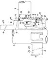
図1ないし図7に示すくさび緊結式足場における緊結装置は、支柱(1)の所定高さの外周に固着せられた受け金具(2)と、2つの支柱(1)間に渡される腕木材(3)の端部に前側が露出するように埋入付設せられかつ受け金具(2)に係止せられる係止金具(4)とよりなる。支柱(1)および腕木材(3)は、所定長さを有する鋼管製であり、4つの鋼製受け金具(2)が、図1に示すように、支柱(1)の同一高さの周面四方に溶接により固着せられている。4つの受け金具(2)のうち対向する2つは、一段下に位置せしめられることもある。 The binding device in the wedge-binding scaffold shown in FIG. 1 to FIG. 7 is a brace (2) fixed to the outer periphery of a predetermined height of the support column (1) and the arm wood passed between the two support columns (1). It consists of a locking fitting (4) that is embedded in the end of (3) so that the front side is exposed and locked to the receiving fitting (2). The support column (1) and the arm wood (3) are made of steel pipes having a predetermined length, and four steel support brackets (2) are arranged at the same height of the support column (1) as shown in FIG. It is fixed to the four sides by welding. Two of the four metal fittings (2) facing each other may be positioned one step below.
受け金具(2)は、平面からみてコ形で中央壁(5)が前下がりに傾斜せしめられている。係止金具(4)は、緊結のため降下せしめるさいに支柱(1)と接する垂直部(6)を備えかつ下部が受け金具(2)に挿入し易いように若干後下がりに傾斜せしめられた前縁と受け金具(2)の中央壁(5)と略同じ斜度で前下がりに傾斜した後縁(7)を有する鋼製縦長板状のくさび(8)と、一部が腕木材(3)から下方に突出しかつ平面からみて受け金具(2)に嵌る大きさのコ形で中央壁(9)が受け金具(2)の中央壁(5)と同じ斜度で前下がりに傾斜せしめられており、くさび(8)が上下動自在に挿入されているくさび案内部材(10)と、くさび(8)とくさび案内部材(10)の中央壁(9)の間に介在せられて上端部がくさび案内部材(10)の両側壁(11)に止め軸(12)により前後揺動自在に取付けられ、かつ下端部に折り曲げ状に後方に突出した抜け止め突起(13)が設けられるとともに、コイルばね(14)でくさび(2)側に付勢せられている揺動バー(15)とを備えている。コイルばね(14)は、揺動バー(15)の下端寄りにあけられた後向き有底孔(16)に後方突出状態に嵌め入れられ、その後方突出端はくさび案内部材(10)の中央壁(9)の前面で受けられている。くさび(8)は緊結解除時にはくさび案内部材(10)より上方に一部が突出し、緊結時にはくさび案内部材(10)より下方に一部が突出し得る長さを有し、くさび案内部材(10)の両側壁(11)の幅ほぼ真中位置でコイルばね(14)より若干上方位置にくさび脱出阻止バー(17)が渡し止められ、くさび脱出阻止バー(17)が横断しかつくさび(9)の上下動に必要な縦長さでくさび脱出阻止バー(17)が接する後縁(18)を備えた縦長孔(19)がくさび(8)に形成せられている。この縦長孔(19)は、くさび案内部材(10)の中央壁(9)と同じ斜度で前下がりに傾斜している。なお、縦長孔(19)の代わりにこれと同様の後縁を有する前向き切欠部でもよい。受け金具(2)の中央壁(5)と略同じ斜度で前下がりに傾斜した後縁(7)は、くさび案内部材(10)に揺動バー(15)の前側において挿入し易いように、略下半部がその上方より若干斜度を小ならしめられている。 The metal fitting (2) is U-shaped when viewed from the plane, and the central wall (5) is inclined forward and downward. The locking metal fitting (4) has a vertical part (6) in contact with the support column (1) when being lowered for tightening, and the lower part is inclined slightly downward so that it can be easily inserted into the receiving metal fitting (2). A steel vertical wedge (8) having a front edge and a rear edge (7) inclined forward and downward at substantially the same inclination as the central wall (5) of the catch (2); 3) Projected downward from the plane and sized to fit into the bracket (2) when viewed from above, the central wall (9) is tilted forward and downward at the same inclination as the central wall (5) of the bracket (2). And a wedge guide member (10) in which the wedge (8) is inserted so as to be movable up and down, and an upper end interposed between the wedge (8) and the central wall (9) of the wedge guide member (10). The part is attached to both side walls (11) of the wedge guide member (10) by a stop shaft (12) so that it can swing back and forth. The lower end is provided with a retaining protrusion (13) that protrudes backward in a bent shape, and a swing bar (15) that is biased toward the wedge (2) by a coil spring (14). . The coil spring (14) is fitted in a rearward projecting state in a rearward bottomed hole (16) opened near the lower end of the swing bar (15), and the rearward projecting end is the central wall of the wedge guide member (10). Received on the front of (9). The wedge (8) has a length that can protrude partly above the wedge guide member (10) when the binding is released, and partly protrude below the wedge guide member (10) when tightened. The wedge escape prevention bar (17) is blocked from the coil spring (14) at a position approximately in the middle of the width of both side walls (11) of the coil spring (14). A longitudinal hole (19) having a rear edge (18) with which the wedge escape prevention bar (17) is in contact with the longitudinal length necessary for vertical movement is formed in the wedge (8). The vertically long hole (19) is inclined forward and downward at the same inclination as the central wall (9) of the wedge guide member (10). Instead of the vertically long hole (19), a forward notch having a rear edge similar to this may be used. The rear edge (7) inclined forward and downward with substantially the same inclination as the central wall (5) of the catch (2) is easily inserted into the wedge guide member (10) on the front side of the swing bar (15). The substantially lower half is slightly inclined from the upper part.
くさび案内部材(10)の腕木材(3)から下方が受け金具(2)への挿入部(20)となされ、くさび案内部材(10)の中央壁(9)における挿入部部分には、前後に貫通する逆U形の抜け止め突起収納下向き切欠部(21)が形成せられ、くさび案内部材(10)の挿入部(20)が受け金具(2)に挿入されて受け金具(2)の上端に腕木材(3)の端部が受け止められた状態において、受け金具(2)の中央壁(5)に抜け止め突起収納下向き切欠部(21)に対応して逆U形の抜け止め突起受け入れ下向き切欠部(22)が形成せられている。抜け止め突起受け入れ下向き切欠部(22)は、係止金具(4)が受け金具(2)から上方に抜けようとしたさい抜け止め突起(13)が引っ掛かる上縁を有している。揺動バー(15)が、緊結時ばね力に抗して後方に揺動し、抜け止め突起(13)を受け金具(2)の抜け止め突起受け入れ切欠部(22)に押し入れ、緊結解除時ばね力により前方に揺動して抜け止め突起(13)を受け金具(2)の抜け止め突起受け入れ下向き切欠部(22)から引き出すように、くさび案内部材(10)の中央壁(9)とくさび(8)との間隔が定められている。なお、抜け止め突起収納下向き切欠部(21)の代わりに貫通孔でもよいし、また抜け止め突起受け入れ下向き切欠部(22)の代わりに前向き凹部でもよい。 The lower part from the arm wood (3) of the wedge guide member (10) is an insertion part (20) to the receiving metal fitting (2), and the insertion part part in the central wall (9) of the wedge guide member (10) An inverted U-shaped retaining projection storage downward cutout (21) penetrating into the recess is formed, and the insertion portion (20) of the wedge guide member (10) is inserted into the receiving bracket (2), and the receiving bracket (2) In a state where the end of the arm lumber (3) is received at the upper end, the reverse U-shaped retaining projection corresponding to the retaining projection storage downward notch (21) on the central wall (5) of the receiving bracket (2) A receiving downward notch (22) is formed. The retaining protrusion receiving downward notch (22) has an upper edge on which the retaining protrusion (13) is hooked when the locking metal fitting (4) tries to come out upward from the receiving metal fitting (2). The swing bar (15) swings backward against the spring force when tightened, and the retaining protrusion (13) is pushed into the retaining protrusion receiving notch (22) of the metal fitting (2) to release the tightening. The center wall (9) of the wedge guide member (10) is pivoted forward by the spring force so as to be pulled out from the retaining projection receiving downward notch (22) of the metal fitting (2) by receiving the retaining projection (13). The distance from the wedge (8) is determined. A through-hole may be used instead of the retaining protrusion receiving downward notch (21), and a forward recess may be used instead of the retaining protrusion receiving downward notch (22).
くさび案内部材(10)は、腕木材(3)の端部からつぎのようにして下方にのびるように設けられる。腕木材(3)は、鋼管製である。そこで、金属管端部の上下周壁対向部にくさび案内部材(10)の対応部分が密に嵌る平面からみてコ形の切欠部(23) (41)が設けられ、くさび案内部材(10)がその上縁を管の上面からわずかに突出するように上下切欠部(23) (41)に嵌め入れられ、コ形の上下切欠部(23) (41)の両側縁部外側で腕木材(3)に溶接せられている。とくに、コ形の下切欠部(41)の両側縁部外側では、受け金具(2)の両側壁(24)上端ほぼ全長にわたって形成せられた浅い窪み(25)にビード(26)が嵌るように、窪み(25)対応部分でくさび案内部材(10)が腕木材(3)に溶接せられている。そして、くさび案内部材(10)の両側壁(11)に止められている揺動バー(15)の上端部がくさび案内部材(10)の上縁を上方に越えないようになされているとともに、くさび案内部材(10)に挿入せられたくさび(8) は、緊結時その上縁(27)全体のうち緊結時枠組足場用薄鋼板製床付き布わくのつかみ金具の掛かる部分が、わずかに後下がりに傾斜せしめられてくさび案内部材(10)の上縁を上方に越えない形状に形成せられ、その前側がハンマー叩き用上方突出部(28)となされている(図5参照)。 The wedge guide member (10) is provided so as to extend downward from the end of the arm wood (3) as follows. The arm wood (3) is made of steel pipe. Therefore, a U-shaped notch (23) (41 ) is provided in the plane where the corresponding portion of the wedge guide member (10) fits closely at the upper and lower peripheral wall facing portions of the end portion of the metal tube, and the wedge guide member (10 ) is provided. The upper edge is fitted into the upper and lower cutouts (23) and (41 ) so as to slightly protrude from the upper surface of the pipe, and the arm wood (3 ). In particular, at the outer side of both side edges of the U-shaped lower notch (41), the bead (26) fits into the shallow recess (25) formed over almost the entire upper end of the side walls (24) of the receiving metal fitting (2). The wedge guide member (10) is welded to the arm wood (3) at the portion corresponding to the depression (25). The upper end portion of the swing bar (15) fixed to the both side walls (11) of the wedge guide member (10) does not exceed the upper edge of the wedge guide member (10). The wedge (8) inserted into the wedge guide member (10) has a slight portion of the entire upper edge (27) of the wedge guide member (10) where the gripping bracket of the cloth frame with the thin steel sheet floor for the frame frame scaffolding is fastened. The upper end of the wedge guide member (10) is formed so as not to be inclined upwardly by being inclined downward, and the front side of the wedge guide member (10) is an upper protrusion (28) for hammering (see FIG. 5).
図8ないし図10に、揺動バーのくさび案内部材に対する取付け部分およびくさびの上縁部分の変形例を示す。 FIG. 8 to FIG. 10 show modifications of the attaching portion of the swing bar to the wedge guide member and the upper edge portion of the wedge.
同図に示す揺動バー(31)には、上端部に折り曲げ状に後方に突出した掛け止め突起(32)が設けられるとともに、くさび案内部材(33)の中央壁(34)の上端部から両側壁(35)の後側上端部にかけて上向き切欠部(36)が形成せられ、この上向き切欠部(36)に揺動バー(31)の掛け止め突起(32)が嵌め入れられて中央壁(34)の上縁に前後揺動自在に掛け止められている。なお、この実施形態では、くさび案内部材(33)に上向き切欠部(36)が形成せらている関係上、コ形の上切欠部 (42)の奥行はコ形の下切欠部(23)の奥行より短くなる。 The swing bar (31) shown in the figure is provided with a latching protrusion (32) protruding rearward in a bent shape at the upper end portion, and from the upper end portion of the central wall (34) of the wedge guide member (33). An upward notch (36) is formed on the rear upper end of both side walls (35), and a latching protrusion (32) of the swing bar (31) is fitted into the upward notch (36) to form a central wall. (34) It is hooked on the upper edge so as to be swingable back and forth. In this embodiment, since the wedge-shaped guide member (33) is formed with an upward notch (36), the depth of the U-shaped upper notch (42) is the same as that of the U-shaped lower notch (23). It becomes shorter than the depth.
同図に示すくさび案内部材(33)に挿入せられたくさび(37) は、緊結時その上縁(38)全体のうち緊結時枠組足場用薄鋼板製床付き布わくのつかみ金具の掛かる部分が水平で、くさび案内部材(33)の上縁をわずかに越える形状に形成せられ、その前側がハンマー叩き用上方突出部(39)となされており、その上部に後方凸円弧状部(40)が形成せられている(図9参照)。 The wedge (37) inserted into the wedge guide member (33) shown in the figure is the part of the upper edge (38) of the entire upper edge (38) at the time of tightening where the gripping bracket of the cloth with the steel sheet floor for the frame scaffolding is fastened. Is formed in a shape slightly beyond the upper edge of the wedge guide member (33), the front side thereof is an upper protrusion (39) for hammering, and the rear convex arc-shaped portion (40 ) Is formed (see FIG. 9).
図8ないし図10において、図1ないし図7に示す実施形態と若干寸法または形状が異なっていてもこの実施形態と実質的に異ならないものおよび同一のものについては、同一符号を付してその説明を省略する。 8 to 10, the same reference numerals are given to the same or similar parts that are not substantially different from this embodiment even if they are slightly different in size or shape from the embodiment shown in FIGS. 1 to 7. Description is omitted.
上記において、支柱(l)に腕木材(3)を緊結するため、支柱(1)の受け金具(2)に腕木材(3)の係止金具(4)を係止するに当たり、まず、係止金具(4)を受け金具(2)に入れる。すると、くさび案内部材(10)(33)の挿入部(20)が受け金具(2)に嵌って腕木材(3)の端部自体が受け金具(2)の上縁に受け止められるので、腕木材(3)が傾いたりせず、その水平度が保証せられる。この状態において、くさび(8)(37)は、ばね力により前方に揺動している揺動バー(15)(31)と縦長孔(19)の後縁(18)に接しているくさび脱出阻止バー(17)で挟まれており、くさび案内部材(10)(33)からその上部が突出した状態に保持されているので、つぎに、ハンマーで上からくさび(8)(37)を叩き下げる。すると、くさび(8)(37)の前縁(6)の垂直部が支柱(l)に接していることにより、コイルばね(14)を通る水平線上における支柱(l)と揺動バー(15) (31)の間隔は、くさび(8)(37)の降下につれて次第に広がり換言すれば揺動バー(15) (31)を後方に揺動させ、緊結時くさび案内部材(10)(33)の中央壁(9)(34)の抜け止め突起収納下向き切欠部(21)にあった抜け止め突起(13)をばね力に抗して受け金具(2)の抜け止め突起受け入れ切欠部(22)に押し入れる。以上の結果、くさび作用により、支柱(1)に対し腕木材(3)が安定した状態でしっかりと水平に保たれて緊結される。しかも、離れた一対の腕木材(3)に図示しないつかみ金具を備えた薄鋼板製床付き布わくが取り付けられた場合、これに下からの強い風圧が加わったとしても、係止金具(4)側の抜け止め突起(13)が受け金具(2)の抜け止め突起受け入れ切欠部(22)の上縁に引っ掛かり、係止金具(4)が受け金具(2)から上に抜ける危険性はない。 In the above description, in order to fasten the arm lumber (3) to the strut (l), the latch metal (4) of the arm lumber (3) is first latched to the catch (2) of the strut (1). Put the fastener (4) into the receptacle (2). Then, the insertion portion (20) of the wedge guide member (10) (33) fits into the receiving metal fitting (2) and the end of the arm lumber (3) itself is received by the upper edge of the receiving metal fitting (2). The timber (3) does not tilt and its levelness is guaranteed. In this state, the wedges (8) and (37) escape from the wedge in contact with the swinging bars (15) and (31) swinging forward by the spring force and the rear edge (18) of the vertically long hole (19). Since the upper part of the wedge guide member (10) (33) protrudes from the wedge guide member (10) (33), the wedge (8) (37) is hit from above with a hammer. Lower. Then, since the vertical part of the front edge (6) of the wedges (8) and (37) is in contact with the support (1), the support (1) on the horizontal line passing through the coil spring (14) and the swing bar (15 ) The interval of (31) gradually widens as the wedges (8) and (37) are lowered. In other words, the rocking bar (15) (31) is swung backward, and the wedge guide members (10) and (33) are tightened. The retaining protrusion receiving notch (22) of the metal fitting (2) against the spring force against the retaining protrusion (13) of the retaining protrusion housing downward notch (21) of the central wall (9) (34) ). As a result of the above, by the wedge action, the arm lumber (3) is kept firmly and tightly connected to the support post (1) in a stable state. Moreover, when a thin steel plate floor cloth with a gripping metal not shown is attached to a pair of separated arm timbers (3), even if a strong wind pressure is applied from below, the locking metal (4 ) -Side retaining protrusion (13) is caught on the upper edge of the retaining protrusion receiving notch (22) of the receiving metal fitting (2), and there is a risk that the locking metal fitting (4) may come off from the receiving metal fitting (2). Absent.
支柱(1)の受け金具(2)から腕木材(3)の係止金具(4)を外すには、受け金具(2)から下方に突出しているくさび(8)(37)の下端部をハンマーで叩き上げると、くさび(8)(37)の上昇に伴い、くさび作用が解けるとともに、押しばね(14)を通る水平線上における支柱(l)と揺動バー(15) (31)の間隔は、くさび(8)(37)の上昇につれて狭くなり、その結果、揺動バー(15) (31)はばね力により前方に揺動し、抜け止め突起(13)が受け金具(2)の抜け止め突起受け入れ下向き切欠部(22)から引き出されてくさび案内部材(10)(33)の中央壁(9)(34)の抜け止め突起収納下向き切欠部(21)に戻される。すると、くさび案内部材(10)(33)は受け金具(2)に対し自由になるので、腕木材(3)を持ち上げると、受け金具(2)から係止金具(4)を外すことができ、支柱(1)に対する腕木材(3)の緊結を解除し得る。 To remove the locking bracket (4) of the arm lumber (3) from the bracket (2) of the support column (1), the lower end of the wedge (8) (37) protruding downward from the bracket (2) is used. When the hammer is struck up, the wedge action is released as the wedge (8) (37) rises, and the distance between the support (1) and the swing bar (15) (31) on the horizontal line passing through the push spring (14). Is narrowed as the wedges (8) and (37) are lifted. As a result, the swinging bars (15) and (31) are swung forward by the spring force, and the retaining protrusions (13) are mounted on the catches (2). It is pulled out of the retaining projection receiving downward notch (22) and returned to the retaining projection housing downward notch (21) of the central walls (9) and (34) of the wedge guide members (10) and (33). Then, since the wedge guide members (10) and (33) are free with respect to the metal fitting (2), when the arm lumber (3) is lifted, the locking metal fitting (4) can be removed from the metal fitting (2). The arm wood (3) can be released from the support (1).
このようにして、支柱(1)からの腕木材(3)の不測の緊結解除と支柱(1)に対する腕木材(3)の不安定さをともになくすることができるのである。 In this way, it is possible to eliminate both unexpected release of the arm wood (3) from the support post (1) and instability of the arm wood (3) with respect to the support post (1).
(1) 支柱
(2) 受け金具
(3) 腕木材
(4) 係止金具
(5) 受け金具の中央壁
(6) くさびの前縁
(7) くさびの後縁
(8) (37) くさび
(9) (34) くさび案内部材の中央壁
(10) (33) くさび案内部材
(11) (35) くさび案内部材の両側壁
(13) 抜け止め突起
(14) コイルばね(押しばね)
(15) (31) 揺動バー
(17) 脱出阻止バー
(18) 縦長孔の後縁
(19) 縦長孔
(20) くさび案内部材の受け金具への挿入部
(21) 抜け止め突起収納下向き切欠部(抜け止め突起収納部)
(22) 抜け止め突起受け入れ下向き切欠部(抜け止め突起受け入れ部)
(23)(42) コ形の上切欠部
(41) コ形の下切欠部
(27)(38) くさびの上縁
(1) Support (2) Receiving bracket (3) Arm lumber (4) Locking bracket (5) Center wall of the receiving bracket
(6) Wedge front edge
(7) Trailing edge of the wedge
(8) (37) Wedge
(9) (34) Central wall of wedge guide member
(10) (33) Wedge guide member
(11) (35) Both side walls of wedge guide member
(13) Retaining protrusion
(14) Coil spring (pressing spring)
(15) (31) Oscillating bar (17) Escape prevention bar (18) Rear edge of the vertical hole (19) Vertical hole (20) Insertion part of the wedge guide member into the receiving bracket (21) Downward notch housing (Retaining protrusion storage part)
(22) Retaining protrusion receiving downward notch (Retaining protrusion receiving part)
(23) (42) U-shaped upper notch (41) U-shaped lower notch (27) (38) Upper edge of the wedge
Claims (3)
Priority Applications (1)
| Application Number | Priority Date | Filing Date | Title |
|---|---|---|---|
| JP2007125714A JP4220561B2 (en) | 2007-05-10 | 2007-05-10 | Tightening device for wedge-tight scaffolding |
Applications Claiming Priority (1)
| Application Number | Priority Date | Filing Date | Title |
|---|---|---|---|
| JP2007125714A JP4220561B2 (en) | 2007-05-10 | 2007-05-10 | Tightening device for wedge-tight scaffolding |
Publications (2)
| Publication Number | Publication Date |
|---|---|
| JP2008280743A JP2008280743A (en) | 2008-11-20 |
| JP4220561B2 true JP4220561B2 (en) | 2009-02-04 |
Family
ID=40141795
Family Applications (1)
| Application Number | Title | Priority Date | Filing Date |
|---|---|---|---|
| JP2007125714A Active JP4220561B2 (en) | 2007-05-10 | 2007-05-10 | Tightening device for wedge-tight scaffolding |
Country Status (1)
| Country | Link |
|---|---|
| JP (1) | JP4220561B2 (en) |
Families Citing this family (14)
| Publication number | Priority date | Publication date | Assignee | Title |
|---|---|---|---|---|
| KR101522737B1 (en) * | 2009-02-13 | 2015-05-26 | 도한 고교 가부시키가이샤 | Fastening device of wedge fastening type scaffold |
| JP5443018B2 (en) * | 2009-02-20 | 2014-03-19 | 信和株式会社 | Handrail braiding |
| JP5210215B2 (en) * | 2009-03-25 | 2013-06-12 | 平和技研株式会社 | Scaffolding wedge fittings |
| JP5127900B2 (en) * | 2010-09-15 | 2013-01-23 | 東阪工業株式会社 | Bracing struts for bracing in temporary scaffolding |
| JP5016736B1 (en) * | 2012-04-12 | 2012-09-05 | ホリー株式会社 | Joint for temporary scaffolding |
| JP2013234554A (en) * | 2012-05-08 | 2013-11-21 | Kyc Machine Industry Co Ltd | Binding member and binding structure using the same |
| JP5779143B2 (en) * | 2012-06-22 | 2015-09-16 | 株式会社エヌ・エス・ピー | Prop clamp for temporary installation |
| JP5608831B1 (en) * | 2014-06-30 | 2014-10-15 | 東阪工業株式会社 | Tightening device for wedge-tight scaffolding |
| JP5640173B1 (en) * | 2014-08-04 | 2014-12-10 | 東阪工業株式会社 | Tightening device for wedge-tight scaffolding |
| JP6362173B2 (en) * | 2015-08-07 | 2018-07-25 | Jfe機材フォーミング株式会社 | Tightening device for wedge-tight scaffolding |
| JP7141658B2 (en) * | 2018-07-31 | 2022-09-26 | 株式会社杉孝グループホールディングス | Wedge binding device in scaffolding |
| JP7306643B2 (en) * | 2018-07-31 | 2023-07-11 | 株式会社杉孝グループホールディングス | Wedge binding device in scaffolding |
| KR102287422B1 (en) * | 2019-06-18 | 2021-08-09 | 금강공업 주식회사 | Horizontal units of system scaffold |
| CN116625733B (en) * | 2023-06-08 | 2024-03-19 | 经纬汇达(北京)检测技术有限公司 | Depth-adjustable soil detection device |
-
2007
- 2007-05-10 JP JP2007125714A patent/JP4220561B2/en active Active
Also Published As
| Publication number | Publication date |
|---|---|
| JP2008280743A (en) | 2008-11-20 |
Similar Documents
| Publication | Publication Date | Title |
|---|---|---|
| JP4220561B2 (en) | Tightening device for wedge-tight scaffolding | |
| JP4220560B2 (en) | Tightening device for wedge-tight scaffolding | |
| JP2009221786A (en) | Connecting structure of scaffold member in temporary scaffold | |
| JP5608831B1 (en) | Tightening device for wedge-tight scaffolding | |
| JP6311063B1 (en) | Tightening device for wedge-tight scaffolding | |
| KR101522737B1 (en) | Fastening device of wedge fastening type scaffold | |
| JP2004519568A (en) | Scaffolding coupling device | |
| JP4220559B2 (en) | Tightening device for wedge-type tight scaffolding | |
| JP6271073B1 (en) | Tightening device for wedge-tight scaffolding | |
| JP5648145B1 (en) | Tightening device for wedge-tight scaffolding | |
| JP5677616B1 (en) | Tightening device for wedge-tight scaffolding | |
| JP5640173B1 (en) | Tightening device for wedge-tight scaffolding | |
| JP2020020127A (en) | Wedge binding device in scaffold | |
| JP6695545B1 (en) | Tying device for wedge-tightened scaffolding | |
| JP4108075B2 (en) | Wife side skirting board for scaffolding board | |
| JP5613858B1 (en) | Tightening device for wedge-tight scaffolding | |
| JP5640171B1 (en) | Tightening device for wedge-tight scaffolding | |
| JP5223093B2 (en) | Scaffolding board | |
| JP7136506B1 (en) | Fastening device for wedge fastening scaffolding | |
| JP4684265B2 (en) | Wood connection structure for building | |
| JP5613860B1 (en) | Tightening device for wedge-tight scaffolding | |
| KR20100045812A (en) | Clamp | |
| JP3032539U (en) | Greenhouse structure connection fittings | |
| JP7306643B2 (en) | Wedge binding device in scaffolding | |
| KR20200105058A (en) | Mounting clip for clip bar |
Legal Events
| Date | Code | Title | Description |
|---|---|---|---|
| A871 | Explanation of circumstances concerning accelerated examination |
Free format text: JAPANESE INTERMEDIATE CODE: A871 Effective date: 20080917 |
|
| TRDD | Decision of grant or rejection written | ||
| A975 | Report on accelerated examination |
Free format text: JAPANESE INTERMEDIATE CODE: A971005 Effective date: 20081017 |
|
| A01 | Written decision to grant a patent or to grant a registration (utility model) |
Free format text: JAPANESE INTERMEDIATE CODE: A01 Effective date: 20081028 |
|
| A01 | Written decision to grant a patent or to grant a registration (utility model) |
Free format text: JAPANESE INTERMEDIATE CODE: A01 |
|
| A61 | First payment of annual fees (during grant procedure) |
Free format text: JAPANESE INTERMEDIATE CODE: A61 Effective date: 20081113 |
|
| FPAY | Renewal fee payment (event date is renewal date of database) |
Free format text: PAYMENT UNTIL: 20111121 Year of fee payment: 3 |
|
| R150 | Certificate of patent or registration of utility model |
Ref document number: 4220561 Country of ref document: JP Free format text: JAPANESE INTERMEDIATE CODE: R150 Free format text: JAPANESE INTERMEDIATE CODE: R150 |
|
| FPAY | Renewal fee payment (event date is renewal date of database) |
Free format text: PAYMENT UNTIL: 20121121 Year of fee payment: 4 |
|
| R250 | Receipt of annual fees |
Free format text: JAPANESE INTERMEDIATE CODE: R250 |
|
| FPAY | Renewal fee payment (event date is renewal date of database) |
Free format text: PAYMENT UNTIL: 20131121 Year of fee payment: 5 |
|
| R250 | Receipt of annual fees |
Free format text: JAPANESE INTERMEDIATE CODE: R250 |
|
| R250 | Receipt of annual fees |
Free format text: JAPANESE INTERMEDIATE CODE: R250 |
|
| R250 | Receipt of annual fees |
Free format text: JAPANESE INTERMEDIATE CODE: R250 |
|
| R250 | Receipt of annual fees |
Free format text: JAPANESE INTERMEDIATE CODE: R250 |
|
| R250 | Receipt of annual fees |
Free format text: JAPANESE INTERMEDIATE CODE: R250 |
|
| R250 | Receipt of annual fees |
Free format text: JAPANESE INTERMEDIATE CODE: R250 |
|
| R250 | Receipt of annual fees |
Free format text: JAPANESE INTERMEDIATE CODE: R250 |
|
| R250 | Receipt of annual fees |
Free format text: JAPANESE INTERMEDIATE CODE: R250 |
|
| R250 | Receipt of annual fees |
Free format text: JAPANESE INTERMEDIATE CODE: R250 |
|
| R250 | Receipt of annual fees |
Free format text: JAPANESE INTERMEDIATE CODE: R250 |
|
| R250 | Receipt of annual fees |
Free format text: JAPANESE INTERMEDIATE CODE: R250 |
|
| R250 | Receipt of annual fees |
Free format text: JAPANESE INTERMEDIATE CODE: R250 |
|
| R250 | Receipt of annual fees |
Free format text: JAPANESE INTERMEDIATE CODE: R250 |